
Proteomic analysis of the tetraspanin web using LC-ESI-MS/MS and MALDI-FTICR-MS
Upload
khangminh22Category
view
0download
0
Engine Control Unit MS 6Manual
Version 1.1 6/5/2018


Engine Control Unit MS 6 Table of contents | en 3
Bosch Motorsport Manual 07.05.2018 | Version 1.1 |
Table of contents1 Getting Started 52 Technical Data 62.1 System Layout 62.1.1 Structure MS 6 Devices, Licenses and Order Numbers 82.1.2 Disposal 92.2 Mechanical Data 92.2.1 Installation 112.3 Electrical Data 112.3.1 Communication 112.3.2 Inputs 122.3.3 Sensor supplies and screens 132.3.4 Outputs 132.3.5 Supply System 142.3.6 Pin Layout 152.3.7 Harness / Wiring 252.3.8 Ignition Trigger Wheel 282.4 Disposal 303 Starting up 313.1 Installation of Software Tools 313.1.1 Communication PC to device 313.2 Configuration of the system 323.2.1 First Steps to create and configure a Project 323.2.2 Programs Installation 343.2.3 Feature/License Activation 364 Prepare Data Base 384.1 Initial Data Application 384.1.1 Basic Engine Data 384.1.2 Crank- and Camshaft Wheel 384.1.3 Initial Steps 394.1.4 Basic Path of Injection Calculation 394.1.5 Main Data Labels to configure for Engine Start up 404.1.6 Main Data Labels for Load Calculation 404.1.7 Main Data Labels for Injection 414.1.8 Labels to configure Injection during Start Conditions 414.1.9 Main Data Labels for Ignition 424.1.10 Main Data Labels for Engine Speed Limitation 424.1.11 Main Data Labels for Cutoff Pattern 434.2 Peripherals 444.3 Throttle Control 464.4 Vehicle Test 495 ECU plus Data Logger 525.1 Software Tools 525.2 First Recording (Quick Start) 525.3 USB Data Recording 546 Project Configuration 566.1 Math Channels 566.2 Conditional Function 576.3 Condition Channels 59

4 en | Table of contents Engine Control Unit MS 6
07.05.2018 | Version 1.1 | Manual Bosch Motorsport
6.3.1 Condition Combination 606.4 CPU Load 617 CAN Configuration 627.1 CAN Bus Trivia 627.2 CAN Input 637.2.1 Input configuration 637.2.2 Create a new CAN channel 637.2.3 CAN channel configuration 657.2.4 Extracting data from CAN bus 667.2.5 Conversion to physical values 677.2.6 Online view of CAN channels in vehicle 687.2.7 Import a CAN database (DBC) file 697.2.8 Export in RaceCon 707.2.9 Import in RaceCon 707.3 CAN Output 727.3.1 Output configuration 727.3.2 Create new CAN output message channel 727.3.3 Export in RaceCon 747.3.4 Import in RaceCon 748 Online Measurement and Calibration 768.1 Setting up an Online Measurement 768.2 Using the Measurement Sheets 779 Error Memory 789.1 Error Memory representing in RaceCon 789.2 Writing an Error 789.3 Error Memory Properties 79
Engine Control Unit MS 6 Getting Started | en 5
Bosch Motorsport Manual 07.05.2018 | Version 1.1 |
1 Getting StartedDisclaimerDue to continuous enhancements we reserve the rights to change illustrations, photos ortechnical data within this manual. Please retain this manual for your records.
Before startingBefore starting your engine for the first time, install the complete software. Bosch Motorsportsoftware is developed for Windows operation systems. Read the manual carefully and followthe application hints step by step. Don’t hesitate to contact us. Contact data can be found onthe backside of this document.
!
Caution!Risk of injury if using the MS 6 inappropriately.Use the MS 6 only as intended in this manual. Any maintenance or repair must be performedby authorized and qualified personnel approved by Bosch Motorsport.
!
Caution!Risk of injury if using the MS 6 with uncertified combinations and accessoriesOperation of the MS 6 is only certified with the combinations and accessories that arespecified in this manual. The use of variant combinations, accessories and other devicesoutside the scope of this manual is only permitted when they have been determined to becompliant from a performance and safety standpoint by a representative from BoschMotorsport.
Notice!For professionals only.The Bosch Motorsport MS 6 was developed for use by professionals and requires in depthknowledge of automobile technology and experience in motorsport. Using the system doesnot come without its risks.It is the duty of the customer to use the system for motor racing purposes only and not onpublic roads. We accept no responsibility for the reliability of the system on public roads. Inthe event that the system is used on public roads, we shall not be held responsible or liablefor damages.
Notice!Drive-by-wire systemsFor systems with drive-by-wire additional safety provisions apply. For details please refer tothe document „Safety Instructions for Drive-by-Wire Systems in Motorsport Applications“.

6 en | Technical Data Engine Control Unit MS 6
07.05.2018 | Version 1.1 | Manual Bosch Motorsport
2 Technical Data
The MS 6 engine control unit features a powerful digital processing dual-core with floatingpoint arithmetic and a high-end field programmable gate array FPGA for ultimate performanceand flexibility.The software development process is based on MATLAB® & Simulink®. It significantly speedsalgorithm development by using automatic code and documentation generation.Custom functions can be generated quickly and easily. The flexible hardware design allows theMS 6 to support complex or unusual engine or chassis configurations. Integrated loggercontrol areas present a cost efficient and weight optimized all-in-one solution.
2.1 System Layout– Controls for max. 12 cylinder engines are available with the selection of low- or high
pressure injection.– Integrated torque-structures for power control functions as speed-, launch, rpm and
traction limitations or regulations– Two engine bank related separated lines for physical air mass determination, influenced
by own Lambda corrections– Options from simple gear cut support up to complete gear change functions– Different target maps to differ applications like Lambda-, spark- and electrical throttle
controls– State of the art engine functions like fuel cut off, idle control, injection valve corrections
and knock control are already integrated in the basic program structure.– Sequential fuel injection realized also for asymmetric injection and ignition timings– Various networks like 2 Ethernet-, 1 USB, 1 LIN for system communication, 3 configurable
CAN for external device communication and 1 RS232 for online telemetry data transfer.– Functionalities may be linked to in and outputs for free system design or harness
adaptation– Internal data logger divided into 2 partitions, 1 GB each– Option to copy all data to removable USB stick
Engine Control Unit MS 6 Technical Data | en 7
Bosch Motorsport Manual 07.05.2018 | Version 1.1 |
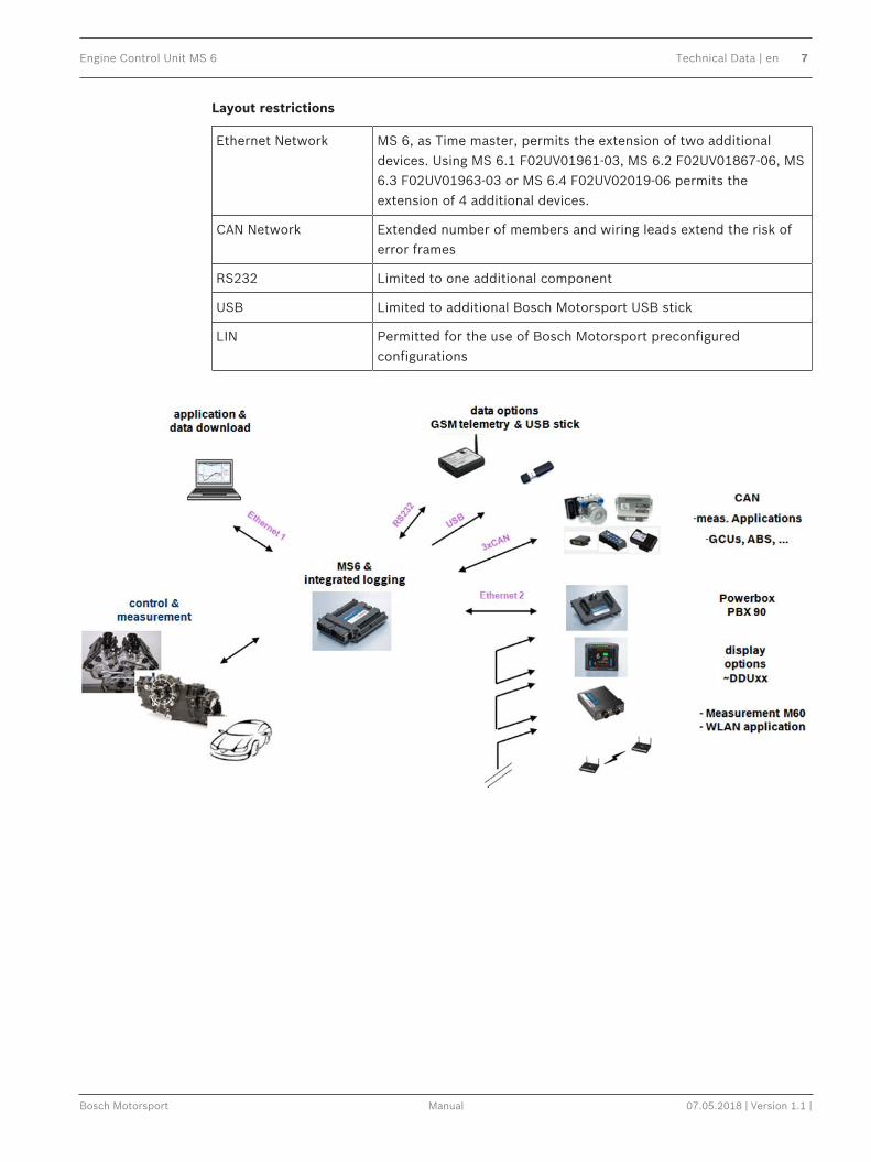
Layout restrictions
Ethernet Network MS 6, as Time master, permits the extension of two additionaldevices. Using MS 6.1 F02UV01961-03, MS 6.2 F02UV01867-06, MS6.3 F02UV01963-03 or MS 6.4 F02UV02019-06 permits theextension of 4 additional devices.
CAN Network Extended number of members and wiring leads extend the risk oferror frames
RS232 Limited to one additional component
USB Limited to additional Bosch Motorsport USB stick
LIN Permitted for the use of Bosch Motorsport preconfiguredconfigurations

8 en | Technical Data Engine Control Unit MS 6
07.05.2018 | Version 1.1 | Manual Bosch Motorsport
2.1.1 Structure MS 6 Devices, Licenses and Order NumbersTo accommodate the wide range of different engine requirements and race track operatingconditions, the MS 6 Motronic system is classified into the main groups high- and lowpressure injection support, subdivided into fully equipped- and functional reduced versions.Beside the change from low- to high pressure systems, all limited functions may be activatedlater. The license concept is related to the individual device and the requested upgrading.
For MS 6.1
Engine function package I To activate electronic throttle,camshaft and turbo control
F 02U V02 001-01
Engine function package II To activate traction andlaunch control
F 02U V02 002-01
For MS 6.1 and MS 6.3
Measurement package To increase from 21 to 42analog channel inputs
F 02U V02 000-01
For MS 6.3
High pressure injection package To activate 2nd engine bankand 2nd MSV controls
F 02U V01 999-01
For all MS 6 Versions
Logger package I Increase the number ofmeasure channels up to 720Sampling up to 1,000 Hz or 1synchroMax. number of 1,080channels are to respect
F 02U V01 993-01
Logger package II Activation of partition 2, 1 GBmemory, 720 channelsSampling up to 1,000 Hz or 1synchroLong term recording, owndata protection code
F 02U V01 998-01
Logger package III Copy data of partition 1 toUSB data stick
F 02U V02 082-01
Gear control package I Gear change control, basedupon Megaline functions(License model via Megaline)
F 02U V02 107-01On request
Gear control package II Strategy for pneumatic forcedgear change control
F 02U V02 108-01

Engine Control Unit MS 6 Technical Data | en 9
Bosch Motorsport Manual 07.05.2018 | Version 1.1 |
For all MS 6 Versions
Gear control package III Support for external GCU likeCosworth or Megaline(included for base versionsbeginning withMS6A_BASE_0800 orcomparable)
F 02U V02 109-01On request
Notice!Verify the necessity of gearbox control licenses by checking the Features info window inRaceCon (see section Feature/License Activation, page 36).
2.1.2 DisposalHardware, accessories and packaging should be sorted for recycling in an environment-friendlymanner.Do not dispose of this electronic device in your household waste.Waste electronic equipment must be disposed of properly according to Electrical andElectronics Act (ElektroG) and the European WEE directive.
2.2 Mechanical Data
Aluminum housing
2 automotive connectors, 196 pins in total
Vibration suppression via multipoint fixed circuit boards
Size without connectors 226 x 181 x 44 mm
Weight 1,086 g
Protection Classification IP54
Temperature range -20 to 80°C
Inspection services recommended after 220 h or 2 years, no components to replace

10 en | Technical Data Engine Control Unit MS 6
07.05.2018 | Version 1.1 | Manual Bosch Motorsport

Engine Control Unit MS 6 Technical Data | en 11
Bosch Motorsport Manual 07.05.2018 | Version 1.1 |
2.2.1 Installation
Mounting 4 housing integrated screw sockets
Offer drawing Available at Bosch Motorsport website on MS 6 product page.
3D Data Available at Bosch Motorsport website on MS 6 product page.
RecommendationUse rubber vibration absorbers for soft mounting in the vehicle. To assist the heat flow,especially if HP injection is active, the device has to be mounted uncovered and air circulationhas to be guaranteed around the entire surface area.Inside touring cars placement passenger side is favored, open connectors should not beuncovered to vertical axe. It has to be assured in mounting position that water cannotinfiltrate through wiring harness into the ECU and that the pressure compensating elementand the sealing in the revolving groove do not get submerged in water. Wiring harness needsto be fixed mechanically in the area of the ECU in a way that excitation of ECU have the samesequence.
2.3 Electrical Data
Power supply 6 to 18 V
CPU Dual Core 667 MHz; FPGA
2.3.1 Communication
3 x CAN The MS 6 has 3 CAN buses configurable as input and output. Differentbaud rates are selectable. Please note that the MS 6 containintegrated switchable 120 Ohm CAN termination resistors.
1 x LIN The Bus is not configurable by the customer, but Bosch Motorsportoffers data selectable protocols to integrate LIN based devices intothe system.
2 x Ethernet Integrated are 100 Mbit full duplex Ethernet communication ports,internally connected with an Ethernet switch. The ports have “cableauto crossover” functionality
1 x USB For data transfer to an USB-stick
1 x RS232 One serial port with programmable baud rate for online telemetry
1 x TimesyncCoordination
For additional devices added via Ethernet
12 en | Technical Data Engine Control Unit MS 6
07.05.2018 | Version 1.1 | Manual Bosch Motorsport
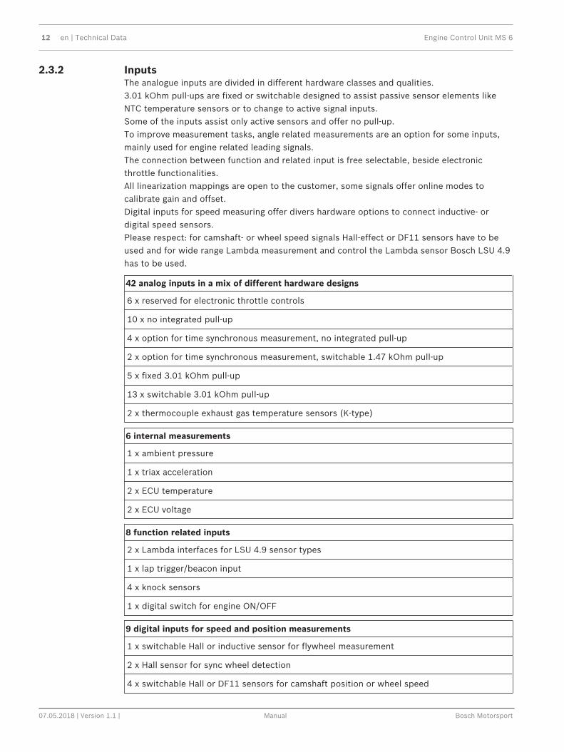
2.3.2 InputsThe analogue inputs are divided in different hardware classes and qualities.3.01 kOhm pull-ups are fixed or switchable designed to assist passive sensor elements likeNTC temperature sensors or to change to active signal inputs.Some of the inputs assist only active sensors and offer no pull-up.To improve measurement tasks, angle related measurements are an option for some inputs,mainly used for engine related leading signals.The connection between function and related input is free selectable, beside electronicthrottle functionalities.All linearization mappings are open to the customer, some signals offer online modes tocalibrate gain and offset.Digital inputs for speed measuring offer divers hardware options to connect inductive- ordigital speed sensors.Please respect: for camshaft- or wheel speed signals Hall-effect or DF11 sensors have to beused and for wide range Lambda measurement and control the Lambda sensor Bosch LSU 4.9has to be used.
42 analog inputs in a mix of different hardware designs
6 x reserved for electronic throttle controls
10 x no integrated pull-up
4 x option for time synchronous measurement, no integrated pull-up
2 x option for time synchronous measurement, switchable 1.47 kOhm pull-up
5 x fixed 3.01 kOhm pull-up
13 x switchable 3.01 kOhm pull-up
2 x thermocouple exhaust gas temperature sensors (K-type)
6 internal measurements
1 x ambient pressure
1 x triax acceleration
2 x ECU temperature
2 x ECU voltage
8 function related inputs
2 x Lambda interfaces for LSU 4.9 sensor types
1 x lap trigger/beacon input
4 x knock sensors
1 x digital switch for engine ON/OFF
9 digital inputs for speed and position measurements
1 x switchable Hall or inductive sensor for flywheel measurement
2 x Hall sensor for sync wheel detection
4 x switchable Hall or DF11 sensors for camshaft position or wheel speed

Engine Control Unit MS 6 Technical Data | en 13
Bosch Motorsport Manual 07.05.2018 | Version 1.1 |
9 digital inputs for speed and position measurements
2 x switchable Hall or inductive sensors for turbo speed measurement
2.3.3 Sensor supplies and screens
4 x sensor supplies 5 V / 50 mA
3 x sensor supplies 5 V / 150 mA
7 x sensor grounds
2 x sensor screens
2.3.4 Outputs
19 freely configurable outputs in a mix of different hardware designs
8 x 2.2 amp pwm lowside switch
4 x 3 amp pwm lowside switch
2 x 4 amp pwm lowside switch
2 x 1 amp pwm lowside switch
2 x 1 amp pwm lowside switch, low dump resistant
1 x 8.5 amp H-bridge
38 function related outputs
12 x ignition controls, support of coils with integrated amplifier only
12 x low pressure injection power stages for high impedance valves (max. 2.2 amps and min. 6 Ohm internal resistance of the injectors)
8 x high pressure injection power stages for magnetic valves (HDEV 5)
2 x outputs for high pressure pump controls (MSV)
2 x 8.5 amp H-bridge for electronic throttle control
2 x 4 amp pwm lowside switch for Lambda heater
3 output signals
1 x flywheel
1 x trigger wheel
1 x engine rpm

14 en | Technical Data Engine Control Unit MS 6
07.05.2018 | Version 1.1 | Manual Bosch Motorsport
2.3.5 Supply SystemPlease ensure that you have a good ground installation with a solid, low resistance connectionto the battery minus terminal. The connection should be free from dirt, grease, paint,anodizing, etc.– MS 6 power consumption at appr. 13 V– ~ 20 - 25 amps (4 cyl. FDI at 8,500 1/min / 200 bar, 1 MSV, 1 electronic throttle, standard
chassis equipment)– ~ 30 - 35 amps (8 cyl. FDI at 8,500 1/min / 200 bar, 2 MSV, 2 electronic throttle, standard
chassis equipment)– Power Consumption of LP-injectors, actuators and coils are to calculate separately.– The MS 6 power supply is separated into the maintenance of controller and power stages.– Ensure controller supply is activated before the power stages.– The MS 6 is able to control a main relay or even the power box itself via a low side
output.– As long as the controller is activated, data logging, telemetry and communication is also
ongoing.– The engine On/Off switch activates the ignition and injection outputs to enable engine
start separately from power supply.
Engine Control Unit MS 6 Pin Layout | en 15
Bosch Motorsport Manual 07.05.2018 | Version 1.1 |
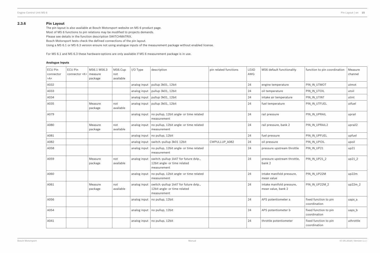
2.3.6 Pin LayoutThe pin layout is also available at Bosch Motorsport website on MS 6 product page.Most of MS 6 functions to pin relations may be modified to projects demands.Please see details in the function description SWITCHMATRIX.Bosch Motorsport tests check the defined connections of the pin layout.Using a MS 6.1 or MS 6.3 version ensure not using analogue inputs of the measurement package without enabled license.
For MS 6.1 and MS 6.3 these hardware-options are only available if MS 6 measurement package is in use.
Analogue Inputs
ECU Pinconnector>A<
ECU Pinconnector >K<
MS6.1 MS6.3measurepackage
MS6.Cupnotavailable
I/O Type description pin related functions LEADAWG
MS6 default functionality function to pin coordination Measurechannel
A032 analog input pullup 3k01, 12bit 24 engine temperature PIN_IN_UTMOT utmot
A033 analog input pullup 3k01, 12bit 24 oil temperature PIN_IN_UTOIL utoil
A034 analog input pullup 3k01, 12bit 24 intake air temperature PIN_IN_UTINT utint
A035 Measurepackage
notavailable
analog input pullup 3k01, 12bit 24 fuel temperature PIN_IN_UTFUEL utfuel
A079 analog input no pullup, 12bit angle- or time relatedmeasurement
24 rail pressure PIN_IN_UPRAIL uprail
A080 Measurepackage
notavailable
analog input no pullup, 12bit angle- or time relatedmeasurement
24 rail pressure, bank 2 PIN_IN_UPRAIL2 uprail2
A081 analog input no pullup, 12bit 24 fuel pressure PIN_IN_UPFUEL upfuel
A082 analog input switch.-pullup 3k01 12bit CWPULLUP_A082 24 oil pressure PIN_IN_UPOIL upoil
A058 analog input no pullup, 12bit angle- or time relatedmeasurement
24 pressure upstream throttle PIN_IN_UP21 up21
A059 Measurepackage
notavailable
analog input switch.-pullup 1k47 for future dvlp.,12bit angle- or time relatedmeasurement
24 pressure upstream throttle,bank 2
PIN_IN_UP21_2 up21_2
A060 analog input no pullup, 12bit angle- or time relatedmeasurement
24 intake manifold pressure,mean value
PIN_IN_UP22M up22m
A061 Measurepackage
notavailable
analog input switch.-pullup 1k47 for future dvlp.,12bit angle- or time relatedmeasurement
24 intake manifold pressure,mean value, bank 2
PIN_IN_UP22M_2 up22m_2
A056 analog input no pullup, 12bit 24 APS potentiometer a fixed function to pincoordination
uaps_a
A054 analog input no pullup, 12bit 24 APS potentiometer b fixed function to pincoordination
uaps_b
A041 analog input no pullup, 12bit 24 throttle potentiometer fixed function to pincoordination
uthrottle

16 en | Pin Layout Engine Control Unit MS 6
07.05.2018 | Version 1.1 | Manual Bosch Motorsport
A053 analog input no pullup, 12bit 24 backup throttle potentiometer fixed function to pincoordination
uthrottle_b
A036 notavailable
analog input no pullup, 12bit 24 throttle potentiometer, bank 2 fixed function to pincoordination
uthrottle2
A037 notavailable
analog input no pullup, 12bit 24 backup throttlepotentiometer, bank 2
fixed function to pincoordination
uthrottle2_b
K036 analog input pullup 3k01, 12bit 24 map switch PIN_IN_UMAPSW umapsw
K031 analog input switch.-pullup 3k01 12bit CWPULLUP_K031 24 pitspeed switch PIN_IN_UPITSPEEDSW upitspeedsw
K019 Measurepackage
analog input switch.-pullup 3k01 12bit CWPULLUP_K019 24 launch control switch PIN_IN_ULAUNCHSW ulaunchsw
K015 analog input switch.-pullup 3k01 12bit CWPULLUP_K015 24 traction control switch PIN_IN_UTCSW utcsw
K016 Measurepackage
notavailable
analog input switch.-pullup 3k01 12bit CWPULLUP_K016 24 reset chassis channels switch PIN_IN_UCHRESSW uchressw
K017 Measurepackage
notavailable
analog input switch.-pullup 3k01 12bit CWPULLUP_K017 24 wet track switch PIN_IN_UWETSW uwetsw
A039 analog input no pullup, 12bit 24 gear position PIN_IN_UGEARP ugearp
A055 Measurepackage
analog input switch.-pullup 3k01 12bit CWPULLUP_A055 24 reverse shift switch PIN_IN_UREVSW ushiftrevsw
A057 Measurepackage
analog input switch.-pullup 3k01 12bit CWPULLUP_A057 24 downshift switch PIN_IN_USHIFTDNSW ushiftdnsw
A076 Measurepackage
analog input switch.-pullup 3k01 12bit CWPULLUP_A076 24 upshift switch PIN_IN_USHIFTUPSW ushiftupsw
A077 analog input switch.-pullup 3k01 12bit CWPULLUP_A077 24 gearshift PIN_IN_UGS ugs
A078 Measurepackage
analog input switch.-pullup 3k01 12bit CWPULLUP_A078 24 free measure channel A78
A038 Measurepackage
analog input no pullup, 12bit 24 gearbox pneumatic pressure PIN_IN_UPGEARAIR upgearair
K033 Measurepackage
analog input no pullup, 12bit 24 clutch pressure PIN_IN_UPCLUTCH upclutch
K048 Measurepackage
notavailable
analog input no pullup, 12bit 24 free measure channel K48
K047 digital input fixed pullup to 5volts 24 laptrigger fixed function to pincoordination
lapctr
A040 analog input no pullup, 12bit 24 brake pressure rear PIN_IN_UPBRAKE_R upbrake_r
K020 analog input switch.-pullup 3k01 12bit CWPULLUP_K020 24 brake pressure front PIN_IN_UPBRAKE_F upbrake_f
K018 Measurepackage
notavailable
analog input switch.-pullup 3k01 12bit CWPULLUP_K018 24 damper sensor front/left PIN_IN_UDAM_FL udam_fl
K032 Measurepackage
notavailable
analog input no pullup, 12bit 24 damper sensor front right PIN_IN_UDAM_FR udam_fr

Engine Control Unit MS 6 Pin Layout | en 17
Bosch Motorsport Manual 07.05.2018 | Version 1.1 |
K034 Measurepackage
notavailable
analog input no pullup, 12bit 24 damper sensor rear left PIN_IN_UDAM_RL udam_rl
K035 Measurepackage
notavailable
analog input no pullup, 12bit 24 damper sensor rear right PIN_IN_UDAM_RR udam_rr
K050 Measurepackage
notavailable
analog input no pullup, 12bit 24 steering angle PIN_IN_USTEER usteer
K077 Thermocouple input
k-type sensor 24shieldthermo
exhaust gas temperature fixed function to pincoordination
utexh
K076
K079 Measurepackage
notavailable
Thermocouple input
k-type sensor 24shieldthermo
exhaust gas temperature bank2
fixed function to pincoordination
utexh2
K078 Measurepackage
notavailable
Digital Inputs
ECU Pinconnector >A<
ECU Pinconnector >K<
MS6.1 MS6.3 measurepackage
MS6.Cupnotavailable
I/O Type description pin related functions LEADAWG
MS6 default functionality function to pin coordination Measure channel
A047 crankshaft+(Hall/Inductive)
switchable between halleffect- andinductive sensor
CWINTF_CRANKPIN_IN_CRANKCWINTF_CRANK_KCWINTF_CRANK_TH
24shield engine speed fixed function to pincoordination
nmot
A048 crankshaft -(inductive)
24shield
A074 digital input halleffect sensor only 24shield camshaft inlet PIN_IN_CAM_IN cam_pos_edges_001
A075 digital input halleffect sensor only 24shield camshaft outlet PIN_IN_CAM_OUT cam_pos_edges_out_001
A049 digital input switchable between halleffect- or DF11sensors
CWINTF_A049 24shield camshaft inlet bank2 orwheelspeed front right
PIN_IN_CAM_IN2 orPIN_IN_FWEEL_FR
cam_pos_edges2_001 orfwheel_fr
A050 digital input switchable between halleffect- or DF11sensors
CWINTF_A050 24shield camshaft outlet bank2 orwheelspeed front left
PIN_IN_CAM_OUT2 orPIN_IN_FWEEL_FL
cam_pos_edges_out2_001 orfwheel_fl
A051 digital input switchable between halleffect- or DF11sensors
CWINTF_A051 24shield wheelspeed rear right PIN_IN_FWHEEL_RR fwheel_rr
A052 digital input switchable between halleffect- or DF11sensors
CWINTF_A052 24shield wheel speed rear left PIN_IN_FWHEEL_RL fwheel_rl
K045 digital input switchable between halleffect- andinductive sensor
CWINTF_K045CWINTF_K045_KCWINTF_K045_TH
24shield turbo speed PIN_IN_FTURBO fturbo

18 en | Pin Layout Engine Control Unit MS 6
07.05.2018 | Version 1.1 | Manual Bosch Motorsport
K046 digital input switchable between halleffect- andinductive sensor
CWINTF_K046CWINTF_K046_KCWINTF_K046_TH
24shield turbo speed bank2 PIN_IN_FTURBO2 fturbo2
K062 groundsupply
if inductive sensos are connected toK045 or K046
24shield ground for turbo speed and--2
K054 digital input 20 Engine On/Off switch b_engon(_in)
A013 knock input 24shield knock sensor 1, bank1 KCSENCYL ikcraw_n_..
A014 knock input 24shield knock sensor 2, bank1 KCSENCYL ikcraw_n_..
A015 not avl. knock input 24shield knock sensor 1, bank2 KCSENCYL ikcraw_n_..
A016 not avl. knock input 24shield knock sensor 2, bank2 KCSENCYL ikcraw_n_..
A017 knocksensorground
24shield
K085 Lambda_IA LSU4.9 probe only 24 Lambda fixed function to pin coordination
lambda
K086 Lambda_IP 24
K087 Lambda_UN 24
K088 Lambda_VM 24
K068 not avl. Lambda_IA LSU4.9 probe only 24 Lambda bank2 fixed function to pin coordination
lambda2
K069 not avl. Lambda_IP 24
K070 not avl. Lambda_UN 24
K071 not avl. Lambda_VM 24
Ignition- & Injection Outputs
ECU Pinconnector >A<
ECU Pinconnector >K<
MS6.1 MS6.3measurepackage
MS6.Cupnotavailable
I/O Type description pin relatedfunctions
LEADAWG
MS6 default functionality function to pin coordination Measure channel

Engine Control Unit MS 6 Pin Layout | en 19
Bosch Motorsport Manual 07.05.2018 | Version 1.1 |
A026 ignitiondriver
output related to mechanical cylindernumber;
use of coil integrated power stages only
CWIGNDRV_MODEIGNDRV_CURRENT
24 Ignition cyl.1 CYLNUMBERCYLANGLE
ign_out_n_001
A027 24 Ignition cyl.2 ign_out_n_002
A028 24 Ignition cyl.3 ign_out_n_003
A029 24 Ignition cyl.4 ign_out_n_004
A030 not avl. 24 Ignition cyl.5 ign_out_n_005
A031 not avl. 24 Ignition cyl.6 ign_out_n_006
A068 not avl. 24 Ignition cyl.7 ign_out_n_007
A069 not avl. 24 Ignition cyl.8 ign_out_n_008
A070 not avl. 24 ignition cyl.9 ign_out_n_009
A071 not avl. 24 ignition cyl.10 ign_out_n_010
A072 not avl. 24 ignition cyl.11 ign_out_n_011
A073 not avl. 24 ignition cyl.12 ign_out_n_012
A098 low pressureoutput forhigh imp. injectors
output related to mechanical cylindernumber
24twist Injection cyl.1 CYLNUMBERCYLANGLEor(PIN_OUT_LPINJ_A098 … PIN_OUT_LPINJ_A084)
tinj_n_001
A100 24twist Injection cyl.2 tinj_n_002
A101 24twist Injection cyl.3 tinj_n_003
A096 24twist Injection cyl.4 tinj_n_004
A099 not avl. 24twist Injection cyl.5 tinj_n_005
A103 not avl. 24twist Injection cyl.6 tinj_n_006
A042 not avl. 24twist Injection cyl.7 tinj_n_007
A105 not avl. 24twist Injection cyl.8 tinj_n_008
A018 not avl. 24twist Injection cyl.9 tinj_n_009
A020 not avl. 24twist Injection cyl.10 tinj_n_010
A063 not avl. 24twist Injection cyl.11 tinj_n_011
A084 not avl. 24twist Injection cyl.12 tinj_n_012

20 en | Pin Layout Engine Control Unit MS 6
07.05.2018 | Version 1.1 | Manual Bosch Motorsport
A043 highpressureoutputs for magnetic injectors
INJVH1 20twist Injection cyl.A PIN_OUT_HPINJ11A_A043_A064
tinj_n_(cyl.A)
A064 INJVL11 20twist
A002 not avl. INJVH3 20twist Injection cyl.B PIN_OUT_HPINJ12E_A002_A023
tinj_n_(cyl.B)
A023 not avl. INJVL32 20twist
A003 INJVH2 20twist Injection cyl.C PIN_OUT_HPINJ21C_A003_A024
tinj_n_(cyl.C)
A024 INJVL21 20twist
A046 not avl. INJVH4 20twist Injection cyl.D PIN_OUT_HPINJ22G_A046_A067
tinj_n_(cyl.D)
A067 not avl. INJVL42 20twist
A044 not avl. INJVH1 20twist Injection cyl.E PIN_OUT_HPINJ31F_A044_A065
tinj_n_(cyl.E)
A065 not avl. INJVL12 20twist
A001 INJVH3 20twist Injection cyl.F PIN_OUT_HPINJ32B_A001_A022
tinj_n_(cyl.F)
A022 INJVL31 20twist
A004 not avl. INJVH2 20twist Injection cyl.G PIN_OUT_HPINJ41H_A004_A025
tinj_n_(cyl.G)
A025 not avl. INJVL22 20twist
A045 INJVH4 20twist Injection cyl.H PIN_OUT_HPINJ42D_A045_A066
tinj_n_(cyl.H)
A066 INJVL41 20twist
Outputs
ECU Pin connector >A<
ECU Pinconnector >K<
MS6.1 MS6.3 measurepackage
MS6.Cupnotavailable
I/O Type description pin related functions LEAD AWG
MS6 default functionality function to pin coordination Measurechannel
A095 lowside switch 4 amps pwm 24twist camshaft inlet control fixed pin to output controlcoordination
cam_pwm
A021 not avl. lowside switch 4 amps pwm 24twist camshaft inlet control bank2 fixed pin to output controlcoordination
cam_pwm2
A102 lowside switch 3 amps pwm 24twist camshaft outlet control fixed pin to output controlcoordination
cam_pwm_out
A094 not avl. lowside switch 3 amps pwm 24twist camshaft outlet controlbank2
fixed pin to output controlcoordination
cam_pwm_out2
A019 lowside switch 3 amps pwm 24twist PIN_OUT_A019
A104 not avl. lowside switch 3 amps pwm 24twist PIN_OUT_A104
A097 lowside switch 2,2 amps pwm 24twist wastegate increase PIN_OUT_A097 wgc_inc_pwm
A093 not avl. lowside switch 2,2 amps pwm 24twist wastegate increase bank2 PIN_OUT_A093 wgc_inc_pwm2
K039 not avl. lowside switch 2,2 amps pwm 24twist PIN_OUT_K039
K056 lowside switch 2,2 amps pwm 24twist air conditioning compressor PIN_OUT_K056 comp_pwm

Engine Control Unit MS 6 Pin Layout | en 21
Bosch Motorsport Manual 07.05.2018 | Version 1.1 |
K038 lowside switch 2,2 amps pwm 24twist gearshift actuator upshift PIN_OUT_K038 shiftup_pwm
K040 not avl. lowside switch 2,2 amps pwm 24twist PIN_OUT_K040
K055 lowside switch 2,2 amps pwm 24twist gearshift actuator downshift PIN_OUT_K055 shiftdn_pwm
K074 lowside switch 2,2 amps pwm 24twist PIN_OUT_K074
K089 lowside switch 1 amps pwm 24twist fuel pump relay PIN_OUT_K089 fpump_pwm
K073 not avl. lowside switch 1 amps pwm 24twist PIN_OUT_K073
K057 lowside switch 1amp pwm reset < 3,5V 24twist control main relay fixed pin to output controlcoordination
b_mainrelay
K072 lowside switch 1amp pwm reset < 3,5V 24twist Kl.50 / starter control fixed pin to output controlcoordination
b_starter
K022 lowside switch 4 amp pwm 24twist heater lambda fixed pin to output controlcoordination
lsuh_out
K023 not avl. lowside switch 4 amp pwm 24twist heater lambda2 fixed pin to output controlcoordination
lsuh_out2
H-Bridges & Metering Unit
ECU Pinconnector >A<
ECU Pinconnector>K<
MS6.1 MS6.3measurepackage
MS6.Cupnotavailable
I/O Type description pin relatedfunctions
LEADAWG
MS6 default functionality function to pin coordination Measurechannel
A089 H-Bridge 1 pos. 8,5 amps CWHB1_EN 24twist electrical throttle fixed pin to output controlcoordination
etc_pwm
A090 H-Bridge 1 neg.
A091 H-Bridge 2 pos. 8,5 amps CWHB2_EN 24twist electrical throttle bank 2 fixed pin to output controlcoordination
etc_pwm2
A092 H-Bridge 2 neg.
K090 H-Bridge 3 pos. 8,5 amps CWHB3_EN 24twist fixed pin to output controlcoordination
K091 H-Bridge 3 neg.
A085 MSV1 controllerpos.
FCVH1 24twist high press. pump MSV valve1
fixed pin to output controlcoordination
msv_dlvy_angle
A086 MSV1 controllerneg.
FCVL1
A087 not avl. MSV2 controllerpos.
FCVH2 24twist high press. pump MSV valve2
fixed pin to output controlcoordination
msv_dlvy_angle2
A088 not avl. MSV2 controllerneg.
FCVL2
22 en | Pin Layout Engine Control Unit MS 6
07.05.2018 | Version 1.1 | Manual Bosch Motorsport
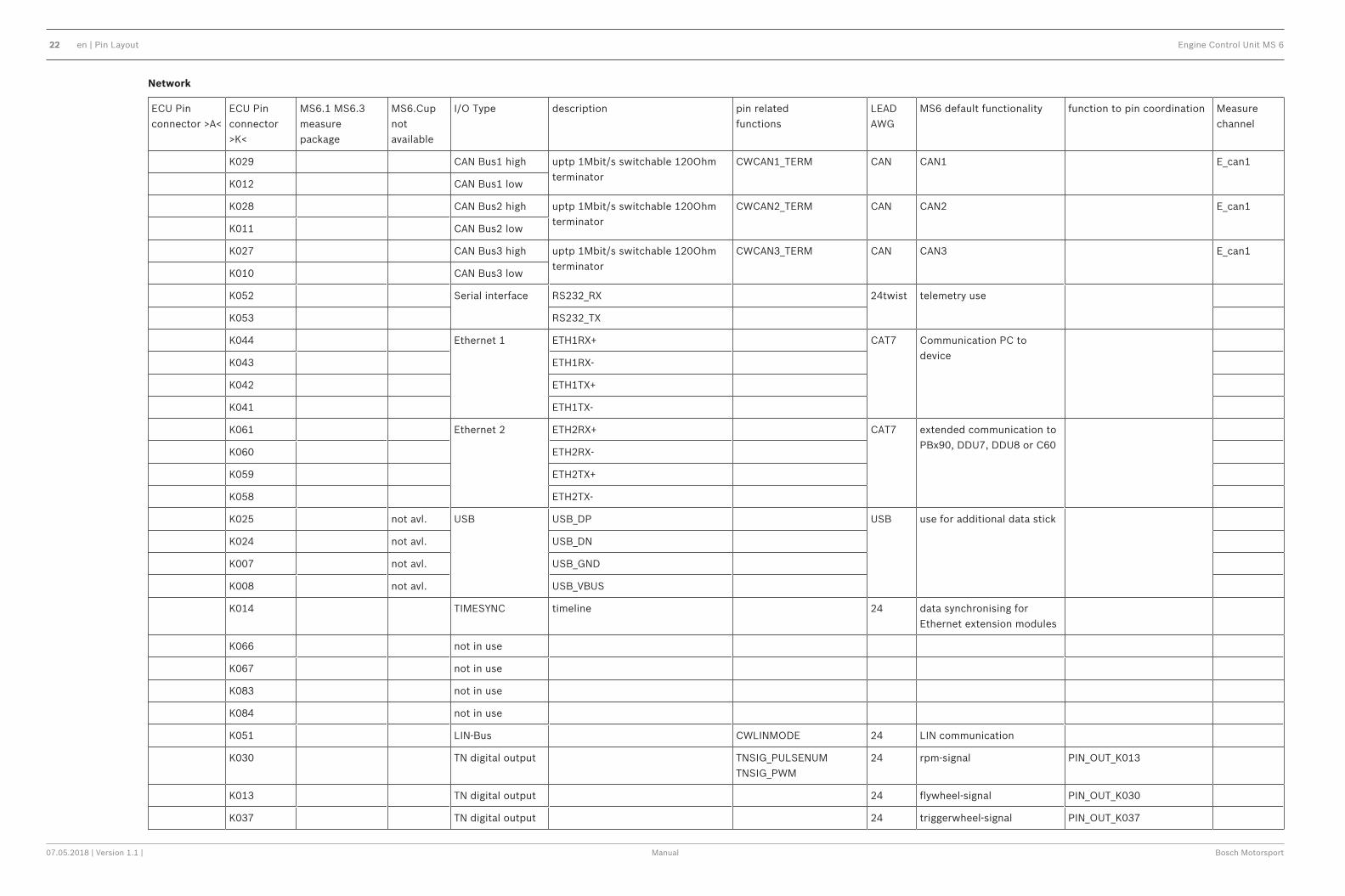
Network
ECU Pinconnector >A<
ECU Pinconnector>K<
MS6.1 MS6.3measurepackage
MS6.Cupnotavailable
I/O Type description pin relatedfunctions
LEADAWG
MS6 default functionality function to pin coordination Measurechannel
K029 CAN Bus1 high uptp 1Mbit/s switchable 120Ohmterminator
CWCAN1_TERM CAN CAN1 E_can1
K012 CAN Bus1 low
K028 CAN Bus2 high uptp 1Mbit/s switchable 120Ohmterminator
CWCAN2_TERM CAN CAN2 E_can1
K011 CAN Bus2 low
K027 CAN Bus3 high uptp 1Mbit/s switchable 120Ohmterminator
CWCAN3_TERM CAN CAN3 E_can1
K010 CAN Bus3 low
K052 Serial interface RS232_RX 24twist telemetry use
K053 RS232_TX
K044 Ethernet 1 ETH1RX+ CAT7 Communication PC todevice
K043 ETH1RX-
K042 ETH1TX+
K041 ETH1TX-
K061 Ethernet 2 ETH2RX+ CAT7 extended communication toPBx90, DDU7, DDU8 or C60
K060 ETH2RX-
K059 ETH2TX+
K058 ETH2TX-
K025 not avl. USB USB_DP USB use for additional data stick
K024 not avl. USB_DN
K007 not avl. USB_GND
K008 not avl. USB_VBUS
K014 TIMESYNC timeline 24 data synchronising forEthernet extension modules
K066 not in use
K067 not in use
K083 not in use
K084 not in use
K051 LIN-Bus CWLINMODE 24 LIN communication
K030 TN digital output TNSIG_PULSENUMTNSIG_PWM
24 rpm-signal PIN_OUT_K013
K013 TN digital output 24 flywheel-signal PIN_OUT_K030
K037 TN digital output 24 triggerwheel-signal PIN_OUT_K037

Engine Control Unit MS 6 Pin Layout | en 23
Bosch Motorsport Manual 07.05.2018 | Version 1.1 |
Power Supplies
ECU Pin connector>A<
ECU Pinconnector>K<
MS6.1 MS6.3 measurepackage
MS6.Cupnotavailable
I/O Type description pin related functions LEAD AWG
MS6 default functionality function to pin coordination Measurechannel
K003 battery plus 14 dynamic power supply
K005 battery plus 14 dynamic power supply
K006 battery plus 14 dynamic power supply
K075 battery plus 20 digital power supply
K001 battery minus 14
K002 battery minus 14
K004 battery minus 14
A009 sensor supply5V/50mamp
recommended supply for: aps_a, etc 24 ETC sensor supply 1
A011 sensor supply5V/50mamp
recommended supply for: aps_b,etc2
24 ETC sensor supply 2
K065 sensor supply5V/150mamp
CW5VOUT3_EN 24 5 V sensor supply 4
A007 sensor supply5V/50mamp
24 5 V sensor supply 5
A005 sensor supply5V/150mamp
CW5VOUT1_EN 24 5 V sensor supply 1
K064 sensor supply5V/150mamp
CW5VOUT2_EN 24 5 V sensor supply 2
K063 sensor supply5V/50mamp
24 5 V sensor supply 3
K080 sensor ground 1 20 ground sensor supply
K081 sensor ground 2 20 ground sensor supply
K082 sensor ground 3 20 ground sensor supply
A006 sensor ground 4 20 ground sensor supply
A008 sensor ground 5 20 ground sensor supply
A010 sensor ground 6 recommended ground for: aps_a,etc
20 ground sensor supply
A012 sensor ground 7 recommended ground for: aps_b,etc2
20 ground sensor supply
A062 shield ground 24 sensor shields
K021 shield ground 24 sensor shields
K026 shield ground 24 Ethernet and LIN shields
24 en | Pin Layout Engine Control Unit MS 6
07.05.2018 | Version 1.1 | Manual Bosch Motorsport
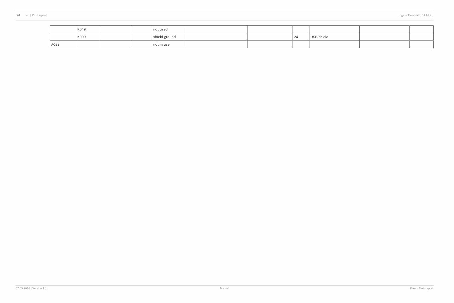
K049 not used
K009 shield ground 24 USB shield
A083 not in use

Engine Control Unit MS 6 Technical Data | en 25
Bosch Motorsport Manual 07.05.2018 | Version 1.1 |
2.3.7 Harness / WiringThe wiring diagram is available at Bosch Motorsport website on the MS 6 product page.
Notice!The wiring diagram shows a principle of wiring and connection options.ECU pin relation may change to customer data application and program layout. Sensor-,actuator- and power supplies may also change to the request of the project.

26 en | Technical Data Engine Control Unit MS 6
07.05.2018 | Version 1.1 | Manual Bosch Motorsport
41
32
ENG GND
+
Kl.1
ECU GND
D261 205 336-01
41
32
ENG GND
+
Kl.1
ECU GND
D261 205 336-01
41
32
ENG GND
+
Kl.1
ECU GND
D261 205 336-01
41
32
ENG GND
+
Kl.1
ECU GND
D261 205 336-01
41
32
ENG GND
+
Kl.1
ECU GND
D261 205 336-01
41
32
ENG GND
+
Kl.1
ECU GND
D261 205 336-01
41
32
ENG GND
+
Kl.1
ECU GND
D261 205 336-01
41
32
ENG GND
+
Kl.1
ECU GND
D261 205 336-01
Cylin
de
r 1
ign
itio
n
2,5mm²
12
Inje
ctio
n
va
lve
Cylin
de
r D .
12
Inje
ctio
n
va
lve
Cylin
de
r C .
12
Inje
ctio
n
va
lve
Cylin
de
r B .
12
Inje
ctio
n
va
lve
Cylin
de
r A .
12
..
ca
msh
aft
co
ntr
ol in
ca
m
12
..
ca
msh
aft
co
ntr
ol in
2
ca
m 2
??
not def.
wa
ste
ga
te
co
ntr
ol va
lve
incre
ase
ba
nk1
wa
ste
ga
te in
c b
1
??
not def.
wa
ste
ga
te
co
ntr
ol va
lve
incre
ase
ba
nk2
wa
ste
ga
te in
c b
2
12
..
ge
ars
hift
actu
ato
r
up
sh
ift
up
sh
ift
12
..
ge
ars
hift
actu
ato
r
do
wn
sh
ift
do
wn
sh
ift
X1
21
X2
3
fue
l p
um
p
rela
y. r/
pu
mp
AWG 14
fue
l p
um
p
no
t d
ef.
pu
mp
AWG 14
X1
21
X2
3
ma
in r
ela
y. r/
ma
in
AWG 8
M +-
5
+
S1
-
S2
H+
H-
ele
ctr
on
ic
thro
ttle
co
ntr
ol
ath 3
46
12
ele
ctr
on
ic
thro
ttle
co
ntr
ol 2
ath
2
M+ -
5
+
S2
-
S1
H+
H-
31
64
2
.
.
.
.
M+ -
.
H+
H-
.
??
not def.not def.
de
live
r
co
ntr
ol
va
lve
ba
nk1
fcv 1 ?
?
not def.not def.
de
live
r
co
ntr
ol
va
lve
ba
nk2
fcv 2
H-B
rid
ge
3
oil
tem
pe
ratu
re
toil
??
not def.not def.
fue
lte
mp
era
ture
tfu
el
??
not def.not def.
??
not def.not def.
??
not def.not def.
air
tem
pe
ratu
re
tin
t
en
gin
e
tem
pe
ratu
re
tmo
t
.
Signal
+-
oil
pre
ssu
rese
nso
r
po
il
.
.
??
?
not def.not def.
.
Signal
+-
P2
1
inta
ke
ma
nifo
ldse
nso
rp
21
.
.
??
?
not def.not def.
.
Signal
+-
.
.
??
?
not def.not def.
.
Signal
+-
.
.
??
?
not def.not def.
P2
1_
2
inta
ke
ma
nifo
ldse
nso
r
p2
1_
2
P2
2
inta
ke
ma
nifo
ld
se
nso
r
aft
er
thro
ttle
p2
2
.
Signal
+-
.
.
??
?
not def.not def.
P2
2_
2
inta
ke
ma
nifo
ldse
nso
r
aft
er
thro
ttle
p2
2_
2
S+
-S
+-
12
34
56
acce
lera
tio
n
pe
da
lse
nso
r
ap
s
AS 007-35SN.AS 607-35PN
lau
nch
fun
ctio
n
sw
itch
B_
LA
UN
CH
SW
ch
assis
fu
nctio
nre
se
t
sw
itch
B_
CH
AS
SIS
RE
SS
W
pit
sp
ee
d
sw
itch
B_
PIT
SP
EE
DS
W
ma
pp
ositio
n
sw
itch
MA
PP
OS
tra
ctio
n
co
ntr
ol
sw
itch
TC
_S
TA
GE
we
t
sw
itch
B_
WE
T
Signal
+-
se
nso
rm
ea
sK
48
me
as_
K4
8
??
?
not def.
not def.
l angi S
+-
clu
tch
pre
ssu
re
pclu
tch
??
?
not def.not def.
l angi S
+-
lap
trig
ge
r
be
aco
n
lap
trig
12
3
ASL 0-06-05-SDASL 6-06-05-PD
S+
-
ge
ar
po
ten
tio
me
ter
ge
ar
.
.
??
?
not def.not def.
S+
-
ge
ar
sh
ift
se
nso
r
ge
ars
hift
.
??
?
not def.not def.
S+
-
fre
e m
ea
s.
ch
an
ne
l A
78
me
as_
A7
8
.
??
?
not def.not def.
S+
-
da
mp
er
po
sitio
n
se
nso
r
rea
r le
ft
da
m_
rl
??
?
.not def.not def.
S+
-
da
mp
er
po
sitio
n
se
nso
r
rea
r rig
ht
da
m_
rr
??
?
.not def.not def.
??
?
not def.not def.
Signal
+-
??
?
not def.not def.
bra
ke
pre
ssu
re
fro
nt
pb
rake
_f
ge
arb
ox
pn
eu
ma
tic
pre
ssu
re
pg
ea
rair
??
?
. not def.not def.
bra
ke
pre
ssu
rese
nso
rre
ar
pb
rake
_r
??
?
. not def.not def.
S+
-
ste
erin
g
an
gle
po
ten
tio
me
ter
ste
er
.
.
??
?
not def.not def.
..
.
..
exh
au
st
ga
ste
mp
. se
nso
r1
texh
..
exh
au
st
ga
ste
mp
. se
nso
r2
texh
2
..
.
a_
ca
mctr
l_o
ut
ca
m o
ut
po
sitio
n
a_
ca
mctr
l
ca
m in
po
sitio
n
a_
ca
mctr
l_o
ut2
ca
m2
ou
tp
ositio
n
+S
-
??
?
..
+S
-+
S-
??
?
.
.
??
?
..
+-
cra
nksh
aft
sig
na
l
nm
ot
N S
??
?
..
wh
ee
l
sp
ee
d _
fr
vw
he
el_
fr
wh
ee
l
sp
ee
d_
fl
vw
he
el_
fl
wh
ee
l
sp
ee
d_
rr
vw
he
el_
rr
wh
ee
l
sp
ee
d_
rl
vw
he
el_
rl
+S
-
??
?
not def.not def.
+S
-
??
?
not def.not def.
+S
-
??
?
not def.not def.
+S
-
??
?
not def.not def.
kn
ock
se
nso
r 1
ba
nk 1
KN
OC
K1
B1
kn
ock
se
nso
r 2
ba
nk 1
KN
OC
K2
B1
21
12
.
.
kn
ock
se
nso
r 1
ba
nk 2
KN
OC
K1
B2
kn
ock
se
nso
r 2
ba
nk 2
KN
OC
K2
B2
21
12
.
.
not def.not def.
not def.not def.
not def.not def.
not def.not def.
+-
turb
o
sp
ee
d
nT
urb
o
NS
??
?
not def.not def.
+-
NS
??
?
not def.not def.
16
31
19
17
15
36
55
38
90
91
48
33
47
35
34
32
20
50
78
79
76
77
37
36
91
92
41
53
89
90
82
58
59
60
61
4320
6420
220
2320
320
2420
4620
6720
26
95
21
97
93
85
86
87
88
39
77
78
38
40
75
74
50
49
50
51
52
17
13
14
15
16
45
62
sh
ift
up
sw
itch
up
sw
sh
ift
do
wn
sw
itch
dn
sw
76
57
+S
-
..
47
cra
nksh
aft
sig
na
l
nm
ot
12
Inje
ctio
n
va
lve
Cylin
de
r E.
12
Inje
ctio
n
va
lve
Cylin
de
r F.
2
Inje
ctio
n
va
lve
Cylin
de
r H.
12
Inje
ctio
n
va
lve
Cylin
de
r G.
44 20
65 20
1 20
22 20
4 20
25 20
45 20
66 20
gro
un
d te
rmin
al
29 CAN_H
12 CAN_L
28 CAN_H
11 CAN_L
27 CAN_H
10 CAN_L
52 RX
53 TX
44
43
42
41
B_D_ETH2Rx+
61
B_D_ETH2Rx-
60
B_D_ETH2Tx+
59
B_D_ETH2Tx-
58
B_D_USB_DP
25
B_D_USB_DN
24
G_G_USB_GND
07
O_V_USB_VBUS
08
51
30
13
37
0614
0514
0314
7520
0414
0214
0114
89
GNDUSBSCR
09
SCN_DATA
26
gro
un
d te
rmin
al
41
32
USB Buchse.
US
B
da
ta
stick
US
B
57
68
3
42
1
RJ-4
5 B
uch
se
An
sic
ht
vo
n h
inte
n
36
12
pair_1
pair_2
Ethernet wire
RJ45 ETH Buchse
21
21
81
81
81
80
81
82
82
82
82
82
82
82
82
63
64
65
65
62
62
62
62
62
62
62
62
62
62
62
62
62
17
17
17
77
11
11
09
09
55
xx
xx
ETH1_RX+
ETH1_RX-
ETH1_TX+
ETH1_TX-
x
SYNC IN
shield
x
SP
/DD
U8
/C6
0A
S D
D 6
-12
-41
-SN
. DD
U8
/C6
0
Dis
pla
y D
DU
S2
Plu
s
AS
6-1
4-3
5-S
ND
DU
S2
+
pair_1
pair_2
Ethernet wire
26
pair_1
pair_2
B_F_TIMESYNC
14
21
21
46
62
5420
61
20
60
60
62
72
82
9
68
69
70
71
OP
TIO
NA
L E
TH
ER
NE
T E
XT
EN
SIO
N
12
..
ca
msh
aft
co
ntr
ol o
ut
ca
m o
ut
12
..
ca
msh
aft
co
ntr
ol o
ut2
ca
m o
ut 2
10
29
4
06
08
08
2,5mm²
po
we
r su
pp
ly
gro
un
d te
rmin
al
ecu
inte
rfa
ce
DIA
G
57
AWG 8
72
Starter output
54
84
7
a_
ca
mctr
l2
ca
m2
in
po
sitio
n
+S
-
..
49
62
55
OP
TIO
NA
LO
PT
ION
AL
for
ind
uctive
se
nso
r
LIN-BUS
GN
D_
en
gin
e
rc 8
mm
blu
eG
ND
_E
NG
sh
ort
co
nn
ectio
nto
en
gin
e b
lock
GN
D_
en
gin
e
rc 8
mm
blu
e
GN
D_
EN
G
F0
2U
.S0
0.4
44
-03
Ba
sis
an
sch
luss M
S6
F0
2U
.S0
0.4
44
-03
M
S6
B
asic
Wir
ing
Achtu
ng :
- a
lle n
ich
t b
eze
ich
ne
ten
Le
itu
ng
en
sin
d a
uf A
WG
2
4 a
usg
ele
gt
- kle
ine
Bu
ch
sta
be
n s
ind
un
ters
tric
he
n
-
rc =
Rin
gve
rbin
de
r
- E
the
rne
tka
be
l m
it S
pe
c. C
AT
5 v
erw
en
de
n
- F
ire
wire
ka
be
l n
ach
Sta
nd
ard
IE
E1
39
4
- je
de
CA
N V
erb
ind
un
g m
uss m
it 6
0Ω
ab
ge
sch
losse
n s
ein
- b
ei U
SB
un
d E
the
rne
tle
itu
ng
un
be
din
gt a
uf P
aa
re a
ch
ten
- E
the
rne
tve
rka
be
lun
g m
uss s
ep
era
t g
efü
hrt
we
rde
n
- K
ab
elq
ue
rsch
nitte
mü
sse
n n
ach
Be
da
rf a
ng
ep
asst w
erd
en
Attention :
-
all
no
t m
ark
ed
wire
´ a
re A
WG
24
-
sm
all
lette
rs a
re u
nd
erlin
ed
-
rc =
rin
gw
ire
-
use
eth
ern
etc
ab
le C
AT
5
-
fire
wire
ca
ble
as s
pe
c IE
E1
39
4
-
all
CA
N n
etw
ork
s m
ust b
e te
rmin
ate
d w
ith
60
Ω
-
ple
ase
re
sp
ect str
ictly th
e p
airs w
hile
usin
g d
ata
wire
s lik
e U
SB
or
Eth
ern
et
-
eth
ern
et w
ire
´s m
ust b
e w
ire
d s
ep
ara
tely
-
wire
dia
me
tre
mu
st b
e a
da
pte
d d
ep
en
din
g o
n u
sa
ge
sh
ort
co
nn
ectio
n
to
en
gin
e b
lock
po
we
r su
pp
ly
EN
GIN
E
on
/off
sw
itch
B_
EN
GO
N_
IN
F0
2U
.B0
0.7
12
-01
??
??
??
OP
TIO
NA
L
41
32
ENG GND
+
Kl.1
ECU GND
D261 205 336-01
41
32
ENG GND
+
Kl.1
ECU GND
D261 205 336-01
30
31
41
32
ENG GND
+
Kl.1
ECU GND
D261 205 336-01
41
32
ENG GND
+
Kl.1
ECU GND
D261 205 336-01
Cylin
de
r 2
ign
itio
n
Cylin
de
r 3
ign
itio
n
Cylin
de
r 4
ign
itio
n
Cylin
de
r 5
ign
itio
n
Cylin
de
r 6
ign
itio
n
Cylin
de
r 7
ign
itio
n
Cylin
de
r 8
ign
itio
n
Cylin
de
r 9
ign
itio
n
Cylin
de
r 1
1
ign
itio
n
Cylin
de
r 1
2
ign
itio
n
Cylin
de
r 1
0
ign
itio
n
72
73
54
.
l angi S
+-
fue
l
pre
ssu
re
hig
hse
nso
r 2
pra
il 2
.
.
??
?
not def.not def.
.
Signal
+-
fue
l
pre
ssu
re
hig
hse
nso
r 1
pra
il
.
.
??
?
not def.not def.
.
Signal
+-
fue
l
pre
ssu
re
low
se
nso
r
pfu
el
.
.
??
?
not def.not def.
80
79
81
75
70
6
1
12
Inje
ctio
n
va
lve
Cylin
de
r 4 .
12
Inje
ctio
n
va
lve
Cylin
de
r 3 .
12
Inje
ctio
n
va
lve
Cylin
de
r 2 .
12
Inje
ctio
n
va
lve
Cylin
de
r 1 .
12
Inje
ctio
n
va
lve
Cylin
de
r 5 .
12
Inje
ctio
n
va
lve
Cylin
de
r 6 .
98
10
01
01
96
99
10
3
12
Inje
ctio
n
va
lve
Cylin
de
r 1
0.
12
Inje
ctio
n
va
lve
Cylin
de
r 9.
12
Inje
ctio
n
va
lve
Cylin
de
r 8.
12
Inje
ctio
n
va
lve
Cylin
de
r 7.
12
Inje
ctio
n
va
lve
Cylin
de
r 1
1.
12
Inje
ctio
n
va
lve
Cylin
de
r 1
2.
42
10
51
82
06
38
4
OP
TIO
N IN
JE
CT
ION
LO
W P
RE
SS
UR
EO
PT
ION
IN
JE
CT
ION
HIG
H P
RE
SS
UR
E
F0
2U
.B0
0.7
11
-01
OP
TIO
NA
L U
SB
Da
ta S
tick
01
An
lage
20
14
07
18
HtM
..
BE
G/E
MS
3.
Co
nnecto
r "A
"
AWG 14
AWG 14
AWG 14
10mm2
Kl.3
0_
Mo
tro
nic
rc 8
mm
re
d
Kl.3
0_
Mo
tro
nic
po
we
r su
pp
ly
OP
TIO
NA
L w
ith
MA
IN R
EL
AY
AWG 14
AWG 14
AWG 14
Signal
+-
Signal
+-
12
10
10
51
05
10
51
05
10
51
05
10
12
12
55
12
12
12
Kl.3
1
rc 8
mm
blu
eG
ND
08
08
11
11
09
09
32
06
33
34
35
08
08
06
08
08
OP
TIO
NA
L
S+
-
da
mp
er
po
sitio
n
se
nso
r
fro
nt
rig
ht
da
m_
fr
64
64
64
??
?
not def.not def.
18
81 S
+-
da
mp
er
po
sitio
n
se
nso
r
fro
nt
left
da
m_
fl
64
82
CAN wire
CAN wire
CAN wire
26
CAN 3
CAN 2
CAN 1
ext. components with
function request
(gearcontrol, steeringwheel,..)
Components Bosch Motorsport
(ABS,PBX90,MSA-Box,Bypass,HPI)
ext. components
(measure components)
useable for options like
- alternator control
- wiper control
RS232useable for options like
- telemetry
Co
nnecto
r "K
"
LS 1AMP
TRIGGERWHEEL_SIGNAL Output
FLYWHEEL_SiGNAL Output
RPM SIGNAL Output
20
15
02
10
HtM
Kl.3
0_
Mo
tro
nic
rc 8
mm
re
d
Kl.3
0_
Mo
tro
nic
D261.205.356-01.
twisted pair
twisted pair
23
69
87
88
22
86
70
71
68
85
lam
bd
a s
en
so
r B
an
k1
D2
61
.20
5.3
56
-01
LS
U 4
.9
lam
_1
16
52
34
Nernst
Pump
D261.205.356-01.
lam
bd
a s
en
so
r B
an
k2
D2
61
.20
5.3
56
-01
LS
U 4
.9
lam
_2
16
52
34
Nernst
Pump
twisted pair
twisted pair
21
21
turb
o
sp
ee
d 2
nT
urb
o2
20
15
02
18
HtM
98
16 CAN1_low
4
CAN1_high
22 SCREEN
10 K LINE
3
Unit_GND
1
PERM.POS.
2
SW .POS.
15
ecu
in
terf
ace
(MS
A-B
ox2
)A
S 0
12
-35
SN
DIA
G
12
11
TERM 15 PIN
ETH_RX-
ETH_RX+
ETH_TX-
ETH_TX+
44
43
42
41
26
pair_1
pair_2
Ethernet wire
OP
TIO
NA
L D
DU
S2
PL
US
OP
TIO
NA
L D
IAG
AWG 8
AWG 20
M
+-
X1
21
X2
3
air c
on
dito
in
co
mp
resso
r re
lay
. R/G
EA
RA
IR
AWG 14air
co
mp
resso
r
no
t d
ef.
AC
AWG14
AWG 14
56
08
reve
rse
ge
ar
sh
ift sw
itch
reve
rse
55
12
.
6mm2
.
.
tbd.
tbd.
tbd.
tbd.
tbd.
tbd.
tbd.
+-
+-
RE
DT
x+
BL
UE
Tx-
Ye
llow
Rx+
GR
EE
N
Rx-
Eth
ern
etw
ire
4
x A
WG
24
Min
be
nd
ra
diu
s:
dyn
: 4
7m
m
sta
t: 2
4m
m
56
not def.not def.
not def.not def.
..not def.not def.
up
da
te A
PIX
+1
2V
dig
ita
l p
ow
er
su
pp
ly
rc 8
mm
re
d+
12
V
+1
2V
en
gin
e o
n s
w
rc 8
mm
re
d+
12
V
AWG 20
RE
SP
EC
T W
IRE
SP
EC
/LE
NG
TH
!
- u
se
th
e r
igh
t S
PE
Ce
d w
ire
sig
ne
d
"Eth
ern
etw
ire
"
AWG 20
- tw
iste
d / tw
iste
d p
air
up
da
te
Kl.3
1
rc 8
mm
blu
eG
ND
M
+-
AWG 14
AWG14
Kl.3
1
rc 8
mm
blu
eG
ND
USB/Ethernet wire
RE
SP
EC
T W
IRE
SP
EC
!
- u
se
th
e r
igh
t S
PE
Ce
d w
ire
sig
ne
d
"E
the
rne
twire
"
- ta
ke
ca
re a
bo
ut th
e w
ire
orie
nta
tio
n
RE
SP
EC
T W
IRE
SP
EC
!
- u
se
th
e r
igh
t S
PE
Ce
d w
ire
sig
ne
d
"Eth
ern
etw
ire
"
RE
SP
EC
T W
IRE
SP
EC
!
- u
se
th
e r
igh
t S
PE
Ce
d w
ire
sig
ne
d
"Eth
ern
etw
ire
"
RE
SP
EC
T W
IRE
SP
EC
!
- u
se
th
e r
igh
t S
PE
Ce
d w
ire
sig
ne
d
"Eth
ern
etw
ire
"
02
20
15
05
05
HtM
up
da
te D
DU
S2
+0
3
B_D_ETH2Rx+
61
B_D_ETH2Rx-
60
B_D_ETH2Tx+
59
B_D_ETH2Tx-
58
SCN_DATA
26
92
41
02
5
ETH1_RX+
ETH1_RX-
ETH1_TX+
ETH1_TX-
28 SYNC IN
shield
22
pair_1
pair_2
Ethernet wire
B_F_TIMESYNC
14
3
+12V Supply
4
GND
32 +12V Supply
GND
+12V Supply
+12V Supply
Y:\
Fert
igung\2
5_Zeic
hnungen\K
abel\Ansc
hlu
ssplä
ne_Kabelb
äum
e_F\A
CAD
Ansc
hlu
ssplä
ne K
abelb
äum
e_F\F
02U
_S00_444_03_Basi
sansc
hlu
sspla
n_M
S6_O
ffiz
iel.dw
g, 05.0
5.2
015 1
0:1
1:4
6, D
WG
To P
DF.p
c3

Engine Control Unit MS 6 Technical Data | en 27
Bosch Motorsport Manual 07.05.2018 | Version 1.1 |
Harness connectorsBosch automotive connectors are not available as complete set of components, so BoschMotorsport itself offers such a package. For more technical details please check Bosch-connector homepage, 196 pins http://www.bosch-connectors.com/bogscoca/category/142
MS 6 harness connector type A (105contacts), coding variant 1
F 02U B00 712-01
MS 6 harness connector type K ( 91contacts), coding variant 1
F 02U B00 711-01
Protection Classification IP X6K, X8, X9K
Temperature range -40 to 120°C
Shakeproofed Max. 3.4 g
Wiring diameter 0.35 to 2.5 mm²
Pinsize 1.2 mm; 2.8 mm
Dummy Plug
Dummy plug 1 928 405 459 for unusedconnections
Matrix 1.2 / CB / 0.75 to 1.0 mm²
Dummy plug 1 928 405 460 for unusedconnections
Matrix 1.2 / CB / 1.0 - 1.5 mm²
Dummy plug 1 928 301 207 BTL 2.8
Tools and Contacts
Tool Matrix Contact Wire size
1928498212 Matrix 1.2 Clean Body1928.498.991
0.35 to 0.5 mm²
1928498213 Matrix 1.2 Clean Body1928.498.992
0.75 to 1.0 mm²
1928498837 1928498840 BTL 2.8 1928.498.651 1.5 to 2.5 mm²
WiringBosch Motorsport recommends using the specified cable material and harness layout forautomotive connectors and wiring applications.For Ethernet and USB connection CAT5 specified material is recommended and the pairs andshield connections have to be strictly respected as shown in the wiring diagram.For USB, the maximum wiring length is limited to 3 m and it is not allowed to be included intoa common harness and also there is no interruption allowed.Due to installation condition, the length may have to be reduced.

28 en | Technical Data Engine Control Unit MS 6
07.05.2018 | Version 1.1 | Manual Bosch Motorsport
Keep network wiring in distance to main sources of electrical noise like coils, coil- and HP-injector wirings and also in distance to any telemetry transmitter.CAN-networks need a 120 Ohm termination at 2 ends of the wiring.The MS 6 is able to switch on an internal 120 Ohm termination, set CWCANx_TERM true toenable the termination.For wiring layout, respect the common rules of failure reduction like separated sensor powersupply between important system sensors (e.g. camshaft detection) and measure options(e.g. damper position).Be ensure HP-injectors, electronic throttles and other high frequently switched actuators areconnected within the wiring limits of 2.5 m and all wires are manufactured as twisted pairs.If using a preinstalled production harness, first verify the way of sensor- and actuator controls.Often production parts have to be connected to 12 V power supply and actuators arecontrolled in different ways. The production harness may need to be modified.
Office harnessReduced layout to realize communication between PC, MS 6 device and Display DDU,recommended for flash configuration, display configuration and installation tasks. BoschMotorsport part number: F 02U V01 809
2.3.8 Ignition Trigger WheelTo detect the engine position and to calculate the exact crankcase position, the systemassumes toothed trigger wheels for proper operation. Recommended is to use 60 (-2) teethfor the flywheel and one teeth for the camshaft detection. Modifications of the mechanicaldesigns are possible, such as using quick-start production designs for the camshaft ordifferent number of teeth for the flywheel (limited to 30 to 60 teeth).
Notice!Less number of teeth reduces the accuracy of the system angle measurement.Not usable are flywheels with 4-1 or 6-1 teeth. Please follow the description below asrecommendation for the mechanical dimensions.
Recommended values:– D = min. 160 mm– h1 = 3.5 mm– h2 = h1/2 (important for the use of inductive sensor)– LSKW = 0.8 mm +/- 0.3 mm– t = min. 5 mm– LNSW = 1.0 mm +/- 0.5 mm

Engine Control Unit MS 6 Technical Data | en 29
Bosch Motorsport Manual 07.05.2018 | Version 1.1 |
The procedure for correct adjustment of the trigger wheel
Procedure to find the right position for the crank and cam trigger:1. Rotate the engine to the precise position of TDC compression for cylinder #1.2. Rotate the engine 78 crankshaft degrees backwards.3. Adjust the position of the crank trigger wheel in reference to its inductive speed sensor:
the longitudinal axis of the sensor must point exactly towards the reference mark (2nd
falling edge after the gap).4. Rotate the engine further 15 crankshaft degrees backwards.5. Adjust the position of the cam trigger in reference to its Hall effect speed sensor: the
sensor must be at the begin of the tooth.6. Turn the engine by 345 crankshaft degrees to reach the position of 78° before TDC
exhaust for cylinder #1.

30 en | Technical Data Engine Control Unit MS 6
07.05.2018 | Version 1.1 | Manual Bosch Motorsport
7. Verify that the crank trigger reference is in alignment with the longitudinal axis of thesensor (same as step 3) and that the cam trigger tooth is at the opposite side of its speedsensor.
Notice!All angles are shown and indicated in crankshaft degrees.The width of the cam trigger tooth is not important, however it is recommended to use atleast 48 crankshaft degrees (24 cam degrees).The Hall effect signal may be the inversion of its cam trigger: the tooth effects a “low” signalat the sensor and vice versa for other trigger wheel configurations the indicated values mayvary.
2.4 DisposalHardware, accessories and packaging should be sorted for recycling in an environment-friendlymanner.Do not dispose of this electronic device in your household waste.Waste electronic equipment must be disposed of properly according to Electrical andElectronics Act (ElektroG) and the European WEE directive.

Engine Control Unit MS 6 Starting up | en 31
Bosch Motorsport Manual 07.05.2018 | Version 1.1 |
3 Starting up3.1 Installation of Software Tools
PC tools and ECU programs for the MS 6 system are available at Bosch Motorsport homepagefor free download.
RaceCon V2.5.1.400 or higher Mainly used for system configuration
Modas Sport V1.08.012 or higher Data application and online measurement
WinDarab V7 Data analysis tool, Light version as sharewareor Expert version if license available
MS 6 customer_delivery ECU programs and function description
All tools are delivered as self-installing executable files.Select your personal installation folder.
3.1.1 Communication PC to deviceEthernet as used network may have some restrictions by firewall and IT protections. Be assureno firewall is active at the PC.For assistance, Bosch Motorsport homepage explains the necessary PC installations.The MS 6 system requests a defined IP-adress at the PC, for example 10.10.0.14.
Middle of 2016, programs and basic systems were extended to handle automatic TCP/IPselection also. Former produced devices and program versions may be modified to customerrequest and -order.MS 6 devices are connectable via commercial CAT7 cables to the PC; also Bosch Motorsportoffers diagnostic cable and programming harnesses as track- and office connections.Successful connection between PC and MS 6 is shown as green marked connection in the topleft corner of RaceCon.

32 en | Starting up Engine Control Unit MS 6
07.05.2018 | Version 1.1 | Manual Bosch Motorsport
3.2 Configuration of the systemBosch MS 6 devices are delivered in a not engine executable mode. The customer has toinclude the correct programs, data applications and licenses.The MS 6 offers two mainly different configuration areas, related to the two core areas of thecontroller.
MS 6 ECU1st core area for the functional part of the MS 6 program. The available content isdocumentated in the functional descriptions Bosch Motorsport adds to the customerdeliveries. Application works will be done via opening the data labels in the edition windowsof INCA, Modas Sport or RaceCon.
MS 6 Logger2nd core area for the tool displayed parts like logger-, lap trigger, telemetry and CAN-networkconfigurations. Application work will be done in the predefined function windows of RaceCon.
MS 6 ProgrammingFor system programming or flashing of the device we developed the system configuration toolRaceCon. After the start of the tool, RaceCon opens the screen “Welcome to RaceCon”.With “Last Projects” former projects can be opened directly.
3.2.1 First Steps to create and configure a ProjectFile / New / RaceCon Project opens a new project in RaceCon.
ProjectTree
Data Area Message Area
Main Area
Toolbox
To create a new vehicle configuration, the devices can be pushed via drag & drop from thetoolbox to the vehicle. Then they are part of the project and can be configured.Select an ECU model MS 6 from the Toolbox / Devices / ECUs.Drag the ECU icon with pressed left mouse click on the vehicle view, then a dialog opens.

Engine Control Unit MS 6 Starting up | en 33
Bosch Motorsport Manual 07.05.2018 | Version 1.1 |
Now the ECU program archive PST files must be selected. These archives are delivered byBosch or are available at Bosch Motorsport homepage. Specify the MS 6 program archive:MS6A_XXX_xxx.pst.
Access to all configurable data is now available.Installation may now be saved as customer project for further data application.

34 en | Starting up Engine Control Unit MS 6
07.05.2018 | Version 1.1 | Manual Bosch Motorsport
3.2.2 Programs InstallationGoing Online for program and license configurationIn the project tree both parts of the MS 6 core are shown as >red<, means MS 6 device andRaceCon project differ in the used program version.
Synchronize MS 6 and RaceCon program version / update the firmware of the device:Project-tree / right mouse button to one of the red MS 6 core / synchronize / update firmware>select customer software of the MS 6 (file with extension: -.pst)

Engine Control Unit MS 6 Starting up | en 35
Bosch Motorsport Manual 07.05.2018 | Version 1.1 |
Notice!Do not interrupt flash process.
In the project tree, the MS 6 logger core is shown as >yellow<, means the firmware of MS 6device and project are identical, but the data differs.
The offline preconfigured data have to be sent to the MS 6. Option one, select: Project tree /right mouse button to the yellow MS 6 core / synchronize / or follow the RaceCon menu:

36 en | Starting up Engine Control Unit MS 6
07.05.2018 | Version 1.1 | Manual Bosch Motorsport
Both MS 6 cores are shown as green, means firmware and data of device and project are nowidentical.
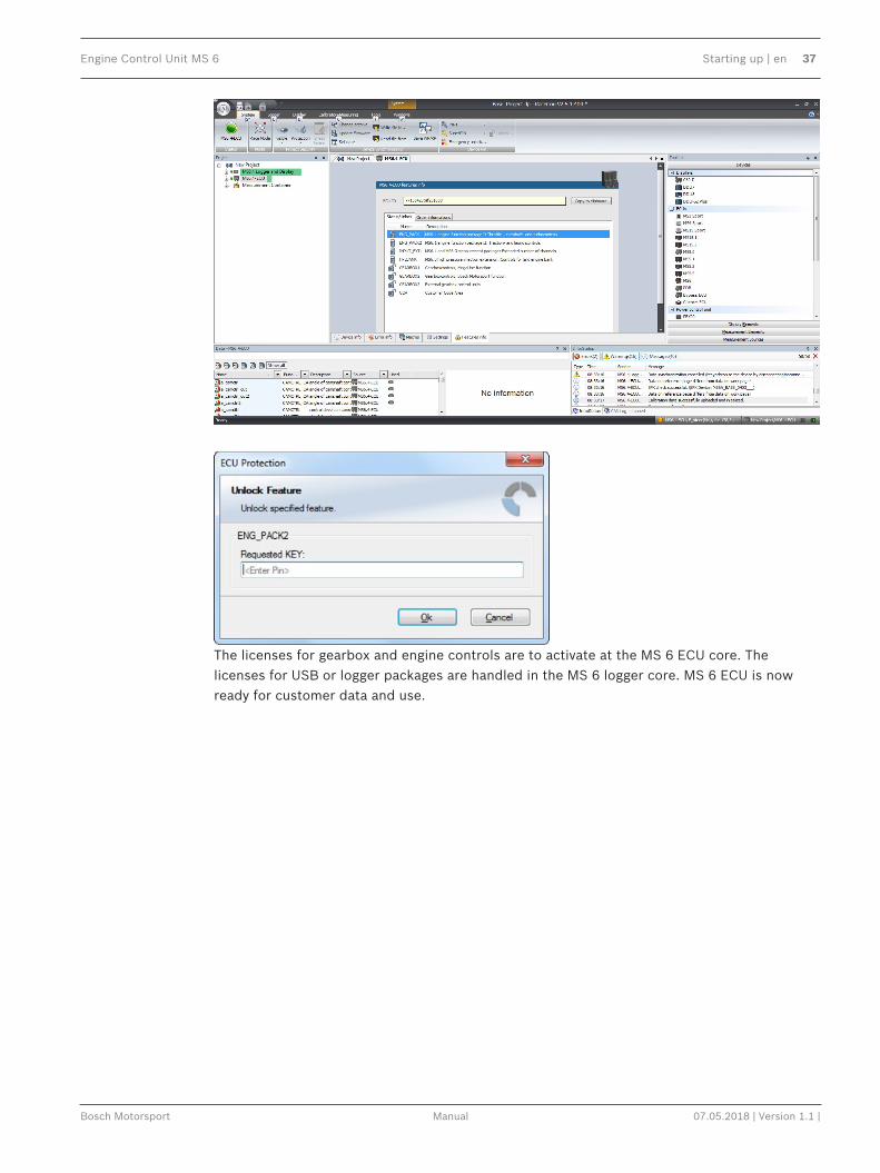
3.2.3 Feature/License ActivationFor code area generation, additional functionalities and/or data logging licenses may berequested for activation. Generally all MS 6 licenses are related to one specific device and thedelivered code is only to activate for this ECU. Both cores, MS 6 ECU and MS 6 logger, contentown license structures. Double-click to the core symbol at the project and choice featuresinfo. Select the license feature and activate the functionality using the related license code.
Engine Control Unit MS 6 Starting up | en 37
Bosch Motorsport Manual 07.05.2018 | Version 1.1 |
The licenses for gearbox and engine controls are to activate at the MS 6 ECU core. Thelicenses for USB or logger packages are handled in the MS 6 logger core. MS 6 ECU is nowready for customer data and use.

38 en | Prepare Data Base Engine Control Unit MS 6
07.05.2018 | Version 1.1 | Manual Bosch Motorsport
4 Prepare Data BaseUsing RaceCon, the data base is already generated and the modification may startimmediately. For information, please see RaceCon manual.ModasSport uses the two MS 6 programs MS6a_xxxx_yyyy_data.s19 andMS6a_xxxx_yyyy_ms_a2l for work folder generation.For help, please follow the Modas Sport manual instructions.
4.1 Initial Data ApplicationThe following chapter deals only with the main parameters which should be checked before afirst engine startup. Several functions are recommended to be switched off, many softwarelabels will not be explained in detail. To work on these functions and labels after the firststartup, please refer the full-scope function description. The offline data application guideshall help to get the engine started the first time without problems.
!
Caution!Wrong engine setup data may lead to serious engine damages.
4.1.1 Basic Engine DataThe MS 6 system can be used for engines up to 12 cylinders. Please ensure that the correctsoftware variant is loaded in your ECU. Define the engine parameters like number of cylinders,firing order, injection system and cam- and crankshaft designs in relation to TDC.
4.1.2 Crank- and Camshaft WheelThe system initially supports wheels with 60-2 teeth. Other configurations in the limitsbetween 30- and 60 teeth may be possible to configure also. Please refer also to the chapterIgnition Trigger Wheel, page 28.
Main Data Labels to configure for crank- and camshaft wheel
CRANK_TOOTH_CNT Number of teeth of the flywheel (including the missingteeth) (limited to 30-60 teeth)
CWINTF_CRANK Selection of used crankshaft sensor type (Hall or inductivetype)
CRANK_GAP_TOOTH_CNT Number of missing teeth on the flywheel
CAM_MODE Camshaft position detection mode
CAM_TOOTH_CNTx Number of teeth on the camshaft
CAM_POS_EDGESx Position [°CRK] of positive camshaft edges
CAM_NEG_EDGESx Position [°CRK] of negative camshaft edges (onlinemeasurement, see channels cam_neg(pos)_edges_xxx)
ANG_CAM_CATCHx Max. deviation of cam edges angles allowed
SYNC_CAM Camshaft signal used for engine synchronization
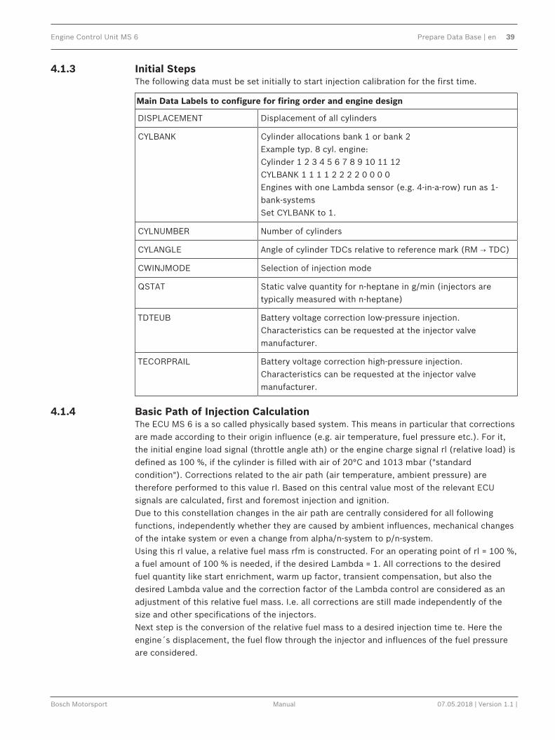
Engine Control Unit MS 6 Prepare Data Base | en 39
Bosch Motorsport Manual 07.05.2018 | Version 1.1 |
4.1.3 Initial StepsThe following data must be set initially to start injection calibration for the first time.
Main Data Labels to configure for firing order and engine design
DISPLACEMENT Displacement of all cylinders
CYLBANK Cylinder allocations bank 1 or bank 2Example typ. 8 cyl. engine:Cylinder 1 2 3 4 5 6 7 8 9 10 11 12CYLBANK 1 1 1 1 2 2 2 2 0 0 0 0Engines with one Lambda sensor (e.g. 4-in-a-row) run as 1-bank-systemsSet CYLBANK to 1.
CYLNUMBER Number of cylinders
CYLANGLE Angle of cylinder TDCs relative to reference mark (RM → TDC)
CWINJMODE Selection of injection mode
QSTAT Static valve quantity for n-heptane in g/min (injectors aretypically measured with n-heptane)
TDTEUB Battery voltage correction low-pressure injection.Characteristics can be requested at the injector valvemanufacturer.
TECORPRAIL Battery voltage correction high-pressure injection.Characteristics can be requested at the injector valvemanufacturer.
4.1.4 Basic Path of Injection CalculationThe ECU MS 6 is a so called physically based system. This means in particular that correctionsare made according to their origin influence (e.g. air temperature, fuel pressure etc.). For it,the initial engine load signal (throttle angle ath) or the engine charge signal rl (relative load) isdefined as 100 %, if the cylinder is filled with air of 20°C and 1013 mbar ("standardcondition"). Corrections related to the air path (air temperature, ambient pressure) aretherefore performed to this value rl. Based on this central value most of the relevant ECUsignals are calculated, first and foremost injection and ignition.Due to this constellation changes in the air path are centrally considered for all followingfunctions, independently whether they are caused by ambient influences, mechanical changesof the intake system or even a change from alpha/n-system to p/n-system.Using this rl value, a relative fuel mass rfm is constructed. For an operating point of rl = 100 %,a fuel amount of 100 % is needed, if the desired Lambda = 1. All corrections to the desiredfuel quantity like start enrichment, warm up factor, transient compensation, but also thedesired Lambda value and the correction factor of the Lambda control are considered as anadjustment of this relative fuel mass. I.e. all corrections are still made independently of thesize and other specifications of the injectors.Next step is the conversion of the relative fuel mass to a desired injection time te. Here theengine´s displacement, the fuel flow through the injector and influences of the fuel pressureare considered.

40 en | Prepare Data Base Engine Control Unit MS 6
07.05.2018 | Version 1.1 | Manual Bosch Motorsport
Finally the actual duration of the control pulse ti is calculated, considering pick-up delays ofthe injectors, fuel cutoff (e.g. overrun cutoff, speed limiter, gear cut) and cylinder individualcorrection factors. Please refer also to the system overview in the Function Description ECOV.
4.1.5 Main Data Labels to configure for Engine Start up
Main Data Labels to configure for engine start up
MP_MIXCORR(2) Mixture correction, set to 1.0 for startup
MIXCORR_APP Global factor for mixture correction, set to 1.0 for the beginof startup
CWPRAILCOR If a correction by fuel pressure is intended, set = 1. In thiscase please set PRAILREF according to the referenced fuelpressure. Also refer to MP_P22MOD. Usually the predefinedvalues are suitable. If unsure, set CWPRAILCOR to 0 for firststartup.
FINJ_WARMUP Correction via engine coolant temperature. Usually thepredefined values are suitable. Ensure, that for coolanttemperatures driven on your dyno during calibration, nowarm up factor applies (i.e. FINJ_WARMUP is 0.0 for thistemperature).
MP_LAM_MP1 Desired Lambda value, valid for map position 1. According toyour expectations, e.g. 0.9. For alternative positions of yourmap switch the maps MP_LAM_MP2 (3) or (_PACE) apply,therefore ensure correct switch position
4.1.6 Main Data Labels for Load Calculation
Main Data Labels for Load Calculation
CWLOAD Decision between alpha/n or p/n related load calculation
CWLOADP1 Decision between P1 and ambient pressure
alpha/n system
FRLPAMB_P1 Correction via intake air pressure
FRLTINT Correction via ambient temperature Usually the predefined values are suitable. If unsure, setFRLTINT to 1.0 for first startup.
MP_RL Relative load depending on throttle angle and engine speed.Set value until your desired Lambda is matched.
p/n systems
FRLPAMB_P1 Correction via intake air pressure
FRLPTINT Correction via ambient temperature. Usually the predefinedvalues are suitable. If unsure, set FRLPTINT to 1.0 for firststartup.
FRLPTHR Factor to throttle dependence. If unsure, set to 1.0 forstartup.
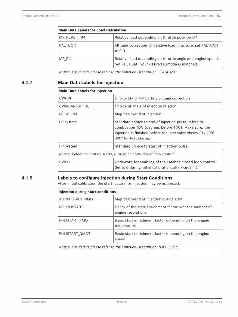
Engine Control Unit MS 6 Prepare Data Base | en 41
Bosch Motorsport Manual 07.05.2018 | Version 1.1 |
Main Data Labels for Load Calculation
MP_RLP1 … P4 Relative load depending on throttle position 1-4
PALTCOR Altitude correction for relative load. If unsure, set PALTCORto 0.0.
MP_RL Relative load depending on throttle angle and engine speed.Set value until your desired Lambda is matched.
Notice: For details please refer to the Function Description LOADCALC.
4.1.7 Main Data Labels for Injection
Main Data Labels for injection
CWHPI Choice LP- or HP battery voltage correction
CWINJANGMODE Choice of angle of injection relation
MP_AOINJ Map begin/end of injection
LP-system Standard choice to end of injection pulse, refers tocombustion TDC (degrees before TDC). Make sure, theinjection is finished before the inlet valve closes. Try 200° -300° for first startup.
HP-system Standard choice to start of injection pulse.
Notice: Before calibration starts, turn off Lambda closed loop control.
CWLC Codeword for enabling of the Lambda closed loop control.Set to 0 during initial calibration, afterwards = 1
4.1.8 Labels to configure Injection during Start ConditionsAfter initial calibration the start factors for injection may be optimized.
Injection during start conditions
AOINJ_START_NMOT Map begin/end of injection during start
MP_INJSTART Decay of the start enrichment factor over the number ofengine revolutions
FINJSTART_TMOT Basic start enrichment factor depending on the enginetemperature
FINJSTART_NMOT Basic start enrichment factor depending on the enginespeed
Notice: For details please refer to the Function Description INJPRECTRL

42 en | Prepare Data Base Engine Control Unit MS 6
07.05.2018 | Version 1.1 | Manual Bosch Motorsport
4.1.9 Main Data Labels for Ignition
Main Data Labels for ignition
Notice: Positive values stand for ignition angles before TDC, negative values after TDC. Beginwith moderate values to protect your engine from damages.
MP_TDWELL Coil dwell time. Consult the coil manufacturer fordetails. Most coils need dwell times about 1.5 to2.5 ms at 12 to 14 V. For further backgroundinformation please refer to the FunctionDescription IGNITION.
DIGN_CYL1-…12 Cylinder individual corrections. Set to 0.0.Numbering refers to mechanical cylinders.
MP_IGN_START/DIGN_ST_TINT Base spark advance during engine start. Set to 5to 10 deg, according to the requirements of theengine.
MP_IGN(2/3) Base ignition timing in deg crankshaft before TDC.Use modest values at the first time. Atmosphericengines may run safe at 20 to 25 deg in part load,turbo engines at high boosts may demand evenless spark advance. These values are stronglydependant on compression ratio, fuel quality,temperature and engine specifics. If you knowyou’re using “poor” fuel, run at high temperaturesor your engine is very sensitive on spark advance,go to the safe side.
MP_DIGN_TEMP/MP_DIGN_TEMPW Ignition angle temperature dependent
DIGN_APPL Delta value for spark advance, use for applicationwork. Start at 0.0 for first startup.
IGN_IDLE_STAT Ignition timing during idle. 10 deg are suitable formost applications
NIDLE_NOM / DIGN_IDLECTRL Desired engine idle speed for idle stabilization. Setvalue to desired speed or deactivate stabilizationby setting DIGN_IDLECTRL to 0.0.
4.1.10 Main Data Labels for Engine Speed LimitationThe rev limiter works in two steps:– Soft limitation by ignition retardation or cylinder individual cutoff of injection and/or
ignition– Hard limitation by injection cut off and/or ignition cutoff of all cylindersTo achieve a good dynamic behavior by advanced intervention, the engine speed is predictedby means of the speed gradient.

Engine Control Unit MS 6 Prepare Data Base | en 43
Bosch Motorsport Manual 07.05.2018 | Version 1.1 |
Main Data Labels for engine speed limitation
CWNMAX_CUTOFF Codeword for type of intervention during soft limiter:0 = only ignition retard1 = injection cutoff2 = ignition cutoff,3 = injection and ignition cutoff
CWNMAXH_CUTOFF Codeword for type of intervention during hard limiter:1 = injection cutoff2 = ignition cutoff,3 = injection and ignition cutoff
NMAX_GEAR Engine speed limit, gear dependent
NMAX_P Determines the slope of the soft limiter between soft limit andhard limit. Predefined. Vary according to your engine´s dynamic behavior.
TC_GEARNMAXPR Prediction time for rev limiter, depends on the inertial torqueof the engine. If oscillations occur, reduce value or turn off bysetting = 0.0.
4.1.11 Main Data Labels for Cutoff Pattern
Cutoff Pattern
MP_COPATTERN Defines the appropriate cylinders for torque reduction bycylinder cutoff.At the beginning of an intervention the next possible cylinderfor starting the cutoff pattern is determined. Based on thisinfo the actual pattern is taken out of the map.Pattern should be defined in view of minimized oscillations ofthe crankshaft.Usually a regular distribution of firing and non-firing cylindersleads to the best result. However, investigations of theindividual engine are recommendable.For it, cutoff pattern can be also turned on manually viaCUTOFF_APP and CWCUTOFF_APPExample: 4-cylinder engineStart Cyl./Cutoff stage 1 2 3 41 1 (=0001b) 2 (=0010b) 4 (=0100b) 8 (=1000b)2 9 (=1001b) 6 (=0110b) 6 (=0110b) 9 (=1001b)3 11 (=1011b) 14 (=1110b) 7 (=0111b) 13 (=1101b)4 15 (=1111b) 15 (=1111b) 15 (=1111b) 15 (=1111b)The cylinders are assigned bitwise, the lowest bit representscylinder 1.Numbering refers to mechanical cylinders, e.g. pattern = 9:Mechanical cylinders 1 and 4 are fade out.
CUTOFF_APP Cutoff pattern for test purposes. Bit representation asdescribed at MP_COPATTERN

44 en | Prepare Data Base Engine Control Unit MS 6
07.05.2018 | Version 1.1 | Manual Bosch Motorsport
Cutoff Pattern
CWCUTOFF_APP Codeword for type of intervention during test cutoff:Set: 1 = injection cutoff 2 = ignition cutoff 3 = injection and ignition cutoff.
Notice: This option is also useful for searching a misfiring cylinder. Select one cylinder after theother during test cutoff and watch your engine.
4.2 PeripheralsSensors and peripherals can be checked when the system is powered up electrically.Do not start the engine before all steps in this chapter are carried out.
Notice!Make sure the battery is connected properly, all sensors are connected and ground wiring isfixed before powering up the system. Check all sensors for errors (E_...) and reliable measurevalues before starting the engine.
Sensor configurationThe MS 6 has the option to link a lot of functionalities to a possible hardware input. Thechapters “ECUPINS, SWITCHMATRIX and Input Signal Processing” of the functionaldescription explains the details. All functions of Base MS 6 programs are linked like describedin the MS 6 documents (e.g. function description ADC_ECU_MAP) or the wiring diagrams.
Analogue sensor inputsThe physical way of conversion from sensor signal voltage to physical values follow the samestructures. The hardware input may be connected to different kinds of pull-up options. Inputswith fixed 1.47 kOhm or 3.01 kOhm pull-up resistors are prepared to handle passive sensorelements, for instance temperature sensors with integrated resistors (NTC- or PT100 sensors).Inputs without any pull-up resistors are prepared to handle active sensor elements, whichdeliver 0 to 5 V signals, for instance pressure-, potentiometer- or acceleration sensors. Inputswith switchable 1.47 kOhm pull-ups are designed to handle mainly active sensors withdisabled pull-up, but are prepared for future measuring of digital signals. Inputs withswitchable 3.01 kOhm pull-ups offer the most options and are recommended to link after thestandard sensors are connected. The pull-up resistor itself is not modifiable and for bettermeasure results may be, the version of sensor/mapping line has to be changed. To activate thePin-Selection, first the label “SWITCHMATRIX_ENABLED_PIN_IN_ADC” has to be enabled. Errordetection of an analogue input signal detects short cuts to ground, U”function”_MINrecommended to be set to 0.2 V and short cuts to power supply U”function”_MAXrecommended to be set to 4.8 V. Failure are activated after the adjustable debounce time ofdiagnosis TD”function”. If a sensor error is set, the output is switched to the default value“function”_DEF.

Engine Control Unit MS 6 Prepare Data Base | en 45
Bosch Motorsport Manual 07.05.2018 | Version 1.1 |
5 Volt
3.01 kOhm pullup
PULLUP_“function“
MS6 sw.pullup:
CWPULLUP_“pin“
MS6 input
PIN_IN_U“function“
Principle structure of analogue signal conversion
sensor gradient
„function“ _GRD
/_ phys. converted
measure channel
phys. converted
measure channel
phys. converted
measure channel
input-voltage:
u“function“
sensor mapping line (R)
function_CONV
sensor o!set
„function“ _OFF
2 point- and o!set adjustment for
determination of sensor values
CW“function“CAL: choice of adjustment
„function“CAL/Pos1/Pos2: value of adj.
Pressure measurementsThe system offers a lot of different pressure channels, please see function description inputsignal processing for details. For gradient and offset information contact sensor manufacturer.
Example: Ambient Pressure
PAMB_OFF, PAMB_GRD Sensor offset and gradient
UPAMB_MIN, UPAMB_MAX Minimum and maximum accepted sensorvoltage. When violated, an error is set(E_pamb = 1).
PAMB_DEF Default value if an error occurred.
FCPAMB Filter constant. For ambient pressure use 1second, for other pressures chooseappropriate values, ~ 100 to 200 milliseconds
All other variables are named by the same rule, replace “pamb” by e.g. “poil” to apply data forthe oil pressure sensor.
Temperature measurementsThe system offers a lot of different temperature channels, please see function descriptioninput signal processing for details.
Example: Intake Air Temperature
UTINT_MIN, UTINT_MAX Minimum and maximum accepted sensorvoltage. When violated, an error is set (E_tint= 1).
TINT_CONV Sensor characteristic. Consult the sensormanufacturer.

46 en | Prepare Data Base Engine Control Unit MS 6
07.05.2018 | Version 1.1 | Manual Bosch Motorsport
Example: Intake Air Temperature
PULLUP_TINT Value of the used pull-up resistor. If only theECU´s pull-up is used (standard case). Keepthe predefined value of 3.01 kOhm.
ThermocouplesThe exhaust gas temperatures are measured via thermocouple elements, using a specialevaluation circuit. Predefined values should be suitable for NiCrNi or k-type elements. Forfurther details and project specific variants please refer to the function description.
Digital sensor inputsMS 6 digital sensor inputs used for frequency measurements are possible to configure todifferent of sensor types.
CWINTF_CRANK Selection between Hall effect or inductivesensor for flywheel measurement, related toMS 6 contact A047 (use ground A048 ifinductive type is selected).
CWINTF_K045/K046 Selection between Hall effect or inductivesensors for frequency measurements, liketurbo- or driveshaft speeds, related to MS 6contacts K045 or K046 (use ground K062 ifinductive types are selected).
CWINTF_A049/A050/A051/A052 Selection between Hall effect or DF11sensors for frequency measurement, likewheel speeds or cam position detection,related to MS 6 contacts A49, A50, A51 orA52.
4.3 Throttle ControlThe system supports mechanic and electronic throttle controls.Using an MS 6.1 device, respect the necessary license for electronic throttle is activated.Electronic Throttle Control is a safety-critical function. The Bosch Motorsport ElectronicThrottle Control System (ETC) is designed and developed exclusively for use in racing carsduring motorsport events and corresponds to prototype state. Therefore the driving of an ETCequipped vehicle is limited exclusively to professional race drivers while motorsport eventsand to system‐experienced drivers on closed tracks for testing purposes. In both cases thedriver must be instructed regarding the functionality, possible malfunctions of the system andtheir consequences and must be familiar with possible emergency actions (e.g. pressing theemergency stop switch or the main switch). The system must have emergency switch, whoseactivation at least cuts the throttle valve actuator from the power supply. Depending onspecific use and/or construction, the safety functions, fault detections and fault responses ofthe ETC system may differ in several points from ETC systems used in series production.Hence before each vehicle-commissioning the system must be checked for accuracy andfaultlessness.The functionality of the ETC diagnosis and the fault responses are described in the technicaldocuments, handed over to the customer together with the system. Each driver must bebriefed regarding the system description. Further information you will find in document“SICHERHEITSHINWEISE-Systemanforderungen zum Betrieb eines Bosch Engineering GmbHEGas-Systems” or can be enquired at Bosch Motorsport.

Engine Control Unit MS 6 Prepare Data Base | en 47
Bosch Motorsport Manual 07.05.2018 | Version 1.1 |
The customer is responsible for the activation of all ETC‐relevant diagnosis and for theircorrect parameterization. By disregarding this information the functionality of the ECU and thesafety cannot be ensured.Notice: For detailed information see function description ETCThe usual route of ETC determines the drivers input measuring the pedal position andtransferring this leading signal via functionality options into the control of an electrical throttleactuator. Pedal- and actuator positions are generally measured in a secondary redundant wayto verify the reliability of the function. To activate the system, first verify the signal tolerancesand error messages by moving acceleration pedal and throttle actuator manually. An inactivesystem usually is the result of inverted wired sensor signals or actuator controls. Calibrate thepedal- and throttle positions.Verification of acceleration pedal signals:The mathematic value of voltage pedal signal 1 - 2*voltage pedal signal 2 has to be below 0.5 Vor below value of “UAPSCM_MAX”.
Signal principle of an acceleration pedal sensor:
uaps_a Voltage APS potentiometer a
uaps_b Voltage APS potentiometer b
aps Acceleration pedal position
UAPS_MIN, UAPS_MAX: Minimum and maximum accepted sensorvoltage. Set to approx. 200 mV/4,800 mV.Check if the uaps(x) outputs are changingwhen the pedal is moved.
CWAPSADJ Codeword to adjust acceleration pedal signal:0 = calibration inactive1 = calibrate release pedal2 = calibrate full-pressed pedal
E_APS Detected error messages of accelerationpedal functionality. If errors are detected, theETC functionality will become inactive.

48 en | Prepare Data Base Engine Control Unit MS 6
07.05.2018 | Version 1.1 | Manual Bosch Motorsport
Verification of throttle position signals:The mathematic value of voltage throttle signal 1 + voltage throttle signal 2 - 5 V has to bebelow value of “UDTHRCM_MAX” (recommended 0.2 V)The signal sequences of a throttle position sensor:
Throttle position main data labels:
CWTHR Codeword for type of throttle controls:0 = mechanical throttle1 = mechanical throttle with backuppotentiometer2 = electric throttle single bank3 = electric throttle dual bank
Throttle position signals:
UDTHR_MIN, UDTHR_MAX Minimum and maximum accepted sensorvoltage. When violated, an error is set (E_thr= 1). Set to approx. 200 mV/4800 mV Checkif the uthrottle(xx) outputs are changingwhen throttles are moved
uthrottle 2 sensor output values and their redundant
uthrottle_b signals (_b). The system expect a rising up
uthrottle2 voltage for the main signals and a fallingsignal
uthrottle2_b for the redundant one.
UDTHRCM_MAX max. allowed difference between sensoroutput and redundant signalabs (uthrottle(x)+uthrottle(x)_b)-5V <UDTHRCM_MAX

Engine Control Unit MS 6 Prepare Data Base | en 49
Bosch Motorsport Manual 07.05.2018 | Version 1.1 |
Calibration:
CWTHRADJ Codeword for throttle adjust:1 = automatical calibration process2 = calibrate lower mechanical stop3 = calibrate upper mechanical stop4 = calibrate limp home position
Manual Procedure:– Close throttle and set CWTHRADJ to 1– Open throttle fully and set CWTHRADJ to 2– Adjust the throttle to idle point.– Do not forget to set CWTHRADJ back to 0. Check calibration by moving throttle
4.4 Vehicle TestBefore starting with your vehicle test, some initial data should be set:
Speed & distance measurements The signals for speed calculation may beavailable from different sources, like MS 6own measurement, GPS data or via CANreceived information from ABS calculation.For MS 6 own calculation, mechanicalinfluenced data like number of availablesensors, front wheel drive, number ofdetected increments, wheel circumferencesand dynamic corrections like corner speedapplication a lot of functional options assistthe calculation of the effective vehicle speed.Distance measure channels may be derivedfrom speed information. For detailedinformation see function description>CARSPEED<
CWSPEEDGPS Selection for car speed from GPS signal
CWWHEELCAN Selection for car speed from GPS signal
CWWHEEL Connected number of wheel speed sensorsor –signals
CWFWD Selection of front driven vehicle
CWSPEEDDYN Release of dynamic speed calculation
INC_FRONT Number of pulses per revolution of the frontspeed signal
INC_REAR Number of pulses per revolution of the rearspeed signal
CIRCWHEEL_F Wheel circumference of the front wheels
Consider dynamic increase of the tire
CIRCWHEEL_R Wheel circumference of the rear wheels.Consider dynamic increase of the tire.

50 en | Prepare Data Base Engine Control Unit MS 6
07.05.2018 | Version 1.1 | Manual Bosch Motorsport
Vwheel_xx Measure channel of the individual wheelspeeds
Speed Result of calculated vehicle speed
Accv Result of speed based derivation oflongitudinal acceleration
Ltdist Lifetime distance as accumulated result ofspeed derivation
Lap information and -functions The necessary data application is integratedin the system configuration tool RaceCon.The wizard leads to configure the beaconinput, asks for trustable limits of lap- andsignal detection. Additional options for tracksegmentation, additional on track beaconsare also available. Drag and drop thesubfolder lap trigger of the measurementsources into the project and follow thewizard.
Depending to the configuration, values forlap-and outing counter, lap time, segmenttimes and differential lap- or segment timesfor data analysis and driver information willbe created.

Engine Control Unit MS 6 Prepare Data Base | en 51
Bosch Motorsport Manual 07.05.2018 | Version 1.1 |
Laptrigger_xxxx_yy Results and measure channels of lap-functionalities
Consumption-calculation Is designed in the same way as lap-information, drag and drop the subfolder tothe project and follow the wizard
Set time & date MS 6 device is equipped with a real timeclock which is supplied for max. 14 days, ifthe ECU is disconnected from power supply.Please connect the ECU to the PC and clickon “SET DATE & TIME” in the context menu ofthe MS 6.
time_xx The measure channels of the real time clock.

52 en | ECU plus Data Logger Engine Control Unit MS 6
07.05.2018 | Version 1.1 | Manual Bosch Motorsport
5 ECU plus Data LoggerThe MS 6 combines ECU and data logger in one common housing for a cost efficient andweight optimized all-in-one solution.
5.1 Software Tools
RaceCon Create and configure a projectConfiguration & management of recordingsCreate a new recordingAdd channels to a recordingCreate user-defined conditions for therecordingDownload recording configuration
WinDARAB Upload recorded dataDisplay and analyze the data
5.2 First Recording (Quick Start)Starting up the data loggingThe following chapters demonstrate how to set up data logging and how to analyze therecorded data. It shows the most important functions and features of RaceCon and WinDarab.For this tutorial we assume, that you have a MS 6 connected to your computer via an Ethernetline.The MS 6 data recording is separated in two partitions. Both are completely independent. Thefree of license storable channels have to be selected into the >Recording< folder. Data loggingextensions for more than 100 channels or the 2nd partitioning have to be activated in front ofthe configuration.Select topic >Logger< in the menu bar>Recording< selects data logging package I or the free area for data logging>Longterm< selects data logging package IIDrag and Drop the channels of your selection.
>settings< For limited recording, please follow the wizard

Engine Control Unit MS 6 ECU plus Data Logger | en 53
Bosch Motorsport Manual 07.05.2018 | Version 1.1 |
>statistics< check the selection to ensure the system limits are respected.
>group< to separate measure channels into different groups, referring to customer- orfunctional structures>edit recording channel< right mouse button to one or a selection of recorded channels opensthe option to modify the sampling rate and/or the selection for online telemetry

54 en | ECU plus Data Logger Engine Control Unit MS 6
07.05.2018 | Version 1.1 | Manual Bosch Motorsport
>Project Window / MS 6 Logger / right mouse button / download configuration>download configuration< Send your configuration to the device, the recording will startwithin the defined limits (without defined condition, the recording will start immediately).
5.3 USB Data RecordingThe MS 6 data recording contents the feature to send a copy of the recorded data to an USBstick. Required is just an activated USB-license and wire installation. Technical aspects ofcommercial USB sticks may lead to connection- and data storage problems. Therefore BoschMotorsport recommends and offers just USB drive with the Bosch Order NumberF02U.V01.342‐02.Please format the storage medium to Bosch file system available at >RaceCon / menu bar /tools / format USB stick< before the first use. Please press >format USB stick< first, theninsert the stick.

Engine Control Unit MS 6 ECU plus Data Logger | en 55
Bosch Motorsport Manual 07.05.2018 | Version 1.1 |
Measure channels to verify USB data recording
usb_mediastate 0123456
not foundstick detectedstick installedstick unplugged(access)errorcorrupted
meas_cnt_forked counter of recorded data blocks

56 en | Project Configuration Engine Control Unit MS 6
07.05.2018 | Version 1.1 | Manual Bosch Motorsport
6 Project Configuration6.1 Math Channels
– Arithmetic and logical operations on up to 4 measurement channels– Numerical results– Result can be used as input source for various calculations in the whole projectDouble click “Math Channels” in MS 6 logger and display project tree.
The ‘Create/edit math channel’ window appears. Define the math channel using the followingconfiguration possibilities:
a) Enter the name of the math channel.b) Enter a description of the math channel.c) Enter the formula.d) Select the logical operator.e) Choose a measurement channel.
a)b)c)
d)
e)
f)
g)
h)
f) Define a value that can be used as a constant in the formula.g) Choose a function.h) Describes the function selected above.

Engine Control Unit MS 6 Project Configuration | en 57
Bosch Motorsport Manual 07.05.2018 | Version 1.1 |
Click ‘Finish’ when done. The math channel is displayed in the MS 6 math channel window.
6.2 Conditional Function– Arithmetic and logical operations on one or more measurement channels– If - Else structure with reset– Numerical result– Result can be used as input source for further calculations in the whole project1. Follow the steps shown in the screenshot.
1st: Double-click on"Math Channels"in Project Tree
2nd: Click on the dropdown arrow beside 'Add channel'
3rd: Choose 'Conditional function...'
The “Create/edit conditional function” window appears.2. Define the conditional function, using the following configuration possibilities:
a)
b)
c)
d)
e)
a) Enter the name of the conditional function.b) Enter the If-condition. Click on the pencil symbol to open an editor to enter expressions.c) Enter the Then-condition. Click on the pencil symbol to open an editor to enter expressions.d) Enter the Otherwise-condition.Click on the pencil symbol to open an editor to enter expressions.e) Enter the reset value (must be a number).
3. Click ‘Finish’ when done.

58 en | Project Configuration Engine Control Unit MS 6
07.05.2018 | Version 1.1 | Manual Bosch Motorsport
The conditional function works the following way:The program always calculates the condition entered in the IF window and checks if thecondition is TRUE or FALSE.If the condition entered in the IF window is TRUE, the program calculates the conditionentered in the THEN window. The returned value is the content of the new variable (entered in“Name”).If the condition entered in the IF window is FALSE, the program calculates the conditionentered in the OTHERWISE window. The returned value is the content of the new variable(entered in “Name”).The reset value is always set for the new variable (entered in “Name”):– before the If-condition becomes TRUE for the first time after power-up– when the If-condition changes state from FALSE to TRUE.An example of a condition to set up the maximum front brake pressure is given on the nextpage.The conditional function is displayed in the MS 6 math channel window.
Example: Setting up a condition for maximum front brake pressure
20
20
10
Max brake pressure of the variable ‘front p_br_front_mx’
Reset
value
is used
Hold
max.
value
Follow
max.
value
Reset
value
is used
Time
Time
Condition ‘p_br_front > 20’
Brake pressure front p_br_front
30
40
30
40
10
Brake pressure ‘front p_br_front’
Hold max.
value
Hold max.
value
Threshold
reached

Engine Control Unit MS 6 Project Configuration | en 59
Bosch Motorsport Manual 07.05.2018 | Version 1.1 |
– At power-up, the reset value (10) is used for ‘p_br_front_mx’.– ‘p_br_front’ rises to 30. As ‘p_br_front’ is > 20 (condition is TRUE), the condition ‘max
(p_br_front, p_br_front_mx)’ in the THEN window is triggered. The condition sets thebigger value as new value for ‘p_br_front_mx’. As ‘p_br_front’ (30) is bigger than‘p_br_front_mx’ (10), the new value for ‘p_br_front_mx’ is set to 30.
– Although ‘p_br_front’ falls to 25, the value of ‘p_br_front_mx’ stays 30. This is caused bythe THEN-condition, because p_br_front_mx’ (30) is still bigger than p_br_front’ (25).
– ‘p_br_front’ rises to 40. As ‘p_br_front’ (40) is bigger than ‘p_br_front_mx’ (30), the newvalue for ‘p_br_front_mx’ is set to 40.
– As ‘p_br_front’ falls below 20, the IF-condition turns to FALSE. Now the OTHERWISE-condition is triggered. Because the condition ‘p_br_front_mx’ sets the value of‘p_br_front_mx’ and the value is already set to 40, nothing changes.
– When ‘p_br_front’ rises to 40, the IF-condition changes to TRUE again and triggers theTHEN-condition. Now the reset value (10) is used for ‘p_br_front_mx’ in the THEN-condition.
– Because 40 is bigger than 10 the new value of ‘p_br_front_mx’ is 40.
6.3 Condition Channels– Logical operations on measurement channels– If – Else structure with reset– Logical result– Result can be used as input source for further calculations in the whole project1. Follow the steps shown in the screenshot.
1st: Double-clickon "Conditional Channels" in Project Tree
2nd: Click on 'Add condition'
The “Create/edit condition” window appears.

60 en | Project Configuration Engine Control Unit MS 6
07.05.2018 | Version 1.1 | Manual Bosch Motorsport
2. Define the condition channel, using the following configuration possibilities:
a)
b)
c)
d)e)
f)
a) Enter the name of the conditional channel.b) Select the comparing mode:- Constant: Compare a measurement channel with a constant value.- Channel: Compare a measurement channel with a measurement channel.- Range: Compare a measurement channel with a defined value range.- Multiple: Compare a measurement channel with up to 5 constant values.c) Depending on the chosen comparing mode, you can enter the following values:- Constant: Choose the measurement channel or condition, the operator and enter the value of the channel.- Channel: Choose the measurement channel or condition, the operator and the measurement channel or condition to be compared.- Range: Choose the measurement channel or condition, the operator and define the minium and maximum value.- Multiple: Choose the measurement channel or condition, the operator and enter the value of up to 5 constants.d) Enter the minimal time to detect the signal of the measurement channel, to avoid high-frequent switchovers.e) Enter the time the signal of the measurement channel is delayed after its ending.f) Choose the output setting of the result.- Constant TRUE/FALSE: Result is as a constant with the value TRUE or FALSE.- Blinking: Result is a blinking, if the condition is fulfilled.- Pulse: Result is a short one-time pulse, if the condition is fulfilled.- Toggling output: Result is a pulse that lasts until the next condition is fulfilled.
3. Click ‘Ok’ when done. The conditional channel is displayed in the MS 6 condition channelwindow.
6.3.1 Condition Combination– Combination of up to 16 condition channels for more complex calculations– Logical result– All conditions can be used globally in the whole project1. Follow the steps shown in the screenshot.
1st: Double-clickon 'Conditional Channels'in Project Tree
2nd: Click on the dropdownarrow beside 'Addcondition'
3rd: Choose'Conditional combination'

Engine Control Unit MS 6 Project Configuration | en 61
Bosch Motorsport Manual 07.05.2018 | Version 1.1 |
2. The ”Create/edit condition combination” window appears. Define the conditioncombination, using the following configuration possibilities:
a)
b)
a) Enter the name of the condition combination.b) Create the condition combination in the window.- Choose a channel (condition, conditional function, math, measurement channel with binary values) to be compared.- Combine multiple conditions, by adding 'AND' or 'OR' relations.- To negate a condition, click with the right mouse-button on the condition and select 'Negation (!)'.- Combine several (up to 16) conditions.
3. Click ‘Next’ to go to the next page. Choose the output setting of the result:– Constant TRUE/FALSE: Result is as a constant with the value TRUE or FALSE.– Blinking: Result is a blinking, if the condition is fulfilled.– Pulse: Result is a short one-time pulse, if the condition is fulfilled.– Toggling output: Result is a pulse that lasts until the next condition is fulfilled.
4. Click ‘Finish’ when done. The conditional combination is displayed in the MS 6 conditionchannel window.
6.4 CPU LoadGenerating math and conditional channels, also the configuration of CAN network use capacityof the MS 6`s processor. Please ensure to keep the processor load below 85 % (averaged).“cpu_load_001” measure channel actual measurement rate

62 en | CAN Configuration Engine Control Unit MS 6
07.05.2018 | Version 1.1 | Manual Bosch Motorsport
7 CAN ConfigurationMS 6 has 3 fully configurable CAN buses– Baudrate (125 kbit … 1 Mbit)– Input configuration: read messages from CAN bus and convert to MS 6 measurement
variables– CAN bus supports row counter configuration– Output configuration: write MS 6 measure variables to CAN messages– Configurable output frequency and row counter– CAN gateway functionality (transfer from one bus to another)– Verify errors on the CAN bus and configurable default values
7.1 CAN Bus TriviaCAN message– 11 Bit (standard) or 29 Bit (extended) identifier– Up to 8 bytes of data payload
CAN bus– Needs termination resistors (120 Ohm) in wiring harness– All devices connected to the bus must use identical data rate
Configuration of MS 6 bus data rate in ‘Properties’ menuby double click on the CAN bus in project tree (1 MBaud, 500 kBit, 250 kBit, 125 kBit)

Engine Control Unit MS 6 CAN Configuration | en 63
Bosch Motorsport Manual 07.05.2018 | Version 1.1 |
7.2 CAN Input
7.2.1 Input configuration
Create new channel to read from CAN bus
Import Vector CAN database (DBC) channel configuration
Export RaceCon CAN configuration to file
Import RaceCon CAN configuration from file
Display CAN bus properties (Baudrate)
Create new CAN output message
Export Vector CAN database (DBC) channel configuration
7.2.2 Create a new CAN channel1. Double-click on any CAN bus item, to open the "CAN messages overview".2. Select ‘Add CAN-IN’ and choose the desired CAN bus for the new input channel.
A CAN channel configuration window opens.

64 en | CAN Configuration Engine Control Unit MS 6
07.05.2018 | Version 1.1 | Manual Bosch Motorsport
3. Insert the name and description of the channel.
4. Click ‘OK’ when done.The channel is listed in the Data window.

Engine Control Unit MS 6 CAN Configuration | en 65
Bosch Motorsport Manual 07.05.2018 | Version 1.1 |
7.2.3 CAN channel configuration
Extraction of datafrom CAN bus
Conversion to physical values
Mini CANanalyzer functionality
Automaticassignment tomeasurement view

66 en | CAN Configuration Engine Control Unit MS 6
07.05.2018 | Version 1.1 | Manual Bosch Motorsport
7.2.4 Extracting data from CAN busRepresentation: ByteSome CAN devices need to be addressed by a byte represented CAN channel. The address canbe assigned in this window and is illustrated by a bar graph.
a)b)
c)
d)
a) Enter CAN message ID. If extended IDs (29 bit) are used, check the box.b) If replacement values are used, specify timeout period and raw value.c) If a multiplexer (row counter) is used, check the box.d) Enter data position, length and format.e) The bargraph shows assignment of the bytes.- Red colored fields show the assignment of the data bytes.- Orange colored fields show the assignment of the multiplexer bytes.
e)

Engine Control Unit MS 6 CAN Configuration | en 67
Bosch Motorsport Manual 07.05.2018 | Version 1.1 |
Representation: BitSome CAN devices need to be addressed by a bit represented CAN channel. The address canbe assigned in this window and is illustrated by a matrix table.
a)b)
c)
d)
e)
a) Enter CAN message ID. If extended IDs (29 bit) are used, check the box.b) If replacement values are used, specify time-out period and raw value.c) If a multiplexer (row counter) is used, check the box.d) Enter data position, length and format.e) The bargraph shows the assignment of the bits.- Red colored fields show the assignment of the data bits.- Orange colored fields show the assignment of the multiplexer bits.
7.2.5 Conversion to physical values
a)b)c)d)
e)f)g)
a) Enter factor (gain) for conversion to physical value.b) Enter offset for conversion to physical value.c) Select type of physical value.d) Select unit of physical value.e) Enter minimum physical limit of the channel. (for manual setup)f) Enter maximum physical limit of the channel. (for manual setup)g) Check the box to automatically adjust the limits of the channel.

68 en | CAN Configuration Engine Control Unit MS 6
07.05.2018 | Version 1.1 | Manual Bosch Motorsport
7.2.6 Online view of CAN channels in vehicle
1. Double-click on ‘Sheet 1’ in Project Tree. Measurement Sheet 1 is displayed in Main Area.2. Click on ‘Measurement elements’ in the Toolbox.3. Drag the desired Measurement element (e.g. Numeric Indicator) and drop it on the
Measurement Sheet.
Drag + Drop
4. Click on folder ‘CAN Input’ of desired CAN bus to display available channels.5. Drag desired Measurement channel and drop it on the Measurement element.
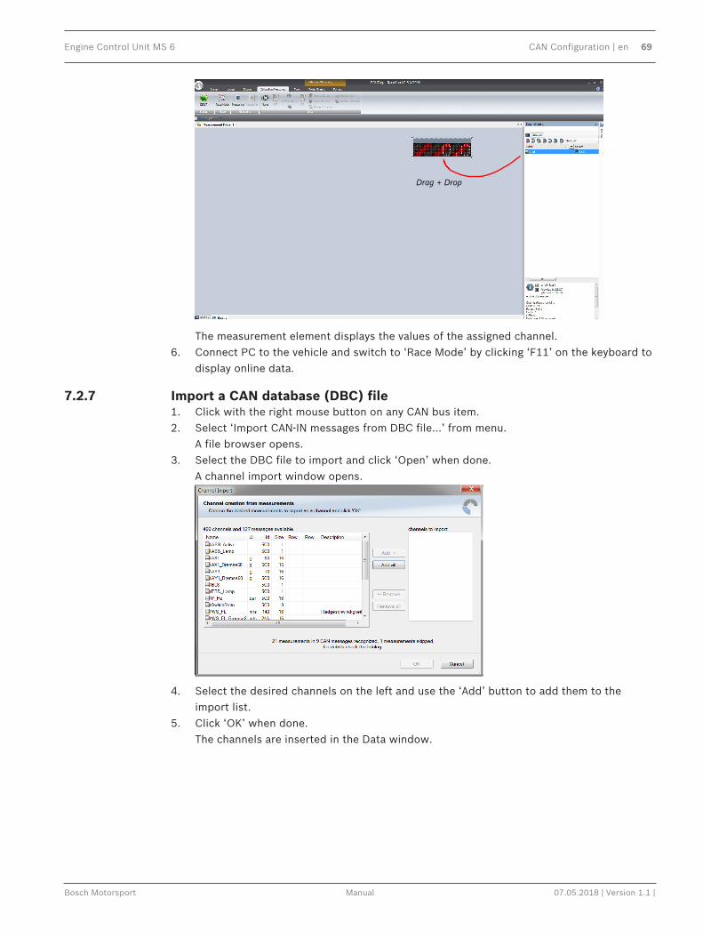
Engine Control Unit MS 6 CAN Configuration | en 69
Bosch Motorsport Manual 07.05.2018 | Version 1.1 |
Drag + Drop
The measurement element displays the values of the assigned channel.6. Connect PC to the vehicle and switch to ‘Race Mode’ by clicking ‘F11’ on the keyboard to
display online data.
7.2.7 Import a CAN database (DBC) file1. Click with the right mouse button on any CAN bus item.2. Select ‘Import CAN-IN messages from DBC file…’ from menu.
A file browser opens.3. Select the DBC file to import and click ‘Open’ when done.
A channel import window opens.
4. Select the desired channels on the left and use the ‘Add’ button to add them to theimport list.
5. Click ‘OK’ when done.The channels are inserted in the Data window.
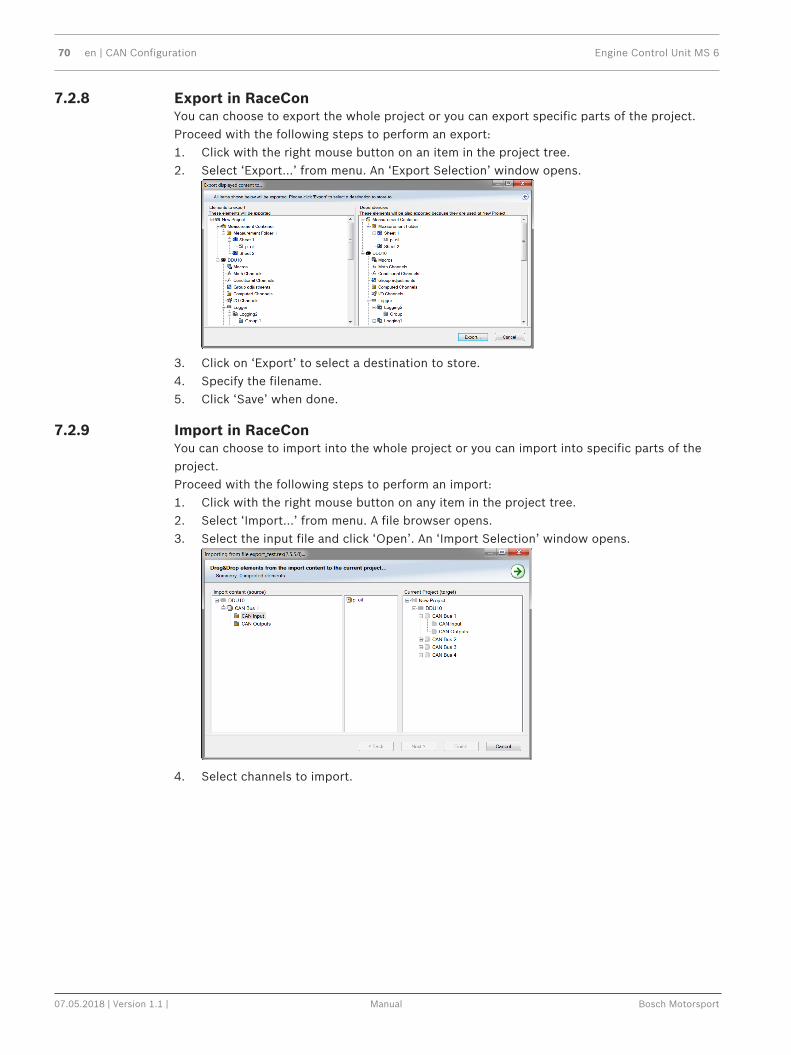
70 en | CAN Configuration Engine Control Unit MS 6
07.05.2018 | Version 1.1 | Manual Bosch Motorsport
7.2.8 Export in RaceConYou can choose to export the whole project or you can export specific parts of the project.Proceed with the following steps to perform an export:1. Click with the right mouse button on an item in the project tree.2. Select ‘Export…’ from menu. An ‘Export Selection’ window opens.
3. Click on ‘Export’ to select a destination to store.4. Specify the filename.5. Click ‘Save’ when done.
7.2.9 Import in RaceConYou can choose to import into the whole project or you can import into specific parts of theproject.Proceed with the following steps to perform an import:1. Click with the right mouse button on any item in the project tree.2. Select ‘Import…’ from menu. A file browser opens.3. Select the input file and click ‘Open’. An ‘Import Selection’ window opens.
4. Select channels to import.

Engine Control Unit MS 6 CAN Configuration | en 71
Bosch Motorsport Manual 07.05.2018 | Version 1.1 |
5. Drag and drop the channel to ‘CAN Input’ of desired CAN bus on right hand side.
6. Click ‘Finish’. If a measurement channel belongs to more than one source (e.g. MS 6 andMS 5.1), the ‘Solve Label Ambiguity’ window opens.
7. Assign the ambiguous channels to the desired source.8. Click ‘Finish’.

72 en | CAN Configuration Engine Control Unit MS 6
07.05.2018 | Version 1.1 | Manual Bosch Motorsport
7.3 CAN Output
7.3.1 Output configuration
Create new CAN output message
Export RaceCon CAN output configurationto file
Import RaceCon CAN out configurationfrom file
Display CAN bus properties (Baudrate)
7.3.2 Create new CAN output message channelDouble-click on any CAN bus item, to open the "CAN messages overview".1. Select ‘Add CAN-OUT’ and choose the desired CAN bus for the new output channel.
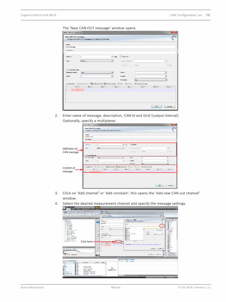
Engine Control Unit MS 6 CAN Configuration | en 73
Bosch Motorsport Manual 07.05.2018 | Version 1.1 |
The ‘New CAN-OUT message’ window opens.
2. Enter name of message, description, CAN-Id and Grid (output interval).Optionally, specify a multiplexer.
Definition of CAN message
Content of message
3. Click on ‘Add channel’ or ‘Add constant’, this opens the ‘Add new CAN out channel’window.
4. Select the desired measurement channel and specify the message settings.
Click here

74 en | CAN Configuration Engine Control Unit MS 6
07.05.2018 | Version 1.1 | Manual Bosch Motorsport
The measurement channel is now assigned to the CAN message.
7.3.3 Export in RaceConYou can choose to export the whole project or you can export specific parts of the project.Proceed with the following steps to perform an export:1. Click with the right mouse button on an item in the project tree.2. Select ‘Export…’ from menu. An ‘Export Selection’ window opens.
3. Click on ‘Export’ to select a destination to store.4. Specify the filename.5. Click ‘Save’ when done.
7.3.4 Import in RaceConYou can choose to import into the whole project or you can import into specific parts of theproject.Proceed with the following steps to perform an import:1. Click with the right mouse button on any item in the project tree.2. Select ‘Import…’ from menu. A file browser opens.3. Select the input file and click ‘Open’. An ‘Import Selection’ window opens.
4. Select channels to import.

Engine Control Unit MS 6 CAN Configuration | en 75
Bosch Motorsport Manual 07.05.2018 | Version 1.1 |
5. Drag and drop the channel to ‘CAN Input’ of desired CAN bus on right hand side.
6. Click ‘Finish’. If a measurement channel belongs to more than one source (e.g. MS 6 andMS 5.1), the ‘Solve Label Ambiguity’ window opens.
7. Assign the ambiguous channels to the desired source.8. Click ‘Finish’.

76 en | Online Measurement and Calibration Engine Control Unit MS 6
07.05.2018 | Version 1.1 | Manual Bosch Motorsport
8 Online Measurement and Calibration– Verify system status and diagnosis.– Check and calibrate sensors of the system.– Data application in online mode.– PC and device are connected.– Local PC data match to MS 6 configuration (devices are indicated as green).– From the context menu of the project, new measurement pages can be created.
8.1 Setting up an Online Measurement– Expand measurement container and measurement folder in the project tree.– Double click on Sheet 1 opens the main area.– The context menus offer a lot of options, like add, delete and rename folder or sheets,
also import and export functionalities for data storage are available.
– The main area opens additional window data sheet and toolbox.– Drag and drop the measure channels and select the graphic rendition or select first
toolbox offers and place the channel to the element.
Measure and calibration:(Example: damper position measurement)

Engine Control Unit MS 6 Online Measurement and Calibration | en 77
Bosch Motorsport Manual 07.05.2018 | Version 1.1 |
Base of the data list are the function- and measure labels, described in details in the functiondescription.– To assist the discovery of relevant labels, data list may be graduated.– Description and label symbol explain the task of the data label.– Structure of Bosch Motorsport Labels shall communicate recognition values.
CWxxx Code-Word starts an action for the function
CWDAMCAL Code-Word damper travel adjustment“True” sets the actual measure values of alldampers to 0
CWDAMCAL_FL Code-Word damper front left adjustment,2-point sensor calibration added by offsetadjustment for each single damper
dam_xx measure values are always typed in smallletters
dam_fl damper position front left
udam_xx voltage values starts always with “u”, thevalue represents the sensor signal
DAM_XX_YY Data Label are always typed in big letters
DAM_FL_GRD Gradient for damper travel sensor, front left,values are available from sensormanufacturer
8.2 Using the Measurement Sheets– When RaceCon is online, press “F11” key to switch from Design Mode into Race Mode.– The measurement sheet is extended to full screen.– Switch between different sheets using the tabs at the bottom of the page or the keyboard
shortcuts associated with the sheets.– Press ESC key to return to Design Mode.

78 en | Error Memory Engine Control Unit MS 6
07.05.2018 | Version 1.1 | Manual Bosch Motorsport
9 Error Memory9.1 Error Memory representing in RaceCon
– Bosch Motorsport devices feature an error memory. Information on detected errors canbe visualized via RaceCon (online measurement) or can be transmitted via telemetry.
– Select any configured device of the system and inspect the “error info” folder.
– Adapt the messages to the configured hardware. In general, properties of the errormemory and properties of an individual error need to be distinguished.
– The memory is situated inside the device and non-volatile. As a consequence, an errorwhich has occurred and has not been cleared by the user will remain in the error memoryeven after a power cycle. The error state will then reflect if the error is still active or not.
– An error is deleted from the list when– the user actively clears the error memory,– the user updates the firmware.
– Clearing the error memory– in the top right corner of the error monitor,– alternatively at the bottom of the menu bar,– alternatively reset the error monitor in the measurement folder >CLRERRMON< =
TRUE.
9.2 Writing an ErrorFor the functional part of the MS 6 system (MS 6-ECU) the error bits are related to thefunction and have to be distinguished if the function is activated. If an error is detected, theinformation may be shown as part of the error monitor in RaceCon, as display information andas measure channel. To support driver visibility, an activated error may activate also an outputto enable the MIL-light (B_mildiag will be enabled).
CW_EM_xxx Individual error related to a function
0 Error will not be stored in the monitor
1 Error is stored in the monitor
2 Not valid

Engine Control Unit MS 6 Error Memory | en 79
Bosch Motorsport Manual 07.05.2018 | Version 1.1 |
3 Error is stored in the monitor and the MIL condition isswitched on
The single error bits may be collected in the error monitor.
9.3 Error Memory PropertiesThe following property is available for the error memory itself.
CLRERRMON Reset of the error monitor
Error Status /device measurement label error_state
0 No error present in the memory
1 At least one inactive error present in memory, no active errors
2 At least one active error present in memory
If displayed in a measurement sheet, this property value (0, 1 or 2) is translated into a verbaldescription.

80 en | Error Memory Engine Control Unit MS 6
07.05.2018 | Version 1.1 | Manual Bosch Motorsport
It is also represented by a color scheme within RaceCon (provided RaceCon is online with thesystem):0 (no error present in memory)
1 (at least one inactive error present in memory, no active errors)

Engine Control Unit MS 6 Error Memory | en 81
Bosch Motorsport Manual 07.05.2018 | Version 1.1 |
2 (at least one active error present in memory)


Bosch Engineering GmbHMotorsportRobert-Bosch-Allee 174232 AbstattGermanywww.bosch-motorsport.com© Bosch Engineering GmbH, 2018
Copyright © 2022 FDOKUMEN