Bosch Motorsport - Display DDU 8 - Manual
162
Bosch Motorsport Display DDU 8 Manual F 02U 002 643-02
-
Upload
khangminh22 -
Category
Documents
-
view
13 -
download
0
Transcript of Bosch Motorsport - Display DDU 8 - Manual

Bosch Motorsport Display DDU 8 Manual F 02U 002 643-02


Content
3
Content 1 Preparation ............................................................................................................ 5
2 Power supply ......................................................................................................... 6
3 Onboard network concept ..................................................................................... 6
4 Technical data ........................................................................................................ 7
5 Inputs and outputs ................................................................................................. 9 5.1 Input channels ......................................................................................................... 9 5.2 Output channels .................................................................................................... 10 5.3 Communication channels ...................................................................................... 11 5.4 Pin layout life connector ........................................................................................ 12 5.5 Pin layout sensor connector .................................................................................. 13
6 Mechanical drawing ............................................................................................. 14
7 Starting up the DDU 8 .......................................................................................... 15 7.1 Before starting ....................................................................................................... 15 7.2 Feature activation .................................................................................................. 22 7.3 1st display configuration (Quick Start) ................................................................... 24 7.4 1st recording (Quick Start)..................................................................................... 28
8 Display configuration ........................................................................................... 33 8.1 Display page setup ................................................................................................ 33 8.2 Display element configuration ............................................................................... 35 8.3 LEDs ...................................................................................................................... 44 8.4 Page select ............................................................................................................ 50 8.5 Display + LED brightness ....................................................................................... 52 8.6 Math + condition channels..................................................................................... 53 8.7 Condition channels ................................................................................................ 58
9 CAN bus................................................................................................................ 62 9.1 CAN bus trivia ........................................................................................................ 62 9.2 CAN input .............................................................................................................. 63 9.3 CAN output ............................................................................................................ 72
10 Analog and frequency inputs ............................................................................. 76 10.1 DDU 8 features ...................................................................................................... 76 10.2 Analog inputs ......................................................................................................... 77 10.3 Configuring inputs ................................................................................................. 78 10.4 Computed sources ................................................................................................ 92 10.5 Hysteresis .............................................................................................................. 94 10.6 Configuring PWM outputs ...................................................................................... 98
11 Online measurement ........................................................................................ 101 11.1 Achieving an online connection ........................................................................... 101 11.2 Setting up an online measurement ...................................................................... 103 11.3 Online calibration of measurement channels ....................................................... 109 11.4 Group adjustment ............................................................................................... 110 11.5 Online calibration of multipoint adjustment channels ......................................... 114

Preparation
4
12 Recording and telemetry ................................................................................. 117 12.1 DDU 8 features .................................................................................................... 117 12.2 Configuration of recordings ................................................................................. 118 12.3 Configuration of online telemetry ........................................................................ 124 12.4 Configuration of burst telemetry ......................................................................... 129 12.5 Setup for USB recording...................................................................................... 132
13 Lap trigger ........................................................................................................ 137 13.1 Lap trigger (timing beacon) ................................................................................. 137 13.2 Counting outings / laps / fragments .................................................................... 143 13.3 Lap timing ........................................................................................................... 144 13.4 Segment timing ................................................................................................... 148 13.5 Countdown timer ................................................................................................ 151
14 Firmware .......................................................................................................... 152 14.1 Firmware and configuration ................................................................................. 152 14.2 Firmware update ................................................................................................. 153
15 GPS sensor ....................................................................................................... 155 15.1 GPS (Global Positioning System) ........................................................................ 155 15.2 Protocol ............................................................................................................... 155 15.3 Sensor recommendation ..................................................................................... 156 15.4 Measurement labels ............................................................................................ 156 15.5 GPS troubleshooting ........................................................................................... 157
16 Fuel consumption calculation.......................................................................... 158 16.1 Setting up fuel consumption calculation and tank management for DDU 8 ......... 158 16.2 Fuel consumption diagnosis / counter reset ........................................................ 160 16.3 Example ............................................................................................................... 160
17 RaceCon shortcuts ........................................................................................... 161

Preparation
5
1 Preparation Important Notes:
Use the DDU 8 only as intended in this manual. Any maintenance or repair must be performed by
authorized and qualified personnel approved by Bosch Motorsport.
Operation of the DDU 8 is only certified with the combinations and accessories that are specified in
this manual. The use of variant combinations, accessories, and other devices outside the scope of
this manual are only permitted when they have been determined to be compliant from a
performance and safety standpoint by a representative from Bosch Motorsport.
Read the manual carefully and follow the application hints step by step. Don’t hesitate to contact
us, contact data can be found on the last page of this document.
Disclaimer:
Due to continuous enhancements we reserve the rights to change any illustrations, photos and
technical data within this manual.
Please retain this manual for your records.
Edition: März 21, 2012

Power supply
6
2 Power supply Please ensure that you have a good ground installation. That means:
• A ground that has a solid, low resistance connection to the negative battery terminal.
• Connection should be free from dirt, grease, paint, anodizing, etc.
• Use large diameter wire
• More metal-to-metal contact is better!
The following notations for power signals are used:
• KL 15 is a switched battery rail controlled by the IGN-switch
• KL 30 is an unswitched battery positive rail (same as battery positive terminal)
• KL 31 is an unswitched ground rail (same as battery negative terminal)
Be careful to observe current limits of wires and connector pins!
3 Onboard network concept
G
Engine_GND
GND_StarpointChassis
KL31
LS_GND_1LS_GND_2
MainSwitch
UBATStar connection
(term30)positive terminal
Electric Loads
IGN-Switch
KL15
SENSPWR5
SENSGND
activeSensor
ANA_IN(xx) NTCSensor
ANA_IN(xy)
switched pos. terminal
Star connectiondig. sensors(e.g. wheelspeed)
µC
As short aspossible
SENSPWR10
UBATT_FUSE
KL30
LS_SWITCH1…4
Bosch Motorsportdiagnosis connector
PCDDU 8

Technical data
7
4 Technical data
The display DDU 8 integrates a programmable
full color dash board display with a data
logging system for motorsports applications.
This allows for synchronized acquisition and
visualization of engine data from the ECU and
chassis data from up to 24 analog and 4 digital
input channels. Additional input devices can
be connected via the Ethernet and CAN buses.
Recorded data from the internal 2 GB flash
memory can be downloaded via high-speed
Ethernet or via wireless connection with the
BT 60 burst telemetry system.
As a base system the DDU 8 is sold as display
only. Software upgrades for the DDU 8 (field
upgradable by entering a key) activate data
logger functionality, additional recording on
USB Flash drive, CCP-Master and additional
input channels.
Application 800 x 480 pixel high resolution 5” full graphics color display
Multiple user configurable display pages
Multicolor (RGB) gearshift lights
8 kHz AD converters with digital low pass filter
Configurable Math channels
User configurable CAN in/out messages
Up to 1,000 Hz acquisition rate for all channels
Online data compression
Up to 200 kB/s data acquisition rate
Up to 720 recording channels
1,000 kB/s upload rate
3-port network switch
Additional recording on USB Flash drive
CCP-Master, data acquisition from ECU that support CAN calibration protocol
Mechanical Data Size 161 x 111 x 31 (49) mm
Weight 675 g
Dust and splash water proof aluminum housing
Operating temperature (internal) -20 … +60 °C
Max. vibration Vibration profile 1 (see www.bosch-motorsport.com)
Connectors Autosport connectors double density 2 x 41 pin
Mating connector (Red) AS DD 6-12-41SN F 02U 002 216-01
Mating connector (Yellow) AS DD 6-12-41SA F 02U 004 180-01
Software Configuration via RaceCon over Ethernet or MSA-Box II

Technical data
8
Electrical Data Supply voltage 8 to 18 V
Max. power consumption (w/o loads) 14 W at 14 V
Inputs
Page/brightness selection 2
Analog channels 4
Input range 0 to 5 V
Resolution 12 bit
Switchable pull up resistor 3 kOhm
Outputs
PWM outputs (Low side switch, 2 A each) 4
Sensor supply 5 V/350 mA 1
Communication Interfaces
CAN 2
Ethernet 100BaseT 3
Laptrigger input (on yellow connector, always active) 1
Application Hints Internal battery for data preservation included
Required service interval 12 months (internal battery is replaced)
Accessories External switch for page selection (12 step switch) B 261 209 658
External switch for brightness adjustment or page selection (6 step switch) B 261 209 659
Rugged USB Flash drive and connector are available on request.
Software Upgrades Software Upgrade 1 F 02U V00 701-01
Activation of internal data logger 2 GB
Telemetry support BT 60
Long range telemetry support FM 40
Interface for telemetry (on yellow connector) RS232
Software Upgrade 2 F 02U V00 702-01
Yellow connector unlocked
GPS input
20 additional analog channels
Additional rotational channels (Input Hall/inductive) 4
Additional sensor supplies 5 V/350 mA 3
Additional sensor supply 10 V/350 mA 1
Additional sensor supply 10 V/1 A non regulated 1
Interface for GPS RS232
Software Upgrade 3 F 02U V00 796-01
CCP-Master (ASAP2 file from ECU manufacturer required)
Software Upgrade 4 F 02U V00 871-01
Requires Software Update 1
USB-Port unlocked (USB Flash drive 2 GB Bosch File System (BFS) format included, works with Bosch File System (BFS) preformatted USB Flash drive only)
Part Number Display DDU 8 F 02U V00 320-03

Inputs and outputs
9
5 Inputs and outputs
5.1 Input channels
5.1.1 Analog inputs
The DDU 8 analog inputs accept an input signal of 0 to 5 V. A 3.01 kOhm pull-up resistor can be
activated by software.
5.1.2 Digital inputs
The digital inputs of the DDU 8 accept 0 V to 5 V signals of Hall-effect sensors by default. Connect
the output of the Hall-effect sensor to the REVn_P pin and leave the REVn_M pin open. Support of
inductive speed sensors is available as a hardware option. Inductive sensors are connected to the
REVn_P and REVn_M pins.
5.1.3 Page selection switch
Pin 36 of the DDU 8 life connector is used as a page selection switch for the display. The internal
pull-up resistor is automatically activated. Display pages are selected by connecting the pin to
SENSGND with different resistor values over a 12 position switch:
Page Resistor Value
Page 1 43,9 Ohm
Page 2 142 Ohm
Page 3 264 Ohm
Page 4 409 Ohm
Page 5 609 Ohm
Page 6 846 Ohm
Page 7 1180 Ohm
Page 8 1650 Ohm
Page 9 2430 Ohm
Page 10 3830 Ohm
Page 11 6980 Ohm
Page 12 23200 Ohm

Inputs and outputs
10
5.1.4 Display brightness switch
Pin 37 of the life connector is used as a dimmer switch for the display. The internal pull-up resistor
is automatically activated. Different dim settings are selected by a connecting the pin to SENSGND
with different resistor values over a 6 position switch. The individual brightness settings for LEDs
and the display are defined by RaceCon.
Dim Level Resistor Value Level 1 43,9 Ohm
Level 2 142 Ohm
Level 3 264 Ohm
Level 4 409 Ohm
Level 5 609 Ohm
Level 6 846 Ohm
5.2 Output channels
5.2.1 PWM output
The DDU 8 has 4 low side switch outputs controlled by pulse width modulation (PWM). Each switch
is rated 2 A max current. Maximum PWM switch frequency is 8 kHz with a 0 % … 100 % duty cycle.
Each output is short circuit protected to GND and battery voltage. It is mandatory to connect the
LS_PWM pins to vehicle GND as indicated in the circuit diagram when using the PWM outputs.
5.2.2 Sensor power supply
The DDU 8 has three types of sensor power supply: 12 V unregulated battery voltage, 5 V and 10 V
regulated voltage. The 12 V unregulated output is fused and rated 1 A max. The regulated 5 V and
10 V outputs can deliver 350 mA each. They are short circuit protected to battery voltage and GND.

Inputs and outputs
11
5.3 Communication channels
5.3.1 CAN bus
The DDU 8 has 2 CAN buses configurable as input and output. Different baud rates are selectable.
Please note that the DDU 8 does not contain any CAN termination resistors. Thus the CAN
termination resistors need to be integrated into the wiring loom.
5.3.2 Ethernet channels
The DDU 8 has three 100 MBit full duplex Ethernet communication ports. The ports are internally
connected with an Ethernet switch. The Ethernet ports have 'cable auto crossover' functionality.
5.3.3 RS232 ports
The DDU 8 has two RS232 serial ports. Baudrate for both ports is programmable. RS232 port 1 is
reserved for online telemetry, port 2 can be used for reception of data from a serial GPS receiver.
5.3.4 Vehicle diagnosis connector
The Bosch Motorsport vehicle diagnosis connector is used as a standard interface to connect the
vehicle to a PC e.g. via a MSA-Box II. Loom connector: AS 0-12-35SN
Pin Name Description Used for DDU 8
Pin 1 Terminal 30 Permanent positive +
Pin 2 Terminal 15 Switched positive +
Pin 3 Terminal 31 GND +
Pin 4 CAN High Diagnostic CAN bus
Pin 16 CAN Low Diagnostic CAN bus
Pin 10 K-Line ECU diagnosis
Pin 8 Ethernet RxD + Ethernet interface +
Pin 9 Ethernet RxD - Ethernet interface +
Pin 11 Ethernet TxD + Ethernet interface +
Pin 12 Ethernet TxD - Ethernet interface +
Pin 22 Screen Cable screen +

Inputs and outputs
12
5.4 Pin layout life connector
Life Connector ASDD-2-12-41PN (Red)
Pin Name Description Direction Remark 1 UBATT (Kl. 30) power supply Ubat input
2 switched positive Kl.15 switched power supply Ubat input
3 switched positive Kl.15 switched power supply Ubat input
4 unit ground (Kl. 31) ground power supply input
5 unit ground ground power supply input
6 7 8 9
ETH1_TX+ ETH1_TX- ETH1_RX+ ETH1_RX-
Ethernet interface 1 (10/100BaseT)
bidirectional dataline
10 ETH_SCR screen for Ethernet screen
11 12 13 14
ETH2_TX+ ETH2_TX- ETH2_RX+ ETH2_RX-
Ethernet interface 2 (10/100BaseT)
bidirectional dataline
15 16 17 18
ETH3_TX+ ETH3_TX- ETH3_RX+ ETH3_RX-
Ethernet interface 3 (10/100BaseT)
bidirectional dataline
19 20
CAN1_H CAN1_L
CAN interface 1 (up to 1 MBit/s)
bidirectional dataline
MS 3/MS 4 CardMemory
21 22
CAN2_H CAN2_L
CAN interface 2 (up to 1 MBit/s)
bidirectional dataline
23 24 25 26
USB_Power USB_DP USB_DM USB_GND
USB power USB data + USB data - USB ground
input input input input
27 SENSPWR5_1 5 V power supply for analog sensors output
28 SENSGND_1 sensor ground 1 output
29
TimeSync
signal of synchronisation
inout
used for timing of system components
30 LS_GND_1 PWM ground output
31 LS_SWITCH_1 PWM lowside switch 1 input
32 LS_SWITCH_2 PWM lowside switch 2 input
33 LS_SWITCH_3 PWM lowside switch 3 input
34 LS_SWITCH_4 PWM lowside switch 4 input
35 LS_GND_2 PWM ground output
36 ANA01: Page select analog signal 1 input
37 ANA02: Brightness select analog signal 2 input
38 ANA03: Alarm reset analog signal 3 input
39 ANA04 analog signal 4 input
40 ANA05 analog signal 5 input
41 ANA06 analog signal 6 input

Inputs and outputs
13
5.5 Pin layout sensor connector
Sensor Connector ASDD-2-12-41PA (Yellow)
Pin Name Description Direction Remark 1 UBATT_FUSE1 battery voltage supply output
2 SENSPWR10_1 10 V power supply for analog sensors output
3 SENSPWR5_2 5 V power supply for analog sensors output
4 SENSPWR5_3 5 V power supply for analog sensors output
5 SENSPWR5_4 5 V power supply for analog sensors output
6 SENSGND_2 sensor ground 2 output
7 SENSGND_3 sensor ground 3 output
8 9
RS232_1_TX RS232_1_RX
RS232_1 transmit data RS232_1 receive data
bidirectional dataline
used for telemetry link
10 11
RS232_2_TX RS232_2_RX
RS232_2 transmit data RS232_2 receive data
bidirectional dataline
used for GPS-sensor
12 RS232_GND RS232 ground
13 14
REV1_P REV1_M
speed signal 1 positive (ind. and hall) speed signal 1 negative (ind.)
input
15 16
REV2_P REV2_M
speed signal 2 positive (ind. and hall) speed signal 2 negative (ind.)
input
17 18
REV3_P REV3_M
speed signal 3 positive (ind. and hall) speed signal 3 negative (ind.)
input
19 20
REV4_P REV4_M
speed signal 4 positive (ind. and hall) speed signal 4 negative (ind.)
input
21 ANA07 analog signal 7 input
22 ANA08 analog signal 8 input
23 ANA09 analog signal 9 input
24 ANA10 analog signal 10 input
25 ANA11 analog signal 11 input
26 ANA12 analog signal 12 input
27 ANA13 analog signal 13 input
28 ANA14 analog signal 14 input
29 ANA15 analog signal 15 input
30 ANA16 analog signal 16 input
31 ANA17 analog signal 17 input
32 ANA18 analog signal 18 input
33 ANA19 analog signal 19 input
34 ANA20 analog signal 20 input
35 ANA21 analog signal 21 input
36 ANA22 analog signal 22 input
37 ANA23 analog signal 23 input
38 ANA24 analog signal 24 input
39 ANA25 analog signal 25 input
40 ANA26 analog signal 26 input
41 LAP_TRIG laptrigger input input

6 Mechanical drawing

Starting up the DDU 8
15
7 Starting up the DDU 8
7.1 Before starting
Install the software required for DDU 8 operation. It is developed for Windows 2000/XP/Vista/7.
Following software versions are used in this manual:
• DDU 8 setup, configuration and calibration: RaceCon 2.1.0
• Measurement data analysis: WinDarab V7
Set up the 100 Mbit Ethernet connection to the DDU 8.
• All three Ethernet ports of DDU 8 are internally connected by a network switch
• All Ethernet ports have ‘cable auto crossover’ functionality
Minimum wiring loom of the Life connector (red):
Pin Description
Pin 1+2+3 12 V supply voltage
Pin 4+5 GND supply voltage
Pin 6 Ethernet Tx+
Pin 7 Ethernet Tx-
Pin 8 Ethernet Rx+
Pin 9 Ethernet Rx-
Pin 10 Ethernet Screen
7.1.1 Setting up the network interface
The DDU 8 contains a DHCP server, network addresses can be assigned automatically to the
configuration PC. The DDU 8’s IP address is 10.10.0.207.
1. Switch off the PC’s firewall.
2. Set up the PC’s network interface as shown in the screenshots.
Select ‘Internet Protocol (TCP/IP)’
Click ‘Properties’
Select ‘Obtain an IP address automatically’
Click ‘OK’ when done

Starting up the DDU 8
16
7.1.2 Starting the DDU 8
The DDU 8 powers up by turning on the ignition of the car.
At startup the DDU 8 will display a Bosch logo.
After a moment the DDU 8 shows a display element screen.
The ‘Link LED’ at the PC’s network adapter will illuminate.
If the LED is off, check the wiring harness.
7.1.3 About RaceCon
RaceCon is an all integrated software tool for configuration and calibration of Bosch Motorsport
hardware products. It is used to set up, configure and calibrate the DDU 8.
For better understanding, Bosch Motorsport offers a video tutorial that explains many functions of
RaceCon.
The video tutorial is available in the ‘Software Download’ section of www.bosch-motorsport.com.

Starting up the DDU 8
17
7.1.4 Connecting the DDU 8 to RaceCon
The following screenshot shows an overview of the RaceCon Main Screen with its areas.
All (sub-) windows are resizable and dockable.
1. Start the RaceCon software.

Starting up the DDU 8
18
2. In the ‘File’ menu select ‘New’ to create a new project.
3. In the Toolbox select the DDU 8 and drag it into the Main Area. A pop up window to specify the DDU 8 program archive appears.
Drag + Drop

Starting up the DDU 8
19
An information shows that the archive is valid or not.
4. Select the program archive delivered with the DDU 8 (.PST file).
5. Click ‘Next’.
6. Select ‘Race track’.
7. Choose the way to switch display pages that fits to your hardware configuration. For more information see chapter ‘8.4 Page select.
8. Click ‘Finish’. The DDU 8 is inserted into the project and RaceCon tries to connect to the device.

Starting up the DDU 8
20
RaceCon detects configuration differences between the DDU 8 and the RaceCon project and asks for permission for data download.
9. Click ‘OK’ to proceed.
The download starts and the DDU 8 carries out a reset.
Successful Ethernet connection, DDU 8 ‘talks’ to PC

Starting up the DDU 8
21
After the reset RaceCon reconnects to the DDU 8. Local configuration on both the PC and DDU 8 match (Indicated by green background and dot). The DDU 8 is now connected to RaceCon.
Green back-ground and dot indicate matching configuration

Starting up the DDU 8
22
7.2 Feature activation
• Optional software feature packages are available for the DDU 8.
• If you have purchased an optional software feature package, it must be activated before it
becomes operational.
• The feature activation status is stored permanently in the device and requires activating
once only.
• As the activation key is device specific, a key delivered with one DDU 8 does not work on
any other DDU 8
• If you have not purchased an option package, the next steps can be skipped.
1. To activate a feature, double-click on ‘DDU 8’ in the Project Tree and click on the ‘Features info’ tab in the Main Area.
The ‘DDU 8 features info’ window appears.
Feature status Locked (disabled)
Unlocked (activated)
List of features available
1st: Double- click on ‘DDU8’
2nd: Click on ‘Features Info’

Starting up the DDU 8
23
2. Double-click on the feature you want to activate. A feature unlock window appears.
3. Enter the activation key you received for this feature on this device and click ‘OK’ when done. The feature’s status changes to ‘unlocked’.
4. Perform these steps to activate other features you purchased.
5. Switch the car’s ignition off and on again to cycle the power of the DDU 8.

Starting up the DDU 8
24
7.3 1st display configuration (Quick Start)
This chapter explains the configuration of a display element showing the battery voltage.
See chapter ‘8.2 Display element configuration’ for a detailed instruction to configure display
elements.
1. Expand the DDU 8 Project Tree by clicking ‘+’.
2. Double-click on ‘New Page’. The DDU 8 display configuration area opens.
Click ‘+’
Double-click ‘New Page‘

Starting up the DDU 8
25
3. Drag a ‘Large Element’ from the Toolbox and drop it on the display page. A message in the ‘Large Element’ box shows that it is not linked to a measurement channel.
4. In the DDU 8 Project Tree, click on ‘DDU 8’ to display the available measurement channels.
5. In the data window, scroll down to ‘ub’ (measurement channel for battery voltage).
Drag + Drop
Scroll down to ‘ub‘
Click ‘DDU 8‘

Starting up the DDU 8
26
6. Drag the ‘ub’ measurement channel from the Data Area and drop it on the ‘Large Element’.
7. Right-click on ‘DDU 8’ in the DDU 8 Project Tree and choose ‘Download Configuration’.
Drag + Drop
Click ‘Download configuration’

Starting up the DDU 8
27
The configuration download starts and the DDU 8 carries out a reset.
The value of the battery voltage is displayed on the DDU 8.

Starting up the DDU 8
28
7.4 1st recording (Quick Start)
This chapter explains the configuration of the recording of the battery voltage channel.
See chapter ‘12 Recording and telemetry’for a detailed instruction to configure recordings.
This function requires the installation of Software Upgrade 1.
For data recording on the DDU 8, the software upgrade ‘DDU 8 Datalogger’ must be activated.
See chapter ‘7.2 Feature activation’ for an instruction to activate software upgrades on DDU 8.
1. Expand the DDU 8 Project Tree by clicking ‘+’
2. Expand the Logger Tree by clicking ‘+’.
3. Double-click on ‘Recording’.
The DDU 8 recording configuration area opens.
3rd: Double-click ‘Recording’
2nd: Click ‘Logger’
1st: Click ‘+’

Starting up the DDU 8
29
4. In the DDU 8 Project Tree, click on ‘DDU 8’ to display the available measurement channels.
5. In the data window, scroll down to ‘ub’ (measurement channel for battery voltage).
6. Drag + drop the ‘ub’ measurement channel into the recording area.
Drag + Drop
Click ‘DDU 8‘
Scroll down to ‘ub‘

Starting up the DDU 8
30
7. Right-click on ‘DDU 8’ in the DDU 8 Project Tree and choose ‘Download configuration’.
The configuration download starts and the DDU 8 carries out a reset.
As we did not define global start conditions, recording starts immediately.
Click ‘Download configuration’

Starting up the DDU 8
31
8. Start the WinDarab software.
9. Disconnect the DDU 8 network cable.
10. Click on the ‘Import/Export’ icon.
11. Select ‘Data logger C50/C55/C60/DDU7/DDU8’ and click ‘OK’ when done.
The ‘Read measurement Data’ dialog opens.
12. Click on ‘Modify’ button and select the base folder.
13. Choose ‘FTP’ as data transmission method.
14. Choose ‘DDU8 - 10.10.0.207’ in the Vehicle dropdown list.
15. Activate ‘Auto save’.
16. Click ‘Save’ when done.
Choose ‘DDU8‘ in dropdown list
Click ‘Import/Export’

Starting up the DDU 8
32
17. Connect the DDU 8 network cable. Data transmission from the DDU 8 starts automatically.
Measurement files are stored automatically in the base folder.
18. Click on ‘Close’ when transmission has finished.
19. Click on the Start button and choose ‘Open measurement file’.
20. Select the measurement files from the storage folder.
21. Click on ‘Open’.
22. Click in ‘New Desktop‘ to open a new measurement data window.
23. Drag the ‘ub’ measurement channel from the Channel list and drop it into the measurement data window. ‘ub’ measurement channel‘s graph is displayed.
Note: For more detailed descriptions and instructions refer to the WinDarab V7 manual.

Display configuration
33
8 Display configuration • DDU 8 features 800 x 480 full color TFT display + 10 color LEDs
• Display and LEDs are fully configurable
• ECU channels, analog channels, and CAN channels can be displayed
• Display elements: large numeric, medium numeric, bar graph style, alarm messages, static
elements, image element
• DDU 8 supports up to 12 display pages, 6 brightness settings for display and LEDs
8.1 Display page setup
8.1.1 Organizing display pages
• All Pages: Display elements placed on this page are displayed on all pages. Recommended for “Alarm” display elements.
• Single Page: Display elements placed on this page are displayed only on this page.
The priority of display elements placed on “All Pages” is higher than the priority of display elements
placed on single pages.
Example: An Alarm placed on “All Pages” is displayed on all display pages and is always in front of
other display elements.

Display configuration
34
8.1.2 Adding a new display page
Right-click on ‘Display’ and click ‘Add Page’ in the menu.
A new empty page opens.
8.1.3 Selecting display pages
In the DDU 8 Project Tree, click on ‘DDU 8’, then on ‘Display’ and double-click on the page you want
to select (example: ‘New Page’).
In the Main Area, a representation of the DDU 8 opens.
Configurable LEDs
Display area
Tabs to switch between different items/ pages

Display configuration
35
8.2 Display element configuration
8.2.1 Numeric display element
Adding a numeric display element to display page
The ‘Large Element’ and the ‘Medium Element’ numeric display elements differ in element and font
size. The element and font size can be changed using the Numeric Wizard.
1. Drag a numeric display element from the Toolbox and drop it on the display page. A message in the numeric element box shows that it is not linked to a measurement channel.
2. Drag a measurement channel from the Data Area and drop it on the numeric display element.
The measurement channel is linked to the numeric display element.
Drag + Drop
Drag + Drop

Display configuration
36
Note: In this view the displayed values are random values and do not show the real values of the
measurement channels.
Configuring a numeric display element
1. Double-click on the numeric display element. The Numeric Wizard window opens.
a) Enter the title displayed on top of the numeric display element.
b) Enter the text displayed in the middle of the numeric display element.
The variable <channel value> displays the value of the measurement channel.
c) Choose the measurement channel.
d) Choose the type of input data:
• Value
• Gear
• Time (in different formats)
e) Enter the number of decimal places of the measurement channel.
f) Choose the font size, alignment, borderstyle, background and foreground color of the numeric
display element.
g) Click the Extended button to show further options to change the color of the title, border and
text individually.
2. Click ‘OK’ when done.
a)
b) c) d)
e)
f)
g)

Display configuration
37
8.2.2 ‘Bargraph’ display element
Adding a ‘Bargraph’ display element to display page
Drag the ‘Bargraph’ display element from the Toolbox and drop it on the display page.
Configuring a ‘Bargraph’ display element
1. Double-click on the ‘Bargraph’ display element. The Bargraph Wizard window opens.
a) Enter the title displayed on top of the ‘Bargraph’ display element.
b) Choose the measurement channel.
c) Define the tick text corresponding with the physical value. You can add more tic labels by
entering values in the row labeled with *.
d) Choose the orientation of the Bargraph (horizontal or vertical).
e) Chose the color mode of the Bargraph:
• Solid: The whole Bargraph and tics are colored in one color
• Stacked: The Bargraph is subdivided in segments with different colors. The colors are set in
the tab ‘Conditional Formatting’. For details, see chapter ‘8.2.5 Conditional formatting’.
f) Define if ticks and numbers are shown.
g) Choose the style of the border lines.
h) Enter the physical value where the Bargraph begins.
i) Enter the physical value where the Bargraph ends.
j) Choose the background color of the Bargraph.
k) Choose the foreground color of the Bargraph.
l) Click the Extended button to show further options to change the color of the title, border and
text individually.
a) b)
d) e) f) g)
c) h) i) j) k) l)

Display configuration
38
2. Click ‘OK’ when done.
Note: The tab ‘Conditional Formatting’ is explained in chapter ‘8.2.5 Conditional formatting’.
8.2.3 ‘Alarm’ display element
The ‘Alarm’ display element displays a warning message in case of a defined condition becoming
‘true’. In case of a condition becoming ‘false’, the ‘Alarm’ display element is not shown.
Two types of ‘Alarm’ display elements are available:
• Alarm: An alarm displaying a defined text
• Alarm Icon: An alarm displaying a defined image (e.g. a warning triangle)
Adding an ‘Alarm’ display element to display page
Drag an ‘Alarm’ element from the Toolbox and drop it on the display page.
Configuring an ‘Alarm’ (text) display element
1. Double-click on the ‘Alarm’ display element. The Alarm Wizard window opens.
a) Enter the title displayed on top of the ‘Alarm’ display element.
b) Choose the condition when the alarm will be activated:
• Create a condition using the Condition Creator. For more information see chapter
‘8.7.1 Creating a new condition channel’.
• Choose an existing condition
The Alarm is displayed if function is ‘TRUE’, i.e. result of the calculation is >0.
c) Enter the alarm message displayed in the middle of the ‘Alarm’ display element. Enter the
variable <channel value> to display the value of the measurement channel.
d) Choose the measurement channel.
a) b) g)
c)
d) e)
f)

Display configuration
39
e) Choose the type of input data:
• Value
• Gear
• Time (in different formats)
f) Enter the number of decimal places of the measurement channel.
g) Choose the font size, alignment, borderstyle, background and foreground color of the ‘Alarm’
display element.
2. Switch to the tab ‘Alarm representation’.
a) Choose if the alarm can be reset or not.
b) Choose if the alarm blinks slowly, fast or does not blink.
c) Enter the minimum time the Alarm display element is displayed if an alarm is triggered.
d) Enter the time until the Alarm resets automatically after the minimum display time entered in c).
Only possible if Alarm is resettable.
e) Enter the time until the Alarm can appear again after a reset.
3. Click ‘OK’ when done.
4. Copy alarm to all display pages by clicking ‘Move to’ -> ‘All Pages’.
a) b) c) d) e)

Display configuration
40
Configuring an ‘Alarm Icon’ (image) display element
1. Double-click on the ‘Alarm Icon’ display element. The Alarm Icon Wizard window opens.
a) Select the image from the hard drive that is shown in case of an alarm.
b) Choose the condition when the alarm will be activated:
• Create a condition using the Condition Creator. For more information see chapter
‘8.7.1 Creating a new condition channel’.
• Choose an existing condition
The ‘Alarm Icon’ is displayed if function is ‘TRUE’, i.e. result of the calculation is >0.
c) Enable the checkbox if you want to define parts of the image as transparent.
d) Select the basic transparent color key. This means that any pixel of the image near (depending of
the tolerance value) to this color gets transparent.
e) Select a tolerance in percent to define parts of the image as transparent.
2. Switch to the tab ‘Alarm representation’. It is configured in the same way as the ‘Alarm’ text display element.
3. Click ‘OK’ when done.
Note: If several active alarms in the display overlap, each alarm is in the foreground for 2 seconds.
a) b)
c) d) e)

Display configuration
41
8.2.4 Other display elements
Two types of other display elements are available:
• Label: A label displaying a specified text
• Picture element: An element displaying a static picture (e.g. temperature warning)
Adding a Label or picture display element to display page
Drag the Label or picture display element from the Toolbox and drop it on the display page.
Configuring a Label display element
1. Double-click on the Label display element. The Label Wizard window opens.
a) Enter the title displayed on top of the Label display element.
b) Enter the text displayed in the middle of the Label display element.
c) Choose the font size, alignment, borderstyle, background and foreground color of the Label
display element.
d) Click the Extended button to show further options to change the color of the title, border and
text individually.
2. Click ‘OK’ when done.
a) b)
c)
d)

Display configuration
42
Configuring a Picture display element
Supported image file formats are: bmp, jpg, gif, png, tif
1. Double-click on the Picture display element. The Picture Wizard window opens.
a) Select the image from the hard drive.
b) Enable the checkbox if you want to define parts of the image as transparent.
c) Select the basic transparent color key. This means that any pixel of the image near (depending of
the Tolerance value) to this color gets transparent.
d) Select a tolerance in percent to define parts of the image as transparent.
2. Click ‘OK’ when done.
a)
c) d)
b)

Display configuration
43
8.2.5 Conditional formatting
This function pigments the displayed values in dependence of a specified measurement channel
value.
Example: The text color changes from white to red when the battery voltage is fewer than 12 V.
Conditional Formatting is available at numeric, ‘Bargraph’ and ‘Alarm’ display element.
1. Double-click on the display element. The Numeric Wizard window opens.
2. Switch to the tab ‘Conditional Formatting’.
The lower and the upper limits are configured in the same way.
a) Check the box to activate the formatting at a lower limit.
b) Enter the limit value when the formatting is active.
c) Enter the limit value when the reset hysteresis function is active. The reset hysteresis function
avoids the high-frequent switchover of the measurement channel value.
d) Choose the borderstyle, background and foreground color of the numeric display element.
e) Click the Extended button to show further options to change the color of the title, border and
text individually. If a ‘Bargraph’ display element is used, its colors can also be changed.
3. Click ‘OK’ when done.
a)
b) c) d)
e)

Display configuration
44
8.2.6 Context menu
The context menu appears by right-clicking on a display element.
8.3 LEDs
The LEDs are fully configurable to show the optimal shifting point. They can also be configured to
flash in case of a customized condition becoming ‘true’.
8.3.1 Configuring shift LEDs
To use shift LEDs, RPM and gear measurement channels an ECU has to be loaded in RaceCon.
1. In the display view, click on the tab ‘LEDs’.
2. Click on the button ‘Add shift lights’
Change type of display element
Move element to different page
Remove assigned measurement channel
Delete element
Manage overlapping elements
Insert element into library in toolbox
Show and edit properties
Copy element to different page or all pages
Tab ‘LEDs’
Button ‘Add shift lights’

Display configuration
45
The shift light configuration window appears.
3. Set up the shifting lights using the following configuration possibilities:
a) Choose the measurement channel for ‘Revolution’. Revolution must have 1/min quantization.
b) Enter the limit value when the RPM hysteresis function is active. The RPM hysteresis function
avoids the high-frequent switchover of the measurement channel value.
c) Choose a predefined Pattern style.
d) Define the gear (must be ASCII quantization). Only if gear channel is used.
e) Define the RPM-limits individually for each LED and each gear.
f) Choose the measurement channel for ‘Gear’. Gear must have an ASCII quantization (1st gear=‘1’
= 49, 2nd gear=‘2’= 50, … ). (ASCII quantization is standard for the ‘gear’ channel of Bosch ECUs. If
you get the gear information of a different control unit as the Bosch ECU (e.g. a gearbox control
unit), use the Gear Lookup Table to translate numeric values to ASCII format. For more information
see chapter ‘’8.3.2 Converting a gear channel to ASCII representation.)
g) Choose the number and color of the LEDs corresponding to the RPM-limits shown in the table.
You can choose the number and color of each LED individually by right-clicking.
4. Click ‘OK’ when done. The configuration is displayed in the DDU 8 LED Configuration window.
a) b)
c)
d)
e)
f)
g)

Display configuration
46
8.3.2 Converting a gear channel to ASCII representation
If you get the gear information of a different control unit as the Bosch ECU (e.g. a gearbox control
unit), use the Gear Lookup Table to translate numeric values to ASCII format.
1. Click on the Measurement Sources button in the Toolbox.
2. Drag the ‘Gear Lookup Table’ symbol and drop it in the ‘Computed Channels’ folder.
The Gear Lookup Table Wizard appears.
3. Set up the settings as shown in the screenshot.
Choose the input channel of the gear information This column shows
the numeric value of the input channel Enter the default
ASCII value that is set if no output value is entered in the table
This column shows the ASCII value of the output channel
Drag + Drop
Measurement sources

Display configuration
47
4. Click ‘OK’ when done.
The ‘Create channel on DDU 8’ window appears.
5. Enter the name and an optional description of the translated ASCII measurement channel.
6. Click ‘Ok’ when done. A graphic shows the connection between the input and output channels. The measurement channel
can now be used in the shift LED configuration.

Display configuration
48
8.3.3 Creating customized LED pattern
You can create your own LED pattern with an individually created condition. The LEDs flash if the
condition becomes true.
1. Click on the button ‘Add pattern’ in the display view. The LED pattern configuration window appears.
a) Choose the number and color of the LEDs by right-clicking.
b) Select if the LEDs blink or do not blink.
c) Choose the condition when the LEDs will flash.
• Create a condition using the Condition Creator. For more information see chapter
‘8.7.1 Creating a new condition channel’.
• Choose an existing condition
d) Check the box to show a demo of the LEDs. (Important to check blinking)
To create a LED that alternately blinks in two different colors, choose ‘Display “on” pattern’ and
define the LEDs in the one color. Then choose ‘Display “off” pattern’ and define the LEDs in the
other color.
2. Click ‘OK’ when done. The configuration is displayed in the DDU 8 LED Configuration window.
a)
b)
c)
d)

Display configuration
49
8.3.4 Assigning display pattern priority
You can assign the priority of the created display pattern and shift lights.
The 1st display pattern is activated before all following pattern if its condition is ‘true’. The 2nd
display pattern is only activated if the condition of the 1st display pattern is ‘false’ or the LEDs of
the 1st display pattern are transparent.
Change the priority by clicking the ‘Move up’ or ‘Move down’ button.

Display configuration
50
8.4 Page select
8.4.1 Option 1 – 12 position switch
• 12 position switch connected to analog input ANA01
• 3 kOhm pull-up resistor in DDU 8 automatically activated
• 12 position switch connects resistor to GND (43,9 / 142 / 264 / 409 / 609 / 846 / 1180 /
1650 / 2430 / 3830 / 6980 / 23200 Ohm)
Connection diagram of 12 position switch
Note: If pin ANA01 is open or directly connected to GND, the DDU 8 displays Page 1 by default.
Display pages selectable by page select switch

Display configuration
51
8.4.2 Option 2 – up/down switches
• ‘Up switch’ connects ANA01 to GND
• Optional ‘Down switch’ connects ANA01 to GND over a 3 kOhm resistor
• 3 kOhm pull-up resistor in DDU 8 automatically activated
• Application: page control from steering wheel or motorcycle
Display page selected at power-down will show up at next power up automatically.
The software calibration variable DISPLAY_SWITCH needs to be set:
• 0 Rotary switch
• 1 Up/Down switch
• 2 Up/Down switch with wrap around
By default, the DDU 8 is configured for a 12 position rotary switch.
Connection diagram of up/down switches
Note: De-bounce time of switches is 30 ms.
Display configuration
52
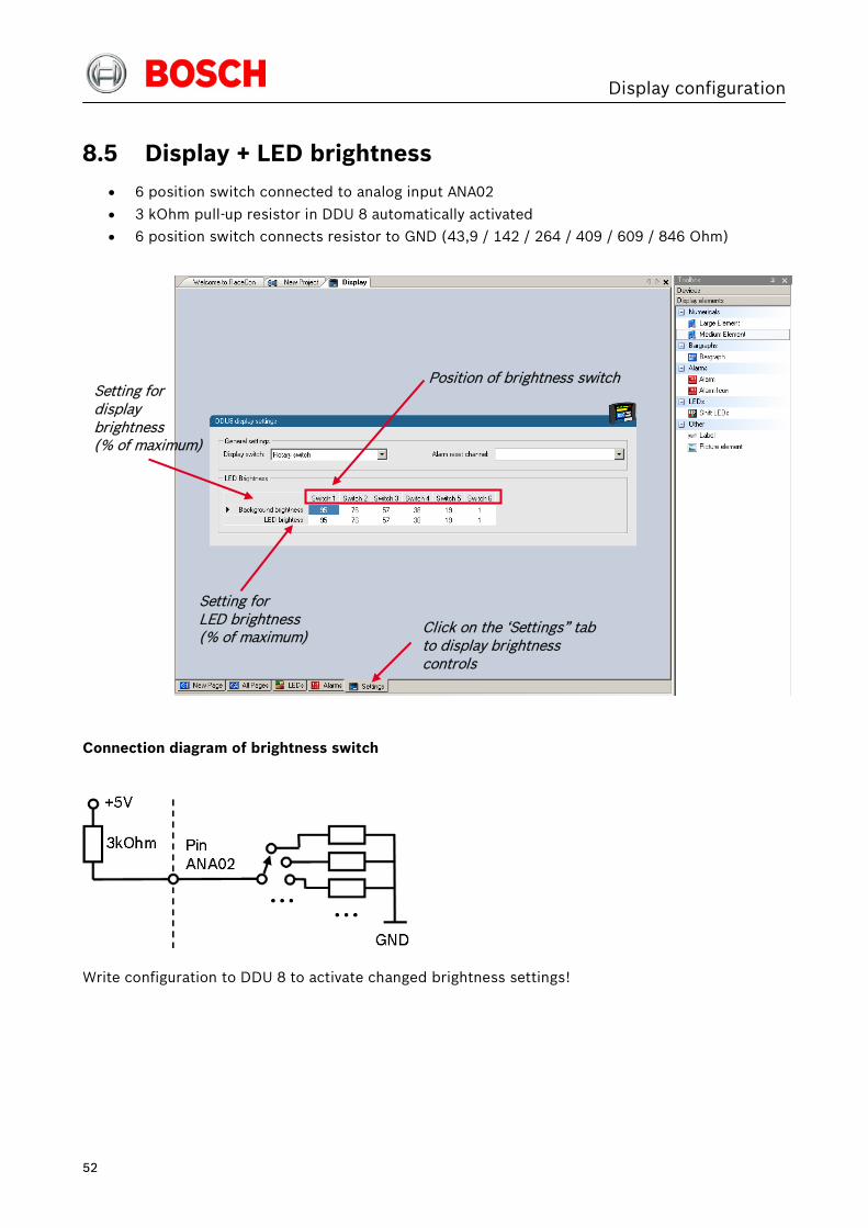
8.5 Display + LED brightness
• 6 position switch connected to analog input ANA02
• 3 kOhm pull-up resistor in DDU 8 automatically activated
• 6 position switch connects resistor to GND (43,9 / 142 / 264 / 409 / 609 / 846 Ohm)
Connection diagram of brightness switch
Write configuration to DDU 8 to activate changed brightness settings!
Position of brightness switch
Click on the ‘Settings” tab to display brightness controls
Setting for display brightness (% of maximum)
Setting for LED brightness (% of maximum)

Display configuration
53
8.6 Math + condition channels
8.6.1 Math channels
Math channel
• Arithmetic and logical operations on up to 4 measurement channel(s)
• Numerical result
• Result can be used as input source for various display elements (numeric elements, alarms,
Bargraphs) and further calculations in the whole RaceCon project
Conditional function
• Arithmetic and logical operations on one or more measurement channel(s)
• If-Else structure with reset
• Numerical result
• Result can be used as input source for various display elements (numeric elements, alarms,
Bargraphs) and further calculations in the whole RaceCon project
All math channels can be used globally in the whole DDU 8 project.
8.6.2 Creating a new math channel
1. Follow the steps shown in the screenshot.
1st : Double-click on ‘Math Channels’ in DDU 8 Project Tree
2nd : Click on ‘Add channel’

Display configuration
54
The ‘create/edit math channel’ window appears.
2. Define the math channel using the following configuration possibilities:
a) Enter the name of the math channel.
b) Enter a description of the math channel.
c) Enter the formula.
d) Select the logical operator.
e) Choose a measurement channel.
f) Define a value that can be used as a constant in the formula.
g) Choose a function.
h) Describes the function selected above.
3. Click ‘Finish’ when done. The math channel is displayed in the DDU 8 math channel window.
d)
c)
e)
f)
a) b)
g)
h)

Display configuration
55
8.6.3 Creating a new conditional function
1. Follow the steps shown in the screenshot.
2nd : Click on the dropdown arrow beside ‘Add channel’
3rd : Choose ‘Conditional Function’
1st : Double-click on ‘Math Channels’ in Project Tree

Display configuration
56
The ‘create/edit conditional function’ window appears.
The conditional function works the following way:
The program always calculates the condition entered in the IF window and checks if the condition is
TRUE or FALSE.
If the condition entered in the IF window is TRUE, the program calculates the condition entered in
the THEN window. The returned value is the content of the new variable (entered in ‘Name’).
If the condition entered in the IF window is FALSE, the program calculates the condition entered in
the OTHERWISE window. The returned value is the content of the new variable (entered in ‘Name’).
The reset value is always set for the new variable (entered in ‘Name’):
• before If-condition becomes TRUE for the first time after power-up
• when If-condition changes state from FALSE to TRUE.
An example of a condition to set up the maximum front brake pressure is given on the next page.
2. Define the conditional function using the following configuration possibilities:
a) Enter the name of the conditional function.
b) Enter the If-condition. Click on the pencil symbol to open an editor to enter expressions.
c) Enter the Then-condition. Click on the pencil symbol to open an editor to enter expressions.
d) Enter the Otherwise-condition. Click on the pencil symbol to open an editor to enter expressions.
e) Enter the reset value (must be a number).
3. Click ‘Finish’ when done. The conditional function is displayed in the DDU 8 math channel window.
c)
d)
a)
b)
e)

Display configuration
57
Example: Setting up a condition for maximum front brake pressure
• At power-up, the reset value (10) is used for ‘p_br_front_mx’.
• ‘p_br_front’ rises to 30. As ‘p_br_front’ is > 20 (condition is TRUE), the condition ‘max
(p_br_front, p_br_front_mx)’ in the THEN window is triggered. The condition sets the bigger
value as new value for ‘p_br_front_mx’. As ‘p_br_front’ (30) is bigger than ‘p_br_front_mx’
(10), the new value for ‘p_br_front_mx’ is set to 30.
• Although ‘p_br_front’ falls to 25, the value of ‘p_br_front_mx’ stays 30. This is caused by the
THEN-condition, because p_br_front_mx’ (30) is still bigger than p_br_front’ (25).
• As ‘p_br_front’ rises to 40. As ‘p_br_front’ (40) is bigger than ‘p_br_front_mx’ (30), the new
value for ‘p_br_front_mx’ is set to 40.
• As ‘p_br_front’ falls below 20, the IF-condition turns to FALSE. Now the OTHERWISE-
condition is triggered. Because the condition ‘p_br_front_mx’ sets the value of
‘p_br_front_mx’ and the value that is already set to 40 before, nothing changes.
• When ‘p_br_front’ rises to 40, the If-condition changes to TRUE again and triggers the THEN-
condition. Now the reset value (10) is used for ‘p_br_front_mx’ in the THEN-condition.
• Because 40 is bigger than 10 the new value of ‘p_br_front_mx’ is 40.
20
20
10
Max brake pressure of the variable ‘front p_br_front_mx’
Reset value is used
Hold max. value
Threshold reached
Follow max. value
Reset value is used
Hold max. value
Time
Time
Condition ‘p_br_front > 20’
Hold max. value
30
40
30
40
10
Brake pressure ‘front p_br_front’

Display configuration
58
8.7 Condition channels
Condition channel
• Logical operations on measurement channel(s)
• If-Else structure with reset
• Logical result
• Result can be used as input source for Alarm display elements and further calculations in the
whole RaceCon project
Condition combination
• Combination of several (up to 16) condition channels for more complex calculations
• Logical result
All condition channels can be used globally in the whole DDU 8 project.
8.7.1 Creating a new condition channel
1. Follow the steps shown in the screenshot.
1st : Double-click on ‘Conditional Channels” in Project Tree
2nd : Click on ‘Add condition”

Display configuration
59
The ‘create/edit condition’ window appears.
2. Define the condition channel using the following configuration possibilities:
a) Enter the name of the condition channel.
b) Select the comparing mode:
• Constant: Compare a measurement channel with a constant value.
• Channel: Compare a measurement channel with a measurement channel.
• Range: Compare a measurement channel with a defined value range.
• Multiple: Compare a measurement channel with up to 5 constant values.
c) Depending on the chosen comparing mode, you can enter the following values:
• Constant: Choose the measurement channel or condition, the operator and enter the value
of the constant.
• Channel: Choose the measurement channel or condition, the operator and the measurement
channel or condition to be compared.
• Range: Choose the measurement channel or condition, the operator and define the
minimum and maximum value.
• Multiple: Choose the measurement channel or condition, the operator and enter the value of
up to 5 constants.
d) Enter the minimal time to detect the signal of the measurement channel to avoid high-frequent
switchovers.
e) Enter the time the signal of the measurement channel is delayed after its ending.
f) Choose the output setting of the result.
• Constant TRUE/FALSE: Result is as a constant with the value TRUE or FALSE.
• Blinking: Result is a blinking if the condition is fulfilled.
• Pulse: Result is a short one-time pulse if the condition is fulfilled.
• Toggling output: Result is a pulse that lasts until the next condition is fulfilled.
c)
b)
d)
a)
f)
e)

Display configuration
60
3. Click ‘Ok’ when done. The conditional channel is displayed in the DDU 8 condition channel window.
8.7.2 Creating a new condition combination
1. Follow the steps shown in the screenshot.
2nd : Click on the dropdown arrow beside ‘Add condition’
3rd : Choose ‘Conditional combination’
1st : Double-click on ‘Conditional Channels’ in Project Tree

Display configuration
61
The ‘create/edit condition combination’ window appears.
2. Define the condition combination using the following configuration possibilities:
a) Enter the name of the condition combination.
b) Create the condition combination in the window.
• Choose a channel (condition, conditional function, math, measurement channel with
binary values) to be compared.
• Combine multiple conditions by adding ‘AND’ or ‘OR’ relations.
• To negate a condition, right-click on the condition and select ‘Negation (!)’.
• Combine several (up to 16) conditions.
3. Click ‘Next’ to go to the next page.
Choose the output setting of the result. • Constant TRUE/FALSE: Result is as a constant with the value TRUE or FALSE.
• Blinking: Result is a blinking if the condition is fulfilled.
• Pulse: Result is a short one-time pulse if the condition is fulfilled.
• Toggling output: Result is a pulse that lasts until the next condition is fulfilled.
4. Click ‘Finish’ when done. The conditional combination is displayed in the DDU 8 condition channel window.
b)
a)

CAN bus
62
9 CAN bus DDU 8 has 2 CAN buses. Both buses are fully configurable.
• Baudrate (125 kBit … 1 MBit)
• 11 Bit or 29 Bit identifiers
• Input configuration: Read messages from CAN bus and convert to DDU 8 measurement /
display variables. CAN bus supports row counter configuration.
• Output configuration: Write DDU 8 measurement variables to CAN messages, output
frequency and row counter are configurable, CAN gateway functionality (transfer from one
bus to the other)
9.1 CAN bus trivia
CAN message
• 11 Bit (standard) or 29 Bit (extended) identifier
• Up to 8 bytes of data payload
CAN bus
• Needs termination resistors (120 Ohm) in wiring harness
• All devices connected to the bus must use identical data rate
Configuration of DDU 8 bus data rate in ‘Properties’ menu

CAN bus
63
Row counter concept
• Re-use (multiplex) of message identifiers
• One byte of message contains row counter
• 7 bytes payload remaining
• Position of row counter is configurable
9.2 CAN input
9.2.1 Input configuration
9.2.2 Create new CAN channel
1. Right-click on CAN Input of desired bus (CAN1 or CAN2).
2. Select ‘New CAN Channel’ from menu.
3. Insert name and description of channel.
4. Click ‘OK’ when done.
Message Id
Payload Area Row Counter
Create new channel to read from CAN bus
Export RaceCon CAN input configuration to file
Import RaceCon CAN input configuration from file
Display CAN bus properties (Baudrate)
Import Vector CAN database (DBC) channel configuration

CAN bus
64
The channel is listed in the Data window and a CAN channel configuration window opens.
9.2.3 CAN channel configuration
Extraction of data from CAN bus
Conversion to physical values
Automatic assignment to measurement view
Mini CAN analyzer functionality

CAN bus
65
9.2.4 Extracting data from CAN bus
Representation: Byte
Some CAN devices need to be addressed by a byte represented CAN channel. The address can be
assigned in this window and is illustrated by a bargraph.
a) Enter name of the CAN-channel.
b) Enter CAN message ID. Check the box, if extended IDs (29 bit) are used.
c) If replacement values are used, specify time-out period and raw value.
d) Check the box, if a multiplexer (row counter) is used.
e) Enter data position, length and format.
f) The bargraph shows assignment of the bytes.
• Red colored fields show the assignment of the data bytes.
• Orange colored fields show the assignment of the multiplexer bytes.
e)
c) b)
d)
f)
a)

CAN bus
66
Representation: Bit
Some CAN devices need to be addressed by a bit represented CAN channel. The address can be
assigned in this window and is illustrated by a matrix table.
a) Enter name of the CAN-channel.
b) Enter CAN message ID. Check the box, if extended IDs (29 bit) are used.
c) If replacement values are used, specify time-out period and raw value.
d) Check the box, if a multiplexer (row counter) is used.
e) Enter data position, length and format.
f) The matrix table shows the assignment of the bits.
• Red colored fields show the assignment of the data bits.
• Orange colored fields show the assignment of the multiplexer bits.
e)
c) b)
d)
f)
a)

CAN bus
67
9.2.5 Conversion to physical values
a) Enter factor (gain) for conversion to physical value.
b) Enter offset for conversion to physical value.
c) Select type of physical value.
d) Select unit of physical value.
e) Enter minimum physical limit of the channel. (for manual setup)
f) Enter maximum physical limit of the channel. (for manual setup)
g) Check the box to automatically adjust the limits of the channel.
9.2.6 Special features
CAN analyzer functionality
This functionality is only available, if a MSA-Box (I & II) is used to connect the DDU 8 to the PC.
Choose the CAN bus that is connected to the MSA-Box to display the raw value and the converted
physical value here.
Automatic creation of online measurement sheets
The CAN channel can be automatically inserted to a measurement sheet. Insert a name for a new
sheet or select an existing sheet from the listbox.
For an online view of the value measured by the DDU 8, insert the channel in an online
measurement sheet which is described in the next chapter.
d)
b) f) a) e)
c) g)

CAN bus
68
9.2.7 Online view of CAN channels in vehicle
1. Double-click on ‘Sheet 1’ in Project Tree.
Measurement Sheet 1 is displayed in Main Area.
2. Click on ‘Measurement elements’ in the Toolbox.
3. Drag the desired Measurement element (e.g. Numeric Indicator) and drop it on the Measurement Sheet.
Drag + Drop

CAN bus
69
4. Click on folder ‘CAN Input’ of desired CAN bus to display available channels.
5. Drag desired Measurement channel and drop it on the Measurement element.
The measurement element displays the values of the assigned channel.
6. Connect PC to the vehicle and switch to ‘Race Mode’ by clicking ‘F11’ on the keyboard to display online data.
Drag + Drop

CAN bus
70
9.2.8 Import a CAN database (DBC) file
1. Right-click on CAN Input of desired bus (CAN1 or CAN2).
2. Select ‘Import DBC file’ from menu. A file browser opens.
3. Select DBC file to import and click ‘OK’ when done. A channel import window opens.
4. Select desired channels on the left and use the ‘Add’ button to add them to import list.
5. Click ‘OK’ when complete. The channels are inserted in the Data window.
9.2.9 Export RaceCon CAN configuration
1. Right-click on CAN Input of desired bus (CAN1 or CAN2).
2. Select ‘Export… ’ from menu. An ‘Export Selection’ window opens.

CAN bus
71
3. Specify the filename.
4. Click ‘OK’ when done.
9.2.10 Import RaceCon CAN configuration
1. Right-click on CAN Input of desired bus (CAN1 or CAN2).
2. Select ‘Import… ’ from menu. A file browser opens.
3. Select the input file and click ‘OK’. An ‘Import Selection’ window opens.
4. Select channels to import.
5. Drag and drop the channel to ‘CAN Input’ of desired CAN bus on right hand side.
6. Click ‘Next’. If a measurement channel belongs to more than one source (e.g. DDU 8 and ECU MS 5.1), the
‘Solve Label Ambiguity’ window opens.
Drag + Drop

CAN bus
72
7. Assign the ambiguous channels to the desired source.
8. Click ‘Finish’.
9.3 CAN output
9.3.1 Output configuration
9.3.2 Create new CAN output message channel
1. Right-click on CAN Output of desired bus (CAN1 or CAN2).
2. Select ‘New CAN Message’ from menu. The ‘Create new CAN message’ window opens.
3. Enter name of message, CAN-Id and Grid (output interval).
4. Optionally, specify a row counter (multiplexer).
5. Click ‘OK’ when done.
Create new CAN output message
Export RaceCon CAN output configuration to file
Display CAN bus properties (Baudrate)
Import RaceCon CAN output configuration from file

CAN bus
73
A CAN message configuration window opens in the Main Area.
6. Click on ‘DDU 8’ in the DDU 8 Project Tree to display all labels.
7. Select the desired measurement channel and drop it on message’s bytes.
The measurement channel is assigned to the CAN message.
Output messages on CAN bus 1
Definition of CAN message
Content of message
Click here
Drag + Drop

CAN bus
74
9.3.3 Set up of word length, byte order and quantization
Word length and quantization of channel are fixed.
Byte Order can only be changed if a channel allocates more than one byte.
9.3.4 Export RaceCon CAN configuration
1. Right-click on CAN Output of desired bus (CAN1 or CAN2).
2. Select ‘Export… ’ from menu. The ‘Export Selection’ window opens.
3. Specify the filename.
4. Click ‘OK’ when done.
Set byte order of channel on CAN bus

CAN bus
75
9.3.5 Import RaceCon CAN configuration
1. Right-click on CAN Output of desired bus (CAN1 or CAN2).
2. Select ‘Import… ’ from menu. A file browser opens.
3. Select the input file and click ‘OK’. An ‘Import Selection’ window opens.
4. Select channels to import.
5. Drag and drop the channel to ‘CAN Output’ of desired CAN bus on right hand side.
6. Click ‘Next’. If a measurement channel belongs to more than one source (e.g. DDU 8 and ECU MS 5.1), the
‘Solve Label Ambiguity’ window opens.
7. Assign the ambiguous channels to the desired source.
8. Click ‘Finish’.

Analog and frequency inputs
76
10 Analog and frequency inputs
10.1 DDU 8 features
24 analog inputs (with Software Upgrade 2; 4 analog inputs available without upgrade)
• 0…5 V
• 12 bit A/D converter
• Switchable 3.01 kOhm pull-up resistor
• 8 kHz acquisition rate, up to 1 kHz recording rate
• Linear phase digital filter
4 frequency inputs (with Software Upgrade 2; no frequency inputs available without upgrade)
• 5 V Hall-effect type, 2.5 V trigger level
• 20 kHz max. frequency
• 10 ms measurement window
4 PWM outputs
• Low-side switch
• Up to 2 A each
• Output frequency selectable

Analog and frequency inputs
77
10.2 Analog inputs
10.2.1 Measurement channels
For each analog channel, several ‘subchannels’ are available.
Measurement labels with the characters ‘raw’ show the exact values in mV.
Measurement labels with the characters ‘_fi’ show filtered values.
The word ‘name’ in the table is a placeholder for the channel’s name.
Measurement label Function
raw_name mV value of sensor
raw_name_fi filtered mV value of sensor
name physical value of sensor
name_fi filtered physical value
Filtered channels are routed through digital low pass filters:
• DDU 8 uses A/D converter oversampling and digital filtering to recording rate
• Digital filters eliminate ‘out-of-band’ noise
• Cut-off frequency automatically adjusted to recording rate
• Linear phase – no signal distortion
• Latency compensation – no filter delay in recorded data

Analog and frequency inputs
78
10.3 Configuring inputs
10.3.1 Configuring a predefined Bosch sensor with the ‘Bosch Sensor Wizard’
1. Click on ‘Measurement Sources’ in the Toolbox.
2. Expand the list of ‘I/O Channels’ by clicking on ‘+’ in the DDU 8 Project Tree.
3. Drag the ‘Bosch Sensor Wizard’ from the Toolbox and drop it on the desired analog input channel in the DDU 8 Project Tree. The ‘Bosch Sensor Wizard’ opens.
4. Click ‘Finish’ when done.
1st: Choose the sensor’s category
2nd: Narrow your choice by choosing a type
3rd: Select the exact type
Opens sensor’s datasheet
These calibration values will be used

Analog and frequency inputs
79
5. The ‘Create channel on DDU 8’ window opens.
6. Enter channel name and description.
7. Click ‘Ok’ when done. The channel is inserted into the DDU 8 Project Tree.
Available measurements for channel:
Measurement label Function
raw_name mV value of sensor
raw_name_fi filtered mV value of sensor
name physical value of sensor
name_fi filtered physical value
Calculation of physical value with characteristic curve
Input pin Pull-up resistor is activated
Channel is linked to ANA03

Analog and frequency inputs
80
10.3.2 Configuring a generic linear sensor
Example: Acceleration sensor 5g
• From sensor data sheet – operating characteristics:
• Sensitivity 400 mV/g, Offset 2500 mV
• The sensor has a linear output signal with sensitivity and offset
1. Click on ‘Measurement Sources’ in the Toolbox.
2. Expand the list of ‘I/O Channels’ by clicking on ‘+’ in the DDU 8 Project Tree.
3. Drag the ‘Sensitivity/Offset’ analog signal source from the Toolbox and drop it on the desired analog input channel in the DDU 8 Project Tree. A ‘Sensitivity/Offset Wizard’ opens.
4. To activate the internal DDU 8 pullup-resistor, check the box. The internal DDU 8 pullup-resistor is used to get a 5 V signal at the analog channel of the DDU 8.
It allows you to use a push-button.
The fixed value of the internal DDU 8 pullup-resistor is 3010 Ohm. If using an additional external
pullup-resistor, set up the overall resistance.
5. Click ‘Next’ when done.

Analog and frequency inputs
81
The second part of the ‘Sensitivity/Offset Wizard’ opens.
6. Click ‘Next’ when done. The third part of the ‘Sensitivity/Offset Wizard’ opens.
Note: Working with automatically created measurement sheets is explained in chapter ‘11.2 Setting
up an online measurement’.
7. Click ‘Finish’ when done.
8. Enter channel name and description.
9. Click ‘OK’ when done.
Choose unit group and unit of physical value
Enter values from sensor datasheet
Electrical (pin) value
Physical (channel) value
Physical limits of channel
Enter physical limits of the sensor
Choose data type of the measurement variable
Check box to enable online calibration of offset and enter desired physical offset value
Enter name to auto-matically create a new measurement sheet

Analog and frequency inputs
82
The channel is inserted into the DDU 8 Project Tree.
Available measurements for channel:
Measurement label Function raw_name mV value of sensor
raw_name_fi filtered mV value of sensor
name physical value of sensor
name_fi filtered physical value
Input pin Pull-up resistor is deactivated
Sensitivity and Offset value for sensor
Adjustment is enabled
Channel is linked to ANA04

Analog and frequency inputs
83
10.3.3 Configuring a generic nonlinear sensor
Example: Thermistor 5 kOhm
• From sensor data sheet: resistance values over temperature
• The sensor has a nonlinear behavior
• Use characteristic curve for linearization
• Input voltage is the ratio between pull-up resistor and thermistor
3 kOhm
Pin
Thermistor
+5V

Analog and frequency inputs
84
1. Click on ‘Measurement Sources’ in the Toolbox.
2. Expand the list of ‘I/O Channels’ by clicking on ‘+’ in the DDU 8 Project Tree.
3. Drag the ‘Characteristic Curve’ analog signal source from the Toolbox and drop it on the desired analog input channel in the DDU 8 Project Tree. A ‘Characteristic Curve Wizard’ opens.
4. To activate the internal DDU 8 pullup-resistor, check the box. The internal DDU 8 pullup-resistor is used to get a 5V signal at the analog channel of the DDU 8.
It allows you to use a push-button.
The fixed value of the internal DDU 8 pullup-resistor is 3010 Ohm. If using an additional external
pullup-resistor, set up the overall resistance.
5. Click ‘Next’ when done. The second part of the ‘Sensitivity/Offset Wizard’ opens.
Select physical unit.
Physical (channel) value
Enter resistance/temperature pairs from sensor datasheet here (The 3.01 kOhm pullup- resistor is automatically taken into account)
Choose ‘Ohm’ to enter datasheet values directly.

Analog and frequency inputs
85
6. Click ‘Next’ when done. The third part of the ‘Characteristic Curve Wizard’opens.
Note: Working with automatically created measurement sheets is explained in chapter ‘11.2 Setting
up an online measurement’.
7. Click ‘Finish’ when done.
8. Enter channel name and description.
9. Click ‘OK’ when done. The channel is inserted into the DDU 8 Project Tree.
Available measurements for channel:
Measurement label Function
raw_name mV value of sensor
raw_name_fi filtered mV value of sensor
name physical value of sensor
name_fi filtered physical value
Enter physical limits of the channel
Choose data type of the measurement variable
This sensor does not need offset calibration
Input pin Pull-up resistor is activated
Characteristic curve for sensor
Adjustment is disabled
Physical limits of channel
Channel is linked to ANA05
Enter name to automatically create a new measurement sheet

Analog and frequency inputs
86
10.3.4 Configuring a multipoint adjustment
Example: Measurement of wheel force
• Physical property ‘wheel force’ not directly measureable
• Load transfer through suspension kinematics
• Physical value at sensor position defined by vehicle
• Curve definition by online adjustment at vehicle
1. Click on ‘Measurement Sources’ in the Toolbox.
2. Expand the list of ‘I/O Channels’ by clicking on ‘+’ in the DDU 8 Project Tree.
3. Drag the ‘Multipoint Adjustment’ analog signal source from the Toolbox and drop it on the desired analog input channel in the DDU 8 Project Tree. A ‘Multipoint Adjustment Wizard’ opens.
4. To activate the internal DDU 8 pullup-resistor, check the box. The internal DDU 8 pullup-resistor is used to get a 5 V signal at the analog channel of the DDU 8.
It allows you to use a push-button.
The fixed value of the internal DDU 8 pullup-resistor is 3010 ohm. If using an additional external
pullup-resistor, set up the overall resistance.
Force at wheel
Force at sensor

Analog and frequency inputs
87
5. Click ‘Next’ when done. The second part of the ‘Multipoint Adjustment Wizard’ opens.
6. Click ‘Next’ when done. The third part of the ‘Multipoint Adjustment Wizard’ opens.
Note: Working with automatically created measurement sheets is explained in chapter ‘11.2 Setting
up an online measurement’.
7. Click ‘Finish’ when done.
8. Enter channel name and description.
9. Click ‘OK’ when done.
Enter physical limits of the sensor
Choose data type of the measurement variable
Enable additonal online calibration
Choose unit group and unit of physical value
Enter physical adjustment values values here (Can still be edited later)
Electrical (pin) value
Select type of curve
Physical limits of channel
Physical (channel) value
Enter name to automatically create a new measurement sheet

Analog and frequency inputs
88
The channel is inserted into the DDU 8 Project Tree.
Available measurements for channel:
Measurement label Function
raw_name mV value of sensor
raw_name_fi filtered mV value of sensor
name physical value of sensor
name_fi filtered physical value
Online definition of the curve is covered in the chapter ‘11.3 Online calibration of measurement
channels’ of this manual.
Input pin Pull-up resistor is deactivated
Characteristic curve for sensor
Adjustment is enabled
Channel is linked to ANA06

Analog and frequency inputs
89
10.3.5 Digital filter details
DDU 8 uses A/D converter oversampling and digital filtering to recording rate.
Digital filters eliminate ‘out-of-band’ noise
Cut-off frequency automatically adjusted to recording rate
Example:
• 100 Hz recording rate (10 ms)
• < 40 Hz passband (> 99%)
• > 50 Hz stopband (< 1%)

Analog and frequency inputs
90
Linear phase – no signal distortion
Latency compensation – no filter delay in recorded data
• Filtering is (smart) averaging over several samples
• Filtered signal is delayed with respect to real time signal
• DDU 8 filters have constant, frequency independent delay
• Delay (e.g. 22 samples at 10ms) is corrected during recording
• No delay filtered vs. unfiltered in recorded data
• Correction is (of course) not possible for real time data (display, online, PWM out)
• Use filtered data for recording, use unfiltered data for realtime
10.3.6 Configuring a frequency input
This function requires the installation of Software Upgrade 2.
Example: measurement of wheel speed
• Pulse wheel attached to wheel
• Each passing tooth of pulse wheel triggers hall sensor
• Calculation of wheel speed with wheel circumference
1. Click on ‘Measurement Sources’ in the Toolbox.
2. Expand the list of ‘I/O Channels’ by clicking on ‘+’ in the DDU 8 Project Tree.
3. Drag the ‘Velocity’ digital signal source from the Toolbox and drop it on the desired ‘REV’ input channel in the DDU 8 Project Tree. The ‘Velocity Wizard’ opens.
0 500 1000 1500 2000 2500 3000-2
-1.5
-1
-0.5
0
0.5
1
1.5
2
Abtastwerte (roh)
Wer
t
10000Hz Abtastrate
0 5 10 15 20 25 30-1.5
-1
-0.5
0
0.5
1
1.5
Abtastwerte (gefiltert)
Wer
t
100Hz Abtastrate
0 5 10 15 20 25 30-1.5
-1
-0.5
0
0.5
1
1.5
Abtastwerte (dezimiert)
Wer
t
100Hz Abtastrate
Sensor signal with noise
Recorded signal 100Hz (unfiltered)
Recorded signal 100Hz (filtered)

Analog and frequency inputs
91
4. Click ‘Finish’ when done.
5. Enter channel name and description.
6. Click ‘OK’ when done. The channel is inserted into the DDU 8 Project Tree.
Available measurements for channel:
Measurement label Function
raw_name mV value of sensor
raw_name_fi filtered mV value of sensor
name physical value of sensor
name_fi filtered physical value
Note: Measurement of ‘Revolution’ is similar.
Choose data type of the measurement variable
Circumference of wheel for speed calculation
Enter name to automatically create a new measurement sheet
Input pin has hall interface
Number of teeth
Wheel circumference
Channel is linked to REV01
Special functionality for sensors with frequency offset (e.g. Correvit) Set to ‘0’ for wheelspeed measurement
Number of teeth on the pulse wheel

Analog and frequency inputs
92
10.4 Computed sources
10.4.1 Configuring computed sources
Computed sources receive data from a measurement channel rather than an input pin.
• Sensitivity / Offset calculation on input channel
• Characteristic curve calculation on input channel
• Computed vehicle speed
• PWM output control (covered in a special section)
• Lap trigger (covered in a special section)
Example: Sensitivity / offset calculation on input channel
1. Click ‘Measurement Sources’ in the Toolbox.
2. Drag the ‘Sensitivity/Offset’ computed source from the Toolbox and drop it on ‘Computed Channels’ in the DDU 8 Project Tree. A ‘Computed Sensitivity / Offset Wizard’ opens.
3. Click ‘Next’ when done.
Choose unit group and unit of output
Enter sensitivity and offset of conversion formula
Choose input channel

Analog and frequency inputs
93
The second part of the ‘Computed Sensitivity / Offset Wizard’ opens.
Note: Working with automatically created measurement sheets is explained in chapter ‘11.2 Setting
up an online measurement’.
4. Click ‘Finish’ when done.
5. Enter channel name and description.
6. Click ‘OK’ when done. The channel is inserted into the DDU 8 Project Tree.
Enter physical limits of the channel
Choose data type of the measurement variable
Check the box to force the channel’s quantization if the quantization should be a fixed value in the whole CAN system
Enter name to automatically create a new measurement sheet
Physical limits of channel

Analog and frequency inputs
94
10.5 Hysteresis
The hysteresis function avoids the high-frequent switchover of the measurement channel value. The
hysteresis can be adjusted for each input measurement channel individually and can be used for
further processing.
1. Click ‘Measurement Sources’ in the Toolbox.
2. Drag the ‘Hysteresis’ computed source from the Toolbox and drop it on ‘Computed Channels’ in the DDU 8 Project Tree. A ‘Hysteresis Wizard’ opens.
a) Choose input measurement channel.
b) Choose unit group and unit of output.
c) Enter output value of state A in the unit selected in b).
d) Enter threshold value when state changes from A to B.
e) Enter delay time when state changes from A to B.
f) Enter output value of state B in the unit selected in b).
g) Enter threshold value when state changes from B to A.
h) Enter delay time when state changes from B to A.
i) Enter time when the hysteresis function is activated after vehicle’s startup.
j) Enter the channel’s state (A or B) at startup.
b)
a)
c) d)
e)
g) h)
f)
i)
j)

Analog and frequency inputs
95
3. Click ‘Next’ when done. The second part of the ‘Hysteresis Wizard’ opens.
4. Click ‘Finish’ when done.
5. Enter channel name and description.
6. Click ‘OK’ when done. The channel is inserted into the DDU 8 Project Tree.
Calculation of hysteresis channel
Check the box to force the channel’s quantization if the quantization should be a fixed value in the whole CAN system
Choose data type of the measurement variable
Enter name to automatically create a new measurement sheet
Available measurements for channel
Channels available in Computed Sources

Analog and frequency inputs
96
10.5.1 Special functionality: Vehicle speed
This functionality allows:
• high performance vehicle owners to measure wheel spin under acceleration and wheel
slip/lock under braking.
• calculating vehicle ‘speed over ground’.
Vehicle speed calculation function
• Calculating vehicle speed of 2 wheel drive: (Wheel speeds of non-driven axle as input)
Calculated speed is average of both speeds if speed difference between wheels < limit.
Calculated speed is maximum of both speeds if speed difference between wheels > limit.
• Calculating vehicle speed of 4 wheel drive: (Wheel speeds of all wheels as input)
Calculated speed is speed of 2nd fastest wheel.
10.5.2 Setting up calculated speed for DDU 8
1. Click on tab ‘System Overview’.
2. Click on ‘Measurement Sources’ in the Toolbox.
3. Drag the ‘Speed’ computed source from the Toolbox and drop it on ‘Computed Channels’ in the DDU 8 Project Tree. Do not drop it on ‘DDU 8’!
Drag + Drop

Analog and frequency inputs
97
A ‘Calculated Speed Wizard’ opens.
4. Click ‘Finish’ when done. The speed calculation is inserted into the DDU 8 Project Tree.
Choose driven axle
Choose input source (internal / external)
Choose individual wheel speed channels
Set limit for speed difference for calculation
Configu-ration window
Measurement channels calculated speed and calculated distance
Choose device
Speed calculation in DDU 8 Project Tree

Analog and frequency inputs
98
10.6 Configuring PWM outputs
PWM
• Pulse Width Modulation
• Output frequency is constant
• ‘On time’ (duty cycle) controlled by input channel
DDU 8 has 4 PWM outputs
• Low-side switch
• Up to 2 A each
• Selectable output frequency
• Duty cycle controlled by characteristic curve
Output frequency Time
Duty cycle 20% (switch closed)
Uout
Time
Uout
Output frequency
Duty cycle 80%

Analog and frequency inputs
99
10.6.1 Configuring a PWM output
1. Click on ‘Measurement Sources’ in the Toolbox.
2. Drag the ‘PWM Out’ computed source from the Toolbox and drop it on the desired ‘PWM_OUT’ channel in the DDU 8 Project Tree. A ‘PWM Out Wizard’ opens.
Note: Working with automatically created measurement sheets is explained in chapter ‘11.2 Setting
up an online measurement’.
Note: Choosing a filtered channel as an input for ‘PWM_OUT’ will cause delayed reaction due to the
delay introduced by the digital filter. Use unfiltered values for this purpose.
Note: The ‘power-on’ state of the PWM output is ‘switch open’ (0% duty cycle).
3. Click ‘Finish’ when done.
4. Enter channel name and description.
5. Click ‘OK’ when done.
Choose output frequency
Define characteristic curve
Choose input channel
Enter name to automatically create a new measurement sheet

Analog and frequency inputs
100
The channel is inserted into the DDU 8 Project Tree.
Diagnostic channels
Measurement label Function
pwm_err_ls_out_01_OL PWM output 1 error open load
pwm_err_ls_out_01_OT PWM output 1 error over temperature
pwm_err_ls_out_01_SCB PWM output 1 error short circuit to battery
pwm_err_ls_out_01_SCG PWM output 1 error short circuit to GND
Note: The diagnosis of PWM output 2-4 is similar.
Characteristic curve
Output frequency
Channel is linked to PWM_OUT02
Measurement channels

Online measurement
101
11 Online measurement DDU 8 configuration
• System configuration (channel + display configuration, CAN I/O, PWM Out, etc.) is stored in
the DDU 8
• Use RaceCon to create and download configuration from the PC to DDU 8
• Communication interface: Ethernet
• Communication protocol: XCP
Online measurement + calibration
• System status and diagnosis
• Check and calibrate sensors in the vehicle
• Live display of sensor values on the PC
• Use RaceCon for diagnosis, online measurement and calibration
• Communication interface: Ethernet
• Communication protocol: XCP
11.1 Achieving an online connection
11.1.1 Set up the PC for access to the DDU 8
1. Switch off local firewall on the PC.
2. Set IP Configuration for the Ethernet interface to ‘automatic configuration’ (DHCP). See chapter ‘7.1.1 Setting up the network interface‘ for details.
3. Start RaceCon.
4. Establish the Ethernet connection to the vehicle.
5. Power on the vehicle.
Status message window
Click ‘OK’ to download RaceCon configuration to device
Yellow dot indicates live connection to the device, but local RaceCon configuration does not match the DDU 8’s configuration

Online measurement
102
11.1.2 Going online
Click ‘OK to download RaceCon configuration to DDU 8.
The download starts.
A green dot and background at the device in the project view and the DDU 8 Project Tree indicate a
successful download and system consistency.
If the system’s configuration in RaceCon has been changed, the dot and background becomes
yellow and a configuration download is necessary.
11.1.3 Configuration download
1. Right-click on DDU 8 in the DDU 8 Project Tree.
2. Select ‘Download configuration’.
The configuration download starts.

Online measurement
103
A Green dot and background indicate a successful download.
11.2 Setting up an online measurement
DDU 8 supports online measurement of sensor values and diagnostic variables. Expand ‘Measurement Container’ and ‘Measurement Folder 1’ in the Project Tree and double-click
on ‘Sheet1’. ‘Sheet 1’ is opened in the Main Area.
From the context menu of the project, new measurement pages can be created.
From the context menu of a measurement page, the folder can be renamed and deleted. It also
allows the creation of measurement pages.

Online measurement
104
From the context menu of a measurement page, the page can be renamed and deleted.
To change between different pages, click on the tabs on the bottom of the Main Project Area.
To add an element to a measurement sheet, do following steps:
1. Drag a measurement element from the Toolbox and drop it on the measurement sheet.
Drag + Drop
Tabs to switch between sheets

Online measurement
105
2. Click on ‘DDU 8’ in the Project Tree to display all measurement channels.
3. Select the desired measurement channel and drop it on the measurement element. If the DDU 8 is online, the value is displayed.
The measurement element’s appearance can be changed using the Properties Menu.
Drag + Drop

Online measurement
106
RaceCon offers different types of measurement elements:
Vertical Bar
graph style
Numeric indicator
Temperature gauge
Horizontal Bar
graph style
Measurement label
Circular gauge
Oscilloscope (Chart)

Online measurement
107
11.2.1 Automatic creation of measurement sheets
RaceCon can create measurement sheets automatically.
You can create and use measurement sheets with the DDU 8 as well as with all other devices
connected to RaceCon.
1. During the configuration of a measurement channel, select a measurement sheet from the list box or enter a name for a new measurement sheet.
2. To create the sheets, right-click on DDU 8 and select ‘Create measurement views… ’ from the DDU 8 context menu.
Select existing sheet from list or enter name of new sheet
Click to create measurement sheets

Online measurement
108
The automatically created sheet is inserted in the Project Tree under ‘Measurement Container’ and
‘Device Channels’. If the DDU 8 is connected to RaceCon, live values of the channels are shown.
11.2.2 Using the measurement sheets
1. When RaceCon is online, press the ‘F11’ key to switch from ‘Design Mode’ into ‘Race Mode’. The measurement sheet is extended to full screen.
The button for offset calibration is active.
2. Switch between different sheets using the tabs at the bottom of the page or the keyboard shortcuts associated with the sheets.
3. Press the ‘Esc’ key to return to ‘Design Mode’.
Raw and physical channel values
Characteristic values
Button for online offset calibration
Access to sheet

Online measurement
109
11.3 Online calibration of measurement channels
• Analog sensors drift with age, temperature, etc.
• Manual calibration is necessary
• Solution: online offset calibration
• Example: acceleration sensor
11.3.1 Enable online offset calibration for measurement channel
During creation of the measurement channel
In the channel view
Activate switch to enable online calibration
Check box to enable online offset calibration and enter desired physical target value

Online measurement
110
11.3.2 Performing the online offset calibration
DDU 8 has to be connected to RaceCon to calibrate the sensor’s offset.
1. Apply the desired physical condition to the sensor. (e.g. 1 G to an acceleration sensor)
2. Open the measurement channel’s online page by double-clicking on the measurement channel name in the Data Area.
3. Enter the physical target value (e.g. 1 G) and press the ‘Calibrate’ button.
The sensor’s offset is now calibrated.
11.4 Group adjustment
Group adjustment is the simultaneous online calibration of several channels. This is useful e.g. to
set all wheel forces and damper positions to ‘0’ when the vehicle is positioned on a flat patch.
11.4.1 Configuration of group adjustment
Group adjustment consists of two components:
• An input channel which triggers the adjustment event
• A group of input channels linked to the group adjustment event
Calibration target value
Initiate calibration

Online measurement
111
11.4.2 Setting up the group adjustment trigger channel
1. Click on ‘Measurement Sources’ in the Toolbox.
2. Drag the ‘Group Adjustment Channel’ element from the Toolbox and drop it on the DDU 8.
A ‘Group Adjustment Channel Wizard’ opens.
Note: If a low-active signal is selected as an input channel, do not forget to enable the pull-up
resistor for the pin. Otherwise the group adjustment will be triggered periodically. See chapter
‘10.3.2 Configuring a generic linear sensor‘for further information concerning the pullup-resistor.
Check the box to activate the internal DDU 8 pullup-resistor and set the resistor value
Select the pin to which the sensor shall be connected
Drag + drop

Online measurement
112
3. Click ‘Next’ when done. The second part of the ‘Computed Sensitivity / Offset Wizard’ opens.
Note: Working with automatically created measurement sheets is explained in chapter ‘11.2 Setting
up an online measurement’.
4. Click ‘Finish’ when done.
5. Enter channel name and description.
6. Click ‘OK’ when done.
Define minimum time between two activations
Define minimum active time to detect activation
Signal is active high or active low
Enter name to automatically create a new measurement sheet

Online measurement
113
11.4.3 Assigning channels to the group adjustment
1. Double-click on the created channel (e.g. ‘grp_adj_channel’) in the Project Tree. In the Main Area, an overview of the available adjustment channels opens.
2. To add measurement channel(s) to the group adjustement event, check the ‘Calibrate’ box of the desired channel(s).
The selected measurement channels are added to the group adjustment event.
11.4.4 Triggering the group adjustment
1. Connect the input pin to GND using a push-button.
2. Make sure the pullup-resistor is enabled, if you selected ‘active low’ trigger polarity.
3. Double-click on the input channel ‘grp_adj_channel’ of the group adjustment.
4. Download the configuration on the DDU 8. To connect the DD8 to RaceCon, see chapter ‘7.1.4 Connecting the DDU 8 to RaceCon’.
5. Open a measurement sheet by clicking on the desired measurement sheet in the Project Tree.
6. Drag the ‘grp_adj_channel’ and the ‘input_grp_adj_channel’ to the online measurement sheet.
7. Press and release the push-button.
8. The measurement labels indicate the state of the input pin and the state of the adjustment.
Check box to add channel to group adjustment
Double-click to open group adjustment overview

Online measurement
114
Hint: A display alarm can be linked to the trigger channel to indicate that the trigger has been
detected.
11.5 Online calibration of multipoint adjustment channels
Example: measurement of wheel force
• Physical property ‘wheel force’ not directly measureable
• Load transfer through suspension kinematics
• Physical value at sensor position defined by vehicle
• Curve definition by online adjustment at vehicle
Voltage at input pin
State of adjustment 0 – Idle 1– Adjustment triggered 2 – Adjustment lock time
Force at wheel
Force at sensor
Drag channels on Measurement Sheet

Online measurement
115
1. Create a multipoint adjustment measurement channel. To create a multipoint channel, see chapter ‘10.3.4 Configuring a multipoint adjustment’.
2. Download the configuration on the DDU 8. To connect the DDU 8 to RaceCon, see chapter ‘7.1.4 Connecting the DDU 8 to RaceCon’.
3. Click on the desired channel in the DDU 8 Project Tree.
4. Double-click on a measurement channel in the Data Area to open the online view.
5. Click on ‘Calibrate adjustment points’ to open calibration window.
6. Apply the desired physical condition to the sensor (e.g. by applying a force on the wheel).
7. Enter the physical value in the value column of the desired calibration point (e.g. 745 N).
8. Press the ‘Calibrate’ button of the desired calibration point.
9. Repeat for all curve points.
10. Click ‘Close’ when done.
Click to open calibration window
Analog and physical value
Click to open measurement channels in data view
Double-click to open online view

Online measurement
116
The calibration curve is displayed in the online view.
Adjustment points vs. offset adjustment
UIN
Fwheel_FR
Calibration of individual curve points
UIN
Fwheel_FR
Overall offset adjustment of all curve points. E.g. to compensate sensor drift

Recording and telemetry
117
12 Recording and telemetry
This function requires the installation of Software Upgrade 1.
12.1 DDU 8 features
Recording
• Synchronized recording of DDU 8 analog and digital input channels, DDU 8 internal
measurement channels, ECU data, Data from external sensor interfaces
• Up to two independent recordings
• Measurement rate 1 ms… 1 s
• Two global start conditions (thresholds)
• Up to 16 measurement conditions (fast-slow-switches)
Telemetry
• Support for long-range online telemetry
• Individual programmable team code
• Fast block – slow block mechanism
• Programmable data rate
Burst telemetry
• Support for burst telemetry (BT 60)
• Programmable IP configuration
• BT 60 diagnosis via DDU 8

Recording and telemetry
118
12.2 Configuration of recordings
1. Expand the list of ‘Loggers’ by clicking on ‘+’ in the DDU 8 Project Tree.
2. Double-click on ‘Recording’ in DDU 8 Project Tree. The recording configuration is displayed in the Main Area.
3. To add measurement channels to a recording, click ‘DDU 8’ in the DDU 8 Project Tree. In the Data Area, the measurement channels are displayed.
Variables can be grouped
Tabs to access conditions, settings and statistics
Double-click to display configuration

Recording and telemetry
119
4. Drag and drop desired measurement channels into recording group.
5. To edit channel’s settings, mark the channel(s) and click ‘Edit Channel’. An ‘Edit Recording Channels’ window opens.
Note: If no condition is defined or condition is ‘false’, measurement channels are recorded at the
value chosen in ‘Rate’. If the condition is ‘true’, measurement channels are recorded at the value
chosen in ‘True rate’.
6. Click ‘OK’ when done.
Drag measurement channels into group
Recording properties
Recording rate if condition is ‘true’
Recording rate 1 ms…1 s
Click to display DDU 8 variables
Activate these filters
Condition to switch between fast / slow rate
List of channels selected
Settings for long range telemetry ‘None / Fast / Slow’ (only if telemetry unit is available)

Recording and telemetry
120
Using fast block / slow block transmission
DDU 8 telemetry uses available bandwidth of Telemetry Unit FM 40 (19200 baud -> approx. 1700
bytes/s). The bandwidth has to be divided into channel information to be transmitted high-
frequently and low-frequently using the ‘fast/ slow block’ setting.
Channels are grouped into 8 blocks which are transferred each cycle:
• Fast block (Block 1) is transferred every cycle and used for a high-frequent transmission of
channel information (e.g. speed, rpm).
• Slow blocks (Block 2…n): are transferred every n-th cycle and used for a low-frequent
transmission of channel information (e.g. tire pressure, oil temperature).
Transmission Scheme
If the maximum bandwidth of a block is reached, a warning will be displayed. To fix this problem
you can view the allocation of the channels and data rate in the ‘Statistics’ tab of the Main Area.
See chapter ‘12.2.4 Recording statistics’ for more information.
12.2.1 Adding a recording
DDU 8 supports up to two independent recordings.
To add a recording, select ‘Add Recording’ from the context menu of the Logger in the DDU 8
Project Tree.

Recording and telemetry
121
12.2.2 Adding a recording group
Recording channels can be grouped.
To add a new group, select ‘Add group’ in the context menu of the recording.
The groups can be renamed to ‘Gearbox’, ‘Aero’, ‘Engine’, etc.
12.2.3 Global DDU 8 settings
To display the global DDU 8 settings, select the ‘Settings’ Tab.
c)
d)
e)
f)
g) a) b)

Recording and telemetry
122
a) Choose setting for outing counter mode:
• For testbench (without lap trigger) select ‘Testbench’.
• For racetrack (with lap trigger) select ‘Racetrack’.
b) Choose your WinDarab version. In V6 the file is encrypted by WinDarab. In V7 you can enter an
optional self created password in the ‘Encryption’ field shown in f).
c) Choose Baud rate of CAN bus 1 and 2.
d) Select ‘Statusblock’ (optional). ‘Statusblocks’ contain information of channels specially adapted
by Bosch Motorsport.
e) Choose or create the condition to start recording.
f) If selecting WinDarab V7 in b), enter a password hint and a password. (optional)
g) Setting for automatic fragmentation. Do not change!
12.2.4 Recording statistics
The tab ‘Statistics’ shows the channels’ allocation and their current data rate related to the
transmission frequency of the DDU 8 and the whole transmission system.
The overview helps to detect bandwidth bottlenecks of channels. Bandwidth bottlenecks can be
solved by changing the ‘fast/slow block’ setting for each channel.
The data rate of the whole system is often less than the data rate of the DDU 8 and limits the overall
transmission speed.

Recording and telemetry
123
12.2.5 Recording diagnosis
The channel ‘statectrl_ok’ of the DDU 8 can be used for online monitoring of recording status.
Bit Value Name
0 1 RECORD
1 2 DATAOK
2 4 BLKOK
3 8 -
4 16 -
5 32 -
6 64 STARTED
7 128 -
Content of status bits
Name Bit set Bit cleared RECORD
Measurement data is recorded.
No measurement data will be stored because measurement thresholds are not reached.
DATAOK
Received data without error.
Discarding received data because of wrong timestamps. Check wiring of SYNC signal.
BLKOK
All measurement blocks have been set up correctly.
Some measurement blocks have not been set up correctly.
STARTED
A measurement has been set up.
A measurement is not set up. Either no recording configuration has been found or logger software upgrade is not activated.
12.2.6 Displaying online recording diagnosis (‘statectrl_ok’)
1. To add a Recording Diagnosis element to a measurement sheet, drag a ‘Bit-LED’ element from the Toolbox and drop it on measurement sheet.
2. Drag channel ‘statectrl_ok’ from the Data Area and drop it on the ‘Bit-LED’ element.

Recording and telemetry
124
The ‘Bit-LED’ element shows the state of received channel data in bit-representation. A green
highlighted channel means 0, a red highlighted channel means 1.
• Measurement correctly initialized, but recording threshold(s) not reached: 254
• Measurement correctly initialized, DDU 8 is recording data: 255
• Values less than 254 indicate an error state
• ‘statectrl_ok’ can be linked to an alarm on the display. See chapter ‘8.2.3 ‘Alarm’ display
element’ for details.
12.3 Configuration of online telemetry
12.3.1 Long range telemetry system FM 40
• 440 MHz band
• 25 KHz bandwidth
• 10 W max. RF output
• 19.2 kBit/s data rate - unidirectional
• RS232 interface
• Full online track coverage on almost all tracks
Link quality at Hockenheim

Recording and telemetry
125
12.3.2 Hardware setup
Antenna Cable Kit B261209490
Car Antenna B261208888
FM 40 Transmitter B261208898
RS232
RS422 RS232
Antenna Cable 8m B261209493
Control Module B261208871
Pit Receiver Box1 (for one car) F01TA20451-01
Connecting Cable 50m B261209481
(optional)
Pit Receiver Box2 (for two cars) F01TA20455-01
DDU 8
Rod Antenna 7dBi B261208867

Recording and telemetry
126
12.3.3 Software setup
1. Drop FM 40 from Toolbox into system overview.
2. Click on FM 40 in Project Tree to display the Properties Menu.
Drag + drop
Project Key (1111…9999)
Baudrate of DDU 8 (must match baudrate of FM 40)
Transmission pause (5% recommended for improved re-synchronisation)
Path to configuration folder of WDServer on receiver PC (usually ….\WDServer\DCP) to store telemetry configuration file

Recording and telemetry
127
Adding channels to telemetry
1. Expand the list of ‘Loggers’ by clicking on ‘+’ in the DDU 8 Project Tree.
2. Double-click on ‘Recording’ in DDU 8 Project Tree. The recording configuration is displayed in the Main Area.
3. Click ‘Edit channel(s)’. The ‘Edit Recording Channels’ window appears.
4. Choose between ‘Fast/Slow block’ transmission. See chapter ‘12.2.2 Adding a recording group’ for information about ‘Fast/Slow block’.
None – channel(s) are not transferred Slow – channel(s) are transferred in the slow telemetry block Fast – channel(s) are transferred in the fast telemetry block

Recording and telemetry
128
12.3.4 Telemetry channels with special functionality
The FM 40 allows the transmission of special information such as running distance of current lap,
lap number of current lap and lap time, fuel consumption of last lap completed. You have to assign
the channel type to the telemetry channel so that it is recognized accurately by RaceCon.
Channel's names are e.g.: distlap, fuelcons, lapctr, laptime. Different channel names are possible
between different devices (e.g. ECU MS 3 Sport, ECU MS 5.1).
1. Double-click on FM 40 in Project Tree. An overview of all available telemetry channels is displayed.
2. Click on the telemetry channel you want to assign a special functionality.
3. Click ‘Edit channel(s)’. An ‘Edit Telemetry Channel’ window appears.
4. Choose the channel type. The table below shows the function of the available channel types.
Measurement channel Function Lap time Exact lap time of lap completed
Distance Running distance of current lap
Lap number Lap number of current lap
Lap fuel Fuel consumption of last lap completed
5. Click ‘Ok’ when done. The telemetry channels and their assigned channel types are displayed in the overview list.

Recording and telemetry
129
12.4 Configuration of burst telemetry
12.4.1 Burst telemetry system BT 60
• 5 GHz ISM band – 20 MHz bandwidth
• 0.4 W max. RF output
• 802.11a OFDM system; proprietary protocol
• max 12 MBit/s data rate – bidirectional
• Ethernet interface to DDU 8 / C 60 / C 55
• Partial track coverage
• Approx. 300 m reception range
• High speed burst transmission of recorded data
Link quality at Hockenheim

Recording and telemetry
130
12.4.2 Hardware setup
BT 60 F Set F02UV00038
Ethernet
Connecting Cable B261209743
BR 60 F Set F02UV00047
DDU 8

Recording and telemetry
131
12.4.3 Software setup
The IP address of the DDU 8 must be compatible with the address range of the pit PC, the BT 60
and the BR 60.
1. Drop BT 60 from Toolbox into system overview.
2. Open a measurement sheet.
3. Drag the channel ‘BURST_DEVICE_IP’ to the measurement sheet.
4. Switch to ‘Race Mode’.
5. Enter the desired IP address.
Enter IP address
Drag + drop

Recording and telemetry
132
12.4.4 Diagnostic channels
Diagnosis of BT 60 is possible through channels on DDU 8.
To display a channel, drag a channel from Data Area to the measurement sheet.
12.5 Setup for USB recording
This function requires the installation of Software Upgrade 1 and 4.
Enable the Software Upgrade for USB recording
USB recording is enabled by Software Upgrade 4.
Note: For USB recording, Software Upgrade 1 also has to be enabled.
To activate Software Upgrade 4, enter the license key as described in the chapter
‘7.2 Feature activation’.
Data ready for transmission
Signal quality of radio link: -55 dBm: good -70 dBm: fair -95 dBm: no link
DDU 8 connected to BT60
Byte counter for data transmission over radio link

Recording and telemetry
133
Wiring harness
Bit Value
Pin 23 Power (red)
Pin 24 D + (green)
Pin 25 D – (white)
Pin 26 GND (black) Note: Colors matching a standard USB cable.
Storage device
The recording function can be used with a dedicated Bosch Motorsport USB device. The USB device
has to be preformatted with the Bosch File System (BFS) in RaceCon before first use.
To format the USB device with the Bosch File System (BFS), do the following steps:
1. Insert the USB device into the PC and wait until it has been installed by Windows.
2. In RaceCon, select ‘Extras’ and choose ‘Format USB stick’.
3. Press ‘Format’.
An USB device is recognized by Windows as a ‘storage medium’, but it can only be initialized with
RaceCon and read with WinDarab.
12.5.1 Recording data on USB device
1. Plug an USB device to DDU 8.
2. Prepare a recording configuration in RaceCon.
3. Power on the system and connect with RaceCon to the vehicle.
4. Download the configuration to the DDU 8.
5. Record measurement data. If an USB device is present, the DDU 8 stores the data in parallel on the internal memory and the USB device.

Recording and telemetry
134
6. Power off the system.
7. Remove USB device from the vehicle.
8. Start the WinDarab software.
9. Click on the ‘Import/Export’ icon.
10. Select ‘Data logger C50/C55/C60/DDU7/DDU8’ and click ‘OK’ when done.
The ‘Read measurement data’ dialog opens.
11. Click on ‘Modify’ button and select the base folder.
12. Choose ‘Flashcard’ as data transmission method.
13. Choose ‘DDU8 - 10.10.0.207’ in the Vehicle dropdown list.
14. Activate ‘Auto save’.
15. Click ‘Save’ when done.
Choose ‘DDU8‘ in dropdown list
Click ‘Import/Export’

Recording and telemetry
135
16. Insert the USB device into the PC. Data transmission from device starts automatically.
Measurement files are stored automatically in the base folder.
17. Click ‘Close’ when transmission has finished.
18. Click on the Start button and choose ‘Open measurement file’.
19. Select the measurement files from the storage folder.
20. Click on ‘Open’.
21. Click in ‘New Desktop‘ to open a new measurement data window.
22. Drag the desired measurement channel from the Channel list and drop it into the measurement data window. The measurement channel‘s graph is displayed.
Note: For more detailed descriptions and instructions refer to the WinDarab V7 manual.

Recording and telemetry
136
12.5.2 USB Device handling hints
Using the USB device
Always plug the USB device into vehicle before power up to ensure that all measurement data is
stored on the USB device.
• If the USB device is plugged in after recording has started, the existing recording is saved.
• Data recorded on the DDU 8 before the USB device is plugged in will not be saved.
Removing the USB device
Always power off the system before unplugging the USB device!
• If the USB device is unplugged while recording is active, parts of the measurement data may
be missing.
• If the USB device is unplugged and re-inserted for < 4 s while the DDU 8 is powered up, the
DDU 8 still records data.
• If the USB device is unplugged and re-inserted for > 4 s while the DDU 8 is powered up or a
different USB device is plugged in, the DDU 8 restarts. In this case, the DDU 8 is not
operational for 1.5 s.
12.5.3 Troubleshooting
When no data on the USB device is recorded:
Configure the measurement label usb_mediastate on a RaceCon measurement view or on a DDU 8
display page.
The value of usb_mediastate reflects the operating condition of the USB bus:
State Description 0: Wait: Device not found
The USB device is not found (also: waiting for re-plug stick). No USB device inserted. USB device is defect. No electrical connection or wiring harness problem. USB software upgrade not activated (Purchase of unlock code needed).
1: Wait: Device detected An USB device is found, but not yet installed.
2: Ok: Media installed
The USB device is found and is operational (idle). This does not imply that recording data is written!
3: Stop: Device unplugged
The USB device has been removed. The DDU 8 performs a restart when an USB device is re-plugged in.
4: Ok: Media access Data is currently read from/written to the USB device.
5: Error: Media error
The communication to the USB device broke down. The USB device is defect. The USB device is not supported by DDU 8.
6: Error: Media corrupt
The USB device is not in valid BFS format. (Hint: Re-format the USB device in RaceCon.)

Lap trigger
137
13 Lap trigger
13.1 Lap trigger (timing beacon)
Why do we need a lap trigger (timing beacon)?
• Vehicle lap time measurement
• Calculation of lap-dependent functions (lap fuel consumption, min/max values)
• Calculation of lap distance dependent functions
• Control of data logging system
System consists of
• Transmitter (trackside unit)
• Receiver (in-vehicle unit)
Types of systems
• GPS based (low cost, low precision)
• IR based (low cost, high precision, limited reliability)
• RF (microwave) based (high precision, high reliability)
Lap Trigger Receiver
Lap Trigger Transmitter

Lap trigger
138
13.1.1 Electrical trigger signal
In DDU 8 all sources of measurement channels can be used as trigger signal.
• Analog input
• Digital input
• CAN input
Signal (measurement channel) properties
Low active signal (Bosch triggers): Trigger releases if signal is below the threshold.
High active signal (other manufacturer’s triggers): Trigger releases if signal is above the threshold.
Two types of trigger signal
• Main trigger (end-of-lap at start/finish line)
• Sub-trigger (segment time, optional)
Bosch standard:
• Main trigger > 20 ms, < 40 ms, low active (Recommendation for Bosch triggers: 15 ms)
• Sub trigger > 40 ms, low active (Recommendation for Bosch triggers: 30 ms)
13.1.2 Software functionality
• Race track topology and transmitter location frequently cause false triggers.
Software functionality prevents acceptance of false triggers.
• Under race conditions, trigger signals are sometimes missed.
Software functionality introduces ‘forced trigger’.
13.1.3 Prevention of false triggers
• Minimum vehicle speed for acceptance of trigger prevents false triggers while vehicle is
stationary in the pits.
• Time based re-trigger protection prevents false triggers due to signal reflections on main
straight.
• Lap distance based retrigger protection prevents false triggers due to track topology.
13.1.4 Forced triggers
Lap distance based insertion of ‘forced trigger’.

Lap trigger
139
13.1.5 Setting up a lap trigger for DDU 8
1. Click ‘Measurement Sources’ in Toolbox.
2. Drag ‘Laptrigger’ into ‘System Overview’ and drop it on vehicle. Do not drop it on ‘DDU 8’!
A ‘Laptrigger Wizard’ window opens.
Note: In this example, the Rx is connected to the dedicated lap trigger pin of DDU 8. The channel
‘speed’ is calculated from 4 wheel speeds.
3. Click ‘Finish’ to complete the operation.
Choose the signal channel for the trigger signal
Choose the signal device for the trigger signal
Choose the source for vehicle speed
Enter the distance of the racetrack
Drag + Drop

Lap trigger
140
A pre-configured lap trigger window opens.
a) Change signal device, if desired.
b) Change signal channel, if desired.
c) Choose signal threshold. See chapter ‘13.1.1 Electrical trigger signal’ for details.
d) Define threshold of input channel signal when trigger is released. Only possible if no digital
source is selected as signal source.
e) Define settings for lap timing (main trigger). See chapter ‘13.3 Lap timing’ for details.
f) Define settings for segmented timing (sub trigger). See chapter ‘13.4 Segment timing’ for details.
g) Define settings for countdown timer. See chapter ‘13.5 Countdown timer’ for details.
h) Change signal for vehicle speed, if desired.
i) Enter minimum speed for trigger release.
j) Define settings for distance based retrigger protection. See chapter ‘13.3.2 Distance based
retrigger protection’ for details.
k) Define settings for distance based forced trigger. See chapter ‘13.3.3 Distance based forced
trigger’ for details.
l) Define presettings for trigger. See chapter ‘13.1.7 Lap trigger presettings’ for details.
a)
e)
f)
g) b) c) d)
h) i)
j)
k)
l)

Lap trigger
141
13.1.6 Lap trigger channel diagnosis / counter reset
To display a quick lap trigger channel diagnosis and to reset counters use the diagnosis page in
RaceCon. Any ‘Laptrigger_xxx’ channel can be displayed.
Double-click on any ‘Laptrigger_xxx’ channel in the Data Area. Example: ‘laptrigger_lapdist_dls’
A diagnosis window opens in Main Area.
Lap trigger diagnosis scheme
Button to reset lap distance to 0
Button to reset lap counter
Button to reset outing counter
Button to generate trigger signal
Button to reset best lap time
Button to reset best lap time and distance-based segmentation

Lap trigger
142
13.1.7 Lap trigger presettings
When the reset buttons on the diagnosis page are activated, these values are used.
Minimum laptime that a new ‘best laptime’ is accepted
Preset value for ‘best laptime’
Preset values for lap counter and outing counter

Lap trigger
143
13.2 Counting outings / laps / fragments
Functionality
• Power ON: system + measurement is initialized but not yet started
• Global start condition fulfilled: recording starts
• Reception of valid lap trigger: recording of lap completed, new lap starts
• Power OFF: recording of lap completed, system shutdown
The system is counting:
Outing: one or several laps from leaving the garage to entering the garage
Lap (min. 20% of lap distance travelled)
• Leaving the pits to lap trigger
• Lap trigger to lap trigger
• Lap trigger to entering the pits
Fragment (less than 20% of lap distance travelled)
• Testbench operation
• Engine warm-up
• Power cycle on track (e.g. engine stalled)

Lap trigger
144
Channels for display
To display counters use the following channels:
Channel Function
Laptrigger_outcnt_dls Outing counter
Laptrigger_lapctr_dls Lap counter
Fractr Fragment counter
Counting in WinDarab
To automatically name recorded files use filename templates in WinDarab dialog:
Filename template Function
[outing] Value of outing counter
[lap] Value of lap counter
[fragment] Value of fragment counter
[###03] indicates: ‘always use 3 digits with leading zeros’.
13.3 Lap timing
There are different possibilities to adjust the lap trigger to the timing situation.
The detection time defines the minimum time the input signal changes its state. E.g. a low active
signal needs to be below the threshold for min. 15 ms to release the trigger.
Channels for display
To display lap times use the following channels:
Channel Function Laptrigger_lapcurr_dls Current lap number
Laptrigger_lapctr_dls Number of completed laps
Laptrigger_laptime_dls Running laptime
Laptrigger_laptime_best_dls Laptime of best lap
Laptrigger_laptimeold_dls Laptime of last lap completed
Laptrigger_laptimeseg_dls Segment time of last segment

Lap trigger
145
13.3.1 Time based retrigger protection
Trigger is locked for 5 s after main trigger was received.
To deactivate time based retrigger protection, set ‘Retrigger lock time’ to 0 ms.
5000ms
Main Trigger

Lap trigger
146
13.3.2 Distance based retrigger protection
Trigger is locked until 80% of track distance has been covered (3200 m).
To deactivate distance based retrigger protection, set min distance to 0%.
800m
Main Trigger

Lap trigger
147
13.3.3 Distance based forced trigger
After a missed main trigger, a forced trigger is inserted, if 120% of the track distance has been
covered (4800 m). In this case, the channel ‘Laptrigger_distlap_dls’ starts at 800 m.
To deactivate distance based forced trigger, uncheck box.
800m
Missed Trigger Forced Trigger

Lap trigger
148
13.4 Segment timing
Segment timing is the calculation of elapsed time for parts of laps (segments).
Segments are defined:
• based on sub-trigger signals (additional transmitters)
• based on distance travelled
Times for segments are compared to:
• Last lap completed
• Fastest lap
Channels for display
To display segment times use the following channels:
Channel Function Laptrigger_lapdiff Time difference between finished lap and last lap
Laptrigger_lapdiffb Time difference between finished lap and best lap
Laptrigger_dlast Difference of lap segment time compared to last lap
Laptrigger_dbest Difference of lap segment time compared to best lap
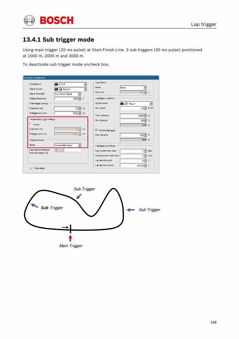
Lap trigger
149
13.4.1 Sub trigger mode
Using main trigger (20 ms pulse) at Start-Finish-Line. 3 sub triggers (40 ms pulse) positioned
at 1000 m, 2000 m and 3000 m.
To deactivate sub trigger mode uncheck box.
Main Trigger
Sub Trigger
Sub Trigger
Sub Trigger
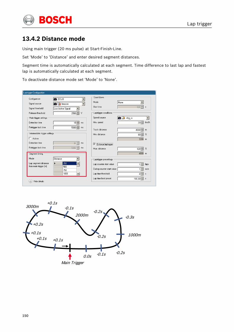
Lap trigger
150
13.4.2 Distance mode
Using main trigger (20 ms pulse) at Start-Finish-Line.
Set ‘Mode’ to ‘Distance’ and enter desired segment distances.
Segment time is automatically calculated at each segment. Time difference to last lap and fastest
lap is automatically calculated at each segment.
To deactivate distance mode set ‘Mode’ to ‘None’.
Main Trigger
2000m
3000m
0.0s -0.1s -0.2s
-0.2s
-0.2s
-0.1s
+0.1s +0.1s
+0.2s
1000m
-0.3s
+0.1s
+0.1s

Lap trigger
151
13.5 Countdown timer
Some race classes require a minimum time spent in the pits. An additional lap trigger Tx is
configured as a segment trigger positioned at pit entry. The trigger signal starts a timer countdown.
The current value of the timer is stored in the variable Laptrigger_cntdown_dls which can be
displayed.

Firmware
152
14 Firmware
14.1 Firmware and configuration
DDU 8 holds 4 types of data:
• Firmware: the software (PST program file) of the DDU 8
• Configuration: the configuration of Input channels, CAN I/O, PWM, display configuration,
recording + telemetry configuration
• Calibration data: Characteristic curves and offsets created by online calibration at the
vehicle
• Recorded data: Measurement data recorded during vehicle operation

Firmware
153
14.2 Firmware update
The scheme shows the process during each connection between RaceCon and DDU 8.
14.2.1 Performing the firmware update
Firmware update is only possible if the DDU 8 is connected to RaceCon.
The configuration of Input channels, CAN I/O, display, recording + telemetry will not be changed.
1. In the DDU 8 Project Tree, right-click on ‘DDU 8’ and choose ‘Synchronize’ then ‘Update firmware’.
Version match Version does not match
Firmware version consistency check
Firmware check successful
Update firmware Change program archive in RaceCon
DDU 8 RaceCon

Firmware
154
A pop-up menu opens.
2. Select the destination of the firmware archive (PST).
3. Click ‘OK’ when done. The firmware update starts. The DDU 8 displays the message ‘Updating firmware’.
Do not switch off the car’s ignition or interrupt the power supply of the DDU 8!
When the firmware update is complete, the DDU 8 displays the message ‘Updating firmware
finished. Do a powercycle.’
4. Switch the car’s ignition off and on again to cycle the power of the DDU 8.

GPS sensor
155
15 GPS sensor This function requires the installation of Software Upgrade 2.
15.1 GPS (Global Positioning System)
• Space-based global navigation satellite system
• GPS provides positioning, navigation, and timing services to worldwide users
• GPS receiver (sensor) gives digital information about position (longitude, latitude, height),
ground speed, course, and status
Two types of GPS receivers:
• CAN output -> Read in messages via CAN Input of DDU 8 (not covered here)
• Serial output -> Read in messages via RS232 Interface of DDU 8 (serial interface 2)
15.1.1 Serial interface characterization
Serial Interface is characterized by:
• Voltage levels: RS232 is standard (+/-12 V), UART (0 V/ 5 V) needs level shifter
• Baud rate: 9600 is standard for GPS, DDU 8 supports 1200…115200 baud. GPS Rx interface
baud rate must match DDU interface baud rate. DDU 8 Baud rate can be set with the
‘GPS_BAUDRATE’ characteristic
• Data format: DDU 8 expects 8 data bits, no parity bit, 1 stop bit (8N1)
15.2 Protocol
DDU 8 expects NMEA Protocol (ASCII).
The following messages are decoded:
Message Function
GGA GPS fix information
GSA Overall satellite data
GSV Detailed satellite data
RMC Recommended minimum data for GPS
VTG Vector track and speed over the ground
On most GPS sensors, these messages are activated in the default configuration.

GPS sensor
156
15.3 Sensor recommendation
The system has been tested with a Navilock NL 403P serial GPS receiver.
This sensor is based on an UBlox5 chipset and is fully configurable with UCenter SW.
15.4 Measurement labels
The decoded NMEA messages are copied to these DDU 8 measurement labels.
Measurement label Function gps_PDOP Position Dilution Of Precision
gps_HDOP Horizontal Dilution Of Precision
gps_VDOP Vertical Dilution Of Precision
gps_lat Latitude in NDEG - +/-[degree][min].[sec/60]
gps_long Longitude in NDEG - +/-[degree][min].[sec/60]
gps_elv Antenna altitude above/below mean sea level (geoid) in meters
gps_speed Speed over the ground in kilometers/hour
gps_direction Track angle in degrees
gps_declination Magnetic variation degrees (Easterly var. subtracts from true course)
gps_year Years since 1900
gps_mon Months since January - [0,11]
gps_day Day of the month - [1,31]
gps_hour Hours since midnight - [0,23]
gps_min Minutes after the hour - [0,59]
gps_sec Seconds after the minute - [0,59]
gps_hsec Hundredth part of second - [0,99]
gps_smask Mask specifying types of packages from which data has been obtained
gps_sig GPS quality indicator (0 = Invalid; 1 = Fix; 2 = Differential, 3 = Sensitive)
gps_fix Operating mode, used for navigation (1 = Fix not available; 2 = 2D; 3 = 3D)
These measurement labels are arrays, where the indexed element points to the same satellite
(E.g. gps_info_satsigstrength[3] tells the receiving signal strength of satellite 3. Satellite 3 has the
SAT-ID given in gps_info_satid[3].)
Measurement label Function gps_info_satid[ ] Satellite PRN number
gps_info_satinuse[ ] Used in position fix
gps_info_satelevation[ ] Elevation in degrees, 90 maximum
gps_info_satazimuth[ ] Azimuth, degrees from true north, 000 to 359
gps_info_satsigstrength[ ] Signal, 00-99 dB

GPS sensor
157
15.5 GPS troubleshooting
Electrical
• Is the transmitter signal of the GPS sensor connected to the receiver pin of serial interface 2
of the DDU 8 ?
• Is the GPS sensor powered up?
• Does the GPS sensor deliver RS232 signal levels?
Interface
• Do the baudrates of the GPS sensor and the DDU match?
• Is the GPS sensor set up for 8N1 transmission parameters?
• Is the GPS sensor set up for NMEA messages?
• Are the GGA, VTG, RMC messages activated?
• With a correctly wired and powered GPS sensor the changing GPS time information
(gps_sec) can be immediately observed.
• Is Software Upgrade 2 activated in the DDU 8 ?
GPS sensor start-up
• Does the GPS sensor ‘view’ the sky?
• Did the GPS sensor complete its initial start-up procedure? This may take up to 20 min.
• A correct reception is indicated when ‘gps_fix’ is showing ‘3D Fix’.

Fuel consumption calculation
158
16 Fuel consumption calculation
16.1 Setting up fuel consumption calculation and tank management for DDU 8
1. Select ‘Measurement Sources’ in Toolbox.
2. Drag ‘Fuel’ element and drop it on the vehicle in System Overview. Do not drop it on the DDU 8!
A ‘fuel consumption wizard‘ opens.
Drag + Drop
b)
c) d) e)
f)
g)
a)

Fuel consumption calculation
159
a) Change device for fuel calculation, if desired.
b) Enter tank capacity of vehicle.
c) Choose calculation mode:
• using fuel consumed (summed-up fuel consumption)
• using fuel flow rate (momentary fuel consumption)
d) Choose input channel and enter adaption factor.
Use adaption factor to adapt value of input channel to:
• 1ml per inc for summed-up fuel consumption
• 1ml/s per inc for momentary consumption
e) Enter factor to correct calculated consumption in DDU 8 vs. ‘real’ consumption of vehicle, if
required.
f) Choose method to calculate remaining laps with fuel in tank, if desired:
• using fuel consumption of last lap completed
• using target lap consumption (entered in the field ‘Target lap consumption’)
g) Choose values to initiate a reset of fuel consumption, if desired:
• manually using RaceCon
• On ‘power down’ (assuming that the tank is filled each time the ignition is turned off)
• By signal source as input channel (e.g. a switch connected to input pin)
3. Press ‘Finish’ when done.

Fuel consumption calculation
160
16.2 Fuel consumption diagnosis / counter reset
To display a fuel consumption diagnosis and to reset counters, use the diagnosis page in RaceCon.
Double-click on any ‘fuel_xxx’ channel in channel list.
A diagnosis window opens in Main Area.
16.3 Example
Measurement label Function
Fuel_fuelcons_dls Running fuel consumption, starting at ‘0’
Fuel_fuelrem_dls Remaining fuel in tank, starting at tank capacity
Fuel_fuellap_dls Fuel consumption for current lap, starting at ‘0’
Fuel_fuellapold_dls Fuel consumption of last lap completed
Fuel_laprem_dls Remaining laps with fuel in tank
Button to reset fuel consumption manually (Can also be triggered ‘by signal source’ or ‘on power down’)
Button to reset total fuel consumption (Reset with RaceCon only)
Settings overview
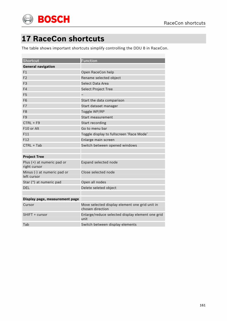
RaceCon shortcuts
161
17 RaceCon shortcuts The table shows important shortcuts simplify controlling the DDU 8 in RaceCon.
Shortcut Function General navigation
F1 Open RaceCon help
F2 Rename selected object
F3 Select Data Area
F4 Select Project Tree
F5 –
F6 Start the data comparison
F7 Start dataset manager
F8 Toggle WP/RP
F9 Start measurement
CTRL + F9 Start recording
F10 or Alt Go to menu bar
F11 Toggle display to fullscreen ‘Race Mode’
F12 Enlarge main screen
CTRL + Tab Switch between opened windows
Project Tree
Plus (+) at numeric pad or right cursor
Expand selected node
Minus (-) at numeric pad or left cursor
Close selected node
Star (*) at numeric pad Open all nodes
DEL Delete seleted object
Display page, measurement page
Cursor
Move selected display element one grid unit in chosen direction
SHIFT + cursor
Enlarge/reduce selected display element one grid unit
Tab Switch between display elements

Contact
Europe: Bosch Engineering GmbH
Motorsport Robert-Bosch-Allee 1
74232 Abstatt Germany
Phone: +49 7062 911 79101 Fax: +49 7062 911 79104
North and South America:
Bosch Engineering North America Motorsports
38000 Hills Tech Drive Farmington Hills, MI 48331-3417
United States of America Phone: +1 248 876 2977
Fax: +1 248 876 7373
Asia Pacific: Bosch Engineering K.K.
Motorsport 18th Floor, Queen’s Tower C, 2-3-5 Minatomirai
Nishi-ku, Yokohama, 220-6218 Kanagawa Japan
Tel.: +81 45 650 5610 Fax: +81 45 650 5611
E-Mail: [email protected]
www.bosch-motorsport.com
Status: 21 März 2012
© All rights reserved by Bosch Engineering GmbH, also for the case of patent reports.
All rights such as copying and forwarding through us. Modifications reserved.