EC7823A, RM7823A 7800 SERIES Relay Modules - Docuthek
12
INSTALLATION INSTRUCTIONS 32-00230-01 SIL 3 Capable EC7823A, RM7823A 7800 SERIES Relay Modules APPLICATION The Honeywell EC/RM7823A Relay Module is a microprocessor based flame detector relay that can be fitted with any 7800 SERIES Flame Amplifier to provide relay action from one dpdt relay when flame is or is not present. The EC/RM7823A system consists of a relay module, wiring subbase and flame amplifier. Options include keyboard display module (KDM), personal computer interface, Data ControlBus Module™, remote display mounting and Combustion System Manager™ Software. Functions provided by the EC/RM7823A include flame monitoring, self-diagnostics and troubleshooting.The EC/RM7823A is a solid state replacement for the R7023B,C Flame Detector Relays. The EC7823/RM7823 is a flame detector relay only. A switchable primary control must be used to provide safe- start check, safety lockout, load switching and other functions required in Flame Safeguard systems. This document covers the following 7800 Series Relay Modules: EC7823A1016 RM7823A1004 EC7823A2016 RM7823A2004 This document provides installation and static checkout instructions. Other applicable publications are: SPECIFICATIONS Electrical Ratings, see Table 3: Voltage and Frequency: EC7823A: 220-240 Vac +10%/-15%, 50/60 Hz ±10%. RM7823A: 120 Vac, +10%/-15%, 50/60 Hz, ± 10%. Power Dissipation: 10W maximum. Maximum Total Connected Load: 2000 VA. Fusing: Total Connected Load: 15A, type SC, Fast Blow, or equivalent. Environmental Ratings: Ambient Temperature: Operating: -40°F to 140°F (-40°C to +60°C). Storage: -40°F to 150°F (-40°C to +66°C). Humidity: 85% relative humidity continuous, noncondensing. Vibration: 0.5G environment. Approvals: RM7823A: Underwriters Laboratories Inc. Listed: File No. MP268. ANSI/UL 60730-2-5 / CSA C22.2 No. 60730-2-5 - Automatic Electrical Controls for Household and Similar Use, Part 2-5: Particular Requirements for Automatic Electrical Burner Control Systems Factory Mutual Approved: Report No. J.I.1V9A0.AF. Swiss Re (formerly Industrial Risk Insurers): Acceptable. Federal Communications Commission: Part 15, Class B, Emissions. Form Number Description 32-00110 S7800A2142 4-line LCD Keyboard Display Module Product Data 32-00166 204729A/C KDM NEMA4 Covers for 4-line LCD KDM 32-00235 R7824, R7847, R7848, R7849, R7861, R7886 Flame Amplifiers for the 7800 SERIES Product Data 65-0084 Q7800A,B 22-Terminal Wiring Subbase Product Data 65-0090 S7800A Keyboard Display Module Product Data 65-0091 S7810A Data ControlBus™ Module Product Data 65-0095 S7820 Remote Reset Module Product Data 65-0097 221729C Dust Cover Packing Instructions 65-0131 221818A Extension Cable Assembly Product Data 65-0228 S7810B Multi-Drop Switch Module Product Data 65-0229 7800 SERIES Relay Modules Checkout and Troubleshooting Product Data 65-0249 S7810M ModBus Module (For CE , Modbus module S7810M1029 only). 65-0295 50023821-001/2 KDM NEMA4 Covers for classic 2-line VFD KDM Form Number Description
-
Upload
khangminh22 -
Category
Documents
-
view
1 -
download
0
Transcript of EC7823A, RM7823A 7800 SERIES Relay Modules - Docuthek

INSTALLATION INSTRUCTIONS
32-00230-01
SIL3Capable
EC7823A, RM7823A7800 SERIES Relay Modules
APPLICATIONThe Honeywell EC/RM7823A Relay Module is a microprocessor based flame detector relay that can be fitted with any 7800 SERIES Flame Amplifier to provide relay action from one dpdt relay when flame is or is not present. The EC/RM7823A system consists of a relay module, wiring subbase and flame amplifier. Options include keyboard display module (KDM), personal computer interface, Data ControlBus Module™, remote display mounting and Combustion System Manager™ Software.
Functions provided by the EC/RM7823A include flame monitoring, self-diagnostics and troubleshooting.The EC/RM7823A is a solid state replacement for the R7023B,C Flame Detector Relays.
The EC7823/RM7823 is a flame detector relay only. A switchable primary control must be used to provide safe-start check, safety lockout, load switching and other functions required in Flame Safeguard systems.
This document covers the following 7800 Series Relay Modules:EC7823A1016RM7823A1004EC7823A2016RM7823A2004
This document provides installation and static checkout instructions. Other applicable publications are:
SPECIFICATIONSElectrical Ratings, see Table 3:Voltage and Frequency:
EC7823A: 220-240 Vac +10%/-15%, 50/60 Hz ±10%.RM7823A: 120 Vac, +10%/-15%, 50/60 Hz, ± 10%.Power Dissipation:10W maximum.
Maximum Total Connected Load: 2000 VA.Fusing: Total Connected Load: 15A, type SC, Fast Blow, or
equivalent.
Environmental Ratings:Ambient Temperature:
Operating: -40°F to 140°F (-40°C to +60°C).Storage: -40°F to 150°F (-40°C to +66°C).
Humidity: 85% relative humidity continuous, noncondensing.
Vibration: 0.5G environment.
Approvals:
RM7823A:Underwriters Laboratories Inc. Listed: File No. MP268.
ANSI/UL 60730-2-5 / CSA C22.2 No. 60730-2-5 -Automatic Electrical Controls for Household and Similar Use, Part 2-5: Particular Requirements for Automatic Electrical Burner Control Systems
Factory Mutual Approved: Report No. J.I.1V9A0.AF.Swiss Re (formerly Industrial Risk Insurers): Acceptable.Federal Communications Commission:
Part 15, Class B, Emissions.
Form Number Description
32-00110 S7800A2142 4-line LCD Keyboard Display Module Product Data
32-00166 204729A/C KDM NEMA4 Covers for 4-line LCD KDM
32-00235 R7824, R7847, R7848, R7849, R7861, R7886 Flame Amplifiers for the 7800 SERIES Product Data
65-0084 Q7800A,B 22-Terminal Wiring Subbase Product Data
65-0090 S7800A Keyboard Display Module Product Data
65-0091 S7810A Data ControlBus™ Module Product Data
65-0095 S7820 Remote Reset Module Product Data
65-0097 221729C Dust Cover Packing Instructions
65-0131 221818A Extension Cable Assembly Product Data
65-0228 S7810B Multi-Drop Switch Module Product Data
65-0229 7800 SERIES Relay Modules Checkout and Troubleshooting Product Data
65-0249 S7810M ModBus Module (For CE , Modbus module S7810M1029 only).
65-0295 50023821-001/2 KDM NEMA4 Covers for classic 2-line VFD KDM
Form Number Description
EC7823A, RM7823A 7800 SERIES RELAY MODULES
32-00230—01 2
CE European DirectivesEAC TC N RU д-US.Aи3O.B.04013
SIL3 Capable:SIL3 Capable in a properly designed Safety Instru-
mented System. See form number 32-00256 for Certificate Agreement
EC7823A:Factory Mutual Approved: Report No. J.I.1V9A0.AF.Federal Communications Commission:
Part 15, Class B, Emissions.CE European DirectivesEAC TC N RU д-US.Aи3O.B.04013
SIL3 Capable:SIL3 Capable in a properly designed Safety Instru-
mented System. See form number 32-00256 for Certificate Agreement
European DirectivesGas Appliances Regulation: 2016/426/EU GARLow Voltage Directive: 2014/35/EU LVD.EMC Directive: 2014/30/EU EMC (Immunity Emission
conformity can only be verified in combination with the appliance).
Applicable Standards:EN 298:2012 Automatic burner controlsEN 60335-2-102 Household and similar electrical
appliancesEN 746-2 Industrial thermo-processing - fuel handling
systemsPlease note the following to comply with EN60730 for remote mounting of the KDM and/or remote reset module. It is necessary to provide electrical separation using insulation at least equivalent to double or reinforced insulation. This can be accomplished by either:
1. Optically isolating the communication and/or remote reset lines from the control cabinet or
2. Providing physical separation from the communica-tion and/or remote reset lines using electrical con-duit and a 204718A Remote Display Cover Assembly or other suitable enclosure that meets NEMA4 class of protection.
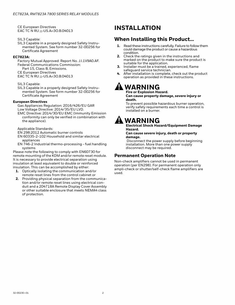
INSTALLATION
When Installing this Product…1. Read these instructions carefully. Failure to follow them
could damage the product or cause a hazardous condition.
2. Check the ratings given in the instructions and marked on the product to make sure the product is suitable for the application.
3. Installer must be a trained, experienced, flame safeguard service technician.
4. After installation is complete, check out the product operation as provided in these instructions.
WARNINGFire or Explosion Hazard.Can cause property damage, severe injury or death.To prevent possible hazardous burner operation, verify safety requirements each time a control is installed on a burner.
WARNINGElectrical Shock Hazard/Equipment Damage Hazard.Can cause severe injury, death or property damage. Disconnect the power supply before beginning installation. More than one power supply disconnect may be required.
Permanent Operation NoteNon-check amplifiers cannot be used in permanent operation (per EN298). For permanent operation only ampli-check or shutter/self-check flame amplifiers are used.
EC7823A, RM7823A 7800 SERIES RELAY MODULES
3 32-00230—01
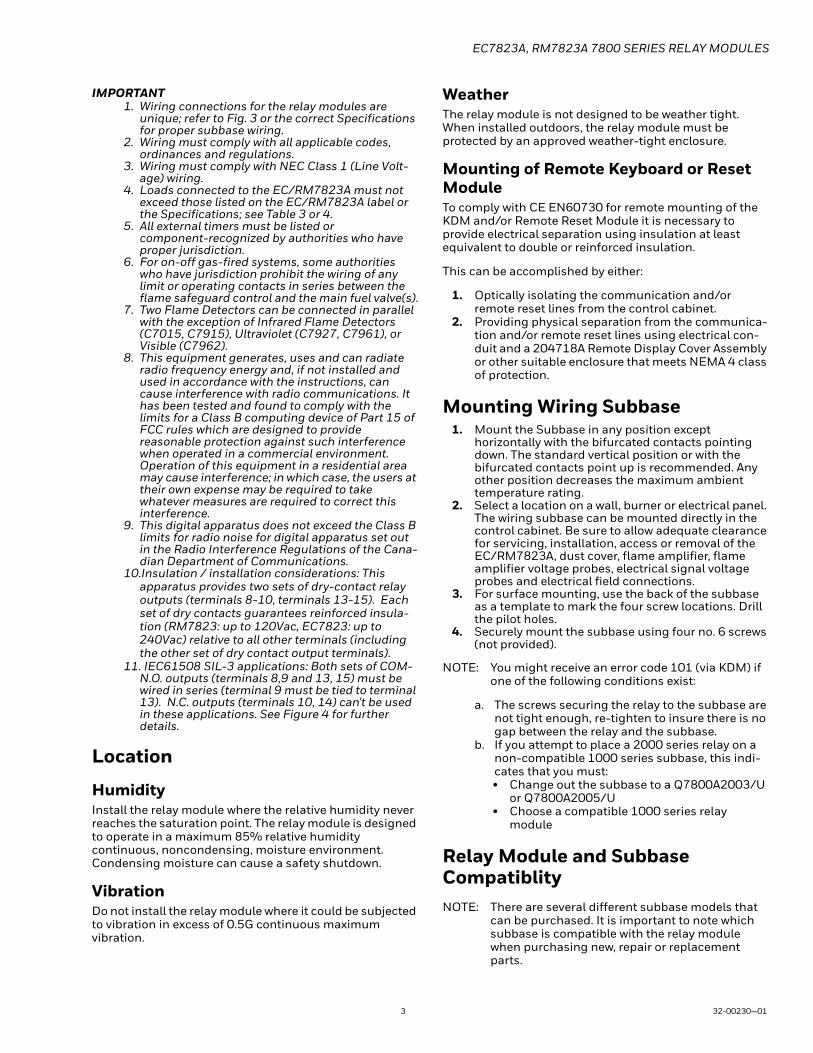
IMPORTANT1. Wiring connections for the relay modules are
unique; refer to Fig. 3 or the correct Specifications for proper subbase wiring.
2. Wiring must comply with all applicable codes, ordinances and regulations.
3. Wiring must comply with NEC Class 1 (Line Volt-age) wiring.
4. Loads connected to the EC/RM7823A must not exceed those listed on the EC/RM7823A label or the Specifications; see Table 3 or 4.
5. All external timers must be listed or component-recognized by authorities who have proper jurisdiction.
6. For on-off gas-fired systems, some authorities who have jurisdiction prohibit the wiring of any limit or operating contacts in series between the flame safeguard control and the main fuel valve(s).
7. Two Flame Detectors can be connected in parallel with the exception of Infrared Flame Detectors (C7015, C7915), Ultraviolet (C7927, C7961), or Visible (C7962).
8. This equipment generates, uses and can radiate radio frequency energy and, if not installed and used in accordance with the instructions, can cause interference with radio communications. It has been tested and found to comply with the limits for a Class B computing device of Part 15 of FCC rules which are designed to provide reasonable protection against such interference when operated in a commercial environment. Operation of this equipment in a residential area may cause interference; in which case, the users at their own expense may be required to take whatever measures are required to correct this interference.
9. This digital apparatus does not exceed the Class B limits for radio noise for digital apparatus set out in the Radio Interference Regulations of the Cana-dian Department of Communications.
10.Insulation / installation considerations: This apparatus provides two sets of dry-contact relay outputs (terminals 8-10, terminals 13-15). Each set of dry contacts guarantees reinforced insula-tion (RM7823: up to 120Vac, EC7823: up to 240Vac) relative to all other terminals (including the other set of dry contact output terminals).
11. IEC61508 SIL-3 applications: Both sets of COM-N.O. outputs (terminals 8,9 and 13, 15) must be wired in series (terminal 9 must be tied to terminal 13). N.C. outputs (terminals 10, 14) can't be used in these applications. See Figure 4 for further details.
Location
HumidityInstall the relay module where the relative humidity never reaches the saturation point. The relay module is designed to operate in a maximum 85% relative humidity continuous, noncondensing, moisture environment. Condensing moisture can cause a safety shutdown.
VibrationDo not install the relay module where it could be subjected to vibration in excess of 0.5G continuous maximum vibration.
WeatherThe relay module is not designed to be weather tight. When installed outdoors, the relay module must be protected by an approved weather-tight enclosure.
Mounting of Remote Keyboard or Reset ModuleTo comply with CE EN60730 for remote mounting of the KDM and/or Remote Reset Module it is necessary to provide electrical separation using insulation at least equivalent to double or reinforced insulation.
This can be accomplished by either:
1. Optically isolating the communication and/or remote reset lines from the control cabinet.
2. Providing physical separation from the communica-tion and/or remote reset lines using electrical con-duit and a 204718A Remote Display Cover Assembly or other suitable enclosure that meets NEMA 4 class of protection.
Mounting Wiring Subbase1. Mount the Subbase in any position except
horizontally with the bifurcated contacts pointing down. The standard vertical position or with the bifurcated contacts point up is recommended. Any other position decreases the maximum ambient temperature rating.
2. Select a location on a wall, burner or electrical panel. The wiring subbase can be mounted directly in the control cabinet. Be sure to allow adequate clearance for servicing, installation, access or removal of the EC/RM7823A, dust cover, flame amplifier, flame amplifier voltage probes, electrical signal voltage probes and electrical field connections.
3. For surface mounting, use the back of the subbase as a template to mark the four screw locations. Drill the pilot holes.
4. Securely mount the subbase using four no. 6 screws (not provided).
NOTE: You might receive an error code 101 (via KDM) if one of the following conditions exist:
a. The screws securing the relay to the subbase are not tight enough, re-tighten to insure there is no gap between the relay and the subbase.
b. If you attempt to place a 2000 series relay on a non-compatible 1000 series subbase, this indi-cates that you must:• Change out the subbase to a Q7800A2003/U
or Q7800A2005/U• Choose a compatible 1000 series relay
module
Relay Module and Subbase CompatiblityNOTE: There are several different subbase models that
can be purchased. It is important to note which subbase is compatible with the relay module when purchasing new, repair or replacement parts.

EC7823A, RM7823A 7800 SERIES RELAY MODULES
32-00230—01 4
Series 1000 Relay ModulesAll relay product codes that start with a 1 (example: RM7840G1014/U) can be used with existing subbase Q7800A1003/U and Q7800A1005/U.
Series 2000 Relay ModulesAll relay product codes that start with a 2 (example: RM7840G2014/U) must be used with subbase Q7800A2003/U and Q7800A2005/U.
Subbase CompatibilityAny Relay Module in the 1000 Series with a Software Revision level number starting with a "5" or greater will be compatible with all subbase models both installed and newly purchased. This includes (Q7800A1005/U, Q7800B1003/U), and the 2000 Series subbases (Q7800A2005/U, Q7800B2003/U).
See Fig. 1 for Software Revision Level number location on the label (located on the rear of the relay module).
Any relay module in the new 2000 series will only be able to be installed on subbase Q7800A2005/U, Q7800B2003/U and will not be backward compatible with any Q7800A1003/U and Q7800A1005/U subbases already installed in the field.
Fig. 1. Software revision location.
IMPORTANTMake sure to check the relay model number and the software revision level on the relay.
5. If you attempt to place a 2000 series relay on a non-compatible 1000 series subbase, you will receive an error code of 101. This indicates that you must a) change out the subbase to a Q7800A2003/U or Q7800A2005/U or b) choose a compatible 1000 series relay module.
Wiring Subbase
WARNINGElectrical Shock Hazard.Can cause serious injury, death or equipment/control damage.Disconnect the power supply before beginning installation. More than one power supply disconnect may be required.
EC7823A, RM7823A 7800 SERIES RELAY MODULES
5 32-00230—01
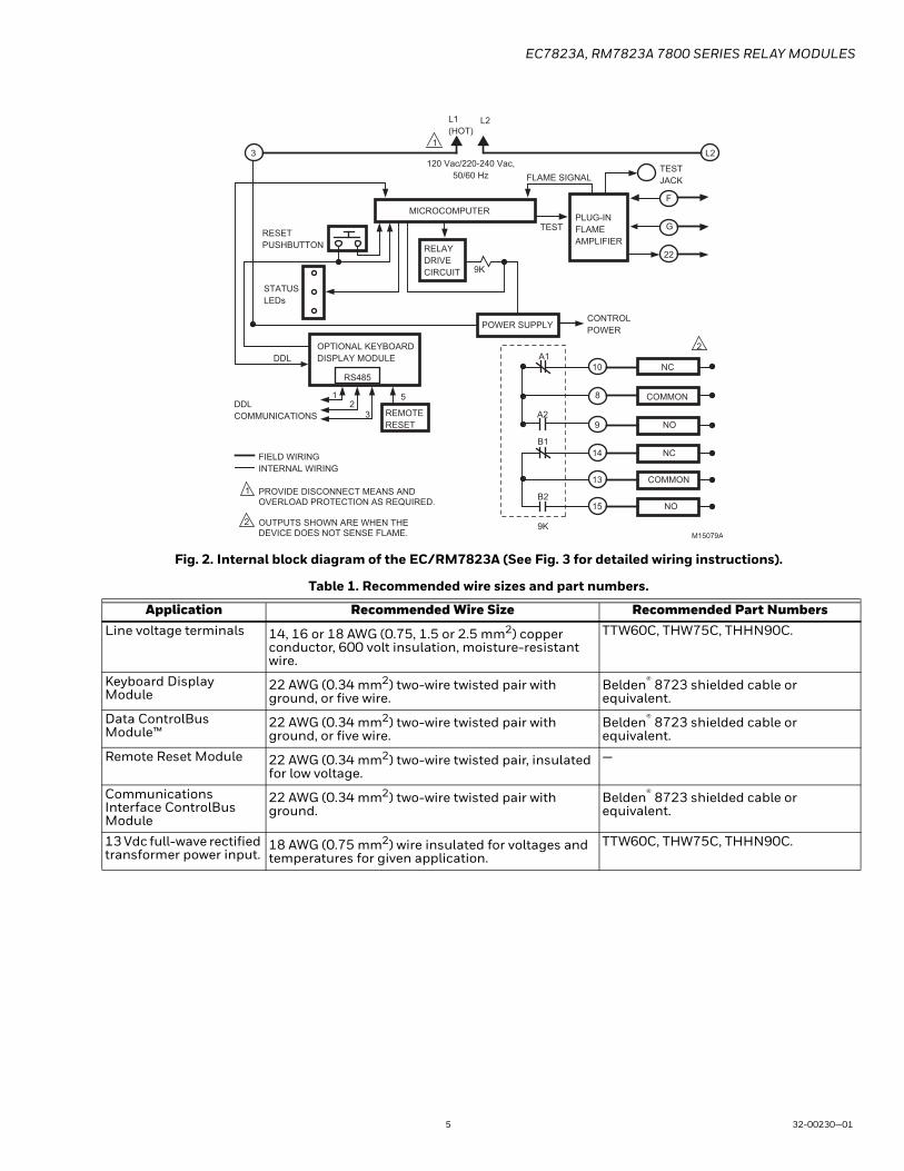
Fig. 2. Internal block diagram of the EC/RM7823A (See Fig. 3 for detailed wiring instructions).
Table 1. Recommended wire sizes and part numbers.
Application Recommended Wire Size Recommended Part NumbersLine voltage terminals 14, 16 or 18 AWG (0.75, 1.5 or 2.5 mm2) copper
conductor, 600 volt insulation, moisture-resistant wire.
TTW60C, THW75C, THHN90C.
Keyboard Display Module
22 AWG (0.34 mm2) two-wire twisted pair with ground, or five wire.
Belden® 8723 shielded cable or equivalent.
Data ControlBus Module™
22 AWG (0.34 mm2) two-wire twisted pair with ground, or five wire.
Belden® 8723 shielded cable or equivalent.
Remote Reset Module 22 AWG (0.34 mm2) two-wire twisted pair, insulated for low voltage.
—
Communications Interface ControlBus Module
22 AWG (0.34 mm2) two-wire twisted pair with ground.
Belden® 8723 shielded cable or equivalent.
13 Vdc full-wave rectified transformer power input.
18 AWG (0.75 mm2) wire insulated for voltages and temperatures for given application.
TTW60C, THW75C, THHN90C.
MICROCOMPUTER
RESET
PUSHBUTTON
STATUS
LEDs
POWER SUPPLY
PLUG-IN
FLAME
AMPLIFIERRELAY
DRIVE
CIRCUIT
CONTROL
POWER
TEST
JACK
FIELD WIRING
INTERNAL WIRING
NC
COMMON
NO
NC
A1
120 Vac/220-240 Vac,
50/60 Hz FLAME SIGNAL
TEST
PROVIDE DISCONNECT MEANS AND OVERLOAD PROTECTION AS REQUIRED.
OUTPUTS SHOWN ARE WHEN THE DEVICE DOES NOT SENSE FLAME.
L1
(HOT)L2
3
A2
B1
10
8
9
14
F
G
22
1
COMMON13
NO15
L2
OPTIONAL KEYBOARD
DISPLAY MODULE
REMOTE
RESET
DDL
DDL
COMMUNICATIONS
RS485
12
3
5
1
M15079A
9K
B2
9K2
2

EC7823A, RM7823A 7800 SERIES RELAY MODULES
32-00230—01 6
Table 2. Recommended Grounding Practices.
Fig. 3. Wiring subbase for EC/RM7823A.
Ground Type Recommended PracticeEarth ground (subbase and relay module)
1. Use to provide a connection between the subbase and the control panel of the equipment. Earth ground must be capable of conducting enough cur-rent to blow the 15A fuse (or breaker) in the event of an internal short circuit.
2. Use wide straps or brackets to provide minimum-length, maximum-surface area ground conductors. If a leadwire must be used, use 14 AWG (2.5 mm2) copper wire.
3. Make sure that mechanically tightened joints along the ground path are free of nonconductive coatings and protected against corrosion on mating sur-faces.
Signal Ground (KDM, Data ControlBus™ Module, Communications Interface ControlBus™ Module)
Use the shield of the signal wire to ground the device to the signal ground terminal 3(c) of each device. Connect the shield at both ends of the daisy chain to earth ground.
M15080GR
G
L2
3
4
5
6
7
8
9
10
F
(L1)
13
14
15
16
17
18
19
20
21
22
12
MASTERSWITCH
NORMALLY CLOSED
NORMALLY OPEN
COMMON
FLAME DETECTOR
120V, 50/60 Hz (RM7823); 220-240V, 50/60 Hz (EC7823) POWER SUPPLY. PROVIDE DISCONNECT MEANS AND OVERLOAD PROTECTION AS REQUIRED.DO NOT CONNECT ANY WIRES TO UNUSED TERMINALS
OUTPUTS SHOWN ARE WHEN THE DEVICE DOES NOT SEE FLAME.
SEE FLAME DETECTOR INSTALLATION INSTRUCTIONS FOR CORRECT WIRING.
NOTE: FOR EC7823, A 220/240V TO 120V, 10VA, STEP-DOWN TRANSFORMER IS REQUIRED.
L1 (HOT)
L2
1
1
Q7800
2
2
NORMALLY CLOSED
NORMALLY OPEN
COMMON
4
4
3
3
3
EC7823A, RM7823A 7800 SERIES RELAY MODULES
7 32-00230—01
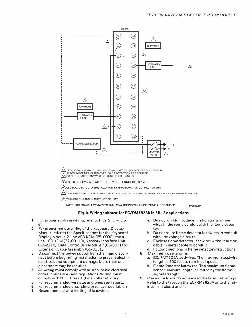
Fig. 4. Wiring subbase for EC/RM7823A in SIL-3 applications
1. For proper subbase wiring, refer to Figs. 2, 3, 4, 5 or 6.
2. For proper remote wiring of the Keyboard Display Module, refer to the Specifications for the Keyboard Display Module 2-line VFD KDM (65-0090), the 4-line LCD KDM (32-00110), Network Interface Unit (63-2278), Data ControlBus Module™ (65-0091) or Extension Cable Assembly (65-0131).
3. Disconnect the power supply from the main discon-nect before beginning installation to prevent electri-cal shock and equipment damage. More than one disconnect may be required.
4. All wiring must comply with all applicable electrical codes, ordinances and regulations. Wiring must comply with NEC, Class 1 (Line Voltage) wiring.
5. For recommended wire size and type, see Table 1.6. For recommended grounding practices, see Table 2.7. Recommended wire routing of leadwires:
a. Do not run high voltage ignition transformer wires in the same conduit with the flame detec-tor.
b. Do not route flame detector leadwires in conduit with line voltage circuits.
c. Enclose flame detector leadwires without armor cable in metal cable or conduit.
d. Follow directions in flame detector instructions.8. Maximum wire lengths:
a. EC/RM7823A leadwires: The maximum leadwire length is 300 feet to terminal inputs.
b. Flame Detector leadwires: The maximum flame sensor leadwire length is limited by the flame signal strength.
9. Make sure loads do not exceed the terminal ratings. Refer to the label on the EC/RM7823A or to the rat-ings in Tables 3 and 4.
G
L2
3
4
5
6
7
8
9
10
F
(L1)
13
14
15
16
17
18
19
20
21
22
12
MASTERSWITCH
NORMALLY OPEN
COMMON
FLAME DETECTOR
120V, 50/60 Hz (RM7823); 220-240V, 50/60 Hz (EC7823) POWER SUPPLY. PROVIDE DISCONNECT MEANS AND OVERLOAD PROTECTION AS REQUIRED.DO NOT CONNECT ANY WIRES TO UNUSED TERMINALS
OUTPUTS SHOWN ARE WHEN THE DEVICE DOES NOT SEE FLAME.
SEE FLAME DETECTOR INSTALLATION INSTRUCTIONS FOR CORRECT WIRING.
L1 (HOT)
L2
1
1
Q7800
2
2
NORMALLY OPEN
COMMON
4
4
3 OUTPUTS SHOWN ARE WHEN THE DEVICE DOES NOT SEE FLAME.
SEE FLAME DETECTOR INSTALLATION INSTRUCTIONS FOR CORRECT WIRING.
TERMINALS 9 AND 13 MUST BE WIRED TOGETHER (BOTH COM-N.O. RELAY OUTPUTS ARE WIRED IN SERIES)
4
3
M15080GRA NOTE: FOR EC7823, A 220/240V TO 120V, 10VA, STEP-DOWN TRANSFORMER IS REQUIRED.
6
5
M15080GRA
TERMINALS 10 AND 14 MUST NOT BE USED.
NOTE: FOR EC7823, A 220/240V TO 120V, 10VA, STEP-DOWN TRANSFORMER IS REQUIRED.
3
3
6
6
5

EC7823A, RM7823A 7800 SERIES RELAY MODULES
32-00230—01 8
Final Wiring Check1. Check the power supply circuit. The voltage and
frequency tolerance must match those of the EC/RM7823A. A separate power supply circuit may be required for the EC/RM7823A. Add the required disconnect means and overload protection.
2. Check all wiring circuits and complete the Static Checkout in Table 5 before installing the EC/RM7823A on the subbase.
3. Install all electrical connectors. 4. Restore panel power.
Table 3. Terminal Ratings for RM7823A.
a The relay module must have an earth ground providing a connection between the subbase and the control panel or theequipment. See Table 2 for furhter details.
b 100K operation cycles.c 250K operation cycles.d N.C. outputs cannot be used in SIL-3 applications.e A 220-240 Vac to 120 Vac, 10 VA minimum stepdown transformer (not provided) must be used to drive the shutter.
Terminal Number Description
Ratings
UL60730-2-5b EN298c IEC61508 SIL-3G Flame Sensor
Grounda—
Earth G Earth Grounda —
L2(N) Line Voltage Common —
3 Line Voltage Supply (L1)
120 Vac (+10%/-15%), 50/60 Hz (±10%).
4-7 Unused —
8 9KA Common —
9 9KA1 N.O. 6 FLA, 18 LRA at 120Vac, or1A Pilot Duty at 120Vac, or1A resistive at 30Vdc
4A / PF0.5 at 120Vac (non-permanent operation) or2A / PF0.5 at 120Vac (permanent operation)
Connect to terminal 13
10 9KA2 N.C. 1A Pilot Duty at 120Vac, or1A resistive at 30Vdc
2A / PF0.5 at 120Vac (permanent operation)
Not usedd
F(11) Flame Sensor 60 to 220 Vac, current limited.
12 Unused. —
13 9KB Common — — Connect to terminal 9
14 9KB1 N.C. 1A Pilot Duty at 120Vac, or1A resistive at 30Vdc
4A / PF0.5 at 120Vac (non-permanent operation) or2A / PF0.5 at 120Vac (permanent operation)
Not usedd
15 9KB2 N.O. 6 FLA, 18 LRA at 120Vac, or1A Pilot Duty at 120Vac, or1A resistive at 30Vdc
2A / PF0.5 at 120Vac (permanent operation)
0.7A / PF0.5 at 120Vac
16-21 Unused —
22 Shutter 120 Vac, 0.5A.
EC7823A, RM7823A 7800 SERIES RELAY MODULES
9 32-00230—01
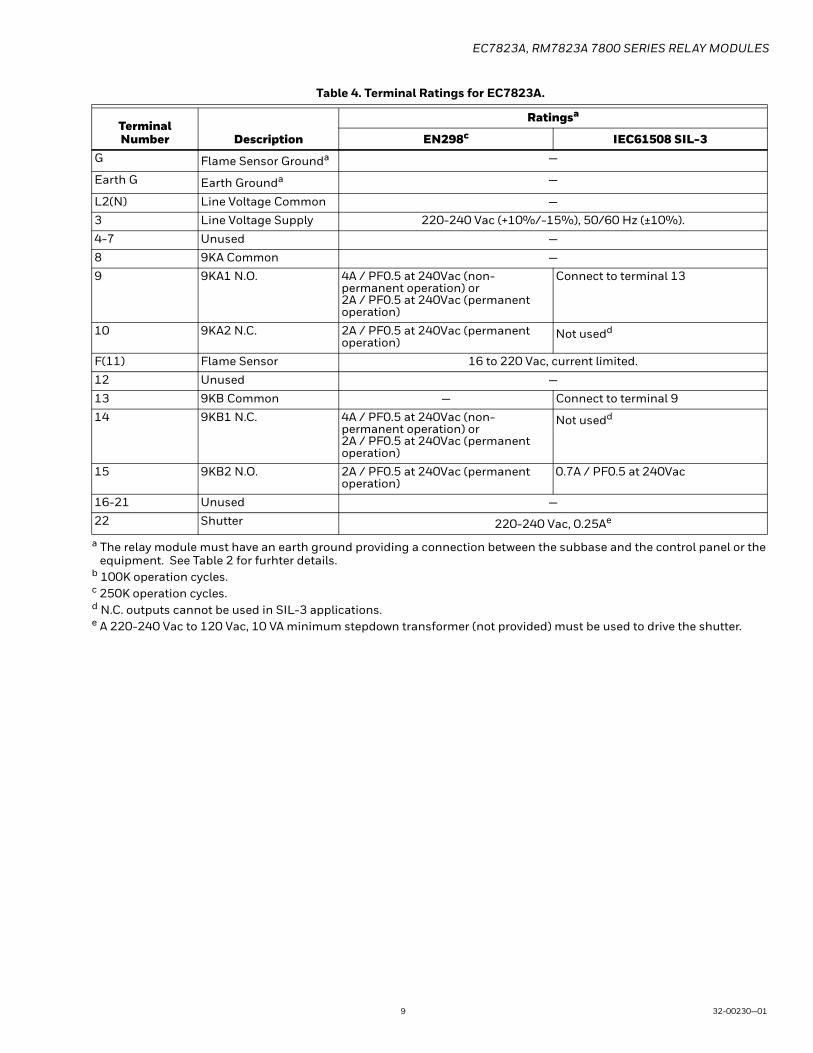
Table 4. Terminal Ratings for EC7823A.
a The relay module must have an earth ground providing a connection between the subbase and the control panel or theequipment. See Table 2 for furhter details.
b 100K operation cycles.c 250K operation cycles.d N.C. outputs cannot be used in SIL-3 applications.e A 220-240 Vac to 120 Vac, 10 VA minimum stepdown transformer (not provided) must be used to drive the shutter.
Terminal Number Description
Ratingsa
EN298c IEC61508 SIL-3G Flame Sensor Grounda —
Earth G Earth Grounda —
L2(N) Line Voltage Common —
3 Line Voltage Supply 220-240 Vac (+10%/-15%), 50/60 Hz (±10%).
4-7 Unused —
8 9KA Common —
9 9KA1 N.O. 4A / PF0.5 at 240Vac (non-permanent operation) or2A / PF0.5 at 240Vac (permanent operation)
Connect to terminal 13
10 9KA2 N.C. 2A / PF0.5 at 240Vac (permanent operation)
Not usedd
F(11) Flame Sensor 16 to 220 Vac, current limited.
12 Unused —
13 9KB Common — Connect to terminal 9
14 9KB1 N.C. 4A / PF0.5 at 240Vac (non-permanent operation) or2A / PF0.5 at 240Vac (permanent operation)
Not usedd
15 9KB2 N.O. 2A / PF0.5 at 240Vac (permanent operation)
0.7A / PF0.5 at 240Vac
16-21 Unused —
22 Shutter 220-240 Vac, 0.25Ae
EC7823A, RM7823A 7800 SERIES RELAY MODULES
32-00230—01 10
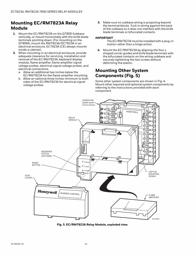
Mounting EC/RM7823A Relay Module
1. Mount the EC/RM7823A on the Q7800 Subbase vertically, or mount horizontally with the knife blade terminals pointing down. (For mounting on the Q7800A, mount the RM7823A/EC7823A in an electrical enclosure, EC7823A (CE) always mounts inside a cabinet).
2. When mounting in an electrical enclosure, provide adequate clearance for servicing, installation and removal of the EC/RM7823A, keyboard display module, flame amplifier, flame amplifier signal voltage probes, electrical signal voltage probes, and electrical connections. a. Allow an additional two inches below the
EC/RM7823A for the flame amplifier mounting. b. Allow an optional three inches minimum to both
sides of the EC/RM7823A for electrical signal voltage probes.
3. Make sure no subbase wiring is projecting beyond the terminal blocks. Tuck in wiring against the back of the subbase so it does not interfere with the knife blade terminals or bifurcated contacts.
IMPORTANTThe EC/RM7823A must be installed with a plug-in motion rather than a hinge action.
4. Mount the EC/RM7823A by aligning the four L shaped corner guides and knife blade terminals with the bifurcated contacts on the wiring subbase and securely tightening the two screws without deforming the plastic.
Mounting Other System Components (Fig. 5)Some other system components are shown in Fig. 4. Mount other required and optional system components by referring to the instructions provided with each component.
Fig. 5. EC/RM7823A Relay Module, exploded view.
HONEYWELL
POWER
FLAME
RESETDUSTCOVER
Q7800A1005 (plastic panel mount version)
CAPTIVE MOUNTING SCREW
RELAY MODULE
SEQUENCE STATUS LED PANEL
RESET BUTTON
FLAMEAMPLIFIER
BURNER CONTROL
M17823B
ALARM
EC7823A, RM7823A 7800 SERIES RELAY MODULES
11 32-00230—01
OPERATION
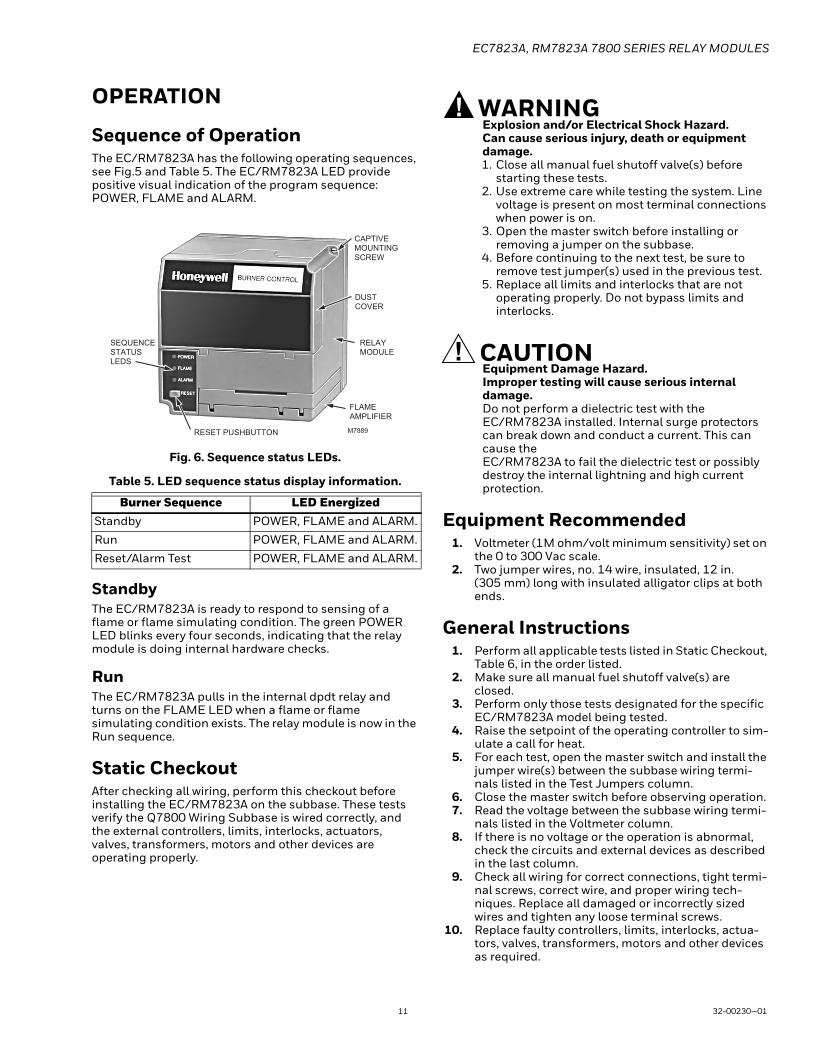
Sequence of OperationThe EC/RM7823A has the following operating sequences, see Fig.5 and Table 5. The EC/RM7823A LED provide positive visual indication of the program sequence: POWER, FLAME and ALARM.
Fig. 6. Sequence status LEDs.
Table 5. LED sequence status display information.
StandbyThe EC/RM7823A is ready to respond to sensing of a flame or flame simulating condition. The green POWER LED blinks every four seconds, indicating that the relay module is doing internal hardware checks.
RunThe EC/RM7823A pulls in the internal dpdt relay and turns on the FLAME LED when a flame or flame simulating condition exists. The relay module is now in the Run sequence.
Static CheckoutAfter checking all wiring, perform this checkout before installing the EC/RM7823A on the subbase. These tests verify the Q7800 Wiring Subbase is wired correctly, and the external controllers, limits, interlocks, actuators, valves, transformers, motors and other devices are operating properly.
WARNINGExplosion and/or Electrical Shock Hazard.Can cause serious injury, death or equipment damage.1. Close all manual fuel shutoff valve(s) before
starting these tests. 2. Use extreme care while testing the system. Line
voltage is present on most terminal connections when power is on.
3. Open the master switch before installing or removing a jumper on the subbase.
4. Before continuing to the next test, be sure to remove test jumper(s) used in the previous test.
5. Replace all limits and interlocks that are not operating properly. Do not bypass limits and interlocks.
CAUTIONEquipment Damage Hazard.Improper testing will cause serious internal damage.Do not perform a dielectric test with the EC/RM7823A installed. Internal surge protectors can break down and conduct a current. This can cause the EC/RM7823A to fail the dielectric test or possibly destroy the internal lightning and high current protection.
Equipment Recommended1. Voltmeter (1M ohm/volt minimum sensitivity) set on
the 0 to 300 Vac scale. 2. Two jumper wires, no. 14 wire, insulated, 12 in.
(305 mm) long with insulated alligator clips at both ends.
General Instructions1. Perform all applicable tests listed in Static Checkout,
Table 6, in the order listed. 2. Make sure all manual fuel shutoff valve(s) are
closed.3. Perform only those tests designated for the specific
EC/RM7823A model being tested. 4. Raise the setpoint of the operating controller to sim-
ulate a call for heat. 5. For each test, open the master switch and install the
jumper wire(s) between the subbase wiring termi-nals listed in the Test Jumpers column.
6. Close the master switch before observing operation. 7. Read the voltage between the subbase wiring termi-
nals listed in the Voltmeter column.8. If there is no voltage or the operation is abnormal,
check the circuits and external devices as described in the last column.
9. Check all wiring for correct connections, tight termi-nal screws, correct wire, and proper wiring tech-niques. Replace all damaged or incorrectly sized wires and tighten any loose terminal screws.
10. Replace faulty controllers, limits, interlocks, actua-tors, valves, transformers, motors and other devices as required.
Burner Sequence LED EnergizedStandby POWER, FLAME and ALARM.
Run POWER, FLAME and ALARM.
Reset/Alarm Test POWER, FLAME and ALARM.
CAPTIVE MOUNTING SCREW
DUSTCOVER
RELAY MODULE
FLAMEAMPLIFIER
RESET PUSHBUTTON
SEQUENCESTATUSLEDS
M7889

EC7823A, RM7823A 7800 SERIES RELAY MODULES
For More InformationThe Honeywell Thermal Solutions family of products includes
Honeywell Combustion Safety, Eclipse, Exothermics, Hauck,
Kromschröder and Maxon. To learn more about our products,
visit ThermalSolutions.honeywell.com or contact your
Honeywell Sales Engineer.
Honeywell Process SolutionsHoneywell Thermal Solutions (HTS)
1250 West Sam Houston Parkway
South Houston, TX 77042
ThermalSolutions.honeywell
® U.S. Registered Trademark© 2019 Honeywell International Inc.32-00230—01 M.S. 09-19Printed in United States
11. Make sure normal operation is obtained for each required test before continuing the checkout.
12. After completing each test, be sure to remove the test jumper(s).
WARNINGExplosion hazard. Can cause serious injury or death.Be sure all manual fuel shutoff valves are closed.
Table 6. Static checkout.
SAFETY AND SECURITY
Physical device protectionDevice shall be accessible to authorized personnel only – Installation on publicly accessible places is not recommended as this could lead to unwanted and potentially unsafe changes to device (wiring, configuration, etc).
It is recommended to lock the device in an enclosed cabinet with access allowed only to approved and trained personnel. Also, it is strongly advised to keep all the wiring of device physically secure.
Physical protection of the device is applied via Run/Test switch label/seal. It is intended to prevent and detect unauthorized access.
Modbus & DDL Interface securityAny conducts critical to device functionality (DDL, Modbus lines etc.) shall be physically protected (installed outside public access) since they could be damaged or tampered-with by unauthorized people, either accidentally or for purpose.
Modbus RS-485 & DDL protocols do not support security features. For DDL interface - only DDL devices shall be connected to the Burner Controller DDL line.
License agreementCopying and reverse engineering is prohibited by the law.
Test Number
Test Jumpers Voltmeter Normal Operation
If Operation is Abnormal, Check the Items Listed Below
1 — L2-3 Line voltage at terminal 3. 1. Master Switch.2. Power connected to the master switch.3. Overload protection (fuse, circuit
breaker, etc.) has not opened the power line.
2 8-9 — Load operation without flame sighting.
Load connections to terminals 8 and 9.
3 8-10 — Load operation when flame detected. Load connections to terminals 8 and 10.
4 13-14 — Load operation without flame sighting.
Load connections to terminals 13 and 14.
5 13-15 — Load operation when flame detected. Load connections to terminals 13 and 15.
FINAL ALL
CAUTIONEquipment Damage Hazard.Leaving jumpers in place will damage the equipment.
After completing these tests, open the master switch and remove all test jumpers from the subbase terminals. Remove any bypass jumpers from limits.