
Earthwork Design and Construction
10
1 Technical Fundamentals for Design and Construction April 6, 2020 Earthwork Design and Construction Key Points • The primary objectives of earthwork operations are: (1) to increase soil bearing capacity; (2) control shrinkage and swelling; and (3) reduce permeability. • Particle shape is a critical physical soil property influencing engineering modification of a soil. • Proper water content is essential to economically achieve specified soil density. Purpose and Scope of Earthwork The purpose and scope of earth construction differ for various types of constructed facilities. The major types of earthwork projects include: • Transportation projects, which require embankments, roadways, and bridge approaches. • Water control, which usually involves dams, levies, and canals. • Landfill closures, which need impervious caps. • Building foundations, which must support loads and limit soil movement by shrinkage and swelling. Properly modified soils are the most economical solution for many constructed facilities. To meet structural support requirements, soils at some project sites may require treatment such as the addition of water, lime, or cement.
-
Upload
khangminh22 -
Category
Documents
-
view
1 -
download
0
Transcript of Earthwork Design and Construction
1
Technical Fundamentals for
Design and Construction
April 6, 2020
Earthwork Design and Construction
Key Points
• The primary objectives of earthwork operations are: (1) to increase soil bearing capacity; (2) control
shrinkage and swelling; and (3) reduce permeability.
• Particle shape is a critical physical soil property influencing engineering modification of a soil.
• Proper water content is essential to economically achieve specified soil density.
Purpose and Scope of Earthwork
The purpose and scope of earth construction differ for various types of constructed facilities. The major
types of earthwork projects include:
• Transportation projects, which require embankments, roadways, and bridge approaches.
• Water control, which usually involves dams, levies, and canals.
• Landfill closures, which need impervious caps.
• Building foundations, which must support loads and limit soil movement by shrinkage and
swelling.
Properly modified soils are the most economical solution for many constructed facilities. To meet
structural support requirements, soils at some project sites may require treatment such as the addition
of water, lime, or cement.
2
Technical Fundamentals for Earthwork Design, Materials, and Resources
The physical chemical properties of project site soils have a major influence on the design of earthen
structures and on the resources and operations needed to properly modify a soil. The fundamental
properties of a soil include: granularity, course to fine; water content; specific gravity; and particle size
distribution. Other properties include permeability, shear strength, and bearing capacity. The
engineering design of a soil seeks to provide sufficient bearing capacity, settlement control, and either
limit, in the case of dams and landfill caps, the movement of water or facilitate the movement of water
in the case of drains, such as behind retaining walls.
Soil density and moisture content are interrelated. The Proctor compaction test is the standard method
used to define this relationship. This laboratory test determines the maximum density (unit weight) of a
particular soil type at a standard level of input compactive energy. The project design engineer uses this
information to specify the value of soil density to be achieved in the field. The soil density achieved by
soil compaction operations in the field is typically checked by Nuclear test gage, the quickest method, or
by the sand cone method, most accurate.
Laws and principles of mechanics determine the capability and performance of construction equipment
in completing each of the field operations. The driving power created by the power train of a machine
must overcome the retarding forces at the desired speed and production rate for each type of
operation. The main retarding forces include loads on implements, grade resistance, rolling resistance,
and friction in the power train. The machine power available is determined by the power train, including
engine horsepower, and friction in the components. The coefficient of traction between the traction
system of the equipment and the travel surface limits available power.
Earthwork
The purpose and scope of earthwork operations are to: improve load bearing capacity, control shrinkage
and swelling, and reduce permeability or improve permeability. When proper construction procedures
are used, desired results are achieved in an economical manner. Compaction ‒ densification ─ of a soil
can increase shear strength, reduce compressibility, and decrease permeability. To meet these design
objectives, the soils at some project sites may require treatment by chemical agents (cement or lime).
Lime will reduce the plasticity index of a clay soil. The treatment of silt or sandy soils with cement is an
effective method for improving soft conditions. The addition of even small quantities of cement to a soil
will reduce its plasticity and increase its bearing capacity. In all cases, the important physical properties
of a soil and the keys to planning earthwork operations are particle size and shape.
3
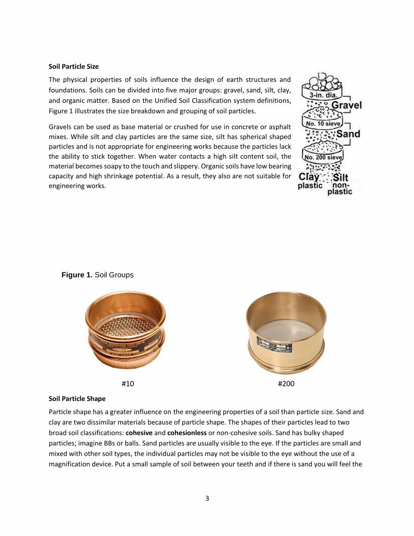
Soil Particle Size
The physical properties of soils influence the design of earth structures and
foundations. Soils can be divided into five major groups: gravel, sand, silt, clay,
and organic matter. Based on the Unified Soil Classification system definitions,
Figure 1 illustrates the size breakdown and grouping of soil particles.
Gravels can be used as base material or crushed for use in concrete or asphalt
mixes. While silt and clay particles are the same size, silt has spherical shaped
particles and is not appropriate for engineering works because the particles lack
the ability to stick together. When water contacts a high silt content soil, the
material becomes soapy to the touch and slippery. Organic soils have low bearing
capacity and high shrinkage potential. As a result, they also are not suitable for
engineering works.
Figure 1. Soil Groups
#10 #200
Soil Particle Shape
Particle shape has a greater influence on the engineering properties of a soil than particle size. Sand and
clay are two dissimilar materials because of particle shape. The shapes of their particles lead to two
broad soil classifications: cohesive and cohesionless or non-cohesive soils. Sand has bulky shaped
particles; imagine BBs or balls. Sand particles are usually visible to the eye. If the particles are small and
mixed with other soil types, the individual particles may not be visible to the eye without the use of a
magnification device. Put a small sample of soil between your teeth and if there is sand you will feel the
4
grit of fine sand even when mixed with other soil types. Sand has no cohesive properties: BBs and balls
do not stick together because of their shape. Even when tightly packed, sand particles have void spaces.
The shape of clay particles can be compared to sheets of paper, a slender mass with an electrical charge.
The charge causes clay particles in the presence of water to have a mutual attraction termed cohesion.
Clay will hold absorbed water within its mass. Sand will not hold water. Water will flow out of a sand
through the void spaces between the individual particles.
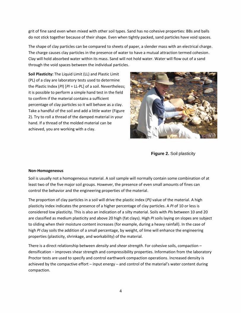
Soil Plasticity: The Liquid Limit (LL) and Plastic Limit
(PL) of a clay are laboratory tests used to determine
the Plastic Index (PI) [PI = LL-PL] of a soil. Nevertheless;
it is possible to perform a simple hand test in the field
to confirm if the material contains a sufficient
percentage of clay particles so it will behave as a clay.
Take a handful of the soil and add a little water (Figure
2). Try to roll a thread of the damped material in your
hand. If a thread of the molded material can be
achieved, you are working with a clay.
Non-Homogeneous
Soil is usually not a homogeneous material. A soil sample will normally contain some combination of at
least two of the five major soil groups. However, the presence of even small amounts of fines can
control the behavior and the engineering properties of the material.
The proportion of clay particles in a soil will drive the plastic index (PI) value of the material. A high
plasticity index indicates the presence of a higher percentage of clay particles. A PI of 10 or less is
considered low plasticity. This is also an indication of a silty material. Soils with PIs between 10 and 20
are classified as medium plasticity and above 20 high (fat clays). High PI soils laying on slopes are subject
to sliding when their moisture content increases (for example, during a heavy rainfall). In the case of
high PI clay soils the addition of a small percentage, by weight, of lime will enhance the engineering
properties (plasticity, shrinkage, and workability) of the material.
There is a direct relationship between density and shear strength. For cohesive soils, compaction –
densification − improves shear strength and compressibility properties. Information from the laboratory
Proctor tests are used to specify and control earthwork compaction operations. Increased density is
achieved by the compactive effort ─ input energy ─ and control of the material’s water content during
compaction.
Figure 2. Soil plasticity
5
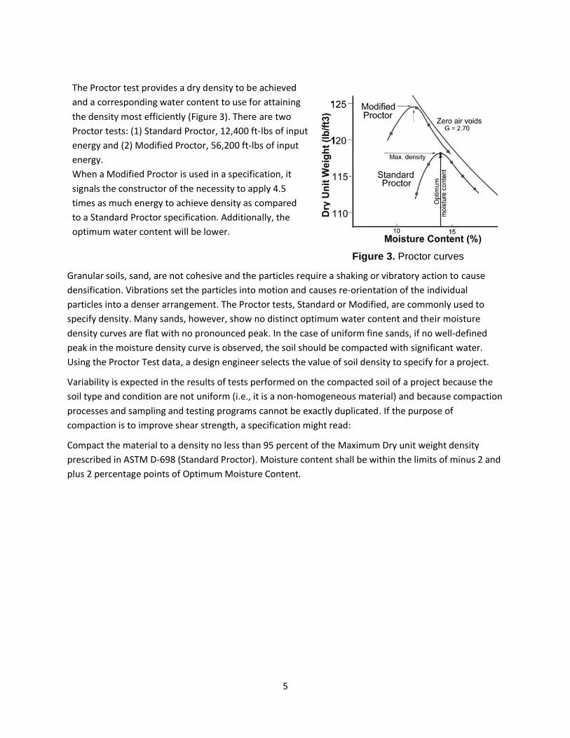
The Proctor test provides a dry density to be achieved
and a corresponding water content to use for attaining
the density most efficiently (Figure 3). There are two
Proctor tests: (1) Standard Proctor, 12,400 ft-lbs of input
energy and (2) Modified Proctor, 56,200 ft-lbs of input
energy.
When a Modified Proctor is used in a specification, it
signals the constructor of the necessity to apply 4.5
times as much energy to achieve density as compared
to a Standard Proctor specification. Additionally, the
optimum water content will be lower.
Figure 3. Proctor curves
Granular soils, sand, are not cohesive and the particles require a shaking or vibratory action to cause
densification. Vibrations set the particles into motion and causes re-orientation of the individual
particles into a denser arrangement. The Proctor tests, Standard or Modified, are commonly used to
specify density. Many sands, however, show no distinct optimum water content and their moisture
density curves are flat with no pronounced peak. In the case of uniform fine sands, if no well-defined
peak in the moisture density curve is observed, the soil should be compacted with significant water.
Using the Proctor Test data, a design engineer selects the value of soil density to specify for a project.
Variability is expected in the results of tests performed on the compacted soil of a project because the
soil type and condition are not uniform (i.e., it is a non-homogeneous material) and because compaction
processes and sampling and testing programs cannot be exactly duplicated. If the purpose of
compaction is to improve shear strength, a specification might read:
Compact the material to a density no less than 95 percent of the Maximum Dry unit weight density
prescribed in ASTM D-698 (Standard Proctor). Moisture content shall be within the limits of minus 2 and
plus 2 percentage points of Optimum Moisture Content.
6
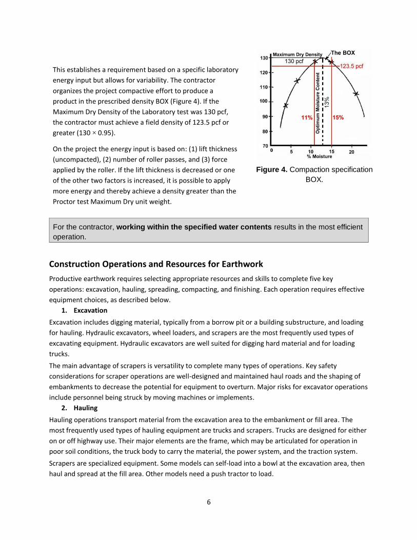
This establishes a requirement based on a specific laboratory
energy input but allows for variability. The contractor
organizes the project compactive effort to produce a
product in the prescribed density BOX (Figure 4). If the
Maximum Dry Density of the Laboratory test was 130 pcf,
the contractor must achieve a field density of 123.5 pcf or
greater (130 × 0.95).
On the project the energy input is based on: (1) lift thickness
(uncompacted), (2) number of roller passes, and (3) force
applied by the roller. If the lift thickness is decreased or one
of the other two factors is increased, it is possible to apply
more energy and thereby achieve a density greater than the
Proctor test Maximum Dry unit weight.
Figure 4. Compaction specification
BOX.
For the contractor, working within the specified water contents results in the most efficient
operation.
Construction Operations and Resources for Earthwork
Productive earthwork requires selecting appropriate resources and skills to complete five key
operations: excavation, hauling, spreading, compacting, and finishing. Each operation requires effective
equipment choices, as described below.
1. Excavation
Excavation includes digging material, typically from a borrow pit or a building substructure, and loading
for hauling. Hydraulic excavators, wheel loaders, and scrapers are the most frequently used types of
excavating equipment. Hydraulic excavators are well suited for digging hard material and for loading
trucks.
The main advantage of scrapers is versatility to complete many types of operations. Key safety
considerations for scraper operations are well-designed and maintained haul roads and the shaping of
embankments to decrease the potential for equipment to overturn. Major risks for excavator operations
include personnel being struck by moving machines or implements.
2. Hauling
Hauling operations transport material from the excavation area to the embankment or fill area. The
most frequently used types of hauling equipment are trucks and scrapers. Trucks are designed for either
on or off highway use. Their major elements are the frame, which may be articulated for operation in
poor soil conditions, the truck body to carry the material, the power system, and the traction system.
Scrapers are specialized equipment. Some models can self-load into a bowl at the excavation area, then
haul and spread at the fill area. Other models need a push tractor to load.
7
3. Spreading
Spreading from a truck requires tilting the truck bed, opening the gates, and placing material to the
approximate depth for efficient compaction operations. The final lift of material should be thick enough
to allow cutting the final compacted lift to the top elevation required by the design.
4. Compacting
Compacting increases density, shear strength,
and load bearing capacity of a soil and
decreases soil settlement. Soils used in
engineered fills may require the addition of
water to the loose material to increase the
moisture content to an acceptable range for
compaction before applying the force to
achieve the specified density. Tamping foot
rollers or steel drum vibratory rollers are
typically used. As confirmed by a prior test
section on the project soils, meeting the
required in-place soil density typically involves
three or more passes of the compactor over 8
to 12 inches of loose fill material.
Figure 5. Water truck adds water to a fill.
Material: Material is hauled from either cut areas on the project or from offsite borrow areas to where it is needed on the project and spread in a uniform loose thickness. When the loose material is not dumped on the previously compacted lift but rather on the uncompacted loose lift and then worked with a dozer to form the loose lift, the blending of the material results in better bonding with the previous lift. Typical lift thickness for soils in an embankment of cohesive soils is eight inches loose, but this depends on the soil being handled. As a rule of thumb, one roller pass is needed per inch of lift. Uniform lift thickness is essential in achieving proper compaction.
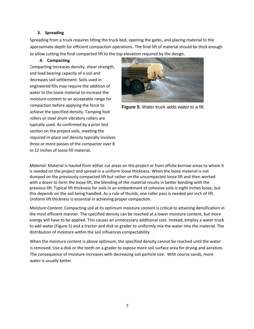
Moisture Content: Compacting soil at its optimum moisture content is critical to attaining densification in
the most efficient manner. The specified density can be reached at a lower moisture content, but more
energy will have to be applied. This causes an unnecessary additional cost. Instead, employ a water truck
to add water (Figure 5) and a tractor and disk or grader to uniformly mix the water into the material. The
distribution of moisture within the soil influences compactability.
When the moisture content is above optimum, the specified density cannot be reached until the water
is removed. Use a disk or the teeth on a grader to expose more soil surface area for drying and aeration.
The consequence of moisture increases with decreasing soil particle size. With course sands, more
water is usually better.
8
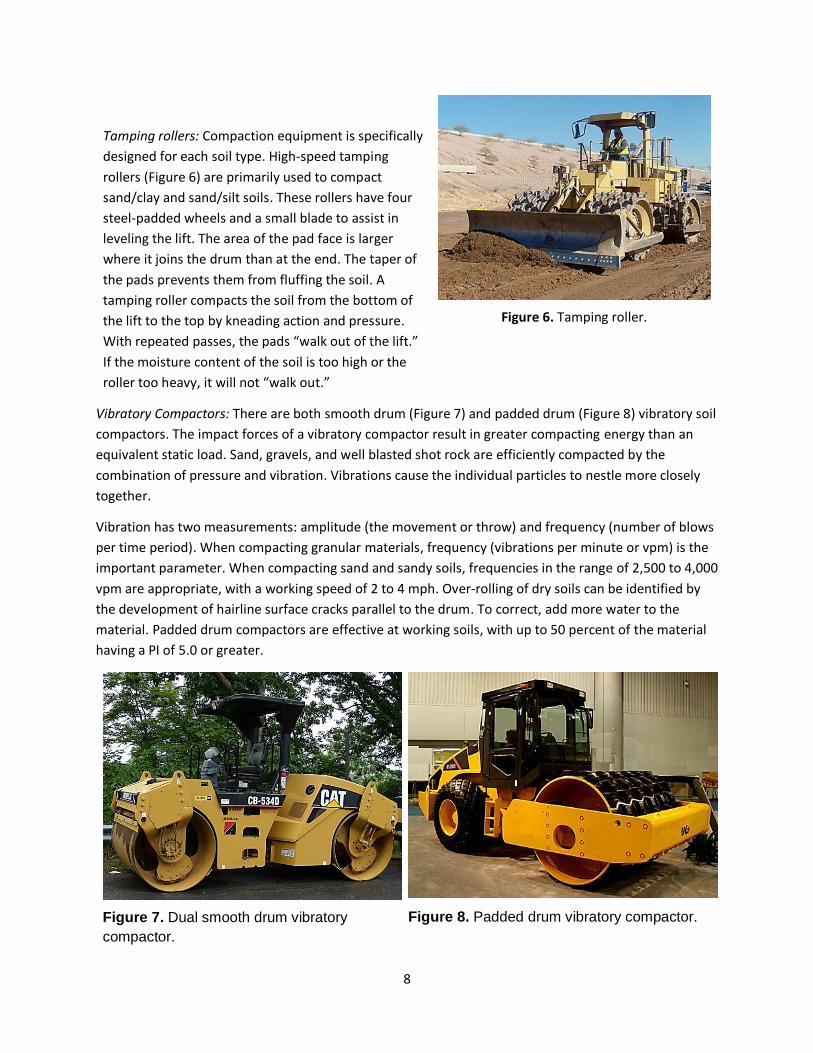
Tamping rollers: Compaction equipment is specifically
designed for each soil type. High-speed tamping
rollers (Figure 6) are primarily used to compact
sand/clay and sand/silt soils. These rollers have four
steel-padded wheels and a small blade to assist in
leveling the lift. The area of the pad face is larger
where it joins the drum than at the end. The taper of
the pads prevents them from fluffing the soil. A
tamping roller compacts the soil from the bottom of
the lift to the top by kneading action and pressure.
With repeated passes, the pads “walk out of the lift.”
If the moisture content of the soil is too high or the
roller too heavy, it will not “walk out.”
Figure 6. Tamping roller.
Vibratory Compactors: There are both smooth drum (Figure 7) and padded drum (Figure 8) vibratory soil
compactors. The impact forces of a vibratory compactor result in greater compacting energy than an
equivalent static load. Sand, gravels, and well blasted shot rock are efficiently compacted by the
combination of pressure and vibration. Vibrations cause the individual particles to nestle more closely
together.
Vibration has two measurements: amplitude (the movement or throw) and frequency (number of blows
per time period). When compacting granular materials, frequency (vibrations per minute or vpm) is the
important parameter. When compacting sand and sandy soils, frequencies in the range of 2,500 to 4,000
vpm are appropriate, with a working speed of 2 to 4 mph. Over-rolling of dry soils can be identified by
the development of hairline surface cracks parallel to the drum. To correct, add more water to the
material. Padded drum compactors are effective at working soils, with up to 50 percent of the material
having a PI of 5.0 or greater.
Figure 7. Dual smooth drum vibratory
compactor.
Figure 8. Padded drum vibratory compactor.
9
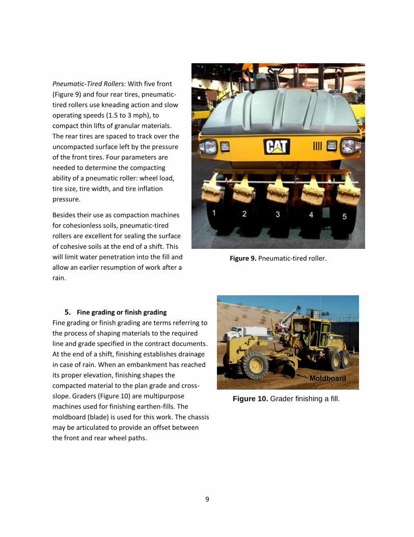
Pneumatic-Tired Rollers: With five front
(Figure 9) and four rear tires, pneumatic-
tired rollers use kneading action and slow
operating speeds (1.5 to 3 mph), to
compact thin lifts of granular materials.
The rear tires are spaced to track over the
uncompacted surface left by the pressure
of the front tires. Four parameters are
needed to determine the compacting
ability of a pneumatic roller: wheel load,
tire size, tire width, and tire inflation
pressure.
Besides their use as compaction machines
for cohesionless soils, pneumatic-tired
rollers are excellent for sealing the surface
of cohesive soils at the end of a shift. This
will limit water penetration into the fill and
allow an earlier resumption of work after a
rain.
Figure 9. Pneumatic-tired roller.
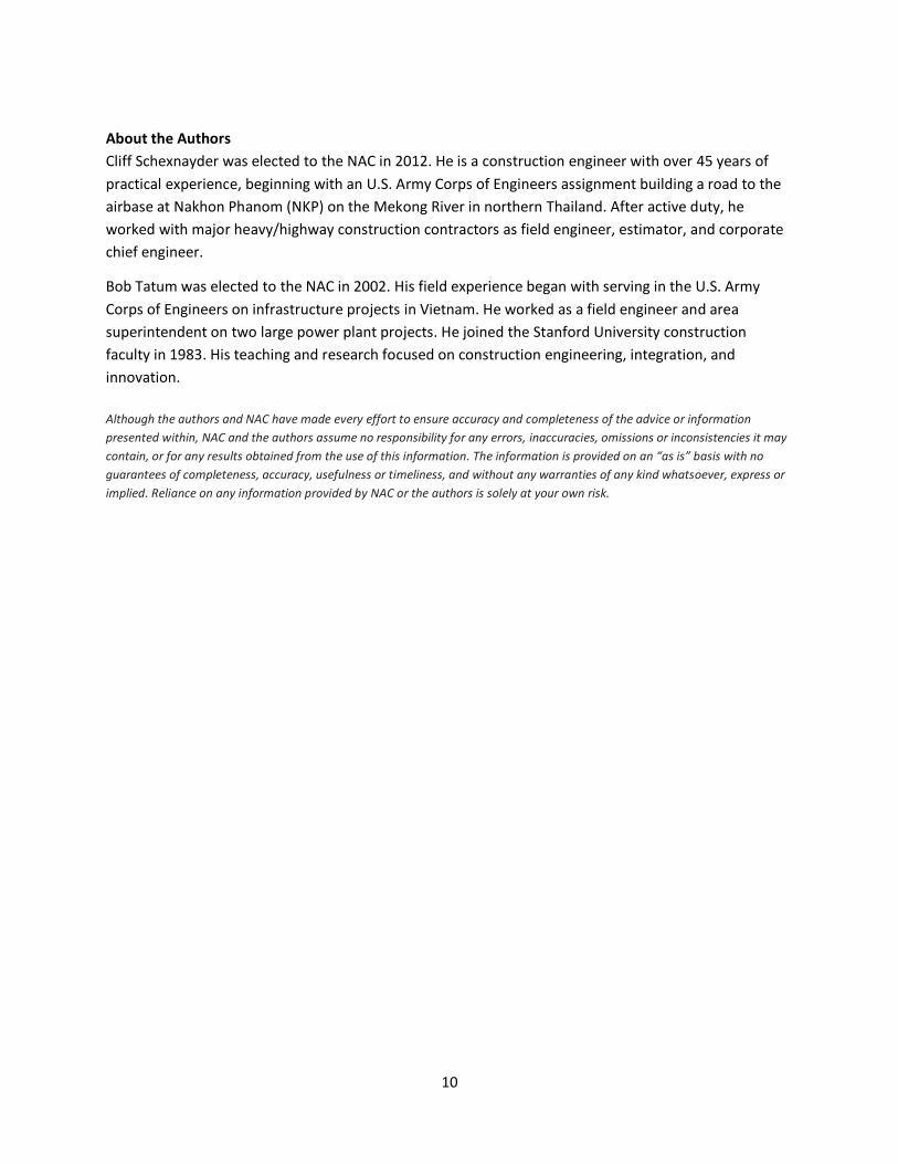
5. Fine grading or finish grading
Fine grading or finish grading are terms referring to
the process of shaping materials to the required
line and grade specified in the contract documents.
At the end of a shift, finishing establishes drainage
in case of rain. When an embankment has reached
its proper elevation, finishing shapes the
compacted material to the plan grade and cross-
slope. Graders (Figure 10) are multipurpose
machines used for finishing earthen-fills. The
moldboard (blade) is used for this work. The chassis
may be articulated to provide an offset between
the front and rear wheel paths.
Figure 10. Grader finishing a fill.
10
About the Authors
Cliff Schexnayder was elected to the NAC in 2012. He is a construction engineer with over 45 years of
practical experience, beginning with an U.S. Army Corps of Engineers assignment building a road to the
airbase at Nakhon Phanom (NKP) on the Mekong River in northern Thailand. After active duty, he
worked with major heavy/highway construction contractors as field engineer, estimator, and corporate
chief engineer.
Bob Tatum was elected to the NAC in 2002. His field experience began with serving in the U.S. Army
Corps of Engineers on infrastructure projects in Vietnam. He worked as a field engineer and area
superintendent on two large power plant projects. He joined the Stanford University construction
faculty in 1983. His teaching and research focused on construction engineering, integration, and
innovation.
Although the authors and NAC have made every effort to ensure accuracy and completeness of the advice or information
presented within, NAC and the authors assume no responsibility for any errors, inaccuracies, omissions or inconsistencies it may
contain, or for any results obtained from the use of this information. The information is provided on an “as is” basis with no
guarantees of completeness, accuracy, usefulness or timeliness, and without any warranties of any kind whatsoever, express or
implied. Reliance on any information provided by NAC or the authors is solely at your own risk.