
DESIGN AND CONSTRUCTION OF WOOD GASIFIER
22
DESIGN AND CONSTRUCTION OF WOOD GASIFIER Adenike A .Kolawole 1 , S.B Adeyemo 2 ,Moradeyo K .Odunfa 1 1 Mechanical Engineering Department ,University of Ibadan ,Ibadan. Nigeria. 2 Mechanical Engineering Department ,Ekiti State University ,Ado Ekiti ,Nigeria Email; [email protected] Abstract Gasification was practiced as early as the 19 th century and was developed to an advanced stage of technology in the first half of the present centuries especially in Europe.The 1970s energy crisis was a period in which the economies of the major industrial countries of the world, particularly the United States, Canada, Western Europe, Japan, Australia, and New Zealand were heavily affected and faced substantial petroleum shortages, as well as elevated prices. Since 1973 during energy crisis ,greater attention have been directed to alternative fuels to replace the over dependence on petroleum based fuels in developed countries .Hence biomass was put in place. For a biomass gasification system to operate most efficiently, the heat generated by the system must be used as well as the electricity. To improve on design of bed reactor gasifier using woodchips as generation of fuel at a reduced cost for the production of high quality gas called producer gas. Also to improve on gas produce( using mahogany woodchips) for heating, cooking or for running of an energy in other to be affordable for people living in the rural area. Analytical method was used, downdraft fixed bed reactor was designed and constructed with 3mm mild steel plate ,using
Transcript of DESIGN AND CONSTRUCTION OF WOOD GASIFIER
DESIGN AND CONSTRUCTION OF WOOD GASIFIER
Adenike A .Kolawole1 , S.B Adeyemo 2,Moradeyo K .Odunfa1
1Mechanical Engineering Department ,University of Ibadan ,Ibadan.Nigeria.2Mechanical Engineering Department ,Ekiti State University ,Ado Ekiti ,NigeriaEmail; [email protected]
Abstract
Gasification was practiced as early as the 19th century and wasdeveloped to an advanced stage of technology in the first half ofthe present centuries especially in Europe.The 1970s energy crisis was a period in which the economies of the major industrial countries of the world, particularly the United States, Canada, Western Europe, Japan, Australia, and New Zealandwere heavily affected and faced substantial petroleum shortages, as well as elevated prices.
Since 1973 during energy crisis ,greater attention have been directed to alternative fuels to replace the over dependence on petroleum based fuels in developed countries .Hence biomass was put in place.
For a biomass gasification system to operate most efficiently, the heat generated by the system must be used as well as the electricity. To improve on design of bed reactor gasifier usingwoodchips as generation of fuel at a reduced cost for the production of high quality gas called producer gas. Also to improve on gas produce( using mahogany woodchips) for heating, cooking or for running of an energy in other to be affordable for people living in the rural area.
Analytical method was used, downdraft fixed bed reactor was designed and constructed with 3mm mild steel plate ,using

woodchips to generate fuel at a reduced cost ,environmental friendly with high efficiency ,reliability makes the difference and it reduces C02 emissions thus reducing global warming. The result indicate that, Wood chips were fed through the top of the combustion chamber via air-lock system ,pyrolysis took place at 250 0 C ,oxidation at 1200 0C to 1500 0 C and heat is supplied .The wood chips that were burnt in the gasifier ,produce a very hot gas which were stored in the storage tank for domestic purposes such as heating furnance and cooking food. The pressure gauge was found rising indicating thestorage of gas .At the end of combustion of 10kg of the wood (mahogany) the pressures gauge 20.5KN/m2 (2.1kg/cm2 ). The temperature was measured which range between 200 and 2500c using oven thermometer.
10kg of Mahogany wood produces 1000kilowatts or more of energy.Further studies , Incorporation of cooling device is important .Also to power internal combustion engine, additional equipment would be needed that is provision of purifierKeywordsCombustion of fuel ,improving the quality of gas produced ,balancing of analytical equation .
1. INTRODUCTIONEnergy is vital for human sustainance on earth, modern energy forindustrial development is
largely based on fossil fuels which if coupled with other humanactivities ,have been
unequivocally shown to be responsible for the warming of theclimate system [1]. Over the last few years ,a new gasifierdesign has been developed through co-operative effort ,Since 1973during energy crisis , greater attention have been directed toalternative fuels .

The utilization wood gasifier peaked during the Second World Warwhen almost a million gasifier were used all over the world,mainly vehicles operating on domestic solid fuels instead ofgasoline. [4].The gas obtained from coal gasification is calledproducer gas. The producer gas is the mixture of hydrogen andcarbon II oxide prepared by passing a stream of air through redhot coke ,the oxygen in the air oxidize the coke of carbon IIoxide with liberation of a lot of heat but the nitrogen isunchanged and using the heat generated to pyrolyse or thermallybreaks down the rest of the material into volatile gasses [10].The aim of gasification is almost the complete transformation of these constituents into gaseous form, so that only the ashes and inert materials remain. The gas product in a gasifier unit contains approximately 20% Hydrogen, 20% carbon monoxide and small amount of methane with 50 to 60 % of nitrogen. All these components are combustible except nitrogen. The rest are non- combustible and consists mainly of nitrogen, carbon-dioxide & water vapour. The gas also contain condensable tar, acids & dust. These impurities may lead to operational problems and abnormal engine wear. The main problem of gasifier system design is to generate agas with a high proportion of carbon monoxide, a poisonous gas. The toxic hazards associated with breathing, this gas should be avoided during refueling operations or prolonged idling particularly in inadequately ventilated areas (7).Gasifier has three major functional components, the bunker, the gas cleaners and the mixing box. The gas generator is the main component where gasification process takes place. Solid biomass, usually charcoal or wood chips is introduced into the gasifier at the top .Percentage Composition of the gas ,Carbon II oxide (co ) 27.5%,Hydrogen Gas ( H ) 14%,Carbon ( IV ) oxide 6.5 % ,Oxygen ( O 2 ) 0.5 %, Methane ( CH 4 ) 2.06 % ,Nitrogen ( N 2 ) 49.5 %.

According to the United Nations Framework Convention on Climate Change (UNFCCC), global increases in CO2 concentrations are due primarily to fossil fuel consumption together with land-use change (LUC) which provides another significant contribution (2). Urgent actions are nowbeing taken worldwide to stem the rising levels of greenhouse gases (GHGs) through mitigation and adaptation activities , whichinclude reduction in the use of fossil fuels through energy efficiency measures and the uptake of renewable and clean energy technologies.
OBJECTIVES OF THIS PROJECT
The general aim and objective of this project is to design and construct a downdraft type fixed bed reactor gasifier using woodchips as a fuel at a reduced cost for the production of high quality gas called producer gasANALYTICAL MODELBiomass Gasifier is a chemical reactor that converts wood, or other biomass substances into a combustible gas that can be burned for heating, cooking or for running an internal combustionengine.This is achieved by partially combusting the biomass in the reactor, and using the heat generated to pyrolyse or thermally breaks down the rest of the material into relative gasses. Another objective of this work is to make decision – maker more aware of the possibilities of using wood gasification as a substitute for gasoline and diesel oil.In complete combustion, carbon dioxide is obtained from the carbon and water from the hydrogen. Oxygen from the fuel will of course be incorporated in the combustion products, thereby decreasing the amount of combustion air needed.

Oxidation, or combustion, is described by the following chemical reaction formulae;
C + O2 → CO2 -401.9KJ/mol
H + 2O2 → H 2O -241.1KJ/mol
These formulae mean that burning 1 gram atom, i.e. 12.00 g of carbon, to dioxide, a heat quantity of 401.9 kJ is released, and that a heat quantity of 241.1kJ results from the oxidation of 1 gram molecule, i.e. 2.016 g of hydrogen to water vapour. (6)
In all types of gasifiers, carbon dioxide (CO2) and water vapour (H2O) are converted (reduced) as much as possible to carbon monoxide, hydrogen and methane, which are the main combustible components of producer gas.The most important reactions that takeplace in the reduction zone of a gasifier between the different gaseous and solid reactants are given below. A minus sign indicates that heat is generated in the reaction, a positive signthat the reaction requires heat.(16)
a)
+ 164.9 kJ/kmol
b)
+ 122.6 kJ/kmol
c)
+ 42.3 kJ/kmol
d)
0
e)
- 205.9 kJ/kmol
2.1 PYROLYSIS REACTION
Pyrolysis is the simplest and almost certainly the oldest method of processing of one fuel in order to produce a better one.Convectional pyrolysis involves heating the original materialwhich is often pulverized or shredded and then fed into a reactorvessel in the near absence of air typically at 300/500 0 C unit the volatile matter has been driven off [4] .Charcoal is produced by pyrolysis of wood. Pyrolysis can be carried out in the presence of small quantity of oxygen (gasification) [12].The pyrolysis products flow downwards into the hotter zones of the gasifier. Some will be burned in the oxidation zone and the rest will break down to even smaller molecules of hydrogen, methane, carbon monoxide, ethane, ethylene e. t. c
2.2 GASIFICATION REACTIONWhen a stream of sufficient air is passed through red – hot cake,producer gas is produced which comprises of hydrogen and carbon (II) oxide. The oxygen in the air oxidizes the coke to carbon II oxide with the liberation of a lot of heat while the nitrogen in the air is unchanged due to its inertness.(9)Combustion zoneC(s) + O2(g) → CO2 - 401.9 kj/kmolBond wards ReactionC(s) + 1/2O 2g → CO(g)H + 1/2O2 → H2O – 24.1. 1kj/kmolThese formulae that burning 1 gram atom i. e. 12.00g of carbon, to dioxide, a heat quantity of 401.9KJ is released, and that a heat quantity of 241.1KJ results from the oxidation of 1gram molecules will produce 2.016g of hydrogen & water vapour. ( 8 )C + CO2 → 2CO 2
+ 164.9kj/kmol……………… (a)

C + H2O → CO + + 122.6kj/kmol……………………….(b)CO + H 2 → CO+ H2O
+42.3kj/kmol…………… …………. (c)C + 2H2 → CH4 O ……………… ……………. (d)CO + 3H2 → CH 4 + H2O - 205.9kj/kmol………… …………. (e)Equation (a) & (b) which are the main reactions of reduction, show that reduction requires heat. Therefore the gas temperature will decrease during reduction.Reaction (c) describes the so-called water – gas equilibrium. Foreach temperature in theory, the ration between the product of theconcentration of carbon monoxide (CO) and water vapour (H2O) and the product of the concentration of carbon dioxide (CO2) and hydrogen (H2) is fixed by the value of the water gas equilibrium constant (KWE) i . e kilowatt of energy in practice, the equilibrium composition of the gas will only be reached in cases the reaction rate and the time for reaction are sufficient. The reaction rate decreases with failing temperature. (3)Values of KWE for different temperature are given in table below
KWE ( CO ) ⃰ ( H2O )
( CO ) ⃰ ( H2 )
Table 1.1 Temperature dependence of the H2O – gas equilibrium constantTemperature
( 0C )Kilowatt ofEnergy
600 0.38700 0.62800 0.92900 1.27

1000 1.60
Formation of methane and water vapour, when carbon (IV) oxide react with hydrogen gas, carbon may be reduced in the presence ofthe Hydrogen gas.CO2 (g) + 4H2O (g) → CH4(g) + 2H2O(g) (5)
ACCEPTOR REACTIONCarbon IV oxide acceptorCaO (g) + CO2 (g) → CaCO 3 (g)Sulphur reactionCaO (g) + H2S (g) → CaS + H2OIn the above reaction limestone is used to retain the sulphur when the acceptor is calcined before feeding to the gasifier, carbon IV oxide may also be retained .Table 2.3 below gives typical gas compositions as obtained from commercial wood and charcoal downdraught gasifiers operated on low to medium moisture content fuels (wood 20 percent, charcoal 7percent) (9).
Table 1.2 Composition of gas from-commercial wood and charcoal gasifiers.
Component Wood Gas (vol. %)
Charcoal Gas (vol. %)
Nitrogen 50 – 54 55 – 65Carbon monoxide 17 – 22 28 – 32Carbon dioxide 9 – 15 1 – 3Hydrogen 12 – 20 4 – 10Methane 2 – 3 0 – 2Gas heating value kJ/m³
5000 – 5900 4500 – 5600

2.2. GASIFIER EFFICIENCY
An important factor determining the actual technical operation, as well as the economic feasibility of using a gasifier system, is the gasification efficiency.A useful definition of the gasification efficiency if the gas is used for engine applications .
The air intake is at the bottom and the gas leaves at the top. Near the grate at the bottom the combustion reactions occur, which are followed by reduction reactions somewhat higher up in

the gasifier. In the upper part of the gasifier, heating and pyrolysis of the feedstock occur as a result of heat transfer by forced convection and radiation from the lower zones. The tars and volatiles produced during this process will be carried in thegas stream. Ashes are removed from the bottom of the gasifier.(11)
The major advantages of this type of gasifier are its simplicity,high charcoal burn-out and internal heat exchange leading to low gas exit temperatures and high equipment efficiency, as well as the possibility of operation with many types of feedstock (sawdust, cereal hulls, etc.) Major drawbacks result from the possibility of "channelling" in the equipment, which can lead to oxygen break-through and dangerous, explosive situations and the necessity to install automatic moving grates, as well as from theproblems associated with disposal of the tar-containing condensates that result from the gas cleaning operations. The latter is of minor importance if the gas is used for direct heat applications, in which case the tars are simply burnt.
Downdraught gasifiers also suffer from the problems associated with high ash content fuels (slagging) to a larger extent than updraught gasifiers.
2.3 ENERGY CONTENT OF THE FUEL
The choice of a fuel for gasification will in part be decided by its heating value. The method of measurement of the fuel energy content will influence the estimate of efficiency of a given gasification system. Reporting of fuel heating values is often confusing since at least three different bases are used:
Fuel higher heating values on a moisture and ash free basis, which disregard the incombustible components and consequently provide estimates of energy content too high for a given weight

of fuel, especially in the case of some agricultural residues (rice husks).Average lower heating values of wood, charcoal and peat are given below
Table 2.3 (13)
Fuel Moisture content (%)
Lower heating value (kJ/kg)
Wood 20 - 25 13 – 15000Charcoal
2 - 7 29 – 30000
Peat 35 - 50 12 – 14000
2.4 MOISTURE CONTENT OF THE FUEL
The heating value of the gas produced by any type of gasifier depends at least in part on the moisture content of the feedstock.Moisture content can be determined on a dry basis as well as on a wet basis.High moisture contents reduce the thermal efficiency since heat is used to drive off the water and consequently this energy is not available for the reduction reactions and for converting thermal energy into chemical bound energy in the gas. Therefore high moisture contents result in lowgas heating values.(14)
2.5 VOLATILE MATTER CONTENT OF THE FUEL
The amount of volatiles in the feedstock determines the necessityof special measures (either in design of the gasifier or in the layout of the gas cleanup train) in order to remove tars from theproduct gas in engine applications.

2.6 REACTIVITY OF THE FUEL
The reactivity is an important factor determining the rate of reduction of carbon dioxide to carbon monoxide in a gasifier.In addition certain operational characteristics of the gasification system (load following response, restarting after temporary shutdown) are affected by the reactivity of the char produced in the gasifier. Reactivity depends in the first .Instance on the type of fuel. For example, it has been observed that fuels such as wood, charcoal and peat are far more reactive than coal.(1)
2.6. 1 BULK DENSITY OF THE FUEL
Bulk density is defined as the weight per unit volume of loosely tipped fuel. Fuels with high bulk density are advantageous because they represent a high energy-for-volume and value. Consequently these fuels need less bunker space for a given refuelling time. Low bulk density fuels sometimes give rise to insufficient flow under gravity, resulting in low gas heating values and ultimately in burning of the char in the reduction zone.
Table 2.4 Average bulk densities of wood
Fuel Bulk density (kg/m³)
Wood 300 – 550Charcoal
200 – 300
Peat 300 – 400The bulk density varies significantly with moisture content and particle size of the fuel. (15)

In the down-draught gasifier,the fuel is introduced at the top, the air is normally introduced at some intermediate level and thegas is taken out at the bottom.
It is possible to distinguish four separate zones in the gasifier, each of which is characterized by one important step inthe process of converting the fuel to a combustible gas.
a) Bunker Section (drying zone) , b) Pyrolysis Zone c) Oxidation Zone(d) Reduction zone
3.0 DESIGN / ANALYSIS AND FORMULATION
The main dimensions of the three standard sizes of gasifiers, each with four combinations of choke plate and nozzle sizes, are shown below
In comparison with the design guidelines for wood block gasifiers,the maximum "hearth load" B defined as the superficial velocity of gas through the narrowest section of the gasifier is generallyslightly higher, i.e. about 1.0 m /cm h., and the turn-down ratiohigher, i.e. about 6 - 9.
Figure 3.1 Main dimensions of standard type gasifiers for wood chips
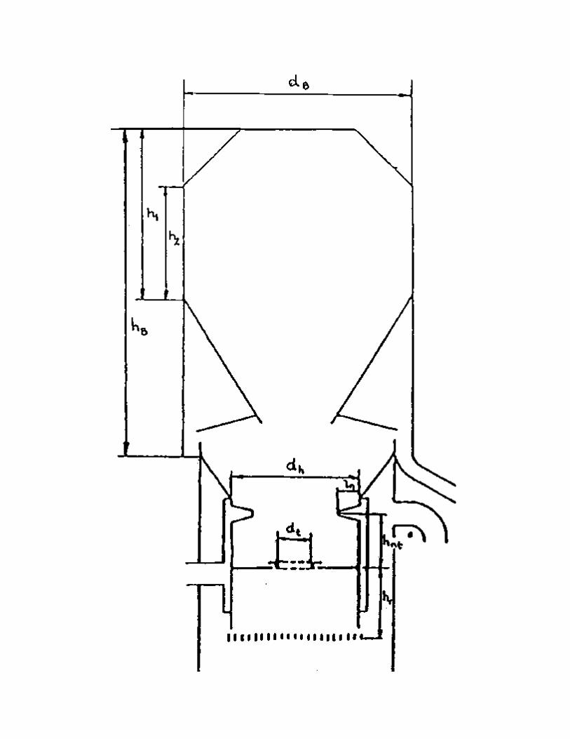

Figure 3.2 Below Shows The Design guidelines for down-draftgasifiers - b. Diameter of the fire box, dr, as a function of the
throat diameter, dt. (15)

Figure 3.4 Below Shows The Design guidelines for down-draftgasifiers - d. Height of the nozzle plane above the throat, hnt,
as a function of the throat diameter .(15)
The throat section is built-up by a loose throat ring resting on a support ring which can be placed at different levels below the nozzle tip plane by variation of the number of distance rings between the support ring and the brackets welded to the fire-box wall. This throat ring can easily be changed to adapt the gasifier to new operating conditions, and it can also easily be replaced if damaged by overheating.
The overall cold gas efficiency of this type of gasifier defined as:

where
g = overall cold gas efficiencyqVg = gas volume flowqMf = fuel mass flowHig = lower gas heating valueHif = lower fuel heating value
3.2 DESIGN CALCULATION/METHODOLOGY
Throat diameter = dt
Height of nozzle plane above the throat = hnt
Height of reduction zone = hr
Fire box diameter = dr
Diameter of the Bunker = db
(A) Determining throat diameter dt
For this project, a fire box diameter dr is 120mm.(7)
dt/dr = 3.5
dr = 120mm
dt = dr/3.5,where dr = 120mm
dt = 120/3.5 = 34.29mm
Throat diameter (dt) is 140mm

(B) To calculate the height of nozzle plane above the throat hnt
Using the graph value in figure above dt = 40mm
hnt/dt = 1.25
hnt/dt = 1.25 where dt = 40mm
hnt = 1.25 × 40mm
hnt = 50mm
The height of nozzle plane above the throat (hnt )is 100mm (5)
(C) Height of reduction zone hr
The recommended height of the reduction zone should be more than 200mm.(5)
In this project and an average height of 250mm was considered
hr = 250mm
(D) Bunker Diameter
With inclination at 600 and height of taper section of 100mm was considered
From trigonometry ratio
Tan θ = Opposite/Adjacent
Tan 60 = 100/db-dr × 2
db – dr = 200/tan 60 = 115.5
db = 115.57 + dr

db = 115.5+120 =235.5mm
Diameter of the Bunker is 235.5mm
(E) Diameter of nozzle Tip Ring (dnt)
From the graph in figure above at a throat diameter of 40mm.(16)
dnt/dt is 2.5
dnt = 2.5dt
since dt = 40
dnt = 40 × 2.5
dnt = 100mm
Diameter of nozzle Top ring = 100mm.
From figure above the rate nozzle flow area An & throat area At at throat diameter of 40mm is considered as 0.069.
An = area of the nozzle
At = area of the throat.
an/at × 100 = 6.9
100×3×1/4×Π×dn 2 r = 6.9
1/4×Π×dn2 t
Where dn = throat diameter
100 × 4 × dn 2 = 6.9
dn2t

dn = √6.9 × 100 2 = 15mm
4 × 100
The nozzle diameter is 15mm(13)
5.0 RESULT AND DISCUSSION
The design and construction of a downdraft fixed bed reactor chamber was made using mild steel of 3mm thickness which could conveniently gasify 10kg oven dry mass of mahogany woodchips.
The reactor ,which is of height 560mm,consists of an upright metal cylinder containing the bed stock having on inlet and outlet for gases ,means of feeding solid feedstock from above anda means ash removal at the base .Wood chips were fed through the top of the combustion chamber via air-lock system and heat is supplied .The wood chips that were burnt in the gasifier ,produce a hot gas which were stored in the storage tank.
The pressure gauge was found rising indicating the storage of gas .At the end of combustion of 10kg of the wood (mahogany) the pressures gauge 20.5KN/m2 (2.1kg/cm2 ). The temperature was measured which range between 200 and 2500c using oven thermometer.(11)
The first test was carried out using bursen burner, which was technically connected to the storage tank outlet, which has a control value. When the valve was opened ,spark of iginition fromthree crown matches was introduced and the fire to burn and the flame produced was a pure blue which proved that all other constituents have been removed.(14)
The producer gas can be used effectively in several applications.One application is to fuel internal combustion (K) engines to

produce shaft power ,for generating electricity , water pumping, grain milling ,sawing of timber ,and so on. .
6.0 CONCLUSIONS
A downdraft fixed bed reactor plant for the production of producer gas had been designed and constructed .A very hot gas ,was evolved, and found to support combustion at site of production, The gas could be used raw domestic purposes such as heating furnance and cooking food.
7.1 RECOMMENDATION
1. Further research into incorporation of cooling device2. To power internal combustion engine, additional equipment
would be needed that is provision of purifier3. Commercialization of this process can be quickly
implemented to alleviate both solid waste disposal and natural gas shortage problems in urban areas
REFERENCES
1. Adeyemo. S. B. (2001) ‘ Energy Potential of Organic Waste Proceeding of the First National Conference 2nd – 3rd May, 2001. Department of Mechanical Engineering University of Uyo, Nigeria ISSBN – 978- 35533- 0 – 5 Pp 56 – 61.
2. Ohunakin,o . s.,Leramo,O.R.,Abidakun, o.A.,Odunfa ,M.K and ,Bafuwa,O.B (2013) Energy and Cost Analysis of cement production using the wet, and dry processes in Nigeria .Energy and Power Engineering 5 , 537-550.
3. Appel, H. R., Wender, I. And Miker, R. D., (1969), Solubilization of Low Rank Coal with Carbon Monoxide and Water, Chem. Ind. (London) 49,1703.
4. Axelsson, R. 1969a. Summary of laboratory Tests with Producer Gas operation of Tractor massey Ferguson 1100 (in Swedish). Statens Maskinprovninger, Umea, Sweden.
5. Axelsson, R. 1969b. Sweden. Summary of tests with Producer Gas Truck Scania L80 (in Swedish).
6. Groeneveld, M.J. Thesis, Twente University of technology, Enschede, The Netherlands. 1980.
7. Hoglund, C. 1981. agricultural Residues as fuel for Generation. The Beijer institute, Stockholm, Sweden.
8. Hubert E., Stassen (1995) Small – scale Biomass Gasifies forHeat and Power, a Global review by the International Bank for Reconstruction and Development. THE WORLD BANK 1818 street, N. W. Washington D. C. 20433, U. S. A. Pp. 1
9. Jenkins, B. M. 1980. Down-draught Gasification Characteristics of major California Residue-derived fuels, Ph. D. Thesis, Engineering, University of California, Davis,U. S. A.
10. Kaupp, A.1982. The Gasification Characteristics of Rice Hulls for the Generation of Electricity and Shaft power on asmall (530hp) scale, 1st Int. Prod. Gas Conf., Colombo, Sri Lanka.
11. Schlapfter, P. and Tobler, J. 1937. Theoretischem und Praktische Untersuchungen uber den Betrieb von motorfahrzeuge mit Holzgas, Bern.
12. Scurlock, J. an Hall, (1990). ‘The contribution of Biomass to Global Energy’. In Biomass, Vol. 21 Pp 75-81.
13. Shilton, P. 1982. Preliminary Experience in the Operation ofa Gasogen Plant of Classical Imbert Design using Mixed Wood/Coconut Husks as a fuel, 1st Int. Prod. Gas Conf., Colombo, Sri Lanka.
14. Venselaar, j. 1982. Design rules for down-draught Gasifiers,a short review, IT Bandung, Indonasia.
15. Zerbe, J. I. (1977). Conversion of Stagnated Timer Stands toProductive Sites in ‘Fuels and Energy from Renewable Resources’ (Tilman, D. A. Salrlanen K. V and Andreson, L. L.eds). Academic press, New York.
16. Zijp, T. an Stassen, H. E.M. 1982. Gasification of Maize Spills for Mechanical Energy Generation in Rural Areas in Tanzania. 1st Int. prod. Gas., Colombo, Sri Lanka.