
E6681A EXM-WB Wireless Test Set Getting Started Guide
158
Getting Started Guide Keysight Wireless Test Solutions E6681A EXM-WB Wireless Test Set
-
Upload
khangminh22 -
Category
Documents
-
view
2 -
download
0
Transcript of E6681A EXM-WB Wireless Test Set Getting Started Guide

Getting Started Guide
Keysight Wireless Test Solutions
E6681A EXM-WB Wireless Test Set

Notices
© Keysight Technologies, Inc. 2021
No part of this manual may be reproduced in any form or by any means (including electronic storage and retrieval or translation into a foreign language) without prior agreement and written consent from Keysight Technologies, Inc. as governed by United States and international copyright laws.
Manual Part Number
E6681-90001
Edition
Edition 1, June 2021 Supersedes: Feb 2021
Printed in USA/Malaysia
Published by:Keysight Technologies1400 Fountaingrove Parkway Santa Rosa, CA 95403
Warranty
THE MATERIAL CONTAINED IN THIS DOCUMENT IS PROVIDED “AS IS,” AND IS SUBJECT TO BEING CHANGED, WITHOUT NOTICE, IN FUTURE EDITIONS. FURTHER, TO THE MAXIMUM EXTENT PERMITTED BY APPLICABLE LAW, KEYSIGHT DISCLAIMS ALL WARRANTIES, EITHER EXPRESS OR IMPLIED WITH REGARD TO THIS MANUAL AND ANY INFORMATION CONTAINED HEREIN, INCLUDING BUT NOT LIMITED TO THE IMPLIED WARRANTIES OF MERCHANTABILITY AND FITNESS FOR A PARTICULAR PURPOSE. KEYSIGHT SHALL NOT BE LIABLE FOR ERRORS OR FOR INCIDENTAL OR CONSEQUENTIAL DAMAGES IN CONNECTION WITH THE FURNISHING, USE, OR PERFORMANCE OF THIS DOCUMENT OR ANY INFORMATION CONTAINED HEREIN. SHOULD KEYSIGHT AND THE USER HAVE A SEPARATE WRITTEN AGREEMENT WITH WARRANTY TERMS COVERING THE MATERIAL IN THIS DOCUMENT THAT CONFLICT WITH THESE TERMS, THE WARRANTY TERMS IN THE SEPARATE AGREEMENT WILL CONTROL.
Technology Licenses
The hardware and/or software described in this document are furnished under a license and may be used or copied only in accordance with the terms of such license.
U.S. Government Rights
The Software is “commercial computer software,” as defined by Federal Acquisition Regulation (“FAR”) 2.101. Pursuant to FAR 12.212 and 27.405-3 and Department of Defense FAR Supplement (“DFARS”) 227.7202, the U.S. government acquires commercial computer software under the same terms by which the software is customarily provided to the public. Accordingly, Keysight provides the Software to U.S. government customers under its standard commercial license, which is embodied in its End User License Agreement (EULA), a copy of which can be found at http://www.keysight.com/find/sweulaThe license set forth in the EULA represents the exclusive authority by which the U.S. government may use, modify, distribute, or disclose the Software. The EULA and the license set forth therein, does not require or permit, among other things, that Keysight: (1) Furnish technical information related to commercial computer software or commercial computer software documentation that is not customarily provided to the public; or (2) Relinquish to, or otherwise provide, the government rights in excess of these rights customarily provided to the public to use, modify, reproduce, release, perform, display, or disclose commercial computer software or commercial computer software documentation. No additional government requirements beyond those set forth in the EULA shall apply, except to the extent that those terms, rights, or
licenses are explicitly required from all providers of commercial computer software pursuant to the FAR and the DFARS and are set forth specifically in writing elsewhere in the EULA. Keysight shall be under no obligation to update, revise or otherwise modify the Software. With respect to any technical data as defined by FAR 2.101, pursuant to FAR 12.211 and 27.404.2 and DFARS 227.7102, the U.S. government acquires no greater than Limited Rights as defined in FAR 27.401 or DFAR 227.7103-5 (c), as applicable in any technical data.
Safety Notices
A CAUTION notice denotes a hazard. It calls attention to an operating procedure, practice, or the like that, if not correctly performed or adhered to, could result in damage to the product or loss of important data. Do not proceed beyond a CAUTION notice until the indicated conditions are fully understood and met.
A WARNING notice denotes a hazard. It calls attention to an operating procedure, practice, or the like that, if not correctly performed or adhered to, could result in personal injury or death. Do not proceed beyond a WARNING notice until the indicated conditions are fully understood and met.
A NOTE calls the user’s attention to an important point or special information in the text.

3
Where to Find the Latest Information
Documentation is updated periodically. For the latest information about these products, including instrument software upgrades, application information, and product information, browse to one of the following URLs, according to the name of your product:
http://www.keysight.com/find/exmwb
To receive the latest updates by email, subscribe to Keysight Email Updates at the following URL:
http://www.keysight.com/find/MyKeysight
Information on preventing instrument damage can be found at:
www.keysight.com/find/PreventingInstrumentRepair
Is your product software up-to-date?
Periodically, Keysight releases software updates to fix known defects and incorporate product enhancements. To search for software updates for your product, go to the Keysight Technical Support website at:
http://www.keysight.com/find/techsupport

4

Contents
Getting Started Guide 5
Table of Contents
Safety & Environmental Information 9
Elements of the System 10
Warning Statements and Symbols 11
Safety 12Safety Compliance 12Acoustic statement (European Machinery Directive) 12General Safety Notices 12
Environmental Conditions (Operating) 13Environmental Information 13
EMC (Electromagnetic Compatibility) 14South Korean Class A EMC declaration 14Declaration of Conformity 14
Ventilation 15
Power requirements (E6681A) 16
Power requirements (M1740A) 16
Using Accessories 17
Location and Mounting 17
Weight and Dimensions (E6681A) 17
Weight and Dimensions (M1740A) 17
Electrical Safety 18
Protecting against electrostatic discharge 19
Instrument Maintenance 20Cleaning the Instrument 20Cleaning the connectors 20
Quick Start 21
Initial Inspection 22Shipping Problems? 23
Purpose and Function 24
Options and Licenses 26E6681A Hardware Options 26M1740A Hardware Options 26Application Licenses 27
Exterior Features 29
Front Panel Features 30

6 Getting Started Guide
Contents
Controller interface 32TRX connectors 33Reference 34System status 35
Rear Panel Features 36
Labels and Symbols 37
Graphical User Interface 39
Launching the Measurement Software 40Restarting measurement applications (two methods) 42Configure applications 43
Screen Interface 44Screen Tabs 46System Settings 47Preset 48Meas Bar 49Menu Panel 50Measurement Display 51Control Bar 52Minimized window 53Help System 54
Command Interface 56
Operating Tasks 59
TRX Selection 60Using HiSLIP 61Using Socket Ports 61Using VXI-11/SICL 61Using Telnet Connection 61
Receiver Setup 62
Source Setup 67
Port Configuration 70Port selection 71Configuration example 74
Alignments 76Alignments menu 76Alignment ranges 77Comparing alignment types 77“All” alignment (weekly use) 78Subsets of Align Now All 80Align IF Cable 82

Contents
Getting Started Guide 7
Checking Temperature and Status 83About System Calibration 83
LAN Address Configuration 84Configuring the LAN 85
Managing Licenses 86Node-locked License 87Transportable License 87USB-Portable License 88Floating License 89
System Calibration 91
Calibration Equipment Required 92
Calibration Ports 93
Launching System Calibration 94Connecting the power sensor 95Setting up VISA addresses 96
When to Calibrate 98
Power Calibration 99Repeating the power calibration for RFHD 2 103
Flatness Calibration 104Repeating the flatness calibration for RFHD 2 108
Tabs of the System Calibration window 109Equipment tab 110Calibration Status tab 112Power Calibration tab 114Flatness Calibration tab 117Cable Calibration tab 120Dual Source Calibration tab 120Diagnostics tab 120
Test Set Operating System 121
Keysight Software Installed 122Customer Installation of Software 122
User Accounts 123Administrator login 123User login 123Customer creation of accounts 124
Licensing New Application Software - After Initial Purchase 125
Transporting a License Between Test Sets 127
Windows Security 130

8 Getting Started Guide
Contents
Windows Firewall 131Virus protection 132Spyware protection 132
System Maintenance 133Back-up 133System Restore 133Disk defragmenting 133USB Connections 134Hard Drive Partitioning and Use 134Hard Drive Recovery Process 135
Instrument software installation 140
Troubleshooting 145
Basic Operational Check 146
Identifying Problems 152
System Components 153
Where to get technical help 155
Returning the E6681A for Service 156Calling Keysight Technologies 156Locations for Keysight Technologies 157

9
Keysight Wireless Test SolutionsE6681A EXM-WB WirelessTest Set
Getting Started Guide
1 Safety & Environmental Information
The following topics can be found in this section:
“Warning Statements and Symbols” on page 11
“Safety” on page 12
“Environmental Conditions (Operating)” on page 13
“EMC (Electromagnetic Compatibility)” on page 14
“Ventilation” on page 15
“Power requirements (E6681A)” on page 16
“Power requirements (M1740A)” on page 16
“Using Accessories” on page 17
“Location and Mounting” on page 17
“Weight and Dimensions (E6681A)” on page 17
“Electrical Safety” on page 18
“Protecting against electrostatic discharge” on page 19
“Instrument Maintenance” on page 20

10 Getting Started Guide
Safety & Environmental InformationElements of the System
Elements of the SystemThe three main elements of the E6681A EXM-WB Wireless Test Set will be referred to in this guide as follows:
— E6681A (source/analyzer instruments enclosed in PXIe chassis)
— M1740A (the M1740A mmWave Transceiver, which is used by the PXIe Subsystem as a Remote Radio Head to test mmWave devices; two M1740As may be connected, if the E6681A includes two TRX units)
— RF Cables (supplied cables designed to connect the E6681A with the M1740A)
Figure 1-1 Three main elements of E6681A EXM-WB Wireless Test Set

Getting Started Guide 11
Safety & Environmental InformationWarning Statements and Symbols
Warning Statements and SymbolsCaution and Warning notices are used in this document are described below.
See also: “Labels and Symbols” on page 37.
A CAUTION notice denotes a hazard. It calls attention to an operating procedure, practice, or the like that, if not correctly performed or adhered to, could result in damage to the product or loss of important data. Do not proceed beyond a CAUTION notice until the indicated conditions are fully understood and met.
A WARNING denotes a hazard. It calls attention to an operating procedure, practice or the like that, if not correctly performed or adhered to, could result in personal injury or death. Do not proceed beyond a WARNING notice until the indicated conditions are fully understood and met.
A NOTE calls the user’s attention to an important point or special information in the text.

12 Getting Started Guide
Safety & Environmental InformationSafety
Safety
Safety Compliance
This product complies with the essential requirements of the European Low Voltage Directive as well as current editions of the following standards (dates and editions are cited in the Declaration of Conformity):
— IEC/EN 61010-1
— Canada: CSA C22.2 No. 61010-1
— USA: UL std no. 61010-1
Acoustic statement (European Machinery Directive)
Acoustic noise emission LpA <70 dB Operator position Normal operation mode per ISO 7779
General Safety Notices
This product has been designed and tested in accordance with accepted industry standards, and has been supplied in a safe condition.The documentation contains information and warnings that must be followed by the user to ensure safe operation and to maintain the product in a safe condition.
If this product is not used as specified, the protection provided by the equipment could be impaired. This product must be used in a normal condition (in which all means for protection are intact) only.
No operator serviceable parts inside. Refer servicing to qualified personnel. To prevent electrical shock, do not remove covers.
Safety of any system incorporating the equipment is the responsibility of the assembler of the system.

Getting Started Guide 13
Safety & Environmental InformationEnvironmental Conditions (Operating)
Environmental Conditions (Operating)This product is designed for use in the following conditions:
— For indoor use only
— Altitude up to 2000 m
— Temperature 5°C to 45°C
— Maximum Relative Humidity (non-condensing): 85% RH up to 40°C, decreases linearly to 45% RH at 45°C. (From 40°C to 45°C, the maximum % Relative Humidity follows the line of constant dew point.)
Environmental Information
Samples of this product have been type tested in accordance with the Keysight Environmental Test Manual and verified to be robust against the environmental stresses of Storage, Transportation and End-use; those stresses include but are not limited to temperature, humidity, shock, vibration, altitude and power line conditions.
Test Methods are aligned with IEC 60068-2 and levels are similar to MIL-PRF-28800F Class 3.
This product is designed for use in INSTALLATION CATEGORY II and POLLUTION DEGREE 2.

14 Getting Started Guide
Safety & Environmental InformationEMC (Electromagnetic Compatibility)
EMC (Electromagnetic Compatibility)This product complies with the essential requirements of the European Directive as well as current editions of the following standards (dates and editions are cited in the Declaration of Conformity):
— IEC/EN 61326-1
— CISPR Pub 11 Group 1, class A
— AS/NZS CISPR 11
— CAN ICES/NMB-001(A) This ISM device complies with Canadian ICES-001. Cet appareil ISM est conforme a la norme NMB-001 du Canada.
South Korean Class A EMC declaration
This equipment is Class A suitable for professional use and is for use in electromagnetic environments outside of the home.
Declaration of Conformity
The Declaration of Conformity for any Keysight product can be found on the website: http://www.keysight.com/go/conformity
This equipment is not intended for use in residential environments and may not provide adequate protection to radio reception is such environments.

Getting Started Guide 15
Safety & Environmental InformationVentilation
VentilationVENTILATION REQUIREMENTS: When installing the instrument(s) into a cabinet, consideration shall be given to the convection flow into and out of the cabinet. Consideration shall also be given to the individual instruments to avoid having the heated discharge of one instrument, now becoming the cooling intake air for another instrument. Do not place the test set against any surface in such a way as to block its ventilation openings. Interfering with ventilation airflow can cause the test set to overheat. Another area of concern is verification that the maximum ambient operating temperature of the instrument(s) is not exceeded by cabinet installation. Keysight recommends forced air convection whenever an instrument(s) are installed in a cabinet and further recommends that the maximum operating temperature of the cabinet be reduced 10°C from the lowest, of the maximum operating temperature of a single instrument. If there are any concerns or special requirements an Keysight Field Engineer should be consulted to assure instrument(s) temperature compliance and performance.

16 Getting Started Guide
Safety & Environmental InformationPower requirements (E6681A)
Power requirements (E6681A)100/120V, 1200W MAX; 220/240V, 1300W MAX
50/60 Hz
The input terminals for this product are classified as Measurement Category None.
Power requirements (M1740A)36 VDC, <1 A
The input terminals for this product are classified as Measurement Category None.
The M1740A does not have an AC power connection. It is powered by a DC voltage from the E6681A; this voltage is supplied over an RF Cable to the LO/Pwr/Ctrl/IF In connector. The DC supply does not represent a risk of personal injury.
The instrument can operate with mains supply voltage fluctuations up to +10% of the nominal voltage.
The main power cord is the system disconnecting device. It disconnects the mains circuits from the mains supply.
This is a Safety Protection Class I Product (provided with a protective earthing ground incorporated in the power cord). The mains plug shall only be inserted in a socket outlet provided with a protective earth contact. Any interruption of the protective conductor inside or outside of the product is likely to make the product dangerous. Intentional interruption is prohibited.
This instrument has auto-ranging line voltage input. Be sure the supply voltage is within the specified range, and that voltage fluctuations do not to exceed 10 percent of the nominal supply voltage.
The RF Cable Assembly should not be connected to, or disconnected from, the M1740A while it is suppling DC power from the E6681A. This connection should be made only when the E6681A is powered off, or the cable is not connected to the E6681A. If the LED status indicator on the front of the M1740A is lit, the M1740A is powered up and the cable should not be disconnected.

Getting Started Guide 17
Safety & Environmental InformationUsing Accessories
Using AccessoriesOnly Keysight approved accessories shall be used.
Location and Mounting
Weight and Dimensions (E6681A)The weight and dimensions of the E6681A are as follows:
— Weight: 23.6 kg (25 kg if a second TRX is installed)
— Height: 197.8 mm
— Width: 568.9 mm
— Length: 449.5 mm
Weight and Dimensions (M1740A)The weight and dimensions of the M1740A are as follows:
— Weight: 2.2 kg
— Height: 66 mm
— Width: 139 mm
— Length: 183 mm
Proper ergonomics should be considered when using accessories such as a keyboard or a mouse.
Install the instrument so that the detachable power cord is readily identifiable and is easily reached by the operator. The detachable power cord is the instrument disconnecting device. It disconnects the mains circuits from the mains supply before other parts of the instrument. The front panel switch is only a standby switch and is not a LINE switch. Alternatively, an externally installed switch or circuit breaker (which is readily identifiable and is easily reached by the operator) may be used as a disconnecting device.

18 Getting Started Guide
Safety & Environmental InformationElectrical Safety
Electrical SafetyThis is a Safety Class 1 Product (provided with a protective earth ground incorporated in the power cord). The mains plug shall only be inserted in a socket outlet provided with a protective earth contact. Any interruption of the protective conductor inside or outside of the instrument is likely to make the instrument dangerous. Intentional interruption is prohibited.
If this product is not used as specified, the protection provided by the equipment could be impaired. This product must be used in a normal condition (in which all means for protection are intact) only. Install the instrument so that the detachable power cord is readily identifiable and easily reached by the operator. The detachable power cord is the instrument disconnecting device. It disconnects the mains circuits from the mains supply before other parts of the instrument. The front panel switch is only a standby switch and is not a LINE switch. Alternatively, an externally installed switch or circuit breaker (which is readily identifiable and is easily reached by the operator) may be used as a disconnecting device.
This instrument has an auto-ranging line voltage input. Ensure the supply voltage is within the specified range and voltage fluctuations do not exceed 10 percent of the nominal supply voltage.
When installing the product in a cabinet the convection into and out of the product must not be restricted. The ambient temperature (outside the cabinet) must be less than the maximum operating temperature of the product by 4° C for every 100 watts dissipated in the cabinet. If the total power dissipated in the cabinet is greater than 800 watts, then forced convection must be used. It is your responsibility to ensure the ambient temperature does not exceed the rated ambient temperature stated in the specification.
The Mains wiring and connectors shall be compatible with the connector used in the premise electrical system. Failure, to ensure adequate earth grounding by not using the correct components may cause product damage, and serious injury.
Use the Keysight supplied power cord or one with the same or better electrical rating.

Getting Started Guide 19
Safety & Environmental InformationProtecting against electrostatic discharge
Protecting against electrostatic dischargeElectrostatic discharge (ESD) can damage or destroy electronic components (the possibility of unseen damage caused by ESD is present whenever components are transported, stored, or used).
Test equipment and ESD
To help reduce ESD damage that can occur while using test equipment:
• Before connecting any coaxial cable to a test set connector for the first time each day, momentarily short the center and outer conductors of the cable together.
• Personnel should be grounded with a 1 MΩ resistor-isolated wrist-strap before touching the center pin of any connector and before removing any assembly from the test set.
• Be sure that all instruments are properly earth-grounded to prevent build-up of static charge.
• Perform work on all components or assemblies at a static-safe workstation.
• Keep static-generating materials at least one meter away from all components.
• Store or transport components in static-shielding containers.
• Always handle printed circuit board assemblies by the edges. This reduces the possibility of ESD damage to components and prevent contamination of exposed plating.
Additional information about ESD
For more information about ESD and how to prevent ESD damage, contact the Electrostatic Discharge Association (http://www.esda.org). The ESD standards developed by this agency are sanctioned by the American National Standards Institute (ANSI).
Do not use these first three techniques when working on circuitry with a voltage potential greater than 500 volts.

20 Getting Started Guide
Safety & Environmental InformationInstrument Maintenance
Instrument Maintenance
Cleaning the Instrument
Cleaning the connectors
To prevent electrical shock, disconnect the instrument from mains before cleaning. Use a dry cloth slightly dampened with water to clean the external case parts. Do not attempt to clean internally.
Cleaning connectors with alcohol shall only be done with the instrument’s power cord removed, and in a well-ventilated area. Allow all residual liquid alcohol to evaporate and the fumes to dissipate prior to energizing the instrument.
21
Keysight Wireless Test SolutionsE6681A EXM-WB WirelessTest Set
Getting Started Guide
2 Quick Start
The following topics can be found in this section:
“Initial Inspection” on page 22
“Purpose and Function” on page 24
“Options and Licenses” on page 26

22 Getting Started Guide
Quick StartInitial Inspection
Initial InspectionInspect the shipping container and the cushioning material for signs of stress. Retain undamaged shipping materials for future use, as you may wish to ship the test set to another location or to Keysight Technologies for service. Verify the contents of the container against the table below.
Item Deliverable Description
Getting Started Guide (this document)
Provides first-time power on instructions, licensing information, operating system information, and general hardware information.
Keysight E6681A EXM-WB Wireless Test Set
E6681A-001 (TRX 1) E6681A-002 (option TRX 2)
M1740A mmWave Transceiver Quantity of 1 for TRX 1 Quantity of 2 for TRX 1 + TRX 2
RF Cables M1740A-CA4 (for "IF" connections) Quantity of 2 for TRX 1 Quantity of 4 for TRX 1 + TRX 2
RF Cables M1740A-CB4 (for "LO" connections) Quantity of 1 for TRX 1 Quantity of 2 for TRX 1 + TRX 2
Y1217A Rack mount and rack rail kit Optional

Getting Started Guide 23
Quick StartInitial Inspection
Shipping Problems?
If the shipping materials are damaged or the contents of the container are incomplete:
— Contact the nearest Keysight Technologies office.
— Keep the shipping materials for the carrier’s inspection.
— If you must return a test set to Keysight Technologies, use the undamaged original or comparable shipping materials. See “Returning the E6681A for Service” on page 156.

24 Getting Started Guide
Quick StartPurpose and Function
Purpose and FunctionThe E6681A test set supports wireless device testing, with up to two transmit/receive modules (each driving an M1740A remote radio head to interface with millimeter-wave devices under test). The second TRX unit is included only with Option E6681A-002).
Each TRX unit in the E6681A system chassis supports an IF output port, an IF input port, and a composite port which provides an LO output, DC power, and Control signals to a remote radio head.
Figure 2-1 Functional blocks of the E6681A and M1740A
Getting Started Guide 25
Quick StartPurpose and Function
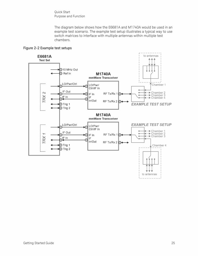
The diagram below shows how the E6681A and M1740A would be used in an example test scenario. The example test setup illustrates a typical way to use switch matrices to interface with multiple antennas within multiple test chambers.
Figure 2-2 Example test setups

26 Getting Started Guide
Quick StartOptions and Licenses
Options and Licenses
E6681A Hardware Options
M1740A Hardware Options
Designation Description
E6681A EXM-WB Wireless Test Set
E6681A-001 One TRX Module, designated TRX1
E6681A-002 (Optional) Second TRX module, designated TRX2
E6681A-B3X 300 MHz Bandwidth (for a specified TRX module)
E6681A-B6X 600 MHz Bandwidth (for a specified TRX module)
E6681A-B12 1200 MHz Bandwidth (for a specified TRX module)
E6681A-BTS (Optional) Downlink Measurement Capability
E6681A-MSS Uplink Measurement Capability (always included in E6681A)
Y1168A Optional USB keyboard and optical mouse
Y1217A Optional PXI chassis rack rail kit
Designation Description
M1740A mmWave Transceiver for 5G (qty 1 for each TRX)
M1740A-CA4 2 RF cable, N-SMA, 4 m (qty 2 for each TRX)
M1740A-CB4 RF cable, TNC-SMA, 4m (qty 1 for each TRX)

Getting Started Guide 27
Quick StartOptions and Licenses
Application Licenses
The licenses for various applications that are installed on the E6681A controller are listed in the Keysight License Manager, which can be launched from the Windows Start menu, or from the Licensing window under System Settings as illustrated below:
Figure 2-3 Keysight License Manager
The licenses available are described in the table below:
Designation Description
V9060EM0E Test set measurement (always included in E6681A)
V9065EM1E Sequence analyzer device applications (always included in E6681A)
V9065EM0E (Optional) Sequence analyzer BTS applications:
V9065EM2E Parallel analysis of multiple devices
V9085EM1E (Optional) PAvT measurement application; also requires 5NR application, Y9085EM0E)
Y9085EM0E 5G NR non-signaling waveform and measurement
N90E1S91A Remote Radio Head software application (control of M1740A)

28 Getting Started Guide
Quick StartOptions and Licenses

29
Keysight Wireless Test SolutionsE6681A EXM-WB WirelessTest Set
Getting Started Guide
3 Exterior Features
The following topics can be found in this section:
“Front Panel Features” on page 30
“Labels and Symbols” on page 37

30 Getting Started Guide
Exterior FeaturesFront Panel Features
Front Panel FeaturesThe E6681A front panel and two sides of the M1740A are illustrated below (the E6681A-facing side of the M1740A is shown bottom left, and the DUT-facing side is shown bottom right).
Figure 3-1 E6681A & M1740A exterior panels
The M1740A and its connectors are separately documented in the M1740A mmWave Transceiver Getting Started Guide, which can be found at: http://www.keysight.com/find/m1740a

Getting Started Guide 31
Exterior FeaturesFront Panel Features
The photo below shows the various sections of the front panel of the E6681A.
Figure 3-2 E6681A front panel
These sections of the front panel are described separately, as follows:
1. See “Controller interface” on page 32.
2. See “TRX connectors” on page 33.
3. See “Reference” on page 34.
4. See “System status” on page 35.

32 Getting Started Guide
Exterior FeaturesFront Panel Features
Controller interface
Figure 3-3 Controller interface
Connector
Description
(1) Monitor Port
This connector supports a connection to a monitor with a DisplayPort input.
(2) Drive/Power/User
—DRIVE: When the Solid State Drive is active, the LED will flash.
—POWER: If the LED is on, the power supply to the controller is good and the system should boot.
—USER: Not used.
(3) Trig
This trigger line is not used by the E6681A.
(4) LAN1 & LAN2
Two TCP/IP Interface connectors that are used for remote test set operation. Choose the LAN 1 port to have an IP address assigned to the test set dynamically, using DHCP. If your local network does not support DHCP, choose the LAN 2 port to use a private static IP address.
(5) USB 3.0 (SS)
Two USB 3.0 interface ports are provided.
(6) USB 2.0
Four USB 2.0 interface ports are provided.

Getting Started Guide 33
Exterior FeaturesFront Panel Features
TRX connectors
The picture below illustrates only TRX1; TRX2, if installed, has the same components and layout.
Figure 3-4 TRX connectors
Connector
Description
(1) TRXn Status
This LED indicates the status of the TRX module. The LED lights green when the measurement application software is loaded for the TRX. The light turns red if the TRX develops an error condition which it is unable to correct.
(2) IF In
This Type N connector receives the signal from the DUT which has been downconverted by the M1740A mmWave Transceiver. (The connected port on the M1740A is called IF In/Out.)
(3) IF Out
This Type N connector transmits the test signal to the M1740A mmWave Transceiver, which upconverts it to the frequency range of the DUT. (The connected port on the M1740A is called IF In.)
(4) LO/Pwr/Ctrl
This BNC connector furnishes to the M1740A mmWave Transceiver a composite signal containing an LO signal, DC power, and control signals. (The connected port on the M1740A is called LO/Pwr/Ctrl/IF In.)
(5 & 6) Trig In 1 & Trig In 2
These BNC connectors are for triggers (configurable as input or output triggers). They can be setup as source triggers or receiver triggers.

34 Getting Started Guide
Exterior FeaturesFront Panel Features
Reference
Figure 3-5 System interfaces
Connector
Description
(1) Ref Status
This LED indicates the status of the frequency reference.
—Green: frequency reference is operating normally.
—Red: frequency reference is unlocked.
—Off: frequency reference has lost power or lost connection to the controller.
(2) 10 MHz Out
This BNC connector provides a 10 MHz output reference signal.
(3) Ref In
This BNC connector accepts a 1 MHz to 110 MHz input reference signal.

Getting Started Guide 35
Exterior FeaturesFront Panel Features
System status
Figure 3-6 System status
Connector
Description
(1) Temp
This amber LED is off when chassis temperature is in the normal operating range. The LED flashes to indicate the chassis is overheated. (It is never on continuously.)
(2) Fan
This green LED is off when the chassis is turned off. It is on continuously when the fans are running normally. The LED flashes whenever a fan is stopped or running too slowly.
(3) Power
This blue LED is off when the chassis is turned off. It is on continuously when all supply voltages are normal. The LED flashes whenever a supply voltage is outside its normal range.
(5) On/Standby Pushbutton
This pushbutton is used to turn chassis power on and off.

36 Getting Started Guide
Exterior FeaturesRear Panel Features
Rear Panel Features
Figure 3-7 E6681A rear panel
Number Item Name Description
1 Line power input The AC power connection. See the product specifications for more details.
2 POWER SYNCH IN/OUT Reserved for future use.
3 FAN Fan speed control (settings are HIGH and AUTO).
4 INHIBIT Inhibit switch. The settings are DEF (default) and MAN (manual).
—When the switch is in the default position, the chassis is powered up by the front panel ON/Standby pushbutton. This is the recommended setting.
—When the switch is in the manual position, the chassis is powered up by the Inhibit input signal on the rear panel INHIBIT/VOLTAGE MON DB-9 connector.
5 INHIBIT/VOLTAGE MON This DB-9 connector provides access for testing of internal power supply voltages. The voltages (by Pin #) are: (1) Logic Gnd, (2) +5 VDC, (3) Rsrvd, (4) +3.3 VDC, (5) Inhibit [Low], (6) +12 VDC, (7) Rsrvd, (8) -12 VDC, (9) Logic Gnd.
6 10 MHz REF OUT This BNC connector is not used by the E6681A test set. The front panel 10 MHz OUT connector should be used instead.
7 10 MHz REF IN This BNC connector is not used by the E6681A test set. The front panel REF IN connector should be used instead.

Getting Started Guide 37
Exterior FeaturesLabels and Symbols
Labels and SymbolsLabels and symbols which may be shown on the E6681A (mainly on the rear panel of the chassis) are described in the table below.
Symbol Description
This symbol marks the standby position of the power line switch.
This symbol indicates that the input power required is AC.
This symbol indicates DC voltage.
This symbol indicates frame or chassis terminal.
The instruction documentation symbol. The product is marked with this symbol when it is necessary for the user to refer to instructions in the documentation.
This symbol identifies the Protective Conductor Terminal.
The CE marking is a registered trademark of the European Community (if accompanied by a year, it is the year when the design was proven). It indicates that the product complies with all relevant directives.
The Keysight email address is required by EU directives applicable to our product.
The CSA mark is a registered trademark of the CSA international.
The RCM mark is a registered trademark of the Australian Communications and Media Authority.
South Korean Certification (KC) mark; includes the marking’s identifier code which follows this format: R-R-Kst-XXXXXXX

38 Getting Started Guide
Exterior FeaturesLabels and Symbols
This is a combined marking to indicate product compliance with the industry Canadian Interference-Causing Equipment Standard (ICES-001). This is also a symbol of an Industrial Scientifici and Medical Group 1 Class A product (CISPR 11, Clause 5).
This marking on a port indicates that it should not be connected to a Local Area Network.
This WEEE symbol indicates separate collection for electrical and electronic equipment, mandated under EU law as of August 13, 2005. All electrical and electronic equipment are required to be separated from normal waste for disposal.
China Restriced Substance Product Label. The EPUP (environmental protection use period) number in the center indicates the time period during which no hazardous or toxic substances or elements are expected to leak or deteriorate during normal use and generally reflects the expected useful life of the product.
Universal recycling symbol. This symbol indicates compliance with the China standard GB 18455-2001 as required by the China RoHS regulations for paper/fiberboard packaging.
Symbol Description

39
Keysight Wireless Test SolutionsE6681A EXM-WB WirelessTest Set
Getting Started Guide
4 Graphical User Interface
The following topics can be found in this section:
“Launching the Measurement Software” on page 40
“Screen Interface” on page 44
“Command Interface” on page 56

40 Getting Started Guide
Graphical User InterfaceLaunching the Measurement Software
Launching the Measurement SoftwareAt bootup, the E6681A launches the S910xA Service Manager automatically, and the Service Manager automatically launches the measurement software.
Figure 4-1 Automatic launching of the Service Manager and measurement software
After the software is finished loading, it runs the measurement applications for TRX1 and TRX2 in separate windows (assuming both TRXs are installed).
Figure 4-2 Separate measurement windows for the TRXs

Getting Started Guide 41
Graphical User InterfaceLaunching the Measurement Software
If the Service Manager has been shut down, it can be launched (without rebooting) by going to the Windows Start menu and selecting Service Manager under the Keysight S910xA folder.
Figure 4-3 Re-launching the Service Manager from the Start Menu
The Configuration Tool in the Keysight S910xA folder is used by Keysight for factory configuration and field service purposes; it is not usually not needed for customer operation of the E6681A. However, it may be needed during software upgrades, as described in “Instrument software installation” on page 140. Use of the S910xA System Calibration tool is described in “Launching System Calibration” on page 94.

42 Getting Started Guide
Graphical User InterfaceLaunching the Measurement Software
Restarting measurement applications (two methods)
If you close the TRX measurement windows and want to reopen them without rebooting, there are two ways to do this. The simplest way is to click Restart Services at the bottom of the Service Manager window (see Figure 4-1 on page 40). However, this is not the quickest method, because restarting the Service Manager will repeat some startup tasks needlessly. To save time, go to the Windows Start menu and select LaunchModularTRX under the Keysight Modular Transceiver folder. (Or use the desktop icon for this, if an optional desktop icon was created for it during the software installation process.)
Figure 4-4 LauchModularTRX (from Windows Start menu or desktop icon)
In the window which opens, the TRXs are listed under Status as "Running" or "Idle". To activate one or both idle TRXs, check the appropriate box under Selected, and then click Run Selected:
Figure 4-5 Selecting one of two TRXs
Do not run LaunchModularTRX if the Service Manager has been shut down; that would cause communication problems between the E6681A and the M1740A. Relaunch the Service Manager from Windows Start instead.

Getting Started Guide 43
Graphical User InterfaceLaunching the Measurement Software
Configure applications
You can reduce unnecessary startup time for the E6681A, by limiting the number of measurement applications which are loaded automatically at bootup. Go to the Windows Start menu and select Configure Applications under the Keysight Modular Transceiver folder. Use the checkbox selector to choose only the applications you want loaded automatically at startup, and click OK.
Figure 4-6 Launching Configure X-Series Applications utility from Windows Start menu

44 Getting Started Guide
Graphical User InterfaceScreen Interface
Screen InterfaceThe overall appearance of the display interface is illustrated below. Different parts of it are discussed in more detail in the following sections.
Figure 4-7 Application display interface (with results window for ACP measurement)
If a second TRX unit is installed, it is represented by a separate window:
Figure 4-8 Separate display windows for TRX1 and TRX 2

Getting Started Guide 45
Graphical User InterfaceScreen Interface
Elements of the interface are discussed in more detail in the following sections.
Figure 4-9 Elements of the display interface

46 Getting Started Guide
Graphical User InterfaceScreen Interface
Screen Tabs
These are used to select a measurement screen for viewing and configuration (to add another screen, click the + button at the right of the existing tabs).
Figure 4-10 Screen tabs
Clicking on the currently selected tab brings up the Mode/Meas/View dialog, to change settings for that screen.
Figure 4-11 Mode/Meas/View dialog
The Sequencer feature at the left side of the dialog is not related to List Sequencer mode. This selection only determines how multiple measurement screens are displayed and updated.

Getting Started Guide 47
Graphical User InterfaceScreen Interface
System Settings
Clicking the "gear" icon opens the System Settings dialog, which allows you to access various information screens and settings interfaces. The tabs on the left side let you access various configuration screens.
Figure 4-12 System Settings
The System Settings screens include:
— System
— I/O Config
— User Interface
— Power On
— Restore Defaults
— Alignments
— Licensing
— Security
— Diagnostics
— Service

48 Getting Started Guide
Graphical User InterfaceScreen Interface
Preset
Clicking this icon opens a menu which provides access to the various ways in which settings can be restored to a default condition or a condition you defined earlier.
Figure 4-13 Preset

Getting Started Guide 49
Graphical User InterfaceScreen Interface
Meas Bar
This bar displays important settings for the measurement, in a series of annotation panels which can be clicked on to reveal menu choices for them. The panel at the far left, for example, allows you to toggle between continuous and single measurement modes, and also to restart or pause a measurement.
Figure 4-14 Meas Bar

50 Getting Started Guide
Graphical User InterfaceScreen Interface
Menu Panel
Clicking on the name at the top of the menu offers the available menus (Amplitude, BW, and so on) for selection. The selected menu is usually divided into separate sub-menus, any of which can be selected by clicking on the tabs to the right (for example, the tabs on the right of the Amplitude menu represent the Y Scale and Range sub-menus). Which items are included on a menu depend on which measurement is currently active, and sometimes on how other settings have been configured.
Figure 4-15 Menus (and sub-menus)

Getting Started Guide 51
Graphical User InterfaceScreen Interface
Measurement Display
The interface is centered around the display windows, which show the results of a measurement. The number of windows and the type of information displayed in them varies from measurement to measurement. For example, the Channel Power measurement example below shows a spectrum display and a table of numerical data. More complex measurements often show multiple graphs and tables.
Figure 4-16 Measurement display for Channel Power
52 Getting Started Guide
Graphical User InterfaceScreen Interface
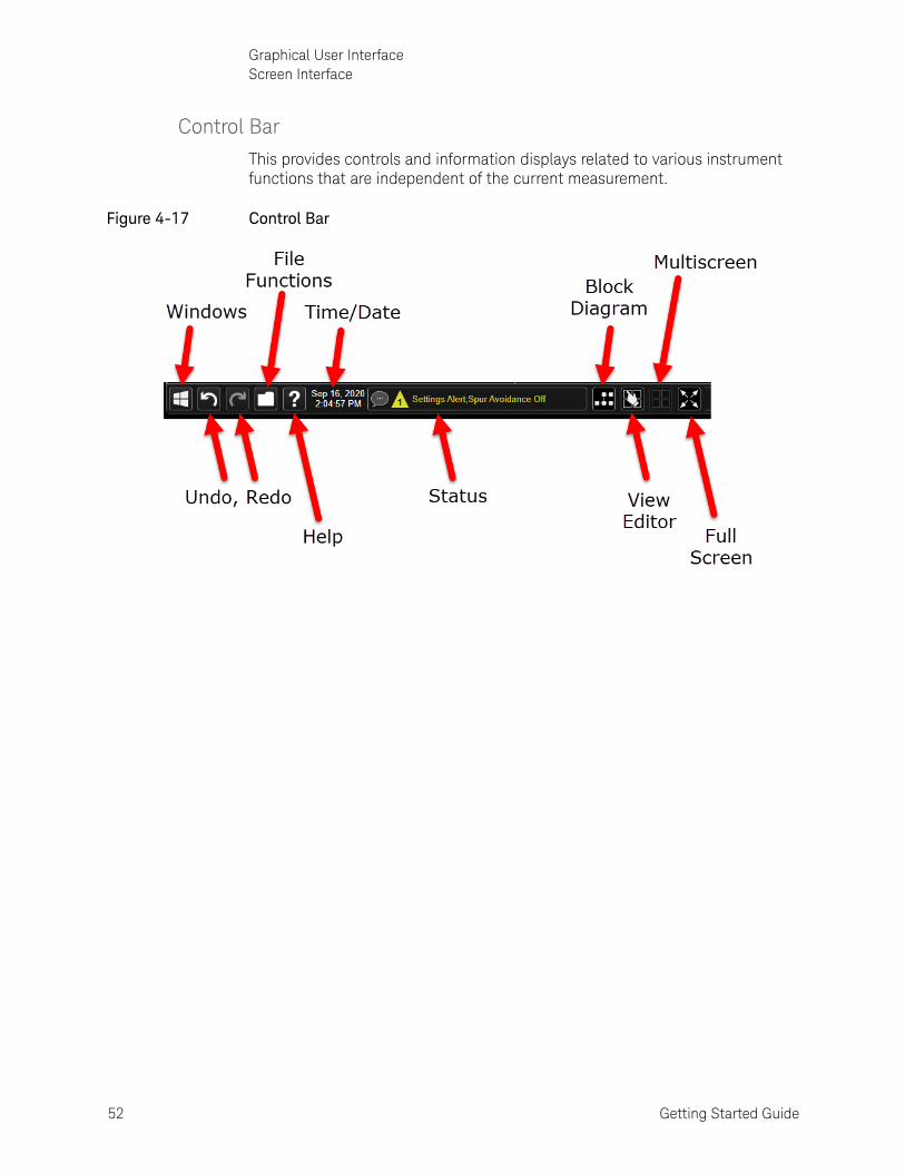
Control Bar
This provides controls and information displays related to various instrument functions that are independent of the current measurement.
Figure 4-17 Control Bar

Getting Started Guide 53
Graphical User InterfaceScreen Interface
Minimized window
A minimized window can be brought back up by finding the icon representing it in the Windows taskbar. Although the graphics for any two Keysight applications may look alike (as in the illustration below), hovering the mouse over one of them will display its Slot number and a small graphic representation of its measurement screen.
Figure 4-18 Reopening minimized windows

54 Getting Started Guide
Graphical User InterfaceScreen Interface
Help System
Detailed information about all features of the test software is available from the help system. To open the help content for the mode currently running, click the question-mark icon at the bottom of the screen. Because menus and features differ between (for example) the WLAN mode and the 5GNR mode, separate help systems for these modes are installed on the system.
Figure 4-19 Opening the help content
Within the help system, information can be found either by using the Search window at the upper right or by navigating the Contents tab at the left.
However, when you are looking for information specific to a menu selection or other feature of the user interface, it is easier to find it by using the context-sensitive help system described on the following page.
Getting Started Guide 55
Graphical User InterfaceScreen Interface
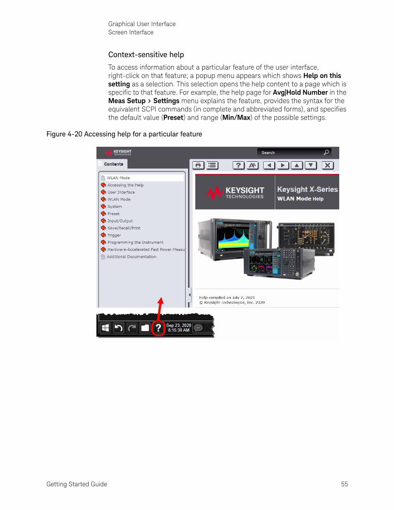
Context-sensitive help
To access information about a particular feature of the user interface, right-click on that feature; a popup menu appears which shows Help on this setting as a selection. This selection opens the help content to a page which is specific to that feature. For example, the help page for Avg|Hold Number in the Meas Setup > Settings menu explains the feature, provides the syntax for the equivalent SCPI commands (in complete and abbreviated forms), and specifies the default value (Preset) and range (Min/Max) of the possible settings.
Figure 4-20 Accessing help for a particular feature

56 Getting Started Guide
Graphical User InterfaceCommand Interface
Command InterfaceIn addition to being controlled and monitored by way of the screen interface, the instrument can be controlled and monitored by means of SCPI commands. For example, averaging can be disabled for the ACP measurement screen by changing the Averaging setting to Off in the Meas Setup > Settings menu. The same thing can be done by sending the command [:SENSe]:ACPower:AVERage:[STATe] OFF
Figure 4-21 Screen interface setting vs. SCPI command
In the SCPI command syntax, variables are indicated by angled brackets; for example, a parameter specifying an amplitude in dBm might be represented in the command syntax by the variable <ampl>, but in an actual command this variable be replaced by an actual value, such as -10.
Where a command parameter must be one of a limited set of choices, the alternatives are listed, with vertical lines separating the choices: OFF|ON|0|1.
The SCPI syntax allows for certain elements of a command to be omitted for brevity. Where a command name is given in a mixture of upper-case and lower-case letters, the lower-case letters are optional (for example, AVERage can be shortened to AVER). Also, any element that is enclosed in brackets is optional (however, if you do include the optional element, omit the brackets).
This command: [:SENSe]:ACPower:AVERage:[STATe] OFF can be sent in its long format: :SENSe:ACPower:AVERage:STATe OFF Or it can be shortened by omitting lower-case characters: :SENS:ACP:AVER:STAT OFF Or it can be shortened further by omitting the bracketed elements: :ACP:AVER OFF

Getting Started Guide 57
Graphical User InterfaceCommand Interface
To take another example, the command which sets the measurement center frequency has the following syntax: [:SENSe]:FREQuency:CENTer <freq>
This command can be sent in its long form: :SENSe:FREQuency:CENTer 16 GHz
However, it can also be shortened to: :FREQ:CENT 16 GHz
Detailed information about the SCPI commands and how they are used is provided in the help file for the measurement application you are running.
There is not always a command equivalent for a function of the screen interface (some functions which relate only to the display do not need a command). Also, there is not always a screen interface equivalent for a command (some commands perform functions which aren’t available from the screen interface).

58 Getting Started Guide
Graphical User InterfaceCommand Interface

59
Keysight Wireless Test SolutionsE6681A EXM-WB WirelessTest Set
Getting Started Guide
5 Operating Tasks
The following topics can be found in this section:
“TRX Selection” on page 60
“Receiver Setup” on page 62
“Source Setup” on page 67
“Port Configuration” on page 70
“Alignments” on page 76
“LAN Address Configuration” on page 84
“Managing Licenses” on page 86

60 Getting Started Guide
Operating TasksTRX Selection
TRX SelectionOn the monitor or remote desktop view of the test set, each TRX is represented by a separate XSA window. You can identify which TRX a window controls by looking for the identifier (TRX1 through TRX4 for a fully loaded system) at the top left corner of the window. (The TRXs are placed in numerical order in the PXIe chassis, beginning with TRX1 on the left.)
Figure 5-1 Identifying application windows for different TRXs
Although the test set as a whole is assigned only one IP address for the entire PXIe chassis, the individual TRXs within the chassis can be differentiated in network communication with the test set. The means of identifying a TRX depends upon the connection method, as outlined below. (You can also verify the connections for any TRX from the System Settings > I/O Config menu.)
Figure 5-2 SCPI LAN on I/O Config Menu
Getting Started Guide 61
Operating TasksTRX Selection
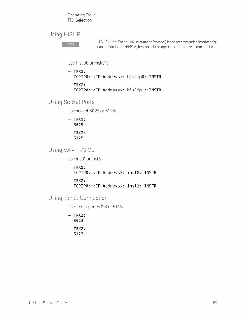
Using HiSLIP
Use hislip0 or hislip1:
— TRX1: TCPIP0::<IP Address>::hislip0::INSTR
— TRX2: TCPIP0::<IP Address>::hislip1::INSTR
Using Socket Ports
Use socket 5025 or 5125:
— TRX1: 5025
— TRX2: 5125
Using VXI-11/SICL
Use inst0 or inst3:
— TRX1: TCPIP0::<IP Address>::inst0::INSTR
— TRX2: TCPIP0::<IP Address>::inst1::INSTR
Using Telnet Connection
Use telnet port 5023 or 5123:
— TRX1: 5023
— TRX2: 5123
HiSLIP (High-Speed LAN Instrument Protocol) is the recommended interface for connection to the E6681A, because of its superior performance characteristics.

62 Getting Started Guide
Operating TasksReceiver Setup
Receiver SetupThe analyzer/receiver function of the E6681A relates to measurement of signals received from the DUT.
Clicking on the measurement tab at the upper left corner of the display opens the Mode/Measurement/View Selector, which you can use to select a particular kind of measurement. In this example, 5GNR has been selected under Mode, and the selections under Measurement are the measurements available in that mode. (For some measurements, there are also selections to be made under View.) In the example illustrated below, the Channel Power measurement is selected. Click OK to run this mode/measurement selection.
Figure 5-3 Selecting Mode/Measurement

Getting Started Guide 63
Operating TasksReceiver Setup
Most measurement settings are made from the menus, which can be accessed by selecting the dropdown button near the upper right of the display.
Figure 5-4 Accessing Menus
Selecting a menu from the dropdown list displays the menu selections (usually the selections are indented under multiple tabs shown at the right).

64 Getting Started Guide
Operating TasksReceiver Setup
For example, the Amplitude menu has three tabs; the selections under the Y Scale and Range tabs are shown below.
Figure 5-5 Measurement Menus

Getting Started Guide 65
Operating TasksReceiver Setup
Although some menu choices involve only a simple selection (On | Off) or a value to be entered (17 GHz), some choices cause a more elaborate selection screen to appear in the display. In the example illustrated below, Trigger > Trigger Settings Diagram opens an interactive display (the trigger source can be changed from Free Run to Ext 1 by clicking on the graphic).
Figure 5-6 Trigger Settings Diagram

66 Getting Started Guide
Operating TasksReceiver Setup
Another type of complex screen which some menu selections open is a configuration window such as the Meas Setup Summary Table, which gathers together multiple settings on one screen to make it easier to review them.
Figure 5-7 Meas Setup Summary Table
The menu choices are different for each measurement. For more detailed
information, see the help file for the 5G application.
Getting Started Guide 67
Operating TasksSource Setup
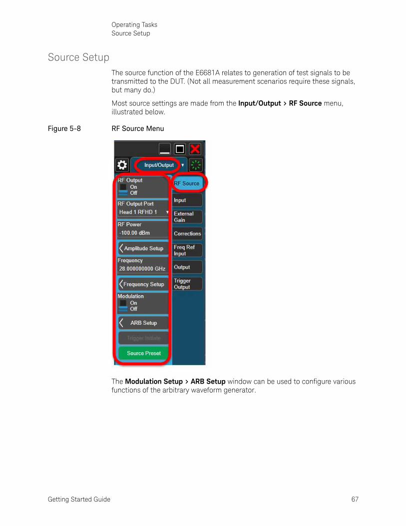
Source SetupThe source function of the E6681A relates to generation of test signals to be transmitted to the DUT. (Not all measurement scenarios require these signals, but many do.)
Most source settings are made from the Input/Output > RF Source menu, illustrated below.
Figure 5-8 RF Source Menu
The Modulation Setup > ARB Setup window can be used to configure various functions of the arbitrary waveform generator.

68 Getting Started Guide
Operating TasksSource Setup
Figure 5-9 ARB Setup Window
The source employs a user-defined waveform file for modulation (typically such a file would be created in Keysight Signal Studio software). To load a waveform file that is saved in a location on the disk drive, click the File icon at the bottom of the screen, and click the Recall icon which appears. This opens the Recall window; from there, select Waveform and Recall From File, and navigate to the appropriate file path to load the file.

Getting Started Guide 69
Operating TasksSource Setup
Figure 5-10 Recalling an ARB file
For more detailed information about source setup, see the help file for the 5G
application.

70 Getting Started Guide
Operating TasksPort Configuration
Port ConfigurationThe ports referred to in the Input/Output menus are the DUT-facing ports of the M1740A, not the ports on the front panel of the E6681A. The diagram below shows the names of ports, as they appear on the M1740A (black titles), and also as they are named in the user interface (blue titles) and in the SCPI commands (red titles).
Figure 5-11 Port nomenclature (in labels, menus, & commands)
The DUT-facing ports of the M1740A can be configured as inputs or outputs (one of each). Path-switching within the M1740A is configured automatically to support the chosen port settings.
Because each TRX is controlled independently (that is, by menus in separate windows, or by means of SCPI commands sent to different addresses), the menu settings and their equivalent commands are the same for both TRX1 and TRX2.
Because it is never permitted to set the same port as both input and output, swapping the current input/output status of the two ports requires an intermediate step, in which one of the ports is temporarily set to "None".

Getting Started Guide 71
Operating TasksPort Configuration
Port selection
Setting the output port
To set the Tx (output) port, go to the menu Input/Output > RF Source menu, and select a port name from the RF Output Port dropdown list.
— Head 1 RFHD 1 means the M1740A RF Tx/Rx 1 port.
— Head 1 RFHD 2 means the M1740A RF Tx/Rx 2 port.
— None (used temporarily during port setup changes, to avoid creating a settings conflict by choosing one port as output and input simultaneously).
Figure 5-12 Output port selections
The equivalent SCPI command to set the output port is: :FEED:RF:PORT:OUTP <port name> where the available port names are: RRH1RFHD1 | RRH1RFHD2 | NONE Example: :FEED:RF:PORT:OUTP RRH1RFHD1

72 Getting Started Guide
Operating TasksPort Configuration
Setting the input port
To set the Rx (input) port, go to the menu Input/Output > Input menu, and select a port name from the RF Input Port dropdown list.
— Head 1 RFHD 1 means the M1740A RF Tx/Rx 1 port.
— Head 1 RFHD 2 means the M1740A RF Tx/Rx 2 port.
— None (used temporarily during port setup changes, to avoid creating a settings conflict by choosing one port as output and input simultaneously.)
Figure 5-13 Input port selections
The equivalent SCPI command to set the input port is: :FEED:RF:PORT <port name> where the available port names are: RRH1RFHD1 | RRH1RFHD2 | NONE Example: :FEED:RF:PORT RRH1RFHD1

Getting Started Guide 73
Operating TasksPort Configuration
"Output" menu
Two settings are visible on the menu Input/Output > Output menu (REF Output and LO Output). These actually relate to signals within the E6681A, and are not used in connection with features that are currently available. They are reserved for use with possible future enhancements. Leave these menu items set to their default values (Off in both cases).
Figure 5-14 "Output" menu

74 Getting Started Guide
Operating TasksPort Configuration
Configuration example
In the example below, the RF Tx/Rx 1 port on the M1740A transmits a signal to the DUT, and the RF Tx/Rx 2 port receives a signal from the DUT.
Figure 5-15 Example: two TRXs, Tx/Rx1 as output, Tx/Rx2 as input
Set up the RF Input using this menu setting or its equivalent command:
Input/Output > Input > RF Input Port > Head1 RFHD 2
Command: :FEED:RF:PORT RRH1RFHD2
Then set up the RF Output using this menu setting or its equivalent command:
Input/Output > RF Source > RF Output Port > Head1 RFHD 1
Command: :FEED:RF:PORT:OUTP RRH1RFHD1
If the RF Output port is already set to Head1 RFHD HD2 but you want to set the Input port to Head1 RFHD HD2, you must first set the RF Output Port to None (command :FEED:RF:PORT:OUTP NONE).

Getting Started Guide 75
Operating TasksPort Configuration
The port settings in the previous example can be reversed, so that the RF Tx/Rx 2 port on the M1740A transmits a signal to the DUT, and the RF Tx/Rx 1 port receives a signal from the DUT.
Figure 5-16 Example: two TRXs, Tx/Rx1 as input, Tx/Rx2 as output
Set up the RF Input using this menu setting or its equivalent command:
Input/Output > Input > RF Input Port > Head1 RFHD 1
Command: :FEED:RF:PORT RRH1RFHD1
Then set up the RF Output using this menu setting or its equivalent command:
Input/Output > RF Source > RF Output Port > Head1 RFHD 2
Command: :FEED:RF:PORT:OUTP RRH1RFHD2
If the RF Output port is already set to Head1 RFHD HD1 but you want to set the Input port to Head1 RFHD HD1, you must first set the RF Output Port to None (command :FEED:RF:PORT:OUTP NONE).

76 Getting Started Guide
Operating TasksAlignments
AlignmentsAlignments are internal calibration adjustments which the transceiver must make to ensure that internal signal levels are properly maintained.
Alignments menu
To avoid interruptions, the alignments are not run automatically, either at startup or afterward; you must run them explicitly, using the Alignments menu (or sending equivalent SCPI commands).
The System Settings > Alignments > Align Now menu is illustrated below (the System Settings menus are accessed by clicking on the "gear" icon).
Figure 5-17 Alignments menu
The alignment process covers the E6681A and its cable connections to the IF ports of the M1740A remote radio head. Level correction for the M1740A itself is accomplished using a separate process; see Chapter 6, “System Calibration”, on page 91.
Getting Started Guide 77
Operating TasksAlignments
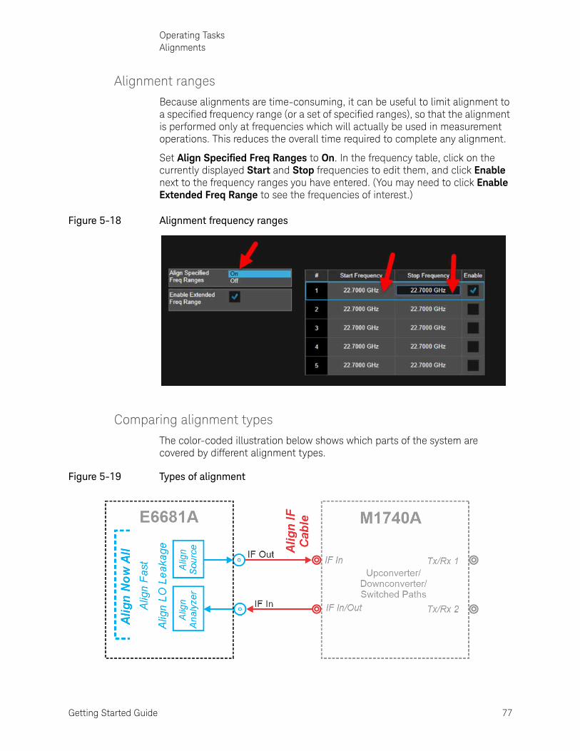
Alignment ranges
Because alignments are time-consuming, it can be useful to limit alignment to a specified frequency range (or a set of specified ranges), so that the alignment is performed only at frequencies which will actually be used in measurement operations. This reduces the overall time required to complete any alignment.
Set Align Specified Freq Ranges to On. In the frequency table, click on the currently displayed Start and Stop frequencies to edit them, and click Enable next to the frequency ranges you have entered. (You may need to click Enable Extended Freq Range to see the frequencies of interest.)
Figure 5-18 Alignment frequency ranges
Comparing alignment types
The color-coded illustration below shows which parts of the system are covered by different alignment types.
Figure 5-19 Types of alignment

78 Getting Started Guide
Operating TasksAlignments
The standard Align Now All option (blue in the illustration) is for internal alignment of the E6681A; it assures proper signal levels at the IF In and IF Out connectors on the E6681A front panel. (See ““All” alignment (weekly use)” on page 78.) Subsets of the All alignment can be run, to save time in situations where some signal paths are not used. (See “Subsets of Align Now All” on page 80.)
The remaining three alignments relate to the M1740A.
Align IF Cable (red in the illustration) includes the IF cables from the E6681A to the M1740A; it assures proper signal levels at the IF In and IF In/Out ports of the M1740A.
“All” alignment (weekly use)
Figure 5-20 Align Now All
This alignment of all RF subsystems in the TRX needs to be performed whenever any of the following statements is true:
1. The TRX’s internal temperature has drifted more than 5° C since the previous "All" alignment (see “Checking Temperature and Status” on page 83)
2. More than 7 days have elapsed since the previous “All” alignment
3. More than 8 hours have elapsed since the previous "Fast" alignment (or "All" alignment).
"All" refers to all subsystems within the E6681A itself; the "All" alignment does not encompass the alignment for IF cables to the M1740A remote radio head.

Getting Started Guide 79
Operating TasksAlignments
The “All” alignment typically takes less than 15 minutes to run.
To run the alignment, select System Settings> Alignments > Align Now > Align Now All, or send the SCPI command: :CAL
After the "All" alignment has been run, "Align IF Cable" should be run as well (see “Align IF Cable” on page 82).
The alignment process requires a 45-minute preliminary warm-up period, after applying power or after restarting the XSA application (when the application is not running, power is not applied to the TRXs; therefore an application shutdown has the same effect on alignment as a power shutdown).
80 Getting Started Guide
Operating TasksAlignments
Subsets of Align Now All
"Fast" alignment (daily use)
This partial alignment saves time by omitting some of the finer adjustments (such as IF Response Alignments) of the "All" alignment process. "Fast" alignment needs to be performed when any of the following statements is true:
1. The TRX’s internal temperature has drifted more than 5° C since the previous "All" alignment (see “Checking Temperature and Status” on page 83)
2. More than 7 days have elapsed since the previous “All” alignment
3. More than 8 hours have elapsed since the previous "Fast" alignment (or "All" alignment).
The “Fast” alignment typically takes less than 9 minutes to run.
To run the alignment, select System Settings> Alignments > Align Now > Align Fast, or send the SCPI command: :CAL:INT:FAST
The alignment process requires a 45-minute preliminary warm-up period, after applying power or after restarting the XSA application (when the application is not running, power is not applied to the TRXs; therefore an application shutdown has the same effect on alignment as a power shutdown).

Getting Started Guide 81
Operating TasksAlignments
Other parial alignments (rarely used)
The only partial alignment which is run routinely is the "Fast" alignment. However, it is sometimes appropriate to run some other subset of the processes included in Align Now All.
This need typically arises when a previous alignment was partly successful, but an error message such as "Align Analyzer skipped" was displayed. You can correct the problem which caused the alignment failure (typically an interfering RF signal applied to an RFIO port) and then run only the part of the "All" alignment that was skipped.
1. Select System Settings > Alignments > Align Now> Align Source, or send the SCPI commands: :CAL:INT:SOUR *WAI
2. Select System Settings > Alignments > Align Now > Align Analyzer, or send the SCPI commands: :CAL:INT:REC *WAI
3. Select System Settings > Alignments > Align Now > Align LO Leakage, or send the SCPI commands: :CAL:INT:LOL *WAI
Any alignment process requires a 45-minute preliminary warm-up period, after applying power or after restarting the XSA application (when the application is not running, power is not applied to the TRXs; therefore an application shutdown has the same effect on alignment as a power shutdown).

82 Getting Started Guide
Operating TasksAlignments
Align IF Cable
This alignment includes the IF cables from the front panel of the PXIe Subsystem to the instrument-facing side of the M1740A remote radio head transceiver; it assures proper signal levels at the Tx IF In and RX IF Out ports of the M1740A.
This alignment needs to be run once a week, or whenever the cables are reconnected (or have been subject to significant moving or bending of the cables). Also, whenever Align Now All is run, Align IF Cable should be run following it.
This alignment typically takes 7 to 10 minutes to run.
The IF cables must be fully connected to the M1740A while running this alignment. (DUT facing connections on the other side of the M1740A don’t have an effect on this alignment.)
Figure 5-21 Align IF Cable
To run the alignment, select System Settings> Alignments > Align Now > Align IF Cable, or send the SCPI command: :CAL:INT:IFC
The alignment process requires a 45-minute preliminary warm-up period (with the XSA application running).
The alignment plane for this process stops at the IF ports of the M1740A remote radio head. Level correction for the M1740A itself is accomplished using a separate process; see Chapter 6, “System Calibration”, on page 91.

Getting Started Guide 83
Operating TasksAlignments
Checking Temperature and Status
The PXIe subsystem’s internal temperature and the time since the most recent alignment can be checked by selecting System Settings> Alignments > Show Alignment Statistics, as illustrated below.
Figure 5-22 Show Alignment Statistics
About System Calibration
The PXIe subsystem’s internal temperature and the time since the most recent alignment can be checked by selecting System Settings> Alignments > Show Alignment Statistics, as illustrated below.

84 Getting Started Guide
Operating TasksLAN Address Configuration
LAN Address ConfigurationThe E6681A supports both dynamic and static assignment of its IP address, using ports LAN 1 and LAN 2.
The LAN 1 port is designed for dynamic IP addressing, using the Dynamic Host Configuration Protocol. If the your site network supports DHCP, the E6681A will be assigned an IP address automatically when it is connected to the LAN. Once the address is assigned, it is listed, along with the computer name, under System > Show > System. The address or computer name can be used to find the test set on the LAN. However, to see the System > Show > System screen and find this information, it is necessary either to connect a monitor to the front panel monitor port, or else to use the LAN 2 port to connect test set to a PC directly.
Figure 5-23 Checking the LAN address
Using the LAN ports to connect the test set directly to the public LAN is potentially insecure, because the test set does not provide anti-virus protection. Connecting the test set to the public LAN by way of a PC with antivirus protection is the preferred solution.
Getting Started Guide 85
Operating TasksLAN Address Configuration
To find the test set on the LAN, you will need to know its IP address or computer name. If you cannot easily obtain a monitor view of System > Show > System, you can determine the computer name using the instrument serial number. The computer name is in the format K-E6681A-nnnnn, ending in the last five digits of the serial number.
Configuring the LAN
Hostname
The Computer Name, or hostname, is pre-configured from the factory. It must be a unique name so that it does not conflict with other equipment on your LAN. The pre-configured Computer Name is K-E6681A-xxxxx, where xxxxx represents the last 5 digits of the test set serial number.
To change the Computer Name consult the Microsoft Windows Help and Support Center.
IP Address & Gateway
The test set is pre-configured to obtain an IP Address using DHCP. The IP Address and Gateway can be changed. Consult the Microsoft Windows Help and Support Center to configure the LAN.

86 Getting Started Guide
Operating TasksManaging Licenses
Managing LicensesLicenses can be tied to a particular instrument, or transferable from one instrument to another by various means.
Licenses can be either time-based or perpetual (the latter have no expiration date).
To verify which licenses are installed, open the Keysight License Manager from the Windows Start menu. (It can also be opened by clicking the "gear" icon at the upper left to open the System Settings screen, and clicking Licensing > License Manager.) The licenses installed on the test set are listed, with information provided about license types and expiration dates (in the illustrated example, "Fixed" indicates a node-locked license).
Figure 5-24 Installed licenses (as displayed in Keysight License Manager)

Getting Started Guide 87
Operating TasksManaging Licenses
Node-locked License
A node-locked license is a license which permits the licensed software to run on one particular machine. Each node-locked license is locked to an instrument or computer; the license is resident on the hard disk of the system it is locked to, and that system runs the licensed feature or product.
Trial licenses, which are sometimes provided by Keysight so that customers can try out a product, are node-locked, time-based licenses. Trial licenses are issued for a particular instrument or computer, and have an expiration date.
Transportable License
A transportable license is a type of node-locked license which is not tied permanently to a single instrument: it can be unlocked from one client host and then locked to another client host (however, it can only be assigned to one instrument at a time).
A transportable license is installed on an instrument by copying the contents of a license file into the Keysight License Manager application (KLM), either manually (copy and pasting file contents) or by placing the license files on a USB memory device (KLM automatically takes in any license files detected on the memory device). KLM can also be used to delete a license, or transport it to a different instrument.
Unlike permanently node-locked licenses, which are pre-installed at the factory with new instrument purchases, transportable licenses require redemption and installation of the license before the first use. This allows the user to determine on which instrument to initially install the application license.
Transportable licenses require a connection to the Keysight Software Manager (KSM) web site: https://ksm.software.keysight.com/ASM/External/
However, the connection to KSM is needed only for managing the check-in or check-out of the license. KSM also provides for storage of unused licenses which have been transported off instruments but are awaiting assignment to new instruments. The server will limit the number of transports per 30 day period per application license to 10.
Keysight recommends that instruments use the same instrument software release to ensure the latest code is available on each instrument, so that the user experience is identical between instruments. This is particularly important when transporting the license for a newly-released application which may only be available in the latest software release.

88 Getting Started Guide
Operating TasksManaging Licenses
After initial installation of the license, when you want to transport a license, run Keysight License Manager on the host that currently has the license, and transport the license. (Select Help > Keysight License Manager Help and search for “transport” to find detailed instructions.)
Other related topics for managing your software and licenses can be found by reviewing the Keysight License Manager Help available by clicking "?" icon in the KLM window.
USB-Portable License
A USB portable license is another type of transferable license, in which the license is tied to a dongle which can be plugged into the instrument’s USB port.
A USB-portable license is a version of a transportable license, in which the license is locked to a USB dongle rather than to an instrument. An instrument that runs the licensed feature or product must have the license file resident on its disk drive, and have the dongle connected to one of its USB ports when it runs the licensed feature or product. Transporting the license, in this case, becomes a simple matter of plugging the USB device into a different instrument.
Transportable licenses for the E6681A allow you to transport licenses up to 30 times within 10 days.

Getting Started Guide 89
Operating TasksManaging Licenses
Floating License
A floating license (sometimes referred to as a network license) is another type of transferable license, in which the license is assigned temporarily by a designated license server. Setup your license server by installing Keysight License Manager 6.
Floating licenses reside on the license server and are checked out for use by Keysight products (instruments or applications), then returned (checked in), when no longer needed, so that they can be used on another computer or instrument.
Floating licenses can also be borrowed for a specified number of days. Once you have borrowed a license, you can disconnect the licensed instrument or computer from the license server and continue to use the license offline for the duration of the borrow period.
Installing a floating license
Server setup:
1. Install Keysight License Server or Keysight License Manager on the server machine.
2. Obtain a license file.
3. Save the license file.
4. User manual process or Keysight License Manager to add the license file and start the server process.
Client setup:
1. Install the Keysight product/software to be licensed.
2. Install Keysight License Manager.
3. Use Keysight License Manager to specify license server (provides access to licenses).
4. Start the product.
The Keysight implementation of FlexNet Publisher floating licensing requires the FlexNet Publisher license server manager (lmgrd) and Keysight vendor daemon (agileesofd) to run on any local computer used as a license server system.

90 Getting Started Guide
Operating TasksManaging Licenses

91
Keysight Wireless Test SolutionsE6681A EXM-WB WirelessTest Set
Getting Started Guide
6 System Calibration
System Calibration corrects for any power-level irregularities related to signal paths through the M1740A remote radio head.
The alignment process described in “Alignments” on page 76 provides a similar correction related to paths with the E6681A, or between the E6681A and the M1740A.
The following topics can be found in this section:
“Calibration Equipment Required” on page 92
“Calibration Ports” on page 93
“Launching System Calibration” on page 94
“Power Calibration” on page 99
“Flatness Calibration” on page 104
“Tabs of the System Calibration window” on page 109
92 Getting Started Guide
System CalibrationCalibration Equipment Required
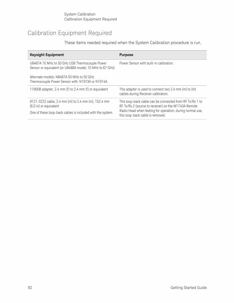
Calibration Equipment Required
These items needed required when the System Calibration procedure is run.
Keysight Equipment Purpose
U8487A 10 MHz to 50 GHz USB Thermocouple Power Sensor or equivalent (or U8488A model, 10 MHz to 67 GHz) Alternate models: N8487A 50 MHz to 50 GHz Thermocouple Power Sensor with: N1913A or N1914A.
Power Sensor with built-in calibration.
11900B adapter, 2.4 mm (f ) to 2.4 mm (f ) or equivalent This adapter is used to connect two 2.4 mm (m) to (m) cables during Receiver calibration.
8121-3222 cable, 2.4 mm (m) to 2.4 mm (m), 152.4 mm (6.0 in) or equivalent
One of these loop-back cables is included with the system.
This loop-back cable can be connected from RF Tx/Rx 1 to RF Tx/Rx 2 (source to receiver) on the M1740A Remote Radio Head when testing for operation; during normal use, this loop-back cable is removed.

Getting Started Guide 93
System CalibrationCalibration Ports
Calibration Ports
The DUT-facing ports M1740A RF TxRx 1 and M1740A RF TxRx 2 (at the bottom of the illustration) are to be calibrated.
Additional connections between the E6681A and the M1740As are illustrated below.
Figure 6-1 System connections and calibration ports
One end of the U8478A power sensor head is connected by cable to a USB port on the front panel of the E6681A (any of the USB ports can be used); the RF end of the sensor connects to ports or cables to be measured.

94 Getting Started Guide
System CalibrationLaunching System Calibration
Launching System CalibrationOnce the S910xA System Calibration utility has been installed, a shortcut can be found in the Windows Start menu (as illustrated below).
S910xA System Calibration can also be started by navigating to the directory: C:\Program Files\Keysight\S9100A\System Calibration and running: S9100A System Calibration.exe
Figure 6-2 S910xA System Calibration icon in Windows Start menu
This opens the System Calibration window as shown below. The window has a tabbed display with seven tabs to choose from; the window as shown below is open to the Equipment tab.
Figure 6-3 System Calibration window

Getting Started Guide 95
System CalibrationLaunching System Calibration
Connecting the power sensor
After the utility launches connect the USB power sensor (U8487A) to the USB port on the E6681A controller (as indicated in Figure 6-1 on page 93).
You will need the VISA address of the power sensor. Open Keysight Connection Expert from the Windows start menu (or from task bar, if the "IO" icon is visible there).
Figure 6-4 Opening Keysight Connection Expert
Find the power sensor in the Connection Expert window, and copy its VISA address (it will be pasted into the System Calibration window.
Figure 6-5 Connection Expert window, showing U8487A sensor

96 Getting Started Guide
System CalibrationLaunching System Calibration
Setting up VISA addresses
It is necessary to identify the hardware involved in a calibration by entering VISA addresses.
VISA Address for the power meter
In the Equipment tab of the System Calibration window, copy the VISA address of the power sensor to the Power Meter > VISA Address field. (This could also be the address of a separate power meter, to which the power sensor is connected.) You can click the Test button to verify that this is recognized by the system as a valid address. Leave the Channel set to 1.
Figure 6-6 Setting the address of the power sensor
Zero the sensor by clicking Zero/Calibrate > Start. At the prompt, make sure the sensor isn’t connected to any RF port, and click Ok. Wait for the confirmation window to indicate the process is complete.
Figure 6-7 Zeroing the power sensor

Getting Started Guide 97
System CalibrationLaunching System Calibration
VISA Address for the TRX/M1740A pair
In the Equipment tab of the System Calibration window, enter the address of the TRX which is connected to the M1740A you are calibrating to the Primary Transceiver > VISA Address field.
The TRX units are VXT module (M9411A) within the E6681A chassis. Assuming the calibration software is running on the embedded controller (local host), the addresses are:
— TRX1: TCPIP0::localhost::hislip0::INSTR
— TRX2 (if present): TCPIP0::localhost::hislip1::INSTR
If the software is running on an external controller, see “Equipment tab” on page 110 for further details.
The Secondary Transceiver > VISA Address field is not used in the case of the E6681A. To calibrate TRX2 if it is included in the E6681A, you must run a separate calibration procedure for it, using its VISA address in the Primary Transceiver > VISA Address field.
You can click the Test button to verify that this is recognized by the system as a valid address.
Figure 6-8 Setting the VISA address for TRX1

98 Getting Started Guide
System CalibrationWhen to Calibrate
When to CalibrateRegular calibration is necessary to ensure accurate measurement using the M1740A remote radio head. Calibration is required:
— When you first use the E6681A and M1740A.
— When you replace one M1740A remote radio head with another.
— When you replace the RF cables that connect the E6681A to the M1740A.
— When the date shown under Last Performed in the Calibration Status tab is older than the date shown under Expires (see “Calibration Status tab” on page 112 for more information).
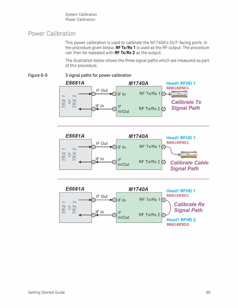
Getting Started Guide 99
System CalibrationPower Calibration
Power Calibration This power calibration is used to calibrate the M1740A’s DUT-facing ports. In the procedure given below, RF Tx/Rx 1 is used as the RF output. The procedure can then be repeated with RF Tx/Rx 2 as the output.
The illustration below shows the three signal paths which are measured as part of this procedure.
Figure 6-9 3 signal paths for power calibration

100 Getting Started Guide
System CalibrationPower Calibration
Figure 6-10 Power Calibration tab
Step 1. Calibrate the Tx signal path:
1. Make sure the power sensor you are using is identified in the Equipment tab, and has been zeroed; see “VISA Address for the power meter” on page 96.
2. Make sure the TRX/M1740A pair you are calibrating is identified in the Equipment tab; see “VISA Address for the TRX/M1740A pair” on page 97.
3. Select the Power Calibration tab.
4. Select the Operation drop-down arrow and select Calibration.
5. Select the Calibration Step(s) drop-down arrow and select Complete.
6. Select the Port Selection drop-down arrow and select RRH 1 RFHD 1 -> RRH 1 RFHD 2.
7. Click the green triangle button to begin the calibration, and follow the prompts which appear. (During calibration, the green triangle is replaced by a red square.)
8. Connect the U8487A Power Sensor or equivalent to M1740A RF Tx/Rx 1. (Torque with a 9 inch/lbs wrench.)
9. Select Ok in the prompt window to continue the calibration.

Getting Started Guide 101
System CalibrationPower Calibration
Step 2. Calibrate the cable signal path:
1. You will be prompted to connect a cable to the Tx/Rx1 port. Begin by disconnecting the power sensor from M1740A RF Tx/Rx 1.
2. Using an 8121-3222 cable, 2.4 mm (m) to 2.4 mm (m), 152.4 mm (6.0 in) or equivalent, connect one end of the cable to M1740A RF Tx/Rx 1. (Torque with a 9 inch/lbs wrench.)
3. Using an 11900B adapter, 2.4 mm (f) to 2.4 mm (f) or equivalent, connect the U8487A Power Sensor or equivalent to the end of the cable. (Torque with a 9 inch/lbs wrench.)
4. Select Ok in the prompt window to continue the calibration. Results appear in the Results Cable tab when the calibration is complete.
Step 3. Calibrate the Rx signal path:
1. You will be prompted to disconnect the power sensor and connect the cable to the Tx/Rx2 port. Begin by disconnecting the power sensor and adapter from the cable.
2. Connect the free end of the cable to M1740A RF Tx/Rx 2.

102 Getting Started Guide
System CalibrationPower Calibration
3. Select Ok in the prompt window to continue the calibration. When the power calibration is complete the green triangle re-appears and the results appear in the Results Receiver tab. Power calibration corrections are saved C:\ProgramData\Keysight\S9100A with the folders named Rx_SystemCal and Tx_SystemCal.

Getting Started Guide 103
System CalibrationPower Calibration
Repeating the power calibration for RFHD 2
The power calibration procedure (described under “Power Calibration” on page 99) needs to be repeated, this time with Tx/Rx 2 used as the RF output and Tx/Rx 1 used as the RF input. The procedure is the same, except for the reversed roles of the two ports. The signal paths in this case are as illustrated below.
Figure 6-11 3 signal paths for power calibration, with RF Tx/Rx 2 as output
In this case, under the Port Selection drop-down arrow, select RRH 1 RFHD 2 -> RRH 1 RFHD 1. The prompts which appear during the procedure will be modified to match this port selection.

104 Getting Started Guide
System CalibrationFlatness Calibration
Flatness Calibration This flatness calibration is used to calibrate the M1740A’s DUT-facing ports, with RF Tx/Rx 1 used as the RF output. The procedure can then be repeated with RF Tx/Rx 2 as the output.
The purpose of flatness calibration is to minimize variations in power level across a 1 GHz bandwdith with a defined center frequency. During this calibration, multiple traces are generated, at 100 MHz intervals extending 500 MHz below and 500 MHz above the center frequency.
The illustration below shows the three signal paths which are measured as part of this procedure.
Figure 6-12 3 signal paths for flatness calibration

Getting Started Guide 105
System CalibrationFlatness Calibration
Figure 6-13 Flatness Calibration tab
Step 1. Calibrate the Tx signal path:
1. Make sure the power sensor you are using is identified in the Equipment tab, and has been zeroed; see “VISA Address for the power meter” on page 96.
2. Make sure the TRX/M1740A pair you are calibrating is identified in the Equipment tab; see “VISA Address for the TRX/M1740A pair” on page 97.
3. Select the Flatness Calibration tab.
4. Select the Operation drop-down arrow and select Calibration.
5. Select the Calibration Step(s) drop-down arrow and select Complete.
6. Select the Port Selection drop-down arrow and select RRH 1 RFHD 1 -> RRH 1 RFHD 2.
7. Enter the Center Frequencies at which you wish to calibrate (use the plus and minus buttons to add or delete frequencies.
8. Click the green triangle button to begin the calibration, and follow the prompts which appear. (During calibration, the green triangle is replaced by a red square.)
9. Connect the U8487A Power Sensor or equivalent to M1740A RF Tx/Rx 1. (Torque with a 9 inch/lbs wrench.)
10. Select Ok in the prompt window to continue the calibration.

106 Getting Started Guide
System CalibrationFlatness Calibration
Step 2. Calibrate the cable signal path:
1. You will be prompted to connect a cable to the Tx/Rx1 port. Begin by disconnecting the power sensor from M1740A RF Tx/Rx 1.
2. Using an 8121-3222 cable, 2.4 mm (m) to 2.4 mm (m), 152.4 mm (6.0 in) or equivalent, connect one end of the cable to M1740A RF Tx/Rx 1. (Torque with a 9 inch/lbs wrench.)
3. Using an 11900B adapter, 2.4 mm (f) to 2.4 mm (f) or equivalent, connect the U8487A Power Sensor or equivalent to the end of the cable. (Torque with a 9 inch/lbs wrench.)
4. Select Ok in the prompt window to continue the calibration.
Step 3. Calibrate the Rx signal path:
1. You will be prompted to disconnect the power sensor and connect the cable to the Tx/Rx2 port. Begin by disconnecting the power sensor and adapter from the cable.
2. Connect the free end of the cable to M1740A RF Tx/Rx 2.
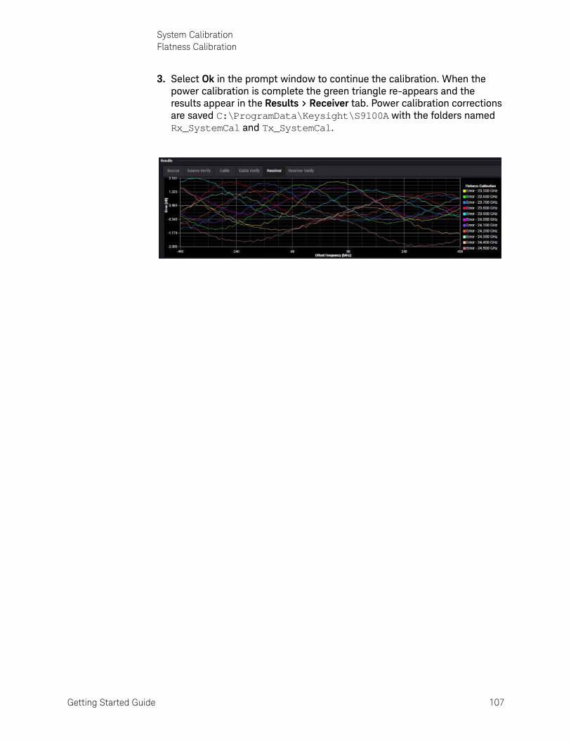
Getting Started Guide 107
System CalibrationFlatness Calibration
3. Select Ok in the prompt window to continue the calibration. When the power calibration is complete the green triangle re-appears and the results appear in the Results > Receiver tab. Power calibration corrections are saved C:\ProgramData\Keysight\S9100A with the folders named Rx_SystemCal and Tx_SystemCal.
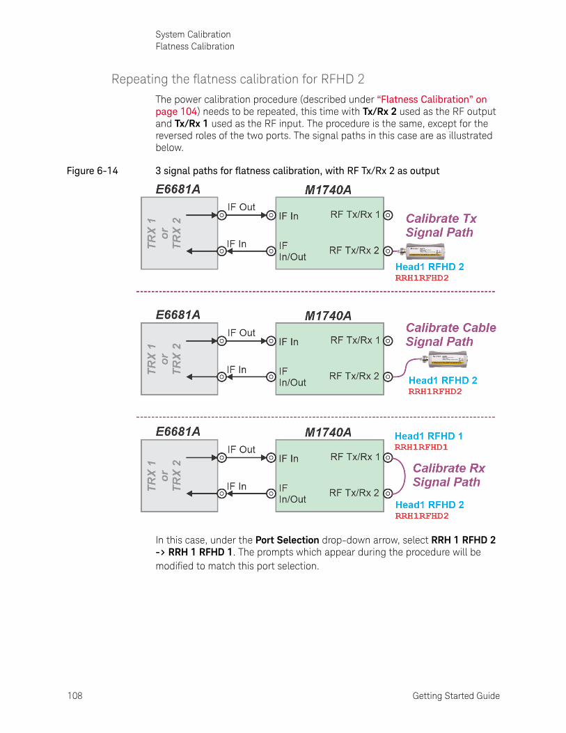
108 Getting Started Guide
System CalibrationFlatness Calibration
Repeating the flatness calibration for RFHD 2
The power calibration procedure (described under “Flatness Calibration” on page 104) needs to be repeated, this time with Tx/Rx 2 used as the RF output and Tx/Rx 1 used as the RF input. The procedure is the same, except for the reversed roles of the two ports. The signal paths in this case are as illustrated below.
Figure 6-14 3 signal paths for flatness calibration, with RF Tx/Rx 2 as output
In this case, under the Port Selection drop-down arrow, select RRH 1 RFHD 2 -> RRH 1 RFHD 1. The prompts which appear during the procedure will be modified to match this port selection.

Getting Started Guide 109
System CalibrationTabs of the System Calibration window
Tabs of the System Calibration windowThe seven tabs are described in the table below.
Tab Purpose
Equipment To enter VISA Address and hislip socket number "Connection Strings" for all equipment used during Calibration. (See page 110.)
Calibration Status To display the status of all calibrations, the last time a calibration was performed, the time that a calibration expires and has to be repeated, as well as any recommended steps that need to be taken. (See page 112.)
Power Calibration To provide an accurate power level at each mmWave I/O port. (See page 114.)
Flatness Calibration To provide a consistent power level, at each mmWave I/O port, across a given bandwidth. (See page 117.)
Cable Calibration This tab is not applicable to E6681A.
Dual Source Calibration
This tab is not applicable to E6681A.
Diagnostics This tab is not for customer use; it is used by Keysight service engineers.
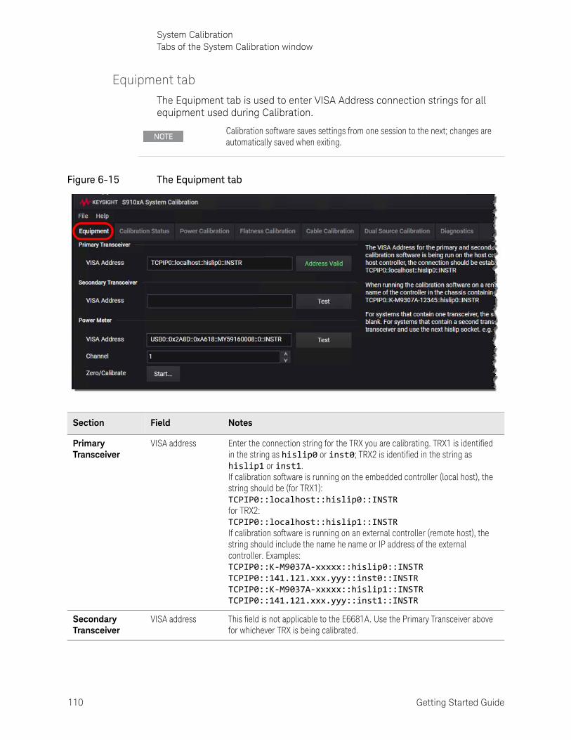
110 Getting Started Guide
System CalibrationTabs of the System Calibration window
Equipment tab
The Equipment tab is used to enter VISA Address connection strings for all equipment used during Calibration.
Figure 6-15 The Equipment tab
Calibration software saves settings from one session to the next; changes are automatically saved when exiting.
Section Field Notes
Primary Transceiver
VISA address Enter the connection string for the TRX you are calibrating. TRX1 is identified in the string as hislip0 or inst0; TRX2 is identified in the string as hislip1 or inst1. If calibration software is running on the embedded controller (local host), the string should be (for TRX1): TCPIP0::localhost::hislip0::INSTR for TRX2: TCPIP0::localhost::hislip1::INSTR If calibration software is running on an external controller (remote host), the string should include the name he name or IP address of the external controller. Examples: TCPIP0::K-M9037A-xxxxx::hislip0::INSTR TCPIP0::141.121.xxx.yyy::inst0::INSTR TCPIP0::K-M9037A-xxxxx::hislip1::INSTR TCPIP0::141.121.xxx.yyy::inst1::INSTR
Secondary Transceiver
VISA address This field is not applicable to the E6681A. Use the Primary Transceiver above for whichever TRX is being calibrated.

Getting Started Guide 111
System CalibrationTabs of the System Calibration window
Once the VISA addresses have been entered, verify connectivity by clicking the Test button located next to each entry box; Address Valid is displayed on a button if the address connects properly.
Power Meter VISA address Enter the connection string for a one or two channel power meter available via LAN or a USB sensor. The string should contain the IP address. Example: USBO::0x2A8D::0xA618::MY59320004::0::INSTR
Channel Specify which channel the power sensor is connected to on the power meter. Select 1 to use Channel 1 (or select 2 to use Channel 2 on a power meter with two channels).
Zero/Calibrate The Start... button is used to calibrate the power meter before use.
Section Field Notes

112 Getting Started Guide
System CalibrationTabs of the System Calibration window
Calibration Status tab
This tab is used to display the status of all calibrations, the last time a calibration was performed, the time that a calibration expires and has to be repeated, as well as any recommended steps that need to be taken.
Figure 6-16 Calibration Status tab
Each calibration path is tracked separately, and if a calibration is recommended, the steps are displayed. Although there are four different system calibrations supported by the software, the available calibrations are dependent on the hardware in the system being calibrated; only a subset of these calibrations is used by the E6681A.

Getting Started Guide 113
System CalibrationTabs of the System Calibration window
Section Name Notes
Power RRH 1 RFHD 1 -> RRH 1 RFHD 2
Calibration for: M1740A RF Tx/Rx 1 as the output, and RF Tx/Rx 2 is the input.
RRH 1 RFHD 2 -> RRH 1 RFHD 1
Calibration for: M1740A RF Tx/Rx 2 as the output, and RF Tx/Rx 1 as the input.
IFIO 1 -> IFIO 1 Not applicable to E6681A
RF Output -> RF Input
Not applicable to E6681A
Cable (N/A) Not applicable to E6681A.
Dual Source (N/A) Not applicable to E6681A
Power Sensor U8487A Zero/calibration of the U8748A power sensor

114 Getting Started Guide
System CalibrationTabs of the System Calibration window
Power Calibration tab
Power Calibration is used to ensure an accurate power level at each mmWave Transceiver input and output port.
Figure 6-17 Power Calibration tab
Before running a power calibration, select an Operation, Calibration Step, Port Selection. Then click the start icon (a green arrow). Once started, a calibration can be stopped by clicking the stop icon (a red square).
The calibration procedure requires user interaction. Between each of the calibration steps, the user must connect a power sensor to different ports, and/or connect a cable (short loop-back cable). Cable connection prompts are displayed which direct you to perform the desired connections. Click Ok to continue after making the connection, or Cancel to end the calibration.

Getting Started Guide 115
System CalibrationTabs of the System Calibration window
Figure 6-18 Cable Connection prompt
A Complete power calibration for a signal path uses a three-step process that consists of:
— A source (Tx) power calibration,
— followed by a cable or power reference calibration,
— followed by a a receiver (Rx) power calibration.
During this three-step process, the source port is calibrated to provide an accurate power at the output of the transmit signal path. Next, a cable (short loop-back cable) is connected (to the source port and a cable calibration is
Section Field Notes
Setup Operation Select a Calibration only, a Verification only, or a combined Calibration and Verification.
Calibration Step(s) Select which step of the calibration process to perform: Source, Cable, Receiver, or Complete. (See notes on the Complete calibration below.)
Port Selection Select from: RRH 1 RFHD 1 -> RRH 1 RFHD 2 RRH 1 RFHD 2 -> RRH 1 RFHD 1 (These refer to M1740A RF Tx/Rx 1 and RF Tx/Rx 2)
Results (All of these results are taken if Operation is set to Calibration and Calibration Step is set to Complete)
Source Results of a Source power calibration when Operation is set to Calibration and Calibration Step is set to Source.
Source Verify Results of a Source power calibration when Operation is set to Verification and Calibration Step is set to Source.
Cable Results of a Cable power calibration when Operation is set to Calibration and Calibration Step is set to Cable.
Cable Verify Results of a Cable power calibration when Operation is set to Verification and Calibration Step is set to Cable.
Receiver Results of a Receiver power calibration when Operation is set to Calibration and Calibration Step is set to Receiver.
Receiver Verify Results of a Receiver power calibration when Operation is set to Verification and Calibration Step is set to Receiver.
Status Messages
Verbosity Normal is the default setting, but can be changed to Detailed; (in which case additional details are displayed that are related to a particular calibration).

116 Getting Started Guide
System CalibrationTabs of the System Calibration window
performed. This records the power level at the end of the cable and the power reference values are stored for use in the receiver calibration. To calculate a correction value, the receiver calibration looks at the difference between the power reference values at the end of the cable and the actual power at the receiver.
During the source power calibration step, a male adapter is required on the power meter; during the cable calibration step, a female adapter is required. These adapters should be of equal lengths. For a list of required adapters, see “Calibration Equipment Required” on page 92.
Results are displayed on the graphs as the calibrations are completed.
Figure 6-19 Calibration Results display
Power Calibration results are stored at: C:\ProgramData\Keysight\S9100A\ under TX_SystemCal or RX_SystemCal
Filenames for port selection RRH 1 RFHD 1 ->RRH 1 RFHD 2: Source: TX_SystemCal S9100ID_<SerialNumber>-Tx-RFIO_1-CHANNELPOWER.csv Receiver: RX_SystemCal S9100ID_<SerialNumber>-Rx-RFInputOutput2-CHANNELPOWER.csvFilenames for port selection RRH 1 RFHD 2 ->RRH 1 RFHD 1: Source: TX_SystemCal S9100ID_<SerialNumber>-Tx-RFIO_2-CHANNELPOWER.csv Receiver: RX_SystemCal S9100ID_<SerialNumber>-Rx-RFInputOutput1-CHANNELPOWER.csv

Getting Started Guide 117
System CalibrationTabs of the System Calibration window
Flatness Calibration tab
The Flatness Calibration tab is used to provide a consistent power level, at each mmWave Transceiver input and output port, across a given bandwidth. During this calibration, multiple traces are generated for source and receiver power at 100 MHz intervals, across a 1 GHz span around the center frequency. For example, a flatness calibration at 28 GHz generates flatness data at 27.5 GHz, 27.6 GHz, 27.7 GHz, and so on up to 28.5 GHz.
Figure 6-20 Flatness Calibration tab
Before running a flatness calibration, select an Operation, Calibration Step, Port Selection. Then click the start icon (a green arrow). Once started, a calibration can be stopped by clicking the stop icon (a red square).
As in the case of power calibration, flatness calibration procedure requires user interaction. Cable connection prompts are displayed which direct you to perform the desired connections. Click Ok to continue after making the connection, or Cancel to end the calibration.
Figure 6-21 Cable Connection prompt

118 Getting Started Guide
System CalibrationTabs of the System Calibration window
A Complete flatness calibration for a signal path uses a three-step process that consists of:
— A source (Tx) power calibration,
— followed by a cable or power reference calibration,
— followed by a a receiver (Rx) power calibration.
During this three-step process, the source port is calibrated to provide an accurate power at the output of the transmit signal path. Next, a cable (short loop-back cable) is connected (to the source port and a cable calibration is performed. This records the power level at the end of the cable and the power reference values are stored for use in the receiver calibration. To calculate a correction value, the receiver calibration looks at the difference between the power reference values at the end of the cable and the actual power at the receiver.
Section Field Notes
Setup Operation Select a Calibration only, a Verification only, or a combined Calibration and Verification.
Calibration Step(s) Select which step of the calibration process to perform: Source, Cable, Receiver, or Complete. (See notes on the Complete calibration below.)
Port Selection Select from: RRH 1 RFHD 1 -> RRH 1 RFHD 2 RRH 1 RFHD 2 -> RRH 1 RFHD 1 (These refer to M1740A RF Tx/Rx 1 and RF Tx/Rx 2)
Results (All of these results are taken if Operation is set to Calibration and Calibration Step is set to Complete)
Source Results of a Source power calibration when Operation is set to Calibration and Calibration Step is set to Source.
Source Verify Results of a Source power calibration when Operation is set to Verification and Calibration Step is set to Source.
Cable Results of a Cable power calibration when Operation is set to Calibration and Calibration Step is set to Cable.
Cable Verify Results of a Cable power calibration when Operation is set to Verification and Calibration Step is set to Cable.
Receiver Results of a Receiver power calibration when Operation is set to Calibration and Calibration Step is set to Receiver.
Receiver Verify Results of a Receiver power calibration when Operation is set to Verification and Calibration Step is set to Receiver.
Status Messages
Verbosity Normal is the default setting, but can be changed to Detailed; (in which case additional details are displayed that are related to a particular calibration).

Getting Started Guide 119
System CalibrationTabs of the System Calibration window
During the source power calibration step, a male adapter is required on the power meter; during the cable calibration step, a female adapter is required. These adapters should be of equal lengths. For a list of required adapters, see “Calibration Equipment Required” on page 92.
Results are displayed on the graphs as the calibrations are completed.
Flatness Calibration results are stored at: C:\ProgramData\Keysight\S9100A\ under TX_SystemCal or RX_SystemCal
Filenames for port selection RRH 1 RFHD 1 ->RRH 1 RFHD 2: Source: TX_SystemCal S9100ID_<SerialNumber>-Tx-RFIO_1-FLATNESS.csv Receiver: RX_SystemCal S9100ID_<SerialNumber>-Rx-RFInputOutput2-FLATNESS.csvFilenames for port selection RRH 1 RFHD 2 ->RRH 1 RFHD 1: Source: TX_SystemCal S9100ID_<SerialNumber>-Tx-RFIO_2-FLATNESS.csv Receiver: RX_SystemCal S9100ID_<SerialNumber>-Rx-RFInputOutput1-FLATNESS.csv

120 Getting Started Guide
System CalibrationTabs of the System Calibration window
Cable Calibration tab
This tab is not applicable to the E6681A.
Dual Source Calibration tab
This tab is not applicable to the E6681A.
Diagnostics tab
This tab provides diagnostic tests used by Keysight service engineers; it is not intended for customer use.

121
Keysight Wireless Test SolutionsE6681A EXM-WB WirelessTest Set
Getting Started Guide
7 Test Set Operating System
The following topics can be found in this section:
“Keysight Software Installed” on page 122
“User Accounts” on page 123
“Licensing New Application Software - After Initial Purchase” on page 125
“Transporting a License Between Test Sets” on page 127
“Windows Security” on page 130
“System Maintenance” on page 133
“Instrument software installation” on page 140

122 Getting Started Guide
Test Set Operating SystemKeysight Software Installed
Keysight Software InstalledUse of the E6681A measurement applications requires appropriate licenses. Whichever licenses were purchased with the instrument are installed at the factory (see “Application Licenses” on page 27). Other licenses can be purchased and installed later (including transportable licenses). For more information, see: http://www.keysight.com/find/E6681A
Customer Installation of Software
3rd Party software verified by Keysight
Keysight has verified that the following program is compatible with the test set applications: Symantec AntiVirus™ Corporate Edition version 10
Installation of other 3rd party software
The E6681A platform is an open Windows environment, so you can install non-approved software on the test set. However, installation of non-approved software may affect test set performance. Keysight does not warrant the performance of the test set with non-approved software installed.
If you install programs other than those that Keysight has tested, it could cause problems with the test set's applications. If this happens, you should try uninstalling the program that has caused the problem, or try changing the program's configuration. If this does not correct the problem, you may have to use the Keysight Recovery system to reinstall the test set's system software.
Installation of additional or updated Keysight software
See “Instrument software installation” on page 140.
Before installing any additional programs on the test set, you should exit the E6681A Application.
Also, you must not remove any applications or programs that are installed on the test set when it is shipped from the factory.
Getting Started Guide 123
Test Set Operating SystemUser Accounts
User Accounts
Administrator login
The Administrator account ships from the factory with the password “Keysight4u!”. Using the Administrator account you can perform the following operations:
— Install software— Configure network and printer access— Access all files on the test set— Add or change user accounts and passwords— Change Firewall settings— Change Windows settings— Change the time and date— Run any application
User login
The default user account that ships from the factory is “Instrument” with the password “measure4u”. This user is a member of the Standard Users group. Using the Instrument account you can perform the following operations:
— Access files on the test set that are accessible to the Standard Users group— Run applications that are accessible to the Standard Users group

124 Getting Started Guide
Test Set Operating SystemUser Accounts
Customer creation of accounts
You can create additional user accounts and decide on the level of security granted to any new user accounts created. For example, the level of security can be assigned as administrator, power user, user, backup operators. User names are not case sensitive but passwords are case sensitive.
It is Keysight’s expectation that each user’s My Documents folder is mapped to the D: drive. This is to avoid overwriting the user’s data in the event the Keysight Recovery must be performed. Also, this facilitates convenient backup by copying the contents of the D: drive to external media. All users accounts created by the factory already have My Documents mapped to the D: drive. Please map all new users My Documents folders to the D: drive.
For the test set software to operate, the user account executing the software must be assigned Administrator or Power User privileges. Otherwise, the test set software will not operate correctly.
Getting Started Guide 125
Test Set Operating SystemLicensing New Application Software - After Initial Purchase
Licensing New Application Software - After Initial PurchaseAdditional measurement application software can be ordered after your initial purchase of the E6681A test set. Software upgrades are provided in a kit that includes an option based Entitlement Certificate. The licenses are downloaded from the license Web site onto a storage device so they can be loaded into the instrument.
If you do not want to wait for your upgrade kit to arrive, licenses can be installed using any available USB storage device. If you choose to do this, we recommend that the latest version of the instrument software be installed. This ensures that the measurement application being licensed and installed matches the most current version of the instrument software.
The latest revision of the software may be downloaded from: http://www.keysight.com/find/E6681A
A license key is usually for one instrument model and serial number combination. The license key will only install itself on that instrument.
The installation procedure is as follows:
No calibration is required after a test set application installation.
Step Action Notes
1. Redeem the Option Upgrade Entitlement Certificate
Follow the instructions on the certificate. Log into MyKeysight at http://www.keysight.com/my and go to the Keysight Software Manager to redeem your entitlement certificate. After redeeming your Option Upgrade Entitlement Certificate you will receive an e-mail with a License Certificate (.lic file).
2. Save the license file Save the .lic file to the root directory of a USB storage device.
3. Load the license file Connect the USB storage device to one of the test set USB ports.
Windows will detect the new hardware and may display the configuration menu.
The test set automatically loads the license file. (This may take a few minutes) Upon completion, the Keysight License Manager displays a “Successful License Installation” message.
Alternatively the license file can be manually installed over USB or LAN by placing the license file in the following folder on the test set. C:\Program Files\Agilent\licensing

126 Getting Started Guide
Test Set Operating SystemLicensing New Application Software - After Initial Purchase
4. Verify installation The test set automatically loads the license file. (This may take a few minutes). Upon completion, the Keysight License Manager displays a “Successful License Installation” message.
On the License tab of the System > System Information window, verify that the new license is listed.
5. Restart the E6681A Application
Close the E6681A Application and re-launch it, to activate the new license.
Step Action Notes

Getting Started Guide 127
Test Set Operating SystemTransporting a License Between Test Sets
Transporting a License Between Test SetsTransportable licenses are identified as such in the Type column of Keysight License Manager.
To transport a license from one test set to another, Keysight recommends that both test sets be at the same instrument software release. This ensures that the user experience is identical between instruments.
As a minimum, the instrument software release in the test set that will receive the transportable license (the "target instrument") must at least be able to support the desired application.
The E6681A supports several ways of transporting licenses. The procedure below will focus on the most common procedure, where neither of the test sets has access to an internet connection. For this procedure to work, a PC with an internet connection is required.
You will need the following:
— USB flash drive
— USB keyboard
— USB mouse
We will refer to the test set from which the transportable license will be removed as the "source instrument". We will refer to the test set which will receive the transportable license as the "target instrument".
The installation procedure is as follows:
Step Action Notes
1. Connect the USB devices to the source instrument
Connect the USB flash drive, USB keyboard, and USB mouse to the USB ports on the source instrument.
It will be necessary to use one or more of the rear panel ports to connect the USB devices.
2. Verify software version in each test set
For each test set, select System > System Information > System and make note of the Instrument S/W Revision on each.
Ideally, the revisions will be the same. But at least, both versions should be able to support the application whose license is being transported.
3. Obtain the Host ID from the Target Instrument
On the target instrument, select System > System Information > System and make note of the Host ID.
This information will be needed to issue the license for the target instrument. The Host ID is the model number, followed by a comma, followed by the serial number.

128 Getting Started Guide
Test Set Operating SystemTransporting a License Between Test Sets
4. Start the License Manager on the Source Instrument
Using the Windows Start menu on the source instrument, open Keysight License Manager. It may take a minute for the Keysight License Manager screen to be fully populated with all the installed licenses:
5. Transport the Transportable License from Source Instrument
Follow these steps:
1.On the source instrument, locate the desired license to be transported in the KLM window and click on it to highlight it. Its option designator should include the letters "TP" or "TY".
2.Right-click on the mouse and select Delete.
3.Click Yes in the License Deletion Confirmation dialog box.
4.After a few seconds, a Transport License dialog box will appear. Click OK and save the *.url file on the USB flash drive, with a name such as "5G_license.url"
Be sure you are selecting a transportable license and not a node-locked (perpetual) license. Although you are "deleting" the transportable license, the ultimate action will be to transport it. The information in this dialog box will be used to issue a new license for the target instrument.
6. Get New License from KSM Transportation Web page
Follow these steps:
1.Insert USB flash drive into PC that is connected to the internet.
2.On the PC, locate the *.url file on the USB flash drive that was saved in the previous step and click on it.
3.After a few seconds, the KSM Transportation Web page will appear. One field, the New Host ID, will be empty.
4.Enter the Host ID of the target instrument (step 3 above) into the field marked New Host ID.
5.Click Submit.
The PC must have an internet connection and an available USB port. Most of the fields have been populated from the information in the *.url file. Be very careful when entering the New Host ID. A mistake made in entering the New Host ID will result in an invalid license being issued. Be sure there is a comma between the model number and serial number. There should be no spaces in the Host ID.
Step Action Notes

Getting Started Guide 129
Test Set Operating SystemTransporting a License Between Test Sets
7. Save License File to USB Flash Drive
Follow these steps:
1.The KSM Transportation Web page will indicate that a license file is available and display two links to the license file. Right-click on the license file and select Save Target As…
2.Save the license file to the root level of the USB flash drive, keeping the ".lic" file extension.
3.Close the Save dialog and exit the KSM Transportation Web page.
Either link can be used to either display or save the license file. The license file must be saved to the root level of the USB flash drive for it to be recognized by the target instrument.
8. Install License File in Target Instrument
Follow these steps:
1.With the target instrument running, insert the USB flash drive into one of the front panel USB ports. After a few minutes, you should see a message saying "Successful License Installation".
2.Cycle power on the target instrument.
3.Once the test set has re-booted, the application should be ready to use on the target instrument.
The Keysight License Services running on the target instrument looks for *.lic files whenever it detects a USB device has been inserted. If the contents of the *.lic file are appropriate for the instrument, the license will be installed automatically. Newly-installed licenses are only recognized by the instrument software on power-up.
Step Action Notes

130 Getting Started Guide
Test Set Operating SystemWindows Security
Windows SecurityMicrosoft recommends the following to ensure the test set Windows operating system is protected:
— Use an internet firewall.
— Get the latest critical Windows updates.
— Use up-to-date antivirus software.
To check the status or make changes in the security settings for your test set, click Start, Control Panel, and then Security and Maintenance. The following window appears:
Figure 7-1 Security and Maintenance

Getting Started Guide 131
Test Set Operating SystemWindows Security
Windows Firewall
Click Windows Firewall in the System and Security window to check the firewall status of your test set. The test set is shipped with the Windows Firewall enabled.
Figure 7-2 Windows Firewall
Windows Firewall exceptions for programs and ports have been added to allow proper operation of the test set over a network. Modifying these settings may prevent the test set from operating properly.

132 Getting Started Guide
Test Set Operating SystemWindows Security
Virus protection
Under Action Center in the System and Security window, click Review your computer’s status and resolve issues to check the status of virus protection on your test set. There is no antivirus software included with your test set. Antivirus application software has been tested to be compatible with the test set. See the section on “3rd Party software verified by Keysight” on page 122 for anti-virus software that has been tested by Keysight.
Figure 7-3 Virus protection
Spyware protection
The Review your computer’s status and resolve issues window described above also shows the status of spyware protection. There is no anti-spyware software installed on the test set. This should not be a problem if you do not use the test set for a lot of internet browsing. Having spyware in the test set could have an impact on the test set performance.
Having antivirus software installed may have a slight impact on the test set performance.

Getting Started Guide 133
Test Set Operating SystemSystem Maintenance
System Maintenance
Back-up
It is recommended that you have a regular back-up strategy for all files which you create (these will be on the D: drive). Your IT department may already have a back-up strategy in place which is suitable for the test set and its data.
The Windows operating system has a Backup utility that you can use to archive files and folders in case of a hard disk drive failure. See the Microsoft Windows Help and Support Center for more information on this utility.
When performing back-ups, we recommend that you back-up the data to an external storage device connected to your company’s internal network or one of the test set’s USB connectors. Also, you should perform back-ups at times when the Server PC is not being used for normal operations as it may impact the test set’s overall performance.
System Restore
The Windows operating system has the capability to restore the system to a previous point in time. System Restore is enabled with default settings as provided by Microsoft. However, System Restore is not 100% successful. Therefore, it is not the recommended method to back-up the instrument. System Restore has not been tested to verify successful restoration on this instrument.
Disk defragmenting
Over time the hard disk on the test set becomes fragmented. Windows has a Disk Defragmenter utility that you can use to defragment the hard disk. See the Microsoft Windows Help and Support Center for more information on this utility.
Running Disk Defragmenter should be done when the measurement application is not running. Measurement throughput is significantly impacted while disk defragmentation is in process.

134 Getting Started Guide
Test Set Operating SystemSystem Maintenance
USB Connections
The instrument provides USB 2.0 ports on the front panel and rear panel (see “Front Panel Features” on page 30 and “Rear Panel Features” on page 36). These can be connected to USB mass storage devices and to accessories such as printers and keyboards. The test set USB Host support includes the standard Microsoft Windows USB class drivers for human interface, mass storage, printing, scanning, and imaging devices.
In addition, the Keysight IO Libraries software that was included with your test set contains USB Host drivers that allow control of other test sets connected to the USB bus.
Keysight Technologies does not support or warrant correct test set operation if additional USB drivers from third parties are installed in the test set. It is possible that additional drivers could break the normal USB operation. If USB operation is broken, recovery might require reinstalling the test set application using the hard drive recovery process.
Hard Drive Partitioning and Use
The drive is partitioned into 3 sections: C:, D:, and E:
— The C: partition contains the Windows operating system and software installed by Keysight. This is an Open System which means you can install additional software. However, only a limited set of software applications are tested for use with the Keysight measurement software. The installation and/or use of other software is not warranted and could interfere with the operation of the measurement software. If instrument repair is ever needed, the Keysight version of the C: drive is the only part of the instrument software that is restored by the Instrument Image Recovery System. You must reload any other software that you have added in the instrument.
— The D: partition is reserved for data storage. The User Accounts that are configured by Keysight have their Users folder mapped to the D: drive. This is for the convenience of backing-up the test set measurement data. You should always back-up the data on the D: drive to an external device. This enables you to restore the data should the hard drive need to be replaced.
— The E: partition is reserved for Keysight’s use. The primary use of the E: drive is for storing the Calibration and Alignment data. Do not change or overwrite the files on this drive. This could cause your instrument to not meet specifications, or even to stop functioning correctly. Do not use this drive for data storage.

Getting Started Guide 135
Test Set Operating SystemSystem Maintenance
Hard Drive Recovery Process
The Keysight Recovery System can be used to repair errors on the test set's C: drive partition, or to restore the original factory configuration of the system software. The Keysight Recovery System is stored in a separate hidden hard disk drive partition.
Repairing errors on the hard disk drive may result in loss of data or files. If you need more information about the Windows “chkdsk” error repair process, see the chkdsk documentation in the Microsoft Windows Help and Support Center.
Restoring the original factory system software does not restore any of the following items:
— Windows system configurations that were made after the test set was shipped from the factory. For example, Windows and Service Pack updates, user accounts, and Windows configuration settings. After an Keysight Recovery, these configurations need to be redone.
— Additional software that was installed after the test set was shipped from the factory. After an Keysight Recovery, that software needs to be re-installed.
— Any data or programs saved on the D: or E: drives.
— Any upgrades that were made to the Keysight measurement application software.
Restoring the original factory system software will not synchronize the code in the Field Programmable Gate Arrays (FPGAs) on the various hardware assemblies. As a result, you may see an error dialog box appear during the final boot-up at the end of the recovery process. This typically occurs when there are significant differences between the software version installed prior to performing the recovery and the version restored by the recovery. In these situations, upgrade the software to the latest version.
It is recommended that routine backups of the test set information be performed to keep current archives of the test set information. This allows a full recovery of the test set information after the test set recovery system operations are performed. See “Hard Drive Partitioning and Use” on page 134 for more details.
It is recommended that you use a regular back up strategy. Your IT department may already have a back up strategy in place which is suitable for the test set and its data. See “Hard Drive Partitioning and Use” on page 134. Using the Keysight Recovery System in conjunction with a regular back up strategy should allow you to fully recover the test set software and data.

136 Getting Started Guide
Test Set Operating SystemSystem Maintenance
Step Notes
1. Make sure the test set is turned off.
2. Turn test set power on.
After the Keysight Technologies screen is displayed,
the Windows Boot Manager screen is displayed for five seconds.
3. When the Keysight Recovery System has booted, follow the on-screen instructions to recover the image of the C: drive.
Follow these steps:
1.Press 2, then press Enter to select the recovery.
2.Press 1, then press Enter to continue.
3.Press 1, then Enter to confirm.
4. Wait for the reboot After exiting the Keysight Recovery System, the test set reboots.
Additional recovery steps may be required to fully recover the system to a more current working state. This could involve restoring your own backups of the test set configuration, including re-installing applications, data, and performing system customizations.

Getting Started Guide 137
Test Set Operating SystemSystem Maintenance
Updating the software
The purpose of this update is to ensure that the E6681A’s software, its measurement mode applications, and the FPGA content of its PC boards are all current and up to date.
Determining the current software revision
To determine what revision of instrument software is currently installed, select System > System Information. One the window which opens, look for the "Instrument S/W Revision" entry on the "System" tab. If the installed revision is the same as the latest revision on the web, there is no need to update the instrument software.
Requirements
The following requirements must be met to use this procedure:
— The E6681A must be functioning properly before the update is attempted.
— You must have a USB keyboard and mouse.
— You must be able to log in to the instrument as the administrator.
— You must be able to transfer a large file (~.6 MByte) to the E6681A being updated.
File Download
1. Go to http://www.keysight.com/find/E6681A and go to the Technical Support section; select the Driver, Firmware & Software tab.
2. Download the executable file by clicking on the file link. Save the file to a location of your choice. If you do not have the ability to download files directly to the C: drive of the E6681A being updated, store the file on a large capacity USB storage device for transfer to the instrument. (The file size is ~.6 MByte.)
An update to the instrument software revision does not require a new license key for the measurement applications, so long as the applications were licensed prior to the update.
This procedure will only update the instrument software that currently resides on the C: drive of the instrument. It will not update the version that exists on the recovery partition. Because of this, if the recovery process is performed, the instrument will revert back to the instrument software revision that was originally shipped from the factory.
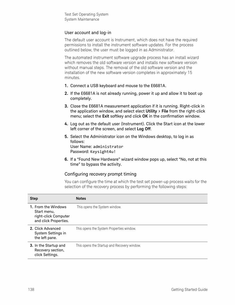
138 Getting Started Guide
Test Set Operating SystemSystem Maintenance
User account and log-in
The default user account is Instrument, which does not have the required permissions to install the instrument software updates. For the process outlined below, the user must be logged in as Administrator.
The automated instrument software upgrade process has an install wizard which removes the old software version and installs new software version without manual steps. The removal of the old software version and the installation of the new software version completes in approximately 15 minutes.
1. Connect a USB keyboard and mouse to the E6681A.
2. If the E6681A is not already running, power it up and allow it to boot up completely.
3. Close the E6681A measurement application if it is running. Right-click in the application window, and select elect Utility > File from the right-click menu; select the Exit softkey and click OK in the confirmation window.
4. Log out as the default user (Instrument). Click the Start icon at the lower left corner of the screen, and select Log Off.
5. Select the Administrator icon on the Windows desktop, to log in as follows: User Name: administrator Password: Keysight4u!
6. If a “Found New Hardware” wizard window pops up, select “No, not at this time” to bypass the activity.
Configuring recovery prompt timing
You can configure the time at which the test set power-up process waits for the selection of the recovery process by performing the following steps:
Step Notes
1. From the Windows Start menu, right-click Computer and click Properties.
This opens the System window.
2. Click Advanced System Settings in the left pane.
This opens the System Properties window.
3. In the Startup and Recovery section, click Settings.
This opens the Startup and Recovery window.

Getting Started Guide 139
Test Set Operating SystemSystem Maintenance
4. Under the System Startup section, uncheck the "Time to display a list of operating systems" checkbox, or select the "Time to display recovery option when needed" checkbox and change the number of seconds to delay for it.
You must be logged in as an administrator to change these settings. See “User Accounts” on page 123 for more information.
Step Notes

140 Getting Started Guide
Test Set Operating SystemInstrument software installation
Instrument software installationIf you downloaded the instrument software update file to the instrument via LAN, access that file from the location that it was stored and proceed to step 1.
If you downloaded the instrument software update file to a USB storage device, plug that into one of the USB ports on the front of the instrument. Access the file for the removable drive, then proceed to step 1.
This installation may involve updating of FPGA devices within the E6681A. During the installation, DO NOT power off the E6681A for ANY reason! Interrupting the FPGA update process can place the instrument in an unusable state, requiring it to be returned to Keysight for repair.
Step Notes
1. Double-click on the installer file, and click "Yes" in the confirmation window that appears.
The installer is an executable file with a name in the format: E6681A_Installer_E.xx.xx_Self-Extractor.exe
2. A window appears showing the extraction of the software installer.
A confirmation window will ask for your permission to continue the installation process after the installer has been extracted.

Getting Started Guide 141
Test Set Operating SystemInstrument software installation
3. Wait while the system checks for required updates, and uninstalls the previous version of the software.
4. Wait while the new version of the software is installed.
During installation, you may see additional windows open briefly, showing that FPGA changes or other changes are being made. These can be ignored.
5. After installation is completed, an instrument restart is required. Click Restart Computer Now.
Step Notes

142 Getting Started Guide
Test Set Operating SystemInstrument software installation
6. Reboot manually if necessary.
If the instrument shuts down but does not reboot automatically, remove the USB storage device and cycle power. The boot order for the instrument may have been changed in the instrument BIOS previously, and the instrument may be instructed to boot from USB first, and the internal drive second. If this is the case, failure to remove the USB device will result in an error, as the instrument attempts to boot from it.
7. After reboot, allow Service Manager to configure the system and open the TRX measurement applications. Watch for a configuration error, and close the window if it appears. (If it doesn’t, skip the next three steps).
The Service Manager may show a message saying that it is unable to find an E6681A System Configuration. If this occurs, close the Service Manager window by clicking the close icon at the upper right corner of the window.
If you fail to close the Service Manager at this point, updating the configuration (as described below) may result in confusing error messages (for example, "Reboot CIU/Power cycle the E7770"). A restart of the Service Manager should clear these errors.
8. To clear the configuration error described in the previous step, open the Configuration Tool from the Windows Start menu.
The Configuration Tool is found under the Keysight S910xA folder.
9. In the Configuration Tool, enter the correct number of installed TRX modules in the Number of RRHs field (it may have reset to zero during software installation).
After updating the Number of RRHs field, click Configure. When the Configuration successful message appears, close the Configuration Tool.
Step Notes

Getting Started Guide 143
Test Set Operating SystemInstrument software installation
10. Restart the Service Manager from the Windows Start menu.
Re-launch the Service Manager from the Start menu, in the Keysight S910xA folder.
11. The Service Manager will automatically open the TRX measurement applications.
Be patient during this step: the startup process for the Service Manager takes about 4 minutes (with pauses which may make it appear to have stopped working), and after that point the measurement applications must load, which adds additional minutes to the wait. The process isn’t complete until the measurement application window appears on the screen (two windows, if two TRXs are installed).
12. Verify that the correct software version is installed.
Within the measurement application, select System > System Information. On the window which opens, look for the Instrument S/W Revision entry on the System tab, and verify that it matches the revision of the installer.
Step Notes

144 Getting Started Guide
Test Set Operating SystemInstrument software installation

145
Keysight Wireless Test SolutionsE6681A EXM-WB WirelessTest Set
Getting Started Guide
8 Troubleshooting
The following topics can be found in this section:
“Basic Operational Check” on page 146
“Identifying Problems” on page 152
“System Components” on page 153
“Where to get technical help” on page 155
“Returning the E6681A for Service” on page 156
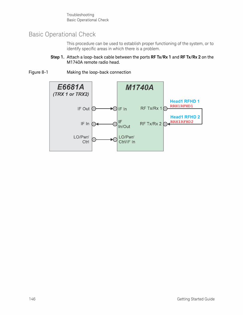
146 Getting Started Guide
TroubleshootingBasic Operational Check
Basic Operational CheckThis procedure can be used to establish proper functioning of the system, or to identify specific areas in which there is a problem.
Step 1. Attach a loop-back cable between the ports RF Tx/Rx 1 and RF Tx/Rx 2 on the M1740A remote radio head.
Figure 8-1 Making the loop-back connection

Getting Started Guide 147
TroubleshootingBasic Operational Check
Step 2. Launch the measurement application (if it is not already running).
Figure 8-2 Launching the application
The application begins with an IQ analyzer measurement window displayed.
Figure 8-3 Measurement window at startup

148 Getting Started Guide
TroubleshootingBasic Operational Check
Step 3. Select RF Output and RF Input ports.
In this procedure the M1740A remote radio head is used, so the Head 1 ports need to be used. These settings can be set from the Input/Output menu, but a quicker method is to click on the Input/Output column at the top of the measurement screen to open a menu below it. Set RF Input Port to Head 1 RFHD2 (using the dropdown selector if a different port is currently set as the input). Set RF Output Port to Head 1 RFHD1.
Figure 8-4 Selecting output and input ports

Getting Started Guide 149
TroubleshootingBasic Operational Check
Step 4. Set the source and measurement frequencies.
Go to Input/Ouptut > RF Source and set Frequency to 28.0 GHz. This is the output (source) frequency.
Go to the Frequency menu and set Center Frequency to 28.0 GHz. This is the input (measurement) frequency.
Figure 8-5 Setting the source frequency (left) and measurement frequency (right)
Step 5. Set the power range.
As illustrated below, set the Range to 0 dBm.
Figure 8-6 Setting the range

150 Getting Started Guide
TroubleshootingBasic Operational Check
Step 6. Set up power & modulation for the source.
Go to Input/Output > RF Source. Set RF Output to On. Set RF Power to 0 dBm.
Figure 8-7 Setting source power/modulation

Getting Started Guide 151
TroubleshootingBasic Operational Check
Step 7. Verify received signal power.
With RF Output set to On, you should see a signal on the display corresponding to the frequency and power level that were set. (Although the frequency should be an exact match, cable loss will cause the received signal to show a slightly lower power level than was set for the transmitted signal.) If you don’t see this signal, make sure that both the input and output are set to the same frequency (28 GHz).
Figure 8-8 Checking the signal

152 Getting Started Guide
TroubleshootingIdentifying Problems
Identifying Problems
If the status indicator on the M1740A is not lit, or if it appears that mmWave signals are not being exchanged with the Device Under Test check the following:
1. Are the RF cables connected appropriately between the E6681A and the measurement instrument? (See “Cable Connections” on page 56.)
2. Is the E6681A powered on?
3. Is the PXIe chassis (and its measurement instruments) powered on?
4. Is the measurement application properly configured (for example, are the input and output ports selected appropriately for your test setup?).
If no obvious problem in the test setup can be found, contact Keysight Technologies to ask for technical support.
No operator serviceable parts inside. Refer servicing to qualified personnel. To prevent electrical shock do not remove covers.

Getting Started Guide 153
TroubleshootingSystem Components
System Components
Because instruments interior to the E6681A are sometimes referred to in the Service Manager, the System menus, and in error messages, the diagrams below are provided to indicate what these system components are and how they interface with exterior connectors.
Figure 8-9 E6681A with 1 TRX module
No operator serviceable parts inside. Refer servicing to qualified personnel. To prevent electrical shock do not remove covers.

154 Getting Started Guide
TroubleshootingSystem Components
Figure 8-10 E6681A with 2 TRX modules

Getting Started Guide 155
TroubleshootingWhere to get technical help
Where to get technical helpFor online assistance: http://www.keysight.com/find/assist
To contact Keysight Technologies: http://www.keysight.com/find/contactus
Also, see “Locations for Keysight Technologies” on page 157.

156 Getting Started Guide
TroubleshootingReturning the E6681A for Service
Returning the E6681A for ServiceUse original packaging, or comparable packaging, when returning the E6681A for service.
Calling Keysight Technologies
Keysight Technologies has offices around the world to provide you with complete support for the E6681A. To obtain servicing information, or to order replacement parts, contact the nearest Keysight Technologies office listed under “Locations for Keysight Technologies” on page 157. In any correspondence or telephone conversations, refer to your test set by its product number and full serial number.
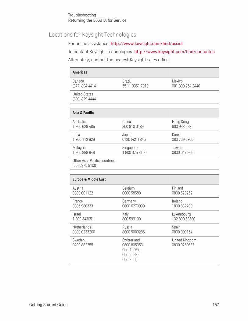
Getting Started Guide 157
TroubleshootingReturning the E6681A for Service
Locations for Keysight Technologies
For online assistance: http://www.keysight.com/find/assist
To contact Keysight Technologies: http://www.keysight.com/find/contactus
Alternately, contact the nearest Keysight sales office:
Americas
Canada (877) 894 4414
Brazil 55 11 3351 7010
Mexico 001 800 254 2440
United States (800) 829 4444
Asia & Pacific
Australia 1 800 629 485
China 800 810 0189
Hong Kong 800 938 693
India 1 800 112 929
Japan 0120 (421) 345
Korea 080 769 0800
Malaysia 1 800 888 848
Singapore 1 800 375 8100
Taiwan 0800 047 866
Other Asia-Pacific countries: (65) 6375 8100
Europe & Middle East
Austria 0800 001122
Belgium 0800 58580
Finland 0800 523252
France 0805 980333
Germany 0800 6270999
Ireland 1800 832700
Israel 1 809 343051
Italy 800 599100
Luxembourg +32 800 58580
Netherlands 0800 0233200
Russia 8800 5009286
Spain 0800 000154
Sweden 0200 882255
Switzerland 0800 805353 Opt. 1 (DE), Opt. 2 (FR), Opt. 3 (IT)
United Kingdom 0800 0260637

This information is subject to change without notice. © Keysight Technologies 2021
Edition 1, June 2021
E6681-90001
www.keysight.com


![PIPEPHASE Getting Started Guide[1] - baixardoc](https://static.fdokumen.com/doc/165x107/6315b7d1aca2b42b580df6a1/pipephase-getting-started-guide1-baixardoc.jpg)