DYNAMOMETER SHEET - Rekluse
31
©2017 Rekluse Motor Sports Rekluse Motor Sports, Inc. [email protected] DYNAMOMETER SHEET For Harley-Davidson Big Twin & M8, Sportster, and 500/750 Motorcycles Doc ID: 199-6202A Revision: 052118
-
Upload
khangminh22 -
Category
Documents
-
view
2 -
download
0
Transcript of DYNAMOMETER SHEET - Rekluse

©2017 Rekluse Motor Sports Rekluse Motor Sports, Inc.
DYNAMOMETER SHEET For Harley-Davidson Big Twin & M8, Sportster, and 500/750 Motorcycles
Doc ID: 199-6202A Revision: 052118
Pg. 2 Doc ID: 199-6202A Doc Rev: 052118
Table of Contents INSTALLATION TIPS .................................................................... 3
TOOLS ........................................................................................... 4
TUNING CHART ............................................................................ 5
Big Twin & M8 Hydraulic Actuated Models ................................... 7
Collapse the installed gap ......................................................... 7
Dyno Test .................................................................................. 8
Set the installed gap .................................................................. 9
Big Twin & M8 Cable Actuated Models ....................................... 11
Collapse the installed gap ....................................................... 11
Dyno Test ................................................................................ 12
Set the installed gap ................................................................ 13
Sportster Models.......................................................................... 16
Collapse the installed gap ....................................................... 16
Dyno Test ................................................................................ 18
Set the installed gap ................................................................ 19
500/750 Models ........................................................................... 22
Collapse the installed gap ....................................................... 22
Dyno Test ................................................................................ 23
Set the installed gap ................................................................ 23
CHECK FREE PLAY GAIN ......................................................... 23
Two Ways to Check for Free Play Gain .................................. 24
The Rubber Band Method ....................................................... 25
The Hand Method .................................................................... 26
ADJUST FREE PLAY GAIN ........................................................ 28
Big Twin & M8 Models............................................................. 28
Sportster Models ..................................................................... 29
500/750 Models ....................................................................... 30
NEED ADDITIONAL HELP? ........................................................ 31

Doc ID: 199-6202A Doc Rev: 052118
Pg. 3
OVERVIEW This guide provides instructions on how to properly prepare a Harley-Davidson® motorcycle for dyno testing when equipped with a Core EXP or RadiusX auto clutch.
All auto clutches have an installed gap that must be disabled in order to dyno test. By disabling the auto clutch, the clutch functions as a manual clutch for dyno testing. After testing, the installed gap is then reset to restore the auto clutch features. This guide covers: • How to collapse the installed gap for different models • How to properly reset the installed gap following dyno testing • How to check and set clutch lever Free Play Gain
To dyno test your engine without damaging the clutch you must first disable the automatic function. Failure to disable automatic clutch function of the product will result in a clutch failure. Rekluse does not provide warranty for clutch damage caused by performing dyno runs while the clutch is set to automatic mode.
Work only with certified dyno technicians and certified equipment. Failure to use a certified dyno technician and certified equipment can result in injury or death.
Use only your certified dyno testing center. Failure to do so can result in damage to your motorcycle. Rekluse does not accept any liability for parts damaged during dyno testing.
INSTALLATION TIPS • Only work with a certified dyno testing center. • Thoroughly read and understand the Safety Information and
User’s Guide documents for this product.

Pg. 4 Doc ID: 199-6202A Doc Rev: 052118
• Work in a well ventilated area. • Protect eyes and skin – wear
safety glasses and work gloves.
TOOLS Big Twin & M8 Hydraulic Actuated
• T27 Torx Bit • 7/32” Hex Key • 4 mm Hex Key • Torque Wrench
Big Twin & M8 Cable Actuated
• T27 Torx Bit • 7/32” Hex Key • 11/16” Open-end
Wrench
• ½” Open-end Wrench • 9/16” Open-end Wrench • Torque Wrench
Sportster Cable Actuated
• T27 Torx Bit • Screwdriver • 9/16” Open-end Wrench
• ½” Open-end Wrench • Torque Wrench
500/750 Cable Actuated
• 9/16” Open-end Wrench

Doc ID: 199-6202A Doc Rev: 052118
Pg. 5
TUNING CHART See the following charts for product peak torque capacity. Typically, the OE Belleville spring is reused when installing a Rekluse auto clutch. However, if the bike has a highly-modified engine, and the OE clutch did not provide enough torque capacity, alternate springs can be purchased to optimize the clutch setup.
Product: RMS-6201, RMS-6202, RMS-6203, RMS-6204 Max Engine Output
Torque (ft-lb)
Harley-Davidson Spring Part
Number
Spring Type
Spring Marking
’96-’06 Models
(excluding ’06 Dynas)
‘07+ Models
(including ’06 Dynas)
37882-06 Belleville Blue 86 92 37871-04 Belleville Yellow 103 110 37807-03 Belleville Pink 125 133
Harley Screaming Eagle After-market only: 37951-98
Belleville None 138 147
For Trikes: 2013 or earlier, or Conversions: Rekluse highly recommends purchasing the 37951-98 Screamin’ Eagle spring for best results with this clutch product. Since trikes are heavier and create more inherent drag than a 2-wheeler, their clutches are more susceptible to creating excessive heat during regular use, and thus may cause premature wear, slip, or poor performance. Installing a higher-force spring can significantly improve clutch life and performance by reducing this heat.

Pg. 6 Doc ID: 199-6202A Doc Rev: 052118
Product: RMS-6205, RMS-6208
Max Engine Output Torque (ft-lb)
Rekluse Part Number
Spring Type
Spring Marking
‘13+CVO, ‘14+Triglide, ‘15+ Free Wheeler, ‘15+ Low, ‘16+ S models, and Milwaukee
442-114 Coil Yellow 151
Product: RMS-6206
Max Engine Output Torque (ft-lb)
Rekluse Part Number
Spring Type
Spring Marking
‘04+ Sportster
883
‘04+ Sportster
1200
442-104 Coil Gold 63 95
Product: RMS-6215007
Max Engine Output Torque (ft-lb)
Rekluse Part Number
Spring Type
Spring Marking 500 / 750 Models
442-108 Coil Olive Green 66

Doc ID: 199-6202A Doc Rev: 052118
Pg. 7
Big Twin & M8 Hydraulic Actuated Models Collapse the installed gap 1. Remove derby cover and respective gasket. 2. Shift the bike into 2nd gear.
3. Use a 4 mm hex key or socket to loosen the two pipe plugs.
Note: Do not fully un-index the pipe plugs from the adjuster.
4. Using the 7/32” hex key or ½” wrench, turn the adjuster screw counterclockwise until it spins freely.
5. Slowly turn the adjuster screw clockwise until you feel firm resistance. This position is known as the Starting Point.

Pg. 8 Doc ID: 199-6202A Doc Rev: 052118
6. Slowly turn the adjuster screw ¾
turn counterclockwise from the starting point.
7. Use a ½” open-end wrench to hold the adjuster screw in place, then tighten the pipe plugs evenly in small increments to 40 in-lb (4.5 N-m).
Note: When torqued correctly, the tops of the plugs should be nearly flush with the top of the aluminum adjuster piece.
8. Reinstall the clutch derby cover gasket and cover.
Dyno Test Once the installed gap is collapsed, the bike is ready for dyno testing.
Manual clutch override will be limited at high RPM. Be sure to pull the clutch lever all the way to the bar to disengage the clutch during motorcycle operation.
• Proceed with your certified technician’s dyno testing procedure.
• Allow the motorcycle to fully cool down before proceeding to set the installed gap.
Doc ID: 199-6202A Doc Rev: 052118
Pg. 9
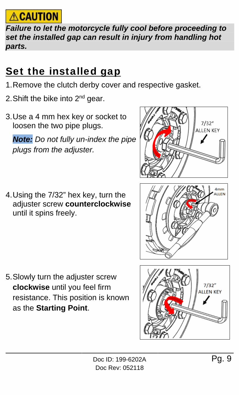
Failure to let the motorcycle fully cool before proceeding to set the installed gap can result in injury from handling hot parts.
Set the installed gap 1. Remove the clutch derby cover and respective gasket.
2. Shift the bike into 2nd gear.
3. Use a 4 mm hex key or socket to loosen the two pipe plugs.
Note: Do not fully un-index the pipe plugs from the adjuster.
4. Using the 7/32” hex key, turn the adjuster screw counterclockwise until it spins freely.
5. Slowly turn the adjuster screw
clockwise until you feel firm resistance. This position is known as the Starting Point.
Pg. 10 Doc ID: 199-6202A Doc Rev: 052118
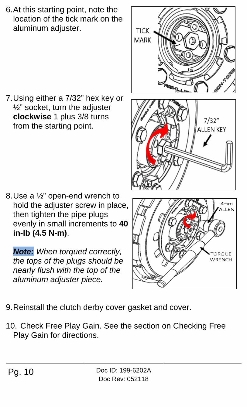
6. At this starting point, note the location of the tick mark on the aluminum adjuster.
7. Using either a 7/32” hex key or ½” socket, turn the adjuster clockwise 1 plus 3/8 turns from the starting point.
8. Use a ½” open-end wrench to hold the adjuster screw in place, then tighten the pipe plugs evenly in small increments to 40 in-lb (4.5 N-m). Note: When torqued correctly, the tops of the plugs should be nearly flush with the top of the aluminum adjuster piece.
9. Reinstall the clutch derby cover gasket and cover.
10. Check Free Play Gain. See the section on Checking Free Play Gain for directions.

Doc ID: 199-6202A Doc Rev: 052118
Pg. 11
Big Twin & M8 Cable Actuated Models Collapse the installed gap 1. Remove derby cover and respective gasket.
2. Use an 11/16” open-end wrench
to loosen the adjuster jam nut.
2. Use a 7/32” hex key to turn the adjuster screw counterclockwise until it spins freely.
3. Slowly turn the adjuster screw clockwise until you feel firm resistance. This position is known as the Starting Point.

Pg. 12 Doc ID: 199-6202A Doc Rev: 052118
4. Slowly turn the throw-out rod ¾ turn counterclockwise from the starting point.
5. Use a 7/32” hex key to hold the adjuster screw in place, then tighten the adjuster jam nut using an 11/16” open-end wrench.
6. Use a torque wrench to torque the adjuster jam nut to 90 in-lb (10 N-m).
7. Reinstall the clutch derby cover gasket and cover.
8. Adjust the cable tension so that you have clutch lever override at 2,500 RPM.
Dyno Test Once the installed gap is collapsed, the bike is ready for dyno testing.
Manual clutch override will be limited at high RPM. Be sure to pull the clutch lever all the way to the bar to disengage the clutch during motorcycle operation.

Doc ID: 199-6202A Doc Rev: 052118
Pg. 13
• Proceed with your certified technician’s dyno testing procedure.
• Allow the motorcycle to fully cool down before proceeding to setting the installed gap.
Failure to let the motorcycle fully cool before proceeding to set the installed gap can result in injury from handling hot parts.
Set the installed gap 1. Fully collapse the in-line adjuster,
so that the cable slack allows the clutch lever to become very loose at the perch.
2. Remove derby cover and respective gasket.
3. Use an 11/16” open-end wrench to loosen the adjuster jam nut.

Pg. 14 Doc ID: 199-6202A Doc Rev: 052118
4. Use a 7/32” hex key to turn the adjuster screw counterclockwise until it spins freely.
5. Slowly turn the adjuster screw
clockwise until you feel firm resistance. This position is known as the Starting Point.
6. From the starting point, turn the adjuster screw 1¼ turn clockwise to lift the pressure plate.

Doc ID: 199-6202A Doc Rev: 052118
Pg. 15
7. Use a 7/32” hex key to hold the adjuster screw in place, then tighten the adjuster jam nut using an 11/16” open-end wrench.
8. Use a torque wrench to torque the adjuster jam nut to 90 in-lb (10 N-m).
9. Reinstall the clutch derby cover gasket and cover.
10. Reset lever free play. Expand the in-line adjuster until the cable slack is between 1/16” and 1/8” at the lever perch.
11. Check Free Play Gain. See the section on Checking Free
Play Gain for directions.

Pg. 16 Doc ID: 199-6202A Doc Rev: 052118
Sportster Models Collapse the installed gap 1. Remove derby cover and respective gasket.
2. Remove the OE clutch actuating mechanism spring.
3. Remove and set aside the jam nut that is seated over the threaded stud in the clutch actuating mechanism
4. Turn the threaded throw-out rod clockwise until it spins freely.
Doc ID: 199-6202A Doc Rev: 052118
Pg. 17
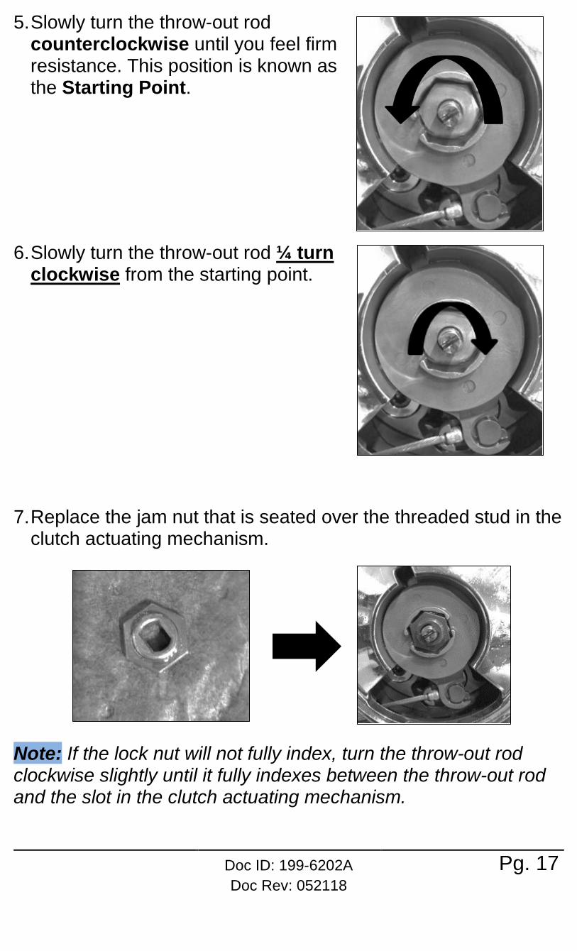
5. Slowly turn the throw-out rod counterclockwise until you feel firm resistance. This position is known as the Starting Point.
6. Slowly turn the throw-out rod ¼ turn clockwise from the starting point.
7. Replace the jam nut that is seated over the threaded stud in the clutch actuating mechanism.
Note: If the lock nut will not fully index, turn the throw-out rod clockwise slightly until it fully indexes between the throw-out rod and the slot in the clutch actuating mechanism.

Pg. 18 Doc ID: 199-6202A Doc Rev: 052118
8. Reinstall the OE clutch actuating mechanism spring by pressing it onto the lock nut in the clutch actuating mechanism.
9. Reinstall the clutch derby cover gasket and cover.
10. For cable actuated bikes: Adjust the cable tension so that you have clutch lever override at 2,500 RPM.
Dyno Test Once the installed gap is collapsed, the bike is ready for dyno testing.
Manual clutch override will be limited at high RPM. Be sure to pull the clutch lever all the way to the bar to disengage the clutch during motorcycle operation.
• Proceed with your certified technician’s dyno testing procedure.
• Allow the motorcycle to fully cool down before proceeding to set the installed gap.
Failure to let the motorcycle fully cool before proceeding to set the installed gap can result in injury from handling hot parts.

Doc ID: 199-6202A Doc Rev: 052118
Pg. 19
Set the installed gap 1. Remove the clutch derby cover and respective gasket.
2. For cable actuated bikes: Fully
collapse the in-line adjuster, so that the cable slack allows the clutch lever to become very loose at the perch.
3. Remove the OE clutch actuating mechanism spring.
4. Remove and set aside the lock nut that is seated over the threaded stud in the clutch actuating mechanism

Pg. 20 Doc ID: 199-6202A Doc Rev: 052118
5. Turn the threaded throw-out rod clockwise until it spins freely.
6. Slowly turn the throw-out rod
counterclockwise until you feel firm resistance. This position is known as the Starting Point.
7. Firmly turn the OE throw-out rod 1¼ turns counterclockwise past the starting point.
8. Replace the lock nut that is seated over the threaded stud in the clutch actuating mechanism.

Doc ID: 199-6202A Doc Rev: 052118
Pg. 21
Note: If the lock nut will not fully index, turn the throw-out rod counterclockwise slightly until it fully indexes between the throw-out rod and the slot in the clutch actuating mechanism.
9. Reinstall the OE clutch actuating mechanism spring by pressing it onto the lock nut in the clutch actuating mechanism.
10. Reinstall the clutch derby cover gasket and cover.
12. For cable actuated bikes: Reset lever free play. Expand the
in-line adjuster until the cable slack is between 1/16” and 1/8” at the lever perch.
13. Check Free Play Gain. See the section on Checking Free
Play Gain for directions.

Pg. 22 Doc ID: 199-6202A Doc Rev: 052118
500/750 Models Collapse the installed gap
1. Collapse the installed gap until there is no more than an 1/8 inch of cable free play at the lever. There are two ways to collapse the gap: the perch adjuster or the in-line adjuster. • Start with the perch adjuster to collapse the gap. • If you still do not have enough lever free play, use the in-
line adjuster. Note: Measuring the current width of the cable adjustment is helpful for resetting the adjustment after dyno testing.
Fully collapsing the adjusters will not allow clutch override during the testing.
Perch adjuster
In-line adjuster

Doc ID: 199-6202A Doc Rev: 052118
Pg. 23
Dyno Test Once the installed gap is collapsed, the bike is ready for dyno testing.
Manual clutch override will be limited at high RPM. Be sure to pull the clutch lever all the way to the bar to disengage the clutch during motorcycle operation. • Proceed with your certified technician’s dyno testing
procedure. • Allow the motorcycle to fully cool down before proceeding to
setting the installed gap.
Failure to let the motorcycle fully cool before proceeding to set the installed gap can result in injury from handling hot parts.
Set the installed gap 1. Move the perch adjuster halfway between the clutch cable
and the perch. 2. Check Free Play Gain (next section) to adjust the cable
tension to its final setting.
CHECK FREE PLAY GAIN It is important to verify the correct installed gap by checking Free Play Gain. Additional information about Free Play Gain can be found in the User’s Guide that came with the clutch. Follow the instructions below or view the support video entitled “How to Check Free Play Gain” at www.rekluse.com/support/videos.

Pg. 24 Doc ID: 199-6202A Doc Rev: 052118
Optimal Free Play Gain yields 1/8-1/4” (3 mm-6 mm) of clutch lever movement, measured at the end of the lever. This measurement at the lever correlates to achieving the ideal installed gap.
Failure to check and verify Free Play Gain can cause failure or damage to this product. Setting the correct installed gap is critical for clutch performance.
Two Ways to Check for Free Play Gain The following steps explain 2 ways to check Free Play Gain. One way uses the rubber band Rekluse includes in the clutch kit, and one uses your hand. You can use either method to check for Free Play Gain.
BEFORE YOU BEGIN, verify that the bike is in NEUTRAL before checking Free Play Gain. Failure to do so may result
Lever with “slack” removed
Lever position around 4,000 RPM
Free Play Gain 1/8”-1/4” (3 mm-6 mm) lever movement

Doc ID: 199-6202A Doc Rev: 052118
Pg. 25
in the bike lurching forward, and loss of control and/or injury may result. A Rekluse auto-clutch can make your motorcycle appear to be in neutral when in gear, even when the engine is running and clutch lever released. Motorcycles equipped with a Rekluse auto-clutch can move suddenly and unexpectedly and cause riders to lose control. To avoid death, serious injury, and/or property damage, always sit on the motorcycle to start it.
The Rubber Band Method a) Before you begin, place the bike in NEUTRAL, start the
engine and let it warm up for 2-3 minutes to idle down and warm the engine oil.
b) Stretch the included rubber band between your thumbs, then place the top end of the rubber band on the outer end of the left handlebar grip.
c) While holding the top end of the rubber band against the handlebar, stretch the band downward, then loop it through itself.

Pg. 26 Doc ID: 199-6202A Doc Rev: 052118
d) Pull the band through the loop, then attach it to the outside end of the clutch lever. This will take up the initial free play (slack) and put the lever in a position to detect the Free Play Gain.
e) While still in NEUTRAL, quickly rev the engine between 3,000-5,000 RPM (1/4 to 1/2 throttle), then let it return to idle. Notice the movement in the clutch lever when the engine is revved. This is your Free Play Gain.
Note: It is very important the motor returns to idle before revving the engine again or Free Play Gain will not be correct.
f) If you do not have the correct lever movement, see the “Adjust Free Play Gain” section.
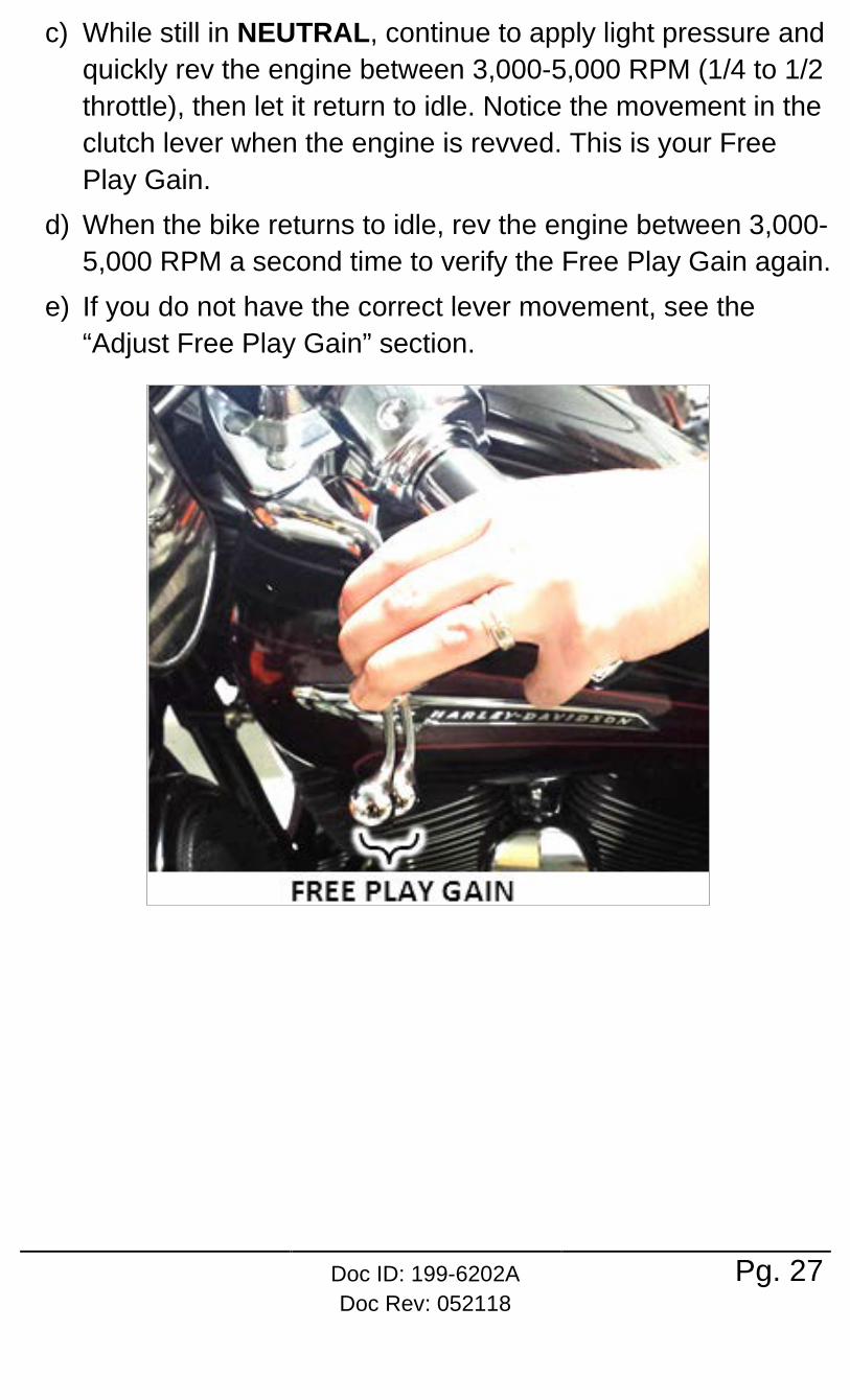
The Hand Method a) Before you begin, place the bike in NEUTRAL, start the
engine and let it warm up for 2-3 minutes to idle down and warm up the engine oil.
b) With the bike at idle, apply enough pressure to the clutch lever to take up the initial free play (slack) in the clutch lever.
Doc ID: 199-6202A Doc Rev: 052118
Pg. 27
c) While still in NEUTRAL, continue to apply light pressure and quickly rev the engine between 3,000-5,000 RPM (1/4 to 1/2 throttle), then let it return to idle. Notice the movement in the clutch lever when the engine is revved. This is your Free Play Gain.
d) When the bike returns to idle, rev the engine between 3,000-5,000 RPM a second time to verify the Free Play Gain again.
e) If you do not have the correct lever movement, see the “Adjust Free Play Gain” section.

Pg. 28 Doc ID: 199-6202A Doc Rev: 052118
ADJUST FREE PLAY GAIN After checking for Free Play Gain, you may need to adjust the installed gap.
Each adjustment can be performed just by removing the derby cover, and should be done in small increments. After each adjustment, recheck Free Play Gain until it is optimal.
Big Twin & M8 Models
Symptom Reason Solution
• Clutch lever moves in too far (too much Free Play Gain)
• Clutch has excessive drag or stalls
• It is difficult to fully
override the clutch with the lever
Installed gap is too small
Turn the throw-out rod clockwise to increase the installed gap. Recheck Free Play Gain.
• Clutch lever only
moves slightly or does not move at all (too little Free Play Gain)
• Clutch slips
• Bike seems to lose power
Installed gap is too large
Turn the throw-out rod counterclockwise to reduce the installed gap. It may be helpful to re-find the starting point. Recheck Free Play Gain.

Doc ID: 199-6202A Doc Rev: 052118
Pg. 29
Sportster Models
Symptom Reason Solution
• Clutch lever moves in too far (too much Free Play Gain)
• Clutch has excessive drag or stalls
• It is difficult to fully
override the clutch with the lever
Installed gap is too small
Turn the throw-out rod counterclockwise to increase the installed gap. Recheck Free Play Gain.
• Clutch lever only
moves slightly or does not move at all (too little Free Play Gain)
• Clutch slips
• Bike seems to lose power
Installed gap is too large
Turn the throw-out rod clockwise to reduce the installed gap. It may be helpful to re-find the starting point. Recheck Free Play Gain.

Pg. 30 Doc ID: 199-6202A Doc Rev: 052118
500/750 Models Symptom Reason Solution
• Clutch lever moves in too far (too much Free Play Gain)
• Clutch has excessive drag or stalls
• It is difficult to fully
override the clutch with the lever
Installed gap is too small
Tighten the cable: increase the length of the in-line cable adjuster housing until the correct amount of Free Play Gain is achieved. Recheck Free Play Gain.
• Clutch lever only
moves slightly or does not move at all (too little Free Play Gain)
• Clutch slips
• Bike seems to lose power
Installed gap is too large
Loosen the cable: Reduce the length of the cable housing (collapse the adjusters) until the correct amount of Free Play Gain is achieved. Recheck Free Play Gain.

Doc ID: 199-6202A Doc Rev: 052118
Pg. 31
NEED ADDITIONAL HELP? Website www.rekluse.com/support
Frequently Asked Questions www.rekluse.com/faq
Support Videos www.rekluse.com/support/videos
Phone (208) 426-0659
Technical Support Contact Technical Support for questions related to product installation, tuning, and performance.
Technical Support hours: Monday thru Friday: 8:00 a.m. - 5:00 p.m. Mountain Time zone Email: [email protected]
Customer Service Contact Customer Service for additional product information, orders, and returns.
Customer Service hours: Monday thru Friday: 8:00 a.m. - 5:00 p.m. Mountain Time zone Email: [email protected]