TITLE SHEET INDEX SHEET NO. TITLE SHEET ———————————— 1 REVISION STATUS OF...
47
APPLICATION DASH NO. NEXT ASSY USED ON -000 980-4710 980-6021 980-6023 TITLE SHEET INDEX SHEET NO. TITLE SHEET ———————————— 1 REVISION STATUS OF SHEETS INDEX —— 2 REVISIONS ———————————— 3 DOCUMENT ———————————— 4 This document is an unpublished work. Copyright 1998, 2005 Honeywell International, Inc. All rights reserved. This document and all information and expression contained herein are the property of Honeywell International, Inc., and is provided to the recipient in confidence on a “need to know” basis. Your use of this document is strictly limited to a legitimate business purpose requiring the information contained therein. Your use of this document constitutes acceptance of these terms. Typed signatures constitute approval. Actual signatures on file at Honeywell in Redmond WA. CONTRACT NO. PRECIOUS METAL INDICATOR CODE: NA Honeywell International Inc. Redmond, WA 98073-9701 DRAWN M. Thompson 98-11-11 CHECK ENGR M. Thompson 98-11-11 MFG Installation Manual, Advanced Recorder Series, AR-CVR, AR-FDR, AR-COMBI QA SIZE CAGE CODE DWG NO. REV. APVD G.Kersten 99-4-19 A 97896 012-0708 D APVD D.W.Schofield 99-4-19 SCALE: NONE SHEET 1 OF 47 d:\projects\ar-combi expansion\066 tso submittal\012-0708 rev d.doc January 11, 2005
Transcript of TITLE SHEET INDEX SHEET NO. TITLE SHEET ———————————— 1 REVISION STATUS OF...
APPLICATION DASH NO. NEXT ASSY USED ON
-000 980-4710 980-6021 980-6023
TITLE SHEET INDEX
SHEET NO. TITLE SHEET ———————————— 1 REVISION STATUS OF SHEETS INDEX —— 2 REVISIONS ———————————— 3 DOCUMENT ———————————— 4
This document is an unpublished work. Copyright 1998, 2005 Honeywell International, Inc. All rights reserved.
This document and all information and expression contained herein are the property of Honeywell International, Inc., and is provided to the recipient in confidence on a “need to know” basis. Your use of this document is strictly limited to a legitimate business purpose requiring the information contained therein. Your use of this document constitutes acceptance of these terms.
Typed signatures constitute approval. Actual signatures on file at Honeywell in Redmond WA.
CONTRACT NO. PRECIOUS METAL INDICATOR CODE:
NA Honeywell International Inc.
Redmond, WA 98073-9701 DRAWN M. Thompson 98-11-11 CHECK ENGR M. Thompson 98-11-11 MFG
Installation Manual, Advanced Recorder Series,
AR-CVR, AR-FDR, AR-COMBI QA SIZE CAGE CODE DWG NO. REV.
APVD G.Kersten 99-4-19 A 97896 012-0708 D APVD D.W.Schofield 99-4-19 SCALE: NONE SHEET 1 OF 47 d:\projects\ar-combi expansion\066 tso submittal\012-0708 rev d.doc January 11, 2005
ASAI-2121 CAGE CODE: 97896 SCALE: NONE SIZE: A DWG NO. 012-0708 REV: D SHEET 2 �
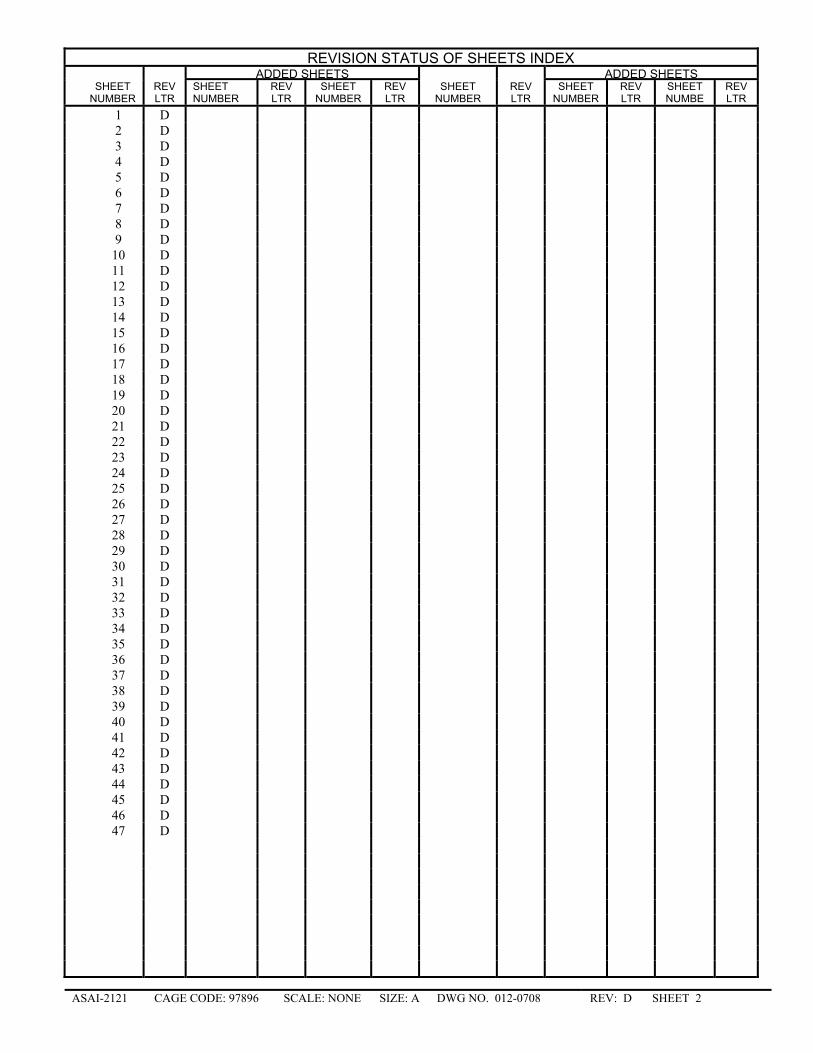
REVISION STATUS OF SHEETS INDEX ADDED SHEETS ADDED SHEETS
SHEET NUMBER
REV LTR
SHEET NUMBER
REV LTR
SHEET NUMBER
REV LTR
SHEET NUMBER
REV LTR
SHEET NUMBER
REV LTR
SHEET NUMBE
REV LTR
1 D 2 D 3 D 4 D 5 D 6 D 7 D 8 D 9 D
10 D 11 D 12 D 13 D 14 D 15 D 16 D 17 D 18 D 19 D 20 D 21 D 22 D 23 D 24 D 25 D 26 D 27 D 28 D 29 D 30 D 31 D 32 D 33 D 34 D 35 D 36 D 37 D 38 D 39 D 40 D 41 D 42 D 43 D 44 D 45 D 46 D 47 D
ASAI-2121 CAGE CODE: 97896 SCALE: NONE SIZE: A DWG NO. 012-0708 REV: D SHEET 3 �
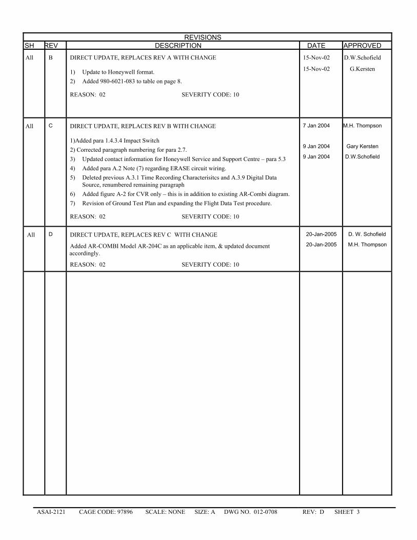
REVISIONS
SH REV DESCRIPTION DATE APPROVED
All
B DIRECT UPDATE, REPLACES REV A WITH CHANGE 1) Update to Honeywell format. 2) Added 980-6021-083 to table on page 8.
REASON: 02 SEVERITY CODE: 10
15-Nov-02
15-Nov-02
D.W.Schofield
G.Kersten
All
C DIRECT UPDATE, REPLACES REV B WITH CHANGE 1)Added para 1.4.3.4 Impact Switch 2) Corrected paragraph numbering for para 2.7. 3) Updated contact information for Honeywell Service and Support Centre – para 5.3 4) Added para A.2 Note (7) regarding ERASE circuit wiring. 5) Deleted previous A.3.1 Time Recording Characterisitcs and A.3.9 Digital Data
Source, renumbered remaining paragraph 6) Added figure A-2 for CVR only – this is in addition to existing AR-Combi diagram. 7) Revision of Ground Test Plan and expanding the Flight Data Test procedure.
REASON: 02 SEVERITY CODE: 10
7 Jan 2004
9 Jan 2004
9 Jan 2004
M.H. Thompson
Gary Kersten
D.W.Schofield
All D DIRECT UPDATE, REPLACES REV C WITH CHANGE
Added AR-COMBI Model AR-204C as an applicable item, & updated document accordingly.
REASON: 02 SEVERITY CODE: 10
20-Jan-2005
20-Jan-2005
D. W. Schofield
M.H. Thompson
ASAI-2121 CAGE CODE: 97896 SCALE: NONE SIZE: A DWG NO. 012-0708 REV: D SHEET 4 �
_________________________
INSTALLATION MANUAL FOR THE
ADVANCED SERIES SOLID STATE RECORDER
SYSTEM, (AR-CVR, AR-FDR,
AR-Combi)
________________________
Honeywell International, Inc. 15001 N.E. 36th Street
P.O. Box 97001 Redmond, Washington 98073-9701
Copyright 1998, 2005, Honeywell International, Inc.
ASAI-2121 CAGE CODE: 97896 SCALE: NONE SIZE: A DWG NO. 012-0708 REV: D SHEET 5 �
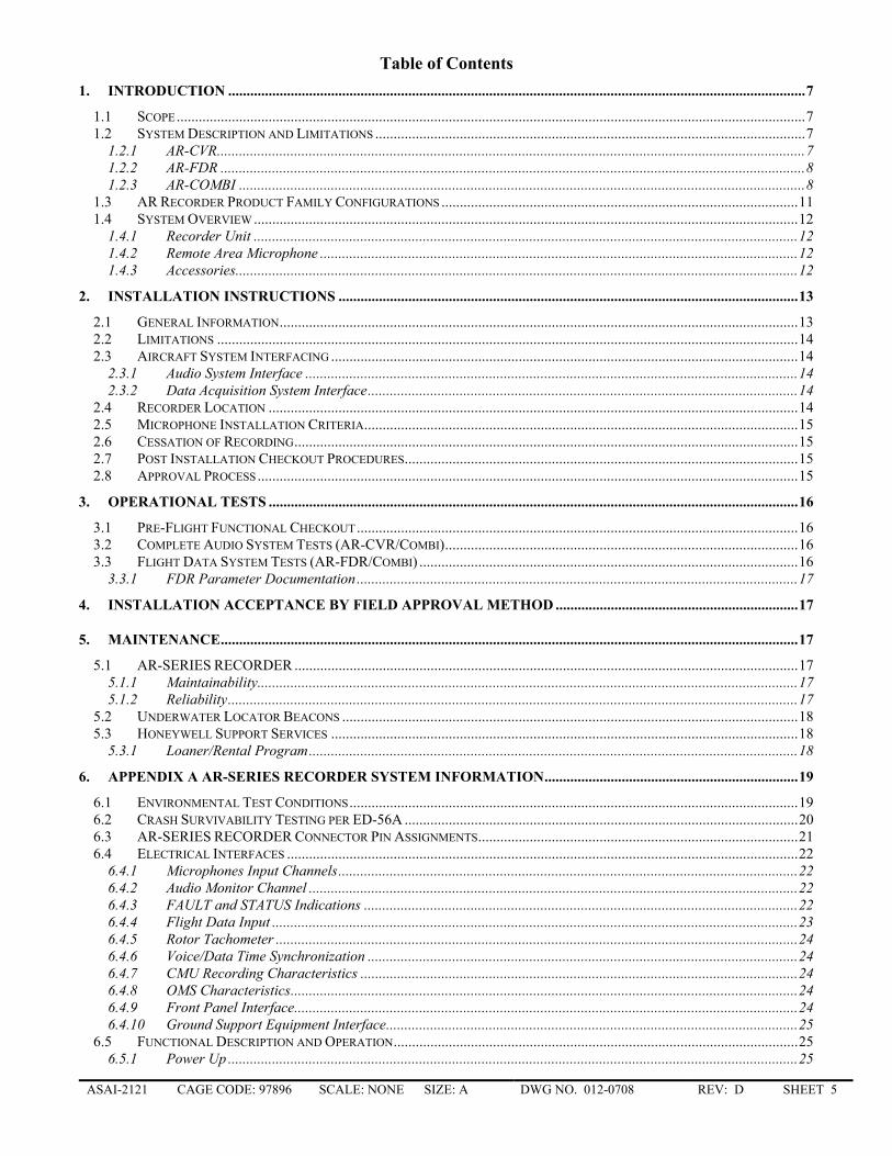
Table of Contents 1. INTRODUCTION .............................................................................................................................................................7
1.1 SCOPE...........................................................................................................................................................................7 1.2 SYSTEM DESCRIPTION AND LIMITATIONS .....................................................................................................................7
1.2.1 AR-CVR................................................................................................................................................................7 1.2.2 AR-FDR ...............................................................................................................................................................8 1.2.3 AR-COMBI ..........................................................................................................................................................8
1.3 AR RECORDER PRODUCT FAMILY CONFIGURATIONS .................................................................................................11 1.4 SYSTEM OVERVIEW ....................................................................................................................................................12
1.4.1 Recorder Unit ....................................................................................................................................................12 1.4.2 Remote Area Microphone ..................................................................................................................................12 1.4.3 Accessories.........................................................................................................................................................12
2. INSTALLATION INSTRUCTIONS .............................................................................................................................13 2.1 GENERAL INFORMATION.............................................................................................................................................13 2.2 LIMITATIONS ..............................................................................................................................................................14 2.3 AIRCRAFT SYSTEM INTERFACING ...............................................................................................................................14
2.3.1 Audio System Interface ......................................................................................................................................14 2.3.2 Data Acquisition System Interface.....................................................................................................................14
2.4 RECORDER LOCATION ................................................................................................................................................14 2.5 MICROPHONE INSTALLATION CRITERIA......................................................................................................................15 2.6 CESSATION OF RECORDING.........................................................................................................................................15 2.7 POST INSTALLATION CHECKOUT PROCEDURES...........................................................................................................15 2.8 APPROVAL PROCESS...................................................................................................................................................15
3. OPERATIONAL TESTS ................................................................................................................................................16 3.1 PRE-FLIGHT FUNCTIONAL CHECKOUT........................................................................................................................16 3.2 COMPLETE AUDIO SYSTEM TESTS (AR-CVR/COMBI)................................................................................................16 3.3 FLIGHT DATA SYSTEM TESTS (AR-FDR/COMBI) .......................................................................................................16
3.3.1 FDR Parameter Documentation ........................................................................................................................17 4. INSTALLATION ACCEPTANCE BY FIELD APPROVAL METHOD ..................................................................17
5. MAINTENANCE.............................................................................................................................................................17 5.1 AR-SERIES RECORDER .........................................................................................................................................17
5.1.1 Maintainability...................................................................................................................................................17 5.1.2 Reliability...........................................................................................................................................................17
5.2 UNDERWATER LOCATOR BEACONS ............................................................................................................................18 5.3 HONEYWELL SUPPORT SERVICES ...............................................................................................................................18
5.3.1 Loaner/Rental Program.....................................................................................................................................18 6. APPENDIX A AR-SERIES RECORDER SYSTEM INFORMATION.....................................................................19
6.1 ENVIRONMENTAL TEST CONDITIONS..........................................................................................................................19 6.2 CRASH SURVIVABILITY TESTING PER ED-56A ...........................................................................................................20 6.3 AR-SERIES RECORDER CONNECTOR PIN ASSIGNMENTS.......................................................................................21 6.4 ELECTRICAL INTERFACES ...........................................................................................................................................22
6.4.1 Microphones Input Channels.............................................................................................................................22 6.4.2 Audio Monitor Channel .....................................................................................................................................22 6.4.3 FAULT and STATUS Indications ......................................................................................................................22 6.4.4 Flight Data Input ...............................................................................................................................................23 6.4.5 Rotor Tachometer ..............................................................................................................................................24 6.4.6 Voice/Data Time Synchronization .....................................................................................................................24 6.4.7 CMU Recording Characteristics .......................................................................................................................24 6.4.8 OMS Characteristics..........................................................................................................................................24 6.4.9 Front Panel Interface.........................................................................................................................................24 6.4.10 Ground Support Equipment Interface................................................................................................................25
6.5 FUNCTIONAL DESCRIPTION AND OPERATION..............................................................................................................25 6.5.1 Power Up ...........................................................................................................................................................25
ASAI-2121 CAGE CODE: 97896 SCALE: NONE SIZE: A DWG NO. 012-0708 REV: D SHEET 6 �
6.5.2 Record, Test, & Status Monitor .........................................................................................................................25 6.5.3 Push To Test ......................................................................................................................................................25 6.5.4 Push To Erase....................................................................................................................................................25 6.5.5 Built In Test (BIT) ..............................................................................................................................................26 6.5.6 Power Down ......................................................................................................................................................26 6.5.7 Input Power .......................................................................................................................................................26
6.6 RECORDING CHARACTERISTICS ..................................................................................................................................26 6.6.1 Memory Characteristics.....................................................................................................................................26 6.6.2 Timing Characteristics ......................................................................................................................................27 6.6.3 Audio Performance ............................................................................................................................................27 6.6.4 Attenuation Strapping ........................................................................................................................................27
7. APPENDIX B REMOTE MICROPHONES................................................................................................................31 7.1 GENERAL SPECIFICATIONS .........................................................................................................................................31
7.1.1 Mechanical Characteristics ...............................................................................................................................31 7.1.2 Performance Characteristics .............................................................................................................................31 7.1.3 Environmental Characteristics ..........................................................................................................................33
7.2 MOUNTING BRACKET .................................................................................................................................................34 8. APPENDIX C CERTIFICATION PROCEDURE......................................................................................................35
8.1 PURPOSE..................................................................................................................................................................35 8.2 DOCUMENTATION REQUIRED ...........................................................................................................................35 8.3 FACILITY AND EQUIPMENT REQUIREMENTS ................................................................................................35 8.4 INSTALLATION PROCEDURE..............................................................................................................................35
9. APPENDIX D GROUND TEST PROCEDURE..........................................................................................................36 9.1 PURPOSE..................................................................................................................................................................36 9.2 REFERENCE DOCUMENTS...................................................................................................................................36 9.3 FACILITY AND TEST EQUIPMENT REQUIREMENTS ......................................................................................36
9.3.1 Facility Requirements ........................................................................................................................................36 9.3.2 Test Equipment Requirements............................................................................................................................36
9.4 TEST PROCEDURE .................................................................................................................................................36 9.4.1 Preliminary Tests ...............................................................................................................................................36
9.5 AUDIO OPERATIONAL TESTS ....................................................................................................................................36 9.6 FLIGHT DATA OPERATIONAL TESTS .......................................................................................................................38
9.6.1 Verification of FDAU-AR-FDR/AR-Combi Communication .............................................................................38 9.6.2 Verification of AR-FDR/Combi Recording FUNCtionality ..............................................................................39
9.7 SAMPLE TEST PROCEDURE.................................................................................................................................40 9.7.1 Heading Signal ..................................................................................................................................................40 9.7.2 CADC signals: Coarse Altitude, Fine Altitude, and Airspeed ...........................................................................40 9.7.3 Electronic Chronometer Signal .........................................................................................................................41 9.7.4 Communication Event Signal (Radio Transmission Keying).............................................................................41 Sample Test Data Sheet .....................................................................................................................................................42
10. APPENDIX E: MODEL FLIGHT TEST PROCEDURE........................................................................................43 10.1 PURPOSE..................................................................................................................................................................43 10.2 REFERENCE DOCUMENTS...................................................................................................................................43 10.3 FACILITY AND TEST EQUIPMENT REQUIREMENTS ......................................................................................43
10.3.1 Facility Requirements ........................................................................................................................................43 10.4 TEST PROCEDURE .................................................................................................................................................43
10.4.1 Operational Tests...............................................................................................................................................43 10.5 TEST DATA SHEET.................................................................................................................................................44
11. APPENDIX F: MODEL FLIGHT MANUAL SUPPLEMENT ..............................................................................45
12. APPENDIX G DOWNLOAD AND PLAYBACK ...................................................................................................46 12.1 PLAYBACK AND TEST STATION ..................................................................................................................................46
ASAI-2121 CAGE CODE: 97896 SCALE: NONE SIZE: A DWG NO. 012-0708 REV: D SHEET 7 �
1. INTRODUCTION
1.1 Scope
This Installation Manual describes the administrative and technical aspects, features, functions, components, operation and installation of Honeywell Advance Recorder (AR) Series Cockpit Voice Recorder (AR-CVR), AR Flight Data Recorder (AR-FDR) and AR Combined Voice and Data Recorder (AR-Combi) systems.
1.2 System Description and Limitations
The AR-Series recorders are lightweight crash survivable, solid state recording devices, in a non-ARINC form factor, intended for installation in general aviation aircraft, and helicopters to accommodate mandatory cockpit voice and/or flight data recording. In this section, the three types of recorders will be described.
1.3 Applicability
This installation manual applies to the equipment listed in Table A. Additional details of the individual equipment items are provided in Table B, Table C, and Table D.
Part Number Model Description 980-4710-001 AR-64 Lightweight Solid State Flight Data Recorder, 1x 980-4710-002 AR-128 Lightweight Solid State Flight Data Recorder, 2x 980-4710-003 AR-256 Lightweight Solid State Flight Data Recorder, 4x 980-6023-001 AR-30 Lightweight Solid State Cockpit Voice Recorder, 30-MInute 980-6023-002 AR-120 Lightweight Solid State Cockpit Voice Recorder, 2-Hour 980-6021-032 AR-302C Lightweight Solid State Combination Cockpit Voice/Flight Data Recorder 980-6021-066 AR-204C Lightweight Solid State Combination Cockpit Voice/Flight Data Recorder 980-6021-072 AR-204C Lightweight Solid State Combination Cockpit Voice/Flight Data Recorder
Table A
1.3.1 AR-CVR
The two models of Lightweight Cockpit Voice Recorder, AR-30 and AR-120, are lightweight airborne crash-survivable recording devices intended for installation in general aviation aircraft and helicopters to accommodate mandatory recording of cockpit audio. The AR-30 and AR-120 conform to all the requirements of Technical Standard Order C-123a, EASA Technical Standard Order C-123a, and of EUROCAE Document ED56A. The AR-CVR simultaneously records:
Up to four (4) channels of audio present at the inputs. The audio data is retained for 30 or 120 minutes, depending on model.
One (1) channel for ARINC 429 containing Greenwich Mean Time (GMT) data for the purpose of correlating voice and flight data.
One (1) channel for ARINC 429 for obtaining digital communications data (Data Link) from a Communication Management Unit (CMU). Data Link messages are retained for the same duration as audio data.
One (1) channel for helicopter rotor speed.
The audio input signals represent the cockpit acoustic environment and consist of one (1) wideband cockpit channel for the cockpit area microphone (CAM) and up to three (3) narrow band voice channels. The pre-amplification and audio conditioning functions for the wide-band channel are contained within the recorder. The need for a Microphone Monitor control unit is optional in order to reduce weight and cockpit panel space requirements.
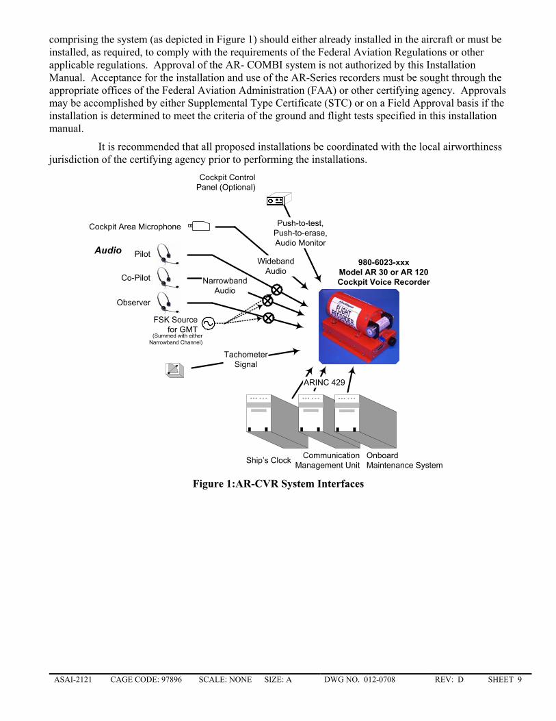
The configurations of the AR-CVR are listed in Table B. A system diagram is shown in Figure 1.
ASAI-2121 CAGE CODE: 97896 SCALE: NONE SIZE: A DWG NO. 012-0708 REV: D SHEET 8 �
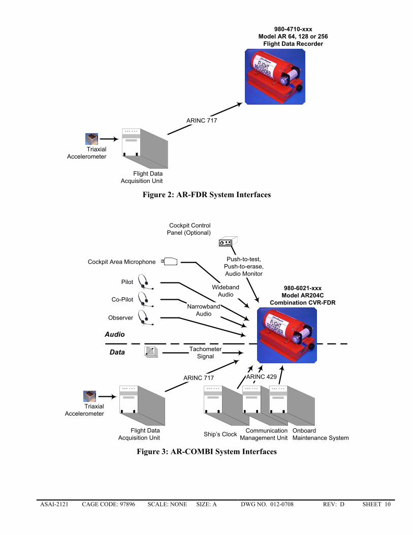
1.3.2 AR-FDR
The Lightweight Fight Data Recorder, AR-64, AR-128 or AR-256, are lightweight airborne crash-survivable recording devices intended for installation in general aviation aircraft and helicopters to accommodate mandatory recording of flight data. The AR-64, AR-128 or AR-256, conform to all the requirements of Technical Standard Order C-124a, EASA Technical Standard Order C-124a, and of EUROCAE Document ED55.
The configurations of the AR-FDR are listed in Table C. A system diagram is shown inFigure 2.
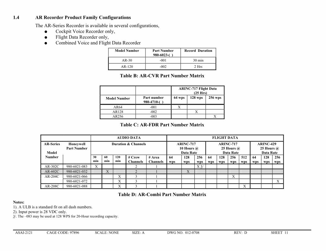
1.3.3 AR-COMBI
The Lightweight Combined Cockpit Voice and Fight Data Recorder (AR-COMBI) is a lightweight airborne crash-survivable recording device intended for installation in general aviation aircraft and helicopters to accommodate mandatory recording of cockpit voice and flight data. The AR-COMBI conforms to all the requirements of Technical Standard Orders C-123a, C-124a, EASA Technical Standard Orders C-123a, C-124a, and of EUROCAE Documents ED56A and ED55. The COMBI simultaneously records:
Up to four (4) channels of audio present at the inputs. The audio data is retained for 30, 60, or 120 minutes, depending on model.
One (1) channel for ARINC 429 containing Greenwich Mean Time (GMT) data for the purpose of correlating voice and flight data.
One (1) channel for ARINC 429 for obtaining digital communications data (Data Link) from a Communication Management Unit (CMU). Data Link messages are retained for the same duration as audio data.
One (1) channel for flight data information received from an data acquisition device by either an ARINC 573/717 or ARINC 429 bus. Depending on model, sufficient memory is provided to retain the requisite duration, 10 or 25 hours depending on application, at data rates of 64, 128 or 256 words per second.
One (1) channel for helicopter rotor speed.
The audio input signals represent the cockpit acoustic environment and consist of one (1) wideband cockpit channel for the cockpit area microphone (CAM) and up to three (3) narrow band voice channels. The pre-amplification and audio conditioning functions for the wide-band channel are contained within the recorder. The need for a Microphone Monitor control unit is optional in order to reduce weight and cockpit panel space requirements.
Depending on model, the flight data input may be either an ARINC-717 or ARINC-429 digital data stream from a Flight Data Acquisition System.
The AR-COMBI contains an ARINC 429 low-speed input for recording of Digital Communication, Navigation and Surveillance/Air Traffic Management (CNS/ATM) messages and, depending on model, also provides automatic status information reporting to an Onboard Maintenance System (OMS) by means of an ARINC 429 low-speed output.
The solid state memory is housed in a protective enclosure, termed the Crash Survivable Memory Unit (CSMU).
The configurations of the AR-COMBI are listed in Table D. The 980-6021-032 and -066 are currently offered; the remaining part numbers have been reserved for the functions indicated in the table. A system diagram is shown in Figure 3.
The AR-COMBI system consists of two essential components manufactured by Honeywell - the Recorder Unit, and a Pre-amplified Remote Area Microphone. All other system components
ASAI-2121 CAGE CODE: 97896 SCALE: NONE SIZE: A DWG NO. 012-0708 REV: D SHEET 9 �
comprising the system (as depicted in Figure 1) should either already installed in the aircraft or must be installed, as required, to comply with the requirements of the Federal Aviation Regulations or other applicable regulations. Approval of the AR- COMBI system is not authorized by this Installation Manual. Acceptance for the installation and use of the AR-Series recorders must be sought through the appropriate offices of the Federal Aviation Administration (FAA) or other certifying agency. Approvals may be accomplished by either Supplemental Type Certificate (STC) or on a Field Approval basis if the installation is determined to meet the criteria of the ground and flight tests specified in this installation manual.
It is recommended that all proposed installations be coordinated with the local airworthiness jurisdiction of the certifying agency prior to performing the installations.
Audio Pilot
Co-Pilot
Observer
Cockpit Area Microphone
CommunicationManagement Unit
OnboardMaintenance System
TachometerSignal
NarrowbandAudio
WidebandAudio
980-6023-xxxModel AR 30 or AR 120Cockpit Voice Recorder
Ship’s Clock
ARINC 429
Cockpit ControlPanel (Optional)
Push-to-test,Push-to-erase,Audio Monitor
FSK Sourcefor GMT
(Summed with eitherNarrowband Channel)
Figure 1:AR-CVR System Interfaces
ASAI-2121 CAGE CODE: 97896 SCALE: NONE SIZE: A DWG NO. 012-0708 REV: D SHEET 10 �
980-4710-xxxModel AR 64, 128 or 256
Flight Data Recorder
Flight DataAcquisition Unit
ARINC 717
TriaxialAccelerometer
Figure 2: AR-FDR System Interfaces
Audio
Data
Pilot
Co-Pilot
Observer
Cockpit Area Microphone
Flight DataAcquisition Unit
CommunicationManagement Unit
OnboardMaintenance System
ARINC 717
TachometerSignal
NarrowbandAudio
TriaxialAccelerometer
WidebandAudio
980-6021-xxxModel AR204C
Combination CVR-FDR
Ship’s Clock
ARINC 429
Cockpit ControlPanel (Optional)
Push-to-test,Push-to-erase,Audio Monitor
Figure 3: AR-COMBI System Interfaces
ASAI-2121 CAGE CODE: 97896 SCALE: NONE SIZE: A DWG NO. 012-0708 REV: D SHEET 11 �
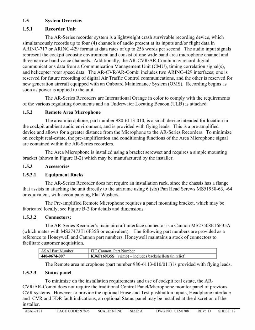
1.4 AR Recorder Product Family Configurations
The AR-Series Recorder is available in several configurations, Cockpit Voice Recorder only, Flight Data Recorder only, Combined Voice and Flight Data Recorder
Model Number Part Number 980-6023-( )
Record Duration
AR-30 -001 30 min
AR-120 -002 2 Hrs
Table B: AR-CVR Part Number Matrix
ARINC-717 Flight Data
(25 Hrs) Model Number Part number
980-4710-( ) 64 wps 128 wps 256 wps
AR64 -001 X AR128 -002 X AR256 -003 X
Table C: AR-FDR Part Number Matrix
AUDIO DATA FLIGHT DATA
Duration & Channels ARINC-717 10 Hours @ Data Rate
ARINC-717 25 Hours @ Data Rate
ARINC-429 25 Hours @ Data Rate
AR-Series
Model Number
Honeywell Part Number
30 min
60 min
120 min
# Crew Channels
# Area Channels
64 wps
128 wps
256 wps
64 wps
128wps
256 wps
512 wps
64 wps
128 wps
256 wps
AR-302C 980-6021-083 X 2 1 X 3/ AR-602C 980-6021-032 X 2 1 X AR-204C 980-6021-066 X 3 1 X
980-6021-072 X 3 1 X AR-208C 980-6021-088 X 3 1 X
Table D: AR-Combi Part Number Matrix Notes: 1). A ULB is a standard fit on all dash numbers. 2). Input power is 28 VDC only. 3/. The –083 may be used at 128 WPS for 20-Hour recording capacity.
ASAI-2121 CAGE CODE: 97896 SCALE: NONE SIZE: A DWG NO. 012-0708 REV: D SHEET 12 �
1.5 System Overview
1.5.1 Recorder Unit
The AR-Series recorder system is a lightweight crash survivable recording device, which simultaneously records up to four (4) channels of audio present at its inputs and/or flight data in ARINC-717 or ARINC-429 format at data rates of up to 256 words per second. The audio input signals represent the cockpit acoustic environment and consist of one wide band area microphone channel and three narrow band voice channels. Additionally, the AR-CVR/AR-Combi may record digital communications data from a Communication Management Unit (CMU), timing correlation signal(s), and helicopter rotor speed data. The AR-CVR/AR-Combi includes two ARINC-429 interfaces; one is reserved for future recording of digital Air Traffic Control communications, and the other is reserved for new generation aircraft equipped with an Onboard Maintenance System (OMS). Recording begins as soon as power is applied to the unit.
The AR-Series Recorders are International Orange in color to comply with the requirements of the various regulating documents and an Underwater Locating Beacon (ULB) is attached.
1.5.2 Remote Area Microphone
The area microphone, part number 980-6113-010, is a small device intended for location in the cockpit ambient audio environment, and is provided with flying leads. This is a pre-amplified device and allows for a greater distance from the Microphone to the AR-Series Recorders. To minimize on cockpit real-estate, the pre-amplification and conditioning functions of the Area Microphone signal are contained within the AR-Series recorders.
The Area Microphone is installed using a bracket screwset and requires a simple mounting bracket (shown in Figure B-2) which may be manufactured by the installer.
1.5.3 Accessories
1.5.3.1 Equipment Racks
The AR-Series Recorder does not require an installation rack, since the chassis has a flange that assists in attaching the unit directly to the airframe using 6 (six) Pan Head Screws MS51958-63, -64 or equivalent, with accompanying Flat Washers.
The Pre-amplified Remote Microphone requires a panel mounting bracket, which may be fabricated locally, see Figure B-2 for details and dimensions.
1.5.3.2 Connectors:
The AR-Series Recorder’s main aircraft interface connector is a Cannon MS27508E16F35A (which mates with MS27473T16F35S or equivalent). The following part numbers are provided as a reference to Honeywell and Cannon part numbers. Honeywell maintains a stock of connectors to facilitate customer acquisition.
ASAI Part Number ITT Cannon Part Number 440-0674-007 KJ6F16N35S (crimp) – includes backshell/strain relief
The Remote area microphone (part number 980-6113-010/011) is provided with flying leads.
1.5.3.3 Status panel
To minimize on the installation requirements and use of cockpit real estate, the AR-CVR/AR-Combi does not require the traditional Control Panel/Microphone monitor panel of previous CVR systems. However to provide the optional Erase and Test pushbutton inputs, Headphone interface and CVR and FDR fault indications, an optional Status panel may be installed at the discretion of the installer.
ASAI-2121 CAGE CODE: 97896 SCALE: NONE SIZE: A DWG NO. 012-0708 REV: D SHEET 13 �
Due to the many possible differing customer configurations Honeywell do not provide Status Panel.
1.5.3.4 Impact Switch
Impact Switch part number 370-0145-003 is a 28 VDC rated switch with a 3g trip level.
The connector is PTO7A-8-3 which mates with PTO6A-8-3 (442-0007-073).
Reset button – press to reset to normal operating state. The Light indicates contact (switched output) status.
Impact switches are one way to interrupt the primary power input when the Recorder is powered from the aircraft BATTERY bus.
2. INSTALLATION INSTRUCTIONS
2.1 General Information
This section contains considerations and recommendations for installation of the Honeywell AR-Series Recorder and associated system components. Interconnect harness wiring, physical mounting, optional components (preamplifiers and summing amps) must be considered, as required, to satisfy all of the applicable regulations. All of the components discussed within this installation manual meet the conditions and tests required for TSO C123a/C-124a approval in accordance with minimum performance standards of EUROCAE ED-55 and ED-56A for FDR and CVR respectively.
The FAA issued several Advisory Circulars, which may be referred to in the approval processes.
Advisory Circular 25.1457-1A specifically addresses one acceptable means of compliance with Federal Air Regulation (FAR) 25.1457 (b), (e) and (f). Installations of CVR must conform to the Operating Rules in FAR 23.1457, 25.1457, 27.1457 and 29.1457 appropriate to the category of operation under FAR Parts 91, 135, and 121 (Air Carrier).
Installations of FDR must conform to the Operating Rules in FAR 23.1459, 25.1459, 27.1459 and 29.1459 appropriate to the category of operation under FAR Parts 91, 135, and 121 (Air Carrier).
Applicable FAR's specify that the Recorder shall receive electrical power from the bus which provides maximum reliability for recorder operation without jeopardizing service to essential or emergency loads.
To ensure optimum performance of the AR-Series Recorder system, the following is recommended:
a) All wire shall be in accordance with MIL-W-22759 or equivalent. b) Twisted Shielded Cable shall be in accordance with MIL-C-27500 or equivalent. c) Power and Ground wires shall be 22 AWG minimum, all other wires shall be 24 AWG minimum.
Audio input lines to the recorder shall be twisted shielded pairs. d) The 28 VDC Power Ground wire, pin 53, shall be connected to Aircraft Chassis ground within one foot
of the rear connector. e) Pin 20 is designated as DC common/Chassis Ground. All shield drain wires shall be terminated with
respect to this pin to minimize noise pickup. It is permissible to "Daisy Chain" the shield drain wires such that only one wire is connected to either pin 20 or the terminal which terminates pin 20 to Aircraft Chassis Ground.
f) The ERASE function is not mandated by the FAA and therefore it is an installation option. If the option is exercised, the ERASE function must be interlocked to minimize the potential of accidental AR-CVR/AR-Combi memory erasure. A minimum of one interlock is required, however, it is recommended that two be installed. Many aircraft installations use a normally open (in flight) Weight
ASAI-2121 CAGE CODE: 97896 SCALE: NONE SIZE: A DWG NO. 012-0708 REV: D SHEET 14 �
On Wheels switch in series with a normally open Parking Brake switch to insure that the ERASE circuit can only be activated when the aircraft is on the ground with the Parking Brake set. If the ERASE circuit is not used, connect pin 5 (ERASE A) to DC Common pin 20, and Pin 11 is open circuit.
g) The AR-CVR/AR-Combi audio input impedance for each channel is ten-thousand (10,000) ohms (±10%). The Narrowband channels are designed for an input signal level of fifty (50) millivoltsrms minimum and two and one-half (2.5) Voltsrms maximum (input dynamic range of 34 dB) for the three voice channels. The area (wide band) channel is designed for an input signal of 175 millivoltsrms nominal, and is adjusted via the addition of attenuation jumpers at Pins 48, 49 and 50, as required following ground and flight testing.
2.2 Limitations
The conditions and tests required for TSO approval of this article are minimum performance standards. It is the responsibility of those desiring to install this article either on or within a specific type or class of aircraft to determine that the aircraft installation conditions are within the TSO standards. The article may be installed only if further evaluation by the applicant documents an acceptable installation and is approved by the Administrator.
2.3 Aircraft System Interfacing The following information is provided for reference only.
It is the responsibility of the installer to determine the means of interfacing the Aircraft Audio and Data Acquisition systems with the AR-Series recorders to comply with regulations.
2.3.1 Audio System Interface
Aircraft audio systems may require rework to insure all cockpit communications including Air Traffic Control (ATC), Intercom, Mask Microphone, and Sidetone audio, are present at the AR-CVR/AR-Combi inputs independent of the mode selection made on the audio control panel. In some cases, selection of the Loud Speaker function disables Sidetone output and, therefore, transmissions to ATC may not be recorded. Such conditions must be remedied to provide continuous received audio from the communications radios. Old Systems: Rework the Audio Control panel, or system to provide a CVR output or install an external summing
amplifier. The addition of a summing amplifier provides existing audio systems with the "hot" boom microphone capability which is required by the FAR's. Summing Amplifiers may be obtained from Avtec, Baker Electronics, Racal and others.
New Systems: Some later generation audio panels have a CVR signal output already provided. A summing amplifier may be required to provide "hot" boom microphone operation.
Future Systems: Audio Control panels and systems designed to meet or exceed the characteristics found in Radio Technical Commission for Aeronautics(RTCA) DO-170 for "hot" boom microphone capability may be determined to be acceptable.
2.3.2 Data Acquisition System Interface
The AR-Series interfaces with the Data Acquisition Unit (DAU) on the aircraft through an ARINC-717 or ARINC-429 interface as applicable to the aircraft installation. The data rate pin strapping of the AR-FDR or AR-Combi must match the incoming data rate from the acquisition unit.
2.4 Recorder Location
The Honeywell AR-Series Recorder is designed for maximum flexibility during installation and does not require a mounting rack, and may be mounted directly to the airframe and in any orientation. This, combined with the small form factor, allows more latitude in mounting location on the aircraft. Long term reliability will be affected when the recorder is installed in harsher environments, but is certified to withstand the environmental test limits as listed in Appendix A.
ASAI-2121 CAGE CODE: 97896 SCALE: NONE SIZE: A DWG NO. 012-0708 REV: D SHEET 15 �
2.5 Microphone Installation Criteria
The most desirable mounting location for the Cockpit Area Microphone is forward of a vertical plane oriented laterally through the pilots and co-pilots normal head position. The microphone should face the crew members. Microphone location considerations must include the sources and effects of noise on recording intelligibility, and, cockpit ergonomics; the microphone should not be installed in a location where it is subject to damage or being covered up by accident. Potential noise sources include speakers, heater blowers, structural vibration, wind noise, etc. Best results can be achieved if the microphone is mounted in a low noise environment away from noise sources, directly in front of and between the pilots.
The length of wire between the microphone body and the AR-CVR/AR-Combi shall be 125 feet maximum to reduce the potential of picking up undesirable microphone noise.
2.6 Cessation of Recording
Federal Air Regulations 23.1457 (d)(2), 25.1457 (d)(2), 27.1457 (d)(2), and 29.1457 (d)(2) for CVRs, and similarly 23.1459(5), 25.1459(5), 27.1459(5), and 29.1459(2) for FDRs state that "There is an automatic means to simultaneously stop the recorder and prevent each erasure feature from functioning within 10 minutes after crash impact."
It is the responsibility of the installer to demonstrate "cessation of recording" requirements are met. Systems operating from 28 VDC aircraft batteries require, as a minimum, an Inertia/impact switch installed in series with input power line (pin 55). The inertia switch is the most accepted method of interrupting recorder power and meeting the regulation requirements. Honeywell strongly encourages its use in all instances.
2.7 Post Installation Checkout Procedures
The FAA has indicated that Flight Tests will be required on all new installations. Since Flight Tests are expensive, it is recommended that a thorough Ground Test be conducted prior to flying the aircraft. This manual contains model Ground and Flight Test Procedures. The information provided is for reference only and will require tailoring to fit other installations as appropriate.
See Appendix D for Ground Test Procedure, and Appendix E for Flight Test Procedure.
2.8 Approval Process
It is highly recommended that the installer contact the local FAA office prior to initiating the installation effort to determine certification advice and direction and to establish a project number.
In addition to the installation drawing, installation instructions, ground and flight test procedures, a flight manual supplement, and piece part drawings, the following analyses may be required:
Structural analysis of the recorder installation Weight and Balance Computations Electrical Load analysis
Refer to Appendix F for a model "flight manual supplement" for documentation regarding test of the system during pre-flight, and statements related to system limitations and emergency operations which will be required on the aircraft. The FAA may also require an audio copy tape of the Flight Test transcription.
ASAI-2121 CAGE CODE: 97896 SCALE: NONE SIZE: A DWG NO. 012-0708 REV: D SHEET 16 �
3. OPERATIONAL TESTS
3.1 Pre-Flight Functional Checkout
A Pre-flight Functional Check, which is recommended to be performed before every flight, is used to assure the operator that the equipment is serviceable.
PUSH-TO-TEST Input (Pin 47) is not required for standard Cockpit Voice Recorder Installation. (Internal BITE Testing is performed within the AR-Series recorder at power-up and continuously during operation). However, if a Status Panel, with Maintenance Fault indicators is installed, a suitable Pre-Flight functional check may be as follows:
a) With the recorder Circuit Breaker closed, verify that the CVR Maintenance Fault and FDR Maintenance Fault indicators, as applicable, on the Status Panel are NOT illuminated.
b) Open the circuit breaker to verify that CVR/FDR Maintenance Fault indicators illuminate.
c) Reset the circuit breaker.
Alternately, if the optional Status panel is installed with a TEST switch, a) Push and hold the "TEST" switch (if installed) for 1/2 second.
b) After approximately 2 seconds satisfactory operation is annunciated in the following ways: • The presense of a two second 800 Hz tone on the headphones. • Simultaneously, the CVR Maintenance fault discrete is not asserted and an installed, placarded
LED is not illuminated.
The AR-Series Recorder provides a CVR Maintenance Fault (BITE) output (Pin 17) and/or FDR Maintenance Output (Pin 18) to individual optional cockpit indicators, which may be installed at the discretion of the installer. If the recorder malfunctions, is removed from the aircraft, or if the Power is OFF, the output will be Open Circuit.
3.2 Complete Audio System Tests (AR-CVR/Combi)
A complete Audio System interface test must be completed at specified maintenance periods (as agreed between the operator and the local certifying inspection agency) or, whenever unscheduled maintenance is performed which may have affected the performance of the AR-CVR/AR-Combi System. To accomplish this test, the Pilot's, Co-pilot's, Third Crewmember or Public Address System and Cockpit Area Microphone inputs must be individually checked for their operational integrity with the AR-CVR/AR-Combi. Upon satisfactory performance of these tests, an entry shall be made in the maintenance records of the aircraft.
The Cockpit Area Microphone test can be accomplished with a 600 ohm headset inserted into the optional "Monitor" jack. Speak in a normal voice 2 feet away from the Cockpit Area Microphone and listen to the "monitor" audio. The signal shall be free of significant noise, distortion or time delay. This test ensures the cockpit area microphone is operating.
3.3 Flight Data System Tests (AR-FDR/Combi)
A complete Flight Data transcription must be completed at specified maintenance periods (as agreed between the operator and the local certifying inspection agency) or, whenever unscheduled maintenance is performed which may have affected the performance of the AR-FDR/AR-Combi System.
The Transcription (Download, Readout and Analysis of the FDR data) of the data should be sufficient to determine the operability of the data with the exception of the accelerometer, since this is a dedicated Flight Data Recorder Instrument that is not monitored during normal flight. Refer to the applicable Maintenance Manual procedures for the testing of the Accelerometer.
ASAI-2121 CAGE CODE: 97896 SCALE: NONE SIZE: A DWG NO. 012-0708 REV: D SHEET 17 �
3.3.1 FDR Parameter Documentation
The aircraft Flight Data Recorder (FDR) system records data in a serial binary or binary coded decimal data stream that must be correlated to engineering units or to discrete states in order for the performance, incident or accident investigator to use the data.
NOTE: FAA Advisory Circular AC 20-141 requires Part 121 operators to maintain documentation on all flight data recorder systems sufficient to convert recorded data into the engineering units and discrete values. This documentation shall provide Flight Data Recorder system data in a form recommended by FAA rules and recommendations. It is to be maintained with current and accurate data for presentation to the FAA or NTSB when requested. It is also to be used to conform Flight Data Recorder readout and playback equipment to current standards.
4. INSTALLATION ACCEPTANCE BY FIELD APPROVAL METHOD
An applicant for Field Approval of a AR-Series recorder installation must be properly certified, appropriately rated, qualified and equipped to accomplish the installation and approve the aircraft for return to service.
The AR-Series recorder should be installed in accordance with the instructions and limitations contained in this Installation Manual.
The applicant must submit all appropriate data and drawings to the Inspector prior to beginning installation of the system using FAA Form 337, describing the work performed to the airframe to accomplish the installation of the system. The Form 337 must also include a statement that a complete Audio Interface Test was performed as required and that the Cockpit Area Microphone is installed within the recommended locations identified within FAA Advisory Circular 25.1457-1A and this Installation Manual.
All deviations from this Installation Manual shall be brought to the attention of the Inspector and cited on the Form 337.
Finally, ground and flight tests must be conducted to verify that the Audio System Interface is satisfactory and that "normal" conversation can be discerned from the Cockpit Area Microphone and the individual Pilot, Copilot, the Third Crew Member or Public Address stations as appropriate.
The Recording System must be found free of any objectionable audio interference or other unwanted noise in order to ensure discernible recordings.
Any discrepancies identified during the ground and flight tests must be brought to the attention of the inspector and corrected before the aircraft can be returned to service.
5. MAINTENANCE
5.1 AR-SERIES RECORDER
5.1.1 Maintainability
The AR-Series Recorder is designed so that no scheduled periodic maintenance or servicing is required during the life of the unit (except for the ULB). It is constructed in a modular fashion to allow Shop Replaceable Unit (SRU) replacement for ease of repair with an estimated Mean Time to Repair (MTTR) of 30 minutes. The AR-Series recorder also utilizes extensive BIT to provide comprehensive SRU fault isolation. Intermediate level repair may be accomplished by a customer while depot level repair will be performed by an Honeywell approved facility.
5.1.2 Reliability
The AR-Series Recorder is designed for use in general aviation aircraft and helicopters. The unit has a predicted Mean Time Between Failure (MTBF) rate of 10,500 hours for an inhabited cargo
ASAI-2121 CAGE CODE: 97896 SCALE: NONE SIZE: A DWG NO. 012-0708 REV: D SHEET 18 �
aircraft per MIL-HDBK-217F. AR-Series Recorder is designed to have a useful life in excess of 20 years not including the ULB.
NOTE: Several years of in service operation of the AR-Series recorders has yielded MTBF’s far in exceedance of this modest calculated value and typical MTBF of 30,000 hours is common.
5.2 Underwater Locator Beacons
The AR-Series Recorder has an Underwater Locator Beacon (ULB) fitted to the front panel of the Crash Survivable Memory Unit (CSMU) for easy removal and replacement.
Maintenance, such as a periodic system test, is recommended every 24 months for ULBs. The ULB battery has a typical service life of 6 years from date of manufacture and therefore requires periodic replacement. Fabrication date of the battery is stamped on the ULB casing. The ULB battery may be replaced in the field or may be sent to the manufacturer for replacement.
The battery itself is a 7.9V Lithium battery, with a rated capacity of 2.5 Amp hours, and an operating life of greater than 30 days.
The battery should be removed from service on or before the expiration date stamp indicated on the ULB case label. This date stamp may be represented by three (3) letters that represent the month, and four (4) numbers that represent the year, for example MAR2009 means March 2009. Other date codes may include the following, MAR09, or alternatively 03/09 - each represent March 2009.
5.3 Honeywell Support Services
Honeywell performs repair, overhaul and readout services for AR-Series Recorder system components. Items should be shipped to the address listed. Questions concerning repair and overhaul should be directed to:
Honeywell Service Area Support Centre. 4150 Lind Avenue SW RENTON, WA 98055 USA.
Technical Support is avaiable 24 hours, 7 days per week at: Telephone International (602) 436-2005
Toll Free (877) 436-2005 or e-mail : [email protected]
5.3.1 Loaner/Rental Program
Honeywell Authorized Repair Facilities are capable of providing loaner/rental AR-Series Recorder.
Contact Honeywell Support Services, at the above contacts, for additional information and rates.
ASAI-2121 CAGE CODE: 97896 SCALE: NONE SIZE: A DWG NO. 012-0708 REV: D SHEET 19 �
6. APPENDIX A AR-SERIES RECORDER SYSTEM INFORMATION
Appendix A contains information regarding the primary component of the AR-Series Recorder System.
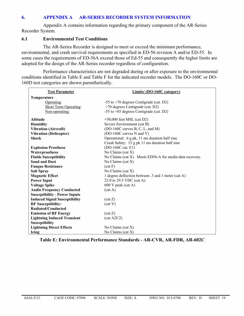
6.1 Environmental Test Conditions
The AR-Series Recorder is designed to meet or exceed the minimum performance, environmental, and crash survival requirements as specified in ED-56 revision A and/or ED-55. In some cases the requirements of ED-56A exceed those of Ed-55 and consequently the higher limits are adopted for the design of the AR-Series recorder regardless of configuration.
Performance characteristics are not degraded during or after exposure to the environmental conditions identified in Table E and Table F for the indicated recorder models. The DO-160C or DO-160D test categories are shown parenthetically.
Test Parameter Limits/ (DO-160C category) Temperature Operating -55 to +70 degrees Centigrade (cat. D2) Short Term Operating: +70 degrees Centigrade (cat. D2) Non-operating: -55 to +85 degrees Centigrade (cat. D2)
Altitude +50,000 feet MSL (cat D2) Humidity Severe Environment (cat B) Vibration (Aircraft) (DO-160C curves B, C, L, and M) Vibration (Helicopter) (DO-160C curves N and V) Shock Operational: 6 g pk, 11 ms duration half sine
Crash Safety: 15 g pk 11 ms duration half sine Explosion Proofness (DO-160C cat. E1) Waterproofness No Claims (cat X) Fluids Susceptibility No Claims (cat X). Meets ED56-A for media data recovery. Sand and Dust No Claims (cat X) Fungus Resistance (cat F) Salt Spray No Claims (cat X) Magnetic Effect 1 degree deflection between .3 and 1 meter (cat A) Power Input 22.0 to 29.5 VDC (cat A) Voltage Spike 600 V peak (cat A) Audio Frequency Conducted Susceptibility - Power Inputs
(cat A)
Induced Signal Susceptibility (cat Z) RF Susceptibility: Radiated/Conducted
(cat V)
Emission of RF Energy (cat Z) Lightning Induced Transient Susceptibility
(cat A2C2)
Lightning Direct Effects No Claims (cat X) Icing No Claims (cat X)
Table E: Environmental Performance Standards - AR-CVR, AR-FDR, AR-602C
ASAI-2121 CAGE CODE: 97896 SCALE: NONE SIZE: A DWG NO. 012-0708 REV: D SHEET 20 �
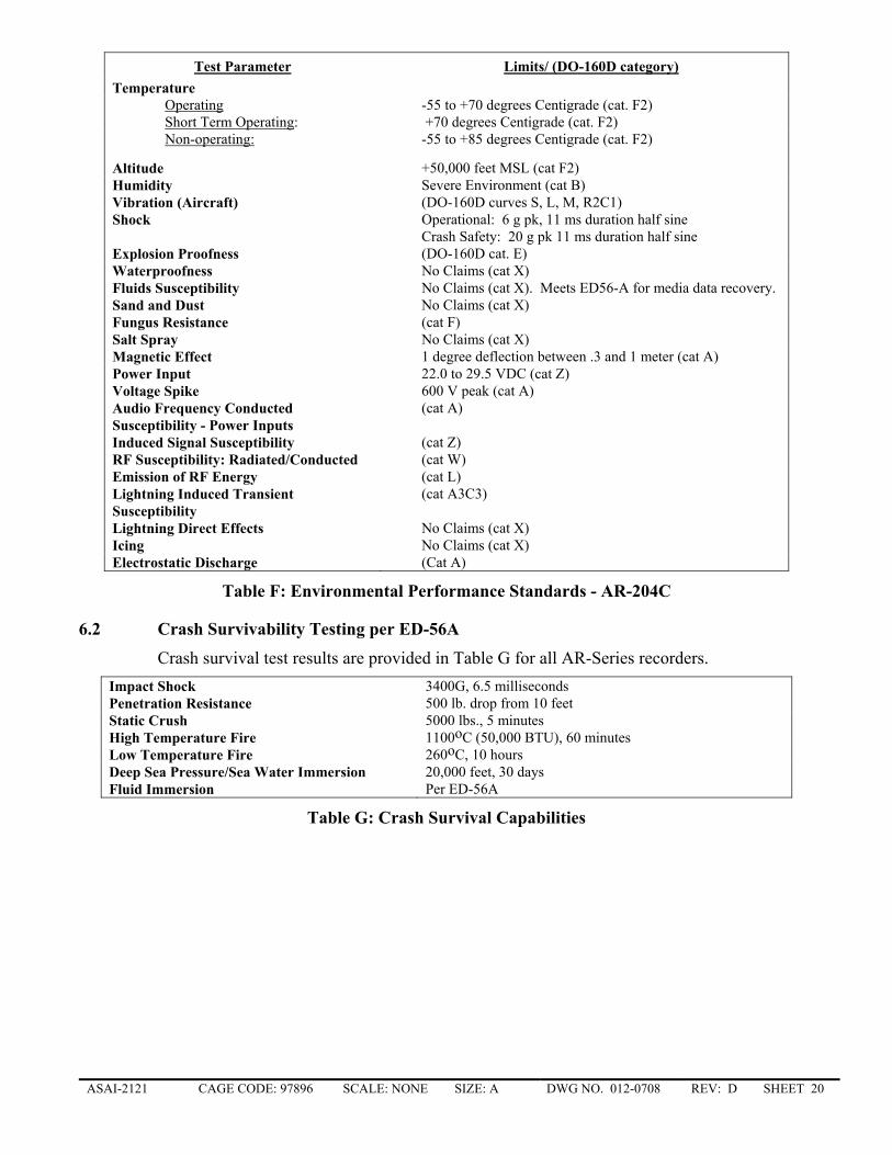
Test Parameter Limits/ (DO-160D category) Temperature Operating -55 to +70 degrees Centigrade (cat. F2) Short Term Operating: +70 degrees Centigrade (cat. F2) Non-operating: -55 to +85 degrees Centigrade (cat. F2)
Altitude +50,000 feet MSL (cat F2) Humidity Severe Environment (cat B) Vibration (Aircraft) (DO-160D curves S, L, M, R2C1) Shock Operational: 6 g pk, 11 ms duration half sine
Crash Safety: 20 g pk 11 ms duration half sine Explosion Proofness (DO-160D cat. E) Waterproofness No Claims (cat X) Fluids Susceptibility No Claims (cat X). Meets ED56-A for media data recovery. Sand and Dust No Claims (cat X) Fungus Resistance (cat F) Salt Spray No Claims (cat X) Magnetic Effect 1 degree deflection between .3 and 1 meter (cat A) Power Input 22.0 to 29.5 VDC (cat Z) Voltage Spike 600 V peak (cat A) Audio Frequency Conducted Susceptibility - Power Inputs
(cat A)
Induced Signal Susceptibility (cat Z) RF Susceptibility: Radiated/Conducted (cat W) Emission of RF Energy (cat L) Lightning Induced Transient Susceptibility
(cat A3C3)
Lightning Direct Effects No Claims (cat X) Icing No Claims (cat X) Electrostatic Discharge (Cat A)
Table F: Environmental Performance Standards - AR-204C
6.2 Crash Survivability Testing per ED-56A
Crash survival test results are provided in Table G for all AR-Series recorders. Impact Shock 3400G, 6.5 milliseconds Penetration Resistance 500 lb. drop from 10 feet Static Crush 5000 lbs., 5 minutes High Temperature Fire 1100oC (50,000 BTU), 60 minutes Low Temperature Fire 260oC, 10 hours Deep Sea Pressure/Sea Water Immersion 20,000 feet, 30 days Fluid Immersion Per ED-56A
Table G: Crash Survival Capabilities
ASAI-2121 CAGE CODE: 97896 SCALE: NONE SIZE: A DWG NO. 012-0708 REV: D SHEET 21 �
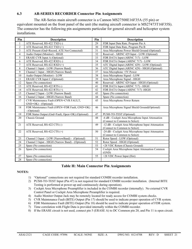
6.3 AR-SERIES RECORDER Connector Pin Assignments
The AR-Series main aircraft connector is a Cannon MS27508E16F35A (55 pin) or equivalent mounted on the front panel of the unit (the mating aircraft connector is MS27473T16F35S). The connector has the following pin assignments particular for general aircraft and helicopter system installations.
Pin Description Pin Description 1 ATE Reserved, RS-422 TXD (-) 29 FDR Input Data Rate, Program Pin A 2 ATE Reserved, RS-422 TXD (+) 30 FDR Input Data Rate, Program Pin B 3 ATE Present (Gnd=Record, ATE Not Connected) 31 Area Microphone Power Shield Ground (Optional) 4 Audio Output (Monitor) - HIGH 32 Reserved - ARINC 429 Input - LOW (Optional) 5 ERASE CVR Input A (Optional) 33 FDR DATA Input (ARINC 717) - LOW 6 ATE Reserved, RS-422 RXD (-) 34 FDR DATA Output (ARINC 717) - LOW 7 ATE Reserved, RS-422 RXD (+) 35 ATC Digital Input (ARINC 429) - LOW (Optional) 8 Channel 1 Input - LOW (Narrow Band) 36 ATC Digital Input (ARINC 429) - HIGH (Optional) 9 Channel 1 Input - HIGH (Narrow Band) 37 Area Microphone +5V Power 10 Audio Output (Monitor) - LOW 38 Area Microphone Signal - LOW 11 ERASE CVR Input C (Optional) 39 Area Microphone Signal - HIGH 12 Spare (No connection) 40 Reserved - ARINC 429 Input - HIGH (Optional) 13 ATE Reserved, RS-422 RTS (-) 41 FDR DATA Input (ARINC 717) - HIGH 14 ATE Reserved, RS-422 RTS (+) 42 FDR DATA Output (ARINC 717) -HIGH 15 Channel 2 Input - LOW (Narrow Band) 43 Spare (No connection) 16 Channel 2 Input - HIGH (Narrow Band) 44 Spare (No connection) 17 CVR Maintenance Fault (OPEN=CVR FAULT,
GND=OK) - (Optional) 45 Area Microphone Power Return
18 FDR Maintenance Fault (OPEN=FDR Fault, GND=OK) - (Optional)
46 Area Microphone Signal Shield Ground(Optional)
19 FDR Status Output (Gnd=Fault, Open=OK) (Optional) 47 PUSH-TO-TEST (Optional) 20 Chassis Ground 48 -6 dB - Cockpit Area Microphone Input Attenuation
(Connect to Common to Select) 21 ATE Reserved, RS-422 CTS (-) 49 -12 dB - Cockpit Area Microphone Input Attenuation
(Connect to Common to Select) 22 ATE Reserved, RS-422 CTS (+) 50 -24 dB - Cockpit Area Microphone Input Attenuation
(Connect to Common to Select) 23 Channel 3 Input - LOW (NarrowBand) - (Optional) 51 Rotor Speed - LOW (Optional) 24 Channel 3 Input - HIGH (Narrow Band) - (Optional) 52 Rotor Speed - HIGH (Optional) 25 Spare (No connection) 53 +28 VDC Return (Chassis Ground) 26 Spare (No connection) 54 Cockpit Area Microphone Input Attenuation Common
(GND) 27 Spare (No connection) 55 +28 VDC Power Input (Hot) 28 Spare (No connection)
Table H: Main Connector Pin Assignments
NOTES:
1) “Optional” connections are not required for standard COMBI recorder installation. 2) PUSH-TO-TEST Input (Pin 47) is not required for standard COMBI recorder installation. (Internal BITE
Testing is performed at power-up and continuously during operation). 3) Cockpit Area Microphone Preamplifier is included in the COMBI recorder (internally). No external CVR
Control Panel or Cockpit Area Microphone Preamplifier is required. 4) Audio Monitor Output Jack may be remotely located for ready access for COMBI system checks. 5) CVR Maintenance Fault (BITE) Output (Pin 17) should be used to indicate proper operation of CVR system. 6) FDR Maintenance Fault (BITE) Output (Pin 18) should be used to indicate proper operation of FDR system. 7) Time correlation with Flight Data is provided internally within the COMBI recorder. 8) If the ERASE circuit is not used, connect pin 5 (ERASE A) to DC Common pin 20, and Pin 11 is open circuit.
ASAI-2121 CAGE CODE: 97896 SCALE: NONE SIZE: A DWG NO. 012-0708 REV: D SHEET 22 �
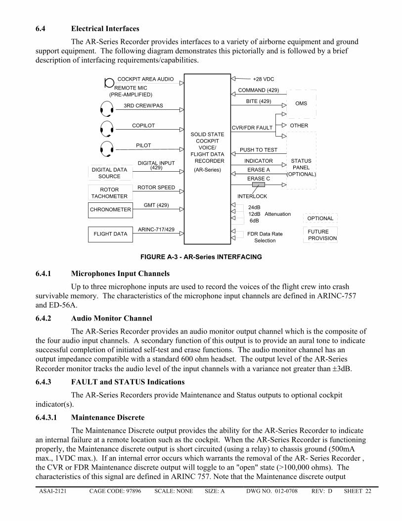
6.4 Electrical Interfaces
The AR-Series Recorder provides interfaces to a variety of airborne equipment and ground support equipment. The following diagram demonstrates this pictorially and is followed by a brief description of interfacing requirements/capabilities.
COCKPIT
CHRONOMETERGMT (429)
3RD CREW/PAS
COPILOT
PILOT
DIGITAL DATADIGITAL INPUT STATUS
ERASE C
ERASE A
INDICATOR
INTERLOCK
PUSH TO TEST
6dB12dB24dB
OMSBITE (429)
COMMAND (429)
CVR/FDR FAULT
VOICE/
RECORDER
+28 VDC
ROTOR ROTOR SPEED
(429) PANEL
REMOTE MIC
SOURCE
TACHOMETER
OTHER
SOLID STATE
(AR-Series)(OPTIONAL)
(PRE-AMPLIFIED)
Attenuation
COCKPIT AREA AUDIO
FLIGHT DATAARINC-717/429
FDR Data RateSelection
OPTIONAL
FUTUREPROVISION
FLIGHT DATA
FIGURE A-3 - AR-Series INTERFACING
6.4.1 Microphones Input Channels
Up to three microphone inputs are used to record the voices of the flight crew into crash survivable memory. The characteristics of the microphone input channels are defined in ARINC-757 and ED-56A.
6.4.2 Audio Monitor Channel
The AR-Series Recorder provides an audio monitor output channel which is the composite of the four audio input channels. A secondary function of this output is to provide an aural tone to indicate successful completion of initiated self-test and erase functions. The audio monitor channel has an output impedance compatible with a standard 600 ohm headset. The output level of the AR-Series Recorder monitor tracks the audio level of the input channels with a variance not greater than ±3dB.
6.4.3 FAULT and STATUS Indications
The AR-Series Recorders provide Maintenance and Status outputs to optional cockpit indicator(s).
6.4.3.1 Maintenance Discrete
The Maintenance Discrete output provides the ability for the AR-Series Recorder to indicate an internal failure at a remote location such as the cockpit. When the AR-Series Recorder is functioning properly, the Maintenance discrete output is short circuited (using a relay) to chassis ground (500mA max., 1VDC max.). If an internal error occurs which warrants the removal of the AR- Series Recorder , the CVR or FDR Maintenance discrete output will toggle to an "open" state (>100,000 ohms). The characteristics of this signal are defined in ARINC 757. Note that the Maintenance discrete output
ASAI-2121 CAGE CODE: 97896 SCALE: NONE SIZE: A DWG NO. 012-0708 REV: D SHEET 23 �
provides a fault indication (open state) if the AR-Series Recorder is not installed in the aircraft or if the power to the AR-Series Recorder is Off.
6.4.3.2 CVR Maintenance Fault Output
This output (Pin 17) is normally short circuited (using a relay) to chassis ground (500 mA max, 1 VDC max), but if any CVR section(s) of the AR-CVR/AR-Combi malfunction, if the AR-CVR/AR-Combi is removed from the aircraft, or if the system power is off, this output will toggle to an "open" state (>100,000 ohms).
6.4.3.3 FDR Maintenance Fault Output
This output (Pin 18) is normally short circuited (using a relay) to chassis ground (500 mA max, 1 VDC max), but if any FDR section(s) of the AR-FDR/AR-Combi malfunction, this output will toggle to an "open" state (>100,000 ohms).
6.4.3.4 FDR Status Output
When the AR-FDR/AR-Combi is functioning properly, the FDR Status output (Pin 19) is in an "open" state (>100,000 ohms). If an internal FDR related error occurs, the output will toggle to chassis ground (500 mA max, 1 VDC max).
6.4.4 Flight Data Input
The AR-FDR has the capability to receive and record Flight Data from an ARINC-573/717 data bus; the AR-COMBI has the capability to receive and record Flight Data from either an ARINC-573/717 data bus or a low speed (12.0 to 14.5 Kbps) ARINC-429 data bus. For both recorders, flight data is recorded as it is received, i.e. no attempt is made to interpret the data content or to synchronize with the incoming data stream. Flight data is supplied to the recorder from a separate, onboard data acquisition system.
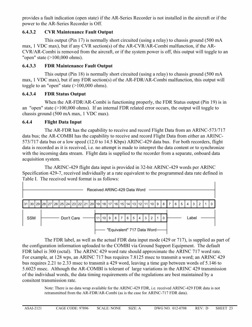
The ARINC-429 flight data input is provided in 32-bit ARINC-429 words per ARINC Specification 429-7, received individually at a rate equivalent to the programmed data rate defined in Table I. The received word format is as follows:
31 30 29 28 27 26 25 24 23 22 21 20 19 18 17 16 15 14 13 12 11 10 9 8 7 6 5 4 3 2 1 0
Label11 10 9 8 7 6 5 4 3 2 1 0SSM Don't Care
"Equivalent" 717 Data Word
Received ARINC-429 Data Word
The FDR label, as well as the actual FDR data input mode (429 or 717), is supplied as part of the configuration information uploaded to the COMBI via Ground Support Equipment. The default FDR label is 300 (octal). The ARINC 429 word rate should approximate the ARINC 717 word rate. For example, at 128 wps, an ARINC 717 bus requires 7.8125 msec to transmit a word; an ARINC 429 bus requires 2.21 to 2.33 msec to transmit a 429 word, leaving a time gap between words of 5.146 to 5.6025 msec. Although the AR-COMBI is tolerant of large variations in the ARINC 429 transmission of the individual words, the data timing requirements of the regulations are best maintained by a consitent transmission rate.
Note: There is no data wrap available for the ARINC-429 FDR, i.e. received ARINC-429 FDR data is not retransmitted from the AR-FDR/AR-Combi (as is the case for ARINC-717 FDR data).
ASAI-2121 CAGE CODE: 97896 SCALE: NONE SIZE: A DWG NO. 012-0708 REV: D SHEET 24 �
6.4.4.1 FDR Data Rate Selection
Data Rate programming for either FDR input configuration is set via jumpers on the main aircraft connector per the recommendations of ARINC-747, as defined below.
Program B (Pin 30)
Program A (Pin 29)
Input Data Rate
open open 64 wps open ground 128 wps
ground open 256 wps ground ground 512 wps
Table I: FDR Data Rate Programming
6.4.5 Rotor Tachometer
The purpose of this input is to record helicopter rotor speed data into crash survivable memory. The rotor tachometer input is a general purpose frequency recording input with the characteristics defined in ARINC 573-7, paragraph 4.2.4 and ARINC 757. The AR-Series Recorder can accept rotor inputs from 2 Vrms to 122 Vrms and from 7 Hz to 77 Hz (normal frequency range) or from 7 to 6,000 Hz (extended frequency range). This input is sampled once every 0.5 seconds and stored to crash protected memory.
6.4.6 Voice/Data Time Synchronization
The AR-Series Recorder is designed to provide internal timing synchronization for direct correlation of the recorded Cockpit Voice to Flight Data information. Additional timing information may be recorded by providing timing signals at the optional low speed ARINC-429 GMT input, typically mixed in a narrow band channel and is used to record time data into crash survivable memory. The characteristics of this input channel are defined in ARINC 429 (see Greenwich Mean Time, labels 125 and 150).
6.4.7 CMU Recording Characteristics
The AR-CVR and AR-COMBI have the capability to receive and record CMU information (such as digital ATC messages) as received from the Communications Management Unit (CMU) via an ARINC-429 low speed bus. For the AR-CVR and AR-602C, the capacity is 3 messages per minute, 300 bytes per message. The message will be recorded in solid-state memory within five (5) seconds of receipt at the channel input. For the AR-204C, the capacity is equivalent to the maximum duty cycle of the ARINC 429 low speed bus.
6.4.8 OMS Characteristics
The AR-Series Recorder has the capability to provide BITE information to an On-board Maintenance System (OMS) through a low speed ARINC-429 interface. The Onboard Maintenance System (OMS) input/output is an ARINC-429 low speed channel intended to be used to receive self-test requests and provide self-test status information to an OMS system. The characteristics of this interface channel are defined in ARINC Report 624 and ARINC 757.
6.4.9 Front Panel Interface
The front panel of the AR-Series Recorder provides a BITE indicator for status monitoring and health indication of the unit. If the AR-Series Recorder detects a fault, which requires removal of the unit from the aircraft installation, the BITE indicator will be activated. The BITE indicator remains inactive in all other cases.
ASAI-2121 CAGE CODE: 97896 SCALE: NONE SIZE: A DWG NO. 012-0708 REV: D SHEET 25 �
6.4.10 Ground Support Equipment Interface
The GSE interface consists of an RS-422 serial channel to provide download, playback, and test functions using the Honeywell PATS. This interface is activated when the ATE Present (pin 3) input is grounded.
Flight Data only may be downloaded from the AR-FDR/AR-Combi via the download connector on the front of the unit, using the Honeywell Handheld Download Unit (HHDLU) without removing the unit from the aircraft.
6.5 Functional Description and Operation
The main function of the AR-Series Recorder is to record audio, flight data, digital communications data, timing data, and rotor speed data to crash protected memory. The AR-Series Recorder may also perform erase and test functions, which are operator, initiated using discrete control signals activated by optional push buttons in the cockpit. In order to provide controlled operation, power up initialization and power down monitoring must also be performed. In order to download the stored data and to test the unit for return to service and end-item acceptance testing, the AR-Series Recorder also supports download and return to service and end-item acceptance testing. A brief description of each major functional attribute is presented below.
6.5.1 Power Up
The power up function performs power on Built in Test (BIT) to determine the integrity of the system. If a failure is detected, the failure condition is stored in crash protected memory, the front panel BITE indicator is continuously activated and the Maintenance Discrete is set in the failure mode. The failure condition is also sent to an optional OMS system and a remotely mounted Maintenance and Fault status indicator. The AR-Series Recorder will begin to record within 250 msec of power being applied to the unit.
6.5.2 Record, Test, & Status Monitor
The record, test, and status function stores audio, digital data, timing, and rotor speed data to the crash survivable memory. In addition, this function also stores ancillary data such as configuration data, memory start/stop pointers, BIT data, Elapsed Time Indicator (ETI), error logging data, and repair history. A background test is also performed to verify correct operation of the unit. If a failure is detected, the front panel BITE indicator is continuously activated, the Maintenance Discrete is set in the failure mode, and the error condition is reported to the optional OMS system.
6.5.3 Push To Test
The push to test function is activated using an optional discrete input of the AR-Series Recorder and performs an extensive set of functional tests to determine the integrity of the recorder. A successful self-test results in an aural indication provided to a headphone jack - a two second 800 Hz tone is sent to indicate a successful self-test.
If a failure condition exists, the aural tone is not provided and the CVR Maintenance Fault is activated. Also, if a failure occurs, the failure condition is stored in crash protected memory, the front panel indicator is continuously activated and the optional OMS system is informed.
6.5.4 Push To Erase
The push to erase function is activated using an optional discrete input to the AR-CVR/AR-Combi and is typically activated using an ERASE switch when the aircraft parking brake and landing gear relays are closed (safety interlocks). Once activated, this function prohibits the download of previously recorded voice data from the crash survivable memory using the normal download function.
ASAI-2121 CAGE CODE: 97896 SCALE: NONE SIZE: A DWG NO. 012-0708 REV: D SHEET 26 �
This function does not erase ancillary system data. Successful erasure is indicated by an aural indication of three second 400 Hz tone, provided to a headphone jack.
6.5.5 Built In Test (BIT)
The AR-Series Recorder has been designed to detect and isolate errors to the SRU level. BIT also detects and reports fault conditions to the component level for depot level repair.
The AR-Series Recorder implements BIT functions using three methods: (1) power on initialization, (2) commanded self-test, and (3) background continuous test. A history of the BIT status is maintained in memory for product trend analysis and warranty support. In addition, the AR-Series Recorder provides a Maintenance Discrete output and front panel indicator to indicate BIT failures. Commanded self-test indication is provided through the Status Discrete output and Audio Monitor output.
Power on initialization verifies operation of the AR-Series Recorder insofar as it is practicable given the specified 250 millisecond power on to recording delay. Functions tested include the main processor, RAM memory check, program checksum verification, testing of the CSMU interface, and partial testing of the audio interface. Commanded self-test is invoked through the initiate self-test discrete and is a much more rigorous, complete test. The background continuous monitor test utilizes spare processor time to continuously monitor the integrity of the AR-Series Recorder. All BIT failures are recorded in solid-state memory for extraction by the GSE.
6.5.6 Power Down
When a power failure occurs, the AR-Series Recorder enters the power down function. It is important to note that recording continues while in the power down function. If the power failure condition exists for more than 200 milliseconds, "housekeeping" tasks are performed to provide a graceful power down sequence (pointers saved, store buffered data to crash survivable memory, etc.). If the power is recovered after 200 milliseconds but before a hardware reset is issued, the record function is re-activated. If power does not recover, recording will cease until power is again applied.
6.5.7 Input Power
The AR-Series Recorder power supply is designed to operate from +28 Vdc aircraft power. The AR-Series Recorder is designed to use 8 watts nominally and 10 watts maximum.
6.6 Recording Characteristics
6.6.1 Memory Characteristics
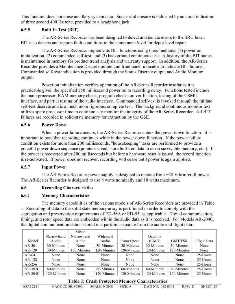
The memory capabilities of the various models of AR-Series Recorders are provided in Table J. Recording of data to the solid state memory array is partitioned in order to comply with the segregation and preservation requirements of ED-56A or ED-55, as applicable. Digital communication, timing, and rotor speed data are embedded within the audio data as it is received. For Models AR-204C, the digital communication data is stored in a partition separate from the audio and flight data.
Model Narrowband
Audio
Mixed Narrowband
Audio Wideband
Audio Rotor Speed Datalink (CMU) GMT/FSK Flight Data
AR-30 30-Minutes None 30-Minutes 30-Minutes 30-Minutes 30-Minutes None AR-120 30-Minutes 120-Minutes 120-Minutes 120-Minutes 120-Minutes 120-Minutes None AR-64 None None None None None None 25-Hours AR-128 None None None None None None 25-Hours AR-256 None None None None None None 25-Hours AR-302C 60-Minutes None 60-Minutes 60-Minutes 60-Minutes 60-Minutes 25-Hours AR-204C 120-Minutes None 120-Minutes 120-Minutes 120-Minutes 120-Minutes 25-Hours
Table J: Crash Protected Memory Characteristics
ASAI-2121 CAGE CODE: 97896 SCALE: NONE SIZE: A DWG NO. 012-0708 REV: D SHEET 27 �
6.6.2 Timing Characteristics
Upon the application of electrical power, the AR-Series Recorder begins storing digital audio data to the crash survivable memory within two-hundred fifty (250) milliseconds. The delay in recording of the digital audio information from the time of reception at the AR-Series Recorder input to the time of recording in the crash survivable memory does not exceed fifty (50) milliseconds. The recorded digital audio data on each of the four channels is synchronized in time to within four (4) milliseconds. The time correlation of the arrival time at the AR-Series Recorder of the CMU message is within five (5) seconds.
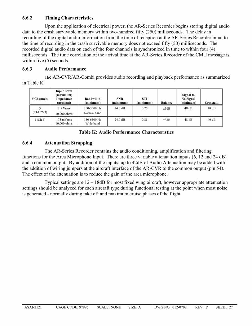
6.6.3 Audio Performance
The AR-CVR/AR-Combi provides audio recording and playback performance as summarized in Table K.
# Channels
Input Level (maximum) Impedance (nominal)
Bandwidth (minimum)
SNR
(minimum)
STI
(minimum)
Balance
Signal to No Signal
(minimum)
Crosstalk
3 (Ch1,2&3)
2.5 Vrms
10,000 ohms
150-3500 Hz Narrow band
24.0 dB 0.75 ±3dB 48 dB 40 dB
1 (Ch 4) 175 mVrms 10,000 ohms
150-6500 Hz Wide band
24.0 dB 0.85 ±3dB 48 dB 40 dB
Table K: Audio Performance Characteristics
6.6.4 Attenuation Strapping
The AR-Series Recorder contains the audio conditioning, amplification and filtering functions for the Area Microphone Input. There are three variable attenuation inputs (6, 12 and 24 dB) and a common output. By addition of the inputs, up to 42dB of Audio Attenuation may be added with the addition of wiring jumpers at the aircraft interface of the AR-CVR to the common output (pin 54). The effect of the attenuation is to reduce the gain of the area microphone.
Typical settings are 12 – 18dB for most fixed wing aircraft, however appropriate attenuation settings should be analyzed for each aircraft type during functional testing at the point when most noise is generated - normally during take off and maximum cruise phases of the flight
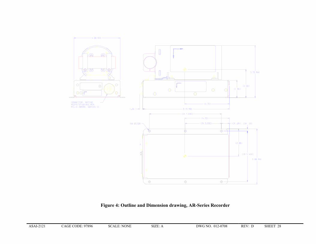
ASAI-2121 CAGE CODE: 97896 SCALE: NONE SIZE: A DWG NO. 012-0708 REV: D SHEET 28
Figure 4: Outline and Dimension drawing, AR-Series Recorder
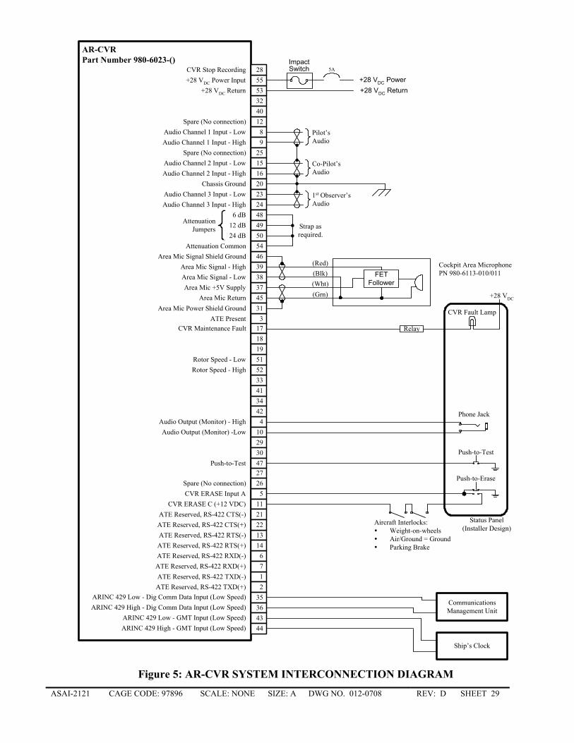
ASAI-2121 CAGE CODE: 97896 SCALE: NONE SIZE: A DWG NO. 012-0708 REV: D SHEET 29
AR-CVRPart Number 980-6023-()
12
3
4
5
67
89
10
11
12
1314
1516
171819
20
2122
2324
25
2627
2930
32
33
34
3536
373839
40
41
42
4344
45
46
47
5152
53
54
55
Area Mic Return
ARINC 429 Low - Dig Comm Data Input (Low Speed)
Area Mic +5V Supply
ATE Reserved, RS-422 TXD(-)ATE Reserved, RS-422 TXD(+)
ATE Present
Audio Output (Monitor) - High
CVR ERASE Input A
Audio Channel 1 Input - LowSpare (No connection)
ATE Reserved, RS-422 RXD(-)ATE Reserved, RS-422 RXD(+)
Audio Channel 1 Input - High
Area Mic Signal - Low
CVR Maintenance Fault
Chassis Ground
Audio Output (Monitor) -Low
CVR ERASE C (+12 VDC)
ATE Reserved, RS-422 RTS(-)ATE Reserved, RS-422 RTS(+)
Audio Channel 2 Input - LowAudio Channel 2 Input - High
ATE Reserved, RS-422 CTS(-)ATE Reserved, RS-422 CTS(+)
Audio Channel 3 Input - LowAudio Channel 3 Input - High
Spare (No connection)
Spare (No connection)
ARINC 429 High - Dig Comm Data Input (Low Speed)
Area Mic Signal - High
ARINC 429 Low - GMT Input (Low Speed)ARINC 429 High - GMT Input (Low Speed)
Area Mic Signal Shield Ground
Push-to-Test
Rotor Speed - Low
Attenuation Common
Rotor Speed - High
+28 VDC Return+28 VDC Power Input
28CVR Stop Recording
31Area Mic Power Shield Ground
484950
AttenuationJumpers
6 dB
24 dB12 dB Strap as
required.
5AImpactSwitch
+28 VDC Power+28 VDC Return
Pilot’sAudio
Co-Pilot’sAudio
1st Observer’sAudio
FETFollower
Cockpit Area MicrophonePN 980-6113-010/011
CVR Fault Lamp
Push-to-Test
Relay
+28 VDC
Phone Jack
Push-to-Erase
Status Panel(Installer Design)
Aircraft Interlocks:Weight-on-wheelsAir/Ground = GroundParking Brake
CommunicationsManagement Unit
Ship’s Clock
(Red)(Blk)(Wht)(Grn)
Figure 5: AR-CVR SYSTEM INTERCONNECTION DIAGRAM
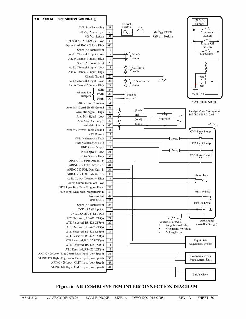
ASAI-2121 CAGE CODE: 97896 SCALE: NONE SIZE: A DWG NO. 012-0708 REV: D SHEET 30
AR-COMBI - Part Number 980-6021-()
12
3
4
5
67
89
10
11
12
1314
1516
171819
20
2122
2324
25
2627
2930
32
33
34
3536
373839
40
41
42
4344
45
46
47
5152
53
54
55
Area Mic Return
Optional ARINC 429 Rx - Low
ARINC 429 Low - Dig Comm Data Input (Low Speed)
Area Mic +5V Supply
ATE Reserved, RS-422 TXD(-)ATE Reserved, RS-422 TXD(+)
ATE Present
Audio Output (Monitor) - High
CVR ERASE Input A
Audio Channel 1 Input - LowSpare (No connection)
ATE Reserved, RS-422 RXD(-)ATE Reserved, RS-422 RXD(+)
Audio Channel 1 Input - High
FDR Inhibit
Area Mic Signal - Low
FDR Input Data Rate, Program Pin A
CVR Maintenance Fault
Chassis Ground
Audio Output (Monitor) -Low
CVR ERASE C (+12 VDC)
ATE Reserved, RS-422 RTS(-)ATE Reserved, RS-422 RTS(+)
Audio Channel 2 Input - LowAudio Channel 2 Input - High
FDR Maintenance FaultFDR Status Output
ATE Reserved, RS-422 CTS(-)ATE Reserved, RS-422 CTS(+)
Audio Channel 3 Input - LowAudio Channel 3 Input - High
Spare (No connection)
Spare (No connection)
FDR Input Data Rate, Program Pin B
ARINC 717 FDR Data In - B
ARINC 717 FDR Data Out - B
ARINC 429 High - Dig Comm Data Input (Low Speed)
Area Mic Signal - High
Optional ARINC 429 Rx - High
ARINC 717 FDR Data In - A
ARINC 717 FDR Data Out - A
ARINC 429 Low - GMT Input (Low Speed)ARINC 429 High - GMT Input (Low Speed)
Area Mic Signal Shield Ground
Push-to-Test
Rotor Speed - Low
Attenuation Common
Rotor Speed - High
+28 VDC Return+28 VDC Power Input
28CVR Stop Recording
31Area Mic Power Shield Ground
484950
AttenuationJumpers
6 dB
24 dB12 dB Strap as
required.
5AImpactSwitch
+28 VDC Power+28 VDC Return
Pilot’sAudio
Co-Pilot’sAudio
1st Observer’sAudio
FETFollower
Cockpit Area MicrophonePN 980-6113-010/011
CVR Fault Lamp
FDR Fault Lamp
FDR Status Lamp
Push-to-Test
Relay
Relay
+28 VDC
Phone Jack
Push-to-Erase
Status Panel(Installer Design)
Aircraft Interlocks:Weight-on-wheelsAir/Ground = GroundParking Brake
Flight DataAcquisition System
CommunicationsManagement Unit
Ship’s Clock
Air-GroundSwitch
Engine OilPressure
Test Switch
+28 VDCSupply
N.C.
N.O.
To Pin 27
FDR Inhibit Wiring
(Red)(Blk)(Wht)(Grn)
Figure 6: AR-COMBI SYSTEM INTERCONNECTION DIAGRAM
ASAI-2121 CAGE CODE: 97896 SCALE: NONE SIZE: A DWG NO. 012-0708 REV: D SHEET 31
7. APPENDIX B REMOTE MICROPHONES
The Remote Microphone compatible with the AR-Series Recorder is available in the configurations as listed below:
Part number Color (FED-STD-595) Wiring interface Mount
980-6113-010 GRAY (#26132) 2.75” Flying Leads Bracket/Setscrew 980-6113-011 Black #37038 2.75” Flying Leads Bracket/Setscrew
Table L: Remote Microphone Part Number Matrix
The microphone element within the 980-6113-010 assemblies are electret type microphones which are pre-amplified and require biasing – see Figure 5 and Figure 6 for recommended wiring.
7.1 General Specifications
7.1.1 Mechanical Characteristics Dimensions:
Height (panel): 1.2 inch max Width (body): 1.10 inch max Length: 2.25 inch max Microphone protrusion: 0.54 inch max Weight: 0.2 lbs max Connector: None
7.1.2 Performance Characteristics Input Bias voltage 5 to 12 VDC Current 300µA maximum, 50 µA typical Harmonic Distortion <5% at 90 dB Sound Pressure Level re: 20 µPascal; over 150 to 8,000 Hz
<10% at 120 dB SPL at 1KHz Polar Response front ± 60° within ± 6 dB front to rear at least 10 dB Frequency Response 150 to 10,000 within 10 dB
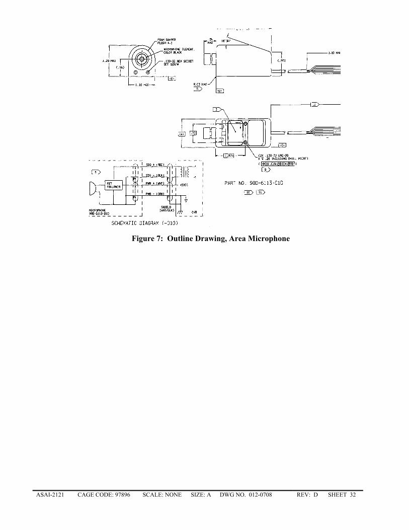
ASAI-2121 CAGE CODE: 97896 SCALE: NONE SIZE: A DWG NO. 012-0708 REV: D SHEET 32
Figure 7: Outline Drawing, Area Microphone
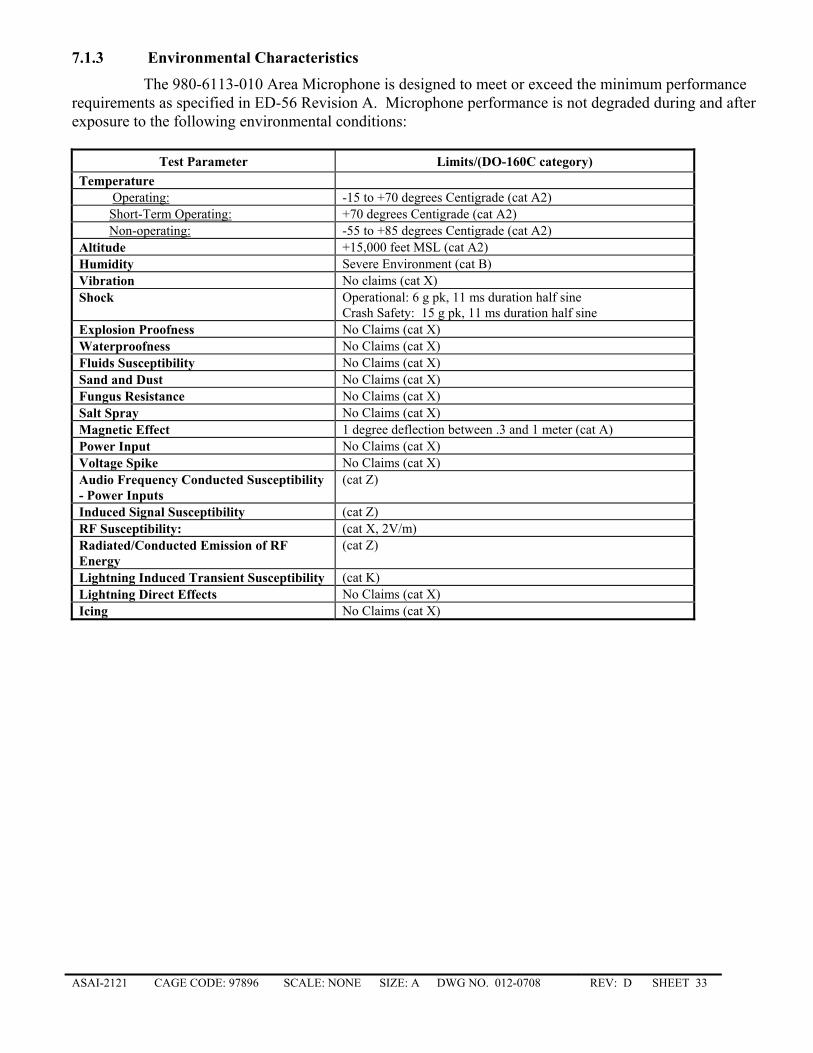
ASAI-2121 CAGE CODE: 97896 SCALE: NONE SIZE: A DWG NO. 012-0708 REV: D SHEET 33
7.1.3 Environmental Characteristics
The 980-6113-010 Area Microphone is designed to meet or exceed the minimum performance requirements as specified in ED-56 Revision A. Microphone performance is not degraded during and after exposure to the following environmental conditions:
Test Parameter Limits/(DO-160C category) Temperature Operating: -15 to +70 degrees Centigrade (cat A2) Short-Term Operating: +70 degrees Centigrade (cat A2) Non-operating: -55 to +85 degrees Centigrade (cat A2) Altitude +15,000 feet MSL (cat A2) Humidity Severe Environment (cat B) Vibration No claims (cat X) Shock Operational: 6 g pk, 11 ms duration half sine
Crash Safety: 15 g pk, 11 ms duration half sine Explosion Proofness No Claims (cat X) Waterproofness No Claims (cat X) Fluids Susceptibility No Claims (cat X) Sand and Dust No Claims (cat X) Fungus Resistance No Claims (cat X) Salt Spray No Claims (cat X) Magnetic Effect 1 degree deflection between .3 and 1 meter (cat A) Power Input No Claims (cat X) Voltage Spike No Claims (cat X) Audio Frequency Conducted Susceptibility - Power Inputs
(cat Z)
Induced Signal Susceptibility (cat Z) RF Susceptibility: (cat X, 2V/m) Radiated/Conducted Emission of RF Energy
(cat Z)
Lightning Induced Transient Susceptibility (cat K) Lightning Direct Effects No Claims (cat X) Icing No Claims (cat X)
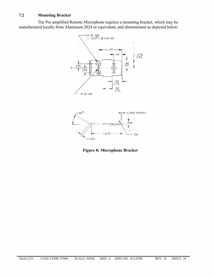
ASAI-2121 CAGE CODE: 97896 SCALE: NONE SIZE: A DWG NO. 012-0708 REV: D SHEET 34
7.2 Mounting Bracket
The Pre-amplified Remote Microphone requires a mounting bracket, which may be manufactured locally from Aluminum 2024 or equivalent, and dimensioned as depicted below:
Figure 8: Microphone Bracket
ASAI-2121 CAGE CODE: 97896 SCALE: NONE SIZE: A DWG NO. 012-0708 REV: D SHEET 35
8. APPENDIX C CERTIFICATION PROCEDURE PRELIMINARY
8.1 PURPOSE
This document provides guidance material for installing the Honeywell AR-Series Recorder System and suggested testing procedures necessary to obtain regulatory approval for the installation.
8.2 DOCUMENTATION REQUIRED A/C 43.13-2A Accepted Methods for Aircraft Repair and Modification APPENDIX D Ground Test Procedure APPENDIX E Flight Test Procedure APPENDIX A Interface Control Dwg., AR-Series Recorder APPENDIX B Interface Control Dwg., Remote Mic. APPENDIX F Approved Airplane Flight Manual Supplement
8.3 FACILITY AND EQUIPMENT REQUIREMENTS • Complete set of standard hand tools. • Power suitable for powering commercial equipment and the Aircraft.
8.4 INSTALLATION PROCEDURE
Installation instructions are accomplished in three parts. (a) In the first part, cable assemblies and other items requiring fabrication and/or assembly should be built in the shop. The diagrams for these interconnections are not included in this installation manual. (b) In the second part, disassembly of the aircraft is required. This is subject to the configuration of the individual aircraft or helicopter in which the recording system is being installed. ( c) The third part, installation of the AR-Series Recorder system is required. This installation provides reference and guidance for this.
ASAI-2121 CAGE CODE: 97896 SCALE: NONE SIZE: A DWG NO. 012-0708 REV: D SHEET 36
9. APPENDIX D GROUND TEST PROCEDURE GROUND TEST PROCEDURE
FOR BEECHCRAFT C-90 AIRCRAFT WITH HONEYWELL AR-CVR SYSTEM INSTALLED
9.1 PURPOSE
This Section defines ground test methods and criteria for the Honeywell AR-Series Recorders System installed on Beechcraft C-90 Aircraft. The document is written on the assumption that the system is a new installation that has not been energized. This procedure may be used as the basis for any other installation or system configuration of the AR-Series Recorder.
9.2 REFERENCE DOCUMENTS APPENDIX C System Installation APPENDIX G Transcription and Analysis
9.3 FACILITY AND TEST EQUIPMENT REQUIREMENTS
9.3.1 Facility Requirements • Source of 28 Vdc aircraft or ground power.
9.3.2 Test Equipment Requirements • Multimeter. • Chronometer with second hand. • Standard 600 ohm headphones.
9.4 TEST PROCEDURE
9.4.1 Preliminary Tests 1. Verify that the recorder is not connected to the aircraft interface connector and that the G-Switch is in the
tripped (open) condition. 2. Verify the resistance from CVR connector pin 53 to the aircraft chassis ground is less than 1 ohm. 3. Apply 28 Vdc power to the aircraft. 4. Verify that the Interphone/Audio panel POWER is OFF. 5. Measure the voltage at terminal number 1 of the G-Switch with respect to ground; the multimeter shall
indicate 28 VDC ±10 %. Measure the voltage at terminal 2 of the G-Switch; the multimeter shall indicate less than 1 V rms. Reset the CVR Circuit Breaker.
6. Measure the voltage at terminal 1 of the G-Switch; the multimeter shall indicate less than 1 V rms. Reset the circuit breaker.
7. Measure the voltage across CVR connector pins 55(+) and 53(-). The meter shall indicate less than 1V rms. 8. Push the RESET button located on G-Switch. 9. Measure the voltage across CVR connector pins 55 and 53. The meter shall indicate +28 ± 10% 10. Set the INVERTER POWER switch to OFF. Install the aircraft interface connector to the CVR. 11. Connect the multimeter positive lead to CVR connector pin 5 and the negative lead to the aircraft chassis
ground. The multimeter shall indicate less than 1 Vdc. Push the ERASE switch (if installed) on the status panel; the multimeter shall indicate 9 to 15 VDC. Release the ERASE switch.
12. Disconnect the Actuating Arm connecting the Weight-On-Wheels switch to the landing gear. Move the actuating arm such that the Weight-On-Wheels switch is defeated (landing gear retracted). Push the ERASE switch; the multimeter shall indicate less than 1 Vdc. Release the ERASE switch. Reconnect the Actuating Arm to the Weight-On-Wheels switch.
13. Observe the Magnetic Compass for the effects of magnetic interference while pulling and resetting the Circuit Breaker identified CVR. There shall be no change.
9.5 AUDIO Operational Tests
These tests can best be performed with three persons. Two persons assume the Pilot and Co-pilot positions and the third listens to the AR-CVR/AR-Combi audio output via the Status Panel phone jack (if installed). During this portion of the test procedure the cockpit voice recorder system will be operated in
ASAI-2121 CAGE CODE: 97896 SCALE: NONE SIZE: A DWG NO. 012-0708 REV: D SHEET 37
a static environment. Initially, just the Area Microphone input will be active; the pilot and co-pilot Audio Interphones will not be used. As the test proceeds, the co-pilot and pilot audio inputs will be added to the AR-CVR; separately at first, and then together. This course of action is required to verify aircraft wiring and AR-CVR operation because the audio output from the CVR is the summation of all recorded channels.
1. Verify that all LRU's of the Recorder System are interconnected per AR-CVR System Drawing. 2. Set the AVIONICS MASTER switch to ON. Verify that the pilot and co-pilot Audio Interphone systems
are OFF. 3. Install headphones into the phone jack located on Status panel; listen to the headphones. Area microphone
audio may be present. Initiate the Erase function by depressing the Status Panel ERASE switch for 1/2 second. The Erase function is verified if a 400 Hz tone is heard approximately two seconds after the ERASE switch is depressed.
4. Initiate system self test by momentarily depressing TEST switch located on Status panel. Satisfactory operation is indicated visually and aurally. Visually observe that the Status Panel LED does not illuminate. Aurally on the headphones, an 800 Hz tone will be present for two seconds coincidentally with completion of the BIT test.
NOTE: The dialogue portion of this test should take less than 25 minutes to perform. The reason the test should not take longer than 25 minutes is to ascertain that the Erase function occurred. Crew member dialogue should be at normal conversational level.
5. Remote Microphone Check-Out: Pilot: "The time is (note time). We are checking Area Microphone functions. If the system is
functioning, audio should be heard on the headset connected to the Status Panel. Can you confirm that this has occurred?"
Listener: "Yes I can hear your speech over the headphones." Co-pilot: "Can you hear me also? Do you notice any difference in the level or intelligibility of my speech
as compared to that of the pilot's?" Listener: "Yes I can hear you and do not notice any change in level or intelligibility." Repeat the above dialogue until the listener can confirm all questions. Pilot: “The time is (note time). We have confirmed that normal speech between pilot and co-pilot is
being recorded on the CVR. We are now going to determine whether or not the CVR system is capable of recording communications received over COM1 and patched to the cockpit speaker."
Configure the communication system to receive any voice transmission on COM1 and patch it to cockpit speaker. Adjust the speaker audio output to a normal level.
Pilot: "Outside communications are being received on COM1 and the audio is patched to the cockpit speaker. Can you hear these outside communications on the headphones?"
Listener: "Yes, I can hear the audio from COM1. Secure COM1 and patch COM2 adjusted to the same frequency to the cockpit speaker."
Co-pilot: "COM2 is on the speaker. Can you confirm that these signals are being recorded and that it sounds similar to what you heard with COM1."
Listener: "Yes I can hear the audio from COM2 and it sounds similar to what was heard when COM1 was on line. Turn the heater blower on so that we can find out if the added noise detracts from signal intelligibility."
Co-pilot: "The heater blower is on now. Does the sound of the blower detract from your ability to discern the reception of COM2 signals and my speech?"
Listener: Remark as appropriate. Pilot: "Please comment on how heater blower noise impacts your ability to discern my speech." Listener: Remark as appropriate. Pilot: "We have just completed verification of the Remote Microphone, and Channel 3 of the AR-
CVR. I am now going to secure the heater blower and unpatch COM2 from the cockpit speaker. We will then move into the next set of tests to ascertain that the Co-pilots Audio/Interphone system is functioning properly in conjunction with recording on the AR-CVR. The time is (note time)."
6. Secure the heater blower and unpatch the COM2 output from the Cockpit Speaker. Turn the Co-pilot Audio/Interphone system ON. Adjust the COM2 transceiver to frequency known to be active and initiate communications. Conduct radio checks using all microphones and transmit keys normally used by the co-pilot. Prior to keying any transmit switch, announce the microphone circuit to be used. Note microphone usage in the test data sheet. Upon completion of radio check on all circuits, the following dialogue shall occur:
Co-pilot: "The time is (note time). Were you able to hear both sides of the communications via the Status
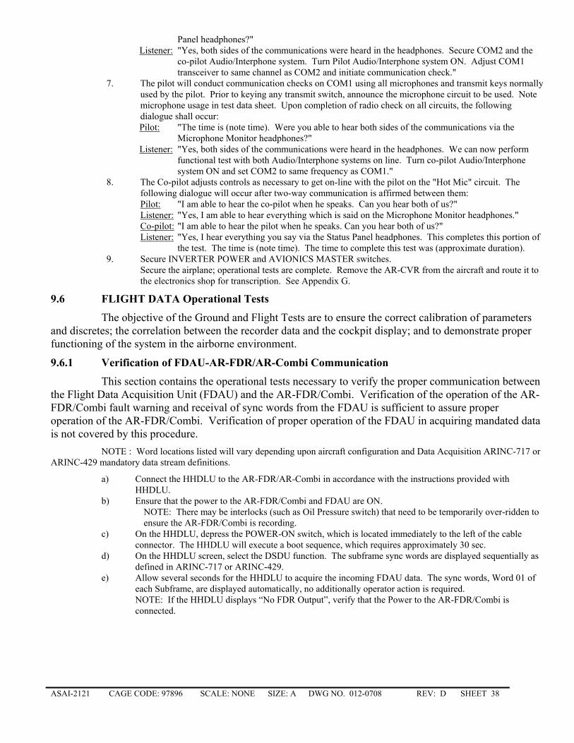
ASAI-2121 CAGE CODE: 97896 SCALE: NONE SIZE: A DWG NO. 012-0708 REV: D SHEET 38
Panel headphones?" Listener: "Yes, both sides of the communications were heard in the headphones. Secure COM2 and the
co-pilot Audio/Interphone system. Turn Pilot Audio/Interphone system ON. Adjust COM1 transceiver to same channel as COM2 and initiate communication check."
7. The pilot will conduct communication checks on COM1 using all microphones and transmit keys normally used by the pilot. Prior to keying any transmit switch, announce the microphone circuit to be used. Note microphone usage in test data sheet. Upon completion of radio check on all circuits, the following dialogue shall occur:
Pilot: "The time is (note time). Were you able to hear both sides of the communications via the Microphone Monitor headphones?"
Listener: "Yes, both sides of the communications were heard in the headphones. We can now perform functional test with both Audio/Interphone systems on line. Turn co-pilot Audio/Interphone system ON and set COM2 to same frequency as COM1."
8. The Co-pilot adjusts controls as necessary to get on-line with the pilot on the "Hot Mic" circuit. The following dialogue will occur after two-way communication is affirmed between them:
Pilot: "I am able to hear the co-pilot when he speaks. Can you hear both of us?" Listener: "Yes, I am able to hear everything which is said on the Microphone Monitor headphones." Co-pilot: "I am able to hear the pilot when he speaks. Can you hear both of us?" Listener: "Yes, I hear everything you say via the Status Panel headphones. This completes this portion of
the test. The time is (note time). The time to complete this test was (approximate duration). 9. Secure INVERTER POWER and AVIONICS MASTER switches.
Secure the airplane; operational tests are complete. Remove the AR-CVR from the aircraft and route it to the electronics shop for transcription. See Appendix G.
9.6 FLIGHT DATA Operational Tests
The objective of the Ground and Flight Tests are to ensure the correct calibration of parameters and discretes; the correlation between the recorder data and the cockpit display; and to demonstrate proper functioning of the system in the airborne environment.
9.6.1 Verification of FDAU-AR-FDR/AR-Combi Communication
This section contains the operational tests necessary to verify the proper communication between the Flight Data Acquisition Unit (FDAU) and the AR-FDR/Combi. Verification of the operation of the AR-FDR/Combi fault warning and receival of sync words from the FDAU is sufficient to assure proper operation of the AR-FDR/Combi. Verification of proper operation of the FDAU in acquiring mandated data is not covered by this procedure.
NOTE : Word locations listed will vary depending upon aircraft configuration and Data Acquisition ARINC-717 or ARINC-429 mandatory data stream definitions.
a) Connect the HHDLU to the AR-FDR/AR-Combi in accordance with the instructions provided with HHDLU.
b) Ensure that the power to the AR-FDR/Combi and FDAU are ON. NOTE: There may be interlocks (such as Oil Pressure switch) that need to be temporarily over-ridden to ensure the AR-FDR/Combi is recording.
c) On the HHDLU, depress the POWER-ON switch, which is located immediately to the left of the cable connector. The HHDLU will execute a boot sequence, which requires approximately 30 sec.
d) On the HHDLU screen, select the DSDU function. The subframe sync words are displayed sequentially as defined in ARINC-717 or ARINC-429.
e) Allow several seconds for the HHDLU to acquire the incoming FDAU data. The sync words, Word 01 of each Subframe, are displayed automatically, no additionally operator action is required. NOTE: If the HHDLU displays “No FDR Output”, verify that the Power to the AR-FDR/Combi is connected.
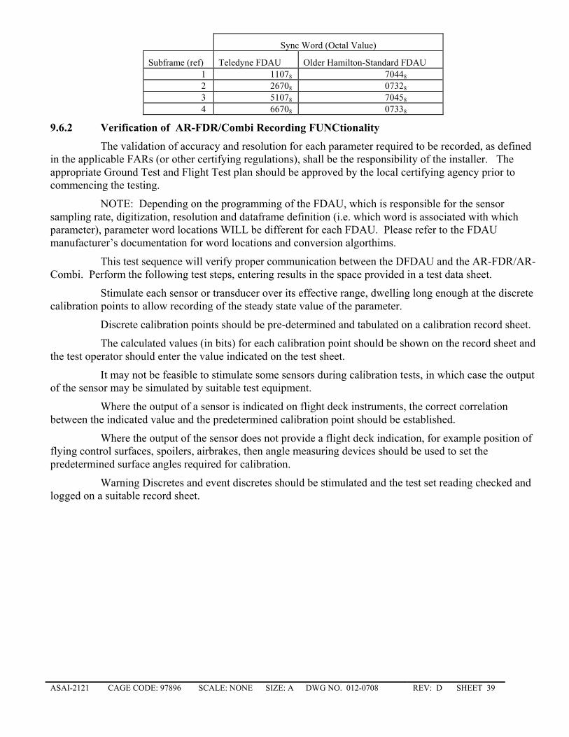
ASAI-2121 CAGE CODE: 97896 SCALE: NONE SIZE: A DWG NO. 012-0708 REV: D SHEET 39
Sync Word (Octal Value)
Subframe (ref) Teledyne FDAU Older Hamilton-Standard FDAU 1 11078 70448 2 26708 07328 3 51078 70458 4 66708 07338
9.6.2 Verification of AR-FDR/Combi Recording FUNCtionality
The validation of accuracy and resolution for each parameter required to be recorded, as defined in the applicable FARs (or other certifying regulations), shall be the responsibility of the installer. The appropriate Ground Test and Flight Test plan should be approved by the local certifying agency prior to commencing the testing.
NOTE: Depending on the programming of the FDAU, which is responsible for the sensor sampling rate, digitization, resolution and dataframe definition (i.e. which word is associated with which parameter), parameter word locations WILL be different for each FDAU. Please refer to the FDAU manufacturer’s documentation for word locations and conversion algorthims.
This test sequence will verify proper communication between the DFDAU and the AR-FDR/AR-Combi. Perform the following test steps, entering results in the space provided in a test data sheet.
Stimulate each sensor or transducer over its effective range, dwelling long enough at the discrete calibration points to allow recording of the steady state value of the parameter.
Discrete calibration points should be pre-determined and tabulated on a calibration record sheet.
The calculated values (in bits) for each calibration point should be shown on the record sheet and the test operator should enter the value indicated on the test sheet.
It may not be feasible to stimulate some sensors during calibration tests, in which case the output of the sensor may be simulated by suitable test equipment.
Where the output of a sensor is indicated on flight deck instruments, the correct correlation between the indicated value and the predetermined calibration point should be established.
Where the output of the sensor does not provide a flight deck indication, for example position of flying control surfaces, spoilers, airbrakes, then angle measuring devices should be used to set the predetermined surface angles required for calibration.
Warning Discretes and event discretes should be stimulated and the test set reading checked and logged on a suitable record sheet.
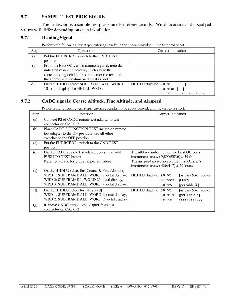
ASAI-2121 CAGE CODE: 97896 SCALE: NONE SIZE: A DWG NO. 012-0708 REV: D SHEET 40
9.7 SAMPLE TEST PROCEDURE
The following is a sample test procedure for reference only. Word locations and dispalyed values will differ depending on each installation.
9.7.1 Heading Signal Perform the following test steps, entering results in the space provided in the test data sheet.
Step Operation Correct Indication (a). Put the FLT RCRDR switch to the GND TEST
position.
(b). From the First Officer’s instrument panel, note the indicated magnetic heading. Determine the corresponding octal counts, and enter the result in the appropriate location on the data sheet.
c) On the HHDLU select SUBFRAME ALL, WORD 30, octal display, for HHDLU WRD 2.
HHDLU display: S0 W1 [ ] S0 W30 [ ] Sx Wx xxxxxxxxxxxx
9.7.2 CADC signals: Coarse Altitude, Fine Altitude, and Airspeed Perform the following test steps, entering results in the space provided in the test data sheet.
Step Operation Correct Indication (a). Connect P2 of CADC remote test adapter to test
connector on CADC-2
(b). Place CADC-2 FUNCTION TEST switch on remote test adapter to the ON position, and all other switches to the OFF position.
(c). Put the FLT RCRDR switch to the GND TEST position.
(d). On the CADC remote test adapter, press and hold PUSH TO TEST button
The altitude indication on the First Officer’s instruments shows 9,890(9830) ± 50 ft.
Refer to table X for proper expected values. The airspeed indication on the First Officer’s instruments shows 420(417) ± 20 knots.
(e). On the HHDLU select for [Coarse & Fine Altitude] WRD 1: SUBFRAME ALL, WORD 1, octal display, WRD 2: SUBFRAME 1, WORD 23, octal display, WRD 3: SUBFRAME ALL, WORD 5, octal display.
HHDLU display: S0 W1 [as para 9.6.1 above] S1 W23 [0002] S0 W5 [per table X]
(f). On the HHDLU select for [Airspeed] WRD 1: SUBFRAME ALL, WORD 1, octal display, WRD 2: SUBFRAME ALL, WORD 19 octal display
HHDLU display: S0 W1 [as para 9.6.1 above] S0 W19 [per Table X] Sx Wx xxxxxxxxxxxx
(g). Remove CADC remote test adapter from test connector on CADC-2
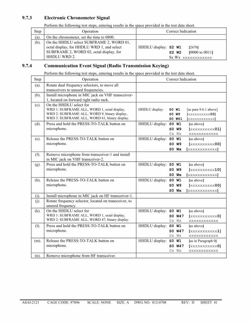
ASAI-2121 CAGE CODE: 97896 SCALE: NONE SIZE: A DWG NO. 012-0708 REV: D SHEET 41
9.7.3 Electronic Chronometer Signal Perform the following test steps, entering results in the space provided in the test data sheet.
Step Operation Correct Indication (a). On the chronometer, set the time to 0800. (b). On the HHDLU select SUBFRAME 2, WORD 01,
octal display, for HHDLU WRD 1, and select SUBFRAME 2, WORD 02, octal display, for HHDLU WRD 2.
HHDLU display: S2 W1 [2670] S2 W2 [0000 to 0011] Sx Wx xxxxxxxxxxxx
9.7.4 Communication Event Signal (Radio Transmission Keying) Perform the following test steps, entering results in the space provided in the test data sheet.
Step Operation Correct Indication (a). Rotate dual frequency selectors, to move all
transceivers to unused frequencies.
(b). Install microphone in MIC jack on VHF transceiver-1, located on forward right radio rack.
(c). On the HHDLU select for WRD 1: SUBFRAME ALL, WORD 1, octal display, WRD 2: SUBFRAME ALL, WORD 9, binary display, WRD 3: SUBFRAME ALL, WORD 61, binary display.
HHDLU display: S0 W1 [as para 9.6.1 above] S0 W9 [xxxxxxxxxx00] S0 W61 [xxxxxxxxxxxx]
(d). Press and hold the PRESS-TO-TALK button on microphone.
HHDLU display: S0 W1 [as above] S0 W9 [xxxxxxxxxx01] Sx Wx xxxxxxxxxxxx
(e). Release the PRESS-TO-TALK button on microphone.
HHDLU display: S0 W1 [as above] S0 W9 [xxxxxxxxxx00] S0 Wx [xxxxxxxxxxxx]
(f). Remove microphone from transceiver-1 and install in MIC jack on VHF transceiver-2.
(g). Press and hold the PRESS-TO-TALK button on microphone.
HHDLU display: S0 W1 [as above] S0 W9 [xxxxxxxxxx10] S0 Wx [xxxxxxxxxxxx]
(h). Release the PRESS-TO-TALK button on microphone.
HHDLU display: S0 W1 [as above] S0 W9 [xxxxxxxxxx00] S0 Wx [xxxxxxxxxxxx]
(i). Install microphone in MIC jack on HF transceiver-1. (j). Rotate frequency selector, located on transceiver, to
unused frequency.
(k). On the HHDLU select for WRD 1: SUBFRAME ALL, WORD 1, octal display, WRD 2: SUBFRAME ALL, WORD 47, binary display.
HHDLU display: S0 W1 [as above] S0 W47 [xxxxxxxxxxx0] Sx Wx xxxxxxxxxxxx
(l). Press and hold the PRESS-TO-TALK button on microphone.
HHDLU display: S0 W1 [as above] S0 W47 [xxxxxxxxxxx1] Sx Wx xxxxxxxxxxxx
(m). Release the PRESS-TO-TALK button on microphone.
HHDLU display: S0 W1 [as in Paragraph 0] S0 W47 [xxxxxxxxxxx0] Sx Wx xxxxxxxxxxxx
(n). Remove microphone from HF transceiver.
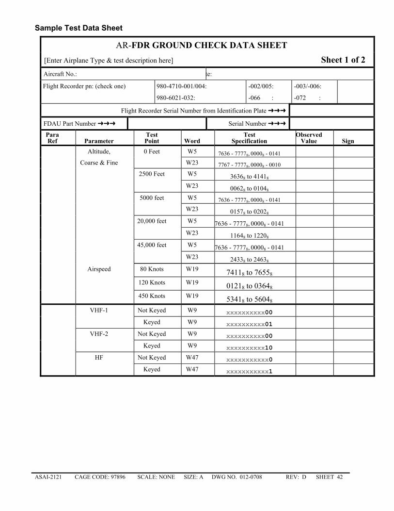
ASAI-2121 CAGE CODE: 97896 SCALE: NONE SIZE: A DWG NO. 012-0708 REV: D SHEET 42
Sample Test Data Sheet
AR-FDR GROUND CHECK DATA SHEET [Enter Airplane Type & test description here] Sheet 1 of 2 Aircraft No.: te:
Flight Recorder pn: (check one) 980-4710-001/004: � -002/005: � -003/-006: �
980-6021-032: � -066 : � -072 : �
Flight Recorder Serial Number from Identification Plate
FDAU Part Number Serial Number
Para Test Test ObservedRef Parameter Point Word Specification Value Sign
Altitude, 0 Feet W5 7636 - 77778, 00008 - 0141 Coarse & Fine W23 7767 - 77778, 00008 - 0010 2500 Feet W5 36368 to 41418 W23 00628 to 01048 5000 feet W5 7636 - 77778, 00008 - 0141 W23 01578 to 02028 20,000 feet W5 7636 - 77778, 00008 - 0141 W23 11648 to 12208 45,000 feet W5 7636 - 77778, 00008 - 0141 W23 24338 to 24638 Airspeed 80 Knots W19 74118 to 76558 120 Knots W19 01218 to 03648 450 Knots W19 53418 to 56048 VHF-1 Not Keyed W9 xxxxxxxxxx00 Keyed W9 xxxxxxxxxx01 VHF-2 Not Keyed W9 xxxxxxxxxx00 Keyed W9 xxxxxxxxxx10 HF Not Keyed W47 xxxxxxxxxxx0 Keyed W47 xxxxxxxxxxx1
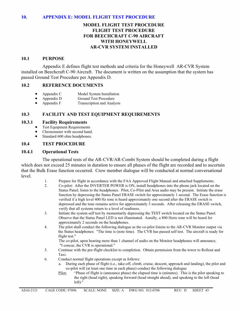
ASAI-2121 CAGE CODE: 97896 SCALE: NONE SIZE: A DWG NO. 012-0708 REV: D SHEET 43
10. APPENDIX E: MODEL FLIGHT TEST PROCEDURE
MODEL FLIGHT TEST PROCEDURE FLIGHT TEST PROCEDURE
FOR BEECHCRAFT C-90 AIRCRAFT WITH HONEYWELL
AR-CVR SYSTEM INSTALLED
10.1 PURPOSE
Appendix E defines flight test methods and criteria for the Honeywell AR-CVR System installed on Beechcraft C-90 Aircraft. The document is written on the assumption that the system has passed Ground Test Procedure per Appendix D.
10.2 REFERENCE DOCUMENTS
• Appendix C Model System Installation • Appendix D Ground Test Procedure • Appendix F Transcription and Analysis
10.3 FACILITY AND TEST EQUIPMENT REQUIREMENTS
10.3.1 Facility Requirements • Test Equipment Requirements • Chronometer with second hand. • Standard 600 ohm headphones.
10.4 TEST PROCEDURE
10.4.1 Operational Tests
The operational tests of the AR-CVR/AR-Combi System should be completed during a flight which does not exceed 25 minutes in duration to ensure all phases of the flight are recorded and to ascertain that the Bulk Erase function occurred. Crew member dialogue will be conducted at normal conversational level.
1. Prepare for flight in accordance with the FAA Approved Flight Manual and attached Supplements. 2. Co-pilot: After the INVERTER POWER is ON, install headphones into the phone jack located on the
Status Panel; listen to the headphones. Pilot, Co-Pilot and Area audio may be present. Initiate the erase function by depressing the Status Panel ERASE switch for approximately 1 second. The Erase function is verified if a high level 400 Hz tone is heard approximately one second after the ERASE switch is depressed and the tone remains active for approximately 3 seconds. After releasing the ERASE switch, verify that all systems return to a level of readiness.
3. Initiate the system self test by momentarily depressing the TEST switch located on the Status Panel. Observe that the Status Panel LED is not illuminated. Aurally, a 800 Hertz tone will be heard for approximately 2 seconds on the headphones.
4. The pilot shall conduct the following dialogue as the co-pilot listens to the AR-CVR Monitor output via the Status headphones: "The time is (note time). The CVR has passed self test. The aircraft is ready for flight test." The co-pilot, upon hearing more than 1 channel of audio on the Monitor headphones will announce, "I concur, the CVR is operational."
5. Continue with the pre-flight checklist to completion. Obtain permission from the tower to Rollout and Taxi.
6. Conduct normal flight operations except as follows: a. During each phase of flight (i.e., take-off, climb, cruise, descent, approach and landing), the pilot and
co-pilot will (at least one time in each phase) conduct the following dialogue Pilot: “Phase of flight is (announce phase) the elapsed time is (minutes). This is the pilot speaking to
the right (head right), speaking forward (head straight ahead), and speaking to the left (head left)."
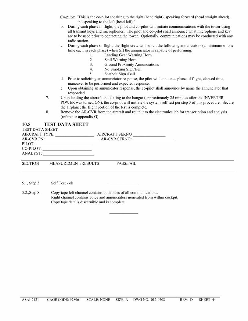
ASAI-2121 CAGE CODE: 97896 SCALE: NONE SIZE: A DWG NO. 012-0708 REV: D SHEET 44
Co-pilot: "This is the co-pilot speaking to the right (head right), speaking forward (head straight ahead), and speaking to the left (head left)."
b. During each phase in flight, the pilot and co-pilot will initiate communications with the tower using all transmit keys and microphones. The pilot and co-pilot shall announce what microphone and key are to be used prior to contacting the tower. Optionally, communications may be conducted with any radio station.
c. During each phase of flight, the flight crew will solicit the following annunciators (a minimum of one time each in each phase) when (if) the annunciator is capable of performing.
1. Landing Gear Warning Horn 2 Stall Warning Horn 3. Ground Proximity Annunciations 4. No Smoking Sign/Bell 5. Seatbelt Sign /Bell
d. Prior to soliciting an annunciator response, the pilot will announce phase of flight, elapsed time, maneuver to be performed and expected response.
e. Upon obtaining an annunicator response, the co-pilot shall announce by name the annunciator that responded.
7. Upon landing the aircraft and taxiing to the hangar (approximately 25 minutes after the INVERTER POWER was turned ON), the co-pilot will initiate the system self test per step 3 of this procedure. Secure the airplane; the flight portion of the test is complete.
8. Remove the AR-CVR from the aircraft and route it to the electronics lab for transcription and analysis. (reference appendix G)
10.5 TEST DATA SHEET TEST DATA SHEET AIRCRAFT TYPE: ___________________ AIRCRAFT SERNO ________________ AR-CVR PN: __________________________ AR-CVR SERNO: ____________________ PILOT: ___________________________ CO-PILOT: ________________________ ANALYST: _________________________
SECTION MEASUREMENT/RESULTS PASS/FAIL 5.1, Step 3 Self Test - ok ______________ 5.2.,Step 8 Copy tape left channel contains both sides of all communications.
Right channel contains voice and annunciators generated from within cockpit. Copy tape data is discernible and is complete.
______________
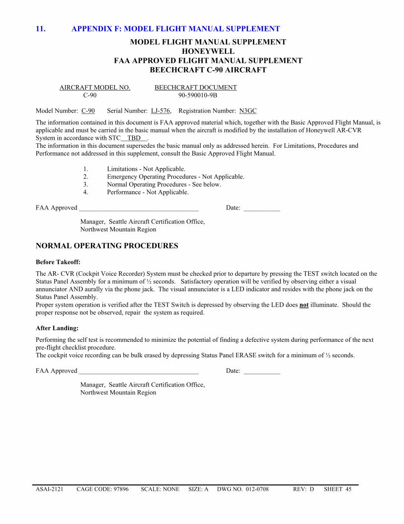
ASAI-2121 CAGE CODE: 97896 SCALE: NONE SIZE: A DWG NO. 012-0708 REV: D SHEET 45
11. APPENDIX F: MODEL FLIGHT MANUAL SUPPLEMENT
MODEL FLIGHT MANUAL SUPPLEMENT HONEYWELL
FAA APPROVED FLIGHT MANUAL SUPPLEMENT BEECHCRAFT C-90 AIRCRAFT
AIRCRAFT MODEL NO. BEECHCRAFT DOCUMENT C-90 90-590010-9B Model Number: C-90 Serial Number: LJ-576, Registration Number: N3GC
The information contained in this document is FAA approved material which, together with the Basic Approved Flight Manual, is applicable and must be carried in the basic manual when the aircraft is modified by the installation of Honeywell AR-CVR System in accordance with STC TBD . The information in this document supersedes the basic manual only as addressed herein. For Limitations, Procedures and Performance not addressed in this supplement, consult the Basic Approved Flight Manual.
1. Limitations - Not Applicable. 2. Emergency Operating Procedures - Not Applicable. 3. Normal Operating Procedures - See below. 4. Performance - Not Applicable.
FAA Approved ____________________________________ Date: ___________
Manager, Seattle Aircraft Certification Office, Northwest Mountain Region
NORMAL OPERATING PROCEDURES Before Takeoff:
The AR- CVR (Cockpit Voice Recorder) System must be checked prior to departure by pressing the TEST switch located on the Status Panel Assembly for a minimum of ½ seconds. Satisfactory operation will be verified by observing either a visual annunciator AND aurally via the phone jack. The visual annunciator is a LED indicator and resides with the phone jack on the Status Panel Assembly. Proper system operation is verified after the TEST Switch is depressed by observing the LED does not illuminate. Should the proper response not be observed, repair the system as required. After Landing:
Performing the self test is recommended to minimize the potential of finding a defective system during performance of the next pre-flight checklist procedure. The cockpit voice recording can be bulk erased by depressing Status Panel ERASE switch for a minimum of ½ seconds. FAA Approved ____________________________________ Date: ___________
Manager, Seattle Aircraft Certification Office, Northwest Mountain Region
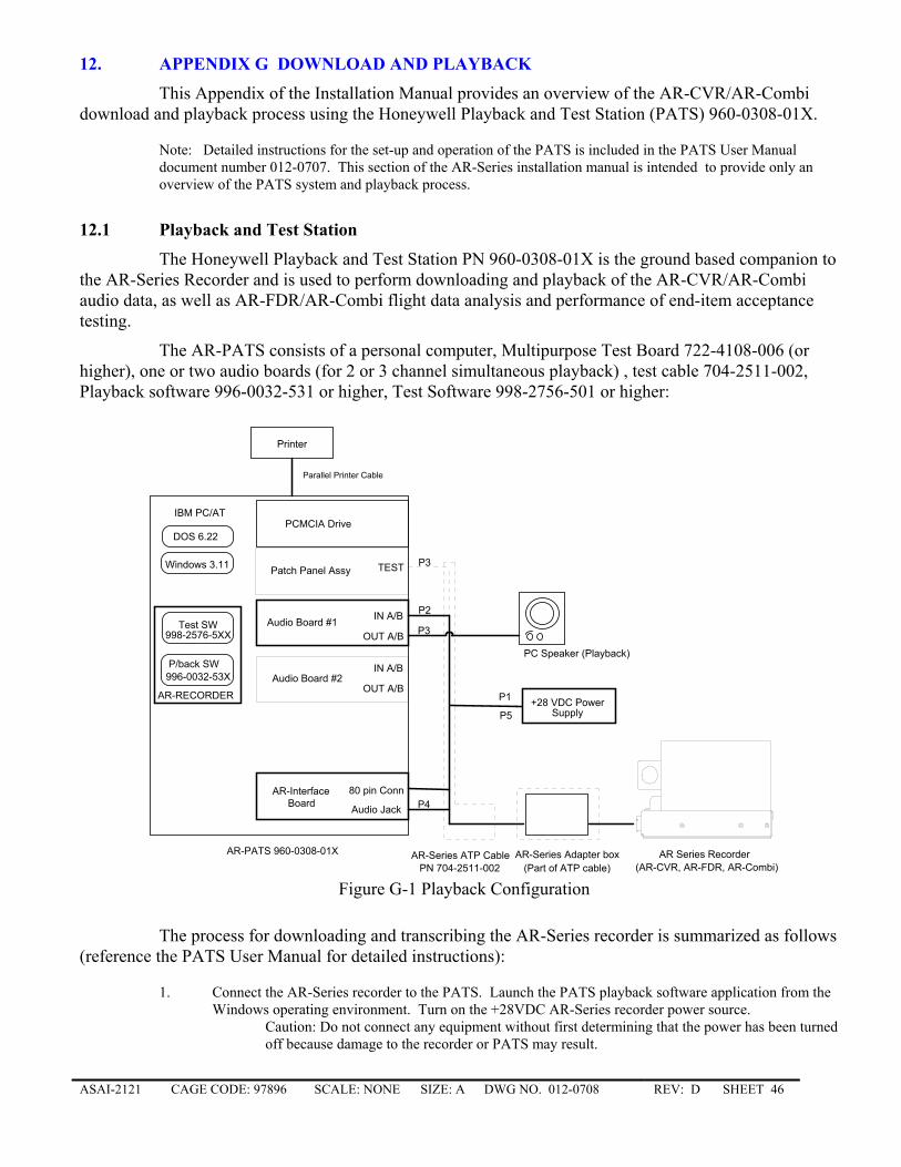
ASAI-2121 CAGE CODE: 97896 SCALE: NONE SIZE: A DWG NO. 012-0708 REV: D SHEET 46
12. APPENDIX G DOWNLOAD AND PLAYBACK
This Appendix of the Installation Manual provides an overview of the AR-CVR/AR-Combi download and playback process using the Honeywell Playback and Test Station (PATS) 960-0308-01X.
Note: Detailed instructions for the set-up and operation of the PATS is included in the PATS User Manual document number 012-0707. This section of the AR-Series installation manual is intended to provide only an overview of the PATS system and playback process.
12.1 Playback and Test Station
The Honeywell Playback and Test Station PN 960-0308-01X is the ground based companion to the AR-Series Recorder and is used to perform downloading and playback of the AR-CVR/AR-Combi audio data, as well as AR-FDR/AR-Combi flight data analysis and performance of end-item acceptance testing.
The AR-PATS consists of a personal computer, Multipurpose Test Board 722-4108-006 (or higher), one or two audio boards (for 2 or 3 channel simultaneous playback) , test cable 704-2511-002, Playback software 996-0032-531 or higher, Test Software 998-2756-501 or higher:
+28 VDC PowerSupply
AR-Series ATP Cable AR Series Recorder
Printer
IBM PC/AT
AR-Interface
Parallel Printer Cable
DOS 6.22
Windows 3.11
Test SW998-2576-5XX
Audio Board #1
AR-PATS 960-0308-01X
P4
P3
P2IN A/B
OUT A/B
Audio Jack
80 pin Conn
Audio Board #2 IN A/B
OUT A/B
Patch Panel Assy P3TEST
Board
PN 704-2511-002AR-Series Adapter box
(AR-CVR, AR-FDR, AR-Combi)(Part of ATP cable)
P/back SW996-0032-53X
PC Speaker (Playback)
AR-RECORDER
PCMCIA Drive
P1
P5
Figure G-1 Playback Configuration
The process for downloading and transcribing the AR-Series recorder is summarized as follows (reference the PATS User Manual for detailed instructions):
1. Connect the AR-Series recorder to the PATS. Launch the PATS playback software application from the Windows operating environment. Turn on the +28VDC AR-Series recorder power source.
Caution: Do not connect any equipment without first determining that the power has been turned off because damage to the recorder or PATS may result.
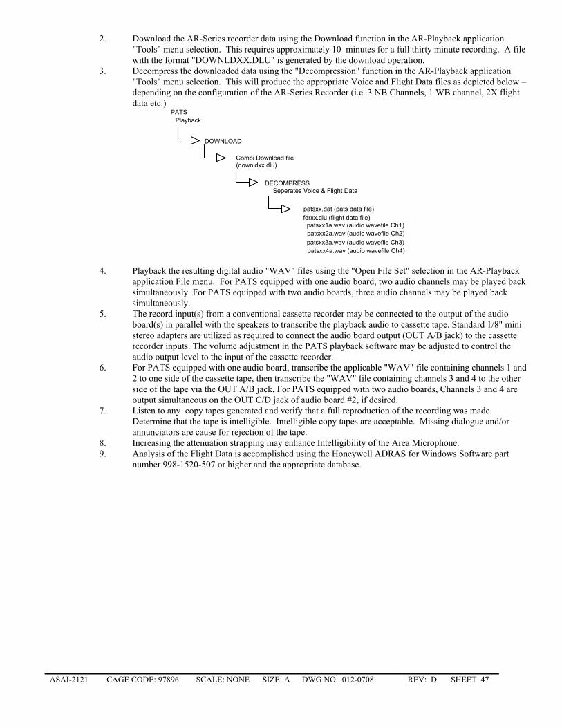
ASAI-2121 CAGE CODE: 97896 SCALE: NONE SIZE: A DWG NO. 012-0708 REV: D SHEET 47
2. Download the AR-Series recorder data using the Download function in the AR-Playback application "Tools" menu selection. This requires approximately 10 minutes for a full thirty minute recording. A file with the format "DOWNLDXX.DLU" is generated by the download operation.
3. Decompress the downloaded data using the "Decompression" function in the AR-Playback application "Tools" menu selection. This will produce the appropriate Voice and Flight Data files as depicted below – depending on the configuration of the AR-Series Recorder (i.e. 3 NB Channels, 1 WB channel, 2X flight data etc.)
PlaybackPATS
DOWNLOAD
Combi Download file(downldxx.dlu)
DECOMPRESSSeperates Voice & Flight Data
patsxx.dat (pats data file)fdrxx.dlu (flight data file)
patsxx1a.wav (audio wavefile Ch1)patsxx2a.wav (audio wavefile Ch2)patsxx3a.wav (audio wavefile Ch3)patsxx4a.wav (audio wavefile Ch4)
4. Playback the resulting digital audio "WAV" files using the "Open File Set" selection in the AR-Playback
application File menu. For PATS equipped with one audio board, two audio channels may be played back simultaneously. For PATS equipped with two audio boards, three audio channels may be played back simultaneously.
5. The record input(s) from a conventional cassette recorder may be connected to the output of the audio board(s) in parallel with the speakers to transcribe the playback audio to cassette tape. Standard 1/8" mini stereo adapters are utilized as required to connect the audio board output (OUT A/B jack) to the cassette recorder inputs. The volume adjustment in the PATS playback software may be adjusted to control the audio output level to the input of the cassette recorder.
6. For PATS equipped with one audio board, transcribe the applicable "WAV" file containing channels 1 and 2 to one side of the cassette tape, then transcribe the "WAV" file containing channels 3 and 4 to the other side of the tape via the OUT A/B jack. For PATS equipped with two audio boards, Channels 3 and 4 are output simultaneous on the OUT C/D jack of audio board #2, if desired.
7. Listen to any copy tapes generated and verify that a full reproduction of the recording was made. Determine that the tape is intelligible. Intelligible copy tapes are acceptable. Missing dialogue and/or annunciators are cause for rejection of the tape.
8. Increasing the attenuation strapping may enhance Intelligibility of the Area Microphone. 9. Analysis of the Flight Data is accomplished using the Honeywell ADRAS for Windows Software part
number 998-1520-507 or higher and the appropriate database.