Dynamic vibration analysis of a swash-plate type water hydraulic motor
18
Dynamic vibration analysis of a swash-plate type water hydraulic motor H.X. Chen, Patrick S.K. Chua, G.H. Lim * School of Mechanical and Production Engineering, Nanyang Technological University, 50 Nanyang Avenue, Singapore 639798, Singapore Received 13 October 2004; received in revised form 3 August 2005; accepted 7 September 2005 Available online 3 November 2005 Abstract This paper presents the study of the dynamic analysis of a swash-plate water hydraulic motor in a modern water hydraulic system. A swash-plate mechanism is modeled as a system with three masses and 14 degrees of freedom (DOF). In order to evaluate the applicability of the dynamic model, the numerical simulation analysis of the dynamic response of the model due to pressure pulsation is presented and compared with experimental results. A series of the dynamic vibration characteristics of the water hydraulic piston motor are studied by the numerical simulation. It is effec- tive for the model to simulate the vibration signal of the casing in the hydraulic motor. The waveform and frequency of the simulated signal is similar to the experimental signal. The simulated signals in other directions show that the vibration signals in all the directions mainly consist of the hydraulic pump and hydraulic motor rotational frequencies. Ó 2005 Elsevier Ltd. All rights reserved. Keywords: Water hydraulic motor; Dynamic response; Numerical simulation; Vibration analysis; Swash plate; Pressure 1. Introduction With the increasing environmental impact of the operating oil-based hydraulic system and the concern raised by environmentally conscious organizations, a most exciting area of development in the fluid power industry over the past few years has been in the area of water hydraulics, which involves using tap water as a viable alternative to oil in fluid power transmission. Water hydraulic systems have been used in the farm- ing, forestry, food, pharmaceutical and paper industries [1–3]. The axial piston motor is commonly applied to provide high torque and performance for water hydraulic system. Axial piston swash-plate type hydraulic motor is comprised of a discrete number of pistons that recip- rocate in a sinusoidal fashion for the purposes of torque output. The basic force within axial piston pump is analyzed and summarized. The instantaneous torque exerted on the shaft is computed and its resonant 0094-114X/$ - see front matter Ó 2005 Elsevier Ltd. All rights reserved. doi:10.1016/j.mechmachtheory.2005.09.002 * Corresponding author. Fax: +65 6791 1859. E-mail address: [email protected] (G.H. Lim). Mechanism and Machine Theory 41 (2006) 487–504 www.elsevier.com/locate/mechmt Mechanism and Machine Theory
-
Upload
independent -
Category
Documents
-
view
4 -
download
0
Transcript of Dynamic vibration analysis of a swash-plate type water hydraulic motor

Mechanism
Mechanism and Machine Theory 41 (2006) 487–504
www.elsevier.com/locate/mechmt
andMachine Theory
Dynamic vibration analysis of a swash-plate type waterhydraulic motor
H.X. Chen, Patrick S.K. Chua, G.H. Lim *
School of Mechanical and Production Engineering, Nanyang Technological University, 50 Nanyang Avenue, Singapore 639798, Singapore
Received 13 October 2004; received in revised form 3 August 2005; accepted 7 September 2005Available online 3 November 2005
Abstract
This paper presents the study of the dynamic analysis of a swash-plate water hydraulic motor in a modern waterhydraulic system. A swash-plate mechanism is modeled as a system with three masses and 14 degrees of freedom(DOF). In order to evaluate the applicability of the dynamic model, the numerical simulation analysis of the dynamicresponse of the model due to pressure pulsation is presented and compared with experimental results. A series of thedynamic vibration characteristics of the water hydraulic piston motor are studied by the numerical simulation. It is effec-tive for the model to simulate the vibration signal of the casing in the hydraulic motor. The waveform and frequency of thesimulated signal is similar to the experimental signal. The simulated signals in other directions show that the vibrationsignals in all the directions mainly consist of the hydraulic pump and hydraulic motor rotational frequencies.� 2005 Elsevier Ltd. All rights reserved.
Keywords: Water hydraulic motor; Dynamic response; Numerical simulation; Vibration analysis; Swash plate; Pressure
1. Introduction
With the increasing environmental impact of the operating oil-based hydraulic system and the concernraised by environmentally conscious organizations, a most exciting area of development in the fluid powerindustry over the past few years has been in the area of water hydraulics, which involves using tap wateras a viable alternative to oil in fluid power transmission. Water hydraulic systems have been used in the farm-ing, forestry, food, pharmaceutical and paper industries [1–3].
The axial piston motor is commonly applied to provide high torque and performance for water hydraulicsystem. Axial piston swash-plate type hydraulic motor is comprised of a discrete number of pistons that recip-rocate in a sinusoidal fashion for the purposes of torque output. The basic force within axial piston pumpis analyzed and summarized. The instantaneous torque exerted on the shaft is computed and its resonant
0094-114X/$ - see front matter � 2005 Elsevier Ltd. All rights reserved.
doi:10.1016/j.mechmachtheory.2005.09.002
* Corresponding author. Fax: +65 6791 1859.E-mail address: [email protected] (G.H. Lim).
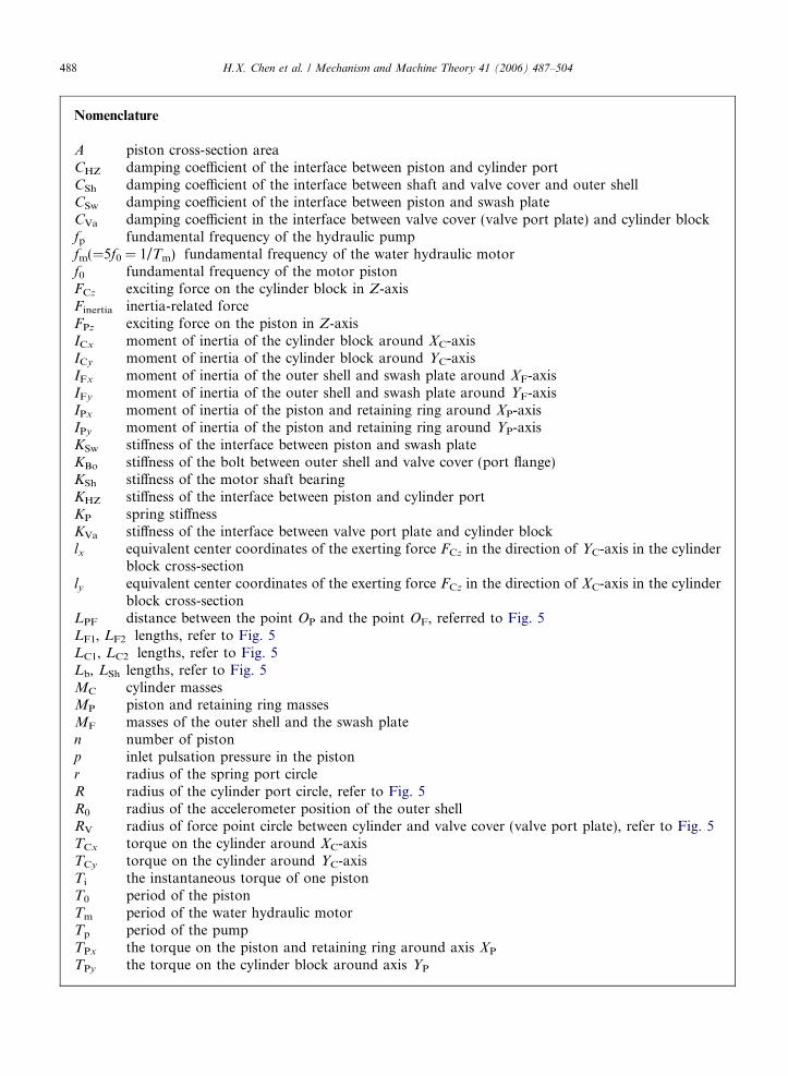
Nomenclature
A piston cross-section areaCHZ damping coefficient of the interface between piston and cylinder portCSh damping coefficient of the interface between shaft and valve cover and outer shellCSw damping coefficient of the interface between piston and swash plateCVa damping coefficient in the interface between valve cover (valve port plate) and cylinder blockfp fundamental frequency of the hydraulic pumpfm(=5f0 = 1/Tm) fundamental frequency of the water hydraulic motorf0 fundamental frequency of the motor pistonFCz exciting force on the cylinder block in Z-axisFinertia inertia-related forceFPz exciting force on the piston in Z-axisICx moment of inertia of the cylinder block around XC-axisICy moment of inertia of the cylinder block around YC-axisIFx moment of inertia of the outer shell and swash plate around XF-axisIFy moment of inertia of the outer shell and swash plate around YF-axisIPx moment of inertia of the piston and retaining ring around XP-axisIPy moment of inertia of the piston and retaining ring around YP-axisKSw stiffness of the interface between piston and swash plateKBo stiffness of the bolt between outer shell and valve cover (port flange)KSh stiffness of the motor shaft bearingKHZ stiffness of the interface between piston and cylinder portKP spring stiffnessKVa stiffness of the interface between valve port plate and cylinder blocklx equivalent center coordinates of the exerting force FCz in the direction of YC-axis in the cylinder
block cross-sectionly equivalent center coordinates of the exerting force FCz in the direction of XC-axis in the cylinder
block cross-sectionLPF distance between the point OP and the point OF, referred to Fig. 5LF1, LF2 lengths, refer to Fig. 5LC1, LC2 lengths, refer to Fig. 5Lb, LSh lengths, refer to Fig. 5MC cylinder massesMP piston and retaining ring massesMF masses of the outer shell and the swash platen number of pistonp inlet pulsation pressure in the pistonr radius of the spring port circleR radius of the cylinder port circle, refer to Fig. 5R0 radius of the accelerometer position of the outer shellRV radius of force point circle between cylinder and valve cover (valve port plate), refer to Fig. 5TCx torque on the cylinder around XC-axisTCy torque on the cylinder around YC-axisTi the instantaneous torque of one pistonT0 period of the pistonTm period of the water hydraulic motorTp period of the pumpTPx the torque on the piston and retaining ring around axis XP
TPy the torque on the cylinder block around axis YP
488 H.X. Chen et al. / Mechanism and Machine Theory 41 (2006) 487–504
TP the piston torqued0 angle of swash platex0 hydraulic motor angular velocity/ circular motion around axis X
h circular motion around axis Y
# anger between the radius and +YF-axis
H.X. Chen et al. / Mechanism and Machine Theory 41 (2006) 487–504 489
frequencies of the pump that occur at even-multiple of the ‘‘piston-pass’’ frequency has been discussed byManring [4]. The mathematical equations describing swash-plate model are derived from the general hydraulicand mechanical considerations [5]. Kaliafetis et al. [6] studied the model of an axial piston variable displace-ment pump with pressure control.
The fluctuating aspects of the discharge flow have been addressed in the published literature. Manring [7]derived the closed-form expressions to describe the characteristics of the flow ripple. The ripple height and thepulse frequency of the flow ripple are described. Harrison and Edge [8] achieved a novel timing mechanism toreduce the source flow ripple in hydraulic systems in order to reduce the pressure ripple and system noise.Kojima and Shinada [9] investigated the fluid-borne noise characteristics in the fluid pump. The second sourcemethod on model and detection of the fluid noise characteristics have been studied. Some researchersproposed the test method for the measurement of the pump fluid-borne noise characteristics, pump pressureripple and flow ripple characteristics [10,11]. Edge and Darling [12] proposed a theoretical model of the axialpiston pump flow ripple.
The dynamic behaviour of the axial piston motor is non-linear and the factors that influenced the perfor-mance of the axial piston motor are complicated. The vibration energy transmission characteristics from thecylinder to a swash-plate within an axial piston pump had been studied [13]. Qi and Lu [14] investigated thevibration of oil hydraulic axial piston pumps. Investigations showed that the main source of vibration isthe impact between the slipper and swash plate when the piston/slipper moved into a pre-compression process.This impact force may excite a resonant vibration of the pump shell. Bahr et al. [15] developed a mathematicalmodel to investigate the vibration characteristics of the pumping mechanism of oil hydraulic constant-poweraxial piston pumps with conical cylinder blocks. Nishimura et al. [16] analyzed the dynamic response of aswash-plate type hydraulic piston pump.
The purpose of this research work is to analyze the dynamic response of water hydraulic motor. A modelconsisting of three masses and 14 DOF is developed. This model includes swash plate and outer shell, pistonand retaining ring and cylinder block that generate rotary and reciprocal motion. The dynamic kinematicequations are formulated for analyzing the vibration characteristics of this model in numerical simulation.The results of numerical simulation were compared with experimental results to verify the model developed.It presents the vibration characteristics of the components in water hydraulic motor.
2. Water hydraulic motor description
The modern water hydraulic system installed in the School of Mechanical and Production Engineering,Nanyang Technological University, was acquired from Danfoss Inc. [17]. Fig. 1 showed the water hydraulicmotor test setup system. The water hydraulic system consists of electrical motor, water hydraulic pump, fourkinds of valves, pressure sensors, flow rate sensors and water hydraulic motor. The water hydraulic motor isfixed-displacement swash plate. The water hydraulic pump was 5-piston axial piston pump. The water hydrau-lic system was connected by the rubber hose to the water hydraulic motor.
The output torque and flow rate of the water hydraulic motor were 2 N m and 0.12 l/s. The angular speedsof hydraulic motor and pump were 630 rev/min and 1450 rev/min. The flow rate of the water hydraulic systemwas 0.12 l/s.
The vibration signals were acquired by the accelerometer, which was mounted on the outer shell near theinlet of the water hydraulic motor.

Fig. 1. Schematic hardware architecture of modern water hydraulic system.
490 H.X. Chen et al. / Mechanism and Machine Theory 41 (2006) 487–504
The actuator studied here is a five piston axial piston motor used in a water hydraulic system. A MAH 12.5water hydraulic motor and water hydraulic system manufactured by Danfoss Inc. were used to measure thevibration and the inlet pressure pulsation of water hydraulic motor. Fig. 2 shows the structure of waterhydraulic motor. An axial piston motor consists mainly of a valve port plate with inlet and outlet ports, aswash plate, an outer shell, a cylinder block, pistons with shoes, a bias spring, a port flange and a shaft.The piston fits within bores of the cylinder barrel and is on the same axis as output shaft. The swash plateis positioned at an angle and acts as a surface on which piston shoes travel. The shoes are held in contact withthe swash plate by the retaining ring and the bias spring. The port plate separates incoming fluid from dis-charging fluid. The output shaft is connected to the cylinder barrel.
As the water enters the inlet and exits at the outlet of the hydraulic motor, the pressure in the cylinder holealternates from high pressure to low pressure. This causes the pressure pulsation to occur. The total cylinderarea inside a delivery port is variable as a result of the cycle variations of the piston number passing throughthe delivery port. It generates the variations of the axial output moment. The variation of force is applied fromthe piston to the swash plate and the valve cover. The force between the support for the swash plate and thevalve cover is opposite. The hydraulic motor body vibrates.
3. Characteristics of pressure ripple in water hydraulic system
A hydraulic system generates more complicated vibration (noise) on account of the interaction between thetwo pressure pulsations produced by the motor and pump. The fluidborne vibration causes structurebornevibration that has negative effect on the hydraulic motor and pump. Kojima and Shinada [18] and Edge
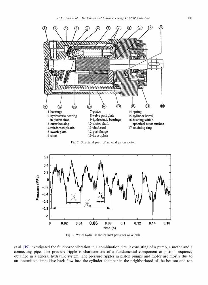
Fig. 2. Structural parts of an axial piston motor.
Fig. 3. Water hydraulic motor inlet pressures waveform.
H.X. Chen et al. / Mechanism and Machine Theory 41 (2006) 487–504 491
et al. [19] investigated the fluidborne vibration in a combination circuit consisting of a pump, a motor and aconnecting pipe. The pressure ripple is characteristic of a fundamental component at piston frequencyobtained in a general hydraulic system. The pressure ripples in piston pumps and motor are mostly due toan intermittent impulsive back flow into the cylinder chamber in the neighborhood of the bottom and top
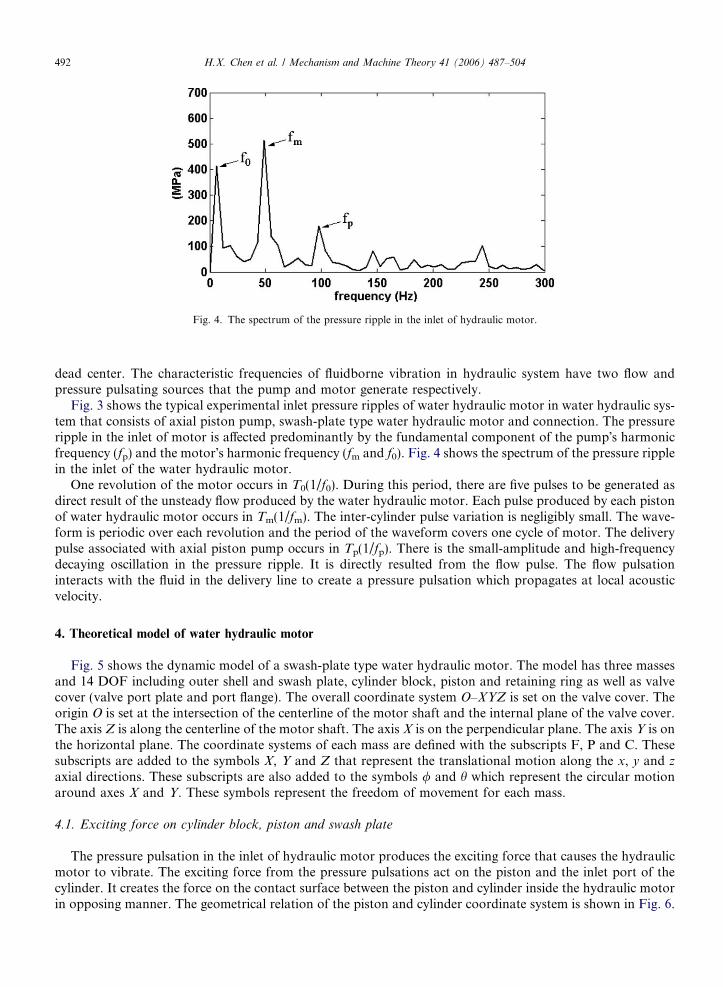
Fig. 4. The spectrum of the pressure ripple in the inlet of hydraulic motor.
492 H.X. Chen et al. / Mechanism and Machine Theory 41 (2006) 487–504
dead center. The characteristic frequencies of fluidborne vibration in hydraulic system have two flow andpressure pulsating sources that the pump and motor generate respectively.
Fig. 3 shows the typical experimental inlet pressure ripples of water hydraulic motor in water hydraulic sys-tem that consists of axial piston pump, swash-plate type water hydraulic motor and connection. The pressureripple in the inlet of motor is affected predominantly by the fundamental component of the pump�s harmonicfrequency (fp) and the motor�s harmonic frequency (fm and f0). Fig. 4 shows the spectrum of the pressure ripplein the inlet of the water hydraulic motor.
One revolution of the motor occurs in T0(1/f0). During this period, there are five pulses to be generated asdirect result of the unsteady flow produced by the water hydraulic motor. Each pulse produced by each pistonof water hydraulic motor occurs in Tm(1/fm). The inter-cylinder pulse variation is negligibly small. The wave-form is periodic over each revolution and the period of the waveform covers one cycle of motor. The deliverypulse associated with axial piston pump occurs in Tp(1/fp). There is the small-amplitude and high-frequencydecaying oscillation in the pressure ripple. It is directly resulted from the flow pulse. The flow pulsationinteracts with the fluid in the delivery line to create a pressure pulsation which propagates at local acousticvelocity.
4. Theoretical model of water hydraulic motor
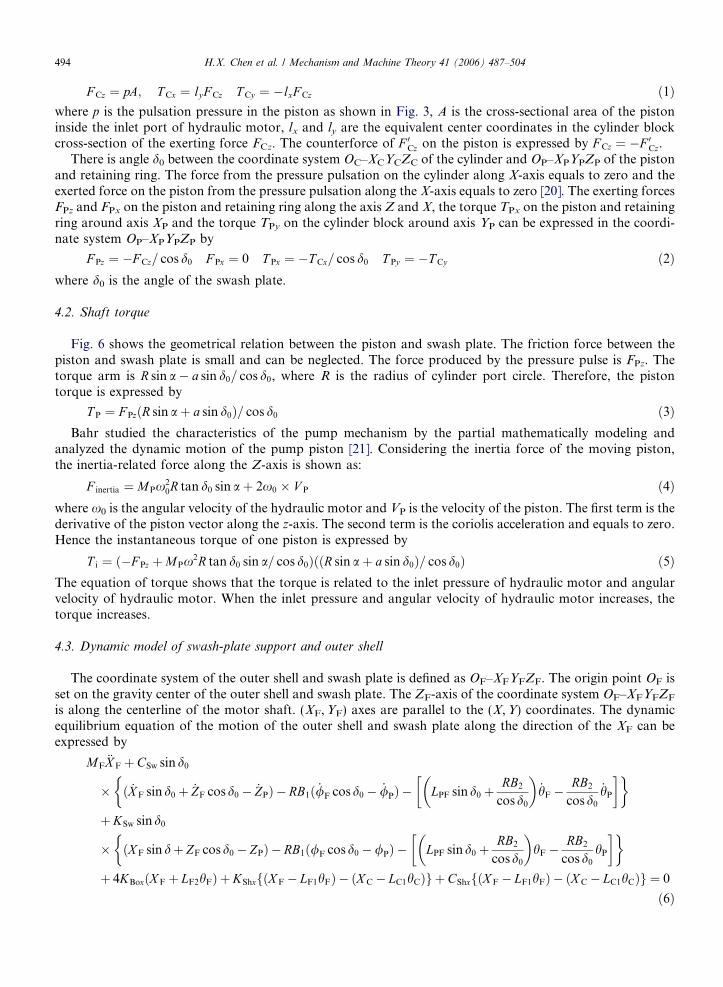
Fig. 5 shows the dynamic model of a swash-plate type water hydraulic motor. The model has three massesand 14 DOF including outer shell and swash plate, cylinder block, piston and retaining ring as well as valvecover (valve port plate and port flange). The overall coordinate system O–XYZ is set on the valve cover. Theorigin O is set at the intersection of the centerline of the motor shaft and the internal plane of the valve cover.The axis Z is along the centerline of the motor shaft. The axis X is on the perpendicular plane. The axis Y is onthe horizontal plane. The coordinate systems of each mass are defined with the subscripts F, P and C. Thesesubscripts are added to the symbols X, Y and Z that represent the translational motion along the x, y and z
axial directions. These subscripts are also added to the symbols / and h which represent the circular motionaround axes X and Y. These symbols represent the freedom of movement for each mass.
4.1. Exciting force on cylinder block, piston and swash plate
The pressure pulsation in the inlet of hydraulic motor produces the exciting force that causes the hydraulicmotor to vibrate. The exciting force from the pressure pulsations act on the piston and the inlet port of thecylinder. It creates the force on the contact surface between the piston and cylinder inside the hydraulic motorin opposing manner. The geometrical relation of the piston and cylinder coordinate system is shown in Fig. 6.
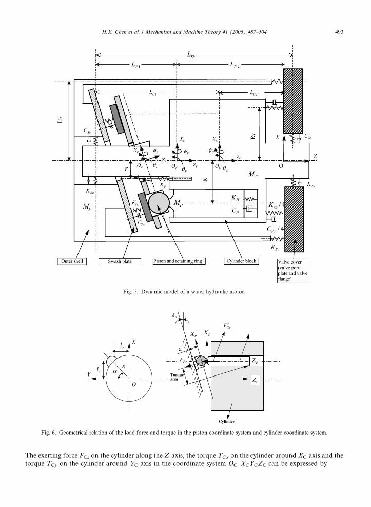
Fig. 5. Dynamic model of a water hydraulic motor.
Y
PX CX
PZ
CZ
X
O
CzF ′
PzF
yl
xl
Cylinder
0δ
a
Torquearm
αR
Fig. 6. Geometrical relation of the load force and torque in the piston coordinate system and cylinder coordinate system.
H.X. Chen et al. / Mechanism and Machine Theory 41 (2006) 487–504 493
The exerting force FCz on the cylinder along the Z-axis, the torque TCx on the cylinder around XC-axis and thetorque TCy on the cylinder around YC-axis in the coordinate system OC–XCYCZC can be expressed by
494 H.X. Chen et al. / Mechanism and Machine Theory 41 (2006) 487–504
F Cz ¼ pA; T Cx ¼ lyF Cz T Cy ¼ �lxF Cz ð1Þ
where p is the pulsation pressure in the piston as shown in Fig. 3, A is the cross-sectional area of the pistoninside the inlet port of hydraulic motor, lx and ly are the equivalent center coordinates in the cylinder blockcross-section of the exerting force FCz. The counterforce of F 0Cz on the piston is expressed by F Cz ¼ �F 0Cz.There is angle d0 between the coordinate system OC–XCYCZC of the cylinder and OP–XPYPZP of the pistonand retaining ring. The force from the pressure pulsation on the cylinder along X-axis equals to zero and theexerted force on the piston from the pressure pulsation along the X-axis equals to zero [20]. The exerting forcesFPz and FPx on the piston and retaining ring along the axis Z and X, the torque TPx on the piston and retainingring around axis XP and the torque TPy on the cylinder block around axis YP can be expressed in the coordi-nate system OP–XPYPZP by
F Pz ¼ �F Cz= cos d0 F Px ¼ 0 T Px ¼ �T Cx= cos d0 T Py ¼ �T Cy ð2Þ
where d0 is the angle of the swash plate.4.2. Shaft torque
Fig. 6 shows the geometrical relation between the piston and swash plate. The friction force between thepiston and swash plate is small and can be neglected. The force produced by the pressure pulse is FPz. Thetorque arm is R sin a� a sin d0= cos d0, where R is the radius of cylinder port circle. Therefore, the pistontorque is expressed by
T P ¼ F PzðR sin aþ a sin d0Þ= cos d0 ð3Þ
Bahr studied the characteristics of the pump mechanism by the partial mathematically modeling andanalyzed the dynamic motion of the pump piston [21]. Considering the inertia force of the moving piston,the inertia-related force along the Z-axis is shown as:
F inertia ¼ MPx20R tan d0 sin aþ 2x0 � V P ð4Þ
where x0 is the angular velocity of the hydraulic motor and VP is the velocity of the piston. The first term is thederivative of the piston vector along the z-axis. The second term is the coriolis acceleration and equals to zero.Hence the instantaneous torque of one piston is expressed by
T i ¼ ð�F Pz þMPx2R tan d0 sin a= cos d0ÞððR sin aþ a sin d0Þ= cos d0Þ ð5Þ
The equation of torque shows that the torque is related to the inlet pressure of hydraulic motor and angularvelocity of hydraulic motor. When the inlet pressure and angular velocity of hydraulic motor increases, thetorque increases.
4.3. Dynamic model of swash-plate support and outer shell
The coordinate system of the outer shell and swash plate is defined as OF–XFYFZF. The origin point OF isset on the gravity center of the outer shell and swash plate. The ZF-axis of the coordinate system OF–XFYFZF
is along the centerline of the motor shaft. (XF,YF) axes are parallel to the (X,Y) coordinates. The dynamicequilibrium equation of the motion of the outer shell and swash plate along the direction of the XF can beexpressed by
MF€X F þCSw sind0
� ð _X F sin d0 þ _ZF cosd0 � _ZPÞ � RB1ð _/F cosd0 � _/PÞ � LPF sind0 þRB2
cosd0
� �_hF �
RB2
cosd0
_hP
� �� �
þKSw sind0
� ðX F sin dþ ZF cosd0 � ZPÞ � RB1ð/F cosd0 �/PÞ � LPF sind0 þRB2
cosd0
� �hF �
RB2
cosd0
hP
� �� �
þ 4KBoxðX F þ LF2hFÞ þKShxfðX F � LF1hFÞ � ðX C � LC1hCÞg þCShxfðX F � LF1hFÞ � ðX C � LC1hCÞg ¼ 0
ð6Þ
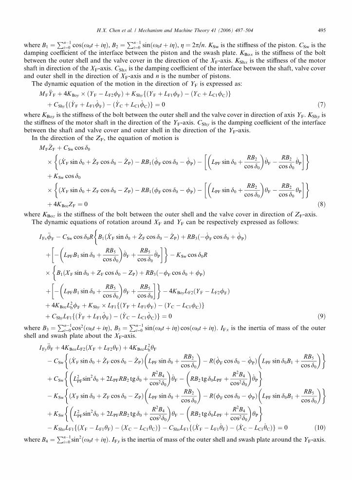
H.X. Chen et al. / Mechanism and Machine Theory 41 (2006) 487–504 495
where B1 ¼Pn�1
i¼0 cosðx0t þ igÞ, B2 ¼Pn�1
i¼0 sinðx0t þ igÞ, g = 2p/n. KSw is the stiffness of the piston. CSw is thedamping coefficient of the interface between the piston and the swash plate. KBox is the stiffness of the boltbetween the outer shell and the valve cover in the direction of the XF-axis. KShx is the stiffness of the motorshaft in direction of the XF-axis. CShx is the damping coefficient of the interface between the shaft, valve coverand outer shell in the direction of XF-axis and n is the number of pistons.
The dynamic equation of the motion in the direction of YF is expressed as:
MF€Y F þ 4KBoy � ðY F � LF2/FÞ þ KShyfðY F þ LF1/FÞ � ðY C þ LC1/CÞgþ CShyfð _Y F þ LF1
_/FÞ � ð _Y C þ LC1_/CÞg ¼ 0 ð7Þ
where KBoy is the stiffness of the bolt between the outer shell and the valve cover in direction of axis YF. KShy isthe stiffness of the motor shaft in the direction of the YF-axis. CShy is the damping coefficient of the interfacebetween the shaft and valve cover and outer shell in the direction of the YF-axis.
In the direction of the ZF, the equation of motion is
MF€ZF þ CSw cos d0
� ð _X F sin d0 þ _ZF cos d0 � _ZPÞ � RB1ð _/F cos d0 � _/PÞ � LPF sin d0 þRB2
cos d0
� �_hF �
RB2
cos d0
_hP
� �� �
þ KSw cos d0
� ðX F sin d0 þ ZF cos d0 � ZPÞ � RB1ð/F cos d0 � /PÞ � LPF sin d0 þRB2
cos d0
� �hF �
RB2
cos d0
hP
� �� �
þ 4KBozZF ¼ 0 ð8Þ
where KBoz is the stiffness of the bolt between the outer shell and the valve cover in direction of ZF-axis.The dynamic equations of rotation around XF and YF can be respectively expressed as follows:
IFx€/F � CSw cos d0R
�B1ð _X F sin d0 þ _ZF cos d0 � _ZPÞ þ RB3ð� _/F cos d0 þ _/PÞ
þ � LPFB1 sin d0 þRB5
cos d0
� �_hF þ
RB5
cos d0
_hP
� ��� KSw cos d0R
� B1ðX F sin d0 þ ZF cos d0 � ZPÞ þ RB3ð�/F cos d0 þ /PÞ�
þ � LPFB1 sin d0 þRB5
cos d0
� �hF þ
RB5
cos d0
� ��� 4KBoyLF2ðY F � LF2/FÞ
þ 4KBozL2b/F þ KShy � LF1fðY F þ LF1/FÞ � ðY C � LC1/CÞg
þ CShyLF1fð _Y F þ LF1_/FÞ � ð _Y C � LC1
_/CÞg ¼ 0 ð9Þ
where B3 ¼Pn�1
i¼0 cos2ðx0t þ igÞ, B5 ¼Pn�1
i¼0 sinðx0t þ igÞ cosðx0t þ igÞ. IFx is the inertia of mass of the outershell and swash plate about the XF-axis.
IFy€hF þ 4KBoxLF2ðX F þ LF2hFÞ þ 4KBozL2
bhF
� CSw ð _X F sin d0 þ _ZF cos d0 � _ZPÞ LPF sin d0 þRB2
cos d0
� �� Rð _/F cos d0 � _/PÞ LPF sin d0B1 þ
RB5
cos d0
� �� �
þ CSw L2PFsin2d0 þ 2LPFRB2 tgd0 þ
R2B4
cos2d0
� �_hF � RB2 tgd0LPF þ
R2B4
cos2d0
� �_hP
� �
� KSw ðX F sin d0 þ ZF cos d0 � ZPÞ LPF sin d0 þRB2
cos d0
� �� Rð/F cos d0 � /PÞ LPF sin d0B1 þ
RB5
cos d0
� �� �
þ KSw L2PFsin2d0 þ 2LPFRB2 tgd0 þ
R2B4
cos2d0
� �hF � RB2 tgd0LPF þ
R2B4
cos2d0
� �hP
� �
� KShxLF1fðX F � LF1hFÞ � ðX C � LC1hCÞg � CShxLF1fð _X F � LF1_hFÞ � ð _X C � LC1
_hCÞg ¼ 0 ð10Þ
where B4 ¼Pn�1
i¼0 sin2ðx0t þ igÞ. IFy is the inertia of mass of the outer shell and swash plate around the YF-axis.
496 H.X. Chen et al. / Mechanism and Machine Theory 41 (2006) 487–504
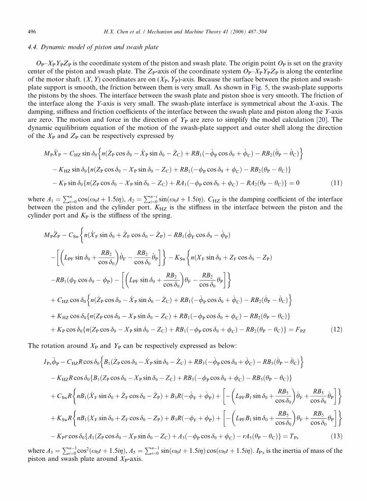
4.4. Dynamic model of piston and swash plate
OP–XPYPZP is the coordinate system of the piston and swash plate. The origin point OP is set on the gravitycenter of the piston and swash plate. The ZP-axis of the coordinate system OP–XPYPZP is along the centerlineof the motor shaft. (X,Y) coordinates are on (XP,YP)-axis. Because the surface between the piston and swash-plate support is smooth, the friction between them is very small. As shown in Fig. 5, the swash-plate supportsthe pistons by the shoes. The interface between the swash plate and piston shoe is very smooth. The friction ofthe interface along the Y-axis is very small. The swash-plate interface is symmetrical about the X-axis. Thedamping, stiffness and friction coefficients of the interface between the swash plate and piston along the Y-axisare zero. The motion and force in the direction of YP are zero to simplify the model calculation [20]. Thedynamic equilibrium equation of the motion of the swash-plate support and outer shell along the directionof the XP and ZP can be respectively expressed by
MP€X P � CHZ sin d0 nð _ZP cos d0 � _X P sin d0 � _ZCÞ þ RB1ð� _/P cos d0 þ _/CÞ � RB2ð _hP � _hCÞ
n o
� KHZ sin d0 nðZP cos d0 � X P sin d0 � ZCÞ þ RB1ð�/P cos d0 þ /CÞ � RB2ðhP � hCÞf g
� KP sin d0 nðZP cos d0 � X P sin d0 � ZCÞ þ RA1ð�/P cos d0 þ /CÞ � RA2ðhP � hCÞf g ¼ 0 ð11Þ
where A1 ¼Pn
i¼0 cosðx0t þ 1:5igÞ, A2 ¼Pn�i
i¼0 sinðx0t þ 1:5igÞ. CHZ is the damping coefficient of the interfacebetween the piston and the cylinder port. KHZ is the stiffness in the interface between the piston and thecylinder port and KP is the stiffness of the spring.
MP€ZP � CSw nð _X F sin d0 þ _ZF cos d0 � _ZPÞ � RB1ð _/F cos d0 � _/PÞ
�
� LPF sin d0 þRB2
cos d0
� �_hF �
RB2
cos d0
_hP
� ��� KSw nðX F sin d0 þ ZF cos d0 � ZPÞ
�
�RB1ð/F cos d0 � /PÞ � LPF sin d0 þRB2
cos d0
� �hF �
RB2
cos d0
hP
� ��
þ CHZ cos d0 nð _ZP cos d0 � _X P sin d0 � _ZCÞ þ RB1ð� _/P cos d0 þ _/CÞ � RB2ð _hP � _hCÞn o
þ KHZ cos d0 nðZP cos d0 � X P sin d0 � ZCÞ þ RB1ð�/P cos d0 þ /CÞ � RB2ðhP � hCÞf g
þ KP cos d0 nðZP cos d0 � X P sin d0 � ZCÞ þ RB1ð�/P cos d0 þ /CÞ � RB2ðhP � hCÞf g ¼ F PZ ð12Þ
The rotation around XP and YP can be respectively expressed as below:
IPx€/P�CHZR cosd0 B1ð _ZP cosd0� _X P sind0� _ZCÞ þRB3ð� _/P cosd0þ _/CÞ �RB5ð _hP� _hCÞ
n o
�KHZR cosd0 B1ðZP cosd0 �X P sind0� ZCÞ þRB3ð�/P cosd0þ/CÞ �RB5ðhP� hCÞf g
þCSwR nB1ð _X F sind0þ _ZF cosd0� _ZPÞ þB3Rð� _/F þ _/PÞ þ � LPFB1 sind0þRB5
cosd0
� �_hF þ
RB5
cosd0
_hP
� �� �
þKSwR nB1ðX F sind0þ ZF cosd0 � ZPÞ þB3Rð�/Fþ/PÞ þ � LPFB1 sind0þRB5
cosd0
� �hFþ
RB5
cosd0
hP
� �� �
�KPr cosd0 A1ðZP cosd0�X P sind0� ZCÞ þA3ð�/P cosd0þ/CÞ � rA5ðhP� hCÞf g ¼ T Px ð13Þ
where A3 ¼Pn�1
i¼0 cos2ðx0t þ 1:5igÞ, A5 ¼Pn�1
i¼0 sinðx0t þ 1:5igÞ cosðx0t þ 1:5igÞ. IPx is the inertia of mass of thepiston and swash plate around XP-axis.

H.X. Chen et al. / Mechanism and Machine Theory 41 (2006) 487–504 497
IPy€hP � CHZR cos d0fB2ð _ZP cos d0 � _X P sin d0 � _ZCÞ þ RB5ð� _/P cos d0 þ _/CÞ � RB4ð _hP � _hCÞg
� KHZR cos d0fB2ðZP cos d0 � X P sin d0 � ZCÞ þ RB5ð�/P cos d0 þ /CÞ � RB4ðhP � hCÞg
þ CSwðR= cos d0Þ�
B2ð _X F sin d0 þ _ZF cos d0 � _ZPÞ þ B5Rð� _/F cos d0 þ _/PÞ
þ � LPFB2 sin d0 þRB4
cos d0
� �_hF þ
RB4
cos d0
_hP
� ��
þ KSwðR= cos d0Þ B2ðX F sin d0 þ ZF cos d0 � ZPÞ þ B5Rð�/F cos d0 þ /PÞ�
þ � LPFB2 sin d0 þRB4
cos d0
� �hF þ
RB4
cos d0
hP
� ��� KPr cos d0fA2ðZP cos d0 � X P sin d0 � ZCÞ
þ rA5ð�/P cos d0 þ /CÞ � rA4ðhP � hCÞg ¼ T Py ð14Þ
where A4 ¼Pn�1
i¼0 sin2ðx0t þ 1:5igÞ. IPy is the inertia of mass of the piston and swash plate around the YP-axis.
4.5. Dynamic model of cylinder block
The coordinate system of the cylinder block is OC–XCYCZC. The original point OC is at the gravity centerof the cylinder block. The ZC-axis is on the centerline of the motor shaft. (XC,YC)-axis are parallel to the(X,Y) coordinates. The dynamic equilibrium equation of the motion of the cylinder block in the directionof the XC, YC and ZC can be respectively expressed as follows:
MC€X C � KShxfðX F � LF1hFÞ � ðX C � LC1hCÞg � CShxfð _X F � LF1
_hFÞ � ð _X C � LC1_hCÞg ¼ 0 ð15Þ
MC€Y C � KShyfðY F þ LF1/FÞ � ðY C þ LC1/CÞg þ KShyðY C � LC2/CÞ � CShyfð _Y F þ LF1
_/FÞ� ð _Y C þ LC1
_/CÞg þ CShyð _Y C � LC2_/CÞ ¼ 0 ð16Þ
MC€ZC � CHZfnð _ZP cos d0 � _X P sin d0 � _ZCÞ þ RB1ð� _/P cos d0 þ _/CÞ � RB2ð _hP � _hCÞg� KHZfnðZP cos d0 � X P sin d0 � ZCÞ þ RB1ð�/P cos d0 þ /CÞ � RB2ðhP � hCÞg� KPfnðZP cos d0 � X P sin d0 � ZCÞ þ RA1ð�/P cos d0 þ /CÞ � RA2ðhP � hCÞgþ CVaz
_ZC þ KVazZC ¼ F Cz ð17Þ
where KVa and CVa is the stiffness and damping coefficient in the interface between the valve cover and thecylinder block respectively.
The equation of rotation about XC and YC can be respectively expressed by
ICx€/C þ CHZRfB1ð _ZP cos d0 � _X P sin d0 � _ZCÞ þ RB3ð� _/P cos d0 þ _/CÞ � RB5ð _hP � _hCÞg
þ KHZRfB1ðZP cos d0 � X P sin d0 � ZCÞ þ RB3ð�/P cos d0 þ/CÞ � RB5ðhP � hCÞg
þ KPrfA1ðZP cos d0�X P sin d0�ZCÞþ rA3ð�/P cos d0 þ /CÞ� rA5ðhP � hCÞg þCVaz
2R2
V_/C þ
KVaz
2R2
V/C
� KShyLC1fðY F þ LF1/FÞ � ðY C þ LC1/CÞg �CShyLC1fð _Y F þ LF1_/FÞ � ð _Y C þ LC1
_/CÞg ¼ T Cx ð18Þ
ICy€hC þ CHZRfB2ðZP cos d0 � X P sin d0 � ZCÞ þ B5ð�/P cos d0 þ /CÞ þ B4ð�hP þ hCÞgþ KHZfB2ðZP cos d0 � X P sin d0 � ZCÞ þ B5ð�/P cos d0 þ /CÞ þ B4ð�hP þ hCÞgþ KShxLC1fðX F � LF1hFÞ � ðX C � LC1hCÞg þ CShxLC1fð _X F � LF1
_hFÞ � ð _X C � LC1_hÞg ¼ T Cy ð19Þ
where ICx is the inertia of mass of the cylinder block about the XC-axis. ICy is the inertia of mass of the cylinderblock about YC-axis.
498 H.X. Chen et al. / Mechanism and Machine Theory 41 (2006) 487–504
5. Generalized system equations of motion
The equation of motion for the hydraulic motor can be written in matrix form as
TableParam
Param
A
CHZ
CShx
CShy
CSw
CVa
ICx
ICy
IFx
IFy
IPx
IPy
KBox
KBoy
KBoz
KHZ
KP
KShx
½M �f€qg þ ½C�f _qg þ ½K�fqg ¼ fQðtÞg ð20Þ
wherefqg ¼ fX F; Y F; ZF;/F; hF;X P; ZP;/P; hP;X C; Y C; ZC;/C; hCgT;
fQðtÞg ¼ f0; 0; 0; 0; 0; 0; F Pz; T Px; T Py ; 0; 0; F Cz; T Cx; T Cyg.
By incorporating the equivalent viscous modal damping, the equation in the form of modal components isexpressed as fqg ¼ ½~u�fgðtÞg, where ½~u� is the orthonormal modal matrix. The generalized force is given byfNðtÞg ¼ ½~u�TfQðtÞg. By applying the orthogonal condition to simplify the above couple equations and trans-pose of the orthonormal modal matrix, the following modal forced vibration equations can be obtained.
€gr þ 2nrpr _gþ p2r gr ¼ NrðtÞ ð21Þ
where nr is the equivalent modal damping ratio.The applicable Matlab [22] simulation program has been developed based on the above approaches.
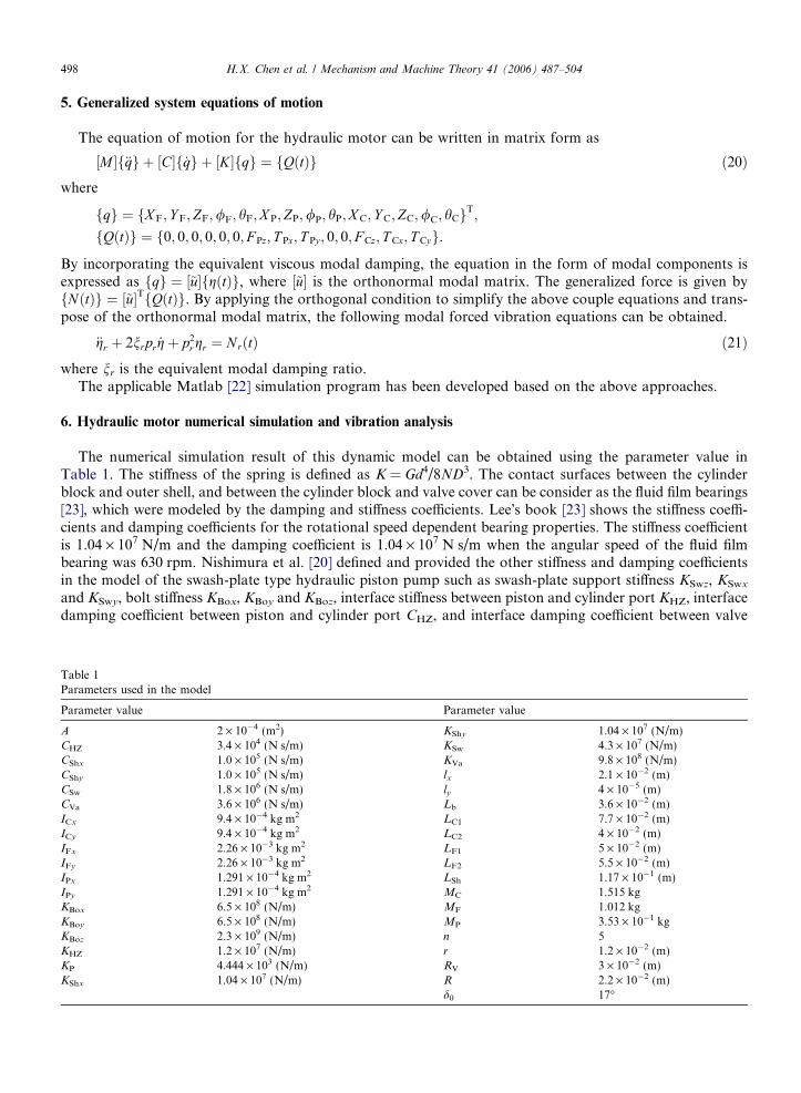
6. Hydraulic motor numerical simulation and vibration analysis
The numerical simulation result of this dynamic model can be obtained using the parameter value inTable 1. The stiffness of the spring is defined as K = Gd4/8ND3. The contact surfaces between the cylinderblock and outer shell, and between the cylinder block and valve cover can be consider as the fluid film bearings[23], which were modeled by the damping and stiffness coefficients. Lee�s book [23] shows the stiffness coeffi-cients and damping coefficients for the rotational speed dependent bearing properties. The stiffness coefficientis 1.04 · 107 N/m and the damping coefficient is 1.04 · 107 N s/m when the angular speed of the fluid filmbearing was 630 rpm. Nishimura et al. [20] defined and provided the other stiffness and damping coefficientsin the model of the swash-plate type hydraulic piston pump such as swash-plate support stiffness KSwz, KSwx
and KSwy, bolt stiffness KBox, KBoy and KBoz, interface stiffness between piston and cylinder port KHZ, interfacedamping coefficient between piston and cylinder port CHZ, and interface damping coefficient between valve
1eters used in the model
eter value Parameter value
2 · 10�4 (m2) KShy 1.04 · 107 (N/m)3.4 · 104 (N s/m) KSw 4.3 · 107 (N/m)1.0 · 105 (N s/m) KVa 9.8 · 108 (N/m)1.0 · 105 (N s/m) lx 2.1 · 10�2 (m)1.8 · 106 (N s/m) ly 4 · 10�5 (m)3.6 · 106 (N s/m) Lb 3.6 · 10�2 (m)9.4 · 10�4 kg m2 LC1 7.7 · 10�2 (m)9.4 · 10�4 kg m2 LC2 4 · 10�2 (m)2.26 · 10�3 kg m2 LF1 5 · 10�2 (m)2.26 · 10�3 kg m2 LF2 5.5 · 10�2 (m)1.291 · 10�4 kg m2 LSh 1.17 · 10�1 (m)1.291 · 10�4 kg m2 MC 1.515 kg6.5 · 108 (N/m) MF 1.012 kg6.5 · 108 (N/m) MP 3.53 · 10�1 kg2.3 · 109 (N/m) n 51.2 · 107 (N/m) r 1.2 · 10�2 (m)4.444 · 103 (N/m) RV 3 · 10�2 (m)1.04 · 107 (N/m) R 2.2 · 10�2 (m)
d0 17�
H.X. Chen et al. / Mechanism and Machine Theory 41 (2006) 487–504 499
plate and cylinder block CVaz. The moment of inertia of the whole shape is given by the equation I ¼P
mir2i ,
where it is the sum of all the elemental particles masses multiplied by their distance from the rotational axissquared [24].
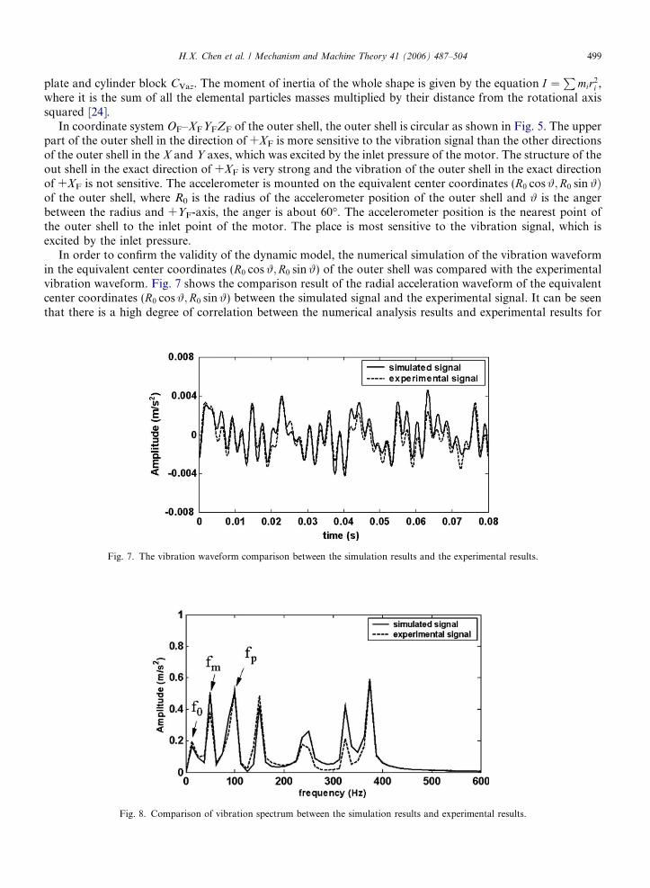
In coordinate system OF–XFYFZF of the outer shell, the outer shell is circular as shown in Fig. 5. The upperpart of the outer shell in the direction of +XF is more sensitive to the vibration signal than the other directionsof the outer shell in the X and Y axes, which was excited by the inlet pressure of the motor. The structure of theout shell in the exact direction of +XF is very strong and the vibration of the outer shell in the exact directionof +XF is not sensitive. The accelerometer is mounted on the equivalent center coordinates (R0 cos#;R0 sin#Þof the outer shell, where R0 is the radius of the accelerometer position of the outer shell and # is the angerbetween the radius and +YF-axis, the anger is about 60�. The accelerometer position is the nearest point ofthe outer shell to the inlet point of the motor. The place is most sensitive to the vibration signal, which isexcited by the inlet pressure.
In order to confirm the validity of the dynamic model, the numerical simulation of the vibration waveformin the equivalent center coordinates (R0 cos#;R0 sin#) of the outer shell was compared with the experimentalvibration waveform. Fig. 7 shows the comparison result of the radial acceleration waveform of the equivalentcenter coordinates (R0 cos#;R0 sin#) between the simulated signal and the experimental signal. It can be seenthat there is a high degree of correlation between the numerical analysis results and experimental results for
Fig. 7. The vibration waveform comparison between the simulation results and the experimental results.
Fig. 8. Comparison of vibration spectrum between the simulation results and experimental results.

500 H.X. Chen et al. / Mechanism and Machine Theory 41 (2006) 487–504
both the cycle period and amplitude of the vibration. Fig. 8 shows the spectrum comparison of the simulatedacceleration signal and the experimental signal. The fundamental frequencies are approximately same whichare the hydraulic motor rotational speed (f0 and fm) and hydraulic pump speed (fp). The integer multiples ofthe fundamental frequency are also approximately the same. The result of the above comparison confirms thevalidity of the dynamic analysis presented.
In order to clarify the vibration response characteristics for the total water hydraulic motor, the vibrationresponses from each mass of the hydraulic motor were obtained from the above simulated dynamic mode.Fig. 9 shows the result of the acceleration of the outer shell in the direction of XF, YF and ZF axes. The ampli-tudes of the acceleration in XF-axis are the largest among the three axes. The amplitudes of the acceleration inYF are smallest. This was as a result of the external force produced by the pressure pulse in the ZF-axis. Theexternal force tends to warp the swash-plate support and the outer shell in a downward direction in theXF-axis and pushes the outer shell in the opposite direction in the ZF-axis. Because the stiffness of the outershell in the ZF-axis is larger than the stiffness in the XF-axis, the magnitudes of the vibration acceleration in theZF-axis are smaller than that in the XF-axis. Fig. 10 shows the angular acceleration around the XF-axis and theYF-axis. The vibration characteristics around the XF and YF axes are similar.
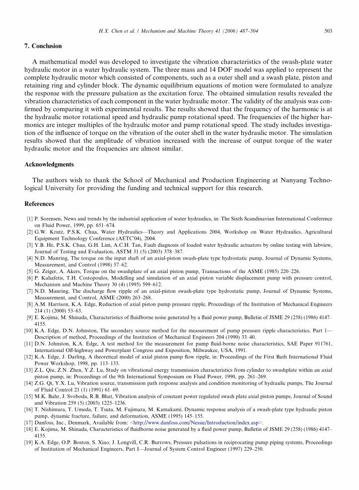
Fig. 11 shows the acceleration of the piston and swash plate in the direction of the XP-axis and the ZP-axis.The vibration characteristics in the XP-axis are different from that in the ZP-axis. The vibration characteristicsin the XP-axis are as a result of the piston frequency and the vibration characteristics in the ZP-axis are as aresult of the external load force including the hydraulic motor frequency and pump frequency. Compared withthe vibration characteristics of outer shell and swash plate, the amplitudes of the vibration in the pistons arelarge. This was due to the direct external force on the pistons from the pressure pulse and the small stiffness ofthe piston coordinate system.
Fig. 9. Simulated acceleration of the outer shell in the direction of XF, YF and ZF axes.
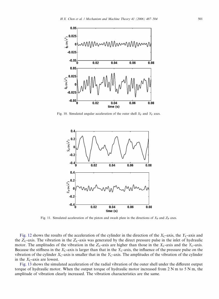
Fig. 10. Simulated angular acceleration of the outer shell XF and YF axes.
Fig. 11. Simulated acceleration of the piston and swash plate in the directions of XP and ZP axes.
H.X. Chen et al. / Mechanism and Machine Theory 41 (2006) 487–504 501
Fig. 12 shows the results of the acceleration of the cylinder in the direction of the XC-axis, the YC-axis andthe ZC-axis. The vibration in the ZC-axis was generated by the direct pressure pulse in the inlet of hydraulicmotor. The amplitudes of the vibration in the ZC-axis are higher than those in the XC-axis and the YC-axis.Because the stiffness in the XC-axis is larger than that in the YC-axis, the influence of the pressure pulse on thevibration of the cylinder XC-axis is smaller that in the YC-axis. The amplitudes of the vibration of the cylinderin the XC-axis are lowest.
Fig. 13 shows the simulated acceleration of the radial vibration of the outer shell under the different outputtorque of hydraulic motor. When the output torque of hydraulic motor increased from 2 N m to 5 N m, theamplitude of vibration clearly increased. The vibration characteristics are the same.

Fig. 12. Simulated acceleration of the cylinder in the direction of XC, YC and ZC axes.
Fig. 13. Simulated acceleration of the radial vibration of the outer shell. (a) Torque = 2 N m. (b) Torque = 5 N m.
502 H.X. Chen et al. / Mechanism and Machine Theory 41 (2006) 487–504
H.X. Chen et al. / Mechanism and Machine Theory 41 (2006) 487–504 503
7. Conclusion
A mathematical model was developed to investigate the vibration characteristics of the swash-plate waterhydraulic motor in a water hydraulic system. The three mass and 14 DOF model was applied to represent thecomplete hydraulic motor which consisted of components, such as a outer shell and a swash plate, piston andretaining ring and cylinder block. The dynamic equilibrium equations of motion were formulated to analyzethe response with the pressure pulsation as the excitation force. The obtained simulation results revealed thevibration characteristics of each component in the water hydraulic motor. The validity of the analysis was con-firmed by comparing it with experimental results. The results showed that the frequency of the harmonic is atthe hydraulic motor rotational speed and hydraulic pump rotational speed. The frequencies of the higher har-monics are integer multiples of the hydraulic motor and pump rotational speed. The study includes investiga-tion of the influence of torque on the vibration of the outer shell in the water hydraulic motor. The simulationresults showed that the amplitude of vibration increased with the increase of output torque of the waterhydraulic motor and the frequencies are almost similar.
Acknowledgments
The authors wish to thank the School of Mechanical and Production Engineering at Nanyang Techno-logical University for providing the funding and technical support for this research.
References
[1] P. Sorensen, News and trends by the industrial application of water hydraulics, in: The Sixth Scandinavian International Conferenceon Fluid Power, 1999, pp. 651–674.
[2] G.W. Krutz, P.S.K. Chua, Water Hydraulics—Theory and Applications 2004, Workshop on Water Hydraulics, AgriculturalEquipment Technology Conference (AETC�04), 2004.
[3] Y.B. He, P.S.K. Chua, G.H. Lim, A.C.H. Tan, Fault diagnosis of loaded water hydraulic actuators by online testing with labview,Journal of Testing and Evaluation, ASTM 31 (5) (2003) 378–387.
[4] N.D. Manring, The torque on the input shaft of an axial-piston swash-plate type hydrostatic pump, Journal of Dynamic Systems,Measurement, and Control (1998) 57–62.
[5] G. Zeiger, A. Akers, Torque on the swashplate of an axial piston pump, Transactions of the ASME (1985) 220–226.[6] P. Kaliafetis, T.H. Costopoulos, Modelling and simulation of an axial piston variable displacement pump with pressure control,
Mechanism and Machine Theory 30 (4) (1995) 599–612.[7] N.D. Manring, The discharge flow ripple of an axial-piston swash-plate type hydrostatic pump, Journal of Dynamic Systems,
Measurement, and Control, ASME (2000) 263–268.[8] A.M. Harrison, K.A. Edge, Reduction of axial piston pump pressure ripple, Proceedings of the Institution of Mechanical Engineers
214 (1) (2000) 53–63.[9] E. Kojima, M. Shinada, Characteristics of fluidborne noise generated by a fluid power pump, Bulletin of JSME 29 (258) (1986) 4147–
4155.[10] K.A. Edge, D.N. Johnston, The secondary source method for the measurement of pump pressure ripple characteristics, Part 1—
Description of method, Proceedings of the Institution of Mechanical Engineers 204 (1990) 33–40.[11] D.N. Johnston, K.A. Edge, A test method for the measurement for pump fluid-borne noise characteristics, SAE Paper 911761,
International Off-highway and Powerplant Congress and Exposition, Milwaukee, USA, 1991.[12] K.A. Edge, J. Darling, A theoretical model of axial piston pump flow ripple, in: Proceedings of the First Bath International Fluid
Power Workshop, 1998, pp. 113–133.[13] Z.L. Qiu, Z.N. Zhen, Y.Z. Lu, Study on vibrational energy transmission characteristics from cylinder to swashplate within an axial
piston pump, in: Proceedings of the 9th International Symposium on Fluid Power, 1990, pp. 261–269.[14] Z.G. Qi, Y.X. Lu, Vibration source, transmission path response analysis and condition monitoring of hydraulic pumps, The Journal
of Fluid Control 21 (1) (1991) 61–69.[15] M.K. Bahr, J. Svoboda, R.B. Bhat, Vibration analysis of constant power regulated swash plate axial piston pumps, Journal of Sound
and Vibration 259 (5) (2003) 1225–1236.[16] T. Nishimura, T. Umeda, T. Tsuta, M. Fujimara, M. Kamakami, Dynamic response analysis of a swash-plate type hydraulic piston
pump, dynamic fracture, failure, and deformation, ASME (1995) 145–155.[17] Danfoss, Inc., Denmark, Available from: <http://www.danfoss.com/Nessie/Introduction/index.asp>.[18] E. Kojima, M. Shinada, Characteristics of fluidborne noise generated by a fluid power pump, Bulletin of JSME 29 (258) (1986) 4147–
4155.[19] K.A. Edge, O.P. Boston, S. Xiao, J. Longvill, C.R. Burrows, Pressure pulsations in reciprocating pump piping systems, Proceedings
of Institution of Mechanical Engineers, Part I—Journal of System Control Engineer (1997) 229–250.
504 H.X. Chen et al. / Mechanism and Machine Theory 41 (2006) 487–504
[20] T. Nishimura, T. Umeda, T. Tsuta, M. Fujiwara, M. Kawakami, Dynamic response analysis of a swash-plate type hydraulic pistonpump, dynamic fracture, failure and deformation, ASME (1995) 145–155.
[21] M.K. Bahr Khalil, J. Svoboda, R.B. Bhat, Modeling of swash plate axial piston pumps with conical cylinder blocks, Journal ofMechanical Design, V 126 (1) (2004) 196–200.
[22] D.M. Etter, Engineering Problem Solving with MATLAB, Prentice-Hall, Englewood Cliffs, NJ, 1993.[23] C.W. Lee, Vibration Analysis of Rotors, Kluwer Academic Publishers, 1993.[24] A.P. Boresi, Advanced Mechanics of Materials, John Wiley & Sons, 2003.