Dynamic Modeling of the Coproduction of Liquid Fuels and Electricity from a Hybrid Solar Gasifier...
14
Dynamic Modeling of the Coproduction of Liquid Fuels and Electricity from a Hybrid Solar Gasifier with Various Fuel Blends Ashok A. Kaniyal,* ,†,‡ Philip J. van Eyk, †,§ and Graham J. Nathan †,‡ † Centre for Energy Technology, ‡ School of Mechanical Engineering, and § School of Chemical Engineering, The University of Adelaide, Adelaide SA 5005, Australia ABSTRACT: A sensitivity analysis is presented of the energetic and environmental performance of a hybridized solar gasification, coal-to-liquids (CTL sol ) polygeneration system using a pseudo-steady-state model outlined in a recently submitted paper. The hybrid CTL sol system was assumed to be integrated with pressurized (upgraded) syngas and O 2 storage to reduce the impact of solar resource transience on the unit operations downstream of the hybrid gasifier. Reported is the sensitivity of the CTL sol system’s energetic and environmental performance to variations in gasification reactor pressure, to turn-down in the fuel feed rate to the hybrid gasifier, to the integration of an indirectly irradiated hybrid natural gas dry or steam reforming system, and to the proportion of biomass cogasified with the coal. The energetic performance of the CTL sol system was shown to be only weakly sensitive to the solar hybrid gasifier pressure. The incorporation of a natural gas steam reformer within the hybrid solar coal gasifier was shown to reduce by an additional 15% the process’ mine-to-tank CO 2 -e emissions relative to the configuration without the co-reformer. However, the addition of the co-reformer to the solar hybrid gasifier also reduced the solar share of the system output to 17% from 20%. The use of a dry reforming process was found to enable similar energetic and environmental performance characteristics to the steam reforming process. Mine-to-tank greenhouse gas emissions parity with diesel production from mineral sands can be achieved with a 30% biomass cogasification fraction, by weight, in a solar hybrid cogasifier, while 45 wt % biomass is required for the nonsolar equivalent. This coal-biomass solar cogasification system also achieved a 22% improvement in energetic productivity relative to the nonsolar reference system. Mine-to-tank CO 2 -e emissions of 0 was found to be achievable with a biomass cogasification fraction of 60 wt %, while the nonsolar equivalent was found to require a biomass fraction of 70 wt % to enable the same outcome. Reducing the amount of biomass to achieve a given environmental target is important given that biomass is typically three to four times more expensive than coal. 1. INTRODUCTION Synthetic liquid fuels produced by the gasification of carbona- ceous fuels coupled with Fischer−Tropsch synthesis (FT) is expected to play a significant role in meeting the energy needs of the transportation sector over the next 50 years. 1 However, a barrier to the implementation of coal to Fischer−Tropsch liquid systems is that the mine-to-tank greenhouse gas (GHG) emissions are almost 2.5 times larger than those of producing diesel from tar sands and more than 6 times those of producing diesel from conventional mineral crude. 2−5 This environmental challenge offers an opportunity to identify options to reduce the CO 2 -e emissions associated with producing liquid fuels by the FT process. Hence, the present assessment seeks to determine the emission reduction potential of a range of renewable energy integrated coal-to-liquid (CTL) systems. An innovative approach to lowering the net GHG emissions of the CTL process is the introduction of concentrated solar thermal power to the endothermic, oxygen-blown, autothermal coal gasification process. The value of solar hybridization has previously received extensive treatment in the context of power generation processes. 6−9 However, the work of Kaniyal et al. 10 was the first comprehensive process analysis of a solar hybrid coal-to-liquids, CTL sol polygeneration system. The pseudo- steady-state system level analysis of the CTL sol system showed the potential to increase by 21% the net energy output per unit feedstock input for a full solar year and reduce by 30% the mine-to-tank greenhouse gas emissions, relative to the verified autothermal CTL ref system. 10 As in other examples of solar hybrid power generation systems, the CTL sol polygeneration system showed the potential to eliminate the influence of solar intermittency on unscheduled plant shut downs and, with a modest amount of syngas storage, 7−9,11 on load fluctuations in the unit operations downstream of the solar hybrid gasifier. 10 Nevertheless, the GHG emissions of the CTL sol system were found to be 1.6 times larger than those associated with producing diesel from tar sands and 4 times those of producing diesel from conventional mineral crude. Thus, there is a need to identify additional approaches to further reduce CO 2 -e emissions. Options to achieve this include alternative reactor operating conditions, integration of solar natural gas co- reforming processes, 12 and the cogasification of coal with biomass. Hence, the present investigation aims to assess the energetic GHG emissions and capital utilization performance impacts of each of these three options. A significant opportunity to improve the economic and GHG emissions performance of a CTL polygeneration system was recently identified by integrating the autothermal entrained flow gasifier with a conventional tubular, pressurized steam methane reforming (SMR) reactor. 13 Blending the output from the autothermal coal gasification process, which has a low ratio of H 2 /CO ∼ 0.4, with the syngas produced by the SMR Received: February 5, 2013 Revised: April 30, 2013 Published: May 3, 2013 Article pubs.acs.org/EF © 2013 American Chemical Society 3556 dx.doi.org/10.1021/ef400217n | Energy Fuels 2013, 27, 3556−3569
Transcript of Dynamic Modeling of the Coproduction of Liquid Fuels and Electricity from a Hybrid Solar Gasifier...
Dynamic Modeling of the Coproduction of Liquid Fuels andElectricity from a Hybrid Solar Gasifier with Various Fuel BlendsAshok A. Kaniyal,*,†,‡ Philip J. van Eyk,†,§ and Graham J. Nathan†,‡
†Centre for Energy Technology, ‡School of Mechanical Engineering, and §School of Chemical Engineering, The University ofAdelaide, Adelaide SA 5005, Australia
ABSTRACT: A sensitivity analysis is presented of the energetic and environmental performance of a hybridized solargasification, coal-to-liquids (CTLsol) polygeneration system using a pseudo-steady-state model outlined in a recently submittedpaper. The hybrid CTLsol system was assumed to be integrated with pressurized (upgraded) syngas and O2 storage to reduce theimpact of solar resource transience on the unit operations downstream of the hybrid gasifier. Reported is the sensitivity of theCTLsol system’s energetic and environmental performance to variations in gasification reactor pressure, to turn-down in the fuelfeed rate to the hybrid gasifier, to the integration of an indirectly irradiated hybrid natural gas dry or steam reforming system, andto the proportion of biomass cogasified with the coal. The energetic performance of the CTLsol system was shown to be onlyweakly sensitive to the solar hybrid gasifier pressure. The incorporation of a natural gas steam reformer within the hybrid solarcoal gasifier was shown to reduce by an additional 15% the process’ mine-to-tank CO2-e emissions relative to the configurationwithout the co-reformer. However, the addition of the co-reformer to the solar hybrid gasifier also reduced the solar share of thesystem output to 17% from 20%. The use of a dry reforming process was found to enable similar energetic and environmentalperformance characteristics to the steam reforming process. Mine-to-tank greenhouse gas emissions parity with diesel productionfrom mineral sands can be achieved with a 30% biomass cogasification fraction, by weight, in a solar hybrid cogasifier, while 45 wt% biomass is required for the nonsolar equivalent. This coal-biomass solar cogasification system also achieved a 22%improvement in energetic productivity relative to the nonsolar reference system. Mine-to-tank CO2-e emissions of 0 was found tobe achievable with a biomass cogasification fraction of 60 wt %, while the nonsolar equivalent was found to require a biomassfraction of 70 wt % to enable the same outcome. Reducing the amount of biomass to achieve a given environmental target isimportant given that biomass is typically three to four times more expensive than coal.
1. INTRODUCTIONSynthetic liquid fuels produced by the gasification of carbona-ceous fuels coupled with Fischer−Tropsch synthesis (FT) isexpected to play a significant role in meeting the energy needsof the transportation sector over the next 50 years.1 However, abarrier to the implementation of coal to Fischer−Tropschliquid systems is that the mine-to-tank greenhouse gas (GHG)emissions are almost 2.5 times larger than those of producingdiesel from tar sands and more than 6 times those of producingdiesel from conventional mineral crude.2−5 This environmentalchallenge offers an opportunity to identify options to reducethe CO2-e emissions associated with producing liquid fuels bythe FT process. Hence, the present assessment seeks todetermine the emission reduction potential of a range ofrenewable energy integrated coal-to-liquid (CTL) systems.An innovative approach to lowering the net GHG emissions
of the CTL process is the introduction of concentrated solarthermal power to the endothermic, oxygen-blown, autothermalcoal gasification process. The value of solar hybridization haspreviously received extensive treatment in the context of powergeneration processes.6−9 However, the work of Kaniyal et al.10
was the first comprehensive process analysis of a solar hybridcoal-to-liquids, CTLsol polygeneration system. The pseudo-steady-state system level analysis of the CTLsol system showedthe potential to increase by 21% the net energy output per unitfeedstock input for a full solar year and reduce by 30% themine-to-tank greenhouse gas emissions, relative to the verifiedautothermal CTLref system.10 As in other examples of solar
hybrid power generation systems, the CTLsol polygenerationsystem showed the potential to eliminate the influence of solarintermittency on unscheduled plant shut downs and, with amodest amount of syngas storage,7−9,11 on load fluctuations inthe unit operations downstream of the solar hybrid gasifier.10
Nevertheless, the GHG emissions of the CTLsol system werefound to be 1.6 times larger than those associated withproducing diesel from tar sands and 4 times those of producingdiesel from conventional mineral crude. Thus, there is a need toidentify additional approaches to further reduce CO2-eemissions. Options to achieve this include alternative reactoroperating conditions, integration of solar natural gas co-reforming processes,12 and the cogasification of coal withbiomass. Hence, the present investigation aims to assess theenergetic GHG emissions and capital utilization performanceimpacts of each of these three options.A significant opportunity to improve the economic and GHG
emissions performance of a CTL polygeneration system wasrecently identified by integrating the autothermal entrainedflow gasifier with a conventional tubular, pressurized steammethane reforming (SMR) reactor.13 Blending the output fromthe autothermal coal gasification process, which has a low ratioof H2/CO ∼ 0.4, with the syngas produced by the SMR
Received: February 5, 2013Revised: April 30, 2013Published: May 3, 2013
Article
pubs.acs.org/EF
© 2013 American Chemical Society 3556 dx.doi.org/10.1021/ef400217n | Energy Fuels 2013, 27, 3556−3569
process, which has a high ratio of H2/CO ∼ 3.0, reduces thetotal CO2 emissions intensity of the water−gas shift (WGS)upgrade reactions. This is because the FT synthesis processrequires syngas with H2/CO ∼ 2.26.3,10 Furthermore, theexpected cost of integrating a tubular reformer within anentrained flow gasification system is expected to be low.13 Forthe conventional gasification case, the integration of a tubularreformer was shown to increase the capital cost by <1%,offering the potential to significantly improve the viability ofCTL polygeneration.13 It should be noted, that while the totalcost of this polygeneration configuration changes very little dueto balance-of-plant savings, Adams and Barton13 assume that itcosts 25% more to use a radiant cooler in a gasifier with steamreforming than to use a traditional steam-only radiant syngascooler. Furthermore, in the context of an atmospheric pressure,windowed, solar hybrid gasifier, the integration of a tubular co-reforming process offers a feasible approach to generatepressurized syngas without comprising the structural integrityof the quartz window, as would occur with the use of elevatedpressures14 and/or temperatures.15−17 This approach couldreduce the technical challenges associated with the need for apressurized, windowed, directly irradiated, gasification, co-reforming reactor, as was recently proposed in Sudiro’s studyof a FT liquid polygeneration system.12 However, to date, noassessment has been reported of the energetic and GHGemission performance of a FT liquid polygeneration systemintegrated with a co-reforming reactor. Hence, an additionalaim of the present investigation is to meet this need.A disadvantage of both the solar-hybridized coal gasification
and the steam methane reforming process (SMR) is its largecombined steam demand.18 This is an important issue, not onlybecause of the parasitic impact of producing steam for internaluse in a polygeneration system but also because access to wateris typically poor in the arid regions where the solar resource isgreatest. The dry reforming of natural gas with CO2 is oneoption by which the water consumption intensity of the solar-intensive portion of the CTLsol polygeneration system could bereduced.19 Such a process could also offer important synergieswith CO2 geo-sequestration pipeline networks, which areanticipated to be introduced in the medium-term.20 Further-more, the solar dry reforming process could also improve theviability of natural gas reserves that are currently madeuneconomic by high dissolved CO2 concentrations.21 Hence,a further aim of the present investigation is to compare the netenergetic, GHG emissions and steam consumption perform-ance of integrating an indirectly irradiated dry co-reformer withthat of a steam co-reformer within a solar hybrid coalgasification system.The flexibility to vary the fuel feed rate to the solar hybrid
gasifier in response to the amount of solar thermal power that isavailable has the potential to significantly improve the energeticand GHG emissions performance of the CTLsol system relativeto operation based on an invariant fuel feed rate.10 Oneapproach to increase the flexibility of the plant to respond tovariations in the input of concentrated solar radiation is to allowthe fuel feed rate to be boosted intermittently above thenominal design value (1 kg/s for the case investigated byKaniyal et al.10). Gasifier operation with a constant fuel flowrate leads to the suboptimal use of the installed heliostatcollection capacity and therefore the “spillage” of solar radiationwhenever the optimal potential thermal power output of theheliostats exceeds the endothermic demand of gasifying coal atthe nominal design rate of fuel flow.10 However, the solar-
boosted production of syngas has the disadvantage of increasingthe polygeneration system’s large, parasitic syngas compressionload.10 This is because the windowed solar-hybridized gas-ification process is unlikely to be feasible at elevatedpressures.22−24 One option to partially offset the solar-boostedsyngas compression load is to turn-down the fuel flow rate tothe hybrid gasifier below the nominal design flow rate at night,which has the added advantage of also reducing the gasifier’s O2
demand.10 The hybrid solar gasifier and heliostat field couldreasonably be expected to be the two most expensivecomponents of a CTLsol polygeneration system. This isassuming that the hybrid solar gasifier has a similar cost profileto the autothermal entrained flow gasification system2,13,25−29
and because the heliostat field typically forms ∼50% of the costof concentrated solar power systems.30 Thus, the flexibility toboost and turn-down the fuel feed rate to the gasifier gives riseto an important capital productivity trade-off between thegasifier’s excess thermal capacity and the installed heliostatcollection capacity. No quantitative assessment of these trade-offs has been reported previously. Hence, the presentinvestigation aims to quantify the trade-off between theperformance, energy output per unit feedstock, GHGemissions, and the capital utilization of the installed excesshybrid gasifier and excess heliostat collection capacity.Biomass cogasification is likely to be necessary to reduce the
CO2-e emissions of diesel produced by the autothermal CTLprocess to below that of production from conventional mineralcrude or tar sands, in the absence of carbon capture and storagetechnology.2,3,25,27 However, the autothermal coal-biomass-to-liquids (CTLbio) process requires biomass cogasificationfractions of at least 60% by weight to reduce its GHGemissions to below that of (non-tar sands/bitumen) mineralcrude-derived diesel.2,25,27 Such large cogasification fractionsare likely to present significant technical challenges in bothsourcing biomass at the required scale31 and in gasifierdesign.32−34 Additionally, because biomass has typically been3−4 times more expensive than coal,31,34−36 there aresignificant economic advantages in reducing the biomassfraction to achieve a given CO2 emissions target. This couldpotentially be achieved by the solar-hybridized cogasification ofcoal-biomass since the CTLsol process stores ∼23% morecarbon in the FTL end product than the autothermal CTLrefprocess.10 However, the magnitude of these potential benefits isyet to be reported. Hence, the present investigation also aims toquantify the potential benefits of the hybridization ofconcentrated solar thermal radiation into the autothermalcoal-biomass cogasification process for the production of FTLfuels.The primary objective of the present assessment is to identify
effective combinations of operating conditions, reactorconfigurations, and blend ratios of biomass with coal thatachieve CO2-e emissions parity with diesel derived fromconventional mineral crude or tar sands or that achieve carbon-neutral production on a mine-to-tank basis. Specifically, theinvestigation aims to evaluate the operating conditions thatoptimize the utilization of both the hybrid gasification reactorand heliostat field. It also aims to examine the potential GHGemissions and energetic value of incorporating an indirectlyirradiated, pressurized dry or steam natural gas reformingsystem within the solar hybrid gasifier, for the production ofFTL fuels.
Energy & Fuels Article
dx.doi.org/10.1021/ef400217n | Energy Fuels 2013, 27, 3556−35693557
2. METHODOLOGYThe energetic and environmental performance of the solar-hybridizedgasification, coal-to-liquids polygeneration system, hereafter termedCTLsol, was assessed relative to a “reference” system based on aconventional, autothermal, pressurized (40 bar) “Shell”-type gasifier,hereafter termed CTLref.
3 The autothermal CTLref system developedby Kaniyal et al.10 (see Figure 1a) is consistent with and verifiedagainst the baseline scheme investigated by Meerman et al.3 TheCTLsol system was also developed and investigated by Kaniyal et al.10
As in the authors’ earlier work,10 all scenarios investigated hereinassume that all of the CO2 produced by the facility is vented. Hence,further mitigation could be achieved were carbon sequestration to beincorporated. All unit operations, except the gasifier section, weremodeled using Aspen Plus v7.1 software, while the hybrid cogasifiersection of the CTLref and CTLsol systems was modeled using AspenHYSYS v7.1 software.
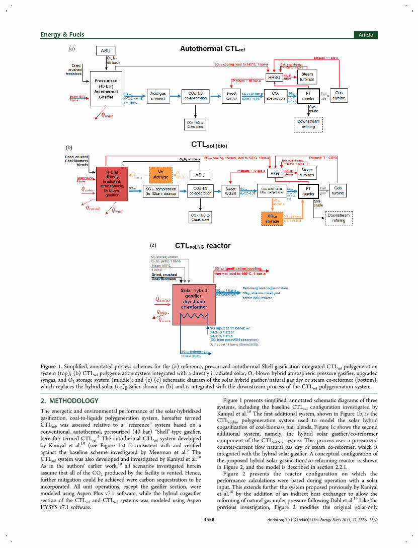
Figure 1 presents simplified, annotated schematic diagrams of threesystems, including the baseline CTLsol configuration investigated byKaniyal et al.10 The first additional system, shown in Figure 1b, is theCTLsol,bio polygeneration system used to model the solar hybridcogasification of coal-biomass fuel blends. Figure 1c shows the secondadditional system, namely, the hybrid solar gasifier/co-reformercomponent of the CTLsol,NG system. This process uses a pressurizedcounter-current flow natural gas dry or steam co-reformer, which isintegrated with the hybrid solar gasifier. A conceptual configuration ofthe proposed hybrid solar gasification/co-reforming reactor is shownin Figure 2, and the model is described in section 2.2.1.
Figure 2 presents the reactor configuration on which theperformance calculations were based during operation with a solarinput. This extends further the system proposed previously by Kaniyalet al.10 by the addition of an indirect heat exchanger to allow thereforming of natural gas under pressure following Dahl et al.14 Like theprevious investigation, Figure 2 modifies the original solar-only
Figure 1. Simplified, annotated process schemes for the (a) reference, pressurized autothermal Shell gasification integrated CTLref polygenerationsystem (top); (b) CTLsol polygeneration system integrated with a directly irradiated solar, O2-blown hybrid atmospheric pressure gasifier, upgradedsyngas, and O2 storage system (middle); and (c) (c) schematic diagram of the solar hybrid gasifier/natural gas dry or steam co-reformer (bottom),which replaces the hybrid solar (co)gasifier shown in (b) and is integrated with the downstream process of the CTLsol polygeneration system.
Energy & Fuels Article
dx.doi.org/10.1021/ef400217n | Energy Fuels 2013, 27, 3556−35693558
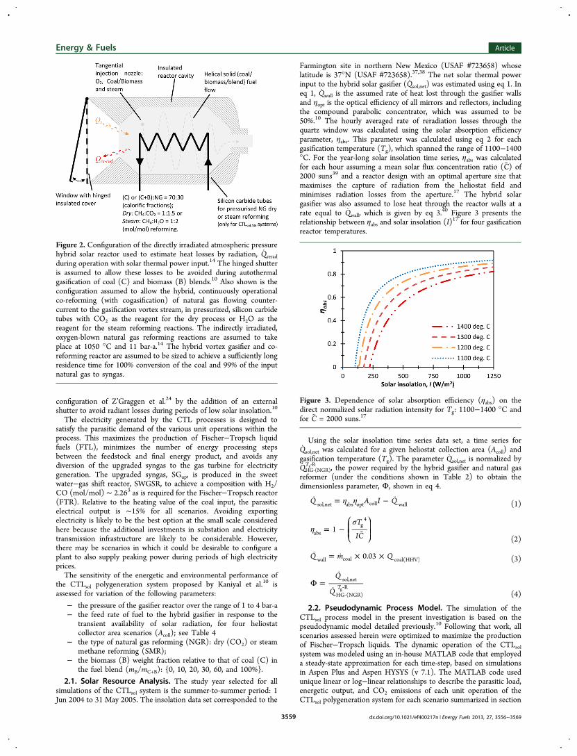
configuration of Z’Graggen et al.24 by the addition of an externalshutter to avoid radiant losses during periods of low solar insolation.10
The electricity generated by the CTL processes is designed tosatisfy the parasitic demand of the various unit operations within theprocess. This maximizes the production of Fischer−Tropsch liquidfuels (FTL), minimizes the number of energy processing stepsbetween the feedstock and final energy product, and avoids anydiversion of the upgraded syngas to the gas turbine for electricitygeneration. The upgraded syngas, SGup, is produced in the sweetwater−gas shift reactor, SWGSR, to achieve a composition with H2/CO (mol/mol) ∼ 2.263 as is required for the Fischer−Tropsch reactor(FTR). Relative to the heating value of the coal input, the parasiticelectrical output is ∼15% for all scenarios. Avoiding exportingelectricity is likely to be the best option at the small scale consideredhere because the additional investments in substation and electricitytransmission infrastructure are likely to be considerable. However,there may be scenarios in which it could be desirable to configure aplant to also supply peaking power during periods of high electricityprices.The sensitivity of the energetic and environmental performance of
the CTLsol polygeneration system proposed by Kaniyal et al.10 isassessed for variation of the following parameters:
− the pressure of the gasifier reactor over the range of 1 to 4 bar-a− the feed rate of fuel to the hybrid gasifier in response to the
transient availability of solar radiation, for four heliostatcollector area scenarios (Acoll); see Table 4
− the type of natural gas reforming (NGR): dry (CO2) or steammethane reforming (SMR);
− the biomass (B) weight fraction relative to that of coal (C) inthe fuel blend (mB/mC+B): {0, 10, 20, 30, 60, and 100%}.
2.1. Solar Resource Analysis. The study year selected for allsimulations of the CTLsol system is the summer-to-summer period: 1Jun 2004 to 31 May 2005. The insolation data set corresponded to the
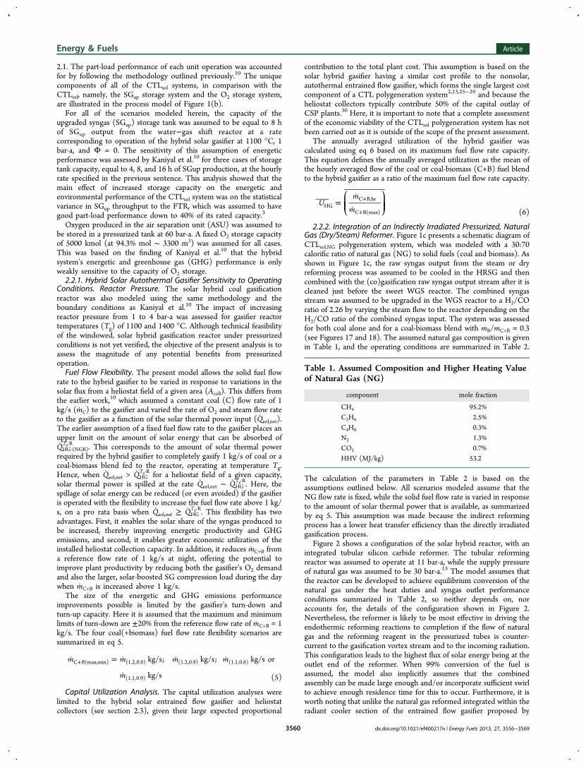
Farmington site in northern New Mexico (USAF #723658) whoselatitude is 37°N (USAF #723658).37,38 The net solar thermal powerinput to the hybrid solar gasifier (Qsol,net) was estimated using eq 1. Ineq 1, Qwall is the assumed rate of heat lost through the gasifier wallsand ηopt is the optical efficiency of all mirrors and reflectors, includingthe compound parabolic concentrator, which was assumed to be50%.10 The hourly averaged rate of reradiation losses through thequartz window was calculated using the solar absorption efficiencyparameter, ηabs. This parameter was calculated using eq 2 for eachgasification temperature (Tg), which spanned the range of 1100−1400°C. For the year-long solar insolation time series, ηabs was calculatedfor each hour assuming a mean solar flux concentration ratio (C) of2000 suns39 and a reactor design with an optimal aperture size thatmaximises the capture of radiation from the heliostat field andminimises radiation losses from the aperture.17 The hybrid solargasifier was also assumed to lose heat through the reactor walls at arate equal to Qwall, which is given by eq 3.40 Figure 3 presents therelationship between ηabs and solar insolation (I)17 for four gasificationreactor temperatures.
Using the solar insolation time series data set, a time series forQsol,net was calculated for a given heliostat collection area (Acoll) andgasification temperature (Tg). The parameter Qsol,net is normalized byQHG‑(NGR)
Tg‑R , the power required by the hybrid gasifier and natural gasreformer (under the conditions shown in Table 2) to obtain thedimensionless parameter, Φ, shown in eq 4.
η η = − Q A I Qsol,net abs opt coll wall (1)
ησ
= −
⎛⎝⎜⎜
⎞⎠⎟⎟
T
IC1abs
g4
(2)
= × ×Q m Q0.03wall coal coal(HHV) (3)
Φ =
‐
‐
Q
Q Tsol,net
HG (NGR)Rg
(4)
2.2. Pseudodynamic Process Model. The simulation of theCTLsol process model in the present investigation is based on thepseudodynamic model detailed previously.10 Following that work, allscenarios assessed herein were optimized to maximize the productionof Fischer−Tropsch liquids. The dynamic operation of the CTLsolsystem was modeled using an in-house MATLAB code that employeda steady-state approximation for each time-step, based on simulationsin Aspen Plus and Aspen HYSYS (v 7.1). The MATLAB code usedunique linear or log−linear relationships to describe the parasitic load,energetic output, and CO2 emissions of each unit operation of theCTLsol polygeneration system for each scenario summarized in section
Figure 2. Configuration of the directly irradiated atmospheric pressurehybrid solar reactor used to estimate heat losses by radiation, Qreradduring operation with solar thermal power input.14 The hinged shutteris assumed to allow these losses to be avoided during autothermalgasification of coal (C) and biomass (B) blends.10 Also shown is theconfiguration assumed to allow the hybrid, continuously operationalco-reforming (with cogasification) of natural gas flowing counter-current to the gasification vortex stream, in pressurized, silicon carbidetubes with CO2 as the reagent for the dry process or H2O as thereagent for the steam reforming reactions. The indirectly irradiated,oxygen-blown natural gas reforming reactions are assumed to takeplace at 1050 °C and 11 bar-a.14 The hybrid vortex gasifier and co-reforming reactor are assumed to be sized to achieve a sufficiently longresidence time for 100% conversion of the coal and 99% of the inputnatural gas to syngas.
Figure 3. Dependence of solar absorption efficiency (ηabs) on thedirect normalized solar radiation intensity for Tg: 1100−1400 °C andfor C = 2000 suns.17
Energy & Fuels Article
dx.doi.org/10.1021/ef400217n | Energy Fuels 2013, 27, 3556−35693559
2.1. The part-load performance of each unit operation was accountedfor by following the methodology outlined previously.10 The uniquecomponents of all of the CTLsol systems, in comparison with theCTLref, namely, the SGup storage system and the O2 storage system,are illustrated in the process model of Figure 1(b).For all of the scenarios modeled herein, the capacity of the
upgraded syngas (SGup) storage tank was assumed to be equal to 8 hof SGup output from the water−gas shift reactor at a ratecorresponding to operation of the hybrid solar gasifier at 1100 °C, 1bar-a, and Φ = 0. The sensitivity of this assumption of energeticperformance was assessed by Kaniyal et al.10 for three cases of storagetank capacity, equal to 4, 8, and 16 h of SGup production, at the hourlyrate specified in the previous sentence. This analysis showed that themain effect of increased storage capacity on the energetic andenvironmental performance of the CTLsol system was on the statisticalvariance in SGup throughput to the FTR, which was assumed to havegood part-load performance down to 40% of its rated capacity.3
Oxygen produced in the air separation unit (ASU) was assumed tobe stored in a pressurized tank at 60 bar-a. A fixed O2 storage capacityof 5000 kmol (at 94.3% mol ∼ 3300 m3) was assumed for all cases.This was based on the finding of Kaniyal et al.10 that the hybridsystem’s energetic and greenhouse gas (GHG) performance is onlyweakly sensitive to the capacity of O2 storage.2.2.1. Hybrid Solar Autothermal Gasifier Sensitivity to Operating
Conditions. Reactor Pressure. The solar hybrid coal gasificationreactor was also modeled using the same methodology and theboundary conditions as Kaniyal et al.10 The impact of increasingreactor pressure from 1 to 4 bar-a was assessed for gasifier reactortemperatures (Tg) of 1100 and 1400 °C. Although technical feasibilityof the windowed, solar hybrid gasification reactor under pressurizedconditions is not yet verified, the objective of the present analysis is toassess the magnitude of any potential benefits from pressurizedoperation.Fuel Flow Flexibility. The present model allows the solid fuel flow
rate to the hybrid gasifier to be varied in response to variations in thesolar flux from a heliostat field of a given area (Acoll). This differs fromthe earlier work,10 which assumed a constant coal (C) flow rate of 1kg/s (mC) to the gasifier and varied the rate of O2 and steam flow rateto the gasifier as a function of the solar thermal power input (Qsol,net).The earlier assumption of a fixed fuel flow rate to the gasifier places anupper limit on the amount of solar energy that can be absorbed ofQHG‑(NGR)
Tg‑R . This corresponds to the amount of solar thermal powerrequired by the hybrid gasifier to completely gasify 1 kg/s of coal or acoal-biomass blend fed to the reactor, operating at temperature Tg.Hence, when Qsol,net > QHG
Tg‑R for a heliostat field of a given capacity,solar thermal power is spilled at the rate Qsol,net − QHG
Tg‑R. Here, thespillage of solar energy can be reduced (or even avoided) if the gasifieris operated with the flexibility to increase the fuel flow rate above 1 kg/s, on a pro rata basis when Qsol,net ≥ QHG
Tg‑R. This flexibility has twoadvantages. First, it enables the solar share of the syngas produced tobe increased, thereby improving energetic productivity and GHGemissions, and second, it enables greater economic utilization of theinstalled heliostat collection capacity. In addition, it reduces mC+B froma reference flow rate of 1 kg/s at night, offering the potential toimprove plant productivity by reducing both the gasifier’s O2 demandand also the larger, solar-boosted SG compression load during the daywhen mC+B is increased above 1 kg/s.The size of the energetic and GHG emissions performance
improvements possible is limited by the gasifier’s turn-down andturn-up capacity. Here it is assumed that the maximum and minimumlimits of turn-down are ±20% from the reference flow rate of mC+B = 1kg/s. The four coal(+biomass) fuel flow rate flexibility scenarios aresummarized in eq 5.
=
+m m m m
m
kg/s; kg/s; kg/s or
kg/s
C B(max,min) (1.2,0.8) (1.2,0.9) (1.1,0.8)
(1.1,0.9) (5)
Capital Utilization Analysis. The capital utilization analyses werelimited to the hybrid solar entrained flow gasifier and heliostatcollectors (see section 2.3), given their large expected proportional
contribution to the total plant cost. This assumption is based on thesolar hybrid gasifier having a similar cost profile to the nonsolar,autothermal entrained flow gasifier, which forms the single largest costcomponent of a CTL polygeneration system2,13,25−29 and because theheliostat collectors typically contribute 50% of the capital outlay ofCSP plants.30 Here, it is important to note that a complete assessmentof the economic viability of the CTLsol polygeneration system has notbeen carried out as it is outside of the scope of the present assessment.
The annually averaged utilization of the hybrid gasifier wascalculated using eq 6 based on its maximum fuel flow rate capacity.This equation defines the annually averaged utilization as the mean ofthe hourly averaged flow of the coal or coal-biomass (C+B) fuel blendto the hybrid gasifier as a ratio of the maximum fuel flow rate capacity.
=
+
+
⎛⎝⎜⎜
⎞⎠⎟⎟U
m
mHGC B,hr
C B(max) (6)
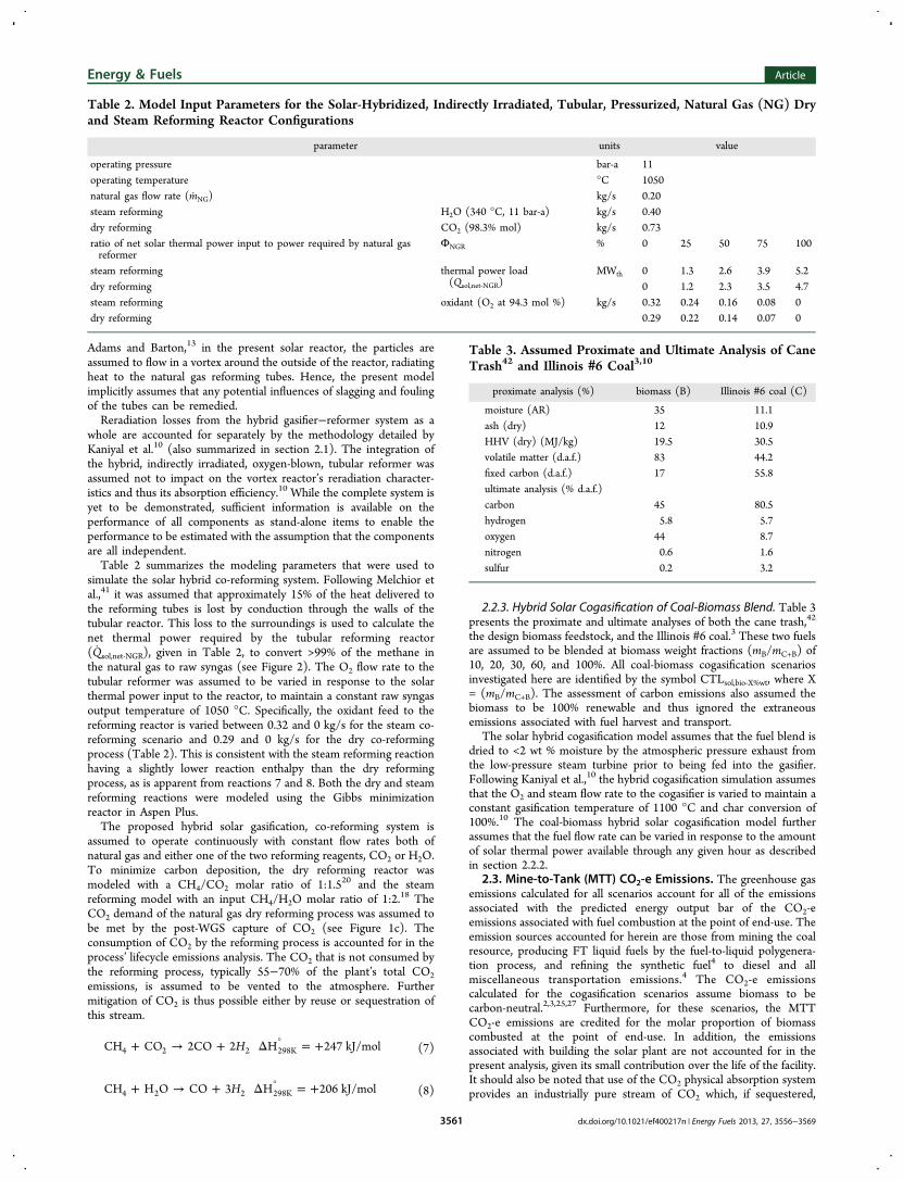
2.2.2. Integration of an Indirectly Irradiated Pressurized, NaturalGas (Dry/Steam) Reformer. Figure 1c presents a schematic diagram ofCTLsol,NG polygeneration system, which was modeled with a 30:70calorific ratio of natural gas (NG) to solid fuels (coal and biomass). Asshown in Figure 1c, the raw syngas output from the steam or dryreforming process was assumed to be cooled in the HRSG and thencombined with the (co)gasification raw syngas output stream after it iscleaned just before the sweet WGS reactor. The combined syngasstream was assumed to be upgraded in the WGS reactor to a H2/COratio of 2.26 by varying the steam flow to the reactor depending on theH2/CO ratio of the combined syngas input. The system was assessedfor both coal alone and for a coal-biomass blend with mB/mC+B = 0.3(see Figures 17 and 18). The assumed natural gas composition is givenin Table 1, and the operating conditions are summarized in Table 2.
The calculation of the parameters in Table 2 is based on theassumptions outlined below. All scenarios modeled assume that theNG flow rate is fixed, while the solid fuel flow rate is varied in responseto the amount of solar thermal power that is available, as summarizedby eq 5. This assumption was made because the indirect reformingprocess has a lower heat transfer efficiency than the directly irradiatedgasification process.
Figure 2 shows a configuration of the solar hybrid reactor, with anintegrated tubular silicon carbide reformer. The tubular reformingreactor was assumed to operate at 11 bar-a, while the supply pressureof natural gas was assumed to be 30 bar-a.13 The model assumes thatthe reactor can be developed to achieve equilibrium conversion of thenatural gas under the heat duties and syngas outlet performanceconditions summarized in Table 2, so neither depends on, noraccounts for, the details of the configuration shown in Figure 2.Nevertheless, the reformer is likely to be most effective in driving theendothermic reforming reactions to completion if the flow of naturalgas and the reforming reagent in the pressurized tubes is counter-current to the gasification vortex stream and to the incoming radiation.This configuration leads to the highest flux of solar energy being at theoutlet end of the reformer. When 99% conversion of the fuel isassumed, the model also implicitly assumes that the combinedassembly can be made large enough and/or incorporate sufficient swirlto achieve enough residence time for this to occur. Furthermore, it isworth noting that unlike the natural gas reformed integrated within theradiant cooler section of the entrained flow gasifier proposed by
Table 1. Assumed Composition and Higher Heating Valueof Natural Gas (NG)
component mole fraction
CH4 95.2%C2H6 2.5%C4H8 0.3%N2 1.3%CO2 0.7%HHV (MJ/kg) 53.2
Energy & Fuels Article
dx.doi.org/10.1021/ef400217n | Energy Fuels 2013, 27, 3556−35693560
Adams and Barton,13 in the present solar reactor, the particles areassumed to flow in a vortex around the outside of the reactor, radiatingheat to the natural gas reforming tubes. Hence, the present modelimplicitly assumes that any potential influences of slagging and foulingof the tubes can be remedied.Reradiation losses from the hybrid gasifier−reformer system as a
whole are accounted for separately by the methodology detailed byKaniyal et al.10 (also summarized in section 2.1). The integration ofthe hybrid, indirectly irradiated, oxygen-blown, tubular reformer wasassumed not to impact on the vortex reactor’s reradiation character-istics and thus its absorption efficiency.10 While the complete system isyet to be demonstrated, sufficient information is available on theperformance of all components as stand-alone items to enable theperformance to be estimated with the assumption that the componentsare all independent.Table 2 summarizes the modeling parameters that were used to
simulate the solar hybrid co-reforming system. Following Melchior etal.,41 it was assumed that approximately 15% of the heat delivered tothe reforming tubes is lost by conduction through the walls of thetubular reactor. This loss to the surroundings is used to calculate thenet thermal power required by the tubular reforming reactor(Qsol,net‑NGR), given in Table 2, to convert >99% of the methane inthe natural gas to raw syngas (see Figure 2). The O2 flow rate to thetubular reformer was assumed to be varied in response to the solarthermal power input to the reactor, to maintain a constant raw syngasoutput temperature of 1050 °C. Specifically, the oxidant feed to thereforming reactor is varied between 0.32 and 0 kg/s for the steam co-reforming scenario and 0.29 and 0 kg/s for the dry co-reformingprocess (Table 2). This is consistent with the steam reforming reactionhaving a slightly lower reaction enthalpy than the dry reformingprocess, as is apparent from reactions 7 and 8. Both the dry and steamreforming reactions were modeled using the Gibbs minimizationreactor in Aspen Plus.The proposed hybrid solar gasification, co-reforming system is
assumed to operate continuously with constant flow rates both ofnatural gas and either one of the two reforming reagents, CO2 or H2O.To minimize carbon deposition, the dry reforming reactor wasmodeled with a CH4/CO2 molar ratio of 1:1.520 and the steamreforming model with an input CH4/H2O molar ratio of 1:2.18 TheCO2 demand of the natural gas dry reforming process was assumed tobe met by the post-WGS capture of CO2 (see Figure 1c). Theconsumption of CO2 by the reforming process is accounted for in theprocess’ lifecycle emissions analysis. The CO2 that is not consumed bythe reforming process, typically 55−70% of the plant’s total CO2emissions, is assumed to be vented to the atmosphere. Furthermitigation of CO2 is thus possible either by reuse or sequestration ofthis stream.
+ → + Δ = +°HCH CO 2CO 2 H 247 kJ/mol4 2 2 298K (7)
+ → + Δ = +°HCH H O CO 3 H 206 kJ/mol4 2 2 298K (8)
2.2.3. Hybrid Solar Cogasification of Coal-Biomass Blend. Table 3presents the proximate and ultimate analyses of both the cane trash,42
the design biomass feedstock, and the Illinois #6 coal.3 These two fuelsare assumed to be blended at biomass weight fractions (mB/mC+B) of10, 20, 30, 60, and 100%. All coal-biomass cogasification scenariosinvestigated here are identified by the symbol CTLsol,bio‑X%wt, where X= (mB/mC+B). The assessment of carbon emissions also assumed thebiomass to be 100% renewable and thus ignored the extraneousemissions associated with fuel harvest and transport.
The solar hybrid cogasification model assumes that the fuel blend isdried to <2 wt % moisture by the atmospheric pressure exhaust fromthe low-pressure steam turbine prior to being fed into the gasifier.Following Kaniyal et al.,10 the hybrid cogasification simulation assumesthat the O2 and steam flow rate to the cogasifier is varied to maintain aconstant gasification temperature of 1100 °C and char conversion of100%.10 The coal-biomass hybrid solar cogasification model furtherassumes that the fuel flow rate can be varied in response to the amountof solar thermal power available through any given hour as describedin section 2.2.2.
2.3. Mine-to-Tank (MTT) CO2-e Emissions. The greenhouse gasemissions calculated for all scenarios account for all of the emissionsassociated with the predicted energy output bar of the CO2-eemissions associated with fuel combustion at the point of end-use. Theemission sources accounted for herein are those from mining the coalresource, producing FT liquid fuels by the fuel-to-liquid polygenera-tion process, and refining the synthetic fuel4 to diesel and allmiscellaneous transportation emissions.4 The CO2-e emissionscalculated for the cogasification scenarios assume biomass to becarbon-neutral.2,3,25,27 Furthermore, for these scenarios, the MTTCO2-e emissions are credited for the molar proportion of biomasscombusted at the point of end-use. In addition, the emissionsassociated with building the solar plant are not accounted for in thepresent analysis, given its small contribution over the life of the facility.It should also be noted that use of the CO2 physical absorption systemprovides an industrially pure stream of CO2 which, if sequestered,
Table 2. Model Input Parameters for the Solar-Hybridized, Indirectly Irradiated, Tubular, Pressurized, Natural Gas (NG) Dryand Steam Reforming Reactor Configurations
parameter units value
operating pressure bar-a 11operating temperature °C 1050natural gas flow rate (mNG) kg/s 0.20steam reforming H2O (340 °C, 11 bar-a) kg/s 0.40dry reforming CO2 (98.3% mol) kg/s 0.73ratio of net solar thermal power input to power required by natural gasreformer
ΦNGR % 0 25 50 75 100
steam reforming thermal power load(Qsol,net‑NGR)
MWth 0 1.3 2.6 3.9 5.2dry reforming 0 1.2 2.3 3.5 4.7steam reforming oxidant (O2 at 94.3 mol %) kg/s 0.32 0.24 0.16 0.08 0dry reforming 0.29 0.22 0.14 0.07 0
Table 3. Assumed Proximate and Ultimate Analysis of CaneTrash42 and Illinois #6 Coal3,10
proximate analysis (%) biomass (B) Illinois #6 coal (C)
moisture (AR) 35 11.1ash (dry) 12 10.9HHV (dry) (MJ/kg) 19.5 30.5volatile matter (d.a.f.) 83 44.2fixed carbon (d.a.f.) 17 55.8ultimate analysis (% d.a.f.)carbon 45 80.5hydrogen 5.8 5.7oxygen 44 8.7nitrogen 0.6 1.6sulfur 0.2 3.2
Energy & Fuels Article
dx.doi.org/10.1021/ef400217n | Energy Fuels 2013, 27, 3556−35693561
would further reduce the net CO2 emissions from the baseline CTLsolprocess by approximately 50%.2.4. Heliostat Field Size Area Sensitivity. The impact of the
heliostat field area (Acoll) on the energetic productivity and CO2-eemission performance of the hybrid solar polygeneration system isassessed for four Acoll scenarios over the range of 33 × 103 to 89 × 103
m2. Following the work of Kaniyal et al.,10 each Acoll scenario isnormalized using eq 9 as Φpeak
Acoll . Here, ΦpeakAcoll is the fraction by which the
annual, peak hourly averaged thermal power output of a heliostat fieldof a given collection capacity, (Qsol,net
Acoll )ann(peak), exceeds theendothermic demand of the hybrid solar gasification reactor andnatural gas reformer, QHG‑(NGR)
Tg‑R (for the relevant scenarios). The Acollscenarios and the corresponding normalized parameters aresummarized for the CTLsol plant configuration and the two CTLsol,NGconfigurations in Table 4.
Φ =
‐
‐
Q
Q
( )AA
Tpeaksol,net ann(peak)
HG (NGR)R
coll
coll
g(9)
2.4.1. Capital Utilization Analysis. The second component of thecapital utilization analysis is that of the heliostat collector field. This isassumed to be the other most significant capital expense on the basisthat numerous assessments of concentrated solar electrical powersystems have shown that the cost of the heliostat field contributes∼50% of the total capital expense.30 Equation 10 is used to estimatethe hourly averaged utilization of the installed heliostat collectioncapacity as the ratio of the amount of solar thermal power consumedby the hybrid solar gasifier and co-reforming system (if applicable) tothe output of the heliostat array for that hourcalculated using eq 1.In eq 10, QHG‑(NGR)
Tg‑R is the combined endothermic load of the hybridsolar gasifier operating with a coal or a coal-biomass (C+B) blend, fuelflow rate of 1 kg/s, and (if applicable) the natural gas reformer whoseoperating conditions are outlined in Table 2. The annually averagedutilization of the heliostat field was calculated by taking the mean ofthe UAcoll,h time series.
=
≤
×
>
‐‐
+‐
‐‐
⎧
⎨⎪⎪⎪
⎩⎪⎪⎪
⎛
⎝⎜⎜⎜
⎞
⎠⎟⎟⎟
( )U
Q Q
m Q
QQ Q
1; if
; ifA
T
T
T
sol,net,h HG (NGR)R
C B HGR
h
sol,net,hsol,net,h HG (NGR)
Rcoll,h
g
g
g
(10)
3. RESULTS
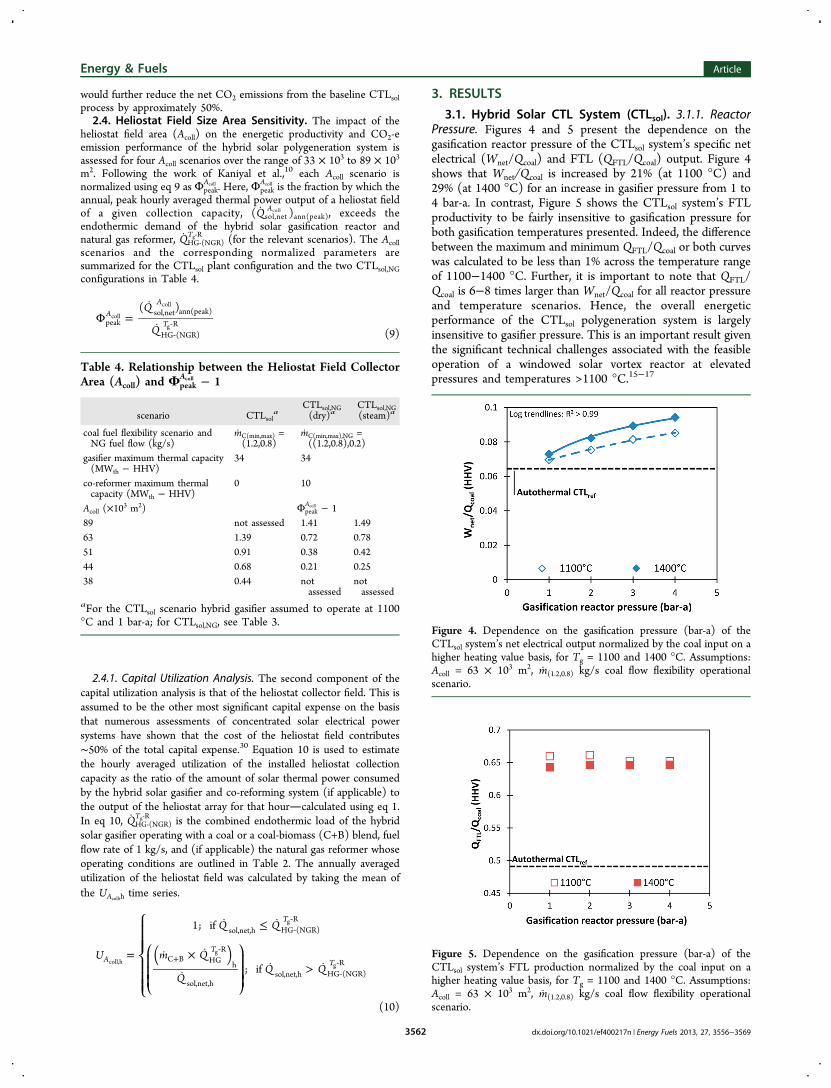
3.1. Hybrid Solar CTL System (CTLsol). 3.1.1. ReactorPressure. Figures 4 and 5 present the dependence on thegasification reactor pressure of the CTLsol system’s specific netelectrical (Wnet/Qcoal) and FTL (QFTL/Qcoal) output. Figure 4shows that Wnet/Qcoal is increased by 21% (at 1100 °C) and29% (at 1400 °C) for an increase in gasifier pressure from 1 to4 bar-a. In contrast, Figure 5 shows the CTLsol system’s FTLproductivity to be fairly insensitive to gasification pressure forboth gasification temperatures presented. Indeed, the differencebetween the maximum and minimum QFTL/Qcoal or both curveswas calculated to be less than 1% across the temperature rangeof 1100−1400 °C. Further, it is important to note that QFTL/Qcoal is 6−8 times larger than Wnet/Qcoal for all reactor pressureand temperature scenarios. Hence, the overall energeticperformance of the CTLsol polygeneration system is largelyinsensitive to gasifier pressure. This is an important result giventhe significant technical challenges associated with the feasibleoperation of a windowed solar vortex reactor at elevatedpressures and temperatures >1100 °C.15−17
Table 4. Relationship between the Heliostat Field CollectorArea (Acoll) and Φpeak
Acoll − 1
scenario CTLsola
CTLsol,NG(dry)a
CTLsol,NG(steam)a
coal fuel flexibility scenario andNG fuel flow (kg/s)
mC(min,max) =(1.2,0.8)
mC(min,max),NG =((1.2,0.8),0.2)
gasifier maximum thermal capacity(MWth − HHV)
34 34
co-reformer maximum thermalcapacity (MWth − HHV)
0 10
Acoll (×103 m2) Φpeak
Acoll − 189 not assessed 1.41 1.4963 1.39 0.72 0.7851 0.91 0.38 0.4244 0.68 0.21 0.2538 0.44 not
assessednotassessed
aFor the CTLsol scenario hybrid gasifier assumed to operate at 1100°C and 1 bar-a; for CTLsol,NG, see Table 3.
Figure 4. Dependence on the gasification pressure (bar-a) of theCTLsol system’s net electrical output normalized by the coal input on ahigher heating value basis, for Tg = 1100 and 1400 °C. Assumptions:Acoll = 63 × 103 m2, m(1.2,0.8) kg/s coal flow flexibility operationalscenario.
Figure 5. Dependence on the gasification pressure (bar-a) of theCTLsol system’s FTL production normalized by the coal input on ahigher heating value basis, for Tg = 1100 and 1400 °C. Assumptions:Acoll = 63 × 103 m2, m(1.2,0.8) kg/s coal flow flexibility operationalscenario.
Energy & Fuels Article
dx.doi.org/10.1021/ef400217n | Energy Fuels 2013, 27, 3556−35693562
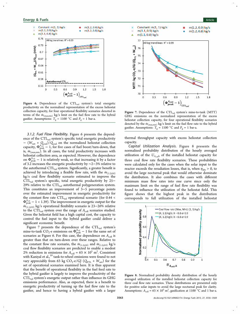
3.1.2. Fuel Flow Flexibility. Figure 6 presents the depend-ence of the CTLsol system’s specific total energetic productivity− (Wnet + Qcoal)/Qcoal on the normalized heliostat collectioncapacity, Φpeak
Acoll − 1, for five cases of fuel boost/turn-down, thatis, m(max,min). In all cases, the total productivity increases withheliostat collection area, as expected. However, the dependenceon Φpeak
Acoll − 1 is relatively weak, so that increasing it by a factorof 3.2 increases the energetic productivity by ∼2−3% relative tothe autothermal CTLref system. Significantly, a greater benefit isachieved by introducing a flexible flow rate, with the m(1.2,0.8)kg/s coal flow flexibility scenario estimated to improve theCTLsol system’s specific, total energetic productivity by 25−29% relative to the CTLref autothermal polygeneration system.This constitutes an improvement of 3−5 percentage pointsover the estimated improvement in energetic productivity forthe constant flow rate CTLsol operational scenario (for 0.44 <Φpeak
Acoll − 1 < 1.39). The improvement in energetic output for them(1.1,0.9) kg/s operational flexibility scenario is 23−26% relativeto the CTLref system over the range of Acoll scenarios studied.Given the heliostat field has a high capital cost, the capacity tocontrol the fuel input to the hybrid gasifier could deliver asignificant economic benefit.Figure 7 presents the dependence of the CTLsol system’s
mine-to-tank CO2-e emissions on ΦpeakAcoll − 1 for the same set of
scenarios as Figure 6. For this case, the dependence on Acoll isgreater than that on turn-down over these ranges. Relative tothe constant flow rate scenario, the m(1.2,0.8) and m(1.2,0.9) kg/scoal flow flexibility scenarios are predicted to enable a modest2% reduction in emissions for Acoll = 63 × 103 m2. Consistentwith Kaniyal et al.,10 tank-to-wheel emissions were found to notvary appreciably from 63 kg CO2-e/GJ (QFTL + Wnet) for theset of operational scenarios examined here. It is thus apparentthat the benefit of operational flexibility in the fuel feed rate tothe hybrid gasifier is largely to improve the productivity of theCTLsol system’s energetic output rather than influence its GHGemissions performance. Also, as expected, there is a benefit toenergetic productivity of turning up the fuel flow rate to thegasifier, and hence to having a hybrid gasifier with a larger
thermal throughput capacity with excess heliostat collectioncapacity.
Capital Utilization Analysis. Figure 8 presents thenormalized probability distribution of the hourly averagedutilization of the UAcoll,h of the installed heliostat capacity forthree coal flow rate flexibility scenarios. These probabilitieswere calculated only for the cases when the solar input to thereactor exceeds the reradiation losses, that is, when ηabs > 0, toavoid the large nocturnal peak that would otherwise dominatethe distribution. It also combines the cases with differentminimum mass flow rates into one curve since only themaximum limit on the range of fuel flow rate flexibility wasfound to influence the utilization of the heliostat field. Thisfigure shows that the highest peak in the distributioncorresponds to full utilization of the installed heliostat
Figure 6. Dependence of the CTLsol system’s total energeticproductivity on the normalized representation of the excess heliostatcollection capacity, for four operational flexibility scenarios denoted interms of the m(max,min) kg/s limit on the fuel flow rate to the hybridgasifier. Assumptions: Tg = 1100 °C and Pg = 1 bar-a.
Figure 7. Dependence of the CTLsol system’s mine-to-tank (MTT)GHG emissions on the normalized representation of the excessheliostat collection capacity, for four operational flexibility scenariosdenoted by the m(max,min) kg/s limit on the fuel flow rate to the hybridgasifier. Assumptions: Tg = 1100 °C and Pg = 1 bar-a.
Figure 8. Normalized probability density distribution of the hourlyaveraged utilization of the installed heliostat collection capacity forthree coal flow rate scenarios. These distributions are presented onlyfor positive solar inputs to avoid the large nocturnal peak for clarity.Assumptions: Acoll = 63 × 103 m2, gasification at 1100 °C and 1 bar-a.
Energy & Fuels Article
dx.doi.org/10.1021/ef400217n | Energy Fuels 2013, 27, 3556−35693563
collection capacity (i.e., UAcoll,h = 1). These periods of full
utilization occur when Φ ≤ 1 and can largely be attributed tosolar hours in winter and at dusk/dawn when insolation isinherently low. However, the area under this part of the curve islow relative to the more significant peak in the distributionwhen UAcoll,h is between 46 and 54%. This more significant peak
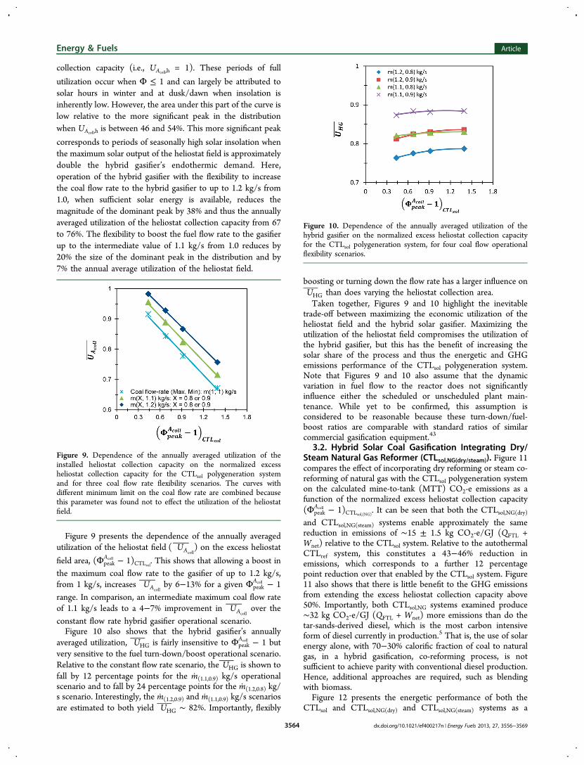
corresponds to periods of seasonally high solar insolation whenthe maximum solar output of the heliostat field is approximatelydouble the hybrid gasifier’s endothermic demand. Here,operation of the hybrid gasifier with the flexibility to increasethe coal flow rate to the hybrid gasifier to up to 1.2 kg/s from1.0, when sufficient solar energy is available, reduces themagnitude of the dominant peak by 38% and thus the annuallyaveraged utilization of the heliostat collection capacity from 67to 76%. The flexibility to boost the fuel flow rate to the gasifierup to the intermediate value of 1.1 kg/s from 1.0 reduces by20% the size of the dominant peak in the distribution and by7% the annual average utilization of the heliostat field.
Figure 9 presents the dependence of the annually averagedutilization of the heliostat field U( )Acoll
on the excess heliostat
field area, (ΦpeakAcoll − 1)CTLsol. This shows that allowing a boost in
the maximum coal flow rate to the gasifier of up to 1.2 kg/s,from 1 kg/s, increases UAcoll
by 6−13% for a given ΦpeakAcoll − 1
range. In comparison, an intermediate maximum coal flow rateof 1.1 kg/s leads to a 4−7% improvement in UAcoll
over theconstant flow rate hybrid gasifier operational scenario.Figure 10 also shows that the hybrid gasifier’s annually
averaged utilization, UHG is fairly insensitive to ΦpeakAcoll − 1 but
very sensitive to the fuel turn-down/boost operational scenario.Relative to the constant flow rate scenario, the UHG is shown tofall by 12 percentage points for the m(1.1,0.9) kg/s operationalscenario and to fall by 24 percentage points for the m(1.2,0.8) kg/s scenario. Interestingly, the m(1.2,0.9) and m(1.1,0.9) kg/s scenariosare estimated to both yield UHG ∼ 82%. Importantly, flexibly
boosting or turning down the flow rate has a larger influence onUHG than does varying the heliostat collection area.Taken together, Figures 9 and 10 highlight the inevitable
trade-off between maximizing the economic utilization of theheliostat field and the hybrid solar gasifier. Maximizing theutilization of the heliostat field compromises the utilization ofthe hybrid gasifier, but this has the benefit of increasing thesolar share of the process and thus the energetic and GHGemissions performance of the CTLsol polygeneration system.Note that Figures 9 and 10 also assume that the dynamicvariation in fuel flow to the reactor does not significantlyinfluence either the scheduled or unscheduled plant main-tenance. While yet to be confirmed, this assumption isconsidered to be reasonable because these turn-down/fuel-boost ratios are comparable with standard ratios of similarcommercial gasification equipment.43
3.2. Hybrid Solar Coal Gasification Integrating Dry/Steam Natural Gas Reformer (CTLsol,NG(dry/steam)). Figure 11compares the effect of incorporating dry reforming or steam co-reforming of natural gas with the CTLsol polygeneration systemon the calculated mine-to-tank (MTT) CO2-e emissions as afunction of the normalized excess heliostat collection capacity(Φpeak
Acoll − 1)CTLsol,(NG). It can be seen that both the CTLsol,NG(dry)and CTLsol,NG(steam) systems enable approximately the samereduction in emissions of ∼15 ± 1.5 kg CO2-e/GJ (QFTL +Wnet) relative to the CTLsol system. Relative to the autothermalCTLref system, this constitutes a 43−46% reduction inemissions, which corresponds to a further 12 percentagepoint reduction over that enabled by the CTLsol system. Figure11 also shows that there is little benefit to the GHG emissionsfrom extending the excess heliostat collection capacity above50%. Importantly, both CTLsol,NG systems examined produce∼32 kg CO2-e/GJ (QFTL + Wnet) more emissions than do thetar-sands-derived diesel, which is the most carbon intensiveform of diesel currently in production.5 That is, the use of solarenergy alone, with 70−30% calorific fraction of coal to naturalgas, in a hybrid gasification, co-reforming process, is notsufficient to achieve parity with conventional diesel production.Hence, additional approaches are required, such as blendingwith biomass.Figure 12 presents the energetic performance of both the
CTLsol and CTLsol,NG(dry) and CTLsol,NG(steam) systems as a
Figure 9. Dependence of the annually averaged utilization of theinstalled heliostat collection capacity on the normalized excessheliostat collection capacity for the CTLsol polygeneration systemand for three coal flow rate flexibility scenarios. The curves withdifferent minimum limit on the coal flow rate are combined becausethis parameter was found not to effect the utilization of the heliostatfield.
Figure 10. Dependence of the annually averaged utilization of thehybrid gasifier on the normalized excess heliostat collection capacityfor the CTLsol polygeneration system, for four coal flow operationalflexibility scenarios.
Energy & Fuels Article
dx.doi.org/10.1021/ef400217n | Energy Fuels 2013, 27, 3556−35693564
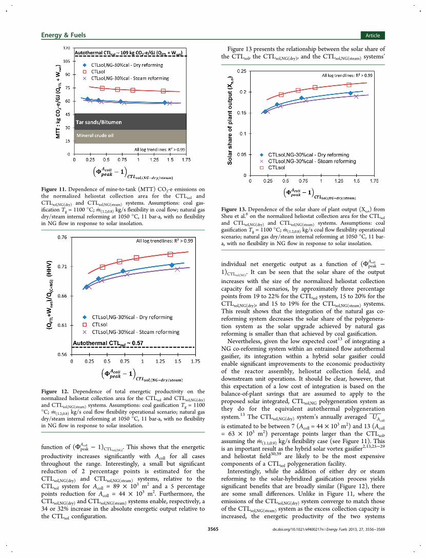
function of (ΦpeakAcoll − 1)CTLsol,(NG). This shows that the energetic
productivity increases significantly with Acoll for all casesthroughout the range. Interestingly, a small but significantreduction of 2 percentage points is estimated for theCTLsol,NG(dry) and CTLsol,NG(steam) systems, relative to theCTLsol system for Acoll = 89 × 103 m2 and a 5 percentagepoints reduction for Acoll = 44 × 103 m2. Furthermore, theCTLsol,NG(dry) and CTLsol,NG(steam) systems enable, respectively, a34 or 32% increase in the absolute energetic output relative tothe CTLsol configuration.
Figure 13 presents the relationship between the solar share ofthe CTLsol, the CTLsol,NG(dry), and the CTLsol,NG(steam) systems’
individual net energetic output as a function of (ΦpeakAcoll −
1)CTLsol,(NG). It can be seen that the solar share of the outputincreases with the size of the normalized heliostat collectioncapacity for all scenarios, by approximately three percentagepoints from 19 to 22% for the CTLsol system, 15 to 20% for theCTLsol,NG(dry), and 15 to 19% for the CTLsol,NG(steam) systems.This result shows that the integration of the natural gas co-reforming system decreases the solar share of the polygenera-tion system as the solar upgrade achieved by natural gasreforming is smaller than that achieved by coal gasification.Nevertheless, given the low expected cost13 of integrating a
NG co-reforming system within an entrained flow autothermalgasifier, its integration within a hybrid solar gasifier couldenable significant improvements to the economic productivityof the reactor assembly, heliostat collection field, anddownstream unit operations. It should be clear, however, thatthis expectation of a low cost of integration is based on thebalance-of-plant savings that are assumed to apply to theproposed solar integrated, CTLsol,NG polygeneration system asthey do for the equivalent autothermal polygenerationsystem.13 The CTLsol,NG(dry) system’s annually averaged UAcoll
is estimated to be between 7 (Acoll = 44 × 103 m2) and 13 (Acoll= 63 × 103 m2) percentage points larger than the CTLsol,assuming the m(1.1,0.9) kg/s flexibility case (see Figure 11). Thisis an important result as the hybrid solar vortex gasifier2,13,25−29
and heliostat field30,39 are likely to be the most expensivecomponents of a CTLsol polygeneration facility.Interestingly, while the addition of either dry or steam
reforming to the solar-hybridized gasification process yieldssignificant benefits that are broadly similar (Figure 12), thereare some small differences. Unlike in Figure 11, where theemissions of the CTLsol,NG(dry) system converge to match thoseof the CTLsol,NG(steam) system as the excess collection capacity isincreased, the energetic productivity of the two systems
Figure 11. Dependence of mine-to-tank (MTT) CO2-e emissions onthe normalized heliostat collection area for the CTLsol andCTLsol,NG(dry) and CTLsol,NG(steam) systems. Assumptions: coal gas-ification Tg = 1100 °C; m(1.2,0.8) kg/s flexibility in coal flow; natural gasdry/steam internal reforming at 1050 °C, 11 bar-a, with no flexibilityin NG flow in response to solar insolation.
Figure 12. Dependence of total energetic productivity on thenormalized heliostat collection area for the CTLsol and CTLsol,NG(dry)and CTLsol,NG(steam) systems. Assumptions: coal gasification Tg = 1100°C; m(1.2,0.8) kg/s coal flow flexibility operational scenario; natural gasdry/steam internal reforming at 1050 °C, 11 bar-a, with no flexibilityin NG flow in response to solar insolation.
Figure 13. Dependence of the solar share of plant output (Xs,o) fromSheu et al.6 on the normalized heliostat collection area for the CTLsoland CTLsol,NG(dry) and CTLsol,NG(steam) systems. Assumptions: coalgasification Tg = 1100 °C; m(1.2,0.8) kg/s coal flow flexibility operationalscenario; natural gas dry/steam internal reforming at 1050 °C, 11 bar-a, with no flexibility in NG flow in response to solar insolation.
Energy & Fuels Article
dx.doi.org/10.1021/ef400217n | Energy Fuels 2013, 27, 3556−35693565
diverges with increasing excess field capacity. This is a result ofthe CTLsol,NG(dry) system’s larger total endothermic demand(see Table 2), which enables it to consume more of the solarenergy that becomes available as the excess heliostat collectioncapacity is increased. However, the CTLsol,NG(dry) system’slarger energetic productivity is balanced by the low H2/COratio of the raw syngas output from the co-reformer, leading toits WGS upgrading process producing 3% more CO2-eemissions than the CTLsol,NG(steam) WGS process. This leadsto the two systems having approximately the same CO2-eemissions profile in Figure 11.3.3. Hybrid Solar Coal-Biomass to Liquids (CTLsol,bio)
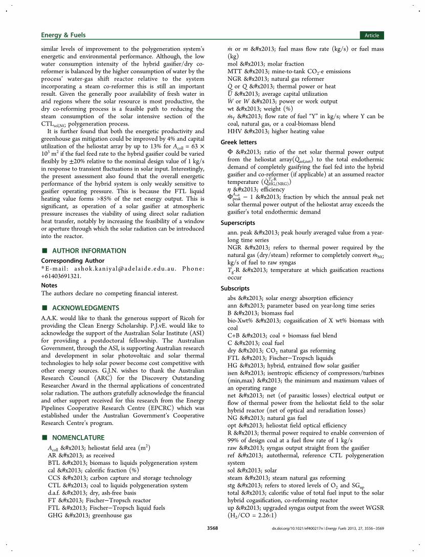
System. Figure 14 presents the mine-to-tank (MTT) CO2-eemissions from the CTLsol,bio system as a function of thebiomass fuel weight fraction (mB/mC+B). Also shown is acomparison of the CTLsol,bio system’s CO2-e emissionsperformance with that of the nonsolar, autothermal CTLbiopolygeneration system. The calculated MTT CO2-e emissionsof the CTLsol,bio system were credited with the proportion ofbiomass, on a carbon mol fraction basis, combusted at the pointof end-use. Figure 14 shows that the CTLsol,bio system achievesCO2-e emissions parity with the upper limit of conventionaldiesel from tar sands for mB/mC+B ∼ 0.3.5 In comparison,emissions from the nonsolar CTLbio system are calculated tomatch those of diesel derived from tar sands for mB/mC+B ∼0.45.5 For mB/mC+B ∼ 0.53, the CTLsol,bio system’s energeticoutput achieves lower GHG emissions than all forms of mineralcrude currently in production.4 Additionally, the CTLsol,biosystem’s MTT emissions are reduced to 0 for a biomasscogasification weight fraction of 60%, while the comparableautothermal CTLbio system requires a biomass cogasificationweight fraction of 70%. Furthermore, the CO2-e emissionsavoidance potential of the solar biomass-to-liquids, BTLsol (mB/mC+B = 1) system is 13% higher on a MTT basis, than thenonsolar, autothermal CTLbio polygeneration system, afteraccounting for the molar proportion of biomass-derived carbonburnt at the point of end-use. As expected, the percentagecontribution of solar energy to the reduction in CO2 emissionsdecreases with increasing mB/mC+B because the calorific contentof coal is 1.36 times that of biomass on a mass basis. Thepotential for the solar-hybridized cogasification process tosignificantly reduce the amount of biomass required to meet agiven CO2-e emissions standard is important given biomass istypically three to four times more expensive than coal.Figure 15 presents the total energetic productivity of the
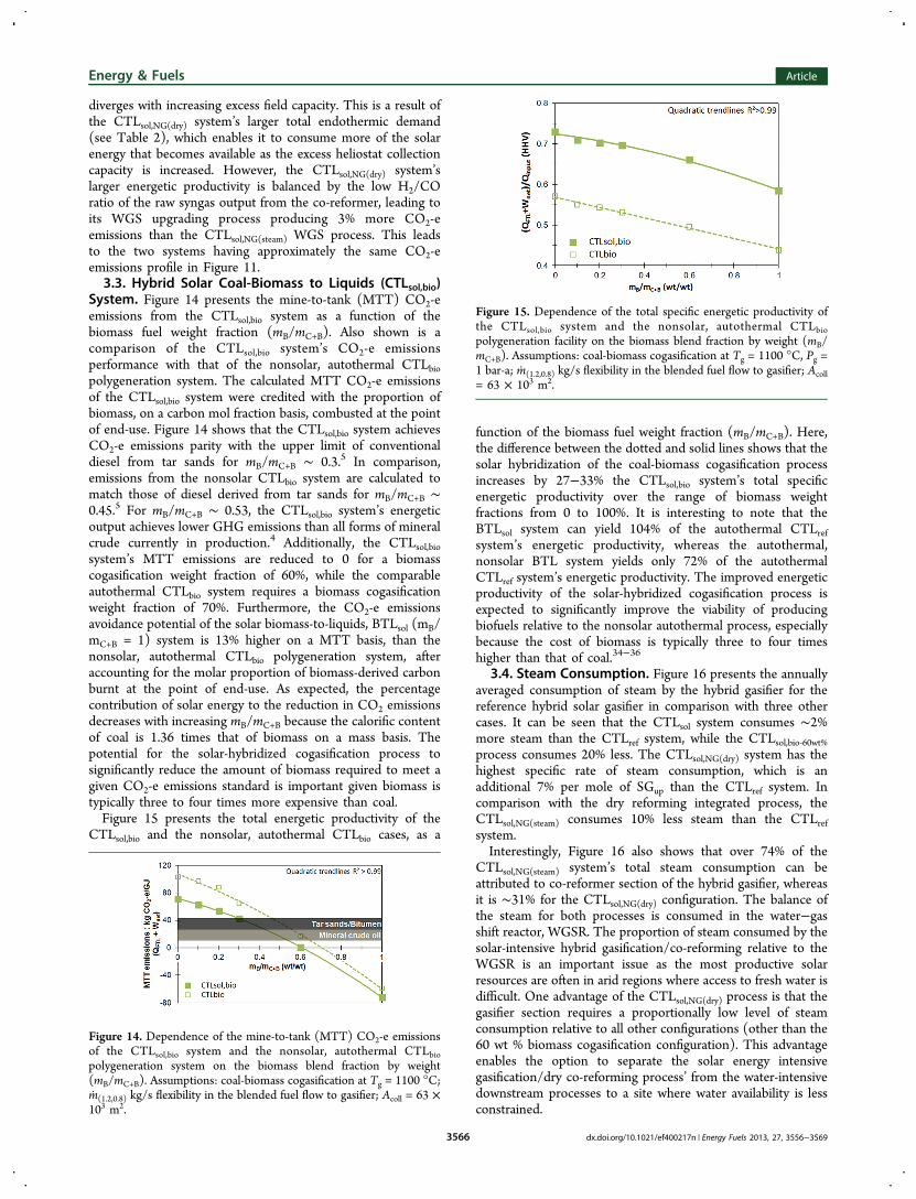
CTLsol,bio and the nonsolar, autothermal CTLbio cases, as a
function of the biomass fuel weight fraction (mB/mC+B). Here,the difference between the dotted and solid lines shows that thesolar hybridization of the coal-biomass cogasification processincreases by 27−33% the CTLsol,bio system’s total specificenergetic productivity over the range of biomass weightfractions from 0 to 100%. It is interesting to note that theBTLsol system can yield 104% of the autothermal CTLrefsystem’s energetic productivity, whereas the autothermal,nonsolar BTL system yields only 72% of the autothermalCTLref system’s energetic productivity. The improved energeticproductivity of the solar-hybridized cogasification process isexpected to significantly improve the viability of producingbiofuels relative to the nonsolar autothermal process, especiallybecause the cost of biomass is typically three to four timeshigher than that of coal.34−36
3.4. Steam Consumption. Figure 16 presents the annuallyaveraged consumption of steam by the hybrid gasifier for thereference hybrid solar gasifier in comparison with three othercases. It can be seen that the CTLsol system consumes ∼2%more steam than the CTLref system, while the CTLsol,bio‑60wt%process consumes 20% less. The CTLsol,NG(dry) system has thehighest specific rate of steam consumption, which is anadditional 7% per mole of SGup than the CTLref system. Incomparison with the dry reforming integrated process, theCTLsol,NG(steam) consumes 10% less steam than the CTLrefsystem.Interestingly, Figure 16 also shows that over 74% of the
CTLsol,NG(steam) system’s total steam consumption can beattributed to co-reformer section of the hybrid gasifier, whereasit is ∼31% for the CTLsol,NG(dry) configuration. The balance ofthe steam for both processes is consumed in the water−gasshift reactor, WGSR. The proportion of steam consumed by thesolar-intensive hybrid gasification/co-reforming relative to theWGSR is an important issue as the most productive solarresources are often in arid regions where access to fresh water isdifficult. One advantage of the CTLsol,NG(dry) process is that thegasifier section requires a proportionally low level of steamconsumption relative to all other configurations (other than the60 wt % biomass cogasification configuration). This advantageenables the option to separate the solar energy intensivegasification/dry co-reforming process’ from the water-intensivedownstream processes to a site where water availability is lessconstrained.
Figure 14. Dependence of the mine-to-tank (MTT) CO2-e emissionsof the CTLsol,bio system and the nonsolar, autothermal CTLbiopolygeneration system on the biomass blend fraction by weight(mB/mC+B). Assumptions: coal-biomass cogasification at Tg = 1100 °C;m(1.2,0.8) kg/s flexibility in the blended fuel flow to gasifier; Acoll = 63 ×103 m2.
Figure 15. Dependence of the total specific energetic productivity ofthe CTLsol,bio system and the nonsolar, autothermal CTLbiopolygeneration facility on the biomass blend fraction by weight (mB/mC+B). Assumptions: coal-biomass cogasification at Tg = 1100 °C, Pg =1 bar-a; m(1.2,0.8) kg/s flexibility in the blended fuel flow to gasifier; Acoll= 63 × 103 m2.
Energy & Fuels Article
dx.doi.org/10.1021/ef400217n | Energy Fuels 2013, 27, 3556−35693566

3.5. Overall Scenario Comparison. Figures 17 and 18summarize the MTT CO2-e emissions and total energeticproductivity (HHV) for eight key scenarios of fuel blends andhybrid solar gasification reactor configurations. In particular,Figure 17 shows that the use of solar gasification with a 30%blend of biomass (the CTLsol,bio‑30wt% case) achieves CO2-eemissions parity with that of conventional production ofsynthetic crude from tar sands, while the further incorporationof a natural gas dry co-reformer as part of the CTLsol,bio‑30%wt,NGsystem achieves an additional 10% reduction in MTTemissions. On a mine-to-tank basis, the CTLsol,bio‑60wt% systemproduces 0 CO2-e emissions and the solar gasification with purebiomass enables a net avoidance of 72 kg CO2-e/GJ (QFTL +Wnet) on a MTT basis. It is important to note that these CO2-e
emissions results are credited with the molar proportion ofbiomass that is burnt at the point of end-use.Figure 18 shows the CTLsol,bio,NG system to have 95% of the
energetic productivity of the CTLsol,bio‑30wt%, but this corre-sponds to a 37% improvement on an absolute energy outputbasis. This has important implications for the economicproductivity of the hybrid cogasification reactor system. Onthe far right of the two distributions, the CTLsol,NG system has94% of the carbon emissions of the CTLsol,bio‑10wt% config-uration but energetic productivity that is only 2% lower.It is worth noting that all of the results presented in Figures
17 and 18 are based on the m(1.2,0.8) kg/s operational flexibilityscenario in solid fuel flow to the gasifier. The sensitivity tovariations in pressure and heliostat area is likely to be similar tothe analysis presented in section 3.1.2 .
4. CONCLUSIONSThe incorporation of concentrated solar radiation into a coal-to-liquids, coal-natural-gas-to-liquids process or into a coal-biomass-to-liquids process offers significant potential advan-tages both to the energetic productivity of the polygenerationsystem and to lowering its mine-to-tank CO2-e emissionsintensity. In particular, solar hybridization decreases by up to33% the weight fraction of biomass required to meet the CO2-eemissions associated with diesel derived from tar sands andreduce by 17% the weight fraction required to eliminate CO2-eemissions at production altogether relative to the autothermalcogasification-based, coal-biomass-to-liquids process. This mayenable a significant economic advantage given that biomass hastypically been 3−4 times more expensive than coal.31,34−36
The incorporation of an indirectly irradiated solar hybridsteam natural gas reformer within the hybrid gasifier(CTLsol,NG) was shown to improve by 33% the system’sabsolute energetic output, reduce by 15% its GHG emissions,and improve by 15% the annually averaged utilization of aheliostat field with Acoll = 63 × 103 m2, relative to the CTLsolsystem. Importantly, the dry co-reformer was found to halve thecombined hybrid gasifier/co-reformer assembly’s rate of waterconsumption relative to the steam co-reformer, while achieving
Figure 16. Annually averaged ratio of the total molar steamconsumption to the production of upgraded syngas (SGup/H2/CO∼ 2.26) (blue); annually averaged fraction of steam consumed by thehybrid gasifier relative to the total (red) for four CTLsol plant scenariosand the CTLref system.
Figure 17. Summary of the mine-to-tank (MTT) CO2-e emissionsperformance of the CTLsol base system for all range of fuel blendscenarios (*mB/mC+B = 30 wt %, †QNG/Qtotal = 30% cal). All scenariosare based on the m(1.2,0.8) kg/s operational flexibility scenario in solid(biomass-coal blend) fuel flow, Acoll = 63 × 103 m2, Tg = 1100 °C, andPg = 1 bar-a.
Figure 18. Summary of the total energetic productivity of the CTLsolbase system for a range of fuel blend scenarios (*mB/mC+B = 30 wt %,†QNG/Qtotal = 30% cal). All scenarios are based on the m(1.2,0.8) kg/soperational flexibility scenario in solid (biomass-coal blend) fuel flow,Acoll = 63 × 103 m2, Tg = 1100 °C, and Pg = 1 bar-a.
Energy & Fuels Article
dx.doi.org/10.1021/ef400217n | Energy Fuels 2013, 27, 3556−35693567
similar levels of improvement to the polygeneration system’senergetic and environmental performance. Although, the lowwater consumption intensity of the hybrid gasifier/dry co-reformer is balanced by the higher consumption of water by theprocess’ water-gas shift reactor relative to the systemincorporating a steam co-reformer this is still an importantresult. Given the generally poor availability of fresh water inarid regions where the solar resource is most productive, thedry co-reforming process is a feasible path to reducing thesteam consumption of the solar intensive section of theCTLsol,NG polygeneration process.It is further found that both the energetic productivity and
greenhouse gas mitigation could be improved by 4% and capitalutilization of the heliostat array by up to 13% for Acoll = 63 ×103 m2 if the fuel feed rate to the hybrid gasifier could be variedflexibly by ±20% relative to the nominal design value of 1 kg/sin response to transient fluctuations in solar input. Interestingly,the present assessment also found that the overall energeticperformance of the hybrid system is only weakly sensitive togasifier operating pressure. This is because the FTL liquidheating value forms >85% of the net energy output. This issignificant, as operation of a solar gasifier at atmosphericpressure increases the viability of using direct solar radiationheat transfer, notably by increasing the feasibility of a windowor aperture through which the solar radiation can be introducedinto the reactor.
■ AUTHOR INFORMATIONCorresponding Author*E-ma i l : a shok .kan i ya l@ade l a ide . edu . au . Phone :+61403691321.NotesThe authors declare no competing financial interest.
■ ACKNOWLEDGMENTSA.A.K. would like to thank the generous support of Ricoh forproviding the Clean Energy Scholarship. P.J.vE. would like toacknowledge the support of the Australian Solar Institute (ASI)for providing a postdoctoral fellowship. The AustralianGovernment, through the ASI, is supporting Australian researchand development in solar photovoltaic and solar thermaltechnologies to help solar power become cost competitive withother energy sources. G.J.N. wishes to thank the AustralianResearch Council (ARC) for the Discovery OutstandingResearcher Award in the thermal applications of concentratedsolar radiation. The authors gratefully acknowledge the financialand other support received for this research from the EnergyPipelines Cooperative Research Centre (EPCRC) which wasestablished under the Australian Government’s CooperativeResearch Centre’s program.
■ NOMENCLATUREAcoll – heliostat field area (m2)AR – as receivedBTL – biomass to liquids polygeneration systemcal – calorific fraction (%)CCS – carbon capture and storage technologyCTL – coal to liquids polygeneration systemd.a.f. – dry, ash-free basisFT – Fischer−Tropsch reactorFTL – Fischer−Tropsch liquid fuelsGHG – greenhouse gas
m or m – fuel mass flow rate (kg/s) or fuel mass(kg)mol – molar fractionMTT – mine-to-tank CO2-e emissionsNGR – natural gas reformerQ or Q – thermal power or heatU – average capital utilizationW or W – power or work outputwt – weight (%)mY – flow rate of fuel “Y” in kg/s; where Y can becoal, natural gas, or a coal-biomass blendHHV – higher heating value
Greek letters
Φ – ratio of the net solar thermal power outputfrom the heliostat array(Qsol,net) to the total endothermicdemand of completely gasifying the fuel fed into the hybridgasifier and co-reformer (if applicable) at an assumed reactortemperature (QHG,(NRG)
Tg‑R )η – efficiencyΦpeak
Acoll − 1 – fraction by which the annual peak netsolar thermal power output of the heliostat array exceeds thegasifier’s total endothermic demand
Superscripts
ann. peak – peak hourly averaged value from a year-long time seriesNGR – refers to thermal power required by thenatural gas (dry/steam) reformer to completely convert mNGkg/s of fuel to raw syngasTg-R – temperature at which gasification reactionsoccur
Subscripts
abs – solar energy absorption efficiencyann – parameter based on year-long time seriesB – biomass fuelbio-Xwt% – cogasification of X wt% biomass withcoalC+B – coal + biomass fuel blendC – coal fueldry – CO2 natural gas reformingFTL – Fischer−Tropsch liquidsHG – hybrid, entrained flow solar gasifierisen – isentropic efficiency of compressors/turbines(min,max) – the minimum and maximum values ofan operating rangenet – net (of parasitic losses) electrical output orflow of thermal power from the heliostat field to the solarhybrid reactor (net of optical and reradiation losses)NG – natural gas fuelopt – heliostat field optical efficiencyR – thermal power required to enable conversion of99% of design coal at a fuel flow rate of 1 kg/sraw – syngas output straight from the gasifierref – autothermal, reference CTL polygenerationsystemsol – solarsteam – steam natural gas reformingstg – refers to stored levels of O2 and SGuptotal – calorific value of total fuel input to the solarhybrid cogasification, co-reforming reactorup – upgraded syngas output from the sweet WGSR(H2/CO = 2.26:1)
Energy & Fuels Article
dx.doi.org/10.1021/ef400217n | Energy Fuels 2013, 27, 3556−35693568
wall – heat losses through the walls of the entrainedflow gasifier
■ REFERENCES(1) Takeshita, T.; Yamaji, K. Important roles of Fischer−Tropschsynfuels in the global energy future. Energy Policy 2008, 36, 2773−2784.(2) Liu, G.; Larson, E.; Williams, R.; Kreutz, T.; Guo, X. MakingFischer−Tropsch fuels and electricity from coal and biomass:performance and cost analysis. Energy Fuels 2011, 25, 415−437.(3) Meerman, J.; Ramirez, A.; Turkenburg, W.; Faaij, A. Performanceof simulated flexible integrated gasification polygeneration facilities.Part A: A technical-energetic assessment. Renew. Sustain. Energy Rev.2011, 15, 2563−2587.(4) Gerdes, K.; Skone, T. J. An Evaluation of the Extraction, Transportand Refining of Imported Crude Oils and the Impact on Life CycleGreenhouse Gas Emissions; NETL: Pittsburgh, PA, 2009; p 42.(5) Lattanzio, R. Canadian Oil Sands: Life-Cycle Assessments ofGreenhouse Gas Emissions; Congressional Research Service: Wash-ington DC, 2012; p 31.(6) Sheu, E.; Mitsos, A.; Eter, A.; Mokheimer, E.; Habib, M.; Al-Qutub, A. A review of hybrid solar-fossil fuel power generation systemsand performance metrics. J. Solar Energy Eng. 2012, 134.(7) Kribus, A.; Zaibel, R.; Carey, D.; Segal, A.; Karni, J. A solar-drivencombined cycle power plant. Sol. Energy 1998, 62, 121−129.(8) Ordorica-Garcia, G.; Delgado, A.; Garcia, A. Novel integrationoptions of concentrating solar thermal technology with fossil-fuelledand CO2 capture processes. Energy Procedia 2011, 4, 809−816.(9) Nathan, G.; Battye, D.; Ashman, P. Economic evaluation of anovel fuel-saver hybrid combining a solar receiver with a combustor fora solar power tower. Appl. Energy 2012, submitted for review.(10) Kaniyal, A.; van Eyk, P.; Nathan, G.; Ashman, P.; Pincus, J.Polygeneration of liquid fuels and electricity by the atmosphericpressure hybrid solar gasification of coal. Energy Fuels 2013, submittedfor review.(11) Turchi, C.; Ma, Z.; Erbes, M. Gas turbine/solar parabolic troughhybrid designs. In ASME Turbo Expo 2011, NREL: Vancouver,Canada, 2011.(12) Sudiro, M.; Bertucco, A. Synthetic fuels by a limited CO2emission process which uses both fossil and solar energy. Energy Fuels2007, 21, 3668−3675.(13) Adams, T., II; Barton, P. Combining coal gasification andnatural gas reforming for efficient polygeneration. Fuel Process. Technol.2011, 92, 639−655.(14) Dahl, J.; Weimer, A.; Lewandowski, A.; Bingham, C.; Bruetsch,F.; Steinfeld, A. Dry reforming of methane using a solar-thermalaerosol flow reactor. Ind. Eng. Chem. Res. 2004, 43, 5489−5495.(15) Weimer, A. Solar thermal chemical processing challenges andcommercial path forward. Curr. Opin. Chem. Eng. 2012, 1, 211−217.(16) Trainham, J.; Newman, J.; Bonino, C.; Hoertz, P.; Akunuri, N.Whither solar fuels? Curr. Opin. Chem. Eng. 2012, 1, 204−210.(17) Steinfeld, A.; Palumbo, R. Solar thermochemical processtechnology. In Encyclopedia of Physical Science & Technology; Meyers,R., Ed.; Academic Press: New York, 2001; Vol. 15, pp 237−256.(18) Opoku-Gyamfi, K.; Adesina, A. Forced composition cycling of anovel thermally self-sustaining fluidised-bed reactor for methanereforming. Chem. Eng. Sci. 1999, 54, 2575−2583.(19) ABARES, Australian Energy Resource Assessment. In ABARES;Australian Government: Canberra, 2010.(20) Sun, Y.; Ritchie, T.; Hla, S.; McEvoy, S.; Stein, W.; Edwards, J.Thermodynamic analysis of mixed and dry reforming of methane forsolar thermal applications. J. Nat. Gas Chem. 2011, 20, 568−576.(21) Price, L. Origins, characteristics, controls and economicviabilities of deep-basin gas resources. Chem. Geol. 1995, 126, 335−349.(22) Z’Graggen, A.; Haueter, P.; Maag, G.; Romero, M.; Steinfeld, A.Hydrogen production by steam-gasification of carbonaceous materialsusing concentrated solar power - IV. Reactor experimentation withvacuum residue. Int. J. Hydrogen Energy 2008, 33, 679−684.
(23) Z’Graggen, A.; Haueter, P.; Maag, G.; Vidal, A.; Romero, M.;Steinfeld, A. Hydrogen production by steam-gasification of petroleumcoke using concentrated solar power - III. Reactor experimentationwith slurry feeding. Int. J. Hydrogen Energy 2007, 32, 992−996.(24) Z’Graggen, A.; Steinfeld, A. Hydrogen production by steam-gasification of carbonaceous materials using concentrated solar energy- V. Reactor modeling, optimization and scale-up. Int. J. HydrogenEnergy 2008, 33, 5484−5492.(25) Kreutz, T.; Larson, E.; Liu, G.; Williams, R. In Fischer−TropschFuels from Coal and Biomass, 25th Ann. Intl Pittsburgh CoalConference; Pittsburgh, Pennsylvania, 2008.(26) Kreutz, T.; Williams, R.; Consonni, S.; Chiesa, P. Co-productionof hydrogen, electricity and CO2 from coal with commercially readytechnology. Part B: Economic analysis. Int. J. Hydrogen Energy 2005,30, 769−784.(27) Larson, E.; Fiorese, G.; Liu, G.; Williams, R.; Kreutz, T.;Consonni, S. Co-production of decarbonized synfuels and electricityfrom coal + biomass with CO2 capture and storage: An Illinois casestudy. Energy Environ. Sci. 2010, 3, 28−42.(28) Meerman, J.; Ramirez, A.; Turkenburg, W.; Faaij, A.Performance of simulated flexible integrated gasification polygenera-tion facilities, Part B: Economic evaluation. Renew. Sustain. Energy Rev.2012, 16, 6083−6102.(29) Woods, M.; Capicotto, P.; Haslbeck, J.; Kuehn, N.;Matuszewski, M.; Pinkerton, L.; Rutkowski, M.; Schoff, R.; Vaysman,V. Bituminous Coal and Natural Gas to Electricity Final Report, DoE/NETL-2007/1281; US DoE, August 2007; Vol. 1.(30) Kolb, G.; Jones, S.; Donnelly, M.; Gorman, D.; Thomas, R.;Davenport, R.; Lumia, R. Heliostat Cost Reduction Study; SandiaNational Laboratories: Alburquerque, NM, 2007; p 158.(31) Berndes, G.; Hoogwijk, M.; van den Broek, R. The contributionof biomass in the future global energy supply: a review of 17 studies.Biomass Bioenergy 2003, 25, 1−28.(32) Baxter, L. Biomass-coal co-combustion: opportunity foraffordable renewable energy. Fuel 2005, 84, 1295−1302.(33) Kirkels, A.; Verbong, G. Biomass gasification: Still promising? A30-year global overview. Renew. Sustain. Energy Rev. 2011, 15, 471−481.(34) Sami, M.; Annamalai, K.; Woolridge, M. Co-firing of coal andbiomass fuel blends. Prog. Energy Combust. Sci. 2001, 27, 171−214.(35) De, S.; Assadi, M. Impact of cofiring biomass with coal in powerplantsA techno-economic assessment. Biomass Bioenergy 2009, 33,283−293.(36) Tijmensen, M.; Faaij, A.; Hamelinck, C.; van Hardeveld, M.Exploration of the possibilities for production of Fischer−Tropschliquids and power via biomass gasification. Biomass Bioenergy 2002, 23,129−152.(37) NREL National Solar Radiation Database Update: User’SManual, 1991−2005 update; US DoE; Golden, CO, 2007.(38) NREL National solar radiation database 1991−2005 update.(39) Meier, A.; Gremaud, N.; Steinfeld, A. Economic evaluation ofthe industrial solar production of lime. Energy Convers. Manage. 2005,46, 905−926.(40) Higman, C.; van der Burgt, M. Gasification, 2nd ed.; Elsevier:Oxford, UK, 2008.(41) Melchior, T.; Perkins, P.; Lichty, A.; Weimer, A.; Steinfeld, A.Solar-driven biochar gasification in a particle-flow reactor. Chem. Eng.Proc. 2009, 48, 1279−1287.(42) Moghtaderi, B.; Sheng, C.; Wall, T. An overview of theAustralian biomass resources and utilization technologies. BioResources2006, 1, 93−115.(43) Marbe, Å.; Harvey, S.; Berntsson, T. Biofuel gasificationcombined heat and powernew implementation opportunitiesresulting from combined supply of process steam and district heating.Energy 2004, 29, 1117−1137.
Energy & Fuels Article
dx.doi.org/10.1021/ef400217n | Energy Fuels 2013, 27, 3556−35693569