Dynamic management of virtual infrastructures - GRyCAP
23
Noname manuscript No. (will be inserted by the editor) Dynamic management of virtual infrastructures Miguel Caballer · Ignacio Blanquer · Germ´ an Molt´ o · Carlos de Alfonso Received: date / Accepted: date Abstract Cloud infrastructures are becoming an appropriate solution to address the computational needs of scientific applications. However, the use of public or on- premises Infrastructure as a Service (IaaS) clouds requires users to have non-trivial system administration skills. Resource provisioning systems provide facilities to choose the most suitable Virtual Machine Images (VMI) and basic configuration of multiple instances and subnetworks. Other tasks such as the configuration of cluster services, computational frameworks or specific applications are not trivial on the cloud, and normally users have to manually select the VMI that best fits, including undesired additional services and software packages. This paper presents a set of components that ease the access and the usability of IaaS clouds by au- tomating the VMI selection, deployment, configuration, software installation, mon- itoring and update of Virtual Appliances. It supports APIs from a large number of virtual platforms, making user applications cloud-agnostic. In addition it inte- grates a contextualization system to enable the installation and configuration of all the user required applications providing the user with a fully functional infras- tructure. Therefore, golden VMIs and configuration recipes can be easily reused across different deployments. Moreover, the contextualization agent included in the framework supports horizontal (increase/decrease the number of resources) and vertical (increase/decrease resources within a running Virtual Machine) by properly reconfiguring the software installed, considering the configuration of the Miguel Caballer( ) · Ignacio Blanquer · Germ´anMolt´o · Carlos de Alfonso Instituto de Instrumentaci´on para Imagen Molecular (I3M). Centro mixto CSIC – Universitat Polit` ecnica de Val` encia – CIEMAT Camino de Vera s/n, 46022 Valencia, Spain. E-mail: [email protected] Ignacio Blanquer E-mail: [email protected] Germ´anMolt´o E-mail: [email protected] Carlos de Alfonso E-mail: [email protected]
-
Upload
khangminh22 -
Category
Documents
-
view
0 -
download
0
Transcript of Dynamic management of virtual infrastructures - GRyCAP

Noname manuscript No.(will be inserted by the editor)
Dynamic management of virtual infrastructures
Miguel Caballer · Ignacio Blanquer ·German Molto · Carlos de Alfonso
Received: date / Accepted: date
Abstract Cloud infrastructures are becoming an appropriate solution to addressthe computational needs of scientific applications. However, the use of public or on-premises Infrastructure as a Service (IaaS) clouds requires users to have non-trivialsystem administration skills. Resource provisioning systems provide facilities tochoose the most suitable Virtual Machine Images (VMI) and basic configurationof multiple instances and subnetworks. Other tasks such as the configuration ofcluster services, computational frameworks or specific applications are not trivialon the cloud, and normally users have to manually select the VMI that best fits,including undesired additional services and software packages. This paper presentsa set of components that ease the access and the usability of IaaS clouds by au-tomating the VMI selection, deployment, configuration, software installation, mon-itoring and update of Virtual Appliances. It supports APIs from a large numberof virtual platforms, making user applications cloud-agnostic. In addition it inte-grates a contextualization system to enable the installation and configuration ofall the user required applications providing the user with a fully functional infras-tructure. Therefore, golden VMIs and configuration recipes can be easily reusedacross different deployments. Moreover, the contextualization agent included inthe framework supports horizontal (increase/decrease the number of resources)and vertical (increase/decrease resources within a running Virtual Machine) byproperly reconfiguring the software installed, considering the configuration of the
Miguel Caballer(�) · Ignacio Blanquer · German Molto · Carlos de AlfonsoInstituto de Instrumentacion para Imagen Molecular (I3M). Centro mixto CSIC – UniversitatPolitecnica de Valencia – CIEMAT Camino de Vera s/n, 46022 Valencia, Spain.E-mail: [email protected]
Ignacio BlanquerE-mail: [email protected]
German MoltoE-mail: [email protected]
Carlos de AlfonsoE-mail: [email protected]

2 Miguel Caballer et al.
multiple resources running. This paves the way for automatic virtual infrastructuredeployment, customization and elastic modification at runtime for IaaS clouds.
Keywords Cloud Computing · Virtual Infrastructures · Contextualization
1 Introduction
With the advent of virtualization technologies and cloud infrastructures, scientistsare exploring the usage of computational clouds for their research. Cloud comput-ing technologies can offer: “ubiquitous, convenient, on-demand network access to ashared pool of configurable computing resources” [28]. Many scientific infrastruc-ture providers are including IaaS as an added value [16] and [5] analyzes the usecases that scientific cloud infrastructures should cover. One of the most importantfeatures of cloud technologies and virtualization is that the software requirementsare defined by the user rather than by the infrastructure provider. Moreover, tosome extent, users can also define part of the hardware requirements. This is animportant point to ease the migration of scientific applications into the cloud.However, the user is still required to prepare, deploy, configure and run the virtualappliances and the applications inside, requiring in some cases non trivial sys-tem administration skills. Nowadays there are different cloud providers, differentsoftware packages to deploy cloud platforms, etc. which makes even more difficultto integrate these technologies. Users need an easy way to define dependenciesand application restrictions and delegate on a platform to automatically deploy,configure and monitor their virtual infrastructures.
This paper presents a set of components developed to simplify the automaticdeployment and configuration of virtual infrastructures. The platform developedconsiders all the aspects related to the creation and management of virtual in-frastructures: i) The software and hardware requirements specification for theuser applications, using a simple language defined to be easy to understand bynon-advanced users who just want to deploy a basic virtual infrastructure, butwith enough expressivity for advanced users to set all the configuration param-eters needed to get the infrastructure fully configured. ii) The selection of themost suitable Virtual Machine Images (VMI) based on the user expressed require-ments. iii) The provision of Virtual Machines on the cloud providers available tothe user, including both public IaaS Clouds (Amazon Web Services, WindowsAzure IaaS, etc.) and on-premise resource provisioning systems (OpenNebula,OpenStack, etc.). iv) The contextualization of the infrastructure at run-time byinstalling and configuring all the required software that may not be available inthe golden images (VMIs) used and, finally, v) the elasticity management, bothhorizontal (adding/removing nodes) and vertical (growing/shrinking the capacityof nodes). Considering the highly dynamic Cloud landscape, the platform shouldbe extensible to future back-ends or standards.
In a previous work [1] an early prototype of the platform along with initial testscases was presented. This paper describes an evolution of the platform featuring thefollowing contributions: the contextualization phase, improving the functionalityby enabling the deployment of a fully functional configured infrastructure, and theelasticity management. The automatic configuration and elasticity management atruntime are key issues in Cloud infrastructures and represent a major step forwardwith respect to our early prototype.

Dynamic management of virtual infrastructures 3
The remainder of the paper is structured as follows. First, section 2 analyzesthe current tools for virtual infrastructure deployment. Then, section 3 describesthe software architecture of the Infrastructure Manager along with the underlyingcomponents used. Then, section 4 describes a case study to test the suitability ofthis platform for the deployment of virtual clusters. Finally, section 5 summarisesthe paper and points to future work.
2 State of the art
There exist works in the literature and software tools that address the deploymentof virtual infrastructures. In the next paragraphs different approaches are analyzed,detailing the achievement of the objectives described in the introduction. FinallyTable 1 shows a comparison of the features of all the analyzed works.
Several cloud providers, such as Amazon Web Services (AWS), provide toolsto deploy virtual infrastructures. In particular, CloudFormation [3] provides de-velopers and systems administrators with an easy way to create and manage acollection of related AWS resources, provisioning and updating them in an orderlyand predictable fashion. It provides tools to launch a set of VMs in a coordinatedfashion, and can also configure a set of Amazon services (Elastic Load Balancer,Auto Scaling, etc.). AWS CloudFormation introduces two concepts: Template, aJSON text-based file that describes all the AWS resources you need to deploy andrun your application; and Stack, the set of AWS resources that are created andmanaged as a single unit when a template is instantiated by AWS CloudForma-tion. The user must select the image of the VM from the Amazon Machine Image(AMI) catalog. This catalog only provides very basic information about the AMIs(architecture, O.S. and a free text field with a description), so the user must pre-viously know the configuration and software installed in the image to use. Thisis an important problem that hinders reusing existing VMIs. Other limitation ofthis tool is that it can only be used in the Amazon EC2 infrastructure.
The Nimbus project team group has developed a Context Broker [21]. This con-text broker enables the contextualization of VMs to create the so-called “One-ClickVirtual Clusters”. A created set of VMs are configured according to some roles in-side the cluster distribution. The VMs are launched using the Nimbus commands,so it can only be used in Nimbus-based cloud providers, or Amazon EC2 using the“IaaS Gateway” component. It also requires that the user chooses the requiredVMI. In addition, the contextualization has some limitations, such as the use ofsimple scripts that must be stored in the VMIs, so the images must be speciallycustomized for each application. Furthermore, the tool does not offer recontextu-alization of the infrastructure if new nodes are added, thus hindering the elasticitymanagement. The same research group has developed other system [22, 26] thatenables extending a “real” cluster elastically adding new resources over a cloudinfrastructure (with cloud bursting techniques). In this case, to avoid the recon-figuration limitations of the Context Broker they use a combination of Chef [19]and a new developed component called Recontextualization Broker to perform theinitial configuration and later reconfiguration of the cluster when new nodes areadded or removed. This new component solves some of the problems of the previoussoftware but it cannot be used as a general solution since it focuses on the deploy-ment of HPC clusters and cannot deploy other virtual infrastructures. In a further

4 Miguel Caballer et al.
work, the same group has developed another tool called cloudinit.d [6] designed tolaunch, control and monitor cloud applications. It automates the VM creation pro-cess, the contextualization and the coordination of service deployment. It supportsmultiple clouds and the synchronization of different “runlevels” to launch servicesin a defined order. Furthermore it provides a system to monitor the services thatuses user-created scripts to ensure that they are running. This system checks forservice errors, re-launching failed services or launching new VMs. However, thestatic selection of VMIs is still required. It enables the contextualization of VMsusing simple scripts, which are insufficient in scenarios with multiple VMs withdifferent Operating Systems.
Claudia [30, 37, 38] enables the deployment of a set of VMs in IaaS environ-ments, using an extension of the Open Virtualization Format (OVF) [14] calledService Description File (SDF). Static selection of VMIs are used in the deploymentstage, and no contextualization is made, so it is based in the software previouslyinstalled in the VMIs. The SDF language includes an elasticity section adding rulesto manage the evolution of the size of the cluster using the defined “Key Perfor-mance Indicators” (KPI). It has a modular design with a plug-in system which canbe used to add new deployment types. It currently supports only OpenNebula.
Apache Whirr [4] supports deploying clusters both on EC2 and Rackspace. Theuser specifies the number of instances needed and the roles they must provide. Ithas the same problem of the static selection of VMIs. It has been initially designedto launch hadoop clusters, but it can be extended adding new Java classes toimplement the installation and contextualization of the new roles defined. It doesnot enable elasticity management, so once the cluster is launched its size cannotbe modified by the user.
Wrangler [20] has a specific orientation to launch VMs in a general way. Itenables the users to define their requirements using an XML file. In this file theuser can also specify the scripts to be used to configure the VMs to adopt aspecific role within the virtual infrastructure. In this case the scripts are stored inthe wrangler coordinator node, so it does not need to be previously copied in theVMIs. But the VMIs indeed require a prior step to prepare them by installing thewrangler agent and configuring it to connect to the coordinator node.
SixSq SlipStream1 provides a web portal to deploy and configure a set of VMs.The configuration of the nodes are made by means of a list of packages to installand a script file that can be executed in each VM. Each script is completed witha set of parameter values as “hostname” or “instanceid” to enable to create morefunctional and customized scripts. It enables to access a large list of Cloud plat-forms, both public and on-premise: EC2, Azure, OpenNebula, OpenStack, OCCI,etc. The main limitation is the static selection of VMIs. In addition, it does notenable elasticity management and, therefore, once the infrastructure is deployedits size cannot be modified by the user.
Vagrant [18] was initially designed to launch VMs over the VirtualBox virtu-alization platform but it has a modular design that enables new providers to beadded. Currently it has support to VirtualBox, VMware Fusion and EC2. It en-ables the management of a set of VMs using the “multi-machine” environments. Italso supports the usage of provisioning tools such as shell scripts, Chef, or Puppetto automatically install and configure software on the machines. As in the previous
1 https://slipstream.sixsq.com

Dynamic management of virtual infrastructures 5
Table 1 Virtual Infrastructure deployment tools comparison.
Wrangler Whirr Claudia Cloudinit.d SlipStream Recont. Cloud Vagrant TOSCABroker Formation
Systems support EC2, EC2 OpenNebula EC2, EC2, EC2, EC2 VirtualBox, -Eucalyptus, Nimbus OpenStack, Nimbus VMWare,OpenNebula OpenNebula EC2
Azure, ... EC2
VMs Context. Yes Yes No Yes Yes Yes No Yes Yes
High levelContext. Lang.
No No - No No Yes - Yes No
VM pre-config. Yes Yes Yes Yes No No No Yes No
Simple deploy lang. Yes Yes No Yes Yes Yes Yes Yes No
Extensible Yes Yes Yes No No No No Yes Yes
Catalog of VMIs No No No No No No No No -
Elasticity Mgmt Yes No Yes No No Yes Yes1 Yes Yes
case to use any of these tools they must be installed previously in the VMIs to use.It provides the “box” concept to encapsulate the VMIs for each provider. A “box”is a tar file where all the files needed to encapsulate a VMI in the Vagrant envi-ronment. In the case of VirtualBox and VMware this box file contains the imageitself. In the case of EC2, it contains a reference to the AMI. However, Vagrantis designed to work in a single machine and, therefore, it does not support thedeployment of large virtual infrastructures.
Currently the are also some initiatives from standardization organizations, suchas OASIS with the Topology and Orchestration Specification for Cloud Applica-tions (TOSCA) [31] to describe service templates across *aaS layers and connectingthem to the resource abstraction layer. It enables the description of a service witha high level topology and plan for implementation and configuration. A servicespecified with TOSCA typically describes virtual hardware, software, configura-tion, and policies necessary to orchestrate the service. Currently it provides noimplementation, but some cloud software packages as OpenStack is studying thepossibility of the integration of TOSCA with their software stack. Although thisspecification considers the contextualization of the VMs it does it using executablefiles, and not using some high level contextualization language.
One common limitation in all the analyzed systems is the usage of manuallyselected base images to launch the VMs. It is an important limitation because itimplies that users must create their own images or they must previously knowthe details about software and configuration of the image selected. This limitationaffects the reutilization of the previously created VMIs, forcing the user to wastetime testing the existing images or creating new ones (as an example in AmazonEC2 there are thousands of AMIs). Another issue is that most of them needto use a VMI specifically prepared for their tools, requiring a specific softwareinstalled, a set of scripts prepared, etc. Another important limitation is the usageof simple scripts in the contextualization, instead of higher level languages suchas Puppet [35], Chef [33], Ansible [13], etc. which enable the creation of systemindependent configurations. Only the Nimbus “Recontextualization Broker” usesChef to perform these tasks. This problem is exacerbated in some tools where theconfiguration scripts must also be stored in the base image of the VM.
1 Using the Auto Scaling service from Amazon.

6 Miguel Caballer et al.
3 Architecture
In order to support all the functionality issues addressed in Table 1, an architecturehas been developed, which is depicted in Figure 1. The different components aredescribed.
The first component of the architecture is the language describing the require-ments of the virtual infrastructure, called the Resource and Application Descrip-tion Language (RADL). This language has been designed to be simple for non-advanced users, who can deploy infrastructures by specifying very basic informa-tion. Additionally, savvy users can access more advanced functionality. The Vir-tual Machine Image Repository & Catalog (VMRC) enables indexing and storingthe VMIs including all the relevant information about them, including the soft-ware applications installed. The Infrastructure Manager (IM) implements a servicethat provides APIs, using standard connection methods (XML-RCP, and REST),with a relatively simple set of functions to provide the functionality required inthe management of VMs. It is also in charge of orchestrating the deployment ofvirtual infrastructures using the rest of components. The last component is thecontextualization system, which installs and configures all the software not yetavailable in the VMIs from the VMRC and described in the RADL. It also dealswith the reconfiguration in the case of adding or removing nodes. This system usesAnsible [13] integrated with a set of developed tools to build up the contextualiza-tion system. Finally, client tools (command line and web application) have beendeveloped to ease the access to the functionality of this platform for the user.
Infrastructure Manager
CloudSelector
VMRC
Cloud Connector
Conf.Manager
Conf & CTX Files
XMLRPC API REST API
Web Interface CLI Interface
VM
VM
VM
...
RADL
Master VM
Cntxt.Agent
Ansible
Fig. 1 Infrastructure Manager Architecture

Dynamic management of virtual infrastructures 7
The following subsections describe the aforementioned components.
3.1 Resource and Application description Language (RADL)
The main purpose of the Resource and Application description Language (RADL)is to specify the requirements of the resources where the scientific applicationswill be executed. It must address not only hardware (CPU number, CPU architec-ture, RAM size, etc.) but also software requirements (applications, libraries, database systems, etc.). It should include all the configuration details needed to geta fully functional and configured VM (a Virtual Appliance or VA). It merges thedefinitions of specifications, such as OVF, but using a declarative scheme, withcontextualization languages such as Ansible. It also allows describing the under-lying network capabilities required.
The initial scheme of the RADL language is described in [1], where a minimalexample is shown in Figure 2. This section presents a brief description of theRADL scheme focusing on the new contributions. A typical RADL file includesthe following sections:
– Environment features. This includes devices, services, etc. not provided bythe VMs, but requiring some interaction from the VMs. Some examples arenetworks, Windows Active Directory Service, Storage Area Networks, etc. Cur-rently only networks are implemented and they are assumed to be Local AreaNetworks (LAN) that the VMs can use to connect to the other VMs and toother external networks. This part is defined with the reserved word “network”.
– Type of nodes definition: The reserved word “system” is used to specify thesection to describe all the features (hardware and software) of one type or roleof nodes in the infrastructure. A role describes a group of nodes that have thesame features.
– Deploy instructions: A set of deploy instructions to specify the number ofinstances of the defined “system” types to effectively launch. Two additionalparameters can by specified (not shown in the example): The first one enablesspecifying the cloud platform on which to deploy the VMs. The valued specifiedmust be one of the IDs defined in the authorization data (see section 3.3.1).The second one enables specifying a deployment priority. The instances witha higher number will be deployed later to the nodes with a lower number, tocreate an ordered deployment. It enables, for example the deployment of adatabase server before deploying an application server that needs to have theconnection to the database active to start functioning.
– Configuration section: The reserved word “configure” is used to specify thesection where the user can specify (using Ansible’s language) the necessaryrecipes to configure the VMs. Each “configure” section is defined with a nameand can include as many configure sections as needed. In addition, one configuresection can “include” another, enabling to reuse existing configure sections.Finally, for each instance of type defined in the “system” section, only theinstructions of the corresponding configuration section will be applied. Thesefeatures will be clarified in the examples.
These last two features described (ordered deployment and configuration sec-tion) have been added in the new release of the RADL language.

8 Miguel Caballer et al.
system nodeS (memory.size>=1024M anddisk.0.applications contains (name=’tomcat’)
)
deploy nodeS 2
Fig. 2 Example of a simple RADL file
network red (outbound = yes)
system nodeB (system=’kvm’ andcpu.count>=1 and cpu.arch=’i686’ andmemory.size>=1024M andnet_interface.0.connection=’red’ andnet_interface.0.dns_name=’node-#N#’ anddisk.0.os.name=’linux’ anddisk.0.os.flavour=’ubuntu’ anddisk.0.os.version>=’9.10’ anddisk.0.applications contains (name=’tomcat’))
configure common (@begin---
- tasks:- user: name=user1 password=a7ae2ax1k0a
@end)
configure nodeB (@begin---
- tasks:- include: common.yml- yum: pkg=${item} state=installed
with_items:- torque-client- torque-server
@end)
deploy nodeB 10
Fig. 3 Example of a extended RADL file
The RADL sample in Figure 2 shows how a non-advanced user can define avirtual infrastructure only by specifying the application relevant data. In particularthe example requires two VMs with at least 1GB of RAM with the Apache Tomcatapplication server installed. The rest of parameters required to finally deploy theVM are generated by the platform, using default values (i.e. one 32-bit CPU, onenetwork connection with outbound connectivity, etc.).
Figure 3 shows another example of a complete RADL document that includesmost of the advanced features of the RADL language. In the top of the example thebasic VM characteristics are shown: An x86 32-bit CPU with 1 GB of RAM and
Dynamic management of virtual infrastructures 9
an outbound network connection, Ubuntu 9.10 (or higher) as the OS and ApacheTomcat installed. The “dns name” field has been added to the network interfacesenabling the user to specify the DNS name to the interface. The name used in theinterface with the id “0” will be used as the name of the host. It is important tonotice that all the DNS names will only be visible for the nodes included in theinfrastructure. This field must be carefully used in case of deploying a set of VMsusing the same “system” definition, because all the VMs will have the same DNSname. The substitution string “#N#” has been added to deal with this issue. Thisstring will be replaced with the number of the instance inside the infrastructure.For example if a DNS name like “node-#N#” is used, the name of the VMs willbe node-0, node-1, etc.
The initial version of the language [1] had limited functionality because it didnot include support to define the tasks that can be automated to configure a virtualinfrastructure. The new “configure” section uses Ansible’s language to specify allthe configuration details. In the example two “configure” sections appear: commonand nodeB. The former does not match with any “system” defined, so it will notbe applied, but it will be available to be used by the nodes using the Ansible“include” statement. The latter will be applied to all the VMs of the “nodeB”type. As this one includes the “common configure”, all the nodeB VMs will createa user named “user1” and then install the torque client and server packages, as isdefined in the configure section.
The Infrastructure Manager (IM) creates a set of variables to enable someinformation of the RADL language to be accessible from Ansible. These variablesare very useful to perform some configuration tasks, as using IM MASTER FQDNto set the name of the front-end node in the configuration process of any client-server system, identifying the current node ID or HOSTNAME to download thecorrect files to a specific VM, etc.
– IM NODE HOSTNAME: Hostname of the node being processed (without thedomain).
– IM NODE FQDN: Complete FQDN of the node being processed.– IM NODE DOMAIN: Domain of the node being processed.– IM NODE NUM: Number of the instance of the node being processed.– IM MASTER HOSTNAME: Hostname of the master node (without the do-
main).– IM MASTER FQDN: Complete FQDN of the master node.– IM MASTER DOMAIN: Domain of the master node.
For each of the applications pre-installed, and added as metadata in the VMRC,in the VMI used, the IM also provides the following variables:
– IM [application name] VERSION: Version of the application [application name].– IM [application name] PATH: Install path of the application [application name].
3.2 Virtual Machine image Repository and Catalog (VMRC)
The VMRC (Virtual Machine image Repository and Catalog) [11] is used to find asuitable Virtual Machine Image (VMI) that satisfies the requirements of the user(in terms of Operating System, CPU architecture, applications installed, etc.), and

10 Miguel Caballer et al.
it is compatible with the hypervisor available in the Cloud system. This compo-nent is used to index the VMIs that are typically stored in the different Clouddeployments, so that they can be reused in multiple contexts. It also implementsmatchmaking algorithms to obtain a ranked list of VMIs that satisfy the aforemen-tioned given set of requirements. Depending on the scenario, the VMI descriptionscan be created only by the administrator of the VMRC, with curated and testedimages, or by a set of users responsible for creating and maintaining the virtualmachines required for specific virtual organizations, or sites.
An URI naming convention has been defined to enable the registration of VMIsin the VMRC when the VMIs are stored in the cloud providers. This URIs enablethe IM to know their location and how to access them. The protocol field of theURI is used to specify the cloud provider type: one (OpenNebula), ec2 (AmazonEC2) and ost (OpenStack). In the case of OpenNebula and OpenStack, the addressand port fields have their default function and the path is used to specify the IDof the images, an integer number for OpenNebula and a string for OpenStack. Inthe case of EC2, the address field is used to specify the region where the image isstored and the path to store the name of the AMI.
– one://server:port/image-id– ost://server:port/ami-id– ec2://region/ami-id
3.3 Infrastructure Manager - IM
The main goal of the Infrastructure Manager is to provide a set of functions for theeffective deployment of all the required virtual infrastructures needed to launch anapplication in a cloud environment and then managing them on demand duringall the execution time.
The IM provides two sets of APIs to enable high-level components to accessthe functionality. The first APIs uses the XML-RCP protocol, that can be calledthe “native” API. Second, a REST API has been implemented, given its increasingpopularity. There are also secured versions of both APIs using Secure Sockets Layer(SSL) to encrypt the communications. These APIs provide a set of simple functionsfor clients to create, destroy, and get information about the infrastructures. TheRADL language is used both to create and to get the information about theinfrastructures. The IM also provides functions to add and remove resources andmodify the features of the existing ones, both hardware and software at run-time.
Figure 1 shows the architecture of the Infrastructure Manager. On the top, theclient interfaces currently available for users are depicted. The IM in the centerof the figure provides the upper layers with the functionality through the APIsprovided. The IM uses the “Cloud Selector” component to query the VMRC servicefor the list of VMIs that best fit the user requirements (expressed in the RADLdocument) and merge this information with the list of available cloud providers forthe user, in order to get the best option. The “Cloud Connector” layer is used toprovision the VMs in the cloud providers. It provides an homogeneous interface toconnect with the different cloud middlewares. Finally, once the VMs are deployedand in the running state, the “Configuration Manager” is in charge of managingthe contextualization of all the VMs of the infrastructures using the Ansible tool.

Dynamic management of virtual infrastructures 11
id = one; type = OpenNebula; host = server:2633; username = user; password = passid = one2; type = OpenNebula; host = server2:2633; username = user2; password = pass2id = libvirt; type = LibVirt; host = server; username = user; password = passtype = InfrastructureManager; username = user; password = passtype = VMRC; username = user; password = passid = ec2; type = EC2; user = id; password = keyid = ost; type = OpenStack; host = server:8773; username = id; password = keyid = occi; type = OCCI; host = server:4567; username = user; password = pass
Fig. 4 Authorization data examples
3.3.1 Authorization Data
The authorization data is used to validate access to the components in the infras-tructure. Therefore, it must be included in all the calls to the APIs. The nativeAPI requires including this authorization data as the last parameter in every call.The REST API requires these data to be placed inside the “AUTHORIZATION”HTTP header. This parameter is composed of a set of “key - value” pairs, wherethe user specifies the authorization data for all the components and cloud providersavailable. Figure 4 shows examples of authorization data.
The list of “key” values that must be specified for each component are:
– id: An optional field used to identify the virtual deployment. It must be uniquein the authorization data.
– type: The type of the component. It can be any of the components of thearchitecture, such as the “InfrastructureManager”, “VMRC” or any of thecloud providers currently supported by the IM: OpenNebula, EC2, OpenStack,OCCI or LibVirt.
– username: The name of the user for the authentication. In the EC2 and Open-Stack cases it refers to the Access Key ID value.
– password: The password for the authentication. In the EC2 and OpenStackcases it refers to the Secret Access Key value.
– host: The address to the server in format “address:port” to specify the cloudprovider to access. In the EC2 and in the system components (IM and VMRC)this field is not used.
Using the authentication data the “Cloud Selector” will get the list of availablecloud providers for the user. This list may be different in each system call. Itprovides more flexibility to the system, thus avoiding the maintenance of a list offixed cloud providers.
3.3.2 Cloud Selector
The Cloud Selector (CS) is the central component of the IM. It will select the bestcombination of the available VMIs and cloud providers. To perform this task, itmust contact the VMRC to select the VMIs that best fits the user’s requirements,in terms of operating systems and software installed. Then, it will use the usercredentials to get list of available cloud providers. The CS must select the cloudproviders compatible with the VMIs obtained from the catalog. Reciprocally, it

12 Miguel Caballer et al.
must select the VMIs with the appropriate format to be launched in the cloudprovider selected, to finally combine the information to get the best “cloud - VMI”pair.
The selection of the “best” provider is not trivial. There are many factors toconsider like the number of total and available resources, performance of the VMs,price, location, etc. Moreover, most of the cloud providers do not provide infor-mation about the underlying infrastructure such as the total number of resources,available resources, etc. This case is even more complicated, since the IM can ac-cess not only cloud providers like Amazon EC2, where you know the theoreticalperformance of the VMs, but also OpenNebula deployments or LibVirt virtualiza-tion platforms, which do not provide this information. For public Cloud platformselection there are some interesting works: STRATOS [34] facilitates the deploy-ment of Cloud application topologies from multiple Cloud providers using cost asthe main objective, by means of multi-criteria optimization algorithms. Compati-bleOne [41] considers not only the user specified cloud provider constraints but alsoa wide range of objectives as financial, energetic, geographic or operator contrac-tual preferences to select the best cloud provider. Other works as [8, 12,24,36,39]describe several solutions to select the best cloud provider using SLAs or K-nearestneighbour algorithms. Other simple solution is to select the cheapest provider, butthis cannot be applied in private or on-premise providers.
In our case, the CS will first select the most suitable VMI located in the cloudproviders specified in the authentication data. It will use the Suitability Value (SV)returned by the VMRC [11] that considers the soft weights specified by the user inthe RADL applications requirements. This means that the VMI that best satisfiesthe requirements and preferences of the user will receive a higher SV. Then it willselect the cloud provider where the image is located to launch the VM. If someimages obtain the same SV, the CS uses the order specified by the user in theauthentication data to select the image - cloud provider pair.
VM co-location dependencies that force a set of them to be launched in thesame cloud deployment (infrastructure) must also be considered. The most com-mon one is that a set of VMs has a common private network. In this case the CSwill select the pair image - cloud provider for this group forcing that all of themare in the same cloud provider. The usage of VPNs will be studied in the futureto remove this restriction.
3.3.3 Cloud Connector
Currently, a lot of different cloud providers are available. Most of them are usingdifferent and non-standard connection protocols. Although the proprietary proto-cols used by Amazon Web Services, being a pioneer and the largest IaaS provider,are becoming “de facto” standards, it is difficult to find an open standard tohomogeneously access IaaS cloud infrastructures.
There are many works in the literature [7,23,25] regarding cloud interoperabil-ity or federation, because only through federation and interoperability can cloudproviders take advantage of their aggregated capabilities to provide a seeminglyinfinite service computing utility. But these solutions are based on the usage ofopen standards.
Different initiatives have appeared in the last years to create an open standardAPI to access IaaS clouds to provide this vision of federated clouds: Open Cloud

Dynamic management of virtual infrastructures 13
Computing Interface (OCCI) [32] is an Open Grid Forum recommendation of aprotocol and a REST API designed to access IaaS clouds. Cloud InfrastructureManagement Interface (CIMI) [15] is a standard proposed by the Distributed Man-agement Task Force (DMTF) to simplify the cloud infrastructures management.TCloud API Specification [40] is a cloud API proposed by Telefonica based inthe vCloud 0.8 API published by VMware. Although OCCI is the most extendedstandard with the largest number of implementations, not all the implementationsof OCCI are fully compatible, thus making the interoperability difficult.
To address these incompatibility issues, some “aggregation APIs” have ap-peared. Apache Libcloud3 and Deltacloud4 are the most widely used. Althoughthese tools are very useful in some scenarios, there are some issues that complicatetheir usage. For example, Libcloud does not have all the basic functionality (launchand terminate VMs) for all of its “drivers”. Moreover, the support of OpenNeb-ula (the main cloud software used in our private cloud) is very restricted throughthe OCCI interface, and the native interface is not supported. Deltacloud has thesame problems accessing OpenNebula deployments. In addition, in order to usethe REST API, you should launch as many servers as the number of differentcloud providers, which complicates their deployment and usage.
Due to the difficulty to find an homogeneous way to access the different cloudproviders, the IM has added a new abstraction layer to enable the interoperabilitywith different IaaS clouds, until a real open standard is defined and used widely.This layer has been designed with a simple API with 6 functions to provide thebasic functionality needed by the IM:
– Launch a VM: Create and run a VM following the requirements defined in theRADL.
– Terminate a VM: Completely terminate the VM.– Get VM information: Get the VM information in RADL format.– Stop a VM: Stop (but not destroy) a VM.– Resume a VM: Start a previously stopped VM.– Modify VM: Modify the properties of a running VM, to provide vertical elas-
ticity functionality where the underlying platform supports this feature.
This layer has been designed using a plug-in scheme to ease its extension. Wecurrently provide plug-ins for: OpenNebula, OCCI, Amazon EC2, OpenStack andlibvirt. This set of plug-ins enables access to a large number of cloud providersand virtualization platforms, thus enabling the user to start using a simple virtu-alization system and then transparently migrate to the cloud.
3.3.4 Configuration Manager
The management of the contextualization process in the infrastructure is orches-trated by the Configuration Manager (CM) component. It is in charge of managingall the steps to perform the configuration tasks needed for a fully functional in-frastructure, considering the user requirements and using the appropriate tools.
There are two options when it comes to perform the contextualization. The firstone is to require the VMIs to have the contextualizator (or configuration agent)
3 http://libcloud.apache.org/about.html4 http://deltacloud.apache.org/about.html

14 Miguel Caballer et al.
pre-installed. This option eases the complexity of the CM, but it complicatesthe reutilization of the VMIs since they must be previously customized to thedeployment environment. Moreover, as these tools usually uses a pull scheme, usinga client-server approach, it is necessary to configure the clients with a fixed addressto connect to the server. These kind of solutions are widely extended in platformssuch as EC25 and other deployments with the same interface as OpenStack6 (usingthe 169.254.169.254 IP)
The second option is to use a set of basic scripts to install and configure thecontextualizator during the infrastructure launch process. This second option ismore flexible since the VMIs do not require a proper customization beforehand,but notice that this involves an extra step in the infrastructure deployment process.This has been chosen for the proposed platform. One of the steps performed by theCM is the installation and configuration of the contextualizator in the deployedinfrastructure, thus being able to interact with any VMI.
As stated in previous sections, there are many contextualization tools such asPuppet [35], Chef [33], or Ansible [13]. The latter has been selected over othercontextualization tools since it only requires SSH-based access on the machinesbeing configured (thus avoiding to have pre-packaged VMIs). In addition, it usesa “push” approach, enabling one node to have the control of the contextualizationprocess and precisely know when a certain configuration has been applied to agiven machine.
The CM is launched by the IM once the infrastructure has been created inthe cloud provider. Then the steps performed by the CM to contextualize theinfrastructure are the following:
1. Get the list of applications to install from the user RADL and compare themwith the list of pre-installed applications in the VMIs, obtained from theVMRC. This will determine the list of applications to install.
2. Choose one of the VMs with public IP and wait until it is running and can beaccessed via SSH. The credentials obtained from the VMRC are used to accessthe VMs. This VM is named as the “master” node and it is used to bootstrapthe configuration of the other VMs.
3. Configure the “master” VM. This process implies installing and configuringAnsible, including copying all the necessary recipes to install the applicationsselected by the user and the configuration recipes included in the RADL.
4. The CM launches a contextualization agent that is in charge of coordinating allthe contextualization tasks using the Ansible API. The fist step is to wait forall the VMs to have the SSH access active to finally call Ansible to configureall the VMs of the infrastructure (including the master VM itself).
3.3.5 Elasticity management
The elasticity management, as one of the key features of the cloud infrastructures,is an important task enabling the virtual infrastructures to adapt their resourcesto the dynamic requirements of the applications.
5 http://docs.amazonwebservices.com/AWSEC2/latest/UserGuide/AESDG-chapter-instancedata.html
6 http://docs.openstack.org/trunk/openstack-compute/admin/content/metadata-service.html

Dynamic management of virtual infrastructures 15
Conf.Manager
VMRC
Get AppsIn VMI
RADL
RequestedApps
Check SSH
VM VM VM...
ConfigureMaster
Master VM
Cntxt.Agent
Ansible
CheckSSH
ConfigureNodes
41
2
3
Fig. 5 Configuration Manager Steps
The IM provides functions in its API to support two models of elasticity man-agement. On the one hand, horizontal elasticity enables adding or removing VMsto an infrastructure. On the other hand, the vertical elasticity enables an individ-ual VM to adapt its features to the application requirements (mainly in terms ofCPUs and RAM) [17]. The IM exposes this features to higher-layer frameworkswhich provide with the needed monitoring and decision-making systems to triggerthe elasticity. As shown in the section on Use Cases 4, the EC3 layer [10] providesIM with this functionality.
Currently the horizontal elasticity management is easier as it is supportedintrinsically in all the Virtual Machine Management (VMM) systems. The man-agement of the vertical elasticity is more complex since it must be supported byall the virtualization elements: the VMM the hypervisor and the operating systemof the VM. Most of the current operating systems (Windows, Linux, etc.) supportthis kind of feature using “memory ballooning” techniques. In addition, most ofthe hypervisors provide support (KVM, XEN, Hyper-V, VMWare, etc.). But thereare no VMM that provides native support to this kind of features. A work to ex-tend the OpenNebula API to support vertical elasticity on top of KVM platformswas developed by the authors as a proof of concept [29]. Furthermore it must beconsidered that, in some cases, adding new resources to a VM may trigger a VMmigration to another physical node with enough resources. This process is donewith the “live migration” process to avoid interruptions in the VM functionality.
The IM provides support to both elasticity techniques to enable other soft-ware layers that provide monitoring functions (as in [29]) to manage the elas-ticity of the infrastructures. Although the IM does not provide monitoring func-tions, it has been integrated with the Ganglia monitoring system [27] to showthe monitoring information of the infrastructure merged with the common infor-mation provided by the IM in RADL format, adding new properties such as as:“disk.free”, “cpu.usage”, “memory.free”, etc. If the deployed virtual infrastructurehas installed and configured Ganglia this information will be shown in the IMinformation system. The IM provides contextualization facilities to enable the in-stallation and configuration of Ganglia in the virtual infrastructure thus enablingnon advanced users to get the monitoring information. In that case the user mustadd Ganglia as an application requirement in the RADL. In the “master” nodeadding the “gmetad” application and “ganglia” in the other nodes.
16 Miguel Caballer et al.
4 Use Cases
In this section two different use cases will be shown to demonstrate the function-ality of the system as well as to show the time required for the infrastructuredeployment using different types and sizes showing the versatility and scalabilityof the proposed system. Initially it will be shown a use case of the platform, fromthe point of view of a user that access directly to the functionality of the IM serviceto launch his virtual infrastructure. Then other services will be shown that usethe IM API to create a more complex system with enhanced functionality.
4.1 Scientific infrastructure deployment - EMI Cluster
A representative use case is the set-up of a grid node based on the EMI-27 dis-tribution. The use case will consist of deploying and configuring an EMI-2 clusterwith Torque batch system. Grid nodes share their resources in the frame of theEGI initiative8. The workload in EGI is unpredictable and the capability to de-ploy and undeploy nodes of a cluster will be very effective. A virtual cluster will belaunched expressing all the requirements in a RADL document (Figure 6). Then,the process of adding or removing nodes is analysed, measuring the time neededfor each step, to show the elasticity capabilities of the platform.
The steps described in the “configure” sections of the RADL are the standardof the EMI software10. The user should create all the configuration files neededto configure the EMI software: site-info.def, groups.conf, users.conf and put themin an accessible URL. Or they can be also included in the recipe. In this case thefirst solution has been selected to create a shorter RADL document.
One of the advantages of the proposed system is that it enables the additionand removal of nodes with a simple call to the IM. It will reconfigure the wholeinfrastructure to continue working properly. The IM makes the management ofclusters easier by adding or removing nodes on demand.
Three different tests has been made using two cloud providers. The first cloudprovider is an on-premise cloud with OpenNebula composed of a set of three Dellblades (M600 and M610), each one with two Quad-Core processors and 16 GBof RAM. The second one uses the public cloud infrastructure of Amazon EC2.Initially a cluster with 6 nodes will be launched both in the OpenNebula and EC2platforms. Finally a larger cluster with 32 nodes will be launched in the EC2 cloud.It is worth mentioning that the RADL document used in the two first cases is thesame. The only change resides in the user credentials and in the last case only thenumber in the “deploy” instruction was changed.
The time needed to deploy the infrastructure can be decomposed into thefollowing steps:
– VM Running: Time needed to have the master VM in the running state. Thistime is quite short in both cases. In the OpenNebula case the base VMI selectedis relatively small thus requiring short time to transfer. In the EC2 case theAMI uses an EBS (Elastic Block Store) volume.
7 http://www.eu-emi.eu/8 http://www.egi.eu/
10 https://twiki.cern.ch/twiki/bin/view/EMI/GenericInstallationConfigurationEMI2

Dynamic management of virtual infrastructures 17
network publica (outbound = ’yes’)
network privada
system front (
cpu.arch=’x86_64’ and
cpu.count>=1 and
memory.size>=1024m and
net_interfaces.count = 2 and
net_interface.0.connection = ’publica’ and
net_interface.0.dns_name = ’pbsserver.i3m.upv.es’ and
net_interface.1.connection = ’privada’ and
disk.0.os.name=’linux’ and
disk.0.os.flavour=’scientific’ and
disk.0.os.version=’6.3’
)
system wn (
cpu.arch=’x86_64’ and
cpu.count>=1 and
memory.size>=1024m and
net_interfaces.count = 1 and
net_interface.0.connection = ’privada’ and
net_interface.0.dns_name = ’wn-#N#’ and
disk.0.os.name=’linux’ and
disk.0.os.flavour=’scientific’ and
disk.0.os.version=’6.3’
)
configure common (
@begin
- template: src=utils/templates/hosts.conf dest=/root/wn-list.conf
- get_url: url=http://.../EGI-trustanchors.repo dest=/etc/yum.repos.d/EGI-trustanchors.repo
- command: yum -y install http://.../epel-release-6-8.noarch.rpm creates=/etc/yum.repos.d/epel.repo
- command: yum -y install http://.../emi-release-2.0.0-1.sl6.noarch.rpm creates=/etc/yum.repos.d/emi2-base.repo
- yum: pkg=${item} state=installed
with_items:
- ca-policy-egi-core
- emi-torque-client
- emi-wn
- get_url: url=$RSCF/$item dest=/root/$item
with_items:
- site-info.def
- groups.conf
- users.conf
@end
)
configure front (
@begin
- vars:
ntp_server: ntp.upv.es
RSCF: http://web.i3m.upv.es/RSCF/UMD
tasks:
- include: conf_common.yml
- include: ntp/tasks/ntp.yml
- yum: pkg=emi-torque-server state=installed
- command: /usr/sbin/create-munge-key creates=/etc/munge/munge.key
- file: path=/etc/munge/munge.key owner=munge group=munge mode=0400
- service: name=munge state=started
- command: /opt/glite/yaim/bin/yaim -c -s site-info.def -n TORQUE_client -n WN -n TORQUE_server chdir=/root
@end
)
configure wn (
@begin
- vars:
ntp_server: ntp.upv.es
RSCF: http://web.i3m.upv.es/RSCF/UMD
tasks:
- include: conf_common.yml
- include: ntp/tasks/ntp.yml
- copy: src=/etc/munge/munge.key dest=/etc/munge/munge.key owner=munge group=munge mode=0400
- service: name=munge state=started
- command: /opt/glite/yaim/bin/yaim -c -s site-info.def -n TORQUE_client -n WN chdir=/root
@end
)
deploy front 1
deploy wn 1
Fig. 6 RADL document of the Use Case. Notice that long URLs have been shortened for thesake of clarity. Machine names have been anonymized
– VMs Accessible: Time needed to have the SSH port accessible in the masterVM. This time depends on the time used by the Operating System (OS) of theVMs to boot and launch the SSH server.

18 Miguel Caballer et al.
Table 2 Virtual Infrastructure creation times
6 node 6 nodes 32 nodes
(ONE) (EC2) (EC2)
VM Running 0:31 1:02 0:33
VMs Accessible 2:12 0:52 0:56
Ansible Configured 2:49 3:39 3:09
System Configured 31:21 17:53 20:34
Total Creation 36:53 23:26 25:12
New VM running 0:40 0:50 1:01
Reconfiguration 25:02 12:09 12:35
Total Addition 25:42 12:59 13:36
VM Removed 0:03 0:03 0:04
Reconfiguration 2:20 2:11 2:15
– Ansible Configured: Time needed to install and configure the Ansible contex-tualization software in the master node. This is a relatively simple process thatimplies to download the software and a small list of requirements, install themand copy all the “recipes” needed to configure the infrastructure.
– System Configured: This process implies the installation of all the needed pack-ages to install the EMI software in all the nodes and the whole configurationprocess. Since the image base selected is very lightweight a large number ofsoftware packages must be installed (254 packages and 112 MB). This processis made simultaneously in all the nodes, so it may cause some bottlenecks inthe network or in the disk access.
In the node addition test and the following reconfiguration of the infrastructurethe steps are the following:
– VM Running: As stated before, using a small image and EBS this time is quiteshort.
– System Reconfigured: This step includes the time needed for the VM to bootand have the SSH server active, and the configuration of the added node andthe reconfiguration of the rest of the nodes.
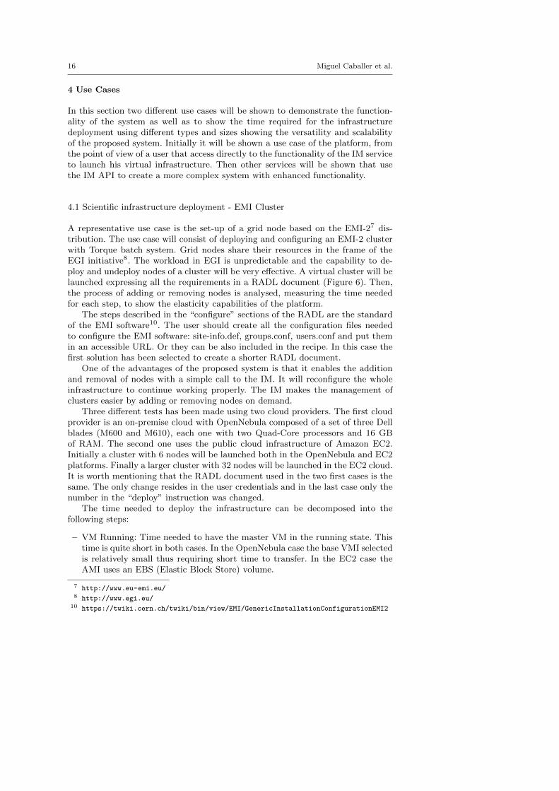
Table 2 shows the time needed in each individual step and Figure 7 depicts theaccumulated time needed to perform all the steps. The shown times are the aver-age values of three tests performed in each case. In the case of EC2 the measuresobtained slightly change for the different experiments and only depend on thenetwork performance with the different software repositories used. In the Open-Nebula one, as a small Cloud platform the are many factors as the number ofVMs launched, the overload on the network or the disks of the physical nodesetc. As shown in the results the average time needed to have a small or mediumsized fully functional EMI-2 cluster is about 20 or 30 minutes and the most timeconsuming step is the configuration since the EMI software has to install a largelist of packages in every node. The time needed to add a new node is slightly loweras only one machine must be totally configured and the other nodes just need toadd the new one to the configuration. Finally, the node removal is the quickest
Dynamic management of virtual infrastructures 19
0:00:00
0:07:12
0:14:24
0:21:36
0:28:48
0:36:00
0:43:12
VM Running VM Accesible Ansible Configured System Configured
6-Nodes (ONE) 6 Nodes (EC2) 32 nodes (EC2)
Fig. 7 Virtual Infrastructure Creation Times
operation since terminating a VM can be done very quickly and it only needs toremove the node from the configuration of the other nodes.
In this last use case, the time needed to add a node to the virtual infrastructureis reasonably long. In this case the system uses a basic Scientific Linux image asVMI, so the contextualization process must install a large number of packages.This is not a limitation of the IM since this use case fits many scenarios (dedicatednodes for specific experiments, maintenance interventions, training infrastructures,development environments, software verification, etc.). If deployment time is anissue (e.g. dealing with an unpredicted workload), the configuration process couldbe reduced by using a pre-configured VMI with some (or most) of the softwarerequirements.
4.2 Higher level services - EC3
In the EC3 work [9] the IM is used in conjunction with a energy managementsoftware for clusters called CLUES [2] to enable the deployment of elastic clusterson cloud platforms.
In this case it is used the IM functionality to launch virtual infrastructures oncloud providers and the management of the cluster sizes automatically on demandprovided by CLUES.
CLUES and the IM interact at two levels: First in the initial launch of thefront-end VM of the elastic cluster. In this step the EC3 launcher starts an IMthat becomes responsible of deploying the cluster front-end. This is done by meansof the following steps:
1. Selecting the VMI for the front-end. The IM can take a particular user-specifiedVMI, or it can contact the VMRC to choose the most appropriate VMI avail-able, considering the requirements specified in the RADL.
2. Choosing the cloud provider according to the specification of the user (if thereare different providers).
3. Submitting an instance of the corresponding VMI and, once it is available,installing and configuring all the required software that is not already prein-stalled in the VM: The Local Resource Management System (LRMS) selectedby the user and CLUES configured to use this LRMS and the IM to managethe virtual nodes.

20 Miguel Caballer et al.
One of the main LRMS configuration steps is to set up the names of the clusternodes. This is done using a sysadmin-specified name pattern (e.g. vnode-*) sothat the LRMS considers a set of nodes such as vnode-1, vnode-2... vnode-n, where n is the maximum cluster size. This procedure results in a fullyoperational elastic cluster.
In the second level CLUES internally uses an IM to submit the VMs that willbe used as working nodes for the cluster. For that, it uses a RADL documentdefined by the sysadmin, where the features of the working nodes are specified.Once these nodes are available, they are automatically integrated in the cluster asnew available nodes for the LRMS. Thus, the process to deploy the working nodesis similar to the one employed to deploy the front-end.
Notice that the ability to dynamically deploy, configure, monitor and re-configurevirtual infrastructures at runtime paves the way for a simplified usage of Cloudresources for different computational activities.
5 Conclusion and Future Work
This paper shows a platform for the dynamic management of virtual infrastruc-tures. The platform developed considers all the aspects related to the creation andmanagement of virtual infrastructures: the expression of the user requirements us-ing the RADL language, the deployment of the VMs on the desired platform andall the configuration (and reconfiguration) tasks to make the infrastructure workproperly.
One of the main goals of this platform is to enable the users to reuse theexisting VMIs created by themselves or by other users, thus avoiding the workof creating new VMIs for each application to be launched in cloud environments.For this purpose it has been used a catalog system to index the VMIs with all therelevant metadata, including the list of software installed. This is combined witha contextualization process, which enables the installation and configuration of allthe user requirements. This combination enables to contextualize in run-time allthe required applications where the installation and configuration process can bedone automatically in a reasonable time, and in the other cases have a preparedVMI correctly registered in the catalog with the application with the complexinstallation produce make by hand.
Another important feature is the possibility to access different cloud providers.For this reason, a modular system has been developed to interact with both publicand on-premise cloud providers. It enables the management of virtual infrastruc-tures in the same way as using any underling platform. Therefore, a user can definean RADL and test it in a local virtualization platform or a private cloud, and thenwithout any modification deploy a replica of the same infrastructure using a publiccloud platform.
The elasticity management, as one of the key features of the cloud infrastruc-tures, is also supported by the platform. Not only horizontal elasticity, by addingor removing VMs to an infrastructure, but also the vertical one adapting the VMcapacities to the application requirements (by dynamic changing the VM memorysize).
Some use cases have been shown to demonstrate the functionality of the plat-form using two different environments (Amazon EC2 and OpenNebula). The first

Dynamic management of virtual infrastructures 21
case study describes using the IM to launch an EMI-2 cluster with Torque. Thesecond one shows the integration of the IM in another software layer (EC3) toelastically manage the size of a virtual cluster.
The IM relies on network connectivity to access all the components involved inthe virtual infrastructure deployment: cloud provider, VMs, software repositories,etc. In case of network failures some of the steps of the infrastructure deploymentcould fail. If the error is produced in the deployment step, the IM will retry it anumber of times (configurable), but if the error is produced in the contextualizationstep, it will fail. In this case the IM will notify about the error, and the user orhigher level software will be able to capture it and use the IM recontextualizationfunction to start again the configuration process. Given that Ansible providesidempotent functionality, only the steps that have failed will be made.
Future works will include the development of new plug-ins in the Cloud Con-nector layer to access more cloud providers such as Microsoft Azure or GoogleCompute, and to integrate other aggregation libraries as a gateway to additionalCloud systems. Recently, Amazon has presented a new service called OpsWorks(in beta version at the time of the work of this article) that provides a similarfunctionality to the IM, which could be analysed once it becomes stable. Anotherinteresting issue is the selection of the “best” cloud provider. In this area furtherresearch is required to enable cloud-bursting and to include performance/priceratios or similar criteria.
Acknowledgements The authors would like to thank to thank the financial support receivedfrom the Ministerio de Economıa y Competitividad for the project CodeCloud (TIN2010-17804).
References
1. de Alfonso, C., Caballer, M., Alvarruiz, F., Molto, G., Hernandez, V.: Infrastructure De-ployment Over the Cloud. In: 2011 IEEE Third International Conference on Cloud Com-puting Technology and Science, pp. 517–521. IEEE (2011). DOI 10.1109/CloudCom.2011.77
2. Alvarruiz, F., De Alfonso, C., Caballer, M., Hernandez, V.: An Energy Manager for HighPerformance Computer Clusters. In: 2012 IEEE 10th International Symposium on Paralleland Distributed Processing with Applications, pp. 231–238 (2012). DOI 10.1109/ISPA.2012.38
3. Amazon Web Services: AWS CloudFormation (2013). URL http://aws.amazon.com/es/cloudformation/
4. Apache: Whirr (2013). URL http://whirr.apache.org/
5. Blanquer, I., Brasche, G., Lezzi, D.: Requirements of scientific applications in Cloud offer-ings. In: Proceedings of the 2012 Sixth Iberian Grid Infrastructure Conference, IBERGRID’12, pp. 173–182 (2012)
6. Bresnahan, J., Freeman, T., LaBissoniere, D., Keahey, K.: Managing appliance launches ininfrastructure clouds. In: Proceedings of the 2011 TeraGrid Conference: Extreme DigitalDiscovery, TG ’11, pp. 12:1—-12:7. ACM, New York, NY, USA (2011). DOI 10.1145/2016741.2016755
7. Buyya, R., Ranjan, R., Calheiros, R.N.: InterCloud: Utility-Oriented Federation of CloudComputing Environments for Scaling of Application Services. Algorithms and Architec-tures for Parallel Processing 6081, 20 (2010)
8. Buyya, R., Yeo, C.S., Venugopal, S., Broberg, J., Brandic, I.: Cloud computing and emerg-ing IT platforms: Vision, hype, and reality for delivering computing as the 5th utility.Future Generation Computer Systems 25(6), 599–616 (2009). DOI 10.1016/j.future.2008.12.001
22 Miguel Caballer et al.
9. Caballer, M., De Alfonso, C., Alvarruiz, F., Molto, G.: EC3: Elastic Cloud ComputingCluster. Journal of Computer and System Sciences (2013). DOI 10.1016/j.jcss.2013.06.005
10. Caballer, M., Garcıa, A., Molto, G., de Alfonso, C.: Towards SLA-driven Management ofCloud Infrastructures to Elastically Execute Scientific Applications. In: 6th Iberian GridInfrastructure Conference (IberGrid), pp. 207–218 (2012)
11. Carrion, J.V., Molto, G., De Alfonso, C., Caballer, M., Hernandez, V.: A Generic Catalogand Repository Service for Virtual Machine Images. In: 2nd International ICST Conferenceon Cloud Computing CloudComp 2010 (2010)
12. Cuomo, A., Modica, G., Distefano, S., Puliafito, A., Rak, M., Tomarchio, O., Venticinque,S., Villano, U.: An SLA-based Broker for Cloud Infrastructures. Journal of Grid Comput-ing 11(1), 1–25 (2012). DOI 10.1007/s10723-012-9241-4
13. DeHaan, M.: Ansible (2013). URL http://ansible.cc/
14. Distributed Management Task Force, Inc: Open Virtualization Format (OVF) (2010). URLhttp://dmtf.org/sites/default/files/standards/documents/DSP0243_1.1.0.pdf
15. Distributed Management Task Force, Inc: Cloud Infrastructure Management Interface(CIMI) Model and REST Interface over HTTP Specification (2012). URL http://dmtf.org/sites/default/files/standards/documents/DSP0263_1.0.1.pdf
16. EGI.eu: Seeking new horizons: EGI’s role for 2020. Tech. rep. (2012). URLhttps://documents.egi.eu/public/RetrieveFile?docid=1098\&version=4\&filename=EGI-1098-D230-final.pdf
17. Elmroth, E., Tordsson, J., Hernandez, F.: Self-management challenges for multi-cloudarchitectures. Towards a Service-Based Internet. Lecture Notes in Computer Science 6994,38–49 (2011)
18. HashiCorp: Vagrant (2013). URL http://www.vagrantup.com/
19. Jacob, A.: Infrastructure in the cloud era. In: Proceedings of the 2009 International OReillyConference Velocity (2009)
20. Juve, G., Deelman, E.: Automating Application Deployment in Infrastructure Clouds. In:Proceedings of the 2011 IEEE Third International Conference on Cloud Computing Tech-nology and Science, CLOUDCOM ’11, pp. 658–665. IEEE Computer Society, Washington,DC, USA (2011). DOI 10.1109/CloudCom.2011.102
21. Keahey, K., Freeman, T.: Contextualization: Providing One-Click Virtual Clusters. In:Fourth IEEE International Conference on eScience, pp. 301–308 (2008)
22. Keahey, K., Freeman, T.: Architecting a Large-Scale Elastic Environment: Recontextual-ization and Adaptive Cloud Services for Scientific Computing (2012)
23. Kecskemeti, G., Kertesz, A., Marosi, A., Kacsuk, P.: Interoperable Resource Managementfor establishing Federated Clouds. In: Achieving Federated and SelfManageable CloudInfrastructures Theory and Practice, pp. 18–35 (2012). DOI 10.4018/978-1-4666-1631-8.ch002
24. Kertesz, A., Kecskemeti, G., Oriol, M., Kotcauer, P., Acs, S., Rodrıguez, M., Merce, O.,Marosi, A.C., Marco, J., Franch, X.: Enhancing Federated Cloud Management with anIntegrated Service Monitoring Approach. Journal of Grid Computing 11(4), 699–720(2013). DOI 10.1007/s10723-013-9269-0
25. Loutas, N., Kamateri, E., Bosi, F., Tarabanis, K.: Cloud Computing Interoperability: TheState of Play. 2011 IEEE Third International Conference on Cloud Computing Technologyand Science pp. 752–757 (2011). DOI 10.1109/CloudCom.2011.116
26. Marshall, P., Keahey, K., Freeman, T.: Elastic Site: Using Clouds to Elastically ExtendSite Resources. In: Proceedings of the 2010 IEEE/ACM 10th International Conference onCluster, Cloud and Grid Computing, CCGRID ’10, pp. 43–52. IEEE Computer Society,Washington, DC, USA (2010). DOI 10.1109/CCGRID.2010.80
27. Massie, M.L., Chun, B.N., Culler, D.E.: The ganglia distributed monitoring system: design,implementation, and experience. Parallel Computing 30(5-6), 817–840 (2004)
28. Mell, P., Grance, T.: The NIST Definition of Cloud Computing. NIST Special Publication800-145 (Final). Tech. rep. (2011). URL http://csrc.nist.gov/publications/nistpubs/800-145/SP800-145.pdf
29. Molto, G., Caballer, M., Romero, E., Alfonso, C.D.: Elastic Memory Management of Virtu-alized Infrastructures for Applications with Dynamic Memory Requirements. In: Proceed-ings of the International Conference on Computational Science ICCS 2013, pp. 159–168.Elsevier (2013). DOI 10.1016/j.procs.2013.05.179
30. Morfeo: Claudia (2013). URL http://claudia.morfeo-project.org/wiki/index.php/Main_Page

Dynamic management of virtual infrastructures 23
31. OASIS: Topology and Orchestration Specification for Cloud Applications Version 1.0(2013). URL http://docs.oasis-open.org/tosca/TOSCA/v1.0/TOSCA-v1.0.html
32. OCCI working group within the Open Grid Forum: Open Cloud Computing InterfaceInfrastructure (2011). URL http://ogf.org/documents/GFD.184.pdf
33. Opscode: Chef (2013). URL http://www.opscode.com/chef/34. Pawluk, P., Simmons, B., Smit, M., Litoiu, M., Mankovski, S.: Introducing STRATOS: A
Cloud Broker Service. In: 2012 IEEE Fifth International Conference on Cloud Computing,pp. 891–898 (2012). DOI 10.1109/CLOUD.2012.24
35. Puppet Labs: IT Automation Software for System Administrators (2013). URL http://www.puppetlabs.com/
36. Redl, C., Breskovic, I., Brandic, I., Dustdar, S.: Automatic SLA Matching and ProviderSelection in Grid and Cloud Computing Markets. In: Proceedings of the 2012 ACM/IEEE13th International Conference on Grid Computing, GRID ’12, pp. 85–94. IEEE ComputerSociety, Washington, DC, USA (2012). DOI 10.1109/Grid.2012.18
37. Rodero-Merino, L., Vaquero, L.M., Gil, V., Galan, F., Fontan, J., Montero, R.S., Llorente,I.M.: From infrastructure delivery to service management in clouds. Future GenerationComputer Systems 26(8), 1226–1240 (2010). DOI 10.1016/j.future.2010.02.013
38. StratusLab: Claudia Platform (2013). URL http://stratuslab.eu/doku.php/claudia39. Sundareswaran, S., Squicciarini, A., Lin, D.: A Brokerage-Based Approach for Cloud Ser-
vice Selection. In: Proceedings of the 2012 IEEE 5th International Conference on CloudComputing, CLOUD ’12, pp. 558–565 (2012). DOI 10.1109/CLOUD.2012.119
40. Telefonica Investigacion y Desarrollo S.A. Unipersonal.: Telefonicas TCloud API Specifi-cation. (2010). URL http://www.tid.es/files/doc/apis/TCloud_API_Spec_v0.9.pdf
41. Yangui, S., Marshall, I.J., Laisne, J.P., Tata, S.: CompatibleOne: The Open Source CloudBroker. Journal of Grid Computing (2013). DOI 10.1007/s10723-013-9285-0