Dual-space adaptive control of redundantly actuated parallel manipulators for extremely fast...
8
Dual-Space Adaptive Control of Redundantly Actuated Cable-Driven Parallel Robots Johann Lamaury 1 , Marc Gouttefarde 1 , Ahmed Chemori 1 and Pierre- ´ Elie Herv´ e 1 Abstract— CDPR are efficient manipulators able to carry heavy payloads across large workspaces. Therefore, the dy- namic parameters such as the mobile platform mass and center of mass location may considerably vary. Without any adaption, the erroneous parametric estimate results in mismatch terms added to the closed-loop system, which may decrease the robot performances. In this paper, we introduce an adaptive dual-space motion control scheme for cable-driven parallel robots (CDPR). The proposed method aims at increasing the robot tracking performances, while keeping all the cable tensed despite uncertainties and changes in the robot dynamics parameters. Reel-time experimental tests, performed on a large redundantly actuated CDPR prototype, validate the efficiency of the proposed control scheme. These results are compared to those obtained with a non-adaptive dual-space feedforward control scheme. I. INTRODUCTION Cable-driven parallel robots (CDPR) consist of a mobile platform (end-effector) linked to a fixed base through flex- ible cables. The cable lengths are controlled by means of winches allowing the platform motion control. Cables can be unwound over great lengths such that large workspaces can be obtained. This latter characteristic together with the cable capability of carrying heavy payloads make CDPR particu- larly well adapted to perform large dimension manipulation or positioning tasks [1]–[4]. In order to drive the platform while controlling all its degrees of freedom (DOF) and to obtain large workspace to footprint ratios, redundant actuation can be used. Several papers proposed redundancy resolution schemes (tension distribution) [5]–[7] based on optimization methods. In order to fulfill practical real-time needs, a computationally efficient non-iterative algorithm for tension distribution (TD) was proposed in [8] based on the previous work of [9]. This algorithm works for redundantly actuated CDPR having two more actuators than DOF, i.e. m = n+2 where m is the cable number and n the number of DOF of the mobile platform. The proposed TD algorithm keeps the cable tension vector t ∈ R m between a non-negative minimum value t min ≥ 0 and a maximum value t max (generally induced by the mechanical design). If these constraints are satisfied, then t is said to be admissible. Note that the non-negativity condition on cable tensions is a key issue in CDPR control. Indeed, cables are flexible links that cannot push on the platform. Consequently, a control action in which a cable is 1 J. Lamaury, M. Gouttefarde, A. Chemori and Pierre- ´ Elie Herv´ e are with the Laboratory of Informatics, Robotics and Microelectronics of Montpellier (LIRMM-CNRS-UM2), 161 rue Ada, 34392 Montpellier Cedex 5, France, [email protected], [email protected], [email protected], [email protected] required to push on the platform (i.e. with negative tension) is not valid [6]. In this paper, we focus on motion control of a redundantly actuated CDPR where the cable tension constraint is ensured by the TD algorithm introduced in [8]. Compared to the vast literature on robot motion control, few studies deal with CDPR. Kawamura et al. proposed to use a proportional and derivative (PD) controller in joint space. Oh and Agrawal introduced a PD controller based on feedback linearization to asymptotically stabilize the system to the desired pose, taking into account the platform dynamics [6]. In order to compensate this dynamics, computed-torque-like controllers using corrective feedfor- ward terms were also studied. Fang et al. [3] applied a joint space feedforward controller to compensate the motor dynamics. Working in both joint and operational spaces, Vafaei et al. proposed in [10] an integrated controller with two feedforward terms. However, only the platform dynamics is compensated. In order to compensate wind disturbances applied to the cabin of their CDPR, Zi et al. designed a fuzzy proportional-integral controller [11]. In [12], we introduced a dual-space feedforward control scheme in operational space with two feedforward terms to compensate both the platform dynamics and the winch dynamicsand friction. In this paper, for performance comparison purposes, the control scheme of [12] is also considered, but with a joint space controller. The practical implementation of such feedforward control schemes, which are based on inverse dynamics, requires a good knowledge of the system dynamic parameters. Since some of them can be unknown or may vary during the execution of the task, these controllers can provide erroneous inputs, decreasing the tracking and regulation performances. In practice, these drawbacks were observed while experi- menting on the CoGiRo suspended CDPR shown in Fig. 2. Some parameter variations, specifically the payload mass, the position of the center of mass (COM) of the loaded mobile platform and uncertainties on the winch friction parameters can significantly affect the global performances of the closed- loop system. In order to handle such parametric uncertainties and vari- ability, adaptive control may be a good solution [13], [14]. Adaptive laws inspired from the controller in [15] have been successfully applied to Delta-like parallel robots [16] with online estimation of the mass of the payload and the arm and motor inertias). Besides, in [17], Kino et al. used adaptive compensation on a fully constrained CDPR in order to reduce errors on internal forces due to uncertainties in actuator positions. However, dynamic parameter uncertainties were not considered.
-
Upload
univ-montp2 -
Category
Documents
-
view
1 -
download
0
Transcript of Dual-space adaptive control of redundantly actuated parallel manipulators for extremely fast...
Dual-Space Adaptive Control of Redundantly Actuated Cable-Driven
Parallel Robots
Johann Lamaury1, Marc Gouttefarde1, Ahmed Chemori1 and Pierre-Elie Herve1
Abstract— CDPR are efficient manipulators able to carryheavy payloads across large workspaces. Therefore, the dy-namic parameters such as the mobile platform mass and centerof mass location may considerably vary. Without any adaption,the erroneous parametric estimate results in mismatch termsadded to the closed-loop system, which may decrease therobot performances. In this paper, we introduce an adaptivedual-space motion control scheme for cable-driven parallelrobots (CDPR). The proposed method aims at increasingthe robot tracking performances, while keeping all the cabletensed despite uncertainties and changes in the robot dynamicsparameters. Reel-time experimental tests, performed on a largeredundantly actuated CDPR prototype, validate the efficiencyof the proposed control scheme. These results are comparedto those obtained with a non-adaptive dual-space feedforwardcontrol scheme.
I. INTRODUCTION
Cable-driven parallel robots (CDPR) consist of a mobile
platform (end-effector) linked to a fixed base through flex-
ible cables. The cable lengths are controlled by means of
winches allowing the platform motion control. Cables can be
unwound over great lengths such that large workspaces can
be obtained. This latter characteristic together with the cable
capability of carrying heavy payloads make CDPR particu-
larly well adapted to perform large dimension manipulation
or positioning tasks [1]–[4].
In order to drive the platform while controlling all its
degrees of freedom (DOF) and to obtain large workspace
to footprint ratios, redundant actuation can be used. Several
papers proposed redundancy resolution schemes (tension
distribution) [5]–[7] based on optimization methods. In order
to fulfill practical real-time needs, a computationally efficient
non-iterative algorithm for tension distribution (TD) was
proposed in [8] based on the previous work of [9]. This
algorithm works for redundantly actuated CDPR having two
more actuators than DOF, i.e. m = n+2 where m is the cable
number and n the number of DOF of the mobile platform.
The proposed TD algorithm keeps the cable tension vector
t ∈ Rm between a non-negative minimum value tmin ≥
0 and a maximum value tmax (generally induced by the
mechanical design). If these constraints are satisfied, then
t is said to be admissible. Note that the non-negativity
condition on cable tensions is a key issue in CDPR control.
Indeed, cables are flexible links that cannot push on the
platform. Consequently, a control action in which a cable is
1J. Lamaury, M. Gouttefarde, A. Chemori and Pierre-Elie Herve arewith the Laboratory of Informatics, Robotics and Microelectronics ofMontpellier (LIRMM-CNRS-UM2), 161 rue Ada, 34392 Montpellier Cedex5, France, [email protected], [email protected],[email protected], [email protected]
required to push on the platform (i.e. with negative tension)
is not valid [6]. In this paper, we focus on motion control
of a redundantly actuated CDPR where the cable tension
constraint is ensured by the TD algorithm introduced in [8].
Compared to the vast literature on robot motion control,
few studies deal with CDPR. Kawamura et al. proposed
to use a proportional and derivative (PD) controller in
joint space. Oh and Agrawal introduced a PD controller
based on feedback linearization to asymptotically stabilize
the system to the desired pose, taking into account the
platform dynamics [6]. In order to compensate this dynamics,
computed-torque-like controllers using corrective feedfor-
ward terms were also studied. Fang et al. [3] applied a
joint space feedforward controller to compensate the motor
dynamics. Working in both joint and operational spaces,
Vafaei et al. proposed in [10] an integrated controller with
two feedforward terms. However, only the platform dynamics
is compensated. In order to compensate wind disturbances
applied to the cabin of their CDPR, Zi et al. designed a fuzzy
proportional-integral controller [11]. In [12], we introduced a
dual-space feedforward control scheme in operational space
with two feedforward terms to compensate both the platform
dynamics and the winch dynamicsand friction. In this paper,
for performance comparison purposes, the control scheme of
[12] is also considered, but with a joint space controller.
The practical implementation of such feedforward control
schemes, which are based on inverse dynamics, requires a
good knowledge of the system dynamic parameters. Since
some of them can be unknown or may vary during the
execution of the task, these controllers can provide erroneous
inputs, decreasing the tracking and regulation performances.
In practice, these drawbacks were observed while experi-
menting on the CoGiRo suspended CDPR shown in Fig. 2.
Some parameter variations, specifically the payload mass, the
position of the center of mass (COM) of the loaded mobile
platform and uncertainties on the winch friction parameters
can significantly affect the global performances of the closed-
loop system.
In order to handle such parametric uncertainties and vari-
ability, adaptive control may be a good solution [13], [14].
Adaptive laws inspired from the controller in [15] have been
successfully applied to Delta-like parallel robots [16] with
online estimation of the mass of the payload and the arm and
motor inertias). Besides, in [17], Kino et al. used adaptive
compensation on a fully constrained CDPR in order to reduce
errors on internal forces due to uncertainties in actuator
positions. However, dynamic parameter uncertainties were
not considered.

−50
5
−50
50
2
4
R0
x(m)
7
8
xb
65
zb
12
yb
43
y(m)
z(m
)
Fig. 1. Schematic view of the 8-cable CoGiRo configuration
The contribution of this paper is an adaptive dual-space
control scheme able to perform motion control of redun-
dantly actuated CDPR in presence of parameter uncertainties
and variability. Twenty-six parameters are estimated online,
namely the loaded (or unloaded) platform mass, the corre-
sponding COM location as well as inertia parameters and
the dry and viscous friction coefficients of the winches. The
proposed controller only requires the measurements of the
actuator rotational positions and speeds. The performances
of the proposed adaptive controller are shown through real-
time experimental results. The latter, obtained on the CoGiRo
suspended CDPR, are compared to those of the non-adaptive
dual-space feedforward controller introduced in [12] in order
to highlight the performance improvements.
This paper is organized as follows. The dynamic modeling
of CDPR is summarized in Section II. The dual-space feed-
forward control scheme is presented in Section III. Section IV
addresses the adaptive controller design while experimental
results are presented and discussed in Section V. Finally,
conclusions and future works are given in Section VI.
II. KINEMATIC AND DYNAMIC MODELING
A. Kinematics
This work aims at performing an accurate motion control
of 6-DOF suspended CDPR equipped with m actuators. The
mobile platform pose is defined by an operational space
vector xφ = [x y z φ θ ψ]T
=[
pT oT]T
∈ R6 (XYZ
Euler angle convention) which contains the position p and
orientation o of the platform frame ℜp = {P, xp, yp, zp }with respect to the robot base frame ℜb = {0, xb, yb, zb}.
P is the reference point of the platform.
The 3 × 3 rotation matrix Q which defines the platform
orientation is given by
Q(φ, θ, ψ) =
cθcψ −cθsψ sθcφsψ + sφsθcψ cφcψ − sφsθsψ −sφcθsφsψ − cφsθcψ sφcψ + cφsθsψ cφcθ
were cθ = cos(θ), sψ = sin(ψ) etc. The joint coor-
dinate vector of motor rotational positions, denoted q ={q1, q2, ..., qm} ∈ R
m, and its time derivative q are
assumed to be measured (by means of incremental encoders).
The relationship between the ith motor angle and the corre-
sponding unwound cable length li is written as follows:
li = ±riqi (1)
Fig. 2. The LIRMM/Tecnalia COGIRO suspended CDPR prototype
where ri accounts for the mechanical transmission reduction
ratio and the drum pitch radius of the ith winch. The rela-
tionship between the operational and joint space coordinates
(inverse kinematics) is as follows
li = ‖(p + Qbi − ai)‖ (2)
where ai and bi denote the base drawing point and platform
attachment point positions of the ith cable, respectively. The
time first derivative of (2) yields
l = Rq = Jx (3)
where x =[
pT
ωT]T
, ω being the mobile platform angular
velocity vector, l is the time-derivative of l = [l1 . . . lm] ∈Rm, J is the m× 6 Jacobian matrix of the CDPR and R is
the diagonal matrix such that diag(R) = {r1, r2, . . . , rm} ∈Rm. The relationship between ω and o, the first time
derivative of the vector of Euler angles, is given by
ω =
ω1
ω2
ω3
=
1 0 sθ0 cφ −sφcθ0 sφ cφcθ
φ
θ
ψ
= So (4)
By time differentiation, we also have ω = So+So. The time
differentiation of (3) yields
l = Rq = Jx + Jx (5)
The dynamics of a CDPR may be separated into the
dynamics of the mobile parts and the winches. The mobile
parts are composed of the mobile platform (equipped with
the crane fork in the case of CoGiRo robot shown in Fig.2)
and a possible payload.
B. Mobile platform and payload dynamics
Depending on the task at hand, e.g. if the CDPR performs
pick-and-place tasks, the mass, the COM location (called Gin the following) and the inertia parameters of the mobile
platform (loaded or unloaded) may vary. Consequently, Gmay not be coincident with P (G 6= P ), and the correspond-
ing displacement vector, expressed in the base frame ℜb, is
denoted by d =−−→PG = [u v w]
T. Under this assumption,
Newton-Euler equations of motion are expressed by
M(x)x + C(x, x)x = fg(x) + Wt (6)
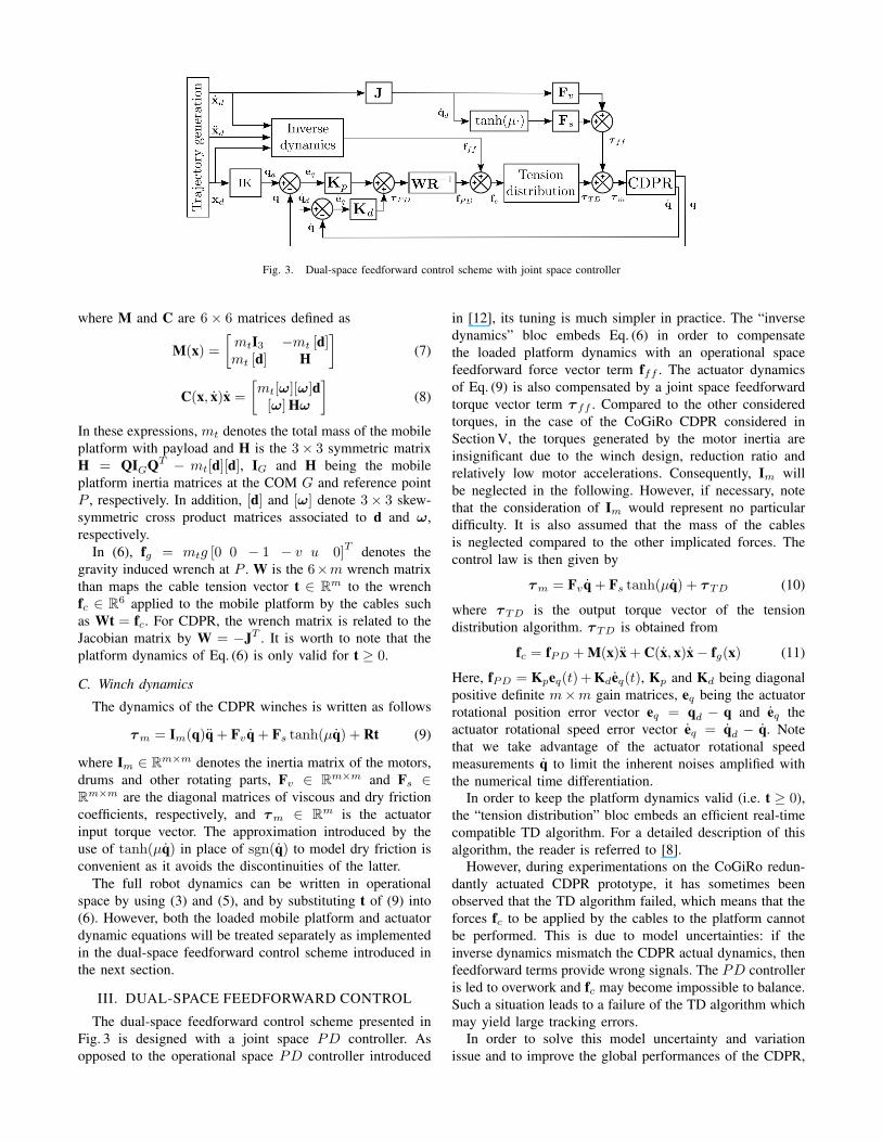
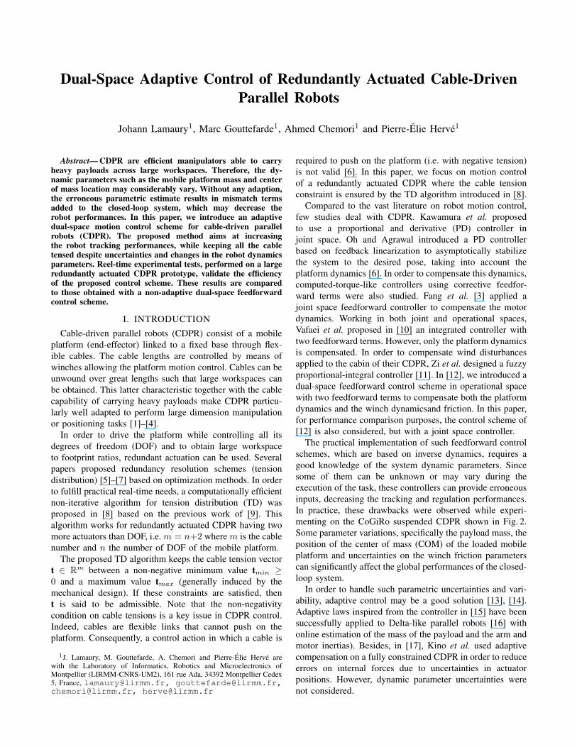
Fig. 3. Dual-space feedforward control scheme with joint space controller
where M and C are 6× 6 matrices defined as
M(x) =
[
mtI3 −mt [d]mt [d] H
]
(7)
C(x, x)x =
[
mt[ω][ω]d[ω]Hω
]
(8)
In these expressions, mt denotes the total mass of the mobile
platform with payload and H is the 3× 3 symmetric matrix
H = QIGQT − mt[d][d], IG and H being the mobile
platform inertia matrices at the COM G and reference point
P , respectively. In addition, [d] and [ω] denote 3× 3 skew-
symmetric cross product matrices associated to d and ω,
respectively.
In (6), fg = mtg [0 0 − 1 − v u 0]T
denotes the
gravity induced wrench at P . W is the 6×m wrench matrix
than maps the cable tension vector t ∈ Rm to the wrench
fc ∈ R6 applied to the mobile platform by the cables such
as Wt = fc. For CDPR, the wrench matrix is related to the
Jacobian matrix by W = −JT . It is worth to note that the
platform dynamics of Eq. (6) is only valid for t ≥ 0.
C. Winch dynamics
The dynamics of the CDPR winches is written as follows
τm = Im(q)q + Fvq + Fs tanh(µq) + Rt (9)
where Im ∈ Rm×m denotes the inertia matrix of the motors,
drums and other rotating parts, Fv ∈ Rm×m and Fs ∈
Rm×m are the diagonal matrices of viscous and dry friction
coefficients, respectively, and τm ∈ Rm is the actuator
input torque vector. The approximation introduced by the
use of tanh(µq) in place of sgn(q) to model dry friction is
convenient as it avoids the discontinuities of the latter.
The full robot dynamics can be written in operational
space by using (3) and (5), and by substituting t of (9) into
(6). However, both the loaded mobile platform and actuator
dynamic equations will be treated separately as implemented
in the dual-space feedforward control scheme introduced in
the next section.
III. DUAL-SPACE FEEDFORWARD CONTROL
The dual-space feedforward control scheme presented in
Fig. 3 is designed with a joint space PD controller. As
opposed to the operational space PD controller introduced
in [12], its tuning is much simpler in practice. The “inverse
dynamics” bloc embeds Eq. (6) in order to compensate
the loaded platform dynamics with an operational space
feedforward force vector term fff . The actuator dynamics
of Eq. (9) is also compensated by a joint space feedforward
torque vector term τ ff . Compared to the other considered
torques, in the case of the CoGiRo CDPR considered in
Section V, the torques generated by the motor inertia are
insignificant due to the winch design, reduction ratio and
relatively low motor accelerations. Consequently, Im will
be neglected in the following. However, if necessary, note
that the consideration of Im would represent no particular
difficulty. It is also assumed that the mass of the cables
is neglected compared to the other implicated forces. The
control law is then given by
τm = Fvq + Fs tanh(µq) + τTD (10)
where τTD is the output torque vector of the tension
distribution algorithm. τTD is obtained from
fc = fPD + M(x)x + C(x, x)x − fg(x) (11)
Here, fPD = Kpeq(t)+Kdeq(t), Kp and Kd being diagonal
positive definite m×m gain matrices, eq being the actuator
rotational position error vector eq = qd − q and eq the
actuator rotational speed error vector eq = qd − q. Note
that we take advantage of the actuator rotational speed
measurements q to limit the inherent noises amplified with
the numerical time differentiation.
In order to keep the platform dynamics valid (i.e. t ≥ 0),
the “tension distribution” bloc embeds an efficient real-time
compatible TD algorithm. For a detailed description of this
algorithm, the reader is referred to [8].
However, during experimentations on the CoGiRo redun-
dantly actuated CDPR prototype, it has sometimes been
observed that the TD algorithm failed, which means that the
forces fc to be applied by the cables to the platform cannot
be performed. This is due to model uncertainties: if the
inverse dynamics mismatch the CDPR actual dynamics, then
feedforward terms provide wrong signals. The PD controller
is led to overwork and fc may become impossible to balance.
Such a situation leads to a failure of the TD algorithm which
may yield large tracking errors.
In order to solve this model uncertainty and variation
issue and to improve the global performances of the CDPR,
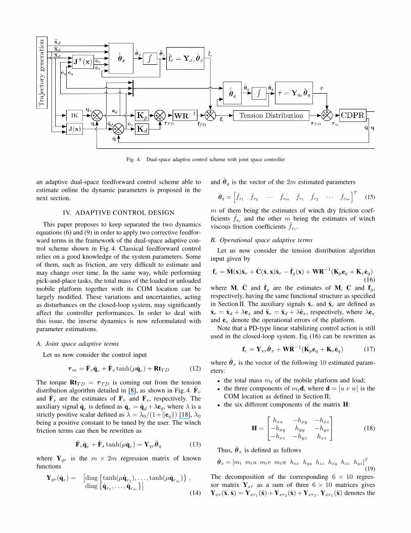
Fig. 4. Dual-space adaptive control scheme with joint space controller
an adaptive dual-space feedforward control scheme able to
estimate online the dynamic parameters is proposed in the
next section.
IV. ADAPTIVE CONTROL DESIGN
This paper proposes to keep separated the two dynamics
equations (6) and (9) in order to apply two corrective feedfor-
ward terms in the framework of the dual-space adaptive con-
trol scheme shown in Fig. 4. Classical feedforward control
relies on a good knowledge of the system parameters. Some
of them, such as friction, are very difficult to estimate and
may change over time. In the same way, while performing
pick-and-place tasks, the total mass of the loaded or unloaded
mobile platform together with its COM location can be
largely modified. These variations and uncertainties, acting
as disturbances on the closed-loop system, may significantly
affect the controller performances. In order to deal with
this issue, the inverse dynamics is now reformulated with
parameter estimations.
A. Joint space adaptive terms
Let us now consider the control input
τm = Fvqr + Fs tanh(µqr) + RtTD (12)
The torque RtTD = τTD is coming out from the tension
distribution algorithm detailed in [8], as shown in Fig. 4. Fvand Fs are the estimates of Fv and Fs, respectively. The
auxiliary signal qr is defined as qr = qd+λeq , where λ is a
strictly positive scalar defined as λ = λ0/(1+‖eq‖) [18], λ0being a positive constant to be tuned by the user. The winch
friction terms can then be rewritten as
Fvqr + Fs tanh(µqr) = Yqrθq (13)
where Yqr is the m × 2m regression matrix of known
functions
Yqr(qr) =[
diag{
tanh(µqr1), . . . , tanh(µqrm)}
,diag
{
qr1 , . . . , qrm}]
(14)
and θq is the vector of the 2m estimated parameters
θq =[
fs1 fs2 · · · fsm fv1 fv2 · · · fvm
]T
(15)
m of them being the estimates of winch dry friction coef-
ficients fsi and the other m being the estimates of winch
viscous friction coefficients fvi .
B. Operational space adaptive terms
Let us now consider the tension distribution algorithm
input given by
fc = M(x)xr + C(x, x)xr − fg(x) + WR−1(Kpeq + Kv eq)(16)
where M, C and fg are the estimates of M, C and fg ,
respectively, having the same functional structure as specified
in Section II. The auxiliary signals xr and xr are defined as
xr = xd + λex and xr = xd + λex, respectively, where λexand ex denote the operational errors of the platform.
Note that a PD-type linear stabilizing control action is still
used in the closed-loop system. Eq. (16) can be rewritten as
fc = Yxrθx + WR−1(Kpeq + Kv eq) (17)
where θx is the vector of the following 10 estimated param-
eters:
• the total mass mt of the mobile platform and load;
• the three components of mtd, where d = [u v w] is the
COM location as defined in Section II;
• the six different components of the matrix H:
H =
hxx −hxy −hxz−hxy hyy −hyz−hxz −hyz hzz
(18)
Thus, θx is defined as follows
θx = [mt mtu mtv mtw hxx hyy hzz hxy hxz hyz]T
(19)
The decomposition of the corresponding 6 × 10 regres-
sor matrix Yxr as a sum of three 6 × 10 matrices gives
Yxr(x, x) = Yxr1(x)+Yxr2(x)+Yxr3 . Yxr1(x) denotes the
known functions composing the expression of acceleration
forces. It has the following structure
Yxr1(x) =
[
p [ω] 03×3 03×3
03×1 − [p] diag(ω) E
]
(20)
where
E =
−ω2 −ω3 0−ω1 0 −ω3
0 −ω1 −ω2
(21)
The expression of Yx2(x), the matrix of known functions of
the centrifugal and Coriolis forces, takes the following form
Yx2(x) =
[
03×1 A(ω) 03×6
03×1 03×3 B(ω)
]
(22)
where A is the following 3× 3 symmetric matrix
A =
[
−(ω2
2+ω2
3) ω2
1ω2
2ω2
1ω2
3
ω2
1ω2
2−(ω2
1+ω2
3) ω2
2ω2
3
ω2
1ω2
3ω2
2ω2
3−(ω2
1+ω2
3)
]
(23)
and B is a 3× 6 matrix
B =
[
0 −ω2ω3 ω2ω3 ω1ω3 −ω1ω2 (ω2
3−ω2
2)ω1ω3 0 −ω1ω3 −ω2ω3 (ω2
1−ω2
3) ω1ω2
−ω1ω2 ω1ω2 0 (ω2
2−ω2
1) ω2ω3 −ω1ω3
]
(24)
The last matrix Yx3denotes the known functions of the
gravity action
Yx3=
02×3 02×7
G 03×7
01×3 01×7
, G =
g 0 00 0 g0 −g 0
(25)
C. Adaptive laws
The two chosen adaptive laws use the projection algorithm
of Khalil [15]. The first one defines the updating of the 2mjoint space parameters
˙θqi =
γqiφqiif
aqi < θqi < bqi or
θqi ≥ bqi & φqi≤ 0 or
θqi ≤ aqi & φqi≥ 0
γqi
(
1 +bqi
−θqiδq
)
φqiif θqi ≥ bqi & φqi
≥ 0
γqi
(
1 +θqi
−aqiδq
)
φqiif θqi ≤ aqi & φqi
≤ 0
(26)
for i = 1 . . . 2m and where δq ≥ 0. Let us denote Γq =diag {γq1 , . . . , γq2m} the positive diagonal matrix of adaptive
gains in the joint space. aqi et bqi are the lower and upper
bounds on the ith parameter to be estimated, respectively.
Furthermore, φq = −YTqrsq , where sq is the joint space
combined error sq = eq + λeq , φqi being the ith component
of φq. Using (26), for all time t ≥ 0 and with aqi ≤ θqi(0) ≤bqi , then all estimated parameters are bounded such as aqi ≤θqi ≤ bqi . In the same way, the second adaptive law updating
the 10 operational space parameters is given by
˙θxj
=
γxjφxj
if
axj< θxj
< bxjor
θxj≥ bxj
& φxj≤ 0 or
θxj≤ axj
& φxj≥ 0
γxj
(
1 +bxj
−θxjδx
)
φxjif θxj
≥ bxj& φxj
≥ 0
γxj
(
1 +θxj
−axjδx
)
φxjif θxj
≤ axj& φxj
≤ 0
(27)
for j = 1 . . . 10 and where δx ≥ 0. Let us denote Γx =diag {γx1
, . . . , γx10} the positive diagonal matrix of adaptive
gains in the operational space. axjet bxj
are the lower
and upper bounds on the jth parameter to be estimated,
respectively. Furthermore, φx = −YTxrsx, where sx is the
operational space combined error sx = ex+λex = J+sq , φxj
being the jth component of φx. Again, using (26), ∀t ≥ 0and with axi
≤ θxi(0) ≤ bxi
, then all these parameters are
bounded such as axi≤ θxi
≤ bxi. All bounds, δ values,
adaption gains γ and λ0 must be defined by the user. The
proposed dual-space adaptive control scheme shown in Fig. 4
has been implemented in the CoGiRo CDPR control system.
Experimental results are given in the following section.
V. REAL-TIME EXPERIMENTAL RESULTS
A. CoGiRo prototype
The CoGiRo CDPR prototype shown in Fig. 2 has the
following main characteristics:
• 15m×11m×6m (L× l×h) overall dimensions with
a potential workspace of 677m3;
• Cubic mobile platform of side length 1m in suspended
configuration equipped with a crane fork. Its total mass
is about mp = 93 kg;
• 6 degrees of freedom (DOF) mobile platform;
• m = 8 actuators so that the prototype has 2 degrees of
actuation redundancy;
• At least 300 kg payload capability over all the
workspace and 500 kg as long as the platform is not
too closed to the workspace boundaries;
• tmin = 0N in order to respect the non-negativity con-
straint on cable tensions and tmax = 5000N according
to the maximum capabilities of the force sensors.
• The motor rotational positions and speeds are obtained
by means of incremental absolute encoders.
• The reference point P is located at the center of the
bottom face of the platform.
As shown in Fig. 1 and Fig. 2, CoGiRo is a suspended
CDPR since all the cable drawing points are located near
the top of the base frame. In contrast to fully constrained
CDPR for which there exists at least one mobile platform
pose having force-closure [19], gravity is here used to help
keeping the cables tensed.
This section reports some experimental results of the
implementation in ANSI C code in the control system of
CoGiRo CDPR of the control scheme proposed in Section IV
with a 2 kHz sampling frequency. The control system pro-
gramming interface is B&R Automation Studio.
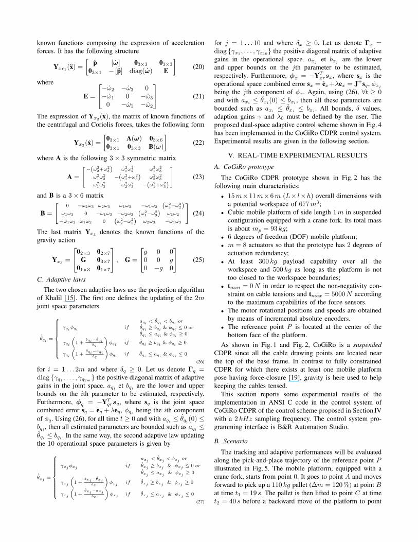
B. Scenario
The tracking and adaptive performances will be evaluated
along the pick-and-place trajectory of the reference point Pillustrated in Fig. 5. The mobile platform, equipped with a
crane fork, starts from point 0. It goes to point A and moves
forward to pick up a 110 kg pallet (∆m = 120%) at point Bat time t1 = 19 s. The pallet is then lifted to point C at time
t2 = 40 s before a backward move of the platform to point
−5
0
5
−4−3−2−101234
0
0.5
1
1.5
2
x [m]
y [m]
z [
m]
Fig. 5. Pick-and-place trajectory performing a 110 kg pallet lifting
D. In a last step, the mobile platform comes back to its initial
position 0. In this section, this pick-and-place task will be
firstly performed with a feedforward-free control scheme (i.e.
controller of Fig. 3 with fff = 0 and τ ff = 0), and secondly
using the dual-space feedforward control scheme shown in
Fig 3. Finally, the dual-space adaptive control scheme shown
in Fig. 4 is applied. The performances of the proposed control
schemes are quantified by comparison of the maximum value
ǫmax and root mean square (RMS) value ǫrms of both the
position tracking error (PTE) and orientation tracking error
(OTE) in the operational space.
Note that CoGiRo is here not equipped with external
measurement system able to provide the current operational
pose x and velocity x of the mobile platform. In order
to get the operational tracking errors ex and ex, the joint
tracking errors eq and eq are converted by means of the
pseudo-inverse of the Jacobian matrix. Indeed, from (3) we
write ex = J+Req . Furthermore, the sampling period being
small (∆t is equal to 0.5ms), we can write eq = q∆t and
ex = x∆t. Then, it is also possible to write ex = J+Req .
The paper is accompanied by a video, showing the Co-
GiRo CDPR performing this pick-and-place task via the
proposed adaptive control scheme.
0 10 20 30 40 50 60−0.04
−0.02
0
0.02
0.04
Time [s]
PT
E a
nd O
TE
[m] and [ra
d]
x y z φ θ ψ
0 10 20 30 40 50 60−0.1
−0.05
0
0.05
0.1
Time [s]
Velo
city e
rrors
[m/s
] and [ra
d/s
]
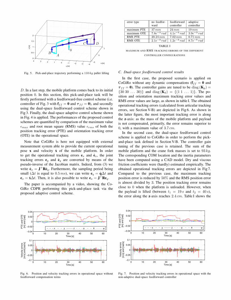
Fig. 6. Position and velocity tracking errors in operational space withoutfeedforward compensation terms
error type no feedfor-ward
feedforwardcontroller
adaptivecontroller
maximum PTE 37mm 24mm 19mm
maximum OTE 7.8e−3 rad 4.1e−3 rad 3.9e−3 rad
RMS PTE 20.24mm 7.02mm 0.71mm
RMS OTE 2.1e−3 rad 1.2e−3 rad 8.7e−5 rad
TABLE I
MAXIMUM AND RMS TRACKING ERRORS OF THE DIFFERENT
CONTROLLER CONFIGURATIONS
C. Dual-space feedforward control results
In the first case, the proposed scenario is applied on
CoGiRo without any dynamic compensations (fff = 0 and
τ ff = 0). The controller gains are tuned to be diag (Kp) ={30 30 . . . 30)} and diag (Kd) = {(1 1 . . . 1)}. The po-
sition and orientation maximum tracking error values and
RMS error values are large, as shown in table I. The obtained
operational tracking errors (calculated from articular tracking
errors, see Section V-B) are depicted in Fig 6. As shown in
the latter figure, the most important tracking error is along
the z-axis: as the mass of the mobile platform and payload
is not compensated, primarily, the error remains superior to
0, with a maximum value of 3.7 cm.
In the second case, the dual-space feedforward control
scheme is applied to CoGiRo in order to perform the pick-
and-place task defined in Section V-B. The controller gain
tuning of the previous case is retained. The sum of the
mobile platform and the crane fork masses is set to 93 kg.
The corresponding COM location and the inertia parameters
have been computed using a CAD model. Dry and viscous
friction coefficients were (hardly) estimated empirically. The
obtained operational tracking errors are depicted in Fig 7.
Compared to the previous case, the maximum tracking
position error is reduced by 50% and the RMS position error
is almost divided by 3. The position tracking error remains
close to 0 when the platform is unloaded. However, when
the payload is lifted (between t1 = 19 s and t2 = 40 s),the error along the z-axis reaches 2.4 cm. Table I shows the
0 10 20 30 40 50 60−0.04
−0.02
0
0.02
0.04
Time [s]
PT
E a
nd O
TE
[m] and [ra
d]
x y z φ θ ψ
0 10 20 30 40 50 60−0.1
−0.05
0
0.05
0.1
Time [s]
Velo
city e
rrors
[m/s
] and [ra
d/s
]
Fig. 7. Position and velocity tracking errors in operational space with thenon-adaptive dual-space feedforward controller
0 10 20 30 40 50 600
10
20
30
Time [s]
Co
ntr
ol in
pu
ts [
Nm
]
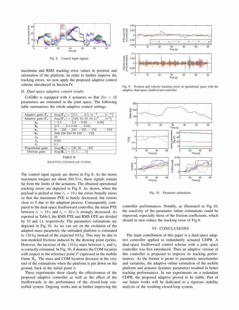
Fig. 8. Control input signals
maximum and RMS tracking error values in position and
orientation of the platform. In order to further improve the
tracking errors, we now apply the proposed adaptive control
scheme introduced in Section IV.
D. Dual-space adaptive control results
CoGiRo is equipped with 8 actuators so that 2m = 16parameters are estimated in the joint space. The following
table summarizes the whole adaptive control settings.
Adaptive gains Γq diag(Γq) ={
0.5, . . . , 0.5, 1e−4, . . . , 1e−4}
Adaptive gains Γx diag(Γx) ={
120, 10, 10, 10, 1e3 . . . , 1e3}
aq [−2.5 . . . − 2.5 − 0.02 . . . − 0.02]bq [2.5 . . . 2.5 0.02 . . . 0.02]ax [0 − 250 − 250 − 250 − 150 . . . − 150]bx [500 250 250 50 150 . . . 150]λ0 10δq 0.001δx 0.1
Proportional gains diag(Kp) = {30, 30, . . . , 30}Derivate gains diag(Kv) = {1, 1, . . . , 1}
TABLE II
ADAPTIVE CONTROLLER TUNING
The control input signals are shown in Fig. 8. As the motor
maximum torques are about 280Nm, these signals remain
far from the limits of the actuators. The obtained operational
tracking errors are depicted in Fig. 9. As shown, when the
payload is picked at time t1 = 19 s the errors brutally raises
so that the maximum PTE is barely decreased, but returns
close to 0 due to the adaption process. Consequently, com-
pared to the dual-space feedforward controller, the mean PTE
between t1 = 19 s and t2 = 50 s is strongly decreased. As
reported in Table I, the RMS PTE and RMS OTE are divided
by 10 and 14, respectively. The parameters estimations are
depicted in Fig. 10. As we can see on the evolution of the
adapted mass parameter, the unloaded platform is estimated
to 150 kg instead of the expected 93 kg. This may be due to
non-modeled frictions induced by the drawing point eyelets.
However, the increase of the 110 kg mass between t1 and t2is correctly estimated. In Fig. 10, δ denotes the COM location
with respect to the reference point P expressed in the mobile
frame ℜp. The mass and COM location decrease at the very
end of the estimations when the platform is put down on the
ground, back at the initial point 0.
These experiments show clearly the effectiveness of the
proposed adaptive controller as well as the effect of the
feedforwards in the performance of the closed-loop con-
trolled system. Ongoing works aim at further improving the
0 10 20 30 40 50 60−0.04
−0.02
0
0.02
0.04
Time [s]
PT
E a
nd O
TE
[m] and [ra
d]
x y z φ θ ψ
0 10 20 30 40 50 60−0.1
−0.05
0
0.05
0.1
Time [s]
Velo
city e
rrors
[m/s
] and [ra
d/s
]
Fig. 9. Position and velocity tracking errors in operational space with theadaptive dual-space feedforward controller
0 10 20 30 40 50 600
100
200
300
Time [s]M
ass [kg]
0 20 40 60−0.2
−0.1
0
0.1
Time [s]
δ [m
]
0 20 40 60
0
20
40
60
Time [s]
Inert
ia p
ara
mete
rs[k
g.m
²]
0 20 40 600
2
4
6
Time [s]
fs [N
m]
0 20 40 60
0
0.02
0.04
Time [s]
fv [N
ms/r
ad]
Fig. 10. Parameter estimations
controller performances. Notably, as illustrated in Fig. 10,
the reactivity of the parameter online estimations could be
improved, especially those of the friction coefficients, which
should in turn reduce the tracking error of Fig.9.
VI. CONCLUSIONS
The main contribution of this paper is a dual-space adap-
tive controller applied to redundantly actuated CDPR. A
dual-space feedforward control scheme with a joint space
controller was first introduced. Then an adaptive version of
this controller is proposed to improve its tracking perfor-
mances. As the former is prone to parametric uncertainties
and variations, the adaptive online estimation of the mobile
platform and actuator dynamic parameters resulted in better
tracking performances. In our experiments on a redundant
CDPR, the proposed adaptive proved to be stable. Part of
our future works will be dedicated to a rigorous stability
analysis of the resulting closed-loop system.
ACKNOWLEDGMENT
The financial support of the ANR (grant 2009 SEGI 018
01) and of the Region Languedoc-Roussillon (grants 115217
and 120218) are greatly acknowledged.
REFERENCES
[1] J. Albus, R. Bostelman, and N. Dagalakis, “The NIST Robocrane,”Jour. of Robotic Systems, vol. 10, no. 2, pp. 709–724, 1993.
[2] W.-J. Shiang, D. Cannon, and J. Gorman, “Optimal force distributionapplied to a robotic crane with flexible cables,” in IEEE Int. Conf. on
Robotics and Automation, San Francisco, CA, USA, 2000, pp. 1948–1954.
[3] S. Fang, D. Franitza, M. Torlo, F. Bekes, and M. Hiller, “MotionControl of a Tendon-Based Parallel Tension Distribution,” IEEE/ASME
Trans. on Mechatronics, vol. 9, no. 3, pp. 561–568, 2004.
[4] C. Lambert, M. Nahon, and D. Chalmers, “Implementation of an Aero-stat Positioning system with Cable Control,” Trans. on Mechatronics,vol. 12, no. 1, pp. 32–40, 2007.
[5] A. B. Alp and S. K. Agrawal, “Cable suspended robots: feedbackcontrollers with positive inputs,” in American Control Conference,Anchorage, Alaska, USA, 2002, pp. 815–820.
[6] S.-R. Oh and S. K. Agrawal, “Cable Suspended Planar Robots WithRedundant Cables : Controllers with Positive Tensions,” IEEE Trans.
on Robotics, vol. 21, no. 3, pp. 457–465, 2005.
[7] P. H. Borgstrom, B. L. Jordan, G. S. Sukhatme, M. A. Batalin, andW. J. Kaiser, “Rapid Computation of Optimally Safe Tension Distri-butions for Parallel Cable-Driven Robots,” IEEE Trans. on Robotics,vol. 25, no. 6, pp. 1271–1281, Dec. 2009.
[8] J. Lamaury and M. Gouttefarde, “A Tension Distribution Method withImproved Computational Efficiency,” in First Int. Conf. on Cable-
Driven Parallel Robots, T. Bruckmann and A. Pott, Eds., Stuttgart,Germany, 2012, pp. 71–85.
[9] L. Mikelsons, T. Bruckmann, M. Hiller, and D. Schramm, “A Real-Time Capable Force Calculation Algorithm for Redundant Tendon-Based Parallel Manipulators,” in IEEE Int. Conf. on Robotics and
Automation, Pasadena, CA, USA, May 2008.[10] A. Vafaei, M. M. Aref, and H. D. Taghirad, “Integrated Controller
For An Over Constrained Cable Driven Parallel Manipulator : KNTUCDRPM,” in IEEE Int. Conf. on Robotics and Automation, Anchorage,Alaska, USA, 2010.
[11] B. Zi, B. Duan, J. Du, and H. Bao, “Dynamic modeling and activecontrol of a cable-suspended parallel robot,” Mechatronics, vol. 18,no. 1, pp. 1–12, Feb. 2008.
[12] J. Lamaury and M. Gouttefarde, “Control of a Large RedondantlyActuated Cable-Suspended Parallel Robot,” in IEEE Int. Conf. on
Robotics and Automation (to appear), Karlsruhe, Germany, 2013.[13] J. J. Craig, P. Hsu, and S. S. Sastry, “Adaptative Control of Mechanical
Manipulators,” The Int. Jour. of Robotics Research, pp. 190–195, 1986.[14] J.-J. E. Slotine and W. Li, “On the Adaptive Control of Robot
Manipulators,” The Int. Jour. of Robotics Research, vol. 6, no. 3, pp.49–59, Sep. 1987.
[15] K. W. Lee and H. K. Khalil, “Adaptive output feedback control of robotmanipulators using high-gain observer,” Int. Jour. Control, vol. 67,no. 6, pp. 869–886, 1997.
[16] G. S. Natal, A. Chemori, and F. Pierrot, “Dual-Space Adaptive Controlof Redundantly Actuated Parallel Manipulators for Extremely FastOperations With Load Changes,” in IEEE Int. Conf. on Robotics and
Automation, Saint Paul, Minnesota, USA, 2012.[17] H. Kino, T. Yahiro, T. Fumiaki, and T. Morizono, “Robust PD Control
Using Adaptative Compensation for Completely Restrained Parallel-Wire Driven Robots,” in IEEE Trans. on Robotics, vol. 23, no. 4, 2007,pp. 803–812.
[18] H. Berghuis, R. Ortega, and H. Nijmeijer, “A Robust Adaptive RobotController,” IEEE Trans. on Robotics and Automation, vol. 9, no. 6,pp. 825–830, 1993.
[19] S. Kawamura, H. Kino, and C. Won, “High-speed manipulation byusing parallel wire-driven robots,” Robotica, vol. 18, pp. 13–21, 2000.