DSP for Coherent Single-Carrier Receivers
9
3614 JOURNAL OF LIGHTWAVE TECHNOLOGY, VOL. 27, NO. 16, AUGUST 15, 2009 DSP for Coherent Single-Carrier Receivers Maxim Kuschnerov, Student Member, IEEE, Fabian N. Hauske, Member, IEEE, Kittipong Piyawanno, Bernhard Spinnler, Mohammad S. Alfiad, Student Member, IEEE, Antonio Napoli, and Berthold Lankl, Member, IEEE Abstract—In this paper, we outline the design of signal pro- cessing (DSP) algorithms with blind estimation for 100-G coherent optical polarization-diversity receivers in single-carrier systems. As main degrading optical propagation effects, we considered chromatic dispersion (CD), polarization-mode dispersion (PMD), polarization-dependent loss (PDL), and cross-phase modulation (XPM). In the context of this work, we developed algorithms to increase the robustness of the single DSP receiver modules against the aforesaid propagation effects. In particular, we first present a new and fast algorithm to perform blind adaptive CD compensa- tion through frequency-domain equalization. This low complexity equalizer component inherits a highly precise estimation of residual dispersion independent from previous or subsequent blocks. Next, we introduce an original dispersion-tolerant timing recovery and illustrate the derivation of blind polarization demul- tiplexing, capable to operate also in condition of high PDL. At last, we propose an XPM-mitigating carrier phase recovery as an extension of the standard Viterbi–Viterbi algorithm. Index Terms—Blind adaptation, carrier phase recovery, coherent detection, digital receiver, equalization, fiber optic com- munication, timing recovery. I. INTRODUCTION D IGITAL SIGNAL PROCESSING (DSP) algorithms for blind coherent fiber optic receivers can be derived from their wireless communication counterparts. However, modifi- cations and further developments are necessary and inevitable considering the special nature of the fiber channel. Although the algorithms have to be as simple as possible to enable high-speed processing, the channel impulse response that can arise in the fiber channel differs from typical wireless systems and can be significantly longer. Since the variations in the fiber channel are very slow compared to the symbol rate, adaptation speed is of less concern, so that blind adaptation can be used. Chromatic dispersion (CD) is typically compensated for by a finite impulse response (FIR) butterfly structure [1]. In case of large accumulated CD in uncompensated links, the equal- ization of CD and PMD can be performed in two steps, first compensating for the static dispersion [2]. Here, the equalizer Manuscript received January 15, 2009; revised May 11, 2009. First published June 10, 2009; current version published July 24, 2009. M. Kuschnerov, K. Piyawanno, and B. Lankl are with the Univer- sity of the Federal Armed Forces, Munich, 85577 Neubiberg, Germany (e-mail: [email protected]; [email protected]; [email protected]). F. N. Hauske is on the leave from the University of the Federal Armed Forces, Munich, 85577 Neubiberg, Germany (e-mail: [email protected]). B. Spinnler and A. Napoli are with Nokia Siemens Networks, Munich 81379, Germany (e-mail: [email protected]; [email protected]). M. S. Alfiad is with COBRA institute, Eindhoven University of Technology, Eindhoven 5612AZ, The Netherlands (e-mail: m.s.alfi[email protected]). Digital Object Identifier 10.1109/JLT.2009.2024963 Fig. 1. Polarization-diversity coherent receiver front-end. usually cannot be properly adapted using standard adaptation algorithms due to the severity of the distortion. In various in- vestigations based on measured data, the filtering function for the CD compensation was either a priori known or no informa- tion on the blind adaptation scheme with an appropriate analysis was given [2]. Next, a correction of the timing frequency and phase offset is necessary before the FIR butterfly filter. Conventional timing recovery algorithms cited in [1] and [3] lack a high dispersion tolerance that is usually required in optically compensated sys- tems, thus creating a possible bottleneck in the receiver design. Contrary to wireless communication using polarization multiplexing [4], where the absolute signal polarization only slightly deviates from the original axes of the transmitter, the polarization evolution in typical fibers is arbitrary. Coherent receivers therefore require either a polarization control to align the signal and the local oscillator (LO), or polarization diversity reception, where the cross-polarization interference can be compensated for in the digital domain. Modifications to blind equalizer adaptation algorithms are required to achieve the demultiplexing of the two polarizations. Finally, XPM has been identified as the major limitation in the multichannel transmission of quaternary phase-shift keying (QPSK) over legacy systems with ON–OFF keying (OOK) neigh- bors [6], [7]. XPM can be mitigated in the carrier phase recovery averaging over only a small number of taps due to the rapid XPM-induced phase fluctuations [8]. This paper presents solution concepts for all of the above mentioned problems of DSP algorithm design, emphasizing the subcomponent interaction, and is structured as follows. Section II provides an overview on the coherent optical receiver, while Section III introduces the frequency-domain equalizer as the first component of the digital receiver and presents a blind CD estimation algorithm. Sections IV and V present the timing recovery and the blind polarization demultiplexing, respectively. Section VI deals with the XPM-mitigating carrier phase recovery. Finally, Section VII draws the conclusions. The digital signal processing principles will be mainly demonstrated on single-carrier polarization-multiplexed (PolMux) QPSK, 0733-8724/$25.00 © 2009 IEEE Authorized licensed use limited to: Eindhoven University of Technology. Downloaded on October 12, 2009 at 06:00 from IEEE Xplore. Restrictions apply.
-
Upload
independent -
Category
Documents
-
view
1 -
download
0
Transcript of DSP for Coherent Single-Carrier Receivers

3614 JOURNAL OF LIGHTWAVE TECHNOLOGY, VOL. 27, NO. 16, AUGUST 15, 2009
DSP for Coherent Single-Carrier ReceiversMaxim Kuschnerov, Student Member, IEEE, Fabian N. Hauske, Member, IEEE, Kittipong Piyawanno,
Bernhard Spinnler, Mohammad S. Alfiad, Student Member, IEEE, Antonio Napoli, andBerthold Lankl, Member, IEEE
Abstract—In this paper, we outline the design of signal pro-cessing (DSP) algorithms with blind estimation for 100-G coherentoptical polarization-diversity receivers in single-carrier systems.As main degrading optical propagation effects, we consideredchromatic dispersion (CD), polarization-mode dispersion (PMD),polarization-dependent loss (PDL), and cross-phase modulation(XPM). In the context of this work, we developed algorithms toincrease the robustness of the single DSP receiver modules againstthe aforesaid propagation effects. In particular, we first present anew and fast algorithm to perform blind adaptive CD compensa-tion through frequency-domain equalization. This low complexityequalizer component inherits a highly precise estimation ofresidual dispersion independent from previous or subsequentblocks. Next, we introduce an original dispersion-tolerant timingrecovery and illustrate the derivation of blind polarization demul-tiplexing, capable to operate also in condition of high PDL. Atlast, we propose an XPM-mitigating carrier phase recovery as anextension of the standard Viterbi–Viterbi algorithm.
Index Terms—Blind adaptation, carrier phase recovery,coherent detection, digital receiver, equalization, fiber optic com-munication, timing recovery.
I. INTRODUCTION
D IGITAL SIGNAL PROCESSING (DSP) algorithms forblind coherent fiber optic receivers can be derived from
their wireless communication counterparts. However, modifi-cations and further developments are necessary and inevitableconsidering the special nature of the fiber channel. Although thealgorithms have to be as simple as possible to enable high-speedprocessing, the channel impulse response that can arise in thefiber channel differs from typical wireless systems and can besignificantly longer. Since the variations in the fiber channel arevery slow compared to the symbol rate, adaptation speed is ofless concern, so that blind adaptation can be used.
Chromatic dispersion (CD) is typically compensated for bya finite impulse response (FIR) butterfly structure [1]. In caseof large accumulated CD in uncompensated links, the equal-ization of CD and PMD can be performed in two steps, firstcompensating for the static dispersion [2]. Here, the equalizer
Manuscript received January 15, 2009; revised May 11, 2009. First publishedJune 10, 2009; current version published July 24, 2009.
M. Kuschnerov, K. Piyawanno, and B. Lankl are with the Univer-sity of the Federal Armed Forces, Munich, 85577 Neubiberg, Germany(e-mail: [email protected]; [email protected];[email protected]).
F. N. Hauske is on the leave from the University of the Federal Armed Forces,Munich, 85577 Neubiberg, Germany (e-mail: [email protected]).
B. Spinnler and A. Napoli are with Nokia Siemens Networks, Munich 81379,Germany (e-mail: [email protected]; [email protected]).
M. S. Alfiad is with COBRA institute, Eindhoven University of Technology,Eindhoven 5612AZ, The Netherlands (e-mail: [email protected]).
Digital Object Identifier 10.1109/JLT.2009.2024963
Fig. 1. Polarization-diversity coherent receiver front-end.
usually cannot be properly adapted using standard adaptationalgorithms due to the severity of the distortion. In various in-vestigations based on measured data, the filtering function forthe CD compensation was either a priori known or no informa-tion on the blind adaptation scheme with an appropriate analysiswas given [2].
Next, a correction of the timing frequency and phase offsetis necessary before the FIR butterfly filter. Conventional timingrecovery algorithms cited in [1] and [3] lack a high dispersiontolerance that is usually required in optically compensated sys-tems, thus creating a possible bottleneck in the receiver design.
Contrary to wireless communication using polarizationmultiplexing [4], where the absolute signal polarization onlyslightly deviates from the original axes of the transmitter, thepolarization evolution in typical fibers is arbitrary. Coherentreceivers therefore require either a polarization control to alignthe signal and the local oscillator (LO), or polarization diversityreception, where the cross-polarization interference can becompensated for in the digital domain. Modifications to blindequalizer adaptation algorithms are required to achieve thedemultiplexing of the two polarizations.
Finally, XPM has been identified as the major limitation inthe multichannel transmission of quaternary phase-shift keying(QPSK) over legacy systems with ON–OFF keying (OOK) neigh-bors [6], [7]. XPM can be mitigated in the carrier phase recoveryaveraging over only a small number of taps due to the rapidXPM-induced phase fluctuations [8].
This paper presents solution concepts for all of the abovementioned problems of DSP algorithm design, emphasizingthe subcomponent interaction, and is structured as follows.Section II provides an overview on the coherent optical receiver,while Section III introduces the frequency-domain equalizeras the first component of the digital receiver and presents ablind CD estimation algorithm. Sections IV and V presentthe timing recovery and the blind polarization demultiplexing,respectively. Section VI deals with the XPM-mitigating carrierphase recovery. Finally, Section VII draws the conclusions. Thedigital signal processing principles will be mainly demonstratedon single-carrier polarization-multiplexed (PolMux) QPSK,
0733-8724/$25.00 © 2009 IEEE
Authorized licensed use limited to: Eindhoven University of Technology. Downloaded on October 12, 2009 at 06:00 from IEEE Xplore. Restrictions apply.
KUSCHNEROV et al.: DSP FOR COHERENT SINGLE-CARRIER RECEIVERS 3615
Fig. 2. Digital signal processing in a blind coherent digital receiver.
Fig. 3. Chromatic dispersion compensation using (a) time-domain filtering and (b) frequency-domain filtering.
although they can as well be applied to higher order modulationformats.
II. BLIND COHERENT RECEIVER DESIGN
A typical coherent receiver front-end employing polarizationdiversity is shown in Fig. 1 [1]. After a polarization-beamsplitter, the two orthogonal polarizations are mixed with alocal oscillator in two 90 optical hybrids and sampled inan analog-to-digital converter (ADC) after the automaticgain control (AGC). Depending on the distortion-tolerancerequirements, the ADC can sample with one or two samplesper symbol. While a twofold oversampling makes it possibleto fully equalize the signal, symbol-rate sampling can beemployed in lower complexity systems with a limited disper-sion tolerance [9]. The local oscillator can be controlled vialow-bandwidth feedback from the receiver to achieve a roughfrequency alignment, while a precise digital carrier frequencyacquisition continuously tracks the remaining frequency andphase offset in the electrical domain. Further digital signal pro-cessing is required in order to compensate for linear distortion,mitigate nonlinear transmission effects, and demultiplex bothpolarizations.
In the following, the signals in the four real-valued tributarieswill be described in complex vector notation form leading to
(1)
Here, , , is the complex symbol vector at the timeinstant consisting of one sample for Nyquist rate sam-pling or two samples for twofold oversampling.A typical blind receiver block diagram is shown in Fig. 2.
The receiver employs frequency-domain equalization (FDE)to compensate for the bulk of accumulated chromatic disper-
sion. Then, the signal is retimed, demultiplexed, and equalizedin a butterfly FIR filter. Finally, the constellation diagramis derotated in the carrier frequency and phase recovery.Throughout this paper, a 35-GHz, second-order optical Gaussfilter and a 19.6-GHz fifth-order electrical Bessel filter wereassumed.
III. DISPERSION COMPENSATION
A. Filter Design
Coherent transmission systems can be operated either onoptically compensated links with dispersion-compensatingfiber (DCF), or over fully uncompensated links with no DCFsin place. In the latter case, system installation can be made morecost-efficient and tolerant to nonlinearities [10]. If dispersioncompensation is performed in front of the timing recoveryand the other processing blocks in the receiver, the subse-quent algorithms can remain identical for compensated anduncompensated transmission with similar residual dispersionrequirements.
Dispersion can either be compensated using time-domain(TDE) [2] or frequency-domain equalization [11]. Fig. 3 showsthe equalizer structures for TDE and FDE equalization.
The filter choice between TDE and FDE mainly depends onthe maximum dispersion in the channel and the resulting filterlength. Fig. 4 compares the equalization complexity for 43- and112-Gb/s PolMux-QPSK receivers [11]. Here, a FIR butterflywith five taps (43 Gb/s) and nine taps (112 Gb/s) was assumed,in order to compensate for PMD and low-pass filtering. Thefilter length is set to a maximum of 1-dB required OSNR penaltyfor the given chromatic dispersion. While the CD compensatingfilters were assumed nonadaptive for the computation, the time-domain butterfly filter was adapted using the least-mean squarealgorithm (LMS) [12]. Fig. 4 shows that FDE achieves a break-
Authorized licensed use limited to: Eindhoven University of Technology. Downloaded on October 12, 2009 at 06:00 from IEEE Xplore. Restrictions apply.

3616 JOURNAL OF LIGHTWAVE TECHNOLOGY, VOL. 27, NO. 16, AUGUST 15, 2009
Fig. 4. Filtering complexity for 43- and 112-Gb/s PolMux-QPSK versus chro-matic dispersion [11].
TABLE ICOMPARISON OF DATA-AIDED AND BLIND ADAPTATION
even over TDE starting at 11 000 ps/nm in 40 G systems andat 2000 ps/nm in 100-G systems.
Another possibility for dispersion compensation is infiniteimpulse response (IIR) filtering, where the required tap numberis lower as for FIR filters [13]. However, the inherent feed-back of IIR equalizers makes this approach virtually impos-sible to implement in high-speed applications with parallelizedsignal processing. In the following, dispersion estimation willbe demonstrated on the example of FDE, although it can as wellbe applied to time-domain filters.
B. Dispersion Estimation
The receiver must be able to estimate the chromatic disper-sion at system startup and continuously monitor it during trans-mission. Ideally, the estimation is performed in the dispersion-compensating device, independently of the follow-up DSP, thusincreasing the startup speed of the receiver.
If the dispersion is to be estimated, one can distinguish be-tween data-aided and blind estimation algorithms. The pros andcons for each are listed in Table I.
In addition to these arguments, one has to add that there isonly one unknown parameter in the second-order approxima-tion of the chromatic dispersion transfer function, which can beanalytically described by
(2)
where is the transmission distance, is the dispersion param-eter, is the carrier wavelength, is the speed of light, and
Fig. 5. Minimum-search frequency-domain equalizer, identical for both polar-izations � � �� �.
TABLE IICOMPUTATION OF THE NORMALIZATION CONSTANTS � ���
is the angular frequency. Clearly, the equation, which de-scribes a parabolic phase transfer function, has only one degreeof freedom, so that a fully adaptive estimation is not justifiedunder these conditions.
In the following, a blind estimation algorithm first introducedin [14] will be presented that restricts the equalizer solutionsto the inverse of the dispersion transfer function from (2), thusstabilizing the equalizer convergence. The presented minimum-search algorithm is nondata aided and works prior to the timingrecovery. Given a minimum and a maximum dispersion in thechannel, predefined CD-values are loaded in the filter as shownon Fig. 5.
The proposed minimum search algorithm uses an error crite-rion that was derived from Godard’s CMA [15]. It employs acost function working on the twofold oversampled signal givenby
(3)
where are the normalization constants of the odd andthe even samples for , and is index of the fast Fouriertransform (FFT)-block. In order to account for the changingtiming phase due to the timing frequency offset between thetransmitter and receiver oscillators, the normalization constant
is determined separately for every FFT signal block.They are computed from the mean power for the odd and evensamples after equalization given by
(4)
where is the number of symbols equalized per eachFFT. Here, a simple case differentiation of the power ratio
for each FFT-block is sufficient to give optimumresults regardless of return-to-zero (RZ) or nonreturn-to-zero(NRZ) pulse shaping. It is given in Table II.
Authorized licensed use limited to: Eindhoven University of Technology. Downloaded on October 12, 2009 at 06:00 from IEEE Xplore. Restrictions apply.
KUSCHNEROV et al.: DSP FOR COHERENT SINGLE-CARRIER RECEIVERS 3617
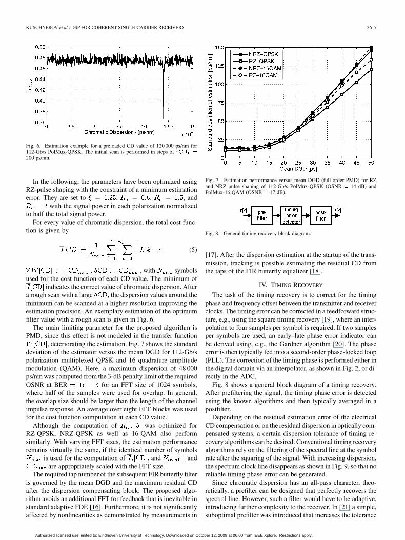
Fig. 6. Estimation example for a preloaded CD value of 120 000 ps/nm for112-Gb/s PolMux-QPSK. The initial scan is performed in steps of ��� �
200 ps/nm.
In the following, the parameters have been optimized usingRZ-pulse shaping with the constraint of a minimum estimationerror. They are set to , , , and
with the signal power in each polarization normalizedto half the total signal power.
For every value of chromatic dispersion, the total cost func-tion is given by
(5)
, with symbolsused for the cost function of each CD value. The minimum of
indicates the correct value of chromatic dispersion. Aftera rough scan with a large , the dispersion values around theminimum can be scanned at a higher resolution improving theestimation precision. An exemplary estimation of the optimumfilter value with a rough scan is given in Fig. 6.
The main limiting parameter for the proposed algorithm isPMD, since this effect is not modeled in the transfer function
, deteriorating the estimation. Fig. 7 shows the standarddeviation of the estimator versus the mean DGD for 112-Gb/spolarization multiplexed QPSK and 16 quadrature amplitudemodulation (QAM). Here, a maximum dispersion of 48 000ps/nm was computed from the 3-dB penalty limit of the requiredOSNR at BER for an FFT size of 1024 symbols,where half of the samples were used for overlap. In general,the overlap size should be larger than the length of the channelimpulse response. An average over eight FFT blocks was usedfor the cost function computation at each CD value.
Although the computation of was optimized forRZ-QPSK, NRZ-QPSK as well as 16-QAM also performsimilarly. With varying FFT sizes, the estimation performanceremains virtually the same, if the identical number of symbols
is used for the computation of , and andare appropriately scaled with the FFT size.
The required tap number of the subsequent FIR butterfly filteris governed by the mean DGD and the maximum residual CDafter the dispersion compensating block. The proposed algo-rithm avoids an additional FFT for feedback that is inevitable instandard adaptive FDE [16]. Furthermore, it is not significantlyaffected by nonlinearities as demonstrated by measurements in
Fig. 7. Estimation performance versus mean DGD (full-order PMD) for RZand NRZ pulse shaping of 112-Gb/s PolMux-QPSK (OSNR � 14 dB) andPolMux-16 QAM (OSNR � 17 dB).
Fig. 8. General timing recovery block diagram.
[17]. After the dispersion estimation at the startup of the trans-mission, tracking is possible estimating the residual CD fromthe taps of the FIR butterfly equalizer [18].
IV. TIMING RECOVERY
The task of the timing recovery is to correct for the timingphase and frequency offset between the transmitter and receiverclocks. The timing error can be corrected in a feedforward struc-ture, e.g., using the square timing recovery [19], where an inter-polation to four samples per symbol is required. If two samplesper symbols are used, an early–late phase error indicator canbe derived using, e.g., the Gardner algorithm [20]. The phaseerror is then typically fed into a second-order phase-locked loop(PLL). The correction of the timing phase is performed either inthe digital domain via an interpolator, as shown in Fig. 2, or di-rectly in the ADC.
Fig. 8 shows a general block diagram of a timing recovery.After prefiltering the signal, the timing phase error is detectedusing the known algorithms and then typically averaged in apostfilter.
Depending on the residual estimation error of the electricalCD compensation or on the residual dispersion in optically com-pensated systems, a certain dispersion tolerance of timing re-covery algorithms can be desired. Conventional timing recoveryalgorithms rely on the filtering of the spectral line at the symbolrate after the squaring of the signal. With increasing dispersion,the spectrum clock line disappears as shown in Fig. 9, so that noreliable timing phase error can be generated.
Since chromatic dispersion has an all-pass character, theo-retically, a prefilter can be designed that perfectly recovers thespectral line. However, such a filter would have to be adaptive,introducing further complexity to the receiver. In [21] a simple,suboptimal prefilter was introduced that increases the tolerance
Authorized licensed use limited to: Eindhoven University of Technology. Downloaded on October 12, 2009 at 06:00 from IEEE Xplore. Restrictions apply.

3618 JOURNAL OF LIGHTWAVE TECHNOLOGY, VOL. 27, NO. 16, AUGUST 15, 2009
Fig. 9. Spectrum of the absolute square of a 112-Gb/s PolMux-QPSK signalafter low-pass filtering for several values of chromatic dispersion. The spectralclock line is at 28 GHz.
Fig. 10. Absolute value of the prefilter transfer function � for severalfilter lengths � .
of the timing recovery up to arbitrary values of chromatic dis-persion. The filter is given by
(6)
where is the filter length index, isthe number of filtered symbols, and for twofold over-sampling. The resulting filter is a band-pass around the Nyquistfrequency. Increasing the filter length , the band-pass of thefilter can be decreased, thus lowering interfering beat terms atthe symbol rate after signal squaring. The filtering requires onlyadders and can be performed separately on the odd and evensamples of the signal with filter length to fur-ther reduce complexity, which will be assumed in the following.The transfer function value is shown in Fig. 10 for several real-izations of .
The minimum required length for the timing recovery pre-filter is defined by the signal spread due to chromatic disper-sion, similar to FIR filter length requirements for equalization.The dispersion tolerance of the timing recovery will be demon-strated using the timing detector presented in [21]. The perfor-mance of the histogram timing recovery can be verified againstthe modified Cramer–Rao bound (MCRB), which is the lowerbound on the normalized estimation variance and given by
(7)
Fig. 11. Estimator performance versus chromatic dispersion for various pre-filter lengths � , � � ����, and 112-Gb/s PolMux-QPSK at OSNR � 15dB.
with
(8)
for pulse-amplitude modulation, where is the symbol du-ration, is the averaging length of the postfilter, and isthe spectrum of the signal pulse shape. Fig. 11 shows the esti-mator variance versus chromatic dispersion for several prefilterlengths.
In a back-to-back configuration with zero dispersion andno prefiltering, the estimator performance is very close to theMCRB. The maximum dispersion that can be tolerated in thiscase is around 300 ps/nm. The dispersion tolerance requirementin optically compensated systems is usually higher, and in thecase that the previously presented electrical dispersion com-pensation was used, the estimation precision can deteriorate forhigh PMD. In order to remove the timing recovery bottleneck,the prefilter can be introduced, clearly increasing the dispersiontolerance a the cost of a back-to-back degradation. A similarperformance as in back-to-back configurations without pre-filtering can be achieved, if the averaging length of the filteris increased, thus lowering the overall response bandwidth.
V. BLIND POLARIZATION DEMULTIPLEXING
Polarization multiplexing in the fiber optic channel is a prin-ciple that has been used in radio transmission since the 1980s[4]. The optic channel is a special case of the more general mul-tiple-input–multiple-output (MIMO) systems, widely applied inspace-division multiplexing. Polarization demultiplexing is oneof the most interesting problems of coherent receiver design.
The CMA is a popular choice for approximate channel ac-quisition that can be followed by the LMS for tracking pur-poses. If no known training symbols are available at the receiver,translating the CMA from a single-input–single-output (SISO)channel to a 2 2 MIMO equalizer [26], as shown in Fig. 3,results in the possibility of the degenerate one-to-many outputproblem.
Authorized licensed use limited to: Eindhoven University of Technology. Downloaded on October 12, 2009 at 06:00 from IEEE Xplore. Restrictions apply.

KUSCHNEROV et al.: DSP FOR COHERENT SINGLE-CARRIER RECEIVERS 3619
Fig. 12. Comparison of the equalizer failure probability with a degenerate solu-tion for pure CMA/LMS and with an added constraint of a unitary PMD matrixversus PDL for 112-Gb/s PolMux-QPSK, �� � 1000 ps/nm and OSNR� 14dB. A 15-tap T/2 filter is used for equalization.
In [2] and [22], the PMD-matrix constraint was imposed onthe equalizer filter taps, using the unitary properties of the fiberchannel transfer function given by
(9)
with being the PMD transfer matrix with. Although this approach works well as long as the matrix
is unitary, once significant PDL is present in the channel, thetransfer function loses its previously described characterizationand the probability of a degenerate equalizer solution increasesas shown in Fig. 12, with the identical polarization appearing atboth outputs of the equalizer. Here, one can distinguish betweena best and a worst case in terms of performance, depending onthe input polarization into the PDL element at the beginning ofthe transmission [5]. For a given channel realization, the equal-izer converged using CMA/LMS with the constraint of (9). Inthe degenerate case of the same polarization at both equalizeroutputs, a convergence failure was counted. Since the degen-erate convergence is a random process that depends on the trans-mitted signal, noise, distortion, as well as the update speed of theequalizer, a convergence failure probability was evaluated overa sufficient number of trials.
Other solutions for the demultiplexing problem have beendemonstrated for one-tap filters only [23], or have not been fullycommented upon [5]. In [24], a semiblind approach is described,where one polarization is adapted blindly and the other one af-terwards with the help of the extracted training symbols fromthe first polarization, presumably using higher layer informa-tion bits. Introducing training symbols in all polarizations mightseem as the most elegant solution [25]. However, it comes at thecost of signal overhead, so that a fully blind approach might bepreferred for 100-G QPSK systems.
The problem of blind source separation based on the CMAhas been widely covered in wireless literature [27], [28]. Whilethe CMA is able to achieve optimal equalization using second-
Fig. 13. Required OSNR penalty versus PDL, at 1000-ps/nm CD, 30-ps meanDGD (full-order PMD), and 15 taps of a T/2-spaced butterfly FIR and 112-Gb/sPolMux-QPSK.
order statistics in combination with oversampling, MIMO sys-tems require higher order statistics [29], and independent-com-ponent analysis (ICA) in order to achieve blind source separa-tion, as introduced by [30] for fiber optic systems and one-tapfiltering. While [30] uses an ICA cost function different fromthe CMA or LMS, the source separation method described in[28] has the advantage that it can be added on top of the ex-isting CMA/LMS algorithms, thus leading to virtually identicalconvergence and tracking properties in most cases as standardCMA algorithms. It is given by
(10)where is the expectation value. Here is the cross-cor-relation function between polarization and defined as
(11)
and and are integers that depend on the channel delayspread. By minimizing the cross-correlation between the chan-nels, both sources can be separated in presence of PDL. Fig. 13evaluates the performance of the algorithm versus PDL for sim-ulations of 112-Gb/s PolMux-QPSK using a 15-tap T/2 fraction-ally spaced FIR butterfly with worst case distortions of1000 ps/nm and 30-ps mean DGD (full-order PMD). Even inthis case, where the channel memory length begins to exceedthe number of equalizer taps, the theoretical performance canapproximately be achieved for PDL ranging from 0 to 10 dB.
After initial convergence with the CMA, faster convergencecan be reached by switching to the LMS, especially if signifi-cant PDL is present. However, the LMS algorithm is decisiondirected, requiring a prior correction of the carrier phase andfrequency offset.
VI. CARRIER PHASE RECOVERY
The mixing with the local oscillator introduces a frequencyand phase offset, identical in both polarizations, leading to a
Authorized licensed use limited to: Eindhoven University of Technology. Downloaded on October 12, 2009 at 06:00 from IEEE Xplore. Restrictions apply.

3620 JOURNAL OF LIGHTWAVE TECHNOLOGY, VOL. 27, NO. 16, AUGUST 15, 2009
Fig. 14. Block diagram of the JP V&V carrier phase estimator for the �-polar-ization with LMS equalization.
Fig. 15. Block diagram of the JP carrier phase estimator for the �-polarizationwith CMA equalization.
rotating constellation diagram. Feedback or feedforward algo-rithms can be used to compensate for the LO phase offset [31].While the LO-phase recovery should have a rather low band-width in order to minimize noise influence, a second high-band-width component can be employed to mitigate for nonlineari-ties, if SPM and XPM are the main limiting effects over am-plified spontaneous emission (ASE) and the LO phase noise. Ifthe coherent polarization multiplexed channel is transmitted inoverlay to legacy OOK channels, the resulting cross-phase mod-ulation (XPM) can be effectively compensated using the phaserecovery [8]. Here, the th power Viterbi-and-Viterbi (V&V)algorithm was used for phase offset estimation [32] by reducingthe averaging length for the feedforward structure down to 2–5symbols. The estimator is given by
(12)
where is a weighting factor, and have to be chosen ac-cording to the required tap number. In AWGN systems, canbe optimized depending on the signal-to-noise ratio [33]. How-ever, in the case of OOK-neighbor limited transmission, an op-timization of did not yield significant improvements for thelow tap numbers in contrast to . Inevitable cycle slipswere mitigated using differential precoding of the phase-modu-lated signal.
Standard implementations of the V&V algorithm, as used in[8], process each polarization independently and do not makeuse of the phase correlation between the two polarizations. Thejoint-polarization (JP) algorithm [34] is an extension of the stan-dard V&V algorithm, making use of the correlated carrier phaseinformation in both polarizations. In case that the carrier in both
Fig. 16. Comparison of the JP and single-polarization V&V phase-recoveryperformance versus transmission distance for varying input power.
Fig. 17. Performance versus coupling factor � at 1900 km for various inputpowers per channel.
polarizations is synchronous, e.g., when using the LMS algo-rithm for tracking in the equalizer, the phase offset informa-tion in the two polarizations can be simply superpositioned, asshown in Fig. 14.
Note that the feedforward structure requires phase unwrap-ping, introducing feedback [31]. If, however, the equalization isperformed using the CMA only, the carriers in the two polariza-tions are typically asynchronous, requiring feedback as shownin Fig. 15.
Fig. 16 shows the performance of the JP phase recovery com-pared to V&V for the measurements as described in [8] witha 43-Gb/s PolMux-NRZ-QPSK channel and nine copolarized10.7-Gb/s NRZ-OOK neighbors at arbitrary orientation to theQPSK channel on the 50-GHz ITU grid. Timing recovery andequalization were performed using methods introduced before.The LO phase and frequency offset was corrected using a PLL asoutlined in Fig. 2 for LMS adaptation as in Fig. 14. CMA-onlyadaptation with a phase recovery as in Fig. 15 led to identicalBER. The phase was averaged over three taps in each polariza-tion, giving the best overall performance.
Authorized licensed use limited to: Eindhoven University of Technology. Downloaded on October 12, 2009 at 06:00 from IEEE Xplore. Restrictions apply.

KUSCHNEROV et al.: DSP FOR COHERENT SINGLE-CARRIER RECEIVERS 3621
The performance gain is significant for input powers up to 4dBm per channel and saturates due to high XPM at 2 dBm forthe given transmission distances. Fig. 17 shows the influenceof XPM on the optimum coupling factor that decreases forhigher input power due to different nonlinear phase shifts in bothpolarizations [36].
The correlation of the phases in the two polarizations de-creases with high XPM, and a near-optimum performance canbe reached with a constant both for CMA and LMSimplementations [34]. These improvements lead to a significantincrease of the ASE noise tolerance, as demonstrated in [7].
VII. CONCLUSION
This contribution outlined the design of the key DSP algo-rithms for fiber optic coherent receivers. A blind stable disper-sion estimation algorithm for arbitrarily large dispersion waspresented in combination with frequency-domain equalization.The following timing recovery with prefiltering can be designedto tolerate any residual dispersion requirements, which is notpossible using conventional algorithms, thus removing a criticalbottleneck in receiver design. After the correction of the timingphase and frequency, the proposed equalization cost functioncan be used to derive polarization demultiplexing tolerant toPDL under worst case linear distortions and avoiding degenerateequalizer solutions. Finally, a JP version of the V&V algorithmfor the carrier phase recovery was presented, further increasingthe nonlinear tolerance in legacy channels with OOK-neighbors.
ACKNOWLEDGMENT
The authors would like to thank D. van den Borne, T. Wuth,E.-D. Schmidt, T. Duthel, C. Fludger, F. Bondoux, and E.Gourdon for all the valuable discussions and their contributionto this work.
REFERENCES
[1] C. R. S. Fludger, T. Duthel, D. van den Borne, C. Schulien, E.-D.Schmidt, T. Wuth, J. Geyer, E. De Man, G.-D. Khoe, and H. de Waardt,“Coherent equalization and POLMUX-RZ-DQPSK for robust 100-GEtransmission,” J. Lightw. Technol., vol. 26, no. 1, pp. 64–72, Jan. 2008.
[2] S. J. Savory, G. Gavioli, R. I. Killey, and P. Bayvel, “Digital filters forcoherent optical receivers,” Opt. Exp., vol. 15, no. 5, pp. 2120–2126,2007.
[3] H. Sun, K.-T. Wu, and K. Roberts, “Real-time measurements of a 40Gb/s coherent system,” Opt. Exp., vol. 16, no. 2, pp. 873–879, 2008.
[4] B. Lankl, J. A. Nossek, and G. Sebald, “Cross-polarization interfer-ence cancellation in the presence of delay effects,” in Proc. Int. Conf.Commun., 1988, pp. 1355–1361.
[5] T. Duthel, C. R. S. Fludger, J. Geyer, and C. Schulien, “Impact of polar-ization-dependent loss on coherent POLMUX-NRZ-DQPSK,” in Proc.Opt. Fiber Commun. Conf., San Diego, CA, 2008, OThU5.
[6] O. B. Pardo, J. Renaudier, H. Mardoyan, P. Tran, G. Charlet, and S.Bigo, “Investigation of design options for overlaying 40 Gb/s coherentPDM-QPSK channels over a 10 Gb/s system infrastructure,” in Proc.Opt. Fiber Commun. Conf., San Diego, CA, 2008, OTuM5.
[7] T. J. Xia, G. Wellbrock, D. Peterson, W. Lee, M. Pollock, B. Basch,D. Chen, M. Freiberger, M. Alfiad, H. de Waardt, M. Kuschnerov,B. Lankl, T. Wuth, E. D. Schmidt, B. Spinnler, C. J. Weiske, E.de Man, C. Xie, D. van den Borne, M. Finkenzeller, S. Spaelter,M. Rehman, J. Behel, M. Chbat, and J. Stachowiak, “Multi-rate(111-Gb/s, 2� 43-Gb/s, and 8� 10.7-Gb/s) transmission at 50- GHzchannel spacing over 1040-km field-deployed fiber,” in Proc. Eur.Conf. Opt. Commun., Brussels, Belgium, 2008, Th.2.E.2.
[8] D. van den Borne, C. R. S. Fludger, T. Duthel, T. Wuth, E.-D.Schmidt, C. Schulien, E. Gottwald, G. D. Khoe, and H. de Waardt,“Carrier phase estimation for coherent equalization of 43-Gb/sPOLMUX-NRZ-DQPSK transmission with 10.7 Gb/s NRZ neigh-bors,” in Proc. Eur. Conf. Opt. Commun., Berlin, Germany, 2007,We.7.2.3.
[9] T. Duthel, C. Fludger, C. Schulien, D. van den Borne, G.-D. Khoe, H.d. Waardt, E.-D. Schmidt, E. d. Man, and T. Wuth, “Impairment toler-ance of 111 Gbit/s POLMUX-RZ-DQPSK using a reduced complexitycoherent receiver with a T-spaced equaliser,” in Proc. Eur. Conf. Opt.Commun., Berlin, Belgium, 2007, vol. 1, pp. 53–54.
[10] V. Curri, P. Poggiolini, A. Carena, and F. Forghieri, “Dispersion com-pensation and mitigation of nonlinear effects in 111-Gb/s WDM co-herent PM-QPSK systems,” IEEE Photon. Technol. Lett., vol. 20, no.17, pp. 1473–1475, Sep. 2008.
[11] B. Spinnler, F. N. Hauske, and M. Kuschnerov, “Adaptive equalizercomplexity in coherent optical receivers,” in Proc. Eur. Conf. Opt.Commun., Brussels, Belgium, 2008, We.2.E.4.
[12] B. Widrow and M. E. Hoff Jr., “Adaptive switching circuits,” IREWESCON Conv. Rec., pt. 4, pp. 96–104, 1960.
[13] G. Goldfarb and G. Li, “Chromatic dispersion compensation using dig-ital IIR filtering with coherent detection,” IEEE Photon. Technol. Lett.,vol. 19, no. 13, pp. 969–971, Jul. 2007.
[14] M. Kuschnerov, F. N. Hauske, K. Piyawanno, B. Spinnler, A. Napoli,and B. Lankl, “Adaptive chromatic dispersion equalization for non-dispersion managed coherent systems,” in Proc. Opt. Fiber Commun.Conf., San Diego, CA, 2009, OMT1.
[15] D. N. Godard, “Self-recovering equalization and carrier trackingin two-dimensional data communication systems,” IEEE Trans.Commun., vol. COM-28, no. 11, pp. 1867–1875, Nov. 1980.
[16] N. Benvenuto and G. Cherubini, Algorithms for Communications Sys-tems and their Applications. New York: Wiley, 2002.
[17] M. S. Alfiad, D. van den Borne, S. Jansen, T. Wuth, M. Kuschnerov,A. Napoli, and H. de Waardt, “Transmission of 11� 111 Gb/sPOLMUX-RZ-DQPSK over 2000 km of LEAF w/wo optical disper-sion compensation,” in Proc. Opt. Fiber Commun. Conf., San Diego,CA, 2009, OThR4.
[18] F. N. Hauske, J. Geyer, M. Kuschnerov, K. Piyawanno, B. Lankl, T.Duthel, C. R. S. Fludger, D. van den Borne, E.-D. Schmidt, and B.Spinnler, “Optical performance monitoring from FIR filter coefficientsin coherent receivers,” in Proc. Opt. Fiber Commun. Conf. 2008, SanDiego, CA, Feb. 2008, OThW2.
[19] M. Oerder and H. Meyr, “Digital filter and square timing recovery,”IEEE Trans. Commun., vol. COMM-36, no. 5, pp. 605–612, May 1988.
[20] F. M. Gardner, “A BPSK/QPSK timing-error detector for sampled re-ceivers,” IEEE Trans. Commun., vol. COMM-34, no. 5, pp. 423–429,May 1986.
[21] M. Kuschnerov, F. N. Hauske, K. Piyawanno, B. Spinnler, E.-D.Schmidt, and B. Lankl, “Joint equalization and timing recovery forcoherent fiber optic receivers,” in Proc. Eur. Conf. Opt. Commun.,Brussels, Belgium, 2008, Mo.3.D.3.
[22] L. Liu, Z. Tao, W. Yan, S. Oda, T. Hoshida, and J. C. Rasmussen, “Ini-tial tap setup of constant modulus algorithm for polarization de-mul-tiplexing in optical coherent receivers,” in Proc. Opt. Fiber Commun.Conf., San Diego, CA, 2009, OMT2.
[23] M. El-Darawy, T. Pfau, C. Wördehoff, B. Koch, S. Hoffmann, R.Peveling, M. Porrmann, and R. Noé, “Real-time 40 krad/s polarizationtracking with 6 dB PDL in digital synchronous polarization multi-plexed QPSK receiver,” in Proc. Eur. Conf. Opt. Commun., Brussels,Belgium, 2008, We.3.E.4.
[24] H. Sun and K. T. Wu, “Equalization Strategy for Dual-Polarization Op-tical Transport System,” U.S. Patent 7,315,575 B2, 2008.
[25] C. Bontu, M. O’Sullivan, K. B. Roberts, H. Sun, and K. T. Wu, “Polar-ization compensation in a coherent optical receiver,” Int. Publ. Numb.WO 2007/045072 A1.
[26] S. J. Savory, “Digital filters for coherent optical receivers,” Opt. Exp.,vol. 16, no. 2, pp. 804–817, 2008.
[27] C. B. Papadias and A. Paulraj, “A space-time constant modulus algo-rithm for SDMA systems,” in Proc. IEEE/VTS 46th Veh. Conf., Atlanta,GA, Apr. 1996, pp. 86–90.
[28] A. J. Paulraj and C. B. Papadias, “Space-time processing for wire-less communications,” IEEE Signal Process. Mag., vol. 14, no. 6, pp.49–83, Nov. 1997.
[29] S. Haykin, Unsupervised Adaptive Filtering. New York: Wiley, 2000,vol. 2, Blind Deconvolution.
Authorized licensed use limited to: Eindhoven University of Technology. Downloaded on October 12, 2009 at 06:00 from IEEE Xplore. Restrictions apply.

3622 JOURNAL OF LIGHTWAVE TECHNOLOGY, VOL. 27, NO. 16, AUGUST 15, 2009
[30] H. Zhang, Z. Tao, L. Liu, S. Oda, T. Hoshida, and J. C. Rasmussen,“Polarization demultiplexing based on independent component anal-ysis in optical coherent receivers,” in Proc. Eur. Conf. Opt. Commun.,Brussels, Belgium, 2008, Mo.3.D.5.
[31] H. Meyr, M. Moeneclaey, and S. A. Fechtel, Digital CommunicationReceivers. New York: Wiley, 1998.
[32] A. J. Viterbi and A. M. Viterbi, “Nonlinear estimation of PSK-mod-ulated carrier phase with applications to burst digital transmission,”IEEE Trans. Inf. Theory, vol. IT-29, no. 4, pp. 543–551, Jul. 1983.
[33] E. Ip and J. M. Kahn, “Feedforward carrier recovery for coherentoptical communications,” J. Lightwave Technol., vol. 25, no. 9, pp.2675–2692, Sep. 2007.
[34] M. Kuschnerov, D. van den Borne, K. Piyawanno, F. N. Hauske, C. R.S. Fludger, T. Duthel, T. Wuth, J. C. Geyer, C. Schulien, B. Spinnler,E.-D. Schmidt, and B. Lankl, “Joint-polarization carrier phase estima-tion for XPM-limited coherent polarization-multiplexed QPSK trans-mission with OOK-neighbors,” in Proc. Eur. Conf. Opt. Commun.,Brussels, Belgium, 2008, Mo.4.D.2.
[35] X. Zhou, J. Yu, and P. Magill, “Cascaded two-modulus algorithm forblind polarization demultiplexing of 114-Gb/s PDM-8-QAM opticalsignals,” in Proc. Opt. Fiber Commun. Conf. 2009, San Diego, CA,2009, OWG3.
[36] G. P. Agrawal, Nonlinear Fiber Optics. New York: Academic, 2001.
Maxim Kuschnerov (S’05) was born in Kiev,Ukraine, in 1980. He received the Dipl.-Ing. degreein electrical engineering from the Technical Uni-versity of Munich, Munich, Germany, in 2006. In2004–2005, he was a visiting student at the CityCollege of New York and graduated from the Centerfor Digital Technology and Management (CDTM),Munich, Germany, in 2004. In 2007 he joined theInstitute for Communications Engineering of theUniversity of the Federal Armed Forces, Munich,Germany, and is working towards the Ph.D. degree
in cooperation with Nokia Siemens Networks.His research focuses on digital signal processing for optical transmission sys-
tems.
Fabian N. Hauske (M’09) was born in Munich,Germany, in 1977. He received the Dipl.-Ing. degreein electrical engineering from the Munich Universityof Technology, Munich, Germany, in 2003. From2000 to 2001, he was a visiting student at the Uni-versity of Nottingham, U.K. Since 2003, he has beenwith the Institute for Communications Engineering,University of the Federal Armed Forces, Munich,working towards the Dr.-Ing. degree in collaborationwith Nokia Siemens Networks GmbH & Co. KG.
In 2003, he carried out research at the Fuijtsu Lab-oratories, Ltd., Kawasaki, Japan, within the scope of his diploma thesis. Hisfields of interest cover digital signal processing algorithms for equalization andoptical performance monitoring for next generation optical transmission sys-tems.
Kittipong Piyawanno was born in Thailand in1980. He received the Dipl.-Ing. degree in electricalengineering and information technology from theUniversity of the Federal Armed Forces, Munich,Germany, in 2007, where he is currently workingtowards the Ph.D. degree in collaboration withNokia Siemens Networks (previously Siemens AG),Munich, Germany.
His focus is on digital carrier frequency and phaserecovery with advanced modulation formats.
Bernhard Spinnler was born in Erlangen, Germany,in 1968. He received the Dipl.-Ing. degree in com-munications engineering from the University of Er-langen-Nürnberg, Germany, in 1994 and the Dr.-Ing.degree with a thesis on noncoherent detection of con-tinuous phase modulation in 1997.
Since 1997, he worked on low-complexity modemdesign of wireless radio relay systems at SiemensAG, Information and Communication Networks.In 2002, he joined the optical networks group ofSiemens Corporate Technology which later merged
into Nokia Siemens Networks. There he is working on robust and tolerantdesign of optical communications systems. His interests focus on advancedmodulation, forward error correction, and equalization.
Mohammad S. Alfiad (SM’05) was born in Zarqa,Jordan, in 1982. He received the M.Sc. in broadband telecommunication (cum laude) from Eind-hoven University of Technology, Eindhoven, TheNetherlands, in 2007. His M.Sc. thesis researchwas conducted at Siemens AG, Munich, Germany.Currently, he is working towards the Ph.D. at theEindhoven University of Technology in cooperationwith Nokia Siemens Networks, Munich, Germany.
His research focuses on digital signal processingand 100-Gb/s Ethernet for long-haul fiber-optic trans-
mission systems.
Antonio Napoli was born in Cossato, Italy, in1974. He received the M.S. degree in electronicsengineering and the Ph.D. degree with a dissertationon electronic equalization for advanced modulationformats from Politecnico di Torino, Torino, Italy, in2002 and 2006, respectively.
During his studies, he was a visiting student at theTechnical University Wien, Universitat Politecnicade Catalunya, and University College London. In2006, he joined the R&D of Siemens which latermerged into Nokia Siemens Networks, where he is
working on digital signal processing algorithms for optical communicationssystems. His interests cover the areas of digital signal processing, advancedmodulation formats, forward error correction, and equalization.
Berthold Lankl (M’82) was born in Tirschenreuth,Bavaria, in 1959. He received the Dipl.-Ing. degree inelectrical engineering from the Technical Universityof Munich, Munich, Germany, in 1983 and the Dr.-Ing. degree from the University of the Federal ArmedForces, Munich, Germany, in 1989.
From 1983 to 2001, he worked at the Transmis-sion Systems Division of Siemens AG, Munich, Ger-many, particularly in the development of radio relaysystems. From 2001 to 2003, he was responsible fora research department in the field of optical commu-
nications. Since October 2003, he has been a Full Professor of CommunicationsEngineering at the University of the Federal Armed Forces, Munich, Germany.
Dr. Lankl is a member of Verband der Elektrotechnik, Elektronik und Infor-mationstechnik e.V. (VDE) and Informationstechnische Gesellschaft im VDE(ITG).
Authorized licensed use limited to: Eindhoven University of Technology. Downloaded on October 12, 2009 at 06:00 from IEEE Xplore. Restrictions apply.