DSP-Based Sensorless Electric Motor Fault Diagnosis Tools for Electric and Hybrid Electric Vehicle...
10
2150 IEEE TRANSACTIONS ON VEHICULAR TECHNOLOGY, VOL. 58, NO. 5, JUNE 2009 DSP-Based Sensorless Electric Motor Fault Diagnosis Tools for Electric and Hybrid Electric Vehicle Powertrain Applications Bilal Akin, Member, IEEE, Salih Baris Ozturk, Member, IEEE, Hamid A. Toliyat, Fellow, IEEE, and Mark Rayner Abstract—The integrity of electric motors in work and passen- ger vehicles can best be maintained by frequently monitoring its condition. In this paper, a signal processing-based motor fault diagnosis scheme is presented in detail. The practicability and re- liability of the proposed algorithm are tested on rotor asymmetry detection at zero speed, i.e., at startup and idle modes in the case of a vehicle. Regular rotor asymmetry tests are done when the motor is running at a certain speed under load with stationary current signal assumption. It is quite challenging to obtain these regular test conditions for long-enough periods of time during daily vehicle operations. In addition, automobile vibrations cause nonuniform air-gap motor operation, which directly affects the inductances of electric motors and results in a noisy current spectrum. Therefore, it is challenging to apply conventional rotor fault-detection methods while examining the condition of electric motors as part of the hybrid electric vehicle (HEV) powertrain. The proposed method overcomes the aforementioned problems by simply testing the rotor asymmetry at zero speed. This test can be achieved at startup or repeated during idle modes where the speed of the vehicle is zero. The proposed method can be implemented at no cost using the readily available electric motor inverter sensors and microprocessing unit. Induction motor fault signatures are experimentally tested online by employing the drive-embedded master processor (TMS320F2812 DSP) to prove the effectiveness of the proposed method. Index Terms—Digital signal processor (DSP)-based fault detec- tion, hybrid electric vehicle (HEV), induction motor, motor fault diagnosis. I. I NTRODUCTION T HE INDUSTRY’S dependence on electric motors in crit- ical applications frequently results in very costly shut- downs due to motor failures. Therefore, fault diagnosis and condition monitoring have been studied in the past decade to prevent costly interruptions due to motor faults. In the case of hybrid electric vehicles (HEVs), unless the electric motor is continuously monitored, motor faults might cause permanent Manuscript received July 4, 2008; revised August 4, 2008. First published October 31, 2008; current version published May 11, 2009. The review of this paper was coordinated by Mr. D. Diallo. B. Akin is with Texas Instruments Incorporated, Dallas, TX 75243 USA (e-mail: [email protected]; [email protected]) S. B. Ozturk is with the United Technologies Research Center, East Hartford, CT 06108 USA. H. A. Toliyat is with the Department of Electrical and Computer Engineer- ing, Texas A&M University, College Station, TX 77843-3128 USA. M. Rayner was with the Industrial Division, Toshiba International Corpora- tion, Houston, TX 77041 USA. Color versions of one or more of the figures in this paper are available online at http://ieeexplore.ieee.org. Digital Object Identifier 10.1109/TVT.2008.2007587 damage or even accidents, depending on the severity of the fault. In HEV, at least half of the entire drive process depends on the proper operation of the electric machines. The early detection of electric machine faults and asymmetries in HEVs would prevent the propagation of faults, which may lead to the catastrophic failure of the electric machine, and provide the internal combustion engine (ICE) full control of the drive. Then, the proper maintenance of the electric machine can be performed, thereby reducing the costs of outage time and repair. As a widely applied method, phase current analysis has received much attention in the search for providing a practical solution to continuous monitoring and incipient fault detection [1]–[4]. Although vibration analysis with accelerometers and thermal analysis provides satisfactory results [5]–[7] in addition to traditional current signal analysis, continual low-cost protec- tion without the use of extra sensors and hardware is one of the most attractive methods for vehicle applications. Further- more, practical issues and significant mechanical vibrations in a vehicle increase the tendency toward motor current signature analysis due to the shortcomings of the aforementioned meth- ods. The line current information of inverter-fed vehicle motors is readily available for control and protection purposes. Thus, a motor-drive-embedded fault diagnosis system without using any external hardware or microprocessing unit is one of the best alternatives for vehicle applications. Although numerous offline fault detection methods are re- ported using complex software and hardware [2]–[4], the im- plementation of a low-cost real-time monitoring has still been a challenge due to the involved computational complexity and expensive hardware. To achieve a low-cost online monitoring system, the diagnosis algorithms should be simple enough to be executed using industrial microprocessors in real time. Since thousands of data are processed during fault detection, and the number of data is a critical parameter for precision, the proposed solutions should avoid storing or buffering data. One of the most commonly used signal-based techniques is the fast Fourier transform (FFT) method [1]–[4], [6]. The main duty of the FFT-radix algorithms is to reduce the complexity by decomposing the discrete Fourier transforms (DFTs) into smaller DFTs in a recursive manner [8], [9]. To obtain high resolution and accurate results in inverter-driven systems, a large number of data points should be buffered due to the low signal frequency and high switching frequency constraints. The computational burden doubles when complex Fourier analy- sis is realized to find the negative frequency components, as 0018-9545/$25.00 © 2009 IEEE
-
Upload
independent -
Category
Documents
-
view
5 -
download
0
Transcript of DSP-Based Sensorless Electric Motor Fault Diagnosis Tools for Electric and Hybrid Electric Vehicle...

2150 IEEE TRANSACTIONS ON VEHICULAR TECHNOLOGY, VOL. 58, NO. 5, JUNE 2009
DSP-Based Sensorless Electric Motor FaultDiagnosis Tools for Electric and Hybrid Electric
Vehicle Powertrain ApplicationsBilal Akin, Member, IEEE, Salih Baris Ozturk, Member, IEEE, Hamid A. Toliyat, Fellow, IEEE, and Mark Rayner
Abstract—The integrity of electric motors in work and passen-ger vehicles can best be maintained by frequently monitoring itscondition. In this paper, a signal processing-based motor faultdiagnosis scheme is presented in detail. The practicability and re-liability of the proposed algorithm are tested on rotor asymmetrydetection at zero speed, i.e., at startup and idle modes in the caseof a vehicle. Regular rotor asymmetry tests are done when themotor is running at a certain speed under load with stationarycurrent signal assumption. It is quite challenging to obtain theseregular test conditions for long-enough periods of time duringdaily vehicle operations. In addition, automobile vibrations causenonuniform air-gap motor operation, which directly affects theinductances of electric motors and results in a noisy currentspectrum. Therefore, it is challenging to apply conventional rotorfault-detection methods while examining the condition of electricmotors as part of the hybrid electric vehicle (HEV) powertrain.The proposed method overcomes the aforementioned problems bysimply testing the rotor asymmetry at zero speed. This test can beachieved at startup or repeated during idle modes where the speedof the vehicle is zero. The proposed method can be implemented atno cost using the readily available electric motor inverter sensorsand microprocessing unit. Induction motor fault signatures areexperimentally tested online by employing the drive-embeddedmaster processor (TMS320F2812 DSP) to prove the effectivenessof the proposed method.
Index Terms—Digital signal processor (DSP)-based fault detec-tion, hybrid electric vehicle (HEV), induction motor, motor faultdiagnosis.
I. INTRODUCTION
THE INDUSTRY’S dependence on electric motors in crit-ical applications frequently results in very costly shut-
downs due to motor failures. Therefore, fault diagnosis andcondition monitoring have been studied in the past decade toprevent costly interruptions due to motor faults. In the case ofhybrid electric vehicles (HEVs), unless the electric motor iscontinuously monitored, motor faults might cause permanent
Manuscript received July 4, 2008; revised August 4, 2008. First publishedOctober 31, 2008; current version published May 11, 2009. The review of thispaper was coordinated by Mr. D. Diallo.
B. Akin is with Texas Instruments Incorporated, Dallas, TX 75243 USA(e-mail: [email protected]; [email protected])
S. B. Ozturk is with the United Technologies Research Center, East Hartford,CT 06108 USA.
H. A. Toliyat is with the Department of Electrical and Computer Engineer-ing, Texas A&M University, College Station, TX 77843-3128 USA.
M. Rayner was with the Industrial Division, Toshiba International Corpora-tion, Houston, TX 77041 USA.
Color versions of one or more of the figures in this paper are available onlineat http://ieeexplore.ieee.org.
Digital Object Identifier 10.1109/TVT.2008.2007587
damage or even accidents, depending on the severity of thefault. In HEV, at least half of the entire drive process dependson the proper operation of the electric machines. The earlydetection of electric machine faults and asymmetries in HEVswould prevent the propagation of faults, which may lead tothe catastrophic failure of the electric machine, and providethe internal combustion engine (ICE) full control of the drive.Then, the proper maintenance of the electric machine can beperformed, thereby reducing the costs of outage time and repair.
As a widely applied method, phase current analysis hasreceived much attention in the search for providing a practicalsolution to continuous monitoring and incipient fault detection[1]–[4]. Although vibration analysis with accelerometers andthermal analysis provides satisfactory results [5]–[7] in additionto traditional current signal analysis, continual low-cost protec-tion without the use of extra sensors and hardware is one ofthe most attractive methods for vehicle applications. Further-more, practical issues and significant mechanical vibrations ina vehicle increase the tendency toward motor current signatureanalysis due to the shortcomings of the aforementioned meth-ods. The line current information of inverter-fed vehicle motorsis readily available for control and protection purposes. Thus,a motor-drive-embedded fault diagnosis system without usingany external hardware or microprocessing unit is one of the bestalternatives for vehicle applications.
Although numerous offline fault detection methods are re-ported using complex software and hardware [2]–[4], the im-plementation of a low-cost real-time monitoring has still beena challenge due to the involved computational complexity andexpensive hardware. To achieve a low-cost online monitoringsystem, the diagnosis algorithms should be simple enough tobe executed using industrial microprocessors in real time. Sincethousands of data are processed during fault detection, andthe number of data is a critical parameter for precision, theproposed solutions should avoid storing or buffering data.
One of the most commonly used signal-based techniques isthe fast Fourier transform (FFT) method [1]–[4], [6]. The mainduty of the FFT-radix algorithms is to reduce the complexityby decomposing the discrete Fourier transforms (DFTs) intosmaller DFTs in a recursive manner [8], [9]. To obtain highresolution and accurate results in inverter-driven systems, alarge number of data points should be buffered due to the lowsignal frequency and high switching frequency constraints. Thecomputational burden doubles when complex Fourier analy-sis is realized to find the negative frequency components, as
0018-9545/$25.00 © 2009 IEEE

AKIN et al.: DSP-BASED FAULT DIAGNOSIS TOOLS FOR ELECTRIC VEHICLE AND HEV APPLICATIONS 2151
implemented in this paper. Therefore, implementing FFT al-gorithms in real time using cheap industrial processors is achallenging task.
In this paper, a simple motor-drive-embedded fault diagnosismethod is proposed and implemented using the core micro-processor of the inverter, i.e., the Texas Instruments digitalsignal processor (DSP) TMS320F2812. As a diagnosis tool, thereference frame theory is employed to measure the normalizedamplitude of fault-related harmonics both in the negative andpositive frequency domains. Instead of checking the whole cur-rent spectrum, each time only a few fault-related harmonics arechecked to speed up the process and lower the computationalburden.
II. SIMPLE REAL-TIME FAULT SIGNATURE MONITORING
TOOL FOR LOW-COST MOTOR-DRIVE-EMBEDDED
DIAGNOSIS SYSTEM
A. Introduction
The basic idea behind this technique is to use a simplereference frame theory for fault detection as a powerful tool toanalyze the spectrum of the complex stator current space vector.The proposed method converts the associated fault signaturesto dc quantity. Therefore, there is no need to search for all theavailable harmonic contents in the current spectrum. Becausethe rotor and stator fault signature frequencies are well known,the proposed method only focuses on the fault signatures in thecurrent spectrum depending on the examined motor fault.
The advantages of this method in terms of cost-effectivediagnosis include the following. 1) There is no need to employexternal hardware or a PC running a high-level program. 2) Thecurrent data are not stored; thus, there is no need for a largememory size. 3) The method is embedded into the motor drive;thus, readily available drive sensors and core processor are usedwithout employing additional hardware. 4) No need for a speedsensor at standstill. In addition to the cost-effective advantages,there are numerous extra features in terms of efficiency andsimplicity, as follows: 1) The method provides instantaneousfault monitoring using a DSP controller in real time; 2) veryshort conversion time; 3) immunity to nonidealities like sensordc offsets, unbalance, etc.; 4) no need for a notch filter to filterout the fundamental harmonics; 5) steady-state or stationarycurrent signal assumptions are not necessary; and 6) no needfor a special loading system to monitor the rotor currents.
B. Reference Frame Theory
The introduction of reference frame theory in the analysisof electrical machine systems has not only turned out to beuseful in their control and analysis but also provided a powerfultool for condition monitoring. By judiciously choosing the
Fig. 1. Fault component space vector with other harmonic vectors in thestationary and rotating reference frames.
reference frame, it is possible to monitor any kind of motorfault whose effects are reflected to the line current, as shown inthe following section. One must note that the rotating referenceframe module in the software used for fault analysis worksseparately and independently than the module used for motorcontrol, which is synchronized to the fundamental harmonicvector.
C. Fault Signature Analysis of Multiphase Systems
The commonly used transformation is the poly-phase toorthogonal two-phase transformation. For the n-phase to two-phase case, it can be expressed in the arbitrary referenceframe as
[fxy] = [T (θ)] .[f123,...,n] (1)
where [T (θ)] is expressed in (2), shown at the bottom ofthe page.
The electrical angle between the adjacent magnetic axes ofthe uniformly distributed n-phase windings is represented by ξ.The harmonic current space vector in the stationary referenceframe is defined as the complex quantity
ihαβ(t) = ihα(t) + jihβ(t). (3)
Note that the notations, indices, and axes of the frames mightchange depending on how they are defined by the user. In theliterature, there are different representations of reference frametheory, but the basics of all are the same.
A complex fault harmonic vector describes a circular trajec-tory in the space vector plane, as shown in Fig. 1. Therefore,a multiphase system in phase variables transforms to a circularlocus in the equivalent two-axis representation. In Fig. 1, theradius of the circle around the origin is the peak magnitude ofthe inspected harmonic quantities, and the vector rotation fre-quency is equal to the angular frequency of the phase harmonicquantities. Note that the drawings in Fig. 1 are exaggerated to
[T (θ)] =
√2n
[cos(Pθ/2) cos(Pθ/2 − ξ) . . . cos (Pθ/2 − (n − 1)ξ)sin(Pθ/2) sin(Pθ/2 − ξ) . . . sin(Pθ/2 − (n − 1)ξ
](2)

2152 IEEE TRANSACTIONS ON VEHICULAR TECHNOLOGY, VOL. 58, NO. 5, JUNE 2009
explicitly explain the basic of the theory. Indeed, the magnitudeof the fundamental harmonic is several times higher than all theline and fault harmonics. If the new rotating reference frame isdefined, where the axes are made to rotate at the same rate asthe angular frequency of the inspected harmonic, a stationarycurrent space vector results, where its orthogonal componentsare dc quantities. The current harmonic space vector in this newreference frame is given by
ihdq = ihd + jihq = ihe−jθh (4)
where θh is the phase angle between the stationary referenceframe and the reference frame synchronized to the fault har-monic vector.
Assuming the first harmonic of the fault componentin a three-phase system to be a sinusoidal waveform,iha = ifault sin(θfault − ϕfault), and ihb = ifault sin(θfault −(2π/3) − ϕfault), ihαβ in (3) can be written in the form of−j|ifault|ej(θfault−ϕfault) by using (1)–(3), ignoring transforma-tion constant. When this harmonic component is transformedto the reference frame at angular rotation θh = θfault, theharmonic vector turns out to be dc in this new frame as inthe form of |ifault|ej(−ϕfault). In practice, the phase currentis composed of infinite harmonic vectors besides the faultcomponents, where θh �= θfault. In the new reference frame, allthe harmonics other than the inspected harmonic remain as ac.The average of these ac harmonics converges to zero and has anegligible effect on the average after a sufficient time. In otherwords, the reference frame that is synchronized with the faultharmonic shifts the frequency spectrum of the phase current bythe frequency of the fault component. The rotating frame onlyconverts the associated fault harmonic vector to a stationaryvector at 0 Hz, whose projection on the orthogonal base vectorsare dc, and the averages are nonzero in time. Thus, when theresultant fault vector modulation is normalized with respect tothe fundamental vector that is computed at a synchronouslyrotating reference frame, the ratio gives the relative magnitudeof the fault harmonic as∣∣∣∣Ifault
I1
∣∣∣∣
=20 log
⎡⎢⎢⎢⎢⎢⎣
((1N
N∑k=1
idk
)2
+(
1N
N∑k=1
iqk
)2)∣∣∣∣∣
θ=θfault((1N
N∑k=1
idk
)2
+(
1N
N∑k=1
iqk
)2)∣∣∣∣∣
θ=θ1
⎤⎥⎥⎥⎥⎥⎦
1/2
(dB)
(5)
where idk and iqk are the dq components of the phase currentin the rotating frame, θ1 is the angular position of the statorreference frame, and I1 and Ifault are the relative magnitudesof the fundamental and fault harmonic vectors, respectively.In addition to fault harmonic magnitude calculation, the phaseangle information of the associated harmonic vector can alsobe found by using the dq components obtained by the proposedtechnique. The dq components of the harmonic vectors decou-ple, depending on the phase angle between the rotating frame
and the vector, as shown in Fig. 1. Therefore, the phase angle isformulated as
ϕfault = tan−1
⎛⎜⎜⎜⎝
∑k
ihqk
∣∣∣∣θh=θfault∑
k
ihdk
∣∣∣∣θh=θfault
⎞⎟⎟⎟⎠ . (6)
III. PREDICTIVE AUTOMOTIVE MAINTENANCE:PROGNOSIS AND DIAGNOSIS OF VEHICULAR SYSTEMS
It is very important and even required for any vehicle tocontinuously monitor its vital equipment. Therefore, nowadays,almost all vehicles are equipped with an onboard diagnosis(OBD) system [10]. This system has been used for warningsand monitoring critical failures in the vehicle such as ignition,battery, oil and gasoline level, engine, brakes, etc. If a prob-lem or malfunction is detected, then the OBD system sets amalfunction indicator light (MIL) that is readily visible to thevehicle operator on the dashboard to inform the driver that aproblem exists. When illuminated, it shall display a universallyrecognizable symbol or a similar phrase for each failure. TheOBD is a valuable tool that assists in the service and repairof vehicles by providing a simple, quick, and effective way topinpoint problems by retrieving vital automobile diagnostics[10], [11].
A. Fault Diagnosis of Electric Machines in HEV
The U.S. Code of Federal Regulations states that the man-ufacturer must equip each HEV with a maintenance indicatorconsisting of a light that must automatically activate by illumi-nating the first time the minimum performance level is observedfor each battery system component. Possible battery systemcomponents requiring monitoring are battery water level, tem-perature control, pressure control, and other parameters criticalfor determining the battery condition [12].
Not being a mature enough technology, the electric motorfault diagnostics issues are not pronounced as a standard inHEV systems by the Code of Federal Regulations. As one of themost vital electrical components in HEV, monitoring the con-ditions of the electric machine is very important in case of anyfailures such as bearing, rotor, and stator faults. By diagnosingthe electric machine faults as early as possible, one can prolongthe lifetime of the electric machine in HEV by performingmaintenance before a catastrophic failure occurs. Therefore,emerging HEVs require embedded fault diagnosis systems (asdepicted in Fig. 2) both to support critical functions of the con-trol system and to provide cost-effective maintenance [13]. Thetool detailed in this paper is considered as a possible solutionthat can be applied to HEV systems to enhance the reliabilityof the powertrain. Once the fault diagnostic system makes anykind of severe electric motor fault decision, the traction of thevehicle can totally be taken over by the combustion engine toprevent permanent damages and total loss of the electric motor.Basically, this alternative is possible if the HEV is designedbased on parallel or parallel and series architectures. However,in series configurations, the ICE is connected to the electricmotor through an electric generator [14]. The only power plant

AKIN et al.: DSP-BASED FAULT DIAGNOSIS TOOLS FOR ELECTRIC VEHICLE AND HEV APPLICATIONS 2153
Fig. 2. Drive-embedded fault diagnosis scheme integrated to the HEV.
that propels the vehicle is the electric motor. Therefore, anyfailure in it by means of a fault degrades the performance ofthe HEV. As soon as the electric motor fault is detected in aseries HEV, the maintenance should be performed to preventany catastrophic failures and help prolonging the lifetime of theelectric motor.
The mechanical vibration of the vehicle degrades the faultdiagnosis of the electric motor integrated to the HEV. The vi-bration causes nonuniform air-gap operation; therefore, the ma-chine inductance oscillates. Because of this oscillation, the linecurrent becomes noisy, and the noise floor of the current-spectrum becomes higher. This noise in the current spectrumgenerated by mechanical vibration degrades the fault signatureanalysis results. Therefore, one of the best alternatives iscondition monitoring at zero speed. Either idle modes orstartup might provide a long enough time to process the currentdata and report the condition of the electric motor. On the otherhand, the vibrating nature of the vehicle makes the use of othervibration-sensitive sensors such as accelerometer impracticaldue to the excessive noise at the sensor output. Thus, one of
the best alternative combinations is to employ current sensorsat zero speed where the mechanical vibration effect is atminimum.
B. Drive Cycle Analysis for Fault Diagnosis
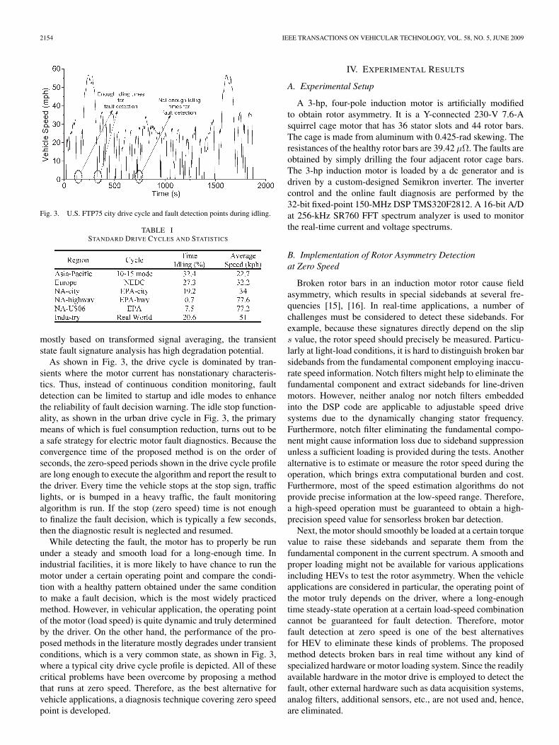
The drive cycle is typically used by independent emissiontesting laboratories to validate the HEV economy and emis-sions. The U.S. Environmental Protection Agency city cycleis the first 1300s of the Federal Test Procedure (FTP75)-regulated cycle charted out in Fig. 3. Table I shows the mostcommon drive cycles and their statistics respective of theirgeographical regions. Other than the highway mode, the trafficflow is uneven, with very frequent stop–go events and longidle times, as shown in Table I. This is why city cycles havea low average speed compared with a similar performance onthe U.S. highway cycle. Because of the high percentage of stoptime, as shown in Table I, the proposed algorithm can oftenbe run to monitor the motor condition where the mechanicalvibration is minimum. Since the current spectrum analysis is
2154 IEEE TRANSACTIONS ON VEHICULAR TECHNOLOGY, VOL. 58, NO. 5, JUNE 2009
Fig. 3. U.S. FTP75 city drive cycle and fault detection points during idling.
TABLE ISTANDARD DRIVE CYCLES AND STATISTICS
mostly based on transformed signal averaging, the transientstate fault signature analysis has high degradation potential.
As shown in Fig. 3, the drive cycle is dominated by tran-sients where the motor current has nonstationary characteris-tics. Thus, instead of continuous condition monitoring, faultdetection can be limited to startup and idle modes to enhancethe reliability of fault decision warning. The idle stop function-ality, as shown in the urban drive cycle in Fig. 3, the primarymeans of which is fuel consumption reduction, turns out to bea safe strategy for electric motor fault diagnostics. Because theconvergence time of the proposed method is on the order ofseconds, the zero-speed periods shown in the drive cycle profileare long enough to execute the algorithm and report the result tothe driver. Every time the vehicle stops at the stop sign, trafficlights, or is bumped in a heavy traffic, the fault monitoringalgorithm is run. If the stop (zero speed) time is not enoughto finalize the fault decision, which is typically a few seconds,then the diagnostic result is neglected and resumed.
While detecting the fault, the motor has to properly be rununder a steady and smooth load for a long-enough time. Inindustrial facilities, it is more likely to have chance to run themotor under a certain operating point and compare the condi-tion with a healthy pattern obtained under the same conditionto make a fault decision, which is the most widely practicedmethod. However, in vehicular application, the operating pointof the motor (load speed) is quite dynamic and truly determinedby the driver. On the other hand, the performance of the pro-posed methods in the literature mostly degrades under transientconditions, which is a very common state, as shown in Fig. 3,where a typical city drive cycle profile is depicted. All of thesecritical problems have been overcome by proposing a methodthat runs at zero speed. Therefore, as the best alternative forvehicle applications, a diagnosis technique covering zero speedpoint is developed.
IV. EXPERIMENTAL RESULTS
A. Experimental Setup
A 3-hp, four-pole induction motor is artificially modifiedto obtain rotor asymmetry. It is a Y-connected 230-V 7.6-Asquirrel cage motor that has 36 stator slots and 44 rotor bars.The cage is made from aluminum with 0.425-rad skewing. Theresistances of the healthy rotor bars are 39.42 μΩ. The faults areobtained by simply drilling the four adjacent rotor cage bars.The 3-hp induction motor is loaded by a dc generator and isdriven by a custom-designed Semikron inverter. The invertercontrol and the online fault diagnosis are performed by the32-bit fixed-point 150-MHz DSP TMS320F2812. A 16-bit A/Dat 256-kHz SR760 FFT spectrum analyzer is used to monitorthe real-time current and voltage spectrums.
B. Implementation of Rotor Asymmetry Detectionat Zero Speed
Broken rotor bars in an induction motor rotor cause fieldasymmetry, which results in special sidebands at several fre-quencies [15], [16]. In real-time applications, a number ofchallenges must be considered to detect these sidebands. Forexample, because these signatures directly depend on the slips value, the rotor speed should precisely be measured. Particu-larly at light-load conditions, it is hard to distinguish broken barsidebands from the fundamental component employing inaccu-rate speed information. Notch filters might help to eliminate thefundamental component and extract sidebands for line-drivenmotors. However, neither analog nor notch filters embeddedinto the DSP code are applicable to adjustable speed drivesystems due to the dynamically changing stator frequency.Furthermore, notch filter eliminating the fundamental compo-nent might cause information loss due to sideband suppressionunless a sufficient loading is provided during the tests. Anotheralternative is to estimate or measure the rotor speed during theoperation, which brings extra computational burden and cost.Furthermore, most of the speed estimation algorithms do notprovide precise information at the low-speed range. Therefore,a high-speed operation must be guaranteed to obtain a high-precision speed value for sensorless broken bar detection.
Next, the motor should smoothly be loaded at a certain torquevalue to raise these sidebands and separate them from thefundamental component in the current spectrum. A smooth andproper loading might not be available for various applicationsincluding HEVs to test the rotor asymmetry. When the vehicleapplications are considered in particular, the operating point ofthe motor truly depends on the driver, where a long-enoughtime steady-state operation at a certain load-speed combinationcannot be guaranteed for fault detection. Therefore, motorfault detection at zero speed is one of the best alternativesfor HEV to eliminate these kinds of problems. The proposedmethod detects broken bars in real time without any kind ofspecialized hardware or motor loading system. Since the readilyavailable hardware in the motor drive is employed to detect thefault, other external hardware such as data acquisition systems,analog filters, additional sensors, etc., are not used and, hence,are eliminated.

AKIN et al.: DSP-BASED FAULT DIAGNOSIS TOOLS FOR ELECTRIC VEHICLE AND HEV APPLICATIONS 2155
Fig. 4. Current spectrum of rotor broken bar motor. (a) Regular test. (b) Zerospeed test.
The test is implemented at zero speed; therefore, there is noneed for speed measurement or speed estimation. The rotor ismechanically or electrically locked using dc braking. Becausethe injected signal to test the rotor asymmetry is below 10%of the rated voltage values, the generated torque during thetest is negligible. Thus, a broken rotor bar test can be im-plemented without an additional featured loading system. Thefs(1 − 2s) term is caused by torque vibrations [17] and initiatesan electromechanical chain interaction between the rotor andthe stator that results in many asymmetrical signatures in thespectrum. Therefore, the low-frequency range is dominatedby consecutive asymmetry signatures that complicate the faultanalysis, as shown in Fig. 4(a).
Since the slip is unity when the rotor is stationary, theexisting consecutive signatures are quite far from each other,as shown in Fig. 4(b). Indeed, most of these components in theline current spectrum tend to theoretically vanish at zero speed,and the spectrum becomes quite clean when compared to thecurrent spectrum at rated speed and rated torque operation.
The method presented here focuses on the fs(1 − 2s) term.At zero speed, s = 1; thus, the fs(1 − 2s) term is at frequency−(fs). Single-phase reference frame analyses do not work fora negative frequency; therefore, three-phase current vectorsare transformed to a complex current space vector. Single-phase real or imaginary current analyses are insensitive tovector rotation direction; thus, they find superposition of theleft sideband and the fundamental component at the excitationfrequency (fs). To separately compute the left sideband and thefundamental components, the fault-relevant components of thecurrent space vector are experimentally examined.
Fig. 5. Normalized left-sideband magnitude of a healthy motor obtainedby the DSP in real time at standstill (I = 9 A, V/Hz = 1.0, f = 48 Hz).(a) Time–frequency domain. (b) Frequency domain.
To verify the proposed method, a number of experimentsare implemented under various Volts/Hertz ratios, line currents,and frequencies. It is observed that if a high enough currentis supplied around or higher than the rated current, then un-der all conditions the healthy and faulty patterns can easilybe distinguished by using the proposed method. In Figs. 5and 6, the real-time fault signature tracking results are givenwhen the motor is injected with a 48-Hz low-voltage signalat standstill near the rated current. Both the fault signaturemagnitude at −(fs) and the fundamental component at (fs)are simultaneously and separately computed in real time bythe DSP to obtain the normalized fault signature magnitude.In Fig. 5, the fault signature frequency of a healthy motor isexamined when Volts/Hertz is set to 1.0 at 48 Hz. In Fig. 5(a),the DSP continuously computes and updates the normalized leftsideband magnitude of a healthy motor in each second. Fig. 5(b)depicts an instant magnitude of the left sideband componentrelative to the fundamental in the frequency domain.
A similar test is repeated for the motor that has 4 out of 44broken bars on the cage, and the results are shown in Fig. 6(a)and (b). When Figs. 5 and 6 are compared to each other, it isclearly seen that under the same conditions the left sideband isincreased by 13 dB, which is high enough to distinguish healthyand faulty motors from each other.

2156 IEEE TRANSACTIONS ON VEHICULAR TECHNOLOGY, VOL. 58, NO. 5, JUNE 2009
Fig. 6. Normalized left-sideband magnitude of a faulty motor obtained bythe DSP in real time at standstill (I = 9 A, V/Hz = 1.0, f = 48 Hz).(a) Time–frequency domain. (b) Frequency domain.
In Fig. 7, the normalized fault component magnitudes aregiven at various frequencies when the Volts/Hertz ratio is setto 0.5. During this test, the locked motor is excited at variouslow-voltage levels at four different frequencies to examine theoperating point where the fault can best be monitored using theproposed method. The healthy and faulty motors are individu-ally tested at the same setup under the same conditions to obtainproper comparison results. The frequency and Volt/Hertz ratioof the motor drive are kept constant, and the dc link voltageis modified to implement this test. The normalized fault sig-nature magnitude values measured by DSP are recorded whilegradually increasing the line current up to 12 A. In general, itis noticed that the measurements around the rated current levelprovide good enough information to separate the healthy andfaulty patterns from each other, as shown in Fig. 7(a)–(d). Thedifference between the normalized left-sideband magnitudes ofhealthy and faulty patterns around the rated current value atrated frequency is measured as 17 dB, as shown in Fig. 7(c).In the case of a regular (full-load rated-speed) broken bar test,the same difference is measured as 14 dB, as shown in Fig. 8.It is experimentally shown that almost the same results can beobtained at standstill without employing an external hardwarejust before the motor startup or at idle mode in a second.
The same test is implemented when the Volts/Hertz ratio isset to 1.0, and the results are given in Fig. 9(a)–(c). It is noticed
Fig. 7. Normalized left-sideband magnitude obtained by the DSP in real timeversus line current (Volts/Hertz = 0.5). (a) 36 Hz. (b) 48 Hz. (c) 60 Hz.(d) 72 Hz.

AKIN et al.: DSP-BASED FAULT DIAGNOSIS TOOLS FOR ELECTRIC VEHICLE AND HEV APPLICATIONS 2157
Fig. 8. Rotor asymmetry signatures on an inverter-driven motor line currentspectrum at rated speed under full load.
that the fault patterns measured at two different Volts/Hertzratio tests are quite close to each other, as shown in Figs. 7and 9. In Fig. 10, the fault signature magnitude values recordedat 48 Hz are plotted on the same graph to clearly show thisfact. On the other hand, when the Volt/Hertz ratio is 0.5, theinherent asymmetry of the healthy motor is reflected on thestator current at a lower rate, where the line current valueis around the rated value, as shown in Fig. 7. Although thedifference between the healthy and faulty patterns around therated current is high enough to detect the asymmetry at variousfrequencies and Volt/Hertz, one can search the operating pointwhere the fault is most obviously monitored to enhance the faultdecision reliability.
V. DISCUSSIONS
The automotive industry has turned into an attractive marketfor power-electronic products. Adjustable-speed motor drives,static power converters, high-performance electric motors, andpower-management systems have become an inherent part ofmodern vehicles [18]–[22]. It is obvious that as the tendency toelectrification of vehicular systems increases, the system- andcomponent-level solutions attract more attention. As a naturalconsequence of this trend, the health monitoring of each unit inthe energy conversion system of HEVs is becoming a criticalissue that needs to be solved. To monitor the tolerable or severefaults inside the electric motor or embedded drive hardware toavoid a catastrophic failure, the prognosis and diagnosis of eachcomponent in the electric powertrain should be realized for aproper maintenance and repair of electric vehicles and HEVs.Although the electric motor is a direct interest of this paper, theproposed solution can be extended as a general fault signatureanalyzer to capture the well-known fault signatures of electricalcomponents such as the inverter, various drive components, thebattery, alternator, etc., simply by processing the associatedsensor output data. Note that the proposed solution is limitedto faults that generate periodic fault signatures.
To implement the extended version, the faults observed inthe related drive component or subsystems should be analyzedin detail, and the generated fault signatures are to be modeled.Next, the frequency of the reference frame is set to the expectedfault signature frequency to convert the associated signal todc. In the new frame, all the signal components other than
Fig. 9. Normalized left-sideband magnitude obtained by the DSP in real timeversus line current (Volts/Hertz = 1.0). (a) 36 Hz. (b) 48 Hz. (c) 60 Hz.
the inspected component including the fundamental harmonic,measurement dc offset, and noise components remain ac; there-fore, the average of all these components converge to zero.After averaging 5-k to 20-k data using the DSP as practiced inthis paper, the only surviving component will be the inspectedfault component. The effect of the other signal componentson the average becomes negligibly small. The same procedureshould be repeated to measure the fundamental component for

2158 IEEE TRANSACTIONS ON VEHICULAR TECHNOLOGY, VOL. 58, NO. 5, JUNE 2009
Fig. 10. Normalized left-sideband magnitude obtained by the DSP in real timeversus line current (Volts/Hertz = 1.0 and 0.5, f = 48 Hz).
Fig. 11. (a) Experimentally obtained V/f-controlled inverter-driven eccentricmotor single-phase line current rotating frame harmonic analysis result. (b) FFTspectrum analyzer output of the line current.
the normalization of the fault signature amplitude. The normal-ization of the fault signal is necessary to obtain generalizedresults to make sure that the measured value is independentfrom sensor gain or signal conditioning board amplification.After measuring the normalized fault signature amplitude, theresults are compared with a threshold to make the decisionabout the status of the examined component.
This claim is supported with an experimental result thatexamines another motor fault, i.e., mixed eccentricity, by uti-lizing the same setup. To obtain eccentricity, an identical 3-hphealthy motor house is remachined, and the bearing housing ismachined off-centered. In this test, the eccentric motor is drivenat 0.66-pu reference speed under no load, where fs = 40 Hz,and wr ≈ 1180 r/min. As shown in Fig. 11, the left-hand-side-normalized fault harmonics at (fs − fr) hertz are foundto be −50.45 dB using the technique previously mentioned,and the FFT spectrum analyzer result is −51.67 dB. On theother hand, the right-hand-side-normalized fault harmonics at(fs + fr) hertz are found to be −48.17 dB using the sametechnique, and the FFT spectrum analyzer result is −49.92 dB.As shown in this example, a modified version of this methodcan successfully be applied to other motor faults. According tothe statistics, almost 60% of the motor faults are electrical, and40% of them are mechanical [8]. Because the fault signaturesof the electrical faults are quite remarkable in the current spec-trum, this method can be used to detect all kinds of electricalfaults such as eccentricity, broken bar, stator faults, etc. Inthe case of mechanical faults, the proposed method properlyworks as well. However, the fault signatures are quite small, and
quantization errors of 12-bit ADC dominate. Therefore, at leasta 16-bit ADC is needed to accurately read the mechanical faultsignatures. Likewise, other electrical components’ status canalso be screened by using an extended version of the proposedmethod.
VI. CONCLUSION
Condition monitoring and fault detection of electric motorsin HEVs are quite vital for safety and cost-effective mainte-nance. This paper has proposed a simple real-time fault diagno-sis tool at zero speed based on the reference frame theory, whichcan be run at startup and during idle mode (standstill). Themajor advantages of the method are very fast convergence time,no need for an additional sensor or hardware, robustness andreliability, and its speed sensorless implementation. The zero-speed application makes it highly robust against mechanicalvibrations, fault signature analysis degradation effects of thetransient state, and loading problems. It is a well-known factthat automotive companies are very strict with regard to someparameters of new technologies integrated into the vehicle suchas size limitations, packaging issues, and cost. Because thesolution is based on readily available drive hardware, duringthe implementation, no additional cost is necessary, and noadditional volume is occupied. Being a model independent faultanalyzer, the applications of the proposed solution can easilybe extended to the fault diagnosis of other types of electricmotors and the condition monitoring of various powertraincomponents.
REFERENCES
[1] G. B. Kliman, R. A. Koegl, J. Stein, R. D. Endicott, andM. W. Madden, “Noninvasive detection of broken rotor bars in operat-ing induction motors,” IEEE Trans. Energy Convers., vol. 3, no. 4,pp. 873–879, Dec. 1988.
[2] R. Schoen, T. Habetler, F. Kamran, and R. Bartfield, “Motor bearing dam-age detection using stator current monitoring,” IEEE Trans. Ind. Appl.,vol. 31, no. 6, pp. 1274–1279, Nov./Dec. 1995.
[3] M. E. H. Benbouzid, “A review of induction motors signature analysis asa medium for faults detection,” IEEE Trans. Ind. Electron., vol. 47, no. 5,pp. 984–993, Oct. 2000.
[4] S. Nandi, M. Bharadwaj, and H. A. Toliyat, “Performance analysis of athree-phase induction motor under mixed eccentricity condition,” IEEETrans. Energy Convers., vol. 17, no. 3, pp. 392–399, Sep. 2002.
[5] D. G. Dorrell, W. T. Thomson, and S. Roach, “Analysis of airgap flux,current, and vibration signals as a function of the combination of static anddynamic airgap eccentricity in 3-phase induction motors,” IEEE Trans.Ind. Appl., vol. 33, no. 1, pp. 24–34, Jan. 1997.
[6] M. J. Devaney and L. Eren, “Detecting motor bearing faults,” IEEEInstrum. Meas. Mag., vol. 7, no. 4, pp. 30–36, Dec. 2004.
[7] C. Riley, K. Lin, T. Habetler, and G. B. Kliman, “Stator current harmonicsand their causal vibrations: A preliminary of sensorless vibration moni-toring applications,” IEEE Trans. Ind. Appl., vol. 35, no. 1, pp. 94–99,Jan. 1999.
[8] S. Nandi, H. A. Toliyat, and X. Li, “Condition monitoring and faultdiagnosis of electrical motors—A review,” IEEE Trans. Energy Convers.,vol. 20, no. 4, pp. 719–729, Dec. 2005.
[9] A. V. Oppenheim and R. W. Schafer, Discrete-Time Signal Processing.New York: Prentice–Hall, 1989.
[10] R. K. Jurgen, On and Off-Board Diagnostics. Warrendale, PA: SAE,2000.
[11] Office of the Federal Register (U.S.), Title 40: Protection. Code Fed.Regulations.
[12] M. Ehsani, Y. Gao, S. E. Gay, and A. Emadi, Modern Electric, HybridElectric, and Fuel Cell Vehicles: Fundamentals, Theory, and Design,1st ed. Boca Raton, FL: CRC, 2004.

AKIN et al.: DSP-BASED FAULT DIAGNOSIS TOOLS FOR ELECTRIC VEHICLE AND HEV APPLICATIONS 2159
[13] “Hybrid electric vehicle front cover illustration,” IEEE Power Electron.Soc. Newslett., vol. 19, no. 1, p. 1, First Quarter 2007.
[14] J. M. Miller, Propulsion Systems for Hybrid Vehicles. Stevenage, U.K.:Peregrinus, 2004.
[15] C. Kral, F. Pirker, and G. Pascoli, “Detection of rotor faults in squirrel-cage induction machines at standstill for batch tests by means of theVienna monitoring method,” IEEE Trans. Ind. Appl., vol. 38, no. 3,pp. 618–624, May 2002.
[16] H. Henao, C. Demian, and G. A. Capolino, “Detection of inductionmachines rotor faults at standstill using signals injection,” IEEE Trans.Ind. Appl., vol. 41, no. 6, pp. 1550–1559, Nov. 2004.
[17] F. Filippetti, G. Franceschini, C. Tassoni, and P. Vas, “AI techniques ininduction machines diagnosis including the speed ripple effect,” IEEETrans. Ind. Appl., vol. 34, no. 1, pp. 98–108, Jan./Feb. 1998.
[18] B. Fahimi and T. Sebastian, “Special section on automotive electro-mechanical converters,” IEEE Trans. Veh. Technol., vol. 56, no. 4,pp. 1470–1476, Jul. 2007.
[19] R. Jayabalan and B. Fahimi, “Monitoring and fault diagnosis of multi-converter systems in hybrid electric vehicles,” IEEE Trans. Veh. Technol.,vol. 55, no. 5, pp. 1475–1484, Sep. 2006.
[20] M. E. H. Benbouzid, D. Diallo, and M. Zeraoulia, “Advanced fault-tolerant control of induction-motor drives for EV/HEV traction applica-tions: From conventional to modern and intelligent control techniques,”IEEE Trans. Veh. Technol., vol. 56, no. 2, pp. 519–528, Mar. 2007.
[21] N. Bianchi, M. D. Pre, and S. Bolognani, “Design of a fault-tolerant IPMmotor for electric power steering,” IEEE Trans. Veh. Technol., vol. 55,no. 4, pp. 1102–1111, Jul. 2006.
[22] L. Shuai, K. A. Corzine, and M. Ferdowsi, “A new battery/ultracapacitorenergy storage system design and its motor drive integration for hybridelectric vehicles,” IEEE Trans. Veh. Technol., vol. 56, no. 4, pp. 1516–1523, Jul. 2007.
Bilal Akin (S’03–M’08) received the B.S. and M.S.degrees in electrical engineering from Middle EastTechnical University, Ankara, Turkey, in 2000 and2003, respectively, and the Ph.D. degree in electri-cal engineering from the Texas A&M University,College Station, in 2007.
From 1999 to 2000, he was an R&D Engineerwith Tubitak Bilten, Ankara. From 2005 to 2007,he was an R&D Engineer with Toshiba IndustrialDivision, Houston, TX. From 2007 to 2008, he wasa Postdoctoral Research Associate with Texas A&M
University. Since 2008, he has been an Application Engineer with the C2000Embedded Control Group, Texas Instruments Incorporated, Dallas. His re-search interests are advanced control methods in motor drives, real-time faultdiagnosis of industrial systems, digital power management, and variousDSP-based industrial applications.
Salih Baris Ozturk (M’08) received the B.S. de-gree (Hons.) in electrical engineering from IstanbulTechnical University, Istanbul, Turkey, in 2000 andthe M.S. and Ph.D. degrees in electrical engineeringfrom Texas A&M University, College Station, in2005 and 2008, respectively.
In 2004, he was with the Whirlpool R&D Center,Benton Harbor, MI. Since June 2008, he has been aSenior Research Engineer with the Power Electron-ics Group, United Technologies Research Center,East Hartford, CT. His primary research interests
include power electronics, fault diagnosis of electric machines, and digitalsignal processor-based advanced control of ac drives, in particular, sensorlessand direct torque control of permanent-magnet assisted synchronous reluctanceand permanent-magnet synchronous and brushless dc motors. He also is oneof the contributing authors of the book DSP-Based Electromagnetic MotionControl (Boca Raton, FL: CRC, 2003).
Hamid A. Toliyat (S’87–M’91–SM’96–F’08)received the B.S. degree in electrical engineeringfrom Sharif University of Technology, Tehran, Iran,in 1982, the M.S. degree in electrical engineeringfrom West Virginia University, Morgantown, in1986, and the Ph.D. degree in electrical engineeringfrom the University of Wisconsin–Madison,Madison, in 1991.
In 1991, he was an Assistant Professor of electricalengineering with the faculty of Ferdowsi Universityof Mashhad, Mashhad, Iran. Since March 1994, he
has been with the Department of Electrical and Computer Engineering, TexasA&M University, College Station, where he is currently a Raytheon EndowedProfessor. He has supervised more than 36 graduate students, published over310 technical papers, where 92 papers are in IEEE TRANSACTIONS, andpresented more than 50 invited lectures all over the world. He is also an inventorand has ten issued and pending U.S. patents in these fields. He is the author ofDSP-Based Electromechanical Motion Control (CRC, 2003) and the coeditorof Handbook of Electric Motors—2nd Edition (Marcel Dekker, 2004). His mainresearch interests and experience include the analysis and design of electricalmachines, variable-speed drives for traction and propulsion applications, faultdiagnosis of electric machinery, and sensorless variable-speed drives.
Dr. Toliyat is a member of Sigma Xi. He is a Professional Engineer inthe State of Texas. He was the General Chair of the 2005 IEEE InternationalElectric Machines and Drives Conference in San Antonio, TX. He is an Editorof the IEEE TRANSACTIONS ON ENERGY CONVERSION and was an AssociateEditor of the IEEE TRANSACTIONS ON POWER ELECTRONICS. He receivedthe prestigious Cyrill Veinott Award in Electromechanical Energy Conversionfrom the IEEE Power Engineering Society in 2004, the TEES Fellow Award in2004 and 2006, the Outstanding Professor Award in 2005 from Texas A&M, theDistinguished Teaching Award in 2003, the E.D. Brockett Professorship Awardin 2002, the Eugene Webb Faculty Fellow Award in 2000, and the Texas A&MSelect Young Investigator Award in 1999 from Texas A&M University. Healso received the Space Act Award from NASA in 1999 and the SchlumbergerFoundation Technical Awards in 2001 and 2000. He is also the Chair of IEEE-IAS Industrial Power Conversion Systems Department of IEEE-IAS. He is therecipient of the 1996 and 2006 IEEE Power Engineering Society Prize PaperAward and 2006 IEEE Industry Applications Society Transactions Third PrizePaper Award.
Mark Rayner, photograph and biography not available at the time ofpublication.