Physical-Mechanical properties of H-10 blocks manufactured ...
Upload
independentCategory
view
1download
0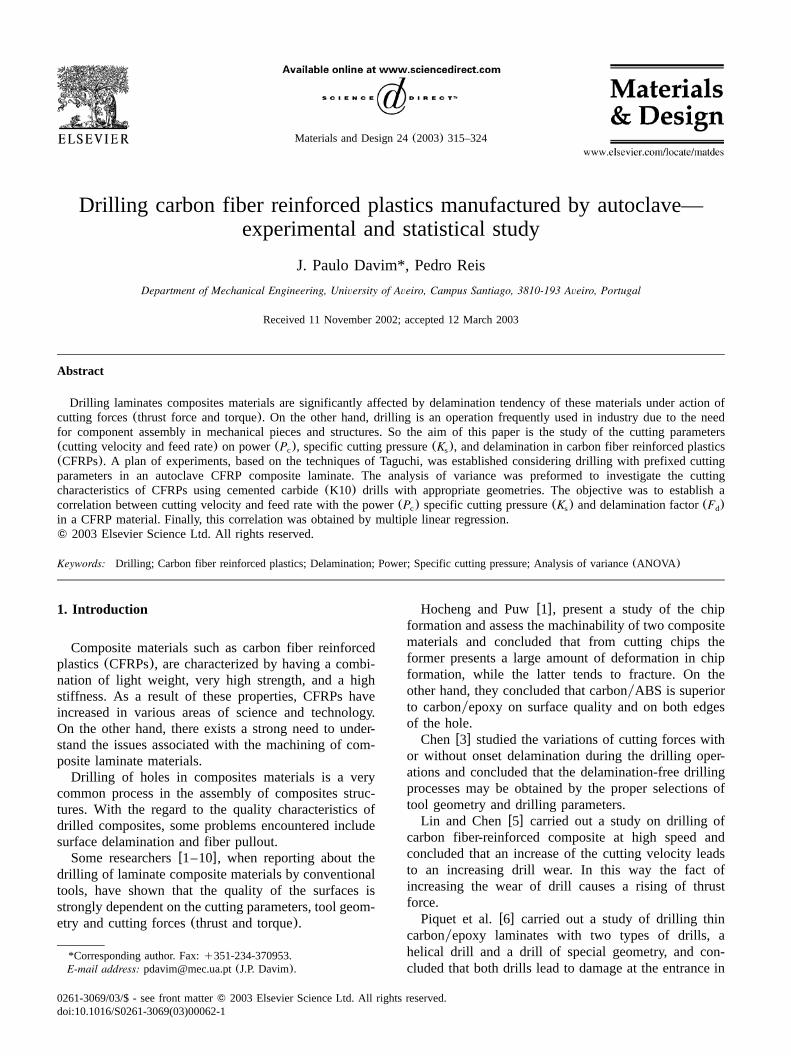
Materials and Design 24(2003) 315–324
0261-3069/03/$ - see front matter� 2003 Elsevier Science Ltd. All rights reserved.doi:10.1016/S0261-3069(03)00062-1
Drilling carbon fiber reinforced plastics manufactured by autoclave—experimental and statistical study
J. Paulo Davim*, Pedro Reis
Department of Mechanical Engineering, University of Aveiro, Campus Santiago, 3810-193 Aveiro, Portugal
Received 11 November 2002; accepted 12 March 2003
Abstract
Drilling laminates composites materials are significantly affected by delamination tendency of these materials under action ofcutting forces(thrust force and torque). On the other hand, drilling is an operation frequently used in industry due to the needfor component assembly in mechanical pieces and structures. So the aim of this paper is the study of the cutting parameters(cutting velocity and feed rate) on power(P ), specific cutting pressure(K ), and delamination in carbon fiber reinforced plasticsc s
(CFRPs). A plan of experiments, based on the techniques of Taguchi, was established considering drilling with prefixed cuttingparameters in an autoclave CFRP composite laminate. The analysis of variance was preformed to investigate the cuttingcharacteristics of CFRPs using cemented carbide(K10) drills with appropriate geometries. The objective was to establish acorrelation between cutting velocity and feed rate with the power(P ) specific cutting pressure(K ) and delamination factor(F )c s d
in a CFRP material. Finally, this correlation was obtained by multiple linear regression.� 2003 Elsevier Science Ltd. All rights reserved.
Keywords: Drilling; Carbon fiber reinforced plastics; Delamination; Power; Specific cutting pressure; Analysis of variance(ANOVA)
1. Introduction
Composite materials such as carbon fiber reinforcedplastics(CFRPs), are characterized by having a combi-nation of light weight, very high strength, and a highstiffness. As a result of these properties, CFRPs haveincreased in various areas of science and technology.On the other hand, there exists a strong need to under-stand the issues associated with the machining of com-posite laminate materials.Drilling of holes in composites materials is a very
common process in the assembly of composites struc-tures. With the regard to the quality characteristics ofdrilled composites, some problems encountered includesurface delamination and fiber pullout.Some researchersw1–10x, when reporting about the
drilling of laminate composite materials by conventionaltools, have shown that the quality of the surfaces isstrongly dependent on the cutting parameters, tool geom-etry and cutting forces(thrust and torque).
*Corresponding author. Fax:q351-234-370953.E-mail address: [email protected](J.P. Davim).
Hocheng and Puww1x, present a study of the chipformation and assess the machinability of two compositematerials and concluded that from cutting chips theformer presents a large amount of deformation in chipformation, while the latter tends to fracture. On theother hand, they concluded that carbonyABS is superiorto carbonyepoxy on surface quality and on both edgesof the hole.Chenw3x studied the variations of cutting forces with
or without onset delamination during the drilling oper-ations and concluded that the delamination-free drillingprocesses may be obtained by the proper selections oftool geometry and drilling parameters.Lin and Chenw5x carried out a study on drilling of
carbon fiber-reinforced composite at high speed andconcluded that an increase of the cutting velocity leadsto an increasing drill wear. In this way the fact ofincreasing the wear of drill causes a rising of thrustforce.Piquet et al.w6x carried out a study of drilling thin
carbonyepoxy laminates with two types of drills, ahelical drill and a drill of special geometry, and con-cluded that both drills lead to damage at the entrance in
316 J.P. Davim, P. Reis / Materials and Design 24 (2003) 315–324
Fig. 1. Laminate produced by autoclave with a fiber orientation of08y908.
Fig. 3. Squeeze of the composite material in the press of jaw in themachining center.
Table 1Assignment of the levels to the factors
Level Cutting velocity Feed rateV (mymin) f (mmyrev)
1 30 (1910 rpm) 0.052 40 (2547 rpm) 0.13 50 (3138 rpm) 0.2
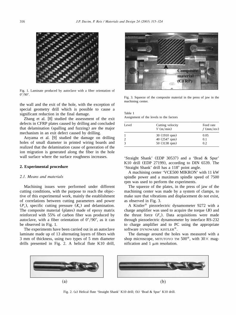
Fig. 2. (a) Helical flute ‘Straight Shank’ K10 drill;(b) ‘Brad & Spur’ K10 drill.
the wall and the exit of the hole, with the exception ofspecial geometry drill which is possible to cause asignificant reduction in the final damage.Zhang et al.w8x studied the assessment of the exit
defects in CFRP plates caused by drilling and concludedthat delamination(spalling and fuzzing) are the majormechanism in an exit defect caused by drilling.Aoyama et al.w9x studied the damage on drilling
holes of small diameter in printed wiring boards andrealized that the delamination cause of generation of theion migration is generated along the fiber in the holewall surface where the surface roughness increases.
2. Experimental procedure
2.1. Means and materials
Machining issues were performed under differentcutting conditions, with the purpose to reach the objec-tive of this experimental work, mainly the establishmentof correlations between cutting parameters and power(P ), specific cutting pressure(K ) and delamination.c s
The composite material(plates) made of epoxy matrixreinforced with 55% of carbon fiber was produced byautoclave, with a fiber orientation of 08y908, as it canbe observed in Fig. 1.The experiments have been carried out in an autoclave
laminate made up of 13 alternating layers of fibers with3 mm of thickness, using two types of 5 mm diameterdrills presented in Fig. 2. A helical flute K10 drill,
‘Straight Shank’ (EDP 30537) and a ‘Brad & Spur’K10 drill (EDP 27199), according to DIN 6539. The‘Straight Shank’ drill has a 1188 point angle.A machining center ‘VCE500 MIKRON’ with 11 kW
spindle power and a maximum spindle speed of 7500rpm was used to perform the experiments.The squeeze of the plates, in the press of jaw of the
machining center was made by a system of clamps, tomake sure that vibrations and displacement do not exist,as observed in Fig. 3.A Kistler piezoelectric dynamometer 9272 with a�
charge amplifier was used to acquire the torque(B) andthe thrust force(F ). Data acquisitions were madez
through piezoelectric dynamometer by interface RS-232to charge amplifier and to PC using the appropriatesoftwareDYNOWARE KISTLER .�
The damage around the holes was measured with ashop microscope,MITUTOYO TM 500 , with 30= mag-�
nification and 1mm resolution.
317J.P. Davim, P. Reis / Materials and Design 24 (2003) 315–324
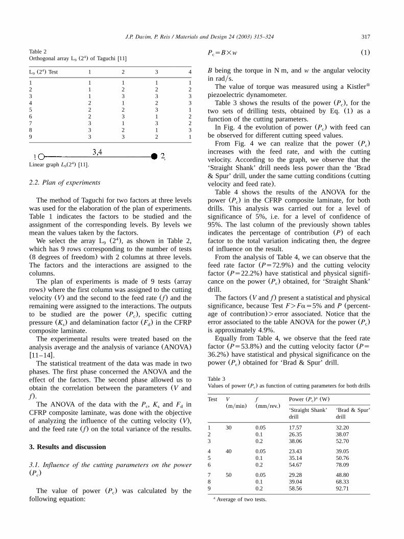
Table 2Orthogonal array L (2 ) of Taguchiw11x4
9
L (2 ) Test49 1 2 3 4
1 1 1 1 12 1 2 2 23 1 3 3 34 2 1 2 35 2 2 3 16 2 3 1 27 3 1 3 28 3 2 1 39 3 3 2 1
,Linear graph w11x.4L (2 )9
Table 3Values of power(P ) as function of cutting parameters for both drillsc
Test V f Power(P ) (W)ac
(mymin) (mmyrev.)‘Straight Shank’ ‘Brad & Spur’drill drill
1 30 0.05 17.57 32.202 0.1 26.35 38.073 0.2 38.06 52.70
4 40 0.05 23.43 39.055 0.1 35.14 50.766 0.2 54.67 78.09
7 50 0.05 29.28 48.808 0.1 39.04 68.339 0.2 58.56 92.71
Average of two tests.a
2.2. Plan of experiments
The method of Taguchi for two factors at three levelswas used for the elaboration of the plan of experiments.Table 1 indicates the factors to be studied and theassignment of the corresponding levels. By levels wemean the values taken by the factors.We select the array L(2 ), as shown in Table 2,4
9
which has 9 rows corresponding to the number of tests(8 degrees of freedom) with 2 columns at three levels.The factors and the interactions are assigned to thecolumns.The plan of experiments is made of 9 tests(array
rows) where the first column was assigned to the cuttingvelocity (V) and the second to the feed rate(f) and theremaining were assigned to the interactions. The outputsto be studied are the power(P ), specific cuttingc
pressure(K ) and delamination factor(F ) in the CFRPs d
composite laminate.The experimental results were treated based on the
analysis average and the analysis of variance(ANOVA)w11–14x.The statistical treatment of the data was made in two
phases. The first phase concerned the ANOVA and theeffect of the factors. The second phase allowed us toobtain the correlation between the parameters(V andf).The ANOVA of the data with theP , K and F inc s d
CFRP composite laminate, was done with the objectiveof analyzing the influence of the cutting velocity(V),and the feed rate(f) on the total variance of the results.
3. Results and discussion
3.1. Influence of the cutting parameters on the power(P )c
The value of power(P ) was calculated by thec
following equation:
P sB=w (1)c
B being the torque in N m, andw the angular velocityin radys.The value of torque was measured using a Kistler�
piezoelectric dynamometer.Table 3 shows the results of the power(P ), for thec
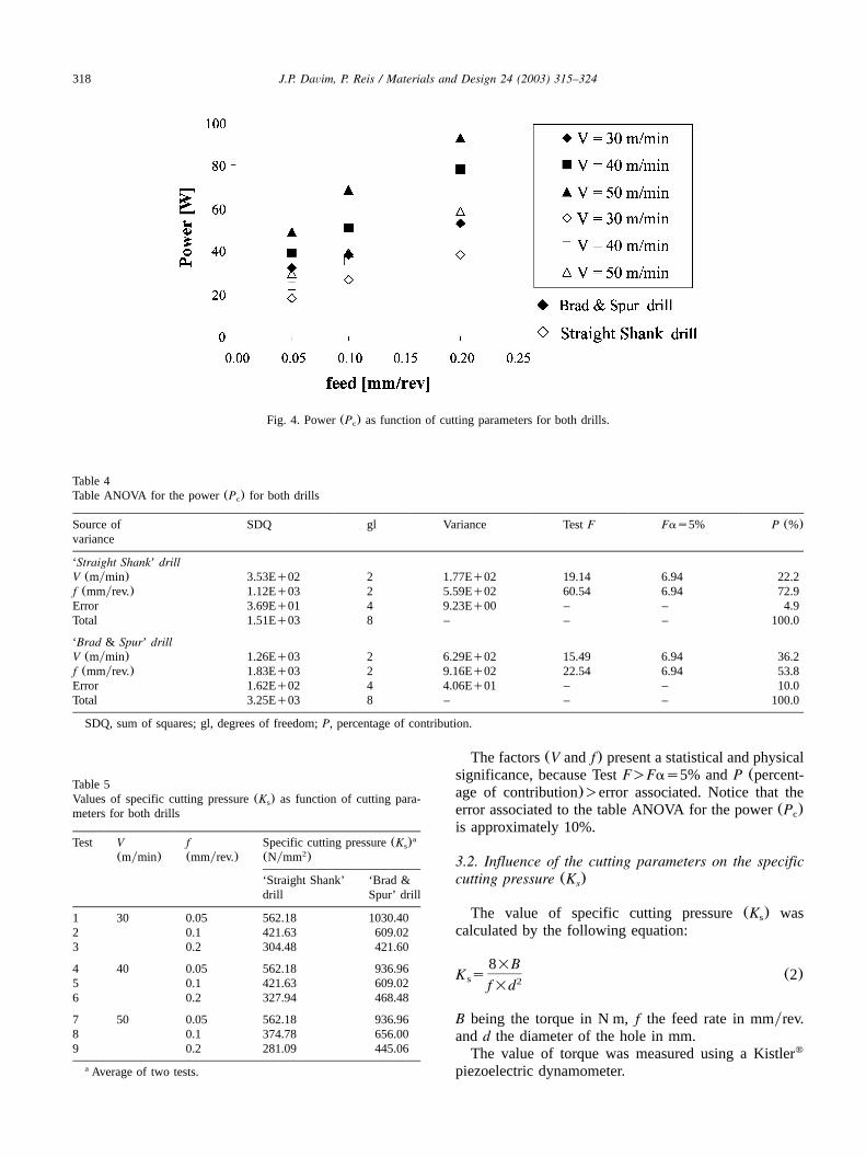
two sets of drilling tests, obtained by Eq.(1) as afunction of the cutting parameters.In Fig. 4 the evolution of power(P ) with feed canc
be observed for different cutting speed values.From Fig. 4 we can realize that the power(P )c
increases with the feed rate, and with the cuttingvelocity. According to the graph, we observe that the‘Straight Shank’ drill needs less power than the ‘Brad& Spur’ drill, under the same cutting conditions(cuttingvelocity and feed rate).Table 4 shows the results of the ANOVA for the
power (P ) in the CFRP composite laminate, for bothc
drills. This analysis was carried out for a level ofsignificance of 5%, i.e. for a level of confidence of95%. The last column of the previously shown tablesindicates the percentage of contribution(P) of eachfactor to the total variation indicating then, the degreeof influence on the result.From the analysis of Table 4, we can observe that the
feed rate factor(Ps72.9%) and the cutting velocityfactor (Ps22.2%) have statistical and physical signifi-cance on the power(P ) obtained, for ‘Straight Shank’c
drill.The factors(V and f) present a statistical and physical
significance, because TestF)Fas5% andP (percent-age of contribution))error associated. Notice that theerror associated to the table ANOVA for the power(P )cis approximately 4.9%.Equally from Table 4, we observe that the feed rate
factor (Ps53.8%) and the cutting velocity factor(Ps36.2%) have statistical and physical significance on thepower(P ) obtained for ‘Brad & Spur’ drill.c
318 J.P. Davim, P. Reis / Materials and Design 24 (2003) 315–324
Fig. 4. Power(P ) as function of cutting parameters for both drills.c
Table 4Table ANOVA for the power(P ) for both drillsc
Source of SDQ gl Variance TestF Fas5% P (%)variance
‘Straight Shank’ drillV (mymin) 3.53Eq02 2 1.77Eq02 19.14 6.94 22.2f (mmyrev.) 1.12Eq03 2 5.59Eq02 60.54 6.94 72.9Error 3.69Eq01 4 9.23Eq00 – – 4.9Total 1.51Eq03 8 – – – 100.0
‘Brad & Spur’ drillV (mymin) 1.26Eq03 2 6.29Eq02 15.49 6.94 36.2f (mmyrev.) 1.83Eq03 2 9.16Eq02 22.54 6.94 53.8Error 1.62Eq02 4 4.06Eq01 – – 10.0Total 3.25Eq03 8 – – – 100.0
SDQ, sum of squares; gl, degrees of freedom;P, percentage of contribution.
Table 5Values of specific cutting pressure(K ) as function of cutting para-s
meters for both drills
Test V f Specific cutting pressure(K )as
(mymin) (mmyrev.) (Nymm )2
‘Straight Shank’ ‘Brad &drill Spur’ drill
1 30 0.05 562.18 1030.402 0.1 421.63 609.023 0.2 304.48 421.60
4 40 0.05 562.18 936.965 0.1 421.63 609.026 0.2 327.94 468.48
7 50 0.05 562.18 936.968 0.1 374.78 656.009 0.2 281.09 445.06
Average of two tests.a
The factors(V and f) present a statistical and physicalsignificance, because TestF)Fas5% andP (percent-age of contribution))error associated. Notice that theerror associated to the table ANOVA for the power(P )cis approximately 10%.
3.2. Influence of the cutting parameters on the specificcutting pressure (K )s
The value of specific cutting pressure(K ) wass
calculated by the following equation:
8=BK s (2)s 2f=d
B being the torque in N m,f the feed rate in mmyrev.andd the diameter of the hole in mm.The value of torque was measured using a Kistler�
piezoelectric dynamometer.
319J.P. Davim, P. Reis / Materials and Design 24 (2003) 315–324
Fig. 5. Specific cutting pressure(K ) as function of cutting parameters for both drills.s
Table 5 shows the results of the specific cuttingpressure(K ), for the two sets of drilling tests, obtaineds
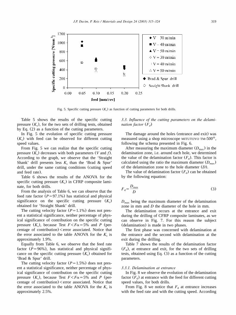
by Eq. (2) as a function of the cutting parameters.In Fig. 5 the evolution of specific cutting pressure
(K ) with feed can be observed for different cuttings
speed values.From Fig. 5 we can realize that the specific cutting
pressure(K ) decreases with both parameters(V and f).s
According to the graph, we observe that the ‘StraightShank’ drill presents lessK than the ‘Brad & Spur’s
drill, under the same cutting conditions(cutting speedand feed rate).Table 6 shows the results of the ANOVA for the
specific cutting pressure(K ) in CFRP composite lami-s
nate, for both drills.From the analysis of Table 6, we can observe that the
feed rate factor(Ps97.1%) has statistical and physicalsignificance on the specific cutting pressure(K )sobtained for ‘Straight Shank’ drill.The cutting velocity factor(Ps1.1%) does not pres-
ent a statistical significance, neither percentage of phys-ical significance of contribution on the specific cuttingpressure(K ), because TestF-Fas5% andP (per-s
centage of contribution)-error associated. Notice thatthe error associated to the table ANOVA for theK iss
approximately 1.9%.Equally from Table 6, we observe that the feed rate
factor (Ps96%), has statistical and physical signifi-cance on the specific cutting pressure(K ) obtained fors
‘Brad & Spur’ drill.The cutting velocity factor(Ps1.5%) does not pres-
ent a statistical significance, neither percentage of phys-ical significance of contribution on the specific cuttingpressure(K ), because TestF-Fas5% andP (per-s
centage of contribution)-error associated. Notice thatthe error associated to the table ANOVA for theK iss
approximately 2.5%.
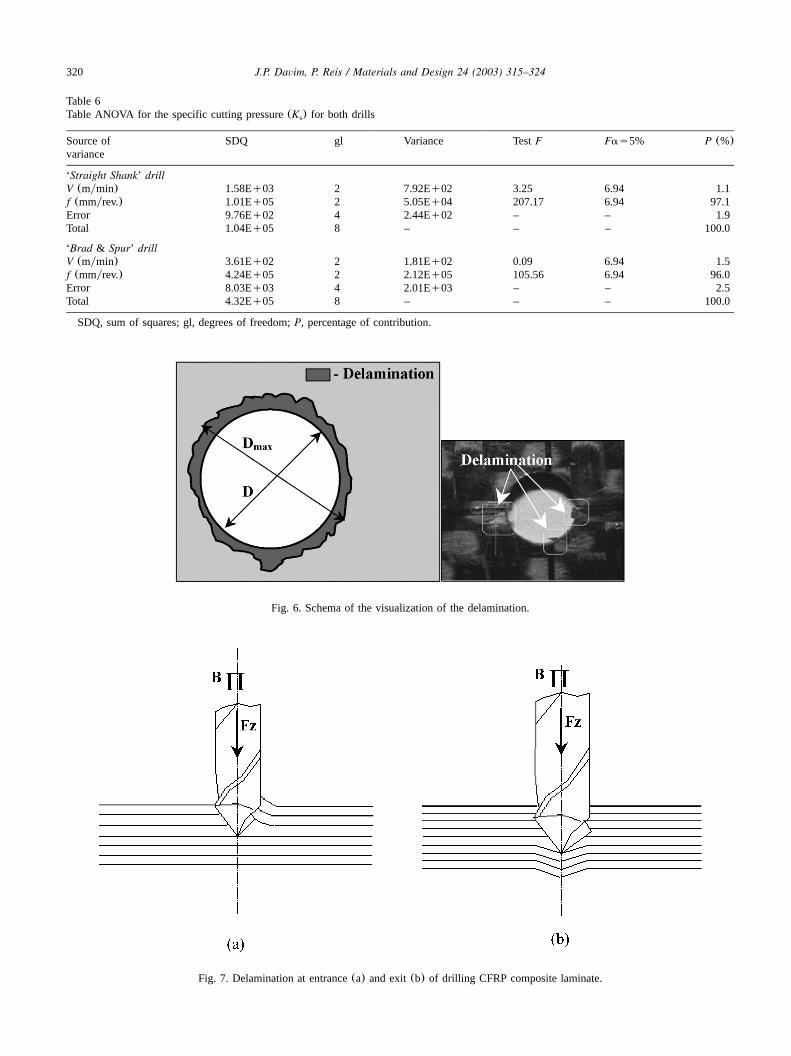
3.3. Influence of the cutting parameters on the delami-nation factor (F )d
The damage around the holes(entrance and exit) wasmeasured using a shop microscopeMITUTOYO TM-500 ,�
following the schema presented in Fig. 6.After measuring the maximum diameter(D ) in themax
delamination zone, i.e. around each hole, we determinedthe value of the delamination factor(F ). This factor isd
calculated using the ratio the maximum diameter(D )max
of the delamination zone to the hole diameter(D).The value of delamination factor(F ) can be obtainedd
by the following equation:
DmaxF s (3)d D
D being the maximum diameter of the delaminationmax
zone in mm andD the diameter of the hole in mm.The delamination occurs at the entrance and exit
during the drilling of CFRP composite laminates, as wecan observe in Fig. 7. For this reason the subject(delamination) is made in two phases.The first phase was concerned with delamination at
the entrance and the second with delamination at theexit during the drilling.Table 7 shows the results of the delamination factor
(F ), at entrance and exit, for the two sets of drillingd
tests, obtained using Eq.(3) as a function of the cuttingparameters.
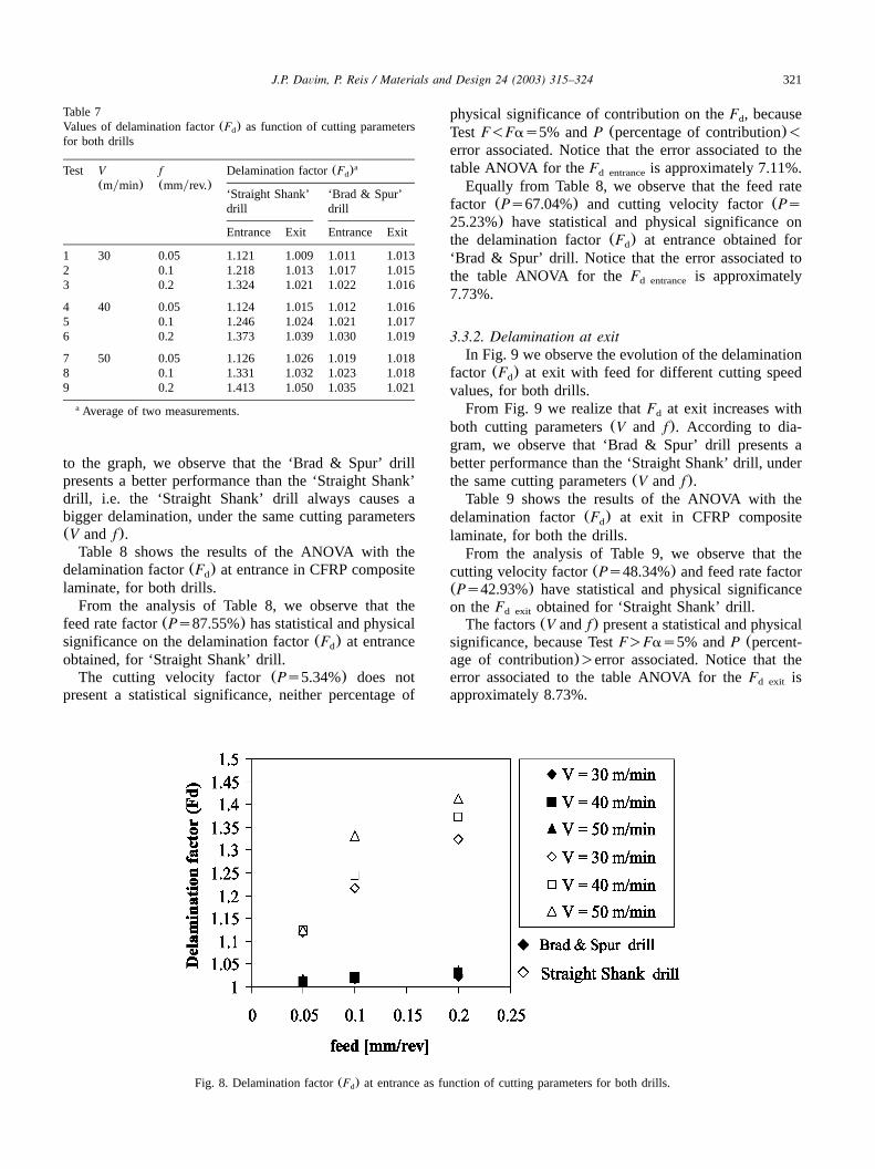
3.3.1. Delamination at entranceIn Fig. 8 we observe the evolution of the delamination
factor(F ) at entrance with the feed for different cuttingd
speed values, for both drills.From Fig. 8 we notice thatF at entrance increasesd
with the feed rate and with the cutting speed. According
320 J.P. Davim, P. Reis / Materials and Design 24 (2003) 315–324
Table 6Table ANOVA for the specific cutting pressure(K ) for both drillss
Source of SDQ gl Variance TestF Fas5% P (%)variance
‘Straight Shank’ drillV (mymin) 1.58Eq03 2 7.92Eq02 3.25 6.94 1.1f (mmyrev.) 1.01Eq05 2 5.05Eq04 207.17 6.94 97.1Error 9.76Eq02 4 2.44Eq02 – – 1.9Total 1.04Eq05 8 – – – 100.0
‘Brad & Spur’ drillV (mymin) 3.61Eq02 2 1.81Eq02 0.09 6.94 1.5f (mmyrev.) 4.24Eq05 2 2.12Eq05 105.56 6.94 96.0Error 8.03Eq03 4 2.01Eq03 – – 2.5Total 4.32Eq05 8 – – – 100.0
SDQ, sum of squares; gl, degrees of freedom;P, percentage of contribution.
Fig. 6. Schema of the visualization of the delamination.
Fig. 7. Delamination at entrance(a) and exit(b) of drilling CFRP composite laminate.
321J.P. Davim, P. Reis / Materials and Design 24 (2003) 315–324
Table 7Values of delamination factor(F ) as function of cutting parametersd
for both drills
Test V f Delamination factor(F )ad
(mymin) (mmyrev.)‘Straight Shank’drill
‘Brad & Spur’drill
Entrance Exit Entrance Exit
1 30 0.05 1.121 1.009 1.011 1.0132 0.1 1.218 1.013 1.017 1.0153 0.2 1.324 1.021 1.022 1.016
4 40 0.05 1.124 1.015 1.012 1.0165 0.1 1.246 1.024 1.021 1.0176 0.2 1.373 1.039 1.030 1.019
7 50 0.05 1.126 1.026 1.019 1.0188 0.1 1.331 1.032 1.023 1.0189 0.2 1.413 1.050 1.035 1.021
Average of two measurements.a
Fig. 8. Delamination factor(F ) at entrance as function of cutting parameters for both drills.d
to the graph, we observe that the ‘Brad & Spur’ drillpresents a better performance than the ‘Straight Shank’drill, i.e. the ‘Straight Shank’ drill always causes abigger delamination, under the same cutting parameters(V and f).Table 8 shows the results of the ANOVA with the
delamination factor(F ) at entrance in CFRP composited
laminate, for both drills.From the analysis of Table 8, we observe that the
feed rate factor(Ps87.55%) has statistical and physicalsignificance on the delamination factor(F ) at entranced
obtained, for ‘Straight Shank’ drill.The cutting velocity factor(Ps5.34%) does not
present a statistical significance, neither percentage of
physical significance of contribution on theF , becaused
TestF-Fas5% andP (percentage of contribution)-error associated. Notice that the error associated to thetable ANOVA for theF is approximately 7.11%.d entrance
Equally from Table 8, we observe that the feed ratefactor (Ps67.04%) and cutting velocity factor(Ps25.23%) have statistical and physical significance onthe delamination factor(F ) at entrance obtained ford
‘Brad & Spur’ drill. Notice that the error associated tothe table ANOVA for theF is approximatelyd entrance
7.73%.
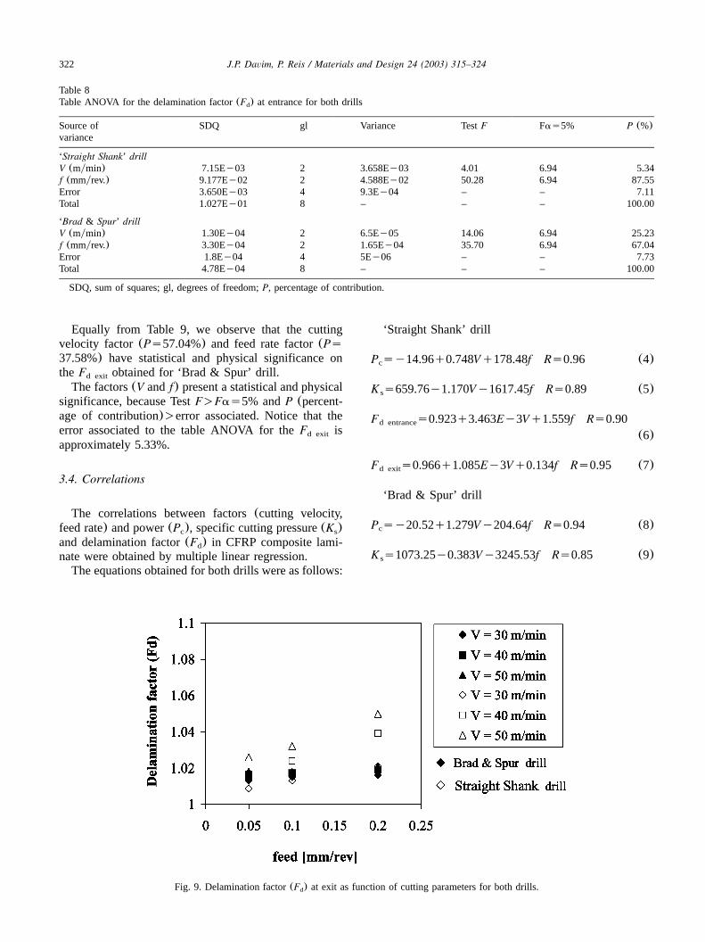
3.3.2. Delamination at exitIn Fig. 9 we observe the evolution of the delamination
factor (F ) at exit with feed for different cutting speedd
values, for both drills.From Fig. 9 we realize thatF at exit increases withd
both cutting parameters(V and f). According to dia-gram, we observe that ‘Brad & Spur’ drill presents abetter performance than the ‘Straight Shank’ drill, underthe same cutting parameters(V and f).Table 9 shows the results of the ANOVA with the
delamination factor(F ) at exit in CFRP composited
laminate, for both the drills.From the analysis of Table 9, we observe that the
cutting velocity factor(Ps48.34%) and feed rate factor(Ps42.93%) have statistical and physical significanceon theF obtained for ‘Straight Shank’ drill.d exit
The factors(V and f) present a statistical and physicalsignificance, because TestF)Fas5% andP (percent-age of contribution))error associated. Notice that theerror associated to the table ANOVA for theF isd exit
approximately 8.73%.
322 J.P. Davim, P. Reis / Materials and Design 24 (2003) 315–324
Table 8Table ANOVA for the delamination factor(F ) at entrance for both drillsd
Source of SDQ gl Variance TestF Fas5% P (%)variance
‘Straight Shank’ drillV (mymin) 7.15Ey03 2 3.658Ey03 4.01 6.94 5.34f (mmyrev.) 9.177Ey02 2 4.588Ey02 50.28 6.94 87.55Error 3.650Ey03 4 9.3Ey04 – – 7.11Total 1.027Ey01 8 – – – 100.00
‘Brad & Spur’ drillV (mymin) 1.30Ey04 2 6.5Ey05 14.06 6.94 25.23f (mmyrev.) 3.30Ey04 2 1.65Ey04 35.70 6.94 67.04Error 1.8Ey04 4 5Ey06 – – 7.73Total 4.78Ey04 8 – – – 100.00
SDQ, sum of squares; gl, degrees of freedom;P, percentage of contribution.
Fig. 9. Delamination factor(F ) at exit as function of cutting parameters for both drills.d
Equally from Table 9, we observe that the cuttingvelocity factor (Ps57.04%) and feed rate factor(Ps37.58%) have statistical and physical significance ontheF obtained for ‘Brad & Spur’ drill.d exit
The factors(V and f) present a statistical and physicalsignificance, because TestF)Fas5% andP (percent-age of contribution))error associated. Notice that theerror associated to the table ANOVA for theF isd exit
approximately 5.33%.
3.4. Correlations
The correlations between factors(cutting velocity,feed rate) and power(P ), specific cutting pressure(K )c s
and delamination factor(F ) in CFRP composite lami-d
nate were obtained by multiple linear regression.The equations obtained for both drills were as follows:
‘Straight Shank’ drill
P sy14.96q0.748Vq178.48f Rs0.96 (4)c
K s659.76y1.170Vy1617.45f Rs0.89 (5)s
F s0.923q3.463Ey3Vq1.559f Rs0.90d entrance
(6)
F s0.966q1.085Ey3Vq0.134f Rs0.95 (7)d exit
‘Brad & Spur’ drill
P sy20.52q1.279Vy204.64f Rs0.94 (8)c
K s1073.25y0.383Vy3245.53f Rs0.85 (9)s
323J.P. Davim, P. Reis / Materials and Design 24 (2003) 315–324
Table 9Table ANOVA for the delamination factor(F ) at exit for both drillsd
Source of SDQ gl Variance TestF Fas5% P (%)variance
‘Straight Shank’ drillV (mymin) 7.08Ey04 2 3.54Ey04 23.17 6.94 48.34f (mmyrev.) 6.32Ey04 2 3.16Ey04 20.68 6.94 42.93Error 6.1Ey05 4 1.5Ey05 – – 8.73Total 1.401Ey03 8 – – – 100.00
‘Brad & Spur’ drillV (mymin) 2.4Ey05 2 1.2Ey05 43.85 6.94 57.09f (mmyrev.) 1.6Ey05 2 8Ey06 29.20 6.94 37.58Error 1Ey06 4 0 – – 5.33Total 4.0Ey05 8 – – – 100.00
SDQ, sum of squares; gl, degrees of freedom;P, percentage of contribution.
F s0.991q4.65Ey4Vq0.097f Rs0.95d entrance
(10)
F s1.006q1.980Ey4Vq0.021f Rs0.97 (11)d exit
being, V the cutting of velocity in mymin, and f thefeed rate in mmyrev.
4. Conclusions
Based on the experimental results presented, thefollowing conclusions can be drawn from drilling ofCFRP manufactured by autoclave:
● The ‘Straight Shank’ drill presents lessP and Kc s
than the ‘Brad & Spur’ drill, considering the samecutting parameters(cutting speed and feed rate).
● The feed rate is the cutting parameter that has greaterinfluence(physical and statistic) on the power(72.9and 53.8%) for both drills, respectively.
● The power(P ) increases with both cutting parame-c
ters(cutting velocity and feed rate).● The specific cutting pressure decreases with both
cutting parameters(V and f).● The feed rate is the cutting parameter which has the
highest physical as well statistic influence on thespecific cutting pressure(97.1 and 96%) for bothdrills, respectively.
● The delamination factor(F ) at exit is lesser thand
F at entrance for both drills.d
● The delamination increases with both cutting para-meters, which means that the composite delaminationis bigger for higher cutting speed and for higher feed.
● The ‘Brad & Spur’ drill produces less delaminationon the CFRP composite laminate(entrance and exit)than the ‘Straight Shank’ drill, i.e. the delaminationfactor (F ) is smaller.d
● The feed rate is the cutting parameter that has thehighest physical as well as statistical influence on thedelamination at entrance in CFRP composite laminate(87.55 and 67.45%), for both drills, respectively.
● The cutting velocity has the highest physical as wellstatistical influence on the delamination at exit in
CFRP composite laminate(48.34 and 57.04%) imme-diately followed by feed rate(42.93 and 37.58%),for both drills, respectively.
Acknowledgments
The authors acknowledge Prof. Antonio Torres Mar-´ques, from INEGIyFEUP, for providing the compositelaminate to be used in the drilling tests. They alsoacknowledge the graduates in Mechanical Engineer Aca-´cio Patrıcio and Rui Nery for their participation in the´experimental work.
References
w1x Hocheng H, Puw H. On drilling characteristics of fibre-reinforced thermoset and thermoplastics. Int J Mach ToolsManufact 1992;32(4):583–592.
w2x Hocheng H, Puw H, Yao K, Experimental aspects of drillingof some fibre-reinforced plastics. Proceedings of the Machiningof Composite Materials Symposium. Chicago, IL: ASM Mate-rials week; 1992. pp. 127–38.
w3x Chen W. Some experimental investigations in the drilling ofcarbon fibre-reinforced plastic(CFRP) composite laminates.Int J Mach Tools Manufact 1997;37(8):1097–1108.
w4x Chambers A, Bishop G. The drilling of carbon fibre polymermatrix composites. Processing Manuf 1995;III:565–572.
w5x Lin SC, Chen IK. Drilling of carbon fiber-reinforced compositematerial at high speed. Wear 1996;194(1–2):156–162.
w6x Piquet R, Ferret B, Lachaud F, Swider P. Experimental analysisof drilling damage in thin carbonyepoxy laminate using specialdrills. Compos Part A: Appl Sci Manuf 2000;31(10):1107–1115.
w7x Ugo Enemuoh E, Sherif El-Gizawy A, Chukwujekwu OkaforA. An approach for development of damage-free drilling ofcarbon fiber reinforced thermosets. Int J Machine Tools Man-ufacture 2001;41(12):1795–1814.
w8x Zhang H, Chen W, Chen D, Zhang L. Assessment of the exitdefects in carbon fibre-reinforced plastic plates caused bydrilling. Precision Machining Advan Mater 2001;196:43–52.
w9x Aoyama E, Nobe H, Hirogaki T. Drilled hole damage of smalldiameter in printed wiring board. J Mater Processing Technol2001;118:436–441.

324 J.P. Davim, P. Reis / Materials and Design 24 (2003) 315–324
w10x Mathew J, Ramakrishnan N, Naik NK. Investigations into theeffect of geometry of a trepanning tool on thrust and torqueduring drilling of GFRP composites. J Mater ProcessingTechnol 1999;91(1):1–11.
w11x Ross P. Taguchi techniques for quality engineering—loss func-tion, orthogonal experiments, parameter and tolerance design.New York: McGraw-Hill, 1988. p. 10–50.
w12x Taguchi G, Konishi S. Taguchi methods, orthogonal arrays andlinear graphs, tools for quality engineering.American SupplierInstitute, 1987. p. 35–38.
w13x Taguchi G. Taguchi on robust technology development meth-ods. New York: ASME Press, 1993. p. 1–40.
w14x Phadke MS. Quality engineering using robust design. Engle-wood Cliffs, NJ: Prentice-Hall, 1989. p. 1–50.
Copyright © 2022 FDOKUMEN