
PLASTICS - Licharz
11
with survey tables DESIGNING WITH ENGINEERING PLASTICS
-
Upload
khangminh22 -
Category
Documents
-
view
1 -
download
0
Transcript of PLASTICS - Licharz

DES
IGNIN
G W
ITH E
NGIN
EERI
NG P
LAST
ICS
with survey tables
DESIGNING WITH ENGINEERING
PLASTICS
Germany: Licharz GmbH
Industriepark Nord | D-53567 Buchholz | Germany
Telefon: +49 (0) 2683 - 977 0 | Fax: +49 (0) 2683 - 977 111
Internet: www.licharz.com | E-Mail: [email protected]
France: Licharz eurl.
Z.I. de Leveau – Entrée G | F-38200 Vienne | France
Téléphone: +33 (0) 4 74 31 87 08 | Fax: +33 (0) 4 74 31 87 07
Internet: www.licharz.fr | E-Mail: [email protected]
Great Britain: Licharz Ltd
34 Lanchester Way | Royal Oak Industrial Estate | Daventry, NN11 8PH | Great Britain
Phone: +44 (0) 1327 877 500 | Fax: +44 (0) 1327 877 333
Internet: www.licharz.co.uk | E-Mail: [email protected]
USA: Timco Inc
2 Greentown Rd | Buchanan NY 10511 | USA
Phone: +1 914 - 736 0206 | Fax: +1 914 - 736 0395
Internet: www.timco-eng.com | E-Mail: [email protected]
LIC
H-1
3075
Kon
stru
iere
n m
it K
unst
stof
fen
GB
LICHARZ
EXACTLY YOUR SOLUTION:We think with you from the beginning!
We offer advice on how to utilise plastics and develop your component
together with you:
• we check application conditions on your machine
• we check your design drawing
• we recommend the material and the process
• we manufacture a prototype for you if required
You will receive your product quickly and economically, exactly as you need it!
nominal charge 18.00 Euro

LICHARZ
TOLERANCESThe competitive edge through engineered components made of plastic

Tolerances
1. Material-related tolerances for machined plastic component parts
Plastics are often integrated into existing assemblies to replace conventional materials. As a rule,
however, the production drawing is only altered in respect to the new material. Often the tolerances
that have been specified for the steel component are not adapted to suit the new material. But
even in the case of new designs where plastic is planned as a material, the tolerance fields that
are normal for steel are still used. However, the special features of plastics preclude the use of
the narrow production tolerances required for steel parts.
The decisive factor is not the possibility of manufacturing the parts, since this is virtually no
problem with the use of modern CNC machine tools, but rather the permanent compliance with
the tolerances after the manufacturing process. This applies especially to dimensions in a class of
tolerances with very narrow fields (< 0.1 mm). These can change immediately after the part is taken
from the machine due to the visco-elastic behaviour of the plastics. In particular, the higher level
of thermal expansion, volume changes due to the absorption of moisture as well as form and dimen-
sional changes caused by the relaxation of production-related residual stresses are just some of the
possible causes.
Another problem is the fact that there is no general standard for machined plastic components.
The lack of a common basis for material-related tolerances for parts such as this often leads to
disagreement between the customer and the supplier in regard to the classification of rejects and/
or defects in delivery. Choosing a tolerance field that is suitable for the respective material can avoid
disputes and also ensure that the plastic components function and operate safely as intended.
The following sections of this chapter are based on our many years of experience with different
plastics and are intended to assist design engineers in defining tolerances. The aim is to create a
standard basis and to avoid unnecessary costs caused by rejects due to off-spec tolerances.
The tolerance fields that we recommend can be achieved with conventional production methods
and without any additional expenditure. In general, the functioning and operating safety of the
components were not limited because of the increased tolerance. Narrower tolerances than those
stated here are possible to a certain extent, but would necessitate unjustifiably high processing
expenditure, and the materials would also require intermediate treatment (annealing) during the
production process. If component parts require tolerance fields of < 0.1 mm or ISO series IT 9 fits
and smaller, we will be happy to advise you in the choice of a technically/economically practical
and sustainable tolerance field.
2. Plastic-related tolerances
2.1 General tolerances
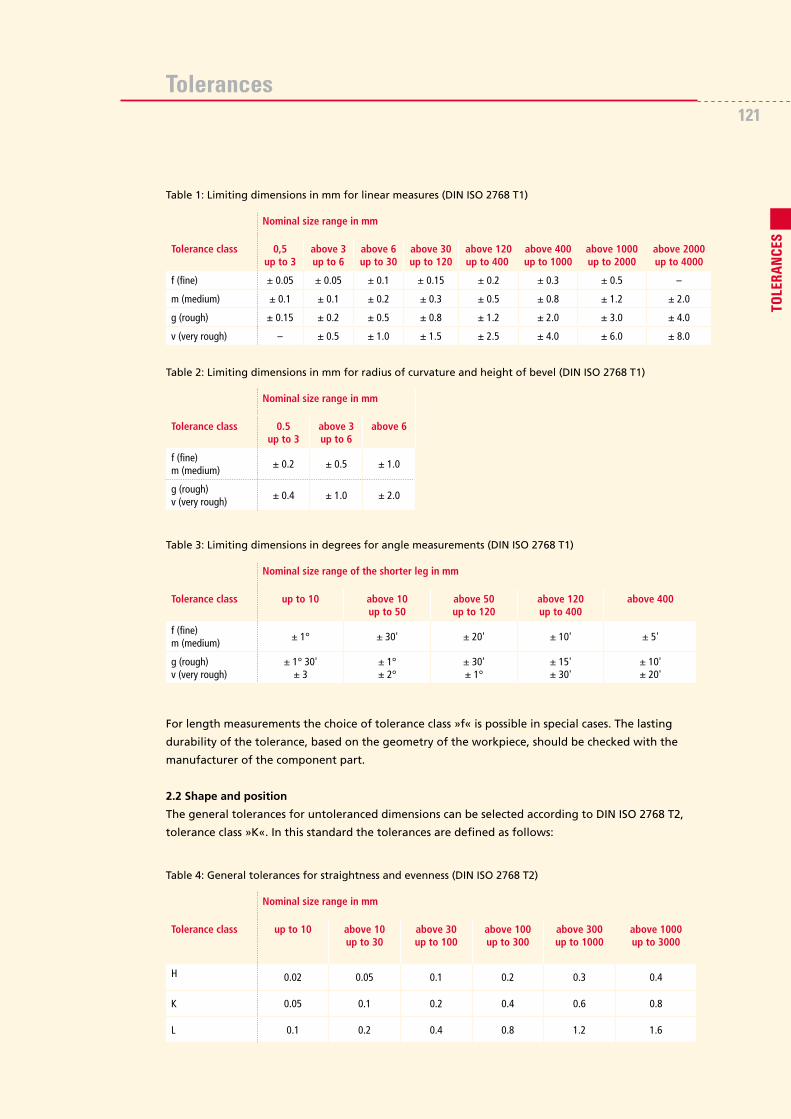
The general tolerances for untoleranced dimensions can be chosen according to DIN ISO 2768 T1,
tolerance class »m«. In this standard, the tolerances are defined as follows:
Tolerances
For length measurements the choice of tolerance class »f« is possible in special cases. The lasting
durability of the tolerance, based on the geometry of the workpiece, should be checked with the
manufacturer of the component part.
2.2 Shape and position
The general tolerances for untoleranced dimensions can be selected according to DIN ISO 2768 T2,
tolerance class »K«. In this standard the tolerances are defined as follows:
Nominal size range in mm
Tolerance class 0,5up to 3
above 3up to 6
above 6up to 30
above 30up to 120
above 120up to 400γ
above 400up to 1000
above 1000up to 2000
above 2000up to 4000
f (fine) ± 0.05 ± 0.05 ± 0.1 ± 0.15 ± 0.2 ± 0.3 ± 0.5 –
m (medium) ± 0.1 ± 0.1 ± 0.2 ± 0.3 ± 0.5 ± 0.8 ± 1.2 ± 2.0
g (rough) ± 0.15 ± 0.2 ± 0.5 ± 0.8 ± 1.2 ± 2.0 ± 3.0 ± 4.0
v (very rough) – ± 0.5 ± 1.0 ± 1.5 ± 2.5 ± 4.0 ± 6.0 ± 8.0
Table 1: Limiting dimensions in mm for linear measures (DIN ISO 2768 T1)
Nominal size range of the shorter leg in mm
Tolerance class up to 10 above 10up to 50
above 50up to 120
above 120up to 400
above 400γ
f (fine)m (medium)
± 1° ± 30' ± 20' ± 10' ± 5'
g (rough)v (very rough)
± 1° 30'± 3
± 1°± 2°
± 30'± 1°
± 15'± 30'
± 10'± 20'
Table 3: Limiting dimensions in degrees for angle measurements (DIN ISO 2768 T1)
Nominal size range in mm
Tolerance class up to 10 above 10up to 30
above 30up to 100
above 100up to 300
above 300up to 1000
γ
above 1000up to 3000
H 0.02 0.05 0.1 0.2 0.3 0.4
K 0.05 0.1 0.2 0.4 0.6 0.8
L 0.1 0.2 0.4 0.8 1.2 1.6
Table 4: General tolerances for straightness and evenness (DIN ISO 2768 T2)
Nominal size range in mm
Tolerance class 0.5up to 3
above 3up to 6
above 6
f (fine)m (medium)
± 0.2 ± 0.5 ± 1.0
g (rough)v (very rough)
± 0.4 ± 1.0 ± 2.0
Table 2: Limiting dimensions in mm for radius of curvature and height of bevel (DIN ISO 2768 T1)
121
TOLE
RANCE
S

Tolerances
The general tolerance for run-out and concentricity for class »K« is 0.2 mm.
In special cases it is possible to choose tolerance class »H«. The general tolerance for run-out and
concentricity for class »H« is 0.1 mm.
It is important to check with the manufacturer to make sure the tolerance can be held over the
long term.
2.3 Press fit
As described above, it is not possible to apply the ISO tolerance system that is usually applied to
steel components. Accordingly, the tolerance series IT 01-9 should not be used. In addition, to
determine the correct tolerance series, the machining method and the type of plastic being used
must be considered.
2.3.1 Dimensional categories
The different plastics can be classified into two categories according to their dimensional stability.
These are shown in Table 7.
Table 7: Dimension categories for plastics
Nominal size range in mm
Tolerance class up to 100 above 100up to 300
above 300up to 1000
above 1000up to 3000
H 0.2 0.3 0.4 0.5
K 0.4 0.6 0.8 1.0
L 0.6 1.0 1.5 2.0
Table 5: General tolerances for rectangularity (DIN ISO 2768 T2)
Nominal size range in mm
Tolerance class to 100 above 100up to 300
above 300up to 1000
above 1000up to 3000
H 0.5
K 0.6 0.8 1.0
L 0.6 1.0 1.5 2.0
Table 6: General tolerances for symmetry (DIN ISO 2768 T2)
Dimension category Plastics Comments
A POM, PET, PTFE+glass, PTFE+bronze,
PTFE+carbon,PC,PVC-U, PVDF, PP-H,
PEEK, PEI, PSU, HGW (laminated fabric)
Thermoplastics with or
or without reinforcement/fillers
(with low moisture absorption)
B PE-HD, PE-HMW, PE-UHMW, PTFE,
PA 6, LiNNOTAM, PA 66, PA 12
Soft thermoplastics and polyamides with
moisture absorption

Tolerances
Nominal size range mm
ISO tolerance series (IT)
6 7 8 9 10 11 12 13 14 15 16
From up to 1-3 6 10 14 25 40 60 100 140 250 400 600
Above up to 3-6 8 12 18 30 48 75 120 180 300 480 750
Above up to 6-10 9 15 22 36 58 90 150 220 360 580 900
Above up to 10-18 11 18 27 43 70 110 180 270 430 700 110
Above up to 18-30 13 21 33 52 84 130 210 330 520 540 1300
Above up to 30-50 16 25 39 62 100 160 250 390 620 1000 1600
Above up to 50-80 19 30 46 74 120 190 300 460 740 1200 1900
Above up to 80-120 22 35 54 87 140 220 350 540 870 1400 2200
Above up to 120-180 25 40 63 100 160 250 400 630 1000 1600 2500
Above up to 180-250 29 46 72 115 185 290 460 420 1150 1850 2900
Above up to 250-315 32 52 81 130 210 320 520 810 1300 2100 3200
Above up to 315-400 36 57 89 140 230 360 570 890 140 2300 3600
Above up to 400-500 40 63 97 155 250 400 630 970 1550 2500 4000
Table 8: ISO basic tolerances in µm according to DIN ISO 286
2.3.2 Classification of tolerance series for milled parts
Classification for milled parts with tolerances
Dimension A IT 10-12
category: B IT 11-13
2.3.3 Classification of tolerance series for turned parts
Classification for turned parts with tolerances
Dimension A IT 10-11
category: B IT 11-12
123
TOLE
RANCE
S

Tolerances
2.4 Surface quality
The degree of surface quality that can be achieved depends on the machining method. Table 9
shows the surface qualities that can be achieved without any additional expenditure for the individual
processes.
It is possible to achieve better surface qualities than those shown in Table 9 in conjunction with
higher production expenditure. However, the production possibilities must be discussed with the
manufacturer of the component part in regard to the respective plastic and the machining method.
2.5 Tolerances for press fits
2.5.1 Oversize for bushes
To ensure that friction bearing bushes sit properly
in the bearing bore, the insertion of an oversized
component has proved to be a good method. The
oversize for plastic bushes is very large compared
to metal bearing bushes. However, due to the visco-
elastic behaviour of the plastics, this is especially
important because of the effects of heat, as otherwise
the bearing bush would become loose in the bore. If
the maximum service temperature is 50 °C, it is pos-
sible to do without an additional securing device for
the bearing bush if the oversizes from Diagram 1 are
complied with. In the case of temperatures above
50 °C, we recommend that the bush be secured with
a device commonly used in machine engineering
(e.g. a retaining ring according to DIN 472, see also
the chapter on »Friction bearings« section 2.5).
It should also be considered that when the bearing
bush is being inserted, its oversize leads to it being
compressed. Consequently the oversize must be
considered as an excess to the operating bearing
play, and the internal diameter of the bearing must
be dimensioned accordingly. Diagram 2 shows the
required bearing play in relation to the internal
diameter of the bearing. To prevent the bearing
from sticking at temperatures above 50 °C, it is
necessary to correct the bearing play by the factors
shown in the chapter on »Friction bearings« section 2.3.
Table 9: Achievable surface qualities for various machining processes
Form of machining
Max. achievabledegree of roughness
Average roughnessvalue Ra (μm)
Averaged depth ofroughness Rz(μm)
Milling N7 1.6 8
Turning N7 1.6 8
Planing N8 3.2 12.5
Sawing N8 3.3 26
0.007
0.006
0.005
0.004
0.003
0.002
0.001
20 40 60 80 100 120 140 160 1800
Outer diameter of the friction bearing in mm
Pres
s-fi
t o
vers
ize
per
mm
ou
ter
dia
met
er in
mm
Diagram 1:Press-fit oversize for friction bearings
0 10 30 50 100 150 200
0.1
1.0
0.9
0.8
0.7
0.6
0.5
0.4
0.3
0.2
0
Internal diameter of bearing in mm
Op
erat
ing
bea
rin
g p
lay
in %
Diagram 2: Operating bearing play

Tolerances
In regard to dimensioning thin walled bearing
bushes, rings and similar components, it must
be noted that the measuring forces that are
applied and the deformation that this causes
can result in incorrect measurements. Hence,
the tolerances for the outer diameter and
wall thickness shown in Figure1 are
recommended.
2.5.2 Press-fit undersize for antifriction bearings
Antifriction bearings can be inserted directly into the undersized bearing seat for maximum
operating temperatures of up to 50 °C. If low loads and low operating temperatures are expected,
no additional securing is required for the bearing, but it is recommended for higher loads and
operating temperatures. Again this is because of the visco-elastic behaviour of the
plastics which can result in a reduction
in the compression force and bearing
migration. The bearing can also be
secured with devices commonly used in
machine engineering (e.g. retaining ring
according to DIN 472). If the bearing is
to be used in areas where high tempe-
ratures or loads are expected, it is also
possible to place a steel sleeve in the
bearing bore. This steel sleeve is fixed
in the bearing bore with additional
securing elements, and the bearing
is pressed in to this ring. Diagram 3
shows the required temperature-related
undersizes for fixing the bearing in the
bearing seat by compression.
For bearing seats into which anti-friction bearings are inserted for operation at normal temperature
and load conditions, we recommend the following press-fit undersizes and tolerances:
Bearing seat diameter up to 50 mm ➜ -0,15/-0,25 mm
Bearing seat diameter above 50 up to 120 mm ➜ -0,25/-0,35 mm
Bearing seat diameter above 120 mm ➜ -0,40/-0,50 mm
In our many years of experience, bearing seats manufactured according to the above exhibit no excessive
decrease in compression force and are able to keep the anti-friction bearings in position safely and
securely. However, if this recommendation is taken, it should be noted that in the case of extremely
small ratios between the bearing seat diameter and the outer diameter it is possible that the bearings
loosen despite compliance with our recommendations. This can be attributed to the fact that the
stresses caused by insertion can result in deformation of the plastic material. As a result of this, the
bearing seat diameter becomes larger and the compression force needed to fix the bearing can no
longer be maintained. This behaviour is exacerbated by high temperatures and/or flexing that occurs
during operation. This can be negated to a certain extent by the securing measures described above.
70 0-0.2
2.5
-0.1
0-0
.15
Ø 4
5
(Ø 4
0)+0.
25+
0.15
Figure 1: Example of tolerance for abearing bush
0.1
0.7
0.6
0.5
0.4
0.3
0.2
0.020 40 60 80 100 120
Operating temperature 50 °C
Operating temperature 20 °C
Antifriction bearing diameter in mm
Bo
re s
etti
ng
siz
e in
mm
Diagram 3: Bore setting sizes for bearing seats
125
TOLE
RANCE
S

Tolerances
3. General information
The basic tolerances and dimensions stated above can only be sustainably maintained under
normal climatic conditions (23 °C/50% rel. humidity). If the environmental conditions differ, they
must be considered by applying the respective correction factors. These can be found for the
specific cases in the previous chapters.
3.1 Dimensional and volume changes under the influence of temperature
In general it can be said that elongation caused by temperature is approx. 0.1% per 10 K temperature
change. In addition, in the case of polyamides, due to the absorption of moisture a change in
volume of 0.15-0.20% per 1% water absorbed must be considered.
Considering the material-specific coefficient of elongation, the expected elongation and volume
changes due to fluctuating temperatures can be calculated approximately. Hence, the expected
elongation is
ΔI = I · a · (u1 – u2 ) [mm]
where
ΔI = expected elongation
l = original length in mm
a = material-specific coefficient of elongation
u1 = installation temperature in °C
u2 = operating temperature in °C
The expected change in volume is calculated – with the assumption that the elongation is not
hindered in any direction – from:
ΔV = V · b · (u2 – u1) [mm3]
and
b = 3 · a
where
ΔV = expected change in volume
V = original volume in mm3
a = material-specific coefficient of elongation
b = material-specific coefficient of volume expansion
u1 = installation temperature in °C
u2 = operating temperature in °C
The material-specific coefficients of elongation can be found in Table 10.

Tolerances
3.2 Geometric shapes
The geometric relationships of a workpiece can cause changes in dimensions and shape after the
machining process. Therefore, either the geometric shape has to be changed or the recommended
tolerance series for workpieces with extreme geometric shape and wall thickness relationships, e.g.
extreme one-sided machining, extremely thin walls, extreme wall thickness differences, must be
adapted accordingly. If there is any uncertainty in regard to the definition of shape, dimension or
position tolerances, we would be pleased to assist.
3.3 Measuring technology
It is very difficult to measure narrow tolerances in plastic workpieces, especially in thin-walled parts.
The pressure exerted on the workpiece by the measuring instrument can deform the plastic part,
or the low coefficient of friction of plastics can distort the starting torque of micrometre gauges.
This inevitably leads to incorrect measured values. Therefore it is recommended that contactless
measuring systems are used.
Product Material Coefficient of elongation a 10-5 . K-1
LiNNOTAM PA 6 C 7
LiNNOTAM CC PA 6 C -CC 8
LiNNOTAMGLiDE PA 6 C + Oil 7
LiNNOTAMGLiDE PRO T PA 6 C + Solid lubricant 7
LiNNOTAMHiPERFORMANCE 612 PA 6/12 G 8
LiNNOTAMHiPERFORMANCE 1200 PA 12 G 10
Polyamide 6 PA 6 9
Polyamide 6 + 30% glass fibre PA 6 C F30 3
Polyamide 66 PA 66 10
Polyamide 12 PA 12 12
Polyacetal POM-C 10
Polyacetal GF-filled POM-C-GF30 2.5
Polyethylene terephthalate PET 7
Polyethylene terephthalate + lubricant additive PET-GL 8
Polytetrafluoroethylene PTFE 19
Polytetrafluoroethylene + 25% glass fibre PTFE-GF25 13
Polytetrafluoroethylene + 25% carbon PTFE-K25 11
Polytetrafluoroethylene + 40% bronze PTFE-B40 10
Polyethylene 500 PE-HMW 18
Polyethylene 1000 PE-UHMW 18
Polyetheretherketone PEEK 4
Polyetheretherketone modified PEEK-GL 3
Polysulfone PSU 6
Polyetherimide PEI 6
Table 10: Linear coefficients of elongation of various plastics
127
TOLE
RANCE
S

DES
IGNIN
G W
ITH E
NGIN
EERI
NG P
LAST
ICS
with survey tables
DESIGNING WITH ENGINEERING
PLASTICS
Germany: Licharz GmbH
Industriepark Nord | D-53567 Buchholz | Germany
Telefon: +49 (0) 2683 - 977 0 | Fax: +49 (0) 2683 - 977 111
Internet: www.licharz.com | E-Mail: [email protected]
France: Licharz eurl.
Z.I. de Leveau – Entrée G | F-38200 Vienne | France
Téléphone: +33 (0) 4 74 31 87 08 | Fax: +33 (0) 4 74 31 87 07
Internet: www.licharz.fr | E-Mail: [email protected]
Great Britain: Licharz Ltd
34 Lanchester Way | Royal Oak Industrial Estate | Daventry, NN11 8PH | Great Britain
Phone: +44 (0) 1327 877 500 | Fax: +44 (0) 1327 877 333
Internet: www.licharz.co.uk | E-Mail: [email protected]
USA: Timco Inc
2 Greentown Rd | Buchanan NY 10511 | USA
Phone: +1 914 - 736 0206 | Fax: +1 914 - 736 0395
Internet: www.timco-eng.com | E-Mail: [email protected]
LIC
H-1
3075
Kon
stru
iere
n m
it K
unst
stof
fen
GB
LICHARZ
EXACTLY YOUR SOLUTION:We think with you from the beginning!
We offer advice on how to utilise plastics and develop your component
together with you:
• we check application conditions on your machine
• we check your design drawing
• we recommend the material and the process
• we manufacture a prototype for you if required
You will receive your product quickly and economically, exactly as you need it!
nominal charge 18.00 Euro