DR5000 - Modular Contribution Decoder - User Manual
143
DR5000 - Modular Contribution Decoder User Manual DVBCommunity - cообщество профессионалов ЦТВ https://dvbcommunity.ru/
-
Upload
khangminh22 -
Category
Documents
-
view
2 -
download
0
Transcript of DR5000 - Modular Contribution Decoder - User Manual

DR5000 - Modular Contribution Decoder
User Manual
DVBCommunity - cообщество профессионалов ЦТВ https://dvbcommunity.ru/

DR5000 User Manual UM-DR5000-FW1.2.1.0-REV1.02015-02-13
www.ateme.com Page ii
Table of Contents1. Document Overview ...................................................................................................................... 7
1.1. Document identification ....................................................................................................... 71.2. Disclaimer ......................................................................................................................... 81.3. Copyrights ......................................................................................................................... 91.4. Precautions ....................................................................................................................... 10
2. Product Overview ........................................................................................................................ 112.1. Package Content ............................................................................................................... 112.2. Front View ....................................................................................................................... 122.3. Rear View ........................................................................................................................ 13
2.3.1. DVB-S2 IO Interfaces ............................................................................................. 142.3.2. ASI IO Interfaces .................................................................................................... 152.3.3. SDI Output Interfaces .............................................................................................. 152.3.4. Synchonization IO Interfaces .................................................................................... 162.3.5. Ethernet IO Interfaces .............................................................................................. 162.3.6. Ethernet Management Interface ................................................................................. 172.3.7. Audio Out Interfaces ............................................................................................... 172.3.8. Analog Audio Out Interfaces .................................................................................... 17
2.4. Ventilation ....................................................................................................................... 193. Installation .................................................................................................................................. 20
3.1. Setting Up Your Device ..................................................................................................... 203.2. Quick start ....................................................................................................................... 21
3.2.1. Setting up the Management IP Address ....................................................................... 213.2.2. Accessing the Web GUI ........................................................................................... 21
4. User Interfaces ............................................................................................................................ 234.1. Three configuration tools .................................................................................................... 234.2. Front Panel ...................................................................................................................... 24
4.2.1. Status LED ............................................................................................................ 244.2.2. LCD ..................................................................................................................... 244.2.3. TFT ...................................................................................................................... 254.2.4. Keypad ................................................................................................................. 254.2.5. USB ..................................................................................................................... 254.2.6. Menus ................................................................................................................... 25
4.3. Web GUI ......................................................................................................................... 344.3.1. Gui Overview ......................................................................................................... 344.3.2. Decoding Status Panels ............................................................................................ 354.3.3. Configuration Panel ................................................................................................. 41
5. Setting up a configuration ............................................................................................................. 625.1. Overview ......................................................................................................................... 625.2. Input ............................................................................................................................... 63
5.2.1. ASI Input .............................................................................................................. 635.2.2. DVB-S/S2 Input ..................................................................................................... 635.2.3. IP Input ................................................................................................................. 655.2.4. ZIXI Input ............................................................................................................. 70
5.3. Service Selection ............................................................................................................... 725.3.1. Service Editor ........................................................................................................ 735.3.2. Video Output ......................................................................................................... 745.3.3. Audio Output ......................................................................................................... 74
5.4. Biss/CA ........................................................................................................................... 815.4.1. BISS parameters ..................................................................................................... 825.4.2. CA parameters ....................................................................................................... 83
5.5. Data Output ...................................................................................................................... 84
DVBCommunity - cообщество профессионалов ЦТВ https://dvbcommunity.ru/

DR5000 User Manual UM-DR5000-FW1.2.1.0-REV1.02015-02-13
www.ateme.com Page iii
5.5.1. Ancillary Data ........................................................................................................ 865.5.2. VBI Data ............................................................................................................... 895.5.3. Overlay ................................................................................................................. 90
5.6. SDI Output ...................................................................................................................... 915.6.1. SDI Connector Mapping .......................................................................................... 915.6.2. SDI Settings ........................................................................................................... 92
5.7. Stream Forwarding ............................................................................................................ 955.7.1. ASI Output ............................................................................................................ 955.7.2. IP Output .............................................................................................................. 965.7.3. Remux Output ........................................................................................................ 97
5.8. MPE ............................................................................................................................... 996. Specific Operations .................................................................................................................... 100
6.1. Installing License ............................................................................................................. 1006.2. Recovery ........................................................................................................................ 101
A. MIB User Guide ....................................................................................................................... 102A.1. SNMP Overview ............................................................................................................. 102A.2. MIB Overview ............................................................................................................... 104
A.2.1. Main nodes ......................................................................................................... 105A.3. MIB Use Cases .............................................................................................................. 108
A.3.1. Identification process ............................................................................................ 108A.3.2. Configuration lock ................................................................................................ 108A.3.3. Rebooting the system ............................................................................................ 108A.3.4. Setting time ......................................................................................................... 109A.3.5. Configuring communities and traps .......................................................................... 109A.3.6. Configuring network interfaces ............................................................................... 110A.3.7. Configuring routes ................................................................................................ 111A.3.8. Saving and loading a preset .................................................................................... 112A.3.9. ASI Input ............................................................................................................ 113A.3.10. IP Input ............................................................................................................. 113A.3.11. IP Input with FEC .............................................................................................. 114A.3.12. IP Input with Failover .......................................................................................... 115A.3.13. DVB-S/S2 Input ................................................................................................. 116A.3.14. Automatic audio composition ................................................................................ 118A.3.15. Manual composition ............................................................................................ 118A.3.16. Configuring Biss-E .............................................................................................. 119A.3.17. Clock synchronization .......................................................................................... 120A.3.18. IP Forwarding .................................................................................................... 121A.3.19. Forward remux ................................................................................................... 121A.3.20. Checking composition results ................................................................................ 122A.3.21. TS Descriptor ..................................................................................................... 123
B. Input Statistics .......................................................................................................................... 126B.1. Input Statistics Overview .................................................................................................. 126B.2. Input Statistics File Format ............................................................................................... 127
C. Appendix ................................................................................................................................. 131C.1. Product's specification ...................................................................................................... 131C.2. Warranty ....................................................................................................................... 138C.3. Normative Reference ....................................................................................................... 139C.4. Glossary ........................................................................................................................ 140C.5. Support and Ressources .................................................................................................... 143
DVBCommunity - cообщество профессионалов ЦТВ https://dvbcommunity.ru/
DR5000 User Manual UM-DR5000-FW1.2.1.0-REV1.02015-02-13
www.ateme.com Page iv
List of Figures2.1. Front View Interface .................................................................................................................. 122.2. Rear View Interface example 1 .................................................................................................... 132.3. Rear View Interface example 2 .................................................................................................... 132.4. DVB-S/S2 Input/Output Interfaces ................................................................................................ 142.5. ASI Input/Output Interfaces ........................................................................................................ 152.6. SDI Output Interfaces ................................................................................................................ 152.7. Synchronization Interfaces .......................................................................................................... 162.8. Stream Ethernet Interfaces .......................................................................................................... 162.9. Management Ethernet Interface .................................................................................................... 172.10. Audio Output Interfaces ............................................................................................................ 172.11. Analog Output Interfaces .......................................................................................................... 182.12. Cool air intakes on the front panel .............................................................................................. 192.13. Warm air outputs on the rear panel ............................................................................................. 193.1. Accessing the Web GUI ............................................................................................................. 224.1. Front Panel sub-elements' identification ......................................................................................... 244.2. Gui Overview ........................................................................................................................... 344.3. Decoding Status panels .............................................................................................................. 354.4. Active service overview ............................................................................................................. 364.5. Probed programs ....................................................................................................................... 384.6. Sat Input status example ............................................................................................................. 394.7. IP Input status example .............................................................................................................. 404.8. Status Panel .............................................................................................................................. 424.9. Service Panel View ................................................................................................................... 444.10. Network Panel ........................................................................................................................ 474.11. Time Panel ............................................................................................................................. 494.12. Alarms and Traps Panel View .................................................................................................... 504.13. System Descrambling Parameters view ........................................................................................ 554.14. Licenses view ......................................................................................................................... 564.15. Firmware and Troubleshooting view ........................................................................................... 575.1. Input Type Parameter ................................................................................................................. 635.2. DVB-S2 Settings View .............................................................................................................. 645.3. IP Settings View ....................................................................................................................... 665.4. ZIXI Settings View ................................................................................................................... 715.5. Service Selection View .............................................................................................................. 725.6. Descrambling Parameters view .................................................................................................... 815.7. Data Output View ..................................................................................................................... 855.8. Output parameters view .............................................................................................................. 915.9. Stream Forwarding View ............................................................................................................ 955.10. MPE Settings View .................................................................................................................. 99
DVBCommunity - cообщество профессионалов ЦТВ https://dvbcommunity.ru/

DR5000 User Manual UM-DR5000-FW1.2.1.0-REV1.02015-02-13
www.ateme.com Page v
List of Tables1.1. Document Identification ............................................................................................................... 72.1. Front View Interface .................................................................................................................. 122.2. Rear View Interface example 1 .................................................................................................... 132.3. Rear View Interface example 2 .................................................................................................... 142.4. DVB-S/S2 Input/Output Interfaces Description ............................................................................... 142.5. ASI Input/Output Interfaces Description ........................................................................................ 152.6. SDI Output Interfaces Description ................................................................................................ 152.7. Synchronization Interfaces Description .......................................................................................... 162.8. Stream Ethernet Interfaces Description .......................................................................................... 162.9. Analog audio extension board Sub-D25 connector mapping .............................................................. 183.1. Installation ............................................................................................................................... 204.1. Status LED .............................................................................................................................. 244.2. Front Panel Menu ...................................................................................................................... 254.3. Front Panel Configuration Menu .................................................................................................. 284.4. Front Panel Input Menu .............................................................................................................. 284.5. Front Panel Composition Menu .................................................................................................... 294.6. Front Panel Output Menu ........................................................................................................... 324.7. Front Panel Mpe Menu .............................................................................................................. 334.8. Gui Overview ........................................................................................................................... 344.9. Decoding Status panels .............................................................................................................. 354.10. Input status ............................................................................................................................. 394.11. Configuration Panel Description ................................................................................................. 414.12. Status Panel Description ........................................................................................................... 424.13. Service Panel Tabs Description .................................................................................................. 444.14. System Panel Description .......................................................................................................... 464.15. Input alarms ............................................................................................................................ 514.16. Stream alarms ......................................................................................................................... 514.17. Genlock alarms ....................................................................................................................... 524.18. System alarms ......................................................................................................................... 524.19. Decoding alarms ...................................................................................................................... 524.20. Configuration alarms ................................................................................................................ 534.21. Traps description ..................................................................................................................... 535.1. Input Type ............................................................................................................................... 635.2. ASI Input ................................................................................................................................. 635.3. DVB-S2 Settings ....................................................................................................................... 645.4. Basic IP Settings Description ...................................................................................................... 665.5. Failover IP Settings Description ................................................................................................... 675.6. SMPTE 2022-7 Settings Description ............................................................................................. 685.7. IP SSM Settings Description ....................................................................................................... 695.8. VBR Settings Description ........................................................................................................... 705.9. ZIXI Settings settings ................................................................................................................ 715.10. Service Selection Parameters ..................................................................................................... 735.11. Video Output Parameters .......................................................................................................... 745.12. Audio Output Parameters .......................................................................................................... 745.13. Audio Mode Compliance .......................................................................................................... 765.14. DolbyE start line recommandations ............................................................................................. 775.15. Analog Audio Output Levels Description ..................................................................................... 775.16. Audio PID selection example 1 .................................................................................................. 785.17. Audio PID selection example 2 .................................................................................................. 795.18. Audio PID selection example 3 .................................................................................................. 795.19. BISS/CA Parameters Description ................................................................................................ 82
DVBCommunity - cообщество профессионалов ЦТВ https://dvbcommunity.ru/

DR5000 User Manual UM-DR5000-FW1.2.1.0-REV1.02015-02-13
www.ateme.com Page vi
5.20. BISS parameters ...................................................................................................................... 825.21. Vertical Ancillary data default location ........................................................................................ 865.22. Switch lines ............................................................................................................................ 865.23. Overlay settings ....................................................................................................................... 905.24. SDI Mapping Parameters Description .......................................................................................... 925.25. SDI General Settings Description ............................................................................................... 925.26. Synchronization Settings Description ........................................................................................... 925.27. Downscale Settings Description .................................................................................................. 935.28. Emulation Settings Description .................................................................................................. 945.29. Asi Output Parameter Description ............................................................................................... 965.30. IP Output Parameters Description ............................................................................................... 965.31. Remux Output Parameter Description .......................................................................................... 985.32. MPE Settings Description ......................................................................................................... 99B.1. ASI input statistics .................................................................................................................. 127B.2. IP input statistics .................................................................................................................... 127B.3. IP with Failover input statistics .................................................................................................. 127B.4. IP with SMPTE 2022-7 input statistics ........................................................................................ 128B.5. Sat input statistics ................................................................................................................... 129B.6. Zixi input statistics .................................................................................................................. 129B.7. DS3 input statistics .................................................................................................................. 130C.1. Specification - Identification ..................................................................................................... 131C.2. Specification - Physical ............................................................................................................ 131C.3. Specification - Configuration and Management ............................................................................. 131C.4. Specification - Video Codec ...................................................................................................... 132C.5. Specification - Video Output ..................................................................................................... 132C.6. Specification - Video Decoding/Output ....................................................................................... 132C.7. Specification - Data Input/Output ............................................................................................... 132C.8. Specification - Descrambling ..................................................................................................... 134C.9. Specification - Functions .......................................................................................................... 134C.10. Specification - RF Support ...................................................................................................... 134C.11. Specification - Audio analog extension board ............................................................................. 135C.12. Specification - Licenses .......................................................................................................... 135C.13. Specification - Environmental Conditions .................................................................................. 135C.14. Specification - Physical Parameters ........................................................................................... 135C.15. Specification - Power Supply ................................................................................................... 136C.16. Specification - Electromagnetic Emissions by Council Directive 89/366/EEC .................................... 136C.17. Specification - Electromagnetic Immunity by Council Directive 89/366/EEC .................................... 136C.18. Specification - Safety by Council Directive 73/23/EEC ................................................................. 136C.19. Specification - Shock and Vibration .......................................................................................... 136C.20. Specification - CE Marking ..................................................................................................... 136C.21. Specification - Material Declaration .......................................................................................... 137C.22. Normative reference ............................................................................................................... 139C.23. Glossary ............................................................................................................................... 140
DVBCommunity - cообщество профессионалов ЦТВ https://dvbcommunity.ru/

DR5000 User Manual UM-DR5000-FW1.2.1.0-REV1.02015-02-13
www.ateme.com Page 7
1. Document Overview
1.1. Document identification
Table 1.1. Document Identification
Title DR5000 - Modular Contribution Decoder - User Manual
Revision Number 1.0
Description Document for firmware release 1.2.1.0
Date of Issue 2015-02-13
Document Reference UM-DR5000-FW1.2.1.0-REV1.0
DVBCommunity - cообщество профессионалов ЦТВ https://dvbcommunity.ru/

DR5000 User Manual UM-DR5000-FW1.2.1.0-REV1.02015-02-13
www.ateme.com Page 8
1.2. DisclaimerThe material in this document is for information only and subject to change without notice. While reasonable effortshave been made in the preparation of this document to assure its accuracy, ATEME assumes no liability resultingfrom errors or omissions in this document, or from the use of the information contained herein. ATEME reservesthe right to make changes or revisions in the product design or the product manual without reservation and withoutobligation to notify any person of such revisions and changes.
DVBCommunity - cообщество профессионалов ЦТВ https://dvbcommunity.ru/

DR5000 User Manual UM-DR5000-FW1.2.1.0-REV1.02015-02-13
www.ateme.com Page 9
1.3. Copyrights
Notice
The ATEME Kyrion(R) is not designed or intended to violate any other entity's copyright or other IP (IntellectualProperty) rights. Each ATEME Kyrion(R) user may only use their ATEME Kyrion(R) in conjunction with materialslegally owned or licensed by such user, and only to the extent that such ownership or license rights permit such use.
Copyright (c) 2013 ATEME
These materials, ATEME products and all related documentation are protected by copyright and other laws, interna-tional treaties and conventions. All rights, title and interest in the materials, ATEME products and related documen-tation shall remain with ATEME and its licensors. All registered or unregistered trademarks in these materials are thesole property of their respective owners. No part of this document or related ATEME products may be reproduced inany form, or by any means without written authorization of ATEME Corporation.
These materials are provided "as-is." ATEME makes no warranties, stated or implied, as to, the information containedherein. In addition, ATEME makes no stated or implied warranties of merchantability or working condition for aparticular purpose or use with respect the information contained in these materials.
In no event shall ATEME be liable for any indirect, special, consequential or incidental damages, including, but notlimited to, lost profits or loss or damage to data arising from the use of these materials, even if advised in advanceof the possibility of such damages.
The glossary of this document is partially extracted from the Wikipedia encyclopedia.
Trademarks
ATEME, the ATEME logo, Kyrion(R) and the KYRION(R) logo are all trademarks or registered trademarks ofATEME Corporation. The Kyrion(R) clustering technology -as well as other technologies included in Kyrion(R) - areprotected by patents or pending patent applications in the U.S. and other countries. All other trademarks or registeredtrademarks are property of their respective owners.
DVBCommunity - cообщество профессионалов ЦТВ https://dvbcommunity.ru/

DR5000 User Manual UM-DR5000-FW1.2.1.0-REV1.02015-02-13
www.ateme.com Page 10
1.4. PrecautionsOnly qualified persons are authorized to carry out maintenance on this device.
Read the Users' Manual carefully, and follow the correct procedure when setting up the device.
Do not open your Kyrion or attempt to disassemble or modify it, unless instructed by an ATEME representative. Toavoid any risk of electrical shock, fire, short-circuiting or dangerous emissions, never insert any metallic object intothe enclosure. Your Kyrion contains no user-serviceable parts. If it appears to be malfunctioning, have it inspectedby a qualified ATEME Technical Support representative.
Never expose your device to rain, use it near water, or in damp or wet conditions. Never place objects containingliquids on the Kyrion, as they may spill into its openings; doing so increases the risk of electrical shock, short-circuiting, fire or personal injury.
Basic electrical safety precautions should be followed to protect you from harm and the system from damage:
• Be aware of where the On/Off power switch is situated on the chassis; as well as the rack's emergency power off-switch. Check also where the disconnection switch or electrical outlet is located.
• Do not work alone when working with high voltage components.
• Power should always be disconnected from the system before opening it. When disconnecting the power, youshould first power down the system and unplug the power cords of the power supply.
• Ground pin shall be connected to earth for safe operation.
For the 220VAC version:
• Only the provided power supply cord must be use to power the Kyrion. This power supply cord includes a groundingplug and it must be plugged into a grounded electrical outlet. If you should use a different power supply cord, makesure it is compatible with your locale electrical power supply.
• The mains plug (or the mains plugs for dual plug version) is used as the disconnect device and shall be easilyaccessible.
For the 48VDC version:
• The internal fuse of the DC filter board shall be replaced by a 5x20mm medium-acting 8A 250V fuse, like LittleFuse234 series.
• The rear connector is used as the disconnect device and shall be easily accessible.
Warning
This product contains a lithium battery. The lithium battery may explode if it is incorrectly replaced.This battery must be replaced only with the same or equivalent type recommended by the manufacturer.Dispose of used batteries according to the manufacturer's instructions.
DVBCommunity - cообщество профессионалов ЦТВ https://dvbcommunity.ru/

DR5000 User Manual UM-DR5000-FW1.2.1.0-REV1.02015-02-13
www.ateme.com Page 11
2. Product Overview
2.1. Package ContentBefore continuing, please check the content of the product package. This product package should contain the followingitems:
• One (1) Kyrion(R) DR5000,
• One (1) Power Cord,
• One (1) USB Key,
• Spare air filters kit with Allen key,
• Printed Quick Start Guide,
• This User's Manual.
If anything is missing, please contact your place of purchase.
DVBCommunity - cообщество профессионалов ЦТВ https://dvbcommunity.ru/

DR5000 User Manual UM-DR5000-FW1.2.1.0-REV1.02015-02-13
www.ateme.com Page 12
2.2. Front ViewNext picture describes the front interface of the Kyrion(R) DR5000.
Figure 2.1. Front View Interface
Table 2.1. Front View Interface
FP Front Panel
A Air Intakes
Front Panel Interfaces FP are described in Section 4.2, “ Front Panel ”
Ventilation using Air Intakes A is described in Section 2.4, “ Ventilation ”
Note
Depending on your hardware options, a double slot CAM input may also be present.
DVBCommunity - cообщество профессионалов ЦТВ https://dvbcommunity.ru/

DR5000 User Manual UM-DR5000-FW1.2.1.0-REV1.02015-02-13
www.ateme.com Page 13
2.3. Rear ViewNext picture describes the generic rear interfaces of Kyrion(R) Decoders. The groups highlighted in the picture belowwill be described in the next sections. Pictures below show possible configurations of the rear panel, that may varydepending on your hardware options.
Figure 2.2. Rear View Interface example 1
Table 2.2. Rear View Interface example 1
DVB-S/S2 In/Out 75 Ohms, F-Type connector input/output.
Fan OutThe air output must never be obstructed to en-
sure proper temperature regulation of the decoder.
ASI In/Out BNC Connector for ASI input or ASI loopback output.
SDI Out BNC Connector for SD/HD/3G SDI output.
Sync In BNC Connector for Blackburst/TriLevel synchronization signal input.
Sync Out BNC Connector for Blackburst/TriLevel synchronization signal forwarding.
Ethernet MGT RJ-45 connector, dedicated to management.
Ethernet In/Out RJ-45 connector, IP stream input/output (can be used for management as well).
Audio Out BNC Connector for EBU/AES digital audio output.
AC Inlet Connect the provided cable to the inlet. The decoder auto-detects the input AC voltage.
Figure 2.3. Rear View Interface example 2
DVBCommunity - cообщество профессионалов ЦТВ https://dvbcommunity.ru/

DR5000 User Manual UM-DR5000-FW1.2.1.0-REV1.02015-02-13
www.ateme.com Page 14
Table 2.3. Rear View Interface example 2
DVB-S/S2 In/Out 75 Ohms, F-Type connector input/output.
Fan OutThe air output must never be obstructed to en-
sure proper temperature regulation of the decoder.
ASI In/Out BNC Connector for ASI input or ASI loopback output.
SDI Out BNC Connector for SD/HD/3G SDI output.
Sync In BNC Connector for Blackburst/TriLevel synchronization signal input.
Sync Out BNC Connector for Blackburst/TriLevel synchronization signal forwarding.
Ethernet MGT RJ-45 connector, dedicated to management.
Ethernet In/Out RJ-45 connector, IP stream input/output (can be used for management as well).
Audio Out BNC Connector for EBU/AES digital audio output.
Analog Audio Out SUB D-25 connector for analog audio output.
48V DC InletConnect a +48V or -48V DC source to the inlet: Be care-
ful to respect + and – polarity as indicated on the rear panel.
Note
Earth pin shall also be correctly connected, or be shunt to either + / – DC input if already grounded, asthe + / - DC input is floating and fully isolated from ground.
The following sections details the previously highlighted blocks
2.3.1. DVB-S2 IO Interfaces
The Kyrion(R) DR5000 has four 75 Ohms F-Type input connectors, that are used to feed a single DVB-S/S2 tuner/demodulator. This can typically be used for professional antennas that provide four output wire for all the polariza-tion/band capabilitites. Besides, the DR5000 can drive a LNB through the active input connector.
Figure 2.4. DVB-S/S2 Input/Output Interfaces
Table 2.4. DVB-S/S2 Input/Output Interfaces Description
RF IN-PUTS 1-4
Use this 75 Ohms, type F connector to input DVB-S/S2 signal to receive a satel-lite stream. These 4 connectors are internally mapped to a single tuner/de-
modulator. The input connector is choosen through the decoder configuration.
RF Loop-back
This 75 Ohms, type F connector is a loopback of the choosenRF INPUT connector, without any signal processing.
DVBCommunity - cообщество профессионалов ЦТВ https://dvbcommunity.ru/

DR5000 User Manual UM-DR5000-FW1.2.1.0-REV1.02015-02-13
www.ateme.com Page 15
2.3.2. ASI IO Interfaces
The Kyrion(R) DR5000 has two BNC connector used for ASI input, and two (duplicate) BNC connectors used forASI output.
Figure 2.5. ASI Input/Output Interfaces
Table 2.5. ASI Input/Output Interfaces Description
ASI IN 1-2Use one of these BNC connectors to receive a transport stream.
The input connector is choosen through the decoder configuration.
ASI OUT
This BNC connector is a loopback (which may be processed) of the input stream, whatever the con-figured input is. In other words, these two (mirror) connectors will output a valid transport stream aslong as a valid stream is received through any of the input (IP, ASI or DVB-S/S2). The output streammay be processed (biss descrambling, please refer to the appropriate section for further information).
2.3.3. SDI Output Interfaces
The Kyrion(R) DR5000 has three SDI output connectors, separated in two groups described below.
Figure 2.6. SDI Output Interfaces
Table 2.6. SDI Output Interfaces Description
SDI OUT 1 These are two mirror connectors (they will always output the same SDI signal).
SDI OUT 2This connector can be used either as a mirror of the SDIOUT 1 connectors, or to output a different SDI signal.
DVBCommunity - cообщество профессионалов ЦТВ https://dvbcommunity.ru/
DR5000 User Manual UM-DR5000-FW1.2.1.0-REV1.02015-02-13
www.ateme.com Page 16
Note
Version 1.2.1.0 of the DR5000 will always output the same signal on both SDI connector groups.
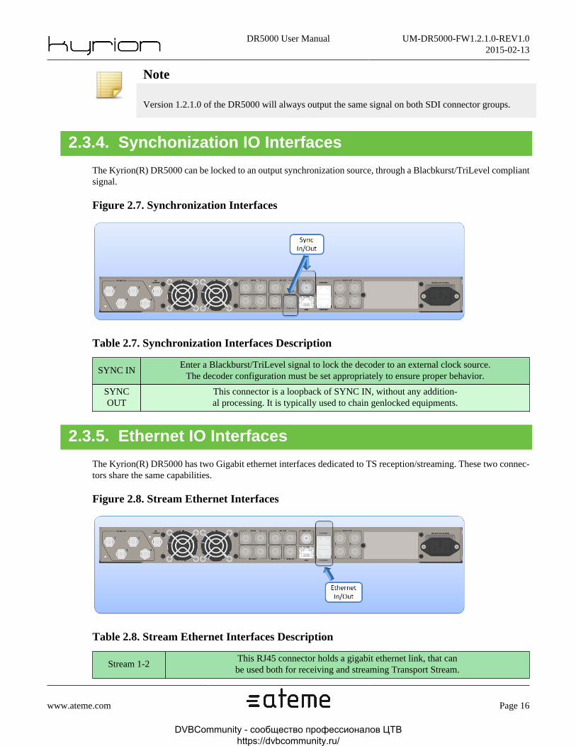
2.3.4. Synchonization IO Interfaces
The Kyrion(R) DR5000 can be locked to an output synchronization source, through a Blacbkurst/TriLevel compliantsignal.
Figure 2.7. Synchronization Interfaces
Table 2.7. Synchronization Interfaces Description
SYNC INEnter a Blackburst/TriLevel signal to lock the decoder to an external clock source.
The decoder configuration must be set appropriately to ensure proper behavior.
SYNCOUT
This connector is a loopback of SYNC IN, without any addition-al processing. It is typically used to chain genlocked equipments.
2.3.5. Ethernet IO Interfaces
The Kyrion(R) DR5000 has two Gigabit ethernet interfaces dedicated to TS reception/streaming. These two connec-tors share the same capabilities.
Figure 2.8. Stream Ethernet Interfaces
Table 2.8. Stream Ethernet Interfaces Description
Stream 1-2This RJ45 connector holds a gigabit ethernet link, that canbe used both for receiving and streaming Transport Stream.
DVBCommunity - cообщество профессионалов ЦТВ https://dvbcommunity.ru/

DR5000 User Manual UM-DR5000-FW1.2.1.0-REV1.02015-02-13
www.ateme.com Page 17
Note
The "Management" port, described in Section 2.3.6, “ Ethernet Management Interface ”, is not suited toreceive/transmit Transport Stream, and shall be used only for management purposes (SNMP monitoring,web GUI, etc.). Nevertheless, those streaming connectors can be used for management purposes.
2.3.6. Ethernet Management Interface
The Kyrion(R) DR5000 one ethernet management port. This 100 mb port is not suited to receive/transmit TransportStream, and shall be used only for management purposes (SNMP monitoring, web GUI, etc.).
Figure 2.9. Management Ethernet Interface
2.3.7. Audio Out Interfaces
The Kyrion(R) DR5000 has four independent digital unbalanced AES/EBU outputs, under the form of BNC connec-tors. The user can configure which audio track is provided on each AES output.
Figure 2.10. Audio Output Interfaces
2.3.8. Analog Audio Out Interfaces
The Kyrion(R) DR5000 may have an optional analog audio extension board. This provides four independent analogbalanced audio outputs, under the form of Sub-D25 connector. The user can configure which audio track is providedon each analog output.
DVBCommunity - cообщество профессионалов ЦТВ https://dvbcommunity.ru/

DR5000 User Manual UM-DR5000-FW1.2.1.0-REV1.02015-02-13
www.ateme.com Page 18
Figure 2.11. Analog Output Interfaces
Table 2.9. Analog audio extension board Sub-D25 connector mapping
Pin Index Function
1 AUDIO_OUT_P_8
2 GND
3 AUDIO_OUT_N_7
4 AUDIO_OUT_P_6
5 GND
6 AUDIO_OUT_N_5
7 AUDIO_OUT_P_4
8 GND
9 AUDIO_OUT_N_3
10 AUDIO_OUT_P_2
11 GND
12 AUDIO_OUT_N_1
13 NC
14 AUDIO_OUT_N_8
15 AUDIO_OUT_P_7
16 GND
17 AUDIO_OUT_N_6
18 AUDIO_OUT_P_5
19 GND
20 AUDIO_OUT_N_4
21 AUDIO_OUT_P_3
22 GND
23 AUDIO_OUT_N_2
24 AUDIO_OUT_P_1
25 GND
DVBCommunity - cообщество профессионалов ЦТВ https://dvbcommunity.ru/

DR5000 User Manual UM-DR5000-FW1.2.1.0-REV1.02015-02-13
www.ateme.com Page 19
2.4. VentilationAir ventilation prevents abnormal temperature rises inside the unit. Next figures show cool air intakes and warm airoutputs.
Figure 2.12. Cool air intakes on the front panel
Figure 2.13. Warm air outputs on the rear panel
Place the Kyrion(R) in a well-ventilated space, and allow ideally up to 10cm of free space on all sides of the Kyrion(R)so increasing air circulation and cooling.
Warning
Never obstruct air intakes and outtakes. Beware of 19'' bays doors, if any.
DVBCommunity - cообщество профессионалов ЦТВ https://dvbcommunity.ru/

DR5000 User Manual UM-DR5000-FW1.2.1.0-REV1.02015-02-13
www.ateme.com Page 20
3. Installation
3.1. Setting Up Your DeviceUnpack your DR5000 unit, and carefully slide it into a shelf space in the rack. Use your equipment rack's screw tosecure the device in place. You should then plug in the following order:
Table 3.1. Installation
# Installation Step
1Connect the MPEG-2/4 feed you wish to decode on theASI input (refer to Section 2.3.2, “ ASI IO Interfaces ”)
2 Connect the SDI output to a monitor (refer to Section 2.3.3, “ SDI Output Interfaces ”)
3Connect the management ethernet interface to your supervision net-
work (refer to Section 2.3.6, “ Ethernet Management Interface ”)
4Power up the decoder by connecting the power cable, and placing the power switch on 1. Both theLCD and the TXT front panel should instantaneously display welcome messages. After a few sec-
onds, the decoded service found on the ASI input transport stream will be displayed on your monitor.
DVBCommunity - cообщество профессионалов ЦТВ https://dvbcommunity.ru/

DR5000 User Manual UM-DR5000-FW1.2.1.0-REV1.02015-02-13
www.ateme.com Page 21
3.2. Quick startOnce the steps described in Section 3.1, “ Setting Up Your Device ” have been followed, the decoder will decode thefirst program found in the incoming ASI stream. Its configuration is fully automatic, which means that the DR5000will automatically select the program, and the way the PIDs will be mapped on output. Please follow the next stepsto connect to the decoder Web GUI.
3.2.1. Setting up the Management IP Address
In order to access the Web GUI, you first need to configure the Management interface so that it can be accessedthrough your supervision network. These steps can be performed through the front panel.
Note
Factory address for the Management ethernet is 192.168.128.1.
• Use the arrows of the front panel to enter "System -> Network -> Management" menu.
• Check that the interface is enabled by entering the "Mode" sub-menu.
• Enter the appropriate IP address and netmask ("Address" and "Netmask" sub-menus) so that the decoder can bereached through your network.
• Configure the gateway, if required.
Your DR5000 is now connected to your supervision network.
3.2.2. Accessing the Web GUI
Once the steps described in Section 3.2.1, “ Setting up the Management IP Address ” have been performed, you canaccess the Web GUI by launching your favorite web browser, and entering the configured IP address in the browseraddress bar. The DR5000 GUI should be launched.
Warning
The DR5000 requires Adobe Flash Player, version 10 or above.
DVBCommunity - cообщество профессионалов ЦТВ https://dvbcommunity.ru/

DR5000 User Manual UM-DR5000-FW1.2.1.0-REV1.02015-02-13
www.ateme.com Page 22
Figure 3.1. Accessing the Web GUI
DVBCommunity - cообщество профессионалов ЦТВ https://dvbcommunity.ru/
DR5000 User Manual UM-DR5000-FW1.2.1.0-REV1.02015-02-13
www.ateme.com Page 23
4. User Interfaces
4.1. Three configuration toolsThere are 3 different ways to configure your Kyrion®:
• Front Panel access (see Section 4.2, “ Front Panel ”),
• Web interface (see Section 4.3, “ Web GUI ”),
• SNMP.
The web interface provides access to all the parameters but need a network connection to be used. The Front Panelinterface provides access to all the operational parameters and most of the system ones. Choose the most appropriateway depending on your overall system’s design.
DVBCommunity - cообщество профессионалов ЦТВ https://dvbcommunity.ru/

DR5000 User Manual UM-DR5000-FW1.2.1.0-REV1.02015-02-13
www.ateme.com Page 24
4.2. Front PanelThe Kyrion(R) has a local LCD and keypad interface allowing a simple management of the unit.
The control buttons and LCD provide an easy method of setting the network interface addresses and default gatewayparameters directly from the front of the Kyrion(R) System without using a management computer.
No IT knowledge is required and the Kyrion(R) can be up and running in minutes.
Next figure describes the front panel sub-elements' identification.
Figure 4.1. Front Panel sub-elements' identification
4.2.1. Status LED
The Kyrion(R) comes with a complete range of LEDs that report the device status.
Table 4.1. Status LED
FP1 INSolid Red: No input signal
Solid Green: Valid input signal
FP2 OUTSolid Red: No output signal
Solid Green: Valid output signal
FP3 ALARMOff: No Status
Solid Red: Decoder alarm
Note
The events that will switch the "ALARM" LED to "Solid RED" can be configured in the Web GUI.
4.2.2. LCD
The LCD [FP4] displays some status information and configuration menus.
DVBCommunity - cообщество профессионалов ЦТВ https://dvbcommunity.ru/
DR5000 User Manual UM-DR5000-FW1.2.1.0-REV1.02015-02-13
www.ateme.com Page 25
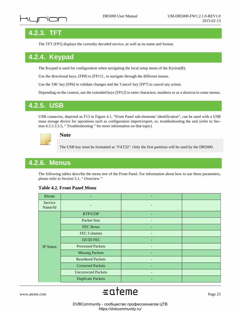
4.2.3. TFT
The TFT [FP5] displays the currenlty decoded service, as well as its name and format.
4.2.4. Keypad
The Keypad is used for configuration when navigating the local setup menu of the Kyrion(R).
Use the directional keys, [FP8] to [FP11] , to navigate through the different menus.
Use the 'OK' key [FP6] to validate changes and the 'Cancel' key [FP7] to cancel any action.
Depending on the context, use the extended keys [FP12] to enter characters, numbers or as a shortcut to some menus.
4.2.5. USB
USB connector, depicted as F13 in Figure 4.1, “Front Panel sub-elements' identification”, can be used with a USBmass storage device for operations such as configuration import/export, or, troubleshooting the unit (refer to Sec-tion 4.3.3.3.5.5, “ Troubleshooting ” for more information on that topic).
Note
The USB key must be formatted as "FAT32". Only the first partition will be used by the DR5000.
4.2.6. Menus
The following tables describe the menu tree of the Front Panel. For information about how to use these parameters,please refer to Section 5.1, “ Overview ”
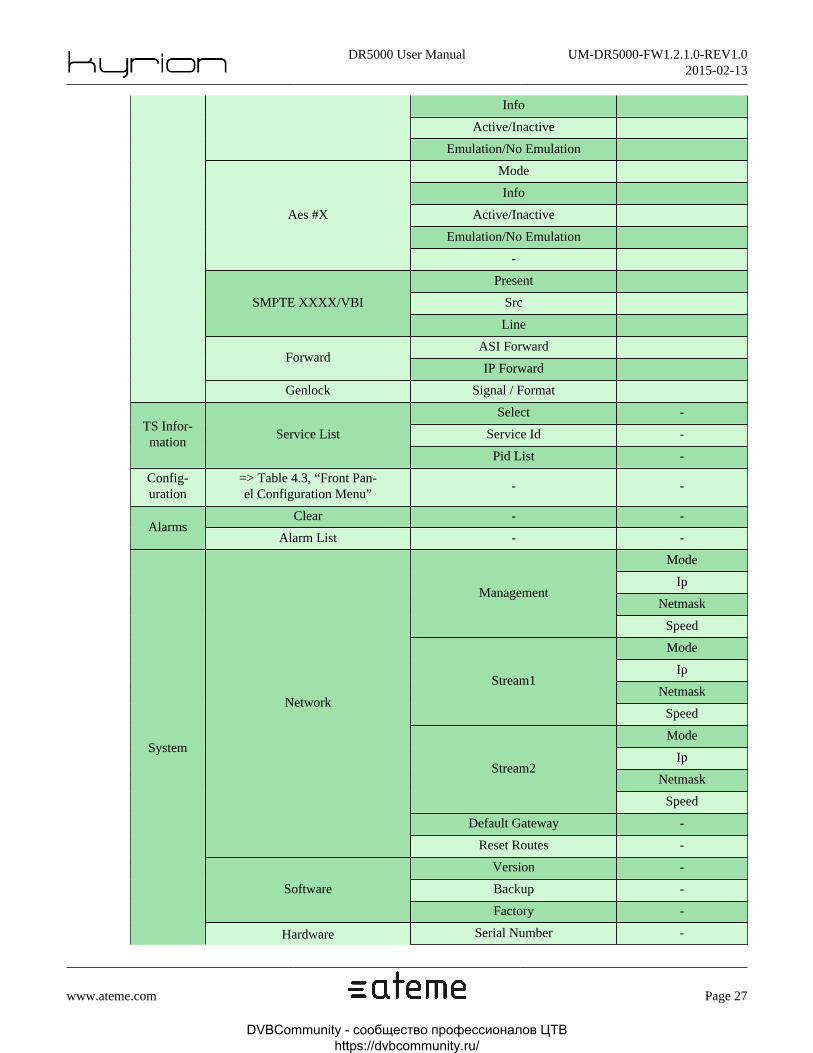
Table 4.2. Front Panel Menu
Bitrate - -
ServiceName/Id
- -
RTP/UDP -
Packet Size -
FEC Rows -
FEC Columns -
1D/2D FEC -
Processed Packets -
Missing Packets -
Reordered Packets -
Corrected Packets -
Uncorrected Packets -
IP Status
Duplicate Packets -
DVBCommunity - cообщество профессионалов ЦТВ https://dvbcommunity.ru/

DR5000 User Manual UM-DR5000-FW1.2.1.0-REV1.02015-02-13
www.ateme.com Page 26
Input Error Rate -
Output Error Rate -
Jitter (us) -
Mode
Source
Primary SourceFailover
Secondary Source
Pr. Activity
Sec. Activity
Time Off.
Pr. Picked
SMPTE 2022-7
Sec. Picked
Locked/Unlocked -
Standard -
Modulation -
FEC Rate -
Roll Off -
Int. Frequency -
Symbol Rate -
Power -
C/N -
BER -
C/N Margin -
SAT Status
Pilots -
Format -
Manufacturer -
Serial Number -
Identifier -
Telephone Number -
Longitude -
Latitude -
Carrier ID
User Information -
Size
Profile
Depth
Color Space
Fps
Video
Bitrate
Output
GrX/PrY Mode
DVBCommunity - cообщество профессионалов ЦТВ https://dvbcommunity.ru/
DR5000 User Manual UM-DR5000-FW1.2.1.0-REV1.02015-02-13
www.ateme.com Page 27
Info
Active/Inactive
Emulation/No Emulation
Mode
Info
Active/Inactive
Emulation/No Emulation
Aes #X
-
Present
SrcSMPTE XXXX/VBI
Line
ASI ForwardForward
IP Forward
Genlock Signal / Format
Select -
Service Id -TS Infor-mation
Service List
Pid List -
Config-uration
=> Table 4.3, “Front Pan-el Configuration Menu”
- -
Clear - -Alarms
Alarm List - -
Mode
Ip
NetmaskManagement
Speed
Mode
Ip
NetmaskStream1
Speed
Mode
Ip
NetmaskStream2
Speed
Default Gateway -
Network
Reset Routes -
Version -
Backup -Software
Factory -
System
Hardware Serial Number -
DVBCommunity - cообщество профессионалов ЦТВ https://dvbcommunity.ru/

DR5000 User Manual UM-DR5000-FW1.2.1.0-REV1.02015-02-13
www.ateme.com Page 28
Temp -
Uptime -
ID1 -Biss-E
ID2 -
Reboot - -
Force Toggle - -
Force Primary -
Backlight-
Licenses License List
Extension Boards -
Reset Gui Password -
Table 4.3. Front Panel Configuration Menu
LoadPresets
Save
Input (=> Table 4.4, “Front Panel Input Menu”)
Composition (=> Table 4.5, “Front Panel Composition Menu”)
Output (=> Table 4.6, “Front Panel Output Menu”)
Configuration
Edit
Mpe (=> Table 4.7, “Front Panel Mpe Menu”)
Table 4.4. Front Panel Input Menu
Type - -
Address -
Port -
Interface -
Fec -
Buffer Size [ms] -
Enabled
ModeSsm
Address[1-8]
Enabled
Address
Port
Auto Join
Mode
Trig. Period [ms]
Failover
Interface
Enable VLAN -
Ip
VLAN Id -
DVBCommunity - cообщество профессионалов ЦТВ https://dvbcommunity.ru/

DR5000 User Manual UM-DR5000-FW1.2.1.0-REV1.02015-02-13
www.ateme.com Page 29
Enabled
Address
Port
Interface
Enable VLAN
Smpte2022_7
VLAN Id
VBR Support Enabled
Asi Interface
Interface -
Mode -
Sym. Rate [kBd] -
Search Rng [kHz] -
DownLnk Fr. [kHz] -
L.O. Freq. [kHz] -
Powered
22kHz Tone
Sat
Lnb
Polarization
Port -
Interface -
Enable VLAN -Zixi
VLAN Id -
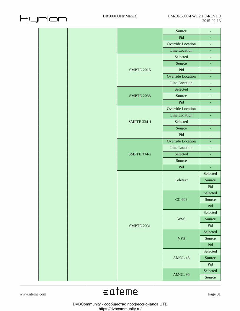
Table 4.5. Front Panel Composition Menu
Primary Serv. Id - - -Service
Scndry Serv. Id - - -
Video Pid - - -
Mode - -
Silence Emulation - -
Monitor Pid -
Automatic Pid -
Pid
Channel1 ChannelSelection
PidPcm
Channel2 ChannelSelection
Pid -PassThrough
Aes Pair Sel. -
Pid -
Audio EmbeddedAes[1-8]
DolbyPassThroughAes Pair Sel. -
DVBCommunity - cообщество профессионалов ЦТВ https://dvbcommunity.ru/

DR5000 User Manual UM-DR5000-FW1.2.1.0-REV1.02015-02-13
www.ateme.com Page 30
Override Location -
-
Mode -
Silence Emulation
Line Location
-
Monitor Pid -
Automatic Pid -
Pid
Channel1 ChannelSelection
PidPcm
Channel2 ChannelSelection
Pid -PassThrough
Aes Pair Sel. -
Pid -
Aes Pair Sel. -
Override Location -
ExternalAes[1-4]
DolbyPassThrough
-
Mode -
Silence Emulation
Line Location
-
Monitor Pid -
Automatic Pid -
Pid
Channel1 ChannelSelection
PidPcm
ChannelSelection
Analog[1-4]
Gain
Channel2
-
Descrambling Mode - - -
Mode - -
Biss-1 Key - -Biss
Biss-E Key - -
Force 3V3 - -
Service limiting - -CAM
BR limit [mbps] - -
Descr. Services - - -
Descrambling
Service[1-8] Service Id - -
SMPTE 12M Selected -Data Ancillary
SMPTE 2010 Selected -
DVBCommunity - cообщество профессионалов ЦТВ https://dvbcommunity.ru/
DR5000 User Manual UM-DR5000-FW1.2.1.0-REV1.02015-02-13
www.ateme.com Page 31
Source -
Pid -
Override Location -
Line Location -
Selected -
Source -
Pid -
Override Location -
SMPTE 2016
Line Location -
Selected -
Source -SMPTE 2038
Pid -
Override Location -
Line Location -
Selected -
Source -
SMPTE 334-1
Pid -
Override Location -
Line Location -
Selected -
Source -
SMPTE 334-2
Pid -
Selected
SourceTeletext
Pid
Selected
SourceCC 608
Pid
Selected
SourceWSS
Pid
Selected
SourceVPS
Pid
Selected
SourceAMOL 48
Pid
Selected
SMPTE 2031
AMOL 96Source
DVBCommunity - cообщество профессионалов ЦТВ https://dvbcommunity.ru/
DR5000 User Manual UM-DR5000-FW1.2.1.0-REV1.02015-02-13
www.ateme.com Page 32
Pid
Override Location -
Line Location -
Selected -
Source -Teletext
Pid -
Selected -
Source -CC 608
Pid -
Selected -
Source -WSS
Pid -
Selected -
Source -VPS
Pid -
Selected -
Source -AMOL 48
Pid -
Selected -
Source -AMOL 96
Pid -
Selected -
Source -
VBI
Video Index
Pid -
Mode - -
Source - -
Pid - -
Teletext Page - -
DVBS Serv. Index - -
Overlay
CC608 service - -
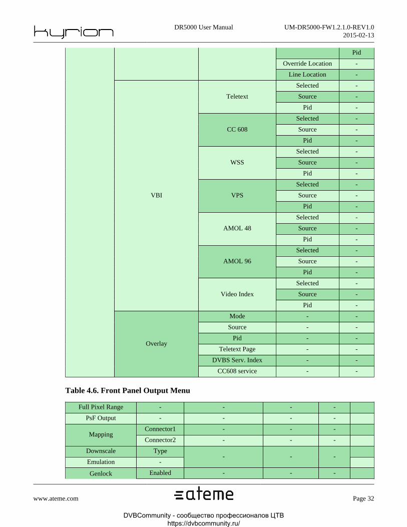
Table 4.6. Front Panel Output Menu
Full Pixel Range - - - -
PsF Output - - - -
Connector1 - - -Mapping
Connector2 - - -
Downscale Type
Emulation -- - -
Genlock Enabled - - -
DVBCommunity - cообщество профессионалов ЦТВ https://dvbcommunity.ru/
DR5000 User Manual UM-DR5000-FW1.2.1.0-REV1.02015-02-13
www.ateme.com Page 33
Pixel Offset - - -
LineOffset - - -
Descrambled - -Asi
Remuxed - -
Descrambled - -
Enabled -
Interface -
Dst. Address -
Dst. Port -
TS Pkts/IP frame -
Time To Live -
Specify ToS -
Type of Service -
Enable VLAN -
VLAN Id -
Enabled
Spoofing Src Ad-dress
Enabled
User-De-
finedRTP
SSRC
Value
Enabled
Columns
Rows
Streams[1-3]
FEC
Step
Ip
Remuxed - -
Forward
Asi2 VPSC Enabled -
Descrambled - - -
Bit. Modify - - -Remux
Bitrate - - -
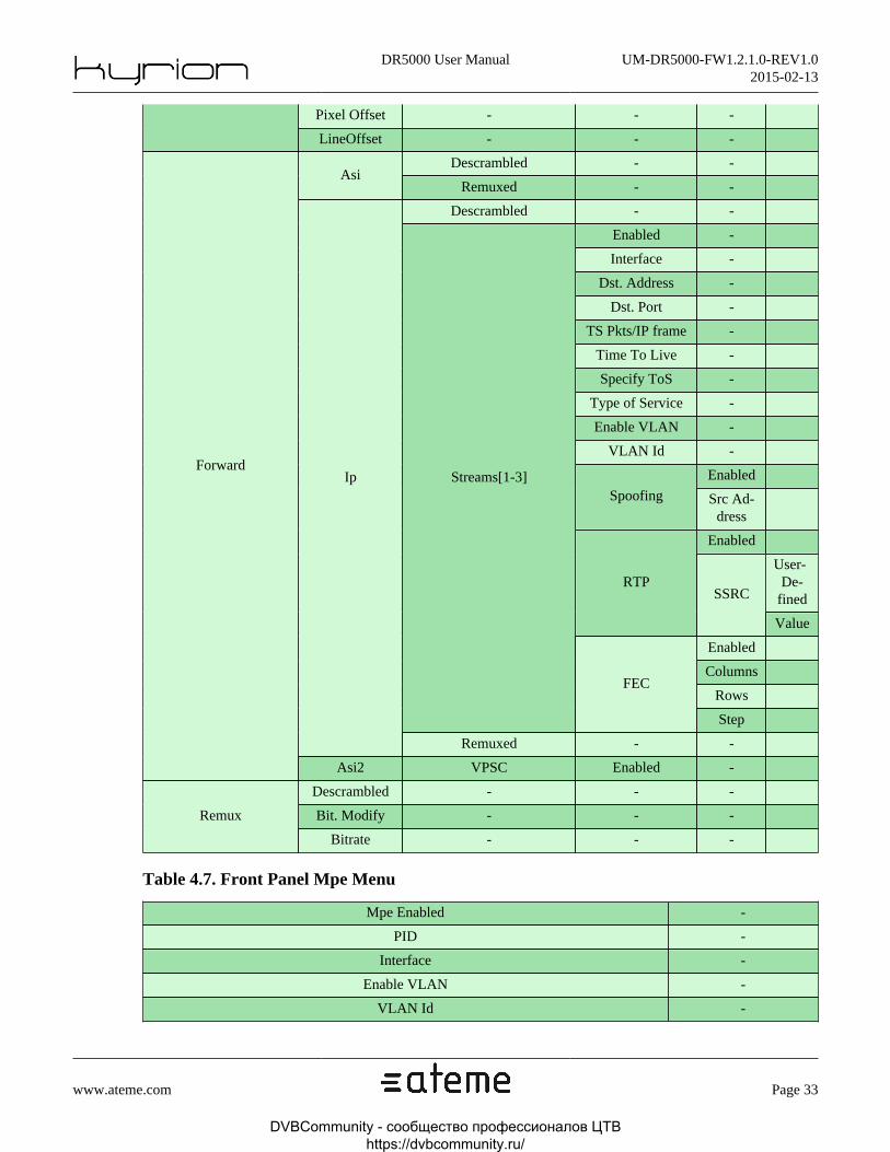
Table 4.7. Front Panel Mpe Menu
Mpe Enabled -
PID -
Interface -
Enable VLAN -
VLAN Id -
DVBCommunity - cообщество профессионалов ЦТВ https://dvbcommunity.ru/

DR5000 User Manual UM-DR5000-FW1.2.1.0-REV1.02015-02-13
www.ateme.com Page 34
4.3. Web GUIThe DR5000 Web interface is a flexible and user-friendly way to use the decoder. It has been designed to fit aresolution of at least 1024x768. The following sections will give you an overview of the features of the web GUI.
4.3.1. Gui Overview
The Web GUI is divided in two parts that can be seen as independent.
Figure 4.2. Gui Overview
Table 4.8. Gui Overview
ADecoding Sta-
tus Panels
These three, vertically stacked panels give an in-depth view of the decoding/dis-covered program. These panels are read-only, and are used to monitor the DR5000activity. Refer to Section 4.3.2, “ Decoding Status Panels ” for more information.
BConfigura-tion Panel
This panel is used to configure the DR5000, both from a system (IPaddress, SNMP management, Alarms reporting, etc.) and from a
configuration (input type, decoded service, etc.) point of view. re-fer to Section 4.3.3, “ Configuration Panel ” for more information.
DVBCommunity - cообщество профессионалов ЦТВ https://dvbcommunity.ru/

DR5000 User Manual UM-DR5000-FW1.2.1.0-REV1.02015-02-13
www.ateme.com Page 35
Note
The "Decoding Status" panel can be hidden by double-clicking on the separator between the "DecodingStatus" and "Configuration" panels.
4.3.2. Decoding Status Panels
Those panels are dedicated to monitor the decoder activity.
Figure 4.3. Decoding Status panels
Table 4.9. Decoding Status panels
A
Rear panel.depicts the currently active con-nectors so that the overall decoding status
can be monitored at a glance. Each connec-tor can have four colors: grey stands for
unused, green stands for used without er-rors, orange stands for used, active warningswhile red means that th connector is in error.
B Active service overview
This shows what is currently input, decoded and outputby the DR5000. This panel is dynamic, which meansthat the lines reported in that panel will vary depend-ing on the configuration. Miscellaneous examples areshown on Section 4.3.2.1, “ Active service overview ”
C Probed programsThis panel reports the content of the trans-
port stream that has been discovered on
DVBCommunity - cообщество профессионалов ЦТВ https://dvbcommunity.ru/
DR5000 User Manual UM-DR5000-FW1.2.1.0-REV1.02015-02-13
www.ateme.com Page 36
the input interface. All the services are dis-played along with their names (when present).
D Input status This reports the input advanced status.
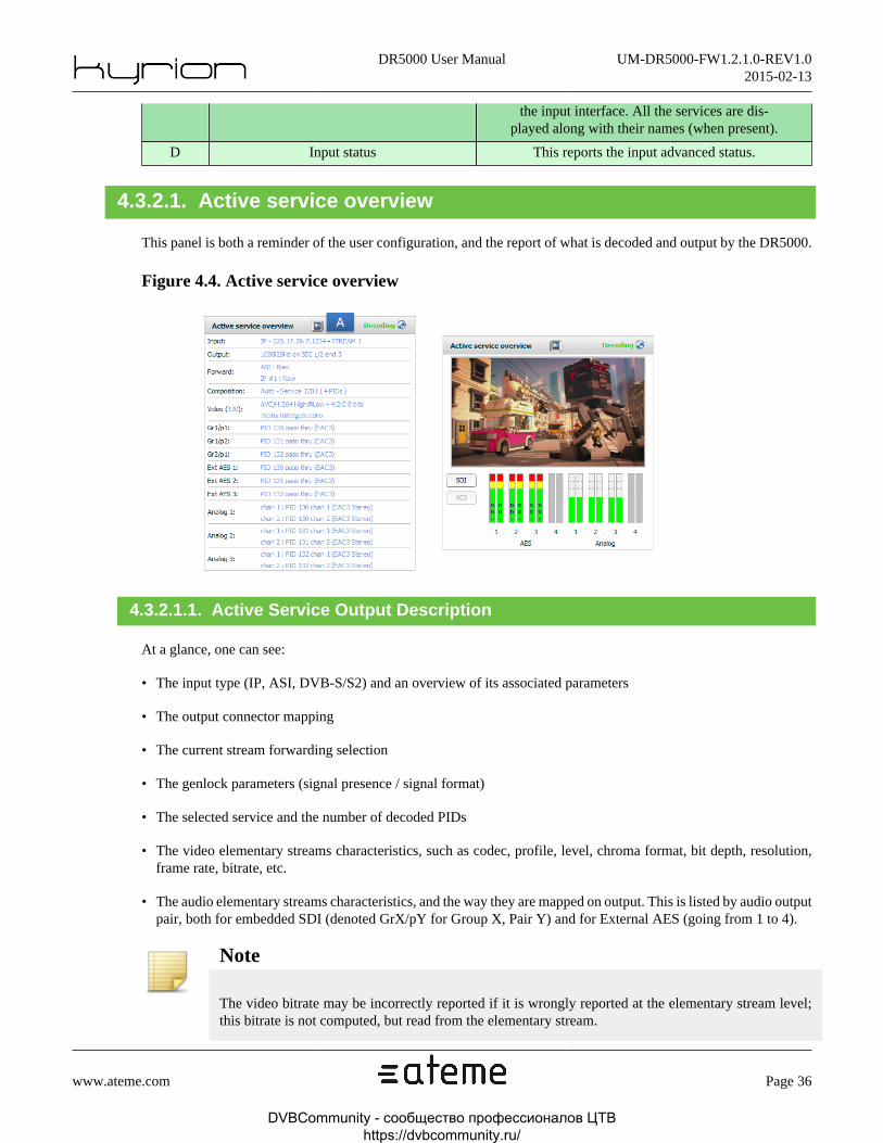
4.3.2.1. Active service overview
This panel is both a reminder of the user configuration, and the report of what is decoded and output by the DR5000.
Figure 4.4. Active service overview
4.3.2.1.1. Active Service Output Description
At a glance, one can see:
• The input type (IP, ASI, DVB-S/S2) and an overview of its associated parameters
• The output connector mapping
• The current stream forwarding selection
• The genlock parameters (signal presence / signal format)
• The selected service and the number of decoded PIDs
• The video elementary streams characteristics, such as codec, profile, level, chroma format, bit depth, resolution,frame rate, bitrate, etc.
• The audio elementary streams characteristics, and the way they are mapped on output. This is listed by audio outputpair, both for embedded SDI (denoted GrX/pY for Group X, Pair Y) and for External AES (going from 1 to 4).
Note
The video bitrate may be incorrectly reported if it is wrongly reported at the elementary stream level;this bitrate is not computed, but read from the elementary stream.
DVBCommunity - cообщество профессионалов ЦТВ https://dvbcommunity.ru/

DR5000 User Manual UM-DR5000-FW1.2.1.0-REV1.02015-02-13
www.ateme.com Page 37
Note
Errors may be reported by highlighting the associated lines in red. This will typically be the case whena selected PID has not been found in the incoming stream.
Note
More information is reported through tooltips that will be displayed when the mouse cursor is left abovea given line for a short amount of time.
4.3.2.1.2. Active Service Thumbnail
This panel can also be used to monitor the audio/video output of the DR5000, by clicking on the "tv" icon depictedby label A in Section 4.3.2.1, “ Active service overview ”.
• The video thumbnail depicts what is currently output by the DR5000; the same video can be seen on the frontpanel "confidence monitor".
• Audio vu-meters are meant to give an overview of the DR5000 audio outputs, for embedded (SDI) AES, externalAES, or analog audio (when applicable). The same information can be retrieved on the front panel "confidencemonitor". A given audio output will be greyed out when disabled, and non-pcm data will be detected and displayedin the associated vu-meter.
4.3.2.2. Probed programs
This panel reports the discovered streams on the configured input interface, as well as a more detailed view of theservice/PIDs characteristics. It is also the place where Carrier ID information may be reported, and where DVB-SSUpackages can be monitored and downloaded.
4.3.2.2.1. Probed program list
The name of the service will be displayed with the service ID when it is present.
DVBCommunity - cообщество профессионалов ЦТВ https://dvbcommunity.ru/
DR5000 User Manual UM-DR5000-FW1.2.1.0-REV1.02015-02-13
www.ateme.com Page 38
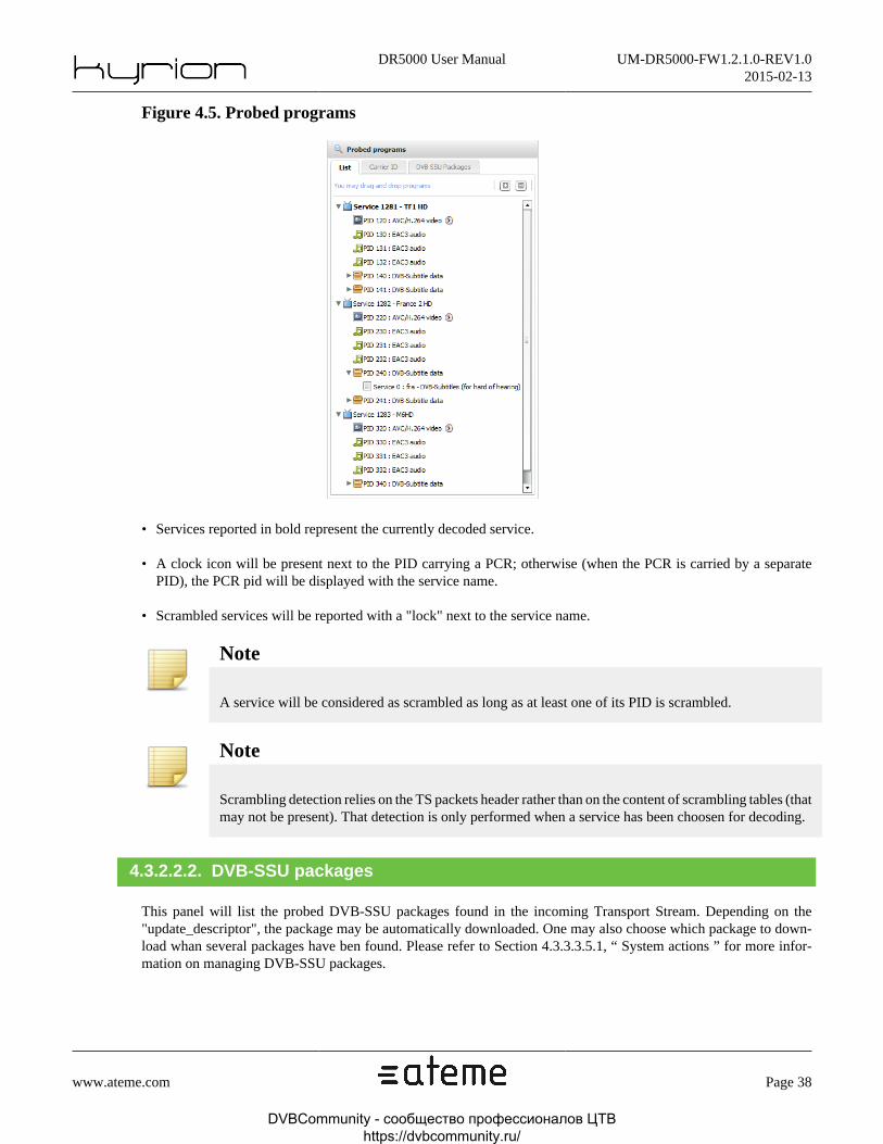
Figure 4.5. Probed programs
• Services reported in bold represent the currently decoded service.
• A clock icon will be present next to the PID carrying a PCR; otherwise (when the PCR is carried by a separatePID), the PCR pid will be displayed with the service name.
• Scrambled services will be reported with a "lock" next to the service name.
Note
A service will be considered as scrambled as long as at least one of its PID is scrambled.
Note
Scrambling detection relies on the TS packets header rather than on the content of scrambling tables (thatmay not be present). That detection is only performed when a service has been choosen for decoding.
4.3.2.2.2. DVB-SSU packages
This panel will list the probed DVB-SSU packages found in the incoming Transport Stream. Depending on the"update_descriptor", the package may be automatically downloaded. One may also choose which package to down-load whan several packages have ben found. Please refer to Section 4.3.3.3.5.1, “ System actions ” for more infor-mation on managing DVB-SSU packages.
DVBCommunity - cообщество профессионалов ЦТВ https://dvbcommunity.ru/

DR5000 User Manual UM-DR5000-FW1.2.1.0-REV1.02015-02-13
www.ateme.com Page 39
4.3.2.3. Input status
This panel reports information about the input "physical" layer. Its content will thus vary, depending on the inputtype. The first tab will always represent the input bitrate history, while the other tabs will dynamically be updateddepending on the input configuration.
Table 4.10. Input status
ASI No other tabs
IP
The Counters tab will report information about the UDP/RTP layer, such as the pack-et size, the number of received packets, etc. When using RTP, some more informa-tion will be provided, such as missing packets, out of order packets. When FEC isconfigured (and detected), FEC matrix dimensions as well as the corrected pack-
et count will be reported. Depending on the input configuration, failover or SMPTE2022-7 status may also be displayed. Furthermore, IP input jitter (RMS) is reported.
DVB-S/S2An Advanced tab will be displayed, reporting the DVB-S/S2 signal characteris-tics: C/N, C/N Margin, modulation type, FEC, roll-off, DVB-S2 pilots, BER and
power. An additional graph displays evolution of C/N Margin over the last minute.
Figure 4.6. Sat Input status example
DVBCommunity - cообщество профессионалов ЦТВ https://dvbcommunity.ru/

DR5000 User Manual UM-DR5000-FW1.2.1.0-REV1.02015-02-13
www.ateme.com Page 40
Figure 4.7. IP Input status example
IP input status will be split in several tabs, depending both on the user-configuration and on the stream content.
Note
Please refer to Section 5.2.3, “ IP Input ” for information on IP configuration.
Counters tab
This tab will report static stream properties (UDP/RTP, detected FEC matrix) as well as internal counters, meant tomonitor the IP input. All these counters pertain to media packets only (by opposition to FEC packets) and may beresetted either by user operation ("Reset" button), or by external stream events (UDP/RTP switch, SSRC change,SN discontinuity, etc).
• RTP, UDP: Packet counter reports the total number of packets.
• RTP, UDP: Missing packet counter reports the amount of packets that have been lost in input. The missing packetsmay be corrected when FEC is in use. Missing packet detection relies on RTP sequence number, or on PCRs gapsfor UDP.
• RTP: Duplicate Packet counter reports the number of IP frames that have been duplicated, based on RTP sequencenumber, for media packets only.
• RTP: Out of order counter reports the number of IP frames that have been received, but not in the same order asthey were sent.
DVBCommunity - cообщество профессионалов ЦТВ https://dvbcommunity.ru/

DR5000 User Manual UM-DR5000-FW1.2.1.0-REV1.02015-02-13
www.ateme.com Page 41
• RTP: Corrected Packet counter reports the number of IP frames that have been found missing, but recovered thanksto FEC.
• RTP, UDP: Uncorrected Packet counter reports the number of IP frames that have been found missing, and notrecovered by FEC. In UDP, that counter is always equal to the "Missing packet" counter.
Note
ST2022-7 is a preprocessing stage for RTP input. As such, all the counters refer to the output ofST2022-7 processing. In other words, if a packet is declared missing with ST2022-7 activated, it meansthat ST2022-7 failed to recover that packet.
ST2022-7 tab
This tab reports information about ST2022-7, when configured.
• The upper part gives an overview of the status protection. Input is considered as "protected" when both sources areactive (see below), and when the delay between sources is less than the configured network skew (please refer toSection 5.2.3.3, “ SMPTE 2022-7 Settings ” for information on ST2022-7 configuration).
• The center part reports sources activity. A source is considered active as long as some packets are received.
• The bottom part reports the amount of packets taken from primary and secondary sources, as well as the offsetbetween sources. Positive offset values mean that the secondary source is late, negative values mean that the primarysource is late.
Failover tab
This tab reports information about failover, when configured. Sources activity are monitored, and a "toggle" buttonwill appear when configured in manual/toggle mode, to enforce source switch.
Graphs
Bitrate, Jitter and Pre/Post-FEC error rates graphs are plotted for monitoring the IP input at a glance.
4.3.3. Configuration Panel
This view is the entry point to configure your DR5000. It is made of three main sub-sections, that are hereinafterdescribed.
Table 4.11. Configuration Panel Description
Rear PanelIndicates which inputs/outputs are currently in use, and reports potential er-rors (in such case, the associated input/output will be filled with solid red).
StatusPanel
Gives an overview of the DR5000 status, from a system point of view. Events will also belogged in that window (please refer to Section 4.3.3.1.3, “ Message Log ” for more information)
DVBCommunity - cообщество профессионалов ЦТВ https://dvbcommunity.ru/

DR5000 User Manual UM-DR5000-FW1.2.1.0-REV1.02015-02-13
www.ateme.com Page 42
ServicePanel
That's where one can configure the parameters that pertain to the decodingprocess itself, i.e. input type, service selection, output mapping, etc. Chang-
ing a parameter in that panel will typically impact the decoder outputs.
SystemPanel
System configuration can be performed in that tab,such as setting time, IP address, BISS injected IDs, etc.
4.3.3.1. Status Panel
This is the panel that is shown when connecting to the web GUI. It is further split into three sub-tabs that are explainedin the table below.
Figure 4.8. Status Panel
Table 4.12. Status Panel Description
A System Info Display high-level system information.
B System NotesEditable field that can be used as a 'sticky
note' to remind that the unit is currently in use.
DVBCommunity - cообщество профессионалов ЦТВ https://dvbcommunity.ru/

DR5000 User Manual UM-DR5000-FW1.2.1.0-REV1.02015-02-13
www.ateme.com Page 43
C Message Log Reports all events of the DR5000.
4.3.3.1.1. System Information
• 'Serial number' is a unique DR5000 identifier. One can find this number on a sticker on the side of the unit; thatnumber is used to identify your unit when contacting the support. This field is read-only.
• 'System name' is a user-configurable name that one can use to identify a unit when configuring multiple DR5000with one computer.
• 'System version' identifies the firwmare that is currently running on the unit.
• 'System time' reports the current system date/time. Please refer to Section 4.3.3.3, “ System Panel ”
• 'Temperature' reports the maximum temperature of all the sensors inside the unit.
• 'Locked/Unlocked' allows to lock the system. The configuration cannot be changed when the system is locked.
4.3.3.1.2. System Notes
This field can be used as a sticky note, when the unit is shared among multiple operators. The content of that field isstored in the DR5000 rather than on the computer used to access the GUI. That means that its content will be sharedamong all the computers that may concurrently access the DR5000 Web GUI.
4.3.3.1.3. Message Log
This panel is intended to log all the events that occurred in the DR5000. The events have a user-configurable severitylevel, a 'begin' time, and, when applicable, a 'end' time. An alarm is said to be "opened" when it has started (it has a'begin' time), but not ended (it does not have a 'end' time).
The list of the possible events and there associated severity levels can be configured; please refer to Section 4.3.3.3.2,“ Setting Alarms And Traps ” for more information.
Note
Logs can be exported to an external file, for technical support analysis. However, the information con-tained in such logs is not intended for advanced unit troubleshooting. Please refer to Section 4.3.3.3.5,“ Firmware And Troubleshooting ” for more information.
Note
Clearing the logs will not clear the opened alarms.
Warning
When clearing the logs, the latter will be deleted from the DR5000, not only from the Web GUI. Thisoperation can not be canceled.
DVBCommunity - cообщество профессионалов ЦТВ https://dvbcommunity.ru/

DR5000 User Manual UM-DR5000-FW1.2.1.0-REV1.02015-02-13
www.ateme.com Page 44
4.3.3.2. Service Panel
That section has several sub-panels that pertain to the decoding configuration itself. An in-depth description of thesub-panels embedded in tha view is given in Section 5.1, “ Overview ”, while this section will focus on configuration(so-called "preset") management.
Figure 4.9. Service Panel View
Table 4.13. Service Panel Tabs Description
Input Selects the input type (IP, ASI, DVB-S/S2) and its associated parameters.
DVBCommunity - cообщество профессионалов ЦТВ https://dvbcommunity.ru/
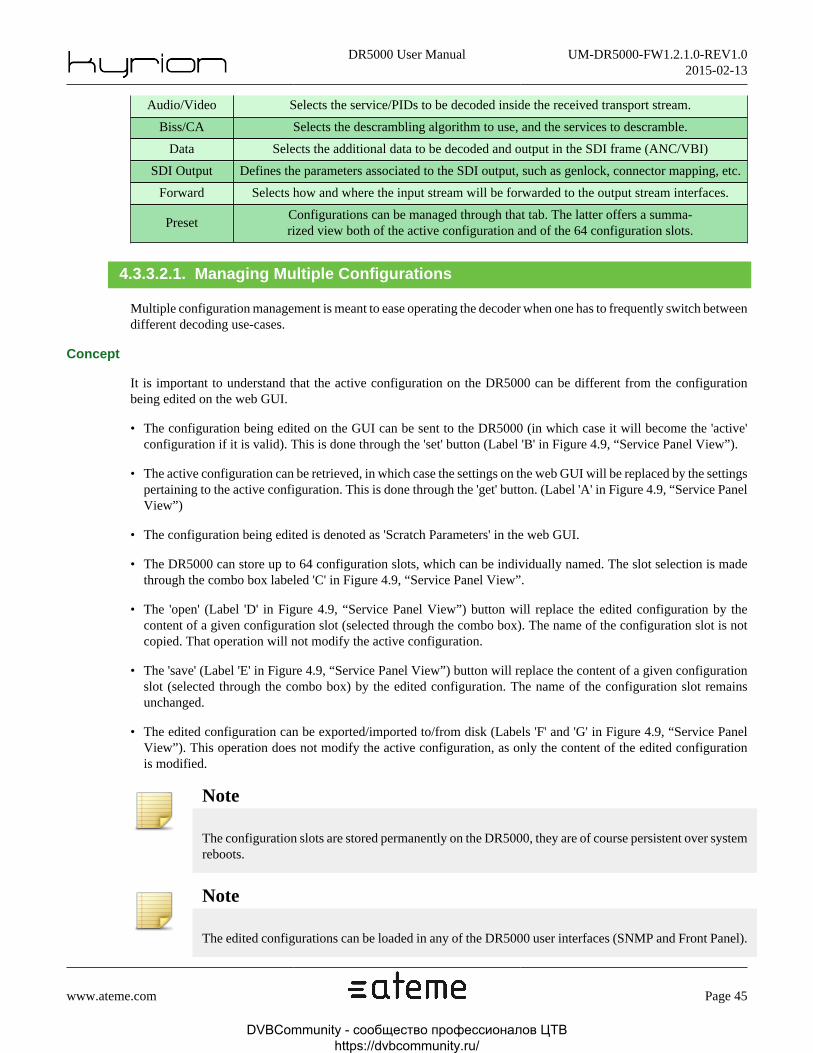
DR5000 User Manual UM-DR5000-FW1.2.1.0-REV1.02015-02-13
www.ateme.com Page 45
Audio/Video Selects the service/PIDs to be decoded inside the received transport stream.
Biss/CA Selects the descrambling algorithm to use, and the services to descramble.
Data Selects the additional data to be decoded and output in the SDI frame (ANC/VBI)
SDI Output Defines the parameters associated to the SDI output, such as genlock, connector mapping, etc.
Forward Selects how and where the input stream will be forwarded to the output stream interfaces.
PresetConfigurations can be managed through that tab. The latter offers a summa-rized view both of the active configuration and of the 64 configuration slots.
4.3.3.2.1. Managing Multiple Configurations
Multiple configuration management is meant to ease operating the decoder when one has to frequently switch betweendifferent decoding use-cases.
Concept
It is important to understand that the active configuration on the DR5000 can be different from the configurationbeing edited on the web GUI.
• The configuration being edited on the GUI can be sent to the DR5000 (in which case it will become the 'active'configuration if it is valid). This is done through the 'set' button (Label 'B' in Figure 4.9, “Service Panel View”).
• The active configuration can be retrieved, in which case the settings on the web GUI will be replaced by the settingspertaining to the active configuration. This is done through the 'get' button. (Label 'A' in Figure 4.9, “Service PanelView”)
• The configuration being edited is denoted as 'Scratch Parameters' in the web GUI.
• The DR5000 can store up to 64 configuration slots, which can be individually named. The slot selection is madethrough the combo box labeled 'C' in Figure 4.9, “Service Panel View”.
• The 'open' (Label 'D' in Figure 4.9, “Service Panel View”) button will replace the edited configuration by thecontent of a given configuration slot (selected through the combo box). The name of the configuration slot is notcopied. That operation will not modify the active configuration.
• The 'save' (Label 'E' in Figure 4.9, “Service Panel View”) button will replace the content of a given configurationslot (selected through the combo box) by the edited configuration. The name of the configuration slot remainsunchanged.
• The edited configuration can be exported/imported to/from disk (Labels 'F' and 'G' in Figure 4.9, “Service PanelView”). This operation does not modify the active configuration, as only the content of the edited configurationis modified.
Note
The configuration slots are stored permanently on the DR5000, they are of course persistent over systemreboots.
Note
The edited configurations can be loaded in any of the DR5000 user interfaces (SNMP and Front Panel).
DVBCommunity - cообщество профессионалов ЦТВ https://dvbcommunity.ru/

DR5000 User Manual UM-DR5000-FW1.2.1.0-REV1.02015-02-13
www.ateme.com Page 46
Examples
Save the active configuration
If one wants to save the active configuration, the following steps need to be performed:
• Click the 'get' button to copy the active configuration into the scratch parameters.
• Select an appropriate configuration slot in the combo box (right panel)
• Click the 'save' button
• Additionaly, a name can be given to that slot.
Change the active configuration by loading a configuration slot
Warning
The DR5000 output will be modified.
• Select an appropriate configuration slot in the combo box (right panel)
• Click the 'load' button
• Click the 'set' button to send the scratch parameters to the DR5000.
Edit configuration without modifying the DR5000 output
It is possible to use the Web GUI as a configuration editor, without modifying the decoder output.
• If required, click the 'load' button to fill the edited configuration with a set of pre-defined parameters.
• Use the service tabs to edit the scratch parameters to fit your needs.
• Go back to the 'config tabs', and select an appropriate configuration slot in the combo box
• Click the 'save' button
• Additionaly, a name can be given to that slot.
4.3.3.3. System Panel
That panel is used to configure the DR5000 system configuration.
Table 4.14. System Panel Description
Network/Time Used to configure ethernet settings, and change DR5000 date/time.
Alarm/TrapsDefine the events severity level, and the actions taken
when the events occur. Also defines the SNMP trap targets.
BISS Id/CAAllows to specify BISS injected IDs. Also provides access toDVB-CI MMI menus, if CAM extension board is available.
DVBCommunity - cообщество профессионалов ЦТВ https://dvbcommunity.ru/

DR5000 User Manual UM-DR5000-FW1.2.1.0-REV1.02015-02-13
www.ateme.com Page 47
Licenses Shows the currently install licenses. Also lists the installed extensions boards status.
Firmware/Trou-bleshooting
Use this page for upgrading your device to a new firmware, or whenrequired by the ATEME support, for troubleshooting your unit.
4.3.3.3.1. Setting Network And Time
Use this tab to modify the IP settings for both streaming and management interfaces, and for setting the system time.
4.3.3.3.1.1. IP settings
Figure 4.10. Network Panel
• Management, Stream 1 or Stream 2 (respectively labeled 'A', 'B' and 'C' in Figure 4.10, “Network Panel” areindependent and can be individually enabled/disabled/configured.
• DHCP is available for convenience and lab testing, but is deprecated as interface IP address is not guaranteed tobe the same when rebooting the unit.
• Clicking the 'Apply' button (label 'F' in Figure 4.10, “Network Panel”) will change the configuration for all theinterfaces. Nevertheless, no action will be taken when parameters of a given interface have not been changed.
DVBCommunity - cообщество профессионалов ЦТВ https://dvbcommunity.ru/

DR5000 User Manual UM-DR5000-FW1.2.1.0-REV1.02015-02-13
www.ateme.com Page 48
Note
Management interface can not be used to receive/emit transport stream, and shall be used for manage-ment purposes only
Warning
Even though both streaming interfaces may be used for management purposes, this usage is deprecated(Management tasks such as SNMP polling may otherwise interfere with stream reception)
Warning
Modifying the IP address of an interface being currently used for decoding purposes will disturb theDR5000 output!
Configuring VLANs (label 'D' in Figure 4.10, “Network Panel”)
VLAN (Virtual LAN) are used to create virtual sub-networks on a physical infrastructure, without additional equip-ment. Up to 12 virtual interface can be created. Virtual interfaces can then be used exactly like the physical interfacesfor receiving or sending IP transport stream (please refer to Section 5.2.3, “ IP Input ” and Section 5.7.2, “ IP Output” for informations on how to use virtual interfaces in the DR5000 configuration)
• The VLAN ID is a 12-bit field specifying the VLAN to which the frame belongs.
• The VLAN priority indicates the frame priority level. Values are from 0 (best effort) to 7 (highest). These valuescan be used to prioritize different classes of traffic.
Warning
VLAN IDs 4090 and 4091 can not be used in the DR5000.
Warning
VLAN IDs are shared among stream1 ans stream2 interfaces. A given VLAN ID can thus only be usedonce, either for stream1 or stream2, but not for both interfaces.
Configuring Routes (label 'E' in Figure 4.10, “Network Panel”)
The DR5000 provides a way to control the network routes to be used to reach hosts or networks. These routes canbe configured on a interface basis, or be common to all interfaces.
• Route "type" defines which kind of destination the route is intended to reach. It can be "host" to specify a route toa given equipment (in such case, the netmask is not used), "net" to specify a route to a network through a gateway,or "default" to specify a default route that will be used by all the outgoing packet whose destination address isoutside the interface sub-network.
• Route "interface" defines to which interface the route will apply; it should be noted that a route can pertain to allinterfaces ("any"), and that "interface" refers to physical or virtual interfaces.
DVBCommunity - cообщество профессионалов ЦТВ https://dvbcommunity.ru/

DR5000 User Manual UM-DR5000-FW1.2.1.0-REV1.02015-02-13
www.ateme.com Page 49
Warning
Misconfiguring the routes can make the DR5000 unreachable through the web GUI. In such case, theonly option is use the "Reset Routes" functionality on the front panel.
4.3.3.3.1.2. Date/Time
Figure 4.11. Time Panel
Time can be managed either through a NTP server (label E of Figure 4.11, “Time Panel”), or by entering the date/time. The modification is performed when clicking on the 'apply' button (label F of Figure 4.11, “Time Panel”)
Note
The time entered here will be used for event logging and troubleshooting. Having a valid system date/time is essential for technical support purposes.
4.3.3.3.2. Setting Alarms And Traps
This panel configures the behavior of the DR5000, when specified events occur on the unit. This panel is also usedto configure SNMP trap targets and community password.
Note
Any modification of one of the four SNMP targets or of the SNMP community password will requirea system reboot to be taken into account.
Note
The default SNMP passwords are "public" for the "read" community, and "private" for the "write"community.
DVBCommunity - cообщество профессионалов ЦТВ https://dvbcommunity.ru/

DR5000 User Manual UM-DR5000-FW1.2.1.0-REV1.02015-02-13
www.ateme.com Page 50
Figure 4.12. Alarms and Traps Panel View
An event will trigger up to three events:
• A message will be displayed in the Message Log Section 4.3.3.1.3, “ Message Log ” panel.
• The 'Alarm LED' Section 4.2.1, “ Status LED ” of the front panel can be switched to solid red.
• A SNMP trap can be sent to up to four targets. Those targets are specified through panel 'G' in Figure 4.12, “Alarmsand Traps Panel View”.
Note
All the events can not be associated to all the actions. For instance, transitory events (such as 'ServiceStarted') will display a log, but can not be assigned to the 'Alarm' LED in the front panel.
Alarms and traps are grouped by theme :
• Table 4.15, “Input alarms” includes all events concerning raw input module (ASI, IP, Sat and Zixi) low-level errors.
• Table 4.16, “Stream alarms” includes all events concerning TS level.
• Table 4.17, “Genlock alarms” includes all genlock-related events.
DVBCommunity - cообщество профессионалов ЦТВ https://dvbcommunity.ru/

DR5000 User Manual UM-DR5000-FW1.2.1.0-REV1.02015-02-13
www.ateme.com Page 51
• Table 4.18, “System alarms” includes all base system alarms.
• Table 4.19, “Decoding alarms” includes all decoding alarms.
• Table 4.20, “Configuration alarms” includes all decoding configuration alarms.
Note
Some of these alarms can be configured. To avoid multiples trigger when value oscillates around thelimit, a fully-configurable hysteresis has been added. If only one value is configured, the other one willbe automatically set the same value, thus deactivating this hysteresis protection.
The tables below give a description of the actions associated to an event.
Table 4.15. Input alarms
Alarm name Description Reference
No input activity No TS input stream detected Section 5.2, “ Input ”
IP input failure IP input interface could not be opened Section 5.2.3, “ IP Input ”
Excessive IP/Zixiinput jitter [ms]
Input IP/Zixi jitter has reached the configured limit Section 5.2.3, “ IP Input ”
Excessive SMPTE2022-7 Skew
SMPTE 2022-7 network skewhas reached the configured limit
Section 5.2.3.3, “ SMPTE2022-7 Settings ”
SMPTE2022-7is unprotected
SMPTE 2022-7 is not protectedSection 5.2.3.3, “ SMPTE
2022-7 Settings ”
Missing pre-FECRTP IP packets [%]
Pre-FEC RTP input missing packetsrate has reached the configured limit
Section 5.2.3, “ IP Input ”
Missing post-FECRTP IP packets [%]
Post-FEC RTP input missing packetsrate has reached the configured limit
Section 5.2.3, “ IP Input ”
Sat Input unlocked SAT input is not lockedSection 5.2.2, “
DVB-S/S2 Input ”
Sat Input minimumC/N Margin[dB]
Sat input C/N Margin hasreached the configured limit
Section 5.2.2, “DVB-S/S2 Input ”
Sat Input mini-mum power [dBm]
Sat input Power has reached the configured limitSection 5.2.2, “
DVB-S/S2 Input ”
Sat Input minimum BER Sat input BER has reached the configured limitSection 5.2.2, “
DVB-S/S2 Input ”
Zixi input unconnected Zixi input is not connected Section 5.2.4, “ ZIXI Input ”
Zixi input error rate [%] Zixi input error rate has reached the configured limit Section 5.2.4, “ ZIXI Input ”
Failover switch -Section 5.2.3.2, “
Failover IP Settings ”
Excessive CAM bitrateInput bitrate is Higher than 72 Mbpsand cannot be forwarded to CAM.
Table C.8, “Specifica-tion - Descrambling”
Table 4.16. Stream alarms
Alarm name Description Reference
TS discontinuity on audio PID TS discontinuity found on audio PID -
DVBCommunity - cообщество профессионалов ЦТВ https://dvbcommunity.ru/

DR5000 User Manual UM-DR5000-FW1.2.1.0-REV1.02015-02-13
www.ateme.com Page 52
TS discontinuity on video PID TS discontinuity found on video PID -
TS discontinuity on data PID TS discontinuity found no data PID -
TS discontinuity on other PIDTS discontinuity found on other
PID (neither video, audio nor data)-
Program is scrambled Selected service is scrambledSection 5.4.1,
“ BISS pa-rameters ”
Table 4.17. Genlock alarms
Alarm name Description Reference
Genlock signal missing Genlock configured, but no genlock signal detectedSection 5.6.2.2, “ Syn-chronization Settings ”
Genlock unlocked Genlock signal cannot lockSection 5.6.2.2, “ Syn-chronization Settings ”
New genlock format Genlock format has changedSection 5.6.2.2, “ Syn-chronization Settings ”
Video output/Gen-lock format mismatch
Genlock format does not match video formatSection 5.6.2.2, “ Syn-chronization Settings ”
Table 4.18. System alarms
Alarm name Description Reference
Engine service started Engine service started -
Fan failure A fan is misfunctionningSection 2.4, “Ventilation ”
PSU failure A Power Supply Unit is misfunctionning -
Critical temperature Critical temperature level reachedSection 2.4, “Ventilation ”
Network input link down IP Input interface link downSection 4.3.3.3.1.1,
“ IP settings ”
Network output link down IP Output interface link downSection 4.3.3.3.1.1,
“ IP settings ”
IGMP version changed IGMP version changedSection 5.2.3.4, “IP SSM Settings ”
SSM not available No IGMP SSM available on current IGMP versionSection 5.2.3.4, “IP SSM Settings ”
Invalid extension board Hardware problem detected with extension board -
Table 4.19. Decoding alarms
Alarm name Description Reference
Output activity missingNo video output (either due to de-
coding error or missing input)Section 5.3.2, “Video Output ”
Missing license A missing licence is required for current configurationSection 4.3.3.3.4.1,“ License handling ”
DVBCommunity - cообщество профессионалов ЦТВ https://dvbcommunity.ru/

DR5000 User Manual UM-DR5000-FW1.2.1.0-REV1.02015-02-13
www.ateme.com Page 53
Table 4.20. Configuration alarms
Alarm name Description Reference
Missing Audio PID Selected audio PID missing from input streamSection 5.3.3, “Audio Output ”
Audio decoderslimit exceeded
Maximum number of audio decoders reachedSection 5.3.3, “Audio Output ”
AC3/DD decoderslimit exceeded
Maximum number of AC3 / Dol-byDigital audio decoders reached
Section 5.3.3, “Audio Output ”
EAC3/DD+ de-coders limit exceeded
Maximum number of EAC3 / Dol-byDigital+ audio decoders reached
Section 5.3.3, “Audio Output ”
Audio pass thrulimit exceeded
Maximum audio pass-thru limit reachedSection 5.3.3, “Audio Output ”
Configuration errorEither no video in selected service,
or no service with selected video PIDSection 5.3, “ Ser-
vice Selection ”
Too low Remux bitrateRemux bitrate configuration isn'tsufficient for current input stream
Section 5.7.3, “Remux Output ”
Dolby E missingDolby-E selected, but no Dol-by-E present in S302 stream
Section 5.3.3.1.5, “ Dol-byE Pass-Through mode ”
Dolby E moving Dolby-E is movingSection 5.3.3.1.5, “ Dol-
byE Pass-Through mode ”
Selected pair doesn't exist Selected Dolby-E pair does not exist in input streamSection 5.3.3.1.5, “ Dol-
byE Pass-Through mode ”
Invalid decoded PID Selected audio PID is not decodableSection 5.3.3.1.3,
“ PCM mode ”
Invalid pass-through PID Pass-through is not possible for selected audio PIDSection 5.3.3.1.4, “
Pass-Through mode ”
Anc wrong user line Wrong user line selected for ANC module Section 5.5, “ Data Output ”
Anc line conflict Conflict on ANC line configuration Section 5.5, “ Data Output ”
Table 4.21. Traps description
Missing Audio PID (Refer to associated alarm description)
Audio decoders limit exceeded (Refer to associated alarm description)
Audio pass thru limit exceeded (Refer to associated alarm description)
output activity missing (Refer to associated alarm description)
IP input failure (Refer to associated alarm description)
No input activity (Refer to associated alarm description)
Configuration error (Refer to associated alarm description)
Engine service started (Refer to associated alarm description)
TS discontinuity on audio PID (Refer to associated alarm description)
TS discontinuity on video PID (Refer to associated alarm description)
TS discontinuity on data PID (Refer to associated alarm description)
TS discontinuity on other PID (Refer to associated alarm description)
DVBCommunity - cообщество профессионалов ЦТВ https://dvbcommunity.ru/
DR5000 User Manual UM-DR5000-FW1.2.1.0-REV1.02015-02-13
www.ateme.com Page 54
Program is scrambled (Refer to associated alarm description)
Fan failure (Refer to associated alarm description)
Critical temperature (Refer to associated alarm description)
Network input link down (Refer to associated alarm description)
Network output link down (Refer to associated alarm description)
Dolby E missing (Refer to associated alarm description)
Dolby E moving (Refer to associated alarm description)
Selected pair doesn't exist (Refer to associated alarm description)
Note
That table is saved on the DR5000, and persistent over system reboots.
Warning
It is not possible to restore factory settings for that page once modified (unless performing a 'RestoreFactory' operation.
4.3.3.3.3. BISS/CA System Parameter
This panel is meant to manage parameters that pertain to the descrambling, from a system point of view. It is used tomanage BISS injected IDs, and to communicate with CAM modules through MMI mechanism.
DVBCommunity - cообщество профессионалов ЦТВ https://dvbcommunity.ru/

DR5000 User Manual UM-DR5000-FW1.2.1.0-REV1.02015-02-13
www.ateme.com Page 55
Figure 4.13. System Descrambling Parameters view
BISS injected IDs
The DR5000 can hold two injected IDs. Those injected IDs can be entered through the fields 'A' and 'B' of Figure 4.13,“System Descrambling Parameters view”. Selecting which key to use is then done through the decoder configuration.
Note
Injected IDs are used to perform BISS-E descrambling; they are used to descramble the EncryptedSession Word (ESW) to form a Session Word (SW).
CAM Man Machine Interface
The DR5000 offers the ability to communicate with both CAM modules through MMI, with panels 'C' and 'D' ofFigure 4.13, “System Descrambling Parameters view”. It should be noted that the CAM modules are responsible forthe content of these panels.
Note
The "System" and "Biss Id/CA" menus will blink when a module requests an action from the end user.
DVBCommunity - cообщество профессионалов ЦТВ https://dvbcommunity.ru/

DR5000 User Manual UM-DR5000-FW1.2.1.0-REV1.02015-02-13
www.ateme.com Page 56
4.3.3.3.4. License management
This panel is meant to manage and monitor software licenses and extension boards.
Figure 4.14. Licenses view
4.3.3.3.4.1. License handling
The panel labeled 'A' of Figure 4.14, “Licenses view” is dedicated to license management. License state is reported inthe panel labeled 'B', and license update can be performed through this page (license files must be provided exclusivelyby the support team)
DVBCommunity - cообщество профессионалов ЦТВ https://dvbcommunity.ru/

DR5000 User Manual UM-DR5000-FW1.2.1.0-REV1.02015-02-13
www.ateme.com Page 57
4.3.3.3.4.2. Extension boards
The panel labeled 'C' of Figure 4.14, “Licenses view” details the extension boards (when present) and their status.Please contact the support team in case of board failure.
4.3.3.3.5. Firmware And Troubleshooting
Figure 4.15. Firmware and Troubleshooting view
4.3.3.3.5.1. System actions
The panel labeled 'A' of Figure 4.15, “Firmware and Troubleshooting view” is dedicated to firmware management.From here, you can, install a new firmware version, make a backup of your current version or restore your backupversion.
DVBCommunity - cообщество профессионалов ЦТВ https://dvbcommunity.ru/

DR5000 User Manual UM-DR5000-FW1.2.1.0-REV1.02015-02-13
www.ateme.com Page 58
Firmware update
Click Update. A popup should appear asking for the update package file. Click on the Browse button to point to itand click Ok to proceed with the update, or Cancel to abort.
After a few seconds, a popup should appear, asking you to wait while the update process is running. Wait until thispopup disappears.
Note
You can check that the upgrade process went well by checking that the displayed Current Versionnumber is the expected one.
Note
Update package are specific files provided by ATEME support. They should bear the extension '.pkg'.Other files will be rejected.
Firmware backup
Click Backup, and press Yes in the popup asking you to confirm that you really want to save your current systemversion. The Backup button is disabled until the backup is done.
Note
You can check that the backup process went well by checking that the Current Backup version numbermatches the Current Version's one.
Firmware restore
Click Restore, and press Yes in the popup asking you to confirm you really want to restore the last saved systemversion.
After a few seconds, a popup should appear, asking you to wait while the restore process is running. Wait until thispopup disappears.
Note
You can check that the restore process did well by checking that the System Version number matchesthe Current Backup's one.
Note
It is always a good idea to make a backup of a known good functioning system version. It can be usefulto recover from situations requiring a Factory Reset per example or coming back from an update notfully fulfilling your needs.
Over The Air Firmware Update (DVB-SSU)
The DR5000 can retrieve and apply update packages through the incoming Transport Stream, regardless of the phys-ical transport link. It means that firmware updates can be retrieved when receiving ASI, IP, or DVB-S/S2 transport
DVBCommunity - cообщество профессионалов ЦТВ https://dvbcommunity.ru/

DR5000 User Manual UM-DR5000-FW1.2.1.0-REV1.02015-02-13
www.ateme.com Page 59
stream. The DR5000 achieve reception of the update package through ETSI TS 102006 recommandation: "Specifi-cation for System Software Update in DVB Systems".
Firmware download can be managed through the "probed programs" panel, located on the left side of the web GUI(please refer to Section 4.3.2.2, “ Probed programs ”).
• "Install SSU" button will install the downloaded update package (if any). There is no difference between installinga update through the mechanism described in Section 4.3.3.3.5.1, “ System actions ” and installing a DVB-SSUpackage.
• "Drop SSU" button will remove the downloaded package from the unit. It is useful to enforce a new download ofa firmware package through the incoming Transport Stream. This will only erase the downloaded file, and will notperform any package update/restore actions.
Note
This feature is meant for IRD management in a global system. As such, it is highly recommended tocontact the ATEME support team if using that feature is envisioned.
Warning
Depending on the "update_descriptor" located in the UNT, the DR5000 may automatically downloadand even install the update, which will of course interrupt the decoding process. This can be overridenthrough "DVB-SSU options".
4.3.3.3.5.2. DVB-SSU options
The DR5000 provides a way to ensure that DVB-SSU operations will never interfere with the decoding process.Although ETSI TS 102006 recommandation defines an "update_descriptor" which can request automatic update ofthe unit (and thus interruption of the decoding processs), the checkbox depicted in label 'B' of Figure 4.15, “Firmwareand Troubleshooting view” will always assume that the "update_descriptor" requests a "manual update" (followingTSI 102006 semantic). It means that installing the update will always require a user action.
4.3.3.3.5.3. GUI options
The panel labeled 'C' of Figure 4.15, “Firmware and Troubleshooting view” is dedicated to GUI options.
Tab switching
If this option is enabled, a pop-up will appear when leaving a configuration tab with unapplied changes.
Change warning
If this option is enabled, a pop-up will appear when configuration has configuration changed by external means (FrontPanel, SNMP, or another Web GUI).
GUI Password
If this option is enabled, a password will be required to access the Web GUI.
Note
You can remove password either by disabling this checkbox, unselect it from the front panel 'system'menu, or performing a factory reset.
DVBCommunity - cообщество профессионалов ЦТВ https://dvbcommunity.ru/

DR5000 User Manual UM-DR5000-FW1.2.1.0-REV1.02015-02-13
www.ateme.com Page 60
Note
If the option is selected but password field is left empty, the password is unchanged. This allows youto modify other GUI options without re-typing password.
Note
When asked for the password, your web browser will also ask for a login. The default value is "admin"and is not configurable.
4.3.3.3.5.4. Remote Syslog
The DR5000 provides a syslog functionnality. This allows system logs to be sent to the remote syslog server specifiedin the panel labeled 'D' or Figure 4.15, “Firmware and Troubleshooting view”.
Note
The logs can be sent either by UDP or TCP.
4.3.3.3.5.5. Troubleshooting
Logs
Upon request, you may be asked to retrieve 'debug package' that will be further analyzed by the ATEME technicalsupport. This will be achieved by clicking the appropriate buttons (label 'E' of Figure 4.15, “Firmware and Trou-bleshooting view”).
• Debug package contains all the logs, plus some internal DR5000 information that can be helpful.
• On-Demand logs will only contain a subset of the last lines of logs.
• Input statistics will contain a log file describing the evolution of the input stream. Please refer to Section B.2, “Input Statistics File Format ” for more informations about this file.
Stream recording
The DR5000 can record the incoming stream on an external USB mass storage device, inserted on the front panelUSB connector (please refer to Section 4.2, “ Front Panel ”). This feature should be used exclusively upon supportteam request, and may interfere with the DR5000 decoding process.
• A click on the "Record" button will immediately starts the recording
• A record duration (in seconds) and/or a maximal file size (in MB) can be specified to trigger the end of the recording,otherwise a click on the "Stop" button will stop the recording.
• A popup will always be displayed at the end of the recording to summarize the troubleshooting operation.
Note
The recording bandwidth is limited by the inserted USB key capabilities, which can be checked byclicking the "Test" button.
DVBCommunity - cообщество профессионалов ЦТВ https://dvbcommunity.ru/

DR5000 User Manual UM-DR5000-FW1.2.1.0-REV1.02015-02-13
www.ateme.com Page 61
Warning
The recorded data may or may not be descrambled, depending on the IP forwarding output mode (referto Section 5.7, “ Stream Forwarding ”)
DVBCommunity - cообщество профессионалов ЦТВ https://dvbcommunity.ru/

DR5000 User Manual UM-DR5000-FW1.2.1.0-REV1.02015-02-13
www.ateme.com Page 62
5. Setting up a configuration
5.1. OverviewThis chapter will describe all the steps and all the parameters required to build a decoding configuration with theDR5000.
Note
Although the Web GUI will be used as a basis to describe the configuration parameters, the meaning ofthose parameters are the same among all user interfaces. One can use the following chapters to build aconfiguration through the front panel or through SNMP.
Note
The settings edited in the Web GUI are not sent to the DR5000 until the 'Apply' button has been clicked.If an edited parameter does the match the active parameter, it will be highlighted. Please refer to Sec-tion 4.3.3.2.1, “ Managing Multiple Configurations ” for more information on that topic.
DVBCommunity - cообщество профессионалов ЦТВ https://dvbcommunity.ru/
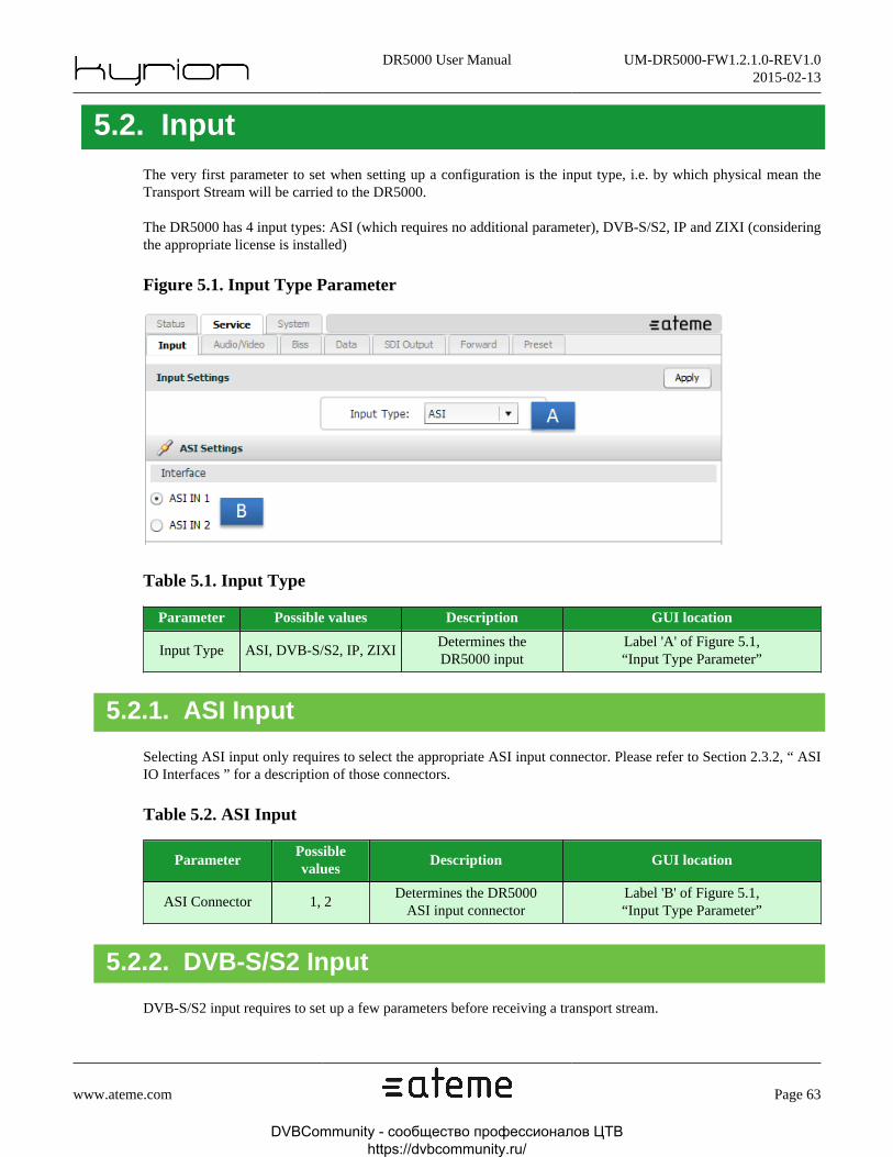
DR5000 User Manual UM-DR5000-FW1.2.1.0-REV1.02015-02-13
www.ateme.com Page 63
5.2. InputThe very first parameter to set when setting up a configuration is the input type, i.e. by which physical mean theTransport Stream will be carried to the DR5000.
The DR5000 has 4 input types: ASI (which requires no additional parameter), DVB-S/S2, IP and ZIXI (consideringthe appropriate license is installed)
Figure 5.1. Input Type Parameter
Table 5.1. Input Type
Parameter Possible values Description GUI location
Input Type ASI, DVB-S/S2, IP, ZIXIDetermines theDR5000 input
Label 'A' of Figure 5.1,“Input Type Parameter”
5.2.1. ASI Input
Selecting ASI input only requires to select the appropriate ASI input connector. Please refer to Section 2.3.2, “ ASIIO Interfaces ” for a description of those connectors.
Table 5.2. ASI Input
ParameterPossiblevalues
Description GUI location
ASI Connector 1, 2Determines the DR5000
ASI input connectorLabel 'B' of Figure 5.1,“Input Type Parameter”
5.2.2. DVB-S/S2 Input
DVB-S/S2 input requires to set up a few parameters before receiving a transport stream.
DVBCommunity - cообщество профессионалов ЦТВ https://dvbcommunity.ru/

DR5000 User Manual UM-DR5000-FW1.2.1.0-REV1.02015-02-13
www.ateme.com Page 64
Figure 5.2. DVB-S2 Settings View
Table 5.3. DVB-S2 Settings
ParameterPossiblevalues
Description GUI location
LNB Control On, Off Determines if signals will be sent to control the LNBLabel 'A' of Figure 5.2,
“DVB-S2 Settings View”
PolarizationVerti-
cal, Hor-izontal
When LNB Control is enabled, deter-mines the desired polarization type (and
the associated DC 13V 18V signal)
Label 'B' of Figure 5.2,“DVB-S2 Settings View”
Tone 22kHz Off, OnWhen LNB Control is enabled, deter-mines band selection to switch the an-
tenna Local Oscillator (Dual Band LNB)
Label 'C' of Figure 5.2,“DVB-S2 Settings View”
InterfaceRF1,RF2,
RF3, RF4
Determines which RF connectorwill be used to receive the stream
Label 'D' of Figure 5.2,“DVB-S2 Settings View”
ModeAuto,
DVB-S,DVB-S2
Determines the modulation standard.'Auto' usually gives the best result
Label 'E' of Figure 5.2,“DVB-S2 Settings View”
DownlinkFrequency
MHz
Downlink frequency of the desired signal.The DR5000 will automatically derive theintermediate frequency by comparing thisvalue to the Local Oscillator Frequency
Label 'F' of Figure 5.2,“DVB-S2 Settings View”
DVBCommunity - cообщество профессионалов ЦТВ https://dvbcommunity.ru/
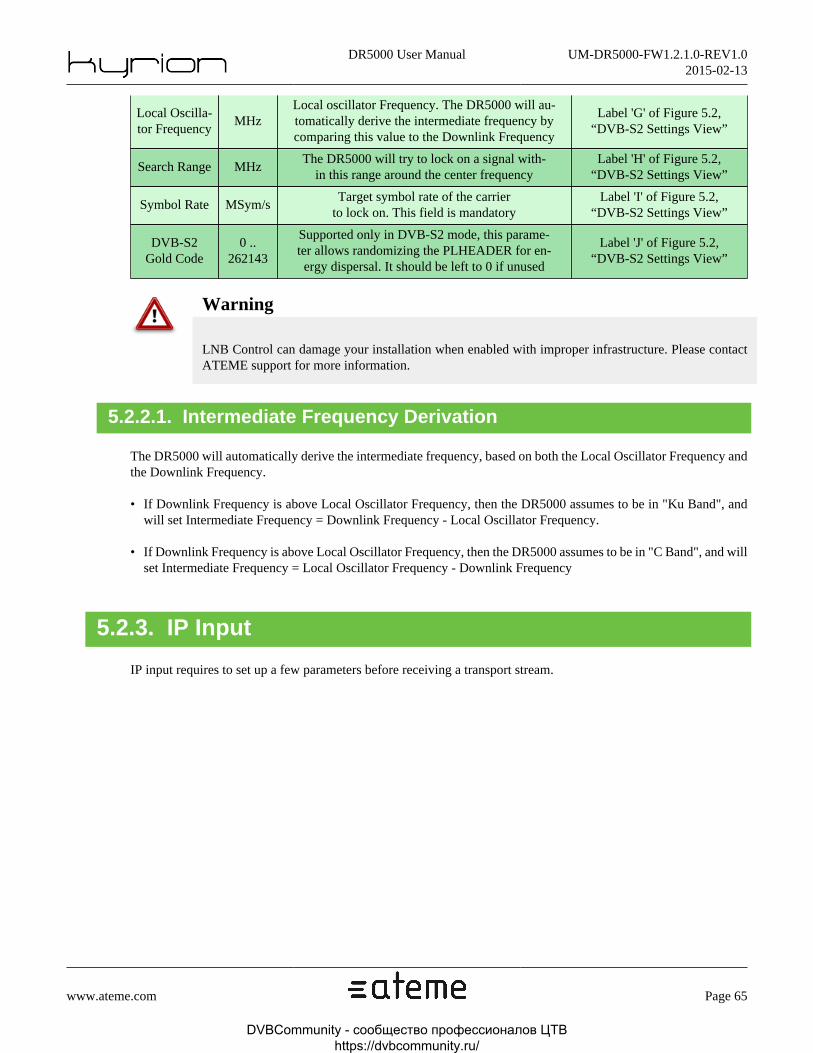
DR5000 User Manual UM-DR5000-FW1.2.1.0-REV1.02015-02-13
www.ateme.com Page 65
Local Oscilla-tor Frequency
MHzLocal oscillator Frequency. The DR5000 will au-tomatically derive the intermediate frequency bycomparing this value to the Downlink Frequency
Label 'G' of Figure 5.2,“DVB-S2 Settings View”
Search Range MHzThe DR5000 will try to lock on a signal with-
in this range around the center frequencyLabel 'H' of Figure 5.2,
“DVB-S2 Settings View”
Symbol Rate MSym/sTarget symbol rate of the carrier
to lock on. This field is mandatoryLabel 'I' of Figure 5.2,
“DVB-S2 Settings View”
DVB-S2Gold Code
0 ..262143
Supported only in DVB-S2 mode, this parame-ter allows randomizing the PLHEADER for en-ergy dispersal. It should be left to 0 if unused
Label 'J' of Figure 5.2,“DVB-S2 Settings View”
Warning
LNB Control can damage your installation when enabled with improper infrastructure. Please contactATEME support for more information.
5.2.2.1. Intermediate Frequency Derivation
The DR5000 will automatically derive the intermediate frequency, based on both the Local Oscillator Frequency andthe Downlink Frequency.
• If Downlink Frequency is above Local Oscillator Frequency, then the DR5000 assumes to be in "Ku Band", andwill set Intermediate Frequency = Downlink Frequency - Local Oscillator Frequency.
• If Downlink Frequency is above Local Oscillator Frequency, then the DR5000 assumes to be in "C Band", and willset Intermediate Frequency = Local Oscillator Frequency - Downlink Frequency
5.2.3. IP Input
IP input requires to set up a few parameters before receiving a transport stream.
DVBCommunity - cообщество профессионалов ЦТВ https://dvbcommunity.ru/

DR5000 User Manual UM-DR5000-FW1.2.1.0-REV1.02015-02-13
www.ateme.com Page 66
Figure 5.3. IP Settings View
5.2.3.1. Basic IP settings
Decoding a transport stream carried over IP is quite straightforward (it requires not more than a reception interface anda multicast group address). Once the parameters described in Table 5.4, “Basic IP Settings Description” are correctlyset, stream reception will start.
Table 5.4. Basic IP Settings Description
Parameter Possible values Description GUI location
InputBuffer Size
Milliseconds
Determines the buffer duration of the IP in-put. This buffer is responsible for IP dejitter-ing and for FEC reconstruction. Large valuesimplies more latency, but may enhance out-put signal stability and FEC reconstruction
Label 'A' of Figure 5.3,“IP Settings View”
DVBCommunity - cообщество профессионалов ЦТВ https://dvbcommunity.ru/
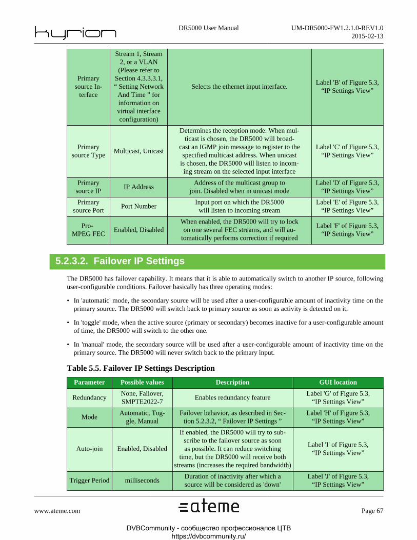
DR5000 User Manual UM-DR5000-FW1.2.1.0-REV1.02015-02-13
www.ateme.com Page 67
Primarysource In-
terface
Stream 1, Stream2, or a VLAN(Please refer to
Section 4.3.3.3.1,“ Setting Network
And Time ” forinformation onvirtual interfaceconfiguration)
Selects the ethernet input interface.Label 'B' of Figure 5.3,
“IP Settings View”
Primarysource Type
Multicast, Unicast
Determines the reception mode. When mul-ticast is chosen, the DR5000 will broad-
cast an IGMP join message to register to thespecified multicast address. When unicast
is chosen, the DR5000 will listen to incom-ing stream on the selected input interface
Label 'C' of Figure 5.3,“IP Settings View”
Primarysource IP
IP AddressAddress of the multicast group to
join. Disabled when in unicast modeLabel 'D' of Figure 5.3,
“IP Settings View”
Primarysource Port
Port NumberInput port on which the DR5000
will listen to incoming streamLabel 'E' of Figure 5.3,
“IP Settings View”
Pro-MPEG FEC
Enabled, DisabledWhen enabled, the DR5000 will try to lockon one several FEC streams, and will au-
tomatically performs correction if required
Label 'F' of Figure 5.3,“IP Settings View”
5.2.3.2. Failover IP Settings
The DR5000 has failover capability. It means that it is able to automatically switch to another IP source, followinguser-configurable conditions. Failover basically has three operating modes:
• In 'automatic' mode, the secondary source will be used after a user-configurable amount of inactivity time on theprimary source. The DR5000 will switch back to primary source as soon as activity is detected on it.
• In 'toggle' mode, when the active source (primary or secondary) becomes inactive for a user-configurable amountof time, the DR5000 will switch to the other one.
• In 'manual' mode, the secondary source will be used after a user-configurable amount of inactivity time on theprimary source. The DR5000 will never switch back to the primary input.
Table 5.5. Failover IP Settings Description
Parameter Possible values Description GUI location
RedundancyNone, Failover,SMPTE2022-7
Enables redundancy featureLabel 'G' of Figure 5.3,
“IP Settings View”
ModeAutomatic, Tog-
gle, ManualFailover behavior, as described in Sec-
tion 5.2.3.2, “ Failover IP Settings ”Label 'H' of Figure 5.3,
“IP Settings View”
Auto-join Enabled, Disabled
If enabled, the DR5000 will try to sub-scribe to the failover source as soonas possible. It can reduce switching
time, but the DR5000 will receive bothstreams (increases the required bandwidth)
Label 'I' of Figure 5.3,“IP Settings View”
Trigger Period millisecondsDuration of inactivity after which asource will be considered as 'down'
Label 'J' of Figure 5.3,“IP Settings View”
DVBCommunity - cообщество профессионалов ЦТВ https://dvbcommunity.ru/

DR5000 User Manual UM-DR5000-FW1.2.1.0-REV1.02015-02-13
www.ateme.com Page 68
Secondarysource In-
terface
Stream 1, Stream2, or a VLAN
(Please refer to Sec-tion 4.3.3.3.1, “ Set-ting Network And
Time ” for informa-tion on virtual inter-face configuration)
Selects the ethernet input interface.A warning icon will appear whentrying to use a disabled interface
Label 'L' of Figure 5.3,“IP Settings View”
Secondarysource Type
Multicast, UnicastDetermines the reception
mode of the secondary source.Label 'M' of Figure 5.3,
“IP Settings View”
Secondarysource IP
IP AddressAddress of the multicast group to
join. Disabled when in unicast modeLabel 'N' of Figure 5.3,
“IP Settings View”
Secondarysource Port
Port NumberInput port on which the
DR5000 will listen to incom-ing stream for secondary source
Label 'O' of Figure 5.3,“IP Settings View”
In 'toggle' and 'manual' mode, two special actions can force the switch behavior:
• 'Force toggle', available only in 'toggle' mode, will switch to the other interface (primary if currently using secondaryinterface, and reciprocally).
• 'Force primary', available only in 'manual' mode, will switch to primary interface (regardless of which interfaceis currently active).
5.2.3.3. SMPTE 2022-7 Settings
The DR5000 supports SMPTE 2022-7, which purpose is to provide seamless switching between two or more streams.The underlying assumption is that the IRD receives a duplicate of the stream, from a RTP point of view (all the fieldsof the RTP header shall be identical for every received packet).
Note
The DR5000 supports "Class SBR" (Slower Bit Rate, i.e. bitrates lower than 270 mbps) streams, andis compatible with High-Skew links (i.e. "combination of switching-induced jitter and differential pathdelay in such a link can be greater than 50ms", according to SMPTE 2022-7).
Table 5.6. SMPTE 2022-7 Settings Description
Parameter Possible values Description GUI location
RedundancyNone, Failover,SMPTE2022-7
Enables redundancy featureLabel 'G' of Figure 5.3,
“IP Settings View”
Network Skew Low, Moderate, HighSelects the skew tolerance. Thishas to be chosen accordingly tothe physical link characteristics
Label 'K' of Figure 5.3,“IP Settings View”
Secondarysource In-
terface
Stream 1, Stream 2, or aVLAN (Please refer toSection 4.3.3.3.1, “ Set-
ting Network And Time ”for information on virtualinterface configuration)
Selects the ethernet input interface.A warning icon will appear whentrying to use a disabled interface
Label 'L' of Figure 5.3,“IP Settings View”
DVBCommunity - cообщество профессионалов ЦТВ https://dvbcommunity.ru/

DR5000 User Manual UM-DR5000-FW1.2.1.0-REV1.02015-02-13
www.ateme.com Page 69
Secondarysource Type
Multicast, UnicastDetermines the reception
mode of the secondary source.Label 'M' of Figure 5.3,
“IP Settings View”
Secondarysource IP
IP AddressAddress of the multicast group to
join. Disabled when in unicast modeLabel 'N' of Figure 5.3,
“IP Settings View”
Secondarysource Port
Port NumberInput port on which the
DR5000 will listen to incom-ing stream for secondary source
Label 'O' of Figure 5.3,“IP Settings View”
Note
The "Network skew" settings defines the amount of buffer that will be kept in the DR5000. That buffer-ing is meant to ensure that the two SMPTE 2022-7 sources will overlap and that the DR5000 will be ableto pick packets from one or another source, in a seamless way. This "skew" buffer comes in addition ofthe "dejittering" buffer defined in Section 5.2.3.1, “ Basic IP settings ”.
Warning
SMPTE 2022-7 latency is twice the skew tolerance. For instance, when using "High skew" tolerance,the specific SMPTE 2022-7 latency will be 900ms.
5.2.3.4. IP SSM Settings
SSM is the acronym for Source Specific Multicast. It is a feature brought by IGMP V3, that allows to subscribe notonly to a multicast group, but to specific sources inside that multicast group. For instance, one can choose betweentwo streams which share the same multicast address, but emitted by different encoders.
Note
This feature requires IGMP V3 network infrastructure. Otherwise, the DR5000 will fallback to IGMPV2 which does not offer SSM.
SSM has two operating modes:
• In 'exclude' mode, the DR5000 will subscribe to a multicast group, and request sources that are not part of theprovided list.
• In 'include' mode, the DR5000 will subscribe to a multicast group, and request only sources that are part of theprovided list.
Note
'Excluding' no source is equivalent to including all the sources: it is the standard IGMP V2 behavior.
Table 5.7. IP SSM Settings Description
ParameterPossiblevalues
Description GUI location
DVBCommunity - cообщество профессионалов ЦТВ https://dvbcommunity.ru/

DR5000 User Manual UM-DR5000-FW1.2.1.0-REV1.02015-02-13
www.ateme.com Page 70
SourceFiltering
Enabled,Disabled
Enables Source Specific MulticastLabel 'P' of Figure 5.3,
“IP Settings View”
Filter modeExclude,Include
Filter mode, as described in Sec-tion 5.2.3.4, “ IP SSM Settings ”
Label 'Q' of Figure 5.3,“IP Settings View”
Sources List IP AddressesList of addresses to include or exclude,
depending on the specified filtering modeLabel 'R' of Figure 5.3,
“IP Settings View”
Note
Source filtering is applied for both primary and secondary sources.
5.2.3.5. IP VBR Settings
VBR support refers to stream where the PCR rate varies in time. It is typically the case when some PIDs have beenremoved from a TS CBR stream, without paying attention to PCR accuracy aspects. A common application is NULLpackets removal, where TS layer stuffing is removed to decrease the bandwidth. The DR5000 supports such streams.
This option shall only be activated on VBR streams.
Note
VBR does not refer here to SMPTE 2022-3/4 standards.
Table 5.8. VBR Settings Description
Para-meter
Possiblevalues
Description GUI location
VBRSupport
Enabled,Disabled
When enabled, the DR5000 will internally padd the incom-ing stream with NULL packets to re-generate a PCR-ac-
curate stream. When enabled, the buffer duration is forcedto 500 ms (refer to Section 5.2.3.1, “ Basic IP settings ”).
Label 'S' of Fig-ure 5.3, “IP Set-
tings View”
Warning
VBR is only supported on UDP streams in version 1.2.1.0, with a maximum bitrate of 50 mbps.
5.2.4. ZIXI Input
ZIXI Input uses the IP interface. Setting up a ZIXI configuration is rather straightforward, as only the IP interfaceand the listening port have to be configured.
Note
Version 1.2.1.0 of the DR5000 only support "push" mode, it can receive a stream coming from a ZIXIfeeder or broadcaster, but can not "join" a stream with the "pull" method.
DVBCommunity - cообщество профессионалов ЦТВ https://dvbcommunity.ru/

DR5000 User Manual UM-DR5000-FW1.2.1.0-REV1.02015-02-13
www.ateme.com Page 71
Figure 5.4. ZIXI Settings View
Table 5.9. ZIXI Settings settings
Primary sourceInterface
Stream 1, Stream 2, or a VLAN(Please refer to Section 4.3.3.3.1,
“ Setting Network And Time” for information on virtu-al interface configuration)
Selects the ether-net input interface.
Label 'A' of Figure 5.4,“ZIXI Settings View”
Primarysource Port
Port NumberInput port on which theDR5000 will listen toincoming ZIXI stream
Label 'B' of Figure 5.4,“ZIXI Settings View”
Note
The appropriate ZIXI license must be installed on your system for this option to appear in the web GUI.Please contact the ATEME support team for more information.
DVBCommunity - cообщество профессионалов ЦТВ https://dvbcommunity.ru/

DR5000 User Manual UM-DR5000-FW1.2.1.0-REV1.02015-02-13
www.ateme.com Page 72
5.3. Service SelectionOnce the input has been configured, the DR5000 should be receiving transport stream (this can be checked by lookingat Section 4.3.2.3, “ Input status ” and Section 4.3.2.2, “ Probed programs ”, to figure out if the DR5000 succeededto lock to the input stream)
This panel lets you choose which service (or which PIDs inside a service) you want to decode, and how the audioPIDs will be mapped on the available audio output pairs.
Figure 5.5. Service Selection View
That view is made of 3 panels that will be hereinafter described: Service Editor, Video Output, Audio Output.
DVBCommunity - cообщество профессионалов ЦТВ https://dvbcommunity.ru/

DR5000 User Manual UM-DR5000-FW1.2.1.0-REV1.02015-02-13
www.ateme.com Page 73
5.3.1. Service Editor
The DR5000 has three service selection modes:
• Auto mode will automatically selects the first program (in PAT appearance order) to decode in the incomingtransport stream. Unless you only work with Single Program Transport Stream (SPTS), this mode is deprecated asit is very likely that the decoder will not select the program you wish to decode. Nevertheless, this mode can beuseful to get a fast and reliable check that the input settings are correct. In that mode, the audio and video PIDs areautomatically chosen (please refer to Section 5.3.3, “ Audio Output ” for more information of how audio is mapped).
Note
"Auto" program selection is made regardless of the program scrambling; In other words, this modeselects the first program, not the first unscrambled program.
• Auto-Service mode. This mode can be seen as an advanced version of the 'Auto' mode. In auto-service, one canset two 'preferred' service IDs which the DR5000 will try to find in the incoming transport stream. Once found, theaudio and video PIDs are automatically chosen (please refer to Section 5.3.3, “ Audio Output ” for more informationof how audio is mapped).
Note
"Auto-Service" program selection is made regardless of the program scrambling; the DR5000 will notautomatically switch to the secondary service when the primary service is scrambled.
• Pid-Locked mode. This is the preferred operational mode. Everything is specified by the operator, the DR5000will not perform any automatic PID selection (it may still perform automatic PID mapping for audio, refer toSection 5.3.3, “ Audio Output ” for more information).
Table 5.10. Service Selection Parameters
Para-meter
Possiblevalues
Description GUI location
ModeAuto, Au-to Service,Pid Locked
Service selection mode, as describedin Section 5.3.1, “ Service Editor ”
Label 'A' of Figure 5.5,“Service Selection View”
Prima-ry Ser-vice Id
Service Id
First 'preferred' service Id that the DR5000 willtry to find, when in 'auto-service' mode. A val-ue of 0 means 'any' (fallback to 'auto' mode). Ifthe service is not found, the DR5000 will try tofind a service matching the secondary service Id
Label 'B' of Figure 5.5,“Service Selection View”
Se-condary
Ser-vice Id
Service Id
Secondary 'preferred' service Id that the DR5000will try to find, when in 'auto-service' mode,
if the Primary service Id was not found A val-ue of 0 means 'any' (fallback to 'auto' mode).
Label 'C' of Figure 5.5,“Service Selection View”
DVBCommunity - cообщество профессионалов ЦТВ https://dvbcommunity.ru/

DR5000 User Manual UM-DR5000-FW1.2.1.0-REV1.02015-02-13
www.ateme.com Page 74
Note
If the DR5000 fails to find any service/PID that match the user selection in the incoming stream, aconfiguration error alarm will be raised.
Warning
Whatever the selection mode, it is not possible to output PIDs that are not part of the same service.
5.3.2. Video Output
This panel is only used in "pid-locked" mode. Otherwise, the DR5000 automatically selects the video PID.
Table 5.11. Video Output Parameters
Para-meter
Possible values Description GUI location
Pid a PidVideo PID to decode and output. It shallbe the PID of a MPEG2/MPEG4 stream
Label 'D' of Figure 5.5,“Service Selection View”
5.3.3. Audio Output
There are twelve output pairs on the DR5000: eight pairs can be embedded in the SDI signal, and four discrete pairscan be output through AES connectors (refer to Section 2.3.7, “ Audio Out Interfaces ”)
Audio output is very flexible on the DR5000. Basically, any audio input PID (more precisely, any channel of anyaudio input PID) can be mapped to any output channel.
The complete mapping can be envisioned in two steps:
• Selecting the output mode of a given output. That step must always be performed, whatever the service selectionmode.
• Selecting the PID(s) associated to a given output. That step is automatic in 'auto' or 'auto-service' modes, and user-specified in 'pid-locked' mode.
Table 5.12. Audio Output Parameters
ParameterPossiblevalues
Description GUI location
Output Mode
Auto, PCM,Monitor,
Pass-Through,DolbyE Pass-
Through,Disabled
Selects the audio output mode, as describedin Section 5.3.3.1, “ Audio Output Modes ”
Label 'E' of Figure 5.5,“Service Selection View”
Pid (Auto,Monitor,
Pass-through,a Pid
Selects the PID that will be output ofthe associated stereo pair. Only presentin 'pid-locked' service selection mode
Label 'F' of Figure 5.5,“Service Selection View”
DVBCommunity - cообщество профессионалов ЦТВ https://dvbcommunity.ru/

DR5000 User Manual UM-DR5000-FW1.2.1.0-REV1.02015-02-13
www.ateme.com Page 75
DolbyE Pass-throughmodes)
First Chan-nel PID
(PCM mode)a Pid
Selects the PID that will be output on the firstchannel of the associated stereo pair. Only
present in 'pid-locked' service selection mode
Label 'G' of Figure 5.5,“Service Selection View”
Second Chan-nel PID
(PCM mode)a Pid
Selects the PID that will be output on the sec-ond channel of the associated stereo pair. On-
ly present in 'pid-locked' service selection mode
Label 'H' of Figure 5.5,“Service Selection View”
First ChannelPID channel(PCM mode)
a channelindex (1-6)
Selects the channel of a given PID that will be out-put on the first channel of the associated stereo pair.Only present in 'pid-locked' service selection mode
Label 'I' of Figure 5.5,“Service Selection View”
SecondChannel
PID channel(PCM mode)
a channelindex (1-6)
Selects the channel of a given PID that will be outputon the second channel of the associated stereo pair.Only present in 'pid-locked' service selection mode
Label 'J' of Figure 5.5,“Service Selection View”
AES pairA pair in-dex (1-4)
Selects the AES pair that will be extract-ed from the S302M input PID (a S302M pidcan hold up to 4 AES pairs). Not taken in-to account if the input PID is not S302M
Label 'K' of Figure 5.5,“Service Selection View”
User lineEnabled,Disabled
Override the default line location ofthe DolbyE data inside the SDI frame
Label 'L' of Figure 5.5,“Service Selection View”
Line Number A line numberWhen User line is enabled, specifiesthe location (first line inside the out-put SDI frame) of the DolbyE data.
Label 'M' of Figure 5.5,“Service Selection View”
Output LevelAnalog out-
put levelSpecifies the analog output level. Please refer toSection 5.3.3.2, “ Analog audio output level ”
Label 'N' of Figure 5.5,“Service Selection View”
5.3.3.1. Audio Output Modes
There are five possible operating modes for each of those twelve outputs. Those modes are described in the sectionsbelow.
Note
When selecting "Disabled" mode, no audio will be output on that pair.
Warning
Selecting a mode which is not compatible with a given PID will raise a configuration alarm, and noaudio will be output on the associated pair.
5.3.3.1.1. Auto mode
The DR5000 will automatically selects the appropriate processing and output of a given input PID, depending onits codec.
DVBCommunity - cообщество профессионалов ЦТВ https://dvbcommunity.ru/
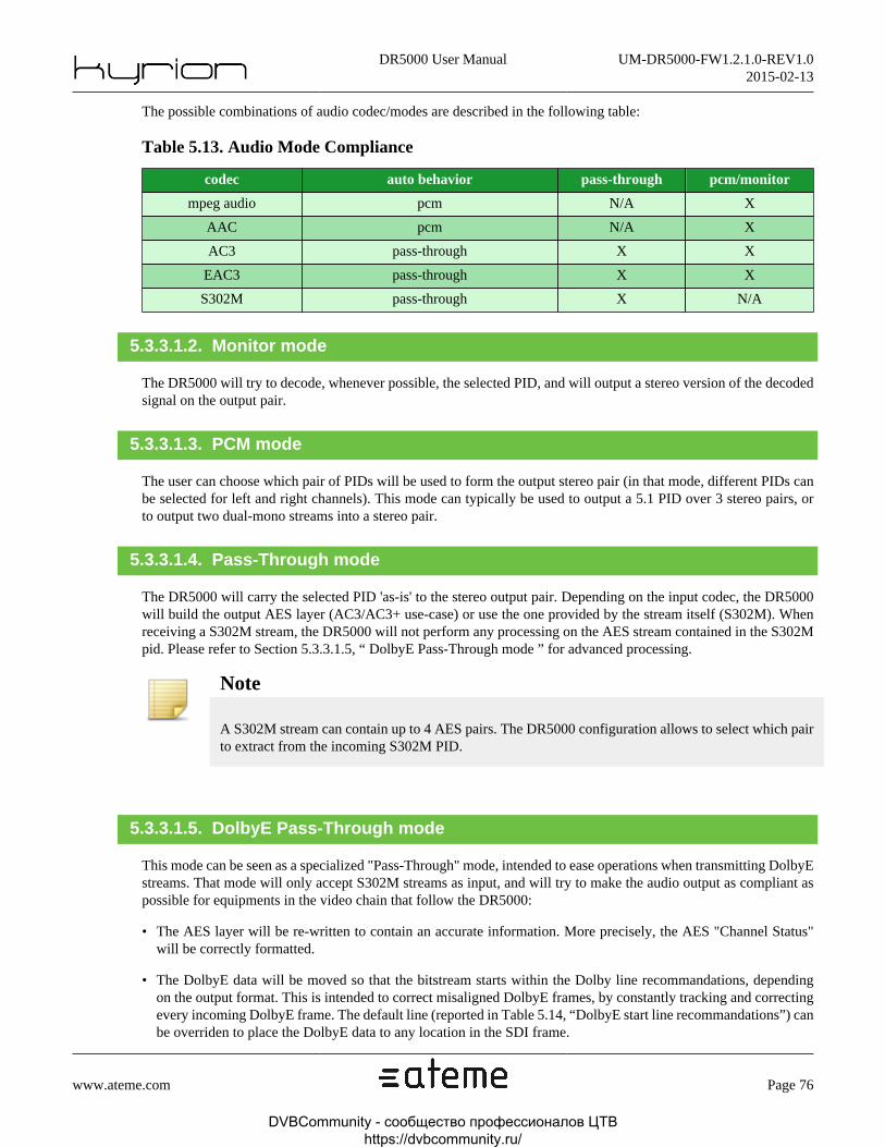
DR5000 User Manual UM-DR5000-FW1.2.1.0-REV1.02015-02-13
www.ateme.com Page 76
The possible combinations of audio codec/modes are described in the following table:
Table 5.13. Audio Mode Compliance
codec auto behavior pass-through pcm/monitor
mpeg audio pcm N/A X
AAC pcm N/A X
AC3 pass-through X X
EAC3 pass-through X X
S302M pass-through X N/A
5.3.3.1.2. Monitor mode
The DR5000 will try to decode, whenever possible, the selected PID, and will output a stereo version of the decodedsignal on the output pair.
5.3.3.1.3. PCM mode
The user can choose which pair of PIDs will be used to form the output stereo pair (in that mode, different PIDs canbe selected for left and right channels). This mode can typically be used to output a 5.1 PID over 3 stereo pairs, orto output two dual-mono streams into a stereo pair.
5.3.3.1.4. Pass-Through mode
The DR5000 will carry the selected PID 'as-is' to the stereo output pair. Depending on the input codec, the DR5000will build the output AES layer (AC3/AC3+ use-case) or use the one provided by the stream itself (S302M). Whenreceiving a S302M stream, the DR5000 will not perform any processing on the AES stream contained in the S302Mpid. Please refer to Section 5.3.3.1.5, “ DolbyE Pass-Through mode ” for advanced processing.
Note
A S302M stream can contain up to 4 AES pairs. The DR5000 configuration allows to select which pairto extract from the incoming S302M PID.
5.3.3.1.5. DolbyE Pass-Through mode
This mode can be seen as a specialized "Pass-Through" mode, intended to ease operations when transmitting DolbyEstreams. That mode will only accept S302M streams as input, and will try to make the audio output as compliant aspossible for equipments in the video chain that follow the DR5000:
• The AES layer will be re-written to contain an accurate information. More precisely, the AES "Channel Status"will be correctly formatted.
• The DolbyE data will be moved so that the bitstream starts within the Dolby line recommandations, dependingon the output format. This is intended to correct misaligned DolbyE frames, by constantly tracking and correctingevery incoming DolbyE frame. The default line (reported in Table 5.14, “DolbyE start line recommandations”) canbe overriden to place the DolbyE data to any location in the SDI frame.
DVBCommunity - cообщество профессионалов ЦТВ https://dvbcommunity.ru/

DR5000 User Manual UM-DR5000-FW1.2.1.0-REV1.02015-02-13
www.ateme.com Page 77
Table 5.14. DolbyE start line recommandations
Video Format Total number of linesRecommendedDolby position
625/50/i 625 12
525/59.94/i 525 14
1920x1080/60/i 1125 24
1920x1080/59.94/i 1125 24
1920x1080/50/i 1125 21
1920x1080/60/p 1125 47
1920x1080/59.94/p 1125 47
1920x1080/50/p 1125 42
1920x1080/30/p 1125 24
1920x1080/29.97/p 1125 24
1920x1080/25/p 1125 21
1920x1080/24/p 1125 27
1920x1080/23.98/p 1125 27
1280x720/60/p 750 32
1280x720/59.94/p 750 32
1280x720/50/p 750 28
1280x720/30/p 750 16
1280x720/29.97/p 750 16
1280x720/25/p 750 14
1280x720/24/p 750 18
1280x720/23.98/p 750 18
Warning
That mode of operation is only intended for S302M streams that contain DolbyE data. All other inputtypes will result in an empty audio output (the associated alarm will also be raised).
5.3.3.2. Analog audio output level
When available, analog audio output level can take four values
Table 5.15. Analog Audio Output Levels Description
Output Level Description
24 dBu @ 0 dBFS USA standard, Dolby recommandations
22 dBu @ 0 dBFS France and Japan standards
18 dBu @ 0 dBFS EBU R68, most European countries
DVBCommunity - cообщество профессионалов ЦТВ https://dvbcommunity.ru/

DR5000 User Manual UM-DR5000-FW1.2.1.0-REV1.02015-02-13
www.ateme.com Page 78
-10 dbV @ -20 dbFS Domestic recording, consumer line level.
5.3.3.3. Audio PID selection
Auto or Auto-Service modes
When not in 'pid-locked' mode (refer to Section 5.3.1, “ Service Editor ”), the DR5000 is responsible for selecting theaudio PIDs that will be output. In such case, the DR5000 will map the incoming PIDs according to their numericalorders on the audio outputs: the first PID (in PID value order) will be mapped on Group1/Pair1, the second PID onGroup1/Pair2, and so on. The following rules apply:
• If a given audio output is disabled, the corresponding PID will not be mapped.
• If the audio output mode is not compatible with the PID codec (for instance, 'pass-through' mode is configured forGroup1/Pair1, but the first PID is AAC, which can't be output in pass-through), then the corresponding PID willnot be mapped: silence will be output and an alarm is raised.
• If the audio output mode is set to "auto", then the DR5000 will automatically select the appropriate output mode('pass-through' or 'pcm'). If a PID can be output both as pass-through and PCM, pass-through will always be pre-ferred.
Note
PID mapping is independant on Embedded AES, External AES or Analog outputs.
Note
Pass-through PIDs are discarded in the analog output list.
Example 1
Let's consider a service containing four audio PIDs: PID 120 (AC3), PID 121 (S302M), PID 122 (AAC), PID 123(AAC)
Table 5.16. Audio PID selection example 1
OutputConfigured
Output modeSelected PID Output Mode
Group 1/Pair 1 auto 120 (AC3) pass-through
Group 1/Pair 2 auto 121 (S302M) pass-through
Group 2/Pair 1 auto 122 (AAC) pcm
Group 2/Pair 2 auto 123 (AAC) pcm
Group 3/Pair 1 auto none disabled
Group 3/Pair 2 auto none disabled
Group 4/Pair 1 auto none disabled
Group 4/Pair 2 auto none disabled
DVBCommunity - cообщество профессионалов ЦТВ https://dvbcommunity.ru/
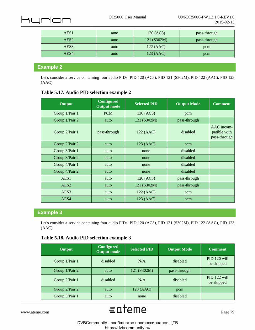
DR5000 User Manual UM-DR5000-FW1.2.1.0-REV1.02015-02-13
www.ateme.com Page 79
AES1 auto 120 (AC3) pass-through
AES2 auto 121 (S302M) pass-through
AES3 auto 122 (AAC) pcm
AES4 auto 123 (AAC) pcm
Example 2
Let's consider a service containing four audio PIDs: PID 120 (AC3), PID 121 (S302M), PID 122 (AAC), PID 123(AAC)
Table 5.17. Audio PID selection example 2
OutputConfigured
Output modeSelected PID Output Mode Comment
Group 1/Pair 1 PCM 120 (AC3) pcm
Group 1/Pair 2 auto 121 (S302M) pass-through
Group 2/Pair 1 pass-through 122 (AAC) disabledAAC incom-patible withpass-through
Group 2/Pair 2 auto 123 (AAC) pcm
Group 3/Pair 1 auto none disabled
Group 3/Pair 2 auto none disabled
Group 4/Pair 1 auto none disabled
Group 4/Pair 2 auto none disabled
AES1 auto 120 (AC3) pass-through
AES2 auto 121 (S302M) pass-through
AES3 auto 122 (AAC) pcm
AES4 auto 123 (AAC) pcm
Example 3
Let's consider a service containing four audio PIDs: PID 120 (AC3), PID 121 (S302M), PID 122 (AAC), PID 123(AAC)
Table 5.18. Audio PID selection example 3
OutputConfigured
Output modeSelected PID Output Mode Comment
Group 1/Pair 1 disabled N/A disabledPID 120 willbe skipped
Group 1/Pair 2 auto 121 (S302M) pass-through
Group 2/Pair 1 disabled N/A disabledPID 122 willbe skipped
Group 2/Pair 2 auto 123 (AAC) pcm
Group 3/Pair 1 auto none disabled
DVBCommunity - cообщество профессионалов ЦТВ https://dvbcommunity.ru/
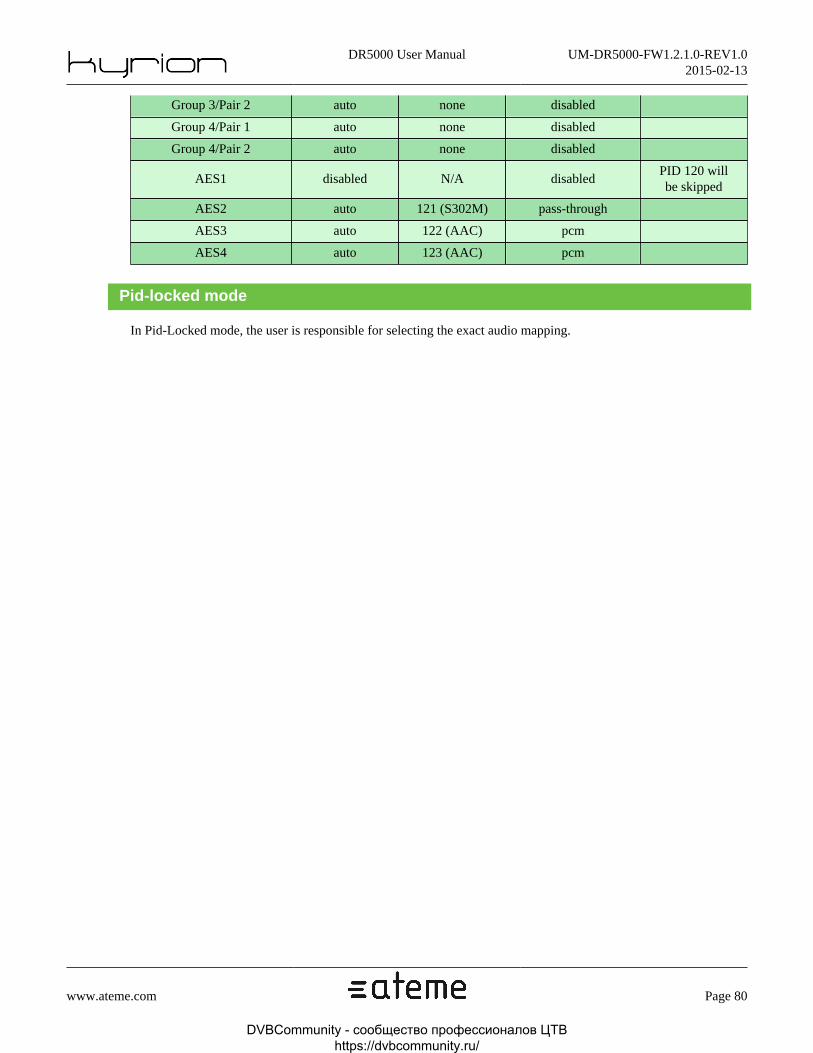
DR5000 User Manual UM-DR5000-FW1.2.1.0-REV1.02015-02-13
www.ateme.com Page 80
Group 3/Pair 2 auto none disabled
Group 4/Pair 1 auto none disabled
Group 4/Pair 2 auto none disabled
AES1 disabled N/A disabledPID 120 willbe skipped
AES2 auto 121 (S302M) pass-through
AES3 auto 122 (AAC) pcm
AES4 auto 123 (AAC) pcm
Pid-locked mode
In Pid-Locked mode, the user is responsible for selecting the exact audio mapping.
DVBCommunity - cообщество профессионалов ЦТВ https://dvbcommunity.ru/

DR5000 User Manual UM-DR5000-FW1.2.1.0-REV1.02015-02-13
www.ateme.com Page 81
5.4. Biss/CAThe DR5000 can descramble the incoming stream using either BISS or using a DVB-CI compatible ConditionalAccess Module module plugged into one of the available slots. Those modes of operation are exclusive: CAM andBISS can not be configured simultaneously.
Figure 5.6. Descrambling Parameters view
The list of services that are to be descrambled is independant from the descrambling itself (BISS or CAM), and canbe built in various ways:
• No programs will be descrambled.
• All the programs will be descrambled. Selecting this mode can corrupt the forwarded stream if the input streamcontains multiple programs scrambled with different keys.
• Only the decoded program will be descrambled (the choice of the program being decoded is made in Section 5.3,“ Service Selection ”).
DVBCommunity - cообщество профессионалов ЦТВ https://dvbcommunity.ru/

DR5000 User Manual UM-DR5000-FW1.2.1.0-REV1.02015-02-13
www.ateme.com Page 82
• "User-Defined" mode allows to specify which programs to descramble, independantly from the program beingdecoded. This is the preferred mode when using the DR5000 to forward one or more descrambled program to adownstream equipment, either through ASI (Section 5.7.1, “ ASI Output ”) or IP (Section 5.7.2, “ IP Output ”).
Note
The descrambling is only made on packets that are marked as scrambled in their TS header
Table 5.19. BISS/CA Parameters Description
ParameterPossiblevalues
Description GUI location
Descram-bling Mode
None,Biss, CAM
Descrambling mode of operation.label 'A' of Figure 5.6, “De-
scrambling Parameters view”
Serviceselection
All, Decoded,User-Defined
Defines how the descram-bled services list will be built.
label 'B' of Figure 5.6, “De-scrambling Parameters view”
Service list N/A
When in User-Defined service se-lection mode, this list allows to
specify all the programs that are tobe descrambled. Additionally, theCAM slot to use can be specified.
label 'C' of Figure 5.6, “De-scrambling Parameters view”
5.4.1. BISS parameters
BISS descrambling has two modes of operation:
• BISS 1: In such case, a Session Word (SW) of 12 hexadecimal digits is entered to descramble the stream. That SWis meant to be private and shall never be shared as it is self-sufficient to perform descrambling.
• BISS E: In such case, an Encrypted Session Word (ESW) of 16 hexadecimal digits is entered to descramble thestream. That encrypted session word may be public, as it has to be decrypted thanks to the unit Injected ID (referto Figure 4.13, “System Descrambling Parameters view”) to be usable as a SW.
Note
The DR5000 can hold two injected IDs. The selection of which injected ID to use is made through theBISS-E operating mode, which is split in Biss E1 (which uses Injected ID #1) and Biss E2 (which usesInjected ID #2) to perform descrambling.
Table 5.20. BISS parameters
Parameter Possible values Description GUI location
Biss ModeBiss-1, Biss-
E #1, Biss-E #2Biss Mode, as described in Sec-tion 5.4.1, “ BISS parameters ”
Label 'D' of Figure 5.6, “De-scrambling Parameters view”
SW/ESW Key12 (Biss 1) or 16 (Biss-
E1/2) hexa digitsSW or ESW key to beused for descrambling
Label 'E' of Figure 5.6, “De-scrambling Parameters view”
DVBCommunity - cообщество профессионалов ЦТВ https://dvbcommunity.ru/

DR5000 User Manual UM-DR5000-FW1.2.1.0-REV1.02015-02-13
www.ateme.com Page 83
5.4.2. CA parameters
The CAM slot selection follows the following rules:
• In "Decoded" or "All" service selection modes, only the top CAM slot will be used for descrambling operations.The bottom slot will not descramble the stream in those operating modes.
• In "User-Defined" service selection mode, one of the two slots holding CA modules can be specified for the de-scrambling of a given program. Up to 8 programs can be selected. That selection is made on the GUI using thedropdown depicted in label 'C' of Figure 5.6, “Descrambling Parameters view”. An icon will appear on the GUIwhen one selects a CAM slot which does not currently hold a CA module.
Warning
The number of programs that the DR5000 will descramble will depend on the module capabilities. Oneshould not try to descramble more programs than what is officially supported by the module vendor,otherwise unexpected behavior can occur.
Note
Parameters "Force3V3" and "Service limiting" have no effect in version 1.2.1.0 of the DR5000.
DVBCommunity - cообщество профессионалов ЦТВ https://dvbcommunity.ru/

DR5000 User Manual UM-DR5000-FW1.2.1.0-REV1.02015-02-13
www.ateme.com Page 84
5.5. Data OutputOnce the input has been configured, the DR5000 should be receiving transport stream (this can be checked by lookingat Section 4.3.2.3, “ Input status ” and Section 4.3.2.2, “ Probed programs ”, to figure out if the DR5000 succeededto lock to the input stream)
This panel lets you choose which data (under the form of ANC/VBI) will be processed and output by the DR5000.Some data may also be "burnt" onto the video itself, for monitoring purposes.
DVBCommunity - cообщество профессионалов ЦТВ https://dvbcommunity.ru/

DR5000 User Manual UM-DR5000-FW1.2.1.0-REV1.02015-02-13
www.ateme.com Page 85
Figure 5.7. Data Output View
DVBCommunity - cообщество профессионалов ЦТВ https://dvbcommunity.ru/

DR5000 User Manual UM-DR5000-FW1.2.1.0-REV1.02015-02-13
www.ateme.com Page 86
Note
DR5000 version 1.2.1.0 will not insert any ANC/VBI data on a downscaled version of an HD inputsignal. VBI/ANC data may of course be inserted in a SD-SDI signal when the input signal is a SD stream.
5.5.1. Ancillary Data
Ancillary data are inserted either in the Horizontal or Vertical ancillary space. All the configurable ANC data in theDR5000 follow the same philosophy:
• ANC data insertion can be enabled/disabled (label 'A' of Figure 5.7, “Data Output View”)
• ANC data source can be configured, either explicitely (from a PID) or implicitely (by specifying the data type);label 'B' of Figure 5.7, “Data Output View”
• ANC data line location can either be automatic, or user-defined, through labels 'C' and 'D' of Figure 5.7, “DataOutput View”. Default line location are shown in Table 5.21, “Vertical Ancillary data default location”.
Note
Audio Control Packet is always inserted in HD video formats. It is not inserted for SD video formats.
Note
S352M packets are always inserted.
Table 5.21. Vertical Ancillary data default location
ANC Type Default Line (offset from the switch line)
SMPTE 12 +2 (SD), N/A (HD)
SMPTE 2010 +2
SMPTE 2016 +1
SMPTE 2031 +2
SMPTE 334-1 +2
SMPTE 334-2 +2
SMPTE 2038 N/A
Table 5.22. Switch lines
Video Format SMPTE RP168 Switch lines
625/50/i 6,319
525/59.94/i 10,273
1920x1080/X/i 7,569
1920x1080/X/p 7
1280x720/X/p 7
DVBCommunity - cообщество профессионалов ЦТВ https://dvbcommunity.ru/

DR5000 User Manual UM-DR5000-FW1.2.1.0-REV1.02015-02-13
www.ateme.com Page 87
Warning
In case of line location conflicts in the ANC space, user-defined locations are always satisfied first,while the DR5000 will try to place the other ANC data in the remaining ANC space. The appropriatealarm will be raised if the conflict can not be automatically solved.
5.5.1.1. SMPTE 12
SMPTE 12 defines the transmission of time code in the Horizontal Ancillary Data Space (for HD) or Vertical AncillaryData Space (for SD). The DR5000 supports insertion of Vertical Intervale Time Code in the ancillary space.
VITC source is always a video PID, the time code being extracted from the "user data" of the video elementary stream.When missing, the time code will be interpolated from its last value in the incoming stream.
5.5.1.2. SMPTE 2010
SMPTE 2010 defines the carriage of ANSI/SCTE 104 messages in the Vertical Ancillary Data space, both is SD orHD video formats. Those ANSI/SCTE 104 messages, in the DR5000, come from SCTE 35 messages that are carriedthrough a dedicated PID.
Note
Only the "splice_insert" and "splice_null" command are supported in SCTE 35 to SCTE 104 translation.
5.5.1.3. SMPTE 2016
SMPTE 2016 allows to carry Active Format Description (AFD), Bar Data and Pan-Scan information into the SDIframe, so that an equipment receiving that SDI frame can extract the Region Of Interest inside that frame that carrythe active video, that may not match with the entire frame because of 4:3 to 16:9 conversions.
Note
Pan-Scan information is not supported in version 1.2.1.0 of the DR5000.
SMPTE 2016 source can be:
• A video PID: the message payload will be extracted from the video elementary stream, as a combination of thesignalled aspect ratio and of the "afd_data" structure carried in the elementary stream user data (as defined in ETSIEN 101 154). This is the preferred way of carrying AFD/Bar Data information.
• A VBI PID: the message payload will be extracted from the "wss" data field of the VBI PID (as defined in ETSIEN 301 775).
5.5.1.4. SMPTE 2038
SMPTE 2038 defines the carriage of arbitrary Ancillary Data Packets in an MPEG-2 Transport Stream. In the scope ofthe DR5000, SMPTE 2038 refers to the insertion of SMPTE 2038 messages directly into the SDI frame. As SMPTE
DVBCommunity - cообщество профессионалов ЦТВ https://dvbcommunity.ru/

DR5000 User Manual UM-DR5000-FW1.2.1.0-REV1.02015-02-13
www.ateme.com Page 88
2038 messages precisely define on which line to place the ANC packet payload, there is no "default" or "user-defined"line in SMPTE 2038 decoder configuration.
Warning
SMPTE 2038 may contain ANC messages which location conflicts with other ANC data insertion.Those conflicts will be reported through the appropriate alarm.
Note
The DR5000 will only place SMPTE 2038 data into the VANC area.
5.5.1.5. SMPTE 334-1
SMPTE 334-1 defines the mapping of caption data into the VANC space.
In the scope of the DR5000, SMPTE 334-1 will be used to carry CEA-608 data (thanks to SMPTE 334-1, Annex Aformat), that may come either from:
• A video PID: The message payload will be extracted from the "user data" of the video elementary stream. This isthe preferred way of carrying closed captioning data.
• A VBI PID: The message payload will be extracted from the "closed_captioning" data field of the VBI PID (asdefined in ETSI EN 301 775).
Note
CEA-708 data messages can be carried thanks to SMPTE 334-2, refer to Section 5.5.1.6, “ SMPTE334-2 ”.
5.5.1.6. SMPTE 334-2
SMPTE 334-2 is an extension of SMPTE 334-1, which allows to carry CEA-608 and/or CEA-708 data using CaptionDistribution Packet (CDP) payload, that may come either from:
• A video PID: The message payload will be extracted from the "user data" of the video elementary stream. This isthe preferred way of carrying closed captioning data.
• A VBI PID: The message payload will be extracted from the "closed_captioning" data field of the VBI PID (asdefined in ETSI EN 301 775).
5.5.1.7. SMPTE 2031
SMPTE 2031 defines the carriage of DVB/SCTE VBI Data in the VANC space. It was originally designed to carryVBI data in HD, where VBI data do not exist "as-is". SMPTE 2031 can be seen as way of carrying, in the ancillaryspace, data that would have been modulated in the VBI space in SD format.
DVBCommunity - cообщество профессионалов ЦТВ https://dvbcommunity.ru/

DR5000 User Manual UM-DR5000-FW1.2.1.0-REV1.02015-02-13
www.ateme.com Page 89
SMPTE 2031 can carry many "data fields" that are formed of the fields that are modulated in the VBI space. Theappropriate source can be selected for each of these data fields, although the preferred source is a VBI PID (as definedin ETSI EN 301 775).
• Teletext: the source can be a VBI PID (ETSI EN 301 775) or a teletext PID (ETSI EN 300 472)
• ClosedCaption: the source can be a VBI PID (ETSI EN 301 775) or a video pid (through user data of the videoelementary stream)
• Wss: the source can be a VBI PID (ETSI EN 301 775) or a video pid (through afd_data, carried in the user dataof the video elementary stream)
• Vps: the only possible source is a VBI PID (ETSI EN 301 775)
• VITC: the only possible source is a video pid (through user data of the video elementary stream). When missing,the time code will be interpolated from its last value in the incoming stream.
• AMOL48: the only possible source is a VBI PID (ETSI EN 301 775)
• AMOL96: the only possible source is a VBI PID (ETSI EN 301 775)
Note
SMPTE 2031 will be enabled as soon as one of its data fields is enabled.
5.5.2. VBI Data
VBI is only present in SD. Selected data will be modulated in the VBI space. Selectable data, by construction, arethe same as in SMPTE 2031.
• Teletext: the source can be a VBI PID (ETSI EN 301 775) or a teletext PID (ETSI EN 300 472)
• ClosedCaption: the source can be a VBI PID (ETSI EN 301 775) or a video pid (through user data of the videoelementary stream)
• Wss: the source can be a VBI PID (ETSI EN 301 775) or a video pid (through afd_data, carried in the user dataof the video elementary stream)
• Vps: the only possible source is a VBI PID (ETSI EN 301 775)
• VITC: the only possible source is a video pid (through user data of the video elementary stream). When missing,the time code will be interpolated from its last value in the incoming stream.
• AMOL48: the only possible source is a VBI PID (ETSI EN 301 775)
• AMOL96: the only possible source is a VBI PID (ETSI EN 301 775)
• Video Index (RP186): legacy way to carry Aspect Ratio and AFD BarData. The source can be a VBI PID (ETSIEN 301 775) or a video pid (through afd_data, carried in the user data of the video elementary stream)
DVBCommunity - cообщество профессионалов ЦТВ https://dvbcommunity.ru/
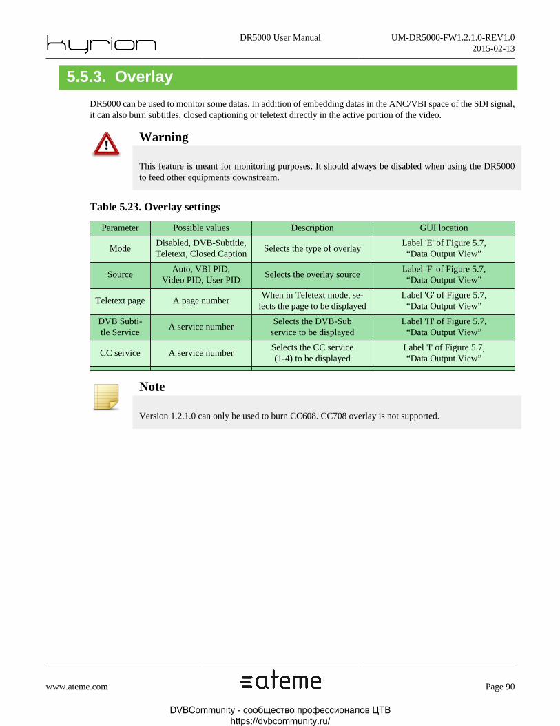
DR5000 User Manual UM-DR5000-FW1.2.1.0-REV1.02015-02-13
www.ateme.com Page 90
5.5.3. Overlay
DR5000 can be used to monitor some datas. In addition of embedding datas in the ANC/VBI space of the SDI signal,it can also burn subtitles, closed captioning or teletext directly in the active portion of the video.
Warning
This feature is meant for monitoring purposes. It should always be disabled when using the DR5000to feed other equipments downstream.
Table 5.23. Overlay settings
Parameter Possible values Description GUI location
ModeDisabled, DVB-Subtitle,Teletext, Closed Caption
Selects the type of overlayLabel 'E' of Figure 5.7,“Data Output View”
SourceAuto, VBI PID,
Video PID, User PIDSelects the overlay source
Label 'F' of Figure 5.7,“Data Output View”
Teletext page A page numberWhen in Teletext mode, se-
lects the page to be displayedLabel 'G' of Figure 5.7,
“Data Output View”
DVB Subti-tle Service
A service numberSelects the DVB-Sub
service to be displayedLabel 'H' of Figure 5.7,
“Data Output View”
CC service A service numberSelects the CC service(1-4) to be displayed
Label 'I' of Figure 5.7,“Data Output View”
Note
Version 1.2.1.0 can only be used to burn CC608. CC708 overlay is not supported.
DVBCommunity - cообщество профессионалов ЦТВ https://dvbcommunity.ru/

DR5000 User Manual UM-DR5000-FW1.2.1.0-REV1.02015-02-13
www.ateme.com Page 91
5.6. SDI OutputOnce the input is has been configured, and once the service to be decoded have been selected (refer to Section 5.3, “Service Selection ”), the DR5000 should now output a valid SDI stream on output. This can be checked by lookingat the active service overview (refer to Section 4.3.2.1, “ Active service overview ”)
This panel lets you adjust the SDI output parameters.
Figure 5.8. Output parameters view
5.6.1. SDI Connector Mapping
SDI connectors are organized in two groups:
• SDI #1 and #2 are mirror and always share the same output
• SDI #3 can be independently mapped.
A SDI connector has two operating modes:
• In Auto-SDI, the output SDI format follows the video source. This is the most common use-case.
• In SD-SDI, the output SDI format will always be SD-SDI, even though the input source may be HD. Selectionbetween 625i (PAL) and 525i (NTSC) is made according to the source framerate.
DVBCommunity - cообщество профессионалов ЦТВ https://dvbcommunity.ru/

DR5000 User Manual UM-DR5000-FW1.2.1.0-REV1.02015-02-13
www.ateme.com Page 92
Table 5.24. SDI Mapping Parameters Description
ParameterPossiblevalues
Description GUI location
Connector#1/2 mapping
AutoSDI,SD-SDI
Selects the output standardon SDI connectors 1 and 2
(which are mirror connectors)
Label 'A' of Figure 5.8,“Output parameters view”
Connector#3 mapping
AutoSDI,SD-SDI
Selects the output stan-dard on SDI connector 3
Label 'B' of Figure 5.8,“Output parameters view”
5.6.2. SDI Settings
5.6.2.1. SDI General Settings
Table 5.25. SDI General Settings Description
Para-meter
Possiblevalues
Description GUI location
Full PixelRange
On, Off
Controls the output pixel range. When set to 'off', out-put pixels will be clipped to SMPTE standards range, i.e.
[16-235] for luma and [16-240] for chroma (when ex-pressed in 8 bits samples). When set to 'on', output pix-els will only be clipped to the SDI limits (i.e. [1-254])
Label 'C' of Fig-ure 5.8, “Output
parameters view”
EnablePsF
outputOn, Off
Controls the video output format. When set to 'on', pro-gressive-signaled video will be output as PsF (1080p25 as1080psf25, 1080p29.97 as 1080psf29.97 and 1080p30 as
1080psf30). Interlaced formats will not be converted to PsF
Label 'D' of Fig-ure 5.8, “Output
parameters view”
5.6.2.2. Synchronization Settings
The DR5000 can be synchronized with an external clock reference. Once properly locked, both the "Auto-SDI" and"SD-SDI" outputs will be locked to the external reference. The external reference can be:
• A bi/tri-level signal, commonly called "genlock", entered through the "SYNC IN" connector.
• A "VPSC" signal, coming from another DR5000, entered through the "ASI IN 2" connector. VPSC is typicallyused for synchronizing IRDs without requiring additional genlock signal, for instance when using 4x DR5000 toperform UHD decoding.
Table 5.26. Synchronization Settings Description
Para-meter
Possiblevalues
Description GUI location
Clocksynhro-
niza-tion type
Follow TSInput, Gen-lock, VPSC
Controls the synchronization source of the DR5000. When setto 'Follow TS Input', the DR5000 will lock its output clock tothe incoming stream (PCRs). When set to 'Genlock', the syn-chronization signal entered on the SYNC IN connector will
be used as a source for the DR5000 output clock. When set to
Label 'E' of Fig-ure 5.8, “Output
parameters view”
DVBCommunity - cообщество профессионалов ЦТВ https://dvbcommunity.ru/
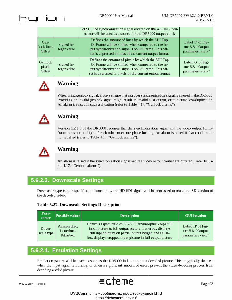
DR5000 User Manual UM-DR5000-FW1.2.1.0-REV1.02015-02-13
www.ateme.com Page 93
'VPSC', the synchronization signal entered on the ASI IN 2 con-nector will be used as a source for the DR5000 output clock
Gen-lock lines
Offset
signed in-teger value
Defines the amount of lines by which the SDI TopOf Frame will be shifted when compared to the in-put synchronization signal Top Of Frame. This off-set is expressed in lines of the current output format
Label 'F' of Fig-ure 5.8, “Output
parameters view”
GenlockpixelsOffset
signed in-teger value
Defines the amount of pixels by which the SDI TopOf Frame will be shifted when compared to the in-put synchronization signal Top Of Frame. This off-
set is expressed in pixels of the current output format
Label 'G' of Fig-ure 5.8, “Output
parameters view”
Warning
When using genlock signal, always ensure that a proper synchronization signal is entered in the DR5000.Providing an invalid genlock signal might result in invalid SDI output, or to picture loss/duplication.An alarm is raised in such a situation (refer to Table 4.17, “Genlock alarms”).
Warning
Version 1.2.1.0 of the DR5000 requires that the synchronization signal and the video output formatframe rates are multiple of each other to ensure phase locking. An alarm is raised if that condition isnot satisfied (refer to Table 4.17, “Genlock alarms”).
Warning
An alarm is raised if the synchronization signal and the video output format are different (refer to Ta-ble 4.17, “Genlock alarms”).
5.6.2.3. Downscale Settings
Downscale type can be specified to control how the HD-SDI signal will be processed to make the SD version ofthe decoded video.
Table 5.27. Downscale Settings Description
Para-meter
Possible values Description GUI location
Down-scale type
Anamorphic,Letterbox,Pillarbox
Controls aspect ratio of SD-SDI: Anamorphic keeps fullinput picture to full output picture, Letterbox displaysfull input picture on partial output height, and Pillar-
box displays cropped input picture in full output picture
Label 'H' of Fig-ure 5.8, “Output
parameters view”
5.6.2.4. Emulation Settings
Emulation pattern will be used as soon as the DR5000 fails to output a decoded picture. This is typically the casewhen the input signal is missing, or when a significant amount of errors prevent the video decoding process fromdecoding a valid picture.
DVBCommunity - cообщество профессионалов ЦТВ https://dvbcommunity.ru/

DR5000 User Manual UM-DR5000-FW1.2.1.0-REV1.02015-02-13
www.ateme.com Page 94
Emulation consists of repeating the last valid picture (for a user-configurable amount of time), displaying a solid-colorpicture, or disabling the SDI output.
Table 5.28. Emulation Settings Description
ParameterPossiblevalues
Description GUI location
Default Emu-lation Format
A video formatDefines the video format that
will be output on DR5000 boot.
Label 'I' of Fig-ure 5.8, “Output
parameters view”.
Freezeduration
A duration
Defines the amount of time during which the lastvalid picture will be repeated before switching to thesolid-color emulation pattern, or disabling the SDI
output (depending on the selected emulation pattern)
Label 'J' of Fig-ure 5.8, “Output
parameters view”.
Emula-tion pattern
A color or'Disabledoutput'
Defines the behavior after the 'Freeze duration' haselapsed: display a solid-color or disable SDI output
Label 'K' of Fig-ure 5.8, “Output
parameters view”.
Warning
It is highly recommended to set the "Freeze duration" parameter to a non-zero value, otherwise thesolid-color pattern will we displayed as soon as a the DR5000 fails to decode a picture, which is verylikely to happen in error prone environment.
Note
The "Default emulation format" parameters is only used at boot time. It will be overriden by the decodedstream video format as soon as a program is decoded.
5.6.2.5. Confidence Monitor
"Confidence Monitor" is the front panel monitor. It can be disabled on a configuration basis, through checkbox "M"of Figure 5.8, “Output parameters view”.
DVBCommunity - cообщество профессионалов ЦТВ https://dvbcommunity.ru/

DR5000 User Manual UM-DR5000-FW1.2.1.0-REV1.02015-02-13
www.ateme.com Page 95
5.7. Stream ForwardingThe DR5000 can perform stream forwarding on its ASI or IP interfaces. It is not only stream mirroring (as it is doneon the RF loopback, for instance) as descrambling and remuxing may be performed on the stream before being output.
Figure 5.9. Stream Forwarding View
5.7.1. ASI Output
ASI forwarding is performed through two (mirrored) ASI output connectors (refer Section 2.3.2, “ ASI IO Interfaces”).
DVBCommunity - cообщество профессионалов ЦТВ https://dvbcommunity.ru/
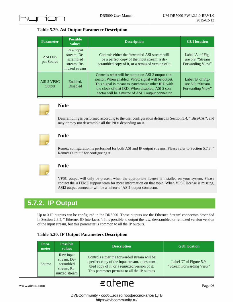
DR5000 User Manual UM-DR5000-FW1.2.1.0-REV1.02015-02-13
www.ateme.com Page 96
Table 5.29. Asi Output Parameter Description
ParameterPossiblevalues
Description GUI location
ASI Out-put Source
Raw inputstream, De-scrambledstream, Re-
muxed stream
Controls either the forwarded ASI stream willbe a perfect copy of the input stream, a de-
scrambled copy of it, or a remuxed version of it
Label 'A' of Fig-ure 5.9, “Stream
Forwarding View”
ASI 2 VPSCOutput
Enabled,Disabled
Controls what will be output on ASI 2 output con-nector. When enabled, VPSC signal will be output.This signal is meant to synchronize other IRD withthe clock of that IRD. When disabled, ASI 2 con-nector will be a mirror of ASI 1 output connector
Label 'B' of Fig-ure 5.9, “Stream
Forwarding View”
Note
Descrambling is performed according to the user configuration defined in Section 5.4, “ Biss/CA ”, andmay or may not descramble all the PIDs depending on it.
Note
Remux configuration is performed for both ASI and IP output streams. Please refer to Section 5.7.3, “Remux Output ” for configuring it
Note
VPSC output will only be present when the appropriate license is installed on your system. Pleasecontact the ATEME support team for more information on that topic. When VPSC license is missing,ASI2 output connector will be a mirror of ASI1 output connector.
5.7.2. IP Output
Up to 3 IP outputs can be configured in the DR5000. Those outputs use the Ethernet 'Stream' connectors describedin Section 2.3.5, “ Ethernet IO Interfaces ”. It is possible to output the raw, descrambled or remuxed version versionof the input stream, but this parameter is common to all the IP outputs.
Table 5.30. IP Output Parameters Description
Para-meter
Possiblevalues
Description GUI location
Source
Raw inputstream, De-scrambledstream, Re-
muxed stream
Controls either the forwarded stream will bea perfect copy of the input stream, a descram-
bled copy of it, or a remuxed version of it.This parameter pertains to all the IP outputs
Label 'C' of Figure 5.9,“Stream Forwarding View”
DVBCommunity - cообщество профессионалов ЦТВ https://dvbcommunity.ru/

DR5000 User Manual UM-DR5000-FW1.2.1.0-REV1.02015-02-13
www.ateme.com Page 97
IP OutputEnable
On, Off Enable or disable a given IP outputLabel 'D' of Figure 5.9,
“Stream Forwarding View”
InterfaceStream 1,Stream 2
Controls the output interface. A warning iconwill appear if a disabled interface is used
Label 'E' of Figure 5.9,“Stream Forwarding View”
Src Ad-dress
Auto,Not Auto
Controls the source IP address that will be in-dicated in the ethernet packet header. When
set to 'auto', the interface address will be used.Otherwise, the provided user address is used
Labels 'F' and 'G' of Figure 5.9,“Stream Forwarding View”
Dst Ad-dress
IP Address This can be either a Multicast or a Unicast addressLabel 'H' of Figure 5.9,
“Stream Forwarding View”
Dst Port Port Number Streaming PortLabel 'I' of Figure 5.9,
“Stream Forwarding View”
Type UDP, RTPDefines if RTP headers will
be added to the output streamLabel 'J' of Figure 5.9,
“Stream Forwarding View”
TSPackets
1-256Defines the number of TS packets that will be car-
ried by one ethernet frame. 7 is a very commonvalue as it fits into the standard 1500 bytes MTU
Label 'K' of Figure 5.9,“Stream Forwarding View”
TTL 0-255
Defines the network 'Time To Live' of mul-ticast datagrams, to allow packet forwarding
through all the network equipments. This fieldhas no effect when streaming to a unicast address
Label 'L' of Figure 5.9,“Stream Forwarding View”
ToS 0-255When enabled, the ToS field (also known
as DS field and ECN from RFC 2474)of the IPv4 header can be specified
Label 'M' of Figure 5.9,“Stream Forwarding View”
SSRCAuto,
Not Auto
Defines if the SSRC written in the RTP header isautomatic or user-defined. This field is typicallyused to determine the source of the RTP packets
Labels 'N' and 'O' of Figure 5.9,“Stream Forwarding View”
FECEnabled,Disabled
When Enabled, additional SMPTE 2022 FEC streamswill be output (on Dst Port + 2, Dst Port + 4) toallow error correction on error-prone networks
Label 'P' of Figure 5.9,“Stream Forwarding View”
Columns 1-20Defines the FEC Matrix length(parameter 'L' in SMPTE 2022)
Label 'Q' of Figure 5.9,“Stream Forwarding View”
Rows 4-20Defines the FEC Matrix depth
(parameter 'D' in SMPTE 2022)Label 'R' of Figure 5.9,
“Stream Forwarding View”
Step 0-19Controls how the FEC packets are applied to me-
dia packets (i.e. the matrix shape). Setting thisparameter to '0' will lead to a square FEC matrix
Label 'S' of Figure 5.9,“Stream Forwarding View”
5.7.3. Remux Output
Stream remuxing allows to remove services payloads from the stream.
Note
The DR5000 leaves the SI/PSI tables unmodified. Precisely, PMT of removed services are not includedin the stream, but are still referenced in the PAT.
DVBCommunity - cообщество профессионалов ЦТВ https://dvbcommunity.ru/

DR5000 User Manual UM-DR5000-FW1.2.1.0-REV1.02015-02-13
www.ateme.com Page 98
Remuxed stream can be based either on raw input stream, or on descrambled stream (as configured in Section 5.4,“ Biss/CA ”).
Remuxing can be performed in two ways:
• PID Decimator: in this mode, TS packets with PIDs marked as 'to be removed' will be replaced by null TS packets.This garanty the bitrate to be strictly unmodified.
• Temporal Remux: in this mode, a bitrate must be specified. For the remuxed stream to match the desired bitrate,two actions are performed: null TS packets are added and/or removed, and PCR (of TS packets carrying them) willbe corrected to match their new position in the stream.
Note
Even if the PCR is modified, it is based on the same clock, so PTS and DTS can be left unmodified andstill be referenced by any user-defined process.
There is three possibilities to select the remuxed services:
• In 'Follow decoded' mode, only the decoded program will be left in the remuxed stream. All other programs willbe removed.
• In 'User-defined Include List' mode, a service list must be filled: each service in this list will be present in theremuxed stream, but all services out of this list will be removed: the services are 'included' in the remuxed stream.
• In 'User-defined Exclude List' mode, a service list must be filled: each service in this list will be removed from theremuxed stream, and all service out of this list will be included: the services are 'excluded' from the remuxed stream.
Table 5.31. Remux Output Parameter Description
ParameterPossiblevalues
Description GUI location
DescramblingEnabled,Disabled
Controls if the remuxed stream is basedon the raw or descrambled stream
Label 'T' of Figure 5.9,“Stream Forwarding View”
Bitrateadaptation
Enabled,Disabled
When enabled, the remuxed stream will matchthe entered bitrate. When disabled, the out-put bitrate is the same as the input bitrate
Label 'U' of Figure 5.9,“Stream Forwarding View”
Bitrate A bitrateControls the remuxed bitrate,
when bitrate adaptation is enabledLabel 'V' of Figure 5.9,
“Stream Forwarding View”
Serviceselection
Follow Decod-ed, User-De-fined include,
User-De-fined exclude
Defines how the remuxedservices list will be built.
label 'W' of Figure 5.9,“Stream Forwarding View”
Service list N/AWhen in User-Defined service selection mode,
this list allows to specify all the programsthat are to be included/excluded from remux.
Label 'X' of Figure 5.9,“Stream Forwarding View”
DVBCommunity - cообщество профессионалов ЦТВ https://dvbcommunity.ru/

DR5000 User Manual UM-DR5000-FW1.2.1.0-REV1.02015-02-13
www.ateme.com Page 99
5.8. MPEMPE stands for MultiProtocol Encapsulation, which is defined by ETSI 301192. The DR5000 can be used to outputIP traffic, encapsulated in the incoming Transport Stream (whatever the underlying physical transport layer).
Warning
MPE data consists of IP datagrams (including source and destination IP). The DR5000 is only respon-sible for Layer2 (Ethernet) formatting.
Note
Version 1.2.1.0 does only implements a sub-set of the standard. IP/MAC Notification Table are notsupported.
Note
Management interface can not be used to output MPE IP traffic.
Figure 5.10. MPE Settings View
Table 5.32. MPE Settings Description
Para-meter
Possible values Description GUI location
MPEEnabled,Disabled
When enabled, the DR5000 will output IP pack-ets embedded in a ETSI 301192 compliant PID.
Label 'A' of Figure 5.10,“MPE Settings View”
PID a pidA PID containing IP datagrams. IP data
shall be embedded following ETSI 301192.Label 'B' of Figure 5.10,“MPE Settings View”
InterfaceStream 1,Stream 2
Ethernet interface that will be usedto output MPE-based datagrams
Label 'C' of Figure 5.10,“MPE Settings View”
DVBCommunity - cообщество профессионалов ЦТВ https://dvbcommunity.ru/
DR5000 User Manual UM-DR5000-FW1.2.1.0-REV1.02015-02-13
www.ateme.com Page 100
6. Specific Operations
6.1. Installing LicenseIn the web GUI, go to the System tab and click License.
The upper section is used to update the license settings.
To do so, click the Update button. A pop-up should appear asking for a license file. Click on the Browse button topoint to it and click Ok to proceed with the update, or Cancel to abort.
After a few seconds, a pop-up should appear, asking you to wait while the update process is running. Wait until thispop-up disappears.
Note
License files are specific files provided by ATEME support. They should bear the extension ".lic" andare bound to a specific unit Serial Number. If the file does not meet these requirements, it will be rejected.
The lower section is a summary of the licensed features with their status:
• 'Yes': A valid license file has been provided and the feature is available for use.
• 'No': The feature is disabled.
• 'Value': The feature is enabled and its limit is set to 'Value'
DVBCommunity - cообщество профессионалов ЦТВ https://dvbcommunity.ru/

DR5000 User Manual UM-DR5000-FW1.2.1.0-REV1.02015-02-13
www.ateme.com Page 101
6.2. RecoveryIf the web GUI becomes unreachable (and you are sure this is not a network problem) or the decoder keeps rebootingby itself without allowing you to do anything, it may be due to a corrupted file or settings incompatibility between2 versions preventing the system to boot normally.
To recover from such situation, the decoder has a maintenance menu, accessible early on boot by the front panel FP ,and allowing cleaning some parts of the system.
Follow the steps below to access the maintenance menu:
Step 1
Turn on your decoder or restart it if it's already on.
Step 2
Watch for a Maintenance message displayed on FP4 after a few seconds.
Step 3
Quickly press the 'OK' button (FP6 see Section 4.2, “ Front Panel ”) to enter the Maintenance menu. Available optionsare:
• Continue: Exit the maintenance menu and continue booting normally.
• Reset Config: Erase all service configuration parameters. The "Reset Config" function is useful when a newlyinstalled version is unstable on boot because of an incompatibility with the previous settings. Only the serviceconfiguration parameters will be lost. The firmware version and system parameters will stay the same.
This is the first thing to try.
• Restore System: Restores a previously saved system version. If the current system version gets corrupted for somereason, restoring an older version can make the system usable again allowing you to take control of the web interfaceback.
• Restore Factory: Restores the system to its factory version. It will reset everything including: services configurationsettings, firmware version and system parameters.
• This menu also displays one IP address configured on the system and current system version.
DVBCommunity - cообщество профессионалов ЦТВ https://dvbcommunity.ru/

DR5000 User Manual UM-DR5000-FW1.2.1.0-REV1.02015-02-13
www.ateme.com Page 102
Appendix A. MIB User Guide
A.1. SNMP OverviewThis section applies to the DR5000 version 1.2.1.0. It is a guide for interfacing the DR5000 via a NMS, or throughsimple SNMP commands. The MIB of the DR5000 can be used to control, configure, and monitor the unit. Everythingthat can be done through the web GUI can also be done through SNMP.
Note
All the examples provided in this section are using command-line applications snmpget and snmpset,part of the Open Source Net-SNMP software package which is available for all major Operating Sys-tems. Graphical MIB browser software can also be used alternatively. This guide is not intented to coverthe usage of these softwares that are only used to illustrate our MIB implementation. For more detailsabout these softwares, please refer to their respective documentations. In all examples here below thekeyword "host" represents the IP address of the DR5000 interface through which SNMP commands areperformed. To reproduce the example, one shall replace this keyword by the effective IP address of theDR5000 to be controlled.
Note
All the MIB variables are commented in the MIB itself.
Ethernet interface
All the ethernet interfaces of the DR5000 can be used to drive the unit through SNMP. Nevertheless, it is highlyrecommended to use the "Management" interface as using Stream1/2 may interfere with the decoding process.
Protocol
SNMP version V2.C is supported.
Requests
The DR5000 listens to incoming SNMP requests on the standard SNMP port 161 (not configurable). GET, GET-NEXT, GET-BULK and SET requests are supported.
Traps
Traps can be sent to notify transitions between variable states, such as alarms. Traps can be sent simultaneously to upto 4 targets, on a user-specified port (although standard SNMP port 162 is recommended). All enabled traps are sentto all targets: enabled traps are configurable at the system level, not on a per-target basis. Traps are further detailedin Section A.3.5, “ Configuring communities and traps ”.
DVBCommunity - cообщество профессионалов ЦТВ https://dvbcommunity.ru/

DR5000 User Manual UM-DR5000-FW1.2.1.0-REV1.02015-02-13
www.ateme.com Page 103
Request rate
The DR5000 will process up to 50 requests per second. Walking through the entire MIB may thus take dozens ofseconds.
Communities
Community string provide a basic right access mechanism. Two community strings are defined: "public" is associatedto Read-Only variables, "private" is associated to Read-Write variables. Those strings can be overriden. Please referto Section 4.3.3.3.2, “ Setting Alarms And Traps ” and to Section A.3.5, “ Configuring communities and traps ” formore information.
DVBCommunity - cообщество профессионалов ЦТВ https://dvbcommunity.ru/
DR5000 User Manual UM-DR5000-FW1.2.1.0-REV1.02015-02-13
www.ateme.com Page 104
A.2. MIB OverviewParameters application is equivalent to Front Panel : they are instantly applied, there is no need to send a validationrequest. There is no possibility to prepare several parameters that should be applied at the same time.
Every node and leaf follow the same naming convention : it is the concatenation of its parent node name with thecurrent parameter name. For example, dr5000StatusInputBitrate leaf is located in dr5000StatusInput node, which isitself located in the dr5000Status node. Thanks to this naming convention, equivalences between Front Panel para-meters and SNMP nodes are easily found.
DVBCommunity - cообщество профессионалов ЦТВ https://dvbcommunity.ru/

DR5000 User Manual UM-DR5000-FW1.2.1.0-REV1.02015-02-13
www.ateme.com Page 105
A.2.1. Main nodes
DR5000 MIB is organized in thirteen nodes which description is hereinafter given.
.|-- dr5000Conformance (OID 1.3.6.1.4.1.27338.5.1)|-- dr5000Unit (OID 1.3.6.1.4.1.27338.5.2)|-- dr5000Channel (OID 1.3.6.1.4.1.27338.5.3)|-- dr5000Command (OID 1.3.6.1.4.1.27338.5.4)|-- dr5000Status (OID 1.3.6.1.4.1.27338.5.5)| |-- dr5000StatusTsDescriptor (OID 1.3.6.1.4.1.27338.5.5.1)| |-- dr5000StatusDecode (OID 1.3.6.1.4.1.27338.5.5.2)| `-- dr5000StatusInput (OID 1.3.6.1.4.1.27338.5.5.3)|-- dr5000Software (OID 1.3.6.1.4.1.27338.5.6)|-- dr5000Hardware (OID 1.3.6.1.4.1.27338.5.7)|-- dr5000Network (OID 1.3.6.1.4.1.27338.5.8)|-- dr5000Biss (OID 1.3.6.1.4.1.27338.5.9)|-- dr5000Time (OID 1.3.6.1.4.1.27338.5.10)|-- dr5000Snmp (OID 1.3.6.1.4.1.27338.5.11)|-- dr5000Preset (OID 1.3.6.1.4.1.27338.5.12)`-- dr5000Licenses (OID 1.3.6.1.4.1.27338.5.13)
dr5000Conformance (OID 1.3.6.1.4.1.27338.5.1)
The DR5000 only exports full compliance group. Please refer to RFC 2580 for more information on that topic.
dr5000Unit (OID 1.3.6.1.4.1.27338.5.2)
This node contains information pertaining to the physical unit, such as unit Serial Number (RO), Name (RW) andModel (RO).
Note
The "model" node can be used to identify a unit in a decoder farm, by following the process describedin Section A.3.1, “ Identification process ”.
dr5000Channel (OID 1.3.6.1.4.1.27338.5.3)
This node is targeted at preset management, and is organized in two sub-nodes:
• dr5000ChannelCommand (OID 1.3.6.1.4.1.27338.5.3.1) allows to load/save a preset from one of the configurationslot. This equivalent to the Web GUI tab "Service/Presets" described inSection 4.3.3.2, “ Service Panel ”. For moreinformation about its use, please refer to Section A.3.8, “ Saving and loading a preset ”.
• dr5000ChannelConfiguration (OID 1.3.6.1.4.1.27338.5.3.2) is used to modify the running configuration. For in-stance, this is the appropriate node for setting the input type, the decoded PIDs or the audio mapping.
DVBCommunity - cообщество профессионалов ЦТВ https://dvbcommunity.ru/

DR5000 User Manual UM-DR5000-FW1.2.1.0-REV1.02015-02-13
www.ateme.com Page 106
dr5000Command (OID 1.3.6.1.4.1.27338.5.4)
From here, one can take "action" on the system. An "action" is not stored in the configuration itself as it identifies atransition from one state to another. An "action" can be rebooting the unit, resetting the input counters, etc.
Note
Actions act as triggers, and as such do not require their nodes to be cleared: writing the same valueseveral times in a row will perform the action several times.
dr5000Status (OID 1.3.6.1.4.1.27338.5.5)
This node is used to retrieve information on the decoding itself (by opposition to system-wide information such asnetwork, time, etc.). It is organized in three sub nodes:
• dr5000StatusTsDescriptor (OID 1.3.6.1.4.1.27338.5.5.1) allows to retrieve TS level information that have beenprobed, such as the number of programs, program names, stream types, pid, etc. This sub-node correspond to theinformation listed in the "probed programs" panel in the GUI (Section 4.3.2.2, “ Probed programs ”). Please referto Section A.3.21, “ TS Descriptor ” for more information about this node.
• dr5000StatusDecode (OID 1.3.6.1.4.1.27338.5.5.2) reports advanced information about the program being current-ly decoded, such as video format, audio codecs, samplerates, scrambling information, etc. This sub-node corre-sponds to the information listed in the "active service overview" panel in the GUI (Section 4.3.2.1, “ Active serviceoverview ”). Please refer to Section A.3.20, “ Checking composition results ” for more information about this node.
• dr5000StatusInput (OID 1.3.6.1.4.1.27338.5.5.3) reports information on the input layer, such as DVB-S/S2 signalcharacteristics (C/N, modulation, etc) or IP input counters. This sub-node corresponds to the information listed inthe "Input status" of the GUI (Section 4.3.2.3, “ Input status ”)
dr5000Software (OID 1.3.6.1.4.1.27338.5.6)
Contains information pertaining to the firmwares installed as "current", "backup" or "factory" on the unit.
dr5000Hardware (OID 1.3.6.1.4.1.27338.5.7)
Contains hardware related information, such as temperature, fan status, Power Supply status, or ethernet interfacesconnection status.
dr5000Network (OID 1.3.6.1.4.1.27338.5.8)
Allows to configure / retrieve information about ethernet connection and routes. Sub-node dr5000NetworkConnection(OID 1.3.6.1.4.1.27338.5.3.2) is used to configure network connections (including VLANs), while sub-nodedr5000NetworkRoute (OID 1.3.6.1.4.1.27338.5.8.2) is used to manage routes (specify a gateway for a given interface,for instance. This node is equivalent to Figure 4.10, “Network Panel” in the web GUI. Please refer to Section A.3.6,“ Configuring network interfaces ” and Section A.3.7, “ Configuring routes ” for more information.
DVBCommunity - cообщество профессионалов ЦТВ https://dvbcommunity.ru/

DR5000 User Manual UM-DR5000-FW1.2.1.0-REV1.02015-02-13
www.ateme.com Page 107
dr5000Biss (OID 1.3.6.1.4.1.27338.5.9)
Used to specify injected IDs. Please note that these fields are Write-Only, but belong to the Read-Write community.The DR5000 can hold two injected IDs. This node is equivalent to Section 4.3.3.3.3, “ BISS/CA System Parameter” in the web GUI.
dr5000Time (OID 1.3.6.1.4.1.27338.5.10)
Used to set or get the current date. Please refer to Section A.3.4, “ Setting time ” for more information.
dr5000Snmp (OID 1.3.6.1.4.1.27338.5.11)
Used to control community passwords, trap targets, and MIB variables associated to trap sending. Equivalent to Sec-tion 4.3.3.3.2, “ Setting Alarms And Traps ” in the web GUI. Please refer to Section A.3.5, “ Configuring communitiesand traps ” for more information.
dr5000Preset (OID 1.3.6.1.4.1.27338.5.12)
This node is related to preset management. It lists all the configuration slots stored in the unit, and can also be used toedit the slot name. Please note that this node can neither be used to view nor edit configuration slot content, but onlyits name. Viewing/editing the content can be performed through node dr5000Channel (OID 1.3.6.1.4.1.27338.5.3),as explained in Section A.3.8, “ Saving and loading a preset ”.
dr5000Licenses (OID 1.3.6.1.4.1.27338.5.13)
List all the possible licenses and their state (present or not) on the unit.
DVBCommunity - cообщество профессионалов ЦТВ https://dvbcommunity.ru/

DR5000 User Manual UM-DR5000-FW1.2.1.0-REV1.02015-02-13
www.ateme.com Page 108
A.3. MIB Use Cases
A.3.1. Identification process
A DR5000 can be probed as the current system through the use of the node sysObjectID from RFC1213. This nodemust points to another one, which describes the current model. For a DR5000, this last node is dr5000UnitModeland has the value "DR5000".
When the model is identified, its name and serial number can be retrieved through the nodes dr5000UnitName anddr5000UnitSerialNumber.
The following example shows the identification process of a DR5000.
$ snmpget -v2c -c public host SNMPv2-MIB::sysObjectID.0SNMPv2-MIB::sysObjectID.0 = OID: SNMPv2-SMI::enterprises.27338.5.2.2
$ snmpget -v2c -c public host SNMPv2-SMI::enterprises.27338.5.2.2.0SNMPv2-SMI::enterprises.27338.5.2.2.0 = STRING: "DR5000"
$ snmpget -v2c -c public host ATEME-DR5000-MIB::dr5000UnitName.0ATEME-DR5000-MIB::dr5000UnitName.0 = STRING: Host
$ snmpget -v2c -c public host ATEME-DR5000-MIB::dr5000UnitSerialNumber.0ATEME-DR5000-MIB::dr5000UnitSerialNumber.0 = STRING: 1250-00013
A.3.2. Configuration lock
The lock feature, described in Section 4.3.3.1.1, “ System Information ”, is accessible through the nodedr5000CommandSystemAction.
Warning
Writing a protected node when the system is locked does not raise any warning: the effect is just nottaken into account.
The following example locks and unlocks the system.
$ snmpset -v2c -c private host ATEME-DR5000-MIB::dr5000CommandSystemAction.0 i 2ATEME-DR5000-MIB::dr5000CommandSystemAction.0 = INTEGER: lock(2)
$ snmpset -v2c -c private host ATEME-DR5000-MIB::dr5000CommandSystemAction.0 i 3ATEME-DR5000-MIB::dr5000CommandSystemAction.0 = INTEGER: unlock(3)
A.3.3. Rebooting the system
The system may have to be restarted, either on support request or for some specific operations to be applied. Toperform this, the value reboot(1) must be written into dr5000CommandSystemAction.
DVBCommunity - cообщество профессионалов ЦТВ https://dvbcommunity.ru/

DR5000 User Manual UM-DR5000-FW1.2.1.0-REV1.02015-02-13
www.ateme.com Page 109
The following example performs a reboot.
$ snmpset -v2c -c private host ATEME-DR5000-MIB::dr5000CommandSystemAction.0 i 1ATEME-DR5000-MIB::dr5000CommandSystemAction.0 = INTEGER: reboot(1)
A.3.4. Setting time
The time on the DR5000 can be set in two ways:
• Thanks to dr5000TimeDate. In such case, the value to set is the number of seconds since January 1st, 1970.
• By configuring a NTP server in dr5000TimeNtpAddress.
The following example forces the date to March 19, 1994, and then uses the NTP server 172.16.0.1.
$ snmpset -v2c -c private host ATEME-DR5000-MIB::dr5000TimeDate.0 i 764035200ATEME-DR5000-MIB::dr5000TimeDate.0 = INTEGER: 764035200
$ snmpset -v2c -c private host ATEME-DR5000-MIB::dr5000TimeNtpAddress.0 d 172.16.0.1ATEME-DR5000-MIB::dr5000TimeNtpAddress.0 = Hex-STRING: AC 10 00 01
A.3.5. Configuring communities and traps
SNMP community strings can be changed through the nodes dr5000SnmpCommunityReadOnly anddr5000SnmpCommunityReadWrite.
Note
The DR5000 must be rebooted (see Section A.3.3, “ Rebooting the system ”) for new communities tobe taken into account.
The DR5000 can send SNMP traps on pre-defined events up to four targets. The trap target are defined in the listdr5000SnmpManager.
Warning
This list is automatically reorganized so that enabled targets are located on the lowest indexes. Perform-ing several changes in a single SNMP commands has thus an undefined behaviour.
The following example replaces both read-only and read-write communities.
DVBCommunity - cообщество профессионалов ЦТВ https://dvbcommunity.ru/

DR5000 User Manual UM-DR5000-FW1.2.1.0-REV1.02015-02-13
www.ateme.com Page 110
$ snmpset -v2c -c private host \ ATEME-DR5000-MIB::dr5000SnmpCommunityReadOnly.0 s "read-only"ATEME-DR5000-MIB::dr5000SnmpCommunityReadOnly.0 = STRING: read-only
$ snmpset -v2c -c private host \ ATEME-DR5000-MIB::dr5000SnmpCommunityReadWrite.0 s "read/write"ATEME-DR5000-MIB::dr5000SnmpCommunityReadWrite.0 = STRING: read/write
$ snmpset -v2c -c private host ATEME-DR5000-MIB::dr5000CommandSystemAction.0 i 1ATEME-DR5000-MIB::dr5000CommandSystemAction.0 = INTEGER: reboot(1)
The following example empties the list of trap target, and adds 172.16.1.22:1256 as a new target.
$ snmpset -v2c -c private host ATEME-DR5000-MIB::dr5000SnmpManagerIsEnabled.1 i 2ATEME-DR5000-MIB::dr5000SnmpManagerIsEnabled.1 = INTEGER: false(2)
$ snmpset -v2c -c private host ATEME-DR5000-MIB::dr5000SnmpManagerIsEnabled.1 i 2ATEME-DR5000-MIB::dr5000SnmpManagerIsEnabled.1 = INTEGER: false(2)
$ snmpset -v2c -c private host ATEME-DR5000-MIB::dr5000SnmpManagerIsEnabled.1 i 2ATEME-DR5000-MIB::dr5000SnmpManagerIsEnabled.1 = INTEGER: false(2)
$ snmpset -v2c -c private host ATEME-DR5000-MIB::dr5000SnmpManagerIsEnabled.1 i 1ATEME-DR5000-MIB::dr5000SnmpManagerIsEnabled.1 = INTEGER: true(1)
$ snmpset -v2c -c private host \ ATEME-DR5000-MIB::dr5000SnmpManagerAddress.1 d 172.16.1.22ATEME-DR5000-MIB::dr5000SnmpManagerAddress.1 = Hex-STRING: AC 10 01 16
$ snmpset -v2c -c private host ATEME-DR5000-MIB::dr5000SnmpManagerPort.1 u 1256ATEME-DR5000-MIB::dr5000SnmpManagerPort.1 = Gauge32: 1256
A.3.6. Configuring network interfaces
Configuring the network interfaces (for both LAN and VLAN) is performed through dr5000NetworkConnection. Thefirst three rows of this table (Management, Stream1 and Stream2) correspond to physical interfaces, while the otherentries correspond to VLAN. For more information about network management in DR5000, see Section 4.3.3.3.1.1,“ IP settings ”.
Warning
This list is automatically reorganized so that the enabled VLAN are located on the lowest indexes.Performing several changes in a single SNMP command has thus an undefined behaviour.
Warning
The application of the network configuration does not require a reboot. Modifying the interface usedfor SNMP configuration can thus lead to SNMP connection loss.
The following example seeks for Stream 2 physical interface and configures it to be 10.16.127.221/16.
DVBCommunity - cообщество профессионалов ЦТВ https://dvbcommunity.ru/
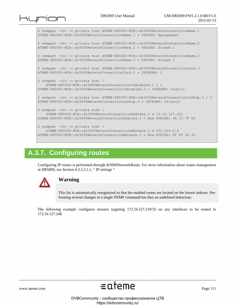
DR5000 User Manual UM-DR5000-FW1.2.1.0-REV1.02015-02-13
www.ateme.com Page 111
$ snmpget -v2c -c private host ATEME-DR5000-MIB::dr5000NetworkConnectionName.1ATEME-DR5000-MIB::dr5000NetworkConnectionName.1 = STRING: Management
$ snmpget -v2c -c private host ATEME-DR5000-MIB::dr5000NetworkConnectionName.2ATEME-DR5000-MIB::dr5000NetworkConnectionName.2 = STRING: Stream 1
$ snmpget -v2c -c private host ATEME-DR5000-MIB::dr5000NetworkConnectionName.3ATEME-DR5000-MIB::dr5000NetworkConnectionName.3 = STRING: Stream 2
$ snmpget -v2c -c private host ATEME-DR5000-MIB::dr5000NetworkConnectionCard.3ATEME-DR5000-MIB::dr5000NetworkConnectionCard.3 = INTEGER: 2
$ snmpset -v2c -c private host \ ATEME-DR5000-MIB::dr5000NetworkConnectionIsEnabled.3 i 1ATEME-DR5000-MIB::dr5000NetworkConnectionIsEnabled.3 = INTEGER: true(1)
$ snmpset -v2c -c private host ATEME-DR5000-MIB::dr5000NetworkConnectionIsDhcp.3 i 2ATEME-DR5000-MIB::dr5000NetworkConnectionIsDhcp.3 = INTEGER: false(2)
$ snmpset -v2c -c private host \ ATEME-DR5000-MIB::dr5000NetworkConnectionAddress.3 d 10.16.127.221ATEME-DR5000-MIB::dr5000NetworkConnectionAddress.3 = Hex-STRING: 0A 10 7F DD
$ snmpset -v2c -c private host \ ATEME-DR5000-MIB::dr5000NetworkConnectionNetmask.3 d 255.255.0.0ATEME-DR5000-MIB::dr5000NetworkConnectionNetmask.3 = Hex-STRING: FF FF 00 00
A.3.7. Configuring routes
Configuring IP routes is performed through dr5000NetworkRoute. For more information about routes managementin DR5000, see Section 4.3.3.3.1.1, “ IP settings ”.
Warning
This list is automatically reorganized so that the enabled routes are located on the lowest indexes. Per-forming several changes in a single SNMP command has thus an undefined behaviour.
The following example configures streams targeting 172.16.127.219/32 on any interfaces to be routed to172.16.127.248.
DVBCommunity - cообщество профессионалов ЦТВ https://dvbcommunity.ru/

DR5000 User Manual UM-DR5000-FW1.2.1.0-REV1.02015-02-13
www.ateme.com Page 112
$ snmpset -v2c -c private host ATEME-DR5000-MIB::dr5000NetworkRouteIsEnabled.1 i 1ATEME-DR5000-MIB::dr5000NetworkRouteIsEnabled.1 = INTEGER: true(1)
$ snmpset -v2c -c private host \ ATEME-DR5000-MIB::dr5000NetworkRouteAddress.1 d 172.16.127.219ATEME-DR5000-MIB::dr5000NetworkRouteAddress.1 = Hex-STRING: AC 10 7F DB
$ snmpset -v2c -c private host \ ATEME-DR5000-MIB::dr5000NetworkRouteNetmask.1 d 0.0.0.0ATEME-DR5000-MIB::dr5000NetworkRouteNetmask.1 = Hex-STRING: 00 00 00 00
$ snmpset -v2c -c private host \ ATEME-DR5000-MIB::dr5000NetworkRouteGateway.1 d 172.16.127.248ATEME-DR5000-MIB::dr5000NetworkRouteGateway.1 = Hex-STRING: AC 10 7F F8
$ snmpset -v2c -c private host \ ATEME-DR5000-MIB::dr5000NetworkRouteInterfaceRuleIsEnabled.1 i 2ATEME-DR5000-MIB::dr5000NetworkRouteInterfaceRuleIsEnabled.1 = INTEGER: false(2)
A.3.8. Saving and loading a preset
As described in Section 4.3.3.2.1, “ Managing Multiple Configurations ”, the full DR5000 configuration can be savedas a "preset". Only the presets that are saved on the DR5000 can be managed through SNMP. Because loading apreset also applies it, the node dr5000ChannelConfigurationName will always show "Active configuration". It is notmeant to be used through SNMP. To read or write a preset name, dr5000PresetPresetName must be used.
Note
The presets cannot be previewed through SNMP. To know what it contains, the preset must be loaded,which means it is applied.
Presets are stored in indexed "slots". A preset saved as "Preset #N" will have to be loaded as "Preset #N". The sameconfiguration can be saved in several slots. These slots must be seen as copies at a given instant of the configuration.Modifying the current configuration (by any other way than "saving the preset") will not modify the content of thepreset. Thus, the action of loading a preset does only perform a copy of the preset into the active configuration, andthe action of saving a preset does only perform a copy of the active configuration into a preset.
Warning
Presets are 0-indexed in SNMP, and 1-indexed in Web GUI.
To load a preset, the node dr5000ChannelCommandLoadPreset must be written the index of the preset to be loaded.Once it is done, the action load(2) must be written in dr5000ChannelCommandAction.
Saving a preset follows the same logic: the preset index must be written in dr5000ChannelCommandSavePreset, thenthe action save(3) must be written in dr5000ChannelCommandAction.
The following example reads the name of preset #42, loads it, and stores it in preset #51.
DVBCommunity - cообщество профессионалов ЦТВ https://dvbcommunity.ru/
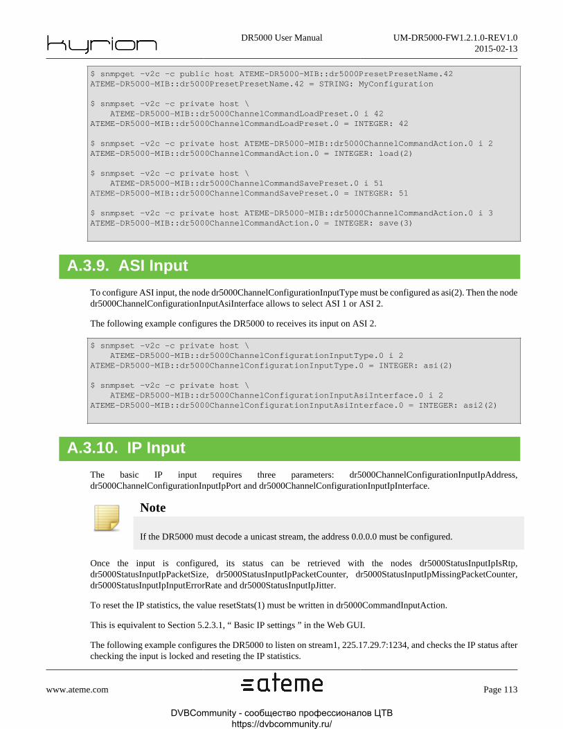
DR5000 User Manual UM-DR5000-FW1.2.1.0-REV1.02015-02-13
www.ateme.com Page 113
$ snmpget -v2c -c public host ATEME-DR5000-MIB::dr5000PresetPresetName.42ATEME-DR5000-MIB::dr5000PresetPresetName.42 = STRING: MyConfiguration
$ snmpset -v2c -c private host \ ATEME-DR5000-MIB::dr5000ChannelCommandLoadPreset.0 i 42ATEME-DR5000-MIB::dr5000ChannelCommandLoadPreset.0 = INTEGER: 42
$ snmpset -v2c -c private host ATEME-DR5000-MIB::dr5000ChannelCommandAction.0 i 2ATEME-DR5000-MIB::dr5000ChannelCommandAction.0 = INTEGER: load(2)
$ snmpset -v2c -c private host \ ATEME-DR5000-MIB::dr5000ChannelCommandSavePreset.0 i 51ATEME-DR5000-MIB::dr5000ChannelCommandSavePreset.0 = INTEGER: 51
$ snmpset -v2c -c private host ATEME-DR5000-MIB::dr5000ChannelCommandAction.0 i 3ATEME-DR5000-MIB::dr5000ChannelCommandAction.0 = INTEGER: save(3)
A.3.9. ASI Input
To configure ASI input, the node dr5000ChannelConfigurationInputType must be configured as asi(2). Then the nodedr5000ChannelConfigurationInputAsiInterface allows to select ASI 1 or ASI 2.
The following example configures the DR5000 to receives its input on ASI 2.
$ snmpset -v2c -c private host \ ATEME-DR5000-MIB::dr5000ChannelConfigurationInputType.0 i 2ATEME-DR5000-MIB::dr5000ChannelConfigurationInputType.0 = INTEGER: asi(2)
$ snmpset -v2c -c private host \ ATEME-DR5000-MIB::dr5000ChannelConfigurationInputAsiInterface.0 i 2ATEME-DR5000-MIB::dr5000ChannelConfigurationInputAsiInterface.0 = INTEGER: asi2(2)
A.3.10. IP Input
The basic IP input requires three parameters: dr5000ChannelConfigurationInputIpAddress,dr5000ChannelConfigurationInputIpPort and dr5000ChannelConfigurationInputIpInterface.
Note
If the DR5000 must decode a unicast stream, the address 0.0.0.0 must be configured.
Once the input is configured, its status can be retrieved with the nodes dr5000StatusInputIpIsRtp,dr5000StatusInputIpPacketSize, dr5000StatusInputIpPacketCounter, dr5000StatusInputIpMissingPacketCounter,dr5000StatusInputIpInputErrorRate and dr5000StatusInputIpJitter.
To reset the IP statistics, the value resetStats(1) must be written in dr5000CommandInputAction.
This is equivalent to Section 5.2.3.1, “ Basic IP settings ” in the Web GUI.
The following example configures the DR5000 to listen on stream1, 225.17.29.7:1234, and checks the IP status afterchecking the input is locked and reseting the IP statistics.
DVBCommunity - cообщество профессионалов ЦТВ https://dvbcommunity.ru/

DR5000 User Manual UM-DR5000-FW1.2.1.0-REV1.02015-02-13
www.ateme.com Page 114
$ snmpset -v2c -c private host \ ATEME-DR5000-MIB::dr5000ChannelConfigurationInputType.0 i 1ATEME-DR5000-MIB::dr5000StatusTsDescriptorProgramStreamType.2.5 = INTEGER: data(4)
$ snmpset -v2c -c private host \ ATEME-DR5000-MIB::dr5000ChannelConfigurationInputIpAddress.0 d 225.17.29.7ATEME-DR5000-MIB::dr5000ChannelConfigurationInputIpAddress.0 = \ Hex-STRING: E1 11 1D 07
$ snmpset -v2c -c private host \ ATEME-DR5000-MIB::dr5000ChannelConfigurationInputIpPort.0 u 1234ATEME-DR5000-MIB::dr5000ChannelConfigurationInputIpPort.0 = Gauge32: 1234
$ snmpset -v2c -c private host \ ATEME-DR5000-MIB::dr5000ChannelConfigurationInputIpInterface.0 i 1ATEME-DR5000-MIB::dr5000ChannelConfigurationInputIpInterface.0 = INTEGER: stream1(1)
$ snmpget -v2c -c private host ATEME-DR5000-MIB::dr5000StatusInputTsLocked.0ATEME-DR5000-MIB::dr5000StatusInputTsLocked.0 = INTEGER: true(1)
$ snmpset -v2c -c private host ATEME-DR5000-MIB::dr5000CommandInputAction.0 i 1ATEME-DR5000-MIB::dr5000CommandInputAction.0 = INTEGER: resetStats(1)
$ snmpget -v2c -c private host ATEME-DR5000-MIB::dr5000StatusInputIpIsRtp.0ATEME-DR5000-MIB::dr5000StatusInputIpIsRtp.0 = INTEGER: true(1)
$ snmpget -v2c -c private host ATEME-DR5000-MIB::dr5000StatusInputIpPacketSize.0ATEME-DR5000-MIB::dr5000StatusInputIpPacketSize.0 = INTEGER: 1328
$ snmpget -v2c -c private host ATEME-DR5000-MIB::dr5000StatusInputIpPacketCounter.0ATEME-DR5000-MIB::dr5000StatusInputIpPacketCounter.0 = INTEGER: 13453
$ snmpget -v2c -c private host \ ATEME-DR5000-MIB::dr5000StatusInputIpMissingPacketCounter.0ATEME-DR5000-MIB::dr5000StatusInputIpMissingPacketCounter.0 = INTEGER: 0
A.3.11. IP Input with FEC
Once the IP input without FEC is configured (see Section 5.2.3, “ IP Input ”), configuring the FEC requires only onenode: dr5000ChannelConfigurationInputIpIsFecEnabled, which must be set to true(1).
The FEC caracteristics (FEC 4x5-2D, etc.) and statistics (amount of cor-rected and uncorrected packets) can be retrieved in dr5000StatusInputIpFecRows,dr5000StatusInputIpFecColumns, dr5000StatusInputIpIs2dFec, dr5000StatusInputIpCorrectedPacketCounter,dr5000StatusInputIpUncorrectedPacketCounter and dr5000StatusInputIpOutputErrorRate.
Based on the basic IP configuration, the following example configures FEC and gets its caracteristics and statistics.
DVBCommunity - cообщество профессионалов ЦТВ https://dvbcommunity.ru/

DR5000 User Manual UM-DR5000-FW1.2.1.0-REV1.02015-02-13
www.ateme.com Page 115
$ snmpset -v2c -c private host \ ATEME-DR5000-MIB::dr5000ChannelConfigurationInputIpIsFecEnabled.0 i 1ATEME-DR5000-MIB::dr5000ChannelConfigurationInputIpIsFecEnabled.0 = INTEGER: true(1)
$ snmpget -v2c -c private host ATEME-DR5000-MIB::dr5000StatusInputIpFecRows.0ATEME-DR5000-MIB::dr5000StatusInputIpFecRows.0 = INTEGER: 4
$ snmpget -v2c -c private host ATEME-DR5000-MIB::dr5000StatusInputIpFecColumns.0ATEME-DR5000-MIB::dr5000StatusInputIpFecColumns.0 = INTEGER: 3
$ snmpget -v2c -c private host ATEME-DR5000-MIB::dr5000StatusInputIpIs2dFec.0ATEME-DR5000-MIB::dr5000StatusInputIpIs2dFec.0 = INTEGER: false(2)
$ snmpget -v2c -c private host \ ATEME-DR5000-MIB::dr5000StatusInputIpOutputErrorRate.0ATEME-DR5000-MIB::dr5000StatusInputIpOutputErrorRate.0 = INTEGER: 0
A.3.12. IP Input with Failover
Configuring the IP with Failover starts by configuring basic IP input (see Section 5.2.3, “ IP In-put ”). The feature is then activated with dr5000ChannelConfigurationInputIpFailoverAddress, and config-ured with dr5000ChannelConfigurationInputIpFailoverAddress, dr5000ChannelConfigurationInputIpFailoverPort,dr5000ChannelConfigurationInputIpFailoverInterface, dr5000ChannelConfigurationInputIpFailoverMode,dr5000ChannelConfigurationInputIpFailoverFailoverTriggerPeriod.
When configured, status can be retrieved with dr5000StatusInputIpFailoverActiveInterfaceId,dr5000StatusInputIpFailoverPrimary and dr5000StatusInputIpFailoverSecondary.
Some actions may have to be taken on the Failover Input. It is done by accessing dr5000CommandFailoverAction.This node acts as a pulse: writing it triggers an action, but there is no need to clear it.
See Section 5.2.3.2, “ Failover IP Settings ” for more information about failover.
Based on the basic IP configuration, the following example configures failover on stream2/225.127.81.1:1248, inforce toggle mode, then checks the failover status, and force a toggle.
DVBCommunity - cообщество профессионалов ЦТВ https://dvbcommunity.ru/

DR5000 User Manual UM-DR5000-FW1.2.1.0-REV1.02015-02-13
www.ateme.com Page 116
$ snmpset -v2c -c private host \ ATEME-DR5000-MIB::dr5000ChannelConfigurationInputIpFailoverIsEnabled.0 i 1ATEME-DR5000-MIB::dr5000ChannelConfigurationInputIpFailoverIsEnabled.0 = \ INTEGER: true(1)
$ snmpset -v2c -c private host \ ATEME-DR5000-MIB::dr5000ChannelConfigurationInputIpFailoverAddress.0 \ d 225.127.81.1ATEME-DR5000-MIB::dr5000ChannelConfigurationInputIpFailoverAddress.0 = \ Hex-STRING: E1 7F 51 01
$ snmpset -v2c -c private host \ ATEME-DR5000-MIB::dr5000ChannelConfigurationInputIpFailoverPort.0 u 1248ATEME-DR5000-MIB::dr5000ChannelConfigurationInputIpFailoverPort.0 = Gauge32: 1248
$ snmpset -v2c -c private host \ ATEME-DR5000-MIB::dr5000ChannelConfigurationInputIpFailoverInterface.0 i 2ATEME-DR5000-MIB::dr5000ChannelConfigurationInputIpFailoverInterface.0 = \ INTEGER: stream2(2)
$ snmpset -v2c -c private host \ ATEME-DR5000-MIB::dr5000ChannelConfigurationInputIpFailoverMode.0 i 2ATEME-DR5000-MIB::dr5000ChannelConfigurationInputIpFailoverMode.0 = \ INTEGER: toggle(2)
$ snmpget -v2c -c private host \ ATEME-DR5000-MIB::dr5000StatusInputIpFailoverActiveInterfaceId.0ATEME-DR5000-MIB::dr5000StatusInputIpFailoverActiveInterfaceId.0 = INTEGER: 0
$ snmpget -v2c -c private host ATEME-DR5000-MIB::dr5000StatusInputIpFailoverPrimary.0ATEME-DR5000-MIB::dr5000StatusInputIpFailoverPrimary.0 = INTEGER: active(1)
$ snmpget -v2c -c private host \ ATEME-DR5000-MIB::dr5000StatusInputIpFailoverSecondary.0ATEME-DR5000-MIB::dr5000StatusInputIpFailoverSecondary.0 = INTEGER: inactive(2)
$ snmpset -v2c -c private host ATEME-DR5000-MIB::dr5000CommandFailoverAction.0 i 2ATEME-DR5000-MIB::dr5000CommandFailoverAction.0 = INTEGER: forceToggle(2)
A.3.13. DVB-S/S2 Input
To configure DVB-S/S2 input, one must first set the dr5000ChannelConfigurationInputType to sat(3). Then, the nodedr5000ChannelConfigurationInputSat must be used to configure DVB-S/S2 specific parameters (frequency, etc.), andthe node dr5000StatusInputSat can be used to monitor DVB-S/S2 signal characteristics. Please refer to Section 5.2.2,“ DVB-S/S2 Input ” for more information on DVB-S/S2 configuration.
The following example will lock on Astra 19,2E, 12,266 MHz, 27,5 MSym/s, horizontal polarization
DVBCommunity - cообщество профессионалов ЦТВ https://dvbcommunity.ru/

DR5000 User Manual UM-DR5000-FW1.2.1.0-REV1.02015-02-13
www.ateme.com Page 117
# Set Input to sat (3)$ snmpset -v2c -c private host \ ATEME-DR5000-MIB::dr5000ChannelConfigurationInputType.0 i 3ATEME-DR5000-MIB::dr5000ChannelConfigurationInputType.0 = INTEGER: sat(3)
# Set the input physical interface to rf3 (3)$ snmpset -v2c -c private host \ ATEME-DR5000-MIB::dr5000ChannelConfigurationInputSatInterface.0 i 3ATEME-DR5000-MIB::dr5000ChannelConfigurationInputSatInterface.0 = INTEGER: rf3(3)
# Set the mode to automatic (1) and the symbol rate to 27500 kbps$ snmpset -v2c -c private host \ ATEME-DR5000-MIB::dr5000ChannelConfigurationInputSatMode.0 i 1ATEME-DR5000-MIB::dr5000ChannelConfigurationInputSatMode.0 = INTEGER: automatic(1)
# Set the symbol rate to 27500 kbps$ snmpset -v2c -c private host \ ATEME-DR5000-MIB::dr5000ChannelConfigurationInputSatSymbolRate.0 i 27500ATEME-DR5000-MIB::dr5000ChannelConfigurationInputSatSymbolRate.0 = INTEGER: 27500
# Set the Local Oscillator frequency to 10600000 kHz, as we are# in High Band (Downlink Frequency > 11700 MHz)$ snmpset -v2c -c private host \ ATEME-DR5000-MIB::dr5000ChannelConfigurationInputSatOscillatorFrequency.0 \ i 10600000ATEME-DR5000-MIB::dr5000ChannelConfigurationInputSatOscillatorFrequency.0 = \ INTEGER: 10600000
# Set the Downlink frequency to 12266000 kHz, as we are in # High Band (Downlink Frequency > 11700 MHz)$ snmpset -v2c -c private host \ ATEME-DR5000-MIB::dr5000ChannelConfigurationInputSatDownlinkFrequency.0 \ i 12266000ATEME-DR5000-MIB::dr5000ChannelConfigurationInputSatDownlinkFrequency.0 = \ INTEGER: 12266000
# Set the search range to 5 MHz around the downlink frequency$ snmpset -v2c -c private host \ ATEME-DR5000-MIB::dr5000ChannelConfigurationInputSatSearchRange.0 i 5000ATEME-DR5000-MIB::dr5000ChannelConfigurationInputSatSearchRange.0 = INTEGER: 5000
# Do not pilot the LNB at all$ snmpset -v2c -c private host \ ATEME-DR5000-MIB::dr5000ChannelConfigurationInputSatLnbIsPowered.0 i 2ATEME-DR5000-MIB::dr5000ChannelConfigurationInputSatLnbIsPowered.0 = \ INTEGER: false(2)
$ snmpset -v2c -c private host \ ATEME-DR5000-MIB::dr5000ChannelConfigurationInputSatLnbSend22kTone.0 i 2ATEME-DR5000-MIB::dr5000ChannelConfigurationInputSatLnbSend22kTone.0 = \ INTEGER: false(2)
# Do not use any gold code (set it to 0)$ snmpset -v2c -c private host \ ATEME-DR5000-MIB::dr5000ChannelConfigurationInputSatGoldCode.0 i 0ATEME-DR5000-MIB::dr5000ChannelConfigurationInputSatGoldCode.0 = INTEGER: 0
The following example will check the lock status, and retrieve C/N margin and exact lock frequency
DVBCommunity - cообщество профессионалов ЦТВ https://dvbcommunity.ru/

DR5000 User Manual UM-DR5000-FW1.2.1.0-REV1.02015-02-13
www.ateme.com Page 118
# Check the lock flag, and get the exact lock frequency and the C/N Margin ...$ snmpget -v2c -c public host \ ATEME-DR5000-MIB::dr5000StatusInputSatLocked.0ATEME-DR5000-MIB::dr5000StatusInputSatLocked.0 = INTEGER: true(1)
$ snmpget -v2c -c public host \ ATEME-DR5000-MIB::dr5000StatusInputSatFrequency.0ATEME-DR5000-MIB::dr5000StatusInputSatFrequency.0 = INTEGER: 1667498
$ snmpget -v2c -c public host \ ATEME-DR5000-MIB::dr5000StatusInputSatSnrMargin.0ATEME-DR5000-MIB::dr5000StatusInputSatSnrMargin.0 = INTEGER: 121
A.3.14. Automatic audio composition
When automatic composition mode is selected in dr5000ChannelConfigurationCompositionMode, on-ly the audio types have to be selected, PID mapping being automatically performed, as describedin Section 5.3.3.1.1, “ Auto mode ”. This mode must be selected for each embedded AES, ex-ternal AES and analog audio, through dr5000ChannelConfigurationCompositionAudioEmbeddedAesMode,dr5000ChannelConfigurationCompositionAudioExternalAesMode anddr5000ChannelConfigurationCompositionAudioAnalogMode.
The following examples selects automatic composition for a TS carrying three services : 1281, 1282 and 1283. Theservice 1281 (which will be automatically selected) carries three audio pids : 130, 131 and 132. The first pid willbe monitored on external AES, while the third one will be pass-throughed on SDI. The composition results can bechecked in Section A.3.20, “ Checking composition results ”.
$ snmpset -v2c -c private host \ ATEME-DR5000-MIB::dr5000ChannelConfigurationCompositionMode.0 i 1ATEME-DR5000-MIB::dr5000ChannelConfigurationCompositionMode.0 = INTEGER: automatic(1)
$ snmpset -v2c -c private host \ ATEME-DR5000-MIB::dr5000ChannelConfigurationCompositionAudioEmbeddedAesMode.3 i 3ATEME-DR5000-MIB::dr5000ChannelConfigurationCompositionAudioEmbeddedAesMode.3 = \ INTEGER: passthrough(3)
$ snmpset -v2c -c private host \ ATEME-DR5000-MIB::dr5000ChannelConfigurationCompositionAudioExternalAesMode.2 i 5ATEME-DR5000-MIB::dr5000ChannelConfigurationCompositionAudioExternalAesMode.2 = \ INTEGER: monitor(5)
A.3.15. Manual composition
When pidlocked(3) mode has been chosen in dr5000ChannelConfigurationCompositionMode, the video pid must bespecified in dr5000ChannelConfigurationCompositionVideoPid. The audio configuration must be done in a similarway than Section A.3.14, “ Automatic audio composition ”, except that the pids (and components when available)must be configured.
The following example performs manually the very same composition than Section A.3.14, “ Automatic audio com-position ”. Even if the composition results are foreseeable, they can be checked with the method described in Sec-tion A.3.20, “ Checking composition results ”.
DVBCommunity - cообщество профессионалов ЦТВ https://dvbcommunity.ru/

DR5000 User Manual UM-DR5000-FW1.2.1.0-REV1.02015-02-13
www.ateme.com Page 119
$ snmpset -v2c -c private host\ ATEME-DR5000-MIB::dr5000ChannelConfigurationCompositionMode.0 i 3ATEME-DR5000-MIB::dr5000ChannelConfigurationCompositionMode.0 = INTEGER: pidlocked(3)
$ snmpset -v2c -c private host\ ATEME-DR5000-MIB::dr5000ChannelConfigurationCompositionVideoPid.0 i 120ATEME-DR5000-MIB::dr5000ChannelConfigurationCompositionVideoPid.0 = INTEGER: 120
$ snmpset -v2c -c private host\ ATEME-DR5000-MIB::dr5000ChannelConfigurationCompositionAudioEmbeddedAesMode.3 i 3ATEME-DR5000-MIB::dr5000ChannelConfigurationCompositionAudioEmbeddedAesMode.3=\ INTEGER: passthrough(3)
$ snmpset -v2c -c private host ATEME-DR5000-MIB::\ dr5000ChannelConfigurationCompositionAudioEmbeddedAesMonitorPid.3 i 132ATEME-DR5000-MIB::dr5000ChannelConfigurationCompositionAudioEmbeddedAesMonitorPid.3=\ INTEGER: 132
$ snmpset -v2c -c private host\ ATEME-DR5000-MIB::dr5000ChannelConfigurationCompositionAudioExternalAesMode.2 i 5ATEME-DR5000-MIB::dr5000ChannelConfigurationCompositionAudioExternalAesMode.2=\ INTEGER: monitor(5)
$ snmpset -v2c -c private host ATEME-DR5000-MIB::\ dr5000ChannelConfigurationCompositionAudioExternalAesMonitorPid.1 i 130ATEME-DR5000-MIB::dr5000ChannelConfigurationCompositionAudioExternalAesMonitorPid.1=\ INTEGER: 130
A.3.16. Configuring Biss-E
Configuring BISS is performed by setting dr5000ChannelConfigurationCompositionDescramblingMode to biss(2)and using dr5000ChannelConfigurationCompositionDescramblingBiss. It is equivalent to Section 5.4.1, “ BISS pa-rameters ” in Web GUI.
BISS-E injected ID are system configuration, and thus defined in dr5000BissKeyInjectedId. They are not impactedby saving or loading presets (See Section A.3.8, “ Saving and loading a preset ”).
Warning
The node dr5000ChannelConfigurationCompositionBiss is deprecated and shall not be used.
The following example descrambles the input stream with a BISS-E key of 1234567890ABCDEF and an injectedID of AABBCCDDEEFF00.
DVBCommunity - cообщество профессионалов ЦТВ https://dvbcommunity.ru/

DR5000 User Manual UM-DR5000-FW1.2.1.0-REV1.02015-02-13
www.ateme.com Page 120
$ snmpset -v2c -c private host \ ATEME-DR5000-MIB::dr5000ChannelConfigurationCompositionDescramblingMode.0 i 2ATEME-DR5000-MIB::dr5000ChannelConfigurationCompositionDescramblingMode.0 = \ INTEGER: biss(2)
$ snmpset -v2c -c private host \ ATEME-DR5000-MIB::dr5000ChannelConfigurationCompositionDescramblingBissMode.0 i 2ATEME-DR5000-MIB::dr5000ChannelConfigurationCompositionDescramblingBissMode.0 = \ INTEGER: bisse1(2)
$ snmpset -v2c -c private host \ ATEME-DR5000-MIB::dr5000ChannelConfigurationCompositionDescramblingBissBissEKey.0\ s 1234567890abcdefATEME-DR5000-MIB::dr5000ChannelConfigurationCompositionDescramblingBissBissEKey.0 = \ STRING: 1234567890abcdef
$ snmpset -v2c -c private host \ ATEME-DR5000-MIB::dr5000BissKeyInjectedId.1 s aabbccddeeff00ATEME-DR5000-MIB::dr5000BissKeyInjectedId.1 = STRING: aabbccddeeff00
Note
The scrambling state of the current program can be found indr5000StatusDecodeCurrentProgramScrambled.
A.3.17. Clock synchronization
To configure clock synchronization, the genlock must be activated in dr5000ChannelConfigurationOutputGenlock.The status of this feature can be found in dr5000StatusDecodeCurrentProgramGenlock. It is equivalent to Sec-tion 5.6.2.2, “ Synchronization Settings ” in Web GUI.
The following example configure the genlock to be used, with a PAL input clock.
$ snmpset -v2c -c private host \ ATEME-DR5000-MIB::dr5000ChannelConfigurationOutputGenlockIsEnabled.0 i 1ATEME-DR5000-MIB::dr5000ChannelConfigurationOutputGenlockIsEnabled.0 = \ INTEGER: true(1)
$ snmpget -v2c -c private host \ ATEME-DR5000-MIB::dr5000StatusDecodeCurrentProgramGenlockIsSignal.0ATEME-DR5000-MIB::dr5000StatusDecodeCurrentProgramGenlockIsSignal.0 = \ INTEGER: true(1)
$ snmpget -v2c -c private host \ ATEME-DR5000-MIB::dr5000StatusDecodeCurrentProgramGenlockIsGenlocked.0ATEME-DR5000-MIB::dr5000StatusDecodeCurrentProgramGenlockIsGenlocked.0 = \ INTEGER: true(1)
$ snmpget -v2c -c private host \ ATEME-DR5000-MIB::dr5000StatusDecodeCurrentProgramGenlockFormat.0ATEME-DR5000-MIB::dr5000StatusDecodeCurrentProgramGenlockFormat.0 = \ INTEGER: sdpal720x576i25(2)
DVBCommunity - cообщество профессионалов ЦТВ https://dvbcommunity.ru/

DR5000 User Manual UM-DR5000-FW1.2.1.0-REV1.02015-02-13
www.ateme.com Page 121
A.3.18. IP Forwarding
Enabling IP forwarding is performed through the node dr5000ChannelConfigurationOutputIpForward. For more in-formation, please refer to Section 5.7.2, “ IP Output ”.
The following example activates descrambled IP forwarding to stream1/225.127.221.1:1234
$ snmpset -v2c -c private host \ ATEME-DR5000-MIB::dr5000ChannelConfigurationOutputForwardIpIsDescrambled.0 i 2ATEME-DR5000-MIB::dr5000ChannelConfigurationOutputForwardIpIsDescrambled.0 = \ INTEGER: false(2)
$ snmpset -v2c -c private host \ ATEME-DR5000-MIB::dr5000ChannelConfigurationOutputForwardIpIsRemuxed.0 i 2ATEME-DR5000-MIB::dr5000ChannelConfigurationOutputForwardIpIsRemuxed.0 = \ INTEGER: false(2)
$ snmpset -v2c -c private host \ ATEME-DR5000-MIB::dr5000ChannelConfigurationOutputForwardIpStreamsIsEnabled.1 i 1ATEME-DR5000-MIB::dr5000ChannelConfigurationOutputForwardIpStreamsIsEnabled.1 = \ INTEGER: true(1)
$ snmpset -v2c -c private host \ ATEME-DR5000-MIB::dr5000ChannelConfigurationOutputForwardIpStreamsInterface.1 i 1ATEME-DR5000-MIB::dr5000ChannelConfigurationOutputForwardIpStreamsInterface.1 = \ INTEGER: stream1(1)
$ snmpset -v2c -c private host \ ATEME-DR5000-MIB::dr5000ChannelConfigurationOutputForwardIpStreamsDstAddress.1 \ d 225.127.221.1ATEME-DR5000-MIB::dr5000ChannelConfigurationOutputForwardIpStreamsDstAddress.1 = \ Hex-STRING: E1 7F DD 01
$ snmpset -v2c -c private host \ ATEME-DR5000-MIB::dr5000ChannelConfigurationOutputForwardIpStreamsDstPort.1 u 1234ATEME-DR5000-MIB::dr5000ChannelConfigurationOutputForwardIpStreamsDstPort.1 = \ Gauge32: 1234
A.3.19. Forward remux
Remuxing the forwarded stream is configured separately for ASI and IP. The remux configuration itself is per-formed in dr5000ChannelConfigurationOutputForwardRemuxIsDescrambled. For more information, please refer toSection 5.7.3, “ Remux Output ”.
The following example includes service 42 and 51, remuxed at 13 Mbps, on ASI Output.
DVBCommunity - cообщество профессионалов ЦТВ https://dvbcommunity.ru/
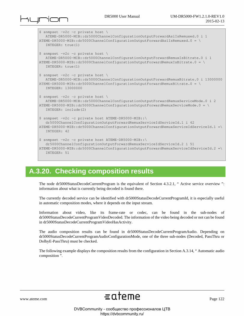
DR5000 User Manual UM-DR5000-FW1.2.1.0-REV1.02015-02-13
www.ateme.com Page 122
$ snmpset -v2c -c private host \ ATEME-DR5000-MIB::dr5000ChannelConfigurationOutputForwardAsiIsRemuxed.0 i 1ATEME-DR5000-MIB::dr5000ChannelConfigurationOutputForwardAsiIsRemuxed.0 = \ INTEGER: true(1)
$ snmpset -v2c -c private host \ ATEME-DR5000-MIB::dr5000ChannelConfigurationOutputForwardRemuxIsBitrate.0 i 1ATEME-DR5000-MIB::dr5000ChannelConfigurationOutputForwardRemuxIsBitrate.0 = \ INTEGER: true(1)
$ snmpset -v2c -c private host \ ATEME-DR5000-MIB::dr5000ChannelConfigurationOutputForwardRemuxBitrate.0 i 13000000ATEME-DR5000-MIB::dr5000ChannelConfigurationOutputForwardRemuxBitrate.0 = \ INTEGER: 13000000
$ snmpset -v2c -c private host \ ATEME-DR5000-MIB::dr5000ChannelConfigurationOutputForwardRemuxServiceMode.0 i 2ATEME-DR5000-MIB::dr5000ChannelConfigurationOutputForwardRemuxServiceMode.0 = \ INTEGER: include(2)
$ snmpset -v2c -c private host ATEME-DR5000-MIB::\ dr5000ChannelConfigurationOutputForwardRemuxServiceIdServiceId.1 i 42ATEME-DR5000-MIB::dr5000ChannelConfigurationOutputForwardRemuxServiceIdServiceId.1 =\ INTEGER: 42
$ snmpset -v2c -c private host ATEME-DR5000-MIB::\ dr5000ChannelConfigurationOutputForwardRemuxServiceIdServiceId.2 i 51ATEME-DR5000-MIB::dr5000ChannelConfigurationOutputForwardRemuxServiceIdServiceId.2 =\ INTEGER: 51
A.3.20. Checking composition results
The node dr5000StatusDecodeCurrentProgram is the equivalent of Section 4.3.2.1, “ Active service overview ”:information about what is currently being decoded is found there.
The currently decoded service can be identified with dr5000StatusDecodeCurrentProgramId, it is especially usefulin automatic composition modes, where it depends on the input stream.
Information about video, like its frame-rate or codec, can be found in the sub-nodes ofdr5000StatusDecodeCurrentProgramVideoDecoded. The information of the video being decoded or not can be foundin dr5000StatusDecodeCurrentProgramVideoHasActivity.
The audio composition results can be found in dr5000StatusDecodeCurrentProgramAudio. Depending ondr5000StatusDecodeCurrentProgramAudioConfigurationMode, one of the three sub-nodes (Decoded, PassThru orDolbyE-PassThru) must be checked.
The following example displays the composition results from the configuration in Section A.3.14, “ Automatic audiocomposition ”.
DVBCommunity - cообщество профессионалов ЦТВ https://dvbcommunity.ru/

DR5000 User Manual UM-DR5000-FW1.2.1.0-REV1.02015-02-13
www.ateme.com Page 123
$ snmpget -v2c -c private host ATEME-DR5000-MIB::dr5000StatusDecodeCurrentProgramId.0ATEME-DR5000-MIB::dr5000StatusDecodeCurrentProgramId.0 = INTEGER: 1281
$ snmpget -v2c -c private host \ ATEME-DR5000-MIB::dr5000StatusDecodeCurrentProgramVideoConfigurationPid.0ATEME-DR5000-MIB::dr5000StatusDecodeCurrentProgramVideoConfigurationPid.0 =\ INTEGER: 120
$ snmpget -v2c -c private host \ ATEME-DR5000-MIB::dr5000StatusDecodeCurrentProgramAudioConfigurationMode.9ATEME-DR5000-MIB::dr5000StatusDecodeCurrentProgramAudioConfigurationMode.9 =\ INTEGER: decode(2)
$ snmpget -v2c -c private host \ ATEME-DR5000-MIB::dr5000StatusDecodeCurrentProgramAudioConfigurationDecodedPid.9.1ATEME-DR5000-MIB::dr5000StatusDecodeCurrentProgramAudioConfigurationDecodedPid.9.1 =\ INTEGER: 130
$ snmpget -v2c -c private host \ ATEME-DR5000-MIB::dr5000StatusDecodeCurrentProgramAudioConfigurationDecodedPid.9.2ATEME-DR5000-MIB::dr5000StatusDecodeCurrentProgramAudioConfigurationDecodedPid.9.2 =\ INTEGER: 130
$ snmpget -v2c -c private host \ ATEME-DR5000-MIB::dr5000StatusDecodeCurrentProgramAudioConfigurationMode.3ATEME-DR5000-MIB::dr5000StatusDecodeCurrentProgramAudioConfigurationMode.3 =\ INTEGER: passThru(3)
$ snmpget -v2c -c private host \ ATEME-DR5000-MIB::dr5000StatusDecodeCurrentProgramAudioConfigurationPassThruPid.3ATEME-DR5000-MIB::dr5000StatusDecodeCurrentProgramAudioConfigurationPassThruPid.3 =\ INTEGER: 132
A.3.21. TS Descriptor
Once the DR5000 input is configured, it may be locked on a TS. It is reported in dr5000StatusInputTsLocked. If theDR5000 is locked, then the TS bitrate is non-null and can be retrieved in DR5000StatusInputBitrate.
Being locked on the TS also fills the dr5000StatusTsDescriptor. The presence of Network Information is described indr5000StatusTsDescriptorNitHasNit. When a NIT is available, all the others nodes of dr5000StatusTsDescriptorNitare filled in, eventually with an empty string if the stream does not carry the information.
TS Desriptor content is split into programs, streams, and DVB-Subtitle services :
• The number of programs carried in the TS can be found in dr5000StatusTsDescriptorProgramCount.Each of these programs are described in dr5000StatusTsDescriptorProgram. For example, the N-th pro-gram PMT Pid can be found in dr5000StatusTsDescriptorProgramPid.N. If the program has a ServiceDescriptor (dr5000StatusTsDescriptorProgramHasSdt), its name, provider and type are filled, respective-ly in dr5000StatusTsDescriptorProgramServiceName, dr5000StatusTsDescriptorProgramServiceProvider anddr5000StatusTsDescriptorProgramServiceType.
• The only node in dr5000StatusTsDescriptorProgram that is dependent on the user configuration isdr5000StatusTsDescriptorProgramSelected.N: it will be true if the service is currently being decoded (dependingon service selection).
DVBCommunity - cообщество профессионалов ЦТВ https://dvbcommunity.ru/

DR5000 User Manual UM-DR5000-FW1.2.1.0-REV1.02015-02-13
www.ateme.com Page 124
• The amount of streams carried by the N-th program can be read in the nodedr5000StatusTsDescriptorProgramStreamCount.N. Information about the M-th stream of the N-th program can befound in the list dr5000StatusTsDescriptorProgramStream*.N.M.
• If the stream carries DVB-Subtitle services, their number will be known indr5000StatusTsDescriptorProgramStreamNDvbSubService, and their content will be located indr5000StatusTsDescriptorProgramStreamDvbSubService.
The following example performs the discovery of a TS carrying three programs (TF1 HD, France 2 HD and M6HD),and lists the first streams of the currently selected program (France 2 HD).
# Check if the IRD is locked on a TS$ snmpget -v2c -c private host ATEME-DR5000-MIB::dr5000StatusInputTsLocked.0ATEME-DR5000-MIB::dr5000StatusInputTsLocked.0 = INTEGER: true(1)
$ snmpget -v2c -c private host ATEME-DR5000-MIB::dr5000StatusInputBitrate.0ATEME-DR5000-MIB::dr5000StatusInputBitrate.0 = INTEGER: 24882
# Retrieves TS information (Note: there is no applicable NIT here)$ snmpget -v2c -c private host ATEME-DR5000-MIB::dr5000StatusTsDescriptorNitHasNit.0ATEME-DR5000-MIB::dr5000StatusTsDescriptorNitHasNit.0 = INTEGER: false(2)
$ snmpget -v2c -c private host \ ATEME-DR5000-MIB::dr5000StatusTsDescriptorTransportStreamId.0ATEME-DR5000-MIB::dr5000StatusTsDescriptorTransportStreamId.0 = INTEGER: 5
# Iterate over every program, get its name, and check if it is being decoded$ snmpget -v2c -c private host \ ATEME-DR5000-MIB::dr5000StatusTsDescriptorProgramCount.0ATEME-DR5000-MIB::dr5000StatusTsDescriptorProgramCount.0 = INTEGER: 3
$ snmpget -v2c -c private host \ ATEME-DR5000-MIB::dr5000StatusTsDescriptorProgramHasSdt.1ATEME-DR5000-MIB::dr5000StatusTsDescriptorProgramHasSdt.1 = INTEGER: true(1)
$ snmpget -v2c -c private host \ ATEME-DR5000-MIB::dr5000StatusTsDescriptorProgramServiceName.1ATEME-DR5000-MIB::dr5000StatusTsDescriptorProgramServiceName.1 = STRING: TF1 HD
$ snmpget -v2c -c private host \ ATEME-DR5000-MIB::dr5000StatusTsDescriptorProgramSelected.1ATEME-DR5000-MIB::dr5000StatusTsDescriptorProgramSelected.1 = INTEGER: false(2)
$ snmpget -v2c -c private host \ ATEME-DR5000-MIB::dr5000StatusTsDescriptorProgramHasSdt.2ATEME-DR5000-MIB::dr5000StatusTsDescriptorProgramHasSdt.2 = INTEGER: true(1)
$ snmpget -v2c -c private host \ ATEME-DR5000-MIB::dr5000StatusTsDescriptorProgramServiceName.2ATEME-DR5000-MIB::dr5000StatusTsDescriptorProgramServiceName.2 = STRING: France 2 HD
$ snmpget -v2c -c private host \ ATEME-DR5000-MIB::dr5000StatusTsDescriptorProgramSelected.2ATEME-DR5000-MIB::dr5000StatusTsDescriptorProgramSelected.2 = INTEGER: true(1)
DVBCommunity - cообщество профессионалов ЦТВ https://dvbcommunity.ru/

DR5000 User Manual UM-DR5000-FW1.2.1.0-REV1.02015-02-13
www.ateme.com Page 125
# List the stream of the decoded service$ snmpget -v2c -c private host \ ATEME-DR5000-MIB::dr5000StatusTsDescriptorProgramStreamCount.2ATEME-DR5000-MIB::dr5000StatusTsDescriptorProgramStreamCount.2 = INTEGER: 9
$ snmpget -v2c -c private host \ ATEME-DR5000-MIB::dr5000StatusTsDescriptorProgramStreamPid.2.1ATEME-DR5000-MIB::dr5000StatusTsDescriptorProgramStreamPid.2.1 = INTEGER: 220
$ snmpget -v2c -c private host \ ATEME-DR5000-MIB::dr5000StatusTsDescriptorProgramStreamType.2.1ATEME-DR5000-MIB::dr5000StatusTsDescriptorProgramStreamType.2.1 = INTEGER: video(3)
$ snmpget -v2c -c private host \ ATEME-DR5000-MIB::dr5000StatusTsDescriptorProgramStreamPid.2.2ATEME-DR5000-MIB::dr5000StatusTsDescriptorProgramStreamPid.2.2 = INTEGER: 230
$ snmpget -v2c -c private host \ ATEME-DR5000-MIB::dr5000StatusTsDescriptorProgramStreamType.2.2ATEME-DR5000-MIB::dr5000StatusTsDescriptorProgramStreamType.2.2 = INTEGER: audio(2)
Warning
Because these different table are statically allocated, accessing every node (either with snmpwalk or byperforming more than the program/stream count GET accesses) will take a very long time and shouldbe avoided.
DVBCommunity - cообщество профессионалов ЦТВ https://dvbcommunity.ru/

DR5000 User Manual UM-DR5000-FW1.2.1.0-REV1.02015-02-13
www.ateme.com Page 126
Appendix B. Input Statistics
B.1. Input Statistics OverviewWeb GUI allows to retrieve an input statistics file from two places :
• Input status tab of Decodig Status Panel (See Section 4.3.2.3, “ Input status ”).
• Firmware/Troubleshooting tab of System Panel (See Section 4.3.3.3.5.5, “ Troubleshooting ”).
This file is a CSV file with semi-colon separated values. One line corresponds to one measure point.
DVBCommunity - cообщество профессионалов ЦТВ https://dvbcommunity.ru/

DR5000 User Manual UM-DR5000-FW1.2.1.0-REV1.02015-02-13
www.ateme.com Page 127
B.2. Input Statistics File FormatThe meaning of each value depends on the input type.
Table B.1. ASI input statistics
1-based field index Meaning
1 Time and Date (expressed as DD/MM/YYYY HH:MM:SS)
2 Input Type: ASI
3 Bitrate [kbps]
Table B.2. IP input statistics
1-basedfield index
Meaning
1 Time and Date (expressed as DD/MM/YYYY HH:MM:SS)
2 Input Type: IP
3 Bitrate [kbps]
4 Protocol (UDP/RTP)
5 FEC rows
6 FEC columns
7 Number of detected FEC streams
8 Number of packet received since the last reset
9 Number of missing packets since the last reset
10 Number of reordered packets since the last reset
11 Number of correct packets since the last reset
12 Number of uncorrect packets received since the last reset
13 Number of duplicated packets received since the last reset
14 Error rate before FEC correction [%]
15 Error rate after FEC correction [%]
16 Jitter [ms]
Table B.3. IP with Failover input statistics
1-basedfield index
Meaning
1 Time and Date (expressed as DD/MM/YYYY HH:MM:SS)
2 Input Type: IP-Failover
3 Bitrate [kbps]
4 Protocol (UDP/RTP)
5 FEC rows
6 FEC columns
DVBCommunity - cообщество профессионалов ЦТВ https://dvbcommunity.ru/
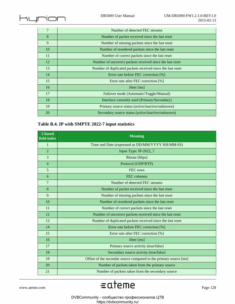
DR5000 User Manual UM-DR5000-FW1.2.1.0-REV1.02015-02-13
www.ateme.com Page 128
7 Number of detected FEC streams
8 Number of packet received since the last reset
9 Number of missing packets since the last reset
10 Number of reordered packets since the last reset
11 Number of correct packets since the last reset
12 Number of uncorrect packets received since the last reset
13 Number of duplicated packets received since the last reset
14 Error rate before FEC correction [%]
15 Error rate after FEC correction [%]
16 Jitter [ms]
17 Failover mode (Automatic/Toggle/Manual)
18 Interface currently used (Primary/Secondary)
19 Primary source status (active/inactive/unknown)
20 Secondary source status (active/inactive/unknown)
Table B.4. IP with SMPTE 2022-7 input statistics
1-basedfield index
Meaning
1 Time and Date (expressed as DD/MM/YYYY HH:MM:SS)
2 Input Type: IP-2022_7
3 Bitrate [kbps]
4 Protocol (UDP/RTP)
5 FEC rows
6 FEC columns
7 Number of detected FEC streams
8 Number of packet received since the last reset
9 Number of missing packets since the last reset
10 Number of reordered packets since the last reset
11 Number of correct packets since the last reset
12 Number of uncorrect packets received since the last reset
13 Number of duplicated packets received since the last reset
14 Error rate before FEC correction [%]
15 Error rate after FEC correction [%]
16 Jitter [ms]
17 Primary source activity (true/false)
18 Secondary source activity (true/false)
19 Offset of the secondar source compared to the primary source [ms]
20 Number of packets taken from the primary source
21 Number of packets taken from the secondary source
DVBCommunity - cообщество профессионалов ЦТВ https://dvbcommunity.ru/

DR5000 User Manual UM-DR5000-FW1.2.1.0-REV1.02015-02-13
www.ateme.com Page 129
Table B.5. Sat input statistics
1-basedfield index
Meaning
1 Time and Date (expressed as DD/MM/YYYY HH:MM:SS)
2 Input Type: SAT
3 Bitrate [kbps]
4 Lock status (Locked/Unlocked)
5 Standard (DVBS / DVB-S2)
6 Modulation (QPSK, 8PSK, 16APSK, 32APSK)
7 Symbol Rate [Sym/s]
8 Fec rate
9 Roll-Off
10 Carrier frequency [kHz]
11 C/N [dB]
12 C/N Margin [dB]
13 BER
14 Power [dBm]
Table B.6. Zixi input statistics
1-basedfield index
Meaning
1 Time and Date (expressed as DD/MM/YYYY HH:MM:SS)
2 Input Type: Zixi
3 Bitrate [kbps]
4 Connection status (Connected/Not connected)
5 Processed packet counter
6 Bytes counter
7 Out of Order packet counter
8 Dropped packet counter
9 Duplicate packet counter
10 Overflow packet counter
11 Round Trip Time [ms]
12 Network jitter [ms]
13 Network latency [ms]
14 ARQ responses counter
15 FEC packets counter
16 ARQ-Recovered packet counter
17 FEC-Recovered packet counter
18 Unrecovered packet counter
DVBCommunity - cообщество профессионалов ЦТВ https://dvbcommunity.ru/
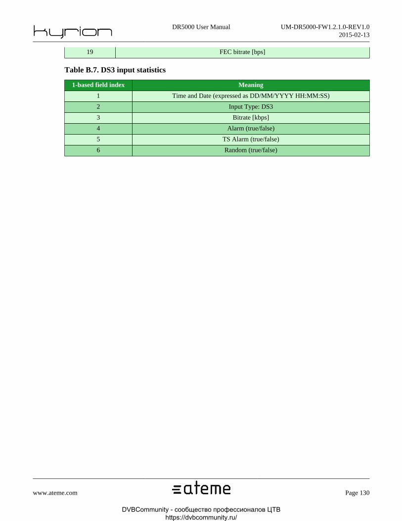
DR5000 User Manual UM-DR5000-FW1.2.1.0-REV1.02015-02-13
www.ateme.com Page 130
19 FEC bitrate [bps]
Table B.7. DS3 input statistics
1-based field index Meaning
1 Time and Date (expressed as DD/MM/YYYY HH:MM:SS)
2 Input Type: DS3
3 Bitrate [kbps]
4 Alarm (true/false)
5 TS Alarm (true/false)
6 Random (true/false)
DVBCommunity - cообщество профессионалов ЦТВ https://dvbcommunity.ru/

DR5000 User Manual UM-DR5000-FW1.2.1.0-REV1.02015-02-13
www.ateme.com Page 131
Appendix C. Appendix
C.1. Product's specification
Table C.1. Specification - Identification
Product Name DR5000
Table C.2. Specification - Physical
Function Type Comment Number
Independant AES Output BNC connector - 4
ASI input BNC connector - 2
ASI output BNC connector - 2
SDI output BNC connector Limited to 40Mbps 3
IP input/output RJ45 connector Limited to 120Mbps 2
IP management RJ45 connector 1 Tuner 1
RF input Type -F 1 Tuner 4
RF output Type -F Loopback 1
Genlock input BNC connector Blackburst or Tri-level 1
Genlock output BNC connector Loopback 1
Conditional Access Interface CAM Slot To insert CAM module 2
USB USB-A - 1
Sub-D25 4 pairs 1
Audio Analog outputSub-D25
24 / 22 / 18 dBu @ 0 dBFS ./-10 dbV @ -20 dBFS
1
Table C.3. Specification - Configuration and Management
Function X Present
SNMP (MIB v2c) with remote SNMP supervisor X X
Embedded web-server configuration X X
Front panel with LCD/alphanumerical keypad/Direct access keys - X
DVB-SSUFollowing
ETSI 102006new
USB for configuration import/export - X
USB for stream recording - X
Video monitoring on Front panel video display and on Web GUI - X
Audio monitoring on Front panel video display and on Web GUI - X
DVBCommunity - cообщество профессионалов ЦТВ https://dvbcommunity.ru/
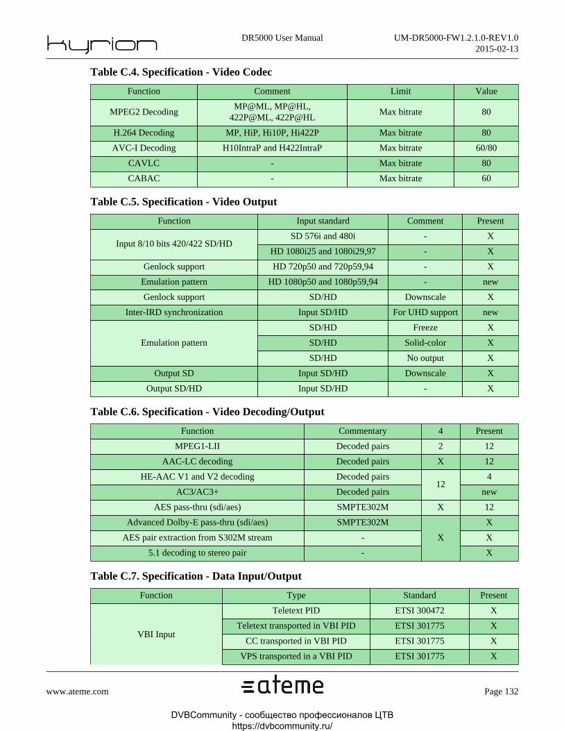
DR5000 User Manual UM-DR5000-FW1.2.1.0-REV1.02015-02-13
www.ateme.com Page 132
Table C.4. Specification - Video Codec
Function Comment Limit Value
MPEG2 DecodingMP@ML, MP@HL,
422P@ML, 422P@HLMax bitrate 80
H.264 Decoding MP, HiP, Hi10P, Hi422P Max bitrate 80
AVC-I Decoding H10IntraP and H422IntraP Max bitrate 60/80
CAVLC - Max bitrate 80
CABAC - Max bitrate 60
Table C.5. Specification - Video Output
Function Input standard Comment Present
SD 576i and 480i - XInput 8/10 bits 420/422 SD/HD
HD 1080i25 and 1080i29,97 - X
Genlock support HD 720p50 and 720p59,94 - X
Emulation pattern HD 1080p50 and 1080p59,94 - new
Genlock support SD/HD Downscale X
Inter-IRD synchronization Input SD/HD For UHD support new
SD/HD Freeze X
SD/HD Solid-color XEmulation pattern
SD/HD No output X
Output SD Input SD/HD Downscale X
Output SD/HD Input SD/HD - X
Table C.6. Specification - Video Decoding/Output
Function Commentary 4 Present
MPEG1-LII Decoded pairs 2 12
AAC-LC decoding Decoded pairs X 12
HE-AAC V1 and V2 decoding Decoded pairs 4
AC3/AC3+ Decoded pairs12
new
AES pass-thru (sdi/aes) SMPTE302M X 12
Advanced Dolby-E pass-thru (sdi/aes) SMPTE302M X
AES pair extraction from S302M stream - X
5.1 decoding to stereo pair -
X
X
Table C.7. Specification - Data Input/Output
Function Type Standard Present
Teletext PID ETSI 300472 X
Teletext transported in VBI PID ETSI 301775 X
CC transported in VBI PID ETSI 301775 XVBI Input
VPS transported in a VBI PID ETSI 301775 X
DVBCommunity - cообщество профессионалов ЦТВ https://dvbcommunity.ru/

DR5000 User Manual UM-DR5000-FW1.2.1.0-REV1.02015-02-13
www.ateme.com Page 133
WSS transported un a VBI PID ETSI 301775 X
Amol48 transported in VBI PID SCTE127 -
Amol96 transported in VBI PID SCTE127 -
Data Input TVG2x transported in VBI PID SCTE127 -
SMPTE2038 SCTE35 X
SCTE35ETSI 101154or ATSC A53
XData Input
CC as user data (MPEG2)or SEI (H.264) of the ES
ETSI 101154or ATSC A53
X
Ancillary Time Code as user data(MPEG2) or SEI (H.264) of the ES
ETSI-300706 X
Data Output - SMPTE2031 WSS extract from ES, throughinterpretation of sample as-
pect ratio and afd information
ETSI 101154or ATSC A53
X
Teletext ETSI-300706 X
WSS ETSI-300294 X
VPS ETSI-300231 X
Amol48 CEA-2020 -
Data Output - SMPTE2031
Amol96 CEA-2020 -
Data Output - VBI Closed Caption CEA-608 X
Teletext ETSI-300706 X
WSS ETSI-300294 X
VPS ETSI-300231 X
Amol48 CEA-2020 -
Amol96 CEA-2020 -
Data Output - VBI
Closed Caption CEA-608 X
Data Output VITC SMPTE 12M-1 X
SCTE104 SMPTE2010 X
Close Caption CEA-608 SMPTE334-1 X
Close Caption CEA-708 SMPTE334-2 X
VPID SMPTE352M X
AFD SMPTE2016 X
VANC SMPTE2038 X
VITC SMPTE 12M-2 X
Data Output
OP-47 OP-47 X
DVB-Sub ETSI-300743 new
Close Caption CEA-608 Close Caption CEA-608 newData Overlay
Teletext ETSI-300706 new
DVBCommunity - cообщество профессионалов ЦТВ https://dvbcommunity.ru/

DR5000 User Manual UM-DR5000-FW1.2.1.0-REV1.02015-02-13
www.ateme.com Page 134
Table C.8. Specification - Descrambling
Function Commentary Limit Value
Biss 1, Biss-E with 2 Injected Ids - X
DVB-CI 72 Mbps X
MPTS forward with user de-fined descrambled programs
2 slots8 programs X
Table C.9. Specification - Functions
Function Comment Limit Value
FEC ProMPEG CoP3r2 SMPTE 2022 - X
SPTS / MPTS Input SMPTE 2022 - X
Failover IP3 modes (Auto,
Manual, Toggle)- X
SMPTE 2022-7 Hitless Redundancy - new
ZIXI ARQ-based Max bitrate 15 (new)
IP source filtering - Max bitrate X
IP forwarding - Max bitrate 200
PID/Service filtering - - new
VLAN support 16 Interfaces can be configured - X
Multiple Gateway support - - X
TOS support - - X
ASI forwarding - - X
Carrier ID monitoring - - X
Table C.10. Specification - RF Support
Description Limit Present
DVB-S - QPSK Symbol Rate 45
DVB-S2 - QPSK Symbol Rate 67,5
DVB-S2 - 8PSK Symbol Rate 63
DVB-S2 - 16APSK Symbol Rate 47
DVB-S2 - 32APSK Symbol Rate 38
Frequency Range: 950-2150 MHz (L-Band) - X
RF input level: -65 dBm to -25 dBm - X
Roll-Off 5/10/15/20/25/35 % X
Gold Code - X
Nominal input impedance: 75 ohm 75 ohms -
Image rejection: > 40 dB > 40dB -
Input Return Loss: > 9.5 dB > 9.5 dB -
Noise Figure: < 12 dB < 12 dB -
DVBCommunity - cообщество профессионалов ЦТВ https://dvbcommunity.ru/

DR5000 User Manual UM-DR5000-FW1.2.1.0-REV1.02015-02-13
www.ateme.com Page 135
Table C.11. Specification - Audio analog extension board
Output drive capacity 600 ohm balanced
Number of outputs 4 stereo or 8 mono
Output connector type XLR
Peak Output Level 24 dBm into 600 ohm balanced
Clipping level From -10dBV@-20dBFS to 24dBu@0dBFS
Sampling rate 48 kHz
Frequency response < +/- 0.1 dB on [20 Hz - 20 kHz]
THD+N 0.01% at 1 kHz
Dynamic range > 90 dB
Cross talk at 1 kHz > 100 dB
SNR > 80 dB Unweighted
Table C.12. Specification - Licenses
Description Limit Present
MPEG4 1080p50/59,94 Decoding - X
MPEG4 HD Video Decoding - X
MPEG4 Video Decoding - X
Downscale SD - X
Audio PID decoding count 8 X
AC3 decoding count 4 X
AC3+ decoding count 4 -
10b Video decoding - X
MPEG4 422 Video decoding - X
DVBS2 16 & 32 APSK - X
DVB-CI Multi-service descrambling 8 X
Video Phase Shict Control support (UHD) - X
ZIXI Input - X
Table C.13. Specification - Environmental Conditions
Operating temperature +5 to +55°C / +41°F to +131°FAmbient air tempera-ture with free airflow
Storage temperature -20°C to +70°C / -4°F to +158°F -
Operating humidity 5% to 90% (non condensing) -
Cooling air flow from front side to rear side. - -
Table C.14. Specification - Physical Parameters
Mass storage uSD disk -
Weight 3.4 kg/7.5 lbs -
DVBCommunity - cообщество профессионалов ЦТВ https://dvbcommunity.ru/

DR5000 User Manual UM-DR5000-FW1.2.1.0-REV1.02015-02-13
www.ateme.com Page 136
Dimensions 19 1-RU 482x445x 310 mm /19x17.5x12.2
Table C.15. Specification - Power Supply
Description Limit
100-240 VAC, 50/60 HzInput voltage range
40-60V DC
Power consumption 34 W
Table C.16. Specification - Electromagnetic Emissions by Council Directive 89/366/EEC
EN 55013: 2001(including AmendmentsA1: 2003 and A2: 2006)
EN 55022: 2010
EN 61000-3-2: 2006 / prA1: 2007
EN 61000-3-3: 2008
FCC Part 15 Class B: 2007
IECS-003 issue 4 Class B: 2004
CISPR 22 Class B: 2008
Table C.17. Specification - Electromagnetic Immunity by Council Directive 89/366/EEC
EN 55020: 2007
EN 55024: 2010 CISPR 24 ed2.0 (2010-08)
Table C.18. Specification - Safety by Council Directive 73/23/EEC
IEC 60950-1:2005
US standard UL 60950-1
Including request responding to: Canadian Standard CAN/CSA 22.2 NO 60950-1-03
EN60950-1:2006+A11:2009+A12:2011+A1:2010
Table C.19. Specification - Shock and Vibration
ETS 300-019-2-2: 1994 (sample packed)Random vibrations, me-
chanical bumpsand free falls
ETS 300-019-2-5: 2002 (sample operational) Random vibrations
IEC 60068-2-27: 2008 (sample operational) Mechanical shocks
Table C.20. Specification - CE Marking
Directive 2006/95/EC: 12 December 2006
Directive 2004/108/EC:15 December 2004
1999/5/EC: 9 March 1999
DVBCommunity - cообщество профессионалов ЦТВ https://dvbcommunity.ru/
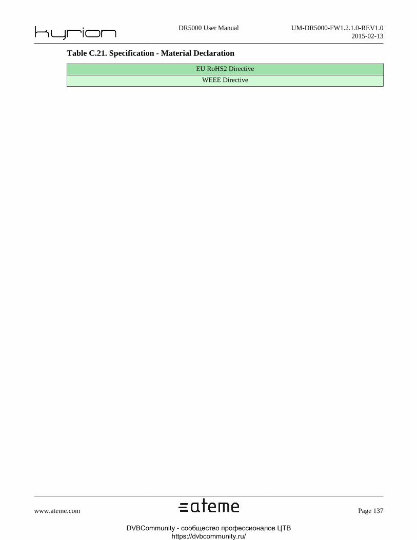
DR5000 User Manual UM-DR5000-FW1.2.1.0-REV1.02015-02-13
www.ateme.com Page 137
Table C.21. Specification - Material Declaration
EU RoHS2 Directive
WEEE Directive
DVBCommunity - cообщество профессионалов ЦТВ https://dvbcommunity.ru/

DR5000 User Manual UM-DR5000-FW1.2.1.0-REV1.02015-02-13
www.ateme.com Page 138
C.2. WarrantyATEME warranties your Kyrion® against any defect in material and workmanship, under normal use, for the perioddesignated on your warranty certificate. In the event this product is found to be defective within the warranty period,ATEME may, at its will, repair or replace the defective Kyrion®.
This warranty is void if:
• The Kyrion® was operated/stored in abnormal use or maintenance conditions;
• The Kyrion® is repaired, modified or altered, unless such repair, modification or alteration is expressly authorizedin writing by ATEME;
• The Kyrion® was subjected to abuse, neglect, lightning strike, electrical fault, improper packaging or accident;
• The Kyrion® was installed improperly;
• The Serial Number of the Kyrion® is defaced or missing;
• The broken part is a non ATEME approved replacement part;
• The tamper seal on the Kyrion® casing is broken.
ATEME and its suppliers accept no liability for any loss of service during the use of this device, or for any of theproblems caused as a result.
ATEME will not, under any circumstances, be liable to direct, uncommon or consequential damages such as, but notlimited to, damage or loss of property or equipment, loss of profits or revenues, cost of replacement goods, or expenseor inconvenience caused by service interruptions.
Any loss, corruption or destruction of data while using an ATEME Kyrion® is the sole responsibility of the user, andunder no circumstances will ATEME be held liable for the recovery or restoration of this data.
Under no circumstances will any person be entitled to any sum greater than the purchase price paid for the Kyrion®.
To obtain warranty service, call ATEME Technical Support. You will be asked to provide your ATEME product'sSerial Number, and you may be asked to furnish proof of purchase to confirm that the Kyrion® is still under warranty.
All Kyrion® returned to ATEME must be securely packaged in their original box and shipped with postage prepaid.
DVBCommunity - cообщество профессионалов ЦТВ https://dvbcommunity.ru/

DR5000 User Manual UM-DR5000-FW1.2.1.0-REV1.02015-02-13
www.ateme.com Page 139
C.3. Normative Reference
Table C.22. Normative reference
Subject Reference
Ancillary AFDBarData SMPTE 2016M-1/3
Ancillary ATC SMPTE 12M-2
Ancillary Audio HD SMPTE 299M
Ancillary Audio SD SMPTE 272M
Ancillary cc608 SMPTE 334-2
Ancillary cc708 SMPTE 334-1
Ancillary DvbScte SMPTE 2031M
Ancillary SCTE-104 SMPTE 2010
Ancillary Video Payload Identification SMPTE 352M
Audio Embedded in SD-SDI SMPTE 272M
Audio Embedded in HD-SDI SMPTE 299
BISS Tech 3290 (EBU)
HD-SDI SMPTE 292
MPEG-2 TS ISO/IEC 13818-1
MPEG-2 TS PID TeletextETSI EN 300 472 (DVB, ISDB, SBTVD) -
Specifications for embedding teletext into TS
MPEG-2 TS PID VBI ETSI EN 301 775 (DVB, ISDB, SBTVD)
MPEG-2 Video ISO/IEC 13818-2
MPEG-2 Video time code User Data SMPTE 328M
MPEG-2 Video/MPEG-4 AVC AFD ETSI TS 101 154 (Annex B) / A/53 part 4
MPEG-2 Video/MPEG-4 AVC CC ETSI TS 101 154 (Annex B) / A/53 part 4
MPEG-4 AVC ISO/IEC 14496-10
SD-SDI SMPTE 259M
TeletextETSI EN 300 706 (DVB, ISDB, SBTVD)
- Specifications of the teletext syntax
VBI cc608 CEA/EIA-608-D (625i/525i)
VBI VITC IEC-60461 (625i/525i)
VBI VPS ETS 300 231-1998 (625i)
VBI WSSITU-R BT.1119-2 and ETSI EN 300 294(625i) / IEC 61880 Ed. 1.0 b:1998 (525i)
VBI WST ITU-R BT.653-3 (625i)
DVBCommunity - cообщество профессионалов ЦТВ https://dvbcommunity.ru/

DR5000 User Manual UM-DR5000-FW1.2.1.0-REV1.02015-02-13
www.ateme.com Page 140
C.4. Glossary
Table C.23. Glossary
3:2 pull-down
Process of converting 24 frame/s material to 29.97 frame/s.
422/420Sampling method. In 420 sampling, chrominance components have half the horizontal and verticalresolution of luminance component. In 422 sampling, chrominance components have half the hori-zontal resolution of luminance component
ASI Asynchronous Serial Interface
BISS Basic Interoperable Scrambling System. Non-proprietary encryption from EBU (Tech3290).
CABAC Context-based Adaptive Binary Arithmetic Coding
CAVLC Context Adaptive Variable Length Coding
Chromi-nance
Color difference component
EBU European Broadcasting Union
FECForward Error Correction. System of error control for data transmission where the sender adds redun-dant data (error-correcting code) to its messages. The receiver can check the accuracy of the trans-mission and eventually correct errors.
FTP File Transfer Protocol. Protocol used to transfer files over a TCP/IP network.
GOP
Group Of Pictures. In MPEG video encoding, a group of pictures, or GOP, specifies the order inwhich intra-frames and inter-frames are arranged.The GOP is a group of successive pictures within a MPEG-coded film and/or video stream. EachMPEG-coded film and/or video stream consists of successive GOPs. From the MPEG pictures con-tained in it the visible frames are generated.A GOP can contain the following picture types:I-picture and/or I-Frame (English intra coded picture) reference picture, corresponds to a fixed imageand is independent of other picture types. Each GOP begins with this type of picture.P-picture and/or P-Frame (English predictive coded picture) contains difference information from thepreceding I or P-Frame.B-picture and/or B-Frame (English bidirectional predictive coded pictures) contain difference infor-mation from the preceding and/or following I or P-Frame.D-picture and/or D-Frame (English DC direct coded picture) serves the fast advance.A GOP always begins with an I-Frame. Afterwards several P-Frames follow, in each case with someframes distance. In the remaining gaps are B-Frames. With the next I-Frame a new GOP begins.
GUI Graphical User Interface.
HDTV High Definition Television
IEC International Electrotechnical Committee
IP Internet Protocol
ISO International Standards Organisation
ITU-R International Telecommunications Union - Radiocommunications Study Groups
ITU-T International Telecommunications Union - Telecommunications Standardisation Sector
MGT Management
DVBCommunity - cообщество профессионалов ЦТВ https://dvbcommunity.ru/
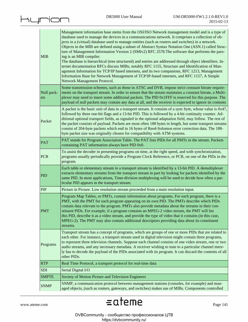
DR5000 User Manual UM-DR5000-FW1.2.1.0-REV1.02015-02-13
www.ateme.com Page 141
MIB
Management information base stems from the OSI/ISO Network management model and is a type ofdatabase used to manage the devices in a communications network. It comprises a collection of ob-jects in a (virtual) database used to manage entities (such as routers and switches) in a network.Objects in the MIB are defined using a subset of Abstract Syntax Notation One (ASN.1) called Struc-ture of Management Information Version 2 (SMIv2) RFC 2578.The software that performs the pars-ing is an MIB compiler.The database is hierarchical (tree structured) and entries are addressed through object identifiers. In-ternet documentation RFCs discuss MIBs, notably RFC 1155, Structure and Identification of Man-agement Information for TCP/IP based internets, and its two companions, RFC 1213, ManagementInformation Base for Network Management of TCP/IP-based internets, and RFC 1157, A SimpleNetwork Management Protocol.
Null pack-ets
Some transmission schemes, such as those in ATSC and DVB, impose strict constant bitrate require-ments on the transport stream. In order to ensure that the stream maintains a constant bitrate, a Multi-plexer may need to insert some additional packets. The PID 0x1FFF is reserved for this purpose. Thepayload of null packets may contain any data at all, and the receiver is expected to ignore its contents
Packet
A packet is the basic unit of data in a transport stream. It consists of a sync byte, whose value is 0x47,followed by three one-bit flags and a 13-bit PID. This is followed by a 4-bit continuity counter. Ad-ditional optional transport fields, as signaled in the optional adaptation field, may follow. The rest ofthe packet consists of payload. Packets are most often 188 bytes in length, but some transport streamsconsist of 204-byte packets which end in 16 bytes of Reed-Solomon error correction data. The 188-byte packet size was originally chosen for compatibility with ATM systems.
PATPAT stands for Program Association Table. The PAT lists PIDs for all PMTs in the stream. Packetscontaining PAT information always have PID 0x0.
PCRTo assist the decoder in presenting programs on time, at the right speed, and with synchronization,programs usually periodically provide a Program Clock Reference, or PCR, on one of the PIDs in theprogram.
PID
Each table or elementary stream in a transport stream is identified by a 13-bit PID. A demultiplexerextracts elementary streams from the transport stream in part by looking for packets identified by thesame PID. In most applications, Time-division multiplexing will be used to decide how often a par-ticular PID appears in the transport stream.
PIP Picture in Picture. Low resolution stream proceeded from a main resolution input.
PMT
Program Map Tables, or PMTs, contain information about programs. For each program, there is aPMT, with the PMT for each program appearing on its own PID. The PMTs describe which PIDscontain data relevant to the program. PMTs also provide metadata about the streams in their con-stituent PIDs. For example, if a program contains an MPEG-2 video stream, the PMT will listthis PID, describe it as a video stream, and provide the type of video that it contains (in this case,MPEG-2). The PMT may also contain additional descriptors providing data about its constituentstreams.
Programs
Transport stream has a concept of programs, which are groups of one or more PIDs that are related toeach other. For instance, a transport stream used in digital television might contain three programs,to represent three television channels. Suppose each channel consists of one video stream, one or twoaudio streams, and any necessary metadata. A receiver wishing to tune to a particular channel mere-ly has to decode the payload of the PIDs associated with its program. It can discard the contents of allother PIDs.
RTP Real Time Protocol, a transport protocol for real-time data
SDI Serial Digital I/O
SMPTE Society of Motion Picture and Television Engineers
SNMPSNMP, a communication protocol between management stations (consoles, for example) and man-aged objects, (such as routers, gateways, and switches) makes use of MIBs. Components controlled
DVBCommunity - cообщество профессионалов ЦТВ https://dvbcommunity.ru/

DR5000 User Manual UM-DR5000-FW1.2.1.0-REV1.02015-02-13
www.ateme.com Page 142
by the management console need a so-called SNMP agent -- a software module that can communi-cate with the SNMP manager.SNMP uses a specified set of commands and queries. An MIB should contain information on thesecommands and on the target objects (controllable entities or potential sources of status information)with a view to tuning the network transport to the current needs.
TS Transport Stream
DVBCommunity - cообщество профессионалов ЦТВ https://dvbcommunity.ru/

DR5000 User Manual UM-DR5000-FW1.2.1.0-REV1.02015-02-13
www.ateme.com Page 143
C.5. Support and Ressources
Contact Technical Support
Before You Contact Technical Support:
• Read the manuals.
• Try to isolate the problem or to reproduce it many times.
• Make sure that all of the cables are correctly and firmly attached.
If you have asked yourself all of the pertinent questions in the troubleshooting checklist, and you still can't get yourKyrion® to work properly, contact us via the provided link.
ATEME Technical Support - [email protected]
Before contacting us, make sure that you have a physical access to your Kyrion and that you have the followinginformation on hand:
• Your Kyrion's Serial Number
• Names of any other devices installed in your system (Router's brands, specific equipments, etc.)
Online Resources
Visit this link for more information and documentation about ATEME and ATEME products.
http://www.ateme.com/
Customer Service
ATEME Customer Service provides assistance with product information, sales, registration, and other non-technicalissues.
To find out how to contact ATEME Customer Service, please visit http://www.ateme.com/ for your region or countryand click Contact Us.
DVBCommunity - cообщество профессионалов ЦТВ https://dvbcommunity.ru/