
DPoE MAC and Upper Layer Protocols Interface Specification
135
DOCSIS® Provisioning of EPON Specifications DPoEv2.0 DPoE MAC and Upper Layer Protocols Interface Specification DPoE-SP-MULPIv2.0-I12-170510 ISSUED Notice This DPoE™ specification is the result of a cooperative effort undertaken at the direction of Cable Television Laboratories, Inc. for the benefit of the cable industry and its customers. You may download, copy, distribute, and reference the documents herein only for the purpose of developing products or services in accordance with such documents, and educational use. Except as granted by CableLabs® in a separate written license agreement, no license is granted to modify the documents herein (except via the Engineering Change process), or to use, copy, modify or distribute the documents for any other purpose. This document may contain references to other documents not owned or controlled by CableLabs. Use and understanding of this document may require access to such other documents. Designing, manufacturing, distributing, using, selling, or servicing products, or providing services, based on this document may require intellectual property licenses from third parties for technology referenced in this document. To the extent this document contains or refers to documents of third parties, you agree to abide by the terms of any licenses associated with such third-party documents, including open source licenses, if any. Cable Television Laboratories, Inc., 2012-2017
-
Upload
khangminh22 -
Category
Documents
-
view
2 -
download
0
Transcript of DPoE MAC and Upper Layer Protocols Interface Specification

DOCSIS® Provisioning of EPON Specifications DPoEv2.0
DPoE MAC and Upper Layer Protocols Interface Specification
DPoE-SP-MULPIv2.0-I12-170510 ISSUED
Notice
This DPoE™ specification is the result of a cooperative effort undertaken at the direction of Cable Television Laboratories, Inc. for the benefit of the cable industry and its customers. You may download, copy, distribute, and reference the documents herein only for the purpose of developing products or services in accordance with such documents, and educational use. Except as granted by CableLabs® in a separate written license agreement, no license is granted to modify the documents herein (except via the Engineering Change process), or to use, copy, modify or distribute the documents for any other purpose.
This document may contain references to other documents not owned or controlled by CableLabs. Use and understanding of this document may require access to such other documents. Designing, manufacturing, distributing, using, selling, or servicing products, or providing services, based on this document may require intellectual property licenses from third parties for technology referenced in this document. To the extent this document contains or refers to documents of third parties, you agree to abide by the terms of any licenses associated with such third-party documents, including open source licenses, if any.
Cable Television Laboratories, Inc., 2012-2017

DPoE-SP-MULPIv2.0-I12-170510 DOCSIS® Provisioning of EPON Specifications
2 CableLabs 05/10/17
DISCLAIMER
This document is furnished on an "AS IS" basis and neither CableLabs nor its members provides any representation or warranty, express or implied, regarding the accuracy, completeness, noninfringement, or fitness for a particular purpose of this document, or any document referenced herein. Any use or reliance on the information or opinion in this document is at the risk of the user, and CableLabs and its members shall not be liable for any damage or injury incurred by any person arising out of the completeness, accuracy, or utility of any information or opinion contained in the document.
CableLabs reserves the right to revise this document for any reason including, but not limited to, changes in laws, regulations, or standards promulgated by various entities, technology advances, or changes in equipment design, manufacturing techniques, or operating procedures described, or referred to, herein.
This document is not to be construed to suggest that any company modify or change any of its products or procedures, nor does this document represent a commitment by CableLabs or any of its members to purchase any product whether or not it meets the characteristics described in the document. Unless granted in a separate written agreement from CableLabs, nothing contained herein shall be construed to confer any license or right to any intellectual property. This document is not to be construed as an endorsement of any product or company or as the adoption or promulgation of any guidelines, standards, or recommendations.

DPoE MAC and Upper Layer Protocols Interface Specification DPoE-SP-MULPIv2.0-I12-170510
05/10/17 CableLabs 3
Document Status Sheet
Document Control Number: DPoE-SP-MULPIv2.0-I12-170510
Document Title: DPoE MAC and Upper Layer Protocols Interface Specification
Revision History: I01 - Released 10/04/2012 I02 - Released 03/28/2013 I03 - Released 08/08/2013 I04 - Released 11/14/2013 I05 - Released 03/27/2014 I06 - Released 08/07/2014 I07 - Released 03/19/2015 I08 - Released 06/11/2015 I09 - Released 12/10/2015 I10 - Released 06/02/2016 I11 - Released 01/11/2017 I12 - Released 05/10/2017
Date: May 10, 2017
Status: Work in Progress
Draft Issued Closed
Distribution Restrictions: Author Only
CL/Member CL/ Member/ Vendor
Public
Key to Document Status Codes
Work in Progress An incomplete document, designed to guide discussion and generate feedback that may include several alternative requirements for consideration.
Draft A document in specification format considered largely complete, but lacking review by Members and vendors. Drafts are susceptible to substantial change during the review process.
Issued A generally public document that has undergone Member and Technology Supplier review, cross-vendor interoperability, and is for Certification testing if applicable. Issued Specifications are subject to the Engineering Change Process.
Closed A static document, reviewed, tested, validated, and closed to further engineering change requests to the specification through CableLabs.
Trademarks CableLabs® is a registered trademark of Cable Television Laboratories, Inc. Other CableLabs marks are listed at http://www.cablelabs.com/certqual/trademarks. All other marks are the property of their respective owners.

DPoE-SP-MULPIv2.0-I12-170510 DOCSIS® Provisioning of EPON Specifications
4 CableLabs 05/10/17
Contents INTRODUCTION ..................................................................................................................................................... 11
1.1 DPoE Technology Introduction ................................................................................................................... 11 1.2 Scope ........................................................................................................................................................... 11 1.3 Goals ............................................................................................................................................................ 12 1.4 Requirements ............................................................................................................................................... 12 1.5 DPoE Version 2.0 Specifications ................................................................................................................. 12 1.6 Reference Architecture ................................................................................................................................ 13 1.7 DPoE Interfaces and Reference Points ........................................................................................................ 14
2 REFERENCES .................................................................................................................................................. 17 2.1 Normative References.................................................................................................................................. 17 2.2 Informative References ................................................................................................................................ 19 2.3 Reference Acquisition.................................................................................................................................. 20
3 TERMS AND DEFINITIONS .......................................................................................................................... 21 3.1 DPoE Network Elements ............................................................................................................................. 21 3.2 Other Terms and Definitions ....................................................................................................................... 23
4 ABBREVIATIONS AND ACRONYMS .......................................................................................................... 24
5 OVERVIEW AND THEORY OF OPERATIONS ......................................................................................... 27 5.1 MULPI Key Features ................................................................................................................................... 27 5.2 Technical Overview ..................................................................................................................................... 27
5.2.1 Multicast Operation ............................................................................................................................. 27 5.2.2 Network and Higher Layer Protocols .................................................................................................. 28 5.2.3 vCM, D-ONU, and CPE Provisioning and Management .................................................................... 28 5.2.4 Relationship to the Physical Plant Topology ....................................................................................... 31
6 MEDIA ACCESS CONTROL SPECIFICATION ......................................................................................... 33 6.1 Introduction ................................................................................................................................................. 33
6.1.1 Overview .............................................................................................................................................. 33 6.1.2 Definitions............................................................................................................................................ 33
6.2 MAC Frame Formats ................................................................................................................................... 34 6.2.1 Generic MAC Frame Format............................................................................................................... 34
6.3 MAC Management Messages ...................................................................................................................... 34 6.3.1 DPoE OAM Messages ......................................................................................................................... 35
7 MEDIA ACCESS CONTROL PROTOCOL OPERATION ......................................................................... 37 7.1 Timing and Synchronization ........................................................................................................................ 37
7.1.1 Synchronization in EPON .................................................................................................................... 37 7.1.2 EToD, Phase and Frequency Distribution ........................................................................................... 37 7.1.3 Operating Principle ............................................................................................................................. 38 7.1.4 Synchronization of Multiple DPoE Systems to Common Reference Clock .......................................... 40 7.1.5 Control and Management for EToD Distribution Service ................................................................... 40 7.1.6 1588v2 Provisioning Parameters ........................................................................................................ 40
7.2 Upstream Data Transmission ....................................................................................................................... 40 7.2.1 Upstream Bandwidth Allocation .......................................................................................................... 40 7.2.2 Upstream Transmission Request Policies and Contention Resolution ................................................ 41 7.2.3 Upstream Service Flow Scheduling Services ....................................................................................... 41
7.3 Quality of Service ........................................................................................................................................ 42 7.3.1 QoS Model in DPoE ............................................................................................................................ 42 7.3.2 Frame Classification and Rule execution ............................................................................................ 47 7.3.3 Classifiers ............................................................................................................................................ 49

DPoE MAC and Upper Layer Protocols Interface Specification DPoE-SP-MULPIv2.0-I12-170510
05/10/17 CableLabs 5
7.3.4 Service Classes .................................................................................................................................... 50 7.3.5 Authorization ....................................................................................................................................... 51 7.3.6 SF and Classifiers ................................................................................................................................ 51 7.3.7 QoS Support for Downstream IP Multicast Traffic ............................................................................. 53 7.3.8 IPv6 Multicast Traffic and Other Multicast ......................................................................................... 54
7.4 Acquiring D-ONU Capabilities and D-ONU Provisioning ........................................................................ 54 7.5 D-ONU Capabilities .................................................................................................................................... 54 7.6 Data Link Encryption Support ..................................................................................................................... 55 7.7 Power Saving .............................................................................................................................................. 55
7.7.1 General Requirements ......................................................................................................................... 55 7.7.2 Specific requirements ........................................................................................................................... 55
7.8 Optical Line Protection ................................................................................................................................ 56 7.8.1 General Requirements ......................................................................................................................... 56 7.8.2 Specific Requirements .......................................................................................................................... 56
8 DATA FORWARDING .................................................................................................................................... 57 8.1 MEF Forwarding Requirements .................................................................................................................. 57
8.1.1 Provider Bridge (PB) ........................................................................................................................... 57 8.1.2 Provider Backbone Bridge (PBB) ........................................................................................................ 58
8.2 Multicast Forwarding ................................................................................................................................... 59 8.2.1 Introduction ......................................................................................................................................... 59 8.2.2 Downstream Multicast Forwarding ..................................................................................................... 59 8.2.3 Downstream Multicast Encryption ...................................................................................................... 61 8.2.4 Upstream Multicast Forwarding and Encryption ................................................................................ 61 8.2.5 Static Multicast Session Encodings ..................................................................................................... 61 8.2.6 IGMP and MLD Support ..................................................................................................................... 61 8.2.7 Explicit Tracking of CPEs Joined to a Multicast Group ..................................................................... 62 8.2.8 IPv6 Multicast Traffic: Neighbor Discovery, Router Solicitation, etc. ................................................ 62
8.3 Requirements for IP(HSD) and L2HSD Forwarding ................................................................................... 62 8.3.1 IP Serving Group (IP-SG) ................................................................................................................... 63 8.3.2 Layer 2 HSD (L2HSD) ......................................................................................................................... 63
8.4 L2VPN Layer 2 Forwarding Services ......................................................................................................... 63
9 DPOE SYSTEM AND D-ONU INTERACTION ............................................................................................ 64 9.1 D-ONU and vCM Initialization and Reinitialization ................................................................................... 64
9.1.1 Scan for Downstream Channel ............................................................................................................ 64 9.1.2 Continue Downstream Scanning .......................................................................................................... 64 9.1.3 Service Group Discovery and Initial Ranging ..................................................................................... 64 9.1.4 Authentication ...................................................................................................................................... 64 9.1.5 Establishing IP Connectivity................................................................................................................ 65 9.1.6 Registration with the DPoE System ..................................................................................................... 78 9.1.7 Service IDs During vCM Initialization ................................................................................................ 79
9.2 Periodic Maintenance .................................................................................................................................. 79 9.3 Fault Detection and Recovery ...................................................................................................................... 80
9.3.1 MAC Layer Error-Handling ................................................................................................................ 80 9.4 vCM and D-ONU Operational Relationship ................................................................................................ 81 9.5 Dynamic D-ONU Configuration Update Mechanism .................................................................................. 81
9.5.1 High Level Operation .......................................................................................................................... 81 9.5.2 Dynamic Config Update Steps ............................................................................................................. 82 9.5.3 Operational State ................................................................................................................................. 85
9.6 UNI Management ........................................................................................................................................ 85
10 DOWNLOADING CABLE MODEM OPERATING SOFTWARE ......................................................... 86
ANNEX A WELL-KNOWN ADDRESSES (NORMATIVE) ........................................................................... 87
ANNEX B PARAMETERS AND CONSTANTS (NORMATIVE) .................................................................. 88

DPoE-SP-MULPIv2.0-I12-170510 DOCSIS® Provisioning of EPON Specifications
6 CableLabs 05/10/17
ANNEX C COMMON TLV ENCODINGS (NORMATIVE) ........................................................................... 89 C.1 [802.1ad] S-Tag and C-Tag Frame Classification Encodings...................................................................... 89
C.1.1 [802.1ad] S-TPID ................................................................................................................................ 89 C.1.2 [802.1ad] S-VID .................................................................................................................................. 90 C.1.3 [802.1ad] S-PCP ................................................................................................................................. 90 C.1.4 [802.1ad] S-DEI .................................................................................................................................. 90 C.1.5 [802.1ad] C-TPID ............................................................................................................................... 90 C.1.6 [802.1ad] C-VID .................................................................................................................................. 91 C.1.7 [802.1ad] C-PCP ................................................................................................................................. 91 C.1.8 [802.1ad] C-CFI .................................................................................................................................. 92 C.1.9 [802.1ad] S-TCI ................................................................................................................................... 92 C.1.10 [802.1ad] C-TCI .................................................................................................................................. 92
C.2 [802.1ah] Packet Classification Encodings .................................................................................................. 92 C.2.1 [802.1ah] I-TPID ................................................................................................................................. 93 C.2.2 [802.1ah] I-SID ................................................................................................................................... 93 C.2.3 [802.1ah] I-TCI ................................................................................................................................... 93 C.2.4 [802.1ah] I-PCP .................................................................................................................................. 93 C.2.5 [802.1ah] I-DEI ................................................................................................................................... 94 C.2.6 [802.1ah] I-UCA .................................................................................................................................. 94 C.2.7 [802.1ah] B-TPID ................................................................................................................................ 94 C.2.8 [802.1ah] B-TCI .................................................................................................................................. 94 C.2.9 [802.1ah] B-PCP ................................................................................................................................. 95 C.2.10 [802.1ah] B-DEI .................................................................................................................................. 95 C.2.11 [802.1ah] B-VID .................................................................................................................................. 95 C.2.12 [802.1ah] B-DA ................................................................................................................................... 96 C.2.13 [802.1ah] B-SA .................................................................................................................................... 96
C.3 MPLS Classification Encodings .................................................................................................................. 96 C.3.1 MPLS TC bits ....................................................................................................................................... 96 C.3.2 MPLS Label ......................................................................................................................................... 96
C.4 Ethernet LLC Packet Classification Encodings ........................................................................................... 96 C.4.1 Slow Protocol Subtype ......................................................................................................................... 97
C.5 Metro Ethernet Service Profile (MESP) ...................................................................................................... 97 C.5.1 MESP Reference ................................................................................................................................. 97 C.5.2 MESP Bandwidth Profile (MESP-BP) ................................................................................................. 97 C.5.3 MESP Name ....................................................................................................................................... 101
C.6 Aggregate Service Flow (ASF) .................................................................................................................. 101 C.6.1 Upstream Aggregate Service Flow Encodings .................................................................................. 101 C.6.2 Downstream Aggregate Service Flow Encodings .............................................................................. 101 C.6.3 ASF Reference ................................................................................................................................... 101 C.6.4 MESP Reference ................................................................................................................................ 101
C.7 Changes to DOCSIS TLV 24/25................................................................................................................ 102 C.7.1 Aggregate Service Flow Reference .................................................................................................... 102 C.7.2 Metro Ethernet Service Profile (MESP) Reference ........................................................................... 102 C.7.3 Serving Group Name ......................................................................................................................... 102 C.7.4 SF Collection ........................................................................................................................................... 102
C.8 D-ONU Capabilities Encoding .................................................................................................................. 103 C.8.1 DPoE Version Number ...................................................................................................................... 103 C.8.2 Number of Unicast LLIDs Supported (Bidirectional) ........................................................................ 103 C.8.3 Number of Multicast LLIDs Supported (Downstream Only) ............................................................. 103 C.8.4 MESP Support (Metro Ethernet Service Profile) ............................................................................... 104 C.8.5 Number of D-ONU Ports ................................................................................................................... 104 C.8.6 EPON Data Rate Support .................................................................................................................. 104 C.8.7 Service OAM ...................................................................................................................................... 104
C.9 Network Timing Profile ............................................................................................................................. 105 C.9.1 Network Timing Profile Reference ..................................................................................................... 105

DPoE MAC and Upper Layer Protocols Interface Specification DPoE-SP-MULPIv2.0-I12-170510
05/10/17 CableLabs 7
C.9.2 Network Timing Profile Name ........................................................................................................... 105 C.10 Top Level TLVs .................................................................................................................................... 105 C.11 TLV 11 .................................................................................................................................................. 107 C.12 Security (TLV 17) .................................................................................................................................. 108 C.13 Classification (TLVs 22 and 23) ............................................................................................................ 109 C.14 Service Flows and Aggregate (TLVs 24, 25, and 70, 71) ...................................................................... 111 C.15 Device Management (TLVs 38, 53 and 54) ........................................................................................... 113 C.16 TLV 43 .................................................................................................................................................. 114 C.17 [DPoE-MEFv2.0] and [L2VPN] (TLVs 43.5, 45, and 65) .................................................................... 114 C.18 Customer (Subscriber) Management (TLV 43.7) .................................................................................. 116 C.19 Upstream Drop Classification (TLV 60) ............................................................................................... 116 C.20 Subscriber Management (TLV18 and TLV35) ...................................................................................... 117
ANNEX D ESAFE DHCP SNOOPING (NORMATIVE) ............................................................................... 119
ANNEX E MPCP DISCOVERY PROCESSING IN DPOE NETWORKS(NORMATIVE) ...................... 120 E.1 IEEE MPCP Discovery Process ................................................................................................................ 120 E.2 DPoE MPCP Discovery Process ................................................................................................................ 121
E.2.1 Discovery Using Multiple GATE Messages ....................................................................................... 122
APPENDIX I EPON MEDIA ACCESS CONTROL PROTOCOL (INFORMATIVE) ............................... 125 I.1 Timing and Synchronization ...................................................................................................................... 125
I.1.1 MPCP Clock Synchronization ............................................................................................................... 125 I.1.2 Loop Timing in EPON ........................................................................................................................... 125
APPENDIX II EPON MULTIPOINT CONTROL PROTOCOL DATA UNITS (INFORMATIVE) ...... 126
APPENDIX III ILLUSTRATION OF SERVICE FLOW AGGREGATION (INFORMATIVE) .............. 128
APPENDIX IV DPOE MULTICAST FLOW DIAGRAMS (INFORMATIVE) .......................................... 129
APPENDIX V ACKNOWLEDGEMENTS (INFORMATIVE) .................................................................... 133
APPENDIX VI REVISION HISTORY (INFORMATIVE)............................................................................ 134 VI.1 Engineering Change incorporated into DPoE-SP-MULPIv2.0-I02-130328 ............................................ 134 VI.2 Engineering Changes incorporated into DPoE-SP-MULPIv2.0-I03-130808 .......................................... 134 VI.3 Engineering Changes incorporated into DPoE-SP-MULPIv2.0-I04-131114 .......................................... 134 VI.4 Engineering Changes incorporated into DPoE-SP-MULPIv2.0-I05-140327 .......................................... 134 VI.5 Engineering Changes incorporated into DPoE-SP-MULPIv2.0-I06-140807 .......................................... 134 VI.6 Engineering Changes incorporated into DPoE-SP-MULPIv2.0-I07-150319 .......................................... 135 VI.7 Engineering Changes incorporated into DPoE-SP-MULPIv2.0-I08-150611 .......................................... 135 VI.8 Engineering Changes incorporated into DPoE-SP-MULPIv2.0-I09-151210 .......................................... 135 VI.9 Engineering Changes incorporated into DPoE-SP-MULPIv2.0-I10-160602 .......................................... 135 VI.10 Engineering Change incorporated into DPoE-SP-MULPIv2.0-I11-170111 ............................................ 135 VI.11 Engineering Change incorporated into DPoE-SP-MULPIv2.0-I12-170510 ............................................ 135
DPoE-SP-MULPIv2.0-I12-170510 DOCSIS® Provisioning of EPON Specifications
8 CableLabs 05/10/17
Figures Figure 1 - DPoEv2.0 Reference Architecture .............................................................................................................. 13 Figure 2 - DPoEv2.0 Interfaces and Reference Points ................................................................................................. 14 Figure 3 - D-ONU Types ............................................................................................................................................. 22 Figure 4 - DPoE Network Elements ............................................................................................................................ 22 Figure 5 - D-ONU Initialization .................................................................................................................................. 29 Figure 6 - vCM within the DPoE network ................................................................................................................... 30 Figure 7 - Graphical Representation of the EToD Distribution Mechanism in DPoE Network .................................. 38 Figure 8 - Illustration of Relationship for EToD Parameters ....................................................................................... 39 Figure 9 - Object Model Diagram for Upstream ASF and MESP TLVs and Relationship to DPoE L2VPN Model .. 43 Figure 10 - Object Model Diagram for Downstream ASF and MESP TLVs and Relationship to L2VPN
Model ................................................................................................................................................................... 44 Figure 11 - Example of Three Upstream SFs (SF1, SF2, and SF3) Aggregated into ASF ............................................ 44 Figure 12 - Example of Three Downstream SFs (SF1, SF2, and SF3) Aggregated into ASF ..................................... 45 Figure 13 - 802.1ad and 802.1ah Classifiers................................................................................................................ 50 Figure 14 - Establish IP Connectivity .......................................................................................................................... 65 Figure 15 - IPv4-only Provisioning Mode ................................................................................................................... 66 Figure 16 - IPv6-only Provisioning Mode ................................................................................................................... 67 Figure 17 - IPv6 Address Acquisition ......................................................................................................................... 68 Figure 18 - Establishment of IPv4 Network Connectivity ........................................................................................... 69 Figure 19 - Establishment of IPv6 Network Connectivity ........................................................................................... 73 Figure 20 - Registration of D-ONU in DPoE System .................................................................................................. 78 Figure 21 - BackOffice System Operation .................................................................................................................. 82 Figure 22 - Operation of the vCM ............................................................................................................................... 83 Figure 23 - MPCP Discovery Process Message Sequence. ....................................................................................... 120 Figure 24 - Discovery Process with registerStartTime, registerAckDelay, and registerDeadline. ............................ 122 Figure 25 - DPoE MPCP Discovery Process Using Multiple Auxiliary GATE Messages, REGISTER_ACK Message
Arrived in Grant from Auxiliary GATE Message. ............................................................................................ 123 Figure 26 - DPoE MPCP Discovery Process Using Multiple GATE Messages, REGISTER_ACK Message Arrived
in Grant from Deadline GATE message. ........................................................................................................... 124 Figure 27 - Behavior of Devices within MEF Network............................................................................................. 128 Figure 28 - Behavior of ASF-SF within D-ONU ....................................................................................................... 128 Figure 29 - Dynamic Join .......................................................................................................................................... 129 Figure 30 - Static ....................................................................................................................................................... 130 Figure 31 - Downstream Multicast Data Traffic Forwarding .................................................................................... 131 Figure 32 - Multicast Group Specific Messages ........................................................................................................ 131 Figure 33 - Multicast Leave Processing .................................................................................................................... 132
DPoE MAC and Upper Layer Protocols Interface Specification DPoE-SP-MULPIv2.0-I12-170510
05/10/17 CableLabs 9
Tables Table 1 - DPoE 2.0 Series of Specifications ................................................................................................................ 12 Table 2 - DPoEv2.0 Interface and Reference Point Descriptions ................................................................................ 15 Table 3 - DPoE Upstream Service Flow Parameters ................................................................................................... 41 Table 4 - DHCPv4 Discover/Request Fields ............................................................................................................... 71 Table 5 - DHCPv4 Response ....................................................................................................................................... 72 Table 6 - DHCPv6 Solicit/Request Options ................................................................................................................ 76 Table 7 - DHCPv6 Advertise/Confirm Fields ............................................................................................................. 76 Table 8 - Top Level TLVs ......................................................................................................................................... 105 Table 9 - TLV 11 ....................................................................................................................................................... 107 Table 10 - TLV 17 ..................................................................................................................................................... 108 Table 11 - TLV 22 and 23 ......................................................................................................................................... 109 Table 12 - TLV 24, 25, and 70, 71 ............................................................................................................................ 111 Table 13 - TLV 38, 53 and 54 ................................................................................................................................... 113 Table 14 - TLV 43 ..................................................................................................................................................... 114 Table 15 - TLV 43.5, 45, and 65 ............................................................................................................................... 114 Table 16 - TLV 43.7 .................................................................................................................................................. 116 Table 17 - TLV 60 ..................................................................................................................................................... 116

DPoE-SP-MULPIv2.0-I12-170510 DOCSIS® Provisioning of EPON Specifications
10 CableLabs 05/10/17
This page intentionally left blank
DPoE MAC and Upper Layer Protocols Interface Specification DPoE-SP-MULPIv2.0-I12-170510
05/10/17 CableLabs 11
INTRODUCTION DOCSIS Provisioning of EPON (DPoE) version 2.0 specifications are a joint effort of Cable Television Laboratories (CableLabs), cable operators, vendors, and suppliers to support EPON technology using existing DOCSIS-based back office systems and processes. DPoE v2.0 specifications augment the DPoE v1.0 specifications to provide requirements for additional service capabilities and corresponding provisioning and network management capabilities.
Ethernet PON (EPON) is an [802.3] standard for a passive optical network (PON). A PON is a specific type of multi-access optical network. A multi-access optical network is an optical fiber based network technology that permits more than two network elements to transmit and receive on the same fiber.
DPoE specifications are focused on DOCSIS-based provisioning and operations of Internet Protocol (IP) using DOCSIS Internet service (which is typically referred to as High Speed Data (HSD)), or IP(HSD) for short, and Metro Ethernet services as described by Metro Ethernet Forum (MEF) standards. DPoE Networks offer IP(HSD) services, functionally equivalent to DOCSIS networks, where the DPoE System acts like a DOCSIS CMTS and the DPoE System and DPoE Optical Network Unit (ONU) together act like a DOCSIS CM.
1.1 DPoE Technology Introduction1
DPoE technology was established with the following common requirements already developed by operators. Each of the participant operators had previously selected 1G-EPON and 10G-EPON as the appropriate technology for one or more applications. EPON is a widely deployed technology with a sufficient and large supply of vendors offering a variety of products for each component of the access network. 10G-EPON technology is available and is backwards compatible with 1G-EPON. A 1G-EPON network can be incrementally upgraded to 10G-EPON, adding or replacing ONUs as business needs require. 1G-EPON and 10G-EPON are compatible with [SCTE 174].
1G-EPON and 10G-EPON, originally defined in [802.3ah] and [802.3av] respectively, support a point-to-multipoint architecture with a centralized controller called an Optical Line Terminal (OLT) and distributed low cost Layer 2 ONUs. The basic service mapping architecture in EPON is to map Ethernet (or IP) frame header information (e.g., addresses, IP Differentiated Service Code Points, Ethernet Q tag, S-VLAN/C-VLAN ID, ISID, bridge address, etc.) to a logical circuit called a Logical Link Identifier (LLID) in [802.3]. The service mapping function in DPoE specifications is similar to that used in DOCSIS specifications. Both DOCSIS and DPoE networks rely on a centralized scheduler though EPON utilizes an LLID which functions like a SID in DOCSIS to support unicast, broadcast, and multicast.
At the time when development efforts around the DPoE specifications started, there were no standard management interfaces for the ongoing operations and maintenance of the network, including fault management, performance management, security, etc. Operators already had fully working and scaled-out systems that solve these challenges for DOCSIS networks. One of the primary goals for DPoE specifications was therefore to use the existing DOCSIS back office infrastructure to scale up EPON-based business services.
1.2 Scope2
As the name suggests, the scope for this document is the MAC and upper layer protocols for DPoE Networks. The MAC in DPoE Networks is EPON. This specification does not place any additional requirements on the EPON MAC beyond the [802.3] specifications for EPON. The first set of requirements is for the support of DOCSIS-based Operations Administration Maintenance and Provisioning (OAMP) for the MAC and upper layer protocols as specified in [MULPIv3.0]. The second set of requirements is in addition to the above functionality traffic classification (as provisioned) and traffic forwarding (as both provisioned and according to the requirements set forth in this specification).
1 Revised per MULPIv2.0-N-14.0172-1 on 7/16/14 by JB. 2 Revised per MULPIv2.0-N-14.0172-1 on 7/16/14 by JB.

DPoE-SP-MULPIv2.0-I12-170510 DOCSIS® Provisioning of EPON Specifications
12 CableLabs 05/10/17
The primary addition to the DOCSIS specifications are the requirements and accompanying specifications for Metro Ethernet services as described in [DPoE-MEFv2.0].
1.3 Goals
The objective of this specification is to document the requirements to support the automated provisioning of IP High Speed Data Services and Metro Ethernet services over EPON network using DOCSIS provisioning methods and backend servers. The intention of this document is to specify requirements and guidelines to assure interoperability between DPoE products. The idea is to establish requirements that are in addition and in some cases in replacement of requirements in DOCSIS 3.0.
1.4 Requirements
Throughout this document, the words that are used to define the significance of particular requirements are capitalized. These words are:
"MUST" This word means that the item is an absolute requirement of this specification. "MUST NOT" This phrase means that the item is an absolute prohibition of this specification. "SHOULD" This word means that there may exist valid reasons in particular circumstances to ignore
this item, but the full implications should be understood and the case carefully weighed before choosing a different course.
"SHOULD NOT" This phrase means that there may exist valid reasons in particular circumstances when the listed behavior is acceptable or even useful, but the full implications should be understood and the case carefully weighed before implementing any behavior described with this label.
"MAY" This word means that this item is truly optional. One vendor may choose to include the item because a particular marketplace requires it or because it enhances the product, for example; another vendor may omit the same item.
1.5 DPoE Version 2.0 Specifications
A list of the specifications included in the DPoE 2.0 series is provided in Table 1. For further information please refer to http://www.cablelabs.com/specs/specification-search/?cat=dpoe&scat=dpoe-2-0.
Table 1 - DPoE 2.0 Series of Specifications3
Designation Title
DPoE-SP-ARCHv2.0 DPoE Architecture Specification DPoE-SP-OAMv2.0 DPoE OAM Extensions Specification DPoE-SP-PHYv2.0 DPoE Physical Layer Specification DPoE-SP-SECv2.0 DPoE Security and Certificate Specification DPoE-SP-IPNEv2.0 DPoE IP Network Element Requirements DPoE-SP-MULPIv2.0 DPoE MAC and Upper Layer Protocols Interface Specification DPoE-SP-MEFv2.0 DPoE Metro Ethernet Forum Specification DPoE-SP-OSSIv2.0 DPoE Operations and Support System Interface Specification
3 Revised per MULPIv2.0-N-15.0228-1 on 2/11/16 by JB. Replaced per MULPIv2.0-16.0238-1 on 6/2/16 by JB.

DPoE MAC and Upper Layer Protocols Interface Specification DPoE-SP-MULPIv2.0-I12-170510
05/10/17 CableLabs 13
1.6 Reference Architecture
The DPoE reference architecture shown in Figure 1 identifies the elements that a DPoE Network minimally requires to illustrate and communicate the physical hardware and logical software interfaces between the functional subsystems of the DPoE architecture. The principal elements in the architecture are the DPoE System that resides in the headend or hub site, and the DPoE ONU (D-ONU) which may be an off-the-shelf EPON ONU, EPON SFP-ONU, or an EPON ONU with additional subsystems. The remaining elements in the architecture are existing servers and systems in the operator's network. All the server elements have connectivity through an IP (TCP/IP) network. Transport of bearer traffic, and (in some cases) Layer 2 OAM Protocol Data Units (PDUs) are available through either IP or Layer 2 Ethernet-based Network Interfaces.
DPoE-SP-IPNEv2Routing
ARPNDPIS-ISOSPF
MP-BGPMPLSVPLSLDP
X
DPoE System
IP Network RPE(VE)
DPoE-SP-OSSIv2TFTPDHCPSNMP
DPoE-SP-MEFv2MEF EVCs
DPoE-SP-PHYODN
RPE
RP
S-ONU
B-ONU
eDVA
IEEE 802.3 (EPON)
DPoE-SP-IPNEv2SSH2Telnet
TACACS+RADIUS
HTTPNTP
FTP/SFTPTFTPSNMP
OLT
DPoE-SP-OAMv2EPON OAM + EPON OAM Extensions
R/X
OSS
DEMARC
eRouter
IP(HSD)
DEMARC
eSAFE EVCs
XIEEE802.1Switch
DEMARC
sDVA
eWiFi
WiFi
sSAFE SNMPeSAFE SNMP
KEY
IEEE 1904.1 (SIEPON)
MESP
MESP
MESPMESP
MESPMESP
ASF
MESP
MESP
MESP
vCM
LLID
ASFLLID
SFLLID
SFLLID
SFLLID
SFLLID
SFLLID
SFLLID
D Converged IP InterfaceLCI Logical CPE InterfaceCPE Customer Premise Equipment (CMCI only)CMCI Cable Modem CPE Interface
MN MEF NNI or INNI (and L2VPN NSI)MI MEF INNIMU MEF UNICE Customer Equipment (MU only)
SF Service FlowASF Aggregate Service Flow
SF1
SF4
SF1
SF2
SF3
SF5
SF6
SF2
SF3
SF4
SF5
SF6 SF7.1
SF7.2
SF8.1
SF8.2
SF9
SF10.1
SF10.2
SF11
SF12
DEMARCASFLLID SF10.2
ASFLLID SF12
ASFLLID SF10.1+11
ASFLLID SF9
ASFLLID SF8.1+8.2
ASFLLID SF7.1+7.2
SF1
SF2
MESP
IEEE802.1Switch
X
IEEE802.1Switch
PBBI-BEB
CE
CE
CE
CE
CE
CE
CE
CE
CE
CPECPE
MESP
MESP Metro Ethernet Service Profile (OPTIONALLY CONFIGURED
VSIn
VSI2VSI1
Figure 1 - DPoEv2.0 Reference Architecture4
4 Replaced per MULPIv2.0-16.0238-1 on 6/2/16 by JB.

DPoE-SP-MULPIv2.0-I12-170510 DOCSIS® Provisioning of EPON Specifications
14 CableLabs 05/10/17
1.7 DPoE Interfaces and Reference Points
The DPoE interfaces and reference points shown in Figure 2 provide a basis for the description and enumeration of DPoE specifications for the DPoE architecture. Each interface or reference point indicates a point between separate subsystems. The reference points have protocols that run across them, or have a common format of bearer traffic (with no signaling protocol). All the interfaces are bi-directional interfaces that support two-way communications. The protocols in DPoE specifications operate within different layers based on the [802.3], [802.1], IETF, MEF, and CableLabs specifications. The C reference points are uni-directional for upstream (CO) or downstream (CS) classification, respectively.
DPoE-SP-IPNEv2Routing
ARPNDPIS-ISOSPF
MP-BGPMPLSVPLSLDP
X
MI Tags802.1d MAC
802.1q VLAN802.1ad
802.1ah ISID
DPoE System
IP Network RPE(VE)
DPoE-SP-OSSIv2TFTPDHCPSNMP
DPoE-SP-MEFv2MEF EVCs
DPoE-SP-PHYODN
RPE
RP
S-ONU
B-ONU
eDVA
IEEE 802.3 (EPON)
D
TU
DPoE-SP-IPNEv2SSH2Telnet
TACACS+RADIUS
HTTPNTP
FTP/SFTPTFTPSNMP
OLT
DPoE-SP-OAMv2EPON OAM + EPON OAM Extensions
R/X
OSS
MNI
DEMARC
S1
eRouter
IP(HSD)
DEMARC
eSAFE EVCs
XIEEE802.1Switch
LCI
DEMARC
MI
CO
CS
CMCI
sDVA
eWiFi
WiFi
sSAFE SNMPeSAFE SNMP
KEYReference
Point(GREEN)
Interface(RED)
MU
IEEE 1904.1 (SIEPON)
TUL
VirtualInterface
(RED)
MESP
MESP
MESPMESP
MESPMESP
ASF
MESP
MESP
MESP
Reference Interface(GREEN)
vCM
MU Tags802.1d MAC
802.1q VLAN802.1ad
LLID
ASFLLID
SFLLID
SFLLID
SFLLID
SFLLID
SFLLID
SFLLID
D Converged IP InterfaceLCI Logical CPE InterfaceCPE Customer Premise Equipment (CMCI only)CMCI Cable Modem CPE Interface
MN MEF NNI or INNI (and L2VPN NSI)MI MEF INNIMU MEF UNICE Customer Equipment (MU only)
SF Service FlowASF Aggregate Service Flow
SF1
SF4
SF1
SF2
SF3
SF5
SF6
SF2
SF3
SF4
SF5
SF6 SF7.1
SF7.2
SF8.1
SF8.2
SF9
SF10.1
SF10.2
SF11
SF12
DEMARC
4
1
23
5
6
7
8
9
10
1112
ASFLLID SF10.2
ASFLLID SF12
ASFLLID SF10.1+11
ASFLLID SF9
ASFLLID SF8.1+8.2
ASFLLID SF7.1+7.2
CMIM
1
2
SF1
SF2
MESP
IEEE802.1Switch
S2
MNE
X
IEEE802.1Switch
PBBI-BEB
MI
CE
CE
CE
CE
CE
CE
CE
CE
CE
CPECPE
MESP
MESP Metro Ethernet Service Profile (OPTIONALLY CONFIGURED
VSIn
VSI2VSI1
Figure 2 - DPoEv2.0 Interfaces and Reference Points5
5 Revised per MULPIv2.0-16.0238-1 on 6/2/16 by JB.

DPoE MAC and Upper Layer Protocols Interface Specification DPoE-SP-MULPIv2.0-I12-170510
05/10/17 CableLabs 15
Table 2 - DPoEv2.0 Interface and Reference Point Descriptions
Interface or Reference Point
Interface or Reference Point Description
MN MN is a logical concept used for the specification of requirements for MEF INNI that apply to both MNE and MNI. MN logically provides the equivalent function of a MEF INNI or L2VPN NSI. It is an NNI for Metro Ethernet services only.
MNE The MNE (MEF INNI External) interface is a substitute for the MN reference interface from DPoE version 1.0 specifications. The MN interface is an [802.3] interface for Ethernet (or MEF or L2VPN emulated) services only. It serves the role of a MEF INNI or L2VPN NSI. It is an NNI for Metro Ethernet services only.
MNI The MNI reference interface is used to describe the virtual interface between an OLT and a VPLS Virtual Switch Instance (VSI). In particular, it is used to describe the requirements for stitching VSIs to DPoE System and OLT [802.1] components such as [802.1d] bridge groups, [802.1ad] S-VLAN or C-VLAN (S-component or C-component), or [802.1ad] I-BEB (I-component) or B-BEB (B-component) backbone edge bridges. The DPoE System stitches VPLS and VPWS transport and forwarding for Metro Ethernet Services between the D interface and the MNI reference interface6.
D The D interface is the DOCSIS IP NNI interface. It is an operator network-facing interface, sometimes called a Network Systems Interface (NSI) in DOCSIS specifications. The D interface allows a DPoE System to communicate with an IP network. The D interface carries all IP management traffic including OSSI and IP NE traffic. The D interface carries all DOCSIS IP service traffic, IP/MPLS/VPLS traffic, and IP/MPLS/VPWS traffic.
TU The TU interface is the interface between the DPoE System and the D-ONU.
TUL The TUL interface is a virtual interface representing a logical EPON on an ODN. Each ODN has at least one TUL, and each TUL represents a MAC domain.
C The C reference point is used for explanation of traffic ingress to a DPoE classifier.
CO The CO reference point is used for explanation of traffic ingress to a D-ONU upstream classifier.
CS The CS reference point is used for explanation of traffic ingress to a DPoE System downstream classifier.
S The S interface is an IEEE 802 interface. The S interface may be an internal interface, such as [802.3] across a SERDES (GMII or XGMII) interface in a BP-ONU (such as an SFP-ONU, SFP+ONU or XFP-ONU), or it may be an external Ethernet interface in a BB-ONU or S-ONU. S1 is an interface for an S-ONU. S2 is a reference point used for explanation of services with the B-ONU.
S1 The S1 interfaces are the general case of all interfaces on an S-ONU. S1 interfaces may be CMCI, LCI, MI, or MU interfaces.
S2 The S2 reference point is used for explanation of traffic ingress to and egress from interfaces on a DEMARC device in a DPoE System. Although there are no specifications or requirements for the S2 reference point, informative text refers to the S2 reference point to provide the full context for the use of a B-ONU with a DEMARC device providing Metro Ethernet services.
6 MNI is required for IP-based forwarding and transport of Metro Ethernet services with DPoE in order to provide MEF E-LAN and E-TREE services described in DPoE version 2.0. While these services can be constructed with MNE, these specifications do not describe the process to do so.

DPoE-SP-MULPIv2.0-I12-170510 DOCSIS® Provisioning of EPON Specifications
16 CableLabs 05/10/17
Interface or Reference Point
Interface or Reference Point Description
LCI The Logical CPE Interface (LCI) interface is an eDOCSIS interface as defined in [eDOCSIS]. eSAFEs are connected to LCI interfaces.
CMCI CMCI is the DPoE interface equivalent of the DOCSIS Cable Modem CPE Interface as defined in [CMCIv3.0]. This is the service interface for DOCSIS-based IP services. Customer Premise Equipment (CPE) is connected to CMCI interfaces.
MI MI is an S interface that operates as a MEF INNI with additional requirements as specified in [DPoE-MEFv2.0]. The MI interface is an [802.3] interface (or reference point) between a D-ONU and a DEMARC device.
• A D-ONU that provides a MEF INNI has an MI interface. • A D-ONU can have MU as an interface and an MI reference point on different S
interfaces in a single D-ONU. DEMARC devices are connected to MI interfaces.
MU MU is an S interface (or S reference interface) that operates as a MEF UNI. The MU reference interface is an [802.3] interface (or reference point) between a D-ONU or a DEMARC device and a customer's equipment.
• A D-ONU that directly provides a MEF UNI (MU) interface has MU as an interface.
• A D-ONU can have MU as an interface and an MI reference point on different S interfaces in a single D-ONU.
Customer Edge (CE) devices are connected to MU interfaces.

DPoE MAC and Upper Layer Protocols Interface Specification DPoE-SP-MULPIv2.0-I12-170510
05/10/17 CableLabs 17
2 REFERENCES7
2.1 Normative References
In order to claim compliance with this specification, it is necessary to conform to the following standards and other works as indicated, in addition to the other requirements of this specification. Notwithstanding, intellectual property rights may be required to use or implement such normative references. At the time of publication, the editions indicated were valid. All references are subject to revision, and users of this document are encouraged to investigate the possibility of applying the most recent editions of the documents listed below. References are either specific (identified by date of publication, edition number, version number, etc.) or non-specific. For a non-specific reference, the latest version applies.
In this specification, terms "802.1ad" and "802.1ah" are used to indicate compliance with the [802.1ad] and [802.1ah] standards, respectively, now incorporated as part of [802.1Q]. For all intents and purposes, claiming compliance to [802.1Q], [802.1ad] or [802.1ah] in the scope of this specification will be treated as claiming compliance to IEEE Std 802.1Q-2011. Unless otherwise stated, claiming compliance to 802.1q-2005 requires a specific date reference.
[1904.1A] IEEE Std 1904.1™-2016, IEEE Standard for Service Interoperability in Ethernet Passive Optical Networks (SIEPON), Package A, draft D2..
[802.1] Refers to entire suite of IEEE 802.1 standards unless otherwise specified. [802.1ad] IEEE Std 802.1ad-2005™, IEEE Standard for Local and Metropolitan Area Networks – Virtual
Bridged Local Area Networks Amendment 4: Provider Bridges, May 2006. Former amendment to 802.1Q, now part of 802.1Q-2011.
[802.1ah] IEEE Std 802.1ah-2008, IEEE Standard for Local and Metropolitan Area Networks – Virtual Bridged Local Area Networks – Amendment 6: Provider Backbone Bridges, January 2008. Former amendment to 802.1Q, now part of 802.1Q-2011.
[802.1d] IEEE Std 802.1d™-2004, IEEE Standard for Local and Metropolitan Area Networks: Media Access Control (MAC) Bridges.
[802.1Q] IEEE Std 802.1Q-2011, IEEE Standard for Local and Metropolitan Area Networks - Media Access Control (MAC) Bridges and Virtual Bridge Local Area Networks, August 2011.
[802.3] IEEE Std 802.3-2012, IEEE Standard for Ethernet, December 2012. [802.3ah] IEEE Std 802.3ah™-2004, IEEE Standard for Information technology-Telecommunications and
information systems-Local and metropolitan area networks-Specific requirements, Part 3: Carrier Sense Multiple Access with Collision Detection (CSMA/CD) Access Method and Physical Layer Specifications, Amendment: Media Access Control Parameters, Physical Layers, and Management Parameters for Subscriber Access Networks, now part of [802.3].
[802.3as] IEEE Std 802.3as™-2006. Amendment 3 to IEEE Standard for Information technology-Telecommunications and information exchange between systems-Local and metropolitan area networks-Specific requirements-Part 3: Carrier Sense Multiple Access with Collision Detection (CSMA/CD) Access Method and Physical Layer Specifications Amendment 3, November 2006, now part of [802.3].
[802.3av] IEEE Std 802.3av™-2009, IEEE Standard for Information technology-Telecommunications and information systems-Local and metropolitan area networks-Specific requirements, Part 3: Carrier Sense Multiple Access with Collision Detection (CSMA/CD) Access Method and Physical Layer Specifications Amendment 1: Physical Layer Specifications and Management Parameters for 10Gb/s Passive Optical Networks, now part of [802.3].
7 Revised per MULPIv2.0-N-14.0172-1 on 7/16/14 by JB. Revised per MULPIv2.0-N-14.0195-1 on 11/18/14 by JB. Revised per MULPIv2.0-N-15.0223-2 and MULPIv2.0-N-15.0223-2 on 2/11/16 by JB. Revised per MULPIv2.0-16.0238-1 on 6/2/16 by JB.

DPoE-SP-MULPIv2.0-I12-170510 DOCSIS® Provisioning of EPON Specifications
18 CableLabs 05/10/17
[1588v2] IEEE Std 1588™-2008, IEEE Standard for a Precision Clock Synchronization Protocol for Networked Measurement and Control Systems.
[CANN-DHCP-Reg]
CableLabs' DHCP Options Registry, CL-SP-CANN-DHCP-Reg-I14-170111, January 11, 2017, Cable Television Laboratories, Inc.
[CMCIv3.0] Data-Over-Cable Service Interface Specifications, Cable Modem to Customer Premise Equipment Interface Specification, CM-SP-CMCIv3.0-I03-170510, May 10, 2017, Cable Television Laboratories, Inc.
[DOCSIS] Refers to entire suite of DOCSIS 3.0 specifications unless otherwise specified. [DPoE-ARCHv2.0]
DOCSIS Provisioning of EPON, DPoE Architecture Specification, DPoE-SP-ARCHv2.0-I05-160602, June 2, 2016, Cable Television Laboratories, Inc.
[DPoE-IPNEv2.0]
DOCSIS Provisioning of EPON, IP Network Element Requirements, DPoE-SP-IPNEv2.0-I06-160602, June 2, 2016, Cable Television Laboratories, Inc.
[DPoE-MEFv2.0]
DOCSIS Provisioning of EPON, Metro Ethernet Forum Specification, DPoE-SP-MEFv2.0-I05-170111, January 11, 2017, Cable Television Laboratories, Inc.
[DPoE-OAMv2.0]
DOCSIS Provisioning of EPON, OAM Extensions Specification, DPoE-SP-OAMv2.0-I11-170510, May 10, 2017, Cable Television Laboratories, Inc.
[DPoE-OSSIv2.0]
DOCSIS Provisioning of EPON, Operations and Support System Interface Specification, DPoE-SP-OSSIv2.0-I11-170510, May 10, 2017, Cable Television Laboratories, Inc.
[DPoE-PHYv2.0]
DOCSIS Provisioning of EPON, Physical Layer Specification, DPoE-SP-PHYv2.0-I05-160602, June 2, 2016, Cable Television Laboratories, Inc.
[DPoE-SECv2.0]
DOCSIS Provisioning of EPON, Security and Certificate Specification, DPoE-SP-SECv2.0-I05-160602, June 2, 2016, Cable Television Laboratories, Inc.
[eDOCSIS] Data-Over-Cable Service Interface Specifications, eDOCSIS Specification, CM-SP-eDOCSIS-I28-150305, March 5, 2015, Cable Television Laboratories, Inc.
[eRouter] Data-Over-Cable Service Interface Specifications, eRouter Specification, CM-SP-eRouter-I19-1600923, September 23, 2016, Cable Television Laboratories, Inc.
[L2VPN] Data-Over-Cable Service Interface Specifications, Layer 2 Virtual Private Networks, CM-SP-L2VPN-I15-150528, May 28, 2015, Cable Television Laboratories, Inc.
[MEF 10.2] Metro Ethernet Forum, Ethernet Services Attributes – Phase 2, October 2009. [MULPIv3.0] Data-Over-Cable Service Interface Specifications, MAC and Upper Layer Protocols Interface
Specification, CM-SP-MULPIv3.0-I30-170111, January 11, 2017, Cable Television Laboratories, Inc.
[RFC 2131] IETF RFC 2131, Dynamic Host Configuration Protocol, R. Droms, March 1997. [RFC 2132] IETF RFC 2132, DHCP Options and BOOTP Vendor Extensions, S. Alexander, R. Droms, March
1997. [RFC 3046] IETF RFC 3046, DHCP Relay Agent Information Option, January 2001. [RFC 3315] IETF RFC 3315, R. Droms, Ed., J. Bound, B. Volz, T. Lemon, C. Perkins, M. Car, Dynamic Host
Configuration Protocol for IPv6 (DHCPv6), July 2003. [RFC 3376] IETF RFC 3376, B. Cain, S. Deering, I. Kouvelas, B. Fenner, A.Thyagarajan, Internet
Group Management Protocol, Version 3, October 2002. [RFC 3513] IETF RFC 3513, R. Hinden, S. Deering, Internet Protocol Version 6 (IPv6) Addressing Architecture,
April 2003. [RFC 3810] IETF RFC 3810, R. Vida, Ed., L. Costa, Ed. Multicast Listener Discovery Version 2
(MLDv2) for IPv6, June 2004. [RFC 4361] IETF RFC 4361 Node-specific Client Identifiers for Dynamic Host Configuration, February 2006. [RFC 4649] IETF RFC 4649, B. Volz, "Dynamic Host Configuration Protocol for IPv6 (DHCPv6) Relay Agent
Remote-ID Option" August 2006.
DPoE MAC and Upper Layer Protocols Interface Specification DPoE-SP-MULPIv2.0-I12-170510
05/10/17 CableLabs 19
[RFC 4862] IETF RFC 4862, S. Thomson, T. Narten, T. Jinmei, IPv6 Stateless Address Autoconfiguration, September 2007.
2.2 Informative References
This specification uses the following informative references.
[802.1ag] IEEE Std 802.1ag–2007™, IEEE Standard for Local and metropolitan Area Networks – Virtual Bridged Local Area Networks Amendment 5: Connectivity Fault Management, December 2007.
[802.1ax] IEEE Std 802.1ax-2008, IEEE Standard for Local and Metropolitan Area Networks-Link Aggregation, January 2008.
[MEF 6] Metro Ethernet Forum, MEF 6.1 Ethernet Services Definitions, Phase 2, April 2008. [MEF 9] Metro Ethernet Forum, Abstract Test Suite for Ethernet Services at the UNI, October 2004. [MEF 14] Metro Ethernet Forum, Abstract Test Suite for Traffic Management Phase 1, November 2005. [MEF 21] Metro Ethernet Forum, Service OAM and Requirements Framework, Phase 1, April 2007. [MEF 26] Metro Ethernet Forum, External Network to Network Interface (ENNI) – Phase 1, January 2010. [OSSIv3.0] Data-Over-Cable Service Interface Specifications, Operations Support System Interface
Specification, CM-SP-OSSIv3.0-I30-170111, January 11, 2017, Cable Television Laboratories, Inc. [PHYv3.0] Data-Over-Cable Service Interface Specifications, Physical Layer Specification, CM-SP-PHYv3.0-
I13-170111, January 11, 2017, Cable Television Laboratories, Inc. [RFC 1918] IETF RFC 1918, Address Allocation for Private Internets. [RFC 2669] IETF RFC 2669, DOCSIS Cable Device MIB Cable Device Management Information Base for
DOCSIS compliant Cable Modems and Cable Modem Termination Systems. August 1999. [RFC 2863] IETF RFC 2863, The Interfaces Group MIB, June 2000. [RFC 3032] IETF RFC 3032, MPLS Label Stack Encoding, January 2001. [RFC 3418] IETF RFC 3418/STD0062, Management Information Base (MIB) for the Simple Network
Management Protocol (SNMP), June 2000. [RFC 4188] IETF RFC 4188, Definitions of Managed Objects for Bridges, September 2005. [RFC 4293] IETF RFC 4293, Management Information Base for the Internet Protocol (IP), April 2006. [RFC 5462] IETF RFC 5462, Multiprotocol Label Switching (MPLS) Label Stack Entry: "EXP" Field Renamed
to "Traffic Class" Field, February 2009. [SCTE 174] ANSI/SCTE 174 2010, Radio Frequency over Glass Fiber-to-the-Home Specification. [SECv3.0] Data-Over-Cable Service Interface Specifications, Security Specification, CM-SP-SECv3.0-I16-
160602, June 2, 2016, Cable Television Laboratories, Inc. [SFF-8077i] SFF-8077i 10 Gigabit Small Form Factor Pluggable Module, Revision 4.0, released April 13, 2004. [SFF-8472] SFF-8472 Specification for Diagnostic Monitoring Interface for Optical Transceivers, Revision 10.4,
released January 2009. [SFP MSA] INF 8074i Rev 1.0, Small Form-factor Pluggable Multi-Source Agreement, released 12 May 2001.
DPoE-SP-MULPIv2.0-I12-170510 DOCSIS® Provisioning of EPON Specifications
20 CableLabs 05/10/17
2.3 Reference Acquisition
• Cable Television Laboratories, Inc., 858 Coal Creek Circle, Louisville, CO 80027; Phone +1-303-661-9100; Fax +1-303-661-9199; http://www.cablelabs.com
• Internet Engineering Task Force (IETF) Secretariat, 48377 Fremont Blvd., Suite 117, Fremont, California 94538, USA, Phone: +1-510-492-4080, Fax: +1-510-492-4001, http://www.ietf.org
• Institute of Electrical and Electronics Engineers (IEEE), +1 800 422 4633 (USA and Canada); http://www.ieee.org
• SCTE, Society of Cable Telecommunications Engineers Inc., 140 Philips Road, Exton, PA 19341 Phone: +1-800-542-5040, Fax: +1-610-363-5898, Internet: http://www.scte.org/
• Small Form Factor Committee (SFF), http://www.sffcommittee.com

DPoE MAC and Upper Layer Protocols Interface Specification DPoE-SP-MULPIv2.0-I12-170510
05/10/17 CableLabs 21
3 TERMS AND DEFINITIONS8
3.1 DPoE Network Elements
DPoE Network This term means all the elements of a DPoE implementation, including at least one DPoE System, and one or more D-ONUs connected to that DPoE System.
DPoE System
This term refers to the set of subsystems within the hub site that provides the functions necessary to meet DPoE specification requirements.
DPoE ONU (D-ONU) This term means a DPoE-capable ONU that complies with all the DPoE specifications. There are two logical types of D-ONUs. These are the DPoE Standalone ONU (S-ONU) and the DPoE Bridge ONU (B-ONU). Requirements specified for a D-ONU must be met by all ONUs.
DPoE Standalone ONU (S-ONU)
This term means a D-ONU that provides all the functions of a B-ONU and also provides at least one CMCI port. An S-ONU can optionally have one or more eSAFEs.
DPoE Bridge ONU (B-ONU) This term means a D-ONU that is capable of [802.1] forwarding but cannot do all the encapsulation functions required to be an S-ONU. The B-ONU is a logical definition used by the specification for requirements that apply to all types of B-ONUs. The two types of B-ONUs are the BP-ONU and the BB-ONU.
DPoE Bridge Pluggable ONU (BP-ONU)
This term means a D-ONU that is a B-ONU which is pluggable. Pluggable BP-ONUs include devices such as an SFP-ONU (1G-EPON), SFP+ONU (10G-EPON), or XFP-ONU (10G-EPON).
DPoE Bridge Baseband ONU (BB-ONU)
This term means a D-ONU that is a B-ONU which has a baseband IEEE Ethernet interface. BB-ONUs include those with one or more [802.3] baseband PMDs. (See [DPoE-ARCHv2.0], section 7.2.6.2 for examples.)
DEMARC Short form of "Demarcation Device." This term means the device, owned and operated by the operator that provides the demarcation (sometimes called the UNI interface) to the customer. Some architectures describe this device as the CPE (as in DOCSIS) or the NID (as in the MEF model).
8 Revised per MULPIv2.0-N-15.0223-2 on 2/11/16 by JB.

DPoE-SP-MULPIv2.0-I12-170510 DOCSIS® Provisioning of EPON Specifications
22 CableLabs 05/10/17
Product
Logical D-ONU
B-ONU S-ONU
SFP-ONU
BP-ONU
SFP+ONU XFP-ONU
S-ONU+eSAFEs
S-ONU+.1ah
S-ONU+eSAFE
+.1ahProductOptions
Logical DPoE ElementsD-ONU DPoE ONUB-ONU Bridge ONUBP-ONU Bridge Pluggable ONUBB-ONU Bridge Baseband ONUS-ONU Standalone ONU
Real ONUsS-ONU Standalone ONUBB-ONU Bridge Baseband ONU
BP-ONU Bridge Pluggable ONUsSFP-ONU SFP ONU (1G-EPON)SFP+ONU SFP+ ONU (10G-EPON)XFP-ONU XFP-ONU (10G-EPON)
Used for DPoE Specifications (Normative Requirements)
May be used for DPoE informative, but not for normative specifications.
Likely products. MUST not be used for DPoE normative (specifications). Should not be used for DPoE informative.
Logical+ Product
Used for DPoE Specifications(Normative Requirements) or for informative text.
BB-ONU
BB-ONU+.1ah
Figure 3 - D-ONU Types
DPoE System
R
ONU
X
S-ONU
BB-ONU
eDVA
OLT
ONU
eRouter
DEMARC
IEEE802.1Switch
DEMARC
WiFi
D-ONU
EPONCHIP
EPONCHIP
ONUBP-ONU DEMARC
B-ONUEPONCHIP
DPoE Network
DEMARC
CE
CE
CE
CE
CE
CE
DEMARC CE
Figure 4 - DPoE Network Elements

DPoE MAC and Upper Layer Protocols Interface Specification DPoE-SP-MULPIv2.0-I12-170510
05/10/17 CableLabs 23
3.2 Other Terms and Definitions9
1G-EPON EPON as first defined in [802.3ah], now part of [802.3]. 10G-EPON EPON as first defined in [802.3av], now part of [802.3]. Address Resolution Protocol
A protocol of the IETF for converting network addresses to 48-bit Ethernet addresses.
Byte A contiguous sequence of eight bits. An octet. Burst A single, continuous transmission in the upstream direction originating from a single
ONU, where queued customer data is transmitted towards the DPoE System at the full data rate supported by the transmission channel. Between bursts, ONUs do not transmit any data.
Cable Modem CPE Interface
CMCI as defined in [MULPIv3.0].
Classifier A set of criteria used for packet matching according to TCP, UDP, IP, LLC, or [802.1Q] packet fields. A classifier maps each packet to a Service Flow. A Downstream classifier is used by the DPoE System to assign packets to downstream service flows. An Upstream classifier is used by The D-ONU to assign packets to upstream service flows.
Codeword An element of an error-correcting code used to detect and correct transmission errors. Customer Premise Equipment (CPE)
Customer Premise Equipment as defined in [DOCSIS].
Data Link Layer Layer 2 in the Open System Interconnection (OSI) architecture; the layer that provides services to transfer data over the transmission link between open systems (here, equal to EPON).
Data Rate Rate Throughput, data transmitted in units of time usually in bits per second (bps). Various multipliers are used in this document, ranging from kbit/s (thousand bits per second) to Gbps (billion bits per second).
EPON Operations and Maintenance Messaging (OAM)
EPON OAM messaging as defined in [802.3] and [DPoE-OAMv2.0]; Ethernet OAM is not the same as EPON OAM; Ethernet OAM is defined in [802.1ag].
Ethernet Passive Optical Network (EPON)
Refers to both 1G-EPON and 10G-EPON collectively.
Frame Basic data organizational unit. Here, equal to MAC frame per [802.3], Clause 4. Logical CPE Interface LCI as defined in [eDOCSIS]. Network Interface Device (NID)
A DEMARC device in DPoE specifications.
Upstream The direction of transmission from the customer to the head-end.
9 Revised per MULPIv2.0-N-14.0172-1 on 7/16/14 by JB. Revised per MULPIv2.0-N-15.0223-2 on 2/11/16 by JB.

DPoE-SP-MULPIv2.0-I12-170510 DOCSIS® Provisioning of EPON Specifications
24 CableLabs 05/10/17
4 ABBREVIATIONS AND ACRONYMS10 This specification uses the following abbreviations:
ASF Aggregate Service Flow ASFID Aggregate Service Flow Identifier ASF-REF Aggregate Service Flow Reference BE Best Effort Service B-DA Backbone MAC Destination Address B-SA Backbone MAC Source Address B-VID Backbone VLAN ID CBS Committed Burst Size CID Classifier IDs CIR Committed Information Rate CMCI Cable Modem CPE Interface as defined in [CMCIv3.0] CMIM Cable Modem Interface Mask CoS Class of Service CPE Customer Premise Equipment DBA Dynamic Bandwidth Allocation DCID Downstream Channel Identifier DPM Dual-stack Provisioning Mode DPoE DOCSIS Provisioning of EPON DR Default Router DUT Downstream Unencrypted Traffic EBS Excess Burst Size EIR Excess Information Rate ENNI External Network to Network Interface EPON Ethernet Passive Optical Network; refers to both 1G-EPON and 10G-EPON collectively EToD EPON Time of Day eSAFE embedded Service/Application Functional Entity EVC Ethernet Virtual Connection FEC Forward error correction Gbps Gigabits per second (as used in the industry) GSF Group Service Flows IM Intensity Modulated IP Internet Protocol IP(HSD) High Speed Data Broadband Internet Access using DOCSIS I-NNI Internal Network to Network Interface I-SID [802.1ah] I-Component Service Identifier IP-SG IP Serving Group
10 Revised per MULPIv2.0-N-15.0223-2 on 2/11/16 by JB.

DPoE MAC and Upper Layer Protocols Interface Specification DPoE-SP-MULPIv2.0-I12-170510
05/10/17 CableLabs 25
LCI Logical CPE Interface as defined in [eDOCSIS] LLID Logical Link Identifier LTE Logical Topology Emulation mLLID multicast LLID MEF Metro Ethernet Forum MEN Metro Ethernet Network MESP Metro Ethernet Service Profile MESPID Metro Ethernet Service Profile Identifier MESP-REF Metro Ethernet Service Profile Reference MI MEF INNI Interface at a customer premise MN MEF INNI Interface to operators MEN MPCP Multi-Point Control Protocol MPCPDU MPCP Data Unit MSC Mobile Switching Center MU MEF UNI Interface NID Network Interface Device NNI Network to Network Interface NSI Network Systems Interface OAM Operations Administration and Maintenance OAMP Operations Administration Maintenance and Provisioning ODN Optical Distribution Network OLT Optical Line Termination ONU Optical Network Unit OSC Optical Splitter Combiner OSI Open System Interconnection P2MP Point to Multi-Point P2P Point-to-Point P2PE Point-to-Point Emulation PB Provider Bridging [802.1ad] PBB Provider Backbone Bridging [802.1ah] PCS Physical Coding Sublayer PDUs Protocol Data Units PHY Physical Layer PMA Physical Medium Attachment PMD Physical Media Dependent (Sublayer) PON Passive Optical Network QoS Quality of Service R IP Router RAIO Relay Agent Information Option RS Reconciliation Sublayer RTPS Real Time Polling Service

DPoE-SP-MULPIv2.0-I12-170510 DOCSIS® Provisioning of EPON Specifications
26 CableLabs 05/10/17
RTT Round Trip Time SAO DPoE Standalone ONU SCB Single Copy Broadcast sDVA Standalone Digital Voice Adapter SF Service Flow SFID Service Flow Identifier SFP Small Form-factor Pluggable SFP+ Small Form-factor Pluggable Plus (+) SNMP Simple Network Management Protocol TDM Time Division Multiplexing TDMA Time Division Multiple Access TFTP Trivial File Transfer Protocol ToD Time of Day TPID Tag Protocol Identifier TQ Time Quanta UCID Upstream Channel Identifier UGS Unsolicited Grant Service UNI User Network Interface vCM Virtual Cable Modem VFI Virtual Forwarding Instance VSI Virtual Switch Instances V-UNI Virtual-UNI WSC Wireless Switching Center X IEEE Ethernet Switch (Generic) XFP X Form-factor Pluggable

DPoE MAC and Upper Layer Protocols Interface Specification DPoE-SP-MULPIv2.0-I12-170510
05/10/17 CableLabs 27
5 OVERVIEW AND THEORY OF OPERATIONS
5.1 MULPI Key Features11
DPoE specifications introduce a number of features that build upon features defined in the DOCSIS 3.0 specifications, as well as [802.3] EPON specifications, together with the series of other relevant specifications as listed in Section 2. This specification includes the following key new features for the MAC and Upper Layer Protocols Interface as compared to the DOCSIS 3.0 version [MULPIv3.0].
Downstream Channel transmission is operated using Time Division Multiplexing (TDM) transmission over EPON with Intensity Modulated signal. Channel Bonding [MULPIv3.0] is not supported in DPoE Networks, and bandwidth is assigned to individual links or circuits on demand via the Dynamic Bandwidth Allocation (DBA) operating in the DPoE System. DPoE specifications building on 1G-EPON [802.3] offer an effective downstream bandwidth of approximately 960 Mbit/s (already accounting for transmission overhead, excluding optional Forward error correction (FEC) parity), while DPoE specifications building on 10G-EPON [802.3] offer an effective downstream bandwidth of approximately 8.9 Gbps (already accounting for transmission overhead, including mandatory FEC parity etc.). The downstream channel in DPoE Networks provides broadcast and multicast capability inherent for Point to Multi Point (P2MP) passive architecture of EPON.
Upstream Channel transmission is operated using Time Division Multiple Access (TDMA) transmission over EPONs with IM signal, where several D-ONUs connected to a single DPoE System time-share a single receiver to the upstream medium. Channel Bonding is not supported in DPoE Networks, and bandwidth is assigned to individual D-ONUs / logical entities on demand via the DBA operating at the DPoE System. DPoE specifications building on 1G-EPON [802.3] offer an effective upstream bandwidth of approximately 920 Mbit/s (already accounting for transmission overhead, including typical band gaps, excluding optional FEC parity), while DPoE specifications building on 10G-EPON [802.3] offer an effective upstream bandwidth of approximately 8.6 Gbps (already accounting for transmission overhead, including mandatory FEC parity and band gaps, etc.).
5.2 Technical Overview
This specification defines the MAC layer protocols of the DPoE Network elements, as well as requirements for upper layer protocols (IP, DHCP, etc.) operating on top of the EPON MAC. DPoE specifications introduce the EPON MAC as a substitute for the DOCSIS MAC in the DOCSIS specifications, reusing EPON MAC definitions for transmission of Ethernet encapsulated data over P2MP passive optical links.
EPON, and therefore DPoE specifications, do not support DOCSIS MAC-specific functions, such as:
• DOCSIS Dynamic Quality of Service (QoS) establishment and two-phase activation process;
• DOCSIS-specific load balancing;
• DOCSIS channel bonding in upstream and downstream channels;
• frame fragmentation at the transport layer.
5.2.1 Multicast Operation12
The DPoEv2.0 Specifications support IP multicast for IP(HSD) services by adopting the IP multicast model defined in [MULPIv3.0]. This model supports the delivery of Any Source Multicast (ASM) and Source-Specific Multicast (SSM) IP multicast streams to D-ONUs. As defined in [MULPIv3.0], the D-ONU is not aware of IP multicast control protocols. In DPoE specifications, the D-ONU does not proxy or snoop to track Layer-3 IP multicast group membership. Instead, all of the processing and management functionality related to multicast group membership is at the DPoE System.
11 Revised per MULPIv2.0-N-14.0172-1 on 7/16/14 by JB. 12 Revised per MULPIv2.0-N-14.0142-1 on 5/29/14 by JB.

DPoE-SP-MULPIv2.0-I12-170510 DOCSIS® Provisioning of EPON Specifications
28 CableLabs 05/10/17
The DPoE Network supports the provisioning and operation of IP multicast for IP(HSD) as defined in [MULPIv3.0], and this includes:
• Support for forwarding Source Specific Multicast traffic for IGMPv3 [RFC 3376] and MLDv2 [RFC 3810] CPE devices
• Support for forwarding Any Source Multicast traffic for IGMPv1/v2 and MLDv1 CPE devices
• Support for downstream multicast QoS
• Support for static multicast
• Support for downstream encrypted multicast
• Support for IPv4 and IPv6 multicast traffic
• Explicit tracking at the DPoE System of CPEs joined to a given multicast group
The following exceptions and differences from [MULPIv3.0] for support of IP multicast apply to this version of DPoE specifications:
• Upstream multicast is not defined in this version of the DPoE specification but the forwarding of upstream multicast traffic is not actively prevented. There is no upstream support defined for functionality such as multicast QoS or upstream multicast encryption.
• Pre-Registration IP multicast is not supported.
• Downstream Service ID (DSID) defined in [MULPIv3.0] is replaced with a multicast LLID (mLLID).
5.2.2 Network and Higher Layer Protocols13
The DPoE System MUST perform (Ethernet) MAC Layer bridging and Network Layer routing of data traffic. The D-ONU MUST perform only MAC layer bridging of data traffic. However, both DPoE System and D-ONU are network-layer and transport-layer aware. Specifically, the DPoE System and D-ONU support classifying user traffic, based on operator configured set of criteria, including network layer and transport layer information among others, for purposes of providing QoS and packet classification.
Additionally, the DPoE System MUST support the following protocols for operation and management:
• SNMP,
• TFTP, used by the DPoE System for downloading operational software and configuration information,
• DHCPv4 and DHCPv6, used by the DPoE System to obtain IP addresses and other configuration for D-ONU for vCM provisioning and management.
5.2.3 vCM, D-ONU, and CPE Provisioning and Management
5.2.3.1 Initialization, Provisioning and Management of CMs14 During initialization, the D-ONU goes through a number of steps before becoming fully operational in the DPoE Network. The full initialization comprises the same four fundamental stages specified for a DOCSIS CM:
1. Topology resolution and physical layer initialization 2. Authentication and encryption initialization 3. IP initialization 4. Registration (MAC layer initialization)
13 Revised per MULPIv2.0-N-15.0220-2 on 11/4/15 by JB. Revised per MULPIv2.0-N-15.0223-2 on 2/11/16 by JB. 14 Revised per MULPIv2.0-N-14.0172-1 on 7/16/14 by JB.

DPoE MAC and Upper Layer Protocols Interface Specification DPoE-SP-MULPIv2.0-I12-170510
05/10/17 CableLabs 29
The D-ONU initialization is shown in Figure 5.
Figure 5 - D-ONU Initialization
The first stage, topology resolution and physical layer initialization, is specified in [DPoE-PHYv2.0], which describes the DPoE Network relationship to EPON system specifications. The 1G-EPON specifications were released first in [802.3ah], while higher speed 10G-EPON specifications were released first in [802.3av]. Both specifications are now part in [802.3].
The second stage, authentication and encryption, is specified in [DPoE-SECv2.0], which describes how security is implemented in a DPoE Network.
The third stage, IP Initialization, requires the assignment of an IPv4, IPv6, or IPv4 and IPv6 address to a vCM. Depending on the capabilities of the OSSI system, this enables management of the D-ONU through the vCM. Since the D-ONU does not contain an IP stack (i.e., not directly addressable using IP), the vCM MUST obtain an IP address and CM configuration file from the OSS provisioning systems, on behalf of the D-ONU, as part of the registration process.
As described in [DPoE-OSSIv2.0], the DPoE System MUST provide management capabilities on behalf of the D-ONU for all IP-based management functions when the OSS management systems direct management requests to a given D-ONU. The concept of a virtual Cable Modem (vCM) is used in this specification to represent the IP-addressable management entity maintained and controlled within the DPoE System; one vCM is maintained per D-ONU. See Figure 6. The vCM is used to map requirements that were previously required of the DOCSIS Cable Modem to requirements on the DPoE System. Note that all requirements written against the vCM are understood to be directly interpreted as DPoE System requirements.
Authentication and encryption Initialization
IP Initialization
Registration
END
Physical Layer Initialization

DPoE-SP-MULPIv2.0-I12-170510 DOCSIS® Provisioning of EPON Specifications
30 CableLabs 05/10/17
When the DPoE System receives management requests destined to a vCM, it checks whether the given management request requires interaction with the D-ONU. If no interaction is needed the request is handled locally, but if the request requires an extended Operations Administration and Maintenance (eOAM) message exchange between the DPoE System and the D-ONU, it converts those requests into the appropriate eOAM messages, and sends the eOAM requests to the corresponding D-ONU as needed. See [DPoE-OAMv2.0] for a full description of the DPoE OAM messaging.
Figure 6 - vCM within the DPoE network
The DPoE System uses DHCPv4 to acquire an IPv4 address and/or uses DHCPv6 to acquire an IPv6 address. This step is followed by TFTP to obtain D-ONU operational parameters. To facilitate compatibility with existing provisioning systems, this process is identical to the DOCSIS CM provisioning process and is further described in Section 9.
The fourth stage, registration, involves the DPoE System processing the CM configuration file. The DPoE System validates the contents and configures the DPoE System and D-ONU based on the service provisioning information in the CM configuration file. The vCM is used by the DPoE System to store the registration state, as well as the configuration of the D-ONU.
After the DPoE System completes initialization, the vCM is a manageable network element in the operator's IP network. The vCM supports SNMP (as mentioned above), and responds to queries directed to the IPv4 and/or IPv6 address that it acquired during initialization.
5.2.3.2 Initialization, Provisioning, and Management of CPEs15 DOCSIS specifications assume the use of DHCP for provisioning of CPE devices (per [DPoE-ARCHv2.0]). To that end, the DPoE System MUST support a DHCP Relay Agent that allows the operator to associate a CPE IP address (DHCP) request with the customer D-ONU MAC address. This feature is also used as the basis of a mechanism that prevents spoofing of IP addresses.
If a CPE client DCHPDISCOVER is received by the DPoE System on an upstream service flow that is configured in an IP-SG, the DPoE System relay agent MUST set the giaddr field in accordance with the IP parameter specified in the IP-SG.
15 Revised per MULPIv2.0-N-14.0142-1 on 5/29/14 by JB.
SNMPManager
Syslog Server
DHCPv 4Server
DHCPv 6Server
TimeServer
TFTPServer
OSS Infrastructure PON Home Network
DPoESystem
DPoEONU
IPv4 CPE
IPv6 CPE
DPoEONU
IPv4 CPE
IPv6 CPE
VirtualCM
VirtualCM

DPoE MAC and Upper Layer Protocols Interface Specification DPoE-SP-MULPIv2.0-I12-170510
05/10/17 CableLabs 31
5.2.3.3 Relationship between CMIM and D-ONU Ports The Cable Modem Interface Mask (CMIM) is a bit mask representing the interfaces of the D-ONU from which the D-ONU classifies traffic in the upstream and sends traffic to on the downstream. These interfaces include both physical ports and Logical CPE Interfaces (LCI) on the D-ONU. Any of the classifier configuration related to these interfaces is provisioned using the CMIM. The vCM is responsible for translating between a CMIM-bit position and the corresponding port on the D-ONU, this translation is needed as the eOAM uses port numbers.
5.2.4 Relationship to the Physical Plant Topology
The DPoE Network uses an all-fiber passive Optical Distribution Network (ODN). Typically there are no active elements in the ODN. The ODN elements include optical splitter/combiners, connectors, and fiber.
In the DPoE Network, a MAC Domain is defined as a shared group of upstream and downstream channels on the same logical TU interface (TUL) that require the use of a shared scheduling algorithm for all D-ONUs on those channels. The DPoE System MUST allocate unique LLIDs for all D-ONUs within the same MAC Domain.
The concept of MAC Domain in the DPoE Network is used for the purpose of compatibility with [OSSIv3.0] functions and to support 1G/10G coexistence. A DPoE System MUST represent each TUL as a single MAC Domain to the DOCSIS OSS in order to provide backwards compatibility with [MULPIv3.0]. A DPoE System MUST have at least one TUL per TU.
The DPoE System MUST ensure the following for a MAC Domain:
• Each D-ONU belongs to one and only one MAC Domain.
• Each downstream channel belongs to one and only one MAC Domain.
• Each upstream channel belongs to one and only one MAC Domain.
• A MAC Domain can contain multiple downstream channels.
• For the purposes of compatibility with [OSSIv3.0] functions, an 8-bit Downstream Channel ID (DCID) is assigned by the DPoE System to each downstream channel within a MAC Domain. Similar to the definition within [MULPIv3.0], the DCID value is unique within the scope of a particular MAC Domain.
• A MAC Domain can contain multiple upstream channels.
• For the purposes of compatibility with [OSSIv3.0] functions, an 8-bit Upstream Channel ID (UCID) is assigned by the DPoE System to each upstream channel within a MAC Domain. Similar to the definition within [MULPIv3.0], the UCID value is unique within the scope of a particular MAC Domain.
The DPoE Network implements the necessary [DOCSIS] functionality primarily through the proxy of these functions on the DPoE System, which operates a vCM in place of a CM to emulate the function of the CM for management purposes in a DPoE Network. In DOCSIS specifications, the MAC Domain is used to directly manage CMs in the MAC Domain, without respect to the IP address of the CM. Likewise, the DPoE specification uses MAC domains to directly manage services on the D-ONU.
5.2.4.1 Examples of MAC Domain Relationship to the Physical Plant Topology Although this specification does not explicitly mandate the number of MAC Domains to associate with a particular physical plant topology, this section provides examples of the relationship between MAC Domain and various DPoE Network topologies.
These examples define a TU interface with various combinations of 1G and 10G downstream channels, with never more than one of each type of channel available on a TU interface. Therefore, the wavelength bands of the downstream channels do not overlap and the output from the transmitters can be multiplexed using a WDM coupler.
10G downstream channel using the 1575-1580 nm wavelength band
1G downstream channel using the 1480-1500 nm wavelength band

DPoE-SP-MULPIv2.0-I12-170510 DOCSIS® Provisioning of EPON Specifications
32 CableLabs 05/10/17
The examples also include various combinations of 1G and 10G upstream channels. Depending on the 1G wavelength band in use, the upstream channels may overlap. If they overlap, a scheduler treats them as a single channel, only allowing one D-ONU transmitter of either type to be active at a time.
10G upstream channel using the 1260-1280 nm wavelength band
1G upstream channel using the 1260-1360 nm wavelength band
The first column in the table below identifies the type of downstream channels available on a particular TU interface. The second column identifies the type of upstream channels in use or planned on the same TU interface. The third column identifies the number of MAC Domains that a vendor or operator may want to associate with the TU interface given the number and type of channels available.
Downstreams in TU Upstreams in TU MDs (TULs) in TU 1G 1G 1
10G 1G 1
10G 10G 1
10G 10G and 1G overlapping 1
10G 10G and 1G non-overlapping 1
10G and 1G 1G 1
10G and 1G 10G and 1G overlapping 1
10G and 1G 10G and 1G non-overlapping 1 or 2
In most of the examples above, the upstream channels must be assigned to the same scheduler and therefore the same MAC Domain. In the last case, there is the possibility of scheduling the upstreams independently, resulting in the option of associating all channels to one MAC Domain or splitting the channels across two MAC Domains. If the latter case is chosen, the MAC domain (TUL) channel assignment could be as follows:
MAC Domain #1: 1G Downstream + 1G Upstream
MAC Domain #2: 10G Downstream + 10G Upstream
The first MAC Domain would include only the 1G channels and support 1G/1G symmetric D-ONUs. The second MAC Domain would include only the 10G channels and support 10G/10G symmetric D-ONUs. The potential advantage of choosing this option is the non-overlapping upstreams could both be active simultaneously, resulting in more available bandwidth in the upstream direction. The disadvantage is a 10G/1G D-ONU could not be supported in this particular scenario since the 10G downstream and 1G upstream channels are assigned to different MAC Domains.

DPoE MAC and Upper Layer Protocols Interface Specification DPoE-SP-MULPIv2.0-I12-170510
05/10/17 CableLabs 33
6 MEDIA ACCESS CONTROL SPECIFICATION
6.1 Introduction16
6.1.1 Overview
A DPoE Network uses the EPON MAC. The additional requirements beyond the EPON specifications are provided in this section and include the following functions of the MAC, MAC Clients, and MAC Control sublayers:
• Dynamic Bandwidth Allocation (DBA) controlled by the DPoE System for the upstream channel.
• Downstream channel operated using TDM technique.
• Upstream channel operated using TDMA technique with centrally controlled medium access.
• High bandwidth efficiency through native support for Ethernet encapsulation and limitation of protocol conversions between the CPE and Ethernet-based transport network.
• Native support for variable packet lengths (see [DPoE-ARCHv2.0] for more details on the size of supported frames). Note that the maximum payload size of the Ethernet frame is equal to 1500 bytes. This feature combines naturally with variable-size packets produced by TCP/IP carrying the majority of today's network traffic.
• Strong link layer security as described in [DPoE-SECv2.0].
• Strong QoS support through
• support for bandwidth and latency guarantees,
• packet classification,
• dynamic, on-demand bandwidth allocation for increased on-demand throughput, and
• inherent support for various levels of fairness for bandwidth sharing.
6.1.2 Definitions
6.1.2.1 MAC Frame This is an Ethernet frame as defined in Clause 4 [802.3] with extensions introduced in [802.3], Clause 65 and Clause 76 to support Point-to-Point (P2P) emulation on P2MP physical medium. DPoE Networks do not modify the Ethernet frame format in any way.
6.1.2.2 Time Division Multiplexing This is a mode of transmission between the DPoE System and D-ONUs (in downstream) in which the data channel is divided into a number of smaller transmission slots any number of which can be assigned to any of the receiving stations depending on the data pending transmission at the DPoE System. Data in a DPoE Network is sent in Ethernet MAC frames, comprising an organized structure of data as defined in Section 6.1.2.1.
In the downstream channel, there is only one transmitter active at any time (DPoE System), and multiple receivers (D-ONUs), hence no collision avoidance mechanism is needed.
6.1.2.3 Time Division Multiple Access This is a mode of transmission between the D-ONUs and the DPoE System (in upstream), in which individual stations take possession of the data channel for a strictly controlled period of time and send data towards the DPoE System using TDM transmission. Data in a DPoE Network is sent in Ethernet MAC frames, comprising an organized structure of data as defined in Section 6.1.2.1.
16 Revised per MULPIv2.0-N-14.0172-1 on 7/16/14 by JB.

DPoE-SP-MULPIv2.0-I12-170510 DOCSIS® Provisioning of EPON Specifications
34 CableLabs 05/10/17
In the upstream channel, there are multiple transmitters that can be active at any time, and only one receiver; hence a collision avoidance mechanism is needed, in which a central medium access controller (DPoE System) assigns transmission opportunities to individual D-ONUs in a pre-defined and non-colliding manner. Bandwidth assignment is dynamic and depends on the SLAs, supported services, fairness, etc., subject to definition by the service provider.
6.1.2.4 LLID In DPoE specifications, as in the EPON standard, an LLID is used to identify a logical link between the DPoE System and a D-ONU. The LLID is a 15-bit field transmitted in the preamble of both upstream and downstream frames. During the registration process, the DPoE System assigns one or more LLIDs to a D-ONU. In the downstream direction, if the frame received by a D-ONU contains an LLID that matches an LLID previously assigned to a D-ONU, then the D-ONU accepts the frame and forwards it to its MAC layer. Conversely, if the frame received by a D-ONU contains an LLID that does not match an LLID previously assigned to a D-ONU, the frame is rejected by the D-ONU. In the upstream direction, based on the LLID in an incoming frame, the DPoE System forwards frames to the appropriate MAC entity. In this way, a point-to-point (P2P) emulation over the point-to-multipoint (P2MP) PON architecture is created.
The LLID is also used to represent a traffic-bearing entity that requires upstream bandwidth allocation by the DPoE System. Through a queue occupancy reporting mechanism defined in the EPON standard, the D-ONU informs the DPoE System how much data is waiting to be transmitted for a particular LLID. The DPoE System, in turn, schedules the LLID for upstream transmission.
In 1G-EPON, one LLID (value 0x7FFF) is reserved for broadcast transmission (flooding data to all D-ONUs) in the downstream channel and transmission of unregistered D-ONUs in the upstream channel. In 10G-EPON, a different LLID is reserved (0x7FFE) for the same purpose to facilitate coexistence between both systems. Additionally, a range of LLIDs is left reserved for future use - 0x7F00–0x7FFD (see [802.3],Table 76-4 for details).
6.2 MAC Frame Formats
6.2.1 Generic MAC Frame Format17
In the scope of this document, the term Generic MAC Frame is considered to be equal to the term Ethernet MAC frame as defined in Section 6.1.2.1. The only normative document defining the Ethernet MAC frame format in use in the DPoE System is [802.3] Clause 4.
The DPoE System MUST support the maximum Ethernet frame size of at least 1600 bytes for 1G-EPON. The DPoE System MUST support the maximum Ethernet frame size of at least 2000 bytes [802.3as] for 10G-EPON. The DPoE System SHOULD support the maximum Ethernet frame size of at least 4000 bytes for 1G-EPON. The DPoE System SHOULD support the maximum Ethernet frame size of at least 9000 bytes for 10G-EPON. The D-ONU MUST support the maximum Ethernet frame size of at least 1600 bytes for 1G-EPON. The D-ONU MUST support the maximum Ethernet frame size of 2000 bytes for 10G-EPON. The D-ONU SHOULD support the maximum Ethernet frame size of at least 4000 bytes for 1G-EPON. The D-ONU SHOULD support the maximum Ethernet frame size of at least 9000 bytes for 10G-EPON. These maximum sizes above indicate the size for the whole Ethernet frame including the preamble, DA, SA, Type/Size, Payload, FCS and any [802.1Q] tags (encapsulation) there may be.
The D-ONU MUST drop frames exceeding the supported size of the frame for the given type of EPON when received on an S interface. The DPoE System MUST drop frames exceeding the supported frame size of a given MAC Domain. Accounting for all necessary encapsulation and tagging overhead remains the sole responsibility of the operator.
6.3 MAC Management Messages18
Messages defined in [MULPIv3.0], subsections 6.4.1 through 6.4.36, are not supported by the DPoE System.
17 Revised per MULPIv2.0-N-14.0135-1 on 5/29 by JB. 18 Revised per MULPIv2.0-N-14.0172-1 on 7/16/14 by JB.

DPoE MAC and Upper Layer Protocols Interface Specification DPoE-SP-MULPIv2.0-I12-170510
05/10/17 CableLabs 35
6.3.1 DPoE OAM Messages19
Operation of the [802.3], Clause 57 OAM protocol on a generic Ethernet interface (regardless of whether it is a legacy P2P full-duplex or EPON P2MP link) does not affect standard data transmission, having a minimum impact on bandwidth available for services. The OAM protocol can be implemented in hardware or software, thus providing the desired media independence and flexibility required, especially for legacy equipment where hardware changes are highly unwelcome and software alternations are limited in scope. OAM frames target the slow protocol MAC address and are intercepted by the MAC sublayer, and thus do not propagate across multiple hops in an Ethernet network, assuring the OAM protocol data units (OAMPDUs) affect only the operation of the OAM protocol itself, while leaving the contents of the customer frames unaltered.
The main supported OAM features and functionalities include:
• Discovery process – The OAM Discovery Process is the first phase of [802.3], Clause 57 OAM protocol, and its basic functionality is limited to identifying the individual devices in the given network domain as well as their OAM capabilities. In [802.3], Clause 57, upon powering up, a device enters a discovery state and attempts to send the Information OAMPDU to its link peer, thus establishing the local link information path, which will be used further on for exchange of more specialized OAM frames. In the case of standard Ethernet OAM, the discovery process relies on the Information OAMPDUs, which are propagated in the given network and trigger all connected OAM-enabled devices to issue their OAM capabilities information, which will be encapsulated in the appropriate frames and delivered to other link peer stations.
• Link performance monitoring – The OAM link monitoring administration tools target detection and identification of link faults, where the detection mechanism utilizes the Event Notification OAMPDU, sending link state-related events to a Link Partner OAM entity, thus relaying the information on the potential link problems. If the link partner happens to be SNMP-enabled, an SNMP trap could pass the OAMPDU to a remote entity. There are a number of standard defined error events, helping to diagnose the current state of the link.
• Remote fault detection – Describing means of detecting and handling compromised links in any underlying Ethernet network infrastructure.
• Remote loopback – In the loopback mode, every Ethernet frame received is transmitted back on that same port except for OAMPDUs and pause frames, which provide flow control and OAM functionality. This particular functionality helps network administrators ensure and measure link quality during installation or troubleshooting stages, when no standard data exchange occurs and the given links are subject to testing and quality evaluation. The remote loopback session requires a periodic exchange of OAMPDUs; otherwise, the OAM session is interrupted and all link peer stations transition into the standard transmission mode. It is interesting to note that any OAM-enabled station with a link in active mode (as opposed to passive mode) can force its link peer station into the remote loopback mode simply by sending a loopback control OAMPDU. The loopback command is acknowledged by responding with an Information OAMPDU with the loopback state indicated in the state field.
• MIB variable retrieval – Providing management information look-up from a remote database, delivering required OAM-specific information on the given network structure.
• D-ONU provisioning – where a CM configuration file received by the vCM is then translated by the vCM into a series of extended OAM messages and used then to configure (and effectively provision) individual services on the D-ONU.
• Power Saving Mechanism – describing the protocol implemented by the DPoE System and D-ONUs, enabling the implementation of power saving features on the D-ONU. Under this mechanism, the DPoE System controls the status of each connected D-ONU, reacting to requests to enter the power saving mode (allow / refuse) issued by each connected D-ONU.
• Optical Link Protection Mechanism – describing the protocol implemented by the DPoE System and ONUs, enabling the implementation of tree / trunk optical line protection mechanism on the ONU. Under this mechanism, the DPoE System monitors the status of each connected ONU, reacting to loss of signal on at least
19 Revised per MULPIv2.0-N-14.0198-1 on 11/18/14 by JB. Revised per MULPIv2.0-N-15.0223-2 on 2/11/16 by JB.

DPoE-SP-MULPIv2.0-I12-170510 DOCSIS® Provisioning of EPON Specifications
36 CableLabs 05/10/17
one ONU and switching to a backup optical line following the optical line protection mechanism defined in [1904.1A], subclause 9.3.3 or 9.3.4, respectively.
• Organization-specific enhancements – System vendors have chosen to utilize organization-specific extensions to the standard Ethernet OAM protocol to implement additional and extended events, include additional information during the discovery phase, or even develop a completely proprietary OAM protocol, while maintaining the general framework compatibility with the standard IEEE-compliant OAM.
Detailed specification of both [802.3], Clause 57 compliant OAM and DPoE-specific extended OAM (eOAM), can be found in [DPoE-OAMv2.0].

DPoE MAC and Upper Layer Protocols Interface Specification DPoE-SP-MULPIv2.0-I12-170510
05/10/17 CableLabs 37
7 MEDIA ACCESS CONTROL PROTOCOL OPERATION20 The DPoE specifications rely on the respective [802.3] and [802.3av] standards and do not introduce any changes to their stipulations. Bandwidth allocation for each LLID is controlled using Multi-Point Control Protocol (MPCP) as described therein.
The DPoE specifications provide additional requirements, included in the following subsections, which are not covered by the respective [802.3] standards providing definitions of functions outside the scope of [802.3].
7.1 Timing and Synchronization
The DPoE Network must support a time of day, phase, and frequency distribution mechanism as defined in the following sections. Hereafter, the term EToD (EPON Time of Day) is used to designate the [1588v2]-based Time of Day delivery mechanism, as defined in this section.
7.1.1 Synchronization in EPON
EPON, as defined in [802.3], inherently supports two synchronization mechanisms, as defined below:
• Physical layer synchronization, in which the local ONU clock tracks the OLT clock transferred to the ONU via the continuous downstream signal. This process operates in a continuous and uninterrupted manner as long as the ONU receives downstream signal from the OLT. This mechanism guarantees that the ONU may use lower quality oscillators while the higher precision oscillators are used in the OLT, sourcing clock information to the ONU. Effectively, this mechanism provides phase and frequency transfer. For example, OLTs operating in central offices are suggested to use Stratum-2 clock reference or better, OLTs operating in local offices are suggested to use Stratum-3 clock reference or better, while OLTs operating in a free-running mode, irrespective of their location are suggested to use Stratum-4 clock reference or better.
• MPCP layer synchronization, in which the local ONU MPCP clock is synchronized periodically with the OLT MPCP clock via the exchange of time-stamped MPCPDUs (GATE, REPORT). The MPCP clock is not bound to any specific time domain and represents EPON internal reference time sourced by the OLT and used to schedule transmissions from individual ONUs. Effectively, this mechanism provides an internal EPON time reference, which can be used to calculate the EToD for any selected time domain.
7.1.2 EToD, Phase and Frequency Distribution
This section describes the method used to obtain the accurate EToD in DPoE Network, timing relations between the DPoE System and D-ONUs, and references to other DPoE specifications required for proper operation. A D-ONU MAY support EToD transfer function, as defined in this section. An S-ONU MUST support EToD transfer function, as defined in this section. A D-ONU not supporting the EToD transfer function as defined in this section MUST support forwarding [1588v2] frames received from the TU, TUL, or S interfaces.
The accuracy of the EToD clock sourced at the D-ONU across any of the supported interfaces SHOULD be ±50ns. The accuracy of the EToD clock sourced at the D-ONU across any of the supported interfaces MUST be at least ±200ns. The mechanism used to synchronize the DPoE System EToD clock instance(s) with the network-based EToD source(s) (EToD master clock(s)) is outside the scope of this specification. The DPoE System MUST support [1588v2] boundary clock acting as a local EToD clock. The DPoE System MAY support [1588v2] transparent clock.
The D-ONU S interface may support various types of synchronization mechanisms. A D-ONU that supports EToD distribution services MUST support the [1588v2] boundary clock. A D-ONU that supports EToD distribution services MAY support [1588v2] transparent clock. A D-ONU that supports EToD distribution services MAY support 1PPS+EToD interface. The D-ONU providing EToD distribution services may support other types of EToD distribution interfaces, including 1PPS+ToD21 or others, subject to operator choice.
20 Revised per MULPIv2.0-N-14.0172-1 on 7/16/14 by JB. 21 1PPS + ToD interface is currently under standardization in ITU-T SG1, 5Q13.

DPoE-SP-MULPIv2.0-I12-170510 DOCSIS® Provisioning of EPON Specifications
38 CableLabs 05/10/17
The EToD transfer between the DPoE System and the connected D-ONUs uses the MPCP clock synchronization function, as defined in EPON, combined with the EToD transfer mechanism described in the following section, relying on the periodic exchange of TLVs over the unicast, multicast and broadcast eOAM channels across the TUL. This process is presented in Figure 7, together with the location of [1588v2] boundary clocks, and two time domains, named A and B, synchronized with [1588v2] Grand Master A and B, respectively. In this way, the EToD mechanism used in DPoE may support more than one time domain within a single DPoE Network, providing maximum flexibility for the operators.
Domains 1, 2, and 3, as shown in Figure 7, illustrate the boundaries of individual timing domains, considering that the DPoE System and D-ONU feature [1588v2] boundary clock implementations. The first domain spans therefore between the [1588v2] Grand Master clock (either A or B) and the [1588v2] boundary clock on the DPoE System. This domain uses [1588v2] frames for synchronization and EToD purposes. The third domain spans between the [1588v2] boundary clock on the D-ONU and one or more EToD slave devices, sinking [1588v2] frames or using 1PPS+EToD signaling for synchronization purposes. This domain uses [1588v2] frames for synchronization and EToD purposes if the EToD Slave device sinks [1588v2].
The second time domain spans between [1588v2] boundary clock on the DPoE System and the [1588v2] boundary clock on the D-ONU and represents the internal DPoE Network domain, where EToD, phase, and frequency information is sourced from the DPoE System and delivered to the ONU using the mechanism defined in this section.
In the future versions of this specification, once hardware support for transparent [1588v2] clocks on the DPoE System and the D-ONU is available, these three timing domains may be collapsed into a single domain, supporting end-to-end [1588v2] frame exchange.
Figure 7 - Graphical Representation of the EToD Distribution Mechanism in DPoE Network
7.1.3 Operating Principle
The principle of operation is as follows. It is assumed that the DPoE System and D-ONU in question support a single EToD domain – the description can be easily extended into multiple EToD domains. The DPoE System MUST support at least one accurate EToD clock per TUL interface, where the implementation of such EToD clock(s), their internal relationships, and their synchronization is outside the scope of this specification.
At certain time (TMPCP_0 in the MPCP clock domain, TToD_0 in the EToD domain), the DPoE System decides to synchronize the D-ONU EToD value to the EToD clock operating on the DPoE System which is synchronized to the selected EToD master clock. In this way, hierarchical clock distribution model is achieved. The DPoE System selects some instance of time (here, assumed to be in the future), at which the value of EToD clock in the given
MPCP
eOAM
DPoE Network
1588v2
1PPS+ToD
DPoESystem
domain A&B
1588v2 Grand Master A
1588v2 Grand Master B
domain 1
D-ONUdomain A
D-ONUdomain B
ToD Slave
ToD Slave
domain 3domain 2
1588v2Boundary Clock
1588v2Boundary Clock

DPoE MAC and Upper Layer Protocols Interface Specification DPoE-SP-MULPIv2.0-I12-170510
05/10/17 CableLabs 39
EToD domain will be equal to TToD_3. Next, the DPoE System calculates what the value of the local MPCP clock (TMPCP_3) at the time TToD_3 will be. The DPoE System and the D-ONU use the MPCP plane clock synchronization and distribution model specified (EPON), in which the D-ONU MPCP clock is synchronized with the DPoE System MPCP clock, with the delay corresponding to the downstream transmission delay between the DPoE System and the D-ONU. With reasonable precision, this delay can be estimated as RTT/2, where RTT is characteristic for the given D-ONU.
The DPoE System, knowing the value of TToD_3 as well as the corresponding value of the MPCP clock at time TMPCP_3, delivers the two aforementioned values to all connected ONUs using the broadcast eOAM channel (via the broadcast LLID – SCB mechanism), with the use of the "MPCP and EToD transfer" TLV. Once a D-ONU receives the said pair of values, it calculates the value of the local EToD (TTOD_5), which may lie before or after the TTOD_3 selected by the OLT for calculation. The ONU uses the following formula for calculation:
where TMPCP_5 is the local MPCP clock value when the ONU performs the update of its local EToD clock, RTT is the RTT for the given ONU, delivered to the ONU using the unicast "RTT transfer" TLV, ndown and nup represent the downstream and upstream refractive indices of light for the transmission medium at the wavelength for the given EPON type. The values of the ndown and nup parameters are pre-provisioned on the given ONU. These values could be measured or be calculated theoretically. A D-ONU that optionally supports or an S-ONU that is required to support EToD distribution services MAY adjust these values when sent the 'Propagation Parameters’ TLV. The DPoE System MUST deliver the RTT value specific for the given D-ONU to that D-ONU using the 'Time Transfer’ TLV.
Figure 8 - Illustration of Relationship for EToD Parameters
The aforementioned process of calculation is not affected by changes in the RTT value. The MPCP as specified in EPON provides continuous RTT measurement and real-time update to its value for every pair of GATE / REPORT MPCPDUs exchanged between the DPoE System and the D-ONU. The DPoE System MUST notify the given D-ONU on any changes in its RTT once they are detected, using the 'Time Transfer’ TLV.
The periodicity of the EToD distribution between the DPoE System and the D-ONU is outside the scope of this specification and SHOULD be configurable on the DPoE System. The DPoE System MUST synchronize EToD for all connected D-ONUs supporting the EToD distribution service. The eOAMPDUs required for the support of the EToD transfer function are specified in [DPoE-OAMv2.0].
6ns1)( 3_5_down
down3_5_ ×
−+
++= MPCPMPCP
upTODTOD TT
nnnRTTTT
OLT
ONU
now
TMPCP_1
TToD_2
future
TMPCP_0
TToD_0
TMPCP_2
TToD_2
TMPCP_3
TToD_3
TMPCP_4
TToD_3
TMPCP_5
TToD_5
TMPCP_5
TToD_5

DPoE-SP-MULPIv2.0-I12-170510 DOCSIS® Provisioning of EPON Specifications
40 CableLabs 05/10/17
7.1.4 Synchronization of Multiple DPoE Systems to Common Reference Clock
Using the [1588v2] infrastructure, it is possible to synchronize multiple instances of DPoE System to a common reference clock. In such a scenario, multiple DPoE Systems may be synchronized to a common instance of the [1588v2] grand master clock. The operating principle of the [1588v2] protocol itself guarantees all clients (in this case, all connected instances of the DPoE System) to be within the same time domain; i.e., be synchronized with one another.
Synchronization between individual D-ONUs in this scenario may be achieved using the mechanism described in this section, where each ONU synchronizes with the nearest [1588v2] boundary clock, located in the DPoE System to which it is connected.
In this way, a hierarchical system of [1588v2] clock domains is achieved.
7.1.5 Control and Management for EToD Distribution Service
The EToD distribution service in the DPoE Network relies on two mechanisms, as defined below:
• MPCP clock distribution and synchronization mechanism, as specified in EPON and outlined in Appendix I, where the DPoE System timestamps each outgoing GATE MPCPDU with the local value of the MPCP clock. Upon reception of the said GATE MPCPDU at the D-ONU, the local MPCP clock operating at the D-ONU is set to the value carried in the GATE MPCPDU, achieving the synchronization function. Given the frequent exchange of the said MPCPDUs, the MPCP clocks running at the DPoE System and D-ONU remain synchronized with high precision. The MPCP plane clock operates with the resolution of 16 ns (1 TQ) as specified in EPON.
• Distribution of EToD information using the TLVs specified in [DPoE-OAMv2.0].
7.1.6 1588v2 Provisioning Parameters22
This version of the DPoE specifications provides a number of EToD provisioning parameters. These EToD provisioning parameters are configured via a Network Timing Profile, the configuration of which is described within [DPoE-IPNEv2.0]. The Network Timing Profile (TLV 73) includes the Network Timing Profile Name (TLV73.2) and includes the capability of extending the Network Timing Profile TLV for future needs. This Network Timing TLV is referenced from the L2VPN encoding via the Network Timing Profile Reference (TLV 73.1).
7.2 Upstream Data Transmission
In EPON, in the upstream direction, due to the directional properties of passive splitter/combiner devices deployed in the ODN, data packets transmitted from any of the connected D-ONUs only reach the DPoE System and no other D-ONUs. In this way, the properties of the upstream EPON channel are similar to those of a standard P2P link.
However, unlike a true P2P architecture, in the DPoE Network all D-ONUs belong to a single collision domain. This means that data packets from different D-ONUs transmitted simultaneously still may collide, since they are contending for access to a single DPoE System TU interface. Therefore, in the upstream direction, the DPoE Network needs to employ some form of the medium access arbitration mechanism to avoid data collisions, and fairly share the channel capacity among D-ONUs, subject to specific user service agreements, fairness rules imposed in the network, etc.
7.2.1 Upstream Bandwidth Allocation
Definition of the Dynamic Bandwidth Allocation (DBA) mechanism is outside of the scope of the DPoE specifications. The Upstream Bandwidth Allocation mechanism in DPoE System relies on the MPCP functionalities (i.e., GATE MPCPDU and REPORT MPCPDU), as described in more detail in Appendix II.
22 Revised per MULPIv2.0-N-14.0147-1 on 5/29/14 by JB.

DPoE MAC and Upper Layer Protocols Interface Specification DPoE-SP-MULPIv2.0-I12-170510
05/10/17 CableLabs 41
7.2.2 Upstream Transmission Request Policies and Contention Resolution
In both DOCSIS and EPON MAC layers, the upstream direction transmission does not start until a D-ONU gets a grant/gate for transmission from DPoE System.
There are two upstream granting policies defined in DOCSIS and EPON MAC layers. One is "request-based" – when the DPoE System gives grants as a consequence of data transmission requests made from the D-ONU. Another is "unsolicited mode" – when the DPoE System gives grants based on its own policies without consideration for requests from the D-ONU, usually on a periodic basis. In DOCSIS specifications, such a mechanism is called Unsolicited Grant Service (UGS). This version of the DPoE specification does not require support of UGS services.
When using a "request-based" granting policy, a DPoE System does not give grants until a bandwidth request (REPORT MPCPDU) is received from the D-ONU for transmission of data. Therefore, for proper support of QoS, it is very important to give D-ONU the opportunity to transmit requests on a timely basis. The DPoE System guarantees timely reception of the bandwidth requests from the connected D-ONUs via transmission of GATE MPCPDUs with the report request bit set.
DOCSIS networks may use contention-based request scheduling policies, where requests from different CMs may be transmitted during the same time, and therefore, may collide and need to be retransmitted at a later time. Contention-based request scheduling is implemented in DOCSIS networks to be able to support large numbers of CMs in the same MAC domain with limited bandwidth overhead. A "contention resolution" mechanism is needed to guarantee that individual CMs can deliver data to the CMTS. Obviously, such a mechanism is statistical, introduces additional transmission delay, and therefore, is not well suited for real-time services. The DPoE Network, does not use contention-based request scheduling in the MAC layer. Every request transmission in the DPoE Network is always contention-less and, therefore, is delay bound.
7.2.3 Upstream Service Flow Scheduling Services23
[MULPIv3.0] defines five Service Flow Scheduling Types: Best Effort(BE), Real-time Polling Service(RTPS), Non-Real-time Polling Service (NRTPs), Unsolicited Grant Service(UGS), and Unsolicited Grant Service-Activity Detection (UGS-AD). This version of the DPoE specifications only supports two types: RTPS and BE. A DPoE System MUST support the Service Flow Scheduling Type (TLV 24.15) values for Real Time Polling Service (RTPS) and Best Effort (BE). A DPoE System MAY support other Service Flow Scheduling Type values in a vendor-specific manner. If a DPoE System does not support a specific Scheduling Type, and sees the corresponding value in a CM configuration file, it MUST disallow registration of the vCM.
Table 3 details which parameters are applicable for an Upstream Service Flow, according to its configured Upstream Scheduling Service Type per [MULPIv3.0].
Table 3 - DPoE Upstream Service Flow Parameters
Service Flow Parameter as defined in DOCSIS MULPI Best Effort Real-Time Polling Miscellaneous
Traffic Priority Optional Default = 0
N/A1
Upstream Scheduling Service Type Optional Default = 2
Mandatory
Request/Transmission Policy Optional Default = 0
Optional Default = 0
Maximum Rate Max Sustained Traffic Rate Optional
Default = 0 Optional Default = 0
Max Traffic Burst Optional Default = 12800 bytes
Optional Default = 12800 bytes
23 Revised per MULPIv2.0-N-15.0215-1 on 10/5/15 by JB.

DPoE-SP-MULPIv2.0-I12-170510 DOCSIS® Provisioning of EPON Specifications
42 CableLabs 05/10/17
Service Flow Parameter as defined in DOCSIS MULPI Best Effort Real-Time Polling Minimum Rate
Min Reserved Traffic Rate Optional Default = 0
Optional Default = 0
Polls Nominal Polling Interval N/A1 Mandatory
Table Note: N/A means not applicable to this service flow scheduling type.
If a request for a service flow contains a parameter that is not applicable for the given service flow scheduling type, the DPoE System MUST reject the vCM registration.. Note that a DPoE System MUST support a Nominal Polling Interval (TLV 24.17) parameter in a vCM configuration file where RTPS is specified. This parameter defines the minimum time between poll requests. The DPoE System is not required to set up an EPON polling interval exactly as configured, and it may use a value that approximates the configured one. However, the DPoE System MUST reflect the actual value (approximated by the system) in the docsQos3ParamSetNomPollInterval MIB variable. How a DPoE System chooses an EPON polling interval for BE is vendor-specific.
7.3 Quality of Service
7.3.1 QoS Model in DPoE
The DPoE Network supports QoS through the concept of a Service Flows and Aggregate Service Flows, this allows for a two layer QoS model. These concepts are detailed in the following sections.
7.3.1.1 Definition of a Service Flow (SF) The DPoE Network supports QoS through the concept of a Service Flow (SF), which is defined as a DPoE MAC-layer transport service that provides unidirectional transport of frames, transmitted in the upstream direction by the D-ONU, or in the downstream direction by the DPoE System. An SF is characterized by a set of QoS parameters provisioned via the CM configuration file, a Service Class definition in the DPoE System, or a combination of both.
The Quality of Service Parameter Set Type (TLV 24/25.6) included in the CM configuration file defines the SF states for which the QoS parameters apply. The DPoE System MUST only support a value of '7’, corresponding to a bitmask setting the Provisioned, Admitted and Active states to a value of 1, which means that the configured QoS parameters apply to all these three states. A DPoE System that receives a CM configuration file with QoS Parameter Set values other than 7 MUST reject the configuration file.
An SF can be provisioned with a Metro Ethernet Service Profile (MESP) when the SF TLV 24/25 contains an optional reference to an MESP, which is called an MESP Reference (sub TLV 37). Then, the SF is said to be associated with an MESP. In this case, the QoS parameters for the SF are described within the MESP parameters and the DPoE System MUST ignore any parameters carried within the Service Flow encodings.
7.3.1.2 Definition of Aggregate Service Flow (ASF) An Aggregate Service Flow (ASF) is a grouping of one or more SFs.
The DPoE Network supports a two-layered QoS model through the concept of an ASF, which is defined as a DPoE MAC-layer transport service that provides unidirectional transport of frames, transmitted in the upstream direction by the D-ONU, or in the downstream direction by the DPoE System.
When an SF TLV 24/25 contains an optional ASF Reference (ASF-REF) (sub TLV 36) then the SF is aggregated into the ASF indicated by ASF reference. Multiple SFs can be associated with a single ASF, as shown in Figure 11.
The concept of ASF applies in both the upstream and downstream directions.
The DPoE System MUST support a CM configuration file with ASF parameters for Metro Ethernet services, as defined in [DPoE-MEFv2.0]. The DPoE System MAY support a CM configuration file with ASF parameters for IP (HSD) services.

DPoE MAC and Upper Layer Protocols Interface Specification DPoE-SP-MULPIv2.0-I12-170510
05/10/17 CableLabs 43
7.3.1.3 Relationship between SF and ASF24 An ASF aggregates SFs, where each of the aggregated SFs contains the same ASF-REF in the TLV 24/25. An ASF may be provisioned without any associated SF, this may be used for addition of service flows at a later time. The DPoE System MUST support a CM configuration file which contains an ASF encoding without any associated SF encodings. Figure 11 shows an example of aggregating three upstream SFs, number 1, 2, and 3 into a single ASF number 1. Figure 12 shows an example of mapping between three downstream SFs into a single ASF (ASF1). For an SF which is aggregated the SF TLV 24/25 contains the ASF-REF pointing to the provisioned ASF that SF aggregates into. All the SFs may optionally contain a reference to an MESP (e.g., MESP1 in Figure 11 defining QoS parameters for the given SF.
The ASF MUST contain a reference to an MESP (e.g., MESP2 in Figure 11), defining QoS parameters for the given ASF. The ASF, MESP relationship is shown for upstream and downstream in Figure 9 and Figure 10.
Service Flow Reference(24.1)
QoS- Parameters (Optional)
ASF Reference (24.36)
MESP Reference (24.37)
L2VPN Encoding (43.5)
Service Flow Encoding (US)
(TLV 24)
Classifier Reference(22.1)
Classification Criteria…
Service Flow Reference(22.3)
ClassifierEncoding (US)
(TLV 22)
N1
MESP Reference (72.1)
MESP Parameters…
1
1
Aggregate Service Flow (ASF) Encoding
(TLV 70)
ASF Reference (70.1)
MESP Reference (70.37) N1
1
N
1
N
Metro Ethernet Service Profile
(MESP) Encoding(TLV 72)
L2VPN Encoding(TLV 43.5)
VPN ID (43.5.1)
Encapsulation (43.5.2)
...
Figure 9 - Object Model Diagram for Upstream ASF and MESP TLVs and Relationship to DPoE L2VPN Model
24 Figures 9 through 12 replaced per MULPIv2.0-N-0098-1 on 10/9/13 by JB.
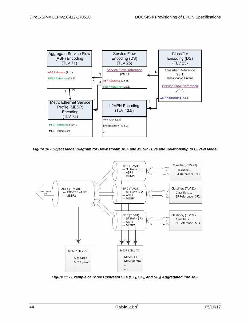
DPoE-SP-MULPIv2.0-I12-170510 DOCSIS® Provisioning of EPON Specifications
44 CableLabs 05/10/17
Figure 10 - Object Model Diagram for Downstream ASF and MESP TLVs and Relationship to L2VPN Model
Figure 11 - Example of Three Upstream SFs (SF1, SF2, and SF3) Aggregated into ASF

DPoE MAC and Upper Layer Protocols Interface Specification DPoE-SP-MULPIv2.0-I12-170510
05/10/17 CableLabs 45
Figure 12 - Example of Three Downstream SFs (SF1, SF2, and SF3) Aggregated into ASF
When an SF is mapped into an ASF, the classifier forwards matching traffic into a configured SF, which is aggregated with other SFs into an ASF, depending on the ASF-REF present in the Service Flow Encoding TLV (24/25). The traffic is transmitted with the LLID associated with the ASF. The LLID is autonomously assigned to the ASF by the DPoE System. SFs associated with an ASF are not assigned dedicated LLIDs.
When an SF is not mapped into an ASF, the classifier forwards matching traffic into a configured SF. The traffic is transmitted with the LLID associated with the SF, identical to the behavior defined in the DPoEv1.0 specifications. The LLID is autonomously assigned to the SF by the DPoE System.
7.3.1.4 SF and ASF Parameters An SF or ASF is characterized by the following set of parameters:
• For an SF, Service Flow ID (SFID) serves as the principal identifier of the SF in the DPoE System.
• For an ASF, Aggregating Service Flow ID (ASFID) serves as the principal identifier of the ASF in the DPoE System.
• For a MESP, Metro Ethernet Service Profile ID (MESPID) serves as the principal identifier of the MESP in the DPoE System.
7.3.1.4.1 QoS Parameters25
The DPoE System MUST support the following QoS parameters for SFs.
These parameters apply to the given SF only when the given SF is not associated with an MESP (i.e., when the SF does not contain an instance of the sub TLV 37).
25 Revised per MULPIv2.0-N-14.0126-1 on 3/6/14 by JB.

DPoE-SP-MULPIv2.0-I12-170510 DOCSIS® Provisioning of EPON Specifications
46 CableLabs 05/10/17
• The Maximum Sustained Traffic Rate (TLV 24/25.8) parameter.
• The Maximum Traffic Burst (TLV 24/25.9) parameter. This parameter has a minimum value of 1600 bytes and a default value of 12800 bytes.
• The Minimum Reserved Traffic Rate (TLV 24/25.10) parameter.
• The Data Rate Unit Setting (TLV 24/25.41) as defined in [MULPIv3.0] for all data rates.
• The Request Transmission Policy (TLV 24.16) parameter to control EPON scheduling behavior for Upstream Service flows. Only Bit #4, the "No Piggyback Bit", is supported as a way to disable MPCP Force Report behavior, where REPORT MPCP PDUs are piggybacked with data frames.
The DPoE System MUST ignore the Maximum Concatenated Burst parameter for Service Flows.
Unless stated otherwise, these parameters defined above are to be interpreted as defined in [MULPIv3.0].
In addition to the parameters above, for IP(HSD) services the DPoE System MUST support the following parameters.
• A Service Flow Scheduling Type (TLV 24.15) value of "Best Effort" for all upstream service flows.
• The Traffic Priority (TLV 24/25.7) parameter.
For IP(HSD) services, only the DOCSIS QoS Parameters are used, the MESP parameters are used only with MEF services.
In addition to the parameter above, for Metro Ethernet services the DPoE System MUST support the following parameters
• A Service Flow Scheduling Type (TLV 24.15) value of "Real-Time Polling" for all upstream service flows.
• The Nominal Polling Interval (TLV 24.17) for "Real-Time Polling" upstream service flows.
All the DOCSIS QoS Parameters apply to a Service Flow(SF) or Aggregate Service Flow (ASF) created for MEF services. When a MESP is also provisioned for a Service Flow created for MEF services, the MESP overrides the rate related DOCSIS QoS parameters such as maximum sustained rate, minimum reserved rate, maximum traffic burst, peak traffic rate, etc.
These MESP parameters are provisioned using the TLV 72, as specified in Annex C.
The vCM MUST support the MESP parameters for an ASF and configure the D-ONU appropriately based on D-ONU capabilities. The vCM MUST support the MESP parameters for an SF and configure the D-ONU appropriately, based on D-ONU capabilities. If a Service Flow is configured using both a DOCSIS Service Flow parameters and a set of MESP parameters, the MESP parameters take precedence.
7.3.1.5 SF Requirements When an SF is not aggregated into an ASF, the DPoE System MUST map the SF into one of the available LLIDs. The mapping between the SF and the LLID is a vendor-specific process and outside the scope of this specification.
When an SF is aggregated into an ASF, the DPoE System MUST map such an SF into one of the provisioned ASFs, where the mapping between the SF and the ASF is defined through sub-TLV 36.
An SF begins its existence when the DPoE System assigns an SFID to it. The SFID serves as the principal identifier for the SF within the DPoE System. Within a DPoE System, any SF MUST have an assigned SFID, together with the set of QoS parameters, as defined above. An SF cannot exist without an assigned SFID.
The DPoE System MUST support assignment of SIDs to upstream SFs and upstream ASFs. The SID is an important management identifier in DOCSIS networks. SID Clusters defined in [MULPIv3.0] are not supported in DPoE specifications. The concept of SID in DOCSIS (at a logical level) corresponds to the LLID in the DPoE Network.

DPoE MAC and Upper Layer Protocols Interface Specification DPoE-SP-MULPIv2.0-I12-170510
05/10/17 CableLabs 47
In [MULPIv3.0], an SF can be in one of several states – provisioned, admitted, and active. For each of those states, the flow may have a different set of values of QoS parameters. However, the DPoE System MUST only support SFs that are provisioned, admitted, and active (Quality of Service Parameter Set Type (TLV 24/25.6) value of 7). There are no provisions for deferred admission and activation of SFs. The DPoE System MUST admit and activate SFs when the given SFs are provisioned.
7.3.1.6 ASF-Related Requirements The DPoE System MUST map each ASF into one of the available LLIDs. The mapping between the ASF and the LLID is a vendor-specific process and outside the scope of this specification.
The DPoE System creates the ASF and assigns an ASFID to it. The ASFID serves as the principal identifier for the ASF within the DPoE System. A DPoE System MUST assign an ASFID to each ASF. An ASF cannot exist without an assigned ASFID.
7.3.1.7 MESP Requirements The DPoE System MUST assign an MESPID to an MESP. The MESPID serves as the principal identifier for the MESP within the D-ONU and DPoE System.
An MESP may be associated with any number of SFs and ASFs. SFs and ASFs may be associated with DOCSIS QoS parameters and MESP parameters. ASFs are always associated with an MESP. The DPoE System MUST reject the CM configuration file if it encounters an ASF encoding that is not associated with an MESP .
7.3.2 Frame Classification and Rule execution
In the DPoE Network, all operations on data frames related with QoS enforcement and forwarding operations are performed based on classification operations and execution of associated actions. The purpose of the classification process in the DPoE Network is to identify all frames belonging to the given SF / ASF, to determine what actions to take on the frame (e.g., encapsulate / de-encapsulate, convert specific subfields, set bits in specific locations etc.) and to forward the given frame to the appropriate LLID (in upstream and downstream direction alike).
Independent classification engines execute inside each D-ONU and the DPoE System in the very same manner. The DPoE System classification engine is configured jointly via the IPNE mechanisms and CM configuration files. The D-ONU classification engine is configured via the eOAM as defined in [DPoE-OAMv2.0], where individual eOAM PDUs represent translated configuration parameters contained in the CM configuration file.
Each classification engine operates on a set containing at least one classification rule. Each classification rule comprises at least one condition, followed by at least one action to be executed, as shown below:
IF (condition[0] AND condition[1] AND … condition[N]) THEN (action[1], action [2] … action[M])
All conditions are logically ANDed and the action is executed only if all the conditions evaluate to "true". Each condition may compare a particular header field in a frame against a provisioned value, test for existence of a field, or unconditionally return "true" or "false". The same field may be used in multiple comparisons (either in different comparison rules or in different rule conditions of the same comparison rule). There is no conceptual limitation on the complexity of the classification rules, number of classification conditions per single rule and the number of actions executed on a frame matching the given classification rule. There may be some practical limitations, though, especially in terms of the memory space available for the classification engine, effectively limiting the number of classification rules which can be stored on a single device, and their complexity, though such aspects are implementation-dependent and not subject to restriction in the scope of this specification.
All classification rules provisioned on the given classification engine are organized in a data set according to the rule priority. Rules with the highest priority are stored at the head of the data set and tested first, and the rules with the lowest priority are stored at the tail of the data set and tested last.
Each classification engine operates in a sequential manner; i.e., an incoming frame is compared against the classification rules stored in the data set maintained by the classification engine, starting from the classification rules with the highest priority until the first successful match is found. When the first successful match is found, actions associated with the given classification rule are executed and the following classification rules are not tested on the given frame. This means that, each frame is processed only by actions associated with one classification rule, the

DPoE-SP-MULPIv2.0-I12-170510 DOCSIS® Provisioning of EPON Specifications
48 CableLabs 05/10/17
conditions of which match the given incoming frame. If the primary SF is not enabled on the D-ONU, frames not matching any of the provisioned classification rules are dropped and counted.
In the upstream direction, the D-ONU MUST classify upstream packets to active SFs. If a primary upstream SF is configured and a frame does not match any configured classification rules (and hence is not classified to any SF), the D-ONU MUST assign such a frame to the primary upstream SF and forward it accordingly. If a primary upstream SF is not configured, any frame not meeting any of configured classification rules (and hence not classified to any SF) MUST be dropped by the D-ONU, so that it is not sent on the TU interface.
In the downstream direction, the DPoE System MUST classify downstream packets to active SFs. If a primary downstream SF is configured and a frame does not match any configured classification rules (and hence is not classified to any SF), the DPoE System MUST assign such a frame to the primary downstream SF and forward it accordingly. If a primary downstream SF is not configured, any frame not meeting any of configured classification rules (and hence not classified to any SF) MUST be dropped by the DPoE System.
The process of frame classification operates only on the fields already present in the given frame when it enters the classification engine. The classification engine does not operate on the fields added to the frame in the result of the successful match of the given classification rule and execution of the associated actions. This means that, if the frame matches the given classification rule and, for example, an I-Tag is added to this frame, there is no way to classify this frame on the newly added I-Tag field.
The list of frame fields accessible for the classification engine comparison operators as well as provisioning of the classification engine are described in more detail in the Annex C and [DPoE-OAMv2.0]. The list of classifier types below is for information purposes only:
• 802.3 fields: C-SA, C-DA, Ethertype
• 802.1ad fields: C-VID, S-VID, C-TPID, S-TPID, C-TCI, S-TCI, C-PCP, S-PCP, C-CFI and S-DEI;
• 802.1ah fields: I-SID, I-TPID, I-TCI, I-PCP, I-DEI, I-UCA, B-DA, B-SA, B-TCI, B-TPID, B-PCP, B-DEI, B-VID;
• IPv4 TOS/IPv6 Traffic Class;
• IPv4 TTL/IPv6 Hop Limit;
• IPv4 Protocol Type;26
• IPv4 Source Address;
• IPv6 Source Address;
• IPv4 Destination Address;
• IPv6 Destination Address;
• IPv6 Next Header;
• IPv6 Flow Label;
• TCP/UDP source port;
• TCP/UDP destination port;
• Custom fields defined using the mechanism specified in [DPoE-OAMv2.0].
The custom field specified in [DPoE-OAMv2.0] allows the operator to identify fields of arbitrary size and at an arbitrary location within the frame header, subject to distance or size limitations set forth in [DPoE-OAMv2.0], providing a mechanism to access, read and optionally modify any field fragment within the incoming frame. Additionally, this mechanism allows access to fields not listed above and not readily accessible to the classification engine.
26 Revised per MULPIv2.0-N-13.0061-1 on 2/8/13 by JB.

DPoE MAC and Upper Layer Protocols Interface Specification DPoE-SP-MULPIv2.0-I12-170510
05/10/17 CableLabs 49
In the DPoE Network, the classification rules are used for both QoS enforcement and forwarding purposes; i.e., a single classification rule is used to provide QoS specific processing to frame fields (e.g., set PCP field bits, add or remove fields etc.), forward the frame into the appropriate queue for transmission or perform frame filtering(selective drop).
7.3.3 Classifiers27
In the DPoE Network, classifiers describe the association of the given frame to a specific SF / ASF through a classification rule and associated actions. In a DPoE Network, all the same classifier behavior as defined in [MULPIv3.0] applies. Matching criteria not specified in a classifier will not be given consideration while classifying frames. If no Classifier Rule Priority is specified, the DPoE System MUST use the default Rule Priority of 0. The DPoE System MUST assign classifier IDs to individual classifiers. The classifier ID is an important management identifier as specified in [MULPIv3.0].
Additionally, a classifier references the target SF, to which selected frames are attributed if the specific classification rule(s) are met.
The classification behavior (i.e., classification of frames into SF at the D-ONU and the DPoE System) follows the requirements specified in [MULPIv3.0]. The vCM MUST support the Upstream Drop classifiers (TLV 60). The vCM MUST support the Upstream Drop classifiers Group ID (TLV 62). The vCM MUST configure the D-ONU according to the Upstream Drop classifiers.
The DPoE ONU supports the following combinations of classifiers:
• The DPoE ONU MUST support classification based on one or more fields in an I-Tag.
• The DPoE ONU MUST support classification based on one or more fields in an S-Tag.
• The DPoE ONU MUST support classification based on one or more fields in a C-Tag.
• The DPoE ONU MUST support classification based on one or more fields in an S-Tag and one or more fields in a C-Tag simultaneously.
• The DPoE ONU MUST support classification based on one or more fields in an B-Tag and one or more fields in a I-Tag simultaneously.
• The DPoE ONU SHOULD support classification based on other combinations of classifiers operating on fields of individual tags listed above.
When a TPID classifier is provisioned in a configuration file, it is expected that the corresponding VID classifier is also present in Annex C.
When L2 classifiers are provisioned in the CM configuration file for an individual SF, the DPoE System and DPoE ONU adhere to the following rules:
• If one or more fields from a single tag (e.g., C-TPID or C-VID within a C-Tag) are provisioned in a classifier, the DPoE System MUST configure the D-ONU to match these fields against the outermost tag on a frame.
• If one or more fields from both an S-Tag and C-Tag (e.g., S-VID within S-Tag and C-VID within C-Tag) are provisioned in a classifier, the DPoE System MUST configure the D-ONU to match these parameters with the S-Tag as the outer tag and C-Tag as the inner tag.
• If one or more fields from an I-Tag (e.g., I-SID within I-Tag) are provisioned in a classifier, the DPoE System MUST configure the D-ONU to match these parameters with or without the existence of the B-Tag in the frame.
• If one or more fields from both an B-Tag and I-Tag (e.g., B-VID within B-Tag and I-SID within I-Tag) are provisioned in a classifier, the DPoE System MUST configure the D-ONU to match these parameters with the B-Tag as the outer tag and I-Tag as the inner tag.
27 Revised per MULPIv2.0-N-14.0128-2 on 3/7/14 by JB.

DPoE-SP-MULPIv2.0-I12-170510 DOCSIS® Provisioning of EPON Specifications
50 CableLabs 05/10/17
The set of classifiers used by the DPoE Network, applicable to both IP(HSD) and MEF SFs, are as defined in [MULPIv3.0] with the following exceptions:
• Individual Classifiers cannot be added to the frame classification table using the DOCSIS MAC sublayer service interface, which is not instantiated within the DPoE Network.
• In DPoE, classifiers do not support deferred activation; i.e., once the classifier is provisioned, the DPoE System MUST automatically activate it.
Figure 13 shows the Layer2 classification fields (Layer3 or Layer4 classification fields are not shown) and corresponding TLVs that are described in Annex C.
Figure 13 - 802.1ad and 802.1ah Classifiers
7.3.4 Service Classes
The DPoE System MUST support configuration of QoS parameters via Named Service Classes as specified in [MULPIv3.0]. If a Service Flow is configured using both a Named Service Class and a set of MESP parameters, the MESP parameters take precedence over the rate related parameters and those Service Class parameters are ignored. This functionality allows for configuration of a common set of QoS parameters for SFs through the access to the "CMTS MIBs" as opposed to configuring them via CM configuration files. However, the CM configuration file still needs to refer to a specific Service Class Name configured on DPoE System. It is up to the operator to synchronize the definition of Service Class Names in the DPoE System and in the configuration files.
PayloadTypeSA TPID PCP CFI VIDTPID PCP DEI VIDDA
PayloadTypeSA TPID PCP CFI VIDDA
PayloadTypeSADA
B-SA TPID PCP DEI I-SIDTPID PCP DEI B-VIDB-DA
PayloadTypeSA TPID PCP CFI VIDTPID PCP DEI VIDDA
DestMacAddr22.10.1
SourceMacAddr22.10.2
ProtocolType22.10.3
DestMacAddr22.10.1
SourceMacAddr22.10.2
ProtocolType22.10.3
DestMacAddr22.10.1
SourceMacAddr22.10.2
ProtocolType22.10.3
DestMacAddr22.10.1
SourceMacAddr22.10.2
ProtocolType22.10.3
802.1adC-TPID
22/23.14.5
802.1adC-CFI
22/23.14.8
802.1adC-VID
22/23.14.6
802.1adS-TPID
22/23.14.1802.1adS-PCP
22/23.14.3
802.1adS-DEI
22/23.14.4
802.1adS-VID
22/23.14.2
802.1adS-TPID
22/23.14.1
802.1adS-VID
22/23.14.2
802.1ahI-SID
22/23.15.2
802.1ahI-DEI
22/23.15.4
802.1ahI-TAG I-PCP22/23.15.3
802.1ahI-TAG I-TPID22/23.15.1
802.1ahB-VID
22/23.15.10
802.1ahB-DEI
22/23.15.9802.1ahB-PCP
22/23.15.8
802.1ahB-DA
22/23.15.11
802.1ahB-SA
22/23.15.12
DOCSIS 3.0 SupportedDPoE 1.0DPoE 2.0
802.1adS-TCI
22/23.14.9
Untagged
802.1Q Tagged
802.1ad Tagged
802.1ah Encapsulation
802.1adC-TCI
22/23.14.10
802.1adS-PCP
22/23.14.3
802.1adS-DEI
22/23.14.4
802.1adS-TCI
22/23.14.9
802.1ahB-TCI
22/23.15.7
B-TPD22/23.15.6
802.1ahI-TCI
22/23.15.13
802.1adC-CFI
22/23.14.8
802.1adC-CFI
22/23.14.8
802.1adC-PCP
22/23.14.7
802.1adC-PCP
22/23.14.7
802.1adC-PCP
22/23.14.7
802.1adC-TCI
22/23.14.10
802.1adC-TCI
22/23.14.10
802.1adC-TPID
22/23.14.5
802.1adC-TPID
22/23.14.5
UCA
802.1ahI-UCA
22/23.15.5
802.1adC-VID
22/23.14.6
802.1adC-VID
22/23.14.6

DPoE MAC and Upper Layer Protocols Interface Specification DPoE-SP-MULPIv2.0-I12-170510
05/10/17 CableLabs 51
7.3.5 Authorization
In the DPoE Network, the SF authorization process is not required, because the admission control and resource availability decisions are performed on the DPoE System, and the D-ONU does not participate in this process. The D-ONU is controlled by the DPoE System using the master-slave relationship.
7.3.6 SF and Classifiers28
The provisioned classification rules associate packets into exactly one SF. The SF or ASF encodings provide the QoS Parameters for treatment of those frames on the EPON. Service Flow encodings are described in Section 7.3.1 and Annex C.
7.3.6.1 The Primary SF29 Support for primary SFs in the DPoE specifications is introduced to maintain partial backward compatibility with the DOCSIS provisioning systems of some operators who rely on the presence and support of primary SFs for the implementation of IP(HSD) applications. There are no primary SFs in MEF services
The definition of a primary SF in DPoE specifications is different from that in [MULPIv3.0]. In DPoE specifications, an SF in the given transmission direction is considered to be primary if it has no associated classifiers irrespective of the position of this SF within the CM configuration file. In this way, if each SF present in the CM configuration file has an associated classifier, then the DPoE System operates without primary SFs for that D-ONU. Only one primary upstream SF and one primary downstream SF may be configured for a D-ONU.
A DPoE System supports CM configuration files with and without primary SFs. An SF encoding can occur anywhere within the CM configuration file. If a primary SF is present in the CM configuration file, it applies to all ports including the internal (LCI) and external ports (CMCI).
If all of the SFs in the CM configuration file have associated classifiers, then the DPoE System MUST operate without creating any primary SFs for both the upstream and downstream directions. The DPoE System MUST NOT require the configuration of a primary downstream SF to perform downstream forwarding. The D-ONU MUST NOT require the existence of a primary upstream SF to perform upstream forwarding. When there are no primary downstream SFs configured, the DPoE System MUST discard all unclassified traffic. When there are no primary upstream SFs configured, the D-ONU MUST discard all unclassified traffic. The DPoE System MUST set the docsQoSServiceFlowPrimary value to 'false' for all SFs when operating without primary SFs.
If the CM configuration file contains at least one upstream SF without an associated classifier, the DPoE System MUST use the first such SF, based on position within the CM configuration file, without an associated classifier entry as the primary upstream SF. The DPoE System MUST ignore all the other upstream SFs without an associated classifier. If configured by the DPoE System, the D-ONU MUST use the primary upstream SF as the default upstream SF to forward all unclassified upstream traffic.
If the CM configuration file contains at least one downstream SF without an associated classifier, the DPoE System MUST use the first such SF, based on the position within the CM configuration file, without an associated classifier entry as the primary downstream SF. The DPoE System MUST ignore all the other downstream SFs without an associated classifier. The DPoE System MUST use the primary downstream SF as the default downstream SF for all unclassified downstream traffic. The DPoE System MUST set the docsQoSServiceFlowPrimary value to true for both the upstream and downstream primary SFs.
7.3.6.2 Downstream and Upstream SFs in IP(HSD) A pair of non-primary SFs creates a bidirectional IP(HSD) service instance when:
• both are associated with one or more classifiers that contain the same CMIM encoding; or
• both are associated with at least one classifier with the proper CMIM encoding and there is an instance of the SF Collection TLV binding both SFs together.
28 Revised per MULPIv2.0-N-15.0205-2 on 2/23/15 by JB. 29 Revised per MULPIv2.0-N-15.0216-1 on 10/5/15 by JB.

DPoE-SP-MULPIv2.0-I12-170510 DOCSIS® Provisioning of EPON Specifications
52 CableLabs 05/10/17
The presence of the SF Collection TLV is optional. The DPoE System MUST be able to create bidirectional IP(HSD) services by combining non-primary SFs associated with classifiers containing the same CMIM. If the given CMIM value is present in more than one classifier associated with non-primary SFs for the given transmission direction (downstream or upstream), the DPoE System MUST use the first SF entry, based on the position within the CM configuration file, for the given direction associated with the given CMIM when constructing the bidirectional IP(HSD) service. The DPoE System MUST be able to create bidirectional IP(HSD) services by combining non-primary SFs associated through an instance of SF Collection TLV.
For example, an ONU with two physical UNI ports (UNI1 and UNI2) may have two bidirectional IP(HSD) service instances setup as follows:
• upstream SF1 associated with UNI1 through upstream classifier containing CMIM 40 00 00 00;
• downstream SF2 associated with UNI1 through downstream classifier containing CMIM 40 00 00 00;
• upstream SF3 associated with UNI2 through upstream classifier containing CMIM 04 00 00 00;
• downstream SF4 associated with UNI2 through downstream classifier containing CMIM 04 00 00 00;
In this case, SF1 and SF2 create the first bidirectional IP(HSD) service instance associated with UNI1 through classifier with CMIM 40 00 00 00, and SF3 and SF4 create the second bidirectional IP(HSD) service instance associated with UNI2 through classifier with CMIM 04 00 00 00.
In another example, an ONU with two physical UNI ports (UNI1 and UNI2) may have two bidirectional IP(HSD) service instances setup in the following fashion:
• upstream SF1 associated with UNI1 through upstream classifier containing CMIM 40 00 00 00;
• downstream SF2;
• an SF Collection TLV present in both SF1 and SF2, combining upstream SF1 and downstream SF2;
• upstream SF3 associated with UNI2 through upstream classifier containing CMIM 04 00 00 00;
• downstream SF4;
• an SF Collection TLV present in both SF3 and SF4, combining upstream SF3 and downstream SF4.
In this case, SF1 and SF2 create the first bidirectional IP(HSD) service instance associated with UNI1 and bound together via SF Collection TLV. SF3 and SF4 create the first bidirectional IP(HSD) service instance associated with UNI2 and bound together via SF Collection TLV.
7.3.6.3 Downstream and Upstream SFs in MEF A pair of non-primary SFs creates a bidirectional MEF service instance when they meet the following conditions:
• The DPoE System MUST ignore all the other downstream SFs without an associated classifier. The CM configuration file contains an instance of GeneralExtensionInformation TLV 43 with the specific value of L2VPNIdentifier (L2VPID);
• The upstream SF definition contains an instance of VendorSpecificParams TLV 43 with the specific value of L2VPNIdentifier (L2VPID);
• The downstream classifier definition, associated with the downstream SF contains an instance of VendorSpecificParams TLV 43 with the specific value of L2VPNIdentifier (L2VPID);
• The upstream and downstream classifier definitions contain the same CMIM instance.
In this case, the upstream and downstream SF create a bidirectional MEF service instance.
7.3.6.4 Additional Requirements Classification of "DOCSIS MAC Management Messages", via the "Ethertype/DSAP/MacType" TLV, does not apply to DPoE Networks. DPoE Systems do not classify OAM, eOAM, or MPCP frames. D-ONUs do not classify OAM, eOAM, or MPCP frames.

DPoE MAC and Upper Layer Protocols Interface Specification DPoE-SP-MULPIv2.0-I12-170510
05/10/17 CableLabs 53
7.3.7 QoS Support for Downstream IP Multicast Traffic30
QoS support for dynamically joined sessions (using a multicast management protocol such as IGMP/MLD), as well as statically joined sessions (using Static Multicast Session Encodings), is supported as defined in [MULPIv3.0]. For downstream IP multicast traffic, QoS is supported using the concept of Group Service Flows (GSFs). Just as classifiers match and forward unicast traffic onto SFs, Group Classifier Rules (GCRs) match multicast traffic and forward them on GSFs.
For IP multicast QoS, a cable operator controls the creation of GCRs and GSFs on each downstream channel by configuring entries in Group Configuration (GC) and Group QoS Configuration (GQC) tables per [DPoE-OSSIv2.0]. These tables only configure the QoS for IP multicast sessions; they do not control how a DPoE System replicates IP multicast traffic onto multicast LLIDs. Replication of IP multicast traffic is determined based on joiners to IP multicast sessions. In the DOCSIS Network [MULPIv3.0], the multicast replication is done per downstream channel set within a MAC domain, whereas in the DPoE Network the replication is per downstream channel in the MAC domain.
The operator defines the QoS needed for various IP multicast sessions using entries in the GC and GQC tables. When the first client behind the D-ONU sends up a multicast IGMP/MLD joinrequest, the DPoE System MUST use the information in the GC and GQC tables to dynamically create GCRs and GSFs on the appropriate downstream channel. The DPoE System then starts forwarding the multicast stream on that GSF. The DPoE System follows the steps defined in [MULPIv3.0] for controlling QoS for multicast sessions.
Each GQC entry has a QoS Control parameter as defined in [MULPIv3.0] which determines how the DPoE System instantiates GSFs:
• When the QoS Control parameter has the value of "Single-Session", the DPoE System creates a GSF for each session; i.e., each unique combination of (Source, Group) IP address which matches the GC entry.
• When the QoS Control parameter has the value of "Aggregate-Session", the DPoE System creates only one GSF and associates GCR entries as needed with that GSF.
In a "Single Session" GSF, there is only one multicast session per GSF, whereas in "Aggregate Session" GSFs, multiple multicast sessions use the same GSF. See [MULPIv3.0] for details on this behaviour.
The DPoE System MUST associate each GSF with a unique multicast LLID (mLLID) each time it creates a new GSF. This mLLID is signaled (along with the multicast classification and forwarding information) to D-ONUs that need to receive and forward the multicast traffic, via the eOAM as defined in [DPoE-OAMv2.0].
The DPoE System MUST establish a default GSF as specified in [MULPIv3.0]. All unclassified multicast traffic is forwarded on the default GSF. The DPoE System MUST associate the default GSF with a unique multicast LLID (mLLID). This mLLID is signaled to the D-ONUs which need to receive and forward multicast traffic being sent on the default GSF, via the eOAM as defined in [DPoE-OAMv2.0].
7.3.7.1 Forwarding Multicast Control Protocols31 The DPoE System supports the downstream forwarding of multicast control traffic per Serving Group based on the serving group configuration as described in [DPoE-IPNEv2.0]. Examples of multicast control traffic are downstream local network control packets, link-local multicast packets as well as packets for routing protocols that utilize IP multicast. The DPoE System MUST establish a multicast control traffic GSF for multicast control traffic per IP serving group. The DPoE System MUST create GCRs that support forwarding of multicast control traffic protocols by default as per [MULPIv3.0]. The multicast control protocols specified in DOCSIS would be allowed by default. The DPoE System MUST support overrides to the default GCR for the configured multicast control traffic protocols as specified in [DPoE-IPNEv2.0]. The [DPoE-IPNEv2.0] configuration is used to override the default behavior to allow or deny forwarding of multicast traffic or control protocols. The DPoE System MUST associate each multicast control traffic GSF with a unique mLLID. This mLLID is signaled (along with the multicast classification and forwarding information) to the D-ONUs which need to receive and forward multicast control traffic being sent on the multicast control GSF, via the eOAM as defined in [DPoE-OAMv2.0]. The DPoE System 30 Revised per MULPIv2.0-N-15.0220-2 on 11/4/15 by JB. 31 Revised per MULPIv2.0-N-15.0220-2 on 11/4/15 by JB.

DPoE-SP-MULPIv2.0-I12-170510 DOCSIS® Provisioning of EPON Specifications
54 CableLabs 05/10/17
MUST signal the mLLID for each GSF associated with an IP Serving Group to only the D-ONUs associated with the IP Serving Group. The DPoE System MUST signal the mLLID for each GSF associated with a Multicast Serving Group to only the D-ONUs associated with the Multicast Serving Group.
7.3.8 IPv6 Multicast Traffic and Other Multicast
As described in [DPoE-IPNEv2.0], the DPoE System supports multicast for IPv6 protocols as well as for routing protocols that utilize IP multicast. The DPoE System MUST forward all IPv6 multicast provisioning traffic destined to the CPEs behind a D-ONU on the multicast control GSF associated with the Serving Group for this D-ONU. QoS support for layer 2 multicast is not defined in this specification.
7.4 Acquiring D-ONU Capabilities and D-ONU Provisioning 32
The DPoE System and connected D-ONUs, operate in a master-slave relationship, where the DPoE System remains in control of individual D-ONUs.
After the initial MPCP discovery and registration process is complete (as defined in [802.3], Clause 64 and Clause 77, the D-ONUs are subject to the OAM discovery process, as defined in [802.3], Clause 57. Once these processes are complete, the DPoE System may provision any of the connected D-ONUs as provisioned by the operator using appropriate CM configuration files. The process in the DPoE Network is driven by the given instance of the vCM associated with the given D-ONU and features exchange of the eOAMPDUs, where the exchange may serve the following purposes:
• Obtaining D-ONU configuration parameters and capabilities, including chipset ID, software version, number of supported unicast and multicast LLIDs etc.
• Configuration of D-ONU parameters and capabilities, such as queue thresholds for REPORT MPCPDU generation.
• Establishment of services on D-ONU and configuration of associated classification and modification rules, together with queue and LLID mapping rules, established based on the binary configuration files received by the vCM and translated into a series of configuration eOAMPDUs.
Definitions of individual D-ONU attributes as well as the details on the provisioning, configuration and polling mechanism used to exchange information between the D-ONU and the vCM are included in the [DPoE-OAMv2.0] specification, covering message format, attribute format and additional requirements for the eOAM protocol, extending definitions found in [802.3], Clause 57.
Note that the D-ONU capability request process in the DPoE Network is driven by the DPoE System, and specifically, by the vCM associated with the given D-ONU, and may be executed at any time after the D-ONU registration into the DPoE Network, depending on the current requirements, operator demand (on-demand polling) etc. The DPoE System MUST acquire D-ONU capabilities before provisioning any of the services defined in the CM configuration file. To guarantee interoperability between DPoE System and D-ONU devices from various suppliers, it is necessary to guarantee interoperability at the TUL interface, provided by the definitions and requirements found in the [DPoE-OAMv2.0] specification.
7.5 D-ONU Capabilities
The D-ONU capabilities are queried by the DPoE System as described above. The D-ONU MUST support reporting the following capabilities to the DPoE System. The DPoE System MUST support reporting the following capabilities to the provisioning system using DHCP messages. Also see Annex C for TLV definitions.
• DPoE Version Number
• Number of unicast LLIDs
• Number of multicast LLIDs 32 Revised per MULPIv2.0-N-15.0223-2 on 2/11/16 by JB.

DPoE MAC and Upper Layer Protocols Interface Specification DPoE-SP-MULPIv2.0-I12-170510
05/10/17 CableLabs 55
• MESP Support
• Color marking
• Color Awareness
• Smart Color Dropping
• Number of CMCI ports on D-ONU
• EPON data rate support
• Service OAM capabilities
7.6 Data Link Encryption Support
The procedures to support data-link encryption are defined in [DPoE-SECv2.0]. The interaction between the MAC layer and the security system is limited to the items defined below.
MAC Messages: Encryption of the OAMPDUs, the MPCPDUs, and the data bearing MAC DATAPDUs is defined in [DPoE-SECv2.0].
Framing: Detailed information on the MAC framing format, when encrypted, is included in the [DPoE-SECv2.0] specification.
7.7 Power Saving 33
Power conservation and reduction of the carbon footprint of access networks is globally recognized as one of the technical targets for the optical access networks. The objectives of the power-saving mechanisms are to reduce ecological impact, reduce operating cost, and extend battery backup time (if supported by the given product), while minimizing any degradation of network performance to maintain the configured SLA. The scope of the power saving mechanism defined for DPoE covers the operation of the D-ONU, DPoE System, as well as the interaction between the DPoE System and the D-ONU (control protocol). There are no requirements for the performance of the power saving mechanism (i.e., number of watts saved) when enabled on the D-ONU and the DPoE System.
7.7.1 General Requirements
The DPoE System SHOULD support the power saving mechanism as described in Section 7.7.2. The D-ONU SHOULD support the power saving mechanism as described in Section 7.7.2.
7.7.2 Specific requirements
If the power saving mechanism is supported on the DPoE System, the DPoE System MUST implement the power saving mechanism as defined in [1904.1A], section 10.5.2. If the power saving mechanism is supported on the D-ONU, the D-ONU MUST implement the power saving mechanism as defined in [1904.1A], section 10.5.2.
By default, the D-ONU MUST disable the power saving mechanism at the time of registration with the DPoE System (during the MPCP Discovery & Registration process). This gives the DPoE System opportunity to enable the power saving mechanism for the selected D-ONUs, depending on the explicit operator configuration via CLI or SNMP. The configuration of the power saving mechanism on the given D-ONU is non-persistent, i.e., the power saving mechanism returns to its default disabled state after the D-ONU reset / reboot.
33 Revised per MULPIv2.0-N-14.0198-1 on 11/18/14 by JB.

DPoE-SP-MULPIv2.0-I12-170510 DOCSIS® Provisioning of EPON Specifications
56 CableLabs 05/10/17
7.8 Optical Line Protection34
Optical link protection provides redundancy for the data path between the DPoE System and D-ONUs connected to one of the TU interfaces on the DPoE System. Two types of optical link protection schemes are supported in [1904.1A], i.e., namely, a trunk protection (see [1904.1A], subclause 9.3.3) and a tree protection (see [1904.1A], subclause 9.3.4), each addressing a different application space and providing different types of functionality. The scope of the optical link protection mechanisms defined in DPoE specifications covers the operation of the D-ONU, DPoE System, as well as the interaction between the DPoE System and the D-ONU (control protocol).
There are no requirements for the performance of the optical link protection mechanism (i.e., maximum number of lost packets, maximum down time, etc.) when enabled on the D-ONU and the DPoE System.
7.8.1 General Requirements
The DPoE System SHOULD support the tree and trunk optical line mechanism as described in Section 7.7.2. The D-ONU SHOULD support the tree and trunk optical line mechanism as described in Section 7.7.2.
7.8.2 Specific Requirements
If the trunk optical line mechanism is supported on the DPoE System, the DPoE System MUST implement the power saving mechanism as defined in [1904.1A], subclause 9.3.3. If the tree optical line mechanism is supported on the DPoE System, the DPoE System MUST implement the power saving mechanism as defined in [1904.1A], subclause 9.3.4.
If the trunk optical line mechanism is supported on the D-ONU, the D-ONU MUST implement the power saving mechanism as defined in [1904.1A], subclause 9.3.3. If the tree optical line mechanism is supported on the D-ONU, the D-ONU MUST implement the power saving mechanism as defined in [1904.1A], subclause 9.3.4.
By default, the D-ONU MUST enable the trunk / tree optical line protection mechanism at the time of registration with the DPoE System (during the MPCP Discovery & Registration process), if supported on the given D-ONU. The DPoE System has ability to discover the support for tree / trunk optical line protection mechanism on individual D-ONUs and react accordingly to the state of optical line connecting the DPoE System to individual D-ONUs.
The configuration of the trunk / tree optical line protection mechanism parameters on the given D-ONU is non-persistent, i.e., individual parameters associated the trunk / tree optical line protection mechanism returns to their default values state after the D-ONU reset / reboot.
34 Revised per MULPIv2.0-N-15.0223-2 on 2/11/16 by JB.

DPoE MAC and Upper Layer Protocols Interface Specification DPoE-SP-MULPIv2.0-I12-170510
05/10/17 CableLabs 57
8 DATA FORWARDING35 The basic architecture for DPoE Networks is described in [DPoE-ARCHv2.0]. For MEF Services, the DPoE Network uses EPON technology to provide P2P Ethernet connections between the DPoE System and a D-ONU. P2P Ethernet connections in the form of Ethernet Virtual Connections (EVCs) are the underlying transport technology for Metro Ethernet services in the DPoE Network. IP(HSD) is a DPoE service that transports IP packets in the same manner as traditional DOCSIS and does not require the use of EVCs and [802.1ad] tagging across the TU interface. Since EPON has a P2MP architecture at the physical layer, P2P services are emulated via the Logical Topology Emulation (LTE) function through the use of LLID, as described in Section 6.1.2.4.
8.1 MEF Forwarding Requirements
Under [802.1ad], the term S-VLAN typically refers to a Service (S) VLAN, and the term C-VLAN typically refers to a Customer (C) VLAN. In telecommunications access services implemented with DPoE Networks, for example, the S-VLAN and C-VLAN are used as "outer" and "inner" tags (q-in-q) without respect to their typical meaning in [802.1ad]. [DPoE-MEFv2.0] provides a detailed explanation and requirements for the Metro Ethernet services.
There are two Ethernet forwarding models in DPoE Networks for Metro Ethernet services. These are the Provider Bridge (PB) and Provider Backbone Bridge (PBB). In the DPoE Network, classification rules provisioned by an operator are used to make decisions on which frames are dropped or forwarded to specific LLIDs. The selection of the specific forwarding path, operation on the given frame (addition, replacement, or removal of specific fields, as indicated by the provisioned rules) and resulting forwarding path depend on the provisioned classification and modification rules in Section 7.1.4.
8.1.1 Provider Bridge (PB)
The common data-forwarding mode used in [DPoE-MEFv2.0] for data delivery relies on the Metro Ethernet Forum service model that is implemented with [802.1ad]. The DPoE System MUST support [802.1ad] forwarding, The D-ONU MUST support [802.1ad] forwarding. Data-forwarding for each service is accomplished by establishing, at the time of provisioning, a unique combination (local to the DPoE System) of IEEE 802.1 headers (C-Tag, S-Tag) and D-ONU port information. The port information on the D-ONU is associated with the Cable Modem Interface Mask (CMIM), the CMIM is used locally on the D-ONU.
PB forwarding by the DPoE System MUST use the parameters per the list below. PB forwarding by the D-ONU MUST use the following parameters per the list below.
List of parameters used for PB forwarding:
• C-DA
• C-SA
• S-TPID (default of 0x88a8)
• S-TCI, or any combination of the S-TCI fields: (S-PCP, S-DEI, S-VID)
• C-TPID (default of 0x8100)
• C-TCI, or any combination of the C-TCI fields: (C-PCP, C-CFI, C-VID).
If no S-TPID is specified within the CM configuration file when adding an S-Tag, the DPoE System MUST default to an S-TPID of 0x88a8. If no C-TPID is specified within the CM configuration file when adding a C-Tag, the DPoE System MUST default to an C-TPID of 0x8100. The DPoE System configures the D-ONU, through eOAM messages, to use the appropriate values for S-TPID and C-TPID.
Legacy implementations of PB may use different values of the S-TPID. Examples of such S-TPID values include 0x8100, 0x9100, and 0x9200. [802.1ad] implementations of PB use S-TPID 0x88a8.
35 Revised per MULPIv2.0-N-14.0142-1 on 5/29/14 by JB.

DPoE-SP-MULPIv2.0-I12-170510 DOCSIS® Provisioning of EPON Specifications
58 CableLabs 05/10/17
A frame is considered to be S-Tagged when the frame TPID is equal to the value of the S-TPID provisioned in the CM configuration file or the default TPID for [802.1ad] if a specific S-TPID value is not provisioned in the CM configuration file. A frame is considered to be C-Tagged when the frame TPID is equal to the value of the C-TPID provisioned in the CM configuration file or the default TPID for [802.1ad] if a specific C-TPID value is not provisioned in the CM configuration file. Such values are known to the operator in advance and can be included in the D-ONU and DPoE System configuration for specific services, where such frames are expected.
[DPoE-MEFv2.0] offers optional methods of operator configurable TPID translation for PB frames on the DPoE System.
The DPoE System MUST support classification and forwarding of individual PB frames into an SF. DPoE System MUST support processing of PB frames (adding, modifying and stripping of individual PB fields), subject to detailed requirements as listed in [DPoE-MEFv2.0].
The D-ONU MUST support classification and forwarding of individual PB frames into an SF. D-ONU MUST support processing of PB frames (adding, modifying and stripping of individual PB fields), subject to detailed requirements as listed in [DPoE-MEFv2.0].
The selection of what operation is to be performed on a specific frame depends on the classification rule and the associated operations. In this way, the operator controls explicitly what PB frames are subject to what transformations and to where (what LLID) they are forwarded.
8.1.2 Provider Backbone Bridge (PBB)
The DPoE System MUST Support [802.1ah] forwarding and classification. The D-ONU MUST Support [802.1ah] forwarding and classification.
Every DPoE System functions as an I-BEB, B-BEB, IB-BEB or BCB as configured by the operator on per-SF basis, as specified in [DPoE-MEFv2.0].The DPoE System forwards PBB traffic based on provisioned [802.1ah] parameters, utilizing at least one of those identified below.
The DPoE System MUST support the [802.1ah] frame fields, per the following list, to classify and forward frames into individual SFs. The D-ONU MUST support the [802.1ah] frame fields, per the following list, to classify (forward) frames into individual SFs.
List of the [802.1ah] frame fields used for Classification and Forwarding:
• B-DA
• B-SA
• B-TPID (default of 0x88a8)
• B-TCI, or any combination of the B-TCI fields: (B-PCP, B-DEI, B-VID)
• I-TPID (default of 0x88e7)
• I-TCI, or any combination of the following I-TCI fields: (I-PCP, I-DEI, I-UCA, I-SID)
• S-TPID (default of 0x88a8)
• S-TCI, or any combination of the S-TCI fields: ( S-PCP, S-DEI, S-VID)
• C-TPID (default of 0x8100)
• C-TCI, or any combination of the C-TCI fields: (C-PCP, C-CFI, C-VID)
If no B-TPID is specified within the CM configuration file when adding a B-Tag, the DPoE System MUST default to a B-TPID of 0x88a8. If no I-TPID is specified within the CM configuration file when adding an I-Tag the DPoE System MUST default to a I-TPID of 0x88e7. The DPoE System configures the D-ONU through eOAM messages, to use the appropriate values for B-TPID and I-TPID.
Legacy implementations of PBB may use different values of the I-TPID. Examples of such I-TPID values include 0x8100, 0x9100, 0x9200, or 0x8902. [802.1ah] standard compliant implementations of PBB use I-TPID 0x88e7.

DPoE MAC and Upper Layer Protocols Interface Specification DPoE-SP-MULPIv2.0-I12-170510
05/10/17 CableLabs 59
Legacy implementations of PBB may use different values of the B-TPID. Examples of such B-TPID values include 0x8100, 0x9100, or 0x9200. [802.1ah] implementations of PBB use B-TPID 0x88a8.
A frame is considered to be I-Tagged when the frame TPID is equal to the value of I-TPID provisioned in the CM configuration file or the default I-TPID for [802.1ah] if a specific I-TPID value is not provisioned in the CM configuration file. A frame is considered to be B-Tagged when an I-Tag is present and the TPID in the B-Tag is equal to the value of B-TPID provisioned in the CM configuration file or the default B-TPID for [802.1ah] if a specific B-TPID value is not provisioned in the CM configuration file. Such values are known to the operator in advance and can be included in the D-ONU and DPoE System configuration for specific services, where such frames are expected.
[DPoE-MEFv2.0] offers optional methods of operator configurable TPID translation for PBB frames on the DPoE System.
The DPoE System MUST support classification and forwarding of individual PBB frames into an SF. DPoE System MUST support processing of PBB frames (adding, modifying and stripping of individual PBB fields), subject to detailed requirements as listed in [DPoE-MEFv2.0].
The D-ONU MUST support classification and forwarding individual PBB frames into an SF. D-ONU MAY support processing of PBB frames (adding, modifying and stripping of individual PBB fields), subject to detailed requirements as listed in [DPoE-MEFv2.0].
The selection of what operation is to be performed on a specific frame depends on the classification rule and the associated operations. In this way, the operator controls explicitly what PBB frames are subject to what transformations and to where (what LLID) they are forwarded.
8.2 Multicast Forwarding36
8.2.1 Introduction37
The DPoE Network supports IP multicast for IP(HSD) services by adopting the IP multicast model defined in [MULPIv3.0]. As defined in the [MULPIv3.0] DOCSIS 3.0 model, the D-ONU does not proxy or snoop messages to track Layer-3 IP multicast group membership and has no IP multicast control protocol awareness. The D-ONU transparently forwards IGMP/MLD control messages received from the client CPEs to the DPoE System.
Support of the IP multicast control protocols and tracking of Layer-3 IP multicast group membership is centralized and performed on the DPoE System. The DPoE System forwards downstream all packets from a set of multicast session on the multicast LLID (mLLID) assigned by the DPoE System to that particular set of multicast sessions. From the DPoE System perspective, an mLLID identifies a set of multicast sessions which may be received by a set of D-ONUs. The mLLID is used by the D-ONU to classify and forward multicast packets. The DPoE System controls the multicast forwarding of downstream multicast packets to specific interfaces through configuration of the D-ONU. The DPoE System configures the D-ONU with the mLLID and associated group forwarding attributes to specify the forwarding of IP multicast packets.
8.2.2 Downstream Multicast Forwarding
This section outlines the DPoE System and D-ONU requirements for downstream multicast forwarding. In the DOCSIS Network [MULPIv3.0], the DSID is used to restrict forwarding of multicast sessions through CMs with multicast clients that have joined the session, in a DPoE Network, the DSID is replaced by the mLLID.
The DPoE System MUST assign mLLIDs to GSFs. The DPoE System MUST assign mLLIDs uniquely per MAC Domain.
In order to reach all of the members of an IP multicast session, the DPoE System MUST replicate the packet on the downstream channels of a MAC Domain. The DPoE System MUST forward IP multicast packets if the session has active group membership. Active group membership is determined by the presence of a multicast listener (client) behind a D-ONU. 36 Revised per MULPIv2.0-N-14.0142-1 on 5/29/14 by JB. 37 Revised per MULPIv2.0-N-15.0220-2 on 11/4/15 by JB.

DPoE-SP-MULPIv2.0-I12-170510 DOCSIS® Provisioning of EPON Specifications
60 CableLabs 05/10/17
8.2.2.1 Labeling Multicast Packets with mLLIDs The DPoE System MUST tag all downstream multicast packets with an mLLID. The DPoE System signals the needed mLLIDs to the appropriate D-ONU. Packets with a known mLLID are received by the D-ONU and further classified and forwarded to the set of CMIM-Interfaces (S interfaces) associated with this multicast session. Packets with an unknown mLLID are discarded by the D-ONU.
In [MULPIv3.0], each replication of an (S,G) IP multicast session to a particular Downstream Channel Set is assigned a unique DSID label within a MAC Domain. In DPoE Networks each GSF is assigned a unique mLLID within a MAC Domain. This is an important difference. In DOCSIS Networks, the DSID is unique to an individual (S,G) IP multicast session and in DPoE Networks, the mLLID is unique to the GSF. A GSF and the assigned mLLID can be used to forward one or many IP multicast sessions downstream.
8.2.2.2 Communicating mLLIDs, Classification and Forwarding Attributes to a D-ONU38 The DPoE System is responsible for signaling to the D-ONU the required parameters for classifying and forwarding multicast traffic.
After the DPoE System successfully authorizes a dynamic or static IP multicast session, the DPoE System MUST configure the D-ONU as defined in [DPoE-OAMv2.0] with the following classification and forwarding parameters: mLLID, Source Address, IP multicast group and UNI port. The D-ONU MUST discard all multicast packets that do not match a configured mLLID, source address and IP multicast group address.
The process for communicating the required parameters for dynamic multicast sessions and static multicast sessions follows.
For dynamic multicast sessions, the DPoE System MUST query the D-ONU for the UNI port value to configure the requested multicast session. Once the DPoE System learns the target UNI port value, the DPoE System configures the D-ONU using the configuration messages defined in [DPoE-OAMv2.0]. For static multicast sessions, the vCM signals the DPoE System the required configuration parameters for the D-ONU as described in the Static Multicast Session Encoding. The DPoE System then configures the D-ONU using the configuration messages defined in [DPoE-OAMv2.0].
When a dynamic session is no longer active on any of the CPE devices attached to the D-ONU, the DPoE System MUST request the D-ONU to remove the mLLID and all associated classification and forwarding parameters as defined in [DPoE-OAMv2.0]. When a static session is removed, the DPoE System MUST direct the D-ONU to remove the mLLID and all associated classification and forwarding parameters as defined in [DPoE-OAMv2.0].
8.2.2.3 Forwarding Local Network Control and Link-Local Multicast Addresses The DPoE System determines which GSF to transmit downstream local network control [DPoE-IPNEv2.0] and link-local multicast packets based on the destination multicast address.
Downstream local network control packets addressed to the all hosts multicast address and link-local multicast packets addressed to the all nodes address MUST be transmitted by the DPoE System on the multicast control traffic GSF and the associated mLLID for each IP(HSD) and multicast serving group. The DPoE System MUST support the downstream forwarding of the local network control and link-local multicast control protocols on the multicast control GSF based on the serving group configuration as specified in [DPoE-IPNEv2.0].
For packets that are destined to a multicast group specific address, the DPoE System MUST signal the appropriate mLLID to only the D-ONUs with active membership in the associated multicast group. The DPoE System MUST forward all downstream local network control and link-local multicast packets addressed to specific multicast group addresses on the same mLLID assigned by the DPoE System for the multicast data for this group address. Downstream local network control and link-local multicast packets addressed to a specific multicast group address are not transmitted on the multicast control traffic GSF or the associated mLLID.
38 Revised per MULPIv2.0-N-15.0220-2 on 11/4/15 by JB.

DPoE MAC and Upper Layer Protocols Interface Specification DPoE-SP-MULPIv2.0-I12-170510
05/10/17 CableLabs 61
8.2.3 Downstream Multicast Encryption
When a DPoE System encrypts downstream IP multicast traffic that is intended to be forwarded by a group of D-ONUs, it signals the security association to each of those D-ONUs. The procedures to support IP multicast encryption and the necessary signaling associations are defined in [DPoE-SECv2.0].
The encryption for IP multicast sessions can be configured in the Group Encryption Configuration object which is referenced from the 'Group Configuration' (GC) object [DPoE-OSSIv2.0]. If a multicast session is configured to be encrypted, then the GC entry for the multicast session points to an entry in the Group Encryption Table. The DPoE System MUST encrypt the multicast session as configured by the Group Encryption Table. If there is no configuration for encryption, The DPoE System MUST forward the particular multicast session unencrypted. This encryption is to be applied to dynamically joined sessions using multicast management protocols as well as statically joined sessions using Static Multicast Session Encoding TLV.
8.2.4 Upstream Multicast Forwarding and Encryption
In this version of DPoE specifications, there are no special requirements around forwarding of upstream multicast packets. When a D-ONU receives multicast packets on its SI interface, it forwards upstream data packets to the DPoE System on the unicast LLID. In this version of DPoE specifications, there are no requirements for encrypting of upstream multicast packets.
8.2.5 Static Multicast Session Encodings
The cable operator can configure the D-ONU to join static multicast sessions using CMTS Static Multicast Session Encodings (TLV64) as defined in [MULPIv3.0]. The DPoE System MUST configure the forwarding of a static session on the D-ONU as part of the vCM registration process. During the vCM registration process, the DPoE System configures the D-ONU as defined in [DPoE-OAMv2.0] with the following parameters: mLLID, Source Address, IP multicast group address and CMIM-Interface map. If the static IP multicast session is encrypted, the DPoE System MUST enable encryption for this mLLID as part of the vCM registration process. The procedures to enable multicast encryption for static multicast sessions are the same as defined in Section 8.2.3.
8.2.6 IGMP and MLD Support39
In the DPoE Network, the DPoE System is the single point of control for IP multicast operations. This alleviates the need for any IGMP or MLD support in the D-ONU. From a multicast client’s perspective, the DPoE System operates as an IGMP/MLD querier, and as an IPv4/IPv6 multicast router. The DPoE System MUST provide IP multicast querier and router support for IPv4 using IGMPv3. The DPoE System MUST provide IP multicast querier and router support for IPv6 using MLDv2.
A DPoE System support for IGMP/MLD backwards compatibility is configured per serving group as specified in [DPoE-IPNEv2.0]. If the configuration specifies that the DPoE Network must limit IGMP/MLD support to IGMPv3/MLDv2, then the DPoE System MUST NOT support backwards compatibility with IGMPv1/v2 and MLDv1. If the DPoE System is not operating in IGMP version backwards compatibility mode, the DPoE System MUST discard all IGMP packets other than IGMPv3 packets. If the DPoE System is not operating in MLD version backwards compatibility mode, the DPoE System MUST discard all MLD packets other than MLDv2 packets. If the configuration specifies that the DPoE Network supports IGMP/MLD backwards compatibility, the DPoE System MUST support IGMPv1/v2 clients and MLDv1 clients as specified in IGMPv3 [RFC 3376] and MLDv2 [RFC 3810].
Multicast clients send IGMP/MLD membership reports when they want to start or stop receiving an IP multicast session. A D-ONU MUST transparently pass these membership reports on the TU interface to the DPoE System.
39 Revised per MULPIv2.0-N-15.0220-2 on 11/4/15 by JB.

DPoE-SP-MULPIv2.0-I12-170510 DOCSIS® Provisioning of EPON Specifications
62 CableLabs 05/10/17
The forwarding of IGMPv3 / MLDv2 packets is based on the following requirements:
The DPoE System MUST forward all downstream IGMP / MLD messages sent to the all hosts address and all nodes address on the TU using the mLLID for multicast control traffic for each IP serving group.
The DPoE System MUST forward all downstream IGMP / MLD messages sent to a group specific address on the TU interface using the mLLID for that session. This is the mLLID assigned by the DPoE System for the forwarding of multicast data for that group specific address.
The D-ONU MUST bridge all upstream IGMP /MLD message on the TU using the upstream unicast LLID corresponding to the CMIM interface that the D-ONU received the packet on. If this CPE device is authorized for the session and is not currently configured on the D-ONU, the DPoE System MUST configure the addition of the mLLID and associated classification and forwarding parameters on the D-ONU as defined in [DPoE-OAMv2.0]. If the multicast session on the D-ONU is not authorized, the DPoE System MUST NOT configure the addition of the mLLID and associated classification and forwarding parameters on the D-ONU as defined in [DPoE-OAMv2.0].
8.2.6.1 IGMP/MLD Leave Processing40 When the DPoE System determines that there are no multicast clients for a dynamic IP multicast session behind all the D-ONU UNI ports, the DPoE System MUST perform the deletion of the mLLID and associated classification and forwarding parameters as defined in [DPoE-OAMv2.0] for this D-ONU. When the DPoE System determines that there are no multicast clients for an IP multicast session on any D-ONU, the DPoE System may choose to release the mLLID and reuse it as needed.
8.2.7 Explicit Tracking of CPEs Joined to a Multicast Group
The centralized model described here enables the DPoE System to perform tracking of multicast sessions on a per user basis, see the multicast MIB objects defined in [DPoE-OSSIv2.0].
8.2.8 IPv6 Multicast Traffic: Neighbor Discovery, Router Solicitation, etc.
Some of the IPv6 traffic used for DHCPv6, Neighbor Solicitation (DAD), and IPv6 Router Advertisements (RAs), are sent using IP multicast. The DPoE System MUST send all such multicast IPv6 Provisioning Traffic using a separate mLLID chosen for this purpose. The DPoE System signals such an mLLID to D-ONUs to support forwarding of traffic related to IPv6 provisioning. The mLLID and the set of D-ONUs which receive the mLLID are chosen in a vendor-specific manner.
8.3 Requirements for IP(HSD) and L2HSD Forwarding41
The DPoE System MUST support forwardingIPv4 and IPv6 frames that belong to an IP(HSD) or L2HSD service, using a combination of [802.1d] bridging and layer 3 routing in the case of IP(HSD. Both services use the constructs of IP Serving Groups (IP-SG) defined in [DPoE-IPNEv2.0].
If the IP Serving Group associated with the upstream service flow does not specify an S-VID (i.e., IP(HSD) traffic), the DPoE System OLT MUST forward the associated traffic to the DPoE System router without further modification. The DPoE System OLT MUST NOT add an S-Tag to any frames belonging to IP(HSD) upstream service flows.
If the IP Serving Group associated with the upstream service flow specifies an S-VID, the DPoE System OLT MUST add the configured S-Tag (along with the default S-TPID value of 0x88a8, S-PCP set to 0x0, and S-DEI set to 0x0) to all frames belonging to the L2HSD upstream service flows. The DPoE System MUST forward L2HSD traffic to an external interface without traversing the DPoE System router.
The DPoE ONU MUST support forwarding IP(HSD) and L2HSD frames having an IPv4 format and IPv6 format. The DPoE ONU is intended to forward upstream IP(HSD) and L2HSD frames using 802.1d bridging. The
40 Revised per MULPIv2.0-N-15.0220-2 on 11/4/15 by JB. 41 Revised per MULPIv2.0-N-14.0142-1 on 5/29/14 and per MULPIv2.0-N-15.0208-1 on 4/16/15 by JB.

DPoE MAC and Upper Layer Protocols Interface Specification DPoE-SP-MULPIv2.0-I12-170510
05/10/17 CableLabs 63
DPoE ONU uses the combination of dynamic MAC address learning and static MAC provisioning to properly select the UNI port for downstream frames.
8.3.1 IP Serving Group (IP-SG) An IP Serving Group (IP-SG) represents a collection of one or more IP(HSD) upstream service flows, whose traffic is associated with a DPoE System physical or virtual router interface. The configuration of an IP-SG is specified in [DPoE-IPNEv2.0]. The IP(HSD) frames are associated with an IP-SG based on the service flow attribute mask parameter configured in both the associated upstream service flow and the IP-SG. If the upstream service flow is not associated with an IP-SG, the DPoE System MUST use the default IP-SG configured.
8.3.2 Layer 2 HSD (L2HSD)42 L2HSD is a special case of IP Serving groups that requires only Layer 2 bridging operations (i.e., no Layer 3 routing is required). Example L2HSD applications include DEMARC Management and walled garden-based applications using private IP addresses.
For L2HSD services, the DPoE System performs MAC learning and forwards packets based on destination MAC addresses. The user-to-user communication is allowed or disallowed per configuration of the “multipoint” parameter included in an individual Serving Group, per [DPoE-IPNEv2.0].
8.4 L2VPN Layer 2 Forwarding Services 43
The DPoE System MUST support [L2VPN] Layer 2 Point-to-Point Forwarding Mode in which a single VPN ID is associated with two D-ONUs where each D-ONU is provisioned with a unique VLAN ID. The DPoE System MUST reject a D-ONU registration attempt if another D-ONU with the same VPNID and VLAN ID is already registered. Similarly, the DPoE System MUST reject a D-ONU registration attempt if another D-ONU is already registered with the same VLAN ID but with a different VPNID. In both these cases, the DPoE System MUST generate an alarm when it rejects a D-ONU registration attempt.
The DPoE System MUST support [L2VPN] Layer 2 Multipoint Forwarding Mode. One or more L2 multipoint forwarders can be instantiated on a DPoE System. Each L2 multipoint forwarder is identified by a unique VPNID. A VPN service instance is created when a D-ONU, provisioned with a VPNID and VLAN ID, successfully registers with the DPoE System. This new VPN service instance establishes the Multipoint Forwarding Mode based on the presence of the TLV 43.5.27 in the CM configuration file and its value. If another D-ONU subsequently attempts to register and join an existing VPN service instance but is provisioned with a conflicting multipoint forwarding mode, the DPoE System MUST reject the registration request for such a D-ONU with conflicting configuration of the multipoint forwarding mode. In this case, the DPoE System also reports an alarm.
Communication between service flows on different D-ONUs associated with the same L2 multipoint forwarder is possible via the DPoE System. This communication can be restricted within a given VPN using TLV 43.5.27 defined in [L2VPN]. If TLV 43.5.27 is not present in the CM configuration file or the TLV 43.5.27 is present in the CM configuration with the value “Enabled”, the DPoE System MUST enable communication between service flows associated with D-ONUs participating in the VPN. Conversely, if the TLV 43.5.27 is present in the CM configuration with the value “Disabled”, the DPoE System MUST disable communication between service flows associated with D-ONUs participating in the VPN.
42 Revised per MULPIv2.0-N-15.0208-1 on 4/16/15 by JB. 43 Revised per MULPIv2.0-N-15.0210-1 on 5/1/15 by JB.
DPoE-SP-MULPIv2.0-I12-170510 DOCSIS® Provisioning of EPON Specifications
64 CableLabs 05/10/17
9 DPOE SYSTEM AND D-ONU INTERACTION
9.1 D-ONU and vCM Initialization and Reinitialization44
9.1.1 Scan for Downstream Channel
A D-ONU, upon initialization, MUST NOT transmit any CPE traffic until it is discovered by the DPoE System, ranged, registered, and granted access to the DPoE Network. When powered on, it starts receiving the downstream channel data stream to (1) acquire and align the receive path clock to the data clock retrieved from the continuous transmission, and (2) synchronize its data path to the incoming frames.
Detailed description of the D-ONU synchronization process in 10G-EPON is included in [802.3], 76.3.3.2.
D-ONU synchronization process for 1G-EPON is based on the legacy 1000BASE-X synchronization procedure, as described in [802.3], 36.2.5.2.6. Relationship between the legacy 1000BASE-X Physical Coding Sublayer (PCS) functions and EPON stack is depicted in [802.3], Figure 65–4.
Since multi-channel operation is not supported in the DPoE System, there is also no need to store any last operational parameters in a non-volatile storage. Every time it is initialized, the D-ONU MUST go through a complete initialization, discovery, ranging, registration, and granting process until it is fully operational. There may be exceptions to this rule in case of support of advanced power-saving modes, where the D-ONU may have selectively disabled receive or transmit paths. In this case, it may be required to go only through the process of synchronization to the downstream channel and clock re-acquisition, while completely skipping the initialization, discovery, ranging, and registration steps. Specific details are outside of the scope of the DPoE specifications and are considered vendor-specific.
9.1.2 Continue Downstream Scanning
A D-ONU MUST NOT select any other transmission channel apart from the channel meeting the requirements of the [DPoE-PHYv2.0] specification. That means that any functions related to channel scanning are not supported in the DPoE Network.
9.1.3 Service Group Discovery and Initial Ranging
The DPoE System MUST NOT determine the service group of a DOCSIS CM for channel bonding and load balancing, since such functions are not supported by the underlying EPON transport layer.
Ranging in the DPoE System is performed first during the Discovery phase of the D-ONU registration, and then is carried out continuously during the regular operation, guaranteeing that the D-ONU RTT always remains correct and up-to-date. The ranging process for 10G-EPON is defined in [802.3], 77.2.1.1, and for 1G-EPON is defined in [802.3], 64.2.1.1.
DOCSIS-specific service group discovery and initial ranging functions are not supported in the DPoE System.
See [802.3], 77.3.3 for 10G-EPON and [802.3], 64.3.3 for 1G-EPON, for detailed information on the Discovery phase and related processes taking place on the DPoE System and D-ONU side. D-ONU Discovery represents the time when the D-ONU has successfully completed DPoE Network registration (see [802.3], 64.3.3 and [802.3], 77.3.3) for some number of LLIDs (EPON logical links).
9.1.4 Authentication
See [DPoE-SECv2.0] for details.
44 Revised per MULPIv2.0-N-14.0172-1 on 7/16/14 by JB.

DPoE MAC and Upper Layer Protocols Interface Specification DPoE-SP-MULPIv2.0-I12-170510
05/10/17 CableLabs 65
9.1.5 Establishing IP Connectivity45
The D-ONU does not contain an IP stack and is not directly addressable using IP. The vCM MUST obtain an IP address (management) on behalf of the D-ONU. The vCM performs IP provisioning for each D-ONU as they are discovered across the TUL interface. The vCM MUST maintain the IP address and associated parameters for the D-ONU.
Upon successful completion of IP address assignment, the DPoE System obtains the vCM configuration file via TFTP, followed by the processing of the DOCSIS CM configuration file. The diagram in Figure 14 shows an overview of the DPoE System establishing IP connectivity, which takes place for each discovered D-ONU.
The DPoE provisioning is almost identical to what is specified in previous versions of [MULPIv3.0]. This section specifies only requirements that are new or different from [MULPIv3.0] with respect to a DPoE Network. The DPoE System performing IP provisioning on behalf of a D-ONU MUST follow the operational flow of Figure 14.
The DPoE System MUST perform on behalf of the vCM, IP provisioning in one of two modes: IPv4 only and IPv6 only. Alternate Provisioning Mode and Dual stack Provisioning Mode as defined in [MULPIv3.0] are not supported by the vCM. The DPoE System MUST determine the IP provisioning mode via the 'MdCfg' management object defined in [DPoE-OSSIv2.0]. The vCM exists virtually on the DPoE System and therefore no DOCSIS MDD messaging, as defined in [MULPIv3.0], is required to inform the vCM of which IP Provisioning Mode to use during registration.
The vCM performing IP provisioning MUST follow the operational flow of Figure 14 through Figure 18 to arrive at an 'IP Connectivity Successful' or 'IP Connectivity Failed' state. . Figure 14 shows the selection of the provisioning modes. Figure 15 through Figure 18 show the steps the vCM takes in each of the provisioning modes. Figure 16 and Figure 17 show the process the vCM follows for acquiring an IPv6 address. The acquisition of an IPv4 address, done through DHCPv4, is shown as part of Figure 15 and Figure 18.
Once the vCM is registered, any applications and services running on the vCM, such as SNMP, use either or both of IPv4 or IPv6. The vCM uses IPv4 or IPv6 to obtain the CM configuration file if the vCM has provisioned in IPv4 only or IPv6 only modes. The behaviour for specific management and service applications will depend on how the applications are configured on the DPoE System [DPoE-IPNEv2.0].
Figure 14 - Establish IP Connectivity
45 Revised per MULPIv2.0-N-14.0165-2 on 7/16/14 by JB.
IPv4 Only
IPv4 OnlyProvisioning
Mode
IPv6 Only
IPv6 OnlyProvisioning
Mode
Establish IPConnectivity Begin
DetermineProvisioning Mode
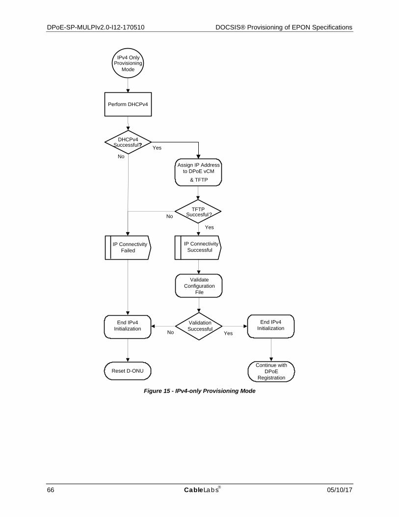
DPoE-SP-MULPIv2.0-I12-170510 DOCSIS® Provisioning of EPON Specifications
66 CableLabs 05/10/17
IP ConnectivitySuccessful
TFTPSuccesful?
Perform DHCPv4
DHCPv4Successful??
NoYes
& TFTP
No
IP ConnectivityFailed
Yes
IPv4 OnlyProvisioning
Mode
Reset D-ONU
Assign IP Address to DPoE vCM
Validate Configuration
File
Validation SuccessfulNo Yes
End IPv4 Initialization
Continue with DPoE
Registration
End IPv4 Initialization
Figure 15 - IPv4-only Provisioning Mode
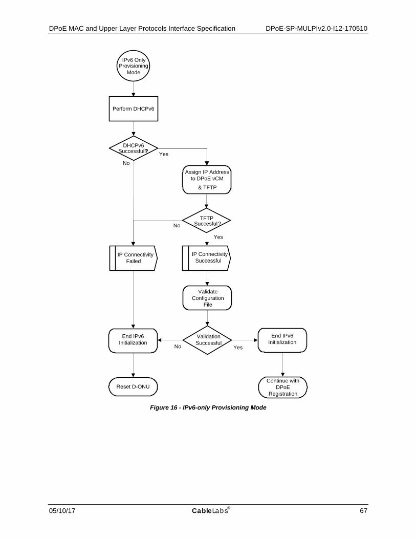
DPoE MAC and Upper Layer Protocols Interface Specification DPoE-SP-MULPIv2.0-I12-170510
05/10/17 CableLabs 67
IP ConnectivitySuccessful
TFTPSuccesful?
Perform DHCPv6
DHCPv6Successful??
NoYes
& TFTP
No
IP ConnectivityFailed
Yes
IPv6 OnlyProvisioning
Mode
Reset D-ONU
Assign IP Address to DPoE vCM
Validate Configuration
File
Validation SuccessfulNo Yes
End IPv6 Initialization
Continue with DPoE
Registration
End IPv6 Initialization
Figure 16 - IPv6-only Provisioning Mode

DPoE-SP-MULPIv2.0-I12-170510 DOCSIS® Provisioning of EPON Specifications
68 CableLabs 05/10/17
DHCPv6 successful?
Yes
No
IPv6 Address Acquisition
Failed
IPv6 Address Acquisition Successful
Initiate DAD on DHCP Address
Perform DHCPv6
Perform Link Local address
assignment of the vCM
Perform Router Discovery
Acquire IPv6 Address Begin
Continue with DPoE
RegistrationReset D-ONU
Figure 17 - IPv6 Address Acquisition
9.1.5.1 Establish IPv4 Network Connectivity This section describes how the DPoE System provisions an IPv4 address and associated parameters on behalf of a D-ONU, as the vCM. Since the vCM and the DHCPv4 Relay Agent exist on the DPoE System; the Broadcast and Request phases of DHCPv4 address assignment are generated by the vCM and directed to the DHCPv4 Server as unicast packets by the Relay Agent. Refer to Figure 18 for DHCPv4 message flow detail. The vCM MUST support the requirements as specified in [MULPIv3.0]. Figure 18 shows the DHCPv4 message sequence for a DPoE System. The vCM MUST establish IPv4 Network Connectivity only after the discovery of the D-ONU.
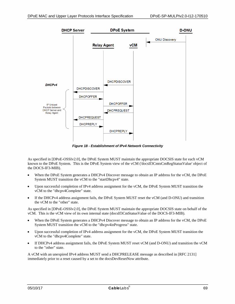
DPoE MAC and Upper Layer Protocols Interface Specification DPoE-SP-MULPIv2.0-I12-170510
05/10/17 CableLabs 69
Figure 18 - Establishment of IPv4 Network Connectivity
As specified in [DPoE-OSSIv2.0], the DPoE System MUST maintain the appropriate DOCSIS state for each vCM known to the DPoE System. This is the DPoE System view of the vCM ('docsIf3CmtsCmRegStatusValue' object of the DOCS-IF3-MIB).
• When the DPoE System generates a DHCPv4 Discover message to obtain an IP address for the vCM, the DPoE System MUST transition the vCM to the "startDhcpv4" state.
• Upon successful completion of IPv4 address assignment for the vCM, the DPoE System MUST transition the vCM to the "dhcpv4Complete" state.
• If the DHCPv4 address assignment fails, the DPoE System MUST reset the vCM (and D-ONU) and transition the vCM to the "other" state.
As specified in [DPoE-OSSIv2.0], the DPoE System MUST maintain the appropriate DOCSIS state on behalf of the vCM. This is the vCM view of its own internal state (docsIf3CmStatusValue of the DOCS-IF3-MIB).
• When the DPoE System generates a DHCPv4 Discover message to obtain an IP address for the vCM, the DPoE System MUST transition the vCM to the "dhcpv4inProgress" state.
• Upon successful completion of IPv4 address assignment for the vCM, the DPoE System MUST transition the vCM to the "dhcpv4Complete" state.
• If DHCPv4 address assignment fails, the DPoE System MUST reset vCM (and D-ONU) and transition the vCM to the "other" state.
A vCM with an unexpired IPv4 address MUST send a DHCPRELEASE message as described in [RFC 2131] immediately prior to a reset caused by a set to the docsDevResetNow attribute.

DPoE-SP-MULPIv2.0-I12-170510 DOCSIS® Provisioning of EPON Specifications
70 CableLabs 05/10/17
9.1.5.1.1 DHCPv4 Fields Used by the vCM
The vCM MUST support the DHCP requirements for this section as specified in [MULPIv3.0], with the following exceptions.
The vCM MUST include the following fields in the DHCPDISCOVER and DHCPREQUEST messages from the vCM:
• The client hardware address (chaddr) is set to the 48 bit EPON MAC address of the D-ONU.
• The parameter request list option is included. The option codes are defined in [RFC 2132] and [RFC 4361].
• The vCM MAY include the following option codes in the parameter request list: Option code 1 (Subnet Mask), Option code 2 (Time Offset), Option code 3 (Router Option), Option code 4 (Time Server Option). The vCM MUST include the following option codes in the parameter request list: Option code 7 (Log Server Option) and Option code 125 (DHCPv4 Vendor-Identifying Vendor-specific Information Option).
• Option code 125 (DHCPv4 Vendor-Identifying Vendor-specific Information Options) for DOCSIS 3.0 defined in [CANN-DHCP-Reg], with the following sub-options: Sub-option code 1, the DHCPv4 Option Request option.
• The vCM MUST include the following option codes in the DHCPv4 Option Request option: Sub-option code 2, DHCPv4 TFTP Servers Option, and Sub-option code 5, Modem Capabilities Encoding for DHCPv4.
• Option code 60 (Vendor Class Identifier) — the following ASCII-encoded string is the value to be present in Option code 60: docsis3.0.
9.1.5.1.2 Use of T1 and T2 Timers
The vCM MUST comply with the DHCP T1/T2 requirements as defined in [MULPIv3.0] for DHCPv4.
9.1.5.1.3 DHCPv4 Renew Fields Used by the vCM
During the DHCPv4 renew operation, it is possible that the vCM receives updated fields in the DHCPACK message.
If any of the IP address (yiaddr), the Subnet Mask, or the Next Hop Router (router option) are different in the DHCPACK than the current values used by the DPoE System for the vCM, the DPoE System MUST do one of the following:
• Reinitialize the associated D-ONU.
• Change the vCM's addressing to use the new values without reinitializing the associated D-ONU.
During the DHCP renew process, if the Configuration File Name or the SYSLOG server address is different in the DHCPACK than the current values used by the DPoE System for the vCM, the vCM MUST ignore the new fields.
If the Time Offset or Time server address values are different in the DHCPACK than the current values used by the DPoE System for the vCM, the DPoE System MUST ignore these fields as they do not apply for the DPoE System.
9.1.5.1.4 DPoE System Requirements
The DPoE System MUST support DHCPv4 Option 43 sub-options identified in [CANN-DHCP-Reg] and [eDOCSIS]. The DPoE System MUST support the DHCPv4 Relay Agent requirements as specified in [MULPIv3.0], with the following exceptions.
In order to assist the DHCPv4 server in differentiating between a DHCPDISCOVER sent from a vCM and a DHCPDISCOVER sent from a CPE.
• The DPoE System Relay Agent MUST include the DHCP Relay Agent Information Option (RAIO) according to [RFC 3046]. Specifically, the DPoE System DHCPv4 Relay Agent MUST add an RAIO to the DHCPDISCOVER message before relaying the message to a DHCP server.
• The DPoE System MUST include in the RAIO, the 48-bit MAC address of the D-ONU for the DHCPDISCOVER in the agent remote ID sub-option field [RFC 3046].

DPoE MAC and Upper Layer Protocols Interface Specification DPoE-SP-MULPIv2.0-I12-170510
05/10/17 CableLabs 71
• The DPoE System MUST support "DHCPv4 Relay Agent CMTS capabilities option" as specified in [CANN-DHCP-Reg] including the following sub-options : 'CMTS DOCSIS Version Number', 'DPoE System Version Number', 'DPoE System DHCPv4 PBB service option', 'CMTS CM Service Class', and 'CMTS MSO Defined Text'.
• The DPoE System MUST set the 'CMTS DOCSIS Version Number' sub-option to "3.0"
• The DPoE System MUST set the 'DPoE System Version Number' sub-option to "2.0"
The DPoE System MUST support the D-ONU eOAM Version Number option, [CANN-DHCP-Reg] and include it in messages to the DHCP server. The D-ONU eOAM Version Number option contains the combined value which forms the eOAM version Number Identifier. The value of the 'major vers' field is retrieved from the 4 upper bits of the 'DPoE OAM Version' field in the 'DPoE OAM Support' TLV, defined in [DPoE-OAMv2.0], placed in the 4 lower bits of the field and padded with zeros. The value of the 'minor vers' field is retrieved from the 4 lower bits of the 'DPoE OAM Version' field in the 'DPoE OAM Support' TLV, defined in [DPoE-OAMv2.0], placed in the 4 lower bits of the field and padded with zeros.
The DPoE System MUST support DHCPv4 Option 43 sub-options as identified in [eDOCSIS] per [CANN-DHCP-Reg]. The DPoE System SHOULD support DHCPv4 Option 43 sub-Option 55-60 as defined in [CANN-DHCP-Reg].
S-ONUs that are (optionally) eDOCSIS devices MUST support DHCPv4 Option 43 sub-options as identified in [eDOCSIS] per [CANN-DHCP-Reg]. S-ONUs that are (optionally) eDOCSIS devices SHOULD support DHCPv4 Option 43 sub-Option 55-60 as per [CANN-DHCP-Reg].
9.1.5.1.5 DPoE DHCPv4 Fields and Options
9.1.5.1.5.1 DHCP Discover/ Request messages Table 4 - DHCPv4 Discover/Request Fields
Field Name Option Sub-Option Value(s) Size htype (hardware type) n/a - "01" = Ethernet 8 bits
hlen (hardware address) n/a - "06" = MAC Address Length 8 bits
chaddr (client hardware address)
n/a - D-ONU MAC Address 48 bits
client-identifier 61 - htype +chaddr per [RFC 4361] 56 bits
parameter request list * may be present
55 - Subnet Mask (1)* Time Offset (2)* Router (3)* Time Server (4)* Log Server (7) DHCPv4 Vendor-Identifying Vendor-specific Information (125)
48 bits
vendor class identifier 60 - "docsis3.0:" 80 bits
vendor-specific information 125 4491.1 ORO "02" – Request TFTP Server IP Address 8 bits
125 4491.5 D-ONU Capabilities (see Annex C.8) variable
agent information option 82 1 Agent Circuit ID (vendor-specific string) String
82 2 Agent Remote ID (D-ONU MAC) 48 bits
82 4491.9.1 "30" – DOCSIS 3.0 (major, minor version #) 16 bits
82 4491.9.2 "20" – DPoE (major, minor version #) 16 bits

DPoE-SP-MULPIv2.0-I12-170510 DOCSIS® Provisioning of EPON Specifications
72 CableLabs 05/10/17
9.1.5.1.5.2 DHCP Offer/Ack Messages Table 5 - DHCPv4 Response
Field Name Option Sub-Option Value(s) Size
yiaddr (ip address) n/a - Client IP Address 32 bits
siaddr (next server) n/a - TFTP Server IP Address 32 bits
file (boot file name) n/a - vCM (D-ONU) Boot File Name variable
sub-net mask 1 - Client Sub-Net Mask 32 bits
time-offset 2 - Unsigned 32 bit (2^32 – seconds) 32 bits
router 3 - Next Hop Router IP Address 32 bits
time-server 4 Time Server IP Address 32 bits
log-server 7 Syslog Server IP Address 32 bits
vendor-specific information 125 4491.1 Option Request Option "02" 8 bits
125 4491.2 TFTP Server IP Address 32 bits
agent information option 82 1 Agent Circuit ID (vendor-specific string) string
82 2 Agent Remote ID (D-ONU MAC) 48 bits
82 4491.9.1 "30" – DOCSIS 3.0 (major, minor version #) 16 bits
82 4491.9.2 "20" – DPoE 2.0 (major, minor version #) 16 bits
9.1.5.2 Establish IPv6 Network Connectivity46 This section describes how the DPoE System provisions an IPv6 address and associated configuration parameters on behalf of a D-ONU. The requirements in this section apply only to vCMs instructed to use IPv6 provisioning. A vCM uses IPv6 provisioning when the DPoE System indicates 'IPv6 Only' provisioning. The vCM MUST support the IPv6 provisioning requirements as specified in [MULPIv3.0]. Figure 19 shows the DHCPv6 message sequence for a DPoE System. The vCM MUST establish IPv6 Network Connectivity only after discovery of the D-ONU.
Since the vCM and the Relay Agent exist on the DPoE System, the Link-Local and Router Discovery phases of DHCPv6 address assignment are contained within the DPoE System. The DHCPv6 SOLICIT, ADVERTISE, REQUEST, and REPLY messages are generated by the vCM and relayed to the DHCP Server by means of the Relay Agent on the DPoE System. Refer to Figure 19 for DHCPv6 message flow detail.
46 Revised per MULPIv2.0-N-14.0165-2 on 7/16/14 by JB.

DPoE MAC and Upper Layer Protocols Interface Specification DPoE-SP-MULPIv2.0-I12-170510
05/10/17 CableLabs 73
Figure 19 - Establishment of IPv6 Network Connectivity
The DPoE System MUST establish IPv6 connectivity including the assignment of:
• Link-local address
• Default router
• IPv6 management address and other IPv6 configuration.
These steps are described in the following subsections.
The vCM and its default router are internal to the DPoE System; therefore, router discovery and forwarding for the vCM are not specified.
9.1.5.2.1 Obtain Link-Local Address
The process of obtaining a link-local address occurs within the DPoE System. Within the DPoE System, the vCM MUST construct a link-local address for its management interface according to the procedure in [RFC 4862]. The vCM MUST use the EUI-64 (64-bit Extended Unique Identifier) derived from the D-ONU MAC address as a link-local address for its management interface as described in [RFC 3513].
9.1.5.2.2 Obtain Default Routes
The process of obtaining default routers occurs within the DPoE System. The process works as defined in [MULPIv3.0].
DPoE System D-ONU
DHCPv6RELAY - FORW
DHCP Server
Link- local address
assignment
Routerdiscovery
These two specific RELAY messages are used only if Rapid Commit is not used.
ONU Discovery
Internal to DPoE System
RELAY - REPL
RELAY - FORW
RELAY - REPL
Relay Agent vCM
DHCPv6 Solicit
DHCPv6 Advertise
DHCPv6 Request
DHCP6 Reply

DPoE-SP-MULPIv2.0-I12-170510 DOCSIS® Provisioning of EPON Specifications
74 CableLabs 05/10/17
9.1.5.2.3 Obtain IPv6 Management Address and Other Configuration Parameters
As specified in [DPoE-OSSIv2.0], the DPoE System MUST maintain the appropriate DOCSIS state for each vCM known to the DPoE System. This is the DPoE System view of the vCM (docsIf3CmtsCmRegStatusValue of the DOCS-IF3-MIB).
• When the DPoE System generates a DHCPv6 Solicit message to obtain an IP address for the vCM, the DPoE System MUST transition the vCM to the "startDhcpv6" state.
• Upon successful completion of IPv6 address assignment for the vCM, the DPoE System MUST transition the vCM to the "dhcpv6Complete" state.
• If the DHCPv6 address assignment fails, the DPoE System MUST reset the vCM (and D-ONU) and transition the vCM to the "other" state.
As specified in [DPoE-OSSIv2.0], the DPoE System MUST maintain the appropriate DOCSIS state on behalf of the vCM. This is the vCM view of its own internal state (docsIf3CmStatusValue of the DOCS-IF3-MIB).
• When the DPoE System generates a DHCPv6 Solicit message to obtain an IP Address for the vCM, the DPoE System MUST transition the vCM to the "dhcpv6inProgress" state.
• Upon successful completion of IPv6 address assignment for the vCM, the DPoE System MUST transition the vCM to the "dhcpv6Complete" state.
• If DHCPv6 address assignment fails, the DPoE System MUST reset the vCM (and D-ONU) and transition the vCM to the "other" state.
9.1.5.2.4 DHCPv6 Fields Used by the vCM
The vCM MUST support DHCPv6 requirements as specified in [MULPIv3.0], with the following exceptions.
The vCM MUST include the following fields in the DHCPv6 Solicit and Request messages from the vCM.
• A Client Identifier option containing the DUID (DHCP Unique Identifier) for this vCM as specified by [RFC 3315]. The vCM can choose any one of the rules to construct the DUID according to section 9.1 of [RFC 3315];
• An IA_NA (Identity Association for Non-temporary Addresses) option to obtain its IPv6 management address;
• The client hardware address (chaddr) is set to the EPON MAC address of the D-ONU;
• A Vendor Class option containing 32-bit number 4491 (the Cable Television Laboratories, Inc. enterprise number) and the string "docsis3.0";
• A Vendor-specific option containing:
1. TLV5 Encoding [CANN-DHCP-Reg] containing the encoded TLV5s describing the capabilities of vCM information option in Annex C.1.3.1; (Optional)
2. Device ID option (Sub-option 36) containing the MAC address of the D-ONU;
3. ORO option requesting the following vendor-specific options:
a. Sub Option 37 - Time Protocol Servers (Optional) b. Sub Option 38 - Time Offset (Optional) c. Sub Option 32 - TFTP Server Addresses d. Sub Option 33- Configuration File Name e Sub Option 34 - SYSLOG Server Addresses
• A Rapid Commit option indicating that the vCM is willing to perform a 2-message DHCPv6 message exchange with the server.

DPoE MAC and Upper Layer Protocols Interface Specification DPoE-SP-MULPIv2.0-I12-170510
05/10/17 CableLabs 75
The vCM MUST use the following values for retransmission of the Solicit message (see [RFC 3315] for details):
• IRT (Initial Retransmission Time) = SOL_TIMEOUT
• MRT (Maximum Retransmission Time) = SOL_MAX_RT
• MRC (Maximum Retransmission Count) = 4
• MRD (Maximum Retransmission Duration) = 0
9.1.5.2.5 DHCPv6 Renew Fields Used by the vCM During the DHCPv6 renew operation, it is possible that the vCM will receive updated fields in the DHCPv6 Reply message.
If the vCM IPv6 Management Address (IA_NA option) is different in the DHCP Reply than the current value used by the vCM, the vCM MUST do one of the following:
• Change to using the new IPv6 Management Address without reinitializing the vCM, or
• Reinitialize vCM
During the DHCP renew process, if the following values, TFTP configuration file name (Vendor-Specific Option), the Syslog servers (Vendor-Specific Option) or the Reconfigure Accept option are different in the DHCP Reply than the current values used by the vCM, the vCM MUST ignore the new fields.
The vCM SHOULD NOT support the Time Protocol Servers option in the DHCP Reply since ToD is maintained by the DPoE System.
9.1.5.2.6 IP Provisioning Mode Override
The DPoE System does not require support for the IP Provisioning Mode Override feature since the vCM exists virtually on the DPoE System and the IP Provisioning Mode is part of the DPoE Server configuration.
9.1.5.2.7 Use of T1 and T2 Timers
The vCM MUST comply with the DHCP T1/T2 requirements defined in [MULPIv3.0] for DHCPv6.
9.1.5.2.8 DPoE System DHCPv6 Relay Agent Requirements
The DPoE System MUST send the following DHCPv6 Options when acting as a DHCPv6 Relay Agent, in any Relay-Forward messages used to forward messages from the vCM (DPoE System) to the DHCPv6 Server:
• Interface-ID option [RFC 3315];
• CMTS DOCSIS Version Number option, containing the value "3.0", [CANN-DHCP-Reg];
• DPoE System version number option containing the value "2.0" [CANN-DHCP-Reg];
• CM MAC address option, [CANN-DHCP-Reg];
• The DPoE System MUST set value of this option to be the ONU MAC address;
• Remote-ID option, [RFC 4649].
The DPoE System MUST set the Remote-ID option to the EPON MAC address of the D-ONU for the vCM generating the DHCPDISCOVER sent in the CL_Option_Device_ID sub-option field, as defined in [CANN-DHCP-Reg].
9.1.5.2.9 Prefix Stability at the DPoE System
The DPoE System MUST support the prefix stability requirements as specified for a CMTS in [MULPIv3.0].

DPoE-SP-MULPIv2.0-I12-170510 DOCSIS® Provisioning of EPON Specifications
76 CableLabs 05/10/17
9.1.5.2.10 DPoE DHCPv6 Fields and Options
9.1.5.2.10.1 DHCP Solicit/Request messages Table 6 - DHCPv6 Solicit/Request Options
Field Name Option Sub-Option Value(s) Size
rapid_commit 14 - no associated value, length zero -
reconfigure_accept 20 - no associated value, length zero -
vendor_class 16 4491 "docsis3.0" string
option_request 6 - vendor-specific information (17) variable
vendor-specific information
17 4491.35 tlv5 (d-onu capabilities) variable
17 4491.36 device_id (d-onu mac address) 48 bits
17 4491.1 - option_request option 32 (tftp_server_addresses) - option 33 (config_file_name) - option 37 (syslog_server_addresses)
variable
client-id 1 - - duid_type ("00 03" link layer address) - htype ("00 01" ethernet) - link_layer_address (48 bit D-ONU MAC)
16 bits 16 bits 48 bits
ia_na 3 - - iaid – least significant 32 bits of D-ONU MAC address. - t1 – in seconds, time before contacting server where IA_NA addresses were obtained to extend lifetime. - t2 – in seconds, time before contacting any server to extend lifetime of IA_NA addresses.
32 bits 32 bits 32 bits
9.1.5.2.10.2 DHCP Advertise/Confirm messages Table 7 - DHCPv6 Advertise/Confirm Fields
Field Name Option Sub-Option Value(s) Size
ia_na 3 - - iaid - least significant 32 bits of D-ONU MAC address. - t1 – in seconds, time before contacting server where IA_NA addresses were obtained to extend lifetime. - t2 – in seconds, time before contacting any server to extend lifetime of IA_NA addresses.
32 bits 32 bits 32 bits
3 5 ia_address (IPv6 address, preferred lifetime, valid lifetime)
192 bits
client-id 1 - - duid_type ("00 03" link layer address) - htype ("00 01" ethernet) - link_layer_address (D-ONU MAC)
16 bits 16 bits 48 bits
server_identifier 2 - - duid_type ("00 01" link layer address plus time) - htype ("00 01" ethernet) - time (date, time and zone) - link_layer_address (D-ONU MAC)
16 bits 16 bits 32 bits 48 bits
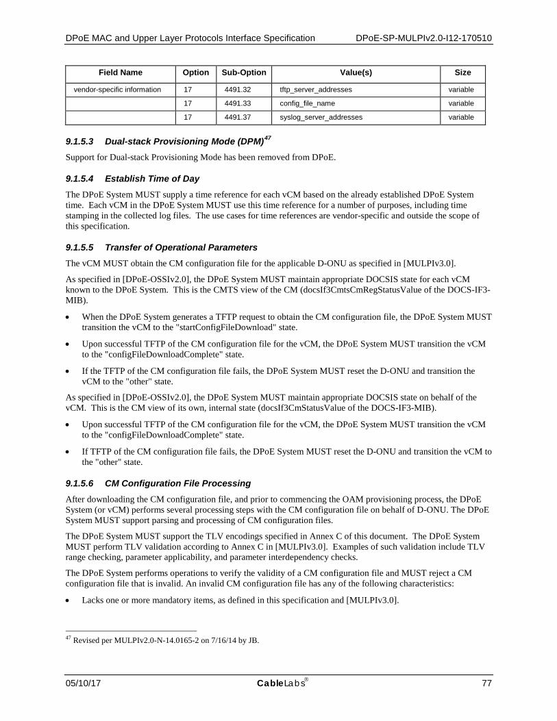
DPoE MAC and Upper Layer Protocols Interface Specification DPoE-SP-MULPIv2.0-I12-170510
05/10/17 CableLabs 77
Field Name Option Sub-Option Value(s) Size
vendor-specific information 17 4491.32 tftp_server_addresses variable
17 4491.33 config_file_name variable
17 4491.37 syslog_server_addresses variable
9.1.5.3 Dual-stack Provisioning Mode (DPM)47 Support for Dual-stack Provisioning Mode has been removed from DPoE.
9.1.5.4 Establish Time of Day The DPoE System MUST supply a time reference for each vCM based on the already established DPoE System time. Each vCM in the DPoE System MUST use this time reference for a number of purposes, including time stamping in the collected log files. The use cases for time references are vendor-specific and outside the scope of this specification.
9.1.5.5 Transfer of Operational Parameters The vCM MUST obtain the CM configuration file for the applicable D-ONU as specified in [MULPIv3.0].
As specified in [DPoE-OSSIv2.0], the DPoE System MUST maintain appropriate DOCSIS state for each vCM known to the DPoE System. This is the CMTS view of the CM (docsIf3CmtsCmRegStatusValue of the DOCS-IF3-MIB).
• When the DPoE System generates a TFTP request to obtain the CM configuration file, the DPoE System MUST transition the vCM to the "startConfigFileDownload" state.
• Upon successful TFTP of the CM configuration file for the vCM, the DPoE System MUST transition the vCM to the "configFileDownloadComplete" state.
• If the TFTP of the CM configuration file fails, the DPoE System MUST reset the D-ONU and transition the vCM to the "other" state.
As specified in [DPoE-OSSIv2.0], the DPoE System MUST maintain appropriate DOCSIS state on behalf of the vCM. This is the CM view of its own, internal state (docsIf3CmStatusValue of the DOCS-IF3-MIB).
• Upon successful TFTP of the CM configuration file for the vCM, the DPoE System MUST transition the vCM to the "configFileDownloadComplete" state.
• If TFTP of the CM configuration file fails, the DPoE System MUST reset the D-ONU and transition the vCM to the "other" state.
9.1.5.6 CM Configuration File Processing After downloading the CM configuration file, and prior to commencing the OAM provisioning process, the DPoE System (or vCM) performs several processing steps with the CM configuration file on behalf of D-ONU. The DPoE System MUST support parsing and processing of CM configuration files.
The DPoE System MUST support the TLV encodings specified in Annex C of this document. The DPoE System MUST perform TLV validation according to Annex C in [MULPIv3.0]. Examples of such validation include TLV range checking, parameter applicability, and parameter interdependency checks.
The DPoE System performs operations to verify the validity of a CM configuration file and MUST reject a CM configuration file that is invalid. An invalid CM configuration file has any of the following characteristics:
• Lacks one or more mandatory items, as defined in this specification and [MULPIv3.0].
47 Revised per MULPIv2.0-N-14.0165-2 on 7/16/14 by JB.

DPoE-SP-MULPIv2.0-I12-170510 DOCSIS® Provisioning of EPON Specifications
78 CableLabs 05/10/17
• Has one or more SNMP MIB Object encodings (TLV 11) that cannot be processed and cause rejection of the file.
• Contains a SNMPv3 Access View Configuration encoding (TLV 54) that causes rejection of the file as defined in [MULPIv3.0].
• Contains specifications for a number of SFs or ASFs that cannot be supported due to the number of EPON Links (LLIDs) registered by the D-ONU.
The DPoE System MAY reject a CM configuration file that has an invalid CM MIC, CMTS MIC, or Extended CMTS MIC as defined in [MULPIv3.0].
If the CM configuration file validation fails, the DPoE System MUST reset the D-ONU.
9.1.5.7 Post-Registration Failures to Renew IP Address The vCM MUST support the Post-Registration Failures and IP Address Renew requirements for either IPv4 or IPv6 as specified in [MULPIv3.0] with no exceptions.
9.1.6 Registration with the DPoE System
Once the CM configuration file is validated, the DPoE System performs registration. The DOCSIS-specified Registration process of Registration Request, Response, and Acknowledgement between the DPoE System and vCM is internal processing by the DPoE System, and thus is not mandated or specified by this document. Figure 20 shows the DPoE System Registration process.
Figure 20 - Registration of D-ONU in DPoE System
Configuration Successful
Configure DPoE ONU through OAM
Messages
Registration
Network Access Enabled
Reset DPoE ONUNo
No
Yes
Yes
All Required DPoE ONU Links Discovered?
Registration End
Privacy Enabled
Configure DPoE ONU through OAM
Messages
Configure DPoE ONU through OAM
Messages
No
T9 Timeout
Yes
Stop T9 Timer

DPoE MAC and Upper Layer Protocols Interface Specification DPoE-SP-MULPIv2.0-I12-170510
05/10/17 CableLabs 79
9.1.6.1 DPoE System vCM Requirements The DPoE System MUST transition the state of the vCM (docsIf3CmStatusValue) to "operational" state upon completion of successful registration. Successful registration is defined as successful completion of processing of the CM configuration file by the DPoE System and the successful configuration of the D-ONU using the DPoE OAM messages.
The DPoE System MUST NOT transition the state of the vCM (docsIf3CmStatusValue) to the "operational" state upon completion of unsuccessful registration. Unsuccessful registration is defined as the failed processing of the CM configuration file by the DPoE System, or the unsuccessful configuration of the D-ONU using the DPoE OAM messages.
If the CM configuration file specifies that network access is disabled, the DPoE System MUST configure the D-ONU with the parameters specified in the CM configuration file, and block all frame forwarding from S interfaces on the D-ONU. The DPoE System MUST also transition the vCM state (docsIf3CmStatusValue) to "forwardingDisabled".
9.1.6.2 DPoE System Requirements Upon the successful validation of the CM configuration file, the DPoE System MUST transition the vCM state (docsIf3CmtsCmRegStatusValue) to "startRegistration". During registration, the vCM MUST configure both itself and the D-ONU based on the TLVs specified in the CM configuration file. The DPoE System MUST configure the D-ONU using the appropriate OAM messages.
If there are any failures during the configuration of the vCM or D-ONU, the DPoE System MUST reset the D-ONU and transition the DPoE System view of the vCM (docsIf3CmtsCmRegStatusValue) to the "other" state.
During the configuration of the D-ONU, the DPoE System MUST discover all of the required D-ONU Links (LLIDs) during the T9 timeout period. If the T9 timer expires, the DPoE System MUST reset the D-ONU and transition the vCM (docsIf3CmtsCmRegStatusValue) to the "other" state.
If the CM configuration file specifies that network access is disabled, the DPoE System MUST configure both the DPoE System and D-ONU with the parameters specified in the CM configuration file, and block all frame forwarding from S interfaces on the D-ONU. The DPoE System MUST also transition the vCM state (docsIf3CmtsCmRegStatusValue) to "forwardingDisabled".
If the CM configuration file specifies that privacy is disabled, the DPoE System MUST disable encryption on all of the LLIDs of the D-ONU being used to carry ASFs/SFs.
Upon successful completion of registration processing, the DPoE System MUST transition the vCM state (docsIf3CmtsCmRegStatusValue) to "operational" for the D-ONU. The DPoE System MUST NOT allow the transmission of data until successful registration is complete.
9.1.7 Service IDs During vCM Initialization
The DPoE System MUST reserve a primary SID and assign it to a vCM when the vCM is instantiated by the DPoE System. The DPoE System MUST reserve additional SIDs (for secondary upstream SFs and upstream ASFs) and assigned after TFTP, prior to OAM provisioning.
9.2 Periodic Maintenance48
In the DPoE Network, periodic maintenance of the underlying EPON transport layer is limited to continuous ranging (see [802.3], 77.2.1.1 for 10G-EPON and [802.3], 64.2.1.1 for 1G-EPON definitions), based on the GATE and REPORT MPCPDUs, exchanged between the DPoE System and connected D-ONUs, and carrying a timestamp field. This particular field is used to calculate the RTT for the given D-ONU in a continuous manner, allowing the DPoE System to dynamically adjust to any changes in the path delay without the need to bring the D-ONU down for
48 Revised per MULPIv2.0-N-14.0172-1 on 7/16/14 by JB.

DPoE-SP-MULPIv2.0-I12-170510 DOCSIS® Provisioning of EPON Specifications
80 CableLabs 05/10/17
re-registration. In this way, the EPON system guarantees timely and accurate information on the D-ONU specific path delay without affecting the carried services.
Additionally, each DPoE System has the ability to monitor continuously the status of the LLIDs associated with the given D-ONU, keeping track of the responses generated by each LLID. A keep-alive mechanism is implemented in EPON, where the DPoE System maintains a watchdog for each registered LLID. Upon expiration of the said watchdog, the associated LLID is considered inactive (for whatever reason) and the given logical link is deregistered. The DPoE System MUST consider as inactive a D-ONU with at least one LLID that was flagged as inactive, affecting in this way all the LLIDs associated with the given D-ONU.
In the EPON specific keep-alive mechanism, each LLID periodically announces its activity to the DPoE System by sending a REPORT MPCPDU in the granted bandwidth slot. The REPORT MPCPDU may be solicited by the DPoE System (hence every time D-ONU is requested to send the REPORT MPCPDU with the current snapshot of its queues, this is considered by the DPoE System as confirmation that the given LLID is active) or unsolicited (in which case the D-ONU automatically includes the REPORT MPCPDU in the assigned transmission slot). Effectively, the DPoE System is notified on the LLID status and may track LLID activity for all registered D-ONUs in the system. Decision on whether to deregister a complete D-ONU (or not) if one of the logical links associated with this ONU is found to be inactive, is implementation-specific and out of the scope of the DPoE specifications.
Keep-alive mechanism is referred to in [802.3], 77.3.6.2 for 10G-EPON and in [802.3], 64.3.6.2 for 1G-EPON, but was never formally specified in the EPON standards.
Other DOCSIS-specific maintenance functions, including periodic ranging, are not supported in the DPoE System.
9.3 Fault Detection and Recovery49
9.3.1 MAC Layer Error-Handling This section describes the procedures that are required when an error occurs at the MAC framing level.
The most obvious type of error occurs when the FCS in the MAC frame fails. In such a case, Ethernet-specific handling is performed, per [802.3] definitions. Specifically, a corrupted Ethernet frame (where calculated FCS does not match the received FCS) is always dropped at the MAC layer to prevent error propagation across Ethernet links.
In the upstream channel, there are two possible type of errors, namely:
• Loss of burst synchronization, where the DPoE System receiver fails to synchronize to the incoming data burst synchronization fields, losing the ability to properly delineate individual frames carried in the burst. This type of error is less common in 1 Gbps links, where data rate is lower and the framing structure does not feature a mandatory stream-based FEC. In 10 Gbps links, inability to synchronize to the incoming burst headers, and specifically inability to acquire the Burst Delimiter (see [802.3], 76.3.2.5.1, applicable to 10G-EPON only), will cause the DPoE System to lose a complete data burst. Luckily, 10G-EPON system is designed to operate correctly at BER as low as 10-3, which guarantees proper system operation under very unfavorable transmission conditions.
• Burst overlap, which occurs when at least two D-ONUs transmit in such a way that their data bursts overlap (either partially or completely) at the DPoE System receiver. In such a case, the DPoE System may be able to recover part of the initial burst only. The rest of the overlapped data bursts are lost. EPON does not have a mechanism to signal burst collision to individual D-ONUs and request their retransmission. EPON relies for retransmission on higher layer protocols (e.g., TCP/IP). Under normal operating conditions, burst overlap is not expected to occur. Burst overlap is expected to occur only during the Discovery Window (see [802.3], 77.3.3 for 10G-EPON and [802.3], 64.3.3 for 1G-EPON).
Additionally, EPON features FEC functionality, as described in [DPoE-PHYv2.0].
49 Revised per MULPIv2.0-N-14.0172-1 on 7/16/14 by JB.

DPoE MAC and Upper Layer Protocols Interface Specification DPoE-SP-MULPIv2.0-I12-170510
05/10/17 CableLabs 81
9.4 vCM and D-ONU Operational Relationship
Once D-ONU and vCM initialization and registration is complete, it's possible for the state of a vCM on the DPoE System to change as the result of an operator request. Similarly, the D-ONU could experience a change in state as the result of an operator request or loss of power. When one of these related elements, a vCM or D-ONU, experiences a transition from a fully operational state, the DPoE System is responsible for ensuring the associated element experiences a similar transition.
When a vCM is reset, the DPoE System MUST do the following:
• trigger a reset of the associated D-ONU,
• transition docsIf3CmtsCmRegStatusValue to the "other" state for the affected vCM,
• drop packets destined to the vCM IP address,
• NOT generate packets sourced from the vCM IP address.
The D-ONU reboots and restarts the initialization and registration process. The DPoE System MUST allow packets destined to or sourced from the vCM IP addresses when IP connectivity is reestablished during the initialization and registration process.
When a DPoE System detects that all logical links to a D-ONU have timed out, the DPoE System MUST do the following:
• transition docsIf3CmtsCmRegStatusValue to the "other" state for the affected vCM,
• drop packets destined to the associated vCM IP address,
• NOT generate packets sourced from the associated vCM IP address.
9.5 Dynamic D-ONU Configuration Update Mechanism
Operators have the need to change the services already configured and operating on a D-ONU. These changes could include (among others), modification of bandwidth parameters assigned to a single customer, adding a new service to a customer, enabling services on multiple ports where the given service was not available before, deleting an EVPL instance, etc.
The goal of the dynamic configuration update feature is to configure changes or add services without affecting the other existing services which are not being modified. In other words, any changes to the vCM and D-ONU configuration SHOULD NOT cause reboot of these devices or changes in QoS parameters or operational state for any existing and configured services on the DPoE Network.
If the new configuration file has TLVs which are service impacting (i.e., cause a reboot), then the D-ONU will reboot and affect all services. The specification aims to describe the general behaviour around dynamic configuration updates, but does not specify the behaviour for each type of change possible.
9.5.1 High Level Operation
The DPoE System configures the initial set of services on the D-ONU based on the configuration file downloaded by the vCM after the D-ONU goes through the registration process.
Once the operator identifies the need to add/modify/delete services on a D-ONU, they first edit the CM (D-ONU) configuration file on the provisioning system. Using the network management system the operator triggers the vCM, using the 'dpoeVcmDynCfgNow' MIB object, to download the new DOCSIS CM configuration file.
The vCM obtains TFTP server and file name values via a DHCPREQUEST mechanism. The vCM downloads the new configuration file and then compares the running configuration with the newly downloaded configuration file and identifies the differences to the services provisioned on the D-ONU. The vCM first validates the configuration file integrity then verifies the resources available, checking that the requested changes can be applied to the D-ONU under the current conditions. Once the configuration feasibility for the delta configuration is confirmed, the vCM updates the D-ONU configuration, modifying the necessary parameters.

DPoE-SP-MULPIv2.0-I12-170510 DOCSIS® Provisioning of EPON Specifications
82 CableLabs 05/10/17
Examples of service-related changes that need to be executed without causing ONU reboot include among others:
• Changes in the bandwidth profile parameters associated with the given service, e.g., increasing or decreasing allocated bandwidth;
• Removing a service instance, e.g., removal of an EP-LINE instance on the given D-ONU, or in more generic terms, removing or adding an EVC on the given D-ONU;
• Modification, adding or removing specific frame-related operations associated with the given SF or ASF, e.g., changing CoS assignment for the given SF, changing TPID translation value, changing encapsulation parameters for the given SF;
• Modification of other SF and non-SF related parameters, including among the others – NACO, EVC names, designation of service names.
Please note that the above list is by no means intended to be exhaustive and presents only examples of changes considered to be critical from the operational point of view.
Figure 21 - BackOffice System Operation
9.5.2 Dynamic Config Update Steps
The dynamic configuration update process is divided into the following steps.
MSO identifies configuration changes are needed
MSO updates configuration file for D-ONUUPDATE Config
File update complete
MSO initiates dynamic update using dpoeIf3CmDynCfgNow MIB object on vCMINITIATE Update
dpoeIf3CmDynCfgState = updateComplete
Process Complete
START
vCM & D-ONU install changed configuration, operational with new config

DPoE MAC and Upper Layer Protocols Interface Specification DPoE-SP-MULPIv2.0-I12-170510
05/10/17 CableLabs 83
Figure 22 - Operation of the vCM
START
Send DHCP REQUEST to backoffice to receive TFTP address and filename
dpoeIf3CmDynCfgNow is set
DHCP REQUEST
DHCP sequence complete
Download updated config file for the vCM and D-ONU from TFTP server, with filename from DHCP request
CONFIG FILE REQUEST
success failure
Start config file validation processdpoeIf3CmDynCfgState <= validationInProgress
VALIDATIONdpoeIf3CmDynCfgState <= downloadFailed
DOWNLOAD FAILED
success failure
dpoeIf3CmDynCfgState <= validationFailed
VALIDATION FAILED
Calculate configuration delta between old configuration and new configuration
dpoeIf3CmDynCfgState <= deltaCalculationInProgress
DELTA CALCULATION
Start config file validation processdpoeIf3CmDynCfgState <= resourceValidationInProgress
RESOURCE VALIDATION
success failure
dpoeIf3CmDynCfgState <= resourceValidationFailed
RESOURCE VALIDATION FAILEDApply the requested changes to the provisioned set of services
dpoeIf3CmDynCfgState <= updateInProgress
APPLY CHANGES
success
dpoeIf3CmDynCfgState <= updateFailed
UPDATE FAILEDdpoeIf3CmDynCfgState <= updateComplete
UPDATE SUCCEEDED
failure

DPoE-SP-MULPIv2.0-I12-170510 DOCSIS® Provisioning of EPON Specifications
84 CableLabs 05/10/17
9.5.2.1 Configuration File Download The vCM MUST initiate the configuration file download process when triggered by the 'dpoeVcmDynCfgNow’ object, defined in [DPoE-OSSIv2.0]. The vCM MUST change the 'dpoeVcmDynCfgState’ object, defined in [DPoE-OSSIv2.0], to "downloadInProgress". The TFTP file download process followed here by the vCM MUST be the same as during initial boot up as described in Section 9.1.5.5, Transfer of Operational Parameters.
The vCM MUST maintain the current active configuration while processing the new configuration file. At any time, the vCM MUST maintain two configuration storage locations, one for the current active configuration, which is currently loaded and provisioned on the D-ONU and another one for the newly downloaded configuration, which MUST be downloaded when the 'dpoeVcmDynCfgNow’ object is triggered. The vCM MUST carry out the comparison operations between the current active configuration and the newly downloaded configuration files. This guarantees that the vCM can continue to operate with the current active configuration file if errors are detected in the newly downloaded configuration file.
If the configuration file download process fails, the vCM MUST do the following:
• abort the dynamic configuration update process and keep the current active configuration; i.e., the vCM and the D-ONU stays with existing configuration.
• report the "Dyn Config Failed – Download" event as specified in [DPoE-OSSIv2.0].
• change the value of dpoeVcmDynCfgState to "downloadFailed".
9.5.2.2 Configuration File Validation After the configuration file download completes successfully, the vCM MUST validate the correctness of the configuration file, as described in Section 9.1.5.6, CM Configuration File Processing. REQ1The vCM MUST change the 'dpoeVcmDynCfgState’ object value to "validationInProgress" at the start of the validation process.
If there are any errors in the DOCSIS CM configuration file, the vCM MUST do the following:
• abort the dynamic configuration update process and keep the current active configuration; i.e., the vCM and the D-ONU stays with existing configuration,
• report event "Dyn Config Failed – Validation" as specified in [DPoE-OSSIv2.0],
• change the value of 'dpoeVcmDynCfgState’ object to "validationFailed".
9.5.2.3 Configuration Delta and Resource Validation The vCM MUST calculate the differences between the currently active and newly downloaded configuration files, identifying the necessary changes to the D-ONU configuration in order to support the new / modified services as detailed in the new received configuration file. This difference in configuration is used to drive the D-ONU update process.
Prior to introducing any changes to the D-ONU configuration based on the new configuration file, the DPoE System SHOULD validate the availability of the requested resources. The DPoE system makes sure that the DPoE System and the D-ONU have the needed resources to provision and support those services; it checks the DPoE System resources and capabilities and also ensures that the D-ONU capabilities can support the new/modified services. The vCM MUST change the 'dpoeVcmDynCfgState’ object value to "resourceValidationInProgress" at the start of the configuration delta calculation and resource validation process.
If the process of the resource validation returns any errors, the vCM MUST do the following:
If the resource validation is successful, the DPoE System MUST start the process of applying changes to the D-ONU.
• abort the dynamic configuration update process and keep the current active configuration, without performing any configuration changes on the D-ONU.
• report the "Dyn Config Failed – Resource Validation" event as specified in [DPoE-OSSIv2.0].
• change the value of 'dpoeVcmDynCfgState’ to "resourceValidationFailed".

DPoE MAC and Upper Layer Protocols Interface Specification DPoE-SP-MULPIv2.0-I12-170510
05/10/17 CableLabs 85
9.5.2.4 Applying Needed Changes Once the DPoE System has completed validating the configuration file and the resources needed, it uses the new validated configuration file to setup the services for the D-ONU. The vCM MUST change the 'dpoeVcmDynCfgState’ object value to "updateInProgress" before changes are applied to the D-ONU and DPoE System. The set of configuration changes needed MUST be converted into a sequence of eOAM control message as defined in [DPoE-OAMv2.0], sent to the D-ONU to add/modify/delete specific service instances.
The D-ONU SHOULD apply the requested changes to the provisioned set of services without disrupting or affecting any other existing and operating services. Once the provisioning is successful, the vCM discards the initial configuration file and stores the new configuration file in its place.
If the services are unable to be provisioned during the eOAM process, the vCM MUST NOT revert to the old configuration. The D-ONU MUST stay with the new configuration, even if the resulting service configuration is invalid or not fully functional.
During the sequence of service provisioning messages, if there are any errors the DPoE SYSTEM SHOULD stop making any more changes to the vCM/D-ONU after the first failed provisioned command.
If an error is encountered during the application of configuration changes, the vCM MUST report the "Dyn Config Failed – Update" event as specified in [DPoE-OSSIv2.0] and change the state of dpoeVcmDynCfgState to "updateFailed".
If the update operation is successful, the vCM MUST report the "Dyn Config Complete" event as specified in [DPoE-OSSIv2.0] and change the state of dpoeVcmDynCfgState to "updateComplete".
9.5.3 Operational State
The vCM MUST initiate dynamic changes only when in the "Operational" or "Forwarding Disabled" States and the dpoeVcmDynCfgState is notStarted or updateComplete.
The DPoE System MUST maintain appropriate state (docsIf3CmtsCmRegStatusValue of the DOCS-IF3-MIB) for each vCM known to the DPoE System, through the dynamic configuration update process. The dynamic configuration process does not affect the registration state of vCMs. If the dynamic configuration process fails, the DPoE System SHOULD NOT change the registration status of the vCM due to the failure.
If the vCM registration status changes during the dynamic configuration process to a value other than "Operational" or "Forwarding Disabled", the vCM MUST do the following:
• abort the dynamic configuration update process,
• change the state of dpoeVcmDynCfgState to "notStarted".
During the process of dynamic configuration updates, the vCM/D-ONU SHOULD preserve the packet counters and statistics of various services, and related management identifiers which are being changed.
9.6 UNI Management50
The configuration of the given UNI port on the D-ONU may be configured via the CM configuration file downloaded by the vCM from the TFTP server during the vCM initialization process, following the process outlined in Section 9.1. The configuration of the UNI parameters such as auto-negotiation function, operating speed, duplex, admin status, Energy Efficient Ethernet (EEE), Power over Ethernet (PoE), as well as media type may be set to specific values at the time when the D-ONU is configured by the vCM at the vCM initialization time. The UNI parameters are defined using TLV 79 and its sub-TLVs as defined in [MULPIv3.0].
The operator may further modify individual UNI parameters via CLI or SNMP, if needed, though any changes to these parameters are non-persistent, i.e., when the vCM is reset / reboots, configuration for individual UNI parameters is read from the downloaded CM configuration file.
50 Revised per MULPIv2.0-N-14.0124-2 on 3/7/14 by JB.

DPoE-SP-MULPIv2.0-I12-170510 DOCSIS® Provisioning of EPON Specifications
86 CableLabs 05/10/17
10 DOWNLOADING CABLE MODEM OPERATING SOFTWARE The protocol requirements are included in [DPoE-OAMv2.0], with further requirements included in [MULPIv3.0], [DPoE-OSSIv2.0], and [DPoE-SECv2.0].
The internal structure of the software package, delineation process, etc., are vendor-specific and outside the scope of the DPoE specifications.

DPoE MAC and Upper Layer Protocols Interface Specification DPoE-SP-MULPIv2.0-I12-170510
05/10/17 CableLabs 87
Annex A Well-Known Addresses (Normative) In the DPoE specifications, the list of well-known addresses is composed of definitions included in section A.1.1 of [MULPIv3.0], with the additional extensions as mentioned below.
• Multicast MAC Control address in EPON, used as MAC DA for MPCPDUs: 0x01-80-C2-00-00-01
• Slow Protocols Multicast address, used as MAC DA in DPoE OAMPDUs: 0x01-80-C2-00-00-02
• Specific ranges of LLIDs are also well-known, namely:
• Broadcast LLID in 1G-EPON: 0x7FFF
• Broadcast LLID in 10G-EPON: 0x7FFE
• Reserved range of LLIDs in 10G-EPON: 0x7F00 – 0x7FFD
NOTE: There is no corresponding range of LLIDs reserved in 1G-EPON.

DPoE-SP-MULPIv2.0-I12-170510 DOCSIS® Provisioning of EPON Specifications
88 CableLabs 05/10/17
Annex B Parameters and Constants (Normative)51 All EPON-specific parameters and constants are defined in the respective EPON standards; i.e., [802.3] Clause 64 and Clause 65 for 1G-EPON, and [802.3] Clause 77 for 10G-EPON. Their reproduction in this document is considered unnecessary.
The DPoE System SHOULD support the following parameters from Table B-1 of DOCSIS [MULPIv3.0], Annex B, as appropriate:
• TFTP Backoff Start
• TFTP Backoff End
• TFTP Request Retries
• TFTP Download Retries
• TFTP Wait
• T9 Timer
51 Revised per MULPIv2.0-N-14.0172-1 on 7/16/14 by JB.

DPoE MAC and Upper Layer Protocols Interface Specification DPoE-SP-MULPIv2.0-I12-170510
05/10/17 CableLabs 89
Annex C Common TLV Encodings (Normative) The DPoE System MUST parse and apply the provisioning parameters defined by the TLVs contained within the CM provisioning files as part of the CM registration process and the dynamic configuration update process. Note that other TLVs are defined in Annex C of [MULPIv3.0], but those are not intended to be present in the configuration file and, therefore, are not covered in this section.
Sections C.1 through C.8 introduce new TLVs defined in the context of DPoE Specifications which are required to be supported by the DPoE System.
Sections C.10 through C.19 contain tables which enumerate whether support is required for a particular TLV by the DPoE System in this version of the DPoE specifications. Four columns are provided in the table; they are:
• TLV – TLV Number as defined in Annex C of [MULPIv3.0],
• Name – Descriptive Name associated with the TLV,
• Support Needed – indicating whether the support for the given TLV is required or not,
• Comments – Additional information regarding limitations for the support of the TLV or an explanation as to why the TLV need not be supported.
When the DPoE System encounters a TLV that is not supported, then the DPoE System MUST ignore the TLV and allow the D-ONU to register normally, following the DPoE Network registration process.
C.1 [802.1ad] S-Tag and C-Tag Frame Classification Encodings This field defines the parameters associated with [802.1ad] S-Tag and C-Tag frame classification.
Type Length Value [22/23/60].14 n
C.1.1 [802.1ad] S-TPID The values of the field specify the matching parameters for the [802.1ad] S-TPID field.
If this parameter is not specified for an entry, then the DPoE System MUST use a default value of 0x88a8 for the [802.1ad] S-TPID field. If this parameter is not specified for a Classifier entry, then the DPoE System MUST configure via eOAMPDU the D-ONU to use a default value of 0x88a8 for the [802.1ad] S-TPID field. Other values of [802.1ad] S-TPID may be provisioned, as required.
The DPoE System MUST NOT match Ethernet frames without the [802.1ad] S-TPID to this entry. The D-ONU MUST NOT match Ethernet frames without the [802.1ad] S-TPID to this entry.
The S-VLAN TPID classifier is not intended to be used by itself. The DPoE System MUST reject a CM configuration file in which a S-VLAN TPID classifier is provisioned without a corresponding S-VLAN VID classifier.
Type Length Value [22/23/60].14.1 2 stpid (16 bits)

DPoE-SP-MULPIv2.0-I12-170510 DOCSIS® Provisioning of EPON Specifications
90 CableLabs 05/10/17
C.1.2 [802.1ad] S-VID
The values of the field specify the matching parameters for the [802.1ad] S-VID field.
If this parameter is specified for an entry, the DPoE System MUST NOT match Ethernet frames without [802.1ad] S-Tag to this entry. If this parameter is specified for an entry, the D-ONU MUST NOT match Ethernet frames without the [802.1ad] S-Tag to this entry.
Type Length Value [22/23/60].14.2 2 This TLV comprises an encoded bit map, featuring one field: svid, as shown in the table
below Field name Description Size Reserved Reserved, ignored on reception 4 bits
svid Encodes the S-VID field 12 bits
C.1.3 [802.1ad] S-PCP
The values of the field specify the matching parameters for the [802.1ad] S-PCP field.
If this parameter is specified for an entry, the DPoE System MUST NOT match Ethernet frames without [802.1ad] S-Tag to this entry. If this parameter is specified for an entry, the D-ONU MUST NOT match Ethernet frames without the [802.1ad] S-Tag to this entry.
Type Length Value [22/23/60].14.3 1 This TLV comprises an encoded bit map, featuring one field: spcp, as shown in the table below
Field name Description Size Reserved Reserved, ignored on reception 5 bits
spcp Encodes the S-PCP field 3 bits
C.1.4 [802.1ad] S-DEI
The values of the field specify the matching parameters for the [802.1ad] S-DEI field.
If this parameter is specified for an entry, the DPoE System MUST NOT match Ethernet frames without [802.1ad] S-Tag to this entry. If this parameter is specified for an entry, the D-ONU MUST NOT match Ethernet frames without the [802.1ad] S-Tag to this entry.
Type Length Value [22/23/60].14.4 1 This TLV comprises an encoded bit map, featuring one field: sdei, as shown in the table
below Field name Description Size Reserved Reserved, ignored on reception 7 bits
sdei Encodes the S-DEI field 1 bit
C.1.5 [802.1ad] C-TPID
The values of the field specify the matching parameters for the [802.1ad] C-TPID field.
If this parameter is not specified for an entry, then the DPoE System MUST use a default value of 0x8100 for the [802.1ad] C-TPID field. If this parameter is not specified for an entry, then the D-ONU MUST use a default value of 0x8100 for the [802.1ad] C-TPID field. Other values of [802.1ad] C-TPID may be provisioned, as required.

DPoE MAC and Upper Layer Protocols Interface Specification DPoE-SP-MULPIv2.0-I12-170510
05/10/17 CableLabs 91
The DPoE System MUST NOT match Ethernet frames without the [802.1ad] C-TPID to this entry. The D-ONU MUST NOT match Ethernet frames without the [802.1ad] C-TPID to this entry.
The C-VLAN TPID classifier is not intended to be used by itself. The DPoE System MUST reject a CM configuration file in which a C-VLAN TPID classifier is provisioned without a corresponding C-VLAN VID classifier.
Type Length Value [22/23/60].14.5 2 ctpid (16 bits)
C.1.6 [802.1ad] C-VID The values of the field specify the matching parameters for the [802.1ad] C-VID field.
If this parameter is specified for an entry, the DPoE System MUST NOT match Ethernet frames without [802.1ad] C-Tag to this entry. If this parameter is specified for an entry, the D-ONU MUST NOT match Ethernet frames without the [802.1ad] C-Tag to this entry.
Note that for DPoEv1.0 compliant devices the [22/23].11.2 TLV is used for configuration of the C-VID. For DPoEv2.0 compliant devices the [22/23].11.2 TLV is not used for configuration of the C-VID, instead [22/23/60].14.6 as defined in this subsection is used.
Type Length Value [22/23/60].14.6 2 This TLV comprises an encoded bit map, featuring one field: cvid, as shown in the table
below
Field name Description Size Reserved Reserved, ignored on reception 4 bits
cvid Encodes the C-VID field 12 bits
C.1.7 [802.1ad] C-PCP
The values of the field specify the matching parameters for the [802.1ad] C-PCP field.
If this parameter is specified for an entry, the DPoE System MUST NOT match Ethernet frames without [802.1ad] C-Tag to this entry. If this parameter is specified for an entry, the D-ONU MUST NOT match Ethernet frames without the [802.1ad] C-Tag to this entry.
Note that for DPoEv1.0 compliant devices the [22/23].11.1 TLV is used for configuration of the C-PCP. For DPoEv2.0 compliant devices the [22/23].11.1 TLV is not used for configuration of the C-PCP, instead [22/23/60].14.7 as defined in this subsection is used.
Type Length Value [22/23/60].14.7 1 This TLV comprises an encoded bit map, featuring one field: cpcp, as shown in the table below
Field name Description Size
Reserved Reserved, ignored on reception 5 bits
cpcp Encodes the C-PCP field 3 bits

DPoE-SP-MULPIv2.0-I12-170510 DOCSIS® Provisioning of EPON Specifications
92 CableLabs 05/10/17
C.1.8 [802.1ad] C-CFI
The values of the field specify the matching parameters for the [802.1ad] C-CFI field.
If this parameter is specified for an entry, the DPoE System MUST NOT match Ethernet frames without [802.1ad] C-Tag to this entry. If this parameter is specified for an entry, the D-ONU MUST NOT match Ethernet frames without the [802.1ad] C-Tag to this entry.
Type Length Value [22/23/60].14.8 1 This TLV comprises an encoded bit map, featuring one field: ccfi, as shown in the table below
Field name Description Size
Reserved Reserved, ignored on reception 7 bits
ccfi Encodes the CFI field in the C-Tag TCI field. 1 bit
C.1.9 [802.1ad] S-TCI The values of the field specify the matching parameters for the [802.1ad] S-TCI field.
If this parameter is specified for an entry, the DPoE System MUST NOT match Ethernet frames without [802.1ad] S-Tag to this entry. If this parameter is specified for an entry, the D-ONU MUST NOT match Ethernet frames without the [802.1ad] S-Tag to this entry.
The DPoE System MUST reject any CM configuration file with S-TCI TLV present when S-PCP TLV, S-DEI TLV, or S-VID TLV is present within the same classifier.
Type Length Value [22/23/60].14.9 2 stci (16 bits)
C.1.10 [802.1ad] C-TCI
The values of the field specify the matching parameters for the [802.1ad] C-TCI field.
If this parameter is specified for an entry, the DPoE System MUST NOT match Ethernet frames without [802.1ad] C-Tag to this entry. If this parameter is specified for an entry, the D-ONU MUST NOT match Ethernet frames without the [802.1ad] C-Tag to this entry.
The DPoE System MUST reject any CM configuration file with C-TCI TLV present when C-PCP TLV, C-CFI TLV, or C-VID TLV is present within the same classifier.
Type Length Value [22/23/60].14.10 2 ctci (16 bits)
C.2 [802.1ah] Packet Classification Encodings This field defines the parameters associated with [802.1ah] packet classification, including the I-TAG, B-TAG, and B-DA/B-SA.
Type Length Value [22/23/60].15 n

DPoE MAC and Upper Layer Protocols Interface Specification DPoE-SP-MULPIv2.0-I12-170510
05/10/17 CableLabs 93
C.2.1 [802.1ah] I-TPID
The values of the field specify the matching parameters for the [802.1ah] I-TPID field.
If this parameter is not specified for an entry, then the DPoE System MUST use a default value of 0x88e7 for the [802.1ah] I-TPID field. If this parameter is not specified for an entry, then the D-ONU MUST use a default value of 0x88e7 for the [802.1ah] I-TPID field. Other values of [802.1ah] I-TPID may be provisioned, as required.
The DPoE System MUST NOT match Ethernet frames without the [802.1ah] I-TAG tag to this entry. The D-ONU MUST NOT match Ethernet frames without the [802.1ah] I-TAG tag to this entry.
The I-TAG I-TPID classifier is not intended to be used by itself. The DPoE System MUST reject a CM configuration file in which a I-TAG I-TPID classifier is provisioned without a corresponding I-TAG I-SID classifier.
Type Length Value [22/23/60].15.1 2 tipped (16 bits)
C.2.2 [802.1ah] I-SID The values of the field specify the matching parameters for the [802.1ah] I-SID field.
If this parameter is specified for an entry, the DPoE System MUST NOT match Ethernet packets without the [802.1ah] I-Tag tag to this entry. If this parameter is specified for an entry, the D-ONU MUST NOT match Ethernet packets without the [802.1ah] I-Tag tag to this entry.
Type Length Value [22/23/60].15.2 3 isid (24 bits)
C.2.3 [802.1ah] I-TCI
The values of the field specify the matching parameters for the [802.1ah] I-TCI field.
If this parameter is specified for an entry, the DPoE System MUST NOT match Ethernet packets without the [802.1ah] I-Tag to this entry. If this parameter is specified for an entry, the D-ONU MUST NOT match Ethernet packets without the [802.1ah] I-Tag to this entry.
The DPoE System MUST reject any CM configuration file with I-TCI TLV present when I-SID TLV, or I-PCP TLV or I-DEI TLV or I-UCA TLV is present within the same classifier.
Type Length Value [22/23/60].15.3 4 itci (32 bits)
C.2.4 [802.1ah] I-PCP
The values of the field specify the matching parameters for the [802.1ah] I-PCP field.
If this parameter is specified for an entry, the DPoE System MUST NOT match Ethernet packets without the [802.1ah] I-Tag to this entry. If this parameter is specified for an entry, the D-ONU MUST NOT match Ethernet packets without the [802.1ah] I-Tag to this entry.
Type Length Value [22/23/60].15.4 1 This TLV comprises an encoded bit map, featuring one field: ipcp, as shown in the table below
Field name Description Size Reserved Reserved, ignored on reception 5 bits
ipcp Encodes the I-PCP field 3 bits

DPoE-SP-MULPIv2.0-I12-170510 DOCSIS® Provisioning of EPON Specifications
94 CableLabs 05/10/17
C.2.5 [802.1ah] I-DEI
The values of the field specify the matching parameters for the [802.1ah] I-DEI field.
If this parameter is specified for an entry, the DPoE System MUST NOT match Ethernet packets without the [802.1ah] I-Tag to this entry. If this parameter is specified for an entry, the D-ONU MUST NOT match Ethernet packets without the [802.1ah] I-Tag to this entry.
Type Length Value [22/23/60].15.5 1 This TLV comprises an encoded bit map, featuring one field: idei, as shown in the table below
Field name Description Size
Reserved Reserved, ignored on reception 7 bits
idei Encodes the I-DEI field 1 bit
C.2.6 [802.1ah] I-UCA The values of the field specify the matching parameters for the [802.1ah] I-UCA field.
If this parameter is specified for an entry, the DPoE System MUST NOT match Ethernet packets without the [802.1ah] I-Tag to this entry. If this parameter is specified for an entry, the D-ONU MUST NOT match Ethernet packets without the [802.1ah] I-Tag to this entry.
Type Length Value [22/23/60].15.6 1 This TLV comprises an encoded bit map, featuring one field: iuca, as shown in the table below
Field name Description Size
Reserved Reserved, ignored on reception 7 bits
iuca Encodes the I-UCA field 1 bit
C.2.7 [802.1ah] B-TPID
The values of the field specify the matching parameters for the [802.1ah] B-TPID field.
If this parameter is not specified for an entry, then the DPoE System MUST use a default value of 0x88a8 for the [802.1ah] B-TPID field. If this parameter is not specified for an entry, then the D-ONU MUST use a default value of 0x88a8 for the [802.1ah] B-TPID field. Other values of [802.1ah] B-TPID may be provisioned, as required.
The DPoE System MUST NOT match Ethernet frames without the [802.1ah] B-Tag to this entry. The D-ONU MUST NOT match Ethernet frames without the [802.1ah] B-Tag to this entry.
Type Length Value [22/23/60].15.7 2 btpid (16 bits)
C.2.8 [802.1ah] B-TCI
The values of the field specify the matching parameters for the [802.1ah] B-TCI field.
If this parameter is specified for an entry, the DPoE System MUST NOT match Ethernet packets without the [802.1ah] B-Tag to this entry. If this parameter is specified for an entry, the D-ONU MUST NOT match Ethernet packets without the [802.1ah] B-Tag to this entry.

DPoE MAC and Upper Layer Protocols Interface Specification DPoE-SP-MULPIv2.0-I12-170510
05/10/17 CableLabs 95
The DPoE System MUST reject any CM configuration file with B-TCI TLV present when B-PCP TLV, B-DEI TLV or B-VID TLV is present within the same classifier.
Type Length Value [22/23/60].15.8 2 btci (32 bits)
C.2.9 [802.1ah] B-PCP
The values of the field specify the matching parameters for the [802.1ah] B-PCP field.
If this parameter is specified for an entry, the DPoE System MUST NOT match Ethernet frames without [802.1ad] B-Tag to this entry. If this parameter is specified for an entry, the D-ONU MUST NOT match Ethernet frames without the [802.1ad] B-Tag to this entry.
Type Length Value [22/23/60].15.9 1 This TLV comprises an encoded bit map, featuring one field: bpcp, as shown in the
table below
Field name Description Size Reserved Reserved, ignored on reception 5 bits
bpcp Encodes the B-PCP field. 3 bits
C.2.10 [802.1ah] B-DEI
The values of the field specify the matching parameters for the [802.1ah] B-DEI field.
If this parameter is specified for an entry, the DPoE System MUST NOT match Ethernet frames without [802.1ad] B-Tag to this entry. If this parameter is specified for an entry, the D-ONU MUST NOT match Ethernet frames without the [802.1ad] B-Tag to this entry.
Type Length Value [22/23/60].15.10 1 This TLV comprises an encoded bit map, featuring one field: bdei, as shown in the
table below
Field name Description Size
Reserved Reserved, ignored on reception 7 bits
bdei Encodes the B-DEI field 1 bit
C.2.11 [802.1ah] B-VID
The values of the field specify the matching parameters for the [802.1ah] Backbone VLAN ID (B-VID) field.
If this parameter is specified for an entry, the DPoE System MUST NOT match Ethernet frames without [802.1ad] B-Tag to this entry. If this parameter is specified for an entry, the D-ONU MUST NOT match Ethernet frames without the [802.1ad] B-Tag to this entry.
Type Length Value [22/23/60].15.11 2 This TLV comprises an encoded bit map, featuring one field: B-VID, as shown in the table below
Field name Description Size
Reserved Reserved, ignored on reception 4 bits
bvid Encodes the B-VID field 12 bits

DPoE-SP-MULPIv2.0-I12-170510 DOCSIS® Provisioning of EPON Specifications
96 CableLabs 05/10/17
C.2.12 [802.1ah] B-DA
The value of the field specifies the matching value for the Backbone MAC Destination Address (B-DA). If this parameter is omitted, then comparison of the B-DA for this entry is irrelevant.
Type Length Value [22/23/60].15.12 6 bda (48 bits)
C.2.13 [802.1ah] B-SA
The value of the field specifies the matching value for the Backbone MAC Source Address (B-SA). If this parameter is omitted, then comparison of the B-SA for this entry is irrelevant.
Type Length Value [22/23/60].15.13 6 bsa (48 bits)
C.3 MPLS Classification Encodings52 This field defines the parameters associated with MPLS packet classification. An MPLS label stack encoding may include one or more label stack entries as described in [RFC 3032] and [RFC 5462]. This field matches the outermost MPLS label stack entry of the label stack encoding on the incoming packets.
Type Length Value [22/23/60].17 n
C.3.1 MPLS TC bits
The value of this field specifies the matching parameters for the MPLS Traffic Class field [RFC 5462].
Type Length Value [22/23/60].17.1 1 MPLS Traffic Class (3 least significant bits)
Field name Description Size Reserved Reserved, ignored on reception 5 bits
mpls_tc Encodes the MPLS Traffic Class field 3 bits
C.3.2 MPLS Label
The value of this field specifies the matching parameters for the MPLS Label field.
Type Length Value [22/23/60].17.2 3 MPLS Label (20 least significant bits)
Field name Description Size
Reserved Reserved, ignored on reception 4 bits
mpls_label Encodes the MPLS Label field 20 bits
C.4 Ethernet LLC Packet Classification Encodings This field defines the parameters associated with Ethernet LLC packet classification. [MULPIv3.0].
52 Revised per MULPIv2.0-N-13.0061-1 on 2/8/13 by JB.

DPoE MAC and Upper Layer Protocols Interface Specification DPoE-SP-MULPIv2.0-I12-170510
05/10/17 CableLabs 97
Type Length Value [22/23/60].10 n
C.4.1 Slow Protocol Subtype
The value of this field specifies the matching Slow Protocol subtype [802.3]. This classifier is intended to be used together with the Ethertype Classifier ([22/23/60].10.3) [MULPIv3.0]. Refer to [DPoE-MEFv2.0] for further details on the Slow Protocol Subtype.
Type Length Value [22/23/60].10.4 2 SlowProtocol subtype (16 bits)
C.5 Metro Ethernet Service Profile (MESP) This TLV defines the structure and format of individual parameters comprising the Metro Ethernet Service Profile (MESP), as defined in [DPoE-MEFv2.0]. [DPoE-MEFv2.0] also defines MESP requirements for SF and ASF on D-ONU and DPoE System. The Bandwidth Profile configuration rules and limitations are defined in [MEF 10.2], 7.11.1 Standard Bandwidth Profile Parameters and Algorithm
Type Length Value 72 n
The DPoE System MUST reject any CM configuration file without exactly one instance of sub-TLVs 72.1 and 72.2 within the MESP TLV (72).
C.5.1 MESP Reference 53
This TLV contains the MESP Reference.
Type Length Value 72.1 2 1-65535
The supported range is 1 – 65535 and the value 0 is reserved.
C.5.2 MESP Bandwidth Profile (MESP-BP)
This TLV defines the bandwidth profile for the given instance of MESP. For the detailed description and device behavior when implementing the following sub-TLVs, please refer to [MEF 10.2].
Type Length Value 72.2 n
MESP-BP Committed Information Rate C.5.2.1The field is used to carry the value of the Committed Information Rate (CIR) [MEF 10.2] associated with the given MESP.
The CIR is expressed in the units of kbps. If not specified, the default value is zero, meaning no CIR.
Type Length Value 72.2.1 4 CIR
53 Revised per MULPIv2.0-N-14.0148-1 on 5/29/14 by JB.

DPoE-SP-MULPIv2.0-I12-170510 DOCSIS® Provisioning of EPON Specifications
98 CableLabs 05/10/17
MESP-BP Committed Burst Size C.5.2.2The field is used to carry the value of the Committed Burst Size (CBS) [MEF 10.2] associated with the given MESP.
The CBS is expressed in the units of Kbytes. If not specified, the default value is zero, meaning there is no CBS for that MESP.
Type Length Value 72.2.2 4 CBS
MESP-BP Excess Information Rate C.5.2.3The field is used to carry the value of the Excess Information Rate (EIR) [MEF 10.2] associated with the given MESP.
The EIR is expressed in the units of kbps. If not specified, the default value is zero, meaning no there is no EIR for that MESP.
Type Length Value 72.2.3 4 EIR
MESP-BP Excess Burst Size C.5.2.4The field is used to carry the value of the Excess Burst Size (EBS) [MEF 10.2] associated with the given MESP.
The EBS is expressed in the units of Kbytes. If not specified, the default value is zero, meaning there is no EBS for that MESP.
Type Length Value 72.2.4 4 EBS
MESP-BP Coupling Flag C.5.2.5The field is used to carry the value of the Coupling Flag (CF) [MEF 10.2] associated with the given MESP.
Two values are supported; i.e., 0 when the coupling flag is disabled (default) and 1 when the coupling flag is enabled.
Type Length Value 72.2.5 1 0: coupling flag disabled (default)
1: coupling flag enabled 2 – 255: reserved
MESP-BP Color Mode C.5.2.6The TLV is used to define the Color Mode (CM) [MEF 10.2] associated with the given MESP, indicating whether it is configured or not and what fields are used to extract the color information if the color aware mode is enabled.
Type Length Value 72.2.6 n
The DPoE System MUST reject any CM configuration file without exactly one instance of sub-TLVs 72.2.6.1 and 72.2.6.2 within 72.2.6 and at least one instance of TLV 72.2.6.

DPoE MAC and Upper Layer Protocols Interface Specification DPoE-SP-MULPIv2.0-I12-170510
05/10/17 CableLabs 99
C.5.2.6.1 MESP-BP-CM Color Identification Field
This TLV is used to indicate which of the field within the incoming frames is used to retrieve color information.
The supported values are indicated in the following table. There is no default value defined for this TLV.
Type Length Value 72.2.6.1 1 0: IPv4 ToS field
1: IPv6 DSCP field 2: PCP in S-Tag 3: PCP in C-Tag 4: PCP in I-Tag 5: PCP in B-Tag 6: DEI in S-Tag 7: CFI in C-Tag 8: DEI in I-Tag 9: DEI in B-Tag 10 - 255: reserved
C.5.2.6.2 MESP-BP-CM Color Identification Field Value
This TLV is used to relay a specific value of the color identification field selected by TLV 72.2.6.1.
Type Length Value 72.2.6.2 1 This TLV comprises an encoded bit map, featuring two distinct fields: color, value,
reserved, as shown in the table below. Field name Description Size Value Encodes the target value of the color identification field identified by TLV 72.2.6.1.
The value is stored in the LSB positions of this 6 bit field. The size of this field is equal to: 6 when TLV 72.2.6.1 = 0. In this case, the 'Value' field encodes the Precedence, D, T and R fields from the IPv4 TOS field. The ECN field is not encoded 6 when TLV 72.2.6.1 = 1. In this case, the 'Value' field encodes the IPv6 DSCP field value. The ECN field is not encoded. 3 when TLV 72.2.6.1 = 2. In this case, the 'Value' field encodes the S-PCP field value. 3 when TLV 72.2.6.1 = 3. In this case, the 'Value' field encodes the C-PCP field value. 3 when TLV 72.2.6.1 = 4. In this case, the 'Value' field encodes the I-PCP field value. 3 when TLV 72.2.6.1 = 5. In this case, the 'Value' field encodes the B-PCP field value. 1 when TLV 72.2.6.1 = 6. In this case, the 'Value' field encodes the S-DEI field value. 1 when TLV 72.2.6.1 = 7. In this case, the 'Value' field encodes the C-CFI field value. 1 when TLV 72.2.6.1 = 8. In this case, the 'Value' field encodes the I-DEI field value. 1 when TLV 72.2.6.1 = 9. In this case, the 'Value' field encodes the B-DEI field value.
6 bits
Color Encodes the color associated with the given color identification field value. The following values are supported: 0b00: green 0b01: yellow 0b10: red 0b11: reserved
2 bits
For example, the TLV value of 0b00001101 identifies that the IPv4 TOS field value of 0b0000110 corresponds to color yellow (0b01).
MESP-BP Color Marking C.5.2.7The TLV is used to define the Color Marking (CR) associated with the given MESP, indicating whether it is configured or not and what fields are used to mark the color information if the color marking mode is enabled. The Color Marking can be applied to MEF service in either transport mode or encapsulation mode. For the MEF service in transport mode, the Color Marking will be applied to field in the Provider tag, including S-Tag, I-Tag and B-Tag.

DPoE-SP-MULPIv2.0-I12-170510 DOCSIS® Provisioning of EPON Specifications
100 CableLabs 05/10/17
For MEF service in encapsulation service, the Color Marking will be applied to the field in Provider tags added during the encapsulation, including S-Tag, I-Tag and B-Tag; i.e., the provisioned Color Marking field in this TLV MUST be part of the provisioned encapsulation Provider tag in the L2VPN TLV of the MEF service.
Type Length Value 72.2.7 n
The DPoE System MUST reject any CM configuration file without exactly one instance of sub-TLVs 72.2.7.1 and 72.2.7.2 within 72.2.7.
C.5.2.7.1 MESP-BP-CR Color Marking Field
This TLV is used to indicate which of the field within the incoming frames is used to save color information to.
The supported values are indicated in the following table. There is no default value defined for this TLV.
Type Length Value 72.2.7.1 1 0: PCP in S-Tag
1: PCP in I-Tag 2: PCP in B-Tag 3: DEI in S-Tag 4: DEI in I-Tag 5: DEI in B-Tag 6 - 255: reserved
C.5.2.7.2 MESP-BP-CR Color Marking Field Value
This TLV is used to relay a specific value of the color marking field selected by TLV 72.2.7.1.
Type Length Value 72.2.7.2 1 This TLV comprises an encoded bit map, featuring two distinct fields: color, value,
reserved, as shown in the table below. In the cases that the field size is 1 bit, the available Value will be 0 and 1. As the result, it is required to overload single Value for multiple Color Markings.
Field name Description Size Value Encodes the target value of the color marking field identified by TLV 72.2.7.1.
The value is stored in the LSB positions of this 6 bit field. The size of this field is equal to: 3 when TLV 72.2.7.1 = 0. In this case, the 'Value' field encodes the S-PCP field value. 3 when TLV 72.2.7.1 = 1. In this case, the 'Value' field encodes the I-PCP field value. 3 when TLV 72.2.7.1 = 2. In this case, the 'Value' field encodes the B-PCP field value. 1 when TLV 72.2.7.1 = 3. In this case, the 'Value' field encodes the S-DEI field value. 1 when TLV 72.2.7.1 = 4. In this case, the 'Value' field encodes the I-DEI field value. 1 when TLV 72.2.7.1 = 5. In this case, the 'Value' field encodes the B-DEI field value.
N bits
Color Encodes the color associated with the given color marking field value. The following values are supported: 0b00: green 0b01: yellow 0b10: red 0b11: reserved
2 bits
If the color marking is included, the green color marking and yellow color marking are required, while the red color marking is optional. The DPoE System MUST reject any CM configuration file that has color marking configuration in MESP but does not include both green color marking and yellow color marking in that specific MESP.
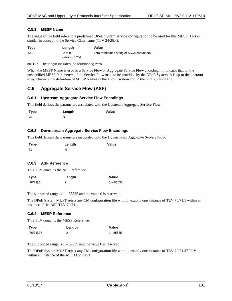
DPoE MAC and Upper Layer Protocols Interface Specification DPoE-SP-MULPIv2.0-I12-170510
05/10/17 CableLabs 101
C.5.3 MESP Name
The value of the field refers to a predefined DPoE System service configuration to be used for this MESP. This is similar in concept to the Service Class name (TLV 24/25.4).
Type Length Value 72.3 2 to n
(max size 254) Zero-terminated string of ASCII characters.
NOTE: The length includes the terminating zero.
When the MESP Name is used in a Service Flow or Aggregate Service Flow encoding, it indicates that all the unspecified MESP Parameters of the Service Flow need to be provided by the DPoE System. It is up to the operator to synchronize the definition of MESP Names in the DPoE System and in the configuration file.
C.6 Aggregate Service Flow (ASF)
C.6.1 Upstream Aggregate Service Flow Encodings
This field defines the parameters associated with the Upstream Aggregate Service Flow.
Type Length Value 70 N
C.6.2 Downstream Aggregate Service Flow Encodings
This field defines the parameters associated with the Downstream Aggregate Service Flow.
Type Length Value 71 N
C.6.3 ASF Reference
This TLV contains the ASF Reference.
Type Length Value [70/71].1 2 1 – 65535
The supported range is 1 – 65535 and the value 0 is reserved.
The DPoE System MUST reject any CM configuration file without exactly one instance of TLV 70/71.1 within an instance of the ASF TLV 70/71.
C.6.4 MESP Reference
This TLV contains the MESP Reference.
Type Length Value [70/71].37 2 1 - 65535
The supported range is 1 – 65535 and the value 0 is reserved.
The DPoE System MUST reject any CM configuration file without exactly one instance of TLV 70/71.37 TLV within an instance of the ASF TLV 70/71.
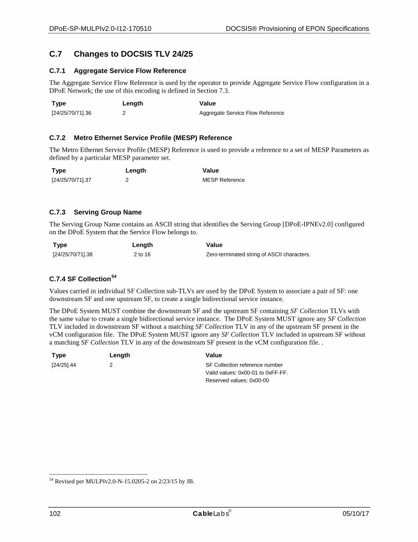
DPoE-SP-MULPIv2.0-I12-170510 DOCSIS® Provisioning of EPON Specifications
102 CableLabs 05/10/17
C.7 Changes to DOCSIS TLV 24/25
C.7.1 Aggregate Service Flow Reference
The Aggregate Service Flow Reference is used by the operator to provide Aggregate Service Flow configuration in a DPoE Network; the use of this encoding is defined in Section 7.3.
Type Length Value [24/25/70/71].36 2 Aggregate Service Flow Reference
C.7.2 Metro Ethernet Service Profile (MESP) Reference
The Metro Ethernet Service Profile (MESP) Reference is used to provide a reference to a set of MESP Parameters as defined by a particular MESP parameter set.
Type Length Value [24/25/70/71].37 2 MESP Reference
C.7.3 Serving Group Name
The Serving Group Name contains an ASCII string that identifies the Serving Group [DPoE-IPNEv2.0] configured on the DPoE System that the Service Flow belongs to.
Type Length Value [24/25/70/71].38 2 to 16 Zero-terminated string of ASCII characters.
C.7.4 SF Collection54
Values carried in individual SF Collection sub-TLVs are used by the DPoE System to associate a pair of SF: one downstream SF and one upstream SF, to create a single bidirectional service instance.
The DPoE System MUST combine the downstream SF and the upstream SF containing SF Collection TLVs with the same value to create a single bidirectional service instance. The DPoE System MUST ignore any SF Collection TLV included in downstream SF without a matching SF Collection TLV in any of the upstream SF present in the vCM configuration file. The DPoE System MUST ignore any SF Collection TLV included in upstream SF without a matching SF Collection TLV in any of the downstream SF present in the vCM configuration file. .
Type Length Value [24/25].44 2 SF Collection reference number
Valid values: 0x00-01 to 0xFF-FF. Reserved values: 0x00-00
54 Revised per MULPIv2.0-N-15.0205-2 on 2/23/15 by JB.

DPoE MAC and Upper Layer Protocols Interface Specification DPoE-SP-MULPIv2.0-I12-170510
05/10/17 CableLabs 103
C.8 D-ONU Capabilities Encoding55 The D-ONU Capabilities Encoding describes the capabilities of a particular D-ONU; i.e., implementation dependent limits on the particular features or number of features, which the D-ONU can support. It consists of a number of encapsulated type/length/value fields; these sub-types define the specific capabilities for the D-ONU in question.
These capabilities are reported by the D-ONU to the DPoE System via specific OAM messages; defined in [DPoE-OAMv2.0]. The DPoE System MUST use the values reported by the D-ONU via OAM messages to populate the corresponding DHCP TLVs, when sending these DHCP TLVs in the DHCP messages from the local vCM.
Type Length Value 5.42 n Capability sub-TLVs
NOTE: DOCSIS CM Capabilities are included under TLV 5. All the DPoE D-ONU Capabilities Encodings are included under TLV 5.42. The sub-type fields defined are only valid within the encapsulated capabilities configuration setting string
The set of possible D-ONU Capability sub-TLVs are described below.
The vCM MUST include all of these capabilities within the Modem Capabilities option, within option 125 (for DHCPv4) and or option 17 (for DHCPv6) unless the description of the capability explicitly prohibits this. DPoE Networks does not support DOCSIS Registration Response messaging and therefore D-ONU capabilities are communicated only via DHCP messaging.
C.8.1 DPoE Version Number
The DPoE Version number is a one byte value representing the DPoE OAM version supported by the D-ONU. Bits[7:4] of the value in this TLV represent the major version number, while Bits[3:0] of the value in this TLV represent the minor version number.
Type Length Value 5.42.1 1 major version: minor version
Field name Description Size majver Major version 4 bits
minver Minor version 4 bits
C.8.2 Number of Unicast LLIDs Supported (Bidirectional)
This field shows the maximum number of Unicast LLIDs that the D-ONU supports.
NOTE: The minimum number of LLIDs that a D-ONU must support is defined in [DPoE-ARCHv2.0].
C.8.3 Number of Multicast LLIDs Supported (Downstream Only)
This field shows the maximum number of Multicast LLIDs that the D-ONU supports.
55 Revised per MULPIv2.0-N-13.0099-1 on 10/9/13 and per MULPIv2.0-N-13.0114-1 on 2/20/14 by JB.
Type Length Value 5.42.2 2
Type Length Value 5.42.3 2

DPoE-SP-MULPIv2.0-I12-170510 DOCSIS® Provisioning of EPON Specifications
104 CableLabs 05/10/17
C.8.4 MESP Support (Metro Ethernet Service Profile)
Value is a bitmask which defines feature support for Color Marking, Color Awareness (for both SF and ASF) and Smart Color Dropping capabilities, for the D-ONU [DPoE-MEFv2.0].
A value of 1 means the feature is supported, a value of 0 means the D-ONU does not support this MESP feature.
C.8.5 Number of D-ONU Ports This value specifies the number of S1 interfaces supported on the D-ONU.
C.8.6 EPON Data Rate Support
This value specifies the data rates supported by the D-ONU on the EPON network.
Type Length Value 5.42.6 1 0 = 1G up /1G down
1 = 1G up /10G down 2 = 10G up /10G down
The EPON data rate supported by the D-ONU is obtained by the DPoE System during D-ONU registration.
C.8.7 Service OAM56
This field indicates the Service OAM capabilities supported by the D-ONU.
56 Revised per MULPIv2.0-16.0238-1 on 6/2/16 by JB.
Type Length Value 5.42.4 1 Bit #0 = Color Marking (at SF level)
Bit #1 = Color Awareness (at SF level) Bit #2 = Smart Color Dropping (at SF and ASF Levels) Bit #3 to #7 reserved
Type Length Value 5.42.5 1 1 to 255
Type Length Value 5.42.7 n Retired (SOAM Capabilities)

DPoE MAC and Upper Layer Protocols Interface Specification DPoE-SP-MULPIv2.0-I12-170510
05/10/17 CableLabs 105
C.9 Network Timing Profile This subtype specifies a Network Timing Profile configured on the DPoE System which provides a match criteria for the Timing Profile Name. EToD [1588v2] provisioning parameters [DPoE-IPNEv2.0] are configured via a Network Timing Profile. The Network Timing Profile TLV is referenced from the L2VPN encoding via the Network Timing Profile Reference. The CPE interfaces (CMIM) to which the Network Timing Profile applies are the interfaces CMIM) to which the L2VPN encoding applies. The DPoE System MUST configure the appropriate CMIM ports with the configuration profile settings of Network Timing Profile. If the DPoE System has a CM configuration file that includes different Network Timing Profile subtypes configured within different L2VPN encodings that are associated to the same CMIM, the DPoE System MUST select the Network Timing Profile under the L2VPN encoding with the smallest VPNID.
Type Length Value 73 N
C.9.1 Network Timing Profile Reference
The Network Timing Profile Reference is used to associate an L2VPN Service Flow to a Network Timing Profile Name in the CM configuration file. A valid Network Timing Profile subtype encoding contains one instance of this subtype.
Type Length Value 73.1 2 Network Timing Profile Reference
C.9.2 Network Timing Profile Name This subtype contains an ASCII string that identifies a Network Timing Profile Name configured on the DPoE System. A valid Network Timing Profile subtype encoding contains one instance of this subtype.
Type Length Value 73.2 2 to 16 Zero-terminated string of ASCII characters.
The DPoE System MUST reject any CM configuration file with a Network Timing Profile subtype encoding containing zero or multiple instances of the Profile Name encoding.
C.10 Top Level TLVs57 Table 8 - Top Level TLVs
TLV Name Support Needed Comments 0 Pad MUST
1 Downstream Frequency MUST NOT Not applicable, as there is only one downstream channel, the EPON itself.
2 Upstream Channel ID MUST NOT Not applicable, as there is only one upstream channel, the EPON itself.
3 Network Access Control Object MUST
4 DOCSIS 1.0 Class of Service MUST NOT No reason to carry this support forward to DPoE specification.
57 Revised per MULPIv2.0-N-13.0091-1 on 7/17/13 and per MULPIv2.0-N-13.0114-3 on 2/20/14 by JB. Revised per MULPIv2.0-N-14.0124-2, then corrected per MULPIv2.0-N-14.0139-1 on 3/7/14 by JB. Revised #65 per MULPIV2.0-N-15.0203-1 on 1/26/15 by JB.

DPoE-SP-MULPIv2.0-I12-170510 DOCSIS® Provisioning of EPON Specifications
106 CableLabs 05/10/17
TLV Name Support Needed Comments 5 Modem Capabilities MUST Added to DPoEv2.0 to support TLV 5.42 D-ONU Capabilities
Encoding, was not supported in v1.0. Note that these are NOT in the CM Config file, but in the DHCP from vCM to DHCP Server.
6 CM Message Integrity Check MAY The operator network is considered to be secure and this TLV is not needed as the DPoE System is getting the file directly from the TFTP Server. This TLV may be supported for backwards compatibility.
7 CMTS Message Integrity Check MAY The operator network is considered to be secure and this TLV is not needed as the DPoE System is getting the file directly from the TFTP Server. This TLV may be supported for backwards compatibility.
9 SW Upgrade Filename MUST
10 SNMP Write Access Control SHOULD NOT Operator feedback was that this TLV is not needed for this version of the specifications.
11 SNMP MIB Object MUST See the TLV 11 section for more details.
14 CPE Ethernet MAC Address SHOULD NOT Operator feedback was that this TLV is not needed for this version of the specifications.
17 Baseline Privacy MUST NOT Encryption is different on EPON, and configurable controls are limited. You can configure Traffic Key lifetime per-PON and per-Link. This doesn't correspond directly to TLV 17 items, however. See Annex C.12 for more details.
18 Max Number of CPEs MUST
19 TFTP Server Timestamp MUST NOT ONUs do not access the configuration file server, so there's no middle man or hackable entity like a CM to worry about.
20 TFTP Server Provisioned Modem IPv4 Address
MUST NOT ONUs have IP addresses proxied by the DPoE System. Thus this TLV has little value.
21 SW Upgrade IPv4 TFTP Server MUST
22 Upstream Packet Classification MUST See Annex C.13 for more details.
23 Downstream Packet Classification
MUST See Annex C.13 for more details.
24 Upstream SF MUST See Annex C.14 for more details.
25 Downstream SF MUST See Annex C.14 for more details.
26 Payload Header Suppression MUST NOT EPON doesn't define header suppression.
28 Maximum Number of Classifiers SHOULD NOT This is admission control for classification resources.
29 Privacy Enable MUST This TLV enables/disables device certificate authentication and traffic encryption functions on the DPoE System and D-ONU. See [DPoE-SECv2.0] for more detail.
32 Manufacturer Code Verification Certificate
MUST
33 Co-Signer Code Verification Certificate
MUST
34 SNMPv3 Kickstart Value SHOULD SNMPv3 support is not mandatory
35 Subscriber Mgmt Control MUST
36 Subscriber Mgmt CPE IPv4 List MUST
37 Subscriber Mgmt Filter Groups MUST
38 SNMPv3 Notification Receiver MUST
39 Enable 2.0 Mode MUST NOT EPON PHY is not DOCSIS PHY.
40 Enable Test Modes MUST NOT Not applicable to EPON ONUs.
41 Downstream Channel List MUST NOT ONUs lock to a single DS PON channel.
42 Static Multicast MAC Address SHOULD
43 DOCSIS Extension Field MUST See Annex C.16, Annex C.17, and Annex C.18 for more detail.

DPoE MAC and Upper Layer Protocols Interface Specification DPoE-SP-MULPIv2.0-I12-170510
05/10/17 CableLabs 107
TLV Name Support Needed Comments 45 Downstream Unencrypted Traffic
(DUT) Filtering SHOULD NOT Not needed for this version of the specifications.
53 SNMPv1v2c Coexistence MUST
54 SNMPv3 Access View MUST
55 SNMP CPE Access Control SHOULD NOT There are currently no requirements to support this in this version of the specifications.
56 Channel Assignment MUST NOT There is no channel bonding in EPON.
58 SW Upgrade IPv6 TFTP Server MUST
59 TFTP Server Provisioned Modem IPv6 Address
MUST
60 Upstream Drop Packet Classification
MUST See Annex C.19 for more details
61 Subscriber Mgmt CPE IPv6 Prefix List
MUST
62 Upstream Drop Classifier Group ID
MUST
63 Subscriber Mgmt Control Max CPE IPv6 Prefix
MUST
64 CMTS Static Multicast Session Encoding
MUST
65 L2VPN MAC Aging Encoding MUST
66 Management Event Control Encoding
SHOULD NOT Not needed for this version of the specifications.
67 Subscriber Mgmt CPE IPv6 List MUST
70 US Aggregate Service Flow MUST
71 DS Aggregate Service Flow MUST
72 Metro Ethernet Service Profile MUST
73 Network Timing Profile MUST
79 UNI Control Encodings MUST
255 End-of-Data MUST
C.11 TLV 1158 The following table, Table 9, specifies those TLV-11 CM SNMP MIB objects that MUST be supported by the DPoE System. Please refer to [DPoE-OSSIv2.0] for detailed requirements. The intent is to list only those objects that are currently in use (or planned to be in use) in CM provisioning files.
Table 9 - TLV 11
TLV-11 OID Name Support Needed Comments docsDevFilterIpDefault MUST A value of 'accept' MUST be supported. A value of 'discard'
MAY be supported. A DPoE System MUST ignore TLV 11 with the docsDevFilterIpDefault SNMP object with the value of 'discard', if this value is not supported.
docsDevFilterIpStatus MUST
docsDevFilterIpControl MUST 'Policy' control is not required. Only 'accept' and 'discard' MUST be supported in this version of the specifications.
docsDevFilterIpIfIndex MUST
58 Revised per MULPIv2.0-N-14.0150-1 on 5/29/14 by JB.

DPoE-SP-MULPIv2.0-I12-170510 DOCSIS® Provisioning of EPON Specifications
108 CableLabs 05/10/17
TLV-11 OID Name Support Needed Comments docsDevFilterIpDirection MUST
docsDevFilterIpBroadcast MUST A value of 'false' MUST be supported. A value of 'true' MAY be supported.
docsDevFilterIpSaddr MUST
docsDevFilterIpSmask MUST
docsDevFilterIpDaddr MUST
docsDevFilterIpDmask MUST
docsDevFilterIpProtocol MUST
docsDevFilterIpSourcePortLow MUST
docsDevFilterIpSourcePortHigh MUST
docsDevFilterIpDestPortLow MUST
docsDevFilterIpDestPortHigh MUST
docsDevFilterIpTos MUST
docsDevFilterIpTosMask MUST
docsDevFilterIpContinue SHOULD NOT No "policy" treatment
docsDevFilterIpPolicyId SHOULD NOT No "policy" treatment
docsDevFilterLLCUnmatchedAction MUST
docsDevFilterLLCIfIndex MUST
docsDevFilterLLCProtocol MUST
docsDevFilterLLCProtocolType MUST
docsDevFilterLLCStatus MUST
docsDevNmAccessCommunity MUST
docsDevNmAccessControl MUST
docsDevNmAccessInterfaces MUST
docsDevNmAccessIp MUST
docsDevNmAccessIpMask MUST
docsDevNmAccessStatus MUST
C.12 Security (TLV 17) Table 10 - TLV 17
TLV Name Support Needed
Comments
17.1 Authorize Wait Timeout MUST NOT None of these apply for EPON.
17.2 Reauthorize Wait Timeout MUST NOT None of these apply for EPON.
17.3 Authorization Grace Time MUST NOT None of these apply for EPON.
17.4 Operational Wait Timeout MUST NOT None of these apply for EPON.
17.5 Rekey Wait Timeout MUST NOT None of these apply for EPON.
17.6 TEK Grace Time MUST NOT None of these apply for EPON.
17.7 Authorize Reject Wait Timeout MUST NOT None of these apply for EPON.
17.8 SA Map Wait Timeout MUST NOT None of these apply for EPON.
17.9 SA Map Max Retries MUST NOT None of these apply for EPON.

DPoE MAC and Upper Layer Protocols Interface Specification DPoE-SP-MULPIv2.0-I12-170510
05/10/17 CableLabs 109
C.13 Classification (TLVs 22 and 23) Table 11 - TLV 22 and 2359
TLV Name Support Needed Comments 22.1 23.1
Classifier Reference MUST
22.3 23.3
SF Reference MUST
22.5 23.5
Rule Priority MUST
22.6 23.6
ClassifierActivationState SHOULD NOT Without deferred activation, there's no reason to support this TLV in this version of the specifications.
22.9.1 23.9.1
IPv4 TOSRange and Mask
MUST
22.9.2 23.9.2
IP Protocol MUST
22.9.3 23.9.3
IPv4 Source Address MUST
22.9.4 23.9.4
IPv4 Source Mask MUST Mask can't be arbitrary bits. Must be used to define "most significant bits" a la IPv6 Prefix.
22.9.5 23.9.5
IPv4 Destination Address MUST
22.9.6 23.9.6
IPv4 Destination Mask MUST Mask can't be arbitrary bits. Must be used to define "most significant bits" a la IPv6 Prefix.
22.9.7 23.9.7
TCP/UDP Source Port Start
MUST
22.9.8 23.9.8
TCP/UDP Source Port End
MUST
22.9.9 23.9.9
TCP/UDP Destination Port Start
MUST
22.9.10 23.9.10
TCP/UDP Destination Port End
MUST
22.10.1 23.10.1
Ethernet DMAC MUST Mask can't be arbitrary bits. Must be used to define "most significant bits" a la IPv6 Prefix.
22.10.2 23.10.2
Ethernet SMAC MUST
22.10.3 23.10.3
Ethertype/DSAP/MacType MUST type=1 MUST be supported. type=3 does not apply to EPON. Other values MAY be supported.
22.11.1 23.11.1
[802.1Q]User Priority MUST
22.11.2 23.11.2
[802.1Q] VLAN ID MUST
22.12.1 23.12.1
IPv6 TrafficClassRange and Mask
MUST
22.12.2 23.12.2
IPv6 Flow Label MUST
22.12.3 23.12.3
IPv6 Next Header Type MUST
22.12.4 23.12.4
IPv6 Source Address MUST
22.12.5 23.12.5
IPv6 Source Prefix Length MUST
59 Revised per MULPIv2.0-N-15.0223-2 on 2/11/16 by JB. Revised per MULPIv2.0-16.0234-1 on 6/2/16 by JB.

DPoE-SP-MULPIv2.0-I12-170510 DOCSIS® Provisioning of EPON Specifications
110 CableLabs 05/10/17
TLV Name Support Needed Comments 22.12.6 23.12.6
IPv6 Destination Address MUST
22.12.7 23.12.7
IPv6 Destination Prefix Length
MUST
22.13 23.13
CM Interface Mask (CMIM) Encoding
MUST Downstream CMIM is used only by the DPoE System to bind a downstream Service Flow to an upstream Service Flow associated with the same CMIM. The binding creates a single bidirectional service instance.
22.14 23.14
[802.1ad] S-VLAN Packet Classification Encodings
MUST TLV for [802.1ad] S-VLAN classifier.
22.14.1 23.14.1
[802.1ad] S- TPID MUST
22.14.2 23.14.2
[802.1ad] S-VID MUST
22.14.3 23.14.3
[802.1ad] S-PCP MUST
22.14.4 23.14.4
[802.1ad] S-DEI MUST
22.14.5 23.14.5
[802.1ad] C-TPID MUST
22.14.6 23.14.6
[802.1ad] C-VID MUST
22.14.7 23.14.7
[802.1ad] C-PCP MUST
22.14.8 23.14.8
[802.1ad] C-CFI MUST
22.14.9 23.14.9
[802.1ad] S-TCI MUST
22.14.10 23.14.10
[802.1ad] C-TCI MUST
22.15 23.15
[802.1ah] I-TAG Packet Classification Encodings
MUST TLV for [802.1ah] I-TAG classifier.
22.15.1 23.15.1
[802.1ah] I-TPID MUST
22.15.2 23.15.2
[802.1ah] I-SID MUST
22.15.3 23.15.3
[802.1ah] I-TCI MUST
22.15.4 23.15.4
[802.1ah] I-PCP MUST
22.15.5 23.15.5
[802.1ah] I-DEI MUST
22.15.6 23.15.6
[802.1ah] I-UCA MUST
22.15.7 23.15.7
[802.1ah] B-TPID MUST
22.15.8 23.15.8
[802.1ah] B-TCI MUST
22.15.9 23.15.9
[802.1ah] B-PCP MUST
22.15.10 23.15.10
[802.1ah] B-DEI MUST
22.15.11 23.15.11
[802.1ah] B-VID MUST
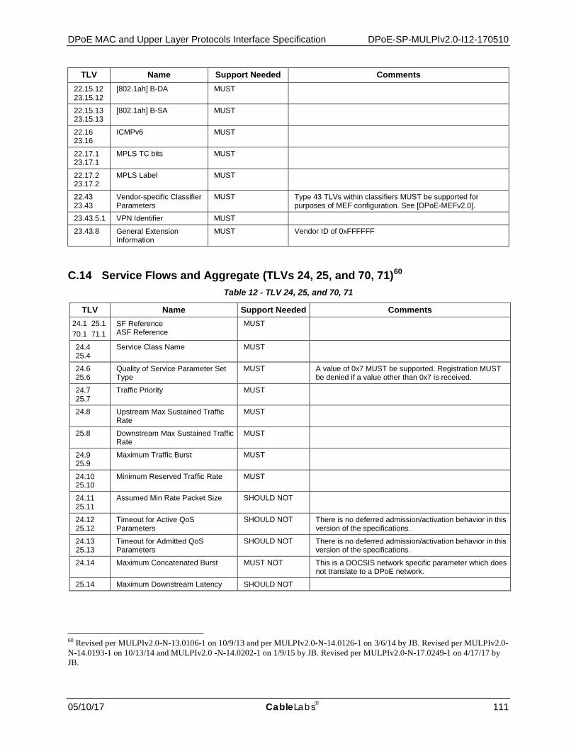
DPoE MAC and Upper Layer Protocols Interface Specification DPoE-SP-MULPIv2.0-I12-170510
05/10/17 CableLabs 111
TLV Name Support Needed Comments 22.15.12 23.15.12
[802.1ah] B-DA MUST
22.15.13 23.15.13
[802.1ah] B-SA MUST
22.16 23.16
ICMPv6 MUST
22.17.1 23.17.1
MPLS TC bits MUST
22.17.2 23.17.2
MPLS Label MUST
22.43 23.43
Vendor-specific Classifier Parameters
MUST Type 43 TLVs within classifiers MUST be supported for purposes of MEF configuration. See [DPoE-MEFv2.0].
23.43.5.1 VPN Identifier MUST
23.43.8 General Extension Information
MUST Vendor ID of 0xFFFFFF
C.14 Service Flows and Aggregate (TLVs 24, 25, and 70, 71)60 Table 12 - TLV 24, 25, and 70, 71
TLV Name Support Needed Comments 24.1 25.1 70.1 71.1
SF Reference ASF Reference
MUST
24.4 25.4
Service Class Name MUST
24.6 25.6
Quality of Service Parameter Set Type
MUST A value of 0x7 MUST be supported. Registration MUST be denied if a value other than 0x7 is received.
24.7 25.7
Traffic Priority MUST
24.8 Upstream Max Sustained Traffic Rate
MUST
25.8 Downstream Max Sustained Traffic Rate
MUST
24.9 25.9
Maximum Traffic Burst MUST
24.10 25.10
Minimum Reserved Traffic Rate MUST
24.11 25.11
Assumed Min Rate Packet Size SHOULD NOT
24.12 25.12
Timeout for Active QoS Parameters
SHOULD NOT There is no deferred admission/activation behavior in this version of the specifications.
24.13 25.13
Timeout for Admitted QoS Parameters
SHOULD NOT There is no deferred admission/activation behavior in this version of the specifications.
24.14 Maximum Concatenated Burst MUST NOT This is a DOCSIS network specific parameter which does not translate to a DPoE network.
25.14 Maximum Downstream Latency SHOULD NOT
60 Revised per MULPIv2.0-N-13.0106-1 on 10/9/13 and per MULPIv2.0-N-14.0126-1 on 3/6/14 by JB. Revised per MULPIv2.0-N-14.0193-1 on 10/13/14 and MULPIv2.0 -N-14.0202-1 on 1/9/15 by JB. Revised per MULPIv2.0-N-17.0249-1 on 4/17/17 by JB.

DPoE-SP-MULPIv2.0-I12-170510 DOCSIS® Provisioning of EPON Specifications
112 CableLabs 05/10/17
TLV Name Support Needed Comments 24.15 SF Scheduling Type MUST Two values MUST be supported for this version of the
specifications: 2 for Best Effort 4 for Real Time Polling Service Other values MAY be supported.
24.16 Request/Transmission Policy MUST The only bit that MUST be supported is Bit 4 (must not piggyback requests).
24.17 Nominal Polling Interval MUST This TLV is used with the Real Time Polling Scheduling Type.
25.17 Downstream Resequencing MUST NOT Not applicable to EPON.
24.18 Tolerated Poll Jitter SHOULD NOT
24.19 Unsolicited Grant Size SHOULD NOT This TLV is not needed to support the BE and RTP scheduling types.
24.20 Nominal Grant Interval SHOULD NOT This TLV is not needed to support the BE and RTP scheduling types.
24.21 Tolerated Grant Jitter SHOULD NOT This TLV is not needed to support the BE and RTP scheduling types.
24.22 Grants Per Interval SHOULD NOT This TLV is not needed to support the BE and RTP scheduling types.
24.23 25.23
IP ToS Overwrite MUST
24.26 Multiplier to Number of Bytes Requested
MUST NOT Not applicable to EPON.
24.27 Upstream Peak Traffic Rate SHOULD NOT
25.27 Downstream Peak Traffic Rate SHOULD NOT
24.31 25.31
SF Required Attribute Mask MUST This attribute is used to steer SFs to an IP-SG.
24.32 25.32
SF Forbidden Attribute Mask MAY The use of this attribute is not required, though may be used to, steer SFs to an IP-SG.
24.33 25.33
SF Attribute Aggregation Rule Mask
MUST NOT Not applicable to EPON.
24.34 25.34
Application Identifier SHOULD NOT This TLV is used to extend admission control decisions based on PCMM policies. There is no PCMM support in this version of the specifications.
24.35.1 25.35.1
Minimum Buffer Size SHOULD NOT
24.35.2 25.35.2
Target Buffer Size MUST TLV 24.35.2 is used for setting ONU LLID queue size (upstream SF). TLV 25.35.2 is used for setting ONU Port queue size (downstream SF). If it is not specified, then the ONU LLID or Port queue size is set to vendor determined value.
24.35.3 25.35.3
Maximum Buffer Size SHOULD NOT
24.36 25.36
Aggregate Service Flow Reference MUST
24.37 25.37 70.37 71.37
MESP Reference MUST
24.41 25.41
Data Rate Unit Setting MUST This setting provides a new data rate multiplier TLV as follows: bits/s → Kbits/s → Mbit/s → Gbit/s, increasing the maximum data rate to the maximum value of 232-1 Gbit/s.
24.43 Vendor-specific QoS Parameters MUST Type 43 TLVs within service flows MUST be supported for purposes of MEF configuration. See [DPoE-MEFv2.0].

DPoE MAC and Upper Layer Protocols Interface Specification DPoE-SP-MULPIv2.0-I12-170510
05/10/17 CableLabs 113
TLV Name Support Needed Comments 24.43.5.1 VPN Identifier MUST
24.43.8 General Extension Information MUST Vendor ID of 0xFFFFFF
24.44 25.44
SF Collection MUST Values carried in individual SF Collection TLVs are used by the DPoE System to associate a pair of SF: one downstream SF (via SF Collection DS TLV), and one upstream SF (SF Collection in US SF TLV), to create a single bidirectional service instance.
C.15 Device Management (TLVs 38, 53 and 54) Table 13 - TLV 38, 53 and 54
TLV Name Support Needed Comments 34.1 SNMPv3 Kickstart Security Name SHOULD SNMPv3 support is not mandatory
34.2 SNMPv3 Kickstart Manager Public Number
SHOULD SNMPv3 support is not mandatory
38.1 SNMPv3 Notification Receiver IPv4 Address
MUST
38.2 SNMPv3 NotificationReceiverUDPPort Number
MUST
38.3 SNMPv3 Notification Receiver Trap Type
MUST
38.4 SNMPv3 Notification Receiver Timeout
MUST
38.5 SNMPv3 Notification Receiver Retries
MUST
38.6 SNMPv3 Notification Receiver Filtering Parameters
MUST
38.7 SNMPv3 Notification Receiver Security Name
MUST
38.8 SNMPv3 Notification Receiver IPv6 Address
MUST
53.1 SNMPv1v2c Community Name MUST
53.2 SNMPv1v2c Transport Address Access
MUST
53.2.1 SNMPv1v2c Transport Address MUST
53.2.2 SNMPv1v2c Transport Address Mask
MUST
53.3 SNMPv1v2c Access View Type MUST
53.4 SNMPv1v2c Access View Name MUST
54.1 SNMPv3 Access View Name MUST
54.2 SNMPv3 Access View Subtree MUST
54.3 SNMPv3 Access View Mask MUST
54.4 SNMPv3 Access View Type MUST

DPoE-SP-MULPIv2.0-I12-170510 DOCSIS® Provisioning of EPON Specifications
114 CableLabs 05/10/17
C.16 TLV 43 Table 14 - TLV 43
TLV Name Support Needed Comments 43.1 CM Load Balancing Policy ID MUST NOT Not applicable to EPON.
43.2 CM Load Balancing Priority MUST NOT Not applicable to EPON.
43.3 CM Load Balancing Group ID MUST NOT Not applicable to EPON.
43.4 CM Ranging Class ID Extension MUST NOT Not applicable to EPON.
43.5 L2VPN Encoding MUST
43.6 Extended CMTS MIC Configuration Setting
MAY ONUs do not request configuration files, thus tampering is not a concern. This TLV may be supported for backwards compatibility.
43.7 Source Address Verification Authorization Encoding
MUST
43.8 General Extension Information MUST
43.9 Cable Modem Attribute Masks MUST NOT This is really bonding-specific, thus not applicable to EPON.
43.10 IP Multicast Join Authorization Encoding
MUST
43.11 Service Type Identifier SHOULD NOT This TLV is not applicable to DPoE Networks in this version of the specifications.
C.17 [DPoE-MEFv2.0] and [L2VPN] (TLVs 43.5, 45, and 65)61 See [DPoE-MEFv2.0] for more information on the expected use and support for these TLVs in this version of DPoE specifications.
Table 15 - TLV 43.5, 45, and 6562
TLV Name Support Needed Comments 43.5.1 VPN Identifier MUST
43.5.2 NSI Encapsulation Subtype MUST
43.5.2.1 Other SHOULD NOT
43.5.2.2 [802.1Q] MUST
43.5.2.3 [802.1ad] MUST
43.5.2.4 MPLS Peer MUST
43.5.2.5 L2TPv3 Peer SHOULD NOT
43.5.2.6 [802.1ah] MUST
43.5.2.6.1 [802.1ah] I-Tag TCI MUST
43.5.2.6.2 [802.1ah] B-DA MUST
43.5.2.6.3 [802.1ah] B-TCI MUST
43.5.2.6.4 [802.1ah] I-TPID MUST
43.5.2.6.5 [802.1ah] I-PCP MUST
43.5.2.6.6 [802.1ah] I-DEI MUST
43.5.2.6.7 [802.1ah] I-UCA MUST
43.5.2.6.8 [802.1ah] I-SID MUST
43.5.2.6.9 [802.1ah] B-TPID MUST
61 Revised per MULPIv2.0-N-15.0210-1 on 5/1/15 by JB. 62 Revised per MULPIv2.0-N-15.0223-2 on 2/11/16 by JB. Revised per MULPIv2.0-N-16.0244-2 on 11/3 by JB.

DPoE MAC and Upper Layer Protocols Interface Specification DPoE-SP-MULPIv2.0-I12-170510
05/10/17 CableLabs 115
TLV Name Support Needed Comments 43.5.2.6.10 [802.1ah] B-PCP MUST
43.5.2.6.11 [802.1ah] B-DEI MUST
43.5.2.6.12 [802.1ah] B-VID MUST
43.5.2.8 [802.1ad] S-TPID MUST
43.5.3 Enable eSAFE DHCP Snooping MUST
43.5.4 CM Interface Mask MUST
43.5.5 Attachment Group ID SHOULD NOT
43.5.6 Source Attachment Individual ID SHOULD NOT
43.5.7 Target Attachment Individual ID SHOULD NOT
43.5.8 Ingress User Priority SHOULD NOT
43.5.9 UserPriorityRange SHOULD NOT
43.5.10 L2VPN SA-Descriptor MUST NOT BPI does not apply here.
43.5.13 L2VPN Mode MUST
43.5.14 DPoE TPID Translation MUST
43.5.14.1 Upstream outmost TPID Translation MUST
43.5.14.2 Downstream outmost TPID Translation MUST
43.5.14.3 Upstream S-TPID Translation MUST
43.5.14.4 Downstream S-TPID Translation MUST
43.5.14.5 Upstream B-TPID Translation MUST
43.5.14.6 Downstream B-TPID Translation MUST
43.5.14.7 Upstream I-TPID Translation MUST
43.5.14.8 Downstream I-TPID Translation MUST
43.5.16 DAC Disable/Enable MUST
43.5.18 Pseudowire-Class MUST
43.5.19 Service Delimiter MUST
43.5.19.1 C-VID MUST
43.5.19.2 S-VID MUST
43.5.19.3 I-SID MUST
43.5.19.4 B-VID MUST
43.5.20.1 VPLS Class MUST
43.5.20.2 E-Tree Role MUST
43.5.20.3 E-Tree Root VID MUST
43.5.20.4 E-Tree Leaf VID MUST
43.5.21.1 Route Distinguisher MUST
43.5.21.2 Route Target(import) MUST
43.5.21.3 Route Target(export) MUST
43.5.27 L2VPN L2 Multipoint Forwarding Mode MUST
45.1 Downstream Unencrypted Traffic (DUT) Control SHOULD NOT
45.2 Downstream Unencrypted Traffic (DUT) CMIM SHOULD NOT
65.1 L2VPN MAC Aging Mode MUST
83 L2CP Management MUST
83.1 CMIM MUST
83.2 L2CP Mode MUST
83.3 L2CP L2PT D-MAC Address MUST
83.4 L2CP Filter MUST

DPoE-SP-MULPIv2.0-I12-170510 DOCSIS® Provisioning of EPON Specifications
116 CableLabs 05/10/17
C.18 Customer (Subscriber) Management (TLV 43.7) Table 16 - TLV 43.7
TLV Name Support Needed Discussion 43.7.1 SAV Group Name Subtype MUST
43.7.2 SAV Static Prefix Rule Subtype MUST
43.7.2.1 SAV Static Prefix Address Subtype MUST IPv4 and IPv6.
43.7.2.2 SAV Static Prefix Length Subtype MUST IPv4 and IPv6.
C.19 Upstream Drop Classification (TLV 60) Table 17 - TLV 6063
TLV Name Support Needed Comments 60.1 Classifier Reference MUST
60.5 Rule Priority MUST
60.9.1 IPv4 TOSRange and Mask MUST
60.9.2 IP Protocol MUST
60.9.3 IPv4 Source Address MUST
60.9.4 IPv4 Source Mask MUST Mask can't be arbitrary bits. Must be used to define "most significant bits" a la IPv6 Prefix.
60.9.5 IPv4 Destination Address MUST
60.9.6 IPv4 Destination Mask MUST Mask can't be arbitrary bits. Must be used to define "most significant bits" a la IPv6 Prefix.
60.9.7 TCP/UDP Source Port Start MUST
60.9.8 TCP/UDP Source Port End MUST
60.9.9 TCP/UDP Destination Port Start MUST
60.9.10 TCP/UDP Destination Port End MUST
60.10.1 Ethernet DMAC MUST Mask can't be arbitrary bits. Must be used to define "most significant bits" a la IPv6 Prefix.
60.10.2 Ethernet SMAC MUST
60.10.3 Ethertype/DSAP/MacType MUST type=1 MUST be supported. type=3 does not apply to EPON. Other type values MAY be supported.
60.11.1 [802.1Q] User Priority MUST
60.11.2 [802.1Q] VLAN ID MUST
60.12.1 IPv6 TrafficClassRange and Mask MUST
60.12.2 IPv6 Flow Label MUST
60.12.3 IPv6 Next Header Type MUST
60.12.4 IPv6 Source Address MUST .
60.12.5 IPv6 Source Prefix Length MUST
60.12.6 IPv6 Destination Address MUST
60.12.7 IPv6 Destination Prefix Length MUST
60.13 CM Interface Mask (CMIM) Encoding
MUST
60.14 [802.1ad] S-VLAN Packet Classification Encodings
MUST TLV for [802.1ad] S-VLAN classifier.
60.14.1 [802.1ad] S- TPID MUST
63 Revised per MULPIv2.0-N-15.0223-2 on 2/11/16 by JB.

DPoE MAC and Upper Layer Protocols Interface Specification DPoE-SP-MULPIv2.0-I12-170510
05/10/17 CableLabs 117
TLV Name Support Needed Comments 60.14.2 [802.1ad] S-VID MUST
60.14.3 [802.1ad] S-PCP MUST
60.14.4 [802.1ad] S-DEI MUST
60.14.5 [802.1ad] C-TPID MUST
60.14.6 [802.1ad] C-VID MUST
60.14.7 [802.1ad] C-PCP MUST
60.14.8 [802.1ad] C-CFI MUST
60.14.9 [802.1ad] S-TCI MUST
60.14.10 [802.1ad] C-TCI MUST
60.15. [802.1ah] I-TAG Packet Classification Encodings
MUST TLV for [802.1ah] I-TAG classifier.
60.15.1 [802.1ah] I-TPID MUST
60.15.2 [802.1ah] I-SID MUST
60.15.3 [802.1ah] I-TCI MUST
60.15.4 [802.1ah] I-PCP MUST
60.15.5 [802.1ah] I-DEI MUST
60.15.6 [802.1ah] I-UCA MUST
60.15.7 [802.1ah] B-TPID MUST
60.15.8 [802.1ah] B-TCI MUST
60.15.9 [802.1ah] B-PCP MUST
60.15.10 [802.1ah] B-DEI MUST
60.15.11 [802.1ah] B-VID MUST
60.15.12 [802.1ah] B-DA MUST
60.15.13 [802.1ah] B-SA MUST
60.16 ICMPv6 MUST
60.17.1 MPLS TC bits MUST
60.17.2 MPLS Label MUST
60.43 Vendor-specific Classifier Parameters
MUST These TLVs will be "supported" in that vendor-proprietary TLVs can be specified in the configuration file, but their implementation is up to the vendor. There currently are no standard DPoE vendor-specific classifier parameters.
C.20 Subscriber Management (TLV18 and TLV35)64 Multiple TLVs are available allowing the operator to manage subscriber traffic through a DOCSIS CM (e.g., TLV18, TLV35, TLV36, TLV61, TLV63, and TLV66). The following text presents the similarities and differences based on the primary entity responsible for enforcing the management settings—the DPoE System or the vCM/ONU. The example below uses only TLV18 and TLV35 for illustration purposes.
TLV18 (Max Number of CPEs) enforces the number of physical CPE devices (each characterized with unique CPE MAC address) that can be connected directly to the D-ONU (and indirectly, to the associated vCM). This TLV does not enforce any limitations on the number active of IP addresses or data sessions across the connected CPE devices.
TLV35 (Subscriber Management Control) enforces the maximum number of IP addresses that can be used at any time by CPE devices connected directly to the D-ONU (and indirectly, to the associated vCM). This TLV does not enforce any limitations on the number of CPE devices connected to the D-ONU.
64 Revised per MULPIv2.0-N-14.0195-1 on 11/18/14 by JB.

DPoE-SP-MULPIv2.0-I12-170510 DOCSIS® Provisioning of EPON Specifications
118 CableLabs 05/10/17
For example, if the vCM configuration file contains TLV18 with the value of 10 and TLV35 with the value of 0, the DPoE System is expected to drop all subscriber IPv4 traffic, even though up to 10 CPE devices can be connected to the D-ONU. Conversely, if the vCM configuration file contains TLV35 with the value of 10 and TLV18 with the value of 0, 1, or TLV18 is absent altogether, only one CPE device can be connected to the D-ONU, but up to 10 IPv4 addresses can be assigned at any time.
Typically, either TLV18 or TLV35 is used in a vCM configuration file. Given the difference in the operation of TLV18 and TLV35, these TLVs are not intended to be interchangeable.

DPoE MAC and Upper Layer Protocols Interface Specification DPoE-SP-MULPIv2.0-I12-170510
05/10/17 CableLabs 119
Annex D eSAFE DHCP Snooping (Normative) This section specifies the requirements around enabling eSAFE DHCP snooping as defined in [L2VPN].
• TLV 43.5.3 "eSAFE DHCP Snooping" defined in [L2VPN] MUST be supported by all DPoE System Relay Agents.
• DPoE Standalone ONUs with one or more eSAFE's present configured (on) with this TLV 43.5.3 MUST relay eSAFE DHCP messages from the DPoE Standalone ONU to the DPoE System on an EVC with S-VLAN ID and C-VLAN ID as configured for the corresponding CMIM or S1 interface.

DPoE-SP-MULPIv2.0-I12-170510 DOCSIS® Provisioning of EPON Specifications
120 CableLabs 05/10/17
Annex E MPCP Discovery Processing in DPoE Networks65(Normative)
E.1 IEEE MPCP Discovery Process The ONU Discovery Process for EPON defined in [802.3] involves the exchange of multiple messages between OLT and ONU. A diagram showing the message sequence of the MPCP Discovery Process is provided in Figure 23.
DPoE System(OLT) D-ONU
DISCOVERY_GATE
REGISTER_REQ
REGISTERGATE (grantStart, grantLength)
REGISTER_ACKgrantStart+RTT
grantEndTime
grantLength
Figure 23 - MPCP Discovery Process Message Sequence.
The Discovery Process begins with the OLT sending a Discovery GATE message to open a contention window for ONUs to transmit a REGISTER_REQ message. Upon receipt of the REGISTER_REQ message, the OLT responds with a REGISTER message. Shortly after sending the REGISTER message, the OLT sends a GATE message to the registering ONU. The ONU uses the corresponding grant in the GATE message to transmit the REGISTER_ACK message. If OLT receives the REGISTER_ACK message by grantEndTime then the ONU is registered and the Discovery Process is complete. If the REGISTER_ACK message is not received by grantEndTime, the ONU is de-registered and must restart the Discovery Process by waiting for a Discovery GATE message.
The time by which the OLT must receive the REGISTER_ACK message is indicated in the variable grantEndTime. While the [802.3] standard defines how to compute grantEndTime based on when the GATE message was sent, the standard does not indicate how long the OLT should wait after sending the REGISTER message before it sends the GATE message. It is recognized that ONUs require a variable amount of processing time before it can respond with the REGISTER_ACK message. This variable and non-standardized processing time leads to interoperability challenges, which motivates changes to the Discovery Process in DPoE Networks, as outlined below.
65 Annex E added per MULPIv2.0-N-13.0080-1 on 7/17/13 by JB.

DPoE MAC and Upper Layer Protocols Interface Specification DPoE-SP-MULPIv2.0-I12-170510
05/10/17 CableLabs 121
E.2 DPoE MPCP Discovery Process The DPoE MPCP Discovery Process implements several modifications aimed at increasing the robustness of the D-ONU discovery. The DPoE MPCP Discovery Process specifies a delay that the DPoE system must enforce between issuing the REGISTER message to a registering D-ONU and issuing a GATE message to the same D-ONU to provide it an opportunity to transmit the REGISTER_ACK message.
To demonstrate the modifications required to the Discovery Process in DPoE Networks, several new variables are defined:
• registerStartTime – the time on DPoE System when REGISTER message is sent to a D-ONU
• registerAckDelay – a delay after which DPoE System sends a GATE message for D-ONU to respond with REGISTER_ACK message.
• registerDeadline – the time on DPoE System indicating the registration deadline. If the REGISTER_ACK message is not received by this time, the DPoE System deregisters the D-ONU.
The DPoE MPCP Discovery Process specifies a delay (registerAckDelay) that the DPoE system must enforce between issuing the REGISTER message to a registering D-ONU (registerStartTime) and issuing a GATE message to the same D-ONU to provide it an opportunity to transmit the REGISTER_ACK message. The first GATE message transmitted at or after DPoE System time (registerStartTime+registerAckDelay) is denoted the “Deadline GATE”. The registerDeadline value is set to be equal to the grantEndTime of the first grant in the Deadline GATE message.
These time variables are related to each other in the following manner:
DeadlineGATE.timestamp ≥ registerStartTime + registerAckDelay
registerDeadline = DeadlineGATE.grantStart[0] + DeadlineGATE.grantLength[0] + RTT
The factor RTT is the round trip time to the D-ONU. The relationship between these time variables is shown pictorially in Figure 24.

DPoE-SP-MULPIv2.0-I12-170510 DOCSIS® Provisioning of EPON Specifications
122 CableLabs 05/10/17
DPoE System(OLT) D-ONU
DISCOVERY_GATE
REGISTER_REQ
REGISTER
Deadline GATE (grantStart, grantLength)
REGISTER_ACK grantLength
registerAckDelay
registerStartTime
grantStart+RTT
registerDeadline = grantEndTime
Figure 24 - Discovery Process with registerStartTime, registerAckDelay, and registerDeadline.
The DPoE System MUST employ a mechanism that allows for D-ONUs at least registerAckDelay time to respond with the REGISTER_ACK message once the D-ONU has received the REGISTER message. The DPoE System MUST use a default value of 100 ms for registerAckDelay. The DPoE System MUST provide the capability to configure registerAckDelay to a value different from the default value. If DPoE System does not receive the REGISTER_ACK message by the registerDeadline, the DPoE System MUST deregister the D-ONU. The specific mechanism employed by the DPoE System to meet these requirements is vendor-specific.
The D-ONU MUST transmit the REGISTER_ACK message within 100 ms after receiving the REGISTER message.
E.2.1 Discovery Using Multiple GATE Messages
If a D-ONU does not require the entire registerAckDelay interval to generate the REGISTER_ACK message, it is beneficial to complete the Discovery process of such D-ONU sooner. To allow such expedited discovery, the DPoE System may optionally issue one or more GATE messages before the Deadline GATE message. GATE messages transmitted prior to the Deadline GATE message are called Auxiliary GATE messages.
Figure 25 shows two Auxiliary GATE messages sent to the D-ONU. In this example, the D-ONU is unable to generate the REGISTER_ACK message quickly enough to respond in the grant contained within the first Auxiliary GATE message. Consequently, the DPoE System sends a second Auxiliary GATE message, which is used by the D-ONU to transmit the REGISTER_ACK message.
The number of Auxiliary GATE messages and the time period between GATE messages is vendor-specific. The discovery process completes as soon as the REGISTER_ACK message is received by the DPoE System, which can occur significantly ahead of the registerDeadline time. If the REGISTER_ACK message is received in a grant in one of the Auxiliary GATE messages, the DPoE System does not need to continue issuing any additional Auxiliary GATE messages or the Deadline GATE message.
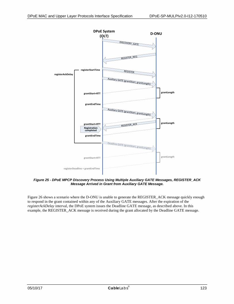
DPoE MAC and Upper Layer Protocols Interface Specification DPoE-SP-MULPIv2.0-I12-170510
05/10/17 CableLabs 123
DPoE System(OLT) D-ONU
DISCOVERY_GATE
REGISTER_REQ
REGISTER
Deadline GATE (grantStart, grantLength)
REGISTER_ACK
grantLength
registerAckDelay
registerStartTime
grantStart+RTT
registerDeadline = grantEndTime
Auxiliary GATE (grantStart, grantLength)
grantLengthgrantStart+RTT
grantEndTime
Auxiliary GATE (grantStart, grantLength)
grantLengthgrantStart+RTTRegistration completed
grantEndTime
Figure 25 - DPoE MPCP Discovery Process Using Multiple Auxiliary GATE Messages, REGISTER_ACK
Message Arrived in Grant from Auxiliary GATE Message.
Figure 26 shows a scenario where the D-ONU is unable to generate the REGISTER_ACK message quickly enough to respond in the grant contained within any of the Auxiliary GATE messages. After the expiration of the registerAckDelay interval, the DPoE system issues the Deadline GATE message, as described above. In this example, the REGISTER_ACK message is received during the grant allocated by the Deadline GATE message.

DPoE-SP-MULPIv2.0-I12-170510 DOCSIS® Provisioning of EPON Specifications
124 CableLabs 05/10/17
DPoE System(OLT) D-ONU
DISCOVERY_GATE
REGISTER_REQ
REGISTER
Deadline GATE (grantStart, grantLength)
REGISTER_ACK grantLength
registerAckDelay
registerStartTime
grantStart+RTT
registerDeadline = grantEndTime
Auxiliary GATE (grantStart, grantLength)
grantLengthgrantStart+RTT
grantEndTime
Auxiliary GATE (grantStart, grantLength)
grantLengthgrantStart+RTT
Registration completed
grantEndTime
Figure 26 - DPoE MPCP Discovery Process Using Multiple GATE Messages, REGISTER_ACK Message
Arrived in Grant from Deadline GATE message.

DPoE MAC and Upper Layer Protocols Interface Specification DPoE-SP-MULPIv2.0-I12-170510
05/10/17 CableLabs 125
Appendix I EPON Media Access Control Protocol (Informative)66
The DPoE specifications rely on the respective [802.3] standards and do not introduce any changes to their stipulations.
I.1 Timing and Synchronization In an EPON network, timing and synchronization services for the EPON transport (over the TU interface) are provided by the Multi-Point Control Protocol (MPCP) as defined in [802.3], Clause 64 and Clause 77.
The ranging and timing process in use in 1G-EPON is defined in [802.3], 64.2.1.1, while the delay variation requirements are defined in [802.3], 65.3.3. Similarly, [802.3], 77.2.1.1 defines the ranging and timing process in use in 10G-EPON, with delay variation specified in [802.3] 76.5.4.11.
I.1.1 MPCP Clock Synchronization
In order to decouple the time of GATE MPCPDU transmission from the start time of the granted upstream slot, the OLT and each ONU maintain a local clock, commonly referred to as the MPCP clock. This MPCP clock has the form of a 32-bit counter, increasing every time quanta (TQ), defined to be equal to 16 ns, or the time required to transmit 2 bytes of data at data rate of 1 Gbps. Effectively, a number of EPON parameters, including the timeslot start times and lengths carried in GATE MPCPDUs, as well as queue lengths carried in REPORT MPCPDUs, are expressed in the units of TQ.
Synchronization between the ONU MPCP clock and the OLT MPCP clock is carried out through the exchange of MPCPDUs. In this process, the OLT MPCP clock is considered to be the timing master and the ONU MPCP clock is always slaved to the OLT time domain. Each MPCPDU carries a timestamp of the local MPCP clock at the time when the given MPCPDU passes through the MAC Control Multiplexer. For details of MPCPDU structure and functional specifications, see [802.3], 64.3.6 and [802.3], 77.3.6.
This clock synchronization scheme is based on the assumption that frame propagation delay between the Control Multiplexer at the transmitting device and the Control Parser at the receiving device is nearly constant. In other words, frames cannot be blocked or delayed in the MAC and PHY sub-layers.
I.1.2 Loop Timing in EPON
In traditional P2P Ethernet, local oscillators are allowed to deviate from the nominal frequency by 100 ppm. Such a relaxed clock tolerance allowed for very inexpensive devices to be built. In EPON, to remedy this situation, MPCP mandates strict loop timing for the ONU, which means that MPCP clocks operating in all slaved ONUs must track the received OLT MPCP clock, recovered from the data transmitted by the OLT. Under such a scenario, even though the OLT MPCP clock is still allowed to deviate ± 100 ppm from the nominal frequency, ONUs are able to recover the clock and remain synchronized at all times. This is achieved thanks to the fact that the downstream channel OLT constantly transmits data or idle characters, meaning that ONUs never lose synchronization OLT clock as long as they are able to receive and recover data.
66 Revised per MULPIv2.0-N-14.0172-1 on 7/16/14 by JB.

DPoE-SP-MULPIv2.0-I12-170510 DOCSIS® Provisioning of EPON Specifications
126 CableLabs 05/10/17
Appendix II EPON Multipoint Control Protocol Data Units (Informative)67
The Multi-Point Control Protocol (MPCP) was specified in [802.3] to resolve the problems related with P2P Ethernet operation in the P2MP environment of EPON systems. MPCP is used in EPON to dynamically allocate access to the transmission medium (ODN path) to individual ONUs connected to EPON. It assigns upstream transmission slots to all active slave devices. Provided that stable operation conditions are maintained in the network and no link suffers from significant variations of the Round Trip Time (RTT), the allocated slots are always non-overlapping. This means that, upon their arrival at the OLT receiver module, the data frames can be received, delineated, and decoded. MPCP provides the complete signaling infrastructure (control plane) for coordinating data transmissions originating from ONUs to an OLT. The functionality of the MPCP sublayer in the ONU and the OLT is quite different:
• The OLT MPCP sublayer is responsible for Discovery of the newly connected stations, their registration, and measurement of the RTT, as well as scheduling and controlling the transmission from individual ONUs in the upstream channel;
• The ONU MPCP sublayer is mainly responsible for the reporting of the current queue state at the end of the upstream transmission slot (provided that the OLT MPCP requested such a functionality through the respective GATE MPCPDU), as well as participation in the Discovery process.
The principle of operation for the MPCP mechanism is relatively straightforward. The total available upstream channel bandwidth is divided into transmission units (typically termed slots) using the TDMA technique. Each such slot of an arbitrary length can be assigned to an ONU (more specifically to the respective LLIDs) based on the DBA mechanism under operation in the OLT central packet scheduler. The scheduler assigns each LLID a certain fraction of the upstream transmission slot, which depends on the current bandwidth demand of the given entity (as indicated using the REPORT MPCPDU), available bandwidth, bandwidth demand of other LLIDs, number of LLIDs, employed service policy, etc. The ONU is then notified of the size and start of the transmission slot using the complementary GATE MPCPDU.
The MPCP transmission arbitration is based on two messages, namely REPORT and GATE MPCPDUs. The REPORT MPCPDUs are transmitted by the ONU and are used to indicate the current bandwidth demand to the OLT. The bandwidth demand is typically estimated based on the current queue occupancy (a single ONU can hold a number of packet queues storing Ethernet frames, mapped into a number of available LLID entities [802.3]) with the maximum number of queue reports included in a single REPORT MPCPDU limited to 13 due to the finite and pre-defined size of an MPCPDU. EPON specifications allow additionally for existence of queue thresholds. These provide the ONU with the ability to indicate several delineation boundaries per single queue, increasing the scheduling efficiency at the OLT side by providing additional information on the internal structure of each particular queue. Queue threshold use and treatment are not specified in [802.3] and are left to vendors to optionally implement.
Once received at the OLT, the REPORT MPCPDU is parsed and passed to the DBA module responsible for scheduling the size and start time for upstream transmission slots. Scheduling must account for both the burst-mode delays and path delay variations between near and distant ONUs to prevent overlap of upstream transmissions at the OLT receiver. The size of each allocated slot depends on the actual bandwidth demand, selected service policy (whether static or dynamic bandwidth allocation is used), number of active LLIDs, amount of available bandwidth, poling protocol in use, etc. MPCP was designed to operate with any DBA algorithm. By requiring a common control plane, but allowing for different algorithms, any vendor can develop new bandwidth allocation protocols with arbitrary complexity. Once the DBA module completes the slot size and time estimation process, a GATE MPCPDU is constructed, loaded with the respective DBA-estimated information, and delivered downstream at the first possible opportunity. All MPCPDUs are transmitted with the highest priority, but may be queued after a long frame under transmission.
In accordance with the EPON specifications, a GATE MPCPDU allows the central DPoE System controller to schedule at most four transmission slots at once (so-called scheduling into the future), with the size of 216-1 TQ (1 TQ = 2 B = 16 ns for effective 1 Gbps data rate), resulting in a single transmission slot limited to roughly 128 kB.
67 Revised per MULPIv2.0-N-14.0172-1 on 7/16/14 by JB.

DPoE MAC and Upper Layer Protocols Interface Specification DPoE-SP-MULPIv2.0-I12-170510
05/10/17 CableLabs 127
Upon reception of such an MPCPDU, the ONU updates its local clock index using the time-stamp field carried in the message body, thus effectively maintaining global synchronization with the OLT clock without the need for a separate clock signal. The scheduling information is parsed and processed accordingly, resulting in the creation of transmission events, which are executed once the local clock value reaches the slot start value, as indicated in the previously processed GATE MPCPDU. During a transmission slot, the given ONU delivers backlogged Ethernet frames using its local intra-ONU scheduler, attempting to fill in the allocated slot as much as possible. Since Ethernet frames cannot be fragmented and delineation bounds typically change between the REPORT MPCPDU transmission and reception of the respective GATE MPCPDU, unused slot remainders are created, leading to certain inefficiencies in the upstream channel transmission. The remaining frames, which do not fit the currently allocated slot, are delayed to the next transmission is granted by the OLT scheduler.

DPoE-SP-MULPIv2.0-I12-170510 DOCSIS® Provisioning of EPON Specifications
128 CableLabs 05/10/17
Appendix III Illustration of Service Flow aggregation (Informative)
The following two diagrams show how traffic from multiple SFs gets aggregated into an ASF. Figure 27 describes the behavior of devices within a MEF Carrier Ethernet network, while Figure 28 draws parallels to an SF-ASF combination within a D-ONU. The SFs on the D-ONU run the bandwidth profile algorithm and perform color marking. The ASF is color-aware and the traffic from the ASF is scheduled on the LLID, which is controlled by the DPoE System.
Figure 27 - Behavior of Devices within MEF Network
Figure 28 - Behavior of ASF-SF within D-ONU

DPoE MAC and Upper Layer Protocols Interface Specification DPoE-SP-MULPIv2.0-I12-170510
05/10/17 CableLabs 129
Appendix IV DPoE Multicast Flow Diagrams (Informative)68
This appendix includes diagrams which explain how multicast for IP(HSD) works in the DPoE Network.
Figure 29 - Dynamic Join
68 Revised per MULPIv2.0-N-15.0220-2 on 11/4/15 by JB.

DPoE-SP-MULPIv2.0-I12-170510 DOCSIS® Provisioning of EPON Specifications
130 CableLabs 05/10/17
DPoE System D-ONU CPE
OAM – Add Multicast Session(M-LLID, S,G, CMIM Interface)
Process of session based on CM Configuration File settings (Static Multicast Session – TLV 64• Perform QoS authorization based on Multicast Serving Group
Configuration• Classify to GSF based on S,G (Determine M-LLID)• Configure ONU for multicast session (OAM Message)
OAM Configuration for D-ONU• Filter• M-LLID • S,G• Forwarding• CMIM Interface
Figure 30 - Static

DPoE MAC and Upper Layer Protocols Interface Specification DPoE-SP-MULPIv2.0-I12-170510
05/10/17 CableLabs 131
DPoE System D-ONU CPE
Multicast Data
Multicast Data (M-LLID)
Mulitcast Data
• Multicast traffic is forwarded onto the MLLID based on GSF configuration
• Multicast traffic is filtered by D-ONU based on M-LLID and multicast Source Address, Group Address (mLLId, S,G)
• Traffic is forwarded to appropriate interfaces based on CMIM interface map
Figure 31 - Downstream Multicast Data Traffic Forwarding
DPoE System D-ONU CPE
IGMP Group Specific Query to ( sent on M- LLID for multicast session (Group Address))
• IGMP Group Specific Query (sent to Group Specific address) forwarded on M-LLID for Multicast Session
IGMP Solicited Membership Report (Sent as IP-HSD on unicast LLID)
Figure 32 - Multicast Group Specific Messages

DPoE-SP-MULPIv2.0-I12-170510 DOCSIS® Provisioning of EPON Specifications
132 CableLabs 05/10/17
Figure 33 - Multicast Leave Processing69
69 Revised per MULPIv2.0-N-15.0220-2 on 11/4/15 by JB.

DPoE MAC and Upper Layer Protocols Interface Specification DPoE-SP-MULPIv2.0-I12-170510
05/10/17 CableLabs 133
Appendix V Acknowledgements (Informative)
On behalf of our industry, we would like to thank the following individuals for their contributions to the development of this specification, listed in alphabetical order of company affiliation.
Contributor Company Affiliation Edwin Mallette, John Dickinson Bright House Networks Paul Gray, Margo Dolas, Andrew Chagnon, Jim Fletcher, Matthew Hartling, Victor Hou
Broadcom
Karthik Sundaresan, Curtis Knittle, Lane Johnson, Vikas Sarawat, Glenn Russell
CableLabs
Chris Hoppe Cisco Mehmet Toy, Shamim Akhtar Comcast Mike Holmes Finisar Corporation Hesham ElBakoury Hitachi Victor Blake Independent Consultant Graham Higgins, Sebnem Zorlu-Ozer, Nate Vanderschaaf Motorola Dylan Ko Qualcomm-Atheros Colin Dearborn Shaw Michael Peters, Christopher Griffith Sumitomo Robert Harris, Hong Nguyen, Armin Sepehri, Kevin Noll Time Warner Cable Marek Hajduczenia ZTE
Steve Burroughs, CableLabs
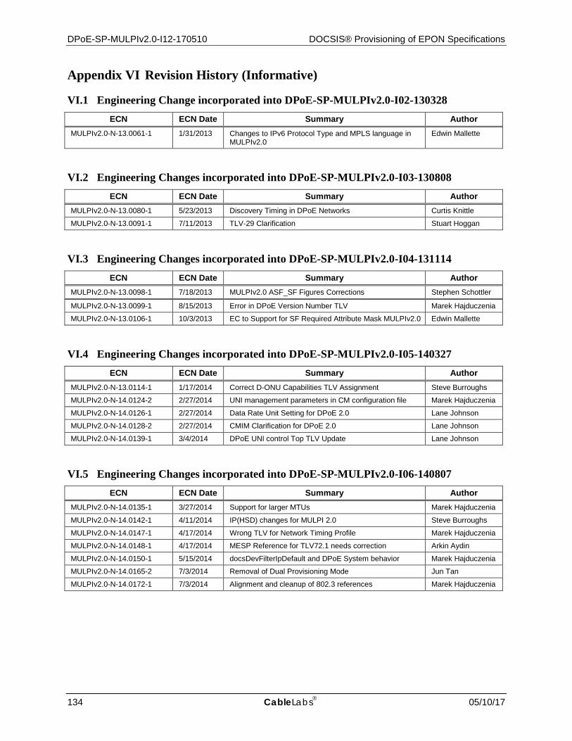
DPoE-SP-MULPIv2.0-I12-170510 DOCSIS® Provisioning of EPON Specifications
134 CableLabs 05/10/17
Appendix VI Revision History (Informative)
VI.1 Engineering Change incorporated into DPoE-SP-MULPIv2.0-I02-130328 ECN ECN Date Summary Author
MULPIv2.0-N-13.0061-1 1/31/2013 Changes to IPv6 Protocol Type and MPLS language in MULPIv2.0
Edwin Mallette
VI.2 Engineering Changes incorporated into DPoE-SP-MULPIv2.0-I03-130808 ECN ECN Date Summary Author
MULPIv2.0-N-13.0080-1 5/23/2013 Discovery Timing in DPoE Networks Curtis Knittle
MULPIv2.0-N-13.0091-1 7/11/2013 TLV-29 Clarification Stuart Hoggan
VI.3 Engineering Changes incorporated into DPoE-SP-MULPIv2.0-I04-131114 ECN ECN Date Summary Author
MULPIv2.0-N-13.0098-1 7/18/2013 MULPIv2.0 ASF_SF Figures Corrections Stephen Schottler
MULPIv2.0-N-13.0099-1 8/15/2013 Error in DPoE Version Number TLV Marek Hajduczenia
MULPIv2.0-N-13.0106-1 10/3/2013 EC to Support for SF Required Attribute Mask MULPIv2.0 Edwin Mallette
VI.4 Engineering Changes incorporated into DPoE-SP-MULPIv2.0-I05-140327 ECN ECN Date Summary Author
MULPIv2.0-N-13.0114-1 1/17/2014 Correct D-ONU Capabilities TLV Assignment Steve Burroughs
MULPIv2.0-N-14.0124-2 2/27/2014 UNI management parameters in CM configuration file Marek Hajduczenia
MULPIv2.0-N-14.0126-1 2/27/2014 Data Rate Unit Setting for DPoE 2.0 Lane Johnson
MULPIv2.0-N-14.0128-2 2/27/2014 CMIM Clarification for DPoE 2.0 Lane Johnson
MULPIv2.0-N-14.0139-1 3/4/2014 DPoE UNI control Top TLV Update Lane Johnson
VI.5 Engineering Changes incorporated into DPoE-SP-MULPIv2.0-I06-140807 ECN ECN Date Summary Author
MULPIv2.0-N-14.0135-1 3/27/2014 Support for larger MTUs Marek Hajduczenia
MULPIv2.0-N-14.0142-1 4/11/2014 IP(HSD) changes for MULPI 2.0 Steve Burroughs
MULPIv2.0-N-14.0147-1 4/17/2014 Wrong TLV for Network Timing Profile Marek Hajduczenia
MULPIv2.0-N-14.0148-1 4/17/2014 MESP Reference for TLV72.1 needs correction Arkin Aydin
MULPIv2.0-N-14.0150-1 5/15/2014 docsDevFilterIpDefault and DPoE System behavior Marek Hajduczenia
MULPIv2.0-N-14.0165-2 7/3/2014 Removal of Dual Provisioning Mode Jun Tan
MULPIv2.0-N-14.0172-1 7/3/2014 Alignment and cleanup of 802.3 references Marek Hajduczenia

DPoE MAC and Upper Layer Protocols Interface Specification DPoE-SP-MULPIv2.0-I12-170510
05/10/17 CableLabs 135
VI.6 Engineering Changes incorporated into DPoE-SP-MULPIv2.0-I07-150319 ECN ECN Date Summary Author
MULPIv2.0-N-14.0193-1 8/28/2014 Remove applicability of Data Rate Unit TLV from ASFs Curtis Knittle
MULPIv2.0-N-14.0195-1 10/30/2014 Clarification on the use of TLV35 and TLV18 in vCM config files
Marek Hajduczenia
MULPIv2.0-N-14.0198-1 10/30/2014 Support for Power Saving mechanism Marek Hajduczenia
MULPIv2.0-N-14.0202-1 1/8/2015 Align ToS Overwrite with DOCSIS Steve Burroughs
MULPIv2.0-N-15.0203-1 2/5/2015 Inconsistent requirements for TLV65.1 Marek Hajduczeni
MULPIv2.0-N-15.0205-1 2/19/2015 Binding downstream and upstream SFs into a single SF collection
Marek Hajduczenia
VI.7 Engineering Changes incorporated into DPoE-SP-MULPIv2.0-I08-150611 ECN ECN Date Summary Author
MULPIv2.0-N-15.0208-1 4/3/2015 DPoE MULPI 2.0 L2HSD Arkin Aydin
MULPIv2.0-N-15.0210-1 4/30/2015 Add L2VPN Multipoint Mode TLV Arkin Aydin
VI.8 Engineering Changes incorporated into DPoE-SP-MULPIv2.0-I09-151210 ECN ECN Date Summary Author
MULPIv2.0-N-15.0215-1 10/1/2015 DPoE System Config File Disposition with Inconsistent TLVs
Steve Burroughs
MULPIv2.0-N-15.0216-1 10/1/2015 Correct the Default CMIM for Primary SF to be all ports instead of first port
Arkin Aydin
MULPIv2.0-N-15.0220-2 11/5/2015 Multicast P1904.1 Alignment Steve Burroughs
VI.9 Engineering Changes incorporated into DPoE-SP-MULPIv2.0-I10-160602 ECN ECN Date Summary Author
MULPIv2.0-N-15.0223-2 12/10/2015 Support for Tree / Trunk optical link protection mechanism Marek Hajduczenia
MULPIv2.0-N-15.0228-1 12/31/2015 Remove DEMARC Specification References and Attributes
Steve Burroughs
MULPIv2.0-16.0234-1 3/17/2016 SF Collection Clarification/Correction Steve Burroughs
MULPIv2.0-16.0238-1 3/31/2016 Retire DPoE Enable/Disable SOAM TLV Steve Burroughs
VI.10 Engineering Change incorporated into DPoE-SP-MULPIv2.0-I11-170111 ECN ECN Date Summary Author
MULPIv2.0-N-16.0244-2 9/15/2016 MULPI2.0 Modify L2CP Filters Marek Hajduczenia
VI.11 Engineering Change incorporated into DPoE-SP-MULPIv2.0-I12-170510 ECN ECN Date Summary Author
MULPIv2.0-N-17.0249-1 4/13/2017 Add Config File TLV [24/25].35.2 for Target Buffer Size Janet Bean