
DNE(W) - Bangladesh Rural Electrification Board
385
DNE(W)- T-01-01 BANGLADESH RURAL ELECTRIFICATION BOARD Project Director “Distribution Network Expansion for 100% Rural Electrification (Rajshahi, Rangpur, Khulna & Barisal Divisions)", BREB.” Training Academy Building (7th floor), Bangladesh Rural Electrification Board, Nikunja-2, Khilkhet, Dhaka-1229. Telephone: 02-8900591 Electronic mail address: [email protected] Turnkey contract for survey, design, supply, carrying, installation, testing and commissioning of 33 kv double circuit river crossing tower with transmission lines including civil constructions at Bank Kali/Vushir Bandar - Bank Kali/Vushir Bandar on Atrai river under Dinajpur PBS-1. Invitation for Tender No: 27.12.0000.162.31.001.19.2506 ; Date : 29-05-2019 Issued on: ....................................................................... Tender Package No:DNE(W)-T-01 Tender Lot No:DNE(W)-T-01-01 ISO 9001, ISO 14001 & OHSAS 18001 Certified
-
Upload
khangminh22 -
Category
Documents
-
view
3 -
download
0
Transcript of DNE(W) - Bangladesh Rural Electrification Board

DNE(W)- T-01-01
BANGLADESH RURAL ELECTRIFICATION BOARD
Project Director
“Distribution Network Expansion for 100% Rural Electrification (Rajshahi,
Rangpur, Khulna & Barisal Divisions)", BREB.”
Training Academy Building (7th floor), Bangladesh Rural Electrification Board,
Nikunja-2, Khilkhet, Dhaka-1229.
Telephone: 02-8900591
Electronic mail address: [email protected]
Turnkey contract for survey, design, supply, carrying, installation, testing and commissioning of 33 kv double circuit river crossing tower with transmission lines including civil constructions at Bank Kali/Vushir Bandar - Bank Kali/Vushir Bandar on Atrai river under Dinajpur PBS-1.
Invitation for Tender No: 27.12.0000.162.31.001.19.2506 ; Date : 29-05-2019
Issued on: .......................................................................
Tender Package No:DNE(W)-T-01
Tender Lot No:DNE(W)-T-01-01
ISO 9001, ISO 14001 &
OHSAS 18001 Certified

DNE(W)- T-01-01
1 Ministry/Division Power Division, Ministry of Power, Energy and Mineral Resources.
2 Agency Bangladesh Rural Electrification Board.
3 Procuring Entity Name & District Project Director, Distribution Network Expansion for 100% Rural Electrification
(Rajshahi, Rangpur, Khulna & Barisal Divisions) Project, BREB
4 Invitation for Tender Name Turnkey Contract for Design, Supply, Installation, Testing & Commissioning of 33 kV
Double Circuit River Crossing Tower.
5 Invitation Ref No. & date 27.12.0000.162.31.001.19.2506 ; Date: 29-05-2019.
KEY INFORMATION
6 Procurement Method One stage Two Envelope Tendering for Turnkey Contract (OTM), NCT.
FUNDING INFORMATION
7 Budget and Source of Funds GOB & BREB Own Fund
8 Development Partners (if applicable) N/A
PARTICULAR INFORMATION
9 Project/ Programmed Code “Distribution Network Expansion for 100% Rural Electrification (Rajshahi, Rangpur,
Khulna & Barisal Divisions)” Project
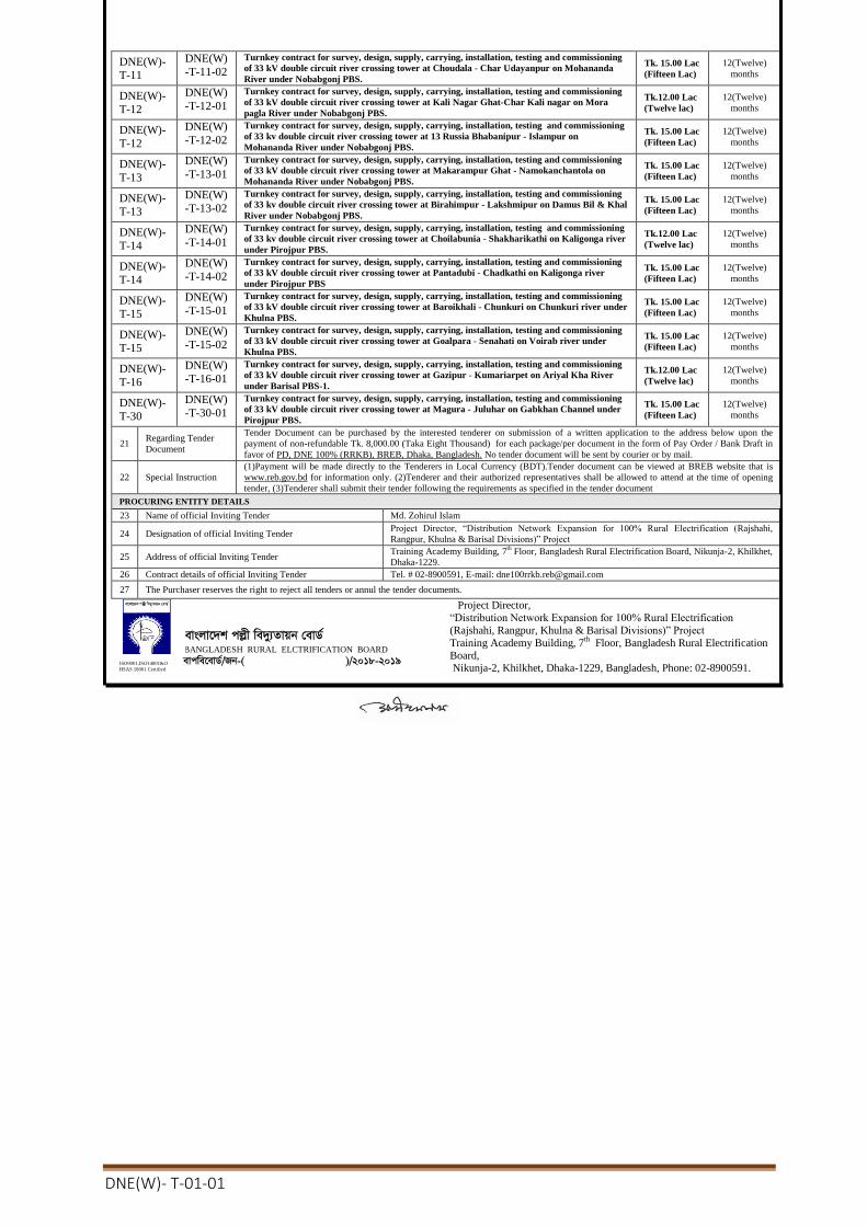
10 Tender Package No. DNE (W)-T-01, 02, 05, 08, 09, 11, 12, 13, 14, 15, 16 & 30.
11 Tender Publication Date Within 30-05-2019
12 Tender Last Selling Date/Closing Date & Time 03-07-2019 up to office time (BST)
13 Last date for Submission of Tender & Time 04-07-2019 up to 12.00 noon(BST)
14 Date and Time for opening of Tender & Time 04-07-2019 on 12.30 noon(BST)
15 Date and Time for Pre-Tender Meeting & Time 24-06-2019 on 11.00 AM(BST)
16 Tender Document including Profile & Typical Drawing will be available
for information only in the BREB website. BREB website: www.reb.gov.bd
17
Name & Address of the office Address
- For Selling Tender Document PD, DNE 100 %( RRKB), 7
th Floor, Training Academy Building, BREB, Nikunja-2,
Khilkhet, Dhaka -1229, Bangladesh.
- For Receiving Tender Document BREB Auditorium, 1
st Floor
, Head office Building, BREB, Nikunja-2, Khilkhet, Dhaka -
1229, Bangladesh.
- For Opening Tender Document BREB Auditorium, 1
st Floor
, Head office Building, BREB, Nikunja-2, Khilkhet, Dhaka -
1229, Bangladesh.
-For Pre-Tender Meeting PD, DNE 100 %( RRKB), 7
th Floor, Training Academy Building, BREB, Nikunja-2,
Khilkhet, Dhaka -1229, Bangladesh.
INFORMATION FOR TENDERER
18
Eligibility of
Tenderers
Specific Experience: The tenderer must have the minimum specific experience as a prime contractor or sub-contractor or management contractor(lead partner
in case of JV) in the turn-key contract for survey, design, supply, carrying, installation, testing and commissioning of 33 kV electrical
tower lines including foundation works as follows:
1. For construction of at least single/double circuit 33 kV electrical tower lines of minimum height 30 m. and span 300 m. including
foundation works of the tower with a minimum value at least TK. ...(as per respective package/ tender document) under maximum
two contract within last five(05) years. Years counting backward from the date of publication IFT in the newspaper.
Or
Any Bangladeshi steel tower manufacturing company having experience of supplying minimum 30 meters height tower shall be
eligible if the manufacturer or its partner in a Joint Venture company having the experience of turn-key contract for construction of at
least single/double circuit 33 kV electrical tower lines of minimum height 30 m. and span 300 m. including foundation works of the
tower with a minimum value at least TK. ....(as per respective package/ tender document) under maximum two contract within last
five(05) years. Years counting backward from the date of publication IFT in the newspaper.
2. In support of experience Tenderer shall submit satisfactory performance certificate(s) from the end-user’s letter head pad. The
certificate(s) shall mention the name and commissioning date of river crossing tower which were designed, supplied, constructed,
tested and commissioned by Tenderer(lead partner in case of JV) and shall contain end-user’s full mailing address, e-mail address,
website address, fax number and phone number for convenience of authentication.
19 Price of Tender
Document Tk.)
Tk.8,000.00 (non-refundable) for Per Document in the form of Pay Order / Bank Draft in favor of PD, DNE 100% (RRKB), BREB,
Dhaka, Bangladesh. From any schedule Bank of Bangladesh (Except BREB black listed Bank).
20 Brief Description of the Services:
Tender Package No. Description & Location of Works Tender
security(Tk.)
Completion
time
DNE(W)-
T-01
DNE(W)
-T-01-01
Turnkey contract for survey, design, supply, carrying, installation, testing and commissioning
of 33 kV double circuit river crossing tower at Bank kali/Vushir Bandar-Bank Kail/ Vushir
Bandar On Atrai River Dinajpur PBS-1.
Tk.12.00 Lac
(Twelve lac)
12(Twelve)
months
DNE(W)-
T-02
DNE(W)-T-02-01
Turnkey contract for survey, design, supply, carrying, installation, testing and commissioning
of 33 kV double circuit river crossing tower at Mohonpur-Jiamor on Atrai river under
Dinajpur PBS-1.
Tk.12.00 Lac
(Twelve lac)
12(Twelve)
months
DNE(W)-
T-05
DNE(W)-T-05-01
Turnkey contract for survey, design, supply, carrying, installation, testing and commissioning
of 33 kV double circuit river crossing tower at Dhorola Soudagar Para - Char Madhab Ram
on Dhorola River under Kurilal PBS.
Tk. 20.00 Lac
(Twenty Lac)
12(Twelve)
months
DNE(W)-
T-05
DNE(W)-T-05-02
Turnkey contract for survey, design, supply, carrying, installation, testing and commissioning
of 33 kV double circuit river crossing tower at Chit Paiker Cara -Bridge Par on Dudh-Kumar
River under Kurilal PBS.
Tk. 18.00 Lac
(Eighteen
Lac)
12(Twelve)
months
DNE(W)-T-08
DNE(W)
-T-08-01 Turnkey contract for survey, design, supply, carrying, installation, testing and commissioning
of 33 kV double circuit river crossing tower at 13 Russia Sonapata Dhakaia Para - Ramgonj
Bilashi on Korotowa River under Thakurgaon PBS.
Tk. 15.00 Lac
(Fifteen Lac)
12(Twelve)
months
DNE(W)-T-08
DNE(W)
-T-08-02 Turnkey contract for survey, design, supply, carrying, installation, testing and commissioning
of 33 kV double circuit river crossing tower at Mirgarh - Mirgarh on Korotowa River under
Thakurgaon PBS..
Tk. 15.00 Lac
(Fifteen Lac)
12(Twelve)
months
DNE(W)-T-09
DNE(W)
-T-09-01 Turnkey contract for survey, design, supply, carrying, installation, testing and commissioning
of 33 kV double circuit river crossing tower at Oviram Para - Thana Para on Korotowa River
under Thakurgaon PBS..
Tk. 15.00 Lac
(Fifteen Lac)
12(Twelve)
months
DNE(W)-T-09
DNE(W)
-T-09-02 Turnkey contract for survey, design, supply, carrying, installation, testing and commissioning
of 33 kV double circuit river crossing tower at Mirgarh - Amtola on Korotowa on Korotowa
River under Thakurgaon PBS.
Tk. 15.00 Lac
(Fifteen Lac)
12(Twelve)
months
DNE(W)-T-11
DNE(W)
-T-11-01 Turnkey contract for survey, design, supply, carrying, installation, testing and commissioning
of 33 kV double circuit river crossing tower at Noyagola Police Line- Jadobpur on Mohananda
River under Nobabgonj PBS.
Tk. 15.00 Lac
(Fifteen Lac)
12(Twelve)
months
Invitation for Tender (Local)
Bangladesh Rural Electrification Board
Government of the People’s Republic of Bangladesh
DNE(W)- T-01-01
DNE(W)-
T-11
DNE(W)
-T-11-02 Turnkey contract for survey, design, supply, carrying, installation, testing and commissioning
of 33 kV double circuit river crossing tower at Choudala - Char Udayanpur on Mohananda
River under Nobabgonj PBS.
Tk. 15.00 Lac
(Fifteen Lac)
12(Twelve)
months
DNE(W)-
T-12
DNE(W)
-T-12-01 Turnkey contract for survey, design, supply, carrying, installation, testing and commissioning
of 33 kV double circuit river crossing tower at Kali Nagar Ghat-Char Kali nagar on Mora
pagla River under Nobabgonj PBS.
Tk.12.00 Lac
(Twelve lac)
12(Twelve)
months
DNE(W)-
T-12
DNE(W)
-T-12-02 Turnkey contract for survey, design, supply, carrying, installation, testing and commissioning
of 33 kv double circuit river crossing tower at 13 Russia Bhabanipur - Islampur on
Mohananda River under Nobabgonj PBS.
Tk. 15.00 Lac
(Fifteen Lac)
12(Twelve)
months
DNE(W)-
T-13
DNE(W)
-T-13-01 Turnkey contract for survey, design, supply, carrying, installation, testing and commissioning
of 33 kV double circuit river crossing tower at Makarampur Ghat - Namokanchantola on
Mohananda River under Nobabgonj PBS.
Tk. 15.00 Lac
(Fifteen Lac)
12(Twelve)
months
DNE(W)-
T-13
DNE(W)
-T-13-02 Turnkey contract for survey, design, supply, carrying, installation, testing and commissioning
of 33 kv double circuit river crossing tower at Birahimpur - Lakshmipur on Damus Bil & Khal
River under Nobabgonj PBS.
Tk. 15.00 Lac
(Fifteen Lac)
12(Twelve)
months
DNE(W)-
T-14
DNE(W)
-T-14-01 Turnkey contract for survey, design, supply, carrying, installation, testing and commissioning
of 33 kv double circuit river crossing tower at Choilabunia - Shakharikathi on Kaligonga river
under Pirojpur PBS.
Tk.12.00 Lac
(Twelve lac)
12(Twelve)
months
DNE(W)-
T-14
DNE(W)
-T-14-02 Turnkey contract for survey, design, supply, carrying, installation, testing and commissioning
of 33 kV double circuit river crossing tower at Pantadubi - Chadkathi on Kaligonga river
under Pirojpur PBS
Tk. 15.00 Lac
(Fifteen Lac)
12(Twelve)
months
DNE(W)-
T-15
DNE(W)
-T-15-01 Turnkey contract for survey, design, supply, carrying, installation, testing and commissioning
of 33 kV double circuit river crossing tower at Baroikhali - Chunkuri on Chunkuri river under
Khulna PBS.
Tk. 15.00 Lac
(Fifteen Lac)
12(Twelve)
months
DNE(W)-
T-15
DNE(W)
-T-15-02 Turnkey contract for survey, design, supply, carrying, installation, testing and commissioning
of 33 kV double circuit river crossing tower at Goalpara - Senahati on Voirab river under
Khulna PBS.
Tk. 15.00 Lac
(Fifteen Lac)
12(Twelve)
months
DNE(W)-
T-16
DNE(W)
-T-16-01 Turnkey contract for survey, design, supply, carrying, installation, testing and commissioning
of 33 kV double circuit river crossing tower at Gazipur - Kumariarpet on Ariyal Kha River
under Barisal PBS-1. Tk.12.00 Lac
(Twelve lac)
12(Twelve)
months
DNE(W)-
T-30
DNE(W)
-T-30-01 Turnkey contract for survey, design, supply, carrying, installation, testing and commissioning
of 33 kV double circuit river crossing tower at Magura - Juluhar on Gabkhan Channel under
Pirojpur PBS. Tk. 15.00 Lac
(Fifteen Lac)
12(Twelve)
months
21 Regarding Tender
Document
Tender Document can be purchased by the interested tenderer on submission of a written application to the address below upon the
payment of non-refundable Tk. 8,000.00 (Taka Eight Thousand) for each package/per document in the form of Pay Order / Bank Draft in
favor of PD, DNE 100% (RRKB), BREB, Dhaka, Bangladesh. No tender document will be sent by courier or by mail.
22 Special Instruction
(1)Payment will be made directly to the Tenderers in Local Currency (BDT).Tender document can be viewed at BREB website that is
www.reb.gov.bd for information only. (2)Tenderer and their authorized representatives shall be allowed to attend at the time of opening
tender, (3)Tenderer shall submit their tender following the requirements as specified in the tender document
PROCURING ENTITY DETAILS
23 Name of official Inviting Tender Md. Zohirul Islam
24 Designation of official Inviting Tender Project Director, “Distribution Network Expansion for 100% Rural Electrification (Rajshahi,
Rangpur, Khulna & Barisal Divisions)” Project
25 Address of official Inviting Tender Training Academy Building, 7
th Floor, Bangladesh Rural Electrification Board, Nikunja-2, Khilkhet,
Dhaka-1229.
26 Contract details of official Inviting Tender Tel. # 02-8900591, E-mail: [email protected]
27 The Purchaser reserves the right to reject all tenders or annul the tender documents.
ISO9001,ISO14001&O
HSAS 18001 Certified
evsjv‡`k cjøx we`y¨Zvqb †evW©
BANGLADESH RURAL ELCTRIFICATION BOARD evcwe‡evW©/Rb-( )/2018-2019
Project Director,
“Distribution Network Expansion for 100% Rural Electrification
(Rajshahi, Rangpur, Khulna & Barisal Divisions)” Project
Training Academy Building, 7th
Floor, Bangladesh Rural Electrification
Board, Nikunja-2, Khilkhet, Dhaka-1229, Bangladesh, Phone: 02-8900591.

DNE(W)- T-01-01
TENDER DOCUMENT FOR THE
Turnkey contract for survey, design, supply, carrying, installation, testing and commissioning of 33 kv double circuit river crossing tower with transmission lines including civil constructions at Bank Kali/Vushir Bandar - Bank Kali/Vushir Bandar on Atrai river under Dinajpur PBS-1.
Volume - 1 of 3
Section 1 Instructions to Tenderers
Section 2 Tender Data Sheet
Volume - 2 of 3
Section 3 General Conditions of Contract
Section 4 Particular Conditions of Contract
Section 5 Tender and Contract Forms
Volume - 3 of 3
Section 6 Employer’s Requirements
Section 7 Drawings
DNE(W)- T-01-01
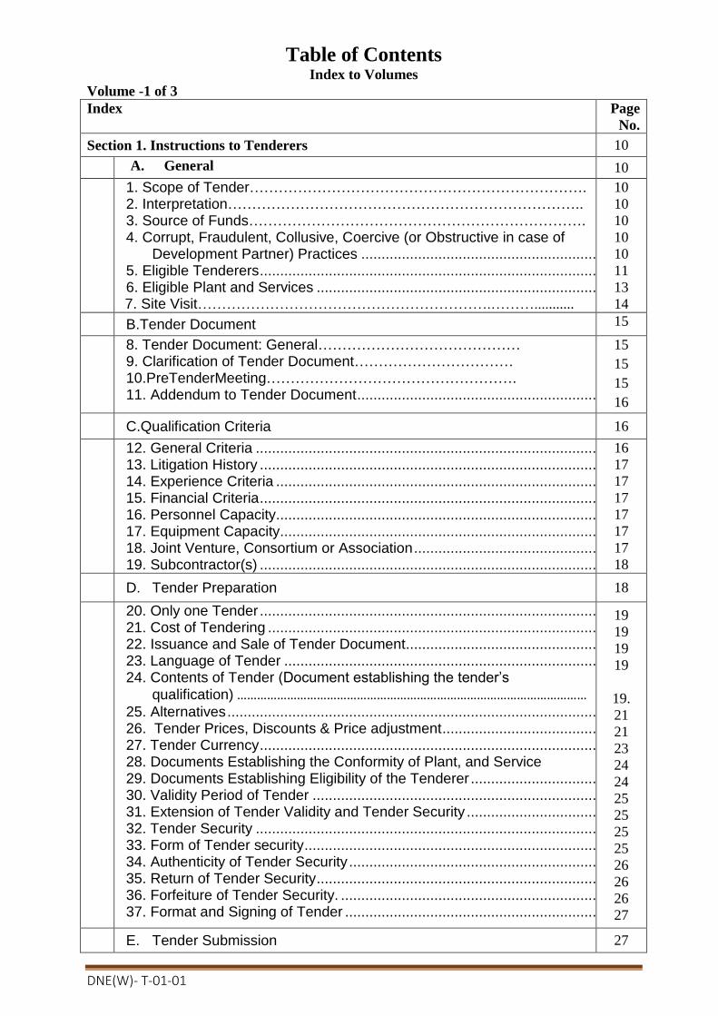
Table of Contents Index to Volumes
Volume -1 of 3
Index Page
No.
Section 1. Instructions to Tenderers 10
A. General 10
1. Scope of Tender……………………………………………………………. 2. Interpretation……………………………………………………………….. 3. Source of Funds……………………………………………………………. 4. Corrupt, Fraudulent, Collusive, Coercive (or Obstructive in case of
Development Partner) Practices ...................................................................... 12 5. Eligible Tenderers ............................................................................................... 14 6. Eligible Plant and Services ................................................................................. 14 7. Site Visit…………………………………………………….………...........
10
10
10
10
10
11
13
14
B.Tender Document 15
8. Tender Document: General…………………………………… 9. Clarification of Tender Document…………………………… 10.PreTenderMeeting……………………………………………. 11. Addendum to Tender Document ....................................................................... 17
15
15
15
16
C.Qualification Criteria 16
12. General Criteria ................................................................................................ 17 13. Litigation History ............................................................................................... 18 14. Experience Criteria ........................................................................................... 18 15. Financial Criteria ............................................................................................... 18 16. Personnel Capacity........................................................................................... 18 17. Equipment Capacity.......................................................................................... 18 18. Joint Venture, Consortium or Association ......................................................... 18 19. Subcontractor(s) ............................................................................................... 19
16
17
17
17
17
17
17
18
D. Tender Preparation 18
20. Only one Tender ............................................................................................... 19 21. Cost of Tendering ............................................................................................. 19 22. Issuance and Sale of Tender Document ........................................................... 20 23. Language of Tender ......................................................................................... 20 24. Contents of Tender (Document establishing the tender’s
qualification) …………………………………………………………………………………………… 25. Alternatives ....................................................................................................... 22 26. Tender Prices, Discounts & Price adjustment .................................................. 22 27. Tender Currency ............................................................................................... 24 28. Documents Establishing the Conformity of Plant, and Service 29. Documents Establishing Eligibility of the Tenderer ........................................... 25 30. Validity Period of Tender .................................................................................. 25 31. Extension of Tender Validity and Tender Security ............................................ 26 32. Tender Security ................................................................................................ 26 33. Form of Tender security .................................................................................... 26 34. Authenticity of Tender Security ......................................................................... 27 35. Return of Tender Security ................................................................................. 27 36. Forfeiture of Tender Security. ........................................................................... 27 37. Format and Signing of Tender .......................................................................... 28
19
19
19
19
19.
21
21
23
24
24
25
25
25
25
26
26
26
27
E. Tender Submission 27
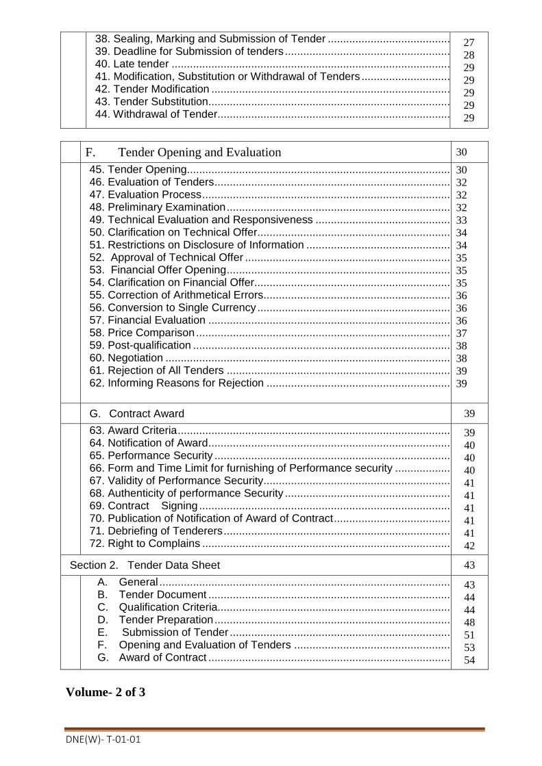
DNE(W)- T-01-01
38. Sealing, Marking and Submission of Tender .................................................... 28 39. Deadline for Submission of tenders .................................................................. 29 40. Late tender ....................................................................................................... 30 41. Modification, Substitution or Withdrawal of Tenders ......................................... 30
42. Tender Modification .......................................................................................... 30 43. Tender Substitution........................................................................................... 30 44. Withdrawal of Tender........................................................................................ 30
27
28
29
29
29
29
29
F. Tender Opening and Evaluation 30
45. Tender Opening................................................................................................. 31 46. Evaluation of Tenders ........................................................................................ 33 47. Evaluation Process ............................................................................................ 33
48. Preliminary Examination .................................................................................... 33 49. Technical Evaluation and Responsiveness ....................................................... 34 50. Clarification on Technical Offer.......................................................................... 35
51. Restrictions on Disclosure of Information .......................................................... 35 52. Approval of Technical Offer .............................................................................. 36 53. Financial Offer Opening .................................................................................... 36 54. Clarification on Financial Offer........................................................................... 36 55. Correction of Arithmetical Errors........................................................................ 37
56. Conversion to Single Currency .......................................................................... 37
57. Financial Evaluation .......................................................................................... 37 58. Price Comparison .............................................................................................. 38 59. Post-qualification ............................................................................................... 39
60. Negotiation ........................................................................................................ 39 61. Rejection of All Tenders .................................................................................... 40
62. Informing Reasons for Rejection ....................................................................... 40
30
32
32
32
33
34
34
35
35
35
36
36
36
37
38
38
39
39
G. Contract Award 39
63. Award Criteria .................................................................................................... 40
64. Notification of Award .......................................................................................... 41 65. Performance Security ........................................................................................ 41
66. Form and Time Limit for furnishing of Performance security ............................. 41 67. Validity of Performance Security........................................................................ 41 68. Authenticity of performance Security ................................................................. 42 69. Contract Signing ............................................................................................. 42
70. Publication of Notification of Award of Contract ................................................. 42 71. Debriefing of Tenderers ..................................................................................... 42 72. Right to Complains ............................................................................................ 43
39
40
40
40
41
41
41
41
41
42
Section 2. Tender Data Sheet 43
A. General ......................................................................................................... 44 B. Tender Document ......................................................................................... 44 C. Qualification Criteria...................................................................................... 45 D. Tender Preparation ....................................................................................... 49 E. Submission of Tender .................................................................................. 52 F. Opening and Evaluation of Tenders ............................................................. 54 G. Award of Contract ......................................................................................... 55
43
44
44
48
51
53
54
Volume- 2 of 3
DNE(W)- T-01-01
Section 3. General Conditions of Contract 55
A. General 55
1. Definitions .............. ………………………………………………………………………. 2. Interpretation ........................................................................................................... 3. Communications & Notices ..................................................................................... 4. Governing Law ........................................................................................................ 5. Governing Language .............................................................................................. 6. Documents Forming the Contract and Priority of Documents ................................. 7. Contract Agreement ................................................................................................ 8. Assignment ............................................................................................................. 9. Eligibility .................................................................................................................. 10. Gratuities / Agency fees ........................................................................................ 11. Confidential Details ............................................................................................... 12. Joint Venture (JV) ................................................................................................. 13. Possession of the Site .......................................................................................... 14. Access to the Site ................................................................................................. 15. Safety, Security and Protection of the Environment .............................................. 16. Working Hours ..................................................................................................... 17. Welfare of Laborers .............................................................................................. 18. Child Labor ............................................................................................................ 19. Fossils& antiquities ............................................................................................... 20. Corrupt, Fraudulent, Collusive or Coercive Practices ........................................... 21. License/ Use of Technical Information ..................................................................
55
59
59
59
60
60
60
60
60
60
60
61
62
62
62
62
62
63
63
63
64
B. Subject Matter of Contract 64
22. Scope of Facilities ................................................................................................. 23. Time for Commencement...................................................................................... 24. Time for Completion .............................................................................................. 25. Employer’s Responsibilities .................................................................................. 26. Contractor’s Responsibilities ................................................................................. 27. Employer’s and Contractor’s Risks ....................................................................... 28. Employer’s Risks .................................................................................................. 29. Contractor’s Risks .................................................................................................
65
65
65
66
67
67
67
68
C. Execution of the Facilities 68
30. Representatives .................................................................................................... 31. Work Program ....................................................................................................... 32. Subcontractor ........................................................................................................ 33. Nominated Subcontractor ..................................................................................... 34. Other Contractors ................................................................................................. 35. Design and Engineering ........................................................................................ 36. Procurement ......................................................................................................... 37. Installation ............................................................................................................. 38. Test & Inspection .................................................................................................. 39. Completion of the Facilities ................................................................................... 40. Commissioning and Operational Acceptance .......................................................
68
69
70
71
71
71
73
74
77
78
80
D. Guarantees and Liabilities 82
41. Completion Time Guarantee ................................................................................. 42. Defect Liability ....................................................................................................... 43. Functional Guarantees .......................................................................................... 44. Patent Indemnity ................................................................................................... 45. Limitation of Liability ..............................................................................................
82
83
85
85
86
E. Risk Distribution 87

DNE(W)- T-01-01
46. Transfer of Ownership .......................................................................................... 47. Care of Facilities ................................................................................................... 48. Loss of or Damage to Property; Accident or Injury to Workers;
Indemnification ..................................................................................................... 49. Insurance .............................................................................................................. 50. Unforeseen Conditions ......................................................................................... 51. Change in Laws and Regulation ........................................................................... 52. Force Majeure ....................................................................................................... 53. Notice of Force Majeure ........................................................................................ 54. Duty to Minimize Delay ......................................................................................... 55. Consequences of Force Majeure ..........................................................................
87
87
88
89
91
92
92
92
93
93
F. Payment 93
56. Contract Price ....................................................................................................... 57. Terms of Payment ................................................................................................. 58. Advance Payment Security ................................................................................... 59. Performance Security ........................................................................................... 60. Taxes and Duties .................................................................................................. 61. Payments to Nominated Subcontractor(s) ............................................................ 62. Price Adjustment ................................................................................................... 63. Liquidated Damages .............................................................................................
93
94
94
94
95
95
95
96
G. Change in Contract Elements 96
64. Change in the Facilities ......................................................................................... 65. Extension of Time for Completion ......................................................................... 66. Suspension ...........................................................................................................
96
99
100
H. Termination and Settlement of Disputes 101
67. Termination ........................................................................................................... 68. Payment upon Termination ................................................................................... 69. Property………………………………………………………………………………………
70. Frustration…………………………………………………………………………………….
101
103
104
104
I. Claims, Disputes and Arbitration 104
71. Contractor’s Claims ........................................................................................ 105
72. Settlement of Disputes…………. .................................................................... 105 104
104
Section 4. Part-I Particular Conditions of Contract…………………………………… .105
Part-II Additional Condition of Particular Application(ACPA): 1. Port Facilities and transport to site ……………….............. ............ .... ACPA -108
2. Documentation and Customs Duty……………................…… ……..... ACPA -108
2.1 Documentation ............…………………...………. .....… ACPA -108
2.2 Exemption of Customs Duty......... ……………………...…… . .... …… ACPA -108
2.3 Shipping Schedule......................... ……………………...……........….... ACPA -108
2.4 Removal of Material and Plant...... ……………………...… .. ..... ACPA -108
3. Units of measurement.................... …………………...….……… .....… ACPA -108
4. Erection and Checking at Site........……………………...…..…......…… ACPA -109
5. Safety Precautions........................ ……………………... …...... ……… ACPA -110
6. Details of offer and variations from specification......…... ….......…….. ACPA -110
7. Contractor's Responsibilities........……………………...……......……... ACPA -111
7.1 General ……………...……………...….................................................. ACPA -111
7.2 Planning of Work........................ ……………………...………....… .. ACPA -111
7.3 Progress Reports and Meetings..... …………………...………....……... ACPA -112
8. Sub-Contracts and Orders............. ……………...……………...... ........ ACPA -113
9. Inspection, Testing and Training...……………………...……..………. ACPA -113
10. Packing and Erection Marks......... ………………...…………........…... ACPA -114
11. Labour and General Site Services ……………...……………................ ACPA -114

DNE(W)- T-01-01
11.1 Living Accommodation ..............……………………...….....………… ACPA -115
11.2 Storage and Working Areas........ ……………………............................ ACPA -115
11.3 Office Accommodation ...............……………………...……………..... ACPA -115
11.4 Health Regulations.......................……………………...…………......... ACPA -115
11.5 Contractor's Employees.............. ……………………...………….. ...... ACPA -115
11.6 Identification of Contractor's Employees, Vehicles & Camps...……..... ACPA -115
11.7 Character of Workmen............... ……………………...……………...... ACPA -115
11.8 Use of Local Sub-Contractor......................................................… ......... ACPA- 116
12. Acts and Rules............................. ……………………...…………… ACPA- 116
13. Lifting Tackle, Tools and Equipment...………………...……………... ACPA -116
14. Spares shall be quoted as per Schedule.…………...…………......... ACPA -116
15. Price Schedules............................……………………...……………... ACPA -116
16. Diaries......................................... ……………………...……………... ACPA- 117
17. Work at Time and Material Rates (Day Work).…...…………….......... ACPA- 117
18. Storage, Protection and Handling Facilities.……...…………….......... ACPA -117
19. Induced Working Voltage............……………………...……………... ACPA -117
20. Documents, Goods, Materials, etc. to be handed over to Employer...... ACPA -117
21. Contractor's Local Agent.................................…...……………........... ACPA- 118
22. Use of English Language....................................................................... ACPA -118
23. Correspondence................................................…...…………….......... ACPA -118
24. Access to Site..................................................…...……………........... ACPA -118
25. Civil Works Design............................................................................... ACPA -118
26. Removal, Transport and Relocation of Existing Equipment............... ACPA -118
27. Drawings, Diagrams and Calculations................................................ ACPA - 119
27.1 General........................................……………………...………...…........ ACPA -119
27.2 Format........................................ ……………………...…………............. ACPA -119
27.3 Drawing Numbering and Revisions...............................…………………. ACPA -119
27.4 Drawing Submittals and Approvals.....………………..…………………… ACPA -120
27.5 Construction Amendments......... ……………………...……………. …….. ACPA -121
27.6 Record Drawing.........................................................................……………. ACPA -121
27.7 Drawing Register....................... ……………………...……………………. ACPA -121
28. Operation and Maintenance Manuals.................................................... ACPA - 122
28.1 General.. ....................................………… ….. …….....……………. ACPA -122
28.2 Contents ..................................................... ........ ............................ ACPA-122
28.3 Binders presentation .......................... ...... ............................ ACPA-123
29. Site storage Facilities................................... ..... ........................... ... . ACPA -123
30. Quality Assurance, Inspection and Testing.. ................................... ... ACPA - 123
30.1 General requirements.......................... ......................................... ACPA -123
30.1.1 Responsibility for Quality ................... ...................................... ACPA -124
30.1.2 Quality Assurance................................. .. ............... ...................... ACPA -124
30.1.3 Manufacturing Capacity............. ............. ................................... . ACPA - 124 30.2 Inspection Plan and Procedures................ ................................... . ACPA -124
30.2.1 General .......... . . . . . . . . . . . . . . . . . . . . . . . .. . . . . . . . . . . . . . . . ACPA - 124 30.2.2 Non-Conforming Material......…………… ...……………............. ACPA -125
30.2.3 Quality Audit...........................………............................................ ACPA -125
30.2.4 Measuring and Testing Equipment.....…… ………...……............. ACPA -125
30.2.5 Preservation Packing and Shipping............ …………...................... ACPA-125
30.2.6 Re-inspection following Non-Conformance...……….…............... ACPA -126
30.3 Plant Performance......................……………………...……......... ACPA -126
30.3.1 Guarantees................................... ……………………....….......... ACPA -126
30.3.2 Rejection..................................……………………...………........ ACPA -126
30.4 Sub-Contracts.............................……………………..….............. ACPA -126
30.5 Tests at Manufacturers Works.... ………………...……......... ACPA -127
30.5.1 General.........................................……………………....….......... ACPA -127
30.5.2 Material Tests ...........................……………………...…….......... ACPA -128
30.5.3 Test Certificates........................... ……………………....……...... ACPA-128
30.6 Site Pre-Commissioning Checks & Commissioning Procedures... ACPA -128
30.6.1 General......................................... …………………….................. ACPA- 128
30.6.2 Contractor's Site Supervisory Staff....................……...….…........ .ACPA -129
30.6.3 Commissioning & Modified Circuits.................……...…............ . ACPA -129
30.6.4 Test Equipment..................................................……...…….......... ACPA -130
31. Ruling Specification.....................…………...……………............ ACPA -130
32. Taxation.......................................……………….………............... ACPA -130

DNE(W)- T-01-01
33. Foreign Country Taxes and Permits…………...…………………. ACPA -130
34. Bangladesh Taxes, Levies and Permits……...……………............ ACPA -130
35. Site Data...................................……………………...…………..... ACPA -130
36. Customs and Import Duties..........………………...…………........ ACPA -130
37. Complaints and Appeals: ................................................................ ACPA - 130
37.1 Right to Complain (Regulation 50 of PPR-2008)…...…..…...…..... ACPA -130
37.2 Complaints to Administrative Authority (Reg. 51 of PPR-2008)… ACPA -131
37.3 The Review Panel (Regulation 52 of PPR-2008)................…. …... ACPA -132
37.4 Complaints to Review Panel (Regulation 53 of PPR-2008)……..... ACPA -132
37.5 Suspension of Procurement Proceedings (Reg. 54 of PPR-2008).... ACPA -133
APPENDIX- 1 ..................................................................................................................... ACPA -134
Part-III Labor Laws (ACPA)…………………………………………………… ACPA -135
Part-IV Appendices:
Appendix 1. Terms and Procedures of Payment ...................................................... 139
Appendix 2. Price Adjustment .................................................................................. 140
Appendix 3. Insurance Requirements ....................................................................... 142
Appendix 4. Time Schedule ..................................................................................... 144
Appendix 5. List of Major Items of Plant and Services and List of
Approved Subcontractors................................................................... 144
Appendix 6. Scope of Works and Supply by the Employer ..................................... 145
Appendix 7. List of Documents for Approval or Review ........................................ 146
Appendix 8. Functional Guarantees ........................................................................ 147
137
138
139
139
139
139
144
145
146
Section 5. Tender and Contract Forms 148
(Form PG5A-1a) ................................................................................................................
Tender Submission Letter for Financial offer(Form PG5A-1b)........................................
Tenderer Information (Form PG5A-2a)............................................................ JVCA Partner Information (Form PG5A-2b) ……………………………………….....
Subcontractor Information (Form PG5A-2c) …………………………………………...
Price Schedule for Plant and Service (Form PG5A-3) …………………………………
Technical Proposal (Form PG5A-4) ……………………………………………………
Specification Submission and Compliance Sheet(PG5A-4a) ……………. Manufacturer’s Authorisation Letter (Form PG5A - 5)............................................
Bank Guarantee for Tender Security (Form PG5A– 6)..........................................
Letter of Commitment for Bank’s undertaking for Line of Credit (Form PG5A-6a)
Notification of Award (Form PG5A - 7) ………………………………………………
Contract Agreement (Form PG5A - 8) …………………………………………………
Bank Guarantee for Performance Security (Form PG5A – 9)................................
Bank Guarantee for Advance Payment (Form PG5A – 10)...................................
Bank Guarantee for Retention Money Security (Form PG5A-11)..........................
149
151
154
157
160
163
166
171
172
173
174
175
176
177
178
179

DNE(W)- T-01-01
Volume-3 of 3
Section 6. Employer’s Requirements 180
6.1 Scope of Supply of Plant/Materials, Installation & Services by the Contractor. (Scope of Works, General/Details Technical Specification and Employer’s Requirement )
6.2 Specification/Particular Specification (Schedule: A-J): Schedule A Manufacturers, Places of Manufacture and Testing ……………
Schedule B Technical particulars and Guarantees…………………………...
Schedule C Departure from Specifications………………………………….
Schedule D Proposed Alternative standards to which Equipment shall
Provided………………………………………………………...
Schedule E Proposed Contract and site organization………………………...
Schedule F Key Personnel...............................................................................
Schedule G Equipment For Construction........................................................
Schedule H Proposed Subcontractors.............................................................
Schedule I Drawings and documents to be submitted with Bid…………….
Schedule J Bar chart programme of key activities..........................................
6.3 Form of Completion Certificate ........................................................................... 6.4 Form of Operational Acceptance Certificate ...................................................... 6.5 Form of Change Order Procedure and Forms ...................................................
180-
351
352
353
354
359
360
361
362
363
364
364
366
367
368
370
Annex 1. Request for Change Proposal ..................................................................... Annex 2. Estimate for Change Proposal .................................................................... Annex 3. Acceptance of Estimate .............................................................................. Annex 4. Change Proposal ........................................................................................ Annex 5. Change Order ............................................................................................. Annex 6. Pending Agreement Change Order…………………………………….
Annex 7. Application for Change Proposal………………………………………..
371
372
373
376
377
378
378
Section 7.Drawings……………………………………………………... 379

DNE(W)- T-01-01
Volume- 1 of 3
Section 1. Instructions to Tenderers
A. General 1. Scope of Tender 1.1 The Purchaser named in the Tender Data Sheet (TDS)
(hereinafter referred to as the “Purchaser”) wishes to issue these Tender Documents for the supply and installation of plant & equipment incidental thereto, as specified in the TDS and as detailed in Section 6: Employer’s Requirements.
1.2 The name of the Tender and the number and identification of its constituent lot(s) are stated in the TDS.
1.3 Unless otherwise stated, throughout this Tender Document definitions and interpretations shall be as prescribed in the Section 3: General Conditions of Contract.
2. Interpretation 2.1 Throughout this Tender Document
(a) the term “in writing” means communication written by hand or machine duly signed and includes properly authenticated messages by facsimile or electronic mail;
(b) if the context so requires, singular means plural and vice versa; and
(c) “day” means calendar days unless otherwise specified as working days;
(d) "Tender Document ", means the Document provided by a Purchaser to a Tenderer as a basis for preparation of its Tender;
(e) "Tender ", depending on the context, means a Tender submitted by a Tenderer for delivery of Goods and Related Services to a Purchaser in response to an Invitation for Tender ;
3. Source of Funds 3.1 The Purchaser has been allocated public funds from the source as indicated in the TDS and intends to apply a portion of the funds to eligible payments under the contract for which this Tender Document is issued.
3.2 For the purpose of this provision, “public funds” means any funds allocated to a Purchaser under Government budget, or loan, grants and credits placed at the disposal of a Purchaser through the Government by the development partners or foreign states or organizations.
3.3 Payments by the development partner, if so indicated in the TDS, will be made only at the request of the Government and upon approval by the development partner in accordance with the applicable Loan/Credit/Grant Agreement, and will be subject in all respects to the terms and conditions of that Agreement.

DNE(W)- T-01-01
4. Corrupt, Fraudulent, Collusive, Coercive (or Obstructive
in case of Development Partner) Practices
4.1 The Government and the Development Partner, if applicablerequires that the Procuring Entity as well as the Tenderers and Contracts (including , sub-contractors, agents, personnel, consultants, and service providers)shall observe the highest standard of ethics during implementation of procurement proceedings and the execution of Contracts under public funds.
4.2 For the purposes of ITT Sub Clause 4.3, the terms set forth below as follows:
(a) “corrupt practice” means offering, giving or promising to give, receiving, or soliciting either directly or indirectly, to any officer or employee of the Procuring Entity or other public or private authority or individual, a gratuity in any form; employment or any other thing or service of value as an inducement with respect to an act or decision or method followed by the Procuring Entity in connection with a Procurement proceeding or Contract execution;
(b) “fraudulent practice” means the misrepresentation or omission of facts in order to influence a decision to be taken in a Procurement proceeding or Contract execution;
(c) “collusive practice” means a scheme or arrangement between two (2) or more Persons, with or without the knowledge of the Procuring Entity, that is designed to arbitrarily reduce the number of Tenders submitted or fix Tender prices at artificial, non-competitive levels, thereby denying the Procuring Entity the benefits of competitive price arising from genuine and open competition;
(d) “coercive practice” means harming or threatening to harm, directly or indirectly, Persons or their property to influence a decision to be taken in the Procurement proceeding or the execution of a Contract, and this will include creating obstructions in the normal submission process used for Tenders.
(e) “Obstructive practice” (applicable in case of Development Partner) means deliberately destroying, falsifying, altering or concealing of evidence material to the investigation or making false statements to investigators in order to materially impede an investigation into allegations of a corrupt, fraudulent, coercive or collusive practice; and /or threatening, harassing or intimidating any party to prevent it from disclosing its knowledge of matters relevant to the investigation or from pursuing the investigation.
4.3 Should any corrupt, fraudulent, collusive, coercive (or obstructive in case of Development Partner) practice of any kind is determined by the Procuring Entity or the Development Partner, if applicable, this will be dealt in accordance with the provisions of the Public Procurement Act and Rules and Guidelines of the Development Partners as stated in the ITT sub-clause 3.3.
In case of obstructive practice, this will be dealt in accordance with Development Partners Guidelines.
DNE(W)- T-01-01
4.4 If corrupt, fraudulent, collusive, coercive (or obstructive in case of Development Partner) practices of any kind is determined by the Procuring Entity against any Tenderer or Contracts (including sub-contractors, agents, personnel, consultants, and service providers) in competing for, or in executing, a contract under public fund:
(a) Procuring Entity and/or the Development Partner shall exclude the concerned Tenderer from further participation in the concerned procurement proceedings;
(b) Procuring Entity and/or the Development Partner shall reject any recommendation for award that had been proposed for that concerned Tenderer;
(c) Procuring Entity and/or the Development Partner shall declare, at its discretion, the concerned Tenderer to be ineligible to participate in further Procurement proceedings, either indefinitely or for a specific period of time;
(d) Development Partner shall sanction the concerned Tenderer or individual, at any time, in accordance with prevailing Development Partner’ sanctions procedures, including by publicly declaring such Tenderer or individual ineligible, either indefinitely or for a stated period of time: (i) to be awarded a Development Partner-financed contract; and (ii) to be a nominated sub-contractor, consultant, manufacturer or Contractor, or service provider of an otherwise eligible firm being awarded a Development Partner-financed contract; and
(e) Development Partner shall cancel the portion of the loan allocated to a contract if it determines at any time that representatives of the Procuring Entity or of a beneficiary of the loan engaged in corrupt, fraudulent, collusive, coercive or obstructive practices during the procurement or the execution of that Development Partner financed contract, without the Procuring Entity having taken timely and appropriate action satisfactory to the Development Partner to remedy the situation.
4.5 Tenderer shall be aware of the provisions on corruption, fraudulence, collusion, coercion (and obstruction, in case of Development Partner) of the Public Procurement Act, 2006, the Public Procurement Rules, 2008 and others as stated in GCC Clause 38.
4.6 In further pursuance of this policy, Tenderers, Contractors and theirsub-contractors, agents, personnel, consultants, service providers shall permit the Government and the Development Partner to inspect any accounts and records and other documents relating to the Tender submission and contract performance, and to have them audited by auditors appointed by the Government and/or the Development Partner during the procurement or the execution of that Development Partner financed contract.
DNE(W)- T-01-01
5. Eligible Tenderers 5.1 This Invitation for Tenders is open to all potential Tenderers from all countries, except for any specified in the TDS.
5.2 Tenderers shall have the legal capacity to enter into the Contract under the Applicable law.
5.3 Tenderers shall be enrolled in the relevant professional or trade organisations registered in Bangladesh.
5.4 Tenderers may be a physical or juridical individual or body of individuals, or company, association or any combination of them in the form of a Joint Venture(JV) invited to take part in public procurement or seeking to be so invited or submitting a Tender in response to an Invitation for Tenders.
5.5 Tenderers shall have fulfilled its obligations to pay taxes and social security contributions under the provisions of laws and regulations of the country of its origin.
5.6 Tenderers should not be associated, or have been associated in the past, directly or indirectly, with a consultant or any of its affiliates which have been engaged by the Procuring Entity to provide consulting services for the preparation of the design, specifications, and other documents to be used for the procurement of the works to be performed under this Invitation for Tenders.
5.7 Tenderers in its own name or its other names or also in the case of its Persons in different names shall not be under a declaration of ineligibility for corrupt, fraudulent, collusive or coercive practices as stated under ITT Sub Clause 4.4 (or obstructive practice, in case of Development Partner) in relation to the Development Partner’s Guidelines in projects financed by Development Partner.
5.8 Tenderers are not restrained or barred from participating in Public Procurement on grounds of poor performance in the past under any Contract.
5.9 Tenderers shall not be insolvent, be in receivership, be bankrupt, be in the process of bankruptcy, be not temporarily barred from undertaking business and it shall not be the subject of legal proceedings for any of the foregoing.
5.10 Government-owned enterprise in Bangladesh may also participate in the Tender if it is legally and financially autonomous, it operates under commercial law, and it is not a dependent agency of the Procuring Entity.
5.11 Tenderers shall provide such evidence of their continued eligibility satisfactory to the Procuring Entity, as the Procuring Entity will reasonably request.
5.12 These above requirements for eligibility will extend, as applicable, to each JV partner and Subcontractor proposed by the Tenderers.
5.13 Tenderers shall have the up-to-date valid license(s), issued by the corresponding competent authority, as specified in the TDS.
6. Eligible Plant and Services
6.1 The plant and services to be supplied under the contract are eligible, unless their origin is from a country specified in the TDS and all expenditures under the contract will be limited to such plant, and services.

DNE(W)- T-01-01
6.2 For purposes of this Clause, the term “plant” means permanent
plant, equipment, machinery, apparatus, articles and things of all
kinds to be provided in the facilities; and “installation services”
means all those services ancillary to the supply of the Plant for
the Facilities, such as transportation and provision of marine or
other similar insurance, inspection, expediting, site preparation,
installation, testing, pre-commissioning, commissioning,
operations, maintenance, the provision of operations and
maintenance manuals, training etc
6.3 For purposes of this clause, “origin” means the place where the
plant, or component parts thereof are mined, grown, produced
or manufactured, and from which the services are provided.
Plant components are produced when, through manufacturing,
processing, or substantial or major assembling of components,
a commercially recognized product results that is substantially
different in its basic characteristics or in purpose or utility from its
components orcountry where the goods have been mined,
grown, cultivated, produced, manufactured or processed; or
through manufacture, processing, or assembly, another
commercially recognized article results that differs substantially
in its basic characteristics from its components.
6.4 The origin of plant & equipment is distinct from the nationality of
the Tenderer. The nationality of the firm that produces,
assembles, distributes, or sells the goods shall not determine
their origin.
7. Site Visit 7.1 The Tenderer is advised to visit and examine the site where
the plant is to be installed and its surroundings and obtain for
itself on its own responsibility all information that may be
necessary for preparing the tender and entering into a
contract for the provision of Plant and Installation Services.
7.2 The Tenderer and any of its personnel or agents will be
granted permission by the Employer to enter upon its
premises and lands for the purpose of such visit, but only
upon the express condition that the Tenderer, its personnel,
and agents will release and indemnify the Employer and its
personnel and agents from and against all liability in respect
thereof, and will be responsible for death or personal injury,
loss of or damage to property, and any other loss, damage,
costs, and expenses incurred as a result of the inspection.
7.3 The Tenderer should ensure that the Purchaser is informed of
the visit in adequate time to allow it to make appropriate
arrangements.
7.4 The costs of visiting the Site shall be at the Tenderer’s own
expense.
B. Tender Document

DNE(W)- T-01-01
8. Tender Document: General
8.1 The Sections comprising the Tender Document are listed below, and should be read in conjunction with any Addendum issued under ITT Clause 11.
Section 1 Instructions to Tenderers (ITT)
Section 2 Tender Data Sheet (TDS)
Section 3 General Conditions of Contract (GCC)
Section 4 Particular Conditions of Contract (PCC)
Section 5 Tender and Contract Forms
Section 6 Employer’s Requirements
Section 7 Drawings
8.2 The Purchaser shall reject any Tender if the Tender Document was not purchased directly from the Purchaser, or through its agent as stated in the TDS.
8.3 The Tenderer is expected to examine all instructions, forms, terms, and specifications in the Tender Document as well as addendum to Tender Documents.
9. Clarification of Tender Document
9.1 A prospective Tenderer requiring any clarification of the Tender Document shall contact the Purchaser in writing at the Purchasers address indicated in the TDS before two-third of time allowed for preparation and submission of Tender elapses.
9.2 The Procuring Entity is not obliged to answer any clarification request received after that date as stated under ITT Sub Clause 9.1.
9.3 The Procuring Entity shall respond in writing within five (5) working days of receipt of any such request for clarification received under ITT Sub Clause 9.1.
9.4 The Procuring Entity shall forward copies of its response to all those who have purchased the Tender Document, including a description of the enquiry but without identifying its source.
9.5 Should the Procuring Entity deem it necessary to revise the Tender Document as a result of a clarification, it will do so following the procedure under ITT Clause 11.
10. Pre-TenderMeeting 10.1 To clarify issues and to answer questions on any matter arising in the Tender Document, the Purchaser may, if stated in the TDS, hold a Pre-Tender Meeting at the place, date and time as specified in the TDS. All Potential Tenderers are encouraged to attend the meeting, if it is held.
10.2 Minutes of the pre-Tender meeting, including the text of the questions raised and the responses given, together with any responses prepared after the meeting, will be transmitted within one week (7 days) after holding the meeting to all those who purchased the Tender Document and even those who did not attend the meeting.
10.3 Any amendment to the Tender Documents listed in ITT Sub-Clause 8.1 that may become necessary as a result of the pre-Tender meeting shall be made by the Purchaser exclusively through the issue of an Addendum as stated under ITT Sub-Clause 11 and not through the minutes of the pre-Tender meeting.

DNE(W)- T-01-01
10.4 Non-attendance at the Pre-Tender meeting will not be a cause for disqualification of a Tenderer.
11. Addendum to Tender Document
11.1 At any time prior to the deadline for submission of Tenders, the Purchaser on its own initiative or in response to a clarification request in writing from a Tenderer, having purchased the Tender Document or as a result of a Pre-Tender meeting, may revise the Tender Document by issuing an addendum pursuant to Rule 95 of the Public Procurement Rules, 2008.
11.2 The addendum issued under ITT Sub-Clause 11.1 shall become an integral part of the Tender Document and shall have a date and an issue number and shall be circulated by fax, mail or e-mail, to Tenderers who have purchased the Tender Documents within five (5) working days of issuance of such addendum, to enable Tenderers to take appropriate action.
11.3 The Tenderer shall acknowledge receipt of an addendum.
11.4 Tenderers who have purchased the Tender Documents but have not received any addendum issued under ITT Sub-clause 11.1 shall inform the Purchaser of the fact by fax, mail or e-mail before two-third of the time allowed for the submission of Tenders has elapsed.
11.5 Procuring Entities shall also ensure posting of relevant addenda with the reference number and date on their website.
11.6 To give a prospective Tenderer reasonable time in which to take an amendment into account in preparing its Tender, the Purchaser may, at its discretion, extend the deadline for the submission of Tenders, pursuant to Rule 95(6) of the Public Procurement Rule, 2008 and under ITT Clause 36.
11.7 If an addendum is issued when time remaining is less than one-third of the time allowed for the preparation of Tenders, a Purchaser shall extend the deadline by an appropriate number of days for the submission of Tenders, depending upon the nature of the Procurement requirement and the addendum. The minimum time for such extension shall not be less than seven (7) days.
C. Qualification Criteria
12. General Criteria 12.1 The Tenderer shall possess the necessary professional and technical qualifications and competence, financial resources, equipment and other physical facilities, managerial capability, specific experience, reputation, and the personnel, to perform the contract.
12.2 In addition to meeting the eligibility criteria, as stated in ITT Clause 5, the Tenderer must satisfy the other criteria stated in ITT Clauses 13 to 15 inclusive.

DNE(W)- T-01-01
12.3 To qualify for multiple number of contracts/lots in a package made up of this and other individual contracts/lots for which tenders are invited in the Invitation for Tenders, the Tenderer shall demonstrate having resources and experience sufficient to meet the aggregate of the qualifying criteria for the individual contracts.
13. Litigation History 13.1 The maximum number of arbitration awards against the Tenderer over a period shall be as specified in the TDS.
14. Experience Criteria
14.1 Tenderers shall have the following minimum level of supply
experience to qualify for supplying the Plant and Services under the contract:
(a) a minimum number of years of general experience in the role of Contractor or Subcontractor or Management Contractor as specified in the TDS; and
(b) Specific experience as a Contractor or Subcontractor or Management Contractor that are similar to the proposed plant and services in at least a number of contract(s) and of a minimum value over the period, as specified in the TDS.
15. Financial Criteria 15.1 Tenderers shall have the following minimum level of financial capacity of qualify for the supply, execution and performance of plant and services under the contract.
(a) the average annual turnover as specified in the TDS calculated as total certified payments received for contracts in progress or completed, during the period specified in the TDS;
(b) availability of minimum liquid assets or working capital or credit facilities, as specified in the TDS; and;
(c) satisfactory resolution of all claims, arbitrations or other litigation cases and shall not have serious negative impact on the financial capacity of the Tenderer.
16. Personnel Capacity 16.1 The Tenderer shall have the following minimum level of
personnel capacity to qualify for the performance of the plant and services under the Contract.
A Project Manager, Engineers, and other key staff with qualifications and experience as specified in the TDS;
17. Equipment Capacity
17.1 The Tenderer shall own suitable equipment and other physical facilities or have proven access through contractual arrangement to hire or lease such equipment or facilities for the desired period, where necessary or have assured access through lease, hire, or other such method, of the essential equipment, in full working order, as specified in the TDS.
18. Joint Venture, Consortium or Association
18.1 The Tenderer may participate in the procurement proceedings forming a Joint Venture, Consortium or Associations (JVCA) by an agreement,executed case by case on a non judicial stamp of value as stated in TDS or alternately with the intent to enter into such an agreement supported by a Letter of Intent along with the proposed agreement duly signed by all partners of the intended JVCA and authenticated by a Notary Public.
18.2 The figures for each of the partners of a JVCA shall be added together to determine the Tenderer’s compliance with the minimum qualifying criteria; however, for a JVCA to qualify,

DNE(W)- T-01-01
lead partner and its other partners must meet the criteria stated in the TDS. Failure to comply with these requirements will result in rejection of the JVCA Tender. Subcontractors’ experience and resources will not be taken into account in determining the Tenderer’s compliance with the qualifying criteria.
18.3 Each partner of the JVCA shall be jointly and severally liable for the execution of the Contract, all liabilities and ethical and legal obligations in accordance with the Contract terms.
18.4 The JVCA shall nominate a Representative (partner-in-charge/Lead Firm) who shall have the authority to conduct all business for and on behalf of any and all the partners of the JVCA during the tendering process and, in the event the JVCA is awarded the Contract, during contract execution including the receipt of payments for and on behalf of the JVCA.
18.5 Each partner of the JVCA shall complete the JVCA Partner Information (Form PG5A-2b)for submission with the Tender
19. Subcontractor(s) 19.1 Tenderer, pursuant to Rule 53 of the PPR2008, is allowed to sub-contract a portion of the Supply.
19.2 The Tenderer shall specify in its Tender all portion of the Plant and Services that will be subcontracted, if any, including the entity(ies) to whom each portion will be subcontracted to, subject to the maximum allowable limit for subcontracting of Plant and Services specified in the TDS.
19.3 The Purchaser may require Tenderers to provide more information about their subcontracting arrangements. If any Subcontractor is found ineligible or unsuitable to carry out the subcontracted tasks, the Procuring Entity may request the Tenderer to propose an acceptable substitute.
19.4 The Purchaser may also select nominated Subcontractor(s) to execute certain specific components of the Works and if so, those will be specified in the TDS.
19.5 The successful Tenderer shall under no circumstances assign the goods/works/services or any part of it to a Subcontractor.
19.6 Subcontractors must comply with the provision of ITT Clause 5. For this purpose contractor shall complete the Subcontractor’s information in Form PG5A-2c for submission with tender.
19.7 If the Purchaser determines that a subcontractor is ineligible, the subcontracting of such portion of the Plants and Services assigned to the ineligible subcontractor shall be disallowed.
D. Tender Preparation 20. Only one Tender 20.1 If a Tender for Plant and Services is invited on ‘lot-by-lot’ basis,
each lot shall constitute a tender. A Tenderer shall submit only one (1) Tender for each lot, either individually or as a JVCA. The Tenderer who submits or participates in more than one (1) Tender for each lot will cause all the Tenders with that Tenderer’s participation to be rejected.
21. Cost of Tendering 21.1 Tenderers shall bear all costs associated with the preparation and submission of its Tender, and the Purchaser shall not be
DNE(W)- T-01-01
responsible or liable for those costs, regardless of the conduct or outcome of the Tendering process.
22. Issuance and Sale of Tender Document
22.1 A Purchaser, pursuant to Rule 94 of the Public Procurement Rules, 2008 shall make Tender Documents available immediately to the potential Tenderers, requesting and willing to purchase at the corresponding price if the advertisement has been published in the newspaper pursuant to Rule 90 of the Public Procurement Rules, 2008.
22.2 Full contact details with mailing address, telephone and facsimile numbers and electronic mail address, as applicable, of those to whom Tender Documents have been issued shall be recorded with a reference number by the Purchaser or its agent.
22.3 There shall not be any pre-conditions whatsoever, for sale of Tender Document and the sale of such Document shall be permitted up to the day prior to the day of deadline for the submission of Tender.
23. Language of Tender
23.1 Tenders shall be written in the English language. Correspondences and documents relating to the Tender may be written in English or Bangla. Supporting documents and printed literature furnished by the Tenderers that are part of the Tender may be in another language, provided they are accompanied by an accurate translation of the relevant passages in the English or Bangla language, in which case, for purposes of interpretation of the Tender, such translation shall govern.
23.2 Tenderers shall bear all costs of translation to the governing language and all risks of the accuracy of such translation.
24. Contents of Tender(Document establishing the tender’s qualification)
24.1 The Tender prepared by the Tenderers shall comprise Two Envelope submitted simultaneously, one called the Technical Offer (Envelope-01) containing the documents listed in ITT 24.2 and other called the Financial Offer containing the documents listed in 24.3, both envelopes enclosed together in an outer Single envelope.
24.2 The Technical Offer (Envelope-01) prepared by the Tenderers will comprise the following:
(a) Technical Submission Letter (Form PG5A-1a) as furnished in Section 5: Tender and Contract Forms. This form must be completed without any alterations to its format, and no substitutes shall be accepted. All blank spaces shall be filled in with the information requested
(b) Tenderer Information Sheet (Form PG5A-2)as furnished in Section 5: Tender and Contract Forms;
(c) Tender Security as stated under ITT Clause 32,33 and 34;
(d) Technical Proposal (Form PG5A-4) as furnished in Section 5: Tender and Contract Forms.
(e) Alternatives, if permitted, as stated under with ITT Clause 25;
(f) Written confirmation authorising the signatory of the Tender to commit the Tenderer, as stated under ITT Sub-Clause 37.3;

DNE(W)- T-01-01
(g) The completed eligibility declarations, to establish its eligibility as stated under ITT Clause 5, in the Tender Submission Sheet (Form PG5A-1a & 1b), as furnished in section 5: Tender and Contract Forms;
(h) An affidavit confirming the legal capacity stating that there are no existing orders of any judicial court that prevents either the Tenderer or employees of a Tenderer entering into or signing a Contract with the Purchaser as stated under ITT clause 5;
(i) An affidavit confirming that the Tenderer is not insolvent, in receivership or not bankrupt or not in the process of bankruptcy, not temporarily barred from undertaking their business for financial reasons and shall not be the subject of legal proceedings for any of the foregoing as stated under ITT Clause 5;
(j) A certificate issued by the competent authority stating that the Tenderer is a Tax payer having valid Tax Identification Number (TIN) and VAT registration number or in lieu any other document acceptable to the Purchaser demonstrating that the Tenderer is a genuine Tax payer and has a VAT registration number as a proof of fulfillment of taxation obligations as stated under ITT Clause 5. In the case of foreign Tenderers, a certificate of competent authority in that country of which the Tenderer is citizen shall be provided ;
(k) Documentary evidence demonstrating that they are enrolled in the relevant professional or trade organizations registered in Bangladesh or in case of foreign tenderer in their country of origin or a certificate concerning their competency issued by a professional institution in accordance with the law of the country of their origin, as stated under ITT Clause 5;
(l) The country of origin declarations, to establish the eligibility of the Plant and Services as stated under ITT Clause 6, in the Price Schedule for Plant and Services (Form PG5A-3) as, applicable, furnished in Section 5: Tender and Contract Forms;
(m) Documentary evidence as stated under ITT Clauses 28, that the Goods and Related Services conform to the Tender Documents;
(n) Documentary evidence as stated under ITT Clause 29 that the Tenderer’s qualifications conform to the Tender Documents;
(o) Documents establishing legal and financial autonomy and compliance with commercial law, as stated under ITT Sub-clause 5.3 in case of government owned entity; and
(p) In addition to the requirements stated under ITT Sub Clause 18.1, Tenders submitted by a JVCA or proposing a Subcontractor shall include.
i. a Joint Venture Agreement entered into by all partners, executed on a non-judicial stamp of value or equivalent as stated under ITT Sub Clause 18.1; or
ii. a Letter of Intent along with the proposed agreement duly signed by all partners of the intended JVCA with

DNE(W)- T-01-01
the declaration that it will execute the Joint Venture agreement in the event the Tenderer is successful;
iii. the JVCA Partner Information (Form PG5A-2b);
iv. the Subcontractor Information (Form PG5A-2c).
(q) the completed Specifications Submission and Compliance Sheet (Form PG5A-4a)as stated under ITT clause 28.1;
(r) Any other document as specified in the TDS.
24.3 The Financial Offer (Financial Envelope -02) prepared by the Tenderers shall comprise the following:
(a) The Financial offer Submission Letter (Form PG5A-1b) as furnished in Section 5:
(b) The Tenderer shall submit the completed Price Schedule for Plant and Services (Form PG5A-3), according to their origin as appropriate as furnished in section 5: Tender and Contract Forms.
(c) the written confirmation authorizing the signatory of the Tender to commit the Tenderer, as stated under ITT Sub Clause 37.3;
(d) any other document as specified in the TDS.
25. Alternatives 25.1 Unless otherwise stated in the TDS, alternatives shall not be considered.
26. Tender Prices, Discounts& Price adjustment
26.1 Unless otherwise specified in the TDS, tenderers shall quote for the entire Plant and Installation Services on a “single responsibility” basis such that the total tender price covers all the Contractor’s obligations mentioned in or to be reasonably inferred from the tender document in respect of the design, manufacture, including procurement and subcontracting (if any), delivery, construction, installation and completion of the plant. This includes all requirements under the Contractor’s responsibilities for testing, pre-commissioning and commissioning of the plant and, where so required by the tender document, the acquisition of all permits, approvals and licenses, etc.; the operation, maintenance and training services and such other items and services as may be specified in the Tender Document, all in accordance with the requirements of the General Conditions of Contract. Items against which no price is entered by the Tenderer will not be paid for by the Purchaser when executed and shall be deemed to be covered by the prices for other items.
26.2 Tenderers are required to quote the price for the commercial, contractual and technical obligations outlined in the tender document
26.3 Tenderers shall give a breakdown of the prices in the manner and detail called for in the Price Schedules included in Section 5, Tender and Contract Forms.
26.4 Depending on the scope of the Contract, the Price Schedules may comprise up to the six (6) schedules listed below. Separate numbered Schedules included in Section IV, Tender Forms, from those numbered 1-4 below, shall be used for each of the elements of the Plant and Installation Services. The total amount from each Schedule corresponding to an element of the Plant and Installation

DNE(W)- T-01-01
Services shall be summarized in the schedule titled Grand Summary, (Schedule 5), giving the total tender price(s) to be entered in the Letter of Tender.
Schedule No. 1 Plant (including Mandatory Spare Parts) Supplied from Abroad
Schedule No. 2 Plant (including Mandatory Spare Parts) Supplied from within the Purchaser’s Country
Schedule No. 3 Design Services
Schedule No. 4 Civil works part
Schedule No. 5 Installation Services
Schedule No. 6 Grand Summary (Schedule Nos. 1 to 4)
Schedule No. 7 Recommended Spare Parts
Tenderers shall note that the plant and equipment included in Schedule Nos. 1 and 2 above exclude materials used for civil, building and other construction works. All such materials shall be included and priced under Schedule No. 4, Installation Services.
26.5 In the Schedules, tenderers shall give the required details and a breakdown of their prices as follows:
a) Plant to be supplied from abroad (Schedule No. 1):
The price of the plant shall be quoted on CIP-named place of destination/CIF basis as specified in the TDS and as applicable.
(b) Plant manufactured within the Purchaser’s country (Schedule No. 2):
i) The price of the plant shall be quoted on an EXW INCOTERM basis (such as “ex-works,” “ex-factory,” “ex-warehouse” or “off-the-shelf,” as applicable),
(ii) Sales tax and all other taxes payable in the Employer’s country on the plant if the contract is awarded to the Tenderer, and
(iii) The total price for the item.
(c) Design Services (Schedule No. 3).
(d) Installation Services shall be quoted separately (Schedule No. 4) and shall include rates or prices for local transportation to named place of final destination as specified in the TDS, insurance and other services incidental to delivery of the plant, all labor, contractor’s equipment, temporary works, materials, consumables and all matters and things of whatsoever nature, including operations and maintenance services, the provision of operations and maintenance manuals, training, etc., where identified in the Tender Document, as necessary for the proper execution of the installation and other services, including all taxes, duties, levies and charges payable in the Employer’s country as of twenty-eight (28) days prior to the deadline for submission of tenders.
(e) Recommended spare parts shall be quoted separately (Schedule 6) as specified in either subparagraph (a) or (b) above in accordance with the origin of the spare parts
26.6 The current edition of INCOTERMS, published by the International Chamber of Commerce shall govern.

DNE(W)- T-01-01
26.7 The prices shall be either fixed or adjustable as specified in the TDS.
26.8 In the case of Fixed Price, prices quoted by the Tenderer shall be fixed during the Tenderer’s performance of the contract and not subject to variation on any account. A tender submitted with an adjustable price quotation will be treated as non-responsive and rejected.
26.9 In the case of Adjustable Price, prices quoted by the Tenderer shall be subject to adjustment during performance of the contract to reflect changes in the cost elements such as labor, material, transport and contractor’s equipment in accordance with the procedures specified in the corresponding Appendix to the Contract Agreement. A tender submitted with a fixed price quotation will not be rejected, but the price adjustment will be treated as zero. Tenderers are required to indicate the source of labor and material indices in the corresponding Form in Section 5, Tender and Contract Forms
26.10 If so indicated in ITT 1.2, tenders areto be invited for individual lots or for any combination of lots (packages). Tenderers wishing to offer any price reduction (discount) for the award of more than one lot shall specify in their Tender Submission Letter the price reductions applicable to each package, or alternatively, to individual Contracts within the package, and the manner in which the price reductions will apply.
26.11 Tenderers wishing to offer any unconditional discount shall specify in their Letter of Tenderthe offered discounts and the manner in which price discounts will apply.
26.12 If so indicated under ITT Sub Clause 26.9, Tenders are being invited with a provision for price adjustments. The unit rates or prices quoted by the Tenderer are subject to adjustment during the performance of the Contract in accordance with the provisions of the relevant GCC Clause and, in such case the Employer shall provide the indexes and weightings or coefficients in Appendix to the Tender for the price adjustment formulae specified in the PCC.
26.13 The Employer may require the Tenderer to justify its proposed indexes, if any of those as stated under ITT Sub Clause 26.12, are instructed to be quoted by the Tenderer in Appendix to the Tender.
26.14 The price adjustment stated under ITT Sub Clause 26.9and 26.12 shall be dealt with in accordance with the provisions in Section 12 and 22 of the Public Procurement Act, 2006 and Rule 5 and 38 of the Public Procurement Rules, 2008.
27.Tender Currency 27.1 For expenditures that will be incurred in Bangladesh, the Tenderer shall quote the prices in Bangladesh Taka
27.2 Suppliers offering Goods manufactured or assembled in Bangladesh are permitted to submit their Tender in a combination of local and foreign currencies.
27.3 In case of National Tender, all quoted price shall be in local currency.
27.4 In case of international competitive tender, for expenditures that will be incurred outside Bangladesh, the Tenderer may quote the prices as specified in TDS.
DNE(W)- T-01-01
28. Documents Establishing the Conformity of Plant, and Services
28.1 To establish the conformity of the plant and services to the Tender Documents, the Tenderer shall furnish as part of its Tender the documentary evidence that the Goods and Related services conform to the technical specifications and standards in Section 6, Employer’s Requirement.
a. a detailed description of the essential technical and performance characteristics of the plant and services, including the functional guarantees of the proposed plant and services, in response to the Specification
b. a list giving full particulars, including available sources, of all spare parts and special tools necessary for the proper and continuing functioning of the plant for the period named in the TDS, following completion of plant and services in accordance with provisions of contract; and
c. a commentary on the Employer’s Specification and adequate evidence demonstrating the substantial responsiveness of the plant and services to those specifications. Tenderers shall note that standards for workmanship, materials and equipment designated by the Employer in the Tender Document are intended to be descriptive (establishing standards of quality and performance) only and not restrictive. The Tenderer may substitute alternative standards, brand names and/or catalog numbers in its tender, provided that it demonstrates to the Employer’s satisfaction that the substitutions are substantially equivalent or superior to the standards designated in the Specification.
29.Documents Establishing Eligibility of the Tenderer
29.1 Tenderers, if applying as a sole Tenderer, shall submit documentary evidence to establish its eligibility as stated under ITT Clause 5 and, in particular, it shall:
(a) complete the eligibility declarations in the Tender Submission Letter (Form PG5A-1a);
(b) complete the Tenderer Information (Form PG5A-2a);
(c) complete Subcontractor Information (Form PG5A-2c), if it intends to engage any Subcontractor(s).
29.2 Tenderers, if applying as a partner of an existing or intended JV shall submit documentary evidence to establish its eligibility as stated under ITT Clause 5 and, in particular, in addition to as stated under ITT Sub Clause 29.1, it shall:
(a) provide for each JV partner, completed JV Partner Information (Form PG5A-2b);
(b) provide the JV agreement or Letter of Intent along with the proposed agreement of the intended JV as stated under ITT Sub Clause 18.1
30. Validity Period of Tender
30.1 Tender validities shall be determined on the basis of the complexity of the Tender and the time needed for its examination, evaluation, approval of the Tender and issuance of the Notification of Award (NOA).
30.2 Tenders shall remain valid for the period specified in the TDS after the date of Tender submission deadline prescribed by the Purchaser, as stated under ITT Clause 39. A Tender valid for a period shorter than that specified will be rejected by the Purchaser as non- responsive.
DNE(W)- T-01-01
31. Extension of Tender Validity and Tender Security
31.1 In justified exceptional circumstances, prior to the expiration of the Tender validity period, the Purchaser following Rule 21 of the Public Procurement Rules, 2008 may solicit, not later than ten (10) days before the expiry date of the Tender validity, compulsorily all the Tenderers’ consent to an extension of the period of validity of their Tenders.
31.2 The request for extension of Tender validity period shall state the new date of the validity of the Tender.
31.3 The request from the Purchaser and the responses from the Tenderers will be made in writing.
31.4 Tenderers consenting in writing to the request made by the Purchaser under ITT Sub-Clause 30.1 shall also correspondingly extend the validity of its Tender Security for twenty-eight (28) days beyond the new date for the expiry of Tender validity.
31.5 Tenderers consenting in writing to the request under ITT Sub-Clause 31.1 shall not be required or permitted to modify its Tender in any circumstances.
31.6 If the Tenderers are not consenting in writing to the request made by the Purchaser under ITT Sub-Clause 31.1, its Tender will not be considered for subsequent evaluation.
32. Tender Security 32.1 The Tender Security and its amount shall be determined sufficient to discourage the submission of frivolous and irresponsible tenders pursuant to Rule 22 of the Public Procurement Rule2008 and shall be expressed as a rounded fixed amount and, shall not be stated as a precise percentage of the estimated total Contract value.
32.2 The Tenderer shall furnish as part of its Technical offer (envelope-1) Tender, in favour of the Purchaser or as otherwise directed on account of the Tenderer, a ender security in original form (not copy) and in the amount as specified in TDS.
32.3 If the Tender is a Joint Venture, the Tenderer shall furnish as part of its Tender, in favour of the Procuring Entity or as otherwise directed on account of the title of the existing or intended JVCA or any of the partners of that JVCA or in the names of all future partners as named in the Letter of Intent of the JVCA, a Tender Security in original form and in the amount as stated under ITT Sub Clause 32.1.
33.Form of Tender security
33.1 The Tender Security shall:
(a) In case of NCT, at the Tendere’s option, be either;
(i) In the form of a Bank Draft, Pay order or
(ii) in the form of an irrevocable bank guarantee issued by any scheduled Bank of Bangladesh, in the format (Form PG5A-6) furnished in Section 5: Tender and Contract Forms.
(b) In case of ICT, in the form of an irrevocable bank guarantee issued by an internationally reputable bank and shall require to be endorsed by its any correspondent bank located in Bangladesh, to make it enforceable, in the format (Form PG5A-6) furnished in Section 5: Tender and Contract Forms;
DNE(W)- T-01-01
33.2 Tender security shall be payable promptly upon written demand by the Purchaser in the case of the conditions listed in ITT Clause 36 being invoked; and
33.3 Tender security shall remain valid for at least twenty eight (28) days beyond the expiry date of the Tender Validity in order to make a claim in due course against a Tenderer in the circumstances detailed under ITT Clause 36.
34. Authenticity of Tender Security
34.1 The authenticity of the Tender security submitted by a Tenderer shall be examined and verified by the Purchaser in writing from the Bank issuing the security, prior to finalization of the Evaluation Report pursuant to Rule, 24 of the Public Procurement Rule, 2008.
34.2 If a Tender Security is found to be not authentic, the Tender which it covers shall not be considered for subsequent evaluation and in such case the Purchaser shall proceed to take punitive measures against that Tenderer as stated under ITT Sub-Clause 4.6, pursuant to Rule 127 of the Public Procurement Rules, 2008 and in accordance with Section 64(5) of the Public Procurement Act, 2006.
34.3 Tender not accompanied by a valid Tender Security as stated under Sub-Clause 29, 30 and 31, shall be considered as non-responsive.
35. Return of Tender Security
35.1 No Tender security shall be returned by the Tender Opening Committee (TOC) during and after the opening of the Tenders pursuant to Rule 26 of the Public Procurement Rules 2008.
35.2 No Tender security shall be returned to the Tenderers before contract signing, except to those who are found non-responsive.
35.3 Tender securities of the non-responsive Tenders shall be returned immediately after the Evaluation Report has been approved by the Purchaser.
35.4 Tender securities of the responsive Tenderers shall be returned only after the lowest evaluated responsive Tenderer has submitted the performance security and signed the contract, that being even before the expiration of the validity period specified in Clause 30.
35.5 Tender Securities of the Tenderers not consenting within the specified date in writing to the request made by the Purchaser under ITT Sub-Clause 31.1 in regard to extension of its Tender validity shall be discharged or returned forthwith.
36. Forfeiture of Tender Security.
36.1 The Tender security pursuant to Rule 25 of the Public Procurement Rules,2008 may be forfeited if a Tenderer:
(a) withdraws its Tender after opening of Tenders but within the validity of the Tender as stated under ITT Clauses 30,and 31, pursuant to Rule 19 of the Public Procurement Rules 2008; or
(b) refuses to accept a Notification of Award as stated under ITT Sub-Clause 65.3, pursuant to Rule 102 of the Public Procurement Rules 2008; or
(c) fails to furnish performance security as stated under ITT Sub-Clause 66.2, pursuant to Rule 102 of the Public Procurement Rules 2008; or
(d) refuses to sign the Contract as stated under ITT Sub-Clause 70.2 pursuant to Rule 102 of the Public Procurement Rules 2008; or
(e) does not accept the correction of the Tender price
DNE(W)- T-01-01
following the correction of arithmetic errors as stated under ITT Clause 55, pursuant to Rule 98(11) of the Public Procurement Rules 2008.
37. Format and Signing of Tender
37.1 Tenderers shall prepare one (1) original of the documents comprising the Technical Offer as described in ITT Clause 24.2 and clearly mark it “ORIGINAL OF TECHNICAL OFFER” In addition, the Tenderers shall prepare the number of copies of the Technical Offer, as specified in the TDS and clearly mark each of them “COPY OF THE TECHNICAL OFFER.” In the event of any discrepancy between the original and the copies, the ORIGINAL shall prevail.
37.2 Tenderers shall prepare one (1) original of the documents comprising the Financial Offer as described in ITT Clause 24.3 and clearly mark it “ORIGINAL OF FINANCIAL OFFER” In addition, the Tenderers shall prepare the number of copies of the Financial Offer, as specified in the TDS and clearly mark each of them “COPY OF THE FINANCIAL OFFER” In the event of any discrepancy between the original and the copies, the ORIGINAL shall prevail.
37.3 Alternatives, if permitted under ITT Clause 25, shall be clearly marked “Alternative”.
37.4 The original and each copy of the Offer shall be typed or written in indelible ink and shall be signed by the Person duly authorized to sign on behalf of the Tenderer. This Tender specific authorization shall be attached to the Technical Offer Submission Letter (Form PW5A-1a) and Financial Offer Submission Letter (Form PW5A-1b). The name and position held by each Person(s) signing the authorization must be typed or printed below the signature. All pages of the original and of each copy of the Tender, except for un-amended printed literature, shall be numbered sequentially and signed by the person signing the Tender.
37.5 Any interlineations, erasures, or overwriting will be valid only if they are signed or initialled by the Person (s) signing the Tender.
E. Tender Submission
38. Sealing, Marking and Submission of Tender
38.1 Tenderers shall enclose the original of Technical Offer in one (1) envelope and all the copies of the Technical Offer, including the alternatives, if permitted under ITT Clause 25, in another envelope, duly marking the envelopes as “ORIGINAL OF TECHNICAL OFFER” “ALTERNATIVES” (if permitted), “COPY OF TECHNICAL OFFER”,”ALTERNATIVES” (if permitted) These sealed envelopes for the original and copies of the technical Tender shall then be enclosed and sealed in one single envelope and clearly mark it “Envelope-01: TECHNICAL OFFER”.
38.2 The inner and outer envelopes of Technical Offer shall:
(a) be addressed to the Procuring Entity at the address as
stated underITT Sub Clause 39.1;
(b) bear the name of the Tender and the Tender Number as
stated under ITT Sub Clause 1.1;
(c) bear the name and address of the Tenderer;
(d) bear a statement “DO NOT OPEN BEFORE ------------------
----” the time and date for Tender opening as stated under

DNE(W)- T-01-01
ITT Sub Clause 45.2
(e) bear any additional identification marks as specified in the
TDS.
38.3 Tenderers shall enclose the original of Financial Offer in one (1) envelope and all the copies of the Financial Offer in another envelope, duly marking the envelopes as “ORIGINAL OF FINANCIAL OFFER” & “COPY OF FINANCIAL OFFER”. These sealed envelopes for the original and copies of the Financial Tender shall then be enclosed and sealed in one single envelope and clearly mark it “ENVELOPE-02: FINANCIAL OFFER.
38.4 The inner and outer envelopes of Financial Offer shall:
(a) be addressed to the Procuring Entity at the address as
stated underITT Sub Clause 39.1;
(b) bear the name of the Tender and the Tender Number as
stated under ITT Sub Clause 1.1;
(c) bear the name and address of the Tenderer;
(d) bear a statement “DO NOT OPEN BEFORE THE
TECHNICAL OFFER EVALUATION AND APPROVAL”.
(e) bear any additional identification marks as specified in the
TDS.
38.5 The Envelope-01 as stated in ITT Clause 38.1 and Envelope-02 as in ITT Clause 38.3 shall then be enclosed and sealed in one single outer envelope which shall contain the information as stated under ITT Clause 38.2 (a) to (e) & ITT Clause 38.4 (a) to (e)
38.6 Tenderers are solely and entirely responsible for pre-disclosure of Tender information if the envelope(s) are not properly sealed and marked.
38.7 Tenders shall be delivered by hand or by mail, including courier services at the address(s) as stated under ITT Sub Clause 39.1.
38.8 The Procuring Entity will, on request, provide the Tenderer with acknowledgement of receipt showing the date and time when it’s Tender was received.
39. Deadline for Submission of tenders
39.1 Tenders shall be delivered to the Purchaser at the address specified in the TDS and no later than the date and time specified in the TDS.
39.2 The Purchaser may, at its discretion on justifiably acceptable grounds duly recorded, extend the deadline for submission of Tender as stated under ITT Sub Clause 39.1, in which case all rights and obligations of the Purchaser and Tenderers previously subject to the deadline will thereafter be subject to the new deadline as extended.
39.3 If submission of Tenders is allowed in more than one location, the date and time, for submission of Tenders for both the primary and the secondary place(s), shall be the “same and not different” as specified in the TDS.
39.4 The Procuring Entity shall ensure that the Tenders received at the secondary place(s) are hand-delivered at the primary place as stated under ITT Sub Clause 39.1, within THREE (3) HOURS after the deadline for submission of Tenders at the
DNE(W)- T-01-01
secondary place (s), in case of MULTIPLE DROPPING as stated under ITT Sub Clause 39.3, as specified in the TDS.
40. Late tender 37.6 Any Tender received by the Purchaser after the deadline for submission of Tenders as stated under ITT Clause 39, shall be declared LATE, rejected, returned unopened to the Tenderer.
41.Modification, Substitution or Withdrawal of Tenders
41.1 Tenderers may modify, substitute or withdraw its Tender after it has been submitted by sending a written notice duly signed by the authorized signatory and properly sealed, and shall include a copy of the authorization; provided that such written notice including the affidavit is received by the Procuring Entity prior to the deadline for submission of Tenders as stated under ITT Clause 39
42.Tender Modification 42.1 Tenderers shall not be allowed to retrieve its original Tender, but shall be allowed to submit corresponding modification either to its original Technical Offer or Financial Offer or both, marked as “MODIFICATION FOR TECHNICAL OFFER(MTO)” or “MODIFICATION FOR FINANCIAL OFFER (MFO)”with two separate envelopes. The envelope/envelopes marked as MTO and/or MFO then be enclosed and sealed in one single outer envelope with a written notice duly as stated under ITT Sub Clause 41.1. The outer envelope shall contain the information as stated under ITT Sub Clause 38.2(a) to (d) and clearly marked as “MODIFICATION (M)”.
43. Tender Substitution
43.1 Tenderers shall not be allowed to retrieve its original Tender, but shall be allowed to submit another Technical Offer or Financial Offer or both, marked as “SUBSTITUTION FOR TECHNICAL OFFER (STO)” or “SUBSTITUTION FOR FINANCIAL OFFER (SFO)”with two separate envelopes. The envelope/envelopes marked as STO and/or SFO then be enclosed and sealed in one single outer envelope with a written notice duly as stated under ITT Sub Clause 41.1. The outer envelope shall contain the information as stated under ITT Sub Clause 38.2(a) to (d) and clearly marked as “SUBSTITUTION (S)”.
44. Withdrawal of Tender
44.1 The Tenderer shall be allowed to withdraw its Tender by a Letter of Withdrawal marked as “WITHDRAWAL” prior to the deadline for submission of Tenders as stated under ITT Clause 39.
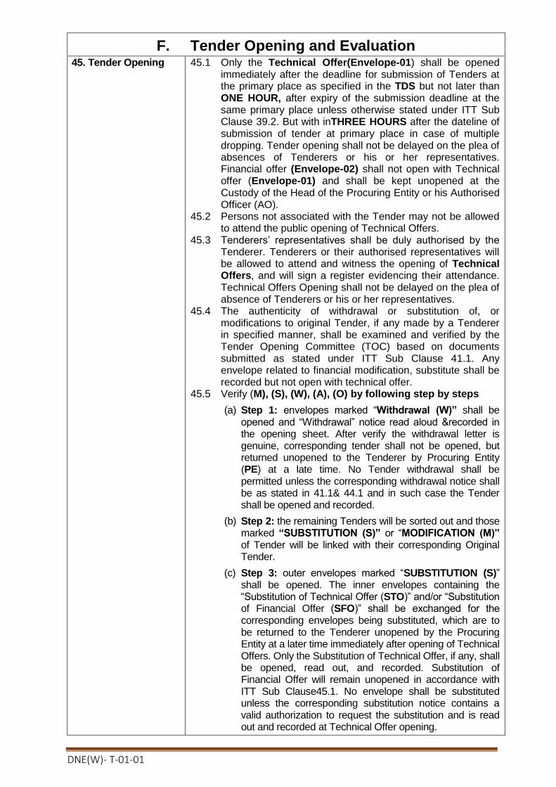
DNE(W)- T-01-01
F. Tender Opening and Evaluation
45. Tender Opening 45.1 Only the Technical Offer(Envelope-01) shall be opened immediately after the deadline for submission of Tenders at the primary place as specified in the TDS but not later than ONE HOUR, after expiry of the submission deadline at the same primary place unless otherwise stated under ITT Sub Clause 39.2. But with inTHREE HOURS after the dateline of submission of tender at primary place in case of multiple dropping. Tender opening shall not be delayed on the plea of absences of Tenderers or his or her representatives. Financial offer (Envelope-02) shall not open with Technical offer (Envelope-01) and shall be kept unopened at the Custody of the Head of the Procuring Entity or his Authorised Officer (AO).
45.2 Persons not associated with the Tender may not be allowed to attend the public opening of Technical Offers.
45.3 Tenderers’ representatives shall be duly authorised by the Tenderer. Tenderers or their authorised representatives will be allowed to attend and witness the opening of Technical Offers, and will sign a register evidencing their attendance. Technical Offers Opening shall not be delayed on the plea of absence of Tenderers or his or her representatives.
45.4 The authenticity of withdrawal or substitution of, or modifications to original Tender, if any made by a Tenderer in specified manner, shall be examined and verified by the Tender Opening Committee (TOC) based on documents submitted as stated under ITT Sub Clause 41.1. Any envelope related to financial modification, substitute shall be recorded but not open with technical offer.
45.5 Verify (M), (S), (W), (A), (O) by following step by steps
(a) Step 1: envelopes marked “Withdrawal (W)” shall be opened and “Withdrawal” notice read aloud &recorded in the opening sheet. After verify the withdrawal letter is genuine, corresponding tender shall not be opened, but returned unopened to the Tenderer by Procuring Entity (PE) at a late time. No Tender withdrawal shall be permitted unless the corresponding withdrawal notice shall be as stated in 41.1& 44.1 and in such case the Tender shall be opened and recorded.
(b) Step 2: the remaining Tenders will be sorted out and those marked “SUBSTITUTION (S)” or “MODIFICATION (M)” of Tender will be linked with their corresponding Original Tender.
(c) Step 3: outer envelopes marked “SUBSTITUTION (S)” shall be opened. The inner envelopes containing the “Substitution of Technical Offer (STO)” and/or “Substitution of Financial Offer (SFO)” shall be exchanged for the corresponding envelopes being substituted, which are to be returned to the Tenderer unopened by the Procuring Entity at a later time immediately after opening of Technical Offers. Only the Substitution of Technical Offer, if any, shall be opened, read out, and recorded. Substitution of Financial Offer will remain unopened in accordance with ITT Sub Clause45.1. No envelope shall be substituted unless the corresponding substitution notice contains a valid authorization to request the substitution and is read out and recorded at Technical Offer opening.

DNE(W)- T-01-01
(d) Step 4: outer envelopes marked “MODIFICATION (M)” shall be opened. No Technical Offer and/or Financial Offer shall be modified unless the corresponding modification notice contains a valid authorization to request the modification and is read out and recorded at the opening of Technical Offers. Only the Technical Offers, both Original as well as Modification, are to be opened, read out, and recorded at the opening. Financial Offers, both Original as well as Modification, will remain unopened in accordance with ITT Sub Clause 45.1
(e) Step5: if so specified in this Tender Document, the envelopes marked “Alternative of Technical Offer (ATO)” shall be opened and read aloud with the corresponding Technical Offer and recorded.
45.6 Ensuring that only the correct (MTO), (STO), (ATO), (OTO) envelopes are opened, details of each Technical Offer will be dealt with as follows:
(a) the Chairperson of the TOC will read aloud each
Technical Offer and record in the Technical Offer Opening
Sheet (TOOS):
(i) the name and address of the Tenderer;
(ii) state if it is a withdrawn, modified, substituted or
original Technical Offer;
(iii) any alternatives;
(iv) record the rejection of the Tender which submitted
Technical Offer and Financial Offer together in one
envelope.
(v) the presence or absence of any requisite Tender
Security; and
(vi) such other details as the Procuring Entity, at its
discretion, may consider appropriate.
(b) Only Technical Offer and alternatives read aloud at the
Technical Offer Opening will be considered in evaluation.
(c) all pages of the original version of the Technical Offer,
except for un-amended printed literature, will be initialled
by members of the TOC. Remember, No financial Offer
shall be open with Technical Offer
45.7 Upon completion of Technical Offer opening, all members of the TOC and the Tenderers or Tenderer’s duly authorised representatives attending the Technical Offer opening shall sign by name, address, designation, the TOS, copies of which shall be issued to the Head of the Procuring Entity or an officer authorised by him or her and also to the members of the TOC and any authorised Consultants and, to the Tenderers immediately.
45.8 The omission of a Tenderer’s signature on the record shall not invalidate the contents and effect of the record under ITT Sub Clause 45.7
45.9 No Tender i.e., Technical or Financial Offer shall be rejected at the Tender opening stage except the LATE Tenders as stated in the ITT Clause 40.

DNE(W)- T-01-01
46. Evaluation of Tenders
46.1 Technical Offers shall be examined and evaluated only on the basis of the criteria specified in the Tender Document.
46.2 Tender Evaluation Committee (TEC) shall examine, evaluate and compare Tenders that are responsive to the requirements of Tender Documents in order to identify the successful Tenderer.
47. Evaluation Process 47.1 TEC may consider a Tender Offer as responsive in the Evaluation, only if it is submitted in compliance with the mandatory requirements set out in the Tender Document. The evaluation process should begin immediately after Technical Offer opening following Two steps:
(a) Preliminary examination
(b) Technical examination and responsiveness
48. Preliminary Examination
48.1 Compliance, adequacy and authenticity of the documentary evidences for meeting the qualification criterion specified in the corresponding section of the Tender document shall have to be preliminarily examined and verified.
48.2 The TEC shall firstly examine the Tenders to confirm that all documentation requested in ITT Clause 24 has been provided. Examination of the compliance, adequacy and authenticity of the documentary evidence may follow the order below:
(a) verification of the completeness of the eligibility declaration in the Tender Submission Letter (Form PG5A-1), to determine the eligibility of the tenderer as stated under ITT Sub-Clause 24(h). Any alterations to its format, filling in all blank spaces with the information requested, failing which the tender may lead to rejection of the Tender;
(b) verification of that the Tenderer is enrolled in the relevant professional or trade organisations as stated under ITT Clause 24(l);
(c) verification of the eligibility in terms of legal capacity and fulfilment of taxation obligation by the tenderer in accordance as stated under ITT Sub-Clause 24(i) and 24(k);
(d) verification of eligibility that the tenderer is not insolvent, in receivership, bankrupt, not in the process of bankruptcy, not temporarily barred as stated under ITT Sub-Clause 24(j);
(e) verification of eligibility of Tenderer’s country of origin as stated under ITT Sub-Clause 24(b);
(f) verification of the written authorization confirming the signatory of the Tenderer to commit the Tender has been attached with Tender Submission Letter (Form PG5A-1) as stated under ITT Sub-Clause 24(g); in order to check the authenticity of Tender and Tenderer itself ;
(g) verification of the Tender Security as stated under ITT Sub-Clause 24(d); and
48.3 The TEC shall confirm that the above documents and information have been provided in the Tender and the completeness of the documents and compliance of instructions given in corresponding ITT Clauses shall be verified, failing

DNE(W)- T-01-01
which the tender shall be considered rejection of that tender.
49.Technical Evaluation and Responsiveness
49.1 Only those Tenders surviving preliminary examination need to be examined in this phase.
49.2 Secondly, the TEC will examine the adequacy and authenticity of the documentary evidence which may follow the order below:
(a) verification of the completeness of the country of origin declaration in the Price Schedule for Plant and Services (Form PG5A-3) as furnished in Section 5: Tender and Contract Forms to determine the eligibility of the Goods and Related Services as stated under ITT Sub Clause 24(m).
(b) verification and examination of the documentary evidence and completed Technical Proposal (Form PG5A-4) as furnished in Section 5: Tender and Contract Forms to establish the conformity of the Goods and Related Services to the Tender Documents as stated under ITT Sub Clause 24(e) and 24(n).
(c) verification and examination of the documentary evidence that the Tenderer’s qualifications conform to the Tender Documents and the Tenderer meets each of the qualification criterion specified in Sub-Section C, Qualification Criteria as stated under ITT Sub Clause 24(o).
(d) verification and examination of the documentary evidence that Tenderer has met all the requirements in regards under Section 6, Employer’s Requirements, without any material deviation or reservation.
(e) verification and examination of the documentary evidence and completed Specification Submission Sheet (Form PG5A-4a) to determine the conformity of the Goods and related services .
49.3 TEC may consider a Tender as responsive in the evaluation, only if comply with the mandatory requirements as stated under Clause 49.2.
49.4 The TEC’s determination of a Tender’s responsiveness is to be based on the documentary evidence as requested in Clause 49.2 without recourse to extrinsic evidence.
49.5 Information contained in a Tender, that was not requested in the Tender Document shall not be considered in evaluation of the Tender.
49.6 If a Tender is not responsive to the mandatory requirements set out in the Tender Document it shall be rejected by the TEC and shall not subsequently be made responsive by the Tenderer by correction of the material deviation, reservation.

DNE(W)- T-01-01
49.7 A material deviation or reservation is one-
(a) which affects in any substantial way the scope, quality, or performance of the Goods and Related Services and Tenderer’s qualifications mentioned in the Tender Document
(b) which limits in any substantial way, inconsistent with the Tender Documents, the Purchaser’s rights or the Tenderer’s obligations under the Contract; or
(c) whose rectification would anyway affect unfairly the competitive position of other Tenderers presenting responsive Tenders.
49.8 During the evaluation of Tender, the following definitions apply:
(a) Deviation” is a departure from the requirements specified in the Tender Document;
(d) “Reservation” is the setting of limiting conditions or withholding from complete acceptance of the requirements specified in the Tender Document;
49.9 A TEC may regard a Tender as responsive, even if it contains-minor or insignificant deviations, which do not meaningfully alter or depart from the technical specifications, characteristics and commercial terms and conditions or other requirements set out in the Tender Document; errors or oversights, which if corrected, would not alter the key aspects of the Tender.
50. Clarification on Technical Offer
50.1 TEC may ask Tenderers for clarification of their Technical Offers in order to facilitate the examination and evaluation of Technical Offers. The request for clarification by the TEC and the response from the Tenderer shall be in writing, and Technical Offers clarifications which may lead to a change in the substance of the Technical Offers or in any of the key elements of the Technical Offers as stated under ITT Sub Clause 49.2, will neither be sought nor be permitted.
50.2 Any request for clarifications by the TEC shall not be directed towards making an apparently non-responsive Tender responsive and reciprocally the response from the concerned Tenderer shall not be articulated towards any addition, alteration or modification to its Technical Offer.
50.3 If a Tenderer does not provide clarifications of its Technical Offer by the date and time, its Tender shall not be considered in the evaluation
51.Restrictions on Disclosure of Information
51.1 Following the opening of Technical Offers until issuance of Notification of Award no Tenderer shall, unless requested to provide clarification to its Tender or unless necessary for submission of a complaint, communicate with the concerned Procuring Entity
51.2 Tenderers shall not seek to influence in anyway, the examination and evaluation of the Tenders
51.3 Any effort by a Tenderer to influence the Procuring Entity in its decision concerning the evaluation of Tenders, Contract awards may result in the non-responsiveness of its Tender as well as further action in accordance with Section 64 (5) of the Public Procurement Act, 2006.
51.4 All clarification requests shall remind Tenderers of the need for confidentiality and that any breach of confidentiality on

DNE(W)- T-01-01
the part of the Tenderer may result in their Tender being non-responsive.
52. Approval of Technical Offer
52.1 TEC shall prepare the Technical Offer Evaluation Report and shall directly submit the Evaluation Report to the Head of the Procuring Entity (HOPE) or Authorized Officer for approval.
53.Financial Offer Opening
53.1 After receiving approval of the Technical Offer Evaluation Report, Financial Offer (Envelope-2) of only the Responsive Tenderers who have been determined as qualified to the requirements of the Technical Offer, shall be opened publicly, The Date, time and place of Financial Offer Opening shall be communicated to the Responsive Tenderers in writing by issuing a Financial Offer Opening notice not less than SEVEN DAYS before the opening.
53.2 Ensuring that only the correct MFO, SFO, OFO envelopes of the Responsive Tenderers shall be opened, in the presence of the Responsive Tenderer’s representatives who choose to attend, on the date, time and at the place as notified by the Procuring Entity in accordance with ITT Clause 53.1. Details of each Financial Offer will be dealt with as follows:
(a) the Chairperson of the Tender Evaluation Committee will
read aloud each Financial Offer and record in the
Financial Offer Opening Sheet (FOOS):
(i) the name and address of the Tenderer;
(ii) state if it is a modified, substituted or original
Financial Offer;
(iii) the Tender Price;
(iv) the number of initialled corrections;
(v) any discounts; and
(vi) any other details as the Procuring Entity, at its
discretion, may consider appropriate
(b) only the discounts and alternatives read aloud and
recorded at the Financial Offer Opening will be considered
in Financial Offer Evaluation. No Tenders shall be rejected
at the opening of the Financial Offer.
(c) all pages of the original version of the Financial Offer,
except for un-amended printed literature, will be initialled
by members of the Tender Evaluation Committee.
(d) The Procuring Entity shall, in writing, notify the Non-responsive Tenderers who have not been determined as qualified to the requirements of the Technical Offer and shall return their Financial Offers (Envelope-02) unopened after signing of the contract.
54. Clarification on Financial Offer
54.1 TEC may ask Tenderers for clarification of their Financial Offers, about the breakdowns of unit rates, in order to facilitate the examination and evaluation of Financial Offers. The request for clarification by the TEC and the response from the Tenderer shall be in writing.
54.2 Changes in the Tender price shall not be sought or permitted, except to confirm the correction of arithmetical errors discovered by the TEC in the evaluation of the Tenders, as

DNE(W)- T-01-01
stated under ITT Sub Clause 55.1.
54.3 If a Tenderer does not provide clarifications of its Financial Offer by the date and time, its Tender shall not be considered in the evaluation.
54.4 Requests for clarifications on Financial Offers shall be duly signed only by the TEC Chairperson.
55. Correction of Arithmetical Errors
55.1 The TEC shall correct any arithmetic errors that are discovered during the examination of Tenders, and shall promptly notify the concerned Tenderer(s) of any such correction(s) pursuant to Rule 98(11) of the Public Procurement Rule, 2008.
55.2 Provided that the Tender is responsive, TEC shall correct arithmetical errors on the following basis:
(a) If there is a discrepancy between the unit price and the line item total that is obtained by multiplying the unit price by the quantity, the unit price shall prevail and the line item total shall be corrected, unless in the opinion of the TEC there is an obvious misplacement of the decimal point in the unit price, in which case the total price as quoted willgovern and the unit price will be corrected;
(b) If there is an error in a total corresponding to the addition or subtraction of subtotals, the sub-totals shall prevail and the total shall be corrected.
55.3 Any Tenderer that does not accept the correction of the Tender amount following correction of arithmetic errors as determined by the application of ITT Sub-Clause 55.2 shall be considered as non-responsive.
56. Conversion to Single Currency
56.1For evaluation and comparison purpose, TEC shall convert all Tender prices expressed in the amounts in various currencies into an amount in Bangladeshi Taka currency, using the selling exchange rates established by the Bangladesh Bank, on the date of Tender opening.
57.Financial Evaluation
57.1 Thirdly the TEC, pursuant to Rule 98 of the Public Procurement Rules, 2008 shall evaluate each Tender that has been determined, up to this stage of the evaluation, to be responsive to the mandatory requirements in the Tender Document..
57.2 To evaluate a Tender in this stage , the Purchaser shall consider the following
(a) Verification and examination of the Price Schedule for Plant and Services (Form PG5-3) as furnished by the Tenderer and checking the compliance with the instructions provided under ITT Clause 26;
(b) Evaluation will be done for Items or lot by lot as stated under ITT Clause 26 and the Total Tender Price as quoted in accordance with Clause 26;
(c) Adjustment for correction of arithmetical errors as stated under ITT Sub-Clause 55.2;
(d) Adjustment for price modification offered as stated under ITT Clause 41;
(e) Adjustment due to discount as stated under ITT Sub-Clauses 26.11 and 57.3;

DNE(W)- T-01-01
(f) Adjustment due to the application of economic factors of evaluation as stated under ITT Sub-Clause 57.5 if any;
(g) Adjustment due to the assessment of the price of unpriced items as stated under ITT Clause 58 if any;
57.3 If Tenders are invited for a single lot or for a number of lots as stated under ITT Sub-clauses 26.10, TEC shall evaluate only lots that have included at least the percentage of items per lot. The TEC shall evaluate and compare the Tenders taking into account:
(a) Lowest evaluated tender for each lot ; (b) The price discount/reduction per lot; (c) Least cost combination for the Purchaser, considering
discounts and the methodology for its application as stated under ITT Sub-clauses 26.10 and 26.11 offered by the Tenderer in its Tender.
57.4 Only those spare parts and tools which are specified as a item in the List of Goods and Related Services in Section 6, Employer’s Requirement or adjustment as stated under ITT Sub-clause 54.5, shall be taken into account in the Tender evaluation. Supplier-recommended spare parts for a specified operating requirement as stated under ITT Sub-clause 28.2(b) shall not be considered in Tender evaluation.
57.5 The Purchaser’s evaluation of a tender may require the consideration of other factors, in addition to the Tender Price quoted as stated under ITT Clause 26. The effect of the factors selected, if any, shall be expressed in monetary terms to facilitate comparison of tenders. The factors, methodologies and criteria to be used shall be as specified in TDS. The applicable economic factors, for the purposes of evaluation of Tenders shall be: (a) Adjustment for Deviations in the Delivery and Completion
Schedule. (b) Cost of major replacement components, mandatory spare
parts, and service.
57.6 Variations, deviations, and alternatives and other factors which are in excess of the requirements of the Tender Document or otherwise result in unsolicited benefits for the Purchaser will not be taken into account in Tender evaluation.
58. Price Comparison 58.1 The TEC shall compare all responsive Tenders to determine the
lowest-evaluated Tender, as stated in ITT 57.2.
58.2 In the extremely unlikely event that there is a tie for the lowest evaluated price, the Tenderer with the superior past performance with the Purchaser shall be selected, whereby factors such as delivery period, quality of Goods delivered, complaints history and performance indicators could be taken into consideration.
58.3 In the event that there is a tie for the lowest price and none of the Tenderers has the record of past performance with the Purchaser, then the Tenderer shall be selected, subject to firm confirmation through the Post-qualification process described in ITT Clause 61, after consideration as to whether the quality of Goods that is considered more advantageous by the end-users.

DNE(W)- T-01-01
58.4 The successful Tenderer as stated under ITT Sub Clauses 58.1, 60.2 and 60.3 shall not be selected through lottery under any circumstances.
59. Post-qualification 59.1 After determining the lowest-evaluated responsive tender as sated under ITT Sub-Clause 58.1, the Purchaser’s TEC pursuant to Rule 100 of the Public Procurement Rules, 2008, shall carry out the Post-Qualification of the Tenderer, using only the requirements specified in Sub-Section C, Qualification Criteria.
59.2 The TEC shall contact the references given by Tenderers about their previous Supply experiences to verify, if necessary, statements made by them in their Tender and to obtain the most up-to-date information concerning the Tenderers.
59.3 The TEC may visit the premises of the Tenderer as a part of the post-qualification process, if practical and appropriate, to verify information contained in its Tender.
59.4 The TEC shall determine to its satisfaction whether the Tenderer that is selected as having submitted the lowest evaluated responsive Tender is qualified to perform the Contract satisfactorily.
59.5 The objective of any visit under ITT Sub-Clause 59.3 shall be limited to a general and visual inspection of the Tenderer’s facilities and its plant and equipment, and there shall be no discussion concerning the Tender or its evaluation with the Tenderer during such visit(s).
59.6 In the event that the Tenderer with lowest evaluated cost fails the post-qualification, the TEC shall make a similar determination for the Tenderer offering the next lowest evaluated cost and so on from the remaining responsive Tenders, provided that,
(a) such action shall only be taken if the evaluated costs of the Tenders under consideration are acceptable to the Purchaser;
(b) when the point is reached whereby the evaluated costs of the remaining responsive Tenders are significantly higher than that of the official estimate, or the market price, the Purchaser may take action pursuant to Rule 33 of the PPR 2008 and may proceed for re-Tendering, using a revised Tender Document designed to achieve a more successful result.
60. Negotiation 60.1 No negotiations shall be held during the financial offer evaluation or award, with the lowest or any other Tenderer.
60.2 The Procuring Entity through the TEC may, however, negotiate with the lowest evaluated Tenderer with the objective to reduce the Contract Price by reducing the scope of works or a reallocation of risks and responsibilities, only when it is found that the lowest evaluated Tender is significantly higher than the official estimated cost; the reasons for such higher price being duly investigated.
60.3 If the Procuring Entity decides to negotiate for reducing the scope of the requirements under ITT Sub Clause 60.2, it will be required to guarantee that the lowest Tenderer remains the lowest Tenderer even after the scope of work has been revised and shall further be ensured that the objective of the
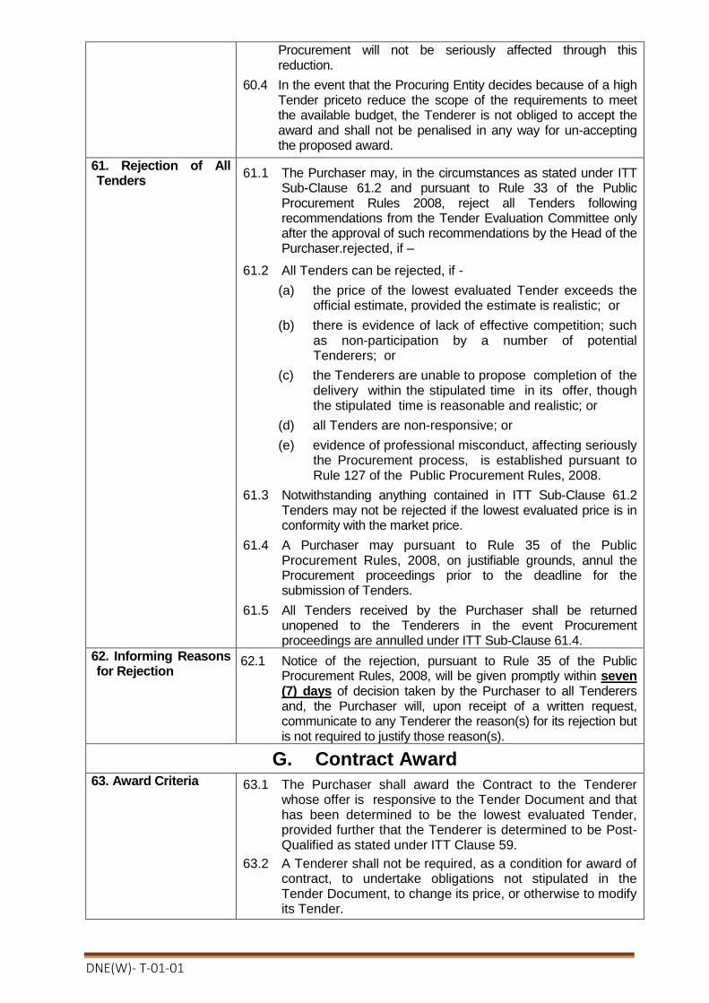
DNE(W)- T-01-01
Procurement will not be seriously affected through this reduction.
60.4 In the event that the Procuring Entity decides because of a high Tender priceto reduce the scope of the requirements to meet the available budget, the Tenderer is not obliged to accept the award and shall not be penalised in any way for un-accepting the proposed award.
61. Rejection of All Tenders
61.1 The Purchaser may, in the circumstances as stated under ITT Sub-Clause 61.2 and pursuant to Rule 33 of the Public Procurement Rules 2008, reject all Tenders following recommendations from the Tender Evaluation Committee only after the approval of such recommendations by the Head of the Purchaser.rejected, if –
61.2 All Tenders can be rejected, if -
(a) the price of the lowest evaluated Tender exceeds the official estimate, provided the estimate is realistic; or
(b) there is evidence of lack of effective competition; such as non-participation by a number of potential Tenderers; or
(c) the Tenderers are unable to propose completion of the delivery within the stipulated time in its offer, though the stipulated time is reasonable and realistic; or
(d) all Tenders are non-responsive; or
(e) evidence of professional misconduct, affecting seriously the Procurement process, is established pursuant to Rule 127 of the Public Procurement Rules, 2008.
61.3 Notwithstanding anything contained in ITT Sub-Clause 61.2 Tenders may not be rejected if the lowest evaluated price is in conformity with the market price.
61.4 A Purchaser may pursuant to Rule 35 of the Public Procurement Rules, 2008, on justifiable grounds, annul the Procurement proceedings prior to the deadline for the submission of Tenders.
61.5 All Tenders received by the Purchaser shall be returned unopened to the Tenderers in the event Procurement proceedings are annulled under ITT Sub-Clause 61.4.
62. Informing Reasons for Rejection
62.1 Notice of the rejection, pursuant to Rule 35 of the Public Procurement Rules, 2008, will be given promptly within seven (7) days of decision taken by the Purchaser to all Tenderers and, the Purchaser will, upon receipt of a written request, communicate to any Tenderer the reason(s) for its rejection but is not required to justify those reason(s).
G. Contract Award
63. Award Criteria 63.1 The Purchaser shall award the Contract to the Tenderer whose offer is responsive to the Tender Document and that has been determined to be the lowest evaluated Tender, provided further that the Tenderer is determined to be Post-Qualified as stated under ITT Clause 59.
63.2 A Tenderer shall not be required, as a condition for award of contract, to undertake obligations not stipulated in the Tender Document, to change its price, or otherwise to modify its Tender.
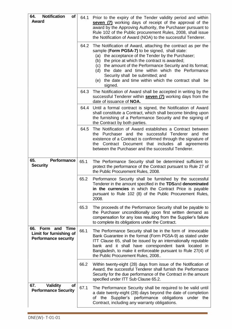
DNE(W)- T-01-01
64. Notification of Award
64.1 Prior to the expiry of the Tender validity period and within seven (7) working days of receipt of the approval of the award by the Approving Authority, the Purchaser pursuant to Rule 102 of the Public procurement Rules, 2008, shall issue the Notification of Award (NOA) to the successful Tenderer.
64.2 The Notification of Award, attaching the contract as per the sample (Form PG5A-7) to be signed, shall state:
(a) the acceptance of the Tender by the Purchaser; (b) the price at which the contract is awarded; (c) the amount of the Performance Security and its format; (d) the date and time within which the Performance
Security shall be submitted; and (e) the date and time within which the contract shall be
signed.
64.3 The Notification of Award shall be accepted in writing by the successful Tenderer within seven (7) working days from the date of issuance of NOA.
64.4 Until a formal contract is signed, the Notification of Award shall constitute a Contract, which shall become binding upon the furnishing of a Performance Security and the signing of the Contract by both parties.
64.5 The Notification of Award establishes a Contract between the Purchaser and the successful Tenderer and the existence of a Contract is confirmed through the signature of the Contract Document that includes all agreements between the Purchaser and the successful Tenderer.
65. Performance Security
65.1 The Performance Security shall be determined sufficient to protect the performance of the Contract pursuant to Rule 27 of the Public Procurement Rules, 2008.
65.2 Performance Security shall be furnished by the successful Tenderer in the amount specified in the TDSand denominated in the currencies in which the Contract Price is payable pursuant to Rule 102 (8) of the Public Procurement Rules, 2008.
65.3 The proceeds of the Performance Security shall be payable to the Purchaser unconditionally upon first written demand as compensation for any loss resulting from the Supplier’s failure to complete its obligations under the Contract.
66. Form and Time Limit for furnishing of Performance security
66.1 The Performance Security shall be in the form of irrevocable Bank Guarantee in the format (Form PG5A-9) as stated under ITT Clause 65, shall be issued by an internationally reputable bank and it shall have correspondent bank located in Bangladesh, to make it enforceable pursuant to Rule 27(4) of the Public Procurement Rules, 2008..
66.2 Within twenty-eight (28) days from issue of the Notification of Award, the successful Tenderer shall furnish the Performance Security for the due performance of the Contract in the amount specified under ITT Sub Clause 65.2.
67. Validity of Performance Security
67.1 The Performance Security shall be required to be valid until a date twenty-eight (28) days beyond the date of completion of the Supplier’s performance obligations under the Contract, including any warranty obligations.
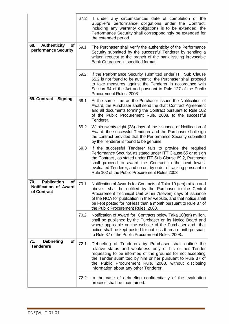
DNE(W)- T-01-01
67.2 If under any circumstances date of completion of the Supplier’s performance obligations under the Contract, including any warranty obligations is to be extended, the Performance Security shall correspondingly be extended for the extended period.
68. Authenticity of performance Security
69.1 The Purchaser shall verify the authenticity of the Performance Security submitted by the successful Tenderer by sending a written request to the branch of the bank issuing irrevocable Bank Guarantee in specified format.
69.2 If the Performance Security submitted under ITT Sub Clause 65.2 is not found to be authentic, the Purchaser shall proceed to take measures against the Tenderer in accordance with Section 64 of the Act and pursuant to Rule 127 of the Public Procurement Rules, 2008.
69. Contract Signing 69.1 At the same time as the Purchaser issues the Notification of Award, the Purchaser shall send the draft Contract Agreement and all documents forming the Contract pursuant to Rule 102 of the Public Procurement Rule, 2008, to the successful Tenderer.
69.2 Within twenty-eight (28) days of the issuance of Notification of Award, the successful Tenderer and the Purchaser shall sign the contract provided that the Performance Security submitted by the Tenderer is found to be genuine.
69.3 If the successful Tenderer fails to provide the required Performance Security, as stated under ITT Clause 65 or to sign the Contract , as stated under ITT Sub-Clause 69.2, Purchaser shall proceed to award the Contract to the next lowest evaluated Tenderer, and so on, by order of ranking pursuant to Rule 102 of the Public Procurement Rules,2008.
70. Publication of Notification of Award of Contract
70.1 Notification of Awards for Contracts of Taka 10 (ten) million and above shall be notified by the Purchaser to the Central Procurement Technical Unit within 7(seven) days of issuance of the NOA for publication in their website, and that notice shall be kept posted for not less than a month pursuant to Rule 37 of the Public Procurement Rules, 2008.
70.2 Notification of Award for Contracts below Taka 10(ten) million, shall be published by the Purchaser on its Notice Board and where applicable on the website of the Purchaser and that notice shall be kept posted for not less than a month pursuant to Rule 37 of the Public Procurement Rules, 2008..
71. Debriefing of Tenderers
72.1 Debriefing of Tenderers by Purchaser shall outline the relative status and weakness only of his or her Tender requesting to be informed of the grounds for not accepting the Tender submitted by him or her pursuant to Rule 37 of the Public Procurement Rule, 2008, without disclosing information about any other Tenderer.
72.2 In the case of debriefing confidentiality of the evaluation process shall be maintained.

DNE(W)- T-01-01
72. Right to Complains 72.1 Any Tenderer has the right to complain if it has suffered or likely to
suffer loss or damage due to a failure of a duty imposed on the Purchaser to fulfil its obligations in accordance with Section 29 of the Public Procurement Act 2006 and pursuant to Part 12 of Chapter Three of the Public Procurement Rules, 2008.
72.2 Circumstances in which a formal complaint may be lodged in sequence by a potential Tenderer against a Purchaser pursuant to Rule 56 of the Public Procurement Rules, 2008, and the complaints, if any, be also processed pursuant to Rule 57 of the Public Procurement Rules 2008.
72.3 The potential Tenderer shall submit his or her complaint in writing within seven (7) calendar days of becoming aware of the circumstances giving rise to the complaint.
72.4 In the first instance, the potential Tenderer shall submit his or her complaint to the Purchaser who issued the Tender Document.
72.5 The place and address for the first stage in the submission of complaints to the Administrative Authority is provided in the TDS.
72.6 The Tenderer may appeal to a Review Panel only if the Tenderer has exhausted all his or her options of complaints to the administrative authority as stated under ITT Sub-Clause 72.2.

DNE(W)- T-01-01
Section 2. Tender Data Sheet
Instructions for completing the Tender Data Sheet are provided, as needed, in the notes in italics and under lined mentioned for the relevant ITT clauses.
ITT Clause Amendments of, and Supplements to, Clauses in the Instruction to Tenderersl
A. General
ITT 1.1
The Purchaser is :Project Director
“Distribution Network Expansion for 100% Rural Electrification (Rajshahi,
Rangpur, Khulna & Barisal Divisions)", BREB.”
Office of the Project Director
Training Academy Building (7th floor), Bangladesh Rural Electrification Board,
Nikunja-2, Khilkhet, Dhaka-1229.
Telephone: 02-8900591
Electronic mail address: [email protected]
The Name and identification number of Tender are DNE(W)-T-01
ITT 1.2 The number, identification and name of lots comprising the Tender are:
Turnkey contract for survey, design, supply, carrying, installation, testing and commissioning of 33 kv double circuit river crossing tower with transmission lines including civil constructions at Bank KAli/ Vushir Bandar - Bank KAli/ Vushir Bandar on Atrai river under Dinajpur PBS-1.
Tender Ref : 27.12.0000.162.31.001.19.2506 ; Date : 29 -05-2019
Package No.: DNE(W)-T-01
ITT3.1 The source of public funds is GOB & BREB Own Fund.
ITT3.3 The name of the Development Partner is Not applicable
ITT5.1 Tenderers from the following countries are not eligible:
All countries except Bangladesh.
ITT 5.13 Tenderers shall have the following up to date valid License : None
ITT6.1 Materials, Equipment and associated services from the following countries are not eligible: Israel.
B. Tender Document
ITT8.2 The following are the offices of the Purchaser or authorised agents for the purpose of providing the Tender Document: None.
Agent’s/Office Name:
Project Director
“Distribution Network Expansion for 100% Rural Electrification
(Rajshahi, Rangpur, Khulna & Barisal Divisions)", BREB.”
Office of the Project Director Training Academy Building (7th floor), Bangladesh Rural Electrification Board,
Nikunja-2, Khilkhet, Dhaka-1229.
Telephone: 02-8900591
Electronic mail address: [email protected]
ITT 9.1 For clarification of Tender Document purposes only, the Procuring Entity’s address is:
Attention: Project Director

DNE(W)- T-01-01
“Distribution Network Expansion for 100% Rural Electrification
(Rajshahi, Rangpur, Khulna & Barisal Divisions)", BREB.”
Office of the Project Director
Training Academy Building (7th floor), Bangladesh Rural Electrification Board,
Nikunja-2, Khilkhet, Dhaka-1229.
Telephone: 02-8900591
Electronic mail address: [email protected] And contact Procuring Entity
within 03-07-2019, 05.00 PM.
ITT 10.1 A Pre- Tender meeting shall be held at
Address:
Office of the Project Director
“Distribution Network Expansion for 100% Rural Electrification
(Rajshahi, Rangpur, Khulna & Barisal Divisions)", BREB.”
Training Academy Building (7th floor), Bangladesh Rural Electrification Board,
Nikunja-2, Khilkhet, Dhaka-1229.
Telephone: 02-8900591
Time & Date:11:00 am Date: 24-06-2019
A site visit conducted by the Employer will not be organized.
Tenderers are advised to conduct site visit at their own responsibility. The Employer may arrange necessary permissions if requested by the Tenderers.
The costs and expenses associated with attending the pre-Tender meeting and/or site visit shall be borne by the Potential Tenderers.
C. Qualification Criteria
ITT 13.1
The maximum three (03) number of arbitration against the Tenderer over a period of the last Five (05) years.
ITT14.1(a) The Tenderer shall have a minimum of three (03) years of overall experience in the role of contractor, subcontractor, or management contractor. Years counting backward from the date of publication IFT in the newspaper.
ITT 14.1(b) ITT14.1(b)continued
Specific Experience: The Tenderer must have the minimum specific experience as a Prime Contractor or Subcontractor or Management Contractor (lead partner in case of JV) in the Turnkey contract for survey, design, supply, carrying, installation, testing and commissioning of 33 kV electrical tower lines including foundation works as follows:
1. For construction of at least double/single circuit 33 kV electrical tower lines of minimum height 30 m. and span 300m. including foundation works of the tower with a minimum value at least TK. 3.00 crore under maximum two contract within last 05(Five) years. Years counting backward from the date of publication IFT in the newspaper.
0r
Any Bangladeshi steel tower manufacturing company having experience of supplying minimum 30 meters height Tower shall also be eligible if the manufacturer or it’s partner in a Joint Venture company having the experience of turn-key contract for construction of at least double/single circuit 33 kv electrical line with tower of minimum height 30 m. and span 300 m.

DNE(W)- T-01-01
ITT14.1(b) continued
including foundation works of the tower with a minimum value at least TK. 3.00 crore under maximum two contract within last 05 (Five) years. Years counting backward from the date of publication IFT in the newspaper.
3. In support of experience Tenderer shall submit Satisfactory Performance Certificate(s) from the end user's letter head pad. The Certificate(s) shall mention the name & commissioning date of river crossing towers which were designed, supplied constructed, tested and commissioned by Tenderer (lead partner in case of JV) and shall contain end-user's full mailing address, e-mail address, website address, fax number and phone number for the convenience of authentication.
4. In case Towers are proposed to be supplied from the local manufacturers, the
manufacturers shall be considered as qualified if :-
i) Manufacturer(s) have to authorize the Tenderer for participating in the tender (incase the Contractor /Tenderer do not manufacture the proposed Tower).
ii) The manufacturer shall have ISO 9001 or equivalent certificate.
iii) The manufacturer shall have at least two(02) nos. of 30 m. height steel tower
supply records with supporting documents within last Five (05) years. The
manufacturer should have modern manufacturing testing facilities and machineries
including CNC machine for Tower manufacturing.
iv) The tenderer shall have to provide the experience certificate from the end-user that
the supplied Tower has been in service satisfactory.
v) Drawings as per requirement of Schedule-I, Volume 3 of 3 of the Tender Document.
vi) Brochure/Catalogue of the manufacturer indicating manufacturing facilities and
machineries available shall also be submitted.
5. In case Towers are proposed to be supplied from the manufacturers out side
of Bangladesh the manufacturers shall be considered as qualified if :-
i) Manufacturer(s) have to authorize the Tenderer for participating in the tender
(incase the Contractor /Tenderer do not manufacture the proposed Tower).
ii) The manufacturer shall have ISO 9001 or equivalent certificate.
iii) Supply record with necessary supporting documents. Performance certificates or
any other relevant documents of at least last ten (10) years for minimum 33kV or
higher voltage Steel Tower (40 m. Height). The minimum average for the last 10
(Ten) years for minimum of at least 10 (Ten) nos. of 40 m. height tower.The
manufacturer should have modern manufacturing testing facilities and machineries
including CNC machine for Tower manufacturing.
iv) The Tenderer has to provide the experience certificate from the user that the said
Tower (minimum 33kV or higher voltage steel tower) be in service satisfactory for
a minimum of three(03) years as on the date of bid opening. Evidence of
satisfactory service shall have to provide from the end-user along with address,
telephone, fax number, e-mail number of the contact person.
v) Drawings as per requirement of Schedule-I, Volume 3 of 3 of the Tender
Document.
vi) Brochure/Catalogue of the manufacturer indicating manufacturing facilities and
machineries available shall also be submitted.
6. In case of Conductor, all types of Contractor/Tenderer/JVC ( Local/ Foreign)
shall be considered as qualified if :-

DNE(W)- T-01-01
i) Manufacturers have to authorize the Contractor/ Tenderer/ JVC (incase the
Contractor/ Tenderer/ JVC do not manufacture the proposed Conductors),
ii) Tenderer/JVCshall furnish copies of ISO 9001:2000 or equivalent certificates of
proposed manufacturers for individual Conductors,
iii) Supply record of Phase conductor with necessary supporting documents.
Performance certificates or any other relevant documents of at least last three (03)
years of Energy saving type AACSR Conductor or equivalent and Earth wire
ASTM A475, 7/4.19, galvanized sever wire strand.
iv) Drawings and Type Test Report as per requirement of Schedule-I, Volume 3 of 3
of the Tender Document.
v) Catalogue or Brochures of the Manufacturer.
7. In case of Insulator, all types of Tenderer/JVC ( Local/ Foreign) shall be
considered as qualified if :-
i) Manufacturers have to authorize the Contractor/Tenderer/ JVC (in case the
Contractor /Tenderer/JVC do not manufacture the proposed Insulator),
ii) Tenderer shall furnish copies of ISO 9001:2000 or equivalent certificates of
proposed Manufacturers of insulator.
iii) Supply record with necessary supporting documents. Performance certificates or
any other relevant documents of at least last ten (10) years of Insulator including
210kN, 70kN Porcelain insulator of the proposed Manufacturers,
iv) The 210kN & 70kN Insulator shall be in service satisfactory for a minimum of
three (03) years as on the date of Tender Opening. Evidence from End user of
service satisfactory mentioned above. Evidence of satisfactory service shall be in
the End user's respective letterhead stationary indicating address, telephone and
Fax numbers of the users.
v) The Contractor/Tenderer/JVC shall submit satisfactory type test certificates as
per requirement of Schedule-I, Volume 3 of 3 of the Tender Document.
vi) Drawings as per requirement of Schedule-I, Volume 3 of 3 of the Tender
Document.
vii) Catalogue or Brochures of the Manufacturer.
ITT 15.1(a)
The required average annual turnover shall be greater than 4.60 crore within the last Five (05) years for the package.
ITT15.1(b) The minimum amount of liquid assets or working capital or credit facilities of the Tenderer shall be Tk. 2.10 crore for the package .

DNE(W)- T-01-01
ITT 16.1(a) A Project Manager, Engineer, and other key staff shall have the following qualifications and experience:
No Position Total Works Experience
(Years)
Experience in similar works
(Years)
1. Project Manager (B.Sc.Engineer) Civil / Electrical)- (1/1 no.)
10 Years 05 Years.
2. Site Engineer (B.Sc./ Diploma Engr.) (Electrical / Mechanical)- (2/2 nos.)
5/10 Years. 03 Years.
3. Site Engineer(B.Sc./Diploma Engr.) ( Civil )- 2 (Two)nos.
5/10 Years. 03 Years.
4. Site Supervisor, Foreman, Lineman for line construction/augmentation works ( 4 nos. )
05 Years 03 Years.
The number of key staff mentioned above may required to increase according to
the site condition
ITT 17.1 The Tenderer shall own or have proven access to hire or lease of the major equipment, in full working order as follows :
Equipment Quantities
For each group For whole contract
1. Tensional (suitable for 315-A3/S-3A, AACSR(400/65) conductor (560 -610) Amps Capacity).
Minimum1 nos.
minimum 3 nos.
2. Puller (suitable for 315-A3/S-3A,
AACSR(400/65) conductor (560
-610) Amps Capacity).
Minimum1 nos.
minimum 3 nos
3. Conductor and earth wire drum stand.
Minimum 2 nos. minimum 6 nos
4. Theodolite machine with stand minimum 2 nos. minimum 6 nos
5. Levelling instrument minimum 2 nos. minimum 6 nos
6. Power winch machine minimum 2 nos. minimum 6 nos
7. Hard winch machine minimum 2 nos. minimum 6 nos
8. Vibrator machine minimum 2 nos. minimum 6 nos
9. Mixer machine minimum 2 nos. minimum 6 nos
10.Welding machine minimum 2 nos. minimum 6 nos
11.Compression jointing machine minimum 2 nos. minimum 6 nos
12.Hydraulic jack minimum 2 nos. minimum 6 nos
13.Chain pulley and blocks minimum 2 nos. minimum 6 nos
14. Chain hoist minimum 2 nos. minimum 6 nos
15. Pile rig, enough to complete the work in time
Enough to complete the work in time
16. D-shackle enough to carry
out the work
enough to carry
out the work
17. Aluminium pulley minimum 50 nos. minimum 150 nos
18. Steel pulley, enough to carry out the work
enough to carry out the work

DNE(W)- T-01-01
19. Water pump with diesel engine. enough to carry out the work
enough to carry
out the work
20. Ear thing lead , minimum 2 nos. Minimum 6 nos
21. Earth tester , enough to carry out the work
enough to carry out the work
22. Megger enough to carry
out the work
enough to carry
out the work
23. Vehicles,
(a) Crane ( Trunk mounted),
(b) Pickup,
(c) 4 WD Jeep ,
Minimum 1 nos.
each
Minimum 3 nos.
each
The tenderer shall submit list of tools & equipment owned by them or have to submit evidence that they own or letter of authorization that they are assured to hire the required equipment, so that they could engage the equipment from the day of starting of the work to ensure the completion of the Project within the specified completion time with the technical proposal.
ITT 18.1
The value of non-judicial stamp for execution of the Joint Venture Agreement shall be Tk. 300.00 only.
ITT 18.2
Maximum number of partners in the JV shall be 3 (Three)
The minimum qualification requirements of Leading Partner, other Partner(s) and requirements by summation of a JV shall be as follows:
TDS Clauses References
Requirements by summation
Requirements for Leading Partner
Requirements for other Partner(s)
ITT-14.1(a) Summation not applicable
Same as stated in TDS
At least one(01) year
ITT-14.1(b) 100% At least one Contract Not applicable
ITT-15.1(a) 100% 40% 25%
ITT-15.1(b) 100% 40% 25%
ITT-16.1(a) 100% Minimum
requirement Not applicable
Minimum Not applicable
ITT-17.1 100% Minimum Not
applicable Minimum Not applicable
D. Tender Preparation
ITT 19.2 The maximum of percentage of Goods allowed to be subcontracted:
(Not Applicable)
ITT 19.4 The Nominated Subcontractor(s) named shall execute the following specific components of the proposed Works: None
ITT 19.3 The Nominated Subcontractor(s) named shall execute the following specific components of the proposed Works: Not Applicable
ITT 20.1 Tenders are being invited for DNE(W)-T-01

DNE(W)- T-01-01
ITT 24.2(r) (A)The Tenderer shall submit with its technical offer the following additional documents:
The Tenderer shall submit the following additional documents furnished below with its Technical Proposal:
1. Tenderers shall furnish copies of ISO 9001/9002 or equivalent certificates of proposed manufacturers for individual equipment/plants/materials supply record of the proposed manufacturers as on the date of tender opening and evidence from users satisfactory service mentioned for the respective equipment/plants/materials .
2. The tenderer shall submit satisfactory type test certificates of the equipment/plants materials to be supplied under this contract.
3. The Tender/manufacturer shall submit with its Tender the following additional documents: All necessary papers, test report, samples, catalogue etc. as described in the technical specification of the Tender document.
4. The tender shall submit along with offer all type & routine test reports of offered equipment as mentioned in the specification enclosed in the tender document from internationally recognized independent testing laboratory such as KEMA HOLLAND, CESI-ITALLY, Under writers Laboratory (UL), U.S.A. CPRI-INDIA or equivalent laboratory for the equipment to be offered. For the test reports from the laboratories other than KEMA, CESI, UL-USA or CPRI, INDIA the tenderer must furnish evidence in support of the status of the laboratories, which should be acceptable to BREB. The Manufacturer’s own test report will not be accepted.
5.
i. Technical specification and brochures of equipment/plant to be incorporated in the works
ii. Letter of authorization to the effect that the Tenderer is authorized to submit Tender on behalf of the respective manufacturers and the Tenderer has the authority to supply equipment to the Employer from the proposed manufacturers for Insulators, conductors, earth wires and hardware fittings for conductors, earth wires and insulators.
iii. Supply records of the manufacturer of Insulators, conductors, earth wires and hardware fittings for conductors, earth wires and insulators as mentioned for the said materials.
6. Performance certificates of the above equipment/plants/materials .
7. Tender Capacity / Bank solvency certificate from their banker showing capability of handling the projects.
8. Tender purchased receipt/Document.
9. Power of attorney in favour of the tender signatory.
10. A written confirmation of Authorization to sign on behave of the tenderer.
11. Statement of works in hand to be completed next 01(one) year including its value of uncompleted portion.
(B) The required Technical Proposal shall include the following additional information :
1. Work plan
2. Statement of working method
3. Technical specification and brochures of machineries plant to be incorporated in the works.
4. Methodology of foundation, erection and stringing.
5. Time Schedule in bar chart.
6. Organogram of the required man power for implementing of this project.
7. Letter of authorization to the effect that the Tendered is authorized to submit the Tender on behalf of the respective manufacturer and that the Tendered has the authority to supply such equipment to the employer from the proposed manufacturers for towers, conductor, earth wire, insulator etc. as the prime items.
8. Supply record of the manufacturer of the and preferably for other items also like conductor, earth wire, insulator and related fittings.

DNE(W)- T-01-01
9. A certificate from end user that the said towers are in service. The certificate shall be in a letter head pad mentioning fax, e-mail, telephone number of contact person. The same will preferable for related items also like conductor earth wire, insulator and related fittings.
10. Electrical and Mechanical type test certificates shall be from an independent reputed Testing Laboratory which should be acceptable to BREB for the conductor, earth wire, insulator and related fittings .
11. ISO 9001/9002 -2008 or equivalent certificates of proposed manufactures for individual tower, conductor, earth wire, insulator and related fittings.
12. Design, documents as per Schedule –E, I of the Tender Document.
13. Personnel required for the work.
14. Equipment required for the work.
24.3(d) The following additional documents shall be submitted with technical offer: The required reports on the financial statement, such as profit and loss statements or audited balance sheet shall be at least for the last 01 (one) year.
ITT 25.1 Alternatives “shall not be “ permitted.
ITT 26.1 Tenderers shall quote for the entire Plant and Installation Services on a single responsibility basis
or
Tenderers shall quote for the following components or services on a single responsibility basis: (Not applicable)
and/or
The following components or services will be provided under the responsibility of the Employer: (Not applicable)
26.5(a) Place of Destination: A list of final construction and installation sites is included in the document , Section -7, Profile and location( Volume 3 of 3), scope of supply/works as per concern river crossing Tower.
26.5(d) Local transportation to named place of final destination is: A list of final construction and installation sites is included in the document/ as per respective river crossing Tower.
ITT 26.7 The prices quoted by the Tenderer shall be fixed for the duration of the Contract.
ITT 27.4 Name of the foreign currency: (Not applicable)
ITT28.1 (b) Spare parts are: “not required”
ITT 28.1(b) Manufacturer’s authorization letter is: “required” for the equipments and metarials which list is given in schedule No. 1 & 2 of Price Schedule for Plant/materials/installation and Services (Form PG5A-3). And Section 6: (Employer’s Requirements, form PG5A-5).
ITT 30.2 The Tender validity period shall be 120 days.
ITT 32.2 The amount of the Tender Security shall be 12.00 lac Taka. Tenderer participating for more than one packages must have tender security for each package individually.
ITT 37.1 In addition to the original of the Tender 02 (Two) copies shall be submitted

DNE(W)- T-01-01
E. Submission of Tender
ITT 38.2(e) The inner and outer envelopes shall bear the following additional identification marks :The inner and outer envelopes shall bear the following:
(a) Be addressed to the Employer at the following address: Attention: Project Director
“Distribution Network Expansion for 100% Rural Electrification (Rajshahi,
Rangpur, Khulna & Barisal Divisions)", BREB.”
Address: Office of the Project Director
“Distribution Network Expansion for 100% Rural Electrification (Rajshahi,
Rangpur, Khulna & Barisal Divisions)", BREB.”
Training Academy Building (7th floor), Bangladesh Rural Electrification Board, Nikunja-
2, Khilkhet, Dhaka-1229.
Telephone: 02-8900591
Electronic mail address: [email protected]
(b) bear the following identification:
Tender for “ Turnkey contract for survey, design, supply, carrying, installation, testing
and commissioning of 33 kv double circuit river crossing tower with transmission lines including civil constructions at Bank KAli/ Vushir Bandar - Bank KAli/ Vushir Bandar on Atrai river under Dinajpur PBS-1.”
Tender Ref :27.12.0000.162.31.001.19.2506 ; Date : 29 - 05-2019
DO NOT OPEN BEFORE 12:30 noon Bangladesh Standard Time on 04-07-2019.
ITT 38.4(e)
(a) The inner and outer envelopes shall bear the following additional identification marks : Be addressed to the Employer at the following address:
Attention: Project Director
“Distribution Network Expansion for 100% Rural Electrification (Rajshahi,
Rangpur, Khulna & Barisal Divisions)", BREB.”
Address: Office of the Project Director
“Distribution Network Expansion for 100% Rural Electrification (Rajshahi,
Rangpur, Khulna & Barisal Divisions)", BREB.”
Training Academy Building (7th floor), Bangladesh Rural Electrification Board, Nikunja-
2, Khilkhet, Dhaka-1229.
Telephone: 02-8900591
Electronic mail address: [email protected]
(b) bear the following identification:
Tender for “ Turnkey contract for survey, design, supply, carrying, installation, testing
and commissioning of 33 kv double circuit river crossing tower with transmission lines including civil constructions at Bank KAli/ Vushir Bandar - Bank KAli/ Vushir Bandar on Atrai river under Dinajpur PBS-1.
Tender Ref :27.12.0000.162.31.001.19.2506 ; Date : 29-05-2019
DO NOT OPEN FINANCIAL OFFER BEFORE THE TECHNICAL
OFFER EVALUATION AND APPROVAL.

DNE(W)- T-01-01
ITT 39.1 For Tender submission purposes, the Purchaser’s address is:
Attention: Project Director
“Distribution Network Expansion for 100% Rural Electrification (Rajshahi,
Rangpur, Khulna & Barisal Divisions)", BREB.”
Training Academy Building (7th floor), Bangladesh Rural Electrification Board,
Nikunja-2, Khilkhet, Dhaka-1229.
Telephone: 02-8900591
Electronic mail address: [email protected]
Address: Tender submission place BREB Auditorium , Head office Building (1
st floor), Bangladesh Rural
Electrification Board, Nikunja-2, Khilkhet, Dhaka-1229.
Telephone: 02-8900591
The deadline for the submission of Tenders is:
Time & Date: 04-07-2019 up to 12:00 noon (BST).
Address( Secondary Place): Not Applicable
ITT 39.3
For Tender submission purposes only, the Procuring Entity’s address is:
Attention:
Project Director
“Distribution Network Expansion for 100% Rural Electrification (Rajshahi,
Rangpur, Khulna & Barisal Divisions)", BREB.”
Training Academy Building (7th floor), Bangladesh Rural Electrification Board,
Nikunja-2, Khilkhet, Dhaka-1229.
Telephone: 02-8900591
Electronic mail address: [email protected]
Address (Primary Place ): Tender submission place
BREB Auditorium, Head office Building (1st floor), Bangladesh Rural
Electrification Board, Nikunja-2, Khilkhet, Dhaka-1229.
Telephone: 02-8900591
The deadline for the submission of Tenders is:
Time & Date: 04-07-2019 up to 12:00 noon (BST).
Address( Secondary Place): Not Applicable
ITT 39.4 The deadline for hand-delivering of the Tenders at the PRIMARY PLACE: Not Applicable

DNE(W)- T-01-01
F. Opening and Evaluation of Tenders
ITT 45.1 The technical offer opening shall take place at:
Address:
BREB Auditorium, Head office Building (1st floor), Bangladesh Rural
Electrification Board, Nikunja-2, Khilkhet, Dhaka-1229.
Time & Date: 04-07-2019 (BST) On 12:30 Noon
The Technical envelope will be opened first. The Financial Proposal will be kept in safe custody of purchaser. Financial Proposal of only technically responsive tender will be opened at date to be notified later to the respective tenderer. The Financial Proposal of the technically non-responsive tenderer will be returned
unopened to the respective tenderer.
ITT 57.5 The applicable economic factors, for the purposes of evaluation of Tenders shall
be:
(a) Adjustment for Deviations in the Delivery and Completion Schedule
“The Plant and Service covered by this Tendering process are required to be delivered in accordance with, and completed within, the Delivery and Completion Schedule specified in Section 6, Employer’s Requirements. No credit will be given for earlier completion. Tender offering late contract performance schedules within acceptable period will be accepted but the tenders shall be Adjusted in the evaluation by adding to the Tender Price at the rate of [specify percentage] ofthe Tender Price for each day ofdelay. Tender offering delivery schedules beyond [specify time Limit] of the date specified in Section 6, Employer’s Requirement, shall be rejected.”
[not applicable]
(b) Cost of major replacement components, mandatory spare parts, and service
The Procuring Entity will draw up a list of high-usage and high-value items of components and spare parts [specify (spare parts, tools, major assemblies, estimated quantities]of usage in the initial period [specify period] of operation. The total cost of these items and quantities will be computed from spare parts unit prices submitted by the Tenderer and added to the tender price, for evaluation purposes only.
[not applicable]
(c) Other factors affecting the true economic value
The Procuring Entity will draw up other factors affecting the true economic value of the Tender price may be life span costs, such as cost of fuel, performance or productivity of the equipment, etc.The total cost of these items and quantities will be computed from submitted Tender and added to the tender price, for evaluation purposes only.
[not applicable]
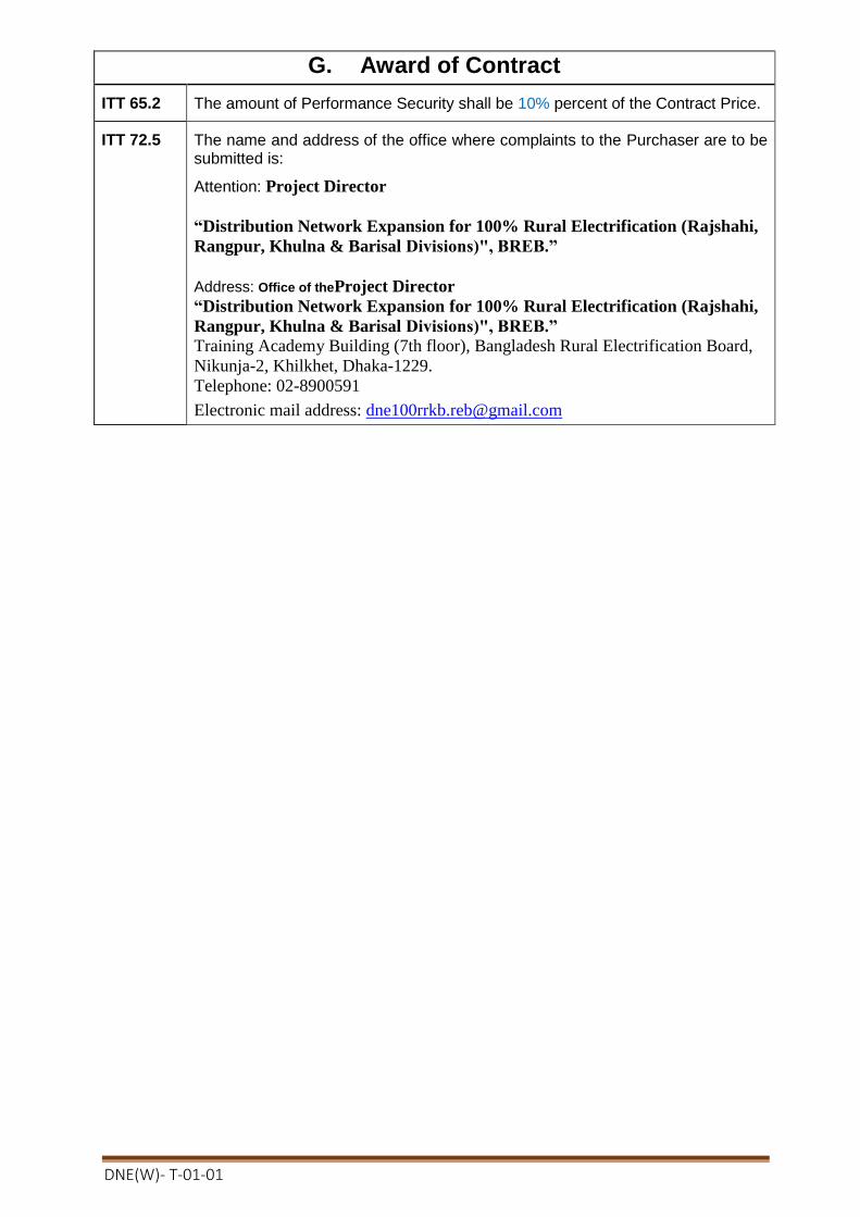
DNE(W)- T-01-01
G. Award of Contract
ITT 65.2 The amount of Performance Security shall be 10% percent of the Contract Price.
ITT 72.5 The name and address of the office where complaints to the Purchaser are to be submitted is:
Attention: Project Director
“Distribution Network Expansion for 100% Rural Electrification (Rajshahi,
Rangpur, Khulna & Barisal Divisions)", BREB.”
Address: Office of theProject Director
“Distribution Network Expansion for 100% Rural Electrification (Rajshahi,
Rangpur, Khulna & Barisal Divisions)", BREB.”
Training Academy Building (7th floor), Bangladesh Rural Electrification Board,
Nikunja-2, Khilkhet, Dhaka-1229.
Telephone: 02-8900591
Electronic mail address: [email protected]
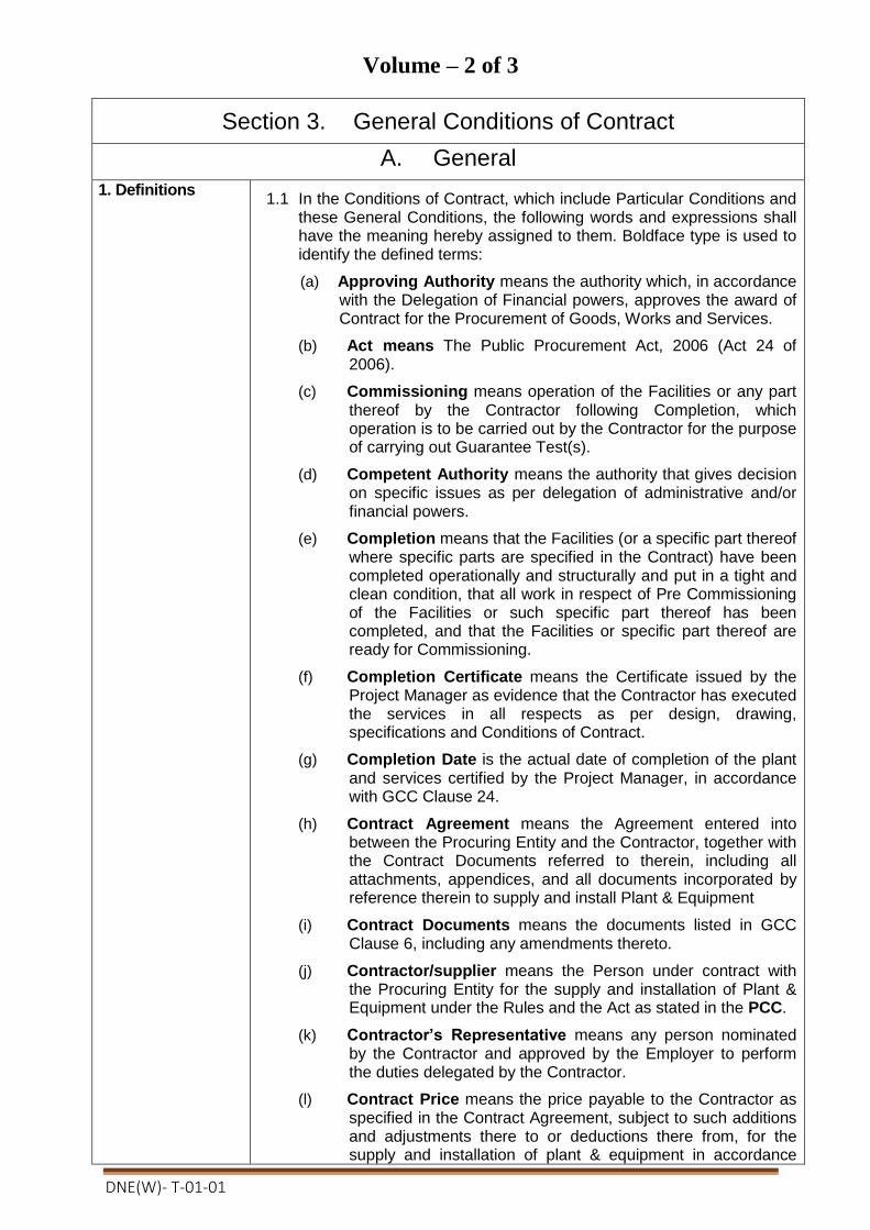
DNE(W)- T-01-01
Volume – 2 of 3
Section 3. General Conditions of Contract
A. General
1. Definitions 1.1 In the Conditions of Contract, which include Particular Conditions and
these General Conditions, the following words and expressions shall have the meaning hereby assigned to them. Boldface type is used to identify the defined terms:
(a) Approving Authority means the authority which, in accordance with the Delegation of Financial powers, approves the award of Contract for the Procurement of Goods, Works and Services.
(b) Act means The Public Procurement Act, 2006 (Act 24 of 2006).
(c) Commissioning means operation of the Facilities or any part thereof by the Contractor following Completion, which operation is to be carried out by the Contractor for the purpose of carrying out Guarantee Test(s).
(d) Competent Authority means the authority that gives decision on specific issues as per delegation of administrative and/or financial powers.
(e) Completion means that the Facilities (or a specific part thereof where specific parts are specified in the Contract) have been completed operationally and structurally and put in a tight and clean condition, that all work in respect of Pre Commissioning of the Facilities or such specific part thereof has been completed, and that the Facilities or specific part thereof are ready for Commissioning.
(f) Completion Certificate means the Certificate issued by the Project Manager as evidence that the Contractor has executed the services in all respects as per design, drawing, specifications and Conditions of Contract.
(g) Completion Date is the actual date of completion of the plant and services certified by the Project Manager, in accordance with GCC Clause 24.
(h) Contract Agreement means the Agreement entered into between the Procuring Entity and the Contractor, together with the Contract Documents referred to therein, including all attachments, appendices, and all documents incorporated by reference therein to supply and install Plant & Equipment
(i) Contract Documents means the documents listed in GCC Clause 6, including any amendments thereto.
(j) Contractor/supplier means the Person under contract with the Procuring Entity for the supply and installation of Plant & Equipment under the Rules and the Act as stated in the PCC.
(k) Contractor’s Representative means any person nominated by the Contractor and approved by the Employer to perform the duties delegated by the Contractor.
(l) Contract Price means the price payable to the Contractor as specified in the Contract Agreement, subject to such additions and adjustments there to or deductions there from, for the supply and installation of plant & equipment in accordance

DNE(W)- T-01-01
with the provisions of the Contract, subject to such additions and adjustments thereto or deductions therefrom, as may be made pursuant to the Contract.
(m) Cost means all expenditures reasonably incurred or to be incurred by the Contractor, whether on or off the Site, including overhead ,profit, taxes, duties, fees, and such other similar levies
(n) Day means calendar day unless otherwise specified as working days.
(o) Dayworks means work carried out following the instructions of the Procuring Entity or the authorised Project Manager and is paid for on the basis of time spent by the Contractor’s workers and equipment at the rates specified in the Schedules, in addition to payments for associated Materials and Plant.
(p) Defect is any part of the Works not completed in accordance with the Contract.
(q) Defect Liability Period means the period of validity of the warranties given by the Contractor commencing at Completion of the Facilities or a part thereof, during which the Contractor is responsible for defects with respect to the Facilities (or the relevant part thereof) as provided in contract document.
(r) Defects Correction Certificate is the certificate issued by the Project Manager upon correction of defects by the Contractor.
(s) Drawings include calculations and other information provided in Section 7 or as approved by the Project Manager for the execution and completion of the Contract.
(t) Effective Date means the date of fulfillment of all conditions of the Contract Agreement, from which the Time for Completion shall be counted.
(u) Equipmentmeans all facilities, equipment, machinery, tools, apparatus, appliances or things of every kind required in or for installation, completion and maintenance of Facilities that are to be provided by the Contractor, but does not include Plant, or other things intended to form or forming part of the Facilities.
(v) Facilitiesmeans the Plant to be supplied and installed, as well as all the Installation Services to be carried out by the Contractor under the Contract. It also includes any ancillary building or infra structure that needs to be constructed/built/erected to support the plant.
(w) Force Majeure means an event or situation beyond the control of the Contractor that is not foreseeable, is unavoidable, and its origins not due to negligence or lack of care on the part of the Contractor; such events may include, but not be limited to, acts of the Government in its sovereign capacity, wars or revolutions, fires, floods, epidemics, quarantine restrictions, and freight embargoes or more as included in GCC Clause 52.
(x) Goods mean the Contractor’s Plant, Equipment, Materials or any of them as appropriate.
(y) GCC means the General Conditions of Contract.
(z) Government means the Government of the People’s Republic of Bangladesh.
(aa) Guarantee Test(s)means the test(s) specified in the Employer’s Requirements to be carried out to ascertain

DNE(W)- T-01-01
whether the Facilities or a specified part thereof is able to attain the Functional Guarantees specified in the Appendix to the Contract Agreement titled Functional Guarantees, in accordance with the provisions of GCC Sub-Clause 25.2 (Guarantee Test) hereof.
(bb) Head of the Procuring Entity means the Secretary of a Ministry or a Division, the Head of a Government Department or Directorate; or the Chief Executive, by whatever designation called, of a local Government agency, an autonomous or semi-autonomous body or a corporation, or a corporate body established under the Companies Act;
(cc) Installation Servicesmeans all those services ancillary to the supply of the Plant for the Facilities, to be provided by the Contractor under the Contract, such as transportation and provision of marine or other similar insurance, inspection, expediting, site preparation works (including the provision and use of Contractor’s Equipment and the supply of all construction materials required), installation, testing, pre-commissioning, commissioning, operations, maintenance, the provision of operations and maintenance manuals, training, etc. as the case may require.
(dd) Intended Completion Date is the date calculated from the Commencement Date as specified in the PCC, on which it is intended that the Contractor shall complete the Works and Physical services as specified in the Contract and may be revised only by the Project Manager by issuing an extension of time or an acceleration order.
(ee) Materials means things of all kinds other than Plant intended to form or forming part of the Permanent Works, including the supply-only materials, if any, to be supplied by the Contractor under the Contract.
(ff) Month means calendar month.
(gg) Original Contract Price is the Contract Price stated in the Procuring Entity’s Notification of Award (Form PG5A-7) and further clearly determined in the PCC.
(hh) Operational Acceptance means the acceptance by the Employer of the Facilities (or any part of the Facilities where the Contract provides for acceptance of the Facilities in parts), which certifies the Contractor’s fulfillment of the Contract in respect of Functional Guarantees of the Facilities (or the relevant part thereof) in accordance with the provisions of contract
(ii) PCC means the Particular Conditions of Contract.
(jj) Plant means permanent plant, equipment, machinery, apparatus, materials, articles, ancillary buildings/structure and things of all kinds to be provided and incorporated in the Facilities by the Contractor under the Contract (including the spare parts to be supplied by the Contractor), but does not include Contractor’s Equipment.
(kk) Pre Commissioningmeans the testing, checking and other requirements specified in the Employer’s Requirements that are to be carried out by the Contractor in preparation for Commissioning.
(ll) Procuring Entity/Employer/Purchaser means, as the context so applies, an Entity having administrative and financial

DNE(W)- T-01-01
powers to undertake procurement of Plant and Physical services using public funds and is as named in the PCC who employs the Contractor to carry out the contractual obligations.
(mm) Project Manager is the person named in the PCC or any other competent person appointed by the Procuring Entity and notified to the Contractor who is responsible for supervising the execution and completion of the plant and services and administering the Contract.
(nn) Schedules means the document(s) entitled schedules, completed by the Contractor and submitted with the Tender Submission Letter, as included in the Contract. Such document may include the data, lists and schedules of rates and/or prices.
(oo) Site means the land and other places upon which the Facilities are to be installed, and such other land or places as may be specified in the PCC as forming part of the Site
(pp) Site Investigation Reports are those that were included in the Tender Document and are factual and interpretative reports about the surface and subsurface conditions at the Site.
(qq) Specification means the Specification of the goods/works/related services included in the Contract and any modifications or additions to the specifications made or approved by the Project Manager in accordance with the Contract.
(rr) Start Date is the date defined in the PCC and it is the last date when the Contractor shall commence execution of the goods/works/services under the Contract.
(ss) Subcontractor means a person or corporate body, who has a contract with the Contractor to carry out a part of the work in the Contract, which includes work on the Site.
(tt) Time for Completion means the time within which Completion of the Facilities as a whole (or of a part of the Facilities where a separate Time for Completion of such part has been prescribed) is to be attained, in accordance with the relevant provisions of the Contract.
(uu) Variation means any change to the plant and services directly procured from the original Contractor to cover increases or decreases in quantities, including the introduction of new work items that are either due to change of plans, design or alignment to suit actual field conditions, within the general scope and physical boundaries of the contract.
(vv) Works means all works associated with the construction, reconstruction, site preparation, demolition, repair, maintenance or renovation of railways, roads, highways, or a building, an infrastructure or structure or an installation or any construction work relating to excavation, installation of equipment and materials, decoration, as well as physical services ancillary to works as detailed in the PCC, if the value of those services does not exceed that of the Works themselves.
(ww) Writing means communication written by hand or machine duly signed and includes properly authenticated messages by facsimile or electronic mail.
2. Interpretation 2.1 In interpreting the GCC, singular also means plural, male also means

DNE(W)- T-01-01
female or neuter, and the other way around. Headings in the GCC shall not be deemed part thereof or be taken into consideration in the interpretation or construance of the Contract. Words have their normal meaning under the language of the Contract unless specifically defined.
2.2 Entire Agreement.
The Contract constitutes the entire agreement between the Employer
and the Contractor and supersedes all communications, negotiations
and agreements (whether written or verbal) of parties with respect
thereto made prior to the date of Contract Agreement; except those
stated under GCC Sub Clause 6.1(j).
2.3 Non waiver.
(a) Subject to GCC Sub Clause 2.3(b), no relaxation, forbearance,
delay, or indulgence by either party in enforcing any of the terms
and conditions of the Contract or the granting of time by either
party to the other shall prejudice, affect, or restrict the rights of
that party under the Contract, neither shall any waiver by either
party of any breach of Contract operate as waiver of any
subsequent or continuing breach of Contract.
(b) Any waiver of a party’s rights, powers, or remedies under the
Contract must be in writing, dated, and signed by an authorized
representative of the party granting such waiver, and must
specify the right and the extent to which it is being waived.
2.4. Severability
If any provision or condition of the Contract is prohibited or rendered
invalid or unenforceable, such prohibition, invalidity or
unenforceability shall not affect the validity or enforceability of any
other provisions and conditions of the Contract.
2.5. Sectional completion If sectional completion is specified in the PCC, references in the GCC
to the Works, the Completion Date, and the Intended Completion
Date apply to any section of the Works (other than references to the
Completion Date and Intended Completion Date for the whole of the
Works).
3. Communications & Notices
3.1 Communications between Parties such as notice, request or consent
required or permitted to be given or made by one party to the other
pursuant to the Contract shall be in writing to the addresses specified
in the PCC.
3.2 A notice shall be effective when delivered or on the notice’s effective date, whichever is later.
3.3 A Party may change its address for notice hereunder by giving the other Party notice of such change to the address.
4. Governing Law 4.1 The Contract shall be governed by and interpreted in accordance with the laws of the People’s Republic of Bangladesh.

DNE(W)- T-01-01
5.Governing Language
5.1 The Contract shall be written in English. All correspondences and documents relating to the Contract may be written in English. Supporting documents and printed literature that are part of the Contract may be in another language, provided they are accompanied by an accurate translation of the relevant passages in English, in which case, for purposes of interpretation of the Contract, such translation shall govern.
5.2 The Contractor shall bear all costs of translation to the governing language and all risks of the accuracy of such translation.
6. Documents Forming the Contract and Priority of Documents
6.1 The following documents forming the Contract shall be interpreted in the following order of priority:
(a) the signed Contract Agreement (Form PG5A-8);
(b) the Notification of Award (PG5A-7);
(c) the completed Tender and the Appendix to the Tender;
(d) the Price Schedule for Plant and Services (PG5A-3);
(e) the Particular Conditions of Contract;
(f) the General Conditions of Contract;
(g) the Technical Specifications;
(h) Personnel Information;
(i) Equipment Information;
(j) the Drawings; and
(k) Any other document listed in the PCC forming part of the Contract.
7. Contract Agreement
7.1 The parties shall enter into a Contract Agreement within twenty eight (28) days from the date of issuance of the Notification of Award (NOA). The costs of stamp duties and similar charges, if any, designated by the applicable law in connection with entry into the Contract Agreement, shall be borne by the Employer.
8. Assignment 8.1 Neither the Contractor nor the Employer shall assign, in whole or in part, its obligations under the Contract; except with the Employer’s prior written approval.
9. Eligibility 9.1 The Contractor and its Subcontractor(s) shall have the nationality of a country other than that specified in the PCC.
9.2 All materials, equipment, plant, and supplies used by the Contractor in both permanent and temporary works and services supplied under the Contract shall have their origin in the countries except any specified in the PCC.
10. Gratuities / Agency fees
10.1 No fees, gratuities, rebates, gifts, commissions or other payments, other than those included in the Contract, shall be given or received in connection with the procurement process or in the Contract execution.
11. Confidential Details
11.1 The Employer and the Contractor shall keep confidential and shall not, without the written consent of the other party hereto, divulge to any third party any documents, data, or other information furnished directly or indirectly by the other party hereto in connection with the Contract, whether such information has been furnished prior to, during or following completion or termination of the Contract. Notwithstanding the above, the Contractor may furnish to its Subcontractor such documents, data, and other information it receives from the Employer to the extent required for the

DNE(W)- T-01-01
Subcontractor to perform its work under the Contract, in which event the Contractor shall obtain from such Subcontractor an undertaking of confidentiality similar to that imposed on the Contractor under GCC Clause 11.
11.2 The Employer shall not use such documents, data, and other
information received from the Contractor for any purposes unrelated
to the Contract. Similarly, the Contractor shall not use such
documents, data, and other information received from the Employer
for any purpose other than the design, construction, or other work and
services required for the performance of the Contract.
11.3 The obligations of a party under GCC Sub Clauses 11.1 and 11.2
above, however, shall not apply to information that: the Employer or
Contractor needs to share with institutions participating in the
financing of the Contract; now or hereafter enters the public domain
through no fault of that party; can be proven to have been possessed
by that party at the time of disclosure and which was not previously
obtained, directly or indirectly, from the other party; or otherwise
lawfully becomes available to that party from a third party that has no
obligation of confidentiality.
11.4 The above provisions of GCC Clause 11 shall not in any way modify any undertaking of confidentiality given by either of the parties hereto prior to the date of the Contract in respect of the Works or any part thereof.
11.5 The provisions of GCC Clause 11 shall survive completion or termination, for whatever reason.
12. Joint Venture (JV)
12.1 If the Contractor is a Joint Venture, Consortium, or Association (JVCA ),
(a) each partner of the JV shall be jointly and severally liable for all liabilities and ethical or legal obligations to the Employer for the performance of the Contract;
(b) the JV partners shall nominate a representative who shall have
the authority to conduct all business including the receipt of
payments for and on behalf of all partners of the JV;
(c) in the event of a dispute that results in legal action against all
partners of the JV, if they are available and if only one partner is
available, then that partner alone shall answer on behalf of all
partners and, if the complaint lodged is proven, the penalty shall
be applicable on that lone partner as whatever penalty all the
partners would have received.
(d) the JV shall notify the Employer of its composition and legal status which shall not be altered without the prior approval of the Employer.
(e) alteration of partners shall only be allowed if any of the partners is found to be incompetent or has any serious difficulties which may impact the overall implementation of the goods/works/service, whereby the incoming partner shall require to possess qualifications equal to or higher than that of the outgoing partner.
(f) if any of the partners of JV has been debarred from participating in any procurement activity due to corrupt, fraudulent, collusive

DNE(W)- T-01-01
or coercive practices, that JV partner shall be altered following provisions under GCC Sub Clause 12.1 (d) and (e), while in case the Leading Partner has been debarred due to the same reasons stated herein the Contract shall be terminated as stated under GCC Sub Clause 67.1(b).
13. Possession of the Site
13.1 The Employer shall give possession of the Site or part(s) of the Site, to the Contractor on the date(s) stated in the PCC. If possession of a part of the Site is not given by the date stated in the PCC, the Employer will be deemed to have delayed the start of the relevant activities, and this will be a Compensation Event.
14. Access to the Site
14.1 The Contractor shall allow the Engineer and any person authorised by the Engineer access to the Site and to any place where work in connection with the Contract is being carried out or is intended to be carried out.
15. Safety, Security and Protection of the Environment
15.1 The Contractor shall throughout the execution and completion of the Works and the remedying of any defects therein:
(a) take all reasonable steps to safeguard the health and safety of all workers working on the Site and other persons entitled to be on it, and to keep the Site in an orderly state;
(b) provide and maintain at the Contractor’s own cost all lights, guards, fencing, warning signs and watching for the protection of the Works or for the safety on-site; and
(c) take all reasonable steps to protect the environment on and off the Site and to avoid damage or nuisance to persons or to property of the public or others resulting from pollution, noise or other causes arising as a consequence of the Contractors methods of operation.
16. Working Hours
16.1 The Contractor shall not perform any work on the Site on the weekly holidays, or during the night or outside the normal working hours, or on any religious or public holiday, without the prior written approval of the Project Manager.
17. Welfare of Laborers
17.1 The Contractor shall comply with all the relevant labour Laws applicable to the Contractor’s personnel relating to their employment, health, safety, welfare, immigration and shall allow them all their legal rights.
17.2 The Contractor, in particular, shall provide proper accommodation to his or her labourers and arrange proper water supply, conservancy and sanitation arrangements at the site for all necessary hygienic requirements and for the prevention of epidemics in accordance with relevant regulations, rules and orders of the government.
17.3 The Contractor, further in particular, shall pay reasonable wages to his or her labourers, and pay them in time. In the event of delay in payment the Employer may effect payments to the labourers and recover the cost from the Contractor.
17.4 The Contractor shall appoint an accident prevention officer at the Site, responsible for maintaining safety and protection against accidents. This person shall be qualified for this responsibility, and shall have the authority to issue instructions and take appropriate protective measures to prevent accidents that could result in injury. Throughout the execution of the Works, the Contractor shall provide whatever is required by this person to exercise this responsibility and authority.

DNE(W)- T-01-01
18. Child Labor 18.1 The Contractor shall not employ any child to perform any work that is
economically exploitative, or is likely to be hazardous to, or to
interfere with, the child's education, or to be harmful to the child's
health or physical, mental, spiritual, moral, or social development in
compliance with the applicable laws and other relevant treaties
ratified by the government.
19. Fossils& antiquities
19.1 All fossils, coins, articles of value or antiquity, and structures and other remains or items of geological or archaeological interest found on the Site shall be placed under the care and authority of the Employer. The Contractor shall take reasonable precautions to prevent Contractor’s Personnel or other persons from removing or damaging any of these findings.
19.2 The Contractor shall, upon discovery of any such finding, promptly
give notice to the Project Manager, who shall issue instructions for
dealing with it. If the Contractor suffers delay and/or incurs cost from
complying with the instructions, the Contractor shall give a further
notice to the Project Manager and shall be entitled subject to Claims
under GCC Clause 71
20.Corrupt, Fraudulent, Collusive or Coercive Practices
20.1 The Government requires that Employer, as well as the Contractor shall observe the highest standard of ethics during the implementation of procurement proceedings and the execution of the Contract.
20.2 The Government requires that Employer, as well as the Contractor
shall, during the Procurement proceedings and the execution of the
Contract under public funds, ensure-
(a) strict compliance with the provisions of Section 64 of the Public Procurement Act, 2006
(b) abiding by the code of ethics as mentioned in the Rule127 of the Public Procurement Rules, 2008;
(c) that neither it, nor any other member of its staff, or any other agents or intermediaries working on its behalf engages in any such practice as detailed in GCC Sub Clause 20.2.
20.3 For the purposes of GCC Sub Clause 20.2, the terms set forth below as follows
(a) “corrupt practice” means offering, giving or promising to give, receiving, or soliciting either directly or indirectly, to any officer or employee of a Employer or other public or private authority or individual, a gratuity in any form; employment or any other thing or service of value as an inducement with respect to an act or decision or method followed by a Employer in connection with a Procurement proceeding or Contract execution;
(b) “fraudulent practice” means the misrepresentation or
omission of facts in order to influence a decision to be taken
in a Procurement proceeding or Contract execution;
(c) collusive practice” means a scheme or arrangement between
two (2) or more Persons, with or without the knowledge of the
Employer, that is designed to arbitrarily reduce the number of
Tenders submitted or fix Tender prices at artificial, non-
competitive levels, thereby denying a Employer the benefits of

DNE(W)- T-01-01
competitive price arising from genuine and open competition; or
(d) “Coercive practice” means harming or threatening to harm, directly or indirectly, Persons or their property to influence a decision to be taken in the Procurement proceeding or the execution of the Contract, and this will include creating obstructions in the normal submission process used for Tenders.
20.4 Should any corrupt, fraudulent, collusive or coercive practice of any
kind come to the knowledge of the Employer, it will, in the first place,
allow the Contractor to provide an explanation and shall, take
actions only when a satisfactory explanation is not received. Such
decision and the reasons thereof, shall be recorded in the record of
the procurement proceedings and promptly communicated to the
Contractor. Any communications between the Contractor and the
Employer related to matters of alleged fraud or corruption shall be in
writing.
20.5 If corrupt, fraudulent, collusive or coercive practices of any kind determined by the Employer against the Contractor alleged to have carried out such practices, the Employer will :
(a) exclude the Contractor from further participation in the particular Procurement proceeding; or
(b) declare, at its discretion, the Contractor to be ineligible to participate in further Procurement proceedings, either indefinitely or for a specific period of time.
20.6 20.6 The Contractor shall be aware of the provisions on corruption, fraudulence, collusion and coercion in Section 64 of the Public Procurement Act, 2006 and Rule 127 of the Public Procurement Rules, 2008.
21. License/ Use of Technical Information
21.1 For the operation and maintenance of the Plant, the Contractor
hereby grants a non-exclusive and non-transferable license (without
the right to sub-license) to the Employer under the patents, utility
models or other industrial property rights owned by the Contractor or
by a third Party from whom the Contractor has received the right to
grant licenses thereunder, and shall also grant to the Employer a
non-exclusive and non-transferable right (without the right to sub-
license) to use the know-how and other technical information
disclosed to the Employer under the Contract. Nothing contained
herein shall be construed as transferring ownership of any patent,
utility model, trademark, design, copyright, know-how or other
intellectual property right from the Contractor or any third Party to the
Employer.
21.2 The copyright in all drawings, documents and other materials
containing data and information furnished to the Employer by the
Contractor herein shall remain vested in the Contractor or, if they are
furnished to the Employer directly or through the Contractor by any
third Party, including suppliers of materials, the copyright in such
materials shall remain vested in such third Party.

DNE(W)- T-01-01
B. Subject Matter of Contract
22. Scope of Facilities
22.1 Unless otherwise expressly limited in the Employer’s Requirements, the Contractor’s obligations cover the provision of all Plant and the performance of all Installation Services required for the design, and the manufacture (including procurement, quality assurance, construction, installation, associated civil works, Pre Commissioning and delivery) of the Plant, and the installation, completion and commissioning of the Facilities in accordance with the plans, procedures, specifications, drawings, codes and any other documents as specified in the Section, Employer’s Requirements. Such specifications include, but are not limited to, the provision of supervision and engineering services; the supply of labor, materials, equipment, spare parts and accessories; Contractor’s Equipment; construction utilities and supplies; temporary materials, structures and facilities; transportation (including, without limitation, unloading and hauling to, from and at the Site); and storage, except for those supplies, works and services that will be provided or performed by the Employer, as set forth in the Appendix to the Contract Agreement titled Scope of Works and Supply by the Employer.
22.2 The Contractor shall, unless specifically excluded in the Contract, perform all such work and/or supply all such items and materials not specifically mentioned in the Contract but that can be reasonably inferred from the Contract as being required for attaining Completion of the Facilities as if such work and/or items and materials were expressly mentioned in the Contract.
22.3 In addition to the supply of Mandatory Spare Parts included in the Contract, the Contractor agrees to supply spare parts required for the operation and maintenance of the Facilities for the period specified in the PCC and the provisions, if any, specified in the PCC. However, the identity, specifications and quantities of such spare parts and the terms and conditions relating to the supply thereof are to be agreed between the Employer and the Contractor, and the price of such spare parts shall be that given in Price Schedule No.1 &2 under form PG5A-3, which shall be added to the Contract Price. The price of such spare parts shall include the purchase price therefor and other costs and expenses (including the Contractor’s fees) relating to the supply of spare parts.
23. Time for Commencement
23.1 The Contractor shall attain Completion of the Facilities or of a part where a separate time for Completion of such part is specified in the Contract, within the time stated in the PCC or within such extended time to which the Contractor shall be entitled under GCC Clause 65.1 hereof.
24. Time for Completion
24.1 The Contractor shall attain Completion of the Facilities or of a part where a separate time for Completion of such part is specified in the Contract, within the time stated in the PCC or within such extended time to which the Contractor shall be entitled under GCC Clause 65.1 hereof.
25. Employer’s Responsibilities
25.1 All information and/or data to be supplied by the Employer as described in the Appendix to the Contract Agreement titled Scope of Works and Supply by the Employer, shall be deemed to be accurate, except when the Employer expressly states otherwise
25.2 The Employer shall be responsible for acquiring and providing

DNE(W)- T-01-01
legal and physical possession of the Site and access thereto, and for providing possession of and access to all other areas reasonably required for the proper execution of the Contract, including all requisite rights of way, as specified in the Appendix to the Contract Agreement titled Scope of Works and Supply by the Employer. The Employer shall give full possession of and accord all rights of access thereto on or before the date(s) specified in that Appendix.
25.3 The Employer shall acquire and pay for all permits, approvals and/or licenses from all local, state or national government authorities or public service undertakings in the country where the Site is located which (a) such authorities or undertakings require the Employer to obtain in the Employer’s name, (b) are necessary for the execution of the Contract, including those required for the performance by both the Contractor and the Employer of their respective obligations under the Contract, and (c) are specified in the Appendix (Scope of Works and Supply by the Employer).
25.4 If requested by the Contractor, the Employer shall use its best endeavors to assist the Contractor in obtaining in a timely and expeditious manner all permits, approvals and/or licenses necessary for the execution of the Contract from all local, state or national government authorities or public service undertakings that such authorities or undertakings require the Contractor or Subcontractors or the personnel of the Contractor or Subcontractors, as the case may be, to obtain
25.5 Unless otherwise specified in the Contract or agreed upon by the Employer and the Contractor, the Employer shall provide sufficient, properly qualified operating and maintenance personnel; shall supply and make available all raw materials, utilities, lubricants, chemicals, catalysts, other materials and facilities; and shall perform all work and services of whatsoever nature, including those required by the Contractor to properly carry out Pre Commissioning, Commissioning and Guarantee Tests, all in accordance with the provisions of the Appendix to the Contract Agreement titled Scope of Works and Supply by the Employer, at or before the time specified in the program furnished by the Contractor under the provisions of contract specified or as otherwise agreed upon by the Employer and the Contractor.
25.6 The Employer shall be responsible for the continued operation of the Facilities after Completion, in accordance with GCC Sub-Clause 39.8, and shall be responsible for facilitating the Guarantee Test(s) for the Facilities, in accordance with GCC Sub-Clause 40.2.
25.7 All costs and expenses involved in the performance of the obligations under this GCC Clause 25 shall be the responsibility of the Employer, save those to be incurred by the Contractor with respect to the performance of Guarantee Tests, in accordance with GCC Sub-Clause 40.2.
25.8 In the event that the Employer shall be in breach of any of his obligations under this Clause, the additional cost incurred by the Contractor in consequence thereof shall be determined by the Project Manager and added to the Contract Price
26. Contractor’s Responsibilities
26.1 The Contractor shall design, manufacture including associated purchases and/or subcontracting, install and complete the Facilities in accordance with the Contract. When completed, the Facilities should be fit for the purposes for which they are intended as defined in the Contract.
26.2 The Contractor confirms that it has entered into this Contract on the basis of a proper examination of the data relating to the Facilities
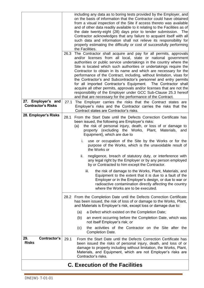
DNE(W)- T-01-01
including any data as to boring tests provided by the Employer, and on the basis of information that the Contractor could have obtained from a visual inspection of the Site if access thereto was available and of other data readily available to it relating to the Facilities as of the date twenty-eight (28) days prior to tender submission. The Contractor acknowledges that any failure to acquaint itself with all such data and information shall not relieve its responsibility for properly estimating the difficulty or cost of successfully performing the Facilities.
26.3 The Contractor shall acquire and pay for all permits, approvals and/or licenses from all local, state or national government authorities or public service undertakings in the country where the Site is located which such authorities or undertakings require the Contractor to obtain in its name and which are necessary for the performance of the Contract, including, without limitation, visas for the Contractor’s and Subcontractor’s personnel and entry permits for all imported Contractor’s Equipment. The Contractor shall acquire all other permits, approvals and/or licenses that are not the responsibility of the Employer under GCC Sub-Clause 25.3 hereof and that are necessary for the performance of the Contract.
27. Employer’s and Contractor’s Risks
27.1 The Employer carries the risks that the Contract states are Employer’s risks and the Contractor carries the risks that the Contract states are Contractor’s risks.
28. Employer’s Risks 28.1 From the Start Date until the Defects Correction Certificate has
been issued, the following are Employer’s risks: (a) the risk of personal injury, death, or loss of or damage to
property (excluding the Works, Plant, Materials, and Equipment), which are due to
i. use or occupation of the Site by the Works or for the purpose of the Works, which is the unavoidable result of the Works or
ii. negligence, breach of statutory duty, or interference with any legal right by the Employer or by any person employed by or Contracted to him except the Contractor.
iii. the risk of damage to the Works, Plant, Materials, and Equipment to the extent that it is due to a fault of the Employer or in the Employer’s design, or due to war or radioactive contamination directly affecting the country where the Works are to be executed.
28.2 From the Completion Date until the Defects Correction Certificate has been issued, the risk of loss of or damage to the Works, Plant, and Materials is Employer’s risk, except loss or damage due to:
(a) a Defect which existed on the Completion Date;
(b) an event occurring before the Completion Date, which was not itself Employer’s risk; or
(c) the activities of the Contractor on the Site after the Completion Date.
29. Contractor’s Risks
29.1 From the Start Date until the Defects Correction Certificate has been issued the risks of personal injury, death, and loss of or damage to property including without limitation, the Works, Plant, Materials, and Equipment, which are not Employer’s risks are Contractor’s risks.
C. Execution of the Facilities
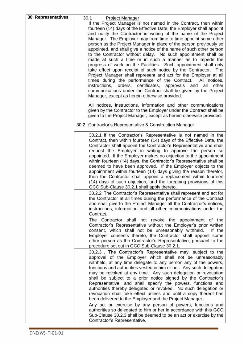
DNE(W)- T-01-01
30. Representatives 30.1 Project Manager If the Project Manager is not named in the Contract, then within fourteen (14) days of the Effective Date, the Employer shall appoint and notify the Contractor in writing of the name of the Project Manager. The Employer may from time to time appoint some other person as the Project Manager in place of the person previously so appointed, and shall give a notice of the name of such other person to the Contractor without delay. No such appointment shall be made at such a time or in such a manner as to impede the progress of work on the Facilities. Such appointment shall only take effect upon receipt of such notice by the Contractor. The Project Manager shall represent and act for the Employer at all times during the performance of the Contract. All notices, instructions, orders, certificates, approvals and all other communications under the Contract shall be given by the Project Manager, except as herein otherwise provided.
All notices, instructions, information and other communications given by the Contractor to the Employer under the Contract shall be given to the Project Manager, except as herein otherwise provided.
30.2 Contractor’s Representative & Construction Manager
30.2.1 If the Contractor’s Representative is not named in the Contract, then within fourteen (14) days of the Effective Date, the Contractor shall appoint the Contractor’s Representative and shall request the Employer in writing to approve the person so appointed. If the Employer makes no objection to the appointment within fourteen (14) days, the Contractor’s Representative shall be deemed to have been approved. If the Employer objects to the appointment within fourteen (14) days giving the reason therefor, then the Contractor shall appoint a replacement within fourteen (14) days of such objection, and the foregoing provisions of this GCC Sub-Clause 30.2.1 shall apply thereto.
30.2.2 The Contractor’s Representative shall represent and act for the Contractor at all times during the performance of the Contract and shall give to the Project Manager all the Contractor’s notices, instructions, information and all other communications under the Contract.
The Contractor shall not revoke the appointment of the Contractor’s Representative without the Employer’s prior written consent, which shall not be unreasonably withheld. If the Employer consents thereto, the Contractor shall appoint some other person as the Contractor’s Representative, pursuant to the procedure set out in GCC Sub-Clause 30.2.1.
30.2.3 . The Contractor’s Representative may, subject to the approval of the Employer which shall not be unreasonably withheld, at any time delegate to any person any of the powers, functions and authorities vested in him or her. Any such delegation may be revoked at any time. Any such delegation or revocation shall be subject to a prior notice signed by the Contractor’s Representative, and shall specify the powers, functions and authorities thereby delegated or revoked. No such delegation or revocation shall take effect unless and until a copy thereof has been delivered to the Employer and the Project Manager.
Any act or exercise by any person of powers, functions and authorities so delegated to him or her in accordance with this GCC Sub-Clause 30.2.3 shall be deemed to be an act or exercise by the Contractor’s Representative.

DNE(W)- T-01-01
30.2.4 From the commencement of installation of the Facilities at the Site until Completion, the Contractor’s Representative shall appoint a suitable person as the Construction Manager. The Construction Manager shall supervise all work done at the Site by the Contractor and shall be present at the Site throughout normal working hours except when on leave, sick or absent for reasons connected with the proper performance of the Contract. Whenever the Construction Manager is absent from the Site, a suitable person shall be appointed to act as the Construction Manager’s deputy.
30.2.5 The Employer may by notice to the Contractor object to any representative or person employed by the Contractor in the execution of the Contract who, in the reasonable opinion of the Employer, may behave inappropriately, may be incompetent or negligent, or may commit a serious breach of the Site regulations provided under GCC Sub-Clause 37.4. The Employer shall provide evidence of the same, whereupon the Contractor shall remove such person from the Facilities.
30.2.6 If any representative or person employed by the Contractor is removed in accordance with GCC Sub-Clause 30.2.5, the Contractor shall, where required, promptly appoint a replacement.
31. Work Program 31.1 Contractor’s Organization
The Contractor shall supply to the Employer and the Project Manager a chart showing the proposed organization to be established by the Contractor for carrying out work on the Facilities within twenty-one (21) days of the Effective Date. The chart shall include the identities of the key personnel and the curricula vitae of such key personnel to be employed shall be supplied together with the chart. The Contractor shall promptly inform the Employer and the Project Manager in writing of any revision or alteration of such an organization chart.
31.2 Program of Performance
Within twenty-eight (28) days after the Effective Date, the Contractor shall submit to the Project Manager a detailed program of performance of the Contract, made in a form acceptable to the Project Manager and showing the sequence in which it proposes to design, manufacture, transport, assemble, install and Pre Commission the Facilities, as well as the date by which the Contractor reasonably requires that the Employer shall have fulfilled its obligations under the Contract so as to enable the Contractor to execute the Contract in accordance with the program and to achieve Completion, Commissioning and Acceptance of the Facilities in accordance with the Contract. The program so submitted by the Contractor shall accord with the Time Schedule included in the Appendix to the Contract Agreement titled Time Schedule, and any other dates and periods specified in the Contract. The Contractor shall update and revise the program as and when appropriate or when required by the Project Manager, but without modification in the Times for Completion specified in the PCC pursuant to Sub-Clause 24.1 and any extension granted in accordance with GCC Clause 65.1, and shall submit all such revisions to the Project Manager.
DNE(W)- T-01-01
31.3 Progress Report The Contractor shall monitor progress of all the activities specified in the program referred to in GCC Sub-Clause 31.2 above, and supply a progress report to the Project Manager every month.
The progress report shall be in a form acceptable to the Project Manager and shall indicate: (a) percentage completion achieved compared with the planned percentage completion for each activity; and (b) where any activity is behind the program, giving comments and likely consequences and stating the corrective action being taken.
31.4 Progress of Performance
If at any time the Contractor’s actual progress falls behind the program referred to in GCC Sub-Clause 31.2, or it becomes apparent that it will so fall behind, the Contractor shall, at the request of the Employer or the Project Manager, prepare and submit to the Project Manager a revised program, taking into account the prevailing circumstances, and shall notify the Project Manager of the steps being taken to expedite progress so as to attain Completion of the Facilities within the Time for Completion under GCC Sub-Clause 24.1, any extension thereof entitled under GCC Sub-Clause 65.1, or any extended period as may otherwise be agreed upon between the Employer and the Contractor.
31.5 Procedures
The Contract shall be executed in accordance with the Contract Documents including the procedures given in the Forms and Procedures of the Employer’s Requirements. The Contractor may execute the Contract in accordance with its own standard project execution plans and procedures to the extent that they do not conflict with the provisions contained in the Contract.
32. Subcontractor 32.1 Subcontracting the whole of the Plant and Service by the Contractor shall not be permissible. The Contractor shall be responsible for the acts or defaults of any Subcontractor, his or her agents or employees, as if they were the acts or defaults of the Contractor.
32.2 The Contractor shall not be required to obtain consent from the Project Manager or his representative, for suppliers solely of Materials or to a subcontract for which the Specialist Subcontractor(s) is already named in the Contract.
32.3 The prior consent, in writing, of the Engineer shall however be obtained for other proposed Subcontractor(s).
33. Nominated Subcontractor
33.1 Nominated Subcontractor named in the Contract shall be entitled to execute the specific components of the Works stated in the PCC.
33.2 The Contractor shall not be under obligations to employ a Nominated Subcontractor against whom the Contractor raises reasonable objection by notice to the Engineer as soon as practicable, with supporting particulars while there are reasons to believe that the Subcontractor does not have sufficient competence, resources or financial strength, or does not accept to indemnify the Contractor against and from any negligence or misuse of Goods by the nominated Subcontractor, or does not accept to enter into a subcontract which specifies that, for the subcontracted work including design, if any, the Nominated Subcontractor shall undertake to the Contractor such obligations and liabilities as will enable the contractor to discharge his or her

DNE(W)- T-01-01
liabilities under the Contract.
34. Other Contractors 34.1 The Contractor shall cooperate and share the Site with other Contractors, public authorities, utilities, the Engineer and the Employer between the dates given in the Schedule of other Contractors. The Contractor shall also provide facilities and services for them as described in the Schedule. The Employer may modify the Schedule of other Contractors, and shall notify the Contractor of any such modification.
35. Design and Engineering
35.1 Specifications and Drawings
35.1.1 The Contractor shall execute the basic and detailed design and the engineering work in compliance with the provisions of the Contract, or where not so specified, in accordance with good engineering practice. The Contractor shall be responsible for any discrepancies, errors or omissions in the specifications, drawings and other technical documents that it has prepared, whether such specifications, drawings and other documents have been approved by the Project Manager or not, provided that such discrepancies, errors or omissions are not because of inaccurate information furnished in writing to the Contractor by or on behalf of the Employer.
35.1.2 The Contractor shall be entitled to disclaim responsibility for any design, data, drawing, specification or other document, or any modification thereof provided or designated by or on behalf of the Employer, by giving a notice of such disclaimer to the Project Manager.
35.2 Codes and Standards
Wherever references are made in the Contract to codes and standards in accordance with which the Contract shall be executed, the edition or the revised version of such codes and standards current at the date twenty-eight (28) days prior to date of tender submission shall apply unless otherwise specified. During Contract execution, any changes in such codes and standards shall be applied subject to approval by the Employer and shall be treated in accordance with GCC Clause 64.
35.3. Approval/Review of Technical Documents by Project Manager
35.3.1 The Contractor shall prepare or cause its Subcontractors to prepare, and furnish to the Project Manager the documents listed in the Appendix to the Contract Agreement titled List of Documents for Approval or Review, for its approval or review as specified and in accordance with the requirements of GCC Sub-Clause 31.2 (Program of Performance).
Any part of the Facilities covered by or related to the documents to be approved by the Project Manager shall be executed only after the Project Manager’s approval thereof.
GCC Sub-Clauses 35.3.2 through 35.3.6 shall apply to those documents requiring the Project Manager’s approval, but not to those furnished to the Project Manager for its review only
35.3.2 Within fourteen (14) days after receipt by the Project Manager of any document requiring the Project Manager’s approval in accordance with GCC Sub-Clause 35.3.1, the Project Manager shall either return one copy thereof to the Contractor with its

DNE(W)- T-01-01
approval endorsed thereon or shall notify the Contractor in writing of its disapproval thereof and the reasons therefor and the modifications that the Project Manager proposes. If the Project Manager fails to take such action within the said fourteen (14) days, then the said document shall be deemed to have been approved by the Project Manager.
35.3.3. The Project Manager shall not disapprove any document, except on the grounds that the document does not comply with the Contract or that it is contrary to good engineering practice.
35.3.4 If the Project Manager disapproves the document, the Contractor shall modify the document and resubmit it for the Project Manager’s approval in accordance with GCC Sub-Clause 35.3.2. If the Project Manager approves the document subject to modification(s), the Contractor shall make the required modification(s), whereupon the document shall be deemed to have been approved.
35.3.5 The Project Manager’s approval, with or without modification of the document furnished by the Contractor, shall not relieve the Contractor of any responsibility or liability imposed upon it by any provisions of the Contract except to the extent that any subsequent failure results from modifications required by the Project Manager.
35.3.6 The Contractor shall not depart from any approved document unless the Contractor has first submitted to the Project Manageran amended document and obtained the Project Manager’s approval thereof, pursuant to the provisions of this GCC Sub-Clause 35.3. If the Project Manager requests any change in any already approved document and/or in any document based thereon, the provisions of GCC Clause 64 shall apply to such request.
36. Procurement 36.1 Plant
Subject to GCC Sub-Clause 60.2, the Contractor shall procure and transport all Plant in an expeditious and orderly manner to the Site.
36.2 Employer-Supplied Plant
If the Appendix to the Contract Agreement titled Scope of Works and Supply by the Employer, provides that the Employer shall furnish any specific items to the Contractor, the following provisions shall apply:
36.2.1 The Employer shall, at its own risk and expense, transport each item to the place on or near the Site as agreed upon by the Parties and make such item available to the Contractor at the time specified in the program furnished by the Contractor, pursuant to GCC Sub-Clause 31.2, unless otherwise mutually agreed.
36.2.2 Upon receipt of such item, the Contractor shall inspect the same visually and notify the Project Manager of any detected shortage, defect or default. The Employer shall immediately remedy any shortage, defect or default, or the Contractor shall, if practicable and possible, at the request of the Employer, remedy such shortage, defect or default at the Employer’s cost and expense. After inspection, such item shall fall under the care, custody and control of the Contractor. The provision of this GCC Sub-Clause 36.2.2 shall apply to any item supplied to remedy any such shortage or default or to substitute for any defective item, or shall apply to defective items that have been repaired.

DNE(W)- T-01-01
36.2.3 The foregoing responsibilities of the Contractor and its obligations of care, custody and control shall not relieve the Employer of liability for any undetected shortage, defect or default, nor place the Contractor under any liability for any such shortage, defect or default whether under GCC Clause 42 or under any other provision of Contract.
36.3 Transportation
36.3.1 The Contractor shall at its own risk and expense transport all the materials and the Contractor’s Equipment to the Site by the mode of transport that the Contractor judges most suitable under all the circumstances.
36.3.2 Unless otherwise provided in the Contract, the Contractor shall be entitled to select any safe mode of transport operated by any person to carry the materials and the Contractor’s Equipment.
36.3.3 Upon dispatch of each shipment of materials and the Contractor’s Equipment, the Contractor shall notify the Employer by telex, cable, facsimile or electronic means, of the description of the materials and of the Contractor’s Equipment, the point and means of dispatch, and the estimated time and point of arrival in the country where the Site is located, if applicable, and at the Site. The Contractor shall furnish the Employer with relevant shipping documents to be agreed upon between the Parties.
36.3.4 The Contractor shall be responsible for obtaining, if necessary, approvals from the authorities for transportation of the materials and the Contractor’s Equipment to the Site. The Employer shall use its best endeavors in a timely and expeditious manner to assist the Contractor in obtaining such approvals, if requested by the Contractor. The Contractor shall indemnify and hold harmless the Employer from and against any claim for damage to roads, bridges or any other traffic facilities that may be caused by the transport of the materials and the Contractor’s Equipment to the Site.
36.4 Customs Clearance
The Contractor shall, at its own expense, handle all imported materials and Contractor’s Equipment at the point(s) of import and shall handle any formalities for customs clearance, subject to the Employer’s obligations under GCC Sub-Clause 60.2, provided that if applicable laws or regulations require any application or act to be made by or in the name of the Employer, the Employer shall take all necessary steps to comply with such laws or regulations. In the event of delays in customs clearance that are not the fault of the Contractor, the Contractor shall be entitled to an extension in the Time for Completion, pursuant to GCC Clause 65.

DNE(W)- T-01-01
37. Installation 37.1 Setting Out/Supervision
37.1.1 Bench Mark: The Contractor shall be responsible for the true and proper setting-out of the Facilities in relation to bench marks, reference marks and lines provided to it in writing by or on behalf of the Employer. If, at any time during the progress of installation of the Facilities, any error shall appear in the position, level or alignment of the Facilities, the Contractor shall forthwith notify the Project Manager of such error and, at its own expense, immediately rectify such error to the reasonable satisfaction of the Project Manager. If such error is based on incorrect data provided in writing by or on behalf of the Employer, the expense of rectifying the same shall be borne by the Employer.
37.1.2 Contractor’s Supervision: The Contractor shall give or provide all necessary superintendence during the installation of the Facilities, and the Construction Manager or its deputy shall be constantly on the Site to provide full-time superintendence of the installation. The Contractor shall provide and employ only technical personnel who are skilled and experienced in their respective callings and supervisory staff who are competent to adequately supervise the work at hand.
37.2 Labor: 37.2.1 Engagement of Staff and Labor
(a) Except as otherwise stated in the Specification, the Contractor shall make arrangements for the engagement of all staff and labor, local or otherwise, and for their payment, housing, feeding and transport.
(b) The Contractor shall provide and employ on the Site in the installation of the Facilities such skilled, semi-skilled and unskilled labor as is necessary for the proper and timely execution of the Contract. The Contractor is encouraged to use local labor that has the necessary skills.
(c) The Contractor shall be responsible for obtaining all necessary permit(s) and/or visa(s) from the appropriate authorities for the entry of all labor and personnel to be employed on the Site into the country where the Site is located. The Employer will, if requested by the Contractor, use his best endeavors in a timely and expeditious manner to assist the Contractor in obtaining any local, state, national or government permission required for bringing in the Contractor’s personnel.
(d) The Contractor shall at its own expense provide the means of repatriation to all of its and its Subcontractor’s personnel employed on the Contract at the Site to the place where they were recruited or to their domicile. It shall also provide suitable temporary maintenance of all such persons from the cessation of their employment on the Contract to the date programmed for their departure. In the event that the Contractor defaults in providing such means of transportation and temporary maintenance, the Employer may provide the same to such personnel and recover the cost of doing so from the Contractor.
37.2.2 Persons in the Service of Employer
The Contractor shall not recruit, or attempt to recruit, staff and

DNE(W)- T-01-01
labor from amongst the Employer’s Personnel.
37.2.3 Facilities for Staff and Labor
Except as otherwise stated in the Specification, the Contractor shall provide and maintain all necessary accommodation and welfare facilities for the Contractor’s Personnel. The Contractor shall also provide facilities for the Employer’s Personnel as stated in the Specification.
The Contractor shall not permit any of the Contractor’s Personnel to maintain any temporary or permanent living quarters within the structures forming part of the Permanent Works
37.3 Contractor’s Equipment
37.3.1 All Contractor’s Equipment brought by the Contractor onto the Site shall be deemed to be intended to be used exclusively for the execution of the Contract. The Contractor shall not remove the same from the Site without the Project Manager’s consent that such Contractor’s Equipment is no longer required for the execution of the Contract.
37.3.2 Unless otherwise specified in the Contract, upon completion of the Facilities, the Contractor shall remove from the Site all Equipment brought by the Contractor onto the Site and any surplus materials remaining thereon.
37.3.3 The Employer will, if requested, use its best endeavors to assist the Contractor in obtaining any local, state or national government permission required by the Contractor for the export of the Contractor’s Equipment imported by the Contractor for use in the execution of the Contract that is no longer required for the execution of the Contract.
37.4 Site Regulations and Safety
The Employer and the Contractor shall establish Site regulations setting out the rules to be observed in the execution of the Contract at the Site and shall comply therewith. The Contractor shall prepare and submit to the Employer, with a copy to the Project Manager, proposed Site regulations for the Employer’s approval, which approval shall not be unreasonably withheld.
Such Site regulations shall include, but shall not be limited to, rules in respect of security, safety of the Facilities, gate control, sanitation, medical care, and fire prevention. reasonable costs incurred by the Employer in connection therewith shall be paid by the Contractor to the Employer. Otherwise, the cost of such remedial work shall be borne by the Employer.
37.5 Site Clearance
37.5.1 Site Clearance in Course of Performance: In the course of carrying out the Contract, the Contractor shallkeeptheSite reasonably free from all unnecessary obstruction, store or remove any surplus materials, clear away any wreckage, rubbish or temporary works from the Site, and remove any Contractor’s

DNE(W)- T-01-01
Equipment no longer required for execution of the Contract
37.6 Opportunities for Other Contractors
37.6.1The Contractor shall, upon written request from the Employer or the Project Manager, give all reasonable opportunities for carrying out the work to any other contractors employed by the Employer on or near the Site.
37.6.2 If the Contractor, upon written request from the Employer or the Project Manager, makes available to other contractors any roads or ways the maintenance for which the Contractor is responsible, permits the use by such other contractors of the Contractor’s Equipment, or provides any other service of whatsoever nature for such other contractors, the Employer shall fully compensate the Contractor for any loss or damage caused or occasioned by such other contractors in respect of any such use or service, and shall pay to the Contractor reasonable remuneration for the use of such equipment or the provision of such services.
37.7 Emergency Work
37.7.1 If, by reason of an emergency arising in connection with and during the execution of the Contract, any protective or remedial work is necessary as a matter of urgency to prevent damage to the Facilities, the Contractor shall immediately carry out such work.
If the Contractor is unable or unwilling to do such work immediately, the Employer may do or cause such work to be done as the Employer may determine is necessary in order to prevent damage to the Facilities. In such event the Employer shall, as soon as practicable after the occurrence of any such emergency, notify the Contractor in writing of such emergency, the work done and the reasons therefor. If the work done or caused to be done by the Employer is work that the Contractor was liable to do at its own expense under the Contract.
37.7.2 Clearance of Site after Completion: After Completion of all parts of the Facilities, the Contractor shall clear away and remove all wreckage, rubbish and debris of any kind from the Site, and shall leave the Site and Facilities in a clean and safe condition.
37.8 Watching and Lighting
The Contractor shall provide and maintain at its own expense alllighting, fencing, and watching when and where necessary for the proper execution and the protection of the Facilities, or for the safety of the owners and occupiers of adjacent property and for the safety of the public.
38. Test & Inspection 38.1 The Contractor shall at its own expense carry out at the place of manufacture and/or on the Site all such tests and/or inspections of the Plant and any part of the Facilities as are specified in the Contract.

DNE(W)- T-01-01
38.2 The Employer and the Project Manager or their designated representatives shall be entitled to attend the aforesaid test and/or inspection, provided that the Employer shall bear all costs and expenses incurred in connection with such attendance including, but not limited to, all traveling and board and lodging expenses.
38.3 38.3 Whenever the Contractor is ready to carry out any such test and/or inspection, the Contractor shall give a reasonable advance notice of such test and/or inspection and of the place and time thereof to the Project Manager. The Contractor shall obtain from any relevant third Party or manufacturer any necessary permission or consent to enable the Employer and the Project Manager or their designated representatives to attend the test and/or inspection.
38.4 The Contractor shall provide the Project Manager with a certified report of the results of any such test and/or inspection. If the Employer or Project Manager or their designated representatives fails to attend the test and/or inspection, or if it is agreed between the Parties that such persons shall not do so, then the Contractor may proceed with the test and/or inspection in the absence of such persons, and may provide the Project Manager with a certified report of the results thereof.
38.5 38.5 The Project Manager may require the Contractor to carry out any test and/or inspection not required by the Contract, provided that the Contractor’s reasonable costs and expenses incurred in the carrying out of such test and/or inspection shall be added to the Contract Price. Further, if such test and/or inspection impede the progress of work on the Facilities and/or the Contractor’s performance of its other obligations under the Contract, due allowance will be made in respect of the Time for Completion and the other obligations so affected.
38.6 If any Plant or any part of the Facilities fails to pass any test and/or inspection, the Contractor shall either rectify or replace such Plant or part of the Facilities and shall repeat the test and/or inspection upon giving a notice under GCC Sub-Clause 38.3.
38.7 If any dispute or difference of opinion shall arise between the Parties in connection with or arising out of the test and/or inspection of the Plant or part of the Facilities that cannot be settled between the Parties within a reasonable period of time, it may be referred to an 72.2.
DNE(W)- T-01-01
38.8 The Contractor shall afford the Employer and the Project Manager, at the Employer’s expense, access at any reasonable time to any place where the Plant are being manufactured or the Facilities are being installed, in order to inspect the progress and the manner of manufacture or installation, provided that the Project Manager shall give the Contractor a reasonable prior notice.
38.9 The Contractor agrees that neither the execution of a test and/or inspection of Plant or any part of the Facilities, nor the attendance by the Employer or the Project Manager, nor the issue of any test certificate pursuant to GCC Sub-Clause 38.4, shall release the Contractor from any other responsibilities under the Contract.
38.10 The Contractor agrees that neither the execution of a test and/or inspection of Plant or any part of the Facilities, nor the attendance by the Employer or the Project Manager, nor the issue of any test certificate pursuant to GCC Sub-Clause 38.4, shall release the Contractor from any other responsibilities under the Contract.
38.11 39.10 No part of the Facilities or foundations shall be covered up on the Site without the Contractor carrying out any test and/or inspection required under the Contract. The Contractor shall give a reasonable notice to the Project Manager whenever any such parts of the Facilities or foundations are ready or about to be ready for test and/or inspection; such test and/or inspection and notice thereof shall be subject to the requirements of the Contract.
38.12 The Contractor shall uncover any part of the Facilities or foundations, or shall make openings in or through the same as the Project Manager may from time to time require at the Site, and shall reinstate and make good such part or parts.
38.12 If any parts of the Facilities or foundations have been covered up at the Site after compliance with the requirement of GCC Sub-Clause 38.10 and are found to be executed in accordance with the Contract, the expenses of uncovering, making openings in or through, reinstating, and making good the same shall be borne by the Employer, and the Time for Completion shall be reasonably adjusted to the extent that the Contractor has thereby been delayed or impeded in the performance of any of its obligations under the Contract.
39. Completion of the Facilities
39.1 As soon as the Facilities or any part thereof has, in the opinion of the Contractor, been completed operationally and structurally and put in a tight and clean condition as specified in the Employer’s Requirements, excluding minor items not materially affecting the operation or safety of the Facilities, the Contractor shall so notify the Employer in writing.

DNE(W)- T-01-01
39.2 Within seven (7) days after receipt of the notice from the Contractor under GCC Sub-Clause 39.1, the Employer shall supply the operating and maintenance personnel specified in the Appendix to the Contract Agreement titled Scope of Works and Supply by the Employer for Pre Commissioning of the Facilities or any part thereof.
Pursuant to the Appendix to the Contract Agreement titled Scope of Works and Supply by the Employer, the Employer shall also provide, within the said seven (7) day period, the raw materials, utilities, lubricants, chemicals, catalysts, facilities, services and other matters required for Pre Commissioning of the Facilities or any part thereof.
39.3 As soon as reasonably practicable after the operating and maintenance personnel have been supplied by the Employer and the raw materials, utilities, lubricants, chemicals, catalysts, facilities, services and other matters have been provided by the Employer in accordance with GCC Sub-Clause 39.2, the Contractor shall commence Pre-commissioning of the Facilities or the relevant part thereof in preparation for Commissioning, subject to GCC Sub-Clause 40.5.
39.4 As soon as all works in respect of Pre-commissioning are completed and, in the opinion of the Contractor, the Facilities or
39.5 The Project Manager shall, within fourteen (14) days after receipt of the Contractor’s notice under GCC Sub-Clause 39.4, either issue a Completion Certificate in the form specified in the Employer’s Requirements (Forms and Procedures), stating that the Facilities or that part thereof have reached Completion as of the date of the Contractor’s notice under GCC Sub-Clause 39.4, or notify the Contractor in writing of any defects and/or deficiencies.
If the Project Manager notifies the Contractor of any defects and/or deficiencies, the Contractor shall then correct such defects and/or deficiencies, and shall repeat the procedure described in GCC Sub-Clause 39.4.
39.6 If the Project Manager is satisfied that the Facilities or that part thereof have reached Completion, the Project Manager shall, within seven (7) days after receipt of the Contractor’s repeated notice, issue a Completion Certificate stating that the Facilities or that part thereof have reached Completion as of the date of the Contractor’s repeated notice.
39.7 If the Project Manager is not so satisfied, then it shall notify the Contractor in writing of any defects and/or deficiencies within seven (7) days after receipt of the Contractor’s repeated notice, and the above procedure shall be repeated.
39.8 If the Project Manager fails to issue the Completion Certificate and fails to inform the Contractor of any defects and/or deficiencies within fourteen (14) days after receipt of the Contractor’s notice under GCC Sub-Clause 39.4 or within seven (7) days after receipt of the Contractor’s repeated notice under GCC Sub-Clause 39.5, or if the Employer makes use of the Facilities or part thereof, then the Facilities or that part thereof shall be deemed to have reached Completion as of the date of the Contractor’s notice or repeated notice, or as of the Employer’s use of the Facilities, as the case may be.
39.9 As soon as possible after Completion, the Contractor shall complete all outstanding minor items so that the Facilities are fully in accordance with the requirements of the Contract, failing
DNE(W)- T-01-01
which the Employer will undertake such completion and deduct the costs thereof from any monies owing to the Contractor.
39.10 Upon Completion, the Employer shall be responsible for the care and custody of the Facilities or the relevant part thereof, together with the risk of loss or damage thereto, and shall thereafter take over the Facilities or the relevant part thereof.
40. Commissioning and Operational Acceptance
40.1 Commissioning
40.1.1 Commissioning of the Facilities or any part thereof shall be commenced by the Contractor immediately after issue of the Completion Certificate by the Project Manager, pursuant to GCC Sub-Clause 39.5, or immediately after the date of the deemed Completion, under GCC Sub-Clause 39.6.
40.1.2 The Employer shall supply the operating and maintenance personnel and all raw materials, utilities, lubricants, chemicals, catalysts, facilities, services and other matters required for Commissioning.
40.1.3 In accordance with the requirements of the Contract, the Contractor’s and Project Manager’s advisory personnel shall attend the Commissioning, including the Guarantee Test, and shall advise and assist the Employer.
40.2 Guarantee Test
40.2.1 Subject to GCC Sub-Clause 40.5, the Guarantee Test and repeats thereof shall be conducted by the Contractor during Commissioning of the Facilities or the relevant part thereof to ascertain whether the Facilities or the relevant part can attain the Functional Guarantees specified in the Appendix to the Contract Agreement titled Functional Guarantees. The Employer shall promptly provide the Contractor with such information as the Contractor may reasonably require in relation to the conduct and results of the Guarantee Test and any repeats thereof.
40.2.2 If for reasons not attributable to the Contractor, the Guarantee Test of the Facilities or the relevant part thereof cannot be successfully completed within the period from the date of Completion specified in the PCC or any other period agreed upon by the Employer and the Contractor, the Contractor shall be deemed to have fulfilled its obligations with respect to the Functional Guarantees, and GCC Sub-Clauses 43.2 and 43.3 shall not apply.
40.3 Operational Acceptance
40.3.2 At any time after any of the events set out in GCC Sub-Clause 40.3.1 have occurred, the Contractor may give a notice to the Project Manager requesting the issue of an Operational Acceptance Certificate in the form provided in the Employer’s Requirements (Forms and Procedures)in respect of the Facilities or the part thereof specified in such notice as of the date of such notice.
40.3.3 The Project Manager shall, after consultation with the Employer, and within seven (7) days after receipt of the Contractor’s notice, issue an Operational Acceptance

DNE(W)- T-01-01
Certificate.
40.3.4 If within seven (7) days after receipt of the Contractor’s notice, the Project Manager fails to issue the Operational Acceptance Certificate or fails to inform the Contractor in writing of the justifiable reasons why the Project Manager has not issued the Operational Acceptance Certificate, the Facilities or the relevant part thereof shall be deemed to have been accepted as of the date of the Contractor’s said notice.
40.4 Partial Acceptance
40.4.1 If the Contract specifies that Completion and Commissioning shall be carried out in respect of parts of the Facilities, the provisions relating to Completion and Commissioning including the Guarantee Test shall apply to each such part of the Facilities individually, and the Operational Acceptance Certificate shall be issued accordingly for each such part of the Facilities.
40.4.2 If a part of the Facilities comprises facilities such as buildings, for which no Commissioning or Guarantee Test is required, then the Project Manager shall issue the Operational Acceptance Certificate for such facility when it attains Completion, provided that the Contractor shall thereafter complete any outstanding minor items that are listed in the Operational Acceptance Certificate
40.5 Delayed Pre-commissioning and/or Guarantee Test
40.5.1 In the event that the Contractor is unable to proceed with the Pre-commissioning of the Facilities pursuant to Sub-Clause 39.3, or with the Guarantee Test pursuant to Sub-Clause 40.2, for reasons attributable to the Employer either on account of non-availability of other facilities under the responsibilities of other contractor(s), or for reasons beyond the Contractor’s control, the provisions leading to “deemed” completion of activities such as Completion, pursuant to GCC Sub-Clause 39.6, and Operational Acceptance, pursuant to GCC Sub-Clause 40.3.4, and Contractor’s obligations regarding Defect Liability Period, pursuant to GCC Sub-Clause 42.2, Functional Guarantee, pursuant to GCC Clause 43, and Care of Facilities, pursuant to GCC Clause 48, and GCC Clause 66.1, Suspension, shall not apply. In this case, the following provisions shall apply.
40.5.2 When the Contractor is notified by the Project Manager that he will be unable to proceed with the activities and obligations pursuant to clauses 58 & 59, the Contractor shall be entitled to the following:

DNE(W)- T-01-01
(a) the Time of Completion shall be extended for the period of suspension without imposition of liquidated damages pursuant to GCC Sub-Clause 41.2;
(b) payments due to the Contractor in accordance with the provision specified in the Appendix to the Contract Agreement titled Terms and Procedures of Payment, which would not have been payable in normal circumstances due to non-completion of the subject activities, shall be released to the Contractor against submission of a security in the form of a bank guarantee of equivalent amount acceptable to the Employer, and which shall become null and void when the Contractor will have complied with its obligations regarding those payments, subject to the provision of Sub-Clause 40.5.3 below;
(c) the expenses towards the above security and extension of other securities under the contract, of which validity needs to be extended, shall be reimbursed to the Contractor by the Employer;
(d) the additional charges towards the care of the Facilities pursuant to GCC Sub-Clause 48.1 shall be reimbursed to the Contractor by the Employer for the period between the notification mentioned above and the notification mentioned in Sub-Clause 40.5.4 below. The provision of GCC Sub-Clause 49.2 shall apply to the Facilities during the same period.
40.5.3 In the event that the period of suspension under above Sub-Clause 40.5.1 actually exceeds one hundred eighty (180) days, the Employer and Contractor shall mutually agree to any additional compensation payable to the Contractor.
40.5.4 When the Contractor is notified by the Project Manager that the plant is ready for Pre-commissioning, the Contractor shall proceed without delay in performing Pre-commissioning, in accordance with Clause 39.
D. Guarantees and Liabilities 41. Completion Time Guarantee
41.1 The Contractor guarantees that it shall attain Completion of the Facilities (or a part for which a separate time for completion is specified) within the Time for Completion specified in the PCC pursuant to GCC Sub-Clause 24.1, or within such extended time to which the Contractor shall be entitled under GCC Clause 65 hereof
41.2 If the Contractor fails to attain Completion of the Facilities or any part thereof within the Time for Completion or any extension thereof under GCC Clause 65, the Contractor shall pay to the Employer liquidated damages in the amount specified in the PCC as a percentage rate of the Contract Price or the relevant part thereof. The aggregate amount of such liquidated damages shall in no event exceed the amount specified as “Maximum” in the PCC as a percentage rate of the Contract Price. Once the “Maximum” is reached, the Employer may consider termination of the Contract, pursuant to GCC Sub-Clause 67.2.2.
Such payment shall completely satisfy the Contractor’s obligation to attain Completion of the Facilities or the relevant part thereof within the Time for Completion or any extension thereof under GCC Clause 65. The Contractor shall have no further liability whatsoever
DNE(W)- T-01-01
to the Employer in respect thereof.
However, the payment of liquidated damages shall not in any way relieve the Contractor from any of its obligations to complete the Facilities or from any other obligations and liabilities of the Contractor under the Contract.
Save for liquidated damages payable under this GCC Sub-Clause 41.2, the failure by the Contractor to attain any milestone or other act, matter or thing by any date specified in the Appendix to the Contract Agreement titled Time Schedule, and/or other program of work prepared pursuant to GCC Sub-Clause 31.2 shall not render the Contractor liable for any loss or damage thereby suffered by the Employer..
41.3 If the Contractor attains Completion of the Facilities or any part thereof before the Time for Completion or any extension thereof under GCC Clause 65, the Employer shall pay to the Contractor a bonus in the amount specified in the PCC. The aggregate amount of such bonus shall in no event exceed the amount specified as “Maximum” in the PCC.
42. Defect Liability 42.1 The Contractor warrants that the Facilities or any part thereof shall be free from defects in the design, engineering, materials and workmanship of the Plant supplied and of the work executed.
42.2 The Defect Liability Period shall be five hundred and forty (540) days from the date of Completion of the Facilities (or any part thereof) or one year from the date of Operational Acceptance of the Facilities (or any part thereof), whichever first occurs, unless specified otherwise in the PCC pursuant to GCC Sub-Clause 42.10.
If during the Defect Liability Period any defect should be found in the design, engineering, materials and workmanship of the Plant supplied or of the work executed by the Contractor, the Contractor shall promptly, in consultation and agreement with the Employer regarding appropriate remedying of the defects, and at its cost, repair, replace or otherwise make good as the Contractor shall determine at its discretion, such defect as well as any damage to the Facilities caused by such defect. The Contractor shall not be responsible for the repair, replacement or making good of any defect or of any damage to the Facilities arising out of or resulting from any of the following causes:
(a) improper operation or maintenance of the Facilities by the Employer;
(b) operation of the Facilities outside specifications provided in the Contract; or
(c) Normal wear and tear.
42.3 The Contractor’s obligations under this GCC Clause 42 shall not apply to:
(a) any materials that are supplied by the Employer under GCC Sub-Clause 36.2, are normally consumed in operation, or have a normal life shorter than the Defect Liability Period stated herein;
(b) any designs, specifications or other data designed, supplied or specified by or on behalf of the Employer or any matters for which the Contractor has disclaimed responsibility herein; or
(c) Any other materials supplied or any other work executed by or on behalf of the Employer, except for the work executed by the Employer under GCC Sub-Clause 42.7.
DNE(W)- T-01-01
42.4 The Employer shall give the Contractor a notice stating the nature of any such defect together with all available evidence thereof, promptly following the discovery thereof. The Employer shall afford all reasonable opportunity for the Contractor to inspect any such defect.
42.5 The Employer shall afford the Contractor all necessary access to the Facilities and the Site to enable the Contractor to perform its obligations under this GCC Clause 42.
The Contractor may, with the consent of the Employer, remove from the Site any Plant or any part of the Facilities that are defective if the nature of the defect, and/or any damage to the Facilities caused by the defect, is such that repairs cannot be expeditiously carried out at the Site.
42.6 If the repair, replacement or making good is of such a character that it may affect the efficiency of the Facilities or any part thereof, the Employer may give to the Contractor a notice requiring that tests of the defective part of the Facilities shall be made by the Contractor immediately upon completion of such remedial work, whereupon the Contractor shall carry out such tests.
If such part fails the tests, the Contractor shall carry out further repair, replacement or making good, as the case may be, until that part of the Facilities passes such tests. The tests shall be agreed upon by the Employer and the Contractor.
42.7 If the Contractor fails to commence the work necessary to remedy such defect or any damage to the Facilities caused by such defect within a reasonable time (which shall in no event be considered to be less than fifteen (15) days), the Employer may, following notice to the Contractor, proceed to do such work, and the reasonable costs incurred by the Employer in connection therewith shall be paid to the Employer by the Contractor or may be deducted by the Employer from any monies due the Contractor or claimed under the Performance Security.
42.8 If the Facilities or any part thereof cannot be used by reason of such defect and/or making good of such defect, the Defect Liability Period of the Facilities or such part, as the case may be, shall be extended by a period equal to the period during which the Facilities or such part cannot be used by the Employer because of any of the aforesaid reasons.
42.9 Except as provided in GCC Clauses 42 and 49, the Contractor shall be under no liability whatsoever and howsoever arising, and whether under the Contract or at law, in respect of defects in the Facilities or any part thereof, the Plant, design or engineering or work executed that appear after Completion of the Facilities or any part thereof, except where such defects are the result of the gross negligence, fraud, or criminal or willful action of the Contractor.
42.10 In addition, any such component of the Facilities, and during the period of time as may be specified in the PCC, shall be subject to an extended defect liability period. Such obligation of the Contractor shall be in addition to the defect liability period specified under GCC Sub-Clause 42.2.
DNE(W)- T-01-01
43. Functional Guarantees
43.1 The Contractor guarantees that during the Guarantee Test, the Facilities and all parts thereof shall attain the Functional Guarantees specified in the Appendix to the Contract Agreement titled Functional Guarantees, subject to and upon the conditions therein specified.
43.2 If, for reasons attributable to the Contractor, the minimum level of the Functional Guarantees specified in the Appendix to the Contract Agreement titled Functional Guarantees, are not met either in whole or in part, the Contractor shall at its cost and expense make such changes, modifications and/or additions to the Plant or any part thereof as may be necessary to meet at least the minimum level of such Guarantees. The Contractor shall notify the Employer upon completion of the necessary changes, modifications and/or additions, and shall request the Employer to repeat the Guarantee Test until the minimum level of the Guarantees has been met. If the Contractor eventually fails to meet the minimum level of Functional Guarantees, the Employer may consider termination of the Contract, pursuant to GCC Sub-Clause 64.2.2.
43.3 If, for reasons attributable to the Contractor, the Functional Guarantees specified in the Appendix to the Contract Agreement titled Functional Guarantees, are not attained either in whole or in part, but the minimum level of the Functional Guarantees specified in the said Appendix to the Contract Agreement is met, the Contractor shall, at the Contractor’s option, either
(a) make such changes, modifications and/or additions to the Facilities or any part thereof that are necessary to attain the Functional Guarantees at its cost and expense, and shall request the Employer to repeat the Guarantee Test or
(b) pay liquidated damages to the Employer in respect of the failure to meet the Functional Guarantees in accordance with the provisions in the Appendix to the Contract Agreement titled Functional Guarantees.
43.4 The payment of liquidated damages under GCC Sub-Clause 43.3, up to the limitation of liability specified in the Appendix to the Contract Agreement titled Functional Guarantees, shall completely satisfy the Contractor’s guarantees under GCC Sub-Clause 43.3, and the Contractor shall have no further liability whatsoever to the Employer in respect thereof. Upon the payment of such liquidated damages by the Contractor, the Project Manager shall issue the Operational Acceptance Certificate for the Facilities or any part thereof in respect of which the liquidated damages have been so paid.
44. Patent Indemnity 44.1 The Contractor shall, subject to the Employer’s compliance with GCC Sub-Clause 44.2, indemnify and hold harmless the Employer and its employees and officers from and against any and all suits, actions or administrative proceedings, claims, demands, losses, damages, costs, and expenses of whatsoever nature, including attorney’s fees and expenses, which the Employer may suffer as a result of any infringement or alleged infringement of any patent, utility model, registered design, trademark, copyright or other intellectual property right registered or otherwise existing at the date of the Contract by reason of: (a) the installation of the Facilities by the Contractor or the use of the Facilities in the country where the Site is located; and (b) the sale of the products produced by the Facilities in any country.
Such indemnity shall not cover any use of the Facilities or any part

DNE(W)- T-01-01
thereof other than for the purpose indicated by or to be reasonably inferred from the Contract, any infringement resulting from the use of the Facilities or any part thereof, or any products produced thereby in association or combination with any other equipment, plant or materials not supplied by the Contractor, pursuant to the Contract Agreement.
44.2 If any proceedings are brought or any claim is made against the Employer arising out of the matters referred to in GCC Sub-Clause 29.1, the Employer shall promptly give the Contractor a notice thereof, and the Contractor may at its own expense and in the Employer’s name conduct such proceedings or claim and any negotiations for the settlement of any such proceedings or claim.
If the Contractor fails to notify the Employer within twenty-eight (28) days after receipt of such notice that it intends to conduct any such proceedings or claim, then the Employer shall be free to conduct the same on its own behalf. Unless the Contractor has so failed to notify the Employer within the twenty-eight (28) day period, the Employer shall make no admission that may be prejudicial to the defense of any such proceedings or claim.
The Employer shall, at the Contractor’s request, afford all available
assistance to the Contractor in conducting such proceedings or
claim, and shall be reimbursed by the Contractor for all reasonable
expenses incurred in so doing.
44.3 The Employer shall indemnify and hold harmless the Contractor and
its employees, officers and Subcontractors from and against any
and all suits, actions or administrative proceedings, claims,
demands, losses, damages, costs, and expenses of whatsoever
nature, including attorney’s fees and expenses, which the Contractor
may suffer as a result of any infringement or alleged infringement of
any patent, utility model, registered design, trademark, copyright or
other intellectual property right registered or otherwise existing at the
date of the Contract arising out of or in connection with any design,
data, drawing, specification, or other documents or materials
provided or designed by or on behalf of the Employer.
45. Limitation of Liability
45.1 Except in cases of criminal negligence or willful misconduct,
(a) neither Party shall be liable to the other Party, whether in
contract, tort, or otherwise, for any indirect or consequential loss or
damage, loss of use, loss of production, or loss of profits or interest
costs, which may be suffered by the other Party in connection with
the Contract, other than specifically provided as any obligation of
the Party in the Contract, and
(b) the aggregate liability of the Contractor to the Employer,
whether under the Contract, in tort or otherwise, shall not exceed
the amount resulting from the application of the multiplier specified
in the PCC, to the Contract Price or, if a multiplier is not so
specified, the total Contract Price, provided that this limitation shall
not apply to the cost of repairing or replacing defective equipment,
or to any obligation of the Contractor to indemnify the Employer with
respect to patent infringement..
E. Risk Distribution

DNE(W)- T-01-01
46. Transfer of Ownership
46.1 Ownership of the Plant (including spare parts) to be imported into the country where the Site is located shall be transferred to the Employer upon loading on to the mode of transport to be used to convey the Plant from the country of origin to that country.
46.2 Ownership of the Plant (including spare parts) procured in the country where the Site is located shall be transferred to the Employer when the Plant are brought on to the Site.
46.3 Ownership of the Contractor’s Equipment used by the Contractor and its Subcontractors in connection with the Contract shall remain with the Contractor or its Subcontractors.
46.4 Ownership of any Plant in excess of the requirements for the Facilities shall revert to the Contractor upon Completion of the Facilities or at such earlier time when the Employer and the Contractor agree that the Plant in question are no longer required for the Facilities.
46.5 Notwithstanding the transfer of ownership of the Plant, the responsibility for care and custody thereof together with the risk of loss or damage thereto shall remain with the Contractor pursuant to GCC Clause 32 (Care of Facilities) hereof until Completion of the Facilities or the part thereof in which such Plant are incorporated.
47. Care of Facilities 47.1 The Contractor shall be responsible for the care and custody of the Facilities or any part thereof until the date of Completion of the Facilities pursuant to GCC Clause 39 or, where the Contract provides for Completion of the Facilities in parts, until the date of Completion of the relevant part, and shall make good at its own cost any loss or damage that may occur to the Facilities or the relevant part thereof from any cause whatsoever during such period. The Contractor shall also be responsible for any loss or damage to the Facilities caused by the Contractor or its Subcontractors in the course of any work carried out, pursuant to GCC Clause 42. Notwithstanding the foregoing, the Contractor shall not be liable for any loss or damage to the Facilities or that part thereof caused by reason of any of the matters specified or referred to in paragraphs (a), (b) and (c) of GCC Sub-Clauses 48.2.
47.2 If any loss or damage occurs to the Facilities or any part thereof or to the Contractor’s temporary facilities by reason of
(a) insofar as they relate to the country where the Site is located, nuclear reaction, nuclear radiation, radioactive contamination, pressure wave caused by aircraft or other aerial objects, or any other occurrences that an experienced contractor could not reasonably foresee, or if reasonably foreseeable could not reasonably make provision for or insure against, insofar as such risks are not normally insurable on the insurance market and are mentioned in the general exclusions of the policy of insurance, including War Risks and Political Risks, taken out under GCC Clause 34 hereof; or
(b) any use or occupation by the Employer or any third Party other than a Subcontractor, authorized by the Employer of any part of the Facilities; or
(c) any use of or reliance upon any design, data or specification provided or designated by or on behalf of the Employer, or any such matter for which the Contractor has disclaimed responsibility herein,
47.3 the Employer shall pay to the Contractor all sums payable in respect of the Facilities executed, notwithstanding that the same be lost, destroyed or damaged, and will pay to the Contractor the
DNE(W)- T-01-01
replacement value of all temporary facilities and all parts thereof lost, destroyed or damaged. If the Employer requests the Contractor in writing to make good any loss or damage to the Facilities thereby occasioned, the Contractor shall make good the same at the cost of the Employer in accordance with GCC Clause 64. If the Employer does not request the Contractor in writing to make good any loss or damage to the Facilities thereby occasioned, the Employer shall either request a change in accordance with GCC Clause 64, excluding the performance of that part of the Facilities thereby lost, destroyed or damaged, or, where the loss or damage affects a substantial part of the Facilities, the Employer shall terminate the Contract pursuant to GCC Sub-Clause 66.1 hereof.
47.4 The Contractor shall be liable for any loss of or damage to any Contractor’s Equipment, or any other property of the Contractor used or intended to be used for purposes of the Facilities, except (i) as mentioned in GCC Sub-Clause 42.2 with respect to the Contractor’s temporary facilities, and (ii) where such loss or damage arises by reason of any of the matters specified in GCC Sub-Clauses 47.2 (b) and (c).
48. Loss of or Damage to Property; Accident or Injury to Workers; Indemnification
48.1 Subject to GCC Sub-Clause 48.3, the Contractor shall indemnify and hold harmless the Employer and its employees and officers from and against any and all suits, actions or administrative proceedings, claims, demands, losses, damages, costs, and expenses of whatsoever nature, including attorney’s fees and expenses, in respect of the death or injury of any person or loss of or damage to any property other than the Facilities whether accepted or not, arising in connection with the supply and installation of the Facilities and by reason of the negligence of the Contractor or its Subcontractors, or their employees, officers or agents, except any injury, death or property damage caused by the negligence of the Employer, its contractors, employees, officers or agents.
48.2 If any proceedings are brought or any claim is made against the Employer that might subject the Contractor to liability under GCC Sub-Clause 48.1, the Employer shall promptly give the Contractor a notice thereof and the Contractor may at its own expense and in the Employer’s name conduct such proceedings or claim and any negotiations for the settlement of any such proceedings or claim.
48.3 If the Contractor fails to notify the Employer within twenty-eight (28) days after receipt of such notice that it intends to conduct any such proceedings or claim, then the Employer shall be free to conduct the same on its own behalf. Unless the Contractor has so failed to notify the Employer within the twenty-eight (28) day period, the Employer shall make no admission that may be prejudicial to the defense of any such proceedings or claim.
The Employer shall, at the Contractor’s request, afford all available assistance to the Contractor in conducting such proceedings or claim, and shall be reimbursed by the Contractor for all reasonable expenses incurred in so doing.
DNE(W)- T-01-01
48.4 The Employer shall indemnify and hold harmless the Contractor and its employees, officers and Subcontractors from any liability for loss of or damage to property of the Employer, other than the Facilities not yet taken over, that is caused by fire, explosion or any other perils, in excess of the amount recoverable from insurances procured under GCC Clause 49, provided that such fire, explosion or other perils were not caused by any act or failure of the Contractor.
48.5 The Party entitled to the benefit of an indemnity under this GCC Clause 48 shall take all reasonable measures to mitigate any loss or damage which has occurred. If the Party fails to take such measures, the other Party’s liabilities shall be correspondingly reduced.
49. Insurance 49.1 To the extent specified in the Appendix to the Contract Agreement titled Insurance Requirements, the Contractor shall at its expense take out and maintain in effect, or cause to be taken out and maintained in effect, during the performance of the Contract, the insurances set forth below in the sums and with the deductibles and other conditions specified in the said Appendix. The identity of the insurers and the form of the policies shall be subject to the approval of the Employer, who should not unreasonably withhold such approval. (a) Cargo Insurance During Transport
Covering loss or damage occurring while in transit from the Contractor’s or Subcontractor’s works or stores until arrival at the Site, to the Plant (including spare parts therefor) and to the Contractor’s Equipment.
(b) Installation All Risks Insurance
Covering physical loss or damage to the Facilities at the Site, occurring prior to Completion of the Facilities, with extended maintenance coverage for the Contractor’s liability in respect of any loss or damage occurring during the Defect Liability Period while the Contractor is on the Site for the purpose of performing its obligations during the Defect Liability Period.
(c) Third Party Liability Insurance
Covering bodily injury or death suffered by third Parties including the Employer’s personnel, and loss of or damage to property occurring in connection with the supply and installation of the Facilities.
(d) Automobile Liability Insurance
Covering use of all vehicles used by the Contractor or its Subcontractors, whether or not owned by them, in connection with the execution of the Contract.
(e) Workers’ Compensation
In accordance with the statutory requirements applicable in any country where the Contract or any part thereof is executed.
(f) Employer’s Liability
In accordance with the statutory requirements applicable in any country where the Contract or any part thereof is executed.
(g) Other Insurances
Such other insurances as may be specifically agreed upon by the Parties hereto as listed in the Appendix to the Contract Agreement titled Insurance Requirements.
49.2 The Employer shall be named as co-insured under all insurance
DNE(W)- T-01-01
policies taken out by the Contractor pursuant to GCC Sub-Clause 49.1, except for the Third Party Liability, Workers’ Compensation and Employer’s Liability Insurances, and the Contractor’s Subcontractors shall be named as co-insureds under all insurance policies taken out by the Contractor pursuant to GCC Sub-Clause 49.1 except for the Cargo Insurance during Transportation, Workers’ Compensation and Employer’s Liability Insurances. All insurer’s rights of subrogation against such co-insureds for losses or claims arising out of the performance of the Contract shall be waived under such policies.
49.3 The Contractor shall, in accordance with the provisions of the Appendix to the Contract Agreement titled Insurance Requirements, deliver to the Employer certificates of insurance or copies of the insurance policies as evidence that the required policies are in full force and effect. The certificates shall provide that no less than twenty-one (21) days’ notice shall be given to the Employer by insurers prior to cancellation or material modification of a policy.
49.4 The Contractor shall ensure that, where applicable, its Subcontractor(s) shall take out and maintain in effect adequate insurance policies for their personnel and vehicles and for work executed by them under the Contract, unless such Subcontractors are covered by the policies taken out by the Contractor.
49.5 The Employer shall at its expense take out and maintain in effect during the performance of the Contract those insurances specified in the Appendix to the Contract Agreement titled Insurance Requirements, in the sums and with the deductibles and other conditions specified in the said Appendix. The Contractor and the Contractor’s Subcontractors shall be named as co-insured under all such policies. All insurers’ rights of subrogation against such co-insured for losses or claims arising out of the performance of the Contract shall be waived under such policies. The Employer shall deliver to the Contractor satisfactory evidence that the required insurances are in full force and effect. The policies shall provide that not less than twenty-one (21) days’ notice shall be given to the Contractor by all insurers prior to any cancellation or material modification of the policies. If so requested by the Contractor, the Employer shall provide copies of the policies taken out by the Employer under this GCC Sub-Clause 49.5.
49.6 If the Contractor fails to take out and/or maintain in effect the insurances referred to in GCC Sub-Clause 49.1, the Employer may take out and maintain in effect any such insurances and may from time to time deduct from any amount due to the Contractor under the Contract any premium that the Employer shall have paid to the insurer, or may otherwise recover such amount as a debt due from the Contractor. If the Employer fails to take out and/or maintain in effect the insurances referred to in GCC 49.5, the Contractor may take out and maintain in effect any such insurances and may from time to time deduct from any amount due the Employer under the Contract any premium that the Contractor shall have paid to the insurer, or may otherwise recover such amount as a debt due from the Employer. If the Contractor fails to or is unable to take out and maintain in effect any such insurances, the Contractor shall nevertheless have no liability or responsibility towards the Employer, and the Contractor shall have full recourse against the Employer for any and all liabilities of the Employer herein.

DNE(W)- T-01-01
49.7 Unless otherwise provided in the Contract, the Contractor shall prepare and conduct all and any claims made under the policies affected by it pursuant to this GCC Clause 49, and all monies payable by any insurers shall be paid to the Contractor. The Employer shall give to the Contractor all such reasonable assistance as may be required by the Contractor. With respect to insurance claims in which the Employer’s interest is involved, the Contractor shall not give any release or make any compromise with the insurer without the prior written consent of the Employer. With respect to insurance claims in which the Contractor’s interest is involved, the Employer shall not give any release or make any compromise with the insurer without the prior written consent of the Contractor.
50. Unforeseen Conditions
50.1 If, during the execution of the Contract, the Contractor shall encounter on the Site any physical conditions other than climatic conditions, or artificial obstructions that could not have been reasonably foreseen prior to the date of the Contract Agreement by an experienced contractor on the basis of reasonable examination of the data relating to the Facilities including any data as to boring tests, provided by the Employer, and on the basis of information that it could have obtained from a visual inspection of the Site if access thereto was available, or other data readily available to it relating to the Facilities, and if the Contractor determines that it will in consequence of such conditions or obstructions incur additional cost and expense or require additional time to perform its obligations under the Contract that would not have been required if such physical conditions or artificial obstructions had not been encountered, the Contractor shall promptly, and before performing additional work or using additional Plant or Contractor’s Equipment, notify the Project Manager in writing beforehand:
(a) the physical conditions or artificial obstructions on the Site
that could not have been reasonably foreseen;
(b) the additional work and/or Plant and/or Contractor’s
Equipment required, including the steps which the Contractor
will or proposes to take to overcome such conditions or
obstructions;
(c) the extent of the anticipated delay; and
(d) the additional cost and expense that the Contractor is likely to
incur.)
On receiving any notice from the Contractor under this GCC Sub-Clause 50.1, the Project Manager shall promptly consult with the Employer and Contractor and decide upon the actions to be taken to overcome the physical conditions or artificial obstructions encountered. Following such consultations, the Project Manager shall instruct the Contractor, with a copy to the Employer, of the actions to be taken.
50.2 Any reasonable additional cost and expense incurred by the Contractor in following the instructions from the Project Manager to overcome such physical conditions or artificial obstructions referred to in GCC Sub-Clause 50.1 shall be paid by the Employer to the Contractor as an addition to the Contract Price.
50.3 If the Contractor is delayed or impeded in the performance of the Contract because of any such physical conditions or artificial obstructions referred to in GCC Sub-Clause 50.1, the Time for Completion shall be extended in accordance with GCC Clause

DNE(W)- T-01-01
60.
51. Change in Laws and Regulation
51.1 Unless otherwise specified in the Contract, if after the Contract, any law, regulation, ordinance, order or bylaw having the force of law is enacted, promulgated, abrogated, or changed in Bangladesh (which shall be deemed to include any change in interpretation or application by the competent authorities) that subsequently affects the Delivery Date and/or the Contract Price, then such Delivery Date and/or Contract Price shall be correspondingly increased or decreased, to the extent that the Supplier has thereby been affected in the performance of any of its obligations under the Contract.
52. Force Majeure 52.1 In this Clause, “Force Majeure” means an exceptional event or circumstance:
(a) which is beyond a Party’s control;
(b) which such Party could not reasonably have provided against before entering into the Contract;
(c) which, having arisen, such Party could not reasonably have avoided or overcome; and
(d) which is not substantially attributable to the other Party.
52.2 Force Majeure may include, but is not limited to, exceptional events or circumstances of the kind listed below, so long as conditions (a) to (d) above are satisfied:
(i) war, hostilities (whether war be declared or not), invasion, act
of foreign enemies;
(ii) rebellion, terrorism, sabotage by persons other than the
Contractor’s Personnel, revolution, insurrection, military or
usurped power, or civil war;
(iii) riot, commotion, disorder, strike or lockout by persons other
than the Contractor’s Personnel;
(iv) munitions of war, explosive materials, ionising radiation or
contamination by radio-activity, except as may be attributable
to the Contractor’s use of such munitions, explosives, radiation
or radio-activity, and
(v) natural catastrophes such as cyclone, hurricane, typhoon,
tsunami, storm surge,floods, earthquake , landslides, fires,
epidemics, quarantine restrictions, or volcanic activity;
(vi) freight embargoes;
(vii) acts of the Government in its sovereign capacity.
53. Notice of Force Majeure
53.1 If a Party is or will be prevented from performing its substantial obligations under the Contract by Force Majeure, then it shall give notice to the other Party of the event or circumstances constituting the Force Majeure and shall specify the obligations, the performance of which is or will be prevented. The notice shall be given within 14 days after the Party became aware, or should have become aware, of the relevant event or circumstance constituting Force Majeure
53.2 The Party shall, having given notice, be excused performance of its obligations for so long as such Force Majeure prevents it from performing them.
53.3 Notwithstanding any other provision of this Clause, Force Majeure shall not apply to obligations of either Party to make payments to

DNE(W)- T-01-01
the other Party under the Contract.
54. Duty to Minimize Delay
54.1 Each Party shall at all times use all reasonable endeavors to minimize any delay in the performance of the Contract as a result of Force Majeure.
54.2 A Party shall give notice to the other Party when it ceases to be affected by the Force Majeure.
55. Consequences of Force Majeure
55.1 The Contractor shall not be liable for forfeiture of its Performance Security, liquidated damages, or termination for default if and to the extent that it’s delay in performance or other failure to perform its obligations under the Contract is the result of an event of Force Majeure:
55.2 The Employer may suspend the delivery or contract implementation, wholly or partly, by written order for a certain period of time, as it deems necessary due to force majeure as defined in the contract.
55.3 Delivery made either upon the lifting or the expiration of the suspension order. However, if the Employer terminates the contract as stated under GCC clause 66, resumption of delivery cannot be done.
55.4 The Employer determines the existence of a force majeure that will be the basis of the issuance of suspension of order.
F. Payment
56. Contract Price 56.1 The Contract Price shall be paid as specified in the Contract Agreement Form PG5A- 8.
56.2 Unless an adjustment clause is provided for in the PCC, the Contract Price shall be a firm lump sum not subject to any alteration, except in the event of a Change in the Facilities or as otherwise provided in the Contract.
56.3 Subject to GCC Sub-Clauses 25.2, 26.1 and 50 hereof, the Contractor shall be deemed to have satisfied itself as to the correctness and sufficiency of the Contract Price, which shall, except as otherwise provided for in the Contract, cover all its obligations under the Contract.
56.4 Prices shall be adjusted for fluctuations in the cost of inputs only if provided for in the PCC. If so provided, the amounts as certified in each payment certificate, before deducting for Advance Payment, shall be adjusted by applying the respective price adjustment factor to the payment amount. The generic formula indicated below in the form as specified in the PCC applies:
P= A + B (Im/Io)
where:
P is the adjustment factor
A and B are Coefficients specified in the PCC, representing the nonadjustable and adjustable portions, respectively, of the Contract; and
Im is the Index during the month the work has been executed and Io is the Index prevailing twenty eight (28) days prior to the deadline for submission of Tender.
The Indexes to be used is as published by the Bangladesh Bureau of Statistics (BBS) on a monthly basis. In case not available, then other countries or authorities of the sources mentioned in Appendixto the Tender may be used.

DNE(W)- T-01-01
56.5 If the value of the Index is changed after it has been used in a calculation, the calculation shall be corrected and an adjustment made in the next or in the final payment certificate. The Index value shall be deemed to take account of all changes in price due to fluctuations.
57. Terms of Payment
57.1 The Contract Price shall be paid as specified in the Contract Agreement and in the Appendix to the Contract Agreement titled Terms and Procedures of Payment, which also outlines the procedures to be followed in making application for and processing payments.
57.2 No payment made by the Employer herein shall be deemed to constitute acceptance by the Employer of the Facilities or any part(s) thereof.
57.3 In the event that the Employer fails to make any payment by its respective due date or within the period set forth in the Contract, the Employer shall pay to the Contractor interest on the amount of such delayed payment at the rate(s) shown in the Appendices to the Contract Agreement titled Terms and Procedures of Payment, for the period of delay until payment has been made in full, whether before or after judgment or arbitrage award.
57.4 The currency or currencies in which payments are made to the Contractor under this Contract shall be specified in the Appendices to the Contract Agreement titled Terms and Procedures of Payment, subject to the general principle that payments will be made in the currency or currencies in which the Contract Price has been stated in the Contractor’s tender.
58. Advance Payment Security
58.1 The Contractor shall, within twenty-eight (28) days of the notification of contract award, provide a security in an amount equal to the advance payment calculated in accordance with the Appendix to the Contract Agreement titled Terms and Procedures of Payment, and in the same currency or currencies.
58.2 The security shall be in the form provided in the tender documents or in another form acceptable to the Employer. The amount of the security shall be reduced in proportion to the value of the Facilities executed by and paid to the Contractor from time to time, and shall automatically become null and void when the full amount of the advance payment has been recovered by the Employer. The security shall be returned to the Contractor immediately after its expiration.
59. Performance Security
59.1 The Contractor shall, within twenty-eight (28) days of the notification of contract award, provide a security for the due performance of the Contract in the amount specified in the PCC.
59.2 The performance security shall be denominated in the currency or currencies of the Contract, or in a freely convertible currency acceptable to the Employer, and shall be in the form provided in Section 5, Tender and Contract Forms, corresponding to the type of bank guarantee stipulated by the Employer in the PCC, or in another form acceptable to the Employer.
59.3 Unless otherwise specified in the PCC, the security shall be reduced by half on the date of the Operational Acceptance. The Security shall become null and void, or shall be reduced pro rata to the Contract Price of a part of the Facilities for which a separate Time for Completion is provided, five hundred and forty (540) days after Completion of the Facilities or three hundred and sixty five (365) days after Operational Acceptance of the Facilities,

DNE(W)- T-01-01
whichever occurs first; provided, however, that if the Defects Liability Period has been extended on any part of the Facilities pursuant to GCC Sub-Clause 42.8 hereof, the Contractor shall issue an additional security in an amount proportionate to the Contract Price of that part. The security shall be returned to the Contractor immediately after its expiration, provided, however, that if the Contractor, pursuant to GCC Sub-Clause 42.10, is liable for an extended defect liability obligation, the performance security shall be extended for the period specified in the PCC pursuant to GCC Sub-Clause 42.10 and up to the amount specified in the PCC.
59.4 The Employer shall not make a claim under the Performance Security, except for amounts to which the Employer is entitled under the Contract. The Employer shall indemnify and hold the Contractor harmless against and from all damages, losses and expenses (including legal fees and expenses) resulting from a claim under the Performance Security to the extent to which the Employer was not entitled to make the claim.
60. Taxes and Duties 60.1 The Contractor shall be entirely responsible for all kinds of taxes, duties, fees, levies, and such other charges assessed on the Contractor, its Subcontractors or their employees by all municipal, state or national government authorities in connection with the Facilities in and outside of the country where the Site is located.
60.2 Notwithstanding GCC Sub-Clause 60.1 above, the Employer shall bear and promptly pay
(a) all customs and import duties for the Plant specified in Price Schedule No. 1; and
(b) other domestic taxes such as, sales tax and value added tax (VAT) on the Plant specified in Price Schedules No. 1 and No. 2 and that is to be incorporated into the Facilities, and on the finished goods, imposed by the law of the country where the Site is located.
60.3 If any tax exemptions, reductions, allowances or privileges may be available to the Contractor in the country where the Site is located, the Employer shall use its best endeavors to enable the Contractor to benefit from any such tax savings to the maximum allowable extent.
61. Payments to Nominated Subcontractor(s)
61.1 The Contractor shall pay to the Nominated Subcontractor(s) the amounts shown on the Nominated Subcontractor’s invoices approved by the Contractor in accordance with the subcontract included under the Contract.
62. Price Adjustment 62.1 Where the Contract Period (excluding the Defects Liability Period)
exceeds eighteen (18) months, it is normal procedure that prices
payable to the Contractor shall be subject to adjustment during the
performance of the Contract to reflect changes occurring in the
cost of labour and material components. In such cases the tender
documents shall include in the Appendix 2, a formula of such price
adjustment.
62.2 Where Contracts are of a shorter duration than eighteen (18) months or in cases where there is to be no Price Adjustment, the following provision shall not be included. Instead, it shall be indicated under this Appendix 2 that the prices are to remain firm and fixed for the duration of the Contract.
62.3 If the value of the Index is changed after it has been used in a
DNE(W)- T-01-01
calculation, the calculation shall be corrected and an adjustment made in the next or in the final payment certificate. The Index value shall be deemed to take account of all changes in price due to fluctuations.
63. Liquidated Damages
63.1 The Contractor shall be liable to pay Liquidated Damages or in other words the Delay Damages to the Employer at the rate per day as specified in the PCC for each day of delay from the Intended Completion Date, for the uncompleted delivery of goods/works/services or for any part thereof.
63.2 The total amount of Liquidated Damages shall not exceed the amount defined in the PCC.
63.3 Once the cumulative amount of Liquidated Damages reaches ten (10) percent of the Contract price, the Employer may rescind the Contract, without prejudice to other courses of action and remedies open to it.
63.4 The amount of Liquidated Damages may be deducted from any money due or which may become due to the Contractor under the Contract and/or collect such amount of Liquidated Damages from the Retention Money (if any) or other securities posted by the Contractor whichever is convenient to the Employer. In an extreme situation that no such foregoing recourse is available, the contractor be asked to make good the damages from his own finances in writing failing which necessary action as per the provisions of this GCC or PCC be taken.
63.5 Payment of Liquidated Damages by the Contractor shall not relieve the Contractor from its obligations.
63.6 If the Intended Completion Date is extended after Liquidated Damages have been paid, the Engineer shall correct any overpayment of Liquidated Damages by the Contractor by adjusting the next payment certificate.
G. Change in Contract Elements
64. Change in the Facilities
64.1 Introducing a Change
64.1.1 Subject to GCC Sub-Clauses 64.2.5 and 64.2.7, the Employer shall have the right to propose, and subsequently require, that the Project Manager order the Contractor from time to time during the performance of the Contract to make any change, modification, addition or deletion to, in or from the Facilities hereinafter called “Change”, provided that such Change falls within the general scope of the Facilities and does not constitute unrelated work and that it is technically practicable, taking into account both the state of advancement of the Facilities and the technical compatibility of the Change envisaged with the nature of the Facilities as specified in the Contract
64.1.2 The Contractor may from time to time during its performance of the Contract propose to the Employer with a copy to the Project Manager, any Change that the Contractor considers necessary or desirable to improve the quality, efficiency or safety of the Facilities. The Employer may at its discretion approve or reject any Change proposed by the Contractor, provided that the Employer shall approve any Change proposed by the Contractor to ensure the safety of the Facilities.

DNE(W)- T-01-01
64.1.3 Notwithstanding GCC Sub-Clauses 64.1.1 and 64.1.2, no change made necessary because of any default of the Contractor in the performance of its obligations under the Contract shall be deemed to be a Change, and such change shall not result in any adjustment of the Contract Price or the Time for Completion.
64.1.4 The procedure on how to proceed with and execute Changes is specified in GCC Sub-Clauses 64.2 and 64.3, and further details and forms are provided in the Employer’s Requirements (Forms and Procedures).
64.2 Changes Originating from Employer
64.2.1 If the Employer proposes a Change pursuant to GCC Sub-Clause 64.1.1, it shall send to the Contractor a “Request for Change Proposal,” requiring the Contractor to prepare and furnish to the Project Manager as soon as reasonably practicable a “Change Proposal,” which shall include the following:
(a) brief description of the Change
(b) effect on the Time for Completion
(c) estimated cost of the Change
(d) effect on Functional Guarantees (if any)
(e) effect on the Facilities
(f) effect on any other provisions of the Contract.
64.2.2 Prior to preparing and submitting the “Change Proposal,” the Contractor shall submit to the Project Manager an “Estimate for Change Proposal,” which shall be an estimate of the cost of preparing and submitting the Change Proposal.
Upon receipt of the Contractor’s Estimate for Change Proposal, the Employer shall do one of the following:
(a) accept the Contractor’s estimate with instructions to the Contractor to proceed with the preparation of the Change Proposal
(b) advise the Contractor of any part of its Estimate for Change Proposal that is unacceptable and request the Contractor to review its estimate
(c) advise the Contractor that the Employer does not intend to proceed with the Change.
64.2.3 Upon receipt of the Employer’s instruction to proceed under GCC Sub-Clause 64.2.2 (a), the Contractor shall, with proper expedition, proceed with the preparation of the Change Proposal, in accordance with GCC Sub-Clause 64.2.1.
64.2.4 The pricing of any Change shall, as far as practicable, be calculated in accordance with the rates and prices included in the Contract. If such rates and prices are inequitable, the Parties thereto shall agree on specific rates for the valuation of the Change

DNE(W)- T-01-01
64.2.5 If before or during the preparation of the Change Proposal it becomes apparent that the aggregate effect of compliance therewith and with all other Change Orders that have already become binding upon the Contractor under this GCC Clause 64 would be to increase or decrease the Contract Price as originally set forth in Article 2 (Contract Price) of the Contract Agreement by more than fifteen percent (15%), the Contractor may give a written notice of objection thereto prior to furnishing the Change Proposal as aforesaid. If the Employer accepts the Contractor’s objection, the Employer shall withdraw the proposed Change and shall notify the Contractor in writing thereof.
The Contractor’s failure to so object shall neither affect its right to object to any subsequent requested Changes or Change Orders herein, nor affect its right to take into account, when making such subsequent objection, the percentage increase or decrease in the Contract Price that any Change not objected to by the Contractor represents.
64.2.6 Upon receipt of the Change Proposal, the Employer and the Contractor shall mutually agree upon all matters therein contained. Within fourteen (14) days after such agreement, the Employer shall, if it intends to proceed with the Change, issue the Contractor with a Change Order.
If the Employer is unable to reach a decision within fourteen (14) days, it shall notify the Contractor with details of when the Contractor can expect a decision.
If the Employer decides not to proceed with the Change for whatever reason, it shall, within the said period of fourteen (14) days, notify the Contractor accordingly. Under such circumstances, the Contractor shall be entitled to reimbursement of all costs reasonably incurred by it in the preparation of the Change Proposal, provided that these do not exceed the amount given by the Contractor in its Estimate for Change Proposal submitted in accordance with GCC Sub-Clause 64.2.2.
64.2.7If the Employer and the Contractor cannot reach agreement on the price for the Change, an equitable adjustment to the Time for Completion, or any other matters identified in the Change Proposal, the Employer may nevertheless instruct the Contractor to proceed with the Change by issue of a “Pending Agreement Change Order.”
Upon receipt of a Pending Agreement Change Order, the Contractor shall immediately proceed with effecting the Changes covered by such Order. The Parties shall thereafter attempt to reach agreement on the outstanding issues under the Change Proposal.
DNE(W)- T-01-01
64.3 Changes Originating from Contractor
64.3.1 If the Contractor proposes a Change pursuant to GCC Sub-Clause 64.1.2, the Contractor shall submit to the Project Manager a written “Application for Change Proposal,” giving reasons for the proposed Change and including the information specified in GCC Sub-Clause 64.2.1. Upon receipt of the Application for Change Proposal, the Parties shall follow the procedures outlined in GCC Sub-Clauses 64.2.6 and
64.3.2.However, should the Employer choose not to proceed, the Contractor shall not be entitled to recover the costs of preparing the Application for Change Proposal.
65. Extension of Time for Completion
65.1 The Time(s) for Completion specified in the PCC pursuant to GCC Sub-Clause 8.2 shall be extended if the Contractor is delayed or impeded in the performance of any of its obligations under the Contract by reason of any of the following:
(a) any Change in the Facilities as provided in GCC Clause 64
(b) any occurrence of Force Majeure as provided in GCC Clause 52, unforeseen conditions as provided in GCC Clause 50, or other occurrence of any of the matters specified or referred to in paragraphs (a), (b) and (c) of GCC Sub-Clause 47.2
(c) any suspension order given by the Employer under GCC Clause 41 hereof or reduction in the rate of progress pursuant to GCC Sub-Clause 66.2 or
(d) any changes in laws and regulations as provided in GCC Clause 51 or
(e) any default or breach of the Contract by the Employer, Appendix to the Contract Agreement titled ,or any activity, act or omission of the Employer, or the Project Manager, or any other contractors employed by the Employer, or
(f) any delay on the part of a sub-contractor, provided such delay is due to a cause for which the Contractor himself would have been entitled to an extension of time under this sub-clause, or
(g) delays attributable to the Employer or caused by customs, or
(h) any other matter specifically mentioned in the Contract
by such period as shall be fair and reasonable in all the circumstances and as shall fairly reflect the delay or impediment sustained by the Contractor.
DNE(W)- T-01-01
65.2 Except where otherwise specifically provided in the Contract, the
Contractor shall submit to the Project Manager a notice of a claim
for an extension of the Time for Completion, together with particulars
of the event or circumstance justifying such extension as soon as
reasonably practicable after the commencement of such event or
circumstance. As soon as reasonably practicable after receipt of
such notice and supporting particulars of the claim, the Employer
and the Contractor shall agree upon the period of such extension.
The Contractor shall at all times use its reasonable efforts to
minimize any delay in the performance of its obligations under the
Contract.
In all cases where the Contractor has given a notice of a claim for an
extension of time under GCC 65.2, the Contractor shall consult with
the Project Manager in order to determine the steps (if any) which
can be taken to overcome or minimize the actual or anticipated
delay. The Contractor shall there after comply with all reasonable
instructions which the Project Manager shall give in order to
minimize such delay. If compliance with such instructions shall
cause the Contractor to incur extra costs and the Contractor is
entitled to an extension of time under GCC 65.1, the amount of such
extra costs shall be added to the Contract Price.
66. Suspension 66.1 The Employer may request the Project Manager, by notice to the
Contractor, to order the Contractor to suspend performance of any
or all of its obligations under the Contract. Such notice shall specify
the obligation of which performance is to be suspended, the
effective date of the suspension and the reasons thereof. The
Contractor shall thereupon suspend performance of such obligation,
except those obligations necessary for the care or preservation of
the Facilities, until ordered in writing to resume such performance
by the Project Manager..
If, by virtue of a suspension order given by the Project Manager,
other than by reason of the Contractor’s default or breach of the
Contract, the Contractor’s performance of any of its obligations is
suspended for an aggregate period of more than ninety (90) days,
then at any time thereafter and provided that at that time such
performance is still suspended, the Contractor may give a notice to
the Project Manager requiring that the Employer shall, within
twenty-eight (28) days of receipt of the notice, order the resumption
of such performance or request and subsequently order a change in
accordance with GCC Clause 64, excluding the performance of the
suspended obligations from the Contract.
If the Employer fails to do so within such period, the Contractor may,
by a further notice to the Project Manager, elect to treat the
suspension, where it affects a part only of the Facilities, as a
deletion of such part in accordance with GCC Clause 64 or, where it
affects the whole of the Facilities, as termination of the Contract
under GCC Sub-Clause 66.1.
66.2 if
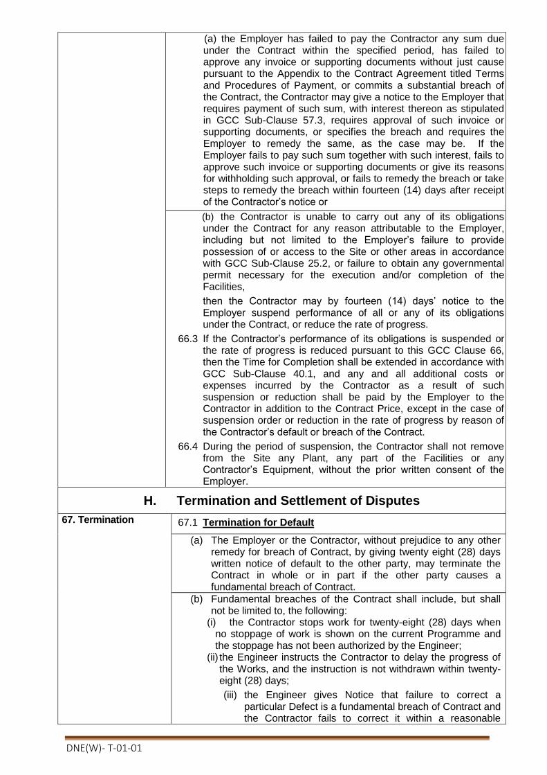
DNE(W)- T-01-01
(a) the Employer has failed to pay the Contractor any sum due under the Contract within the specified period, has failed to approve any invoice or supporting documents without just cause pursuant to the Appendix to the Contract Agreement titled Terms and Procedures of Payment, or commits a substantial breach of the Contract, the Contractor may give a notice to the Employer that requires payment of such sum, with interest thereon as stipulated in GCC Sub-Clause 57.3, requires approval of such invoice or supporting documents, or specifies the breach and requires the Employer to remedy the same, as the case may be. If the Employer fails to pay such sum together with such interest, fails to approve such invoice or supporting documents or give its reasons for withholding such approval, or fails to remedy the breach or take steps to remedy the breach within fourteen (14) days after receipt of the Contractor’s notice or
(b) the Contractor is unable to carry out any of its obligations under the Contract for any reason attributable to the Employer, including but not limited to the Employer’s failure to provide possession of or access to the Site or other areas in accordance with GCC Sub-Clause 25.2, or failure to obtain any governmental permit necessary for the execution and/or completion of the Facilities,
then the Contractor may by fourteen (14) days’ notice to the Employer suspend performance of all or any of its obligations under the Contract, or reduce the rate of progress.
66.3 If the Contractor’s performance of its obligations is suspended or the rate of progress is reduced pursuant to this GCC Clause 66, then the Time for Completion shall be extended in accordance with GCC Sub-Clause 40.1, and any and all additional costs or expenses incurred by the Contractor as a result of such suspension or reduction shall be paid by the Employer to the Contractor in addition to the Contract Price, except in the case of suspension order or reduction in the rate of progress by reason of the Contractor’s default or breach of the Contract.
66.4 During the period of suspension, the Contractor shall not remove from the Site any Plant, any part of the Facilities or any Contractor’s Equipment, without the prior written consent of the Employer.
H. Termination and Settlement of Disputes
67. Termination 67.1 Termination for Default
(a) The Employer or the Contractor, without prejudice to any other remedy for breach of Contract, by giving twenty eight (28) days written notice of default to the other party, may terminate the Contract in whole or in part if the other party causes a fundamental breach of Contract.
(b) Fundamental breaches of the Contract shall include, but shall not be limited to, the following:
(i) the Contractor stops work for twenty-eight (28) days when no stoppage of work is shown on the current Programme and the stoppage has not been authorized by the Engineer;
(ii) the Engineer instructs the Contractor to delay the progress of the Works, and the instruction is not withdrawn within twenty-eight (28) days;
(iii) the Engineer gives Notice that failure to correct a particular Defect is a fundamental breach of Contract and the Contractor fails to correct it within a reasonable
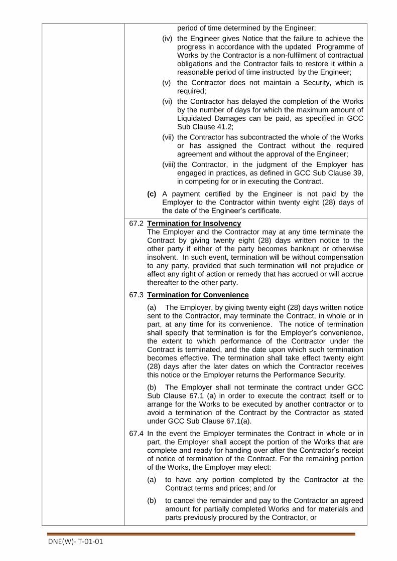
DNE(W)- T-01-01
period of time determined by the Engineer;
(iv) the Engineer gives Notice that the failure to achieve the progress in accordance with the updated Programme of Works by the Contractor is a non-fulfilment of contractual obligations and the Contractor fails to restore it within a reasonable period of time instructed by the Engineer;
(v) the Contractor does not maintain a Security, which is required;
(vi) the Contractor has delayed the completion of the Works by the number of days for which the maximum amount of Liquidated Damages can be paid, as specified in GCC Sub Clause 41.2;
(vii) the Contractor has subcontracted the whole of the Works or has assigned the Contract without the required agreement and without the approval of the Engineer;
(viii) the Contractor, in the judgment of the Employer has engaged in practices, as defined in GCC Sub Clause 39, in competing for or in executing the Contract.
(c) A payment certified by the Engineer is not paid by the Employer to the Contractor within twenty eight (28) days of the date of the Engineer’s certificate.
67.2 Termination for Insolvency The Employer and the Contractor may at any time terminate the Contract by giving twenty eight (28) days written notice to the other party if either of the party becomes bankrupt or otherwise insolvent. In such event, termination will be without compensation to any party, provided that such termination will not prejudice or affect any right of action or remedy that has accrued or will accrue thereafter to the other party.
67.3 Termination for Convenience
(a) The Employer, by giving twenty eight (28) days written notice sent to the Contractor, may terminate the Contract, in whole or in part, at any time for its convenience. The notice of termination shall specify that termination is for the Employer’s convenience, the extent to which performance of the Contractor under the Contract is terminated, and the date upon which such termination becomes effective. The termination shall take effect twenty eight (28) days after the later dates on which the Contractor receives this notice or the Employer returns the Performance Security.
(b) The Employer shall not terminate the contract under GCC Sub Clause 67.1 (a) in order to execute the contract itself or to arrange for the Works to be executed by another contractor or to avoid a termination of the Contract by the Contractor as stated under GCC Sub Clause 67.1(a).
67.4 In the event the Employer terminates the Contract in whole or in part, the Employer shall accept the portion of the Works that are complete and ready for handing over after the Contractor’s receipt of notice of termination of the Contract. For the remaining portion of the Works, the Employer may elect:
(a) to have any portion completed by the Contractor at the Contract terms and prices; and /or
(b) to cancel the remainder and pay to the Contractor an agreed amount for partially completed Works and for materials and parts previously procured by the Contractor, or

DNE(W)- T-01-01
(c) except in the case of termination for convenience as stated under GCC Sub Clause 67, engage another Contractor to complete the Works, and in that case the Contractor shall be liable to the Employer for any cost that may be incurred in excess of the sum that would have been paid to the Contractor, if the work would have been executed and completed by him or her.
67.5 If the Contract is terminated, the Contractor shall stop work immediately, make the Site safe and secure, and leave the Site as soon as is reasonably possible
68. Payment upon Termination
68.1 If the Contract is terminated because of a fundamental breach of Contract under GCC Sub Clause 67.1 by the Contractor, the Project Manager shall issue a certificate for the value of the Works done and Plant and Materials ordered less advance payments received up to the date of the issue of the certificate and less the amount from percentage to apply to the contract value of the works not completed, as indicated in the PCC. If the total amount due to the Employer exceeds any payment due to the Contractor, the difference shall be a debt payable to the Employer.
68.2 If the Contract is terminated for the Employer’s convenience or because of a fundamental breach of Contract by the Employer, the Project Manager shall issue a payment certificate for the value of the work done, Materials ordered, the reasonable cost of removal of Equipment, repatriation of the Contractor’s foreign personnel employed solely on the Works and recruited specifically for the Works, and the Contractor’s costs of protecting and securing the Works, and less advance payments received up to the date of the certificate.
68.3 If the Contract is terminated for reasons of Force Majeure, the The Project Manager shall determine the value of the work done and issue a Payment Certificate which shall include.
(a) the amounts payable for any work carried out for which unit rates or prices are stated in the Contract;
(b) the cost of Plant and Materials ordered for the Works which have been delivered to the Contractor, or of which the Contractor is liable to accept delivery: this Plant and Materials shall become the property of (and be at the risk of) the Employer when paid for by the Employer, and the Contractor shall place the same at the Employer’s disposal;
(c) other costs or liabilities which in the circumstances were reasonably and necessarily incurred by the Contractor in the expectation of completing the Works;
(d) the cost of removal of Temporary Works and Contractor’s Equipment from the Site; and
(e) the cost of repatriation of the Contractor’s staff and labor employed wholly in connection with the Works at the date of termination.
69. Property 69.1 All Materials on the Site, Plant, Equipment, Temporary Works, and Works shall be deemed to be the property of the Employer if the Contract is terminated because of the Contractor’s default stated under GCC Sub Clause 67.1.
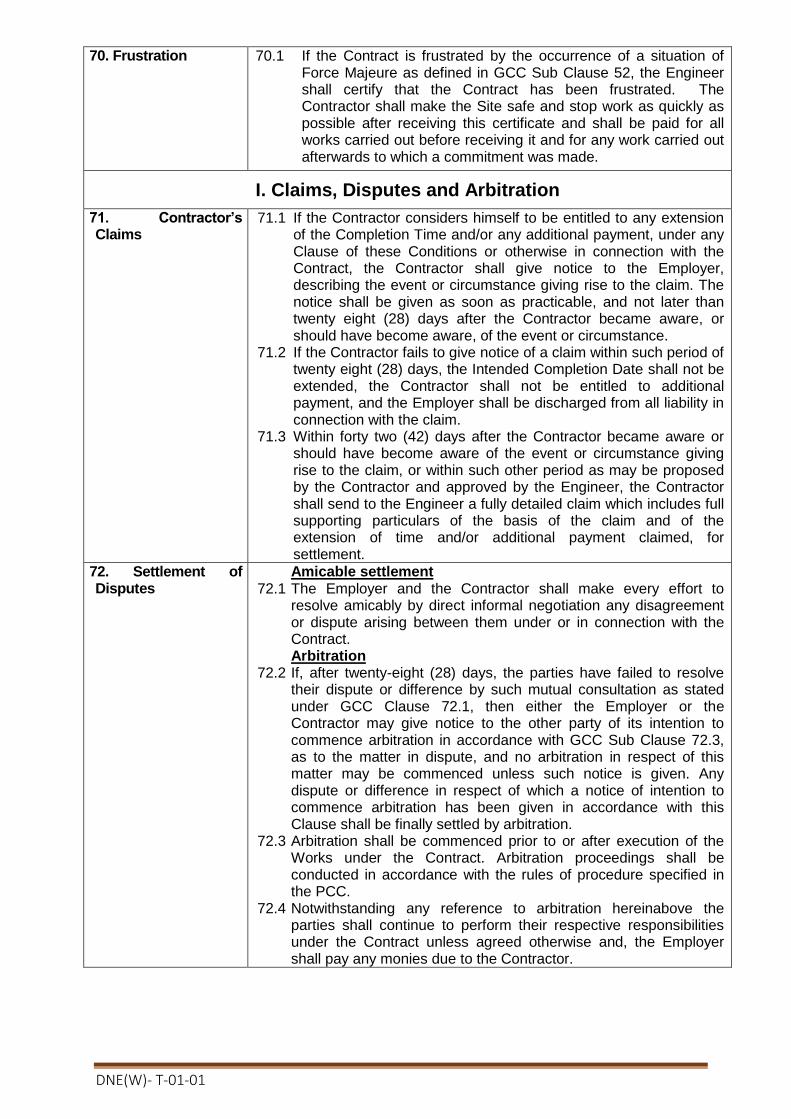
DNE(W)- T-01-01
70. Frustration 70.1 If the Contract is frustrated by the occurrence of a situation of Force Majeure as defined in GCC Sub Clause 52, the Engineer shall certify that the Contract has been frustrated. The Contractor shall make the Site safe and stop work as quickly as possible after receiving this certificate and shall be paid for all works carried out before receiving it and for any work carried out afterwards to which a commitment was made.
I. Claims, Disputes and Arbitration
71. Contractor’s Claims
71.1 If the Contractor considers himself to be entitled to any extension of the Completion Time and/or any additional payment, under any Clause of these Conditions or otherwise in connection with the Contract, the Contractor shall give notice to the Employer, describing the event or circumstance giving rise to the claim. The notice shall be given as soon as practicable, and not later than twenty eight (28) days after the Contractor became aware, or should have become aware, of the event or circumstance.
71.2 If the Contractor fails to give notice of a claim within such period of twenty eight (28) days, the Intended Completion Date shall not be extended, the Contractor shall not be entitled to additional payment, and the Employer shall be discharged from all liability in connection with the claim.
71.3 Within forty two (42) days after the Contractor became aware or should have become aware of the event or circumstance giving rise to the claim, or within such other period as may be proposed by the Contractor and approved by the Engineer, the Contractor shall send to the Engineer a fully detailed claim which includes full supporting particulars of the basis of the claim and of the extension of time and/or additional payment claimed, for settlement.
72. Settlement of Disputes
Amicable settlement 72.1 The Employer and the Contractor shall make every effort to
resolve amicably by direct informal negotiation any disagreement or dispute arising between them under or in connection with the Contract. Arbitration
72.2 If, after twenty-eight (28) days, the parties have failed to resolve their dispute or difference by such mutual consultation as stated under GCC Clause 72.1, then either the Employer or the Contractor may give notice to the other party of its intention to commence arbitration in accordance with GCC Sub Clause 72.3, as to the matter in dispute, and no arbitration in respect of this matter may be commenced unless such notice is given. Any dispute or difference in respect of which a notice of intention to commence arbitration has been given in accordance with this Clause shall be finally settled by arbitration.
72.3 Arbitration shall be commenced prior to or after execution of the Works under the Contract. Arbitration proceedings shall be conducted in accordance with the rules of procedure specified in the PCC.
72.4 Notwithstanding any reference to arbitration hereinabove the parties shall continue to perform their respective responsibilities under the Contract unless agreed otherwise and, the Employer shall pay any monies due to the Contractor.

DNE(W)- T-01-01
Section 4. Part-I Particular Conditions of Contract
Instructions for completing the Particular Conditions of Contract are provided in italics in parenthesis for the relevant GCC Clauses.
GCC Clause
Amendments of, and Supplements to, Clauses in the General Conditions of Contract
GCC 1.1(j)
The Contractor is Name: Address: Name of authorized representative:
GCC 1.1(ll)
(i)The Employer is:
Project Director
“Distribution Network Expansion for 100% Rural Electrification (Rajshahi,
Rangpur, Khulna & Barisal Divisions)", BREB.”
Training Academy Building (7th floor), Bangladesh Rural Electrification Board,
Nikunja-2, Khilkhet, Dhaka-1229.
Telephone: 02-8900591
Electronic mail address: [email protected]
GCC 1.1(mm)
Project Manager:
The project management shall be done under Superintending Engineer, Cumilla Zone, Cumilla, Executive Engineer, Project Division; shall act as Project Manager and shall be responsible for supervising the execution and completion of the works and physical services and administering the Contract under Superintending Engineer, Cumilla Zone, BREB, Cumilla.
Executive Engineer Feni Project Division, BREB.
GCC 1.1(oo)
The Site is located at Turnkey contract for survey, design, supply, carrying, installation, testing and commissioning of 33 kv double circuit river crossing tower with transmission lines including civil constructions at Bank Kali/ Vushir Bandar - Bank KAli/ Vushir Bandar on Atrai river under Dinajpur PBS-1.
GCC 3.1 The Procuring Entity’s address for the purpose of communications under this contract is :
Contact person:
(i) Project Director
“Distribution Network Expansion for 100% Rural Electrification
(Rajshahi, Rangpur, Khulna & Barisal Divisions)", BREB.”
Training Academy Building (7th floor), Bangladesh Rural Electrification
Board, Nikunja-2, Khilkhet, Dhaka-1229.
Telephone: 02-8900591
Electronic mail address: [email protected]
The Contractor’s address for the purpose of communications under this contract is :
Contact person:
Address:Tel:Fax:
e-mail address:
GCC 6.1 (k)
Other documents forming part of the Contract are;
Any other Clarification and Confirmation given by tenderer/supplier if required.
Additional Conditions of Particular Application in this schedule, Schedule of other contractors, Schedule of Key Personnel, Site Investigation Reports, relevant correspondences prior to signing of the Contract agreement etc.

DNE(W)- T-01-01
GCC 9.1 A contractor or a Sub-contractor/JVC that is a national of, or register in, the following countries are not eligible:
Israel
GCC 9.2 Materials, Equipment Plants and supplies shall not have their origin in the following countries:
Israel
GCC 13.1
Possession of the Site or part(s) of the Site, to the Contractor shall be given on the following date(s);
The peg point of river crossing tower shall be selected and fixed by employer and contractor jointly from the date of signing of the contract but the contractor shall be fully responsible to take over possession of the site for awarded river crossing tower construction works and all cost of the damages including required land cost for construction of river crossing tower shall be paid by the Contractor.
GCC 22.3 The Contractor shall have to supply the required parts of the River crossing tower if employer desires for a period of 05 (Five) years
GCC 23.1 Commencement Date shall be from the date of signing of the contract.
GCC 24.1 The time for completion of the whole of the facilities within Twelve(12) months from the effective date as described in the contract agreement.
GCC 26.1 In addition of the sub-clause, section-4(part-II, ACPA), (Employer’s requirements) the Contractor shall be responsible for taking any vetting required from recognize
institution BRTC, BUET/ MIST/ CRTS, DUET for any or all design & drawings
required for various stages of the contract. All or any design & drawings shall be submitted to the engineer/employer for approval.
GCC 32.1 A Subcontractor that is a national of, or registered in, the following countries are not
eligible: Israel
GCC 33.1 Nominated Subcontractor(s) named below;
(Not Applicable)
GCC 38.2 i) The pre–shipment inspection and testing of the materials shall be carried outin presence of Minimum Two (02) representatives of BREB/PBS at the supplier's factory/show room/warehouse at contractor/supplier’s own cost.Shipment clearance will be given after satisfactory completion of pre-shipment inspection of thematerials.
ii) The Supplier shall notify the purchaser at least Four (4) weeks in advance of the date or dates when the products and /o r components will be ready for inspection. Such date must be fixed at least 15 (fifteen) days prior to the due delivery date.
iii) In case the purchaser or its representative does not get the product ready for inspection on the specif ied date as per inspection notice of the tenderer, the fee for any further visit /visits will be borne by the contractor, in addition to liquidated damage applicable as per terms & conditions of the schedule.
iv) Any factory/warehouse inspection prior to delivery or final inspection at the destination of delivery shall not relieve the supplier from full responsibility for furnishing material and / or equipment conforming to the technical specifications contained herein, nor prejudice any claim, right or privilege which the purchaser may have under the warranty furnished by the manufacturer/contractor in accordance with the Tender Document.

DNE(W)- T-01-01
GCC 40.2.2
The Guarantee Test of the Facilities shall be successfully completed within 15 days from the date of Completion.
GCC 41.3 Applicable (amount or rate) for the bonus for early Completion:
[insert amount] and/or
Maximum bonus: (Not Applicable)
Or, No bonus will be given for earlier Completion of the Facilities or part thereof but will give appreciation letter.
GCC 42.2 The Defects Liability Period is 24 (Twenty four) months from the date of operational acceptance of the works..
GCC 42.3 The contractor shall submit the updated programme within 30 days in case of delaying in submission updated programme the employer may impose penalty or the amount to be withheld as justified.
GCC 45.1 (b)
The multiplier of the Contract Price is:
[insert amount] and/or
(Not Applicable)
GCC 56.2 The Contract Price shall be adjusted in accordance with the provisions of the Appendix to the Contract Agreement titled Adjustment Clause.
(Not Applicable)
GCC 56.4 (Not Applicable)
GCC 59.1 The amount of performance security, as a percentage of the Contract Price for the Facility or for the part of the Facility for which a separate Time for Completion is provided, shall be 10% of the contract price.
GCC 59.3 The performance security shall not be reduced before the date of the Operational Acceptance.
GCC 62.1 The Contract is not subject to price adjustment.
GCC 63.1 The amount of Liquidated Damages is 0.075 of ONE (1) percent of the contract value of the uncompleted works or any part thereof completed after expiry of the Intended Completion Date or extended Intended Completion Date, as applicable, per day of delay.
GCC 63.2 The maximum amount of Liquidated Damages for the uncompleted Works or any part thereof is 10%( ten) percent of the final Contract Price of the whole of the Works.
GCC 72.3 The arbitration shall be conducted in accordance with the Arbitration Act(Act No. 1 of 2001) of Bangladesh as at present in force.
eappropriatnot delete
R/JPYUSD/GBP/EUeappropriatnotifdelete
BDT
eappropriatnot delete
R/JPYUSD/GBP/EUeappropriatnotifdelete
BDT

DNE(W)- T-01-01
SECTION:- 4 (PR)- ADDITIONAL CONDITION OF PARTICULAR
APPLICATION (ACPA)
1. PORT FACILITIES AND TRANSPORT TO SITE
Chittagong, Dhaka, Narayanganj, Benapole and Mongla are the ports of entry for material to
Bangladesh by sea and road. Inland transport from Chittagong, Benapole and Mongla can be by
road.
The contractor is responsible for performing all dispatch, shipment, delivery, unloading, inland
transportation and obtaining all approvals and consents etc. necessary for the movement of plant and
contractors equipment from the port to the site.
All necessary access roads, jetties or off-loading points etc. required for the transport of the plant etc to
site will be the Contractor’s responsibility.
Where heavy loads are to be moved the Contractor shall be responsible for performing surveys of the
routes to ensure that all portions have adequate load-bearing capacity.
A comprehensive method statement shall be submitted to the Engineer/ Employer detailing the
proposed transport route(s) and requirements. Plans indicating all bridges, ducts, culverts,
railway crossings, overhead lines, water mains etc., their load bearing capacity or clearances as
appropriate shall be given together with proposed means of achieving the transportation
requirements. Any reinforcement, strengthening, modifications or temporary works required to
obtain the necessary capacity shall be the responsibility of the contractor. The cost of the above
is to be included in the Bid price.
No plant is to be consigned to Bangladesh by air-freight without the prior written approval of the
Employer.
2. DOCUMENTATION AND CUSTOMS DUTY
2.1 Documentation
The whole responsibility lies with the Contractor.
2.2 Exemption of Customs Duty
All Plant and Contractor Equipment imported to Bangladesh by the Contractor will be subject
to all Bangladesh import and customs duties. The Contractor shall be responsible for and bear
the cost of the payment of all duties and obtaining all permits and licences for Contractors
Equipment.
2.3 Shipping Schedule
After factory material orders are placed the Contractor shall forward to the Engineer/Employer
a shipping schedule and this schedule shall be continually up-dated in line with the current
manufacturing and shipping programme and show planned and actual progress.
2.4 Removal of Material and Plant
The Contractor shall be responsible for and shall bear the cost of the removal of Plant and
Contractors equipment from the port of entry without delay after formal clearance documents
have been made available to him.
3. UNITS OF MEASUREMENT
In all correspondence, in all technical schedules, on all drawings and for all instrument scales,
S.I. units of measurement are to be employed.

DNE(W)- T-01-01
4. ERECTION AND CHECKING AT SITE
All work at the Site is to be carried out in such a manner as not to obstruct unduly the public,
the Employer's Staff nor any other Contractor, or the operation of existing transmission systems.
Full facilities and assistance are to be afforded by the Contractor for the Engineer/Employer or
his Representative to check the Site works. Where the works are to interface with other
contractors works, co-ordination of all activities shall be performed in consultation with the
Engineers representative.
The Contractor shall submit to the Engineer/Employer for approval and discussion his
proposals and plans as to the method of procedure to be adopted and particulars of temporary
works involved in construction. In addition the Contractor shall submit for approval, and agree
with the Engineer/Employer the methods, procedures and means of recording all pre-
energization testing and commissioning works.
As each part of the Works is erected the Contractor shall seek the Engineer’s/Employer’s
approval that the works have been constructed in accordance with the specification and
approved drawings. This particularly applies to the accurate plumbing of all stanchions and
columns, and to the levelling, setting and aligning of the various parts, and to the fitting and
adjusting of bearings and other parts. The Engineer and the Employer reserve the right to
inspect all parts of equipment in the Works and/or on Site and require corrections to the works
to ensure compliance with the specification or approved drawings or remedy any defective
workmanship. At the discretion of the Engineer/Employer inspection may be waived on certain
items. This shall in no way absolve the Contractor from his responsibilities.
On a monthly basis the Contractor and Engineer/Employer shall carry out an inspection of the
works and agree the percentage completion of each portion of the works in accordance with the
approved drawings. These percentage completion figures shall form the basis of progress
recording and valuation of site construction. The percentage completion figure shall be agreed
prior to site review meetings to enable up-to-date progress to be recorded.
Any works constructed prior to the issue of drawings approved by the Engineers for the
particular works will not be included in the percentage completion figures.
The Contractor is to provide such protection and watchmen as he may consider necessary to
safeguard his materials and stores. The Employer will not accept responsibilities for any losses
or damage which may occur during the execution of the contract.
The carrying out of all the work included in the Contract shall be supervised by a sufficient
number of qualified representatives of the Contractor, and full facilities and assistance shall be
afforded for the Engineer/Employer to check the Works. The receipt, unpacking, erection,
testing and commissioning of all OPGW are to be supervised by representatives of the
equipment manufacturer. Alternatively Contractors staff who have been trained and certified as
competent to perform such tasks by the individual manufacturers may be used. Copies of the
equipment manufacturers certification of competency for the proposed contractors site staff are
to be submitted with their curriculum vitae as required under clause 7.1.The Contractor shall
obtain from the Engineer/Employer details of the parts which he proposes to inspect, but such
inspection shall in no way exonerate the Contractor from any of his obligations. The Contractor,
if requested by the Engineer/Employer, shall open for inspection before erection any equipment
which has been delivered to the site partly assembled.
The Contractor shall keep reasonably clean the site on which he erects or stores plant, removing
all waste material resulting from the Works as it accumulates and as reasonably directed.
On completion of the Works the Site shall be left clean and tidy to the satisfaction of the
Engineer. Any damage done to buildings, structures, plant or property belonging to the
Purchaser shall be made good at the Contractor's expense.
The Contractor shall ensure the correctness of electrical and mechanical connections to all
equipment supplied under the Contract before such equipment is commissioned.

DNE(W)- T-01-01
During erection and commissioning the Contractor shall provide all temporary scaffolding,
ladders, platforms with toe boards and hand-rails essential for proper access of workmen and
inspectors, cover or rail off dangerous openings or holes in floors, and afford adequate
protection against materials falling from a higher level on to personnel below.
The maximum personal safety must be afforded to personnel either directly engaged on this
Contract or who in the normal course of their occupations find it necessary to utilise temporary
works erected by the Contractor or to frequent the working area.
The Contractor must take particular precaution to ensure adequate protection of all site
personnel during any period when radiographic or X-ray inspection of welding is being carried
out. Warning notices must be fully displayed and the inspection areas fenced off so that no
personnel will at any time be subject to any radiation dosages in excess of the permissible
levels quoted for unclassified non-radiation personnel in published statutory limits.
In each and every case involving a connection between the Plant supplied under this Contract
and any other existing plant which may or may not be in service the Contractor must make
suitable arrangements as regards the time and manner in which the connection is made subject
only to the approval of the Engineer and the Employer's Representative who is in charge of the
existing plant. Where cases arise involving the operation of the plant or work on plant in
operation or whenever required by the Employer's Representative, the Contractor must obtain a
written "Permit to Work" signed by a person duly authorized by the Employer.
5. SAFETY PRECAUTIONS
The Contractor and all persons employed by him on the Site in or about the execution of the
Works shall conform in all respects with the provisions of all Acts and Orders, and Regulations
made by competent authority that shall be applicable to the Works or any temporary Works and
binding upon the Contractor or persons employed as aforesaid and in particular, but without
prejudice to the generality of the foregoing, such matters as concern the safety, health and
welfare of persons working on the Site.
The Engineer/Employer may require the immediate removal from Site or the Works of any
person who in the opinion of the Engineer/Employer fails properly to observe the provisions of
this Clause and such persons shall not be again employed upon the Works without the
permission of the Engineer/Employer. The provisions of this Clause shall apply to and be
binding upon any Sub-Contractor employed by the Contractor for any part of the Works on the
Site and the persons employed by such Sub-Contractor and the Contractor shall ensure that
proper and adequate provisions to this end are included in the Sub-Contract.
6. DETAILS OF OFFER AND VARIATIONS
FROM SPECIFICATION
The Bid is to be accompanied by a detailed specification of the various items of plant and
equipment which are offered. The Schedules in the Specification must also be completed.
The Bidder must complete the relevant Schedule C contained in Volume 3 showing clearly and
in order of the relevant clauses any departure from the requirements of this Specification.
Notwithstanding supporting details provided with the Bid all details other than those shown in
the Schedule F of Departures will be deemed to be in accordance with the Specification and the
standard specifications and codes referred to therein be they of a contractual, commercial,
financial or technical nature.
No departures from the Specification, excepting those shown in the Schedule of Departures and
approved by the Employer are to be made without the written approval of the
Engineer/Employer.

DNE(W)- T-01-01
7. CONTRACTOR'S RESPONSIBILITIES
7.1 General
Unless stated specifically to the contrary in the schedule of departures submitted with the Bid
with full supporting explanations, the Contractor will be deemed to have concurred with the
design and layout of the Works as being sufficient to ensure reliability and safety in operation,
freedom from undue stresses and satisfactory performance in all other essentials as a fully
working plant.
The Contract is to include the whole of the Works which are described in or implied by the
Contract document to provide complete, fully operable, safe and efficient installations, in
accordance with internationally accepted practice.
Works shown upon the drawing and not mentioned or described in the Specification and works
described in the Specification and not shown on the drawings will nevertheless be held to be
included in this Contract and their execution is to be covered by the Contract Sum.
The Contractor's representative on the Site or his nominated deputy is to be given full
responsibility and financial authority to enter into negotiations regarding points arising out of
erection, so that the work may be expedited with as few delays as possible.
Unless otherwise specified, the Contractor is to supply the whole of the labour, material and
equipment required for the completion of the work.
The curriculum vitae of the contractor’s head-office project staff and site engineers together
with organisational diagrams shall be submitted to the Engineer/Employer to demonstrate that
adequate resources and staff of sufficient experience are being employed on the contract. The
Engineer/ Employer shall have the authority to enter the Contractors offices and satisfy himself
that adequate resources have been allocated to the contract.
Until each section of the Contract Works has been taken over by the Employer, the Contractor
is to be entirely responsible (save as is provided by the General Conditions of Contract), for
such section of the Contract Works, whether under construction, during tests or in commercial
use.
The Contractor shall check the electrical and mechanical connections to all plant supplied under
the Contract and the connections to existing plant covered by the Contract before such plant is
brought into commission and shall be responsible for the correctness of such connections in
accordance with the Contract Drawings and the Specification.
7.2 Planning of Work
Within 30 days after acceptance of the Bid, the Contractor shall prepare, in an agreed form, a
detailed Manufacture, Delivery and Erection Programme Chart for the complete Contract
Works, and shall submit the chart to the Engineer/Employer for comments and approval, such
copies of the approved chart as required by the Engineer/Employer shall be provided by the
Contractor.
The Manufacture, Delivery and Erection Programme Chart shall indicate for each major item of
the Contract the various phases of work from the commencement of the Contract to its
completion, e.g. design, ordering of materials, manufacture, delivery, installation and
commissioning. The programme shall include a fully comprehensive drawing production
programme which shall demonstrate the contractors intended issue dates for approval. This
shall indicate compliance with the specification requirements of Clause 26.
These presentations shall be in bar chart and precedence critical path analysis format.
The programme shall indicate percentage completion points of the various phases which can
form the basis of progress reporting as detailed in Clause 7.3
DNE(W)- T-01-01
A cash-flow forecast of the estimated monthly invoice values for both offshore and local
currency shall be included in the programme. This forecast shall take into account the terms of
payment and indicate down-payments, release of retention, etc. Figures may be rounded to the
nearest thousands of the appropriate currency.
The Contractor shall indicate on the programme the number, grade and discipline of
supervisory and managerial site staff proposed throughout the site construction periods. If
specialist erection and commissioning staff are to be employed by the Contractor details of the
number, discipline and duration of visit of these staff are to be indicated on the programme.
The provision of this information will not form any contractual limit on the number of staff to
be provided by the Contractor to ensure the timely completion of the contract. Should any
incident occur which, in the opinion of the Contractor will result in an overrun of any section of
the works this shall be indicated on the programme and brought to the Engineer’s/Employer’s
attention.
If, at any time during the execution of the Contract, it is found necessary to modify the
approved Manufacture, Delivery and Erection Programme Chart, the Contractor shall inform
the Engineer/Employer and submit a modified chart for his approval. The submission, and
subsequent approval, of a modified manufacture, delivery and erection programme chart shall
not necessarily obviate or diminish the Contractor's responsibilities and liabilities under the
Contract. The chart shall be updated at monthly intervals and submitted to the
Engineer/Employer no later than the middle of each calendar month.
7.3 Progress Reports and Meetings
At monthly intervals after approval of the Plant Manufacture, Delivery and Erection
Programme Chart, the Contractor shall submit to the Engineer/Employer updated bar chart
programmes and precedence critical path analysis networks in triplicate in an approved form
indicating the stage reached in the design, ordering of material, manufacture, delivery and
erection of all components of plant. In addition the compile and submit “S-curves” based upon
the approved programme indicating programmed and actual percentage completion of the
various stages of drawing approval, manufacture, shipping, civil works and erection for each
section of the work plus the overall contract. Two bound copies of coloured photographs
showing the status of construction for each portion of the works shall be included with the
progress reports. These reports are to be forwarded promptly so that on receipt by the
Engineer/Employer the information contained therein is not more than 7 days out of date.
An updated cash-flow forecast indicating previously forecast and actual, invoicing levels
together with revised future requirements shall be submitted quarterly. A graphical display in
the form of and “S-Curve” of the actual vs payment certification (on and offshore) shall be
provided by the contractor in triplicate on a quarterly basis to supplement the basic cash-flow
information.
If, during execution of the Contract, the Engineer/Employer considers the progress position of
any section of the work to be unsatisfactory, or for any other reason relating to the Contract, he
will be at liberty to call meetings, either in his Head Office or at Site. If required by the
Engineer/Employer, a responsible representative from the Contractor's works is to attend at the
Contractor's expense such meetings with sufficient authority to issue instructions or effect an
alteration in the works to the satisfaction of the Engineer/Employer.
Access to the Contractor's and Sub-Contractor's works is to be granted to the
Engineer/Employer at all reasonable times for the purpose of ascertaining progress.

DNE(W)- T-01-01
8. SUB-CONTRACTS AND ORDERS
As soon as practicable after entering into the Contract the Contractor shall, having obtained the
Engineer’s/Employer’s consent in accordance with the Conditions of Contract, enter into the
sub-contracts he considers necessary, for the satisfactory completion of the Contract Works.
Three un-priced copies of the Contractor's sub-orders shall be supplied to the
Engineer/Employer.
One copy of any drawing to which the sub-order shall refer shall also be submitted. Each
sub-order and drawing shall contain the following reference and an instruction that the plant is
subject to inspection and tests to be witnessed by the Engineer/Employer with sufficient
authority to issue instructions, or effect an alteration in the Works to the satisfaction of the
Engineer/Employer.
BANGLADESH RURAL ELECTRIFICATION BOARD
Turnkey contract for survey, design, supply, carrying, installation, testing and commissioning of 33 kv double circuit river crossing tower with transmission lines including civil constructions at Bank KAli/ Vushir Bandar - Bank KAli/ Vushir Bandar on Atrai river under Dinajpur PBS-1.
Contract No : …………………………………………………
All sub-orders not originally in the English language shall be accompanied by an English
Translation and the translated version shall take precedence.
Approval by the Engineer/Employer of Contractor's sub-orders shall not relieve the Contractor
of his responsibilities in meeting this Specification. It is the Contractor's responsibility to
ensure that a full specification based on the relevant information in this specification is passed
to the sub-contractor.
The Contractor will be responsible for progressing the Sub-Contractor's works including visits
to the works to ensure the work is to programme, specification, quality and drawings and to
witness all necessary routine, sample and type tests. The cost of this Contract control is deemed
to be included in the Contract Sum.
9. INSPECTION, TESTING AND TRAINING
9.1 Not applicable.
9.2 (a) The contractor shall provide visit by 2(Two) BREB/PBS Engineers in each batch to the
manufacturer factory for witnessing prototype test of a sample transmission line towers in
accordance with clause 18.1.12 of the Technical specification, Volume 3 of 3. All costs of
the above visits shall deemed to be included in the contract price.
(b) Two Engineers nominated by the Employers shall be given training at the Contractor’s/
Manufacturer’s Design Office each for a period of two weeks as per clause 18.1.12 of the
Technical specification, Volume 3of 3. (if employer desires)
9.3 The contractor shall provide on-site local training of 4 (Four) BREB/ PBS Engineers/
Technical-Staff later intended to operate and maintain the transmission line works in
accordance with clause 18.1.13/18.1.14, Volume 3 of 3without additional cost.
Instruction shall be given in the English language. This training is to be carried out in the site as
formal instruction courses on each of the various types of Plant being provided under this
contract. The attendance of REB staff during erection and commissioning works will not be
acceptable as an alternative to the formal training courses.

DNE(W)- T-01-01
10. PACKING AND ERECTION MARKS
Each item is to be export packed and properly protected for shipment, transport and storage in
the port area and for transport to and storage on Site.
All Plant provided under this Contract shall have the packing marked in the following manner.
A green band shall be painted all around each package. The band shall be 8" wide or 1/4 of the
length of the packing whichever is the less. Each package should have the following
information printed on it in bold letters: -
(a) Port of Loading
(b) Name of Consignee
(c) Purchase Order Number
(d) Brief Description of Stores
(e) Number of Package
(f) Gross, tare and net weight
(g) Measurements
(h) Contractors Name
(i) Contract Title
(j) Contract Number
In addition to the green band the following monogram, measuring about 1/4 of the package
must be painted in green on at least two sides of the package.
BANGLADESH RURAL ELECTRIFICATION BOARD
Turnkey contract for survey, design, supply, carrying, installation, testing and commissioning of 33 kv double circuit river crossing tower with transmission lines including civil constructions at Bank KAli/ Vushir Bandar - Bank KAli/ Vushir Bandar on Atrai river under Dinajpur PBS-1.
Contract No : …………………………………………………
All members comprising multipart assemblies, e.g. steel frameworks, are to be marked with
distinguishing numbers and/or letters corresponding to those on the approved drawings or
material lists.
Colour banding to an approved code is to be employed to identify members of similar shape or
type but of differing strengths or grades.
Cases containing delicate items such as relays and instruments should carry a separate marking:
Sensitive equipment packages shall be opened in the presence of a representative of the
Employer.
11. LABOUR AND GENERAL SITE SERVICES
The Contractor shall include for the provision of all necessary supervisory and skilled and
unskilled labour for erecting, testing and commissioning the works, together with all necessary
transport, accommodation where required and other services to support his supervisory and
labour force to meet the specified Date of Completion. A staff tree of the Contractor's head
office and site organization for carrying out the Contract Work shall be set out in the Schedule
H. The Contractors forecast site staffing levels are to be submitted in a bar chart showing the
duration of stay of each member. This bar chart will not form any limiting factor on the
quantities of staff to be provided.

DNE(W)- T-01-01
11.1 Living Accommodation
The Employer will not provide any housing accommodation for the Contractor's local and
expatriate staff and the cost of these shall be deemed to be included in the Contract Sum.
11.2 Storage and Working Areas
The Contractor shall negotiate for and make payment for the lease of land for his site operation
to include offices and equipment storage.
11.3 Office Accommodation
The Contractor is to provide such temporary buildings as may be necessary for office
accommodation for his site staff and the Engineer's Representative or representatives of the
Employer during the erection of the Works and the cost of these shall be deemed to be included
in the Contract Sum.
11.4 Health Regulations
All Contractor's employees shall comply with the appropriate International Health Regulations
and any local health regulations which may apply from time to time in Bangladesh.
11.5 Contractor’s Employees
The Contractor and all persons employed by him on the Site in or about the execution of the
Works shall conform in all respects with the provisions of all Acts and Orders, and Regulations
made by competent authority that shall be applicable to the Works or any temporary works and
binding upon the Contractor or persons employed as aforesaid and in particular, but without
prejudice to the generality of the foregoing, such matters as concern the safety, health or
welfare of persons working on the Site. And the Engineer may require the immediate removal
from Site of any person who in the opinion of the Engineer fails properly to observe the
provisions of this Clause and such person shall not be again employed upon the Works without
the permission of the Engineer.
The provisions of this Clause shall apply to and be binding upon any sub-contractor employed
by the Contractor for any part of the Works on the Site and the persons employed by such
sub-contractor and the Contractor shall secure that proper and adequate provisions to this end
are included in the sub-contract.
Neither the Contractor nor any of his sub-contractors nor employees of either of these parties
shall have any right to claim employment or appointment by the Employer neither during nor
after completion of the Contract.
11.6 Identification of Contractor's Employees, Vehicles and Camps
The Contractor shall provide each of his employees and his sub-contractor's employees with a
suitable number badge bearing the name or initials of the Contractor. Each employee shall
wear his badge upon his person while at work on the Site in such a manner that it will be
plainly visible as a means of identification. All vehicles used by the Contractor or his
Sub-Contractor on the work shall be clearly marked with the Contractor's or Sub-Contractor's
business name. The Contractor's camps, stores, depots and other facilities shall also be clearly
identified.
11.7 Character of Workmen
The Contractor shall employ only persons who are competent to perform the work assigned to
them and, in the case of skilled labourers, only those who are adequately trained and
experienced in their respective trades and who do satisfactory work.
Whenever the Employer shall notify the Contractor that any person on the work is, in his
opinion, incompetent, unfaithful, or disorderly, or who uses threatening or abusive language to
any person representing the Engineer or Employer when on the work, such person shall be
immediately discharged from the work and shall not be re-employed thereon except with the

DNE(W)- T-01-01
consent of the Employer. The Contractor shall not hire or permit to remain on the works any
person who is known or suspected to be involved in any subversive activities.
Particular attention is drawn to the fact that entry into Bangladesh is the subject of restriction.
All new entrants are currently required to be in possession of visas and entry permits. However
entry requirements may change from time to time and the Contractor shall be obliged to check
and ensure that all his expatriate staff comply with these requirements.
11.8 Use of Local Sub-Contractors
It is considered important to encourage and develop the skill of Bangladesh contractors and to
help to achieve this development of local expertise the Contractor shall place Sub-Contracts for
erection work with approved Bangladesh contractors.
12. ACTS AND RULES
The Contractor shall comply in all respects with all Acts, Rules, Regulations and Orders
applicable thereto at the time when the Works are taken over whether the obligations imposed
by such Acts, Orders and Regulations are imposed on the manufacturer of the Works or any
part thereof or on the
occupier of the place where the Works have been placed or erected, but if by reason of the
making after the date of the Contractor's Bid of any such Act, Order or Regulation the cost to
the Contractor of the performance of the Contract shall be increased or reduced the amount of
such increase of decrease shall be added to or subtracted from the Contract Sum as the case
may be. Nothing in this paragraph shall operate so as to oblige the Contractor to supply plant
additional to that comprised in the works. The Contractor shall be responsible for the payment
of any charges by way of examination or certification fees to the Employer, Government or
other Statutory Bodies.
13. LIFTING TACKLE, TOOLS AND MAINTENANCE EQUIPMENT
The Contractor shall provide all tools, tackle and other necessary equipment required for the
complete construction of the whole of the Works, as Contractors Equipment.
14. SPARES SHALL BE QUOTED AS PER SCHEDULE.
15. PRICED SCHEDULES
The Bidder shall fill in prices or rates for each item in the price schedule/BOQ of section-5,
Volume 3 of 3, whether quantities are stated or not, and shall quote a fixed price per unit,
length, etc. Items against which no rate or price is entered by the Bidder will not be paid for by
the Employer when executed, and shall be deemed to be covered by the other rates or prices of
the said Schedules.
The rates and prices Bided in the Schedules are to be for the finished work, complete in every
respect and they must therefore include all incidental or contingent expenses necessary to
complete and maintain the Contract Works in full accordance with the terms of the Conditions
of Contract and this Specification, and the Contractor shall have no claim for further payment
in respect of any work or method of execution which may be described in the Conditions of
Contract or Specification, although apparently no corresponding item is given in the Schedules.
The rates quoted by the Contractor for Schedule Rate Works shall include for provision of all
necessary labour and material and the provision, maintenance and use of all necessary plant,
tools and articles and for all other incidental expenses necessary for proper execution and
completion of work.
All payments made to the labour employed for the work covered by this Specification are to be
included in the Schedule Rates. The Contractor is to accept full responsibility for obtaining all
the necessary labour and materials.
16. DIARIES

DNE(W)- T-01-01
The Contractor shall provide suitable diaries in an approved form to which the
Engineer/Employer shall have access, and shall enter in these diaries all the measurements of
the Contract Works on the Site as completed on the day on which the measurements are taken,
together with full particulars, and details of all obstructions or modifications or extra works, or
incidents and the number of men employed in each of the several portions of the work in
progress and any other information as directed by the Engineer/Employer.
The diaries shall be available at all times for the Engineer/Employer to verify the records, and
the Engineer/Employer shall sign all entries therein so verified, and have full liberty himself to
make entries therein, but no such signature or entry shall imply acceptance of any work or
material, or that the Contractor is entitled to be paid for the same, or at any particular rate. The
diaries shall, when signed by both parties, be deemed to be a true record of the work executed.
The diary(s) shall be the property of the Employer.
17. WORK AT TIME AND MATERIAL RATES (DAY WORK)
The Engineer/Employer may, if in his opinion it is necessary, order in writing that any
additional work shall be executed on a time and material basis.
Any such works shall be carried out at rates in accordance with described in BOQ of Section-5
& Schedule of Volume 3 of 3 which shall be filled in by the Bidder.
Invoices submitted by the Contractor in respect of these works will be accepted only if
supported by the relevant time sheets and material lists which must be certified by the
Engineer’s/Employer’s Site Representative. Such time sheets and material lists shall be
submitted to the Engineer’s/Employer’s Site Representative within one week following the
week to which they relate, otherwise the Engineer/Employer shall be entitled to reject them.
They shall indicate whether they refer to work in progress or work completed.
18. STORAGE PROTECTION AND HANDLING FACILITIES
The Contractor shall be responsible for providing his own storage area for the storage and
protection against loss, theft or damage of plant, equipment and materials during the execution
of the Contract.
The Contractor shall be responsible for the off-loading, transport and all handling of plant etc.,
supplied by him or his sub-contractors.
The handling and storage of any plant at the Site are to be at the risk and responsibility of the
Contractor and will not be the responsibility of the Employer. Watchmen shall be provided and
paid for by the Contractor.
The Contractor is to arrange for the protection of all material against corrosion and mechanical
damage during storage and erection at the Site, to the satisfaction of the Engineer/Employer.
19. INDUCED WORKING VOLTAGE
It shall be the responsibility of the Contractor to ensure the safety of his personnel and to adopt
working procedures to eliminate the risk from induced voltages from parallel circuits or any
other live parts.
20. DOCUMENTS, GOODS, MATERIALS, ETC., TO BE HANDED OVER TO THE
EMPLOYER
For all documents, goods, materials, maintenance equipment, spare parts, instruments, etc.,
handed over to the Employer, the Contractor shall obtain a signed receipt by an authorised
representative of the Employer that the goods etc., have been received in a satisfactory
condition as required under the Contract.
21. CONTRACTOR'S LOCAL AGENT

DNE(W)- T-01-01
It is mandatory that every “successful” Bidder must have a Local Associate. The Bidder in their
own interest, should therefore appoint an associate or enter into a partnership a agreement with
a Local person/firm of Bangladesh nationality having a valid trade license and registered at the
Bangladesh Chamber of Commerce. Before signing the Contract Agreement the successful
Bidder shall be required to submit to the Power Grid Company of Bangladesh documentary
evidence confirming the existence of the said agent or partnership.
22. USE OF ENGLISH LANGUAGE
Throughout the Contract, all letters, instructions, leaflets, drawings, descriptions, invoices,
certificates and documents of any kind shall be in the English language.
23. CORRESPONDENCE
All correspondence on matters arising out of the Contract is to be addressed in duplicate by the
Contractor to the Engineer with a copy to the Superintending Engineer (Grid & Sub-Station),
BREB, Dhaka.
24. ACCESS TO SITE
The Contractor shall be responsible for obtaining and bear the cost of any necessary access
rights or temporary storage and occupation of areas needed for construction outside the
boundaries of sites provided by the Employer.
All Contractor’s staff may be required to carry an identity badge approved by the Employer and
may be subject to security checks on entering and leaving the sites. Access to areas within
existing sites will be limited to work areas designated by the Employer.
25. CIVIL WORKS DESIGN
The Contractor shall supply to the Engineer/Employer full sets of foundation drawings and
supporting calculations together with loading and vibration characteristics of plant in his supply.
Preliminary foundation drawings shall be provided within 2 months of the Contract
commencing date.
At existing sites and where civil works are already in existence and are to be used by the
Contractor the Contractor will be required to approve, in writing, that the existing foundations
are entirely satisfactory for his plant.
Where pipe work or duct work or similar passes through walls or other civil works the
Contractor shall provide all necessary sealing material and equipment including holding down
bolts and sliding plates.
26. REMOVAL, TRANSPORT AND RELOCATION OF EXISTING
EQUIPMENT
Not applicable in this case.
DNE(W)- T-01-01
27. DRAWINGS, DIAGRAMS AND CALCULATIONS
27.1 General
The Contractor shall be responsible for the provision of all drawings required for the various stages of
the Contract and shall have to contract with BRTC, BUET/ MIST/ CRTS, DUET for (a)Tower Location
Survey (Considering River Erosion, HFL, Minimum Conductor Clearance as per requirement of BIWTA)
(b) Soil Investigation (c) Foundation Design (d) Tower Design (e) Preparation of Specification (f)
Inspection during construction and after construction by BRTC, BUET/ MIST/ CRTS, DUET
Representatives (g) Miscellaneous Services which deemed to be required for this installation to be taken
from BRTC, BUET/ MIST/ CRTS, DUET. All drawings, apart from shop drawings in Auto-Cad format,
shall be submitted to the Engineer/Employer for his approval, in accordance with an approved
programme. The Contractor shall ensure that drawings are submitted for approval in good time such that
they may be approved within the 28 days period by the Engineer/Employer prior to the manufacture or
construction commencing. Further adequate time must be allowed by the Contractor to permit any
comments made by the Engineer/Employer to be incorporated. Any works performed prior to approval of
drawings by the Engineer/Employer will not be acceptable.
The Contractor shall be responsible for examining all drawings submitted, including those
prepared by subcontractors, and co-ordinating all aspects of design to produce fully
comprehensive drawings. All drawings submitted to the Engineer/Employer will bear the
Contractor's approval stamp, certifying that he has examined and approved the contents, as
complying with the requirements of the contract.
The term "drawing" shall also include diagrams, schedules, performance curves, and
calculations etc., required for the comprehensive design of the works.
The Contractor shall be fully responsible for obtaining any drawing or data of existing plant
and installations that he requires in order to carry out the works, and shall also be responsible
for verifying that any drawings of existing plant and installations are accurate. The Contractor
shall provide suitable drafting and other staff on site that he requires to investigate and produce
any drawings that he requires of existing equipment and installations in order to carry out the
works. Any costs associated with these requirements are deemed to be included in the contract
price.
Where existing installations have been modified or extended the Contractor shall provide
complete new sets of drawings. In this respect the Contractor shall provide drawings detailing
both the existing and new works and shall not limit the scope of the drawings to the new works
only.
27.2 Format
Drawings are to be submitted for approval on paper prints, folded to A4 size with the project
title block and drawing numbers fully visible. Details of the project title block are given in the
Appendix to this Specification.
27.3 Drawing Numbering and Revisions
The Contractor shall be responsible for adding the Engineer’s/Employer’s drawing numbers to
all drawings prior to submittal. Following award of the contract the Engineer/Employer and
Contractor will review the numbering system, familiarise each other with requirements, and
agree on the numbering system to be applied.
Comprehensive cross-references are to be included on drawings and the Contractor shall
include the Engineer’s/Employer’s drawing number in the cross-references.
At each and every issue of a drawing the revision shall be raised, and details given in revision
boxes on the drawing. Comprehensive details of revisions are to be given and phrases such as
"REVISED", "UPDATED", "MODIFIED" or similar are not acceptable.
Reference to any drawing in communications shall include the Engineer’s/Employer’s drawing
number.
27.4 Drawing Submittals and Approvals
DNE(W)- T-01-01
The Contractor shall submit 2 copies of drawings of the plant and works for formal approval to
the Engineer/Employer with two copies to the Superintending Engineer (Grid & Sub-Station),
BREB, Dhaka. A programme of drawing submittal shall be agreed with the Contractor following
contract award. Drawings issued in accordance with this programme shall take account of the
time periods necessary for postage, and approval by the Engineer/Employer, to ensure that
approved drawings are available prior to manufacture. For site construction works, 4 copies of
"Construction Issue" drawings are to be submitted and made available, on site, at least 21 days
prior to the commencement of the works.
Where appropriate the drawings shall be accompanied by supporting calculations.
The Contractor shall ensure that drawings of a specific aspect of the Works are fully
co-ordinated and submitted together in a logical sequence.
Following examination the Engineer/Employer shall allocate a status to the drawings. The
subsequent action and distribution of drawings will depend on the status given by the
Engineer/Employer as detailed below.
a) "Approved". The details of the drawing have been checked by the Engineer/Employer
and appear to comply with the requirements of the specification. Once approved the
Contractor shall raise the revision to indicate "Approved by the Engineer/Employer
on ...." mark the drawing "Construction Issue".
(b) "Approved Subject to Comment". The drawing has been examined by the
Engineer/Employer, and apart from the minor details which do not effect the operation
or construction of the Works the drawing can be considered Approved subject to the
Contractor making the amendments required by the Engineer/Employer. The
Contractor may issue the drawing as "Approved" as outlined above without
resubmitting to the Engineer/Employer for formal approval, provided the corrections
have been made as required.
(c) "Examined and Returned with Comments". The drawing is considered to deviate from
the requirements of the Specification and requires modification in line with comments
given by the Engineer/Employer. The drawing is to be revised by the Contractor and
immediately resubmitted to the Engineer/Employer for approval.
(d) "Examination not Required". The drawing has been examined by the
Engineer/Employer, and the details contained in the drawing considered necessary for
the correct construction, or a comprehensive record of the Works, but not requiring
approval by the Engineer/Employer. Examples of typical drawings of this nature are:
equipment schedules and diagrams of connections. Drawings returned to the
Contractor of this status shall be stamped "For information only" and "Construction
Issue" and issued in the same manner as Approved drawings.
Approval of a drawing by the Engineer/Employer shall in no way relieve the Contractor of his
responsibilities under the Contract.
Should the Contractor revise a drawing for any reason following approval by the
Engineer/Employer the revised drawing is to be resubmitted for re-Approval by the
Engineer/Employer, the original approval automatically being void.
The Contractor shall submit, on a monthly basis, marked-up copies of the drawing issue
programme indicating the up-to-date status on drawing submittal and approval. In addition the
Contractor shall submit a schedule of the total number of drawings submitted, together with the
total numbers returned of each of the above categories.

DNE(W)- T-01-01
27.5 Construction Amendments
During construction of the Works on the site, the Contractor shall ensure that all departures,
modifications and corrections to the approved drawings are recorded. All such changes to the
drawings are to be marked in red to show the "as-built" state and one set of "as-built" drawings
are to be available on the site at all times.
Should the Contractor wish to make modifications on site to the approved construction
drawings which influences the operation of the Plant, he shall obtain the approval of the
Engineer’s/Employer’s Representative prior to instituting the modifications.
On completion of construction and commissioning the Contractor shall provide 4 copies of any
drawing which has required amendment to show the "as-built" state to the
Engineer’s/Employer’s Representative. These drawings shall be issued by the Contractor prior
to the issue of the Taking Over Certificate, as required under Clause 5.6 of the General
Conditions of Contract.
Following examination of the "as-built" drawing the Engineer’s/Employer’s Representative
shall return one copy to the Contractor indicating Approval of the construction modifications,
or further modifications required to satisfy the requirements of the specifications.
27.6 Record Drawing
On receipt of Approval of "as-built" drawings. The Contractor shall be responsible for the
production of Record Drawings for the complete plant on each section of the Works.
The Contractor shall modify the revision to "As-Built" and "Record Drawing" for all drawings
applicable to the section of the Works and submit these for approval to the Engineer/Employer.
On receipt of the Engineer’s/Employer’s approval the Contractor shall then provide two sets of
paper prints, one reproducible and two 35 mm aperture card mounted negatives of each
drawing. Any contract drawing included in the Operation and Maintenance manuals shall also
be revised in accordance with any "as-built" modifications and re-issued.
These sets of record drawings shall be issued within 90 days of the Taking-over of the plant.
27.7 Drawing Register
The Contractor shall when submitting drawings provide an indexing system for all the drawings
divided into sections for each voltage level and sub-divided for each type of equipment e.g.,
switchgear, transformer and components, control panels, cabling diagrams, schematics,
ancillary equipment, foundations, steelwork etc.
The index shall contain the following information for each drawing:
i) drawing number
ii) revision
iii) title
iv) date submitted for approval
v) date returned for correction
vi) date received for construction
vii) date as-built drawings submitted.
DNE(W)- T-01-01
28. OPERATING AND MAINTENANCE MANUALS
28.1 General
The Contractor shall be responsible for compiling operation and maintenance (O&M) manuals
for each Section of the Works.
Drafts of the manuals are to be submitted to the Engineer/Employer at least six months prior to
the commencement of pre-energization commissioning checks on Site. Following examination
the Engineer/Employer will forward copies of his comments to the Contractor to action prior to
issuing Final O&M manuals. Final O&M manuals are to be available on site prior to the issue
of Taking over Certificate.
Handling, installation, storage and transit instructions, in accordance with Clause 7 of BS 4884
part 1, which shall form part of the manuals, are to be available on site prior to the arrival of
the Plant.
In addition to the compiled manuals, the Contractor shall submit copies of brochures and other
explanatory literature with drawings of the plant.
28.2 Contents
Operation and Maintenance manuals shall be prepared for the whole of the plant for each
section of the works. The content and presentation of the manuals shall conform in full with
BS 4884 parts 1 and 2.
The Contractor shall be responsible for co-ordinating the information provided by individual
sub-contractors to produce a comprehensive O&M manual for all the plant within a section of
the works.
Full design calculations plus factory and site test certificates shall be included for each item of
plant.
The Contractor shall incorporate standard handbooks produced by manufacturers into the text
of the O&M manuals provided that all references or figures of variants, options or alternative
assemblies to that provided are deleted. Any such publication shall be prefixed with details of
the model and type of equipment provided, plus details of the variations, options or special
features provided.
Each volume of the manual shall contain an index of the contents of the complete suite of
volumes for the specific section of the works.
The O&M manuals are also to contain a complete drawing list appropriate to the individual
section of the works. The drawing list shall include the Engineer’s/Employer’s drawing
numbers.
Maintenance instructions for all plant shall comply with Clause 8 of BS 4884 part 1 and cover
preventive and corrective maintenance procedures. For electronic or solid state control,
protection equipment etc. details shall be provided to enable individual circuit cards to be
checked for correct operation and faults to be traced, and repaired.
The Contractor shall compile maintenance and inspection schedules for all the plant at an
individual site and include these in the appropriate manual. These schedules shall give details
of the type of work required on a weekly, monthly, annual, basis etc. Details of all Plant
settings shall be included in the O&M manuals in tabular form for each section of the Works.
Reference to the appropriate Volume and section of the manual will be given where full details
of the procedures etc. are located.
The Contractor shall provide proforma of the required maintenance record sheets for all plant,
which shall include cross-reference to the appropriate section of the O&M manuals which
detail how to perform the tasks required. Any other record sheets suitable for the monitoring of
the plant shall also be designed and provided.

DNE(W)- T-01-01
28.3 Binders, Presentation
The information will be provided on A4 pages, with diagrams on throw-clear pages where
required to enable the text and diagrams to be referred to simultaneously.
O&M manuals are to be collated and presented in binders with a black durable rigid cover. The
binder shall be of the type that may be taken apart without the use of binding posts. The
manuals shall be capable of enabling amendments to be inserted easily, yet the method of
holding pages will ensure that individual sheets cannot be accidentally separated from the
fixings with ease. Volumes shall be capable of laying flat when open to permit ease of
reference whilst working on plant.
The front cover and spine of the manuals shall give the following information:
Project Title
Employer's name
Contract number
Identification of the Section of the Works.
Volume number and total number of volumes applicable (e.g. Volume 3 of 5 volumes)
Contractor's company logo and name
Engineer's company logo and name.
The above shall also be provided on a flysheet inside the front cover of each volume. Draft
O&M manuals may be presented in unprinted covers.
The contents of the manuals shall be presented in accordance with BS 4884 Part- 2.
Four copies of draft O&M manuals are to be provided to the Engineer. Following approval 12
copies are to be provided to the Employer.
29. SITE STORAGE FACILITIES
30. QUALITY ASSURANCE, INSPECTION AND TESTING
30.1 General Requirements
The whole of the plant covered by this Contract shall be tested as detailed in the specification
and as per standard engineering practice, at contractor’s cost, and will be subject to inspection
and witnessing the tests by the Employer during manufacture, erection and on completion. The
inspection and witnessing the tests at manufacturer’s works may be done by the Employer or an
Independent Inspection agency. The approval of the Employer/Engineer or the passing of any
such inspection or test will not, however, prejudice the right of the Employer to reject the plant
if it does not comply with the specification when erected or when in service. Cost of inspectors
of the Employer shall be borne by the Contractor.
The inspection and tests shall include but not be limited by the requirements of this section of
the specification and of the detailed inspection and test requirements included elsewhere in this
specification. Prior to inspection and testing the plant and equipment shall undergo pre-service
cleaning and protection as specified in this section of the specification
Where no test is specified then the various items of plant, materials and equipment shall be
tested in accordance with the relevant British, IEC or International Standards acceptable to the
Engineer/Employer.
Thirty days work notice of the readiness of plant for test or inspection and every facility shall be
provided by the Contractor and sub-contractor to enable the Engineer and Employer to carry out the
inspection and witness the test.
No equipment shall be packed, prepared for shipment, or dismantled for the purpose of packing
for shipment unless it has been inspected and approved (or inspection has been waived) and
written instructions have been received from the Engineer/Employer.
Within 30 days of acceptance of the Contract the Contractor shall submit a quality assurance
programme and a work quality programme for the Engineer’s/Employer’s approval.
30.1.1 Responsibility for Quality

DNE(W)- T-01-01
The Engineer/Employer shall have the right to supervise and witness tests of all materials to be
used and all workmanship employed in connection with manufacture.
No part of the work shall be commenced without prior approval of the Engineer/Employer.
This shall not relieve the Contractor from any liability or obligation under the Contract and he
shall be responsible for the acts, defaults and neglects of any sub-supplier, his agents, servants
or workmen as if they were the acts, defaults, or neglects of the Contractor.
30.1.2 Quality Assurance
For control of the quality of manufacture, material control and documentation, the Contractor
and each main Sub-Contractor shall submit a copy of his manufacturing programme and three
unpriced copies of all orders and sub-orders to the Engineer/Employer. These documents will
be examined and classified according to the extent of expediting, quality audit or inspection
required. The approved manufacturing programmes shall be integrated with the
Engineer’s/Employer’s Quality Department work programme.
30.1.3 Manufacturing Capacity
The Contractor shall furnish evidence that he and his Sub-Contractors have supplied other
equipment of a similar type and size that shall have been in commercial operation successfully
for a minimum of three years.
Should the Engineer require to review and approve any manufacturing capacity, the Contractor
shall secure permission for such reviews to be made by the Engineer/Employer.
30.2 Inspection Plan and Procedures
30.2.1 General
Within 30 days after acceptance of the Contract, the Contractor shall provide the
Engineer/Employer with details of his quality procedures and the scope of inspection required
to ensure that materials as dispatched meet the Specification requirements.
An Inspection Schedule shall be prepared by the Contractor and shall be approved by the
Engineer/Employer.
The Schedule shall include reference to:
(a) IEC, British Standards or equivalent International Standards. For each of the following
stages of the work, the acceptance criteria shall be stated.
(b) Stages of inspection shall cover the following: -
i) Tests to review or approve certification of material.
ii) Review and approval of manufacturing procedures.
ii) Witnessing test or review and approval of certification of operator's
qualification to carry out the work required.
iv) Visual and dimensional examination of components.
v) Pressure tests on casings and vessels.
vi) Non-destructive examination of materials in progress.
vii) Functional tests on sub-assemblies performance tests, type tests on complete
units.
viii) Examination of painting, packing of documentation for shipment.
The Engineer/Employer will indicate the inspection requirements on the agreed inspection
programme in accordance with the following paragraphs.
X1. Hold point which requires a mandatory inspection by the Engineer and jointly by the
Employer. This inspection or test shall be witnessed by the Engineer and Employer
and further progress in manufacture shall not be made until the plant is approved by the
Engineer.
X2. Inspection or test of material shall be required by the Engineer at his discretion.
X3. Certification of material and functional test shall be approved by the Engineer and
Employer jointly before despatch from the works.

DNE(W)- T-01-01
30.2.2 Non-Conforming Material
Any material or equipment which fails to satisfy the acceptance criteria or Specification or
which, in the opinion of the engineer, is unacceptable with respect to potential safety, reliability,
interchange ability or workmanship shall become the subject of a non-conformance report
issued by the Engineer/Employer to the Contractor with copies for third parties concerned.
The non conformance report will identify the following: -
(a) The Plant and its reference number.
(b) The Contractor and his order number.
(c) The manufacturer and his works reference number.
(d) The components and related drawings, reference numbers, etc.
(e) The defect and stage of manufacture with sketches if required, location in the works and the
issuing authority.
(f) Suggested action for acceptance, for repair or for rejection and replacement.
(g) Approval by the Engineer/Employer of action decided.
(h) Final acceptance of the repaired component.
Any material or equipment which has failed to satisfy the acceptance criteria, shall, where
practicable, be separated from the work in progress and in all cases shall be suitably identified
with a distinctive label which will only be removed when corrective action is complete.
30.2.3 Quality Audit
The Contractor shall establish, document and execute a plan for quality evaluations which shall
objectively audit and verify that he is complying with all aspects of the Quality Programme,
operating procedures and Specification requirements.
The Engineer/Employer may from time to time visit the manufacturer to carry out a Quality
Audit to ensure that the manufacturer's quality organisation is capable of discovering an error in
drawing, production control and manufacturing components and equipment at an early stage
and is taking adequate steps to correct the error and prevent a recurrence.
30.2.4 Measuring and Testing Equipment
At prescribed intervals, or prior to each use, all measuring and testing equipment used in
inspection shall be calibrated and adjusted against certified equipment having a known valid
relationship to internationally recognised standards. Where no international standards exist, the
basis employed for calibration shall be approved by the Engineer/Employer.
The manufacturer shall prepare a calibration schedule showing equipment type, identification
number, location, frequency of checks, method of checking and action to take when results are
unsatisfactory.
Each piece of equipment shall be labelled with its identification and current calibration status.
Calibration records for each piece of equipment shall be maintained at least for life of that piece
of equipment and shall be available for examination by the Engineer/Employer.
30.2.5 Preservation Packaging and Shipping
The Contractor shall establish and maintain a system for the preservation, segregation and
handling of all material from receipt through the manufacturing process and subsequent storage
to prevent abuse, misuse, damage, or deterioration by corrosion through exposure to air or
moisture.
Items for despatch shall be suitably packed to the requirements of an approved
national/international standard and additionally or otherwise protected from damage,
deterioration, loss, mishandling and any deleterious effect of the environment during
transportation, shipping and all necessary storage and handling before erection on site. Cases
shall contain desiccants or gases.
Cases or items for shipment shall be suitably identified and addressed to contract requirements
and have labels visible from more than one position when stacked.

DNE(W)- T-01-01
30.2.6 Re-inspection following Non-Conformance
If a non-conformance report is issued, the Contractor shall reimburse the Engineer and
Employer for all costs (including time costs, travel accommodation etc.) for both attending
discussions on remedial matters and any re-inspection that the Engineer and Employer may
deem to be necessary
30.3 Plant Performance
30.3.1 Guarantees
Bidders shall state and guarantee the technical particulars listed in the Schedules E of Technical
Particulars and Guarantees. These guarantees and particulars shall be binding and shall not be
departed from without the written permission of the Engineer/Employer.
The Bidder shall further guarantee that all equipment supplied complies with the Contract
Documents.
The tolerances permitted in the British Standard and IEC shall apply unless otherwise stated.
30.3.2 Rejection
If the guarantees are not met and/or if any item fails to comply with the requirements of this
Specification in any respect whatsoever at any stage of manufacture, test, erection or during the
maintenance period, the Engineer/ Employer may reject the item, or defective component
thereof, whichever he considers necessary, and after adjustment or modification as directed by
the Engineer/Employer, the Contractor shall submit the item for further inspection and/or test.
The repair procedure shall be to the Engineer’s/ Employer’s approval. In the event of a defect
on any item being of such a nature that the requirements of this Specification cannot be fulfilled
by adjustment or modification, such item shall be replaced by the Contractor, at his own
expense to the entire satisfaction of the Engineer/Employer.
Any item of plant repaired to an approved procedure shall not be accepted as a part of the
Works as a permanent solution or replacement unless the Contractor guarantees in writing that
the repaired plant or component shall have the same service life and efficiency as the
component originally manufactured.
30.4 Sub-Contracts
The Contractor shall be responsible for the timely transmission of the relevant and appropriate
sections of the Specification to the Sub-Contractor and other suppliers and the proper execution
of all tests on work or plant or materials carried out or supplied by a Sub-Contractor, wherever
such tests may be carried out, to the same extent as if the tests on work, plant or materials were
carried out or supplied by the Contractor himself. The cost of all tests and including any
repeated test or inspection carried out at Sub-Contractors' works is deemed to be included in
this Contract.
All orders and sub-orders placed by the Contractor shall contain the following instruction:
"This material shall be subject to inspection and test by the Engineer and Employer, with whom
contact shall be made before commencing manufacture to agree inspection procedures and
visits".

DNE(W)- T-01-01
30.5 Tests at Manufacturers Works
30.5.1 General
Where no specific test is specified then the various items of plant, materials and equipment
shall be tested in accordance with the appropriate IEC, BS and International Standards. In all
cases, works tests shall include electrical mechanical and hydraulic tests in addition to any tests
called for by the Engineer/Employer to ensure that the plant being supplied fulfils the
requirements of the Specification.
If considered necessary by the Engineer/Employer any multipart assemblies shall be fully
erected in the Works prior to packing and despatch to Site.
All tests to be performed during manufacture, fabrication and inspection shall be agreed with
the Engineer/Employer prior to commencement of the work. The inspection schedule included
in the Schedule of Miscellany shall be used for this purpose. The Contractor shall prepare the
details of the schedule and submit these to the Engineer/Employer for approval.
It must be ensured that adequate relevant information on the design, code/standard employed,
the manufacture/fabrication/ assembly procedure and the attendant quality control steps
proposed are made available to the Engineer/Employer. The Engineer/Employer will mark in
the appropriate spaces his intention to attend or waive the invited tests, or inspections.
A minimum of 30 days notice in writing, of the readiness of plant for test or inspection shall be
provided to the Engineer and Employer by the Contractor in accordance with the following:
The Contractor shall submit to the Engineer/Employer sequentially numbered applications for
inspection which shall contain the following information.
(a) Contract number
(b) Contract title
(c) Contractors name
(d) Inspection application number
(e) Manufacturers name, address, telephone and telefax numbers, plus name of manufacturers staff
responsible for the testing and manufacturers works order number
(f) Location of tests
(g) Date of tests
(h) Description in full of Plant offered for inspection (Contractors order references alone
are insufficient and unacceptable)
(i) Section of the Works for which Plant is allocated
(j) Schedule of tests to be performed and standard to be applied.
(k) List of the Engineers approved drawing numbers appropriate to the Plant offered
(l) Sub-order number.
The subject items should remain available for the Engineers and Employer inspection and test
up to a minimum of 10 days beyond the agreed date of witnessing the test.
Every facility in respect of access, drawings, instruments, and manpower shall be provided by
the Contractor and his Sub-Contractor to enable the Engineer and Employer to carry out the
necessary inspection and witnessed testing of the Plant.
No equipment shall be packed, prepared for shipment, or dismantled for the purpose of packing
for shipment, unless it has been satisfactorily inspected, and approved for shipment, or
alternatively inspection has been waived. The Contractor shall request permission to despatch
in writing.
Functional electrical, mechanical and hydraulic tests shall be carried out on the completed plant
after assembly in the Works. The extent of these tests and method of recording the results shall
be submitted to, and agreed by, the Engineer/Employer in sufficient time to enable the tests to
be satisfactorily witnessed, or if necessary for any changes required to the proposed programme
of tests to be agreed.
All instruments and apparatus used in the performance of the tests shall be to the approval of
the Engineer/Employer, and, if required by the Engineer/ Employer, shall be calibrated to an
agreed standard at the National Physical Laboratories or equivalent centres and approved by the
Engineer/Employer.
DNE(W)- T-01-01
The cost of carrying out such calibrations shall be borne by the Contractor in all cases.
The Engineer and Employer reserve the right to visit the Contractor's Works at any reasonable
time during manufacture of the items of plant and to familiarise themselves with the progress
made and the quality of the work to date.
30.5.2 Material Tests ........
Requirements for the testing of castings and forging and weld procedures are detailed in
relevant section of this Specification. Representative samples of all plates, bars and pipes etc.
which form components of the plant shall be tested as required by the relevant standard or code
or at the request of the Engineer/Employer.
All test pieces shall be prepared and supplied by the Contractor at his own cost unless
otherwise specified. If any test piece fails to comply with the requirements of the specifications
for the material in question, the Engineer/Employer may reject the whole of the material
represented by that test piece.
All important forging are to be examined jointly at the maker's works by the
Engineer/Employer, together with the representatives of the manufacturers during forging and
heat treatment.
30.5.3 Test Certificates
Within 30 days of the completion of any test, four sets of all principal test records, test
certificates and correction and performance curves for the Plant and its component parts shall
be supplied to the Employer.
These test records, certificates and performance curves shall be supplied for all tests, whether
or not they have been witnessed by the Engineer and Employer. The information given on such
test certificates and curves shall be sufficient to identify the material or equipment to which the
certificate refers and should also bear the contract reference title. It shall be possible to identify
the item of plant to which a specific test certificate refers, including those of sub-components
and the specific site for which the item is allocated.
Contractors order number or drawing reference numbers are not sufficient for this purpose
without a description of the plant involved.
Test certificates shall provide full details of the measurements of their tolerances, and actual
test values obtained. Certificates simply stating phrases such as 'Passed' or 'Tested in
Accordance With' are not acceptable.
When all equipment has been tested the test certificates from all Works and Site tests shall be
compiled by the Contractor into volumes and bound in an approved form complete with index
and included in the appropriate Operation and Maintenance manuals.
30.6 Site Pre-Commissioning Checks and Commissioning Procedures
30.6.1 General
The Contractor shall be responsible for the safe and efficient setting to work of the whole of the
plant and equipment. The methods adopted shall be to the approval of the Engineer/Employer
or his representative on Site, and shall be in accordance with any safety and permit regulations
in force by the Employer on the Site.
At least three months before commencing the commissioning of any plant or equipment, the
Contractor shall submit for approval fully comprehensive schedules of pre-commissioning
checks as applicable to each item of the plant and equipment provided. These schedules shall
then be used during pre-commissioning as a guide to the methods to be followed and to record
the actual activities carried out with the appropriate date, together with details of all work yet to
be completed, variations and modifications to design conditions.
In addition the Contractor is to submit with the schedules to the Engineer’s/Employer’s
representative proforma test sheets (to be used by the Contractor during testing and

DNE(W)- T-01-01
commissioning) forall tests he proposes to carry out and those required by the
Engineer’s/Employer’s Representative.
Each activity on the schedules, when completed to the satisfaction of the
Engineer’s/Employer’s Representative, shall be signed and dated by the Contractor. The
schedules shall be countersigned by the Engineer’s/ Employer’s Representative as necessary. If
during the performance of the pre-commissioning checks the Engineer’s/Employer’s
representative considers that additional tests are necessary to prove the systems or plant the
Contractor shall perform such additional tests to the Engineer’s/Employer’s satisfaction.
The Contractor shall also submit for approval schedules of commissioning procedures that he
proposes to follow when bringing into service groups of plant items during the commissioning
period. These schedules shall detail the tests necessary to ensure the complete and satisfactory
commissioning of each section of plant and shall detail all operational limitations. The
schedules shall be used during commissioning which shall only commence when the relevant
pre-commissioning check schedules have been completed.
Each activity on the commissioning procedure schedules when completed to the satisfaction of
the Engineer’s/Employer’s Representative, shall be signed and dated by the Contractor and
shall be countersigned by the Engineer’s/ Employer’s Representative as necessary.
The commissioning procedures shall ensure that the commissioning of any section of the
Works does not interrupt the normal commercial operation of any previously commissioned
section(s).
21 days prior to commencing commissioning checks the Contractor is to agree with the
Engineer's Representative the method and sequence of performing the commissioning tests.
Following agreement the Contractor shall submit a detailed programme indicating the testing
sequence to permit advance notice to be given to the Employer in order that the Employer's
Representatives may also witness testing if so desired.
When the commissioning of each section of the Works is complete the Contractor shall carry
out such preliminary tests as are necessary to establish that the plant is functioning correctly
and efficiently, and shall make any adjustments required.
The Contractor is to supply all test equipment, tools, chemicals, lubricating oils and greases and
other materials required for the aforementioned operations.
For the purposes of this Contract, the provisions of this section will apply to plant supplied
from nominated subcontractors.
30.6.2 Contractor's Site Supervisory Staff
During the commissioning and subsequent testing of any item of plant the Contractor is to
provide for the services of any special supervisory staff necessary for the purpose of ensuring
proper commissioning and the satisfactory completion of all tests. The cost of such services is
deemed to be part of the bid price for erection of plant.
30.6.3 Commissioning and Modified Circuits
Where the scope of works has included the diversion, relocation or variation of any existing
circuit the Contractor is deemed to have included for all pre-commissioning checks on existing
equipment. Where this work includes overhead line or cable circuits the Contractor is
responsible for carrying out full pre-commissioning and on-load checks at the remote end of the
circuit including the injection testing and re-setting of relays if required.
All and any such work associated with the re-commissioning of existing equipment is deemed
to be included in the contract price.

DNE(W)- T-01-01
30.6.4 Test Equipment
The Contractor is responsible for providing all equipment instrumentation, power, etc.
necessary to carry out all tests on site. Following award of contract the Contractor shall submit
a detailed schedule of the test equipment etc. he intends to provide for carrying out this portion
of the Works. Should the Engineer require additional or alternative test equipment to be
provided to enable full site testing to be performed in accordance with the requirements of the
Specification the Contractor shall supply such equipment at no extra cost.
31. RULING SPECIFICATION
If any Clause of the Particular Technical Requirements contradicts another Clause of the
General Technical Specification then the Particular Technical Requirements shall be taken to
be correct and it will override the General Requirements.
32. TAXATION
As stated in the Tender Document.
33. FOREIGN COUNTRY TAXES AND PERMITS
The Contractor shall pay all sales, income and other taxes and duties, tariffs and imports, that
can be lawfully assessed against the Employer or the Contractor by the Government or any
lawful authority of any country other than the People’s Republic of Bangladesh which has
jurisdiction over the Contractor in connection with this contract and shall pay for all licences,
permits and inspection required for the Works including the cost of securing all export licences
and permits for materials, equipment, supplies and personnel exported from that country to
Bangladesh.
34. BANGLADESH TAXES, LEVIES AND PERMITS
The Contractor shall, at his cost and expense secure, any work permits, labour permits, tax
clearances, tax exemption certificate and any other authorisation which may be required by the
Government of Bangladesh to permit imported personnel of Contractor and its sub-contractors
to perform their work at site. The Contractor shall withhold from the pay roll of all local
employees and remit to appropriate authorities such taxes or assessments as may be required
by Bangladesh Law.
The Contractor shall be liable to the Employer for customs duties and taxes, paid by the
Employer and for the other lawful tax which may be or may become payable, on the
Contractor’s equipment tools and supplies imported for the Works and subsequently sold
within Bangladesh, to a party, or parties other than the Employer. For the selling of anything by
the Contractor, permission of the Employer shall be obtained by the Contractor.
35. SITE DATA
The Contractor shall have no claim to any payment as a result of any variation to his erection
programme found necessary or reduction in rate of progress caused as a result of poor ground
conditions.
36. CUSTOMS AND IMPORT DUTIES
The Contractor shall be responsible for and bear the cost of the payment of all customs/duties
and obtaining all permits and licences for Equipment/materials/services etc.
37. COMPLINTS AND APPEALS:
37.1 Right to Complain ( Regulation 50 of PPR-2008) :
(1) Subject to Regulation 50(2), 50(3) and 50(4) any tenders who claims to have suffered,
or who may suffer, loss or damage due to a breach of a duty imposed on a procuring
entity by these Regulations may complain in accordance with Regulation 51 and 53.
(2) The following shall not be the basis for a complaint provided for in Regulation 50(1):
a) the choice of procurement method pursuant to Chapter IV;

DNE(W)- T-01-01
b) The choice of a procurement sub-method pursuant to Chapter VIII;
c) a refusal by a procuring entity to short list an applicant in response to an
Expression of Interest under Regulation 44.
d) a decision by a procuring entity to reject all tenders, proposals or quotations under
Regulation 14;
e) If a decision for procurement award has been made by the Cabinet Committee on
Government Purchase.
(3) If a procurement contract has not already entered into force the tender shall submit its
complaint in the following manner:
(a) a tenderer shall submit its complaint for consideration through the three stages
of the administrative authority as described under Regulation 51, or;
(b) where the tenderer is still dissatisfied with the outcome of the complaint
considered under Regulation 51, or fails to receive a response within the time
limit mentioned under Regulation 51, the tenderer may then submit the
complaint to a Review Panel under Regulation 53.
(4) However, if a procurement contract has already entered into force the tenderer shall
submit its complaint directly to the Review Panel under Regulations 53.
37.2 Complaints to the Administrative Authority (Regulation 51 of PPR-2008):
(1) A tenderer shall submit its complaint in writing within 7 calendar days of when it became
aware of the circumstance giving rise to the complaint or when it should have become
aware of those circumstances, whichever is earlier.
(2) In the first instance, the tenderer shall submit its complaint to the procuring entity
that has issued the tender document. The procuring entity shall consider the subject matter
of the complaint and decide whether to reject the complaint or to implement any
corrective action to bring the procurement proceedings in conformity with the
Regulations. Within 5 working days of receipt of the complaint the procuring entity shall
issue a written decision to the tenderer stating the reasons for the rejection of the
complaint or advising on the corrective action that has been taken.
(3) If the tenderer is not satisfied with the written decision of the procuring entity and wishes
to pursue its complaint, it must within 3 working days proceed in accordance with
Regulation 51(4).
(4) The tenderer shall submit the complaint in writing to the Head of a Procuring Entity who
shall:
(a) not consider the complaint if he/she is a member or chairperson or the
tenderevaluation committee. In such instance the Head of a Procuring Entity shall forward,
within 3 working days, the complaint to the Secretary to the concerned Ministry/ Division,
advising the tenderer that he/she has so forwarded the complaint;
(b)if he/ she is in a position to accept the complaint then consider the subject matter of
the complaint and decide whether to reject the complaint or to implement any orrective
action to bring the procurement proceedings in conformity with the
Regulations. Within 5 working days of receipt of the complaint the Head of a
Procuring Entity shall issue a written decision to the tenderer stating the reasons for the
rejection of the complaint or advising on the corrective action that has been taken .
(5) if the tenderer is not satisfied with the written decision of the Head of a Procuring Entity
and wishes to pursue its co plaint, it must within 3 working days proceed in accordance
with Regulation 51(6);
(6) The tenderer shall now submit the complaint in writing to the Secretary of the concerned
Ministry/ Division who shall consider the subject matter of the complaint and decide
whether to reject the complaint or to implement any corrective action to bring the
procurement proceedings in conformity with the Regulations. Within 7 working days of
receipt of the complaint the Secretary of the concerned Ministry/ Division shall issue a

DNE(W)- T-01-01
written decision to the tenderer stating the reasons for the rejection of the complaint of
advising on the corrective action that has been taken , copying the decision to the
procuring entity and the CPTU.
(7) If the tenderer is not satisfied with the written decision of the Secretary of the concerned
Ministry/ Division it may wish to consider pursuing its complaint through the Review
Panel under Regulation 53.
(8) If the tenderer failor to receive the written decision within the time period stated at each
stage, then the tenderer has the right to directly approach the next higher level under
which the complaint shall proceed.
37.3 The Review Panel( Regulation 52 of PPR-2008):
(1) The Government shall establish a List of Specialists for the purpose of reviewing a
tenderer's complaint and recommending corrective action to a procuring entity, with
respect to any breach of its obligations under these Regulations. The Specialists shall be
appointed such terms and conditions as the Government may from time to time decide.
(2) The List of Specialists shall be formed from a number, as specified in Annex A of (a)
persons who have been legal professionals; (b) persons who have been senior
officers in the service of the Government with experience in the procurement area, and
(c) person from a list of specialists with experience in the procurement area, provided
by the Federation of Bangladesh Chamber of Commerce and Industry ( FBCCI).
(3) The Specialists shall be grouped into a number of Review Panels, as specified in
Appendix A, each with a nominated Chairperson, both as approved by the Government.
Each panel shall have a minimum of 3 members, one from each of the groups listed in
Regulation 52(2) and up to 2 co-opted members on a case-by-case basis dependant upon
the nature of the complaint. The CPTU shall maintain the list of Specialists and the list of
Review Panels and it shall be made available to any interested person.
37.4 Complaint to the Review (Regulation 53 of PPR-2008 )
(1) A tender may only complain to Review Panel under Regulation 53 provided:
(a) that the complaint cannot be submitted or entertained under Regulation 51
because of the entry into force of the procurement contract, or;
(b) that the tenderer has exhausted its complaints to the administrative authority
under Regulation 51.
(2) A tenderer is not permitted to complain to a Review Panel if a decision for procurement
award has been made by the Cabinet Committee on Government Purchase;
(3) The tenderer must the complaint to the CPTU, after receiving the decision of the
Secretary of the concerned Ministry/Division under Regulation 51(6) of having not
received any timely decisions under Regulation 51(8) and shall:
(a) enclose the complaint and all supporting documents in a sealed envelope, and;
(b) attach a letter station its wish to appeal to the Review Panel and the nature of its
complaint, and
(c) attach the complaint registration fee in the form of a Pay Order in the amount
specified in Appendix A.
(4) Upon receipt of a complaint and the registration fee, the CPTU shall select a Review
Panel on a rotational basis to deal with the complaint, and shall pass over the sealed

DNE(W)- T-01-01
complaint to that Review Panel. At the same time the CPTU shall advise the tenderer
and the Secretary of the concerned Ministry/Division of the action it has taken.
(5) Promptly after appointment the Chairperson of the Review Panel shall determine the
working procedures to be followed in accordance with applicable rules of procedure
issued by CPTU under Regulation 56.
(6) Unless it dismisses the complaint as being frivolous, in which case the tenderer my lose
the registration fee, the Review Panel may:
(a) reject the complaint, stating its reasons and suggest that the procuring entity
continue with the procurement process, or’
(b) state the rules or principles that govern the subject matter of the complaint and
advise both parties to accede accordingly;
(c) advise a procuring entity that it has taken action contrary to its obligations under
these Regulations.
(d) suggest annulment in whole or in part of a non-compliant act or decision of a
procuring entity, other than any act or decision bringing the procurement contract
into force;
(e) if the procuring entity is in breach of its obligations under the Regulations, suggest
the payment of compensation by the procuring entity for any reasonable costs
incurred by the tenderer, including the return of the complaint registration fee pain
under Regulation 53(4);
(f) recommend that the procurement proceedings be terminated.
(7) The Review Panel shall within a maximum of 12 working days from receipt of the
complaint issue a written decision of its findings to the tenderer, copied to the Secretary
of the concerned Ministry/Division, the CPTU and the procuring entity, stating the
reasons for the decision and stating any suggested remedies.
(8) The decision of the Review Panel shall be final and the procuring entity shall act upon
such findings. After the decision has been issued by the Review Panel, the complaint
and the decision shall be promptly made available for inspection to the general public,
provided, however, that no information shall be disclosed if its disclosure would be
contrary to law, would impede law enforcement, would not be in the public interest,
would prejudice legitimate commercial interests of the parties or would inhibit fair
competition.
37.5 Suspension of procurement proceedings (Regulation 54 of PPR-2008 );
(1) The timely submission of a complaint under Regulation 51 shall not suspend the
procurement proceedings, except that if a procuring entity knows that a complaint is
proceeding under Regulation 51 and during this proceeding it receives approval to
issue the Notification of Award, it shall not do so until such time as either;
(a) the tenderer accepts the decision of the administrative authority at any stage, or;
(b) the tenderer does not proceed within 7 days to a Review Panel under Regulation
51(7).
(2) Upon CPTU receiving from a tenderer the request to process its complaint through a
Review Panel, and CPTU having been satisfied that the fee has been properly provided,
the CPTU shall advise the procuring entity to continue the suspension of the
notification of Award until such time as the findings of the Review Panel have been
announced.
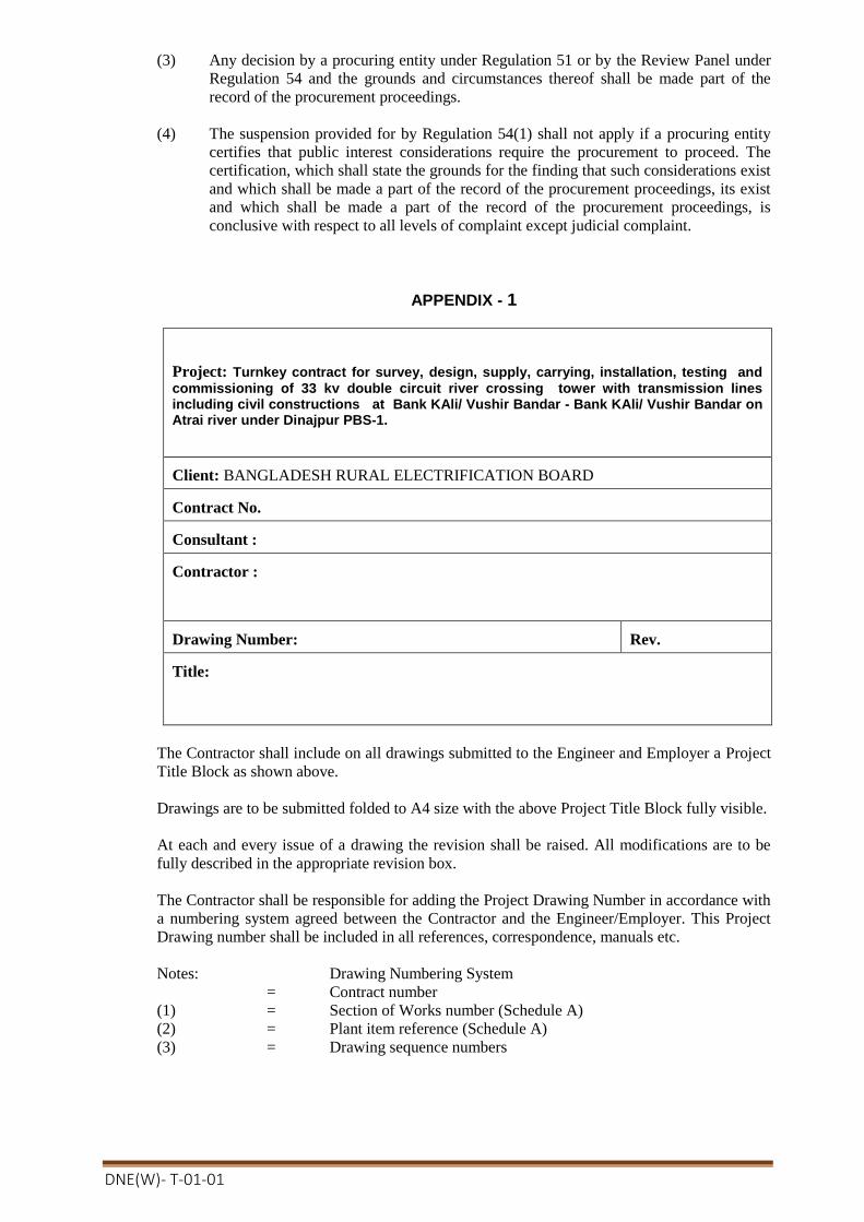
DNE(W)- T-01-01
(3) Any decision by a procuring entity under Regulation 51 or by the Review Panel under
Regulation 54 and the grounds and circumstances thereof shall be made part of the
record of the procurement proceedings.
(4) The suspension provided for by Regulation 54(1) shall not apply if a procuring entity
certifies that public interest considerations require the procurement to proceed. The
certification, which shall state the grounds for the finding that such considerations exist
and which shall be made a part of the record of the procurement proceedings, its exist
and which shall be made a part of the record of the procurement proceedings, is
conclusive with respect to all levels of complaint except judicial complaint.
APPENDIX - 1
Project: Turnkey contract for survey, design, supply, carrying, installation, testing and
commissioning of 33 kv double circuit river crossing tower with transmission lines including civil constructions at Bank KAli/ Vushir Bandar - Bank KAli/ Vushir Bandar on Atrai river under Dinajpur PBS-1.
Client: BANGLADESH RURAL ELECTRIFICATION BOARD Contract No. Consultant : Contractor :
Drawing Number:
Rev.
Title:
The Contractor shall include on all drawings submitted to the Engineer and Employer a Project
Title Block as shown above.
Drawings are to be submitted folded to A4 size with the above Project Title Block fully visible.
At each and every issue of a drawing the revision shall be raised. All modifications are to be
fully described in the appropriate revision box.
The Contractor shall be responsible for adding the Project Drawing Number in accordance with
a numbering system agreed between the Contractor and the Engineer/Employer. This Project
Drawing number shall be included in all references, correspondence, manuals etc.
Notes: Drawing Numbering System
= Contract number
(1) = Section of Works number (Schedule A)
(2) = Plant item reference (Schedule A)
(3) = Drawing sequence numbers

DNE(W)- T-01-01
SECTION 4: PART -III-( LABOUR LAWS )
1. LABOUR LAW
Bangladesh Labour Law shall be applicable for this tender.

DNE(W)- T-01-01
Appendix to the Tender
[In Tables below, the Procuring Entity shall indicate the source and base values with dates of Indexes, unless otherwise instructed to be quoted by the Tenderer, for the different Cost Components and mention its Weightings or Coefficients]
Table 1.1: Price Adjustment Data - n/a
[ ITT Sub Clause 26.9: To be provided by the Procuring Entity]
Index Descriptions Base Value Sources of Index
n/a
Note:
1. The sources of Indexes and its values with dates shall be Bangladesh Bureau of Statistics (BBS) unless otherwise mentioned by the Procuring Entity or instructed to be quoted by the Tenderer.
2. The Procuring Entity may require the Tenderer to justify its proposed Indexes, if quoted by the Tenderer.
3. The Base Value of the Indexes shall be those prevailing twenty eight (28) days prior to the deadline for submission of the Tenders.

DNE(W)- T-01-01
Table 1.2: Price Adjustment Data- N/A
[ GCC Sub Clause 56.4: To be provided by the Procuring Entity]
Item Group
Bill No. if applicable
Index Descriptio
ns
Coefficients or Weightings for
non-adjustable
Cost Component
Coefficients or Weightings for adjustable Cost Components
Total
a b c d e f g h i j
1
1
1
1
1
1
Note:
The Weightings or Coefficients of the Cost Components shall be mentioned by the Procuring Entity based on the proportion of components involved in the items caused to be impacted by rise and fall in its prices.
SECTION 4: Part -IV
APPENDICES [This appendixes shall be the part of the contract] Appendix 1 - Terms and Procedures of Payment
Appendix 2 - Price Adjustment
Appendix 3 - Insurance Requirements
Appendix 4 - Time Schedule
Appendix 5 - List of Major Items of Plant and services and List of Approved Subcontractors
Appendix 6 - Scope of Works and Supply by the Employer
Appendix 7 - List of Documents for Approval or Review
Appendix 8 - Functional Guarantees

DNE(W)- T-01-01
Appendix 1. Terms and Procedures of Payment
In accordance with the provisions of GCC Clause 57 (Terms of Payment), the Employer shall pay the Contractor in the following manner and at the following times, on the basis of the Price Breakdown given in the section on Price Schedules. Payments will be made in the currencies quoted by the Tenderer unless otherwise agreed between the parties. Applications for payment in respect of part deliveries may be made by the Contractor as work proceeds.
(A) Terms of Payment
Schedule No. 1 - Plant and Equipment/materials Supplied from within the Employer’s Country/Abro ad for GOB & BREB Own Fund.
In respect of plant and equipment/materials supplied from within the Employer’s country/abroad, the following payments shall be made:
(1) Thirty percent (30%) of the total or pro rata CIP amount shall be payable as successful Post landing inspection reports and delivery to the respective site after PSI/Pre-Delivery Inspection within forty-five (45) days after receipt .
(2) Twenty percent (20%) of the total or pro rata CIP amount upon issue of the Completion Certificate, within forty-five (45) days after receipt of invoice.
(3) Fifty percent (50%) of the total or pro rata CIP amount upon issue of the Operational Acceptance Certificate, within forty-five (45) days after receipt of invoice.
Schedule No. 2 - Installation and other Services In respect of installation services for both the foreign and local currency portions, the following payments shall be made:
(1) Thirty percent (30%) of the measured value of work performed by the Contractor, as identified in the said Program of Performance, during the preceding month, as evidenced by the Employer’s authorization of the Contractor’s application, will be made monthly within forty-five (45) days after receipt of invoice.
(2) Twenty percent (20%) of the total or pro rata value of installation services performed by the Contractor as evidenced by the Employer’s authorization of the Contractor’s monthly applications, upon issue of the Completion Certificate, within forty-five (45) days after receipt of invoice.
(3) Fifty percent (50%) of the total or pro rata value of installation services performed by the Contractor as evidenced by the Employer’s authorization of the Contractor’s amount upon issue of the Operational Acceptance Certificate, within forty-five (45) days after receipt of invoice.
Schedule No. 3 - Design Services In respect of design services for both the foreign currency and the local currency portions, the following payments shall be made:
(1) Fifty percent (50%) of the total or pro rata design services amount upon acceptance of design in accordance with GCC Clause 35 by the Project Manager/Committee within forty-five (45) days after receipt of invoice.
(2) Fifty percent (50%) of the total or pro rata design services amount upon issue of the Completion Certificate with as-built design and drawing, within forty-five (45) days after receipt of invoice.
.
(B) Payment Procedures

DNE(W)- T-01-01
The procedures to be followed in applying for certification and making payments shall be as follows:
(1) All costs in connection with invoice and document within Bangladesh/Employer’s country shall borne by the Employer and outside of the Bangladesh/Employer’s country shall be borne by the Contractor but Contractor shall be paid as per quoted price by the employer.
(2) Cost of contract Price will be paid by the Employer’s designated Bank.
(3) The retention money shall be deducted @ ten(10) percent from the successful Tenderer’s payable invoices during contract implementation, if awarded the contract.(i.e. retention money shall be deducted@ 10% from each Billing amount.)
(4) 10% money shall be retained for defect liability period either from retention money or from PG , it might be from both sources as per decision of employer's decision.
Appendix 2. Price Adjustment: (Not Applicable)
Prices payable to the Contractor, in accordance with the Contract, shall be subject to adjustment during performance of the Contract to reflect changes in the cost of labor and material components, in accordance with the following formula:
The Contract is subject to price adjustment applying the following formulae and the weightings or coefficients :
[Price Adjustment Formulae to be applicable if stated under ITT Sub Clause 26.9 shall be specified
here]
Example:
P= A + a (Lm/Lo)+ b (BIm/BIo)+ c (CEm/CEo)+ d (RSm/RSo)+ e (STm/STo)+ f (BRm/BRo)+g (MIm/MIo) + h (FUm/FUo)+ etc
where;
L= Labor, BI=Bitumen, CE=Cement, RS=Reinforcing Steel, ST=Stone, BR=Bricks, MI=Miscellaneous, FU= Fuel ]
Weighting or Coefficient A equals between 0.10 and 0.15 and, B (a+b+c+d+e+f+g+h+etc) equals between 0.90 and 0.85.
[insert figure] non-adjustable component (coefficient A)
[insert figure] adjustable component (coefficient B)
[The sum of A+B shall equal ONE (1). It is usual to have value of A between 0.10 and 0.15 and that of B between 0.90 and 0.85. Breakdown of Bshall be provided in Appendix to the Tender.]
[delete as appropriate]
The date of adjustment shall be the mid-point of the period of manufacture or installation of component or Plant.
The following conditions shall apply:
(a) No price increase will be allowed beyond the original delivery date unless covered by an extension of time awarded by the Employer under the terms of the Contract. No price increase will be allowed for periods of delay for which the Contractor is

DNE(W)- T-01-01
responsible. The Employer will, however, be entitled to any price decrease occurring during such periods of delay.
(c) No price adjustment shall be payable on the portion of the Contract price paid to the Contractor as an advance payment.
For complex plant supply and installation involving several sources of supply and/or a substantial amount of installation works, a family of formulas may be necessary, with provision for the usage of Contractor’s equipment in the works formula.

DNE(W)- T-01-01
Appendix 3. Insurance Requirements
Insurances To Be Taken Out By The Contractor:
In accordance with the provisions of GCC Clause 49, the Contractor shall at its expense take out and maintain in effect, or cause to be taken out and maintained in effect, during the performance of the Contract, the insurances set forth below in the sums and with the deductibles and other conditions specified. The identity of the insurers and the form of the policies shall be subject to the approval of the Employer, such approval not to be unreasonably withheld.
(a) Cargo Insurance Covering loss or damage occurring, while in transit from the supplier’s or manufacturer’s works or stores until arrival at the Site, to the Facilities (including spare parts therefore) and to the construction equipment to be provided by the Contractor or its Subcontractors.
Amount Deductible limits
Parties insured From To
[in currency(ies)] [in currency(ies)] [names] [place] [place]
110% of the contract price
-
Bangladesh Rural Electrification Board
Supplier’s or manufacturer’s works or stores
Site
(b) Installation All Risks Insurance Covering physical loss or damage to the Facilities at the Site, occurring prior to completion of the Facilities, with an extended maintenance coverage for the Contractor’s liability in respect of any loss or damage occurring during the defect liability period while the Contractor is on the Site for the purpose of performing its obligations during the defect liability period.
Amount Deductible limits
Parties insured From To
[in currency(ies)] [in currency(ies)] [names] [place] [place]
110% of the contract price
-
Bangladesh Rural Electrification Board
- -
(c) Third Party Liability Insurance Covering bodily injury or death suffered by third parties (including the Employer’s personnel) and loss of or damage to property (including the Employer’s property and any parts of the Facilities that have been accepted by the Employer) occurring in connection with the supply and installation of the Facilities.
Amount Deductible limits
Parties insured From To
[in currency(ies)] [in currency(ies)] [names] [place] [place]
As per law and common practice in Bangladesh
(d) Automobile Liability Insurance

DNE(W)- T-01-01
Covering use of all vehicles used by the Contractor or its Subcontractors (whether or not owned by them) in connection with the supply and installation of the Facilities. Comprehensive insurance in accordance with statutory requirements.
(e) Workers’ Compensation In accordance with the statutory requirements applicable in any country where the Facilities or any part thereof is executed.
(f) Employer’s Liability In accordance with the statutory requirements applicable in any country where the Facilities or any part thereof is executed.
(g) Other Insurances The Contractor is also required to take out and maintain at its own cost the following insurances:
Details:
Amount Deductible limits Parties insured From To [in currency(ies)] [in currency(ies)] [names] [place] [place]
Nil Nil Nil Nil Nil
The Employer shall be named as co-insured under all insurance policies taken out by the Contractor pursuant to GCC Sub-Clause 49.1, except for the Third Party Liability, Workers’ Compensation and Employer’s Liability Insurances, and the Contractor’s Subcontractors shall be named as co-insureds under all insurance policies taken out by the Contractor pursuant to GCC Sub-Clause49.1, except for the Cargo, Workers’ Compensation and Employer’s Liability Insurances. All insurer’s rights of subrogation against such co-insureds for losses or claims arising out of the performance of the Contract shall be waived under such policies.
Insurances to be Taken Out By The Employer
If the Employer is proposing to take out any or all of the above insurances itself, or any other insurances in respect of the Facilities, either in its own name or in the joint names of itself and the Contractor, it shall give details below prior to issuing the tender documents. Under the terms of the Contract, the Contractor and the Contractor’s Subcontractors shall be named as co-insured under all such policies.
The Employer shall at its expense take out and maintain in effect during the performance of the Contract the following insurances.
Details:
Amount Deductible limits
Parties insured
From To
[in currency(ies)] [in currency(ies)] [names] [place] [place]
Nil Nil Nil Nil Nil

DNE(W)- T-01-01
Appendix 4. Time Schedule
The time for completion of whole facilities shall be as specified in the PCC against sub-clause GCC-24.1 of section-4.
Appendix 5. List of Major Items of Plant and Services and List of Approved Subcontractors
1. The plants/ materials & equipments are to be supplied
A list of major items of plant and services is provided below.
The following Subcontractors and/or manufacturers are approved for carrying out the item of the facilities indicated. Where more than one Subcontractor is listed, the Contractor is free to choose between them, but it must notify the Employer of its choice in good time prior to appointing any selected Subcontractor. In accordance with GCC Sub-Clause 32.1, the Contractor is free to submit proposals for Subcontractors for additional items from time to time. No Subcontracts shall be placed with any such Subcontractors for additional items until the Subcontractors have been approved in writing by the Employer and their names have been added to this list of Approved Subcontractors.
Major Items of Plant and Services
Approved Subcontractors/Manufacturers
Nationality
N/A

DNE(W)- T-01-01
Appendix 6. Scope of Works and Supply by the Employer
The following personnel, facilities, works and supplies shall apply as appropriate.25
All personnel, facilities, works and supplies will be provided by the Employer in good time so as not to delay the performance of the Contractor, in accordance with the approved Time Schedule and Program of Performance pursuant to GCC Sub-Clause 31.2.
Unless otherwise indicated, all personnel, facilities, works and supplies will be provided free of charge to the Contractor.
Personnel Charge to Contractor (if any)
Supervision & Management Consultant/Employer’s personnel will be engaged to supervise and certify the works and test Name of the firm/personnel will be informed later on.
No charge to contractor
Facilities Charge to Contractor (if any)
Power shutdown as required and approved by the employer for the execution of works
No charge to contractor
Information/Data on incoming source of electric power
No charge to contractor
Assistance in availing of other utility services. Charge to contractor if applicable.
The employer will not generally provide any storage facility to the contractor. Conductor shall be responsible to provide storage facility.
In the event of any such requirement and subject to availability, the employer may extend the facility to use such storage facility by the contractor on rental charge/cost basis normal terms and conditions.
The amount determined by the employer to be paid by contractor.
Works Charge to Contractor (if any)
The employer will not do any works. Contractor shall be responsible to execute the contract. If contractor do not reinstate the employer’s existing facilities(Civil fencing and other ancillaries) employer will complete it.
Will be deducted from contractor’s payment.
Supplies Charge to Contractor (if any)
The Employer will not supply any machinery/equipment and materials to the contractor.
In the event of any such requirement and subject to availability, the employer may extend the facilities to use such machinery and materials by the contractor on rental charge/cost under normal terms and conditions
No charge to contractor.
The amount determined by the employer to be paid by contractor
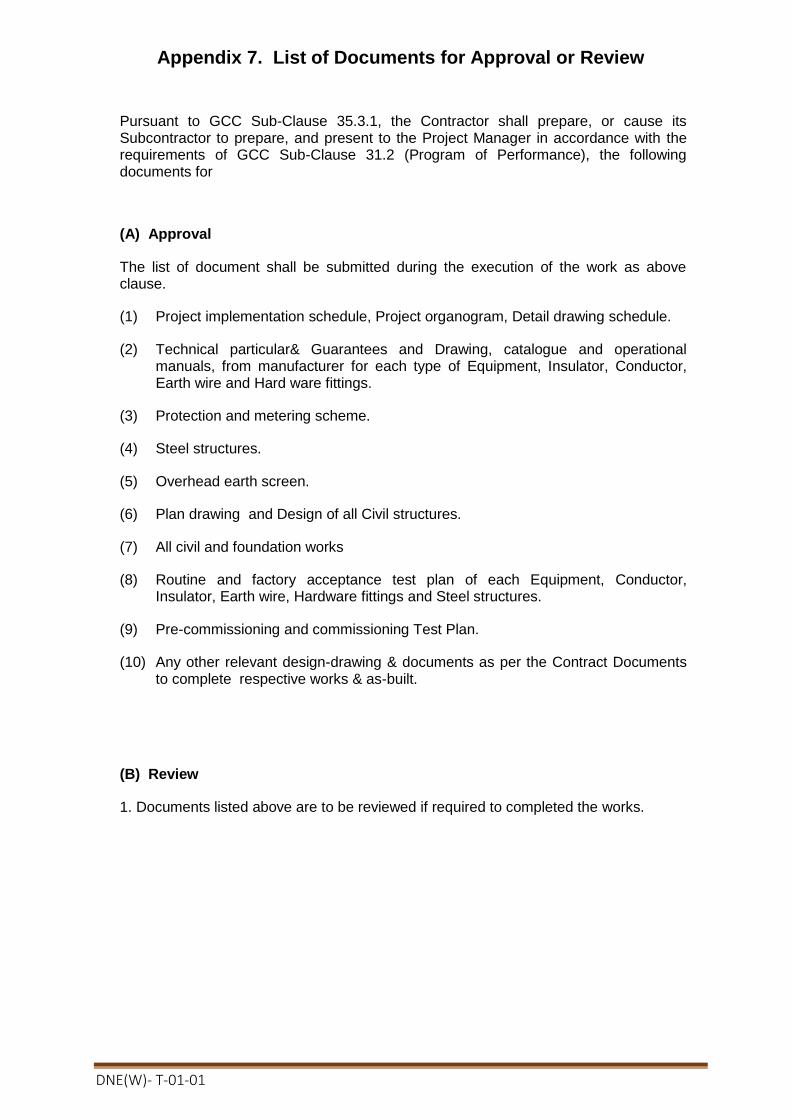
DNE(W)- T-01-01
Appendix 7. List of Documents for Approval or Review
Pursuant to GCC Sub-Clause 35.3.1, the Contractor shall prepare, or cause its Subcontractor to prepare, and present to the Project Manager in accordance with the requirements of GCC Sub-Clause 31.2 (Program of Performance), the following documents for
(A) Approval
The list of document shall be submitted during the execution of the work as above clause.
(1) Project implementation schedule, Project organogram, Detail drawing schedule.
(2) Technical particular& Guarantees and Drawing, catalogue and operational manuals, from manufacturer for each type of Equipment, Insulator, Conductor, Earth wire and Hard ware fittings.
(3) Protection and metering scheme.
(4) Steel structures.
(5) Overhead earth screen.
(6) Plan drawing and Design of all Civil structures.
(7) All civil and foundation works
(8) Routine and factory acceptance test plan of each Equipment, Conductor, Insulator, Earth wire, Hardware fittings and Steel structures.
(9) Pre-commissioning and commissioning Test Plan.
(10) Any other relevant design-drawing & documents as per the Contract Documents to complete respective works & as-built.
(B) Review
1. Documents listed above are to be reviewed if required to completed the works.
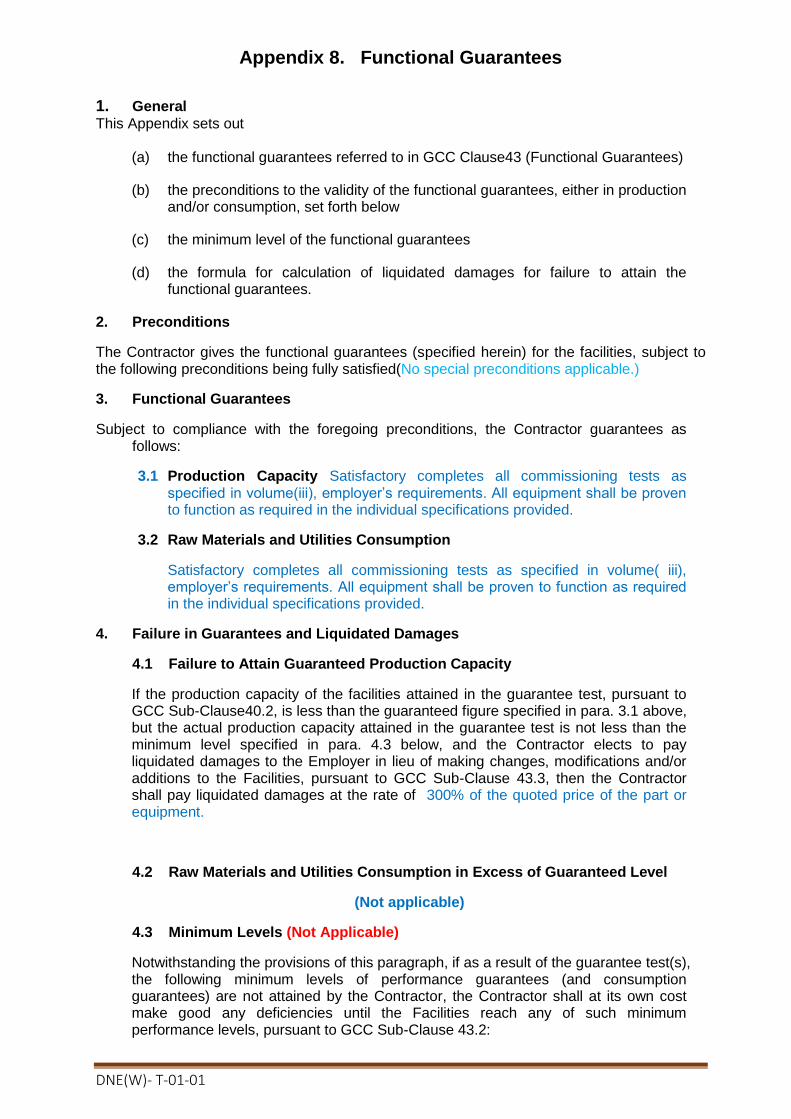
DNE(W)- T-01-01
Appendix 8. Functional Guarantees
1. General
This Appendix sets out
(a) the functional guarantees referred to in GCC Clause43 (Functional Guarantees)
(b) the preconditions to the validity of the functional guarantees, either in production and/or consumption, set forth below
(c) the minimum level of the functional guarantees
(d) the formula for calculation of liquidated damages for failure to attain the functional guarantees.
2. Preconditions
The Contractor gives the functional guarantees (specified herein) for the facilities, subject to the following preconditions being fully satisfied(No special preconditions applicable.)
3. Functional Guarantees
Subject to compliance with the foregoing preconditions, the Contractor guarantees as follows:
3.1 Production Capacity Satisfactory completes all commissioning tests as specified in volume(iii), employer’s requirements. All equipment shall be proven to function as required in the individual specifications provided.
3.2 Raw Materials and Utilities Consumption
Satisfactory completes all commissioning tests as specified in volume( iii), employer’s requirements. All equipment shall be proven to function as required in the individual specifications provided.
4. Failure in Guarantees and Liquidated Damages
4.1 Failure to Attain Guaranteed Production Capacity
If the production capacity of the facilities attained in the guarantee test, pursuant to GCC Sub-Clause40.2, is less than the guaranteed figure specified in para. 3.1 above, but the actual production capacity attained in the guarantee test is not less than the minimum level specified in para. 4.3 below, and the Contractor elects to pay liquidated damages to the Employer in lieu of making changes, modifications and/or additions to the Facilities, pursuant to GCC Sub-Clause 43.3, then the Contractor shall pay liquidated damages at the rate of 300% of the quoted price of the part or equipment.
4.2 Raw Materials and Utilities Consumption in Excess of Guaranteed Level
(Not applicable)
4.3 Minimum Levels (Not Applicable)
Notwithstanding the provisions of this paragraph, if as a result of the guarantee test(s), the following minimum levels of performance guarantees (and consumption guarantees) are not attained by the Contractor, the Contractor shall at its own cost make good any deficiencies until the Facilities reach any of such minimum performance levels, pursuant to GCC Sub-Clause 43.2:

DNE(W)- T-01-01
(a) production capacity of the Facilities attained in the guarantee test: ninety-five percent (95%/100%) of the guaranteed production capacity
and/or
(b) average total cost of consumption of all the raw materials and utilities of the Facilities: one hundred and five percent (105%) of the guaranteed figures.
4.4 Limitation of Liability
Subject to para. 4.3 above, the Contractor’s aggregate liability to pay liquidated damages for failure to attain the functional guarantees shall not exceed 10% of the Contract price

DNE(W)- T-01-01
Section 5. Tender and Contract Forms
Form Title
Tender Forms
PG5A – 1a Tender Submission Letterfor Technical Proposal
PG5A – 1b Tender Submission Letter for Financial (Price) Proposal
PG5A – 2a Tenderer Information Sheet
PG5A – 2b
PG5A – 2c
JVCA Partner Information
Subcontractor Information
PG5A – 3 Price Schedule for Plant and Services
PG5A – 4 Technical Proposal
PG5A – 4a Specification submission & compliance sheet.
PG5A– 5 Manufacturer’s Authorisation Letter
PG5A – 6 Bank Guarantee for Tender Security
PG5A – 6a Letter of Commitment for Bank’s undertaking for Line of Credit (Form PG5A-6a)
Contract Forms
PG5A – 7 Notification of Award
PG5A – 8 Contract Agreement
PG5A – 9 Bank Guarantee for Performance Security
PG5A– 10 Bank Guarantee for Advance Payment
PG5A– 11 Bank Guarantee for Retention Money Security (Form PG5A-11)
Forms PG5A-1a, PG5A-1b to PG5A-6, PG5A-6a comprises part of the Tender and should be completed as stated in ITT Clause 24. Forms PG5A-7 to PG5A-11 and the appendices of the tender comprises part of the Contract as stated in GCC Clause 6.

DNE(W)- T-01-01
Tender Submission Letter for Technical offer
(Form PG5A-1a) [This letter should be completed and signed by the Authorised Signatory preferably on the Letter-Head Pad of the Tenderer and be appended in the technical proposal envelope]
To:
[Contact Person]
[Name of Procuring Entity]
[Address of Procuring Entity]
Date:
Invitation for Tender No: [indicate IFT No]
Tender Package No: [indicate Package No]
This Package is divided into the following Number of Lots
[indicate number of Lot(s)]
We, the undersigned, offer to design, manufacture, test, deliver, install, pre-commission and commission in conformity with the Tender Document, the following Plant and Services, viz:
In signing this letter, and in submitting our Tender, we also confirm that:
(a) our Tender shall be valid for the period stated in the Tender Data Sheet (ITT Sub Clause 30.1) and it shall remain binding upon us and may be accepted at any time before the expiration of that period;
(b) a Tender Security is attached in the form of a [state pay order, bank draft, bank guarantee] in the amount stated in the Tender Data Sheet (ITT Sub Clause 32) and valid for a period of twenty eight (28) days beyond the Tender validity date;
(c) we have examined and have no reservations to the Tender Document, issued by you on [insert date]; including Addendum to Tender Document No(s) [state numbers] , issued in accordance with the Instructions to Tenderers (ITT Clause 11). [insert the number and issuing date of each addendum; or delete this sentence if no Addendum has been issued];
(d) we, including as applicable, any JVCA partner or Subcontractor for any part of the contract resulting from this Tender process, have nationalities from eligible countries, in accordance with ITT Sub Clause 5.1;
(e) we are submitting this Tender as a sole Tenderer in accordance with ITT Sub Clause 38.3
or we are submitting this Tender as the partners of a JVCA, comprising the following other partners in accordance with ITT Sub Clause 18.1;
Name of Partner Address of Partner
1
2
3
4
(f) we are not a Government owned entity as defined in ITT Sub Clause 5.3 or
we are a Government owned entity, and we meet the requirements of ITT Sub Clause 5.3; (delete one of the above as appropriate)
(g) we, including as applicable any JVCA partner, declare that we are not associated, nor have been associated in the past, directly or indirectly, with a consultant or any other entity that has prepared the design, specifications and other documentsin accordance with ITT Sub Clause 5.5;
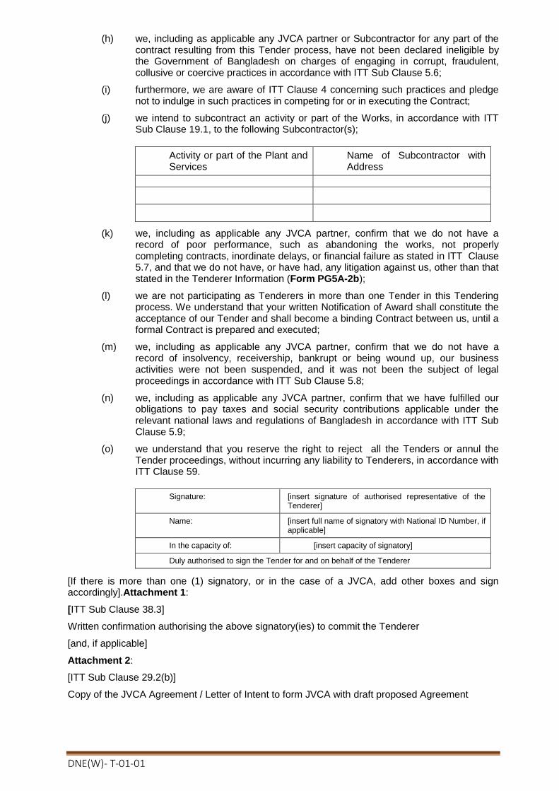
DNE(W)- T-01-01
(h) we, including as applicable any JVCA partner or Subcontractor for any part of the contract resulting from this Tender process, have not been declared ineligible by the Government of Bangladesh on charges of engaging in corrupt, fraudulent, collusive or coercive practices in accordance with ITT Sub Clause 5.6;
(i) furthermore, we are aware of ITT Clause 4 concerning such practices and pledge not to indulge in such practices in competing for or in executing the Contract;
(j) we intend to subcontract an activity or part of the Works, in accordance with ITT Sub Clause 19.1, to the following Subcontractor(s);
Activity or part of the Plant and Services
Name of Subcontractor with Address
(k) we, including as applicable any JVCA partner, confirm that we do not have a record of poor performance, such as abandoning the works, not properly completing contracts, inordinate delays, or financial failure as stated in ITT Clause 5.7, and that we do not have, or have had, any litigation against us, other than that stated in the Tenderer Information (Form PG5A-2b);
(l) we are not participating as Tenderers in more than one Tender in this Tendering process. We understand that your written Notification of Award shall constitute the acceptance of our Tender and shall become a binding Contract between us, until a formal Contract is prepared and executed;
(m) we, including as applicable any JVCA partner, confirm that we do not have a record of insolvency, receivership, bankrupt or being wound up, our business activities were not been suspended, and it was not been the subject of legal proceedings in accordance with ITT Sub Clause 5.8;
(n) we, including as applicable any JVCA partner, confirm that we have fulfilled our obligations to pay taxes and social security contributions applicable under the relevant national laws and regulations of Bangladesh in accordance with ITT Sub Clause 5.9;
(o) we understand that you reserve the right to reject all the Tenders or annul the Tender proceedings, without incurring any liability to Tenderers, in accordance with ITT Clause 59.
Signature: [insert signature of authorised representative of the Tenderer]
Name: [insert full name of signatory with National ID Number, if applicable]
In the capacity of: [insert capacity of signatory]
Duly authorised to sign the Tender for and on behalf of the Tenderer
[If there is more than one (1) signatory, or in the case of a JVCA, add other boxes and sign accordingly].Attachment 1:
[ITT Sub Clause 38.3]
Written confirmation authorising the above signatory(ies) to commit the Tenderer
[and, if applicable]
Attachment 2:
[ITT Sub Clause 29.2(b)]
Copy of the JVCA Agreement / Letter of Intent to form JVCA with draft proposed Agreement

DNE(W)- T-01-01
Tender Submission Letter for Financial offer
(Form PG5A-1b) [This letter should be completed and signed by the Authorised Signatory preferably on the Letter-Head Pad of the Tendererand be appended in the financial proposal envelope]
To:
[Contact Person]
[Name of Procuring Entity]
[Address of Procuring Entity]
Date:
Invitation for Tender No: [indicate IFT No]
Tender Package No: [indicate Package No]
This Package is divided into the following Number of Lots
[NIL]
We, the undersigned, offer to design, manufacture, test, deliver, install, pre-commission and commission in conformity with the Tender Document, the following Plant and Services, viz:
In accordance with ITT Clauses 26 and 27, the following prices and discounts apply to our Tender:
The Tender Price is:
(ITT Sub-Clause 26.1)
[state amount in figures]
and [state amount in words]
Plant (including Mandatory Spare Parts) Supplied from abroad
[state amount in figures]
and [state amount in words]
Plant (including Mandatory Spare Parts) supplied from within the Employer’s Country
Taka[state amount in figures]
And Taka [state amount in words]
Design Services [state amount in figures]
and [state amount in words]
Installation and Other Services [state amount in figures]
and [state amount in words]
Recommended Spare parts Price
(If economic Factor is applicable)
[state amount in figures]
and [state amount in words]
The Unconditional discount is
(ITT Sub-Clause 23.11)
[state amount in figures]
and [state amount in words]
The methodology for Application of the discount is:
[state the methodology]
and we shall accordingly submit an Advance Payment Guarantee in the format shown in Form PG5A- 10.
In signing this letter, and in submitting our Tender, we also confirm that:
a) our Tender shall be valid for the period stated in the Tender Data Sheet (ITT Sub Clause 30.1) and it shall remain binding upon us and may be accepted at any time before the expiration of that period;
b) a Tender Security is attached in the form of a [state pay order, bank draft, bank guarantee] in the amount stated in the Tender Data Sheet (ITT Sub Clause 32) and valid for a period of twenty eight (28) days beyond the Tender validity date;
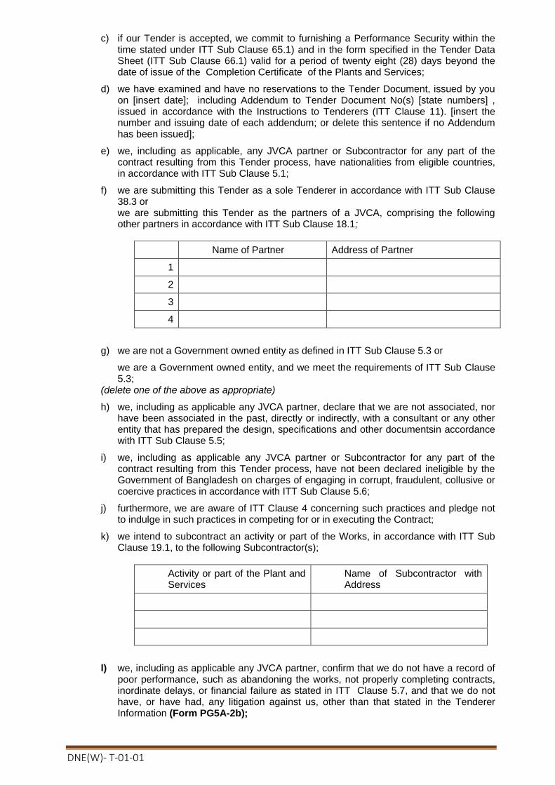
DNE(W)- T-01-01
c) if our Tender is accepted, we commit to furnishing a Performance Security within the time stated under ITT Sub Clause 65.1) and in the form specified in the Tender Data Sheet (ITT Sub Clause 66.1) valid for a period of twenty eight (28) days beyond the date of issue of the Completion Certificate of the Plants and Services;
d) we have examined and have no reservations to the Tender Document, issued by you on [insert date]; including Addendum to Tender Document No(s) [state numbers] , issued in accordance with the Instructions to Tenderers (ITT Clause 11). [insert the number and issuing date of each addendum; or delete this sentence if no Addendum has been issued];
e) we, including as applicable, any JVCA partner or Subcontractor for any part of the contract resulting from this Tender process, have nationalities from eligible countries, in accordance with ITT Sub Clause 5.1;
f) we are submitting this Tender as a sole Tenderer in accordance with ITT Sub Clause 38.3 or we are submitting this Tender as the partners of a JVCA, comprising the following other partners in accordance with ITT Sub Clause 18.1;
Name of Partner Address of Partner
1
2
3
4
g) we are not a Government owned entity as defined in ITT Sub Clause 5.3 or
we are a Government owned entity, and we meet the requirements of ITT Sub Clause 5.3;
(delete one of the above as appropriate)
h) we, including as applicable any JVCA partner, declare that we are not associated, nor have been associated in the past, directly or indirectly, with a consultant or any other entity that has prepared the design, specifications and other documentsin accordance with ITT Sub Clause 5.5;
i) we, including as applicable any JVCA partner or Subcontractor for any part of the contract resulting from this Tender process, have not been declared ineligible by the Government of Bangladesh on charges of engaging in corrupt, fraudulent, collusive or coercive practices in accordance with ITT Sub Clause 5.6;
j) furthermore, we are aware of ITT Clause 4 concerning such practices and pledge not to indulge in such practices in competing for or in executing the Contract;
k) we intend to subcontract an activity or part of the Works, in accordance with ITT Sub Clause 19.1, to the following Subcontractor(s);
Activity or part of the Plant and Services
Name of Subcontractor with Address
l) we, including as applicable any JVCA partner, confirm that we do not have a record of poor performance, such as abandoning the works, not properly completing contracts, inordinate delays, or financial failure as stated in ITT Clause 5.7, and that we do not have, or have had, any litigation against us, other than that stated in the Tenderer Information (Form PG5A-2b);
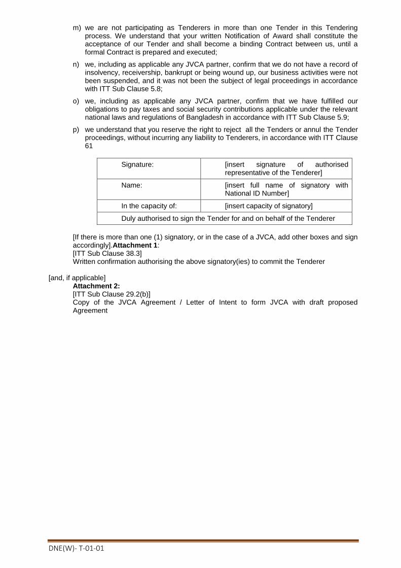
DNE(W)- T-01-01
m) we are not participating as Tenderers in more than one Tender in this Tendering process. We understand that your written Notification of Award shall constitute the acceptance of our Tender and shall become a binding Contract between us, until a formal Contract is prepared and executed;
n) we, including as applicable any JVCA partner, confirm that we do not have a record of insolvency, receivership, bankrupt or being wound up, our business activities were not been suspended, and it was not been the subject of legal proceedings in accordance with ITT Sub Clause 5.8;
o) we, including as applicable any JVCA partner, confirm that we have fulfilled our obligations to pay taxes and social security contributions applicable under the relevant national laws and regulations of Bangladesh in accordance with ITT Sub Clause 5.9;
p) we understand that you reserve the right to reject all the Tenders or annul the Tender proceedings, without incurring any liability to Tenderers, in accordance with ITT Clause 61
Signature: [insert signature of authorised representative of the Tenderer]
Name: [insert full name of signatory with National ID Number]
In the capacity of: [insert capacity of signatory]
Duly authorised to sign the Tender for and on behalf of the Tenderer
[If there is more than one (1) signatory, or in the case of a JVCA, add other boxes and sign accordingly].Attachment 1: [ITT Sub Clause 38.3] Written confirmation authorising the above signatory(ies) to commit the Tenderer
[and, if applicable]
Attachment 2: [ITT Sub Clause 29.2(b)] Copy of the JVCA Agreement / Letter of Intent to form JVCA with draft proposed Agreement
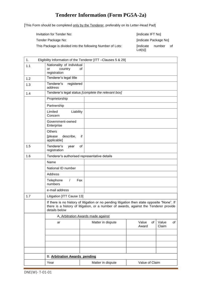
DNE(W)- T-01-01
Tenderer Information (Form PG5A-2a)
[This Form should be completed only by the Tenderer, preferably on its Letter-Head Pad]
Invitation for Tender No: [indicate IFT No]
Tender Package No: [indicate Package No]
This Package is divided into the following Number of Lots: [indicate number of Lot(s)]
1. Eligibility Information of the Tenderer [ITT –Clauses 5 & 29]
1.1 Nationality of individual or country of registration
1.2 Tenderer’s legal title
1.3 Tenderer’s registered address
1.4 Tenderer’s legal status [complete the relevant box]
Proprietorship
Partnership
Limited Liability Concern
Government-owned Enterprise
Others
[please describe, if applicable]
1.5 Tenderer’s year of registration
1.6 Tenderer’s authorised representative details
Name
National ID number
Address
Telephone / Fax numbers
e-mail address
1.7 Litigation [ITT Cause 13]
If there is no history of litigation or no pending litigation then state opposite “None”. If there is a history of litigation, or a number of awards, against the Tenderer provide details below
A. Arbitration Awards made against
ar Matter in dispute Value of Award
Value of Claim
B. Arbitration Awards pending
Year Matter in dispute Value of Claim

DNE(W)- T-01-01
1.8 Tenderer to attach photocopies of the original documents mentioned aside
[All documents required under ITT Clauses 5 and 29]
The following two information are applicable for National Tenderers
1.9 Tenderer’s Value Added Tax Registration (VAT) Number
1.10 Tenderer’s Tax Identification Number(TIN)
[The foreign Tenderers, in accordance with ITT Sub Clause 5.1, shall provide evidence by a written declaration to that effect to demonstrate that it meets the criterion]
8. Qualification Information of the Tenderer [ITT Clause 29]
2.1 General Experience in Plant and Services of Tenderer
Start Month Year
End Month Year
Years Contract No and Name of Contract
Name and Address of Procuring Entity
Brief description of Plant and Services
Role of Tenderer
[Contractor/Subcontractor /Management Contractor]
2.2 Specific Experience in Key Activities
Contract No
Name of Contract
[ insert reference no] of [ insert year]
[insert name]
Role in Contract
[tick relevant box].
Contractor
Subcontractor
Management Contractor
\Award date
Completion date
Total Contract Value
[insert date]
[insert date]
[insert amount]
Procuring Entity’s Name
Address
Tel / Fax
Brief description with justifications of the similarity compared to the Procuring Entity’s requirements
[state justification in support of its similarity compared to the proposed works]
2.3 Average annual turnover [ITT Sub Clause15.1(a)]
[amount invoiced to Procuring Entity(s) for each year of works in progress or completed, using rate of exchange at the end of the period reported]
Year Amount & Currency amount in figures

DNE(W)- T-01-01
2.4 Financial Resources available to meet the cash flow [ITT Sub Clause 15.1(b)]
No Source of Financing Amount Available
In order to confirm the above statements the Tenderer shall submit , as applicable, the documents mentioned in ITT Sub Clause 14.1(a), (b) and 15.1 (a), (b) & (c)
2.5 Contact Details
Name, address, and other contact details of Tenderer Bankers and other Procuring Entity(s) that may provide references, if contacted by this Procuring Entity
2.6 Qualifications and experience of key technical and administrative personnel proposed for
Contract administration and management [ITT Sub Clause 16.1 ]
Position
Name
Years of General Experience
Years of Specific Experience
[Tenderer to complete details of as many personnel as are applicable.Each personnel
listed above should complete the Personnel Information (Form PG5A-5)]
2.7 Major Equipment proposed to carry out the Contract [ITT Sub Clause 17.1 ]
Item of Equipment
Condition
(new, good, average, poor)
Owned, leased or to be purchased
(state owner, lessor seller)
[Tenderer to list details of each item of major equipment, as applicable]
Name: [insert full name of signatory]
Signature with Date and Seal
In the capacity of:
[insert designation of signatory]
[ Sign]
Duly authorised to sign the Tender for and on behalf of the Tenderer
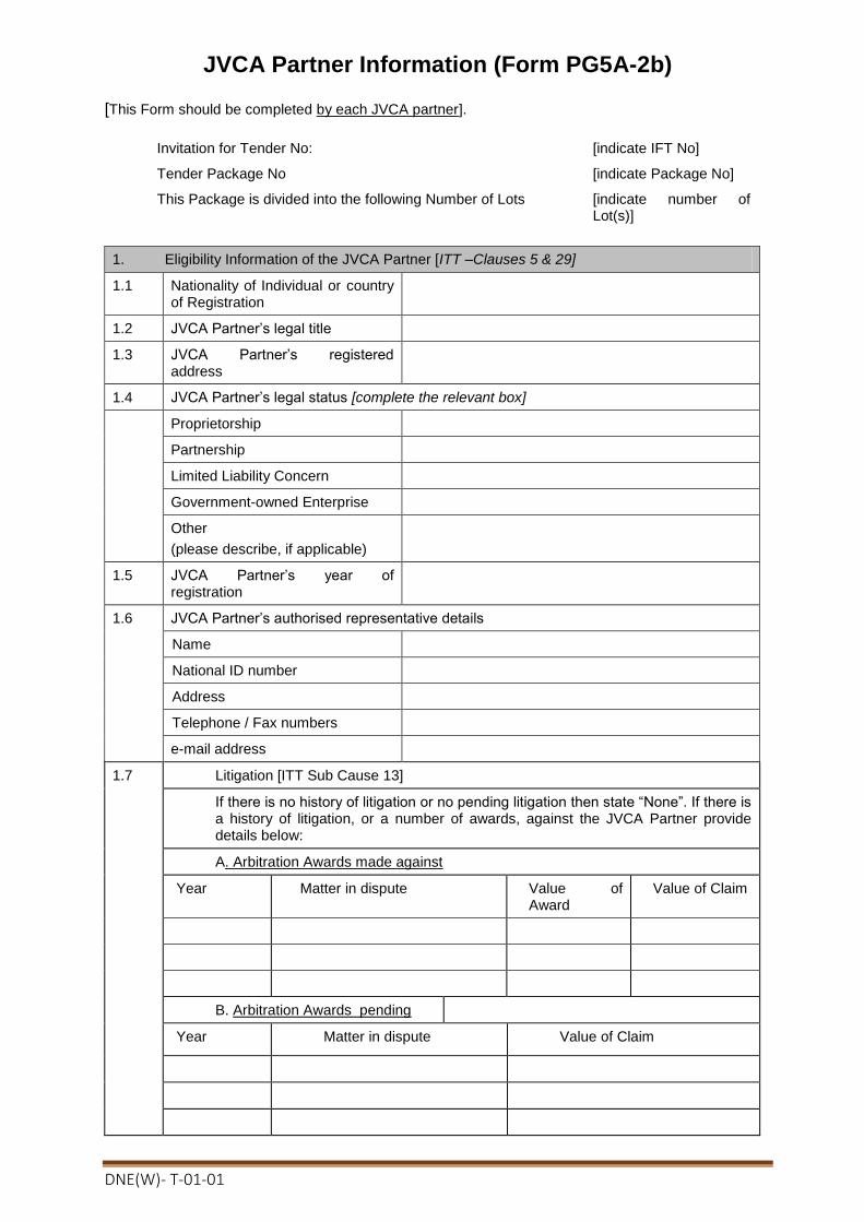
DNE(W)- T-01-01
JVCA Partner Information (Form PG5A-2b)
[This Form should be completed by each JVCA partner].
Invitation for Tender No: [indicate IFT No]
Tender Package No [indicate Package No]
This Package is divided into the following Number of Lots [indicate number of Lot(s)]
1. Eligibility Information of the JVCA Partner [ITT –Clauses 5 & 29]
1.1 Nationality of Individual or country of Registration
1.2 JVCA Partner’s legal title
1.3 JVCA Partner’s registered address
1.4 JVCA Partner’s legal status [complete the relevant box]
Proprietorship
Partnership
Limited Liability Concern
Government-owned Enterprise
Other
(please describe, if applicable)
1.5 JVCA Partner’s year of registration
1.6 JVCA Partner’s authorised representative details
Name
National ID number
Address
Telephone / Fax numbers
e-mail address
1.7 Litigation [ITT Sub Cause 13]
If there is no history of litigation or no pending litigation then state “None”. If there is a history of litigation, or a number of awards, against the JVCA Partner provide details below:
A. Arbitration Awards made against
Year Matter in dispute Value of Award
Value of Claim
B. Arbitration Awards pending
Year Matter in dispute Value of Claim

DNE(W)- T-01-01
1.8 JVCA Partner to attach copies of the original documents mentioned aside
[All documents required under ITT Clauses 5 and 29]
The following two information are applicable for national JVCA Partners only
1.9 JVCA Partner’s Value Added Tax Registration (VAT) Number
1.10 JVCA Partner’s Tax Identification Number (TIN)
[The foreign JVCA Partners, in accordance with ITT Sub Clause 5.1, shall provide evidence by a written declaration to that effect to demonstrate that it meets the criterion]
2. Key Activity(ies) for which it is intended to be joint ventured [ITT Sub Clause 18.2 & 18.3]
Elements of Activity Brief description of Activity
3. Qualification Information of the JVCA Partner [ITT Clause 18]
3.1 General Experience in Plant and Services of JVCA Partner
Start Month Year
End Month Year
Years Contract No and & Name of Contract
Name and Address of Procuring Entity
Brief description of Works
Role of JVCA Partner
[Contractor/Subcontractor/Management Contractor]
3.2 Specific Experience in Key Activities
Contract No
Name of Contract
[ insert reference no] of [ insert year]
[insert name]
Role in Contract
[tick relevant box]
Contractor Subcontractor
Management Contractor
Award date
Completion date
Total Contract Amount
[insert date]
[insert date]
[insert amount]
Procuring Entity’s Name
Address
Tel / Fax
[state justification in support of its similarity compared to the proposed plants and service]
Brief description with justifications of the similarity compared to the Procuring Entity’s requirements
3.3 Average annual construction turnover [ITT Sub Clause 15.1 (a)]
[amount invoiced to Procuring Entity(s) for each year of work in progress or completed, using rate of exchange at the end of the period reported]
Year Amount & Currency Amount in Figures

DNE(W)- T-01-01
3.4 Financial Resources available to meet the cash flow [ITT Sub-Clause 15.1(b)]
No
Source of financing Amount available
In order to confirm the above statements the JVCA Partner shall submit , as applicable, the documents mentioned in ITT Sub Clause 14.1 (a) & (b),15.1 (a), (b), (c) & (d)
3.5 Contact Details
Name, address, and contact details of Tenderer’s Bankers and other Procuring Entity(s) that may provide references if contacted by this Procuring Entity
3.6 Qualifications and experience of key technical and administrative personnel proposed for Contract administration and management [ITT Sub Clause 16.1]
Position
Name
Years of General Experience
Years of Specific Experience
[Tenderer to complete details of as many personnel as are applicable. Each
personnel listed above should complete the Personnel Information (Form PG5A-5)]
3.7 Major items of Construction Equipment proposed for carrying out the works [ITT Sub-Clause 17.1]
Item of Equipment
Condition
(new, good, average, poor)
Owned, leased or to be purchased
(state owner, leaser or seller)
[Tenderer to list details of each item of Major equipment, as applicable]
Name: [insert full name of signatory] Signature with Date and Seal
In the capacity of: [insert designation of signatory]
[ Sign]
Duly authorised to sign the Tender for and on behalf of the Tenderer

DNE(W)- T-01-01
Subcontractor Information (Form PG5A-2c)
[This Form should be completed by each Subcontractor, preferably on its Letter-Head Pad]
Invitation for Tender No: [indicate IFT No]
Tender Package No [indicate Package No]
This Package is divided into the following Number of Lots [indicate number of Lot(s)]
1. Eligibility Information of the Subcontractor [ITT –Clauses 5 & 29]
1.1 Nationality of Individual or country of Registration
1.2 Subcontractor’s legal title
1.3 Subcontractor’s registered address
1.4 Subcontractor’s legal status [complete the relevant box
Proprietorship
Partnership
Limited Liability Concern
Government-owned Enterprise
Other(please describe)
.1.5 Subcontractor’s year of registration
1.6 Subcontractor’s authorised representative details
Name
Address
Telephone / Fax numbers
e-mail address
1.7 Subcontractor to attach copies of the following original documents
All documents to the extent relevant to ITT Clause 5 and 29 in support of its qualifications
The following two information are applicable for national Subcontractors
1.8 Subcontractor’s Value Added Tax Registration (VAT) Number
1.9 Subcontractor’s Tax Identification Number(TIN)
[The foreign Subcontractors , in accordance with ITT sub Clause 5.1, shall provide evidence by a written declaration to that effect to demonstrate that it meets the criterion]
2. Key Activity(ies) for which it is intended to be Subcontracted [ITT Sub Clause 19.1]
2.1 Elements of Activity Brief description of Activity

DNE(W)- T-01-01
2.2 List of Similar Contracts in which the proposed Subcontractor had been engaged
Name of Contract and Year of Execution
Value of Contract
Name of Procuring Entity
Contact Person and contact details
Type of Assignment performed
Name: [insert full name of signatory] Signature with Date and Seal
In the capacity of: [insert designation of signatory]
[ Sign]
Duly authorised to sign the Tender for and on behalf of the Tenderer

DNE(W)- T-01-01
Price Schedule for Plant/Equipments/Materials and Service (Form PG5A-3)
(This form should be completed and submitted by the tenderer and appended in the financial proposal envelope)
Invitation for Tender No: [indicate IFT No]
Tender Package No [indicate Package No]
This Package is divided into the following Number of Lots [NIL]
General
1. The Price Schedules are divided into separate Schedules (PG5A-3) as follows:
Schedule No. 1: Material to be Supplied for the construction of River Crossing Tower with Transmission Line.
Schedule No. 2: Installation and Other Services for the construction of River Crossing Tower with Transmission Line.
Schedule No. 3: Design Services for the construction of River Crossing Tower with Transmission Line.
Schedule No. 4: Grand Summary
2. The Schedules do not generally give a full description of the plant to be supplied and the services to be performed under each item. Tenderers shall be deemed to have read the Employer’s Requirements and other sections of the Tender Document and reviewed the Drawings to ascertain the full scope of the requirements included in each item prior to filling in the rates and prices. The entered rates and prices shall be deemed to cover the full scope as aforesaid, including overheads and profit.
3. If tenderers are unclear or uncertain as to the scope of any item, they shall seek clarification in accordance with ITT 9.1 prior to submitting their tender.
Pricing
4. Prices shall be filled in indelible ink, and any alterations necessary due to errors, etc., shall be initialed by the Tenderer.
As specified in the Tender Data Sheet and Special Conditions of Contract, prices shall be fixed and firm for the duration of the Contract, or prices shall be subject to adjustment in accordance with the corresponding Appendix (Price Adjustment) to the Contract Agreement.
5. Tender prices shall be quoted in the manner indicated and in the currencies specified in the Instructions to Tenderers in the Tender Document.
For each item, tenderers shall complete each appropriate column in the respective Schedules, giving the price breakdown as indicated in the Schedules.
Prices given in the Schedules against each item shall be for the scope covered by that item as detailed in Section 6 (Employer’s Requirements) or elsewhere in the Tender Document.
6. Payments will be made to the Contractor in the currency or currencies indicated under each respective item.
7. When requested by the Employer for the purposes of making payments or partial payments, valuing variations or evaluating claims, or for such other purposes as the Employer may reasonably require, the Contractor shall provide the Employer with a breakdown of any composite or lump sum items included in the Schedules.

DNE(W)- T-01-01
SECTION: 5- Price Schedule for River Crossing Tower(Form -PG5A-3)
Turnkey contract for survey, design, supply, carrying, installation, testing and commissioning of 33 kv double circuit river crossing tower with transmission lines including civil constructions at Bank Kali/ Vushir Bandar - Bank Kali/ Vushir Bandar on Atrai river under Dinajpur PBS-1
Package No. DNE(W)-T-01
Sub-Package No. DNE(W)-
T-01-01
Schedule No.- 1. Materials to be Supplied for River Crossing Tower
Sl. No.
Item No
Description Unit Qnt
y
Uni
t price
Total
Tk.
1 2 3 4 5 6 7
1
1A-1 Supply of Tower: Supply of 33 KV double circuit River Crossing Tower(Anchor & Suspension), its body/leg(equal & unequal) extensions (complete) including with all stubs, nuts-bolts, swivels/shackles, hangers, pack washer, spring washer, plain wasahar etc. appropriate tower earthing, anti theft nuts-bolts, bird guards,anticlimbing devices,rest plat form(if required), lader(if required) step bolts. tower notice and identification plates, danger plates, ACDs, protective coating etc. and all other requirements as per speecification.
1A-1.1
Anchor Tower ( 3DAX Std. ) with Minimum height of 25m. Each 2
1A-1.2
Supply of River Crossing Suspension Tower (3DR Std.) with minumum height of 45 m & Span 330 m (approx.) maintaining minimum 12.19 m navigation clearance from HFL Refd. by BIWTA of Atrai River. (Tomaintain the nevigation clearance, If the design hight of Tower is higher than that of mentioned above, no extra payment shall be given)
Each 2
1A-2 Supply of insulator and related fitting:
Insulator sets complete with insulators and all hardware fittings including suspension clamps, tension dead ends clamps, armor rods as requirement, arching horn and all other requirementsas per specification.
1A-2.1
33KV 70 k N suspension set for 315-A3/S-3A (AACSR)/ (400/65) or Standard Equivalent described in Appendix 11.A/2-33kv .
Per String
set 12
1A-2.2
33 KV 210 k N Tension set for 315-A3/S-3A (AACSR) (400/65) or Standard Equivalent described in Appendix-11.A/2-33kv .
Per String
set 12
1A-3 Supply of Phase Conductor, Earth Wire
1A-3.1
Phase conductor 315-A3/S-3A (AACSR) (400/65) or standard Equivalent described in Appendix11.A/2-33kv single conductor per phase. Total six nos. single conductor for double circuit line starting from one Anchor Tower to Anchor Tower on the other side of the river through Suspension Tower maintaining required sag. Payment for extra length for sag, jumper, joint, repair sleeve and all other requirements as per specification shall deemed to be included in the quoted price. Unit measured as a single liner distance between two Anchor Tower.
Mtr. 246
0

DNE(W)- T-01-01
1A-3.2
Earth wire 7/(4.19-4.75) mm described in Appendix 11.A1/2-33kv BS-183 Grade 1000 mpa with fixing clamps starting from Anchor Tower to Anchor Tower through Suspension Tower on the other side of the river maitaining required sag. Unit measured as a single liner distance between two Anchor Tower.
Mtr. 410
1A-4 Supply of other accessories:
1A-4.1
Vibration Damper for Conductor 315/A3/S-3A (AACSR) (400/65) or Standard Equivalent. Each 48
1A-4.2
Vibration Damper for Earthwire 7/(4.19 - 4.75) mm described in Appendix 11.A/2-33kv .BS 183 Grade 1000 . Each 8
1A-4.3
Aircraft obstruction lights solar powered complete with lamps, solar panels, batteries, control equipments, cables, support framework, tower work platforms and all other requirement.
Per Tower
2
1A-4.4
Aircraft warning sphere balls for the river crossing (330 m span).
Each 12
Sub-Total= ###
Schedule No.-2. Installaion and other Services
2
2A-2 Route Survey & Clearance
2A-2.1
Check Survey in accordance with the requirements of the technical specification, including full ground survey with change of route/spot, if any, tower plotting and preparation and submission of route/spot maps, profile drawings SIMM documents etc. for each set of river crossing.
Per River
Crossing 1
2A-2.2
Route/Spot clearance in accordance with requirements of the technical specification including payment of all damage compensations and others requirement for Construction of The Towers .
Per River
Crossing 1
2A-3 Geotechnical Investigation : Geotechnical Investigation as per
required depth for foundation in accordance with the requirements of the technical specification applicable for both suspension Tower as well as Anchor Tower.
2A-3.1
Level-3 Per Tower
4
2A-3.2
Level-4 Per Tower
4
2A-4 Foundations for towers including all setting out, Concrete, Reinforcement, Excavation, Pumping, Steel cutting, Geotechnical Investigation (level-2), Shuttering, Leveling, Timbering, supply and Installation of Foundation steel work, Earting materials, Back filling approved protective coating, site clearing, waste management, site leveling , dressing etc.
2A-4.1
Anchor Tower ( minimum height-25 m). (As required based on anchor tower & site condition)
Per Tower
2
2A-4.2
Approximate 330 m. span of Suspension Tower (minimum height 45m). (As required based on Suspension Tower & site condition) Per
Tower 2
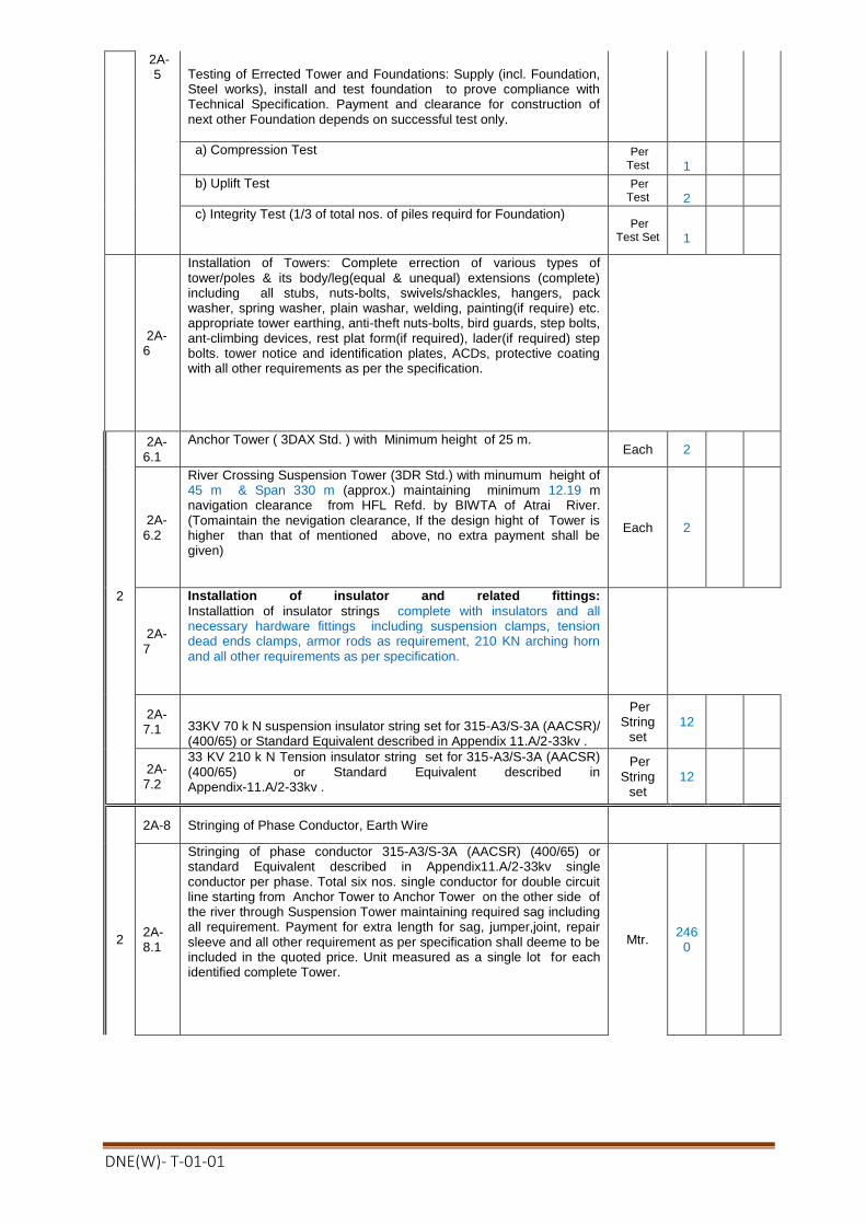
DNE(W)- T-01-01
2A-5 Testing of Errected Tower and Foundations: Supply (incl. Foundation,
Steel works), install and test foundation to prove compliance with Technical Specification. Payment and clearance for construction of next other Foundation depends on successful test only.
a) Compression Test Per Test
1
b) Uplift Test Per Test
2
c) Integrity Test (1/3 of total nos. of piles requird for Foundation) Per
Test Set
1
2A-6
Installation of Towers: Complete errection of various types of tower/poles & its body/leg(equal & unequal) extensions (complete) including all stubs, nuts-bolts, swivels/shackles, hangers, pack washer, spring washer, plain washar, welding, painting(if require) etc. appropriate tower earthing, anti-theft nuts-bolts, bird guards, step bolts, ant-climbing devices, rest plat form(if required), lader(if required) step bolts. tower notice and identification plates, ACDs, protective coating with all other requirements as per the specification.
2A-6.1
Anchor Tower ( 3DAX Std. ) with Minimum height of 25 m. Each 2
2A-6.2
River Crossing Suspension Tower (3DR Std.) with minumum height of 45 m & Span 330 m (approx.) maintaining minimum 12.19 m navigation clearance from HFL Refd. by BIWTA of Atrai River. (Tomaintain the nevigation clearance, If the design hight of Tower is higher than that of mentioned above, no extra payment shall be given)
Each 2
2
2A-7
Installation of insulator and related fittings:
Installattion of insulator strings complete with insulators and all necessary hardware fittings including suspension clamps, tension dead ends clamps, armor rods as requirement, 210 KN arching horn and all other requirements as per specification.
2A-7.1 33KV 70 k N suspension insulator string set for 315-A3/S-3A (AACSR)/
(400/65) or Standard Equivalent described in Appendix 11.A/2-33kv .
Per String
set 12
2A-7.2
33 KV 210 k N Tension insulator string set for 315-A3/S-3A (AACSR) (400/65) or Standard Equivalent described in Appendix-11.A/2-33kv .
Per String
set 12
2A-8 Stringing of Phase Conductor, Earth Wire
2 2A-8.1
Stringing of phase conductor 315-A3/S-3A (AACSR) (400/65) or standard Equivalent described in Appendix11.A/2-33kv single conductor per phase. Total six nos. single conductor for double circuit line starting from Anchor Tower to Anchor Tower on the other side of the river through Suspension Tower maintaining required sag including all requirement. Payment for extra length for sag, jumper,joint, repair sleeve and all other requirement as per specification shall deeme to be included in the quoted price. Unit measured as a single lot for each identified complete Tower.
Mtr. 246
0

DNE(W)- T-01-01
2A-8.2
Earth wire 7/(4.19-4.75) mm described in Appendix 11.A1/2-33kv BS-183 Grade 1000 with fixing clamps starting from Anchor Tower to Anchor Tower through Suspension Tower on the other side of the river maitaining required sag. Unit measured as a single lot for each identified complete Tower.
Mtr. 410
2A-9 Installation of other accessories:
2A-9.1
Installation of Vibration Damper for Conductor 315/A3/S-3A (AACSR) (400/65) or Standard Equivalent. Each 48
2A-9.2
Installation of Vibration Damper for Earthwire 7/(4.19 - 4.75) mm described in Appendix 11.A/2-33kv .BS 183 Grade 1000 . Each 8
2A-9.3
Installation of Aircraft obstruction lights solar powered complete with lamps, solar panels, batteries, control equipments, cables, support framework, tower work platforms etc.
Per Tower
2
2A-9.4
Installation of Aircraft warning sphere balls for the river crossing (330 m span). Each 12
2A-9.5
Painting of river crossing suspension towers in accordance with the requirements of the Technical specifications. Per
Tower 2
Sub Total = ###
Schedule No.-3. Design services
3 3A-1
All design, drawings for tower, tower foundations and other civil works(if any ) related to the 33 kV double circuit tower with BRTC (BUET)/CRTS (DUET)/ MIST approval. Documentation works include 05(Five) sets of As-built drawings and river crossing tower operation and maintenance manual(All other design cost shall deem to be included in the above item.)
Each packag
e(01 set)
1
Sub Total = ###
Schedule No.-4. Grand Summery
4 4A-1
Schedule No.-1 Materials to be Supplied for River Crossing Tower ###
Schedule No.-2. Installaion and other Services for River Crossing Tower ###
Schedule No.-3. Design services for River Crossing Tower ###
Grand Total(Tk.) ###
Grand Total in words: Four Crore Fifty Lac Twelve Thousand Five Hundred Ninety Nine and Sixty Six Poisa only
Note:
(1) All Costs of Equipment shall include Design, Adequacy Test, Factory inspection/material Test, Manufacture, Transportation to site including Insurance, VAT & all other Taxes (as applicable in the Employer's Country).
(2) All Costs of Works shall include Cost of Works including Insurance, VAT, Income Tax & all other Taxes (as applicable in the Employer's Country).
(3) All costs shall include the items / components as detailed in the document.
(4) Minimum Height of tower shall be as mentioned in the schedule. No extra payment shall be made if the Height and Span of the Tower & other items increased according to the design as requiredt for the respective site depending on the field condition. If the span of tower decreased according to the respective field condition then payment shall be given as actual span.

DNE(W)- T-01-01
Technical Proposal (Form PG5A-4)
[The Revised Technical Proposal, if any, shall follow the same format and structure]
Site Organization
Method Statement
Mobilization Structure
Construction Structure
Plant
Safety Plan
Personnel
Equipment
Proposed subcontractors for Major Items of Plant and Services
Time Schedule
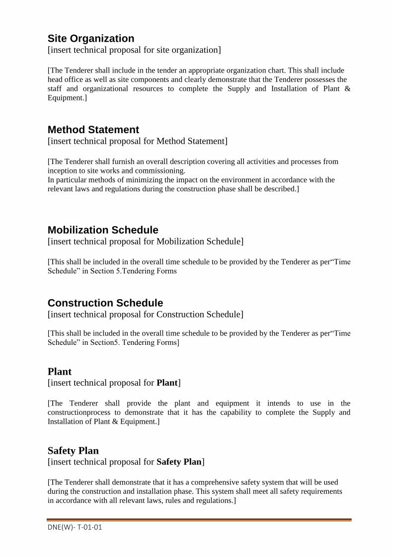
DNE(W)- T-01-01
Site Organization [insert technical proposal for site organization]
[The Tenderer shall include in the tender an appropriate organization chart. This shall include
head office as well as site components and clearly demonstrate that the Tenderer possesses the
staff and organizational resources to complete the Supply and Installation of Plant &
Equipment.]
Method Statement [insert technical proposal for Method Statement]
[The Tenderer shall furnish an overall description covering all activities and processes from
inception to site works and commissioning.
In particular methods of minimizing the impact on the environment in accordance with the
relevant laws and regulations during the construction phase shall be described.]
Mobilization Schedule [insert technical proposal for Mobilization Schedule]
[This shall be included in the overall time schedule to be provided by the Tenderer as per“Time
Schedule” in Section 5.Tendering Forms
Construction Schedule [insert technical proposal for Construction Schedule]
[This shall be included in the overall time schedule to be provided by the Tenderer as per“Time
Schedule” in Section5. Tendering Forms]
Plant [insert technical proposal for Plant]
[The Tenderer shall provide the plant and equipment it intends to use in the
constructionprocess to demonstrate that it has the capability to complete the Supply and
Installation of Plant & Equipment.]
Safety Plan [insert technical proposal for Safety Plan]
[The Tenderer shall demonstrate that it has a comprehensive safety system that will be used
during the construction and installation phase. This system shall meet all safety requirements
in accordance with all relevant laws, rules and regulations.]

DNE(W)- T-01-01
Personnel Information
[This Form should be completed for each person proposed by the Tenderer on Form PG5A-2a& PG5A-2b, where applicable]
Invitation for Tender No: [indicate IFT No]
Tender Package No [indicate Package No]
This Package is divided into the following Number of Lots [NIL]
A. Proposed Position (tick the relevant box)
B. Personal Data
Name
Date of Birth
Years overall experience
Years of specific experience
National ID Number
Years of employment with the Tenderer
B. Professional Qualifications:
1.
2.
C. Present Employment [to be completed only if not employed by the Tenderer]
Name of Procuring Entity:
Address of Procuring Entity:
Present Job Title:
Years with present Procuring Entity:
Tel No:
Fax No: e-mail address:
Contact [manager/personnel officer]:
D. Professional Experience
Summarise professional experience over the last twenty years, in reverse chronological order. Indicate particular technical and managerial experience relevant to the project.
From To Company / Project / Position / Relevant technical and management experience.
1
2
3
Name: [insert full name of signatory]
Signature with Date and Seal
In the capacity of: [insert designation of signatory]
[ Sign]
Duly authorised to sign the Tender for and on behalf of the Tenderer
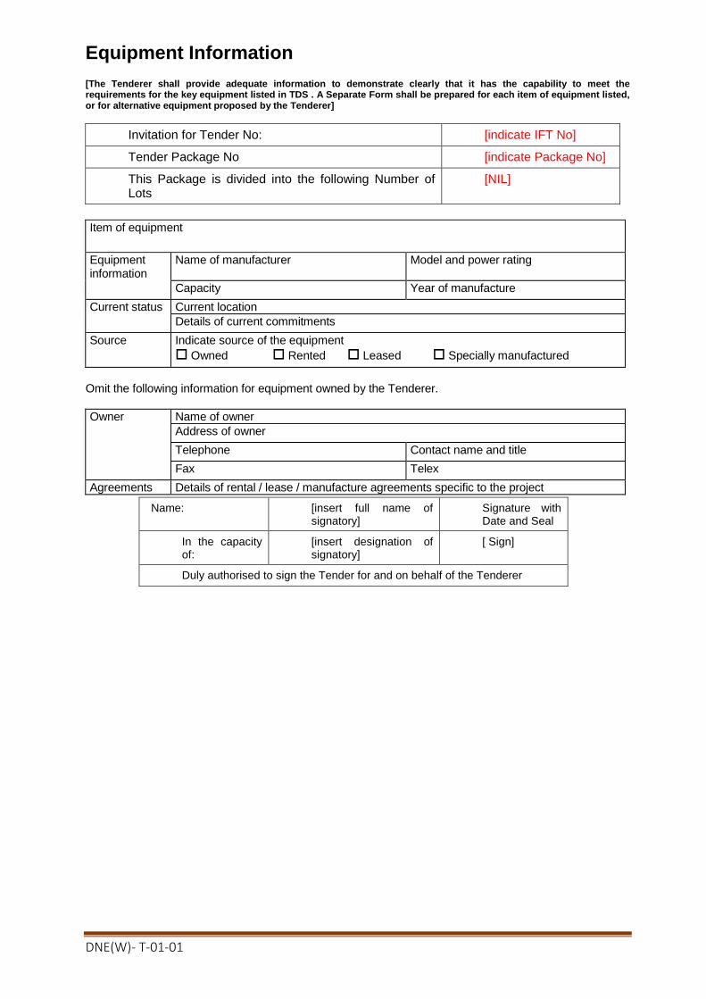
DNE(W)- T-01-01
Equipment Information [The Tenderer shall provide adequate information to demonstrate clearly that it has the capability to meet the requirements for the key equipment listed in TDS . A Separate Form shall be prepared for each item of equipment listed, or for alternative equipment proposed by the Tenderer]
Invitation for Tender No: [indicate IFT No]
Tender Package No [indicate Package No]
This Package is divided into the following Number of Lots
[NIL]
Item of equipment
Equipment information
Name of manufacturer Model and power rating
Capacity Year of manufacture
Current status Current location
Details of current commitments
Source Indicate source of the equipment
Owned Rented Leased Specially manufactured
Omit the following information for equipment owned by the Tenderer.
Owner Name of owner
Address of owner
Telephone Contact name and title
Fax Telex
Agreements Details of rental / lease / manufacture agreements specific to the project
Name: [insert full name of signatory]
Signature with Date and Seal
In the capacity of:
[insert designation of signatory]
[ Sign]
Duly authorised to sign the Tender for and on behalf of the Tenderer

DNE(W)- T-01-01
Proposed Subcontractors for Major Items of Plant and
Installation Services
A list of major items of Plant and Installation Services is provided below.
The following Subcontractors and/or manufacturers are proposed for carrying out the item of
the facilities indicated. Tenderers are free to propose more than one for each item
Major Items of Plant and
Installation Services Proposed
Subcontractors/Manufacturers Nationality
Form Functional Guarantee
The Tenderer shall copy in the left column of the table below, the identification of each
functional
guarantee required in the Specification and stated by the Employer in ITT 24(n) and in the
right column, provide the corresponding value for each functional guarantee of the proposed
plant and equipment.
Invitation for Tender No: [indicate IFT No]
Tender Package No [indicate Package No]
This Package is divided into the following Number of Lots [indicate number of ot(s)]
Required Functional Guarantee Value of Functional Guarantee of the Proposed
Plant and Equipment
1.
2.
3.
4.
5.
6.
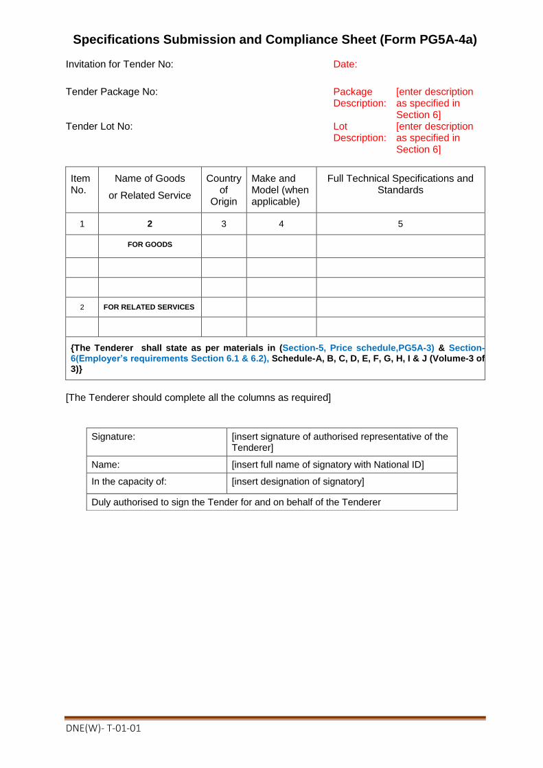
DNE(W)- T-01-01
Specifications Submission and Compliance Sheet (Form PG5A-4a) Invitation for Tender No: Date:
Tender Package No: Package Description:
[enter description as specified in Section 6]
Tender Lot No: Lot Description:
[enter description as specified in Section 6]
ItemNo.
Name of Goods
or Related Service
Country of
Origin
Make and Model (when applicable)
Full Technical Specifications and Standards
1 2 3 4 5
FOR GOODS
2 FOR RELATED SERVICES
{The Tenderer shall state as per materials in (Section-5, Price schedule,PG5A-3) & Section-6(Employer’s requirements Section 6.1 & 6.2), Schedule-A, B, C, D, E, F, G, H, I & J (Volume-3 of 3)}
[The Tenderer should complete all the columns as required]
Signature: [insert signature of authorised representative of the Tenderer]
Name: [insert full name of signatory with National ID]
In the capacity of: [insert designation of signatory]
Duly authorised to sign the Tender for and on behalf of the Tenderer

DNE(W)- T-01-01
Manufacturer’s Authorisation Letter (Form PG5A - 5)
[The Tenderer shall require the Manufacturer to fill in this Form in accordance with the instructions indicated. This letter of authorization should be on the letterhead of the Manufacturer and should be signed by a person with the proper authority to sign documents that are binding on the Manufacturer. The Tenderer shall include it in its tender, if so indicated in the TDS as stated under ITT Sub-Clause29.1(b)]
Invitation for Tender No:
Date:
Tender Package No:
Tender Lot No:
To: Name and address of Employer]
WHEREAS
We [insert complete name of Manufacturer], who are official manufacturers of[insert type of goods manufactured], having factories at [insert full address of Manufacturer’s factories], do hereby authorize[insert complete name of Tenderer] to supply the following Plant and Equipment, manufactured by us [insert name and or brief description of the Goods]. We hereby extend our full guarantee and warranty as stated under GCC Clause 42 of the General Conditions of Contract, with respect to the Goods offered by the above Tenderer. Signed: [insert signature(s) of authorized representative(s) of the Manufacturer] Name: [insert complete name(s) of authorized representative(s) of the Manufacturer] Address: [insert full address including Fax and e-mail] Title: [insert title] Date: [insert date of signing]

DNE(W)- T-01-01
Bank Guarantee for Tender Security (Form PG5A– 6) [this is the format for the Tender Security to be issued by a scheduled bank of Bangladesh as stated under ITT Clauses32 and 33] Invitation for Tender No:
Date:
Tender Package No:
Tender Lot No: To: [Name and address of Employer]
TENDER GUARANTEE No: We have been informed that [insert name of Tenderer] (hereinafter called “the Tenderer”) intends to submit to you its Tender dated [insert date of Tender] (hereinafter called “the Tender”) for the supply and installation of [description of plant and services] under the above Invitation for Tenders (hereinafter called “the IFT”). Furthermore, we understand that, according to your conditions, Tenders must be supported by a Bank Guarantee for Tender Security . At the request of the Tenderer, we [insert name of bank] hereby irrevocably and unconditionallyundertake to pay you, without cavil or argument, any sum or sums not exceeding in total an amount of Tk.[insert amount in figures and in words] upon receipt by us of your first written demand accompanied by a written statement that the Tenderer is in breach of its obligation(s) under the Tender conditions, because the Tenderer:
a. has withdrawn its Tender after opening of Tenders but within the validity of the Tender Security ; or
b. refused to accept the Notification of Award (NOA) within the period as stated under Instructions to Tenderers (ITT) ; or
c. failed to furnish Performance Security within the period as stipulated in the NOA; or d. refused to sign the Contract Agreement by the time specified in the NOA; or e. did not accept the correction of the Tender price following the correction of the
arithmetic errors in accordance with the ITT; or This guarantee will expire:
(a) if the Tenderer is the successful Tenderer, upon our receipt of a copies of the contract signed by the Tenderer and the Performance Security issued to you in accordance with the ITT; or
(b) if the Tenderer is not the successful Tenderer, twenty eight (28) days after the
expiration of the Tenderer’s Tender validity period, being [date of expiration of the Tender validity plus twenty eight(28) days]
Consequently, we must receive at the above-mentioned office any demand for payment under this guarantee on or before that date.

DNE(W)- T-01-01
Letter of Commitment for Bank’s undertaking for Line of Credit (Form PG5A-6a) [This is the format for the Credit Line to be issued by any scheduled Bank of Bangladesh in accordance with ITT Clause 15.1(b)]
Invitation for Tender No:
Date:
Tender Package No:
Lot No (when applicable) To: [Name and address of the Procuring Entity]
CREDIT COMMITTMENT No: [insert number]
We have been informed that [name of Tenderer] (hereinafter called “the Tenderer”) intends to submit to you its Tender (hereinafter called “the Tender”) for the execution of the Supply and Installation of
Plant & Equipment of[description of works] under the above Invitation for Tenders (hereinafter called “the IFT”). Furthermore, we understand that, according to your conditions, the Tenderer’s Financial Capacity i.e. Liquid Asset must be substantiated by a Letter of Commitment of Bank’s Undertaking for Line of Credit. At the request of, and arrangement with, the Tenderer, we [name and address of the Bank] do hereby agree and undertake that [name and address of the Tenderer] will be provided by us with a revolving line of credit, in case awarded the Contract, for execution of the Works viz. [insert name of works], for an amount not less than BDT [in figure]( in words) for the sole purpose of the execution of the above Contract. This Revolving Line of Credit will be maintained by us until issuance of “Taking-Over Certificate” by the Procuring Entity. In witness whereof, authorised representative of the Bank has hereunto signed and sealed this Letter of Commitment.
Signature
Signature

DNE(W)- T-01-01
Notification of Award (Form PG5A - 7) Contract No: Date: To: [Name of Contractor]
This is to notify you that your Tender dated [insert date] for the supply and installation of plant and Services for [name of contract] for the Contract Price of [state amount in figures and in words] as corrected and modified in accordance with the Instructions to Tenderers, has been approved by [name of Employer]. You are thus requested to take following actions:
i. accept in writing the Notification of Award within seven (7) working days of its issuance pursuant to ITT Sub-Clause 64.1
ii. furnish a Performance Security in the specified format and in the amount of Tk.[state amount in figures and words] ,within Twenty-eight (28) days from issue of this Notification of Award but not later than (specify date), in accordance with ITT Clause 64.3
iii. sign the Contract within twenty eight (28 ) days of issuance of this Notification of Award but not later than (specify date), in accordance with ITT Clause 69.2
You may proceed with the execution of the supply of Plant and Services only upon completion of the above tasks. You may also please note that this Notification of Award shall constitute the formation of this Contract, which shall become binding upon you.
We attach the draft Contract and all other documents for your perusal and signature.
Signed
Duly authorised to sign for and on behalf of [name of Employer]
Date:

DNE(W)- T-01-01
Contract Agreement (Form PG5A - 8) THIS AGREEMENT made the [day] day of [month][year] between [name and address of Employer] (hereinafter called “the Employer”) of the one part and [name and address of Contractor] (hereinafter called “the Contractor”) of the other part: WHEREAS the Employer invited Tenders for certain plant and services, viz, [brief description of plant and services] and has accepted a Tender by the Contractor for the supply of those plant and services in the sum of Taka [Contract Price in figures and in words] (hereinafter called “the Contract Price”).
NOW THIS AGREEMENT WITNESSETH AS FOLLOWS: 1. In this Agreement words and expressions shall have the same meanings as are
respectively assigned to them in the General Conditions of Contract hereafter referred to. 2. The following documents forming the Contract shall be in the following order of
precedence, namely : (a) the signed Form of Contract Agreement; (b) the Notification of Award (c) The Tender and the appendices to the Tender (d) Particular Conditions of Contract; (e) General Conditions of Contract; (f) Technical Specifications; (g) Drawings; (h) Price Schedules of Plant and Equipment and; (i) other document including correspondences listed in the PCC forming
part of the Contract 3. In consideration of the payments to be made by the Employer to the Contractor as
hereinafter mentioned, the Contractor hereby covenants with the Employer to provide the plants and related services and to remedy any defects therein in conformity in all respects with the provisions of the Contract.
4. The Employer hereby covenants to pay the Contractor in consideration of the provision
of the plant and services and the remedying of defects therein, the Contract Price or such other sum as may become payable under the provisions of the Contract at the times and in the manner prescribed by the Contract.
5. The Appendices listed in the attached List of Appendices shall be deemed to form an
integral part of this Contract Agreement. Reference in the Contract to any Appendix shall mean the Appendices attached hereto, and the Contract shall be read and construed accordingly.
IN WITNESS whereof the Employer and the Contractor have caused this Agreement to be duly executed by their duly authorized representatives in accordance with the laws of Bangladesh on the day, month and year first written above. Signed by, for and on behalf of the Employer
For the Employer: For the Contractor:
Signature
Print Name Title
In the presence of Name
Address

DNE(W)- T-01-01
Bank Guarantee for Performance Security (Form PG5A – 9) [This is the format for the Performance Security to be issued by an internationally reputable bank and it shall have correspondent bank located in Bangladesh, to make it enforceablein accordance with ITT Sub-Clause
67.1pursuant to Rule 27(4) of the Public Procurement Rules, 2008.]
Contract No:
Date:
To: [Name and address of Employer]
PERFORMANCE GUARANTEE No: [insert Performance Guarantee number] We have been informed that [name of Contractor] (hereinafter called “the Contractor”) has undertaken, pursuant to Contract No [reference number of Contract] dated [date of Contract] (hereinafter called “the Contract”) for the supply and installation of [description of plant and services] under the Contract. Furthermore, we understand that, according to your conditions, Contracts must be supported by a performance guarantee. At the request of the Contractor, we [name of bank] hereby irrevocably and unconditionally undertake to pay you, without cavil or argument, any sum or sums not exceeding in total an amount of Tk.[insert amount in figures and in words] upon receipt by us of your first written demand accompanied by a written statement that the Supplier is in breach of its obligation(s) under the Contract conditions, without you needing to prove or show grounds or reasons for your demand of the sum specified therein. This guarantee is valid until [date of validity of guarantee], consequently, we must receive at the above-mentioned office any demand for payment under this guarantee on or before that date. [Signatures of authorized representatives of the bank] Signature
Seal

DNE(W)- T-01-01
Bank Guarantee for Advance Payment (Form PG5A – 10) [this is the format for the Advance Payment Security to be issued by an internationally reputable bank and it shall have correspondent bank located in Bangladesh, to make it
enforceable in accordance with GCC Clause 57.1] Contract No:
Date:
To: [Name and address of Employer]
ADVANCE PAYMENT GUARANTEE No.: We have been informed that [name of Contractor] (hereinafter called “the Contractor”) has undertaken, pursuant to Contract No [reference number of Contract] dated [date of Contract] (hereinafter called “the Contract”) for the supply and installation of [description of plant and services] under the Contract. Furthermore, we understand that, according to your Particular Conditions of Contract Clause 26.1, Advance Payment(s) on Contracts must be supported by a bank guarantee. At the request of the Contractor, we [name of bank] hereby irrevocably unconditionally undertake to pay you, without cavil or argument, any sum or sums not exceeding in total an amount of Tk.[insert amount in figures and in words] upon receipt by us of your first written demand accompanied by a written statement that the Contractor is in breach of its obligation(s) under the Contract conditions, without you needing to prove or show grounds or reasons for your demand of the sum specified therein. We further agree that no change, addition or other modification of the terms of the Contract to be performed, or of any of the Contract documents which may be made between the Employer and the Contractor, shall in any way release us from any liability under this guarantee, and we hereby waive notice of any such change, addition or modification. This guarantee is valid until [date of validity of guarantee], consequently, we must receive at the above-mentioned office any demand for payment under this guarantee on or before that date.
[Signatures of authorized representatives of the bank]
Signature
Seal
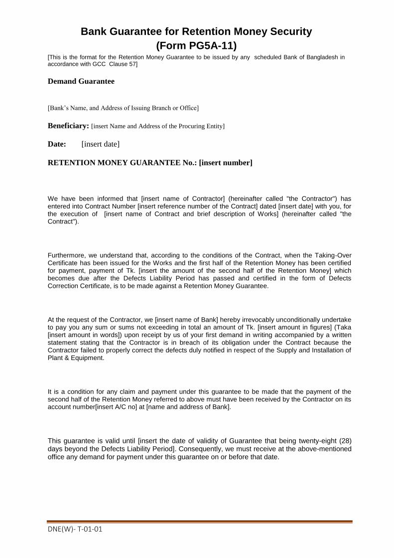
DNE(W)- T-01-01
Bank Guarantee for Retention Money Security
(Form PG5A-11) [This is the format for the Retention Money Guarantee to be issued by any scheduled Bank of Bangladesh in accordance with GCC Clause 57]
Demand Guarantee
[Bank’s Name, and Address of Issuing Branch or Office]
Beneficiary: [insert Name and Address of the Procuring Entity]
Date: [insert date]
RETENTION MONEY GUARANTEE No.: [insert number]
We have been informed that [insert name of Contractor] (hereinafter called "the Contractor") has entered into Contract Number [insert reference number of the Contract] dated [insert date] with you, for the execution of [insert name of Contract and brief description of Works] (hereinafter called "the Contract").
Furthermore, we understand that, according to the conditions of the Contract, when the Taking-Over Certificate has been issued for the Works and the first half of the Retention Money has been certified for payment, payment of Tk. [insert the amount of the second half of the Retention Money] which becomes due after the Defects Liability Period has passed and certified in the form of Defects Correction Certificate, is to be made against a Retention Money Guarantee.
At the request of the Contractor, we [insert name of Bank] hereby irrevocably unconditionally undertake to pay you any sum or sums not exceeding in total an amount of Tk. [insert amount in figures] (Taka [insert amount in words]) upon receipt by us of your first demand in writing accompanied by a written statement stating that the Contractor is in breach of its obligation under the Contract because the Contractor failed to properly correct the defects duly notified in respect of the Supply and Installation of Plant & Equipment.
It is a condition for any claim and payment under this guarantee to be made that the payment of the second half of the Retention Money referred to above must have been received by the Contractor on its account number[insert A/C no] at [name and address of Bank].
This guarantee is valid until [insert the date of validity of Guarantee that being twenty-eight (28) days beyond the Defects Liability Period]. Consequently, we must receive at the above-mentioned office any demand for payment under this guarantee on or before that date.

DNE(W)- T-01-01
Section 6. Employer’s Requirements(Volume-3 of 3)
Table of Contents Index to Section (Volume-3)
6.1 Scope of Works, General/Details Technical Specification and Employer’s Requirement
(Following section 1 -18)
Section Description Page
No.
Section -1 Scope of Work 182-184
Section -2 Site Particulars 185-187
Section-3 Quality Assurance 188-192
Section-4 Design Particulars 193-200
Section -5 Access 201-207
Section -6 Survey, Profile and Geotechnical Investigations 208-214
Section -7 Foundations 215-245
Section -8 Towers 246-277
Section -9 Insulators 278-290
Section -10 Insulator & Conductor Fittings 291-308
Section -11 Conductors 309-322
Section --12 Vibration Dampers 323-331
Section -13 Spacer Dampers 331
Section -14 Optical Fiber Cable & Fittings 331
Section -15 Aircraft Navigation (Obstruction Aids) 332-340
Section -16 Miscellaneous 341-342
Section -17 Packing, Protection and Dispatch Marking 343-345
Section -18 Method of Measurement & Payment 346-351
6.2 Particular Specification, Schedule and Employer’s Requirements. (Following schedule)
Section 6.2 Schedule A Manufacturers, Places of Manufacture and
Testing 353
Schedule B Technical particulars and Guarantees 354
Schedule C Departure from Specifications 359
Schedule D Proposed Alternative standards to which
Equipment shall provided 360
Schedule E Proposed Contract and site organization 361
Schedule F Key Personnel 362
Schedule G Equipment for Construction 363
Schedule H Proposed Sub-Contractors. 364
Schedule I Drawings and documents to be submitted with
Bid. 364
Schedule J Bar chart programme of key activities 366

DNE(W)- T-01-01
6.3 Form of Completion Certificate 367
6.4 Form of Operational Acceptance Certificate 368
6.5 Change Order Procedure and Forms 369
Annex 1. Request for Change Proposal 371
Annex 2. Estimate or Change Proposal 372
Annex 3. Acceptance of Estimate 373
Annex 4. Change Proposal 374
Annex 5. Change Order 376
Annex 6. Pending Agreement Change Order 377
Annex 7. Application for Change Proposal 378
Section .7 Drawing 379

DNE(W)- T-01-01
Volume 3 of 3
SECTION -1
SCOPE OF WORK
1.1 GENERAL
The Extent of Supply is described in the following clauses and in the respective Sections
of the Specification. All work not expressly called for in the Specification, but necessary
for the completion of the work shall be performed and furnished by the Contractor at no
additional cost to the Employer.
The Contract shall comprise the design, manufacture, testing, supply, insurance, delivery
to site of tower, phase conductor, including all associated fittings, complete insulator sets,
phase and earthwire tensionand non-tension joints and clamps, vibration dampers,
erection, setting to work, testing and the replacement and/or adjustment of defective
material and workmanship for the duration of the 24 months(from the date of Operational
acceptance) warranty period of the transmission line(s) detailed in the ‘Extent of Supply’
and associated Appendix 1.A1.
1.2 EXTENT OF SUPPLY
1.2.1 Scope
The Extent of Supply comprises the design, manufacture, testing, supply, insurance,
shipping, loading and unloading, delivery to site of complete tower and foundation
steelwork inclusive of all phase attachment swivels/shackles, tower mounted plates, anti-
climbing devices, foundation and earthing materials and conductor, insulator including
all associated fittings, check topographical survey and all associated profile plotting,
support pegging, provision of access facilities and route clearing, transportation to site,
ground investigation, installation of foundations and all associated civil works, erection
of towers, installation of insulators, conductors and all associated fittings, land clearance,
testing on site, setting to work and supply of spares, tools & equipment as set out in this
bidding document and at prices stated in the Schedules or at such other prices or unit
prices as may from time to time be agreed. The contract price shall also include training
of Employer’s personnel (overseas and local) as detailed in sub-clause18.1.12 and
witnessing of factory tests of materials by Employer’s engineers as detailed in sub
clause18.1.11 and in accordance with the Specification, Standards, Schedules and
accompanying Drawings and Maps defined in Appendix 1.A 1.
1.2.2 Estimated and Final Quantities
The quantities set out in the Schedules are, unless otherwise defined, estimated quantities
of the Works required. They are not to be assumed as the actual and final quantities to be
executed by the Contractor in fulfillment of his obligations under the Contract.
Final quantities are to be established by the Contractor, and agreed upon by the Employer,
within Twelve(12) months from the date of signing of the Contract, after the selection of
tower positions has been made on completion of the survey of the river sides.
1.2.3 Modifications
The river crossing Tower shall be completely in accordance with the Specification and
associated design and general arrangement/outline drawings. Any modifications
thereto are subject to written confirmation by the Employer/Engineer.

DNE(W)- T-01-01
1.3 TERMINAL POINTS
The terminal points for the supply and/or installation of the crossing Towers are
defined in Appendix 1.A2.
1.4 NOT USED FOR THIS TENDER.
1.5 CONTRACTUAL COMPLETION DATES
All the items of work under the scope of the contract shall be completed within the
completion time stated in Clause-24.1 of GCC,Volume 2 of 3.
1.6 PROGRAMME OF WORK
Within 2 (two) weeks of signing of the contract the Contractor shall submit to the
Employer for approval, 5 (five)copies of a bar chart detailing the plant manufacture,
testing, delivery and erection programme (as appropriate) for the complete Contract
Works.
The bar chart shall indicate the various phases of work for all appropriate items of the
Contract, from commencement of the Contract to its final completion e.g. Design,
survey, approval of drawings, ordering of materials, manufacture, testing, delivery,
erection and commissioning. The bar chart shall, when appropriate, allow the requisite
periods of approval by the Employer, and/or any other regulatory body.
If at any time during the execution of the Contract it is found necessary to modify the
approved bar chart, the Contractor shall inform the Employer and submit a modified
bar chart for approval. Such approval is not deemed to be consent to any amendments
to the contractual completion date(s).
Modifications which may affect site work and associated local arrangements must
provide a sufficient notice period to allow for any necessary re-arrangements. It should
be recognized that where certain power line outages for crossing purposes have been
specified, it may not be possible for these to be replanned due to system operational
constraints and this should be allowed for in the overall programme.
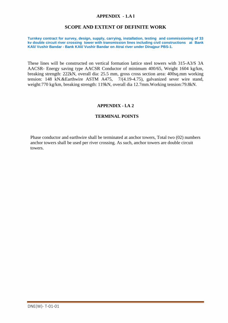
DNE(W)- T-01-01
APPENDIX - 1.A l
SCOPE AND EXTENT OF DEFINITE WORK
Turnkey contract for survey, design, supply, carrying, installation, testing and commissioning of 33 kv double circuit river crossing tower with transmission lines including civil constructions at Bank KAli/ Vushir Bandar - Bank KAli/ Vushir Bandar on Atrai river under Dinajpur PBS-1.
These lines will be constructed on vertical formation lattice steel towers with 315-A3/S 3A
AACSR- Energy saving type AACSR Conductor of minimum 400/65, Weight 1604 kg/km,
breaking strength: 222kN, overall dia: 25.5 mm, gross cross section area: 400sq.mm working
tension: 148 kN.&Earthwire ASTM A475, 7/(4.19-4.75), galvanized sever wire stand,
weight:770 kg/km, breaking strength: 119kN, overall dia 12.7mm.Working tension:79.8kN.
APPENDIX - l.A 2
TERMINAL POINTS
Phase conductor and earthwire shall be terminated at anchor towers, Total two (02) numbers
anchor towers shall be used per river crossing. As such, anchor towers are double circuit
towers.
DNE(W)- T-01-01
SECTION- 2
SITE PARTICULARS
2.1 GENERAL
The location of the transmission line(s) and associated climatic conditions described in
the following clauses are given for guidance only.
2.2 LOCATION
For details of the location of the river crossing tower reference should be made to
Appendix 2.A1 and associated drawings included with the specification.
2.3 CLIMATIC
For details of the climatic conditions associated with the site, reference should be made
to Appendix 2.A2. The Contractor is advised to make a thorough study of local
climatologically records, since no delays to the completion dates due to adverse
weather conditions shall be accepted.

DNE(W)- T-01-01
APPENDIX 2.A 1
“ Turnkey contract for survey, design, supply, carrying, installation, testing and commissioning of 33 kv double circuit river crossing tower with transmission lines including civil constructions at Bank KAli/ Vushir Bandar - Bank KAli/ Vushir Bandar on Atrai river under Dinajpur PBS-1.”
LOCATION OF TOWER AND TRANSMISSION LINES
Sl
No. Package No. Location of the Tower Site PBS Nane Name of Project Division
1 DNE(W)-T-01
33 kV Double circuit River
crossing at Bank KAli/ Vushir
Bandar - Bank KAli/ Vushir
Bandar on Atrai River.
Dinajpur
PBS-1
Office of The Executive
Engineer,
Dinajpur Project Division,
BREB.
Note: (1) Minimum navigation Clearance is from the Highest Flood level(HFL) of each river
crossing site.
(2) The base point for the navigation clearance i.e. HFL data can be collected from the local
office of the local/regional office/head quarter Bangladesh Inland water Transport
Authority and Bangladesh water Development Board(BWDB). Wind speed condition
shall be respective sites.
(3) Bidders can also visit the Flood Forecasting & Warning Center(http://www.ffwc.gov.bd/#
of Bangladesh Water Development Board(BWDB) for relevant information.

DNE(W)- T-01-01
APPENDIX 2.A2
CLIMATIC CONDITIONS
The following climatic information is given for tender purposes only:
Ambient shade temperature range : 5°C – 40°C
Maximum daily average temperature : 35°C
Relative humidity :
maximum : 100%
average : 80%
Rainfall : 2.5 m per annum
3 second gust wind speed with 1 in 50 yea
Keraunic level (thunderstorm days per year)
:
:
4.4 m/se
80
DNE(W)- T-01-01
SECTION 3
QUALITY ASSURANCE
3.1 GENERAL
3.1.1 The quality assurance arrangements shall conform to the appropriate sections of
BS EN ISO 9001-2000 or Equivalent.
3.1.2 The Contractor's/Supplier's Quality Programme for the Works shall define the systems
and procedures adopted to ensure compliance with the Contract requirements. These
systems shall include the following:
Hold Point "A stage in the implementation of project works including material
procurement or fabrication/workmanship process beyond which work shall not proceed
without the documented approval of the Engineer or their appointed representatives".
Notification Point "A stage in the implementation of project works including material
procurement or fabrication/workmanship process for which advance notice of the
activity is required to permit attendance".
3.1.3 The Contractor/Supplier is required to give the Engineer or their appointed
representatives the requisite period of notice of any Notification Point for which
attendance is required.
3.2 QUALITY ASSURANCE PROGRAMME
3.2.1 The Quality Assurance Programme shall give a description of the quality system for the
Works and shall include the following details:
(a) The structure of the Contractor's/Supplier's organization.
(b) The duties and responsibilities of staff assigned to ensure quality of the work.
(c) The system for purchasing, taking delivery and verification of materials.
(d) The system for ensuring quality of workmanship.
(e) The system for control of documentation.
(f) The system for retention of records.
(g) The arrangements for the Contractor's/Suppliers auditing.
(h) A list of the administrative and work procedures required to achieve and verify
the Contract's Quality requirements. These procedures shall be made readily
available to the Engineer for inspection on request.
3.2.2 The Quality Assurance programme for the Works shall be submitted to the Engineer for
approval within 4(four) weeks of signing of contract; unless the Contractor’s/Supplier's
Quality System has been previously audited and approved by the Engineer on behalf of
the Employer/Purchaser.
This is a Hold Point
3.3 QUALITY PLAN 3.3.1 A specific Quality Plan for each section of the work shall be produced by the contractor
and/or Supplier. Each Quality Plan shall set out the activities in a logical sequence and
shall take into account the following:
DNE(W)- T-01-01
(a) An outline of the proposed work and programme sequence.
(b) The structure of the Contractor's and/or Supplier's Organisation for the contract.
(c) The duties and responsibilities of staff assigned to ensure quality of work for the
contract.
(d) Hold and Notification points.
(e) Submission of engineering documents required by this Specification.
(f) The inspection of materials and components on receipt
(g) Reference to the Contractor's and/or Supplier's quality assurance procedures
appropriate to each activity.
(h) Inspection during fabrication/construction.
(i) Final inspection and tests.
3.3.2 The Contractor's and/or Supplier's Quality Plan shall be submitted to the Engineer for
approval within 4(four) weeks of signing of contract. This is a Hold Point.
3.4 RELATED STANDARDS
3.4.1 The IEC and BSI Standards, together with other references referred to in this
Specification are listed in Appendix-7.D1 of each appropriate section, it is the
Contractor's/ Supplier's responsibility to ensure they are in possession of the latest
edition, including all amendments current on the defined date prior to the tender closing
date.
3.4.2 Materials or equipment conforming to alternative international or national standards
will be considered by the Engineer, provided that these standards ensure an equivalent
or higher quality.
3.4.3 The Contractor/Supplier shall bring to the attention of the Engineer any inconsistencies
between the requirements of these Standards and this specification.
3.4.4 Where equivalent standard(s) are offered as an alternative, the Contractor/Supplier shall
provide two copies of English language translations of the standard(s) at no extra cost
to the contract.
3.5 QUALITY CONTROL
3.5.1 Inspection and Testing The prime responsibility for inspection and testing rests with Contractor/Supplier. The
inspection and acceptance of drawings, materials and workmanship; or the waiver of
inspection by the Engineer does not relieve the Contractor/Supplier of any obligations
or responsibilities to carry out the work in accordance with the Contract. The inspection
and testing shall be documented such that it is possible to verify that it was undertaken.
Records of inspection shall include as a minimum the contract identity, the name of
inspector/tester, date of inspection/test, operation/inspection, technique used,
acceptance standard and acceptability.
3.5.2 Type, Sample and Routine Tests Type, sample and routine tests shall be undertaken as appropriate on all components
supplied and/or installed under this contract, in accordance with the requirements of
this specification.
DNE(W)- T-01-01
3.5.3 Certificate of Conformity
Prior to the issue of the 'Release Certificate' or agreement to shipping,, the
Contractor/Supplier shall submit to the Engineer 3(three) copies of the completed
Certificate of Conformity (see Appendix 3.Al). The certificate shall be supported by
copies of the appropriate material test certificates, inspection records, type and sample
test reports as detailed in the relevant section of this specification.
3.6 NON CONFORMING PRODUCTS The Engineer shall review the non-conforming products in accordance with BS EN ISO
9001-2000 or Equivalent
3.7 MONITORING OF QUALITY ASSURANCE ARRANGEMENTS
3.7.1. Monitoring of the Quality Assurance Arrangements may be undertaken by the
Engineer/Employer during the course of the contract. This will take the form of
surveillance of the activities at work locations and/or by formal audits of the
Contractor's/Suppliers systems and procedures which constitute his Quality Assurance
Arrangements. Corrective actions shall be agreed and implemented in respect of any
deficiencies.
3.7.2 The Contractor/Supplier shall provide all facilities including access (including his
suppliers or Sub-Contractors), which may be required by the Engineer/Employer for
monitoring activities.
3.8 SUPPLIERS AND SUB-CONTRACTORS The Contractor/Supplier/JVC shall ensure that any suppliers or sub-contractors
appointed by him under the Contract, shall conform to the requirements of this
Specification. Prior to the appointment of any supplier/Sub-Contractor the
Contractor/Supplier shall ensure that their Quality Assurance Arrangements comply
with the requirements of BS EN ISO9001-2000 or Equivalent and this Specification.
The Contractor's auditing of his supplier's/sub-contractor's Quality Assurance
arrangements shall be documented to demonstrate to the Engineer their extent and
effectiveness.
3.9 METHOD STATEMENTS
Prior to commencing any section of the work, the Contractor shall submit method
statements in accordance with the requirement of the relevant section of this
Specification. Submission of these method statements shall be treated as Hold Points.
When requested by the Engineer or their appointed representatives, additional method
statements related to specific items of work shall be provided by the Contractor.

DNE(W)- T-01-01
APPENDIX 3.A1
CERTIFICATE OF CONFORMITY
To:
Superintending Engineer (Project),
------------------------- Zone, BREB.
*To be marked for the attention of....................................................................
CONTRACT NO. ...........................................................................................
We certify that the products detailed below have been inspected, tested and unless
noted to the contrary, conform in all respects to the requirements.
QUANTITY DESCRIPTION
Please tick
ATTACHMENTS
Test reports (details) -----------------------------------------------------
(Other details as per
relevant section) ----------------------------------------------------
Dated ---------------------------------- Signed --------------------------------
Status --------------------------------

DNE(W)- T-01-01
APPENDIX 3.B1
ENGINEERING DOCUMENTS TO BE SUBMITTED BY THE CONTRACTOR
Clause Reference
Documents Description Comment
3.2.2
3.3.2
Quality Assurance Programme
Quality plan
3.4.4 Equivalent Standards If applicable
APPENDIX 3.C1
NOTIFICATION AND HOLD POINTS
Clause Reference Notification Points Hold Point
3.2.2
3.3.2
Quality Assurance
Programme
Quality Plan
APPENDIX 3.Dl
REFERENCE STANDARDS
The reference standards and other documents referred to in this Section of the Specification are
listed below:
BS EN ISO 9001-2000 Model for quality assurance in design, development, production,
or Equivalent. installation and servicing.

DNE(W)- T-01-01
SECTION -4
DESIGN PARTICULARS
4.1 PHILOSOPHY OF DESIGN
The philosophy of design contained within this specification is based upon deterministic
principles, whereby the applied loading multiplied by the appropriate safety factor must be
less than the ultimate strength of the component.
In tendering the Contractor/Supplier will be deemed to have concurred, as a practical
manufacturer, with the design and layout of the Works as being sufficient to ensure
reliability and safety in operation, freedom from undue stresses and satisfactory
performance in all other essentials as a working plant.
The river crossing tower shall be designed with high reliability and low cost maintenance as
the primary consideration in accordance with the relevant sections of the Specification.
The design shall incorporate all reasonable precautions and provisions for the safety of those
concerned in the erection and subsequent maintenance of the Contract Works.
4.2 UNITS OF MEASUREMENT
In all correspondence, technical schedules, design calculations and drawings, the metric (SI)
units of measurement shall be used. Angular measurement shall be degrees, with 90°
comprising a right angle.
4.3 DOCUMENT SUBMISSIONS The Contractor/Supplier shall submit to the Engineer all design calculation drawings,
method statements, test programmes, test records etc as defined in Appendix 4.B1 of the
relevant sections of the Specifications, or as otherwise agreed by the Engineer. For details of
the number of copies and time periods for approval, reference should be-made to Appendix
4.A1.
4.4 DESIGN CALCULATIONS :
All sets of calculations shall be complete, bound, properly titled and given a unique drawing
number (see Clause 4.5.1). The binding shall be such as to allow the easy introduction of
subsequent pages if necessary.
Bound into each set shall be a fully detailed index. Following this shall be a Design
Information sheet(s)which shall incorporate the following details:
(a) The design concept shall be summarized;
(b) Full details of manuals, design papers or other aids referred to in the text shall
be given, with photocopies of relevant sheets if appropriate;
(c) Full loadings shall be reiterated, with their derivation if appropriate;
(d) Design stresses shall be reiterated;
(e) Code or standard references should be quoted, and equations written out in full for
initial calculations;
Should the Contractor/Supplier be required to re-submit amended calculation or
additional sheet(s), the following annotation shall be adopted.
(f) Amended sheets should retain the same sheet number, but have a lower case revision
letter suffix i.e. sheet 14 when amended becomes 14a, then 14b.

DNE(W)- T-01-01
(g) Additional sheets that needed to be inserted shall be given the sheet number they are
added to, plus an upper case letter prefix i.e. additional sheets to piece 60 become A60,
B60 etc. and if subsequently amended A60a etc.
Where computer programs are used for design calculations a full explanation in the
English language shall be provided to assist the Engineer's approval of the calculations
for each and every program used. Details must include name of program, author, source,
comprehensive description of theoretical basis including all references to relevant
documentation, checks undertaken on program and a list of projects on which the
program has been used.
4.5 DRAWINGS
4.5.1 General Requirements
Drawing shall be to scale, fully detailed and all dimensions shall be in Metric Units.
General arrangement drawings submitted shall be to a scale of not less than 1 to 50 and
all detailed drawings not less than 1 to 20. Profile drawings shall normally be drawn to
vertical scale of 1 to 200 and a horizontal scale of 1 to 2,000.
Drawings sheets shall conform in size to BS 3429, main A0, Al, A2, A3 and A4.
The sheet size is to be stated on the drawing within or adjacent to the title block
Drawings shall be to BS 308 or equivalent.
The scale used shall be stated on the drawing as a ratio together with a linear scale at a
convenient position along the margin of the original drawing sheet.
The physical draughting requirements in respect of line density, strength, contrast,
spacing and character liability shall be met to ensure drawings are suitable for
microfilming in accordance with BS 5536 and the Specification for micro-copying, of
drawings to BS 4210
All drawings shall bear a title in English, serial number of the main Contract, drawing
number shall be unique to this Contract and scale. The system of numbering and layout
of the title block will be to the approval of the Engineer. The title block shall include
the name and address of the Employer and the Engineer. The revision notes shall detail
the nature of each revision. The revision shall be enclosed in a cloud with the revision
letter indicated.
4.5.2 Computer Generated Drawings
The submission of computer generated drawings(Shop drawing in Auto-Cad format)
by electronic transmission or in diskette format shall be subject to agreement by both
the Employer/Purchaser and the Engineer.
4.5.3 Contract Drawing List
At defined intervals the Contractor/Supplier shall submit the requisite number of copies of
the Contract Drawing List.
The list shall contain the following information:
(a) Drawing number;
(b) Drawing title;
(c) Revision status;
(d) Approval status.
All changes since the previous issue shall be clearly indicated and when agreed only the
front (index) sheet and revised sheets need to be submitted.

DNE(W)- T-01-01
4.5.4 Contract Record Drawings
The Contractor/Supplier/ JVC shall submit to the Engineer:
(a) A final issue of the Contract Drawing List indicating which of the drawings,
design calculations, method statements etc. he proposes to issue as final contract
drawings. These drawings shall be updated to incorporate all modifications
made during erection and commissioning.
(b) Requisite number of prints of each schedule, including where appropriate the
Supply and Installation Material Manual.
(c) Requisite number of drawings, including design calculations, schedules
including the supply and Installation Material Manual in diskette format in
either WPG or DXF format.
(d) Requisite number of polyester/transparency film copy of each drawing,
including design calculations, profiles and route maps.
The distribution of the contract record drawings will be advised by the Engineer.
4.5.5 Route Maps
During, the progress of the work the Contractor shall record on profiles of tower Supply
Installation Material Manual (SIMM's) and on a set of Survey Maps of approved scale
such particulars as will allow an accurate reference to be made afterwards in case of any
faults or projected modifications to the line.
The map and/or profile sheet shall show the exact position of every tower with approved
reference marks. The maps shall be supplemented, or profiles marked by sketches where
necessary, to delineate boundary positions of towers which cannot be clearly indicated on
the maps.
The date included on the maps, profile, sketches and SIMMs shall be submitted to the
Engineer, to whom facilities shall be given for examining such records during the progress
of the work.
4.6 SAG TEMPLATES
The Contractor shall supply the specified sets of templates in strong, stable colorless
plastic or similar material not less than 3mm thick. Engraving shall be on the back face of
the templates. The templates shall be for the specified equivalent spans, reference
Appendix 4.A.2.
Each template shall be accurately shaped to provide the sag curve, to the appropriate
scales of the conductor in still air at maximum temperature. The same curve shall be
engraved on the template at a distance below representing the minimum allowable vertical
clearance to normal ground. A further sag curve in still air at minimum temperature shall
also be shown. Each template shall be clearly endorsed with the sagging basis, conductor
particulars, equivalent span and unless otherwise specified to a scale of 1:200 vertical and
1:2000 horizontal.
Templates shall be supplied to the Engineer before the submission of the profiles. Failure
to do so may result in delay which will be responsibility of the Contractor
4.7 SUPPLY AND INSTALLATION MATERIAL MANUAL
As soon as final support positions have been selected and approved, the Contractor shall
provide the requisite copies of the A4 size Supply and Installation Material Manual
(SIMM).
Each tower position shall be represented by one sheet of the, manual with the following
information recorded:
(a) Provisional and final tower numbers;
DNE(W)- T-01-01
(b) Profile and Record Map reference drawing numbers;
(c) Span;
(d) Wind span;
(e) Weight span;
(f) Angle of deviation;
(g) Tower type, leg and body extensions and general arrangement (G.A.) drawing
reference numbers;
(h) Foundation type and G.A. drawing reference number;
(i) Earthing details and G.A. drawing reference number;
(j) Insulator set details and G.A. drawing reference number;
(k) Sag adjustment setting, and linkage requirements - (where appropriate);
(l) Phase conductor jumper details including spacer and general arrangement
drawing reference number - (where appropriate);
(m) Earthwire set details and G.A. drawing reference number;
(n) Earthwire vibration damper G.A. drawing reference number;
(o) Aircraft Navigation (obstruction aids) drawing reference number - (where
appropriate);
(p) Fibre optic junction boxes and cabling G.A. drawing reference number - (where
appropriate);
In addition the following schedules shall be included:
i) Phase conductor and earthwire sags and tensions (erection and final);
ii) Suspension insulator set off-sets;
iii) Location and spacing of phase conductor spacers and spacer dampers (where
appropriate);
iv) Location of all phase conductor and earthwire tension and non tension joints;
v) Location and spacing of all aircraft warning spheres (where appropriate);
vi) Location of all fibre optic joint boxes - (where appropriate);
The appropriate reference drawing numbers shall also be included. Preliminary copies
of SIMMs shall be available prior to any site work commencing, together with material
summaries.
This is a Hold Point.
4.8 MAINTENANCE MANUAL
The Contractor/Supplier shall provide at the specified period before the end of the
construction period of the Contract, a maintenance manual covering, the following
information:-
(a) Type, code number and description of all plant erected, together with names and
addresses of manufacturer;
(b) Methods of assembly of all fittings;
(c) Method of replacing any part of the plant including the use of maintenance holes
provided on the support, access provisions and where appropriate the application of 'live-
line' maintenance techniques;
(d) Recommendations of preventive maintenance including frequency of inspections;
(e) List of recommend maintenance equipment with a description of its use and limitations;
(f) Type and application of temporary earthing equipment;
(g) Personnel safety equipment requirements and any risk assessments required.
The above information must be specified in this Contract and entirely in the English
language.

DNE(W)- T-01-01
Drawings and diagrams shall be used where necessary to enable the Employer/Purchaser
properly to maintain the whole of the Works.
The manual shall be suitably bound within a hard cover and all materials used shall be
reasonablyhard wearing. The manual shall be submitted to the Engineer.
This is a Hold Point
4.9 SAMPLES AND MODELS
If the nature of the Works makes it desirable, the Contractor/Supplier may be asked to
submit or prepare for the Engineer such samples, patterns and models as the Engineer may
reasonably require for the purpose of design approval at the expense of the
Contractor/Supplier.
4.10 PHOTOGRAPHS
The Contractor/Supplier shall make all arrangements to provide progress photographs of all
tests and such sections of the work in progress as directed by the Engineer. Each
photograph shall be of size 25cm X 20cm suitably entitled. The negatives of the
photographs shall be the property of the Employer/Purchaser and no prints from these
negatives shall be supplied to any persons unless under the Authority of the
Employer/Purchaser.
The Contractor/Supplier will normally be required to provide every month at his own cost
the 3(three) sets of unmounted progress photographs suitably inscribed, on portions of the
Work- in progress, throughout the period of construction. Any variation to these quantities
will only be with the permission of the Engineer.

DNE(W)- T-01-01
APPENDIX 4.A 1
TIME INTERVALS FOR DOCUMENTS SUBMISSION, OR TEST &
INSPECTION NOTIFICATION AND NUMBER OF SUBMISSION COPIES
Item Time intervals
(weeks)
Notification
Period (Days)
No. of Copies
Submission of :
Contract Drawing List 4 - 5
Maintenance Manual 34 - 10
Method Statement
- Overall 12 - 5
- Detailed 4 - 5
Programme of Works
Programme of Reports (Weekly) 1 - 5
(Monthly) 4 - 5
Quality Assurance Programme 4 - 5
Quality Plan 4 - 5
Preliminary Supply & Install
Material Manual 12 - 5
Time Intervals
Currency of Standards 4 - -
Drawing Approval 3 - -
Profile Approval and Commencement
of Site Work
X - -
Commencement of Work after issue of
Notice
1 - -
Suspension of Work 1 - -
Notification of Periods:
Type Tests - Overseas - 28 -
- Local - 7 -
Sample Test – overseas - 14 -
Inspection of Work on Site - 3 -
Final Line Inspection - 14 -
Commencement of Survey - 7 -
Stringing of Conductor across roads
etc.
- 7 -
Copies:
Drawings for Approval - - 5
Approved Drawings0 - - 5
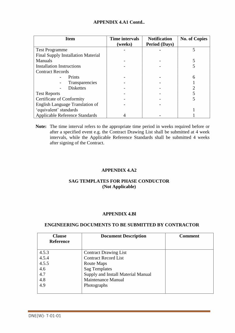
DNE(W)- T-01-01
APPENDIX 4.A1 Contd..
Item Time intervals
(weeks)
Notification
Period (Days)
No. of Copies
Test Programme - - 5
Final Supply Installation Material
Manuals - - 5
Installation Instructions - - 5
Contract Records
- Prints - - 6
- Transparencies - - 1
- Diskettes - - 2
Test Reports - - 5
Certificate of Conformity - - 5
English Language Translation of
‘equivalent’ standards
- -
1
Applicable Reference Standards 4 - 1
Note: The time interval refers to the appropriate time period in weeks required before or
after a specified event e.g. the Contract Drawing List shall be submitted at 4 week
intervals, while the Applicable Reference Standards shall be submitted 4 weeks
after signing of the Contract.
APPENDIX 4.A2
SAG TEMPLATES FOR PHASE CONDUCTOR
(Not Applicable)
APPENDIX 4.Bl
ENGINEERING DOCUMENTS TO BE SUBMITTED BY CONTRACTOR
Clause
Reference
Document Description Comment
4.5.3
4.5.4
4.5.5
4.6
4.7
4.8
4.9
Contract Drawing List
Contract Record List
Route Maps
Sag Templates
Supply and Install Material Manual
Maintenance Manual
Photographs

DNE(W)- T-01-01
APPENDIX 4.Cl
NOTIFICATION AND HOLD POINTS
Clause
Reference
Notification Points Hold Points
4.7
4.8
Supply and Install
Material Manual
Maintenance Manual
APPENDIX 4.Dl
REFERENCE STANDARDS
The reference standards and other documents referred to in this Section of the specification are
listed below:
BS 308 : Engineering drawing practice
BS 3429: Specification for size of drawing sheets
DNE(W)- T-01-01
SECTION 5
ACCESS
5.1 WAYLEAVES
5.1.1 General
Way leaves and access facilities subject to the requirements of landowners
and occupiers, will be provided by the Employer to enable the Contractor to
carry out the erection of the Contract Works but such facilities will not
necessarily include facilities for storing material nor necessarily include
access for wheeled vehicles.
The Contractor will satisfy himself that the necessary rights of entry and access have been
obtained before entry is effected.
The Contractor shall indicate to the Engineer such pipes or other obstructions, telephone,
telegraph and power lines which infringe the clearances specified or otherwise fail to
satisfy the requirements of the Specification.
The necessary permission for the removal of obstructions such as trees and for the
permanent removal or guarding of pipes, telegraph, telephone and power lines will be
obtained by the Employer.
5.1.2 Way leave Schedule
(Not Applicable)
5.2 ACCESS TO SITE, NOTICE OF ENTRY
5.2.1 Access Routes – General
The Engineer may indicate to the Contractor the general route for access to each or any
position as agreed by the Employer, otherwise the Contractor shall make all necessary
arrangements (other than questions of way leaves) with the occupier.
Subject to the provisions of the preceding paragraph the Contractor shall before
commencing work-, at his own expenses, do what is necessary to make the access suitable
for his use and shall take all reasonable precautions to avoid damage, including, if
required the erection of temporary fences or gates where permanent fences, hedges or
gates have been removed. The Contractor shall not be entitled to any additional payment
in the event of a particular access being difficult.
The Contractor shall be responsible for maintaining agreed access routes, without undue
widening, in a usable condition for the duration of the Contract and the occupier shall not
be put to any inconvenience in gaining access to his land or buildings. No unauthorized
access route shall be taken by the Contractor.
5.2.2 Commencement of Work
The Contractor shall be responsible, before beginning work on any property for
obtaining confirmation from the Engineer that wayleaves are in order and any agreed
accesses, have not been altered and for giving not less than 48 hours notice to the
occupiers that work is to begin. Work shall proceed on any land within the requisite
period of such notice being given to the occupier.
DNE(W)- T-01-01
5.2.3 Suspension of Work Where work is to be suspended without the expectation of it being resumed within the
specified period, the Contractor must notify the occupier of such intention and shall
similarly give the occupier prior notification of the resumption of work. The purpose of
this Clause is to assist in maintaining good relations between the occupier, the
Contractor and the Employer and to keep the occupier informed of what is going to
happen on or across his land.
5.2.4 Compliance with Occupier's Requirements The Contractor shall at all times during the execution of the Works ensure compliance
with all such reasonable requirements of the occupier as are brought to the Contractor's
notice by the Engineer. The Contractor shall not be entitled to any additional payment
in respect of his compliance with the reasonable requirements of the occupier.
5.2.5 Notice to Authorities Before the Contractor carries out the stringing of conductors alone, or across the river,
he shall give the requisite notice to the appropriate Authorities of the time and date
when he proposes to perform the work and shall send a duplicate copy of each notice to
the Engineer.
5.3 ROUTE CLEARANCE
For details of the clearance requirements for survey, access routes, tower locations and
conductor stringing reference shall be made to Appendix 5.Al.
5.4 ACCESS ROADS
Access roads/routes shall be identified by the contractors themselves or/where
necessary, and shall be constructed by them at their own expenses and necessary
compensation for damages thereof shall also be paid by contractor. The Employer’s
representative shall assist the contractor in his negotiations with the land owners about
such compensation etc.
5.5 CROSSING OF OBSTACLES
5.5.1 General
The Contractor shall, at his own expense, make any necessary arrangements and take
the necessary precautions for over coming any obstructions or ground over or across
which erection cannot be carried out in the normal manner or has to be avoided. These
arrangements must be submitted to the Engineer.
This is a Hold Point.
Where a tower is set across a fence, hedge, bank or wall, the Contractor shall remove
and reinstate the fence, hedge, bank or wall at his own expense and he shall be
responsible at his own expense for making good to the satisfaction of the Engineer,
owners and tenants concerned, all land, property, roads, drains, fences, walls, hedges,
gates and the like which he has damaged or disturbed during the execution of tile
Contract Works and shall remove all surplus material after erection. The Contractor
shall take proper precautions to prevent the straying of and damage to livestock until
after the backfilling of excavations and permanent reinstatement of fences, walls,
hedges, gates and the like is completed.
5.5.2 Public Utilities

DNE(W)- T-01-01
The Contractor shall ensure that the erection of the Contract Works does not cause
damage to or interference with existing telecommunication, power or pipe lines.
Where appropriate Authorities affected deem it necessary for the protection of their
employees, property, or the public or for the assistance of traffic to provide flagmen
and watchmen, the cost of such provision shall be borne by the Contractor. Where
required by the appropriate Authorities work shall be carried on outside normal hours
and at the Contractor's own expense.
The Contractor shall also be liable to make good at least to the original condition or
compensate the owners, operators and users or any public undertaking in respect of any
damage however caused to their property, lands or roads arising, out of or in
consequence of the execution of the Works.
5.5.3 Scaffolding
The Contractor shall provide all necessary scaffolding and the like for the crossing of
telecommunications or power lines, roads, railways buildings or other obstacles. The
Contractor shall advise the Engineer in each instance of the scaffolding he proposes to
use. Drawings of the proposed scaffolding shall be submitted to the Engineer, and the
appropriate regulatory authorities for approval.
This is Hold Point.
5.5.4 Live Line Scaffolds
The scaffolding which is used to cross specified low, medium and high voltage power
lines shall be of such dimensions and allow such clearances that the power lines being
crossed may remain in commission during construction of the new transmission line.
Shut-downs on the lines to be crossed may be given for construction of new line shall not
be given continuously for longer periods. Such restrictions in building and use of the
scaffolds not be grounds for claiming additional costs. Design and construction of the live
line scaffold shall not be inferior to the minimum standards outlined in the following
clause.
5.5.5 Live Line Scaffold-Construction
The scaffold shall be designed to withstand the maximum design wind speed, except that a
reduced return period will be accepted. Consideration shall also be given due to impact
loading, due to dropping of the upper phase conductor.
The scaffold shall, unless otherwise approved by the Engineer, consist of 3 m wide 300
mm square mesh nylon nets attached to steel wire ropes running perpendicular to the
lower line route, carried by metal scaffolding at 3 m intervals. The nets shall be attached
to the catenary wires by means that do not require the presence of any persons on the net
or the catenary wires whilst the lower line is alive.
An additional movable 3 m 50 mm mesh walk net laid over the 300 mesh nets may be
used whilst the lower line is dead.
Normally steel or aluminum tubular scaffolding to BS 1139 and BS 6323, should be used,
the use of preformed units or frames shall be subject to the Engineer’s approval.
The mechanical construction shall be in accordance with BS 5950. Reference shall also be
made where appropriate to BS 5973.

DNE(W)- T-01-01
The design of the scaffold shall have due regard to the requirements of safety with
particular respect to accidental contact with live conductors during construction, use and
removal.
The scaffold including foundations shall be designed and constructed to ensure stability
during the process of erection and removal, and also at times when work has ceased for
any reason including adverse weather conditions. The foundations shall be suitable for the
ground concerned.
The scaffold shall extend at least 5 m either side of the outermost conductors of the upper
line. a maximum of 2 m of this distance may be provided by means of catchers.
Catchers shall be provided at each end of each scaffold support. The catchers may be
vertical or inclined to a maximum angle of 45o from the vertical. They shall be capable of
withstanding the specified impact loads without excessive distortion that would permit a
falling conductor to approach or touch a live-line.
The upper parts of the scaffold shall be provided with soft wood rubbing boards or
otherwise protected in an approved manner to prevent damage to the conductors resting
on or being drawn over the guard. Soft wood poles may be used for this purpose. The
height of these boards shall be sufficient to prevent the conductor damaging the nylon net.
To avoid damaging the conductors no object other than non-metallic lashing or the
catchers shall protrude above the rubbing boards.
Sufficient endless or double ended lead lines for hauling over pilot wires shall be placed
over the scaffold prior to re-energisation of the lower line.
The side supports shall have working platforms to facilitate the required running of
conductors and pilot wires. Working platforms shall be provided with hand rails, toe
boards and notices warning of the danger of live conductors. The heights of hand rails
shall be 01 m and the toeboards 230 mm. Each working platform shall have a notice plate
indicating the 'Safe Climbing Height'.
The scaffolds shall be fitted with danger plates at intervals of not more than 6 m along the
anti- climbing device with at least one plate on each face of the structure.
The scaffolds shall be constructed to prevent unauthorised access or climbing by the use
of barbed wire anti-climbing devices, fences or other means approved by the Engineer.
The scaffolding shall be lit with red warning lamps from ½hour before sunset to ½ hour
after sunrise if erected within 2m from a highway or footpath without an intervening fence.
The scaffold contractor shall provide or arrange for the supply and/or maintenance of
these lamps (e.g. with the line contractor).
If the scaffolding is constructed adjacent to a roadway, a guard constructed from steel
drums filled with soil or a soil bund shall be provided and suitably lit.
Where possible the resistance to earth of the scaffold shall be less than 10 ohms. Special
consideration by the Engineer and the lower line operator shall be given in cases where this
is not attainable with a reasonable number of driven earth rods.
Bonding the scaffold to the earthing systems of either the live-line, or the line under
construction is not normally acceptable. In the former case a nearby line fault could cause
the scaffold to become live. In the latter case a fault between the live-line and the scaffold

DNE(W)- T-01-01
could cause components of the line under construction to become alive, particularly as it
earthing system may not be complete.
The earth rods should normally be driven into the ground around the outside and
approximately 1m from the scaffold structure. The rods should be securely connected
electrically and mechanically to the scaffold structure by flexible copper or aluminium
leads with minimum cross-sectional areas of 64 sq.mm or 100 sq.mm respectively.
Drawings of the scaffold, complete with details of the clearance plates and earthing
arrangement, together with supporting, calculations shall be submitted to the Engineer and
appropriate regulatory authorities for approval.
This is a Hold Point.
5.6 DAMAGE
5.6.1 General
The Contractor shall take all reasonable precautions to avoid damage to land, property,
roads, crops, field drains, fences walls, hedges, gates, trees and the like and shall ensure
that the work is adequately supervised so that any damage is reduced to the minimum
Save as otherwise provided, the Contractor will be liable for all damage arising by or in
consequence of the Works including damage to crops, trees house and shall pay
compensation or make good the same, as applicable.
5.6.2 Contractor's Responsibility
The Contractor's liability for loss or damage shall extend to any such loss or damage
resulting from the employment of a Subcontractor. This does not relieve the Contractor of
his liability for all actions of his Subcontractor.
5.6.3 Livestock, Dogs Adequate provision shall be made by the Contractor to prevent the straying of or injury to
livestock during the execution of the Works and until the permanent reinstatement of
fences, walls, hedges, gates and the like is completed.
The Contractor shall not bring any dog on or near the site or suffer or permit any of his
employees, representatives or agents or any Subcontractor to bring any dog on or near the
site and shall cause the immediate removal of any dog which may be on or near the Site in
breach of this provision.
The Contractor shall be liable for any injury to or loss of livestock due in the opinion of
the Engineer to failure to comply with the above requirements

DNE(W)- T-01-01
APPENDIX 5.Al
ROUTE CLEARANCE
Where clearing is in the opinion of the Engineer necessary, the following requirements
shall be observed. Trees and tall scrub shall be cleared to a distance of 14 m on either side
of the centre-line of the route. Trees and bushes shall be cut down to a height of not more
than 1.0 m above ground level. In addition, tall trees outside the cleared area, of such
height that they could fall within 2 m of conductors shall be trimmed by the Contractor.
No tree may be felled without the express permission of the Engineer.
This is a Hold Point.
Felled trees and scrub shall be removed from a path 3.5 m wide and running as far as
possible continuously along the route. The Contractor shall grub up tree stumps and roots
from this track and leave a graded way for negotiation by Landrover, Unimog, or similar
four-wheeled drive light vehicle for partrolling and maintenance by the Employer.
All trees, bushes, bamboo and any other vegetation, which normally grows to a height of
2.5 m or more, shall be treated by an approved non-toxic, non-residual agent to prevent
further growth.
The Contractor shall clear a 3.5 m wide agreed construction access track from public
roads, of all trees, stumps, scrub and vegetation to tower positions as required by the
Engineer.
All felled trees or tree trimmings shall remain the property of the landowner.
APPENDIX 5.A2
ACCESS ROADS
Access roads/routes shall be identified by the contractors themselves or/where necessary,
and shall be constructed by them at their own expenses and necessary compensation for
damages thereof shall also be paid by contractor. The Employer’s representative shall
assist the contractor in his negotiations with the land owners about such compensation etc.
APPENDIX 5.B 1
ENGINEERING DOCUMENTS TO BE SUBMITTED BY CONTRACTOR
Clause Reference
Document Description Comment
5.3 Route clearance
5.5.3 Scaffolding
5.5.4 Live line scaffolding
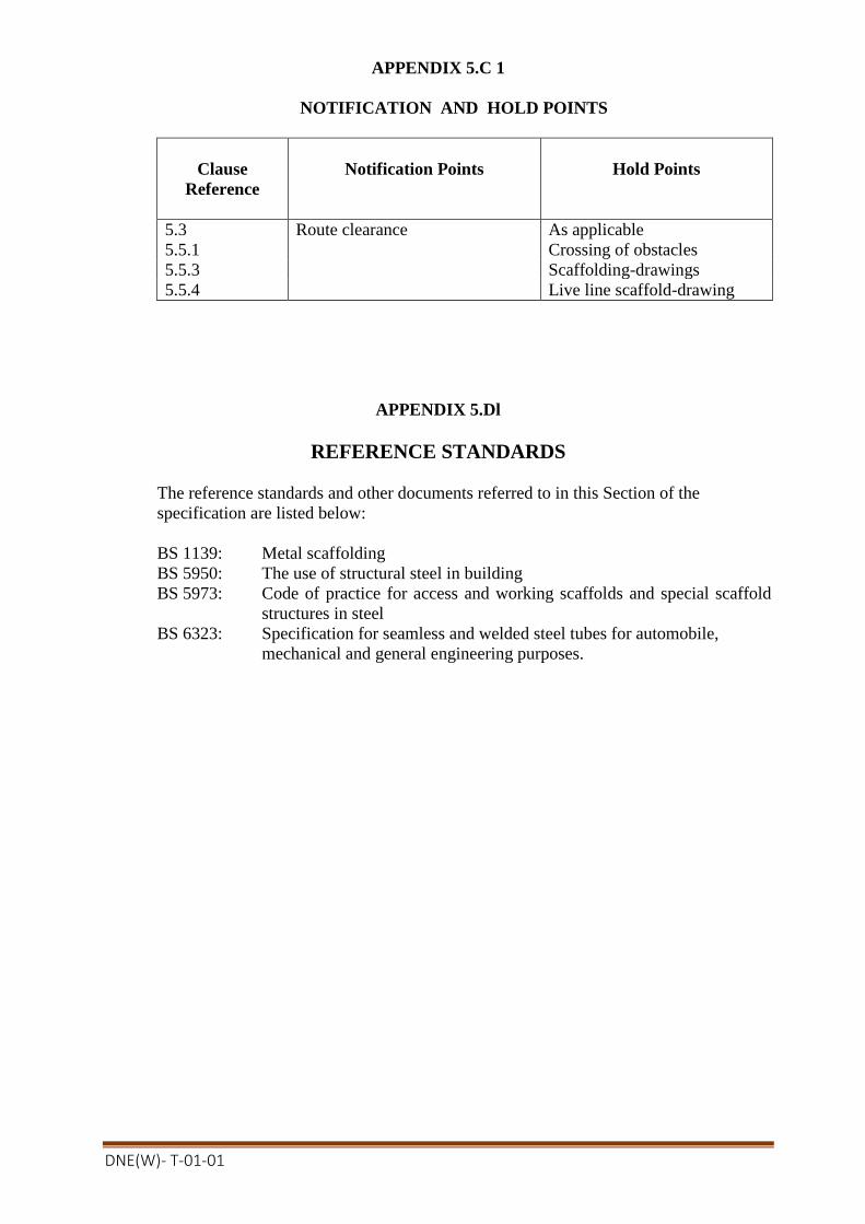
DNE(W)- T-01-01
APPENDIX 5.C 1
NOTIFICATION AND HOLD POINTS
Clause
Reference
Notification Points
Hold Points
5.3 Route clearance As applicable
5.5.1 Crossing of obstacles
5.5.3 Scaffolding-drawings
5.5.4 Live line scaffold-drawing
APPENDIX 5.Dl
REFERENCE STANDARDS
The reference standards and other documents referred to in this Section of the
specification are listed below:
BS 1139: Metal scaffolding
BS 5950: The use of structural steel in building
BS 5973: Code of practice for access and working scaffolds and special scaffold
structures in steel
BS 6323: Specification for seamless and welded steel tubes for automobile,
mechanical and general engineering purposes.

DNE(W)- T-01-01
SECTION 6
SURVEY, PROFILE AND GEOTECHNICAL INVESTIGATIONS
6.1 ROUTE SELECTION
The Engineer will indicate to the Contractor either on maps or during visits to the River
Crossing points towers and the positions of such intermediate. The Contractor shall give
the Engineer the requisite period of notice prior to commencing the survey. This is a Hold
Point.
The negotiations with the landowners about the takeover locations and the construction
works of the line shall be in the responsibility of the contractor. The Employer’s
representative shall assist the contractor in his negotiations with the owners ,
compensation for the crops, trees, houses etc. shall be paid by the contractor and is
deemed to be included in the contract price. about such compensation etc.
6.2 CONTRACTOR'S SURVEY
6.2.1 Access for Survey
For details of the access arrangement for survey, reference should be made to Appendix
5.Al. The Contractor's Surveyor shall in all cases announce himself to the
occupier/landowner immediately before entering any private property for the purpose of
survey.
6.2.2 Accuracy
Profiles shall be produced as a result of a precision ground or aerial survey, the accuracy
of which shall be such that the vertical tolerance between levels forming the profile and
actual ground level shall not exceed 300 mm, and the horizontal distances measured to an
accuracy of not less than 0.2 percent. All levels shall be related to the specified national
datum.
6.2.3 Profile Drawings - Size & Scales
The profile shall either be drawn on a melinex type material or as otherwise approved
with printed grid lines of increasing thickness in 1, 5, 10 and 50 mm squares and shall be
drawn on the reverse side of the melinex to the grid lines.
Computer plotted profiles on plain plastic drawing sheets will be accepted by the
Engineer. However, the format of the profile shall not differ from the details specified in
the following clauses.
The profile shall be plotted with the direction of the line route left to right on the profile
sheet.
6.2.4 Profile Drawings-Details The following details and information are to be included on the profile drawings:
1. At each angle position a 'tie-in' sketch shall be provided on the profile sheet. This
sketch shall show clearly the location of the support using as reference where
possible points which can be located on the ground and on the 1:5,000 or closest
available scale of survey map.
DNE(W)- T-01-01
2. The profile shall show all changes of level of 300 mm or more along the route centre
line and alone, the off-set lines. All features such as hedges, fences, graves, ditches,
roads, railways, rivers, buildings, canals, telephone and railway lines and all power
lines shall be shown. Road numbers or name of roads shall be stated or, if
unclassified, the destination. Railways are to be given the destination, number of
tracks, whether or not electrified and the level at the top of rail stated.
3. The chainage is to be shown at each 300 m and at every geographical feature or
obstruction. Chainage shall also be given to all line pegs.
4. The specified Datum shall be the basis for all levels and the level above the specified
Datum shall be shown at 10m vertical intervals at the beginning and end of each
profile sheet. Levels shall be shown at each peg on line and at every obstruction or
geographical feature.
5. The visual nature of the ground shall be noted, whether cultivated, woodlands, etc.
with special reference to marsh, soft ground or rock and other relevant information
such as soil instability.
6. All buildings or high obstructions within 30m of the centre line shall be shown
dotted at their measured height with the distance left or right of line indicated.
7. Along the bottom of the profile sheet shall be drawn, to the same scale as the
horizontal scale of the profile, a route map showing all relevant details, within a
distance of 30m each side of the route centre line. All items covered by
subparagraphs (a) and (i) above, as appropriate, shall be included.
6.2. Tower Location on Profiles
The Contractor shall submit to the Engineer the requisite copies of route maps and mouza
maps, they shall also submit requisite copies of the profile drawings upon which shall be
indicated the proposed location and type of each tower, spans, section lengths, (i.e.)
distances between tension towers), equivalent spans, wind and weight span, difference in
level between phase conductor attachment points and the sag templates used. This a Hold
Point. Also on the profile shall be plotted the relevant position of the bottom or lowest
phase conductor at the specified maximum conductor temperature and another line
parallel to the phase conductor line and at the minimum statutory ground clearance
specified below it.
Towers shall be so located that the span criteria specified in Appendix 6.Al is not
exceeded, and shall be set down 300mm below the ground line.
6.2.6 Clearance to Obstacles
Clearances to obstacles shall be in accordance with criteria specified in Appendix 6.A2.
6.2.7 Crossing of Obstacles
At the crossing of power supply and telecommunication circuits, no part of the structure
of one support shall be placed less than 35 m from any part of the support structure of
the other circuit.
Pipeline crossings shall not be at an angle to the normal greater than 20°. Crossings of
power supply and telecommunication circuits shall not be at an angle to the normal
greater than 45° without previous agreement from the Engineer.

DNE(W)- T-01-01
6.2.8 Check Survey
The Contractor shall carry out a check survey of the whole spot. No extra cost for
survey and preparation of all drawings of such change of route will be paid to the
Contractor.
The Contractor is required to check thereon the proposed tower positions and submit
the profile drawing to the Engineer. Profile details and tower locations shall be in
accordance with the preceding clauses.
6.3 GEOTECHNICAL INVESTIGATION
6.3.1 General
Geotechnical investigation shall be undertaken in accordance with the technical
requirements detailed in the following clauses. For details of the type and frequency of
the investigation reference should be made to Appendix 6.A4.
Where required by the Engineer the Contractor or his appointed geotechnical consultant
shall undertake the specified slope stability analysis and design.
All investigation, unless specified otherwise shall be in accordance with the
requirements of BS 5930.
The Contractor shall give the Engineer the requisite period of notice prior to
commencing the geotechnical investigation. This is a Hold Point.
6.3.2 Level 1
(Not Used)
6.3.3 Level 2
Level 2 geotechnical investigations shall be based on in-situ testing for the determination of
the soil strength and visual tactile examination of disturbed samples for the determination
of soil classification.
In-situ testing, shall comply with the following requirements:
(a) Non-cohesive soil - standard penetration tests (SPTs), cone penetration tests
(CPTs), or in the absences of large gravel content pressure meter tests (PMTs).
(b) Cohesive soil - As for non cohesive soils except that use of SPTs is subject
to the Engineer's approval. Vane shear tests (VSTS) may also be used in fairly
uniform, fully saturated soils.
(c) Rock -Weak rock SPTs, medium to hard rock PMTs.
Where it is proposed to determine the soil classification indirectly from the in-situ tests
eg. CPTs, cross correlation shall be undertaken at specified intervals using auger
borings.
Where appropriate ground water levels shall be recorded in all boreholes.
DNE(W)- T-01-01
6.3.4 Level 3
Level 3 geotechnical investigation shall be based on in-situ testing (as for Level 2) for
the determination of the soil strength and the recovery of disturbed soil samples for
subsequent laboratory testing.
Laboratory soil classification tests for non-cohesive soils shall be particle size
distribution, moisture content and relative density, whilst those for cohesive soils shall
be moisture content and Atterberg limits. All laboratory testing shall be carried out in
accordance with BS 1377.
6.3.5 Level 4
Level 4 geotechnical investigation shall be based on a combination of in-situ testing (as for
level 2) and recovery of disturbed/undisturbed soil samples for subsequent laboratory
testing.
Laboratory soil classification tests shall be as per Level 3, whilst strength tests shall be
direct shear box (immediate) and bulk density for cohesive soils and unconfined
compressive strength, laboratory vane shear, tri-axial compression (undrained) as
appropriate and bulk, density for cohesive soils.All laboratory testing shall be
undertaken in accordance with BS 1377.
6.3.6Soil and Ground Water Sample
Where specified soil and ground water samples shall be obtained for determination of
the chemical content i.e. organic matter, sulphate, pH and chloride content. All
laboratory testing shall be undertaken in accordance with BS 1377.
6.3.7 Geotechnical Investigation Criteria
Geotechnical investigation shall be undertaken to the following criteria:
(a) Geotechnical investigation shall be undertaken as near as possible to the tower
site. For test foundations the investigation shall be undertaken as near as possible
to the test site, and shall take account of the theoretical failure surface of the
foundation;
(b) Time lapse between the investigation and foundation installation shall take into
account any noticeable effect on the geotechnical properties due to rainfall or
seasonal variations in the groundwater level;
(c) Depth of investigation shall be:
i) for trial pits 2 m; or
ii) the foundation depth plus 1.5 times the maximum base width dimension
for concrete pad and chimney or steel grillage foundations; or
iii) 3m or 5 times shaft diameters (whichever is the greater) below the
foundation depth for piled foundations; or
iv) at least 2m into rock or a hard dense stratum (NSPT >50) if this occurs
before the recommended depth; or
v) for uplift or lateral foundation tests not less than 1m below the base of
the test foundation.
(d) SPTs should be undertaken at the top of each stratum and then at 1m intervals in
soil or weak rock;
DNE(W)- T-01-01
(e) PMTs should be undertaken in each stratum or as required;
(f) CPTs should be taken continuously over depth of investigation;
(g) VSTs should be undertaken at top of each stratum and then at 1m intervals;
(h) Soil/rock description should be based on disturbed samples taken in each stratum
and thereafter at 1m intervals. Soil/rock description should be in accordance with
the recommendations of BS 5930;
(i) Highest ground water level and variation in water level.
6.3.8 Reports
Borehole logs together with a summary of all laboratory testing undertaken shall be
prepared for each tower site when geotechnical investigation has been undertaken. The
5(five) copies of the geotechnical investigation report shall be submitted to the
Engineer and shall subsequently form part of the installation criteria (see Clause 7.2.11).
6.4 FOUNDATION SETTING LEVEL DIAGRAMS
Where specified foundation setting level diagrams shall be prepared for specific tower
positions. Ata scale of 1:200 (horizontally and vertically) the foundation excavation and
setting levels on the two diagonals (drawn separately) shall be shown, together with a
record of the applicable foundation design, leg and body extensions and tower centre-
peg -co-ordinate.
APPENDIX 6.Al
LINE DESIGN SPAN
(Not Used)
APPENDIX 6.A2
CLEARANCE TO OBSTACLES
(Not applicable)
APPENDIX 6.A3
CROSSING OF OBSTACLES
Pipeline crossing shall not be at angle to the normal greater than 20 degrees.
Crossing of power supply and communication circuits shall not be at angle to the
normal greater than 45 degrees without previous agreement of the Employer.
APPENDIX 6.A4
GEOTECHNICAL INVESTIGATION

DNE(W)- T-01-01
Geotechnical Investigation Level Frequency
Level 2,3 & 4 Every tower site.
Ground water samples shall be taken at every tension tower position for chemical
analysis
APPENDIX 6.A5
(Not applicable)
APPENDIX 6.B1
ENGINEERING DOCUMENTS TO BE SUBMITTED BY CONTRACTOR
Clause
Reference
Document Description Comment
6.2.5 Route map, Mouza map & Profile
drawings
6.2.5 Profile drawings
6.3.1 Slope stability analysis If specified
6.3.2 Dynamic probe Calibration details
6.3.8 Geotechnical Investigation Test results
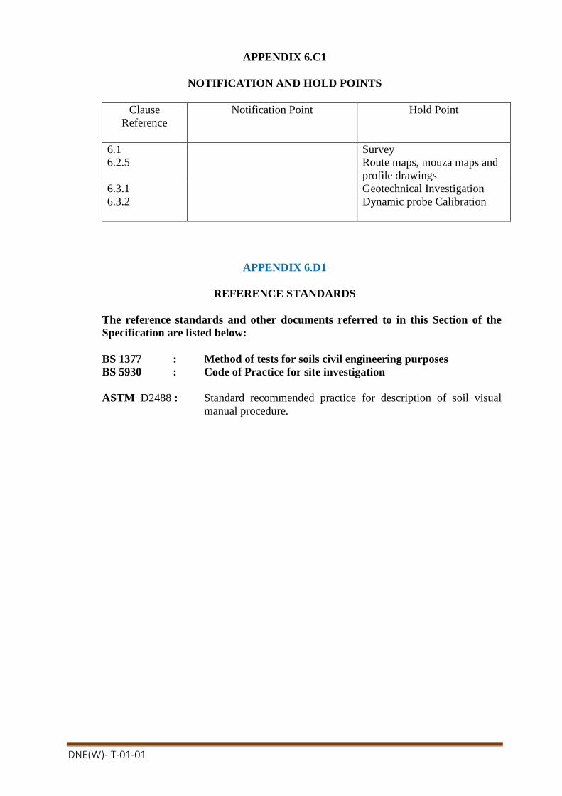
DNE(W)- T-01-01
APPENDIX 6.C1
NOTIFICATION AND HOLD POINTS
Clause
Reference
Notification Point Hold Point
6.1 Survey
6.2.5 Route maps, mouza maps and
profile drawings
6.3.1 Geotechnical Investigation
6.3.2 Dynamic probe Calibration
APPENDIX 6.D1
REFERENCE STANDARDS
The reference standards and other documents referred to in this Section of the
Specification are listed below:
BS 1377 : Method of tests for soils civil engineering purposes
BS 5930 : Code of Practice for site investigation
ASTM D2488 : Standard recommended practice for description of soil visual
manual procedure.

DNE(W)- T-01-01
SECTION 7
FOUNDATIONS
7.1 SCOPE
7.1.1 General The type of foundation to be used at each tower position shall be determined from the
results of the geotechnical investigation. The design of the foundation shall be in
accordance with the design parameters and associated criteria detailed in this
Specification.
The Contractor shall ascertain from the geotechnical investigation that the ground
conditions are suitable for each foundation. The level of geotechnical investigation
specified are the minimum level required at site. The Contractor shall undertake all
necessary geotechnical investigation for the foundation design. Any subsidence or
failure, due in the opinion of the Engineer to insufficient care having been taken in
either the geotechnical investigation, or installation of the foundations shall be the
Contractor's responsibility.
In areas where subsidence is likely to occur the Contractor shall if necessary, carry out
modifications to the tower foundations as agreed by the Engineer. Collar or tie beams
between the individual footings of a tower shall not be used unless specifically
authorized by the Engineer. The Contractor shall not be held responsible for failure of
tower and foundations arising from adjacent mineral extraction subsequent to the
construction of the transmission line. The Contractor shall, however, be held liable for
any lack of foundation or tower stability due to causes other than subsidence due to
subsequent mineral extraction.
The Contractor is responsible for obtaining approval from the Engineer and where
appropriate statutory regulatory bodies for the type and design of the foundations
installed. It should be noted as a general requirement that no site work can commence
before such approvals have been obtained. This is a Hold Point.
7.1.2 Method Statement
TheContractor shall submit to the Engineer a comprehensive method statement giving
sequential details of his proposed installation method and include his intended
programme. The method statement shall include but not be limited to the following
details:
(a) method of excavation .(for all types of foundations) and dealing with water;
(b) methods for heating, welding and site bending of reinforcement;
(c) method of placing of concrete;
(d) method of curing and protecting the concrete;
(e) method of backfilling and compacting;
(f) Reinstatement of working areas;
(g) Quality Control procedures;
(h) Site safety procedures.
This is a Hold Point.
DNE(W)- T-01-01
7.1.3 Types and Uses
The bidder may propose any other type of piled foundation instead of Drilled Shaft
Piled foundation except wooden pile. The bidder shall submit the design of the
proposed type of piled foundation along with detailed design calculation, installation
procedure with drawings, Quality Control procedure, Standards and Codes of Practices
to be followed, Advantages of selecting such type of piles, etc. with the bid. Reinforced
concrete pile caps shall be used for all types of piles. Payments of all types of
foundations shall be on lump-sum basis per tower as per prices quoted in the Price
Schedule.
Unless specified to the contrary, foundations for angle/terminal towers shall not have
different designs for compression and tension footings, but shall be satisfactory for the
most adverse condition of maximum and minimum angles of deviation/entry and with
the wind blowing from the most onerous direction.
Foundations for tower body and leg extensions shall be of the same design and where
appropriate utilize the same type of foundation formers as a foundation for the,
corresponding standard height tower.
7.2 DESIGN
7.2.1 General
During design of towers, the tower reactions on the foundation shall be calculated
considering appropriate maximum simultaneous loading on the towers. During
foundation design the obtained reactions shall be multiplied by the strength factors
indicated in Appendix 7A.2, and the resultant reactions shall be used for foundation
design.
The geotechnical design of the foundation shall be based on accepted codes of practice,
the relevant literature or methods which have been used with satisfactory practical
experience by the Contractor, and agreed by the Engineer.
All foundations shall be designed to withstand uplift, settlement and overturning (as
appropriate) when subjected to the applied system loading. Allowances shall be made
in the foundation design for hydrostatic pressure where this may occur and the effects
of seasonal rains, drying, out, cyclic loading, wind induced vibration of tower members,
and scour.
7.2.2 Geotechnical Parameters The geotechnical parameters for tendering purposes are provided in Appendix 7.a4 to
judge the technical capability of the tenderer. However, all foundations shall be
designed as per actual soil and investigation without any extra payment. Following
information is required to be provided to set the basic design criteria prior to detailed
design of each river crossing tower foundation;.
a) Sections of trial borings or pits showing soil data at site of work;
b) A site plan showing the details of site selected for the crossing extending at least 90
meter upstream and downstream from the central line of the crossing.
The plan should normally include the following:
i) The approximate outlines of the banks;
ii) The direction of flow of water;
iii) The alignment of the crossing & the location of towers; and
iv) The location of trail pits or boring taken in the river bed.

DNE(W)- T-01-01
c) Across section of the river at site of the proposed crossing indicating the following:
i) The bed line up to the top of the banks and the ground line beyond the edges of
the river; with levels at intervals sufficiently close to give a clear outline of
marked features of the bed or ground; showing right and left bank and names of
villages on each side;
ii) The nature of the surface soil in bed and banks with trail pit or bore hole sections
showing the level s and nature of the various strata down to the stratum suitable
for founding the towers;
iii) The ordinary Flood Level;
iv) Low water level;
v) The highest Flood Level and year in which it occurred. State if flood level is
effected by water or tidal effect and if so, give details; and
vi) The estimated depth of scour or scour depth has been observed, the depth of
scour so observed.
d) The maximum mean velocity of water current.
This is a Hold Point.
7.2.3 Foundation Structural Design Parameters
Foundation structural design parameters for concrete shall be based upon the
recommendations of BS 8110, except otherwise defined in this Specification.
7.2.4 Stubs Only one design of stub shall be permitted for each type of tower, and shall not be bent
or cranked.
The thickness of the stub legs shall not be less than the corresponding tower leg
member.
In addition to stubs of normal length, short stubs may be used, provided that provision
is made for the attachment of bolted cleats.
Cleats shall be capable of transferring 100 percent of the design uplift load and 50
percent of the design compression load.
7.2.5 Holding Down Bolts (Not used.)
7.2.6 Concrete Chimneys Reinforced concrete chimneys shall be designed to withstand the maximum resultant
horizontal residual shear component, with due allowance given where appropriate to
resultant lateral (passive) earth pressure of the backfill (assumed to increase linearly
with depth).
No allowance shall be made of the nominal strength of concrete in tension and the stub
shall not be considered as providing any part of the tensile area of reinforcing
steelwork..
The of chimney of tower foundation shall be at least 300mm above nominal ground
level and shall be projected at least 300mm below nominal ground level.
7.2.7 TYPES OF FOUNDATION
Piled Foundation
DNE(W)- T-01-01
Pilled shaft foundations shall comprise piles suitably connected below ground level by
a concrete cap. The Contractor shall submit his proposed method of installation and
Quality Control procedures to the Engineer prior to commencing his design. This is a
Hold Point.
The average skin friction or adhesion per unit area of shaft shall be determined from
either the soil properties measured on samples in an undrained triaxial compression test,
calculated from SPTs (Standard Penetration Tests), or calculated from CPTs (Cone
Penetration Tests). The average value shall be taken over the effective length of the
shaft.
Where shear forces are resisted by a cap, an appropriate reduction in the average value
of the skin friction/adhesion shall be taken for the cap design.
Ultimate uplift resistance shall be obtained assuming the actual weight of piles, pile
caps etc. plus the guaranteed ultimate uplift resistance of the piles. Allowance shall be
made for buoyancy effects. The minimum component of the uplift resistance provided
by the dead weight of the piles and pile caps should not be less than the value specified
in Appendix 7.A4.
Ultimate compressive loads shall include the superimposed weight of soil, pile caps
(and tie-beams, etc.) multiplied by the dead load factor (as per Appendix 7.A2)and shall
be obtained by the guaranteed ultimate resistance of the piles.
7.2.8 Concrete Mix Design The Contractor shall be entirely responsible for the control of the quality of concrete
mixed and placed in the Works. Before the commencement of any concrete work, the
Contractor shall submit to the Engineer, a complete specification giving details of the
materials used, source of supply, storage and quality control requirements, including
preliminary trial mixes and works' tests. This is a Hold Point.
To ensure the durability of the concrete, the requirements specified in Appendix 7.A6
shall be adhered to with regard to characteristic strength, minimum cement content and
maximum free water/cement ratio.
7.2.9 Concrete Cover All structural steelwork and reinforcing including links and stirrups below garound
level shall be completely encased in concrete to ensure a minimum cover as specified in
Appendix 7.A7. Such cover shall exist from the point of entry into the concrete base to
either 200 mm above final ground level, or to the top of the concrete leg extension.
All foundation concrete to a point 200 mm above final ground level shall be undertaken
at the same time and using the same design mix as the main part of the foundation.

DNE(W)- T-01-01
7.2.10 Stability Analysis
All foundations on slopes greater than 1:4 shall be checked for stability against rotation
where appropriate. Due consideration shall be given to the increased upslope lateral
loading of the soil and the decrease in downhill resistance provided by the soil, when
compared to foundations installed on level ground.
Due consideration shall also be taken of any decrease in the uplift resistance of the
foundation. Where appropriate decrease in soil bearing resistance shall also be
considered.
Where required by the Engineer the overall long term stability of the slope, including
any proposed slope modifications for constructional purposes e.g. benching shall be
considered by an approved geotechnical consultant appointed by the Contractor.
7.2.11 Installation Criteria
The Contractor shall prepare a schedule for construction purposes which clearly
indicates the soil class and type of foundation to be installed at each tower site. The
schedule shall show the basis for selection, taking into account the following items:
(a) the results of the geotechnical investigation;
(b) the results of any foundation design test;
(c) the design criteria;
(d) the results of any stability analysis;
(e) those areas which due to the aggressiveness of the sub-soil or sub-soil water a
greater mass of cement per cubic meter of concrete than that specified is
required.
The schedule shall be submitted to the Engineer, prior to any foundation installation
commencing. This is a Hold Point.
7.2.12 Design Submission
The Contractor shall submit the following, design submissions to the Engineer :
(a) foundation design calculations;
(b) foundation general arrangement drawing,;
(c) slope stability analysis;
(d) bar bending schedule (information only) - if appropriate;
(e) foundation formwork drawings (information only) - if appropriate;
(f) foundation setting template.
Reference should be made to Clause 7.1.1 for approval procedures and hold points.
Conceptual Foundation drawing are attached with he Bid Document

DNE(W)- T-01-01
7.3 MATERIALS
7.3.1 Concrete
All materials used in the production of concrete, including all admixtures shall be in
accordance with the requirements of BS 5318.
Cement shall be either:
(a) Portland cement in accordance with BS 12 strength grade 42.5N;
(b) Sulfate resisting Portland cement in accordance with BS 4027 strength grade
42.5N LA;
(c) Portland cement combined with a minimum of 25% and a maximum of 40% of
p.f.a. complying with BS 3892 Part 1.
Where appropriate the Contractor shall take cognizance of CIRIA Special Publication
No.31. Recommendations contained in this report shall be adhered to except that in the
event of any discrepancies this Specification will take precedence unless authorised by
the Engineer.
7.3.2 Potential Alkali Reactivity Aggregate shall not contain any materials that are reactive with alkalis in the aggregate
itself, the cement, the mixing water or inthe water in contact with the finished concrete
or mortar in amounts sufficient to cause excessive localised or general expansion of the
concrete or mortar.
The Contractor may initially assess an aggregate source by testing in accordance with
ASTM C289. If potential reactivity is indicated, then mortar bar tests in accordance
with ASTM C227, shall be carried out and the results shall comply with the limits
given in ASTM C33, before use of the aggregate isapproved. Details of the tests shall
be submitted to the Engineer. This is a Hold Point.
7.3.3 Reinforcement
Unless specified to the contrary high yield steel reinforcement shall be
either hot rolled deformed bars or cold worked deformed bars to BS 4449
and shall have type 2 bond classifications.
Mild steel reinforcing shall be plain hot rolled bars to BS 4449. Steel fabric or
wrapping fabric shall be to BS 4483. Where mild steel hot rolled deformed bars are
used they shall be generally in accordance with BS 4449. Reinforcement shall not be
manufactured from scrap steel, unless otherwise approved by the Engineer.
Where specified fusion bonded epoxy coated reinforcement shall be in accordance with
the requirements of BS 7295. Coated reinforcement shall be delivered to site in its
cutand bent form.
Cropped ends and minor discontinuities of the fusion bonded coating shall be factory
coated using a suitable repair compound formulated in accordance with the
manufacturer's specification.
Where specified fibre enhanced concrete shall contain fibres manufactured from 100
percent virgin polypropylene fibre and designed to achieve maximum distribution and
freedom from clustering in the mix.

DNE(W)- T-01-01
7.3.4 Reinforcing Bar Coupler
The use of proprietary reinforcing bar couplers to extend reinforcement will be
permitted. Details of the coupler system shall be submitted to the Engineer prior to
their use. This a Hold Point.
7.3.5 Spacers
Dense sand/cement mortar spacing blocks shall be of a low permeability having similar
strength, durability and appearance to the surrounding concrete.
Details of patent spacers shall be submitted to the Engineer.
This is a Notification Point
7.3.6 Tying Wire
Tying wire shall be 1.6 mm diameter black annealed mild steel wire for uncoated mild
or high yield steel reinforcement.
Coated bars shall be fixed with plastic coated annealed mild steel tying wire.
7.3.7 Anchor Tendons
All the materials used in the installation of anchor tendons including those used for the
grout shall be in accordance with the requirements of BS 8081.
7.3.8 Gabion Baskets
Gabion baskets and mattresses shall be manufactured from cold drawn steel wire.
Minimum wire diameter for baskets galvanised to BS 729 shall be 3.0 mm whilst for
plastic coated wire galvanised to BS 443 shall be 2.70 mm. The minimum radial plastic
coating thickness shall be 0.25 mm.
All steel wires shall be electrically welded at every intersections.
7.3.9 Holding Down Bolts
Not used
7.3.10 Piles
If pre-cast concrete or steel piles are used all materials shall be in accordance with the
requirements of the ICE ‘Specification for Piling’.
7.3.11 Stubs Stub steelwork and bolts shall not be inferior to the requirements of Clause 8.3.1.
7.3.12 Earthing
All mild steel used in the manufacture of earthing rods shall comply with the
requirements of BS 970: (minimum strength 600N/m) Earthing rods shall have a
minimum diameter of 14 mm.
Phosphor-bronze used in the manufacture of earthing rod couplings shall comply with
the requirements of BS 2874. All compression fittings shall be manufactured from
electrolytic tough pitch high conductivity copper, complying with the requirements of
BS 1977 and BS 2871 designation C101.
Earthing conductors shall be in accordance with the following requirements:
DNE(W)- T-01-01
(a) Copper strip to BS 2870, Grade C101 or C102, minimum cross sectional;
dimensions 20 mm x 3 mm.
(b) Hard drawn copper strand to BS 7884, minimum overall diameter 10.65 (7 x
3.55 mm);
(c) Galvanized steel wire to BS 183, minimum overall diameter 9.75 mm (7 x 3.25
mm).
7.4 WORKMANSHIP
7.4.1 General All workmanship shall be in accordance with the requirements of this Specification, the
appropriate British Standard and local regulations including the appropriate health and
safety requirements.
7.4.2 Site Working Area
The Contractor will be restricted to a specified maximum working area at each tower
site. He shall where required mark this area to clarify boundary lines to other parties.
The Engineer shall be kept informed of any activities by others within the working,
area.
7.4.3 Supports of Excavation
Excavations shall be adequately supported or formed to ensure stability of the sides and
prevent any damage to the surrounding ground or structures. The design of suitable
sheet piling and/or timbering for the support of foundation excavation shall be in
accordance with the recommendations of BS 8004 Section 5.
When requested the Contractor shall submit details of his temporary support details to
the Engineer.
Excavation material suitable for re-use, as backfill shall be stored within the site
working area. Excavation top-soil shall be stored separately.
Excavated material unsuitable for re-use shall be removed from site to a recognised
dumping area provided by the Contractor, and approved by the relevant authorities.
For excavation in cohesive material the final 150 mm above formation level shall only
be removed immediately prior toplacing the blinding concrete. This activity shall be
programmed to be carried out on the same day.
The Contractor shall not permit water to accumulate in any excavation unless otherwise
agreed. Any water whether arising from the excavation or draining into shall be
drained or pumped to an approved location well clear of the excavation area in a
manner that does not cause erosion, silting or contamination of existing drains and
watercourses.
The Contractor shall take adequate steps to prevent adjacent ground from being,
adversely affected by loss of fines in any dewatering process.

DNE(W)- T-01-01
7.4.4 Use of Explosives
The Contractor shall familiarize himself and comply with the laws and local customs
concerning the use, handling and storage of explosives.
(a) Permission
Explosives shall not be used on the Site without the prior approval of the appropriate
Military and Civil Security Authorities and without prior written approval of the
Engineer.
This is a Hold Point.
(b) Control
The handling of all explosives on site shall be carried out in accordance with local
requirements.
(c) Approval
The Engineer shall be given a minimum of 24 hours notice of a proposal to use blasting
and shall be given any details they may require concerning the charges and their
positions. This is a Notification Point.
The Engineer may regulate, restrict or prohibit blasting, if in their opinion it is
necessary to do so for the safety of persons, property, limit noise or to safe guard
the works.
(d) Blasting
For explosives to be allowed in any area of the site, the following and any local
requirements shall be strictly observed.
i) The Contractor will be required to strip overburden and vegetation to
expose rock which requires to be blasted;
ii) Where there is any danger of flying rock engineering persons or property,
blasting screens made of approved materials shall be laid over the rock to
be blasted, to help prevent dangerous projection of fragments;
iii) The use of electric detonators will not be permitted within 60 meters of
any overhead power lines;
iv) Delay blasting techniques will be mandatory for all primary blasting with
charge limits per delay period being imposed in order that ground
vibration from the blasting can be controlled to a peak particle velocity of
25 mm/sec. in the vicinity of any structures or installations;
v) All charges prior to firing will be covered with thick gunny sacking and
1.8m squares of steel mesh weighed down with filled sandbags in order to
prevent the projection of rock fragments;
DNE(W)- T-01-01
vi) The Contractor will be required to take adequate and effective precautions
to prevent debris rolling onto public or private roads and property.
The erection of magazines for storing explosives on site will not be permitted.
7.4.5 Reinforcement
(a) Storage All reinforcement shall be adequately stored to prevent contamination or damage.
(b) Cutting and Bending All reinforcement shall be cut and bent in accordance with the requirements of BS
4466. The reinforcement shall be clearly identified with securely fixed, durable
tags.
(c) Fixing The Contractor shall be responsible for ensuring that the reinforcement is properly
towered and maintained in position by the adequate use of chairs, spacers and tying
wire.
The reinforcement shall be free of all loose rust, scale or contamination of any kind.
(d) Site Bending
Bending and subsequent straightening of reinforcing bars projecting from the
existing concrete shall be undertaking as follows:
i) Unless noted otherwise on the drawings, the minimum distance from the
existing concrete to the beginning of a bend and the minimum inside diameter
of the bend shall be:
Bar Diameter Min Distance from Min Inside bend
surface to beginning (mm) radius
of bend 10-24 3 Bar Diameters 3 Bar Diameters
25-32 4 Bar Diameters 3 Bar Diameters
<32 5 Bar Diameters 5 Bar Diameters
ii) Bars of 10 to 16 mm diameter may be bent once without heating, heating is
required for subsequent straightening or bending.
Bars of 20 to 32 mm diameter may be bent once and subsequently straightened,
heating is required in all cases.
Bars having a diameter greater than 32 mm may be bent only with the approval
of the Engineer, heating is required in all cases.
iii) Heat shall be applied as uniformly as possible over a length of bar equal to 10
bar diameters. The centre of the heated length shall be at the centre of the
completed bend. The temperature shall be maintained consistent during bending
and straightening operations and shall not exceed 350'C. Temperature
measuring crayons or a contact pyrometer shall be used to determine the
temperature. Care shall be taken to prevent quenching of the heated bars either
by application of water, or by a high volume of air.

DNE(W)- T-01-01
iv) Straighten bars shall be visually inspected before and after straightening to
determine whether they are cracked or otherwise damaged.
This is a Notification Point.
(e) Epoxy Coated Bars
i) The Contractor shall take all necessary precautions to minimise damage to the
coating during off-loading, handling and fixing. All equipment used for
handling of coated bars shall have padded contact areas. Coated bars or bundles
shall not be dropped or dragged.
ii) Coated bars shall be stored separately to uncoated bars.
iii) Coated bars shall not be cut or bent on site without the prior approval of the
Engineer. This is a Hold Point.
Cut ends and any damage to the coating shall be repaired in accordance with
Clause 7.5.
iv) Coated bars shall be towered on epoxy coated wire chairs or on chairs of
dielectric material.
7.4.6 Concrete Trial Mixes
Trial concrete mixes using representative materials shall be carried out under full-scale
conditions using the Contractor's proposed method subject to the Engineer's approval.
Testing shall be carried out in accordance with BS 1881. The target mean strength of
the trial mixes shall be specified concrete cube strength plus a current margin of 15
N/mm².
The tests shall be carried out on three different days during which the workability will
be recorded and six cubes made. Of each set of six cubes, three will be crushed at seven
days and the other three at twenty eight days.
This is a Notification Point.
7.4.7 Batching
The aggregate and cement shall be proportioned by means of efficient weigh batching
machines. The machine shall be carefully maintained and cleaned and they shall be
provided with simple and convenient means of checking the weighing mechanism and
they shall be checked when required by the engineer.
Batch materials, shall be measured out within the following tolerances and shall be
discharged into the mixer without loss.
Cement - ± 2 percent of the mass of the cement in the batch.
Aggregate - ± 2 percent of the mass of each aggregate in the batch.
Admixtures - ± 5 percent of the amount to be added to the batch.

DNE(W)- T-01-01
7.4.8 Mixing Concrete by Machine
The concrete is to be mixed in batches in machines which comply with the requirement
of BS 1305. The machines are to ensure that all the concreting materials including the
water are thoroughly mixed together between the time of their deposition in the mixer
and before any portion of the mixture is discharged. The machines must be capable of
discharging their content while running.
7.4.9 Workability
The Contractor shall carry out slump or other workability tests as required during
concreting of the works in order to relate the degree of workability of the mix with the
numerical value obtained during the trial mixes.
7.4.10 Blinding Concrete Blinding concrete shall be provided under specified foundations to a minimum
thickness of 75 mm.
7.4.11 Formwork All formwork shall be accurately constructed to prevent loss of grout and to produce
the correct foundation shape. Formwork shall be sufficiently strong to withstand the
pressures arising from the concrete during placing and compaction and shall be capable
of removal without undue disturbance to the concrete. Formwork shall be retained in
position after concreting for a minimum period of 48 hours.
7.4.12 Placing and Compacting Concrete shall normally be discharged from the delivery vehicle within two hours after
the time of loading at the ready mix plant in accordance with the requirements of BS
5328 Part 3. With the Engineer's approval these periods may be exceeded with the use
of a suitable retarder and/or plasticiser, provided that there is no chance in the quality of
the concrete. Concrete must at all times have the desired workability and characteristics
at the point of placing. Any concrete which no longer meets this requirement shall be
removed from site.
Placing by pump, conveyor or pneumatic method shall be subject to approval by the
Engineer. There shall not be any loss of quality in the concrete, nor harmful effects to
the works by such methods. Concrete pumps shall be operated by mechanically applied
pressure and shall produce a continuous stream of concrete without air pockets.
Where pumps are used the velocity of discharge shall be regulated, by suitable baffles
or hoppers where necessary to prevent segregation or damage and distortion of the
reinforcement, embedded items and formwork, caused by impact.
When pumps are used on large or complicated pours a standby pump shall be provided.
Precautions shall be taken to avoid depositing water or grout in the Works during
starting up operations, or in flushing, or clearing the pipeline. The pipeline shall pass
its own length of concrete in not more than 20 minutes.
Chutes used to deliver concrete shall not be sloped so as to cause segregation of the mix.
Concrete shall be fully, compacted by vibration or other approved means and shall
completely fill the shutter. Immersion vibrators shall be inserted in such a manner and

DNE(W)- T-01-01
at intervals as will ensure the satisfactory uniform compaction of the concrete. The
vibrator shall penetrate the full depth of the layer and where the underlying layer of
concrete has not initially set, they shall enter and re-vibrate the layer to ensure that
Succeeding, layers are well bonded together. Withdrawal of vibrators shall be such as
to prevent the formation of voids. Piles of concrete within the formwork shall not be
moved by immersion of the vibrator, nor shall segregation be caused by over vibration.
Undue laitance or leakage through the formwork shall be avoided. It shall be fully,
worked around reinforcement and other embedded items which shall not be disturbed.
The Contractor shall provide standby vibrators.
The Contractor shall maintain records of daily returns of the quantity, concrete mix and
location within the Works of all concrete placed. These shall be forwarded to the
Engineer when requested.
7.4.13 Joints
The pad and chimney (for pad and chimney type foundations) shall normally be cast in
one operation without construction joints. Where the formation of a joint is unavoidable
the surface against which the fresh concrete is to be placed shall be prepared in
accordance with Clause 6.12 of BS 81 10: Part 1.
This is a Notification Point.
Construction joints in anchor or pile caps, monoblock and raft foundations shall be
treated in similar manner to that described above. When the embedded reinforcement
is insufficient to transmit the required design load, additional reinforcement in the form
of 'starter' bars shall be provided. No construction joints are permitted in cast-in-situ
concrete piles, drilled shaft or side bearing foundations.
7.4.14 Curing and Protection
Curing and protection shall start immediately after the compaction of the concrete and
shall ensure adequate protection from:
(a) Premature drying out, particularly by solar radiation and wind;
(b) Leaching out by rain and flowing water;
(c) Rapid cooling during the first few days after placing;
(d) High internal thermal gradients;
(e) Vibration and impact which may disrupt the concrete and interfere with its bond
to the reinforcement or other embedded items.
Where curing compounds are used to protect exposed surfaces from solar radiation and
improve moisture retention, they shall be subject to the approval of the Engineer.
The temperature of the fresh concrete at the time of delivery on site shall be in
accordance with requirements of BS 5328: Part 3.
7.4.15 Grouting of Anchor Tendons The installation and subsequent grouting of anchor tendons shall be in accordance with
the requirements of BS 8081.
DNE(W)- T-01-01
7.4.16 Drilled Shaft piled Foundations Drilled shaft shall be installed and concreted strictly in accordance with the
recommendations of BS 8004 clause 7.4.5 and as summarised below:
(a) To ensure drilled shafts remain uncontaminated with spoil, shafts shall be
extended by 300 mm or a depth equivalent to the total pitch of the auger blades
(excluding continuous flight augers) below the calculated depth of the auger;
(b) When shafts are installed using bentonite slurry techniques the stability of the
sides of the shaft shall be maintained throughout the installation by an adequate
head of bentonite slurry in conjunction with the temporary casing;
(c) Reinforcing cages shall be provided with roller spacers of an approved type to
ensure that the minimum specified concrete cover is achieved, especially as
regards the cover at the bottom of the shaft;
(d) The tremie pipe shall have a minimum diameter of 150 mm and shall be filled
with an effective plug prior to charging with concrete;
(e) Effective means shall be provided for raising or lowering the tremie quickly by
towering the hopper from a crane. The hopper shall have a minimum capacity
equivalent to that of the tremie;
(f) The tremie shall always be kept full of concrete and shall adequately penetrate
into the concrete to prevent accidental withdrawal if the pipe is surged to
discharge the concrete.
Piled foundations shall be installed in accordance with the requirements of the IEC
'Specification for Piling’.
7.4.17 Stub Setting
Stubs shall be held firmly in position by a stub setting template or other device while
the concrete is placed. This tower shall be maintained until backfilling of the
foundation is complete, or for drilled shaft, anchor and pile caps, monoblocks, rafts etc
until a minimum period of 48 hours has elapsed after concreting
Concrete blocks may be used to tower the lower end of the stub, and they shall have
similar strength and durability to the surrounding concrete.
Where holding bolt assemblies are used, setting templates shall be used and retained in
position for a minimum of 48 hours.
Stub setting templates shall be used to maintain the position of steel grillage foundation
is during backfilling.
7.4.18 Backfilling of Foundations
Backfilling shall be compacted in 300 mm layers to achieve a bulk density of 1.6
Mg/m³, or the value assumed in the design analysis (if this is less than 1.6 Mg/m³)
Commencement of backfilling, shall be a Notification Point.
During, backfilling, the side sheeting to the excavation shall, where possible, be
progressively withdrawn such that the toe of the sheeting, is never more than 600 mm
below the surface of the compacted material.

DNE(W)- T-01-01
Extreme care shall be taken by the Contractor during compaction to ensure that the
foundation is not damaged nor caused to move out of position.
The Contractor shall select the compaction plant most suitable for achieving the
required bulk density. Acceptable methods of compaction shall include, but not be
restricted to, the use of vibrating plate compactor or diesel hand operated vibrating
Wacker plate. The actual method of compaction selected will depend on the type of
material to be compacted and the difficulty in accessing areas within the excavation.
Backfilling of the directly embedded pole annulus shall be undertaken using crushed
rock aggregate in accordance with BS 882, with a nominal maximum size of 40 mm.
7.4.19 Site Clearance
As soon as possible at each tower site, backfilling should be completed, surplus soil
removed and the site cleared at the Contractor's cost. Final site clearance, normally
carried out at the same time as fitting of anti-climbing guards and danger and notice
plates, shall be undertaken without delay. The Contractor shall be responsible for
compacting and relevelling ground to the original surface level and gradient. Where
agreed by the Engineer a percentage of the spoil may be disposed of by local spreading
and the balance, if any, shall be removed from site.
7.4.20 Reinstatement of Working Areas
Reinstatement of all working, access and storage areas shall be the responsibility of the
Contractor.
A programme for reinstatement works shall be submitted to and approved by the
Engineer prior to the issue of the taking over certificate.
Reinstatement where specified shall include all necessary topsoil preparation, hydro
seeding and the planting of shrubs and trees to a standard at least equal to the condition
of the site prior to construction. The sequence of work shall be such as to ensure
establishment of all species and the age and state of growth of plants shall be such as to
ensure successful replanting at site.
All such work shall be completed to the satisfaction of the Engineer and the -relevant
regulatory authorities.
7.4.21 Site Stabilization
Where foundations are installed on sloping or unstable ground the Contractor shall be
responsible for ensuring the stability of the area and the safety of the public, all to the
satisfaction of the Engineer and local regulatory authorities.
Stabilization shall be achieved by approved methods such as retaining walls, buttresses,
sprayed concrete, rock bolts, dowels or gabion baskets/mattresses.
Site assembly of gabion baskets and mattresses shall be carried out in accordance with
the manufacturer's instructions. Gabions shall be placed in position prior to filling and
secured to adjoining gabions with lacing wire. Filling material shall be between 100
and 150 mm; 90 percent of the fill to be retained on a 100 mm ring. The fill shall be
tightly packed with no apparent voids, and shall be overfilled by 25-50 mm to allow fat
settlement lids shall be laced immediately after filling.
Where necessary to prevent erosion and as stipulated by the Engineer, or the
appropriate authority, surface drainage channels shall be provided; surge chambers
stopped ends and sub lets shall be formed as required. Where surface vegetation has

DNE(W)- T-01-01
been removed from sloping ground such that erosion could occur the area shall be re-
instated by planting of grasses using hydro seeding methods or band sprigging.
7.4.22 Site Protection
Where specified tower legs or foundations are in areas open to vehicle access, the
Contractor shall install barriers of a type approved by the Engineer to prevent vehicle
coming into contact with the tower or foundation.
7.4.23 Earthing
The maximum tower footing resistance with earthwires disconnected, shall be 10 ohms.
Earthing shall be provide with two diagonal legs of each tower as shown in drawing
no.7.1. If additional earthing is required, additional earthing conductor shall be attached
to the tower at the earthing holes specified and shall be sufficiently buried to prevent
accidental excavation. The amount of earthing conductor to be buried, or earthing rods
installed will be dependent upon achieving the required footing resistance.
The excavation for the earthing conductor shall be 400 mm wide and not less than 800
mm deep in cultivated land where required by the Engineer. The earthing conductor
shall be laid at a depth of approximately 700 mm, being placed centrally in the trench.
The trench shall be backfilled with a suitable medium.
The connection between the additional earthing conductor and tower leg shall be by
approved thermo weld joints.
Where necessary in areas of high resistivity 90 mm diameter holes shall be drilled
along the tower diagonal, each having, an earthing rod surrounded by a
Bentonite/sodium carbonate mix. The depth of hole depending on the resistivity of the
soil. The earth rod shall comprise standard rods coupled together and connected back,
to the tower leg.
For towers within 150m of a substation and connected to the substation earthing system,
no additional earthing, will normally be required.
7.5 PROTECTIVE TREATMENT
7.5.1 Galvanizing
All stub steelwork, pole sections and holding down bolts shall be protected by hot-
dipped galvanizing to comply with the requirements of BS 729.
7.5.2 Epoxy Coal Tar Paint
All directly embedded pole sections, steel pile and caisson sections, guy anchor rods
shall be protected by two coats of epoxy coal tar paint. For steel pile sections, this
treatment shall only apply to the initial 2 in below final round level.
7.5.3 Epoxy Coated Reinforcement Coating, damaged during transit handling or fixing shall be repaired only with the
approved repair compound supplied, to ensure compatibility with the Fusion Bonded
Epoxy Coating. All repairs shall be carried out strictly in accordance with the
manufacturer's instructions.

DNE(W)- T-01-01
When the extent of the coating damage on any meters length of bar exceeds 1% of the
surface area, the bar shall be rejected.
This is a Notification Point.
7.5.4 Tower Steelwork and Stub-Concrete Interface
After curing has been completed all exposed concrete above ground level and 300 mm
below ground level shall be coated with Coal Tar Epoxy coating applied by either
conventional spraying or brushing to give a minimum dry film thickness of 300 µm.
The surface of the concrete shall be allowed to cure for at least 28 days prior to surface
preparation unless otherwise agreed with the Engineer. After adequate curing all
surface laitance, dirt and other contaminants shall be removed. Prior to the application
of the coating, cracks in the concrete greater than 2mm in width and surface
irregularities, including blow holes, with a depth greater than 10mm, shall be filled with
a proprietary fairing coat compatible with the coating system. The surface of the
substrate shall be prepared in accordance with the coating manufacturers
recommendations. Primers where necessary, shall be obtained from the same
manufacturer as the top coat.
All tower steelwork below the maximum anticipated flood level shall be protected by
Coal Tar Epoxy coatings. All steelwork to a minimum height of 3m above ground level
shall be protected by factory application with the remainder applied on site, including
the stub above concrete level.
For factory application the galvanized steel members should be blast cleaned to a
minimum Sa2 standard BS 7079 using a fine grade mineral blasting medium. The
coating shall be applied by either conventional spraying or brushing to give a minimum
dry-film thickness of 300 µm. Prior to application, the Coatings Applicator shall
submit procedures for coatinc, application and quality control measures for approval by
the Engineer. This is a Hold Point.
The method of application of the coating system shall be in accordance with the
approved procedures and manufacturer's instructions. The contractor shall ensure that
the proposed coverage rates will enable the specified minimum dry film thickness of
each coat to be attained. Wet filmthickness gauges shall be used to check the thickness
of the applied coating.
Each application of the coating shall be generally free from surface defects, particularly
cratering, pinholing, ravelling, sagging, bittiness, dryspray and cissing. The finished
system shall have a uniform appearance.
For site application the same procedure shall be adopted except that use of a 'etch
primer' instead of blast cleaning on site will be permitted. The 'etch primer' must be
obtained from the same supplier as the coating and applied strictly in accordance with
the manufacturers instructions including the cleaning and decreasing of the tower
steelwork on site.

DNE(W)- T-01-01
7.5.5 Earthing Material Steel earth rods shall be clad with 99.9 percent electrolytic pure copper moleculary
bonded to the steel, with a minimum thickness of 0.35 mm. The earthing conductor at
the ground interface and at the connection to the tower shall be protected against
corrosion.
7.5.6 Protection of Buried Steelwork Where it is necessary for tower steelwork to be buried, it shall be buried not more than
1.0 in and shall be protected by an approved medium e . mastic impregnated tape or
bitumastic paint. Details of the proposed materials, application and Quality Control
procedure shall be submitted to the Engineer.
This is a Hold Point.
7.6 QUALITY CONTROL
7.6.1 General Type, sample and routine tests shall be undertaken on all materials used in the
construction of the foundations, and where appropriate on the complete foundations, or
parts of the complete foundation in accordance with the requirements of this
Specification.
7.6.2 Bentonite Slurries
Bentonite slurries used to tower the sides of the drilled shaft foundations shall be prepared
and controlled in accordance with the recommendations of BS 8004 Clause 6.5.3.8 and as
summarised below: -
(a) Bentonite shall be supplied in accordance with the Oil Companies Materials
Association Specification No. DFCP4;
(b) After mixinc, with clean fresh water the fully hydrated bentonite slurry shall
have a density of less than 1.10 g/ml, a viscosity as measured by the Marsh cone
between 30 s to 90 s and a 10 minute gel strength in the ran-e of 1.4 to 10 N/m2;
(c) Immediately prior to concreting, the density of the slurry at a level of 200 mm
above the bottom of the shaft shall be less than 1.5 g/ml;
(d) The pH value of the slurry shall be maintained within the range 9.5 to 12.
7.6.3 Reinforcement All reinforcement shall be supplied from approved suppliers, complete with the
appropriate test certificates in respect of the test requirements of BS 4449 or BS 4483
as appropriate. Copies of these certificates shall be made available to the Engineer upon
request. Where test certificates are not available the Contractor shall arrange for the
tests to be undertaken in accordance with the specified standards.

DNE(W)- T-01-01
7.6.4 Inspection Prior to Concreting
The Contractor shall give the requisite period of notice to the Engineer of his intention
to commence any concreting and shall submit at the same time a record of his
inspection of completed preparatory works. Which shall include all works related to the
fixing of reinforcement.
This is a Notification Point.
7.6.5 Trial Mixes
A trial mix will be approved when the requirements of BS 5328 part 3 Clauses 3.4 and
3.5 are met. Copies of the trial mix test results shall be submitted to the Engineer.
7.6.6 Workability
The Contractor shall carry out slump or other workability tests as required during
concreting of the works in order to relate the degree of workability of the mix with the
numerical value obtained during the trial mix.
Slump tests shall be carried out in accordance with the procedure laid down in BS 1881:
Part 101. A slump test will be accepted as complying with the Specification when the
results are within the following limits:
±25 mm or ± one third of the required value, whichever is the greater.
7.6.7 Works Cubes
Compliance with the specified characteristic strength shall be based on tests made on
cubes at twenty eight days. Cubes shall be made, cured and tested in accordance with
BS 1 88 1. Samples ofConcrete shall be taken at the point of discharge from the
delivery vehicle.
Unless otherwise directed by the Engineer four cubes shall be prepared for each 6 cum
of concrete placed or tower foundation subject to a minimum of four cubes being
formed on each day that concreting is carried out.
Each set of cubes shall be accompanied by a certificate noting the details required by
Clause 5 of BS 1881: Part 101.
Cubes shall be tested in accordance with BS 1881 to determine the density and
characteristic strength as follows:
(a) One cube shall be tested at seven days to provide an early indication as to
whether the twenty eight day strength is likely to be achieved;
(b) Two cubes shall be tested at twenty eight days, the average strength shall be
deemed the test results;
(c) One cube shall be held in reserve for further testing, if required.
The test report shall provide information in accordance with Clause 8 of BS 1881: Part
116.
Concrete shall be assumed to have achieved its characteristic strength when, at twenty
eight days, the conditions specified in Table I of BS 5328: Part 4 are met.

DNE(W)- T-01-01
Copies of the test reports shall be made available to the Engineer on a regular basis.
The Engineer will consider whether the concrete in the Works represented by cubes
falling below the limits laid down can be accepted, and he may order that any or all of
the following, actions shall be taken:
i) Penetration resistance or surface hardness tests;
ii) The drilling of test cylinders in the concrete and testing the samples to
destruction by compression;
iii) The cutting out and replacement of such volumes at their discretion which they
consider to be defective;
7.6.8 Setting Out Tolerance Towers shall be centre-pegged with a displacement along the line of the route not
greater than 2m relative to the profile, and to a displacement in transverse alignment
not greater than 50 mm relative to a theoretical line adjoining the adjacent angle pegs.
7.6.9 Foundation Setting Tolerances The maximum permitted stub tolerances measured at the top of the stubs shall be as
detailed in Table 7.1 and are to apply immediately prior to erecting the tower. Should
these tolerances not be achieved the Contractor shall submit details of his proposed
remedial measures to the Engineer for approval.
This a Hold Point.
Records of the foundation setting out measurements shall be made available to the
Engineer.

DNE(W)- T-01-01
Table 7.1 - Foundation Setting Tolerances
Principal Dimension
Tolerance
Nominal face dimension
Nominal diagonal dimension
Rake of stub from required face or
hip slope
Stub level
(a) Maximum difference in level between
all four stubs of a foundation
(b) Maximum difference between he
mean levels of pairs of diagonally
opposite stubs
Twist of stub in plan
± 10 mm or ± 0. 1% of face dimension
(whichever is greater)
± 15 mm or ± 0. I% of diagonal
dimension (whichever is greater)
1:100
10 mm or 0.05% of diagonal
dimension (whichever is greater)
±6mm
1° about longitudinal axis
7.6.10 Backfilling
Testing of the backfill to ensure that the design value of soil bulk density is achieved
may be undertaken using an approved penetrometer. Results of the tests shall be made
available on request to the Engineer. However, the Engineer reserves the right to
request the Contractor to undertake in-situ density tests in accordance with BS 1377
Part 9 as necessary.
Where imported back-fill is required the following details shall be supplied to the
Engineer:
(a) the type of fill
(b) evidence that when compacted a bulk density consistent with the value assumed
in the design can be achieved.
7.6.11 Foundation Tests - General When requested by the Engineer full scale foundations tests both design and
routine/proof shall be undertaken on all types of foundations.
Tests shall unless specified otherwise be undertaken in accordance with the
recommendations of CEI IEC 1773: “Overhead Lines-Testing of Foundations for
Strucrtures”..
When design tests are required, the sites selected shall be representative of the geo-
technical conditions throughout the length of the transmission line, in which the
Contractor proposes to install that type of foundation.
The Contractor shall submit to the Engineer the following information:

DNE(W)- T-01-01
(a) Details of the test sites, including all geotechnical parameters;
(b) Details of the proposed test equipment, test layout, measuring equipment, test
procedure and the test program. This a Hold Point.
(c) On completion of the design tests the requisite number of test reports shall be
submitted to the Engineer.
The ultimate resistance of the foundation shall unless otherwise specified be
determined from the lesser of:
i) the resistance equivalent to a temporary displacement of 25 mm or,
ii) the resistance equivalent to a permanent displacement of 10 mm.
7.6.12 Not Used
7.6.13 Not Used
7.6.14 Piled Foundation - Tests Unless specified to the contrary, design uplift and compression tests on piled
foundations shall be undertaken. The Contractor shall givethe Engineer testing
procedure for approval and the requisite period of notice prior to undertaking the tests.
This is a Hold Point.
When a pile test(s) is requested by the Engineer, the test pile(s) shall be constructed
before the commencement of the main piling works in a manner similar to that for the
construction of the working, piles. Test piles shall not be incorporated into the final
works.
The test pile shall be deemed to comply with its specified ultimate load when, after the
load is held for at least 30 minutes, the following criteria are satisfied:
i) The displacement at the head of the pile is less than 25 mm or
ii) The movement of the head of the pile shall be slowing down and less than 0.25
mm/hour
iii) the displacement at the head of the pile after all load is removed (after 10 minutes)
is less than 10 mm.
7.6.15 Integrity Testing
Integrity tests shall be performed on all drilled shaft concrete piled foundations for
checking the uniformity, continuity and length of such piles using the acoustic pulse
echo method shall be undertaken by a specialist institute BRTC, BUET/ MIST/ CRTS,
DUET sub-conductor appointed by the Contractor/Tenderer/JVC/.
Details of practical experience of the BRTC, BUET/ MIST/CRTS, DUET sub-
contractor along with details of the test equipment, procedure of testing, presentation of
test data/results shall be submitted along with tender. The actual method of performing
the tests and the interpreting the results shall be subject to the Engineer's approval.
This is a Hold Point.

DNE(W)- T-01-01
The Contractor shall give the Engineer the requisite period of notice prior to
undertaking the tests. This is a Notification Point.
The results of the integrity testing shall be made available to the Engineer upon request.
7.6.16 Earthing Resistance Test
Earth electrical resistance tests shall be undertaken at each tower prior to the erection of
the earth wire . The Contractor shall give the Engineer the requisite period of notice
prior to undertaking the tests. This is a Notification Point.
On sites subject to seasonal variations in the rainfall, or the level of the water table and
sites requiring special earthing arrangements additional earth resistance tests shall be
carried out at intervals to establish the affects on the resistance of such seasonal
variations.
The method of measurement and equipment to be used shall be subject to the approval
of the Engineer. This is a Hold Point.
The results of the earth resistance tests both initial and final i.e. after additional earthing
has been installed shall be forwarded to the Engineer.
7.6.17 Protective Coatings
Where protective coatings are applied to buried tower steelwork or to exposed concrete
surfaces, appropriate routine tests to demonstrate the quality of application shall be
undertaken.
The Contractor shall submit to the Engineer his routine test proposals. This is a Hold
Point.
The Contractor shall give the Engineer the requisite period of notice prior to
undertaking the tests. This is a Notification Point. The results of the tests shall be
made available to the Engineer upon request.

DNE(W)- T-01-01
APPENDIX 7.Al
FOUNDATION TYPES & USES FOR
RIVER CROSSING AND ANCHORTOWERS
Foundations for river crossing towers type 3DR and 3DAX shall be multiple drilled or
mechanically excavated cast-in-situ piled. the contractor shall submit his proposed
method of installation and Q.C. procedures to the Engineer prior to commencing his
design.
This is a Hold Point.
Due cognizance shall be taken of the setting level of the base of the tower relative to
ground level, the maximum depth of flood water , possible bank erosion and river scour.
Where necessary, individual footings shall be interconnected by tie beams, which shall
be adequate to resist lateral forces and hydrostatic pressure exerted by the flood water.
APPENDIX 7.A2
FOUNDATION STRENGTH FACTOR
Applied Loading Case Strength Factor
Tower Type
3DR 3DAX
For all load cases:
1.35 1.35
APPENDIX 7.A3
( NOT USED)

DNE(W)- T-01-01
APPENDIX 7.A4
GEOTECHNICAL PARAMETERS
(Tender Purposes only)
Parameter Soil Category
4
Ultimate skin friction = ½ Kspdtanδ As
Bored piles Ks Δ
0.7 Φ
where
pd = effective overburden
pressure (peak value shall
attain at a depth equal to
15 diameter of pile);
φ = angle of shearing
resistance
As = surface area of pile
shaft (m2)
Driven piles:
Steel Ks δ
0.5
20°
Concrete Ks δ
1.0
¾ Φ
Assumed Soil Profile for Tender Design purposes only
Water level at ground level.
Minimum Requirement for Piled Foundations:
Parameter
Requirement
Minimum factor of safety used with static formula for
Sandy soil
1.5
Minimum factor of safety used with static formula for
Clayey or Silty soil
2.0
Minimum percentage of ultimate uplift load to be
resisted by dead weight of piles & pile cap
28%
Depth Visual Soil
Classification
Shear Characteristics Density ( kN/m3 ) W (%)
Φ (deg) C (kPa) γw γd (%)
0-4
7.5
12.5
Very Loose Clay (shall be
considered as unsupported
length)
Loose to compact
silty SAND
28.0*
0
-
19.5
15.3
27.4
18.0
24.0
30
Compact to dense
silty SAND
30
32
-
-
19.0
19.4
14.1
15.6
34.7
24.3

DNE(W)- T-01-01
APPENDIX 7.A5
PARTIAL MATERIAL FACTORS
APPENDIX 7.A6
CONCRETE MIX PARAMETERS
Grade of
Concrete
Cement Type Aggressiveness
Sulphate class
(Ref. BS5328)
Minimum
Cement Content
kg/m3
Maximum
Freewater/ cement
ratio
C30
BS 12
1 & 2 370 0.50
BS 4207
3 & 4 370 0.45
Notes 1. Maximum nominal aggregate size 20 mm.
2. For installation of drilled shaft and piled foundations using bentonite slurries
minimum cement content shall be increased to 400 kg/m3.
APPENDIX 7.A7
CONCRETE COVER
Aggressiveness
Sulphate Class (1)
Reinforcement
(mm)
Stub Steelwork or Reinforcing
Designed as ‘Stub’ Steelwork (mm)
1-3
4
5
50
75
100
100
125
150
Note: For concrete cast directly against the soil the minimum reinforcement cover
shall be increased to 75mm and for stub steel work to 125mm.
(NOT USED)
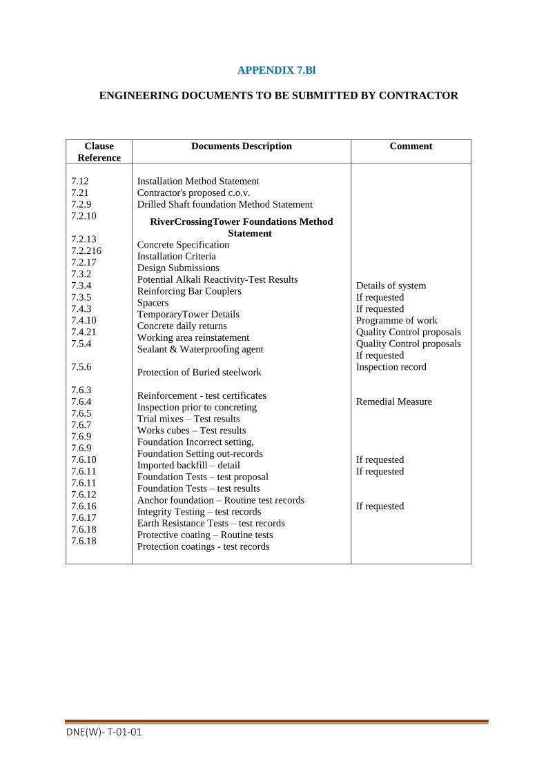
DNE(W)- T-01-01
APPENDIX 7.Bl
ENGINEERING DOCUMENTS TO BE SUBMITTED BY CONTRACTOR
Clause
Reference
Documents Description Comment
7.12
7.21
7.2.9
7.2.10
7.2.13
7.2.216
7.2.17
7.3.2
7.3.4
7.3.5
7.4.3
7.4.10
7.4.21
7.5.4
7.5.6
7.6.3
7.6.4
7.6.5
7.6.7
7.6.9
7.6.9
7.6.10
7.6.11
7.6.11
7.6.12
7.6.16
7.6.17
7.6.18
7.6.18
Installation Method Statement
Contractor's proposed c.o.v.
Drilled Shaft foundation Method Statement
RiverCrossingTower Foundations Method
Statement
Concrete Specification
Installation Criteria
Design Submissions
Potential Alkali Reactivity-Test Results
Reinforcing Bar Couplers
Spacers
TemporaryTower Details
Concrete daily returns
Working area reinstatement
Sealant & Waterproofing agent
Protection of Buried steelwork
Reinforcement - test certificates
Inspection prior to concreting
Trial mixes – Test results
Works cubes – Test results
Foundation Incorrect setting,
Foundation Setting out-records
Imported backfill – detail
Foundation Tests – test proposal
Foundation Tests – test results
Anchor foundation – Routine test records
Integrity Testing – test records
Earth Resistance Tests – test records
Protective coating – Routine tests
Protection coatings - test records
Details of system
If requested
If requested
Programme of work
Quality Control proposals
Quality Control proposals
If requested
Inspection record
Remedial Measure
If requested
If requested
If requested

DNE(W)- T-01-01
APPENDIX 7.Cl
NOTIFICATION AND HOLD POINTS
ClauseRefere
nce
Notification Points Hold Points
7.1.1
7.1.2
7.2.9
7.2.13
7.2.16
7.3.2
7.3.4
7.3.5
7.4.4
7.4.4
7.4.5
7.4.5
7.4.6
7.4.13
7.4.14
7.5.3
7.5.4
7.5.6
7.6.4
7.6.7
7.6.9
7.6.11
7.6.12
7.6.12
7.6.12
7.6.13
7.6.14
Spacers
Use of Explosives
Straightening of bars
Concrete Trial mixes
Joints
Epoxy Coating repair
Inspection prior to concreting
Concrete cube tests
Anchor Foundation-Routine
Tests
Foundation Design
Method statement
Drilled Shaft - Method statement
Concrete Mix Design -Specification
Installation Criteria
Potential Alkali Reactivity
Reinforcing Bar Couplers
Use of Explosives
Epoxy bars site cutting
Curing compounds
Sealant & waterproofing agent
Protection of buried steel work
Foundation Setting remedial measure
Foundation test program
Anchor Foundation -Suitability test
Anchor Foundation – Design test
Concrete pad & chimney
foundations – Design tests
Drilled shaft foundations -
Design tests

DNE(W)- T-01-01
APPENDIX 7.Cl
NOTIFICATION AND HOLD POINTS (Continued..)
Clause
Reference
Notification Points Hold Points
7.6.15
7.6.16
7.6.16
7.6.17
7.6.17
7.6.18
7.6.18
Integrity testing
Earth resistance tests
Protective coating tests
Piled foundations - Design tests
Integrity testing - test proposals
Earth resistance tests –Test proposals
Protective coating – test proposals
APPENDIX 7.Dl
REFERENCE STANDARDS
The reference standards and other documents referred to in this Section of the Specification
are listed below:
BS 12: Specification for Portland cement
BS 183: Specification for general purpose galvanized steel wire strand
BS 443: Specification for testing zinc coating on steel wire & for quality equirements
BS 729: Specification for hot dip galvanized coatings on iron & steel articles
BS 882: Specification for aggregates from natural sources of concrete
BS 970: Specification for wrought steel for mechanical and applied engineering purposes
BS 1305: Specification for batch type concrete mixers
BS 1377: Method of tests for soils for civil engineering purposes
Part 9: In-situ tests
BS 1881: Testing concrete
Part 101: Method of sampling fresh concrete on site
Part 116: Method of determining compressive strength of concrete
BS 1990: Wood poles for overhead and telecommunication lines
BS 1977: Specification for high conductivity copper tubes for electrical purposes
BS 2870: Specification for rolled copper and copper alloys, sheet, strip and foil
BS 2971: Specification for copper and copper alloys. Tubes
BS 2874: Specification for wrought steel for mechanical and applied engineering purposes.
BS 3643: ISO Metric screw threads
BS 3892: Pulverized - fuel ash
Part 1: Specification for pulverized - fuel ash for use Alith Portland cement
BS 4027: Specification for sulphate - resisting Portland cement
BS 4190: Specification for ISO metric black hexagon bolts, screws and nuts
BS 4449: Specification for carbon steel bars for the reinforcement of concrete
BS 4466: Specification for scheduling, dimensioning , bending & cutting of steel reinforcement for
concrete
BS 4483: Specification for steel fabric for the reinforcement of concrete
BS 5328: Concrete
Part 1: Guide to specifying, concrete
Part 2: Methods for specifying concrete mixes
Part 3: Specification for the procedure to be used in producing, and transporting concrete
Part 4: Specification for the procedure to be used in sampling, testing and assessing compliance
of concrete
BS 7079 Visual Assessment of surface cleanliness
Part 1A Specification rust grades and preparation grades of uncoated steel substrates and steel substrates after
overall removal of previous coatings.

DNE(W)- T-01-01
BS 7295:Fusion bonded epoxy coated carbon steel bars for the reinforcement of concrete
Part 1: Specification for coated bars
Part 2: Specification for coatings
BS 7884:Specification for copper and copper cadmium stranded conductors for overhead electric traction and
power transmission systems.
BS 8004: Code of practice for foundations
BS 8081: Code of practice for ground anchorage
BS 8110: Structural use of concrete
Part 1: Code of practice for design and construction
BS EN 10025: Specification for hot rolled products of non-alloyed structural steels
and their technical delivery requirements
ASTM C33: Specification for concrete aggregates
ASTM C227: Standard Test Method for Potential Alkali Reactivity of
cement/aggregate combinations (Mortar bar method)
ASTM C289: Standard Test Method for Potential Alkali Reactivity of Aggregates (chemical method)
ICE: Specification for piling
CIRIA: Special Publication No.31 Guide to Concrete Construction in the Gulf Region
CIGRE: Special Publication No.81 Foundation Testing.

DNE(W)- T-01-01
DRTAWING 7.1 : EARTHING ARRANGEMENT
attached herewith.
DNE(W)- T-01-01
SECTION- 8
TOWERS
8.1 SCOPE
8.1.1 Classes of Towers
Reference shall be made to Appendix 8.A1 for the classes of tower required.
8.1.2 Designation of Tower Types
Reference shall be made to Appendix 8.A2 for the designation and use of the different tower
types.
8.1.3Standard HeightTowers
All standard height towers are those designed to support the conductors at the defined
clearance above designated ground under the specified ultimate limit state system loading
assuming such towers are at the same level on level ground and at the standard span apart.
Unless specified to the contrary, after taking account of the length of the insulator set all
standard height towers shall be arranged so that the point of attachment or suspension of the
phase conductors above the ground shall be the same for all tower types.
8.1.4 Extensions
Where specified each type of tower shall be designed to allow for variations in height. Towers
with any specified combination of extensions to the standard height tower, shall be capable of
carrying all required phase conductors, earthwires, insulator sets and fittings under the
specified system loading.
Reference shall be made to the Appendix 8.A3 for the range and type of extensions required.
Where individual leg extensions are specified for lattice steel towers they shall be directly
interconnect able and fully compatible with the basic tower body and all specified body
extensions.
8.1.5Span Criteria
The span lengths specified in Appendix 8.A4 shall be deemed to be the horizontal distance
between centre lines of adjacent support. When a span in excess of the specified maximum
span is unavoidable, advice on the application should be obtained from the Engineer.
Designs shall allow for the adjacent spans of the maximum specified length with one of the
spans at the maximum allowed for a single span. However the required weight span shall be
calculated by the contractor.
Angle Towers shall be suitable for minimum weight spans combined with maximum wind
span through the full angular range of line deviations for which the angle Towers are designed.
8.1.6 Not used
DNE(W)- T-01-01
8.1.7 Angle Towers
For angle Towers at the mean angle of deviation, the mean horizontal separation between
circuits shall not be less than that of a intermediate type support.
For bundled phase conductors the phase conductor attachment points on each crossarm/ganty
shall be arrange to ensure that the nominal horizontal separation between sub-conductors at the
tension joint (dead end), is not reduced by more than 25 mm.
8.2 DESIGN
8.2.1 General
Towers shall have the general arrangements and configurations shown in the drawings
included with the Specification. They shall be designed to resist the specified system loading
taking into consideration the required strength co-ordination factors. Clearances between live
parts and supporting steelwork, and between the phase conductors and ground or other
obstacles shall be as specified.
All tower designs shall be such as to facilitate inspection, painting, maintenance, repairs and
operation with the continuity of supply being the prime consideration.
The design shall be such that the number of different parts shall be as few as possible to
facilitate transport, erection and inspection. The maximum weight of the heaviest single
member should be limited to that within the normal lifting capability of the proposed erection
equipment.
Main leg members of lattice steel towers shall be formed of the maximum single lengths
appropriate to the body or leg extensions, and shall not without the Engineer's approval,
incorporate additional spliced sections.
For lattice steel towers a fully triangulated system of bracings shall preferably be adopted. If
full triangulation is not adopted, the overall stability and secondary bending, stresses must be
considered in the design.
Where fabrication processes employed adversely affect the material properties, or introduce
zones of high stress concentration the overall design of the structures shall take such factors
into account.
Cross arms shall be so arranged that they can be disconnected in the plane of the longitudinal
face of the tower without disturbing any members forming part of the tower body.
8.2.2 Attachments to Towers
The attachment of phase conductors, earthwires and erection/maintenance brackets shall be
undertaken as follows;
(a) River Crossing Towers
DNE(W)- T-01-01
i) Suspension insulator set and earthwire attachments shall be of an approved
swivel or shackle arrangement;
ii) Adjacent to and either side of all suspension insulators set attachment points,
additional maintenance points shall be provided, capable of resisting the
specified construction and maintenance (C&M) load;
iii) Adjacent to the earthwire suspension set attachment point, an additional
maintenance point shall be provided, capable of resisting the specified C&M
load;
iv) At each tower body cross arm connection point (bottom chord level)
maintenance plates/brackets shall be provided for the attachment of rigging
blocks, capable of resisting the specified C&M load;
v) Where it is proposed to erect complete sections of the tower by crane or
helicopter then permanent lifting points shall be provided.
(b) Auxiliary Tower
i) Tension insulator set attachments shall be of an approved swivel or shackle
arrangement;
ii) Adjacent to and either side of all tension insulator set attachment points,
additional maintenance points shall be provided, capable of resisting the
specified C&M loading. The additional maintenance points shall provide the
necessary mountings for stringing and maintenance equipment;
iii) Adjacent to all tension insulator set attachment points, a vertical maintenance
attachment point shall be provided, capable of resisting either the specified
C&M loads or that imposed by the use of a conductor stringing platform;
iv) Adjacent to the earthwire tension set attachment point, an additional
maintenance point shall be provided, capable of resisting the specified C&M
loads;
v) At each tower body cross arm connection point (bottom chord level)
maintenance plates/brackets shall be provided for the attachment of rigging,
blocks, capable of resisting the specified C&M loads.
All tower general arrangement drawings and/or erection diagrams shall clearly indicate
the safe working, load capacities of all maintenance points.
8.2.3 Stubs
Stubs for the standard height tower, tower body and leg extensions shall be of the same
design. Unless specified to the contrary only design of stub shall be permitted for each
type of tower and the stubs shall be identical for all four legs. For details of the cleat
design, reference shall be made to Clause 7.2.4.
The thickness of the stub leg members shall not be less than the corresponding tower leg
members.
8.2.4 Design Criteria
The towers shall be designed and dimensioned for maximum simultaneous load. The
design loads shall be calculated as per standard codes of practice taking into following
load assumptions:
I. Maximum working tension for conductors and earth wire shall be 50% of UTS for
Coastal region.
II. Maximum operating temperature shall be of 80˚ C and minimum temperature shall be
of 5˚ C .
DNE(W)- T-01-01
III. Maximum wind on conductor and earth ware shall be of 260 Kmph or according to
the Recommendation of Bangladesh National Building Code (BNBC) at Coastal
region (e.g. As per maximum wind for respective Tower’s site/location).
The Tower shall be designed and dimensioned for maximum simultaneous load. The
design loads shall be calculated as per standard codes of practice considering the above
mentioned guide line.
8.2.4.1 Normal Load Condition
a) Normal Loading
The towers shall be designed for the following loads considered to be applicable
simultaneously:
i) Vertical Loading
The weight of all insulators and all other fittings, tower, tower members,
condition & earthwire considering the weight span plus a load of 150 kg
regarding the weight of a lineman with tools.
ii) Transverse Loading
Wind pressure at right angles to the lines on the whole projected area of conductors
and groundwires of the specified lengths (wind spans), tower members, insulators
and all other fittings and the transverse components of the maximum working
tensions of conductor & earthwire due to maximum horizontal deviation angle of the
line.
iii) Longitudinal Loading
Longitudinal components of the maximum working tensions of conductor &earthwire
(for 3DAX).
b) Eccentric Loading
Towers shall be checked for eccentric loading caused by stringing of conductor for one
circuit and one earthwire on one side of the tower. In checking the tower for this kind
of loading the loads mentioned above for vertical, transverse and longitudinal loads
shall be considered for three conductors and ground wire on one side of the tower in
addition to wind on tower and weight of tower.
c) High Intensity Local Wind
High Intensity Local Wind is required to be considered by applying wind pressure at
right angle, 45˚ and 90˚ to the line specified in clause 8.2.5 (c) on tower body.

DNE(W)- T-01-01
8.2.4.2 Broken Wire Conditions
Towers shall be designed for conditions of any one phase conductor broken or earthwire
broken.
Towers shall be designed to keep safely the torsional moment from the phase and earth
conductors string forces on one circuit.
All attachment points with no broken wire load shall have the vertical, transverse and
longitudinal loads as specified under normal loading condition. The points with broken
wire longitudinal loads shall have the vertical and transverse loads due to the broken
wire weight and wind spans together with the transverse component of the phase or
ground wire from the unbroken span.
Each tower shall be designed so that no failure or permanent distortion occurs when
tested with applied forces considering the safety factors as mentioned in Clause
hereunder.
8.2.4.3 Safety Factor
Related to the loads applied the following minimum safety factors under maximum
simultaneous working loads shall apply.
Description Normal
Condition
Broken Wire
Conditions
Factor of safety based on elastic limit 2.50 1.5
8.2.5 Climatic Loadings
The climatic loadings on the conductors and insulators have been calculated using the
following expressions:
(a) Conductors
Fc = qdesCf A cos2
where:
qdes = design wind pressure including height and spatial effects (N/m2)
Cf = Force coefficient
= 0.9 Conductors DVS>0.6
= 1.3 Earthwires DVS>0.6
A = full projected area perpendicular to the wind (m2)
= angle of incidence of the wind to the conductors.
Note: The effective force is perpendicular to the conductor.
The total effect of the wind upon bundle conductors will be equal to the sum of the actions on the individual sub conductor.

DNE(W)- T-01-01
(b) Insulators
Fl = qdesCf A
where:
qdes = design wind pressure including height and spatial effects (N/m2)
Cf = Force coefficient (1.2)
A = area of insulator perpendicular to the wind (m2)
c) Lattice Towers
For lattice towers the following formulae shall be used to calculate the wind loading on the tower.
Ft = q10 {H/10} (1+0.2sin
22 )(AlCf 1 cos
2 + A2 Cf2 sin
2)
where:
q10 = reference wind pressure at 10m above ground level,
specified on the appropriate tower loading reference drawing
H = height to the centre of pressure of the panel (m) under consideration
= 0.19 for tower types 2DL, 2D1, 2D25, 2DT6
= 0.0 for case 4 for all tower types
= angle of incidence of the wind to face 1
A1, A2 = area of members in face 1 and 2
Cf 1, Cf2 = Force coefficient for faces 1 and 2
For flat sided members Cff = 3.96 (1-1.5Ø + Ø2)
Ø = solidity ratio.
For circular section members Cfc = 2.25 (1-1.5Ø + 3.125Ø2)
For mixed construction Cf = CffAf+ CfcAc
A A
where A = total area of members, Af area of flat sided members and Ac area of
circular members.
Note: 1) Where access ladders are fitted, they should be included in the
respective face area;
2) For horizontal formation towers between the gantry and the waist,
for any wind direction apart from 'longitudinal' both inner and
outer transverse faces should be considered;
8.2.6 Not used.
8.2.7 Security Loadings
Two conditions of security loadings have been considered in the design of the towers:
(a) Broken Wire The specified broken wire loading (residual static loads) shall be applied to the defined
phase conductor and earthwire attachment points; whilst the intact security loading shall
be applied to the remaining phase conductor and earthwire attachment points.
For towers fitted with suspension insulator sets the alleviating effects of the insulator set
movement have already been included in the specified loads. No allowance shall be taken
of any movement of the tower, unless specifically stated.
(b) Longitudinal
DNE(W)- T-01-01
The specified longitudinal loading (cascade collapse) shall be applied to all phase
conductor and earthwire attachment points simultaneously. For towers fitted with
suspension insulator sets the alleviating effects of insulator set movement have already
been included in the specified loads. No allowance shall be taken of any movement of the
support, unless specifically stated.
Where climatic (wind loading) have been specified, the appropriate support wind loading
shall be calculated in accordance with the requirements of Clause 8.2.5. No patch or
localised wind loading shall be considered.
8.2.8 Construction and Maintenance Loading
The specified construction and maintenance loading shall be applied to all phase
conductor and earthwire attachment points in the combinations stated.
Where appropriate these loadings and/or their individual components shall also be
applied to the corresponding maintenance points e.g. the vertical component shall be
applied to vertical maintenance attachment points, whilst the longitudinal is distributed to
the horizontal maintenance plates.
All members with an inclination of 40 degrees to 90 degrees to the vertical, shall be
checked for the effects of point loading of 1.5kN at its most onerous position. No other
loading shall be considered under this condition.
It is the Contractor's responsibility to consider all constructional loading due to his
proposed method of tower erection and conductor stringing. Where necessary, any
additional loading due to these methods shall be considered in the design of the tower and
especially the specified maintenance, lifting or attachment points. Under these conditions
a minimum partial safety factor of 1.5 shall be considered.
8.2.9 Downlead Tensions
The maximum downlead tension shall be as specified in Appendix 8.A5. However, for
the purpose of tower design they shall be assumed to be zero except where the vertical
load component increases the stresses in tower members. These tensions shall be
assumed to apply at both ends on low duty tension insulator sets.
8.2.10 Not Used
8.2.11 Not Used
8.2.12 Allowable Ultimate Unit Stresses
The allowable ultimate unit stresses used in the determination of the nominal strength
of support members shall be based on the following criteria:
(a) For lattice steel tower shall be based on the recommendations contained in BS DD 133
or ANSI/ASCE Std 10-90. For Std 10-90 the appropriate reference stress levels shall be
based on the values specified in BS 5950, and as summarised below:

DNE(W)- T-01-01
Grade Reference Stress Level (N/mm²)
S235JRG2 235 16 mm Nominal Thickness
225 > 16 40mm
S275JR 275 16mm
265 > 16 40mm
S355JO 355 16mm
345 > 16 40mm
(b) For lattice steel tower where the appropriate design stresses are not contained in the
specified code of practice/manual, reference shall be made to BS 5950;
8.2.13 Design Criteria
The maximum allowable slenderness ratios for members of lattice steel towers shall be:
For leg members, cross arm chords 120
For other load-bearing compression members 200
For secondary bracings, 250
For tension only members 250
For angles with slenderness ratios
measured about their x-x and/or y-y axis 200
Secondary bracings shall be designed in accordance with the requirements of DD
133.Members shall be of such size, shape and length as to preclude damage or failure
from vibration or stress reversal, including the detailing of the connections.
The minimum thickness and diameter of material used in members and bolts shall be in
accordance with the requirements of Appendix 8.A6.
8.2.14 Bolted Joints
Where appropriate all metal parts shall be secured with bolts and nuts with single spring
washers. All nuts and bolts shall be in accordance with clause 8.3.3 unless specified to
the contrary.
When in position all bolts shall project through the corresponding nuts by at least three
threads, but such projections shall not exceed 10 mm. No screwed threads shall form part
of a shearing plane between members.
The nuts of all bolts attaching phase conductor insulator sets, earthwire sets, maintenance
brackets/plates, access ladder brackets, fall arrest system attachment brackets shall be
locked in an approved manner preferably by locknuts.
The bolts of any one diameter in a tower/pole shall be one grade of steel.
Leg members shall be joined in such a way that electrical continuity is maintained to
ground.
DNE(W)- T-01-01
8.2.15 Electrical Clearances - Live Metal and Earthed Steelworks
Minimum clearance between live metal and earthed steelwork shall be in accordance with
the requirements of Appendix 8.A7.
8.2.16 Down lead Clearances
The clearance in still-air between down leads shall be in accordance with the
requirements of Appendix 8.A7. In exceptional circumstances and with the approval of
the Engineer, under conditions of maximum (opposing) conductor swing and sag, the
clearance may be reduced to the values specified in Appendix 8.A7.
8.2.17 Anti-Climbing Devices
Each support shall be fitted with an approved type of anti-climbing device as specified in
Appendix 8.A8. The height of the anti-climbing device shall be adjustable and shall be
within the limits specified in the Appendix.
Where specified the anti-climbing device shall be provided with a hinged section where
access for personnel is required. The hinged section shall be capable of being bolted and
locked in the closed position with either a bolt, nut and locknut or a padlock. In the open
position, no projection to impede safe access shall be permitted.
In no case shall an anti-climbing device be installed where it can be bypassed from a side
slope or internal bracing.
Barbed wire type anti-climbing devices shall comply with the following requirements:
(a) Barbed wire shall be of the mild steel type with high security long barbs 15 mm long
set at 50 mm spacing, but in all other respects the barbed wire shall comply with BS
4102, Section 4;
(b) For lattice steel towers the minimum distance between strands or between strands and
horizontal tower member/pole sections shall not be less than 150 mm;
(c) No unprotected space greater than 230 mm across shall be left inside the device;
(d) Spacers shall be fitted at 1.5 m intervals and shall be attached to tower members where
possible;
(e) Normally 5 strands of barbed wire are required outside the tower face and 3 strands
inside;
Spiked type anti-climbing devices shall comply with the following requirements:
(a) The minimum spike diameter shall not be less than 10 mm, and shall project
horizontally 50 mm and curve vertically down by 40 mm.
(b) Where spikes are bolted to the support frame the spike threads must be clenched after
installation.

DNE(W)- T-01-01
8.2.18 Livestock Guards
Means shall be provided on all lattice steel towers and tower extensions to avoid the risk
of livestock being caught between tower members and being injured.
Tower members near the around shall be sufficiently robust to avoid being damaged by
livestock. To enable supplementary livestock guards to be added, spare holes, normally
17.5 mm diameter and 300 mm apart, shall be provided on each face of the main leg
members and the appropriate faces of bracing members, for a distance of approximately
1200 mm from ground level.
8.2.19 Bird Guards
Where specified bird guards of an approved type shall be fitted to intermediate towers
fitted with suspension insulator sets. The bird guard shall either comprise a saw-tooth
plate, or a length of earthwire suitably distanced and splayed out at each end and
clamped to the cross arm member.
8. 2.20 Access Facilities
Each support shall be fitted with approved access facilities as specified in Appendix
8.A8. The following requirements for specific types of access facilities shall apply as
appropriate.
(a) Step Bolts
i) Step bolts shall be fitted between specified levels at 380 mm spacing;
ii) On double circuit towers they shall be fitted on the right hand leg on both
transverse faces; for single circuit towers they shall be fitted on the right hand
leg on one transverse face;
iii) The first step bolt below each cross arm or gantry shall be located on the
transverse face of the leg, and all remaining step bolts shall be fitted,
alternatively on the remaining of the support;
iv) On terminal and junction towers, provision shall be made for fitting of step bolts
on all legs;
v) Step bolts shall not be less than 16 mm diameters, fitted with nut, washer and
nut and shall project not less than 150 mm from the support when fitted;
vi) For steel poles, removable step bolts or step brackets in accordance with the
requirements of (v) shall be fitted. The step bolt brackets shall be permanently
attached to the pole;
vii) Where support legs are fabricated from solid round sections, clamp type steps
shall be provided at similar spacings and projection as step bolts.

DNE(W)- T-01-01
(b) Ladders
i) Ladders shall be fitted between specified levels, support faces and either
externally or internally;
ii) Ladders shall be in accordance with BS 4211, 350 mm between internal faces
and 300 mm rung spacing;
iii) Rest platforms shall where specified be fitted at approximately 10m height
increments with the rest platform 850 mm square and fitted with a guard rail
(1000 mm above the platform), intermediate rail and toe board (projecting 100
mm);
iv) Ladders shall project 1100mm above platforms, unless other hand holds are
provided and shall be between 150 to 230 mm from the platform where side
access to the platform is provided.
(c) Fall Arrest Systems
i) Fall arrest system shall be in accordance with the requirements of BS EN 360;
ii) The system shall be either a guided type fall arrester on a rigid anchorage line to
BS EN 353-1, or a guided type fall arrester on a flexible anchorage line to BS EN
353-2.
(d) Work Platforms
i) Work platforms shall be provided with hand rails as detailed in clause (b) iii);
ii) Platforms shall be designed for a transient load of 1.5kN vertically concentrated
load over any square with a 300 mm side, plus a 1.5 kN/sqm vertically
distributed load applied simultaneously to produce the worst loading condition.
iii) Flooring for platforms shall be the open type metal in accordance with BS 4592.
8.2.21 Danger and Identification Plates
All towers shall be fitted with danger and identification plates as specified in Appendix 8.A 8.
8.2.22 Earthwire Bonding
Attachment holes for the connection of earthwire bonds shall be provided adjacent to the
earthwire attachment point
8.2.23 Earthing of Towers
Attachment holes for the connection of the ground earthing conductor shall be provided on all
lattice towers standard heights adjacent to the stub connection, leg and body extension and
cleats of stubs.

DNE(W)- T-01-01
8.2.24 Design Calculations
The Contractor shall submit the following design calculations to the Engineer:
(a) wire clearance diagram;
(b) line diagram;
(c) tower design calculations (in an approved format) indicating the applied loadings,
the design load for each member under the critical loading case, member size,
slenderness ratio, allowable load and end connection details;
(d) when requested the load for each member for each loading case shall be made
available;
(e) foundation load schedule;
(f) wire clearance diagrams for each terminal and junction position.
The Contractor shall not proceed with any tower prototype test until after the
approval of the design calculation. This is a Hold Point.
8.2.25 Fabrication Drawings
The Contractor shall submit the following fabrication drawings to the Engineer;
(a) Panel assembly (fabrication) drawings;
(b) Erection drawings;
(c) Stub setting diagrams;
(d) Stub, anchor bolt assembly.
Panel assembly drawings shall show all material in place, complete with all fabrication and
connection details. A complete tabulation listing all pieces for the portion of the support
detailed shall be shown on each drawing.
Each erection diagram shall show one support panel, together with a key diagram
indicating its location on the complete support. Each piece shall be identified by its mark
number. The number and length of bolts and number and type of nuts and washers required
for proper assembly shall be shown at each connection. A complete tabulation listing all
the material needed for the support panel including all bolts, nuts, fill and bevel washers
and locknuts, shall be shown on each drawing.
The tabulation shall show the quantity, the mark number, the description of the piece
(including size and length), the total mass (including the allowance of 3.5% additional
mass for galvanizing) to the nearest 0. 1 kg of all the pieces of the same mark, and the
number of the drawing on which the shop detail of the piece can be found. The quantities
including 5% excess of step bolts, bolts, nuts, fill and bevel washers, and locknuts shall be
shown.
The Contractor shall make all changes to the detail (fabrication) and the erection drawings
which the Engineer determines necessary to make the finished support fabrication conform
to the requirements and intent of this Specification. The Contractor shall not proceed with
any fabrication until after the submission of the fabrication drawings. This is a Hold Point.
8.3 MATERIALS

DNE(W)- T-01-01
8.3.1 Steel
All steel shall comply with BS EN 10025 or BS EN 10210 as appropriate, unless
otherwise specified and shall be suitable for all the usual fabrication processes, including
hot and cold working within the specified ranges.
The quality of finished steel shall be in accordance with BS EN 10163. All steel shall be
free from blisters, scale, laminations, segregations and other defects. There shall be no
rolling laps at toes of angles or rolled-in mill scale.
Unless specified to the contrary the following grades of steel shall be applicable:
(a) Mild steel shall be either grade S235JRG2 or S275JR.
(b) High tensile steel shall be grade S355JR for sections less than 20 mm thick and
S355JO for sections greater or equal to 20 mm thick, except for plates which shall be
greater or equal to 40 mm thick.
(c) Steel plate used for folded, pressed braked or stretch bending pole Towers shall be
grade S275JO for rnild and grade S355JO for high tensile.
(d) Mild and high tensile steel hollow sections shall be grades S275JOH respectively.
(e) High tensile steel solid round sections shall be grade S355J,.IG3.
Steel section profiles shall be in accordance with the requirements of BS 4: Part 1, BS
4848: Part 2, BS 4848: Part 4 BS, BS EN 10024, BS EN 10034 and BS EN 10056-2 as
appropriate.
Hot rolled steel plate 3 mm thick- or above shall be in accordance with the requirements
of BS EN 10029.
8.3.2 Malleable Cast Iron
Malleable cast iron shall be in accordance with the requirements of BS 6681 for
whiteheart or pearlite and BS 2789 for spheroidal graphite.
8.3.3 Bolts, Nuts, Clevis Pins and Washers
Unless specified to the contrary the following grades of steel shall be applicable:
(a) Steel for bolts of 12 mm diameter and under shall be Grade S275 JR.
(b) Steel for bolts and clevis pins of 16 mm diameter and over shall be Grade S355JR.
(c) Steel for non-structural step bolts shall be Grade S275JR.
(d) Nuts shall be Grade S275JR.
Unless other specified, bolts and nuts shall be ISO Metric Black Hexagon to BS 4190, and
shall be threaded ISO Metric Course Pitch to BS 3643: Part 2, Tolerance Class 7H/8g.
Countersunk and other bolts without hexagon heads shall have slotted heads.

DNE(W)- T-01-01
All flat washers shall comply with the requirements of BS 4320, Form E, Grade 4.6. Unless
specified to the contrary they shall be 3 mm thick. Pack washers shall have an external
diameter of twice the nominal bolt diameter + 15 mm, a hole diameter of nominal diameter
+2 mm and a thickness as specified on the appropriate fabrication drawing,
Single core spring washers shall comply with the requirements of BS 4464, Type B.
Split pins shall comply with the requirements of BS 1574 and shall be of austentic stainless
steel capable of complying with the requirements relating to the inter crystalline corrosion
test of BS 970: Part 1 .
8.3.4 Welding
Consumable for use in metal arc welding shall be in accordance with the requirements of
BS 5135.
8.3.5 Flooring
Open type floor shall be fabricated from either steel complying with BS EN 10025 Grade
S275JR or BS 1474 Grade HE30. Minimum thickness for load bearing, transverse and
pressed bars shall not be less than 3.0 mm.
8.4 WORKMANSHIP
8.4.1 General
The work shall be carried out in a thoroughly reliable and workmanlike fashion in order to
ensure satisfactory assembly and erection, interchangeability of similar members,
accuracy of dimensions, position and alignment of holes.
Punched holes, shall wherever practicable, be Jig, NC or CNC punched true to form and
free from rags, burrs and distortions. Punches and dies shall be strictly monitored to
ensure that any producing, irregular holes or defects previously mentioned shall be
immediately replaced. Drilled holes shall be clean, free from burrs and square to the
surface of the material.
Hole diameters shall be in the black unless specified to the contrary. For bolts up to but
not including 30 mm diameter - nominal diameter +1.5 mm. For bolts 30 mm diameter or
greater - nominal diameter +2.0 mm.
8.4.2 Cutting
Cutting of materials by either cropping, shearing, guillotining will be permitted upto and
including the thickness specified below:
Quality (sub-grade) JR - 16 mm
JO - 20 mm
M aterials of either greater thickness or higher quality (sub-grade) must be either machine
frame-cut or cold sawn. Hand held flame-cutting is not permitted.
Where materials are cropped, sheared or Guillotined, the finished edge shall be free form
rags, burrs, notches and distortions. Flame-cutting of grade S355 steel shall be preceded by

DNE(W)- T-01-01
a slight pre-heat by passing the cutting, flame over the area to be cut and the cutting speed
reduced in comparison to those normally used for Grade S275 steels of similar thickness.
Every effort shall be made to avoid having the flame-cut edge in tension, especially in
grade S355. The flame-cut edges shall be lightly dressed after cutting to remove notches
etc.
8.4.3 Drilling and Punching
Punching, full sized holes will be permitted up to and including the thick nesses specified
below:
Quality (sub-grade) JR - 16 mm
JO - 20 mm
No hole shall be punched where the thickness of the materials exceeds the finished
diameter of the hole. Finished holes shall be true to form and free from rags, burrs and
distortion.
Materials of either greater thickness or higher quality (sub-grade) must be either drilled to
final diameter or punched 2 mm undersize and reamed or core drilled to final diameter.
The welding, up of misplaced holes is not permitted without the prior approval of the
Engineer. This is a Hold Point. In the case where approval is granted, the new hole must
be drilled where it passes through or adjacent to the weld are of the previous hole
irrespective of material grade or thickness.
8.4.4 Presswork/Bending
All bends in Grades S355JO and S355J2G3 steel over 90 in 1000 shall be made hot within
the temperature range of 850 to 1000 degrees Celsius, but normal cold correction will be
permitted. Means shall be provided for the random checking of temperatures (Tempilstiks
or Pyrometer).
Bends in Grades S235JRG2 and 275JR steel plates up to 10 mm thick may be made cold
up to an including 1175 in 1000.
Bends, open and close flanges in angle sections may be made cold up to and including 600
in 1000.
However, in both of the above cases, the Contractor shall take adequate precautions to
avoid the risk of subsequent galvanising embrittlement.
Bends shall be of even, profile and free from surface damage due to press tools
indentations.
The formation of bends by the 'cut and weld' method unless specified on the drawings, is not
permitted without prior approval of the Engineer. This is a Hold Point.
8.4.5 Welding
All welding shall be carried out in accordance with BS 5135.
Pre-heating, where required, shall be checked by the use of Tempilstiks or similar over an
area of 150 mm either side of the weld area.
Assembly welds (tacks) shall be carried out to the same procedures and welding
conditions as the main welds and shall be at least 50 mm long.

DNE(W)- T-01-01
Stop-start positions shall be kept to a minimum and shall be kept clear by a minimum of
25 mm of all corners and edges of plates (ie. the weld must be laid down continuously at
these points). Where the first run in multi-run welds is larger than subsequent runs,
welding should continue until completed, thereby ensuring the weld area is not allowed to
cool. After completion the unit should be allowed to cool slowly and should not be
subjected to draughts or low temperatures.
Where materials are to be galvanised, all welds shall be continuous so as to ensure a
pickle-tight connection and shall be thoroughly cleaned (preferably by shot-blasting) to
remove all slag, manganese (Carbon Dioxide welding), and weld splatter.
8.4.6 Erection Marks
Before leaving the fabricator's works, all members shall be stamped with distinguishing
numbers and/or letters corresponding to those on the general arrangement or fabrication
drawings. Additionally, the agreed fabricator's identification symbol must appear adjacent
to the erection mark.
Erection marks shall be stamped on before galvanising, using characters at least 10 mm
high and shall be clearly legible after galvanising.
Erection marks shall be located as follows:
(a) All members - stamped within 600 mm of the end but clear of holes;
(b) Plates or flat bars - stamped at most suitable position between holes;
(c) Main leg and elevation diagonal members - stamped at top end of bar;
(d) Horizontal members - stamped at either end of bar;
(e) Steel poles 100 mm either side of the joint.
Where malleable cast iron fittings are used the erection mark shall be 6 mm high raised
characters, where appropriate the following information shall be included:
(a) specified minimum failing load;
(b) date of manufacture (month and year)
(c) cast code.
Erection Mark coding shall be agreed with the Engineer. This is a Hold Point.

DNE(W)- T-01-01
8.5 PROTECTIVE TREATMENT
8.5.1 Galvanizing
Unless otherwise specified after completion of all fabrication processes (including all
drilling, punching, stamping, cutting bending and welding) support steelwork, poles and
pole steelwork, including nuts, bolts and washers shall be hot-dip galvanized and tested in
accordance with the requirements of BS 729. Electro-galvanizing is not an acceptable
alternative.
The minimum average coating thickness shall be as follows:
Thickness µm (Mass g/m²)
Steel articles which are not centrifuged :
5 mm thick and over 85 (610)
under 5 mm but not less than 2 mm 64 (460) Grey and malleable iron castings 85 (610)
Threaded works and other articles which are centrifuged 43 (305)
Excessively thick or brittle coatings due to high levels of silicon or phosphorus in the steel,
which may result in an increased risk of coating damage and/or other features that make
the final product non-fit-for-purpose shall be cause for rejection.
The ingot zinc used for galvanizing shall comply with the requirements of BS 3436.
All materials prior to galvanizing shall be free from oil, grease or any substance which
may adversely effect the quality of finish.
Castings should be as free as possible from surface porosity and shrinkage holes and
should be cleaned by grit blasting, electrolytic pickling or by other means specially
suitable for castings.
The preparation for galvanizing and the galvanizing itself shall not adversely affect the
mechanical properties of the coated materials.
Unless otherwise specified, all materials shall be treated with Sodium Dichromate in
order to prevent wet storage stains (white rust) during storage and transport.
All bolts and screwed rods, including the threaded portions, shall be galvanized. The
threads shall be cleaned of all surplus on packing, clear of the ground and away from all
materials that might stain or corrode the galvanizing. Black steel packing or bins shall not
be spelter by spinning or brushing. Dies shall not be used for cleaning threads other than
on nuts. Nuts shall be galvanized and tapped 0.4 mm oversize and threads shall be oiled.
Bolts shall be delivered with nuts run up the full extent of the thread.als shall be stored
used.
DNE(W)- T-01-01
8.6 TOWER ERECTION
8.6.1 General
The Contractor shall provide the Engineer with a method statement giving sequential
details of the erection method and including his intended program.
The method statement shall be submitted to the Engineer for acceptance the requisite
period before support erection commences. This is a Hold Point.
8.6.2 Safety
The erection shall be carried out in accordance with guidance given in the relevant parts
of BS 5531 and current health and safety legislation.
8.6.3 Site Storage
All support steelwork stored at site shall be kept clear of the ground where possible.
Contact with brackish water, or other substances likely to attack galvanizing shall be
avoided and all tower members kept in a clean and tidy condition.
Preventative measures shall be taken to prevent deterioration of galvanized or other
protective surfaces during transport, storage and erection. Superficial rust stains shall be
removed without causing damage to the protective surfaces.
8.6.4 Damaged Steelwork
Unless otherwise directed, steelwork damaged during off-loading, transportation, storage or
erection shall be replaced.
8.6.5 Damaged Galvanizing
The renovation of damaged area of galvanizing shall be carried out using a technical agreed
with the Engineer. This is a Hold Point.
8.6.6 Workmanship
The Contractor shall ensure that Towers are not strained or damaged in any way during
erection.
As far as practical, bolt heads, rather than nuts, shall be on the inner or downward faces of
support joints. Bolt locking, after erection shall be in accordance with the requirements of
Appendix 8.A.8.
All holes that align through both components of double angle (back to back) members shall
be filled by fitting, a bolt, with suitable pack washers between components. All spare holes
(eg. holes for alternative positions of supplementary fittings) in double angle members
shall be included in this requirement.
Towers shall be erected vertically within a tolerance of 0.005 percent of the overall height
before conductor erection.

DNE(W)- T-01-01
8.6.7 Anti-Climbing Devices, Danger and Identification Plates
As soon as practical after completion of support erection, anti-climbing devices, danger
and identification plates in accordance with the requirements of the clause 8.2.19 et sequis
shall be fitted.
All ladders and temporary step bolts below the anti-climbing device shall be removed
when erection work is not in progress.
8.6.8 Aircraft Navigation (Obstruction Aids)
Where required aircraft navigation obstruction lights complete with all necessary cabling,
control equipment, solar panels, storage batteries, access ladders and platforms shall be
fitted.
All installation shall be in accordance with approved general arrangement drawings and
supplier's instructions.
8.7 QUALITY CONTROL
8.7.1 General
Routine tests on raw material and fabricated individual members (components) of lattice
steel towers and associated steelwork shall be undertaken in accordance with the
requirements of this Specification. Prototype (type) tests on lattice steel towers shall be
undertaken when required by the Engineer in accordance with the requirements of Clause
8.7.7.
All steel ex-mills or received from merchants' stocks shall be marked to identify the cast
or casts from which it was made in accordance with Section 9 of BS EN 10025 and
Section 10 of BS EN 10210, and be covered by a test (mill) certificate stating the
mechanical, chemical and where specified the impact properties and carbon equivalent
value and clearly showing the cast numbers; to prove compliance with tables 2 and 5 of
BS EN 10025 and tables Al and A3 of BS EN 10210.
The optional impact test BS EN 10210 option 1.6 for quality JO steel hollow sections is
required.
Unless agreed to the contrary the following maximum Carbon Equivalent Values (CEV)
for steel supplied in accordance with BS EN 10025 and BS EN 10210 shall not be
exceeded:
Grade S235 0.35
S275 0.41
S355 0.45
see also BS 5950 Part 2, Clause 4.2
All high tensile steel solid round sections shall be ultrasonic tested for laminations at the
rolling mills in accordance with the requirements of BS 5996.
In the event of test certificates being unobtainable, the Contractor shall arrange, at his own
cost, for the independent testing and analysis of materials. Testing shall be in accordance
with the requirements of BSEN 10025, Section 8 and BS EN 10210, Section 7.

DNE(W)- T-01-01
The material grades of all individual pieces of shall be capable of positive identification
at all stages of fabrication.
Steels of different quality shall be stored separately.
Bolts and nuts shall be covered by the appropriate test certificate in respect of the tests
requirements stated in BS 4190.
Copies of all test certificates shall be made available to the Engineer.
8.7.2 Welding
Unless specified to the contrary all structural welded joints shall be undertaken using
approved welding procedures in accordance with BS EN 288. Copies of the welding
procedures shall be made available to the Engineer upon request. However, for all
welding associated with the fabrication of high tensile steel solid round sections, or where
the combined thickness of the material is in excess of 60 mm, the welding procedures
shall be submitted to the Engineer for approval, together with the related quality control
documentation such as electrode storage, drying and handling requirements.
This is a Hold Point.
All welders shall be tested to meet the requirements of BS EN 287 Part 1 using the
appropriate test corresponding to the weld positions and parent materials to be used.
Copies of the test certificates shall be made available to the Engineer upon request.
The Engineer reserves the right to have any welding operator retested at any time at no
extra cost.
Unless specified to the contrary all welding shall be subjected to a non-destructive testing
(NDT) programme. Where necessary, this may involve the appointment by the supplier of
an independent NDT organization approved by the Engineer who will undertake the NDT
programme.
This is a Hold Point.
The NDT organization shall have operators suitably qualified to Level 2 of
PCN/WSB/MT/001/87. The NDT organization shall submit their proposed procedures for
approval. This is a Held Point. The Contractor shall then ensure that the approved
procedures are rigidly adhered to.
The Contractor shall arrange for the appropriate level of weld/inspection to be undertaken,
which shall not be less than the following minimum requirements. For details of the
required level of inspection reference should be made to Appendix 8.A9.
Level 1: 100 percent visual inspection in accordance with the requirements of BS 5289.

DNE(W)- T-01-01
Level 2: 10 percent of the overall output shall be magnetic particle tested to the
acceptance criteria stated in BS 5135 Tables 18 and 19, Category C (except for
porosity, see Note A) for butt and fillet welds respectively.
Level 3: 10 percent of each welder's output shall be magnetic particle tested to the
acceptance criteria stated in BS 5135 Tables 18 and 19, Category B (except for
porosity, see Note A) for butt and fillet welds respectively.
Level 4: 20 percent of each welder's output shall be magnetic particle tested to the
acceptance criteria stated in BS 5135 Table 19, Category B (except for
porosity, see Note A) for fillet welds.
Level 5: 10percent of each welder's output shall be ultrasonic tested, with a further 10
percent of each welder's output magnetic particle tested - both to the
acceptance criteria in BS 5135, Table 18, Category B except for porosity. (See
Note A) for butt welds.
Note A All welds, especially butt welds must be continuous to ensure a pickle-tight
connection when galvanized.
B Ultrasonic testing to be in accordance with BS 3923, Part 1.
C Magnetic particle testing to be in accordance with BS 6072.
All weld inspection/testing, shall be undertaken a minimum of 48 hours after the
completion of the respective weld. This is a Notification point.
Copies of the NDT inspection reports for weld inspection levels 5 and 4 shall be made
available to the Engineer.
Copies for the NDT inspection reports for weld inspection level 3 and 2 shall be made
available to the Engineer upon request.
8.7.3 Castings All malleable cast iron castings shall be thoroughly inspected after sand blasting, and any
casting with castings defects e.g. sand inclusions and metal penetrations, cracking, raised
core, porosity shall be scrapped.
8.7.4 Check Erection
Prototype structures (and, where required by the Engineer repeat structures) shall be check
erected in order to verify the accuracy of detailing and fabrications, including forming,
location and size of bolt holes, clipping and shearing
The degree of check erection shall be sufficient to verify not only the main structure, but
all ancillary steelwork such as platforms, walkways, ladders etc.
In the case of lattice towers, the minimum check erection required shall be one face lying
horizontally and the adjacent face erected in the vertical plane, complete with hip and plan
bracings. Cross arms and earthwire peaks shall be completely assembled.
Sufficient blocking and support shall be provided to prevent distortion and overstressing
of the members to ensure proper fit. Assembly shall be accomplished without
extraordinary effort to align bolt holes or to force pieces into position. Bolt holes shall not
be reamed or enlarged.
DNE(W)- T-01-01
All modifications found necessary at the time of check erection shall be accurately
recorded and the Contractor's drawings, NC tapes etc., shall be amended. Where
necessary, modified G.A. drawings shall be forwarded to the Engineer.
Unless otherwise specified the check erection may be undertaken in either the black or
galvanized condition. Where materials are check erected galvanized, all modified items,
those subjected to damage or prolonged contact with black steel, shall be re-galvanized at
the supplier's cost.
The Contractor shall give the Engineer the requisite period of notice prior to a check
erection being ready for inspection. This is a Hold Point.
8.7.5 Galvanizing Tests for galvanized members and components shall be carried out at the works to ensure
compliance with the requirements of BS 729. Details of the test results shall be made
available to the Engineer upon request.
Certificates relating to the ingot zinc used for galvanizing shall also be made available to
the Engineer upon request. When requested the fabricator shall, at his own cost, provide a
pot melt analysis.
8.7.6 Tolerances The fabrication tolerances after galvanizing, which are not to be considered cumulative,
shall be as follows:
(a) On linear dimensions of nominal sections as per BS 4, BS 4848, BS EN 10024, BS EN
10029, BS EN 100-34 & BS EN 10056-2
(b) On overall length of member ± 1 mm
(c) On centres of holes ± 1 mm
(d) On centers of groups of holes ± 2 mm
(e) On back-gauges ± 1 mm
(f) On corresponding holes in opposite faces of an-le or channel sections ± 1 mm
(g) On specified hole diameter on the punch side + 0.3 mm
(in the black) or where drilled - 0 mm
(h) Taper on punched holes as measured between the specified hole
diameter on the punch side and the hole diameter on the die's side
(in the black-) shall not exceed + 1.00 mm
(i) On specified bends, open and close flanges ± 20/1,000
(j) On the specified included angle (in plan) between
welded leg connections or bracing connection plates ± 20/1,000
The permitted tolerance from straightness after galvanising shall not exceed an offset of 1:
1,000, except for hollow sections which shall not exceed 1:600 measured at the worst
point. For members greater than 3 m in length, the offset shall be measured over any 3 m
length in the member.
8.7.7 Prototype Tests – Lattice Steel Tower
Load tests on lattice steel towers shall be undertaken in accordance with the requirements
of IEC 60652 except the last sentence of sub-Clause 14.1 regarding premature failure of
Design tests. If a failure occurs in the final load case, the tower shall be re-tested.

DNE(W)- T-01-01
Test tower shall be fabricated from steel meeting the following maximum limits on yield
point :
Grade of Steel Maximum Yield Point
S235JRG2/ S275JR 345 N/mm²
S355JR/ S355JO 415 N/mm²
Each member of the test tower shall have its yield point identified either from certified
mill test reports traceable to the actual steel supplied or from test coupons. Yield point
values shall be recorded in the test reports.
The type and extension of the structures to be tested shall be in accordance with those
specified in Appendix 8.A10. In the event of the testing, facilities not be capable of special
testing the structures specified, the testing facilities may be assessed by the Engineer and
the extension reduced; or the Engineer has the right to specify a different test facility for
testing maximum height structures at no extra cost to Employer.
The structure shall be assembled on rigid foundations. If the Contractor, in carrying out
erection of structures on Site, proposed to assemble the structures on the ground and
subsequently raise them to the vertical position, the test structures shall be so erected in
the presence of the Engineer. The contractor shall give the Engineer the requisite period of
notice prior to the erection of the structure. This is a Notification Point. Structures
submitted for test, to-ether with bolts and fittings shall be galvanized.
The test load cases required to prove compliance of the structure design and order of tests
shall be agreed between the Engineer and the Contractor. There shall be no restrictions on
the number of test load cases to be applied to the structure which may include a test to
destruction. Loads shall be applied in a manner approved by the Engineer and maintained
for one minute, without variation. The test programme together with details of the test
rigging and load attachment details shall be submitted to the Engineer, this is a Hold Point.
Should it become necessary to adjust the loading, the one minute period shall
recommence after the loading is stabilised and constant. All test loads shall be removed
completely before the loads for the next tests are applied, unless previously agreed by the
Engineer. All test loads corresponding to phase conductor and earthwire loading shall be
applied directly to the regular attachment details provided for these loads.
Any conspicuous yielding or any failure under any test loading or the use of any incorrect
grade of steel shall be considered a defect. If a failure occurs, the Contractor shall correct
the defect and repeat the test loading at his own expense.
Coupons or test samples shall be cut from members which fail in the destruction tests and
from those members judged to be critical from the design calculations, and standard
tensile tests shall be performed at the Contractor's expense. The results of these tests
together with test report and certificate shall be made available to the Engineer.
Any structure or part thereof which has been subjected to type testing shall not be used
subsequently in the construction of the line, and the Contractor shall confirm the disposal
to the Engineer.
The Contractor shall furnish all test structures, testing facilities, rigging, load cells as may
be required and shall perform all work herein specified or implied. All items not
specifically mentioned shall be deemed inclusive to testing.

DNE(W)- T-01-01
The Contractor shall give the Engineer the requisite period of notice prior to undertaking
the tests.
8.7.7.1 Alternate of Prototype Tests – Lattice Steel Tower
The Tenderer shall be allowed to avoid Prototype Tests - Lattice Steel Tower ( as per -
8.7.7) by submitting a certificate from BRTC, BUET/ MIST/ CRTS, DUET to the
Employer having concurrence of using sophisticated software, which are capable of
producing very safe and adequate design of towers and are very reliable provided that the
tower are very safe and adequately design with appropriate design parameters and loading
conditions through analysis and verification of design on computers using appropriate
sophisticated software.
Also in such cases, the laboratory testing of tower materials (angles, bolts, plates) are to be
carried out to confirm the compliance with the design specifications from BRTC, BUET/
MIST/ CRTS, DUET approved by the Project Manager.
This is a Hold Point . 8.7.8 Certificate of Conformity
The certificate of conformity shall be supported by the following documentation:
(a) material test (mill) certificates;
(b) bolt and nut certificates;
(c) NDT welding inspection (levels 5 & 4);
(d) test reports of any prototype or sample tests undertaken;
(e) the results of any ultrasonic testing of solid round sections;
(f) the results of any welding NDT inspections (levels 3 & 2);
(g) Welder's test certificates;
(h) galvanizing thickness records;
(i) the ingot zinc certificates;
(j) galvanizing pot melt analysis;
8.7.9 Quality Control after Erection
The Contractor shall be responsible for checking that the Towers are complete and that all
bolts have been correctly tightened before conductor commences. A record of this work
shall be kept by the Contractor and made available to the Engineer on request.
Critical bolts are to be marked after erection with red paint to ensure priority checking
during maintenance.
Where appropriate, test on the aircraft obstruction lighting shall be undertaken to prove
compliance of the system. Records of the tests shall be made available to the Engineer
upon request.
APPENDIX 8.Al
CLASSES OF TOWER
33KV double circuit three phase river crossing towers with Energy saving type AACSR
Phase Conductor of minimum 400/65, Weight 1604 kg/km, breaking strength: 222kN,
overall dia: 25.5 mm, area of alluminium 400 sq.mm & area of steel 65 sq.mm, working
DNE(W)- T-01-01
tension: 148 kN.& One Earth wire ASTM A475, 7/(4.19-4.79)mm, galvanized sever wire
stand, weight:770-970 kg/km, breaking strength: 119-124 kN, overall dia 12.7mm.Working
tension:79.8 kN.
APPENDIX 8.A2
DESIGNATION & USES OF TOWERS
Designation Angle of
Deviation/Entry Description Type of
Insulator Set
33KVRiverCrossingTower 3DR 0 Degree River crossing Suspension 3DAX 0 to 20 Degree River crossing
Anchor
Tension
APPENDIX 8.A3
EXTENSIONS
Tower Type Type of Extension Range (m)
3DR ( Coastal ) Body Standard
3DAX ( Coastal ) Body/Leg Standard +4.5 Extension

DNE(W)- T-01-01
APPENDIX 8.A4
SPAN CRITERIA
1.0 River Crossing Towers
1.1 Climatic Loadings and Security Loadings (Intact Conditions)
Tower Type 3DR ( For Coastal )
(a) Wind span (A) (m) -
(b) Maximum weight span (m) -
(c) Minimum weight span (m) -
Tower Type 3DAX ( For Coastal )
(a) Wind span (A) front face (m) - rear face (m) -
(b) Maximum weight span front face (m) -rear face (m) -
(c) Minimum weight span front face (m) -rear face (m) -
1.2 Security, Loadings (Broken Wire Conditions)
Tower Type 3DR ( For Coastal )
(a) Wind span (A) (m) -
(b) Maximum weight span (m) -
(c) Minimum weight span (m) -
N.B- The Above data {described in Appendix 8.A4 ( Span Criteria) of 1.1 and 1.2} shall be
filled/finalized for each site based on the design and drawings approve by BRTC, BUET/
MIST/ CRTS, DUET approved by Project Manager and accepted by Project Manager.

DNE(W)- T-01-01
APPENDIX 8.A5
ASSUMED SYSTEM LOADING CRITERIA
8.A5-1 Tower Loading
33KV river crossing towers shall be designed assumed system loading criteria specified in
clause 8.2.4.
The Contractor's attention is drawn to the requirements of Clause 8.2.8 with regard to
Construction & Maintenance loading.
8.A5-2 Not used.
8.A5-3Downlead Tensions
Maximum phase conductor downlead tension 7.0 kN
Maximum earthwire downlead tension 4.5 kN
The above conditions apply under the specified MWT conditions as defined in Appendix
11.A3/1.
APPENDIX 8.A6
MINIMUM THICKNESS & DIAMETER OF MATERIAL
The minimum thickness and diameter of material used in members and bolts shall be as
detailed below:
(a) For leg members and compression chords in gantries
and cross arms. (mm) 6
(b) For secondary members without calculated stress. (mm) 5
(c) Gusset plates for lattice towers. (mm) 6
DNE(W)- T-01-01
APPENDIX 8.A7
1. ELECTRICAL CLEARANCES - LIVE METAL & EARTHED STEELWORK
Please refer to drawing of section-19, Volume 2 of 3 of the Tender Document.
2. SPATIAL DISTANCES 33 KV
(b) Minimum shielding angle of the earthwire
(still air) from the vertical (degrees) 20°
(c) Maximum swing of the earthwire from vertical (degrees) 85°
(d) Minimum vertical spacing between adjacent phases (m) 5.0
(f) Minimum vertical spacing between phase
conductors and earthwire (m) 3.2
(g) Minimum horizontal spacing between adjacent
phase conductors spaced horizontally. (m) 7.0 -
3. DOWNLEAD CLEARANCES
(a) The minimum clearance in still air at the assumed
maximum conductor temperature between adjacent
downleads shall not be less than. (mm) 915
(b) In exceptional circumstances and with the approval
of the Engineer, based on the condition of maximum
(opposing) conductor swing and sag, the clearance
may be reduced to. (m) -

DNE(W)- T-01-01
APPENDIX 8.A8
1. ANTI-CLIMBING DEVICES (ACD) Required / Not Required
(a) Barbed wire type at a minimum height
above ground level …….. (m) Not required
(b) Spiked type at a minimum height above
ground level …………..(m) 3.0
(c) Ladder to be fitted with spike type. 3.0
ACD with a lockable gate at a
minimum height above ground level….. (m)
(d) Bolt Locking All bolts below the bottom cross arm
level shall be locked by bronze
brazing of the nuts.
2. ACCESS FACILITIES
(a) Step bolts fitted between Ground level & within 1m of top of towers
(b) Ladders fitted between (or provision for) River Crossing Towers
from 15 above
ground level to top
of tower
(c) Rest platforms Required for River Crossing
Towers at 10 meter intervals
(d) Work platforms River Crossing and Anchor
Towers at all cross arm level.
(e) Fall arrest system To be fitted to ladder
3. DANGER & IDENTIFICATION PLATES
(a) Danger Palate Required
(b) Tower Number,
Circuit Identification & Required
Phase Color Plate.

DNE(W)- T-01-01
APPENDIX 8.A9
QUALITY CONTROL WELD INSPECTION LEVELS
Level 1: All welded items not covered by higher level of inspection
Level 2:
Level 3: Conductor attachment fittings for all types of towers.
Level 4: All welding undertaken for all types of 3DR & 3DAX towers.
Level 5:
APPENDIX 8.A10
TOWER TEST REQUIREMENTS
The following tower types shall require full scale prototype tower tests in accordance with
IEC 652.
33KV: 3DR (Coastal )
3DAX Standard

DNE(W)- T-01-01
APPENDIX 8.Bl
ENGINEERING DOCUMENTS TO BE SUBMITTED BY CONTRACTOR
Clause
Reference
Document Description Comment
8.2.24
8.2.25
8.6.1 8.7.1 Material Test Certificates
8.7.1
8.7.1
8.7.2
8.7.2
8.7.2 8.7.2 NDT Inspection reports
8.7.2
8.7.2
8.7.5
8.7.5
8.7.5
8.7.7 8.7.7 Prototype test reports
8.7.7
8.7.8
8.7.9 8.7.9 Support Erection records If requested
Design Calculation
Fabrication Drawings
Method Statement
Material Test Certificates
Bolt & Nut Test Certificates
Welding procedures
Welders test certificates If requested
NDT procedures
NDT Inspection reports
NDT Inspection reports If requested
Galvanizing test records If requested
Ingot zinc certificates
Pot melt analysis
Prototype tower test programme
Prototype test reports
Certificate of conformity
Tower Erection records
If requested
If requested
If requested
If requested
If requested
If requested
If requested
APPENDIX 8.Cl
NOTIFICATION AND HOLD POINTS
Clause
Reference
Notification Points
Hold Points
8.2.24
8.2.25
8.4.3
8.4.4
8.4.6
8.6.1
8.6.5
8.7.2
8.7.2
8.7.2
8.7.7
8.7.7
8.7.7
Design Calculation
Fabrication Drawings
Misplaces Holes
Formation of Bends
Erection Marks
Method Statement
Damaged Galvanizing
Welding procedure
NDT organisation
NDT procedure
Prototype tower erection
Prototype tower test programme
Prototype tower test

DNE(W)- T-01-01
APPENDIX 8.D1
REFERENCE STANDARDS
The reference standards and other documents referred to in this specification are listed below IEC 60652: Loading Tests on OverheadLineTowers
IEC 60826 Design Criteria of Overhead Transmission Line
BS 4: Structural Steel Sections
Part 1: Specification for hot rolled sections
BS 183: Specification for general purpose galvanized steel wire strand
BS 443: Specification for testing zinc coatings on steel wire and for quality requirements.
BS 464: Specification for thimbles for wire ropes.
BS 729: Specification for hot-dipped galvanizing coating, on iron and steel article.
BS 970: Specification for wrought steel for mechanical and allied engineering purposes.
Part 1: General inspection and testing procedures and specific requirements for carbon, carbon manganese, alloy
and stainless steel.
BS 1474: Specification for wrought aluminium and aluminium alloys for general engineering purposes bars,
extruded round tubes and sections.
BS 1574: Specification for split cotter pins.
BS 2789: Specification for spheroidal graphite or nodular graphite cast iron.
BS 3643: ISO Metric threads.
Part 2: Limits and tolerances for course pitch screw threads.
BS 3923: Method of ultrasonic examination of welds.
Part 1: Method of manual examination of fusion welds in ferric steel.
BS 4102: Steel wire and wire products for fences.
BS 4190: Specification for ISO metric hexagon bolts, screws and nuts.
BS 4211 Ladders for permanent access to chimneys, other high structures, silos and bins.
BS 4320: Specification for metal washer for general engineering purposes. Metric series.
BS 4464: Specification for spring, washers for general engineering and automobile.
BS 4592: Industrial type metal flooring, walkways and stair treads.
BS 4848: Hot rolled structural steel sections.
Part 2: Specification for hot-finished hollow sections.
Part 4: Equal and unequal angles.
BS 5135: Specification for arc welding of carbon and carbon manganese steels
BS 5289: Code of practice. Visual inspection of fusion welded joints.
BS 5531 Code of practice. For safety in erecting structural frames.
BS 5950: Structural use of steelwork in buildings.
BS 5996: Methods of ultrasonic testing and specifying, quality grades of ferric steel plates.
BS 6072: Methods for magnetic particle flow detection.
BS 6681: Specification for malleable cast iron.
BS EN 287: Approval testing of welders for fusion welding.
BS EN 288: Specification and approval of welding procedures for metallic materials.
BS EN 353: Personal protective equipment against falls from heights guided type fall arresters.
BS EN 353-1: Specification for guided type fall arresters on a rigid anchorage line.
BS EN 353-2: Specification for guided type fall arresters on a flexible anchorage line.
BS EN 360: Personal protective equipment against falls froma height. Retractable type fall arrestors.
BS EN 1179: Specification for Zinc & Zinc Alloys.
BS EN 10024: Hot rolled taper flange I-sections. Tolerance on shape and dimensions.
BS EN 10025: Specification for hot rolled products of non-alloyed structural steels a their technical delivery requirements.
BS EN 10029: Tolerance on dimensions, shape and mass of hot rolled steel plat 3 mm thick or above.
BS EN 10034: Structural steel I and H sections. Tolerance on shape and dimensions.
BS EN 10056: Specification for structural steel equal and unequal angles
Part 2 Tolerance on shape and dimension
BS EN 10163: Delivery requirements for surface conditions of hot rolled steel plates, wide flats and sections.
Part 1 General requirements
Part 2: Plates and wide flats
Part 3: Sections
BS EN 10210-1: Hot finished structural hollow sections of non-alloy and fine grainedstructural steels-Technical delivery
requirements
BS DD 133 Code of Practice for strength assessment of members of lattice towers masts.
ANSI/ASCE Std 10-90 Design of SteelTransmissionTowers
DNE(W)- T-01-01
SECTION 9
INSULATORS
9.1 SCOPE
Both the type of insulator unit andinsulator set, whether suspension or tension used on
each type of support shall be approved, and shall have proven use under similar
environmental and operational conditions.
Insulator strings shall comprise of porcelain disc insulator units. All types of
insulators to be supplied under this Contract shall be supplied from the same
manufacturer.
Reference shall be made to Appendix 9.A1 for details of the specific requirements. Where
specified porcelain insulators shall be glazed Munsell Grey in accordance with BS 5252 or
equivalent.
9.2 DESIGN
9.2.1 General
All insulator units shall be designed to withstand the design service voltages including
lightning, switching and power frequency, the mechanical loads relevant to the
installation-service-maintenance conditions, the service temperature and environmental
effects. Internal stresses due to expansion and contraction of any part of the insulator unit
shall not lead to deterioration.
The design of insulator units shall be such as to avoid local corona formation and no
significant radio interferences shall be exhibited. Cap and pin Insulator units shall comply
with the general requirements of the IEC 60305 standards, except where specified
otherwise in this Specification
and Insulator units shall have straight head design to avoid concentration of mechanical
stress. Cross-section sketch of insulators unit showing the head design is included in the
enclosed drawing in drawing section.
9.2.2 Electrical and Mechanical Characteristics
The individual insulator units and the complete insulator sets shall have the electrical and
mechanical characteristics stated in Appendix 9.A2.
9.2.3 Couplings
Couplings between individual insulator units shall be as specified in Appendix 9.A 1.Ball
and socket couplings shall be in accordance with the requirements of IEC 60120. Sockets
shall either have ‘W’type security clips, or a split pin(R) clip in accordance with the
requirements of IEC 60372 as specified.

DNE(W)- T-01-01
9.2.4 Pollution
The design of insulator units shall take into account the principles contained in IEC 60815
for the specified pollution category. However, minimum creepage values (mm/kV) shall
be as specified.
9.2.5 Zinc Sleeve
Cap and pin insulator units shall where specified be fitted with zinc sleeve pins to prevent
cracking due to pin corrosion caused by the effects of pollution and high humidity. The
exposed part of the sleeve shall have a mass of at least 5(five) gram and metallurgic ally
bonded to the insulator pin.
9.2.6 Insulator Protective Device
The design of insulator protective fittings including corona shields shall
comply with the following requirements:
(a) shall effectively protect the insulator units, and the fittings from damage caused by
power arcs;
(b) shall effectively improve the voltage distribution along the insulator string;
(c) shall effectively improve the corona performance of the insulator set;
(d) shall be designed in such a way as not to be subject to breakage fatigue due to wind
induced vibration;
(e) shall withstand a specified mechanical load.
(f) shall be suitable where specified for live-line maintenance.
For details of the materials, workmanship and quality control requirements
for insulator protective fittings reference shall be made to Section 10.0 of this
Specification.
9.2.7 Low Duty Insulator Sets:
(Not Applicable)
9.2.8 Tension Insulator Sets-Earth End Linkages
Additional earth end links shall be provided where necessary to ensure that either the
specified clearance is maintained between the tension insulator set and the support
body/crossarm, or that satisfactory pairing is achieved between the phase sub-conductors.
9.3 MATERIALS
High grade, wet process porcelain used in the manufacturer of insulator units shall
comply with the requirement of IEC 60672.
Insulator caps and bases of malleable cast iron shall be manufactured from a suitable
grade of MCI complying with the requirement of BS 2789 for spheroidal graphite, or BS
6681 forwhiteheart and paralytic.
Insulator end fittings of forced or cast aluminium alloy shall be manufactured from a
suitable grade of aluminium alloy complying with the requirements of BS 1472 or BS
1490 and/or BS EN 1676 or equivalent respectively.

DNE(W)- T-01-01
Securitv 'W' clips shall be of phosphor-bronze composition in accordance with the
requirements of BS 2870 or equivalent and supplied in the half-hard condition with a
minimum harness of 155 VPN
Security 'R' clips shall be of austentic stainless steel capable of complying with the
requirements of relating to inter-crystalline corrosion tests of BS 970: Part 1.
Zinc sleeve shall have a total impurity not greater than 0.2 percent and shall comply
withthe requirement of BS EN 1179 or equivalent.
9.4 WORKMANSHIP
9.4.1 Insulator Units
The dimensions of all insulator units, together with materials and grades and other
pertinent information shall be shown on the contract drawings. Contract drawings shall be
submitted to the Engineer. This is a Hold Point.
Particular regard shall be paid to those dimensions which involve interchangeability,
correct assembly and those for which gauges are specified. Where appropriate insulator
caps and pins shall comply with the requirement of IEC 60120, IEC 60372 and IEC 60471.
Porcelain shall be sound, thoroughly vitrified and free from defects and blemishes which
might adversely affect the life of the insulator units.
Cement used in the construction of an insulator unit shall not fracture by virtue of
expansion, nor loosen by contraction and proper care shall be taken to locate the
individual parts correctly during assembly. The cement shall not give rise to chemical
reaction with metal fittings nor the zinc collars. The cement thickness shall be as uniform
as possible.
All insulator caps and bases are to be free from flaws, blowholes and shall be of a close-
grained quality.
Insulator pins shall be round, free from cracks, surface flaws, lamination and other defects.
The zinc sleeve shall not be porous and all mould lines shall be removed. The cement level
shall be approximately at the mid-point of the sleeve.
9.4.2 Identification and Marking
All insulator units shall be marked to ensure a system of traceability. Each unit shall be
clearly and indelibly marked as follows on the insulating component according to the
requirements of IEC 60383-1 :
(a) Electromechanical failing load
(b) Name or trade mark of the manufacturer
(c) Year of manufacture.
9.4.3 Installation Criteria
The manufacturer shall where necessary provide comprehensive instructions in a suitable
format regarding, the handling, and installation of insulator units.

DNE(W)- T-01-01
9.4.4 Erection
The Contractor shall provide the Engineer with a method statement giving sequential
details of the proposed erection method. The method statement shall be submitted to the
Engineer, the requisite period before insulator set erection commences. This is a Hold
Point.
Care shall be exercised in the handling and erection of insulator units to prevent scratches,
chipping or cracking of the insulation medium.
The Engineer shall be reasonable entitled to request the removal and destruction of any
insulator units from a string which they notice has been severely handled or knocked
during,
erection. All units which are scratched, chipped or abraded shall be removed and replaced.
Insulator units and fittings shall be laid on plastic sheets prior to erection and any foreign
matter shall be removed prior to installation.
The Contractor shall ensure that insulator units are not strained or damaged in any way
during, erection.
All bolt threads shall be coated with an approved grease immediately before erection.
9.5 PROTECTIVE TREATMENT
All insulator caps, bases and pins shall either be inherently resistant to atmospheric
corrosion or suitably protected against corrosion, such as may occur in transit, storage and
in service. All ferrous parts which will be exposed to the atmosphere in service, except
those made in the appropriate grade of stainless steel, shall be protected by hot dipped
galvanising to comply with the requirements of BS 729. All manufacturing processes shall
be completed prior to galvanizing.
The ingot zinc used for galvanizing shall comply with the requirements of BS EN 1179 or
equivalent.
All galvanized materials shall be stored on packing, clear off the ground and away from
all materials that might stain or corrode the galvanizing. Black steel packing, or bins shall
not be used.
9.6 QUALITY CONTROL
9.6.1 General
Type, sample and routine tests shall be undertaken on all insulator units and type tests on
insulator sets in accordance with the requirements of this Specification. Details of the test
requirements are summarized in Table 9. 1.
Acceptance criteria for Thermal Mechanical Performance Test and Electromechanical
Failing (EMF) load test shall be governed by the following, formula, irrespective of
sample size:
X- SFL
3 < C =

DNE(W)- T-01-01
where C =Acceptance Constant
X =Mean value of failing load
SFL =Specified EMF load
=Standard deviation
Test result of each sample shall not be less than the specified EMF load.
In addition electrical puncture shall not occur before ultimate fracture.
Contract, drawings previously submitted to the Engineers shall be available at the time of
testing.
The Contractor shall give the Engineer the requisite period of notice prior to undertaking
the tests, and shall submit to the Engineer a test programme and procedures. This is a
Hold Point.
9.6.2 Type Tests –
(i) String Insulator Units:
Type test for string, (cap and pin) insulator units shall be in accordance with all the
requirements of IEC 60383-1.
Methods of tests shall comply with the requirements of the above standard, unless
otherwise specified in the following clauses.
(ii) Insulator Sets
Type tests for insulator sets comprising cap and pin, insulator units complete with all
appropriate fittings including insulator protective fittings shall be undertaken in
accordance with the requirements of IEC 60383-2, to determine the dry lightning impulse
withstand voltage, wet switching impulse withstand voltage and the power frequency
withstand voltage as appropriate.
The manufacture shall submit details of the proposed simulation of the support structure
and mounting arrangement of the insulator sets to the Engineer. This is a Hold Point.
(iii) Type Tests - Radio Interference & Coron
Radio interference type tests shall be under-taken both on single insulator units followed by
a complete insulator set test. All radio noise measurements shall be made at a frequency of
1.0 MHZ (9 kHz band width), using a radio interference measuring set having a response
conforming to CISPR Publication 1. The test circuit shall conform to IEC 60437 and shall
be calibrated in-situ to determine any circuit losses. The set shall be adjusted to indicate
correctly, or alternatively an appropriate correction (in dB) shall be added to the
measurement. Ideally the measurement shall be made using a 300-ohm load resistance. All
readings shall be converted to dB above 1V across 300 ohms, taking into account any
corrections necessary.
The single unit test voltage shall be that which would appear across the live end unit in the
complete set test and shall be determined by an initial voltage distribution measurement.
Before final readings of the radio noise are taken it is permissible to wipe the unit with a
dry clean cloth, and to condition it at not more than 50% above the test voltage for up to 2
minutes. This may be repeated if the first measurement exceeds the first level.
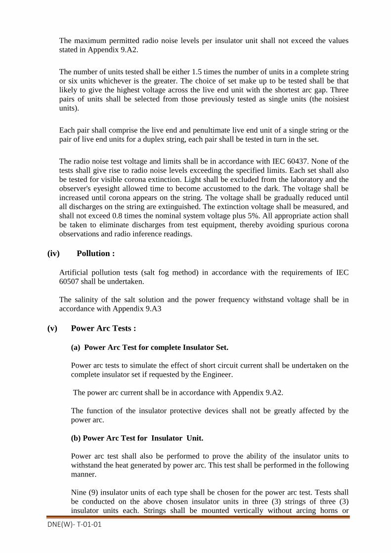
DNE(W)- T-01-01
The maximum permitted radio noise levels per insulator unit shall not exceed the values
stated in Appendix 9.A2.
The number of units tested shall be either 1.5 times the number of units in a complete string
or six units whichever is the greater. The choice of set make up to be tested shall be that
likely to give the highest voltage across the live end unit with the shortest arc gap. Three
pairs of units shall be selected from those previously tested as single units (the noisiest
units).
Each pair shall comprise the live end and penultimate live end unit of a single string or the
pair of live end units for a duplex string, each pair shall be tested in turn in the set.
The radio noise test voltage and limits shall be in accordance with IEC 60437. None of the
tests shall give rise to radio noise levels exceeding the specified limits. Each set shall also
be tested for visible corona extinction. Light shall be excluded from the laboratory and the
observer's eyesight allowed time to become accustomed to the dark. The voltage shall be
increased until corona appears on the string. The voltage shall be gradually reduced until
all discharges on the string are extinguished. The extinction voltage shall be measured, and
shall not exceed 0.8 times the nominal system voltage plus 5%. All appropriate action shall
be taken to eliminate discharges from test equipment, thereby avoiding spurious corona
observations and radio inference readings.
(iv) Pollution :
Artificial pollution tests (salt fog method) in accordance with the requirements of IEC
60507 shall be undertaken.
The salinity of the salt solution and the power frequency withstand voltage shall be in
accordance with Appendix 9.A3
(v) Power Arc Tests :
(a) Power Arc Test for complete Insulator Set.
Power arc tests to simulate the effect of short circuit current shall be undertaken on the
complete insulator set if requested by the Engineer.
The power arc current shall be in accordance with Appendix 9.A2.
The function of the insulator protective devices shall not be greatly affected by the
power arc.
(b) Power Arc Test for Insulator Unit.
Power arc test shall also be performed to prove the ability of the insulator units to
withstand the heat generated by power arc. This test shall be performed in the following
manner.
Nine (9) insulator units of each type shall be chosen for the power arc test. Tests shall
be conducted on the above chosen insulator units in three (3) strings of three (3)
insulator units each. Strings shall be mounted vertically without arcing horns or
DNE(W)- T-01-01
conductors. The current and duration of power arc shall be 12kA (symmetrical r.m.s)
and 0.1 sec or 6kA (symmetrical r.m.s) and 0.2 sec.
No shed breakage shall occur during the power arc test. Peeling-off or burn out of glaze
on the insulator surface and partial rib chip shall be permitted. If two or more insulator
units string break in the power arc test, this insulator design is considered to have failed
to meet the specifications. In case one insulator unit fails in the test, re-test on another
nine (9) insulator units shall be conducted in the same manner. Failure of anyone unit in
the re-test means that the insulator design has failed to meet the specification.
(vi) Impulse Voltage Puncture Tests
Impulse voltage puncture tests shall be undertaken in accordance with the
requirements of IEC 61211.
(vii) Residual Strength Tests
Residual strength tests on string insulator units shall be undertaken in accordance with the
recommendations of IEC 60797.
9.6.3 Sample Tests
The Contractor shall, give the Engineer the requisite period of notice prior to undertaking
Sample Tests. This is a Notification Point.
Sample tests for string insulator (cap & pin) insulator units shall be undertaken in
accordance with the requirements of IEC 603683-1, see also Appendix 9.Al.
Sample tests in respect of radio noise shall be undertaken on single units only in
accordance with the requirement of Clause 9.6.5 of this Specification. The sample size
shall generally be 0.5% of the batch offered for acceptance.
Number of sample to check the metallurgical bond of the zinc sleeve to the pin shall be in
accordance with IEC 61325.
The metallurgical purity of the zinc shall be established by chemical analysis to ensure that
any impurities do not sensitise the zinc to intergranular corrosion.
The zinc sleeve of each sample tested for mechanical strength shall also be inspected
according to IEC 61325, to ensure no radial and circumferential cracking has occurred.
9.6.4. Routine Tests
Routine tests for string insulator (cap and pin) units shall be undertaken in accordance with
the requirements of IEC 383-1, see also Appendix 9.Al.

DNE(W)- T-01-01
9.6.5 Galvanizing
Tests for galvanized insulator caps, bases and pins shall be carried out at the works to
ensure compliance with the requirements of BS 729. Details of the test results shall be
made available to the Engineer upon request.
Certificates relating to the ingot zinc used for galvanising shall also be made available to
the Engineer upon request.
9.6.6 Test Certificates
All metallic materials used in the manufacture of insulator caps, bases and pins shall be
covered by test certificates stating their mechanical, chemical and where specified the
impact properties and clearly showing the cast numbers to prove compliance with the
requirements of this Specification and BS 2789, BS 6681, BS 970, BS 1472, BS 1490, BS
2870, BS EN 1179 as appropriate.
Test certificates for metallic materials and bolts shall be made available to the Engineer
upon request.
Test certificates covering Type and Sample tests shall be made available to the Engineer
upon request.
9.6.7 Certificate of Conformity
When requested copies of the following certificates/records shall also be forwarded:
(a) Routine test records
(b) Metallic material test certificates
(c) Galvanizing test records
(d) Ingot zinc certificates
(e) Metallurgical purity test records for zinc sleeve.
9.6.8 Installation
The Contractor shall be responsible for checking that all insulator sets are complete and
that all bolts, split pins and security clips have been correctly installed. A record of this
work shall be kept by the Contractor and made available to the Engineer upon request.

DNE(W)- T-01-01
TABLE 9.1 - TEST REQUIREMENTS
Test String Insulator Units
Cap & Pin (Type B)
Insulator Sets
Type Tests:
Verification of dimensions
X X
Dry lightning, impulse w. voltage
X X
Wet power frequency w. voltage
X X(a)
Thermal mechanical performance
X
Mechanical or EMF load
X
Radia Interference Voltage (RIV)
X X
Pollution performance
X (b)
Power arc
X X
Impulse voltage puncture
X -
Zinc sleeve
X -
Residual strength
X -
Sample Tests: -
Verification of dimensions
X -
Verification of locking system and
displacement
X -
Temperature cycle test
X -
Mechanical or EMF load
X -
Porosity
X -
Galvanizing,
X -
Impulse Voltage puncture
X -
Routine Tests:
Visual inspection
X
Mechanical
X
Electrical
X
Notes: (b) Insulator string without fittings
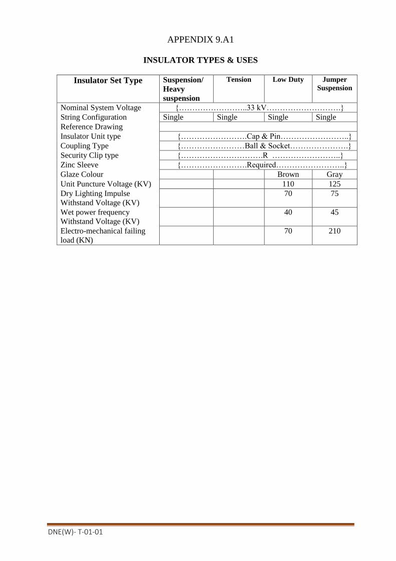
DNE(W)- T-01-01
APPENDIX 9.A1
INSULATOR TYPES & USES
Insulator Set Type Suspension/
Heavy
suspension
Tension Low Duty Jumper
Suspension
Nominal System Voltage {……………………..33 kV……………………….}
String Configuration Single Single Single Single
Reference Drawing
Insulator Unit type {…………………….Cap & Pin……………………..}
Coupling Type {……………………Ball & Socket………………….}
Security Clip type {………………………….R ……………………..}
Zinc Sleeve {…………………….Required……………………..}
Glaze Colour Brown Gray
Unit Puncture Voltage (KV) 110 125
Dry Lighting Impulse
Withstand Voltage (KV)
70 75
Wet power frequency
Withstand Voltage (KV)
40 45
Electro-mechanical failing
load (KN)
70 210
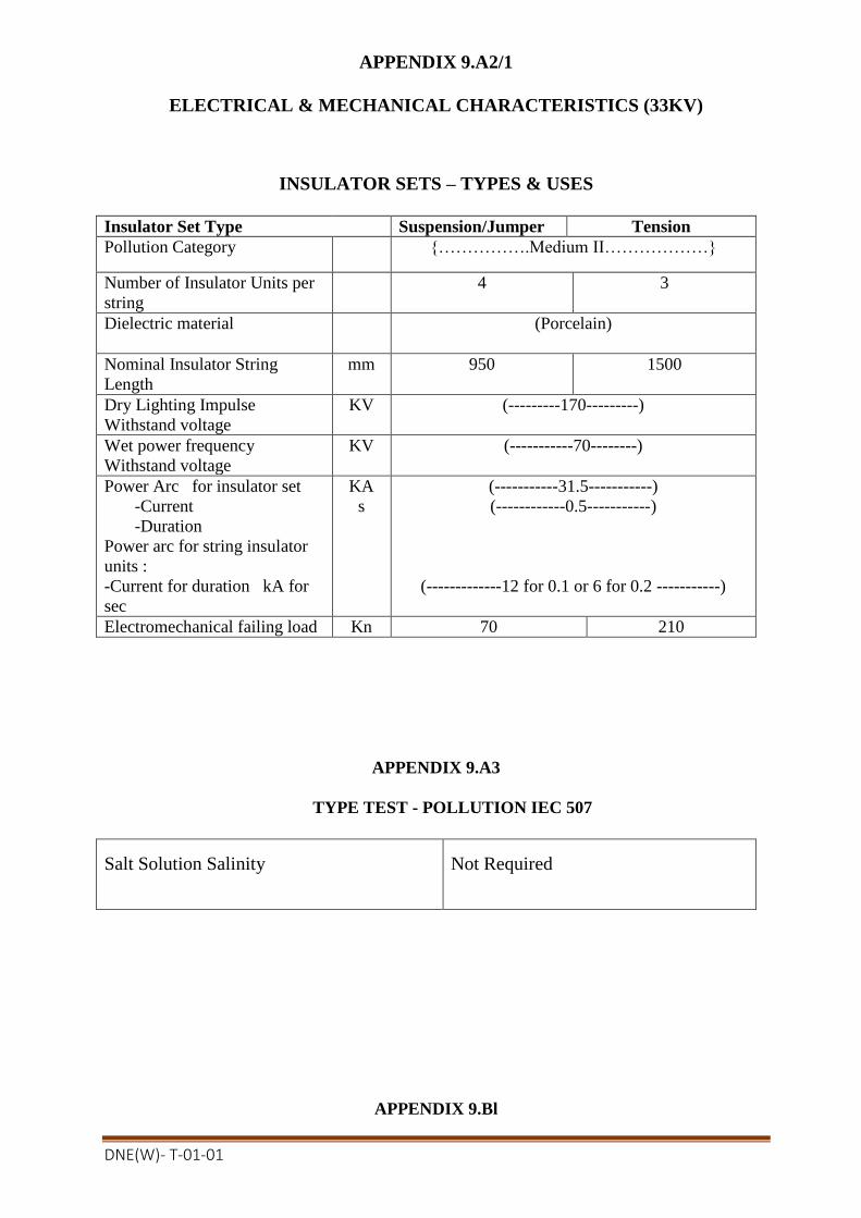
DNE(W)- T-01-01
APPENDIX 9.A2/1
ELECTRICAL & MECHANICAL CHARACTERISTICS (33KV)
INSULATOR SETS – TYPES & USES
Insulator Set Type Suspension/Jumper Tension
Pollution Category {…………….Medium II………………}
Number of Insulator Units per
string
4 3
Dielectric material
(Porcelain)
Nominal Insulator String
Length
mm 950 1500
Dry Lighting Impulse
Withstand voltage
KV (---------170---------)
Wet power frequency
Withstand voltage
KV (-----------70--------)
Power Arc for insulator set
-Current
-Duration
Power arc for string insulator
units :
-Current for duration kA for
sec
KA
s
(-----------31.5-----------)
(------------0.5-----------)
(-------------12 for 0.1 or 6 for 0.2 -----------)
Electromechanical failing load Kn 70 210
APPENDIX 9.A3
TYPE TEST - POLLUTION IEC 507
Salt Solution Salinity Not Required
APPENDIX 9.Bl

DNE(W)- T-01-01
ENGINEERING DOCUMENTS TO BE SUBMITTED BY CONTRACTOR
Clause
Reference
Document Description Comment
9.4.1 Insulator Units - Contract Drawings
9.4.3 Installation procedures Where necessary
9.4.4 Contract Drawings
9.6.1 Insulator units - Type test certificates If tests waived
9.6.1 Insulator sets - Type test certificates If tests waived
9.6.1 Type test - Programme& Procedure
9.6.4 Detailsof support simulations
9.6.11 Galvanizing, test results If requested
9.6.11 Ingot zinc certificates If requested
9.6.12 Materialtest certificates If requested
9.6.12 Insulator units - Type test results
9.6.12 Insulator units - sample test results
9.6.12 Insulator units - Routine test results If requested
9.6.13 Certificates of Conformity
9.6.14 Installation records Ifrequested
APPENDIX 9.Cl
NOTIFICATION AND HOLD POINTS
Clause
Reference
Notification Points Hold Points
9.4.1 Contract Drawings
9.4.4 Method Statement
9.6.1 Insulators - Type tests
9.6.4 Type tests - Support Simulation
details
9.6.8 Insulator - Sample Tests

DNE(W)- T-01-01
APPENDIX 9.Dl
REFERENCE STANDARDS
The reference standards and other documents referred to in this Section of i
Specification are listed below:
IEC 60120: Dimensions of ball and socket couplings of string, insulator units.
IEC 60305: Characteristics of string, insulator units of cap and pin type.
IEC 60372: Locking devices for ball and socket coupling of string insulator units -
Dimensions and tests.
IEC 60383: Insulators for overhead lines with a nominal voltage above 1000V
Part 1: Ceramic or class insulator units for ac systems Definitions, test methods and
acceptance criteria.
Part 2: Insulator string and insulator sets for ac - Definitions, test method and
acceptance criteria.
TEC 60437: Radio interference tests on high voltage insulators.
IEC 60471: Dimensions of clevis and tongue couplings of string insulator units.
IEC 60507: Artificial pollution tests on high-voltage insulators to be used on a.c. systems.
IEC 60672: Specification for ceramic and glass insulating materials.
IEC 60797: Residual strength of string, insulator units of glass or ceramic, materials for
overhead lines after mechanical damage of the dielectric.
IEC 60815: Guide for selection of insulators in respect of polluted conditions.
IEC 61211: Insulators of ceramic material or glass for overhead lines with a nominal
voltage greater than 1000V - Puncture testing,
BS 729: Specification for hot-dipped galvanizing coating on iron and steel articles.
BS 970: Specification for wrought steel for mechanical and applied Engineering
purposes.
Part 1: General inspectionand test procedures and specific requirements for carbon,
carbon manganese, alloy and stainless steel.
BS 1472: Specification for wrought aluminium and aluminium alloy.
BS 1490: Specification for Aluminium and aluminium alloy ingots and casting for
general engineering purposes.
BS 2870: Specification for Rolled Copper and Copper Alloys: Sheet, strip and foil.
BS 2789: Spheroidal graphite cast iron.
BS 4190: Specification for ISO metric hexagon bolts, screws and nuts.
BS 5252: Framework for colour co-ordinations of buildings.
BS 6681: Specification for malleable cast iron.
BS EN 1179: Specification for Zinc & Zinc Alloys
BS EN 1676: Aluminiurn & aluminium alloys - Alloyed ingots for re-melting.
CISPR: Publication 1 Specification for CISPR radio interference measuring apparatus
for the frequency range 0.15to 30 MHZ.

DNE(W)- T-01-01
SECTION 10
INSULATOR AND CONDUCTOR FITTINGS
10.1 SCOPE
10.1.1 Types and Uses
The type and arrangement of all insulator and earthwire sets inclusive of all insulator
and earthwire set fittings, suspension clamps, conductor tension fittings and insulator
protective devices shall be approved.
Reference shall be made to Appendix 10.A1, A2 and A3 for details of the specific
requirements.
10.2 DESIGN
10.2.1 General
All insulator and conductor fittings shall be so designed so as to:
(a) avoid damaging the conductor under all service conditions;
(b) withstand the mechanical loads relevant to the installation-service-maintenance
conditions, the design service current including short circuit effects, tile service
temperature and environmental effects;
(c) be free from visible and audible corona discharge and radio interference at the
voltage levels specified, except those designed exclusively for use on earthwires;
(d) minimize the number of parts and the possibility of incorrect assembly and
installation;
(e) ensure that individual components are secured against becoming loose in service,
and all threaded fasteners shall be locked;
(f) Compression fittings after compression shall not permit relative movement between
the individual layers of the conductor.
(g) from material, which have sufficient strength, ductility and environmental
resistance to withstand the static and dynamic loading.
Where appropriate insulator and conductor fittings shall be in accordance with the
requirements of IEC 1284. Ball and socket coupling shall be in accordance with the
requirements of IEC 120. Socket fitting shall be designed for 'W' type security clips or
'R' type security pins in accordance with the requirements of IEC 372 as appropriate,
clevis tongue couplings shall be in accordance with the requirements of IEC 471.
All factory formed helical fittings shall be preformed with a right hand lay and shall
completely enclose the conductor except for small gaps required to ensure that all rods
make good contact with the conductor over their entire length.

DNE(W)- T-01-01
10.2.2 Live-Line Working
Where live-line working is specified in Appendix 10.A1 the design of the fittings
shall take into account the following requirements:
(a) both suspension and tension insulator sets shall include either clevis fittings, or
yoke plates incorporating cut-outs correctly dimensioned suitable for live-line
working;
(b) the minimum distance between the attachment point and the shoulder for clevis
fittings shall not be less than 125 mm, where no yoke plate is adjacent;
(c) clevis and tongue and clevis-clevis connections shall be provided with 'R' type
security pins;
(d) insulator protective devices attached to yoke plates shall utilize captive bolts.
10.2.3 Sag Adjusters
All tension insulator sets shall incorporate sag adjusters for adjusting the sag of either
Individual phase conductors or sub-conductors forming a phase conductor bundle.
The total range of linear adjustment and individual steps shall be as specified in
Appendix 10.A1.
When specified low-duty tension insulator sets shall incorporate a turnbuckle for
adjusting the sag of the complete downlead. The turnbuckle where appropriate shall
comply with the requirements of BS 4429 and shall be fitted with locknuts. The total
range of linear adjustment shall be as specified in Appendix 10.A1. The turnbuckle
shall be fitted in the earth end of the low duty tension insulator set.
10.2.4 Insulator Protective Fittings: Not Used
10.2.5 Electrical and Mechanical Characteristics
The insulator and earthwire set fittings, suspension clamps, conductor tension fittings
and insulator protection devices shall have the electrical and mechanical characteristics
specified in Appendix 10.Al, A2 and A3.
10.2.6 Suspension Clamps
Suspension clamps shall be designed to meet the following requirements:
(a) so that the effects of vibration both on the conductors, or the earthwire and on the
clamp themselves are minimised;
(b) to avoid localised pressure or damage to the conductor or earthwire, and shall
have sufficient contact surface to avoid damage by fault currents;
(c) shall be free to pivot in the vertical plane of the conductor/earthwire and shall
have a minimum range of movement of plus or minus 30 degrees;
(d) shall have a slipping capacity between specified minimum and maximum slipping
loads;
(e) suspension clamp assemblies shall have sufficient strength and durability to
prevent deterioration in service;
f) The mouth of the suspension clamp shall be rounded and slightly flared, with a
minimum radius of curvature in the vertical plane of 150 mm.

DNE(W)- T-01-01
10.2.7 Earthwire Suspension Clamps
Where specified earthwire suspension clamps and all suspension clamps for use with
earthwire with embedded optical fibre cable and ADSS optical fibre cable shall be of
the armour grip type, generally in accordance with the requirements of Clause 10.2.5,
except that they shall be capable of being used in conjunction with factory formed
helical armour rods and neoprene liners.
10.2.8 Counterweights
When specified counterweights shall either be fitted below the suspension clamp by
extension of the clamp-keeper retaining bolts, by attachment to the yoke plate, or by
replacement of the complete assemblies for multi-bundled conductors for use with pilot
suspension insulator sets.
Where the complete clamp assembly is replaced, the counterweight shall be fitted with
permanently bonded aluminium liners and all retaining bolts, nuts and washers shall not
protrude beyond the cylindrical section of the weight.
10.2.9 Connectors and Joints
Connections and joints shall be designed to meet the following requirements.
(a) that after installation the initial contact area of the fitting to the conductor or
earthwire does not raise stresses which may lead to failure under aeolian
vibration or other conductor oscillation conditions;
(b) localised pressures which may cause excessive cold flow of the conductor or
earthwire shall be avoided;
(c) to minimise internal voids and to prevent the ingress of moisture during service;
(d) full tension joints (dead ends and midspans) shall not permit slipping of, or cause
damage to, or failure of the complete conductor or any part thereof at a load less
than 95 percent of the rated ultimate strength of the conductor;
(e) non tension joints and connectors shall not permit slipping of, or cause damage to
the conductor at a load less than 25 percent of the rated ultimate strength of the
conductor;
(f) those connectors and joints with auxiliary eyes intended for use during
construction or maintenance shall be marked with the specified minimum failing
loaded stated by the manufacturer.
10.2.10 Tee Connector
Tee connectors shall be as specified either interlocking compression type or bolted type.

DNE(W)- T-01-01
10.2.11 Full Tension Joints (Dead End)
Full tension joints (dead end) shall be of the following types:
(a) Compression
Compression dead ends shall have either integral jumper terminals or jumper terminal
flags for use with bolted jumper palms. Integral jumper terminals shall either be
straight or 30 degree line type.
(b) Bolted Bolted dead ends shall be designed to ensure that once the bolts have been tightened to
the manufacturer's recommended torque, no slackening of the clamp can occur.
(c) Wedge
Wedge clamps shall be designed with the attachment straps. The body and the wedges
shall be of forged aluminium alloy. The body shall be hinged and the design shall
incorporate dovetail interlocking wedges and body. The performance of the clamp
shall be unaffected by manufacturing tolerances in the wedges and the bodies. The
design of the conductor guide assembly shall ensure that it is possible to tighten the
bolts with the wedge clamp straps assembled in their correct position.
(d) Factory Formed Helical
For details of the exact requirements reference shall be made to Appendix 10.A3.
Helical dead ends for earthwires or ADSS optical fibre cables shall be supplied
complete with solid thimbles in accordance with the requirements of BS 464.
10.2.12 Full Tension Joints (Midspans)
Full tension midspan joints shall be of the compression type, joints for metallic
conductors shall include a longitudinal centring key. Joints for monometallic
conductors shall include a central barrier stop to ensure correct longitudinal centring of
the joint.
10.2.13 Non-Tension Joints
Non-tension joints shall be of the following types:
(a) Disconnectable
Disconnectable joints shall comprise two identical straight palms, and shall be supplied
complete with bolt assemblies. Bolt assemblies shall consist of bolts and nuts, grade
8.8/8 in accordance with BS 4190 complete with load spreading washers.
(b) Non-disconnectable
Non-disconnectable joints shall be of the compression type.
(c) Jumper Palms Jumper palms for connecting jumper loops to dead ends, or tee connectors shall be of
the compression type with either straight or 30 degree lugs. Bolt assemblies shall be
in accordance with requirements specified for disconnectable joints.

DNE(W)- T-01-01
10.2.14 Repair Sleeves
Repair sleeves shall be either compression types, or factory formed helical type. The
compression type shall be two part interlocking sleeve or key type. Reference shall be
made to Appendix 10.A3 for the specified requirements.
Repair sleeve shall be designed to make good a conductor of which not more than one-
third of the strands of the outermost layer have been severed.
10.2.15 Line Termination Fittings Line termination fittings shall be either bimetallic or aluminium. Bi-metallic fittings
shall be designed to prevent corrosion between dissimilar metals, they shall include
both a waterproof barrier at the end of the compression termination and a waterproof
joint adjacent to the substation equipment terminal.
Reference shall be made to Appendix 10.A3 for the specific requirements.
10.2.16 Armour Rods
Armour rods shall be of the factory formed helical type and comprise sets of individual
rods compatible with the conductor. The rods shall completely enclose the conductor
except for small gaps required to ensure that all the rods make good contact with the
conductor over the entire length.
10.2.17 Jumper Weights
Jumper weights for multi-bundled phase conductors shall be fitted with permanently
bonded aluminum liners, and all retaining bolts, nuts and washers shall not protrude
beyond the section of the weight.
10.2.18 Tubular Jumpers
Tubular Jumpers where specified shall be supplied complete with integral compression
jumper terminals. Earthing bars for tubular jumpers shall have captive locking bolts
opposite to the hinge bolt. The earthing bar shall be of solid aluminium rod.
10.2.19 Earthwire Bonding Clamps
Earthwire bonding clamps for the connection of flexible earthwire bonds to the
earthwire shall be explosively applied wedge tap assemblies C-type, in accordance with
the requirements of BS 4579: Part 3. For OPGW termination positions the C-type
connectors shall be complete with a lug. The lug shall have a 18 mm diameter hole.
10.2.20 Earthwire Bond
Earthwire bonds shall be manufactured from multi-strand, multi-wire fatigue resistant
aluminium alloy to BS 3242, with a minimum nominal cross sectional area of 100 mm².
The overall bond and individual strands shall be thoroughly greased with an approved
conductor grease (see clause 11.3.2), before being covered by an extruded flexible PVC
sheath, of minimum thickness 1.5 mm.
The bond shall be fitted with either a compression type lug or a compression type pin
20 mm diameter as appropriate. Compression lugs shall accommodate either M 16 or
M 12 bolts.
10.3 MATERIALS

DNE(W)- T-01-01
10.3.1Insulator and Conductor Fittings
Materials used in the manufacture of insulator and conductor fittings shall be of:
(a) adequate strength for the intended application and service life requirements
(including mechanical loads, vibrations, electrical currents and
environmental effects) and free from defects which would affect the
performance of the fitting;
(b) shall not be liable to inter granular or stress corrosion;
(c) the materials of compression fittings shall be capable of withstanding the
cold working of the material due to compression;
(d) steel compression components shall have sufficient impact strength after
compression;
(e) compatible with the conductor material, or capable of being used with an
intermediate material such that there can be no deterious effects on the
conductor, or fittings resulting from their use;
(f) the material shall not beadversely affected in the long term by a coating
applied for corrosion protection.
All phase conductor fittings shall have aluminium or aluminium alloy only in contact
with the phase conductor.
All mild and high tensile steel used in the manufacture of insulator and conductor
fittings including suspension saddles shall comply with the requirements of BS EN 10
025. Minimum steel grades shall be S275JR and S355JR for mild and high tensile steel
respectively.
Malleable cast iron fittings shall be made from whiteheart or pearlitic MCI or
spheroidal graphite MCI of a suitable grade complying with the requirements of BS
6681 or BS 2789 respectively.
Forged aluminium and aluminium alloy fittings shall be made from aluminium or
aluminium alloy of a suitable grade, complying with the requirements of BS 1472.
Cast aluminium and aluminium alloy fittings shall be made from aluminium or
aluminium alloy of a suitable grade, complying with the requirements of BS 1490
and/or BS EN 1676.
Twin-single bridging plates shall be manufactured from 99.9% pure EC grade
aluminium.
Bolts and nuts shall be either ISO Metric Black Hexagon to BS 4190, and shall unless
otherwise specified be threaded ISO Metric Course Pitch to BS 3643: Part 2, Tolerance
Class 7h/8g, or ISO Metric Precision Hexagon to BS 3692.
Flat washers shall either comply with the requirements of BS 4320, Form E, Grade 4.6,
or ISO Metric to BS 4320, 'bright series'. Spring washers shall be ISO Metric to BS
4464.
Split pins including 'R' type. security pins shall comply with the requirements of BS
1574 and IEC 372 respectively, and shall be of austentic stainless steel capable of
complying with the requirements relating to the intercrystalline corrosion tests of BS
970: Part 1.

DNE(W)- T-01-01
Security 'W' clips shall be of phosphor-bronze composition in accordance with BS 2870,
and supplied in half-hard condition with a minimum hardness of 155 VPN
Non metallic materials used shall have:
(a) good resistance to ageing;
(b) capable of withstanding service temperatures without detrimental change of
properties;
(c) adequate resistance to the effects of nitrogen oxides, ozone, ultra-violet
radiation and air pollution over the whole range of service temperatures.
10.3.2 Oxide Inhibiting Compound
Compression fittings shall be filled with oxide inhibiting compounds prior to despatch
from the manufacturers with the ends of the fittings temporarily protected. The
quantity of oxide inhibiting compounds shall be sufficient to ensure the integrity of the
fitting.
Where grease is used as an oxide inhibiting compound, it shall be of a neutral soft type
with a high melting point, and shall be in accordance with the requirements of Clause
11.3.2.
10.4 WORKMANSHIP
10.4.1 General
The dimensions of all insulator and conductor fittings shall be shown on the contract
drawings, together with material types and grades, protective treatment and any other
pertinent information. Contract drawings shall be submitted to the Engineer. This is a
Hold Point. Particular regard shall be paid to those dimensions which involve
interchangeability, correct assembly and those for which gauges are specified. Tolerances
where appropriate shall be in accordance with the requirements of IEC 372 or IEC 471.
All castings shall be free from flaws, blowholes and shall be of a closed-grained quality.
No repair of any casting shall be carried out without the approval of the Engineer. This is a
Hold Point.
The welding of all ferrous metals shall be carried out in accordance with BS 5135.
Ball ended fittings shall be free from cracks, surface flows, laminations and other defects.
Fittings shall be free from sharp edges, burrs and swarf, particular attention shall be paid to
insulator protective devices to prevent corona in service. The faces of flat faced fittings
shall be sufficiently parallel and flat to provide a suitable contact service and shall remain so
after fabrication. In addition care shall be taken to remove any surface contaminates prior
to packing, other than material introduced by the manufacturer as a protective measure.
The mouth of suspension and top (trunnion) clamps, counterweight, wedge and bolted
jumper weight clamps shall be free of sharp radius of curvature, ridges or other irregularities
which may lead to localised pressure or damage to the conductors, or the separation of
individual strands.
DNE(W)- T-01-01
Factory formed helical fittings shall have rounded ends, when used with ADSS optical fibre
cable the ends shall be relieved.
10.4.2 Identification and Marking
All insulator and conductor fittings shall be marked to ensure a system of traceability for
each component part of the fittings. Where practicable, and unless otherwise agreed
between the Engineer and the manufacturer, fittings shall be clearly and indelibly marked
with minimum 3 mm high characters as follows:
(a) Identification of fitting (reference number/specified minimum failing load);
(b) Maker's identification;
(c) Date of manufacture (month and year);
(d) Cast code - if appropriate;
(e) Conductor size or diameter range or code name - if appropriate;
(f) Fitting bolt installation torque - if appropriate;
(g) Compression die size - if appropriate;
(h) Length and direction to be compressed - if appropriate.
In the case of factory formed helical fittings, the information as required above shall be
provided on tear-off labels; additionally they shall be marked with paint to an agreed colour
code either at the cross-over point or at the centre of the fitting.
10.4.3 Installation Criteria
The supplier shall provide comprehensive instructions in a suitable format covering the
selection and installation, including the installation torque of any bolt, compression die sizes
and direction of compression.
Installation instructions shall include directions for the use of any additional materials to the
fittings, including the selection of such materials and of the conductor preparation.
Joints and connectors intended for the restoration of electrical and mechanical properties of a
conductor, shall have clearly defined manufacturer's instructions as to the extent of the
damage which they are intended to repair.
10.5 PROTECTIVE TREATMENT
All parts of insulator and conductor fittings shall be either inherently resistant to atmospheric
corrosion or suitably protected against corrosion, such as may occur in transit, storage and in
service. All ferrous parts which will be exposed to the atmosphere in service, except those
made in appropriate stainless steel, shall be protected by hot-dipped galvanising to comply
with the requirements of BS 729. All manufacturing processes shall be completed prior to
galvanising.
The ingot zinc used for galvanising shall comply with the requirements of BS EN 1179.
All external threads shall be cut or rolled before hot-dipped galvanised. Nuts to be
galvanised shall be subsequently tapped 0.4 mm oversize with the threads oiled.

DNE(W)- T-01-01
Where tubular steel insulator protective fittings are provided with galvanizing vent-holes,
these holes shall be effectively plugged after galvanizing with zinc plugs.
The rough machined surfaces of bolted palm joints and aluminium line termination fittings
shall be protected with a removable dry waterproof coating.
All galvanised materials shall be stored on packing, clear of the ground and away from all
materials that might stain or corrode the galvanizing. Black steel packing or bin shall not be
used.
10.6 QUALITY CONTROL
10.6.1 General
Type, sample and routine tests shall be undertaken on insulator and conductor fittings in
accordance with the requirements of this Specification. Type and sample test requirements
are detailed in Table 10.1. Type tests specified in Table 10.1 shall be undertaken on a
minimum of three samples, which shall be identical in all essential details, with the fittings to
be supplied. Heat cycle tests shall be undertaken on four samples.
Contract drawings previously submitted to the Engineer shall be available at the time of
testing. The Contractor/Supplier shall give the Engineer the requisite period of notice prior to
undertaking the tests and shall submit to the Engineer a test programme and procedures. This
is a Hold Point.
In addition to the tests specified, when required by the Engineer electrical type tests shall be
undertaken on complete insulator sets. For details of these tests reference should be made to
Section 9.0 of this Specification.
Mechanical Type Tests
10.6.2 Insulator Set and Earthwire Set Fittings
Each fitting shall withstand its specified minimum failing load for one minute, and shall be
tested in a manner as far as practical to that in service. One sample shall if practical be
taken to failure and the mode of failure recorded.
10.6.3 Insulator Protective Fittings (Not Used)
10.6.4 Suspension Clamps, Earthwire Suspension Clamps
(a) Tensile Test The clamp supported by its trunnions as appropriate shall be installed at its recommended
installation torque on a rigid bar of a suitable size and a tensile load equal to half its
specified minimum failing load applied to 90 degrees to the conductor axis. The load shall
be steadily increased, no failure shall occur at a load less than the specified minimum
failing load.

DNE(W)- T-01-01
(b) Conductor Slip Test A length of conductor shall be fitted into the clamp and the clamp bolts tightened to the
recommended torque. An axial tensile force shall be applied either to the conductor, or the
clamp. The conductor shall not slip through the clamp below a load of 7 kN or 5 percent of
the nominal breaking load of the conductor, whichever is the greater value. The conductor
shall slip through the clamp at a load not greater than 30 percent of the conductor minimum
breaking load. The conductor shall not be damaged, other than some flattening of the
strands.
10.6.5 Tension Joints, TeeJoints and Sleeves The fitting shall be assembled in accordance with the manufacturer's instruction on
conductors of the size and type with which it is to be used. The assembly shall be mounted
in a tensile testing machine, the end fixings of the conductor shall be such as to prevent
birdcaging or slipping of the individual strands. The length of conductor between fittings
under test and any other clamp or joint in the test assembly shall not be less than 100 times
the overall diameter of the conductor.
For factory formed helical tension terminations, the fitting shall be assembled in
accordance with the manufacturer's instructions. A tensile load of 40 percent of the
conductor breaking load shall be applied and maintained for 1 minute. The load shall be
relaxed and the fitting removed. The fitting shall be reapplied and the test repeated, after
subsequent removal and replacement the test shall be continued as detailed above.
For wedge clamps the test shall be carried out on a maximum size body and minimum size
wedges and on a minimum size body and maximum size wedge. The maximum and
minimum sizes shall be defined by the Manufacturer.
(a) The following additional requirement shall be applicable to wedge clamps. A 5 kN load
shall be applied to the assembly and the position of the wedges relative to the clamp
body recorded. Loads of 20, 30 and 40 percent of the conductor's nominal breaking load
shall be applied to the conductor and the relative position of the wedges recorded. After
the application of each load the torque on the wedge and conductor guide bolts shall be
removed and no conductor slip, shall occur. After 40 percent of the load when the
wedge bolts are released to check for no slip, it shall then be confirmed that the wedges
and body may be separated with the recommended extractor tool.
The number of strands severed for repair sleeves shall be the nearest whole number to one-
third of the total number of strands in the outermost layer and shall be severed at a uniform
spacing along the conductor.
A tensile load of 50 percent of the breaking load of the conductor shall be applied and the
conductor marked so that any relative movement of the fitting can be easily detected.
Without any subsequent adjustment of the fitting, the load shall be increased to 95 percent of
the breaking load and then reduced to 90 percent and held for 1 minute. There shall be no
movement of the conductor relative to the fitting due to slip during this period of 1 minute
and no failure of the fitting.
TABLE - 10.1

DNE(W)- T-01-01
TYPE AND SAMPLE TEST REQUIREMENTS
Note T = Type Tests S = Sample Tests
Fitting Type of Test
Mechanical Resistance Heat
Cycle
Corona Bolt
Torque
Conductor
Damage Insulator set fittings TS T Earth set fittings TS Insulator protective
fittings TS T
Suspension Clamps TS T TS TS Earthwire suspension
clamps TS TS TS
Counter weights T T T L.P.I. Top (Trunnion)
clamps TS T T T
Earthwire Top (Trunnion)
clamps TS T T
Tee Connectors
(Compression)
(bolted)
TS
TS
TS
TS
T
T
TS
Tension Joints
(deadends)
Compression
Bolted
Wedge
Helical
TS
TS
TS
TS
TS
T
T
T
T
T
T
T
T
TS
TS
TS
TS
TS Tension joints
(midspan)
Compression
TS
TS
T
Non-tensile Joints
Disconnectable
Non-disconnectable
Jumper palms
TS
TS
TS
TS
TS
TS
T
T
TS
Repair sleeves
Compression
Helical
TS
TS
TS
TS
Line termination
Fittings TS TS
Armour rods T Jumper weights TS Tubular jumpers TS T T Earthwire bonding
Clamps T
Earthwire bonds TS

DNE(W)- T-01-01
10.6.6 Non-Tension Joints, Line Termination Fittings and Tubular Jumpers
A tensile load of 0.6 kN shall be applied and the conductor marked so that any relative
movement of the fitting can be easily detected. Without any subsequent adjustment of
the fitting, the load shall be increased to 10 percent of the conductor's nominal
breaking load and this load held for 1 minute. There shall be no movement of the
conductor relative to the fitting due to slip during this period and no failure of the
fitting.
10.6.7 Compression Fittings
All compression fittings after installation in accordance with the manufacturer's
instructions shall remain straight after compression.
10.6.8 Resistance
The fitting shall be assembled in accordance with the manufacturer's instruction on a
length of conductor. The electrical resistance shall be measured between two points
on the conductor on either side of and immediately adjacent to, the fitting. The test
shall be made with direct current. The current connections shall be at a distance of not
less than 50 times the conductor diameter from the fitting. A micrometer having an
accuracy of 0.1 percent with current reversal and averaging shall be used for
measurement. The measured resistance shall not exceed 75 percent of the equivalent
length of conductor.
10.6.9 Heat Cycle
Heat cycle tests shall be undertaken in accordance with the requirements of IEC 1284.
10.6.10 Current Pulse
In addition to the heat cycle test described in clause 10.6.9, non-tension fittings shall
be subject to the current pulse test undertaken in accordance with the requirements of
IEC 1284.
The test assembly shall be so arranged that current is passed through the fitting from
the main conductor to the jumper conductor on tension joints (dead ends) and from the
main conductor to the tee conductor on the tee joints.
10.6.11 Corona and RIV
All fittings, other than those used exclusively for earthwire application shall be erected
as in service, (which may necessitate representation of the tower body) and subjected
to a visible corona and RIV test. The test shall be undertaken in accordance with the
requirements of IEC 1284.
10.6.12 Bolt Torque The bolts shall be tightened to twice the recommended torque on the conductor. No
damage shall occur to the fitting or its bolts at less than this torque.

DNE(W)- T-01-01
10.6.13 Conductor Damage
The fitting shall be installed on the conductor and where appropriate the bolts
tightened to the recommended torque. In the case of factory formed helical fittings,
these shall be checked to ensure that the rods make contact with the conductor over
their entire length. The position of the fitting shall be marked and then removed from
the conductor. No indentations in the outer strands of the conductor shall be present in
the area of the fitting.
10.6.14 Sample Tests
Sample tests identical to type tests shall be undertaken as indicated in Table 10.1. In
addition, verification of compliance with the 'contract drawings' and surface finish
compatible with the reference fitting shall also form part of the sample test.
The Contractor shall give the Engineer the requisite period of notice prior to
undertaking Sample Tests. This is a Notification Point.
The number of samples selected for test shall be in accordance with the following
requirements, where 'p' is the numbers of fittings to be tested, and 'n ' is the number of
fittings produced in a batch.
p = 1 when 25 < n 50
p = 2 when 50 <n 75
p = 3 when 75 < n 500
p = 4 when 100 < n 500
p = 4 + 1.5n/1000 when n >500
If the randomly selected samples meet the test requirement, the batch(s) shall be
deemed to comply with Specification. In the event of any sample not meeting this
requirement, a further set of 'p' samples shall be tested. Should any further failure
occur the whole batch(s) from the samples have been selected shall be liable to
rejection.
10.6.15 Routine Tests
Unless otherwise specified routine mechanical tests shall be undertaken on insulator set
and suspension clamp castings and those fittings in which a weld is subject to service
load, insulator protective fittings and tension joints.
All fittings, tested shall be subjected to the routine test load of 50 percent of the
specified minimum failing load. The application of the test load for 30 seconds shall
not cause any permanent deformation or damage.
10.6.16 Gaivanising
Tests for galvanising conductor and insulator fittings shall be carried out at the works to
ensure compliance with the requirements of BS 729. Details of the tests results shall be
made available to the Engineer upon request.
Certificates relating to the ingot zinc used for galvanising shall also made available to
the Engineer request.

DNE(W)- T-01-01
10.6.17 Test Certificates
All metallic materials used in the manufacture of conductor and insulator fittings shall
be covered by test certificates stating their mechanical, chemical and where specified
the impact properties and clearly showing the cast numbers, to prove compliance with
the requirements of this Specification and BS EN 10025, BS 970, BS 6681, BS 2789,
BS 1472, BS 1490, BS 2870 BS EN 1676 as appropriate.
Test certificates for metallic materials and bolts and nuts shall be made available to the
Engineer upon request.
Test results covering Type and Sample tests shall be made available to the Engineer.
Test results covering Routine tests shall be made available to the Engineer upon request.
10.6.18 Certificates of Conformity
When requested copies of the following certificate/records shall also be forwarded:
(a) Routine test records
(b) Metallic materials and nuts/bolts test certificates
(c) Galvanising test records
(d) Ingot zinc certificates.
APPENDIX 10.A1/1 – 230 KV
NOT USED
APPENDIX 10.A1/2 – 33 KV
INSULATOR SETS – TYPES & USES
Insulator Set Type Suspension Tension
Reference Drawing
Set Configuration Single Single
No. Insulator strings 1 1
Min. separation between centres of
parallel strings (mm)
---
---
Coupling Type Ball & Socket Ball & Socket
Security clip type R R
No. of sub-conductor 1
Sub-conductor spacing (mm) -
Live line working Not required Not required
Sag adjuster type - Quadrant
Linear range (mm) - 75 – 225
Increment (mm) - -
Overall set length (mm) 950 1500
Min. Failing load complete set (KN) 70 210

DNE(W)- T-01-01
APPENDIX 10.A2/1 – 230 kV
NOT USED
APPENDIX 10.A2/2– 33KV
EARTHWIRE SETS – TYPES & USES
Earthwire Set Type Suspension Tension
Reference Drawing
Overall set length (mm)
Min. Failing Load Complete set
(kN)
-
70
-
210

DNE(W)- T-01-01
APPENDIX 10.A3/1 – 230 kv
(NOT USED)
APPENDIX 10.A3/2 – 33KV
CONDUCTOR JOINTS & CLAMPS – TYPES & USES
Joint & Clamp Type Phase Earthwire
Conductor 315-A3/5-3A (AACSR) (400/65)
or Standard Equivalent described in Appendix 11.A/2-33kv .
7/ (4.19-4.75)
Suspension Clamp-type Trunnion Trunnion
Armour Rods Preformed type-required for
132/33kV, 120kN suspension set; not
required for other sets
Required
Counterweights (kgs)
50 -
Tension Joints :
Dead end-type Compression Compression
Jumper terminal-type Compression -
Midspans-type Compression Compression
Repair Sleeves - type Compression Compr/Helical
Tee connectors-type
Compression -
Non-Tensile Joints :
Disconnectable - -
Non-disconnectable - -
Jumper palms –type
Bolted 0° & 30° -
Line Termination fittings-type - -
Jumper weights (kgs) Weighted spacers -
Tubular Jumpers 2 x 30 -
Earthwire bonds – end fitting type - Lug-lug

DNE(W)- T-01-01
APPENDIX 10.B1
ENGINEERING DOCUMENTS TO BE SUBMITTED BY CONDUCDTOR
Clause
Reference
Document Description Comment
10.4.1 Insulator & Conductor Fittings - Contract drawings
10.4.3 Installation procedures
10.6.1 Insulator & Conductor Fittings – type test certificate If requested
10.6.1 Type test-programme& procedures
10.6.16 Galvanizing test results If requested
10.6.16 Ingot zinc certificates If requested
10.6.17 Metallic & bolt/nuts material test certificate If requested
10.6.17 Insulator & Conductor Fittings – type test results
10.6.17 Insulator & Conductor Fittings – sample test results
10.6.17 Insulator & Conductor Fittings – routine test results If requested
10.6.18 Certificates of conformity
APPENDIX 10.C1
NOTIFICATION AND HOLD POINTS
Clause
Reference
Notification Points Hold Points
10.4.1 Contract drawings
10.6.1 Insulator and Conductor
fittings – type tests
10.6.14 Insulator & Conductor Fittings – sample tests
DNE(W)- T-01-01
APPENDIX 10.Dl
REFERENCE STANDARDS
The reference standards and other documents referred to in this Section of the
Specification are listed below:
IEC 120: Dimensions of ball and socket couplings of string insulator units
IEC 372: Locking devices for ball and socket couplings of string insulator units
Dimensions and tests
IEC 47 1: Dimensions of clevis and tongue couplings of string insulator units
IEC 1284: Overhead lines Requirements and tests for fittings
BS 464: Specification for thimbles for wire rope
BS 729: Specification for hot-dipped galvanising coating on iron and steel articles
BS 970: Specification for wrought steel for mechanical and applied engineering
purposes
Part 1: General inspection and testing procedures and specific requirements for
carbon, carbon manganese, alloy and stainless steel
BS 1387: Specification for screwed and socketed steel tubes and tubular and for plain
end steel tubes suitable for welding or screwing to BS 21 pipe threads
BS 1472: Specification for wrought aluminium and aluminium alloy
BS 1490: Specification for aluminium and aluminium alloy ingots and castings for
general engineering purposes
BS 1574: Specification for split cotter pins
BS 2789: Specification for spheroidal graphite cast iron
BS 2870: Specification for rolled copper and copper alloys: Sheet strip and foil
BS 3242: Aluminium alloy stranded conductors for overhead power lines
BS 3643: ISO Metric threads
Part 2: Limits and tolerances for course pitch series threads
BS 3692: Specification for ISO Metric Precision hexagon bolts, screws and nuts
BS 4190: Specification for ISO Metric hexagon bolts, screws and nuts
BS 4320: Specification for metal washers for general engineering purposes. Metric
series
BS 4429: Specification for rigging screws and turnbuckles for general engineering,
lifting purposes and pipe hanger applications
BS 4464: Specification for Spring Washers for general engineering and automobile
purposes. Metric series.
BS 4579: Part 3 Performance of Mechanical and Compression Joints in Electric
Cables and Wire Connectors
BS 5135: Specification for arc welding of carbon and carbon manganese steel
BS 6681: Specification for Malleable cast iron
BS EN 1676: Aluminium and aluminium alloys - Alloyed ingots for remelting.
BS EN 1179: Zinc and Zinc Alloys.
BS EN 10025: Specification for hot rolled products of non-alloy structural steels and their
technical delivery requirements.

DNE(W)- T-01-01
SECTION 11
CONDUCTORS
11.1 SCOPE
11.1.1 Types and Uses
The type and configuration of the phase conductor and earthwire shall be in accordance
with the requirement of this Specification. For types of conductor reference should be
made to Appendix11.A1.
11.1.2 Definition
The following definitions are used throughout this Specification.
AAC All Aluminium Conductor
AAAC All Aluminium Alloy Conductors
ACSR Aluminium Conductor Steel Reinforced
ACAR Aluminium Conductor Alloy Reinforced
AACSR Aluminium Alloy Conductor Steel Reinforced
ACSAR Aluminium Conductor Aluminium clad steel reinforced
S Galvanised Steel Conductor
SA Aluminium clad steel conductor
11.1.3 Sub conductor Configuration
For details of sub conductor configuration and spacing reference should be made to
Appendix 11.A2.
11.1.4 Optical Fibre Cable
For details of embedded optical fibre cable reference should be made Section 14.0 of
this Specification.
11.2 DESIGN
11.2.1 General
All AAC, AAAC, ACSR, AACAR and AACSR conductors shall comply with the
requirements of IEC 1089. Where applicable the selection of parameters not quantified
nor specified in IEC 1089, reference shall be made to the appropriate standard
Specification stated in Appendix 11.A.1.
The design of non-standard conductors including thermal resistant, fibre optic earthwire
and those incorporating shaped wire sections shall be submitted to the Engineer. This is
a Hold Point.

DNE(W)- T-01-01
11.2.2 System Loading Conditions
Reference should be made to Appendix 11.A3 for details of the applicable phase
conductor and earthwire system loadings.
11.3 MATERIALS
11.3.1 Conductors Aluminium wire used for AAC, ACSR, ACAR, ACSAR or incorporated in fibre optic
earthwire shall comply with the requirements of IEC 889. The aluminium shall be of
the highest purity commercially obtainable, the copper content shall not exceed 0.04
percent.
Aluminium alloy wire used for AAAC, AACAR or incorporated in fibre optic
earthwire shall comply with the requirements of IEC 104. The copper content shall not
exceed 0.05 percent. Galvanised steel core wire used for ACSR and AAAC SR shall
comply with the requirements of IEC 888. Aluminium clad steel wire for ACSAR, SA
or incorporated in fibre optic earthwire shall comply with the requirements of IEC 1232.
Shaped aluminium or aluminium alloy wire sections shall conform to the requirements
of the appropriate IEC standard. Galvanised steel earthwire shall comply with the
requirements of IEC 888.
11.3.2 Conductor Grease All grease applied to the specified inner aluminium, aluminium alloy or steel strands of
the conductor shall be of a neutral type and shall have the following properties:
(a) The grease shall protect the conductors from corrosion in service which may
include operation in atmospheres containing salt spray or industrial pollution.
(b) The grease shall not corrode steel, aluminium or aluminium alloy wires or any
combination of wires.
(c) The grease shall be compatible with any wire drawing lubricant present on the
conductor wires.
(d) The grease or any component of the grease shall not flow within, nor exude
from the conductor during storage, transport, erection or during service at
temperatures up to 100 degrees C.
(e) The grease shall retain its properties at all operating temperatures specified in
Appendix 11.A.1.
(f) The grease shall not be damaged by storage or by the conductor manufacturing
process (a hot applied grease shall be unimpaired after heating to 20 degrees C
above its dropping point for 150 hours, or 10 degrees C above the temperature
reached during the application of the grease to the conductor, whichever is
greater).
(g) The grease shall have adequate resistance to oxidation.
(h) The grease shall not present a health hazard and shall conform to relevant
current health and safety requirements.
DNE(W)- T-01-01
11.4 WORKMANSHIP
Precautions shall be taken during the manufacture, storage and delivery of conductors
to prevent contamination by copper or other materials which may adversely affect the
aluminium or aluminium alloy.
Where permitted in IEC 1089 for aluminium or aluminium alloy wires the preferred
method of jointing single wires is cold pressure welding.
11.5 PROTECTIVE TREATMENT
All steel core wires unless specified to the contrary shall be hot-dipped galvanised to
comply with the requirements of IEC 888.
Aluminium clad steel shall comply with the requirements of IEC 1232.
Unless specified to the contrary all conductors shall be uniformly covered with a
neutral grease (i.e as case 2 appendix C IEC 1089). The minimum fill factor of the
grease shall not be less than 70 percent. Each layer of wire except the outer layer shall
have, both lengthwise and peripherally, an even and continuous coating of grease. Wax
thickened greases shall be applied at a temperature above the dropping point, and shall
be substantially free from contaminants. No grease must be visible on the exterior of
the conductor and every effort should be made to minimise the presence of drawing oil
on the surface of the finished conductor.
11.6 CONDUCTOR ERECTION
11.6.1 Method Statement
The contractor shall provide the Engineer with a method statement giving sequential
details of the conductor stringing, sagging, jointing, clamping-in etc. methods and
including his intended programme. Full tension stringing shall be undertaken, unless
otherwise agreed in writing by the Engineer.
The method statement shall be submitted to the Engineer for acceptance the requisite
period before conductor stringing commences. This is a Hold Point.
11.6.2 Conductor Lengths and Joints
The fullest possible use shall be made of the maximum conductor lengths in order to
reduce to a minimum the number of mid-span joints. The number, span and location of
any phase conductor or earthwire mid-span joints used on the line shall be approved by
the Engineer. There shall not be more than one such joint per conductor in any one
span. A conductor schedule detailing the lengths of conductors and positions of mid-
span joints in the section, shall be submitted to the Engineer for approval; this requisite
period before conductor stringing commences.
This is a Hold Point. Mid -span joints shall not be used:
(a) Within 3m of the conductor suspension clamp or tension joint (dead end).

DNE(W)- T-01-01
(b) In sections between tension towers of less than three spans unless specifically
approved.
(c) In spans over railways, navigable rivers, main roads, trunk routes, buildings or
spans covered by special wayleave conditions. A line shall be deemed to be over a
building when, at the specified maximum conductor temperature with an assumed
conductor swing of 45 degrees from the vertical, any part of the building is
vertically below any conductor.
(d) In any span immediately adjacent to a span as described in (c), unless the tower
between such span and adjacent spans is fitted with tension insulator sets.
11.6.3 Repair Sleeves
In the case of local damage to individual wires of a conductor during erection, repair
sleeves may be permitted with the approval of the Engineer and subject to no repair
sleeve being nearer than 1.2 m from any conductor fitting other than spacer dampers.
This is a Hold Point.
11.6.4 Line Terminations Line termination fittings either bimetallic or aluminium shall be fitted as specified at
line terminations, to provide the connection interface between the downleads and/or
downdroppers and the substation equipment and/or cable sealing ends.
11.6.5 Inelastic Extensions of Conductors
The contractor shall be responsible for evaluating the inelastic extension which is likely
to occur in the conductor over the defined period of years. Reference shall be made to
the recommendations contained in CIGRE Electra No. 75 for the evaluation.
Compensation for the inelastic extensions so determined shall be made by the selection
and use of an optimum pretension and time period and over tensioning the conductor at
the time of erection. Over tensioning of the conductor shall be made by an allowance
in the erection temperature i.e. Sagging temperature equals conductor temperature
minus equivalent temperature correction. However, it should be noted that the
maximum conductor tension under the defined system loading must not be exceeded at
the time the transmission line is handed over.
The Contractor shall ensure that the erection tensions do not exceed the appropriate
system loading on the supports. The Contractor's proposals shall be submitted to the
Engineer in conjunction with the erection sags and tensions.
11.6.6 Sags and Tensions
The Contractor shall prepare sag and tension calculations and schedules (see also
Clause 4.7) for the phase conductor and earthwire for every span at the proposed range
of sagging operations, the design loading condition and at the maximum conductor
operating temperature.
Due allowance shall be made for any severe gradient in the transmission line route, in
addition the suspension insulator sets shall be vertical at the specified temperature
immediately after stringing.
These schedules shall be submitted to the Engineer the requisite period prior to the
commencement of within the supply and install manual. This is a Hold Point.

DNE(W)- T-01-01
11.6.7 Conductor Stringing The Contractor shall take special care that during the stringing of the phase conductor
and earthwire to ensure that no contact is made with the ground or any obstacles such
as walls, fences, or buildings etc., nor shall they be over-strained during this process.
Drum battens shall not be removed until conductor drums are properly mounted at the
drum station on the line and the battens shall be immediately refitted to the drums if
any surplus conductor is left thereon. Drums will be transported and positioned on
station with the least possible amount of rolling.
Approved means shall be provided to prevent any damage to conductors where they are
run over temporary supports.
The conductors, joints and clamps shall be erected in such a manner that no bird caging,
over-tensioning of individual wires or layers, or other deformation, or damage to the
conductors shall occur.
Clamps or hauling devices shall, under erection conditions, allow no relative movement
of strands or layers of the conductor. If required by the Engineer, this property shall be
demonstrated by actual tests.
The Contractor shall at his own expense make suitable arrangements for temporary
guying of supports where necessary. Suitable plates (detachable or otherwise) shall be
provided on the supports for the attachment of any temporary guys. The additional
loads imposed on specific support during conductor stringing by the use of temporary
guys shall be calculated and submitted to the Engineer for appraisal prior to conductor
stringing commencing. This is a Hold Point.
Each conductor shall be clamped in at suspension points and the adjacent spans fitted
with spacer dampers or vibration dampers at a concurrent operation, after having been
sagged and tensioned off at section supports. The maximum time period between
clamping-in and fitting of spacer dampers or vibration dampers shall not exceed 36
hours, or such other time agreed with the Engineer.
11.6.8 Running Out Blocks Conductor running out blocks shall be free running on ball or roller bearings and of an
approved design to avoid damage to the conductor. The blocks shall have an electrical
conducting path between their suspension fittings and the conductors supported by the
blocks.
If conductors are being erected on one circuit of a double circuit line with the other
circuit live or in other situations likely to induce a voltage into the conductor all
running-out blocks shall be bonded to the support steelwork by means of flexible
connections approved by the Engineer.
The diameter of the running out block shall not be less than 20 times the diameter of
the respective conductor. Alternatively, where a group of smaller blocks are used these
shall be arranged such that the conductor passes over an equivalent radius of not less
than 20 times the conductor diameter.
The hangers for the running out blocks should be of a uniform length so that the
conductors and the sheaves are held at a uniform distance, not exceeding 500 mm
above, or below their final position when clamped in.
DNE(W)- T-01-01
11.6.9 Sagging The Contractor shall use approved dynamometers, accurate sighting and/or other
apparatus necessary for the proper checking of the work. Every section shall be offered
to the Engineer for inspection of the results before sagging equipment, dynamometers,
sighting or other apparatus is removed from that portion of the Works. This is a
Notification Point.
The assumed temperature of the conductor for the purposes of sagging, will be
determined from an accurate thermometer basket suspended clear of the support
steelwork at a point adjacent to the bottom crossarm level of one support at one end of
the span being used to control sagging. The basket shall have been in position 15
minutes before temperature reading is taken.
11.6.10 Earthing of Conductor During Erection (Safety
During the erection of conductors and subsequently when any work is being carried out
on the support above the anti-climbing device level, the Contractor shall ensure the
conductors are adequately earthed at points not more than three spans apart, or such
other spacing as may be necessary or directed by the Engineer.
The earthing equipment shall be approved by the Engineer and shall be designed to be
clearly visible from the ground.
11.6.11 Crossings Over Roads, Railways, Buildings, Structures, etc.
Where the transmission line crosses over roads or tracks liable to be used by traffic of
any description, or railways, buildings, structures and obstacles of any kind the
Contractor shall provide temporary scaffolding during stringing operations.
Scaffolding in accordance with this clause and Clause 5.5.3 shall be of adequate
construction and height. Drawings and supporting calculations shall be submitted to
the Engineer and governmental or statutory bodies. This is a Hold Point.
11.6.12 Live Line Scaffolds
Where it is possible only to have a restricted outage on a distribution or a transmission
line sufficient only to erect the upper portion and 'net' the scaffold a live-line scaffold
shall be used. Live line scaffolds shall be in accordance with the requirements of
Clause 5.5.5. Drawings and supporting calculations shall be submitted to the Engineer
and governmental or other statutory bodies. This is a Hold Point.
11.6.13 Downleads Downlead spans between terminal supports and substation anchor points shall be
erected at reduced tensions in accordance with Clause 8.2.10.
The Contractor shall include within his Method Statement details of his proposal for
tensioning downleads.
11.6.14 Conductor Cutting
Conductor joints shall be made over protective sheeting and waste materials shall be
removed from site. Cutting of layers of conductors shall be carried out with tools
designed to prevent damage to underlying strands. Preparation prior to jointing shall be
carried out in accordance with Clause 11.6.15

DNE(W)- T-01-01
11.6.15 Jointing Before the conductor is inserted into compression type joints, clamps, connectors,
compression spacers or repair sleeves, it shall be prepared in the following manner,
using an approved grease for phase conductors and earthwires.
The Contractor shall include within his Method Statement full details of his proposed
jointing procedures, including where necessary appropriate diagrams.
(a) New Conductor: The outer layer of the conductor throughout the whole length
of the joint shall be wiped clean, coated with grease, wire brushed (stainless
steel) through the grease which shall be left on and assembled in the fitting after
a further liberal application of grease.
(b) Old Conductor: Where a compression joint is to be made on to old conductor
the Engineer shall be given the requisite period of notice. This is a Notification
Point.
Unless otherwise agreed with the Engineer who will take account of the degree of
corrosion of the conductor, all the aluminium layers, after preliminary cleaning of the
individual aluminium wires with a fine grade of abrasive paper or cloth, shall be coated
with grease, wire brushed through the grease which shall be left on and assembled in
the fitting after a further liberal application of grease. The innermost layer of
aluminium wires should not be unlaid but treated on their external surfaces only. Care
shall be taken to avoid damage to the wires especially by kinking or excessive removal
of metal. If however, damage does occur the whole conductor shall be cut clear of the
damage and as a fresh joint prepared.
All compression joints shall be fitted strictly in accordance with the manufacturer's
instructions. During compression all dies shall fully close at each end of the bite and
the bites shall overlap by a minimum of 5 mm. All flashes shall be removed.
11.6.16 Surface Greasing of Conductor Except where specified to the contrary, the conductor shall be coated with an approved
grease at the point of attachment of fittings immediately before the final assembly of
any fittings and all surplus grease shall be removed after assembly.
11.6.17 Greasing of Bolted Interfaces For bolted jumper connections, non-tension joints, tee connectors and bonding leads,
the lug and clevis contact faces shall be greased with an approved grease, wire brushed
through the grease liberally before assembly. All nuts and bolts shall be tightened to
the supplier's recommended torque.
Where jumper or non-tension joint bolts are found to be loose the Contractor shall
dismantle and re-assemble the joint as above before re-bolting and tightening.
All bolts shall face towards the centre line of each conductor bundle.
11.6.18 Inspection Holes
Where a tension joint is supplied with an inspection hole the aluminium alloy drive
screw shall be hammered in firmly until smooth and flush with the surface of the
aluminium sleeve using the flat face of a hammer. Final smoothing over may be
carried out using a flat file if necessary.
DNE(W)- T-01-01
11.6.19 Tension Support Jumpers
All tension support jumper loops shall be erected complete with all fittings in
accordance with the approved wire clearance diagram.
Where quadruple bundle sub conductors are specified a reduced spacing twin spacer
shall be fitted on the lowest pair of the jumper sub-conductors. They shall be adjusted
on site to give the best possible clearance to prevent contact between the phase and
jumper sub-conductors.
Where specified bonding spacers shall be located at a point suitable for the application
of temporary earthing bonds, normally near the middle of the jumper. In the case of
non-tension joint bonding spacers the conductors must butt in the centre. Jointing shall
be in accordance with the requirements of Clause 11.6.14 and resistance measurement
in accordance with Clause 11.7.9.
Where tubular jumpers are fitted, the earthing bar shall be arranged as near as practical
to a step-bolt of the support.
11.6.20 Spacer Dampers
Not used
11.6.21 Vibration Dampers
Vibration dampers shall be fitted to the earthwires and where specified the phase
conductors, strictly in accordance with the manufacturer's instructions.
11.6.22 Aircraft Warning Spheres
Where specified aircraft warning spheres shall be fitted to the earthwires, complete
with factory formed helical armour rods. The spheres shall, be located in accordance
with the requirements of ICAO Annex 14 unless specified to the contrary.
11.6.23 Earthwire Bonds
Flexible earthwire bonds in accordance with the requirements of Clause 10.2.20 shall
be fitted between all earthwire suspension and tension sets and the support. Where
OPGW is used the connection to the earthwire shall if necessary be via a 'C' type
connector (Ref. Clause 10.2.19).
No bond is required at terminal support positions where the earthwire jumper shall be
attached directly to the support. At other tension positions the earthwire shall be
continuously jumpered through. Where OPGW is used the jumper shall be formed from
a short length of equivalent conductor attached to the earthwire via a 'C' type connector.

DNE(W)- T-01-01
11.7 QUALITY CONTROL
11.7.1 Conductors
Sample tests shall be undertaken on all conductors in accordance with the requirements
of IEC 1089 as applicable and this Specification. This is a Notification Point.
The mechanical tests shall be taken on straightened samples of individual wires taken
after conductor stranding. In the event of the sample from any length lot passing the
mechanical or resistivity tests, a second and third sample shall be taken from the same
length, and if one of these also fails under test, the length of conductor (i.e. drum) from
which it has been taken shall be rejected. For the ductility tests, should any variation
occur in the results between the torsion and elongation methods of testing the results of
the torsion test shall prevail.
In the event of any machinery used for conductor manufacture being used for materials,
other than aluminium, galvanised or aluminium clad steel, the manufacturers shall
furnish the Engineer with a certificate stating that the machinery has been thoroughly
cleaned before use on aluminium, aluminium alloy, galvanized or aluminium clad steel
wire and that the conductor is free from contamination.
11.7.2 Grease
The manufacturer's type test proposals for proving compliance with this Specification
with regard to the following grease properties shall be submitted to the Engineer. This
is a Hold Point.
(a) Dropping Point Tests;
(b) Thermal History Test;
(c) Reversibility;
(d) Oxidation;
(e) Corrosive Substances in grease;
(f) Anti-corrosion properties;
(g) Complete conductor test, to ensure that the grease does not appear through the
outer wires at less than the specified temperature.
Sample tests on grease shall be undertaken a the same time as sample tests on the
conductor. The mass and length of the conductor sample shall be measured and
recorded. The sample shall be inspected to ascertain that no grease is visible on the
exterior. The wires shall then be separated progressively layer by layer whilst being
inspected to verify the coating requirements are met.
Grease for the dropping test shall be removed without heating, the remaining grease
may then be removed by a convenient method. The mass of the cleaned conductor
sample shall be determined and recorded. The mass of grease shall be determined from
the difference in masses and shall be recorded.
The mass of grease per unit length of conductor shall not be less than the minimum
value given in Appendix 11.A1.
All drums of conductor shall be routinely inspected for traces of visible grease on the
exterior of the conductor.

DNE(W)- T-01-01
11.7.3 Galvanizing
Tests for galvanized steel wire shall be carried out at the works to ensure compliance
with the requirements of IEC 888. Details of the test results shall be made available to
the Engineer upon request.
11.7.4 Aluminium Clad Steel
Tests for aluminium clad steel wire shall be carried out at the works to ensure
compliance with the requirements of IEC 1232. Details of the test results shall be made
available to the Engineer upon request.
11.7.5 Test Certificate
All metallic materials used in the manufacture of conductors shall be covered by test
Certificates stating their mechanical and chemical properties to prove compliance with
this Specification and IEC as appropriate.
These certificates shall be made available to the Engineer upon request.
Test records covering Type and Sample tests shall be made available to the Engineer.
11.7.6 Certificate of Conformity
When requested copies of the following certificate/records shall also be forwarded:
(a) Metallic material test certificate;
(b) Conductor stranding equipment non contamination certificate;
(c) Galvanizing test records;
(d) Ingot zinc certificate;
(e) Aluminium cladding test records.
11.7.7 Sagging Tolerance
Immediately after the conductors have been sagged and clamped in, the mean sag of the
conductors forming any phase shall not differ from the calculated erection sag by more
than 4 percent and the sub-conductors forming each phase conductor bundle shall not
differ from each other by more than 40 mm. In addition the sag of any one phase shall
not differ by more than 150 mmfrom the mean sag of all phases in the same span. The
linear adjustment available on thesag adjusters, unless specified to the contrary, at the
end of the maintenance period shall not be less than ± 75 mm.
11.7.8 Jointing Competence
Tension and non-tension compression joints, repair sleeves, tee connectors and
bimetallic connectors shall be fitted to the conductors only by linesmen whom the
Contractor posses written approval of their Jointing Competence issued by the Engineer.
Where necessary the Contractor shall arrange for the appropriate tests to be witnessed
by the Engineer allowing the requisite period of notice. This is a Hold Point.
DNE(W)- T-01-01
11.7.9 Electrical Resistance of Joints and Clamps
The maximum resistance, measured overall (primary measurement), of all joints shall
not exceed 75 percent of the resistance of an equivalent length of conductor.
11.7.10 Bolt Tightness
The Contractor shall be responsible for checking that the bolts in all fittings including
spacers, spacer dampers, vibration dampers etc, have been correctly tightened to the
Supplier's recommended torque value. A record of this work shall be kept and made
available to the Engineer upon request.
11.7.11 Clearances
Clearance between phase conductors, including jumpers and ground and between
jumpers and support structures shall be checked during erection and before handing over
the line.
11.7.12 Final Inspection
Immediately prior to handover of the transmission line, the Contractor shall conduct a
final line route inspection to ensure that the specified clearances are available to all
supports, ground etc. all temporary earths have been removed and that extraneous
objects are removed.
This is a Notification Point.
Where specified after the final route inspection the Contractor shall demonstrate by
means of a low voltage test, to the complete satisfaction of the Engineer, that there is
complete continuity over each phase. This is a Hold Point.
11.7.13 Records
During the course of the Work, the SIMM document (reference Clause 4.7) shall be
updated with details of the actual phase conductor and earthwire erection sags, location
of phase conductor and earthwire tension joints including repair sleeves and the
electrical resistance of all joints and clamps including the name of the linesman
responsible and the date of assembly.

DNE(W)- T-01-01
APPENDIX 11.A/2 –33KV
CONDUCTOR - TYPES AND USES
Conductor Phase Earthwire
Designation
(Code Name)
315-A3/S3A
Energy saving type
AACSR
conductor(AACSR
(400/65)
ASTM
A475,
Type 7 x (4.19-4.75)
Reference standards Grade ASTM B399 BS 183
Aluminium Alloy Grade A3 -
Steel Grade Grade - S3A,1000
Galvanising Thickness Grade - -
Aluminium class (AS wire) Ref IEC 61089 - -
Aluminium type (AS wire) 61232 - -
Conductor Operating TemperatureRange(°C ) 5-80(°C ) -
Minimum mass of grease (kg/km) ( 34 ) -
Creep period of conductor to be considered (years) 20 year -
No. and diameter of wire (No./mm) (Al, Steel )
26/4.43, 7/3.44 7/(4.19-4.75)
Overall diameter (mm) 25.5 12.7
Nominal breaking load (kN) 222 119-124
Weight (kg/km) 1604 770-970
Direction of extended Lay 10-16 16-26
Area of Aluminium (mm Sq.) 400 -
Area of Steel (mm Sq.) 65 126
Supplier may choose any equivalent conductor instead of the above mentioned Phase
conductor and Earth wire meeting the minimum required electrical and strength requirement. .
minimum current carrying capacity 560-610 Amps in 40 (°C ) temperature.
AC
ST
DNE(W)- T-01-01
APPENDIX 11.A3/1 - 230 kV
( NOT USED)
APPENDIX 11.A3/2 – 33KV
CONDUCTOR SYSTEM LOADING
( Not Applicable)
APPENDIX 11.Bl
ENGINEERING DOCUMENTS TO BE SUBMITTED BY CONTRACTOR
Clause
Reference
Document Description Comment
11.2.1 Design of non-standard conductors
11.6.1 Conductor Erection-Method Statement
11.6.2 Conductor Joint schedule See also clause 4.7
11.6.4 Inelastic Extension –Creep calculation
11.6.5 Sag and Tension calculations See also clause 4.7
11.6.6 Temporary Guy – Support loadings
11.6.10 Temporary Scaffolds – calculations &
drawings
11.6.11 Live Line Scaffolds – Calculation & Drawings
11.7.2 Conductor Grease – Type test results
11.7.3 Galvanizing test results If requested
11.7.3 Ingot zinc certificates If requested
11.7.4 Aluminium clad steel certificates If requested
11.7.5 Metallic materials – test certificates
11.7.5 Conductor Grease – Type test results
11.7.5 Conductor – sample test results
11.7.5 Conductor Grease – Sample test results
11.7.6 Certificate of conformity
11.7.10 Bolt tightness If requested
11.7.13 Final records – SIMM If requested

DNE(W)- T-01-01
APPENDIX 11.Cl
NOTIFICATION AND HOLD POINTS
Clause Reference.
Notification Point Hold Point
11.2.1 Non standard conductor
11.6.1 Method statement
11.6.2 Conductor joint schedule
11.6.3 Repair Sleeves
11.6.5 Conductor Sags & Tensions
11.6.8 Conductor Sagging
11.6.10 Temporary Scaffolds
11.6.11 Live line Scaffolds
11.6.14 Jointing of old conductors
11.7.1 Conductor Sample tests
11.7.2 Conductor Grease Type tests
11.7.8 Jointing competence
11.7.9 Electrical resistance
11.7.12 Final Line Route Inspection
11.7.12 Continuity test
APPENDIX 11.Dl
REFERENCE STANDARDS
The reference standards and other documents referred to in this Section of the
Specification are listed below:
IEC 104: Aluminium-magnesium-silicon alloy wire for overhead line conductors
IEC 888: Zinc coated steel wires for stranded conductors
IEC 889: Hard drawn aluminium wire for overhead line conductors
IEC 1089: Round wire concentric lay overhead electrical stranded conductor
IEC 1232: Aluminium-clad steel wires for electrical purposes.
Cigre Electra No. 75 ' Permanent elongation of conductors. Predictor equation and evaluation
method'. SC22 WG05.
ICAO - Aerodrome Annex 14 Volume 1 'Aerodrome Design and Operation'.
DNE(W)- T-01-01
SECTION 12
VIBRATION DAMPERS
12.1 SCOPE
12.1.1 General Vibration dampers shall be either of the Stockbridge type comprising two weights
attached via a messenger cable to a conductor clamp, or spiral type (SVD) for
installation on the conductor, OPGW or all dielectric self supporting (ADSS) optical
fiber cable for which the damper is designed.
12.1.2 Types and Uses Reference shall be made to Appendix 12.A1 for details of the specified requirements.
12.2 DESIGN
12.2.1 When installed in accordance with the manufacturer's recommendations the vibration
damper(s) shall limit the aeolian vibration levels so that the conductor bending strain
in the surface of the outer wires, determined in accordance with the Cigre/IEEE
recommendations, shall not exceed 300 micro-strains peak to peak at the vibration
damper clamp and at the adjacent suspension clamp or tension joint (dead end). This
requirement shall be met for all frequencies up to f=1480/d Hz, where d is the
conductor diameter in mm. The manufacturer shall provide either suitable laboratory
test results, field test results or calculations to demonstrate to the Engineer's
satisfaction that this requirement is met for each damper/conductor combination.
12.2.2 The vibration damper shall be designed to perform satisfactorily under the
environmental factors, including conductor temperature variations, ultra-violet
radiation, ozone and atmospheric pollutants applicable to the Site. The vibration
damper shall not damage or cause corrosion to the conductor or individual strands
when installed or during service.
12.2.3 The weights for Stockbridge type dampers can be of equal or unequal weight and can
have symmetrical or unsymmetrical shape. They can also be symmetrically or
asymmetrically located on the messenger cable.
12.2.4 SVD's shall be manufactured from solid poly-vinyl-chloride (PVC) rod.
12.2.5 Vibration damper clamps shall be designed to ensure that it is not possible for the
vibration damper to be removed from the conductor, without initially undoing the
clamp bolt. The clamp design shall also ensure that after the bolt has been correctly
tightened, no slackening of the clamp can occur in service.
The clamp bolt shall be suitably modified to prevent them being completely removed
inadvertently. Any nut shall be captive.
12.2.6 For OPGW and ADSS optical fiber cable, the transmission properties of the optical
fibers shall be unaffected by the vibration damper. During installation the interface
between the clamp and the conductor shall be filled with grease to exclude moisture
and this fact shall be taken into account in the design.
12.2.7 The messenger cable shall comprise a suitable number of high tensile steel wire
strands, (minimum number 19), shall be straight and sufficiently stiff to remain
straight when the vibration damper is suspended by it's clamp. The attachment points
of the cable to the clamp and to the weights shall be protected from water ingress. No
relative movement shall be permitted between the clamp and the cable.

DNE(W)- T-01-01
12.2.8 Damper weights shall be of a ferrous or zinc material and the design shall ensure that
there is no contact between the weight and the conductor or the messenger cable
when in service. Drain holes (minimum diameter 6mm) shall be provided where
applicable to ensure that any water entering the weights can escape.
12.2.9 The active part length of SVD's must capture one loop length of vibration.
12.2.10 Dampers shall be free from visible and audible corona discharge and radio
interference at the voltage levels specified except those designed exclusively for use
on earthwires.
12.2.11 No audible noise shall be induced by the wind under any weather conditions.
12.3 MATERIALS
12.3.1 Materials used in the manufacture of vibration dampers shall be of: (a) Adequate strength for the intended application, service life requirements and
free from defects which would affect their performance;
(b) Shall not be liable to inter granular or stress corrosion; (c) Compatible with the conductor material, such that there can be no deleterious
effects on the conductor or vibration damper resulting from their use;
(d) The material shall not adversely be affected in the long term by a coating
applied for corrosion protection.
12.3.2 Vibration damper clamps shall be made from aluminum or aluminum alloy of a
suitable grade complying with the requirements of BS 1490.
12.3.3 Messenger wires shall be made from high tensile steel wire having a minimum tensile
strength of 1220 N/mm².
12.3.4 Malleable cast iron weights shall be made of a suitable grade complying with either BS 6681 or BS 2789. Grey cast iron weights shall be made of a suitable grade complying with BS 1452.
12.3.5 Cast zinc weights shall be made of a suitable grade complying with BS 1004.
12.3.6 Bolts and nuts shall be ISO Metric Precision Hexagon to BS 3692. Metal washers shall be ISO Metric to BS 4320 "Bright Series", and spring washers shall be ISO Metric to BS 4464.
12.3.7 Non-metallic materials used shall have:
(a) A good resistance to ageing;
(b) Capable of withstanding service temperatures and voltages without detrimental
change of properties;
(c) Adequate resistance to the effects of nitrogen oxides, ozone, ultra-violet
radiation and air pollution over the whole range of service temperatures.
DNE(W)- T-01-01
12.4 WORKMANSHIP
12.4.1 General
The dimensions of the vibration dampers shall be shown on the contract drawings, together
with material types and grades, protective treatment and any other pertinent information.
Contract drawings shall be submitted to the Engineer for approval. This is a Hold Point.
12.4.2 Identification
All vibration dampers shall be marked to ensure a system of traceability. Where
practicable, and unless otherwise agreed between the Engineer and the manufacturer,
vibration dampers shall be clearly and indelibly marked with 3 mm minimum high characters
as follows:
(a) Identification of vibration damper (reference number);
(b) Manufacturer's identification;
(c) Date of manufacture (month and year);
(d) Conductor diameter range, or designation;
(e) Clamp bolt installation torque.
In the case of SVD's the information required above shall be provided on tear-off labels.
12.4.3 Installation Criteria
The supplier shall be responsible for determining (a) the exact number of vibration
dampers required for each individual phase in each span of the transmission line, (b)
distance of the vibration damper from the suspension clamp or mouth of the tension
joint (dead end), (c) in-span separation and (d) clamp bolt installation torque. The rate
for supply of vibration damper shall be quoted accordingly.
12.5 PROTECTIVE TREATMENT
12.5.1 Vibration dampers shall either be inherently resistant to atmospheric corrosion, or
suitably protected against corrosion, such as may occur in transit, storage and in service.
All ferrous parts which will be exposed to the atmosphere in service except steel wire,
shall be protected by hot-dipped galvanizing to comply with the requirements of BS 729.
12.5.2 Steel messenger wires shall be hot-dipped galvanized to comply with the
requirements of BS 443.
12.5.3 The ingot zinc used for galvanizing shall comply with the requirements of
BS 3436.
12.5.4 All external threads shall be cut or rolled before hot-dipped galvanizing. Nuts to be
galvanized shall be subsequently tapped 0.4 mm oversize and threads oiled.
12.5.5 All galvanized materials shall be stored on packing, clear of the ground and away from
all material that might stain or corrode the galvanizing. Black steel packing or bins shall
not be used.

DNE(W)- T-01-01
12.6 QUALITY CONTROL
12.6.1 General Type and sample tests shall be undertaken on the vibration dampers in accordance with
the requirements of this specification. Type tests specified in clauses 12.6.2 to 12.6.8
shall be undertaken on a minimum of three samples which shall be identical in all
essential details with the vibration dampers to be supplied.
Contract drawings previously submitted to the Engineer shall be available at the time of
testing.
The Contractor/Supplier shall give the Engineer the requisite period of notice prior to
undertaking the tests, and shall submit to the Engineer a test programme and procedures.
This is a Hold Point.
12.6.2 Conductor Damage
An undamaged length of conductor shall be tensioned to approximately 20 percent of its
nominal breaking load and the vibration damper clamp shall be installed using the
recommended torque. The position of the clamp shall be marked and then removed from
the conductors. No indentations in the outer strands of the conductor shall be present in
the area of the clamp.
For vibration dampers used on fiber optic earthwire, to check for any degradation in the
optical fiber signal strength, the above test set-up shall be reused, except that the clamp
installation torque shall be twice the recommended value. The degradation of the optical
fiber signal shall be measured using an optical power meter.
Using a similar test set-up to that described above a spiral vibration damper shall be
installed. The position of the SVD shall be marked and then removed from the conductor.
No indentations in the outer strands of the conductor shall be present in the area of contact
of the SVD.
12.6.3 Clamp Grip
The axial grip of the clamp shall be measured on a 4 m sample of greased conductor,
Tensioned at 20 percent of its nominal breaking load. The end fixings of the tensioned
Conductor shall be such as to prevent bird caging or slipping of the individual strands.
With the vibration damper clamped at the recommended torque, a co-axial force of 2.5 kN
shall be applied to the clamp. The relative movement of the clamp shall not exceed 0.5
mm after the 2.5 kN has been held for one minute. The force shall then be increased until
the manufacturer's design value has been reached, no additional movement should occur.
With a test set-up identical to that described above, the clamp bolt shall be tightened to
twice the recommended installation torque. Where aluminum alloy shearhead clamp bolts
are used, they shall be replaced by high tensile steel bolts for this test. However, the
aluminum alloy shearhead clamp bolts shall be capable of withstanding 1.5 times the
recommended installation torque. No damage shall occur to the clamp or its fasteners.
12.6.4 Slip Test On an assembled vibration damper an axial tensile force of 10 kN (for conductor
diameters up to 25 mm) or 15 kN (for conductor diameters greater than 25 mm) shall be
applied between the weights for one minute and the distance between the weights shall not
increase by more than 2mm. The force shall then be increased until the manufacturers
design value has been reached, no additional movement should occur.

DNE(W)- T-01-01
12.6.5 Corona All vibration dampers, other than those used exclusively for earthwire applications shall
be erected as in service (which may necessitate representation of the tower body) and
subjected to a visible corona test. Corona tests shall be undertaken in accordance with the
recommendations of IEC 1284. The visible corona extinction voltage shall not be less
than 0.8 times the nominal system voltage plus 5 percent. One sample shall be retained
for reference purposes.
12.6.6 Vibration Damper Characteristics This test is required to establish the characteristics of the vibration dampers used in the
Damping Effectiveness test and the Fatigue test. Characteristics obtained before and
after the Fatigue test shall be used as one of the acceptance criteria for the Fatigue test.
The vibration damper shall be mounted vertically on a shaker table and driven with
constant table velocities of 0.05 m/sec and 0.10 m/sec over a given frequency range of
165/D to 1480/D where D is the conductor diameter in mm. The frequency shall be
varied either continuously with a maximum 0.2 decade per minute, or step-by-step with a
maximum interval of 1 Hz. When measuring using the step-by-step procedures the
vibration must be stable at each step.
The following values shall be measured and plotted against frequency over the defined
frequency range:
(a) Reaction Force (Fv)
(b) Phase shift between the reaction force and the velocity (Q)
(c) Damper power absorption, Pw = 0.5FvVcosQ
where Fv = reaction force (rms)
V = velocity (rms)
Q = phase shift
12.6.7 Damping Effectiveness This test is intended to verify that the damping system i.e. the vibration damper installed
on the conductor is efficient in protecting the conductor from fatigue damage.
The same damper which has been subjected to the test in accordance with Clause 12.6.6
shall be used.
This test shall also be undertaken using spiral vibration dampers.
The test shall be conducted on a laboratory span with a minimum length of 30 m. The test
span shall be arranged in accordance with CIGRE guides Electra No. 62 and IEEE Std.
664. The conductor shall be tensioned to 20±1 percent of its nominal breaking load.
After the conductor has been tensioned, a square faced clamp shall be installed to rigidly
support (but not to tension) the conductor at the same end of the span where the damper
is to be rigidly installed. The vibration damper shall be installed on the conductor at the
distance recommended by the Supplier from the clamp. If strain gauges are used they
shall be mounted on the conductor outside of the square faced clamp and on either side of
the vibration damper clamp or SVD. The strain gauges, at least two at each point, shall
be mounted on the two uppermost strands, and within 2 mm of the clamp to measure the
highest stress at each point on the conductor. Alternatively, if bending amplitude of the
conductor is measured this shall be undertaken at the same three points in span.
The test span shall be vibrated in steady waves within a given frequency range of 185/D,
but not less than 8 Hz, to 1295/D, where D is the conductor diameter in mm. The power
input for each tunable harmonic shall be regulated to a strain of 150 µm/m, peak-to-peak,

DNE(W)- T-01-01
at the most stressed point. Alternatively when bending amplitude is measured, the power
input for each tunable harmonic shall be regulated to a bending amplitude corresponding
to a strain of 150 µm/m, peak-to-peak, at the most stressed point. The bending amplitude
at a distance of 89 mm outside the last contact between the clamp and the conductor shall
be determined in accordance with IEEE Standard 664.
The following values shall be measured at each tunable harmonic:
(a) The power input from the shaker;
(b) The conductor antinodes amplitude peak-to-peak in one of the first four loops
nearest the vibration damper;
(c) The strain at the three measuring points of the test span or the bending amplitude
at the same points.
The wind power input shall be calculated from the equation:
P = D4f3fnc (Y/D) L
where P = calculated wind input (Watts)
D = conductor diameter (mm)
F = tunable harmonic frequency (Hz)
Y = conductor antinode amplitude peak-to-peak (meters)
fnc (Y/D) = a function of conductor antinode
amplitude peak-to peak, expressed in terms of
conductor meter given in Figure 12-1.
L = span length defined in Appendix 12.A1
Diagrams with the following data plotted against the frequency for each tunable
harmonic within the given frequency shall be presented:
(a) Strain at all three measuring points or, bending amplitude at all three measuring
points;
(b) Conductor antinode amplitude peak-to-peak;
(c) Power input from the shaker;
(d) Calculated wind power input.
The acceptance criteria for this test, shall be that the measured input from the shaker
must be greater than the calculated wind power input at all tunable harmonics within
the given frequency range.
12.6.8 Fatigue
The same vibration damper previously used for the Vibration Damper Characteristics
and Damping Effectiveness tests shall be used.
The damper shall be attached to a shaker and driven in a vertical direction for 107
cycles. The frequency shall be the tunable harmonic found in the damping
effectiveness test, nearest to the frequency 555/D, where D is the conductor diameter in
mm. The minimum peak-to-peak amplitude at the damper clamp shall be equal to the
conductor antinode amplitude peak-to-peak measured at the corresponding harmonic.
After the fatigue test, the vibration damper shall again be subjected to the vibration
damper characteristic test, to ensure that the dynamic behavior of the vibration damper
is maintained. The test shall be performed in an identical manner to that previously
undertaken and the results shall be presented accordingly.

DNE(W)- T-01-01
The acceptance criteria for this test, shall be that the characteristics of the vibration
damper must not show any significant divergence's before and after the test. In
addition a (destructive) examination of the messenger wires shall show none to be
broken.
12.6.9 Sample Tests The clamp grip and slip type tests shall be repeated as sample tests. In addition,
verification of compliance with the "contract drawings" and that their shape and surface
finish compares satisfactorily with the corona test reference sample shall also form part
of the sample test.
The Supplier shall give the Engineer the requisite period of notice prior to undertaking
sample tests. This is a Notification Point.
The number of samples selected for test shall be in accordance with the following
requirements, where "p" is the number of fittings to be tested, and "n" is the number of
fittings produced in a batch:
p = 4 when n <500
p= 4 + 1.5n when > 500
1000
In addition to the sample tests defined above, a vibration damper characteristic test in
accordance with Clause 12.6.6 shall be undertaken when requested by the Engineer.
The reaction force and the phase angle between the reaction force and the velocity shall
be measured and plotted against the frequency over the given frequency range. The
corresponding curves for the type test shall also be plotted on the same graph.
If the randomly selected samples meet the test requirements, the batch(s) shall be
deemed to comply with this Specification. In the event of any samples not meeting the
requirements, a further set of "p" samples shall be tested. Should any further failure
occur the whole batch(es) from which the samples have been selected shall be liable to
rejection.
12.6.10 Galvanizing
Tests for galvanized components of vibration dampers, shall be carried out at the works
to ensure compliance with the requirements of BS 729 and BS 443. Details of the test
results shall be made available to the Engineer.
Certificates relating to the ingot zinc used for galvanizing shall also be made available
to the Engineer.
12.6.11 Test Certificates
All metallic materials used in the manufacture of vibration dampers shall be covered by
test certificates stating their mechanical and chemical properties to show compliance
with this Specification and BS 1490, BS 6681, BS 2789, BS 1452, BS 1004 and BS EN
1676 as appropriate. Bolts and nuts shall be covered by the appropriate test certificate
in respect of the test requirements of BS 3692.
Spiral vibration dampers shall be covered by the appropriate test certificate stating their
mechanical and chemical properties. Test certificates for metallic, non-metallic

DNE(W)- T-01-01
materials and bolt and nuts shall be made available to the Engineer. Test records,
covering Type and Sample tests shall be made available to the Engineer.
12.6.12 Certificate of Conformity
Copies of the following certificates/records shall also be forwarded:
(a) Metallic and non-metallic material test certificates
(b) Bolt and nut test certificates
(c) Galvanising test records
(d) Ingot zinc certificate
APPENDIX 12.A1
VIBRATION DAMPERS TYPES & USERS
Parameters CONDUCTOR TYPE
Phase Earthwire
Conductor Designation 315-A3/S-3 (AACSR) (400/65) or
Equivalent Standard
7 x (4.192-4.75)
Conductor Material AACSR S
Armour Rods Fitted YES YES
Basic Span (m) 300 300
Everyday Temperature (°C)
Everyday Tension (kN)
30
39.51
30
24.80
Vibration Damper Type Stockbridge Stockbridge
APPENDIX 12.B1
ENGINEERING DOCUMENTS TO BE SUBMITTED BY CONTRACTOR
Clause Ref.
Document Description Comments
12.4.1
12.4.3
12.6.1
12.6.1
12.6.10
12.6.10
12.6.11
12.6.11
12.6.11
12.6.11
12.6.12
Vibration dampers - Contract drawings
Installation procedures
Type Test programme and procedures
Vibration dampers - Type Test Certificates
Galvanizing test results
Ingot zinc certificates
Metallic material test certificates
Bolts and nut material type test certificates
Vibration dampers - Type test results
Vibration dampers - Sample test results
Certificate of Conformity
APPENDIX 12.C1
NOTIFICATION AND HOLD POINTS
Clause Ref. Notification Points Hold Points
12.4.1
12.6.1
12.6.9
Vibration Dampers-Sample Tests
Contract drawings
Vibration dampers-type tests.

DNE(W)- T-01-01
APPENDIX 12.Dl
REFERENCE STANDARDS
The reference standards and other documents referred to in this section of the specification are
listed below:
IEC 1284: Overhead lines - Requirements and tests for fittings
BS 443: Testing zinc coatings on steel wire for quality requirements
BS 729: Specification for hot-dipped galvanizing coating on iron and steel articles.
BS 1004: Specification for zinc alloys for die castings and zinc alloy die castings
BS 1452: Specification for flake graphite cast iron
BS 1490: Specification for aluminium and aluminium alloy ingots and castings for
general engineering purposes
BS 2789: Specification for spherodical graphite cast iron
BS 3436: Specification for ingot zinc
BS 3692: Specification for ISO Metric hexagon bolts, screws and nuts
BS 4320: Specification for metal washers for general engineering purposes. Metric series.
BS 4464: Specification for Spring Washers for general engineering and automobile
purposes. Metric series.
BS 6681: Specification for Malleable cast iron
BS EN 1676: Aluminium and aluminium alloys - Alloyed ingots for remelting
IEEE Trans Vol. PAS-85 (1966) No. 1 "Standardization of Conductor Vibration
Measurement"
IEE Std. 664: "Guide to Laboratory Measurement of the Power Dissipation Characteristics for
Aeolian Vibration Dampers for Single Conductors".
SECTION 13
13.0 Spacer Damper(Not used)
SECTION 14
14.0 Optical Fiber Cable & Fittings(Not used)
DNE(W)- T-01-01
SECTION 15
AIRCRAFT NAVIGATION (OBSTRUCTION AIDS)
15.1 SCOPE
15.1.1 Types and Uses
The type and arrangement of all aircraft navigation (obstruction aids) i.e. aircraft
warning lights (solar or LV powered), solar arrays, batteries and aircraft warning
spheres shall be approved.
Reference shall be made to Appendix 15.A1 for details of the specific requirements.
15.2 DESIGN
15.2.1 General
All aircraft navigation (obstruction aids) shall be so designed as to:
(a) Withstand the mechanical loads relevant to the installation-service-maintenance
conditions and environmental effects;
(b) Minimize the number of parts and the possibility of incorrect assembly and
installation;
(c) Ensure that individual components are secured against becoming loose in
service; all threaded fasteners shall be locked;
(d) Utilize materials which have sufficient strength, ductility and environmental
resistance to withstand the static dynamic loading;
(e) Avoid damaging the earthwire under all service conditions;
(f) Comply with the requirements of ICAO Aerodromes Annex 14 Volume 1
Aerodrome Design and Operation and Aerodrome Design Manual Part 4 unless
stated to the contrary.
15.2.2 Obstruction Lights (Solar powered)
The complete solar powered obstruction light system i.e. obstruction lights,
photovoltaic cells, storage batteries and control equipment, shall be designed to ensure
maximum unattended operation with minimal maintenance, i.e. maximum once per
year.
The obstruction lights shall consist of one main and one stand-by low intensity omni
directional red lamps in compliance with local aviation requirements.
The light shall be equipped with Neon discharge lamps having a luminous intensity of
approximately 320 candelas, and a rated life of at least 20,000 hours. Neon discharge
lamps shall be of the cold cathode type and fitted with RF screens.
The light shall be designed to allow it to be directly installed on any vertical or
horizontal surface on the peak of the tower. In case the power adapter cannot be
installed at the lamp locations, an extension cable assembly with lamp holder shall be
provided.
The operation of the lights during darkness or poor visibility shall be controlled by a
photoelectric switch. The levels of luminance falling on a vertical surface for
activating the lights shall be agreed with the Engineer.
DNE(W)- T-01-01
15.2.3 Obstruction Lights (LV powered)
Obstruction lights shall consist of one main and one standby low intensity omni-
directional red lamps in compliance with ICAO requirements.
The luminous intensity shall be approximately 320 candelas and have the longest
possible rated life, which should not be less than 10,000 hours.
The light shall be designed to allow it to be directly installed on any vertical or
horizontal surface on the tower. The operation of the light during darkness or poor
visibility shall be controlled by a photo-electric switch. The level of luminance falling
on a vertical surface for activating the lights shall be agreed with the Engineer.
At the base of the tower immediately above the A.C.D. level a termination box shall be
provided complete with isolator and other control gear as necessary.
The termination box shall be manufactured from either steel or die cast aluminum to
provide protection to IEC 529 IP 55.
15.2.4 Photo-Voltaic Cells(Solar array) The photo-voltaic cells in conjunction with the storage batteries shall be designed to
have the maximum system reliability and battery life. Solar panels shall not be
designed to provide maximum power during, periods of peak solar radiation, but to
provide power at an essentially constant rate over the annual solar cycle. The minimum
charge state shall provide adequate reserve for weather anomalies which may comprise
up to one month of continuous heavy cloud cover, whilst the maximum charge state
achieved during favorable conditions shall not exceed the rated battery capacity to
prevent the possibility of overcharging the battery causing electrolyte evaporation.
For protection of the solar array from reverse currents during darkness, a diode shall be
placed in series with the array.
The complete solar panel shall be designed to ensure that the maximum electrical
Output degradation shall not exceed 10 percent over a 10 year period.
The photo-voltaic cells shall be redundantly interconnected and provided with integral
bypass diodes to prevent cell overheating due to localised shading and system
continuity in the event of cell circuit failure.
The complete solar panel shall be suitably sealed in an aluminium frame which
effectively isolates the cells from thermal and mechanical shock and-prevents the
ingress of moisture.
15.2.5 Support Framework The solar array support framework shall be designed to mount the complete solar panel
at the optimum tilt angle, and to resist the imposed wind loading calculated in
accordance with Section 8 of this Specification.
15.2.6 Storage Batteries Vented lead acid electrolyte batteries of an extremely low self-discharging type shall be
used in conjunction with photo-voltaic cells. Catalytic recombinator caps shall be used
to reduce water loss to very low levels. The batteries shall have proven cycling abilities
in conjunction with photo-voltaic operation and shall be designed to provide power
during periods of low solar radiation, which shall not be less than a minimum of 5 days,
DNE(W)- T-01-01
reserve storage plus specified low solar storage calculated from the optimum storage
array, size associated with the location.
A regulator shall be used to protect the battery from overcharging and a low voltage
disconnected from excessive discharge.
The batteries must have a stable voltage characteristic with less than 5 percent variation
in nominal output voltage from fully charged to discharged.
15.2.7 Battery Enclosure
A suitably designed battery enclosure shall be provided for housing the batteries and
control unit at the specified work platform level.
The enclosure shall have hinged access panels for ease of battery maintenance, vent
holes in the base and ventilation at the top to provide adequate air through venting of
gases from the batteries. Maximum and minimum electrolyte levels of all battery cells
shall be clearly visible.
15.2.8 LV Cables
All LV cables and cabling shall be in accordance with the appropriate British Standards
and local health and safety requirements.
15.2.9 Aircraft Warning Spheres
Aircraft warning spheres shall be a minimum of 600 mm diameter and shall be fitted to
the earthwire.
Externally, the spheres shall be colored red or orange to meet the local environmental
conditions and installed alternatively with white spheres. All component bolts shall be
captive and preference shall be given to use of shear-head clamp tightening bolts.
Factory formed helical armor rods shall be fitted to protect the earthwire at aircraft
warning sphere locations.
15.2.10 Tower Painting
Painting of towers to comply with the requirements of local aviation authorities, shall
be undertaken when specified by the Engineer.
The paint system shall comprise an etch primer, under and gloss coat which shall be
formulated to take into consideration the local environmental conditions. The paint
shall not present a health hazard and shall conform to relevant current health and safety
requirements.
Reference shall be made as appropriate to BS 5493. Details of the proposed painting
system shall be submitted to the Engineer. This is a Hold Point.
For details of the extent of the painting requirements reference should be made to
Appendix 15.Al.

DNE(W)- T-01-01
15.3 MATERIALS
15.3.1 Materials used in the manufacture of aircraft navigation (obstruction aids) shall be of:
(a) Adequate strength for the intended application and service life requirements
(including mechanical loads, vibrations, electrical currents and environmental
effects) and free from defects which would affect the performance of the
equipment.
(b) Shall not be liable to inter granular or stress corrosion.
(c) The material shall not be adversely affected in the long term by a coating
applied for corrosion protection.
15.3.2 Photo-voltaic cells shall comprise matched mono crystalline silicon cells enclosed by a
glass front surface and a rear composite layer to provide the optimum thermal and
electrical performance.
The glass front surface shall have similar thermal expansion characteristics to the
photovoltaic cell, shall be resistant to impact and abrasion by wind blown materials and
shall be self-cleaning under the action of rain.
15.3.3 All mild steel used in the manufacture of the support framework shall comply with the
requirements of BS EN 10025 or BS EN 10210. Minimum steel grade shall be S275JR
& S275JOH respectively.
15.3.4 Aluminium or aluminium alloy used in the manufacture of the complete solar panel
frame shall comply with the requirements of BS 1474.
15.3.5 Cast aluminium and aluminium alloy fittings shall be made from aluminium or
aluminium alloy of a suitable grade, complying with the requirements of BS 1490
and/or BS EN 1676.
15.3.6 Aircraft warning spheres shall be made from either glass reinforced polyester resin or
aluminium sheet, having a minimum specified thickness. Aluminium sheet shall
comply with the requirements of BS EN 485
15.3.7 Bolts and nuts shall be either ISO Metric Black Hexagon to BS 4190 threaded ISO
Metric Course Pitch to BS 3643 : Part 2 Tolerance Class 7H/8g, or ISO Metric
Precision Hexagon to BS 3692. Metal washers shall be either to BS 4320, Form E,
Grade 4.6 or 'bright series'. Spring Washers shall be ISO Metric to BS 4464.
15.3.8 Non-metallic materials shall have good resistance to ageing and shall have adequate
resistance to the effects of nitrogen oxide, ozone, ultra-violet radiation and air pollution.
Glass reinforced polyester resin moldings for aircraft warning spheres shall be in
accordance with BS 4549, Part 1.
15.3.9 All paints used shall be suitable for use with and not adversely effect galvanized steel.

DNE(W)- T-01-01
15.4 WORKMANSHIP
15.4.1 The dimensions of all aircraft navigation (obstruction aids) equipment shall be shown
on the contract drawings. Contract drawings including cabling layouts shall be
submitted to the Engineer.
This is a Hold Point.
All equipment shall be i-narked to ensure a system of traceability for each component
of the equipment. Where practicable, and unless otherwise agreed between the
Engineer and the Contractor/Supplier, equipment shall be clearly and indelibly marked
with 6 mm high characters as follows:
(a) Identification of equipi-nent (reference number);
(b) Maker's identification;
(c) Date of manufacture (month and year);
(d) Cast code - if appropriate;
(e) Conductor diameter range - if appropriate;
(f) Fitting bolt installation torque - if appropriate.
15.5 PROTECTIVE TREATMENT
15.5.1 All parts of the aircraft navigation (obstruction aids) equipment shall either be
inherently resistant to atmospheric corrosion or suitably protected against corrosion,
such as may occur in transit, storage and service. All ferrous parts which will be
exposed to the atmosphere in service shall be protected by hot-dipped galvanizing to
comply with the requirements of BS 729. All manufacturing processes shall be
completed prior to galvanizing.
15.5.2 The ingot zinc used for galvanizing shall comply with the requirements of BS 3436.
15.5.3 All external threads shall be cut or rolled before hot-dipped galvanizing. Nuts to be
galvanized shall be subsequently tapped 0.4 mm oversize and the threads oiled.
15.6 INSTALLATION
15.6.1 Aircraft navigation (obstruction aids) shall be installed strictly in accordance with the
Supplier's instructions.
15.6.2 The proposed means of paint application shall take full cognizance of local
environmental requirements and shall be subject to the approval of the Engineer.
This is a Hold Point.
15.7 QUALITY CONTROL
15.7.1General Type, sample and routine tests as appropriate shall be undertaken on both individual
items and complete system, eg. obstruction lights, solar panels, storage batteries etc. in
accordance with the requirements of this Specification. The test procedure must clearly
demonstrate the suitability of the complete system to meet the environmental and
operational conditions specified. The Contractor's proposals for these tests shall be
submitted to the Engineer for approval before manufacture commences.
This is a Hold Point.

DNE(W)- T-01-01
Contract drawings previously submitted to the Engineer shall be available at the time of
testing. The Contractor/Supplier shall give the Engineer the requisite period of notice
prior to undertaking the type and sample tests, and shall submit to the Engineer for
approval a test programme and procedures.
This is a Hold Point.
15.7.2 Galvanizing Tests for galvanized equipment shall be carried out at the works to ensure compliance
with the requirements of BS 729. Details of the test results shall be made available to
the Engineer upon request.
15.7.3 Test Certificates All metallic materials used in the manufacture of the equipment shall be covered by test
certificates stating their mechanical and chemical properties to prove compliance with
requirements of this Specification and BS EN 10210, BS EN 10025, BS EN 485, BS 3
1 00, BS 4190, BS 1474, BS 1470 as appropriate.
Bolts and nuts shall be covered bythe appropriate test certificate in respect of either BS
4190 or BS 3692.
Tests certificates for metallic materials, bolts and nuts and where appropriate non-
metallic materials shall be made available to the Engineer upon request.
Where Type and Sample tests are undertaken test certificates covering these tests shall
be made available to the Engineer.
Where Routine tests are undertaken test certificates covering the tests shall be made
available to the Engineer upon request.
15.7.4 Certificate of Conformity Prior to dispatch the Contractor/Supplier shall forward to the Engineer requisite copies
of the completed Certificate of Conformity. The certificate shall be supported by
copies of the appropriate test reports of any type and/or sample tests undertaken.
When requested copies of the following certificates/records shall also be forwarded:
(a) Metallic material test certificates
(b) Bolt and nut test certificates
(c) Non-metallic material test certificates
(d) Galvanizing test records
(e) Routine test records.
15.7.5 Site Tests
Prior to commissioning the Contractor shall submit to the Engineer his proposals for
checking/testing the complete installation. This is a Hold Point. The Contractor shall
give the Engineer the requisite period of notice prior to undertaking the agreed
commissioning tests. This is a Notification Point.
15.7.6 Painting
Prior to the commencement of painting the Contractor shall submit to the Engineer his
proposals for checking/testing the routine quality of the Painting. This is a Hold Point.
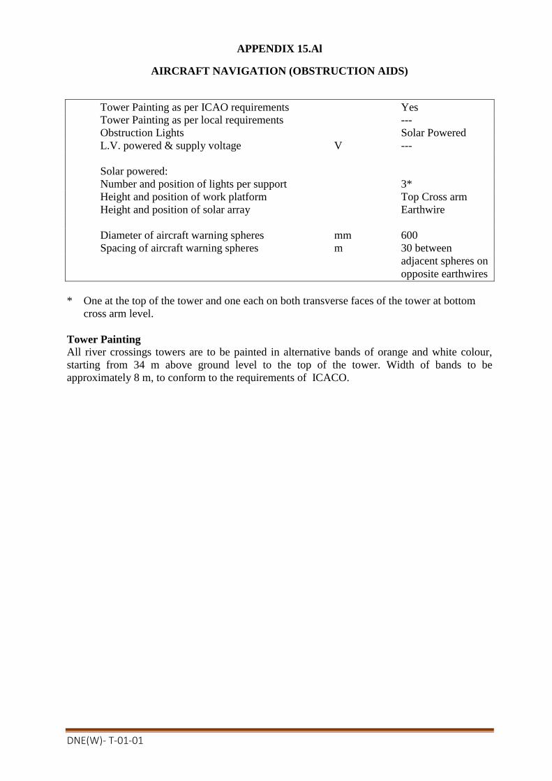
DNE(W)- T-01-01
APPENDIX 15.Al
AIRCRAFT NAVIGATION (OBSTRUCTION AIDS)
Tower Painting as per ICAO requirements Yes
Tower Painting as per local requirements ---
Obstruction Lights Solar Powered
L.V. powered & supply voltage V ---
Solar powered:
Number and position of lights per support 3*
Height and position of work platform Top Cross arm
Height and position of solar array Earthwire
Diameter of aircraft warning spheres mm 600
Spacing of aircraft warning spheres m 30 between
adjacent spheres on
opposite earthwires
* One at the top of the tower and one each on both transverse faces of the tower at bottom
cross arm level.
Tower Painting All river crossings towers are to be painted in alternative bands of orange and white colour,
starting from 34 m above ground level to the top of the tower. Width of bands to be
approximately 8 m, to conform to the requirements of ICACO.

DNE(W)- T-01-01
APPENDIX 15.Bl
ENGINEERING DOCUMENTS TO BE SUBMITTED BY CONTRACTOR
Clause
Reference
Document Description Comments
15.2.10 Tower Painting – Painting system
15.4.1 Obstruction Aids – Contract drawing
15.6.2 Painting – Method Statement
15.7.1 Test Proposals – type, sample, routine
15.7.2 Galvanizing test results If requested
15.7.3 Metalic material test certificates If requested
15.7.3 Bolt and nuts test certificates If requested
15.7.3 Non-metalic material test certificates If requested
15.7.3 Type test records
15.7.3 Sample test records
15.7.3 Routine test records If requested
15.7.4 Certificate of conformity
15.7.5 Commissioning test proposals
15.7.6 Painting – routine test procedure
APPENDIX 15.Cl
NOTIFICATION AND HOLD POINTS
Clause
Reference
Notification Points Hold Points
15.2.10 Tower Painting System
15.4.1 Contract drawings
15.6.2 Painting – Method statement
15.7.1 Test Proposals
15.7.1 Type tests
15.7.5 Test Proposals
15.7.5 Commissioning tests
15.7.6 Painting – Routine test
proposals
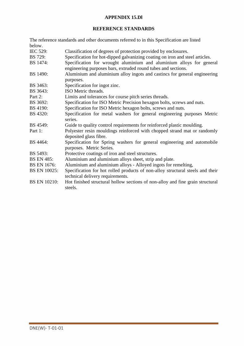
DNE(W)- T-01-01
APPENDIX 15.Dl
REFERENCE STANDARDS
The reference standards and other documents referred to in this Specification are listed
below.
IEC 529: Classification of degrees of protection provided by enclosures.
BS 729: Specification for hot-dipped galvanizing coating on iron and steel articles.
BS 1474: Specification for wrought aluminium and aluminium alloys for general
engineering purposes bars, extruded round tubes and sections.
BS 1490: Aluminium and aluminium alloy ingots and castincs for general engineering
purposes.
BS 3463: Specification for ingot zinc.
BS 3643: ISO Metric threads.
Part 2: Limits and tolerances for course pitch series threads.
BS 3692: Specification for ISO Metric Precision hexagon bolts, screws and nuts.
BS 4190: Specification for ISO Metric hexagon bolts, screws and nuts.
BS 4320: Specification for metal washers for general engineering purposes Metric
series.
BS 4549: Guide to quality control requirements for reinforced plastic moulding.
Part 1: Polyester resin mouldings reinforced with chopped strand mat or randomly
deposited glass fibre.
BS 4464: Specification for Spring washers for general engineering and automobile
purposes. Metric Series.
BS 5493: Protective coatings of iron and steel structures.
BS EN 485: Aluminium and aluminium alloys sheet, strip and plate.
BS EN 1676: Aluminium and aluminium alloys - Alloyed ingots for remelting,
BS EN 10025: Specification for hot rolled products of non-alloy structural steels and their
technical delivery requirements.
BS EN 10210: Hot finished structural hollow sections of non-alloy and fine grain structural
steels.

DNE(W)- T-01-01
SECTION 16
MISCELLANEOUS
16.1 TOOLS AND APPLIANCES
Each tool or appliance shall be clearly marked with its size and/or purpose and is not to
be used for erection purposes by the Contractor.
The tools and appliances with the appropriate boxes are to be handed over to the
Employer at the Employer's stores depot at the time of arrival at Site.
The Contractor shall, where required, by the Engineer, provide test certificates and die-
stamp or indelible mark on each piece of equipment in an approved manner.
For details of the tools and appliances to be supplied reference should be made to
Appendix 16.A1.
APPENDIX 16.Al
TOOLS & APPLIANCES
(a) Twin suspension saddles shall suitable for lifting for 315-A3/S-3A(AACSR-
described inAppendix-11.A/2-33KV for conductor-types and uses) or Standard
Equivalent phase conductors at suspension points. The conductors support shoes shall
be suitably lined and flared so as not to crush or scope the conductors during lifting. A
Safe Working Load (SWL) of 35 KN is required and proof tests to 52.5KN 26.25 KN
on each shoe) shall be carried out on each saddle before shipment. Test certificate
will be required.
(b) Aluminium alloy hook ladders shall be at least 8m long and shall be proof tested to
simulate a distributed load of 300kg in either the horizontal or vertical position.
Hooks shall be bolted onto the frame of the ladder and shall incorporate a safety chain
from each hook which shall be capable of being firmly attached to the frame.
(c) Pullifts shall have safe working loads of 3 tone, 4.5 tone and 6.5 tone as specified in
Schedule C1. All pullifts offered shall be tested at the manufacturer's works and
certificates issued showing a proof load at least 50% in excess of the safe working
load.
(d) "Tirfor" hoists shall have a safe working load of 5 tonnes. Rope for use with "Tirfor"
hoists shall be of a construction such as "Maxiflex" recommended by the
manufacturer of the hoists.
(e) Wire rope slings, unless otherwise stated, shall be complete with two thimbles and
clamped at each end by means of a Talurit type compression clamp. Lengths
specified in Price Schedule shall be the overall length of the sling and not the length
of rope contained in the sling. The construction of the wire rope shall be approved by
the Engineer.
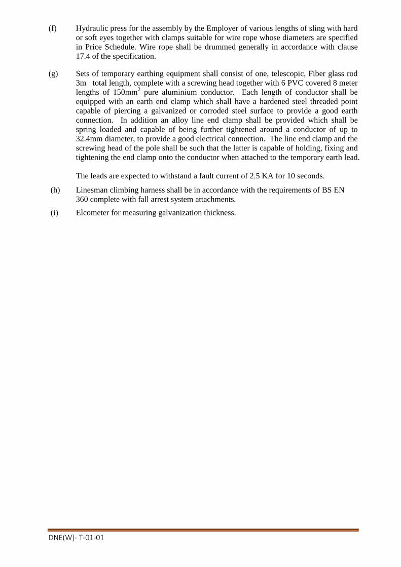
DNE(W)- T-01-01
(f) Hydraulic press for the assembly by the Employer of various lengths of sling with hard
or soft eyes together with clamps suitable for wire rope whose diameters are specified
in Price Schedule. Wire rope shall be drummed generally in accordance with clause
17.4 of the specification.
(g) Sets of temporary earthing equipment shall consist of one, telescopic, Fiber glass rod
3m total length, complete with a screwing head together with 6 PVC covered 8 meter
lengths of 150mm2 pure aluminium conductor. Each length of conductor shall be
equipped with an earth end clamp which shall have a hardened steel threaded point
capable of piercing a galvanized or corroded steel surface to provide a good earth
connection. In addition an alloy line end clamp shall be provided which shall be
spring loaded and capable of being further tightened around a conductor of up to
32.4mm diameter, to provide a good electrical connection. The line end clamp and the
screwing head of the pole shall be such that the latter is capable of holding, fixing and
tightening the end clamp onto the conductor when attached to the temporary earth lead.
The leads are expected to withstand a fault current of 2.5 KA for 10 seconds.
(h) Linesman climbing harness shall be in accordance with the requirements of BS EN
360 complete with fall arrest system attachments.
(i) Elcometer for measuring galvanization thickness.
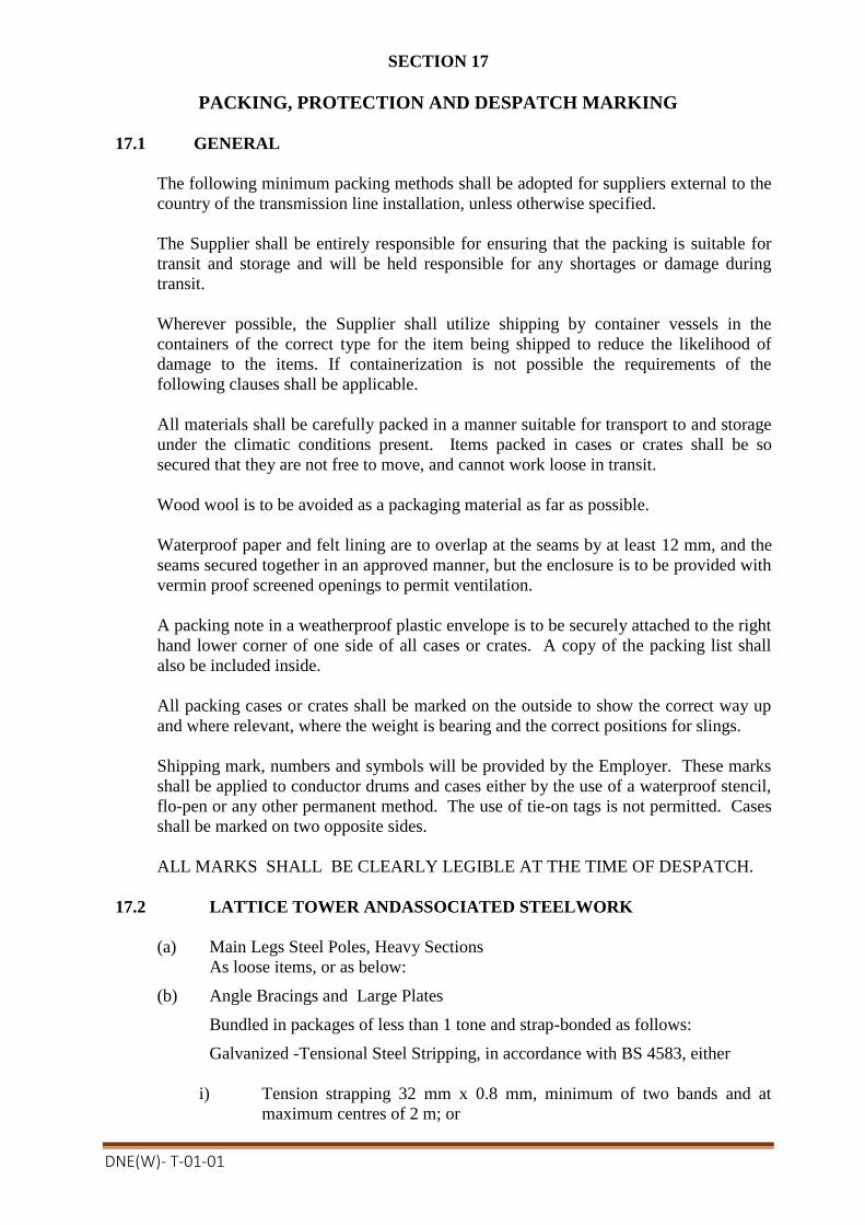
DNE(W)- T-01-01
SECTION 17
PACKING, PROTECTION AND DESPATCH MARKING
17.1 GENERAL
The following minimum packing methods shall be adopted for suppliers external to the
country of the transmission line installation, unless otherwise specified.
The Supplier shall be entirely responsible for ensuring that the packing is suitable for
transit and storage and will be held responsible for any shortages or damage during
transit.
Wherever possible, the Supplier shall utilize shipping by container vessels in the
containers of the correct type for the item being shipped to reduce the likelihood of
damage to the items. If containerization is not possible the requirements of the
following clauses shall be applicable.
All materials shall be carefully packed in a manner suitable for transport to and storage
under the climatic conditions present. Items packed in cases or crates shall be so
secured that they are not free to move, and cannot work loose in transit.
Wood wool is to be avoided as a packaging material as far as possible.
Waterproof paper and felt lining are to overlap at the seams by at least 12 mm, and the
seams secured together in an approved manner, but the enclosure is to be provided with
vermin proof screened openings to permit ventilation.
A packing note in a weatherproof plastic envelope is to be securely attached to the right
hand lower corner of one side of all cases or crates. A copy of the packing list shall
also be included inside.
All packing cases or crates shall be marked on the outside to show the correct way up
and where relevant, where the weight is bearing and the correct positions for slings.
Shipping mark, numbers and symbols will be provided by the Employer. These marks
shall be applied to conductor drums and cases either by the use of a waterproof stencil,
flo-pen or any other permanent method. The use of tie-on tags is not permitted. Cases
shall be marked on two opposite sides.
ALL MARKS SHALL BE CLEARLY LEGIBLE AT THE TIME OF DESPATCH.
17.2 LATTICE TOWER ANDASSOCIATED STEELWORK
(a) Main Legs Steel Poles, Heavy Sections
As loose items, or as below:
(b) Angle Bracings and Large Plates
Bundled in packages of less than 1 tone and strap-bonded as follows:
Galvanized -Tensional Steel Stripping, in accordance with BS 4583, either
i) Tension strapping 32 mm x 0.8 mm, minimum of two bands and at
maximum centres of 2 m; or

DNE(W)- T-01-01
ii) Tension strapping 19 mm x 0.8 mm, minimum of three bands and at
maximum centres of 1.25 m.
Whichever method i) or ii) is adopted, bundles shall also have a layer of either
hessian or polythene between the strap-bands and the galvanized steelwork.
One end of tie bundle shall also be wired in such a way as to prevent the removal
of any single piece.
(c) Plates, Small Items
These shall becased (maximum net mass 500 kg).
Cases shall be of sturdy construction, made from new 25 mm thick timber and
constructed with annular (rag) nails. They shall have packing pieces on the
underside to enable the use of fork-lift trucks.
(d) Bolts
Shall be double bagged and cased as above. A contents list shall be included in
each bag. (Cases used both (c) and (d) shall be stored in dry areas both before
and after packing.
Where required, materials shall be colour flashed to aid recognition.
17.3 CONTAINERISATION
Where materials shipped by the use of containers, a reduced level of packing, is
acceptable
(a) Strap-band centres may be increased to 3m for 32 mm x 0.8 mm bands and 2.5m
for 19 mm x 0.8 mm bands.
(b) The use of wire through bundle ends is not required.
(c) Cases may be 20 mm thick timber.
17.4 CONDUCTOR
Conductors shall be supplied on drums of sufficient sturdiness to withstand overseas
shipment, and the drums shall be securely battened to prevent damage to the conductor.
All wooden components shall be manufactured from sound defect-free seasoned
softwood and suitable for prolonged storage without deterioration. Wood shall be
either planed or finely sawn to facilitate accuracy in assembly. The thickness of each
ply or component part shall be of reasonable uniformity.
The flanges of drums shall be constructed from two ply of wood laminated in such a
manner to be cross-grain to each other. The boards shall be close butted to provide
maximum support. Fastenings of the flanges shall be with suitable bright nails with the
head countersunk on the inside flange. A flange conductor hole of sufficient diameter
for the free passage of the conductor shall be cut in one flange. The exposed end of the
conductor shall be protected by a suitable sheet metal plate.
Drainage holes shall be provided through each flange as close as possible to the
underside of the barrel lagging. The inner checks of the drum shall be painted with an
aluminium flake or bitumen based paint.
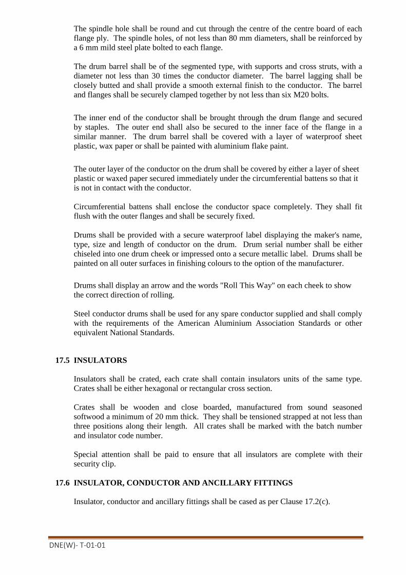
DNE(W)- T-01-01
The spindle hole shall be round and cut through the centre of the centre board of each
flange ply. The spindle holes, of not less than 80 mm diameters, shall be reinforced by
a 6 mm mild steel plate bolted to each flange.
The drum barrel shall be of the segmented type, with supports and cross struts, with a
diameter not less than 30 times the conductor diameter. The barrel lagging shall be
closely butted and shall provide a smooth external finish to the conductor. The barrel
and flanges shall be securely clamped together by not less than six M20 bolts.
The inner end of the conductor shall be brought through the drum flange and secured
by staples. The outer end shall also be secured to the inner face of the flange in a
similar manner. The drum barrel shall be covered with a layer of waterproof sheet
plastic, wax paper or shall be painted with aluminium flake paint.
The outer layer of the conductor on the drum shall be covered by either a layer of sheet
plastic or waxed paper secured immediately under the circumferential battens so that it
is not in contact with the conductor.
Circumferential battens shall enclose the conductor space completely. They shall fit
flush with the outer flanges and shall be securely fixed.
Drums shall be provided with a secure waterproof label displaying the maker's name,
type, size and length of conductor on the drum. Drum serial number shall be either
chiseled into one drum cheek or impressed onto a secure metallic label. Drums shall be
painted on all outer surfaces in finishing colours to the option of the manufacturer.
Drums shall display an arrow and the words "Roll This Way" on each cheek to show
the correct direction of rolling.
Steel conductor drums shall be used for any spare conductor supplied and shall comply
with the requirements of the American Aluminium Association Standards or other
equivalent National Standards.
17.5 INSULATORS
Insulators shall be crated, each crate shall contain insulators units of the same type.
Crates shall be either hexagonal or rectangular cross section.
Crates shall be wooden and close boarded, manufactured from sound seasoned
softwood a minimum of 20 mm thick. They shall be tensioned strapped at not less than
three positions along their length. All crates shall be marked with the batch number
and insulator code number.
Special attention shall be paid to ensure that all insulators are complete with their
security clip.
17.6 INSULATOR, CONDUCTOR AND ANCILLARY FITTINGS
Insulator, conductor and ancillary fittings shall be cased as per Clause 17.2(c).

DNE(W)- T-01-01
SECTION-18
METHOD OF MEASUREMENT & PAYMENT
18.1I NTRODUCTION
18.1.1 General
Payment will be made in accordance with the unit prices and total prices set against the items
in the Price schedule/BOQ in Section-5 as amplified in this section and against the final
quantities approved by the Employer. These unit prices and total prices shall include all of
the work, temporary and permanent, necessary to comply with the Contract. Where
unquantified unit prices are required in the Bid submission, they shall be so provided.
Measurement for the purposes of payment shall where appropriate be made jointly by the
representative of the Employer and the Contractor.
The Contractor when requested shall attend for purposes of measurement, or otherwise
accept measurements made by the Employer alone.
Where applicable the Contractor shall indicate on each invoice the identification number of
each support to which items in the invoice refer.
Unit prices in Price schedule/BOQ in Section-5 where applicable shall be deemed to include
for all work on site irrespective of access conditions, including slope of ground, nature of
subsoil, presence of water or other obstacles adjacent to or across the line of the route.
The unit prices shall include all incidental expenses which the Contractor or specialist Sub-
contractor may incur in the preparation and maintenance of access, in the provision of site
services and of all transportation for labour whether skilled or unskilled.
The unit prices in the Price schedule/BOQ in Section-5 shall include all out allowances or
other supplementary payment to skilled or unskilled labour, customary, authorized or
required by regulations in force at the date of the Bid.
The unit prices shall be deemed to include payment to labour, or other expenses incurred for
idle time during- which work on site is interrupted by weather conditions or flooding by
storm overflow or the like.
Whilst every assistance will be provided to facilitate line construction activities in sequence
in accordance with the Contractor's agreed programme of work, there could be occasions
when this may not be possible. No claims for additional costs to the Contractor will be
accepted solely for such discontinuity of working.
Only those prices shown in the miscellaneous unit prices will be accepted as additional to the
Contract price where the use of such unit prices is authorised by the Employer.
18.1.2 Surplus Material
Surplus quantity or waste material of Goods and materials if any, collected from the
Purchaser's Stores, are to be returned to the Employer. Surplus or waste material
supplied by the Contractor will not be paid by the Employer.
18.1.3 Nominated Sub-contractor/Supplier (Not used.)
18.1.4 Specialist Sub-contractors (Not used.)

DNE(W)- T-01-01
18.1.5 Quantities The quantities set out in the Price schedule/BOQ in Section-5 are unless otherwise
defined estimated quantities of the Works. They are not to be assumed as the actual
and correct quantities to be executed by the Contractor in fulfillment of his obligations
under the Contract. The Contractor is presumed to have satisfied himself as to the
relevance of the estimated quantities in the preparation of his Bid. Final quantities shall
be established and agreed upon between the Employer and the Contractor no later than
Ten(10) months after the date of signing of the Contract.
18.1.6 CIP Price (Not Applicable)
18.1.7 Freight and Insurance Prices (Not Applicable)
18.1.8 Ex-works (EXW) Price
EXW price shall include all items of Goods domestically manufactured and offered
locally, from within Bangladesh, inclusive of duties and taxes paid or payable on
components and material incorporated or to be incorporated in the Goods, and available
for delivery at the Supplier's premises (i.e. works, factory, warehouse etc).
18.1.9 Local transportation & Erection (LT&E) Price
Total Price shall include all items of local transport to site, local insurance, duties and
where appropriate visas, permits, geotechnical investigation and works, erection. site
testing, etc, so that the total prices represents the complete cost of the contract.
18.1.10 Drawings, Reference Standards and Records
The provision of all drawings, design calculations, records etc as specified in the
Contract shall deemed to be included in the Contract price.
18.1.11 Witnessing of Inspection &Testing by Employer
Two (2) Engineers of the Employer shall visit at manufacturer’s factory for witnessing
of inspection & testing of all towers, insulator & fittings, conductor, earthwire & other
accessories. All types of travel cost and per diem allowance shall be borne by the
contractor as per government rules. All costs for the above visits are deemed to be
included in the Contract price.
1 8.1.12 Overseas Training (N/A)
Two(2)Engineers nominated by the Employer shall be given training at the
Contractor’s/manufacturer’s design office each for a period of one (1) weeks.
The Contractor shall provide the following for the trainee:
i ) Return air ticket from Dhaka to the place of training;
ii) Hotel accommodation during the entire training period,
iii) Traveling expenses during training,
iv) Per diem allowance as per government rules as per government rules to
cover food and incidental expenses. health insurance to cover all
medical costs that may be required during training.
Training shall be provided in the aspects of transmission line design and specifically
the design of river crossing towers and foundations.
All costs for the above training are deemed to be included in the Contract price.

DNE(W)- T-01-01
18.1.13 Pre-Award Plant Inspection
Committee formed by BREB including Representative from BRTC, BUET/ MIST/
CRTS, DUET shall inspect the tower manufacturing plant before award given by the
employer for verification of man power’s engineering knowledge & experience as well
as standard quality of machineries like galvanizing plant, CNC (Computerized
Numerically Controlled) machines for steel cutting, drilling & punching etc.
18.1.14 Instruction of Employer's Staff
The contractor shall provide on-site, local training of 4 (Four) BREB/ PBS Engineers
on Transmission line works without additional cost.
Instruction shall be given in the English language. This training is to be carried out in
the site as formal instruction courses on each of the various types of Plant being
provided under this contract. The attendance of BREB staff during erection and
commissioning works will not be acceptable as an alternative to the formal training
courses.
18.2 SURVEY
Full precision check survey undertaken by the Contractor on the Employer's instruction
shall be paid for in thePrice schedule/BOQ in Section-5 unit prices and shall be measured
to the nearest metre along the centre-line of the route. The unit price shall include for
the establishment or re-establishment of the line route from terminal points and other
such fixed points the Employer may define, full ground survey, preparation and
submission of route maps, mouza maps, profile drawings with tower plotting, SIMMs
document, tree marking and tree schedule and pegging of tower locations.
18.3 ROUTE CLEARANCE & ACCESS
Route clearance undertaken by the Contractor on the Employer's instruction shall be
paid for in the Price schedule/BOQ in Section-5unit prices and shall be measured to the
nearest metre along the centre line of the route. The prices of route clearance shall
include payment of all kinds of damage compensation by the Contractor. All damage
compensation shall be paid by the Contractor.
18.4 FOUNDATIONS
18.4.1 General
The prices quoted in the Price schedule/BOQ in Section-5 for the supply and installation
of a foundation refers to a foundation required in accordance with the Specification and
'Method of Measurement and payment’. Where additional work is required over and
above that provided for in the Specification and 'Method of measurement and Payment'
this will be paid on a measured basis at miscellaneous unit prices or unit prices to be
agreed.
The unit prices for foundations shall include all necessary geotechnical investigation
and geotechnical studies as defined in the Specification or as required by relevant
authorities.
The unit prices for all foundations shall include for site clearing, excavating in any
material and by any means. manual or mechanical, and for ensuring, stability and
natural drainage inside the working area, for all back filling, compacting and disposal

DNE(W)- T-01-01
of surplus material, routine testing, site restoration and for all necessary supports to
sides of excavations.
The complete foundations for a tower shall be paid for at the appropriate unit prices
described in the Price schedule/BOQ in Section-5. The unit price shall include for all
excavations. conventional pumping (including well-point dewatering), excavation
supports, concrete work, formwork, reinforcing,,, stub steelwork. stub cutting, routine
testing, backfilling, clearing up and all other work required to complete the foundation
in accordance with the Specification.
The unit prices shall also include supply of weak-mix concrete or the importation of
any back fill material necessary due to the excavated material being unsuitable as
backfill.
The unit prices for foundations shall include the use of whichever type of cement is to
he used and density of concrete necessary to meet the requirements of the Specification.
The unit prices for foundations shall include all stub steelwork installation and setting
out including the use of templates, setting to any level and any excavation necessary for
Setting out. The protective treatment to defined concrete faces or support steelwork
and provision of site protection barriers shall be included in the rates for the
foundations.
The unit prices for foundations shall include the cost for all earthing requirements.
Where site stabilizations outside the defined 'working area' is required this shall be
undertaken at unit prices to be agreed.
Design tests on foundations to prove the foundation design shall be paid for at the unit
prices quoted. The unit prices shall include for the removal of concrete and steel down
to 1m below groundlevel where this is deemed necessary by the Employer.
18.4.2 Pile Foundations
The complete foundations for each support shall be paid for at the appropriate unit
prices described in the Price schedule/BOQ in Section-5. The unit prices shall include for
mobilization and de-mobilization of piling rig, setting out, cleaning, cutting, to length,
reinforcement and pile cap connection. Jointing of piles as necessary, irrespective of
number of piles, all excavations (including rock). conventional pumping (including
well-point dewatering), excavation supports (including use of bentonite slurries),
concrete work for piles, pile cap and tie beams, formwork, reinforcing stub steelwork,
stub cutting, routine testing, backfilling, clearing up and all other work required to
complete the foundation in accordance with the Specification.
The unit prices for piled foundations shall be based on, the unit price for a complete
tower foundation including piles, pile cap and tie beams.
18.4.3 Flood Protection Walls(Not Applicable.)
l 8.4.4 Miscellaneous Unit Prices (Not Applicable)
18.4.5 STEELTOWERS
Steel towers normal extensions shall be paid for at prices described in the Price
schedule/BOQ in Section-5. The unit prices shall include for standard cross arms. and shall
include stub steelwork.

DNE(W)- T-01-01
The unit prices for steel towers shall include for access facilities, anti-climbing devices,
attachment plates, ancillary steelwork etc. used as standard fittings on the tower.
The unit prices shall include for all tower mounted notice plates.
Type tests on individual tower to prove the support design shall be paid for at the unit
prices described in the Price schedule/BOQ in Section-5for successful tests only. All other
quality control requirements shall be included within the appropriate unit price.
Special Supports and additional steelwork to the approved design shall be paid for at Price
schedule unit prices.
The unit price of towers shall include all supplies and all works associated with the towers
which are specified in this tender document.
18.6 INSULATOR SETS AND ASSOCIATED FITTINGS
All Insulator sets shall be paid for at unit prices described in the Price schedule/BOQ in
Section-5. The unit prices for insulator, sets shall include for all insulator units, links, sag
adjusters, turnbuckles, weights, insulators protective devices (arc horns), tension joints
(dead ends) and suspension clamps (Inclusive of helical armour rods), used as a standard
between the support and the phase conductor and all others fittings specified to be
supplied in this tender document.
Unit prices for earthwire tension and suspension sets shall where specified include for all
earthwire bonding to the supports including all earthwire bonding clamps in accordance
with the Specification and all others fittings specified to be supplied in this tender
document.
All conductor tee-connectors and line termination fittings shall be paid for at Price
schedule/BOQ in Section-5 unit prices.
18.7 CONDUCTOR AND FITTINGS
Phase conductors and earthwires shall be paid for at unit prices described in the Price
schedule/BOQ in Section-5 and shall be measured to the nearest meter after erection,
along the centre of the route without allowance for sag jumpers or scrap. The supply and
erection unit price shall include for all normal phase and earthwire jumpers including the
jumpers at terminal supports between phase conductors or earthwires and down leads.
Down leads between terminal supports and anchorages and down droppers between
down leads and substation equipment shall be paid for at unit prices described in the Price
schedule/BOQ in Section-5. The unit prices shall include for conductors, jumpers and
associated fittings.
The aforementioned erection unit prices shall include all joints, clamps and fittings other
than insulator sets and their fittings, tension. joints (dead ends) and or earthwire, jumpers
and downlead conductors.
All spacer dampers, vibration dampers and spacers including bonding and weighted
jumper and/or spacer shall be paid for at unit prices described Price schedule/BOQ in
Section-5. .
18.8 AIRCRAFT NAVIGATION (OBSTRUCTION AIDS)
Aircraft warning lights shall be paid for at unit prices described in the Price schedule/BOQ
in Section-5 and shall be measured on the naper support basis. The unit price shall include
for the warning lights and as appreciate connection to LV main supply or solar panels,

DNE(W)- T-01-01
storage batteries etc. all power and control cables, solar light switches, support steel works
as necessary.
The unit prices for aircraft warning lights shall include for all type, sample and routine
tests.
The unit prices for access ladders (when not included as standard item on the support)
shall include for all access and maintenance platforms, lifting and safety equipment as
necessary.
1 8.9 MISCELLANEOUS
Tools and spares shall be paid for at the unit prices described in the Price schedule/BOQ
in Section-5
18.10 PAYMENT FOR WORK CARRIED OUT AT TIME AND
MATERIAL RATES
The Employer may, if in their opinion it is necessary or desirable, order that any
additional or substituted work shall be executed on a Time and Material basis.
No work shall be carried out on a Time and Materials basis without written instructions
of the Employer. All applications for payment for such work by the Contractor shall be
accompanied by statements, authorizing the undertaking of such work, duly signed by
the Employer and shall be submitted within three months of completion of such work.
When the work is in progress the Contractor shall render day work sheets in duplicate
to the Employer showing the number of men so employed with the number of hours
worked and detailed quantities of materials used. The Contractor shall obtain the
Employer's certification of the day work sheets at the end of each working week whilst
the work is in progress and failure to do so shall render the Contractor liable to
forfeiture of payment.
Where the Contractor is required to carry out work at the Time and Material unit prices,
the Employer will furnish the Contractor with such particulars as necessary to enable
the Contractor to prepare such drawings and schedules as required for such work. Unit
prices for work executed on a Time and Material basis shall be agreed.

DNE(W)- T-01-01
SECTION: 6.2- SPECIFICATION/PARTICULAR SPECIFICATION
The Plant & Equipment/materials shall comply with following Technical
Specifications:
Schedule A Manufacturers, Places of Manufacture and Testing
Schedule B Technical particulars and Guarantees
Schedule C Departure from Specifications
Schedule D Proposed Alternative standards to which Equipment shall provided
Schedule E Proposed Contract and site organization
Schedule F Key Personnel
Schedule G Equipment for Construction
Schedule H Proposed Subcontractors
Schedule I Drawings and documents to be submitted with Bid.
Schedule J Bar Chart Programme of Key Activities
SCHEDULE - A
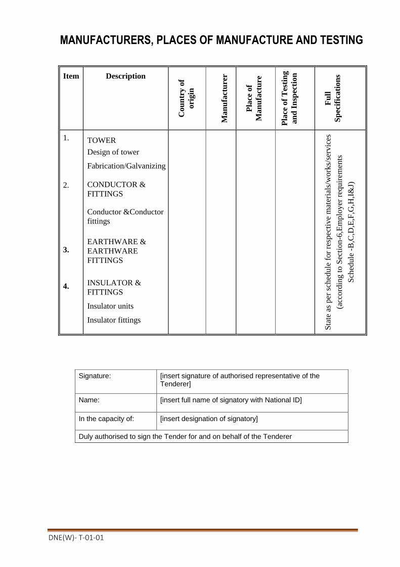
DNE(W)- T-01-01
MANUFACTURERS, PLACES OF MANUFACTURE AND TESTING
Item
Description
C
ou
ntr
y o
f
ori
gin
Man
ufa
ctu
rer
P
lace
of
Man
ufa
ctu
re
Pla
ce o
f T
esti
ng
an
d I
nsp
ecti
on
F
ull
Sp
ecif
icati
on
s
1.
2.
3.
4.
TOWER
Design of tower
Fabrication/Galvanizing
CONDUCTOR &
FITTINGS
Conductor &Conductor
fittings
EARTHWARE &
EARTHWARE
FITTINGS
INSULATOR &
FITTINGS
Insulator units
Insulator fittings
S
tate
as
per
sch
edule
for
resp
ecti
ve
mat
eria
ls/w
ork
s/se
rvic
es
(acc
ord
ing t
o S
ecti
on
-6,E
mplo
yer
req
uir
emen
ts
Sch
edule
-B
,C,D
,E,F
,G,H
,I&
J)
Signature: [insert signature of authorised representative of the Tenderer]
Name: [insert full name of signatory with National ID]
In the capacity of: [insert designation of signatory]
Duly authorised to sign the Tender for and on behalf of the Tenderer
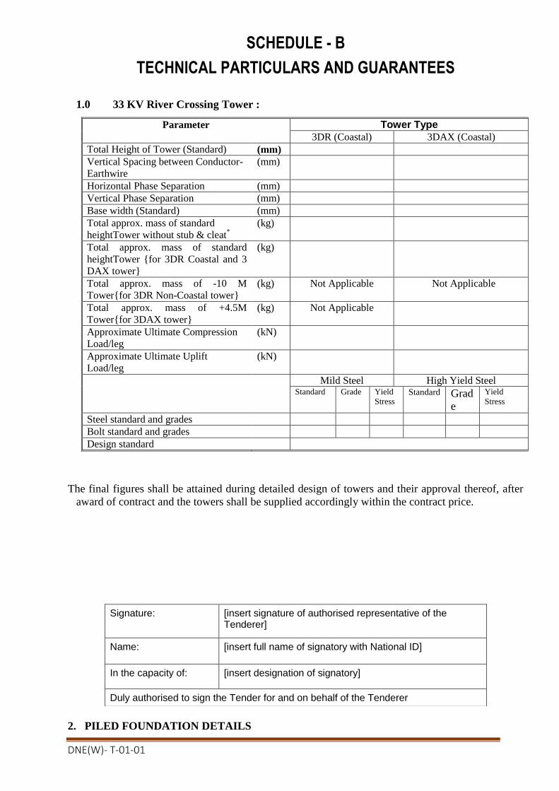
DNE(W)- T-01-01
SCHEDULE - B
TECHNICAL PARTICULARS AND GUARANTEES
1.0 33 KV River Crossing Tower :
Parameter Tower Type
3DR (Coastal) 3DAX (Coastal)
Total Height of Tower (Standard) (mm)
Vertical Spacing between Conductor-
Earthwire
(mm)
Horizontal Phase Separation (mm)
Vertical Phase Separation (mm)
Base width (Standard) (mm)
Total approx. mass of standard
heightTower without stub & cleat*
(kg)
Total approx. mass of standard
heightTower {for 3DR Coastal and 3
DAX tower}
(kg)
Total approx. mass of -10 M
Tower{for 3DR Non-Coastal tower}
(kg) Not Applicable Not Applicable
Total approx. mass of +4.5M
Tower{for 3DAX tower}
(kg) Not Applicable
Approximate Ultimate Compression
Load/leg
(kN)
Approximate Ultimate Uplift
Load/leg
(kN)
Mild Steel High Yield Steel Standard Grade Yield
Stress Standard Grad
e
Yield
Stress
Steel standard and grades
Bolt standard and grades
Design standard
The final figures shall be attained during detailed design of towers and their approval thereof, after
award of contract and the towers shall be supplied accordingly within the contract price.
2. PILED FOUNDATION DETAILS
Signature: [insert signature of authorised representative of the Tenderer]
Name: [insert full name of signatory with National ID]
In the capacity of: [insert designation of signatory]
Duly authorised to sign the Tender for and on behalf of the Tenderer
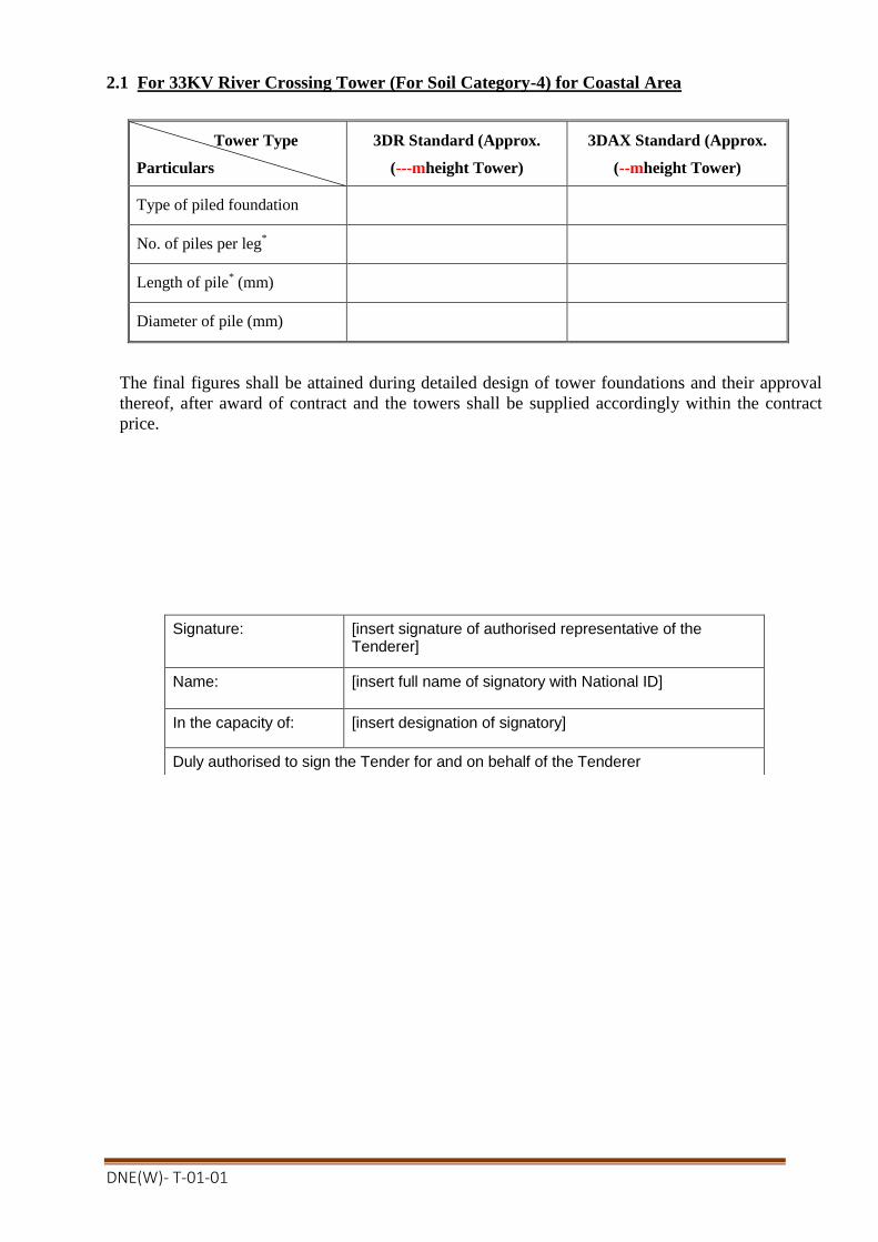
DNE(W)- T-01-01
2.1 For 33KV River Crossing Tower (For Soil Category-4) for Coastal Area
Tower Type
Particulars
3DR Standard (Approx.
(---mheight Tower)
3DAX Standard (Approx.
(--mheight Tower)
Type of piled foundation
No. of piles per leg*
Length of pile* (mm)
Diameter of pile (mm)
The final figures shall be attained during detailed design of tower foundations and their approval
thereof, after award of contract and the towers shall be supplied accordingly within the contract
price.
Signature: [insert signature of authorised representative of the Tenderer]
Name: [insert full name of signatory with National ID]
In the capacity of: [insert designation of signatory]
Duly authorised to sign the Tender for and on behalf of the Tenderer

DNE(W)- T-01-01
3. CONDUCTOR & EARTHWIRE
Parameter Unit Conductor Earthwire
Conductor Designation & Type
Reference standard
Number & Diameter of strands No.x
mm
Overall Diameter mm
Guaranteed Ultimate Tensile
strength kN
Final Modulus of elasticity N/mm²
Coefficient of Linear Expansion per °C
D.C. Resistance at 20°C ohm/m
Standard Weight Per m
Weight of grease Kg/m
Drop point of grease °C
Standard length on drum m
Weight of complete drum kgs
Percentage of random short
drum lengths (not more than 4
percent)
%
4. (Not Applicable)
5. INSULATOR SETS & FITTINGS
Signature: [insert signature of authorised representative of the Tenderer]
Name: [insert full name of signatory with National ID]
In the capacity of: [insert designation of signatory]
Duly authorised to sign the Tender for and on behalf of the Tenderer

DNE(W)- T-01-01
5.1 Cap and Pin type Porcelain Disc Insulators
Suspension/ Jumper
Suspension
Tension
Insulator Units
Insulator Unit Type No.
Dielectric Material
Total creepage per unit
(mm)
Spacing per unit
(mm)
Diameter of disc
(mm)
Puncture Voltage of unit (kV)
Electro Mechanical Failing
Load of unit
(kN)
Drawing No. of Unit
Type test Certificate No. of
Unit
Insulator string sets
Number of units per string
Total creepage of string
(mm)
Overall length of set
(mm)
Sag adjuster type and step
(mm)
Ultimate strength of set
(kN)
Mass of set
(kg)
Lightning impulse
withstand Voltage
Wet Power Frequency
withstand Voltage
Corona extinction level
(kV)
(kV)
(kV)

DNE(W)- T-01-01
6.0 VIBRATION DAMPERS
Parameter
Unit
Unit Weight of vibration dampers
- for phase conductor
kg
Material
-
No. of vibration dampers to be used for each phase per
span in case of 33 kV phase conductors
nos.
Total quantities of vibration dampers for one basic span
in case of 33 kV phase conductors
nos.
No. of vibration dampers to be used for each earthwire
per span
nos.
Signature: [insert signature of authorised representative of the Tenderer]
Name: [insert full name of signatory with National ID]
In the capacity of: [insert designation of signatory]
Duly authorised to sign the Tender for and on behalf of the Tenderer

DNE(W)- T-01-01
SCHEDULE - C
DEPARTURES FROM THE SPECIFICATION
Bidders are to list all departures from the requirements of the specification in this schedule. All
technical departures or of a commercial nature are to be included.Any item that does not have a
departure listed in this schedule will be deemed to be in full accordance with the requirements of the
specification.No other document or detail accompanying the tender will be considered in evaluating
departures. Tenders are not permitted to offer any alternative to this schedule.
Item
Volume
Clause
Detail of Departure from Specification
Signature: [insert signature of authorised representative of the Tenderer]
Name: [insert full name of signatory with National ID]
In the capacity of: [insert designation of signatory]
Duly authorised to sign the Tender for and on behalf of the Tenderer

DNE(W)- T-01-01
SCHEDULE- D
PROPOSED ALTERNATIVE STANDARDS TO WHICH EQUIPMENT SHALL
PROVIDED
(Within the quoted Price & specification)
The tenderer shall list below all the alternative engineering and design Standards which he proposes
to use in his design, manufacture and testing of equipment to be supplied. Should these standards
differ from the specified standard in any respect, the tenderer shall detail the differences between the
proposed and specified standard within the quoted price of the price schedule as well as in tender
submission sheet.
Compliance with any standard equal or superior to those specified will be considered acceptable.
In the absence of any listed alternative standard, it is deemed that the standards specified in the
Tender documents are fully complied with.
Specified Standard Alternative Standard
Number Title
Signature: [insert signature of authorised representative of the Tenderer]
Name: [insert full name of signatory with National ID]
In the capacity of: [insert designation of signatory]
Duly authorised to sign the Tender for and on behalf of the Tenderer

DNE(W)- T-01-01
SCHEDULE - E
PROPOSED CONTRACT AND SITE ORGANIZATION
The Tenderer is required to provide full organisation charts of his proposed head-office and site-
office arrangements. These should include how site sub-contractors are to interface with the
contractors’ organisation.
The Tenderer shall list in the form of Schedule attached, the key personnel (including first nominee
and the second choice alternate) he will employ at Head office and at Site office to direct and
execute and work for the execution of the Contract, together with their qualifications, positions held
and their nationalities. Should specialist sub-designers be proposed (eg civil designers) details of
these are also to be provided with how these interface with the contractor’s organisation.
Should the Tenderer be proposing to put any restriction on his site managers authority to carry out
instructions issued by the Engineer’s Representative, full details of these, be they financial or
contractual/technical are to be provided in the tender.
The information provided in the Tender in accordance with the above, will not represent any
limitation on the staff required to perform the works in accordance with the conditions of contract.
Should the contractor require to utilise additional staff to those proposed in order to meet his
obligations these are to be provided at no additional cost. The Contractor shall however have to
employ all the expatriate staffs proposed in the tender as to be employed at site. In case of failure to
employ the required number of expatriate staffs at site as per tender proposal, for which the work
may suffer, the Employer may go for termination of the Contract.
In addition the Bidder is required to provide a schedule of the site resources he intends to provide,
e.g. equipment for haulage, lifting, site power supplies, foundation, erection, stringing, testing and
commissioning. Major items of equipment for construction purposes, which the tenderer proposes to
import, are to be submitted with the Bid. The tenderer shall have to bring the above proposed
equipment during construction otherwise they may be penalized, as per clause 8.6 of General
Conditions of Contract, for any delay due to non-availability of such equipment at site.
The successful Tenderer will be required to submit detailed schedules of his proposed site testing
and commissioning equipment and experience of his commissioning engineers.
The Tenderer is also required to provide details of his site organisation concerning office locations,
storage facilities proposed, both open and covered, site transportation, etc. The successful Tenderer
will be required to provide details of his proposed organisational procedures for the receipt,
inspection and transportation of Plant, plus monthly progress monitoring, invoice submission etc.

DNE(W)- T-01-01
SCHEDULE –F OF KEY PERSONNEL
Position Name
Nationality Summary of
qualifications, experience
and present occupation Head Office staff:
1.
2.
3.
4.
etc.
Site Office staff:
1.
2.
3.
4.
etc.
Signature: [insert signature of authorised representative of the Tenderer]
Name: [insert full name of signatory with National ID]
In the capacity of: [insert designation of signatory]
Duly authorised to sign the Tender for and on behalf of the Tenderer
DNE(W)- T-01-01
SCHEDULE – G OF EQUIPMENT FOR CONSTRUCTION
Name of Equipment Ownership
Present Location
i
d
d
e
r
Signature: [insert signature of authorised representative of the Tenderer]
Name: [insert full name of signatory with National ID]
In the capacity of: [insert designation of signatory]
Duly authorised to sign the Tender for and on behalf of the Tenderer

DNE(W)- T-01-01
SCHEDULE-H
PROPOSED SUBCONTRACTORS
(NOT APPLICABLE)
The tenderer shall propose a list of the Sub-contractors in the following table as per clause 15
Subcontractors, section-4, Part-II and Clause 8, Condition of Particular Application of
Volume 2 of 3.
SCHEDULE -I
DRAWING AND DOCUMENTS TO BE SUBMITED WITH THE TENDER
The following drawings and documents shall be submitted with the Tender:
1. Outline drawings of all type of towers with clearance diagram& Shop Drawing in Auto-Cad
format whenever required. Brochure/Catalogue of manufacturer indicating manufacturing
facilities and machinery available shall also be submitted. Detailed design calculations for
tower type 3DR Non-Coastal showing stress analysis, member and bolt sizes, yield strength
of tower materials, foundation reaction etc. Tenderer shall ensure submission of all
documents in support of their design of tower thereof to facilitate cheeking of submitted
design by the employer and to asses their technical capability.
It may be noted here that no extra payment shall be made for any changes which may be
needed from the above design at the time of design/ drawing approval during contract
execution stage.
2. Foundation drawings of all type of towers. The piled system the tenderer intends to use for
the foundations along with dimensions of piles, the materials of the shaft and pile cap and the
maximum possible length of pile which can be installed with the tenderer’s proposed pile
system. Further, the tenderers shall give information about the piling method, such as details
of casing, methods of soil excavation, type of reinforcement for both pile and pile cap and
the facility to transport all equipment.
3. Detailed drawings of all types of insulators and insulator sets including cross section sketch
of head portion of all types of disc insulators.
4. Cross-sectional drawings of conductors and detailed drawings of its accessories.
5. (Not Applicable.)
6.
6. Detailed drawings/specifications of tools and equipment.
7. Test Certificates
7.1 Dampers
Type test certificates from an independent reputed testing laboratory for the following
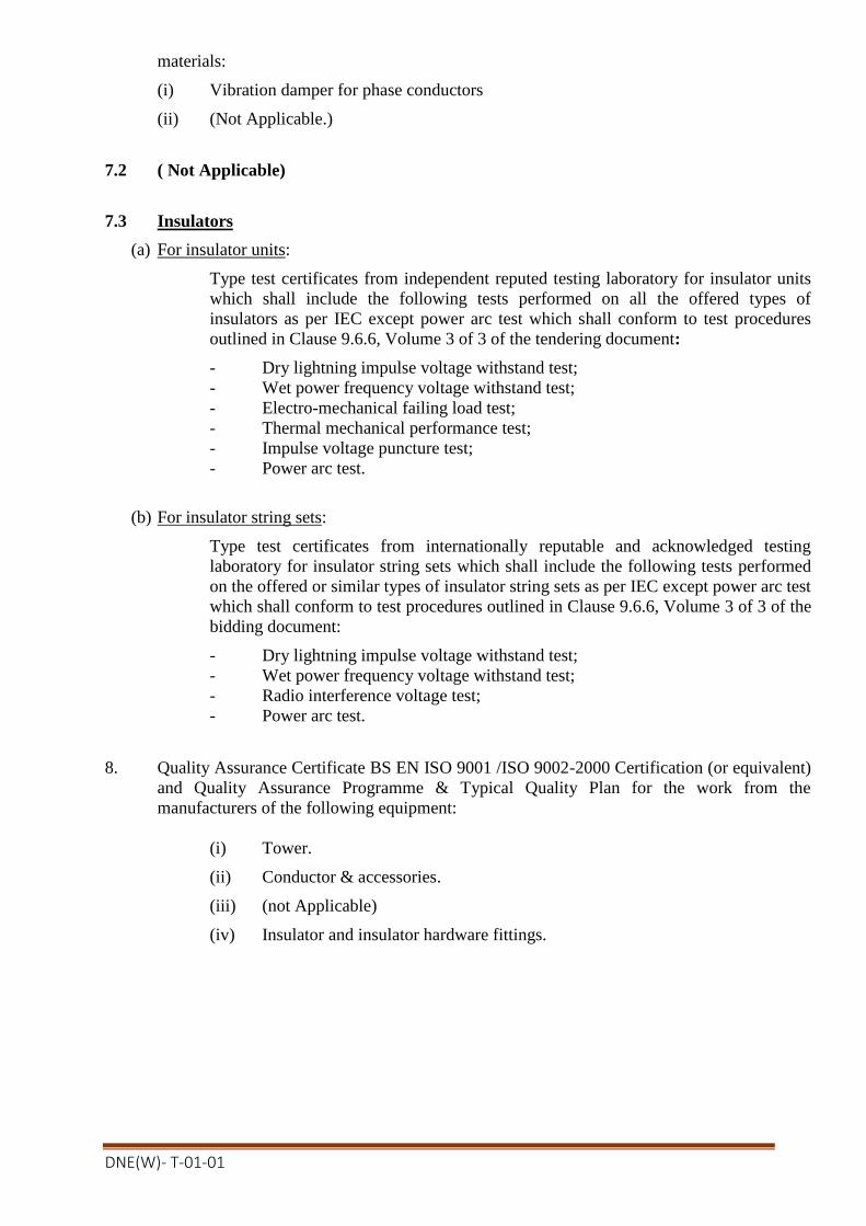
DNE(W)- T-01-01
materials:
(i) Vibration damper for phase conductors
(ii) (Not Applicable.)
7.2 ( Not Applicable)
7.3 Insulators
(a) For insulator units:
Type test certificates from independent reputed testing laboratory for insulator units
which shall include the following tests performed on all the offered types of
insulators as per IEC except power arc test which shall conform to test procedures
outlined in Clause 9.6.6, Volume 3 of 3 of the tendering document:
- Dry lightning impulse voltage withstand test;
- Wet power frequency voltage withstand test;
- Electro-mechanical failing load test;
- Thermal mechanical performance test;
- Impulse voltage puncture test;
- Power arc test.
(b) For insulator string sets:
Type test certificates from internationally reputable and acknowledged testing
laboratory for insulator string sets which shall include the following tests performed
on the offered or similar types of insulator string sets as per IEC except power arc test
which shall conform to test procedures outlined in Clause 9.6.6, Volume 3 of 3 of the
bidding document:
- Dry lightning impulse voltage withstand test;
- Wet power frequency voltage withstand test;
- Radio interference voltage test;
- Power arc test.
8. Quality Assurance Certificate BS EN ISO 9001 /ISO 9002-2000 Certification (or equivalent)
and Quality Assurance Programme & Typical Quality Plan for the work from the
manufacturers of the following equipment:
(i) Tower.
(ii) Conductor & accessories.
(iii) (not Applicable)
(iv) Insulator and insulator hardware fittings.
DNE(W)- T-01-01
SCHEDULE-J
BAR CHART PROGRAMME OF KEY ACTIVITIES
Signature: [insert signature of authorised representative of the Tenderer]
Name: [insert full name of signatory with National ID]
In the capacity of: [insert designation of signatory]
Duly authorised to sign the Tender for and on behalf of the Tenderer
DNE(W)- T-01-01
6.3 Form of Completion Certificate
Contract No: Date: To: [Name of Contractor]
Pursuant to GCC Clause 39 (Completion of the Facilities) of the General Conditions of the Contract entered into between yourselves and the Employer dated [insert date], for the supply and installation of plant and Services for [name of contract], we hereby notify you that the following part(s) of the Facilities was (were) complete on the date specified below, and that, in accordance with the terms of the Contract, the Employer hereby takes over the said part(s) of the Facilities, together with the responsibility for care and custody and the risk of loss thereof on the date mentioned below.
1.Description of the Facilities or part thereof: ______________________________ 2.Date of Completion: __________________
However, you are required to complete the outstanding items listed in the attachment hereto as soon as practicable. This letter does not relieve you of your obligation to complete the execution of the Facilities in accordance with the Contract nor of your obligations during the Defect Liability Period. Very truly yours,
for and on behalf of the Employer
[ Signature ] [ Title of the Project Manager ]

DNE(W)- T-01-01
6.4 Form of Operational Acceptance Certificate
Contract No: Date: To: [Name of Contractor]
Pursuant to GCC Clause 40.3 (Operational Acceptance) of the General Conditions of the Contract entered into between yourselves and the Employer dated [insert date],for the supply and installation of plant and Servicesfor [name of contract],we hereby notify you that the Functional Guarantees of the following part(s) of the Facilities were satisfactorily attained on the date specified below.
1.Description of the Facilities or part thereof: _______________________________ 2.Date of Operational Acceptance: _______________________
This letter does not relieve you of your obligation to complete the execution of the Facilities in accordance with the Contract nor of your obligations during the Defect Liability Period. Very truly yours, for and on behalf of the Employer
[ Signature ] [ Title of the Project Manager ]

DNE(W)- T-01-01
6.5 Form of Change Order Procedure and Forms
Contract No: Date: To: [Name of Contractor]
CONTENTS 1. General 2. Change Order Log 3. References for Changes ANNEXES Annex 1 Request for Change Proposal Annex 2 Estimate for Change Proposal Annex 3 Acceptance of Estimate Annex 4 Change Proposal Annex 5 Change Order Annex 6 Pending Agreement Change Order Annex 7 Application for Change Proposal

DNE(W)- T-01-01
Change Order Procedure 1. General
This section provides samples of procedures and forms for implementing changes in the Facilities during the performance of the Contract in accordance with GCC Clause 64 (Change in the Facilities) of the General Conditions.
2. Change Order Log The Contractor shall keep an up-to-date Change Order Log to show the current status of Requests for Change and Changes authorized or pending, as Annex 8. Entries of the Changes in the Change Order Log shall be made to ensure that the log is up-to-date. The Contractor shall attach a copy of the current Change Order Log in the monthly progress report to be submitted to the Employer.
3. References for Changes (1) Request for Change as referred to in GCC Clause64 shall be serially numbered
CR-X-nnn. (2) Estimate for Change Proposal as referred to in GCC Clause 64 shall be serially
numbered CN-X-nnn. (3) Acceptance of Estimate as referred to in GCC Clause 64 shall be serially
numbered CA-X-nnn. (4) Change Proposal as referred to in GCC Clause 64 shall be serially numbered CP-
X-nnn. (5) Change Order as referred to in GCC Clause 64 shall be serially numbered CO-X-
nnn. Note: (a) Requests for Change issued from the Employer’s Home Office and the Site
representatives of the Employer shall have the following respective references:
Home Office CR-H-nnn Site CR-S-nnn
(b) The above number “nnn” is the same for Request for Change, Estimate for
Change Proposal, Acceptance of Estimate, Change Proposal and Change Order.
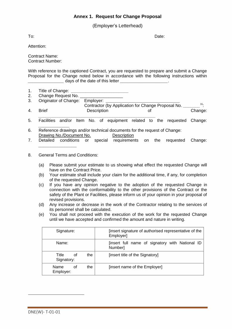
DNE(W)- T-01-01
Annex 1. Request for Change Proposal
(Employer’s Letterhead) To: Date: Attention: Contract Name: Contract Number: With reference to the captioned Contract, you are requested to prepare and submit a Change Proposal for the Change noted below in accordance with the following instructions within _______________ days of the date of this letter ____________________. 1. Title of Change: ________________________ 2. Change Request No. __________________ 3. Originator of Change: Employer: _______________________________
Contractor (by Application for Change Proposal No. _______16:
4. Brief Description of Change: _________________________________________________
5. Facilities and/or Item No. of equipment related to the requested Change: _____________
6. Reference drawings and/or technical documents for the request of Change: Drawing No./Document No. Description
7. Detailed conditions or special requirements on the requested Change: ________________
8. General Terms and Conditions:
(a) Please submit your estimate to us showing what effect the requested Change will
have on the Contract Price. (b) Your estimate shall include your claim for the additional time, if any, for completion
of the requested Change. (c) If you have any opinion negative to the adoption of the requested Change in
connection with the conformability to the other provisions of the Contract or the safety of the Plant or Facilities, please inform us of your opinion in your proposal of revised provisions.
(d) Any increase or decrease in the work of the Contractor relating to the services of its personnel shall be calculated.
(e) You shall not proceed with the execution of the work for the requested Change until we have accepted and confirmed the amount and nature in writing.
Signature: [insert signature of authorised representative of the Employer]
Name: [insert full name of signatory with National ID Number]
Title of the Signatory:
[insert title of the Signatory]
Name of the Employer:
[insert name of the Employer]

DNE(W)- T-01-01
Annex 2. Estimate for Change Proposal
(Contractor’s Letterhead) To: Date: Attention: Contract Name: Contract Number: With reference to your Request for Change Proposal, we are pleased to notify you of the approximate cost of preparing the below-referenced Change Proposal in accordance with GCC Sub-Clause64.2.1 of the General Conditions. We acknowledge that your agreement to the cost of preparing the Change Proposal, in accordance with GCC Sub-Clause64.2.2, is required before estimating the cost for change work. 1. Title of Change: ________________________ 2. Change Request No./Rev.: ____________________________ 3. Brief Description of Change: __________________________ 4. Scheduled Impact of Change: ___________________________ 5. Cost for Preparation of Change Proposal: _______________17
(a) Engineering (Amount)
(i) Engineer hrs x rate/hr = (ii) Draftsperson hrs x rate/hr =
Sub-total hrs Total Engineering Cost
(b) Other Cost
Total Cost (a) + (b)
Signature: [insert signature of authorised representative of the Employer]
Name: [insert full name of signatory with National ID Number]
Title of the Signatory: [insert title of the Signatory]
Name of the Employer: [insert name of the Employer]

DNE(W)- T-01-01
Annex 3. Acceptance of Estimate
(Employer’s Letterhead)
To: Date: Attention: Contract Name: Contract Number:
We hereby accept your Estimate for Change Proposal and agree that you should proceed with the preparation of the Change Proposal. 1. Title of Change: ___________________________ 2. Change Request No./Rev.: _______________________________ 3. Estimate for Change Proposal No./Rev.: _______________________________ 4. Acceptance of Estimate No./Rev.: _______________________________ 5. Brief Description of Change: _______________________________ 6. Other Terms and Conditions: In the event that we decide not to order the Change
accepted, you shall be entitled to compensation for the cost of preparation of Change Proposal described in your Estimate for Change Proposal mentioned in para. 3 above in accordance with GCC Clause64 of the General Conditions.
Signature: [insert signature of authorised representative of the Employer]
Name: [insert full name of signatory with National ID Number]
Title of the Signatory: [insert title of the Signatory]
Name of the Employer: [insert name of the Employer]
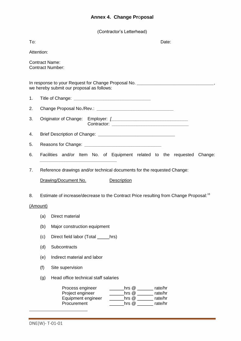
DNE(W)- T-01-01
Annex 4. Change Proposal
(Contractor’s Letterhead)
To: Date: Attention: Contract Name: Contract Number: In response to your Request for Change Proposal No. _______________________________, we hereby submit our proposal as follows: 1. Title of Change: _______________________________ 2. Change Proposal No./Rev.: _______________________________ 3. Originator of Change: Employer: [_______________________________
Contractor: _______________________________ 4. Brief Description of Change: _______________________________ 5. Reasons for Change: _______________________________ 6. Facilities and/or Item No. of Equipment related to the requested Change:
_______________________________ 7. Reference drawings and/or technical documents for the requested Change:
Drawing/Document No. Description
8. Estimate of increase/decrease to the Contract Price resulting from Change Proposal:18
(Amount)
(a) Direct material (b) Major construction equipment (c) Direct field labor (Total hrs) (d) Subcontracts (e) Indirect material and labor (f) Site supervision (g) Head office technical staff salaries
Process engineer hrs @ rate/hr Project engineer hrs @ rate/hr Equipment engineer hrs @ rate/hr Procurement hrs @ rate/hr

DNE(W)- T-01-01
Draftsperson hrs @ rate/hr Total hrs
(h) Extraordinary costs (computer, travel, etc.) (i) Fee for general administration, % of Items (j) Taxes and customs duties Total lump sum cost of Change Proposal (Sum of items (a) to (j)) Cost to prepare Estimate for Change Proposal (Amount payable if Change is not accepted)
9. Additional time for Completion required due to Change Proposal 10. Effect on the Functional Guarantees 11. Effect on the other terms and conditions of the Contract 12. Validity of this Proposal: within [Number] days after receipt of this Proposal by the
Employer 13. Other terms and conditions of this Change Proposal:
(a) You are requested to notify us of your acceptance, comments or rejection of this detailed Change Proposal within ______________ days from your receipt of this Proposal.
(b) The amount of any increase and/or decrease shall be taken into account in the
adjustment of the Contract Price. (c) Contractor’s cost for preparation of this Change Proposal:2
Signature: [insert signature of authorised representative of the Contractor]
Name: [insert full name of signatory with National ID Number]
Title of the Signatory: [insert title of the Signatory]
Name of the Contractor: [insert name of the Contractor]

DNE(W)- T-01-01
Annex 5. Change Order
(Employer’s Letterhead)
To: Date: Attention: Contract Name:…………………… Contract Number:…………………… We approve the Change Order for the work specified in the Change Proposal (No. _______), and agree to adjust the Contract Price, Time for Completion and/or other conditions of the Contract in accordance with GCC Clause64 of the General Conditions. 1. Title of Change: _______________________________ 2. Change Request No./Rev.: _______________________________ 3. Change Order No./Rev.: _______________________________ 4. Originator of Change: Employer: _______________________________
Contractor: _______________________________ 5. Authorized Price:
Ref. No.: _______________________________ Date: __________________________ Foreign currency portion __________ plus Local currency portion __________
6. Adjustment of Time for Completion
None Increase _________ days Decrease _________ days 7. Other effects, if any Authorized by: Date:
(Employer) Accepted by: Date: (Contractor)

DNE(W)- T-01-01
Annex 6. Pending Agreement Change Order
(Employer’s Letterhead)
To: Date: Attention: Contract Name: Contract Number: We instruct you to carry out the work in the Change Order detailed below in accordance with GCC Clause64 of the General Conditions. 1. Title of Change: _______________________________ 2. Employer’s Request for Change Proposal No./Rev.:
_______________________________ dated: __________ 3. Contractor’s Change Proposal No./Rev.: _______________________________ dated:
__________ 4. Brief Description of Change: _______________________________ 5. Facilities and/or Item No. of equipment related to the requested Change:
_______________________________ 6. Reference Drawings and/or technical documents for the requested Change:
Drawing/Document No. Description 7. Adjustment of Time for Completion: 8. Other change in the Contract terms: 9. Other terms and conditions:
Signature: [insert signature of authorised representative of the Employer]
Name: [insert full name of signatory with National ID Number]
Title of the Signatory: [insert title of the Signatory]
Name of the Employer: [insert name of the Employer]

DNE(W)- T-01-01
Annex 7. Application for Change Proposal
(Contractor’s Letterhead) To: Date: Attention: Contract Name:…………………………… Contract Number:…………………………… We hereby propose that the below-mentioned work be treated as a Change in the Facilities. 1. Title of Change: _______________________________ 2. Application for Change Proposal No./Rev.: _______________________________
dated: _______________________________
3. Brief Description of Change: _______________________________ 4. Reasons for Change: 5. Order of Magnitude Estimation (in the currencies of the Contract): 6. Scheduled Impact of Change: 7. Effect on Functional Guarantees, if any: 8. Appendix:
Signature: [insert signature of authorised representative of the Contractor]
Name: [insert full name of signatory with National ID Number]
Title of the Signatory: [insert title of the Signatory]
Name of the Contractor: [insert name of the Contractor]
Signature Seal

DNE(W)- T-01-01
Section 7. List of Drawings
Package Name Drawing Name Page No.
DNE(W)-T-01 Indicative Drawing & Profile for 33 Double
circuit River Crossing Tower
Indicative Earthing Arrangement
380-381 382
DRAWING
Profile & Location
Location of 33 kV River Crossing :
“ Turnkey contract for survey, design, supply, carrying, installation, testing and commissioning of 33 kv double circuit river crossing tower with transmission lines including civil constructions at Bank KAli/ Vushir Bandar - Bank KAli/ Vushir Bandar on Atrai river under Dinajpur PBS-1.”
Sl.
No
.
Package No. Location of the Tower
Site PBS Name
Name of Project
Division
Minimum
Navigation
Height (mtr.)
1 DNE(W)-T-01
33 kV Double circuit
River crossing at Bank
KAli/ Vushir Bandar -
Bank KAli/ Vushir
Bandar on Atrai River.
Dinajpur
PBS-1
Office of the
Executive Engineer,
Dinajpur Project
Division, BREB.
12.19
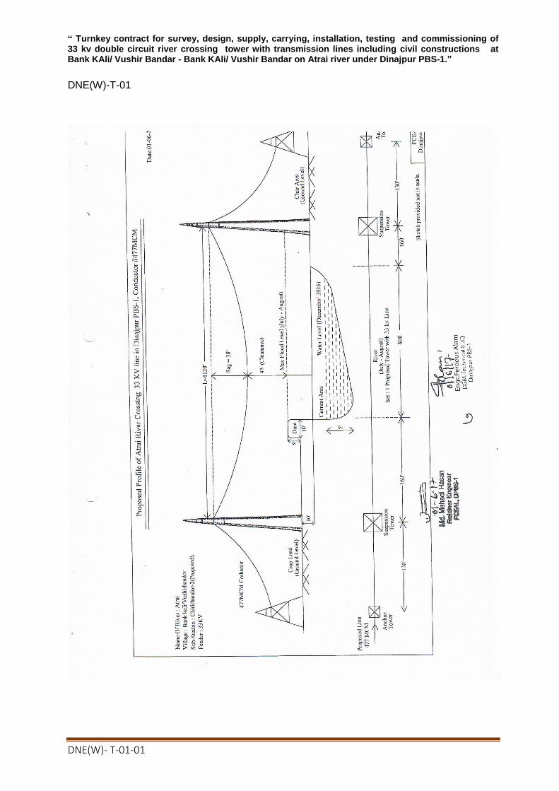
DNE(W)- T-01-01
“ Turnkey contract for survey, design, supply, carrying, installation, testing and commissioning of 33 kv double circuit river crossing tower with transmission lines including civil constructions at Bank KAli/ Vushir Bandar - Bank KAli/ Vushir Bandar on Atrai river under Dinajpur PBS-1.”
DNE(W)-T-01

DNE(W)- T-01-01

DNE(W)- T-01-01

![Rural Development Academy [RDA] Bogura, Bangladesh](https://static.fdokumen.com/doc/165x107/633366825c229e42ad09e485/rural-development-academy-rda-bogura-bangladesh.jpg)