
Bangladesh Rural Electrification Board (BREB) TENDER ...
575
Bangladesh Rural Electrification Board (BREB) TENDER DOCUMENT FOR Design, Supply, Installation, Testing and Commissioning of Hardware (1 phase and 3 phase Meter with HES, NIC, HHU, UCC, UVS, DCU, Repeater, DR, Data Centre accessories etc.) & Software for Implementation of AMI with MDM and related service Under BREB for 5 lac smart meter that will be scalable up to 2 crore smart meter on Turnkey Basis. National Competitive Tender (One Stage – Two Envelope) Invitation for Tender No. : 27.12.0000.112.35.019.18.120 Issued on : 28.03.2021 Tender Package No : 01) SPPM-MCS-01; Lot-1: 02) SPPM-MCS-01; Lot-2:
-
Upload
khangminh22 -
Category
Documents
-
view
0 -
download
0
Transcript of Bangladesh Rural Electrification Board (BREB) TENDER ...

Bangladesh Rural Electrification Board (BREB)
TENDER DOCUMENT
FOR
Design, Supply, Installation, Testing and Commissioning of Hardware (1 phase
and 3 phase Meter with HES, NIC, HHU, UCC, UVS, DCU, Repeater, DR, Data
Centre accessories etc.) & Software for Implementation of AMI with MDM and
related service Under BREB for 5 lac smart meter that will be scalable up to 2
crore smart meter on Turnkey Basis.
National Competitive Tender
(One Stage – Two Envelope)
Invitation for Tender No. : 27.12.0000.112.35.019.18.120
Issued on : 28.03.2021
Tender Package No : 01) SPPM-MCS-01; Lot-1: 02) SPPM-MCS-01; Lot-2:

i
Guidance Notes on the Use of
The Standard Tender Document
These guidance notes have been prepared by the CPTU to assist a Purchaser in the preparation, using the
Standard Tender Document (STD),for the Supply & Installation of Plant & Equipment. The Purchaser
should also refer to the Public Procurement Act 2006 (PPA 2006) and the Public Procurement Rule 2008
(PPR2008), issued to supplement the ACT, available on CPTU’s website www.cptu.gov.bd/. All concerned
are advised to refer to the aforementioned Act and Rules, while participating in any Tendering process.
The use of STD (PG5A) applies when a Purchaser (Procuring Entity) wishes to select a Tenderer (a
Supplier/contractor) for the Supply & Installation of Plant & Equipment under Turnkey Contract
(combination of goods, works and services) in international competition for which the Contract award is
being determined on the basis of the responsive lowest evaluated Tender.
STD(PG5A) is based upon internationally acceptable model formats, which have been adapted to suit the
particular needs of procurement for Bangladesh. STD (PG5A) has Seven (7) Sections, of which Section 1
(Instructions to Tenderers) and Section 3 (General Conditions of Contract) shall not be altered or modified
under any circumstances. The Invitation for Tenders (IFT) is provided in the Tender Document for
information only.
The way in which a Purchaser/Employer addresses its specific needs is through the information provided
in the Tender Data Sheet (TDS) and the Particular Conditions of Contract (PCC) as well as in the
detailed requirements of the procurement in the Employer’s Requirements, and/or the Drawings.
Guidance notes in brackets and italics are provided for both the Purchaser and the Tenderer and the
Purchaser should carefully decide what notes need to remain and what other guidance notes might be
required to assist the Tenderer in preparing its Tender Submission so as to minimise an inept Tendering
process.
STD (PG5A) provides all the information that a Tenderer needs in order to prepare and submit a Tender.
This should provide a sound basis on which a Purchaser/Employer can fairly, transparently and accurately
carry out a Tender evaluation process on the Tenders submitted by the Tenderers.
The following briefly describes the Sections of the STD (PG5A) and how a Purchaser should use these
when preparing a particular Tender Document.
Section 1. Instructions to Tenderers (ITT)
This Section provides relevant information to help Tenderers prepare their Tenders.
Information is also provided on the submission, opening, and evaluation of Tenders and on
the award of Contract. The Instructions to Tenderer (ITT) specify the instruction and
procedure that govern the tendering process. This Section also contains the criteria to be
used by the Purchaser in order to determine the responsive lowest evaluated Tender and
the qualifications of the Tenderer to perform the Contract. The Instructions to Tenderer are
not a Contract document and, therefore, are not a part of the Contract.
(The text of the clauses in this Section shall not be modified.)

ii
Section 2. Tender Data Sheet (TDS)
This Section provides the information that is specific to each object of procurement and
that supplements the information or requirements included in Section 1: Instructions to
Tenderers.
The Purchaser shall specify in the TDS only the information that the ITT instruct, be
specified in the TDS.
To facilitate the preparation of the TDS, its clause numbers are numbered with the same
numbers of corresponding ITT Clauses.
Section 3. General Conditions of Contract (GCC)
This Section provides the General Conditions of Contract that will apply to the Contract
for which the Tender document is issued.
The GCC clearly identify the provisions that may normally need to be specified for a
particular tendering process and need to be addressed through the PCC. The GCC is a
Contract document and, therefore, is a part of the Contract
(The text of the clauses in this Section shall not be modified.)
.
Section 4. Particular Conditions of Contract (PCC)
This Section provides clauses specific to the particular Contract that modify or supplement
Section 3: General Conditions of Contract.
The Purchaser/employer should include at the time of issuing the Tender Documents all
information that the GCC indicate shall be provided in the PCC. No PCC Clause should be
left blank.
To facilitate the preparation of the PCC, its clause numbers are numbered with the same
numbers of the corresponding GCC Clauses.
Section 5. Tender and Contract Forms
This Section provides the standard form for the Tender Submission Letter(Form PG5A-
1a, PG5A-1b), Tenderer Information Sheet (PG5A-2a), JVCA Partner Information
Sheet (PG5A-2b)Sub-contractor Information (PG5A-2c), Price Schedule for Plant
and Services (Form PG5A-3), Technical Proposal (Form PG5A-4), Manufacturer’s
Authorisation Letter (Form PG5A-5) and Bank Guarantee for Tender Security
(Form PG5A-6) Letter of Commitment for Bank’s undertaking for Line of Credit
(Form PG5A-6a) to be submitted by the Tenderer. [Note: Reference to rules, no joint
venture is allowed for procurement of goods but it may be applicable in this document due
to turnkey contract is the combination of goods, works and services]
This Section also contains the form of the Notification of Award (Form PG5A-7) and
Contract Agreement (Form PG5A-8), which when completed, incorporates any
corrections or modifications to the accepted Tender relating to amendments permitted by
the Instructions to Tenderers, the General Conditions of Contract (GCC), and the Particular
Conditions of Contract (PCC).
The forms of Bank Guarantee for Performance Security (Form PG5A-9) and Bank
Guarantee for Advance Payment Security (Form PG5A-10) and Bank Guarantee for
Retention Money Security (Form PG5A-11) if applicable, are to be submitted by the
successful Tenderer.

iii
Section 6. Employer’s Requirements
This Section contains the Scope of supply and installation services by the Contractor,
Specification, and supplementary information that describe the Plant and Installation
Services to be procured.
Section 7. Drawings
This Section contains any Drawings that supplement the Technical Specifications for the
Plant and Services to be procured.

iv
Table of Contents
Section 1. Instructions to Tenderers ................................................................................ 1
A. General ......................................................................................................................... 1 1. Scope of Tender ............................................................................................................................ 1 2. Interpretation ................................................................................................................................. 1 3. Source of Funds............................................................................................................................. 1 4. Corrupt, Fraudulent, Collusive, Coercive (or Obstructive in case of Development Partner)
Practices ................................................................................................................................... 2 5. Eligible Tenderers ......................................................................................................................... 3 6. Eligible Plant and Services ............................................................................................................ 4 7. Site Visit ........................................................................................................................................ 5
B. Tender Document ....................................................................................................... 6 8. Tender Document: General ........................................................................................................... 6 9. Clarification of Tender Document ................................................................................................ 6 10. Pre-Tender Meeting..................................................................................................................... 6 11. Addendum to Tender Document ................................................................................................. 7
C. Qualification Criteria ................................................................................................. 7 12. General Criteria ........................................................................................................................... 7 13. Litigation History ........................................................................................................................ 8 14. Experience Criteria ...................................................................................................................... 8 15. Financial Criteria ......................................................................................................................... 8 16. Personnel Capacity ...................................................................................................................... 8 17. Equipment Capacity .................................................................................................................... 8 18. Joint Venture, Consortium or Association .................................................................................. 9 19. Subcontractor(s) .......................................................................................................................... 9
D. Tender Preparation .................................................................................................. 10 20. Only one Tender ........................................................................................................................ 10 21. Cost of Tendering ...................................................................................................................... 10 22. Issuance and Sale of Tender Document .................................................................................... 10 23. Language of Tender .................................................................................................................. 10 24. Contents of Tender .................................................................................................................... 11 (Document establishing the tender’s qualification) ......................................................................... 11 25. Alternatives ............................................................................................................................... 13 26. Tender Prices, Discounts & Price adjustment .......................................................................... 13 27. Tender Currency ........................................................................................................................ 15 28. Documents Establishing the Conformity of Plant, and Services ............................................... 15 29. Documents Establishing Eligibility of the Tenderer .............................................................. 16 30. Validity Period of Tender .......................................................................................................... 16 31. Extension of Tender Validity and Tender Security ................................................................... 16 32. Tender Security ......................................................................................................................... 17 33. Form of Tender security ............................................................................................................ 17 34. Authenticity of Tender Security ................................................................................................ 18 35. Return of Tender Security ......................................................................................................... 18 36. Forfeiture of Tender Security. ................................................................................................... 18 37. Format and Signing of Tender................................................................................................... 19
E. Tender Submission ................................................................................................... 19 38. Sealing, Marking and Submission of Tender ............................................................................ 19 39. Deadline for Submission of tenders .......................................................................................... 20 40. Late tender ................................................................................................................................. 21 41. Modification, Substitution or Withdrawal of Tenders ............................................................... 21 42. Tender Modification .................................................................................................................. 21

v
43. Tender Substitution ................................................................................................................... 21 44. Withdrawal of Tender ............................................................................................................... 21
F. Tender Opening and Evaluation ............................................................................. 22 45. Tender Opening ......................................................................................................................... 22 46. Evaluation of Tenders ............................................................................................................... 24 47. Evaluation Process .................................................................................................................... 24 48. Preliminary Examination ........................................................................................................... 24 49. Technical Evaluation and Responsiveness ................................................................................ 25 50. Clarification on Technical Offer ............................................................................................... 26 51. Restrictions on Disclosure of Information ................................................................................ 27 52. Approval of Technical Offer .................................................................................................... 27 53. Financial Offer Opening ........................................................................................................... 27 54. Clarification on Financial Offer ................................................................................................ 28 55. Correction of Arithmetical Errors ............................................................................................. 29 56. Conversion to Single Currency ................................................................................................. 29 57. Financial Evaluation .................................................................................................................. 29 58. Price Comparison ...................................................................................................................... 30 59. Post-qualification ...................................................................................................................... 31 60. Negotiation ................................................................................................................................ 31 61. Rejection of All Tenders ........................................................................................................... 32 62. Informing Reasons for Rejection .............................................................................................. 32
G. Contract Award ........................................................................................................ 32 63. Award Criteria ........................................................................................................................... 32 64. Notification of Award ............................................................................................................... 33 65. Performance Security ................................................................................................................ 33 66. Form and Time Limit for furnishing of Performance security .................................................. 33 67. Validity of Performance Security .............................................................................................. 34 68. Authenticity of performance Security ....................................................................................... 34 69. Contract Signing ..................................................................................................................... 34 70. Publication of Notification of Award of Contract ..................................................................... 34 71. Debriefing of Tenderers ............................................................................................................ 35 72. Right to Complains ................................................................................................................... 35
Section 2. Tender Data Sheet .................................................................................... 36
A. General ....................................................................................................................... 36
B. Tender Document ..................................................................................................... 37
C. Qualification Criteria ............................................................................................... 38
D. Tender Preparation .................................................................................................. 45
E. Submission of Tender .............................................................................................. 47
F. Opening and Evaluation of Tenders ....................................................................... 50
G. Award of Contract .................................................................................................... 51
Section 3. General Conditions of Contract .............................................................. 53
A. General ....................................................................................................................... 53 1. Definitions ................................................................................................................................... 53 2. Interpretation ............................................................................................................................... 57 3. Communications & Notices ........................................................................................................ 58 4. Governing Law............................................................................................................................ 58 5. Governing Language ................................................................................................................... 58 6. Documents Forming the Contract and Priority of Documents .................................................... 58 7. Contract Agreement .................................................................................................................... 59 8. Assignment .................................................................................................................................. 59

vi
9. Eligibility .................................................................................................................................... 59 10. Gratuities / Agency fees ............................................................................................................ 59 11. Confidential Details .................................................................................................................. 59 12. Joint Venture (JV) ..................................................................................................................... 60 13. Possession of the Site ................................................................................................................ 61 14. Access to the Site ...................................................................................................................... 61 15. Safety, Security and Protection of the Environment ................................................................. 61 16. Working Hours ......................................................................................................................... 61 17. Welfare of Laborers .................................................................................................................. 61 18. Child Labor ............................................................................................................................... 62 19. Fossils& antiquities ................................................................................................................... 62 20. Corrupt, Fraudulent, Collusive or Coercive Practices ............................................................... 62 21. License/ Use of Technical Information ..................................................................................... 63
B. Subject Matter of Contract .............................................................................................. 64 22. Scope of Facilities ..................................................................................................................... 64 23. Time for Commencement .......................................................................................................... 64 24. Time for Completion ................................................................................................................. 64 25. Employer’s Responsibilities ...................................................................................................... 65 26. Contractor’s Responsibilities .................................................................................................... 66 27. Employer’s and Contractor’s Risks ........................................................................................... 66 28. Employer’s Risks ...................................................................................................................... 66 29. Contractor’s Risks ..................................................................................................................... 67
C. Execution of the Facilities ................................................................................................. 67 30. Representatives ......................................................................................................................... 67 31. Work Program ........................................................................................................................... 69 32. Subcontractor ............................................................................................................................ 70 33. Nominated Subcontractor .......................................................................................................... 70 34. Other Contractors ...................................................................................................................... 70 35. Design and Engineering ............................................................................................................ 71 36. Procurement .............................................................................................................................. 72 37. Installation ................................................................................................................................. 73 38. Test & Inspection ...................................................................................................................... 76 39. Completion of the Facilities ...................................................................................................... 78 40. Commissioning and Operational Acceptance ........................................................................... 80
D. Guarantees and Liabilities ....................................................................................... 82 41. Completion Time Guarantee ..................................................................................................... 82 42. Defect Liability ......................................................................................................................... 83 43. Functional Guarantees ............................................................................................................... 85 44. Patent Indemnity ....................................................................................................................... 85 45. Limitation of Liability ............................................................................................................... 86
E. Risk Distribution ....................................................................................................... 87 46. Transfer of Ownership .............................................................................................................. 87 47. Care of Facilities ....................................................................................................................... 87 48. Loss of or Damage to Property; Accident or Injury to Workers; Indemnification .................... 88 49. Insurance ................................................................................................................................... 89 50. Unforeseen Conditions .............................................................................................................. 91 51. Change in Laws and Regulation ................................................................................................ 92 52. Force Majeure ........................................................................................................................... 92 53. Notice of Force Majeure ........................................................................................................... 93 54. Duty to Minimize Delay ............................................................................................................ 93 55. Consequences of Force Majeure ............................................................................................... 94
F. Payment .............................................................................................................................. 94 56. Contract Price ............................................................................................................................ 94 57. Terms of Payment ..................................................................................................................... 95

vii
58. Advance Payment Security ....................................................................................................... 95 59. Performance Security ................................................................................................................ 95 60. Taxes and Duties ....................................................................................................................... 96 61. Payments to Nominated Subcontractor(s) ................................................................................. 96 62. Price Adjustment ...................................................................................................................... 96 63. Liquidated Damages .................................................................................................................. 97
G. Change in Contract Elements .......................................................................................... 97 64. Change in the Facilities ............................................................................................................. 97 65. Extension of Time for Completion .......................................................................................... 100 66. Suspension .............................................................................................................................. 101
H. Termination and Settlement of Disputes .............................................................. 102 67. Termination ............................................................................................................................. 102 68. Payment upon Termination ..................................................................................................... 104 69. Property ................................................................................................................................... 105 70. Frustration ............................................................................................................................... 105
I. Claims, Disputes and Arbitration ................................................................................... 105 71. Contractor’s Claims ................................................................................................................ 105 72. Settlement of Disputes ............................................................................................................ 106
Section 4. Particular Conditions of Contract ........................................................ 107
Appendix 1. Terms and Procedures of Payment .............................................................. 114
Appendix 2. Price Adjustment ........................................................................................... 116
Appendix 3. Insurance Requirements ............................................................................... 117
Appendix 4. Time Schedule ................................................................................................ 120
Appendix 5. List of Major Items of Plant and Services and List of Approved
Subcontractors ........................................................................................................ 121
Appendix 6. Scope of Works and Supply by the Employer ............................................ 122
Appendix 7. List of Documents for Approval or Review ................................................ 123
Appendix 8. Functional Guarantees ................................................................................. 124
Section 5. Tender and Contract Forms .................................................................. 126 Tender Submission Letter for Technical offer ............................................................................ 127 (Form PG5A-1a) ............................................................................................................................ 127 Tender Submission Letter for Financial offer ............................................................................. 130 (Form PG5A-1b) ............................................................................................................................ 130 Tenderer Information (Form PG5A-2a) ...................................................................................... 134 JVCA Partner Information (Form PG5A-2b) ............................................................................. 138 Subcontractor Information (Form PG5A-2c) .............................................................................. 142 Price Schedule for Plant and Service (Form PG5A-3) ................................................................ 144 Technical Proposal (Form PG5A-4) ............................................................................................. 172 Manufacturer’s Authorisation Letter (Form PG5A - 5) ............................................................. 183 Bank Guarantee for Tender Security (Form PG5A– 6) ............................................................. 184 Letter of Commitment for Bank’s undertaking for Line of Credit (Form PG5A-6a) .............. 185 Notification of Award (Form PG5A - 7) ....................................................................................... 186 Contract Agreement (Form PG5A - 8) ......................................................................................... 187 Bank Guarantee for Performance Security (Form PG5A – 9) ................................................... 189 Bank Guarantee for Advance Payment (Form PG5A – 10) ....................................................... 190 Bank Guarantee for Retention Money Security (Form PG5A-11) ............................................ 191
Section 6. Employer’s Requirements .......................................................................... 192
6.2 Specification ............................................................................................................ 202
6.3 Form of Completion Certificate.................................................................................... 541
viii
6.4 Form of Operational Acceptance Certificate .............................................................. 542
6.5 Form of Change Order Procedure and Forms ............................................................ 543 Annex 1. Request for Change Proposal ........................................................................................ 545 Annex 2. Estimate for Change Proposal ...................................................................................... 547 Annex 3. Acceptance of Estimate ................................................................................................ 548 Annex 4. Change Proposal ........................................................................................................... 549 Annex 5. Change Order ................................................................................................................ 551 Annex 6. Pending Agreement Change Order ............................................................................... 552
Annex 7. Application for Change Proposal………………………………………………………553
Section 7. Drawings ............................................................ …………………..……558

1
Section 1. Instructions to Tenderers
A. General
1. Scope of Tender 1.1 The Purchaser named in the Tender Data Sheet (TDS) (hereinafter referred to as
the “Purchaser”) wishes to issue these Tender Documents for the supply and
installation of plant & equipment incidental thereto, as specified in the TDS and
as detailed in Section 6: Employer’s Requirements.
1.2 The name of the Tender and the number and identification of its constituent lot(s)
are stated in the TDS.
1.3 Unless otherwise stated, throughout this Tender Document definitions and
interpretations shall be as prescribed in the Section 3: General Conditions of
Contract.
2. Interpretation 2.1 Throughout this Tender Document
(a) the term “in writing” means communication written by hand or machine
duly signed and includes properly authenticated messages by facsimile or
electronic mail;
(b) if the context so requires, singular means plural and vice versa; and
(c) “day” means calendar days unless otherwise specified as working days;
(d) "Tender Document ", means the Document provided by a Purchaser to a
Tenderer as a basis for preparation of its Tender;
(e) "Tender ", depending on the context, means a Tender submitted by a
Tenderer for delivery of Goods and Related Services to a Purchaser in
response to an Invitation for Tender ;
3. Source of Funds 3.1 The Purchaser has been allocated public funds from the source as indicated
in the TDS and intends to apply a portion of the funds to eligible payments
under the contract for which this Tender Document is issued.
3.2 For the purpose of this provision, “public funds” means any funds allocated
to a Purchaser under Government budget, or loan, grants and credits placed
at the disposal of a Purchaser through the Government by the development
partners or foreign states or organizations.
3.3 Payments by the development partner, if so indicated in the TDS, will be
made only at the request of the Government and upon approval by the
development partner in accordance with the applicable Loan/Credit/Grant
Agreement, and will be subject in all respects to the terms and conditions of
that Agreement.

2
Corrupt, Fraudulent,
Collusive, Coercive (or
Obstructive in case of
Development Partner)
Practices
4.1 The Government and the Development Partner, if applicablerequires that
the Procuring Entity as well as the Tenderers and Contracts (including,
sub-contractors, agents, personnel, consultants, and service providers)
shall observe the highest standard of ethics during implementation of
procurement proceedings and the execution of Contracts under public
funds.
4.2 For the purposes of ITT Sub Clause 4.3, the terms set forth below as
follows:
(a) “corrupt practice” means offering, giving or promising to give,
receiving, or soliciting either directly or indirectly, to any officer
or employee of the Procuring Entity or other public or private
authority or individual, a gratuity in any form; employment or any
other thing or service of value as an inducement with respect to an
act or decision or method followed by the Procuring Entity in
connection with a Procurement proceeding or Contract execution;
(b) “fraudulent practice” means the misrepresentation or omission of
facts in order to influence a decision to be taken in a Procurement
proceeding or Contract execution;
(c) “collusive practice” means a scheme or arrangement between two (2)
or more Persons, with or without the knowledge of the Procuring
Entity, that is designed to arbitrarily reduce the number of Tenders
submitted or fix Tender prices at artificial, non-competitive levels,
thereby denying the Procuring Entity the benefits of competitive
price arising from genuine and open competition;
(d) “coercive practice” means harming or threatening to harm, directly
or indirectly, Persons or their property to influence a decision to
be taken in the Procurement proceeding or the execution of a
Contract, and this will include creating obstructions in the normal
submission process used for Tenders.
(e) “Obstructive practice” (applicable in case of Development
Partner) means deliberately destroying, falsifying, altering or
concealing of evidence material to the investigation or making
false statements to investigators in order to materially impede an
investigation into allegations of a corrupt, fraudulent, coercive or
collusive practice; and /or threatening, harassing or intimidating
any party to prevent it from disclosing its knowledge of matters
relevant to the investigation or from pursuing the investigation.
4.3 Should any corrupt, fraudulent, collusive, coercive (or obstructive in case
of Development Partner) practice of any kind is determined by the
Procuring Entity or the Development Partner, if applicable, this will be
dealt in accordance with the provisions of the Public Procurement Act and
Rules and Guidelines of the Development Partners as stated in the ITT sub-
clause 3.3.

3
In case of obstructive practice, this will be dealt in accordance with Development
Partners Guidelines.
4.4 If corrupt, fraudulent, collusive, coercive (or obstructive in case of
Development Partner) practices of any kind is determined by the
Procuring Entity against any Tenderer or Contracts (including sub-
contractors, agents, personnel, consultants, and service providers) in
competing for, or in executing, a contract under public fund:
(a) Procuring Entity and/or the Development Partner shall exclude
the concerned Tenderer from further participation in the
concerned procurement proceedings;
(b) Procuring Entity and/or the Development Partner shall reject any
recommendation for award that had been proposed for that
concerned Tenderer;
(c) Procuring Entity and/or the Development Partner shall declare, at
its discretion, the concerned Tenderer to be ineligible to participate in
further Procurement proceedings, either indefinitely or for a specific
period of time;
(d) Development Partner shall sanction the concerned Tenderer or
individual, at any time, in accordance with prevailing
Development Partner’ sanctions procedures, including by
publicly declaring such Tenderer or individual ineligible, either
indefinitely or for a stated period of time: (i) to be awarded a
Development Partner-financed contract; and (ii) to be a
nominated sub-contractor, consultant, manufacturer or
Contractor, or service provider of an otherwise eligible firm being
awarded a Development Partner-financed contract; and
(e) Development Partner shall cancel the portion of the loan allocated
to a contract if it determines at any time that representatives of the
Procuring Entity or of a beneficiary of the loan engaged in
corrupt, fraudulent, collusive, coercive or obstructive practices
during the procurement or the execution of that Development
Partner financed contract, without the Procuring Entity having
taken timely and appropriate action satisfactory to the
Development Partner to remedy the situation.
4.5 Tenderer shall be aware of the provisions on corruption, fraudulence,
collusion, coercion (and obstruction, in case of Development Partner)
of the Public Procurement Act, 2006, the Public Procurement Rules, 2008
and others as stated in GCC Clause 38.
4.6 In further pursuance of this policy, Tenderers, Contractors and their sub-
contractors, agents, personnel, consultants, service providers shall permit
the Government and the Development Partner to inspect any accounts and
records and other documents relating to the Tender submission and
contract performance, and to have them audited by auditors appointed by
the Government and/or the Development Partner during the procurement
or the execution of that Development Partner financed contract.
5. Eligible Tenderers 5.1 This Invitation for Tenders is open to all potential Tenderers from all
countries, except for any specified in the TDS.

4
5.2 Tenderers shall have the legal capacity to enter into the Contract under
the Applicable law.
5.3 Tenderers shall be enrolled in the relevant professional or trade
organisations registered in Bangladesh.
5.4 Tenderers may be a physical or juridical individual or body of
individuals, or company, association or any combination of them in the
form of a Joint Venture(JV) invited to take part in public procurement
or seeking to be so invited or submitting a Tender in response to an
Invitation for Tenders.
5.5 Tenderers shall have fulfilled its obligations to pay taxes and social
security contributions under the provisions of laws and regulations of
the country of its origin.
5.6 Tenderers should not be associated, or have been associated in the past,
directly or indirectly, with a consultant or any of its affiliates which
have been engaged by the Procuring Entity to provide consulting
services for the preparation of the design, specifications, and other
documents to be used for the procurement of the works to be performed
under this Invitation for Tenders.
5.7 Tenderers in its own name or its other names or also in the case of its
Persons in different names shall not be under a declaration of
ineligibility for corrupt, fraudulent, collusive or coercive practices as
stated under ITT Sub Clause 4.4 (or obstructive practice, in case of
Development Partner) in relation to the Development Partner’s
Guidelines in projects financed by Development Partner.
5.8 Tenderers are not restrained or barred from participating in Public
Procurement on grounds of poor performance in the past under any
Contract.
5.9 Tenderers shall not be insolvent, be in receivership, be bankrupt, be in
the process of bankruptcy, be not temporarily barred from undertaking
business and it shall not be the subject of legal proceedings for any of
the foregoing.
5.10 Government-owned enterprise in Bangladesh may also participate in
the Tender if it is legally and financially autonomous, it operates under
commercial law, and it is not a dependent agency of the Procuring
Entity.
5.11 Tenderers shall provide such evidence of their continued eligibility
satisfactory to the Procuring Entity, as the Procuring Entity will
reasonably request.
5.12 These above requirements for eligibility will extend, as applicable, to
each JV partner and Subcontractor proposed by the Tenderers.
5.13 Tenderers shall have the up-to-date valid license(s), issued by the
corresponding competent authority, as specified in the TDS.
6. Eligible Plant and
Services 6.1 The plant and services to be supplied under the contract are eligible, unless
their origin is from a country specified in the TDS and all expenditures
under the contract will be limited to such plant, and services.

5
6.2 For purposes of this Clause, the term “plant” means permanent plant,
equipment, machinery, apparatus, articles and things of all kinds to be
provided in the facilities; and “installation services” means all those
services ancillary to the supply of the Plant for the Facilities, such as
transportation and provision of marine or other similar insurance,
inspection, expediting, site preparation, installation, testing, pre-
commissioning, commissioning, operations, maintenance, the provision of
operations and maintenance manuals, training etc
6.3 For purposes of this clause, “origin” means the place where the plant, or
component parts thereof are mined, grown, produced or manufactured, and
from which the services are provided. Plant components are produced
when, through manufacturing, processing, or substantial or major
assembling of components, a commercially recognized product results that
is substantially different in its basic characteristics or in purpose or utility
from its components or country where the goods have been mined, grown,
cultivated, produced, manufactured or processed; or through manufacture,
processing, or assembly, another commercially recognized article results
that differs substantially in its basic characteristics from its components.
6.4 The origin of plant & equipment is distinct from the nationality of the
Tenderer. The nationality of the firm that produces, assembles, distributes,
or sells the goods shall not determine their origin.
7. Site Visit 7.1 The Tenderer is advised to visit and examine the site where the plant is
to be installed and its surroundings and obtain for itself on its own
responsibility all information that may be necessary for preparing the
tender and entering into a contract for the provision of Plant and
Installation Services.
7.2 The Tenderer and any of its personnel or agents will be granted
permission by the Employer to enter upon its premises and lands for the
purpose of such visit, but only upon the express condition that the
Tenderer, its personnel, and agents will release and indemnify the
Employer and its personnel and agents from and against all liability in
respect thereof, and will be responsible for death or personal injury, loss
of or damage to property, and any other loss, damage, costs, and
expenses incurred as a result of the inspection.
7.3 The Tenderer should ensure that the Purchaser is informed of the visit
in adequate time to allow it to make appropriate arrangements.
7.4 The costs of visiting the Site shall be at the Tenderer’s own expense.

6
B. Tender Document
8. Tender Document:
General 8.1 The Sections comprising the Tender Document are listed below, and
should be read in conjunction with any Addendum issued under ITT
Clause 11.
• Section 1 Instructions to Tenderers (ITT)
• Section 2 Tender Data Sheet (TDS)
• Section 3 General Conditions of Contract (GCC)
• Section 4 Particular Conditions of Contract (PCC)
• Section 5 Tender and Contract Forms
• Section 6 Employer’s Requirements
• Section 7 Drawings
8.2 The Purchaser shall reject any Tender if the Tender Document was not
purchased directly from the Purchaser, or through its agent as stated in
the TDS.
8.3 The Tenderer is expected to examine all instructions, forms, terms, and
specifications in the Tender Document as well as addendum to Tender
Documents.
9. Clarification of Tender
Document 9.1 A prospective Tenderer requiring any clarification of the Tender Document
shall contact the Purchaser in writing at the Purchasers address indicated
in the TDS before two-third of time allowed for preparation and
submission of Tender elapses.
9.2 The Procuring Entity is not obliged to answer any clarification request
received after that date as stated under ITT Sub Clause 9.1.
9.3 The Procuring Entity shall respond in writing within five (5) working
days of receipt of any such request for clarification received under ITT
Sub Clause 9.1.
9.4 The Procuring Entity shall forward copies of its response to all those who
have purchased the Tender Document, including a description of the
enquiry but without identifying its source.
9.5 Should the Procuring Entity deem it necessary to revise the Tender
Document as a result of a clarification, it will do so following the procedure
under ITT Clause 11.
10. Pre-Tender Meeting 10.1 To clarify issues and to answer questions on any matter arising in the
Tender Document, the Purchaser may, if stated in the TDS, hold a Pre-
Tender Meeting at the place, date and time as specified in the TDS. All
Potential Tenderers are encouraged to attend the meeting, if it is held.
10.2 Minutes of the pre-Tender meeting, including the text of the questions
raised and the responses given, together with any responses prepared after
the meeting, will be transmitted within one week (7 days) after holding the
meeting to all those who purchased the Tender Document and even those
who did not attend the meeting.

7
10.3 Any amendment to the Tender Documents listed in ITT Sub-Clause 8.1
that may become necessary as a result of the pre-Tender meeting shall be
made by the Purchaser exclusively through the issue of an Addendum as
stated under ITT Sub-Clause 11 and not through the minutes of the pre-
Tender meeting.
10.4 Non-attendance at the Pre-Tender meeting will not be a cause for
disqualification of a Tenderer.
11. Addendum to Tender
Document
11.1 At any time prior to the deadline for submission of Tenders, the Purchaser
on its own initiative or in response to a clarification request in writing from
a Tenderer, having purchased the Tender Document or as a result of a Pre-
Tender meeting, may revise the Tender Document by issuing an addendum
pursuant to Rule 95 of the Public Procurement Rules, 2008.
11.2 The addendum issued under ITT Sub-Clause 11.1 shall become an
integral part of the Tender Document and shall have a date and an issue
number and shall be circulated by fax, mail or e-mail, to Tenderers who
have purchased the Tender Documents within five (5) working days of
issuance of such addendum, to enable Tenderers to take appropriate
action.
11.3 The Tenderer shall acknowledge receipt of an addendum.
11.4 Tenderers who have purchased the Tender Documents but have not
received any addendum issued under ITT Sub-clause 11.1 shall inform the
Purchaser of the fact by fax, mail or e-mail before two-third of the time
allowed for the submission of Tenders has elapsed.
11.5 Procuring Entities shall also ensure posting of relevant addenda with the
reference number and date on their website.
11.6 To give a prospective Tenderer reasonable time in which to take an
amendment into account in preparing its Tender, the Purchaser may, at
its discretion, extend the deadline for the submission of Tenders,
pursuant to Rule 95(6) of the Public Procurement Rule, 2008 and under
ITT Clause 36.
11.7 If an addendum is issued when time remaining is less than one-third of
the time allowed for the preparation of Tenders, a Purchaser shall extend
the deadline by an appropriate number of days for the submission of
Tenders, depending upon the nature of the Procurement requirement and
the addendum. The minimum time for such extension shall not be less
than seven (7) days.
C. Qualification Criteria
12. General Criteria 12.1 The Tenderer shall possess the necessary professional and technical
qualifications and competence, financial resources, equipment and
other physical facilities, managerial capability, specific experience,
reputation, and the personnel, to perform the contract.

8
12.2 In addition to meeting the eligibility criteria, as stated in ITT Clause 5,
the Tenderer must satisfy the other criteria stated in ITT Clauses 13 to
15 inclusive.
12.3 To qualify for multiple number of contracts/lots in a package made up
of this and other individual contracts/lots for which tenders are invited
in the Invitation for Tenders, the Tenderer shall demonstrate having
resources and experience sufficient to meet the aggregate of the
qualifying criteria for the individual contracts.
13. Litigation History 13.1 The maximum number of arbitration awards against the Tenderer over
a period shall be as specified in the TDS.
14. Experience Criteria
14.1 Tenderers shall have the following minimum level of supply experience
to qualify for supplying the Plant and Services under the contract:
(a) a minimum number of years of general experience in the role
of Contractor or Subcontractor or Management Contractor as
specified in the TDS; and
(b) Specific experience as a Contractor or Subcontractor or
Management Contractor that are similar to the proposed plant
and services in at least a number of contract(s) and of a minimum
value over the period, as specified in the TDS.
15. Financial Criteria 15.1 Tenderers shall have the following minimum level of financial capacity
of qualify for the supply, execution and performance of plant and
services under the contract.
(a) the average annual turnover as specified in the TDS calculated
as total certified payments received for contracts in progress or
completed, during the period specified in the TDS;
(b) availability of minimum liquid assets or working capital or credit
facilities, as specified in the TDS; and;
(c) satisfactory resolution of all claims, arbitrations or other
litigation cases and shall not have serious negative impact on the
financial capacity of the Tenderer.
16. Personnel Capacity 16.1 The Tenderer shall have the following minimum level of personnel
capacity to qualify for the performance of the plant and services under
the Contract.
A Project Manager, Engineers, and other key staff with qualifications
and experience as specified in the TDS;
17. Equipment Capacity 17.1 The Tenderer shall own suitable equipment and other physical facilities
or have proven access through contractual arrangement to hire or lease
such equipment or facilities for the desired period, where necessary or
have assured access through lease, hire, or other such method, of the
essential equipment, in full working order, as specified in the TDS.

9
18. Joint Venture,
Consortium or
Association
18.1 The Tenderer may participate in the procurement proceedings forming a
Joint Venture, Consortium or Associations (JVCA) by an agreement,
executed case by case on a non judicial stamp of value as stated in TDS or
alternately with the intent to enter into such an agreement supported by a
Letter of Intent along with the proposed agreement duly signed by all
partners of the intended JVCA and authenticated by a Notary Public.
18.2 The figures for each of the partners of a JVCA shall be added together to
determine the Tenderer’s compliance with the minimum qualifying
criteria; however, for a JVCA to qualify, lead partner and its other partners
must meet the criteria stated in the TDS. Failure to comply with these
requirements will result in rejection of the JVCA Tender. Subcontractors’
experience and resources will not be taken into account in determining the
Tenderer’s compliance with the qualifying criteria.
18.3 Each partner of the JVCA shall be jointly and severally liable for the
execution of the Contract, all liabilities and ethical and legal obligations in
accordance with the Contract terms.
18.4 The JVCA shall nominate a Representative (partner-in-charge/Lead Firm)
who shall have the authority to conduct all business for and on behalf of
any and all the partners of the JVCA during the tendering process and, in
the event the JVCA is awarded the Contract, during contract execution
including the receipt of payments for and on behalf of the JVCA.
18.5 Each partner of the JVCA shall complete the JVCA Partner Information
(Form PG5A-2b)for submission with the Tender
19. Subcontractor(s) 19.1 Tenderer, pursuant to Rule 53 of the PPR2008, is allowed to sub-contract
a portion of the Supply.
19.2 The Tenderer shall specify in its Tender all portion of the Plant and
Services that will be subcontracted, if any, including the entity(ies) to
whom each portion will be subcontracted to, subject to the maximum
allowable limit for subcontracting of Plant and Services specified in the
TDS.
19.3 The Purchaser may require Tenderers to provide more information about
their subcontracting arrangements. If any Subcontractor is found ineligible
or unsuitable to carry out the subcontracted tasks, the Procuring Entity may
request the Tenderer to propose an acceptable substitute.
19.4 The Purchaser may also select nominated Subcontractor(s) to execute
certain specific components of the Works and if so, those will be specified
in the TDS.
19.5 The successful Tenderer shall under no circumstances assign the
goods/works/services or any part of it to a Subcontractor

10
19.6 Subcontractors must comply with the provision of ITT Clause 5. For this
purpose contractor shall complete the Subcontractor’s information in
Form PG5A-2c for submission with tender
19.7 If the Purchaser determines that a subcontractor is ineligible, the
subcontracting of such portion of the Plants and Services assigned to the
ineligible subcontractor shall be disallowed
D. Tender Preparation
20. Only one Tender 20.1 If a Tender for Plant and Services is invited on ‘lot-by-lot’ basis, each
lot shall constitute a tender. A Tenderer shall submit only one (1) Tender
for each lot, either individually or as a JVCA. The Tenderer who submits
or participates in more than one (1) Tender for each lot will cause all the
Tenders with that Tenderer’s participation to be rejected.
21. Cost of Tendering 21.1 Tenderers shall bear all costs associated with the preparation and
submission of its Tender, and the Purchaser shall not be responsible or
liable for those costs, regardless of the conduct or outcome of the
Tendering process.
22. Issuance and Sale of
Tender Document 22.1 A Purchaser, pursuant to Rule 94 of the Public Procurement Rules, 2008
shall make Tender Documents available immediately to the potential
Tenderers, requesting and willing to purchase at the corresponding price
if the advertisement has been published in the newspaper pursuant to
Rule 90 of the Public Procurement Rules, 2008.
22.2 Full contact details with mailing address, telephone and facsimile
numbers and electronic mail address, as applicable, of those to whom
Tender Documents have been issued shall be recorded with a reference
number by the Purchaser or its agent.
22.3 There shall not be any pre-conditions whatsoever, for sale of Tender
Document and the sale of such Document shall be permitted up to the
day prior to the day of deadline for the submission of Tender.
23. Language of Tender 23.1 Tenders shall be written in the English language. Correspondences and
documents relating to the Tender may be written in English or Bangla.
Supporting documents and printed literature furnished by the Tenderers
that are part of the Tender may be in another language, provided they are
accompanied by an accurate translation of the relevant passages in the
English or Bangla language, in which case, for purposes of interpretation
of the Tender, such translation shall govern.

11
23.2 Tenderers shall bear all costs of translation to the governing language
and all risks of the accuracy of such translation.
24. Contents of Tender
(Document establishing
the tender’s qualification)
24.1 The Tender prepared by the Tenderers shall comprise Two Envelope
submitted simultaneously, one called the Technical Offer (Envelope-
01) containing the documents listed in ITT 24.2 and other called the
Financial Offer containing the documents listed in 24.3, both envelopes
enclosed together in an outer Single envelope.
24.2 The Technical Offer (Envelope-01) prepared by the Tenderers will
comprise the following:
(a) Technical Submission Letter (Form PG5A-1a) as furnished in
Section 5: Tender and Contract Forms. This form must be
completed without any alterations to its format, and no
substitutes shall be accepted. All blank spaces shall be filled in
with the information requested
(b) Tenderer Information Sheet (Form PG5A-2) as furnished in
Section 5: Tender and Contract Forms;
(c) Tender Security as stated under ITT Clause 32,33 and 34;
(d) Technical Proposal (Form PG5A-4) as furnished in Section 5:
Tender and Contract Forms.
(e) Alternatives, if permitted, as stated under with ITT Clause 25;
(f) Written confirmation authorising the signatory of the Tender to
commit the Tenderer, as stated under ITT Sub-Clause 37.3;
(g) The completed eligibility declarations, to establish its eligibility as
stated under ITT Clause 5, in the Tender Submission Sheet (Form
PG5A-1a & 1b), as furnished in section 5: Tender and Contract
Forms;
(h) An affidavit confirming the legal capacity stating that there are
no existing orders of any judicial court that prevents either the
Tenderer or employees of a Tenderer entering into or signing a
Contract with the Purchaser as stated under ITT clause 5;
(i) An affidavit confirming that the Tenderer is not insolvent, in
receivership or not bankrupt or not in the process of bankruptcy,
not temporarily barred from undertaking their business for
financial reasons and shall not be the subject of legal
proceedings for any of the foregoing as stated under ITT Clause
5;
(j) A certificate issued by the competent authority stating that the
Tenderer is a Tax payer having valid Tax Identification Number
(TIN) and VAT registration number or in lieu any other
document acceptable to the Purchaser demonstrating that the
Tenderer is a genuine Tax payer and has a VAT registration
number as a proof of fulfillment of taxation obligations as stated
under ITT Clause 5. In the case of foreign Tenderers, a
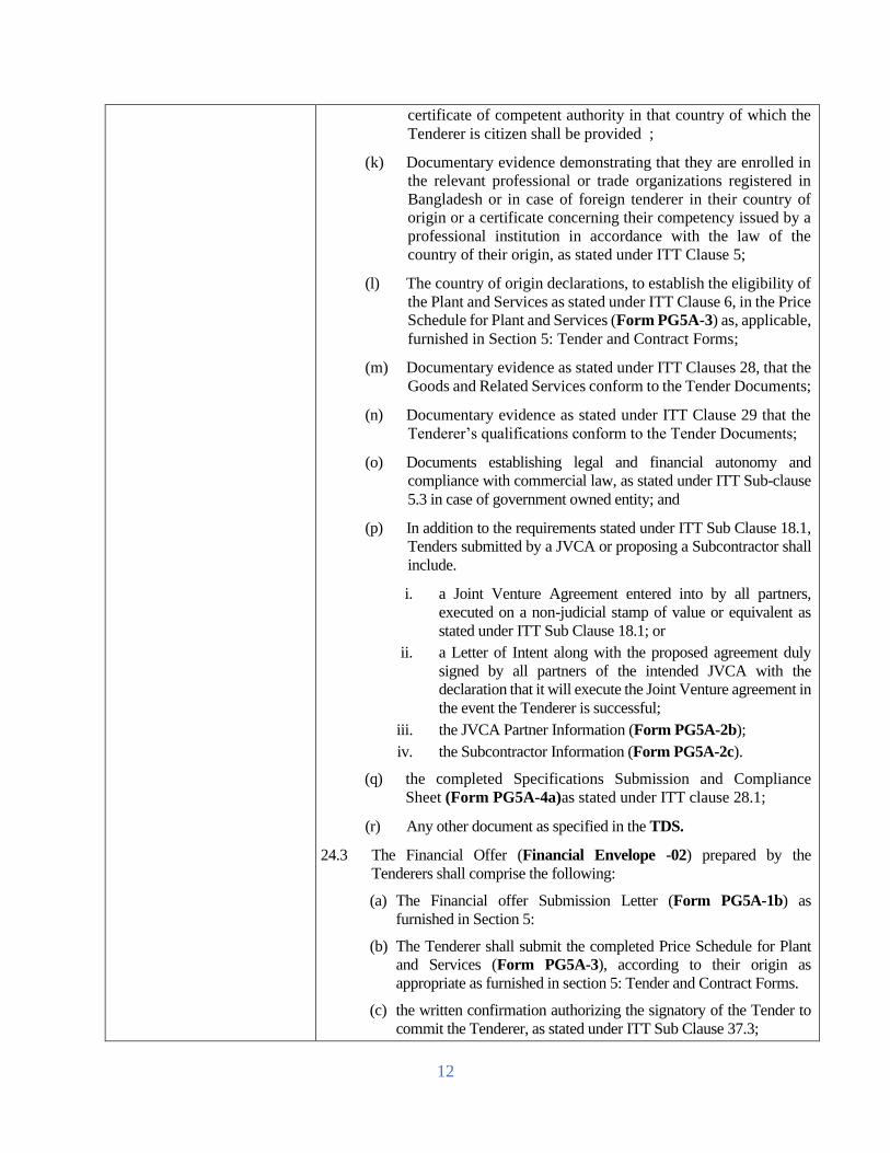
12
certificate of competent authority in that country of which the
Tenderer is citizen shall be provided ;
(k) Documentary evidence demonstrating that they are enrolled in
the relevant professional or trade organizations registered in
Bangladesh or in case of foreign tenderer in their country of
origin or a certificate concerning their competency issued by a
professional institution in accordance with the law of the
country of their origin, as stated under ITT Clause 5;
(l) The country of origin declarations, to establish the eligibility of
the Plant and Services as stated under ITT Clause 6, in the Price
Schedule for Plant and Services (Form PG5A-3) as, applicable,
furnished in Section 5: Tender and Contract Forms;
(m) Documentary evidence as stated under ITT Clauses 28, that the
Goods and Related Services conform to the Tender Documents;
(n) Documentary evidence as stated under ITT Clause 29 that the
Tenderer’s qualifications conform to the Tender Documents;
(o) Documents establishing legal and financial autonomy and
compliance with commercial law, as stated under ITT Sub-clause
5.3 in case of government owned entity; and
(p) In addition to the requirements stated under ITT Sub Clause 18.1,
Tenders submitted by a JVCA or proposing a Subcontractor shall
include.
i. a Joint Venture Agreement entered into by all partners,
executed on a non-judicial stamp of value or equivalent as
stated under ITT Sub Clause 18.1; or
ii. a Letter of Intent along with the proposed agreement duly
signed by all partners of the intended JVCA with the
declaration that it will execute the Joint Venture agreement in
the event the Tenderer is successful;
iii. the JVCA Partner Information (Form PG5A-2b);
iv. the Subcontractor Information (Form PG5A-2c).
(q) the completed Specifications Submission and Compliance
Sheet (Form PG5A-4a)as stated under ITT clause 28.1;
(r) Any other document as specified in the TDS.
24.3 The Financial Offer (Financial Envelope -02) prepared by the
Tenderers shall comprise the following:
(a) The Financial offer Submission Letter (Form PG5A-1b) as
furnished in Section 5:
(b) The Tenderer shall submit the completed Price Schedule for Plant
and Services (Form PG5A-3), according to their origin as
appropriate as furnished in section 5: Tender and Contract Forms.
(c) the written confirmation authorizing the signatory of the Tender to
commit the Tenderer, as stated under ITT Sub Clause 37.3;
13
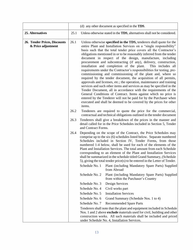
(d) any other document as specified in the TDS.
25. Alternatives 25.1 Unless otherwise stated in the TDS, alternatives shall not be considered.
26. Tender Prices, Discounts
& Price adjustment
26.1 Unless otherwise specified in the TDS, tenderers shall quote for the
entire Plant and Installation Services on a “single responsibility”
basis such that the total tender price covers all the Contractor’s
obligations mentioned in or to be reasonably inferred from the tender
document in respect of the design, manufacture, including
procurement and subcontracting (if any), delivery, construction,
installation and completion of the plant. This includes all
requirements under the Contractor’s responsibilities for testing, pre-
commissioning and commissioning of the plant and, where so
required by the tender document, the acquisition of all permits,
approvals and licenses, etc.; the operation, maintenance and training
services and such other items and services as may be specified in the
Tender Document, all in accordance with the requirements of the
General Conditions of Contract. Items against which no price is
entered by the Tenderer will not be paid for by the Purchaser when
executed and shall be deemed to be covered by the prices for other
items.
26.2 Tenderers are required to quote the price for the commercial,
contractual and technical obligations outlined in the tender document
26.3 Tenderers shall give a breakdown of the prices in the manner and
detail called for in the Price Schedules included in Section 5, Tender
and Contract Forms.
26.4 Depending on the scope of the Contract, the Price Schedules may
comprise up to the six (6) schedules listed below. Separate numbered
Schedules included in Section IV, Tender Forms, from those
numbered 1-4 below, shall be used for each of the elements of the
Plant and Installation Services. The total amount from each Schedule
corresponding to an element of the Plant and Installation Services
shall be summarized in the schedule titled Grand Summary, (Schedule
5), giving the total tender price(s) to be entered in the Letter of Tender.
Schedule No. 1 Plant (including Mandatory Spare Parts) Supplied
from Abroad
Schedule No. 2 Plant (including Mandatory Spare Parts) Supplied
from within the Purchaser’s Country
Schedule No. 3 Design Services
Schedule No. 4 Civil works part
Schedule No. 5 Installation Services
Schedule No. 6 Grand Summary (Schedule Nos. 1 to 4)
Schedule No. 7 Recommended Spare Parts
Tenderers shall note that the plant and equipment included in Schedule
Nos. 1 and 2 above exclude materials used for civil, building and other
construction works. All such materials shall be included and priced
under Schedule No. 4, Installation Services.

14
26.5 In the Schedules, tenderers shall give the required details and a
breakdown of their prices as follows:
a) Plant to be supplied from abroad (Schedule No. 1):
The price of the plant shall be quoted on CIP-named place of
destination/CIF basis as specified in the TDS and as
applicable.
(b) Plant manufactured within the Purchaser’s country (Schedule
No. 2):
i) The price of the plant shall be quoted on an EXW
INCOTERM basis (such as “ex-works,” “ex-factory,”
“ex-warehouse” or “off-the-shelf,” as applicable),
(ii) Sales tax and all other taxes payable in the Employer’s
country on the plant if the contract is awarded to the
Tenderer, and
(iii) The total price for the item.
(c) Design Services (Schedule No. 3).
(d) Installation Services shall be quoted separately (Schedule No.
4) and shall include rates or prices for local transportation to
named place of final destination as specified in the TDS,
insurance and other services incidental to delivery of the plant,
all labor, contractor’s equipment, temporary works, materials,
consumables and all matters and things of whatsoever nature,
including operations and maintenance services, the provision of
operations and maintenance manuals, training, etc., where
identified in the Tender Document, as necessary for the proper
execution of the installation and other services, including all
taxes, duties, levies and charges payable in the Employer’s
country as of twenty-eight (28) days prior to the deadline for
submission of tenders.
(e) Recommended spare parts shall be quoted separately (Schedule
6) as specified in either subparagraph (a) or (b) above in
accordance with the origin of the spare parts
26.6 The current edition of INCOTERMS, published by the International
Chamber of Commerce shall govern.
26.7 The prices shall be either fixed or adjustable as specified in the TDS.
26.8 In the case of Fixed Price, prices quoted by the Tenderer shall be
fixed during the Tenderer’s performance of the contract and not
subject to variation on any account. A tender submitted with an
adjustable price quotation will be treated as non-responsive and
rejected.
26.9 In the case of Adjustable Price, prices quoted by the Tenderer shall
be subject to adjustment during performance of the contract to reflect
changes in the cost elements such as labor, material, transport and
contractor’s equipment in accordance with the procedures specified
in the corresponding Appendix to the Contract Agreement. A tender
submitted with a fixed price quotation will not be rejected, but the
price adjustment will be treated as zero. Tenderers are required to

15
indicate the source of labor and material indices in the corresponding
Form in Section 5, Tender and Contract Forms
26.10 If so indicated in ITT 1.2, tenders are to be invited for individual lots
or for any combination of lots (packages). Tenderers wishing to offer
any price reduction (discount) for the award of more than one lot
shall specify in their Tender Submission Letter the price reductions
applicable to each package, or alternatively, to individual Contracts
within the package, and the manner in which the price reductions will
apply.
26.11 Tenderers wishing to offer any unconditional discount shall specify
in their Letter of Tender the offered discounts and the manner in
which price discounts will apply.
26.12 If so indicated under ITT Sub Clause 26.9, Tenders are being invited
with a provision for price adjustments. The unit rates or prices quoted
by the Tenderer are subject to adjustment during the performance of the
Contract in accordance with the provisions of the relevant GCC Clause
and, in such case the Employer shall provide the indexes and weightings
or coefficients in Appendix to the Tender for the price adjustment
formulae specified in the PCC.
26.13 The Employer may require the Tenderer to justify its proposed indexes,
if any of those as stated under ITT Sub Clause 26.12, are instructed to
be quoted by the Tenderer in Appendix to the Tender.
26.14 The price adjustment stated under ITT Sub Clause 26.9and 26.12 shall
be dealt with in accordance with the provisions in Section 12 and 22 of
the Public Procurement Act, 2006 and Rule 5 and 38 of the Public
Procurement Rules, 2008.
27. Tender Currency 27.1 For expenditures that will be incurred in Bangladesh, the Tenderer
shall quote the prices in Bangladesh Taka
27.2 Suppliers offering Goods manufactured or assembled in Bangladesh
are permitted to submit their Tender in a combination of local and
foreign currencies.
27.3 In case of National Tender, all quoted price shall be in local currency.
27.4 In case of international competitive tender, for expenditures that will
be incurred outside Bangladesh, the Tenderer may quote the prices
as specified in TDS.
28. Documents Establishing
the Conformity of Plant,
and Services
28.1 To establish the conformity of the plant and services to the Tender
Documents, the Tenderer shall furnish as part of its Tender the
documentary evidence that the Goods and Related services conform
to the technical specifications and standards in Section 6, Employer’s
Requirement.
a. a detailed description of the essential technical and
performance characteristics of the plant and services, including
the functional guarantees of the proposed plant and services, in
response to the Specification

16
b. a list giving full particulars, including available sources, of all
spare parts and special tools necessary for the proper and
continuing functioning of the plant for the period named in the
TDS, following completion of plant and services in accordance
with provisions of contract; and
c. a commentary on the Employer’s Specification and adequate
evidence demonstrating the substantial responsiveness of the
plant and services to those specifications. Tenderers shall note
that standards for workmanship, materials and equipment
designated by the Employer in the Tender Document are
intended to be descriptive (establishing standards of quality
and performance) only and not restrictive. The Tenderer may
substitute alternative standards, brand names and/or catalog
numbers in its tender, provided that it demonstrates to the
Employer’s satisfaction that the substitutions are substantially
equivalent or superior to the standards designated in the
Specification.
29. Documents Establishing
Eligibility of the
Tenderer
29.1 Tenderers, if applying as a sole Tenderer, shall submit documentary
evidence to establish its eligibility as stated under ITT Clause 5 and, in
particular, it shall:
(a) complete the eligibility declarations in the Tender Submission
Letter (Form PG5A-1a);
(b) complete the Tenderer Information (Form PG5A-2a);
(c) complete Subcontractor Information (Form PG5A-2c), if it
intends to engage any Subcontractor(s).
29.2 Tenderers, if applying as a partner of an existing or intended JV shall
submit documentary evidence to establish its eligibility as stated under
ITT Clause 5 and, in particular, in addition to as stated under ITT Sub
Clause 29.1, it shall:
(a) provide for each JV partner, completed JV Partner Information
(Form PG5A-2b);
(b) provide the JV agreement or Letter of Intent along with the it
Clause 18.1
30. Validity Period of Tender 30.1 Tender validities shall be determined on the basis of the complexity of
the Tender and the time needed for its examination, evaluation, approval
of the Tender and issuance of the Notification of Award (NOA).
30.2 Tenders shall remain valid for the period specified in the TDS after the
date of Tender submission deadline prescribed by the Purchaser, as
stated under ITT Clause 39. A Tender valid for a period shorter than that
specified will be rejected by the Purchaser as non- responsive.
31. Extension of Tender
Validity and Tender
Security
31.1 In justified exceptional circumstances, prior to the expiration of the
Tender validity period, the Purchaser following Rule 21 of the Public
Procurement Rules, 2008 may solicit, not later than ten (10) days

17
before the expiry date of the Tender validity, compulsorily all the
Tenderers’ consent to an extension of the period of validity of their
Tenders.
31.2 The request for extension of Tender validity period shall state the new
date of the validity of the Tender.
31.3 The request from the Purchaser and the responses from the Tenderers
will be made in writing.
31.4 Tenderers consenting in writing to the request made by the Purchaser
under ITT Sub-Clause 30.1 shall also correspondingly extend the
validity of its Tender Security for twenty-eight (28) days beyond the new
date for the expiry of Tender validity.
31.5 Tenderers consenting in writing to the request under ITT Sub-Clause
31.1 shall not be required or permitted to modify its Tender in any
circumstances.
31.6 If the Tenderers are not consenting in writing to the request made by the
Purchaser under ITT Sub-Clause 31.1, its Tender will not be considered
for subsequent evaluation.
32. Tender Security 32.1 The Tender Security and its amount shall be determined sufficient to
discourage the submission of frivolous and irresponsible tenders
pursuant to Rule 22 of the Public Procurement Rule2008 and shall be
expressed as a rounded fixed amount and, shall not be stated as a precise
percentage of the estimated total Contract value.
32.2 The Tenderer shall furnish as part of its Technical offer (envelope-1)
Tender, in favour of the Purchaser or as otherwise directed on account
of the Tenderer, a ender security in original form (not copy) and in the
amount as specified in TDS.
32.3 If the Tender is a Joint Venture, the Tenderer shall furnish as part of its
Tender, in favour of the Procuring Entity or as otherwise directed on
account of the title of the existing or intended JVCA or any of the
partners of that JVCA or in the names of all future partners as named in
the Letter of Intent of the JVCA, a Tender Security in original form and
in the amount as stated under ITT Sub Clause 32.1.
33. Form of Tender security 33.1 The Tender Security shall:
(a) In case of NCT, at the Tenderer’s option, be either;
(i) In the form of a Bank Draft, Pay order or
(ii) in the form of an irrevocable bank guarantee issued by any
scheduled Bank of Bangladesh, in the format (Form PG5A-
6) furnished in Section 5: Tender and Contract Forms.
(b) In case of ICT, in the form of an irrevocable bank guarantee
issued by an internationally reputable bank and shall require to be
endorsed by its any correspondent bank located in Bangladesh, to
make it enforceable, in the format (Form PG5A-6) furnished in
Section 5: Tender and Contract Forms;

18
33.2 Tender security shall be payable promptly upon written demand by the
Purchaser in the case of the conditions listed in ITT Clause 36 being
invoked; and
33.3 Tender security shall remain valid for at least twenty eight (28) days
beyond the expiry date of the Tender Validity in order to make a claim
in due course against a Tenderer in the circumstances detailed under ITT
Clause 36.
34. Authenticity of Tender
Security
34.1 The authenticity of the Tender security submitted by a Tenderer shall be
examined and verified by the Purchaser in writing from the Bank issuing
the security, prior to finalization of the Evaluation Report pursuant to
Rule, 24 of the Public Procurement Rule, 2008.
34.2 If a Tender Security is found to be not authentic, the Tender which it
covers shall not be considered for subsequent evaluation and in such
case the Purchaser shall proceed to take punitive measures against that
Tenderer as stated under ITT Sub-Clause 4.6, pursuant to Rule 127 of
the Public Procurement Rules, 2008 and in accordance with Section
64(5) of the Public Procurement Act, 2006.
34.3 Tender not accompanied by a valid Tender Security as stated under Sub-
Clause 29, 30 and 31, shall be considered as non-responsive.
35. Return of Tender
Security
35.1 No Tender security shall be returned by the Tender Opening Committee
(TOC) during and after the opening of the Tenders pursuant to Rule 26
of the Public Procurement Rules 2008.
35.2 No Tender security shall be returned to the Tenderers before contract
signing, except to those who are found non-responsive.
35.3 Tender securities of the non-responsive Tenders shall be returned
immediately after the Evaluation Report has been approved by the
Purchaser.
35.4 Tender securities of the responsive Tenderers shall be returned only after
the lowest evaluated responsive Tenderer has submitted the
performance security and signed the contract, that being even before the
expiration of the validity period specified in Clause 30.
35.5 Tender Securities of the Tenderers not consenting within the specified
date in writing to the request made by the Purchaser under ITT Sub-
Clause 31.1 in regard to extension of its Tender validity shall be
discharged or returned forthwith.
36. Forfeiture of Tender
Security.
36.1 The Tender security pursuant to Rule 25 of the Public Procurement
Rules,2008 may be forfeited if a Tenderer:
(a) withdraws its Tender after opening of Tenders but within the
validity of the Tender as stated under ITT Clauses 30,and 31,
pursuant to Rule 19 of the Public Procurement Rules 2008; or
(b) refuses to accept a Notification of Award as stated under ITT
Sub-Clause 65.3, pursuant to Rule 102 of the Public
Procurement Rules 2008; or
(c) fails to furnish performance security as stated under ITT Sub-
Clause 66.2, pursuant to Rule 102 of the Public Procurement
Rules 2008; or

19
(d) refuses to sign the Contract as stated under ITT Sub-Clause
70.2 pursuant to Rule 102 of the Public Procurement Rules
2008; or
(e) does not accept the correction of the Tender price following
the correction of arithmetic errors as stated under ITT Clause
55, pursuant to Rule 98(11) of the Public Procurement Rules
2008.
37. Format and Signing of
Tender 37.1 Tenderers shall prepare one (1) original of the documents comprising the
Technical Offer as described in ITT Clause 24.2 and clearly mark it
“ORIGINAL OF TECHNICAL OFFER” In addition, the Tenderers
shall prepare the number of copies of the Technical Offer, as specified
in the TDS and clearly mark each of them “COPY OF THE
TECHNICAL OFFER.” In the event of any discrepancy between the
original and the copies, the ORIGINAL shall prevail.
37.2 Tenderers shall prepare one (1) original of the documents comprising the
Financial Offer as described in ITT Clause 24.3 and clearly mark it
“ORIGINAL OF FINANCIAL OFFER” In addition, the Tenderers
shall prepare the number of copies of the Financial Offer, as specified in
the TDS and clearly mark each of them “COPY OF THE
FINANCIAL OFFER” In the event of any discrepancy between the
original and the copies, the ORIGINAL shall prevail.
37.3 Alternatives, if permitted under ITT Clause 25, shall be clearly marked
“Alternative”.
37.4 The original and each copy of the Offer shall be typed or written in
indelible ink and shall be signed by the Person duly authorized to sign
on behalf of the Tenderer. This Tender specific authorization shall be
attached to the Technical Offer Submission Letter (Form PW5A-1a)
and Financial Offer Submission Letter (Form PW5A-1b). The name
and position held by each Person(s) signing the authorization must be
typed or printed below the signature. All pages of the original and of
each copy of the Tender, except for un-amended printed literature, shall
be numbered sequentially and signed by the person signing the Tender.
37.5 Any interlineations, erasures, or overwriting will be valid only if they are
signed or initialled by the Person (s) signing the Tender.
E. Tender Submission
38. Sealing, Marking and
Submission of Tender 38.1 Tenderers shall enclose the original of Technical Offer in one (1)
envelope and all the copies of the Technical Offer, including the
alternatives, if permitted under ITT Clause 25, in another envelope, duly
marking the envelopes as “ORIGINAL OF TECHNICAL OFFER”
“ALTERNATIVES” (if permitted), “COPY OF TECHNICAL
OFFER”,”ALTERNATIVES” (if permitted) These sealed
envelopes for the original and copies of the technical Tender shall then
be enclosed and sealed in one single envelope and clearly mark it
“Envelope-01: TECHNICAL OFFER”.

20
38.2 The inner and outer envelopes of Technical Offer shall:
(a) be addressed to the Procuring Entity at the address as stated under
ITT Sub Clause 39.1;
(b) bear the name of the Tender and the Tender Number as stated
under ITT Sub Clause 1.1;
(c) bear the name and address of the Tenderer;
(d) bear a statement “DO NOT OPEN BEFORE ----------------------”
the time and date for Tender opening as stated under ITT Sub
Clause 45.2
(e) bear any additional identification marks as specified in the TDS.
38.3 Tenderers shall enclose the original of Financial Offer in one (1)
envelope and all the copies of the Financial Offer in another envelope,
duly marking the envelopes as “ORIGINAL OF FINANCIAL
OFFER” & “COPY OF FINANCIAL OFFER”. These sealed
envelopes for the original and copies of the Financial Tender shall then
be enclosed and sealed in one single envelope and clearly mark it
“ENVELOPE-02: FINANCIAL OFFER.
38.4 The inner and outer envelopes of Financial Offer shall:
(a) be addressed to the Procuring Entity at the address as stated under
ITT Sub Clause 39.1;
(b) bear the name of the Tender and the Tender Number as stated
under ITT Sub Clause 1.1;
(c) bear the name and address of the Tenderer;
(d) bear a statement “DO NOT OPEN BEFORE THE
TECHNICAL OFFER EVALUATION AND APPROVAL”.
(e) bear any additional identification marks as specified in the TDS.
38.5 The Envelope-01 as stated in ITT Clause 38.1 and Envelope-02 as in
ITT Clause 38.3 shall then be enclosed and sealed in one single outer
envelope which shall contain the information as stated under ITT Clause
38.2 (a) to (e) & ITT Clause 38.4 (a) to (e)
38.6 Tenderers are solely and entirely responsible for pre-disclosure of
Tender information if the envelope(s) are not properly sealed and
marked.
38.7 Tenders shall be delivered by hand or by mail, including courier services
at the address(s) as stated under ITT Sub Clause 39.1.
38.8 The Procuring Entity will, on request, provide the Tenderer with
acknowledgement of receipt showing the date and time when it’s Tender
was received.
39. Deadline for Submission
of tenders 39.1 Tenders shall be delivered to the Purchaser at the address specified in the
TDS and no later than the date and time specified in the TDS.
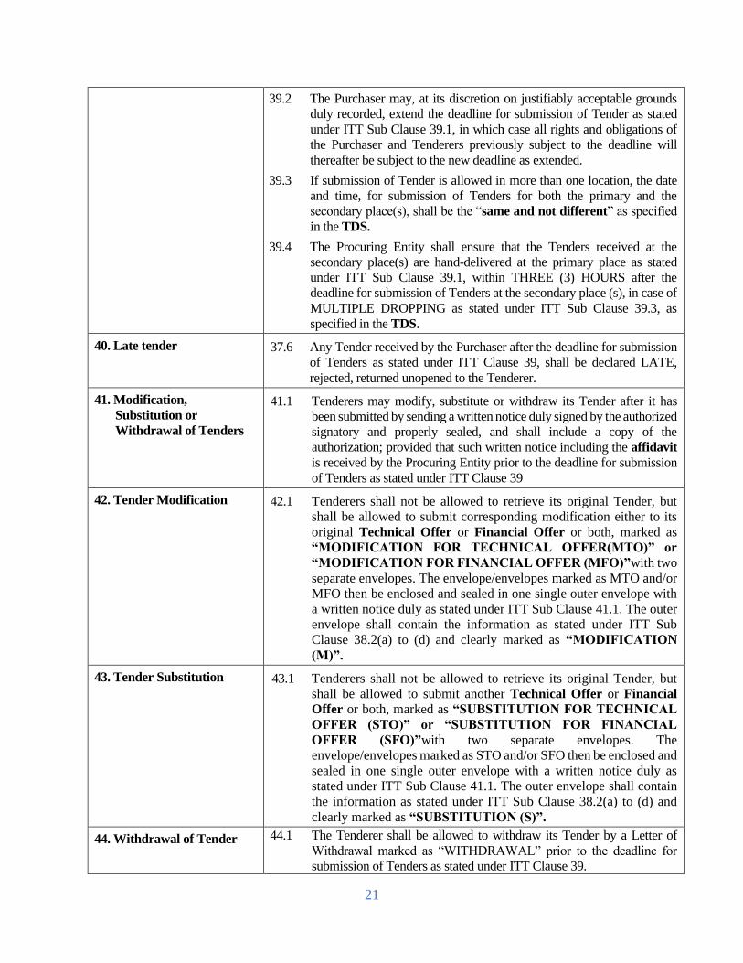
21
39.2 The Purchaser may, at its discretion on justifiably acceptable grounds
duly recorded, extend the deadline for submission of Tender as stated
under ITT Sub Clause 39.1, in which case all rights and obligations of
the Purchaser and Tenderers previously subject to the deadline will
thereafter be subject to the new deadline as extended.
39.3 If submission of Tender is allowed in more than one location, the date
and time, for submission of Tenders for both the primary and the
secondary place(s), shall be the “same and not different” as specified
in the TDS.
39.4 The Procuring Entity shall ensure that the Tenders received at the
secondary place(s) are hand-delivered at the primary place as stated
under ITT Sub Clause 39.1, within THREE (3) HOURS after the
deadline for submission of Tenders at the secondary place (s), in case of
MULTIPLE DROPPING as stated under ITT Sub Clause 39.3, as
specified in the TDS.
40. Late tender 37.6 Any Tender received by the Purchaser after the deadline for submission
of Tenders as stated under ITT Clause 39, shall be declared LATE,
rejected, returned unopened to the Tenderer.
41. Modification,
Substitution or
Withdrawal of Tenders
41.1 Tenderers may modify, substitute or withdraw its Tender after it has
been submitted by sending a written notice duly signed by the authorized
signatory and properly sealed, and shall include a copy of the
authorization; provided that such written notice including the affidavit
is received by the Procuring Entity prior to the deadline for submission
of Tenders as stated under ITT Clause 39
42. Tender Modification 42.1 Tenderers shall not be allowed to retrieve its original Tender, but
shall be allowed to submit corresponding modification either to its
original Technical Offer or Financial Offer or both, marked as
“MODIFICATION FOR TECHNICAL OFFER(MTO)” or
“MODIFICATION FOR FINANCIAL OFFER (MFO)”with two
separate envelopes. The envelope/envelopes marked as MTO and/or
MFO then be enclosed and sealed in one single outer envelope with
a written notice duly as stated under ITT Sub Clause 41.1. The outer
envelope shall contain the information as stated under ITT Sub
Clause 38.2(a) to (d) and clearly marked as “MODIFICATION
(M)”.
43. Tender Substitution 43.1 Tenderers shall not be allowed to retrieve its original Tender, but
shall be allowed to submit another Technical Offer or Financial
Offer or both, marked as “SUBSTITUTION FOR TECHNICAL
OFFER (STO)” or “SUBSTITUTION FOR FINANCIAL
OFFER (SFO)”with two separate envelopes. The
envelope/envelopes marked as STO and/or SFO then be enclosed and
sealed in one single outer envelope with a written notice duly as
stated under ITT Sub Clause 41.1. The outer envelope shall contain
the information as stated under ITT Sub Clause 38.2(a) to (d) and
clearly marked as “SUBSTITUTION (S)”.
44. Withdrawal of Tender 44.1 The Tenderer shall be allowed to withdraw its Tender by a Letter of
Withdrawal marked as “WITHDRAWAL” prior to the deadline for
submission of Tenders as stated under ITT Clause 39.

22
F. Tender Opening and Evaluation
45. Tender Opening 45.1 Only the Technical Offer (Envelope-01) shall be opened
immediately after the deadline for submission of Tenders at the
primary place as specified in the TDS but not later than ONE HOUR,
after expiry of the submission deadline at the same primary place
unless otherwise stated under ITT Sub Clause 39.2. But with in
THREE HOURS after the dateline of submission of tender at
primary place in case of multiple dropping. Tender opening shall not
be delayed on the plea of absences of Tenderers or his or her
representatives. Financial offer (Envelope-02) shall not open with
Technical offer (Envelope-01) and shall be kept unopened at the
Custody of the Head of the Procuring Entity or his Authorised Officer
(AO).
45.2 Persons not associated with the Tender may not be allowed to attend
the public opening of Technical Offers.
45.3 Tenderers’ representatives shall be duly authorised by the Tenderer.
Tenderers or their authorised representatives will be allowed to attend
and witness the opening of Technical Offers, and will sign a register
evidencing their attendance. Technical Offers Opening shall not be
delayed on the plea of absence of Tenderers or his or her
representatives.
45.4 The authenticity of withdrawal or substitution of, or modifications
to original Tender, if any made by a Tenderer in specified manner,
shall be examined and verified by the Tender Opening Committee
(TOC) based on documents submitted as stated under ITT Sub Clause
41.1. Any envelope related to financial modification, substitute shall
be recorded but not open with technical offer.
45.5 Verify (M), (S), (W), (A), (O) by following step by steps
(a) Step 1: envelopes marked “Withdrawal (W)” shall be opened and
“Withdrawal” notice read aloud & recorded in the opening sheet.
After verify the withdrawal letter is genuine, corresponding tender
shall not be opened, but returned unopened to the Tenderer by
Procuring Entity (PE) at a late time. No Tender withdrawal shall be
permitted unless the corresponding withdrawal notice shall be as
stated in 41.1& 44.1 and in such case the Tender shall be opened
and recorded.
(b) Step 2: the remaining Tenders will be sorted out and those marked
“SUBSTITUTION (S)” or “MODIFICATION (M)” of Tender
will be linked with their corresponding Original Tender.

23
(c) Step 3: outer envelopes marked “SUBSTITUTION (S)” shall be
opened. The inner envelopes containing the “Substitution of
Technical Offer (STO)” and/or “Substitution of Financial Offer
(SFO)” shall be exchanged for the corresponding envelopes being
substituted, which are to be returned to the Tenderer unopened by
the Procuring Entity at a later time immediately after opening of
Technical Offers. Only the Substitution of Technical Offer, if any,
shall be opened, read out, and recorded. Substitution of Financial
Offer will remain unopened in accordance with ITT Sub Clause
45.1. No envelope shall be substituted unless the corresponding
substitution notice contains a valid authorization to request the
substitution and is read out and recorded at Technical Offer
opening.
(d) Step 4: outer envelopes marked “MODIFICATION (M)” shall be
opened. No Technical Offer and/or Financial Offer shall be
modified unless the corresponding modification notice contains a
valid authorization to request the modification and is read out and
recorded at the opening of Technical Offers. Only the Technical
Offers, both Original as well as Modification, are to be opened, read
out, and recorded at the opening. Financial Offers, both Original as
well as Modification, will remain unopened in accordance with ITT
Sub Clause 45.1
(e) Step5: if so specified in this Tender Document, the envelopes
marked “Alternative of Technical Offer (ATO)” shall be opened
and read aloud with the corresponding Technical Offer and
recorded.
45.6 Ensuring that only the correct (MTO), (STO), (ATO), (OTO)
envelopes are opened, details of each Technical Offer will be dealt
with as follows:
(a) the Chairperson of the TOC will read aloud each Technical Offer
and record in the Technical Offer Opening Sheet (TOOS):
(i) the name and address of the Tenderer;
(ii) state if it is a withdrawn, modified, substituted or original
Technical Offer;
(iii) any alternatives;
(iv) record the rejection of the Tender which submitted
Technical Offer and Financial Offer together in one
envelope.
(v) the presence or absence of any requisite Tender Security;
and
(vi) such other details as the Procuring Entity, at its discretion,
may consider appropriate.
(b) Only Technical Offer and alternatives read aloud at the Technical
Offer Opening will be considered in evaluation.
(c) all pages of the original version of the Technical Offer, except for
un-amended printed literature, will be initialled by members of the
TOC. Remember, No financial Offer shall be open with
Technical Offer
45.7 Upon completion of Technical Offer opening, all members of the

24
TOC and the Tenderers or Tenderer’s duly authorised representatives
attending the Technical Offer opening shall sign by name, address,
designation, the TOS, copies of which shall be issued to the Head of
the Procuring Entity or an officer authorised by him or her and also
to the members of the TOC and any authorised Consultants and, to
the Tenderers immediately.
45.8 The omission of a Tenderer’s signature on the record shall not
invalidate the contents and effect of the record under ITT Sub Clause
45.7
45.9 No Tender i.e., Technical or Financial Offer shall be rejected at the
Tender opening stage except the LATE Tenders as stated in the ITT
Clause 40.
46. Evaluation of Tenders 46.1 Technical Offers shall be examined and evaluated only on the basis of
the criteria specified in the Tender Document.
46.2 Tender Evaluation Committee (TEC) shall examine, evaluate and
compare Tenders that are responsive to the requirements of Tender
Documents in order to identify the successful Tenderer.
47. Evaluation Process 47.1 TEC may consider a Tender Offer as responsive in the Evaluation, only
if it is submitted in compliance with the mandatory requirements set out
in the Tender Document. The evaluation process should begin
immediately after Technical Offer opening following Two steps:
(a) Preliminary examination
(b) Technical examination and responsiveness
48. Preliminary Examination 48.1 Compliance, adequacy and authenticity of the documentary evidences for
meeting the qualification criterion specified in the corresponding section
of the Tender document shall have to be preliminarily examined and
verified.
48.2 The TEC shall firstly examine the Tenders to confirm that all
documentation requested in ITT Clause 24 has been provided.
Examination of the compliance, adequacy and authenticity of the
documentary evidence may follow the order below:
(a) verification of the completeness of the eligibility declaration in the
Tender Submission Letter (Form PG5A-1), to determine the
eligibility of the tenderer as stated under ITT Sub-Clause 24(h).
Any alterations to its format, filling in all blank spaces with the
information requested, failing which the tender may lead to
rejection of the Tender;
(b) verification of that the Tenderer is enrolled in the relevant
professional or trade organisations as stated under ITT Clause
24(l);
(c) verification of the eligibility in terms of legal capacity and
fulfilment of taxation obligation by the tenderer in accordance as
stated under ITT Sub-Clause 24(i) and 24(k);

25
(d) verification of eligibility that the tenderer is not insolvent, in
receivership, bankrupt, not in the process of bankruptcy, not
temporarily barred as stated under ITT Sub-Clause 24(j);
(e) verification of eligibility of Tenderer’s country of origin as stated
under ITT Sub-Clause 24(b);
(f) verification of the written authorization confirming the signatory
of the Tenderer to commit the Tender has been attached with
Tender Submission Letter (Form PG5A-1) as stated under ITT
Sub-Clause 24(g); in order to check the authenticity of Tender and
Tenderer itself;
(g) verification of the Tender Security as stated under ITT Sub-
Clause 24(d); and
48.3 The TEC shall confirm that the above documents and information have
been provided in the Tender and the completeness of the documents and
compliance of instructions given in corresponding ITT Clauses shall be
verified, failing which the tender shall be considered rejection of that
tender.
49. Technical Evaluation and
Responsiveness 49.1 Only those Tenders surviving preliminary examination need to be
examined in this phase.
49.2 Secondly, the TEC will examine the adequacy and authenticity of the
documentary evidence which may follow the order below:
(a) verification of the completeness of the country-of-origin declaration
in the Price Schedule for Plant and Services (Form PG5A-3) as
furnished in Section 5: Tender and Contract Forms to determine
the eligibility of the Goods and Related Services as stated under ITT
Sub Clause 24(m).
(b) verification and examination of the documentary evidence and
completed Technical Proposal (Form PG5A-4) as furnished in
Section 5: Tender and Contract Forms to establish the conformity
of the Goods and Related Services to the Tender Documents as
stated under ITT Sub Clause 24(e) and 24(n).
(c) verification and examination of the documentary evidence that
the Tenderer’s qualifications conform to the Tender
Documents and the Tenderer meets each of the qualification
criterion specified in Sub-Section C, Qualification Criteria as
stated under ITT Sub Clause 24(o).
(d) verification and examination of the documentary evidence that
Tenderer has met all the requirements in regards under Section
6, Employer’s Requirements, without any material deviation or
reservation.
(e) verification and examination of the documentary evidence and
completed Specification Submission Sheet (Form PG5A-4a) to
determine the conformity of the Goods and related services.
49.3 TEC may consider a Tender as responsive in the evaluation, only if
comply with the mandatory requirements as stated under Clause 49.2.

26
49.4 The TEC’s determination of a Tender’s responsiveness is to be based on
the documentary evidence as requested in Clause 49.2 without recourse
to extrinsic evidence.
49.5 Information contained in a Tender, that was not requested in the Tender
Document shall not be considered in evaluation of the Tender.
49.6 If a Tender is not responsive to the mandatory requirements set out in
the Tender Document it shall be rejected by the TEC and shall not
subsequently be made responsive by the Tenderer by correction of the
material deviation, reservation.
49.7 A material deviation or reservation is one-
(a) which affects in any substantial way the scope, quality, or
performance of the Goods and Related Services and Tenderer’s
qualifications mentioned in the Tender Document
(b) which limits in any substantial way, inconsistent with the Tender
Documents, the Purchaser’s rights or the Tenderer’s obligations
under the Contract; or
(c) whose rectification would anyway affect unfairly the competitive
position of other Tenderers presenting responsive Tenders.
49.8 During the evaluation of Tender, the following definitions apply:
(a) Deviation” is a departure from the requirements specified in
the Tender Document;
(d) “Reservation” is the setting of limiting conditions or withholding
from complete acceptance of the requirements specified in the
Tender Document;
49.9 A TEC may regard a Tender as responsive, even if it contains-minor or
insignificant deviations, which do not meaningfully alter or depart from
the technical specifications, characteristics and commercial terms and
conditions or other requirements set out in the Tender Document; errors
or oversights, which if corrected, would not alter the key aspects of the
Tender.
50. Clarification on Technical
Offer 50.1 TEC may ask Tenderers for clarification of their Technical Offers in
order to facilitate the examination and evaluation of Technical Offers.
The request for clarification by the TEC and the response from the
Tenderer shall be in writing, and Technical Offers clarifications which
may lead to a change in the substance of the Technical Offers or in any
of the key elements of the Technical Offers as stated under ITT Sub
Clause 49.2, will neither be sought nor be permitted.
50.2 Any request for clarifications by the TEC shall not be directed
towards making an apparently non-responsive Tender responsive and
reciprocally the response from the concerned Tenderer shall not be
articulated towards any addition, alteration or modification to its
Technical Offer.

27
50.3 If a Tenderer does not provide clarifications of its Technical Offer by
the date and time, its Tender shall not be considered in the evaluation
51. Restrictions on Disclosure
of Information
51.1 Following the opening of Technical Offers until issuance of
Notification of Award no Tenderer shall, unless requested to provide
clarification to its Tender or unless necessary for submission of a
complaint, communicate with the concerned Procuring Entity
51.2 Tenderers shall not seek to influence in anyway, the examination and
evaluation of the Tenders
51.3 Any effort by a Tenderer to influence the Procuring Entity in its
decision concerning the evaluation of Tenders, Contract awards may
result in the non-responsiveness of its Tender as well as further action
in accordance with Section 64 (5) of the Public Procurement Act,
2006.
51.4 All clarification requests shall remind Tenderers of the need for
confidentiality and that any breach of confidentiality on the part of
the Tenderer may result in their Tender being non-responsive.
52. Approval of Technical
Offer
52.1 TEC shall prepare the Technical Offer Evaluation Report and shall
directly submit the Evaluation Report to the Head of the Procuring
Entity (HOPE) or Authorized Officer for approval.
53. Financial Offer Opening 53.1 After receiving approval of the Technical Offer Evaluation Report,
Financial Offer (Envelope-2) of only the Responsive Tenderers who
have been determined as qualified to the requirements of the
Technical Offer, shall be opened publicly, The Date, time and place
of Financial Offer Opening shall be communicated to the Responsive
Tenderers in writing by issuing a Financial Offer Opening notice not
less than SEVEN DAYS before the opening.

28
53.2 Ensuring that only the correct MFO, SFO, OFO envelopes of the
Responsive Tenderers shall be opened, in the presence of the
Responsive Tenderer’s representatives who choose to attend, on the
date, time and at the place as notified by the Procuring Entity in
accordance with ITT Clause 53.1. Details of each Financial Offer
will be dealt with as follows:
(a) the Chairperson of the Tender Evaluation Committee will read
aloud each Financial Offer and record in the Financial Offer
Opening Sheet (FOOS):
(i) the name and address of the Tenderer;
(ii) state if it is a modified, substituted or original Financial
Offer;
(iii) the Tender Price;
(iv) the number of initialled corrections;
(v) any discounts; and
(vi) any other details as the Procuring Entity, at its discretion,
may consider appropriate
(b) only the discounts and alternatives read aloud and recorded at the
Financial Offer Opening will be considered in Financial Offer
Evaluation. No Tenders shall be rejected at the opening of the
Financial Offer.
(c) all pages of the original version of the Financial Offer, except for
un-amended printed literature, will be initialled by members of the
Tender Evaluation Committee.
(d) The Procuring Entity shall, in writing, notify the Non-responsive
Tenderers who have not been determined as qualified to the
requirements of the Technical Offer and shall return their
Financial Offers (Envelope-02) unopened after signing of the
contract.
54. Clarification on Financial
Offer
54.1 TEC may ask Tenderers for clarification of their Financial Offers,
about the breakdowns of unit rates, in order to facilitate the
examination and evaluation of Financial Offers. The request for
clarification by the TEC and the response from the Tenderer shall be
in writing.
54.2 Changes in the Tender price shall not be sought or permitted, except to
confirm the correction of arithmetical errors discovered by the TEC in
the evaluation of the Tenders, as stated under ITT Sub Clause 55.1.
54.3 If a Tenderer does not provide clarifications of its Financial Offer by
the date and time, its Tender shall not be considered in the evaluation.
54.4 Requests for clarifications on Financial Offers shall be duly signed only
by the TEC Chairperson.

29
55. Correction of
Arithmetical Errors
55.1 The TEC shall correct any arithmetic errors that are discovered during
the examination of Tenders, and shall promptly notify the concerned
Tenderer(s) of any such correction(s) pursuant to Rule 98(11) of the
Public Procurement Rule, 2008.
55.2 Provided that the Tender is responsive, TEC shall correct arithmetical
errors on the following basis:
(a) If there is a discrepancy between the unit price and the line-item
total that is obtained by multiplying the unit price by the quantity,
the unit price shall prevail and the line-item total shall be corrected,
unless in the opinion of the TEC there is an obvious misplacement
of the decimal point in the unit price, in which case the total price
as quoted will govern and the unit price will be corrected;
(b) If there is an error in a total corresponding to the addition or
subtraction of subtotals, the sub-totals shall prevail and the total
shall be corrected.
55.3 Any Tenderer that does not accept the correction of the Tender amount
following correction of arithmetic errors as determined by the
application of ITT Sub-Clause 55.2 shall be considered as non-
responsive.
56. Conversion to Single
Currency
56.1 For evaluation and comparison purpose, TEC shall convert all Tender
prices expressed in the amounts in various currencies into an amount
in Bangladeshi Taka currency, using the selling exchange rates
established by the Bangladesh Bank, on the date of Tender opening.
57. Financial Evaluation 57.1 Thirdly the TEC, pursuant to Rule 98 of the Public Procurement Rules,
2008 shall evaluate each Tender that has been determined, up to this
stage of the evaluation, to be responsive to the mandatory
requirements in the Tender Document.
57.2 To evaluate a Tender in this stage, the Purchaser shall consider the
following
(a) Verification and examination of the Price Schedule for Plant
and Services (Form PG5-3) as furnished by the Tenderer and
checking the compliance with the instructions provided under
ITT Clause 26;
(b) Evaluation will be done for Items or lot by lot as stated under
ITT Clause 26 and the Total Tender Price as quoted in
accordance with Clause 26;
(c) Adjustment for correction of arithmetical errors as stated under
ITT Sub-Clause 55.2;
(d) Adjustment for price modification offered as stated under ITT
Clause 41;
(e) Adjustment due to discount as stated under ITT Sub-Clauses
26.11 and 57.3;
(f) Adjustment due to the application of economic factors of
evaluation as stated under ITT Sub-Clause 57.5 if any;

30
(g) Adjustment due to the assessment of the price of unpriced
items as stated under ITT Clause 58 if any;
57.3 If Tenders are invited for a single lot or for a number of lots as stated
under ITT Sub-clauses 26.10, TEC shall evaluate only lots that have
included at least the percentage of items per lot. The TEC shall
evaluate and compare the Tenders taking into account:
(a) Lowest evaluated tender for each lot ;
(b) The price discount/reduction per lot;
(c) Least cost combination for the Purchaser, considering discounts
and the methodology for its application as stated under ITT Sub-
clauses 26.10 and 26.11 offered by the Tenderer in its Tender.
57.4 Only those spare parts and tools which are specified as a item in the List
of Goods and Related Services in Section 6, Employer’s Requirement
or adjustment as stated under ITT Sub-clause 54.5, shall be taken into
account in the Tender evaluation. Supplier-recommended spare parts
for a specified operating requirement as stated under ITT Sub-clause
28.2(b) shall not be considered in Tender evaluation.
57.5 The Purchaser’s evaluation of a tender may require the consideration of
other factors, in addition to the Tender Price quoted as stated under
ITT Clause 26. The effect of the factors selected, if any, shall be
expressed in monetary terms to facilitate comparison of tenders. The
factors, methodologies and criteria to be used shall be as specified in
TDS. The applicable economic factors, for the purposes of evaluation
of Tenders shall be:
(a) Adjustment for Deviations in the Delivery and Completion
Schedule.
(b) Cost of major replacement components, mandatory spare parts, and
service.
57.6 Variations, deviations, and alternatives and other factors which are in
excess of the requirements of the Tender Document or otherwise
result in unsolicited benefits for the Purchaser will not be taken into
account in Tender evaluation.
58. Price Comparison 58.1 The TEC shall compare all responsive Tenders to determine the lowest-
evaluated Tender, as stated in ITT 57.2.
58.2 In the extremely unlikely event that there is a tie for the lowest evaluated
price, the Tenderer with the superior past performance with the Purchaser
shall be selected, whereby factors such as delivery period, quality of
Goods delivered, complaints history and performance indicators could be
taken into consideration.
58.3 In the event that there is a tie for the lowest price and none of the
Tenderers has the record of past performance with the Purchaser, then the
Tenderer shall be selected, subject to firm confirmation through the Post-

31
qualification process described in ITT Clause 61, after consideration as
to whether the quality of Goods that is considered more advantageous by
the end-users.
58.4 The successful Tenderer as stated under ITT Sub Clauses 58.1, 60.2 and
60.3 shall not be selected through lottery under any circumstances.
59. Post-qualification 59.1 After determining the lowest-evaluated responsive tender as sated under
ITT Sub-Clause 58.1, the Purchaser’s TEC pursuant to Rule 100 of the
Public Procurement Rules, 2008, shall carry out the Post-Qualification of
the Tenderer, using only the requirements specified in Sub-Section C,
Qualification Criteria.
59.2 The TEC shall contact the references given by Tenderers about their
previous Supply experiences to verify, if necessary, statements made by
them in their Tender and to obtain the most up-to-date information
concerning the Tenderers.
59.3 The TEC may visit the premises of the Tenderer as a part of the post-
qualification process, if practical and appropriate, to verify information
contained in its Tender.
59.4 The TEC shall determine to its satisfaction whether the Tenderer that is
selected as having submitted the lowest evaluated responsive Tender is
qualified to perform the Contract satisfactorily.
59.5 The objective of any visit under ITT Sub-Clause 59.3 shall be limited to
a general and visual inspection of the Tenderer’s facilities and its plant
and equipment, and there shall be no discussion concerning the Tender
or its evaluation with the Tenderer during such visit(s).
59.6 In the event that the Tenderer with lowest evaluated cost fails the post-
qualification, the TEC shall make a similar determination for the
Tenderer offering the next lowest evaluated cost and so on from the
remaining responsive Tenders, provided that,
(a) such action shall only be taken if the evaluated costs of the Tenders
under consideration are acceptable to the Purchaser;
(b) when the point is reached whereby the evaluated costs of the
remaining responsive Tenders are significantly higher than that of
the official estimate, or the market price, the Purchaser may take
action pursuant to Rule 33 of the PPR 2008 and may proceed for
re-Tendering, using a revised Tender Document designed to
achieve a more successful result.
60. Negotiation 60.1 No negotiations shall be held during the financial offer evaluation or
award, with the lowest or any other Tenderer.
60.2 The Procuring Entity through the TEC may, however, negotiate with the
lowest evaluated Tenderer with the objective to reduce the Contract Price
by reducing the scope of works or a reallocation of risks and
responsibilities, only when it is found that the lowest evaluated Tender is
significantly higher than the official estimated cost; the reasons for such
higher price being duly investigated.

32
60.3 If the Procuring Entity decides to negotiate for reducing the scope of the
requirements under ITT Sub Clause 60.2, it will be required to guarantee
that the lowest Tenderer remains the lowest Tenderer even after the scope
of work has been revised and shall further be ensured that the objective
of the Procurement will not be seriously affected through this reduction.
60.4 In the event that the Procuring Entity decides because of a high Tender
price to reduce the scope of the requirements to meet the available budget,
the Tenderer is not obliged to accept the award and shall not be penalised
in any way for un-accepting the proposed award.
61. Rejection of All Tenders 61.1 The Purchaser may, in the circumstances as stated under ITT Sub-Clause
61.2 and pursuant to Rule 33 of the Public Procurement Rules 2008,
reject all Tenders following recommendations from the Tender
Evaluation Committee only after the approval of such recommendations
by the Head of the Purchaser.rejected, if –
61.2 All Tenders can be rejected, if -
(a) the price of the lowest evaluated Tender exceeds the official
estimate, provided the estimate is realistic; or
(b) there is evidence of lack of effective competition; such as non-
participation by a number of potential Tenderers; or
(c) the Tenderers are unable to propose completion of the delivery
within the stipulated time in its offer, though the stipulated time
is reasonable and realistic; or
(d) all Tenders are non-responsive; or
(e) evidence of professional misconduct, affecting seriously the
Procurement process, is established pursuant to Rule 127 of the
Public Procurement Rules, 2008.
61.3 Notwithstanding anything contained in ITT Sub-Clause 61.2 Tenders
may not be rejected if the lowest evaluated price is in conformity with
the market price.
61.4 A Purchaser may pursuant to Rule 35 of the Public Procurement
Rules, 2008, on justifiable grounds, annul the Procurement proceedings
prior to the deadline for the submission of Tenders.
61.5 All Tenders received by the Purchaser shall be returned unopened to the
Tenderers in the event Procurement proceedings are annulled under ITT
Sub-Clause 61.4.
62. Informing Reasons for
Rejection 62.1 Notice of the rejection, pursuant to Rule 35 of the Public Procurement
Rules, 2008, will be given promptly within seven (7) days of decision
taken by the Purchaser to all Tenderers and, the Purchaser will, upon
receipt of a written request, communicate to any Tenderer the reason(s)
for its rejection but is not required to justify those reason(s).
G. Contract Award
63. Award Criteria 63.1 The Purchaser shall award the Contract to the Tenderer whose offer
is responsive to the Tender Document and that has been determined
to be the lowest evaluated Tender, provided further that the Tenderer
is determined to be Post-Qualified as stated under ITT Clause 59.

33
63.2 A Tenderer shall not be required, as a condition for award of contract,
to undertake obligations not stipulated in the Tender Document, to
change its price, or otherwise to modify its Tender.
64. Notification of Award
64.1 Prior to the expiry of the Tender validity period and within seven (7)
working days of receipt of the approval of the award by the
Approving Authority, the Purchaser pursuant to Rule 102 of the
Public procurement Rules, 2008, shall issue the Notification of
Award (NOA) to the successful Tenderer.
64.2 The Notification of Award, attaching the contract as per the sample
(Form PG5A-7) to be signed, shall state:
(a) the acceptance of the Tender by the Purchaser;
(b) the price at which the contract is awarded;
(c) the amount of the Performance Security and its format;
(d) the date and time within which the Performance Security shall
be submitted; and
(e) the date and time within which the contract shall be signed.
64.3 The Notification of Award shall be accepted in writing by the
successful Tenderer within seven (7) working days from the date of
issuance of NOA.
64.4 Until a formal contract is signed, the Notification of Award shall
constitute a Contract, which shall become binding upon the
furnishing of a Performance Security and the signing of the Contract
by both parties.
64.5 The Notification of Award establishes a Contract between the
Purchaser and the successful Tenderer and the existence of a Contract
is confirmed through the signature of the Contract Document that
includes all agreements between the Purchaser and the successful
Tenderer.
65. Performance Security 65.1 The Performance Security shall be determined sufficient to protect the
performance of the Contract pursuant to Rule 27 of the Public
Procurement Rules, 2008.
65.2 Performance Security shall be furnished by the successful Tenderer in
the amount specified in the TDS and denominated in the currencies in
which the Contract Price is payable pursuant to Rule 102 (8) of the
Public Procurement Rules, 2008.
65.3 The proceeds of the Performance Security shall be payable to the
Purchaser unconditionally upon first written demand as compensation
for any loss resulting from the Supplier’s failure to complete its
obligations under the Contract.
66. Form and Time Limit for
furnishing of
Performance security
66.1 The Performance Security shall be in the form of irrevocable Bank
Guarantee in the format (Form PG5A-9) as stated under ITT Clause 65,
shall be issued by an internationally reputable bank and it shall have
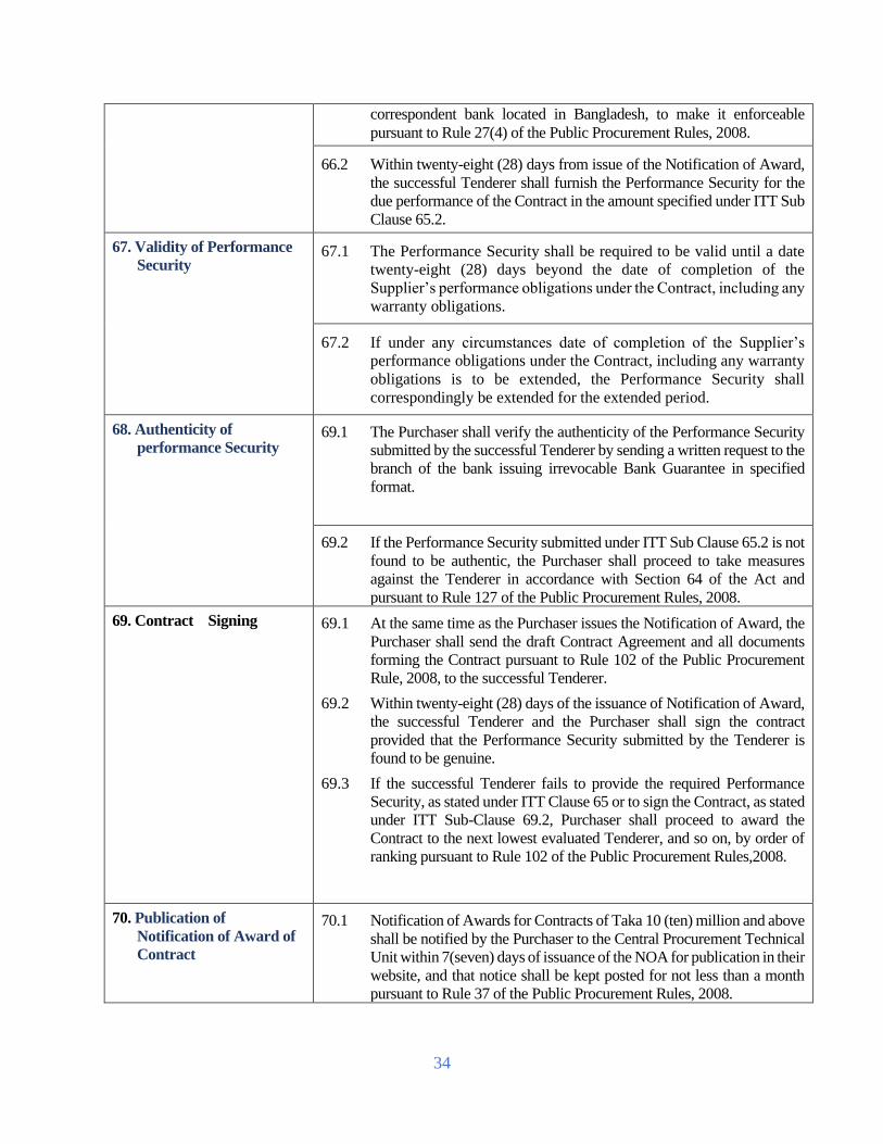
34
correspondent bank located in Bangladesh, to make it enforceable
pursuant to Rule 27(4) of the Public Procurement Rules, 2008.
66.2 Within twenty-eight (28) days from issue of the Notification of Award,
the successful Tenderer shall furnish the Performance Security for the
due performance of the Contract in the amount specified under ITT Sub
Clause 65.2.
67. Validity of Performance
Security 67.1 The Performance Security shall be required to be valid until a date
twenty-eight (28) days beyond the date of completion of the
Supplier’s performance obligations under the Contract, including any
warranty obligations.
67.2 If under any circumstances date of completion of the Supplier’s
performance obligations under the Contract, including any warranty
obligations is to be extended, the Performance Security shall
correspondingly be extended for the extended period.
68. Authenticity of
performance Security 69.1 The Purchaser shall verify the authenticity of the Performance Security
submitted by the successful Tenderer by sending a written request to the
branch of the bank issuing irrevocable Bank Guarantee in specified
format.
69.2 If the Performance Security submitted under ITT Sub Clause 65.2 is not
found to be authentic, the Purchaser shall proceed to take measures
against the Tenderer in accordance with Section 64 of the Act and
pursuant to Rule 127 of the Public Procurement Rules, 2008.
69. Contract Signing 69.1 At the same time as the Purchaser issues the Notification of Award, the
Purchaser shall send the draft Contract Agreement and all documents
forming the Contract pursuant to Rule 102 of the Public Procurement
Rule, 2008, to the successful Tenderer.
69.2 Within twenty-eight (28) days of the issuance of Notification of Award,
the successful Tenderer and the Purchaser shall sign the contract
provided that the Performance Security submitted by the Tenderer is
found to be genuine.
69.3 If the successful Tenderer fails to provide the required Performance
Security, as stated under ITT Clause 65 or to sign the Contract, as stated
under ITT Sub-Clause 69.2, Purchaser shall proceed to award the
Contract to the next lowest evaluated Tenderer, and so on, by order of
ranking pursuant to Rule 102 of the Public Procurement Rules,2008.
70. Publication of
Notification of Award of
Contract
70.1 Notification of Awards for Contracts of Taka 10 (ten) million and above
shall be notified by the Purchaser to the Central Procurement Technical
Unit within 7(seven) days of issuance of the NOA for publication in their
website, and that notice shall be kept posted for not less than a month
pursuant to Rule 37 of the Public Procurement Rules, 2008.

35
70.2 Notification of Award for Contracts below Taka 10(ten) million, shall
be published by the Purchaser on its Notice Board and where applicable
on the website of the Purchaser and that notice shall be kept posted for
not less than a month pursuant to Rule 37 of the Public Procurement
Rules, 2008.
71. Debriefing of Tenderers 72.1 Debriefing of Tenderers by Purchaser shall outline the relative status
and weakness only of his or her Tender requesting to be informed of
the grounds for not accepting the Tender submitted by him or her
pursuant to Rule 37 of the Public Procurement Rule, 2008, without
disclosing information about any other Tenderer.
72.2 In the case of debriefing confidentiality of the evaluation process
shall be maintained.
72. Right to Complains 72.1 Any Tenderer has the right to complain if it has suffered or likely to suffer
loss or damage due to a failure of a duty imposed on the Purchaser to
fulfil its obligations in accordance with Section 29 of the Public
Procurement Act 2006 and pursuant to Part 12 of Chapter Three of the
Public Procurement Rules, 2008.
72.2 Circumstances in which a formal complaint may be lodged in sequence
by a potential Tenderer against a Purchaser pursuant to Rule 56 of the
Public Procurement Rules, 2008, and the complaints, if any, be also
processed pursuant to Rule 57 of the Public Procurement Rules 2008.
72.3 The potential Tenderer shall submit his or her complaint in writing within
seven (7) calendar days of becoming aware of the circumstances giving
rise to the complaint.
72.4 In the first instance, the potential Tenderer shall submit his or her
complaint to the Purchaser who issued the Tender Document.
72.5 The place and address for the first stage in the submission of complaints
to the Administrative Authority is provided in the TDS.
72.6 The Tenderer may appeal to a Review Panel only if the Tenderer has
exhausted all his or her options of complaints to the administrative
authority as stated under ITT Sub-Clause 72.2.

36
Section 2. Tender Data Sheet
Instructions for completing the Tender Data Sheet are provided, as needed, in the notes in
italics and under lined mentioned for the relevant ITT clauses.
ITT
Clause
Amendments of, and Supplements to, Clauses in the Instruction to Tenderers
A. General
ITT 1.1
The Purchaser is : ICT Directorate
Bangladesh Rural Electrification Board,
5th floor, BREB HQ Building,
Nikunja-2, Khilkhet, City: Dhaka-1229, Country: Bangladesh.
Tel: +8802-8900513
E-email: [email protected]
The Name and identification number of Tender are 01) SPPM-MCS-01; Lot-1:
ITT 1.2 The number, identification and name of lots comprising the Tender are:
TENDER PACKAGE NO: SPPM-MCS-01; Lot-1:
Design, Supply, Installation, Testing and Commissioning of Hardware (1 phase and
3 phase Meter with HES, NIC, HHU, UCC, UVS, DCU, Repeater, DR, Data Centre
accessories etc.) & Software for Implementation of AMI with MDM and related
service Under BREB for 5 lac smart meter that will be scalable up to 2 crore smart
meter on Turnkey Basis.
TENDER PACKAGE NO: SPPM-MCS-01; Lot-2:
Design, Supply, Installation of 10 thousand 3 phase, CT/PT Rated, Class 20, AMR
meter with HES and integration with BREB MDM & Server System.
Memo No: 27.12.0000.112.35.019.18.120 Date: 25-03-2021
ITT3.1 The source of public fund is: Own.
ITT3.3 The name of the Development Partner is Not applicable.
ITT5.1 Tenderers from the following countries are not eligible: Israel and countries having
no diplomatic relation with the Government of Bangladesh.
ITT
5.13
Tenderers shall have the following up to date valid License: None

37
ITT6.1 Materials, Equipment and associated services from the following countries are not
eligible: Israel and countries having no diplomatic relation with the Government
of Bangladesh.
B. Tender Document
ITT8.2 The following are the offices of the Purchaser or authorised agents for the purpose
of providing the Tender Document: None
Agent’s/Office Name:
ICT Directorate
Bangladesh Rural Electrification Board,
5th floor, BREB HQ Building,
Nikunja-2, Khilkhet, City: Dhaka-1229, Country: Bangladesh.
Tel: +8802-8900513
E-email: [email protected]
ITT9.1 For clarification of Tender Document purposes only, the Procuring Entity’s
address is:
Attention:
ICT Directorate
Bangladesh Rural Electrification Board,
5th floor, BREB HQ Building,
Nikunja-2, Khilkhet, City: Dhaka-1229, Country: Bangladesh.
Address:
ICT Directorate
Bangladesh Rural Electrification Board,
5th floor, BREB HQ Building,
Nikunja-2, Khilkhet, City: Dhaka-1229, Country: Bangladesh.
Tel: +8802-8900513
E-email: [email protected]
And contact the Procuring Entity within Date: 12-04-2021, Time: 11.00am.

38
ITT10.
1
A Pre- Tender meeting shall be held at
Address:
ICT Directorate
Bangladesh Rural Electrification Board,
5th floor, BREB HQ Building,
Nikunja-2, Khilkhet, City: Dhaka-1229, Country: Bangladesh.
Tel: +8802-8900513
E-email: [email protected]
Time: 11.00am Date: 12-04-2021
A site visit conducted by the Employer will not be organized.'
Tenderers are advised to conduct site visit at their own responsibility. The Employer
will provide necessary support and may arrange necessary permissions if requested
by the Tenderers. The costs and expenses associated with attending the pre-tender
meeting and/or site visit shall be borne by the Potential Tenderers.
C. Qualification Criteria
ITT
13.1
The maximum three (03) number of arbitration against the Tenderer over a period of
the last Five (05) years
ITT14.
1(a)
For Lot -1:
i) The Bidder shall have a minimum of 5 years of overall experience in the role of
contractor in supply and installation of minimum 100,000 electrical Smart
meter/prepayment meter on Turnkey basis in a single contract in electric utility
within last 5 years.
However, in case of JVCA, any partner shall have minimum of 5(five) years of
overall experience in supply and installation of minimum 100,000 electrical smart
prepayment meter / pre-payment meter on Turnkey basis in a single contract in
electric utility within last 5 years.
In case of JVCA, Supplier/Manufacturer of smart meter shall be the Tenderer /
Bidder. The lead partner shall be Bangladeshi.
Necessary supporting documents in English shall have to be submitted as evidence.
ii) The bidder or in case of JVCA, any partner shall have the experience of
establishing of at least 1(one) Data Center (DC) with a capacity to operate minimum
1(one) lac meters. Satisfactory Certificate from the end user shall be provided in
english as evidence.

39
iii) The tenderer/manufacturer shall have sufficient local establishment or local
representative for providing instant services as and when required.
For Lot -2:
i) The Bidder or in case of JVCA any partner shall have minimum of 5 years of
overall experience in the role of contractor in supply of minimum 5,000 nos. of 3
phase Smart meter on Turnkey basis in a single contract in electric utility within last
5 years.
ii) The tenderer/manufacturer shall have sufficient local establishment or local
representative for providing instant services as and when required.
Necessary supporting documents in English shall have to be submitted as evidence.
ITT
14.1(b)
For Lot -1:
The Tenderer should fulfill the following requirements:
i) The Bidder must furnish evidences to demonstrate they have experiences in
successfully interfacing RF based network interface card (NIC)/RF module for at
least 3 different manufacturer’s IEC meters across at least 02 (two) countries/utilities
in last 5 years. The RF communication module/NIC card shall be as per
specification, Wi SUN FAN certified (certificate to be provided), can communicate
with DLMS/COSEM technology and must support plug & play operation mode for
RF, PLC, GPRS(Cellular) etc.
BREB wants to achieve the device level interoperability by choosing RF
communication technology and multiple manufacturer’s smart meters. That is, the
multiple’s manufacture’s meters shall use the same communications technology RF
mesh and shall comply with the RF Network interface card (NIC)/RF
communication module specification of the RF canopy vendor.
ii) The Bidder or in case of JVCA, any partner shall have experience of successfully
establishing RF communication network in at least 02 (two) utilities /countries
covering at least one lac (100,000) smart meters(cumulative) in last 5 (five) years.
Out of these contracts, at least one contract shall have contract amount of minimum
10 (ten) million USD or equivalent in BDT and no. of meters installed shall be
minimum fifty thousand (50,000).
Communication devices (DCU, Repeater) shall be interoperable with at least 3
different manufacturer’s IEC meters. DCU, Repeater shall be as per specification,
Wi SUN FAN certified, can communicate with DLMS/COSEM technology and must
support plug & play operation mode for RF, PLC, GPRS (Cellular) etc.
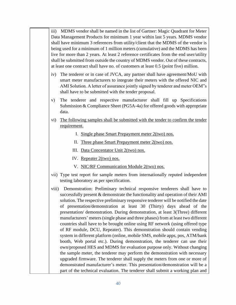
40
iii) MDMS vendor shall be named in the list of Gartner: Magic Quadrant for Meter
Data Management Products for minimum 1 year within last 5 years. MDMS vendor
shall have minimum 3 references from utility/client that the MDMS of the vendor is
being used for a minimum of 1 million meters (cumulative) and the MDMS has been
live for more than 2 years. At least 2 reference certificates from the end user/utility
shall be submitted from outside the country of MDMS vendor. Out of these contracts,
at least one contract shall have no. of customers at least 0.5 (point five) million.
iv) The tenderer or in case of JVCA, any partner shall have agreement/MoU with
smart meter manufacturers to integrate their meters with the offered NIC and
AMI Solution. A letter of assurance jointly signed by tenderer and meter OEM‟s
shall have to be submitted with the tender proposal.
v) The tenderer and respective manufacturer shall fill up Specifications
Submission & Compliance Sheet (PG5A-4a) for offered goods with appropriate
data.
vi) The following samples shall be submitted with the tender to confirm the tender
requirement .
I. Single phase Smart Prepayment meter 2(two) nos.
II. Three phase Smart Prepayment meter 2(two) nos.
III. Data Concentator Unit 2(two) nos.
IV. Repeater 2(two) nos.
V. NIC/RF Communication Module 2(two) nos.
vii) Type test report for sample meters from internationally reputed independent
testing laboratory as per specification.
viii) Demonstration: Preliminary technical responsive tenderers shall have to
successfully present & demonstrate the functionality and operation of their AMI
solution. The respective preliminary responsive tenderer will be notified the date
of presentation/demonstration at least 30 (Thirty) days ahead of the
presentation/ demonstration. During demonstration, at least 3(Three) different
manufacturers’ meters (single phase and three phases) from at least two different
countries shall have to be brought online using RF network (using offered type
of RF module, DCU, Repeater). This demonstration should contain vending
system in different platform (online, mobile SMS, mobile apps, pos, ATM/bank
booth, Web portal etc.). During demonstration, the tenderer can use their
own/proposed HES and MDMS for evaluation purpose only. Without changing
the sample meter, the tenderer may perform the demonstration with necessary
upgraded firmware. The tenderer shall supply the meters from one or more of
demonstrated manufacturer’s meter. This presentation/demonstration will be a
part of the technical evaluation. The tenderer shall submit a working plan and
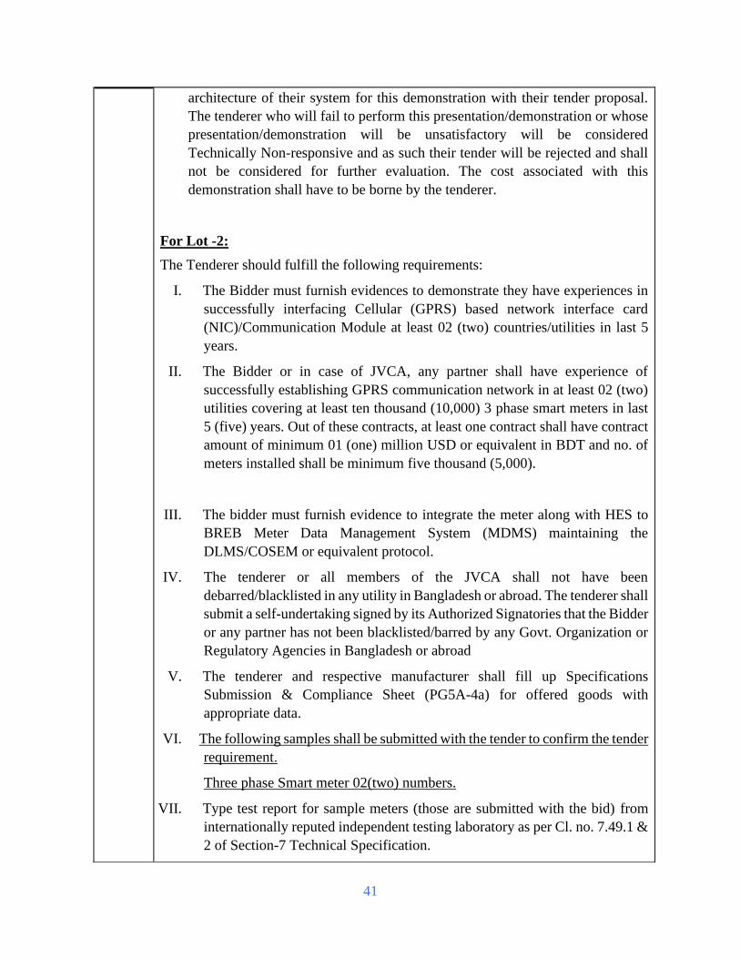
41
architecture of their system for this demonstration with their tender proposal.
The tenderer who will fail to perform this presentation/demonstration or whose
presentation/demonstration will be unsatisfactory will be considered
Technically Non-responsive and as such their tender will be rejected and shall
not be considered for further evaluation. The cost associated with this
demonstration shall have to be borne by the tenderer.
For Lot -2:
The Tenderer should fulfill the following requirements:
I. The Bidder must furnish evidences to demonstrate they have experiences in
successfully interfacing Cellular (GPRS) based network interface card
(NIC)/Communication Module at least 02 (two) countries/utilities in last 5
years.
II. The Bidder or in case of JVCA, any partner shall have experience of
successfully establishing GPRS communication network in at least 02 (two)
utilities covering at least ten thousand (10,000) 3 phase smart meters in last
5 (five) years. Out of these contracts, at least one contract shall have contract
amount of minimum 01 (one) million USD or equivalent in BDT and no. of
meters installed shall be minimum five thousand (5,000).
III. The bidder must furnish evidence to integrate the meter along with HES to
BREB Meter Data Management System (MDMS) maintaining the
DLMS/COSEM or equivalent protocol.
IV. The tenderer or all members of the JVCA shall not have been
debarred/blacklisted in any utility in Bangladesh or abroad. The tenderer shall
submit a self-undertaking signed by its Authorized Signatories that the Bidder
or any partner has not been blacklisted/barred by any Govt. Organization or
Regulatory Agencies in Bangladesh or abroad
V. The tenderer and respective manufacturer shall fill up Specifications
Submission & Compliance Sheet (PG5A-4a) for offered goods with
appropriate data.
VI. The following samples shall be submitted with the tender to confirm the tender
requirement .
Three phase Smart meter 02(two) numbers.
VII. Type test report for sample meters (those are submitted with the bid) from
internationally reputed independent testing laboratory as per Cl. no. 7.49.1 &
2 of Section-7 Technical Specification.

42
VIII. Demonstration: Preliminary technical responsive tenderers shall have to
successfully present & demonstrate the functionality and operation of their
Meter with HES to make it interoperable with BREB MDMS. This
presentation/demonstration will be a part of the technical evaluation. The
tenderer shall submit a working plan and architecture of their system for this
demonstration with their tender proposal. Please refer to Section 6 for the
items/points to be checked during demonstration for evaluation purpose only.
The tenderer who will fail to perform this presentation/ demonstration or
whose presentation/demonstration will be unsatisfactory will be considered
Technically Non-responsive and as such their tender will be rejected and shall
not be considered for further evaluation. The cost associated with this
demonstration shall have to be borne by the tenderer.
ITT
15.1(a)
For Lot -1:
The average annual turnover of the bidder (in case of JVCA, lead bidder) shall not be
less than BDT 400.00 (four hundred) crore for last three (3) financial years. Audited
financial statements in English for last three (3) financial years shall have to be
submitted.
For Lot -2:
The average annual turnover of the bidder (in case of JVCA, lead bidder) shall not be
less than BDT 10.00 (ten) crore for last three (3) financial years. Audited financial
statements in English for last three (3) financial years shall have to be submitted.
ITT
15.1(b)
For Lot -1:
The minimum amount of liquid assets or working capital or credit facilities of the
bidder (in case of JVCA, lead bidder) shall be minimum BDT 300.00 (three hundred)
crore.
Audited Balance Sheets or other financial statements acceptable to the purchaser shall
be submitted by the tenderer to demonstrate the current soundness of the tenderer’s
position and its prospective long-term profitability.
For Lot -2:
The minimum amount of liquid assets or working capital or credit facilities of the
bidder (in case of JVCA, lead bidder) shall be minimum BDT 09.00 (nine) crore .
Audited Balance Sheets or other financial statements acceptable to the purchaser shall
be submitted by the tenderer to demonstrate the current soundness of the tenderer’s
position and its prospective long-term profitability.

43
ITT
16.1(a)
For Lot -1:
The qualifications and experiences of Project key personnel are enumerated in the
following table:
No Position Total Works Experience
(years)
Experience in similar
works (years)
1. Project Manager
(No.- 2; One for
meter and
communication
and other for
MDM, DC and
DR)
10 5
2. Network/
Communication
Specialist
(No.- 5)
5 3
3. Smart Meter
Specialist
(No.- 3)
5 3
4. Software Engineer
(No.- 2)
5 3
5. Database Specialist
(No.- 2)
5 3
6. Electrical
Distribution
Engineer
(No.-1)
10 5
7. Billing Expert
(Software based)
(No.-1)
5 3
CV of the key personnel shall have to be submitted with the proposal.
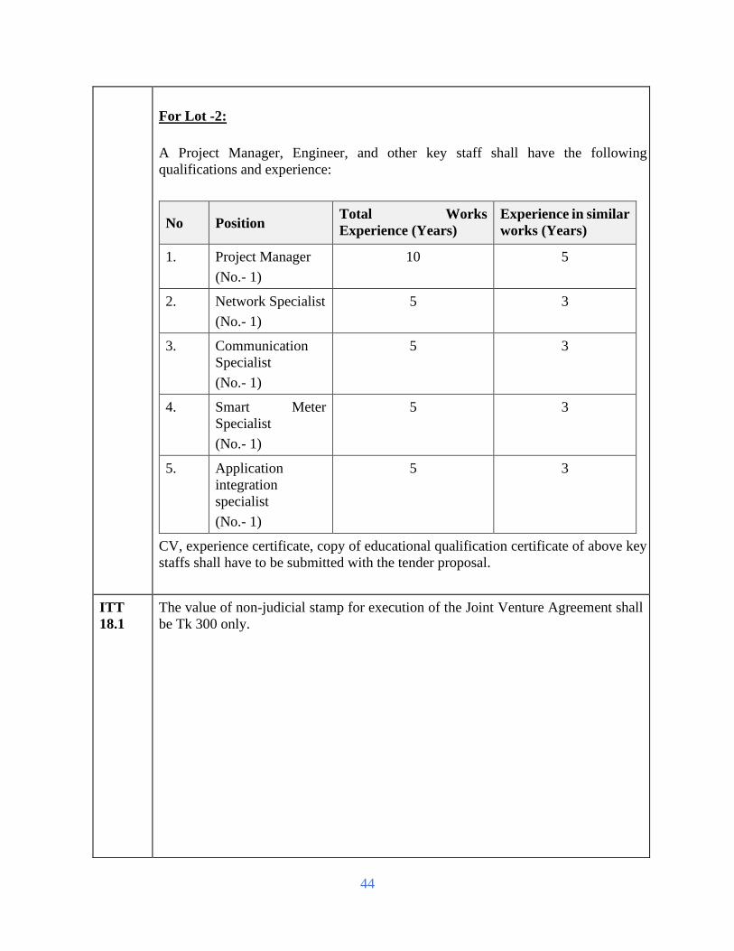
44
For Lot -2:
A Project Manager, Engineer, and other key staff shall have the following
qualifications and experience:
No Position Total Works
Experience (Years)
Experience in similar
works (Years)
1. Project Manager
(No.- 1)
10 5
2. Network Specialist
(No.- 1)
5 3
3. Communication
Specialist
(No.- 1)
5 3
4. Smart Meter
Specialist
(No.- 1)
5 3
5. Application
integration
specialist
(No.- 1)
5 3
CV, experience certificate, copy of educational qualification certificate of above key
staffs shall have to be submitted with the tender proposal.
ITT
18.1
The value of non-judicial stamp for execution of the Joint Venture Agreement shall
be Tk 300 only.

45
ITT 18.2
Maximum number of partners in the JV shall be 4 (Four).
The minimum qualification requirements of Leading Partner, other Partner(s) and
requirements by summation of a JV shall be as follows:
TDS Clauses
References
Requirements
by summation
Requirements for
Leading Partner
Requirements
for other
Partner(s)
ITT-14.1(a) As per TDS As per TDS As per TDS
ITT-14.1(b) As per TDS As per TDS As per TDS
ITT-15.1(a) 100% 40% 25%
ITT-15.1(b) 100% 40% 25%
ITT-16.1(a) 100% Not applicable Not applicable
D. Tender Preparation
ITT 19.2 The maximum of percentage of Goods allowed to be subcontracted: Not Applicable
ITT 19.4 The Nominated Subcontractor(s) named shall execute the following specific
components of the proposed Works: Not Applicable
ITT 20.1
Tenders are being invited for:
1) SPPM-MCS-01; Lot-1
2) SPPM-MCS-01; Lot-2
ITT
24.2(r)
The Tenderer shall submit with its technical offer the following additional
documents:
i. Description of project implementation approach and
methodology.
ii. Drawings, documents, catalogues and leaflets.
iii. The tenderer shall have to submit the Authorization Letter
from data network service provider at their letter head pad as
confirmation.
iv. The tenderer shall submit satisfactory type test certificates of
all the equipment to be supplied under this contract.(if
applicable)
v. All necessary papers, test report, catalogue etc. as described
in the technical specification of the Tender document.
vi. The tender shall submit along with offer all type & routine
test reports of offered equipment as mentioned in the

46
specification enclosed in the tender document from
internationally recognized independent testing laboratory (if
applicable). For the test reports from the laboratories the
tenderer must furnish evidence in support of the status of the
laboratories, which should be acceptable to BREB. The
Manufacturer’s own test report will not be accepted.
vii. Technical specification and brochures of equipment/plant to
be incorporated in the works
viii. Tender purchased receipt/Document.
ix. A written confirmation of Authorization to sign on behave of
the tenderer.
x. Warranty certificate from both Tenderer and manufacturer.
ITT 25.1 Alternative shall not be permitted.
ITT 26.1 Tenderers shall quote for the entire Plant and Installation Services on a single
responsibility basis.
In the offer, tenderer shall fulfil the price schedule for Forieng trainging schedule,
Alternative Forieng trainging schedule & Local Training described in the
technical specification & scope. Among them either schedule Forieng trainging
schedule or Alternative Forieng trainging schedule is applicable. During
evaluation, the purchaser will consider the quoted price for the Forieng trainging
schedule, Alternative Forieng trainging schedule & Local Training and it will
be treated as evaluated price. And during contract the tender value will be
considered as per the higher value (price) between Forieng trainging schedule &
Alternative Forieng trainging schedule.But during execution the purchaser will
pay the bill as per the schedule which is executed.
26.5(a) As per Price Schedule.
26.5(d) Specific project sites.
ITT 26.7 The price shall be fixed.
ITT 27.4 Not Applicable
ITT 28.1
(b)
As per Price Schedule.
ITT
28.1(c) Manufacturer’s authorization: Required
The tenderer shall furnish manufacturer’s authorization letter for Smart meters,
equipments of HES/RF network, MDMS & all major IT products. Authorization
letter from distributor/local agent/supplier for major IT products will be acceptable.

47
ITT 30.2 The Tender validity period shall be 120 days.
ITT 32.2
The amount of the Tender Security shall be:
For Lot-1: BDT 20,00,00,000.00 (Twenty Core)
For Lot-2: BDT 35,00,000.00 (Thirty Five Lac)
in favour of Bangladesh Rural Electrification Board.
ITT 37.1 In addition to the original of the Bid proposal, 2 copies shall be submitted with
soft copy by means of CD and pendrive. Only soft copy will not be acceptable for
tender submission.
E. Submission of Tender
ITT 38.1 Alternative offer shall not be permitted.
The Tender shall be single stage two envelope. Technical and financial proposal
shall be submitted in two separate envelopes duly sealed and signed, which shall be
in a single envelope duly addressed to the employer. The Technical envelope will
be opened first. The original “Technical Offer” and the envelope containing all
copies and original of “Financial Offer” will be kept in safe custody of “ICT
Directorate, BREB”. Financial Proposal of only technically responsive bids will be
opened at date and time to be notified later to the respective bidder. The Financial
Proposal of the technically non-responsive bidder will be returned unopened to the
respective bidder.
ITT
38.2(d)
DO NOT OPEN BEFORE 12:30 noon Bangladesh Standard Time on 26-04-
2021
ITT
38.2(e)
(a) Be addressed to the Employer at the following address:
Attention:
ICT Directorate
Bangladesh Rural Electrification Board,
5th floor, BREB HQ Building,
Nikunja-2, Khilkhet, City: Dhaka-1229, Country: Bangladesh.
Tel: +8802-8900513
E-email: [email protected]
(b) bear the following identification:
TENDER PACKAGE NO: SPPM-MCS-01; Lot-1:

48
Design, Supply, Installation, Testing and Commissioning of Hardware (1 phase and
3 phase Meter with HES, NIC, HHU, UCC, UVS, DCU, Repeater, DR, Data Centre
accessories etc.) & Software for Implementation of AMI with MDM and related
service Under BREB for 5 lac smart meter that will be scalable up to 2 crore smart
meter on Turnkey Basis.
TENDER PACKAGE NO: SPPM-MCS-01; Lot-2:
Design, Supply, Installation of 10 thousand 3 phase, CT/PT Rated, Class 20, AMR
meter with HES and integration with BREB MDM & Server System.
ITT
38.4(e)
The tenderer shall enclose the original Technical Proposal and Financial Proposal
in different envelope. The envelopes will be marked as Technical Proposal Original
and Financial Proposal Original. Similarly copies of technical and financial
proposal will be enclosed in two different envelopes and the envelope will be
marked 'Copy Technical Proposal' and 'Copy Financial Proposal'. Then original
Technical Proposal envelope and copy of the technical proposals will be put into
another envelope and the envelope will be marked as technical proposal. Similarly,
Original of the Financial Proposal and Copy of the Financial Proposal will put into
another envelope will be marked as Financial Proposal. These two envelopes of
Technical Proposal and Financial proposal shall then be enclosed one single outer
envelope. All the envelops should be duly sealed and signed by the bidder.
(a) Be addressed to the Employer at the following address:
Attention:
ICT Directorate
Bangladesh Rural Electrification Board,
5th floor, BREB HQ Building,
Nikunja-2, Khilkhet, City: Dhaka-1229, Country: Bangladesh.
Tel: +8802-8900513
E-email: [email protected]
(b) bear the following identification:

49
TENDER PACKAGE NO: SPPM-MCS-01; Lot-1:
Design, Supply, Installation, Testing and Commissioning of Hardware (1 phase and
3 phase Meter with HES, NIC, HHU, UCC, UVS, DCU, Repeater, DR, Data Centre
accessories etc.) & Software for Implementation of AMI with MDM and related
service Under BREB for 5 lac smart meter that will be scalable up to 2 crore smart
meter on Turnkey Basis.
TENDER PACKAGE NO: SPPM-MCS-01; Lot-2:
Design, Supply, Installation of 10 thousand 3 phase, CT/PT Rated, Class 20, AMR
meter with HES and integration with BREB MDM & Server System.
DO NOT OPEN THE FINANCIAL OFFER BEFORE THE TECHNICAL
OFFER EVALUATION AND APPROVAL.
ITT 39.1 For Tender submission purposes ,the Purchaser’s address is:
Attention: Md. Fahim Uddin
Senior System Analyst, ICT Directorate
Bangladesh Rural Electrification Board,
5th floor, BREB HQ Building,
Nikunja-2, Khilkhet, City: Dhaka-1229, Country: Bangladesh.
Address:
ICT Directorate
Bangladesh Rural Electrification Board,
5th floor, BREB HQ Building,
Nikunja-2, Khilkhet, City: Dhaka-1229, Country: Bangladesh.
Tel: +8802-8900513
E-email: [email protected]
The deadline for submission of Tenders is:
Time & Date: 26-04-2021 up to 12.00 noon (BST).
ITT 39.3 For Tender submission purposes only, the Procuring Entity’s address is:

50
Attention: Md. Fahim Uddin
Senior System Analyst, ICT Directorate
Bangladesh Rural Electrification Board,
5th floor, BREB HQ Building,
Nikunja-2, Khilkhet, City: Dhaka-1229, Country: Bangladesh.
Address:
ICT Directorate
Bangladesh Rural Electrification Board,
5th floor, BREB HQ Building,
Nikunja-2, Khilkhet, City: Dhaka-1229, Country: Bangladesh.
Tel: +8802-8900513
E-email: [email protected]
The deadline for the submission of Tenders is:
Time & Date: 26-04-2021 up to 12.00 noon (BST).
Tender Opening Time & Date: 26-04-2021 up to 12.30 noon (BST).
Address (Secondary Place): Not Applicable
ITT 39.4 The deadline for hand-delivering of the Tenders at the PRIMARY PLACE is:
Not Applicable
F. Opening and Evaluation of Tenders
ITT 45.1 The technical offer opening shall take place at:
Address:
ICT Directorate
Bangladesh Rural Electrification Board,
5th floor, BREB HQ Building,
Nikunja-2, Khilkhet, City: Dhaka-1229, Country: Bangladesh.
Tel: +8802-8900513
E-email: [email protected]

51
Time & Date: 26-04-2021 up to 12.30 noon (BST).
The Technical envelope will be opened first. The Financial Proposal will be kept in
safe custody of purchaser. Financial Proposal of only technically responsive tender
will be opened at date to be notified later to the respective tenderer. The Financial
Proposal of the technically non-responsive tenderer will be returned unopened to
the respective tenderer.
ITT 57.5 The applicable economic factors, for the purposes of evaluation of Tenders shall be:
(a) Adjustment for Deviations in the Delivery and Completion Schedule
“The Plant and Service covered by this Tendering process are required to be
delivered in accordance with, and completed within, the Delivery and
Completion Schedule specified in Section 6, Employer’s Requirements. No
credit will be given for earlier completion. Tender offering late contract
performance schedules within acceptable period will be accepted but the
tenders shall be Adjusted in the evaluation by adding to the Tender Price at
the rate of [specify percentage] ofthe Tender Price for each day ofdelay.
Tender offering delivery schedules beyond [specify time Limit] of the date
specified in Section 6, Employer’s Requirement, shall be rejected.”
[not applicable]
(b) Cost of major replacement components, mandatory spare parts, and
service
The Procuring Entity will draw up a list of high-usage and high-value items
of components and spare parts [specify (spare parts, tools, major
assemblies, estimated quantities] of usage in the initial period [specify
period] of operation. The total cost of these items and quantities will be
computed from spare parts unit prices submitted by the Tenderer and added to
the tender price, for evaluation purposes only.[not applicable]
(c) Other factors affecting the true economic value
The Procuring Entity will draw up other factors affecting the true economic
value of the Tender price may be life span costs, such as cost of fuel,
performance or productivity of the equipment, etc.The total cost of these items
and quantities will be computed from submitted Tender and added to the
tender price, for evaluation purposes only.[not applicable]
G. Award of Contract
ITT 65.2 The amount of Performance Security shall be 10 percent of the Contract Price.
ITT 72.5 The name and address of the office where complaints to the Purchaser are to be
submitted is:
Attention: Md. Fahim Uddin

52
Senior System Analyst, ICT Directorate
Bangladesh Rural Electrification Board,
5th floor, BREB HQ Building,
Nikunja-2, Khilkhet, City: Dhaka-1229, Country: Bangladesh.
Address:
ICT Directorate
Bangladesh Rural Electrification Board,
5th floor, BREB HQ Building,
Nikunja-2, Khilkhet, City: Dhaka-1229, Country: Bangladesh.
Tel: +8802-8900513
E-email: [email protected]

53
Section 3. General Conditions of Contract
A. General
1. Definitions 1.1 In the Conditions of Contract, which include Particular Conditions and these
General Conditions, the following words and expressions shall have the
meaning hereby assigned to them. Boldface type is used to identify the
defined terms:
(a) Approving Authority means the authority which, in accordance
with the Delegation of Financial powers, approves the award of
Contract for the Procurement of Goods, Works and Services.
(b) Act means The Public Procurement Act, 2006 (Act 24 of 2006).
(c) Commissioning means operation of the Facilities or any part thereof
by the Contractor following Completion, which operation is to be
carried out by the Contractor for the purpose of carrying out
Guarantee Test(s).
(d) Competent Authority means the authority that gives decision on
specific issues as per delegation of administrative and/or financial
powers.
(e) Completion means that the Facilities (or a specific part thereof
where specific parts are specified in the Contract) have been
completed operationally and structurally and put in a tight and clean
condition, that all work in respect of Pre Commissioning of the
Facilities or such specific part thereof has been completed, and that
the Facilities or specific part thereof are ready for Commissioning.
(f) Completion Certificate means the Certificate issued by the Project
Manager as evidence that the Contractor has executed the services
in all respects as per design, drawing, specifications and Conditions
of Contract.
(g) Completion Date is the actual date of completion of the plant and
services certified by the Project Manager, in accordance with GCC
Clause 24.
(h) Contract Agreement means the Agreement entered into between
the Procuring Entity and the Contractor, together with the Contract
Documents referred to therein, including all attachments,
appendices, and all documents incorporated by reference therein to
supply and install Plant & Equipment
(i) Contract Documents means the documents listed in GCC Clause
6, including any amendments thereto.
(j) Contractor/supplier means the Person under contract with the
Procuring Entity for the supply and installation of Plant &
Equipment under the Rules and the Act as stated in the PCC.

54
(k) Contractor’s Representative means any person nominated by the
Contractor and approved by the Employer to perform the duties
delegated by the Contractor.
(l) Contract Price means the price payable to the Contractor as
specified in the Contract Agreement, subject to such additions and
adjustments thereto or deductions therefrom, for the supply and
installation of plant & equipment in accordance with the provisions
of the Contract, subject to such additions and adjustments thereto or
deductions therefrom, as may be made pursuant to the Contract.
(m) Cost means all expenditures reasonably incurred or to be incurred
by the Contractor, whether on or off the Site, including
overhead ,profit, taxes, duties, fees, and such other similar levies
(n) Day means calendar day unless otherwise specified as working days.
(o) Dayworks means work carried out following the instructions of the
Procuring Entity or the authorised Project Manager and is paid for
on the basis of time spent by the Contractor’s workers and
equipment at the rates specified in the Schedules, in addition to
payments for associated Materials and Plant.
(p) Defect is any part of the Works not completed in accordance with
the Contract.
(q) Defect Liability Period means the period of validity of the
warranties given by the Contractor commencing at Completion of
the Facilities or a part thereof, during which the Contractor is
responsible for defects with respect to the Facilities (or the relevant
part thereof) as provided in contract document.
(r) Defects Correction Certificate is the certificate issued by the
Project Manager upon correction of defects by the Contractor.
(s) Drawings include calculations and other information provided in
Section 7 or as approved by the Project Manager for the execution
and completion of the Contract.
(t) Effective Date means the date of fulfillment of all conditions of the
Contract Agreement, from which the Time for Completion shall be
counted.
(u) Equipmentmeans all facilities, equipment, machinery, tools,
apparatus, appliances or things of every kind required in or for
installation, completion and maintenance of Facilities that are to be
provided by the Contractor, but does not include Plant, or other
things intended to form or forming part of the Facilities.
(v) Facilities means the Plant to be supplied and installed, as well as all
the Installation Services to be carried out by the Contractor under
the Contract. It also includes any ancillary building or infra structure
that needs to be constructed/built/erected to support the plant.
(w) Force Majeure means an event or situation beyond the control of
the Contractor that is not foreseeable, is unavoidable, and its origins
55
not due to negligence or lack of care on the part of the Contractor;
such events may include, but not be limited to, acts of the
Government in its sovereign capacity, wars or revolutions, fires,
floods, epidemics, quarantine restrictions, and freight embargoes or
more as included in GCC Clause 52.
(x) Goods mean the Contractor’s Plant, Equipment, Materials or any of
them as appropriate.
(y) GCC means the General Conditions of Contract.
(z) Government means the Government of the People’s Republic of
Bangladesh.
(aa) Guarantee Test(s)means the test(s) specified in the Employer’s
Requirements to be carried out to ascertain whether the Facilities or
a specified part thereof is able to attain the Functional Guarantees
specified in the Appendix to the Contract Agreement titled
Functional Guarantees, in accordance with the provisions of GCC
Sub-Clause 25.2 (Guarantee Test) hereof.
(bb) Head of the Procuring Entity means the Secretary of a Ministry or
a Division, the Head of a Government Department or Directorate;
or the Chief Executive, by whatever designation called, of a local
Government agency, an autonomous or semi-autonomous body or a
corporation, or a corporate body established under the Companies
Act;
(cc) Installation Services means all those services ancillary to the
supply of the Plant for the Facilities, to be provided by the
Contractor under the Contract, such as transportation and provision
of marine or other similar insurance, inspection, expediting, site
preparation works (including the provision and use of Contractor’s
Equipment and the supply of all construction materials required),
installation, testing, pre-commissioning, commissioning,
operations, maintenance, the provision of operations and
maintenance manuals, training, etc. as the case may require.
(dd) Intended Completion Date is the date calculated from the
Commencement Date as specified in the PCC, on which it is
intended that the Contractor shall complete the Works and Physical
services as specified in the Contract and may be revised only by the
Project Manager by issuing an extension of time or an acceleration
order.
(ee) Materials means things of all kinds other than Plant intended to
form or forming part of the Permanent Works, including the supply-
only materials, if any, to be supplied by the Contractor under the
Contract.
(ff) Month means calendar month.
(gg) Original Contract Price is the Contract Price stated in the
Procuring Entity’s Notification of Award (Form PG5A-7) and
further clearly determined in the PCC.

56
(hh) Operational Acceptance means the acceptance by the Employer of
the Facilities (or any part of the Facilities where the Contract
provides for acceptance of the Facilities in parts), which certifies the
Contractor’s fulfillment of the Contract in respect of Functional
Guarantees of the Facilities (or the relevant part thereof) in
accordance with the provisions of contract
(ii) PCC means the Particular Conditions of Contract.
(jj) Plant means permanent plant, equipment, machinery, apparatus,
materials, articles, ancillary buildings/structure and things of all
kinds to be provided and incorporated in the Facilities by the
Contractor under the Contract (including the spare parts to be
supplied by the Contractor), but does not include Contractor’s
Equipment.
(kk) Pre-Commissioning means the testing, checking and other
requirements specified in the Employer’s Requirements that are to
be carried out by the Contractor in preparation for Commissioning.
(ll) Procuring Entity/Employer/Purchaser means, as the context so
applies, an Entity having administrative and financial powers to
undertake procurement of Plant and Physical services using public
funds and is as named in the PCC who employs the Contractor to
carry out the contractual obligations.
(mm) Project Manager is the person named in the PCC or any other
competent person appointed by the Procuring Entity and notified to
the Contractor who is responsible for supervising the execution and
completion of the plant and services and administering the Contract.
(nn) Schedules means the document(s) entitled schedules, completed by
the Contractor and submitted with the Tender Submission Letter, as
included in the Contract. Such document may include the data, lists
and schedules of rates and/or prices.
(oo) Site means the land and other places upon which the Facilities are
to be installed, and such other land or places as may be specified in
the PCC as forming part of the Site
(pp) Site Investigation Reports are those that were included in the
Tender Document and are factual and interpretative reports about
the surface and subsurface conditions at the Site.
(qq) Specification means the Specification of the goods/works/related
services included in the Contract and any modifications or additions
to the specifications made or approved by the Project Manager in
accordance with the Contract.
(rr) Start Date is the date defined in the PCC and it is the last date
when the Contractor shall commence execution of the
goods/works/services under the Contract.
(ss) Subcontractor means a person or corporate body, who has a
contract with the Contractor to carry out a part of the work in the
Contract, which includes work on the Site.

57
(tt) Time for Completion means the time within which Completion of
the Facilities as a whole (or of a part of the Facilities where a
separate Time for Completion of such part has been prescribed) is
to be attained, in accordance with the relevant provisions of the
Contract.
(uu) Variation means any change to the plant and services directly
procured from the original Contractor to cover increases or
decreases in quantities, including the introduction of new work
items that are either due to change of plans, design or alignment to
suit actual field conditions, within the general scope and physical
boundaries of the contract.
(vv) Works means all works associated with the construction,
reconstruction, site preparation, demolition, repair, maintenance or
renovation of railways, roads, highways, or a building, an
infrastructure or structure or an installation or any construction work
relating to excavation, installation of equipment and materials,
decoration, as well as physical services ancillary to works as
detailed in the PCC, if the value of those services does not exceed
that of the Works themselves.
(ww) Writing means communication written by hand or machine duly
signed and includes properly authenticated messages by facsimile
or electronic mail.
2. Interpretation 2.1 In interpreting the GCC, singular also means plural, male also means female
or neuter, and the other way around. Headings in the GCC shall not be
deemed part thereof or be taken into consideration in the interpretation or
construance of the Contract. Words have their normal meaning under the
language of the Contract unless specifically defined.
2.2 Entire Agreement.
The Contract constitutes the entire agreement between the Employer and
the Contractor and supersedes all communications, negotiations and
agreements (whether written or verbal) of parties with respect thereto made
prior to the date of Contract Agreement; except those stated under GCC Sub
Clause 6.1(j).
2.3 Non waiver.
(a) Subject to GCC Sub Clause 2.3(b), no relaxation, forbearance, delay,
or indulgence by either party in enforcing any of the terms and
conditions of the Contract or the granting of time by either party to the
other shall prejudice, affect, or restrict the rights of that party under
the Contract, neither shall any waiver by either party of any breach of
Contract operate as waiver of any subsequent or continuing breach of
Contract.
(b) Any waiver of a party’s rights, powers, or remedies under the Contract
must be in writing, dated, and signed by an authorized representative

58
of the party granting such waiver, and must specify the right and the
extent to which it is being waived.
2.4. Severability
If any provision or condition of the Contract is prohibited or rendered
invalid or unenforceable, such prohibition, invalidity or unenforceability
shall not affect the validity or enforceability of any other provisions and
conditions of the Contract.
2.5. Sectional completion
If sectional completion is specified in the PCC, references in the GCC to
the Works, the Completion Date, and the Intended Completion Date apply
to any section of the Works (other than references to the Completion Date
and Intended Completion Date for the whole of the Works).
3. Communications & Notices
3.1 Communications between Parties such as notice, request or consent required
or permitted to be given or made by one party to the other pursuant to the
Contract shall be in writing to the addresses specified in the PCC.
3.2 A notice shall be effective when delivered or on the notice’s effective date,
whichever is later.
3.3 A Party may change its address for notice hereunder by giving the other
Party notice of such change to the address.
4. Governing Law 4.1 The Contract shall be governed by and interpreted in accordance with the
laws of the People’s Republic of Bangladesh.
5. Governing Language
5.1 The Contract shall be written in English. All correspondences and
documents relating to the Contract may be written in English. Supporting
documents and printed literature that are part of the Contract may be in
another language, provided they are accompanied by an accurate translation
of the relevant passages in English, in which case, for purposes of
interpretation of the Contract, such translation shall govern.
5.2 The Contractor shall bear all costs of translation to the governing language
and all risks of the accuracy of such translation.
6. Documents Forming the Contract and Priority of Documents
6.1 The following documents forming the Contract shall be interpreted in the
following order of priority:

59
(a) the signed Contract Agreement (Form PG5A-8);
(b) the Notification of Award (PG5A-7);
(c) the completed Tender and the Appendix to the Tender;
(d) the Price Schedule for Plant and Services (PG5A-3);
(e) the Particular Conditions of Contract;
(f) the General Conditions of Contract;
(g) the Technical Specifications;
(h) Personnel Information;
(i) Equipment Information;
(j) the Drawings; and
(k) Any other document listed in the PCC forming part of the Contract.
7. Contract Agreement 7.1 The parties shall enter into a Contract Agreement within twenty eight (28) days
from the date of issuance of the Notification of Award (NOA). The costs of
stamp duties and similar charges, if any, designated by the applicable law in
connection with entry into the Contract Agreement, shall be borne by the
Employer.
8. Assignment 8.1 Neither the Contractor nor the Employer shall assign, in whole or in part, its
obligations under the Contract; except with the Employer’s prior written
approval.
9. Eligibility 9.1 The Contractor and its Subcontractor(s) shall have the nationality of a
country other than that specified in the PCC.
9.2 All materials, equipment, plant, and supplies used by the Contractor in both
permanent and temporary works and services supplied under the Contract
shall have their origin in the countries except any specified in the PCC.
10. Gratuities / Agency fees
10.1 No fees, gratuities, rebates, gifts, commissions or other payments, other than
those included in the Contract, shall be given or received in connection with
the procurement process or in the Contract execution.
11. Confidential Details
11.1 The Employer and the Contractor shall keep confidential and shall not,
without the written consent of the other party hereto, divulge to any third
party any documents, data, or other information furnished directly or
indirectly by the other party hereto in connection with the Contract, whether
such information has been furnished prior to, during or following
completion or termination of the Contract. Notwithstanding the above, the
Contractor may furnish to its Subcontractor such documents, data, and other
information it receives from the Employer to the extent required for the
Subcontractor to perform its work under the Contract, in which event the
Contractor shall obtain from such Subcontractor an undertaking of
confidentiality similar to that imposed on the Contractor under GCC Clause
11.
60
11.2 The Employer shall not use such documents, data, and other information
received from the Contractor for any purposes unrelated to the Contract.
Similarly, the Contractor shall not use such documents, data, and other
information received from the Employer for any purpose other than the
design, construction, or other work and services required for the
performance of the Contract.
11.3 The obligations of a party under GCC Sub Clauses 11.1 and 11.2 above,
however, shall not apply to information that: the Employer or Contractor
needs to share with institutions participating in the financing of the
Contract; now or hereafter enters the public domain through no fault of that
party; can be proven to have been possessed by that party at the time of
disclosure and which was not previously obtained, directly or indirectly,
from the other party; or otherwise lawfully becomes available to that party
from a third party that has no obligation of confidentiality.
11.4 The above provisions of GCC Clause 11 shall not in any way modify any
undertaking of confidentiality given by either of the parties hereto prior to
the date of the Contract in respect of the Works or any part thereof.
11.5 The provisions of GCC Clause 11 shall survive completion or termination,
for whatever reason.
12. Joint Venture (JV) 12.1 If the Contractor is a Joint Venture, Consortium, or Association (JVCA),
(a) each partner of the JV shall be jointly and severally liable for all
liabilities and ethical or legal obligations to the Employer for the
performance of the Contract;
(b) the JV partners shall nominate a representative who shall have the
authority to conduct all business including the receipt of payments for
and on behalf of all partners of the JV;
(c) in the event of a dispute that results in legal action against all partners
of the JV, if they are available and if only one partner is available,
then that partner alone shall answer on behalf of all partners and, if
the complaint lodged is proven, the penalty shall be applicable on that
lone partner as whatever penalty all the partners would have received.
(d) the JV shall notify the Employer of its composition and legal status
which shall not be altered without the prior approval of the Employer.
(e) alteration of partners shall only be allowed if any of the partners is
found to be incompetent or has any serious difficulties which may
impact the overall implementation of the goods/works/service,
whereby the incoming partner shall require to possess qualifications
equal to or higher than that of the outgoing partner.
(f) if any of the partners of JV has been debarred from participating in
any procurement activity due to corrupt, fraudulent, collusive or
coercive practices, that JV partner shall be altered following
provisions under GCC Sub Clause 12.1 (d) and (e), while in case the
Leading Partner has been debarred due to the same reasons stated

61
herein the Contract shall be terminated as stated under GCC Sub
Clause 67.1(b).
13. Possession of the Site
13.1 The Employer shall give possession of the Site or part(s) of the Site, to the
Contractor on the date(s) stated in the PCC. If possession of a part of the
Site is not given by the date stated in the PCC, the Employer will be deemed
to have delayed the start of the relevant activities, and this will be a
Compensation Event.
14. Access to the Site 14.1 The Contractor shall allow the Engineer and any person authorised by the
Engineer access to the Site and to any place where work in connection with
the Contract is being carried out or is intended to be carried out.
15. Safety, Security and Protection of the Environment
15.1 The Contractor shall throughout the execution and completion of the Works
and the remedying of any defects therein:
(a) take all reasonable steps to safeguard the health and safety of all
workers working on the Site and other persons entitled to be on it,
and to keep the Site in an orderly state;
(b) provide and maintain at the Contractor’s own cost all lights, guards,
fencing, warning signs and watching for the protection of the
Works or for the safety on-site; and
(c) take all reasonable steps to protect the environment on and off the
Site and to avoid damage or nuisance to persons or to property of
the public or others resulting from pollution, noise or other causes
arising as a consequence of the Contractors methods of operation.
16. Working Hours
16.1 The Contractor shall not perform any work on the Site on the weekly
holidays, or during the night or outside the normal working hours, or on
any religious or public holiday, without the prior written approval of the
Project Manager.
17. Welfare of Laborers
17.1 The Contractor shall comply with all the relevant labour Laws applicable
to the Contractor’s personnel relating to their employment, health, safety,
welfare, immigration and shall allow them all their legal rights.
17.2 The Contractor, in particular, shall provide proper accommodation to his
or her labourers and arrange proper water supply, conservancy and
sanitation arrangements at the site for all necessary hygienic requirements
and for the prevention of epidemics in accordance with relevant
regulations, rules and orders of the government.
17.3 The Contractor, further in particular, shall pay reasonable wages to his or
her labourers, and pay them in time. In the event of delay in payment the
Employer may affect payments to the labourers and recover the cost from
the Contractor.
17.4 The Contractor shall appoint an accident prevention officer at the Site,
responsible for maintaining safety and protection against accidents. This
person shall be qualified for this responsibility, and shall have the authority
to issue instructions and take appropriate protective measures to prevent
accidents that could result in injury. Throughout the execution of the

62
Works, the Contractor shall provide whatever is required by this person to
exercise this responsibility and authority.
18. Child Labour 18.1 The Contractor shall not employ any child to perform any work that is
economically exploitative, or is likely to be hazardous to, or to interfere
with, the child's education, or to be harmful to the child's health or physical,
mental, spiritual, moral, or social development in compliance with the
applicable laws and other relevant treaties ratified by the government.
19. Fossils& antiquities
19.1 All fossils, coins, articles of value or antiquity, and structures and other
remains or items of geological or archaeological interest found on the Site
shall be placed under the care and authority of the Employer. The
Contractor shall take reasonable precautions to prevent Contractor’s
Personnel or other persons from removing or damaging any of these
findings.
19.2 The Contractor shall, upon discovery of any such finding, promptly give
notice to the Project Manager, who shall issue instructions for dealing with
it. If the Contractor suffers delay and/or incurs cost from complying with
the instructions, the Contractor shall give a further notice to the Project
Manager and shall be entitled subject to Claims under GCC Clause 71
20. Corrupt, Fraudulent, Collusive or Coercive Practices
20.1 The Government requires that Employer, as well as the Contractor shall
observe the highest standard of ethics during the implementation of
procurement proceedings and the execution of the Contract.
20.2 The Government requires that Employer, as well as the Contractor shall,
during the Procurement proceedings and the execution of the Contract
under public funds, ensure-
(a) strict compliance with the provisions of Section 64 of the Public
Procurement Act, 2006
(b) abiding by the code of ethics as mentioned in the Rule127 of the
Public Procurement Rules, 2008;
(c) that neither it, nor any other member of its staff, or any other agents
or intermediaries working on its behalf engages in any such practice
as detailed in GCC Sub Clause 20.2.
20.3 For the purposes of GCC Sub Clause 20.2, the terms set forth below as
follows
(a) “corrupt practice” means offering, giving or promising to give,
receiving, or soliciting either directly or indirectly, to any officer
or employee of a Employer or other public or private authority or
individual, a gratuity in any form; employment or any other thing or
service of value as an inducement with respect to an act or decision or
method followed by a Employer in connection with a Procurement
proceeding or Contract execution;
(b) “fraudulent practice” means the misrepresentation or omission of
facts in order to influence a decision to be taken in a Procurement
proceeding or Contract execution;

63
(c) collusive practice” means a scheme or arrangement between two (2)
or more Persons, with or without the knowledge of the Employer, that
is designed to arbitrarily reduce the number of Tenders submitted or
fix Tender prices at artificial, non-competitive levels, thereby denying
a Employer the benefits of competitive price arising from genuine and
open competition; or
(d) “Coercive practice” means harming or threatening to harm, directly
or indirectly, Persons or their property to influence a decision to be
taken in the Procurement proceeding or the execution of the
Contract, and this will include creating obstructions in the normal
submission process used for Tenders.
20.4 Should any corrupt, fraudulent, collusive or coercive practice of any kind
come to the knowledge of the Employer, it will, in the first place, allow the
Contractor to provide an explanation and shall, take actions only when a
satisfactory explanation is not received. Such decision and the reasons
thereof, shall be recorded in the record of the procurement proceedings and
promptly communicated to the Contractor. Any communications between
the Contractor and the Employer related to matters of alleged fraud or
corruption shall be in writing.
20.5 If corrupt, fraudulent, collusive or coercive practices of any kind
determined by the Employer against the Contractor alleged to have carried
out such practices, the Employer will:
(a) exclude the Contractor from further participation in the particular
Procurement proceeding; or
(b) declare, at its discretion, the Contractor to be ineligible to participate
in further Procurement proceedings, either indefinitely or for a
specific period of time.
20.6 20.6 The Contractor shall be aware of the provisions on corruption,
fraudulence, collusion and coercion in Section 64 of the Public
Procurement Act, 2006 and Rule 127 of the Public Procurement Rules,
2008.
21. License/ Use of Technical Information
21.1 For the operation and maintenance of the Plant, the Contractor hereby
grants a non-exclusive and non-transferable license (without the right to
sub-license) to the Employer under the patents, utility models or other
industrial property rights owned by the Contractor or by a third Party from
whom the Contractor has received the right to grant licenses thereunder,
and shall also grant to the Employer a non-exclusive and non-transferable
right (without the right to sub-license) to use the know-how and other
technical information disclosed to the Employer under the Contract.
Nothing contained herein shall be construed as transferring ownership of
any patent, utility model, trademark, design, copyright, know-how or other
intellectual property right from the Contractor or any third Party to the
Employer.
21.2 The copyright in all drawings, documents and other materials containing
data and information furnished to the Employer by the Contractor herein
shall remain vested in the Contractor or, if they are furnished to the
Employer directly or through the Contractor by any third Party, including

64
suppliers of materials, the copyright in such materials shall remain vested
in such third Party.
B. Subject Matter of Contract
22. Scope of Facilities 22.1 Unless otherwise expressly limited in the Employer’s Requirements, the
Contractor’s obligations cover the provision of all Plant and the
performance of all Installation Services required for the design, and the
manufacture (including procurement, quality assurance, construction,
installation, associated civil works, Pre Commissioning and delivery) of
the Plant, and the installation, completion and commissioning of the
Facilities in accordance with the plans, procedures, specifications,
drawings, codes and any other documents as specified in the Section,
Employer’s Requirements. Such specifications include, but are not
limited to, the provision of supervision and engineering services; the
supply of labor, materials, equipment, spare parts and accessories;
Contractor’s Equipment; construction utilities and supplies; temporary
materials, structures and facilities; transportation (including, without
limitation, unloading and hauling to, from and at the Site); and storage,
except for those supplies, works and services that will be provided or
performed by the Employer, as set forth in the Appendix to the Contract
Agreement titled Scope of Works and Supply by the Employer.
22.2 The Contractor shall, unless specifically excluded in the Contract, perform
all such work and/or supply all such items and materials not specifically
mentioned in the Contract but that can be reasonably inferred from the
Contract as being required for attaining Completion of the Facilities as if
such work and/or items and materials were expressly mentioned in the
Contract.
22.3 In addition to the supply of Mandatory Spare Parts included in the
Contract, the Contractor agrees to supply spare parts required for the
operation and maintenance of the Facilities for the period specified in the
PCC and the provisions, if any, specified in the PCC. However, the
identity, specifications and quantities of such spare parts and the terms
and conditions relating to the supply thereof are to be agreed between the
Employer and the Contractor, and the price of such spare parts shall be
that given in Price Schedule No.1 & 2 under form PG5A-3, which shall
be added to the Contract Price. The price of such spare parts shall include
the purchase price therefor and other costs and expenses (including the
Contractor’s fees) relating to the supply of spare parts.
23. Time for Commencement
23.1 The Contractor shall attain Completion of the Facilities or of a part where
a separate time for Completion of such part is specified in the Contract,
within the time stated in the PCC or within such extended time to which
the Contractor shall be entitled under GCC Clause 65.1 hereof.
24. Time for Completion
24.1 The Contractor shall attain Completion of the Facilities or of a part where
a separate time for Completion of such part is specified in the Contract,

65
within the time stated in the PCC or within such extended time to which
the Contractor shall be entitled under GCC Clause 65.1 hereof.
25. Employer’s Responsibilities
25.1 All information and/or data to be supplied by the Employer as described in
the Appendix to the Contract Agreement titled Scope of Works and Supply
by the Employer, shall be deemed to be accurate, except when the
Employer expressly states otherwise
25.2 The Employer shall be responsible for acquiring and providing legal and
physical possession of the Site and access thereto, and for providing
possession of and access to all other areas reasonably required for the
proper execution of the Contract, including all requisite rights of way, as
specified in the Appendix to the Contract Agreement titled Scope of Works
and Supply by the Employer. The Employer shall give full possession of
and accord all rights of access thereto on or before the date(s) specified in
that Appendix.
25.3 The Employer shall acquire and pay for all permits, approvals and/or
licenses from all local, state or national government authorities or public
service undertakings in the country where the Site is located which (a) such
authorities or undertakings require the Employer to obtain in the
Employer’s name, (b) are necessary for the execution of the Contract,
including those required for the performance by both the Contractor and
the Employer of their respective obligations under the Contract, and (c) are
specified in the Appendix (Scope of Works and Supply by the Employer).
25.4 If requested by the Contractor, the Employer shall use its best endeavors to
assist the Contractor in obtaining in a timely and expeditious manner all
permits, approvals and/or licenses necessary for the execution of the
Contract from all local, state or national government authorities or public
service undertakings that such authorities or undertakings require the
Contractor or Subcontractors or the personnel of the Contractor or
Subcontractors, as the case may be, to obtain
25.5 Unless otherwise specified in the Contract or agreed upon by the Employer
and the Contractor, the Employer shall provide sufficient, properly
qualified operating and maintenance personnel; shall supply and make
available all raw materials, utilities, lubricants, chemicals, catalysts, other
materials and facilities; and shall perform all work and services of
whatsoever nature, including those required by the Contractor to properly
carry out Pre Commissioning, Commissioning and Guarantee Tests, all in
accordance with the provisions of the Appendix to the Contract Agreement
titled Scope of Works and Supply by the Employer, at or before the time
specified in the program furnished by the Contractor under the provisions
of contract specified or as otherwise agreed upon by the Employer and the
Contractor.
25.6 The Employer shall be responsible for the continued operation of the
Facilities after Completion, in accordance with GCC Sub-Clause 39.8, and
shall be responsible for facilitating the Guarantee Test(s) for the Facilities,
in accordance with GCC Sub-Clause 40.2.
25.7 All costs and expenses involved in the performance of the obligations
under this GCC Clause 25 shall be the responsibility of the Employer, save

66
those to be incurred by the Contractor with respect to the performance of
Guarantee Tests, in accordance with GCC Sub-Clause 40.2.
25.8 In the event that the Employer shall be in breach of any of his obligations
under this Clause, the additional cost incurred by the Contractor in
consequence thereof shall be determined by the Project Manager and added
to the Contract Price
26. Contractor’s Responsibilities
26.1 The Contractor shall design, manufacture including associated purchases
and/or subcontracting, install and complete the Facilities in accordance with
the Contract. When completed, the Facilities should be fit for the purposes
for which they are intended as defined in the Contract. 26.2 The Contractor confirms that it has entered into this Contract on the basis of
a proper examination of the data relating to the Facilities including any data
as to boring tests provided by the Employer, and on the basis of information
that the Contractor could have obtained from a visual inspection of the Site
if access thereto was available and of other data readily available to it
relating to the Facilities as of the date twenty-eight (28) days prior to tender
submission. The Contractor acknowledges that any failure to acquaint itself
with all such data and information shall not relieve its responsibility for
properly estimating the difficulty or cost of successfully performing the
Facilities. 26.3 The Contractor shall acquire and pay for all permits, approvals and/or
licenses from all local, state or national government authorities or public
service undertakings in the country where the Site is located which such
authorities or undertakings require the Contractor to obtain in its name and
which are necessary for the performance of the Contract, including, without
limitation, visas for the Contractor’s and Subcontractor’s personnel and
entry permits for all imported Contractor’s Equipment. The Contractor shall
acquire all other permits, approvals and/or licenses that are not the
responsibility of the Employer under GCC Sub-Clause 25.3 hereof and that
are necessary for the performance of the Contract. 27. Employer’s and
Contractor’s Risks 27.1 The Employer carries the risks that the Contract states are Employer’s
risks and the Contractor carries the risks that the Contract states are
Contractor’s risks.
28. Employer’s Risks 28.1 From the Start Date until the Defects Correction Certificate has been
issued, the following are Employer’s risks:
(a) the risk of personal injury, death, or loss of or damage to property
(excluding the Works, Plant, Materials, and Equipment), which are
due to
i. use or occupation of the Site by the Works or for the purpose
of the Works, which is the unavoidable result of the Works
or
ii. negligence, breach of statutory duty, or interference with any
legal right by the Employer or by any person employed by or
Contracted to him except the Contractor.
iii. the risk of damage to the Works, Plant, Materials, and
Equipment to the extent that it is due to a fault of the
Employer or in the Employer’s design, or due to war or

67
radioactive contamination directly affecting the country
where the Works are to be executed.
28.2 From the Completion Date until the Defects Correction Certificate has been
issued, the risk of loss of or damage to the Works, Plant, and Materials is
Employer’s risk, except loss or damage due to:
(a) a Defect which existed on the Completion Date;
(b) an event occurring before the Completion Date, which was not
itself Employer’s risk; or
(c) the activities of the Contractor on the Site after the Completion
Date.
29. Contractor’s Risks 29.1 From the Start Date until the Defects Correction Certificate has been
issued the risks of personal injury, death, and loss of or damage to
property including without limitation, the Works, Plant, Materials, and
Equipment, which are not Employer’s risks are Contractor’s risks.
C. Execution of the Facilities
30. Representatives 31.1 Project Manager
If the Project Manager is not named in the Contract, then within fourteen
(14) days of the Effective Date, the Employer shall appoint and notify the
Contractor in writing of the name of the Project Manager. The Employer
may from time to time appoint some other person as the Project Manager in
place of the person previously so appointed, and shall give a notice of the
name of such other person to the Contractor without delay. No such
appointment shall be made at such a time or in such a manner as to impede
the progress of work on the Facilities. Such appointment shall only take
effect upon receipt of such notice by the Contractor. The Project Manager
shall represent and act for the Employer at all times during the performance
of the Contract. All notices, instructions, orders, certificates, approvals and
all other communications under the Contract shall be given by the Project
Manager, except as herein otherwise provided.
All notices, instructions, information and other communications given by
the Contractor to the Employer under the Contract shall be given to the
Project Manager, except as herein otherwise provided.
30.2 Contractor’s Representative & Construction Manager
30.2.1 If the Contractor’s Representative is not named in the Contract,
then within fourteen (14) days of the Effective Date, the Contractor shall
appoint the Contractor’s Representative and shall request the Employer in
writing to approve the person so appointed. If the Employer makes no
objection to the appointment within fourteen (14) days, the Contractor’s
Representative shall be deemed to have been approved. If the Employer
objects to the appointment within fourteen (14) days giving the reason
therefor, then the Contractor shall appoint a replacement within fourteen
(14) days of such objection, and the foregoing provisions of this GCC Sub-
Clause 30.2.1 shall apply thereto.

68
30.2.2 The Contractor’s Representative shall represent and act for the
Contractor at all times during the performance of the Contract and shall
give to the Project Manager all the Contractor’s notices, instructions,
information and all other communications under the Contract.
The Contractor shall not revoke the appointment of the Contractor’s
Representative without the Employer’s prior written consent, which shall
not be unreasonably withheld. If the Employer consents thereto, the
Contractor shall appoint some other person as the Contractor’s
Representative, pursuant to the procedure set out in GCC Sub-Clause
30.2.1.
30.2.3 . The Contractor’s Representative may, subject to the approval of
the Employer which shall not be unreasonably withheld, at any time
delegate to any person any of the powers, functions and authorities vested
in him or her. Any such delegation may be revoked at any time. Any such
delegation or revocation shall be subject to a prior notice signed by the
Contractor’s Representative, and shall specify the powers, functions and
authorities thereby delegated or revoked. No such delegation or revocation
shall take effect unless and until a copy thereof has been delivered to the
Employer and the Project Manager.
Any act or exercise by any person of powers, functions and authorities so
delegated to him or her in accordance with this GCC Sub-Clause 30.2.3
shall be deemed to be an act or exercise by the Contractor’s Representative.
30.2.4 From the commencement of installation of the Facilities at the Site
until Completion, the Contractor’s Representative shall appoint a suitable
person as the Construction Manager. The Construction Manager shall
supervise all work done at the Site by the Contractor and shall be present
at the Site throughout normal working hours except when on leave, sick or
absent for reasons connected with the proper performance of the Contract.
Whenever the Construction Manager is absent from the Site, a suitable
person shall be appointed to act as the Construction Manager’s deputy.
30.2.5 The Employer may by notice to the Contractor object to any
representative or person employed by the Contractor in the execution of the
Contract who, in the reasonable opinion of the Employer, may behave
inappropriately, may be incompetent or negligent, or may commit a serious
breach of the Site regulations provided under GCC Sub-Clause 37.4. The
Employer shall provide evidence of the same, whereupon the Contractor
shall remove such person from the Facilities.
30.2.6 If any representative or person employed by the Contractor is
removed in accordance with GCC Sub-Clause 30.2.5, the Contractor shall,
where required, promptly appoint a replacement.

69
31. Work Program 31.1 Contractor’s Organization
The Contractor shall supply to the Employer and the Project Manager a
chart showing the proposed organization to be established by the
Contractor for carrying out work on the Facilities within twenty-one (21)
days of the Effective Date. The chart shall include the identities of the
key personnel and the curricula vitae of such key personnel to be
employed shall be supplied together with the chart. The Contractor shall
promptly inform the Employer and the Project Manager in writing of any
revision or alteration of such an organization chart.
31.2 Program of Performance
Within twenty-eight (28) days after the Effective Date, the Contractor
shall submit to the Project Manager a detailed program of performance of
the Contract, made in a form acceptable to the Project Manager and
showing the sequence in which it proposes to design, manufacture,
transport, assemble, install and Pre Commission the Facilities, as well as
the date by which the Contractor reasonably requires that the Employer
shall have fulfilled its obligations under the Contract so as to enable the
Contractor to execute the Contract in accordance with the program and to
achieve Completion, Commissioning and Acceptance of the Facilities in
accordance with the Contract. The program so submitted by the
Contractor shall accord with the Time Schedule included in the Appendix
to the Contract Agreement titled Time Schedule, and any other dates and
periods specified in the Contract. The Contractor shall update and revise
the program as and when appropriate or when required by the Project
Manager, but without modification in the Times for Completion specified
in the PCC pursuant to Sub-Clause 24.1 and any extension granted in
accordance with GCC Clause 65.1, and shall submit all such revisions to
the Project Manager.
31.3 Progress Report
The Contractor shall monitor progress of all the activities specified in the
program referred to in GCC Sub-Clause 31.2 above, and supply a
progress report to the Project Manager every month.
The progress report shall be in a form acceptable to the Project Manager
and shall indicate: (a) percentage completion achieved compared with the
planned percentage completion for each activity; and (b) where any
activity is behind the program, giving comments and likely consequences
and stating the corrective action being taken.
31.4 Progress of Performance
If at any time the Contractor’s actual progress falls behind the program
referred to in GCC Sub-Clause 31.2, or it becomes apparent that it will so
fall behind, the Contractor shall, at the request of the Employer or the
Project Manager, prepare and submit to the Project Manager a revised
program, taking into account the prevailing circumstances, and shall
notify the Project Manager of the steps being taken to expedite progress
so as to attain Completion of the Facilities within the Time for
Completion under GCC Sub-Clause 24.1, any extension thereof entitled

70
under GCC Sub-Clause 65.1, or any extended period as may otherwise
be agreed upon between the Employer and the Contractor.
31.5 Procedures
The Contract shall be executed in accordance with the Contract
Documents including the procedures given in the Forms and Procedures
of the Employer’s Requirements. The Contractor may execute the
Contract in accordance with its own standard project execution plans and
procedures to the extent that they do not conflict with the provisions
contained in the Contract.
32. Subcontractor 32.1 Subcontracting the whole of the Plant and Service by the Contractor shall
not be permissible. The Contractor shall be responsible for the acts or
defaults of any Subcontractor, his or her agents or employees, as if they
were the acts or defaults of the Contractor.
32.2 The Contractor shall not be required to obtain consent from the Project
Manager or his representative, for suppliers solely of Materials or to a
subcontract for which the Specialist Subcontractor(s) is already named in
the Contract.
32.3 The prior consent, in writing, of the Engineer shall however be obtained
for other proposed Subcontractor(s).
33. Nominated Subcontractor
33.1 Nominated Subcontractor named in the Contract shall be entitled to
execute the specific components of the Works stated in the PCC.
33.2 The Contractor shall not be under obligations to employ a Nominated
Subcontractor against whom the Contractor raises reasonable objection
by notice to the Engineer as soon as practicable, with supporting
particulars while there are reasons to believe that the Subcontractor does
not have sufficient competence, resources or financial strength, or does
not accept to indemnify the Contractor against and from any negligence
or misuse of Goods by the nominated Subcontractor, or does not accept
to enter into a subcontract which specifies that, for the subcontracted
work including design, if any, the Nominated Subcontractor shall
undertake to the Contractor such obligations and liabilities as will enable
the contractor to discharge his or her liabilities under the Contract.
34. Other Contractors 34.1 The Contractor shall cooperate and share the Site with other Contractors,
public authorities, utilities, the Engineer and the Employer between the
dates given in the Schedule of other Contractors. The Contractor shall
also provide facilities and services for them as described in the Schedule.
The Employer may modify the Schedule of other Contractors, and shall
notify the Contractor of any such modification.

71
35. Design and Engineering
35.1 Specifications and Drawings
35.1.1 The Contractor shall execute the basic and detailed design and the
engineering work in compliance with the provisions of the Contract, or
where not so specified, in accordance with good engineering practice. The
Contractor shall be responsible for any discrepancies, errors or omissions
in the specifications, drawings and other technical documents that it has
prepared, whether such specifications, drawings and other documents have
been approved by the Project Manager or not, provided that such
discrepancies, errors or omissions are not because of inaccurate
information furnished in writing to the Contractor by or on behalf of the
Employer.
35.1.2 The Contractor shall be entitled to disclaim responsibility for any design,
data, drawing, specification or other document, or any modification
thereof provided or designated by or on behalf of the Employer, by giving
a notice of such disclaimer to the Project Manager.
35.2 Codes and Standards
Wherever references are made in the Contract to codes and standards in
accordance with which the Contract shall be executed, the edition or the
revised version of such codes and standards current at the date twenty-eight
(28) days prior to date of tender submission shall apply unless otherwise
specified. During Contract execution, any changes in such codes and
standards shall be applied subject to approval by the Employer and shall be
treated in accordance with GCC Clause 64.
35.3. Approval/Review of Technical Documents by Project Manager
35.3.1 The Contractor shall prepare or cause its Subcontractors to prepare,
and furnish to the Project Manager the documents listed in the
Appendix to the Contract Agreement titled List of Documents for
Approval or Review, for its approval or review as specified and in
accordance with the requirements of GCC Sub-Clause 31.2
(Program of Performance).
Any part of the Facilities covered by or related to the documents
to be approved by the Project Manager shall be executed only after
the Project Manager’s approval thereof.
GCC Sub-Clauses 35.3.2 through 35.3.6 shall apply to those documents
requiring the Project Manager’s approval, but not to those furnished
to the Project Manager for its review only
35.3.2 Within fourteen (14) days after receipt by the Project Manager of
any document requiring the Project Manager’s approval in
accordance with GCC Sub-Clause 35.3.1, the Project Manager shall
either return one copy thereof to the Contractor with its approval
endorsed thereon or shall notify the Contractor in writing of its
disapproval thereof and the reasons therefor and the modifications
that the Project Manager proposes. If the Project Manager fails to

72
take such action within the said fourteen (14) days, then the said
document shall be deemed to have been approved by the Project
Manager.
35.3.3. The Project Manager shall not disapprove any document, except on
the grounds that the document does not comply with the Contract or
that it is contrary to good engineering practice.
35.3.4 If the Project Manager disapproves the document, the Contractor
shall modify the document and resubmit it for the Project Manager’s
approval in accordance with GCC Sub-Clause 35.3.2. If the Project
Manager approves the document subject to modification(s), the
Contractor shall make the required modification(s), whereupon the
document shall be deemed to have been approved.
35.3.5 The Project Manager’s approval, with or without modification of
the document furnished by the Contractor, shall not relieve the
Contractor of any responsibility or liability imposed upon it by any
provisions of the Contract except to the extent that any subsequent
failure results from modifications required by the Project Manager.
35.3.6 The Contractor shall not depart from any approved document unless
the Contractor has first submitted to the Project Manageran
amended document and obtained the Project Manager’s approval
thereof, pursuant to the provisions of this GCC Sub-Clause 35.3. If
the Project Manager requests any change in any already approved
document and/or in any document based thereon, the provisions of
GCC Clause 64 shall apply to such request.
36. Procurement 36.1 Plant
Subject to GCC Sub-Clause 60.2, the Contractor shall procure and transport
all Plant in an expeditious and orderly manner to the Site.
36.2 Employer-Supplied Plant
If the Appendix to the Contract Agreement titled Scope of Works and
Supply by the Employer, provides that the Employer shall furnish any
specific items to the Contractor, the following provisions shall apply:
36.2.1 The Employer shall, at its own risk and expense, transport each
item to the place on or near the Site as agreed upon by the Parties and make
such item available to the Contractor at the time specified in the program
furnished by the Contractor, pursuant to GCC Sub-Clause 31.2, unless
otherwise mutually agreed.
36.2.2 Upon receipt of such item, the Contractor shall inspect the same
visually and notify the Project Manager of any detected shortage, defect or
default. The Employer shall immediately remedy any shortage, defect or
default, or the Contractor shall, if practicable and possible, at the request of
the Employer, remedy such shortage, defect or default at the Employer’s
cost and expense. After inspection, such item shall fall under the care,
custody and control of the Contractor. The provision of this GCC Sub-
Clause 36.2.2 shall apply to any item supplied to remedy any such shortage

73
or default or to substitute for any defective item, or shall apply to defective
items that have been repaired.
36.2.3 The foregoing responsibilities of the Contractor and its
obligations of care, custody and control shall not relieve the Employer of
liability for any undetected shortage, defect or default, nor place the
Contractor under any liability for any such shortage, defect or default
whether under GCC Clause 42 or under any other provision of Contract.
36.3 Transportation
36.3.1 The Contractor shall at its own risk and expense transport all the
materials and the Contractor’s Equipment to the Site by the mode of
transport that the Contractor judges most suitable under all the
circumstances.
36.3.2 Unless otherwise provided in the Contract, the Contractor shall be
entitled to select any safe mode of transport operated by any person to carry
the materials and the Contractor’s Equipment.
36.3.3 Upon dispatch of each shipment of materials and the Contractor’s
Equipment, the Contractor shall notify the Employer by telex, cable,
facsimile or electronic means, of the description of the materials and of the
Contractor’s Equipment, the point and means of dispatch, and the estimated
time and point of arrival in the country where the Site is located, if
applicable, and at the Site. The Contractor shall furnish the Employer with
relevant shipping documents to be agreed upon between the Parties.
36.3.4 The Contractor shall be responsible for obtaining, if necessary,
approvals from the authorities for transportation of the materials and the
Contractor’s Equipment to the Site. The Employer shall use its best
endeavors in a timely and expeditious manner to assist the Contractor in
obtaining such approvals, if requested by the Contractor. The Contractor
shall indemnify and hold harmless the Employer from and against any claim
for damage to roads, bridges or any other traffic facilities that may be caused
by the transport of the materials and the Contractor’s Equipment to the Site.
36.4 Customs Clearance
The Contractor shall, at its own expense, handle all imported materials and
Contractor’s Equipment at the point(s) of import and shall handle any
formalities for customs clearance, subject to the Employer’s obligations
under GCC Sub-Clause 60.2, provided that if applicable laws or regulations
require any application or act to be made by or in the name of the Employer,
the Employer shall take all necessary steps to comply with such laws or
regulations. In the event of delays in customs clearance that are not the
fault of the Contractor, the Contractor shall be entitled to an extension in
the Time for Completion, pursuant to GCC Clause 65.
37. Installation 37.1 Setting Out/Supervision
37.1.1 Bench Mark: The Contractor shall be responsible for the true and
proper setting-out of the Facilities in relation to bench marks, reference
marks and lines provided to it in writing by or on behalf of the Employer.
If, at any time during the progress of installation of the Facilities, any error
shall appear in the position, level or alignment of the Facilities, the
Contractor shall forthwith notify the Project Manager of such error and, at
its own expense, immediately rectify such error to the reasonable
74
satisfaction of the Project Manager. If such error is based on incorrect data
provided in writing by or on behalf of the Employer, the expense of
rectifying the same shall be borne by the Employer.
37.1.2 Contractor’s Supervision: The Contractor shall give or provide all
necessary superintendence during the installation of the Facilities, and the
Construction Manager or its deputy shall be constantly on the Site to
provide full-time superintendence of the installation. The Contractor shall
provide and employ only technical personnel who are skilled and
experienced in their respective callings and supervisory staff who are
competent to adequately supervise the work at hand.
37.2 Labor:
37.2.1 Engagement of Staff and Labor
(a) Except as otherwise stated in the Specification, the Contractor
shall make arrangements for the engagement of all staff and labor,
local or otherwise, and for their payment, housing, feeding and
transport.
(b) The Contractor shall provide and employ on the Site in the
installation of the Facilities such skilled, semi-skilled and unskilled
labor as is necessary for the proper and timely execution of the
Contract. The Contractor is encouraged to use local labor that has
the necessary skills.
(c) The Contractor shall be responsible for obtaining all necessary
permit(s) and/or visa(s) from the appropriate authorities for the entry
of all labor and personnel to be employed on the Site into the country
where the Site is located. The Employer will, if requested by the
Contractor, use his best endeavors in a timely and expeditious
manner to assist the Contractor in obtaining any local, state, national
or government permission required for bringing in the Contractor’s
personnel.
(d) The Contractor shall at its own expense provide the means of
repatriation to all of its and its Subcontractor’s personnel employed
on the Contract at the Site to the place where they were recruited or
to their domicile. It shall also provide suitable temporary
maintenance of all such persons from the cessation of their
employment on the Contract to the date programmed for their
departure. In the event that the Contractor defaults in providing such
means of transportation and temporary maintenance, the Employer
may provide the same to such personnel and recover the cost of doing
so from the Contractor.
37.2.2 Persons in the Service of Employer
The Contractor shall not recruit, or attempt to recruit, staff and labor
from amongst the Employer’s Personnel.

75
37.2.3 Facilities for Staff and Labor
Except as otherwise stated in the Specification, the Contractor shall
provide and maintain all necessary accommodation and welfare
facilities for the Contractor’s Personnel. The Contractor shall also
provide facilities for the Employer’s Personnel as stated in the
Specification.
The Contractor shall not permit any of the Contractor’s Personnel to
maintain any temporary or permanent living quarters within the
structures forming part of the Permanent Works
37.3 Contractor’s Equipment
37.3.1 All Contractor’s Equipment brought by the Contractor onto the Site
shall be deemed to be intended to be used exclusively for the
execution of the Contract. The Contractor shall not remove the same
from the Site without the Project Manager’s consent that such
Contractor’s Equipment is no longer required for the execution of
the Contract.
37.3.2 Unless otherwise specified in the Contract, upon completion of the
Facilities, the Contractor shall remove from the Site all Equipment
brought by the Contractor onto the Site and any surplus materials
remaining thereon.
37.3.3 The Employer will, if requested, use its best endeavors to assist the
Contractor in obtaining any local, state or national government
permission required by the Contractor for the export of the
Contractor’s Equipment imported by the Contractor for use in the
execution of the Contract that is no longer required for the execution
of the Contract.
37.4 Site Regulations and Safety
The Employer and the Contractor shall establish Site regulations setting out
the rules to be observed in the execution of the Contract at the Site and shall
comply therewith. The Contractor shall prepare and submit to the
Employer, with a copy to the Project Manager, proposed Site regulations
for the Employer’s approval, which approval shall not be unreasonably
withheld.
Such Site regulations shall include, but shall not be limited to, rules in
respect of security, safety of the Facilities, gate control, sanitation, medical
care, and fire prevention. reasonable costs incurred by the Employer in
connection therewith shall be paid by the Contractor to the Employer.
Otherwise, the cost of such remedial work shall be borne by the Employer.
37.5 Site Clearance
37.5.1 Site Clearance in Course of Performance: In the course of carrying out the
Contract, the Contractor shall keep the Site reasonably free from all
unnecessary obstruction, store or remove any surplus materials, clear away

76
any wreckage, rubbish or temporary works from the Site, and remove any
Contractor’s Equipment no longer required for execution of the Contract
37.6 Opportunities for Other Contractors
37.6.1 The Contractor shall, upon written request from the Employer or
the Project Manager, give all reasonable opportunities for carrying out the
work to any other contractors employed by the Employer on or near the
Site.
37.6.2 If the Contractor, upon written request from the Employer or the
Project Manager, makes available to other contractors any roads or ways the
maintenance for which the Contractor is responsible, permits the use by
such other contractors of the Contractor’s Equipment, or provides any other
service of whatsoever nature for such other contractors, the Employer shall
fully compensate the Contractor for any loss or damage caused or
occasioned by such other contractors in respect of any such use or service,
and shall pay to the Contractor reasonable remuneration for the use of such
equipment or the provision of such services.
37.7 Emergency Work
37.7.1 If, by reason of an emergency arising in connection with and during
the execution of the Contract, any protective or remedial work is necessary
as a matter of urgency to prevent damage to the Facilities, the Contractor
shall immediately carry out such work.
If the Contractor is unable or unwilling to do such work immediately, the
Employer may do or cause such work to be done as the Employer may
determine is necessary in order to prevent damage to the Facilities. In such
event the Employer shall, as soon as practicable after the occurrence of any
such emergency, notify the Contractor in writing of such emergency, the
work done and the reasons therefor. If the work done or caused to be done
by the Employer is work that the Contractor was liable to do at its own
expense under the Contract.
37.7.2 Clearance of Site after Completion: After Completion of all parts
of the Facilities, the Contractor shall clear away and remove all wreckage,
rubbish and debris of any kind from the Site, and shall leave the Site and
Facilities in a clean and safe condition.
37.8 Watching and Lighting
The Contractor shall provide and maintain at its own expense all lighting,
fencing, and watching when and where necessary for the proper execution
and the protection of the Facilities, or for the safety of the owners and
occupiers of adjacent property and for the safety of the public.
38. Test & Inspection 38.1 The Contractor shall at its own expense carry out at the place of
manufacture and/or on the Site all such tests and/or inspections of the
Plant and any part of the Facilities as are specified in the Contract.

77
38.2 The Employer and the Project Manager or their designated representatives
shall be entitled to attend the aforesaid test and/or inspection, provided
that the Employer shall bear all costs and expenses incurred in connection
with such attendance including, but not limited to, all traveling and board
and lodging expenses.
38.3 38.3 Whenever the Contractor is ready to carry out any such test and/or
inspection, the Contractor shall give a reasonable advance notice of such
test and/or inspection and of the place and time thereof to the Project
Manager. The Contractor shall obtain from any relevant third Party or
manufacturer any necessary permission or consent to enable the Employer
and the Project Manager or their designated representatives to attend the
test and/or inspection.
38.4 The Contractor shall provide the Project Manager with a certified report
of the results of any such test and/or inspection. If the Employer or Project
Manager or their designated representatives fails to attend the test and/or
inspection, or if it is agreed between the Parties that such persons shall not
do so, then the Contractor may proceed with the test and/or inspection in
the absence of such persons, and may provide the Project Manager with a
certified report of the results thereof.
38.5 38.5 The Project Manager may require the Contractor to carry out any
test and/or inspection not required by the Contract, provided that the
Contractor’s reasonable costs and expenses incurred in the carrying out of
such test and/or inspection shall be added to the Contract Price. Further,
if such test and/or inspection impede the progress of work on the Facilities
and/or the Contractor’s performance of its other obligations under the
Contract, due allowance will be made in respect of the Time for
Completion and the other obligations so affected.
38.6 If any Plant or any part of the Facilities fails to pass any test and/or
inspection, the Contractor shall either rectify or replace such Plant or part
of the Facilities and shall repeat the test and/or inspection upon giving a
notice under GCC Sub-Clause 38.3.
38.7 If any dispute or difference of opinion shall arise between the Parties in
connection with or arising out of the test and/or inspection of the Plant or
part of the Facilities that cannot be settled between the Parties within a
reasonable period of time, it may be referred to an 72.2.
38.8 The Contractor shall afford the Employer and the Project Manager, at the
Employer’s expense, access at any reasonable time to any place where the
Plant are being manufactured or the Facilities are being installed, in order
to inspect the progress and the manner of manufacture or installation,
provided that the Project Manager shall give the Contractor a reasonable
prior notice.

78
38.9 The Contractor agrees that neither the execution of a test and/or inspection
of Plant or any part of the Facilities, nor the attendance by the Employer
or the Project Manager, nor the issue of any test certificate pursuant to
GCC Sub-Clause 38.4, shall release the Contractor from any other
responsibilities under the Contract.
38.10 39.10 No part of the Facilities or foundations shall be covered up on the
Site without the Contractor carrying out any test and/or inspection
required under the Contract. The Contractor shall give a reasonable notice
to the Project Manager whenever any such parts of the Facilities or
foundations are ready or about to be ready for test and/or inspection; such
test and/or inspection and notice thereof shall be subject to the
requirements of the Contract.
38.11 The Contractor shall uncover any part of the Facilities or foundations, or
shall make openings in or through the same as the Project Manager may
from time to time require at the Site, and shall reinstate and make good
such part or parts.
38.12 If any parts of the Facilities or foundations have been covered up at the
Site after compliance with the requirement of GCC Sub-Clause 38.10 and
are found to be executed in accordance with the Contract, the expenses of
uncovering, making openings in or through, reinstating, and making good
the same shall be borne by the Employer, and the Time for Completion
shall be reasonably adjusted to the extent that the Contractor has thereby
been delayed or impeded in the performance of any of its obligations under
the Contract.
39. Completion of the Facilities
39.1 As soon as the Facilities or any part thereof has, in the opinion of the
Contractor, been completed operationally and structurally and put in a
tight and clean condition as specified in the Employer’s Requirements,
excluding minor items not materially affecting the operation or safety of
the Facilities, the Contractor shall so notify the Employer in writing.
39.2 Within seven (7) days after receipt of the notice from the Contractor
under GCC Sub-Clause 39.1, the Employer shall supply the operating
and maintenance personnel specified in the Appendix to the Contract
Agreement titled Scope of Works and Supply by the Employer for Pre-
Commissioning of the Facilities or any part thereof.
Pursuant to the Appendix to the Contract Agreement titled Scope of
Works and Supply by the Employer, the Employer shall also provide,
within the said seven (7) day period, the raw materials, utilities,
lubricants, chemicals, catalysts, facilities, services and other matters
required for Pre-Commissioning of the Facilities or any part thereof.

79
39.3 As soon as reasonably practicable after the operating and maintenance
personnel have been supplied by the Employer and the raw materials,
utilities, lubricants, chemicals, catalysts, facilities, services and other
matters have been provided by the Employer in accordance with GCC
Sub-Clause 39.2, the Contractor shall commence Pre-commissioning of
the Facilities or the relevant part thereof in preparation for
Commissioning, subject to GCC Sub-Clause 40.5.
39.4 As soon as all works in respect of Pre-commissioning are completed and,
in the opinion of the Contractor, the Facilities or
39.5 The Project Manager shall, within fourteen (14) days after receipt of the
Contractor’s notice under GCC Sub-Clause 39.4, either issue a
Completion Certificate in the form specified in the Employer’s
Requirements (Forms and Procedures), stating that the Facilities or that
part thereof have reached Completion as of the date of the Contractor’s
notice under GCC Sub-Clause 39.4, or notify the Contractor in writing
of any defects and/or deficiencies.
If the Project Manager notifies the Contractor of any defects and/or
deficiencies, the Contractor shall then correct such defects and/or
deficiencies, and shall repeat the procedure described in GCC Sub-
Clause 39.4.
39.6 If the Project Manager is satisfied that the Facilities or that part thereof
have reached Completion, the Project Manager shall, within seven (7)
days after receipt of the Contractor’s repeated notice, issue a Completion
Certificate stating that the Facilities or that part thereof have reached
Completion as of the date of the Contractor’s repeated notice.
39.7 If the Project Manager is not so satisfied, then it shall notify the
Contractor in writing of any defects and/or deficiencies within seven (7)
days after receipt of the Contractor’s repeated notice, and the above
procedure shall be repeated.
39.8 If the Project Manager fails to issue the Completion Certificate and fails
to inform the Contractor of any defects and/or deficiencies within
fourteen (14) days after receipt of the Contractor’s notice under GCC
Sub-Clause 39.4 or within seven (7) days after receipt of the Contractor’s
repeated notice under GCC Sub-Clause 39.5, or if the Employer makes
use of the Facilities or part thereof, then the Facilities or that part thereof
shall be deemed to have reached Completion as of the date of the
Contractor’s notice or repeated notice, or as of the Employer’s use of the
Facilities, as the case may be.
39.9 As soon as possible after Completion, the Contractor shall complete all
outstanding minor items so that the Facilities are fully in accordance with
the requirements of the Contract, failing which the Employer will
undertake such completion and deduct the costs thereof from any monies
owing to the Contractor.
39.10 Upon Completion, the Employer shall be responsible for the care and
custody of the Facilities or the relevant part thereof, together with the
risk of loss or damage thereto, and shall thereafter take over the Facilities
or the relevant part thereof.

80
40. Commissioning and Operational Acceptance
40.1 Commissioning
40.1.1 Commissioning of the Facilities or any part thereof shall be
commenced by the Contractor immediately after issue of the
Completion Certificate by the Project Manager, pursuant to GCC
Sub-Clause 39.5, or immediately after the date of the deemed
Completion, under GCC Sub-Clause 39.6.
40.1.2 The Employer shall supply the operating and maintenance
personnel and all raw materials, utilities, lubricants, chemicals,
catalysts, facilities, services and other matters required for
Commissioning.
40.1.3 In accordance with the requirements of the Contract, the
Contractor’s and Project Manager’s advisory personnel shall attend
the Commissioning, including the Guarantee Test, and shall advise
and assist the Employer.
40.2 Guarantee Test
40.2.1 Subject to GCC Sub-Clause 40.5, the Guarantee Test and
repeats thereof shall be conducted by the Contractor during
Commissioning of the Facilities or the relevant part thereof to
ascertain whether the Facilities or the relevant part can attain the
Functional Guarantees specified in the Appendix to the Contract
Agreement titled Functional Guarantees. The Employer shall
promptly provide the Contractor with such information as the
Contractor may reasonably require in relation to the conduct and
results of the Guarantee Test and any repeats thereof.
40.2.2 If for reasons not attributable to the Contractor, the Guarantee
Test of the Facilities or the relevant part thereof cannot be
successfully completed within the period from the date of
Completion specified in the PCC or any other period agreed
upon by the Employer and the Contractor, the Contractor shall
be deemed to have fulfilled its obligations with respect to the
Functional Guarantees, and GCC Sub-Clauses 43.2 and 43.3
shall not apply.
40.3 Operational Acceptance
40.3.2 At any time after any of the events set out in GCC Sub-Clause
40.3.1 have occurred, the Contractor may give a notice to the
Project Manager requesting the issue of an Operational
Acceptance Certificate in the form provided in the Employer’s
Requirements (Forms and Procedures)in respect of the Facilities
or the part thereof specified in such notice as of the date of such
notice.
40.3.3 The Project Manager shall, after consultation with the Employer,
and within seven (7) days after receipt of the Contractor’s notice,
issue an Operational Acceptance Certificate.

81
40.3.4 If within seven (7) days after receipt of the Contractor’s notice,
the Project Manager fails to issue the Operational Acceptance
Certificate or fails to inform the Contractor in writing of the
justifiable reasons why the Project Manager has not issued the
Operational Acceptance Certificate, the Facilities or the relevant
part thereof shall be deemed to have been accepted as of the date
of the Contractor’s said notice.
40.4 Partial Acceptance
40.4.1 If the Contract specifies that Completion and Commissioning
shall be carried out in respect of parts of the Facilities, the
provisions relating to Completion and Commissioning including
the Guarantee Test shall apply to each such part of the Facilities
individually, and the Operational Acceptance Certificate shall be
issued accordingly for each such part of the Facilities.
40.4.2 If a part of the Facilities comprises facilities such as buildings,
for which no Commissioning or Guarantee Test is required, then
the Project Manager shall issue the Operational Acceptance
Certificate for such facility when it attains Completion, provided
that the Contractor shall thereafter complete any outstanding
minor items that are listed in the Operational Acceptance
Certificate
40.5 Delayed Pre-commissioning and/or Guarantee Test
40.5.1 In the event that the Contractor is unable to proceed with the Pre-
commissioning of the Facilities pursuant to Sub-Clause 39.3, or
with the Guarantee Test pursuant to Sub-Clause 40.2, for reasons
attributable to the Employer either on account of non-availability
of other facilities under the responsibilities of other contractor(s),
or for reasons beyond the Contractor’s control, the provisions
leading to “deemed” completion of activities such as
Completion, pursuant to GCC Sub-Clause 39.6, and Operational
Acceptance, pursuant to GCC Sub-Clause 40.3.4, and
Contractor’s obligations regarding Defect Liability Period,
pursuant to GCC Sub-Clause 42.2, Functional Guarantee,
pursuant to GCC Clause 43, and Care of Facilities, pursuant to
GCC Clause 48, and GCC Clause 66.1, Suspension, shall not
apply. In this case, the following provisions shall apply.
40.5.2 When the Contractor is notified by the Project Manager that he
will be unable to proceed with the activities and obligations
pursuant to clauses 58 & 59, the Contractor shall be entitled to
the following:

82
(a) the Time of Completion shall be extended for the period of
suspension without imposition of liquidated damages
pursuant to GCC Sub-Clause 41.2;
(b) payments due to the Contractor in accordance with the
provision specified in the Appendix to the Contract
Agreement titled Terms and Procedures of Payment, which
would not have been payable in normal circumstances due to
non-completion of the subject activities, shall be released to
the Contractor against submission of a security in the form of
a bank guarantee of equivalent amount acceptable to the
Employer, and which shall become null and void when the
Contractor will have complied with its obligations regarding
those payments, subject to the provision of Sub-Clause
40.5.3 below;
(c) the expenses towards the above security and extension of
other securities under the contract, of which validity needs to
be extended, shall be reimbursed to the Contractor by the
Employer;
(d) the additional charges towards the care of the Facilities
pursuant to GCC Sub-Clause 48.1 shall be reimbursed to the
Contractor by the Employer for the period between the
notification mentioned above and the notification mentioned
in Sub-Clause 40.5.4 below. The provision of GCC Sub-
Clause 49.2 shall apply to the Facilities during the same
period.
40.5.3 In the event that the period of suspension under above Sub-Clause
40.5.1 actually exceeds one hundred eighty (180) days, the
Employer and Contractor shall mutually agree to any additional
compensation payable to the Contractor.
40.5.4 When the Contractor is notified by the Project Manager that the
plant is ready for Pre-commissioning, the Contractor shall proceed
without delay in performing Pre-commissioning, in accordance
with Clause 39.
D. Guarantees and Liabilities
41. Completion Time Guarantee
41.1 The Contractor guarantees that it shall attain Completion of the Facilities (or
a part for which a separate time for completion is specified) within the Time
for Completion specified in the PCC pursuant to GCC Sub-Clause 24.1, or
within such extended time to which the Contractor shall be entitled under
GCC Clause 65 hereof
41.2 If the Contractor fails to attain Completion of the Facilities or any part
thereof within the Time for Completion or any extension thereof under GCC
Clause 65, the Contractor shall pay to the Employer liquidated damages in
the amount specified in the PCC as a percentage rate of the Contract Price
or the relevant part thereof. The aggregate amount of such liquidated
damages shall in no event exceed the amount specified as “Maximum” in
the PCC as a percentage rate of the Contract Price. Once the “Maximum” is

83
reached, the Employer may consider termination of the Contract, pursuant
to GCC Sub-Clause 67.2.2.
Such payment shall completely satisfy the Contractor’s obligation to attain
Completion of the Facilities or the relevant part thereof within the Time for
Completion or any extension thereof under GCC Clause 65. The Contractor
shall have no further liability whatsoever to the Employer in respect thereof.
However, the payment of liquidated damages shall not in any way relieve
the Contractor from any of its obligations to complete the Facilities or from
any other obligations and liabilities of the Contractor under the Contract.
Save for liquidated damages payable under this GCC Sub-Clause 41.2, the
failure by the Contractor to attain any milestone or other act, matter or thing
by any date specified in the Appendix to the Contract Agreement titled Time
Schedule, and/or other program of work prepared pursuant to GCC Sub-
Clause 31.2 shall not render the Contractor liable for any loss or damage
thereby suffered by the Employer.
41.3 If the Contractor attains Completion of the Facilities or any part thereof
before the Time for Completion or any extension thereof under GCC Clause
65, the Employer shall pay to the Contractor a bonus in the amount specified
in the PCC. The aggregate amount of such bonus shall in no event exceed
the amount specified as “Maximum” in the PCC.
42. Defect Liability 42.1 The Contractor warrants that the Facilities or any part thereof shall be free
from defects in the design, engineering, materials and workmanship of the
Plant supplied and of the work executed.
42.2 The Defect Liability Period shall be five hundred and forty (540) days
from the date of Completion of the Facilities (or any part thereof) or one
year from the date of Operational Acceptance of the Facilities (or any part
thereof), whichever first occurs, unless specified otherwise in the PCC
pursuant to GCC Sub-Clause 42.10.
If during the Defect Liability Period any defect should be found in the
design, engineering, materials and workmanship of the Plant supplied or
of the work executed by the Contractor, the Contractor shall promptly, in
consultation and agreement with the Employer regarding appropriate
remedying of the defects, and at its cost, repair, replace or otherwise make
good as the Contractor shall determine at its discretion, such defect as well
as any damage to the Facilities caused by such defect. The Contractor
shall not be responsible for the repair, replacement or making good of any
defect or of any damage to the Facilities arising out of or resulting from
any of the following causes:
(a) improper operation or maintenance of the Facilities by the
Employer;
(b) operation of the Facilities outside specifications provided in the
Contract; or
(c) Normal wear and tear.
42.3 The Contractor’s obligations under this GCC Clause 42 shall not apply to:

84
(a) any materials that are supplied by the Employer under GCC Sub-
Clause 36.2, are normally consumed in operation, or have a normal
life shorter than the Defect Liability Period stated herein;
(b) any designs, specifications or other data designed, supplied or
specified by or on behalf of the Employer or any matters for which
the Contractor has disclaimed responsibility herein; or
(c) Any other materials supplied or any other work executed by or on
behalf of the Employer, except for the work executed by the Employer
under GCC Sub-Clause 42.7.
42.4 The Employer shall give the Contractor a notice stating the nature of any
such defect together with all available evidence thereof, promptly
following the discovery thereof. The Employer shall afford all reasonable
opportunity for the Contractor to inspect any such defect.
42.5 The Employer shall afford the Contractor all necessary access to the
Facilities and the Site to enable the Contractor to perform its obligations
under this GCC Clause 42.
The Contractor may, with the consent of the Employer, remove from the
Site any Plant or any part of the Facilities that are defective if the nature
of the defect, and/or any damage to the Facilities caused by the defect, is
such that repairs cannot be expeditiously carried out at the Site.
42.6 If the repair, replacement or making good is of such a character that it may
affect the efficiency of the Facilities or any part thereof, the Employer
may give to the Contractor a notice requiring that tests of the defective
part of the Facilities shall be made by the Contractor immediately upon
completion of such remedial work, whereupon the Contractor shall carry
out such tests.
If such part fails the tests, the Contractor shall carry out further repair,
replacement or making good, as the case may be, until that part of the
Facilities passes such tests. The tests shall be agreed upon by the
Employer and the Contractor.
42.7 If the Contractor fails to commence the work necessary to remedy such
defect or any damage to the Facilities caused by such defect within a
reasonable time (which shall in no event be considered to be less than
fifteen (15) days), the Employer may, following notice to the Contractor,
proceed to do such work, and the reasonable costs incurred by the
Employer in connection therewith shall be paid to the Employer by the
Contractor or may be deducted by the Employer from any monies due the
Contractor or claimed under the Performance Security.
42.8 If the Facilities or any part thereof cannot be used by reason of such defect
and/or making good of such defect, the Defect Liability Period of the
Facilities or such part, as the case may be, shall be extended by a period
equal to the period during which the Facilities or such part cannot be used
by the Employer because of any of the aforesaid reasons.
42.9 Except as provided in GCC Clauses 42 and 49, the Contractor shall be
under no liability whatsoever and howsoever arising, and whether under

85
the Contract or at law, in respect of defects in the Facilities or any part
thereof, the Plant, design or engineering or work executed that appear
after Completion of the Facilities or any part thereof, except where such
defects are the result of the gross negligence, fraud, or criminal or willful
action of the Contractor.
42.10 In addition, any such component of the Facilities, and during the period
of time as may be specified in the PCC, shall be subject to an extended
defect liability period. Such obligation of the Contractor shall be in
addition to the defect liability period specified under GCC Sub-Clause
42.2.
43. Functional Guarantees
43.1 The Contractor guarantees that during the Guarantee Test, the Facilities and
all parts thereof shall attain the Functional Guarantees specified in the
Appendix to the Contract Agreement titled Functional Guarantees, subject
to and upon the conditions therein specified.
43.2 If, for reasons attributable to the Contractor, the minimum level of the
Functional Guarantees specified in the Appendix to the Contract Agreement
titled Functional Guarantees, are not met either in whole or in part, the
Contractor shall at its cost and expense make such changes, modifications
and/or additions to the Plant or any part thereof as may be necessary to meet
at least the minimum level of such Guarantees. The Contractor shall notify
the Employer upon completion of the necessary changes, modifications
and/or additions, and shall request the Employer to repeat the Guarantee Test
until the minimum level of the Guarantees has been met. If the Contractor
eventually fails to meet the minimum level of Functional Guarantees, the
Employer may consider termination of the Contract, pursuant to GCC Sub-
Clause 64.2.2.
43.3 If, for reasons attributable to the Contractor, the Functional Guarantees
specified in the Appendix to the Contract Agreement titled Functional
Guarantees, are not attained either in whole or in part, but the minimum level
of the Functional Guarantees specified in the said Appendix to the Contract
Agreement is met, the Contractor shall, at the Contractor’s option, either
(a) make such changes, modifications and/or additions to the Facilities or any
part thereof that are necessary to attain the Functional Guarantees at its cost
and expense, and shall request the Employer to repeat the Guarantee Test or
(b) pay liquidated damages to the Employer in respect of the failure to meet the
Functional Guarantees in accordance with the provisions in the Appendix to
the Contract Agreement titled Functional Guarantees.
43.4 The payment of liquidated damages under GCC Sub-Clause 43.3, up to the
limitation of liability specified in the Appendix to the Contract Agreement
titled Functional Guarantees, shall completely satisfy the Contractor’s
guarantees under GCC Sub-Clause 43.3, and the Contractor shall have no
further liability whatsoever to the Employer in respect thereof. Upon the
payment of such liquidated damages by the Contractor, the Project Manager
shall issue the Operational Acceptance Certificate for the Facilities or any
part thereof in respect of which the liquidated damages have been so paid.
44. Patent Indemnity 44.1 The Contractor shall, subject to the Employer’s compliance with GCC Sub-
Clause 44.2, indemnify and hold harmless the Employer and its employees

86
and officers from and against any and all suits, actions or administrative
proceedings, claims, demands, losses, damages, costs, and expenses of
whatsoever nature, including attorney’s fees and expenses, which the
Employer may suffer as a result of any infringement or alleged infringement
of any patent, utility model, registered design, trademark, copyright or other
intellectual property right registered or otherwise existing at the date of the
Contract by reason of: (a) the installation of the Facilities by the Contractor
or the use of the Facilities in the country where the Site is located; and (b)
the sale of the products produced by the Facilities in any country.
Such indemnity shall not cover any use of the Facilities or any part thereof other
than for the purpose indicated by or to be reasonably inferred from the
Contract, any infringement resulting from the use of the Facilities or any part
thereof, or any products produced thereby in association or combination with
any other equipment, plant or materials not supplied by the Contractor,
pursuant to the Contract Agreement.
44.1 If any proceedings are brought or any claim is made against the Employer
arising out of the matters referred to in GCC Sub-Clause 29.1, the Employer
shall promptly give the Contractor a notice thereof, and the Contractor may
at its own expense and in the Employer’s name conduct such proceedings or
claim and any negotiations for the settlement of any such proceedings or
claim.
If the Contractor fails to notify the Employer within twenty-eight (28) days
after receipt of such notice that it intends to conduct any such proceedings
or claim, then the Employer shall be free to conduct the same on its own
behalf. Unless the Contractor has so failed to notify the Employer within the
twenty-eight (28) day period, the Employer shall make no admission that
may be prejudicial to the defense of any such proceedings or claim.
The Employer shall, at the Contractor’s request, afford all available
assistance to the Contractor in conducting such proceedings or claim, and
shall be reimbursed by the Contractor for all reasonable expenses incurred
in so doing.
44.2 The Employer shall indemnify and hold harmless the Contractor and its
employees, officers and Subcontractors from and against any and all suits,
actions or administrative proceedings, claims, demands, losses, damages,
costs, and expenses of whatsoever nature, including attorney’s fees and
expenses, which the Contractor may suffer as a result of any infringement or
alleged infringement of any patent, utility model, registered design,
trademark, copyright or other intellectual property right registered or
otherwise existing at the date of the Contract arising out of or in connection
with any design, data, drawing, specification, or other documents or
materials provided or designed by or on behalf of the Employer.
45. Limitation of Liability
45.1 Except in cases of criminal negligence or willful misconduct,
(a) neither Party shall be liable to the other Party, whether in contract,
tort, or otherwise, for any indirect or consequential loss or damage, loss of
use, loss of production, or loss of profits or interest costs, which may be
suffered by the other Party in connection with the Contract, other than
specifically provided as any obligation of the Party in the Contract, and
87
(b) the aggregate liability of the Contractor to the Employer, whether
under the Contract, in tort or otherwise, shall not exceed the amount
resulting from the application of the multiplier specified in the PCC, to the
Contract Price or, if a multiplier is not so specified, the total Contract Price,
provided that this limitation shall not apply to the cost of repairing or
replacing defective equipment, or to any obligation of the Contractor to
indemnify the Employer with respect to patent infringement..
E. Risk Distribution
46. Transfer of Ownership
46.1 Ownership of the Plant (including spare parts) to be imported into the
country where the Site is located shall be transferred to the Employer upon
loading on to the mode of transport to be used to convey the Plant from the
country of origin to that country.
46.2 Ownership of the Plant (including spare parts) procured in the country where
the Site is located shall be transferred to the Employer when the Plant are
brought on to the Site.
46.3 Ownership of the Contractor’s Equipment used by the Contractor and its
Subcontractors in connection with the Contract shall remain with the
Contractor or its Subcontractors.
46.4 Ownership of any Plant in excess of the requirements for the Facilities shall
revert to the Contractor upon Completion of the Facilities or at such earlier
time when the Employer and the Contractor agree that the Plant in question
are no longer required for the Facilities.
46.5 Notwithstanding the transfer of ownership of the Plant, the responsibility for
care and custody thereof together with the risk of loss or damage thereto
shall remain with the Contractor pursuant to GCC Clause 32 (Care of
Facilities) hereof until Completion of the Facilities or the part thereof in
which such Plant are incorporated.
47. Care of Facilities 47.1 The Contractor shall be responsible for the care and custody of the Facilities or
any part thereof until the date of Completion of the Facilities pursuant to GCC
Clause 39 or, where the Contract provides for Completion of the Facilities in
parts, until the date of Completion of the relevant part, and shall make good at
its own cost any loss or damage that may occur to the Facilities or the relevant
part thereof from any cause whatsoever during such period. The Contractor
shall also be responsible for any loss or damage to the Facilities caused by the
Contractor or its Subcontractors in the course of any work carried out, pursuant
to GCC Clause 42. Notwithstanding the foregoing, the Contractor shall not be
liable for any loss or damage to the Facilities or that part thereof caused by
reason of any of the matters specified or referred to in paragraphs (a), (b) and
(c) of GCC Sub-Clauses 48.2.
47.2 If any loss or damage occurs to the Facilities or any part thereof or to the
Contractor’s temporary facilities by reason of
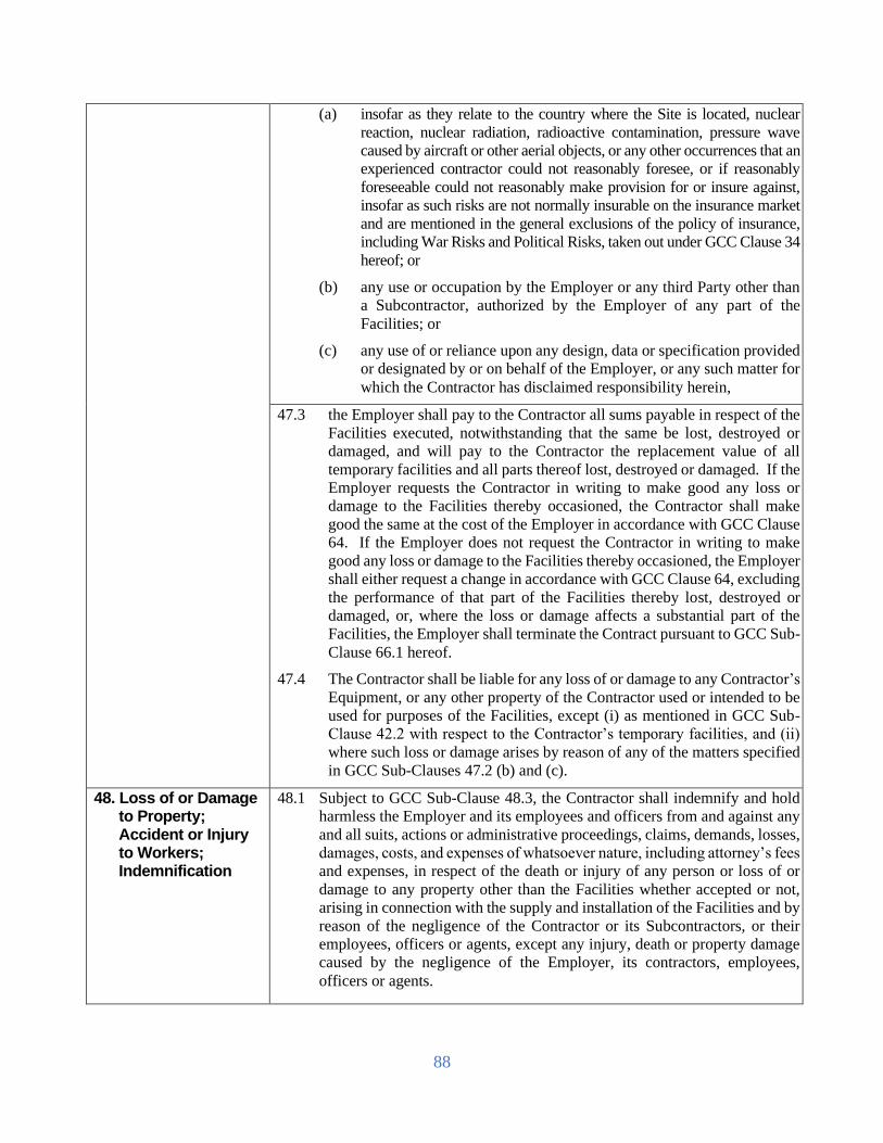
88
(a) insofar as they relate to the country where the Site is located, nuclear
reaction, nuclear radiation, radioactive contamination, pressure wave
caused by aircraft or other aerial objects, or any other occurrences that an
experienced contractor could not reasonably foresee, or if reasonably
foreseeable could not reasonably make provision for or insure against,
insofar as such risks are not normally insurable on the insurance market
and are mentioned in the general exclusions of the policy of insurance,
including War Risks and Political Risks, taken out under GCC Clause 34
hereof; or
(b) any use or occupation by the Employer or any third Party other than
a Subcontractor, authorized by the Employer of any part of the
Facilities; or
(c) any use of or reliance upon any design, data or specification provided
or designated by or on behalf of the Employer, or any such matter for
which the Contractor has disclaimed responsibility herein,
47.3 the Employer shall pay to the Contractor all sums payable in respect of the
Facilities executed, notwithstanding that the same be lost, destroyed or
damaged, and will pay to the Contractor the replacement value of all
temporary facilities and all parts thereof lost, destroyed or damaged. If the
Employer requests the Contractor in writing to make good any loss or
damage to the Facilities thereby occasioned, the Contractor shall make
good the same at the cost of the Employer in accordance with GCC Clause
64. If the Employer does not request the Contractor in writing to make
good any loss or damage to the Facilities thereby occasioned, the Employer
shall either request a change in accordance with GCC Clause 64, excluding
the performance of that part of the Facilities thereby lost, destroyed or
damaged, or, where the loss or damage affects a substantial part of the
Facilities, the Employer shall terminate the Contract pursuant to GCC Sub-
Clause 66.1 hereof.
47.4 The Contractor shall be liable for any loss of or damage to any Contractor’s
Equipment, or any other property of the Contractor used or intended to be
used for purposes of the Facilities, except (i) as mentioned in GCC Sub-
Clause 42.2 with respect to the Contractor’s temporary facilities, and (ii)
where such loss or damage arises by reason of any of the matters specified
in GCC Sub-Clauses 47.2 (b) and (c).
48. Loss of or Damage to Property; Accident or Injury to Workers; Indemnification
48.1 Subject to GCC Sub-Clause 48.3, the Contractor shall indemnify and hold
harmless the Employer and its employees and officers from and against any
and all suits, actions or administrative proceedings, claims, demands, losses,
damages, costs, and expenses of whatsoever nature, including attorney’s fees
and expenses, in respect of the death or injury of any person or loss of or
damage to any property other than the Facilities whether accepted or not,
arising in connection with the supply and installation of the Facilities and by
reason of the negligence of the Contractor or its Subcontractors, or their
employees, officers or agents, except any injury, death or property damage
caused by the negligence of the Employer, its contractors, employees,
officers or agents.

89
48.2 If any proceedings are brought or any claim is made against the Employer
that might subject the Contractor to liability under GCC Sub-Clause 48.1,
the Employer shall promptly give the Contractor a notice thereof and the
Contractor may at its own expense and in the Employer’s name conduct such
proceedings or claim and any negotiations for the settlement of any such
proceedings or claim.
48.3 If the Contractor fails to notify the Employer within twenty-eight (28) days
after receipt of such notice that it intends to conduct any such proceedings
or claim, then the Employer shall be free to conduct the same on its own
behalf. Unless the Contractor has so failed to notify the Employer within
the twenty-eight (28) day period, the Employer shall make no admission that
may be prejudicial to the defense of any such proceedings or claim.
The Employer shall, at the Contractor’s request, afford all available assistance to
the Contractor in conducting such proceedings or claim, and shall be
reimbursed by the Contractor for all reasonable expenses incurred in so
doing.
48.4 The Employer shall indemnify and hold harmless the Contractor and its
employees, officers and Subcontractors from any liability for loss of or
damage to property of the Employer, other than the Facilities not yet taken
over, that is caused by fire, explosion or any other perils, in excess of the
amount recoverable from insurances procured under GCC Clause 49,
provided that such fire, explosion or other perils were not caused by any act
or failure of the Contractor.
48.5 The Party entitled to the benefit of an indemnity under this GCC Clause 48
shall take all reasonable measures to mitigate any loss or damage which has
occurred. If the Party fails to take such measures, the other Party’s liabilities
shall be correspondingly reduced.
49. Insurance 49.1 To the extent specified in the Appendix to the Contract Agreement titled
Insurance Requirements, the Contractor shall at its expense take out and
maintain in effect, or cause to be taken out and maintained in effect, during
the performance of the Contract, the insurances set forth below in the sums
and with the deductibles and other conditions specified in the said
Appendix. The identity of the insurers and the form of the policies shall be
subject to the approval of the Employer, who should not unreasonably
withhold such approval.
(a) Cargo Insurance During Transport
Covering loss or damage occurring while in transit from the
Contractor’s or Subcontractor’s works or stores until arrival at the
Site, to the Plant (including spare parts therefor) and to the
Contractor’s Equipment.
(b) Installation All Risks Insurance
Covering physical loss or damage to the Facilities at the Site,
occurring prior to Completion of the Facilities, with extended
maintenance coverage for the Contractor’s liability in respect of any
loss or damage occurring during the Defect Liability Period while the

90
Contractor is on the Site for the purpose of performing its obligations
during the Defect Liability Period.
(c) Third Party Liability Insurance
Covering bodily injury or death suffered by third Parties including
the Employer’s personnel, and loss of or damage to property
occurring in connection with the supply and installation of the
Facilities.
(d) Automobile Liability Insurance
Covering use of all vehicles used by the Contractor or its
Subcontractors, whether or not owned by them, in connection with
the execution of the Contract.
(e) Workers’ Compensation
In accordance with the statutory requirements applicable in any
country where the Contract or any part thereof is executed.
(f) Employer’s Liability
In accordance with the statutory requirements applicable in any country
where the Contract or any part thereof is executed.
(g) Other Insurances
Such other insurances as may be specifically agreed upon by the
Parties hereto as listed in the Appendix to the Contract Agreement
titled Insurance Requirements.
49.2 The Employer shall be named as co-insured under all insurance policies
taken out by the Contractor pursuant to GCC Sub-Clause 49.1, except for
the Third Party Liability, Workers’ Compensation and Employer’s
Liability Insurances, and the Contractor’s Subcontractors shall be named
as co-insureds under all insurance policies taken out by the Contractor
pursuant to GCC Sub-Clause 49.1 except for the Cargo Insurance during
Transportation, Workers’ Compensation and Employer’s Liability
Insurances. All insurer’s rights of subrogation against such co-insureds
for losses or claims arising out of the performance of the Contract shall
be waived under such policies.
49.3 The Contractor shall, in accordance with the provisions of the Appendix
to the Contract Agreement titled Insurance Requirements, deliver to the
Employer certificates of insurance or copies of the insurance policies as
evidence that the required policies are in full force and effect. The
certificates shall provide that no less than twenty-one (21) days’ notice
shall be given to the Employer by insurers prior to cancellation or
material modification of a policy.
49.4 The Contractor shall ensure that, where applicable, its Subcontractor(s)
shall take out and maintain in effect adequate insurance policies for their
personnel and vehicles and for work executed by them under the
Contract, unless such Subcontractors are covered by the policies taken
out by the Contractor.
49.5 The Employer shall at its expense take out and maintain in effect during
the performance of the Contract those insurances specified in the
Appendix to the Contract Agreement titled Insurance Requirements, in
the sums and with the deductibles and other conditions specified in the
said Appendix. The Contractor and the Contractor’s Subcontractors shall

91
be named as co-insured under all such policies. All insurers’ rights of
subrogation against such co-insured for losses or claims arising out of the
performance of the Contract shall be waived under such policies. The
Employer shall deliver to the Contractor satisfactory evidence that the
required insurances are in full force and effect. The policies shall provide
that not less than twenty-one (21) days’ notice shall be given to the
Contractor by all insurers prior to any cancellation or material
modification of the policies. If so requested by the Contractor, the
Employer shall provide copies of the policies taken out by the Employer
under this GCC Sub-Clause 49.5.
49.6 If the Contractor fails to take out and/or maintain in effect the insurances
referred to in GCC Sub-Clause 49.1, the Employer may take out and
maintain in effect any such insurances and may from time to time deduct
from any amount due to the Contractor under the Contract any premium
that the Employer shall have paid to the insurer, or may otherwise recover
such amount as a debt due from the Contractor. If the Employer fails to
take out and/or maintain in effect the insurances referred to in GCC 49.5,
the Contractor may take out and maintain in effect any such insurances
and may from time to time deduct from any amount due the Employer
under the Contract any premium that the Contractor shall have paid to the
insurer, or may otherwise recover such amount as a debt due from the
Employer. If the Contractor fails to or is unable to take out and maintain
in effect any such insurances, the Contractor shall nevertheless have no
liability or responsibility towards the Employer, and the Contractor shall
have full recourse against the Employer for any and all liabilities of the
Employer herein.
49.7 Unless otherwise provided in the Contract, the Contractor shall prepare
and conduct all and any claims made under the policies affected by it
pursuant to this GCC Clause 49, and all monies payable by any insurers
shall be paid to the Contractor. The Employer shall give to the Contractor
all such reasonable assistance as may be required by the Contractor. With
respect to insurance claims in which the Employer’s interest is involved,
the Contractor shall not give any release or make any compromise with
the insurer without the prior written consent of the Employer. With
respect to insurance claims in which the Contractor’s interest is involved,
the Employer shall not give any release or make any compromise with
the insurer without the prior written consent of the Contractor.
50. Unforeseen Conditions
50.1 If, during the execution of the Contract, the Contractor shall encounter on
the Site any physical conditions other than climatic conditions, or
artificial obstructions that could not have been reasonably foreseen prior
to the date of the Contract Agreement by an experienced contractor on
the basis of reasonable examination of the data relating to the Facilities
including any data as to boring tests, provided by the Employer, and on
the basis of information that it could have obtained from a visual
inspection of the Site if access thereto was available, or other data readily
available to it relating to the Facilities, and if the Contractor determines
that it will in consequence of such conditions or obstructions incur
additional cost and expense or require additional time to perform its
obligations under the Contract that would not have been required if such

92
physical conditions or artificial obstructions had not been encountered,
the Contractor shall promptly, and before performing additional work or
using additional Plant or Contractor’s Equipment, notify the Project
Manager in writing beforehand:
(a the physical conditions or artificial obstructions on the Site that could
not have been reasonably foreseen;
(b) the additional work and/or Plant and/or Contractor’s Equipment
required, including the steps which the Contractor will or proposes
to take to overcome such conditions or obstructions;
(c) the extent of the anticipated delay; and
(d) the additional cost and expense that the Contractor is likely to incur.)
On receiving any notice from the Contractor under this GCC Sub-Clause
50.1, the Project Manager shall promptly consult with the Employer and
Contractor and decide upon the actions to be taken to overcome the
physical conditions or artificial obstructions encountered. Following such
consultations, the Project Manager shall instruct the Contractor, with a
copy to the Employer, of the actions to be taken.
50.2 Any reasonable additional cost and expense incurred by the Contractor in
following the instructions from the Project Manager to overcome such
physical conditions or artificial obstructions referred to in GCC Sub-
Clause 50.1 shall be paid by the Employer to the Contractor as an addition
to the Contract Price.
50.3 If the Contractor is delayed or impeded in the performance of the Contract
because of any such physical conditions or artificial obstructions referred
to in GCC Sub-Clause 50.1, the Time for Completion shall be extended
in accordance with GCC Clause 60.
51. Change in Laws and Regulation
51.1 Unless otherwise specified in the Contract, if after the Contract, any law,
regulation, ordinance, order or bylaw having the force of law is enacted,
promulgated, abrogated, or changed in Bangladesh (which shall be
deemed to include any change in interpretation or application by the
competent authorities) that subsequently affects the Delivery Date and/or
the Contract Price, then such Delivery Date and/or Contract Price shall
be correspondingly increased or decreased, to the extent that the Supplier
has thereby been affected in the performance of any of its obligations
under the Contract.
52. Force Majeure 52.1 In this Clause, “Force Majeure” means an exceptional event or circumstance:
(a) which is beyond a Party’s control;
(b) which such Party could not reasonably have provided against before
entering into the Contract;
(c) which, having arisen, such Party could not reasonably have avoided or
overcome; and
(d) which is not substantially attributable to the other Party.
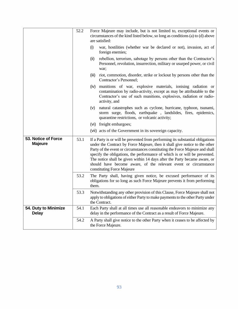
93
52.2 Force Majeure may include, but is not limited to, exceptional events or
circumstances of the kind listed below, so long as conditions (a) to (d) above
are satisfied:
(i) war, hostilities (whether war be declared or not), invasion, act of
foreign enemies;
(ii) rebellion, terrorism, sabotage by persons other than the Contractor’s
Personnel, revolution, insurrection, military or usurped power, or civil
war;
(iii) riot, commotion, disorder, strike or lockout by persons other than the
Contractor’s Personnel;
(iv) munitions of war, explosive materials, ionising radiation or
contamination by radio-activity, except as may be attributable to the
Contractor’s use of such munitions, explosives, radiation or radio-
activity, and
(v) natural catastrophes such as cyclone, hurricane, typhoon, tsunami,
storm surge, floods, earthquake , landslides, fires, epidemics,
quarantine restrictions, or volcanic activity;
(vi) freight embargoes;
(vii) acts of the Government in its sovereign capacity.
53. Notice of Force Majeure
53.1 If a Party is or will be prevented from performing its substantial obligations
under the Contract by Force Majeure, then it shall give notice to the other
Party of the event or circumstances constituting the Force Majeure and shall
specify the obligations, the performance of which is or will be prevented.
The notice shall be given within 14 days after the Party became aware, or
should have become aware, of the relevant event or circumstance
constituting Force Majeure
53.2 The Party shall, having given notice, be excused performance of its
obligations for so long as such Force Majeure prevents it from performing
them.
53.3 Notwithstanding any other provision of this Clause, Force Majeure shall not
apply to obligations of either Party to make payments to the other Party under
the Contract.
54. Duty to Minimize Delay
54.1 Each Party shall at all times use all reasonable endeavors to minimize any
delay in the performance of the Contract as a result of Force Majeure.
54.2 A Party shall give notice to the other Party when it ceases to be affected by
the Force Majeure.

94
55. Consequences of Force Majeure
55.1 The Contractor shall not be liable for forfeiture of its Performance
Security, liquidated damages, or termination for default if and to the
extent that it’s delay in performance or other failure to perform its
obligations under the Contract is the result of an event of Force Majeure:
55.2 The Employer may suspend the delivery or contract implementation,
wholly or partly, by written order for a certain period of time, as it deems
necessary due to force majeure as defined in the contract.
55.3 Delivery made either upon the lifting or the expiration of the suspension
order. However, if the Employer terminates the contract as stated under
GCC clause 66, resumption of delivery cannot be done.
55.4 The Employer determines the existence of a force majeure that will be
the basis of the issuance of suspension of order.
F. Payment
56. Contract Price 56.1 The Contract Price shall be paid as specified in the Contract Agreement
Form PG5A- 8.
56.2 Unless an adjustment clause is provided for in the PCC, the Contract Price
shall be a firm lump sum not subject to any alteration, except in the event
of a Change in the Facilities or as otherwise provided in the Contract.
56.3 Subject to GCC Sub-Clauses 25.2, 26.1 and 50 hereof, the Contractor shall
be deemed to have satisfied itself as to the correctness and sufficiency of
the Contract Price, which shall, except as otherwise provided for in the
Contract, cover all its obligations under the Contract.
56.4 Prices shall be adjusted for fluctuations in the cost of inputs only if provided
for in the PCC. If so provided, the amounts as certified in each payment
certificate, before deducting for Advance Payment, shall be adjusted by
applying the respective price adjustment factor to the payment amount. The
generic formula indicated below in the form as specified in the PCC
applies:
P= A + B (Im/Io)
where:
P is the adjustment factor
A and B are Coefficients specified in the PCC, representing the
nonadjustable and adjustable portions, respectively, of the Contract; and
Im is the Index during the month the work has been executed and Io is the
Index prevailing twenty eight (28) days prior to the deadline for submission
of Tender.
The Indexes to be used is as published by the Bangladesh Bureau of
Statistics (BBS) on a monthly basis. In case not available, then other
countries or authorities of the sources mentioned in Appendix to the
Tender may be used.
56.5 If the value of the Index is changed after it has been used in a calculation,
the calculation shall be corrected and an adjustment made in the next or in
the final payment certificate. The Index value shall be deemed to take
account of all changes in price due to fluctuations.

95
57. Terms of Payment 57.1 The Contract Price shall be paid as specified in the Contract Agreement and
in the Appendix to the Contract Agreement titled Terms and
Procedures of Payment, which also outlines the procedures to be followed
in making application for and processing payments.
57.2 No payment made by the Employer herein shall be deemed to constitute
acceptance by the Employer of the Facilities or any part(s) thereof.
57.3 In the event that the Employer fails to make any payment by its respective
due date or within the period set forth in the Contract, the Employer shall
pay to the Contractor interest on the amount of such delayed payment at the
rate(s) shown in the Appendices to the Contract Agreement titled Terms
and Procedures of Payment, for the period of delay until payment has been
made in full, whether before or after judgment or arbitrage award.
57.4 The currency or currencies in which payments are made to the Contractor
under this Contract shall be specified in the Appendices to the Contract
Agreement titled Terms and Procedures of Payment, subject to the general
principle that payments will be made in the currency or currencies in which
the Contract Price has been stated in the Contractor’s tender.
58. Advance Payment Security
58.1 The Contractor shall, within twenty-eight (28) days of the notification of
contract award, provide a security in an amount equal to the advance
payment calculated in accordance with the Appendix to the Contract
Agreement titled Terms and Procedures of Payment, and in the same
currency or currencies.
58.2 The security shall be in the form provided in the tender documents or in
another form acceptable to the Employer. The amount of the security shall
be reduced in proportion to the value of the Facilities executed by and paid
to the Contractor from time to time, and shall automatically become null
and void when the full amount of the advance payment has been recovered
by the Employer. The security shall be returned to the Contractor
immediately after its expiration.
59. Performance Security
59.1 The Contractor shall, within twenty-eight (28) days of the notification of
contract award, provide a security for the due performance of the Contract
in the amount specified in the PCC.
59.2 The performance security shall be denominated in the currency or
currencies of the Contract, or in a freely convertible currency acceptable to
the Employer, and shall be in the form provided in Section 5, Tender and
Contract Forms, corresponding to the type of bank guarantee stipulated by
the Employer in the PCC, or in another form acceptable to the Employer.
59.3 Unless otherwise specified in the PCC, the security shall be reduced by half
on the date of the Operational Acceptance. The Security shall become null
and void, or shall be reduced pro rata to the Contract Price of a part of the
Facilities for which a separate Time for Completion is provided, five
hundred and forty (540) days after Completion of the Facilities or three
hundred and sixty five (365) days after Operational Acceptance of the
Facilities, whichever occurs first; provided, however, that if the Defects
Liability Period has been extended on any part of the Facilities pursuant to
GCC Sub-Clause 42.8 hereof, the Contractor shall issue an additional
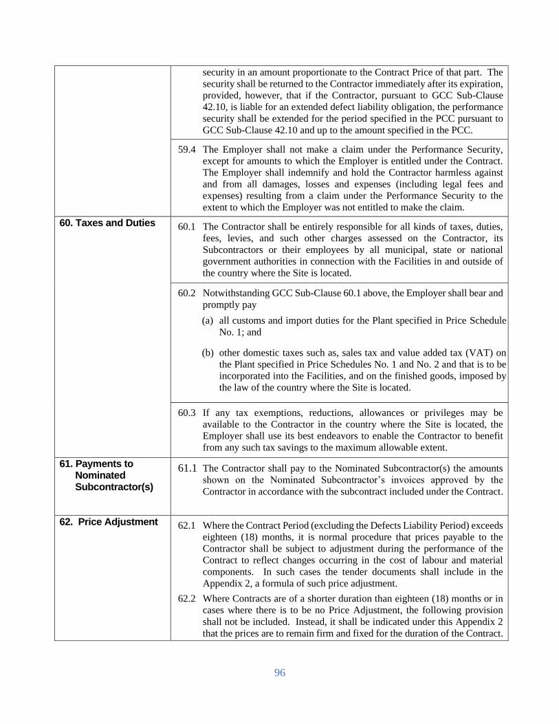
96
security in an amount proportionate to the Contract Price of that part. The
security shall be returned to the Contractor immediately after its expiration,
provided, however, that if the Contractor, pursuant to GCC Sub-Clause
42.10, is liable for an extended defect liability obligation, the performance
security shall be extended for the period specified in the PCC pursuant to
GCC Sub-Clause 42.10 and up to the amount specified in the PCC.
59.4 The Employer shall not make a claim under the Performance Security,
except for amounts to which the Employer is entitled under the Contract.
The Employer shall indemnify and hold the Contractor harmless against
and from all damages, losses and expenses (including legal fees and
expenses) resulting from a claim under the Performance Security to the
extent to which the Employer was not entitled to make the claim.
60. Taxes and Duties 60.1 The Contractor shall be entirely responsible for all kinds of taxes, duties,
fees, levies, and such other charges assessed on the Contractor, its
Subcontractors or their employees by all municipal, state or national
government authorities in connection with the Facilities in and outside of
the country where the Site is located.
60.2 Notwithstanding GCC Sub-Clause 60.1 above, the Employer shall bear and
promptly pay
(a) all customs and import duties for the Plant specified in Price Schedule
No. 1; and
(b) other domestic taxes such as, sales tax and value added tax (VAT) on
the Plant specified in Price Schedules No. 1 and No. 2 and that is to be
incorporated into the Facilities, and on the finished goods, imposed by
the law of the country where the Site is located.
60.3 If any tax exemptions, reductions, allowances or privileges may be
available to the Contractor in the country where the Site is located, the
Employer shall use its best endeavors to enable the Contractor to benefit
from any such tax savings to the maximum allowable extent.
61. Payments to Nominated Subcontractor(s)
61.1 The Contractor shall pay to the Nominated Subcontractor(s) the amounts
shown on the Nominated Subcontractor’s invoices approved by the
Contractor in accordance with the subcontract included under the Contract.
62. Price Adjustment 62.1 Where the Contract Period (excluding the Defects Liability Period) exceeds
eighteen (18) months, it is normal procedure that prices payable to the
Contractor shall be subject to adjustment during the performance of the
Contract to reflect changes occurring in the cost of labour and material
components. In such cases the tender documents shall include in the
Appendix 2, a formula of such price adjustment.
62.2 Where Contracts are of a shorter duration than eighteen (18) months or in
cases where there is to be no Price Adjustment, the following provision
shall not be included. Instead, it shall be indicated under this Appendix 2
that the prices are to remain firm and fixed for the duration of the Contract.

97
62.3 If the value of the Index is changed after it has been used in a calculation,
the calculation shall be corrected and an adjustment made in the next or in
the final payment certificate. The Index value shall be deemed to take
account of all changes in price due to fluctuations.
63. Liquidated Damages
63.1 The Contractor shall be liable to pay Liquidated Damages or in other
words the Delay Damages to the Employer at the rate per day as specified
in the PCC for each day of delay from the Intended Completion Date, for
the uncompleted delivery of goods/works/services or for any part thereof.
63.2 The total amount of Liquidated Damages shall not exceed the amount
defined in the PCC.
63.3 Once the cumulative amount of Liquidated Damages reaches ten (10)
percent of the Contract price, the Employer may rescind the Contract,
without prejudice to other courses of action and remedies open to it.
63.4 The amount of Liquidated Damages may be deducted from any money due
or which may become due to the Contractor under the Contract and/or
collect such amount of Liquidated Damages from the Retention Money (if
any) or other securities posted by the Contractor whichever is convenient
to the Employer. In an extreme situation that no such foregoing recourse is
available, the contractor be asked to make good the damages from his own
finances in writing failing which necessary action as per the provisions of
this GCC or PCC be taken.
63.5 Payment of Liquidated Damages by the Contractor shall not relieve the
Contractor from its obligations.
63.6 If the Intended Completion Date is extended after Liquidated Damages
have been paid, the Engineer shall correct any overpayment of Liquidated
Damages by the Contractor by adjusting the next payment certificate.
G. Change in Contract Elements
64. Change in the Facilities
64.1 Introducing a Change
64.1.1 Subject to GCC Sub-Clauses 64.2.5 and 64.2.7, the Employer
shall have the right to propose, and subsequently require, that the Project
Manager order the Contractor from time to time during the performance of
the Contract to make any change, modification, addition or deletion to, in
or from the Facilities hereinafter called “Change”, provided that such
Change falls within the general scope of the Facilities and does not
constitute unrelated work and that it is technically practicable, taking into
account both the state of advancement of the Facilities and the technical
compatibility of the Change envisaged with the nature of the Facilities as
specified in the Contract
64.1.2 The Contractor may from time to time during its performance of
the Contract propose to the Employer with a copy to the Project Manager,
any Change that the Contractor considers necessary or desirable to improve
the quality, efficiency or safety of the Facilities. The Employer may at its
discretion approve or reject any Change proposed by the Contractor,
provided that the Employer shall approve any Change proposed by the
Contractor to ensure the safety of the Facilities.

98
64.1.3 Notwithstanding GCC Sub-Clauses 64.1.1 and 64.1.2, no change
made necessary because of any default of the Contractor in the performance
of its obligations under the Contract shall be deemed to be a Change, and
such change shall not result in any adjustment of the Contract Price or the
Time for Completion.
64.1.4 The procedure on how to proceed with and execute Changes is
specified in GCC Sub-Clauses 64.2 and 64.3, and further details and forms
are provided in the Employer’s Requirements (Forms and Procedures).
64.2 Changes Originating from Employer
64.2.1 If the Employer proposes a Change pursuant to GCC Sub-Clause
64.1.1, it shall send to the Contractor a “Request for Change Proposal,”
requiring the Contractor to prepare and furnish to the Project Manager as
soon as reasonably practicable a “Change Proposal,” which shall include the
following:
(a) brief description of the Change
(b) effect on the Time for Completion
(c) estimated cost of the Change
(d) effect on Functional Guarantees (if any)
(e) effect on the Facilities
(f) effect on any other provisions of the Contract.
64.2.2 Prior to preparing and submitting the “Change Proposal,” the
Contractor shall submit to the Project Manager an “Estimate for Change
Proposal,” which shall be an estimate of the cost of preparing and submitting
the Change Proposal.
Upon receipt of the Contractor’s Estimate for Change Proposal, the
Employer shall do one of the following:
(a) accept the Contractor’s estimate with instructions to the Contractor to
proceed with the preparation of the Change Proposal
(b) advise the Contractor of any part of its Estimate for Change Proposal
that is unacceptable and request the Contractor to review its estimate
(c) advise the Contractor that the Employer does not intend to proceed
with the Change.
64.2.3 Upon receipt of the Employer’s instruction to proceed under GCC
Sub-Clause 64.2.2 (a), the Contractor shall, with proper expedition, proceed
with the preparation of the Change Proposal, in accordance with GCC Sub-
Clause 64.2.1.
64.2.4 The pricing of any Change shall, as far as practicable, be calculated
in accordance with the rates and prices included in the Contract. If such
rates and prices are inequitable, the Parties thereto shall agree on specific
rates for the valuation of the Change

99
.64.2.5 If before or during the preparation of the Change Proposal it
becomes apparent that the aggregate effect of compliance therewith and with
all other Change Orders that have already become binding upon the
Contractor under this GCC Clause 64 would be to increase or decrease the
Contract Price as originally set forth in Article 2 (Contract Price) of the
Contract Agreement by more than fifteen percent (15%), the Contractor may
give a written notice of objection thereto prior to furnishing the Change
Proposal as aforesaid. If the Employer accepts the Contractor’s objection,
the Employer shall withdraw the proposed Change and shall notify the
Contractor in writing thereof.
The Contractor’s failure to so object shall neither affect its right to object to
any subsequent requested Changes or Change Orders herein, nor affect its
right to take into account, when making such subsequent objection, the
percentage increase or decrease in the Contract Price that any Change not
objected to by the Contractor represents.
64.2.6 Upon receipt of the Change Proposal, the Employer and the
Contractor shall mutually agree upon all matters therein contained. Within
fourteen (14) days after such agreement, the Employer shall, if it intends to
proceed with the Change, issue the Contractor with a Change Order.
If the Employer is unable to reach a decision within fourteen (14) days, it
shall notify the Contractor with details of when the Contractor can expect a
decision.
If the Employer decides not to proceed with the Change for whatever reason,
it shall, within the said period of fourteen (14) days, notify the Contractor
accordingly. Under such circumstances, the Contractor shall be entitled to
reimbursement of all costs reasonably incurred by it in the preparation of the
Change Proposal, provided that these do not exceed the amount given by the
Contractor in its Estimate for Change Proposal submitted in accordance with
GCC Sub-Clause 64.2.2.
64.2.7 If the Employer and the Contractor cannot reach agreement on the
price for the Change, an equitable adjustment to the Time for Completion,
or any other matters identified in the Change Proposal, the Employer may
nevertheless instruct the Contractor to proceed with the Change by issue of
a “Pending Agreement Change Order.”
Upon receipt of a Pending Agreement Change Order, the Contractor shall
immediately proceed with effecting the Changes covered by such Order.
The Parties shall thereafter attempt to reach agreement on the outstanding
issues under the Change Proposal.

100
64.3 Changes Originating from Contractor
64.3.1 If the Contractor proposes a Change pursuant to GCC Sub-Clause
64.1.2, the Contractor shall submit to the Project Manager a written
“Application for Change Proposal,” giving reasons for the
proposed Change and including the information specified in GCC
Sub-Clause 64.2.1.
Upon receipt of the Application for Change Proposal, the Parties
shall follow the procedures outlined in GCC Sub-Clauses 64.2.6
and
64.3.2. However, should the Employer choose not to proceed, the
Contractor shall not be entitled to recover the costs of preparing the
Application for Change Proposal.
65. Extension of Time for Completion
65.1 The Time(s) for Completion specified in the PCC pursuant to GCC Sub-
Clause 8.2 shall be extended if the Contractor is delayed or impeded in the
performance of any of its obligations under the Contract by reason of any
of the following:
(a) any Change in the Facilities as provided in GCC Clause 64
(b) any occurrence of Force Majeure as provided in GCC Clause 52,
unforeseen conditions as provided in GCC Clause 50, or other
occurrence of any of the matters specified or referred to in paragraphs
(a), (b) and (c) of GCC Sub-Clause 47.2
(c) any suspension order given by the Employer under GCC Clause 41
hereof or reduction in the rate of progress pursuant to GCC Sub-
Clause 66.2 or
(d) any changes in laws and regulations as provided in GCC Clause 51
or
(e) any default or breach of the Contract by the Employer, Appendix to
the Contract Agreement titled ,or any activity, act or omission of the
Employer, or the Project Manager, or any other contractors employed
by the Employer, or
(f) any delay on the part of a sub-contractor, provided such delay is due
to a cause for which the Contractor himself would have been entitled
to an extension of time under this sub-clause, or
(g) delays attributable to the Employer or caused by customs, or
(h) any other matter specifically mentioned in the Contract
by such period as shall be fair and reasonable in all the circumstances and
as shall fairly reflect the delay or impediment sustained by the Contractor.

101
65.2 Except where otherwise specifically provided in the Contract, the Contractor
shall submit to the Project Manager a notice of a claim for an extension of
the Time for Completion, together with particulars of the event or
circumstance justifying such extension as soon as reasonably practicable
after the commencement of such event or circumstance. As soon as
reasonably practicable after receipt of such notice and supporting particulars
of the claim, the Employer and the Contractor shall agree upon the period of
such extension. The Contractor shall at all times use its reasonable
efforts to minimize any delay in the performance of its obligations under the
Contract.
In all cases where the Contractor has given a notice of a claim for an extension of
time under GCC 65.2, the Contractor shall consult with the Project Manager
in order to determine the steps (if any) which can be taken to overcome or
minimize the actual or anticipated delay. The Contractor shall there after
comply with all reasonable instructions which the Project Manager shall give
in order to minimize such delay. If compliance with such instructions shall
cause the Contractor to incur extra costs and the Contractor is entitled to an
extension of time under GCC 65.1, the amount of such extra costs shall be
added to the Contract Price.
66. Suspension 66.1 The Employer may request the Project Manager, by notice to the Contractor,
to order the Contractor to suspend performance of any or all of its
obligations under the Contract. Such notice shall specify the obligation of
which performance is to be suspended, the effective date of the suspension
and the reasons thereof. The Contractor shall thereupon suspend
performance of such obligation, except those obligations necessary for the
care or preservation of the Facilities, until ordered in writing to resume such
performance by the Project Manager..
If, by virtue of a suspension order given by the Project Manager, other than
by reason of the Contractor’s default or breach of the Contract, the
Contractor’s performance of any of its obligations is suspended for an
aggregate period of more than ninety (90) days, then at any time thereafter
and provided that at that time such performance is still suspended, the
Contractor may give a notice to the Project Manager requiring that the
Employer shall, within twenty-eight (28) days of receipt of the notice, order
the resumption of such performance or request and subsequently order a
change in accordance with GCC Clause 64, excluding the performance of
the suspended obligations from the Contract.
If the Employer fails to do so within such period, the Contractor may, by a
further notice to the Project Manager, elect to treat the suspension, where it
affects a part only of the Facilities, as a deletion of such part in accordance
with GCC Clause 64 or, where it affects the whole of the Facilities, as
termination of the Contract under GCC Sub-Clause 66.1.
66.2 if

102
(a) the Employer has failed to pay the Contractor any sum due under the
Contract within the specified period, has failed to approve any invoice or
supporting documents without just cause pursuant to the Appendix to the
Contract Agreement titled Terms and Procedures of Payment, or commits
a substantial breach of the Contract, the Contractor may give a notice to the
Employer that requires payment of such sum, with interest thereon as
stipulated in GCC Sub-Clause 57.3, requires approval of such invoice or
supporting documents, or specifies the breach and requires the Employer
to remedy the same, as the case may be. If the Employer fails to pay such
sum together with such interest, fails to approve such invoice or supporting
documents or give its reasons for withholding such approval, or fails to
remedy the breach or take steps to remedy the breach within fourteen (14)
days after receipt of the Contractor’s notice or
(b) the Contractor is unable to carry out any of its obligations under the
Contract for any reason attributable to the Employer, including but not
limited to the Employer’s failure to provide possession of or access to the
Site or other areas in accordance with GCC Sub-Clause 25.2, or failure to
obtain any governmental permit necessary for the execution and/or
completion of the Facilities,
then the Contractor may by fourteen (14) days’ notice to the Employer
suspend performance of all or any of its obligations under the Contract, or
reduce the rate of progress.
66.3 If the Contractor’s performance of its obligations is suspended or the rate
of progress is reduced pursuant to this GCC Clause 66, then the Time for
Completion shall be extended in accordance with GCC Sub-Clause 40.1,
and any and all additional costs or expenses incurred by the Contractor as
a result of such suspension or reduction shall be paid by the Employer to
the Contractor in addition to the Contract Price, except in the case of
suspension order or reduction in the rate of progress by reason of the
Contractor’s default or breach of the Contract.
66.4 During the period of suspension, the Contractor shall not remove from the
Site any Plant, any part of the Facilities or any Contractor’s Equipment,
without the prior written consent of the Employer.
H. Termination and Settlement of Disputes
67. Termination 67.1 Termination for Default
(a) The Employer or the Contractor, without prejudice to any other
remedy for breach of Contract, by giving twenty eight (28) days
written notice of default to the other party, may terminate the
Contract in whole or in part if the other party causes a fundamental
breach of Contract.
(b) Fundamental breaches of the Contract shall include, but shall not be
limited to, the following:

103
(i) the Contractor stops work for twenty-eight (28) days when no
stoppage of work is shown on the current Programme and the
stoppage has not been authorized by the Engineer;
(ii) the Engineer instructs the Contractor to delay the progress of the
Works, and the instruction is not withdrawn within twenty-eight
(28) days;
(iii) the Engineer gives Notice that failure to correct a particular
Defect is a fundamental breach of Contract and the Contractor
fails to correct it within a reasonable period of time determined
by the Engineer;
(iv) the Engineer gives Notice that the failure to achieve the progress
in accordance with the updated Programme of Works by the
Contractor is a non-fulfilment of contractual obligations and the
Contractor fails to restore it within a reasonable period of time
instructed by the Engineer;
(v) the Contractor does not maintain a Security, which is required;
(vi) the Contractor has delayed the completion of the Works by the
number of days for which the maximum amount of Liquidated
Damages can be paid, as specified in GCC Sub Clause 41.2;
(vii) the Contractor has subcontracted the whole of the Works or has
assigned the Contract without the required agreement and
without the approval of the Engineer;
(viii) the Contractor, in the judgment of the Employer has engaged in
practices, as defined in GCC Sub Clause 39, in competing for or
in executing the Contract.
(c) A payment certified by the Engineer is not paid by the Employer to
the Contractor within twenty eight (28) days of the date of the
Engineer’s certificate.
67.2 Termination for Insolvency
The Employer and the Contractor may at any time terminate the
Contract by giving twenty eight (28) days written notice to the other
party if either of the party becomes bankrupt or otherwise insolvent.
In such event, termination will be without compensation to any party,
provided that such termination will not prejudice or affect any right
of action or remedy that has accrued or will accrue thereafter to the
other party.
67.3 Termination for Convenience
(a) The Employer, by giving twenty eight (28) days written notice sent
to the Contractor, may terminate the Contract, in whole or in part, at any
time for its convenience. The notice of termination shall specify that
termination is for the Employer’s convenience, the extent to which
performance of the Contractor under the Contract is terminated, and the
date upon which such termination becomes effective. The termination
shall take effect twenty eight (28) days after the later dates on which the

104
Contractor receives this notice or the Employer returns the Performance
Security.
(b) The Employer shall not terminate the contract under GCC Sub
Clause 67.1 (a) in order to execute the contract itself or to arrange for the
Works to be executed by another contractor or to avoid a termination of
the Contract by the Contractor as stated under GCC Sub Clause 67.1(a).
67.4 In the event the Employer terminates the Contract in whole or in part, the
Employer shall accept the portion of the Works that are complete and
ready for handing over after the Contractor’s receipt of notice of
termination of the Contract. For the remaining portion of the Works, the
Employer may elect:
(a) to have any portion completed by the Contractor at the Contract
terms and prices; and /or
(b) to cancel the remainder and pay to the Contractor an agreed amount
for partially completed Works and for materials and parts previously
procured by the Contractor, or
(c) except in the case of termination for convenience as stated under
GCC Sub Clause 67, engage another Contractor to complete the
Works, and in that case the Contractor shall be liable to the
Employer for any cost that may be incurred in excess of the sum that
would have been paid to the Contractor, if the work would have been
executed and completed by him or her.
67.5 If the Contract is terminated, the Contractor shall stop work immediately,
make the Site safe and secure, and leave the Site as soon as is reasonably
possible
68. Payment upon Termination
68.1 If the Contract is terminated because of a fundamental breach of Contract
under GCC Sub Clause 67.1 by the Contractor, the Project Manager shall
issue a certificate for the value of the Works done and Plant and Materials
ordered less advance payments received up to the date of the issue of the
certificate and less the amount from percentage to apply to the contract
value of the works not completed, as indicated in the PCC. If the total
amount due to the Employer exceeds any payment due to the Contractor,
the difference shall be a debt payable to the Employer.
68.2 If the Contract is terminated for the Employer’s convenience or because
of a fundamental breach of Contract by the Employer, the Project Manager
shall issue a payment certificate for the value of the work done, Materials
ordered, the reasonable cost of removal of Equipment, repatriation of the
Contractor’s foreign personnel employed solely on the Works and
recruited specifically for the Works, and the Contractor’s costs of
protecting and securing the Works, and less advance payments received
up to the date of the certificate.
68.3 If the Contract is terminated for reasons of Force Majeure, the The Project
Manager shall determine the value of the work done and issue a Payment
Certificate which shall include.

105
(a) the amounts payable for any work carried out for which unit rates
or prices are stated in the Contract;
(b) the cost of Plant and Materials ordered for the Works which have
been delivered to the Contractor, or of which the Contractor is
liable to accept delivery: this Plant and Materials shall become the
property of (and be at the risk of) the Employer when paid for by
the Employer, and the Contractor shall place the same at the
Employer’s disposal;
(c) other costs or liabilities which in the circumstances were
reasonably and necessarily incurred by the Contractor in the
expectation of completing the Works;
(d) the cost of removal of Temporary Works and Contractor’s
Equipment from the Site; and
(e) the cost of repatriation of the Contractor’s staff and labor employed
wholly in connection with the Works at the date of termination.
69. Property 69.1 All Materials on the Site, Plant, Equipment, Temporary Works, and
Works shall be deemed to be the property of the Employer if the Contract
is terminated because of the Contractor’s default stated under GCC Sub
Clause 67.1.
70. Frustration 70.1 If the Contract is frustrated by the occurrence of a situation of Force
Majeure as defined in GCC Sub Clause 52, the Engineer shall certify that
the Contract has been frustrated. The Contractor shall make the Site safe
and stop work as quickly as possible after receiving this certificate and
shall be paid for all works carried out before receiving it and for any work
carried out afterwards to which a commitment was made.
I. Claims, Disputes and Arbitration
71. Contractor’s Claims 71.1 If the Contractor considers himself to be entitled to any extension of the
Completion Time and/or any additional payment, under any Clause of
these Conditions or otherwise in connection with the Contract, the
Contractor shall give notice to the Employer, describing the event or
circumstance giving rise to the claim. The notice shall be given as soon as
practicable, and not later than twenty eight (28) days after the Contractor
became aware, or should have become aware, of the event or
circumstance.
71.2 If the Contractor fails to give notice of a claim within such period of twenty
eight (28) days, the Intended Completion Date shall not be extended, the
Contractor shall not be entitled to additional payment, and the Employer
shall be discharged from all liability in connection with the claim.
71.3 Within forty two (42) days after the Contractor became aware or should
have become aware of the event or circumstance giving rise to the claim,
or within such other period as may be proposed by the Contractor and
approved by the Engineer, the Contractor shall send to the Engineer a fully
detailed claim which includes full supporting particulars of the basis of the
claim and of the extension of time and/or additional payment claimed, for
settlement.

106
72. Settlement of Disputes
Amicable settlement
72.1 The Employer and the Contractor shall make every effort to resolve
amicably by direct informal negotiation any disagreement or dispute
arising between them under or in connection with the Contract.
Arbitration
72.2 If, after twenty-eight (28) days, the parties have failed to resolve their
dispute or difference by such mutual consultation as stated under GCC
Clause 72.1, then either the Employer or the Contractor may give notice to
the other party of its intention to commence arbitration in accordance with
GCC Sub Clause 72.3, as to the matter in dispute, and no arbitration in
respect of this matter may be commenced unless such notice is given. Any
dispute or difference in respect of which a notice of intention to commence
arbitration has been given in accordance with this Clause shall be finally
settled by arbitration.
72.3 Arbitration shall be commenced prior to or after execution of the Works
under the Contract. Arbitration proceedings shall be conducted in
accordance with the rules of procedure specified in the PCC.
72.4 Notwithstanding any reference to arbitration hereinabove the parties shall
continue to perform their respective responsibilities under the Contract
unless agreed otherwise and, the Employer shall pay any monies due to the
Contractor.

107
Section 4. Particular Conditions of Contract
Instructions for completing the Particular Conditions of Contract are provided in italics in parenthesis for the relevant GCC
Clauses.
GCC
Clause
Amendments of, and Supplements to, Clauses in the General Conditions of Contract
GCC 1.1(j) The Contractor is
[Name, address, and name of authorized representative]
GCC 1.1(ll) The Purchaser is: Md. Fahim Uddin
Senior System Analyst, ICT Directorate
Bangladesh Rural Electrification Board,
5th floor, BREB HQ Building,
Nikunja-2, Khilkhet, City: Dhaka-1229, Country: Bangladesh.
Tel: +8802-8900513
E-email: [email protected]
GCC
1.1(oo)
The Site is located at: BREB HQ, Disaster Recovery (employer will confirm the location) and
17 PBS as per scope.
GCC 3.1 The Procuring Entity’s address for the purpose of communications under this contract is :
Contact person: Md. Fahim Uddin
Senior System Analyst, ICT Directorate
Bangladesh Rural Electrification Board,
5th floor, BREB HQ Building,
Nikunja-2, Khilkhet, City: Dhaka-1229, Country: Bangladesh.
Tel: +8802-8900513
E-email: [email protected]
The Contractor’s address for the purpose of communications under this contract is :
Contact person:
Address:
Tel:
Fax:
e-mail address:
GCC 6.1 (k) Other documents forming part of the Contract are;

108
Any other Clarification and Confirmation given by tenderer/supplier if required.
Additional Conditions of Particular Application in this schedule, Schedule of other
contract's, Schedule of Key Personnel, Site Investigation Reports, relevant
correspondences prior to signing of the Contract agreement etc.
GCC 9.2 Materials, Equipment Plants and supplies shall not have their origin in the following countries: Israel
GCC 13.1
The Site is located at: BREB HQ, Disaster Recovery (employer will confirm the location) and
17 PBS as per scope. The Contractor shall take all initiatives to take over the site by
communication with the concern department and the employer will assist the tenderer in this
regard.
GCC 22.3 The Contractor shall have to supply the required Spare parts of that contract
works if employer desires for a period of Three years
GCC 23.1 Commencement Date shall be from the date of signing of the contract.
GCC 24.1 The time for completion of the whole of the facilities is within 2 years from the date
of signing of the contract.
GCC 32.1 A Subcontractor that is a national of, or registered in, the following countries are not eligible: Not applicable
GCC 33.1 Nominated Subcontractor(s) named below;
Not applicable
shall be entitled to execute the following specific components of the Works
Not applicable
GCC 38.2 For Lot-1:
i) For Smart meter (1 phase, 3 phase LT), HHU, UPS and MDM FAT/PSI will be
conducted by 05 Engineers from BREB/PBS for minimum 05 days.
ii) For DCU, Repeater, Gateway, RF Module and HES FAT/PSI will be conducted by
05 Engineers from BREB/PBS for minimum 05 days.
iii) For, all server, Networking Device, Printer, Barcode Scanner, FAT/PSI will be
conducted by 05 Engineers from BREB/PBS for minimum 05 days.
iv) Under any circumstances if the FAT/PSI will not occur then the quoted price
against FAT/PSI will deducted from the tender price. But a virtual FAT/PSI have
to be performed confirming the best practice.
v) In case of equipments from employer’s country, FAT/PSI will be attended
by BREB employee and in case of equipments from abroad a third party will
attend FAT/PSI as mandatory participant and BREB employee will attend if
situation allows. BREB will pay for all FAT/PSI cost. For Lot-2:
vi) For Smart meter (3 phase), FAT/PSI will be conducted by third party PSI agent or
03 Engineers from BREB/PBS for minimum 05 days.
vii) Under any circumstances if the FAT/PSI will not occur then the quoted price
against FAT will be deducted from the tender price. But a virtual FAT/PSI have to
be performed confirming the best practice.

109
viii) In case of equipments from employer’s country, FAT/PSI will be attended
by BREB employee and in case of equipments from abroad a third party will
attend FAT/PSI as mandatory participant and BREB employee will attend if
situation allows. BREB will pay for all FAT/PSI cost.
GCC 40.2.2 The Guarantee Test of the Facilities shall be successfully completed within 30 days from
the date of Completion.
GCC 40.3.1 Operational Acceptance:
Operational Acceptance shall occur in respect of Facilities or any part thereof when
a). the Guarantee Test has been successfully completed and the Functional Guarantee are
met; or
b). the Guarantee Test has not been successfully completed or has not been carried out for
reasons not attributable to the Contractor within the period from the date of Completion or
any other agreed upon period as specified in GCC Sub- Clause 40.2.2 or
c). the Contractor has paid the liquidated damages specified in GCC clause 63; and
d). any minor items mentioned in GCC Sub-Clause 39.9 hereof relevant to the Facilities or
that part thereof have been completed; and
e. the system is successfully running for 3 months from commissioning date.
GCC 41.3 No bonus will be given for earlier Completion of the Facilities or part thereof.
GCC 42.2 The Defect Liability Period shall be 36 months from the date of acceptance.
GCC 42.3 The amount to be withheld for late submission of an updated Programme is: Not Applicable.
GCC 42.10 The critical components covered under the extended defect liability are: 36 months
from the date acceptance.
GCC 45.1
(b)
The multiplier of the Contract Price is: Not Applicable.
[insert amount] and/or
GCC 56.2 The Contract Price shall be adjusted in accordance with the provisions of the Appendix to
the Contract Agreement titled Adjustment Clause: Not applicable for this tender
GCC 59.3.1 The amount of performance security, as a percentage of the Contract Price for the Facility
or for the part of the Facility for which a separate Time for Completion is provided, shall
be 10% of contract price for the period of 60 months.
GCC 59.3.3 The performance security shall not be reduced on the date of the Operational Acceptance.
GCC 59.3.3 The performance security shall be submitted ten percent (10%) of the value of the
component covered by the extended defect liability to cover the Contractor’s extended
defect liability in accordance with the provision in the GCC Sub-Clause 42.10.
eappropriatnot delete
R/JPYUSD/GBP/EUeappropriatnotifdelete
BDT

110
GCC 60.1
& 60.2
The Contractor shall be entirely responsible for all kinds of taxes, duties, fees,
levies, and such other charges.
If payment to the contractor is made in Bangladeshi taka, VAT, IT etc. shall be
deducted from the payment as per Govt. policy of Bangladesh.
GCC 62.1 Not Applicable.
GCC 63.1 The amount of Liquidated Damages is 0.075 of ONE (1) percent of the contract value of the
uncompleted works or any part there of completed after expiry of the Intended Completion
Date or extended Intended Completion Date, as applicable, per day of delay.
GCC 63.2 The maximum amount of Liquidated Damages for the uncompleted Works or any part thereof
is 10% (ten) percent of the final Contract Price of the whole of the Works.
GCC 72.2 The arbitration shall be conducted in accordance with the Arbitration Act (Act No
1 of 2001) of Bangladesh as at present in force and the place of arbitration will be
Dhaka, Bangladesh.

111
SECTION 4: PART -III- (LABOUR LAWS)
1. LABOUR LAW
Bangladesh Labour Law shall be applicable for this tender.
Appendix to the Tender
[In Tables below, the Procuring Entity shall indicate the source and base values with
dates of Indexes, unless otherwise instructed to be quoted by the Tenderer, for the
different Cost Components and mention its Weightings or Coefficients]
Table 1.1: Price Adjustment Data – N/A
[ ITT Sub Clause 26.9: To be provided by the Procuring Entity]
Index Descriptions Base Value Sources of Index
Note:
1. The sources of Indexes and its values with dates shall be Bangladesh Bureau of Statistics
(BBS) unless otherwise mentioned by the Procuring Entity or instructed to be quoted by the
Tenderer.
2. The Procuring Entity may require the Tenderer to justify its proposed Indexes, if quoted by
the Tenderer.
3. The Base Value of the Indexes shall be those prevailing twenty eight (28) days prior to the
deadline for submission of the Tenders.

112
Table 1.2: Price Adjustment Data – N/A
[ GCC Sub Clause 56.4: To be provided by the Procuring Entity]
Item
Group
Bill No. if
applicable
Index
Descriptions
Coefficients or
Weightings for
non-adjustable
Cost Component
Coefficients or Weightings for adjustable
Cost Components
Total
a b c d e f g h i j
1
1
1
1
1
1
Note:
The Weightings or Coefficients of the Cost Components shall be mentioned by the Procuring Entity based on
the proportion of components involved in the items caused to be impacted by rise and fall in its prices.

113
APPENDICES [This appendix shall be the part of the contract]
Appendix 1 - Terms and Procedures of Payment
Appendix 2 - Price Adjustment
Appendix 3 - Insurance Requirements
Appendix 4 - Time Schedule
Appendix 5 - List of Major Items of Plant and services and List of Approved Subcontractors
Appendix 6 - Scope of Works and Supply by the Employer
Appendix 7 - List of Documents for Approval or Review
Appendix 8 - Functional Guarantees

114
Appendix 1. Terms and Procedures of Payment
For Lot-1:
(A) Payment for Goods and Services supplied from Bangladesh:
Local Currency Payment for supply of goods, Installation, Testing, Commissioning and related
service shall be made in BDT in the following manner.
(i) 80% (Eighty percent) of the contract price for supply of goods, installation, testing and
commissioning shall be paid on submission of invoice on actual progress duly certified by
engineer and passed for payment by employers. The milestone payments will be completed
within 5(Five) installments.
(ii) 10% (Ten percent) of the contract price for supply of goods, installation, testing &
commissioning and after hand over the system shall be paid after installation, testing and
commissioning of smart pre-payment metering system on submission of documents of
provisional reports of completion and successful commissioning of smart pre-payment
metering system.
(iii) Final 10% (Ten percent) of the Contract Price for supply of goods, installation, testing and
commissioning of Smart Pre-payment Metering System shall be paid within 45 (Forty-Five)
days after submission of invoice certified by respective office of the client upon final
acceptance certificate (FAC).
(B) Payment for supply of Software, Networks, license and other Services:
Payment for supply of this part of shall be made in BDT in the following manner:
(i) 30% (thirty percent) of the contract price for this part(B) shall be paid based on installation
of all software(developed) and networks certified by the engineer.
(ii) 30% (thirty percent) of the contract price for this part(B) shall be paid after installation,
testing, commissioning and handover with submission of provisional completion report
certified by the engineer.
(iii) 30% (thirty percent) of the contract price of this part(B) shall be paid based on monitoring the
overall field operation performance for 6 months from the date of commissioning and the invoice certified
by the engineer for payment.
(iv) Final 10% (Ten percent) of the contract price for this portion shall be paid after submission
of invoice certified by the Engineer upon final acceptance certificate (FAC).

115
For Lot-2:
(A) Terms of Payment
Schedule No. 1 - For design & drawing, supply materials & equipment’s and installation with
testing & commissioning works.
Schedule No. 2 - For Recommended Spare Parts (Contractor shall recommend with all the
details).
In respect of plant and equipment supplied from within the Employer’s country/abroad, the
following payments shall be made:
I. Fifty percent (50%) of the total or pro rata Progress amount after PLI (Post delivery
inspection).
II. Forty (40%) of the total or pro rata Progress amount upon installation and commissioning
of the equipment.
III. Ten percent (10%) of the total or pro rata Progress amount upon issue of the Operational
Acceptance Certificate, within Ninety (90) days after receipt of invoice.
1.1 Payment Procedures (for both Lot-1& Lot-2)
The procedures to be followed in applying for certification and making payments shall be as follows:
1. All costs in connection with invoice and document within Bangladesh/Employer’s country
shall borne by the Employer and outside of the Bangladesh/Employer’s country shall be
borne by the Contractor but tenderer shall be paid as per quoted price by the employer.
2. Cost of contract Price will be paid by the Employer’s designated Bank.
3. The retention money shall be deducted @ ten (10) percent from the successful Tenderer’s
payable invoices during contract implementation, if awarded the contract. (retention money
shall be 10% from each Billing amount.)
4. 10% money shall be retained for defect liability period either from retention money or from
PG, it might be from both sources as per decision of the employer.
5. Invoices will be submitted to the project director by the contractor along with the following
documents:
a. Invoice – 04 nos. (1 original & 3 copies)
b. Packing list – 04 nos. (1 original & 3 copies)
c. Inspection report
d. Acceptance certificate
e. Insurance certificate
f. Warranty certificate
g. Origin and Source certificate
Bill will be certified by the office of the Project Director and payment will be made by the
Director of Accounts/Project Director of BREB. In case of 10% retention money, bill will be pre-
audited by the Directorate of Internal Audit, BREB.

116
Appendix 2. Price Adjustment (Not Applicable)
Prices payable to the Contractor, in accordance with the Contract, shall be subject to adjustment
during performance of the Contract to reflect changes in the cost of labor and material components,
in accordance with the following formula:
The Contract is subject to price adjustment applying the following formulae and the weightings or
coefficients:
[Price Adjustment Formulae to be applicable if stated under ITT Sub Clause 26.9 shall be specified here]
Example:
P= A + a (Lm/Lo)+ b (BIm/BIo)+ c (CEm/CEo)+ d (RSm/RSo)+ e (STm/STo)+ f (BRm/BRo)+g (MIm/MIo) + h
(FUm/FUo)+ etc
where;
L= Labor, BI=Bitumen, CE=Cement, RS=Reinforcing Steel, ST=Stone, BR=Bricks, MI=Miscellaneous, FU= Fuel ]
Weighting or Coefficient A equals between 0.10 and 0.15 and, B (a+b+c+d+e+f+g+h+etc) equals between 0.90 and 0.85.
[insert figure] non-adjustable component (coefficient A)
[insert figure] adjustable component (coefficient B)
[The sum of A+B shall equal ONE (1). It is usual to have value of A between 0.10 and 0.15 and that of B between
0.90 and 0.85. Breakdown of Bshall be provided in Appendix to the Tender.]
[delete as appropriate]
The date of adjustment shall be the mid-point of the period of manufacture or installation of
component or Plant.
The following conditions shall apply:
(a) No price increase will be allowed beyond the original delivery date unless covered by an
extension of time awarded by the Employer under the terms of the Contract. No price increase
will be allowed for periods of delay for which the Contractor is responsible. The Employer
will, however, be entitled to any price decrease occurring during such periods of delay.
(c) No price adjustment shall be payable on the portion of the Contract price paid to the
Contractor as an advance payment.
For complex plant supply and installation involving several sources of supply and/or a substantial
amount of installation works, a family of formulas may be necessary, with provision for the usage
of Contractor’s equipment in the works formula.
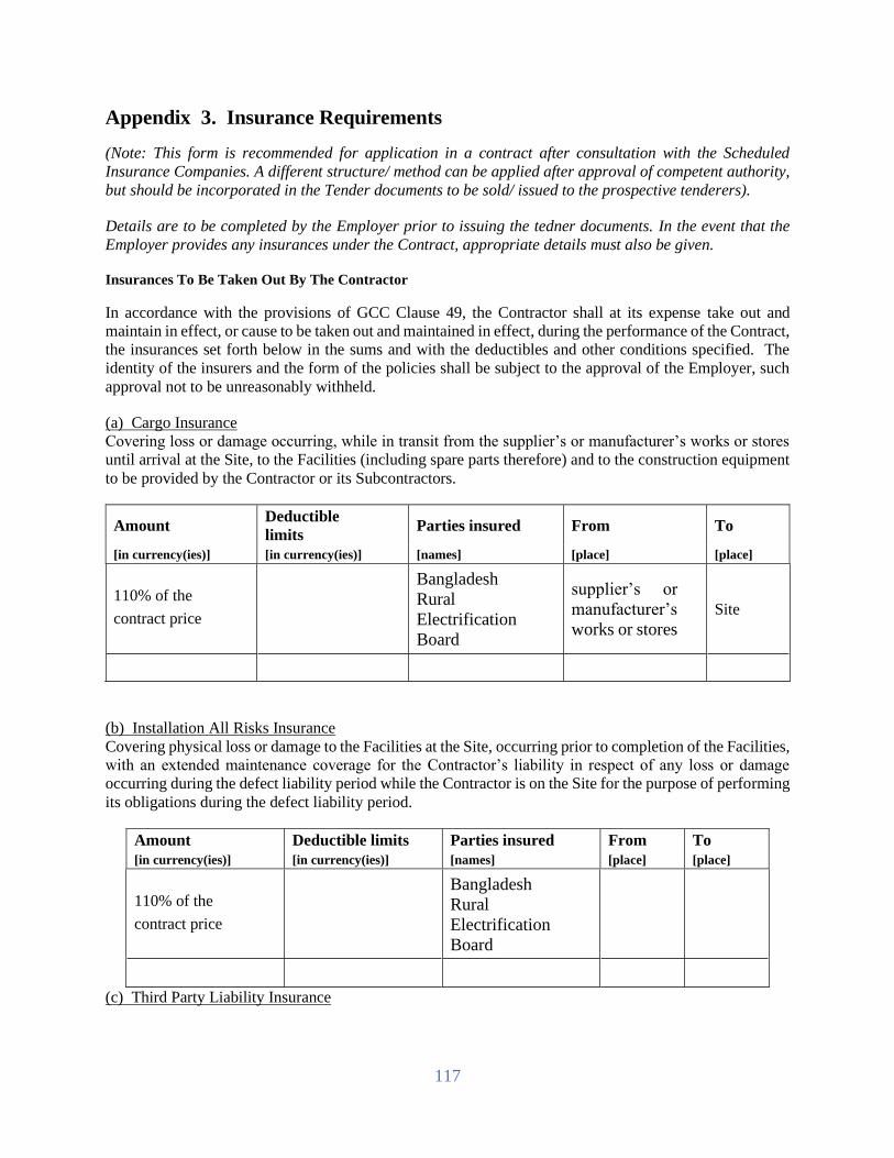
117
Appendix 3. Insurance Requirements
(Note: This form is recommended for application in a contract after consultation with the Scheduled
Insurance Companies. A different structure/ method can be applied after approval of competent authority,
but should be incorporated in the Tender documents to be sold/ issued to the prospective tenderers).
Details are to be completed by the Employer prior to issuing the tedner documents. In the event that the
Employer provides any insurances under the Contract, appropriate details must also be given.
Insurances To Be Taken Out By The Contractor
In accordance with the provisions of GCC Clause 49, the Contractor shall at its expense take out and
maintain in effect, or cause to be taken out and maintained in effect, during the performance of the Contract,
the insurances set forth below in the sums and with the deductibles and other conditions specified. The
identity of the insurers and the form of the policies shall be subject to the approval of the Employer, such
approval not to be unreasonably withheld.
(a) Cargo Insurance
Covering loss or damage occurring, while in transit from the supplier’s or manufacturer’s works or stores
until arrival at the Site, to the Facilities (including spare parts therefore) and to the construction equipment
to be provided by the Contractor or its Subcontractors.
Amount Deductible
limits Parties insured From To
[in currency(ies)] [in currency(ies)] [names] [place] [place]
110% of the
contract price
Bangladesh
Rural
Electrification
Board
supplier’s or
manufacturer’s
works or stores
Site
(b) Installation All Risks Insurance
Covering physical loss or damage to the Facilities at the Site, occurring prior to completion of the Facilities,
with an extended maintenance coverage for the Contractor’s liability in respect of any loss or damage
occurring during the defect liability period while the Contractor is on the Site for the purpose of performing
its obligations during the defect liability period.
Amount Deductible limits Parties insured From To
[in currency(ies)] [in currency(ies)] [names] [place] [place]
110% of the
contract price
Bangladesh
Rural
Electrification
Board
(c) Third Party Liability Insurance
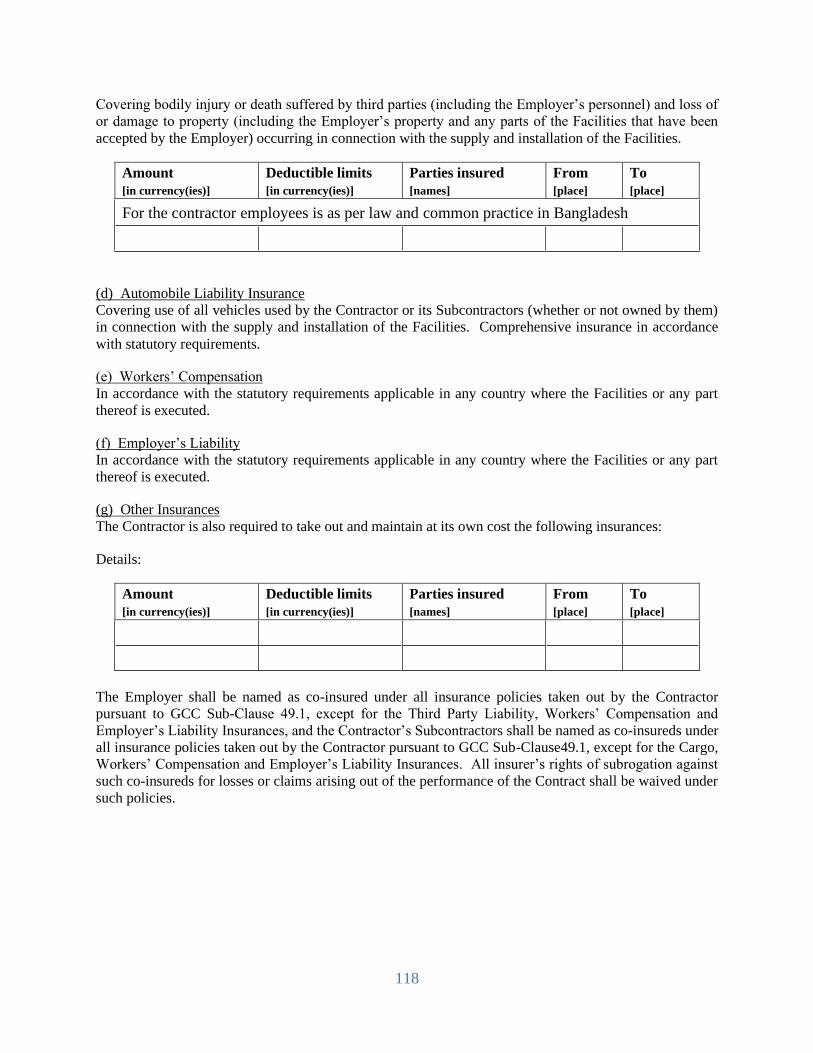
118
Covering bodily injury or death suffered by third parties (including the Employer’s personnel) and loss of
or damage to property (including the Employer’s property and any parts of the Facilities that have been
accepted by the Employer) occurring in connection with the supply and installation of the Facilities.
Amount Deductible limits Parties insured From To
[in currency(ies)] [in currency(ies)] [names] [place] [place]
For the contractor employees is as per law and common practice in Bangladesh
(d) Automobile Liability Insurance
Covering use of all vehicles used by the Contractor or its Subcontractors (whether or not owned by them)
in connection with the supply and installation of the Facilities. Comprehensive insurance in accordance
with statutory requirements.
(e) Workers’ Compensation
In accordance with the statutory requirements applicable in any country where the Facilities or any part
thereof is executed.
(f) Employer’s Liability
In accordance with the statutory requirements applicable in any country where the Facilities or any part
thereof is executed.
(g) Other Insurances
The Contractor is also required to take out and maintain at its own cost the following insurances:
Details:
Amount Deductible limits Parties insured From To
[in currency(ies)] [in currency(ies)] [names] [place] [place]
The Employer shall be named as co-insured under all insurance policies taken out by the Contractor
pursuant to GCC Sub-Clause 49.1, except for the Third Party Liability, Workers’ Compensation and
Employer’s Liability Insurances, and the Contractor’s Subcontractors shall be named as co-insureds under
all insurance policies taken out by the Contractor pursuant to GCC Sub-Clause49.1, except for the Cargo,
Workers’ Compensation and Employer’s Liability Insurances. All insurer’s rights of subrogation against
such co-insureds for losses or claims arising out of the performance of the Contract shall be waived under
such policies.
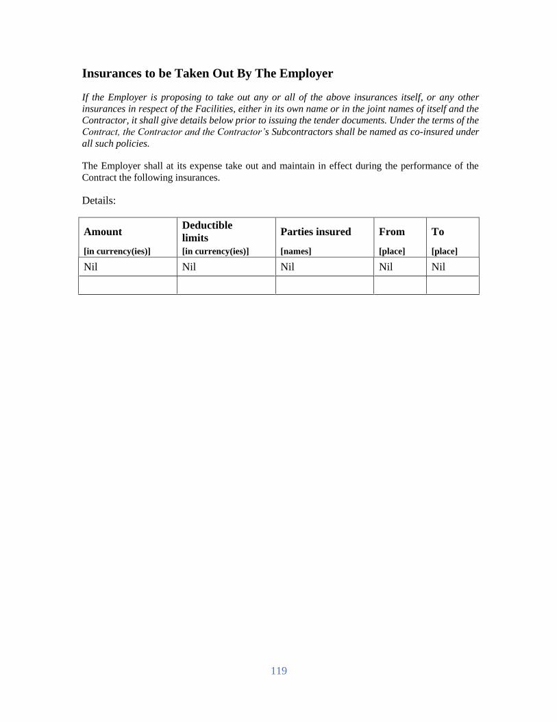
119
Insurances to be Taken Out By The Employer
If the Employer is proposing to take out any or all of the above insurances itself, or any other
insurances in respect of the Facilities, either in its own name or in the joint names of itself and the
Contractor, it shall give details below prior to issuing the tender documents. Under the terms of the
Contract, the Contractor and the Contractor’s Subcontractors shall be named as co-insured under
all such policies.
The Employer shall at its expense take out and maintain in effect during the performance of the
Contract the following insurances.
Details:
Amount Deductible
limits Parties insured From To
[in currency(ies)] [in currency(ies)] [names] [place] [place]
Nil Nil Nil Nil Nil

120
Appendix 4. Time Schedule
The Tenderer are required to submit with its tender a detailed program, normally in the form of a
bar chart, showing how and the order in which it intends to perform the Contract and showing
the key events requiring action or decision by the Employer. In preparing this Program, the
Tenderer shall adhere to the Time(s) for Completion given in the Tender Data Sheet. The time
for completion of whole facilities shall be as specified in the PCC against subclause
GCC-24.1 of section-4.

121
Appendix 5. List of Major Items of Plant and Services and List of Approved
Subcontractors
Prior to issuing the Tender Document, the Employer has established a list of major item of plant and
services for which approval of the Employer is required. Prior to award of Contract, the details of approved
subcontractor, including manufacturers shall be completed, indicating those subcontractors proposed by
the Tenderer in the corresponding Attachment to its tender that are approved by the Employer for
engagement by the Contractor during the performance of the Contract.
A list of major items of plant and services is provided below.
The following Subcontractors and/or manufacturers are approved for carrying out the item of the
facilities indicated. Where more than one Subcontractor is listed, the Contractor is free to choose
between them, but it must notify the Employer of its choice in good time prior to appointing any selected
Subcontractor. In accordance with GCC Sub-Clause 32.1, the Contractor is free to submit proposals for
Subcontractors for additional items from time to time. No Subcontracts shall be placed with any such
Subcontractors for additional items until the Subcontractors have been approved in writing by the
Employer and their names have been added to this list of Approved Subcontractors.
Major Items of
Plant and Services
Approved
Subcontractors/Manufacturers Nationality

122
Appendix 6. Scope of Works and Supply by the Employer
The following personnel, facilities, works and supplies shall apply as appropriate.
All personnel, facilities, works and supplies will be provided by the Employer in good time so as
not to delay the performance of the Contractor, in accordance with the approved Time Schedule and
Program of Performance pursuant to GCC Sub-Clause 31.2.
Unless otherwise indicated, all personnel, facilities, works and supplies will be provided free of
charge to the Contractor.
Personnel Charge to Contractor (if any)
Employer’s personnel will be engaged to
supervise and certify the works and test.
Name of the personnel will be informed
latter on.
No charge to Contractor.
Facilities Charge to Contractor (if any)
Works Charge to Contractor (if any)
Employer will not do any works. If
Contractor does not reinstate the
Employer’s existing facilities (Civil,
networking, power line/materials etc.)
Employer will complete it.
Will be deducted from contractor’s
payment.
Supplies Charge to Contractor (if any)
The Employer will not generally supply
any machinery/Equipment and materials to
the Contractor. In the event of any such
requirement and subject to availability, the
Employer may extend the facilities to use
such machinery and materials by the
Contractor on rental charge/cost under
normal terms and conditions.
The Contractor will be required to pay
the amount to be determined by the
Employer for such facilities.

123
Appendix 7. List of Documents for Approval or Review
Pursuant to GCC Sub-Clause 35.3.1, the Contractor shall prepare, or cause its Subcontractor to
prepare, and present to the Project Manager in accordance with the requirements of GCC Sub-Clause
31.2 (Program of Performance), the following documents for
(A) Approval (Not limited to)
1. RF Network design
2. Meter
3. Civil Design (if any)
4. Project implementation schedule, Project organogram, Detail drawing schedule.
5. Technical particular & Guarantees and Drawing, catalogue and operational manuals, from
manufacturer for each type of Equipment, servers, Software etc.
6. Communication, Operation, Logic diagram, Protection scheme.
7. Routine and factory acceptance test plan of each Equipment, Pre-commissioning and
commissioning Test Plan.
8. Any other relevant design-drawing & documents as per the Contract Documents to the
complete respective works.
9. Any other documents asked by the employer
(B) Review
1. Any documents listed above are to be reviewed if required to complete the works.

124
Appendix 8. Functional Guarantees
1. General
This Appendix sets out
(a) the functional guarantees referred to in GCC Clause43 (Functional Guarantees)
(b) the preconditions to the validity of the functional guarantees, either in production and/or
consumption, set forth below
(c) the minimum level of the functional guarantees
(d) the formula for calculation of liquidated damages for failure to attain the functional
guarantees.
2. Preconditions
The Contractor gives the functional guarantees (specified herein) for the facilities, subject to the following
preconditions being fully satisfied (No special preconditions applicable).
3. Functional Guarantees
Subject to compliance with the foregoing preconditions, the Contractor guarantees as follows:
3.1 Testing & commissioning of all the equipment & materials & software and ready
for commercial operation of the facilities.
4. Failure in Guarantees and Liquidated Damages
4.1 Failure to Attain Guaranteed Production Capacity
If the production capacity of the facilities attained in the guarantee test, pursuant to GCC
Sub-Clause40.2, is less than the guaranteed figure specified in para. 3.1 above, but
the actual production capacity attained in the guarantee test is not less than the
minimum level specified in para. 4.3 below, and the Contractor elects to pay
liquidated damages to the Employer in lieu of making changes, modifications and/or
additions to the Facilities, pursuant to GCC Sub-Clause 43.3, then the Contractor
shall pay liquidated damages at the rate of 300% of the quoted price of the part or
equipment
4.2 Raw Materials and Utilities Consumption in Excess of Guaranteed Level
(Not Applicable)
4.3 Minimum Levels (Not Applicable)
Notwithstanding the provisions of this paragraph, if as a result of the guarantee test(s), the
following minimum levels of performance guarantees (and consumption guarantees) are not
attained by the Contractor, the Contractor shall at its own cost make good any deficiencies
until the Facilities reach any of such minimum performance levels, pursuant to GCC Sub-
Clause 43.2:

125
(a) production capacity of the Facilities attained in the guarantee test: ninety-five percent
(95%/100%) of the guaranteed production capacity
and/or
(b) average total cost of consumption of all the raw materials and utilities of the Facilities:
one hundred and five percent (105%) of the guaranteed figures.
4.4 Limitation of Liability
Subject to para. 4.3 above, the Contractor’s aggregate liability to pay liquidated damages for
failure to attain the functional guarantees shall not exceed 10% of the Contract price

126
Section 5. Tender and Contract Forms
Form Title
Tender Forms
PG5A – 1a Tender Submission Letter for Technical Proposal
PG5A – 1b Tender Submission Letter for Financial (Price) Proposal
PG5A – 2a Tenderer Information Sheet
PG5A – 2b
PG5A – 2c
JVCA Partner Information
Subcontractor Information
PG5A – 3 Price Schedule for Plant and Services
PG5A – 4 Technical Proposal
PG5A – 4a Specification submission & compliance sheet.
PG5A– 5 Manufacturer’s Authorisation Letter
PG5A – 6 Bank Guarantee for Tender Security
PG5A – 6a Letter of Commitment for Bank’s undertaking for Line of Credit
(Form PG5A-6a)
Contract Forms
PG5A – 7 Notification of Award
PG5A – 8 Contract Agreement
PG5A – 9 Bank Guarantee for Performance Security
PG5A– 10 Bank Guarantee for Advance Payment
PG5A– 11 Bank Guarantee for Retention Money Security (Form PG5A-11)
Forms PG5A-1a, PG5A-1b to PG5A-6, PG5A-6a comprises part of the Tender and should be
completed as stated in ITT Clause 24.
Forms PG5A-7 to PG5A-11 and the appendices of the tender comprises part of the Contract as
stated in GCC Clause 6.

127
Tender Submission Letter for Technical offer
(Form PG5A-1a)
[This letter should be completed and signed by the Authorised Signatory preferably on the
Letter-Head Pad of the Tenderer and be appended in the technical proposal envelope]
To:
[Contact Person]
[Name of Procuring Entity]
[Address of Procuring Entity]
Date:
Invitation for Tender No: [indicate IFT No]
Tender Package No: [indicate Package No]
This Package is divided into the following Number of
Lots
[indicate number of
Lot(s)]
We, the undersigned, offer to design, manufacture, test, deliver, install, pre-commission and
commission in conformity with the Tender Document, the following Plant and Services, viz:
In signing this letter, and in submitting our Tender, we also confirm that:
(a) our Tender shall be valid for the period stated in the Tender Data Sheet (ITT
Sub Clause 30.1) and it shall remain binding upon us and may be accepted at
any time before the expiration of that period;
(b) a Tender Security is attached in the form of a [state pay order, bank draft, bank
guarantee] in the amount stated in the Tender Data Sheet (ITT Sub Clause 32)
and valid for a period of twenty-eight (28) days beyond the Tender validity date;
(c) we have examined and have no reservations to the Tender Document, issued by
you on [insert date]; including Addendum to Tender Document No(s) [state
numbers] , issued in accordance with the Instructions to Tenderers (ITT Clause
11). [insert the number and issuing date of each addendum; or delete this
sentence if no Addendum has been issued];
(d) we, including as applicable, any JVCA partner or Subcontractor for any part of
the contract resulting from this Tender process, have nationalities from eligible
countries, in accordance with ITT Sub Clause 5.1;
(e) we are submitting this Tender as a sole Tenderer in accordance with ITT Sub
Clause 38.3
or
we are submitting this Tender as the partners of a JVCA, comprising the
following other partners in accordance with ITT Sub Clause 18.1;
Name of Partner Address of Partner
1
2

128
(f) we are not a Government owned entity as defined in ITT Sub Clause 5.3 or
we are a Government owned entity, and we meet the requirements of ITT Sub
Clause 5.3;
(delete one of the above as appropriate)
(g) we, including as applicable any JVCA partner, declare that we are not
associated, nor have been associated in the past, directly or indirectly, with a
consultant or any other entity that has prepared the design, specifications and
other documents in accordance with ITT Sub Clause 5.5;
(h) we, including as applicable any JVCA partner or Subcontractor for any part of
the contract resulting from this Tender process, have not been declared
ineligible by the Government of Bangladesh on charges of engaging in corrupt,
fraudulent, collusive or coercive practices in accordance with ITT Sub Clause
5.6;
(i) furthermore, we are aware of ITT Clause 4 concerning such practices and pledge
not to indulge in such practices in competing for or in executing the Contract;
(j) we intend to subcontract an activity or part of the Works, in accordance with
ITT Sub Clause 19.1, to the following Subcontractor(s);
Activity or part of the Plant
and Services
Name of Subcontractor with
Address
(k) we, including as applicable any JVCA partner, confirm that we do not have a
record of poor performance, such as abandoning the works, not properly
completing contracts, inordinate delays, or financial failure as stated in ITT
Clause 5.7, and that we do not have, or have had, any litigation against us, other
than that stated in the Tenderer Information (Form PG5A-2b);
(l) we are not participating as Tenderers in more than one Tender in this Tendering
process. We understand that your written Notification of Award shall constitute
the acceptance of our Tender and shall become a binding Contract between us,
until a formal Contract is prepared and executed;
(m) we, including as applicable any JVCA partner, confirm that we do not have a
record of insolvency, receivership, bankrupt or being wound up, our business
activities were not been suspended, and it was not been the subject of legal
proceedings in accordance with ITT Sub Clause 5.8;
(n) we, including as applicable any JVCA partner, confirm that we have fulfilled
our obligations to pay taxes and social security contributions applicable under
the relevant national laws and regulations of Bangladesh in accordance with ITT
Sub Clause 5.9;
(o) we understand that you reserve the right to reject all the Tenders or annul the
Tender proceedings, without incurring any liability to Tenderers, in accordance
with ITT Clause 59.

129
Signature: [insert signature of authorised representative of
the Tenderer]
Name: [insert full name of signatory with National ID
Number, if applicable]
In the capacity
of:
[insert capacity of signatory]
Duly authorised to sign the Tender for and on behalf of the Tenderer
[If there is more than one (1) signatory, or in the case of a JVCA, add other boxes and sign
accordingly].Attachment 1:
[ITT Sub Clause 38.3]
Written confirmation authorising the above signatory(ies) to commit the Tenderer
[and, if applicable]
Attachment 2:
[ITT Sub Clause 29.2(b)]
Copy of the JVCA Agreement / Letter of Intent to form JVCA with draft proposed Agreement

130
Tender Submission Letter for Financial offer
(Form PG5A-1b)
[This letter should be completed and signed by the Authorised Signatory
preferably on the Letter-Head Pad of the Tendererand be appended in the financial proposal
envelope]
To:
[Contact Person]
[Name of Procuring Entity]
[Address of Procuring Entity]
Date:
Invitation for Tender No: [indicate IFT No]
Tender Package No: [indicate Package
No]
This Package is divided into the following Number of
Lots
[indicate number of
Lot(s)]
We, the undersigned, offer to design, manufacture, test, deliver, install, precommission and
commission in conformity with the Tender Document, the following Plant and Services,
viz:
In accordance with ITT Clauses 26 and 27, the following prices and discounts apply to
our Tender:
The Tender Price is:
(ITT Sub-Clause 26.1)
[state amount in figures]
and [state amount in words]
Plant (including Mandatory Spare Parts)
Supplied from abroad
[state amount in figures]
and [state amount in words]
Plant (including Mandatory Spare Parts)
supplied from within the Employer’s
Country
Taka[state amount in figures]
And Taka [state amount in words]
Design Services [state amount in figures]
and [state amount in words]
Installation and Other Services [state amount in figures]
and [state amount in words]
Recommended Spare parts Price
(If economic Factor is applicable)
[state amount in figures]
and [state amount in words]
The Unconditional discount is
(ITT Sub-Clause 23.11)
[state amount in figures]
and [state amount in words]
The methodology for Application of the
discount is:
[state the methodology]

131
and we shall accordingly submit an Advance Payment Guarantee in the format
shown in Form PG5A- 10.
In signing this letter, and in submitting our Tender, we also confirm that:
a) our Tender shall be valid for the period stated in the Tender Data Sheet (ITT Sub
Clause 30.1) and it shall remain binding upon us and may be accepted at any time
before the expiration of that period;
b) a Tender Security is attached in the form of a [state pay order, bank draft, bank
guarantee] in the amount stated in the Tender Data Sheet (ITT Sub Clause 32) and
valid for a period of twenty eight (28) days beyond the Tender validity date;
c) if our Tender is accepted, we commit to furnishing a Performance Security within
the time stated under ITT Sub Clause 65.1) and in the form specified in the Tender
Data Sheet (ITT Sub Clause 66.1) valid for a period of twenty eight (28) days
beyond the date of issue of the Completion Certificate of the Plants and Services;
d) we have examined and have no reservations to the Tender Document, issued by you
on [insert date]; including Addendum to Tender Document No(s) [state numbers] ,
issued in accordance with the Instructions to Tenderers (ITT Clause 11). [insert the
number and issuing date of each addendum; or delete this sentence if no Addendum
has been issued];
e) we, including as applicable, any JVCA partner or Subcontractor for any part of the
contract resulting from this Tender process, have nationalities from eligible
countries, in accordance with ITT Sub Clause 5.1;
f) we are submitting this Tender as a sole Tenderer in accordance with ITT Sub Clause
38.3 or
we are submitting this Tender as the partners of a JVCA, comprising the following
other partners in accordance with ITT Sub Clause 18.1;
Name of Partner Address of Partner
1
2
3
4
g) we are not a Government owned entity as defined in ITT Sub Clause 5.3 or
we are a Government owned entity, and we meet the requirements of ITT Sub
Clause 5.3;
(delete one of the above as appropriate)
h) we, including as applicable any JVCA partner, declare that we are not associated,
nor have been associated in the past, directly or indirectly, with a consultant or any
other entity that has prepared the design, specifications and other documents in
accordance with ITT Sub Clause 5.5;

132
i) we, including as applicable any JVCA partner or Subcontractor for any part of the
contract resulting from this Tender process, have not been declared ineligible by the
Government of Bangladesh on charges of engaging in corrupt, fraudulent, collusive
or coercive practices in accordance with ITT Sub Clause 5.6;
j) furthermore, we are aware of ITT Clause 4 concerning such practices and pledge
not to indulge in such practices in competing for or in executing the Contract;
k) we intend to subcontract an activity or part of the Works, in accordance with ITT
Sub Clause 19.1, to the following Subcontractor(s);
Activity or part of the Plant
and Services
Name of Subcontractor with
Address
l) we, including as applicable any JVCA partner, confirm that we do not have a record
of poor performance, such as abandoning the works, not properly completing
contracts, inordinate delays, or financial failure as stated in ITT Clause 5.7, and
that we do not have, or have had, any litigation against us, other than that stated in
the Tenderer Information (Form PG5A-2b);
m) we are not participating as Tenderers in more than one Tender in this Tendering
process. We understand that your written Notification of Award shall constitute the
acceptance of our Tender and shall become a binding Contract between us, until a
formal Contract is prepared and executed;
n) we, including as applicable any JVCA partner, confirm that we do not have a record
of insolvency, receivership, bankrupt or being wound up, our business activities
were not been suspended, and it was not been the subject of legal proceedings in
accordance with ITT Sub Clause 5.8;
o) we, including as applicable any JVCA partner, confirm that we have fulfilled our
obligations to pay taxes and social security contributions applicable under the
relevant national laws and regulations of Bangladesh in accordance with ITT Sub
Clause 5.9;
p) we understand that you reserve the right to reject all the Tenders or annul the Tender
proceedings, without incurring any liability to Tenderers, in accordance with ITT
Clause 61
Signature: [insert signature of authorised
representative of the Tenderer]
Name: [insert full name of signatory with
National ID Number]
In the capacity of: [insert capacity of signatory]
Duly authorised to sign the Tender for and on behalf of the Tenderer

133
[If there is more than one (1) signatory, or in the case of a JVCA, add other boxes and
sign accordingly].Attachment 1:
[ITT Sub Clause 38.3]
Written confirmation authorising the above signatory(ies) to commit the Tenderer
[and, if applicable]
Attachment 2:
[ITT Sub Clause 29.2(b)]
Copy of the JVCA Agreement / Letter of Intent to form JVCA with draft proposed
Agreement

134
Tenderer Information (Form PG5A-2a)
[This Form should be completed only by the Tenderer, preferably on its Letter-Head Pad]
Invitation for Tender No: [indicate IFT No]
Tender Package No: [indicate Package
No]
This Package is divided into the following Number of
Lots:
[indicate number of
Lot(s)]
1. Eligibility Information of the Tenderer [ITT –Clauses 5 & 29]
1.1 Nationality of
individual or country
of registration
1.2 Tenderer’s legal title
1.3 Tenderer’s registered
address
1.4 Tenderer’s legal status [complete the relevant box]
Proprietorship
Partnership
Limited Liability
Concern
Government-owned
Enterprise
Others
[please describe, if
applicable]
1.5 Tenderer’s year of
registration
1.6 Tenderer’s authorised representative details
Name
National ID number
Address
Telephone / Fax
numbers
e-mail address
1.7 Litigation [ITT Cause 13]
If there is no history of litigation or no pending litigation then state opposite
“None”. If there is a history of litigation, or a number of awards, against the
Tenderer provide details below

135
A. Arbitration Awards made against
ar Matter in dispute Value of
Award
Value of
Claim
B. Arbitration Awards pending
Year Matter in dispute Value of Claim
1.8 Tenderer to attach photocopies
of the original documents
mentioned aside
[All documents required under ITT Clauses 5
and 29]
The following two information are applicable for National Tenderers
1.9 Tenderer’s Value Added Tax
Registration (VAT) Number
1.10 Tenderer’s Tax Identification
Number(TIN)
[The foreign Tenderers, in accordance with ITT Sub Clause 5.1, shall provide evidence by a
written declaration to that effect to demonstrate that it meets the criterion]
1. Qualification Information of the Tenderer [ITT Clause 29]
2.1 General Experience in Plant and Services of Tenderer
Start
Mont
h
Year
End
Mont
h
Year
Years Contract No and Name of
Contract
Name and Address of
Procuring Entity
Brief description of Plant
and Services
Role of Tenderer
[Contractor/Subcontractor
/Management Contractor]
2.
2
Specific Experience in Key Activities
Contract No
Name of Contract
[ insert reference no] of [ insert year]
[insert name]

136
Role in Contract
[tick relevant box].
Contractor
Subcont
ractor
Management
Contractor
\Award date
Completion date
Total Contract Value
[insert date]
[insert date]
[insert amount]
Procuring Entity’s
Name
Address
Tel / Fax
Brief description with
justifications of the
similarity compared to
the Procuring Entity’s
requirements
[state justification in support of its similarity compared
to the proposed works]
2.3 Average annual turnover [ITT Sub Clause15.1(a)]
[amount invoiced to Procuring Entity(s) for each year of works in progress or
completed, using rate of exchange at the end of the period reported]
Year Amount & Currency amount in figures
2.4 Financial Resources available to meet the cash flow [ITT Sub Clause 15.1(b)]
No Source of Financing Amount
Available
In order to confirm the above statements the Tenderer shall submit , as applicable, the
documents mentioned in ITT Sub Clause 14.1(a), (b) and 15.1 (a), (b) & (c)
2.5 Contact Details
Name, address, and other contact details of Tenderer Bankers and other Procuring
Entity(s) that may provide references, if contacted by this Procuring Entity

137
2.6 Qualifications and experience of key technical and administrative personnel
proposed for Contract administration and management [ITT Sub Clause 16.1 ]
Position
Name
Years of General Experience
Years of Specific Experience
[Tenderer to complete details of as many personnel as are applicable.Each personnel
listed above should complete the Personnel Information (Form PG5A-5)]
2.7 Major Equipment proposed to carry out the Contract [ITT Sub Clause 17.1 ]
Item of Equipment
Condition
(new, good, average,
poor)
Owned, leased or to be
purchased
(state owner, less or
seller)
[Tenderer to list details of each item of major equipment, as applicable]
Name: [insert full name of
signatory]
Signature
with Date and
Seal
In the
capacity of:
[insert designation of
signatory]
[ Sign]
Duly authorised to sign the Tender for and on behalf of the
Tenderer

138
JVCA Partner Information (Form PG5A-2b)
[This Form should be completed by each JVCA partner].
Invitation for Tender No: [indicate IFT No]
Tender Package No [indicate Package
No]
This Package is divided into the following Number of
Lots
[indicate number of
Lot(s)]
1. Eligibility Information of the JVCA Partner [ITT –Clauses 5 & 29]
1.1 Nationality of Individual or
country of Registration
1.2 JVCA Partner’s legal title
1.3 JVCA Partner’s registered
address
1.4 JVCA Partner’s legal status [complete the relevant box]
Proprietorship
Partnership
Limited Liability Concern
Government-owned Enterprise
Other
(please describe, if applicable)
1.5 JVCA Partner’s year of
registration
1.6 JVCA Partner’s authorised representative details
Name
National ID number
Address
Telephone / Fax numbers
e-mail address
1.7 Litigation [ITT Sub Cause 13]
If there is no history of litigation or no pending litigation then state “None”.
If there is a history of litigation, or a number of awards, against the JVCA
Partner provide details below:
A. Arbitration Awards made against
Year Matter in dispute Value of
Award
Value of
Claim
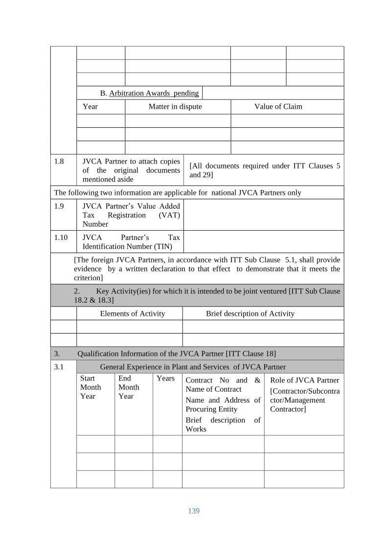
139
B. Arbitration Awards pending
Year Matter in dispute Value of Claim
1.8 JVCA Partner to attach copies
of the original documents
mentioned aside
[All documents required under ITT Clauses 5
and 29]
The following two information are applicable for national JVCA Partners only
1.9 JVCA Partner’s Value Added
Tax Registration (VAT)
Number
1.10 JVCA Partner’s Tax
Identification Number (TIN)
[The foreign JVCA Partners, in accordance with ITT Sub Clause 5.1, shall provide
evidence by a written declaration to that effect to demonstrate that it meets the
criterion]
2. Key Activity(ies) for which it is intended to be joint ventured [ITT Sub Clause
18.2 & 18.3]
Elements of Activity Brief description of Activity
3. Qualification Information of the JVCA Partner [ITT Clause 18]
3.1 General Experience in Plant and Services of JVCA Partner
Start
Month
Year
End
Month
Year
Years Contract No and &
Name of Contract
Name and Address of
Procuring Entity
Brief description of
Works
Role of JVCA Partner
[Contractor/Subcontra
ctor/Management
Contractor]

140
3.2 Specific Experience in Key Activities
Contract No
Name of Contract
[ insert reference no] of [ insert year]
[insert name]
Role in Contract
[tick relevant box]
Contractor Sub
cont
ract
or
Management
Contractor
Award date
Completion date
Total Contract
Amount
[insert date]
[insert date]
[insert amount]
Procuring Entity’s
Name
Address
Tel / Fax
[state justification in support of its similarity
compared to the proposed plants and service]
Brief description with justifications of the similarity
compared to the Procuring Entity’s requirements
3.3 Average annual construction turnover [ITT Sub Clause 15.1 (a)]
[amount invoiced to Procuring Entity(s) for each year of work in progress or
completed, using rate of exchange at the end of the period reported]
Year Amount & Currency Amount in Figures
3.4 Financial Resources available to meet the cash flow [ITT Sub-Clause 15.1(b)]
N
o
Source of financing Amount available
In order to confirm the above statements the JVCA Partner shall submit , as
applicable, the documents mentioned in ITT Sub Clause 14.1 (a) & (b)15.1 (a), (b),
(c) & (d)
3.5 Contact Details
Name, address, and contact details of Tenderer’s Bankers and other Procuring
Entity(s) that may provide references if contacted by this Procuring Entity

141
3.6 Qualifications and experience of key technical and administrative personnel
proposed for Contract administration and management [ITT Sub Clause 16.1]
Position
Name
Years of General Experience
Years of Specific Experience
[Tenderer to complete details of as many personnel as are applicable. Each
personnel listed above should complete the Personnel Information (Form
PG5A-5)]
3.7 Major items of Construction Equipment proposed for carrying out the works [ITT
Sub-Clause 17.1]
Item of Equipment
Condition
(new, good,
average, poor)
Owned, leased or to be
purchased
(state owner, leaser or seller)
[Tenderer to list details of each item of Major equipment, as applicable]
Name: [insert full name of
signatory]
Signature
with Date and
Seal
In the capacity of: [insert designation
of signatory]
[ Sign]
Duly authorised to sign the Tender for and on behalf of the
Tenderer
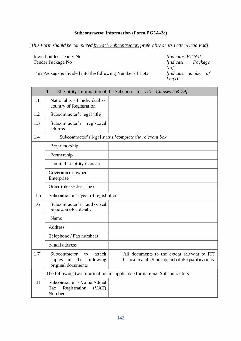
142
Subcontractor Information (Form PG5A-2c)
[This Form should be completed by each Subcontractor, preferably on its Letter-Head Pad]
Invitation for Tender No: [indicate IFT No]
Tender Package No [indicate Package
No]
This Package is divided into the following Number of Lots [indicate number of
Lot(s)]
1. Eligibility Information of the Subcontractor [ITT –Clauses 5 & 29]
1.1 Nationality of Individual or
country of Registration
1.2 Subcontractor’s legal title
1.3 Subcontractor’s registered
address
1.4 Subcontractor’s legal status [complete the relevant box
Proprietorship
Partnership
Limited Liability Concern
Government-owned
Enterprise
Other (please describe)
.1.5 Subcontractor’s year of registration
1.6 Subcontractor’s authorised
representative details
Name
Address
Telephone / Fax numbers
e-mail address
1.7 Subcontractor to attach
copies of the following
original documents
All documents to the extent relevant to ITT
Clause 5 and 29 in support of its qualifications
The following two information are applicable for national Subcontractors
1.8 Subcontractor’s Value Added
Tax Registration (VAT)
Number

143
1.9 Subcontractor’s Tax
Identification Number (TIN)
[The foreign Subcontractors, in accordance with ITT sub-Clause 5.1, shall provide
evidence by a written declaration to that effect to demonstrate that it meets the criterion]
2. Key Activity(ies) for which it is intended to be Subcontracted [ITT Sub Clause 19.1]
2.1 Elements of Activity Brief description of Activity
2.2 List of Similar Contracts in which the proposed Subcontractor had been engaged
Name of Contract and Year of
Execution
Value of Contract
Name of Procuring Entity
Contact Person and contact details
Type of Assignment performed
Name: [insert full name of signatory] Signature with Date and Seal
In the capacity of: [insert designation of
signatory]
[ Sign]
Duly authorized to sign the Tender for and on behalf of the Tenderer

144
Price Schedule for Plant and Service (Form PG5A-3)
(This form should be completed and submitted by the tenderer and appended in the financial
proposal envelope)
Invitation for Tender No: [indicate IFT No]
Tender Package No [indicate Package No]
This Package is divided into the following Number of Lots [indicate number of Lot(s)]
General
1. The Price Schedules are divided into separate Schedules as follows:
Schedule No. 1: Plant (including Mandatory Spare Parts) Supplied from Abroad
Schedule No. 2: Plant (including Mandatory Spare Parts) Supplied from within the
Employer’s Country
Schedule No. 3: Design Services
Schedule No. 4: Installation and Other Services
Schedule No. 5: Grand Summary
Schedule No. 6: Recommended Spare Parts
2. The Schedules do not generally give a full description of the plant to be supplied and
the services to be performed under each item. Tenderers shall be deemed to have
read the Employer’s Requirements and other sections of the Tender Document and
reviewed the Drawings to ascertain the full scope of the requirements included in
each item prior to filling in the rates and prices. The entered rates and prices shall
be deemed to cover the full scope as aforesaid, including overheads and profit.
3. If tenderers are unclear or uncertain as to the scope of any item, they shall seek
clarification in accordance with ITT 9.1 prior to submitting their tender.
Pricing
4. Prices shall be filled in indelible ink, and any alterations necessary due to errors,
etc., shall be initialed by the Tenderer.
As specified in the Tender Data Sheet and Special Conditions of Contract, prices
shall be fixed and firm for the duration of the Contract, or prices shall be subject to
adjustment in accordance with the corresponding Appendix (Price Adjustment) to
the Contract Agreement.
5. Tender prices shall be quoted in the manner indicated and in the currencies specified
in the Instructions to Tenderers in the Tender Document.
For each item, tenderers shall complete each appropriate column in the respective
Schedules, giving the price breakdown as indicated in the Schedules.
Prices given in the Schedules against each item shall be for the scope covered by
that item as detailed in Section 6 (Employer’s Requirements) or elsewhere in the
Tender Document.
6. Payments will be made to the Contractor in the currency or currencies indicated
under each respective item.
7. When requested by the Employer for the purposes of making payments or partial
payments, valuing variations or evaluating claims, or for such other purposes as the
Employer may reasonably require, the Contractor shall provide the Employer with a
breakdown of any composite or lump sum items included in the Schedules.

145
For Lot -1:
Schedules of Rates and Prices
Schedule No. 1 - Plant and Mandatory Spare Parts Supplied from Abroad - Not Applicable
Line
Item
No
Description of Item Country
of Origin
Quantit
y
Unit Price
CIP[insert place of
destination]
Or CIF[insert port of
destination]
[Foreign Currency]
CIF/CIP price per
Line Item
[Foreign Currency]
Taxes and Duties In
Local Currency
1 2 3 4 5 6 = 4 x 5 7
Column 6 to be carried forward to Schedule No. 5. Grand Summary
Note: 1. The Employer may also use other INCOTERMs, if deemed necessary, In such case Form PG5A-6, will require to be customized by the Employer
2. Specify currencies in accordance with ITT 27. Create and use as many columns for Unit Price and Total Price as there are currencies.
Country of Origin Declaration Form
Item Description Country
Name: [insert full name of
signatory]
Signature
with Date and
Seal
In the capacity of: [insert designation of
signatory]
[ Sign]
Duly authorized to sign the Tender for and on behalf of the
Tenderer

146
For Lot -1:
Schedule No. 2 - Plant and Mandatory Spare Parts Supplied from within the Employer’s Country
Line
Item
No.
Description of Item Unit Quantity
Country of
Origin (To be
mentioned)
Unit
Price(including
all Tax, vat)
EXW
(Taka)
Total EXW
Price
(Taka)
Transportation
cost of goods at
destination
Total Price
(Taka)
BDT BDT BDT BDT
1 2 3 4 5 6 7= 4x6 8 9= 7+8
1 Single Phase Smart Pre-payment
Meter
Numbers 4,80,000
2 Three Phase Smart Pre-payment
Meter (LT)
Numbers 10,000
3 RF Network Interface Card/RF
Module including secure plug-in
facility with Cellular and PLC
provision.
Numbers 4,68,000
4 2G Communication Module including
secure plug-in facility with RF and
PLC provision.
Numbers 22,000
5 SIM for 2G communication
module and Data Concentrator
Unit (DCU)
Numbers 23,667
6 Data Concentrator Unit (DCU)
(As per proposed specification
estimated number of DCU is
1667, however bidder will
Numbers
1667
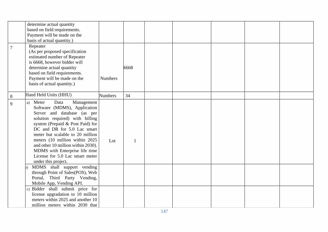
147
determine actual quantity
based on field requirements.
Payment will be made on the
basis of actual quantity.)
7 Repeater
(As per proposed specification
estimated number of Repeater
is 6668, however bidder will
determine actual quantity
based on field requirements.
Payment will be made on the
basis of actual quantity.)
Numbers
6668
8 Hand Held Units (HHU) Numbers 34
9 a) Meter Data Management
Software (MDMS), Application
Server and database (as per
solution required) with billing
system (Prepaid & Post Paid) for
DC and DR for 5.0 Lac smart
meter but scalable to 20 million
meters (10 million within 2025
and other 10 million within 2030).
MDMS with Enterprise life time
License for 5.0 Lac smart meter
under this project.
Lot
1
b) MDMS shall support vending
through Point of Sales(POS), Web
Portal, Third Party Vending,
Mobile App, Vending API.
c) Bidder shall submit price for
license upgradation to 10 million
meters within 2025 and another 10
million meters within 2030 that

148
will be considered for the
evaluation process but will not be
included in project price.
10 Head End System (HES) with related
software and Database &
Application Server (as per solution
required) for DC and DR for 5.0 Lac
smart meter to be interfaced with
offered MDMS. This HES will be
Enterprise life time License for 5.0
Lac smart meter under this project.
Lot
1
11 Enterprise Database Edition Perpetual
License:
• Database Enterprise Edition -
Processor Perpetual
• Diagnostics Pack- Processor
Perpetual
• Tuning Pack – Processor
Perpetual
• Real Application Clusters-
Processor Perpetual
• Active Data Guard – Processor
Perpetual
• Partitioning
Lot
1
12 Middleware Suite Lot 1
13 Hardware for DC (as per specification and quantity mentioned in this tender document) along with power cabling, network setup and all
necessary accessories.
Database Server set 1
General Purpose Storage Number 1
Database Storage Number 1
SAN Switch Number 4
Application Server Number 2

149
Database backup System set 1
Server for HES, MDM and related
software /application
Number 4
Virtualization and Container
Infrastructure for Other Services
set 1
Tape Library for Archival Number 1
Server Load Balancer Number 2
Work Station Number 35
WAN Switch Number 2
Core Router Number 2
Core Switch Number 2
Core firewall Number 2
Server Firm switch Number 4
Internet router Number 2
Web Application firewall Number 1
Distributed Switch Number 3
Access switch Number 20
Central Firewall Management Set 1
DMZ switch number 2
Operating System, Hypervisor,
Container Software license set 1
Antivirus Software set 1
Identity and Access management set 1
Modules and Interfaces set 1
Network Monitoring System Set 1
Application Management System set 1

150
Helpdesk and problem ticketing set
1
Passive Infrastructure Technical
specification all server room
construction
set 1
Electrical Infrastructure set 1
Raise floor system set 1
Accessories Set 1
Rack with cold container set 1
Online modular UPS with lithium-
ion batteries for IT load set 2
Online modular UPS with lithium-
ion batteries for Cooling
equipment and other non-critical
load
set 2
Rack mount static transfer switch
STS/ATS set 4
Metered Rack PDU (single phase) Set 16
Precision Air Conditioner (PAC) set 4
Data center Infrastructure
monitoring set 1
IP KVM set 6
Floor mount isolation transformer set 2
Modular UPS power distribution set 2
Comport Cooling set 4
Rodent system set 1
VESDA Set 1
Fire detection and suppression
system set 1

151
Access Control system set 1
IP CAM and surveillance solution set 1
Generator Number 1
AVR Number 2
TVSS Number 2
Data center Rated-3 Certification Lot 1
14 Hardware for DR (as per specification and quantity mentioned in this tender document) along with power cabling, network setup and all
necessary accessories.
Database Server set 1
General Purpose Storage Number 1
Database Storage Number 1
SAN Switch Number 4
Application Server Number 2
Server for HES, MDM and related
software /application
Number 2
Server Load Balancer Number 2
Work Station Number 15
WAN Switch Number 2
Core Router Number 2
Core Switch Number 2
Core firewall Number 2
Server Firm switch Number 4
Internet router Number 2
Web Application firewall Number 1
Distributed Switch Number 2
Access switch Number 20

152
Central Firewall Management Set 1
DMZ switch number 2
Identity and Access management set 1
Passive Infrastructure Technical
specification all server room
construction
set 1
Electrical Infrastructure set 1
Raise floor system set 1
Accessories Set 1
Rack with cold container set 1
Online modular UPS with lithium-
ion batteries for IT load set 2
Online modular UPS with lithium-
ion batteries for Cooling
equipment and other non-critical
load
set 2
Rack mount static transfer switch
STS/ATS set 2
Metered Rack PDU (single phase) Set 16
Precision Air Conditioner (PAC) set 2
Data center Infrastructure
monitoring set 1
IP KVM set 4
Floor mount isolation transformer set 2
Modular UPS power distribution set 2
Comport Cooling set 4
Rodent system set
1

153
VESDA Set 1
Fire detection and suppression
system set 1
Access Control system set 1
IP CAM and surveillance solution set 1
Generator Number 1
AVR Number 2
TVSS Number 2
Data center Rated-3 Certification Lot 1
15 SPC Pole (60’-2) along with all
necessary equipment’s for mounting
of DCU and Repeater etc. (As per
proposed specification estimated
number of SPC Pole is 8335, however
bidder will determine actual quantity
based on field requirements. Payment
will be made on the basis of actual
quantity.)
Number 8335
16 Utility Vending Station (UVS)
Workstation Number 17
GRPS/EDGE/EVDO Modem Number 34
SIM Card Number 34
VPN router Number 1
Slip Printer Number 17
Barcode Scanner Number 17
Laser Printer Number 17
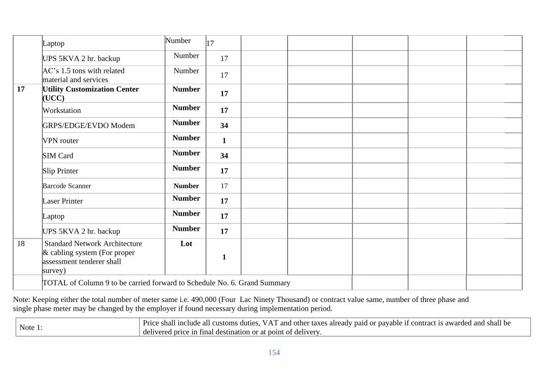
154
Note: Keeping either the total number of meter same i.e. 490,000 (Four Lac Ninety Thousand) or contract value same, number of three phase and
single phase meter may be changed by the employer if found necessary during implementation period.
Note 1: Price shall include all customs duties, VAT and other taxes already paid or payable if contract is awarded and shall be
delivered price in final destination or at point of delivery.
Laptop Number 17
UPS 5KVA 2 hr. backup Number 17
AC’s 1.5 tons with related
material and services
Number 17
17 Utility Customization Center
(UCC)
Number 17
Workstation Number 17
GRPS/EDGE/EVDO Modem Number 34
VPN router Number 1
SIM Card Number 34
Slip Printer Number 17
Barcode Scanner Number 17
Laser Printer Number 17
Laptop Number 17
UPS 5KVA 2 hr. backup Number 17
18 Standard Network Architecture
& cabling system (For proper
assessment tenderer shall
survey)
Lot
1
TOTAL of Column 9 to be carried forward to Schedule No. 6. Grand Summary

155
Name: [insert full name of signatory] Signature with Date and Seal
In the capacity of: [insert designation of signatory] [ Sign]
Duly authorized to sign the Tender for and on behalf of the Tenderer
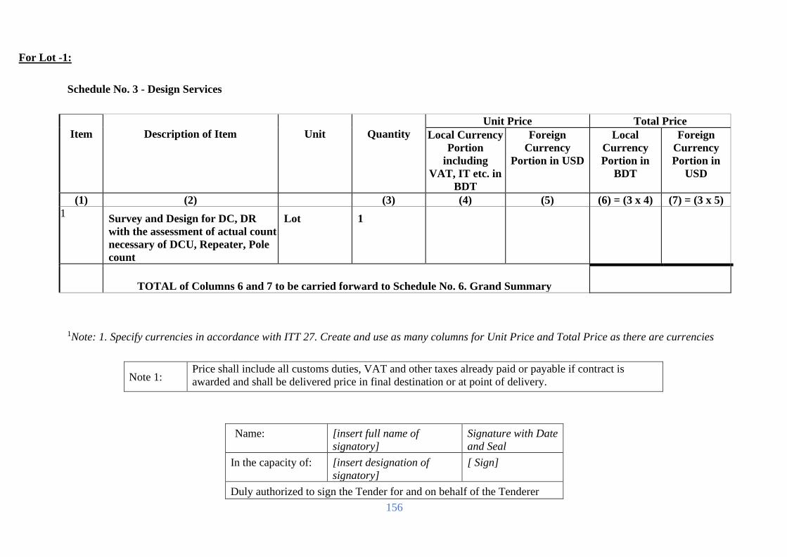
156
For Lot -1:
Schedule No. 3 - Design Services
Item
Description of Item
Unit
Quantity
Unit Price Total Price
Local Currency
Portion
including
VAT, IT etc. in
BDT
Foreign
Currency
Portion in USD
Local
Currency
Portion in
BDT
Foreign
Currency
Portion in
USD
(1) (2) (3) (4) (5) (6) = (3 x 4) (7) = (3 x 5)
1 Survey and Design for DC, DR
with the assessment of actual count
necessary of DCU, Repeater, Pole
count
Lot 1
TOTAL of Columns 6 and 7 to be carried forward to Schedule No. 6. Grand Summary
1Note: 1. Specify currencies in accordance with ITT 27. Create and use as many columns for Unit Price and Total Price as there are currencies
Note 1: Price shall include all customs duties, VAT and other taxes already paid or payable if contract is
awarded and shall be delivered price in final destination or at point of delivery.
Name: [insert full name of
signatory]
Signature with Date
and Seal
In the capacity of: [insert designation of
signatory]
[ Sign]
Duly authorized to sign the Tender for and on behalf of the Tenderer

157
For Lot -1:
Schedule No. 4 –Civil works part
Item
Description of items
Unit
Quantity
Rate in BDT
including
VAT, IT etc.
Total Amount
in BDT
1 2 3 4 5 6 = 4*5
a. Necessary civil work for RF canopy installation
(DCU, Repeater, DC and DR, BREB Jossore
O&M complex) survey and assessment
Lot
1
b. Necessary civil work for UCC & UVS survey and
assessment, along with sitting arrangement(Chair,
Table) for two persons each station
Lot
1
TOTAL of Column 6 to be carried forward to
Schedule No. 6. Grand Summary
Note: 1. Specify currencies in accordance with ITT 27. Create and use as many columns for Unit Price and Total Price as there are currencies
Note 1: Price shall include all customs duties, VAT and other taxes already paid or payable if contract is
awarded and shall be delivered price in final destination or at point of delivery.
Name: [insert full name of
signatory]
Signature with Date
and Seal
In the capacity of: [insert designation of
signatory]
[ Sign]
Duly authorised to sign the Tender for and on behalf of the Tenderer

158
For Lot -1:
Schedule No. 5- Installation and Other Services
Item
Description
Unit
Quantity
Unit Price Total Price
Local
Currency
Portion in
BDT
including
VAT, IT
etc.
Foreign
Currency
Portion in BDT
Local
Currency
Portion in
BDT including
VAT, IT
etc
Foreign
Currency Portion
in BDT
1 2 3 4 5 6 = 3 x 4 7 = 3 x 5
1 Installation and commissioning of
single-phase smart Pre-payment
meter and dismantling & return the
old meter to store
numbers
480000
2 Installation and commissioning of
three-phase smart Pre-payment
meter and dismantling & return the
old meter to store
numbers
10,000
3 Installation, testing, commissioning
and networking of UVS/UCC
including 1 year data connectivity
after handover the project (Data
connectivity will be both optical
fiber and radio link)
Lot 1
4 Set up/establishment of RF
based Network i.e. Smart
Metering System/AMI
Infrastructure:
Installation, Commissioning and
Networking of Data Concentrator
Unit (DCU), Module/NIC,
Repeater/Router, HES,
Lot
1

159
Cellular/GPRS etc. (Inclusive of all
necessary accessories) with
redundant data bandwidth for DCU,
Router/Repeaters etc. as per solution
requirement covering whole of 17
PBS area of BREB. The tenderer will
provide necessary license and BTRC
permission for defined frequency
including one year’s data bill after
hand over the project.
5 Installation of Pole and mounting of
DCU and Repeater etc (As per
proposed specification estimated
number of SPC Pole is 8335, however
bidder will determine actual quantity
based on field requirements. Payment
will be made on the basis of actual
quantity.)
Lot
1
6 Data Connectivity
Primary and redundant data
connectivity between DC and DR
during project implementation stage,
defect liability period and 2 years
Operational and Support Service
(OSS) period.
minimum 200 Mbps for each (the
connectivity shall be fiber optic and
radio link based from 2 different
NTTN i.e ISP provider)
Lot
1

160
Primary and redundant data
connectivity from DCU, Repeater etc.
to system/data center during project
implementation stage, defect liability
period and 2 years OSS period:
minimum 2 Mbps for each (the
connectivity shall be fiber optic based
for primary data connectivity from
strong ISP who have 2 NTTN sources)
along with GPRS/3G/4G data
connectivity for redundant data
connectivity.
Lot
1
Primary and redundant data
connectivity from
34 nos. UCC & UVS to system/data
center during project implementation
stage, defect liability period and 2
years OSS period: minimum 2 Mbps
for each (the connectivity shall be
fiber optic based from 2 different
NTTN i.e ISP
provider)
Lot
1
7 Training
Foreign Training
HES & Communication (DCU,
Module and Repeater):
(30 person for 10 days excluding
travel time in country of OEM.
Man
Days
300
MDM: (10 relevant professionals for 10 days
excluding travel time in country of
OEM origin)
Man
Days
100

161
Database:
(10 relevant professionals for 10 days
excluding travel time in country of
OEM origin)
Man
Days
100
Data Center: (10 relevant professionals for 10 days excluding travel time in country of OEM origin).
Man
Days
100
**Under any circumstances if the Foreign Training will not occur abroad then the bidder will hire OEM expert in Bangladesh
and complete all defined Training.
Alternative Foreign training schedule:
HES & Communication (DCU,
Module and Repeater):
(50 person for 30 days excluding
travel time in country of OEM.
Man
Days
1500
MDM:
(50 relevant professionals for 30 days
excluding travel time in country of
OEM origin)
Man
Days
1500
Database: (30 relevant professionals for 30 days
excluding travel time in country of
OEM origin)
Man
Days
900
Data Center: (30 relevant professionals for 30 days
excluding travel time in country of
OEM origin).
Man
Days
900
Local Training: Man 5000
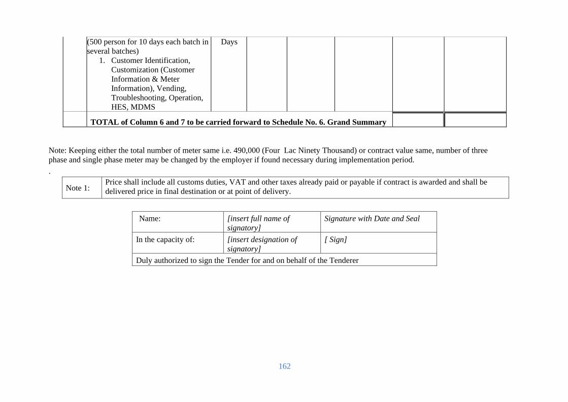
162
(500 person for 10 days each batch in
several batches)
1. Customer Identification,
Customization (Customer
Information & Meter
Information), Vending,
Troubleshooting, Operation,
HES, MDMS
Days
TOTAL of Column 6 and 7 to be carried forward to Schedule No. 6. Grand Summary
Note: Keeping either the total number of meter same i.e. 490,000 (Four Lac Ninety Thousand) or contract value same, number of three
phase and single phase meter may be changed by the employer if found necessary during implementation period.
.
Note 1: Price shall include all customs duties, VAT and other taxes already paid or payable if contract is awarded and shall be
delivered price in final destination or at point of delivery.
Name: [insert full name of
signatory]
Signature with Date and Seal
In the capacity of: [insert designation of
signatory]
[ Sign]
Duly authorized to sign the Tender for and on behalf of the Tenderer

163
For Lot -1:
Schedule No. 6 - Grand Summary
Schedule
No.
Title
Total Price
Local Currency in
BDT
Local Currency in
BDT
2
Plant and Mandatory Spare Parts Supplied Within
the Employer’s Country
3
Design Services
4
Civil work
5
Installation and Other Services
GRAND TOTAL to be carried forward to Form PG5A-1b
Name: [insert full name of
signatory]
Signature with Date
and Seal
In the capacity of: [insert designation of
signatory]
[ Sign]
Duly authorised to sign the Tender for and on behalf of the Tenderer

164
For Lot -1:
Schedule No. 7 - Recommended Spare Parts
Item
Description
Qty
Unit Price Total Price
EXW
Local Parts Local
Currency
CIP
Imported Parts
Foreign
Currency
Local Currency Portion
Foreign Currency Portion
1 2 3 4 5 6 = 3 x 4 7 = 3 x 5
1 All necessary spare parts
recommended by Tenderer
Lot 1
TOTAL
Name: [insert full name
of signatory]
Signature with
Date and Seal
In the capacity
of:
[insert designation
of signatory]
[ Sign]
Duly authorized to sign the Tender for and on behalf of the
Tenderer

165
For Lot -2:
Schedules of Rates and Prices
Schedule No. 1 - Plant and Mandatory Spare Parts Supplied from Abroad - Not Applicable
Lin
e
Ite
m
No
Description of Item Country of Origin Quantity
Unit Price
CIP[insert place of destination]
Or CIF[insert port of destination]
[Foreign Currency]
CIF/CIP price per
Line Item
[Foreign Currency]
Taxes and Duties In
Local Currency
1 2 3 4 5 6 = 4 x 5 7
Column 6 to be carried forward to Schedule No. 5. Grand Summary
Note: 1. The Employer may also use other INCOTERMs, if deemed necessary, In such case Form PG5A-6, will require to be customized by the Employer
2. Specify currencies in accordance with ITT 27. Create and use as many columns for Unit Price and Total Price as there are currencies.
Country of Origin Declaration Form
Item Description Country
Name: [insert full name of
signatory]
Signature with Date
and Seal
In the capacity of: [insert designation of
signatory]
[ Sign]
Duly authorized to sign the Tender for and on behalf of the
Tenderer

166
For Lot -2:
Schedule No. 2 - Plant and Mandatory Spare Parts Supplied from within the Employer’s Country
Line
Item
No.
Description of Item Unit Quantity
Country of
Origin (To be
mentioned)
Unit
Price(including all
Tax,vat) EXW
(Taka)
Total EXW
Price (Taka)
Transportation
cost of goods at
destination
Total Price
(Taka)
BDT BDT BDT BDT
1 2 3 4 5 6 7= 4x6 8 9= 7+8
1 Three Phase Smart Meter (CT/PT rated, class
20)
Numbers 10,000
2 Communication module/chip/ Cellular(GPRS)
including secure plug-in facility along with
RF provision for integration of BREB MDMS
Numbers 10,000
3 Head End System (HES) with related software
(as per solution required) to integrate with
BRBE’s DC and DR. HES with Enterprise life
time License under this project.
Lot
1
TOTAL of Column 9 to be carried forward to Schedule No. 6. Grand Summary
Note
1:
Price shall include all customs duties, VAT and other taxes already paid or payable if contract is awarded and shall be
delivered price in final destination or at point of delivery.
Name: [insert full name of
signatory]
Signature with Date and Seal
In the capacity of: [insert designation of
signatory]
[ Sign]
Duly authorised to sign the Tender for and on behalf of the Tenderer
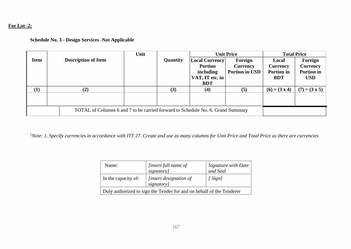
167
For Lot -2:
Schedule No. 3 - Design Services -Not Applicable
Item
Description of Item
Unit
Quantity
Unit Price Total Price
Local Currency
Portion
including
VAT, IT etc. in
BDT
Foreign
Currency
Portion in USD
Local
Currency
Portion in
BDT
Foreign
Currency
Portion in
USD
(1) (2) (3) (4) (5) (6) = (3 x 4) (7) = (3 x 5)
TOTAL of Columns 6 and 7 to be carried forward to Schedule No. 6. Grand Summary
1Note: 1. Specify currencies in accordance with ITT 27. Create and use as many columns for Unit Price and Total Price as there are currencies
Name: [insert full name of
signatory]
Signature with Date
and Seal
In the capacity of: [insert designation of
signatory]
[ Sign]
Duly authorized to sign the Tender for and on behalf of the Tenderer

168
For Lot -2:
Schedule No. 4 –Civil works part -Not Applicable
Item
Description of items
Unit
Quantity
Rate in BDT
including
VAT, IT etc.
Total Amount
in BDT
1 2 3 4 5 6 = 4*5
TOTAL of Column 6 to be carried forward to
Schedule No. 6. Grand Summary
Note: 1. Specify currencies in accordance with ITT 27. Create and use as many columns for Unit Price and Total Price as there are currencies
Name: [insert full name of
signatory]
Signature with Date
and Seal
In the capacity of: [insert designation of
signatory]
[ Sign]
Duly authorised to sign the Tender for and on behalf of the Tenderer

169
For Lot -2:
Schedule No. 5- Installation and Other Services
Item
Description
Unit
Quantity
Unit Price Total Price
Local
Currency
Portion in
BDT including
VAT, IT
etc.
Foreign
Currency
Portion in USD
Local
Currency
Portion in
BDT including
VAT, IT
etc
Foreign
Currency Portion
in USD
1 2 3 4 5 6 = 3 x 4 7 = 3 x 5
1 Installation and comissioning of
three phase smart meter with
GPRS Module and dismantling &
return the old meter to store
numbers
10,000
2 Integration of HES with BREB‟s
MDMS
Lot 1
TOTAL of Column 6 and 7 to be carried forward to Schedule No. 6. Grand Summary
.
Note 1: Price shall include all customs duties, VAT and other taxes already paid or payable if contract is awarded and shall be
delivered price in final destination or at point of delivery.
Note 2: The Tenderer will complete these columns as appropriate following the details specified in section 6:
Schedule of Requirements.
Name: [insert full name of
signatory]
Signature with Date and Seal
In the capacity of: [insert designation of
signatory]
[ Sign]
Duly authorised to sign the Tender for and on behalf of the Tenderer
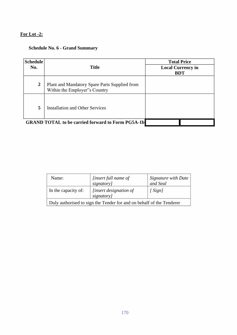
170
For Lot -2:
Schedule No. 6 - Grand Summary
Schedule
No.
Title
Total Price
Local Currency in
BDT
2
Plant and Mandatory Spare Parts Supplied from
Within the Employer‟s Country
5
Installation and Other Services
GRAND TOTAL to be carried forward to Form PG5A-1b
Name: [insert full name of
signatory]
Signature with Date
and Seal
In the capacity of: [insert designation of
signatory]
[ Sign]
Duly authorised to sign the Tender for and on behalf of the Tenderer

171
For Lot -2:
Schedule No. 7 - Recommended Spare Parts
Item
Description
Qty
Unit Price Total Price
EXW
Local
Parts
Local
Currency
CIP
Imported
Parts
Foreign
Currency
Local
Currency
Portion
Foreign
Currency
Portion
1 2 3 4 5 6 = 3 x 4 7 = 3 x 5
1 All necessary spare parts
recommended by Tenderer
Lot 1
TOTAL
Note 1:
Price shall include all customs duties, VAT and other taxes already paid or payable if
contract is awarded and shall be delivered price in final destination or at point of
delivery.
Note 2:
The Tenderer will complete these columns as appropriate following the details
specified in section 6:
Schedule of Requirements .
Name: [insert full name
of signatory]
Signature with
Date and Seal
In the capacity
of:
[insert designation
of signatory]
[ Sign]
Duly authorized to sign the Tender for and on behalf of the
Tenderer

172
Technical Proposal (Form PG5A-4)
[The Revised Technical Proposal, if any, shall follow the same format and structure]
Site Organization
Method Statement
Mobilization Structure
Construction Structure
Plant
Safety Plan
Personnel
Equipment
Proposed subcontractors for Major Items of Plant and Services
Time Schedule

173
Site Organization
The Tenderer shall include in the tender an appropriate organization chart. This shall include head
office as well as site components and clearly demonstrate that the Tenderer possesses the staff and
organizational resources to complete the Supply and Installation of Plant & Equipment.

174
Method Statement
The Tenderer shall furnish an overall description covering all activities and processes from
inception to site works and commissioning.
In particular methods of minimizing the impact on the environment in accordance with the
relevant laws and regulations during the construction phase shall be described.

175
Mobilization Schedule
This shall be included in the overall time schedule to be provided by the Tenderer as per “Time
Schedule” in Section 5.Tendering Forms

176
Construction Schedule
This shall be included in the overall time schedule to be provided by the Tenderer as per “Time
Schedule” in Section5. Tendering Forms

177
Plant
The Tenderer shall provide the plant and equipment it intends to use in the construction process
to demonstrate that it has the capability to complete the Supply and Installation of Plant &
Equipment.

178
Safety Plan
The Tenderer shall demonstrate that it has a comprehensive safety system that will be used
during the construction and installation phase. This system shall meet all safety requirements
in accordance with all relevant laws, rules and regulations.

179
Personnel Information
[This Form should be completed for each person proposed by the Tenderer on Form PG5A-2a&
PG5A-2b, where applicable]
Invitation for Tender No: [indicate IFT No]
Tender Package No [indicate Package No]
This Package is divided into the following Number of Lots [indicate number of Lot(s)]
A. Proposed Position (tick the relevant box)
B. Personal Data
Name
Date of Birth
Years overall experience
Years of specific experience
National ID Number
Years of employment with the
Tenderer
B. Professional Qualifications:
1.
2.
C. Present Employment [to be completed only if not employed by the Tenderer]
Name of Procuring Entity:
Address of Procuring Entity:
Present Job Title:
Years with present Procuring Entity:
Tel No:
Fax No: e-mail address:
Contact [manager/personnel officer]:
D. Professional Experience
Summarise professional experience over the last twenty years, in reverse chronological order.
Indicate particular technical and managerial experience relevant to the project.
From To Company / Project / Position / Relevant technical and management
experience.
1
2
3
Name: [insert full name of signatory] Signature with Date
and Seal
In the capacity of: [insert designation of signatory] [ Sign]
Duly authorized to sign the Tender for and on behalf of the Tenderer

180
Equipment Information
[The Tenderer shall provide adequate information to demonstrate clearly that it has the
capability to meet the requirements for the key equipment listed in TDS . A Separate Form shall
be prepared for each item of equipment listed, or for alternative equipment proposed by the
Tenderer]
Invitation for Tender No: [indicate IFT No]
Tender Package No [indicate Package No]
This Package is divided into the following Number of
Lots
[indicate number of
Lot(s)]
Item of equipment
Equipment
information
Name of manufacturer Model and power rating
Capacity Year of manufacture
Current
status
Current location
Details of current commitments
Source Indicate source of the equipment
Owned Rented Leased Specially manufactured
Omit the following information for equipment owned by the Tenderer.
Owner Name of owner
Address of owner
Telephone Contact name and title
Fax Telex
Agreements Details of rental / lease / manufacture agreements specific to the project
Name: [insert full name of
signatory]
Signature
with Date and
Seal
In the
capacity of:
[insert designation of
signatory]
[ Sign]
Duly authorised to sign the Tender for and on behalf of the
Tenderer

181
Proposed Subcontractors for Major Items of Plant and
Installation Services
A list of major items of Plant and Installation Services is provided below.
The following Subcontractors and/or manufacturers are proposed for carrying out the item of
the facilities indicated. Tenderers are free to propose more than one for each item
Major Items of Plant and
Installation Services
Proposed
Subcontractors/Manufacturers
Nationality
Form Functional Guarantee
The Tenderer shall copy in the left column of the table below, the identification of each functional
guarantee required in the Specification and stated by the Employer in ITT 24(n) and in the right
column, provide the corresponding value for each functional guarantee of the proposed plant and
equipment.
Invitation for Tender No: [indicate IFT No]
Tender Package No [indicate Package No]
This Package is divided into the following Number of
Lots
[indicate number of
ot(s)]
Required Functional Guarantee Value of Functional Guarantee of the
Proposed
Plant and Equipment
1.
2.
3.
4.
5.
6.

182
Specifications Submission and Compliance Sheet (Form PG5A-4a)
Invitation for Tender No: Date:
Tender Package No: Package
Description:
[enter description
as specified in
Section 6]
Tender Lot No: Lot
Description:
[enter description
as specified in
Section 6]
Item
No.
Name of Goods
or Related Service
Countr
y of
Origin
Make and
Model
(when
applicable)
Full Technical Specifications
and Standards
1 2 3 4 5
FOR GOODS Note 1
FOR RELATED
SERVICES
[The Tenderer should complete all the columns as required]
Signature: [insert signature of authorized
representative of the Tenderer]
Name: [insert full name of signatory with National
ID]
In the capacity of: [insert designation of signatory]
Duly authorized to sign the Tender for and on behalf of the Tenderer

183
Manufacturer’s Authorisation Letter (Form PG5A - 5)
[The Tenderer shall require the Manufacturer to fill in this Form in accordance with the
instructions indicated. This letter of authorization should be on the letterhead of the Manufacturer
and should be signed by a person with the proper authority to sign documents that are binding on
the Manufacturer. The Tenderer shall include it in its tender, if so indicated in the TDS as stated
under ITT Sub-Clause29.1(b)]
Invitation for Tender No:
Date:
Tender Package No:
Tender Lot No:
To:
Name and address of Employer]
WHEREAS
We [insert complete name of Manufacturer],
who are official manufacturers of[insert type of goods manufactured], having factories at [insert
full address of Manufacturer’s factories], do hereby
authorize[insert complete name of Tenderer] to supply the following Plant and Equipment,
manufactured by us [insert name and or brief description of the Goods].
We hereby extend our full guarantee and warranty as stated underGCCClause 42 of the General
Conditions of Contract, with respect to the Goods offered by the above Tenderer.
Signed: [insert signature(s) of authorized representative(s) of the Manufacturer]
Name: [insert complete name(s) of authorized representative(s) of the Manufacturer]
Address: [insert full address including Fax and e-mail]
Title: [insert title]
Date: [insert date of signing]

184
Bank Guarantee for Tender Security (Form PG5A– 6)
[this is the format for the Tender Security to be issued by a scheduled bank
of Bangladesh as stated under ITT Clauses32 and 33]
Invitation for Tender No:
Date:
Tender Package No:
Tender Lot No:
To:
[Name and address of Employer]
TENDER GUARANTEE No:
We have been informed that [insert name of Tenderer] (hereinafter called “the Tenderer”) intends
to submit to you its Tender dated [insert date of Tender] (hereinafter called “the Tender”) for the
supply and installation of [description of plant and services] under the above Invitation for
Tenders (hereinafter called “the IFT”).
Furthermore, we understand that, according to your conditions, Tenders must be supported by a
Bank Guarantee for Tender Security .
At the request of the Tenderer, we [insert name of bank] hereby irrevocably and unconditionally
undertake to pay you, without cavil or argument, any sum or sums not exceeding in total an amount
of Tk.[insert amount in figures and in words] upon receipt by us of your first written demand
accompanied by a written statement that the Tenderer is in breach of its obligation(s) under the
Tender conditions, because the Tenderer:
a. has withdrawn its Tender after opening of Tenders but within the validity of the Tender
Security ; or
b. refused to accept the Notification of Award (NOA) within the period as stated under
Instructions to Tenderers (ITT) ; or
c. failed to furnish Performance Security within the period as stipulated in the NOA; or
d. refused to sign the Contract Agreement by the time specified in the NOA; or
e. did not accept the correction of the Tender price following the correction of the
arithmetic errors in accordance with the ITT; or
This guarantee will expire:
(a) if the Tenderer is the successful Tenderer, upon our receipt of a copies of the contract
signed by the Tenderer and the Performance Security issued to you in accordance with
the ITT; or
(b) if the Tenderer is not the successful Tenderer,twenty eight (28) days after the expiration
of the Tenderer’s Tender validity period, being [date of expiration of the Tender validity
plus twenty eight(28) days]

185
Consequently, we must receive at the above-mentioned office any demand for payment under this
guarantee on or before that date.
Letter of Commitment for Bank’s undertaking for Line of Credit (Form PG5A-6a)
[This is the format for the Credit Line to be issued by any scheduled Bank of Bangladesh in
accordance with ITT Clause 15.1(b)]
Invitation for Tender No:
Date:
Tender Package No:
Lot No (when applicable)
To:
[Name and address of the Procuring Entity]
CREDIT COMMITTMENT No: [insert number]
We have been informed that [name of Tenderer] (hereinafter called “the Tenderer”) intends to
submit to you its Tender (hereinafter called “the Tender”) for the execution of the Supply and
Installation of Plant & Equipment of [description of works] under the above Invitation for Tenders
(hereinafter called “the IFT”).
Furthermore, we understand that, according to your conditions, the Tenderer’s Financial Capacity
i.e. Liquid Asset must be substantiated by a Letter of Commitment of Bank’s Undertaking for Line
of Credit.
At the request of, and arrangement with, the Tenderer, we [name and address of the Bank] do
hereby agree and undertake that [name and address of the Tenderer] will be provided by us with
a revolving line of credit, in case awarded the Contract, for execution of the Works viz. [insert
name of works], for an amount not less than BDT [in figure]( in words) for the sole purpose of the
execution of the above Contract. This Revolving Line of Credit will be maintained by us until
issuance of “Taking-Over Certificate” by the Procuring Entity.
In witness whereof, authorised representative of the Bank has hereunto signed and sealed this
Letter of Commitment.
Signature
Signature

186
Notification of Award (Form PG5A - 7)
Contract No: Date:
To:
[Name of Contractor]
This is to notify you that your Tender dated [insert date] for the supply and installation of
plant and Services for [name of contract] for the Contract Price of [state amount in figures
and in words] as corrected and modified in accordance with the Instructions to Tenderers, has
been approved by [name of Employer].
You are thus requested to take following actions:
i. accept in writing the Notification of Award within seven (7) working days of
its issuance pursuant to ITT Sub-Clause 64.1
ii. furnish a Performance Security in the specified format and in the amount of
Tk.[state amount in figures and words] ,within Twenty-eight (28) days from issue
of this Notification of Award but not later than (specify date), in accordance with
ITT Clause 64.3
iii. sign the Contract within twenty eight (28 ) days of issuance of this Notification of
Award but not later than (specify date), in accordance with ITT Clause 69.2
You may proceed with the execution of the supply of Plant and Services only upon completion
of the above tasks. You may also please note that this Notification of Award shall constitute
the formation of this Contract, which shall become binding upon you.
We attach the draft Contract and all other documents for your perusal and signature.
Signed
Duly authorised to sign for and on behalf
of [name of Employer]
Date:

187
Contract Agreement (Form PG5A - 8)
THIS AGREEMENT made the [day] day of [month][year] between [name and address of
Employer] (hereinafter called “the Employer”) of the one part and [name and address of
Contractor] (hereinafter called “the Contractor”) of the other part:
WHEREAS the Employer invited Tenders for certain plant and services, viz, [brief description of
plant and services] and has accepted a Tender by the Contractor for the supply of those plant and
services in the sum of Taka [Contract Price in figures and in words] (hereinafter called “the
Contract Price”).
NOW THIS AGREEMENT WITNESSETH AS FOLLOWS:
1. In this Agreement words and expressions shall have the same meanings as are respectively
assigned to them in the General Conditions of Contract hereafter referred to.
2. The following documents forming the Contract shall be in the following order of precedence,
namely:
(a) the signed Form of Contract Agreement;
(b) the Notification of Award
(c) The Tender and the appendices to the Tender
(d) Particular Conditions of Contract;
(e) General Conditions of Contract;
(f) Technical Specifications;
(g) Drawings;
(h) Price Schedules of Plant and Equipment and;
(i) other document including correspondences listed in the PCC forming part of
the Contract
3. In consideration of the payments to be made by the Employer to the Contractor as hereinafter
mentioned, the Contractor hereby covenants with the Employer to provide the plants and
related services and to remedy any defects therein in conformity in all respects with the
provisions of the Contract.
4. The Employer hereby covenants to pay the Contractor in consideration of the provision of
the plant and services and the remedying of defects therein, the Contract Price or such other
sum as may become payable under the provisions of the Contract at the times and in the
manner prescribed by the Contract.
5. The Appendices listed in the attached List of Appendices shall be deemed to form an integral
part of this Contract Agreement. Reference in the Contract to any Appendix shall mean the
Appendices attached hereto, and the Contract shall be read and construed accordingly.
6. 6. Effective Date (Reference GCC Clause 1) The Effective Date, upon which the period until
the Time for Completion of the Facilities shall be counted from is the date when all of the
following conditions have been fulfilled:

188
(a) This Contract Agreement has been duly executed for and on behalf of the Employer and
the Contractor;
(b)The Contractor has submitted to the Employer the performance security;
(c)An irrevocable Letter of credit has been opened by the purchaser in favor of the contractor
upon written request from the contractor after contract signing. Tender Document for
Advanced Metering Infrastructure with Smart Metering System Page 170 of 569
Each party shall use its best efforts to fulfill the above conditions, for which it is responsible,
at the earliest practicable time.
The contractor shall submit necessary documents to the employer within 1 (one) month from
the date of contract signing to facilitate opening of Letter of Credit (L/C).
IN WITNESS whereof the Employer and the Contractor have caused this Agreement to be duly
executed by t heir duly authorized representatives in accordance with the laws of Bangladesh on
the day, month and year first written above.
[
Signed by, for and on behalf of the Employer
For the Employer: For the Contractor:
Signature
Print Name
Title
In the presence
of Name
Address
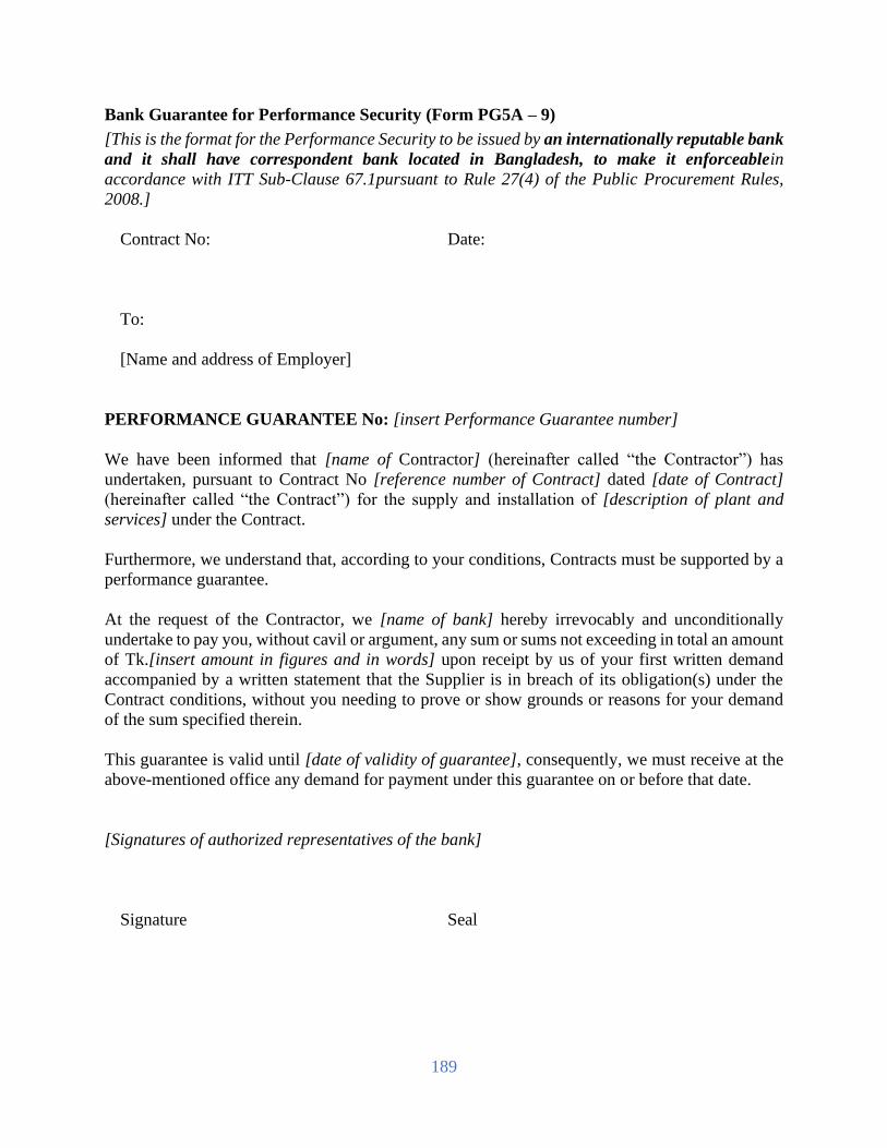
189
Bank Guarantee for Performance Security (Form PG5A – 9)
[This is the format for the Performance Security to be issued by an internationally reputable bank
and it shall have correspondent bank located in Bangladesh, to make it enforceablein
accordance with ITT Sub-Clause 67.1pursuant to Rule 27(4) of the Public Procurement Rules,
2008.]
Contract No:
Date:
To:
[Name and address of Employer]
PERFORMANCE GUARANTEE No: [insert Performance Guarantee number]
We have been informed that [name of Contractor] (hereinafter called “the Contractor”) has
undertaken, pursuant to Contract No [reference number of Contract] dated [date of Contract]
(hereinafter called “the Contract”) for the supply and installation of [description of plant and
services] under the Contract.
Furthermore, we understand that, according to your conditions, Contracts must be supported by a
performance guarantee.
At the request of the Contractor, we [name of bank] hereby irrevocably and unconditionally
undertake to pay you, without cavil or argument, any sum or sums not exceeding in total an amount
of Tk.[insert amount in figures and in words] upon receipt by us of your first written demand
accompanied by a written statement that the Supplier is in breach of its obligation(s) under the
Contract conditions, without you needing to prove or show grounds or reasons for your demand
of the sum specified therein.
This guarantee is valid until [date of validity of guarantee], consequently, we must receive at the
above-mentioned office any demand for payment under this guarantee on or before that date.
[Signatures of authorized representatives of the bank]
Signature
Seal

190
Bank Guarantee for Advance Payment (Form PG5A – 10)
[this is the format for the Advance Payment Security to be issued by an internationally reputable
bank and it shall have correspondent bank located in Bangladesh, to make it enforceable in
accordance with GCC Clause 57.1]
Contract No:
Date:
To:
[Name and address of Employer]
ADVANCE PAYMENT GUARANTEE No.:
We have been informed that [name of Contractor] (hereinafter called “the Contractor”) has
undertaken, pursuant to Contract No [reference number of Contract] dated [date of Contract]
(hereinafter called “the Contract”) for the supply and installation of [description of plant and
services] under the Contract.
Furthermore, we understand that, according to your Particular Conditions of Contract Clause 26.1,
Advance Payment(s) on Contracts must be supported by a bank guarantee.
At the request of the Contractor, we [name of bank] hereby irrevocably unconditionally undertake
to pay you, without cavil or argument, any sum or sums not exceeding in total an amount of
Tk.[insert amount in figures and in words] upon receipt by us of your first written demand
accompanied by a written statement that the Contractor is in breach of its obligation(s) under the
Contract conditions, without you needing to prove or show grounds or reasons for your demand
of the sum specified therein.
We further agree that no change, addition or other modification of the terms of the Contract to be
performed, or of any of the Contract documents which may be made between the Employer and
the Contractor, shall in any way release us from any liability under this guarantee, and we hereby
waive notice of any such change, addition or modification.
This guarantee is valid until [date of validity of guarantee], consequently, we must receive at the
above-mentioned office any demand for payment under this guarantee on or before that date.
[Signatures of authorized representatives of the bank]
Signature
Seal

191
Bank Guarantee for Retention Money Security (Form PG5A-11)
[This is the format for the Retention Money Guarantee to be issued by any scheduled Bank of
Bangladesh in accordance with GCC Clause 57]
Demand Guarantee
[Bank’s Name, and Address of Issuing Branch or Office]
Beneficiary: [insert Name and Address of the Procuring Entity]
Date: [insert date]
RETENTION MONEY GUARANTEE No.: [insert number]
We have been informed that [insert name of Contractor] (hereinafter called "the Contractor") has
entered into Contract Number [insert reference number of the Contract] dated [insert date] with
you, for the execution of [insert name of Contract and brief description of Works] (hereinafter
called "the Contract").
Furthermore, we understand that, according to the conditions of the Contract, when the Taking-
Over Certificate has been issued for the Works and the first half of the Retention Money has been
certified for payment, payment of Tk. [insert the amount of the second half of the Retention
Money] which becomes due after the Defects Liability Period has passed and certified in the form
of Defects Correction Certificate, is to be made against a Retention Money Guarantee.
At the request of the Contractor, we [insert name of Bank] hereby irrevocably unconditionally
undertake to pay you any sum or sums not exceeding in total an amount of Tk. [insert amount in
figures] (Taka [insert amount in words]) upon receipt by us of your first demand in writing
accompanied by a written statement stating that the Contractor is in breach of its obligation under
the Contract because the Contractor failed to properly correct the defects duly notified in respect
of the Supply and Installation of Plant & Equipment.
It is a condition for any claim and payment under this guarantee to be made that the payment of
the second half of the Retention Money referred to above must have been received by the
Contractor on its account number[insert A/C no] at [name and address of Bank].
This guarantee is valid until [insert the date of validity of Guarantee that being twenty-eight (28)
days beyond the Defects Liability Period]. Consequently, we must receive at the above-mentioned
office any demand for payment under this guarantee on or before that date.

192
Section 6. Employer’s Requirements
Table of Contents
6.1 Scope of Supply of Plant and Installation Services by the Contractor 193
6.2 Specification 202
6.3 Form of Completion Certificate 541
6.4 Form of Operational Acceptance Certificate 542
6.5 Change Order Procedure and Forms 543
Annex 1. Request for Change Proposal 545
Annex 2. Estimate or Change Proposal 547
Annex 3. Acceptance of Estimate 548
Annex 4. Change Proposal 549
Annex 5. Change Order 551
Annex 6. Pending Agreement Change Order 552
Annex 7. Application for Change Proposal 553
6.6 Supplementary Information 554

193
6.1 Scope of Supply of Plant and Installation Services by the Contractor
1.0 INTRODUCTION AND GENERAL INFORMATION
1.1 Background
1.2 Project Objectives
Bangladesh Rural Electrification Board (BREB) is planning to implement Advance
Metering Infrastructure to bring about reform in the distribution sector. Through AMI
implementation, BREB aims to mirror the benefits to the customers that can be seen in
a number of countries and can be replicated in Bangladesh Rural Electrification Board
(BREB). In the initial stages of program rollout, the immediate benefits such as reduced
meter reading costs, access to time of use-based tariffs and the cutback in System losses
will be realized. The long-term benefits for BREB eventually include but not limited
to:
i) Improved network visibility and hence reduced or deferred network
reinforcement costs;
ii) Improved management of power outages;
iii) Improved connection processes;
iv) Reduced costs for micro-generation customers;
v) Access to the benefits offered by demand side response;
vi) Losses reduction; and
vii) Improved customer service across a range of routine activities.
viii) Increase Customer satisfaction.
While the introduction of smart meters will bring the immediate benefits to customers,
their full potential in relation to network-related benefits will only be realized when
customers start to adopt behavioral changes in power consumption.
1.3 Advanced Metering Infrastructure
AMI (Advanced Metering Infrastructure) is not a single technology, but rather an
integration of many technologies that provides an intelligent connection between
consumers and Power Utilities. AMI is the collective term to describe the whole
infrastructure from Smart Meter to two way-communication networks to control center
equipment and all the applications that enable the gathering and transfer of energy usage
information in near real-time. AMI makes two-way communications with customers
possible and is the backbone of smart grid. The objectives of AMI can be remote meter
reading for error free data, network problem identification, load profiling, energy audit
and partial load curtailment in place of load shedding.
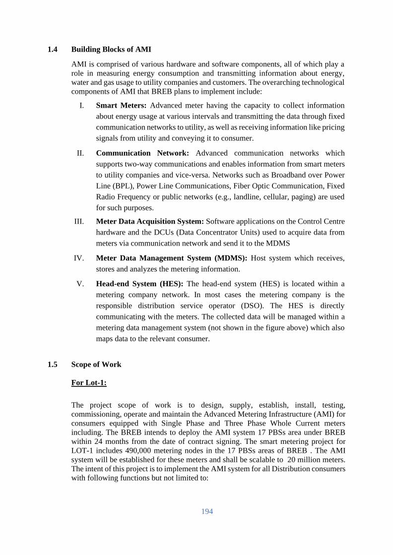
194
1.4 Building Blocks of AMI
AMI is comprised of various hardware and software components, all of which play a
role in measuring energy consumption and transmitting information about energy,
water and gas usage to utility companies and customers. The overarching technological
components of AMI that BREB plans to implement include:
I. Smart Meters: Advanced meter having the capacity to collect information
about energy usage at various intervals and transmitting the data through fixed
communication networks to utility, as well as receiving information like pricing
signals from utility and conveying it to consumer.
II. Communication Network: Advanced communication networks which
supports two-way communications and enables information from smart meters
to utility companies and vice-versa. Networks such as Broadband over Power
Line (BPL), Power Line Communications, Fiber Optic Communication, Fixed
Radio Frequency or public networks (e.g., landline, cellular, paging) are used
for such purposes.
III. Meter Data Acquisition System: Software applications on the Control Centre
hardware and the DCUs (Data Concentrator Units) used to acquire data from
meters via communication network and send it to the MDMS
IV. Meter Data Management System (MDMS): Host system which receives,
stores and analyzes the metering information.
V. Head-end System (HES): The head-end system (HES) is located within a
metering company network. In most cases the metering company is the
responsible distribution service operator (DSO). The HES is directly
communicating with the meters. The collected data will be managed within a
metering data management system (not shown in the figure above) which also
maps data to the relevant consumer.
1.5 Scope of Work
For Lot-1:
The project scope of work is to design, supply, establish, install, testing,
commissioning, operate and maintain the Advanced Metering Infrastructure (AMI) for
consumers equipped with Single Phase and Three Phase Whole Current meters
including. The BREB intends to deploy the AMI system 17 PBSs area under BREB
within 24 months from the date of contract signing. The smart metering project for
LOT-1 includes 490,000 metering nodes in the 17 PBSs areas of BREB . The AMI
system will be established for these meters and shall be scalable to 20 million meters.
The intent of this project is to implement the AMI system for all Distribution consumers
with following functions but not limited to:

195
I. Capability to access AMI meter data at regular intervals and provide all
information on a single console in an integrated manner with the possibility to
remotely control the entire network and increase operational efficiency.
II. The contractor shall establish network platform that can support the multiple
applications like AMI, GlS, DMS etc. Over a single communications platform
using RF communication technology.
III. The contractor shall establish network platform that can support the multiple
applications like AMI, GIS, DMS, Street Light Management and HAN etc. over
a single communications platform using RF communication technology.
IV. The Network canopy to be established using RF communication technology
shall communicate with field devices using intermediate network elements such
as routers/ repeaters/ collectors/ gateways/ data concentrator’s units/ access
points etc.
V. The contractor shall install smart meter and create a RF communication canopy
at the meter installation locations but there shall be provision for GPRS and
PLC.
VI. The contractor will supply, install, configure, commissioning all related
software (HES, MDM, Database, Application Server, Mobile Apps/Mobile
Vending/Online Vending etc.) and hardware (Data Center & Disaster Recovery
Center for 5 million scalable to 20 million meters) for effective AMI
management.
1. Site Survey of client locations to assess the following:
a. Electrical network/grid.
b. Communication infrastructure.
c. IT/Automation Systems.
d. O&M Processes pertaining to the network
e. Existing Business Processes etc.
2. Site survey for the identification of network design (equipment locations etc.)
and detailing out comprehensive bill of material with project inception report.
3. Prepare a detailed project plan & implementation schedule including the following:
a. Develop an overall AMI system architecture capable of upgrades and
scaling as per future requirements.
b. System security and access with due consideration of data privacy,
confidentiality cyber security guidelines etc.
c. Communication network engineering and designing of
communication canopy for 17 PBS under BREB license area.

196
4. Install, test and commissioning of the proposed solution.
5. Suggest the updated business processes for organization under the AMI project
scope e.g. Metering Business Process.
6. Supply, installation and commissioning of necessary hardware, software& support
systems.
7. Integration with existing legacy system like postpaid billing system with MDM if
feasible.
8. Establishment of AMI communication network canopy.
9. Supply and Commissioning of Data Concentrator Unit/Gateway/Access
Point/Collector/Repeater/Router etc.
10. Supply, Install and Commissioning of Smart Prepaid Meters.
11. Head End System
12. Meter Data Management System
13. Development of Interface with mobile app and web portal/dashboard.
14. Interface supplied RF Network Interface Card (NIC)/RF Communication
module/chip with plug-in facility with smart meter which will be selected in
upcoming tender or interested meter manufactures as per BREB‟s instruction.
15. Third party Management System for vending or online vending etc.
16. To successfully complete the project if anything deemed necessary Employer can
demand accordingly
For Lot-2:
Supply, installation and integration with BREB MDMS of 10,000 (ten thousand) 3 phase
CT/PT rated, class 20 meter in 11 KV feeder of 80 PBS and HT(11 KV) consumers in 17 PBS
within 24 months from the date of contract signing.
The intent of Lot-2 under this project is to install and integrate 3 phase CT/PT rated, class
20, AMR meter with BREB MDMS system for 11 KV feeder of 80 PBS and HT (11 KV)
consumers with following functions but not limited to:
I. The contractor of “SPPM-MCS-01; Lot-2:” will design, supply and install of 10 thousand
3 phases, CT/PT Rated, Class 20, AMR meter with HES and integration with BREB
MDM & Server System for effective AMI management.
II. The contractor will be responsible for Integration/Interfacing with HES.
III. The contractor shall establish network connectivity that can support the multiple
applications like AMI, GIS etc. over a single communications platform using GPRS
communication technology.
IV. The contractor shall install 3 phase, CT/PT Rated, Class 20, AMR meter and
create a GPRS communication canopy at the meter installation locations.
1.6 Basic Functions of AMI
The AMI system shall help utility to manage their resource and business process
efficiently. AMI system shall support the following minimum functionalities:

197
i. Remote Meter data reading at configurable intervals (push/pull SMS)
ii. Time of day (TOD)/TOU metering
iii. Pre-paid functionality following Bangladesh Energy Regulatory
Commission (BERC) rules and existing Unified Prepaid Metering
System Business logic.
iv. Net Metering/Billing
v. Alarm/Event detection, notification and reporting
vi. Remote Load Limiter and connection/ disconnection at defined/on
demand conditions
vii. Remote firmware upgrade
viii. Integration with other existing systems like Postpaid billing
software, GIS mapping, consumer indexing, new connections &
disconnection, analysis software, Outage Management System etc.
ix. Security features to prevent unauthorized access to the AMI including
Smart meter & meter data etc. and to ensure authentication of all AMI
elements by third party.
This is only an indicative but not exhaustive list. The system should be capable to
support the other functionalities as per the requirement of BREB as mutually agreed
with vendor. The System should accurately maintain system time synchronization
across all devices to ensure accuracy of data. The system should support the interfacing
with the future Smart Grid functionalities like outage management system, distribution
automation including self-healing system, distribution transformer monitoring units,
Electric vehicle, distributed energy resources etc. The communication network shall
preferably be able to support multiple applications.
The Bidder shall submit an approach paper describing overall architecture and
operational philosophy of the proposed AMI solution and methodology for achieving
different functionalities, specified in this document and also highlight additional
features, if any.
1.7 Advanced Metering Infrastructure (AMI) tentative Rollout Plan
Tenderer will submit AMI implementation plans as per the below table:
Plan Phase – 1 Phase -2
Timeline FY 20-21 FY 21-22 FY 22-23 FY 22-23
1.8 Domain Philosophy

198
Work for AMI will be carried out under the following three domains:
I. Domain -1 - Smart Meters
II. Domain -2 - Communication Infrastructure (Head End System,
NIC, Router/Gateway, Data Collector/Concentrator etc.)
III. Domain -3 - Meter Data Management System (MDMS) &
Associated Applications
1.9 Design, Supply and Installation of AMI System
I. It includes the designing, supply and installation of single phase, three phase
(LT&HT), and other meter smart meters along with the network communication
canopy.
II. Supply and installation of meter data management and acquisition systems that
enables two-way communication between BREB‟s smart metering system and
customers. Supply and installation of necessary hardware and software for
successfully running the AMI system operations.
1.10 Proposed AMI Architecture
Proposed AMI architecture is given below. Considering that AMI solutions are
still evolving, appropriate changes to optimize system performance may be made
in the architecture during the implementation period. Overlapping of domains
indicates the integration requirements among the domains.
1.11 Establishment of Last Mile Communication
I. The Bidder shall carry out the establishment of RF network canopy, to be used
for providing the last mile connectivity for communicating with the AMI, DMS,
GIS, Street light management etc.
II. In case of RF canopy, the bidder shall establish the RF canopy, operating in the
unlicensed frequency bands and be capable of two-way communications.
III. The established network canopy shall be IPv6 technology compliant.

199
IV. The network canopy should be designed to operate at minimum 80% of designed
capacity in normal operation (peak data requirement with guaranteed
performance) for full scale deployment.
V. BREB envisions that the last mile communication infrastructure thus created shall
be scalable over the air for supporting more end-point deployments and other
applications in future. The system shall remain fully operational in the next 10
years and shall consequently not be affected by obsolescence.
VI. Contractor shall use a DCU or Router-based RF canopy for providing last mile
connectivity to the nodes envisaged to be connected by BREB‟s Smart
Metering System.
VII. The required data from the field devices and smart meters shall reach the
DCU/Access Points etc. through the networking elements such as Routers,
Repeaters, and Extender Bridges etc.
VIII. Contractor shall use the GSM/GPRS(Cellular) & Fiber Optics connectivity to
connect the DCU/Access Points to the data center where optical fiber connectivity
is unavailable.
1.12 Integration Requirement
Bidder has to submit an End-to-End Integrated AMI solution and architecture clearly
depicting integration between Electricity Meters, Data Concentrators, Head-End
System (HES), Meter Data Management System (MDM) and other Distribution
applications.
The proposed architecture should guarantee the capability of High Availability,
High Security with High Performance in full load for the components like
concentrators/access points. The software performance shall be tested through
virtual metering point simulation tools which will be provided by the bidder
The scope of integration with external systems includes the already existing and
functional IT systems in utility and any other system commissioned during the AMI
system implementation. The integration is expected to be on-line real time or batch
wherever appropriate and shall operate in an automated fashion without manual
intervention.
The Proposed system and overall software solution should be capable of SOA or any
other open-source integration methodology based integrating with external systems
(BI, Reporting System, Other MDM/RMR etc.). The integrated systems should be
capable of communicating and sharing data with each other or any other external
system as required by BREB to generate the following benefits:
I. Data Analytics
II. Alert and Alarm
III. Dashboard
IV. Business intelligence (BI)Reports

200
V. Any other external system
BREB has started the modernization of Distribution Sub-station network through
Sub-station automation system. Under this new system, BREB has planned to
implement Distribution Management system (DMS), Outage Management system
(OMS).
BREB will also implement other smart grid solution in coming future. Therefore,
the proposed system and overall solution shall be capable to support the vision of
modern/ smart grid. It shall be capable to integrate with modern distribution center
and support latest grid automation technologies as well.
Moreover, BREB is also encouraging renewable energy-based generation such as
Photo voltaic generation and inject the green energy into BREB‟s network. Net
metering is being used to record the total amount of green energy injected into the
network of BREB. The AMI shall also support necessary communication with net
meter to monitor the energy generated from Distributed Generation sources.
1.13 Commissioning and Testing of System
I. The supplied hardware and software solution by contractor shall meet the necessary
standards, compliance and testing criteria.
II. Bidder shall carry out the commission and acceptance of overall AMI system in
compliance to BREB requirements.
III. The supplied hardware, software and energy meters shall have the warranty period
of minimum 3 years along with 2 years operational support, post completion of the
required duration.
IV. Minimum life of RF communication canopy solution including complete hardware
and software (excluding third party software) shall be for 3 years.
1.14 Cyber Security of AMI System
I. Contractor will define the AMI security controls including the description of
security requirements, rational and implementation guideline.
II. Bidder shall map the security controls of AMI logical components from
systems architecture definition.
III. Bidder shall develop the security architecture and detailed design of AMI
components.
IV. Support Security assessment: On completion of Enterprise wide AMI system
acceptance and Go-live, the bidder, in coordination with BREB will carry out
an extensive cyber and information security assessment / audit and testing
through third party network / cyber threat analyst. Based on the findings of
assessment and testing, the Bidder will fix and resolve any high severity issues
and provide a plan around medium and low severity issues.
i. Network and security architecture review and recommendation – Bidder
is expected to comply with leading industry practices and standards for

201
securing network architecture as well as recommendation for secure
configuration of devices.
ii. Vulnerability assessment – The bidder is expected to provide technical
resolution to patch any discovered/ known vulnerabilities in the
systems/ applications deployed.
iii. Penetration testing – The bidder is expected to enhance the Information
Security posture of its infrastructure (network and applications) through
placement of appropriate security solutions
1.15 Documentation
The successful Bidder will provide ongoing product information for referential
purposes and facilitating self-education by BREB‟s personnel. The scope shall
include but not limited to the below deliverables:
V. User Manuals
VI. System Administrator Manuals
VII. OEM Functional Manuals
VIII. Technical Manuals Installation Guides
IX. Business Process Guides
X. Program Flow Descriptions Sample Reports
XI. Troubleshooting Guides FAQ Guides
XII. Dataflow diagram, database manual, use case diagram
XIII. All meter related and other software
Hard copy and soft copy of user manuals are expected to be provided by the successful
Bidder. These should include information on the application concepts in addition to
transaction and field level documentation.
Selected Bidder will be expected to assist in the developing of operational procedure
manuals for the Utility AMI systems. The user manuals shall be provided in the word
format so that client has flexibility to customize them into their own manuals to include
specific business processes or operational procedures.

202
6.2 Specification

203
Bill
of
Materials for Lot-1

204
1. BILL OF MATERIALS
The quantity shown in Bill of Quantity (BOQ) is the minimum requirement.
However, the tenderer must perform their own assessment in order to meet the desired
services, performance requirements and successful operation of AMI system and shall
consider any necessary items which is not included in BOM and price schedule in
preparing their proposals. The offered solution of the tenderer shall be complete in all
respect for 5 lac meters and shall be scalable up to 20 million meters. The cost of those
items not included in the Bill of materials and price schedule but necessary for
successful implementation of the project shall be deemed to have been included in the
financial offer of the tenderer.
2. Project Bill of Materials
Sl.
No. Item Name Unit Quantity
Remarks
1. Single Phase Smart
Meters Numbers 480000
2. Three Phase Smart Meters Numbers 10000
3. Plug-in type RF
NIC/Module/Chi
p
Numbers
468000
4. 2G Module Numbers 22000
5. DCU/Gateway Numbers 1667
6. Repeater Numbers 6668
7. Hand Held Units
(HHU) Numbers 34
8. Pole (60’-2 ) or
higher) with
necessary
equipment
Numbers 8335
9. RF based Network
Establishment
Data Collector/Access
Point Routers/Repeaters
(Inclusive of all necessary
accessories) with redundant
data bandwidth for Data
Collector
Lot
1

205
10. Meter Data Management
Software with
application server for DC
and DR for
5.0 Lac smart meter and
scalable up to 20 million
meters (Enterprise life time
License) and Vending
System software
Lot
1
11. Head End System Software
with related software for
DC and DR for
5.0 Lac smart meter
scalable up to 20 million
meters (Enterprise life time
License)
Lot
1
12. Enterprise Database
Perpetual License:
• DB Enterprise
Edition
• Real Application
Cluster (RAC)
• Active Data
Guard
• Diagnostics Pack
• Tuning Pack
• Partitioning
set
1
13. Middlewire Suite
Number 32 units
14. Data Connectivity for DC
to DR
Bandwidth
200 Mbps
15. Data Connectivity for
DCU/Gateway/Router
to System
Bandwidth
2 Mbps per site
16. Data Connectivity for DC
& DR to 17 PBS with 34
UCC & UVS stations
Bandwidth 2 Mbps per
Station
17. AMI System
Establishment Services
(Designing, Field Survey,
Installation, Testing,
commissioning,
Deployment, Training,
Configuration etc. services
for the complete system)
Lot
1

206
18. Integration Services for
Integration with Utility
existing and upcoming
Systems
Lot
1
19. Training Services Lot 1
20. Facility Management
Services Year 3
21. AMI System OSS Year 2
22. Any other equipment
required for successful
deployment of project
Lot
1
23. Database Server set DC-1
DR-1
24. General Purpose Storage Number DC-1
DR-1
25. Database Storage Number DC-1
DR-1
26. SAN Switch Number DC-4
DR-4
27. Application Server Number DC-2
DR-2
28. Database backup System set DC-1
29. Server for HES, MDM and
related software
/application
Number DC-4
DR-2
30. Virtualization and
Container Infrastructure for
Other Services
set DC-1
31. Tape Library for Archival Number DC-1
32. Server Load Balancer Number DC-2
DR-2
33. Work Station Number DC-35
DR-15
34. WAN Switch Number DC-2
DR-2
35. Core Router Number DC-2
DR-2

207
36. Core Switch Number DC-2
DR-2
37. Core firewall Number DC-2
DR-2
38. Server Firm switch Number DC-4
DR-4
39. Internet router Number DC-2
DR-2
40. Web Application firewall Number DC-1
DR-1
41. Distributed Switch Number DC-3
DR-2
42. Access switch Number DC-20
DR-20
43. Central Firewall
Management Set DC-1
DR-1
44. DMZ switch number
DC-2
DR-2
45. Operating System,
Hypervisor, Container
Software license
set DC-1
46. Antivirus Software set DC-1
47. Identity and Access
management set DC-1
DR-1
48. Modules and Interfaces set DC-1
49. Network Monitoring
System Set DC-1
50. Application Management
System set DC-1
51. Helpdesk and problem
ticketing set DC-1
52. Passive Infrastructure
Technical specification all
server room construction
set DC-1
DR-1

208
53. Civil Infrastructure interior Lot
DC-1
DR-1
54. Electrical Infrastructure set
DC-1
DR-1
55. Raise floor system set
DC-1
DR-1
56. Accessories Set
DC-1
DR-1
57. Rack with cold container set
DC-1
DR-1
58. Online modular UPS with
lithium-ion batteries for IT
load
set DC-2
DR-2
59. Online modular UPS with
lithium-ion batteries for
Cooling equipment and
other non-critical load
set DC-2
DR-2
60. Rack mount static transfer
switch STS/ATS set DC-4
DR-2
61. Metered Rack PDU (single
phase) Set DC-16
DR-16
62. Precision Air Conditioner
(PAC) set DC-4
DR-2
63. Data center Infrastructure
monitoring set DC-1
DR-1
64. IP KVM set
DC-6
DR-4
65. Floor mount isolation
transformer set DC-2
DR-2
66. Modular UPS power
distribution set DC-2
DR-2
67. Comport Cooling set
DC-4
DR-4
68. Rodent system
set
DC-1
DR-1
69. VESDA Set
DC-1
DR-1

209
70. Fire detection and
suppression system set DC-1
DR-1
71. Access Control system set
DC-1
DR-1
72. IP CAM and surveillance
solution set DC-1
DR-1
73. Generator Number
DC-1
DR-1
74. AVR Number
DC-2
DR-2
75. TVSS Number
DC-2
DR-2
76. Data center Rated-3
Certification Lot DC-1
DR-1
2.1. Utility Vending Station (UVS) Hardware
Sl. No. Description of Items Unit of
Measurement Quantity
1. Workstation Number 1
2. GRPS/EDGE/EVDO
Modem
Number 2
3. SIM Card Number 2
4. lip Printer Number 1
5. Barcode Scanner Number 1
6. Laser Printer Number
1
7. Laptop Number 1
8. VPN router Number 1
9. UPS 5KVA 2 hr. backup Number 1
10. AC’s with related material
and services
Number 1
11.
Civil Works (with chair,
table): existing infra-
structure development for
the UVS
Lot
1

210
2.2. Utility Customization Center (UCC) Hardware
Sl. No. Description of Items Unit of
Measurement Quantity
1. Workstation Number 1
2. GRPS/EDGE/EVDO
Modem
Number 2
3. SIM Card Number 2
4. Slip Printer Number 1
5. Barcode Scanner Number 1
6. Laser Printer Number 1
7. Laptop Number 1
8. VPN router Number 1
9. UPS 5KVA 2 hr. backup Number 1
10.
Civil Works(with chair,
table): existing infra-
structure development for
the UCC
Lot 1
4. Foreign training schedule
Sl.
No.
Course Intended trainee Course
length,
man days
(excluding
travel
time)
Number
of trainees
Location
1 HES &
Communication
(DCU, Module
and Repeater)
Maintenance and
System responsible
300 30 Country of
OEM
2 MDM
Maintenance and
System responsible
100 10 Country of
OEM
3 Database
Maintenance and
System responsible
100 10 Country of
OEM
4 Data Center Maintenance and
System responsible
100 10 Country of
OEM
4.1. Alternative of Foreign training schedule:
Sl.
No.
Course Intended trainee Course
length,
man
days
Number
of
trainees
Location
1 HES &
Communication
Maintenance and
System responsible
1500 50 Employer’s
Country

211
(DCU, Module and
Repeater)
2 MDM
Maintenance and
System responsible
1500 50 Employer’s
Country
3 Database
Maintenance and
System responsible
900 30 Employer’s
Country
4 Data Center Maintenance and
System responsible
900 30 Employer’s
Country
4.2. Local Training
Sl.
No.
Course Intended
trainee
Course
length,
man days
Number
of
trainees
Location
1 Local Training:
(500 person for 10 days
each batch in several
batches)
Customer Identification,
Customization (Customer
Information & Meter
Information), Vending,
Troubleshooting,
Operation, HES, MDMS
*(May vary as per purchaser
requirement):
Maintenance
and System
responsible
5000 500 Employer’s
Country
5. Standard Network Architecture & Cabling System
Sl.
No.
Item Name Unit Quantity Remarks
1 Network Infrastructures development in
whole building and Smart Wi-fi System
Solution
set 1 - Main
Building
2 Network Infrastructures development in
whole building and Smart Wi-fi System
Solution
set 2- Training
Building
3 Network Infrastructures development in
whole building and Smart Wi-fi System
Solution
set 3-
Executive
Building
6. 17 PBS of BREB
Sl.
No.
Item Name Unit Quantity Remarks
1 Dhaka PBS-1/2/3/4, Gazipur PBS-1/2,
Narayangonj PBS-1/2, Narsingdi PBS-1/2,
Munshigonj PBS, Manikgonj PBS,
Mymensingha PBS-2, Commilla PBS-1/2/3/4
set
1

212
Bill of
Materials for
Lot-2

213
1. BILL OF MATERIALS
The quantity shown in Bill of Quantity (BOQ) is the minimum requirement. However,
the tenderer must perform their own assessment in order to meet the desired services,
performance requirements and successful operation of AMI system and shall consider
any necessary items which is not included in BOM and price schedule in preparing
their proposals. The offered solution of the tenderer shall be complete in all respect
for 5 lac meters and shall be scalable up to 20 million meters. The cost of those items
not included in the Bill of materials and price schedule but necessary for successful
implementation of the project shall be deemed to have been included in the financial
offer of the tenderer.
1. Three Phase Smart Meter (CT/PT rated)
Sl.
No.
Item Name Unit Quantity Remarks
1
Three Phase Smart Meter
(CT/PT rated, class 20)
Numbers
10000
2
Communication module/chip/
Cellular(GPRS) including secure
plug-in facility along with RF
provision for integration of
BREB MDMS
Numbers
10000
3 Head End System (HES) with
related software (as per solution
required) to integrate with
BRBE’s DC and DR. HES with
Enterprise life time License
under this project.
Lot
1

214
LIST OF ABBREVIATION
2. List of Abbreviation
AMCC Advanced metering control computer MDM
AMI Advanced Metering Infrastructure
AMR Automatic Meter Reading
AP Access Point or Gateway
ASTM American Society for Testing and Materials
BI Business Intelligence
BMS Billing Management System
BOQ Bill of quantity
BREB Bangladesh Rural Electrification Board
BS British Standards
CoAP Constrained Application Protocol
COSEM Companion Specification for Energy Metering
CPP Critical Peak Pricing
CPU Central Processing Unit
DA Distribution Automation
DAT Digital Audio Tape
DC Data Center
DCU Data Concentrator Unit
DER Distributed Energy Resources
DIN Detaches Institutfür Normung
DLMS Device Language message specification
DMZ Demilitarized zone
DR Disaster Recovery
DT Distribution Transformer
EMC Electromagnetic Compatibility
EMS Energy management System
FAN Field Area Network
FAQ Frequently Asked Question
FIFO First In First Out
FRTU Field Remote Terminal Units
GIS Geographic Information System
GPRS General Packets Radio Service
GPS Global positioning system
GSM Global System for Mobile communications
GUI Graphical User Interface
HAN Home Area Network
HES Head End System
IDS Intrusion detection system

215
IEC International Electro technical commission IPS Intrusion prevention system
ISO International Organization for Standardization
IT Information Technology
LCD Liquid Crystal Display
LED Light Emitting Diode
LT AMI
SPM
Low Tension Advanced Metering Infrastructure Smart Prepayment
Metering
LV Low Voltage
MB Mega Byte
MDAS Meter Data Acquisition System
MDM Meter Data Management
MDMS Meter Data Management System
MIC Master Information Centre
MOC Meter Operations Center
MTTF Mean time to failure
MV Medium voltage
NAN Neighbour Area Network
NMM Network Management Module
NMS Network Management System
NTP Network Time Protocol
OEM Original Equipment Manufacturer
OFC Optical Fiber Cable
OFDM Orthogonal Frequency Division Multiplexing
OMS Outage Management System Module
OSS Operational Support Service
OTA Over The Air
PBS Palli Biddyut Samity
PDH Plesiochronous digital hierarchy
PLC Power Line Communications
PQM Power quality Monitor
RAM Random Access Memory
RF Radio Frequency
RFP Request for Proposal
RTC Real Time Clock
SAN Storage area network
SDH Synchronous Digital Hierarchy
SLA Service Level agreement
SMS Short Message Service
SNMP Simple Network Management Protocol
SNTP Simple Network Time Protocol
STS Standard Transfer Specification
TAT Turnaround Time

216
TB Tera Byte
TCP/IP Transmission Control Protocol/Internet Protocol
TOU Time of Usage
TTF Time to first failure
UCC Utility Customization Centre
UVS Utility Vending Station
VDE Verb and Deutscher Elektro trchnikere.V.
VEE Validation, Estimation, and Editing
VS Vending System
WAN Wide Area Network
XML Extended Markup Language

217
FUNCTIONAL AND TECHNICAL REQUIREMENTS
Introduction
Rural Electrification Program in 1977 under Area Coverage Rural Electrification was to ensure
reaching power to the vast rural areas of the country to help improve the socioeconomic stratum of the
rural multitudes. The Board in this noble stride, commenced its institutional development and
operational activities on 01 January 1978 and since then it has encountered many challenges and
accomplished a great deal to become, beyond doubt, a true national infrastructure development
program by drawing interest and trust of the people through-out the length and breadth of the country.
Rural Electrification program over the past thirty nine years is dedicated to ensuring
continuous growth and development in rural and suburban infrastructure, and has registered some very
positive gains for the rural multitudes in respect to significantly increasing the rate of literacy,
promoting health and family welfare, new employment facilities to rural men and women, increasing
productivity both in farms and small & large industries and also help developing industrial habit
hitherto unknown to the rural people.
Communication canopy would span across the license area of BREB providing communication
connectivity to all field elements including smart meters, DA devices, DER (Distributed Energy
Resources) integration, EV charging points, sensors, streetlights point etc. The envisaged high level
architecture diagram is given below:
INTRODUCTION
This document describes the requirements to be met Low Tension Advanced Metering Infrastructure
Smart Prepaid Metering (LT AMI SPM) system of Bangladesh Rural Electrification Board (BREB).
The purpose of the document is to familiarize the Supplier with the requirements for all system
components, as well as to provide additional clarifications that shall assist in the defining of
wholesome functional requirements of applied systems that should be supplied.
Overview of LT AMI SPM System LT AMI SPM system include the following main components as the following:
I. LT AMI SPM meters for measurement and supply control of energy to customers;
II. Communication modules for LT AMI SPM meters based on RF mesh and digital cellular (GPRS);
III. Data Concentrator Unit (DCU) or Gateway or Access Point (AP) for collect and exchange metering data between meter & Head End System;
IV. Head End System for data collection from, configuration and control of LT AMI SPM meters and communication equipment;
V. Meter Data Management System for management of information of LT AMI SPM meters, customers, communication equipments, and processing of collected metering data;
VI. Vending System for generating tokens and management of prepayment accounts for LT AMI SPM meters including management of payment channels for the prepayment operation;
VII. Prepayment customer Portal for consumers to recharge prepayment accounts and monitor

218
consumptionShort Message Service capability to interface to an SMS system to send short message to customers about low credit, emergency message, and etc.;
VIII. Short Message Service capability to interface to an SMS system for sending short message to customers about low credit, emergency message etc.;
IX. Servers, storages, network equipments for LT AMI SPM system.
The figure below is conceptual architecture of BREB’s LT AMI SPM system.
The LT AMI SPM as a whole must be architected and designed in such a manner to:
I. Minimize data loss and data latencies while ensuring, by design, high system reliability,
scalability to beyond the initial pilot project area;
II. Ensure cyber security and information protection by design;
III. Facilitate efficient recoverability from major disruptions caused by major outage events and natural events like storms; and
IV. Allow system maintainability, upgradeability and extensibility to more utility applications in the future.
V. All field equipment (meters, communication module, repeaters & data concentrators, etc.) shall be configurable and upgradable from local and remote.
The System shall comply with applicable industry standards. All components shall support IPv6.
LT AMI SPM meter LT AMI SPM meters are end points of the system. They are essentially solid state meters that meets
BREB meter codes and standards – plus the following components manufactured and integrated
into the meter under glass: I. Communication module to enable two‐way communications with the LT AMI SPM
communication network.

219
II. One or more microprocessors to provide the data processing capabilities within the meter to enable the LT AMI SPM functions, e.g. meter register read processing, power outage detection and notifications; self‐monitor and diagnostics, etc.
III. Persistent data storage to allow short‐term retention of meter data and events in case of communication system failures.
IV. Energy storage to allow the meter to maintain certain key functions for a short term in case of power outages such as “last‐gasp” power outage notifications.
V. An internal time clock that allows automatic time sync with the Head End System to provide accurate timestamps of meter reads and detected events.
Communication network and equipment The LT AMI SPM Communication Network provides network connectivity for the various LT AMI
SPM components together, allowing efficient and reliable communications among them. The major
communication technology types that BREB considers include Radio Frequency and Cellular. Data
concentrator unit (DCU) or Gateway or Access Point (AP), which provides two‐way communications
between a number of LT AMI SPM meters and HES Repeaters are used as needed to extend the reach
of the concentrators.The communication network between meters and the data concentrators is often
referred to as the Neighbor Area Network (NAN) or Field Area Network (FAN). The communication
network between the data concentrators and the Head End System is called the Wide Area Network
(WAN) or backhaul.
Network Management System The NMS consists of a set of applications to support the operation and maintenance of the LT AMI
SPM network, including the following functions: I. Facilitating remote, automatic provisioning and configuration of network equipment and
devices
II. Processing network alarms and events in real‐time, reporting or forwarding the events to the responsible staff
III. Monitoring, analyzing network performance metrics (e.g. message and data latency, missing data, loss of communications) by area and by equipment (e.g. gateway, router…)
IV. Management of device communications (e.g., SNMP Management Information Base)
V. Enabling role‐based access control and other cyber security measures.
Data Collection Automation of Remote Meter Data Collection
The LT AMI SPM meters shall able to collect power data and automatically send information on
power use to BREB through customizable scheduled interval. This function shall be performed
automatically or on-demand. It should also be able to group the meters and specify different interval
collection rate for each group.
Automatic change of seasonable timetable The LT AMI SPM meters shall have the capability of automatically update the measurements based
on predefined time and season rules. LT AMI SPM meters shall register date and time data in
accordance with the on-going season of year.
Interoperability LT AMI SPM meter software and hardware should be friendly to accumulate devices of any
manufacturers if the manufacturer produces devices following a employers prevailing standards.

220
Interoperability between devices and equipment is key, as the introduction of LT AMI SPM
system should not create a barrier to competition or unnecessary costs. An open or interoperable
metering system permits transparent access and integration among equipment and applications.
Especially considering that the procured SPPMS will be the base platform not only for this project
but also for the future expansion of SPPMS, interoperability is one of the most requirements. It
shall also support multi-application such as distribution automation and smart cities on the same
network infrastructure.
Communications Capabilities The meters shall be provided with communication ports and communication protocols for local
and remote communications.The smart metering system shall support secure data communication
to ensure the confidentiality, integrity and availability of the data and commands.
Meter Repeater This function allows the system to reach those meters that are not accessible easily by DCU or are
far away from the feeder/DCU.Depending on situation, separate repeater can be used instead of
meter repeater.
Firmware upgrade HES, DCU & Smart meters shall receive regular software and firmware upgrades that introduce
new features and functionalities so as to be future-proof. Firmware upgrades can be pushed to
devices over the air automatically and perform audits to trace any devices that are running on older
firmware images.
Auto-detection of new meters in the grid The System shall be able automatically discover the meters and topology changes.
Meters network management The System shall be able to manage and control all associated meters. The link between a meter
and System does not to be permanent - a meter can change its concentrator's ownership (or SIM
card) and in this case the System should update its meter list.
Plug and play The installation of the smart meters shall comply with the same procedures as the current meter
installation but with the condition to be operative from day one. The smart metering system
components shall be installable in current existing meter locations in consumer premises.
Storing of meter data The System's elements shall be able to store meter reads and parameters (aggregated by meter).It
is important to store the meters' data on higher System's level especially. The meter reading data
shall be stored in all the higher levels after each meter reading sessions.
The LT AMI SPM meters shall store all required parameters for billing purposes and monitoring
quality supply requirements. In addition, the meters should perform as a data local storage of the
mentioned parameters for the recovery of historic records.
The elements in the system must have the following memory time capabilities: - Meters: no less than 60 days of data (at the interval of customizable minutes)
- Management Information systems (MDMS, etc.): no less than 3 years.
- The memory shall be non-volatile for a data storage life of several years without battery support.
Gateway functionality Intermediate elements in the system shall be able to provide a direct transparent link (tunneling)
over public backhaul links and data encryption to the end meters from HES.

221
Internal Real Time Clock The System should be able to maintain time synchronization across the system with industry
standard protocol such as NTP because this allows synchronizing data of all meters in the single
time axe to see the real picture of network.
Loss Reduction
Disconnection/Reconnection element The Disconnection/Reconnection element shall have the following functions:
- Remote disconnection and reconnection based on commercial decisions regarding the bills overdue,
- It is designed to operate disconnect switch automatically if the customer's load exceeds a predefined limit (sanction load) and duration exceed of sanction load will be indicated a auditable alarm and flashlight by 05 second and will have grace period of 30 seconds for disconnection for sanction load exceed. In the event that the power demand is higher than the power contracted the cut-off element shall cut the energy. Therefore, it shall be possible for BREB to manage the power load of their clients.
Anti-tampering and registration of events and alarms In order to avoid and detect any illegal tamper attempt the Smart Prepayment meters shall
require the following features, among others: - Open the meter case and/or terminal cover;
- By-pass the phase
- Modify the connections to the meter;
- Reprogram the meter software.
- Registration of events and alarms:
- The incoming phase and neutral interchanged;
- The load side interchanged with the input side;
- Detection and alarming of meter and terminal cover opening or tampering;
- Measurement technology shall be highly resistant to tamper attempts with DC magnetic fields.
- Power switch On/Off;
Quality of Service
Internal Diagnostics Indications to show the satisfactory performance of the LT AMI SPM system. The meter shall
have the capability to regularly perform a complete self-check of its circuits, initial memory
locations, integrity of data and parity, and so on, against any malfunctioning.
Pre-Payment Functionality LT AMI SPM meters shall have smart functionality according to Standard Transfer Specification
(STS). STS Prepayment mode is default mode of LT AMI SPM system.
Cyber Security
Confidentially Privacy information is of high importance not only to BREB but also to the end customer. The
LT AMI SPM system shall protect confidential information using security standards for

222
interoperable solutions, as well as various encryption techniques at the energy endpoint and
network levels.
Authentication Only authorized individuals (persons, systems)shall be allowed to obtain access to the LT AMI
SPM system components and information systems for purposes of initiating change, including
upgrades, and modifications.
Integrity LT AMI SPM system must ensure that actions performed against a device can be traced back.
Common forms of maintaining data integrity include data encryption, digital signatures, logging,
tracking and auditing actions.
Certificate-based security for every device communicating on the network to prevent any
spoofing attacks by rogue devices.
Software Functionalities
Software Functional Architecture Head End System, Meter Data Management System and Vendin System should consist of a three-
tier architecture. I. Presentation Layer: which is responsible for providing portable presentation logic.
II. Business Layer: which allows users to share and control business logic by isolating it from the actual application. The application shall be installed on a separate (physical or virtual) server as minimum. The number of servers can increase if necessary for performance and reliability needs.
III. Database Layer: which provides access to dedicated services, such as a database server. The database servers should be grouped into a cluster. The database server should support Scalability, Load Balancing and High Availability. The database should support Storage Area Network, standard SQL and partitioning of Tables and Indexes.
The Presentation Layer should work with Windows Operating System and with Internet Explorer
or similar. The Business Layer should work with Windows Server or Linux Operating System.
The Database Layer should run on Windows Server or Linux Operating System. BREB prefers
Linux Operation System.
The server should be 19” standard rack mountable.
General Functionalities The proposed solution shall ensure that every unit of the electricity received shall be metered,
billed and collected through accurate and error free meter reading, error free and accurate billing,
efficient collection, increased grid system reliability, reduced maintenance cost, reduced the
customer complaints and increased transparency and audit ability.
1. Automation of the Business Processes
The system shall support the automation of the business processes in that way that manual
interaction to operate the system should be limited. The process automation includes - Scheduler that runs recurring processes automatically.
- Event driven processes that causes updating of related operation.
- New device installation that creates all necessary master data in all related systems.
- Errors that should be handled automatically. Non-successful data acquisition should result in using a backup communication path.

223
2. Integrated Processes via several SPPMS components
The system should ensure that business processes running on different components of the SPPM
solution are always handles as entire end-to-end task. The disconnection order initiated by the
billing system is a good example of an integrated process.
3. Scalable Architecture
The solution architecture shall support scalability. The system shall handle an increasing number
of meters, more meter data or more tasks. The system shall be designed in that way that
performance and usability is available.
4. Three Environments of SPPMS - Production, Test and Education Environment
There shall be three environments • Production environment – where the commercial system is running;
• Dev & Test environment – where development, integration and test is to be performed;
• Education environment – where new employees will be trained.
5. High Availability
The solution architecture shall support high availability. Even in case of failure of one system
component/sub-component, the SPPM solution should continue to operate from a different
hardware with redundant component. The databases should not lose any data.
6. Interoperability
The SPPMS shall be designed in that way that new meters and new communication hardware /
methods could be integrated into. The SPPMS shall have the capability to access new meter types
from other vendors.
Head End System The HES is responsible to transfer the logical requests to physical commands to the device like
data acquisition, time synchronization, disconnection and reconnection of direct connected meters,
update of configuration especially Time of Use tables (ToU) and update of the firmware of the
meters, communication modules and DCUs or Gateways or Access Points.
7. Token Transfer
The HES shall interface with the Prepayment System to get token to send to the Smart meters and
to send back collected remaining credit and meter consumption information back to the
Prepayment System. Tokens should only be used for credit transfer. All other functions should be
DLMS/COSEM based.
8. Meter Data Acquisition
The HES is responsible for the communication to all DCU's and meters. The HES should support
all communication methods mentioned above and should support DLMS / COSEM meter
protocols as a minimum. The HES should support the following tasks - Establish the connection to the various levels of the meters using the meter passwords
- Synchronize the time of all meters and DCU's with a central clock
- Acquire billing data and load profile data for all defined registers and collect alarms and messages from the meter
9. Disconnect and Reconnect the Meter
The HES shall send disconnection or reconnection orders to the meters or DCU's. The meter
should accept the orders and send a confirmation to the HES. The HES shall send this confirmation
to the sender of the disconnection or reconnection order.

224
10. Remote Parameterization of Meters
The HES should be able to parameterize the meter remotely. All meter parameters should be
changed by the HES, if the user of the HES has the necessary user rights and access to the
passwords protecting the meter parameterization. The HES should store the old and the new
parameterization with a timestamp in the system. The HES should ensure that all operations should
consider the set of parameters which was valid when the meter data was stored in the meter. This
functionality should be executed for a single meter or a set of meters.
11. Remote Download of Time of Use (ToU) Tables to the meter
The HES should be able download ToU remotely. The ToU tables should be downloaded with a
valid from date, so that ToU download can be done in advanced. The HES should store the
historical and actual set of ToU with its validity into the system. The HES should ensure that all
operations should consider the set of ToU which was valid when the meter data was stored in the
meter. This functionality should be executed for a single meter or a set of meters.
12. Remote Update of new Firmware Versions of the Devices and DCUs
The HES should be able to download new firmware for devices and DCUs remotely. The new
firmware should become effective if the firmware was downloaded without errors. The HES
should store into the system the firmware version and when the firmware was changed. This
functionality should be executed for a single meter or a set of meters. The devices and gateways
must be able to store at least 2 firmware images in the event there is a problem with the
downloaded firmware, it able to rollback to previous version.
13. Reporting
The HES should provide standard reports like • Consumer consumption per customer segment, contract or PBS, • List of devices with certain alarms, • List of devices where that was disconnected or reconnected within a certain period in the past, • List of devices that exceeded contracted power consumption, • List of devices with certain time of use tables, parameterization or firmware version • List of devices where meter data could not be acquired, validated or exported to their target
export destinations. • Meter Security Report: Lists tamper alarms, reverse flow, abnormally low/high usage • Active meter usage is below (configurable) threshold • Active meter usage is above (configurable) threshold • Inactive meter usage is above (configurable) threshold • Physical Tamper (if supported by the meter) • Reverse Flow (if supported by the meter) • Meter has been recalibrated • Meter has been reprogrammed • Interval Gap Report: Lists any interval gaps between 2 user-supplied dates • Event Log Gap Report: Lists any gaps from the event log • Device Inventory Report: Shows all devices that match user-given criteria • Meter Read Report: Shows interval data or register data or security log data for a meter
within a period specified by a user • Last Read Report: Lists each meter and when it was last read • Network Summary Report: Provides visibility into what devices are experiencing the most
communication problems (from an app-level perspective), and provides some high-level summary statistics about how the network is performing
The reports should provide the possibility for user defined reports. The user defined reports should
have access to all attributes defined in the HES. User defined reports should give the users and the
management the possibility to get clarity for certain situations that are not covered by the standard
reports.

225
The reports should be sensitive to the user rights and to the data segments assigned to a user
running the report. All reports should be able access the various versions of the load profiles.
SPECIFICATIONS FOR SINGLE PHASE LT SMART PRE-PAYMENT/AMI METER
Overview This specification covers the design, manufacture, testing and supply of direct connected whole
current single phase prepayment energy meter (hereafter the “meter”) of accuracy Class 1 in low
voltage networks for LT AMI SPM system.
It shall be possible to read meter data and configure meter parameter from remote and local.
The meter shall be able to communicate with Head End System (HES) via data concentrator, gateway
or access point using RF mesh or 2G/3G technologies.
The meter together with communication module shall support meter communication protocols as per
DLMS/COSEM standards.
It shall be possible to switch payment mode between prepaid and postpaid from remote and local.
Prepayment shall comply with IEC 62055, Standard transfer specification (STS).
Scope of Supply
The Supplier shall be responsible for supply, installation, testing & commissioning with related
services packing, loading, shipment, custom clearance if necessary, and transportation, insurance
and unloading at site. .
The meter shall be installed and commissioned according to the minimum guidelines as set out in
technical specification. Prior to installation of meters, customers shall be forewarned by delivery of
a notice explaining what will happen. Public relations will be responsibility of the Employer.
The installation team shall have a work order sheet instructing them what to do. The following
information shall be printed on the works order from:
• Customer Name: Supplied by the Employer and verified by the Supplier
• Customer address: Supplied by the Employer and verified by the Supplier
• Old Account Number: Supplied by the Employer
• Old Meter Number & Reading: Supplied by the Employer
• Tariff Code: The specific tariff to be allocated to the customer must be identified by the tariff code
Installation of meter means:
1. Remove old meter,
2. Fix new meter, and
3. Install new meter.
The following guide lines must be followed by the supplier during installation of the meters:
1. The meters shall be sealed with Ferrule Type/Twist type seals compatible with the meters that uniquely identify the utility person who sealed the meters.
2. Meters shall be tested and commissioned by the installation supervisor using the data from the works order form to program the tariff details.
3. At the time of meter installation the customer’s last metering data shall be captured/ noted on

226
the order by the installation supervisor. The date of commissioning is also entered onto the work order form.
4. Customers shall be registered to HES using the returned work order form within 24 hours of commissioning.
5. All meters shall be installed at a location convenient to the customer as well as service personnel away from sources of heat and moisture.
6. The installation shall be symmetrical, vertical and parallel to respective walls and floors. At the time of installation, on-site training and instruction shall be given to the Employer.
General Technical Requirements
Service conditions The meters to be supplied against this specification shall be suitable for satisfactory continuous
operation under the following tropical conditions.
No. Condition Specification
1 Maximum ambient temperature (°C) 50
2 Minimum ambient temperature (°C) 5
3 Maximum daily average temperature (°C) 35
4 Maximum annual average temperature (°C) 30
5 Mean annual rainfall (mm) 2,500
6 Minimum annual rainfall (mm) 1,461
7 Maximum annual rainfall (mm) 4,127
8 Maximum relative humidity (%) 100
9 Average relative humidity (%) 80
10 Maximum wind velocity (km/h) 180
11 Maximum altitude above mean sea level
(meters)
200
Environmental requirements The meter shall conform to the environmental capability requirements as documented in IEC
62052-11, IEC 62053-21, IEC 62053-23, IEC 62055-21 and IEC 62055-31. In addition, the
following minimum requirements shall be met.
1. The meter shall be protected against malfunction due to the ingress of vermin, by conformal coating of the printed circuit boards in the meter.
2. Any openings shall be as small as practically possible to prevent the ingress of dirt and vermin and to limit the potential for vandalism or tamper following IP54 or higher.
Standards and codes of practice All material and equipment supplied and all works carried out shall comply in every respect with
the technical codes of the International Organization for Standardization (ISO) and with the
recommendations of the International Electrotechnical Commission (IEC), which apply to the
electrical equipment.
Goods and special guarantees beyond the scope of ISO and IEC shall conform at least to one of
the following standards and codes in the following priority:
1. VDE and DIN standards
2. BS or ASTM
3. Other internationally accepted standards which ensure a quality equal to or higher than the

227
standards mentioned above, but only if these are submitted in the English language edition.
The recent edition of the following documents shall be read in conjunction with this specification.
All other relevant standards shall be applied unless otherwise specified in this specification. In
case of conflict, however, this document shall take precedence. Nothing in this specification shall
lessen the Supplier’s obligations detailed in any other documents forming part of the contract.
1) IEC 60068-2-1 Environmental testing - Part 2-1: Tests - Test A: Cold
2) IEC 60068-2-2 Environmental testing - Part 2-2: Tests - Test B: Dry heat
3) IEC 61000-4-2 Electromagnetic compatibility (EMC) - Part 4-2: Testing and measurement techniques - Electrostatic discharge immunity test
4) IEC 61000-4-3 Electromagnetic compatibility (EMC) - Part 4-3: Testing and measurement techniques - Radiated, radio-frequency, electromagnetic field immunity test
5) IEC 61000-4-4 Electromagnetic compatibility (EMC) – Part 4-4: Testing and measurement techniques – Electrical fast transient/burst immunity test
6) IEC 61000-4-5 Electromagnetic compatibility (EMC) - Part 4-5: Testing and measurement techniques - Surge immunity test
7) IEC 61000-4-6 Electromagnetic compatibility (EMC) - Part 4-6: Testing and measurement techniques - Immunity to conducted disturbances, induced by radio-frequency fields
8) IEC 61000-4-8 Electromagnetic compatibility (EMC) – Part 4-8: Testing and measurement techniques – Power frequency magnetic field immunity test
9) IEC 61000-4-11 Electromagnetic compatibility (EMC) - Part 4-11: Testing and measurement techniques - Voltage dips, short interruptions and voltage variations immunity tests
10) IEC 61000-4-30 Electromagnetic compatibility (EMC) - Part 4-30: Testing and measurement techniques - Power quality measurement methods
11) IEC 60529 Degrees of protection provided by enclosures (IP Code)
12) IEC 62052-11 Electricity Metering equipment (a.c.) – General Requirements, Tests and Test Conditions - PART 11: Metering equipment
13) IEC 62052-21 Electricity metering equipment (a.c.) - General requirements, tests and test conditions - Part 21: Tariff and load control equipment
14) IEC 62052-31 Electricity metering equipment (a.c.) - General requirements, tests and test conditions - Part 31: Product safety requirements and tests
15) IEC 62053-21 Electricity metering equipment (a.c.) – Particular Requirements - Part 21: Static meters for active energy (Classes 1 and 2).
16) IEC 62053-23 Electricity metering equipment (a.c.) - Particular requirements -Part 23: Static meters for reactive energy (classes 2 and 3)
17) IEC 62053-61 Electricity metering equipment (a.c.) - Particular requirements - Part 61: Power consumption and voltage requirements
18) IEC 62054-21 Electricity metering (a.c) – Tariff and Load Control- part 21: Particular requirements for time switches
19) IEC 62055-21 Electricity metering – Payment systems – Part 11: Framework for Standardization
20) IEC 62055-31 Electricity metering – Payment systems – Part 31: Particular

228
requirements – Static payment meters for active energy (classes 1 and 2).
21) IEC 62055-41 Electricity metering – Payment systems – Part 41: Standard transfer specification (STS) – Application layer protocol for one-way token carrier systems
22) IEC 62055-51 Electricity metering – Payment systems – Part 51: Standard transfer specification (STS) – Physical layer protocol for one-way numeric and magnetic card token carriers
23) IEC 62055-52 Electricity metering - Payment systems - Part 52: Standard transfer specification (STS) - Physical layer protocol for a two-way virtual token carrier for direct local connection
24) IEC 62056-21 Electricity Metering – Data exchange for meter reading, tariff, and load control – Part 21: Direct local data exchange.
• IEC 62056-46 Electricity metering – Data exchange for meter reading, tariff and load control – Part 46: Data link layer using HDLC protocol
• IEC 62056-53 Electricity metering – Data exchange for meter reading, tariff and load control – Part 53: COSEM Application layer
• IEC 62056-61 Electricity metering – Data exchange for meter reading, tariff and load control – Part 61: OBIS object identification system
• IEC 62056-62 Electricity metering – Data exchange for meter reading, tariff and load control – Part 62: Interface classes
• Others - All other relevant IEC specifications for metering equipment
Specific Technical Requirements The meters to be supplied against this specification shall meet the requirements specified in this clause.
Electrical requirements
No. Description Specification
1 Connection 1-phase, 2-wire, direct connected whole current
(unidirectional)
2 Number of element 1 (one) minimum
3 Rated voltage 230 V phase to neutral
4 Variation in voltage -30% to – +30%
5 Continuous over voltage Should withstand 400 volts for 48 hours without
causing any damage or degrading of its operating
life, or causing changes of more than 0.01 kWh in
its credit registers (excluding the possible
decrement of credit due to power being
consumed)
6 Base current, Ib 5 A
7 Maximum continuous current,
Imax
60 A
8 Starting current 20 mA (0.4% Ib)
9 Rated frequency 50 Hz
10 Variation in frequency ± 4%
11 Power factor 0.5 lag – unity – 0.8 lead
12 Accuracy 1.0 for Active, 2.0 for Reactive
13 Clock Built-in real time clock with 10 years battery
backup
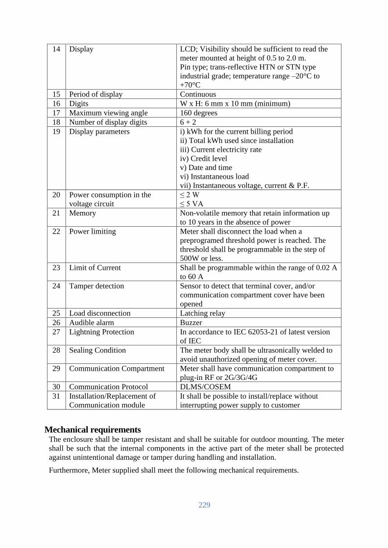
229
14 Display LCD; Visibility should be sufficient to read the
meter mounted at height of 0.5 to 2.0 m.
Pin type; trans-reflective HTN or STN type
industrial grade; temperature range –20°C to
+70°C
15 Period of display Continuous
16 Digits W x H: 6 mm x 10 mm (minimum)
17 Maximum viewing angle 160 degrees
18 Number of display digits 6 + 2
19 Display parameters i) kWh for the current billing period
ii) Total kWh used since installation
iii) Current electricity rate
iv) Credit level
v) Date and time
vi) Instantaneous load
vii) Instantaneous voltage, current & P.F.
20 Power consumption in the
voltage circuit
≤ 2 W
≤ 5 VA
21 Memory Non-volatile memory that retain information up
to 10 years in the absence of power
22 Power limiting Meter shall disconnect the load when a
preprogramed threshold power is reached. The
threshold shall be programmable in the step of
500W or less.
23 Limit of Current Shall be programmable within the range of 0.02 A
to 60 A
24 Tamper detection Sensor to detect that terminal cover, and/or
communication compartment cover have been
opened
25 Load disconnection Latching relay
26 Audible alarm Buzzer
27 Lightning Protection In accordance to IEC 62053-21 of latest version
of IEC
28 Sealing Condition The meter body shall be ultrasonically welded to
avoid unauthorized opening of meter cover.
29 Communication Compartment Meter shall have communication compartment to
plug-in RF or 2G/3G/4G
30 Communication Protocol DLMS/COSEM
31 Installation/Replacement of
Communication module
It shall be possible to install/replace without
interrupting power supply to customer
Mechanical requirements The enclosure shall be tamper resistant and shall be suitable for outdoor mounting. The meter
shall be such that the internal components in the active part of the meter shall be protected
against unintentional damage or tamper during handling and installation.
Furthermore, Meter supplied shall meet the following mechanical requirements.

230
No. Description Specification
1 Meter Case The meter shall be constructed by employing flame
retardant and high impact strength material.
The base, body and frame including terminal block shall be
of heat resistive; shock proof and rust proof good quality
hard material e.g. unbreakable engineering or stamped metal
or moulded phenol resin which shall be capable of
withstanding of 145°C.
The base shall be provided with 3 (three) screw mounting
holes, 1 (one) slotted meter support bracket at the top and 1
(one) round hole on each side in the bottom half of the base
for securely mounting the meter to the meter board so that
any by-pass conductors can not be entered from bottom side
free space.
The meter cover shall be of poly-carbonate.
The meter cover shall be provided with a window of poly-
carbonate or toughened glass for LCD display.
The meter shall be effectively sealed to prevent entrance of
moisture, rain and dust into its internal parts.
2 Terminal Side/bottom entry connection type; minimum 4 terminals to
accommodate 10 mm2 duplex; terminal cover shall be
extended type;
Terminal block shall be polycarbonate grade 500R or
equivalent bakelite; brass or copper current terminals; two
flat-head brass screws at each terminal; terminal bore
diameter 6 mm.
3 Minimum free space
between bottom of
terminal and terminal
cover
60 mm
4 Connections diagrams
and terminal marking
Every meter shall be indelibly marked with a diagram of
connection.
Meter terminals shall be marked, this marking shall appear
on the diagram.
5 Protection class Class II
6 Protection against
penetration of dust
and water
Conform to the degree of protection of IP54 or higher
(outdoor)
7 Top cover sealing Should be properly sealed if there is top cover
8 Pulse output Flashing LED visible from the front.
9 Maximum pulse
frequency
Shall not exceed 2000 imp/kWh (kvar)
10 Protection against
magnetic field
Accuracy shall not be affected by AC/DC magnetic field on
all sides of meter. Meter working shall not be affected by
permanent magnet of 0.5 mT.
11 Temperature range Operation: -25°C to 60°C
Storage and transport: -25°C to 70°C
12 Battery It shall be possible to replace battery at the end of battery
life without opening meter cover. And the cover that hides
battery shall be sealed independently from meter cover.

231
13 Optical port The meter shall have an IEC 62056-21 compliant optical
communication port. This should allow the utility to access
for information stored inside the meter and to upload it into
a hand held unit (HHU) or laptop.
14 Name plate Every meter shall have clearly visible, indelibly and
distinctly marked name plate containing the following
information:
i) Manufacturer’s name
ii) Meter type
iii) Number of phases and number of wire
iv) Meter serial number and year of manufacture
v) Rated voltage of the system
vi) Basic current and maximum current
vii) Reference frequency in hertz
viii) Meter constant in imp/kWh
ix) Class index of the meter
x) Over-current breaking capacity (in kA)
xi) BREB / UTILITY logo
xii) Reference Standard
Latching relay specifications
The specification for the single phase latching relay is as follows:
No. Description Specification
1 No. of coils 2 (two)
2 Rated coil voltage 12 VDC
3 Rated coil power 6 W
4 Pulse to set 30 ms
5 Contact Material Silver alloy
6 Maximum Switching Power 15000 VA
7 Maximum Switching Voltage 250 V AC
8 Maximum Switching Current (rms) 80 A
9 Contact resistance ≤ 2 mΩ
10 Electrical Cycle 1x10⁴
11 Mechanical Cycle 1x10⁵
12 Insulation resistance ≥ 1000 MΩ
13 Dielectric Strength between contacts ≥ 2000 VAC
14 Dielectric Strength between contact and coil
(50 Hz)
≥ 3000 VAC
15 Dielectric Strength between contacts assembly ≥ 4000 VAC
16 Ambient temperature -40 °C to +65 °C
17 Operating humidity 40 to 90%
18 Temperature rise at rated current
(assuming 300C room temp.)
60°C
19 Sealing Complete sealing excepts terminals

232
Meter sealing
1. Provision shall be for sealing the meter at least two Ferrule steel seals.
2. The stainless steel seals shall be applied in such a way that it will not be possible to undo/loosen the mounting screws used to secure the meter without breaking these seals.
3. The stainless steel seals shall be applied in such a way that they will be easily visible when viewing an installed meter from the front.
4. The terminals shall also have Ferrule/TT sealing arrangement.
Electromagnetic compatibility
The meter shall be designed in such a way that conducted or radiated electromagnetic
disturbances as well as electrostatic discharge do not damage or substantially influence the meter.
The meter also shall not generate conducted or radiated noise which could interfere with other
equipment. The following requirement shall be met.
Electrostatic discharges according to IEC 61000-4-2: Contact discharge - 8 kV
Electromagnetic RF fields according to IEC 61000-4-3: 80 MHz to 2 GHz – 10 and 30 V/m
Fast transient burst test according to IEC 61000-4-4
Current and voltage circuits at no load: 4 kV
Auxiliary circuits >40V: 1 kV
Fast transient surge test according to IEC 61000-4-5
Current and voltage circuits: 4 kV
Auxiliary circuits >40V: 1 kV
Insulation strength at 50 Hz during 1 min: 4 kV
Pulse voltage at 1.2/50μs according to IEC 62052-11: Current and voltage circuits: 6kV
Accuracy requirements
1. Limits of error due to variation of the current
The percentage errors shall not exceed the limits for the relevant accuracy class stipulated in
IEC standard.
2. Limits of error due to other influence quantities
The additional percentage error due to the change of influence quantities shall not exceed the
limit for the reference accuracy class stipulated in IEC standard.
3. Limits of error due to ambient temperature variation
The limits of error shall not exceed the limits stipulated in IEC standard.
4. Starting and running with no-load
Initial start-up of the meter: The meter shall be fully functional within 5 seconds after the
voltage is applied to the meter terminals.
Running with no load: When the voltage is applied with no current flowing in the current
circuit the test output of the meter shall not produce more than one pulse.

233
Starting: The meter shall start and continue to register at 0.4Ib% at power factor of 1.
5. Meter constant
The relation between the test output and the indication in the display shall comply with the
marking on the name-plate.
Meter display subsystem
1. General requirements
a) The design philosophy of the meter display subsystem should be that a suitable message or indication must be displayed or annunciated for every meter event and alarm without exception.
b) The meter should make provision for the customer or utility personnel to scroll through the displays.
c) The meter should have a default display that displays the following minimum information:
i. The Remaining Credit ii. The Total Consumption, kWhr to date
iii. The power limit iv. The current Tariff
2. Liquid crystal display
a) A liquid crystal display is required to display status alarm and event information.
b) An illuminated display with a minimum lifetime of ten years is required.
c) The size (number of rows and characters per row) should be appropriate for the display and interpretation of the messages and meter information, and should be legible from a distance of at least 500 cm with a viewing angle of no less than 30º.
3. Rate LED: The meter should include a consumption rate indicator LED that emits visible red
light.
4. Supply status display: The meter should provide a visible indication of the status of the
incoming supply.
5. Status/alarm/event display
In addition to the displays required above the meter must display the following minimum
information in an intuitive way such that an inexperienced user can understand and interpret
the information intelligibly. Laminated instruction cards are to be provided for each unit.
a) Meter ID. b) Out of Credit message c) Invalid token entered d) Duplicate token entered e) Meter tamper state f) Meter failure and/or fault code
The Bidder must submit a detailed specification of the way in which the display are structured
and laid out.
Functional Requirement
The meters to be supplied against this specification shall meet the requirements specified in this
clause.

234
Security All credit and meter management tokens shall be meter specifically encrypted to guarantee
security of the system. Encrypted tokens shall not be reusable. Tokens to display status and test
the meter may be un-encrypted and reusable.
The meter shall have at least 3 levels of passwords with access levels that allow:
• Read only: The meter can be read. No alteration of data or programming is allowed. • Billing read: The meter can be read. Some basic data–altering activity relating to billing
functions is allowed. • Unrestricted: The meter can be read. Full programming of the meter is allowed.
Token validation If a token not meant for the meter is applied, the meter should display a message to that effect.
Similarly, if a valid token is re-entered into the meter then the meter must display an appropriate
message.
Meter personalization In addition to factory personalization and personalization via encrypted tokens, it shall be possible
to personalize the meter from a hand held unit (HHU)/laptop provided the HHU/laptop is
authorized/ programmed to communicate with the meter.
Operation modes The meter shall be required to support at least three modes of operation, namely the prepayment
mode, postpayment mode and the meter test mode.
1. Prepayment mode
The basis of this mode is that credit is transferred to the meter, and provided the meter remains
in credit, the meter provides supply. The credit register is decremented against current
consumption with the countdown total being displayed on the meter display.
2. Postpayment mode
In this mode, the meter provides supply to the customer always except when disconnected
according to predefined conditions in the meter, and normal billing process is applied using
billing information in the meter.
3. Meter test mode
The meter should support a test mode that is activated either from a dedicated test token,
dedicated button on the meter or using the HHU. This test should be automated in the meter and
should include a full diagnostic test, testing of the all the active and inactive functionality,
metering accuracy test (1 minute load test), and connection validation tests. Meter test mode
shall also display following information:
i. Meters software version
ii. Current limit
iii. Switch open and close count
iv. Token acceptance & rejection count
Load disconnection The meters shall be capable of disconnecting/ reconnecting load locally and remotely. In addition:
1. The load shall be disconnected by a latching relay under the following conditions:

235
i. The credit in the meter has expired and grace facilities also expired.
ii. The load power threshold has been exceeded.
iii. The meter is in a tampered state.
iv. Neutral missing at source side.
2. The meter shall indicate whether the load is connected or not and shall display the reason for disconnection.
3. The customer shall not have the option to switch the contactor manually. Under over– current conditions the mechanism to automatically reconnect the load must ensure that the number of switching cycles is limited. The meter shall attempt to reconnect the load up to 5 times at 30-second intervals. If the over-current condition still exits the meter shall wait a period of 30 minutes before attempting to reconnect the load.
Load limit 1. It shall be possible to configure power limit in the step of 500 W for disconnection due to the
over load.
2. When consumed power exceed the contracted power limit, the relay shall automatically disconnect. The time duration to measure and allow the overload before automatic disconnection shall be configurable in the meter.
3. The relay status (connected/disconnected) shall be indicated and visible at all the time on the meter display.
4. After automatic disconnection due to excess of the load, the relay shall be automatically re-connected after a predefined time duration, configurable in the meter. The number of allowable automatic reconnections due to over load disconnection in a short period of time shall also be configurable, to limit the consecutive disconnection and reconnections.
5. It shall be possible to open and close the relay locally from remote.
Tamper detection Tamper shall be detected with power supply.
When the meter detects a tamper condition, it shall register the event with time stamp, and display
tamper with proper symbol in the display. The tamper event shall be reset only locally using HHU
and from remote. The followings shall be considered as tamper:
• Terminal cover/Communication compartment cover open
• Current reverse
• Neutral missing at line side as well as load side
• Meter should detect reverse flow of power and measure correctly by forward registration.
• Meter should measure current for phase and neutral both so that current bypass tamper taken care off.
• Meter should provide tamper log data with date and time and it should be sent to main system through HHU.
• Removal of battery shall be considered as a temper.
The meter shall operate normally under the following conditions:
• Phase Sequence Reversal: The meter should work accurately irrespective of phase sequence of the supply.

236
Date and time management The meter shall be equipped with a real time clock (RTC) supporting the date and time as per IEC
standard together with battery. Pseudo-clock using mains crossing detection is not acceptable. The
maximum drift of the clock shall be less than 30 seconds per month.
The battery shall be used only for RTC and operate maintenance free for a period of at least 10
years. It shall not be used for meter display in case of no line power supply/
The meter must be equipped with a battery monitoring system that monitors the battery’s condition
and initiates a “Change Battery Alarm” to register and display when the battery approaches the
end of its operating life. If the battery is not replaced, the failure of the battery is deemed to
constitute a meter failure, and the meter should be shut down.
It shall be possible to change date and time locally using HHU and from remote. Date and time
changes shall be flagged with previous date/time and new date/time.
Energy Accounting
Credit register The credit register is the “operating account” of the meter being decremented by the metering
process. The specific requirements of this register are:
1. This register must be decremented for the equivalent of every credit unit consumed.
2. When the available credit has been consumed, the meter must open the latching relay and isolate supply from the customer (unless the Friendly hours or Emergency Credit option is invoked).
3. This register can become negative from use of emergency credit.
4. The balance of this register should be written to the token.
Friendly hours, weekend, holidays The meter shall accommodate the “Friendly hours”, “Weekend” and “Holidays” features. These
are time periods during which the meter shall not cut-off power to consumer if the credit becomes
negative. Details of the features are described in the following table.
1. Friendly hours
There shall be provision to define ‘Friendly hours’ in the meter. The utility shall be able to
define the ‘Friendly hours’ and shall be communicated to the meter through token.
2. Weekend
There shall be provision to define ‘Weekend’ in the meter. The utility shall be able to define the
weekend and shall be communicated to the meter through token.
3. Holidays
There shall be provision to define ‘Holidays’ in the meter. At the end of a year the utility shall
be able to define new holiday dates and these shall be communicated to meter through token.
Emergency credit Provision shall be made in the meter for an Emergency Credit facility that allows the customer
to draw on an emergency credit should the credit in the register be consumed.
The specific requirements of this facility are:
1. When the credit register value reaches a programmable Emergency Credit Threshold the meter should sound an audible alarm, and prompt the user to accept the use of the Emergency Credit facility (button depression). The meter should not supply energy against emergency credit

237
unless acknowledged by the customer.
2. If all the available credit in the credit register is expired and power disconnected, the facility to activate the Emergency Credit should remain an option to the user.
3. The meter should remain in service until the Emergency Credit Limit has been reached, after which the supply should be disconnected.
4. If the Emergency credit limit is set to zero, the Emergency Credit Threshold shall function as a low credit warning and provide the user with a visual and audible alarm that credit is low. The user shall have the option to silence the alarm by inserting a card or pressing a button to accept the alarm.
5. If emergency credit has been previously consumed, then the value of emergency credit used shall be deducted from the next token inserted into the meter.
6. Once emergency credit has been exhausted, no further credit facilities shall be available until the full emergency credit allocation has been paid for.
Energy Register 1. Cumulative energy consumption
a. This register records the cumulative consumption since the meter was commissioned.
b. The unit is kWh, rounded to three decimal points (1 Wh).
2. Load profile
a. Number of channels that can be configured locally and remotely is 2 at least.
b. The interval shall be configurable from daily to hourly.
c. It shall be possible for the meter to store hourly load profile for at least 60 days.
3. Maximum demand
a. It shall be possible for the meter to register maximum demand.
4. Monthly consumption
a. The meter shall have at least 12 monthly consumption data.
b. The data shall include monthly consumption (cumulative) and maximum demand together with date and time.
Tariff All tariff calculation must be done within the meter.
The meter is required to support stepped tariffs structures as well as time-of-use and maximum
demand.
The tariff structure consists of the following records:
1. Each tariff must be uniquely identified using the tariff code
2. Each tariff shall have an activation date, being the date on which the tariff becomes effective.
3. Each tariff has up to seven steps (in kWh) for different levels of energy pricing.
4. The rate describes the cost per kWh for energy consumption in that step.
Tariff management in the meter 1. Tariffs shall be entered into the meter via HHU or from remote. The meter should not allow
tariffs to be manually entered using the push buttons.

238
• When the meter is active, the current cannot be overwritten.
• The meter must time and date stamp when the tariff is loaded into meter.
2. In general, when a tariff has expired in the meter, the tariff is automatically deleted by the meter.
Tariff switchover When the meter detects that a new tariff is applicable (using the tariff activation date), the
meter should execute the following steps:
1. The meter shall begin the billing against the new tariff.
2. The current tariff code shall be updated to reflect the new tariff code.
3. The old (expired) tariff should be deleted.
4. New tariffs will only be activated at 00:00 on the first day of a month.
Other Requirements
Time synchronization The meter shall provide local and remote time synchronization function.
Over/Under-voltage monitoring It shall be possible for meter to detect and register under-voltage/over-voltage.
Events shall be registered into a special event log (electricity quality log) with the date/time of
event, with the capacity of at least 100 entries. Under-voltage and overvoltage thresholds shall
be adjusted.
Meter firmware upgrade Meter shall support firmware upgrade option. Firmware upgrade option in the meter is realised
not to alter in any way the metering characteristics (metrology) of the meter, data memorised in
the meter (metering data, statuses, etc.), configuration parameters or operational parameters of
the meter – all these data remain unchanged even after firmware upgrade. New firmware upgrade
in the meter shall be done locally or remotely.
Meter Identification Card Along with the meter, two meter identification cards shall be provided.
1. It shall comply with NRS 009-4: 1995.
2. The printed details and graphic design of the cards shall be submitted to the utility prior to producing the cards for approval.
Meter Numbering The meter number scheme shall be the unique and be followed by a convention of the Employer.
The basic of the convention of the meter number scheme will be provided after signing of the
contract. It must be possible to program the meter with an 11 digit meter number. The first two
digits is utility ID. The third digit corresponds to meter type. (1=Smart Card based, 2=Keypad type,
3=online). The next 8-digit is a sequence number used to identify each meter and will consist of
number (0 - 9) only.
Meter Software Requirement
Meter programming software The software shall
• enable full programming, backup and retrieve the measuring data of the meter and events

239
from the meter;
• enable to export the metering data, events and configurations from the meters to text files (.TXT, .CSV, .HTML);
• enable to save configuration as file for future use for Employer’s needs;
• enable to upgrade meter firmware;
• run on HHU, or laptop with Windows 10 or later version.
The Supplier shall, without additional compensation, provide software to BREB and/or its sub-
contractors for programming/reading the meter. The number of license for the software must be
unlimited for use by the Employer.
Meter firmware The meter must be able to decode information from encoded keys typed through the keypad.
Quality Assurance
The Bidder shall comply with and be certified to the following ISO levels:
1. ISO 9001
2. ISO 17025
The Bidder shall submit copies of certificate with their proposal to this effect. If the Bidder is not meter
manufacturer, the Bidder must get the copy of the certificate from meter manufacturer together with
Manufacturer’s Authorization and submit.
SPECIFICATIONS FOR 3P LT AMI SPM METER
Overview
This specification covers the design, manufacture, testing and supply of direct connected whole
current three phase prepayment energy meter (hereafter the “meter”) of accuracy Class 1 in low
voltage networks for LT AMI SPM system.
It shall be possible to read meter data and configure meter parameter from remote and local.
The meter shall be able to communicate with Head End System (HES) via data concentrator, gateway
or access point using RF mesh or 2G/3G technologies.
The meter together with communication module shall support meter communication protocols as per
DLMS/COSEM standards.
It shall be possible to switch payment mode between prepaid and postpaid from remote and local.
Prepayment shall comply with IEC 62055, Standard transfer specification (STS).
Scope of Supply
The Supplier shall be responsible for supply, installation, testing & commissioning with related
services packing, loading, shipment, custom clearance if necessary, and transportation, insurance
and unloading at site. .
The meter shall be installed and commissioned according to the minimum guidelines as set out in
technical specification. Prior to installation of meters, customers shall be forewarned by delivery of
a notice explaining what will happen. Public relations will be responsibility of the Employer.

240
The installation team shall have a work order sheet instructing them what to do. The following
information shall be printed on the works order from:
• Customer Name: Supplied by the Employer and verified by the Supplier
• Customer address: Supplied by the Employer and verified by the Supplier
• Old Account Number: Supplied by the Employer
• Old Meter Number & Reading: Supplied by the Employer
• Tariff Code: The specific tariff to be allocated to the customer must be identified by the tariff code
Installation of meter means:
1. Remove old meter,
2. Fix new meter, and
3. Install new meter.
The following guide lines must be followed by the supplier during installation of the meters:
1. The meters shall be sealed with Ferrule Type/Twist type seals compatible with the meters that uniquely identify the utility person who sealed the meters.
2. Meters shall be tested and commissioned by the installation supervisor using the data from the works order form to program the tariff details.
3. At the time of meter installation the customer’s last metering data shall be captured/ noted on the order by the installation supervisor. The date of commissioning is also entered onto the work order form.
4. Customers shall be registered to HES using the returned work order form within 24 hours of commissioning.
5. All meters shall be installed at a location convenient to the customer as well as service personnel away from sources of heat and moisture.
6. The installation shall be symmetrical, vertical and parallel to respective walls and floors. At the time of installation, on-site training and instruction shall be given to the Employer.
General Technical Requirements
Service conditions The meters to be supplied against this specification shall be suitable for satisfactory continuous
operation under the following tropical conditions.
No. Condition Specification
1 Maximum ambient temperature (°C) 50
2 Minimum ambient temperature (°C) 5
3 Maximum daily average temperature (°C) 35
4 Maximum annual average temperature (°C) 30
5 Mean annual rainfall (mm) 2,500
6 Minimum annual rainfall (mm) 1,461
7 Maximum annual rainfall (mm) 4,127
8 Maximum relative humidity (%) 100
9 Average relative humidity (%) 80
10 Maximum wind velocity (km/h) 180
11 Maximum altitude above mean sea level (meters) 200
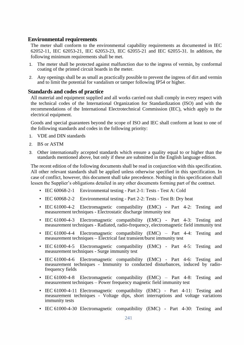
241
Environmental requirements The meter shall conform to the environmental capability requirements as documented in IEC
62052-11, IEC 62053-21, IEC 62053-23, IEC 62055-21 and IEC 62055-31. In addition, the
following minimum requirements shall be met.
1. The meter shall be protected against malfunction due to the ingress of vermin, by conformal coating of the printed circuit boards in the meter.
2. Any openings shall be as small as practically possible to prevent the ingress of dirt and vermin and to limit the potential for vandalism or tamper following IP54 or higher.
Standards and codes of practice All material and equipment supplied and all works carried out shall comply in every respect with
the technical codes of the International Organization for Standardization (ISO) and with the
recommendations of the International Electrotechnical Commission (IEC), which apply to the
electrical equipment.
Goods and special guarantees beyond the scope of ISO and IEC shall conform at least to one of
the following standards and codes in the following priority:
1. VDE and DIN standards
2. BS or ASTM
3. Other internationally accepted standards which ensure a quality equal to or higher than the standards mentioned above, but only if these are submitted in the English language edition.
The recent edition of the following documents shall be read in conjunction with this specification.
All other relevant standards shall be applied unless otherwise specified in this specification. In
case of conflict, however, this document shall take precedence. Nothing in this specification shall
lessen the Supplier’s obligations detailed in any other documents forming part of the contract.
• IEC 60068-2-1 Environmental testing - Part 2-1: Tests - Test A: Cold
• IEC 60068-2-2 Environmental testing - Part 2-2: Tests - Test B: Dry heat
• IEC 61000-4-2 Electromagnetic compatibility (EMC) - Part 4-2: Testing and measurement techniques - Electrostatic discharge immunity test
• IEC 61000-4-3 Electromagnetic compatibility (EMC) - Part 4-3: Testing and measurement techniques - Radiated, radio-frequency, electromagnetic field immunity test
• IEC 61000-4-4 Electromagnetic compatibility (EMC) – Part 4-4: Testing and measurement techniques – Electrical fast transient/burst immunity test
• IEC 61000-4-5 Electromagnetic compatibility (EMC) - Part 4-5: Testing and measurement techniques - Surge immunity test
• IEC 61000-4-6 Electromagnetic compatibility (EMC) - Part 4-6: Testing and measurement techniques - Immunity to conducted disturbances, induced by radio-frequency fields
• IEC 61000-4-8 Electromagnetic compatibility (EMC) – Part 4-8: Testing and measurement techniques – Power frequency magnetic field immunity test
• IEC 61000-4-11 Electromagnetic compatibility (EMC) - Part 4-11: Testing and measurement techniques - Voltage dips, short interruptions and voltage variations immunity tests
• IEC 61000-4-30 Electromagnetic compatibility (EMC) - Part 4-30: Testing and

242
measurement techniques - Power quality measurement methods
• IEC 60529 Degrees of protection provided by enclosures (IP Code)
• IEC 62052-11 Electricity Metering equipment (a.c.) – General Requirements, Tests and Test Conditions - PART 11: Metering equipment
• IEC 62052-21 Electricity metering equipment (a.c.) - General requirements, tests and test conditions - Part 21: Tariff and load control equipment
• IEC 62052-31 Electricity metering equipment (a.c.) - General requirements, tests and test conditions - Part 31: Product safety requirements and tests
• IEC 62053-21 Electricity metering equipment (a.c.) – Particular Requirements - Part 21: Static meters for active energy (Classes 1 and 2).
• IEC 62053-23 Electricity metering equipment (a.c.) - Particular requirements -Part 23: Static meters for reactive energy (classes 2 and 3)
• IEC 62053-61 Electricity metering equipment (a.c.) - Particular requirements - Part 61: Power consumption and voltage requirements
• IEC 62054-21 Electricity metering (a.c) – Tariff and Load Control- part 21: Particular requirements for time switches
• IEC 62055-21 Electricity metering – Payment systems – Part 11: Framework for Standardization
• IEC 62055-31 Electricity metering – Payment systems – Part 31: Particular requirements – Static payment meters for active energy (classes 1 and 2).
• IEC 62055-41 Electricity metering – Payment systems – Part 41: Standard transfer specification (STS) – Application layer protocol for one-way token carrier systems
• IEC 62055-51 Electricity metering – Payment systems – Part 51: Standard transfer specification (STS) – Physical layer protocol for one-way numeric and magnetic card token carriers
• IEC 62055-52 Electricity metering - Payment systems - Part 52: Standard transfer specification (STS) - Physical layer protocol for a two-way virtual token carrier for direct local connection
• IEC 62056-21 Electricity Metering – Data exchange for meter reading, tariff, and load control – Part 21: Direct local data exchange.
• IEC 62056-46 Electricity metering – Data exchange for meter reading, tariff and load control – Part 46: Data link layer using HDLC protocol
• IEC 62056-53 Electricity metering – Data exchange for meter reading, tariff and load control – Part 53: COSEM Application layer
• IEC 62056-61 Electricity metering – Data exchange for meter reading, tariff and load control – Part 61: OBIS object identification system
• IEC 62056-62 Electricity metering – Data exchange for meter reading, tariff and load control – Part 62: Interface classes
• Others - All other relevant IEC specifications for metering equipment

243
Specific Technical Requirements The meters to be supplied against this specification shall meet the requirements specified in this clause.
Electrical requirements
No. Description Specification
1 Connection 3-phase, 4-wire, direct connected whole current
(unidirectional)
2 Number of element 3 (three)
3 Rated voltage 230 V phase to neutral
400 V phase to phase
4 Variation in voltage -30% to – +30%
5 Continuous over voltage Should withstand 400 volts for 48 hours without
causing any damage or degrading of its operating
life, or causing changes of more than 0.01 kWh in its
credit registers (excluding the possible decrement of
credit due to power being consumed)
6 Base current, Ib 10 A
7 Maximum continuous current,
Imax
100 A
8 Starting current 40 mA (0.4% Ib)
9 Rated frequency 50 Hz
10 Variation in frequency ± 4%
11 Power factor 0.5 lag – unity – 0.8 lead
12 Accuracy 1.0 for Active, 2.0 for Reactive
13 Clock Built-in real time clock with 10 years battery backup
14 Display LCD; Visibility should be sufficient to read the
meter mounted at height of 0.5 to 2.0 m.
Pin type; trans-reflective HTN or STN type
industrial grade; temperature range –20°C to +70°C
15 Period of display Continuous
16 Digits W x H: 6 mm x 10 mm (minimum)
17 Maximum viewing angle 160 degrees
18 Number of display digits 6 + 2
19 Display parameters i) kWh for the current billing period
ii) Total kWh used since installation
iii) Current electricity rate
iv) Credit level
v) Date and time
vi) Instantaneous load
vii) Instantaneous voltage, current & P.F.
20 Power consumption in the
voltage circuit
≤ 5 W
≤ 10 VA
21 Memory Non-volatile memory that retain information up to
10 years in the absence of power
22 Power limiting Meter shall disconnect the load when a
preprogramed threshold power is reached. The
threshold shall be programmable in the step of 500W
or less.

244
23 Limit of Current Shall be programmable within the range of 0.04 A to
100 A
24 Tamper detection Sensor to detect that terminal cover, and/or
communication compartment cover have been
opened
25 Load disconnection Latching relay
26 Audible alarm Buzzer
27 Lightning Protection In accordance to IEC 62053-21 of latest version of
IEC
28 Sealing Condition The meter body shall be ultrasonically welded to
avoid unauthorized opening of meter cover.
29 Communication Compartment Meter shall have communication compartment to
plug-in RF or 2G/3G/4G
30 Communication Protocol DLMS/COSEM
31 Installation/Replacement of
Communication module
It shall be possible to install/replace without
interrupting power supply to customer
Mechanical requirements
The enclosure shall be tamper resistant and shall be suitable for outdoor mounting. The meter shall be
such that the internal components in the active part of the meter shall be protected against unintentional
damage or tamper during handling and installation.
Furthermore, Meter supplied shall meet the following mechanical requirements.
No. Description Specification
1 Meter Case The meter shall be constructed by employing flame retardant
and high impact strength material.
The base, body and frame including terminal block shall be of
heat resistive; shock proof and rust proof good quality hard
material e.g. unbreakable engineering or stamped metal or
moulded phenol resin which shall be capable of withstanding
of 145°C.
The base shall be provided with 3 (three) screw mounting
holes, 1 (one) slotted meter support bracket at the top and 1
(one) round hole on each side in the bottom half of the base for
securely mounting the meter to the meter board so that any by-
pass conductors can not be entered from bottom side free
space.
The meter cover shall be of poly-carbonate.
The meter cover shall be provided with a window of poly-
carbonate or toughened glass for LCD display.
The meter shall be effectively sealed to prevent entrance of
moisture, rain and dust into its internal parts.
2 Terminal Side/bottom entry connection type; minimum 8 terminals to
accommodate 16 mm2 duplex; terminal cover shall be
extended type;
Terminal block shall be polycarbonate grade 500R or
equivalent bakelite; brass or copper current terminals; two flat-
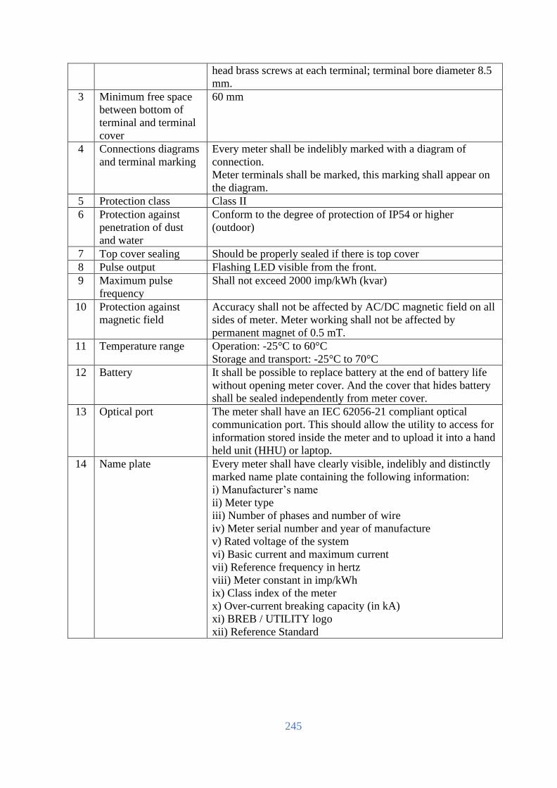
245
head brass screws at each terminal; terminal bore diameter 8.5
mm.
3 Minimum free space
between bottom of
terminal and terminal
cover
60 mm
4 Connections diagrams
and terminal marking
Every meter shall be indelibly marked with a diagram of
connection.
Meter terminals shall be marked, this marking shall appear on
the diagram.
5 Protection class Class II
6 Protection against
penetration of dust
and water
Conform to the degree of protection of IP54 or higher
(outdoor)
7 Top cover sealing Should be properly sealed if there is top cover
8 Pulse output Flashing LED visible from the front.
9 Maximum pulse
frequency
Shall not exceed 2000 imp/kWh (kvar)
10 Protection against
magnetic field
Accuracy shall not be affected by AC/DC magnetic field on all
sides of meter. Meter working shall not be affected by
permanent magnet of 0.5 mT.
11 Temperature range Operation: -25°C to 60°C
Storage and transport: -25°C to 70°C
12 Battery It shall be possible to replace battery at the end of battery life
without opening meter cover. And the cover that hides battery
shall be sealed independently from meter cover.
13 Optical port The meter shall have an IEC 62056-21 compliant optical
communication port. This should allow the utility to access for
information stored inside the meter and to upload it into a hand
held unit (HHU) or laptop.
14 Name plate Every meter shall have clearly visible, indelibly and distinctly
marked name plate containing the following information:
i) Manufacturer’s name
ii) Meter type
iii) Number of phases and number of wire
iv) Meter serial number and year of manufacture
v) Rated voltage of the system
vi) Basic current and maximum current
vii) Reference frequency in hertz
viii) Meter constant in imp/kWh
ix) Class index of the meter
x) Over-current breaking capacity (in kA)
xi) BREB / UTILITY logo
xii) Reference Standard

246
Latching relay specifications The specification for the three phase latching relay is as follows:
No. Description Specification
1 No. of coils 2 (two)
2 Rated coil voltage 12 VDC
3 Rated coil power 9 W
4 Pulse to set 30 ms
5 Contact Material Silver alloy
6 Maximum Switching Power 15000 VA
7 Maximum Switching Voltage 250 V AC
8 Maximum Switching Current (rms) 120 A
9 Contact resistance ≤ 2 mΩ
10 Electrical Cycle 5x10³
11 Mechanical Cycle 1x10⁵
12 Insulation resistance ≥ 1000 MΩ
13 Dielectric Strength between contacts ≥ 2000 VAC
14 Dielectric Strength between contact and coil
(50 Hz)
≥ 3000 VAC
15 Dielectric Strength between contacts assembly ≥ 4000 VAC
16 Ambient temperature -40 °C to +65 °C
17 Operating humidity 40 to 90%
18 Temperature rise at rated current
(assuming 300C room temp.)
60°C
19 Sealing Complete sealing excepts terminals
Meter sealing 1. Provision shall be for sealing the meter at least two Ferrule steel seals.
2. The stainless steel seals shall be applied in such a way that it will not be possible to undo/loosen the mounting screws used to secure the meter without breaking these seals.
3. The stainless steel seals shall be applied in such a way that they will be easily visible when viewing an installed meter from the front.
4. The terminals shall also have Ferrule/TT sealing arrangement.
Electromagnetic compatibility The meter shall be designed in such a way that conducted or radiated electromagnetic disturbances as
well as electrostatic discharge do not damage or substantially influence the meter. The meter also shall
not generate conducted or radiated noise which could interfere with other equipment. The following
requirement shall be met.
Electrostatic discharges according to IEC 61000-4-2: Contact discharge - 8 kV
Electromagnetic RF fields according to IEC 61000-4-3: 80 MHz to 2 GHz – 10 and 30 V/m
Fast transient burst test according to IEC 61000-4-4
Current and voltage circuits at no load: 4 kV
Auxiliary circuits >40V: 1 kV
Fast transient surge test according to IEC 61000-4-5
Current and voltage circuits: 4 kV

247
Auxiliary circuits >40V: 1 kV
Insulation strength at 50 Hz during 1 min: 4 kV
Pulse voltage at 1.2/50μs according to IEC 62052-11: Current and voltage circuits: 6kV
Accuracy requirements 1. Limits of error due to variation of the current
The percentage errors shall not exceed the limits for the relevant accuracy class stipulated in IEC
standard.
2. Limits of error due to other influence quantities
The additional percentage error due to the change of influence quantities shall not exceed the limit for
the reference accuracy class stipulated in IEC standard.
3. Limits of error due to ambient temperature variation
The limits of error shall not exceed the limits stipulated in IEC standard.
4. Starting and running with no-load
Initial start-up of the meter: The meter shall be fully functional within 5 seconds after the voltage is
applied to the meter terminals.
Running with no load: When the voltage is applied with no current flowing in the current circuit the
test output of the meter shall not produce more than one pulse.
Starting: The meter shall start and continue to register at 0.4Ib% at power factor of 1.
5. Meter constant
The relation between the test output and the indication in the display shall comply with the marking on
the name-plate.
Meter display subsystem 1. General requirements
a) The design philosophy of the meter display subsystem should be that a suitable message or indication must be displayed or annunciated for every meter event and alarm without exception.
b) The meter should make provision for the customer or utility personnel to scroll through the displays.
c) The meter should have a default display that displays the following minimum information:
i. The Remaining Credit
ii. The Total Consumption, kWh to date
iii. The power limit
iv. The current Tariff
2. Liquid crystal display
a) A liquid crystal display is required to display status alarm and event information.
b) An illuminated display with a minimum lifetime of ten years is required.
c) The size (number of rows and characters per row) should be appropriate for the display and interpretation of the messages and meter information, and should be legible from a distance of at least 500 cm with a viewing angle of no less than 30º.
3. Rate LED
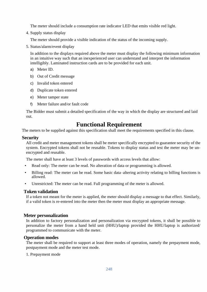
248
The meter should include a consumption rate indicator LED that emits visible red light.
4. Supply status display
The meter should provide a visible indication of the status of the incoming supply.
5. Status/alarm/event display
In addition to the displays required above the meter must display the following minimum information
in an intuitive way such that an inexperienced user can understand and interpret the information
intelligibly. Laminated instruction cards are to be provided for each unit.
a) Meter ID.
b) Out of Credit message
c) Invalid token entered
d) Duplicate token entered
e) Meter tamper state
f) Meter failure and/or fault code
The Bidder must submit a detailed specification of the way in which the display are structured and laid
out.
Functional Requirement The meters to be supplied against this specification shall meet the requirements specified in this clause.
Security All credit and meter management tokens shall be meter specifically encrypted to guarantee security of the
system. Encrypted tokens shall not be reusable. Tokens to display status and test the meter may be un-
encrypted and reusable.
The meter shall have at least 3 levels of passwords with access levels that allow:
• Read only: The meter can be read. No alteration of data or programming is allowed.
• Billing read: The meter can be read. Some basic data–altering activity relating to billing functions is allowed.
• Unrestricted: The meter can be read. Full programming of the meter is allowed.
Token validation If a token not meant for the meter is applied, the meter should display a message to that effect. Similarly,
if a valid token is re-entered into the meter then the meter must display an appropriate message.
Meter personalization In addition to factory personalization and personalization via encrypted tokens, it shall be possible to
personalize the meter from a hand held unit (HHU)/laptop provided the HHU/laptop is authorized/
programmed to communicate with the meter.
Operation modes The meter shall be required to support at least three modes of operation, namely the prepayment mode,
postpayment mode and the meter test mode.
1. Prepayment mode
249
The basis of this mode is that credit is transferred to the meter, and provided the meter remains in credit,
the meter provides supply. The credit register is decremented against current consumption with the
countdown total being displayed on the meter display.
2. Postpayment mode
In this mode, the meter provides supply to the customer always except when disconnected according
to predefined conditions in the meter, and normal billing process is applied using billing information
in the meter.
3. Meter test mode
The meter should support a test mode that is activated either from a dedicated test token, dedicated
button on the meter or using the HHU. This test should be automated in the meter and should include
a full diagnostic test, testing of the all the active and inactive functionality, metering accuracy test (1
minute load test), and connection validation tests. Meter test mode shall also display following
information:
i. Meters software version
ii. Current limit
iii. Switch open and close count
iv. Token acceptance & rejection count
Load disconnection The meters shall be capable of disconnecting/ reconnecting load locally and remotely. In addition:
1. The load shall be disconnected by a latching relay under the following conditions:
i. The credit in the meter has expired and grace facilities also expired.
ii. The load power threshold has been exceeded.
iii. The meter is in a tampered state.
iv. Neutral missing at source side.
2. The meter shall indicate whether the load is connected or not and shall display the reason for disconnection.
3. The customer shall not have the option to switch the contactor manually. Under over– current conditions the mechanism to automatically reconnect the load must ensure that the number of switching cycles is limited. The meter shall attempt to reconnect the load up to 5 times at 30-second intervals. If the over-current condition still exits the meter shall wait a period of 30 minutes before attempting to reconnect the load.
Load limit 1. It shall be possible to configure power limit in the step of 500 W for disconnection due to the
over load.
2. When consumed power exceed the contracted power limit, the relay shall automatically disconnect. The time duration to measure and allow the overload before automatic disconnection shall be configurable in the meter.
3. The relay status (connected/disconnected) shall be indicated and visible at all the time on the meter display.
4. After automatic disconnection due to excess of the load, the relay shall be automatically re-connected after a predefined time duration, configurable in the meter. The number of allowable automatic reconnections due to over load disconnection in a short period of time shall also be configurable, to limit the consecutive disconnection and reconnections.

250
5. It shall be possible to open and close the relay locally from remote.
Tamper detection Tamper shall be detected with power supply.
When the meter detects a tamper condition, it shall register the event with time stamp, and display
tamper with proper symbol in the display. The tamper event shall be reset only locally using HHU
and from remote. The followings shall be considered as tamper.
1. Terminal cover/Communication compartment cover open
2. Current reverse
3. Neutral missing at line side as well as load side
Meter should detect reverse flow of power and measure correctly by forward registration.
Meter should measure current for phase and neutral both so that current bypass tamper taken care
off.
Meter should provide tamper log data with date and time and it should be sent to main system
through HHU.
Removal of battery shall be considered as a temper.
The meter shall operate normally under the following conditions:
• Phase Sequence Reversal: The meter should work accurately irrespective of phase sequence of the supply.
• Shorting / By Passing: The meter shall have capability to record bypassing / shorting and opening of current coil(s) of one or any two phases with date, time.
• Missing Potential: The meter shall be capable of detecting and recording occurrences and restorations of missing potential (1 phase or 2 phases) which can happen due to intentional/ accidental disconnection of potential leads with date and time along with total no. of such occurrences for all phases during the above period.
Date and time management The meter shall be equipped with a real time clock (RTC) supporting the date and time as per IEC
standard together with battery. Pseudo-clock using mains crossing detection is not acceptable. The
maximum drift of the clock shall be less than 30 seconds per month.
The battery shall be used only for RTC and operate maintenance free for a period of at least 10
years. It shall not be used for meter display in case of no line power supply/
The meter must be equipped with a battery monitoring system that monitors the battery’s condition
and initiates a “Change Battery Alarm” to register and display when the battery approaches the end
of its operating life. If the battery is not replaced, the failure of the battery is deemed to constitute
a meter failure, and the meter should be shut down.
It shall be possible to change date and time locally using HHU and from remote. Date and time
changes shall be flagged with previous date/time and new date/time.

251
Energy Accounting
Credit register The credit register is the “operating account” of the meter being decremented by the metering
process. The specific requirements of this register are:
1. This register must be decremented for the equivalent of every credit unit consumed.
2. When the available credit has been consumed, the meter must open the latching relay and isolate supply from the customer (unless the Friendly hours or Emergency Credit option is invoked).
3. This register can become negative from use of emergency credit.
4. The balance of this register should be written to the token.
Friendly hours, weekend, holidays The meter shall accommodate the “Friendly hours”, “Weekend” and “Holidays” features. These
are time periods during which the meter shall not cut-off power to consumer if the credit becomes
negative. Details of the features are described in the following table.
1. Friendly hours
There shall be provision to define ‘Friendly hours’ in the meter. The utility shall be able to define
the ‘Friendly hours’ and shall be communicated to the meter through token.
2. Weekend
There shall be provision to define ‘Weekend’ in the meter. The utility shall be able to define the
weekend and shall be communicated to the meter through token.
3. Holidays
There shall be provision to define ‘Holidays’ in the meter. At the end of a year the utility shall
be able to define new holiday dates and these shall be communicated to meter through token.
Emergency credit Provision shall be made in the meter for an Emergency Credit facility that allows the customer to
draw on an emergency credit should the credit in the register be consumed.
The specific requirements of this facility are:
1. When the credit register value reaches a programmable Emergency Credit Threshold the meter should sound an audible alarm, and prompt the user to accept the use of the Emergency Credit facility (button depression). The meter should not supply energy against emergency credit unless acknowledged by the customer.
2. If all the available credit in the credit register is expired and power disconnected, the facility to activate the Emergency Credit should remain an option to the user.
3. The meter should remain in service until the Emergency Credit Limit has been reached, after which the supply should be disconnected.
4. If the Emergency credit limit is set to zero, the Emergency Credit Threshold shall function as a low credit warning and provide the user with a visual and audible alarm that credit is low. The user shall have the option to silence the alarm by inserting a card or pressing a button to accept the alarm.
5. If emergency credit has been previously consumed, then the value of emergency credit used shall be deducted from the next token inserted into the meter.
6. Once emergency credit has been exhausted, no further credit facilities shall be available until

252
the full emergency credit allocation has been paid for.
Energy Register 1. Cumulative energy consumption
a. This register records the cumulative consumption since the meter was commissioned.
b. The unit is kWh, rounded to three decimal points (1 Wh).
2. Load profile
a. Number of channels that can be configured locally and remotely is 2 at least.
b. The interval shall be configurable from 30 min to hourly.
c. It shall be possible for the meter to store hourly load profile for at least 60 days.
3. Maximum demand
a. It shall be possible for the meter to register maximum demand.
4. Monthly consumption
a. The meter shall have at least 12 monthly consumption data.
b. The data shall include monthly consumption (cumulative) and maximum demand together with date and time.
Tariff All tariff calculation must be done within the meter.
The meter is required to support stepped tariffs structures as well as time-of-use and maximum
demand.
The tariff structure consists of the following records:
1. Each tariff must be uniquely identified using the tariff code
2. Each tariff shall have an activation date, being the date on which the tariff becomes effective.
3. Each tariff has up to seven steps (in kWh) for different levels of energy pricing.
4. The rate describes the cost per kWh for energy consumption in that step.
Tariff management in the meter 1. Tariffs shall be entered into the meter via HHU or from remote. The meter should not allow
tariffs to be manually entered using the push buttons.
• When the meter is active, the current cannot be overwritten.
• The meter must time and date stamp when the tariff is loaded into meter.
2. In general, when a tariff has expired in the meter, the tariff is automatically deleted by the meter.
Tariff switchover When the meter detects that a new tariff is applicable (using the tariff activation date), the meter
should execute the following steps:
1. The meter shall begin the billing against the new tariff.
2. The current tariff code shall be updated to reflect the new tariff code.
3. The old (expired) tariff should be deleted.

253
4. New tariffs will only be activated at 00:00 on the first day of a month.
Other Requirements Time synchronization
The meter shall provide local and remote time synchronization function.
Over/Under-voltage monitoring It shall be possible for meter to detect and register under-voltage/over-voltage.
Events shall be registered into a special event log (electricity quality log) with the date/time of
event, with the capacity of at least 100 entries. Under-voltage and overvoltage thresholds shall be
adjusted.
Meter firmware upgrade Meter shall support firmware upgrade option. Firmware upgrade option in the meter is realised
not to alter in any way the metering characteristics (metrology) of the meter, data memorised in
the meter (metering data, statuses, etc.), configuration parameters or operational parameters of the
meter – all these data remain unchanged even after firmware upgrade. New firmware upgrade in
the meter shall be done locally or remotely.
Meter Identification Card Along with the meter, two meter identification cards shall be provided.
1. It shall comply with NRS 009-4: 1995.
2. The printed details and graphic design of the cards shall be submitted to the utility prior to producing the cards for approval.
Meter Numbering
The meter number scheme shall be the unique and be followed by a convention of the Employer.
The basic of the convention of the meter number scheme will be provided after signing of the
contract. It must be possible to program the meter with an 11 digit meter number. The first two digits
is utility ID. The third digit corresponds to meter type. (1=Smart Card based, 2=Keypad type,
3=online). The next 8-digit is a sequence number used to identify each meter and will consist of
number (0 - 9) only.
Meter Software Requirement
Meter programming software The software shall
• enable full programming, backup and retrieve the measuring data of the meter and events from the meter;
• enable to export the metering data, events and configurations from the meters to text files (.TXT, .CSV, .HTML);
• enable to save configuration as file for future use for Employer’s needs;
• enable to upgrade meter firmware;
• run on HHU, or laptop with Windows 10 or later version.

254
The Supplier shall, without additional compensation, provide software to BREB and/or its sub-
contractors for programming/reading the meter. The number of license for the software must be
unlimited for use by the Employer.
Meter firmware The meter must be able to decode information from encoded keys typed through the keypad.
Quality Assurance
The Bidder shall comply with and be certified to the following ISO levels:
1. ISO 9001
2. ISO 17025
The Bidder shall submit copies of certificate with their proposal to this effect. If the Bidder is not
meter manufacturer, the Bidder must get the copy of the certificate from meter manufacturer together
with Manufacturer’s Authorization and submit.
COMMUNICATION INFRASTRUCTURE
This section describes requirements for communication infrastructure, i.e., communication module
for LT AMI SPM meters, repeaters and data concentrator unit.
General
The equipment shall be tested and/or certified/approved by corresponding authority (BSTI/BTRC or
any other) in Bangladesh before delivery.
The Bidder shall comply with and be certified to the following ISO levels:
1. ISO 9001
The Bidder shall submit copies of certificate with their proposal to this effect. If the Bidder is not
meter manufacturer, the Bidder must get the copy of the certificate from the manufacturer together
with Manufacturer’s Authorization and submit.
Communication Module
There are two different communication modules in the scope of this project: RF mesh and 2G/3G.
RF mesh communication module 1. Overview
Bangladesh Telecommunication Regulatory Commission (BTRC) allocated the following
frequencies considering National Frequency allocation plan (NFAP) for non-cellular IoT: • 433.05 - 434.79 MHz
• 866 - 868 MHz
• 922 - 925 MHz
• 2400 - 2483.5 MHz
• 5725 - 5875 MHz
In order to ensure interoperability not only for this project but also future procurement,
BREB decided to use 922 – 925 MHz frequency band for LT AMI SPM system. 2. Electrical requirements: The module shall be powered by LT AMI SPM meter.
3. RF requirements
• The module shall be Wi-SUN FAN product certified for FCC band. If not certified yet, certification shall be submitted before 2 (two) weeks of Factory Acceptance Test. Platform certificate is not acceptable.

255
• The frequency shall be 922-925 MHz. • Output power shall be from 500 mW to 1 W. • Minimum date rate shall be 100 kbps.
4. Functional requirements
• It shall communicate with HES via DCU. • It shall be field replaceable. • It shall be plug-and-play. • It shall support auto registration. • It shall support auto routing. • It shall support IPv6. • It shall support two-way communication. • It shall support over the air firmware upgrade. • It shall support time synchronization with NTP. • It shall support DTLS. • It shall support self-optimization and self-healing. • It shall support Adaptive Gear Shifting technology. • It shall support traffic prioritization • It shall support Frequency Hopping Spread Spectrum (FHSS) • It shall support backward compatibility. • It should be possible to retrieve directly connected neighbours. • It should be possible to communicate with the meters directly using DLMS/COSEM and
CoAP. • It should be possible both to unicast (upgrade one meter node) and multicast (upgrade a
group of meter nodes simultaneously) using software and common configurations. • It shall support security (SHA-256, RSA-1024 or ECC-256) and encryption (AES-128 or
AES-256). • It shall have a built-in antenna so that a separate external antenna is not necessary. • It shall support “last gasp”.
2G communication module 1. Overview
2G module will be used for where RF mesh can’t cover. 2. Electrical requirements: The module shall be powered by LT AMI SPM meter.
3. RF requirements
• Frequency: Quadband 850/900/1800/1900 MHz • GPRS class: 10 • Output power: Class 4 (2 W) for 850/900 MHz, Class 1 (1 W) for 1800/1900 MHz
4. Functional requirements
• It shall communicate directly with HES.
• It shall be field replaceable.
• It shall be plug-and-play.
• It should be possible to communicate with the meters directly using DLMS/COSEM
• It shall support two-way communication.
• It shall support over the air firmware upgrade.
• It shall support time synchronization.
• It shall have a built-in antenna so that a separate external antenna is not necessary.
• It shall support “last gasp”.

256
Repeater/Relay
Repeater is to be used if communication between LT AMI SPM meter and DCU is not possible but
it is possible to do communication when repeater is used. 1. Electrical requirements: Input power – 230V AC (+/-30%), frequency – 50 Hz (+/-4%)
2. RF requirements
• Repeater shall be Wi-SUN FAN product certified for FCC band. If not certified yet, certification shall be submitted before 2 (two) weeks of Factory Acceptance Test. Platform certificate is not acceptable.
• The frequency shall be 922-925 MHz.
• Output power shall be from 500 mW to 1 W.
• Minimum date rate shall be 100 kbps.
3. Environmental & mechanical requirements
• Operating temperature: -25 °C - +70 °C
• Protection degree: IP65. If IP65 is not met by itself, use of external enclosure that meets the IP degree is acceptable. The dimension shall be less than 400 x 300 x 150 (H x W x D, in mm) except antenna.
• It shall be possible to install on pole and wall.
4. Functional requirements
• It shall be plug-and-play.
• It shall support auto registration.
• It shall support auto routing.
• It shall support IPv6.
• It shall support two-way communication.
• It shall support over the air firmware upgrade.
• It shall support time synchronization with NTP.
• It shall support self-optimization and self-healing.
• It shall support Adaptive Gear Shifting technology.
• It shall support traffic prioritization
• It shall support Frequency Hopping Spread Spectrum (FHSS)
• It shall support backward compatibility.
• It shall support external battery backup.
• It shall support security (SHA-256, RSA-1024 or ECC-256) and encryption (AES-128 or AES-256).
• It shall support “last gasp” and outage notification, and shall be operate at least 4 hours during power outage for communication with data concentrator.
5. Other requirements
• All accessories such as power cable, antenna, for mounting and etc. required for installation shall be supplied together with.
• Software to read/configure repeater/relay shall be supplied together with.

257
a. Data Concentrator Unit/Access Point
DCU handles two-way communication between the HES and the LT AMI SPM meters. The
communication between the meters and DCU is by RF mesh while that between concentrators and
HES is by 2G/3G/4G and/or fiber optical through Ethernet. 1. Electrical requirements: Input power – 230V AC (+/-30%), frequency – 50 Hz (+/-4%)
2. RF requirements
• DCU shall be Wi-SUN FAN product certified for FCC band. If not certified yet, certification shall be submitted before 2 (two) weeks of Factory Acceptance Test. Platform certificate is not acceptable.
• The frequency shall be 922-925 MHz.
• Output power shall be from 500 mW to 1 W.
• Minimum date rate shall be 100 kbps.
3. 2G/3G/4G requirements
• Frequency:
- LTE: 2100(B1), 1800(B3), 2600(B7), 900(B8), 800(B20) MHz
- WCDMA: 2100(B1), 1900(B2), 850(B5), 900(B8) MHz
- GSM/GPRS/EDGE: Quad-band – 850/900/1800/1900 MHz
4. Environmental & mechanical requirements
• Operating temperature: -25 °C - +70 °C
• Protection degree: IP65. If IP65 is not met by itself, use of external enclosure that meets the IP degree is acceptable. The dimension shall be less than 600 x 400 x 200 (H x W x D, in mm) except antenna.
• It shall be possible to install on pole and wall.
5. Functional requirements
• It shall be able to be installed at power poll as well as on wall.
• It shall have external/extension antennas for neighbour area network and backhaul network.
• It shall be plug-and-play.
• It shall support auto discovery of meters and repeaters.
• It shall support auto registration.
• It shall support auto routing.
• It shall support IPv6.
• It shall support two-way communication.
• It shall support over the air firmware upgrade of the equipment itself as well as smart meter, communication module and repeater.
• It shall support time synchronization with NTP.
• It shall support self-optimization and self-healing.
• It shall support Adaptive Gear Shifting technology.
• It shall support traffic prioritization

258
• It shall support Frequency Hopping Spread Spectrum (FHSS)
• It shall support backward compatibility.
• It shall support external battery backup.
• It shall be able to support at least 500 meters.
• It shall support signal level for connected meters.
• It shall support security (SHA-256, RSA-1024 or ECC-256) and encryption (AES-128 or AES-256).
• It shall support SNMP v2.
• It shall support IPSec VPN.
• It shall support “last gasp” and outage notification, and shall be operate at least 8 hours during power outage.
6. Other requirements
• All accessories such as power cable, antennas, for mounting and etc. required for installation shall be supplied together with.
• Software to read/configure DCU/access point shall be supplied together with.
SPUN PRESTRESSED CONCRETE (SPC) POLES
1.0 GENERAL AND SCOPE
This specification provides guidelines for design, manufacture, testing and supply of spun prestressed
concrete (SPC) poles for over head power distribution lines of Rural Electrification Board (REB). The
SPC poles covered by this specification will be interchangeable with the existing wood poles. A
commentary is attached at the end explaining few terms used in the specification.
1.1 Standards
The poles specified herein shall conform to the following international standards or their updated versions.
Codes, standards or other documents referred to in this specification are to be considered as part of this
specification. If a conflict between several referenced documents occurs, the more stringent requirement
shall be followed. In case of a conflict between this specification and any other specification mentioned
herein, this specification shall govern.
ANSI 05.1: 1987 For wood poles specifications and dimensions
ASCE/PCI Committee
Report, 1997 Guide for the design of prestressed concrete poles
ASTM 82 - 97 Standard specification for steel wire, plain, for concrete
reinforcement
ASTM A416 - 98 Standard specification for steel strand, uncoated seven-wire
for prestressed concrete
ASTM A421 - 98a Standard specification for uncoated stress-relieved steel wire
for prestressed concrete

259
ASTM A615M - 96a Standard specification for deformed and plain billet - steel
bars for concrete reinforcement
ASTM A616M - 96a Standard specification for Rail steel deformed and plain bars
for concrete reinforcement
ASTM C1089 - 88 Standard specification for spun cast prestressed concrete
poles
ASTM C143-98 Standard test method for slump of hydraulic cement concrete
ASTM C192-98 Standard practice for making and curing concrete test
specimens in the laboratory
ASTM C31-96 Standard practice for making and curing concrete test
specimens in the field
ASTM C39-96 Standard test method for compressive strength of cylindrical
concrete specimens
AWS D1.1 Recommended procedures for welding, reinforcing steel,
metal inserts and connections in reinforced concrete
construction
BS 146 : 2002 Specification for blastfurnace cements with strength
properties outside the scope of BS EN 197-1: 2000
BS 1052 : 1980 Specification for mild steel wire for general engineering
purposes
BS 1881-102: 1983 Testing concrete. Method for determination of slump
BS 1881-108: 1983 Testing concrete. Method for making test cubes from fresh
concrete
BS 1881-110: 1983 Testing concrete. Method for making test cylinders from fresh
concrete
BS 1881-111: 1983 Testing concrete. Method of normal curing of test specimens
(200 C method)
BS 1881-116: 1983 Testing concrete. Method for determination of compressive
strength of concrete cubes
BS 3797 : 1990
Specification for lightweight aggregates for masonry units
and structural concrete
BS 4449 : 1997 Specification for hot rolled steel bars for the reinforcement of
concrete
BS 5075 Specification for concrete admixtures
BS 5328 - 2 : 1997
Concrete. Methods for specifying concrete mixes
BS 5750 : 1979 Quality systems
BS 5896 : 1980 Specification for high tensile steel wire and standard for
prestressing of concrete
BS 8110: 1985 Structural use of concrete, parts 1 &2

260
BS 812 Testing of aggregates
BS EN 12390-1 : 2000 Testing hardened concrete. Shape, dimensions and other
requirements for specimens and moulds
BS EN 12390-2 : 2000 Testing hardened concrete. Making and curing specimens for
strength tests
BS EN 12390-3 : 2002 Testing hardened concrete. Compressive strength of test
specimens
BS EN 197-1: 2000 Cement. Composition, specifications and conformity criteria
for common cements
JIS A 1136-1978 Method of test for compressive strength of spun concrete
REB 460 : 1988 REB standard for wood poles
2.0 DEFINITIONS AND ABBREVIATIONS:
2.1 Definitions
Admixture : Any material other than water, aggregate, or cement that is used
as an ingredient of concrete and added to concrete before or
during its mixing to modify its properties.
Cracking moment : The moment, which is developed in the pole at the time the
cracking strength of the pole, is attained.
Embedment : That portion of the pole, which is designed to be located in the
ground or other supporting medium.
Failure : Inability of the pole when under test to support further load or
when deformation or cracking of the pole renders it
unserviceable.
Groundline : The point at which the embedment begins. Groundline is used
in transmission/distribution line design such as for determining
ground clearances. Resistance from the supporting soils or
other medium begins at or below groundline.
In-Line Face : The face of the pole which "faces" an adjacent structure in the
line.
Longitudinal Reinforcement : The reinforcing steel, which is installed along the long axis of
the pole.
Manufacturer : The company responsible for the fabrication and casting of the
SPC poles as per prescribed specification. The
manufacturer/supplier makes the poles based on the design and
drawings developed by its structural designer.
Owner : The Rural Electrification Board (REB) including its successors
and its approved agent.
Point of Fixity : The point on the pole at or below groundline where the
maximum moment occurs. Location of this point is dependent

261
on the characteristics of soils around the embedded portion of
the pole.
Pole End Squareness : A measure of how perpendicular the finished surface of the pole
butt is to the longitudinal axis of the pole.
Pole Sweep : The measure of deviation from straightness along the length of
the pole.
Pole Taper : The rate of change of outer diameter along the length of the
pole.
Prestressed Concrete : Reinforced concrete in which internal stresses have been
introduced to reduce potential tensile stress in concrete
resulting from loads.
Purchaser : See Owner.
Reinforcing Steel : Any steel used for the purpose of reinforcing concrete,
including longitudinal reinforcement and transverse/spiral
reinforcement. This may be deformed or plain reinforcing bar,
wire.
Spiral Reinforcement : Steel reinforcement, continuously wound in the form of a
cylindrical helix, which encloses the longitudinal steel.
Spun Prestressed Concrete Pole : A pole which is manufactured by placing prestressed steel
tendons and spiral reinforcement in a mould, adding fresh
concrete and spinning the mould to form the pole.
Tendon : Means any pre-stressing wire or strand conforming to Art. 3.7
or any discrete group of such wires/strands stressed in one
operation.
Ultimate Load : The maximum design load.
Ultimate Moment Capacity : The moment, which is developed in the pole at the time the
ultimate strength of the structure, is realised.
Ultimate Strength : The maximum strength in the stress-strain diagram. For the
pole, this is considered to be the point at which the pole fails,
usually with crushing of the concrete.
Wood Pole Equivalency Factor : The ratio of factor of safety of SPC pole to the factor of safety
of wood pole.
Working Load : See Service Load.
Zero Tension Strength : The moment at which a crack that was previously created by
exceeding the cracking moment strength will open again.
Under this condition, an applied moment will not cause any
tensile stress in the concrete. It will always be less than the
cracking moment strength.

262
3.0 MATERIALS
3.1 Cement
Cement shall be Ordinary Portland Cement complying with BS EN 197-1: 2000. Portland
pulverised fuel ash cement and Portland-blastfurnace cement complying with BS EN 197-1: 2000 and
BS 146: 2002 respectively, can be used. Cement types other than Ordinary Portland Cement can be
used only after receiving Purchaser's approval in writing.
3.2 Aggregates
Fine aggregate shall consist of clean material and coarse aggregate shall consist of clean gravel,
crushed gravel or crushed stone. The maximum nominal size of the coarse aggregates shall not exceed
14 mm. Both the fine and coarse aggregates shall comply with the requirements of BS 812.
Manufactured sands shall be preferred. If a manufacturer can demonstrate that aggregates conforming
to specification BS 3797: 1990 produce an acceptable product (the pole), then those aggregates may be
used only after receiving Purchaser’s approval in writing.
Prohibited aggregates: (as listed below but must conform to BS812 prescription)
- coming from feldspathic or schistose rock,
- containing charcoals or their residues such as coke, ashes, clinkers, cinders,
- brick,
- aggregates which are dredged from the sea.
3.3 Water
All water used for the mixing of concrete shall be preferably of potable quality. It shall be clean
and free of any dissolved or undissolved impurities that may be deleterious to the cement, aggregates
or the steel reinforcement. The water shall contain less than 2000 ppm of suspended matter and less
than 1500 ppm of dissolved salt. The use of seawater is prohibited.
3.4 Admixtures
Admixture may be used with the prior written approval of the purchaser. All admixtures shall
comply with BS 5075. Under no circumstances shall calcium chloride or any admixtures containing
calcium chloride be permitted in the concrete used to manufacture the prestressed concrete poles.
Approval by the purchaser of the use of any admixtures shall in no way relieve the manufacturer and
or supplier of their responsibility in regard to reduction in quality or durability of the concrete used in
the manufacture of poles.
3.5 Form Release Agents
All formworks/moulds shall be coated with a suitable form release agent. Under no
circumstances shall waste engine oil or any other oil, which will affect the finished appearance of the
pole be used. Moulds shall be coated before any steel and concrete are inserted and the release agent
shall not come in contact with any reinforcing steel, prestressing steel or embedded items.
Coverage must be complete and uniform and any excess form release agent shall be removed from the
lower sections of the forms before placing any concrete.
3.6 Reinforcing/ Non-Prestressed/Untensioned Steel
3.6.1 Longitudinal Reinforcement

263
All reinforcing steel used as longitudinal reinforcement shall generally comply with BS 4449: 1997
or ASTM A615M - 96a or ASTM A616M - 96a. Any longitudinal reinforcing bars shall have a
deformed profile (surface of bar provided with lugs or protrusions). They shall have a minimum yield
stress of 275 MPa (2800 kg/cm2). Prestressing steels specified in Art. 3.7 may be used as longitudinal
non-prestressed (untensioned) steel reinforcement in order to contribute to the ultimate moment
capacity at a section. The bars shall be reasonably non-corrosive and shall not be exposed anywhere in
manufactured poles.
3.6.2 Transverse Reinforcement Transverse reinforcement shall include spiral and additional tie/link steel placed in the transverse
direction to the axis of the pole. Such reinforcement shall generally comply with BS 1052: 1980 or
ASTM 82 - 97. The ultimate strength shall be not less than 550 MPa and yield strength may be assumed
to be 80 % of the ultimate strength, if test results are not available. The yield strength shall be
determined at an extension of 0,005 mm/mm of gauge length. All reinforcing wires used to form spirals
or ties shall have a plain round profile only and diameter not less than 3.0 mm. The wires shall be
reasonably non-corrosive and shall not be exposed anywhere in manufactured poles.
Note: General compliance here and elsewhere in this specification implies that the physical /
mechanical properties in general shall meet the requirements prescribed in the specified standard/s.
Nominal diameter, yield strength and ultimate strength may differ but must fall within limits set forth
in this specification. Materials satisfying a standard other than those explicitly specified in this
document, for longitudinal steel and spirals or ties, shall require prior approval of REB.
3.7 Prestressing Steel
Prestressing steel shall be indented or crimped or deformed, cold drawn stress relieved or low relaxation
high tensile wire or 7 wire strands generally conforming to BS 5896-1980 with a minimum wire
diameter of 5mm. The steel shall have a minimum ultimate tensile strength of 1650 MPa and a
minimum stress of 1400 MPa at 1% elongation. Stress shall be calculated based on the specified
nominal cross-sectional area of steel. The steel shall be either Relax Class 1 or Relax Class 2 as
specified in BS 5896. The high tensile wire shall be reasonably noncorrosive. Prestressing steel
reinforcements (wire or strands), conforming to ASTM A 416-98 and ASTM A 421-98a shall be
considered acceptable if relaxation loss of Relax Class -1 or Relax Class-2 of BS 5896 is satisfied.
Materials for prestressing satisfying any other standard shall require prior approval of REB.
3.8 Acceptance Criterion
All materials shall conform to the relevant standard specifications referred in this specification.
Reinforcing steel, pre-stressing steel and cement shall be fresh and undamaged. All inserts shall be
corrosion resistant and used according to the manufacturer's specifications. No aluminium inserts shall
be used. Aggregates for manufacturing concrete shall be clean, strong and durable. Any material found
to be defective will be rejected by the REB / Purchaser and shall be replaced with approved materials
by the manufacturer at his own expense.
Steel manufacturer’s test certificates for all reinforcing and prestressing steel shall be supplied to the
Purchaser. These test certificates shall show compliance with the relevant standard specifications in all
respect. If the manufacture’s test certificates are not available or if the purchaser requires it at any time,
then the pole manufacturer is responsible for arranging all such testing at an approved laboratory
acceptable to REB.

264
The test information so obtained must be sufficient to satisfy the purchaser that the item being tested
conforms to the relevant standard specification.
The manufacturer shall include the cost of all such testing in his tender price.
The SPC pole shall be comparable and interchangeable with wood pole regarding quality, property and
service. Superior type of pole shall be preferred. The interchangeability of SPC and wood poles shall be
based on Equivalency Factor. Details provided in Appendix A.
4.0 STORAGE AND PROTECTION OF MATERIALS
4.1 Cement
Cement shall be stored in a suitable weather tight enclosure on concrete floor or a board platform
raised off the ground. The enclosure should be such that free circulation of air around the bags of
cement is kept to a minimum.
Any cement that has become damp, caked or lumpy shall not be used. Concrete batching operations
shall be organised so that cement that has been stored longest at the place of manufacture of the poles is
used first.
4.2 Aggregates
Both fine and coarse aggregates shall be stored so that they are kept clean and free from contamination
and are not subjected to segregation. Where a clean hard surface is not available for the stockpiles, the
bottom 150 mm of the aggregate piles, which are in contact with the ground, shall not be used.
4.3 Reinforcing / Non-Prestressed Steel
All reinforcing and/or non-prestressed steel shall be stored in a clean dry covered place on concrete
floors or platforms raised off the ground. Grease, oil, paint or any other substance that will affect the
bond of the reinforcement shall not be allowed to come in contact with it. If it does, then all such
substances shall be cleaned off the reinforcement before it is placed in the pole moulds.
4.4 Prestressing Steel
All prestressing tendons shall be stored in a clean dry covered place on concrete floors or on platforms
raised off the ground and must be kept dry at all times. All loose mill scale rust, and any protective oil,
or other contaminants that will affect the bond of the tendons shall be thoroughly removed before
installing them in the pole moulds. Any part of the tendons that have become pitted, have any tears or
nicks, or are permanently deformed or otherwise damaged shall be discarded.
If necessary, the purchaser shall instruct the manufacturer to have sufficient mechanical tests carried
out on the tendons to ensure that their strength has not been impaired in any way (Refer to Art. 3.7).
5.0 INSTALLATION OF REINFORCING AND PRESTRESSING STEEL
All steel shall be accurately placed and shall be held in position during manufacture.
In case of bundled wires, bundles shall comprise of not more than 3 (three) same size wires. In case of
two or three wire bundle, equivalent nominal bar dia should be considered equal to 1.41 times or 1.73
times the individual wire dia, respectively.
Non-prestressing/untensioned longitudinal steel reinforcing may be required in the lower portion of
prestressed poles to provide the controlled release of prestress in the event of groundline failure. Such

265
reinforcing bars shall extend by development length beyond the point where it is no longer required by
design. Development length shall be calculated based on BS 8110.
5.1 Covers
The minimum clear cover from the surface of any steel to the nearest permanent surface of the concrete
including holes cast in the pole, shall be not less than 12 mm or maximum diameter of the longitudinal
reinforcement or maximum size of coarse aggregate, whichever is greater. This will include the surface
of holes cast in the member too. Steel near holes cast using UPVC Sleeves permanently adhered to the
concrete surface may have a cover of minimum 5mm to the surface of concrete protected by the UPVC
Sleeve.
All reinforcement shall be accurately placed and effective means shall be provided for maintaining it
in position during the manufacture of the pole. All buttons or other spacer devices used for this purpose
shall be of rustproof, non-hygroscopic material, which shall not cause degradation of the pole in any
form. To this end, prestressing tendons shall pass through rigidly held guide plates at the ends of
members to maintain the minimum covers.
5.2 Spacing
The clear spacing between parallel reinforcing bars or prestressing tendons shall be at least equal to the
nominal bar diameter, 1.25 times the maximum nominal size of the aggregate or 10 mm which ever is
larger. This spacing requirement may be relaxed by at best 2 mm only at the top of the pole. However,
where accessories are attached, the spacing in such condition shall be large enough not to harm the
quality of the pole.
Tendons can be placed with different spacing to the above in bundles provided that test results show
satisfactory ultimate Behaviour with respect to:
Compression and tension stresses in the tendon anchorage zone.
Spalling of concrete.
Anchorage of pretensioned tendons.
Avoidance of corrosion of tendons at the ends of the elements.
Placing of concrete between tendons and its compaction around the tendons.
5.3 Spiral or Links/Ties
The diameter of the transverse reinforcement (spirals/ links) should not be less than 3 mm and the pitch
shall not be more than 16 times the diameter of the non-prestressed/ untensioned longitudinal
reinforcement or 150 mm whichever is less. Spiral or link spacing shall be halved at the ends up to one
and a half times the transfer length. If bends in links are necessary, it shall have a diameter on the inside
of the bar not less than the enclosed bar diameter or 2 times the diameter of the link, whichever is
greater.
The ends of the link shall be anchored with a minimum of 90 deg. bend plus a straight extension of 8
bar diameter but not less than 65mm. Anchorage of spiral reinforcement shall be provided by one and
a half extra turns of spiral bar or wire at each end of a spiral unit. They shall be firmly attached to the
supporting tendons/ reinforcement using soft wire ties.
Splices in spiral reinforcement shall not be less than the mean perimeter of the pole at the section of
splicing and adequately welded too.
5.4 Welding
Welding of reinforcement or prestressing tendons may be permitted and shall comply with American
Welding Society Code (AWS D1.1) without impairing the mechanical properties of the reinforcement
or prestressing tendons.

266
5.5 Prestressing
All stressing operations shall be carried out under the direct supervision of a person who is thoroughly
experienced with all aspects of pretensioned prestressed concrete construction.
The stressing procedure adopted shall ensure that the force in a tendon increases at a reasonably
constant rate. After stressing and anchoring, the force in a tendon shall be the initial force specified on
the manufacturing drawings. During stressing the maximum force applied to a tendon shall not exceed
0.80 times its ultimate tensile strength.
The required amount of prestressing force shall be measured from both tendon elongation and jack
force or pressure. If the two measurements differ by more than 5 percent, the cause shall be ascertained
and the appropriate corrections are made. In all cases the yield of the gripping devices or anchorage
and inherent losses shall be taken into account.
Tendon elongation shall be calculated from the actual load versus elongation graphs supplied by the
prestressing steel manufacturer and where appropriate, anchorage draw-in shall be accurately assessed
and allowed for. A correction shall be applied to the total elongation observed to compensate for any
initial tensioning of the tendon applied to take up irregularities and slackness.
Jack and anchorage friction shall be assessed and an appropriate correction be made to the jacking
pressure.
Records shall be kept of all stressing operations. They shall include.
1. Amount of tendon elongation up to the stage of anchoring the tendon.
2. Allowance for anchorage draw-in.
3. Jack force at anchorage.
4. Allowance for jack friction.
5. Manufacturer's identification mark for prestressing tendons used.
6. Date and time of stressing.
7. Date and time of de-stressing
8. Curing sequence and concrete strength at time of de-stressing.
9. Identification mark placed on each particular pole.
In pretensioned concrete work, the tension shall be fully maintained by some positive mechanical
means during setting and initial curing of concrete. Post-tensioning or the release of pretensioned
tendons shall not be carried out until the strength of the concrete has attained the value dictated by the
design for load transfer purposes. Release of the prestressing tendons shall be arranged in such a manner
so as to prevent any damage to the bond of these wires in the concrete.
The tensile force applied to the prestressing tendons shall not exceed 80% of the tensile strength unless
otherwise restricted by specific design requirements or tensioning and gripping constraints. The
ultimate strength of the tendon shall conform to that defined in BS 5896: 1980. Ultimate strength other
than that prescribed in BS 5896: 1980 may be allowed, if it is allowed by some other international code
on prestressing tendon and if the manufacturer’s test certificate and the code is produced with the
design. Such usage shall require written approval of the purchaser who shall check that the other
requirements (except yield and ultimate strength) of BS 5896: 1980, are satisfied.
The jacking force shall be measured to an accuracy of 0.025 times the prestressing force and the tendon
elongation to an accuracy of 2 mm.
Safety precautions during and after all stressing operations shall be taken to safeguard persons from
injury and equipment from damage, which may be caused by the sudden release of stored energy in the
stressing system and tendons.

267
If the tendons are stressed and then left for more than 2 weeks before being fully surrounded with
concrete, they shall be removed from the moulds and discarded.
Prestressing equipment shall be maintained in a serviceable condition and its calibration and accuracy
to be checked every 3 months. Certificate of calibration from an authorised agency/authority approved
by REB should be obtained once in a year. It should be kept in the place of manufacture of poles. REB
inspectors shall check such calibration certificates to ensure that proper tensioning of the poles during
manufacture is being carried out.
5.6 Destressing
The transfer of prestress into the hardened concrete shall take place gradually and in such a determined
order that tensile stresses sufficient to cause cracking are not induced in the concrete. Immediately after
destressing, the maximum stress in the tendons shall not exceed 70% of the ultimate tensile strength
for ordinary stress relieved prestressing steel (Relax Class 1) and 73% for low relaxation steel (Relax
Class 2).
If all the tendons are not to be released simultaneously, then the releasing sequence shall be shown on
the manufacturer's drawings and the resulting eccentricity taken care of in the design.
Any releasing device shall be so designed that during the period between stressing and destressing, the
tension in the prestressing tendons remains constant except the change due to steel relaxation. It shall
also be so designed that the stresses in the tendon do not increase above the stress level in them just
prior to destressing.
5.7 Cutting and Finishing of Tendon
After destressing is complete, the ends of the tendons shall be cut off flush with the surface of the
concrete.
If flame cutting is used, there shall be an excess of oxygen in the flame and the cutting be completed
as rapidly as possible.
The ends of the poles shall be coated with coal tar or epoxy paint after flush trimming the tendons and
shall be covered with cement mortar.
6.0 MIXING, PLACING AND CURING CONCRETE
6.1 Mix Design
Full details of the components forming the concrete mix proposed to be used by the manufacturer shall
be submitted to the purchaser for his assessment at least 2 weeks before any concreting operation is
commenced. The standard cube/cylinder strength test report for the proposed mix shall be submitted
with it. Strength of concrete shall always refer to cube strength as the design is based on the cube
strength (BS 8110). If cylinders are tested (which is preferred) it should be transformed into equivalent
cube strength using relation provided in Art. 7.2. Once the proposed mix has been approved by the
purchaser, it shall not be varied by the manufacturer unless the purchaser's re-approval has been
obtained in writing.
The concrete mix shall be designed and tested and their submission shall include the following
information.
1. Source, nature and grading of both the fine and coarse aggregates.
2. Type and supplier (brand name) of the cement to be used.
3. Mix proportions by weight (both the amounts of fine and coarse aggregates per bag of
cement).
4. Weight of cement per cubic meter of concrete.
5. Water-cement ratio (by weight).
6. Estimated slump of the mix.
7. Quantity of admixture by weight or volume per bag (50 kg) of cement.

268
8. Arithmetic mean compressive strength of the mix at 3 or 7 days and at 28 days using 100
mm cubes or 100 mm dia and 200 mm height standard cylinder test samples plus the
standard deviation of the test strengths and the number of cubes/cylinders tested.
Ratio of the weight of fine aggregates to the total weight of aggregates shall be between 0.30 and 0.50.
The minimum cement content shall be 350 kg/m3 if used with cement replacement material but 400
kg/m3 if only cement is used and the maximum water cement ratio by weight shall be 0.45.
The manufacturer shall allow for the cost of all such testing in his tender including further testing and
additional reporting that the purchaser may require from time to time during the production of total
quantity of poles in the tender.
6.2 Mixing of Concrete
All concrete shall be mixed in batching/mixing plant and the concrete making material shall be
accurately measured to ensure the production of uniform batches of concrete. The materials may be
measured by weight and the proportions in each batch are to be adjusted to suit whole bags of cement.
The required weight of mixing water shall be adjusted to allow for the free moisture, if any, contained
in the aggregates. Personnel in charge of the concrete mixing operations shall be well trained and
experienced in this method of concrete production.
All concrete shall be mixed for a minimum of 1½ minutes from the time of adding the last of the
materials in the mixing drum. The mixing shall continue until the materials are thoroughly and
uniformly mixed and the concrete appears uniform in colour and texture, but not more than 3.0 minutes.
The entire batch must be discharged from the mixer before recharging commences. Each batch of
concrete shall have a similar appearance. If lightweight concrete is used with prior approval, mixing
should continue not less than 5 minutes.
For all other cases, not mentioned in this specification, mixing of concrete shall have to comply with
BS 5328 - 2 : 1997.
6.3 Conveying and Placement of Concrete
Concrete shall be conveyed from the mixer machine to the moulds by a method that prevents
segregation or loss of the ingredients. It shall be placed as nearly as practicable in its final position to
avoid segregation due to redistribution or flowing.
Placement of concrete shall be pumped or poured at such a rate that the concrete is at all times plastic
and flows readily into the spaces between the reinforcement. Sufficient concrete must be placed in the
forms to provide the specified cover over reinforcement after spinning operations. No concrete, which
has been partially hardened or contaminated by foreign materials shall be deposited in the moulds nor
shall reconstituted concrete or concrete that has been re-mixed after initial set be used.
The placement of concrete in the moulds shall be completed within 60 minutes after the introduction
of the mixing water to the cement and the aggregates in the concrete mixer. The completion time shall
be appropriately reduced if rapid hardening cements are used instead of Ordinary Portland cements.
Each mould shall be filled with concrete as a continuous operation. Construction joints will not be
permitted in the poles. Should there be an interruption during the placement of concrete into a mould
such that initial set occurs to the deposited concrete then that pole shall be discarded.
6.4 Consolidation of Concrete
All concrete shall be consolidated in the moulds using high frequency centrifugal force. The amount of
centrifugal force against time shall be carefully controlled and varied so that the desired wall thickness
and uniform consolidation of concrete are achieved through out the whole length of the pole. Water
and laitance shall be drained prior to curing.

269
6.5 Protection and curing of concrete
During the initial stages of hardening, the concrete shall be protected from the direct rays of the sun
and from drying winds. The moulds containing the hardened concrete shall not be disturbed or shifted
till such movements will impart any damaging stress to the hardening concrete.
Curing of poles may be achieved either by water curing or by accelerated steam curing or by any other
method or combination of methods, approved by the purchaser, that will give satisfactory result. All
concrete shall be cured in an area that ensures that the pole concrete stays saturated or nearly saturated
during the curing period.
6.5.1 Moist Curing at Ambient Temperature After casting, all surfaces of the pole exposed to the atmosphere shall be constantly kept wet or damp
for at least two days beyond transfer of prestress. Prestressing will be done/transferred within the period
of moist curing when concrete strength permits. Total period of moist curing shall not be less than 9
days for concrete manufactured with Ordinary Portland cement and 6 days for concrete cast with rapid
hardening cement.
6.5.2 Curing at Elevated Temperatures Curing at elevated temperatures is permitted subject to the following precautions:
1. Adequate means shall be provided to prevent moisture loss of the cast concrete from the
time of initial set to the end of the elevated temperature curing cycle.
2. An initial maturing period shall be allowed after casting the concrete and before any
increase above ambient temperature begins. The maturing period shall be measured from
the time of completion of casting to the beginning of increasing the temperature for
elevated temperature curing. This period shall be approximately 2, 3 and 5 hours for steady
curing temperature of 38o, 54o and 75o Celsius respectively. All pins used to form holes
in the pole and other fittings, which pass through the mould and concrete, shall be
withdrawn to prevent damage to the concrete caused by differential expansion between
the mould and the concrete.
3. After the maturity period the heat will be introduced to the concrete at a rate that limits
the temperature rise to a maximum of 24 deg. C per hour. In no way, the temperature rise
during any 15-minute period shall exceed 6 deg. C. The temperature rise shall continue
until the desired maximum curing temperature is reached. The design maximum curing
temperature shall be held steady for a period which will depend on the desired maximum
curing temperature, initial heating time to reach the steady state and the final cooling time.
4. Curing cycle is the total time that includes the heating time (at the end of maturing period)
to raise the pole (ambient) temperature to reach the maximum desired curing temperature
plus the time this maximum temperature is held steady plus the time to go down to the
ambient temperature again. The total cycle of curing (exclusive of the maturing period)
shall not be more than 18 hours.
5. The maximum temperature at any stage during the curing cycle shall not exceed 75 deg.
C.
6. The rate of cooling of the concrete and the removal of any steam covers, blankets, etc.
shall he controlled to prevent any damage due to thermal shock or differential cooling.
7. The heat source shall be well distributed to ensure that a uniform temperature distribution
exists in the concrete and that no local overheating occurs to the concrete mass, the pre-
casting moulds or to any test specimens.

270
8. Concrete test specimens shall be cured in the same manner as the concrete poles,
especially to assess the strength at transfer time.
The following temperature shall be recorded and noted down in a book:
• During the initial maturing period at one hour interval.
• During the temperature rise period at 1/2 hourly interval
• During the maximum constant temperature period at 2 hours interval and at the end of
this period after shutting off the heat source.
• During the cooling period at 1/2 hourly interval.
Elevated temperature cured concrete poles shall be moist cured for a further 4 days at ambient
temperature. During this period, all surfaces of the pole exposed to the atmosphere shall be kept
constantly wet or damp.
The elevated temperature curing method chosen must produce concrete with long term strength and
durability at least equivalent to concrete, which has been moist cured at ambient temperature.
7.0 CONCRETE SAMPLING AND TESTING
Sampling of concrete to assess consistency, workability and strength shall be determined following
Articles 7.1 to 7.3.
7.1 Slump Tests
These shall be taken during all concrete placing operations. Any batch of concrete whose slump
exceeds the value submitted with the mix design (Art. 6.1) by more than 25% or 25mm whichever
is the greater, shall be rejected and not placed in the moulds.
Slump tests shall be carried out in accordance with BS 1881-102: 1983 or ASTM C143-98.
7.2 Specimens for Compressive Strength Test
Specimens for compressive strength tests shall be moulded in either 100 mm cubes or 100 mm
diameter x 200 mm high cylinders. Larger dimension cubes or cylinder specimens may be cast if
relevant standard (BS EN 12390-3: 2002 [previous BS 1881-116: 1983] or ASTM C39 - 96) permits.
However, to assess the concrete strength at transfer, specimens in the form of a hollow cylinder of
200 mm outer diameter and 300 mm in height with 40 mm or 50 mm thickness may be prepared.
Such hollow cylinders shall be formed by the centrifugal force in similar manner like that of the
main product- the pole and cured with it in the same way. All compressive strength tests shall be
carried out carefully so that the increase in strength due to platen restraint effect is kept to a
minimum.
Compressive strength in this specification shall always refer to the concrete cube crushing strength.
For that purpose, cylinder strength shall be multiplied by the following factors to convert it to cube
strength.
Cylinder Strength Conversion Factor
to get Cube Strength
Less than 28 MPa 1.20
28 MPa - 49 MPa 1.15
More than 49 MPa 1.10
A sample shall consist of at least 4 cube or cylinder specimens made concurrently from the same
batch of concrete. Two (2) of the cubes or cylinders shall be used to establish the 28 day compression
strength and two (2) of the cubes or cylinders shall be used to establish the rate of gain in strength
of the concrete before transfer of prestress to concrete (see Art. 7.3).

271
All samples shall be moulded and cured in accordance with the procedures outlined in BS EN 12390-
1: 2000 and BS EN 12390-2: 2000 (previous BS 1881-108, BS 1881-110 and BS 1881-111: 1983)
or ASTM C31-96 or ASTM C192-98 except that cylinders or cubes, taken to check the rate of gain
of compression strength before 28 days. Such early strength gain test samples shall be cured
preferably in the same manner as the concrete poles from which the samples are taken.
A random sampling procedure shall be adopted and the minimum frequency of sampling of the
concrete shall be 1 sample (2 specimens) per 20 poles or 1 per every 10 cubic metre of concrete cast,
whichever gives the greatest number of samples but not less than two samples per day.
All specimens shall be marked with the sampling date and appropriate identification marks that are
legible.
7.3 Compression Strength Test Testing of the compression strength samples shall be carried out in accordance with the procedures
given in standards BS EN 12390-3: 2002 [previous BS 1881-116: 1983] for cubes or ASTM C39 -
96 for cylinders.
The minimum required 28 day compression strength of all concrete used to manufacture spun
concrete poles shall be assessed on the basis of standard cube strength tests and shall be 49 MPa.
The minimum required compressive strength before the transfer of any prestress force into the
concrete is permitted should be 30 MPa. If it can be demonstrated by test to the purchaser's
satisfaction that the serviceability or the ultimate strength of the pole is not reduced then lower
compression strength at transfer may be permitted but shall not be less than 27 MPa (If cylinders are
tested then the results are to be scaled up as per provision of Art 7.2 to check compliance).
7.4 Acceptance Criteria for Compression Strength The test strength of any sample shall be the average strength of two cylinders or cube specimens
made from the same sample of concrete.
7.4.1 28-day Compression Strength Concrete shall be considered acceptable if:
1. The arithmetic mean value of the test strengths of the last thirty samples of a particular
grade of concrete exceeds the required 28 day compression strength by at least 1.65 times
the standard deviation of the test strengths, and
2. No value of test strength is less than the greater of the required 28 day compression
strength minus 1.35 times the standard deviation and 0.8 times the required 28 days
compression strength.
The frequency of assessing compliance with the above shall be as follows:
(a) Compliance with Clause 1 above shall be assessed at intervals not exceeding one month.
(b) Compliance with Clause 2 above shall be assessed daily.
If any of the above requirements are not met modifications shall be made by the manufacturer to his
concrete mix proportions. Such modifications shall be carried out in consultation with the purchaser
and shall require his approval.
In the event that insufficient records are available to calculate a deviation from the test strength (a
minimum of 30 and a maximum of 100) then the following assumed standard deviations should be
used.

272
Required Compressive
Strength
MPa
Assumed Standard
Deviation
MPa
30 4.8
40 and above 5.9
The calculated standard deviation shall be brought up to date after every change of mix design and
at least once a month.
7.4.2 Compressive Strength to Measure Early Strength Gain Where samples are taken to measure the early strength gain of the concrete then the concrete shall be
considered acceptable if the average strength of at least two cubes exceeds the required compressive
strength and the strength of any one specimen is not less than 0.85 times the required early compressive
strength. The cylinder strength (if tested) is to be converted to equivalent cube strength following Art.
7.2 in order to assess compliance. Spun hollow cylinders (Art. 7.2) may be tested to assess early strength
gain of concrete at transfer.
If any of the above requirements are not met then the transfer of prestress or the application of loading
to the poles shall be delayed until the required early compressive strength has been obtained. A rebound
hammer may be used to monitor such additional strength gain provided it has been properly calibrated
beforehand.
7.4.3 Cost of Testing The supplier/ manufacturer shall allow in his tender for the cost of all necessary tests required for
concrete production control. This shall include testing of all the components used to manufacture the
concrete to ensure that they conform to relevant BS standards or other specified standards. Such tests
shall be done as and when necessary as a quality control measure and/or as per instruction of the
purchaser. Regular quality control tests may be allowed at production site if facilities for such tests are
available.
8.0 POLE MOULDS, SURFACE FINISHES AND SPLICING
8.1 Moulds
Moulds shall be designed, constructed and finished to ensure that they can be removed without
damaging the hardened concrete, and they shall be securely braced and supported to prevent sagging
and bulging during the deposition of the concrete. Joints in the materials used to manufacture the
moulds shall be tight and shall not permit leakage of cement paste from the concrete mix. Adjacent
faces of each joint shall be accurately aligned to prevent steps being formed in the finished surface of
the pole. Holes in the walls of the moulds used for retaining pins which form bolt holes in the finished
pole shall be provided with flexible seals or some similar means to prevent the loss of any cement paste
from the concrete mix.
Elevated temperature curing of the concrete is to be employed with the moulds in place around the
hardened concrete. Changes in cross-section of the moulds shall be carefully detailed to ensure that
differential expansion between the mould and the hardened concrete does not cause any damage or
cracking of the concrete.
Moulds which are required to withstand any prestressing force shall be constructed of steel and be
sufficiently rigid to carry these forces without significant distortion.
8.2 Surface Finishes
All poles shall have a surface finish that is smooth, hard, uniform in colour and appearance and free
from any honeycombing and air pockets exceeding 4mm in diameter. All fins and other projections
shall be rubbed down or ground flush with the general surface of the pole.

273
Repair of cracked and defective concrete will not be permitted and the purchaser will reject any pole
containing defective concrete.
8.3 Splicing
Prestressed concrete poles can be spliced with several different types of connections to meet production,
handling and transportation requirements, or to attain additional lengths. Poles up to 12 m shall be cast
in one segment unless the purchaser explicitly asks for spliced poles. Four splices are suggested in this
specification and details of these are given in Appendix B.
9.0 DIMENSIONAL TOLERANCES
The permitted variation from a stated dimension of the finished pole shall be as follows:
Pole Length : 50 mm.
–150 mm or +300 mm for assembled spliced pole.
Pole Diameter : 6 mm.
Wall Thickness : Minus 12 percent of wall thickness or 6 mm, whichever
is greater.
Plus tolerance is limited by plus tolerance of pole weight.
(Tip and butt wall thickness shall be measured at 75 mm
from the tip and butt respectively).
Pole End Squareness : 12 mm per 300 mm of pole diameter.
Pole Sweep : 6 mm per 3 m of pole length.
Pole Weight : 10 percent of calculated weight.
Bolt Hole Diameter : +2 mm, –0 mm of specified diameter.
Bolt Hole Location : 3 mm from specified location
Bolt Hole Alignment : Not to vary from the longitudinal pole centreline of that
group of holes by more than 3 mm.
Location of Longitudinal
Reinforcement and
Prestressing tendons : 6 mm for individual tendon and 3 mm for the centroid
of a group but specified covers shall not be reduced.
Spiral Reinforcement : Spacing may vary 25 percent, but the total required
quantity per 300 mm of pole length shall be maintained.
Location of Identification Plate/Mark: 50 mm.
Notwithstanding all of the above, any apparent deviations along the length of a pole or serious local
variation of smoothness/flatness of the pole surfaces may lead to its rejection by the owner/purchaser.
10.0 MARKING OF POLES
Each pole shall preferably be identified with the manufacturer’s identification plate fabricated from a
noncorrosive, nonstaining metal and that will not react unfavourably with concrete or by cast in-place
markings. Alternatively, the poles may be clearly and indelibly marked with permanent coloured paint
or ink. These markings will be located on an in-line face of the pole in the direction of the
transmission/distribution line at a position 3.0 meter above the butt end for poles upto 15.2 m height
and at a position 4.0 meter above the butt end for 16.7 m and 18.3 m poles. The letters on plate shall

274
not be less than 6 mm in height and those if cast into the surface of the pole shall not be less than 20
mm in height and 3 mm in depth. If permanent ink/paint is used, the letters shall be at least 20 mm high.
The following information shall be stamped into the plate or cast in the concrete or written on pole:
− Manufacturer’s name or identification mark
− IFB number
− Month and year of manufacture (e.g. 01-03)
− Length of pole in meters and class (e.g. for a 9.0 m class N6 pole, the marking shall be 9.0-N6).
− Owner’s name i.e. REB in this case.
11.0 LIFTING AND HANDLING
Poles shall be lifted or handled carefully. Concrete must attain adequate strength so that cracking
moment capacity is not exceeded based on strength at the time of handling and lifting.
The designer shall show on the construction drawings and the manufacturer shall show on the poles the
points at which the poles are to be lifted and supported and only these points shall be used for lifting
and supporting during manufacture and stockpiling. This may be waived if the pole can be lifted at any
point without exceeding cracking moment capacity at the time of handling. When stacked in stock piles
each pole shall be separated by timber bearers placed between each unit at or adjacent to the designated
lifting points. Timber bearers shall be placed only as lines vertically above each other.
12.0 POLE LENGTH, SHAPE AND DESIGN LOADING
12.1 Pole Length
The standard overall length of the pole shall be any of
7.6 m
9.0 m
10.6 m
12.0 m
13.7 m
15.2 m
16.7 m
18.3 m
The length shall be measured with a standard steel tape to determine that they are in agreement with
the specified length within permitted tolerance (Art 9.0).
12.2 Embedment Depth
Embedment depth measured from the bottom of the pole for different length of poles shall be as
follows:
Length of pole Embedment depth measured from the bottom of pole
7.6 m 1.524 m
9.0 m 1.676 m
10.6 m 1.829 m
12.0 m 2.000 m
13.7 m 2.285 m

275
15.2 m 2.530 m
16.7 m 2.780 m
18.3 m 3.050 m
12.3 Shape
The pole configuration shall be that of round hollow section and capped at top and bottom. The outer
diameter, as measured at any location on the pole, shall not vary by more than 6 mm from its specified
design diameter at that section.
The pole shall have a uniform pole taper of about 1 in 75 from top to bottom.
Deviation of the pole from straightness is allowed in one plane and one direction only. A straight line
joining the edge of the pole at the bottom and at the top shall not be further from the surface of the pole
at any point by more than the accumulated value of 6 mm for each 3 metre length between the two
ends.
All poles shall be bored and gained during manufacturing in accordance with Figs. 1 to 7 and Figs. 11
to 13. Poles shall be framed for earth wiring in accordance with Fig. 8.
12.4 Design Loading
The standard design working and ultimate loads to be used in the calculations for different classes of SPC
poles are as follows:
New Class
of SPC
Pole
Design Horizontal Working
Load Applied at 600 mm
Below Pole Top
Design Ultimate Load
Applied at 600 mm Below
Pole Top
N1 6.3 kN 13.86 kN
N2 5.2 kN 11.44 kN
N3 4.1 kN 9.02 kN
N4 3.3 kN 7.26 kN
N5 2.6 kN 5.72 kN
N6 2.0 kN 4.40 kN
N7 1.6 kN 3.52 kN
13.0 DESIGN OF POLES
13.1 General
The manufacturer or supplier is responsible for calculations necessary to establish the cross-sectional
dimensions of the poles and the required reinforcing so that the poles can resist the specified loading
in accordance with various requirements set out in this specification. The person responsible for such
calculations shall be experienced in the structural use of concrete in general and in the design of spun
prestressed concrete poles in particular.
The design procedure of poles shall conform to the following:
1) Each class of pole shall be designed to be adequate under the design loads defined in
Art. 12.4.
2) The pole design shall include allowances for loads from handling, transportation, and
erection without failure, permanent deformation, or damage to the pole when handled
according to the manufacturer's instructions (see Section 11.0).
3) Poles shall be designed by the Ultimate Strength Design (USD) method and shall
conform to BS8110: Part 1: 1985. Poles shall be designed so that the ultimate strength
of the pole exceeds the required strength calculated from the ultimate load applied to
the pole. The point of fixity on the pole shall be considered at groundline.
4) The pole deflection must not exceed 5% of the pole height at design working load
when tested under short term loading conditions.

276
5) The spacing of prestressing wires in SPC pole should be as uniform as possible
6) The untensioned prestressing steel and/or the reinforcing steel required at the point-of-
fixity shall continue to the pole butt. On the other side of the fixity point these steel
shall continue up to the required development length beyond the point where they are
not theoretically required.
7) Poles shall be designed so that zero tension strength of the pole exceeds 32 percent of
the required ultimate strength.
8) Poles shall be designed to withstand a one-point (tilting) pickup during erection. The
poles shall be designed for two-point pickup for horizontal handling. The
manufacturer shall show and include the weight of the pole in the design. All pickup
points shall be clearly shown on the fabrication drawings unless design shows that it
can be held at any point. All poles shall be designed for the loads generated from
handling and erecting without exceeding the cracking moment capacity of the poles.
9) Pole design and design calculations shall be the responsibility of the manufacturer.
13.2 Design for Serviceability
13.2.1 Loss of Prestress
To determine the effective prestress in the pole, allowances shall be made for immediate and deferred
(time dependent) losses in accordance with Section 4.8 of BS 8110: Part 1 & Section 7 of BS 8110: Part
2: 1985. As per Section 4.8.4 of BS 8110: Part 1, different considerations need to be properly estimated
to determine shrinkage strain. However, in absence of experimental evidence, a value of 20010–6 may
be generally used as shrinkage strain for Bangladeshi exposure conditions.
13.2.2 Permissible Concrete Stresses
The following are the maximum permissible concrete stresses allowed in the prestressed concrete poles
when subjected to normal handling loads and loading up to the design working loads. When assessing
the stress due to handling, transportation, and erection, the actual strength of the concrete at the time of
handling shall be substituted in the following formulae, if the strength is less than the 28 day cube
compression strength.
1) Compressive Stress
At transfer 0.55 f 'ci
After allowing for all
Prestress losses 0.50 f 'c
Where f 'ci = Cube compression strength in N/mm2 at transfer.
f 'c =28 day cube compression strength in N/mm2.
Refer to Art. 7.3 for specified concrete strengths.
2) Tensile Stress
Immediately after transfer 0.45'
cif
After allowing for all
prestress losses 0.45'
cf
The allowable tensile stress given above may be increased for SPC poles by up to 1.7 N/mm2 provided
that the pole is subjected to bending or bending and axial force. Further it is to be shown by tests that
such enhanced allowable stress does not exceed three quarters of the tensile stress calculated from the
actual load in the performance test corresponding to the appearance of the first crack. Whenever such
increased value is used, the stress in the concrete due to prestress after losses, should be at least 10 N/mm2.
277
13.2.3 Permissible Tendon Stress
Immediately after transfer of the tendon force into the concrete the maximum permissible tension in the
prestressing steel shall not exceed 70% of the ultimate tensile strength for ordinary stress relieved pre
stressing steel and 73% for low relaxation steel.
13.3 Factor of Safety
The design must ensure an adequate factor of safety between the working load and the calculated
ultimate load, also the satisfactory Behavior of the structure under working load. For structure like SPC
pole, the factor of safety is recommended to be 2.2 for this specification.
13.4 Ultimate Strength Design
The ability of a cross-section of a pole at any location to resist the internal stresses generated by
the design ultimate loads shall be calculated using the ultimate strength design method as detailed in BS
8110: Part 1:1985.
13.4.1 Ultimate Design Strength in Flexure
The ultimate strength in flexure shall be determined following procedure outlined in Section 4.3.7
of BS 8110: Part 1: 1985.
It is to be noted that contribution of prestressing tendons falling in the compression zone shall not be
ignored as long as they are found to be in tension at the ultimate failure stage.
However, allowance may be made for any untensioned longitudinal reinforcing steel when calculating
the effective ultimate strength of the pole.
13.4.2 Ultimate Design Strength in Shear
Poles shall be checked against ultimate flexural shear due to prescribed loading. Ultimate shear
resistance of any cross-section shall be determined following Section 4.3.8 of BS 8110: Part 1: 1985.
14.0 INSPECTION AND TESTING OF POLES
14.1 General
14.1.1 Manufacturing and testing procedures shall be in compliance with this and other applicable
codes and standards listed in Art. 1.1 of this specification.
14.1.2 For each supply, the manufacturer shall furnish the owner/purchaser with certified test reports
for the materials used including steel and concrete. The reports shall have to cover all tests
required by this specification (Sections 3 & 7) and be conducted in accordance with applicable
reference specifications (Art. 1.1). A testing laboratory, acceptable shall issue the test reports to
the owner/purchaser. If the manufacturer has its own laboratory of acceptable standard the
owner may on its discretion accept the test reports produced by this laboratory, provided a prior
approval for the laboratory is taken.
14.1.3 The manufacturer shall perform full-scale load tests of finished poles in presence of the
owner/purchaser or his representative (proof test). The full-scale tests may be performed at the
manufacturer's premises, if an appropriate test set up, acceptable to the owner/purchaser, is
available.
14.1.4 The owner shall have free entry for inspection, examination, and test for conformance of
material and workmanship to the requirements of this specification, at all times, while work is
being carried out, to all parts of the manufacturer's plant where manufacture of the owner's poles
is being performed. The manufacturer shall provide the owner reasonable facilities, without
charge, to satisfy the owner that the poles are being manufactured in strict accordance with this
278
specification. The inspection, examination, or testing could be done at any time during material
procurement, manufacturing, storage periods, transit, or at the pole destination.
14.1.5 Failure of the manufacturer to comply with this specification and other applicable specifications
will be sufficient reason for rejection of any or all poles, which do not comply with these
specifications.
14.1.6 The frequencies of sampling, at all stages through to final component testing, shall be made
available to the owner/purchaser, if requested.
14.2 Material Testing
14.2.1 The manufacturer shall be responsible for testing of cement, aggregates, water, admixtures,
steel, concrete, inserts etc. for the poles to be supplied in a testing laboratory, acceptable to the
owner/purchaser. Tests shall be conducted following applicable standards (Art. 1.1) to satisfy
the requirements for materials, as detailed in Sections 3.0 and 7.0. The manufacturer, however,
may conduct routine test of materials for continuous quality control in own laboratory.
14.2.2 For each supply, the manufacturer shall furnish the owner/purchaser with the certified
reports of testing of materials done in a testing laboratory, acceptable to the owner/purchaser.
14.2.3 The properties of the tested materials for the poles must satisfy the requirements of this and other
applicable reference specifications.
14.2.4 The manufacturer shall have formal procedures, which prevent the further use of
materials/products that have been identified as non-conforming.
14.3 Pole Testing
1) The design load testing of any specific pole shall be on a full-scale basis and is a responsibility of the
manufacturer. Costs for such testing shall be included in the bid price. However, no payment for the
tests shall be made to the manufacturer, in case the manufacturer's poles fail to pass the test
requirements and are rejected.
2) The test equipment, instrumentation, laboratory equipment, measuring devices, load cells, load
control, and staffing shall be of standard quality and approved by the owner/purchaser. All measuring
devices and instrumentation shall be subject to calibration test by a testing laboratory, acceptable to
the owner/purchaser. Such calibration certificates shall not be older than six months at the time of
testing and be made available to the owner/purchaser before testing.
3) The measurement of the applied forces shall be made by inserting dynamometers or load cells in the
pulling ropes as near as possible to the point of loading on the test structure. Each dynamometer or
load cell shall be so selected that its maximum capacity is not less than 150% of the matching ultimate
design load. The pull applied shall always be even and smooth and not subject to variation.
4) Details of test procedures and methods of measuring and recording test loads, deflections and crack
widths shall be specified by the manufacturer in accordance with this specification and approved by
the owner prior to testing.
5) The location, direction, holding time, sequence, and increments of the test loads along with the
number, location, and direction of deflection readings for an individual pole test shall be approved
by the owner prior to pole testing.
6) Prior to pole testing, the method of attaching the test loads to the pole and applying the test loads
shall be approved by the owner.
7) A full report listing results shall be submitted by the manufacturer to the owner after completion of
all testing. The report shall also include a complete description of the load tests with diagrams and
photographs.
279
8) The poles shall be tested either in a horizontal or upright (vertical) position. If tested in the horizontal
position, provisions shall be made for suitable low friction rollers to minimise the bending moment
induced by the weight.
9) 14.3.9 If the pole is tested vertically, it shall be embedded in the ground to the full embedment depth
or supported by other means approved by the owner/purchaser.
10) If the pole is tested horizontally, it shall be held rigidly at its butt end between wooden padding blocks
as shown in Fig. 9. Width of supporting points, that is the distance between exterior edges of the
wooden blocks will depend on the length of poles and shall be selected from Table 14.1. The length
(l), width (b) and thickness (t) of the wooden padding blocks (Fig. 10) shall be selected suitably
according to length of the pole. Blocks shall be so designed that the pole is not subjected to excessive
crushing loads during testing and formation of cracks in the region between supporting points be
avoided. Test set up suggested by applicable reference specification of Art. 1.1 may also be used as
an alternative.
11) Table 14.1 Width of Supporting Points for Testing Depending on Pole Lengths
Pole
Length, m
Pole Class Embedment
Depth,
mm
Width of Supporting
Points, mm
7.6 N5, N6 & N7 1524 1424
9.0 N4, N5, N6 & N7 1676 1576
10.6 N3, N4, N5, N6 & N7 1829 1729
12.0 N3, N4, N5, N6 & N7 2000 1900
13.7 N2, N3, N4, N5, N6 & N7 2285 2185
15.2 N4 & N5 2530 2430
16.7 N4 & N3 2780 2680
18.3 N2 & N3 3050 2950
12) The test load shall be applied at 600 mm (2 ft.) below top of the pole in a direction as perpendicular
as possible to the pole axis and raised at a moderate speed. Loads shall normally be incremented to
40% of design ultimate load and then to working load (45.5% of design ultimate load) and then to
50% of design ultimate load. After this point, the load may be incremented at a rate of 10% of design
ultimate load. At each increment, the load shall be maintained for at least one minute upto 50% of the
design ultimate load and two minutes beyond that to allow time for reading deflections and check
signs of structural distress.
13) At the commencement of manufacture of any particular design of pole, that is the first production of
a particular length and class having same design, the manufacturer is recommended to produce first a
batch of three poles for type testing. Variations in materials, manufacturing techniques etc. should
also be deemed to be variations of the design of pole. The manufacturer is recommended to proceed
with production only after type test results satisfy the acceptance criteria for proof test. The procedure
and acceptance criteria for proof test are described in Art. 14.3.16 & 14.3.17.
14) During production period, the manufacturer is recommended to conduct routine tests of poles in order
to maintain the required quality of poles. The routine tests should be done like type test and results
should satisfy the same requirements.
15) The type tests and routine tests (Art. 14.3.12 and 14.3.13) are the responsibility of the manufacturer
and are recommended to ensure uniform quality of the poles to be supplied. The manufacturer, at his
discretion, may or may not produce these test results to the owner/purchaser. The manufacturer,
however, shall perform proof test of finished poles in presence of the owner/purchaser or his
representative for each supply. These tests may be performed at the manufacturer's premises, if an

280
appropriate test set up, acceptable to the owner/purchaser, is available. The manufacturer shall submit
report, listing results of proof test, to the owner after completion of each test. The owner/purchaser
shall accept the supply only if the proof test results satisfy the acceptance criteria (Art. 14.3.17).
16) For each 1000 or fraction thereof of a supply of poles of a particular type that is of same length and
class having same design, the owner/purchaser shall randomly select three poles for proof test. Each
of these poles shall be selected from different batches of production for that particular type. If the
production was done in a single or double batch, all three or two of the poles may be from same batch.
The manufacturer will then conduct the proof test of selected poles in presence of the owner/purchaser
or his authorised representative as per Art. 14.3.16.
17) Depending on how the pole will be tested, vertically or horizontally, the butt end of the pole shall be
fixed as described in Art. 14.3.9 or 14.3.10. The load shall be applied gradually in accordance with
Art. 14.3.11. At each increment of load detailed in Art. 14.3.11, the pole deflection shall be measured
and development of any crack with location and extent shall be recorded. After recording the
deflection at design ultimate load, the load shall be increased gradually until the pole breaks. The load
at which the pole breaks shall be recorded as the breaking load. The broken pole shall be preserved
for inspection on covers etc. in accordance with Art. 14.4.5. The acceptance criteria for tested poles
shall be as given in Art. 14.3.17.
18) The pole tip deflection must not exceed 5% of the pole height above the point of fixity (exterior edge
of wooden padding block) at design working load. No visible hair cracks shall occur at design working
load. The breaking load shall not be less than the design ultimate load.
19) Where only one of the three poles subjected to the test of Art. 14.3.16 fails to meet the criteria of Art.
14.3.17 retest may be made. In the retest, two additional test specimens shall be taken randomly from
the batch representing the pole failing to meet the criteria. If both of the two specimens meet the
requirements of Art. 14.3.17, the whole set of poles excluding the one rejected in the initial test shall
be accepted.
14.4 Inspection 1) In addition to testing of Art. 14.3, the owner/purchaser or his authorised representative shall inspect
the poles in order to determine that each of the poles to be supplied is in strict accordance with this
specification. Inspection shall be made on appearance, shape, dimensions and concrete covering and
reinforcement spacing of the pole; number, diameter and spacing of holes, gains and earth wire
framing; insert locations; pole markings; evidence of cracks during or after two-point handling and
evidence of exposed rings or reinforcement steel. Procedure of inspection on these matters and
acceptance criteria thereof shall be in accordance with Art. 14.4.2 to 14.4.7.
2) The owner's/purchaser's inspector shall signify his acceptance by marking at least 5% of the accepted
poles of an inspected lot of a supply with a clear, legible permanent ink stamp at top of pole marking.
Only the poles stamped in this way shall be supplied to the owner/purchaser.
3) The inspection on appearance and shape shall be made for all the poles under supply. Poles shall be
free from defects harmful for serviceability such as flaws and cracks, and have smooth surface and the
requirements of Art. 12.3 shall have to be satisfied in order to be acceptable for appearance and shape.
4) The inspection on dimensions shall be made for specimens randomly taken from a set of poles. The
number of poles for constituting a set and number of poles to be taken from a set shall be determined
by the owner/purchaser in agreement with the manufacturer. For dimensions whole set of poles shall
be accepted, if the dimensions of the poles under inspection are in agreement with the dimensions
shown in approved design and the tolerances satisfy the requirements of Section 9.0.
5) The inspection on concrete covering and reinforcement spacing shall be made for specimens subjected
to breaking load test in accordance with Art. 14.3.16. Both inside and outside covers and clear spacing
of bars shall be checked at broken end, at the tip and at the butt end. For concrete cover and bar spacing,
281
the whole set of poles shall be accepted if the requirements of Art. 5.1 and 5.2 & Section 9.0 are
satisfied.
6) The inspection on number, diameter and spacing of holes, gains and earth wire framing, insert locations
shall be made for specimens randomly taken from a set of poles. The number of poles for constituting
a set and number of poles to be taken from a set shall be determined by the owner/purchaser in
agreement with the manufacturer. The whole set of poles shall be accepted, if the requirements of Art.
5.1 & Section 9.0 are satisfied.
7) The insection on pole markings, evidence of cracks during or after two-point handling and evidence of
exposed rings or reinforcement steel shall be made for specimens randomly taken from a set of poles.
The number of poles for constituting a set and number of poles to be taken from a set shall be
determined by the owner/purchaser in agreement with the manufacturer. The whole set of poles shall
be accepted, if the requirements of Section 10.0, Art. 3.6, 3.7, 3.8 & 5.7 and Section 8.0 & 9.0 are
satisfied.
15.0 WARRANTY It is the responsibility of the manufacturer to furnish pole materials and the poles in accordance with this
specification and applicable other reference specifications. This responsibility remains, notwithstanding
any material or pole testing done by a testing laboratory or in presence of the owner/purchaser or
inspection by the owner/purchaser. The manufacturer shall provide a warranty of at least one year for the
poles. If within the warranty period in the case of normal handling, transportation, erection and service
for the installation conditions for which it was designed, any pole sustains damage to such a degree as to
be unfit for its originally specified use, the manufacturer/supplier shall replace the pole at no cost to the
owner/purchaser or reimburse the price within 30 (thirty) days after determination and notification of the
damage on such warranted pole.
14. APPENDIX A
EQUIVALENCY FACTOR The Equivalency factor (Eq.F) is defined as the ratio of factor of safety of SPC pole to the factor of safety
of wood poles. This is termed as wood pole equivalency. The equivalency factor is sometimes a useful
concept to understand as the owner requires a wood pole equivalence under various loading conditions.
Although the equivalent to wood pole method appears simple, significant questions regarding what is
“equivalent” do arise.
It is desirable that the class of the poles is designated by the working load to which a pole is subjected to
under working conditions. Then different factor of safety shall apply for different materials of poles and
at different loading situations.
In the present specification, the working loads for the SPC poles have been derived based on the field
requirements of REB and design wind load conditions prescribed in Bangladesh National Building Code,
1993. As no working loads were prescribed in the previous version of REB 450: 1994, so the SPC poles
described here are designated as new classes e.g. class N1, N2 etc. REB 460: 1988 had prescribed ultimate
loads for wood poles from which working loads could be derived based on a factor of safety of 4.0. Now,
it is desirable to make equivalence of wood poles with new class of SPC poles based on new working load
requirement. This is given in Table A.1.
Table A.1 Equivalent Class of Wood Pole on the Basis of Working Load
New Class of
SPC Pole
Design
Working Load
Working Load of Wood
Pole (Factor of Safety 4.0)
Equivalent Class of Wood
Pole as per REB 460
N1 6.3 - –
N2 5.2 5.0 1

282
N3 4.1 4.125 2
N4 3.3 3.35 3
N5 2.6 2.675 4
N6 2.0 2.125 5
N7 1.6 1.675 6
As described earlier, the wood pole equivalency factor based on FS = 2.2 for SPC pole and FS = 4.0 for
wood pole is,
Eq. F = 2.2/4 = 0.55
This may be applied when wood pole loading are standardised as per REB requirement and local
environmental conditions. Now based on the ultimate load requirement of the new class of SPC poles,
the corresponding equivalent wood poles may be determined. This is shown in Table A.2.
Table A.2 Equivalent Class of Wood Pole on the Basis of Ultimate Load
New
Class of
SPC Pole
Design
Working
Load
Ultimate
Load for
SPC Pole
Required
Ultimate Load
for Wood Pole
Equivalent Class of Wood
Pole as per REB 460
Ultimate Load Class of
Wood Pole
N1 6.3 13.86 kN 25.2 kN - –
N2 5.2 11.44 kN 20.8 kN 20.0 1
N3 4.1 9.02 kN 16.4 kN 16.5 2
N4 3.3 7.26 kN 13.2 kN 13.4 3
N5 2.6 5.72 kN 10.4 kN 10.7 4
N6 2.0 4.40 kN 8.0 kN 8.5 5
N7 1.6 3.52 kN 6.4 kN 6.7 6
APPENDIX B
SPLICING
Four different details of splicing are described below with appropriate figures attached.
Slip Joint Splice
This splice consists of a steel collar with the same tamper as the pole. The upper part is simply slid over
the top of the lower part.
Flange Plate Splice
This splice consists of two flat steel plates that are held in place by the combination of strands and wedges.
The two flanges are bolted together similar to a pipe connection.
Bolted Splice
This splice consists of bolts embedded into lower section of the pole, which is topped with a steel plate
to which the prestressing strands are attached. The upper section has a steel plate to which the strands are
attached and blockouts in the embedded side of the plate to act as voids for the bolts and nuts.
Welded Splice
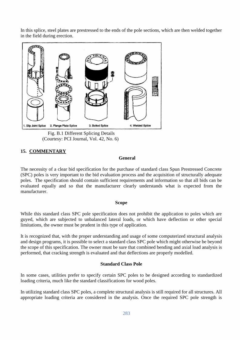
283
In this splice, steel plates are prestressed to the ends of the pole sections, which are then welded together
in the field during erection.
Fig. B.1 Different Splicing Details
(Courtesy: PCI Journal, Vol. 42, No. 6)
15. COMMENTARY
General
The necessity of a clear bid specification for the purchase of standard class Spun Prestressed Concrete
(SPC) poles is very important to the bid evaluation process and the acquisition of structurally adequate
poles. The specification should contain sufficient requirements and information so that all bids can be
evaluated equally and so that the manufacturer clearly understands what is expected from the
manufacturer.
Scope
While this standard class SPC pole specification does not prohibit the application to poles which are
guyed, which are subjected to unbalanced lateral loads, or which have deflection or other special
limitations, the owner must be prudent in this type of application.
It is recognized that, with the proper understanding and usage of some computerized structural analysis
and design programs, it is possible to select a standard class SPC pole which might otherwise be beyond
the scope of this specification. The owner must be sure that combined bending and axial load analysis is
performed, that cracking strength is evaluated and that deflections are properly modelled.
Standard Class Pole
In some cases, utilities prefer to specify certain SPC poles to be designed according to standardized
loading criteria, much like the standard classifications for wood poles.
In utilizing standard class SPC poles, a complete structural analysis is still required for all structures. All
appropriate loading criteria are considered in the analysis. Once the required SPC pole strength is

284
determined, a standard class spun concrete pole, which meets the actual loading conditions, can be
selected.
This specification has been developed to establish a standard classification system and to assist the owner
in procuring a standard class SPC pole, which is properly designed for the intended loading criteria.
This specification attempts to eliminate ambiguity in specifying and purchasing standard class SPC poles.
Since it has become a widespread practice in the industry to design and manufacture poles, which are
based on the wood pole classification system, the SPC pole classifications developed in this specification
generally, follow the wood pole classification system. However, to avoid confusion with the wood pole
classifications, the SPC pole classifications have a unique naming system.
Design Loads
The primary loads for concrete poles are environmental (wind) and erection loads. Common handling
loads are determined by the manufacturer and included in the manufacturer's design. Wind, construction
and maintenance loads need to be determined by the owner in order to select the proper standard class
pole.
Once the design loads have been determined, design of the structure should be performed by the
manufacturer’s engineer or structural designer. The design of SPC pole shall meet the ultimate moment
capacity requirements for the prescribed ultimate loads of the owner. Consideration should be given for
strength requirements at all points along the pole length, not just at the ground line.
The design load given in Art.12.4 is based on ruling span of 300 ft. and a wind speed of 100 km/h. This
transverse wind load may not be sufficient for coastal areas where the normal operating wind speed is
quite high. This increased requirement of transverse wind load on SPC poles can be accommodated by
adjusting the ruling span of transmission/distribution lines.
Point of Fixity
Point of fixity for this specification is defined as the location on the pole where maximum moment occurs.
Maximum moment is calculated by the pole designer using the loading provided by the owner and
multiplying those loading by the appropriate moment arms. The existing soil and backfill should be
capable of supporting the pole with these bending moments applied. The location of this point of fixity
could be at or below the groundline. The exact location is theoretical and depends on the soil condition
and backfill used to support the pole.
For the standard class pole, the point of fixity should remain at the same location on the pole, regardless
of the embedment depth the owner may specify for a given application. Otherwise, the required pole
strength could vary as the location of the point of fixity varies. Within the scope of this standard class
pole specification, the point of fixity is arbitrarily considered to be at ground level. The reinforcing steel
required at the point of fixity is required to continue to the pole butt.
Tip Loading
The tip loading is used to develop a required ultimate moment capacity diagram at any point along the
pole from 600 mm (2') below the pole tip down to the point-of-fixity. This ultimate moment is determined
by multiplying the tip load by the moment arm based on a simple cantilever. As a result, the required
ultimate moment diagram is linear in shape. This same method may be utilised in structural analysis and

285
automated transmission/distribution line design computer programs to develop an array of ultimate
moment requirements for standard concrete pole sizes.
Pole Deflection
This specification limits the allowable pole deflection to 5% of the pole height above the point of fixity
when the working tip load specified in Art.12.4 is applied under a horizontal testing procedure under
short term loading conditions. This is the deflection check at the service loading condition.
For situations where the owner wishes to know the deflection for a standard class pole at a specific load,
the owner should use a suitable structural analysis computer program in which the actual design loading
conditions and SPC pole properties are input into the program. Alternatively, the owner may ask the pole
manufacturer to provide the analysis.
Cracking Strength
Cracking strength is defined as the point at which the concrete just begins to separate due to exceeding
the tensile strength of the concrete on the tension face of the pole.
To minimise the potential for corrosion of the reinforcing steel, it is desirable to avoid cracking under the
service loading conditions, or any other service loads specified by the owner. Within the limits of this
specification, the predominant pole loading will be the transverse wind loads.
Zero Tension Strength
The zero tension strength is defined as the moment at which a crack that was previously created by
exceeding the cracking moment strength will open again. Under this condition, an applied moment will
not cause any tensile stress in the concrete.
It is important to avoid open cracks in situations of significant unbalanced lateral loading and in extremely
corrosive environments in order to protect the steel reinforcing. Typical structures with permanent
unbalanced lateral loads are unguyed angle and unguyed deadend structures. While the design of these
structure types is generally outside the recommended scope of this specification, this specification does
require a minimum zero tension strength for all pole classes.
It may be demonstrated that the zero-tension strength will typically be 70% to 85% of the cracking
strength. With a minimum cracking strength of 45.5% (1.0/2.2) of ultimate, 70% of this value would be
equal to 32% of ultimate. Thus, it is natural for all spun concrete poles to have zero tension strength of
at least 32% of ultimate. As such, this specification requires the standard class concrete pole to have zero
tension strength at 32% of the required ultimate strength.
For situations where the owner wishes to select a standard class pole based on a minimum zero tension
strength, this specification may be utilised. A typical situation where the owner may wish to do this is
when the owner uses a transmission/distribution line design computer program in which zero tension
strength values are input for each pole type.

286
DATA CENTRE
Overview
The figure below illustrates conceptual architecture of LT AMI SPM system. It includes data
center (production site) and DR center (backup site). The architecture and components of the two sites
shall be identical except that DR center also has development & test environment and education
environment. The two sites are connected via dedicated links.
Development and test environment is used for development of HES, MDMS, VS and SMS, and test of
the software. Once the test is completed and approved, the software is to be installed on production
servers in the two sites.
Education environment is used for the education of BREB staffs. It can be used for the education by
the Supplier during project implementation period, and also for the education by BREB itself during
and after project implementation period.
HES, MDMS and VS should consist of a three-tier architecture. 1) Presentation Layer: which is responsible for providing portable presentation logic.
2) Business Layer: which allows users to share and control business logic by isolating it from the actual application. The application shall be installed on a separate (physical or virtual) server as minimum. The number of servers can increase if necessary for performance and reliability needs.
3) Database Layer: which provides access to dedicated services, such as a database server. The database servers should be grouped into a cluster. The database server should support Scalability, Load Balancing and High Availability. The database should support Storage Area Network, standard SQL and partitioning of Tables and Indexes.
The Presentation Layer should work with Windows Operating System from Microsoft and with Internet
Explorer or similar. The Business Layer should work with Windows Server Operating System from

287
Microsoft or Linux operating system. The Database Layer should run on ows Server Operating System
from Microsoft or Linux Operating system.
The Supplier shall be accountable and responsible for acquiring all necessary equipment, managing
installation, and coordination with BREB. i. Specifications: The specifications for IT equipment and other equipment for data centre are
provided in this section but the Supplier shall specify the IT equipment, software including operating system, database and etc., LAN/WAN, and other infrastructure requirements for supporting the technical and performance requirements of the LT AMI SPM system.
ii. Acquisition: The Supplier shall acquire the IT hardware and infrastructure enhancements per the above specifications.
iii. Installation: The Supplier shall install the infrastructure enhancements per the specifications.
iv. Configuration and version control including operating system, database management, IP communication to field devices and other infrastructure software: Bidder shall submit the recommended configurations to BREB for approval and make the approved configuration changes.
Overall Solution
No. Name Description
1 Integrated
Solution
All components of the systems should act as a single LT AMI SPM
solution.
2 Master Data
All Master Data must be inserted only once to the LT AMI SPM
solution. Copies of these master data must distributed automatically to
all systems requiring them. Masterdata can be added, changed, deleted or
retired.
3 Initial Load of
Master Data
All Master Data for the system like meter, register, communication,
parameterization, etc. must be inserted automatically. The
manufacturesfactory file of via the Deployment Management System or
via other methods must dothis.
4 Diagnostics
The LT AMI SPM solution shall have diagnostic capability within the
solution components to show for example: Which processes are currently running on which system.
Category of Alarms and automated action based on the alarms.
Automatic problem solving functionality is required to prevent manual work.
5 Users
Solution should support different kind of user as listed below, as with
following minimum simultaneous access, per each system, and per each
PBS: System Administrators (2 per system)
Super Users/Managers (2 per PBS and per system)
Operators (2 per PBS/UCC/UVS, per system)
Visitors (4 per PBS/UCC/UVS, per system)
The users are located in the data cente and in the remote offices of BREB.
6 Archiving
The HES and MDMS systems shall support 90 days of data retention. An
online data archival storage solutions (e.g., Data Domain), decoupled
from the application and Database shall support for three years. After that
period, the data must be archived outside the system for five years.

288
Business Requirements
Head End System
No. Name Description
1 Frequency of
Meter Data
Acquisition
HES shall be designed to read meter periodically in a day such that all
meter data for 0.
5 million metering points can be acquired in a day.
2 Success Rate 95% of all meter must be successfully collected within one day; 99.5% of
all meter within 3 days.
3 Authentication Password for all level of meter devices and concentrators must be stored
in encrypted format in the system
4 Confidentially The communication from the HES to the meters and to the data
concentrators should be encrypted by Advanced Encryption Standard;
minimum AES-128
5 Integrity The meter data should not change between HES and meter or DCU.
6 Access to the
system
The HES can be accessed by using username and password, only. The
administrator can enforce to use passwords with small and capital letters,
number andspecial signs. The system administrator also can enforce the
user to chance its password on regular base
7 User Roles The HES should be able to give user rights to users directly or to assign
user roles to a user. The user rights shall allow the usage of a certain
functionality for the user; examplethe user role "Visitor" shall allowed to
read meter data only
8 Data
Segmentation
The HES shall have user privileges assigned to users vertically (i.e. by
function within the system).
9 Multilanguage The GUI and the Online Help should be in English language. It should be
possible to introduce other languages.
10 User friendly The Graphical User Interface (GUI) must be modern and user friendly.
11 Meter protocols HES should support many meter protocols, but as a minimum:
DLMS/COSEM
12 Communication
methods
Support of RF, 3G/4G communication, and TCP/IP between HES and
DCU and meters.
13 Meter Data The HES shall collect the following data at least from the meters: Billing Values
Value from Actual Register for all tariffs
Remaining credit register
"frozen" value end of the month for all tariffs
Maximum demand for all tariffs
Load Profile
Daily and/or hourly value for all registers for meters
Alarms and Messages especially tampering detection, power off and on
14 Time
synchronization
Capability to synchronize all meters, repeaters, DCUs via a centralized
clock

289
15 Disconnection Send disconnection and reconnection commands and receive messages
from the meter about successful or not successful execution of that
command
16 Load limitation Configure the device in that way that load limitation in the device is
executed when load exceeds a contracted load for a given time
17 ToU download Support ToU download with valid from date. Receive messages per
meter if new ToU was downloaded successfully
18 Remote
Parameterization
All meters and data concentrators should be fully configured remotely.
HES should receive messages about successful change of
parameterization with the configuration date andstore the date in the
master data for meters and data concentrators
19 Firmware update Support of download new firmware version for meters and data
concentrators. Receive messages if new firmware was downloaded
successfully
20 Meter change HES should store the meter values independent with the Point of Delivery,
independent of the physical meter
Vending System
No. Name Description
1 Overall Performance
Vending System (VS) must process all vending request within 30 seconds. New or changed data must be applied as soon as they are inserted into the database of the VS.
2 Scalability The database and the application of the VS must be scalable, so that future extension of system functionality and higher number of metering point and vending request can be handled even if the number of customers are increased to 20 million.
3 Access to the system
VS should be accessed by using username and password, only. The system administrator can enforce to use passwords with small and capital letters, number and special signs. The system administrator also can enforce the user to chance its password on regular base.
4 User Roles VS should be able to give user rights to users directly or to assign user roles to a user. The user rights shall allow the usage of a certain functionality for the user; example the user role "Visitor" shall allowed to read vending data only.
5 Data Segmentation VS should be segmented in that way that users can see a certain amount of vending data which belongs to the user’s jurisdiction only. Ex.: Only meters in PBS "ABC".
6 User friendly GUI must be modern and user friendly: Easy to use forms for data requests of all, grouped or specific meters
(data request methods: on-demand, historical data).
7 Online Help Online help should be context sensitive to the cursor or to the screen from where the online help is invoked.
8 Token parameter setting
It must be possible to configure parameters such as tariff type, base service charge, tax and etc. to generate STS token from received amount of currency.
9 Limitation of purchase
It must be possible to configure the VS to limit purchasing: Minimum vend amount Maximum vend amount Currency or unit vend only per vendor
10 Token generation VS must be able to generate STS currency credit token, STS units credit token, and STS engineering tokens.
11 Reports Set of standard reports. Reports should be exportable as PDF, EXCEL or CSV. Provision should be made to accommodate additional reports as required for operational purposes.
12 Automatic report The following reports should be generated automatically per cashier/UVS/PBS.

290
Daily sales report Monthly sales report
13 Traceability All history of token generation must be recorded with timestamp, amount including deducted amount, cashier, UVS, PBS and so on.
14 HES interface VS must have interface to MDMS for all data transfer including token.
15 MDMS interface VS must have interface for MDMS to exchange new/changed metering point information.
16 Editing It should be possible to edit metering point information manually and automatically:
17 API API for external systems shall be provided.
18 Overall Performance
Vending System (VS) must process all vending request within 30 seconds. New or changed data must be applied as soon as they are inserted into the database of the VS.
19 “Thin” prepayment Management
Besides the capability of generating STS tokens for the STS meters, the VS shall allow meter's prepaid “wallet” to be managed, meaning the capability of calculating credits for each meter/accounts, based on daily meter consumption readings and credits purchases. The VS shall be able to send commands to HES for opening a meter contact when its respective credit balance is below a pre-defined threshold, or to close the meter contact when the respective credit balance is over the pre-defined threshold.
20 Tariff Management The VS shall allow prepayment tariff management, including support for complex tariffs, block/stepped tariffs with unlimited tariff blocks, fixed charges and taxes.
21 Debt Management The VS shall allow Debts to be managed with multiple debt items and various methods shall be used to recover debt, such as deductions on the purchase credit amount, based on pre-configured percentage of the vend, percentage of the remaining debt balance or an ad-hoc amount in currency.
22 Integration with vending channels and electronic payment channels
Beside the capability of integration with HES and MDM, the VS shall also provide flexible and open integration tools (API) to interface with other payment systems and third-party vending channels. There are many sales channels that can be integrated. Such channels include: Point of Sale (Windows and Android), Third-party sales terminal (bank terminals, supermarket counters, pharmacies, lotto, etc.), Mobile phone, Web consumer portal (mobile and fixed) and Electronic Fund Transfer or TEF (e.g. PayPal). The integration module shall support the ISO8583 protocol, the international standard for exchange messaging generated by financial transaction cards. The solution shall also certified to PCI DSS Level 1 security standard for payment via debit cards, credit cards and other electronic transfer transactions of funds (TEF).
23 Customer Portal The VS shall include a client portal module. This is a consumer-focused website for high-end mobile devices, supported by larger web browsers. This portal allows a consumer to: Manage a profile which can include several accounts and meters, View all purchase transactions, See tariffs and Buy energy and recharge wallets using on-line electronic payment methods (if integrated).
24 SMS Email Notification
The VS shall send customer notifications, via SMS and E-mails, for low credit warnings. At least two credit thresholds shall be configured (e.g. low credit and negative credit). The SMS number and E-mail account shall be configured by the utility operator or by the consumer him/herself via the Customer Portal. The system shall also allow integration with SMS Gateways, local or international.
25 Tokens Tokens should only be used for credit transfer. All other functions should be DLMS/COSEM based.

291
Metering Data Management System
No. Name Description 1 Access to the
system MDMS User access should use Windows Active Directory for authentication to reduce maintenance and align usernames and passwords with corporate security policy.
2 User Roles MDMS should be able to give user rights to users directly or to assign user roles to a user. The user rights shall allow the usage of a certain functionality for the user; example the user role "Visitor" shall allowed to read meter data only.
3 Data Segmentation
MDMS should be segmented in that way that users can see a certain amount of meter data which belongs to the user’s jurisdiction only. Ex.: Only meters in PBS "ABC".
4 User friendly GUI must be modern and user friendly: Easy to use forms for data requests of all, grouped or specific meters
(data request methods: on-demand, schedule (cyclic), historical-stored
data).
Navigation option and Graphical data representations of historical data
(configurable). 5 Online Help Online help should be context sensitive to the cursor or to the screen from
where the online help is invoked. 6 VEE MDMS must validate the data. Non-validated date must be substituted.
Validation Algorithm: Possibility to define validation algorithm, but standard validation algorithms must be implemented, also:
Zero Consumption, Negative Consumption, Gap Detection for load profiles, Load Profile Comparison with Billing Values, Main and Check Meter Comparison, "broken or manipulated meter", lower and upper limit (for example: 15% deviation from previous period) .
Substitution: Possibility to define substitution rules, but standard substitution must be implemented, also:
Substitution rules like "broken or manipulated meter" where billing value shall be substituted by max (average last year, same month of last week ), check meter, value from defined calendar period, interpolation for non-valid load profiles values, etc.
7 Balances Balance reports must be calculated based on different balance methodologies.
8 Alarming Reports The alarming reports should show alarms as part of its Validation process, and either puts an item in the queue or auto sub-directory.
9 Reports Set of standard reports and user defined reports. PDF, Word, EXCEL and HTML reports should be supported. Custom CSV extracts shall be created and provided via email.
10 Calculation Strong module for calculation should be support for: Calculation of billing determents out of load profiles and tariff agreement. Cross sums calculation like sum per user group or balances.
11 Load Limitation MDMS should be able to configure the device via HES in that way that load limitation in the device is executed when load exceeds a contracted load for a given time.
12 Tariff Agreements
MDMS should have the functionality to store tariff agreements. Tariff agreements should be created by graphical user interface. Tariff agreements must be downloaded via HES to the meters.
13 Update of Meters in Reports
Calculations and reports such as the balance report should be updated with new meters automatically.
14 Meter change MDMS should store the meter values independent of metering point, independent of the physical meter.
15 Snapshots MDMS must present the data how the data was stored on a certain time
(data versioning).

292
16 Repeatability Calculation of the data should bring the same results for the same period. For instance: Balance of feeder in a substation should have the same result for a certain period, even if the number of consuming devices has changed after that period.
17 Traceability All changes of meters’ data in the system must be recorded: old value, new value, reason for change, username or process name that changed the value and timestamp when the value was changed.
18 Automatic update of Calculations
Changed values in the meter data (due to substitution for instance) must result in changed values of the calculations automatically.
19 CIM Support MDMS must have CIM interface to integrate HES. MDMS to HES integration shall support a two-way integration flow to provide an end-to-end seamless integration. MDMS and HES must share a data transfer format enabling read data to be shipped in native format and Meters in MDMS must be linked to HES to allow MDMS to be issued from the MDMS GUI by users. Utility systems such as OMS, Billing and ADMS must be able to request MDMS via a published Web API.
20 Vending System interface
MDMS must be master metering point information and exchange the information with Vending System.
21 GIS interface MDMS should be able to interface with GIS system (ArcGIS) to present device information such as device name, type, current state, location and so on.
22 Data collection MDMS must have the capability to access the collected data, in the meter, HES, database as well as manual meter readings via HES.
23 Interval data MDMS should support processing of interval data in high volumes - Manage and store interval data for 3 years online and archive for 5 years - Manage and store interval data for 20 million meters - Ability to re-import archived data via UI.
24 Editing It should be possible to edit meter data manually and automatically: - Replace or change intervals - Copy and replace intervals - Add or delete intervals - Factor intervals
25 Billing determinants
MDMS should summarize interval data into billing determinants.
26 Limit load MDMS should be able to limit load of meter(s) via HES. 27 Disconnection/
Reconnection MDMS should be able to send via HES disconnection and reconnection commands and receive messages from the meter about successful or not successful execution of that command.
TEST
Test Responsibilities
Both the Employer and the Supplier shall designate, in writing and prior to the start of the test, a test
coordinator. The test coordinators shall: • Ensure that the tests are conducted in accordance with the requirements of this Contract.
• Have the authority to make binding commitments for their employer such as approvals of test results and scheduling for variance corrections or, as a minimum, to cause such commitments to be expeditiously made.
The Supplier shall be responsible for all site tests with the exception of the Availability Test. This
responsibility shall include the conduct of the tests and all record keeping and document production.
The Employer shall support the site testing by supplying staff to monitor the tests. The Employer
expects that at least two Supplier staff will be on-site during these tests.
Test Documents
Test plans, procedures, and records shall be provided by the Supplier for all tests to ensure that each
test is comprehensive and verifies the proper performance of the system under test.

293
The test plans and test procedures shall emphasize the testing of each functional requirement, checking
error conditions, and documenting the simulation techniques used.
The test plans and test procedures shall be modular to allow individual test segments to be repeated as
necessary.
All test plans and test procedures (standard, modified standard, and custom functions) shall be
submitted to the Employer for approval at least fifteen (15) days prior to the test and shall be subject to
the approval process.
Variance Recording and Resolution
The Supplier shall establish a process to record and track variances.
Variances shall be used to record system deficiencies, including but not limited to: • Documentation deficiencies.
• Functional deficiencies.
• Performance deficiencies.
• Procedural deficiencies.
• Test deficiencies (as when the system cannot satisfactorily complete a test procedure due to a problem with the test).
The variance process shall produce reports of all variance information and shall produce reports of
subsets of the variances based on searches of the variance parameters singly and in combination.
The variance recording and tracking system shall allow the on-demand production of reports of all
variance information. Variance recording and reporting shall be available to the Employer at all times
via the Internet subject to secure access.
The Supplier shall periodically distribute a variance summary that lists for each variance the report
number, a brief overview of the variance, its category, and its priority.
Test Schedule
The Supplier shall provide a detailed system test schedule that is consistent with project phasing. • The test schedule shall cover all aspects and components of the HES, including backup modes
of operation, full integrated operation and engineering.
• The detailed test schedule shall be subject to Employer approval. All equipment documentation shall be completed, reviewed and approved by the Employer before any
testing.
Factory Acceptance Test
Factory Acceptance Test (FAT) shall be carried out as prescribed in the technical specifications.
The Supplier shall arrange for three (3) participants from the Employer and the Project Manager to
witness tests of major equipment/systems listed below in the manufacturer’s plant. All routine tests
shall be carried out in the presence of the Employer’s representatives. Therepresentatives shall approve
shipment of the equipment if they are satisfied that the requirements of the specification are fully met.
The Supplier shall arrange and meet the full cost of the air tickets, local transportation and etc.The cost
of per diem and accommodation shall be met by the Employer. The cost of anyadditional inspections
other than above, if any, at the bidder premises should be at the purchasercost and not part of this
contract.
Before FAT, the Supplier MUST complete integration of Smart Prepayment System API (seeAnnex
E), and all other functions including three-level password function MUST beimplemented.
FAT shall be carried out for the following; • Meters
• Desktop/Laptop computers
• Handheld unit

294
FAT shall be carried out as prescribed in the particular technical specifications of theequipment. In
particular, all the functions of Smart Prepayment Metering operation usingSmart Prepayment System
API shall be carried out. In addition, three-level password functionshall be demonstrated.
Routine Test
Routine Test shall be performed on equipment (hardware and software) as set out in the scope of supply
including testing items and standards.
The Supplier shall supply the Routine Test before shipping.
Post Landing Inspection
The Supplier shall inform the Employer immediately after arrival of the goods at thedesignated store
of the Employer (as per delivery schedule). An Inspection team of the Employer shall perform the
post-landing inspection in presence of the Supplier'srepresentative. The Supplier shall arrange the
program of post landing inspection. Anydefect or damage have been found at post-landing inspection,
the defective or 0damaged materials/ goods to be replaced by the Supplier at his own cost within the
stipulated time.
The Employer’s right to inspect, test (where necessary) and reject the goods after delivery at the
designated store of the Employer shall in no way be limited or waived by reason of the goods having
previously been inspected, tested and passed by the Employer prior to the good's delivery. In case of
reject, the cost incurred for this inspection shall be borne by the Supplier.
Site Acceptance Test
Site Acceptance Test (SAT) will be conducted after the system has been installed and successful start-
up of the system. The system will be subjected to a subset of the functional performance tests. The
SAT will also include any type of testing that could not be performed in the factory. Unstructured tests
will be employed by the Employer, as necessary, to verify overall system operation under field
conditions. Any defects or design errors discovered during the SAT shall be corrected by the Supplier.
After the system loaded (in-service) test procedures and plans to be conveyed to the Employer.
General Site Acceptance Test
The Site Acceptance Test (SAT) will be conducted once the Supplier had installed the 10% of the
total meters requested.
Scheduled meter data reading
Pass Criteria: Meter data of minimum of 95% of the target meters shall be collected before
08:00 for seven (7) consecutive days.
On-demand meter data reading
Pass Criteria: On-demand reading will be performed for up to 100 meters and valid meter
data will be returned for all meters for which data is received. Validation will be conducted
by manually reading the meter value and compared with the on request read. A minimum of
95% of the tested meters shall return valid data with the first attempt. In the event that 95%
successful reads are not obtained, two more retry will be allowed for each unsuccessfully
meter read. The final value for acceptance test is 98%.
Specific Site Acceptance Test Real time alarm notification
Pass Criteria: Real time alarm test will be executed on two (2) DCUs and five (5) three phase
meters. For each DCU, terminal cover of five (5) single phase meters will be open to generate
real time alarm. And also, it also is applied to five (5) three phase meters. The alarm from single
phase meters shall be collected within five (5) minute, and the alarm from three phase meters
shall be within two (2) minute.
Token transfer
Pass Criteria: Tokens should only be used for credit transfer. All other functions should be
DLMS/COSEM based. Token test will be executed on two (2) DCUs and one (1) 2G/3G phase
meters. For each DCU, test token to check remaining credit will be sent to one (1) DCU for one

295
(1) RF meter respectively, and to one (1) 2G/3G phase meters respectively. The result shall be
collected within one (1) minute respectively.
Availability Test
A 1440-hour (sixty days) availability test shall be conducted for the complete system after the
completion of the implementation. The test shall be performed under actual operating conditions.
The Supplier shall have his qualified representatives available at all times during the test, the purpose
of which is to verify the reliability of the system hardware and software.
The Supplier shall bear the responsibility for all corrective maintenance on the system; the Employer,
however, may correct problems under the supervision of the Supplier.
The Employer will be responsible for the system restart, notification to the Supplier of service
requirements, and preventive maintenance.
Test criteria of the availability test The system shall meet an availability of at least 99.99%.
This availability shall be calculated pro-rata for the actual duration of the test. System availability
shall be computed using the following formula:
𝑆𝑦𝑠𝑡𝑒𝑚_𝐴𝑣𝑎𝑖𝑙𝑎𝑏𝑖𝑙𝑖𝑡𝑦 = 𝑇𝑒𝑠𝑡_𝑡𝑖𝑚𝑒 – 𝐷𝑜𝑤𝑛_𝑡𝑖𝑚𝑒
𝑇𝑒𝑠𝑡_𝑡𝑖𝑚𝑒 ∗ 100%
No more than a total of two automatic or manual failovers or restarts of the central processorsshall
be permitted during the test in order to recover from problems with the system operation.
The test shall be considered to have failed if this number is exceeded.
Test completion requirements If the guaranteed availability cannot be demonstrated at the end of 1440 hours, the Suppliermay
continue the test by moving the starting time of the test forward and continuing the testuntil the 1440
consecutive hours have been accumulated.
If this exceeds 3 starting times orthis period exceeds 180 days, the system shall be deemed to have
failed the test.If the system fails the test, the Supplier shall make all needed hardware and
softwarecorrections, and the test shall be rerun and repeated until successful. The Supplier shall
bearall correction and test rerun costs.
On successful completion of the Final Acceptance Test, the Employer will take over the systemand
the warranty period shall begin. In addition, communication cost for DC/DR/UCC/UVS, 2G/3G and
DCU will be taken over to the Employer.
DOCUMENTATION
Documentation shall be provided for all equipment and functions provided by the Supplier as part of this
procurement. All documentation shall be in English and shall be subject to review and approval by the
Employer to guarantee an acceptable level of written English is delivered.
The documentation shall describe meters, communication and DC/DR/UCC/UVS, including all of its
hardware, software, and interfaces and shall cover functionality, testing, configuration, installation,
system start-up, operations, and maintenance, interface protocols and all other deliverables. All
equipment within the scope of supply shall include documentation.
All documentation shall have an electronic copy and shall be suitable for integration in a web portal. All
documentation shall be structured and have a common root with indexes per subject. This shall include
original equipment manufacturer (OEM) documents as well. System shall include documentation control
tools including search, version management and update control.The intent of the documentation and the
ensuing review and approval process is to ensure that it is of a standard and coverage so that when coupled
with the delivered Training will ensure that the Employer will be self-sufficient in maintenance of the
System. Where it is deemed by the Employer that the documentation fails to fulfil this intent, the Supplier
shall make good and shall deliver additional documentation as directed by the Employer.
In addition, documentation as-built for DC/DR/UCC/UVS shall be submitted after implementation for
approval.

296
ANNEX A: GUARANTEED TECHNICAL SCHEDULE (GTS) for Lot-1
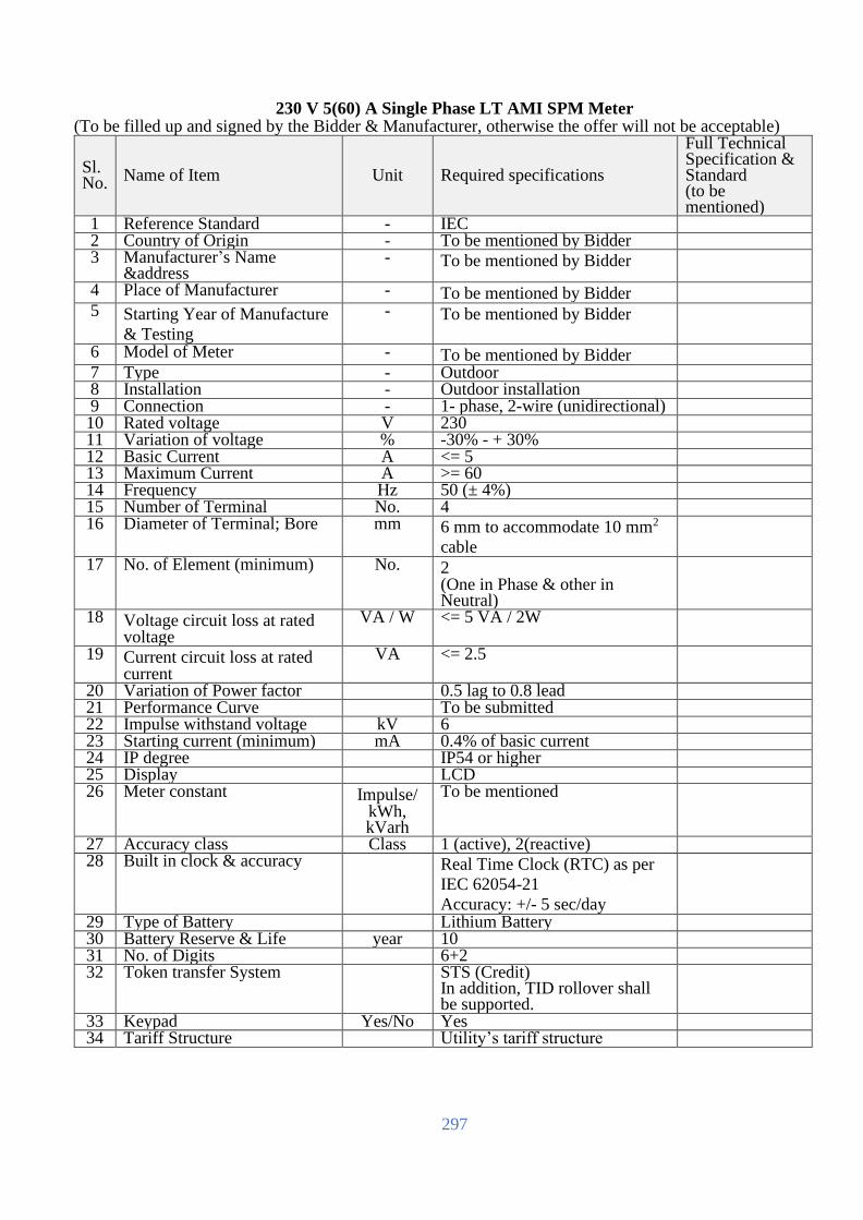
297
230 V 5(60) A Single Phase LT AMI SPM Meter (To be filled up and signed by the Bidder & Manufacturer, otherwise the offer will not be acceptable)
Sl. No.
Name of Item Unit Required specifications
Full Technical Specification & Standard (to be mentioned)
1 Reference Standard - IEC 2 Country of Origin - To be mentioned by Bidder 3 Manufacturer’s Name
&address - To be mentioned by Bidder
4 Place of Manufacturer - To be mentioned by Bidder
5 Starting Year of Manufacture
& Testing
- To be mentioned by Bidder
6 Model of Meter - To be mentioned by Bidder
7 Type - Outdoor 8 Installation - Outdoor installation 9 Connection - 1- phase, 2-wire (unidirectional) 10 Rated voltage V 230 11 Variation of voltage % -30% - + 30% 12 Basic Current A <= 5 13 Maximum Current A >= 60 14 Frequency Hz 50 (± 4%) 15 Number of Terminal No. 4 16 Diameter of Terminal; Bore mm 6 mm to accommodate 10 mm2
cable
17 No. of Element (minimum) No. 2 (One in Phase & other in Neutral)
18 Voltage circuit loss at rated voltage
VA / W <= 5 VA / 2W
19 Current circuit loss at rated current
VA <= 2.5
20 Variation of Power factor 0.5 lag to 0.8 lead 21 Performance Curve To be submitted 22 Impulse withstand voltage kV 6 23 Starting current (minimum) mA 0.4% of basic current 24 IP degree IP54 or higher 25 Display LCD 26 Meter constant Impulse/
kWh, kVarh
To be mentioned
27 Accuracy class Class 1 (active), 2(reactive) 28 Built in clock & accuracy Real Time Clock (RTC) as per
IEC 62054-21
Accuracy: +/- 5 sec/day
29 Type of Battery Lithium Battery 30 Battery Reserve & Life year 10 31 No. of Digits 6+2 32 Token transfer System STS (Credit)
In addition, TID rollover shall be supported.
33 Keypad Yes/No Yes 34 Tariff Structure Utility’s tariff structure

298
35 Front Page Indications - Credit Status
- Accept/Reject
- Low credit warning
- Consumption Rate - Tamper Indication
36 Disconnection Facility - On credit expiry
- Exceeded Power threshold - When tampered
37 Provision for emergency Friendly Credit
To be mentioned by Bidder
38 Configuration of friendly
hours support
Yes/No Yes To be mentioned by Bidder
39 Time interval of recalibration yr >= 10
40 Service life yr >= 10 41 Support of load limit Yes/No Yes
To be mentioned by Bidder
42 Meter body sealing condition
Ultrasonic Welded to prevent
unauthorized opening of meter
cover.
43 Latching relay As per specification
44 Communication protocol DLMS/COSEM
45 Communication compartment For RF & 2G/3G
46 No. of channel for load
profile
No. At least 2
47 No. of load profiles days At least 60 days for hourly LP
for 2 channel
48 Support of maximum demand Yes/No Yes
49 No. of monthly billing data No. 12
50 Weight Kg <= 1 (preferred, including
communication module)
To be mentioned by Bidder
51 Overall dimensions (height,
width, depth)
mm <= 280 x 180 x 90 (preferred,
long terminal cover)
To be mentioned by Bidder
52 Warranty yr 3
[The Bidder should complete all the columns as required]
Name
In the capacity of
Signed
Duly authorized to sign the Bid for and on behalf of
Date

299
230 V 10(100) A Three Phase LT AMI SPM Meter (To be filled up and signed by the Bidder & Manufacturer, otherwise the offer will not be acceptable)
Sl. No. Name of Item Unit Required specifications
Full Technical Specification & Standard (to be mentioned)
1 Reference Standard - IEC 2 Country of Origin - To be mentioned by Bidder 3 Manufacturer’s Name &address - To be mentioned by Bidder
4 Place of Manufacturer - To be mentioned by Bidder
5 Starting Year of Manufacture &
Testing
- To be mentioned by Bidder
6 Model of Meter - To be mentioned by Bidder
7 Type - Outdoor 8 Installation - Outdoor installation 9 Connection - 3- phase, 4-wire
(unidirectional)
10 Rated voltage V 3 x 230 11 Variation of voltage % -30% - + 30% 12 Basic Current A <= 10 13 Maximum Current A >= 100 14 Frequency Hz 50 (± 4%) 15 Number of Terminal No. 8 16 Diameter of Terminal; Bore mm 8.5 mm to accommodate 25
mm2 cable
17 No. of Element (minimum) No. 3 18 Voltage circuit loss at rated
voltage
VA / W <= 10 VA / 5W
19 Current circuit loss at rated current
VA <= 2.5
20 Variation of Power factor 0.5 lag to 0.8 lead 21 Performance Curve To be submitted 22 Impulse withstand voltage kV 6 23 Starting current (minimum) mA 0.4% of basic current 24 IP degree IP54 or higher 25 Display LCD 26 Meter constant Impulse/
kWh, kVarh
To be mentioned
27 Accuracy class Class 1 (active), 2(reactive) 28 Built in clock & accuracy Real Time Clock (RTC) as per
IEC 62054-21
Accuracy: +/- 5 sec/day
29 Type of Battery Lithium Battery 30 Battery Reserve & Life year 10 31 No. of Digits 6+2 32 Token transfer System STS (Credit)
In addition, TID rollover shall be supported.
33 Keypad Yes/No Yes 34 Tariff Structure Utility’s tariff structure

300
35 Front Page Indications - Credit Status
- Accept/Reject
- Low credit warning
- Consumption Rate - Tamper Indication
36 Disconnection Facility - On credit expiry
- Exceeded Power threshold - When tampered
37 Provision for emergency Friendly Credit
To be mentioned by Bidder
38 Configuration of friendly hours
support
Yes/No Yes To be mentioned by Bidder
39 Time interval of recalibration yr >= 10
40 Service life yr >= 10 41 Support of load limiting Yes/No Yes
To be mentioned by Bidder
42 Meter body sealing condition
Ultrasonic Welded to prevent
unauthorized opening of meter
cover.
43 Latching relay As per specification
44 Communication protocol DLMS/COSEM
45 Communication compartment For RF & 2G/3G
46 No. of channel for load profile No. At least 2
47 No. of load profiles days At least 60 days for hourly LP
for 2 ch
48 Support of maximum demand Yes/No Yes
49 No. of monthly billing data No. 12
50 Weight Kg <= 1.5 (preferred, including
communication module)
To be mentioned by Bidder
51 Overall dimensions (height,
width, depth)
mm <= 310 x 200 x 100 (preferred,
long terminal cover)
To be mentioned by Bidder
52 Warranty yr 3
[The Bidder should complete all the columns as required]
Name
In the capacity of
Signed
Duly authorized to sign the Bid for and on behalf of
Date

301
RF Mesh Communication Module for LT AMI SPM Meters (To be filled up and signed by the Bidder & Manufacturer, otherwise the offer will not be acceptable)
Sl. No.
Name of Item Required specifications
Full Technical Specification & Standard (to be mentioned)
1 Country of Origin USA/UK/EU/Switzerland/Australia/Japan 2 Manufacturer’s Name
&address To be mentioned by Bidder
3 Place of Manufacturer To be mentioned by Bidder 4 Starting Year of Manufacture
& Testing To be mentioned by Bidder
5 Model & Version To be mentioned by Bidder 6 Operating power Shall be supplied by meter 7 Operating temp. -25 °C to +65 °C 8 Frequency range (in MHz) 922 - 925 MHz 9 Max output power (EIRP) 500 – 1000 mW 10 Data rage >= 100 kbps 11 Certification Wi-SUN FAN 12 Communication with
application HES via DCU / Gateway / Access Point
13 Replacement Field replaceable 14 Operation Plug-and-play 15 Registration Auto registration 16 Routing Auto routing 17 IP support IPv6
18 Communication Two-way communication 19 Firmware upgrade Over the Air 20 Time sync With HES or Access Point (AP) /
Gateway
21 DTLS support Yes 22 CoAP support Yes 23 Topology information Yes 24 Communication with meter DLMS/COSEM 25 Unicast/Multicast support Yes 26 Security SHA-256, RSA-1024 or ECC-256 27 Encryption AES-128 or AES-256 28 Antenna Built-in 29 Last gasp support Yes 30 Warranty 3 years
[The Bidder should complete all the columns as required]
Name
In the capacity of
Signed
Duly authorized to sign the Bid for and on behalf of
Date

302
2G Communication Module for LT AMI SPM Meters (To be filled up and signed by the Bidder & Manufacturer, otherwise the offer will not be acceptable)
Sl. No.
Name of Item Required specifications
Full Technical Specification & Standard (to be mentioned)
1 Country of Origin To be mentioned by Bidder 2 Manufacturer’s Name
&address To be mentioned by Bidder
3 Place of Manufacturer To be mentioned by Bidder 4 Starting Year of Manufacture
& Testing To be mentioned by Bidder
5 Model & Version To be mentioned by Bidder 6 Operating power Shall be supplied by meter 7 Operating temp. -25 °C to +65 °C 8 Frequency range (in MHz) Quadband: 850/900/1800/1900
MHz
9 Output power (EIRP) 2 W for EGSM850/EGSM900 1 W for GSM1800/GSM1900
10 GPRS Class 10 11 Communication with
application Directly with HES
12 Replacement Field replaceable 13 Operation Plug-and-play 14 Communication Two-way communication 15 Firmware upgrade Over the Air 16 Time sync With HES 17 Communication with meter DLMS/COSEM 18 Antenna Built-in 19 Last gasp support Yes 20 Warranty 3 years
[The Bidder should complete all the columns as required]
Name
In the capacity of
Signed
Duly authorized to sign the Bid for and on behalf of
Date
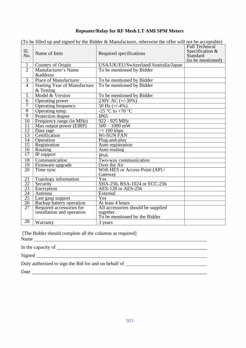
303
Repeater/Relay for RF Mesh LT AMI SPM Meters
(To be filled up and signed by the Bidder & Manufacturer, otherwise the offer will not be acceptable)
Sl. No.
Name of Item Required specifications
Full Technical Specification & Standard (to be mentioned)
1 Country of Origin USA/UK/EU/Switzerland/Australia/Japan 2 Manufacturer’s Name
&address To be mentioned by Bidder
3 Place of Manufacturer To be mentioned by Bidder 4 Starting Year of Manufacture
& Testing To be mentioned by Bidder
5 Model & Version To be mentioned by Bidder 6 Operating power 230V AC (+/-30%) 7 Operating frequency 50 Hz (+/-4%) 8 Operating temp. -25 °C to +70 °C 9 Protection degree IP65 10 Frequency range (in MHz) 922 - 925 MHz 11 Max output power (EIRP) 500 – 1000 mW 12 Data rage >= 100 kbps 13 Certification Wi-SUN FAN 14 Operation Plug-and-play 15 Registration Auto registration 16 Routing Auto routing 17 IP support IPv6
18 Communication Two-way communication 19 Firmware upgrade Over the Air 20 Time sync With HES or Access Point (AP) /
Gateway
21 Topology information Yes 22 Security SHA-256, RSA-1024 or ECC-256 23 Encryption AES-128 or AES-256 24 Antenna External 25 Last gasp support Yes 26 Backup battery operation At least 4 hours 27 Required accessories for
installation and operation All accessories should be supplied together. To be mentioned by the Bidder
28 Warranty 3 years
[The Bidder should complete all the columns as required]
Name
In the capacity of
Signed
Duly authorized to sign the Bid for and on behalf of
Date
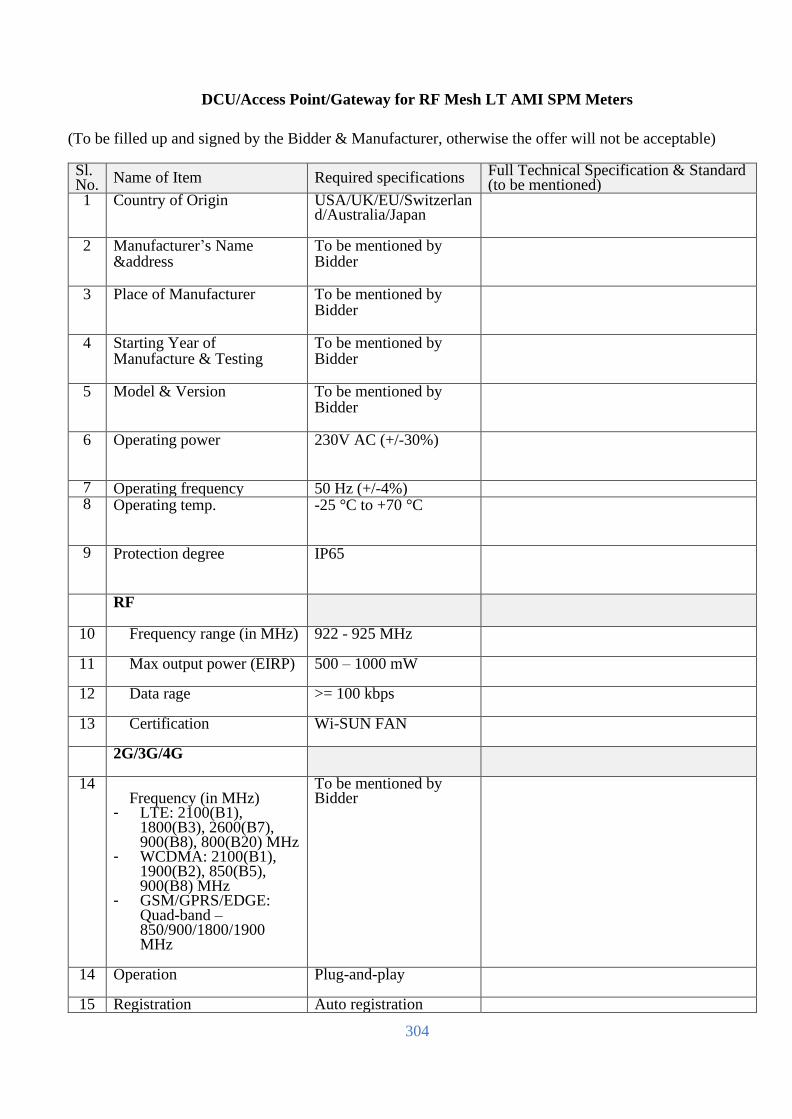
304
DCU/Access Point/Gateway for RF Mesh LT AMI SPM Meters
(To be filled up and signed by the Bidder & Manufacturer, otherwise the offer will not be acceptable) Sl. No.
Name of Item Required specifications Full Technical Specification & Standard (to be mentioned)
1 Country of Origin USA/UK/EU/Switzerland/Australia/Japan
2 Manufacturer’s Name &address
To be mentioned by Bidder
3 Place of Manufacturer To be mentioned by Bidder
4 Starting Year of Manufacture & Testing
To be mentioned by Bidder
5 Model & Version To be mentioned by Bidder
6 Operating power 230V AC (+/-30%)
7 Operating frequency 50 Hz (+/-4%) 8 Operating temp. -25 °C to +70 °C
9 Protection degree IP65
RF
10 Frequency range (in MHz) 922 - 925 MHz
11 Max output power (EIRP) 500 – 1000 mW
12 Data rage >= 100 kbps
13 Certification Wi-SUN FAN
2G/3G/4G
14 Frequency (in MHz)
- LTE: 2100(B1), 1800(B3), 2600(B7), 900(B8), 800(B20) MHz
- WCDMA: 2100(B1), 1900(B2), 850(B5), 900(B8) MHz
- GSM/GPRS/EDGE: Quad-band – 850/900/1800/1900 MHz
To be mentioned by Bidder
14 Operation Plug-and-play
15 Registration Auto registration
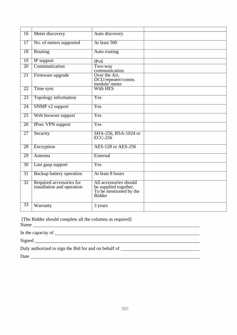
305
16 Meter discovery Auto discovery
17 No. of meters supported At least 500
18 Routing Auto routing
19 IP support IPv6
20 Communication Two-way communication
21 Firmware upgrade Over the Air, DCU/repeater/comm. module/ meter
22 Time sync With HES
23 Topology information Yes
24 SNMP v2 support Yes
25 Web browser support Yes
26 IPsec VPN support Yes
27 Security SHA-256, RSA-1024 or ECC-256
28 Encryption AES-128 or AES-256
29 Antenna External
30 Last gasp support Yes
31 Backup battery operation At least 8 hours
32 Required accessories for installation and operation
All accessories should be supplied together. To be mentioned by the Bidder
33 Warranty 3 years
[The Bidder should complete all the columns as required]
Name
In the capacity of
Signed
Duly authorized to sign the Bid for and on behalf of
Date
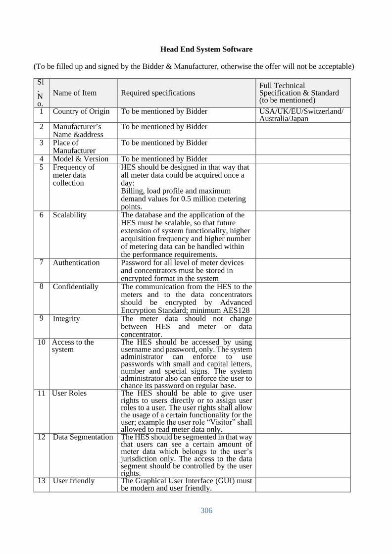
306
Head End System Software
(To be filled up and signed by the Bidder & Manufacturer, otherwise the offer will not be acceptable) Sl. No.
Name of Item Required specifications Full Technical Specification & Standard (to be mentioned)
1 Country of Origin To be mentioned by Bidder USA/UK/EU/Switzerland/Australia/Japan
2 Manufacturer’s Name &address
To be mentioned by Bidder
3 Place of Manufacturer
To be mentioned by Bidder
4 Model & Version To be mentioned by Bidder 5 Frequency of
meter data collection
HES should be designed in that way that all meter data could be acquired once a day: Billing, load profile and maximum demand values for 0.5 million metering points.
6 Scalability
The database and the application of the HES must be scalable, so that future extension of system functionality, higher acquisition frequency and higher number of metering data can be handled within the performance requirements.
7 Authentication
Password for all level of meter devices and concentrators must be stored in encrypted format in the system
8 Confidentially
The communication from the HES to the meters and to the data concentrators should be encrypted by Advanced Encryption Standard; minimum AES128
9 Integrity
The meter data should not change between HES and meter or data concentrator.
10 Access to the system
The HES should be accessed by using username and password, only. The system administrator can enforce to use passwords with small and capital letters, number and special signs. The system administrator also can enforce the user to chance its password on regular base.
11 User Roles The HES should be able to give user rights to users directly or to assign user roles to a user. The user rights shall allow the usage of a certain functionality for the user; example the user role “Visitor” shall allowed to read meter data only.
12 Data Segmentation The HES should be segmented in that way that users can see a certain amount of meter data which belongs to the user’s jurisdiction only. The access to the data segment should be controlled by the user rights.
13 User friendly The Graphical User Interface (GUI) must be modern and user friendly.
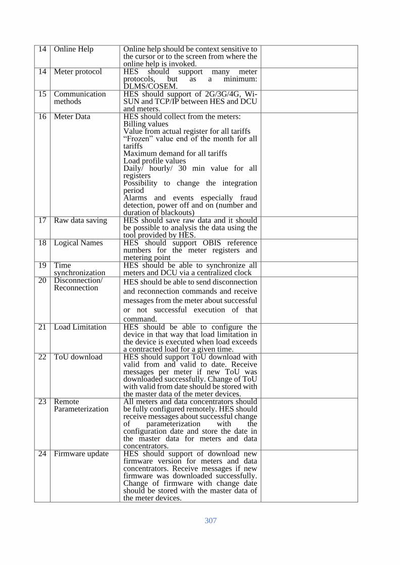
307
14 Online Help Online help should be context sensitive to the cursor or to the screen from where the online help is invoked.
14 Meter protocol HES should support many meter protocols, but as a minimum: DLMS/COSEM.
15 Communication methods
HES should support of 2G/3G/4G, Wi-SUN and TCP/IP between HES and DCU and meters.
16 Meter Data HES should collect from the meters: Billing values Value from actual register for all tariffs “Frozen” value end of the month for all tariffs Maximum demand for all tariffs Load profile values Daily/ hourly/ 30 min value for all registers Possibility to change the integration period Alarms and events especially fraud detection, power off and on (number and duration of blackouts)
17 Raw data saving HES should save raw data and it should be possible to analysis the data using the tool provided by HES.
18 Logical Names HES should support OBIS reference numbers for the meter registers and metering point
19 Time synchronization
HES should be able to synchronize all meters and DCU via a centralized clock
20 Disconnection/ Reconnection
HES should be able to send disconnection
and reconnection commands and receive
messages from the meter about successful
or not successful execution of that
command.
21 Load Limitation HES should be able to configure the device in that way that load limitation in the device is executed when load exceeds a contracted load for a given time.
22 ToU download HES should support ToU download with valid from and valid to date. Receive messages per meter if new ToU was downloaded successfully. Change of ToU with valid from date should be stored with the master data of the meter devices.
23 Remote Parameterization
All meters and data concentrators should be fully configured remotely. HES should receive messages about successful change of parameterization with the configuration date and store the date in the master data for meters and data concentrators.
24 Firmware update HES should support of download new firmware version for meters and data concentrators. Receive messages if new firmware was downloaded successfully. Change of firmware with change date should be stored with the master data of the meter devices.

308
25 Repeatability HES shall contain built-in mechanism to repeat the data collection to/from meters in case of connection failure.
26 Topology Traceability
HES shall track the meter communication path (and record changes) and record the latest communication timestamp, origin and status (success/failure) on a by-meter basis
27 Push or Pull Push and Pull modes for data acquisition should be supported.
28 Token transfer HES must be able to receive STS token from Vending System and to transfer to the corresponding meter, and return the messages that comes from the meter to Vending System.
29 CIM support HES must support Common Information Model (IEC 61968-9) to interface to the MDMS
30 HES database Data in HES database should be available for a period of 3 (previous) + 1 (current) months.
31 Meter reads Meter read access/query time from HES database must be no more than 30 seconds for any data that resides in it for one day.
32 Switch-over Switch-over from primary data center to disaster recovery center through active-passive mode to allow for manual failover in case of occurrence of disaster.
33 Raw values HES must store the raw values of the meter data and the associated meter multipliers (if any). Raw values have to be protected against changes.
34 Concurrent users HES must have the capability to support 160 concurrent users at minimum.
35 SMS integration ``` 36 API HES integration with DCU & 2G/3G
modem/meter and external systems through WEB API.
37 Warranty 3 years
[The Bidder should complete all the columns as required]
Name
In the capacity of
Signed
Duly authorized to sign the Bid for and on behalf of
Date

309
Meter Data Management System Software (To be filled up and signed by the Bidder & Manufacturer, otherwise the offer will not be acceptable)
Sl. No.
Name of Item Required specifications
Full Technical Specification & Standard (to be mentioned)
1 Country of Origin USA/UK/EU/Switzerland/Australia/Japan
2 Manufacturer’s Name &address
To be mentioned by Bidder
3 Place of Manufacturer To be mentioned by Bidder 4 Model & Version To be mentioned by Bidder 5 Overall Performance MDMS must process all data within one
day. New or changed data must be (re-) calculated as soon as they are inserted into the database of the MDMS
6 Scalability The database and the application of the MDMS must be scalable, so that future extension of system functionality and higher number of metering data can be handled even if the number of customers are increased to 20 million and the frequency of data accusation is enhanced to number of times a day within the performance requirements.
7 Access to the system MDMS should be accessed by using username and password, only. The system administrator can enforce to use passwords with small and capital letters, number and special signs. The system administrator also can enforce the user to chance its password on regular base. MDMS User access should use Windows Active Directory for authentication to reduce maintenance and align usernames and passwords with corporate security policy.
8 User Roles MDMS should be able to give user rights to users directly or to assign user roles to a user. The user rights shall allow the usage of a certain functionality for the user; example the user role "Visitor" shall allowed to read meter data only.
9 Data Segmentation MDMS should be segmented in that way that users can see a certain amount of meter data which belongs to the user’s jurisdiction only. Ex.: Only meters in PBS "ABC".
10 User friendly GUI must be modern and user friendly: - Easy to use forms for data requests of all,
grouped or specific meters (data request methods: on-demand, schedule (cyclic), historical-stored data).
- Navigation option and Graphical data representations of historical data (configurable).
11 Online Help Online help should be context sensitive to the cursor or to the screen from where the online help is invoked.

310
12 VEE MDMS must validate the data. Non-validated date must be substituted.
Validation Algorithm: Possibility to define validation algorithm, but standard validation algorithms must be implemented, also:
Zero Consumption, Negative Consumption, Gap Detection for load profiles, Load Profile Comparison with Billing Values, Main and Check Meter Comparison, "broken or manipulated meter", lower and upper limit
(for example: 15% deviation from previous period) .
Substitution: Possibility to define substitution rules, but standard substitution must be implemented, also:
Substitution rules like "broken or manipulated meter" where billing value shall be substituted by max (average last year, same month of last week ), check meter, value from defined calendar period, interpolation for non-valid load profiles values, etc.
13 Balances Balance reports must be calculated based on different balance methodologies.
14 Alarming Reports The alarming reports should show alarms as part of its Validation process, and either puts an item in the queue or auto sub-directory.
14 Reports Set of standard reports and user defined reports. PDF, Word, EXCEL and HTML reports should be supported. Custom CSV extracts shall be created and provided via mail
15 Calculation Strong module for calculation should be support for: Calculation of billing determents out of load profiles and tariff agreement. Cross sums calculation like sum per user group or balances.
16 Load Limitation MDMS should be able to configure the device via HES in that way that load limitation in the device is executed when load exceeds a contracted load for a given time.
17 Tariff Agreements MDMS should have the functionality to store tariff agreements. Tariff agreements should be created by graphical user interface. Tariff agreements must be downloaded via HES to the meters.
18 Update of Meters in Reports
Calculations and reports such as the balance report should be updated with new meters automatically.
19 Meter change MDMS should store the meter values independent of metering point, independent of the physical meter.
20 Snapshots MDMS must present the data how the
data was stored on a certain time (data
versioning).

311
21 Repeatability Calculation of the data should bring the same results for the same period. For instance: Balance of feeder in a substation should have the same result for a certain period, even if the number of consuming devices has changed after that period.
22 Traceability All changes of meters’ data in the system must be recorded: old value, new value, reason for change, username or process name that changed the value and timestamp when the value was changed.
23 Automatic update of Calculations
Changed values in the meter data (due to substitution for instance) must result in changed values of the calculations automatically.
24 CIM Support MDMS must have CIM interface to integrate HES. MDMS to HES integration shall support a two-way integration flow to provide an end-to-end seamless integration. MDMS and HES must share a data transfer format enabling read data to be shipped in native format and Meters in MDMS must be linked to HES to allow MDMS to be issued from the MDMS GUI by users. Utility systems such as OMS, Billing and ADMS must be able to request MDMS via a published Web API.
25 Vending System interface
MDMS must be master metering point information and exchange the information with Vending System.
26 GIS interface MDMS should be able to interface with GIS system (ArcGIS) to present device information such as device name, type, current state, location and so on.
27 Data collection MDMS must have the capability to access the collected data, in the meter, HES, database as well as manual meter readings via HES.
28 Interval data MDMS should support processing of interval data in high volumes - Manage and store interval data for 3 years online and archive for 5 years - Manage and store interval data for 20 million meters - Ability to re-import archived data via UI.
29 Editing It should be possible to edit meter data manually and automatically: - Replace or change intervals - Copy and replace intervals - Add or delete intervals - Factor intervals
30 Billing determinants MDMS should summarize interval data into billing determinants.
31 Limit load MDMS should be able to limit load of meter(s) via HES.
32 Disconnection/ Reconnection
MDMS should be able to send via HES disconnection and reconnection commands and receive messages from

312
the meter about successful or not successful execution of that command.
33 Concurrent users MDMS must have the capability to support 160 concurrent users at minimum.
34 API API for external systems shall be provided.
35 Warranty 3 years
[The Bidder should complete all the columns as required]
Name
In the capacity of
Signed
Duly authorized to sign the Bid for and on behalf of
Date

313
Vending System Software
(To be filled up and signed by the Bidder & Manufacturer, otherwise the offer will not be acceptable)
Sl. No.
Name of Item Required specifications
Full Technical Specification & Standard (to be mentioned)
1 Country of Origin To be mentioned by Bidder 2 Manufacturer’s Name
&address To be mentioned by Bidder
3 Place of Manufacturer To be mentioned by Bidder 4 Model & Version To be mentioned by Bidder 5 Overall Performance Vending System (VS) must process all
vending request within 30 seconds. New or changed data must be applied as soon as they are inserted into the database of the VS.
6 Scalability The database and the application of the VS must be scalable, so that future extension of system functionality and higher number of metering point and vending request can be handled even if the number of customers are increased to 20 million.
7 Access to the system VS should be accessed by using username and password, only. The system administrator can enforce to use passwords with small and capital letters, number and special signs. The system administrator also can enforce the user to chance its password on regular base.
8 User Roles VS should be able to give user rights to users directly or to assign user roles to a user. The user rights shall allow the usage of a certain functionality for the user; example the user role "Visitor" shall allowed to read vending data only.
9 Data Segmentation VS should be segmented in that way that users can see a certain amount of vending data which belongs to the user’s jurisdiction only. Ex.: Only meters in PBS "ABC".
10 User friendly GUI must be modern and user friendly: - Easy to use forms for data requests of
all, grouped or specific meters (data request methods: on-demand, historical data).
11 Online Help Online help should be context sensitive to the cursor or to the screen from where the online help is invoked.
12 Token parameter setting
It must be possible to configure parameters such as tariff type, base service charge, tax and etc. to generate STS token from received amount of currency.
13 Limitation of purchase
It must be possible to limit of purchase per time.

314
14 Token generation VS must be able to generate STS currency token and management tokens.
14 Reports Set of standard reports and user defined reports. PDF, Word, EXCEL and HTML reports should be supported.
15 Automatic report The following reports should be generated automatically per cashier/UVS/PBS. Daily sales report Monthly sales report
16 Traceability All history of token generation must be recorded with timestamp, amount including deducted amount, cashier, UVS, PBS and so on.
17 HES interface VS must have interface for HES to transfer generated token.
18 MDMS interface VS must have interface for MDMS to exchange new/changed metering point information.
19 Editing It should be possible to edit metering point information manually and automatically:
20 VS database VS should - Manage and store interval data for 3 years online and archive for 5 years - Manage and store interval data for 20 million meters
21 Concurrent users VS must have the capability to support 160 concurrent users at minimum.
22 API API for external systems shall be provided.
23 Warranty 3 years
[The Bidder should complete all the columns as required]
Name
In the capacity of
Signed
Duly authorized to sign the Bid for and on behalf of
Date
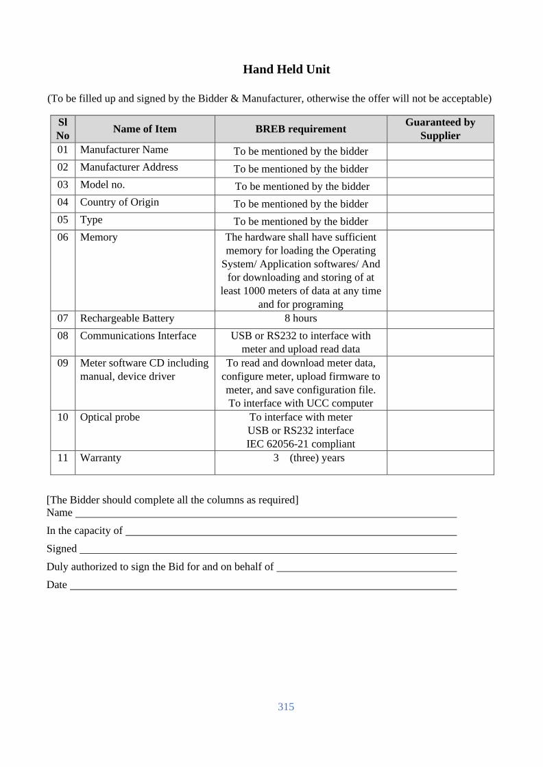
315
Hand Held Unit
(To be filled up and signed by the Bidder & Manufacturer, otherwise the offer will not be acceptable)
Sl
No Name of Item BREB requirement
Guaranteed by
Supplier
01 Manufacturer Name To be mentioned by the bidder
02 Manufacturer Address To be mentioned by the bidder
03 Model no. To be mentioned by the bidder
04 Country of Origin To be mentioned by the bidder
05 Type To be mentioned by the bidder
06 Memory The hardware shall have sufficient
memory for loading the Operating
System/ Application softwares/ And
for downloading and storing of at
least 1000 meters of data at any time
and for programing
07 Rechargeable Battery 8 hours
08 Communications Interface USB or RS232 to interface with
meter and upload read data
09 Meter software CD including
manual, device driver
To read and download meter data,
configure meter, upload firmware to
meter, and save configuration file.
To interface with UCC computer
10 Optical probe To interface with meter
USB or RS232 interface
IEC 62056-21 compliant
11 Warranty 3 (three) years
[The Bidder should complete all the columns as required]
Name
In the capacity of
Signed
Duly authorized to sign the Bid for and on behalf of
Date

316
VPN Router for UCC/UVS
(To be filled up and signed by the Bidder & Manufacturer, otherwise the offer will not be acceptable)
Sl. No.
Name of Item Required specifications
Full Technical Specification & Standard (to be mentioned)
1 Country of Origin To be mentioned by Bidder 2 Manufacturer’s Name
&address To be mentioned by Bidder
3 Place of Manufacturer To be mentioned by Bidder 4 Model To be mentioned by Bidder 5 Functional
Architecture The Bidder shall provide a detail specification.
6 Network Services • Dynamic routing (OSPF, BGP, RIPv2)
• Static and Policy routing
• Route controlled by application
• Built-in DHCP, NTP, DNS Server and DNS proxy
• Interface modes: sniffer, port aggregated, loopback, VLANS (802.1Q and Trunking)
• L2/L3 switching & routing
• Virtual wire (Layer 1) transparent inline deployment
7 IPv6 Services • Management over IPv6, IPv6 logging and HA
• IPv6 tunneling, DNS64/NAT64 etc
• IPv6 routing protocols, static routing, policy routing, ISIS, RIPng, OSPFv3 and BGP4+
• IPS, Application identification, Access control, ND attack defense
8 Firewall Services • Operating modes: NAT/route, transparent (bridge), and mixed mode
• Policy objects: predefined, custom, and object grouping
• Application Level Gateways and session support: MSRCP, PPTP, RAS, RSH, SIP, FTP, TFTP, HTTP, dcerpc, dns-tcp, dns-udp
• NAT support: NAT46, NAT64, NAT444, SNAT, DNAT, PAT, Full Cone NAT, STUN
• NAT configuration: per policy and central NAT table
• Global policy management view
• Schedules: one-time and recurring
9 VPN Services
• IPSec VPN: - Authentication method: certificate and
pre-shared key - IKE mode configuration support (as

317
server or client) - DHCP over IPSEC - Configurable IKE encryption key
expiry, NAT traversal keep alive frequency
- Phase 1/Phase 2 Proposal encryption: DES, 3DES, AES128, AES192, AES256
- Phase 1/Phase 2 Proposal authentication: MD5, SHA1, SHA256, SHA384, SHA512
• IPSEC VPN realm support: allows multiple custom SSL VPN logins associated with user groups (URL paths, design)
• IPSEC VPN configuration options: route-based or policy based
• IPSEC VPN deployment modes: gateway-to-gateway, full mesh, hub-and-spoke, redundant tunnel, VPN termination in transparent mode
• SSL portal concurrent users limiting • Supports clients that run iOS, Android,
and Windows 10 including 64-bit Windows OS
• Host integrity checking and OS checking prior to SSL tunnel connections
• MAC host check per portal • Cache cleaning option prior to ending
SSL VPN session • L2TP client and server mode, L2TP
over IPSEC, and GRE over IPSEC • View and manage IPSEC and SSL
VPN connections 10 IPS Services
• Signatures, protocol anomaly detection,
rate-based detection, custom signatures, manual, automatic push or pull signature updates, integrated threat encyclopedia
• IPS Actions: default, monitor, block, reset (attackers IP or victim IP, incoming interface) with expiry time
• Filter Based Selection: severity, target, OS, application or protocol
• IP exemption from specific IPS signatures
• IDS sniffer mode
• IPv4 and IPv6 rate based DoS protection with threshold settings against
• TCP Syn flood, TCP/UDP/SCTP port scan, ICMP sweep, TCP/UDP/SCIP/ICMP session flooding (source/destination)
• Active bypass with bypass interfaces

318
• Predefined prevention configuration 11 FW Throughput 1 Gbps or more 12 Concurrent Sessions
(Standard/ Maximum) 200,000 or more
13 No. of IPSec Tunnel 512 or more 14 SSL VPN Users 8 or more 15 Management Ports At least 1 x Console, 1 x USB 16 Fixed I/O Ports At least 9 x GE 17 Mobile 2G and/or 3G 18 Form factor 19” standard rack mountable 19 Accessories All necessary should be supplied
together. To be mentioned by Bidder
20 Warranty 3 years
[The Bidder should complete all the columns as required]
Name
In the capacity of
Signed
Duly authorized to sign the Bid for and on behalf of
Date
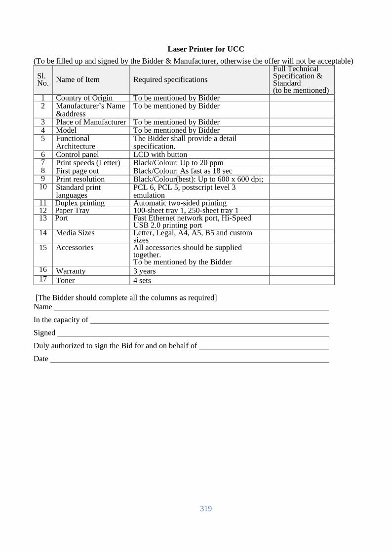
319
Laser Printer for UCC
(To be filled up and signed by the Bidder & Manufacturer, otherwise the offer will not be acceptable)
Sl. No.
Name of Item Required specifications
Full Technical Specification & Standard (to be mentioned)
1 Country of Origin To be mentioned by Bidder 2 Manufacturer’s Name
&address To be mentioned by Bidder
3 Place of Manufacturer To be mentioned by Bidder 4 Model To be mentioned by Bidder 5 Functional
Architecture The Bidder shall provide a detail specification.
6 Control panel LCD with button 7 Print speeds (Letter) Black/Colour: Up to 20 ppm 8 First page out Black/Colour: As fast as 18 sec 9 Print resolution Black/Colour(best): Up to 600 x 600 dpi; 10 Standard print
languages PCL 6, PCL 5, postscript level 3 emulation
11 Duplex printing Automatic two-sided printing 12 Paper Tray 100-sheet tray 1, 250-sheet tray 1 13 Port Fast Ethernet network port, Hi-Speed
USB 2.0 printing port
14 Media Sizes Letter, Legal, A4, A5, B5 and custom sizes
15 Accessories All accessories should be supplied together. To be mentioned by the Bidder
16 Warranty 3 years
17 Toner 4 sets
[The Bidder should complete all the columns as required]
Name
In the capacity of
Signed
Duly authorized to sign the Bid for and on behalf of
Date

320
Laser Printer for UVS
(To be filled up and signed by the Bidder & Manufacturer, otherwise the offer will not be acceptable)
Sl. No.
Name of Item Required specifications
Full Technical Specification & Standard (to be mentioned)
1 Country of Origin To be mentioned by Bidder 2 Manufacturer’s Name
&address To be mentioned by Bidder
3 Place of Manufacturer To be mentioned by Bidder 4 Model To be mentioned by Bidder 5 Functional
Architecture The Bidder shall provide a detail specification.
6 Control panel LCD with button 7 Print speeds (A4) Black/Colour: Up to 27 ppm 8 First page out Black/Colour: As fast as 12 sec 9 Print resolution Black/Colour(best): Up to 600 x 600 dpi; 10 Standard print
languages PCL 6, PCL 5, postscript level 3 emulation
11 Duplex printing Automatic two-sided printing 12 Paper Tray 50-sheet tray 1, 250-sheet tray 1 13 Port Fast Ethernet network port, Hi-Speed
USB 2.0 printing port
14 Media Sizes Letter, Legal, A4, A5, B5 and custom sizes
15 Accessories All accessories should be supplied together. To be mentioned by the Bidder
16 Warranty 3 years
17 Toner 4 sets
[The Bidder should complete all the columns as required]
Name
In the capacity of
Signed
Duly authorized to sign the Bid for and on behalf of
Date

321
Cooling System
(To be filled up and signed by the Bidder & Manufacturer, otherwise the offer will not be acceptable)
Sl. No.
Name of Item Required specifications
Full Technical Specification & Standard (to be
mentioned)
1 Brand International reputed Brand
2 Country of
Origin
USA/UK/EU/Switzerland/Australia/Japan
3 Model To be Mentioned by the Bidder
4 AC Type Split
5 Capacity 1.5 ton
6 Bee Rating Inverter AC Star (3 Star)
7 Warranty 3 Years
9 Noise Level 49 DB
10 Features Comfort even on the far side of the room,
Improved airflow modes, low gas
pressure detection
11 Dimensions (h x
w x d)
To be mention by Bidder.
12 Timers Yes
13 Remote Control Yes
14 Sleep Mode Yes
15 Color White
16 Weight To be mention by Bidder.
17 LED Display Yes
18 Air Filters Yes
19 Technology Precoated, long lasting condenser fins, an
eco friendly refrigerant and auto restart
feature restoring previous AC settings
after a power outage are part of The
Daikin/Mitsubishi or equivalent AC
technology that wrap this AC
[The Bidder should complete all the columns as required]
Name
In the capacity of
Signed
Duly authorized to sign the Bid for and on behalf of
Date

322
UPS for UCC/UVS (To be filled up and signed by the Bidder & Manufacturer, otherwise the offer will not be acceptable)
Sl. No.
Name of Item Required specifications
Full Technical Specification & Standard (to be mentioned)
1 Country of Origin To be mentioned by Bidder 2 Manufacturer’s Name
&address To be mentioned by Bidder
3 Place of Manufacturer To be mentioned by Bidder 4 Model To be mentioned by Bidder 5 Technology Off Line 6 Capacity 5 KVA 7 Transfer Time 2 ms. 8 Back-up time 15 (Fifteen) minutes minimum at full
load
9 Wave Shape Simulated Sine Wave 10 Input Voltage 160-270 VAC 11 Input Frequency 50/60 Hz 12 Output Voltage 220 VAC ± 5% 13 Output Frequency 50/60 Hz ± 0.5% (AC Input)
Auto Tracing
14 Computer Interface Support RS 232 for UPS monitoring Software
15 Battery Sealed Maintenance free Lead Acid 16 Battery Recharging 6-8 Hours up to 90% Capacity
17 Protection Lightning, Spike, Surge, Flicker, Over &
under Voltage, Over Load, Short Circuit,
Battery low (Deep Discharge) & Noise
(EMI/RFI) followed by International
Safety Standard
18 Operating
Temperature
0-40°C
19 Operating Humidity 10%-90% (Non Condensation)
20 Brochure and CDs All brochure, instruction manual and
driver CDs to be supplied with the
product
21 Accessories All accessories should be supplied together. To be mentioned by the Bidder
22 Warranty Period Full 03 (three) years replacement and
instant service warranty
[The Bidder should complete all the columns as required]
Name
In the capacity of
Signed
Duly authorized to sign the Bid for and on behalf of
Date

323
Desktop Computer (Brand) for UCC & UVS:
(To be filled up and signed by the Bidder & Manufacturer, otherwise the offer will not be acceptable)
Brand Internationally Reputed Brand
Model To be Mentioned by bidder
Country of Origin To be Mentioned by bidder
Processor Intel core i7 10th Generation or Higher
Speed Minimum 2.9 GHz to 4.00Ghz, 6 Cores) or Higher
Cache Minimum 16MB or Higher
Chipset Intel Express Chipset B460 Series or Equivalent or Higher
RAM Minimum 16GB (2X8GB) 2666MHz DDR4L Memory, 2 DIMM slots or
Higher.
HDD Minimum 1TB 7200 RPM SATA or Higher
LAN Card Integrated Gigabit LAN-On-Motherboard or Higher
Expansion Slots Minimum (2) PCIe x 1, PCIe x 16
Ports Minimum (2) USB 3.2, (4) USB 2.0, RJ-45, HDMI, VGA
Wireless Wireless 802.11ac 1×1 Wi-Fi and Bluetooth
Graphics (AGP) Built-in
Audio (Sound Card) Built-in
Speakers Built-in
DVD-RW Drive DVD+/-RW Drive
Monitor 18.5" LED Backlit Color, Same Brand
Key-Board USB enhanced, Same Brand
Mouse USB Optical Mouse, Same Brand
Power Supply Minimum 260 W PSU (APFC Full Charge)
OS Support Windows 10 or User Friendly.
Software Windows 10 Liscence, Office & Other Software as per site requirements.
Power Strip Brand: Reputed Brand
Port: Minimum 5 Port
Cable Length: 3 meter
Number of pin: Minimum 3
Others: Rated voltage: 220 V, Rated current: Minimum 10 A,
Individual switch, Single fuse.
Antivirus Brand:To be Mentioned By the Bidder
Internet Security Antivirus, license for 1 year
Warranty 3 Years (Full).
[The Bidder should complete all the columns as required]
Name
In the capacity of
Signed
Duly authorized to sign the Bid for and on behalf of
Date

324
Laptop for UCC and UVS
(To be filled up and signed by the Bidder & Manufacturer, otherwise the offer will not be acceptable)
Brand Internationally Reputed Brand
Model To be Mentioned by bidder
Country of Origin To be Mentioned by bidder
Processor Intel Core i7 (10th Generation ) or Higher
Speed Minimum 1.6 GHz or Higher
Cache 8 MB L3 Cache.
RAM Min. 8GB DDR4, 2666 MHz or Higher
Display Min. 14"HD LED
Graphics Intel HD Graphics
Hard disk Minimum 512 SSD M.2 PCIe NVMe
Sound System To be mentioned by the bidder
Keyboard Full-size 85 Keys US Keyboard.
Mouse Integrated pointing device with touch pad.
Wireless Integrated
NIC In-built with 10/100/1000
Web cam Integrated
Expansion
Ports/Interface
Min. 2 USB 3.2, 1 HDMI, 1 Microphone/Headphone combo, 1 RJ-45
Battery Min. 3-Cell 39WHr Battery
Antivirus Brand: To be Mentioned By Bidder
Internet Security Antivirus, license for 1 year
AC Adaptor 65 Watt AC Adaptor
Operating System Free Dos
Carrying Case Including Original Carrying case
Standard ISO, CE & FCC Class-B.
Warranty 3 Years (1Year For Battery)
[The Bidder should complete all the columns as required]
Name
In the capacity of
Signed
Duly authorized to sign the Bid for and on behalf of
Date

325
Slip Printer
(To be filled up and signed by the Bidder & Manufacturer, otherwise the offer will not be acceptable)
Sl. No.
Name of Item Required specifications
Full Technical Specification & Standard (to be mentioned)
1 Country of Origin To be mentioned by Bidder 2 Manufacturer’s Name
&address To be mentioned by Bidder
3 Place of Manufacturer To be mentioned by Bidder 4 Model To be mentioned by Bidder 5 Printing Method PIN 9 Pin Serial Impact Dot Matrix 6 Print Speed 4.7 lps (at 40 columns, 16 cpi) or higher 7 Data Buffer 4 KB or more 8 Inked Ribbon Black 9 Interface USB Interface, Bi-directional parallel 10 Power Supply AC 120 – 240 VAC 11 Auto Cutter Yes 12 Paper Roll Paper 13 Driver/Manual All Manual, Driver CD/DVD 14 Accessories All accessories should be supplied
together. To be mentioned by the Bidder
15 Warranty Full 03 (three) years replacement and instant service warranty
16 Ribbon cassette Additional 5 (five)
17 Roll paper At least 40 m x 50 rolls
[The Bidder should complete all the columns as required]
Name
In the capacity of
Signed
Duly authorized to sign the Bid for and on behalf of
Date

326
Bar Code Reader (To be filled up and signed by the Bidder & Manufacturer, otherwise the offer will not be acceptable)
Sl. No. Name of Item Required specifications
Full Technical Specification & Standard (to be mentioned)
1 Country of Origin To be mentioned by Bidder 2 Manufacturer’s Name
&address To be mentioned by Bidder
3 Place of Manufacturer To be mentioned by Bidder 4 Model To be mentioned by Bidder 5 Interface USB Interface 6 Power Supply Host powered 7 Protection Degree IP42 or higher 8 Supported barcode Standard 1D barcode 9 Driver/Manual All Manual, Driver CD/DVD
10 Accessories All accessories should be supplied together. To be mentioned by the Bidder
11 Warranty Full 03 (three) years replacement and instant service warranty
[The Bidder should complete all the columns as required]
Name
In the capacity of
Signed
Duly authorized to sign the Bid for and on behalf of
Date

327
GTS for Data Center:
Database Server
(To be filled up and signed by the Bidder & Manufacturer, otherwise the offer will not be acceptable)
SL Item Name Detail Required Specification Bidder response
Set (Quantity) Each Set shall be provided with-
Type I: 02 (Two) units
Type II: 02 (Two) units
1 Brand To be mentioned by Bidder. Must be in the top three
OEM for the last 5 years in terms of revenue and
shipment.
2 Quality ISO 9001/9002 for manufacturer, FCC Class A for quality
assurance
3 Model To be mentioned by the bidder
4 Country of
origin
USA/UK/EU/Switzerland/Australia/Japan
5 Country of
manufacturer
To be mentioned by the bidder
6
Modularity &
Flexibility
The server must be designed in modular architecture,
with each module scaling to 4Sockets architecture.
Scale-up capability and upgrade must be achieved by
adding more building blocks of 4-Socket modules,
without the need to upfront investing to a big chassis.
7
Scalability
Server should be able to scale from lower entry point of
2 sockets and up to 8 sockets in 2-socket increments,
with 16-224 cores.
Scaling from 64 GB to 24TB of shared memory using
DRAM (with 256GB DIMM availability). Shall support
of 1, 4, 6 & 12 DIMM per socket for granular scalability
8
Processor
The server must support 3rd Generation Intel Xeon
Scalable Processors (Cooper Lake 6UPI or CPX6).
Type I Servers- each shall be provided with min. 8x
Intel Xeon-Platinum 8356H (3.9GHz/8-core/225W)
Processor.
&
Type II Servers - each shall be provided with min. 8x
Intel Xeon-Platinum 8380HL (2.9GHz/28-core/250W)
Processor.

328
SL Item Name Detail Required Specification Bidder response
9
Memory
Each server shall be provided with 6TB memory with
min. 48x 128GB Quad-rank DDR4-3200 LRDIMM.
Server should support memory scalability to 12TB using
128GB LRDIMM. 10 Memory
Protection
Should support Adaptive DDDC and Fast Fault
Tolerance
11 HDD Bays
Min. 8x 1.6TB 12G SAS Write Intensive 2.5’ hot-
pluggable SSD.
12 Hard disk drive
& DVD RW
Min. Sixteen (16) 2.5 inch HDD, SSD, or NVMe drive
bays plus an DVD RW optical drive.
13 Array
Controllers
SAS drives use PCIe v3.0 based 12Gb/s SAS Internal
Hardware RAID Controller; 4GB Cache 14
Connectivity
features
Each server shall be provided with embedded 1x 2-port
1GbE RJ45 ports, 4x 2-port 10/25Gb SFP28 adapter
with 25Gb SFP28 SR transceivers and 4x 2-port 32Gbps
FC HBA.
Support of up to 100Gbps network adapter & 200Gb
InfiniBands.
15 IO architectures
Direct IO architecture from all CPUs for unblocking,
best performance, and low latencies
16 Bus Slots
Server shall come with min. Thirty-Two (32) PCIe v3.0
slots per server from Day1.
17
GPUs
Supports up to 4 GPUs in a chassis; up to 16 per system.
GPU should be able to use in Windows OS.
18
Power Supply &
Factory
Integrated
RACK
Each server shall be provided with min. 8x 1600W
power supplies connectivity’s for 8Socket configuration.
Every two server shall be provided min. one Factory
integrated 42U 600mmx1200mm RACK from same
server OEM, 2x Modular 7.3kVA/60309 3-wire
32A/230V Outlets (6) C19/1U Horizontal PDU,
grounding kit, stabilizer kit etc.
19 Fans Min. 8x Redundant hot-plug fan (per Chassis)
20
Reliability,
Availability and
Serviceability
(RAS) features
Key areas of RAS superiority over standard x86-
• Firmware First
• Automatic error logging
• Auto self-healing (Analysis Engine)
• Disabling and deconfiguration of failed FRUs
• Onboard fault analyzer
• Automatic restart
• Advanced processor error handling (EMCA2)
• Advanced memory resiliency (ADDDC)
• Memory error storm response
• Enhanced fabric resiliency (Flex Grid adaptive routing)
• Advanced PCIe error recovery (LER)

329
SL Item Name Detail Required Specification Bidder response
21 Operating
Systems and
Virtualization
Software
Support
RHEL, SLES, VMware, Windows
Virtualization technologies: VMware vSphere, RHEV,
KVM and Microsoft Hyper-V.
22 Operating
System License
Each server shall be provided with Red Hat Enterprise
Linux 1-2Socket, 2 Guest 3Years 24x7 subscription for
8-socket license from the platform provider.
23 GPU support Support of up to 16 single-wide GPUs; up to 8 double-
wide GPUs
24 Security
Secure architecture, design, and supply chain, with
limited exposure Silicon root of trust TPM2.0
25
Server
Management
Embedded management controller with the offered
Server.
Software should have dashboard view to quickly scan
the managed resources to assess the overall health of the
data center. It should provide an at-a-glance visual health
summary of the resource’s user is authorized to view.
The Dashboard minimum should display a health
summary of the following:
• Server Profiles
• Server Hardware
• Appliance alerts
The Systems Management software should provide
Role-based access control
Management software should support integration with
popular virtualization platform management software
like vCenter, and SCVMM
Should help provide proactive notification of actual or
impending component failure alerts on critical
components like CPU, Memory and HDD.
Should provide an online portal that can be accessible
from anywhere. The portal should provide one stop,
online access to the product, support information and
provide information to track warranties, support contrast
and status. The Portal should also provide a Personalized
dashboard to monitor device heath, hardware events,
contract and warranty status. Should provide a visual
status of individual devices and device groups. The Portal
should be available on premise (at our location - console
based) or off premise (in the cloud).
Should help to proactively identify out-of-date BIOS,
drivers, and Server Management agents and enable the
remote update of system software/firmware components.

330
SL Item Name Detail Required Specification Bidder response
26 Installation
services,
manage &
control
Access to OEM experts via phone, web, or both
OEM installation and startup professional service shall
be provided.
Connect devices to OEM for real-time diagnosis, alerts,
and information from Day1.
27 Warranty&
services
3-yrs collaborative warranty with 24x7 mission critical
one-point support from OEM.
4-hour mission critical response time for hardware issue
from OEM. Supporting service-related document shall be
provided.
Root cause analysis report shall be available from day1.
OEM shall maintain local spare parts depot/warehouse in
Bangladesh.
All above features BoQ should be provided with proper
explanation.
[The Bidder should complete all the columns as required]
Name
In the capacity of
Signed
Duly authorized to sign the Bid for and on behalf of
Date

331
General Purpose Storage (To be filled up and signed by the Bidder & Manufacturer, otherwise the offer will not be acceptable)
SL Item Name Detail Required Specification Bidder response
1 Brand Offered storage brand should be in leaders’ quadrant in
Gartner Magic Quadrant of All-Flash Array/ Primary
Storage for the last 5 years release.
2 Quality ISO 9001: 2015 for manufacturer, FCC Class A for quality
assurance.
3 Model To be mentioned by the bidder
4 Country of origin USA/UK/EU/Switzerland/Australia/Japan
5 Country of
manufacturer
To be mentioned by the bidder
6 All-Flash Storage 1. Offered Storage array shall be end-to end 12Gbps
enabled which means that both Front-end Fibre channel
ports and Back-end engines shall be operated at minimum
12Gbps speed.
2. Offered storage shall support both SSD and NVMe SSD
drives.
7 Operating
System &
Clustering
Support
The storage array should support industry-leading
Operating System platforms & clustering including:
Windows Server 2016, VMware, Solaris and HPE--UX,
IBM-AIX and Linux.
8 Capacity &
Scalability
The Storage Array shall be offered with minimum 350TB
Usable capacity without considering the deduplication and
compression-
1. Min. 350TB of the usable Capacity using SSD
(each SSD capacity not more than 4TB) with
RAID6 (Max. 10+2 configuration).
2. Offered storage system shall prove min. 1 (One)
Million IOPS at 8k IO Block considering 80:20
Read/Write ration for the offered configuration on
Day1.
9 Storage
Encryption
1. Vendor shall offer only the encrypted drives with
appropriate encryption licenses and shall meet FIPS 140-2
– Level 2 security requirements. Vendor shall not offer any
controller based or Software based encryption.
2. Offered FIPS 140-2 Validated encryption drives shall
support both KMIP 1.3 and KMIP 1.4 for key management
solutions. Vendor shall offer at-least internal Key manager
engine for key management.
10 Cache 1. Offered Storage array should have at-least 4TB of on-
node cache.

332
2. Cache shall be completely dynamic for read and write
operations and vendor shall not offer any additional card /
module for write cache operations.
3. Offered storage shall be based upon latest generation
Intel CPUs, Minimum Skylake series, and shall be supplied
with at-least 160 numbers of CPU cores, 11 Architecture &
Processing
Power
1. Offered Storage shall be supplied with at-least quad
controllers. Vendor shall ensure that all controllers, with
and without scalability, shall be connected to a common
back-plane and shall not use any loosely connected
architecture like through SAN Switches, Ethernet Switches,
InfiniBand switches etc.
2. Controllers shall be true active-active so that a single
logical unit can be shared across all offered controllers in
symmetrical fashion, while supporting all the major
functionalities like Thin Provisioning etc.
3. Offered storage array shall have native virtualization
support so that Raid can be carved out from a logical space
instead of dedicating separate physical disks for each
application.
12 No Single point
of Failure
Offered Storage Array shall be configured in a No Single
Point of configuration including Array Controller card,
Cache memory, FAN, Power supply etc.
13 Data Protection 1. In case of power failure, storage subsystem shall have
de-staged mode so that un-committed information can be
protected. De-staging shall happen to redundant vault
drives and vault drives shall be encrypted.
2. Vendor shall not use any Vault drive as data drives for
capacity calculation. Vendor shall not consume any
additional drive slot in the drive enclosure for vault drives.
3. Shall be configured in a way that the array can tolerate
an entire drive chassis failure.
14 Host Ports and
Back-end Ports
1. Offered Storage array shall have minimum of 32x
32Gbps Fiber Channel ports.
2. Offered Storage array system shall be supplied with two
additional 10GbE native IP ports for storage-based
replication.
3. Offered Storage array shall have minimum of 32 SAS
port in the back end for disk connectivity running at
12Gbps speed.
4. Offered Storage shall be future proof with respect to
NVMe over Fabric for both Front-end and back-end

333
connectivity and shall have dedicated separate processing
engines (Apart from CPU) inside the storage arrays on day
1 for NVMe command and data queue. 15 Global Hot Spare 1. Offered Storage Array shall support distributed Global
hot Spare for offered Disk drives.
2. Should be provided with minimum 1 drive worth spare
space for every 24 drives.
16 Performance and
Quality of
Service
1. Offered storage array shall support quality of service for
critical applications so that appropriate and required
response time can be defined for application logical units at
storage. It shall be possible to define different service /
response time for different application logical units.
2. Quality of service engine shall allow to define minimum
and maximum cap for required IOPS / bandwidth for a
given logical units of application running at storage array.
3. It shall be possible to change the quality-of-service
Response time (In both milliseconds as well as Sub-
milliseconds), IOPS, bandwidth specification at real time.
17 Capacity
efficiency
1. Offered storage array shall support inline data efficiency
engine (Supporting Thin Zero detect and re-claim, De-
duplication and Compression) and shall be enabled by
default.
2. Vendor shall have flexibility to enable / disable the data
efficiency engine at the time of Volume creation.
3. Storage subsystem shall be supplied with Thin
Provisioning, Thin Re-claim, Snapshot, De-duplication,
Compression, Performance Monitoring, and Quality of
service on day 1 for the maximum supported capacity of
array.
4. Offered storage array shall be tightly integrated with
VMware so that Eager zero disks layout can be used with
thin provisioning and thin re-claim.
18 Maintenance Offered storage shall support online non-disruptive
firmware upgrade for both Controller and disk drives.
19 Integration -
VMWARE
1. Offered storage array shall be tightly integrated with
VMware and shall be certified for VVOL.
2. Offered Storage array VASA provider shall be certified
by VMware for VVOL - Storage based replication.
20 Integration -
Container
Offered Storage array shall be integrated with Docker,
Red-hat OpenShift, Kubernetes and MESOS container
technologies. Vendor shall support at-least following
functionalities through their integration plugin:

334
a. Multiple arrays support so that within a given cluster
using a common configuration file on container platform.
b. Snapshot
c. Replication. Plugin shall allow to define the replication
configuration on the container.
d. Quality of service for response time, Bandwidth and
IOPS.
e. Shall have flexibility to import the non-container volume
into the container.
f. Login credential to array via container platform shall be
encrypted.
g. Container as a service from Storage array where vendor
shall be able to define partition on the storage and shall be
visible to container.
h. Support for both Fiber channel as well as ISCSI.
21 Snapshot / Point
in time copy
The storage array should have support for controller-based
snapshots functionality (At-least 1024 copies for a given
volume).
22 Application
Consistent
Copies
1. Offered storage shall be supplied with unlimited license
for creation of application consistent copies for Oracle,
SQL, Exchange, SAP HANA and VMware through
Storage console GUI.
2. Offered Storage shall be supplied with in-built copy
management and backup S/W unlimited license for
movement of data copies of Oracle, SQL, Exchange, SAP
HANA and VMware to disk based backup device, public
Cloud like AWS, Azure and object storage.
23 Storage Array
Configuration &
Management
Software
Vendor shall provide Storage Array configuration and
Management software.
Software shall be able to manage more than one array of
same family.
Offered Storage management engine shall have in-built on-
site edge analytics performance engine, without
connectivity to Internet / Intranet and shall offer following
functionalities: All required license for offering this
functionality shall be offered.
1. Shall have saturation panel which can depict the
overall saturation level of the storage array at different
time intervals instead of looking into individual
parameters like IOPS, CPU utilization, Cache
utilization etc.
2. Shall have capability to assign and compare the
performance score with similar nature of workload
across worldwide install base. Vendor management

335
and edge analytic engine shall have in-built
performance statistics of worldwide install base
instead of connecting to internet / intranet.
3. Shall have capability to display top 5 volumes by
hotspots as well as by latency.
4. If similar nature of arrays being used in the
environment then offered engine shall show the top
systems by saturation level within the same console
24 Monitoring and
analytic engine
Offered storage shall have cloud enabled monitoring and
analytics engine for proactive Storage management. All
required licenses for same shall be included in the offer.
Cloud Enabled Monitoring and analytics engine shall have
capability to provide following:
a. Providing Firmware upgrade and patch upgrade
recommendations proactively and with awareness of
the peripheral infrastructure connected to the array.
b. Providing extremely granular per-minute historical
capacity and performance trend analysis by default,
without the need to enable extra logging, install any
appliances (physical or virtual), or install any
software.
c. Providing overall saturation level of the array while
combining while analyzing various parameters like
IOPS, MB/sec, Block size etc.
d. Providing overall performance score of the array at
a scale of 0 to 10 for both read and write operations.
e. Shall provide history of support cases logged with
Support team under different column like Critical,
Normal and low severity along with closed cases.
Cloud monitoring tool shall be able to provide the
complete month-wise breakup.
f. Shall be able to provide the executive Dashboard
covering various critical and must aspects of Total
Capacity, overall health / wellness score of array.
De-duplication and compression ratio, over-all
front-end performance etc.
Cloud enabled Analytics engine shall have capability to
provide following:
a. Shall have capability of learning mechanism to
provide the analytics and problem finding/solving

336
based on global learning available for the arrays
across the install based.
b. Analytics engine shall have capability of proactive
recommendation for arresting the issues / problems
noticed at other install base of vendor after
identifying the problematic signature
25 Cloud Enabled -
HyperVisor
Integration
Cloud enabled monitoring and analytics engine integration
with Hypervisor:
a. Offered Cloud enabled monitoring and analytics
engine shall be tightly integrated with Hypervisor
layer and shall be certified to work with at-least
VMware.
b. Hypervisor integration shall be able to provide end
to end monitoring of hypervisor Datacenter, Data-
store, Hypervisor Host and VMs running within the
hypervisor datacenter and shall be able to link with
offered storage array.
c. Cloud monitoring and integration tool shall provide
the detailed analysis of CPU Contention, Memory
contention, IO contention for each VM – including
the latency.
d. Cloud monitoring and integration tool shall have
capability to identify the top VMs which are
contributing towards maximum IOs and Latency.
26 Data Availability Offered storage shall be a 100% availability guaranteed
architecture. 100% availability guaranty shall be clearly
mentioned on vendor web site for the offered model.
27 Data Integrity
(T10 DIFF)
Should ensures the integrity of data by performing a
checksum on the data from the HBA to the disk (T10
DIFF).
28 Remote
Replication
1. The storage array should support hardware-based
data replication at the array controller level across all
models of the offered family.
2. Replication shall support incremental replication
after resumption from Link Failure or failback
situations.
29 Licenses Storage subsystem shall be supplied with all-inclusive
license that should include Thin provisioning, replication,
data-at-rest encryption, Snapshot, Clone, Performance
Monitoring, Online Raid Migration, Online Volume
conversion (thin to thin compressed, thin to thin de-dup etc.),
Quality of services, NVMe cache, and File services on day
1 for the maximum supported capacity of array.
30 Training SAN Storage and Switch administration training for min. 5
days to be provided on OEM Education Training Center for

337
3 (Three) persons. Necessary expenses shall be bearded by
the local vendor.
31 Installation
services, manage
& control
Implementation shall be done by OEM Engineer only. OEM
installation service and engineer’s CV to be submitted
during bid submission.
Partner engineer is not allowed to Powerup the device
without OEM Engineer presence. OEM onsite installation
and startup service should be provided.
Access to OEM experts via phone, web, or both
Connect devices to OEM for real-time diagnosis, alerts,
and information.
32 Warranty&
services
3-yrs collaborative warranty with 24x7 mission critical one-
point support from OEM.
4-hour mission critical response time for hardware issue
from OEM. Supporting service-related document shall be
provided.
Root cause analysis report shall be available from day1.
OEM shall maintain local spare parts depot/warehouse in
Bangladesh.
All above features BoQ should be provided with proper
explanation.
[The Bidder should complete all the columns as required]
Name
In the capacity of
Signed
Duly authorized to sign the Bid for and on behalf of
Date

338
Storage for Database (To be filled up and signed by the Bidder & Manufacturer, otherwise the offer will not be acceptable)
SL Item Name Detail Required Specification Bidder response
1 Brand Offered storage brand should be in leaders’ quadrant in
Gartner Magic Quadrant of All-Flash Array/ Primary
Storage for the last 5 years release.
2 Quality ISO 9001: 2015 for manufacturer, FCC Class A for
quality assurance.
3 Model To be mentioned by the bidder
4 Country of origin USA/UK/EU/Switzerland/Australia/Japan
5 Country of
manufacturer
To be mentioned by the bidder
6 All-Flash Storage 1. Offered Storage array shall be end-to end 12Gbps
enabled which means that both Front-end Fibre channel
ports and Back-end engines shall be operated at
minimum 12Gbps speed.
2. Offered storage shall support both SSD and NVMe
SSD drives.
7 Operating
System &
Clustering
Support
The storage array should support industry-leading
Operating System platforms & clustering including:
Windows Server 2016, VMware, Solaris and HPE--UX,
IBM-AIX and Linux.
8 Capacity &
Scalability
The Storage Array shall be offered with minimum
550TB Usable capacity without considering the
deduplication and compression-
1. Min. 550TB of the usable Capacity using SSD
(each SSD capacity not more than 4TB) with
RAID6 (Max. 10+2 configuration).
2. Offered storage system shall prove min. 1 (One)
Million IOPS at 8k IO Block considering 80:20
Read/Write ration for the offered configuration
on Day1.
9 Storage
Encryption
1. Vendor shall offer only the encrypted drives with
appropriate encryption licenses and shall meet FIPS
140-2 – Level 2 security requirements. Vendor shall not
offer any controller based or Software based encryption.
2. Offered FIPS 140-2 Validated encryption drives shall
support both KMIP 1.3 and KMIP 1.4 for key
management solutions. Vendor shall offer at-least
internal Key manager engine for key management.
10 Cache 1. Offered Storage array should have at-least 4TB of on-
node cache.
2. Cache shall be completely dynamic for read and write
operations and vendor shall not offer any additional card
/ module for write cache operations.

339
3. Offered storage shall be based upon latest generation
Intel CPUs, Minimum Skylake series, and shall be
supplied with at-least 160 numbers of CPU cores,
11 Architecture &
Processing
Power
1. Offered Storage shall be supplied with at-least quad
controllers. Vendor shall ensure that all controllers, with
and without scalability, shall be connected to a common
back-plane and shall not use any loosely connected
architecture like through SAN Switches, Ethernet
Switches, InfiniBand switches etc.
2. Controllers shall be true active-active so that a single
logical unit can be shared across all offered controllers
in symmetrical fashion, while supporting all the major
functionalities like Thin Provisioning etc.
3. Offered storage array shall have native virtualization
support so that Raid can be carved out from a logical
space instead of dedicating separate physical disks for
each application.
12 No Single point
of Failure
Offered Storage Array shall be configured in a No
Single Point of configuration including Array Controller
card, Cache memory, FAN, Power supply etc.
13 Data Protection 1. In case of power failure, storage subsystem shall have
de-staged mode so that un-committed information can
be protected. De-staging shall happen to redundant vault
drives and vault drives shall be encrypted.
2. Vendor shall not use any Vault drive as data drives
for capacity calculation. Vendor shall not consume any
additional drive slot in the drive enclosure for vault
drives.
3. Shall be configured in a way that the array can
tolerate an entire drive chassis failure.
14 Host Ports and
Back-end Ports
1. Offered Storage array shall have minimum of 32x
32Gbps Fiber Channel ports.
2. Offered Storage array system shall be supplied with
two additional 10GbE native IP ports for storage-based
replication.
3. Offered Storage array shall have minimum of 32 SAS
port in the back end for disk connectivity running at
12Gbps speed.
4. Offered Storage shall be future proof with respect to
NVMe over Fabric for both Front-end and back-end
connectivity and shall have dedicated separate
processing engines (Apart from CPU) inside the storage
arrays on day 1 for NVMe command and data queue.
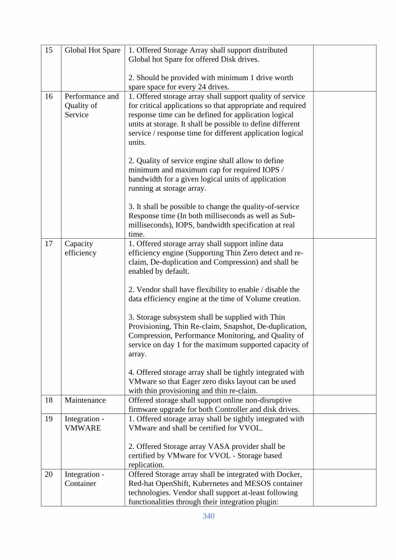
340
15 Global Hot Spare 1. Offered Storage Array shall support distributed
Global hot Spare for offered Disk drives.
2. Should be provided with minimum 1 drive worth
spare space for every 24 drives.
16 Performance and
Quality of
Service
1. Offered storage array shall support quality of service
for critical applications so that appropriate and required
response time can be defined for application logical
units at storage. It shall be possible to define different
service / response time for different application logical
units.
2. Quality of service engine shall allow to define
minimum and maximum cap for required IOPS /
bandwidth for a given logical units of application
running at storage array.
3. It shall be possible to change the quality-of-service
Response time (In both milliseconds as well as Sub-
milliseconds), IOPS, bandwidth specification at real
time.
17 Capacity
efficiency
1. Offered storage array shall support inline data
efficiency engine (Supporting Thin Zero detect and re-
claim, De-duplication and Compression) and shall be
enabled by default.
2. Vendor shall have flexibility to enable / disable the
data efficiency engine at the time of Volume creation.
3. Storage subsystem shall be supplied with Thin
Provisioning, Thin Re-claim, Snapshot, De-duplication,
Compression, Performance Monitoring, and Quality of
service on day 1 for the maximum supported capacity of
array.
4. Offered storage array shall be tightly integrated with
VMware so that Eager zero disks layout can be used
with thin provisioning and thin re-claim.
18 Maintenance Offered storage shall support online non-disruptive
firmware upgrade for both Controller and disk drives.
19 Integration -
VMWARE
1. Offered storage array shall be tightly integrated with
VMware and shall be certified for VVOL.
2. Offered Storage array VASA provider shall be
certified by VMware for VVOL - Storage based
replication.
20 Integration -
Container
Offered Storage array shall be integrated with Docker,
Red-hat OpenShift, Kubernetes and MESOS container
technologies. Vendor shall support at-least following
functionalities through their integration plugin:

341
a. Multiple arrays support so that within a given cluster
using a common configuration file on container
platform.
b. Snapshot
c. Replication. Plugin shall allow to define the
replication configuration on the container.
d. Quality of service for response time, Bandwidth and
IOPS.
e. Shall have flexibility to import the non-container
volume into the container.
f. Login credential to array via container platform shall
be encrypted.
g. Container as a service from Storage array where
vendor shall be able to define partition on the storage
and shall be visible to container.
h. Support for both Fiber channel as well as ISCSI.
21 Snapshot / Point
in time copy
The storage array should have support for controller-
based snapshots functionality (At-least 1024 copies for a
given volume).
22 Application
Consistent
Copies
1. Offered storage shall be supplied with unlimited
license for creation of application consistent copies for
Oracle, SQL, Exchange, SAP HANA and VMware
through Storage console GUI.
2. Offered Storage shall be supplied with in-built copy
management and backup S/W unlimited license for
movement of data copies of Oracle, SQL, Exchange,
SAP HANA and VMware to disk based backup device,
public Cloud like AWS, Azure and object storage.
23 Storage Array
Configuration &
Management
Software
Vendor shall provide Storage Array configuration and
Management software.
Software shall be able to manage more than one array of
same family.
Offered Storage management engine shall have in-built
on-site edge analytics performance engine, without
connectivity to Internet / Intranet and shall offer
following functionalities: All required license for
offering this functionality shall be offered.
a. Shall have saturation panel which can depict the
overall saturation level of the storage array at different
time intervals instead of looking into individual
parameters like IOPS, CPU utilization, Cache utilization
etc.
b. Shall have capability to assign and compare the
performance score with similar nature of workload
across worldwide install base. Vendor management and
edge analytic engine shall have in-built performance

342
statistics of worldwide install base instead of connecting
to internet / intranet.
c. Shall have capability to display top 5 volumes by
hotspots as well as by latency.
d. If similar nature of arrays being used in the
environment then offered engine shall show the top
systems by saturation level within the same console
24 Monitoring and
analytic engine
Offered storage shall have cloud enabled monitoring
and analytics engine for proactive Storage management.
All required licenses for same shall be included in the
offer.
Cloud Enabled Monitoring and analytics engine shall
have capability to provide following:
a. Providing Firmware upgrade and patch upgrade
recommendations proactively and with awareness of the
peripheral infrastructure connected to the array.
b. Providing extremely granular per-minute historical
capacity and performance trend analysis by default,
without the need to enable extra logging, install any
appliances (physical or virtual), or install any software.
c. Providing overall saturation level of the array while
combining while analyzing various parameters like
IOPS, MB/sec, Block size etc.
d. Providing overall performance score of the array at a
scale of 0 to 10 for both read and write operations.
e. Shall provide history of support cases logged with
Support team under different column like Critical,
Normal and low severity along with closed cases. Cloud
monitoring tool shall be able to provide the complete
month-wise breakup.
f. Shall be able to provide the executive Dashboard
covering various critical and must aspects of Total
Capacity, overall health / wellness score of array. De-
duplication and compression ratio, over-all front-end
performance etc.
Cloud enabled Analytics engine shall have capability to
provide following:
a. Shall have capability of learning mechanism to
provide the analytics and problem finding/solving based
on global learning available for the arrays across the
install based.

343
b. Analytics engine shall have capability of
proactive recommendation for arresting the issues /
problems noticed at other install base of vendor after
identifying the problematic signature
25 Cloud Enabled -
HyperVisor
Integration
Cloud enabled monitoring and analytics engine
integration with Hypervisor:
a. Offered Cloud enabled monitoring and analytics
engine shall be tightly integrated with Hypervisor layer
and shall be certified to work with at-least VMware.
b. Hypervisor integration shall be able to provide
end to end monitoring of hypervisor Datacenter, Data-
store, Hypervisor Host and VMs running within the
hypervisor datacenter and shall be able to link with
offered storage array.
c. Cloud monitoring and integration tool shall
provide the detailed analysis of CPU Contention,
Memory contention, IO contention for each VM –
including the latency.
d. Cloud monitoring and integration tool shall have
capability to identify the top VMs which are
contributing towards maximum IOs and Latency.
26 Data Availability Offered storage shall be a 100% data availability
guaranteed architecture. 100% data availability guaranty
shall be clearly mentioned on vendor web site for the
offered model.
27 Data Integrity
(T10 DIFF)
Should ensures the integrity of data by performing a
checksum on the data from the HBA to the disk (T10
DIFF).
28 Remote
Replication
1. The storage array should support hardware-based data
replication at the array controller level across all models
of the offered family.
2. Replication shall support incremental replication after
resumption from Link Failure or failback situations.
3. Offered storage system shall support native
replication that procured for the last 2 Lac meter
project.
29 Licenses Storage subsystem shall be supplied with all-inclusive
license that should include Thin provisioning,
replication, data-at-rest encryption, Snapshot, Clone,
Performance Monitoring, Online Raid Migration,
Online Volume conversion (thin to thin compressed,
thin to thin de-dup etc.), Quality of services, NVMe
cache, and File services on day 1 for the maximum
supported capacity of array.
30 Installation
services, manage
& control
Implementation shall be done by OEM Engineer only.
OEM installation service and engineer’s CV to be
submitted during bid submission.

344
Partner engineer is not allowed to Powerup the device
without OEM Engineer presence. OEM onsite
installation and startup service should be provided.
Access to OEM experts via phone, web, or both
Connect devices to OEM for real-time diagnosis, alerts,
and information.
31 Warranty&
services
3-yrs collaborative warranty with 24x7 mission critical
one-point support from OEM.
4-hour mission critical response time for hardware issue
from OEM. Supporting service-related document shall
be provided.
Root cause analysis report shall be available from day1.
OEM shall maintain local spare parts depot/warehouse
in Bangladesh.
All above features BoQ should be provided with proper
explanation.
[The Bidder should complete all the columns as required]
Name
In the capacity of
Signed
Duly authorized to sign the Bid for and on behalf of
Date

345
SAN Switches (To be filled up and signed by the Bidder & Manufacturer, otherwise the offer will not be acceptable)
SL Item Name Detail Required Specification Bidder
response
1 Brand Same as storage vendor.
2 Model To be mentioned by the bidder
3 Country of origin To be mentioned by the bidder
4 Manufacturing
Country
To be mentioned by the bidder
5 Rack Form
Factor
1U Rack form factor with rail kit.
6 Number of ports Each switch Shall be provided with min. 48x 32Gbps SFP+
connections with transceivers.
7 Port activation Shall be provided with min. 48 (Forty-Eight) activated port.
8 Switch
Aggregated
bandwidth &
Latency
Shall have 2Tbps end-to-end full duplex & latency less
then <700 nanoseconds
9 Software Shall be provided with Fabric vision, Extended fabric and
ISL trunking software license.
10 SAN
Orchestration
Should have tightly integration with the proposed storage
system.
11 Power supply Redundant hot swappable power supply should be
provided.
12 FC Cables Each switch shall be provided with min. 24x 15m LC–LC
Multi-mode OM4 Fiber Cable & 24x 30m LC–LC Multi-
mode OM4 Fiber Cable shall be provided
13 Manageability Should be provided with web browser management tools
14 Warranty 3 years 24x7 4-hour mission critical response
comprehensive OEM warranty with faulty parts
replacement and labor.
OEM shall maintain local spare parts depot/warehouse in
Bangladesh.
Warranty support SKU with the detail BoQ should be
provided with the technical compliance document.
[The Bidder should complete all the columns as required]
Name
In the capacity of
Signed
Duly authorized to sign the Bid for and on behalf of
Date

346
Application Server and SMS Server
(To be filled up and signed by the Bidder & Manufacturer, otherwise the offer will not be acceptable)
SL Item Name Detail Required Specification Bidder response
1 Brand To be mentioned by Bidder. Must be in the top three OEM
for the last 5 years in terms of revenue and shipment.
2 Quality ISO 9001/9002 for manufacturer, FCC Class A for quality
assurance
3 Model To be mentioned by the bidder
4 Country of origin USA/UK/EU/Switzerland/Australia/Japan
5 Country of
manufacturer
To be mentioned by the bidder
6
Modularity &
Flexibility
The server must be designed in modular architecture, with
each module scaling to 4Sockets architecture. Scale-up
capability and upgrade must be achieved by adding more
building blocks of 4-Socket modules, without the need to
upfront investing to a big chassis.
7
Scalability
Server should be able to scale from lower entry point of 2
sockets and up to 8 sockets in 2-socket increments, with
16-224 cores.
Scaling from 64 GB to 24TB of shared memory using
DRAM (with 256GB DIMM availability). Shall support of
1, 4, 6 & 12 DIMM per socket for granular scalability
8
Processor
The server must support 3rd Generation Intel Xeon
Scalable Processors (Cooper Lake 6UPI or CPX6).
Each server shall be provided with min. 4x Intel Xeon-
Platinum 8356H (3.9GHz/8-core/225W) Processor. Can be
expandable up to 8 CPU Server.
9
Memory
Each server shall be provided with 3TB memory with 48x
64GB Quad-rank DDR4-3200 LRDIMM.
Server should support memory scalability to 12TB using
128GB LRDIMM.
10 Memory
Protection Should support Adaptive DDDC and Fast Fault Tolerance
11 HDD Bays
Each server shall be provided with min. 4x 800GB 12G
SAS Write Intensive 2.5’ hot-pluggable SSD.
12 Hard disk drive
& DVD RW
Min. Eight (8) 2.5 inch HDD, SSD, or NVMe drive bays
plus an DVD RW optical drive.
13 Array Controllers
SAS drives use PCIe v3.0 based 12Gb/s SAS Internal
Hardware RAID Controller; 4GB Cache 14
Connectivity
features
Each server shall be provided with embedded 1x 2-port
1GbE RJ45 ports, 2x 2-port 10/25Gb SFP28 adapter with
25Gb SFP28 SR transceivers and 2x 2-port 32Gbps FC
HBA.

347
SL Item Name Detail Required Specification Bidder response
Support of up to 100Gbps network adapter & 200Gb
InfiniBands.
15 IO architectures
Direct IO architecture from all CPUs for unblocking, best
performance, and low latencies
16 Bus Slots
Server shall come with min. Sixteen (16) PCIe v3.0 slots
per server from Day1.
17
GPUs
Supports up to 4 GPUs in a chassis; up to 16 per system.
GPU should be able to use in Windows OS.
18 Power Supply
Each server shall be provided with min. 4x 1600W power
supplies connectivity’s for 8Socket configuration.
19 Fans Min. 8x Redundant hot-plug fan (per Chassis)
20
Reliability,
Availability and
Serviceability
(RAS) features
Key areas of RAS superiority over standard x86-
• Firmware First
• Automatic error logging
• Auto self-healing (Analysis Engine)
• Disabling and deconfiguration of failed FRUs
• Onboard fault analyzer
• Automatic restart
• Advanced processor error handling (EMCA2)
• Advanced memory resiliency (ADDDC)
• Memory error storm response
• Enhanced fabric resiliency (Flex Grid adaptive routing)
• Advanced PCIe error recovery (LER)
21 Operating
Systems and
Virtualization
Software Support
RHEL, SLES, VMware, Windows
Virtualization technologies: VMware vSphere, RHEV,
KVM and Microsoft Hyper-V.
22 Operating
System License
Each server shall be provided with Red Hat Enterprise
Linux 1-2 Guest 3Years 24x7 subscription and support for
4-socket.
23 GPU support Support of up to 16 single-wide GPUs; up to 8 double-wide
GPUs
24 Security
Secure architecture, design and supply chain, with limited
exposure Silicon root of trust TPM2.0
25
Server
Management
Embedded management controller with the offered Server.
Software should have dashboard view to quickly scan the
managed resources to assess the overall health of the data
center. It should provide an at-a-glance visual health
summary of the resource’s user is authorized to view.
The Dashboard minimum should display a health summary
of the following:
• Server Profiles
• Server Hardware
• Appliance alerts
The Systems Management software should provide Role-
based access control

348
SL Item Name Detail Required Specification Bidder response
Management software should have integration with popular
virtualization platform management software like vCenter,
and SCVMM
Should help provide proactive notification of actual or
impending component failure alerts on critical components
like CPU, Memory and HDD.
Should provide an online portal that can be accessible from
anywhere. The portal should provide one stop, online
access to the product, support information and provide
information to track warranties, support contrast and status.
The Portal should also provide a Personalized dashboard to
monitor device heath, hardware events, contract and
warranty status. Should provide a visual status of
individual devices and device groups. The Portal should be
available on premise (at our location - console based) or off
premise (in the cloud).
Should help to proactively identify out-of-date BIOS,
drivers, and Server Management agents and enable the
remote update of system software/firmware components.
26 Installation
services, manage
& control
Access to OEM experts via phone, web, or both
OEM installation and startup professional service shall be
provided.
Connect devices to OEM for real-time diagnosis, alerts,
and information from Day1.
27 Warranty&
services
3-yrs collaborative warranty with 24x7 mission critical
one-point support from OEM.
4-hour mission critical response time for hardware issue
from OEM. Supporting service-related document shall be
provided.
Root cause analysis report shall be available from day1.
OEM shall maintain local spare parts depot/warehouse in
Bangladesh.
All above features BoQ should be provided with proper
explanation.
[The Bidder should complete all the columns as required]
Name
In the capacity of
Signed
Duly authorized to sign the Bid for and on behalf of
Date

349
Database Backup System (To be filled up and signed by the Bidder & Manufacturer, otherwise the offer will not be acceptable)
SL Item Name Detail Required Specification Bidder
Specification
1 Country of Origin USA/UK/EU/Switzerland/Australia/Japan
2 Country of Manufacture To be mentioned by the bidder
3 Brand Name To be mentioned by the bidder
4 Model To be mentioned by the bidder
5 Quantity Proposed backup software will ensure license
100 Front-end-TB capacity & 150 VM
perpetual license with 3-year 24x7
maintenance contract with the platform
provider.
6 Analyst Report Backup software must be present as Leaders
in Gartner's Magic Quadrant for backup
software for the last 5 years.
7 OEM credibility Backup Software OEM should be a publicly
listed company for last 3 years in any of the
world’s leading stock exchanges like NYSE,
NASDAQ, Tokyo Stock Exchange.
8 Centralized Management The backup software may have firewall
support & alerts on Mobile devices etc.
centralized management / Single interface for
management of all backup and archival (file
system and E-mail) activities across physical
servers, VMs and Mobile devices like
Laptops / Tabs / Phone and SaaS based
applications like Microsoft O365(Backup &
Archival) and G Suite
9 Security The proposed solution should have ability to
protect all mount paths associated with disk
libraries configured from a Backup/Media
Server against Ransomware attacks.
10 Efficient Data
Management
Should support software based de-
duplication to support any storage system,
cloud repository and object storage as de-
duplicated disk target. Based on policy
backup software should be able to move data
to a tape library automatically
11 Replication Backup software should be able to replicate
backed up data in de-duplicated format (for
bandwidth optimization) to another site for
compliance purposes, with or without the
need of external replication tools. All
necessary licenses for achieving consistent
replication of backup data should be quoted.

350
12 Licensing The proposed licenses should be Perpetual in
nature. All the necessary licenses should be
supplied along with the solution.
13 Database Support Backup software should be able to protect the
following through online agents enabling
granular restores. Major DBs like Oracle,
Exchange, Sybase, Informix, DB2, MS SQL,
MySQL, MongoDB, MariaDB, etc. and
Applications likes SAP, etc. across wide
range of popular Windows / Linux and Unix
flavors.
14 Reporting Comprehensive reporting of media, backup
server, jobs, analytics should be offered as
part of the functionality in the supplied
software either natively or through additional
reporting software.
15 Hypervisor Support It should have full support for backing up
virtual servers (image level) on various
hypervisors like Hyper - V, ESXi, RHEV,
OVM, Acropolis, Citrix, Fusion, etc.
16 Efficient Data
Management
Backup software should have the ability to
archive data and create a single repository for
backup and archive for space efficiency and
easier data management.
17 Encryption It should support the following algorithms
and provide better security in deployment
across sites - BLOWFISH, GOST, Serpent,
AES, Twofish, 3-DES, etc.
18 Storage Array Support Should support software based de-
duplication to support any storage system,
cloud repository and object storage as de-
duplicated disk target. Based on policy
backup software should be able to move data
to a tape library automatically The proposed
backup solution should support snapshot
based backup from various vendors such as
Hyperflex, HP 3PAR, EVA, Fujitsu Eternus,
Oracle ZFS, Infinidat, Solidfire, Huawei,
Tintri,etc.
19 Oracle Database Security The Backup solution should support Oracle
Data Masking, whereby a copy of backed up
data can be handed over to any third party
without allowing them to view data within
the instance. They should be able to
troubleshoot, run dev / test instances on the
copy and yet not have access to confidential
data of the organization.

351
20 Data Management Proposed solution should support universal
recovery to restore from P2P, P2V, V2V,
V2P, V2C and C2V without having to wait to
extract the full backup to production storage.
Backup software should be able to protect the
Big data apps like Cassandra, Greenplum,
Hadoop, IBM-GPFS
21
Scale Out Architecture
The proposed Backup hardware should be
based on node-based architecture and scale
out design (expand on multiple nodes). Shall
support single node increments after initial 3-
node deployment.
Shall be configured with the tested reference
architecture. Minimum number of nodes
should be offered with high availability.
Scale performance linearly by adding
compute and
networking as you expand capacity via scale-
out
architecture.
22
VTL Support
The proposed Backup hardware should allow
to add external storage for the VTL or target
backup capacity.
23
Erasure Coding
Tolerate a node failure and/or multiple HD
failures within a 3-node cluster with erasure
coding 4+2. And with 6-nodes, cluster can
support up to two node failures
24
Backup Hardware
The proposed backup architecture should be
such that each participating node should have
its independent controller
25
Required Controllers
The proposed backup architecture should
have more than two controllers (Server and
backend capacity) and every node should be
behaving as the active controller.
26
Self-Resiliency
The proposed backup architecture should
have self-resilient architecture.
27
Self-Healing
The proposed backup architecture should
have self-healing architecture.
28
Performance
Every node in the backup architecture should
be equipped with latest and scalable
processor.
29
Memory
Each node in the backup architecture should
be able to expand up to 1TB memory.
30
Performance
Enhancement
The proposed backup architecture should
provide SSD cache with each participating
controller/node to facilitate meta data as well
as to enhance the backup performance as an
cache apart from DDR memory

352
31
Required Ports
The proposed backup appliance, each node
shall have 1x 2-port 10/25Gbps SFP28
adapter with transceivers and 1x 2-port
32GBps FC ports per node.
32
Storage Capacity
For DC, the proposed backup appliance shall
come with minimum 5-node system and shall
provide min. 1PB usable capacity (without
deduplication & compression) with back-end
TB capacity or node-based license and
scalable up to 5PB in a single deduplicated
storage pool.
For DR, the proposed backup appliance shall
come with minimum 3-node system and shall
provide min. 600TB usable capacity (without
deduplication & compression) with back-end
TB capacity or node-based license and
scalable up to 5PB in a single deduplicated
storage pool.
Replication between DC and DR shall be
native and shall be established from Day1.
33
Write Performance
When fully populated, offered device shall
supported rated write performance, when
enabled with source level de-duplication, of
minimum 100TB/hr RPO (full backup)
34
Concurrent Streaming
Offered appliance shall preform minimum
1000 concurrent stream to storage pool.
35
Recovery performance
Offered appliance shall deliver
recovery/restore performance up-to ~10
TB/hr across 100 streams from day one.
Restore performance can be double up-to 20
TB/hr by adding another 3 nodes in the
cluster.
36
Instant Recovery Feature
Granular files, messages, documents, or DB
instance/tables/rows in a single click manner
37
Training
Should be provided with min. 3 Days
administrator training from OEM conducted
training center for the appliance. Other
relevant cost to be conveyed by the bidder.
38 Appliance Warranty
3-yrs collaborative warranty with 24x7 OEM
mission critical one-point support.
4-hour onsite response time for hardware
issue. Supporting service-related document
should provide.

353
[The Bidder should complete all the columns as required]
Name
In the capacity of
Signed
Duly authorized to sign the Bid for and on behalf of
Date
Professional installation and deployment
service shall be provided by the platform
provider.
OEM shall maintain local spare parts
depot/warehouse in Bangladesh.
Warranty support SKU and datasheet with
the detail BoQ and sizing document should
be provided with the technical compliance
document.

354
Server for HES, MDM related software/applications (To be filled up and signed by the Bidder & Manufacturer, otherwise the offer will not be acceptable)
SL Item Name Detail Required Specification Bidder
response
1 Brand To be mentioned by Bidder. Must be in the top three OEM
for the last 5 years in terms of revenue and shipment.
2 Quality ISO 9001/9002 for manufacturer, FCC Class A for quality
assurance
3 Model To be mentioned by the bidder
4 Country of origin USA/UK/EU/Switzerland/Australia/Japan
5 Country of
manufacturer
To be mentioned by the bidder
6 Modularity &
Flexibility
The server must be designed in modular architecture, with
each module scaling to 4Sockets architecture. Scale-up
capability and upgrade must be achieved by adding more
building blocks of 4-Socket modules, without the need to
upfront investing to a big chassis.
7 Scalability Server should be able to scale from lower entry point of 2
sockets and up to 8 sockets in 2-socket increments, with
16-224 cores.
Scaling from 64 GB to 24TB of shared memory using
DRAM (with 256GB DIMM availability). Shall support of
1, 4, 6 & 12 DIMM per socket for granular scalability
8 Processor The server must support 3rd Generation Intel Xeon
Scalable Processors (Cooper Lake 6UPI or CPX6).
Each server shall be provided with min. 4x Intel Xeon-
Platinum 8354H (3.1GHz/18-core/205W) Processor. Can
be future expandable up to 8 CPU server.
9 Memory Each server shall be provided with 1.5TB memory with
24x 64GB Quad-rank DDR4-3200 LRDIMM.
Server should support memory scalability to 12TB using
128GB LRDIMM.
10 Memory
Protection
Should support Adaptive DDDC and Fast Fault Tolerance
11 HDD Bays Each server shall be provided with min. 4x 800GB 12G
SAS Write Intensive 2.5’ hot-pluggable SSD.
12 Hard disk drive
& DVD RW
Min. Eight (8) 2.5 inch HDD, SSD, or NVMe drive bays
plus an DVD RW optical drive.
13 Array Controllers SAS drives use PCIe v3.0 based 12Gb/s SAS Internal
Hardware RAID Controller; 4GB Cache
14 Connectivity
features
Each server shall be provided with embedded 1x 2-port
1GbE RJ45 ports, 2x 2-port 10/25Gb SFP28 adapter with
25Gb SFP28 SR transceivers and 2x 2-port 32Gbps FC
HBA.
Support of up to 100Gbps network adapter & 200Gb
InfiniBands.

355
15 IO architectures Direct IO architecture from all CPUs for unblocking, best
performance, and low latencies
16 Bus Slots Server shall come with min. Sixteen (16) PCIe v3.0 slots
per server from Day1.
17 GPUs Supports up to 4 GPUs in a chassis; up to 16 per system.
GPU should be able to use in Windows OS.
18 Power Supply Each server shall be provided with min. 4x 1600W power
supplies connectivity’s for 8Socket configuration.
19 Fans Min. 8x Redundant hot-plug fan (per Chassis)
20 Reliability,
Availability and
Serviceability
(RAS) features
Key areas of RAS superiority over standard x86-
• Firmware First
• Automatic error logging
• Auto self-healing (Analysis Engine)
• Disabling and deconfiguration of failed FRUs
• Onboard fault analyzer
• Automatic restart
• Advanced processor error handling (EMCA2)
• Advanced memory resiliency (ADDDC)
• Memory error storm response
• Enhanced fabric resiliency (Flex Grid adaptive routing)
• Advanced PCIe error recovery (LER)
21 Operating
Systems and
Virtualization
Software Support
RHEL, SLES, VMware, Windows
Virtualization technologies: VMware vSphere, RHEV,
KVM and Microsoft Hyper-V.
22 Operating
System License
Each server shall be provided with Red Hat Enterprise
Linux Unlimited Guest 3Years 24x7 subscription and
support for 4-socket.
23 GPU support Support of up to 16 single-wide GPUs; up to 8 double-wide
GPUs
24 Security Secure architecture, design and supply chain, with limited
exposure Silicon root of trust TPM2.0
25 Server
Management
Embedded management controller with the offered Server.
Software should have dashboard view to quickly scan the
managed resources to assess the overall health of the data
center. It should provide an at-a-glance visual health
summary of the resource’s user is authorized to view.
The Dashboard minimum should display a health summary
of the following:
• Server Profiles
• Server Hardware
• Appliance alerts
The Systems Management software should provide Role-
based access control
Management software should have integration with popular
virtualization platform management software like vCenter,
and SCVMM

356
[The Bidder should complete all the columns as required]
Name
In the capacity of
Signed
Duly authorized to sign the Bid for and on behalf of
Date
Should help provide proactive notification of actual or
impending component failure alerts on critical components
like CPU, Memory and HDD.
Should provide an online portal that can be accessible from
anywhere. The portal should provide one stop, online
access to the product, support information and provide
information to track warranties, support contrast and status.
The Portal should also provide a Personalized dashboard to
monitor device heath, hardware events, contract and
warranty status. Should provide a visual status of
individual devices and device groups. The Portal should be
available on premise (at our location - console based) or off
premise (in the cloud).
Should help to proactively identify out-of-date BIOS,
drivers, and Server Management agents and enable the
remote update of system software/firmware components.
26 Installation
services, manage
& control
Access to OEM experts via phone, web, or both
OEM installation and startup professional service shall be
provided.
Connect devices to OEM for real-time diagnosis, alerts,
and information from Day1.
27 Warranty&
services
3-yrs collaborative warranty with 24x7 mission critical
one-point support from OEM.
4-hour mission critical response time for hardware issue
from OEM. Supporting service-related document shall be
provided.
Root cause analysis report shall be available from day1.
OEM shall maintain local spare parts depot/warehouse in
Bangladesh.
All above features BoQ should be provided with proper
explanation.

357
Virtualization and Container Infrastructure for other Services
(To be filled up and signed by the Bidder & Manufacturer, otherwise the offer will not be acceptable)
SL Item Name Detail Required Specification Bidder response
1 Blade Chassis As per the blade compute and storage requirement.
Quantity to be mentioned.
1 (One) set for DC and 1 (one) Set for DR. Each set shall
design based on the scope.
1.1 Quality ISO 9001/9002 for manufacturer, FCC Class A/B for
quality assurance.
To be mentioned by Bidder, must be internationally reputed
and have position within the leader quadrant in Gartner
report on modular server for the last 5 years.
1.2 Brand To be mentioned by the bidder
1.3 Model To be mentioned by the bidder
1.4 Country of Origin USA/UK/EU/Switzerland/Australia/Japan
1.5 Form Factor Blade chassis shall be maximum 19" Electronic Industries
Alliance Standard Width rack mountable and provide
appropriate rack mount kit.
Blade Server chassis enclosure should be capable of having
minimum 12 Half Height Blade.
1.6 Power Supply The power supply modules should be hot pluggable
Power supply should be Industry standard.
The power subsystem should support all of the following
modes of power redundancy (N+1/N+N)
1.7 Cooling The Blade server chassis should have the capability to
provide full redundant cooling for all Blade servers
1.8 Server Chassis
Fabric
The chassis shall be able to support Min. three redundant
IO modules for all fabric connectivity.
Should support housing of FCoE, Ethernet, FC and SAS
interconnect fabrics offering redundancy as a feature. Also
should support network switch with 50Gb downlinks and
100G uplink to DC switch.
Should support aggregation of multiple enclosures to
consolidate data center network connections, reduce
hardware and to scale network bandwidth across multiple
enclosures.
At least 60/36 servers should be supported per aggregation.
Layer 2 network traffic should be switched within
enclosure aggregation (without using top of the rack
switch).
Provided Chassis Interconnect Fabric Module solutions
have path for Ethernet and Fiber Channel Traffic-
Ethernet Network Traffic & SAN Storage Traffic:
1. Must provide redundant network IO module with min.
6x QSFP28 port. Should be provided with min. 16x 25Gb
connection to the external network switch (Spine Switch)
with min. 15meter optical Cables &

358
2. Should be provided with min. 16x32Gb connections to
the external FC SAN switch.
3. Offered IO module should be provided with minimum
12 x 50Gb or 24x 25Gb Ethernet downlinks to compute
module’s Converged Network Adapters.
1.9 DVD Should be able to support the feature of virtual DVD to
individual servers from remote systems
1.10 System/Chassis/
Enclosure/
Management/
Software
Management/controlling software have to be from the
OEM.
Should support auto-discovery of Compute, Memory,
Storage and Fabrics within an enclosure or on multiple
connected enclosures
Should support activity, Health and Power LEDs for
immediate status
Should support software-defined intelligence for
configuring profiles to provision compute, storage, fabrics
and images
Should support Firmware and OS Driver updates for the
servers using profile templates to monitor, flag, and
remediate
Should offer collaborative user interface which support
logical resources to physical resources mapping, Smart
Search, Activity Log, HTML5 mobile access, and
Customizable Dashboard
Should support firmware updates on the chassis while
continuing to pass traffic
Should support reporting capabilities for
1) Asset and inventory information for the devices in the
enclosures.
2) Thermal and power information, including real-time
actual power usage per server and per enclosure.
Reports should be exportable to csv or Microsoft Excel
format
Should support personalizing OS per deployment plan.
Should support stateless operation with IP addresses
assigned to bootable images
Tools for personalization and customization of images
1.11 Rack Accessories Each Blade system set should be provided with factory-
integrated 42U Rack system with accessories: 4x 7.3kVA
metered PDUs (two horizontal each with 6x C19 outlets
and two vertical each with 32x C13 & 6x C19 outlets),
KVM console- switch, display kit, USB interface adapter,
grounding kit, side panels, baying, door kit etc.
1.12 Installation
services, manage
& control
OEM on-site installation service should be provided.
Connect devices to OEM for real-time diagnosis, alerts, and
information
1.13 Warranty Mentioning manufacturer warranty should be quoted,
minimum 3 (Three) years 24x7 4-hour response time OEM
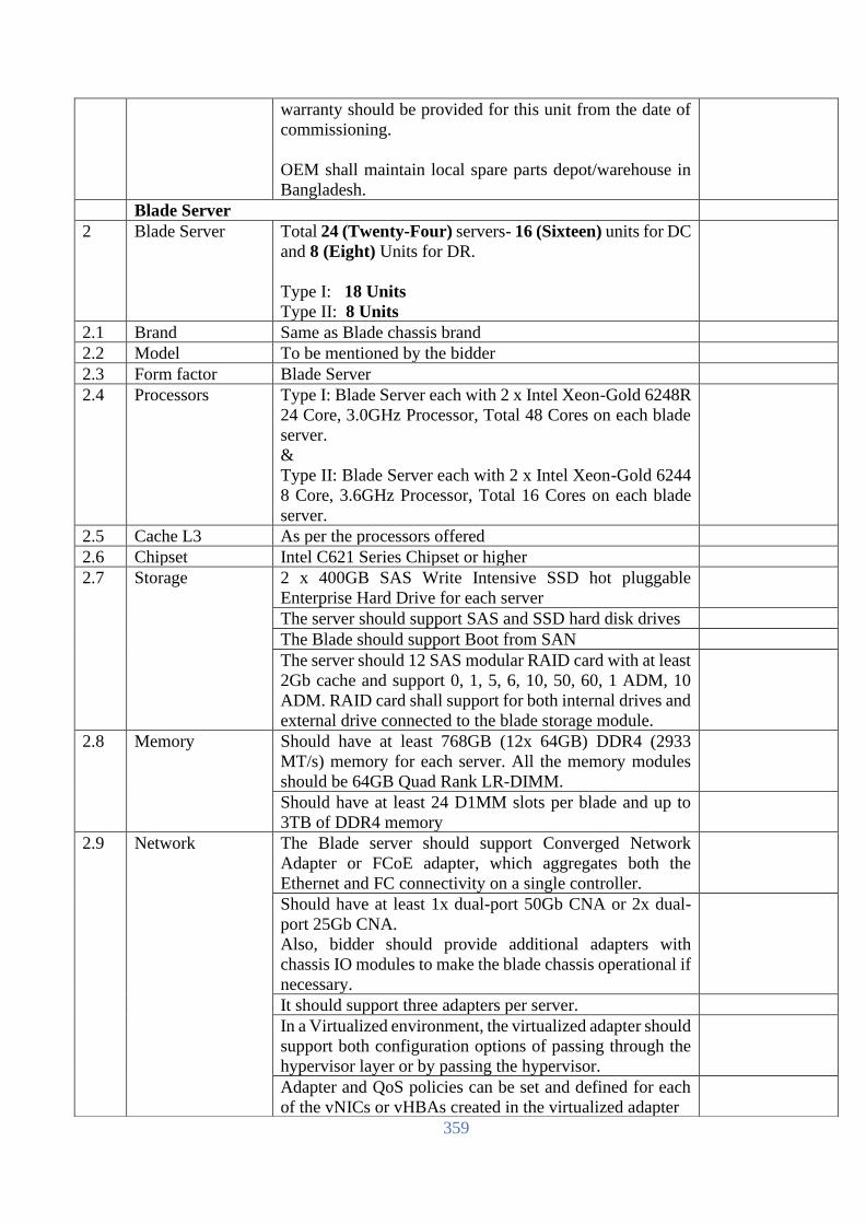
359
warranty should be provided for this unit from the date of
commissioning.
OEM shall maintain local spare parts depot/warehouse in
Bangladesh.
Blade Server
2 Blade Server Total 24 (Twenty-Four) servers- 16 (Sixteen) units for DC
and 8 (Eight) Units for DR.
Type I: 18 Units
Type II: 8 Units
2.1 Brand Same as Blade chassis brand
2.2 Model To be mentioned by the bidder
2.3 Form factor Blade Server
2.4 Processors Type I: Blade Server each with 2 x Intel Xeon-Gold 6248R
24 Core, 3.0GHz Processor, Total 48 Cores on each blade
server.
&
Type II: Blade Server each with 2 x Intel Xeon-Gold 6244
8 Core, 3.6GHz Processor, Total 16 Cores on each blade
server.
2.5 Cache L3 As per the processors offered
2.6 Chipset Intel C621 Series Chipset or higher
2.7 Storage 2 x 400GB SAS Write Intensive SSD hot pluggable
Enterprise Hard Drive for each server
The server should support SAS and SSD hard disk drives
The Blade should support Boot from SAN
The server should 12 SAS modular RAID card with at least
2Gb cache and support 0, 1, 5, 6, 10, 50, 60, 1 ADM, 10
ADM. RAID card shall support for both internal drives and
external drive connected to the blade storage module.
2.8 Memory Should have at least 768GB (12x 64GB) DDR4 (2933
MT/s) memory for each server. All the memory modules
should be 64GB Quad Rank LR-DIMM.
Should have at least 24 D1MM slots per blade and up to
3TB of DDR4 memory
2.9 Network The Blade server should support Converged Network
Adapter or FCoE adapter, which aggregates both the
Ethernet and FC connectivity on a single controller.
Should have at least 1x dual-port 50Gb CNA or 2x dual-
port 25Gb CNA.
Also, bidder should provide additional adapters with
chassis IO modules to make the blade chassis operational if
necessary.
It should support three adapters per server.
In a Virtualized environment, the virtualized adapter should
support both configuration options of passing through the
hypervisor layer or by passing the hypervisor.
Adapter and QoS policies can be set and defined for each
of the vNICs or vHBAs created in the virtualized adapter

360
2.10 Management It should support remote KVM capability from an external
keyboard, video monitor and mouse to all blades installed
in the chassis through the management controllers
Bidder must propose Management system for all blade
servers for deployment, inventory, troubleshooting and
monitoring.
2.11 Others The Blade should be hot pluggable
2.12 Environmental Operating Temperature support from 10 to 35°C and Non-
Operating Temperature from -30 to 60°C
Operating Humidity from 10% to 90% non-condensing and
Non-Operating Humidity from 5% to 95% non-condensing
2.13 Installation
services, manage
& control
OEM on-site installation service should be provided.
Connect devices to OEM for real-time diagnosis, alerts, and
information
2.14 Warranty Min. 3 years 24x7 4-hour response time OEM warranty
with faulty parts replacement and labor.
Warranty support SKU with the detail BoQ should be
provided with the technical compliance document.
OEM shall maintain local spare parts depot/warehouse in
Bangladesh.
Blade Storage (DAS) for the Blade Server
3 Blade Storage Min. 2 (Two) or more based on the drive requirement each
site (for DC and DR).
Each blade chassis shall be provided with min. 1 (One)
Blade Storage module.
3.1 Brand Same as Blade chassis brand
3.2 Model To be mentioned by the bidder
3.3 Form factor Should be able to fit at least Forty (40) SFF disks within a
single storage module and up to 5 storage modules in a
single chassis
3.4 Density Should be able to support at least 200 SFF disks per chassis
with a storage density of up to 20 SFF drives per RU, not
including local disks on the servers.
3.5 Storage Capacity Should be able to support up to a maximum of 3PB of raw
storage per chassis, not including local disks on the servers.
Each blade storage unit shall be provided with min. 24x
3.84TB SAS 12G Read Intensive 2.5inch hot-plug SSD and
12x 800GB SAS 12G Mixed Use 2.5inch hot-plug SSD.
3.6 Fault Tolerance The modules should be able to physically accommodate
redundant SAS I/O modules for redundancy and fault
tolerance. Should support Dual Domain direct attached
SAS architecture.
3.7 HDD Types Should support 12G and 6G SAS and SATA hard disk
drives (HDDs) and solid-state drives (SSDs).
3.8 Universal hot plug
Drive
The SFF disk should be standard across all server platforms
and should be interchangeable. With compatibility across
many enterprise platforms, should free to deploy and re-

361
[The Bidder should complete all the columns as required]
Name
In the capacity of
Signed
Duly authorized to sign the Bid for and on behalf of
Date
deploy these drives to quickly deliver increased storage
capacity, migrate data between systems, and easily manage
spare drives.
3.9 Mix and Match of
Drive Types
Should support mixing of different drive types
(SAS/*SATA, SSD/HDD) and sizes in a single module
3.10 RAID Support Should support RAID 0, 1, 5, 6, 10, 50, 60, 1 ADM and 10
ADM (Advanced Data Mirroring) via the Hardware RAID
Controller
3.11 HDD Indicators The drives should have front panel LEDs indicate drive
activity and system health status. The drives should also
have intuitive icon-based display along with "DO NOT
REMOVE" caution indicator that gets activated
automatically in order to avoid data loss/downtime due to
wrong drive removal
3.12 Manageability Should support delivery of fluid pools of storage resources
to be composed, deployed and provisioned simply and
quickly within a composable infrastructure environment.
Should support deployment and configuration via
templates and profiles.
3.13 Software-defined
Storage
Should support and be certified for software-defined
storage like HPE VSA, VMware VSAN, Red Hat Ceph,
etc.
3.14 Security The Storage Controller should support Secure Encryption
and SmartCache
3.15 Servicing The modules should also support the action of adding,
removing and swapping of disk drives while the system is
still powered on.
3.16 Installation
services, manage
& control
OEM on-site installation service should be provided.
Connect devices to OEM for real-time diagnosis, alerts, and
information
3.17 Warranty Min. 3 years 24x7 4-hour response time OEM warranty
with faulty parts replacement and labor.
Warranty support SKU with the detail BoQ should be
provided with the technical compliance document.
OEM shall maintain local spare parts depot/warehouse in
Bangladesh.

362
Tape Library for Archival
(To be filled up and signed by the Bidder & Manufacturer, otherwise the offer will not be acceptable)
SL Item Name Detail Required Specification Bidder response
1 Brand To be mentioned by the bidder.
2 Model To be mentioned by the bidder.
3 Country of
origin
USA/UK/EU/Switzerland/Australia/Japan
4 Country of
Manufacture
To be mentioned by the bidder.
5 Country of
assemble
To be mentioned by the bidder.
6 Chassis Rack mount with rack kit
7 Architecture Must support Fiber Connectivity to SAN
environment. Capable to allow add or
remove tape drives without schedule
downtime.
8 Tape Storage Should be modular tape library architecture
9 Tape Device
Type
LTO Ultrium 8 or latest.
10 Interface FC (8Gbps) Native Interface.
11 Network
interface
Ethernet (RJ-45)
12 Number of
Drive
Minimum 12 (Twelve) drive should be
configured and upgradeable up to 21 drive.
13 Data transfer
rate (per drive)
Up to 300 Mbps native with LTO Ultrium 8.
14 Number of Tape
Cartridges can
inserted in the
library
At least One Hundred and Sixty (160).
15 Physical
capacity
12 TB native capacity/up to 30 TB
compressed (2:1) capacity.
16 Hot Swap
feature
Power Supply should be hot swappable.
17 Management Tape Library shall come with web-based
remote manageability so it can be easily
monitored and managed from across the
room or across the globe.
Functions included in the management tool
include:
• Status information on the drive and
system
• System configuration operations and
reporting
• System error and status logs

363
• Library and drive firmware upgrade
capabilities
• Diagnostic tests and information
• Cartridge movement for maintenance
and management purposes
• Cleaning cartridge support
• Security and access control
• SNMP support for IP communication
• Partitioning and encryption management
• HTTPS capable
IPv6 and IPv4 network protocol support
18 Form Factor Rack Unit(s), as required.
19 Tape
Cartridges
160 Unit LTO 8 data Cartridge, 2 Unit
cleaning cartridge and 200 nos. bar code
label.
20 Mixed Tape Must support mix tape drive technology and
mix media such in same library.
21 Power Supply Redundant Power Supply.
22 Operating
system
Windows, Linux Operating systems.
23 Product Life
time
Tape Library lifetime will be around 07
(Seven) years after delivery of the product.
24 Accessories As required for successful commissioning.
25 Warranty At least 3 years24x7 4-hour response time
OEM on site with full labor, parts &
replacement.
OEM shall maintain local spare parts
depot/warehouse in Bangladesh.
[The Bidder should complete all the columns as required]
Name
In the capacity of
Signed
Duly authorized to sign the Bid for and on behalf of
Date
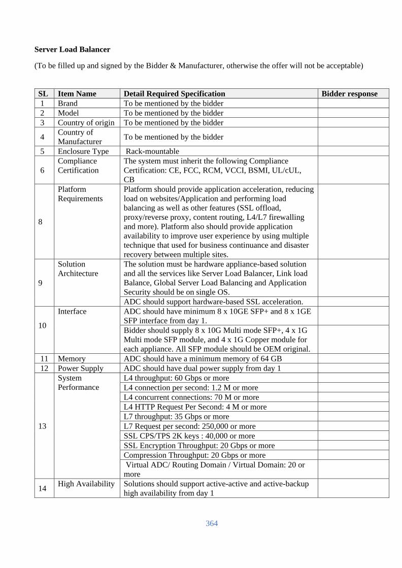
364
Server Load Balancer
(To be filled up and signed by the Bidder & Manufacturer, otherwise the offer will not be acceptable)
SL Item Name Detail Required Specification Bidder response
1 Brand To be mentioned by the bidder
2 Model To be mentioned by the bidder
3 Country of origin To be mentioned by the bidder
4 Country of
Manufacturer To be mentioned by the bidder
5 Enclosure Type Rack-mountable
6
Compliance
Certification
The system must inherit the following Compliance
Certification: CE, FCC, RCM, VCCI, BSMI, UL/cUL,
CB
8
Platform
Requirements
Platform should provide application acceleration, reducing
load on websites/Application and performing load
balancing as well as other features (SSL offload,
proxy/reverse proxy, content routing, L4/L7 firewalling
and more). Platform also should provide application
availability to improve user experience by using multiple
technique that used for business continuance and disaster
recovery between multiple sites.
9
Solution
Architecture
The solution must be hardware appliance-based solution
and all the services like Server Load Balancer, Link load
Balance, Global Server Load Balancing and Application
Security should be on single OS.
ADC should support hardware-based SSL acceleration.
10
Interface ADC should have minimum 8 x 10GE SFP+ and 8 x 1GE
SFP interface from day 1.
Bidder should supply 8 x 10G Multi mode SFP+, 4 x 1G
Multi mode SFP module, and 4 x 1G Copper module for
each appliance. All SFP module should be OEM original.
11 Memory ADC should have a minimum memory of 64 GB
12 Power Supply ADC should have dual power supply from day 1
13
System
Performance
L4 throughput: 60 Gbps or more
L4 connection per second: 1.2 M or more
L4 concurrent connections: 70 M or more
L4 HTTP Request Per Second: 4 M or more
L7 throughput: 35 Gbps or more
L7 Request per second: 250,000 or more
SSL CPS/TPS 2K keys : 40,000 or more
SSL Encryption Throughput: 20 Gbps or more
Compression Throughput: 20 Gbps or more
Virtual ADC/ Routing Domain / Virtual Domain: 20 or
more
14 High Availability Solutions should support active-active and active-backup
high availability from day 1

365
Solution should support network-based failover for
session mirroring, connection mirroring and heartbeat
check
Solutions should support full configuration and session
sync.
Solutions should able to synchronize of the ruleset,
configured policies objects in both units
15
Networking Should support Static NAT, Hide NAT, and Dynamic
NAT for flexibility and scalability
Should support VLAN and port trunking support
Support integration with SDN technology like Cisco ACI,
Nutanix, OpenStack, and Ansible
Should have NVGRE and VXLAN Support
Should support BGP and OSPF with Route Health
Inspection
Should have IPv6 Support for SLB, interfaces, routing,
and firewalling
16
Server Load
Balancing &
Application
Optimization
Features
The solution should support layer4 and layer 7 load
balancing for well-known protocols like HTTP, HTTPS,
TCP, UDP, FTP, RADIUS, RDP, SIP, DNS and more
Should have virtual service definition with inherited
persistence, load balancing method, and pool members
Should support Layer 4/7 application routing policy and
server persistence
Should support scripting for event-driven rules using
predefined commands, variables, and operators for SLB,
content rewrite, persistency, and security
The solution should support the following load balancing
methods:
• Round-Robin
• Weighted Round-Robin
• Least Connections
• Fastest Response
• URI
• Host
• Host Domain
Solutions should provide application & server health
checks for well-known protocols like ICMP, TCP,
TCP_ECHO, HTTP, HTTPS etc.
Solutions should maintain server persistency using
Source-IP /Network, Hash Header, Cookie, RADIUS
Attribute, SSL Session ID persistency options
Solution should support content routing and rewrite
content
Solutions should support custom scripting for SLB and
content rewriting
The solution should support one to one NAT, Source NAT
(change source IP), DNAT (change destination IP) and
Full NAT (change source & destination IP)

366
The solution should support application (JavaScript, xml)
and text (CSS, html, xml, custom plain )
compression/decompression for web site acceleration
Solutions should capable of doing SSL offloading towards
clients and SSL re-encryption towards the real servers.
Solution should support SSLv3, TLSv1.0, TLSv1.1,
TLSv1.2, TLSv1.3
Should support Layer 7 DNS load balancing, security, and
caching
Solution should support full SSL forward proxy to inspect
outbound traffic
17
Global Server
Load Balancing
Solution should support load balancing of servers between
different data centers
The solution should support hardened DNS server that can
be deployed as the authoritative name server
Solutions should have availability to determine of virtual
server health by real-time connectivity checking
The solution should have persistence response for
applications transactions across multiple hosts.
The solution should support dynamic proximity which is
determined by application response time (RTT probes),
least connections, or byte-per-second.
Solution should support DNS-based load balancing of
inbound traffic.
Solutions should support all DNS queries like CANME, A
record, AAAA record, MX record, CNAME record, NS
record, TXT record, SRV record.
Solution should support Response Rate Limit to keeps the
authoritative DNS server from being used in amplifying
reflection denial of service (DoS) attack.
Solution should support DNSSEC
The solution should support DNS64 to allow the
resolution of addresses from the IPv4 world by creating
synthesized AAAA records for hosts where no AAAA
record is available.
18
Link Load
Balancing
Solution should support link load balancing for outbound
traffic using health checks and persistence options to
optimize link utilization.
Solution should support load balancing method like
weighted round robin, least connections, least connection
rate, least throughput and source-IP.
Solution should support Inbound link load balance with
the help of DNS and Round Robin, Weighted Round
Robin, Proximity, and all GSLB functions (Proximity,
Region, etc.) method is used.
Solution should able to route traffic based on source/target
IP, port, protocol, priority to different ISPs, failover, max
throughput supported.

367
19
Security Features Solution should have network layer DDoS prevention
technique using IP Fragmentation Protection, TCP SYN
flood protection, TCP slow data flood protection policy.
Solution should have application layer DDoS prevention
technique using HTTP flood protection, HTTP
Connection Limit, HTTP Access Flood.
Solution should have L4 IP firewall policy to allows or
denies traffic based on a source address, destination
address, and service
Solution should have Intrusion Prevention Service (IPS)
to provides the latest defenses against stealthy network-
level threats.
Solution should support user tracking and authentication
to provide accurate policies to prevent fraud.
The solution should be capable of publishing web
applications and offering backend SSO access
Should support Local, LDAP, RADIUS, NTLM,
Kerberos, SAML 2.0 (SP and Idp) authentication
offloading
Solution should support Two-Factor Authentication
20
Log and
Reporting
Features
The solution should be able to locally store event (audit),
alert & traffic information
The solution should be able to send all log types above to
an external syslog server
Should have a Reporting Engine built-in
Should support integration with renowned SIEM tools like
Arcsight, Splunk, Qradar and others
Log and reporting solution must support custom reporting
as on-demand
The solution should have a dashboard for data analytics
where top “N” information is displayed
21
Device
Administration &
Management
Should provide HTTP/HTTPS/SSH interface management
for administering the device
Should provide SSH interface management for
administering the device
Solution should have In-build diagnostic utilities
Should support role based admin access.
Device should support SNMP
22 MAF Bidder must be submitted Manufacturer Authorization
form (MAF)
23 Warranty Bidder should propose hardware & software for 3 (three)
years OEM warranty and RMA support.
24
Manufacturer's
part number
Bidder should submit BOQ of proposed device including
the detail’s part numbers and Manufacturer's Warranty
part number.
25
License Bidder must offer necessary security license &
subscriptions that includes " Server Load Balance, Link
Load Balance, Global Server Load Balance, DDOS
protection, & Stateful Firewalling " for three years

368
26
Supporting
Document
Bidder must submit the required performance document
and compliance reference document for the proposed
device.
27
Installation,
Testing and
Commissioning
Bidder must carry out on site installation, testing and
commissioning. In consultation with IT Department,
bidder must configure appropriate security and
administration related policies, must do integration with
other related hardware/software required to make the
Network Functional and shall provide respective
documentation to IT Division.
[The Bidder should complete all the columns as required]
Name
In the capacity of
Signed
Duly authorized to sign the Bid for and on behalf of
Date

369
Workstation (To be filled up and signed by the Bidder & Manufacturer, otherwise the offer will not be acceptable)
S/N Item Technical Specifications and Standards Bidders Response
1 Brand Internationally Reputed Brand.
Should be in the top 5 hardware provider in
terms of revenue and shipment.
2 Model To be mentioned by the Bidder
3 Country of Origin USA/Japan/EU/China
4 Country of
Manufacturer
To be mentioned by the Bidder
5 Form Factor All-in-one
6 Processor Minimum 9th Generation Intel Core i7
processor
7 Processor Speed Minimum 2.60 GHz
8 Chipset Intel Q370
9 Cache Minimum 9 MB
10 Memory Minimum 8 GB DDR4-2666 SDRAM (1 X
8 GB)
11 Hard Disk Minimum 1TB SATA HDD & min.
256GB M.2 SSD shall be provided.
12 Optical drive 9.5 mm Slim DVD
13 Graphics Integrated Intel UHD Graphics 630
14 Sound Card Built in
15 Display 54.61 cm (21.5") diagonal FHD IPS
widescreen LCD anti-glare WLED-backlit
16 Expansion Slot 1 M.2 2230 slot for WLAN and 1 M.2
2230/2280 slot for storage
17 Interface & Ports Side: 1 headphone/microphone combo;
1 SD 3.0 card reader;
1 USB 2.0 Type-C™;
1 USB 3.1 Gen 1;
1 USB 3.1 Gen 1 (charging)
Rear: 1 DisplayPort 1.2;
1 power connector;
1 RJ-45; 2 USB 3.1 Gen 1
18 Keyboard USB Slim Wired Keyboard
19 Mouse USB Optical Mouse
20 WebCam Should have MP FHD webcam with
integrated digital microphone that support
maximum resolution of 1920 x 1080
21 Security Features To be mentioned by the Bidder
22 Operating System
Software
Preinstalled Windows 10 Professional 64
bit, OEM
23 Power supply 120 W external power adapter, up to 88%
efficiency, active PFC

370
24 Manufacturer’s
certificate
A Manufacturer’s certificate for 3 year’s
warranty must be submitted at the time of
supply.
25 Warranty Three (03) years comprehensive warranty
& onsite support. The supplier Should have
own regional logistic facility. Warranty
response time will be in 7 (seven) Days
[The Bidder should complete all the columns as required]
Name
In the capacity of
Signed
Duly authorized to sign the Bid for and on behalf of
Date

371
WAN Switch (To be filled up and signed by the Bidder & Manufacturer, otherwise the offer will not be acceptable)
SL Item Name Detail Required Specification Bidder response
1 Brand To be mentioned by the bidder. Must be in the leaders
quadrant of Gartner Magic Quadrant of Wired and Wireless
Network.
2 Model To be mentioned by the bidder
3 Country of
Origin
USA/UK/EU/Switzerland/Australia/Japan
4
Architecture
Should be provided with-
• 24x 1/10G SFP+ Ports with 8x 1G SFP RJ45
Transceivers, 8x 1G SFP LC SX Transceivers, 2x
10G Base-T transceivers
• 4x 1/10/25/50G SFP ports with 1x 50G SFP56 to
SFP56 Direct Attach Copper Cable and 2x 10G
SFP+ LC SR Transceivers
• 1x USB-C Console Port
• 1x USB Type-A Host port
• Shall be provided with rack mounting kit.
5 Memory and
processor
• Memory: min. 8GB
• Packet buffer size: min. 8MB
• Flash: min. 32GB
6
Performance
• 10 Gbps Latency: < 1.5 µSec
• Throughput: > 650 Mbps
• Switching capacity: >880 Gbps
Layer 2 and
Layer 3
switching and
service
The following Layer 2 services shall be supported-
• VLAN support and tagging support for IEEE
802.1Q (4094 VLAN IDs) and 512 VLANs
simultaneously.
• STP supports standard IEEE 802.1D STP, IEEE
802.1w Rapid Spanning Tree Protocol (RSTP) for
faster convergence, and IEEE 802.1s Multiple
Spanning Tree Protocol (MSTP)
• Internet Group Management Protocol (IGMP)
controls and manages the flooding of multicast
packets in a Layer 2 network
The following Layer 3 services and routing shall be
supported-
• Address Resolution Protocol (ARP) determines the
MAC address of another IP host in the same subnet;
supports static ARPs
• Dual IP stack maintains separate stacks for IPv4
and IPv6 to ease the transition from an IPv4-only
network to an IPv6-only network design
• Supports internal loopback testing for maintenance
purposes and increased availability

372
7
Management
• Built-in programmable and easy-to-use REST API
interface
• Central for unified network operations of wired,
WLAN, SD-WAN, and public cloud infrastructure.
• sFlow (RFC 3176) is ASIC-based wire speed
network monitoring and accounting with no impact
on network performance; network operators can
gather a variety of network statistics and
information for capacity planning and real-time
network monitoring purposes.
• SNMPv1/v2c/v3 support provides read capability of
industry standard Management Information Base
(MIB) and private extensions.
• Remote monitoring (RMON) with standard SNMP
monitors essential network functions. Supports
events, alarms, history, and statistics groups as well
as a private alarm extension group.
• TFTP and SFTP support
• Debug and sampler utility supports ping and
traceroute for IPv4 and IPv6
• Network Time Protocol (NTP) synchronizes
timekeeping among distributed time servers and
clients.
• IEEE 802.1AB Link Layer Discovery Protocol
(LLDP) advertises and receives management
information from adjacent devices on a network.
• Dual flash images provide independent primary and
secondary operating system files for backup while
upgrading.
• Unidirectional link detection (UDLD) monitors the
link between two switches and blocks the ports on
both ends of the link if the link goes down at any
point between the two devices.
8
Quality of
Service (QoS)
• Strict priority (SP) queuing
• Traffic prioritization (IEEE 802.1p) for real-time
classification
• Class of Service (CoS) sets the IEEE 802.1p
priority tag based on IP address, IP Type of Service
(ToS), Layer 3 protocol, TCP/UDP port number,
source port, and DiffServ.
• Rate limiting sets per-port ingress enforced
maximums and per-port, per-queue minimums.
• Large buffers for graceful congestion management.
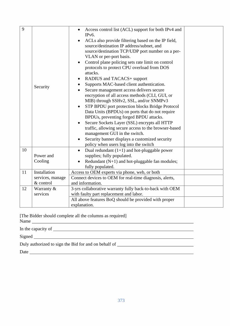
373
9
Security
• Access control list (ACL) support for both IPv4 and
IPv6.
• ACLs also provide filtering based on the IP field,
source/destination IP address/subnet, and
source/destination TCP/UDP port number on a per-
VLAN or per-port basis.
• Control plane policing sets rate limit on control
protocols to protect CPU overload from DOS
attacks.
• RADIUS and TACACS+ support
• Supports MAC-based client authentication.
• Secure management access delivers secure
encryption of all access methods (CLI, GUI, or
MIB) through SSHv2, SSL, and/or SNMPv3
• STP BPDU port protection blocks Bridge Protocol
Data Units (BPDUs) on ports that do not require
BPDUs, preventing forged BPDU attacks.
• Secure Sockets Layer (SSL) encrypts all HTTP
traffic, allowing secure access to the browser-based
management GUI in the switch.
• Security banner displays a customized security
policy when users log into the switch
10
Power and
Cooling
• Dual redundant (1+1) and hot-pluggable power
supplies; fully populated.
• Redundant (N+1) and hot-pluggable fan modules;
fully populated.
11 Installation
services, manage
& control
Access to OEM experts via phone, web, or both
Connect devices to OEM for real-time diagnosis, alerts,
and information.
12 Warranty &
services
3-yrs collaborative warranty fully back-to-back with OEM
with faulty part replacement and labor.
All above features BoQ should be provided with proper
explanation.
[The Bidder should complete all the columns as required]
Name
In the capacity of
Signed
Duly authorized to sign the Bid for and on behalf of
Date

374
Core Router (To be filled up and signed by the Bidder & Manufacturer, otherwise the offer will not be acceptable)
SL Item Name Detail Required Specification Bidder response
1 Quality
ISO 9001/9002 for manufacturer, FCC Class A/B for
quality assurance
2 Brand
Internationally reputed top ten (10) brand of Gartner Magic
Quadrant Report in 2020
3 Model To be mentioned by the bidder
4
Country of
Origin USA/UK/EU/Switzerland/Australia/Japan
5 Environmental
Maintain International Quality Environmental Safety
Standard
6 Enclosure Type Rack-mountable modular Chassis
7
Part No
Bidder should submit BOQ of proposed device including
the details part numbers. Bidder should submit the
required feature & performance compliance document for
the proposed solution.
8
General Features
The Router shall have the following General Features:
Should be a modular router with minimum 2-line card
slots and minimum 2 slots for Routing Engines and
Switch Fabric Modules
Should have a redundant Routing Engine, Redundant
Switch Fabric and Redundant Power Supplies.
Should have routing engine with 2 GHz and 6 Core
processor, minimum of 64 GB memory and 50GB SSDs
storage.
Port Capacity: 20 x 1G SFP (10 x1G RJ45, 10 x 1G SX),
4 x 10GE SFP (4 x 10G SR) and 4 x 40G (4 x 40G SR4).
All transceivers should be manufactured by same router
OEM
Routers should support modular LAN and WAN
connectivity options including 1G Fiber/ Copper, E1,
DS3, OC3, OC12, OC48, 10G, 40G, 100G, 10G DWDM,
100G DWDM and 100G Digital Coherent Optical
interfaces. Router should be ready for 400G interfaces
Router should support a total system throughput of
minimum 3 Tbps and per slot capacity of minimum 1.5
Tbps
Should have scalability up to 2,000,000 IPv4 and
2,000,000 IPv6 routes
Router should support Inline Data Plane Security with
support for line cards that have AES-256 MACsec line-
side encryption and native IPsec tunnel support
Shall support online insertion and removal (OIR) that is
non-disruptive in nature. Online insertion and removal of
one line card shall not lead to ANY packet loss for traffic

375
flowing through other line cards for both unicast and
multicast traffic In case of a line card failure on the router; the multicast
routing, multicast distribution and multicast replication
architecture of the router shall ensure no impact & zero
packet loss of multicast video, audio & data traffic
running on rest of the line cards in the system
In case the primary route processor fails on the router,
there should be ZERO packet loss on the whole router for
both unicast and multicast traffic
Internal Core Firewall and Core Router should be from
same OEM
9
Performance:
Aggregate Throughput – Minimum 3 Tbps
Per slot bandwdith scalable up to 1.5 Tbps
Logical Interfaces: 32000
VLANs - 64,000
IPv4 and IPv6 Routing Table: 9 Million
BGP routes with route resolution to be supported: 12
Million
eBGP/iBGP with no prefixes - 4,000
MPLS LDP/RSVP-TE LSPs: 32,000
VPLS Instances - 8,000
Minimum NAT64 Throughput [1518B]: 18 Gbps
Minimum Statefull firewall throughput [1518B] : 20 Gbps
Minimum IPSec VPN throuhput [1518B]: 15Gbps
Minimum IPSec VPN tunnel of 6,000 with 30 million
flow
Multicast Routes - 200,000
Routing protocol
support
Routers should support IPv4 Routing features - RIP
v1/v2, OSPF, BGP, BGP Route Reflector, IS-IS
Routers should support IPv6 Routing features - RIPng,
OSPFv3, IPv6 MLD, IS-IS and BGP
Shall support MPLS Provider/Provider Edge
functionality. MPLS VPN, MPLS mVPN (Multicast
VPN), Carrier Supporting Carrier (CSC), DiffServ Tunnel
Modes, MPLS TE (Fast re-route), DiffServ-Aware TE,
Inter-AS VPN, Resource Reservation Protocol (RSVP),
VPLS, VPWS, Ethernet over MPLS, EVPN, CESoPSN
and SAToP as per RFC 4553
The router should support Policy Based Routing, Source
Based Routing and Reverse Path Forwarding
Should support SDN Gateway features allowing
interconnecting physical networks and virtual networks
operating with different technologies via support for
Multiprotocol BGP (MBGP), dynamic tunnels using
MPLSoGRE or Virtual Extensible LAN (VXLAN)
encapsulation, virtual routing and forwarding (VRF)
tables, E-VPNs, and Network Configuration Protocol
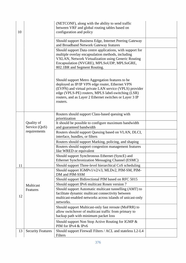
376
10
(NETCONF), along with the ability to send traffic
between VRF and global routing tables based on
configuration and policy
Should support Business Edge, Internet Peering Gateway
and Broadband Network Gateway features
Should support Data centre applications, with support for
multiple overlay encapsulation methods, including
VXLAN, Network Virtualization using Generic Routing
Encapsulation (NVGRE), MPLSoUDP, MPLSoGRE,
802.1BR and Segment Routing.
Should support Metro Aggregation features to be
deployed as IP/IP VPN edge router, Ethernet VPN
(EVPN) and virtual private LAN service (VPLS) provider
edge (VPLS-PE) routers, MPLS label-switching (LSR)
routers, and as Layer 2 Ethernet switches or Layer 3 IP
routers.
11
Quality of
Service (QoS)
requirements
Routers should support Class-based queuing with
prioritization
It should be possible to configure maximum bandwidth
and guaranteed bandwidth
Routers should support Queuing based on VLAN, DLCI,
interface, bundles, or filters
Routers should support Marking, policing, and shaping
Routers should support congestion management features
like WRED or equivalent
Should support Synchronous Ethernet (SyncE) and
Ethernet Synchronization Messaging Channel (ESMC)
Should support Three-level hierarchical CoS scheduling
12
Multicast
Features
Should support IGMPv1/v2/v3, MLDv2, PIM-SM, PIM-
DM and PIM-SSM
Should support Bidirectional PIM based on RFC 5015
Should support IPv6 multicast Rosen version 7
Should support Automatic multicast tunnelling (AMT) to
facilitate dynamic multicast connectivity between
multicast-enabled networks across islands of unicast-only
networks.
Should support Multicast-only fast reroute (MoFRR) to
allow switchover of multicast traffic from primary to
backup path with minimum packet loss
Should support Non Stop Active Routing for IGMP &
PIM for IPv4 & IPv6
13
Security Features
Should support Firewall Filters / ACL and stateless L2-L4
Filters

377
Should support DDoS attack protection for control plane
and FlowSpec for DDoS protection of data plane
Should support inline services on the line card for flow
monitoring, port mirroring, generic routing encapsulation
(GRE), IP tunnelling, logical tunnels, lawful intercept,
and video monitoring
Should have dedicated processing card for compute-
intensive services such as NAT, IPsec VPN, stateful
firewall, deep packet inspection, flow monitoring, and
load balancing.
14
Management and
Troubleshooting
Router should have Console, Telnet and Web for
management of device
Should support an automation ecosystem that includes
support for OpenConfig/YANG, gRPC, Thrift,
NETCONF, JSON/XML, API support for all modern
programming languages, Rich on-box scripting support
using Python and REST APIs
Device should support extensive debug of protocols and
provide native XML capabilities in the OS including
config scripts, operational scripts event policies, event
scripts, and macros that help automate operational and
configuration tasks.
Device should support Synchronous Ethernet for
frequency, and the Precision Time Protocol (PTP) for
frequency and phase synchronization. Should support
hybrid mode of SyncE and PTP to achieve the highest
level of frequency (10 ppb) and phase (<1.5 uS) accuracy
The Router should support CLI with a hierarchical
structure
Router should support streaming telemetry that can
identify current and trending congestion, resource
utilization, traffic volume, and buffer occupancy
15
Certifications
GR-1089-Core EMC and Electrical Safety
Common Bonding Network (CBN)
National Electrical Code (NEC)
GR-63-Core Physical Protection
FIPS 140- Level 2 Cryptographic Certification

378
[The Bidder should complete all the columns as required]
Name
In the capacity of
Signed
Duly authorized to sign the Bid for and on behalf of
Date
Common Criteria Certificate (CCC) for IT Security
Evaluation (Version 3.1)
16
Manufacturer
part number
Bidder should submit BOQ of proposed device including
the details part numbers and Manufacturer Warranty.
Bidder should submit the required performance document
for the proposed device.
17
Warranty
Mentioning manufacturer warranty part number should be
quoted, minimum 3 (Three) years warranty should be
provided for this unit from the date of successful
commissioning

379
Core Switch (To be filled up and signed by the Bidder & Manufacturer, otherwise the offer will not be acceptable)
SL Item Name Detail Required Specification Bidder response
1 Brand To be mentioned by the bidder. Must be in the leaders
quadrant of Gartner Magic Quadrant of Wired and
Wireless Network.
2 Model To be mentioned by the bidder
3 Country of
Origin
USA/UK/EU/Switzerland/Australia/Japan
4
Architecture
Should be provided with-
• Min. 32x 40/100G QSFP+/QSFP28 Ports
• 1x USB-C Console Port
• 1x USB Type-A Host port
• Shall be provided with rack mounting kit.
5
Memory and
processor
• Memory: min. 16GB
• Internal drive: min. 64GB SSD
• Packet buffer size: min. 32MB
• Flash: min. 8GB
6 Performance
• Throughput: > 2000 Mbps
• Switching capacity: >6 Tbps
7
Layer 2 and
Layer 3
switching and
service
The following Layer 2 services shall be supported-
• VLAN support and tagging support for IEEE
802.1Q (4094 VLAN IDs) and 512 VLANs
simultaneously.
• STP supports standard IEEE 802.1D STP, IEEE
802.1w Rapid Spanning Tree Protocol (RSTP)
for faster convergence, and IEEE 802.1s
Multiple Spanning Tree Protocol (MSTP)
• Internet Group Management Protocol (IGMP)
controls and manages the flooding of multicast
packets in a Layer 2 network
The following Layer 3 services and routing shall be
supported-
• Address Resolution Protocol (ARP) determines
the MAC address of another IP host in the same
subnet; supports static ARPs
• Dual IP stack maintains separate stacks for IPv4
and IPv6 to ease the transition from an IPv4-
only network to an IPv6-only network design
• Supports internal loopback testing for
maintenance purposes and increased availability

380
SL Item Name Detail Required Specification Bidder response
7
Management
• Built-in programmable and easy-to-use REST
API interface
• Central for unified network operations of wired,
WLAN, SD-WAN, and public cloud
infrastructure.
• sFlow (RFC 3176) is ASIC-based wire speed
network monitoring and accounting with no
impact on network performance; network
operators can gather a variety of network
statistics and information for capacity planning
and real-time network monitoring purposes.
• SNMPv1/v2c/v3 support provides read
capability of industry standard Management
Information Base (MIB) and private extensions.
• Remote monitoring (RMON) with standard
SNMP monitors essential network functions.
Supports events, alarms, history, and statistics
groups as well as a private alarm extension
group.
• TFTP and SFTP support
• Debug and sampler utility supports ping and
traceroute for IPv4 and IPv6
• Network Time Protocol (NTP) synchronizes
timekeeping among distributed time servers and
clients.
• IEEE 802.1AB Link Layer Discovery Protocol
(LLDP) advertises and receives management
information from adjacent devices on a network.
• Dual flash images provide independent primary
and secondary operating system files for backup
while upgrading.
• Unidirectional link detection (UDLD) monitors
the link between two switches and blocks the
ports on both ends of the link if the link goes
down at any point between the two devices.
8
Quality of
Service (QoS)
• Strict priority (SP) queuing
• Traffic prioritization (IEEE 802.1p) for real-time
classification
• Class of Service (CoS) sets the IEEE 802.1p
priority tag based on IP address, IP Type of
Service (ToS), Layer 3 protocol, TCP/UDP port
number, source port, and DiffServ.
• Rate limiting sets per-port ingress enforced
maximums and per-port, per-queue minimums.
• Large buffers for graceful congestion
management.

381
SL Item Name Detail Required Specification Bidder response
9
Security
• Access control list (ACL) support for both IPv4
and IPv6.
• ACLs also provide filtering based on the IP
field, source/destination IP address/subnet, and
source/destination TCP/UDP port number on a
per-VLAN or per-port basis.
• Control plane policing sets rate limit on control
protocols to protect CPU overload from DOS
attacks.
• RADIUS and TACACS+ support
• Supports MAC-based client authentication.
• Secure management access delivers secure
encryption of all access methods (CLI, GUI, or
MIB) through SSHv2, SSL, and/or SNMPv3
• STP BPDU port protection blocks Bridge
Protocol Data Units (BPDUs) on ports that do
not require BPDUs, preventing forged BPDU
attacks.
• Secure Sockets Layer (SSL) encrypts all HTTP
traffic, allowing secure access to the browser-
based management GUI in the switch.
• Security banner displays a customized security
policy when users log into the switch
10
Power and
Cooling
• Dual redundant (1+1) and hot-pluggable power
supplies; fully populated.
• Redundant (N+1) and hot-pluggable fan
modules; fully populated.
11 Installation
services,
manage &
control
Access to OEM experts via phone, web, or both
Connect devices to OEM for real-time diagnosis, alerts,
and information.
12 Warranty &
services
3-yrs collaborative warranty fully back-to-back with
OEM with faulty part replacement and labor.
All above features BoQ should be provided with proper
explanation.
[The Bidder should complete all the columns as required]
Name
In the capacity of
Signed
Duly authorized to sign the Bid for and on behalf of
Date

382
Core Firewall (To be filled up and signed by the Bidder & Manufacturer, otherwise the offer will not be acceptable)
SL Item Name Detail Required Specification Bidder response
1 Brand To be mentioned by the bidder
2 Model To be mentioned by the bidder
3 Country of
Origin USA/UK/EU/Switzerland/Australia/Japan
4 Country of
Manufacturer To be mentioned by the bidder
5 Environmental Maintain International Quality Environmental Safety
standard
6
Platform
Requirement
The proposed Next Generation Firewall should be
enterprise grade capacity for securing multisite network
connectivity and provide server network protection
against malware, exploits, and malicious websites in both
encrypted and non-encrypted traffic.
7 MTBF Hardware lifetime – MTBF (Mean Time Between Failure)
should be 10 years or higher
8 Form factor Please mention RU with 19-inch rack mounting kits
included
9
3rd Party
Certifications
& Validation
The vendor must attain ISO 9001:1900 certification that
covers the scope of the Quality Management System
which includes the design, development, and
manufacturing of network security products and the
delivery of associated security services and support
The device should be from a family of products that
attains ICSA Labs Certifications for Antivirus, Corporate
Firewall, IPsec, NIPS, SSL-TLS, ATD, ATD-Mail.
The system must attain Phase-2 IPv6 Ready Logo
Certification and successfully fulfilled all requirements for
IPv6 Phase-2 Core Support as a router product.
The system must inherit the following Compliance
Certification:
FCC Part 15B, Class A, CE, RCM, VCCI, UL/cUL, CB,
BSM
The proposed solution must be recognized as a Leader in
2020 Gartner Magic Quadrant for Enterprise Firewalls.
The proposed solution must be from a family of products
that achieves "Recommended" rating from NSS Labs for
NGFW testing
10
Hardware and
System
Requirements
The firewall should have dedicated security/content
processor to offload resource- intensive processing and
drive content inspection to accelerate security functions.
The device should have minimum 4 x 100 GE QSFP28 /
40 GE QSFP+, 16 x 10G SFP+ ports, 1 x Console
interface and 1 x USB interface from day 1.
The device should have minimum 1 x 1GE RJ45 OOB
(Out-of-Band) Management Interface

383
Bidder should quote 8 x 10G SFP+ transceivers and 4x
40G QSFP+ transceivers with each hardware (multimode)
The firewall must support dual hot-swappable power
supplies from day one
The firewall should have 10 Context/Virtual
Domains/Virtual systems from day One and scalable up to
500
The firewall physical interfaces should be configured as
VLAN trunks which support up to 4,000 VLANs ID
Firewall should support creating access-rules with IPv4 &
IPv6 objects
Firewall should support operating in routed & transparent
mode.
Firewall should support Active-Active & Active-Passive
& Clustering high availability from day one
Firewall should support Static, RIP, OSPF, IS-IS and BGP
routing protocol.
Firewall should support static nat, dynamic nat, dynamic
pat
The system should support have the capability to limit
bandwidth on basis of User, IP, Apps, and Networks.
11
Firewall
Performance
The system must support at least 120 Gbps of firewall
throughput from day one.
The system must support at least 20 Gbps of IPS/IDP
throughput from day one.
The system must support at least 18 Gbps of NGFW (FW
+ Application Control + IPS) throughput from day 1
The system must support at least 16 Gbps of Threat
Protection (Firewall, IPS, Application Control, URL
filtering, and Malware Protection) throughput from day
one.
The system must support at least 15 Gbps of SSL
Inspection (DPI) throughput from day one.
The system must support at least 22 Million concurrent
sessions from day one.
The system must support at least 900,000 new sessions
per second
The system shall accommodate at least 10,000 firewall
policies
The system must support at least 30 Gbps Layer-7
Application Control Throughput from day one.
12
SSL Inspection
Features
The system must support DPI (Deep packet Inspection)
for all types of traffic.
The system shall provide Secure sockets layer (SSL)
content scanning and inspection abilities that allow
organizations to apply antivirus scanning, application
control, web filtering, and email filtering to encrypted
traffic

384
The system shall support certificate inspection on port
443, all ports or a specific non-standard port.
The system shall provide the ability to exempt web sites
from SSL inspection by site reputation, address, category,
or using a white list.
13
Traffic Shaping
and QoS
The system shall support various QoS (quality of service)
techniques, including:
- Traffic policing - drops packets that do not conform to
the configured bandwidth limitations.
- Traffic shaping - ensures that traffic consumes
bandwidth at least at the guaranteed rate by assigning a
greater priority queue to the traffic if the guaranteed rate is
not being met.
- Queuing - transmits packets in the order of their assigned
priority queue for that physical interface. All traffic in a
higher priority traffic queue must be completely
transmitted before traffic in lower priority queues is
transmitted
The proposed system must support the ability to
implement interface-based traffic shaping with profiles
that define up to 19 traffic groups by percentage of the
interface bandwidth limit. These traffic groups are
classified and organized based on matching criteria. These
criteria shall include:
- Source address
- Destination address
- Schedule
- Service
- Application
- URL Category.
The proposed system must support the ability to
implement policy-based traffic shaping where different
kind of traffic shaper (configuration setup that indicates
the priority and guaranteed and maximum bandwidth) can
be applied, including:
- Shared traffic shaper - bandwidth management by per
policy
- Per-IP shaper - bandwidth management by per IP
address
- Reverse shaper - applied in the opposite direction
(inbound)
The proposed system must support weighted random early
detection (WRED) queuing function
The proposed system must support DSCP matching, as
well as DSCP marking for traffic shaping
14
ATP (Advance
Threat
The system shall allow organizations to implement both
flow-based and proxy-based anti-malware concurrently,
depending on the network and security needs

385
Protection)
Features
The system shall provide ability to allow/monitor, block
and quarantine attachments or downloads after malware
detection
The system shall be capable of updating AV signatures
without restarting the systems using the following options:
- Manual database upload (without system internet access)
- Periodically scheduled pull update
- Automatic push update
The system shall also be able to block graywares and
mobile malwares
The system shall offer the ability to treat Windows
Executable files in Email Attachments as viruses
The antivirus scanning should be supported on various
protocols:
- HTTP/HTTPS
- SMTP/SMTPS
- POP3/POP3S
- IMAP/IMAPS
- MAPI
- FTP/SFTP
- CIFS
The system shall be able to scan archive files for
malwares
The system shall support Content Disarm and
Reconstruction (CDR) where exploitable content (within
PDF and Microsoft Office files) can be removed and
replaced with content that is known to be safe
The system shall be capable of blocking Botnet server
communications with IPS signatures and IP reputation
database
The system shall maintain a fingerprint-based certificate
blacklist is that useful to block botnet communication that
relies on SSL
The system shall be able to quarantine file and ban
infected host
15
Web Filtering
Features
The system shall allow organizations to implement flow-
based, proxy-based and DNS-based web filtering
concurrently, depending on the network and security
needs
The system shall support static web filtering by:
- Manually-defined URLs using regular expression and
wildcards
- Manually-defined content filter using regular expression
and wildcards
The system shall support dynamic web filtering by
querying real-time cloud-based categorization database
over 250 million URLs rated into 78 categories and in 70
languages

386
Web filtering engine should support Allow, Block,
Monitor (logged), Warning (with message at configurable
time interval), (request for) user authentication actions
when matched to a category
Web filtering engine should support customizable
replacement page for warning and blocking
The system shall provide ability to use local categories
(that override the cloud-based database rating) and remote
categories (external URL list) as part of the URL rating
function.
The system shall have the ability to prevent explicit
websites and images from appearing in Google, Yahoo!,
Bing and Yandex search results by transparently inserting
safe search parameters
The system shall allow implementation of usage quota by
category and category group:
- Allow access for a specified length of time or a specific
bandwidth
- Calculated separately for each user
- Reset on daily basis
The system shall have the option to allow override
blocked categories:
- By administrative override where administrators can
grant temporary access to sites that are otherwise blocked
- By allowing specified users/user groups/IP addresses
The system shall able to Filter Java Applet, ActiveX,
and/or cookie
The system shall able to exempt scanning encrypted
connections on certain categories for the organization
requirements.
The system shall have the ability to limit users' access to
YouTube channels, such as in an education environment
where users are only able to access YouTube education
videos but not other YouTube videos.
16
DNS Filtering
Features
The system shall support DNS category filtering to control
user access to web resources
The system shall be able to categories filters of the DNS
request based on the domain rating send by OEM threat
intelligence center.
The system shall be able to blocks the DNS request for the
known botnet C&C domains
The system shall be able to enforces Google, Bing, and
YouTube safe addresses for parental controls
The system shall be able to allows administrator to define
Static Domain Filtering list to block or allow
The system shall be able to allows administrator to define
an IP block list to block resolved IPs that match this list
The system shall be able to allows administrator to
override DNS translation which can maps the resolved
result to another IP

387
17
IPS Features The system's IPS engine shall offer:
- Signature based detection using real time updated
database
- Anomaly based detection that is based on thresholds
The system's IPS database shall have over 11,000 up-to-
date signatures
The system shall be capable of updating IPS signatures
without restarting the systems using the following options:
- Manual database upload (without system internet access)
- Periodically scheduled pull update
- Automatic push update
The system shall provide configurable IPS filters to
selectively implement signatures based on severity, target
(client/server), protocol, OS and Application types.
The system shall offer one of the following actions when
an attack is detected:
- Allow session
- Monitor and log session
- Block session
- Reset session
- Quarantine attacker
The system shall have the ability to save the network
packets containing the traffic matching an IPS signature to
the attack log
The IPS system shall able to scan botnet-connections to
block Botnet C&C communication
In event if IPS should cease to function, the system shall
fail open by default (configurable). This means that
crucial network traffic will not be blocked and the
Firewall will continue to operate while the problem is
resolved.
18
Application
Control
The system shall able to detect and take action against
network traffic depending on the application generating
the traffic.
The system shall able to analyses network traffic to detect
application traffic even if the traffic uses non-standard
ports or protocols
The system shall support detection for traffic using
HTTP/2 protocol and able to block QUIC traffic so that
browser automatically falls back to HTTP/2 + TLS 1.2
The system shall support dynamic application filtering by
querying real-time cloud-based categorization database
over 2500+ application rated by 18 categories.
Application Control filtering engine should support
Allow, block, reset session, monitor only and attacker
quarantine actions when matched to a category
The system shall support custom application signature
The system shall able to override application filtered by
behavior, category, popularity, technology, risk, vendor,
and/or protocol
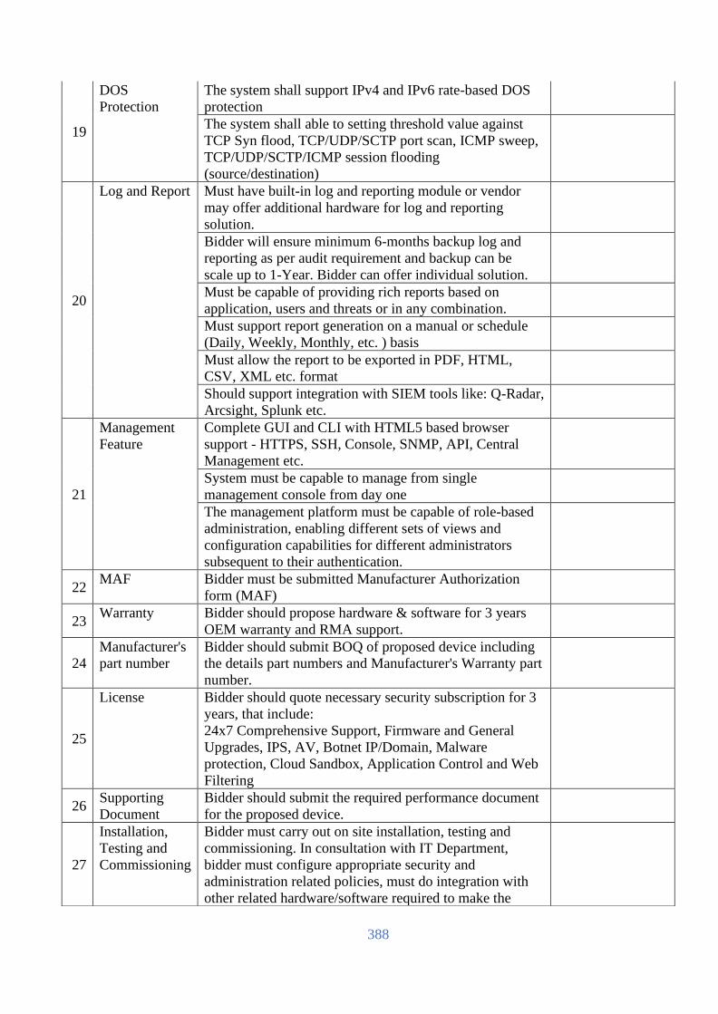
388
19
DOS
Protection
The system shall support IPv4 and IPv6 rate-based DOS
protection
The system shall able to setting threshold value against
TCP Syn flood, TCP/UDP/SCTP port scan, ICMP sweep,
TCP/UDP/SCTP/ICMP session flooding
(source/destination)
20
Log and Report Must have built-in log and reporting module or vendor
may offer additional hardware for log and reporting
solution.
Bidder will ensure minimum 6-months backup log and
reporting as per audit requirement and backup can be
scale up to 1-Year. Bidder can offer individual solution.
Must be capable of providing rich reports based on
application, users and threats or in any combination.
Must support report generation on a manual or schedule
(Daily, Weekly, Monthly, etc. ) basis
Must allow the report to be exported in PDF, HTML,
CSV, XML etc. format
Should support integration with SIEM tools like: Q-Radar,
Arcsight, Splunk etc.
21
Management
Feature
Complete GUI and CLI with HTML5 based browser
support - HTTPS, SSH, Console, SNMP, API, Central
Management etc.
System must be capable to manage from single
management console from day one
The management platform must be capable of role-based
administration, enabling different sets of views and
configuration capabilities for different administrators
subsequent to their authentication.
22 MAF Bidder must be submitted Manufacturer Authorization
form (MAF)
23 Warranty Bidder should propose hardware & software for 3 years
OEM warranty and RMA support.
24
Manufacturer's
part number
Bidder should submit BOQ of proposed device including
the details part numbers and Manufacturer's Warranty part
number.
25
License Bidder should quote necessary security subscription for 3
years, that include:
24x7 Comprehensive Support, Firmware and General
Upgrades, IPS, AV, Botnet IP/Domain, Malware
protection, Cloud Sandbox, Application Control and Web
Filtering
26 Supporting
Document
Bidder should submit the required performance document
for the proposed device.
27
Installation,
Testing and
Commissioning
Bidder must carry out on site installation, testing and
commissioning. In consultation with IT Department,
bidder must configure appropriate security and
administration related policies, must do integration with
other related hardware/software required to make the

389
[The Bidder should complete all the columns as required]
Name
In the capacity of
Signed
Duly authorized to sign the Bid for and on behalf of
Date
Network Functional and shall provide respective
documentation to IT Division.
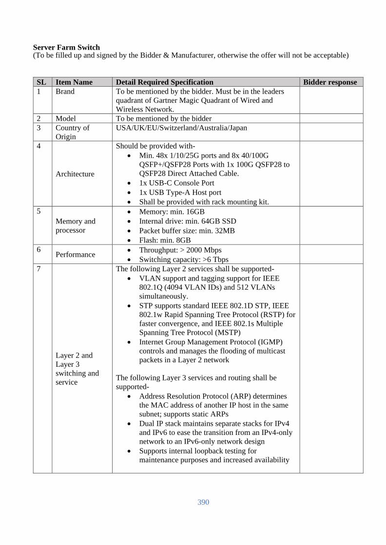
390
Server Farm Switch (To be filled up and signed by the Bidder & Manufacturer, otherwise the offer will not be acceptable)
SL Item Name Detail Required Specification Bidder response
1 Brand To be mentioned by the bidder. Must be in the leaders
quadrant of Gartner Magic Quadrant of Wired and
Wireless Network.
2 Model To be mentioned by the bidder
3 Country of
Origin
USA/UK/EU/Switzerland/Australia/Japan
4
Architecture
Should be provided with-
• Min. 48x 1/10/25G ports and 8x 40/100G
QSFP+/QSFP28 Ports with 1x 100G QSFP28 to
QSFP28 Direct Attached Cable.
• 1x USB-C Console Port
• 1x USB Type-A Host port
• Shall be provided with rack mounting kit.
5
Memory and
processor
• Memory: min. 16GB
• Internal drive: min. 64GB SSD
• Packet buffer size: min. 32MB
• Flash: min. 8GB
6 Performance
• Throughput: > 2000 Mbps
• Switching capacity: >6 Tbps
7
Layer 2 and
Layer 3
switching and
service
The following Layer 2 services shall be supported-
• VLAN support and tagging support for IEEE
802.1Q (4094 VLAN IDs) and 512 VLANs
simultaneously.
• STP supports standard IEEE 802.1D STP, IEEE
802.1w Rapid Spanning Tree Protocol (RSTP) for
faster convergence, and IEEE 802.1s Multiple
Spanning Tree Protocol (MSTP)
• Internet Group Management Protocol (IGMP)
controls and manages the flooding of multicast
packets in a Layer 2 network
The following Layer 3 services and routing shall be
supported-
• Address Resolution Protocol (ARP) determines
the MAC address of another IP host in the same
subnet; supports static ARPs
• Dual IP stack maintains separate stacks for IPv4
and IPv6 to ease the transition from an IPv4-only
network to an IPv6-only network design
• Supports internal loopback testing for
maintenance purposes and increased availability

391
SL Item Name Detail Required Specification Bidder response
7
Management
• Built-in programmable and easy-to-use REST
API interface
• Central for unified network operations of wired,
WLAN, SD-WAN, and public cloud
infrastructure.
• sFlow (RFC 3176) is ASIC-based wire speed
network monitoring and accounting with no
impact on network performance; network
operators can gather a variety of network statistics
and information for capacity planning and real-
time network monitoring purposes.
• SNMPv1/v2c/v3 support provides read capability
of industry standard Management Information
Base (MIB) and private extensions.
• Remote monitoring (RMON) with standard
SNMP monitors essential network functions.
Supports events, alarms, history, and statistics
groups as well as a private alarm extension group.
• TFTP and SFTP support
• Debug and sampler utility supports ping and
traceroute for IPv4 and IPv6
• Network Time Protocol (NTP) synchronizes
timekeeping among distributed time servers and
clients.
• IEEE 802.1AB Link Layer Discovery Protocol
(LLDP) advertises and receives management
information from adjacent devices on a network.
• Dual flash images provide independent primary
and secondary operating system files for backup
while upgrading.
• Unidirectional link detection (UDLD) monitors
the link between two switches and blocks the
ports on both ends of the link if the link goes
down at any point between the two devices.
8
Quality of
Service (QoS)
• Strict priority (SP) queuing
• Traffic prioritization (IEEE 802.1p) for real-time
classification
• Class of Service (CoS) sets the IEEE 802.1p
priority tag based on IP address, IP Type of
Service (ToS), Layer 3 protocol, TCP/UDP port
number, source port, and DiffServ.
• Rate limiting sets per-port ingress enforced
maximums and per-port, per-queue minimums.
• Large buffers for graceful congestion
management.

392
SL Item Name Detail Required Specification Bidder response
9
Security
• Access control list (ACL) support for both IPv4
and IPv6.
• ACLs also provide filtering based on the IP field,
source/destination IP address/subnet, and
source/destination TCP/UDP port number on a
per-VLAN or per-port basis.
• Control plane policing sets rate limit on control
protocols to protect CPU overload from DOS
attacks.
• RADIUS and TACACS+ support
• Supports MAC-based client authentication.
• Secure management access delivers secure
encryption of all access methods (CLI, GUI, or
MIB) through SSHv2, SSL, and/or SNMPv3
• STP BPDU port protection blocks Bridge
Protocol Data Units (BPDUs) on ports that do not
require BPDUs, preventing forged BPDU attacks.
• Secure Sockets Layer (SSL) encrypts all HTTP
traffic, allowing secure access to the browser-
based management GUI in the switch.
• Security banner displays a customized security
policy when users log into the switch
10
Power and
Cooling
• Dual redundant (1+1) and hot-pluggable power
supplies; fully populated.
• Redundant (N+1) and hot-pluggable fan modules;
fully populated.
11 Installation
services, manage
& control
Access to OEM experts via phone, web, or both
Connect devices to OEM for real-time diagnosis, alerts,
and information.
12 Warranty &
services
3-yrs collaborative warranty fully back-to-back with
OEM with faulty part replacement and labor.
All above features BoQ should be provided with proper
explanation.
[The Bidder should complete all the columns as required]
Name
In the capacity of
Signed
Duly authorized to sign the Bid for and on behalf of
Date

393
Internet Router (To be filled up and signed by the Bidder & Manufacturer, otherwise the offer will not be acceptable)
SL Item Name Detail Required Specification Bidder
response
1 Quality /
Certification
ISO, FCC, UL, CE or to be mentioned by the bidder
2 Brand Should be "Leader" in Gartner's Magic Quadrant for both
wired and wireless access LAN infrastructure and
Datacenter and cloud networking in year 2020
3 Model To be mentioned by the bidder
4 Country of Origin USA/UK/EU/Switzerland/Australia/Japan
5 Country of
Assemble /
Manufacture
To be mentioned by the bidder
6 Hardware
Architecture
The appliance should have fixed chassis architecture
Must have redundant power supply
Should have 4X10G SFP+, 4X1G SFP and 10X1G Base-T
port from Day 1
Bidder should provide 4 x 10GE SR and 4 x 1G SFP SX
transceivers.
All transceivers should be manufactured by same OEM
Should have 16GB DRAM, 16GB primary storage
(Flash/mSATA) and 100 GB secondary storage from Day-
1
7 Networking &
System
Performance
Aggregated throughput 8 Gbps
Minimum Packet forwarding capacity of minimum 1.7
Mpps or more for 64 byte packet
Maximum concurrent sessions (IPv4 and IPv6): 2,000,000
Minimum connection per second: 50,000
Routing Table in RIB (IPv4): Minimum 2 Million or more
Routing Table size in FIB (IPv4): Minimum 1 Million or
more
Minimum IPSec VPN Tunnels : 2000 or more
Minimum IPSec VPN throughput (IMIX Packet): 1.3
Gbps
Minimum size of ARP table: 4000 or more
Minimum MAC address table size: 64,000
Should support 8,000 NAT rules
SD-WAN Hub throughput with MPLSoGREoIPSec +
AppQoE [100% CRYPTO with AES-256-GCM and
HTTP 44KB] is 700 Mbps
Maximum No. of spokes per hub: 280
Minimum affordable latency: 9 us
8 Routing Features Must support static routing and dynamic routing protocol
like RIP v1/v2, OSPF/OSPF v3, BGP with Route
Reflector, IS-IS in both IPv4 and IPv6

394
VLAN and Point-to-point protocol over Ethernet (PPPoE)
encapsulation should be supported
Should support source-based and policy-based routing
Should support Equal-cost multipath (ECMP) feature from
Day-1
Should support MPLS with features like RSVP for traffic
engineering and LDP for less provisioning
Should support 500 virtual routes in a single system
9 VPN Features Generic routing encapsulation (GRE), IP-IP, Ipsec tunnels
must be supported from Day-1
Must have Site-site IPsec VPN with multi-proxy ID and
auto VPN, group VPN features for simplifying large VPN
deployment
Must support IPsec crypto algorithms Data Encryption
Standard (DES), triple DES (3DES), Advanced
Encryption Standard (AES-
256), AES-GCM with dedicated crypto engine
Should support IKEv 1&2, NAT-T, IPsec authentication
algorithms: MD5, SHA-1, SHA-128, SHA-256
Must support Pre-shared key and public key infrastructure
(PKI) (X.509),
Features like Perfect forward secrecy, anti-reply, dead
peer detection (DPD) support, VPN monitoring, quality-
of-service (QoS) aware must be enabled from Day-1
10 NAT Should support Source NAT with Port Address
Translation (PAT), Bidirectional 1:1 static NAT,
Destination NAT with PAT, Persistent NAT, IPv6 address
translation
11 Multicasting
Features
Support Multicast: Internet Group Management Protocol
(IGMP)
v1/v2; Protocol Independent Multicast (PIM) sparse mode
(SM)/dense mode (DM)/source-specific multicast (SSM);
Session Description Protocol (SDP); Distance Vector
Multicast Routing Protocol (DVMRP); Multicast Source
Discovery Protocol (MSDP); Reverse Path Forwarding
(RPF)
12 QoS Classification criteria should support for VLAN, datalink
connection identifier (DLCI), interface
Support 802.1p, DiffServ code point (DSCP) remarking
Should support hierarchical shaping and policing
Congestion avoidance capabilities weighted random early
detection (WRED)or equivalent
13 High Availability Router should support HA features, such as VRRP, BFD
Supports active/active and active/backup deployment
scenarios
Provide highly available hardware with dual PSU from
Day 1
Should ensure uninterrupted of service by supporting In-
Service Software Upgrade (ISSU)

395
14 Security Should have stateful firewall feature from Day 1 and
support unified thread module (UTM) and next generation
firewall feature with license upgrade.
Highly scalable filtering, unicast RPF, and rate limiting
protects against IP spoofing and DOS attacks
High-performance IPsec for an additional layer of security
Ubiquitous security features such as port mirroring,
encrypted management session traffic, secure tunneling
capabilities, secure remote logins, and configurable
privilege levels and user accounts.
Should support secure and flexible remote access SSL
VPN with end device client
Performance based routing or Real Time Performance
Monitoring or NQA or equivalent to ensure critical traffic
is taking best path"
Latest encryption methodology to support current and
future functionalities and Operations
15 Management,
Logging and
Reporting
Support accessible through variety of methods, including
console port, Telnet, and SSH
Support for Built-in Management Software for simple,
secure remote management, reporting through integrated
Web-based GUI.
Router should support Administrative AAA access
(RADIUS/TACACS+) with granular access control for
admins i.e. read-only, full-access etc.
Support for both SNMPv2 and SNMPv2c
The SD-WAN solution should be scalable up to 10,000
spoke site verified by independent scalability and
functionality test of EANTC
Should support XSLT commit scripts, python language for
commit, event, operation and SNMP scripts
16 Industry
Certifications and
Recognition
• FIPS 140-2 Level 2
• NDPP
• RoHS 2
• USGv6
The proposed device model/series should have 100%
evasion block rate and 99% Exploit block rate in NSS
LABS FOR DATA CENTER SECURITY IN 2019
Proposed solution should be certified by ICSA Labs for
Advanced Thread Defense (ATD) for 97% or more
effective overall during the Q1 2020 test cycle
Proposed OEM should be evaluated as "Champion" in
Canalys Global Cybersecurity Leadership Matrix 2020
Proposed OEM should be positioned as “Leader” in
Gartner’s Magic Quadrant 2020 for Wired and Wireless
LAN Access Infrastructure

396
Proposed OEM should be positioned as “Leader”/”
Challenger” in Gartner’s Magic Quadrant 2020 for
Network Firewall
17 Manufacturer’s
part number
Bidder should submit BOQ of proposed device including
the details part numbers and Manufacturer Warranty.
Bidder should submit the required performance document
for the proposed device. If the additional accessories are
essential, Bidder will provide by this additional accessory
according to the proposed model.
18 Manufacturer
authorization
Bidder must submit Manufacturer Authorization from the
OEM
19 Warranty The OEM should have local Depo in Bangladesh and
24x7x365 Global TAC support
Manufacturer’s warranty part number should be
mentioned, minimum 3 (Three) years warranty for OEM
technical solution support, Patch & New Software
Upgrade, RMA replacement should be provided for this
unit from the date of commissioning.
[The Bidder should complete all the columns as required]
Name
In the capacity of
Signed
Duly authorized to sign the Bid for and on behalf of
Date

397
Web Application Firewall (To be filled up and signed by the Bidder & Manufacturer, otherwise the offer will not be acceptable)
SL Item Name Detail Required Specification Bidder
response
1 Brand To be mentioned by the bidder
2 Model To be mentioned by the bidder
3 Country of
origin USA/UK/EU/Switzerland/Australia/Japan
4 Country of
Manufacturer To be mentioned by the bidder
5
ISO
Certification
The vendor must attain ISO 9001:1900 certification that
covers the scope of the Quality Management System which
includes the design, development, and manufacturing of
network security products and the delivery of associated
security services and support
6 ICSA LAB
Certification
The device should be from a family of products that attains
ICSA Labs Certifications for Web Application Firewall
7
Gartner
Recognition
The proposed solution must be recognized as a
Leader/Challenger in 2020 Gartner Magic Quadrant for Web
Application Firewalls.
8
NSS LAB
Testing
The proposed solution must be from a family of products that
achieves "Recommended" rating from NSS Labs for NGFW
testing with minimum 95% blocked rate of WAF attack
9
Solution
requirements
Web application firewall should be dedicated WAF
appliance and provide specialized application threat
protection.
Solution should protect against common threats such as those
identified in the OWASP top 10
10
Solution
Architecture
The solution must be VM based dedicated WAF appliance to
protects web applications from attacks that target known and
unknown vulnerabilities.
The solution should support unlimited number of application
from day one.
The virtual appliance should support minimum 4 x vCPU
The virtual appliance should support minimum 4 x 1G
Network Interface
The virtual appliance should support minimum 8 GB
memory
The virtual appliance should support minimum 1 TB Storage
11 Hypervisor
Support
VMware, Microsoft Hyper-V, Citrix XenServer, Open
Source Xen, VirtualBox, and KVM
12 WAF
Throughput The solution should have 3 Gbps dedicated WAF throughput
13 High
Availability
Solutions should support active-active and active-passive
high availability from day 1
14 Deployment
features
Should support Reverse Proxy , Inline Transparent, Offline
Sniffing and WCCP
15 Should support Layer 7 server load balancing

398
Application
Delivery
Features
Should support URL Rewriting
Should support Content Routing
Should support HTTPS/SSL Offloading
Should support HTTP Compression and Caching
Should have IPv6 Support for SLB, interfaces, routing, and
firewalling
16
WAF features The security model singnature should able to protects web
server from the below types of attack:
• Cross Site Scripting
• SQL Injection
• Generic Attacks
• Known Exploits
• Trojans
• Information Disclosure
• Bad Robot
• Credit Card Detection
Should have a Web Vulnerability Scanner feature to detect
existing vulnerabilities like SQL Injection,Cross Site
Scripting,Source code disclosure,OS Commanding in the
web applications.
Should have Data Leak Prevention module to analyze all
outbound traffic by alerting/blocking any credit card leakage
and information disclosure
Solution Should support to create own granular signatures
and DLP patterns together with predefined rules for any type
of events.
Should provide controls to meet PCI compliance
requirements for web application servers
Solution Should have the ability to prevent, detect and
restore web defacement using Anti Web Defacement feature
Solution should copy the content of the webservers to its
own hard drive and compare on a definable time schedule if
files have been changed on the webserver
Should enforce strict RFC compliance check to prevent
attacks such as encoding attacks, buffer overflows and other
application specific attacks.
Should support automatic signature updates to protect
against known and potential application security threats.
Solution Should support XML Application protection
Should have ability to define different policies for different
applications, create custom attack signatures or events and to
combine detection and prevention
Solution must provide ability to allow or deny a specific
URL access.
Solution should support normalization methods such as URL
Decoding, Null Byte string, termination, Converting back
slash to forward slash character etc..
solution should be capable of enforcing application logic by
defining a set of page access rules

399
Should be having an option to validate the inputs. There
should be customizable option to prevent tampering web
sites with hidden inputs
Should have the capability to automatically and dynamically
build a security model of protected applications by
continuously monitoring realtime user activity.
The solution should offer Layer 7 DDOS capabilities
The solution should offer an on-board Anti-Virus solution
and the database should be updated automatically.
The AV database has to come from a 3rd party tested vendor
like VB100 with high rankings (> 99 %)for effectiveness and
false-positive avoidance.
Solution should be capable of detecting and distinguishing
two sets of Bots from the Internet: Known search engines,
Bad robots (scanners, crawlers, spiders)
Solution should have the option to verify the HTTP RFC
standards
Should have prevention against compromise if users use
same username/password combination on Corporate
Application & Social Media Websites
Should have machine Learning Mathematical Models to
automatically tune WAF Appliance as per changes in
backend Applications.
Should have protection for REST APIs, filters malicious
inputs in requests with JSON payloads.
Should have protection against client side Browser
compromise vulnerabilities
Should have attachment scanning capability of
ActiveSync/MAPI applications, OWA and FTP
Should provide a deception technique to identify bots. It
inserts a hidden link into response pages. Clients that fetch
the URL can accurately be classified as bots
Should have biometrics-based detection to verify whether a
client is a bot by monitoring events such as mouse
movement, keyboard, screen touch, and scroll, etc
Should haver threshold-based detection to identify various
scan types using thresholds such occurrence, time period, etc
Should have Mobile Application Identification to verify the
request is legitimate by verifying the token a mobile
application carries when it access a web server
WAF should have capability to detect attack try to get
around CAPTCHAS by farming out the CAPTCFIA images
to pools of user that respond.
WAF appliance should have application‐aware load‐
balancing engine to distribute traffic and route content across
multiple web servers.
The solution should have configurable persistency features to
maintain sessions to the load balanced backend servers

400
The solution should support a connection draining mode in
order to allow maintenance of a protected server without
disrupting the client experience with the application
The solution should be capable of publishing web
applications and offering backend Single Sign On access
The solution should support different authentication schemes
such as Local, LDAP, NTLM and RADIUS for the web
applications
The solution Allows efficient bandwidth utilization and
response time to users by compressing data retrieved from
web servers
The solution should be able to terminate & decrypt SSL
17
Logging and
Reporting
Solution should include the separate logging physical
appliance or virtual appliance with minimum 365 days WAF
log storing capacity for analytical purpose along with custom
& on-demand reporting.
Solution should include at least 25 + predefined templates to
generate the required logs easily
Solution should include scheduling the reports, alerting the
administrators through mail, SNMP
solution should include the JSON API support for any 3rd
party integration
The solution should have a dashboard for data analytics
Should generate comprehensive event reports
18
Device
Administration
& Management
Should provide HTTP/HTTPS/SSH interface management
for administering the device
Should provide SSH interface management for administering
the device
Solution should have In-build diagnostic utilities
Should support central management for multiple WAF
devices
Should support role based admin access.
Device should suppot SNMP
Solutions should support RESTfull API management
19 MAF Bidder must be submitted Manufacturer Authorization form
(MAF)
20 Warranty Bidder should propose hardware & software for 3 (three)
years OEM warranty and RMA support.
21
Manufacturer's
part number
Bidder should submit BOQ of proposed device including the
details part numbers and Manufacturer's Warranty part
number.

401
22
License Bidder must offer necessary security license & subscriptions
that includes " WAF, AV, Web Security Service, IP
Reputation, and Credential Stuffing Defense Service " for
three years
23 Supporting
Document
Bidder must submit the required performance document and
compliance reference document for the proposed device.
24
Installation,
Testing and
Commissioning
Bidder must carry out on site installation, testing and
commissioning. In consultation with IT Department, bidder
must configure appropriate security and administration
related policies, must do integration with other related
hardware/software required to make the Network Functional
and shall provide respective documentation to IT Division.
[The Bidder should complete all the columns as required]
Name
In the capacity of
Signed
Duly authorized to sign the Bid for and on behalf of
Date

402
Distributed Switch (To be filled up and signed by the Bidder & Manufacturer, otherwise the offer will not be acceptable)
SL Item Name Detail Required Specification Bidder
response
1 Brand To be mentioned by the bidder. Must be in the leader’s
quadrant of Gartner Magic Quadrant of Wired and Wireless
Network.
2 Model To be mentioned by the bidder
3 Country of
Origin
USA/UK/EU/Switzerland/Australia/Japan
4
Architecture
Should be provided with-
• Min. 48x 1/10/25G ports and 8x 40/100G
QSFP+/QSFP28 Ports with 1x 100G QSFP28 to
QSFP28 Direct Attached Cable.
• 1x USB-C Console Port
• 1x USB Type-A Host port
• Shall be provided with rack mounting kit.
5
Memory and
processor
• Memory: min. 16GB
• Internal drive: min. 64GB SSD
• Packet buffer size: min. 32MB
• Flash: min. 8GB
6 Performance
• Throughput: > 2000 Mbps
• Switching capacity: >6 Tbps
7
Layer 2 and
Layer 3
switching and
service
The following Layer 2 services shall be supported-
• VLAN support and tagging support for IEEE
802.1Q (4094 VLAN IDs) and 512 VLANs
simultaneously.
• STP supports standard IEEE 802.1D STP, IEEE
802.1w Rapid Spanning Tree Protocol (RSTP) for
faster convergence, and IEEE 802.1s Multiple
Spanning Tree Protocol (MSTP)
• Internet Group Management Protocol (IGMP)
controls and manages the flooding of multicast
packets in a Layer 2 network
The following Layer 3 services and routing shall be
supported-
• Address Resolution Protocol (ARP) determines the
MAC address of another IP host in the same subnet;
supports static ARPs
• Dual IP stack maintains separate stacks for IPv4
and IPv6 to ease the transition from an IPv4-only
network to an IPv6-only network design
• Supports internal loopback testing for maintenance
purposes and increased availability

403
7
Management
• Built-in programmable and easy-to-use REST API
interface
• Central for unified network operations of wired,
WLAN, SD-WAN, and public cloud infrastructure.
• sFlow (RFC 3176) is ASIC-based wire speed
network monitoring and accounting with no impact
on network performance; network operators can
gather a variety of network statistics and
information for capacity planning and real-time
network monitoring purposes.
• SNMPv1/v2c/v3 support provides read capability of
industry standard Management Information Base
(MIB) and private extensions.
• Remote monitoring (RMON) with standard SNMP
monitors essential network functions. Supports
events, alarms, history, and statistics groups as well
as a private alarm extension group.
• TFTP and SFTP support
• Debug and sampler utility supports ping and
traceroute for IPv4 and IPv6
• Network Time Protocol (NTP) synchronizes
timekeeping among distributed time servers and
clients.
• IEEE 802.1AB Link Layer Discovery Protocol
(LLDP) advertises and receives management
information from adjacent devices on a network.
• Dual flash images provide independent primary and
secondary operating system files for backup while
upgrading.
• Unidirectional link detection (UDLD) monitors the
link between two switches and blocks the ports on
both ends of the link if the link goes down at any
point between the two devices.
8
Quality of
Service (QoS)
• Strict priority (SP) queuing
• Traffic prioritization (IEEE 802.1p) for real-time
classification
• Class of Service (CoS) sets the IEEE 802.1p
priority tag based on IP address, IP Type of Service
(ToS), Layer 3 protocol, TCP/UDP port number,
source port, and DiffServ.
• Rate limiting sets per-port ingress enforced
maximums and per-port, per-queue minimums.
• Large buffers for graceful congestion management.

404
9
Security
• Access control list (ACL) support for both IPv4 and
IPv6.
• ACLs also provide filtering based on the IP field,
source/destination IP address/subnet, and
source/destination TCP/UDP port number on a per-
VLAN or per-port basis.
• Control plane policing sets rate limit on control
protocols to protect CPU overload from DOS
attacks.
• RADIUS and TACACS+ support
• Supports MAC-based client authentication.
• Secure management access delivers secure
encryption of all access methods (CLI, GUI, or
MIB) through SSHv2, SSL, and/or SNMPv3
• STP BPDU port protection blocks Bridge Protocol
Data Units (BPDUs) on ports that do not require
BPDUs, preventing forged BPDU attacks.
• Secure Sockets Layer (SSL) encrypts all HTTP
traffic, allowing secure access to the browser-based
management GUI in the switch.
• Security banner displays a customized security
policy when users log into the switch
10
Power and
Cooling
• Dual redundant (1+1) and hot-pluggable power
supplies; fully populated.
• Redundant (N+1) and hot-pluggable fan modules;
fully populated.
11 Installation
services, manage
& control
Access to OEM experts via phone, web, or both
Connect devices to OEM for real-time diagnosis, alerts,
and information.
12 Warranty &
services
3-yrs collaborative warranty fully back-to-back with OEM
with faulty part replacement and labor.
All above features BoQ should be provided with proper
explanation.
[The Bidder should complete all the columns as required]
Name
In the capacity of
Signed
Duly authorized to sign the Bid for and on behalf of
Date

405
Access Switch (To be filled up and signed by the Bidder & Manufacturer, otherwise the offer will not be acceptable)
SL Item Name Detail Required Specification Bidder
response
1 Brand To be mentioned by the bidder. Must be in the leaders
quadrant of Gartner Magic Quadrant of Wired and Wireless
Network.
2 Model To be mentioned by the bidder
3 Country of
Origin
USA/UK/EU/Switzerland/Australia/Japan
4
Architecture
Should be provided with-
• 48x ports 10/100/1000BASE-T Ports
• 4x 1G/10G SFP ports
• 1x USB-C Console Port
• 1x USB Type-A Host port
• Shall be provided with rack mounting kit.
5 Memory and
processor
• Memory: min. 4GB.
• Packet buffer size: min. 12MB
• Flash: min. 16GB
6
Performance
• 10 Gbps Latency: < 1.8 µSec
• Throughput: > 98 Mbps
• Switching capacity: >175 Gbps
7
Layer 2 and
Layer 3
switching and
service
The following Layer 2 services shall be supported-
• VLAN support and tagging support for IEEE
802.1Q (4094 VLAN IDs) and 512 VLANs
simultaneously.
• STP supports standard IEEE 802.1D STP, IEEE
802.1w Rapid Spanning Tree Protocol (RSTP) for
faster convergence, and IEEE 802.1s Multiple
Spanning Tree Protocol (MSTP)
• Internet Group Management Protocol (IGMP)
controls and manages the flooding of multicast
packets in a Layer 2 network
The following Layer 3 services and routing shall be
supported-
• Address Resolution Protocol (ARP) determines the
MAC address of another IP host in the same subnet;
supports static ARPs
• Dual IP stack maintains separate stacks for IPv4
and IPv6 to ease the transition from an IPv4-only
network to an IPv6-only network design
• Supports internal loopback testing for maintenance
purposes and increased availability

406
7
Management
• Built-in programmable and easy-to-use REST API
interface
• Central for unified network operations of wired,
WLAN, SD-WAN, and public cloud infrastructure.
• sFlow (RFC 3176) is ASIC-based wire speed
network monitoring and accounting with no impact
on network performance; network operators can
gather a variety of network statistics and
information for capacity planning and real-time
network monitoring purposes.
• SNMPv1/v2c/v3 support provides read capability of
industry standard Management Information Base
(MIB) and private extensions.
• Remote monitoring (RMON) with standard SNMP
monitors essential network functions. Supports
events, alarms, history, and statistics groups as well
as a private alarm extension group.
• TFTP and SFTP support
• Debug and sampler utility supports ping and
traceroute for IPv4 and IPv6
• Network Time Protocol (NTP) synchronizes
timekeeping among distributed time servers and
clients.
• IEEE 802.1AB Link Layer Discovery Protocol
(LLDP) advertises and receives management
information from adjacent devices on a network.
• Dual flash images provide independent primary and
secondary operating system files for backup while
upgrading.
• Unidirectional link detection (UDLD) monitors the
link between two switches and blocks the ports on
both ends of the link if the link goes down at any
point between the two devices.
8
Quality of
Service (QoS)
• Strict priority (SP) queuing
• Traffic prioritization (IEEE 802.1p) for real-time
classification
• Class of Service (CoS) sets the IEEE 802.1p
priority tag based on IP address, IP Type of Service
(ToS), Layer 3 protocol, TCP/UDP port number,
source port, and DiffServ.
• Rate limiting sets per-port ingress enforced
maximums and per-port, per-queue minimums.
• Large buffers for graceful congestion management.

407
9
Security
• Access control list (ACL) support for both IPv4 and
IPv6.
• ACLs also provide filtering based on the IP field,
source/destination IP address/subnet, and
source/destination TCP/UDP port number on a per-
VLAN or per-port basis.
• Control plane policing sets rate limit on control
protocols to protect CPU overload from DOS
attacks.
• RADIUS and TACACS+ support
• Supports MAC-based client authentication.
• Secure management access delivers secure
encryption of all access methods (CLI, GUI, or
MIB) through SSHv2, SSL, and/or SNMPv3
• STP BPDU port protection blocks Bridge Protocol
Data Units (BPDUs) on ports that do not require
BPDUs, preventing forged BPDU attacks.
• Secure Sockets Layer (SSL) encrypts all HTTP
traffic, allowing secure access to the browser-based
management GUI in the switch.
• Security banner displays a customized security
policy when users log into the switch
10 Power and
Cooling To be mentioned.
11 Installation
services, manage
& control
Access to OEM experts via phone, web, or both
Connect devices to OEM for real-time diagnosis, alerts,
and information.
12 Warranty &
services
3-yrs collaborative warranty fully back-to-back with OEM
with faulty part replacement and labor.
All above features BoQ should be provided with proper
explanation.
[The Bidder should complete all the columns as required]
Name
In the capacity of
Signed
Duly authorized to sign the Bid for and on behalf of
Date

408
DMZ Switch (To be filled up and signed by the Bidder & Manufacturer, otherwise the offer will not be acceptable)
SL Item Name Detail Required Specification Bidder
response
1 Brand To be mentioned by the bidder. Must be in the leader’s
quadrant of Gartner Magic Quadrant of Wired and Wireless
Network.
2 Model To be mentioned by the bidder
3 Country of
Origin
USA/UK/EU/Switzerland/Australia/Japan
4
Architecture
Should be provided with-
• Min. 28x 1/10/25G ports and 4x 40/100G
QSFP+/QSFP28 Ports with 1x 100G QSFP28 to
QSFP28 Direct Attached Cable.
• 1x USB-C Console Port
• 1x USB Type-A Host port
• Shall be provided with rack mounting kit.
5 Memory and
processor
• Memory: min. 16GB
• Packet buffer size: min. 32MB
• Flash: min. 32GB
6 Performance
• Throughput: > 2000 Mbps
• Switching capacity: >2.4 Tbps
7
Layer 2 and
Layer 3
switching and
service
The following Layer 2 services shall be supported-
• VLAN support and tagging support for IEEE
802.1Q (4094 VLAN IDs) and 512 VLANs
simultaneously.
• STP supports standard IEEE 802.1D STP, IEEE
802.1w Rapid Spanning Tree Protocol (RSTP) for
faster convergence, and IEEE 802.1s Multiple
Spanning Tree Protocol (MSTP)
• Internet Group Management Protocol (IGMP)
controls and manages the flooding of multicast
packets in a Layer 2 network
The following Layer 3 services and routing shall be
supported-
• Address Resolution Protocol (ARP) determines the
MAC address of another IP host in the same subnet;
supports static ARPs
• Dual IP stack maintains separate stacks for IPv4
and IPv6 to ease the transition from an IPv4-only
network to an IPv6-only network design
• Supports internal loopback testing for maintenance
purposes and increased availability

409
7
Management
• Built-in programmable and easy-to-use REST API
interface
• Central for unified network operations of wired,
WLAN, SD-WAN, and public cloud infrastructure.
• sFlow (RFC 3176) is ASIC-based wire speed
network monitoring and accounting with no impact
on network performance; network operators can
gather a variety of network statistics and
information for capacity planning and real-time
network monitoring purposes.
• SNMPv1/v2c/v3 support provides read capability of
industry standard Management Information Base
(MIB) and private extensions.
• Remote monitoring (RMON) with standard SNMP
monitors essential network functions. Supports
events, alarms, history, and statistics groups as well
as a private alarm extension group.
• TFTP and SFTP support
• Debug and sampler utility supports ping and
traceroute for IPv4 and IPv6
• Network Time Protocol (NTP) synchronizes
timekeeping among distributed time servers and
clients.
• IEEE 802.1AB Link Layer Discovery Protocol
(LLDP) advertises and receives management
information from adjacent devices on a network.
• Dual flash images provide independent primary and
secondary operating system files for backup while
upgrading.
• Unidirectional link detection (UDLD) monitors the
link between two switches and blocks the ports on
both ends of the link if the link goes down at any
point between the two devices.
8
Quality of
Service (QoS)
• Strict priority (SP) queuing
• Traffic prioritization (IEEE 802.1p) for real-time
classification
• Class of Service (CoS) sets the IEEE 802.1p
priority tag based on IP address, IP Type of Service
(ToS), Layer 3 protocol, TCP/UDP port number,
source port, and DiffServ.
• Rate limiting sets per-port ingress enforced
maximums and per-port, per-queue minimums.
• Large buffers for graceful congestion management.

410
9
Security
• Access control list (ACL) support for both IPv4 and
IPv6.
• ACLs also provide filtering based on the IP field,
source/destination IP address/subnet, and
source/destination TCP/UDP port number on a per-
VLAN or per-port basis.
• Control plane policing sets rate limit on control
protocols to protect CPU overload from DOS
attacks.
• RADIUS and TACACS+ support
• Supports MAC-based client authentication.
• Secure management access delivers secure
encryption of all access methods (CLI, GUI, or
MIB) through SSHv2, SSL, and/or SNMPv3
• STP BPDU port protection blocks Bridge Protocol
Data Units (BPDUs) on ports that do not require
BPDUs, preventing forged BPDU attacks.
• Secure Sockets Layer (SSL) encrypts all HTTP
traffic, allowing secure access to the browser-based
management GUI in the switch.
• Security banner displays a customized security
policy when users log into the switch
10
Power and
Cooling
• Dual redundant (1+1) and hot-pluggable power
supplies; fully populated.
• Redundant (N+1) and hot-pluggable fan modules;
fully populated.
11 Installation
services, manage
& control
Access to OEM experts via phone, web, or both
Connect devices to OEM for real-time diagnosis, alerts,
and information.
12 Warranty &
services
3-yrs collaborative warranty fully back-to-back with OEM
with faulty part replacement and labor.
All above features BoQ should be provided with proper
explanation.
[The Bidder should complete all the columns as required]
Name
In the capacity of
Signed
Duly authorized to sign the Bid for and on behalf of
Date

411
Central Firewall Management (To be filled up and signed by the Bidder & Manufacturer, otherwise the offer will not be acceptable)
SL Item Name Detail Required Specification Bidder
response
1 Brand: To be mentioned by the bidder
2 Model: To be mentioned by the bidder
3 Country of
origin: USA/UK/EU/Switzerland/Australia/Japan
4 Country of
Manufacturer To be mentioned by the bidder
5 Platform
Requirements
Platform should provide automation-driven centralized
management of the proposed network & application firewall
6
Solution
Architecture
The solution must be VM based dedicated management
appliance.
The solution should have minimum 10 device license from
day one.
7 VM Resource
requirement To be mentioned by the bidder
8 Hypervisor
Support
VMware, Microsoft Hyper-V, Citrix XenServer, Open
Source Xen, and KVM
9 Centralized
management
The solution should centrally manage the configurations of
multiple devices from a single console. Configurations can
then be built in a central repository and deployed to multiple
devices when required.
10 High
Availability
Solutions should support active-active and active-passive
high availability from day 1
11
Configuration
revision control
and tracking
The solution should records and maintains the history of all
configuration changes made over time. Revisions can be
scheduled for deployment or rolled back to a previous
configuration when needed.
12 Local update
server
The solution can used for local update server of antivirus,
intrusion prevention, and web filtering
13 Monitoring
The solution should monitors the status and health of devices
in the security infrastructure, including resource monitoring
and network usage. The solution also monitor external
threats to network infrastructure and alerts generated to
advise.
14
Device
Administration
& Management
Should provide HTTP/HTTPS/SSH interface management
for administering the device
Should provide SSH interface management for administering
the device
Solution should have In-build diagnostic utilities
Should support role based admin access.
Device should suppot SNMP
15 MAF Bidder must be submitted Manufacturer Authorization form
(MAF)
16 Warranty Bidder should propose hardware & software for 3 (three)
years OEM warranty and RMA support.
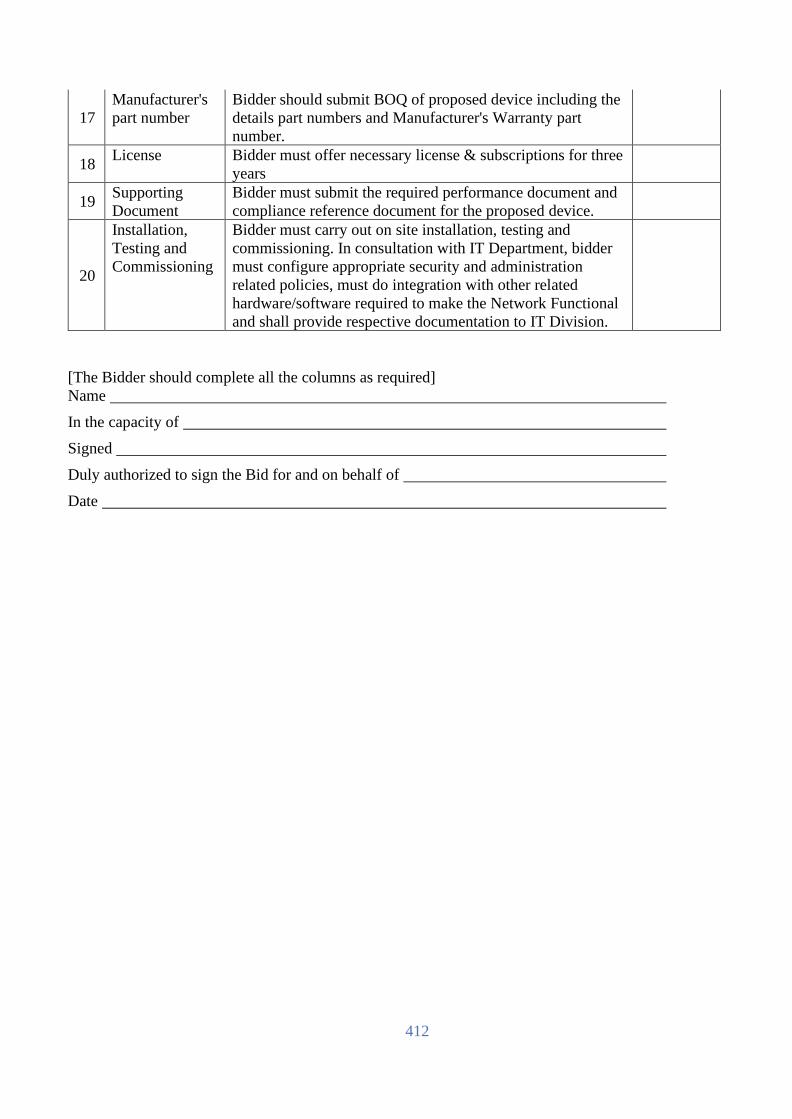
412
17
Manufacturer's
part number
Bidder should submit BOQ of proposed device including the
details part numbers and Manufacturer's Warranty part
number.
18 License Bidder must offer necessary license & subscriptions for three
years
19 Supporting
Document
Bidder must submit the required performance document and
compliance reference document for the proposed device.
20
Installation,
Testing and
Commissioning
Bidder must carry out on site installation, testing and
commissioning. In consultation with IT Department, bidder
must configure appropriate security and administration
related policies, must do integration with other related
hardware/software required to make the Network Functional
and shall provide respective documentation to IT Division.
[The Bidder should complete all the columns as required]
Name
In the capacity of
Signed
Duly authorized to sign the Bid for and on behalf of
Date
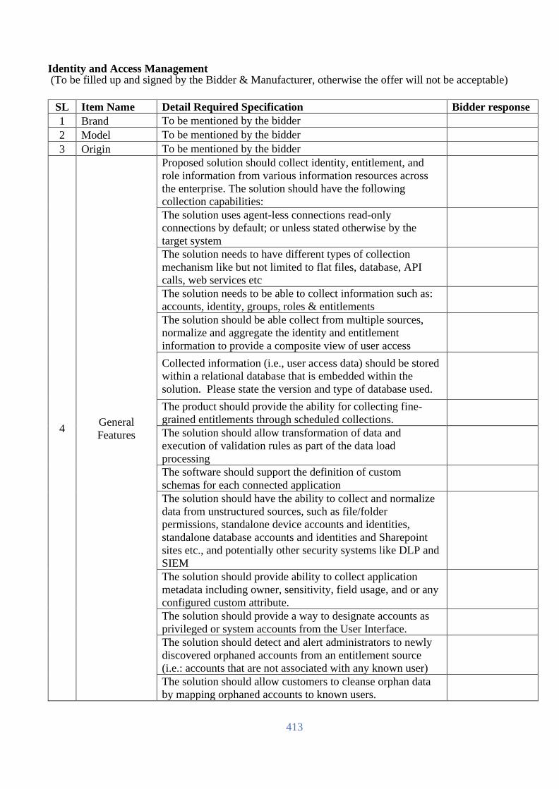
413
Identity and Access Management (To be filled up and signed by the Bidder & Manufacturer, otherwise the offer will not be acceptable)
SL Item Name Detail Required Specification Bidder response
1 Brand To be mentioned by the bidder
2 Model To be mentioned by the bidder
3 Origin To be mentioned by the bidder
4 General
Features
Proposed solution should collect identity, entitlement, and
role information from various information resources across
the enterprise. The solution should have the following
collection capabilities:
The solution uses agent-less connections read-only
connections by default; or unless stated otherwise by the
target system
The solution needs to have different types of collection
mechanism like but not limited to flat files, database, API
calls, web services etc
The solution needs to be able to collect information such as:
accounts, identity, groups, roles & entitlements
The solution should be able collect from multiple sources,
normalize and aggregate the identity and entitlement
information to provide a composite view of user access
Collected information (i.e., user access data) should be stored
within a relational database that is embedded within the
solution. Please state the version and type of database used.
The product should provide the ability for collecting fine-
grained entitlements through scheduled collections.
The solution should allow transformation of data and
execution of validation rules as part of the data load
processing
The software should support the definition of custom
schemas for each connected application
The solution should have the ability to collect and normalize
data from unstructured sources, such as file/folder
permissions, standalone device accounts and identities,
standalone database accounts and identities and Sharepoint
sites etc., and potentially other security systems like DLP and
SIEM
The solution should provide ability to collect application
metadata including owner, sensitivity, field usage, and or any
configured custom attribute.
The solution should provide a way to designate accounts as
privileged or system accounts from the User Interface.
The solution should detect and alert administrators to newly
discovered orphaned accounts from an entitlement source
(i.e.: accounts that are not associated with any known user)
The solution should allow customers to cleanse orphan data
by mapping orphaned accounts to known users.

414
The solution should provide visibility into orphaned accounts.
The solution should have the ability to leverage collected data
for Access Control decisions within the product, e.g.
supervisors can manage their direct reports, regional directors
can view their regional assets and users, etc.
The solution should support bulk update of orphan account
mappings data
The solution should provide a clear indication of compliance
violations during the certification process for these but not
limited to users, policies, roles, entitlements, data access,
standalone access and applications.
The solution should enable certification based on applications
required in a certification bundle
The solution should enable certification based on a specific
set of users or groups according to usage, violations, peer
reviews and uncommon access
The solution should enable certification based on an
application or role owner.
The solution should automatically generate certifications
based on detected changes to a user’s relationship to the
organization (e.g., user changes department or is terminated)
The solution provide certification use cases out-of-the-box
Certification History - The reviewer should be able to view
the past and parallel certification events and all (i.e. current
and past) comments related to a review item.
The solution should provide the ability to configure multi-
step user access reviews through a wizard driven web-based
interface, without the need for any form of scripting. Multi-
step user access reviews should, at a minimum, support the
following 3 steps in a review campaign.
(a) User performs self-review
(b) Supervisor signs off user's self-review
(c) Revoked entitlements are selected for application owner
review
The solution should provide insight into review items that it
could not automatically assign during the review generation
without customization or coding.
The solution should have the ability to drill down into details
of a violation and / or exceptional access caused by items in a
review.
The solution should allow users to review only items in
violation and / or under exception
The solution should have the ability to drill down into details
of a violation and / or exceptional access caused by items in a
review.
The solution should have provide an administrative
dashboard to track aggregated certification metrics across the
enterprise and certification campaigns

415
The workflow of the solution should be configurable and not
custom coded using drag & drop graphical interface
The solution should have the ability to view pending requests
and be able to see what is needed for the request to complete.
The solution should have the ability to skip approval when
the approval does not result in the user having new
entitlements (i.e. giving a role that gives entitlements the user
already has).
The solution should have the ability to reassign requests to
another person for approval.
The solution should have the ability to suspend fulfillment
process and retry later because a system is currently
inaccessible.
The solution should have the ability for notification to be sent
when the system is inaccessible for a more than a specified
time limit.
The solution should have the ability to raise an exception
when the remote fulfillment system does not understand the
request that is being submitted.
The solution should have the ability to filter requests for
high-risk entitlements to get additional approvals (with
custom process)
The solution should have the ability to request to get at the
approval of the level 3 or higher supervisor above the
requested user
The solution should have the ability to identify the current
requests that are in danger of missing their SLA (e.g. 80% of
the time has passed).
The solution should have the ability to restrict requests for
access to specific entitlements based on current security
clearance (or other user info/meta data/attributes).
The solution should allow invocation of provisioning actions
on multiple endpoints within the same workflow
The solution should provide a user-friendly interface for
requesting changes to user access. Describe features oriented
towards ease-of-use for end users.
The Solution should be able to configure and provide an
access to requestor with rule-based appropriate views of
access that is tailored for them
The solution should allow the submitter to see that his request
would contain a segregation of duties (SoD) policy violation
if there is one.
The solution should have self-service access request solution
for additions, changes, and removals of access.
The users should be able to request a start date (“sunrise”)
associated with new access requests for roles as well as
additional entitlements. Alternatively, the users can also
select an end date (“sunset”) when removing access through
the self-service request interface

416
The solution should facilitate requesting of roles,
Entitlements and Accounts.
The solution should have the ability to have complete
visibility of existing access during access request process.
The solution should provide entitlement history for a user -
when it was requested, changed or removed?
The solution should support the definition of automated
lifecycle events (e.g., new hire, promotion, termination) that
trigger provisioning changes.
The solution should support the creation of new accounts
associated with adding new users?
The solution should support configuration of scoping rules
defining who can request access for others. What attributes
can be used to define the request relationship?
The solution should support delegation of approval requests
to other users within the system and provide audit trail on the
process
The solution should have the ability to monitor and detect
onboarding, transfers and terminations with configurable
actions for rule handling (also known as joiner, mover, and
leaver).
The solution should have the ability to grant a set of
entitlements or birthright access to joiners with or without
invention of approval workflows
The solution should have the ability to allow approvers to
approve access request by replying to the approval
notification email (i.e. email-based approval). This capability
should also provide a means for approvers’ comments to be
captured in the audit trail.
The solution should provide a web-based interface, without
the need for Java applet, to design and create access request
forms. The forms should allow conditions for displaying
and/or enabling certain fields for specific users. For example,
only manager of level 3 and above can see certain fields. The
forms should include, but not limited to, the following
controls.
(a) Textfield
(b) Dropdown box
(c) Radio buttons
(d) Attachments
(e) Javascript
(f) User picker
(g) Entitlements
The solution should allow users' to attached documents (such
as signed non-disclosure agreement) when requesting for
access.
The solution needs to provide audit trails for all processes
related to access changes.
The audit logs should be inclusive and permanent.
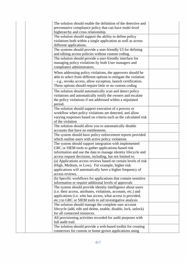
417
The solution should enable the definition of the detective and
preventative compliance policy that can have multi-level
higherarchy and cross relationship.
The solution should support the ability to define policy
violations both within a single application as well as across
different applications.
The systems should provide a user-friendly UI for defining
and editing access policies without custom coding.
The solution should provide a user-friendly interface for
managing policy violations by both User managers and
compliance administrators.
When addressing policy violations, the approvers should be
able to select from different options to mitigate the violation
– e.g., revoke access, allow exception, launch certification.
These options should require little or no custom coding
The solution should automatically scan and detect policy
violations and automatically notify the owners and escalate
the policy violations if not addressed within a stipulated
period.
The solution should support execution of a process or
workflow when policy violations are detected, and allow
varying responses based on criteria such as the calculated risk
of the violation
The solution should allow you to automatically disable
accounts that have no entitlements.
The system should have policy enforcement reports provided
which outline users with active policy violations
The system should support integration with implemented
GRC or SIEM tools to gather applications-based risk
information and use the data to manage identity lifecycle and
access request decisions, including, but not limited to:
(a) Applications access reviews based on certain levels of risk
(High, Medium, or Low). For example, higher risk
applications will automatically have a higher frequency of
access reviews.
(b) Specific workflows for applications that contain sensitive
information or require additional levels of approvals
The system should provide identity intelligence about users
(i.e. their access, attributes, violations, accounts, etc.) and
applications (i.e. who has access, what access is provided,
etc.) to GRC or SIEM tools to aid investigative analysis
The solution should manage the complete user account
lifecycle (add, edit and delete, enable, disable, lock, unlock)
for all connected resources.
All provisioning activities recorded for audit purposes with
full audit trail.
The solution should provide a web-based toolkit for creating
connectors for custom or home grown applications using
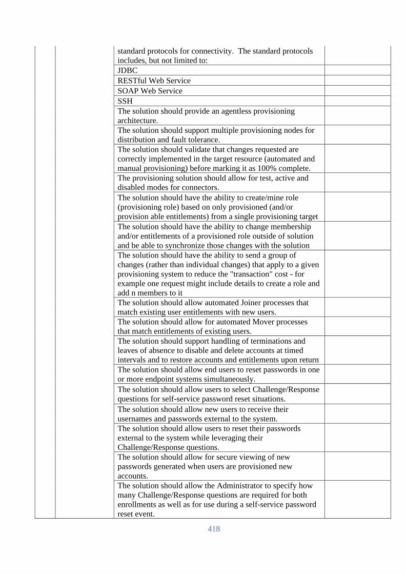
418
standard protocols for connectivity. The standard protocols
includes, but not limited to:
JDBC
RESTful Web Service
SOAP Web Service
SSH
The solution should provide an agentless provisioning
architecture.
The solution should support multiple provisioning nodes for
distribution and fault tolerance.
The solution should validate that changes requested are
correctly implemented in the target resource (automated and
manual provisioning) before marking it as 100% complete.
The provisioning solution should allow for test, active and
disabled modes for connectors.
The solution should have the ability to create/mine role
(provisioning role) based on only provisioned (and/or
provision able entitlements) from a single provisioning target
The solution should have the ability to change membership
and/or entitlements of a provisioned role outside of solution
and be able to synchronize those changes with the solution
The solution should have the ability to send a group of
changes (rather than individual changes) that apply to a given
provisioning system to reduce the "transaction" cost - for
example one request might include details to create a role and
add n members to it
The solution should allow automated Joiner processes that
match existing user entitlements with new users.
The solution should allow for automated Mover processes
that match entitlements of existing users.
The solution should support handling of terminations and
leaves of absence to disable and delete accounts at timed
intervals and to restore accounts and entitlements upon return
The solution should allow end users to reset passwords in one
or more endpoint systems simultaneously.
The solution should allow users to select Challenge/Response
questions for self-service password reset situations.
The solution should allow new users to receive their
usernames and passwords external to the system.
The solution should allow users to reset their passwords
external to the system while leveraging their
Challenge/Response questions.
The solution should allow for secure viewing of new
passwords generated when users are provisioned new
accounts.
The solution should allow the Administrator to specify how
many Challenge/Response questions are required for both
enrollments as well as for use during a self-service password
reset event.

419
The solution should allow the Administrator to specify
password strength requirements, including complexity,
history and minimum age.
The solution should provide Change/Response Enrollment
report showing users who have and have not set their
question/answer pairs.
The solution should allow Administrators to set a max
threshold for unsuccessful login attempts and a timed delay
for allowing subsequent login attempts
the product should support 64-bit Operating Systems and
databases for greater scalability
The Proposed solution should be able to scale horizontally or
vertically to support increased load
the product should allow for easily creating String, Decimal,
Integer, Date & User Type Custom attributes from within the
interface and allow them to be Managed Data (i.e. Augment
collected data with information that may not be available
from the data source but configured within UI and automated
workflow)
The Solution should have ability to cleanse or “correct”
collected data and produce reports that show the differences
which can be handed off to the data owners
The product should provide a single user friendly dashboard
for the Identity and Access Management suite displaying data
appropriate for the various actors (end users, application
owners, managers, admins, help desk)
The product should provide ability to modify and customize
the dashboard from within the admin UI screens
The product should be able to provide report on historical
“point in time” access as well as current state
5
License &
Warranty
The solution should cover at least 200 users from day 1 and
should have the capability to scale up without upgrading the
core application. 3 yrs 24x7 support with free update of
patches and upgrade to new version to be provided from ISV.
Upgraded software image to be provided Free of Cost within
support period.
6
Any other
features may
feel necessary
by the bidder
Professional installation service shall be provided.
[The Bidder should complete all the columns as required]
Name
In the capacity of
Signed
Duly authorized to sign the Bid for and on behalf of
Date

420
Modules and Interfaces: (To be filled up and signed by the Bidder & Manufacturer, otherwise the offer will not be acceptable)
SL Item Name Detail Required Specification Bidder response
1 Brand
From the offered wired switch provider OEM.
Part number details shall be provided.
2
Modules
10G SFP+ SR Transceivers: 300 pcs
25G SFP28 SR Transceivers: 450 pcs
40G QSFP+ LC BiDi Transceivers: 100 pcs
40G QSFP+ MPO SR4 Transceiver: 20 pcs
100Gb QSFP28 to QSFP28 3m DAC: 20 pcs
40Gb QSFP+ to QSFP+ 1m DAC: 20 pcs
100G QSFP28 BiDi Transceivers: 20 pcs
100G QSFP28 MPO SR4 Transceivers: 20 pcs
3
Optical cables
5-meter LC/LC OM4 optical cable: 200 pcs
15-meter LC/LC OM4 optical cable: 600 pcs
30-meter LC/LC OM4 optical cable: 200 pcs
50-meter LC/LC OM4 optical cable: 200 pcs
MPO/MPO Multi-mode OM4 12 fiber 10m Cable: 40
pcs
4 Copper cable
Necessary CAT6A and CAT5 cable shall be provided for
the datacenter connectivity based on the site survey.
5 Warranty
3-yrs collaborative warranty fully back-to-back with OEM
with faulty part replacement and labor.
[The Bidder should complete all the columns as required]
Name
In the capacity of
Signed
Duly authorized to sign the Bid for and on behalf of
Date

421
Network Monitoring System (NMS): (To be filled up and signed by the Bidder & Manufacturer, otherwise the offer will not be acceptable)
SL Item Description Requirement
Bidder
Response
1 Brand Please mention.
Should be in the Gartner Peer Insight
2 Country of Origin USA/UK/EU/Switzerland/Australia/Japan
3 1 - Must Supported Operating Systems:
• Microsoft Windows Server 2019
• Microsoft Windows Server 2016
• Microsoft Windows Server 2012 R2 64 Bits
• Microsoft Windows Server 2012 64 Bits
• Microsoft Windows 10 32/64 Bits
• Microsoft Windows 8.1 64 Bits
• Microsoft Windows 8 32/64 Bits
• Microsoft Windows 7 32/64 Bits
• Microsoft Windows Server 2008 R2 64 Bits
4 1 - Must Agentless (solution should work agentless at least in a local
network). Solution shall be sensor based and min. 2000 sensor
license shall be provided.
5 1 - Must Remote site monitoring (possibility to monitor remotely located
networks)
6 1 - Must Auto discovery option for easy installation
7 1 - Must User interfaces:
• Web interface supporting common browsers
• Desktop Client
• Mobile Applications for Android and iOS
8 1 - Must Database for storing monitoring data
9 1 - Must Monitoring data should be stored for at least 1 year in raw format
10 2 - Should Data export (possibility to export current and historic data in
serviceable formats (e.g. CSV/XML))
11 2 - Should Provide API for data integration purpose
12 1 - Must High availability (failover or cluster architecture)
13 2 - Should Providing maintenance windows option
14 3 - Optional Built-in ticketing system
16 2 - Should Support of IPv6
17 2 - Should Support of in-depth customizations
18 Warranty 3 yrs 24x7 support with free update of patches and upgrade to
new version to be provided from ISV. Upgraded software image
to be provided Free of Cost within support period.
[The Bidder should complete all the columns as required]
Name
In the capacity of
Signed
Duly authorized to sign the Bid for and on behalf of
Date

422
Application Management System:
(To be filled up and signed by the Bidder & Manufacturer, otherwise the offer will not be acceptable)
SL Minimum Technical Specification Compliance
(Yes/No)
Bidder's
Remarks
Deployment Options
1 Vendor encrypts data transmissions end-to-end across the
environment
Installation
2 Single product and architecture to address Gartner’s 5 dimensions of
Application Performance Management (end user experience
monitoring, architecture discovery modeling and display, transaction
profiling, deep-dive monitoring, analytics).
Configuration
3 Configuration and management through a single, web-based user
interface
4 No Root access required to install or operate agent.
5 No use of OS primitive LD_Preload for discovering components -
malware technique
6 Automatically create a single visualization of the entire application
topology with all components.
7 No more than 2->4% overhead out of the box.
9 Ability to globalize alert definition with inbuilt policy engine (rather
than have to setup individually per metric)
10 The ability to provide a multi-tenant environment
11 SSL Encrypted data transmission between EVERY monitoring
component.
Better Application Visibility and Control
12 Provide correlated views of distributed BTs between tiers/services
13 Provide code level diagnostics (class & method-level visibility) of
poorly performing BTs
14 Solution does not disable monitoring functionality as a compromise
to limit product overhead.
Reduce Mean Time To Repair
15 Identify slow SQL queries without manual intervention
16 Identify slow backends systems or external services without manual
intervention
17 Automatic analysis of end-to-end APM data to provide root cause
analysis.
Usability
18 Granular RBAC for flexible usage across teams (Example 1- Certain
application visible to Team A & not Team B, Example 2 - Certain
dashboards are visible to Role A & not Role B)
Runbook Automation and Alerting

423
19 Policy Rules Engine & Alerting:
* Ease of use: point-n-click rules wizard
* Leverage multiple data inputs into analysis (app performance data,
machine data and customer provided data)
* Use Boolean logic to combine multiple conditions through AND /
OR logic
* Disable rule evaluation temporarily for predetermined maintenance
windows
* Trigger alerts or notifications when rules are violated (email, SMS
or custom)
* Use complex logic to combine different metrics into one
trigger/alert
Business Criteria
20 Validate technology can scale to support the business requirements
of the application managed.
Analytics Platform
21 Single UI incorporating Analytics and APM modules
22 Analytics layer providing intelligence across data collected by APM
modules
23 In context drill down between analytics data and APM data
24 Configurable to collect not all, but specific desired transaction
data/fields
25 No code changes required to pull custom (non-native) metrics into
data repository
26 Data collected, stored and analyzed in near real time, not hours,
days, or weeks later.
27 Ability to chart result set in pre-defined dashboards
28 Ability to chart result set in custom dashboards
Platform Support
29 Platform Support for Oracle, SQL Server, MySQL, DB2, Sybase,
PostgreSQL, and MongoDB
Ease Of Deployment
30 Measure and monitor all databases in your environment without
impacting stability or performance.
31 Low overhead, production safe monitoring technology.
32 Agentless installation - ability to rapidly deploy and eliminate risk
on production database servers
Root Cause Analysis
33 Historical performance monitoring and trending - save 100% of
historical data
34 Report top database activities (e.g. Top SQL, Top Users, Top
Programs)
35 Collect and store database instance level statistics (table size, row
count, indexes)
36 Collect and store database server/host Key Performance Indicators
(CPU, Memory, …)
37 Provide Performance Comparison Reports Database Monitoring and Management
38 Ability to co-relate slow query to calling application code

424
Systems Monitoring Capabilities
39 Monitor Machine availability, CPU Usage, Disk performance,
Volume usage, Machine load, Memory, SWAP, Processes, Network
Adapter(s)
Application to Machine Correlation
40 Single UI for Server and Application monitoring
End User Digital Experience Monitoring
41 Support for modern desktop and mobile browsers.
42 Monitor all page, AJAX and iFrame requests.
43 Display response time status on Geo Map
44 Correlate problematic web and mobile transactions with server side
transactions for drill down
45 User session tracking for web and mobile.
46 License:
Shall be provided with 3 units Database Server (each 5 instances), 3
units Application Server, 2 units file system monitoring and 32 units
virtualization server monitoring license from day1.
Shall be deployed in two sites.
47 Product Lifetime:
Product life time will be around 7 (seven) years from the date of
final UAT of the product.
48 Warranty Period:
Warranty Period should be minimum 03 (Three) year from the date
of final UAT of the product.
[The Bidder should complete all the columns as required]
Name
In the capacity of
Signed
Duly authorized to sign the Bid for and on behalf of
Date

425
Helpdesk and Problem Ticketing: (To be filled up and signed by the Bidder & Manufacturer, otherwise the offer will not be acceptable)
Sr. No. Technical Specifications Compliance Yes/No
General
1 The Service Management tool should be Pink
Verify certified in at least 11 ITSM processes
2
Solution includes integrated CMDB
(Configuration Management Database) for
managing key ITIL functions and processes
including and not limited to: IT Service
Desk, Incident, Request , Knowledge,
Problem, Change, Configuration, Service
Level & Asset Management functions
3
The solution supports ITSM process
workflow between solutions users including
routing of request, electronic request
approvals by actionable e-mail, mobile app,
etc.
4 The solution supports ITIL Version 3
frameworks including terms and definitions
5 The solution supports a web-based client for
user and administrative functions.
6
The solution provides Search capabilities in
all ITSM processes - adhoc queries, save
queries, user queries, role-based queries,
shared/public queries
7 Ability to support hot topic or news flash
window within the graphical user interface
8 Ability to generate an automated survey to
requestor to measure satisfaction of requestor.
9
Ability to configure the graphical user
interface by using drag and drop for windows
and fields
10 Ability to support object-specific pop-up
menus in the graphical user interface
Service Management Framework
1
The Solution displays the complete ITIL
process flow for Incident, problem, Change
and release, Asset and Service level
Management
2
The solution should have Service
Management Process Model in built based on
ITIL v3 best practices
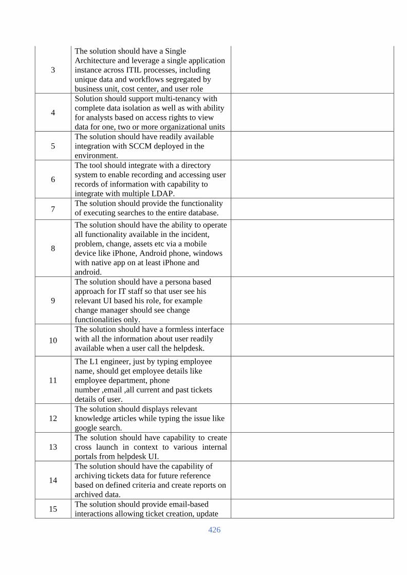
426
3
The solution should have a Single
Architecture and leverage a single application
instance across ITIL processes, including
unique data and workflows segregated by
business unit, cost center, and user role
4
Solution should support multi-tenancy with
complete data isolation as well as with ability
for analysts based on access rights to view
data for one, two or more organizational units
5
The solution should have readily available
integration with SCCM deployed in the
environment.
6
The tool should integrate with a directory
system to enable recording and accessing user
records of information with capability to
integrate with multiple LDAP.
7 The solution should provide the functionality
of executing searches to the entire database.
8
The solution should have the ability to operate
all functionality available in the incident,
problem, change, assets etc via a mobile
device like iPhone, Android phone, windows
with native app on at least iPhone and
android.
9
The solution should have a persona based
approach for IT staff so that user see his
relevant UI based his role, for example
change manager should see change
functionalities only.
10
The solution should have a formless interface
with all the information about user readily
available when a user call the helpdesk.
11
The L1 engineer, just by typing employee
name, should get employee details like
employee department, phone
number ,email ,all current and past tickets
details of user.
12
The solution should displays relevant
knowledge articles while typing the issue like
google search.
13
The solution should have capability to create
cross launch in context to various internal
portals from helpdesk UI.
14
The solution should have the capability of
archiving tickets data for future reference
based on defined criteria and create reports on
archived data.
15 The solution should provide email-based
interactions allowing ticket creation, update

427
and approval of request from the email itself
into the system.
16 The end users should be able to create ticket
through chat functionality.
17 The solution should give all the ticket details
related to a particular business services.
18
The system should have interactive process
flow to help support users to follow the
process.
19 The system should have graphical interface to
define, visualize and update ITIL processes
20
The Solution should have the ability to
develop highly customized workflows and
easy user interface.
21
The Solution should be able to create
processes across multiple vendors helpdesk
and defined their SLA's and escalation matrix
22
The solution should be open and interoperable
and has rich integration capabilities that
support interfaces from command line
interface and web services
23
The Solution should support various
mechanisms and protocols to interact with
third party products such as but not limited to
HTTP, HTTPS, JMS, Microsoft Power Shell,
Scripts, SNMP, SQL, Web Services, SOAP,
Command line, File, FTP, SCP, SFTP, SSH,
Telnet, Windows Command Line, Email
protocols IMAP, POP, SMTP, restful API's.
24
The Solution should provide orchestration
capability for automating common tasks
across systems and applications like active
directory, exchange.
25
The service management software should
have the ability to tightly integrate (bi-
directionally) with enterprise management
systems for auto-creation/closing / reporting
of events/incidents/trouble tickets
26
For integrations with other EMS/NMS tools,
various options for integration should be
provided - APIs, web services, SDKs.
27
The Solution should provide a centralized
Dashboard that picks up relevant business
metrics from the monitoring and service
management solution
28
These dashboards need to be dynamic that
allows user to drag and drop these metrics and
create custom dashboards without any coding.

428
29 Reporting and dashboards should have
Persona based access as per the user role.
30
User should be able to select the time frame to
report on data. This could be monthly,
quarterly, half yearly, yearly or custom dates
31
The Dashboards should support rich
formatting capabilities to represent the data;
this includes different chart formats and PDF.
32
The solution should have readily available
various operational reports and KPI's on
dashboards to gauge the performance of
processes
33
The solution should be robust and scalable
with capacity for more than 1000 concurrent
users to login simultaneously and future
growth.
34
The solution should allow for various ticket
assignment mechanisms including Round
Robin, Skill based and load based routing.
Service Request Management and Service
Catalog
1
Should have self-service interface with service
catalog for end users to submit and track
service request, spanning both IT services and
non-IT services
2
Should provide for Service Requests
Workflows and Fulfillment definitions for
commonly used IT/non-IT services with
approvals, auto assignment, SLA and
escalations.
3 Catalog based on User role – enables access to
service request on user role.
4
The solution should have wizard / graphical
workflow editors allowing definition of new
service catalog items in minutes – without any
programming.
5
Solution should Various types of Customer
profiles are supported, for ex: VIP,Gold,
Platinum, Silver
6
Integrates with any underlying service
management including Service Desk, Change
Management, Service Level Management and
CMDB for request fulfillment
7
The self-service interface should support
knowledge base available to end users self
resolution.

429
8
Users should be able to request for services on
behalf of other employees and the system
should track the request as if the user
requesting for the service has initiated the
request.
9
The self service interface should be accessible
through native mobile in the form of app which
users can download through URL or enterprise
app store.
10
Beyond mobile iOS and Android apps, Self
Service App should be available on any device
with an HTML5 browser.
11
The self service Interface should be searchable
with access to knowledgebase from the mobile
app.
12
User should be able to approve the service
request, change request from the self-service
app on mobile.
13
Self Service App should provide a snapshot of
your day, displaying your activities feed with
upcoming, pending requests, approvals,
unresolved issues, and alerts from systems you
use in your daily work
14
Should provide simple interface with no forms
to complete, short posts should create Incidents
tickets.
Service / Help Desk (Incident and Problem
Management)
1
Service Desk solution should allow detailed
multiple levels/tiers of categorization on the
type of incident being logged for IT/Non IT
services
2
Service Desk solution should provide
classification to differentiate the criticality of
the security incident via the priority levels,
severity levels and impact levels.
3
It should allow SLA to be associated with a
ticket based on priority, severity, incident type,
requestor, asset, location or group individually
as well as collectively
4
It should have the ability to search multiple
built-in knowledge bases like the incident,
problem, and known-error database
simultaneously without requiring the agent to
search each knowledge base individually.
5
Should support automatic assignment of ticket
to the right skilled resource based on business
priority Ex - Database crash issue need not be

430
assigned to an L3 DBA unless the business
service is completely down
6
The tool should have the ability to notify and
functionally escalate (assign) a ticket to an
individual or support group based on pre-
defined parameters, thresholds or manual
override conditions
7
Should Centralize all known error and problem
workarounds into a single, searchable
knowledge base
8
It should provide an interactive process flow
bar that guides novice users through the ITIL
process for incident management to ensure
faster recording and issue resolution
9
The incident management solution should have
the ability to initiate the
change/problem/Knowledge on a button click.
10
The solution should have the ability to
associate an incident with an existing change
request, a problem or an known error for
tracking purposes
11 Service Desk agent should have mobile app to
resolve/update tickets.
Change & Release Management
1
The solution should be able to create and
track a request for change through the
different stages of lifecycle of a change
request.
2
The tool should facilitate the identification of
the change type and associated workflow For
example: standard, normal, and emergency
3
The tool should facilitate the differentiation of
normal Changes For example: Category -
Minor or Small, Category - Significant or
Medium, Category – Major or Large
4
The tool should facilitate the ability to create
simple to complex request workflows through
sequential and parallel tasking
5
The tool should notify all the users about the
scheduled changes/outage and sent a reminder
to responsible contacts for implementation of
change
6
Change management should have fields to
record impact analysis and simulate impact,
back-out plans, within the change record

431
7
It should have the capability to automatically
and continually perform impact analysis, risk
assessment, and change collision dates
detection (for same CI's) on all change
requests.
8
The tool should facilitate the scheduling of
post implementation reviews for implemented
changes after defined time interval
9
The application should have the ability to
assign change advisory board (CAB)
responsibilities to change management roles
10
The tool should facilitate ability of authorized
roles to reject changes For example, status of
reject, ability to record reason for rejects
notification
11
Change management should be capable of
integrating with CMDB to facilitate access to
CI attributes and relationships to enable
change assessment and authorization
12
The solution should have Unified and uniform
approach to enterprise change and release
management across infrastructure, enabling
organizations to automate best practices.
13
Solution should provide a consolidated view of
the tasks that the release management team
must perform to drive the completion of the
change requests and activities required to close
the release.
14
Solution should provide Change and Release
Calendar views for the current schedule of
releases, change requests, and business events
for any potential conflicts.
15
The solution should have the ability to prompt
change planners with suitable time slots for
conducting a change depending upon the
changes that have been scheduled/in progress,
risk associated with it and the priority of the
change
16
The solution should provide complete view of
planned changes with services & their
components.
Knowledge Management
1
The tool should have knowledge management
OOB - knowledge databases to support
investigations, diagnoses, root cause analysis
techniques, and creating / updating
workarounds, temporary fixes and resolutions

432
2
The tool should allow creation and enforced
use of data input rules for creating knowledge
records For example: mandatory fields for
content and information; QA and change
approval to move from draft to production
3 The tool should allow for the entry of free-
form text, images, attachments, etc
4
The tool should automate the population of
knowledge records with author and owner
data, creation date, as well as any other
attributes required by organization
5
The tool should automate trending of
knowledge use & identification of knowledge
gaps
6
The tool should have a powerful search engine
to sort, retrieve and search using advanced
search options, search content in multiple
format, and also search within knowledge
records
7 The tool should allow displaying FAQs and
highlight the newly added knowledge content
8
The module should allow integration with all
other modules of service management to
enable knowledge records to be quickly
created from records with associated links.
9 The tool should be aligned to Knowledge
centered support(KCS) best practices.
Configuration Management database
(CMDB)
1
Solution uses a natively integrated suite of IT
service support processes with a single CMDB
and allow the CI to be associated with tickets.
2
The Configuration Management Database
should support multiple datasets with
federation and reconciliation facilities so as to
get data from various discovery tools and also
through manual import process
3
Reconciliation of data should be possible with
multiple data providers based on common
attributes and ability to define precedence rules
on attributes
4
Federation of external data sources should be
possible with ability to store common
attributes inside CMDB and getting other
attributes from external data sources in real
time

433
5
Should automatically create Service models to
describe how IT infrastructure supports
business services
6
Should Provide a Service catalog so as to
establish a framework for Service definitions
based on IT and business alignment
7
Should Provide Service blueprints to describe
functional and deployment models for the
Service definitions
8
Should provide Attribute-level normalization
and reconciliation to leverage existing data
from third-party asset or discovery tools and
realize the goal of having one dependable
source of configuration data
Asset Lifecycle Management
1
Should be integrated with Service
Desk/change management for maintenance
and support of assets
2
The solution should have the capability to
track software license compliance across
multiple license types like core, cpu,
enterprise, SUM of CPU, sum of core in
datacenter
3
All the information related to supplier,
contract, procurement can be entered and
linked with the assets
4
Automate linkages between assets and
software license, leases, warranty, and
support contracts to optimize entitlements and
ensure compliance
5
Track TCO, including costs attributable to
maintenance, incidents, changes, and
depreciation
6
The solution should come with QR code
generator for the assets in built with the
service management platform.
7
The platform should provide an mobile app
which can scan the QR codes, Barcodes and
displays asset information. The QR scanner
should be inbuilt in self-service app available
on mobile.
8 The mobile app should have capability to
create and update asset information.
Service level Management
1
Solution should support comprehensive SLA
management platform that cuts across
Infrastructure Management and Service
Management.

434
2
Have a consolidated, automated graphical
report for SLA compliance with ability to drill
down to reason for non-compliance
3 Manage service levels for delivery and support
of business services
4
Real-time visualization of service level targets,
agreement compliance data, penalties and
rewards
5
Should support compliance and cost trending
to assist in identifying areas for process and
operational improvements
6
The service level management (SLM) tool
should facilitate creation and maintenance of
SLAs, OLAs and Supplier / Underpinning
Contracts For example: scope, supplier,
contact names, contact method, support hours,
service level targets
7
The product should have the capability to
schedule the review cycle and renewal of
SLAs, OLAs and supplier / underpinning
Contracts
8
It should enable creation, measurement and
reporting of three categories of SLA service
targets — time-based on response / resolution
of tickets, availability relating to uptime of
systems/ services, or performance-monitoring
catering to system metrics like end-user
transaction
9
The module should link available support
hours to service levels when calculating
deadlines as well as suspend SLA calculation
for certain criteria – eg‘ pending information
from customer’
10
The product should facilitate bi-directional
linking of services & customers to associate
multiple agreements with a customer contract
as well as link multiple customers to a
particular service
11
The tool should facilitate the production of
Key Performance Indicator (KPI) reports as
out of-the-box or ad hoc reporting
12
The SLM module should integrate with
incident and problem management to
automate escalation, and notification activities
based on response and resolution targets
13
It should also integrate with change
management to provide access to service level
agreement details, implementation windows,
change blackout periods, and availability
requirements

435
Integration and Development
1
Solution uses a unified and seamless
architecture and workflow to resolve business
issues
2
Solution uses a natively integrated suite of IT
service support processes with a single
CMDB
3
Solution has clear integration of service
support processes with event management and
change execution to create end to end
workflows
4
Solution uses integration of operational events
to incident and problem process in order to
simplify Service Desk operations
5
Solution offers multiple integration methods
for custom solutions or existing solutions
including Legacy & Restful APIs, Web
Services, Email, and ETL methods
Training requirement
1
Please mention the standard OEM training
course for administration and maintenance the
solution with training location and duration.
Design and Implementation Scope
1
The bidder will prepare the entire design.
Also need to share HLD and LLD before start
implementation. Implementation will be done
by OEM based on the standards design
guideline and best practices
User, Device and Administration
Hardware Requirements
1
Vendor will give VM base hardware sizing
and software requirement for Production, Test
and DR as per the hardware requirement
Warranty Period:
1
Min. 3 Years Maintenance service with Help
Desk and incident Management, asset
discovery and management, self service
portal, multisite support and reporting from
the day1 as per the hardware and software
scope in two sites.
[The Bidder should complete all the columns as required]
Name
In the capacity of
Signed
Duly authorized to sign the Bid for and on behalf of
Date

436
EU Centralized antivirus software:
(To be filled up and signed by the Bidder & Manufacturer, otherwise the offer will not be acceptable)
SL Item Description Requirement
Bidder
Response
1 Country of Origin USA/UK/EU/Switzerland/Australia/Japan
2 Brand To be mentioned by the bidder
3 Model To be mentioned by the bidder
4 Quantity 1 Lot
5
Sizing The solution must support at least 500 Endpoint/Device & 50 Server
Coverage
6
Deployment
Methodology
Quoted product must have flexible on site deployment methodology
i.e. appliance or software based on physical/virtual environment. The
solution should support multi tenant deployment.
7
Endpoint &
Server Coverage
Windows Client: The solution must be compatible with the
following operating systems: Windows (32-bit & 64-bit) XP SP2 /
SP3, 7, 8, 8.1 and 10
MAC OS: The solution must be compatible with the following
operating systems: macOS Versions: (10.10), El Capitan (10.11),
Sierra (10.12), High Sierra (10.13), Mojave (10.14) and Catalina
(10.15)
Windows Server: The proposed solution must be compatible with
the following operating systems: Windows Server 2003 R2 SP2,
2008 R1 SP2, 2008 R2, 2012, 2012 R2, 2016 and 2019
Linux: The proposed solution must be compatible with the
following operating systems: Linux Versions: RedHat Enterprise
Linux and CentOS 6.8, 6.9, 6.10, 7.2, 7.3, 7.4, 7.5, 7.6 and 7.7 and
Ubuntu LTS 16.04.5, 16.04.6,18.04.1 and 18.04.2 server, 64-bit
Virtual: The solution must be compatible with the following
operating systems: Virtual Desktop Infrastructure (VDI)
environments on VMware and Citrix. VMware Horizons 6 and 7,
and Citrix XenDesktop 7
Device Detection Solution must have the ability to classify detected devices such as
printers, cameras, network devices
Solution must have the ability to display detailed information about
detected devices such as: IP address, Geolocation
Solution must have the ability to detect IOT devices on the same
network where the installed agents are located.
8
Deployment,
Maintenance and
host Requirement
The solution must support mass installation using tools such as MS
System Center, JAMF, and Satellite.
The solution must have the ability to update the endpoint without
user interaction or without requiring a restart of the station
The solution must have a maximum consumption of 200MB of
RAM
The solution should have an average CPU consumption of less than
2%.
The solution should consume less than 20MB of disk space

437
The solution should have "Anti Tamper" or "Anti-Tamper"
protection.
The solution should work without relying on local hash signatures
of known threats for the detection of malicious files.
The solution should record in real time the process information and
additional information how to determine the user associated with
the events.
The solution should have the option to ask for a password to
uninstall the workstation agent.
The solution should be able to detect and report failures occurred in
the installation and update of the same in case of lack of disk space,
lack of minimum prerequisite of the windows operating system
The solution should be able to detect and report failures occurred in
the installation and update of the same in case of lack of disk space,
lack of minimum prerequisite of the windows operating system.
9
Malware/ Attack
Detection
The solution should work offline when the workstation with the
agent installed is without access to the corporate network providing
complete protection to that workstation.
The solution should detect running processes, loading processes,
process interruption and interaction between processes.
The solution should detect changes made by malicious processes in
the registry keys of the workstation.
Solution should detect unknown malware such as RAT (Remote
Access Trojan) by analyzing malware activities.
The solution should detect connections established on the network
from the protected device.
The solution should be able to update your threat intelligence as
well as your detection scheme
The solution should incorporate mitre ATT&CK-based techniques
into its threat detection
The solution should have the ability to load the commitment
indicators (IOC) such as IP address, domain, file name, file hash,
etc. for threat search
The solution should identify known malicious activity
The solution should have the ability to receive daily threat detection
intelligence updates
The solution should have the ability to categorize the detected
events into different categories such as Malicious, Suspicious,
Inconclusive, Probably Safe
The solution should have the ability to live/work concurrently with
other security solutions that are installed on the workstation as
traditional antivirus or new generation.
10
Malware/ Attack
Prevention
The solution should have the ability to prevent malicious file
execution.
The solution should incorporate a kernel-based software engine
(NGAV) with the capability of "Machine Learning"
The solution should have the ability to control USB devices
The solution should block malicious traffic from data exfiltration
(data leakage)

438
The solution should block malicious traffic from communicating
toward C&C (Command & Control)
The solution should in real time block security holes and attacker
attempts to encrypt or modify data.
The solution should prevent disk encryption caused by ransomware
and modification of files or device records
The solution must be able to be configured in simulation mode in
such a way that no blocking is performed but that all malicious
activity is recorded.
The solution should allow the modification of the actions of the
rules of detection of malicious events to the prevention or
simulation mode and that regardless of the action is always carried
out the log of the malicious behavior.
The solution should allow periodic tracking of the files contained in
the device with the agent installed
11
Diffusion (post-
infection)
The solution should allow the automatic blocking of a device where
malware-caused activity has been found
The solution should allow the blocking of activities carried out by
malicious files
The solution should have the ability to create Whitelist/Blacklist for
the files
The solution should allow the creation of event exceptions based on
Ips addresses, applications, and protocols.
12
Incident
Response
Solution must store meta-data generated by the devices so that they
are used for forensic investigation
Should allow integration with Security Information and Event
Management (SIEM) platforms through Syslog
Solution must have the ability to take snapshots of memory
(dumps) that allow forensic analysis to be performed
Solution must have the ability to open tickets on management
platforms such as ServiceNow and JIRA
Solution must have the ability to terminate a process based on its
classification.
Solution must have the ability to delete a file based on the
classification of the same
Solution should have the ability to restore default settings based on
the default activity classification.
Solution must have the ability to isolate infected devices from the
network
Solution must have the ability to restrict the device's access to the
network automatically according to the classification of the activity
detected
Solution should provide complete visibility into the chain of attacks
and malicious modifications.
Solution should allow automatic cleaning of devices and reverse
malicious modifications while maintaining the availability of the
affected device.
Solution should ensure a low rate of false positives and provide
different mechanisms to treat all false positives

439
Solution should allow the sending of executable files for analysis
by a sandbox for the purpose of determining whether they are
malicious or harmless.
Solution should provide multiple protection mechanisms, including
finalizing a process, deleting a malicious file, blocking a network
connection
13
Application -
Vulnerability
Control and
Communication
Must have the ability to discover vulnerable applications that are
communicating over the network
Must have the ability to perform a virtual patch by restricting
communication access with applications that are vulnerable
Should allow the reduction of the attack surface using proactive
risk-based communication policies determined/qualified according
to the CVE or reputation that an application may have
Solution must have the ability to prevent communication over the
network of any unauthorized application.
Must have the ability to create policies that have the ability to
prevent communication of the application according to the version
of the installed application
Solution must detect and identify all applications on devices that
communicate over the network
Solution must deliver information about the use of applications on
the network showing information such as the target IPs and which
devices are generating traffic
14
Administration The administration console should allow integration with Active
Directory to ensure compliance with the requirements of
organization's password policies.
The solution administration console should allow the use of dual-
factor authentication(2FA) to allow access to the same
The solution administration console should allow the use of access
roles in a granular manner, with different access levels, for solution
administrators
The administration console should allow management for multi-
tenant environments (Multi Tenancy)
The admin console should allow management through Full Restful
API
Solution should be possible to manage an architecture with fully
local services (onpremises)
Must allow integration with the NGFW, NAC, SIEM, Sandbox and
other security solutions
Must enable and support integration with AI based Security
intelligence LAB to protect against zero day malware attack and
threats
The administration console should allow you to view events logged
on devices that require attention
The solution administration console should allow you to view the
health of installed agents.
The administration console should allow remote uninstall of the
agent installed on the devices
The administration console must allow remote deactivation and
activation of the agent installed on the devices

440
The administration console should allow remote updating of agents
installed on the devices.
The administration console should allow the creation of executive
reports containing the summary of the description of security events
and system state
The administration console should allow the creation of
organizational groups in which each group can have protection
rules independent of the others.
The administration console must allow the export of agent-
generated logs from a single point and the information to be
password protected
The administration console should allow the creation of inventory
reports of installed agents containing information such as: IP
address, Hostname, Operating system, MAC address, installed
agent version, agent state, last day seen in console
The admin console should provide visibility into the events
generated by devices or events according to the process performed
The admin console should allow integration with an external SMTP
service for sending alerts via electronic mail
The admin console should allow auditing of changes made by
administrators/operators. These audits can be downloaded into a
file in CSV format
15 MAF Bidder must be submitted Manufacturer Authorization form (MAF)
16 Warranty Bidder should propose hardware & software for 3 (three) years
OEM warranty and RMA support.
17 Manufacturer's
part number
Bidder should submit BOQ of device including the details part
numbers and Manufacturer's Warranty part number.
18
License Bidder must offer necessary license & subscriptions including
Discover, Detection, Protection, Investigation & Respond and
Remediation for three years
License should be available for 1,000 endpoint/device/User from
day one
19 Supporting
Document
Bidder must submit the required performance document and
compliance reference document for the device.
20
Installation,
Testing and
Commissioning
Bidder must carry out on site installation, testing and
commissioning. In consultation with IT Department, bidder must
configure appropriate security and administration related policies,
must do integration with other related hardware/software required
to make the Network Functional and shall provide respective
documentation to IT Division.
[The Bidder should complete all the columns as required]
Name
In the capacity of
Signed
Duly authorized to sign the Bid for and on behalf of
Date

441
Database Software
(To be filled up and signed by the Bidder & Manufacturer, otherwise the offer will not be acceptable)
SL Item
Description Requirement
Bidder
Response
1 Country of
Origin USA/UK/EU/Switzerland/Australia/Japan
2 Brand To be mentioned by the bidder
3 Model To be mentioned by the bidder
4
Quantity Oracle Enterprise edition 12c or later, or Windows SQL Server 2016 or later Enterprise Database: 48 Unit
Real Application Cluster (RAC): 32 Unit
Active Data Guard: 48 Unit
Diagnostics Pack: 48 Unit
Tuning Pack: 48 Unit
Partitioning: 48 Unit
WebLogic Suite: 32 Unit
5 Warranty 3 Years Support and Subscription with perpetual license
[The Bidder should complete all the columns as required]
Name
In the capacity of
Signed
Duly authorized to sign the Bid for and on behalf of
Date

442
Operating System, Hypervisor and Container Software License (To be filled up and signed by the Bidder & Manufacturer, otherwise the offer will not be acceptable)
SL Item
Description Requirement
Bidder
Response
1 Operating System
1.1 Country of
Origin USA/UK/EU/Switzerland/Australia/Japan
1.2 Brand Microsoft Windows Server, Red Hat Enterprise Linus Server &
SUSE Linux Enterprise Server
1.3 Model To be mentioned by the bidder
1.4
Quantity • Microsoft Windows Server: 320-core standard license
(10x 16-core)
• Red Hat Enterprise Linux: 8x Red Hat Enterprise
Linus 1-2 socket Unlimited Guest 24x7 Subscription
• Red Hat Ansible Tower for 100 nodes 9x5 subscription
1.5 Warranty 3 Years Support and Subscription from platform provider.
2 Software for - Virtualization
Brand Any International Reputed Brand
Part no. To be mentioned by the bidder.
Quantity 56 Units/Processors hypervisor license with 24Units/Processor
Software Defined Storage Subscription from respective hypervisor
provider.
Shall provide min. 50VM (Site Recovery) protection between DC
and DR. Necessary subscription with perpetual license shall be
provided.
Warranty 3 years 24x7 support and subscription from the platform provider
Virtualization software shall provide a Virtualization layer that sits
directly on the bare metal server hardware with no dependence on a
general-purpose OS for greater reliability and security
Virtualization software shall be in Leaders Quadrant of 2016
Gartner Magic Quadrant for x86 Server Virtualization
Infrastructure for continuous last 4 years
Virtualization software shall have the capability to create Virtual
machines with upto 128 virtual processors and 4 TB virtual RAM
in virtual machines for all the guest operating system supported by
the hypervisor
Virtualization software should support live Virtual Machine
migration from one physical host to another and between virtual
switches with enhanced CPU compatibility and without the need for
shared storage
Virtualization software should have the ability to live migrate
Virtual machines files from one storage array to another without
any Virtual Machine downtime. It should support this migration
from one storage protocol to another (ex. FC, iSCSI, NFS, DAS)
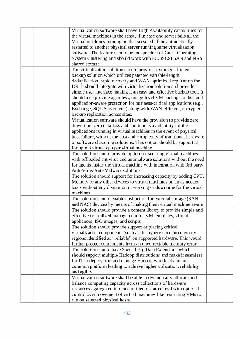
443
Virtualization software shall have High Availability capabilities for
the virtual machines in the sense, if in case one server fails all the
Virtual machines running on that server shall be automatically
restarted to another physical server running same virtualization
software. The feature should be independent of Guest Operating
System Clustering and should work with FC/ iSCSI SAN and NAS
shared storage
The virtualization solution should provide a storage efficient
backup solution which utilizes patented variable-length
deduplication, rapid recovery and WAN-optimized replication for
DR. It should integrate with virtualization solution and provide a
simple user interface making it an easy and effective backup tool. It
should also provide agentless, image-level VM backups to disk and
application-aware protection for business-critical applications (e.g.,
Exchange, SQL Server, etc.) along with WAN-efficient, encrypted
backup replication across sites.
Virtualization software should have the provision to provide zero
downtime, zero data loss and continuous availability for the
applications running in virtual machines in the event of physical
host failure, without the cost and complexity of traditional hardware
or software clustering solutions. This option should be supported
for upto 8 virtual cpu per virtual machine
The solution should provide option for securing virtual machines
with offloaded antivirus and antimalware solutions without the need
for agents inside the virtual machine with integration with 3rd party
Anti-Virus/Anti-Malware solutions
The solution should support for increasing capacity by adding CPU,
Memory or any other devices to virtual machines on an as needed
basis without any disruption in working or downtime for the virtual
machines
The solution should enable abstraction for external storage (SAN
and NAS) devices by means of making them virtual machine aware
The solution should provide a content library to provide simple and
effective centralized management for VM templates, virtual
appliances, ISO images, and scripts
The solution should provide support or placing critical
virtualization components (such as the hypervisor) into memory
regions identified as “reliable” on supported hardware. This would
further protect components from an uncorrectable memory error
The solution should have Special Big Data Extensions which
should support multiple Hadoop distributions and make it seamless
for IT to deploy, run and manage Hadoop workloads on one
common platform leading to achieve higher utilization, reliability
and agility
Virtualization software shall be able to dynamically allocate and
balance computing capacity across collections of hardware
resources aggregated into one unified resource pool with optional
control over movement of virtual machines like restricting VMs to
run on selected physical hosts.

444
The solution should be able to automate energy efficiency in
Distributed Resource Scheduler clusters by continuously optimizing
server power consumption within each cluster
Virtualization Software Should support live Virtual Machine
migrations across Physical Hosts, between virtual switches,
between two different virtualzation managers or between servers
physically separated over a long distance leading upto 100ms of
network latency
The solution should be capable of providing Proactive High
Availability, VM-level Encryption, Integrated Containers,
Centralized Network Management, Rapid Deployment and
Provisioning.
The solution should be able to create a cluster out of multiple
storage datastores and automate load balancing by using storage
characteristics to determine the best place for a virtual machine’s
data to reside, both when it is created and when it is used over time.
Virtualization software should provide network traffic-management
controls to allow flexible partitioning of physical NIC bandwidth
between different network-traffic types and allow user-defined
network resource pools, enabling multi-tenancy deployment, and to
bridge virtual and physical infrastructure QoS with per resource
pool 802.1 tagging.
The solution should be able to set quality-of-service priorities for
storage for guaranteed access to resources
The solution should allow one PCI express (PCIe) adapter to be
presented as multiple separate logical devices to the virtual
machines which in turn should enable users with the ability to
offload I/O processing and reduce network latency
The solution should be able to virtualize server-side flash providing
a high performance read cache layer that dramatically lowers
application latency
The solution should have support to deliver the full benefits of
NVIDIA hardware-accelerated graphics to virtualized solutions
The solution should provide a virtual switch which can span across
a virtual datacenter and multiple hosts should be able to connect to
it. This in turn will simplify and enhance virtual-machine
networking in virtualized environments and enables those
environments to use third-party distributed virtual switches
The solution should provide feature which can perform quick, as-
needed deployment of additional virtualized hosts. When the
service is running, it can push out update images, eliminating
patching and the need to schedule patch windows.
Virtualization management software console shall provide
capability to monitor and analyze virtual machines, and server
utilization and availability with detailed performance graphs.
Virtualization management software console should allow cloning
of both powered on and powered off virtual machines.
Virtualization management software should provide a global
search function to access the entire inventory of multiple instances
of virtualization management server, including virtual machines,

445
hosts, datastores and networks, anywhere from within
Virtualization management server.
Virtualization management software should support user role and
permission assignment (RBAC)
The management solution for hypervisor should provide Single-
Sign-On capability which should dramatically simplify
administration by allowing users to log in once to access all
instances or layers of management without the need for further
authentication.
The management should provide Orchestration facility which
would simplify installation and configuration of the powerful
workflow engine in Management. The workflows should be
launched directly from the Web Client itself
The Virtualization software must be perpetual, no trial versions
accepted.
The software provider must provide direct support option for 24
Hours/Day, 7 Days/Week, 365 Days/Year and support should be
handled from the platform provider.
Software provided must entertain unlimited number of support
requests, within active Support and Subscription contract
3 Software for - Virtualization Management
Brand Any International Reputed Brand
Part no. Please mention
Quantity 02 Unit license
Virtual
Machines
Management
Software
Virtualization management software console shall provide a single
view of all virtual machines, allow monitoring of system
availability and performance and automated notifications with
email alerts.
The management software should provide means to perform quick,
as-needed deployment of additional hypervisor hosts. This
automatic deployment should be able to push out update images,
eliminating patching and the need to schedule patch windows.
The virtualization should have capability to simplify host
deployment and compliance by creating virtual machines from
configuration templates.
Virtualization management software should have integrated
Physical Host and Virtual Machine performance monitoring
including CPU, Memory, Disk, Network, Power, Storage Adapter,
Storage Path, Cluster services, Virtual machine data stores.
Virtualization management software console shall provide reports
for performance and utilization of Virtual Machines. It shall co-
exist and integrate with leading systems management vendors
Virtualization management software console shall provide
capability to monitor and analyze virtual machines, and server
utilization and availability with detailed performance graphs.
Virtualization management software console shall allow to Move a
powered off virtual machine from one physical server to another by
dragging and dropping the virtual machine icon.

446
Virtualization management software console shall provide
Interactive topology maps to visualize the relationships between
physical servers, virtual machines, networks and storage.
Virtualization management software console shall provide the
Manageability of the complete inventory of virtual machines, and
physical servers with greater visibility into object relationships.
Virtualization management software should provide a global search
function to access the entire inventory of multiple instances of
virtualization management server, including virtual machines,
hosts, data stores and networks, anywhere from within
Virtualization management server.
Virtualization management software should support user role and
permission assignment (RBAC)
Virtualization management software should allow you to deploy
and export virtual machines, virtual appliances in Open Virtual
Machine Format (OVF).
Virtualization management software should allow reliable and non-
disruptive migrations for Physical/ Virtual machines running
Windows and Linux operating systems to virtual environment.
Virtualization management software should include provision for
automated host patch management with no VM downtime
Virtualization management software should generate automated
notifications and alerts, and can trigger automated workflows to
remedy and pre-empt problems.
Virtualization management software should be able to integrate into
existing standard EMS systems.
The management solution for hypervisor should provide Single-
Sign-On capability which should dramatically simplify
administration by allowing users to log in once to access all
instances or layers of management without the need for further
authentication.
The management should provide Orchestration facility which
would simplify installation and configuration of the powerful
workflow engine in Management. The workflows should be
launched directly from the Web Client itself.
The Virtualization software must be perpetual, no trial versions
accepted.
The virtualization software provider must provide direct support
option for 24 Hours/Day, 7 Days/Week, 365 Days/Year and support
should be handled from platform provider.
The Virtualization Software provided must entertain unlimited
number of support requests, within active Support and Subscription
contract
Training &
Knowledge
Transfer
Offered virtualization platform and management scopes
administration training shall be provided for min. 10 working days
for 3 persons in the platform service providers training centers.
Warranty Three (3) years 24x7 support from the platform provider.
4 Container Platform (Separate from Virtualization Platform)
Master Nodes Shall be considered deployment on the Virtualization Platform (DC
& DR)

447
Worker Node
(DC)
Node Count: 4 (Four)
Each Node: 2x 8-Core
Memory Each Node: 768GB
Storage: CSI Plug-in with the offered storage
Worker Node
(DR)
Node Count: 4 (Four)
Each Node: 2x 8-Core
Memory Each Node: 768GB
Storage: CSI Plug-in with the offered storage
Warranty 3 Years 24x7 Support and Subscription from the platform provider.
Features
Cloud-like experience for the administrators, and
operators/developers with web console
Flexibility to execute commands via command line or via web
console
Provides cost management feature out-of-the-box
Ability to define cost management metric by individual tenants
Separate web console interface for administrators and
operators/developers
Supports application topology to allow developers to view how the
application is managed and how resources are being consumed
within the platform
Dashboards (web consoles) that display charts with important, low-
level metrics for detailed investigation and troubleshooting of the
cluster logging and Elasticsearch instances.
Support set up in Virtual Machine (VM) and/or Bare-Metal (BM)
and/or Hybrid (Mix of VMs and BM)
Supports full bare-metal setup on-premises?
Supports VMWare VSphere or OpenStack
Supports Multi-cluster
Supports multi-cluster management with Add-on/Built-in
Forbid execution of root-privilege containers out-of-the-box
Supports scalability manually and automatically
Supports multi-tenant with security isolation
Based on minimum Kubernetes 1.19
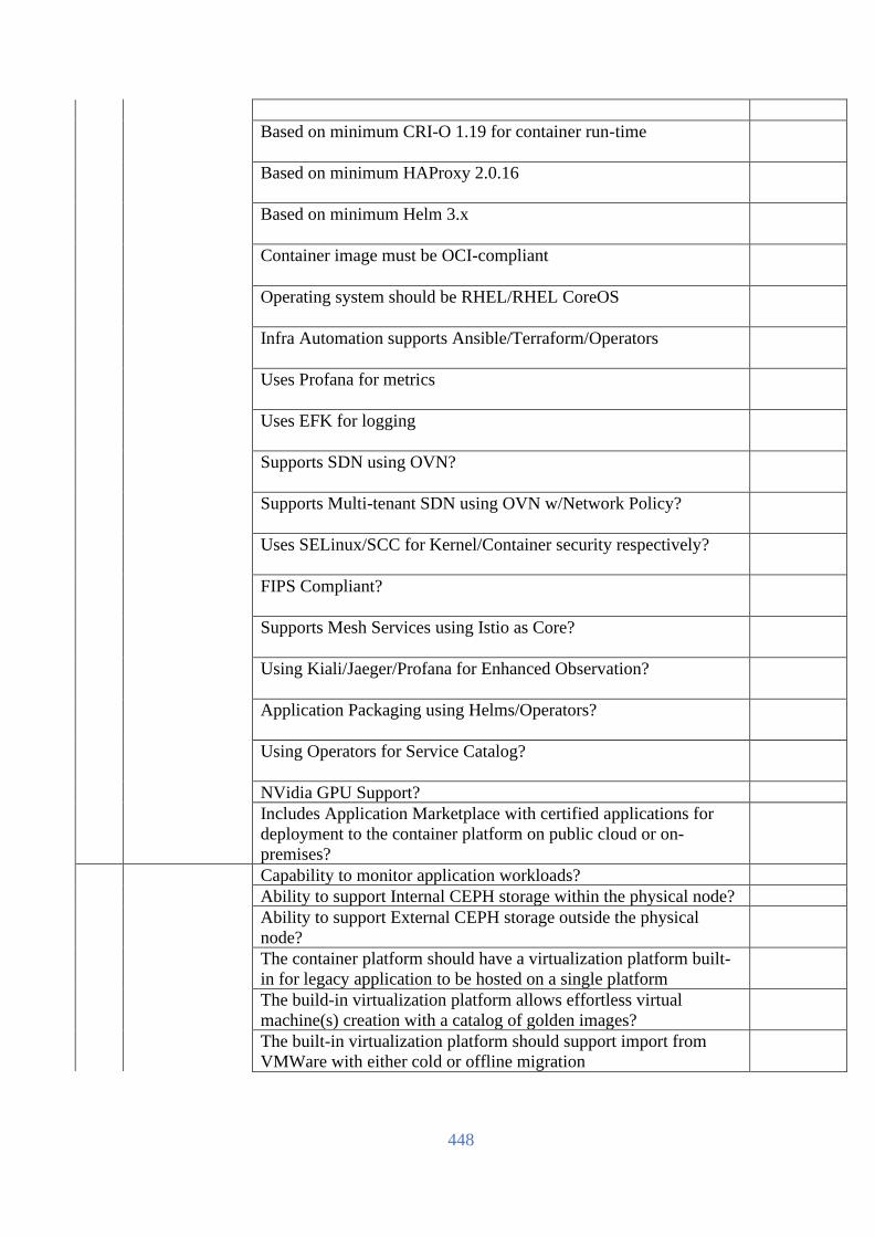
448
Based on minimum CRI-O 1.19 for container run-time
Based on minimum HAProxy 2.0.16
Based on minimum Helm 3.x
Container image must be OCI-compliant
Operating system should be RHEL/RHEL CoreOS
Infra Automation supports Ansible/Terraform/Operators
Uses Profana for metrics
Uses EFK for logging
Supports SDN using OVN?
Supports Multi-tenant SDN using OVN w/Network Policy?
Uses SELinux/SCC for Kernel/Container security respectively?
FIPS Compliant?
Supports Mesh Services using Istio as Core?
Using Kiali/Jaeger/Profana for Enhanced Observation?
Application Packaging using Helms/Operators?
Using Operators for Service Catalog?
NVidia GPU Support?
Includes Application Marketplace with certified applications for
deployment to the container platform on public cloud or on-
premises?
Capability to monitor application workloads?
Ability to support Internal CEPH storage within the physical node?
Ability to support External CEPH storage outside the physical
node?
The container platform should have a virtualization platform built-
in for legacy application to be hosted on a single platform
The build-in virtualization platform allows effortless virtual
machine(s) creation with a catalog of golden images?
The built-in virtualization platform should support import from
VMWare with either cold or offline migration

449
The container platform should include a compliance operator to
provide security/technical compliance scanning of the cluster based
on the selected security profile(s)
The container platform should provide a file integrity operator to
scan selected nodes to populate the advanced intrusion and
detection engine (AIDE) database for administrators to examine the
scan results for status for auditing purposes
The container platform should provide a migration toolkit for
applications to help ease the Java application migration to be more
JEE compliant, and container friendly
The container platform must provide certified storage interface
(CSI) operators for Original Equipment Manufacturers (OEM)
storage solutions
The container platform should provide an over the air update via its
web interface for the administrators with recommendation of update
paths and available channels. It should provide transparency into
the update process with an in-progress checklist. The platform
should include the following alerts status for the administrators.
• whenever a patch becomes available.
• whenever a new minor release becomes available
• Whenever new channels become available.
Supports Add-on Red Hat Ansible Automation Platform for
automation
Supports continuous integration / continuous delivery
process/pipeline (built-in or add-ons)
Supports smart management tools (as an add-on) for management
of RHEL OS
Smart management tool (add-on) provides vulnerability assessment,
compliance assessments and system comparison features
Smart management tool (add-on) provides the ability to execute the
remediation plans provided by Red Hat Insights if Red Hat
Enterprise Linux (RHEL) is used as the operating system for
compute nodes
Availability of Solution Roadmap!
Availability of publicly accessible contents of technology updates
for each releases!
Training and
knowledge base
transfer
Shall be provided with administrator training for min. 5 days for 3
persons in the platform providers training center. Necessary cost to
be conveyed by the bidder.
Installation and
deployment
service
Shall be provided with professional installation and deployment
service from the platform service provider till UAT.
[The Bidder should complete all the columns as required]
Name
In the capacity of
Signed
Duly authorized to sign the Bid for and on behalf of
Date

450
Passive Infrastructure Technical Specification
(To be filled up and signed by the Bidder & Manufacturer, otherwise the offer will not be acceptable)
Required Space Details Approximate Space
(Approx.) Bidder Response
Server Room 1000 to 1200 sft NOC Room 150 sft Power Room 350 sft Battery Room 150 sft Meet Me Room and Staging Room 150 sft
[The Bidder should complete all the columns as required]
Name
In the capacity of
Signed
Duly authorized to sign the Bid for and on behalf of
Date

451
Civil, Infrastructure and Interior (To be filled up and signed by the Bidder & Manufacturer, otherwise the offer will not be acceptable)
SL Description of Items Unit Qty
Bidder's Response
1 Civil, Infrastructure & Interior for Server Room
NOC Room Build Up: Chair & Table & Video Wall with
Controller
Meet Me Room
Power Room
Staging Room Raise Floor Earthing system ISP connectivity
Lot 2
2 Scope (As per the site survey)
[The Bidder should complete all the columns as required]
Name
In the capacity of
Signed
Duly authorized to sign the Bid for and on behalf of
Date

452
Electrical Infrastructure (To be filled up and signed by the Bidder & Manufacturer, otherwise the offer will not be acceptable)
SL Item Description Unit Qty
Bidder’s Response
1 Electrical Infrastructure for 80 KVA with full redundancy
Cabling System Lot 2
Distribution Boards/ Panel
MDB (Multi Distribution Board)
• Mains rating 400, 600, 800A, 1000A and 1200A
• Individually mounted feeder device up to 1200A
• Micrologic trip circuit breakers as main or feeder
• Tested and certified to CSA 22.2 No 31
• Country of Origin:
USA/UK/EU/Switzerland/Australia/Japan
EMDB+MDB
Utility DB
UPS DB
CAC & PAC
Manual Change Overboard
Conduit Work
Lighting System
Switch & Socket
Industrial Socket
Socket Outlet
Installation work as required
2 Scope (As per the site survey)
[The Bidder should complete all the columns as required]
Name
In the capacity of
Signed
Duly authorized to sign the Bid for and on behalf of
Date

453
Raise floor System (To be filled up and signed by the Bidder & Manufacturer, otherwise the offer will not be acceptable)
SL Minimum Technical Requirements Compliance
(Yes/No)
Remarks
1 Country of Origin: USA/UK/EU/Switzerland/Australia/Japan
2 Country of Manufacture:
USA/UK/EU/Switzerland/Australia/Japan
3 The raised floor shall consist of interchangeable modular floor
panels 600x600 mm, gravity laid, supported by a steel structure
made from pedestals and stringers. The under-floor cavity shall be
fully accessible and allow for an easy maintenance of the under
floor technical systems
4 Access floor system shall provide a maximum finished floor height
of 600 mm from the existing floor level. The system shall provide
for suitable pedestal and under-structure designed to withstand
various static loads subjected to it in an office and control rooms
area. The entire Access floor system shall provide for adequate fire
resistance.
5 Calcium sulphate Floor Panel with GI top & bottom finish
Panel consists of a single-ply mineral core formulated with high-
density (≥1500kg/m3) calcium sulphate, 30mm nominal thickness,
bonded with fibers featuring remarkable mechanical resistance and
entirely free of wood particles. To improve the flexural stiffness and
overall mechanical resistance, the panel is produced by applying a
0.3mm thick sheet of zinc-plated steel on the lower & top face. This
also provides an excellent barrier and guarding against fire and
moisture and an equipotential reinforcement for the purpose of
maintaining the electrical continuity of the access floor
6 The panel shall be provided by a full depth rigid PVC-free plastic
edge banding that protects the panel and the top covering against
hits, acts as a barrier against humidity, reduces the transmission of
the horizontal sound. The edge band shall be self-extinguishing in
Class V0 according to the Norm UL to retard the propagation of
flame in case of fire. The edges shall have a 4°-degree inclination
to facilitate the installation and the removal of the panels for
maintenance.
7 The dimension of the panel shall be 600x600 mm with max
dimensional allowances of 0,2 mm according to the Class 1 of the
European Standard EN 12825. All adhesives utilized for the
bonding of the panel components shall be formaldehyde and solvent
free and made of ecofriendly substances.
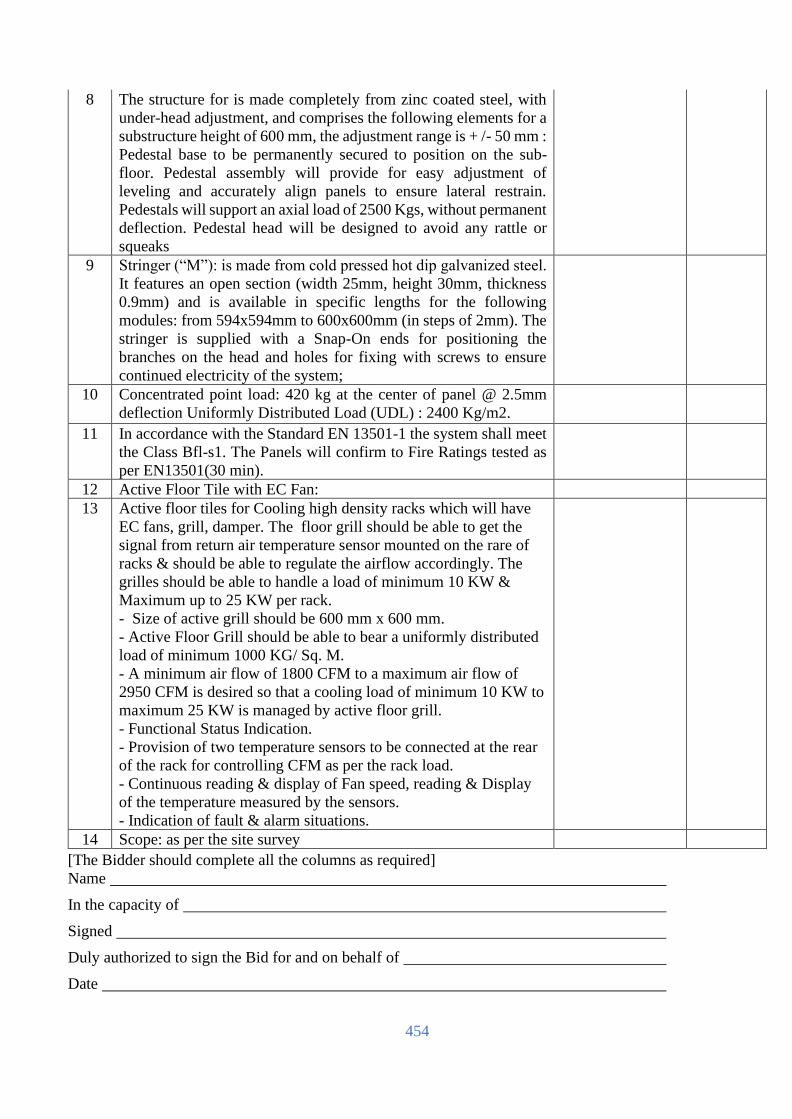
454
8 The structure for is made completely from zinc coated steel, with
under-head adjustment, and comprises the following elements for a
substructure height of 600 mm, the adjustment range is + /- 50 mm :
Pedestal base to be permanently secured to position on the sub-
floor. Pedestal assembly will provide for easy adjustment of
leveling and accurately align panels to ensure lateral restrain.
Pedestals will support an axial load of 2500 Kgs, without permanent
deflection. Pedestal head will be designed to avoid any rattle or
squeaks
9 Stringer (“M”): is made from cold pressed hot dip galvanized steel.
It features an open section (width 25mm, height 30mm, thickness
0.9mm) and is available in specific lengths for the following
modules: from 594x594mm to 600x600mm (in steps of 2mm). The
stringer is supplied with a Snap-On ends for positioning the
branches on the head and holes for fixing with screws to ensure
continued electricity of the system;
10 Concentrated point load: 420 kg at the center of panel @ 2.5mm
deflection Uniformly Distributed Load (UDL) : 2400 Kg/m2.
11 In accordance with the Standard EN 13501-1 the system shall meet
the Class Bfl-s1. The Panels will confirm to Fire Ratings tested as
per EN13501(30 min).
12 Active Floor Tile with EC Fan:
13 Active floor tiles for Cooling high density racks which will have
EC fans, grill, damper. The floor grill should be able to get the
signal from return air temperature sensor mounted on the rare of
racks & should be able to regulate the airflow accordingly. The
grilles should be able to handle a load of minimum 10 KW &
Maximum up to 25 KW per rack.
- Size of active grill should be 600 mm x 600 mm.
- Active Floor Grill should be able to bear a uniformly distributed
load of minimum 1000 KG/ Sq. M.
- A minimum air flow of 1800 CFM to a maximum air flow of
2950 CFM is desired so that a cooling load of minimum 10 KW to
maximum 25 KW is managed by active floor grill.
- Functional Status Indication.
- Provision of two temperature sensors to be connected at the rear
of the rack for controlling CFM as per the rack load.
- Continuous reading & display of Fan speed, reading & Display
of the temperature measured by the sensors.
- Indication of fault & alarm situations.
14 Scope: as per the site survey
[The Bidder should complete all the columns as required]
Name
In the capacity of
Signed
Duly authorized to sign the Bid for and on behalf of
Date

455
Accessories
(To be filled up and signed by the Bidder & Manufacturer, otherwise the offer will not be acceptable)
SL Details Description UOM Qty
1 Double suction
panel lifter
Brand: To be mentioned by the bidder Nos 2
Brand Origin:
USA/UK/EU/Switzerland/Australia/Japan
Country of Manufacture:
USA/UK/EU/Switzerland/Australia/Japan
Model: Should be mentioned
Double suction panel lifter
2 Air grommet Brand: To be mentioned by the bidder Nos 32
Brand Origin:
USA/UK/EU/Switzerland/Australia/Japan
Country of Manufacture:
USA/UK/EU/Switzerland/Australia/Japan
Model:
USA/UK/EU/Switzerland/Australia/Japan
Rectangle shape: Dust-proof panel with
double brush - (opening size 410x215mm)
Accessories
Accessories
Pedestal glue, Locking glue. bottle for filling,
Foam tape, Aluminum pads, Application
device for pedestal glue.
3 Contamination
Control Mat
Contamination Control Mat. Mat for Data
Center & Power Room
1 sets
4 Mesh Cable
Tray & Fiber
Race way
Mesh Cable Tray & Fiber Race way for DC
and DR (Based on the site survey)
1 sets
5 Signal Reference
Grid
25X4 mm Signal Reference Grid SRG for DC
and DR (Based on the site survey)
1 Sets
6 CAT 6 Cabling
Solution
Copper Solution for DC Site and DR Site
(Based on Site Survey)
1 Sets
7 Optical Cabling
Solution
Optical cabling Solution for DC Site and DR
Site (Based on Site Survey)
1 Sets
8 Scope As per the site survey
[The Bidder should complete all the columns as required]
Name
In the capacity of
Signed
Duly authorized to sign the Bid for and on behalf of
Date

456
Rack with Cold Aisle Containment (To be filled up and signed by the Bidder & Manufacturer, otherwise the offer will not be acceptable)
SL Description Required Specification Unit Qty
1.1 Brand: To be mentioned by the bidder
1.2 Model: To be mentioned by the bidder
1.3 Country of Origin: USA/UK/EU/Switzerland/Australia/Japan
1.4 Country of
Manufacturer:
To be mentioned by the bidder
1.5 Rack Profile Steel
Server Rack Cabinets - 42U - 600mm Width x
1200mm Depth x 2000mm maximum
Nos 8
Network Rack Cabinets - 42U - 750mm Width x
1200mm Depth x 2000mm maximum
Nos 4
Loading Capacity: 1700 kg
Height equipment cabinets shall have adjustable 19
inch front and rear vertical mounting extrusions which
are EIA-310D and IEC 60297 compliant and allow up
to 990mm of depth for equipment mounting. Rear pair
of 19 inch extrusions divided. The 19 inch mounting
rails will accept standard threaded cage nuts. Balanced
load rating of 1700 kg. Cabinet shall be manufactured
from materials and processes that are compliant with
the most current environmental management
standards with IP protection rating: IP 20. The front
and rear 19-inch equipment mounting rails and other
internal supporting metals are to be of steel. Cabinet
shall come complete with grounding kit, cage nuts and
the following features and installed accessories:
Front door – reversible, vented with open perforation
of not less than 63 %, complete with handle and
universal key. Hinges releasable from inside only,
door easily removable without tools.
Rear door – vertically divided, open perforation rate
63%, swivel handle, DIN profile, universal key,
multipoint, reversible, complete with handle and
universal key. Hinges releasable from inside only,
door easily removable without tools.
Two pairs (front and rear) steel vertical 19-inch
equipment mounting extrusions fully compatible with
servers, fully adjustable front to rear depth positions
within the cabinet. Marked “U” positions on front and
rear side. Size of mounting holes is 9.5mm x 9.5mm.
Racks should have optional accessories like blanking
panels to fill in the U Space.
Removable 2-piece side panels with 2 locks . Side
panels are grounded.

457
Removable top plate single-piece design with many
options. In standard minimum five openings for cable
entries covered with access caps. All cable openings
accept rubber grommets and/or brushes where
applicable.
Frame columns with holes for screws M5 for
connecting racks to rows with side panels.
Bottom is flat with castors and wheels and enables
direct installation of the rack on the floor
Central grounding point
Cabinets Finish color powder coated Black
5 round/square/rectangle cable entries with brush on
roof
2 Containment Cold Aisle Containment for Data Centre Set 1
Rack and containment should be from same
manufacturer
Supply, Assembly and installation of Cold Aisle
Containment for 16 racks with 2 doors as shown in
layout
General
The Containment uses a series of panels, door frames
and doors, and air blocks to enclose a cold aisle zone
which contains cooling unit supply air
Cold Aisle Containment: The cold aisle zone is the
space between two rows of IT equipment racks with
cold air being supplied between the two rows of racks
(or one row of racks and an architectural wall) and the
IT equipment exhausts hot air away from the aisle. In
this enclosed space cooling unit supply air is collected
inside of the Containment. The cool air is supplied to
the IT equipment while the IT equipment exhaust air
is pushed outside the Containment and returned to the
cooling unit.
By preventing mixing of cool supply air and hot
exhaust air, this self-contained configuration is
capable of supporting a complete range of low,
medium and high power/heat density loads, and can
be deployed in multiple environments without
affecting the surrounding area.
Production Facility shall be certified as suitable for
this data center environment by documentation
supporting UL Listing, European Conformity, ROHS
and ISO 9001 Certifications and compliances
Rack and containment should be from same
manufacturer
Ceiling Panel
A. Ceiling panels shall be minimum 5.0 mm or
more thick Lexan clear-ribbed panels or 2.36 mm
thick V0 clear panels with SPCC framing.

458
B. Minimum Light Transmission per ASTM
D1003 equal to 82% or greater.
C. Ceiling panels shall be designed to be supported
by the frames of the IT Equipment racks. Ceiling
Panel frames sizes shall be suitable to match up with
various rack widths, row width, and aisle widths.
D. The ceiling system shall be designed to permit
removal of the ceiling panel from within the
contained zone without the use of tools for service
access to the space above the Aisle.
Door Frames and Door
A. Metal door frames and doors shall be provided
to establish air containment at the end of two rows of
racks. The door frame system shall match the height
of the rack-based equipment and match the design
width of the contained aisle.
B. Doors shall be Sliding, to permit access into the
contained aisle for maintenance or servicing.
C. Doors shall be provided with a window, handles
and latches.
D. The sliding doors of the containment should open
as swing doors which shall help personnel to push
open the door to escape during emergency
Frames and Component Seal
A. Foam Rubber gaskets or metal/composite, brush,
or plastic air blocks shall be installed at Aisle joints to
minimize open gaps between containment system
components, such as door frames, ceiling and duct
panels, and IT Equipment racks and rack-based
equipment. Gasketing and/or air blocks may include,
but not be limited to, the following.
1. Joints between adjacent ceiling/duct panels
2. Joints between ceiling/duct panels and top of
racks, if not metal to metal.
3. Joints between door frames and ceiling/duct
panels, if not metal to metal.
4. Joints between door frames and racks at the end
of the row(s).
5. Joints between rack bottom rear frame and
floor.
6. Joints between duct panel and ceiling/roof of
room.
Blanking Panels, Height Adapters, and Depth
Extenders
1. Can be used to provide an aesthetic alternative
for varying dimension enclosures.

459
2. Blanking Panels shall be placed where gaps
between racks exist to seal contained aisle. The panel
shall match the height of the enclosures and match the
width of the gap. It shall not be mounted to any
adjacent blanking panels nor shall it support any
adjustable height supports.
3. Depth Extenders shall mount to front or back of
enclosures to align aisle. The extender shall match the
depth of the adjacent racks and match the width and
height of the enclosure (including any height adapters)
of which it is being mounted
4. Height Adapters shall mount to the top of
enclosures to align the enclosure height. The height
adapter matches the height of the adjacent racks and
shall match the width and depth of the rack (including
any depth adapters) of which it is being mounted.
LED Light in each Rack Front
Two Side Light inside Containment
[The Bidder should complete all the columns as required]
Name
In the capacity of
Signed
Duly authorized to sign the Bid for and on behalf of
Date

460
Online Modular UPS with Lithium-Ion batteries for IT Load (To be filled up and signed by the Bidder & Manufacturer, otherwise the offer will not be acceptable)
SL Description Required Specification Unit QTY
1.1 Brand: To be mentioned by the bidder
1.2 Model: To be mentioned by the bidder
1.3 Country of Origin: USA/UK/EU/Switzerland/Australia/Japan
1.4 Country of Manufacture: To be mentioned by the bidder
1.5 Country of Shipment: To be mentioned by the bidder
1.6 Capacity: Minimum 200 KW Module upgradable up
to 500KW within the same frame
1.7 Module: Up to 50KW Hot Plug and hot swappable
function
1.8 Number of Module: To be mentioned by the bidder
1.9 Backup Time: Minimum 60 min at 200 KW load (LMO-
NCM Lithium Ion Battery)30 Minutes back
up on each UPS at 200 kW Load.
1.1 Battery String (Bank): To Be Mentioned by the Bidder
1.11 Input Battery Voltage: To be mentioned by the bidder
1.12 Topology: Modular, True Online Double Conversion
1.13 Module Power kVA (kW) 20 to 50KW
1.14
No. of parallelable module in
one rack
5 to 10
1.15 Power module Dimension To Be Mention by the Bidder
1.16 Dimension and weight To Be Mention by the Bidder
1.17
Efficiency
System AC-AC efficiency
Online Double Conversion
Minimum 96% from 20 % load to 100 %
Loading along with PF Correction to Unity
at Input & Har-monic Correction (THDI) to
< 5% at Input.
Static Bypass Mode of
Operation along with Battery
Charging
≥ 98 % from 20 % load to 100 % Loading
along with PF Correction to Unity at Input
& Harmonic Correction (THDI) to < 5% at
Input and simultaneously Battery Charging
also.
Incase Vendor does not comply; additional
Har-monic Filters and Power Factor
Improvement Unit shall be provided at
UPS Bypass Circuit.
It shall be a standardized solution. UPS
vendor to submit UL Certification for the
same
1.18 Load PF To Be Mention by the Bidder
1.19 Hot swappable Hot Swappable Power Module
1.2 Module control Centralized/ Distributed

461
1.21 Input voltage tolerance To Be Mention by the Bidder
1.22 Input frequency tolerance 40-70 Hz
1.23 Input PF 0.99 @ 100% Load
1.24 THDI <3% @ 100% Load
1.25 Overload 10 Min @ 125% Load
1.26 1 Min @ 150% Load
1.27 Noise level To Be Mention by the Bidder
1.28 Display 7 inch Touch Display
1.29 Input THDi <3%
1.3 Input PF 0.99 @50-100% Load
1.31 THDv @ 100% Linear Load <1%
1.32
THDv @ 100% Non-Linear
Load
<3%
1.33 No of Battery Blocks To be Mentioned by the Bidder
1.34 Static Bypass Centralized
1.35 Dimensions To be Mentioned by the Bidder
1.36 Cable entry Top / Bottom
1.37 Crest factor: 2.5:01
1.38 General Features for UPS:
1.39
Redundancy and Fault
tolerance:
The UPS System Shall Design for no single
point of failure and should be driven by the
different power modules. It should not
consist of any major component failure of
which may cause the failure of all module’s
operations. It shall have fault isolation
capability. True hot Swappable function.
No need to input any special command
before unplug or plugin any module. It
shall be possible to interchange the sub
power modules among each other in the
frame or from any of the other similar
Frame without the need of shutdown or
programming re-quired by the OEM /
Service Team
Phase Sequence Correction at
Input
The UPS shall be provided with Phase
Sequence Correction at Input i.e. In case of
Phase reversal at Input, UPS shall continue
to operate in Double Conversion Mode of
operation without going to battery mode.
Icw for Input/Bypass
Terminals
The UPS shall have a short circuit rating of
65 kA for Input & Bypass Terminals and
limited to ≤ 2 kA for Power Modules.
Cable Termination Top Cable Entry with Copper as well as
Aluminum
Incase Aluminum Cable termination is not
possible, vendor to provide separate

462
cube/box with input & output breakers &
busbars with each UPS module.
Required waveform capturing
/store function availability
like an event triggered
oscilloscope: Input voltage,
Bypass voltage, Output
voltage, Output current,
Battery voltage, Ground
voltage, DC bus voltage
Required (Inbuilt or separate external
device)
100% Conformal coating of
critical components PCBs
Required
User Replaceable Dust Filters
without shutting down the
UPS along with Rodent mesh
Required
Energy Meter for displaying
kWh consumption
(Inbuilt / External)
Required
UPS Full Load Testing UPS shall be capable to test at 100% Load
with-out the need of any ex-ternal load
bank. Incase this feature in not built-in, a
external fully rated load bank of UPS
capacity along with breakers and cables
shall be considered which will be kept at
site till the warranty period of the UPS
1.4
Power module system to
drive Modular UPS system:
Hot Swappable Power Module
1.41
Battery module system to
drive Modular UPS system:
Lithium Ion Batteries (LMO-NCM)
1.42
Centralized static UPS must have centralized module static
Switch as per the Frame capacity
1.43 Centralized control & UPS must have centralized control &
monitoring interface: monitoring interface
1.44 Power module online UPS must have Power module online
swappable: swap ability. It shall be possible to insert &
remove (Plug In-Plug Out) sub power
module from the UPS frame while the UPS
is in Online Double Conversion Mode of
operation i.e., Sub Power modules shall be
swappable without putting the UPS in
bypass/battery operation. Same shall be
certified by UL (Underwriters Laboratory)
1.45 Controller: Individual Controller each module or
Redundant Controller each UPS
1.46 Display: Separate display for UPS
1.46 External Maintenance
Bypass
Central mechanical bypass in a separate
enclosure to be provided.
1.47 Battery Connection: To be mentioned by the bidder

463
1.47 Supported Battery Type: To be mentioned by the bidder
1.48 Environment:
1.48 Protection rating: IP 20 or Better
1.49 Operating Humidity: To be mentioned by the bidder
1.49 Operating temperature: 0–40°C without derating or overload in kW
Capacity of UPS in continuous operation.
1.5 Communication:
1.5 LCD Display: 7 inch Touch Screen Display for showing
all necessary information
1.51 Communication ports: RS-232, SNMP slot or to be mentioned by
the bidder if there any other ports are
available
1.51 Remote Monitoring &
Management:
SNMP card with remote monitoring and
management capability and compatible
with Data Centre Infrastructure
Management System (DCIM) /
Environment Monitoring System (EMS)
1.52 Firmware upgrades: Shall have on the fly Firmware Upgrade
Capability. There shall have no interruption
on live operation.
1.52 Event logging: Event logging capability, preferably with
graphs in the proposed software.
1.53 Standard:
1.53 Safety: IEC/EN 62040-1 and/or to be mentioned
by the bidder if there anything better than
the requirement
1.54 Electromagnetic
Compatibility:
IEC/EN 62040-2 and/or to be mentioned
by the bidder if there anything better than
the requirement
1.54 Product Certification: UL & CE/TÜV
1.55 Manufacturing Certification: ISO 9001, ISO 14001, ISO 50001
1.55 UPS Cabinet Weight & Dimension:
1.56 Weight: To be mentioned by the bidder
1.56 Dimension W(mm) × H
(mm)× D (mm):
To be mentioned by the bidder
1.57 Battery:
1.57 Brand: To be mentioned by the bidder
1.58 Model: To be mentioned by the bidder
1.58 Country of Origin: USA/UK/EU/Switzerland/Australia/Japan
1.59 Country of Manufacture: To be mentioned by the bidder 1.59 Type: To be mentioned by the bidder
1.6 Nominal Voltage: To be Mentioned by the bidder 1.6 Battery Ampere: To be mentioned by the bidder 1.61 Number of Batteries per
module and per UPS Set:
To be mentioned by the bidder

464
1.61 Others: Battery Backup Calculation Sheet must be
submitted by the OEM letterhead from
which batteries are collected showing that
supplied batteries are capable to provide
desired backup at full load at the time of
commissioning 1.62 Weight per Battery (Kg): To be mentioned by the bidder
1.62 Battery Dimension: To be mentioned by the bidder
1.63 Designed Life Time for
Battery:
Minimum 10 Years
1.63 Battery Cabinet: Best quality customizable powder coated
metal cabinet with N+1 circuit breaker box
having an easy-to-open transparent
window. Battery system Certifications:
Safety Cell UL1642, Module UL 1973,
Transportation UN38.3, Seismic GR63,
EMC IEC61000-6-2, 61000-6-4. Proposed
LIB shall be UL 9450A Certified, i.e. Test
Method for Evaluating Thermal Runaway
Fire Propagation in Battery Energy Storage
Systems. Certificate shall be provided by
the bidder
1.64 Battery Cabinet Dimension: To be mentioned by the bidder (preferably
as per drawing)
1.64 Battery Monitoring System (BMS): 1.65 Battery Monitoring System
(BMS):
Battery Monitoring/Management System
with Remote Monitoring Capability.
Battery Monitoring System shall capable to
monitor individual Cell Level, Module
level, Bank Level including all critical
parameters etc. with graphical report. Other
Features to be mentioned by the bidder. 1.65
Battery Monitoring System should be form
same manufacturer as Batteries 1.66 Installation: Supply, Installation, Testing and
Commissioning with all required
components 1.66 Warranty: At least 3 years Full warranty with parts,
labour, replacement and onsite
support. 24/7 Support and respective team
should be assigned on site within 2 (two)
hours after reporting incident.
1.67 Reference Project OEM should have minimum 2 (two)
installations of 150 kVA or more capacity
UPS along with Lithium Ion Battery
installation in any Government or
Enterprise or bank or financial or
Colocation Data Centre in Bangladesh

465
1.68 Battery Calculation Battery Calculation should be submitted in
OEM letter head with seal and signed.
1.69 OEM Qualifications OEM for UPS, Modular Power Distribution
and Isolation Transformer to be Same.
[The Bidder should complete all the columns as required]
Name
In the capacity of
Signed
Duly authorized to sign the Bid for and on behalf of
Date
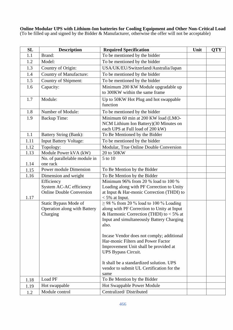
466
Online Modular UPS with Lithium-Ion batteries for Cooling Equipment and Other Non-Critical Load (To be filled up and signed by the Bidder & Manufacturer, otherwise the offer will not be acceptable)
SL Description Required Specification Unit QTY
1.1 Brand: To be mentioned by the bidder
1.2 Model: To be mentioned by the bidder
1.3 Country of Origin: USA/UK/EU/Switzerland/Australia/Japan
1.4 Country of Manufacture: To be mentioned by the bidder
1.5 Country of Shipment: To be mentioned by the bidder
1.6 Capacity: Minimum 200 KW Module upgradable up
to 300KW within the same frame
1.7 Module: Up to 50KW Hot Plug and hot swappable
function
1.8 Number of Module: To be mentioned by the bidder
1.9 Backup Time: Minimum 60 min at 200 KW load (LMO-
NCM Lithium Ion Battery)(30 Minutes on
each UPS at Full load of 200 kW)
1.1 Battery String (Bank): To Be Mentioned by the Bidder
1.11 Input Battery Voltage: To be mentioned by the bidder
1.12 Topology: Modular, True Online Double Conversion
1.13 Module Power kVA (kW) 20 to 50KW
1.14
No. of parallelable module in
one rack
5 to 10
1.15 Power module Dimension To Be Mention by the Bidder
1.16 Dimension and weight To Be Mention by the Bidder
1.17
Efficiency
System AC-AC efficiency
Online Double Conversion
Minimum 96% from 20 % load to 100 %
Loading along with PF Correction to Unity
at Input & Har-monic Correction (THDI) to
< 5% at Input.
Static Bypass Mode of
Operation along with Battery
Charging
≥ 98 % from 20 % load to 100 % Loading
along with PF Correction to Unity at Input
& Harmonic Correction (THDI) to < 5% at
Input and simultaneously Battery Charging
also.
Incase Vendor does not comply; additional
Har-monic Filters and Power Factor
Improvement Unit shall be provided at
UPS Bypass Circuit.
It shall be a standardized solution. UPS
vendor to submit UL Certification for the
same
1.18 Load PF To Be Mention by the Bidder
1.19 Hot swappable Hot Swappable Power Module
1.2 Module control Centralized/ Distributed
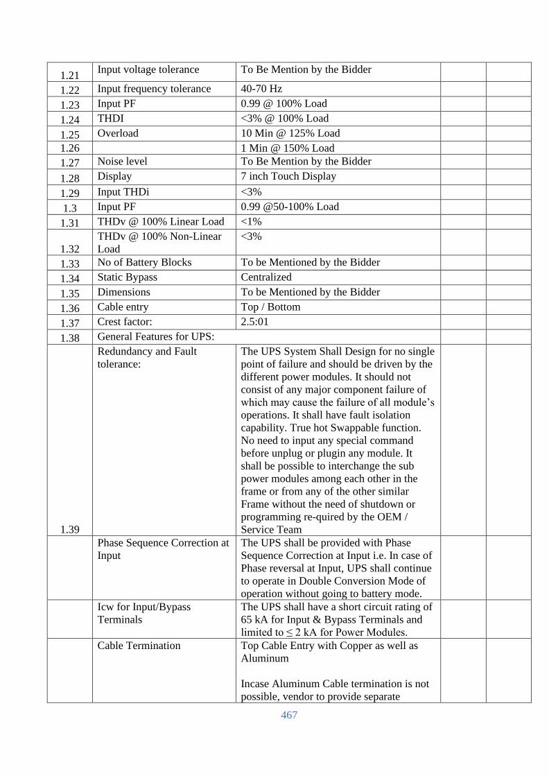
467
1.21 Input voltage tolerance To Be Mention by the Bidder
1.22 Input frequency tolerance 40-70 Hz
1.23 Input PF 0.99 @ 100% Load
1.24 THDI <3% @ 100% Load
1.25 Overload 10 Min @ 125% Load
1.26 1 Min @ 150% Load
1.27 Noise level To Be Mention by the Bidder
1.28 Display 7 inch Touch Display
1.29 Input THDi <3%
1.3 Input PF 0.99 @50-100% Load
1.31 THDv @ 100% Linear Load <1%
1.32
THDv @ 100% Non-Linear
Load
<3%
1.33 No of Battery Blocks To be Mentioned by the Bidder
1.34 Static Bypass Centralized
1.35 Dimensions To be Mentioned by the Bidder
1.36 Cable entry Top / Bottom
1.37 Crest factor: 2.5:01
1.38 General Features for UPS:
1.39
Redundancy and Fault
tolerance:
The UPS System Shall Design for no single
point of failure and should be driven by the
different power modules. It should not
consist of any major component failure of
which may cause the failure of all module’s
operations. It shall have fault isolation
capability. True hot Swappable function.
No need to input any special command
before unplug or plugin any module. It
shall be possible to interchange the sub
power modules among each other in the
frame or from any of the other similar
Frame without the need of shutdown or
programming re-quired by the OEM /
Service Team
Phase Sequence Correction at
Input
The UPS shall be provided with Phase
Sequence Correction at Input i.e. In case of
Phase reversal at Input, UPS shall continue
to operate in Double Conversion Mode of
operation without going to battery mode.
Icw for Input/Bypass
Terminals
The UPS shall have a short circuit rating of
65 kA for Input & Bypass Terminals and
limited to ≤ 2 kA for Power Modules.
Cable Termination Top Cable Entry with Copper as well as
Aluminum
Incase Aluminum Cable termination is not
possible, vendor to provide separate

468
cube/box with input & output breakers &
busbars with each UPS module.
Required waveform capturing
/store function availability
like an event triggered
oscilloscope: Input voltage,
Bypass voltage, Output
voltage, Output current,
Battery voltage, Ground
voltage, DC bus voltage
Required (Inbuilt or separate external
device)
100% Conformal coating of
critical components PCBs
Required
User Replaceable Dust Filters
without shutting down the
UPS along with Rodent mesh
Required
Energy Meter for displaying
kWh consumption
(Inbuilt / External)
Required
UPS Full Load Testing UPS shall be capable to test at 100% Load
with-out the need of any ex-ternal load
bank. Incase this feature in not built-in, a
external fully rated load bank of UPS
capacity along with breakers and cables
shall be considered which will be kept at
site till the warranty period of the UPS
1.4
Power module system to
drive Modular UPS system:
Hot Swappable Power Module
1.41
Battery module system to
drive Modular UPS system:
Lithium Ion Batteries (LMO-NCM)
1.42
Centralized static UPS must have centralized module static
Switch as per the Frame capacity
1.43 Centralized control & UPS must have centralized control &
monitoring interface: monitoring interface
1.44 Power module online UPS must have Power module online
swappable: swap ability. It shall be possible to insert &
remove (Plug In-Plug Out) sub power
module from the UPS frame while the UPS
is in Online Double Conversion Mode of
operation i.e., Sub Power modules shall be
swappable without putting the UPS in
bypass/battery operation. Same shall be
certified by UL (Underwriters Laboratory) 1.45 Controller: Individual Controller each module or
Redundant Controller each UPS
1.46 Display: Separate display for UPS

469
1.46 External Maintenance
Bypass
Central mechanical bypass in a separate
enclosure to be provided.
1.47 Battery Connection: To be mentioned by the bidder
1.47 Supported Battery Type: To be mentioned by the bidder
1.48 Environment:
1.48 Protection rating: IP 20 or Better
1.49 Operating Humidity: To be mentioned by the bidder
1.49 Operating temperature: 0–40°C without derating or overload in kW
Capacity of UPS in continuous operation.
1.5 Communication:
1.5 LCD Display: 7 inch Touch Screen Display for showing
all necessary information
1.51 Communication ports: RS-232, SNMP slot or to be mentioned by
the bidder if there any other ports are
available
1.51 Remote Monitoring &
Management:
SNMP card with remote monitoring and
management capability and compatible
with Data Centre Infrastructure
Management System (DCIM) /
Environment Monitoring System (EMS)
1.52 Firmware upgrades: Shall have on the fly Firmware Upgrade
Capability. There shall have no interruption
on live operation.
1.52 Event logging: Event logging capability, preferably with
graphs in the proposed software.
1.53 Standard:
1.53 Safety: IEC/EN 62040-1 and/or to be mentioned
by the bidder if there anything better than
the requirement
1.54 Electromagnetic
Compatibility:
IEC/EN 62040-2 and/or to be mentioned
by the bidder if there anything better than
the requirement
1.54 Product Certification: UL & CE/TÜV
1.55 Manufacturing Certification: ISO 9001, ISO 14001, ISO 50001
1.55 UPS Cabinet Weight & Dimension:
1.56 Weight: To be mentioned by the bidder

470
1.56 Dimension W(mm) × H
(mm)× D (mm):
To be mentioned by the bidder
1.57 Battery:
1.57 Brand: To be mentioned by the bidder
1.58 Model: To be mentioned by the bidder
1.58 Country of Origin: USA/UK/EU/Switzerland/Australia/Japan
1.59 Country of Manufacture: To be mentioned by the bidder 1.59 Type: To be mentioned by the bidder
1.6 Nominal Voltage: To be Mentioned by the bidder 1.6 Battery Ampere: To be mentioned by the bidder 1.61 Number of Batteries per
module and per UPS Set:
To be mentioned by the bidder
1.61 Others: Battery Backup Calculation Sheet must be
submitted by the OEM letterhead from
which batteries are collected showing that
supplied batteries are capable to provide
desired backup at full load at the time of
commissioning 1.62 Weight per Battery (Kg): To be mentioned by the bidder 1.62 Battery Dimension: To be mentioned by the bidder 1.63 Designed Life Time for
Battery:
Minimum 10 Years
1.63 Battery Cabinet: Best quality customizable powder coated
metal cabinet with N+1 circuit breaker box
having an easy-to-open transparent
window. Battery system Certifications:
Safety Cell UL1642, Module UL 1973,
Transportation UN38.3, Seismic GR63,
EMC IEC61000-6-2, 61000-6-4. Proposed
LIB shall be UL 9450A Certified, i.e. Test
Method for Evaluating Thermal Runaway
Fire Propagation in Battery Energy Storage
Systems. Certificate shall be provided by
the bidder 1.64 Battery Cabinet Dimension: To be mentioned by the bidder (preferably
as per drawing)
1.64 Battery Monitoring System (BMS):
1.65 Battery Monitoring System
(BMS):
Battery Monitoring/Management System
with Remote Monitoring Capability.
Battery Monitoring System shall capable to
monitor individual Cell Level, Module
level, Bank Level including all critical
parameters etc. with graphical report. Other
Features to be mentioned by the bidder. 1.65
Battery Monitoring System should be form
same manufacturer as Batteries

471
1.66 Installation: Supply, Installation, Testing and
Commissioning with all required
components 1.66 Warranty: At least 3 years Full warranty with parts,
labour, replacement and onsite
support. 24/7 Support and respective team
should be assigned on site within 2 (two)
hours after reporting incident.
1.67 Reference Project OEM should have minimum 2 (two)
installations of 150 kVA or more capacity
UPS along with Lithium-Ion Battery
installation in any Government or
Enterprise or bank or financial or
Colocation Data Centre in Bangladesh
1.68 Battery Calculation Battery Calculation should be submitted in
OEM letter head with seal and signed.
[The Bidder should complete all the columns as required]
Name
In the capacity of
Signed
Duly authorized to sign the Bid for and on behalf of
Date

472
Rack Mount Static Transfer Switch – STS/ATS (To be filled up and signed by the Bidder & Manufacturer, otherwise the offer will not be acceptable)
SL Description Required Specification Unit Qty
1 Brand: To be mentioned by the bidder
2 Model: To be mentioned by the bidder
3 Manufacturer: USA/UK/EU/Switzerland/Australia/Japan
4 Origin: To be mentioned by the bidder
5 Nominal current: 32A
6 Voltage: 220/240 V +/- 10% or to be mentioned by
the bidder
7 Input frequency: 50/60 Hz
8 Output
protection:
1 thermal cutout per set of IEC C13
connectors
9 Input
Connection:
Minimum 2 connecting cables with IEC C20
connector (32A male connector)
10 Output
Connection:
16 units C13 and 2 units C19
11 Transfer time: 10-12 millisecond or less in accordance to
IEC guidelines
12 Compatibility: To be compatible with UPS which use on-
line double conversion technology.
13 Dimension
(WxHxD):
To be mentioned by the bidder
14 Weight (Kg): To be mentioned by the bidder
15 Overload
Capacity:
100% continuous
16 Standards: Safety: IEC 60950-1/EN 50091-1 and/or to
be mentioned by the bidder if there anything
updated/better than the requirement
EMC: EMC Directive 2014/30/EU/EN
50022 and/or to be mentioned by the bidder
if there anything updated/better than the
requirement
Marking: TÜV/GS/UL
17 Warranty: 3 (Three) years full warranty and service
support, spare replacement immediately,
round the clock maintenance.
[The Bidder should complete all the columns as required]
Name
In the capacity of
Signed
Duly authorized to sign the Bid for and on behalf of
Date

473
Metered Rack PDU (Single phase) (To be filled up and signed by the Bidder & Manufacturer, otherwise
the offer will not be acceptable)
SL Description Required Specification Unit Qty
1.1 Brand: To be mentioned by the bidder (International
Reputed Brand)
1.2 Model: To be mentioned by the bidder
1.3 Manufacturer: USA/UK/EU/Switzerland/Australia/Japan
1.4 Part Numbers: To be mentioned by the bidder
1.5 Country of Origin: USA/UK/EU/Switzerland/Australia/Japan
1.6 Country of
Manufacture:
To be mentioned by the bidder
2 Features
2.1 Load indicator
LED
Indicates overload and warning conditions
based on the user-defined alarm thresholds.
Alerts users of potential overloaded circuits.
2.2 Local Current
Monitoring Display
The aggregate current draw per power
distribution unit is displayed on the unit via
a digital display. The local digital display
helps installers avoid overloaded circuits by
providing a visible warning when the current
draw is close to the maximum amperage
draw of the strip.
2.3 Wide range of input
and output
connections
Product family includes a variety of input
and output connections to distribute 230V
power to multiple outlets. Having a variety
of inputs and outputs allow users to adapt to
varying power requirements.
2.4 Alarm Thresholds Define alarm thresholds in order to avoid
overloaded circuits. Network and visual
alarms inform the user of possible problems.
2.5 Local and web-
based monitoring
Status available to customers both in the data
center and remotely
3 Agility
3.1 Rack-Mountable Includes horizontal, vertical, and toolless-
mount varieties. Puts power where it is
needed most - in the racks near the
equipment.
3.2 Wide range of input
and output
connections
Product family includes a variety of input
and output connections to distribute 230V
power to multiple outlets. Having a variety
of inputs and outputs allow users to adapt to
varying power requirements. Units that bring
up to 32A 3Phase using a single branch
whip.
3.3 Single input power
source
Supply power from one branch whip to
multiple pieces of equipment, conveniently
powering rack-mount equipment. Saves time

474
and money during installation by using one
branch whip and standard connections.
4 Availability
4.1 Flash Upgradeable Quickly and easily upgrade firmware via
network download for future product
enhancements. Eliminates the need to
replace products already installed in the field
when new features are released. (Note:
Networked units only)
4.2 Integrates An IT-ready, scalable access monitoring
system that collects, organizes, and
distributes critical alerts, surveillance video
and key information, providing a unified
view of complex physical infrastructure
environments from anywhere on the network
4.3 Load indicator
LED
Indicates overload and warning conditions
based on the user-defined alarm thresholds.
Alerts users of potential overloaded circuits.
4.4 Alarm Thresholds Define alarm thresholds in order to avoid
overloaded circuits. Network and visual
alarms inform the user of possible problems.
(Note: Only available on units with the
current monitoring capabilities. Please see
SKU specifications for availability)
4.5 Local Current
Monitoring Display
The aggregate current draw per rack PDU is
displayed on the unit via a digital display.
The local digital display helps installers
avoid overloaded circuits by providing a
visible warning when the current draw is
close to the maximum amperage draw of the
strip. (Available on designated SKUs only)
4.6 Remote
Management
Capabilities
Full-featured network management
interfaces that provide standards-based
management via Web, SNMP, and Telnet.
Allows users to access, configure, and
manage units from remote locations to save
valuable time. Associated with this feature is
the ability to quickly and easily upgrade the
firmware via network download to installed
units for future product enhancements.
5 Input
5.1 Nominal Input
Voltage
230V Single Phase
5.2 Input frequency 50 Hz
5.3 Input Connections IEC 309 32A P+N+PE
5.4 Cord Length 1.83meters

475
5.5 Number of Power
Cords
1
5.6 Load Capacity 7KW Minimum
5.7 Maximum Input
Current
32A
5.8 Maximum Line
Current
32A
5.9 Regulatory Derated
Input Current
32A
6 Output
6.1 Nominal Output
Voltage
230V
6.2 Overload
Protection
No
6.3 Maximum Total
Current Draw
16
6.4 Output
Connections
(6) IEC 320 C19 (Battery Backup)
(36) IEC 320 C13 (Battery Backup)
7 Physical Characteristics
7.1 Maximum Height To Be Mentioned by the Bidder
7.2 Maximum Width To Be Mentioned by the Bidder
7.3 Maximum Depth To Be Mentioned by the Bidder
7.4 Net Weight To Be Mentioned by the Bidder
7.5 Shipping weight To Be Mentioned by the Bidder
7.6 Shipping Height To Be Mentioned by the Bidder
7.7 Shipping Width To Be Mentioned by the Bidder
7.8 Shipping Depth To Be Mentioned by the Bidder
7.9 Color Black
8 Environmental
8.1 Operating
Temperature
-5 - 45 °C
8.2 Operating Relative
Humidity
5 - 95 %
8.3 Operating
Elevation
0-3000meters
8.4 Storage
Temperature
(-25 - 65 °C)
8.5 Storage Relative
Humidity
5 - 95 %

476
8.6 Storage Elevation 0-15000meters
9 Conformance
9.1 Approvals EN 55022 Class A, EN55024, EN 61000-3-
2, EN 61000-3-3, VDE
9.2 Standard warranty 2 years repair or replace
10 Sustainable Offer Status
10.1 RoHS Compliant
10.2 REACH REACH: Contains No SVHCs
10.3 PEP Available in Documentation tab
10.4 EOLI Available in Documentation tab
11 Temperature & Humidity Sensor
11.1 Sensors Each PDU Should have minimum one (1)
temperature & humidity sensors for Sensing
of Racks in front and back
12 Warranty Min. 3Years Collaborative warranty.
[The Bidder should complete all the columns as required]
Name
In the capacity of
Signed
Duly authorized to sign the Bid for and on behalf of
Date

477
Precision Air Conditioner (PAC): (To be filled up and signed by the Bidder & Manufacturer, otherwise the offer will not be acceptable)
SL Item Name Description of Items UOM Qty
1 Brand: To be mentioned by the bidder Nos
Model: To be mentioned by the bidder
Country of Origin: USA/UK/EU/Switzerland/Australia/Japan
Country of Manufacturer: USA/UK/EU/Switzerland/Australia/Japan
Country of Shipment: USA/UK/EU/Switzerland/Australia/Japan
Net sensible capacity: 90kW at 43 Degree Ambient Temperature
Unit Type Air Cooled Down flow Type with stepless
modulation of capacity
Air Distribution Down flow with top return air
Compressor Type Min. one Variable Capacity Scroll
Compressors in each circuit
Number of Compressors Single/Double as per OEM design
Number of refrigerant
circuit
Single/Double as per OEM design
Type of Refrigerant R410a
Set Point 22 +/-2 Deg C non-condensing as pe
ASHRAE TC9.9
Temperature Control (°C) Required temp ± 2 Humidity Control (%) Required humidity ± 10 Unit Control Microprocessor based Control Heater Built in
Dehumidification Built in
Indoor Dimension
(HXWxD)
Vendor to specify
Air flow rate Modulating as per Return Air temperature Electrical supply (V/Ph/Hz) 380-420/3/50 Sound Pressure level To be mentioned by the Bidder Temperature Control To be mentioned by the Bidder Dehumidification Control Built in Should be controlled through EEV
Filtration Control Built in 95% down to 5micron Expansion valves Electronic Expansion valves
Evaporator DX Cooling Coil
Manufacturing tolerance: Not more than -8%
Air flow: Min 11800 CFM
Supply air temp: 20.5 Deg C
Return Air temp: 32degC Fan type: EC Fan
Energy Efficient High Performance Cooling
Fan Technology: High performance EC fan
# low vibration
# low noise operation

478
# wear-resistant
# maintenance-free
# single suction
# Backward curve EC Fan
# electronically commutated motor with
integrated electronic for connection to a
microprocessor system # inherently safe motor with alarm output
# fan speed can be electronically controlled # standard soft start # control from the microprocessor
# multi-range voltage at 50Hz
# integrated current limitation
No of Fan : Please mention 2
Cooling type: Air Cooled
Number of refrigerant circuits: 2
Compressor Type: Scroll Compressor 1
fixed scroll and 1 inverter compressor Outside condenser:
corrosion-resistant self-supporting housing
made of aluminum, protection class IP 44
Protection IP54 one/two open refrigerant circuit
one/two evaporator condensation by
external air-cooled condenser
Indoor ( H x W x D) mm : Please mention
Outdoor (H x W x D) mm: Please mention
Weight (Indoor) : Please mention
Weight (Outdoor) : Please mention
Power Consumption
without heater: To be Mentioned by the Bidder
Power consumption with heater: To be
Mentioned by the Bidder
Voltage: 380 -415 V, 3Ph, 50 Hz.
CONTROLLER
Microcontroller based recording at least 100
alarms with time & date and Temperate and
humidity recording data points at least more
than 500 Can be downloaded through BMS. Controller based Sequencing Facility
Auto Shutdown by external fire alarm
Advanced Display System for Graphical
Display and BMS connectivity Graphs can
be downloaded through BMS
SNMP Based Remote Monitoring & Email
facility
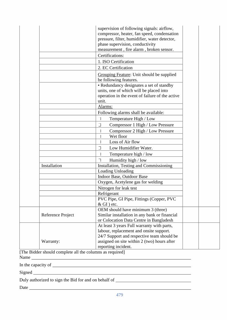
479
supervision of following signals: airflow,
compressor, heater, fan speed, condensation
pressure, filter, humidifier, water detector,
phase supervision, conductivity
measurement , fire alarm , broken sensor. Certifications:
1. ISO Certification
2. EC Certification
Grouping Feature: Unit should be supplied
be following features.
• Redundancy designates a set of standby
units, one of which will be placed into
operation in the event of failure of the active
unit.
Alarms:
Following alarms shall be available:
Temperature High / Low
Compressor 1 High / Low Pressure
Compressor 2 High / Low Pressure
Wet floor
Loss of Air flow
Low Humidifier Water.
Temperature high / low
Humidity high / low
Installation Installation, Testing and Commissioning
Loading Unloading
Indoor Base, Outdoor Base
Oxygen, Acetylene gas for welding
Nitrogen for leak test
Refrigerant
PVC Pipe, GI Pipe, Fittings (Copper, PVC
& GI ) etc.
Reference Project
OEM should have minimum 3 (three)
Similar installation in any bank or financial
or Colocation Data Centre in Bangladesh
Warranty:
At least 3 years Full warranty with parts,
labour, replacement and onsite support.
24/7 Support and respective team should be
assigned on site within 2 (two) hours after
reporting incident.
[The Bidder should complete all the columns as required]
Name
In the capacity of
Signed
Duly authorized to sign the Bid for and on behalf of
Date

480
Data Center infrastructure Management Monitoring (To be filled up and signed by the Bidder &
Manufacturer, otherwise the offer will not be acceptable)
SL Item Description Compliance Remarks
1 Brand: International Reputed Brand (Please
Specify)
2 Country of Origin: USA/UK/EU/Switzerland/Australia/Japan
3 Country of
Manufacturer:
Please Mention
4 Model Please Mention
5 Required for
DCIM Solution
Proposed DCIM solution OEM should be
engaged in the development of data center
infrastructure management systems whose
products have been in satisfactory use in
similar service for a minimum of 5 years.
6 Proposed DCIM application should have
been deployed in Bangladesh for at least one
Bank, one IT Enterprise spanning a
minimum of 20 Rack Infrastructure in each
of the installation in Bangladesh.
7 DCIM software OEM should have its own
dedicated Business Units within the
company to handle the following:
a. Datacenter Lifecycle services for turnkey
datacenter implementations across DCIM.
b. Datacenter Center of Excellence team for
DCIM
c. Datacenter Service & Support Team for
Implementation and troubleshooting DCIM
d. Dedicated DCIM support website for all
clients who buy DCIM to provide anytime
query escalation to Global DCIM product
experts of the DCIM bidder. Bidder has to
submit document proofs of the same and
live showcase during technical evaluation
and relevant stake holders may be called to
represent the same.
e. Datacenter Remote Monitoring Services
to offer Remote Monitoring and more
intensive coverage towards troubleshooting
DCIM Alerts by dedicated man power
offsite.

481
8
SCOPE
Bidder to supply and implement proposed
DCIM solution including hardware/Virtual
server, dcim application/os, dcimdb, dcim
software licenses for successful installation
of DCIM application. Each Rack to be
provided with 2 Temperature sensors and
each aisle(Cold and Hot) to be provided
with Temperature and Humidity sensor
All the features and functionalities or DCIM
services mentioned in this tender scope
should be expandable to manage future
requirement as well and provide us a
simplified and unified view of all the DCs
on future need basis.
Proposed DCIM system for present
requirement should be modular in licensing
nature and provide us flexibility to purchase
and expand enhanced modules according to
our future need. The DCIM should be able
to run on a physical or virtualized server.
DCIM software licensing should be
Perpetual in nature which means that license
once bought for various polled devices/racks
etc. never expire. However the end client is
free to buy extension of software warranties
on yearly basis to keep up to date with new
releases as and when they are launched.
Proposed DCIM solution should be designed
with a top-level 10/100bT Ethernet network,
using the SNMP, and/or Modbus® TCP
protocol. DCIM platform should also be
capable of pushing monitored device
information to any Third Party NMS system
using SNMP INFORM/REQUEST
procedures and to third party BMS system
using Modbus TCP out channel. By this the
DCIM system should ensure it integrates
back to commonly needed Infrastructure
devices like CRAC, Diesel Generators,
Energy Meters, Branch Circuit Power
meters, Rack mount Intelligent Pdu and
Rack Environmental Monitoring systems.
To ensure a clear integration to the said
devices is done an Annexure-A for Device
connectivity is attached, please ensure that
proposed DCIM covers licensing and
integration requirements of the devices.
The installed system shall be able to use
web services to “consume” information

482
within the Network with other products and
systems.
The DCIM shall be a combination of thick
client and thin web client architecture (web‐
based system that is accessed through a
standard web browsing tool such as Internet
Explorer, Chrome, or Firefox).
DCIM server/VM system should allow
integration of client email server via SMTP
channel as well as it should support
integration to SMS Gateway servers by
utilizing the HTTP post Method.
The DCIM must keep a log of all changes
within the data center including the changes
made to the DCIM system and all IMAC
workflow information.
The DCIM must be able to maintain
inventory and asset management within the
data center and provide visualization of the
assets in floor layout, rack elevation, and
individual asset views.
DCIM system should be able to display
energy efficiency information such as PUE,
DCiE and trend them in real time on daily,
monthly and yearly basis.
DCIM system should be able to create
reports in at least .CSV formats.
MONITORING LAYER
9 Monitoring Points Proposed DCIM solution should be designed
with a top-level 10/100bT Ethernet network,
using the SNMP, and/or Modbus® TCP
protocol.
10 Third Party system
Integration
DCIM platform should also be capable of
pushing monitored device information to
any Third Party NMS system using SNMP
INFORM/REQUEST procedures and to
third party BMS system using Modbus TCP
out channel and also support Web services
programming interface.
11 Email Server
Integration
DCIM Monitoring Layer server/VM system
should allow integration of client email
server via SMTP channel.
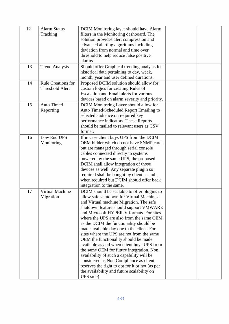
483
12 Alarm Status
Tracking
DCIM Monitoring layer should have Alarm
filters in the Monitoring dashboard. The
solution provides alert compression and
advanced alerting algorithms including
deviation from normal and time over
threshold to help reduce false positive
alarms.
13 Trend Analysis Should offer Graphical trending analysis for
historical data pertaining to day, week,
month, year and user defined durations.
14 Rule Creations for
Threshold Alert
Proposed DCIM solution should allow for
custom logics for creating Rules of
Escalation and Email alerts for various
devices based on alarm severity and priority.
15 Auto Timed
Reporting
DCIM Monitoring Layer should allow for
Auto Timed/Scheduled Report Emailing to
selected audience on required key
performance indicators. These Reports
should be mailed to relevant users as CSV
format.
16 Low End UPS
Monitoring
If in case client buys UPS from the DCIM
OEM bidder which do not have SNMP cards
but are managed through serial console
cables connected directly to systems
powered by the same UPS, the proposed
DCIM shall allow integration of those
devices as well. Any separate plugin so
required shall be bought by client as and
when required but DCIM should offer back
integration to the same.
17 Virtual Machine
Migration
DCIM should be scalable to offer plugins to
allow safe shutdown for Virtual Machines
and Virtual machine Migration. The safe
shutdown feature should support VMWARE
and Microsoft HYPER-V formats. For sites
where the UPS are also from the same OEM
as the DCIM the functionality should be
made available day one to the client. For
sites where the UPS are not from the same
OEM the functionality should be made
available as and when client buys UPS from
the same OEM for future integration. Non
availability of such a capability will be
considered as Non Compliance as client
reserves the right to opt for it or not (as per
the availability and future scalability on
UPS side)

484
This Plugin for Safe shutdown of
Virtualized Infrastructure should support the
following UPS configurations for alerting:
Single UPS, Redundant UPS and Parallel
UPS.
This Plugin for Safe shutdown of
Virtualized Infrastructure should support
Event logging - Pinpoint the timing and
sequence of events leading up to an incident
with the event log.
This Plugin for Safe shutdown of
Virtualized Infrastructure should help
prevent possible data corruption by
performing graceful, unattended operating
system shutdown in the event of an extended
power outage or computer power problem.
It should allow the operator to run command
file - Run command file on network
shutdown sequence as well as start-up
sequence.
It should facilitate Sequenced Server
Shutdown - Sequences the shutdown of
multiple servers powered by the same UPS
to extend runtime for higher priority servers.
CONVERGED MANAGEMENT LAYER
18 Concept Converged Management Layer concept arise
from the fact that irrespective of various
underlying components like Power, Cooling,
Network, U space all of them have to
converge to a single unified system. This
System should facilitate the complete
Lifecycle approach for Datacenter
involving:
a. Analysis
b. Design
c. Implement
d. Operate
e. Evaluate
DCIM Management Layer will have the
capability to configure a bird’s eye view of
the room layout to ensure the layout in the
data center model accurately represents the
real-world physical environment of the
room. This includes any physical attributes
of the room such as size, shape, doors,
windows, aisles, containments, false floor
creations, false ceiling creation and ability to
duct the Racks, Containments and CRAC
units to False ceiling as per site requirement.

485
DCIM Management Layer should have an
ability to import an AutoCAD 2013 .dwg
floor drawing and display the floor layout.
Rooms can be created based on wall
detection on the AutoCAD drawing. This is
different from the usual SVG/Raster
Imaging used and should not be mixed with
that which has been provisioned for
Monitoring Layer only.
User will have the capability to toggle on/off
for each Layer of AutoCAD imported inside
DCIM.
DCIM Management Layer should offer back
export of the datacenter design created or
modified within DCIM in CAD format.
DCIM Management Layer should have a
combination of Thick client and Thin client
version offering at least the following
functionality:
a. Thin client (web client) version should
offer the web view of the system
showcasing the Rack and Rack inventory
views and search dashboard for asset/client.
b. Web view should offer the capability to
create User Access control for various views
of the system. c. Thick client view (the
downloadable client) should offer a more
advance view of the complete Datacenter
starting from bird’s eye view to reach
component level view.
The web client view of the DCIM should
offer at least the following functionalities:
a. Perform simple rack inventory edits.
b. Perform quick search and view
simultaneous rack front/rear view for the
datacenter.
C. User Access Control and license
management
d. User Experience customization like Logo
and color themes.
e. Customize the language of operation
DCIM Management Layer will be able to
provide a product catalog that contains up-
to-date floor and rack mounted data center
equipment having drag & drop functionality
to populate devices & design DC floor
layout within the system as per physical
layout/actuals.
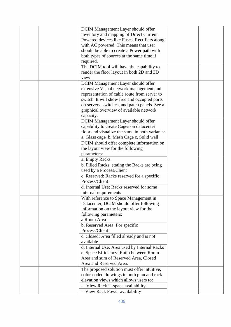
486
DCIM Management Layer should offer
inventory and mapping of Direct Current
Powered devices like Fuses, Rectifiers along
with AC powered. This means that user
should be able to create a Power path with
both types of sources at the same time if
required.
The DCIM tool will have the capability to
render the floor layout in both 2D and 3D
view.
DCIM Management Layer should offer
extensive Visual network management and
representation of cable route from server to
switch. It will show free and occupied ports
on servers, switches, and patch panels. See a
graphical overview of available network
capacity.
DCIM Management Layer should offer
capability to create Cages on datacenter
floor and visualize the same in both variants:
a. Glass cage b. Mesh Cage c. Solid wall
DCIM should offer complete information on
the layout view for the following
parameters:
a. Empty Racks
b. Filled Racks: stating the Racks are being
used by a Process/Client
c. Reserved: Racks reserved for a specific
Process/Client
d. Internal Use: Racks reserved for some
Internal requirements
With reference to Space Management in
Datacenter, DCIM should offer following
information on the layout view for the
following parameters:
a.Room Area
b. Reserved Area: For specific
Process/Client
c. Closed: Area filled already and is not
available
d. Internal Use: Area used by Internal Racks
e. Space Efficiency: Ratio between Room
Area and sum of Reserved Area, Closed
Area and Reserved Area.
The proposed solution must offer intuitive,
color-coded drawings in both plan and rack
elevation views which allows users to:
- View Rack U-space availability
- View Rack Power availability

487
- View Rack weight/Floor Loading
- View Raised Floor & Rack space
utilization
19 Sandbox Testing DCIM Management Layer should offer a
dedicated Test Environment within the same
solution which can import the live
datacenter 3D layouts and all power,
cooling, network and space details into a
separate Sandbox Test Model without
impacting the live functionality of the
Management Layer. This will be used to
simulate to simulate different scenarios, for
example, whether the design is strong
enough to cover your future requirements. If
you continue to add equipment at the current
pace, would the power supply suffice, or
would you need additional power supplies
or cooling units; would you continue to have
the necessary redundancy, etc. Changes to
these lab models should not affect the model
of the actual live environment in Core
DCIM Management Layer.
20 Predictive
Analysis
Predictive Analysis/What If Analysis &
Hypothetical Provisioning/Modelling to ease
decision making (such as: where is the best
place to put new server, do my dc have
sufficient power, cooling & space to occupy
new equipment, etc.)
21 Power Path Map Power Path: Ability to model power
connections between the equipment
supplying and delivering power and the
equipment requiring power. This includes
power path from switchgear, UPS, main
PDU with modular circuit breaker mapping,
rack RPDU and to individual servers.
22 Impact Simulation Impact simulation: Generates a list of
equipment that would be impacted if the
selected piece of equipment, e.g. a UPS or
cooling unit, about to fail or put in
maintenance mode.
The DCIM tool will have a dedicated
Equipment browser view where device
Fields can be customized and sorted as per
user need. It should allow for export of these
data fields in the same format in a CSV file
which can be opened in Excel as set by the
user in the Equipment browser and also to
save these formats for later use inside the
DCIM.

488
The DCIM tool shall have an inbuilt
Recommendation Engine that keeps on
checking the various aspects of datacenter
design like:
Rack contains overlapping equipment’s in
design
Max Rack Load exceeded
Equipment weight Exceeds weight limit of
floor
Room doesn't have enough Airflow
Amount of Rack PDU Power Outlets has not
been Configured
An Invalid Power Path has been Configured
Associated Device Data has been Lost
Capacity Group Equipment is Placed in
Multiple Rooms
Connection has not been Configured
between PDU and Power Supply
Connection has not been Configured
between Power Panel and Power Supply
Connection has not been Configured
between Remote Distribution Panel (RDP)
and Power Supply
Equipment Connected to this PDU Draws
more Power than is Supported by the Power
Supply Breaker
Equipment Connected to this Power Panel
Draws more Power than is Supported by the
Power Supply Breaker
Equipment Connected to this Remote
Distribution Panel (RDP) Draws more
Power than is Supported by the Power
Supply Breaker
Equipment in this Rack Receives Power
from Multiple Power Supply Devices
Equipment is Connected to a Rack PDU
Outside this Rack
Internal Redundancy Setup for UPS and
Group Must Match
PDU and Connected Rack PDU are Placed
in Different Rooms
PDU Output Voltage has not been
Configured Power Connection Configuration is Invalid
for Equipment in one or more Racks in the
Group Power Feed Connection for UPS and Group
must Match

489
Power Panel Output Voltage has not been
Configured Rack's Estimated Load Exceeds Group's
Peak Load Settings 23 Datacenter
Thermal Analysis
& Design
The graphical floor plan of the configured
data center layout should include overlays
showcasing capture index (CI), plenum
pressure, plenum velocities, and 3D
rendering of the temperature map, including
airflow and temperature thresholds. As the
design takes place, client will get a qualified
estimation of the effect of changes in supply
temperature, airflow, and number of cooling
units and room-based cooling parameters.
The data is expected to be simulated on the
basis of plate rating of various cooling
devices, racks, perforated tiles, grilles etc.
The Cooling overlay of the data center floor
layout should show a color-coded overview
of the Capture Index to give client an
overview of the reasons why the tile airflow
may not be the same across the room. Each
rack in a well-formed hot aisle / cold aisle
layout should show a capture index
percentage.
It should also offer dedicated Overlay to
show Floor Plenum to help client drill down
into looking at specific velocity issues in the
plenum and estimate perforated tile airflow
rates. In designing the layout whenever a
client drags in a new cooling unit or moves a
perforated tile, the flow vectors and
perforated tile flow rates should update
instantly on the Plenum view on the DCIM.
In the 3D view, client should be able to see
the room's simulated airflow above the
raised floor. Velocity vector and
temperature results should look like those
from traditional CFD applications and
provide the same ability to quickly locate
problem spots and understand the
underlying causes.
DCIM application should provide design
capability of hot isle and cold aisle ducted to
ceiling scenario creation. It should also
incorporate other components like Blocking
walls, pillars for creation of datacenter
design so that it comes as near to real
scenario.
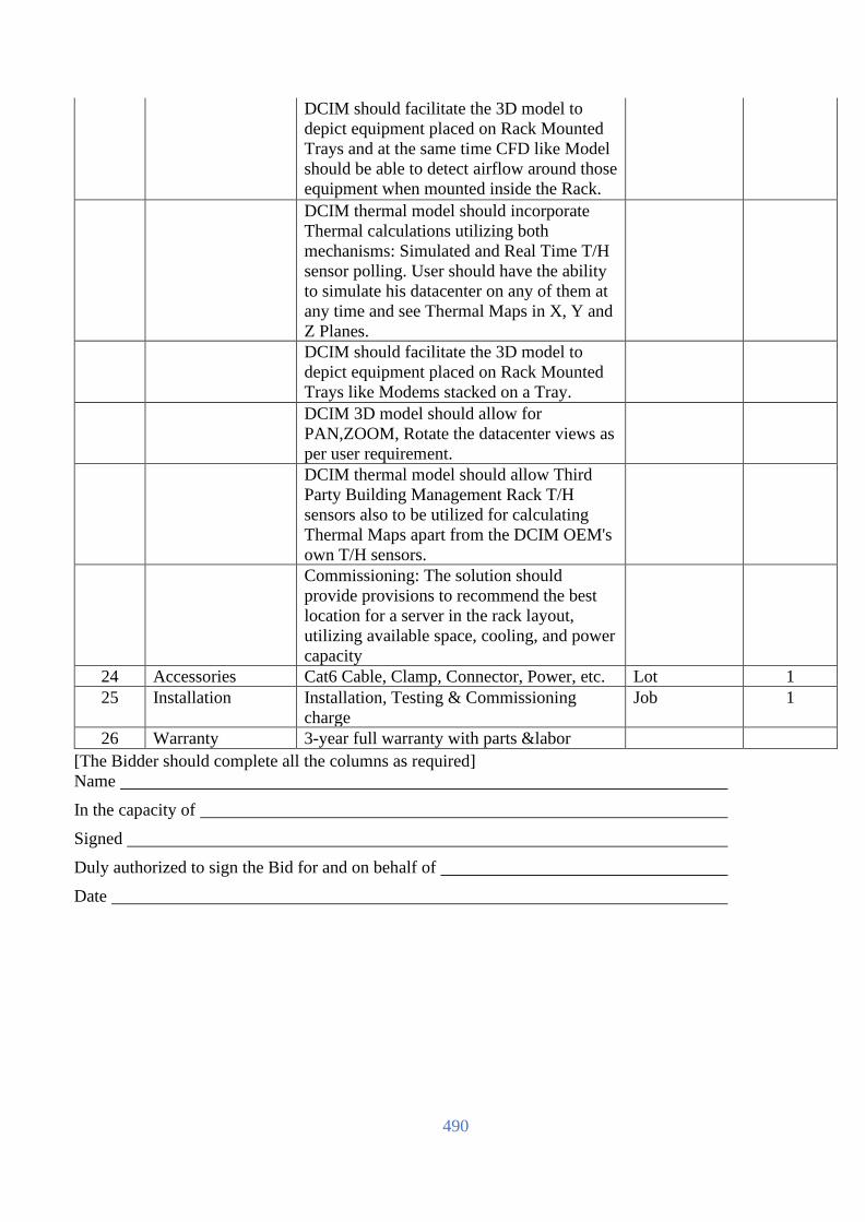
490
DCIM should facilitate the 3D model to
depict equipment placed on Rack Mounted
Trays and at the same time CFD like Model
should be able to detect airflow around those
equipment when mounted inside the Rack.
DCIM thermal model should incorporate
Thermal calculations utilizing both
mechanisms: Simulated and Real Time T/H
sensor polling. User should have the ability
to simulate his datacenter on any of them at
any time and see Thermal Maps in X, Y and
Z Planes.
DCIM should facilitate the 3D model to
depict equipment placed on Rack Mounted
Trays like Modems stacked on a Tray.
DCIM 3D model should allow for
PAN,ZOOM, Rotate the datacenter views as
per user requirement.
DCIM thermal model should allow Third
Party Building Management Rack T/H
sensors also to be utilized for calculating
Thermal Maps apart from the DCIM OEM's
own T/H sensors.
Commissioning: The solution should
provide provisions to recommend the best
location for a server in the rack layout,
utilizing available space, cooling, and power
capacity
24 Accessories Cat6 Cable, Clamp, Connector, Power, etc. Lot 1
25 Installation Installation, Testing & Commissioning
charge
Job 1
26 Warranty 3-year full warranty with parts &labor
[The Bidder should complete all the columns as required]
Name
In the capacity of
Signed
Duly authorized to sign the Bid for and on behalf of
Date

491
IP KVM (To be filled up and signed by the Bidder & Manufacturer, otherwise the offer will not be acceptable)
SL Item Description Compliance Remarks
1 16 Port IP KVM
2 Country of Origin – USA/UK/EU/Switzerland/Australia/Japan
3 Country of Manufacture – To be mentioned by Bidder
4 It should have a minimum of 16 ports scalable & upgradeable.
5 It should support 1 remote users and 1 user at the rack
6 It should take control of servers at BIOS Level
7 It should facilitate both in-band & out-of band access
8
It should be able to integrate with intelligent power strips, so as
to be able to reset power of remote device at port level.
9
It should have facility to integrate with secure management
device
10 Gigabit Ethernet ports.
11
Virtual Media Support of multiple media including 'ISO image'
files
12 PC selection – On screen Display menu hot key
13
Min. 17 inch Rack mountable design with LCD console and
tray
14
Browser based Management available at both remote and local
(Supported Browsers = Internet Explorer for MS-Windows,
Firefox for MS-Windows and Linux)
15 KVM - USB cables - 16 Nos.
16 Minimum 3 Years collaborative warranty
[The Bidder should complete all the columns as required]
Name
In the capacity of
Signed
Duly authorized to sign the Bid for and on behalf of
Date

492
Floor Mount Isolation Transformer (To be filled up and signed by the Bidder & Manufacturer, otherwise the offer will not be acceptable)
SL Minimum Technical Requirements Compliance
(Yes/No)
Remarks
1 Country of Origin: USA/UK/EU/Switzerland/
Australia/Japan
2 Country of Shipment: USA/UK/EU/
Switzerland/Australia/Japan
3 The 250 kVA PDU is designed primarily for isolation of
electrical power and will properly interface the UPS
power source with actual loads in data center
4 PDU shall have Inbuilt K 13 rated Isolation transformer
with efficiency of 98.5% at 50% load
5 PDU shall be equipped with Output Energy Meter ( after
Isolation Transformer) as per design and same shall be
available on Remote communication through MODBUS
TCP/IP
6 PDU shall be Forced air cooled, with 50% fans running at
start and balance 50% Fans activates after Transformer
Temp exceeds 80 DegC
7 Fan failure alarm is required for PDU
8 PDU shall have Manual Soft Start circuit to handle inrush
9 PDU shall have Incoming breaker, outgoing breaker and
Manual Bypass switch Isolation of Transformer in case of
failure
10 Current density for copper busbar is 1.5 A/Sq. mm
11 All Termination busbar shall be Copper only
12 Min. 3 Years Collaborative Warranty
[The Bidder should complete all the columns as required]
Name
In the capacity of
Signed
Duly authorized to sign the Bid for and on behalf of
Date

493
Modular UPS Power Distribution (To be filled up and signed by the Bidder & Manufacturer, otherwise the offer will not be acceptable)
SL Description Compliance Remarks
1
Country of Origin:
USA/UK/EU/Switzerland/Australia/Japan
2 Country of Manufacture: Bidder to Mention
3
400 A Modular Power Distribution Unit with accessories
should have:
A visionary power distribution system is agile enough to
match the needs of state data center today and enable rapid
expansion or reconfiguration in the future. Width of the
modular distribution should not exceed 300 mm wide and
1070 mm depth and should be mounted next to Server racks.
Each PDU should be provided with 16 Nos. 32 A Single Phase
distribution to connect directly to Server and Network Racks
PDUs with required sockets.
Power management is simplified by output metering, branch
current/circuit monitoring and auto- detection by the Data
Center Management suite of management options. When
demand rises and expansion becomes necessary, there is no
need to schedule downtime to add a breaker, as modules
(including circuit breaker, power cord, and power connection)
simply plug into a backplane.
4
The OEM factory-assembled modules should be installed
easily. This eliminates the need for risky hot work and
shields users from dangerous amperage.
5
With add on multiple power ratings and power cord lengths
for low to high power, guaranteeing compatibility and quick,
easy, and convenient installation.
6
PDU should be of minimum 50 Single pole distribution
connected to the output bus of the PDU to serve as critical
load distribution.
7
Testing and quality assurance: All circuit breakers should be
100% factory tested to ensure the highest quality for the PDU.
In addition the PDU should be tested with 100% load and all
panel circuit breakers should be 100% tested. The PDU should
also be Hipot tested per UL 60950-1 guidelines
8
Metered Data: The following data should be available on the
alphanumeric display:
1. Year, month, day, hour, minute, second of occurring
events
2. Output voltage by phase
3. Power distribution module status and manufacturing
information
4. Current and power used by the load

494
5. Load as a percentage of capacity
6. Total energy usage
7. Volt meter
8. Circuit configuration, including individual load
configuration and global alarm configuration
9. Alarms
10. Log
11. Network configuration
12. Help files
9
Modular PDUs should not need to schedule downtime to add
a breaker, as modules (including circuit breaker, power cord,
and power connection) and should be simply plug into back
plane
`
10
The PDU should have it’s own display and should be
integrated with DCIM
11 Warranty: Min. 3 Years collaborative OEM warranty.
[The Bidder should complete all the columns as required]
Name
In the capacity of
Signed
Duly authorized to sign the Bid for and on behalf of
Date

495
Comfort Cooling (To be filled up and signed by the Bidder & Manufacturer, otherwise the offer will not be acceptable)
SL Item Item Description Unit Qty
Comfort AC for NOC Room:
Brand Please Specify
Model Please Specify
Country of Origin USA/UK/EU/Switzerland/Australia/Japan
Type of Unit Split
Capacity 24,000 BTU/H
Power Supply 1 Phase
Support Generator
Timer One auto-controlled timer
Installation Offer should include required installation
accessories (if any).
Warranty 3 years with all parts, labor &
consumables.
[The Bidder should complete all the columns as required]
Name
In the capacity of
Signed
Duly authorized to sign the Bid for and on behalf of
Date

496
Rodent System (To be filled up and signed by the Bidder & Manufacturer, otherwise the offer will not be acceptable)
SL
Item
Item Description
Unit QTY
Bidder's
Response
Rodent System Set 1
1 Brand To be mentioned by bidder
2 Model To be mentioned by bidder
3 Country of Origin USA/UK/EU/Switzerland/Australia/Japan
4 Type Rodent System.
5 Features:
6 Controller
≥4000 Sq Feet of Area Coverage Nos 1
LCD display with on-board controls
Wave Speed: Is an indicator for the
number of frequency sweeps per minute.
It can have a maximum value of 130 and a
minimum value of 60. The incremental size is 5 i.e. 65, 70, 75 and so on.
Wave Density: Is an indicator for the
number of divisions within a frequency
band. It can have a maximum value of
100 and a minimum value of 80. The
incremental size is 10 i.e.80,90 and 100
Frequency Band Time: Is an indicator of
the time for which the controller would
operate in a pre- programmed frequency
band. There are 3 bands available: Band
A, Band B, and Band C. This parameter
can have maximum value of 10 minutes
and a minimum value of 1 minute per
band. Depending upon the time frame set
for each band, the controller will switch the
Warranty 3 (three) Years
[The Bidder should complete all the columns as required]
Name
In the capacity of
Signed
Duly authorized to sign the Bid for and on behalf of
Date

497
Very Early Smoke Detection Apparatus (VESDA)
(To be filled up and signed by the Bidder & Manufacturer, otherwise the offer will not be acceptable)
Sl Items Items Description Unit QTY
1 Aspiration (VESDA) system
Set 1
Brand Please Mention
APPROVALS
standards
• LPCB (Loss Prevention Certification
Board), UK
• FM (Factory Mutual), US
• UL (Under writers Laboratories Inc.), US
• ULC (Underwriters Laboratories Canada),
Canada
• Vds, Germany
Country of origin USA/UK/EU/Switzerland/Australia/Japan
Warranty Min. 3 Years
General Features
Bidder should supply and install Very Early
High Smoke Detection Aspirating (VESDA)
should have the HSSD (High Sensitive
Smoke Detectors) system shall provide an
early warning of fire in its incipient stage,
analyze the risk, and provide alarm and
actions appropriate to the risk the system shall
include a Display Control Panel, Detector
Assembly, and the properly designed
sampling pipe network for the multiple zones
(Server room, Power room, and PAC room).
The system equipment shall be supplied by
the Manufacturer’s or by its authorized
distributor. Invisible hazards can originate
from the release of toxic gases, oxygen
deficiency, or the presence of combustible gases/vapors.
2 Controller for Server Room
Nos 1
Model To be mentioned by bidder
Warranty Min. 3 Years
Features: Out-of-the-box installation and commissioning.
Ultrasonic Airflow testing.

498
Laser-based Absolute Smoke Detection. Programmable Alarm Thresholds.
Clean air barrier optics protection. Instant Recognition Display. Multiple Event Logging in separate logs Determined using ASPIRE2. Offline/online configuration capability. Input Power Voltage: 24V DC Nominal (18- 30 V DC).
IP Rating IP30. Tested to: -10°C–55°C (14°–131°F) Detector Ambient: 0°C–39°C (32°–103°F) Sampled Air: -20°–60°C (-4°–140°F) Humidity: 10%–95% RH, non-condensing Maximum Area: Please Mention Alarm Sensitivity Range: 0.0015%–6.25% obs/ft. (0.005%–20% obs/m)
IP Rating IP30 UL Listed
Controller for Power
& Battery Room with
gas
detector
Nos
1
Model To be mentioned by bidder
Features: Ultrasonic Airflow testing.
Laser-based Absolute Smoke Detection.
Programmable Alarm Thresholds.
Clean air barrier optics protection.
Instant Recognition Display.
Multiple Event Logging in separate logs
Determined using ASPIRE2.
Offline/online configuration capability.
Input Power Voltage: 24V DC Nominal (18- 30 V DC).
IP Rating IP30.
Detector Ambient: 0 °C to 40 °C (32 °F to 104 °F).
Sampled Air: 0 °C to 40 °C (32 °F to 104 °F).
Humidity: 5% to 95% (non-condensing).

499
Maximum Area: Please Mention UL Listed 24V DC, 2 AMP Power Supply Units With Battery
Nos. 2
Sampling Pipe, Smooth bore PVC Pipe 21mm ID and 25mm OD
Lot 1
Hooter Lot 1 2 core x 1.5 sq mm BYA cable for Power - Lot 1 25mm PVC conduit for the above cable Lot 1 End Cap Lot 1 T Joints & L Bends for sampling point network
Lot 1
Installation &
Commissioning
Installation, Commissioning and tested charges will include appropriate and quote for the same. If any other Hardware / Software / Internal or External cables or any component or equipment is required for giving the solution, mention and quote for the same.
Job
1
Warranty 3 Years
[The Bidder should complete all the columns as required]
Name
In the capacity of
Signed
Duly authorized to sign the Bid for and on behalf of
Date

500
Fire Detection & Suppression System (To be filled up and signed by the Bidder & Manufacturer, otherwise the offer will not be acceptable)
SL
Item Item Description Unit Qty
Fire Detection and Suppression System Lot 1
NOVEC 1230 with Cylinder & Accessories (Server Room)
NOVEC 1230
Kg (Apx.) 170
153 TR
Cylinder with
all accessories
Brand: Please specify
Country of Origin:
USA/UK/EU/Switzerland/Australia/Japan
Seamless storage containers having a
working pressure of 34.5 bar. Each Cylinder Assembly
includes storage container, valve, Pressure Gauge, Manual
actuator, Electric Solenoid actuator, Hoses etc. Units
combined with all accessories can be used as modular (one
cylinder) or centralized (multiple cylinders) system. Must
be UL listed.
Nos
(Apx.)
1
Steel Nozzle
360°- 1¼”
Brand: Please specify Origin:
USA/UK/EU/Switzerland/Australia/Japan
UL Listed
Nos
(Apx.)
2
Steel Nozzle
360°-
½”
Brand: Please specify Origin:
USA/UK/EU/Switzerland/Australia/Japan
UL Listed
Nos
(Apx.)
2
NOVEC 1230 with Cylinder & Accessories (Power Room)
NOVEC 1230 Kg
(Apx.)
65
62 LTR
Cylinder with
all accessories
Brand: Please specify Origin:
USA/UK/EU/Switzerland/Australia/Japan
Seamless storage containers having a working pressure of
34.5 bar. Each Cylinder Assembly includes storage
container, valve, Pressure Gauge, Manual actuator,
Electric Solenoid actuator, Hoses etc. Units combined
with all accessories can be used as modular (one cylinder)
or centralized (multiple cylinders) system. UL listed
Nos
(Apx.)
1
STEEL
NOZZLE
360°- 1”
Brand: Please specify Origin:
USA/UK/EU/Switzerland/Australia/Japan
UL Listed
Nos
(Apx.)
1
STEEL
NOZZLE
360°- ½”
Brand: Please specify Origin:
USA/UK/EU/Switzerland/Australia/Japan
UL Listed
Nos
(Apx.)
1

501
DETECTION SYSTEM (Fire Suppression Zone)
Extinguishing
Area Control
Panel with Gas
release
4 Detection zone with 2 Extinguishing area. With cross-
zoning detection feature.
Brand: Please specify Model: Please
specify
Origin: USA/UK/EU/Switzerland/Australia/Japan
Power Supply Input: 240V AC 50Hz , Operating /
System voltage: 24 VDC Others: Must have feature
for PAC shutoff/EPO, Access Door release while discharging gas.
Nos
1
Rechargeable
Sealed Lead-Acid
Battery
Rechargeable Sealed Lead-Acid Battery for control panel,
12VDC, 7.2 Ah
Brand: Please specify Origin: Please specify
Nos
2
Gas Discharge
Sign
Brand: Please specify Origin:
USA/UK/EU/Switzerland/Australia/Japan
Nos 3
Double Flash Light Brand: Please specify
Origin: USA/UK/EU/Switzerland/Australia/Japan
Nos 2
Alarm Bell
Brand: Please specify Origin:
USA/UK/EU/Switzerland/Australia/Japan
Current Consumption: 25mA, Dimensions: 6”.
Low current consumption: Made of aluminum alloy gong,
assurance of higher and clearer sound output
Nos
5
Exit Sign Brand: Please specify
Origin: USA/UK/EU/Switzerland/Australia/Japan
Nos 8
Manual call point/
Break Glass
Brand: Please specify
Origin: USA/UK/EU/Switzerland/Australia/Japan
Nos 2
Heat Detector
Brand: Please specify
Origin: USA/UK/EU/Switzerland/Australia/Japan
Supply Voltage: 12to 28V,
Alarm Indication: Red LED for 360° view
Nos
14
Smoke Detector
Brand: Please specify Origin:
USA/UK/EU/Switzerland/Australia/Japan
Flashing LED,
Supply Voltage: 12to 28V,
Alarm Indication: Red LED for 360° view.
Nos
14

502
Mechanical fittings (Estimated)
Mechanical fittings
(MS Pipes with
fittings)
Schedule 40 pipe 1⅟₂" Dia Schedule 40 pipe 1" Dia
Schedule 40 pipe ¾” Dia Schedule 40 pipe ⅟₂" Dia
MS Fittings (Reducer + Clamping + Elbow) Brand: Please
specify
Origin: USA/UK/EU/Switzerland/Australia/Japan
Lot
1
Electrical fittings
Electrical cable and
Fittings
Fire resistance cable 1.5 RM, BRB or
Paradise
Lot 1
Best Quality Local Painting, Berger or
equivalent
Lot 1
GI and PVC Pipe, Flexible, conduit, fittings
& other Accessories
Lot 1
Installation &
Commissioning
Offer should include required installation accessories &
commissioning. The proper calculation from above
mentioned manufacturer may change the quantity of
the gas and necessary equipment as per requirement
Warranty 3 Years with all required spares &
consumables
[The Bidder should complete all the columns as required]
Name
In the capacity of
Signed
Duly authorized to sign the Bid for and on behalf of
Date

503
Access Control System
Sl Item Item Description Unit Qty Bidder’s
Response
Access Control Solution
Access Control
Software Guideline
Set 1
Access Control
Software Functions
Provide access control software to
perform all control functions
simultaneously, including system
configuration, database updates and
access control validation, without
affecting the performance of the system.
Ensure that the system is fully scalable to
allow additional users, user groups,
access controlled points and operator
interfaces in future.
Use a system that will continue to operate
normally based on the last system settings
when
communication between the center
equipment and field devices are lost.
Access Control
Software
Security
Ensure a minimum of a username and
password protection to limit the software
functions and data records available to
each individual system operator. The
system must be capable to be setup by the
administrator to filter individual company
data and selected personnel fields from
each system user.
Access Control
Software License
Fees
Ensure that all system software license
fees are included within the tender return
and transfer the licenses to the Client at
Practical Completion.
37.2.2 Access Control
Reader (Finger,
Card & PIN)
Nos 7
Brand To be mentioned Model To be mentioned Country of Origin USA/UK/EU/Switzerland/Australia/Japan
Country of
Manufacture
To be mentioned
Technical
Specifications
• Processor: 32-bit ARM MCU • Algorithm: BioNANO V10 • Sensor: AFOS300 Optical Sensor • Sensor: Wake Up Mode Infrared • Scan Area: 22mm*18mm • Resolution: 500 DPI • LCD: 128*64 white LCD • Fingerprint Capacity: 2000 • Card Capacity: 2000

504
• Log Capacity: 50000 • Identification Mode: FP, Card,
ID+FP, ID+PW, PW+Card,
FP+Card • Identification Time: <0.5 Sec • FRR : 0.001% • FAR : 0.00001% • Communication Interface:
RS485,Mini USB Slave, TCP/IP, Wiegand I/O
• Card Reader Module: EM RFID, Optional Mifare and HID
• Fingerprint Image Display: Yes • Self-defined Status : 16 Customizable
time and attendance status • Workcode: 6- digit work code • Short Message: 50 • Scheduled Bell: 30 • Relay : DC 12V, Relay
Output(COM, NO, NC)
• Access Groups & Time Schedules: 15
Groups, 32 Time Zones • Door Open Sensor: Yes • Tamper Alarm: Yes • Operating Voltage: DC 12V • Size: Please Mention: • Temperature: -10 ℃~40 ℃ • IP Level: IP53(Optional Waterproof
Cover) • Certificates: FCC, CE • Applicable Situation: Up to 1000
Users
37.2.3 Cards The card type shall be EM RFID or
equivalent.
Nos 100
37.2.4 Access
Control
Reader for
Exit (Finger & Card)
Access Control Reader for Exit
(Finger & Card)
Nos 7
Brand Please Mention Model Please Mention Country of Origin USA/UK/EU/Switzerland/Australia/Japan
Country of
Manufacture
Please Mention
Technical
Specifications
• Processor: TI Stellaris® 32-Bit High Speed CPU
• Optical Sensor: AFOS Optical
Sensor • Auto Sensor Wake Up Mode: Yes • Scan Area: 22mmx18mm • Resolution: 500 DPI • Fingerprint Capacity: 1000 • Log Capacity: 50000

505
• Identification Mode: FP, Card, FP+Card
• Identification Time: <0.5s • FRR: 0.001% • FAR: 0.00001% • Communication Interface: RS485,
USB Plug & Play, TCP/IP
• Card Reader Module: Standard EM RFID, Optional Mifare Card
• Relay: 1 Relay • Certificate: FCC, CE, ROHS • Wiegand: Wiegand26 Output • Door Open Sensor: Yes • Size(LxWxH): Please Mention
Installation &
Commissioning
Offer should include required installation
accessories & commissioning.
Warranty 3 Years with all required spares &
consumables
[The Bidder should complete all the columns as required]
Name
In the capacity of
Signed
Duly authorized to sign the Bid for and on behalf of
Date

506
IPCAM & Surveillance Solution
Sl
No
Item Item Description Unit Qty
Fixed Indoor Doom IP Camera Nos 16
Country of Origin USA/UK/EU/Switzerland/Australia/Japan
Technical Specification
LAN Port YES
LAN Speed 10/100 Based-T Ethernet
Supported Protocols DDNS, PPPoE, DHCP, NTP, SNTP,
TCP/IP, ICMP, SMTP, FTP, HTTP, RTP,
RTSP, RTCP,IPv4/IPv6, Bonjour, UPnP, DNS,UDP,IGMP, QoS, SNMP
ONVIF Compatible YES (Profile S)
Number of Online
Users
10
Security (1) Multiple user access levels with
password (2) IP address filtering (3) Digest authentication
Remote Access (1) Internet Explorer on Windows operating
system
(2) CMS Lite, 32CH CMS software for
Windows operating system (3) Eagle Eyes on iOS & Android mobile devices
Network
Compression
H.265 / H.264 / MJPEG
Video Resolution 2592 x 1944 / 2048 x 1536 / 1920 x 1080 / 1280 x 720 / 640 x 480 / 320 x 240
Frame Rate 15/12 IPS for 5MP 30/25 IPS for 3MP / 1080P / 720P
Multiple Video
Streaming
4 (H.265 / H.264 / MJPEG)
Image Sensor 1/2.9" SONY CMOS image sensor
Min Illumination 0.1 Lux / F1.8, 0 Lux (IR LED ON)
Shutter Speed 1/10,000 ~ 1/15 (Slow shutter)
S/N Ratio More than 48dB (AGC off)
Lens f2.8mm / F1.8
Viewing Angle 103° (Horizontal) / 54° (Vertical) / 122°
(Diagonal)
IR LED 4 units
IR Effective
Distance**
Up to 40 meters
IR Shift YES

507
Smart Light Control YES
White Balance ATW AGC Auto IRIS Mode AES WDR YES POE YES (IEEE 802.3af)
Privacy Mask YES
Defog YES
RAM 20MB
IP Rating IP66
Startup Temperature 0℃ ~ 50℃
Operating
Temperature
-25℃ ~ 50℃
Operating Humidity 90% or less relative humidity
Power Source
(±10%)
DC12V / 1A
Current Consumption
(±10%)
215mA (IR LED OFF); 550mA (IR LED
ON)
Power Consumption
(±10%)
8.5W (PoE / PoN) ; 7W (DC Adapter)
Net Weight (kg) Please Mention
EaZy Networking YES
Mobile Surveillance iOS & Android mobile devices
Event Notification FTP / Email / SMS
Digital Pan / Tilt /
Zoom
YES
Motion Detection YES
RTC (real-time clock) YES
Minimum Web
Browsing
Requirements
‧Intel core i3 or higher, or equivalent AMD
‧2GB RAM
‧AGP graphics card, Direct Draw, 32MB
RAM
‧Windows 10, Windows 8, Windows 7,
Windows Vista & Windows XP, DirectX 9.0
or later
‧Internet Explorer 7.x or later (Windows
Edge not supported)
Certification CE
Installation Offer should include required installation
accessories (if any)
Warranty 3 years with all parts, labor & consumables.
Outdoor IP Camera Nos 5
Brand Please Mention
Model Please Mention

508
Country of Origin USA/UK/EU/Switzerland/Australia/Japan
Technical Specification
LAN Port YES
LAN Speed 10/100 Based-T Ethernet
Supported Protocols DDNS, PPPoE, DHCP, NTP, SNTP,
TCP/IP, ICMP, SMTP, FTP, HTTP, RTP,
RTSP, RTCP,IPv4/IPv6, Bonjour, UPnP, DNS,UDP,IGMP, QoS, SNMP
ONVIF Compatible YES (Profile S)
Number of Online
Users
10
Security (1) Multiple user access levels with
password (2) IP address filtering (3) Digest authentication
Remote Access (1) Internet Explorer on Windows operating
system
(2) CMS Lite, 32CH CMS software for
Windows operating system (3) EagleEyes on iOS & Android mobile devices
Network
Compression
H.265 / H.264 / MJPEG
Video Resolution 2592 x 1944 / 2048 x 1536 / 1920 x 1080 / 1280 x 720 / 640 x 480 / 320 x 240
Frame Rate 15/12 IPS for 5MP 30/25 IPS for 3MP / 1080P / 720P
Multiple Video
Streaming
4 (H.265 / H.264 / MJPEG)
Image Sensor 1/2.9" SONY CMOS image sensor
Min Illumination 0.1 Lux / F1.8, 0 Lux (IR LED ON)
Shutter Speed 1/10,000 ~ 1/15 (Slow shutter)
S/N Ratio More than 48dB (AGC off)
Lens f2.8mm / F1.8
Viewing Angle 103° (Horizontal) / 54° (Vertical) / 122°
(Diagonal)
IR LED 4 units
IR Effective Distance**
Up to 40 meters
IR Shift YES
Smart Light Control YES
White Balance ATW
AGC Auto
IRIS Mode AES
WDR YES
POE YES (IEEE 802.3af)
Privacy Mask YES
Defog YES
RAM 20MB

509
IP Rating IP66
Startup Temperature 0℃ ~ 50℃
Operating
Temperature
-25℃ ~ 50℃
Operating Humidity 90% or less relative humidity
Power Source
(±10%)
DC12V / 1A
Current Consumption (±10%)
215mA (IR LED OFF); 550mA (IR LED
ON)
Power Consumption
(±10%)
8.5W (PoE / PoN) ; 7W (DC Adapter)
Net Weight (kg) 0.94
EaZy Networking YES
Mobile Surveillance iOS & Android mobile devices
Event Notification FTP / Email / SMS
Digital Pan / Tilt / Zoom
YES
Motion Detection YES
RTC (real-time clock) YES
Minimum Web
Browsing
Requirements
‧Intel core i3 or higher, or equivalent AMD
‧2GB RAM
‧AGP graphics card, Direct Draw, 32MB
RAM
‧Windows 10, Windows 8, Windows 7,
Windows Vista & Windows XP, DirectX 9.0
or later ‧Internet Explorer 7.x or later (Windows Edge not supported)
Certification CE
Installation Offer should include required installation
accessories (if any)
Warranty 3 years with all parts, labor & consumables.
NVR 32 Chanel Nos 1
Brand Please Mention
Model Please Mention
Country of Origin USA/UK/EU/Switzerland/Australia/Japan
Country of
Manufacture
Please Mention
Technical Specification
Backup Storage Include (Minimum 3 Month)
Video Input One LAN port (up to 32 IP cameras)
Video Output HDMI x 2 / VGA x 1
Video Output
Resolution
HDMI-1: Up to 3840 x 2160 (4K2K)
HDMI-2 & VGA: Up to 1920 x 1080
(Full HD)

510
Audio Output YES (Line out / HDMI)
Audio Input YES (Mic in)
Alarm I/O 4 in / 1 out
HDD Storage Five 10TB hard disks
eSATA Port YES
RS-485 Port YES
USB Ports USB 3.0 x 1 / USB 2.0 x 2
Ethernet
LAN port
1000Mbps
Interne t port
1000Mbps
Video Compression
Format
H.265
Audio Compression
Format
G711
Local / Remote
Display Mode
16CH
Local / Remote Playback Mode
16CH
Local Single
Channel Playback
YES
Record Stream Dual
Recording Mode Manual / Event / Alarm / Schedule
Recording
Throughput
Up to 480 IPS @ 2592 x 1944 (5MP), Up to 300Mbps
Pre-alarm Recording YES
Quick Search Time / Event
Event Notification Push Video / Push Status / Video Mail /
Message Mail
Security Multiple user access levels with password
Remote Access (1) Internet Explorer on Windows operating
system (2) CMS Lite, 32CH CMS software for Windows operating system
(3) iOS & Android mobile devices
Max. Online User 20
Multicast YES
Seamless Recording YES
Smart Search YES
Easy Networking YES
IVS YES (16CH)
Spot Monitor Setup Call Monitor / Event Monitor / Live Monitor (HDMI-2 only)
Alarm Scenario
Setup
YES

511
Alarm Pop-up &
Preview
YES
Free DDNS Service YES
Power Source
(±10%)
DC19V / 4.7A
Operating
Temperature
10 ℃ ~ 40℃ (50℉~104℉)
Operating Humidity 10% ~ 85%
Dimensions (mm) Please Mention
Net Weight (kg) Please Mention
Minimum PC
Browsing
Requirements
‧Intel core i3 or higher, or equivalent AMD
‧2GB RAM
‧AGP graphics card, Direct Draw, 32MB
RAM
‧Windows 10, Windows 8, Windows 7,
Windows Vista & Windows XP, DirectX 9.0 or later ‧Internet Explorer 7.x or later (Windows Edge not supported)
Optional Peripherals Full HD Matrix (HDM02) / Rack Mount
(PP- AVC787-00K) / Disk Array (AVX997 / AVX992) / PTZ Joystick (AVX102)
Installation Offer should include required installation
accessories (if any)
Warranty 3 years with all parts, labor & consumables.
[The Bidder should complete all the columns as required]
Name
In the capacity of
Signed
Duly authorized to sign the Bid for and on behalf of
Date
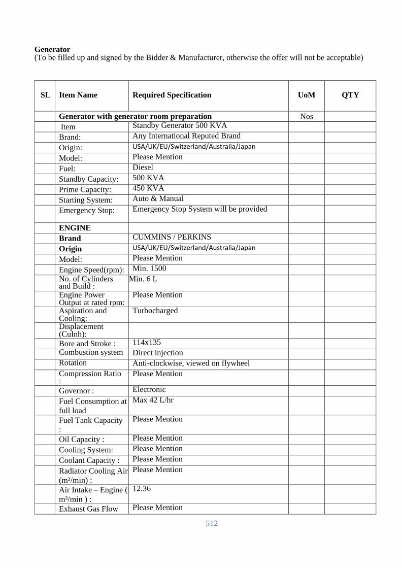
512
Generator (To be filled up and signed by the Bidder & Manufacturer, otherwise the offer will not be acceptable)
SL
Item Name
Required Specification
UoM
QTY
Generator with generator room preparation Nos
Item Standby Generator 500 KVA
Brand: Any International Reputed Brand
Origin: USA/UK/EU/Switzerland/Australia/Japan
Model: Please Mention
Fuel: Diesel
Standby Capacity: 500 KVA
Prime Capacity: 450 KVA
Starting System: Auto & Manual
Emergency Stop: Emergency Stop System will be provided
ENGINE
Brand CUMMINS / PERKINS
Origin USA/UK/EU/Switzerland/Australia/Japan
Model: Please Mention
Engine Speed(rpm): Min. 1500
No. of Cylinders and Build :
Min. 6 L
Engine Power Output at rated rpm:
Please Mention
Aspiration and Cooling:
Turbocharged
Displacement (CuInh):
Bore and Stroke : 114x135
Combustion system Direct injection
Rotation Anti-clockwise, viewed on flywheel
Compression Ratio :
Please Mention
Governor : Electronic
Fuel Consumption at
full load
Max 42 L/hr
Fuel Tank Capacity
:
Please Mention
Oil Capacity : Please Mention
Cooling System: Please Mention
Coolant Capacity : Please Mention
Radiator Cooling Air
(m³/min) :
Please Mention
Air Intake – Engine (
m³/min ) :
12.36
Exhaust Gas Flow Please Mention

513
(m³/min) :
ALTERNATOR
Brand Stamford or Equivalent
Origin USA/UK/EU/Switzerland/Australia/Japan
Design Brushless single bearing, revolving field
Stator 2/3 pitch
Rotor Single bearing, flexible disc
Insulation System Class H
Standard
Temperature Rise :
Please Mention
Exciter Type Self-Excited
Phase Rotation - A (U), B (V), C (W)
Alternator Cooling Direct drive centrifugal blower fan
Standard degree of
protection
IP23
AC Waveform Total
Harmonic Distortion:
No load < 1.5%. Non distorting balanced linear load < 5%
Telephone Influence
Factor
(TIF):
<50 per NEMA MG1-22.43
Telephone Harmonic
Factor (THF):
<2%
CONTROL
SYSTEM
Auto Mains Failure
Control Panel
Panel equipment: Control with AMF module,
Static battery charger
Emergency stop push button
Generating set
control module DSE
6120 features:
The module is used to monitor main supply and starts and stops of a standby generating set
Micro-processor-based design Automatic control of main and generator contactors
Monitors engine performance and AC power output LED alarm indication
Front panel configuration of timers and alarm trip points
CAN and magnetic pick-up versions (specify on ordering)
4 digital inputs/3 analogue inputs 6 outputs (4 configurable on Magnetic Pick-up, 6 configurable on CANbus version)
Easy push button control STOP/RESET – MANUAL – AUTO – TEST – START
Metering via LED
display:
Generator Volts (L-L / L-N)

514
Generator kVA
Engine oil pressure (PSI-Bar)
Generator kW
Generator Ampere (L1,L2,L3)
Generator Cos (σ) Engine temperature (°C&°F)
Generator Frequency (Hz)
Plant battery volts
Engine hours run
Mains Volts (Ph-Ph/Ph-N)
Alarms: Over and Under Speed
Low and High Battery Volt.
Start and Stop Failure
Charge fail
Over Current
Under / Over Generator Voltage
Low Oil Pressure
Emergency stop
High engine temperature
LED Indicators Mains available
Generator available
Mains on load
Generator on load
ATS built-in with generator (Same Brand)
Canopy built-in with generator (MUST BE FOREIGN with same BRAND)
Remote Monitoring
Must be capable of doing remote monitoring and should support integration with the EMS system
Over Speed, Under Speed, Low Oil Pressure,

515
Auto Charger Over Heat, Low Coolant Level, Over Crank, Low Fuel, Auxiliary Fault etc.
Starting system Built – in Trickle Auto Battery Charger
Standard /
Certification
ISO 9001:2008, TS ISO 8528-4, TS ISO 8528-5, TS ISO 8528-8, BS EN ISO 14001:2004, BS OHSAS 18001:2007, TS 12650
DIMENSIONS
(SOUND
ATTENUATED
TYPE)
DIMENSIONS
(LxWxH):
Please Mention
DRY WEIGHT: Please Mention
Generator Room
Bidder needs to propose & quote required generator room as per site and equipment layout.
Warranty 3 years with all parts, labor & consumables;
Note
Generator Fuel is not under scope of Vendor. Vendor will provide up to 100 ltr fuel for test purpose.
[The Bidder should complete all the columns as required]
Name
In the capacity of
Signed
Duly authorized to sign the Bid for and on behalf of
Date

516
Automatic Voltage Regulator AVR
(To be filled up and signed by the Bidder & Manufacturer, otherwise the offer will not be acceptable)
Sl Item Name Item Description UoM QTY
Bidder’s Response
Automatic Voltage Regulator
Automatic Voltage Regulator Nos
Brand: Please Mention
Country of Origin: USA/UK/EU/Switzerland/Australia/Japan
Place of Manufacture To be mentioned
Year of Manufacture To be mentioned
Rated power: 150 KVA
continuous duty INDOOR
INSTALLATION
Input voltage
3PH+N 380Y/220 VAC
3PH and 4 wires
Input voltage range 380Y/230 VAC +/-20%
From 323V up to 460V for three
phase L- L
from 187V up to 265V for single
phase L- N
Output voltage
3PH+N 380Y/220 or
400Y/230 VAC selectable
Output voltage accuracy
: ± 1.0 % RMS stabilized
Frequency : 50 Hz +/- 5%
Admitted load variation 0 to 100%
Admitted load unbalance
up to 100%
Maximum Input Current 270 A
Rated Current : 215 A @ 400 VAC
Operation type:
Electro Servo mechanical, motor
drive controlled
*Operation control system : unit sensed by solid state electronics, conformal coated to prevent short circuiting due to humidity
Correction speed
18 ms/V =1.1 sec x60V, - 15%
drop, response time
Power factor of the load Any
Waveform distortion
< 0,2 % - nil and none added
Full load efficiency > 98% at 100% linear load
Cooling
natural air (aided by fans over 45°C)
Permissible overload
200% x2 minutes, 150% x5 mins,
110% x10 mins

517
Operating temperature -15°C up to +50°C
Relative humidity < 90% (non condensing)
Applicable
Safety Standards
IEEE 587, EN 50081- 1:1992, EN 50082- 1:1998,IEC 439
Fittings
Multi-task digital network analyzers
to provide monitoring of INPUT / OUTPUT electrical values
Measurement front panel with the following parameters (voltage, current, frequency, power factor, Power, KVA )
Lightning protection arrestors of spikes/surges 60kA TVSS class II
Soft start and Soft Stop protections
given by super- capacitor system for
safe load supply at start-up
Logic control based on a
microprocessor control system
Buzzer alarm provisions over-temperature, under/over voltage
Alarms for minimum and
maximum voltage
Alarms for maximum current
Alarms for ventilation failure and over- temperature
Auxiliary circuit are protected by
fuses
*Protection degree : metallic
cabinet IP21 RAL 7035 finish paint
Installation
Installation and commissioning
Warranty 3 years
[The Bidder should complete all the columns as required]
Name
In the capacity of
Signed
Duly authorized to sign the Bid for and on behalf of
Date

518
Transient Voltage Surge Suppressor (TVSS)
(To be filled up and signed by the Bidder & Manufacturer, otherwise the offer will not be acceptable)
Sl Item Name Item Description UoM QTY Bidder’s Response
TVSS (Transient Voltage Surge Suppression
System)
Nos
Brand: Please Mention
Country of origin: Please Mention
Place of Manufacture
To be mentioned
Year of Manufacture
To be mentioned
Electrical Characteristics:
Nominal Operating Voltage,
Vn: 277V ± 3%
Maximum Continuous
Operating Voltage: 350V ±
3%
Vref (peak) @ 5mAmp AC
(peak): 607V ± 3%
Vref @ 5mAmp DC: 582V ± 3%
Operating Frequency
Range: 25…500Hz
Leakage Current at Vn: 0..90Ma
Surge Protection Levels:
Suppressed Voltage Rating
(SVR): 900V ± 3%
Response Time: <1 ns
Maximum Surge Current:
Maximum Surge Current,
Imax (8/20) NEMA LS-1: <as
mentioned below>
Maximum Lightning Current,
Iamp (10/350) IEC 61643-1:
Let Through Voltage Level:
for surge current 10kA* (8/20) (IEEE C62.41-1): 930V
Long Duration Surge
Performance:
1kA square waveform 2msec
(IEEE C62.11):
500A square waveform
2msec (IEEE C62.11): 250hits
Direct (in-line) Installation
Guidelines: TVSS modules
should be tested for safe

519
installation behind:
: * 1600A time delay fuse at
available fault current 100kA
: * 200A breaker at available
fault current 100kA
: * 400A breaker at available
fault current 38kA
Surge Counter: 250 Hit
Standards Compliance:
IEEE C62.41, IEEE C62.45,
IEEE C62.11, NEMA LS-1:
IEC 61643-1, IEC 61643-12:
Listings:
UL 1449 2nd ed, CE.
[The Bidder should complete all the columns as required]
Name
In the capacity of
Signed
Duly authorized to sign the Bid for and on behalf of
Date

520
Data center Rated-3 Certification (To be filled up and signed by the Bidder & Manufacturer, otherwise the offer will not be acceptable)
Data Center
Rated-3
Certification
Vendor must propose Tier-3 Certification from Uptime
Institute.
Vendor must me a authorized agent/service provider of
Uptime Institute
Vendor must have atleast 1 x Certified Data Center
Professional with atleast 3 project experience. Relevant CV
to be submitted.
Vendor must do all communication with UTI, and complete
the certification process and manage End-to-End
Vendor must submit a Project Plan (after the award) and state
all documents required to get the certifications.
[The Bidder should complete all the columns as required]
Name
In the capacity of
Signed
Duly authorized to sign the Bid for and on behalf of
Date

521
Specification
of
CT/PT rated meter(J-4) for lot-2

522
1. SCOPE of Works:
This standard establishes the physical and performance requirements for static CT/PT Rataed meter of
socket type static watt-hour-demand TOU AMR meters that are to be used in BREB distribution systems.
This specification shall cover design, engineering, manufacture, inspection, testing, packing, supply and
delivery at destination. The meter shall be suitable for measurement of different electrical parameters as
per the energy and power demand requirement in an AC balanced/unbalanced system over a power factor
range of zero lag to unity to zero lead. The offered meters to be interfaced/integrated easily with BREB
proposed MDMS.
2. ENVIRONMENTAL CONDITION
The meter shall be suitable for satisfactory continuous operation under the following tropical conditions:
a) Ambient Temperature: -4 0C to 55 0C. Meter electronics shall be designed to operate between -4 0C
to 85 0C.
b) Relative Humidity: 10% to 100 % (non-condensing)
c) Maximum altitude above mean sea level: up to 1000 meters
d) The climate varies from moderately cold to hot and humid, conducive to rust and fungus growth.
Fog is also present in atmosphere. Lightning also occurs during rainy season.
e) The meter shall be designed for indoor and outdoor applications so that sun light, insects, dust, rain
and salt spray shall not adversely affect the meter.
3. GENERAL TECHNICAL REQUIREMENT
Sl.
No. Requirements
Item No
J-4
1 Service Type Three Phase, Ct/PT Rated meter
2 Meter Type Fully Static, Three Phase, Four Wire, Y Configured, Three
element (Three-vector)
3 Base & Form Socket Based, Form 9S
4 Voltage rating of the
Meter
240 V-Phase to Neutral (Line voltage-415 V), Shall be
suitable of Operation between -30% to +15% of rated voltage.
5 Frequency 50 Hz ± 5%
6 Terminal 13 Terminals
7 Maximum Continuous
Current
20 Amps
7 Current Class Class 20, Transformer rated type
8 Test Amperes 2.5
9 Accuracy Class 0.2

523
4. APPLICABLE STANDARDS: Latest Edition
The meters shall comply with the current standards below:-
4.1 ANSI C12.1 American National Standard For Electric Meters -Code for
Electricity meters
4.2 ANSI C12.10 American National Standard For Physical Aspects of Watt-hour
Meter-Safety Standard
4.3 ANSI C12.20 American National Standard For Electricity Meters- 0.2 and 0.5
Accuracy classes
4.4 ANSI C12.16 American National Standard For Electricity Metering- Solid state
Electricity Meters
4.5 ANSI C12.22 American National Standard Protocol Specification For
Interfacing to
Data Communication Networks.
4.6 ANSI C62.41 Voltage AC power circuit and AC circuits.
4.7 ANSI C37.90.1 IEEE Surge Protection
4.8 ANSI C12.18 Protocol for optical port
4.9 ASTM -B117 Salt spray (fog) testing apparatus
4.10 UL-50 Safety enclosure for electrical equipment
5. GENERAL ELECTRICAL REQUIREMENT
5.1 STARTING CURRENT
The meter shall start and continue to register at a current of 0.05 Amps if offered meter
is of Class 100 or 0.10 Amps if offered meter is of Class is 200 in case of J-3 and in case
of J4 the meter shall start and continue to register at a current of 0.01 Amps as per ANSI
C12.20.
5.2 RUNNING WITH NO LOAD
When the 115% of rated voltage is applied with no current flowing in the current circuit,
the meters shall not register any energy and test output of the meter shall not be more
than one pulse/count on "no load".
5.3 POWER SUPPLY VARIATION

524
The effect of variation of voltage upon the performance of the meter shall not exceed that
specified in ANSI C12.20.
5.4 ACCURACY
The class of accuracy of the meter shall be 0.2. The accuracy should not drift with time.
5.5 POWER CONSUMPTION
As per ANSI C12.20, the active and apparent power consumption in each voltage circuit
of the meters shall not exceed 5 W or 20 VA for both J-3 & J-4. The apparent power
consumption in each current circuit of the meters shall not exceed 1.0 VA for J-3 and 0.5
VA for J-4.
6. PERFORMANCE UNDER INFLUENCE QUANTITIES
The meters performance under influence quantities shall be governed by ANSI C12.20. The meter
should be designed and protected such that all external effects and influences shall not change its
performance & shall work satisfactorily within guaranteed accuracy limits, as specified in ANSI
C12.20 (latest version).
7. GENERAL & CONSTRUCTIONAL REQUIREMENTS
7.1 The meter shall be Socket based and should be housed in a safe, high grade engineering
plastic / polycarbonate casing conforming to rain/dust/moisture proof. The meter shall be
made from high accuracy and reliable surface mount technology (SMT) components.
7.2 The meter base and meter cover shall be made of unbreakable high grade fire resistant
non-flammable reinforced, polycarbonate (non bakelite) or equivalent high grade
engineering plastic.
7.3 All insulating material used in the construction of meters shall be non-hygroscopic, non-
ageing and of tested quality. All parts that are likely to develop corrosion shall be
effectively protected against corrosion during operating life by providing suitable
protective coating. Contact points & all screws shall be corrosion less and rust proof over
the service life of the meter.
7.4 The meter shall be protected against ultra-violet radiation.
7.5 The meter cover shall have one window. The window shall be of transparent, high-grade
engineering plastic for easily reading all the displayed values/parameters, nameplate
details and observation of operation indicator. The window or the meter cover shall not
be able to remove undamaged without breaking the meter cover seals.

525
7.6 The entire and construction shall be capable of withstanding stresses likely to occur in
actual service and rough handling during transportation. The meter shall be convenient to
transport and immune to shock and vibration during transportation and handling.
7.7 The meter shall be provided with security sealing provision to accommodate both padlock
& wire type seal.
8. COMMUNICATION CAPABILITY
The meter shall be equipped with a two-way optical port for programming and reading purposes
Compliance with ANSI C12.18 Type 2 or equivalent Optical Port for local communication, and
for remote communication, the meter should be configured with a 2G/3G/4G, And WI-SUN RF
mesh modem for remote reading and monitoring the communication interface should comply with
the ANSI C12.22 or equivalent standard.
9. TROPICAL & OUTDOOR REQUIREMENTS
The Meter shall be suitably designed and treated to operate continuously for the normal life of the
meter in an unsheltered outdoor tropical location under the cold, hot and hazardous tropical
climatic conditions as specified in clause no. 2 without corrosion or other damage to its parts to
adversely affect meter accuracy or reliability. All parts, which are subject to corrosion under
normal working conditions, shall be protected effectively. Any protective coating shall not be
liable to damage by ordinary handling or damage due to exposure to air, under normal working
conditions. The meter shall be effectively sealed to prevent entrance of rain and dust into its
internal parts. The meter shall meet the requirement of weather simulation test as specified in ANSI
C12.1-2001, Salt spray test as per ANSI C12.1 (Test Procedure as ASTM B117), Rain and Dust
test as described in underwriter’s laboratory standard UL-50 (USA) for type 3 enclosures. Meters
shall withstand solar ultraviolet radiation. The 2G/3G/4G, or PLC, or WI-SUN RF mesh modem
should be mounted inside the meter case without influencing anti-water function, the ETU for the
UL-50 test should include the mounted 2G/3G/4G or PLC modem, otherwise the test report will
be rejected;
10. Advanced Metering Functionality
The meter shall have to be delivered with the required HES (provided by tenderer) and Standard
Open Protocol to comply with the ANSI C12.22 or equivalent standard.
10.1 Time synchronization

526
The meter shall capable for local and remote time synchronization function with HES through
DCU or directly incase of GPRS communication.
10.2 Time of use
The meter shall be capable of doing time-of-use (TOU) energy metering and shall have six time-
of-use registers for maximum demand and kWh energy. The time and options shall be as per the
Employer‘s programming requirements. These TOU rates shall further be selectable on the basis
of day, types, and seasons. Each tariff rate shall be programmable to become active during
different periods of the day. The meter shall record information for up to six rates, each rate
being a time period over which the information was recorded. The Meter shall store energy,
maximum demand and time of maximum demand for the current billing period with provision to
display readings of 2 billing period. It shall be possible to change the time period for the TOU
recordings remotely or using HHU with the appropriate security.
10.3 Load Profile
Meter records and registers the load profile (LP, i.e active power value). Integration period shall
be configured from 5, 15, 30, 60 minute interval and for 180 days minimum and daily according
to customers requirements. Corresponding time stamp is recorded in the load profile with
corresponding block of registered active power value. The load profile parameters are to be
customized as per utility requirement. the default parameters are not less than CU KWH, CU
KVARH, present KW demand, Volt, Amperes & P.F.
10.4 Over/Under-voltage monitoring
Meter registers under-voltage/overvoltage occurrence event and termination of the latter. Events
are entered into a special event log (electricity quality log) with the date/time of event, with the
capacity of at least 100 entries. Under-voltage and overvoltage thresholds may be adjusted.
10.5 Event Log
Meter should supports Event Log function, such as battery changes, firmware upgradation Power
Down, Power Up, Time Changed(old time), Time Changed(new time), Event log cleared, Demand
Reset Occurred, Over Voltage, Low Voltage, Over Demand, Over Current ,
PASSWORD_ERROR etc. Meter support event can be individually set whether or not to save the
event _log, users can configure record the types of events according to their needs. Meter can take
fault detection and save fault data automatically which help users to analyze. To detect loss of

527
voltage, phase loss, the reverse power such as the LCD will be the appropriate instructions to save
the data format according to ANSI C12.19.
10.6 Meter Firmware Upgrade
Meter shall support firmware upgrade option. Firmware upgrade option in the meter is
realized not to alter in any way the metering characteristics (metrology) of the meter, data
memorized in the meter (metering data, statuses, etc.), configuration parameters or
operational parameters of the meter – all these data remain unchanged even after firmware
upgrade. New firmware upgrade in the meter shall be done both locally and remotely.
10.7 Communication Encryption
The suitable international encryption algorithm should be used for the communication between
the meter and HES system, the related process should comply with the ANSI C12.22 or
equivalent standards;
10.8 Daily/hourly billing
The meter should have the daily billing and hourly billing register for the system to get exact
data
10.9 Event active report function
Configured event should be reported to the system actively; and the power down and resume
should be reported to the system too;
10.10 Automatic addressing and registering
Meter should connect to the system automatically and no need to configure any other parameters
except for the communication address;
11. PERFORMANCE GUARANTEE
The meter shall have a design to operate satisfactory for 10 years under normal electrical condition
and shall be guaranteed for 36 months from the date of receiving against manufacturing and design
defects. The meters found defective with in guaranteed period should be replaced/ repaired by
supplier free of cost with in two months of intimation.
12. SEALING OF METER
Reliable sealing arrangement should be provided to make the meter tamper proof and avoid
fiddling or tampering by unauthorized persons. For this, at least two no. of seals on meter body.

528
13. MARKING OF METERS
The marking of meters shall be in accordance with ANSI C12.10. Every meter shall have nameplate
and the nameplate shall be marked distinctly and indelibly. The basic marking on the meter nameplate
shall be as follows:
a) “RURAL ELECTRIFICATION BOARD” printed in English with block letters of at least
1/8”(3.2 mm) height on the face plate.
b) Manufacturer’s name & trade mark
c) Type Designation
d) No. of phases & wires
e) Serial number
f) Month and Year of manufacture
g) Reference Voltage
h) Current Class
i) Reference Standard
j) Principal unit(s) of measurement
k) Meter Constant
l) Class index of meter
m) Purchase Order No. & Date
In addition, both item J-3 & J-4, “AMR TOU” will be mentioned as one of the markings.
14. CONNECTION DIAGRAM
The connection diagram of the meter shall be clearly shown for 3 phase 4 wire system on meter cover.
15. QUANTITIES TO BE MEASURED AND DISPLAYED.
The meter shall be capable of measuring and displaying at least the following electrical quantities
within specified accuracy limits for poly-phase balanced or unbalanced loads: Sl. No.
Name of Parameters Symbol Format
1 Cumalative Total KWH kWh XXXX.XX 2 Cumalative, Rate-A KWH (Start Time 17:00) kWh XXXX.XX 3 Cumalative, Rate-B KWH (Start Time 23:00) kWh XXXX.XX 4 Cumalative Total KVARH (Leading) kVARh XXXX.XX 5 Cumalative, Rate-A KVARH (Leading),Start Time
17:00 kVARh XXXX.XX
6 Cumalative, Rate-B KVARH (Leading), Start Time 23:00
kVARh XXXX.XX
7 Cumalative Total KVARH (Lagging) kVARr XXXX.XX 8 Cumalative, Rate-A KVARH (Lagging),Start Time
17:00 kVARr XXXX.XX
9 Cumalative, Rate-B KVARH (Lagging), Start Time 23:00
kVARr XXXX.XX
10 InstanteneousDemad KWprs XXX.XXX
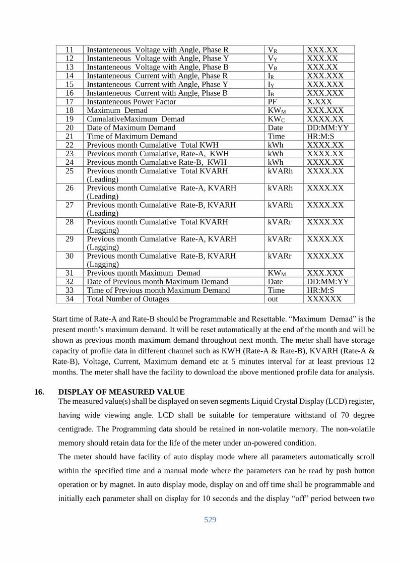
529
11 Instanteneous Voltage with Angle, Phase R VR XXX.XX 12 Instanteneous Voltage with Angle, Phase Y VY XXX.XX 13 Instanteneous Voltage with Angle, Phase B VB XXX.XX 14 Instanteneous Current with Angle, Phase R IR XXX.XXX 15 Instanteneous Current with Angle, Phase Y IY XXX.XXX 16 Instanteneous Current with Angle, Phase B IB XXX.XXX 17 Instanteneous Power Factor PF X.XXX 18 Maximum Demad KWM XXX.XXX 19 CumalativeMaximum Demad KWC XXXX.XX 20 Date of Maximum Demand Date DD:MM:YY 21 Time of Maximum Demand Time HR:M:S 22 Previous month Cumalative Total KWH kWh XXXX.XX 23 Previous month Cumalative, Rate-A, KWH kWh XXXX.XX 24 Previous month Cumalative Rate-B, KWH kWh XXXX.XX 25 Previous month Cumalative Total KVARH
(Leading) kVARh XXXX.XX
26 Previous month Cumalative Rate-A, KVARH (Leading)
kVARh XXXX.XX
27 Previous month Cumalative Rate-B, KVARH (Leading)
kVARh XXXX.XX
28 Previous month Cumalative Total KVARH (Lagging)
kVARr XXXX.XX
29 Previous month Cumalative Rate-A, KVARH (Lagging)
kVARr XXXX.XX
30 Previous month Cumalative Rate-B, KVARH (Lagging)
kVARr XXXX.XX
31 Previous month Maximum Demad KWM XXX.XXX 32 Date of Previous month Maximum Demand Date DD:MM:YY 33 Time of Previous month Maximum Demand Time HR:M:S 34 Total Number of Outages out XXXXXX
Start time of Rate-A and Rate-B should be Programmable and Resettable. “Maximum Demad” is the
present month’s maximum demand. It will be reset automatically at the end of the month and will be
shown as previous month maximum demand throughout next month. The meter shall have storage
capacity of profile data in different channel such as KWH (Rate-A & Rate-B), KVARH (Rate-A &
Rate-B), Voltage, Current, Maximum demand etc at 5 minutes interval for at least previous 12
months. The meter shall have the facility to download the above mentioned profile data for analysis.
16. DISPLAY OF MEASURED VALUE
The measured value(s) shall be displayed on seven segments Liquid Crystal Display (LCD) register,
having wide viewing angle. LCD shall be suitable for temperature withstand of 70 degree
centigrade. The Programming data should be retained in non-volatile memory. The non-volatile
memory should retain data for the life of the meter under un-powered condition.
The meter should have facility of auto display mode where all parameters automatically scroll
within the specified time and a manual mode where the parameters can be read by push button
operation or by magnet. In auto display mode, display on and off time shall be programmable and
initially each parameter shall on display for 10 seconds and the display “off” period between two

530
cycles shall not exceed 30 seconds. The register should not roll over in between this duration. Meter
shall have Scroll Lock facility to display any one desired parameters continuously from display
parameters.
The Integer and Decimal places of the readings shall be as follows:
Programming of register data & display
REB item no. register data Integer Decimal
J-3 Energy 6 0
J-3 & J-4 Cumulative demand 4 2
J-3 & J-4 Demand 3 3
J-4 Energy 4 2
J-3 & J-4 Voltage 3 2
J-3 & J-4 Current 3 3
J-3 & J-4 Power Factor 1 3
17. DEMAND INTEGRATION & MD REGISTRATION
The meter shall continuously monitor and calculate maximum demand for each interval of time,
which may be programmable as a block 30 minutes as per the user’s choice through the
communicating ports as and when required with proper password identification & authentication.
At the end of every demand integration period the new calculated MD shall be compared with the
previous MD and meter shall store whichever value is higher with date & time stamping. Under
the current integration period, the rising demand should be displayed continuously along with the
elapsed time. The rising demand with the elapsed time should be held in the memory in the event
of interruption or switching off supply and it should not become zero on such instances. The
registered demand and the number of times the MD is reset shall also be displayed.
The meter shall have the MD resetting options of automatic reset at the end of a certain predefined
period by default (24:00 hrs of the last day of every month) & Communication driven reset form
the base terminal/server with proper password identification and authentication. It should not be
possible to reset the MD by the use of the local push button.
18. CALIBRATION & TEST OUTPUT
All the meters shall be tested, calibrated and sealed at works before dispatch. Further, no
modification of calibration shall be possible at site by any means.
However, it shall be possible to check the accuracy of energy measurement of the meter while in
operation in the field by means of LED test output on meter, accessible from the front as well as
through high-resolution display using suitable test equipment.

531
Test output device shall be provided in the form of LED for KWh and KVARh with provision of
selecting the parameter being tested. The test output device should have constant pulse rate in terms
of pulse/unit energy.
19. REAL TIME INTERNAL CLOCK (RTC)
The time keeping shall be selectable between line frequency or an internal crystal. If it is an internal
real time clock it shall be pre-programmed for 20 Years day/date without any necessity for correction.
The maximum drift shall not exceed +/- 180 Seconds per year. The clock day/date setting and
synchronization shall only be possible through password/Key code command from Computer.
20. TAMPER & FRAUD MONITORING FEATURES
20.1 Meter must automatically identify the corrected service and verify the correct wiring and it
will be reported to system if any incorrect service found such as phase reversal, irrelevant
phase sequences and absence of any phase voltage
20.2 Meter must operate and accurately register demand and energy when service voltage is
applied across any two of the three input terminals or when service voltage is applied from
any input terminal to neutral.
20.3 Meter will continue to operate even the neutral is missing.
20.4
20.5 The metering system shall be provided with adequate magnetic shielding so that any external
magnetic field (AC Electro Magnet or DC Magnet) applied on the metering system shall not
affect the proper functioning and recording of energy as per error limits prescribed in the
standard.
20.6 The meter cover open detection, anti - theft tampering signal should be sent to remote.
21. SELF DIAGNOSTIC FEATURE
The meter shall be capable of performing complete self-diagnostic check to monitor the circuits for
any malfunctioning to ensure integrity of data memory location at all time. The meter shall have
indication for unsatisfactory/non-functioning/malfunctioning of the following:
a) Time and date on meter display
b) All display segments on meter display
c) Real Time Clock (RTC) status.
d) Non-volatile Memory (NVM) status.
e) While starting, the meter must perform self diagnostic checks as listed below. This is a
minimum standard.
-Check for phase voltages
532
-Check for cross phasing
-Check phase voltage and current polarity.
f) Meter must possess a display of the presence of all voltages.
22. OTHER SALIENT FEATURES OF METERS
a) The meter must be readable in power off condition. For that a battery back-up which is
externally replaceable of suitable capacity shall be provided. Push button or touch or any other
means shall be provided for the normal display shall also be used for battery back-up display
in power off condition for the manual mode reading of the auto display parameters.
23. PROGRAMMING & CUSTOMIZATION
The meter shall be programmed in the factory to a customized setting. Options for the customized setting
will be provided by the purchaser after signing of contract. Suppliers are required to inform the purchaser
for providing necessary information for a customized setting. The bidder shall also provide necessary
programming software and hardware with accessories( two data cable per PBS) for programming,
reading and downloading data locally from the meter.
24. TEST AND TEST CONDITIONS
The Energy meter offered shall be fully Type tested and Routine tested as per relevant ANSI standard.
Test reports including Tropical & Outdoor requirements shall be from an Internationally Recognized
Independent and well-known testing laboratory like KEMA, CESI, CPRI, UL, MET or equivalent.
Supporting documents in support of the status of the Testing Laboratory also shall be submitted.
Bidder shall also submit dimensional drawings, pictures, catalogue information, data on starting watts
and losses, list of spare parts with current prices, bulletin for adjustment, installation and storage
instructions and characteristics performance curves. The submitted Test reports must have the detail
address of the Testing Laboratory complete with telephone, fax, e-mail, website etc. and must be
readily available in the Web-site of the concern laboratory for verification by the Purchaser. All the
Test Reports and documents must be in English Language.
Afterward the Bidder, if awarded, shall carry out Routine tests on each individual meter at
manufacturing premises and Routine tests certificates of individual meter shall be submitted before
Pre-shipment/ Pre-delivery Inspection.
25. INSPECTION:
25.1 The Manufacturer shall perform the necessary inspection and tests to determine if the offered
meters comply with the specifications and shall supply certified test reports that give proof
that the meter meet the specifications and conform to the standards set forth. All information
shall be written in English.

533
25.2 The Purchaser may appoint its own official(s) or a third party inspection agency as Inspector
(s) and they shall be entitled at all reasonable time during manufacture and or pre-delivery/pre-
shipment to inspect and test the goods/materials in order to confirm the specification,
workmanship and performance at the manufacturer’s premises.
25.3 The selected tenderer shall take necessary arrangements for inspection by representative(s)
appointed by the Purchaser and to carry out in their presence necessary acceptance tests on
the meters offered.
25.4 The Purchase through a Three-Member Team of it’s own may carry out Stage Inspection
during manufacturing of goods at the manufacturing plants (s). The Stage inspection will be
applicable only to the Tenders where it is stated in the price schedule. After Stage Inspection
the team shall submit a report to REB after visit. In case the Purchaser intends to attend the
tests, the Supplier shall be informed accordingly in writing, so that the supplier can take action
at their end.
25.5 The Supplier shall, after consulting the Purchaser, give the purchaser reasonable notice in
writing of the date on and the place at which any material or equipment will be ready for
testing as provided in the contract.
25.6 The fees for Pre-shipment Inspection agency shall be born by the purchaser.
26. QUALITY
Overall the quality of the meter should be good and the service life of the meter shall be more than
the guarantee period. The material, components used for manufacturing the meter shall be of premium
quality. The LCD display shall not fade with time and the display annunciators should be visible.
Functionality of the meter shall not be affected by the harsh environmental conditions. Quality meters
shall be given preference and the performance of previous installed meters shall be analyzed before
awarding the tender. Aesthetically, the meter shall be of premium quality.
27. OPTIONAL ITEMS:
The Bidder shall include a list of manufacturer's recommended available optional items with price of
each individual item in his bid and the additional materials required per unit for up gradation.. The cost
of optional items shall not be considered in the tender evaluation. The purchaser reserves the option of
purchasing any or all of the spare parts listed.
28. PACKAGING:
REB meters shall be individually packaged in a suitable container for a tropical climate. Each
container shall be clearly labelled with manufacturer name and catalogue information.
29. OTHER STANDARDS:
The physical and performance requirements of meters based on other internationally recognised standards
are acceptable only if the requirement of such standards are equivalent to or exceed the requirements quoted
in this document.

534
Granted Technical Schedule (GTS) 3 phase CT/PT reated meter (To be filled up and signed by the Bidder & Manufacturer, otherwise the offer will not be acceptable)
Technical Particulars REB specification Guaranteed
specification
Manufacturer's name To be mentioned
Catalogue/Model No. To be mentioned
Standard ANSI C12.1, 12.10, 12.20, 12.16
1) Type Electronic, 3 Phase, 4 Wire, Y Configured,
3 Element.
2) Base & Form Socket based, Form- J-3: 16S, J-4:9S.
3) Voltage rating 240 Volt L-N (415 Volt L-L)
4) Operating voltage range (-) 30 % &(+) 15 % of rated voltage
5) Frequency 50 Hz+ 5%
6) Terminal J-3: 7 Terminals & J-4: 13 Terminals
7) Maximum Continuous
Current
J-3: 100/200 Amps, Self contained & J-4:
20 Amps, CT operated
8) Test Amps
J-3: 15 A (for class 100)/30 A (for class
200) &
J-4: 2.5 Amps
9) Accuracy Class 0.5
10) Environmental
Condition of the
installation Place
Outdoor installtion at ambient temperature:
-40C to 550C, R.H.: 10-100%, Altitude:<
1000M, Hot and humid climate. Meter
Electronics shall operate between -40C to
850C.
11) Starting Current
As per ANSI C12.20.
J-3: 0.05 Amps if the offered meter is of
Class 100 or 0.10 Amps if the offered
meter is of Class 200.
J4: 0.01 Amps.
12) Running with no load At 115% of rated voltage with no load,
Meter shall not register any energy.
13) Power supply variation
The effect of variation of voltage upon the
performance of the meter shall not exceed
that specified in ANSI C12.20.
14) Power Consumption As per ANSI C 12.20.

535
15) Performance under
influence condition
The meter should be designed and protected
such that all external effects and influences
shall not change its performance & shall
work satisfactorily within guaranteed
accuracy limits, as specified in ANSI
C12.20 (latest version).
16) General constructional
Requirement
a) The meter shall be Socket based and
housed in a safe, high grade engineering
plastic / polycarbonate casing conforming
to rain/dust/moisture proof. The meter shall
be made from SMT components.
b) The meter base and meter cover shall be
made of unbreakable high grade fire
resistant non-flammable reinforced,
polycarbonate (non bakelite) or equivalent
high grade engineering plastic.
c) All insulating material used in the
construction of meters shall be non-
hygroscopic, non-ageing and of tested
quality. All parts shall be effectively
protected against corrosion during
operating life by providing suitable
protective coating. Contact points & all
screws shall be corrosion less and rust proof
over the service life of the meter.
d) The meter shall be protected against
ultra-violet radiation.
e) The meter cover shall have one window
of transparent, high-grade engineering
plastic for easily reading all the parameters
and indicators. The window or the meter
cover shall not be able to remove
undamaged without breaking the meter
cover seals.
f) Shall be capable of withstanding stresses
likely to occur in actual service and rough
handling during transportation and shall be
convenient to transport and immune to
shock and vibration during transportation
and handling.
g) The meter shall be provided with security
sealing provision to accommodate both
padlock & wire type seal.
17) Communication
Capability
The meter shall be equipped with a two
way optical port for programming and
reading purposes.

536
18) Tropical & Outdoor
Requirements
The Meter shall be suitabe for unsheltered
outdoor tropical location under the different
climatic condition as specified in clause no.
2 & 9 of specification without corrosion or
other damage to its parts to adversely affect
meter accuracy or reliability. The meter
shall be effectively sealed shall meet the
requirement of weather simulation test as
specified in ANSI C12.1-2001, Salt spray
test as per ANSI C12.1 (Test Procedure as
ASTM B117), Rain and Dust test as
described in underwriter’s laboratory
standard UL-50 (USA) for type 3
enclosures. Meters shall be able to
withstand solar ultraviolet radiation.
19) Quality
Aesthetically, the meter shall be of
premium quality without deterioration of
the material, components used for
manufacturing and without affecting
functionality of the meter during it's life.
Quality meters shall be given preference
and the performance of previous installed
meters shall be analyzed before awarding
the tender.
20) Performance
Guarantee
The meter shall be designed to operate
satisfactory for 10 years under normal
electrical condition and shall be guaranteed
for 36 months from the date of receiving
against manufacturing and design defects.
The meters found defective within
guaranteed period should be replaced/
repaired by supplier free of cost within two
months of intimation.
21) Sealing of Meter
Reliable sealing arrangement should be
provided to avoid fiddling or tampering by
unauthorized persons. For this, at least two
no. of seals on meter body shall be
provided.
22) Marking of Meters
The marking of meters shall be in
accordance with ANSI C12.10. Every
meter shall have nameplate and the
nameplate shall be marked distinctly and
indelibly. The basic marking on the meter
nameplate shall be as specified in clause-
13 of the specification:

537
23) Connection Diagram
The connection diagram of the meter shall
be clearly shown for 3 phase 4 wire system
on meter cover.
24) Quantities to be
measured and displayed
The meter shall be capable of measuring
and displaying at least the following
electrical quantities within specified
accuracy limits for poly-phase balanced or
unbalanced loads: a) Cumulative total
KWH, KVARH (Leading) & KVARH
(Lagging).b) Previous month cumulative
total KWH & KVARH (Leading) &
KVARH (Lagging). c) Instantaneous Phase
voltages, instantaneous Phase currents,
instantaneous Power factor, instantaneous
kW.d) Maximum Demand in KW. The
demand interval length shall be
programmable 30 minutes.e) Previous
month maximum demand in KW.f) Meter
shall record the total number of outage.g)
Annunciator of all parameters.For more
detail see clause 15 of specification
25) Display of measured
values
i) LCD
The measured value(s) shall be displayed on
seven segments Liquid Crystal Display
(LCD) register, having wide viewing
angle.LCD shall be suitable for temperature
withstand of 70 degree centigrade.
ii) Data Retention
The Programming data should be retained
in non-volatile memory for the life of the
meter.
iii) Auto display Facility
The meter should have facility of auto
display mode as specified in clause 16 of
specification.
iv) Scoll lock facility
Meter shall have Scroll Lock facility to
display any one desired parameters
continuously from display parameters.
v) Integer & Decimal
Place
The Integer and Decimal places of the
readings shall be as specified in clause 16
of specification.
26) Demand Integration &
MD Registration As Specified in Clause 17 of Specification.

538
27) Calibration & Test
Output
All the meters shall be factory calibrated for
it's life. Further, no modification of
calibration shall be possible at site by any
means.However, it shall be possible to
check the accuracy of energy measurement
of the meter while in operation in the field
by means of LED test output on meter,
accessible from the front as well as through
high-resolution display using suitable test
equipment.Test output device shall be
provided in the form of LED for KWh and
KVARh with provision of selecting the
parameter being tested. The test output
device should have constant pulse rate in
terms of pulse/unit energy.
28) Real Time Internal
Clock
The time keeping shall be selectable
between line frequency or an internal
crystal. If it is an internal real time clock it
shall be pre-programmed for 20 Years
day/date without any necessity for
correction. The maximum drift shall not
exceed +/- 180 Seconds per year. The clock
day/date setting and synchronization shall
only be possible through password/Key
code command from Computer.
29) Tamper & Fraud
Monitoring Feature As Specified in Clause 20 of Specification.
30) Self Diagnostic
Features As Specified in Clause 21 of Specification.
31) Reading the Meter
during Power off
Condition
The meter must be readable in power off
condition. For that a battery back-up of
suitable capacity shall be provided. Push
button or touch or any other means shall be
provided for the normal display shall also
be used for battery back-up display in
power off condition for the manual mode
reading of the auto display parameters.
32) Programming &
Customization
The meter shall be programmed in the
factory to a customized setting. Options for
the customized setting will be provided by
the purchaser after signing of contract.
Suppliers are required to inform the
purchaser for providing necessary
information for a customized setting. The
bidder shall also provide necessary software

539
and hardware with accessories for
programming, reading and downloading
data from the meter.
33) Test & Test
Conditions
The Energy meter offered shall be fully
Type tested and Routine tested as per
relevant ANSI standard.
a) Status of the Laboratory
Internationally Recognized Independent
and well-known testing laboratory like
KEMA, CESI, CPRI, UL, MET or
equivalent. Supporting documents in
support of the status of the Testing
Laboratory shall be submitted.
b) Address of the Test
Laboratory
The submitted Test reports must have the
detail address of the Testing Laboratory
complete with telephone, fax, e-mail,
website etc. and must be readily available in
the Web-site of the concern laboratory for
verification by the Purchaser.
c) Language of Test
Reports & Documents
All the Test Reports and documents must
be in English Language.
d) Routine & Type Test
Reports as per relevant
ANSI Standard
To be submitted.
e) Test Reports for
Tropical & Outdoor
requirements.
i) Weather simulation test
as specified in ANSI
C12.1-2001
ii) Salt spray test as per
ANSI C12.1 (Test
Procedure as ASTM B117)
iii) Rain and Dust test as
described in underwriter’s
laboratory standard UL-50
(USA) for type 3
enclosures.
iv) Withstand of solar
ultraviolet radiation.
To be submitted.
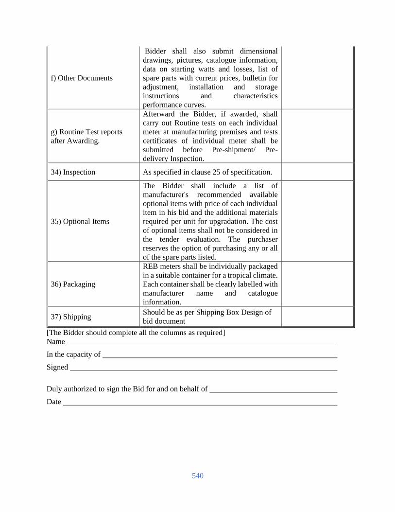
540
f) Other Documents
Bidder shall also submit dimensional
drawings, pictures, catalogue information,
data on starting watts and losses, list of
spare parts with current prices, bulletin for
adjustment, installation and storage
instructions and characteristics
performance curves.
g) Routine Test reports
after Awarding.
Afterward the Bidder, if awarded, shall
carry out Routine tests on each individual
meter at manufacturing premises and tests
certificates of individual meter shall be
submitted before Pre-shipment/ Pre-
delivery Inspection.
34) Inspection As specified in clause 25 of specification.
35) Optional Items
The Bidder shall include a list of
manufacturer's recommended available
optional items with price of each individual
item in his bid and the additional materials
required per unit for upgradation. The cost
of optional items shall not be considered in
the tender evaluation. The purchaser
reserves the option of purchasing any or all
of the spare parts listed.
36) Packaging
REB meters shall be individually packaged
in a suitable container for a tropical climate.
Each container shall be clearly labelled with
manufacturer name and catalogue
information.
37) Shipping Should be as per Shipping Box Design of
bid document
[The Bidder should complete all the columns as required]
Name
In the capacity of
Signed
Duly authorized to sign the Bid for and on behalf of
Date

541
6.3 Form of Completion Certificate
Contract No: Date:
To:
[Name of Contractor]
Pursuant to GCC Clause 39 (Completion of the Facilities) of the General Conditions of
the Contract entered into between yourselves and the Employer dated [insert date], for the
supply and installation of plant and Services for [name of contract], we hereby notify
you that the following part(s) of the Facilities was (were) complete on the date specified
below, and that, in accordance with the terms of the Contract, the Employer hereby takes
over the said part(s) of the Facilities, together with the responsibility for care and custody
and the risk of loss thereof on the date mentioned below.
1. Description of the Facilities or part thereof:
______________________________
2. Date of Completion: __________________
However, you are required to complete the outstanding items listed in the attachment hereto
as soon as practicable.
This letter does not relieve you of your obligation to complete the execution of the Facilities
in accordance with the Contract nor of your obligations during the Defect Liability Period.
Very truly yours,
for and on behalf of the Employer
[ Signature ]
[ Title of the Project Manager ]

542
6.4 Form of Operational Acceptance Certificate
Contract No: Date:
To:
[Name of Contractor]
Pursuant to GCC Clause 40.3 (Operational Acceptance) of the General Conditions of the
Contract entered into between yourselves and the Employer dated [insert date], for the
supply and installation of plant and Services for [name of contract], we hereby notify
you that the Functional Guarantees of the following part(s) of the Facilities were
satisfactorily attained on the date specified below.
1. Description of the Facilities or part thereof:
_______________________________
2. Date of Operational Acceptance: _______________________
This letter does not relieve you of your obligation to complete the execution of the Facilities
in accordance with the Contract nor of your obligations during the Defect Liability Period.
Very truly yours,
for and on behalf of the Employer
[ Signature ]
[ Title of the Project Manager ]

543
6.5 Form of Change Order Procedure and Forms
Contract No: Date:
To:
[Name of Contractor]
CONTENTS
1. General
2. Change Order Log
3. References for Changes
ANNEXES
Annex 1 Request for Change Proposal
Annex 2 Estimate for Change Proposal
Annex 3 Acceptance of Estimate
Annex 4 Change Proposal
Annex 5 Change Order
Annex 6 Pending Agreement Change Order
Annex 7 Application for Change Proposal
Change Order Procedure
1. General
This section provides samples of procedures and forms for implementing changes in the
Facilities during the performance of the Contract in accordance with GCC Clause 64 (Change
in the Facilities) of the General Conditions.
2. Change Order Log
The Contractor shall keep an up-to-date Change Order Log to show the current status of
Requests for Change and Changes authorized or pending, as Annex 8. Entries of the Changes
in the Change Order Log shall be made to ensure that the log is up-to-date. The Contractor
shall attach a copy of the current Change Order Log in the monthly progress report to be
submitted to the Employer.

544
3. References for Changes
(1) Request for Change as referred to in GCC Clause64 shall be serially numbered CR-X-
nnn.
(2) Estimate for Change Proposal as referred to in GCC Clause 64 shall be serially
numbered CN-X-nnn.
(3) Acceptance of Estimate as referred to in GCC Clause 64 shall be serially numbered
CA-X-nnn.
(4) Change Proposal as referred to in GCC Clause 64 shall be serially numbered CP-X-
nnn.
(5) Change Order as referred to in GCC Clause 64 shall be serially numbered CO-X-nnn.
Note: (a) Requests for Change issued from the Employer’s Home Office and the Site
representatives of the Employer shall have the following respective references:
Home Office CR-H-nnn
Site CR-S-nnn
(b) The above number “nnn” is the same for Request for Change, Estimate for
Change Proposal, Acceptance of Estimate, Change Proposal and Change Order.

545
Annex 1. Request for Change Proposal
(Employer’s Letterhead)
To: Date:
Attention:
Contract Name:
Contract Number:
With reference to the captioned Contract, you are requested to prepare and submit a Change
Proposal for the Change noted below in accordance with the following instructions within
_______________ days of the date of this letter ____________________.
1. Title of Change: ________________________
2. Change Request No. __________________
3. Originator of Change: Employer: _______________________________
Contractor (by Application for Change Proposal No. _______1:
4. Brief Description of Change: _________________________________________________
5. Facilities and/or Item No. of equipment related to the requested Change: _____________
6. Reference drawings and/or technical documents for the request of Change:
Drawing No./Document No. Description
7. Detailed conditions or special requirements on the requested Change: ________________
8. General Terms and Conditions:
(a) Please submit your estimate to us showing what effect the requested Change will have
on the Contract Price.
(b) Your estimate shall include your claim for the additional time, if any, for completion
of the requested Change.
(c) If you have any opinion negative to the adoption of the requested Change in connection
with the conformability to the other provisions of the Contract or the safety of the Plant
or Facilities, please inform us of your opinion in your proposal of revised provisions.

546
(d) Any increase or decrease in the work of the Contractor relating to the services of its
personnel shall be calculated.
(e) You shall not proceed with the execution of the work for the requested Change until
we have accepted and confirmed the amount and nature in writing.
Signature: [insert signature of authorised
representative of the Employer]
Name: [insert full name of signatory with
National ID Number]
Title of the Signatory: [insert title of the Signatory]
Name of the Employer: [insert name of the Employer]

547
Annex 2. Estimate for Change Proposal
(Contractor’s Letterhead)
To: Date:
Attention:
Contract Name:
Contract Number:
With reference to your Request for Change Proposal, we are pleased to notify you of the
approximate cost of preparing the below-referenced Change Proposal in accordance with GCC
Sub-Clause64.2.1 of the General Conditions. We acknowledge that your agreement to the cost of
preparing the Change Proposal, in accordance with GCC Sub-Clause64.2.2, is required before
estimating the cost for change work.
1. Title of Change: ________________________
2. Change Request No./Rev.: ____________________________
3. Brief Description of Change: __________________________
4. Scheduled Impact of Change: ___________________________
5. Cost for Preparation of Change Proposal: _______________2
(a) Engineering (Amount)
(i) Engineer hrs x rate/hr =
(ii) Draftsperson hrs x rate/hr =
Sub-total hrs
Total Engineering Cost
(b) Other Cost
Total Cost (a) + (b)
Signature: [insert signature of authorised
representative of the Employer]
Name: [insert full name of signatory with
National ID Number]
Title of the Signatory: [insert title of the Signatory]
Name of the Employer: [insert name of the Employer]
2 Costs shall be in the currencies of the Contract.

548
Annex 3. Acceptance of Estimate
(Employer’s Letterhead)
To: Date:
Attention:
Contract Name:
Contract Number:
We hereby accept your Estimate for Change Proposal and agree that you should proceed with the
preparation of the Change Proposal.
1. Title of Change: ___________________________
2. Change Request No./Rev.: _______________________________
3. Estimate for Change Proposal No./Rev.: _______________________________
4. Acceptance of Estimate No./Rev.: _______________________________
5. Brief Description of Change: _______________________________
6. Other Terms and Conditions: In the event that we decide not to order the Change accepted,
you shall be entitled to compensation for the cost of preparation of Change Proposal
described in your Estimate for Change Proposal mentioned in para. 3 above in accordance
with GCC Clause64 of the General Conditions.
Signature: [insert signature of authorised
representative of the Employer]
Name: [insert full name of signatory with
National ID Number]
Title of the Signatory: [insert title of the Signatory]
Name of the Employer: [insert name of the Employer]

549
Annex 4. Change Proposal
(Contractor’s Letterhead)
To: Date:
Attention:
Contract Name:
Contract Number:
In response to your Request for Change Proposal No. _______________________________, we
hereby submit our proposal as follows:
1. Title of Change: _______________________________
2. Change Proposal No./Rev.: _______________________________
3. Originator of Change: Employer: [_______________________________
Contractor: _______________________________
4. Brief Description of Change: _______________________________
5. Reasons for Change: _______________________________
6. Facilities and/or Item No. of Equipment related to the requested Change:
_______________________________
7. Reference drawings and/or technical documents for the requested Change:
Drawing/Document No. Description
8. Estimate of increase/decrease to the Contract Price resulting from Change Proposal:3
(Amount)
(a) Direct material
(b) Major construction equipment
(c) Direct field labor (Total hrs)
(d) Subcontracts
(e) Indirect material and labor
(f) Site supervision
(g) Head office technical staff salaries
Process engineer hrs @ rate/hr
Project engineer hrs @ rate/hr
Equipment engineer hrs @ rate/hr
Procurement hrs @ rate/hr
Draftsperson hrs @ rate/hr
Total hrs
(h) Extraordinary costs (computer, travel, etc.)
3 Costs shall be in the currencies of the Contract.
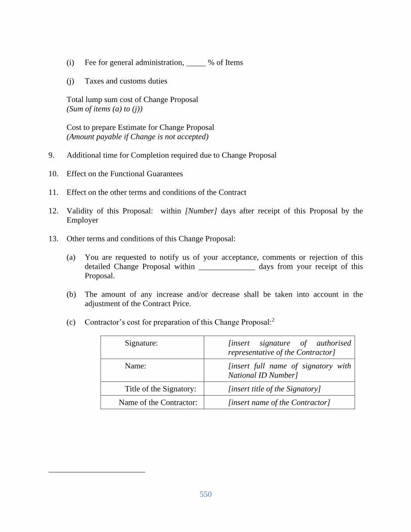
550
(i) Fee for general administration, % of Items
(j) Taxes and customs duties
Total lump sum cost of Change Proposal
(Sum of items (a) to (j))
Cost to prepare Estimate for Change Proposal
(Amount payable if Change is not accepted)
9. Additional time for Completion required due to Change Proposal
10. Effect on the Functional Guarantees
11. Effect on the other terms and conditions of the Contract
12. Validity of this Proposal: within [Number] days after receipt of this Proposal by the
Employer
13. Other terms and conditions of this Change Proposal:
(a) You are requested to notify us of your acceptance, comments or rejection of this
detailed Change Proposal within ______________ days from your receipt of this
Proposal.
(b) The amount of any increase and/or decrease shall be taken into account in the
adjustment of the Contract Price.
(c) Contractor’s cost for preparation of this Change Proposal:2
Signature: [insert signature of authorised
representative of the Contractor]
Name: [insert full name of signatory with
National ID Number]
Title of the Signatory: [insert title of the Signatory]
Name of the Contractor: [insert name of the Contractor]

551
Annex 5. Change Order
(Employer’s Letterhead)
To: Date:
Attention:
Contract Name:
Contract Number:
We approve the Change Order for the work specified in the Change Proposal (No. _______), and
agree to adjust the Contract Price, Time for Completion and/or other conditions of the Contract in
accordance with GCC Clause64 of the General Conditions.
1. Title of Change: _______________________________
2. Change Request No./Rev.: _______________________________
3. Change Order No./Rev.: _______________________________
4. Originator of Change: Employer: _______________________________
Contractor: _______________________________
5. Authorized Price:
Ref. No.: _______________________________ Date:
__________________________
Foreign currency portion __________ plus Local currency portion __________
6. Adjustment of Time for Completion
None Increase _________ days Decrease _________ days
7. Other effects, if any
Authorized by: Date:
(Employer)
Accepted by: Date:
(Contractor)

552
Annex 6. Pending Agreement Change Order
(Employer’s Letterhead)
To: Date:
Attention:
Contract Name:
Contract Number:
We instruct you to carry out the work in the Change Order detailed below in accordance with GCC
Clause64 of the General Conditions.
1. Title of Change: _______________________________
2. Employer’s Request for Change Proposal No./Rev.: _______________________________
dated: __________
3. Contractor’s Change Proposal No./Rev.: _______________________________ dated:
4. Brief Description of Change: _______________________________
5. Facilities and/or Item No. of equipment related to the requested Change:
_______________________________
6. Reference Drawings and/or technical documents for the requested Change:
Drawing/Document No. Description
7. Adjustment of Time for Completion:
8. Other change in the Contract terms:
9. Other terms and conditions:
Signature: [insert signature of authorised
representative of the Employer]
Name: [insert full name of signatory with
National ID Number]
Title of the Signatory: [insert title of the Signatory]
Name of the Employer: [insert name of the Employer]

553
Annex 7. Application for Change Proposal
(Contractor’s Letterhead)
To: Date:
Attention:
Contract Name:
Contract Number:
We hereby propose that the below-mentioned work be treated as a Change in the Facilities.
1. Title of Change: _______________________________
2. Application for Change Proposal No./Rev.: _______________________________ dated:
_______________________________
3. Brief Description of Change: _______________________________
4. Reasons for Change:
5. Order of Magnitude Estimation (in the currencies of the Contract):
6. Scheduled Impact of Change:
7. Effect on Functional Guarantees, if any:
8. Appendix:
Signature: [insert signature of authorised
representative of the Contractor]
Name: [insert full name of signatory with National
ID Number]
Title of the Signatory: [insert title of the Signatory]
Name of the Contractor: [insert name of the Contractor]
Signature Seal

554
6.6 Supplementary Information
[The Tenderer shell furnish additional description/information covering all activities, if any]
Invitation for Tenders
[This is the website format and as used for published advertisement.
It is included in this document for information only]
GOVERNMENT OF THE PEOPLE’S REPUBLIC OF BANGLADESH
1 Ministry/Division < select > V
2 Agency < select > V
3 Purchaser Name < type in name >
4 Purchaser Code Not used at present
5 Purchaser District < select > V
6 Invitation for <
sele
ct >
V <
sele
ct >
V <
sele
ct >
V
7 Invitation Ref No < type in name >
8 Date < select > V
KEY INFORMATION
9 Procurement Method < select > V <
sele
ct >
V
FUNDING INFORMATION
10 Budget and Source of Funds < select > V
11 Development Partners (if applicable) < type in name >
PARTICULAR INFORMATION
12 Project / Programme Code (if
applicable)
< use MOF code >
13 Project / Programme Name (if
applicable)
< use MOF name >
14 Tender Package No. < type in name >
15 Tender Package Name < type in name >
Date
16 Tender Publication Date < select > V
17 Tender Last Selling Date < select > V
Date Time
18 Tender Closing Date and Time < select > V < select > V
19 Tender Opening Date and Time < select > V < select > V
20 Name & Address of the office(s) Address
- Selling Tender Document (Principal) < type in name >
- Selling Tender Document (Others) < type in name >
NO CONDITIONS APPLY FOR SALE, PURCHASE OR DISTRIBUTION OF TENDER
DOCUMENTS
- Receiving Tender Document < type in name >
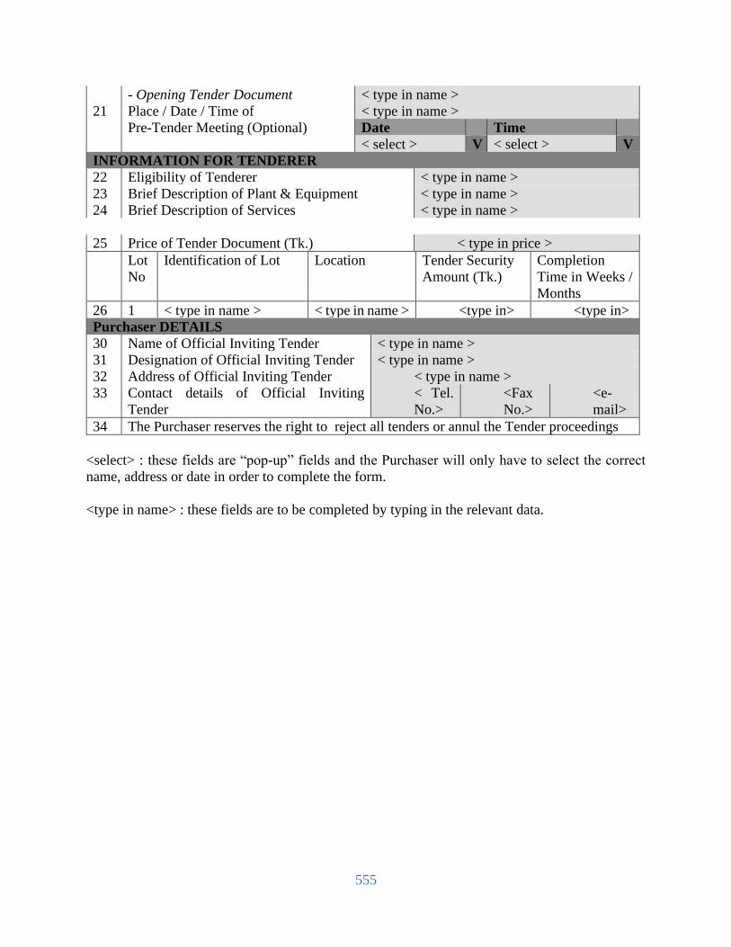
555
- Opening Tender Document < type in name >
21 Place / Date / Time of < type in name >
Pre-Tender Meeting (Optional) Date Time
< select > V < select > V
INFORMATION FOR TENDERER
22 Eligibility of Tenderer < type in name >
23 Brief Description of Plant & Equipment < type in name >
24 Brief Description of Services < type in name >
25 Price of Tender Document (Tk.) < type in price >
Lot
No
Identification of Lot Location Tender Security
Amount (Tk.)
Completion
Time in Weeks /
Months
26 1 < type in name > < type in name > <type in> <type in>
Purchaser DETAILS
30 Name of Official Inviting Tender < type in name >
31 Designation of Official Inviting Tender < type in name >
32 Address of Official Inviting Tender < type in name >
33 Contact details of Official Inviting
Tender
< Tel.
No.>
<Fax
No.>
<e-
mail>
34 The Purchaser reserves the right to reject all tenders or annul the Tender proceedings
<select> : these fields are “pop-up” fields and the Purchaser will only have to select the correct
name, address or date in order to complete the form.
<type in name> : these fields are to be completed by typing in the relevant data.

556
Invitation for Tenders
[for use when there are MULTIPLE lots in a package
This is the website format and as used for published advertisement.
It is included in this document for information only]
GOVERNMENT OF THE PEOPLE’S REPUBLIC OF BANGLADESH
1 Ministry/Division < select > V
2 Agency < select > V
3 Purchaser Name < type in name >
4 Purchaser Code Not used at present
5 Purchaser District < select > V
6 Invitation for <
sele
ct >
V <
sele
ct >
V <
sele
ct >
V
7 Invitation Ref No < type in name >
8 Date < select > V
KEY INFORMATION
9 Procurement Method < select > V <
sele
ct >
V
FUNDING INFORMATION
10 Budget and Source of Funds < select > V
11 Development Partners (if applicable) < type in name >
PARTICULAR INFORMATION
12 Project / Programme Code (if
applicable)
< use MOF code >
13 Project / Programme Name (if
applicable)
< use MOF name >
14 Tender Package No. < type in name >
15 Tender Package Name < type in name >
Date
16 Tender Publication Date < select > V
17 Tender Last Selling Date < select > V
Date Time
18 Tender Closing Date and Time < select > V < select > V
19 Tender Opening Date and Time < select > V < select > V
20 Name & Address of the office(s) Address
- Selling Tender Document (Principal) < type in name >
- Selling Tender Document (Others) < type in name >
NO CONDITIONS APPLY FOR SALE, PURCHASE OR DISTRIBUTION OF TENDER
DOCUMENTS
- Receiving Tender Document < type in name >
- Opening Tender Document < type in name >
21 Place / Date / Time of < type in name >
Pre-Tender Meeting (Optional) Date Time
< select > V < select > V

557
INFORMATION FOR TENDERER
22 Eligibility of Tenderer < type in name >
23 Brief Description of Plant & Equipment < type in name >
24 Brief Description of Services < type in name >
25 Price of Tender Document (Tk.) < type in price >
Lot
No
Identification of Lot Location Tender
Security
Amount (Tk.)
Completion Time
in
Weeks / Months
26 1 < type in name > < type in name > <type
in>
<type in>
27 2 < type in name > < type in name > <type
in>
<type in>
28 3 < type in name > < type in name > <type
in>
<type in>
29 4 < type in name > < type in name > <type
in>
<type in>
30 Name of Official Inviting Tender < type in name >
31 Designation of Official Inviting Tender < type in name >
32 Address of Official Inviting Tender < type in name >
33 Contact details of Official Inviting
Tender
< Tel. No. > < Fax
No. >
< e-
mail >
34 The Purchaser reserves the right to reject all tenders or annul the Tender proceedings
<select> : these fields are “pop-up” fields and the Purchaser will only have to select the correct
name, address or date in order to complete the form.
<type in name> : these fields are to be completed by typing in the relevant data.
Signature
Signature

558
Section 7. Drawings

559
Flow charts of the processes involved between different entities in the prepaid e-metering
system
Overall Process Outline
Main requirement: A receipt is essential as a proof of vending. Otherwise, in case of problem
of actual vending into the meters, resolution of the dispute will be difficult. Therefore, a
consumer for vending purpose must come either to a POS or to a Vending Station for recharging
his/her meters (either single phase or three phases). Since the friendly hour and emergency credit
facilities will be active within the meter so the failure of vending beyond the office hour will not
harm the consumer.
MIC software checks the balance from the vendor’s
operator
Depending on the feedback message received from the MIC, the vending
software will either print the key or writes it into SC
The POS software prints the receipt with
the vending information
Customer if wants to know information like his
sanctioned load during peak hour, rate etc. may send his account number and the appropriate code
via his mobile phone
The request will be processed via SMS server (within system master
station) and the requested information will be retrieved from the
database and sent to the mobile operator
The API appropriate to the meter will generate the encrypted number
and MIC will either sends it to the POS or
to the meter
Operator’s server feedbacks
whether POS vendor has sufficient
balance or not
A failure message will be sent to the POS
MIC sends the vending information directly to the meter
Single
Phase or
Three
Phase
Meter?
The POS software prints the receipt with the vending
information
The POS vendor then attempts to
charge his account
sin
gle
Th
ph
Yes
No
The mobile company
forwards the result to mobile of
the consumer
The mobile company
forwards the request to the utility’s MIC
The consumer pays to the POS
vendor the amount applicable for
vending
Vendor enters the information into the POS software and the software sends them to MIC via the
network

560
Processes initiated at POS
1. Processes involved at the Utility’s Vending Station
2. Same as the POS initiated processes except the checking monitory transactions because
only cash transactions will be made at the vending stations.
3. Processes involved at Short Message Services from consumers’ mobile
1 Multi-factories Access Platform
1.1 Access Platform Architecture Design
Each manufacturer provides its own encryption / decryption API, integrated into the system
software.
When dealing with business based on different meters from each manufacturer, the system
automatically calls the corresponding manufacturers’ encryption / decryption API.
The system defines uniformly data exchange interface corresponding to different business, such
as input and output parameters.
When dealing with a business, for the keypad meter, the system will call the encryption /
decryption API, generates the corresponding Token, and print; for smart card meter, the system
will call the encryption / decryption API, write the corresponding Token to encrypted data area
of the smart card.
The encryption/decryption API from smart card manufacture must be able to generate Token
which must contain the information of business type and length information. So that when smart
card meter read the encrypted data in the card, the meter can separate the Token and identify the
Token business itself.
POS read the smart cards from different manufactures via standard card read devices.

561
MIC communicates with GPRS meters of other factories according to standard data exchange
mechanism.
Note: Token in this document means encrypted data.
2. Business Process
2.1 Vending as example:
Input the Account No.
If it is existed ?Query current tax
and tariff
vending
API return TOKEN
If it is a GPRS meter
Remote charge
WriteIC Card
Y
yes
no
Print receiption
Print receiption
Call encryption/decrypti
on API
If it is a Card meter
N Y
Print receiption
N
This is a brief conceptual drawing. Bidder must provide all the drawings necessary after survey
(if necessary) and those drawings must be approved by employer.
Insert here a list of Drawings. The actual Drawings, including site plans, should be attached
to this section or annexed in a separate folder. The Drawings shall be dated, numbered and
show the revision number.


-The End-
![[Automation, Electrification, and Shared Mobility in Freight]](https://static.fdokumen.com/doc/165x107/632813a2e491bcb36c0b98fc/automation-electrification-and-shared-mobility-in-freight.jpg)