
Divertor Tokamak Test facility Project Proposal
268
DTT Divertor Tokamak Test facility Project Proposal
-
Upload
khangminh22 -
Category
Documents
-
view
2 -
download
0
Transcript of Divertor Tokamak Test facility Project Proposal

DTT Divertor Tokamak Test facility
Project Proposal
ISBN: 978-88-8286-318-0

DTT Divertor Tokamak Test facility
Project Proposal
an opportunity for facing one of the major challenges along the roadmap to the realisation of fusion energy
July 2015

DTT
Divertor Tokamak Test facility - Project Proposal
Italian National Agency for New Technologies,
Energy and Sustainable Economic Development
Edited by Aldo Pizzuto, ENEA
ISBN: 978-88-8286-318-0
Printed in July 2015 at ENEA Frascati Research Center,
Via Enrico Fermi 45, 00044 Frascati (Roma), Italy
Project Proposal
- i -
Contributors
ENEA, Italy L. Affinito
A. Anemona
M. L. Apicella
P. Batistoni
G. Calabrò
A. Cardinali
S. Ceccuzzi
C.Centioli
V. Corato
P. Costa
F. Crisanti
A. Cucchiaro
A. Della Corte
G. De Marzi
A. Di Zenobio
C. Fiamozzi Zignani
L. Gabellieri
A. Lampasi
G. Maddaluno
G. Maffia
D. Marocco
G. Mazzitelli
G. Messina
F. Mirizzi
M. Moneti
L. Muzzi
A. Pizzuto
G. Ramogida
G.L. Ravera
R. Righetti
S. Roccella
F. Starace
G. Tomassetti
A.A. Tuccillo
O. Tudisco
S. Turtù
S. Villari
B. Viola
V. Vitale
G. Vlad
P. Zito
F. Zonca
ENEA - CNR - IFP, Italy A. Bruschi
D. Farina
L. Figini
S. Garavaglia
G. Granucci
M. Lontano
D. Micheletti
S. Nowak
C. Sozzi
ENEA - CREATE, Italy R. Albanese
R. Ambrosino
L. Barbato
S. Ciattaglia
D. Coccorese
V. Coccorese
M. de Magistris
G. Di Gironimo
V. P. Loschiavo
R. Martone
D. Marzullo
S. Mastrostefano
S. Minucci
R. Mozzillo
R. Palmaccio
V. Pericoli-Ridolfini
A. Pironti
G. Rubinacci
A. Tarallo
S. Ventre
F. Villone
ENEA - Politecnico di Torino, Italy R. Maggiora
D. Milanesio
ENEA - RFX, Italy P. Agostinetti
T. Bolzonella
L. Carraro
A. Fassina
P. Franz
E. Gaio
F. Gnesotto
P. Innocente
A. Luchetta
G. Manduchi
L. Marrelli
P. Martin
S. Peruzzo
R. Piovan
M. E. Puiatti
G. Spizzo
P. Scarin
P. Sonato
M. Spolaore
V. Toigo
M. Valisa
L. Zanotto
ENEA - Università degli Studi di Milano - Bicocca, Italy
G. Gorini
CEA, IRFM, France G. Giruzzi
CRPP - EPFL, Switzerland B. Duval
H. Reimerdes
FOM-DIFFER, The Netherlands M. de Baar
IPPLM, Poland
R. Zagórski

Project Proposal
- ii -
Synopsis The recent formation of the EUROfusion Consortium marks a big step in the roadmap toward the
realisation of fusion energy with a demonstration plant DEMO by 2050.
One of the main challenges in the roadmap is to develop a heat and power exhaust system able to
withstand the large loads expected in the divertor of a fusion power plant. Therefore, in parallel with
the programme to optimise the operation with a conventional divertor based on detached conditions to
be tested on ITER, EUROfusion has launched a dedicated project to investigate alternative power
exhaust solutions for DEMO, and the design of a new machine named "Divertor Tokamak Test
facility" (DTT), capable of eventually integrating all relevant physics and technology issues. The set of
possible alternative solutions to be assessed includes advanced magnetic configurations and liquid
metal divertors.
DTT should operate integrating various aspects, with significant power loads, flexible divertors,
plasma edge and bulk conditions approaching as much as possible those planned for DEMO, at least in
terms of dimensionless parameters. An optimal balance between these requirements and the need to
realize the new experiment accomplishing the DEMO timescale, leads to the choice of the following
machine parameters: major radius R=2.15 m, aspect ratio A=3.1 (A=R/a, where ‘a’ is the tokamak
minor radius), toroidal field BT=6 T, plasma current Ip=6 MA, additional power PTot=45 MW. The
machine will have the possibility to test several different magnetic divertor topologies, in reactor
relevant regimes. Different plasma facing materials will be tested (tungsten, liquid metals) up to a
power flow of the order of 20MW/m2. The final target of this experiment is the realization of an
integrated solution (bulk and edge plasma) for the power exhaust in view of DEMO. The related
studies and experiments will allow a valuable development of innovative technologies in several
different fields, with relevant spin off for the industries of all European Countries.
According to the European Road Map, the DTT experiment should start its operation in 2022. To be
coherent with this plan, the realization of the device will cover a time of around 7 years, starting from
the first tender (during 2016) up to full commissioning and the first plasma (during 2022). The
operations should then cover a period of more than 20 years, up to the initial phases of the DEMO
realization.
The occupational impact is expected to be significant, with at least 150 people involved for the
operation (50 % professionals, 50 % support personnel). In addition, a significant amount of on-site
workers are expected during the construction, not to mention the indirect and spin-off opportunities.
The expected economic impact on the hosting territory is also significant. Some financial fall-out for
both the construction and the operation should be addressed to the territory (buildings, electrical grid,
maintenance, etc.). In addition, the continuous presence of an international scientific staff will cause
on the host territory a spin-off linked to the guest family life and activities like lodging, transport,
restaurants, schools ...
While the European Programme allocated about 60 MEUR in Horizon 2020, the expected total cost
for realizing this DTT proposal is estimated to be about 500 MEUR. DTT is a strategic investment in
the key areas of research and innovation, with significant implications on the energetic problem,
offering a stimulus on higher education and training in the fields of science and engineering. Recently,
the Italian Government has offered to the European fusion system the opportunity to get
complementary funding for a dedicated exhaust facility located in Italy. The proposal is among the
projects submitted to the 315 billion Euro of Juncker's plan (EFSI: European Fund for Strategic
Investments).
This report presents the DTT proposal worked out by an International European Team of experts. Its
contents has been independently revised and recommended by Chinese experts. It demonstrates the
possibility to set up a facility able to bridge the power handling gaps between the present day devices,
ITER and DEMO within the European fusion development roadmap, which plays a crucial role for the
development of one of the most promising technologies for an alternative, safe and sustainable energy
source.
Project Proposal
- iii -
Sinossi La recente costituzione del Consorzio EUROfusion rappresenta un notevole passo avanti nel
programma europeo (EU Fusion Road Map) per la realizzazione di un impianto dimostrativo
(DEMO), una centrale nucleare a fusione in grado di fornire energia elettrica alla rete entro il 2050.
Una delle principali sfide nella Road Map è costituita dal problema dei carichi termici previsti nel
divertore (il principale componente dell'impianto di scarico di una centrale a fusione). Pertanto, in
parallelo con il programma di ottimizzare le modalità operative previste nel reattore sperimentale
ITER con un divertore basato sulle condizioni di "distacco" del plasma dalla parete, EUROfusion ha
fatto partire un altro programma per studiare soluzioni alternative al problema dei carichi termici in
DEMO, con il progetto di una macchina denominata "Divertor Tokamak Test facility" (DTT), in grado
di fornire soluzioni integrate con tutti gli aspetti fisici e tecnologici. Le soluzioni alternative da
sottoporre a specifici test in DTT comprenderanno le configurazioni magnetiche avanzate ed i
divertori basati sui metalli liquidi.
DTT dovrà operare in scenari integrati, con carichi termici rilevanti, divertori flessibili, condizioni di
plasma (all'interno ed al bordo) simili a quelle previste per DEMO, quanto meno in termini di
grandezze in scala (adimensionalizzate). Il compromesso tra prestazioni richieste e la necessità di
rispettare la scala dei tempi dettata dalla Road Map per DEMO ha portato alla scelta dei seguenti
parametri: raggio maggiore R=2.15 m, rapporto di aspetto A=3.1 (A=R/a, dove ‘a’ è il raggio minore
del tokamak), campo magnetico toroidale BT=6 T, corrente di plasma Ip=6 MA, potenza addizionale
PTot=45 MW. La macchina potrà provare differenti concetti e topologie di divertore, in condizioni
rilevanti per un reattore. Saranno testati diversi materiali (tungsteno, metalli liquidi) con flussi termici
fino a 20MW/m2. L'obiettivo principale è quello di indicare una soluzione integrata per il problema dei
carichi termici previsti in DEMO. Le attività di ricerca correlate costituiranno una notevole spinta per
lo sviluppo di tecnologie innovative in vari settori, con rilevanti ricadute per le industrie europee.
In base alla Road Map, DTT dovrebbe essere operativo nel 2022. Pertanto, la realizzazione durerà
circa 7 anni a partire dalla prima gara (2016) fino alla messa in servizio con il primo plasma nel 2022.
Le operazioni ed il programma sperimentale dovrebbero poi coprire un periodo di oltre venti anni, fino
all'inizio della costruzione di DEMO ed oltre.
L’impatto occupazionale previsto è rilevante, almeno 150 persone coinvolte nelle operazioni (50 %
ricercatori e personale qualificato, 50 % personale di supporto). E' inoltre previsto un notevole numero
di lavoratori coinvolti nelle fasi di costruzione ed operazione, senza contare le opportunità per spin-off
e sub-appalti.
Anche l'impatto economico previsto sul territorio è significativo nelle fasi di costruzione ed in quelle
successive (edifici, rete elettrica, manutenzione, ecc.). Inoltre, la presenza continuativa richiesta
durante le operazioni darà luogo a ricadute sul territorio legate al soggiorno di un team internazionale
con le relative famiglie (alloggi, trasporti, ristoranti, scuole, ecc.).
EUROfusion ha stanziato circa 60 MEUR in Horizon 2020, ma il costo previsto per la realizzazione di
DTT è valutato intorno alla cifra di 500 MEUR. Recentemente, vedendo nel progetto DTT
un'occasione per dare un contributo al problema energetico ecocompatibile per i prossimi decenni ed
al tempo stesso investire nella ricerca europea con prospettiva di elevatissimo ritorno economico,
fornendo uno stimolo per la formazione di giovani nel settore della ricerca applicata, il governo
italiano ha offerto alla comunità scientifica europea l'opportunità di ottenere i finanziamenti necessari
a costruire DTT in Italia. La proposta è fra i progetti presentati per il finanziamento tramite i 315
miliardi di Euro previsti dall'Agenda Juncker (EFSI: European Fund for Strategic Investments).
Questo rapporto presenta la proposta DTT basata sul lavoro di un qualificato team europeo ed il suo
contenuto è stato sottoposto al vaglio di esperti cinesi, che a valle di una revisione indipendente hanno
espresso una raccomandazione positiva. La proposta dimostra la possibilità di realizzare una macchina
sperimentale in grado di superare il gap tecnologico nel settore dei carichi termici tra i dispositivi
attuali, ITER e DEMO, nel quadro della Road Map Europea per la fusione, che gioca un ruolo
fondamentale per lo sviluppo di una delle tecnologie più promettenti per fornire una sorgente di
energia alternativa sicura, pulita ed inesauribile.

Project Proposal
- iv -
Contents
Chapter 1 .................................................................................................................................................. 1
INTRODUCTION AND EXECUTIVE SUMMARY ............................................................................. 1
1.1 Introduction .................................................................................................................................... 1
1.2 Magnetic fusion as an energy source ............................................................................................. 1
1.3 Power exhaust issues in the fusion roadmap .................................................................................. 2
1.4 Role and objectives ........................................................................................................................ 5
1.4.1 DTT Role ................................................................................................................................. 5
1.4.2 DTT Objectives ........................................................................................................................ 5
1.5 DTT Proposal ................................................................................................................................. 6
1.5.1 The DTT Project ...................................................................................................................... 6
1.5.2 DTT parameters. ...................................................................................................................... 7
1.6 Operation and scientific programme .............................................................................................. 8
1.6.1 Scenarios and scientific program. ............................................................................................ 8
1.7 Design basis and readiness to proceed ......................................................................................... 10
1.8 Costs and schedule ....................................................................................................................... 11
1.9 Site assessment and socio-economic aspects ............................................................................... 11
1.10 Relevance for ITER and DEMO ................................................................................................ 12
1.11 References .................................................................................................................................. 12
Chapter 2 ................................................................................................................................................ 15
ROLE AND OBJECTIVES OF DTT .................................................................................................... 15
2.1 DTT Role ..................................................................................................................................... 15
2.2 DTT Objectives ............................................................................................................................ 15
2.3 Power exhaust issues .................................................................................................................... 16
2.4 Physics basis ................................................................................................................................ 17
2.4.1 Physics of power exhaust ....................................................................................................... 17
2.4.2 Physics basis for alternative configurations ........................................................................... 18
2.4.3 Physics basis of liquid metal targets ...................................................................................... 19
2.5 Contributions of existing programmes and devices ..................................................................... 21
2.6 DTT physics requirements and specifications ............................................................................. 21
2.6.1 Alternative magnetic configurations ...................................................................................... 23
2.6.2 Liquid metals .......................................................................................................................... 23
2.7 DTT technical requirements and specifications ........................................................................... 24
2.7.1 Technological feasibility of alternative configurations .......................................................... 24
2.7.2 Alternative configurations: minimal technical requirements ................................................. 25
2.7.3 Technological feasibility of liquid metal solutions ................................................................ 26
2.8 References .................................................................................................................................... 29

Project Proposal
- v -
Chapter 3 ................................................................................................................................................ 31
CHOICE OF PARAMETERS FOR DTT .............................................................................................. 31
3.1 Rationale for the choice of DTT parameters ................................................................................ 31
3.2 Plasma performance and operational limits ................................................................................. 35
3.3 Plasma equilibrium and control ................................................................................................... 36
3.4 Materials and technologies ........................................................................................................... 40
3.5 Power and particle exhaust .......................................................................................................... 41
3.5.1 Background ............................................................................................................................ 41
3.5.2 Integrated core–edge simulations ........................................................................................... 42
3.5.3 2D edge simulations with TECXY ........................................................................................ 44
3.5.4 Summary ................................................................................................................................ 45
3.6 Divertor physics and technology .................................................................................................. 47
3.7 ELMs and disruptions .................................................................................................................. 49
3.8 Operations, diagnostics and control ............................................................................................. 53
3.9 Additional heating and current drive ........................................................................................... 54
3.10 Scientific program ...................................................................................................................... 55
3.11 References .................................................................................................................................. 58
Chapter 4 ................................................................................................................................................ 61
DTT PROPOSAL ................................................................................................................................... 61
4.1 Magnets ........................................................................................................................................ 61
4.2 Toroidal field coil system ............................................................................................................ 62
4.2.1 Background ............................................................................................................................ 62
4.2.2 Design description .................................................................................................................. 63
4.2.3 Operating conditions .............................................................................................................. 66
4.2.4 Mechanical loads .................................................................................................................... 68
4.2.5 TF coil design proposal: risk assessment ............................................................................... 71
4.2.6 Electrical loads ....................................................................................................................... 72
4.2.7 TF ripple ................................................................................................................................. 73
4.3 Central solenoid and poloidal field coil system ........................................................................... 78
4.3.1 Background to the design ....................................................................................................... 78
4.3.2 Design description .................................................................................................................. 78
4.3.3 Operating conditions .............................................................................................................. 85
4.3.4 Plasma scenarios .................................................................................................................... 91
4.3.5 Mechanical loads .................................................................................................................. 101
4.3.6 Electrical loads ..................................................................................................................... 101
4.3.7 AC losses.............................................................................................................................. 102
4.4 Vacuum vessel ........................................................................................................................... 105
4.4.1 Main vessel .......................................................................................................................... 106
4.4.2 Access ports ......................................................................................................................... 107
Project Proposal
- vi -
4.4.3 Vessel supports .................................................................................................................... 110
4.4.4 Electromagnetic loads on the vacuum vessel due to the current quench in a plasma
disruption ...................................................................................................................................... 111
4.4.5 Electromagnetic loads on the metallic structures: further considerations ............................ 115
4.4.6 Mechanical analysis ............................................................................................................. 121
4.5 First wall .................................................................................................................................... 127
4.5.1 Support structure for the first wall ....................................................................................... 129
4.6 Divertor ...................................................................................................................................... 130
4.7 Neutronics .................................................................................................................................. 132
4.7.1 Background .......................................................................................................................... 132
4.7.2 DTT H-mode reference neutron rate .................................................................................... 132
4.7.3 Shielding assessment of TF coil ........................................................................................... 133
4.7.4 Neutron and gamma fluxes, nuclear heating and dpa in PFC .............................................. 136
4.7.5 Neutron induced radioactivity .............................................................................................. 136
4.7.6 Conclusions .......................................................................................................................... 137
4.8 Maintenance and remote handling ............................................................................................. 137
4.8.1 Divertor remote handling design .......................................................................................... 138
4.8.2 FW remote handling design ................................................................................................. 140
4.9 Heating and current drive systems ............................................................................................. 143
4.9.1 Background .......................................................................................................................... 143
4.9.2 ICRH heating ....................................................................................................................... 144
4.9.3 ECRH heating ...................................................................................................................... 156
4.9.4 NBI heating .......................................................................................................................... 167
4.10 Fueling and pumping systems .................................................................................................. 171
4.10.1 Divertor pumping ............................................................................................................... 171
4.10.2 Vacuum chamber pumping ................................................................................................ 171
4.10.3 Choice of pump type .......................................................................................................... 171
4.10.4 Cryostat pumping ............................................................................................................... 172
4.10.5 Fuelling. ............................................................................................................................. 172
4.11 Cryostat vessel ......................................................................................................................... 172
4.12 Cooling system - cryogenics .................................................................................................... 178
4.13 Cooling system - hydraulic ...................................................................................................... 180
4.14 Power supply ............................................................................................................................ 180
4.14.1 Introduction ........................................................................................................................ 180
4.14.2 Summary of the mathematical model................................................................................. 181
4.14.3 Numerical results ............................................................................................................... 182
4.14.4 Electric characteristics of the DTT power supplies ........................................................... 189
4.15 Electrical distribution system ................................................................................................... 192
4.16 Data acquisition, diagnostics and control................................................................................. 194
4.16.1 Diagnostics ......................................................................................................................... 195
4.16.2 Real time control ................................................................................................................ 206
4.16.3 Machine protection............................................................................................................. 213
4.16.4 Data acquisition and control infrastructure ........................................................................ 213

Project Proposal
- vii -
4.16.5 Real time control functions ................................................................................................ 216
4.16.6 Machine protection functions ............................................................................................. 217
4.17 Possible future upgrading ......................................................................................................... 218
4.18 References ................................................................................................................................ 220
Chapter 5 .............................................................................................................................................. 225
DTT COSTS, SAFETY AND MANAGEMENT ASPECTS .............................................................. 225
5.1 Quality, safety and environment ................................................................................................ 225
5.1.1 Overall quality management ................................................................................................ 225
5.1.2 Licensing .............................................................................................................................. 226
5.1.3 Safety analysis and environmental impact ........................................................................... 226
5.1.4 Radioprotection .................................................................................................................... 229
5.1.5 Safety and quality classification and relevant implications ................................................. 229
5.1.6 Possible upgrading ............................................................................................................... 229
5.1.7 Waste management and decommissioning .......................................................................... 229
5.2 Operation, reliability, availability, maintainability and inspectability analysis ......................... 230
5.2.1 Operation .............................................................................................................................. 230
5.2.2 Reliability and availability target ......................................................................................... 230
5.2.3 RAMI analysis ..................................................................................................................... 230
5.2.4 Operating experience ........................................................................................................... 231
5.3 Site assessment ........................................................................................................................... 237
5.3.1 Requirements ....................................................................................................................... 237
5.3.2 Opportunities ........................................................................................................................ 240
5.4 Cost, manpower and time schedule ............................................................................................ 241
5.4.1 Cost analysis: general ........................................................................................................... 241
5.4.2 Cost analysis: breakdown of the investment ........................................................................ 242
5.4.3 Cost analysis: manpower...................................................................................................... 245
5.4.4 Cost analysis: operation ....................................................................................................... 245
5.4.5 Cost analysis: human and financial resources ...................................................................... 245
5.4.6 Timeline of the construction ................................................................................................ 245
5.5 Project management ................................................................................................................... 246
5.5.1 General ................................................................................................................................. 246
5.5.2 Organization of the project ................................................................................................... 246
5.6 Socio-economic aspects ............................................................................................................. 248
5.7 References .................................................................................................................................. 250
Chapter 6 .............................................................................................................................................. 253
CONCLUDING REMARKS ............................................................................................................... 253
6.1 Background ................................................................................................................................ 253
6.2 Summary .................................................................................................................................... 254
Project Proposal
- viii -
Acknowledgements
This proposal is synergic with the activities carried out within the EUROfusion work packages:
"WPDTT1 - Assessment of alternative divertor geometries and liquid metals PFCs", Project
Leader H. Reimerdes;
"WPDTT2 - Definition and Design of the Divertor Tokamak Test Facility", Project Leader R.
Albanese.
We would like to thank:
the Chairman of the EUROfusion General Assembly, J. Pamela, the EUROfusion Programme
Manager, A.J.H. Donné, and the former EFDA Leader, F. Romanelli, for their support to the
DTT initiative;
the DTT2 Project Board and especially its Chair, B. Saoutic for useful suggestions and the
support to the pre-conceptual design activities of DTT;
the entire DTT2 Team and especially the Responsible Officer and the Activity Managers, who
have not directly worked on the pre-conceptual design activities of DTT, however they have
provided a valuable basis for the preparation of this document: M. Ariola of ENEA-CREATE,
G. Galant of IPPLM, D. Hancock of CCFE, S. McIntosh of CCFE, R. Stankiewicz of IPPLM,
F. L. Tabarés of CIEMAT, M. Turnyanskiy of EUROfusion PMU;
the Department of Power Plant Physics and Technology (EUROfusion PM Unit) and in
particular G. Federici, R. Wenninger and C. Bachmann for their useful suggestions in view of
DTT exploitation for DEMO;
the EUROfusion ITER Physics Department and in particular Xavier Litaudon and D.
McDonald for fruitful discussions on DTT requirements;
M. Cavinato, A. Neto, A. Portone, R. Ranz Santana, F. Sartori of F4E and F. Piccolo, ITER
Machine Operation Officer, for their precious suggestions and observations on magnets and
data acquisition system;
M. Evangelos Biancolini and F. Giorgetti of Università degli Studi di Roma Tor Vergata for
their support to the magnet design;
K. Lackner and E. Salpietro for fruitful discussions and useful suggestions on DTT layout;
Jiangang Li for useful suggestions on DTT project proposal;
A. Albanese, F. Ledda, M. Nicolazzo, and F. Pizzo of ENEA-CREATE for their support on
the web site and the compilation of this report;
S. Papa of ENEA-CREATE for the realization of the DTT logo;
P. Bayetti, M. Bécoulet, S. Brémond, J.M. Bernard, J. Bucalossi, D. Ciazynski, L. Doceul, D.
Douai, J. L. Duchateau, M. Firdaouss, P. Garin, R. Gondé, A. Grosman, G.T. Hoang, P.
Magaud, D. Mazon, M. Missirlian, P. Mollard, Ph. Moreau, R. Magne, E. Nardon, B. Peluso,
C. Reux, F. Saint-Laurent, A. Simonin, M. Soldaini, E. Tsitrone, D. van Houtte, E. Villedieu,
and L. Zani of CEA for being available to review the DTT proposal.
The present document does not represent the opinion of CEA, CRPP - EPFL, FOM-DIFFER, IPPLM,
or any non-Italian EUROfusion beneficiary.
Project Proposal
- 1 -
Chapter 1
INTRODUCTION AND EXECUTIVE SUMMARY
1.1 Introduction
One of the main challenges, within the European Fusion Roadmap [1.1], is to design a power and
particle exhaust system, capable to withstand the large loads expected in the divertor of a DEMO
fusion power plant. On ITER [1.2], [1.3] (the International Fusion experiment under construction in
Cadarache) it is planned to test the actual possibilities of a standard divertor working in “detached
conditions” (see Chap. 2). However, it is already clear that this solution is very challenging and that,
consequently, the power exhaust problem could be a potential “show stopper” of the Fusion Road
towards the realization of a Fusion Reactor.
For this reason a specific project has been launched, within the European Fusion Roadmap, to
investigate alternative power exhaust solutions for DEMO, aiming at the definition and the design of a
Divertor Tokamak Test facility (DTT). This tokamak should carry out scaled experiments integrating
various aspects of the DEMO power and particle exhaust. DTT should retain the possibility of testing
different divertor magnetic configurations, liquid metal divertor targets, and other possible solutions
for the power exhaust problem. Hereby, the present DTT design proposal refers to a set of parameters
selected to reproduce edge conditions as close as possible to DEMO (in terms of a set of
dimensionless parameters characterizing the Physics of Scrape Off Layer (SOL) and of the divertor
region), while remaining compatible with DEMO bulk plasma performance in terms of the
dimensionless parameters that dictate these Physics. Machine parameters have been obtained
consistent with a set of constraints related to the largest possible machine flexibility at given cost.
1.2 Magnetic fusion as an energy source
Nuclear fusion is the process that powers the sun and the stars, making life on Earth possible. It is
called "fusion" because the energy is produced by combining light nuclei, such as hydrogen isotopes,
at extremely temperatures (15 million degrees ºK in the sun, more than 100 million degrees ºK in
laboratory fusion devices). In this process part of the mass of the reactants is converted into kinetic

Project Proposal
-2-
energy of the reaction products (helium and a neutron for the deuterium-tritium reaction), which in
turn can be used to produce electric energy in a standard steam turbine cycle.
Nuclear fusion is considered an essential element of a sustainable and CO2-free basket of electrical
energy sources, which will be used to meet the quick growth of the global energy demand. Global
energy demand is in fact expected to more than double by 2050 due to the combined effect of the
increases of population and energy needs per person in developing countries.
Nuclear fusion, realized in fusion devices in a controlled way, will provide a source of energy:
Environment-friendly: the products of the most promising fusion reaction (D-T, i.e. deuterium
and tritium) are only helium and neutrons. No long-term radioactive wastes are generated and
with a proper choice of materials for the reaction chamber, induced radioactivity in structural
components decays in a relatively short time to values comparable to those in carbon-fired
plants.
Intrinsically safe: no chain-reaction is possible, since a very small amount of fuel is needed; in
case of damage, accident, or loss of control, fusion reactions and heat generation will very
rapidly and automatically switch off.
Ensuring sustainability and security of supply: the fuel, deuterium and lithium (tritium is
produced from lithium in the reactor) are widely available and virtually unlimited (deuterium
is abundant in sea water and lithium can be extracted by rocks and ocean water).
CO2-free: there is no production of greenhouse gases.
At the extremely high temperature needed to achieve fusion on Earth, the fuel is in the plasma state, a
particular gas where its components are ionized, i.e. composed by ions and electrons.
The containment of such a hot fuel cannot be obtained solely by any conventional vessel. Even the
most refractory materials would evaporate. To solve this issue, two options are available.
One is to compress and heat the fusion fuel so quickly that fusion takes place before the fuel can
expand and touch the walls. This is called inertial confinement and relies on compression induced by
very powerful lasers.
The second uses a magnetic field to maintain the hot fuel “detached” from the wall. The plasma ions
and electrons are trapped by the magnetic field, which prevents them from moving in the transverse
direction. However, charged particles can move freely along the parallel direction. If the magnetic
field is designed such to form nested magnetic flux surfaces, it can be used as a special container,
preventing charged particles from hitting the surrounding material walls. Systems designed to this
purpose are called magnetic confinement devices, among which the ''tokamak'' has achieved the best
performance (see Figure 1.1a).
1.3 Power exhaust issues in the fusion roadmap
In 2012 EFDA published “Fusion Electricity – A roadmap to the realisation of fusion energy” [1.1],
which sets out a strategic vision toward the generation of electrical power by a Demonstration Fusion
Power Plant (DEMO) by 2050.
The roadmap elaborates 8 strategic missions to tackle the main challenges in achieving this overall
goal. More specifically, two Work Packages:
WPDTT1 - Assessment of alternative divertor geometries and liquid metals PFCs (Plasma
Facing Components)
WPDTT2 -Definition and Design of the Divertor Tokamak Test (DTT) Facility
on the DTT Project are articulated within Roadmap Mission 2: “Heat-exhaust systems.
Heat-exhaust systems must be capable of withstanding the large heat and particle fluxes of a fusion
power plant. The baseline strategy for the accomplishment of Mission 2 consists of reducing the heat
load on the divertor targets by radiating a sufficient amount of power from the plasma and by
producing “detached” divertor conditions. Such an approach will be tested by ITER, thus providing
an assessment of its adequacy for DEMO. However, the risk exists that high-confinement regimes of
operation are incompatible with the larger core radiation fraction required in DEMO when compared
Project Proposal
- 3 -
with ITER. If ITER shows that the baseline strategy cannot be extrapolated to DEMO, the lack of an
alternative solution would delay the realisation of fusion by 10-20 years. Hence, in parallel with the
necessary programme to optimise and understand the operation with a conventional divertor, e.g. by
developing control methods for detached conditions, in view of the test on ITER, an aggressive
programme to extend the performance of water-cooled targets and to develop alternative solutions for
the divertor is necessary as risk mitigation for DEMO. Some concepts are already being tested at
proof-of-principle level in ≤1MA devices (examples are super-X, snowflake, liquid metals). These
concepts will need not only to pass the proof-of-principle test but also an assessment of their technical
feasibility and integration in DEMO, perhaps by adjusting the overall DEMO system design to the
concept, in order to be explored any further. The goal is to bring at least one of the alternative
strategies (or a combination of baseline and some alternative strategy) to a sufficient level of maturity
by 2030 to allow a positive decision on DEMO even if the baseline divertor strategy does not work. As
the extrapolation from proof-of-principle devices to ITER/DEMO based on divertor/edge modelling
alone is considered too large, a gap exists in this mission. Depending on the details of the most
promising chosen concept, a dedicated test on specifically upgraded existing facilities or on a
dedicated Divertor Tokamak Test (DTT) facility will be necessary. In either case, it will need sufficient
experimental flexibility to achieve the overall target. The facility needs to be ready in the early 2020’s
and is a good opportunity for joint programming among the EURATOM member states and for
international collaboration. As the extrapolation to DEMO will have to rely on validated codes, theory
and modelling effort is crucial for the success of this Mission and the simulation tools should provide
reliable predictions on the behaviour of plasma edge and heat-exhaust systems in the DTT regimes.
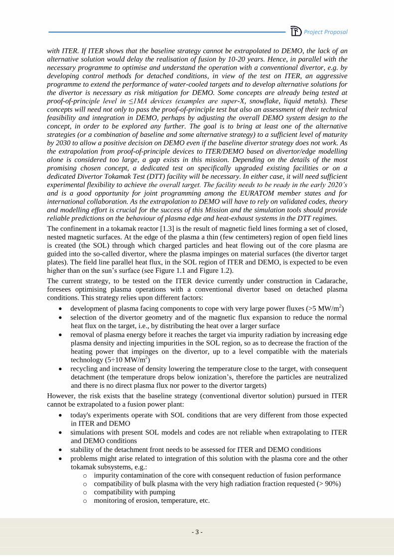
The confinement in a tokamak reactor [1.3] is the result of magnetic field lines forming a set of closed,
nested magnetic surfaces. At the edge of the plasma a thin (few centimeters) region of open field lines
is created (the SOL) through which charged particles and heat flowing out of the core plasma are
guided into the so-called divertor, where the plasma impinges on material surfaces (the divertor target
plates). The field line parallel heat flux, in the SOL region of ITER and DEMO, is expected to be even
higher than on the sun’s surface (see Figure 1.1 and Figure 1.2).
The current strategy, to be tested on the ITER device currently under construction in Cadarache,
foresees optimising plasma operations with a conventional divertor based on detached plasma
conditions. This strategy relies upon different factors:
development of plasma facing components to cope with very large power fluxes (>5 MW/m2)
selection of the divertor geometry and of the magnetic flux expansion to reduce the normal
heat flux on the target, i.e., by distributing the heat over a larger surface
removal of plasma energy before it reaches the target via impurity radiation by increasing edge
plasma density and injecting impurities in the SOL region, so as to decrease the fraction of the
heating power that impinges on the divertor, up to a level compatible with the materials
technology (5÷10 MW/m2)
recycling and increase of density lowering the temperature close to the target, with consequent
detachment (the temperature drops below ionization’s, therefore the particles are neutralized
and there is no direct plasma flux nor power to the divertor targets)
However, the risk exists that the baseline strategy (conventional divertor solution) pursued in ITER
cannot be extrapolated to a fusion power plant:
today's experiments operate with SOL conditions that are very different from those expected
in ITER and DEMO
simulations with present SOL models and codes are not reliable when extrapolating to ITER
and DEMO conditions
stability of the detachment front needs to be assessed for ITER and DEMO conditions
problems might arise related to integration of this solution with the plasma core and the other
tokamak subsystems, e.g.:
o impurity contamination of the core with consequent reduction of fusion performance
o compatibility of bulk plasma with the very high radiation fraction requested (> 90%)
o compatibility with pumping
o monitoring of erosion, temperature, etc.
Project Proposal
-4-
In addition, even if ITER divertor will prove to be successful, it will be difficult to extrapolate to
DEMO, because of its additional requirements (more nuclear aspects and thus limited use of some
materials, requirements in terms of life expectancy of reactor components and thus need of keeping the
temperature low in the divertor region with nearly zero erosion, etc…).
Therefore a specific project has been launched to investigate alternative power exhaust solutions for
DEMO, aimed at the definition and the design of a Divertor Tokamak Test facility. This tokamak
should produce scaled experiments integrating most of the possible aspects of the DEMO power and
particle exhaust.
(a) (b)
(c)
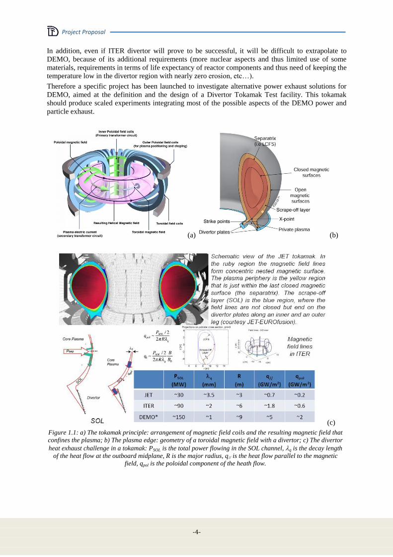
Figure 1.1: a) The tokamak principle: arrangement of magnetic field coils and the resulting magnetic field that
confines the plasma; b) The plasma edge: geometry of a toroidal magnetic field with a divertor; c) The divertor
heat exhaust challenge in a tokamak: PSOL is the total power flowing in the SOL channel, q is the decay length
of the heat flow at the outboard midplane, R is the major radius, q// is the heat flow parallel to the magnetic
field, qpol is the poloidal component of the heath flow.
Project Proposal
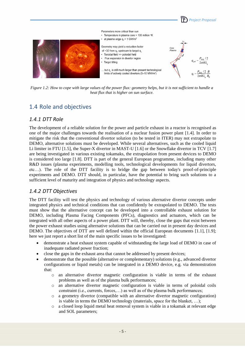
- 5 -
Figure 1.2: How to cope with large values of the power flux: geometry helps, but it is not sufficient to handle a
heat flux that is higher on sun surface.
1.4 Role and objectives
1.4.1 DTT Role
The development of a reliable solution for the power and particle exhaust in a reactor is recognised as
one of the major challenges towards the realisation of a nuclear fusion power plant [1.4]. In order to
mitigate the risk that the conventional divertor solution (to be tested in ITER) may not extrapolate to
DEMO, alternative solutions must be developed. While several alternatives, such as the cooled liquid
Li limiter in FTU [1.5], the Super-X divertor in MAST-U [1.6] or the Snowflake divertor in TCV [1.7]
are being investigated in various existing tokamaks, the extrapolation from present devices to DEMO
is considered too large [1.8]. DTT is part of the general European programme, including many other
R&D issues (plasma experiments, modelling tools, technological developments for liquid divertors,
etc…). The role of the DTT facility is to bridge the gap between today's proof-of-principle
experiments and DEMO. DTT should, in particular, have the potential to bring such solutions to a
sufficient level of maturity and integration of physics and technology aspects.
1.4.2 DTT Objectives
The DTT facility will test the physics and technology of various alternative divertor concepts under
integrated physics and technical conditions that can confidently be extrapolated to DEMO. The tests
must show that the alternative concept can be developed into a controllable exhaust solution for
DEMO, including Plasma Facing Components (PFCs), diagnostics and actuators, which can be
integrated with all other aspects of a power plant. DTT will, thereby, close the gaps that exist between
the power exhaust studies using alternative solutions that can be carried out in present day devices and
DEMO. The objectives of DTT are well defined within the official European documents [1.1], [1.9];
here we just report a short list of the main specific issues to be investigated:
demonstrate a heat exhaust system capable of withstanding the large load of DEMO in case of
inadequate radiated power fraction;
close the gaps in the exhaust area that cannot be addressed by present devices;
demonstrate that the possible (alternative or complementary) solutions (e.g., advanced divertor
configurations or liquid metals) can be integrated in a DEMO device, e.g. via demonstration
that:
o an alternative divertor magnetic configuration is viable in terms of the exhaust
problems as well as of the plasma bulk performances;
o an alternative divertor magnetic configuration is viable in terms of poloidal coils
constraint (i.e., currents, forces,…) as well as of the plasma bulk performances;
o a geometry divertor (compatible with an alternative divertor magnetic configuration)
is viable in terms the DEMO technology (materials, space for the blanket, …);
o a closed loop liquid metal heat removal system is viable in a tokamak at relevant edge
and SOL parameters;
Project Proposal
-6-
o liquid metals are applicable to DEMO (impurities, MHD, etc.);
o an integrated exhaust scenario is viable;
o divertor operation is possible with edge and bulk parameters ν*, ρ*, β, T and n/nG as
close as possible to ITER/DEMO, even taking also account of high core radiation
fraction in DEMO, where ν* is the normalized collisionality, ρ* is the normalized
Larmor radius, β is the plasma kinetic pressure normalized to the magnetic pressure, T
is the plasma temperature and n/nG is a normalized plasma density.
1.5 DTT Proposal
1.5.1 The DTT Project
EUROfusion, being the European Consortium for the Development of Fusion Energy, manages
European fusion research activities on behalf of EURATOM. A significant part of the work
programme of EUROfusion is devoted to the activities related to DTT.
Two Work Packages of the 2014-218 EUROfusion work plan are focused on DTT, entirely in support
of Headline 2.4 (Investigate alternative power exhaust solutions for DEMO) with a planned
investment of more than 60 MEUR from EUROfusion Consortium and EUROfusion members:
WPDTT1: Assessment of alternative divertor geometries and liquid metals PFCs
The general objective of WPDTT1 is the assessment of:
o requirements for physics model development
o DEMO compatibility of alternative divertor designs including Super-X and
SnowFlake divertors (both of them alternative magnetic divertor configurations)
o DEMO compatibility of liquid metal PFCs with selection of best liquid metal, if viable
WPDTT2: Definition and Design of the Divertor Tokamak Test Facility
The general objective of WPDTT2 is to design an experiment addressed to the solution of the
power exhaust issues in view of DEMO. It must provide enough positive evidence that the
alternative solutions could be integrated in a DEMO device in case the conventional divertor
solution does not yield the necessary capabilities for power exhaust [1.10] [1.11].
Italy plays an acknowledged role in international nuclear fusion research, strengthened in the years
thanks to educational and training actions of universities and research institutions as well as a fruitful
involvement of the national industries, paying attention to innovation and giving rise to a virtuous
circle that enriches the country. Italian fusion research is carried out inside labs under the aegis of
MISE (Ministero dello Sviluppo Economico - Ministry of Economic Development) and MIUR
(Ministero dell’Istruzione, Università e Ricerca - Ministry of Education, University and Research):
ENEA in Frascati, Consorzio RFX in Padua, Istituto di Fisica del Plasma del CNR in Milan,
Consorzio CREATE in Naples, which coordinates the activities of several Universities in Southern
Italy, INFN with its labs in Legnaro, together with the important contributions of a number of other
Italian Universities. These groups have been working together for years under the umbrella of
EURATOM-ENEA Association in the framework of EFDA (European Fusion Development
Agreement), and from 2014 as specified by the EUROfusion Consortium agreement.
There are significant results achieved at the Italian labs in Frascati (with FTU, born as an upgrade of
the FT tokamak, which held the world record of the fusion performance parameter for years, and now
is one of the few large fusion devices able to operate in the presence of liquid lithium plasma facing
components) and Padua (with RFX-mod, a device unique capability to explore the Reversed Field
Pinch configuration at plasma currents up to 2MA and is equipped with a sophisticated magnetic
feedback system). Italian researchers also gave a significant contribution to the design and operation
of JET and are significantly contributing to the design and construction of ITER. Italy is also building
in Padova the facility for full-scale testing of ITER Neutral Beam Injectors. Italian researchers,
meanwhile, play a key role in the fusion roadmap, leading several Work Packages in the Horizon 2020
Workprogramme. Finally, there is a great integration between research labs and national industry.
Project Proposal
- 7 -
Taking into account the Italian role in nuclear fusion research, and that the problem of the heat exhaust
is probably the main challenge towards the realisation of magnetic confinement fusion, the Italian
Government has suggested an option for additional funding of a dedicated exhaust facility. The
proposal is among the projects submitted to the 315 billion Euro of Juncker's plan (EFSI: European
Fund for Strategic Investments) with a budget of 500 million Euro:
http://www.eib.org/about/invest-eu/index.htm
http://ec.europa.eu/priorities/jobs-growth-investment/plan/docs/project-list_part-1_en.pdf
http://ec.europa.eu/priorities/jobs-growth-investment/plan/index_en.htm
The "Construction of a Divertor Tokamak Test Facility for fusion energy research", DTT proposal, is
in the list “Knowledge, SMEs and the digital economy” presented by ENEA and Italian Ministry of
Economic Development.
In March 2015 the EUROfusion General Assembly welcomed the opportunity of gaining additional
resources for the DTT, suggesting that the conceptual activities, the definition of the objectives and the
design were carried out in a truly European framework with WPDTT1 and WPDTT2.
1.5.2 DTT parameters.
The closer DTT approaches DEMO dimensions and physics parameters, the more relevant it would be.
However, a limiting factor in this design approach is related to the cost constraint. In fact, this
document shows that DTT can achieve its objectives with an available budget of 500M€, i.e., the
funds requested by Italian Government, plus the financial resources planned by EUROfusion in
20142018 for WPDTT2 [1.11]. The “optimal” values of the main parameters (plasma radius R,
toroidal field BT, plasma current Ip, total additional power PADD …) can be defined within this budget
constraint.
Since the DTT scope should be the “solution” of problems connected with SOL and divertor region,
the main parameters to be preserved, in a scaled experiment, are related to these physics. Different
approaches are possible to this issue; the most obvious one is assuming that plasma edge and bulk are
coupled as integrated system. Thus, a "controlled relaxation” of a subset of relevant parameters can be
identified (see Sections 3.1-3.2). Other "simplified" approaches [1.12]-[1.13]-[1.14] have also been
used to identify characteristic edge parameters. Such a procedure leads to identify PSEP/R (where PSEP
is the power flowing through the last closed magnetic surface) as key parameter to characterize the
divertor load. In addition to PSEP/R, a number of dimensionless parameters can be identified;
normalized Te, υ*=Ld/λei., Δd/λ0, ρi/ Δd, β, where Ld is the divertor field line length, λei. is the electron-
ion mean free path, Δd is the SOL thickness, λ0 is the neutrals mean free path, ρi is the ion Larmor
radius, the electron temperature Te is normalized by a constant energy . Some of these parameters are
intrinsically linked with the divertor “topology” (see Chap. 2 and 3); as a consequence a first strong
constraint arises for the design of DTT: the necessity of having a very flexible divertor
“region/configuration” to study and to optimize the role played by any of the topological linked
parameters. This first constraint must necessarily be integrated to find an exhaust solution that works
in DEMO relevant physics conditions. We know that the (bulk and edge) plasma physics is completely
determined by the dimensionless parameters υ*
(normalized collisionality), ρ* (normalized Larmor
radius), β (plasma to magnetic pressure ratio) and T [1.12]-[1.15]. We know, as well, that it is not
possible to scale an experiment preserving all these factors without getting the experiment itself. A
strategy has been proposed [1.16], where relaxing in controlled way one of these parameters, it is
possible to scale down a reactor like experiment (i.e. ITER, DEMO) preserving all the main physics
aspects (see chap 3.). This procedure, accounting for the above budget constraint, leads to a first
estimate of the machine parameters (Table 1-I).
A machine with a major plasma radius of about 2.15 m can guarantee the necessary divertor region
flexibility to test different magnetic topologies and different divertor geometries and/or materials
(including liquid metals). The relatively high toroidal field (BT=6T) will give the possibility to achieve
plasma parameters not far from the DEMO ones with PSEP/R≈15MW/m that is very close to DEMO’s.
The plasma parameters (for a detailed definition see Chapters 2 and 3) of Table 1-I are obtained by a
0D dimensional scaling and by the transport code METIS for a standard X point scenario. The final

Project Proposal
-8-
machine size and characteristics will result from a detailed engineering design phase, to be carried out
with substantial contributions of other European institutions.
TABLE 1-I
MAIN DTT PARAMETERS FOR A REFERENCE STANDARD X POINT SCENARIO
R (m) 2.15 N 1.5
a (m) 0,7 Res (sec) 8
IP (MA) 6 VLoop (V) 0.17
BT (T) 6 Zeff 1.7
V (m3) 33.0 PRad (MW) 13
PADD (MW) 45 PSep (MW) 32
H98 1 TPed (KeV) 3.1
<ne> (1020 m-3) 1.7 nPed (1020 m-3) 1.4
ne/neG 0.45 p 0.5
<Te> (KeV) 6.2 PDiv (MW/m2) (No Rad) ~ 55
(sec) 0.47 PSep/R (MW/m) 15
ne(0) (1020 m-3) 2.2 PTotB/R (MW T/m) 125
Te(0) (KeV) 10.2 λq (mm) ~ 2.0
1.6 Operation and scientific programme
1.6.1 Scenarios and scientific program.
The nominal scientific programme is described in Chapter 3. A first period will be dedicated to the
commissioning of the different systems. Afterwards, in about one and half year, the machine will
achieve robust H-mode (operational regimes single null divertor configurations at full performance
with the available additional power). The following phases will then be devoted to tests of alternative
divertor solutions, including advanced magnetic configurations and liquid metal targets.
DTT will be equipped with a set of external poloidal coils able to guarantee a large set of different
divertor magnetic configurations, XD configurations [1.17], Snow Flakes configurations (SF) [1.18]
and up and down symmetric standard X point configurations (see Figure 1.3).
The presence of a set of small internal coils will allow to locally modify the topology of a given
magnetic configuration, so as to produce a very large set of quite different topologies. Figure 1.4a
shows a standard X point equilibrium for a high β, Ip=6 MA plasma and the full poloidal coil system.
Varying the current in the small bottom coils (highest total current ≈ 50kA each) allows producing the
different magnetic topologies of the central and of the right picture. In Figure 1.4b a quasi SF [1.19]
configuration is generated with an XD feature. Figure 1.4c shows a very peculiar configuration, with a
very large zone with Bp and its derivative very close to zero.
The large space allocated at the bottom of the machine will easily allow the installation of a divertor
realized by using liquid metal technology [1.20]. The external poloidal system will even allow to
vertically locating the plasma column in a way that, up and down, there will be enough space for a
symmetric double null standard X point divertor. All the external coils (including the toroidal one) are
designed by using superconductor technology; this will allow producing discharges lasting around
100s only limited by the plasma resistive flux consumption (assuming no external current drive). A
mix of different heating systems will provide the required power (a possible power allocation could be
≈15MW ECRH at 170 GHz; ≈15MW ICRH at 60-90 MHz; ≈15MW NBI at 300 keV, the final
Project Proposal
- 9 -
decision will be taken in a later phase of the project, see chap. 3). Several years must be foreseen for
achieving the ambitious DTT scientific program. During the initial plasma operations 15 MW of
ICRH and 10 MW of ECRH will be available. The remaining power, up to the total foreseen (45MW),
will progressively be installed, finalizing the nominal mix of heating systems accordingly with the
experimental needs. The test of different divertors is foreseen, to find an “optimal” geometry divertor,
once a magnetic configuration has been selected, and to optimize a divertor dedicated to the liquid
metals.
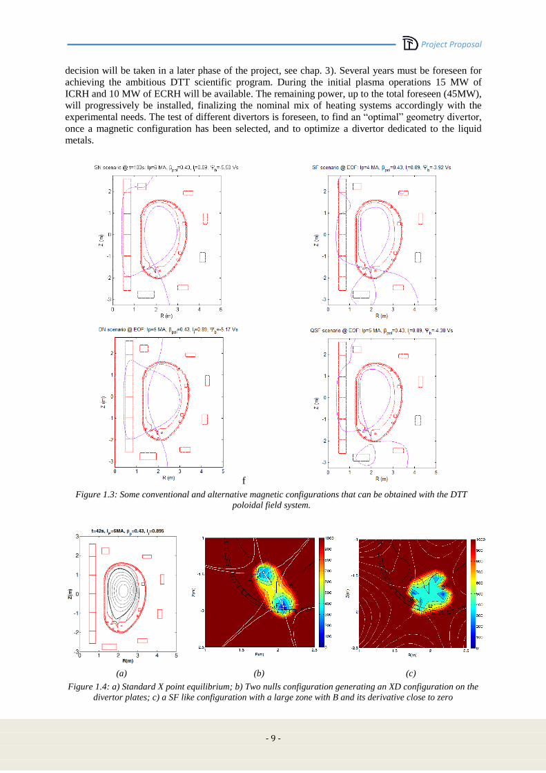
f
Figure 1.3: Some conventional and alternative magnetic configurations that can be obtained with the DTT
poloidal field system.
(a) (b) (c)
Figure 1.4: a) Standard X point equilibrium; b) Two nulls configuration generating an XD configuration on the
divertor plates; c) a SF like configuration with a large zone with B and its derivative close to zero
Project Proposal
-10-
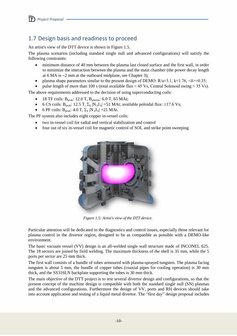
1.7 Design basis and readiness to proceed
An artist's view of the DTT device is shown in Figure 1.5.
The plasma scenarios (including standard single null and advanced configurations) will satisfy the
following constraints:
minimum distance of 40 mm between the plasma last closed surface and the first wall, in order
to minimize the interaction between the plasma and the main chamber (the power decay length
at 6 MA is 2 mm at the outboard midplane, see Chapter 3);
plasma shape parameters similar to the present design of DEMO: R/a≈3.1, k≈1.76, <δ>≈0.35;
pulse length of more than 100 s (total available flux ≈ 45 Vs, Central Solenoid swing ≈ 35 Vs).
The above requirements addressed to the decision of using superconducting coils:
18 TF coils: Bpeak: 12.0 T, Bplasma: 6.0 T, 65 MAt;
6 CS coils: Bpeak: 12.5 T, k |N kI k| =51 MAt; available poloidal flux: 17.6 Vs;
6 PF coils: Bpeak: 4.0 T, k |N kI k| =21 MAt.
The PF system also includes eight copper in-vessel coils:
two in-vessel coil for radial and vertical stabilization and control
four out of six in-vessel coil for magnetic control of SOL and strike point sweeping
Figure 1.5: Artist's view of the DTT device.
Particular attention will be dedicated to the diagnostics and control issues, especially those relevant for
plasma control in the divertor region, designed to be as compatible as possible with a DEMO-like
environment.
The basic vacuum vessel (VV) design is an all-welded single wall structure made of INCONEL 625.
The 18 sectors are joined by field welding. The maximum thickness of the shell is 35 mm, while the 5
ports per sector are 25 mm thick.
The first wall consists of a bundle of tubes armoured with plasma-sprayed tungsten. The plasma facing
tungsten is about 5 mm, the bundle of copper tubes (coaxial pipes for cooling operation) is 30 mm
thick, and the SS316LN backplate supporting the tubes is 30 mm thick.
The main objective of the DTT project is to test several divertor design and configurations, so that the
present concept of the machine design is compatible with both the standard single null (SN) plasmas
and the advanced configurations. Furthermore the design of VV, ports and RH devices should take
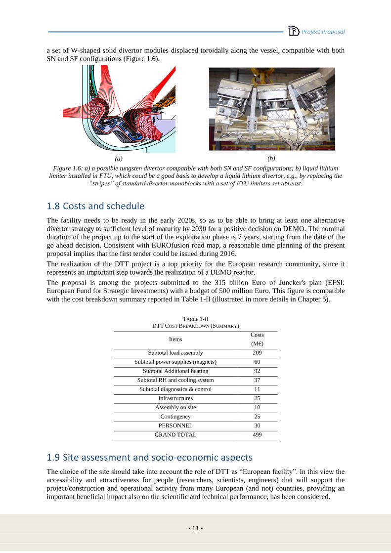
into account application and testing of a liquid metal divertor. The “first day” design proposal includes
Project Proposal
- 11 -
a set of W-shaped solid divertor modules displaced toroidally along the vessel, compatible with both
SN and SF configurations (Figure 1.6).
(a)
(b)
Figure 1.6: a) a possible tungsten divertor compatible with both SN and SF configurations; b) liquid lithium
limiter installed in FTU, which could be a good basis to develop a liquid lithium divertor, e.g., by replacing the
“stripes” of standard divertor monoblocks with a set of FTU limiters set abreast.
1.8 Costs and schedule
The facility needs to be ready in the early 2020s, so as to be able to bring at least one alternative
divertor strategy to sufficient level of maturity by 2030 for a positive decision on DEMO. The nominal
duration of the project up to the start of the exploitation phase is 7 years, starting from the date of the
go ahead decision. Consistent with EUROfusion road map, a reasonable time planning of the present
proposal implies that the first tender could be issued during 2016.
The realization of the DTT project is a top priority for the European research community, since it
represents an important step towards the realization of a DEMO reactor.
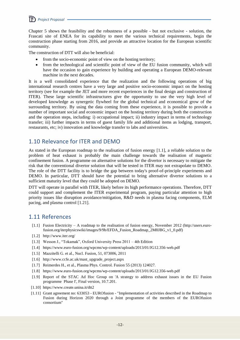
The proposal is among the projects submitted to the 315 billion Euro of Juncker's plan (EFSI:
European Fund for Strategic Investments) with a budget of 500 million Euro. This figure is compatible
with the cost breakdown summary reported in Table 1-II (illustrated in more details in Chapter 5).
TABLE 1-II
DTT COST BREAKDOWN (SUMMARY)
Items Costs
(M€)
Subtotal load assembly 209
Subtotal power supplies (magnets) 60
Subtotal Additional heating 92
Subtotal RH and cooling system 37
Subtotal diagnostics & control 11
Infrastructures 25
Assembly on site 10
Contingency 25
PERSONNEL 30
GRAND TOTAL 499
1.9 Site assessment and socio-economic aspects
The choice of the site should take into account the role of DTT as “European facility”. In this view the
accessibility and attractiveness for people (researchers, scientists, engineers) that will support the
project/construction and operational activity from many European (and not) countries, providing an
important beneficial impact also on the scientific and technical performance, has been considered.
Project Proposal
-12-
Chapter 5 shows the feasibility and the robustness of a possible - but not exclusive - solution, the
Frascati site of ENEA for its capability to meet the various technical requirements, begin the
construction phase starting from 2016, and provide an attractive location for the European scientific
community.
The construction of DTT will also be beneficial:
from the socio-economic point of view on the hosting territory;
from the technological and scientific point of view of the EU fusion community, which will
have the occasion to gain experience by building and operating a European DEMO-relevant
machine in the next decades.
It is a well consolidated experience that the realization and the following operations of big
international research centres have a very large and positive socio-economic impact on the hosting
territory (see for example the JET and more recent experiences in the final design and construction of
ITER). These large scientific infrastructures give the opportunity to use the very high level of
developed knowledge as synergetic flywheel for the global technical and economical grow of the
surrounding territory. By using the data coming from these experience, it is possible to provide a
number of important social and economic impact on the hosting territory during both the construction
and the operation steps, including: i) occupational impact; ii) industry impact in terms of technology
transfer; iii) further impacts in terms of guest family life and additional items as lodging, transport,
restaurants, etc; iv) innovation and knowledge transfer to labs and universities.
1.10 Relevance for ITER and DEMO
As stated in the European roadmap to the realisation of fusion energy [1.1], a reliable solution to the
problem of heat exhaust is probably the main challenge towards the realisation of magnetic
confinement fusion. A programme on alternative solutions for the divertor is necessary to mitigate the
risk that the conventional divertor solution that will be tested in ITER may not extrapolate to DEMO.
The role of the DTT facility is to bridge the gap between today's proof-of-principle experiments and
DEMO. In particular, DTT should have the potential to bring alternative divertor solutions to a
sufficient maturity level that they could be adopted on DEMO.
DTT will operate in parallel with ITER, likely before its high performance operations. Therefore, DTT
could support and complement the ITER experimental program, paying particular attention to high
priority issues like disruption avoidance/mitigation, R&D needs in plasma facing components, ELM
pacing, and plasma control [1.21].
1.11 References [1.1] Fusion Electricity – A roadmap to the realisation of fusion energy, November 2012 (http://users.euro-
fusion.org/iterphysicswiki/images/9/9b/EFDA_Fusion_Roadmap_2M8JBG_v1_0.pdf)
[1.2] http://www.iter.org/
[1.3] Wesson J., “Tokamak”, Oxford University Press 2011 – 4th Edition
[1.4] https://www.euro-fusion.org/wpcms/wp-content/uploads/2013/01/JG12.356-web.pdf
[1.5] Mazzitelli G. et al., Nucl. Fusion, 51, 073006, 2011
[1.6] http://www.ccfe.ac.uk/mast_upgrade_project.aspx
[1.7] Reimerdes H., et al., Plasma Phys. Control. Fusion 55 (2013) 124027.
[1.8] https://www.euro-fusion.org/wpcms/wp-content/uploads/2013/01/JG12.356-web.pdf
[1.9] Report of the STAC Ad Hoc Group on 'A strategy to address exhaust issues in the EU Fusion
programme Phase I', Final version, 10.7.201.
[1.10] https://www.create.unina.it/dtt2
[1.11] Grant agreement no: 633053 - EUROfusion - "Implementation of activities described in the Roadmap to
Fusion during Horizon 2020 through a Joint programme of the members of the EUROfusion
consortium"
Project Proposal
- 13 -
[1.12] Lackner K., Com. Plas. Phys. Control. Fusion, 15, 359 (1994)
[1.13] Hutchinson I. H., Nucl. Fus., 36, 783 (1996).
[1.14] Whyte D. G. Fusion Eng. Des. 87, 234 (2012)
[1.15] Lackner K., Fus. Scien. and Techn., 54, 989 (2008)
[1.16] Pizzuto A., Nucl. Fusion 50, 095005 (2010)
[1.17] Kotschenreuther M., et al., Phys. Plasmas 20 (2013) 102507
[1.18] Ryutov D.D., Phys. Plasmas 14 (2007) 064502
[1.19] Calabro’ G., et al., to appear NF 2015 NF-100496.R2
[1.20] M. Ono et al., 2012 Nucl. Fusion 52 037001 doi:10.1088/0029-5515/52/3/037001
[1.21] D. Campbell, " ITER Research Needs", EUROFusion ITER Physics AWP-2016 Preparation Meeting,
Garching, 6-8 July 2015

Project Proposal
-14-

Project Proposal
- 15 -
Chapter 2
ROLE AND OBJECTIVES OF DTT This chapter provides the rationale for the construction and operation of the proposed DTT facility.
2.1 DTT Role
The development of a reliable solution for the power and particle exhaust in a reactor is recognised as
one of the major challenges towards the realisation of a nuclear fusion power plant [2.1]. In order to
mitigate the risk that the conventional divertor solution that will be tested in ITER may not extrapolate
to DEMO, alternatives must be developed. While several alternatives, such as the cooled liquid Li
limiter in FTU, the Super-X divertor in MAST-U or the Snowflake divertor in TCV are being
investigated in present devices, the extrapolation between present device and DEMO is considered too
large [2.1].
The role of the DTT facility is to bridge the gap between today's proof-of-principle experiments and
DEMO. DTT should, in particular, have the potential to, together with the understanding of the
conventional divertor that will be gained in ITER, bring such alternative solutions to a sufficient
maturity level that they could be adopted on DEMO integrating plasma core and SOL physics and
technology.
2.2 DTT Objectives
The DTT facility will test the physics and technology of various alternative divertor concepts under
plasma conditions that can be confidently extrapolated to DEMO. The tests must show that the
alternative concept can be developed into a viable and controllable exhaust solution for DEMO,
including Plasma Facing Components (PFCs), diagnostics and actuators, which can be integrated with
all other aspects of a power plant. DTT will, thereby, close the gaps that exist between the power
exhaust studies using alternative solutions that can be carried out in present day devices and DEMO.
Project Proposal
-16-
The DTT facility will, specifically, test the alternative geometries of the snowflake divertor (SFD)
[2.2] and the X divertor (XD) [2.3] and also key aspects of the Super-X divertor (SXD) [2.4]. The
DTT facility will feature a large degree of flexibility to have a high possibility to also test any
promising future concepts as they are proposed.
It has to demonstrate easier access to detachment (based on the longer connection length, Section 2.4)
than the conventional single null divertor. It will also test the postulated stabilising effects of the XD
and SXD geometry on the location of the detachment and radiation fronts, respectively, Section 2.4).
Experiments in DTT have to prove a superior power exhaust performance of alternative divertor
configurations while maintaining adequate particle exhaust and core performance compared to the
baseline solution. The performance must be demonstrated for DEMO relevant power densities and
DEMO relevant edge and bulk plasma parameters (ν*, ρ*, β, T, n/nG). Ultimately, the extrapolation of
the performance of the alternative solution to a reactor, based on the specific understanding of
alternative divertor configurations that will be gained in DTT together with the general understanding
of divertor physics that will be gained in ITER, must be sufficiently reliable and sufficiently positive
to implement such a solution in DEMO.
The flexibility of the proposed DTT will also allow for a test of liquid metal plasma facing
components in the divertor once their technological feasibility in a reactor has been shown and their
beneficial performance is supported by a sound physics basis. Any liquid metal solution has to
demonstrate superior power exhaust performance with adequate particle exhaust and without a
detrimental effect on the core performance. The implementation of a liquid metal solution in DTT has
to demonstrate the full liquid metal cycle including the recovery of eroded and evaporated material
and the treatment of any retained hydrogen. The liquid metal cycle has to be able to meet the safety
requirements of a power plant.
The experience gained in the DTT facility will ultimately show whether the implementation of any
alternative exhaust solution in DEMO, alternative configuration or a liquid metal PFCs, is
technologically viable, maintainable and economical.
2.3 Power exhaust issues
In order to reach and maintain the high temperatures required for fusion reactions fusion plasmas have
to be heated, initially, with auxiliary heating and, ultimately, by energetic alpha particles created in the
D-T fusion reaction. The heating power can leave the vessel either via charged particles, neutral
particles or radiation. While neutral particles and radiation are not affected by the magnetic field and
the corresponding power fluxes are relatively evenly distributed over the large interior surface of the
vessel, the charged particles, that leave the closed flux surfaces, follow the magnetic field lines and
interact with the wall on a relatively small surface area. Power exhaust via charged particles can,
thereby, lead to high, localised power densities, which threaten the integrity of the material wall. In
addition the interaction of energetic ions with the wall leads to sputtering, which releases impurities
into the plasma and erodes the target surfaces. The impurity concentration in the core has to be limited
in order to avoid excessive core radiation and, hence, confinement degradation (typically for high Z
impurities) and fuel dilution (typically for low Z impurities). It is, therefore, imperative to limit the
stationary target heat fluxes to 5-10 MW/m2 and ion temperatures at the target to values below 5 eV
[2.5], [2.6].
In conservative European DEMO scenarios approximately 90 to 95% of the effective heating power of
the plasma has to be exhausted via radiation rather than charged particles in order to reduce the heat
flux onto the divertor targets and allow for an economically viable lifetime of the divertor [2.7] Such a
high radiation level should be obtained by a controlled seeding with impurities [2.8]. It is, however,
not certain that the impurity seeded conventional single null solution will reliably allow for such a
high radiation fraction, while maintaining an energy confinement that is sufficient for fusion
performance. The constraints on the exhaust scenario can be relaxed by allowing for more radiation in
the divertor, distributing the heat load by charged particles over a larger wall area or increasing the
heat and particle load capability of the divertor targets. Either scenario would allow for less core
Project Proposal
- 17 -
radiation and, hence, improve the likelihood that the energy confinement will be sufficient for the
targeted fusion performance.
2.4 Physics basis
The physics basis of alternative exhaust solutions has recently been summarised in the context of the
EUROfusion project WPDTT1 [2.7].
2.4.1 Physics of power exhaust
Under stationary conditions the exhaust power is equal to the effective heating power, Pheat,eff,1
required to maintain the plasma pressure. The heating and, hence, the exhaust power is, therefore,
determined by the energy confinement time, E, with predictions for a reactor being largely based on
empiric scaling laws,
(2.4.1)
The power that is radiated in hot pure hydrogen plasmas is generally low, but increases with
unavoidable and intentionally added impurities, with higher atomic numbers. Such an increase of the
power radiated inside the separatrix, Prad,core, is ultimately limited by the need to operate in H-mode,
which is seen to require a minimum power crossing the separatrix via the plasma channel,
(2.4.2)
where predictions for PLH in a reactor are based on empirical scaling laws (e.g., [2.9]). High core
radiation also degrades the confinement, which may no longer be compatible with reactor conditions
or require an even higher heating power.
The scrape off layer (SOL) width is determined by the competition of parallel and perpendicular
transport. While the parallel transport is mainly classical and reasonably well understood, the cross-
field transport may be greatly affected by turbulent transport, in particular, in the reactor relevant high
density regimes. Empirical [2.10], [2.11] and analytical arguments [2.12], [2.13] suggest a scaling with
the ion poloidal gyroradius, i,pol. The SOL width decreases with increasing field, but not with size.
The value of Psep/R is, therefore, often used as a proxy for the heat flux q||,u that has to be handled in
the divertor. Magnetic geometry may affect the SOL width, in particular as turbulent transport is
expected to dominate cross-field transport in the reactor relevant high density regimes. The study of
the relevant physics is among the objective of the DTT.
Avoiding excessive erosion of the divertor target imposes constraints on the plasma parameters at the
target. The erosion must be limited to keep impurity pollution of plasma at a tolerable level. In
addition erosion has to be limited for a reasonable lifetime of the target components. For tungsten
targets these constraints limit the ion temperature at the target to values below 5 eV.
In addition the material integrity of the target currently limits the heat flux onto the target to 5 MW/m2.
Optimised designs and new radiation resistant materials may increase this limit up to 10 MW/m2.
Heating due to recombination at the target will be significant and requires a decrease of particle flux.
As recombination only becomes important at temperatures of a few eV this requirement is well
aligned with the constraint imposed by erosion.
The constraints on the plasma parameters at the target require a significant reduction of the heat flux
via radiative cooling, and a pressure loss via charge exchange. The decrease of the pressure in front of
the target is usually referred to as the onset of detachment. As the temperature decreases
1 Under reactor conditions synchrotron radiation and Bremsstrahlung losses become significant. Since the power is lost in the core it does
not contributing significantly to the heating of the plasma and is subtracted from the total heating power.
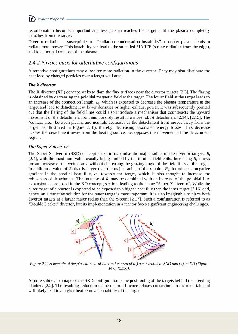
Project Proposal
-18-
recombination becomes important and less plasma reaches the target until the plasma completely
detaches from the target.
Divertor radiation is susceptible to a "radiation condensation instability" as cooler plasma tends to
radiate more power. This instability can lead to the so-called MARFE (strong radiation from the edge),
and to a thermal collapse of the plasma.
2.4.2 Physics basis for alternative configurations
Alternative configurations may allow for more radiation in the divertor. They may also distribute the
heat load by charged particles over a larger wall area.
The X divertor
The X divertor (XD) concept seeks to flare the flux surfaces near the divertor targets [2.3]. The flaring
is obtained by decreasing the poloidal magnetic field at the target. The lower field at the target leads to
an increase of the connection length, L||, which is expected to decrease the plasma temperature at the
target and lead to detachment at lower densities or higher exhaust power. It was subsequently pointed
out that the flaring of the field lines could also introduce a mechanism that counteracts the upward
movement of the detachment front and possibly result in a more robust detachment [2.14], [2.15]. The
"contact area" between plasma and neutrals decreases as the detachment front moves away from the
target, as illustrated in Figure 2.1b), thereby, decreasing associated energy losses. This decrease
pushes the detachment away from the heating source, i.e. opposes the movement of the detachment
region.
The Super-X divertor
The Super-X divertor (SXD) concept seeks to maximise the major radius of the divertor targets, Rt
[2.4], with the maximum value usually being limited by the toroidal field coils. Increasing Rt allows
for an increase of the wetted area without decreasing the grazing angle of the field lines at the target.
In addition a value of Rt that is larger than the major radius of the x-point, Rx, introduces a negative
gradient in the parallel heat flux, q||, towards the target, which is also thought to increase the
robustness of detachment. The increase of Rt may be combined with an increase of the poloidal flux
expansion as proposed in the XD concept, section, leading to the name "Super-X divertor". While the
outer target of a reactor is expected to be exposed to a higher heat flux than the inner target [2.16] and,
hence, an alternative solution for the outer target is most important, it is also imaginable to place both
divertor targets at a larger major radius than the x-point [2.17]. Such a configuration is referred to as
"Double Decker" divertor, but its implementation in a reactor faces significant engineering challenges.
Figure 2.1: Schematic of the plasma-neutral interaction area of (a) a conventional SND and (b) an XD (Figure
14 of [2.15]).
A more subtle advantage of the SXD configuration is the positioning of the targets behind the breeding
blankets [2.2]. The resulting reduction of the neutron fluence relaxes constraints on the materials and
will likely lead to a higher heat removal capability of the target.
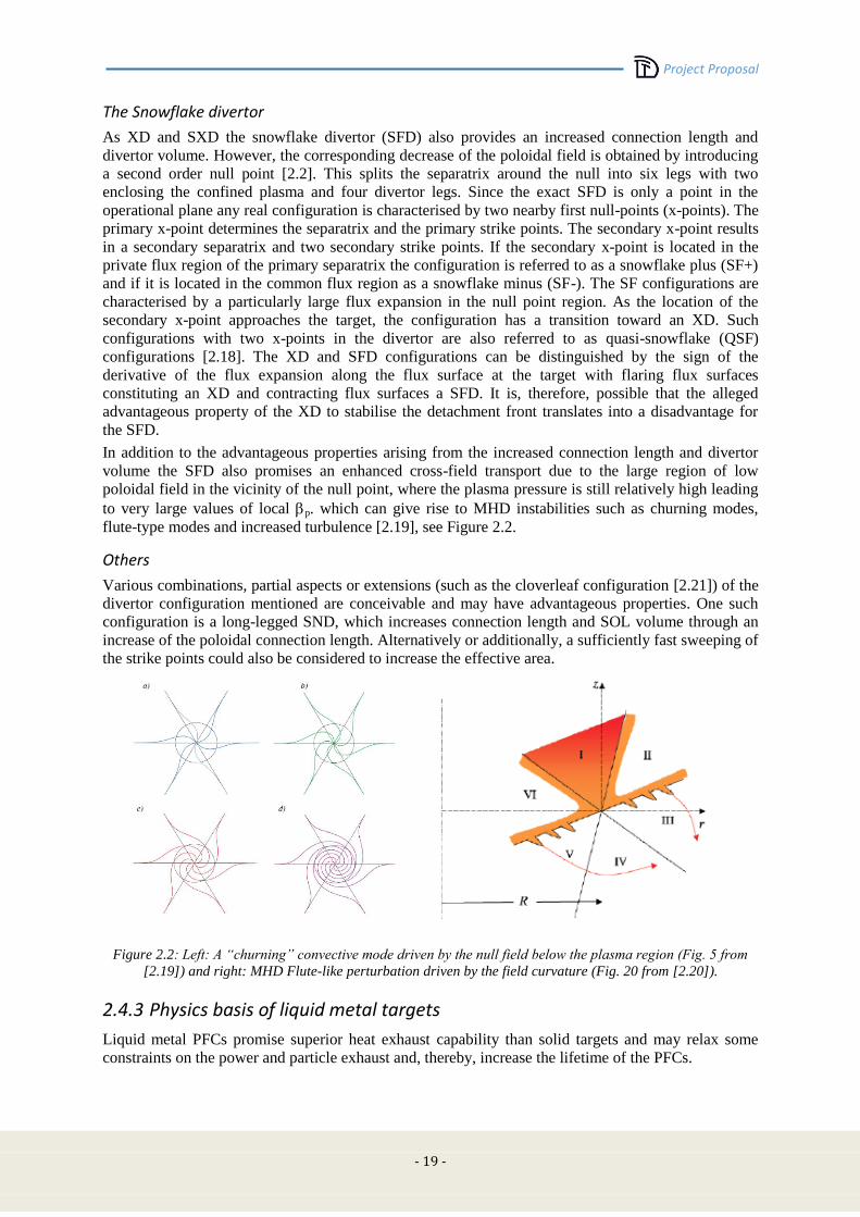
Project Proposal
- 19 -
The Snowflake divertor
As XD and SXD the snowflake divertor (SFD) also provides an increased connection length and
divertor volume. However, the corresponding decrease of the poloidal field is obtained by introducing
a second order null point [2.2]. This splits the separatrix around the null into six legs with two
enclosing the confined plasma and four divertor legs. Since the exact SFD is only a point in the
operational plane any real configuration is characterised by two nearby first null-points (x-points). The
primary x-point determines the separatrix and the primary strike points. The secondary x-point results
in a secondary separatrix and two secondary strike points. If the secondary x-point is located in the
private flux region of the primary separatrix the configuration is referred to as a snowflake plus (SF+)
and if it is located in the common flux region as a snowflake minus (SF-). The SF configurations are
characterised by a particularly large flux expansion in the null point region. As the location of the
secondary x-point approaches the target, the configuration has a transition toward an XD. Such
configurations with two x-points in the divertor are also referred to as quasi-snowflake (QSF)
configurations [2.18]. The XD and SFD configurations can be distinguished by the sign of the
derivative of the flux expansion along the flux surface at the target with flaring flux surfaces
constituting an XD and contracting flux surfaces a SFD. It is, therefore, possible that the alleged
advantageous property of the XD to stabilise the detachment front translates into a disadvantage for
the SFD.
In addition to the advantageous properties arising from the increased connection length and divertor
volume the SFD also promises an enhanced cross-field transport due to the large region of low
poloidal field in the vicinity of the null point, where the plasma pressure is still relatively high leading
to very large values of local p. which can give rise to MHD instabilities such as churning modes,
flute-type modes and increased turbulence [2.19], see Figure 2.2.
Others
Various combinations, partial aspects or extensions (such as the cloverleaf configuration [2.21]) of the
divertor configuration mentioned are conceivable and may have advantageous properties. One such
configuration is a long-legged SND, which increases connection length and SOL volume through an
increase of the poloidal connection length. Alternatively or additionally, a sufficiently fast sweeping of
the strike points could also be considered to increase the effective area.
Figure 2.2: Left: A “churning” convective mode driven by the null field below the plasma region (Fig. 5 from
[2.19]) and right: MHD Flute-like perturbation driven by the field curvature (Fig. 20 from [2.20]).
2.4.3 Physics basis of liquid metal targets
Liquid metal PFCs promise superior heat exhaust capability than solid targets and may relax some
constraints on the power and particle exhaust and, thereby, increase the lifetime of the PFCs.
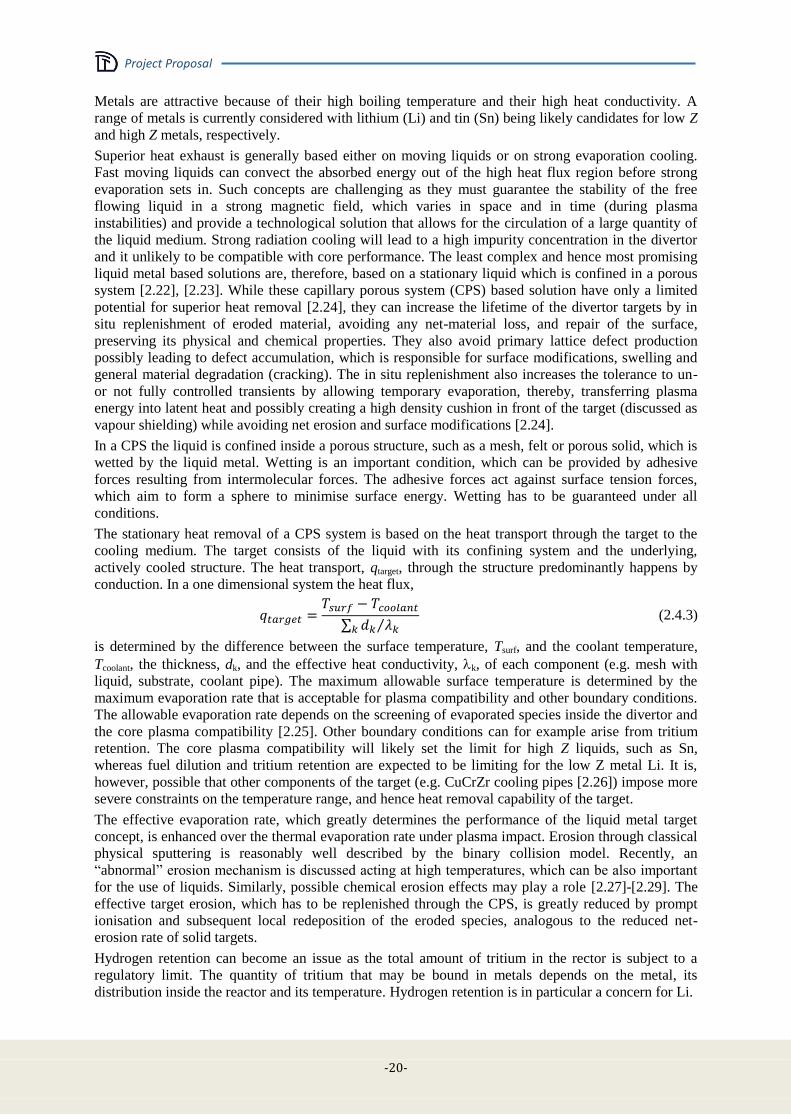
Project Proposal
-20-
Metals are attractive because of their high boiling temperature and their high heat conductivity. A
range of metals is currently considered with lithium (Li) and tin (Sn) being likely candidates for low Z
and high Z metals, respectively.
Superior heat exhaust is generally based either on moving liquids or on strong evaporation cooling.
Fast moving liquids can convect the absorbed energy out of the high heat flux region before strong
evaporation sets in. Such concepts are challenging as they must guarantee the stability of the free
flowing liquid in a strong magnetic field, which varies in space and in time (during plasma
instabilities) and provide a technological solution that allows for the circulation of a large quantity of
the liquid medium. Strong radiation cooling will lead to a high impurity concentration in the divertor
and it unlikely to be compatible with core performance. The least complex and hence most promising
liquid metal based solutions are, therefore, based on a stationary liquid which is confined in a porous
system [2.22], [2.23]. While these capillary porous system (CPS) based solution have only a limited
potential for superior heat removal [2.24], they can increase the lifetime of the divertor targets by in
situ replenishment of eroded material, avoiding any net-material loss, and repair of the surface,
preserving its physical and chemical properties. They also avoid primary lattice defect production
possibly leading to defect accumulation, which is responsible for surface modifications, swelling and
general material degradation (cracking). The in situ replenishment also increases the tolerance to un-
or not fully controlled transients by allowing temporary evaporation, thereby, transferring plasma
energy into latent heat and possibly creating a high density cushion in front of the target (discussed as
vapour shielding) while avoiding net erosion and surface modifications [2.24].
In a CPS the liquid is confined inside a porous structure, such as a mesh, felt or porous solid, which is
wetted by the liquid metal. Wetting is an important condition, which can be provided by adhesive
forces resulting from intermolecular forces. The adhesive forces act against surface tension forces,
which aim to form a sphere to minimise surface energy. Wetting has to be guaranteed under all
conditions.
The stationary heat removal of a CPS system is based on the heat transport through the target to the
cooling medium. The target consists of the liquid with its confining system and the underlying,
actively cooled structure. The heat transport, qtarget, through the structure predominantly happens by
conduction. In a one dimensional system the heat flux,
(2.4.3)
is determined by the difference between the surface temperature, Tsurf, and the coolant temperature,
Tcoolant, the thickness, dk, and the effective heat conductivity, k, of each component (e.g. mesh with
liquid, substrate, coolant pipe). The maximum allowable surface temperature is determined by the
maximum evaporation rate that is acceptable for plasma compatibility and other boundary conditions.
The allowable evaporation rate depends on the screening of evaporated species inside the divertor and
the core plasma compatibility [2.25]. Other boundary conditions can for example arise from tritium
retention. The core plasma compatibility will likely set the limit for high Z liquids, such as Sn,
whereas fuel dilution and tritium retention are expected to be limiting for the low Z metal Li. It is,
however, possible that other components of the target (e.g. CuCrZr cooling pipes [2.26]) impose more
severe constraints on the temperature range, and hence heat removal capability of the target.
The effective evaporation rate, which greatly determines the performance of the liquid metal target
concept, is enhanced over the thermal evaporation rate under plasma impact. Erosion through classical
physical sputtering is reasonably well described by the binary collision model. Recently, an
“abnormal” erosion mechanism is discussed acting at high temperatures, which can be also important
for the use of liquids. Similarly, possible chemical erosion effects may play a role [2.27]-[2.29]. The
effective target erosion, which has to be replenished through the CPS, is greatly reduced by prompt
ionisation and subsequent local redeposition of the eroded species, analogous to the reduced net-
erosion rate of solid targets.
Hydrogen retention can become an issue as the total amount of tritium in the rector is subject to a
regulatory limit. The quantity of tritium that may be bound in metals depends on the metal, its
distribution inside the reactor and its temperature. Hydrogen retention is in particular a concern for Li.

Project Proposal
- 21 -
2.5 Contributions of existing programmes and devices
Most geometric variations that characterise alternative divertor solutions have already been realised in
existing devices:
The XD has been realised in ASDEX [2.30] (now operating as HL-2A) and TCV [2.31]. XD
experiments are also feasible in EAST [2.18].
The SFD has been realised in TCV [2.32], NSTX [2.33] and DIII-[2.34]. SFD experiments are
also feasible in EAST [2.18].
Some aspects of the SXD configuration (the larger target radius) have already been realised in
TCV [2.35] and further studies are planned.
These configurations are, however, generally not optimised for power exhaust. They can be used to
test physics mechanisms and provide the data required for model validation. The non-optimised
geometry makes it difficult or impossible to access divertor conditions, e.g. with high neutral density,
envisaged and required for a reactor. The first device that will feature a specifically designed
alternative divertor will be MAST upgrade, which is scheduled to start operation in 2016. However,
even with an optimised divertor MAST-upgrade will fall short of demonstrating the power exhaust
capability of the scale required for DEMO under the divertor plasma conditions expected in DEMO
(see Table 2-I and Table 2-II).
However all these solutions must be eventually validated in an experiment capable to operate at
relevant plasma performance integrating physics and technology issues.
2.6 DTT physics requirements and specifications
In order to characterize the main physics aspects of the SOL and of the divertor region several
different approaches have been proposed [2.36]-[2.40], starting from considering the divertor region
separately from the bulk plasma up to exactly the contrary. Eventually, all studies performed so far
have tried to work out important parameters that can be used to characterise the SOL and the divertor
region in order to investigate the reactor problem in a down scaled experiment. The physics of the hot
bulk plasma is essentially determined by four dimensionless parameters [2.41], [2.42], the normalized
plasma pressure,
(2.6.1)
the normalized collisionality,
(2.6.2)
the normalized Larmor radius,
(2.6.3)
and the normalized Debye length λD*; the latter is normally ignored, although the assumption could
fail in the divertor region, where the local electric shields are connected with the Debye length. When
atomic physics starts to play an important role, as in the SOL and in the divertor, the normalized
temperature, T/Ei, where Ei is a typical ionization energy must be introduced as an additional
parameter. Since Ei cannot be varied, the absolute value of T must be used. However, the introduction
of the atomic physics and of T leads to the conclusion that no similarity experiment can be performed,
but the trivial one, i.e. the full scale. Some methodology has been proposed to bypass this problem
[2.43], [2.42]. However, whilst it is clear that these proposed methodology can be used to work out the
general parameters (R, B) of a scaled experiment (see Chap. 3), and/or when some degree of
integration between the bulk and the edge has to be preserved, it is questionable whether this is the
best approach to be used when the main purpose is to scale down the physics of the edge of the
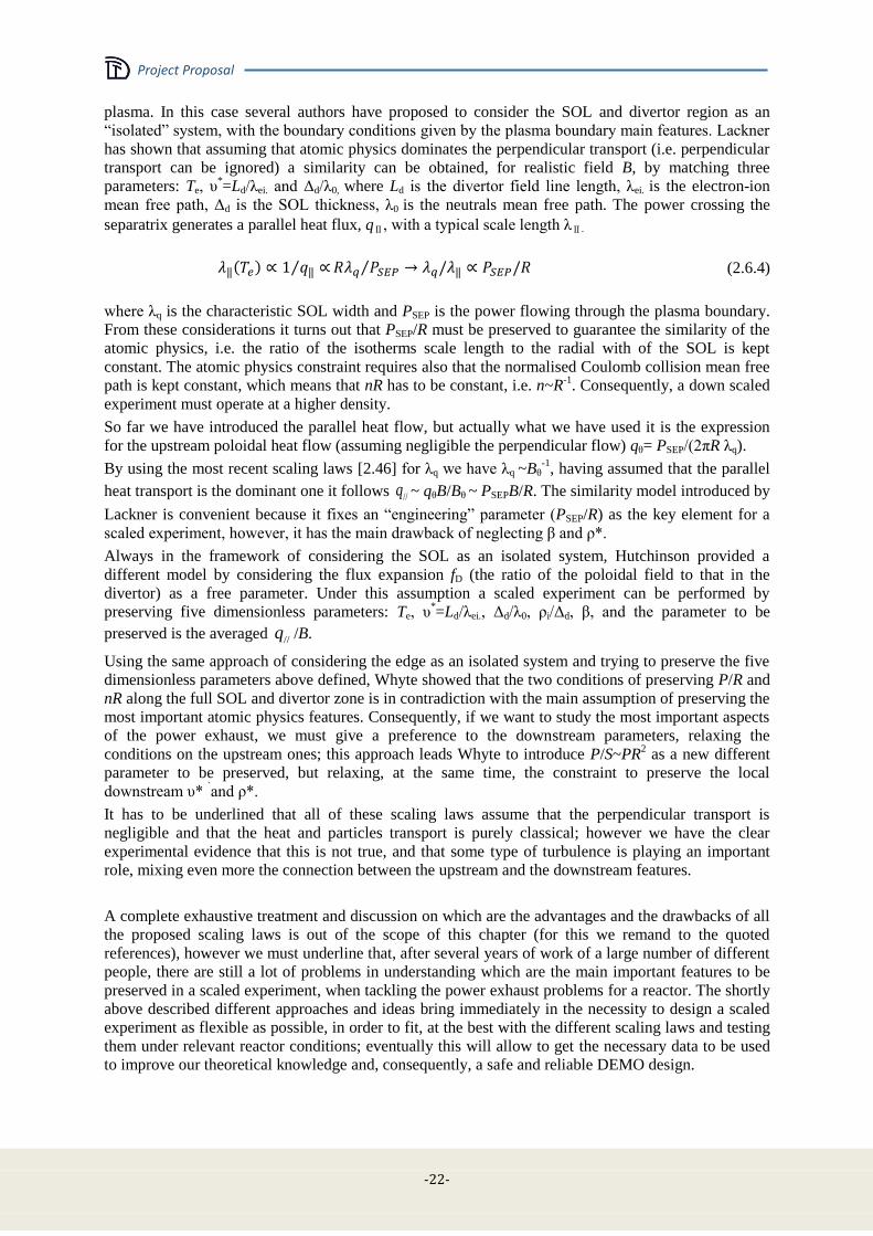
Project Proposal
-22-
plasma. In this case several authors have proposed to consider the SOL and divertor region as an
“isolated” system, with the boundary conditions given by the plasma boundary main features. Lackner
has shown that assuming that atomic physics dominates the perpendicular transport (i.e. perpendicular
transport can be ignored) a similarity can be obtained, for realistic field B, by matching three
parameters: Te, υ*=Ld/λei. and Δd/λ0, where Ld is the divertor field line length, λei. is the electron-ion
mean free path, Δd is the SOL thickness, λ0 is the neutrals mean free path. The power crossing the
separatrix generates a parallel heat flux, qⅡ, with a typical scale length λⅡ.
(2.6.4)
where λq is the characteristic SOL width and PSEP is the power flowing through the plasma boundary.
From these considerations it turns out that PSEP/R must be preserved to guarantee the similarity of the
atomic physics, i.e. the ratio of the isotherms scale length to the radial with of the SOL is kept
constant. The atomic physics constraint requires also that the normalised Coulomb collision mean free
path is kept constant, which means that nR has to be constant, i.e. n~R-1
. Consequently, a down scaled
experiment must operate at a higher density.
So far we have introduced the parallel heat flow, but actually what we have used it is the expression
for the upstream poloidal heat flow (assuming negligible the perpendicular flow) qθ= PSEP/(2πR λq).
By using the most recent scaling laws [2.46] for λq we have λq ~Bθ-1
, having assumed that the parallel
heat transport is the dominant one it follows //q ~ qθB/Bθ ~ PSEPB/R. The similarity model introduced by
Lackner is convenient because it fixes an “engineering” parameter (PSEP/R) as the key element for a
scaled experiment, however, it has the main drawback of neglecting β and ρ*.
Always in the framework of considering the SOL as an isolated system, Hutchinson provided a
different model by considering the flux expansion fD (the ratio of the poloidal field to that in the
divertor) as a free parameter. Under this assumption a scaled experiment can be performed by
preserving five dimensionless parameters: Te, υ*=Ld/λei., Δd/λ0, ρi/Δd, β, and the parameter to be
preserved is the averaged /B.
Using the same approach of considering the edge as an isolated system and trying to preserve the five
dimensionless parameters above defined, Whyte showed that the two conditions of preserving P/R and
nR along the full SOL and divertor zone is in contradiction with the main assumption of preserving the
most important atomic physics features. Consequently, if we want to study the most important aspects
of the power exhaust, we must give a preference to the downstream parameters, relaxing the
conditions on the upstream ones; this approach leads Whyte to introduce P/S~PR2 as a new different
parameter to be preserved, but relaxing, at the same time, the constraint to preserve the local
downstream υ* `and ρ*.
It has to be underlined that all of these scaling laws assume that the perpendicular transport is
negligible and that the heat and particles transport is purely classical; however we have the clear
experimental evidence that this is not true, and that some type of turbulence is playing an important
role, mixing even more the connection between the upstream and the downstream features.
A complete exhaustive treatment and discussion on which are the advantages and the drawbacks of all
the proposed scaling laws is out of the scope of this chapter (for this we remand to the quoted
references), however we must underline that, after several years of work of a large number of different
people, there are still a lot of problems in understanding which are the main important features to be
preserved in a scaled experiment, when tackling the power exhaust problems for a reactor. The shortly
above described different approaches and ideas bring immediately in the necessity to design a scaled
experiment as flexible as possible, in order to fit, at the best with the different scaling laws and testing
them under relevant reactor conditions; eventually this will allow to get the necessary data to be used
to improve our theoretical knowledge and, consequently, a safe and reliable DEMO design.
//q
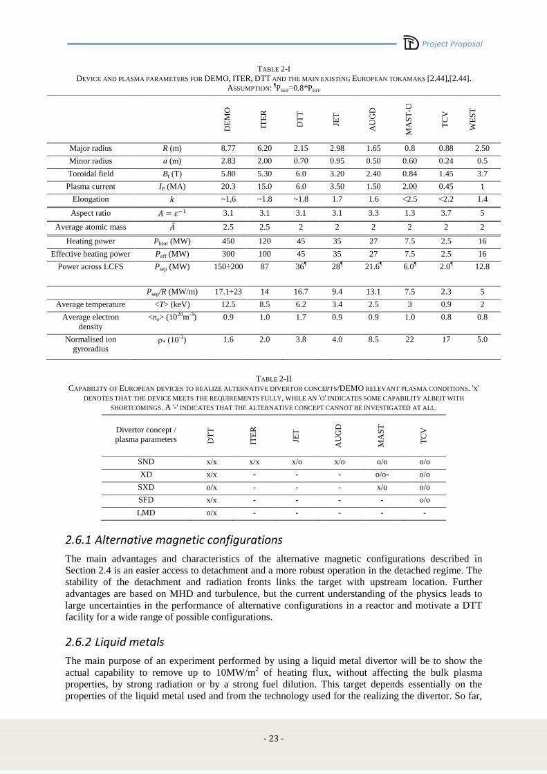
Project Proposal
- 23 -
TABLE 2-I
DEVICE AND PLASMA PARAMETERS FOR DEMO, ITER, DTT AND THE MAIN EXISTING EUROPEAN TOKAMAKS [2.44],[2.44].
ASSUMPTION: ¶PSEP=0.8*PEFF
DE
MO
ITE
R
DT
T
JET
AU
GD
MA
ST
-U
TC
V
WE
ST
Major radius R (m) 8.77 6.20 2.15 2.98 1.65 0.8 0.88 2.50
Minor radius a (m) 2.83 2.00 0.70 0.95 0.50 0.60 0.24 0.5
Toroidal field Bt (T) 5.80 5.30 6.0 3.20 2.40 0.84 1.45 3.7
Plasma current IP (MA) 20.3 15.0 6.0 3.50 1.50 2.00 0.45 1
Elongation ~1,6 ~1.8 ~1.8 1.7 1.6 <2.5 <2.2 1.4
Aspect ratio 3.1 3.1 3.1 3.1 3.3 1.3 3.7 5
Average atomic mass 2.5 2.5 2 2 2 2 2 2
Heating power Pheat (MW) 450 120 45 35 27 7.5 2.5 16
Effective heating power Peff (MW) 300 100 45 35 27 7.5 2.5 16
Power across LCFS Psep (MW) 150÷200 87 36¶ 28¶ 21.6¶ 6.0¶ 2.0¶ 12.8
Psep/R (MW/m) 17.1÷23 14 16.7 9.4 13.1 7.5 2.3 5
Average temperature <T> (keV) 12.5 8.5 6.2 3.4 2.5 3 0.9 2
Average electron
density
<ne> (1020m-3) 0.9 1.0 1.7 0.9 0.9 1.0 0.8 0.8
Normalised ion
gyroradius * (10-3) 1.6 2.0 3.8 4.0 8.5 22 17 5.0
TABLE 2-II
CAPABILITY OF EUROPEAN DEVICES TO REALIZE ALTERNATIVE DIVERTOR CONCEPTS/DEMO RELEVANT PLASMA CONDITIONS. 'X'
DENOTES THAT THE DEVICE MEETS THE REQUIREMENTS FULLY, WHILE AN 'O' INDICATES SOME CAPABILITY ALBEIT WITH
SHORTCOMINGS. A '-' INDICATES THAT THE ALTERNATIVE CONCEPT CANNOT BE INVESTIGATED AT ALL.
Divertor concept /
plasma parameters DT
T
ITE
R
JET
AU
GD
MA
ST
TC
V
SND x/x x/x x/o x/o o/o o/o
XD x/x - - - o/o- o/o
SXD o/x - - - x/o o/o
SFD x/x - - - - o/o
LMD o/x - - - - -
2.6.1 Alternative magnetic configurations
The main advantages and characteristics of the alternative magnetic configurations described in
Section 2.4 is an easier access to detachment and a more robust operation in the detached regime. The
stability of the detachment and radiation fronts links the target with upstream location. Further
advantages are based on MHD and turbulence, but the current understanding of the physics leads to
large uncertainties in the performance of alternative configurations in a reactor and motivate a DTT
facility for a wide range of possible configurations.
2.6.2 Liquid metals
The main purpose of an experiment performed by using a liquid metal divertor will be to show the
actual capability to remove up to 10MW/m2 of heating flux, without affecting the bulk plasma
properties, by strong radiation or by a strong fuel dilution. This target depends essentially on the
properties of the liquid metal used and from the technology used for the realizing the divertor. So far,
Project Proposal
-24-
liquid metals have never been used as a divertor target under large power flux and large ELMs. There
is, consequently, no experience on how to reasonably proceed. Even assuming that the liquid metal
solution has been fixed (for instance the CPS), it remains to be solved the problem of the actual
geometry of the divertor; there are no experience at all about this point and it is not guaranteed that an
ITER like geometry will be the optimal one, actually the only planned experiment [2.47] .with a
divertor module designed for liquid metal, is going to use a flat divertor. In order to have a first
indication how to answer this questions it is mandatory that the present 2D edge codes (SOLPS,
EDGE2D …) are extended to simulate liquid metal targets. The outputs of these codes should be
compared as much as possible with the present ongoing experiments. Only once these data will be
available an actual DTT divertor based on liquid metals could be designed. In any case any DTT
project should include scenarios, where the power flow is larger than 10MW/m2 and with the
possibility to test a liquid metal divertor, under different magnetic configuration. This last is a very
important point. Since the role of the evaporated metal could play an important role in the bulk plasma
dynamic, it is obvious that the local magnetic topology (for instance an XD like configuration) could
play an important part in avoiding or limiting the plasma pollution/dilution due to the large amount of
evaporated material. This is a key point which can only be addressed in a DTT, as linear devices or
small toroidal plasma experiments will not be able to show whether a liquid metal divertor can, at the
same time, guarantee the exhaust of a large power flow and the permanence of high plasma
performances in a DEMO-relevant regime. On top of the plasma bulk compatibility any actual
experiment divertor must be able to demonstrate the capability to deal with all the “technical”
problems connected with the use of a liquid metal, starting from the temperature control of the metal
and the structural frame, up to the show the capability to avoid or handle any hydrogen absorption,
including hydride formation, in the divertor itself and in the main chamber structures (first wall and
vacuum vessel).
2.7 DTT technical requirements and specifications
As mentioned in the previous section the proposed DTT should be able to explore two quite different
solutions, which leads to different requirements. Here, we will first discuss some of the technical
problems connected to both, alternative magnetic divertor configurations and alternative divertor
materials, and then shortly (see also Chap. 3 for more details) illustrate how the connection between
them and the physics requirements can lead to the technical minimal requirements.
2.7.1 Technological feasibility of alternative configurations
The presently considered conventional single (or also double) null divertor uses only low order
multi-pole fields to shape the plasma and guide the SOL flux bundle, and these can be readily applied
by poloidal field (PF) coils outside the toroidal field (TF) coils. Producing a higher order null (SFD),
or guiding the SOL flux bundles over distances comparable to the minor plasma radius (SXD), or
expanding the poloidal flux in the target plate proximity (XD), however, requires higher order multi-
pole fields, which decay more rapidly away from the coil location. Therefore, enhancement factors for
PF current intensity requirements from standard to "alternative" divertors gained from experiments
with in-vessel coils cannot be usefully and directly transferred to reactor situations with PF coils
outside the TF ones.
Although the major effort of this study will be dedicated towards configurations with external PF coils
(except possibly a set, carrying modest currents, for fast vertical control), some alternative divertor
options like, in particular, the Super-X would be virtually excluded by such limitations, and their
technological feasibility will require an assessment considerably beyond the scope of the present
study.
Even within the limitation to external coils, studies may lead to configurations with technological
requirements that are quantitatively beyond limits of feasibility. As we have available efficient tools
for designing equilibria and coil systems under different constraints, but an elaborate engineering
assessment can be carried out only for few concrete proposals, it is important to adopt criteria for pre-
screening configurations, and to develop each option towards one case with optimum chances to pass

Project Proposal
- 25 -
technological scrutiny. We have, therefore, formulated a set of constraints and have defined
parameters, which we expect to characterize the technological costs of particular options and
realisations [2.48]. Definitions of these parameters will necessarily be over-simplified, but needed to
proceed in parallel on several fronts. Technological feasibility can in many cases be considered as a
cost that can be bought with money or further R&D effort.
Plasma volume/volume enclosed by toroidal field coils: To keep this quantity approximately constant in a first step is hoped to allow limiting the impact of the divertor change on the parameters of reactor economy to the inside of the TF coils, minimizing the need for a separate systems code optimization. This will also allow to take into account the cost of the TF coils in a simple manner.
PF system: Alternative configurations will require an increased effort for the PF system. A simple figure of merit is the superconductor mass required, which is proportional to
maxk k kkR N I , where Rk is the radial position of each coil and
maxk kN I its maximum
value of MA*turns.
Limits on forces arising between PF coils: Higher order moments require large
alternating currents in neighbouring coils. This basic problem is overlaid by the fact that
the problem to determine the required coil currents for a desired equilibrium shape is
mathematically badly posed, but optimisation procedures exist.
Torques between TF and PF system: These torques are simply proportional to the net poloidal flux passing between two given points along the TF coils. The large scale torques
are determined by the lowest moments of the PF system, however also local torques due to the higher order moments should be estimated.
Neutron radiation exposure of targets: Other advantages of the design, less directly related
to the heat load issue might also arise and be documented/quantified. An example is the
reduced neutron load on divertor targets that are located behind significant neutron shields
or even blanket modules such as SXD target, which might allow longer dwell times for
divertor structures, or the use of a broader range of materials. A broader range of target
materials and temperatures can significantly increase the heat exhaust capability of the
target.
Controllability: Of comparable importance to the force and cost arguments are the
requirements for controllability of the discharge and of the strike-point position. Concerning
the vertical stability connected issues, large experience and proven tools exist, although the
impact of the necessarily different boundary shape (e.g. a separatrix angle for an exact
snowflake of 60° rather than 90°) has to be assessed. An outcome of this part of the exercise
will be a limit onto the possible plasma elongation, which will affect bulk plasma
performance and should be included into the final assessment of the configuration. More
multi-faceted will be the consequences of minor off-normal events (e.g. sawteeth, mode
transition (L/H or H/L), occasional ELMs, signal errors) onto the plasma wall interaction.
2.7.2 Alternative configurations: minimal technical requirements
To summarize, the main physics specifications of a DTT facility are: a) the possibility to realize the
largest possible set of alternative magnetic configurations and to study the main physics aspects, even
to understand the different “weight” of the classical and of the anomalous effects; b) to propose a
reliable exhaust solution for DEMO, i.e. a solution that is compatible with a plasma bulk reactor,
relevant in terms of the physics dimensionless parameters and in terms of the general performances; c)
to propose a solution using technologies and materials as relevant as possible to DEMO (the nuclear
aspect would involve a very large budget); d) all the feasibility aspect must be accounted. The
integration of all these aspects is very problematic. While the simplest solution would be to realize a
device with the dimension and the performances as close as possible to the values of DEMO,
budgetary constrains will limit such a design. In Chap. 3 we will describe how the link between the
physics and technical requirements and the budget constraint leads to the choice of the main device

Project Proposal
-26-
parameters. Here, we define a “minimal” set of technical requirements that must be satisfied to
accomplish the physics aspects summarised above. Physics specification a) can be easily translated
into the necessity of having: i) a very flexible divertor region in terms of available space (this will
permit to test different divertor geometries “optimized” for the different magnetic topologies); ii) a
very flexible magnetic coil system in order to realize and test them from any point of view (physics
and technology). Although in a reactor it will not be advisable to have internal coils, for a DTT that
wants to be “magnetically” flexible it would be really important to have them; in fact the internal coils
could help in varying the local field “multipolar expansion”. Only when this will be known it will be
possible to design a dedicated set of external poloidal coils [2.15]-[2.20], where the reciprocal position
and shape is optimized for the necessary “multipolar expansion”. When dealing with this matter it
must be considered that we play with the reciprocal position of two poloidal field “nulls”;
consequently, even small variations of the reciprocal position of the external coils, without affecting
the general equilibrium, could strongly influence the local topology around the “nulls”. Physics
specification b), i.e. the “integration” requirement is difficult to translate into technical requirements,
because it involves the general features and targets of the proposed device. A methodology, which
involves the unavoidable “budgetary compromise, will be proposed in Chap. 3. Here, it is important to
underline some clear point. Since the machine will be down scaled in dimensions, if we want to
preserve some global plasma performances, a technically reasonable high field will be mandatory.
DEMO edge and bulk plasma scenarios will be characterized by low collisionality, but at relatively
high density, consequently, this implies that any DDT must be able to operate at high temperature
plasmas, i.e. good confinement and a large heating power. The latter translates directly into a technical
constraint, because it involves the most important targets of the DTT: high power flux divertor
regimes and the use of materials for the PFC reactor relevant. The importance of having robust and
reliable heating power, unavoidably, leads to the choice of a set of different heating systems; this
multiplicity (although not strictly necessary for a power exhaust) will guarantee, at the same time, a
main electron heating (like alpha heating) with a quasi isotropic heating in the velocity space, and with
the flexibility to select different radial profile coupling.
2.7.3 Technological feasibility of liquid metal solutions
Wetting, stability and structural viability
Good wetting of the CPS is a necessary condition, which must be sustained during operation and after
transients. The wetting parameter, given by the contact angle, θ, and the surface tension, σ, determines
the capillary pressure inside a tube of radius rc,
(2.7.1)
This must overcome the plasma pressure, gravity and provide the flow of material through the
capillary system to the surface in the presence of a strong magnetic field. The flow of a fluid through
a porous medium under a given capillary pressure is determined by viscosity and magneto
hydrodynamic parameters, which depend on geometry and magnetic field (Reynolds and Hartmann
number). For the systems discussed here, the liquid material flow under stationary operation, which is
needed to replenish lost material, is low and considered to be unproblematic. For such slow,
viscous flow conditions the Darcy equation can be applied. In addition to providing the forces
for the replenishment flow, capillary forces must also balance the forces that would lead to
unwanted material movement and splashing. Forces acting on the liquid arise from plasma pressure
and Lorentz forces ( j x B ). The plasma pressure at the strike points resulting from the impact
of ions, pi niTi , and is moderate under steady state operation (for Ti = 1 eV and 10 MW/m2
~130
Pa), but can increase significantly in transients like ELMs. Lorentz forces result from currents in the
target, which can flow parallel or perpendicular to the surface. Parallel currents are driven by local
potential differences resulting from gradients of plasma temperature and density and perpendicular
current results from plasma impact directly. At elevated temperatures, thermal electron emission
(Richardson law) can significantly increase perpendicular current through the target. The currents can
Project Proposal
- 27 -
increase largely in plasma disruptions, since the collapsing poloidal magnetic field induces eddy
currents in the target leading to j x B thickness of the liquid film, the electric conductivity, but
decrease with the size of the structure. To limit the forces from eddy currents, PFCs are usually
segmented. The tangential forces drive the liquid along the surface and are counteracted by surface
tension resulting in surface irregularities. Liquids can become unstable, e.g. by Kevin Helmholtz
(critical velocity gradient) or Rayleigh Taylor (critical density gradient) mechanisms, leading to
possible splashing of the liquid. These mechanisms impose an upper limit on the acceleration and
velocity of the liquids in transient events, which can be controlled by the thickness of the fluid film
and the size of the CPS structure. These considerations are supported by experimental observations
showing that Li splashing from a CPS target under transient power loading can be suppressed by a
proper selection of the CPS pore size [2.49]. Material splashing can also occur by boiling of the
overheated liquid or by formation and transport of hydrogen filled bubbles produced by oversaturation
of implanted hydrogen from the plasma. A (limited) database on stability of Li and Sn under plasma
impact exists (FTU, TJII, Pilot PSI, PSI-2, and Textor).
At the end, a LM target must be embedded in a possible reactor divertor geometry, which determines
the direction of the gravity force. A flat horizontal target is the preferred option for a LM target.
Replenishment
A central requirement for the LM target is the replenishment of the eroded liquid, both under steady
state and after possible transient erosion as all plasma exposed surface must remain wetted with the
liquid. The physics of the wetting is determined by the contact angle, the CPS geometry and its
detailed surface texture, which should provide small “effective” radii at the surface to promote
capillary forces and to avoid in parallel hot spots produced by surface irregularities at the grazing
incidence of the power flux. Contact angle and wetting are based on interatomic forces and very
sensitive to the actual surface condition. The other requirement is to provide the liquid flow through
the CPS system from a reservoir to the exposed surface. The flow through the CPS, which is
determined by viscosity and magneto hydrodynamic parameters, depends on the CPS geometry and
the magnetic field (Hartmann number). Finally the CPS must be connected to a liquid reservoir. Under
conduction dominated heat exhaust the stationary replenishment flow is small compensating only
sputter erosion and some small evaporation of similar magnitude. Such a small flow can be provided
by a CPS with small pore size, which is also favourable to optimise the liquid stability. This is
much different for a target, which would rely on evaporation cooling and, therefore, must provide
higher flow rates under steady state conditions requiring a different CPS geometry. Under transient
power impact, sudden evaporation should take place to protect the CPS from damage. The
replenishment flow for transients must be taken from the reservoir inside the CPS. Transient events
should be limited and not significantly increase the time averaged flow from the liquid reservoir.
Optimisation of these requirements based on a selected solid – liquid CPS concept is a main
purpose of present experimental and modelling activities.
Compatibility of LM and structural material
Particular care must be taken with the use of liquid metals in any technological application, e.g. for its
use in the blankets of fusion or as cooling medium for fission reactors. This results from a possible
fast chemical reaction of the liquid with the solid, which is promoted by a possible fast transport and a
possible deep penetration of the liquid in solids, e.g. along grain boundaries. The selected liquid must
be chemically stable with all solid materials that are active parts of the target and liquid metal supply
and reservoir system in a wider temperature range defined by the operational boundary conditions for
normal and off normal events. The liquid material will also be distributed and re-deposited on other
parts of the in-vessel surfaces of a reactor, but preferentially within the divertor volume. Under the
operation conditions described above with limited release during normal operation, the chemical
reaction of the LM with the main vessel wall materials is probably of less importance, while the
surfaces inside the divertor are more critical and should be compatible with the selected liquid.
Possible chemical reaction of water with the in-vessel PFC materials cooling requires particular
attention. This is a critical issue with the possible use of liquid Li. Various data exist on the chemical
stability of selected liquids with solid materials.
Project Proposal
-28-
Erosion/evaporation
Erosion under plasma impact and evaporation greatly determines the performance of a LM target
concept. Erosion through classical physical sputtering is reasonably well described by the binary
collision model (Eckstein data, Trim modelling). Recently, an “abnormal” erosion mechanism is
discussed acting at high temperatures, which can be also important for the use of liquids. Similarly,
possible chemical erosion effects may play a role. These questions are generally discussed for
additional erosion of PFCs under high flux plasma impact. Evaporation rates can be reasonably
estimated from standard literature data but the influence of surface contaminations such as oxide
formation, the near surface plasma pressure and the fine scale surface texturing must be considered,
which can lead to deviations from standard data. Quantification of the material influx in the
experiments is mainly based on spectroscopic analysis. Some quantitative spectroscopic data on Li
exist, but less for Sn and more quantitative spectroscopic data of neutral and low ionisation states of
Sn is needed. The effective target erosion, which has to be replaced by the flowing liquid, is greatly
reduced by local redeposition of the eroded species, similar to solid targets. Local redeposition is
governed by the penetration depth of ions into the near surface plasma, the local transport
(gyromotion) and sticking behavior of the redeposited species. This can be modelled for sputtered
and evaporating species for Li and Sn from local surface and plasma models, e.g. with the ERO code.
Hydrogen retention
The in vessel inventory of tritium is a potential safety hazard due to its possible release into the
environment in a sequence of possible accidents. This sets a limit on the “mobilisable” in vessel
tritium retention. In addition, the short term retention of the fuel in PFCs must be compatible with the
tritium production and supply. The basic physics is given by the hydrogen retention and release
properties of the liquids in connection with the temperatures of the liquid target and the inner wall,
which is important for re-deposited material. The other important parameter is the overall amount of
the in-vessel or recirculating liquid, depending on the overall technical concept. Retention is a
particular critical issue for Li, since Li can retain large amounts of hydrogen and can even form a Li-
H compound under certain conditions. However, the retention in Li decreases with temperature,
which may open an operational window with acceptable retention. The retention of hydrogen in Sn is
lower but must be more analysed under fusion conditions. The possible liquid target concepts must
assess their compatibility with the tritium retention requirements, including the retention in the
target and in re-deposited layers on other areas. Retained fuel after experiments has to be compared
with retention modelling based on material parameters of the selected liquids.
Temperature window
Apart from material parameters, the power exhaust of a concept based on heat conduction depends on
the temperature window of the concept. The maximum surface temperature is limited by the particle
release due to sputtering and evaporation under steady state and transient conditions and possibly by
the chemical reactivity with structural materials. The limit of material influx is certainly much larger
for the low Z Li than for the heavy mass Sn but depends in more detail from a number of complex
physics parameters, which cannot be analysed in detail within this task. Instead data and experiences
from other tokamak studies can be used, e.g. experiences on the plasma compatibility of
carbon and tungsten targets in JET and AUG. The operating temperatures of the cooling structure
arise from material properties, such as ductility and creep and the selected cooling media. With the
use of liquid Li, the use of water cooling sets a limit on the amount of liquid Li which can react in
with water in case of an accident to less than approximately 30 kg. Larger Li amounts, which
could react, would require other cooling media like gas or liquid metals. Gas cooling will lead to
higher temperatures at the cooling structure, reducing the temperature window to the surface and thus
the power exhaust. With the boundary condition of the maximum surface temperature and the
temperature at the cooling structure, the power exhaust capability depends then mainly on the
technological feasibility for the minimum thickness of structures.
Project Proposal
- 29 -
Liquid metals: minimal technical requirements
The largest part of the technical requirements described for the alternative configurations is also
valid for the liquid metals options. However, in this case, some further requirement must be
introduced. Up to now we do not know the optimal geometry for a liquid metal divertor. So far only
an experiment (KTM in 2016) [2.47] is planning to install a module of the divertor using liquid
lithium, by using a flat bottom divertor plate; consequently a main requirement will be the largest
flexibility in installing different divertor geometries.
In a standard divertor a dedicated cooling system must be foreseen, with the necessary input and
output pipes equipment. In the case of a liquid metal technology, an additional system for injecting
the liquid metal has to be foreseen. The DTT facility will not be a dedicated experiment for liquid
metals and since we do not know which liquid metal we will be using (may be more than one).
Therefore, among other important requirements, there will be the necessity of taking in the
possibility of using different liquid metals with various involved technology (e.g. different injecting
pipes, may be different cooling ...). A similar necessity occurs on the pumping system: we must
consider that some dedicated pumping could be necessary. Other minor technical requirement will
involve the control and the diagnostic system that will have to consider the peculiarities of such a
divertor.
2.8 References [2.1] Fusion Electricity – A roadmap to the realisation of fusion energy, November 2012 (http://users.euro-
fusion.org/iterphysicswiki/images/9/9b/EFDA_Fusion_Roadmap_2M8JBG_v1_0.pdf)
[2.2] D.D. Ryutov, Phys. Plasmas 14 (2007) 064502.
[2.3] M. Kotschenreuther, et al., Phys. Plasmas 14 (2007) 72502.
[2.4] P.M. Valanju, et al., Phys. Plasmas 16 (2009) 056110.
[2.5] P.C. Stangeby, A.W. Leonard, Nucl. Fusion 51 (2011) 063001.
[2.6] Report of the STAC Ad Hoc Group on 'A strategy to address exhaust issues in the EU Fusion
programme - Phase I', Final version, 10.7.2013.
[2.7] WPDTT1 report on the "Development of physics models for particle transport and power exhaust",
Version 2.0, April 10, 2015, https://idm.euro-fusion.org/?uid=2MDHQT
[2.8] Kallenbach, et al., Plasma Phys. Contr. Fusion 55 (2013) 124041.
[2.9] Y.R. Martin, et al., J. Phys.: Conf. Ser.123 (2008) 012033.
[2.10] T. Eich, et al., Phys. Rev. Lett.107 (2011) 215001.
[2.11] M.A. Makowski, et al., Phys. Plasmas 19 (2012) 056122.
[2.12] F.L. Hinton, R.D. Hazeltine, Phys. Fluids 17 (1974) 2236.
[2.13] R. Goldston, Nucl. Fusion 52 (2012) 013009.
[2.14] M. Kotschenreuther, P. M. Valanju, S. M. Mahajan et al., 2004 IAEA Fusion Energy Conference,
Vilamoura, Portugal, 2004, IC/P6-43.
[2.15] M. Kotschenreuther, et al., Phys. Plasmas 20 (2013) 102507.
[2.16] Loarte, el al., Plasma Phys. Contr. Fusion 43 (2001) R183.
[2.17] S. McIntosh, et al., 25th IAEA Fusion Energy Conference, St. Petersburg, Russia, 13–18 Oct. 2014,
FIP/P8-9.
[2.18] G. Calabrò, et al., "Quasi-Snowflake divertor configuration studies on EAST", accepted for publication
in Nucl. Fusion.
[2.19] D.D. Ryutov, Physica Scripta 89 (2014) 088002
[2.20] D.D. Ryutov, submitted to Phys. Plasmas
[2.21] D.D. Ryutov, Phys. Plasmas 20 (2013) 092509
[2.22] L.G. Golubchikov, V.A. Evtikhin, I.E. Lyublinski, V.I. Pistunovich, I.N. Potapov and A.N. Chumanov,
J. Nucl. Mater. 233–237 (1996) 667–72.
[2.23] V.A. Evtikhin, J. Nucl. Mater. 271-272 (1999) 396-400.
[2.24] J.W. Coenen, et al., Phys. Scr. (2014) T159.
Project Proposal
-30-
[2.25] D. Post, et al., Phys. Plasmas 2 (1995) 2328–36.
[2.26] J.-H. You, "Divertor PFC concepts considered in the DEMO divertor project", EFPW, Dec 1-3, 2014,
Split, Croatia.
[2.27] R.P. Doerner, et al., J. Nucl. Mater. 290-293 (2001) 166-172.
[2.28] M.D. Coventry, et al., J. Nucl. Mater. 335 (2004) 115–120.
[2.29] T.W. Morgan, et al., J. Nucl. Mater. (2015) in press.
[2.30] Y. Shimomura, et al., Nucl. Fusion 23 (1983) 869.
[2.31] R.A. Pitts, et al., J. Nucl. Mater. 290-293 (2001) 940.
[2.32] F. Piras, et al., Plasma Phys. Control. Fusion 51 (2009) 055009.
[2.33] V.A. Soukhanovskii, et al., J. Nucl. Mater. 415 (2011) S365.
[2.34] S.L. Allen, et al., 24th IAEA Fusion Energy Conference, San Diego, USA, 2012, PD/1-2.
[2.35] H. Reimerdes, et al., Plasma Phys. Control. Fusion 55 (2013) 124027.
[2.36] H. Hutchinson, Nucl. Fus., 36, 783 (1996)
[2.37] D. LaBombard, Nucl. Fus., 55, 053020 (2015)
[2.38] K. Lackner, Com. Plas. Phys. Control. Fusion, 15, 359 (1994)
[2.39] K. Lackner, Fus. Scien. and Techn., 54, 989 (2008)
[2.40] D. G. Whyte, Fusion Eng. Des. 87, 234 (2012)
[2.41] Kadomtsev B. B., Fiz. Plazmy, 1, 531 (1975)
[2.42] ITER Physics Basis Editors, et al., Nucl. Fusion 39 (1999) 2137.
[2.43] Pizzuto et al., Nucl. Fusion 50 (2010) 095005.
[2.44] D. Stork, et al., 23rd IAEA Fusion Energy Conference, Daejeon, Korea, 2010, ICC/P5-06.
[2.45] Karpushov, et al., Fus. Eng. and Des. (2015) in press.
[2.46] T. Eich, Nucl. Fus. 53 (2013) 093031.
[2.47] Lyublinsk I. E., et al Fus. Eng.and Des. 88, 1862, (2013)
[2.48] WPDTT1 project management plan, Version 2.1, December 9, 2014, https://idm.euro-
fusion.org/?uid=2KYYG9
[2.49] L.I. Ivanov, et al., Int. J. of Nuclear Research “Nukleonika” 46 (2001) S113-S115
(http://www.ichtj.waw.pl/ichtj/nukleon/back/full/vol46_2001/v46s1p113f.pdf).

Project Proposal
- 31 -
Chapter 3
CHOICE OF PARAMETERS FOR DTT
3.1 Rationale for the choice of DTT parameters
The main objectives of the DTT device can be summarised as follows:
1) demonstrate a safe and robust power handling solution that can be extrapolated to DEMO;
2) achieve the previous goal without degrading the plasma core and pedestal performances, in a
plasma regime as close as possible to a reactor one;
3) demonstrate the possibility to achieve points 1) and 2) by integrating as much as possible all
the Physics and the Technological aspects.
The integration of these three targets is mandatory for meaningful experiments. It is a quite
challenging task, since to simulate the complete behaviour of DEMO the only solution would to
realize DEMO itself. To overcome this very challenging issue, several different approaches have been
proposed [3.1]-[3.4], either considering the divertor and the SOL as regions completely independent of
the bulk plasma, or focusing the interest also on the core. In any case, a prioritization among the
different parameters should be defined, trying to include all the different aspects as far as possible,
compatibly with the available technology and economical resources.
Since any DTT experiment is finalized to study the power exhaust, the first parameters to preserve are
those connected with the divertor and the SOL regions. As mentioned in Chap. 2, a key parameter
characterizing these two regions is PSEP/R, whose values should be around 15MW/m to be DEMO
relevant (where PSEP is the power flowing through the plasma boundary). Other two important
parameters are the upstream poloidal (qθ) and parallel (q//) power fluxes: qθ=PSEP/λq2πR, where λq~Bθ-1
[3.5] is the decay length of the mid-plane heat channel. Since the parallel heat transport is dominant, it
follows that q// ~qθB/Bθ~ PSEPB/R (>110 MWT/m for DEMO). Previous works [3.3], [3.6] have shown
that, even considering the edge plasma as an insulated region, a complete “self- similarity scaled down
experiment” cannot be realized, but that it could be approximated [3.2], [3.3] by fitting five
dimensionless parameters: Te (with a suitable normalization), υ*=Ld/λei., Δd/λ0, ρi/ Δd, β, where Ld is the
divertor field line length, λei is the electron-ion collisional mean free path, Δd is the SOL thickness, λ0
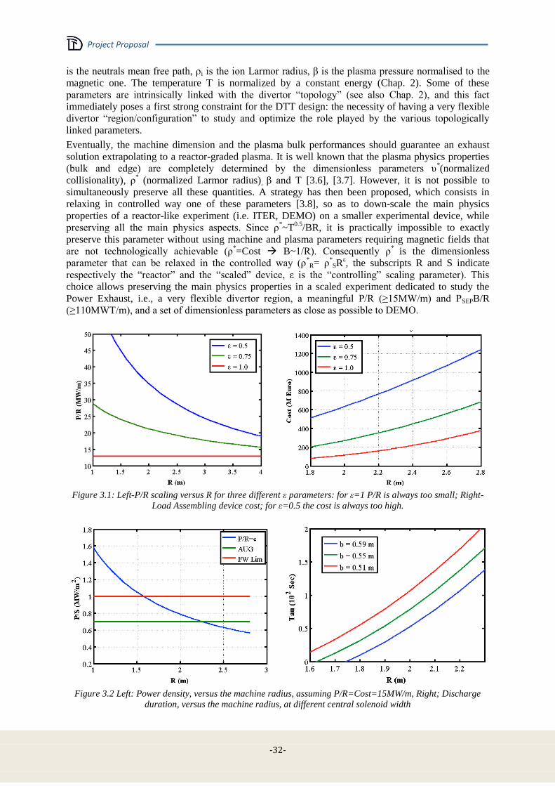
Project Proposal
-32-
is the neutrals mean free path, ρi is the ion Larmor radius, β is the plasma pressure normalised to the
magnetic one. The temperature T is normalized by a constant energy (Chap. 2). Some of these
parameters are intrinsically linked with the divertor “topology” (see also Chap. 2), and this fact
immediately poses a first strong constraint for the DTT design: the necessity of having a very flexible
divertor “region/configuration” to study and optimize the role played by the various topologically
linked parameters.
Eventually, the machine dimension and the plasma bulk performances should guarantee an exhaust
solution extrapolating to a reactor-graded plasma. It is well known that the plasma physics properties
(bulk and edge) are completely determined by the dimensionless parameters υ*(normalized
collisionality), ρ* (normalized Larmor radius), β and T [3.6], [3.7]. However, it is not possible to
simultaneously preserve all these quantities. A strategy has then been proposed, which consists in
relaxing in controlled way one of these parameters [3.8], so as to down-scale the main physics
properties of a reactor-like experiment (i.e. ITER, DEMO) on a smaller experimental device, while
preserving all the main physics aspects. Since ρ*~T
0.5/BR, it is practically impossible to exactly
preserve this parameter without using machine and plasma parameters requiring magnetic fields that
are not technologically achievable (ρ*=Cost B~1/R). Consequently ρ
* is the dimensionless
parameter that can be relaxed in the controlled way (ρ*R= ρ
*SR
ε, the subscripts R and S indicate
respectively the “reactor” and the “scaled” device, ε is the “controlling” scaling parameter). This
choice allows preserving the main physics properties in a scaled experiment dedicated to study the
Power Exhaust, i.e., a very flexible divertor region, a meaningful P/R (≥15MW/m) and PSEPB/R
(≥110MWT/m), and a set of dimensionless parameters as close as possible to DEMO.
Figure 3.1: Left-P/R scaling versus R for three different ε parameters: for ε=1 P/R is always too small; Right-
Load Assembling device cost; for ε=0.5 the cost is always too high.
Figure 3.2 Left: Power density, versus the machine radius, assuming P/R=Cost=15MW/m, Right; Discharge
duration, versus the machine radius, at different central solenoid width
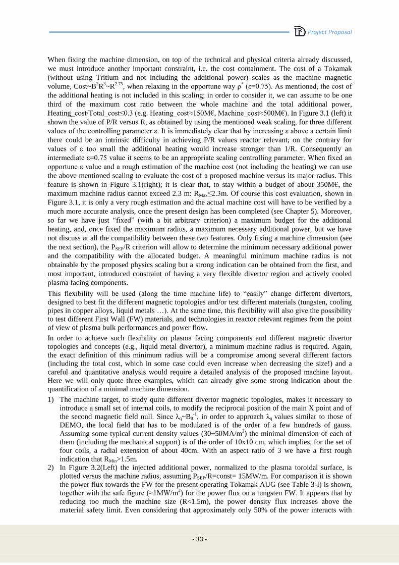
Project Proposal
- 33 -
When fixing the machine dimension, on top of the technical and physical criteria already discussed,
we must introduce another important constraint, i.e. the cost containment. The cost of a Tokamak
(without using Tritium and not including the additional power) scales as the machine magnetic
volume, Cost~B2R
3~R
2.75, when relaxing in the opportune way ρ
* (ε=0.75). As mentioned, the cost of
the additional heating is not included in this scaling; in order to consider it, we can assume to be one
third of the maximum cost ratio between the whole machine and the total additional power,
Heating_cost/Total_cost≤0.3 (e.g. Heating_cost≈150M€, Machine_cost≈500M€). In Figure 3.1 (left) it
shown the value of P/R versus R, as obtained by using the mentioned weak scaling, for three different
values of the controlling parameter ε. It is immediately clear that by increasing ε above a certain limit
there could be an intrinsic difficulty in achieving P/R values reactor relevant; on the contrary for
values of ε too small the additional heating would increase stronger than 1/R. Consequently an
intermediate ε=0.75 value it seems to be an appropriate scaling controlling parameter. When fixed an
opportune ε value and a rough estimation of the machine cost (not including the heating) we can use
the above mentioned scaling to evaluate the cost of a proposed machine versus its major radius. This
feature is shown in Figure 3.1(right); it is clear that, to stay within a budget of about 350M€, the
maximum machine radius cannot exceed 2.3 m: RMax≤2.3m. Of course this cost evaluation, shown in
Figure 3.1, it is only a very rough estimation and the actual machine cost will have to be verified by a
much more accurate analysis, once the present design has been completed (see Chapter 5). Moreover,
so far we have just “fixed” (with a bit arbitrary criterion) a maximum budget for the additional
heating, and, once fixed the maximum radius, a maximum necessary additional power, but we have
not discuss at all the compatibility between these two features. Only fixing a machine dimension (see
the next section), the PSEP/R criterion will allow to determine the minimum necessary additional power
and the compatibility with the allocated budget. A meaningful minimum machine radius is not
obtainable by the proposed physics scaling but a strong indication can be obtained from the first, and
most important, introduced constraint of having a very flexible divertor region and actively cooled
plasma facing components.
This flexibility will be used (along the time machine life) to “easily” change different divertors,
designed to best fit the different magnetic topologies and/or test different materials (tungsten, cooling
pipes in copper alloys, liquid metals …). At the same time, this flexibility will also give the possibility
to test different First Wall (FW) materials, and technologies in reactor relevant regimes from the point
of view of plasma bulk performances and power flow.
In order to achieve such flexibility on plasma facing components and different magnetic divertor
topologies and concepts (e.g., liquid metal divertor), a minimum machine radius is required. Again,
the exact definition of this minimum radius will be a compromise among several different factors
(including the total cost, which in some case could even increase when decreasing the size!) and a
careful and quantitative analysis would require a detailed analysis of the proposed machine layout.
Here we will only quote three examples, which can already give some strong indication about the
quantification of a minimal machine dimension.
1) The machine target, to study quite different divertor magnetic topologies, makes it necessary to
introduce a small set of internal coils, to modify the reciprocal position of the main X point and of
the second magnetic field null. Since λq~Bθ-1
, in order to approach λq values similar to those of
DEMO, the local field that has to be modulated is of the order of a few hundreds of gauss.
Assuming some typical current density values (30÷50MA/m2) the minimal dimension of each of
them (including the mechanical support) is of the order of 10x10 cm, which implies, for the set of
four coils, a radial extension of about 40cm. With an aspect ratio of 3 we have a first rough
indication that RMin>1.5m.
2) In Figure 3.2(Left) the injected additional power, normalized to the plasma toroidal surface, is
plotted versus the machine radius, assuming PSEP/R=const= 15MW/m. For comparison it is shown
the power flux towards the FW for the present operating Tokamak AUG (see Table 3-I) is shown,
together with the safe figure (≈1MW/m2) for the power flux on a tungsten FW. It appears that by
reducing too much the machine size (R<1.5m), the power density flux increases above the
material safety limit. Even considering that approximately only 50% of the power interacts with
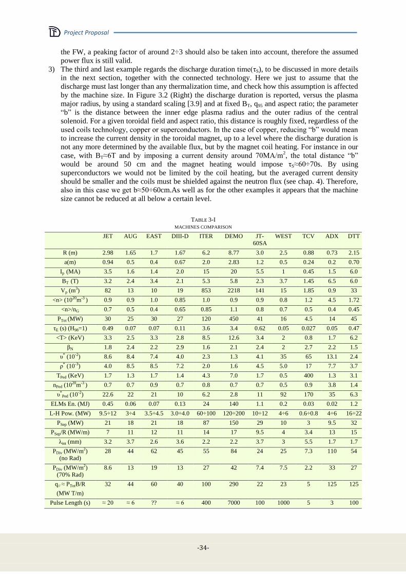
Project Proposal
-34-
the FW, a peaking factor of around 2÷3 should also be taken into account, therefore the assumed
power flux is still valid.
3) The third and last example regards the discharge duration time(τS), to be discussed in more details
in the next section, together with the connected technology. Here we just to assume that the
discharge must last longer than any thermalization time, and check how this assumption is affected
by the machine size. In Figure 3.2 (Right) the discharge duration is reported, versus the plasma
major radius, by using a standard scaling [3.9] and at fixed BT, q95 and aspect ratio; the parameter
“b” is the distance between the inner edge plasma radius and the outer radius of the central
solenoid. For a given toroidal field and aspect ratio, this distance is roughly fixed, regardless of the
used coils technology, copper or superconductors. In the case of copper, reducing “b” would mean
to increase the current density in the toroidal magnet, up to a level where the discharge duration is
not any more determined by the available flux, but by the magnet coil heating. For instance in our
case, with BT≈6T and by imposing a current density around 70MA/m2, the total distance “b”
would be around 50 cm and the magnet heating would impose τS≈60÷70s. By using
superconductors we would not be limited by the coil heating, but the averaged current density
should be smaller and the coils must be shielded against the neutron flux (see chap. 4). Therefore,
also in this case we get b≈50÷60cm.As well as for the other examples it appears that the machine
size cannot be reduced at all below a certain level.
TABLE 3-I
MACHINES COMPARISON
JET AUG EAST DIII-D ITER DEMO JT-
60SA
WEST TCV ADX DTT
R (m) 2.98 1.65 1.7 1.67 6.2 8.77 3.0 2.5 0.88 0.73 2.15
a(m) 0.94 0.5 0.4 0.67 2.0 2.83 1.2 0.5 0.24 0.2 0.70
Ip (MA) 3.5 1.6 1.4 2.0 15 20 5.5 1 0.45 1.5 6.0
BT (T) 3.2 2.4 3.4 2.1 5.3 5.8 2.3 3.7 1.45 6.5 6.0
Vp (m3) 82 13 10 19 853 2218 141 15 1.85 0.9 33
<n> (1020m-3 ) 0.9 0.9 1.0 0.85 1.0 0.9 0.9 0.8 1.2 4.5 1.72
<n>/nG 0.7 0.5 0.4 0.65 0.85 1.1 0.8 0.7 0.5 0.4 0.45
PTot (MW) 30 25 30 27 120 450 41 16 4.5 14 45
τE (s) (H98=1) 0.49 0.07 0.07 0.11 3.6 3.4 0.62 0.05 0.027 0.05 0.47
<T> (KeV) 3.3 2.5 3.3 2.8 8.5 12.6 3.4 2 0.8 1.7 6.2
βN 1.8 2.4 2.2 2.9 1.6 2.1 2.4 2 2.7 2.2 1.5
υ* (10-2) 8.6 8.4 7.4 4.0 2.3 1.3 4.1 35 65 13.1 2.4
ρ* (10-3) 4.0 8.5 8.5 7.2 2.0 1.6 4.5 5.0 17 7.7 3.7
TPed (KeV) 1.7 1.3 1.7 1.4 4.3 7.0 1.7 0.5 400 1.3 3.1
nPed (1020m-3 ) 0.7 0.7 0.9 0.7 0.8 0.7 0.7 0.5 0.9 3.8 1.4
υ*Ped (10-2) 22.6 22 21 10 6.2 2.8 11 92 170 35 6.3
ELMs En. (MJ) 0.45 0.06 0.07 0.13 24 140 1.1 0.2 0.03 0.02 1.2
L-H Pow. (MW) 9.5÷12 3÷4 3.5÷4.5 3.0÷4.0 60÷100 120÷200 10÷12 4÷6 0.6÷0.8 4÷6 16÷22
PSep (MW) 21 18 21 18 87 150 29 10 3 9.5 32
PSep/R (MW/m) 7 11 12 11 14 17 9.5 4 3.4 13 15
λint (mm) 3.2 3.7 2.6 3.6 2.2 2.2 3.7 3 5.5 1.7 1.7
PDiv (MW/m2)
(no Rad)
28 44 62 45 55 84 24 25 7.3 110 54
PDiv (MW/m2)
(70% Rad)
8.6 13 19 13 27 42 7.4 7.5 2.2 33 27
q// ≈ PTotB/R
(MW T/m)
32 44 60 40 100 290 22 23 5 125 125
Pulse Length (s) ≈ 20 ≈ 6 ?? ≈ 6 400 7000 100 1000 5 3 100
Project Proposal
- 35 -
From the overlap of these three example we could roughly estimate a minimum major radius of
RMin=1.7÷1.8m. Eventually, these three “general’ cases are confirmed by the actual experience gained
in previous project proposals [3.8], where a minimum plasma radius of the order RMin=1.5÷1.8m had
to be fixed to have some flexibility in the divertor region
3.2 Plasma performance and operational limits
In the previous section, the use of a weak Kadomtsev like scaling and a reasonable use of the
flexibility constraint has allowed to fix a minimum and a maximum meaningful plasma radius (1.7m
≤R≤2.4 m) for the present DTT proposal. Within this range, we can then fix” a specific value of the
major radius and check (on the basis of a draft design) the performances and the cost of the machine,
by using appropriate and more sophisticated tools. Of course, only at the end of this exercise we will
have the possibility to reconsider the machine parameters to accomplish at the best with the DTT
mission and the budget cost. Eventually, within the European system, this proposal will allow to make
the right choice for the final DTT design. The use of the weak scaling reasoning gives us also the
toroidal field and the plasma current necessary to preserve (assuming an H98=1 confinement time) the
important dimensionless parameters. From Figure 3.1, a reasonable choice for the machine dimension
can be assumed to be R=2.15 m. In order to finalize the machine size the machine aspect ratio A=R/a
remains to be fixed. Presently the European DEMO is studying different options with 2.7<A<3.5,
consequently it seems a reasonable choice to propose a DTT with A≈3. In order to have PSEP/R≈15,
accounting for some bulk plasma radiation, a total additional power PT≈40÷45MW is needed.
Having fixed the machine major plasma radius, the aspect ratio and the total additional heating, the use
of a system code tool will allow an estimate of the machine performances and comparing them with
other devices (existing, under construction or proposals, see Table 3-I).
Table 3-I shows different values of density and Greenwald fraction. An “operational” density has been
chosen, that scales with respect to the ITER and DEMO one as the other machine parameters. For all
the machines of Table 3-I, the maximum available or planned additional power PTOT has been quoted.
For the power flowing through the last magnetic surface, PSEP, there is always a large degree of
uncertainties, depending on the bulk radiation fraction, that, in turns, depends on the assumed
experimental scenario. The quoted λint is the power decay length, by assuming the Eich scaling, and
where the smallest possible values it has been assumed for the width of the flux in private region (see
Section 3.6), consequently the quoted fluxes are describing a slight “pessimistic” case. For a “fair”
comparison in Table 3-I, 30% of bulk plasma radiated power has been assumed for all the machines,
except for DEMO (where a reference 60% is quoted). In the DTT the very high density (even at low
Greenwald fraction) gives the very important advantage/flexibility, to be able to work in very high
radiation regimes and study the interplay between advanced divertor configurations and the radiation
in the various zones (bulk, SOL, divertor). The study and the optimization of the interplay between the
radiation and the divertor magnetic geometry is the main target of the DTT proposal, consequently this
aspect will be extensively discussed in Sec. 3.5. It is very important to note that only DTT and the
proposed ADX tokamak [3.4] have a parallel heating flux feature comparable to a reactor one. All the
dimensionless parameters defined in the previous sections (averaged in the bulk region and/or in the
edge) are very close to the ITER and DEMO ones. As requested by our initial specifications, this will
allow to correctly study the SOL and divertor physics in reactor relevant regimes and, at the same
time, with the necessary integration with a bulk plasma as close as possible to the DEMO one.
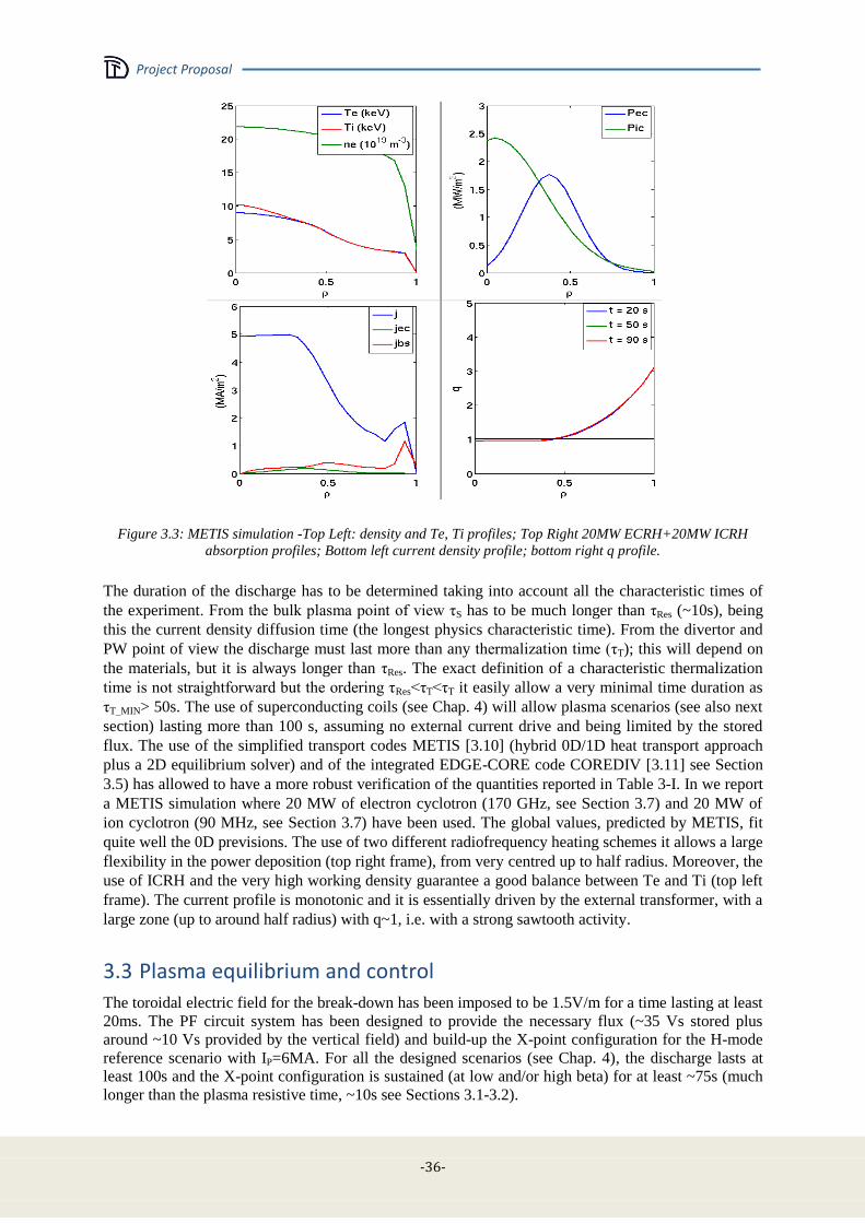
Project Proposal
-36-
Figure 3.3: METIS simulation -Top Left: density and Te, Ti profiles; Top Right 20MW ECRH+20MW ICRH
absorption profiles; Bottom left current density profile; bottom right q profile.
The duration of the discharge has to be determined taking into account all the characteristic times of
the experiment. From the bulk plasma point of view τS has to be much longer than τRes (~10s), being
this the current density diffusion time (the longest physics characteristic time). From the divertor and
PW point of view the discharge must last more than any thermalization time (τT); this will depend on
the materials, but it is always longer than τRes. The exact definition of a characteristic thermalization
time is not straightforward but the ordering τRes<τT<τT it easily allow a very minimal time duration as
τT_MIN> 50s. The use of superconducting coils (see Chap. 4) will allow plasma scenarios (see also next
section) lasting more than 100 s, assuming no external current drive and being limited by the stored
flux. The use of the simplified transport codes METIS [3.10] (hybrid 0D/1D heat transport approach
plus a 2D equilibrium solver) and of the integrated EDGE-CORE code COREDIV [3.11] see Section
3.5) has allowed to have a more robust verification of the quantities reported in Table 3-I. In we report
a METIS simulation where 20 MW of electron cyclotron (170 GHz, see Section 3.7) and 20 MW of
ion cyclotron (90 MHz, see Section 3.7) have been used. The global values, predicted by METIS, fit
quite well the 0D previsions. The use of two different radiofrequency heating schemes it allows a large
flexibility in the power deposition (top right frame), from very centred up to half radius. Moreover, the
use of ICRH and the very high working density guarantee a good balance between Te and Ti (top left
frame). The current profile is monotonic and it is essentially driven by the external transformer, with a
large zone (up to around half radius) with q~1, i.e. with a strong sawtooth activity.
3.3 Plasma equilibrium and control
The toroidal electric field for the break-down has been imposed to be 1.5V/m for a time lasting at least
20ms. The PF circuit system has been designed to provide the necessary flux (~35 Vs stored plus
around ~10 Vs provided by the vertical field) and build-up the X-point configuration for the H-mode
reference scenario with IP=6MA. For all the designed scenarios (see Chap. 4), the discharge lasts at
least 100s and the X-point configuration is sustained (at low and/or high beta) for at least ~75s (much
longer than the plasma resistive time, ~10s see Sections 3.1-3.2).

Project Proposal
- 37 -
The central solenoid (CS) column is split in 6 different coils (see Figure 3.4) to allow for the largest
plasma shaping flexibility. For the same reason, an independent power supply has been foreseen for
each coil, both for CS and Poloidal Field (PF), as described in Chap. 4. Several different scenarios
have been studied), including advanced configurations like ideal Snow Flakes and/or XD and will be
discussed in details in Section 4.3). In all scenarios, the flat top duration will last longer than 50s, in
order to allow testing alternative divertor solutions on a time scale longer than current diffusion and ay
relevant thermal phenomena.
Figure 3.4: DTT field null region during the plasma breakdown
Indeed, the plasma configurations to be studied in DTT, beyond Single Null (SN) and Double Null
(DN) ones (for this solution, presently it has been allocated enough room, on the top of the machine,
for a future upgrade), include the so-called advanced magnetic configurations:
1) SF [3.12]and quasi-SF configurations[3.13],
2) X-divertor (XD) configurations[3.14],
3) single-legged X-divertor [3.15],
4) super-XD configurations [3.16].
All the studied plasma equilibria satisfy the following constraints:
a) minimum distance of 0.04m between the plasma last closed surface and the first wall, in order
to minimize the interaction between the plasma and the main chamber (the power decay length
at 6MA is 2mm, according to Eich scaling [3.5]);
b) maximum current density in the poloidal field coils around 25-30 MA/m2, and maximum field
on any PF coils less than 5T and less than 12.5 T for the CS coils (see Chap. 4);
c) same geometrical plasma features: R=2.15m, a=0.69m, k≈1.76, <δ>≈0.35.
For feedback control we reserve about 10% capability of outboard PF coils and 5% of PF1, PF6, and
CS coils. Within the aforementioned constraints, sufficient flexibility is maintained to allow quite
different plasma shapes. Indeed, the PF system should be capable to modify the magnetic
configurations in the vicinity of the divertor targets in order to allow for experiments aimed at
exploring the effects of various parameters (e.g., connection length, grazing angle, scrape-off volume,
flaring/converging behaviour of the plasma channel) on the power exhaust quantities.
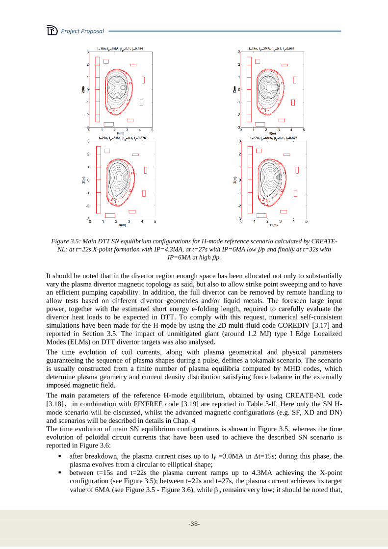
Project Proposal
-38-
Figure 3.5: Main DTT SN equilibrium configurations for H-mode reference scenario calculated by CREATE-
NL: at t=22s X-point formation with IP=4.3MA, at t=27s with IP=6MA low p and finally at t=32s with
IP=6MA at high p.
It should be noted that in the divertor region enough space has been allocated not only to substantially
vary the plasma divertor magnetic topology as said, but also to allow strike point sweeping and to have
an efficient pumping capability. In addition, the full divertor can be removed by remote handling to
allow tests based on different divertor geometries and/or liquid metals. The foreseen large input
power, together with the estimated short energy e-folding length, required to carefully evaluate the
divertor heat loads to be expected in DTT. To comply with this request, numerical self-consistent
simulations have been made for the H-mode by using the 2D multi-fluid code COREDIV [3.17] and
reported in Section 3.5. The impact of unmitigated giant (around 1.2 MJ) type I Edge Localized
Modes (ELMs) on DTT divertor targets was also analysed.
The time evolution of coil currents, along with plasma geometrical and physical parameters
guaranteeing the sequence of plasma shapes during a pulse, defines a tokamak scenario. The scenario
is usually constructed from a finite number of plasma equilibria computed by MHD codes, which
determine plasma geometry and current density distribution satisfying force balance in the externally
imposed magnetic field.
The main parameters of the reference H-mode equilibrium, obtained by using CREATE-NL code
[3.18], in combination with FIXFREE code [3.19] are reported in Table 3-II. Here only the SN H-
mode scenario will be discussed, whilst the advanced magnetic configurations (e.g. SF, XD and DN)
and scenarios will be described in details in Chap. 4
The time evolution of main SN equilibrium configurations is shown in Figure 3.5, whereas the time
evolution of poloidal circuit currents that have been used to achieve the described SN scenario is
reported in Figure 3.6:
after breakdown, the plasma current rises up to IP =3.0MA in t=15s; during this phase, the
plasma evolves from a circular to elliptical shape;
between t=15s and t=22s the plasma current ramps up to 4.3MA achieving the X-point
configuration (see Figure 3.5); between t=22s and t=27s, the plasma current achieves its target
value of 6MA (see Figure 3.5 - Figure 3.6), while p remains very low; it should be noted that,
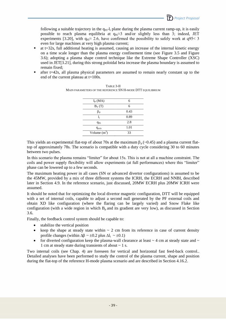
Project Proposal
- 39 -
following a suitable trajectory in the q95-li plane during the plasma current ramp-up, it is easily
possible to reach plasma equilibria at q95≈3 and/or slightly less than 3; indeed, JET
experiments [3.20], with q95≈ 2.6, have confirmed the possibility to safely work at q95< 3
even for large machines at very high plasma current;
at t=32s, full additional heating is assumed, causing an increase of the internal kinetic energy
on a time scale longer than the plasma energy confinement time (see Figure 3.5 and Figure
3.6); adopting a plasma shape control technique like the Extreme Shape Controller (XSC)
used in JET[3.21], during this strong poloidal beta increase the plasma boundary is assumed to
remain fixed;
after t=42s, all plasma physical parameters are assumed to remain nearly constant up to the
end of the current plateau at t=100s.
TABLE 3-II
MAIN PARAMETERS OF THE REFERENCE SN H-MODE DTT EQUILIBRIUM
IP (MA) 6
BT (T) 6
P 0.43
li 0.89
q95 2.8
qaxis 1.01
Volume (m3) 33
This yields an experimental flat-top of about 70s at the maximum p (~0.45) and a plasma current flat-
top of approximately 78s. The scenario is compatible with a duty cycle considering 30 to 60 minutes
between two pulses.
In this scenario the plasma remains “limiter” for about 15s. This is not at all a machine constraint. The
coils and power supply flexibility will allow experiments (at full performances) where this “limiter”
phase can be lowered up to a few seconds.
The maximum heating power in all cases (SN or advanced divertor configurations) is assumed to be
the 45MW, provided by a mix of three different systems the ICRH, the ECRH and NNBI, described
later in Section 4.9. In the reference scenario, just discussed, 20MW ECRH plus 20MW ICRH were
assumed.
It should be noted that for optimizing the local divertor magnetic configuration, DTT will be equipped
with a set of internal coils, capable to adjust a second null generated by the PF external coils and
obtain XD like configuration (where the flaring can be largely varied) and Snow Flake like
configuration (with a wide region in which Bp and its gradient are very low), as discussed in Section
3.6.
Finally, the feedback control system should be capable to:
stabilize the vertical position
keep the shape at steady state within ~ 2 cm from its reference in case of current density
profile changes (within ~ 0.2 plus li ~ 0.1)
for diverted configuration keep the plasma-wall clearance at least ~ 4 cm at steady state and ~
1 cm at steady state during transients of about ~ 1 s.
Two internal coils (see Chap. 4) are foreseen for vertical and horizontal fast feed-back control..
Detailed analyses have been performed to study the control of the plasma current, shape and position
during the flat-top of the reference H-mode plasma scenario and are described in Section 4.16.2.
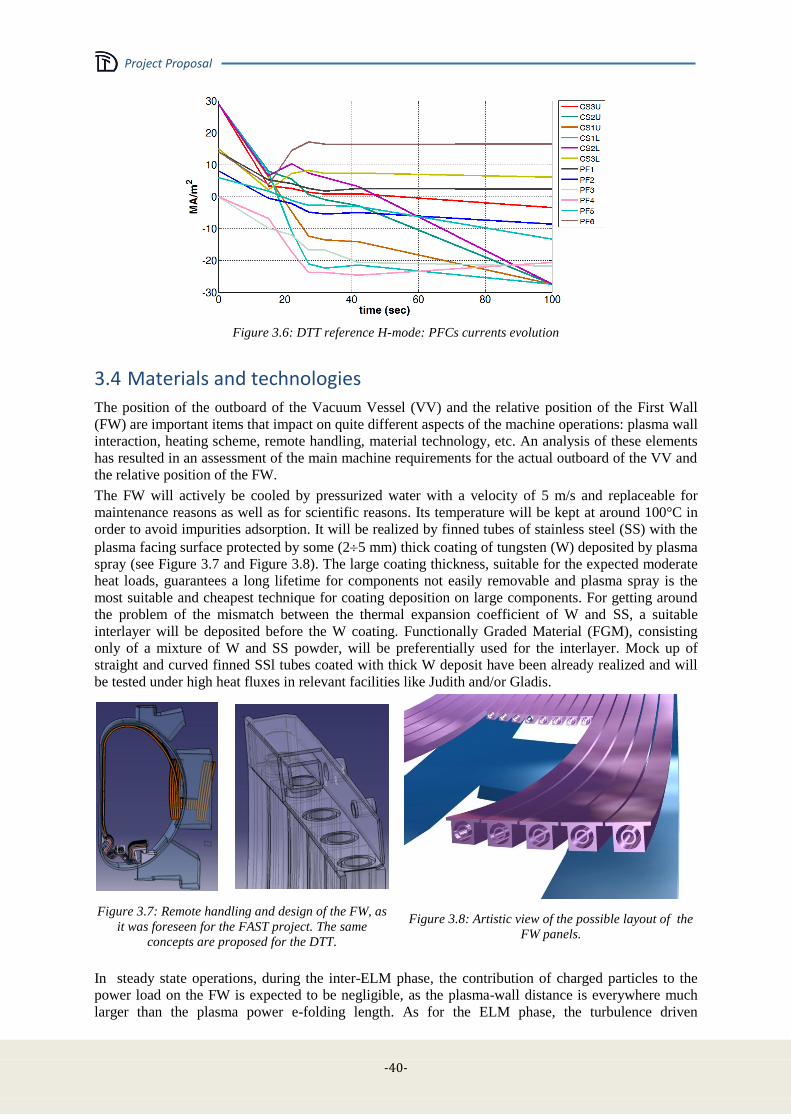
Project Proposal
-40-
Figure 3.6: DTT reference H-mode: PFCs currents evolution
3.4 Materials and technologies
The position of the outboard of the Vacuum Vessel (VV) and the relative position of the First Wall
(FW) are important items that impact on quite different aspects of the machine operations: plasma wall
interaction, heating scheme, remote handling, material technology, etc. An analysis of these elements
has resulted in an assessment of the main machine requirements for the actual outboard of the VV and
the relative position of the FW.
The FW will actively be cooled by pressurized water with a velocity of 5 m/s and replaceable for
maintenance reasons as well as for scientific reasons. Its temperature will be kept at around 100°C in
order to avoid impurities adsorption. It will be realized by finned tubes of stainless steel (SS) with the
plasma facing surface protected by some (25 mm) thick coating of tungsten (W) deposited by plasma
spray (see Figure 3.7 and Figure 3.8). The large coating thickness, suitable for the expected moderate
heat loads, guarantees a long lifetime for components not easily removable and plasma spray is the
most suitable and cheapest technique for coating deposition on large components. For getting around
the problem of the mismatch between the thermal expansion coefficient of W and SS, a suitable
interlayer will be deposited before the W coating. Functionally Graded Material (FGM), consisting
only of a mixture of W and SS powder, will be preferentially used for the interlayer. Mock up of
straight and curved finned SSl tubes coated with thick W deposit have been already realized and will
be tested under high heat fluxes in relevant facilities like Judith and/or Gladis.
Figure 3.7: Remote handling and design of the FW, as
it was foreseen for the FAST project. The same
concepts are proposed for the DTT.
Figure 3.8: Artistic view of the possible layout of the
FW panels.
In steady state operations, during the inter-ELM phase, the contribution of charged particles to the
power load on the FW is expected to be negligible, as the plasma-wall distance is everywhere much
larger than the plasma power e-folding length. As for the ELM phase, the turbulence driven

Project Proposal
- 41 -
filamentary transport of the plasma energy in the far SOL can lead to FW loads due to charged
particles. Taking into account the poloidal extent of plasma filaments (about 10 cm for a plasma radius
of 0.7 m [3.22]), the fraction of the ELM energy transported by a single filament (~ 2.5 %,
corresponding to ~ 40 kJ in DTT), conservatively assuming no decay of the filament energy with the
radial distance, with an ELM frequency of 10 Hz, we get for each filament at most about 400 kW
deposited on a toroidal strip of 2Romp long and about 10 cm wide, yielding a load of 0.3 MW/m2. The
power transported by charge-exchange neutrals has to be better assessed, but it is not expected to be
important. The main contribution to the FW load is instead by radiated power: by assuming that all the
input power (40÷45 MW) is radiated in an isotropic way on the wall surface (about 90 m2), the
resulting average power density is around 0.5 MW/ m2. Even considering toroidal and poloidal peak
factors of 3 the average heat load results in well tolerable values.
Larger power loads by charged particles as well as larger radiation load peak factors are to be expected
during transients like Vertical Displacement Events (VDE) and disruptions. Moreover, if disruption
mitigation by massive gas injection technique will be implemented on DTT, consequent radiation load
peak factors should be carefully assessed. The other source of power load peaking on the FW is to be
expected during the limiter phase of the discharge start-up, when the plasma-wall contact, although
with input power limited to the ohmic fraction (see Section 3.3) , is restricted to a reduced portion of
the inboard FW. The need for the toroidal shaping of the sectors in the inboard wall, as done in the
ITER design [3.23], will be examined.
3.5 Power and particle exhaust
3.5.1 Background
The problem of controlling and safely managing the power exhaust is one of major tasks of the DTT
device. The exploration of the divertor operating conditions has therefore started with modelling tools
able to produce in this phase of the proposal meaningful results in a reasonable lapse of time. Clearly
this implies using codes simpler than the most sophisticated ones presently available in the scientific
community. Nevertheless the produced overview should outline the peculiarities, if any, of the DTT
operating scenarios and provide sound inputs for a subsequent more complex analysis. Furthermore
the plasma and device details necessary for a rigorous simulation are not yet completely defined.
The first step has been to analyse the general plasma performance by means of the simplified
integrated modelling code METIS and check the consistency of the results with the scrape-off layer
(SOL) status through a relatively simple code (0D in the core, two points model for the SOL). The
subsequent step has been to use this information for validating and detailing the scenario with the
COREDIV code [3.11], which is the 1D in the core and multi-fluid 2D in the SOL. In this code the
coupling SOL-core is given by imposing the continuity of energy and particle fluxes, densities and
temperatures at the separatrix, and by using the computed fluxes from the core as boundary conditions
for the SOL. In turn, the temperatures and densities calculated in the SOL are used as boundary
conditions for the core module. In the core, the 1D radial transport equations for bulk ions, for each
ionization state of impurity ions and for the electron and ion temperature are solved. All ions have the
same temperature. Line radiation and bremsstrahlung determine the energy losses. Neoclassical
transport is considered in the bulk, with a contribution from anomalous transport that is scaled to
reproduce the prescribed energy confinement, which is assumed being the ITER-98y2 ELMy H-mode
scaling [3.24] in the present calculations. The plasma density profile is given by the solution of the
radial diffusion equation. The source intensity is determined by the internal iteration procedure in such
a way that the average electron density obtained from neutrality condition equals that of the scenario
considered. The impurity transport is described by the standard neoclassical (collisionality dependent)
and anomalous transport. The anomalous impurity transport includes only a diffusive term, since the
anomalous pinch velocity is set to zero.
The 2D multi-fluid model in the SOL and divertor region is based on Braginskij-like equations [3.25]
for the background plasma and rate equations for the ionization state of each impurity species. These
latter can be both added and intrinsic, i.e. sputtered from the target plates. The various ion species in
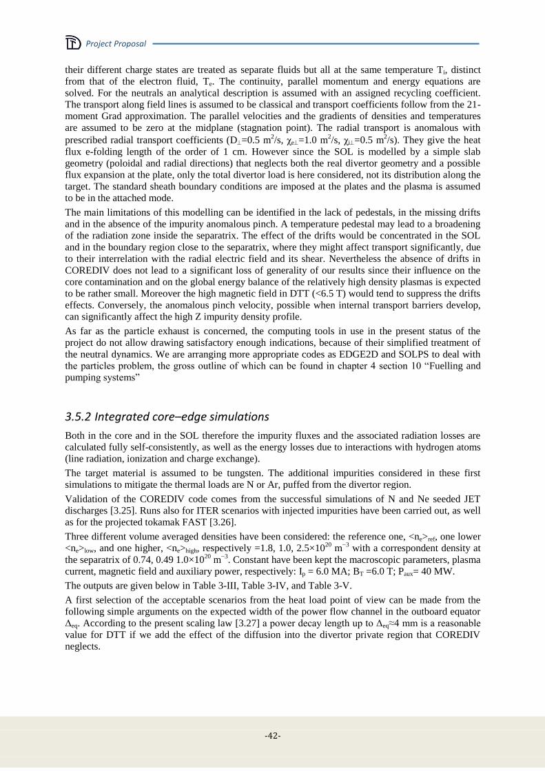
Project Proposal
-42-
their different charge states are treated as separate fluids but all at the same temperature Ti, distinct
from that of the electron fluid, Te. The continuity, parallel momentum and energy equations are
solved. For the neutrals an analytical description is assumed with an assigned recycling coefficient.
The transport along field lines is assumed to be classical and transport coefficients follow from the 21-
moment Grad approximation. The parallel velocities and the gradients of densities and temperatures
are assumed to be zero at the midplane (stagnation point). The radial transport is anomalous with
prescribed radial transport coefficients (D=0.5 m2/s, χe=1.0 m
2/s, χi=0.5 m
2/s). They give the heat
flux e-folding length of the order of 1 cm. However since the SOL is modelled by a simple slab
geometry (poloidal and radial directions) that neglects both the real divertor geometry and a possible
flux expansion at the plate, only the total divertor load is here considered, not its distribution along the
target. The standard sheath boundary conditions are imposed at the plates and the plasma is assumed
to be in the attached mode.
The main limitations of this modelling can be identified in the lack of pedestals, in the missing drifts
and in the absence of the impurity anomalous pinch. A temperature pedestal may lead to a broadening
of the radiation zone inside the separatrix. The effect of the drifts would be concentrated in the SOL
and in the boundary region close to the separatrix, where they might affect transport significantly, due
to their interrelation with the radial electric field and its shear. Nevertheless the absence of drifts in
COREDIV does not lead to a significant loss of generality of our results since their influence on the
core contamination and on the global energy balance of the relatively high density plasmas is expected
to be rather small. Moreover the high magnetic field in DTT (<6.5 T) would tend to suppress the drifts
effects. Conversely, the anomalous pinch velocity, possible when internal transport barriers develop,
can significantly affect the high Z impurity density profile.
As far as the particle exhaust is concerned, the computing tools in use in the present status of the
project do not allow drawing satisfactory enough indications, because of their simplified treatment of
the neutral dynamics. We are arranging more appropriate codes as EDGE2D and SOLPS to deal with
the particles problem, the gross outline of which can be found in chapter 4 section 10 “Fuelling and
pumping systems”
3.5.2 Integrated core–edge simulations
Both in the core and in the SOL therefore the impurity fluxes and the associated radiation losses are
calculated fully self-consistently, as well as the energy losses due to interactions with hydrogen atoms
(line radiation, ionization and charge exchange).
The target material is assumed to be tungsten. The additional impurities considered in these first
simulations to mitigate the thermal loads are N or Ar, puffed from the divertor region.
Validation of the COREDIV code comes from the successful simulations of N and Ne seeded JET
discharges [3.25]. Runs also for ITER scenarios with injected impurities have been carried out, as well
as for the projected tokamak FAST [3.26].
Three different volume averaged densities have been considered: the reference one, <ne>ref, one lower
<ne>low, and one higher, <ne>high, respectively =1.8, 1.0, 2.5×10²⁰
m−3
with a correspondent density at
the separatrix of 0.74, 0.49 1.0×10²⁰
m−3
. Constant have been kept the macroscopic parameters, plasma
current, magnetic field and auxiliary power, respectively: Ip = 6.0 MA; BT =6.0 T; Paux= 40 MW.
The outputs are given below in Table 3-III, Table 3-IV, and Table 3-V.
A first selection of the acceptable scenarios from the heat load point of view can be made from the
following simple arguments on the expected width of the power flow channel in the outboard equator
Δeq. According to the present scaling law [3.27] a power decay length up to Δeq≈4 mm is a reasonable
value for DTT if we add the effect of the diffusion into the divertor private region that COREDIV
neglects.
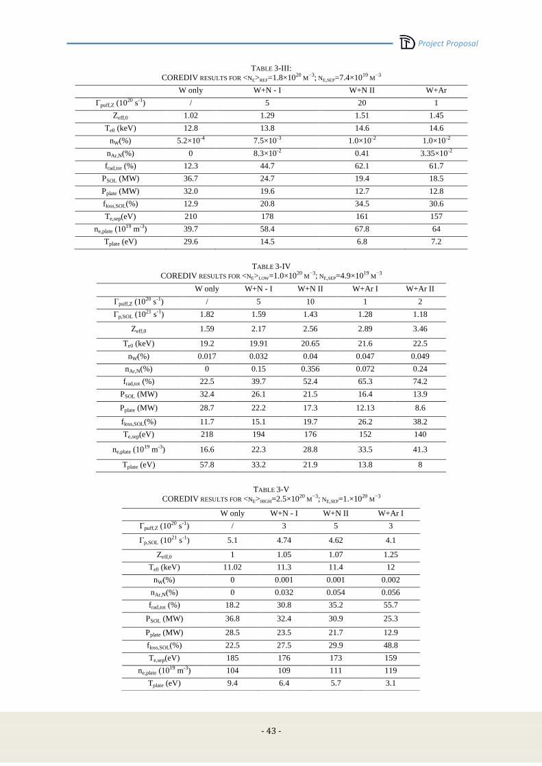
Project Proposal
- 43 -
TABLE 3-III:
COREDIV RESULTS FOR <NE>REF=1.8×10²⁰ M
−3; NE,SEP=7.4×10¹⁹ M
−3
W only W+N - I W+N II W+Ar
Γpuff,Z (1020 s-1) / 5 20 1
Zeff,0 1.02 1.29 1.51 1.45
Te0 (keV) 12.8 13.8 14.6 14.6
nW(%) 5.2×10⁻⁴ 7.5×10⁻³ 1.0×10⁻² 1.0×10⁻²
nAr,N(%) 0 8.3×10⁻² 0.41 3.35×10⁻²
frad,tot (%) 12.3 44.7 62.1 61.7
PSOL (MW) 36.7 24.7 19.4 18.5
Pplate (MW) 32.0 19.6 12.7 12.8
floss,SOL(%) 12.9 20.8 34.5 30.6
Te,sep(eV) 210 178 161 157
ne,plate (1019 m-3) 39.7 58.4 67.8 64
Tplate (eV) 29.6 14.5 6.8 7.2
TABLE 3-IV
COREDIV RESULTS FOR <NE>LOW=1.0×10²⁰ M
−3; NE,SEP=4.9×10¹⁹ M
−3
W only W+N - I W+N II W+Ar I W+Ar II
Γpuff,Z (1020 s-1) / 5 10 1 2
Γp,SOL (1021 s-1) 1.82 1.59 1.43 1.28 1.18
Zeff,0 1.59 2.17 2.56 2.89 3.46
Te0 (keV) 19.2 19.91 20.65 21.6 22.5
nW(%) 0.017 0.032 0.04 0.047 0.049
nAr,N(%) 0 0.15 0.356 0.072 0.24
frad,tot (%) 22.5 39.7 52.4 65.3 74.2
PSOL (MW) 32.4 26.1 21.5 16.4 13.9
Pplate (MW) 28.7 22.2 17.3 12.13 8.6
floss,SOL(%) 11.7 15.1 19.7 26.2 38.2
Te,sep(eV) 218 194 176 152 140
ne,plate (1019 m-3) 16.6 22.3 28.8 33.5 41.3
Tplate (eV) 57.8 33.2 21.9 13.8 8
TABLE 3-V
COREDIV RESULTS FOR <NE>HIGH=2.5×10²⁰ M
−3; NE,SEP=1.×1020 M
−3
W only W+N - I W+N II W+Ar I
Γpuff,Z (1020 s-1) / 3 5 3
Γp,SOL (1021 s-1) 5.1 4.74 4.62 4.1
Zeff,0 1 1.05 1.07 1.25
Te0 (keV) 11.02 11.3 11.4 12
nW(%) 0 0.001 0.001 0.002
nAr,N(%) 0 0.032 0.054 0.056
frad,tot (%) 18.2 30.8 35.2 55.7
PSOL (MW) 36.8 32.4 30.9 25.3
Pplate (MW) 28.5 23.5 21.7 12.9
floss,SOL(%) 22.5 27.5 29.9 48.8
Te,sep(eV) 185 176 173 159
ne,plate (1019 m-3) 104 109 111 119
Tplate (eV) 9.4 6.4 5.7 3.1
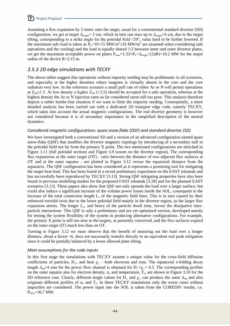
Project Proposal
-44-
Assuming a flux expansion by 5 times onto the target, usual for a conventional standard divertor (SD)
configuration, we get at target Δtarget= 2 cm, which in turn can rises up to Δtarget≈6 cm, due to the target
tilting, corresponding to a strike angle for the poloidal field ≈20°, value hard to be further lowered. If
the maximum safe load is taken as PL=10÷15 MW/m2
(10 MW/m2 are assumed when considering safe
operations and the cooling) and the load is equally shared 1:2 between inner and outer divertor plates,
we get the maximum acceptable power on plates Pmax=1.33×PL×Δtarget×(2πR)=16.2 MW for the major
radius of the device R=2.15 m.
3.5.3 2D edge simulations with TECXY
The above tables suggest that operations without impurity seeding may be problematic in all scenarios,
and especially at the higher densities where tungsten is virtually absent in the core and the core
radiation very low. In the reference scenario a small puff rate of either Ar or N will permit operations
at Zeff≤1.5. At low density a higher Zeff (>2.5) should be accepted for a safe operation, whereas at the
highest density the Ar or N injection rates so far considered seem still too poor. This analysis therefore
depicts a rather border-line situation if we want to limit the impurity seeding. Consequently, a more
detailed analysis has been carried out with a dedicated 2D transport edge code, namely TECXY,
which takes into account the actual magnetic configurations. The real divertor geometry is however
not considered because it is of secondary importance in the simplified description of the neutral
dynamics.
Considered magnetic configurations: quasi snow flake (QSF) and standard divertor (SD)
We have investigated both a conventional SD and a version of an advanced configuration named quasi
snow-flake (QSF) that modifies the divertor magnetic topology by introducing of a secondary null in
the poloidal field not far from the primary X point. The two mentioned configurations are sketched in
Figure 3.11 (full poloidal section) and Figure 3.9 (zoom on the divertor region). The corresponding
flux expansions at the outer target (OT) - ratio between the distance of two adjacent flux surfaces at
OT and at the outer equator - are plotted in Figure 3.12 versus the equatorial distance from the
separatrix. The QSF configuration has been considered as it represents a promising tool for mitigating
the target heat load. This has been found in a recent preliminary experiment on the EAST tokamak and
has successfully been reproduced by TECXY [3.13]. Strong QSF mitigating properties have also been
found in previous modelling studies for the proposed FAST tokamak [3.28] and for the planned EAST
scenarios [3.13]. These papers also show that QSF not only spreads the load over a larger surface, but
could also induce a significant increase of the volume power losses inside the SOL, consequent to the
increase of the total connection length Lc of the magnetic field lines. This is in turn caused by their
enhanced toroidal twist due to the lower poloidal field mainly in the divertor region, as the larger flux
expansion attests. The longer Lc, and hence of the particle dwell time, favour the dissipative inter-
particle interactions. This QSF is only a preliminary and not yet optimized version, developed mainly
for testing the system flexibility of the system in producing alternative configurations. For example,
the primary X point is still too near to the targets, as presently conceived, and the flux surfaces expand
on the inner target (IT) much less than on OT.
Turning to Figure 3.12 we must observe that the benefit of smearing out the load over a longer
distance, about a factor ≈6, does not necessarily transfer directly to an equivalent real peak mitigation
since it could be partially balanced by a lower allowed plate tilting.
Main assumptions for the code inputs
In this first stage the simulations with TECXY assume a unique value for the cross-field diffusion
coefficients of particles, D, and heat - both electrons and ions. The equatorial e-folding decay
length Δeq≈4 mm for the power flow channel is obtained for D== 0.5. The corresponding profiles
on the outer equator also for electron density, ne and temperature, Te, are shown in Figure 3.10 for the
SD reference case. Clearly, different single values for D and can produce the same Δeq and also
originate different profiles of ne and Te. In these TECXY simulations only the worst cases without
impurities are considered. The power input into the SOL is taken from the COREDIV results, i.e.
PSOL=36.7 MW.
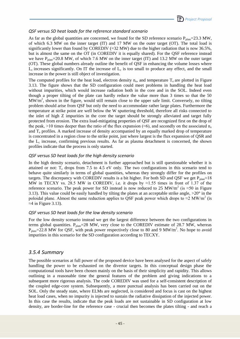
Project Proposal
- 45 -
QSF versus SD heat loads for the reference standard scenario
As far as the global quantities are concerned, we found for the SD reference scenario Pplate=23.3 MW,
of which 6.3 MW on the inner target (IT) and 17 MW on the outer target (OT). The total load is
significantly lower than found by COREDIV (=32 MW) due to the higher radiation that is now 36.5%,
but is almost the same on the OT (in COREDIV it is equally shared). For the QSF reference instead
we have Pplate=20.8 MW, of which 7.6 MW on the inner target (IT) and 13.2 MW on the outer target
(OT). These global numbers already outline the benefit of QSF in enhancing the volume losses where
Lc increases significantly. On IT the increase of Lc is too small to produce any effect, and the small
increase in the power is still object of investigation.
The computed profiles for the heat load, electron density ne, and temperature Te are plotted in Figure
3.13. The figure shows that the SD configuration could meet problems in handling the heat load
without impurities, which would increase radiation both in the core and in the SOL. Indeed even
though a proper tilting of the plate can hardly reduce the value more than 3 times so that the 50
MW/m2, shown in the figure, would still remain close to the upper safe limit. Conversely, no tilting
problem should arise from QSF but only the need to accommodate rather large plates. Furthermore the
temperature at strike point are well below the W sputtering threshold, therefore all risks connected to
the inlet of high Z impurities in the core the target should be strongly alleviated and target fully
protected from erosion. The extra load-mitigating properties of QSF are recognized first on the drop of
the peak, >10 times deeper than the ratio of the flux expansion (≈6), and secondly on the associated ne
and Te profiles. A marked increase of density accompanied by an equally marked drop of temperature
is concentrated in a region close to the strike point, just where largest is the flux expansion of QSR and
the Lc increase, confirming previous results. As far as plasma detachment is concerned, the shown
profiles indicate that the process is only started.
QSF versus SD heat loads for the high density scenario
In the high density scenario, detachment is further approached but is still questionable whether it is
attained or not: Te drops from 7.5 to 4.5 eV only. The two configurations in this scenario tend to
behave quite similarly in terms of global quantities, whereas they strongly differ for the profiles on
targets. The discrepancy with COREDIV results is a bit higher. For both SD and QSF we get Pplate≈18
MW in TECXY vs. 28.5 MW in COREDIV, i.e. it drops by ≈1.55 times in front of 1.37 of the
reference scenario. The peak power for SD instead is now reduced to 25 MW/m2 (is ≈50 in Figure
3.13). This value could be easily handled by tilting the plates at an acceptable strike angle, >20° in the
poloidal plane. Almost the same reduction applies to QSF peak power which drops to ≈2 MW/m2 (is
≈4 in Figure 3.13).
QSF versus SD heat loads for the low density scenario
For the low density scenario instead we get the largest difference between the two configurations in
terms global quantities. Pplate=28 MW, very close to the COREDIV estimate of 28.7 MW, whereas
Pplate=22.8 MW for QSF, with peak power respectively close to 80 and 9 MW/m2. No hope to avoid
impurities in this scenario for the SD configuration according to TECXY.
3.5.4 Summary
The possible scenarios at full power of the proposed device have been analysed for the aspect of safely
handling the power to be exhausted on the divertor targets. In this conceptual design phase the
computational tools have been chosen mainly on the basis of their simplicity and rapidity. This allows
outlining in a reasonable time the general features of the problem and giving indications to a
subsequent more rigorous analysis. The code COREDIV was used for a self-consistent description of
the coupled edge-core system. Subsequently, a more punctual analysis has been carried out on the
SOL. Only the steady state, where ELMs are neglected, is considered and focus is cast on the highest
heat load cases, when no impurity is injected to sustain the radiative dissipation of the injected power.
In this case the results, indicate that the peak loads are not sustainable in SD configuration at low
density, are border-line for the reference case - crucial then becomes the plates tilting - and reach a
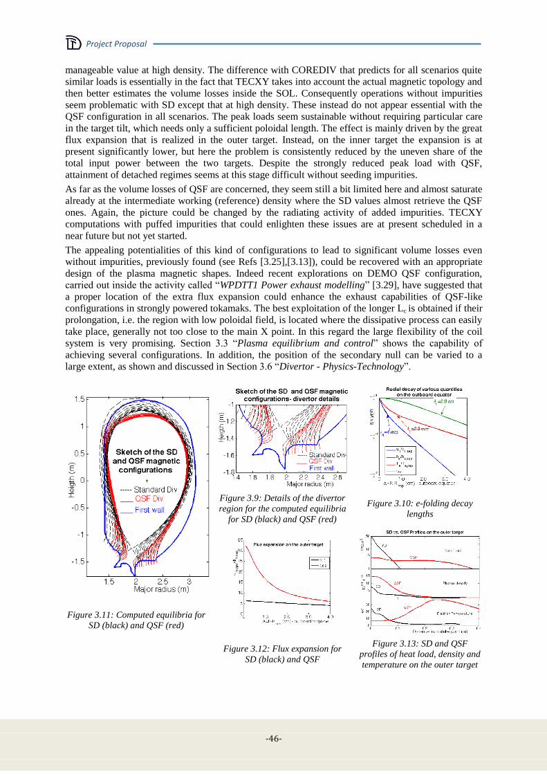
Project Proposal
-46-
manageable value at high density. The difference with COREDIV that predicts for all scenarios quite
similar loads is essentially in the fact that TECXY takes into account the actual magnetic topology and
then better estimates the volume losses inside the SOL. Consequently operations without impurities
seem problematic with SD except that at high density. These instead do not appear essential with the
QSF configuration in all scenarios. The peak loads seem sustainable without requiring particular care
in the target tilt, which needs only a sufficient poloidal length. The effect is mainly driven by the great
flux expansion that is realized in the outer target. Instead, on the inner target the expansion is at
present significantly lower, but here the problem is consistently reduced by the uneven share of the
total input power between the two targets. Despite the strongly reduced peak load with QSF,
attainment of detached regimes seems at this stage difficult without seeding impurities.
As far as the volume losses of QSF are concerned, they seem still a bit limited here and almost saturate
already at the intermediate working (reference) density where the SD values almost retrieve the QSF
ones. Again, the picture could be changed by the radiating activity of added impurities. TECXY
computations with puffed impurities that could enlighten these issues are at present scheduled in a
near future but not yet started.
The appealing potentialities of this kind of configurations to lead to significant volume losses even
without impurities, previously found (see Refs [3.25],[3.13]), could be recovered with an appropriate
design of the plasma magnetic shapes. Indeed recent explorations on DEMO QSF configuration,
carried out inside the activity called “WPDTT1 Power exhaust modelling” [3.29], have suggested that
a proper location of the extra flux expansion could enhance the exhaust capabilities of QSF-like
configurations in strongly powered tokamaks. The best exploitation of the longer Lc is obtained if their
prolongation, i.e. the region with low poloidal field, is located where the dissipative process can easily
take place, generally not too close to the main X point. In this regard the large flexibility of the coil
system is very promising. Section 3.3 “Plasma equilibrium and control” shows the capability of
achieving several configurations. In addition, the position of the secondary null can be varied to a
large extent, as shown and discussed in Section 3.6 “Divertor - Physics-Technology”.
Figure 3.9: Details of the divertor
region for the computed equilibria
for SD (black) and QSF (red)
Figure 3.10: e-folding decay
lengths
Figure 3.11: Computed equilibria for
SD (black) and QSF (red)
Figure 3.12: Flux expansion for
SD (black) and QSF
Figure 3.13: SD and QSF
profiles of heat load, density and
temperature on the outer target
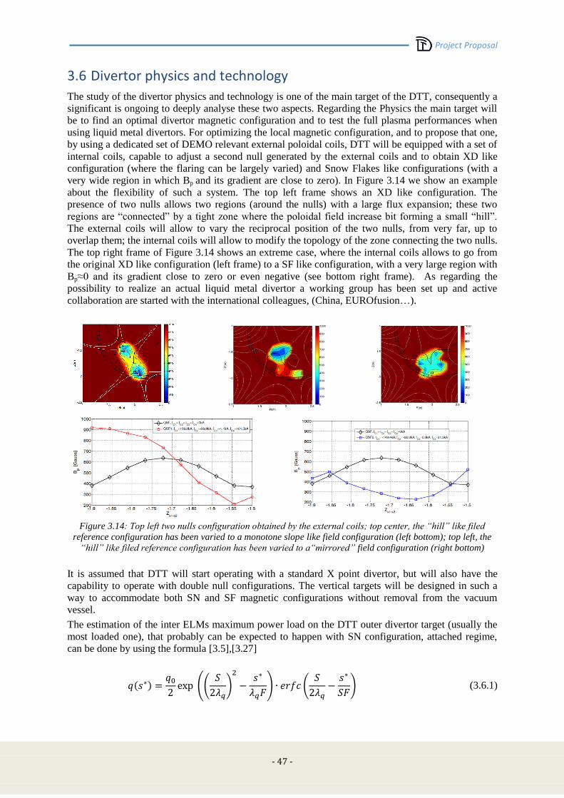
Project Proposal
- 47 -
3.6 Divertor physics and technology
The study of the divertor physics and technology is one of the main target of the DTT, consequently a
significant is ongoing to deeply analyse these two aspects. Regarding the Physics the main target will
be to find an optimal divertor magnetic configuration and to test the full plasma performances when
using liquid metal divertors. For optimizing the local magnetic configuration, and to propose that one,
by using a dedicated set of DEMO relevant external poloidal coils, DTT will be equipped with a set of
internal coils, capable to adjust a second null generated by the external coils and to obtain XD like
configuration (where the flaring can be largely varied) and Snow Flakes like configurations (with a
very wide region in which Bp and its gradient are close to zero). In Figure 3.14 we show an example
about the flexibility of such a system. The top left frame shows an XD like configuration. The
presence of two nulls allows two regions (around the nulls) with a large flux expansion; these two
regions are “connected” by a tight zone where the poloidal field increase bit forming a small “hill”.
The external coils will allow to vary the reciprocal position of the two nulls, from very far, up to
overlap them; the internal coils will allow to modify the topology of the zone connecting the two nulls.
The top right frame of Figure 3.14 shows an extreme case, where the internal coils allows to go from
the original XD like configuration (left frame) to a SF like configuration, with a very large region with
Bp≈0 and its gradient close to zero or even negative (see bottom right frame). As regarding the
possibility to realize an actual liquid metal divertor a working group has been set up and active
collaboration are started with the international colleagues, (China, EUROfusion…).
Figure 3.14: Top left two nulls configuration obtained by the external coils; top center, the “hill” like filed
reference configuration has been varied to a monotone slope like field configuration (left bottom); top left, the
“hill” like filed reference configuration has been varied to a“mirrored” field configuration (right bottom)
It is assumed that DTT will start operating with a standard X point divertor, but will also have the
capability to operate with double null configurations. The vertical targets will be designed in such a
way to accommodate both SN and SF magnetic configurations without removal from the vacuum
vessel.
The estimation of the inter ELMs maximum power load on the DTT outer divertor target (usually the
most loaded one), that probably can be expected to happen with SN configuration, attached regime,
can be done by using the formula [3.5],[3.27]
(3.6.1)
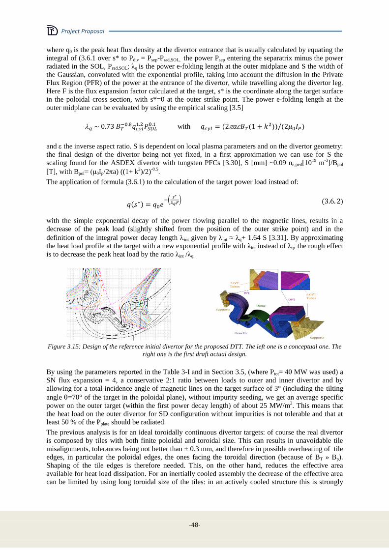
Project Proposal
-48-
where q0 is the peak heat flux density at the divertor entrance that is usually calculated by equating the
integral of (3.6.1 over s* to Pdiv = Psep-Prad,SOL, the power Psep entering the separatrix minus the power
radiated in the SOL, Prad,SOL; λq is the power e-folding length at the outer midplane and S the width of
the Gaussian, convoluted with the exponential profile, taking into account the diffusion in the Private
Flux Region (PFR) of the power at the entrance of the divertor, while travelling along the divertor leg.
Here F is the flux expansion factor calculated at the target, s* is the coordinate along the target surface
in the poloidal cross section, with s*=0 at the outer strike point. The power e-folding length at the
outer midplane can be evaluated by using the empirical scaling [3.5]
with
and the inverse aspect ratio. S is dependent on local plasma parameters and on the divertor geometry:
the final design of the divertor being not yet fixed, in a first approximation we can use for S the
scaling found for the ASDEX divertor with tungsten PFCs [3.30], S [mm] ~0.09 ne,ped[1019
m-3
]/Bpol
[T], with Bpol= (μ0Ip/2a) ((1+ k2)/2)
-0.5.
The application of formula (3.6.1) to the calculation of the target power load instead of:
)
with the simple exponential decay of the power flowing parallel to the magnetic lines, results in a
decrease of the peak load (slightly shifted from the position of the outer strike point) and in the
definition of the integral power decay length int given by λint ≈ λq+ 1.64 S [3.31]. By approximating
the heat load profile at the target with a new exponential profile with λint instead of λq, the rough effect
is to decrease the peak heat load by the ratio λint /λq.
Figure 3.15: Design of the reference initial divertor for the proposed DTT. The left one is a conceptual one. The
right one is the first draft actual design.
By using the parameters reported in the Table 3-I and in Section 3.5, (where Ptot= 40 MW was used) a
SN flux expansion = 4, a conservative 2:1 ratio between loads to outer and inner divertor and by
allowing for a total incidence angle of magnetic lines on the target surface of 3° (including the tilting
angle =70° of the target in the poloidal plane), without impurity seeding, we get an average specific
power on the outer target (within the first power decay length) of about 25 MW/m2. This means that
the heat load on the outer divertor for SD configuration without impurities is not tolerable and that at
least 50 % of the Pplate should be radiated.
The previous analysis is for an ideal toroidally continuous divertor targets: of course the real divertor
is composed by tiles with both finite poloidal and toroidal size. This can results in unavoidable tile
misalignments, tolerances being not better than ± 0.3 mm, and therefore in possible overheating of tile
edges, in particular the poloidal edges, the ones facing the toroidal direction (because of BT » Bp).
Shaping of the tile edges is therefore needed. This, on the other hand, reduces the effective area
available for heat load dissipation. For an inertially cooled assembly the decrease of the effective area
can be limited by using long toroidal size of the tiles: in an actively cooled structure this is strongly

Project Proposal
- 49 -
constrained by the need of optimizing the heat exchange with the coolant. A careful analysis will be
carried out for defining the best tile shaping to be adopted (a work still in progress for ITER too).
As for the central part of the divertor assembly, a dome will be inserted. Its presence is motivated by
the need of providing a neutral pressure suitable for effective pumping and of limiting the backflow of
neutrals towards the vacuum chamber, besides the one of protecting the underneath structures (coils,
diagnostic etc.). The supporting structure of the dome will be semi-transparent to allow the transit of
the neutrals created by the ion flux impinging on the vertical targets.
The technology used for manufacturing the components of the divertor is the Hot Radial Pressing
(HRP), already chosen for the inner vertical target of the ITER divertor. The plasma facing
components will be monoblocks of Tungsten capable to tolerate at least a power flux of 20MW/m2. In
Figure 3.15 we show a sketch of the design of such a divertor. This type of divertor will be the first
one to be mounted on the DTT. It has been designed (Section 4.6) to permit experiments with a
standard X point configuration and to perform quasi-Snowflake experiments. Once the different
magnetic topologies will be tested and verified, a divertor optimized for the most promising of them
will be realized.
3.7 ELMs and disruptions
ELMs energy depends from the total energy stored in the plasma pedestal (at the maximum, in a good
H, around 40% of the total volume averaged energy) and it is inversely proportional to the local
collisionality. Of course, the total stored energy is directly proportional to the plasma volume.
Consequently, there is no possibility, on a scaled experiment, to have ELMs with energies comparable
to the ones on a large volume reactor. However, since the DTT will have a pretty low local
collisionality (in a high density regime, like in a reactor) and a meaningful ELMs energy (≈1MJ), this
will allow to study ELM mitigation strategies in conditions relevant to DEMO. Presently it is under
study the use of error field internal coils (with n=1÷2) to moderate the ELM amplitude; however, since
this technique could be not used in DEMO, other strategies are under investigations (vertical kicks,
pellets, local heating…), in order to achieve situation with lower ELM amplitude and higher
frequency.
The design of every high performance tokamak is strongly influenced by the foreseen number and
severity of the off-normal plasma termination events, by the evaluation of the EM and thermal loads
associated with these events and by the mitigation strategies provided to cope with them. Indeed the
development of the operational scenario and the design of Vacuum Vessel (VV) and in-vessel
components are driven by the kind and number of these unexpected but likely events: among them the
greater EM and thermal loads are due to plasma Major Disruptions (MD) and Vertical Displacement
Events (VDE) followed by plasma Thermal and Current Quenches (TQ and CQ).
According to Codes and Standards for ITER [3.32] and Design and Construction Rules for Mechanical
Components of Nuclear Installations (RCC-MR) [3.33], the following four categories of event
occurrence are defined:
I – Operational;
II – Likely;
III – Unlikely;
IV – Extremely unlikely.
The following four criteria level can be also identified [3.32], [3.33] to specify the damage level in
consequence of an event for a given safety class:
A – Negligible damage, all systems are functional.
B – Negligible damage, all systems are functional but minor adjustments might be required.
C – Possible significant local distortion.
Project Proposal
-50-
D – Possible large general distortion and investment loss.
A general rule states that criteria level A should be applied to events in category I and II, criteria level
C to category III and criteria level D to category IV.
Suitable strategies will be put in place to reduce the risk of plasma disruptions, by designing safe
operation scenarios with density and safety factor within the limits. However, when operating at high
plasma current as in DTT, an additional risk to have a sudden disruption event arises, related to an
increase of interaction among MHD modes [3.34]. This class of disruptions can be observed when the
plasma inductance is relatively high for a given safety factor and cause high forces on the machine,
due to the high currents involved [3.34]. That should be considered in defining the probability of
occurrence of the different disruption events.
In elongated, high performance tokamak machines like DTT the EM loads produced by VDEs are by
far the largest loads among those the VV must withstand and then will be used to assess its structural
integrity. Two category IV event has been defined for DTT as upward or downward VDEs occurring
at the end of the flat top, with the maximum plasma current and thermal energy, and evolving to the
largest possible plasma vertical displacement without thermal losses until the safety factor at 95% flux
surface goes below 1.5, when the TQ and the fast CQ arise. This event is the worst expected accidental
event for the DTT VV integrity, due to the large vertical and horizontal EM loads produced by the
vertically and toroidally asymmetric eddy and halo currents.
This event has been modelled with both MAXFEA [3.35] and Carma0NL [3.36] codes. In these
simulations the plasma is initially displaced by a sudden current “kick” by one of the poloidal field
coil and then is left free to evolve, slowly moving upward or downward in the VV and shrinking in
volume. The plasma is partially stabilized in its movement by the eddy currents induced on the plasma
chamber, with a characteristic vertical instability growth time, about 20 ms in DTT for a 50 mm thick
SS VV. While the plasma column moves and shrinks, the safety factor drops off and the plasma
current slowly decreases due to the poloidal flux conservation. During its movement the plasma
interact with the First Wall (FW) or other in-vessel components, resulting in the cooling of the plasma
edge and providing a path for the poloidal current to flow from plasma into the vessel and then again
to the plasma on open field lines which are in thermal contact with the wall. In this phase some
unstable modes can arise destabilizing the plasma and resulting in a sudden loss of its thermal energy,
the TQ. The chance of arising unstable modes increases dramatically as the safety factor at the edge
decreases, and the severity of the EM loads during a VDE largely depends on the value of the safety
factor at the TQ, that is directly related to the vertical asymmetry of the induced currents on the vessel
and then to the vertical forces applied to the VV. The occurrence of unstable modes is unavoidable
when the safety factor at the edge goes below 2, so this event has been chosen as worst possible EM
accident for the VV integrity and assigned to category IV faults, due to its fast (few ms) transfer to the
chamber of the whole plasma thermal and magnetic energy with the largest vertical and possibly
toroidal asymmetry. After the TQ, the cold plasma has a relatively high resistivity, so the available
poloidal flux is not enough to balance the energy dissipated as Joule effect in the plasma column and
then the plasma begins to lose its current in the CQ phase. The CQ duration is variable and its
minimum can be roughly extrapolated from experience in other machines, as in the ITER Physics
Basis [3.37], using the pre-disruption plasma poloidal area. In DTT the minimum CQ duration (from
80% to 20% of the initial plasma current) with this scaling is 4.7 ms. Figure 3.16 shows the time
evolution of the main plasma macroscopic parameters during the Category IV upward VDE as
modelled in MAXFEA.
The induced (eddy and halo) current during the different plasma disruptions and the EM loads on the
VV have been evaluated using MAXFEA and Carma0NL and will be used as input for the structural
assessment of the machine in the next phase of the design. The detailed 3D evaluations carried out by
Carma0NL are reported in Section 4.4.4: Carma0NL simulation results were recently compared with
experimental data from EAST [3.38] and with MAXFEA simulations [3.39]. Figure 3.17 shows the
vertical forces on the VV due to the halo and eddy current in the worst case, i.e. during the Category
IV upward VDE, as evaluated by MAXFEA.
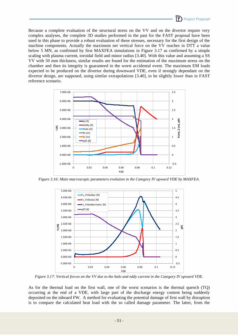
Project Proposal
- 51 -
Because a complete evaluation of the structural stress on the VV and on the divertor require very
complex analyses, the complete 3D studies performed in the past for the FAST proposal have been
used in this phase to provide a robust evaluation of these stresses, necessary for the first design of the
machine components. Actually the maximum net vertical force on the VV reaches in DTT a value
below 5 MN, as confirmed by first MAXFEA simulations in Figure 3.17 as confirmed by a simple
scaling with plasma current, toroidal field and minor radius [3.40]. With this value and assuming a SS
VV with 50 mm thickness, similar results are found for the estimation of the maximum stress on the
chamber and then its integrity is guaranteed in the worst accidental event. The maximum EM loads
expected to be produced on the divertor during downward VDE, even if strongly dependant on the
divertor design, are supposed, using similar extrapolations [3.40], to be slightly lower than in FAST
reference scenario.
Figure 3.16: Main macroscopic parameters evolution in the Category IV upward VDE by MAXFEA.
Figure 3.17: Vertical forces on the VV due to the halo and eddy current in the Category IV upward VDE.
As for the thermal load on the first wall, one of the worst scenarios is the thermal quench (TQ)
occurring at the end of a VDE, with large part of the discharge energy content being suddenly
deposited on the inboard FW. A method for evaluating the potential damage of first wall by disruption
is to compare the calculated heat load with the so called damage parameter. The latter, from the
-0.5
0
0.5
1
1.5
2
2.5
3
3.5
-1.00E+06
0.00E+00
1.00E+06
2.00E+06
3.00E+06
4.00E+06
5.00E+06
6.00E+06
7.00E+06
0 0.02 0.04 0.06 0.08 0.1 0.12
R (
m),
Z (
m),
q9
5
I (A
)
t (s)
Ip [A]
Ieddy [A]
Ihalo [A]
Rc [m]
Zc [m]
q95 [#]
-0.5
0
0.5
1
1.5
2
2.5
3
3.5
4
4.5
5
-5.00E+05
0.00E+00
5.00E+05
1.00E+06
1.50E+06
2.00E+06
2.50E+06
3.00E+06
3.50E+06
4.00E+06
4.50E+06
5.00E+06
0 0.02 0.04 0.06 0.08 0.1 0.12
q9
5
Fz (
N)
t (s)
Fz_VV(eddy) [N]
Fz_VV(halo) [N]
Fz_VV(eddy+halo) [N]
q95 [#]
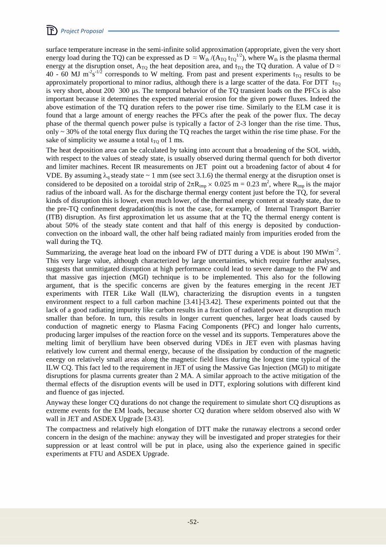
Project Proposal
-52-
surface temperature increase in the semi-infinite solid approximation (appropriate, given the very short
energy load during the TQ) can be expressed as D ≈ Wth /(ATQ tTQ1/2
), where Wth is the plasma thermal
energy at the disruption onset, ATQ the heat deposition area, and tTQ the TQ duration. A value of D ≈
40 - 60 MJ m-2
s-1/2
corresponds to W melting. From past and present experiments tTQ results to be
approximately proportional to minor radius, although there is a large scatter of the data. For DTT tTQ
is very short, about 200 300 μs. The temporal behavior of the TQ transient loads on the PFCs is also
important because it determines the expected material erosion for the given power fluxes. Indeed the
above estimation of the TQ duration refers to the power rise time. Similarly to the ELM case it is
found that a large amount of energy reaches the PFCs after the peak of the power flux. The decay
phase of the thermal quench power pulse is typically a factor of 2-3 longer than the rise time. Thus,
only ~ 30% of the total energy flux during the TQ reaches the target within the rise time phase. For the
sake of simplicity we assume a total tTQ of 1 ms.
The heat deposition area can be calculated by taking into account that a broadening of the SOL width,
with respect to the values of steady state, is usually observed during thermal quench for both divertor
and limiter machines. Recent IR measurements on JET point out a broadening factor of about 4 for
VDE. By assuming q steady state ~ 1 mm (see sect 3.1.6) the thermal energy at the disruption onset is
considered to be deposited on a toroidal strip of 2Rimp 0.025 m = 0.23 m2, where Rimp is the major
radius of the inboard wall. As for the discharge thermal energy content just before the TQ, for several
kinds of disruption this is lower, even much lower, of the thermal energy content at steady state, due to
the pre-TQ confinement degradation(this is not the case, for example, of Internal Transport Barrier
(ITB) disruption. As first approximation let us assume that at the TQ the thermal energy content is
about 50% of the steady state content and that half of this energy is deposited by conduction-
convection on the inboard wall, the other half being radiated mainly from impurities eroded from the
wall during the TQ.
Summarizing, the average heat load on the inboard FW of DTT during a VDE is about 190 MWm2
.
This very large value, although characterized by large uncertainties, which require further analyses,
suggests that unmitigated disruption at high performance could lead to severe damage to the FW and
that massive gas injection (MGI) technique is to be implemented. This also for the following
argument, that is the specific concerns are given by the features emerging in the recent JET
experiments with ITER Like Wall (ILW), characterizing the disruption events in a tungsten
environment respect to a full carbon machine [3.41]-[3.42]. These experiments pointed out that the
lack of a good radiating impurity like carbon results in a fraction of radiated power at disruption much
smaller than before. In turn, this results in longer current quenches, larger heat loads caused by
conduction of magnetic energy to Plasma Facing Components (PFC) and longer halo currents,
producing larger impulses of the reaction force on the vessel and its supports. Temperatures above the
melting limit of beryllium have been observed during VDEs in JET even with plasmas having
relatively low current and thermal energy, because of the dissipation by conduction of the magnetic
energy on relatively small areas along the magnetic field lines during the longest time typical of the
ILW CQ. This fact led to the requirement in JET of using the Massive Gas Injection (MGI) to mitigate
disruptions for plasma currents greater than 2 MA. A similar approach to the active mitigation of the
thermal effects of the disruption events will be used in DTT, exploring solutions with different kind
and fluence of gas injected.
Anyway these longer CQ durations do not change the requirement to simulate short CQ disruptions as
extreme events for the EM loads, because shorter CQ duration where seldom observed also with W
wall in JET and ASDEX Upgrade [3.43].
The compactness and relatively high elongation of DTT make the runaway electrons a second order
concern in the design of the machine: anyway they will be investigated and proper strategies for their
suppression or at least control will be put in place, using also the experience gained in specific
experiments at FTU and ASDEX Upgrade.
Project Proposal
- 53 -
3.8 Operations, diagnostics and control
Operations, diagnostics and control are tightly linked by the necessity in modern experiments of
driving safely long pulses while acquiring adequate data for the scientific analysis. Diagnostics and
control systems are indeed among the most important components of the experiment. The specific
mission of DTT is to study a viable solution for handling the power exhaust in view of DEMO and
therefore an emphasis is to be put on the diagnostics that are necessary in order to address the physics
and control issues of the heat flow, particle flow and in particular impurity transport in the plasma
edge. Also the plasma core deserve however an adequate attention as the experiment to be successful
requires that the power is dissipated without affecting significantly the confinement properties of the
main plasma. In Section 4.16 the present foreseen diagnostics system is described in some details. A
set of fundamental diagnostic has been selected for both the development of the scientific basis of the
experiment, the protection of machine and stable operation of the discharge under robust real time
control of several parameters simultaneously. The compatibility of such diagnostics with the present
machine design has been verified particularly with regard to the geometry. Electromagnetic and
radiation compatibility as well as the integration of those systems with the experiment will be studied
in the specific design phases. At this stage the set of basic diagnostics for the plasma core include:
Magnetic diagnostics; Independent density and temperature measurements; Measurements of the
collective flow; Effective Charge from visible Bremmsstrahlung; Total radiation, Soft X-Rays and line
radiation to characterise the impurity content and its dynamics; Neutron and gamma radiation
diagnostics; Runaway electron diagnostics basically for machine protection and also for studies on RE
effects mitigation. The divertor region is where the most relevant diagnostics concentrate. In this
region, the nature of the problem requires that 2D and 3D characterisation of the main processes in
pursued wherever possible. Langmuir probes and retarding field probes will measure ion and electron
temperature, electron density, particle fluxes and electromagnetic turbulence level in order to analyse
the way heat is channelled through the divertor; besides embedded Langmuir probes and magnetic
probes a reciprocating system will provide spatial information. Infrared Cameras and thermocouples
will measure surface and bulk temperature of the plasma facing components and it spatial distribution.
Two-dimensional measurement of the radiation pattern by means of bolometer arrays, together with
CCD cameras and spectrometers with imaging capability will characterize impurities and their
transport and in particular the position of the ionisation front and therefore the level of plasma
detachment. Survey visible cameras will highlight the presence of hot spots for machine detection.
CCDs can be used also for plasma position.
Time and space resolution are ordinary for most of the diagnostics but for those which characterize the
heat flow to the divertor plates, which have to resolve the heat flow around the divertor legs and the
ELM's dynamics. Possibility of remote maintenance, such as cleaning of mirrors of optical
diagnostics by lasers or replacement of broken parts by remote handling, is part of the specifications of
crucial diagnostics. Active feedback control of the plasma state represents a key element for stationary
tokamak operation and will become essential in future reactors. In DEMO, plasma control is one of the
most critical issues and therefore one key objective of DTT will be to test plasma control via a limited
set of diagnostic systems compatible with a DEMO-like environment. In modern approaches to plasma
feedback control an increasing role is assumed by the physics models, whose prediction capabilities
provide optimal trajectories for the actuators and offer also trustable knowledge of physical quantities
that may not be available because difficult to measure or because of faulty diagnostics. From the early
phases of their realization and of the machine design the real time predictive capabilities of models,
the diagnostic systems, the actuators and the feedback control will be conceived in an integrated way.
Besides testing new diagnostics, the development of smart models to be used in the real time control
system will be one of the major areas of R&D that will accompany DTT. Real time control aspects
may be divided in two big blocks: plant control and plasma control. Plasma control assures that the
plasma trajectory remains well inside the operational boundaries and includes primarily control of
plasma current, density, shape, vertical stabilization, radial control in the presence of H-L transition,
Beta control, ELMs and NTM control, H mode control to minimize or avoid back transitions, power
exhaust control (divertor topology control and detachment control).

Project Proposal
-54-
The Plant Control system implies critical real time functions that mitigate the risk of machine damage
by well defining the operational space limits of each plant component and the way systems must react
to unforeseen failures or anomalies of the plant components, including diagnostics systems.
Approaching operational limits, entering plasma regimes characterized by high disruption risks or with
risk of overloading some plant components, triggers the shutting down of parts of the plant and starts
appropriate experiment termination strategies in order to minimize damages and/or loss of
experimental time. A number of real time diagnostics systems are required for safe machine operation,
including plasma equilibrium, detection of PFC temperatures, hot spot recognition, ionization front in
the divertor, disruption precursors, runaway beams, control of spurious electric field connected with
ICRH antennas, NBI shinethrough and Fast Ion Losses.
Real time plasma control and plant protections are based on an infrastructure that has been conceived
according to modern schemes and tools that collectively allow automating the operation of the DTT
device in a safe way. The whole infrastructure including control room mimics and computers, data
storage and data processing computers, communication networks, and servers to automate the
management of plant system, their operation and control, has been conceptually designed and is
shortly described in Section 4.16
3.9 Additional heating and current drive
The additional heating in a machine like the DTT, mainly designed to study the power exhaust and the
divertor load, has the main target to provide the necessary heating to simulate the SOL power flow in a
reactor, where the nuclear reactions provide the heating source. Since any possible solution of the
power exhaust issues must be compatible with high performance bulk plasma and reactor relevant
scenarios, the additional heating must guarantee the necessary PSEP/R and a reliable plasma heating
capable to simulate as much as possible the reactor situation. As it is possible to extrapolate by Table
3-I, about 40÷45 MW of total heating should be able to guarantee the reactor relevant figure of
PSEP/R≈15MW/m. In order to guarantee a robust and reliable heating (mainly heating the electrons, as
the alpha particles), it seems effective to choose a mix of the three heating systems presently proposed
also for ITER. This could assure a wide flexibility in scenario development and the necessary
availability of power.
A system of installed 18MW of ECRH at 170 GHz should be able to provide 15 MW at plasma for
several tasks, such as:
bulk electron heating to bring the plasma in the high confinement regime;
current profile tailoring during plasma ramp-up by moderate but localized CD;
pulse length extension by assisting current ramp-up reducing the transformer flux
consumption;
control of central impurity accumulation, avoiding unstable hollow temperature profiles;
sawtooth control by localized CD, in order to avoid NTM seeding;
NTM control to assure plasma stability in high beta scenarios.
Plasma termination control, avoiding disruption during the current ramp-down phase
In order to fulfil these requirements, the design of the system should be enough flexible to guarantee
the power absorption, its localization and control. Nevertheless, being the scope of DTT mainly
devoted to power exhaust studies, only a partial flexibility in EC beam steering during the pulse is
foreseen, letting the possibility to change the deposition location and CD shot by shot. The only
launcher with real time control capability is that devoted to NTM control, as described in Section 4.9.
Together with the EC system, since the beginning 15MW of ICRH (around 60-90MHz) can provide
the remaining bulk plasma heating, on both electrons and ions. ICRH is also a useful tool for a heating
scheme acting like the alpha particles, but with an isotropic perpendicular fast ion distribution.
The most suitable schemes based on ICRH are 3He minority heating, H minority heating and
Deuterium 2nd harmonic. 3He minority is preferable for bulk heating, whereas H minority may mostly
heat the tails of the hydrogen distribution function. Minority concentrations in the range 2% – 10% are
adequate for such operations; higher concentrations would incur significant mode conversion at the

Project Proposal
- 55 -
hybrid two-ions resonance. The operational schemes do not dictate particular requirements on
launched power spectra, which can be symmetrical and broad.
Eventually 15MW of NBI could provide a mainly isotropic parallel fast ion distribution that, together
with the ICRH could allow to simulate the alpha heating scheme of a reactor. NBI Heating primary
aim is to reliably support central plasma heating during the main phase of the plasma confinement. On
the other hand, NBI system parameters should also minimize the risk of shine through and for this
reason its use during early current ramp-up and late current ramp-down should be carefully evaluated.
The necessity of central power deposition and the minimization of the shine through risk suggest a
beam energy around 300keV. The power will be absorbed both by electrons and by ions. In addition to
plasma heating, NBI can support plasma current sustainment; for this purpose a dedicated port (see
chap 4) will allow a tangential (45º on the plasma axis) injection.
The full planned power will not be necessary from the very beginning of the machine experimental
activity (see Table 3-V). Initially 25MW coupled with the plasma will be installed (15MW ICRH plus
10 MW ECRH); on the contrary, all the heating “logistic” it will be realized from the very beginning
in order to permit an easy upgrade of the heating along the machine life. The final choice of the
heating mixing scheme will be decided on a later time, even during the machine lifetime, by taking in
account the experience gained during the first phase.
3.10 Scientific program
As underlined in Sec. 3.1, the final target of the DTT facility is to find out the optimal solution for the
power exhaust problem in view of DEMO. Since, presently, there is not a unique solution to be tested
and verified, DTT, along its life, should be able to study as much as possible different concepts
presently under consideration, as well as other possible new ideas that could come out along the years.
This fact, as we have stressed in the previous sections, leads to the strong constraints to realize a very
flexible machine. The electron density, even when far from the Greenwald limit, is in any case
relatively high (in DEMO relevant regimes with low collisionality), allowing to easily sustains highly
radiative scenarios with and without impurity seeding by means of a FW realized by using reactor
relevant materials. The presence of a number of small internal coils will allow to easily test a large set
of different divertor magnetic configurations, including the strike points sweeping and the plasma
wobbling. The large ports and the large space available in the bottom and the top of the machine will
permit to change the divertor easily, allowing for different divertor geometries (including an up-down
symmetric divertor) and materials (including liquid metals). The different heating schemes planned
will allow to test them under DEMO relevant conditions, and the preferential use of the electron
heating will allow to be more relevant in simulating reactor conditions, also from the point of view of
the power exhaust issues. The closeness of the plasma bulk parameters to the DEMO/ITER ones will
guarantee that any solution for the power exhaust will work in DEMO without degrading the plasma
performances. This long, not exhaustive list describing the available DTT experimental possibilities,
is, by itself, giving an idea about the complexity of working out a long term scientific program.
Clearly, a scientific program so ambitious and interconnected cannot be performed on a short time
scale; on the contrary, it will require a very long period of scientific experimentation with several
different campaigns and shut downs, to allow for the necessary maintenance, refurbishment and
installation of new or different hardware. Consequently, for all these reasons, it is practically
impossible to define accurately the long time scientific program. However, we strongly believe that, in
an important and large experimental facility like this, it is mandatory to define, from the very
beginning, an “ideal” scientific program; this program has to start with “robust” milestones and
proceed along the years with some check points, to verify the milestones achieved and to decide the
next steps to update the detailed scientific program in order to best fit the final solution of the power
exhaust.
In Table 3-VI a possible schedule of the scientific exploitation is shown. It is an "ideal" schedule. in
the sense that it would be the optimal timing assuming no delay due to any particular occurrence. The
actual schedule, along the time, will try to fit this one, taking in account all the experimental
necessities. As usual the first operational period (about 6 months) will be devoted to the
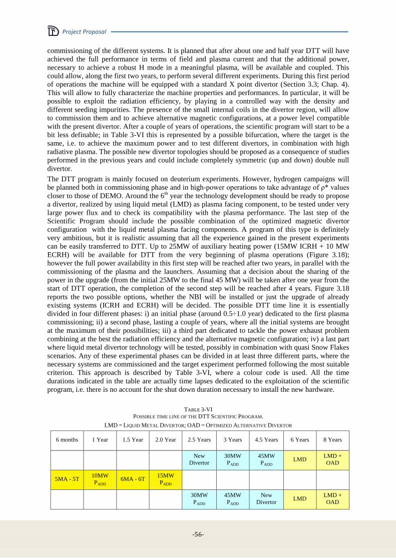
Project Proposal
-56-
commissioning of the different systems. It is planned that after about one and half year DTT will have
achieved the full performance in terms of field and plasma current and that the additional power,
necessary to achieve a robust H mode in a meaningful plasma, will be available and coupled. This
could allow, along the first two years, to perform several different experiments. During this first period
of operations the machine will be equipped with a standard X point divertor (Section 3.3; Chap. 4).
This will allow to fully characterize the machine properties and performances. In particular, it will be
possible to exploit the radiation efficiency, by playing in a controlled way with the density and
different seeding impurities. The presence of the small internal coils in the divertor region, will allow
to commission them and to achieve alternative magnetic configurations, at a power level compatible
with the present divertor. After a couple of years of operations, the scientific program will start to be a
bit less definable; in Table 3-VI this is represented by a possible bifurcation, where the target is the
same, i.e. to achieve the maximum power and to test different divertors, in combination with high
radiative plasma. The possible new divertor topologies should be proposed as a consequence of studies
performed in the previous years and could include completely symmetric (up and down) double null
divertor.
The DTT program is mainly focused on deuterium experiments. However, hydrogen campaigns will
be planned both in commissioning phase and in high-power operations to take advantage of ρ* values
closer to those of DEMO. Around the 6th year the technology development should be ready to propose
a divertor, realized by using liquid metal (LMD) as plasma facing component, to be tested under very
large power flux and to check its compatibility with the plasma performance. The last step of the
Scientific Program should include the possible combination of the optimized magnetic divertor
configuration with the liquid metal plasma facing components. A program of this type is definitely
very ambitious, but it is realistic assuming that all the experience gained in the present experiments
can be easily transferred to DTT. Up to 25MW of auxiliary heating power (15MW ICRH + 10 MW
ECRH) will be available for DTT from the very beginning of plasma operations (Figure 3.18);
however the full power availability in this first step will be reached after two years, in parallel with the
commissioning of the plasma and the launchers. Assuming that a decision about the sharing of the
power in the upgrade (from the initial 25MW to the final 45 MW) will be taken after one year from the
start of DTT operation, the completion of the second step will be reached after 4 years. Figure 3.18
reports the two possible options, whether the NBI will be installed or just the upgrade of already
existing systems (ICRH and ECRH) will be decided. The possible DTT time line it is essentially
divided in four different phases: i) an initial phase (around 0.5÷1.0 year) dedicated to the first plasma
commissioning; ii) a second phase, lasting a couple of years, where all the initial systems are brought
at the maximum of their possibilities; iii) a third part dedicated to tackle the power exhaust problem
combining at the best the radiation efficiency and the alternative magnetic configuration; iv) a last part
where liquid metal divertor technology will be tested, possibly in combination with quasi Snow Flakes
scenarios. Any of these experimental phases can be divided in at least three different parts, where the
necessary systems are commissioned and the target experiment performed following the most suitable
criterion. This approach is described by Table 3-VI, where a colour code is used. All the time
durations indicated in the table are actually time lapses dedicated to the exploitation of the scientific
program, i.e. there is no account for the shut down duration necessary to install the new hardware.
TABLE 3-VI
POSSIBLE TIME LINE OF THE DTT SCIENTIFIC PROGRAM.
LMD = LIQUID METAL DIVERTOR; OAD = OPTIMIZED ALTERNATIVE DIVERTOR
6 months 1 Year 1.5 Year 2.0 Year 2.5 Years 3 Years 4.5 Years 6 Years 8 Years
New
Divertor
30MW
PADD
45MW
PADD LMD
LMD +
OAD
5MA - 5T 10MW
PADD 6MA - 6T
15MW
PADD
30MW
PADD
45MW
PADD
New
Divertor LMD
LMD +
OAD

Project Proposal
- 57 -
Figure 3.18: DTT Auxiliary Power availability. After around one year a decision on the final power upgrade is
assumed between two possible options: a) installation of NBI + RF increase; b) increase of both EC and IC.
Obviously there is no indication about the starting year, but assuming that the operations will start in
the early 2020s, even with some delay in the successful planning described in Table 3-VI, the machine
could be not only important for the design of DEMO, but also play an important role in supporting the
ITER experiments (for instance ELMs and disruptions control could be tested on a machine with
physics parameters very close to the ITER ones).
TABLE 3-VII
POSSIBLE SCIENTIFIC PROGRAM, WITHIN ANY OF THE FOUR EXPERIMENTAL PHASES DESCRIBED IN TABLE 3-VI
Research Targets Initial
Commiss. Phase 1 Phase 2 Integration
Liquid
Metal
System commissioning
Plasma break down
Set. of shape and vert. control for target Ip
Plasma shut down for the diff. phases
Wall cond. in long disch.
Setting of the integr. contr.
Addit. power coupling
Reference H mode
Radiation control
Full power
Exhaust studies of standard X point
Realization of quasi SF (QSF) scenarios
Use of the internal coils on QSF scenarios
Max. poss. heating on QSF scenarios
Integration of QSF and radiation
Power exhaust on dedicated new divertor
Liquid metal divertor (LMD) charact.
LMD at full power
QSF scenarios on LMD

Project Proposal
-58-
3.11 References [3.1] Lackner K., Com. Plas. Phys. Control. Fusion, 15, 359 (1994)
[3.2] Hutchinson I. H., Nucl. Fus., 36, 783 (1996)
[3.3] Whyte D. G. Fusion Eng. Des. 87, 234 (2012)
[3.4] LaBombard D., Nucl. Fus., 55, 053020 (2015)
[3.5] Heich T., Nucl. Fus., 53 093031 (2013)
[3.6] Lackner K., Fus. Scien. and Techn., 54, 989 (2008)
[3.7] Kadomtsev B. B., Fiz. Plazmy, 1, 531 (1975)
[3.8] Pizzuto A., Nucl. Fusion 50, 095005 (2010)
[3.9] Zohm H., Fusion Science and Techn. 58 (2010) 613
[3.10] Metis, CEA/IRFM/PHY/NTT-2008.001 (2008)
[3.11] Stankiewicz R., J. Nucl. Mater.191, 337 (2005)
[3.12] Ryutov D.D., Phys. Plasmas 14 (2007) 064502
[3.13] Calabro’ G., et al., to appear NF 2015 NF-100496.R2
[3.14] Kotschenreuther M., et al., Phys. Plasmas 14 (2007) 72502
[3.15] Kotschenreuther M., et al., Phys. Plasmas 20 (2013) 102507
[3.16] Valanju P.M., et al, Phys. Plasmas16 (2009) 0561107
[3.17] Telesca G., et al., J, Nucl. Materials 438, Supplement, July 2013, S567
[3.18] Mattei, M., et al., “CREATE-NL+: a Robust Control-Oriented Free Boundary Dynamic Plasma
Equilibrium Solver”, presented at 28th Symposium on Fusion Technology, San Sebastian, Spain (2014),
P1.036
[3.19] Alladio F., Crisanti F., Nucl. Fusion 26 (1986) 1143
[3.20] Sartori R, et al., Plasma Physics and Controlled Fusion 40 (1998) 757
[3.21] Albanese R., et al., 2005 Fusion Engineering and Design 74 627–632
[3.22] Kirk A. et al., Journal of Physics: Conference Series 123 (2008) 012011
[3.23] Horacek J. et al, to be presented at the 42nd
EPS Conference on Plasma Physics (Lisbon, Jun 22nd
–
26th
,2015)
[3.24] Cordey J. G. et al., Plasma Phys. Control. Fusion 39 (1997) B115–B127
[3.25] Zagórski R. et al.,Contrib. Plasma Phys. 48 179-84 and J. Nucl. Mater. 390-391 404
[3.26] Pericoli Ridolfini V. et al.,Fus. Eng. Des 88 (2013) 1677-1681
[3.27] Eich T. et al., Phys. Rev. Lett.107 (2011) 215001
[3.28] Pericoli Ridolfini V. et al., J. Nucl. Mat. 438 (2013) S414–S417.
[3.29] PericoliRidolfiniV.presentation at WPDTT1_Meetings-AC-4 - 22 April 2015
[3.30] Sieglin B. et al., Plasma Phys. Control. Fusion 55 (2013) 124039
[3.31] Makowski M., Phys. Plasma 19 056122 2012
[3.32] Codes and Standards for ITER Mechanical Components, v4.0, ITER_D_25EW4K, 21/06/2012.
[3.33] Design and Construction Rules for Mechanical Components of Nuclear Installations, RCC-MR, French
Association for the Design, Construction and Operating Supervision of the Equipment for Electro-
Nuclear boilers (AFCEN), 2007.
[3.34] VannucciA. and Gill R.D.,Nucl.Fusion 31 (1991) 1127.
[3.35] Barabaschi P., “The MAXFEA code”, Plasma Cont. Techn. meeting, Naka (Japan), 1993
[3.36] Villone F. et al., Plasma Phys. Control. Fusion 55 (2013) 095008.
[3.37] Hender T. C. et al.,Nucl. Fusion 47 (2007) S128-S202.
[3.38] Chen S. L. et al., Nucl.Fusion 55 (2015) 013010.
[3.39] Villone F. et al., Fus. Eng. Des. 93(2015) 57–68.
[3.40] Sorbom B. N. et al., “ARC: A compact, high-field, fusion nuclear science facility and demonstration
power plant with demountable magnets”, arXiv:1409.3540 (2014).
[3.41] De VriesP. C. et al., Plasma Phys. Control. Fusion 54 (2012) 124032.

Project Proposal
- 59 -
[3.42] Lehnen M. et al.,Nucl. Fusion 53 (2013) 093007.
[3.43] Neu R. et al., IEEE Trans. on Plasma Science, 42 (2013) 552 – 562.


Project Proposal
- 61 -
Chapter 4
DTT PROPOSAL
4.1 Magnets
In this section the main DTT magnet system characteristics (Figure 4.1) are presented.
The DTT magnet system design is based on Cable-In-Conduit Conductors (CICCs), made of Low
Temperature Superconducting (LTS) materials, as Nb3Sn and NbTi, copper and stainless steel.
Figure 4.1: The DTT magnet system.
It consists of:
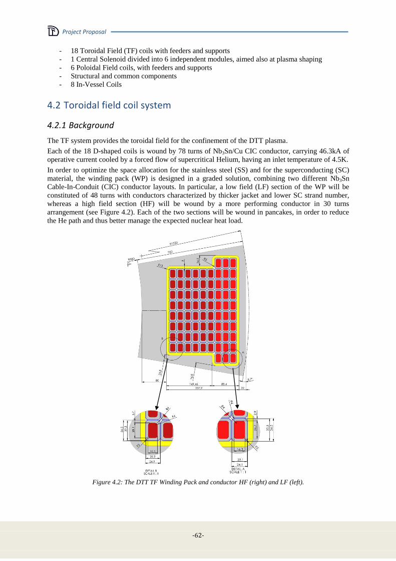
Project Proposal
-62-
- 18 Toroidal Field (TF) coils with feeders and supports
- 1 Central Solenoid divided into 6 independent modules, aimed also at plasma shaping
- 6 Poloidal Field coils, with feeders and supports
- Structural and common components
- 8 In-Vessel Coils
4.2 Toroidal field coil system
4.2.1 Background
The TF system provides the toroidal field for the confinement of the DTT plasma.
Each of the 18 D-shaped coils is wound by 78 turns of Nb3Sn/Cu CIC conductor, carrying 46.3kA of
operative current cooled by a forced flow of supercritical Helium, having an inlet temperature of 4.5K.
In order to optimize the space allocation for the stainless steel (SS) and for the superconducting (SC)
material, the winding pack (WP) is designed in a graded solution, combining two different Nb3Sn
Cable-In-Conduit (CIC) conductor layouts. In particular, a low field (LF) section of the WP will be
constituted of 48 turns with conductors characterized by thicker jacket and lower SC strand number,
whereas a high field section (HF) will be wound by a more performing conductor in 30 turns
arrangement (see Figure 4.2). Each of the two sections will be wound in pancakes, in order to reduce
the He path and thus better manage the expected nuclear heat load.
Figure 4.2: The DTT TF Winding Pack and conductor HF (right) and LF (left).
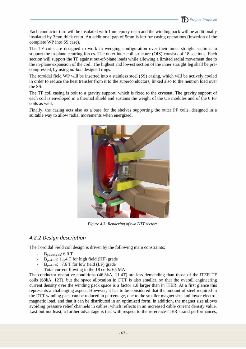
Project Proposal
- 63 -
Each conductor turn will be insulated with 1mm epoxy resin and the winding pack will be additionally
insulated by 3mm thick resin. An additional gap of 5mm is left for casing operations (insertion of the
complete WP into SS case).
The TF coils are designed to work in wedging configuration over their inner straight sections to
support the in-plane centring forces. The outer inter-coil structure (OIS) consists of 18 sections. Each
section will support the TF against out-of-plane loads while allowing a limited radial movement due to
the in-plane expansion of the coil. The highest and lowest section of the inner straight leg shall be pre-
compressed, by using ad-hoc designed rings.
The toroidal field WP will be inserted into a stainless steel (SS) casing, which will be actively cooled
in order to reduce the heat transfer from it to the superconductors, linked also to the neutron load over
the SS.
The TF coil casing is bolt to a gravity support, which is fixed to the cryostat. The gravity support of
each coil is enveloped in a thermal shield and sustains the weight of the CS modules and of the 6 PF
coils as well.
Finally, the casing acts also as a base for the shelves supporting the outer PF coils, designed in a
suitable way to allow radial movements when energized.
Figure 4.3: Rendering of two DTT sectors.
4.2.2 Design description
The Toroidal Field coil design is driven by the following main constraints:
- Bplasma-axis: 6.0 T
- Bpeak-HF: 11.4 T for high field (HF) grade
- Bpeak-LF: 7.6 T for low field (LF) grade
- Total current flowing in the 18 coils: 65 MA
The conductor operative conditions (46.3kA, 11.4T) are less demanding than those of the ITER TF
coils (68kA, 12T), but the space allocation in DTT is also smaller, so that the overall engineering
current density over the winding pack space is a factor 1.8 larger than in ITER. At a first glance this
represents a challenging aspect. However, it has to be considered that the amount of steel required in
the DTT winding pack can be reduced in percentage, due to the smaller magnet size and lower electro-
magnetic load, and that it can be distributed in an optimized form. In addition, the magnet size allows
avoiding pressure relief channels in cables, which reflects in an increased cable current density value.
Last but not least, a further advantage is that with respect to the reference ITER strand performances,
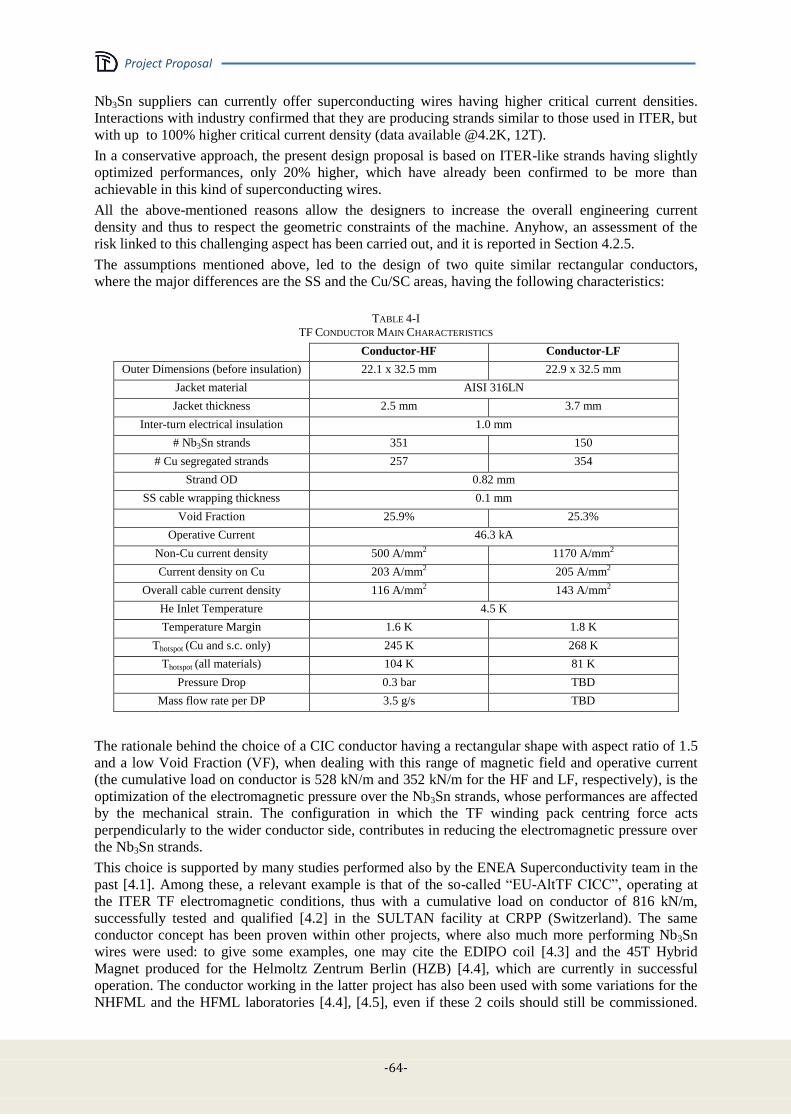
Project Proposal
-64-
Nb3Sn suppliers can currently offer superconducting wires having higher critical current densities.
Interactions with industry confirmed that they are producing strands similar to those used in ITER, but
with up to 100% higher critical current density (data available @4.2K, 12T).
In a conservative approach, the present design proposal is based on ITER-like strands having slightly
optimized performances, only 20% higher, which have already been confirmed to be more than
achievable in this kind of superconducting wires.
All the above-mentioned reasons allow the designers to increase the overall engineering current
density and thus to respect the geometric constraints of the machine. Anyhow, an assessment of the
risk linked to this challenging aspect has been carried out, and it is reported in Section 4.2.5.
The assumptions mentioned above, led to the design of two quite similar rectangular conductors,
where the major differences are the SS and the Cu/SC areas, having the following characteristics:
TABLE 4-I
TF CONDUCTOR MAIN CHARACTERISTICS
Conductor-HF Conductor-LF
Outer Dimensions (before insulation) 22.1 x 32.5 mm 22.9 x 32.5 mm
Jacket material AISI 316LN
Jacket thickness 2.5 mm 3.7 mm
Inter-turn electrical insulation 1.0 mm
# Nb3Sn strands 351 150
# Cu segregated strands 257 354
Strand OD 0.82 mm
SS cable wrapping thickness 0.1 mm
Void Fraction 25.9% 25.3%
Operative Current 46.3 kA
Non-Cu current density 500 A/mm2 1170 A/mm2
Current density on Cu 203 A/mm2 205 A/mm2
Overall cable current density 116 A/mm2 143 A/mm2
He Inlet Temperature 4.5 K
Temperature Margin 1.6 K 1.8 K
Thotspot (Cu and s.c. only) 245 K 268 K
Thotspot (all materials) 104 K 81 K
Pressure Drop 0.3 bar TBD
Mass flow rate per DP 3.5 g/s TBD
The rationale behind the choice of a CIC conductor having a rectangular shape with aspect ratio of 1.5
and a low Void Fraction (VF), when dealing with this range of magnetic field and operative current
(the cumulative load on conductor is 528 kN/m and 352 kN/m for the HF and LF, respectively), is the
optimization of the electromagnetic pressure over the Nb3Sn strands, whose performances are affected
by the mechanical strain. The configuration in which the TF winding pack centring force acts
perpendicularly to the wider conductor side, contributes in reducing the electromagnetic pressure over
the Nb3Sn strands.
This choice is supported by many studies performed also by the ENEA Superconductivity team in the
past [4.1]. Among these, a relevant example is that of the so-called “EU-AltTF CICC”, operating at
the ITER TF electromagnetic conditions, thus with a cumulative load on conductor of 816 kN/m,
successfully tested and qualified [4.2] in the SULTAN facility at CRPP (Switzerland). The same
conductor concept has been proven within other projects, where also much more performing Nb3Sn
wires were used: to give some examples, one may cite the EDIPO coil [4.3] and the 45T Hybrid
Magnet produced for the Helmoltz Zentrum Berlin (HZB) [4.4], which are currently in successful
operation. The conductor working in the latter project has also been used with some variations for the
NHFML and the HFML laboratories [4.4], [4.5], even if these 2 coils should still be commissioned.
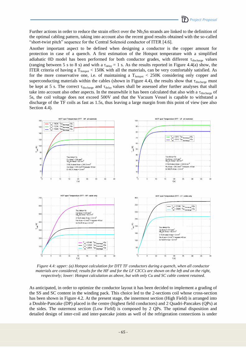
Project Proposal
- 65 -
Further actions in order to reduce the strain effect over the Nb3Sn strands are linked to the definition of
the optimal cabling pattern, taking into account also the recent good results obtained with the so-called
“short-twist pitch” sequence for the Central Solenoid conductor of ITER [4.6].
Another important aspect to be defined when designing a conductor is the copper amount for
protection in case of a quench. A first estimation of the Hotspot temperature with a simplified
adiabatic 0D model has been performed for both conductor grades, with different discharge values
(ranging between 5 s to 8 s) and with adelay = 1 s. As the results reported in Figure 4.4(a) show, the
ITER criteria of having a Thotspot < 150K with all the materials, can be very comfortably satisfied. As
for the more conservative one, i.e. of maintaining a Thotspot < 250K considering only copper and
superconducting materials within the cables (shown in Figure 4.4), the results show that discharge must
be kept at 5 s. The correct discharge and delay values shall be assessed after further analyses that shall
take into account also other aspects. In the meanwhile it has been calculated that also with a discharge of
5s, the coil voltage does not exceed 500V and that the Vacuum Vessel is capable to withstand a
discharge of the TF coils as fast as 1.5s, thus leaving a large margin from this point of view (see also
Section 4.4).
Figure 4.4: upper: (a) Hotspot calculation for DTT TF conductors during a quench, when all conductor
materials are considered; results for the HF and for the LF CICCs are shown on the left and on the right,
respectively; lower: Hotspot calculation as above, but with only Cu and SC cable content retained.
As anticipated, in order to optimize the conductor layout it has been decided to implement a grading of
the SS and SC content in the winding pack. This choice led to the 2-sections coil whose cross-section
has been shown in Figure 4.2. At the present stage, the innermost section (High Field) is arranged into
a Double-Pancake (DP) placed in the centre (highest field conductors) and 2 Quadri-Pancakes (QPs) at
the sides. The outermost section (Low Field) is composed by 2 QPs. The optimal disposition and
detailed design of inter-coil and inter-pancake joints as well of the refrigeration connections is under

Project Proposal
-66-
study: as it could be inferred from Figure 4.3 it is foreseen to place them in the outboard region, where
there is much room availability and lower magnetic field.
Being the employed hydraulic lengths very short (33 m and 66 m for the HF section and 140 m in the
LF section), the first thermo-hydraulic analyses confirmed that there’s no need for a pressure relief
channel, so it has not been foreseen in the present design.
The main characteristics of the TF coils are summarized the following table:
TABLE 4-II
TF CONDUCTOR MAIN CHARACTERISTICS
# turns 78
# DPs / QPs 1 / 4
# layers 9
Ground insulation 8 mm
Inductance (1 TF coil) 35 mH
Inductance (18 TF coil system) 1.5 H
DP / QP lengths 66 m / 132 m / 280 m
Hydraulic lengths 33 m / 66 m / 140 m
Mass flow rate (18 coils) 250 g/s
Conductor length for 1 WP 890 m
Total TF conductor length 16 km
Total Nb3Sn strand length 6800 km
Total Cu strand length 9900 km
Casing material AISI 316L
Weight of 1 TF coil 13 tons
Overall TF coil system weight 235 tons
4.2.3 Operating conditions
TF magnetic field analysis
Magnetic field calculations by the 3D TOSCA code have been carried out on the TF coil system to
define and verify the soundness of the WP area definition, in terms of current density and maximum
magnetic field. The outcomes of these simulations have been also used as inputs to determine the
magnetic load during the mechanical analyses.
In Figure 4.5 the model used for magnetic field evaluation is reported. The operative TF coil current
(3.6 MA per coil) has been spread over the WP section, which has been modelled by 2 current
carrying elements, one representing the HF and the other one the LF section.
The requested field on plasma axis has been verified to be 6.0 T.
Bpeak on TF coil resulted to be 11.44T on the inner TF coil leg. The maximum field over the LF section
is 7.6 T.
In Figure 4.5 a map showing magnetic field distribution inside torus volume is shown (plasma is not
included).
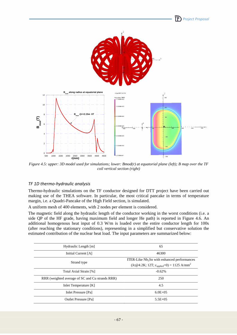
Project Proposal
- 67 -
0
2
4
6
8
10
12
500 1000 1500 2000 2500 3000 3500 4000 4500
Bmod
along radius at equatorial plane
Bm
od(T
)
r(mm)
Bmod
@r=2.15m 6T
Figure 4.5: upper: 3D model used for simulations; lower: Bmod(r) at equatorial plane (left); B map over the TF
coil vertical section (right)
TF 1D thermo-hydraulic analysis
Thermo-hydraulic simulations on the TF conductor designed for DTT project have been carried out
making use of the THEA software. In particular, the most critical pancake in terms of temperature
margin, i.e. a Quadri-Pancake of the High Field section, is simulated.
A uniform mesh of 400 elements, with 2 nodes per element is considered.
The magnetic field along the hydraulic length of the conductor working in the worst conditions (i.e. a
side QP of the HF grade, having maximum field and longer He path) is reported in Figure 4.6. An
additional homogenous heat input of 0.3 W/m is loaded over the entire conductor length for 100s
(after reaching the stationary conditions), representing in a simplified but conservative solution the
estimated contribution of the nuclear heat load. The input parameters are summarized below:
Hydraulic Length [m] 65
Initial Current [A] 46300
Strand type ITER-Like Nb3Sn with enhanced performances
([email protected]; 12T; applied=0) = 1125 A/mm2
Total Axial Strain [%] -0.62%
RRR (weighted average of SC and Cu strands RRR) 250
Inlet Temperature [K] 4.5
Inlet Pressure [Pa] 6.0E+05
Outlet Pressure [Pa] 5.5E+05

Project Proposal
-68-
The temperature margin, Tmarg, defined as the difference of the current sharing temperature Tcs and
the conductor temperature Tcond, has been computed as a function of the hydraulic length at the end of
the 100 s heat input (EOB of the reference scenario); the result is plotted in Figure 4.7.
The minimum value is Tmarg= 1.2 K, at 60m that is the location in which the field is at its maximum
value (innermost layer facing plasma) and He has almost reached the maximum temperature along its
path.
The mass flow rate estimated in this configuration is 1.7 g/s, with a low pressure drop (0.3bar) related
to the short length of the hydraulic circuit; the heat transfer coefficient is about 420 W/m2K.
Figure 4.6: Magnetic field as a function of the
hydraulic length of the HF conductor
Figure 4.7: Temperature margin as a function of the
hydraulic length of the HF conductor
Further and more detailed analyses are requested, where all pancakes will be analysed in detail,
considering also the exact distribution of the nuclear heat load, and adding the contribution due to the
AC losses.
Even if no criticality seems to be present at the present design stage, the actual mass flow rate required
for correctly refrigerating the conductor shall be assessed in the future.
4.2.4 Mechanical loads
TF 3D mechanical analysis
Finite element 3D analysis of the DTT TF coil system has been performed energizing the 18 coils with
their operative current. At this stage of the project, no out-of-plane force has been considered, nor
cool-down effect, even if the material properties have been taken at 4.2K.
The assumed constraint conditions are: frictionless contact at cyclic symmetry surfaces; rigid vertical
gravity support to remove lability. Based on such assumptions, an overall 3D Finite Elements (FE)
model of the coil has been set-up, using a fine mesh with 49161 parabolic tetrahedral elements and
82606 nodes. The software tool used for stress analyses is NX Nastran 8, with the pre-post processor
FEMAP 10.3.
For all material properties, ITER values have been retained [4.7]. A homogenisation procedure has
been applied, to define the smeared material properties of the winding pack.
Electromagnetic load has been evaluated by calculating with the TOSCA code the magnetic field
components for an optimized data set of more than 3000 points in the TF winding pack; this dataset
has been then interpolated using an innovative and fully validated meshless approach, based on Radial
Basis Functions (RBF) [4.8]. This method allows for transforming the scattered data known at source
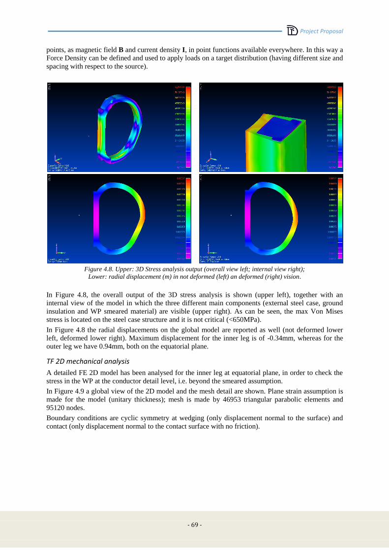
Project Proposal
- 69 -
points, as magnetic field B and current density I, in point functions available everywhere. In this way a
Force Density can be defined and used to apply loads on a target distribution (having different size and
spacing with respect to the source).
Figure 4.8. Upper: 3D Stress analysis output (overall view left; internal view right);
Lower: radial displacement (m) in not deformed (left) an deformed (right) vision.
In Figure 4.8, the overall output of the 3D stress analysis is shown (upper left), together with an
internal view of the model in which the three different main components (external steel case, ground
insulation and WP smeared material) are visible (upper right). As can be seen, the max Von Mises
stress is located on the steel case structure and it is not critical (<650MPa).
In Figure 4.8 the radial displacements on the global model are reported as well (not deformed lower
left, deformed lower right). Maximum displacement for the inner leg is of -0.34mm, whereas for the
outer leg we have 0.94mm, both on the equatorial plane.
TF 2D mechanical analysis
A detailed FE 2D model has been analysed for the inner leg at equatorial plane, in order to check the
stress in the WP at the conductor detail level, i.e. beyond the smeared assumption.
In Figure 4.9 a global view of the 2D model and the mesh detail are shown. Plane strain assumption is
made for the model (unitary thickness); mesh is made by 46953 triangular parabolic elements and
95120 nodes.
Boundary conditions are cyclic symmetry at wedging (only displacement normal to the surface) and
contact (only displacement normal to the contact surface with no friction).

Project Proposal
-70-
Figure 4.9: 2D model: global view (left), mesh detail (right).
In Figure 4.10 the 2D analysis output is shown (deformation and global Von Mises stresses).
Peak stress values of 830MPa, are present in very small and localized zones corresponding to the
jacket inner corner radius (Figure 4.10, upper right). This is not considered a critical issue, as there is
margin to reshape the conductor corner in the safe direction. It has been already verified by the authors
that increasing the corner radius implies a lowering of such stress peaks.
As can be seen in Figure 4.10 (lower), where the inner leg at equatorial plane outputs of 3D and 2D
are compared, max Von Mises stresses on steel case are in good agreement, confirming the reliability
of the model and the assumptions made.
Considering the outcomes of the mechanical analyses carried out, it can be stated that there’s no major
issue about the soundness, from the mechanical point of view, of the present TF coil design proposal.
Further and more complete analyses, including out-of-plane forces and cool-down effects, shall be
carried out to assess it.
Figure 4.10. Upper: (2D model) Von Mises stresses global view (left) and on conductor jacket (right). Lower:
Von Mises stresses in the TF inner leg at equatorial plane, from 3D (left) and 2D (right) analysis.
Project Proposal
- 71 -
4.2.5 TF coil design proposal: risk assessment
As already discussed in the previous sections, the present proposal for the DTT TF coils presents some
slightly innovative and challenging aspects with respect to machines which have been deeply studied
and are currently under construction, as for example ITER of JT-60SA.
This calls for an assessment of the associated risks:
From the point of view of the winding, the grading of the winding pack, with the subdivision
into two pancake-structured sections, needs to be further investigated, mainly because an
innovative layout of terminations and hydraulic connections at the coil outboard should be
implemented. However, thanks to the large space available in that region, once the engineering
studies will be detailed, no risk of coil failure is evaluated. The involvement in this phase of
industrial partners with experience on the winding of coils e.g. for JT-60SA, ITER, or W-7X,
will represent the main baseline to mitigate this risk.
As for the Cable-in-Conduit considered for the present design proposal, as it would work with
current densities higher than other projects, the following points are to be considered: as
outlined in Section 4.2.2, the conductor design concept has been fully validated over different
samples being tested in the more or less recent past. These results confirmed the main
guidelines developed to deal with the most critical issue of the Nb3Sn CICCs, i.e. the
performance degradation with electro-magnetic loading cycles (which is by the way less
relevant when speaking about TF coils, rather than in the CS ones, as they mainly work under
steady conditions). Anyhow, since this specific layout, designed to meet the DTT TF
requirements, has never been proven before, a verification campaign based on qualification
tests is envisaged to mitigate the associated risk. This will include:
o the confirmation of the performances of the procured ITER-like Nb3Sn strands with
slightly enhanced performances;
o the test under relevant electro-magnetic conditions of a full-size conductor length in
the SULTAN or EDIPO test facility for both HF and LF grade, to verify the strand-in-
conductor performances;
o the test of full-size joints according to the layouts that will be defined, in the relevant
conditions;
o to be evaluated is also the possibility to manufacture and test a conductor section in a
long-length coiled configuration, that would guarantee the verification of the
conductor behaviour in case of quench and when subject to a magnetic field
distribution more similar to that of the actual coil.
The impact of these activities on the possible machine construction schedule is negligible for
the points (a) to (c), as they should anticipate the global conductor and coil procurement
activities and they can be performed during the completion of the last executive design phases.
A different discussion should be dedicated to point (d), where the exact definition of the
characteristics of this “dummy” coil, could affect its construction and test schedule.
Should any of the previous qualification tests fail, which at the present stage is considered
very unlikely to happen, a downgrade of the coil performances is still possible. In particular it
is worth noting that a 5% reduction of the magnetic field on plasma axis, i.e. from 6.0 T to 5.7
T, that would not affect the project mission, would result in a reduction of the max magnetic
field on the conductors from 11.4 T to 10.8 T and from 7.6 T to 7.2 T on the HF and LF
grades, respectively. Considering the typical properties of Nb3Sn technological wires, this can
be translated into an increase in the current carrying capability of almost 20% and of about
10%, respectively. With a different perspective, this same magnetic field reduction would
cause an increase in temperature margin of about 0.5 K and of about 0.4 K for the HF and LF
grades, respectively.
Also to be noted is that with the proposed design, the DTT TF temperature margin (1.2K for
the HF, after loading the nuclear heat) is larger than the one retained, for example, in the ITER
TF coils, where 0.8 K are kept.

Project Proposal
-72-
4.2.6 Electrical loads
Inductance calculation of the TF coils system
To estimate the inductance values of the TF coils system, a 3D magneto-static simulation study in
COMSOL Multiphysics environment has been carried out. The software, using AC/DC module, solves
the magnetic fields surrounding the coils and calculates the inductances.
Geometry of this study is created in 3D space dimension and reported in Figure 4.11 and consists of
20 domains: one plasma domain; one air domain surrounding the TF coils and the remaining are coil
domains.
The effects of central solenoid (CS) and poloidal field (PF) coils are not considered in this first study.
As material of TF conductors and plasma region, it has been chosen to approximate them with copper,
having a conductivity σ = 5.998 E+07 S*m-1
, and air respectively. Each TF coil has been modelled
considering only the winding pack without casing, and for accurate results a fine mesh was created.
All coils are driven by a DC current Icoil = 46 kA with no plasma current (Iplasma = 0 ).
Figure 4.11: 3D view of complete TF coil system with a sphere positioned at origin of coordinate system and
having a radius of r = 10 m
Input parameters of each TF coil are reported in Table 4-III:
TABLE 4-III
INPUT PARAMETERS
TF conductor current, I 46.3 kA
Number of turns, N 78
Coil WP cross section area, AWP 1.014 e-04 m2
The problem has been solved as a magneto-static problem.
Project Proposal
- 73 -
Total magnetic energy for the 18 coils is Wm = 1.96 GJ, and the total inductance value of the 18 coils
system is calculated from the total magnetic energy using the following formula:
Wm = (1/2) * L * I2
The same applies for one single TF coil. In this way, the calculated self-inductance values for the
single TF coil and the whole TF coils system are:
Lcoil = 41 mH
L18 coils = 1.83 H
4.2.7 TF ripple
Assumptions
In order to compute the toroidal field (TF) ripple in DTT, the following assumptions are made.
The ripple is defined as follows. For each poloidal location, we compute the toroidal magnetic
field along the toroidal angle ; the ripple is defined as:
The ripple is computed on a number of points representing a typical separatrix, as well as on a
regular grid allowing computation of flux maps.
In addition to the reference option with 18 TF coils, also a fictitious 20 TF coils configuration
has been considered as sensitivity study.
Two different traces of the TF coil in the poloidal plane are considered: "nominal" and
"modified".
Two different winding packs are considered: "rectangular" and "wedge", in order to quantify
the benefit of a wedge winding also from the point of view of TF ripple.
The nominal toroidal magnetic field is supposed to be equal to 6 T at 2.15 m
Magnetostatic analyses have been carried out with the 3D CARIDDI code [4.9].
Three-dimensional model of TF coils
The traces in the poloidal plane of the outer surface of the TF coil (surface farther from the plasma)
are reported in Figure 4.12. In addition to the nominal one also a modified trace has been considered,
aimed at a lower TF ripple in the critical region. The winding pack, reported in Figure 4.12 is assumed
to have a radial width of 0.35 m [4.10]. Two cases have been considered for the extension in the
toroidal direction: both a rectangular and a "wedge" winding pack (Figure 4.13), in order to quantify
the expected advantage of this last configuration on TF ripple. The winding pack is discretized with 5
conductors in the radial direction and 4 conductors in the toroidal direction. No sensitivity analysis on
the number of conductors in the cross section nor along the poloidal direction has been carried out.
The overall mesh is reported in Figure 4.14, together with the nominal separatrix of the plasma.

Project Proposal
-74-
Figure 4.12: Poloidal trace of the TF coil outer surface (farther from the plasma):
nominal (blue circles), deformed (red crosses)
(a) (b)
Figure 4.13: Winding pack cross section (18 TF coils case): (a) rectangular, (b) wedge.
Results
Figure 4.15 shows the behaviour of the toroidal magnetic field as a function of r and at the points of
the separatrix. Figure 4.16 illustrates the position of the points along the separatrix and a pictorial
representation of the TF ripple in one of the cases.
Figure 4.17 shows a contour plot of the ripple in the poloidal plane. Figure 4.18 reports the values of
the TF ripple along the separatrix for various cases and Table 4-IV reports the maximum TF ripple.
Figure 4.19 shows the ripple behaviour along a radial line located at z=0 for case (e) of Table 4-IV. It
should be noted however that a sensitivity analyses on the discretization of the TF coil should be
carried out to assess the results.
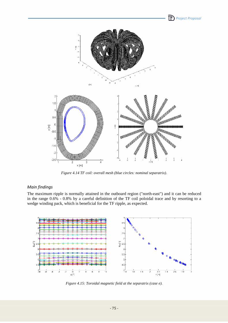
Project Proposal
- 75 -
Figure 4.14 TF coil: overall mesh (blue circles: nominal separatrix).
Main findings
The maximum ripple is normally attained in the outboard region ("north-east") and it can be reduced
in the range 0.6% - 0.8% by a careful definition of the TF coil poloidal trace and by resorting to a
wedge winding pack, which is beneficial for the TF ripple, as expected.
Figure 4.15: Toroidal magnetic field at the separatrix (case e).
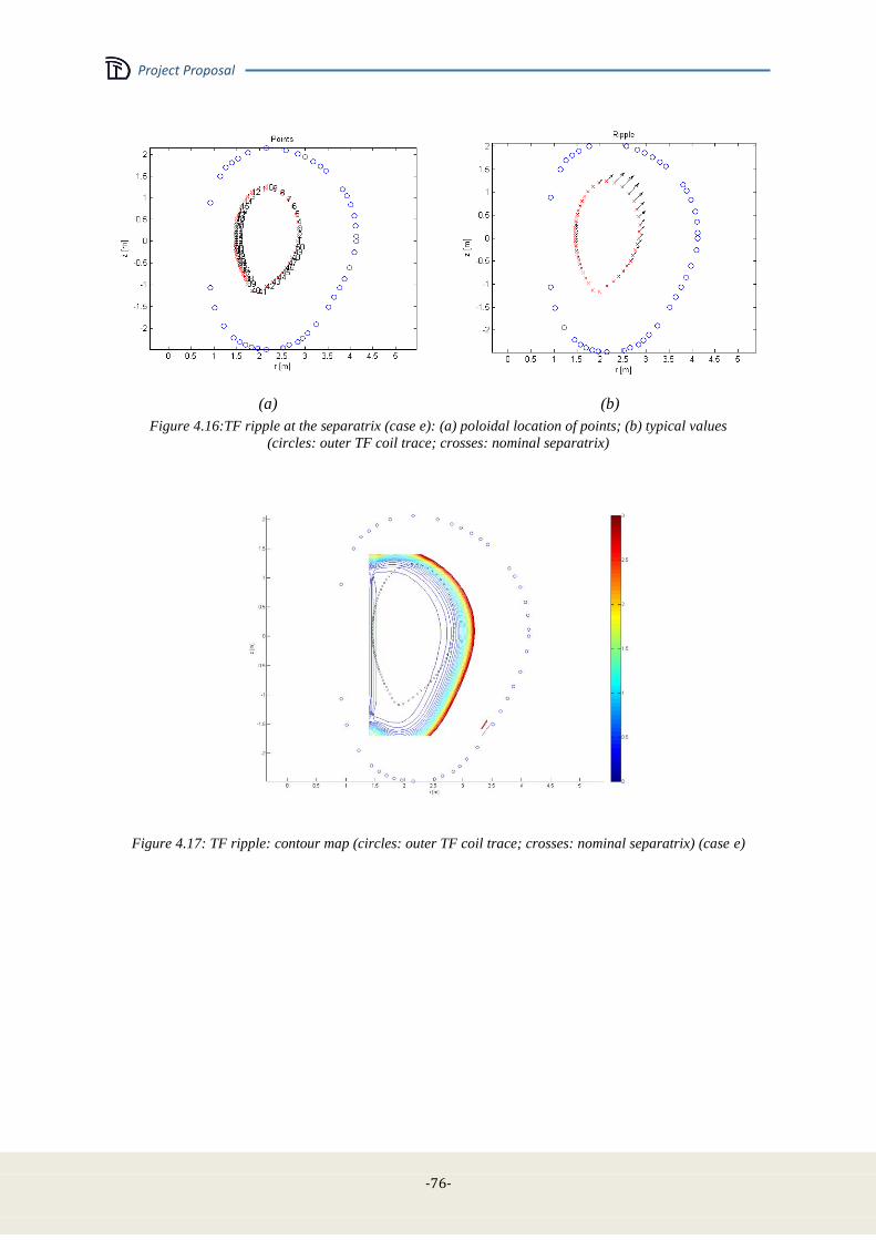
Project Proposal
-76-
(a) (b)
Figure 4.16:TF ripple at the separatrix (case e): (a) poloidal location of points; (b) typical values
(circles: outer TF coil trace; crosses: nominal separatrix)
Figure 4.17: TF ripple: contour map (circles: outer TF coil trace; crosses: nominal separatrix) (case e)
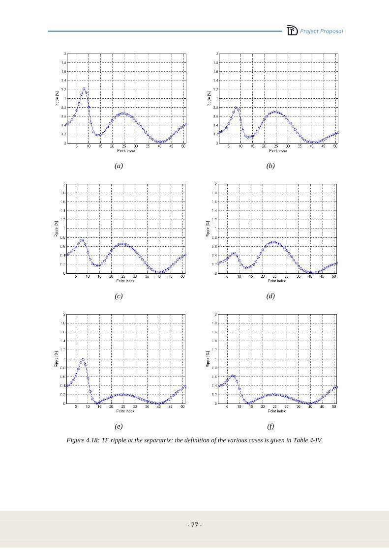
Project Proposal
- 77 -
(a) (b)
(c) (d)
(e) (f)
Figure 4.18: TF ripple at the separatrix: the definition of the various cases is given in Table 4-IV.
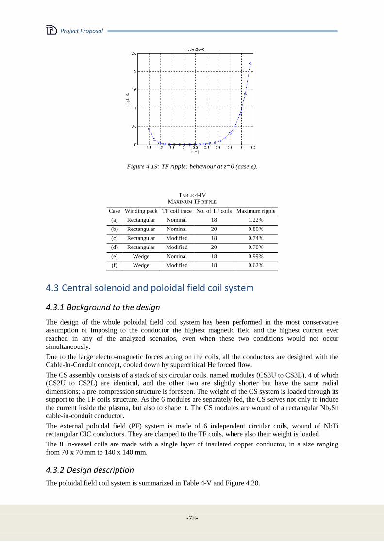
Project Proposal
-78-
Figure 4.19: TF ripple: behaviour at z=0 (case e).
TABLE 4-IV
MAXIMUM TF RIPPLE
Case Winding pack TF coil trace No. of TF coils Maximum ripple
(a) Rectangular Nominal 18 1.22%
(b) Rectangular Nominal 20 0.80%
(c) Rectangular Modified 18 0.74%
(d) Rectangular Modified 20 0.70%
(e) Wedge Nominal 18 0.99%
(f) Wedge Modified 18 0.62%
4.3 Central solenoid and poloidal field coil system
4.3.1 Background to the design
The design of the whole poloidal field coil system has been performed in the most conservative
assumption of imposing to the conductor the highest magnetic field and the highest current ever
reached in any of the analyzed scenarios, even when these two conditions would not occur
simultaneously.
Due to the large electro-magnetic forces acting on the coils, all the conductors are designed with the
Cable-In-Conduit concept, cooled down by supercritical He forced flow.
The CS assembly consists of a stack of six circular coils, named modules (CS3U to CS3L), 4 of which
(CS2U to CS2L) are identical, and the other two are slightly shorter but have the same radial
dimensions; a pre-compression structure is foreseen. The weight of the CS system is loaded through its
support to the TF coils structure. As the 6 modules are separately fed, the CS serves not only to induce
the current inside the plasma, but also to shape it. The CS modules are wound of a rectangular Nb3Sn
cable-in-conduit conductor.
The external poloidal field (PF) system is made of 6 independent circular coils, wound of NbTi
rectangular CIC conductors. They are clamped to the TF coils, where also their weight is loaded.
The 8 In-vessel coils are made with a single layer of insulated copper conductor, in a size ranging
from 70 x 70 mm to 140 x 140 mm.
4.3.2 Design description
The poloidal field coil system is summarized in Table 4-V and Figure 4.20.

Project Proposal
- 79 -
TABLE 4-V
PF COILS SYSTEM
Name Rcenter (m) Zcenter (m) R (m) Z (m) Turns
CS3U 0.67 2.26 0.34 0.64 270
CS2U 0.67 1.46 0.34 0.97 420
CS1U 0.67 0.49 0.34 0.97 420
CS1L 0.67 -0.49 0.34 0.97 420
CS2L 0.67 -1.46 0.34 0.97 420
CS3L 0.67 -2.26 0.34 0.64 270
PF1 1.34 2.23 0.38 0.32 130
PF2 3.49 1.93 0.47 0.18 108
PF3 4.28 0.75 0.19 0.49 112
PF4 4.15 -1.05 0.25 0.47 140
PF5 3.25 -2.45 0.49 0.23 152
PF6 1.54 -2.76 0.75 0.32 260
C1 1.44 -1.481 0.07 0.07 1
C2 1.74 -1.823 0.07 0.07 1
C3 2 -1.925 0.07 0.07 1
C4 2.18 -1.668 0.07 0.07 1
C5 3.1 -0.83 0.14 0.14 4
C6 3.285 0.51 0.14 0.14 4
C7 2.988 -1.15 0.07 0.07 1
C8 2.915 1.25 0.07 0.07 1
Figure 4.20: DTT Magnetic System artistic view, with the complete CS and PF coils system.

Project Proposal
-80-
CS system description
The DTT Central Solenoid (CS) operates at a peak field of 12.5 T, so it relies on Nb3Sn as
superconductor material. The conductor concept is that of a rectangular Cable-in-Conduit conductor
(CICC) with low void fraction, cooled by supercritical helium, manufactured by deformation from a
round tube of constant thickness.
As a reference, a qualitatively similar solution is the one reported in Figure 4.21, as widely discussed
within Section 4.2.2.
Figure 4.21: a rectangular CICC conductor solution, with steel jacket of constant thickness [4.2], qualitatively
representative of the solution proposed for the DTT CS conductor.
The magnet is made of 6 stacked and independent modules. Its assembly is shown in Figure 4.22, and
relies on upper and lower centring systems, connected to the TF coil, and providing support against
horizontal forces.
Figure 4.22: DTT CS coil assembly.

Project Proposal
- 81 -
The CS weight and any net vertical force component are transmitted to the TF coil structures, through
gravity supports. The magnetic hoop forces during operation are reacted internally, within the
winding, by the conductor jacket. A system of flanges and tie plates provides the axial pre-
compression to the stack of modules.
The six modules can be energized independently, according to plasma formation and shaping
requirements. Inter-pancake joints of the “ENEA-type” [4.12] will be manufactured in-line during
winding and will be completely embedded within the coil structures, whereas the terminal joints will
be placed in the outer coil region.
Bus-bars and helium pipes run outside the coil, within the room available between the external CS coil
surface and the inner TF coil surface.
The conductor design operating conditions are: 13.2 T effective magnetic field (effective magnetic
field peak seen by conductor is slightly higher than coil peak field as calculated by code where the WP
single turns have not been detailed, see Section 4.3.3); 23.0 kA current; 1.5 K minimum temperature
margin; conductor outer dimensions, before turn insulation, are: 31.6 mm x 19.8 mm and the AISI 316
LN steel jacket thickness is 2.9 mm. The void fraction inside the conductor is kept at 26%.
Each of the 4 central modules will be constituted of 420 turns, whereas the uppermost and lowermost
modules (CS3U and CS3L, respectively) are made of 270 turns each. Total number of turns in coil is
thus 2220, and total coil current: 51 MA turns. A separation layer of 32 mm is left between modules,
to accommodate an insulation layer and hydraulic pipes.
The modules will be pancake-wound and each single pancake will be made of 15 conductor turns,
corresponding to a conductor length of about 63 m. Due to this relatively short length, conductors can
be wound in hexa-pancakes, still avoiding the use of a pressure relief channel inside the CICC. The
hydraulic length of a hexa-pancake would in fact be quite short (about 190 m), so that the pumping
load on the cryogenic plant can be kept within small levels, with an operating mass flow rate of 1.5 g/s
per cooling path.
In particular, each of the CS3U and CS3L modules will be made of 3 hexa-pancakes, whereas each of
the CS1U, CS1L, CS2U, and CS2L modules will be made of 4 hexa-pancakes, and two double-
pancakes at the upper and lower extremities. The CS coil will thus be made of 60 parallel hydraulic
paths, with the 30 inlet pipes located inside the coil bore, and for a total of 90 g/s of supercritical
helium, circulating at about 6 bar inlet pressure.
In this configuration, the overall CS system will include 24 inter-pancake joints and 12 terminations.
CICC operating conditions can be compared to the corresponding values for the ITER CS:
ITER CS DTT CS
Operating current (kA) 45.0 23.0
Peak magnetic field (T) 13 13.2
Cumulative operating load 585 kN/m 288 kN/m
Conductor outer dimensions 49.0 mm x 49.0 mm 31.6 mm x 19.8 mm
Jacket Thickness 8.2 mm
(minimum value) 2.9 mm
Cable area (mm2) 771
(excluding central channel) 353
Steel section per turn (jacket) 1566 mm2 242.4 mm2
A simplified computation of the hotspot temperature reached by the conductor during a quench has
been carried out, within a simplified adiabatic 0D model.
Figure 4.23 shows the result, in terms of temperature evolution with time, after a quench occurring at
t=0. Here the two reference cases considered are: a) heat absorbed totally by copper and
superconducting wires only (red curve in figure) - ITER design criterion: Thotspot< 250 K; b) heat
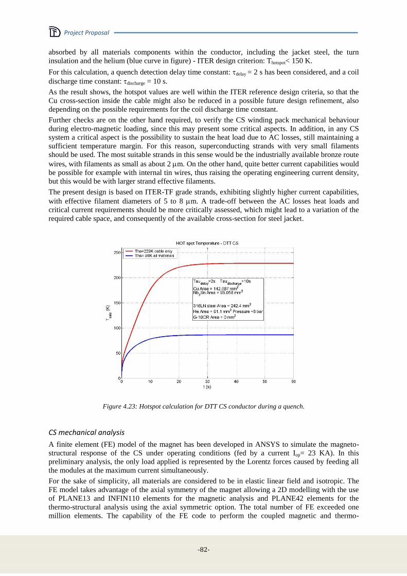
Project Proposal
-82-
absorbed by all materials components within the conductor, including the jacket steel, the turn
insulation and the helium (blue curve in figure) - ITER design criterion: Thotspot< 150 K.
For this calculation, a quench detection delay time constant: delay = 2 s has been considered, and a coil
discharge time constant: discharge = 10 s.
As the result shows, the hotspot values are well within the ITER reference design criteria, so that the
Cu cross-section inside the cable might also be reduced in a possible future design refinement, also
depending on the possible requirements for the coil discharge time constant.
Further checks are on the other hand required, to verify the CS winding pack mechanical behaviour
during electro-magnetic loading, since this may present some critical aspects. In addition, in any CS
system a critical aspect is the possibility to sustain the heat load due to AC losses, still maintaining a
sufficient temperature margin. For this reason, superconducting strands with very small filaments
should be used. The most suitable strands in this sense would be the industrially available bronze route
wires, with filaments as small as about 2 m. On the other hand, quite better current capabilities would
be possible for example with internal tin wires, thus raising the operating engineering current density,
but this would be with larger strand effective filaments.
The present design is based on ITER-TF grade strands, exhibiting slightly higher current capabilities,
with effective filament diameters of 5 to 8 m. A trade-off between the AC losses heat loads and
critical current requirements should be more critically assessed, which might lead to a variation of the
required cable space, and consequently of the available cross-section for steel jacket.
Figure 4.23: Hotspot calculation for DTT CS conductor during a quench.
CS mechanical analysis
A finite element (FE) model of the magnet has been developed in ANSYS to simulate the magneto-
structural response of the CS under operating conditions (fed by a current Iop= 23 KA). In this
preliminary analysis, the only load applied is represented by the Lorentz forces caused by feeding all
the modules at the maximum current simultaneously.
For the sake of simplicity, all materials are considered to be in elastic linear field and isotropic. The
FE model takes advantage of the axial symmetry of the magnet allowing a 2D modelling with the use
of PLANE13 and INFIN110 elements for the magnetic analysis and PLANE42 elements for the
thermo-structural analysis using the axial symmetric option. The total number of FE exceeded one
million elements. The capability of the FE code to perform the coupled magnetic and thermo-
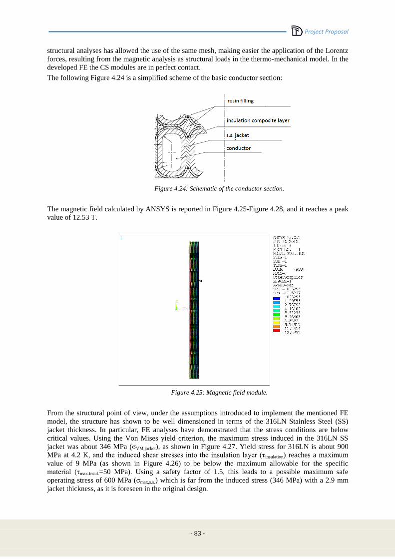
Project Proposal
- 83 -
structural analyses has allowed the use of the same mesh, making easier the application of the Lorentz
forces, resulting from the magnetic analysis as structural loads in the thermo-mechanical model. In the
developed FE the CS modules are in perfect contact.
The following Figure 4.24 is a simplified scheme of the basic conductor section:
Figure 4.24: Schematic of the conductor section.
The magnetic field calculated by ANSYS is reported in Figure 4.25-Figure 4.28, and it reaches a peak
value of 12.53 T.
Figure 4.25: Magnetic field module.
From the structural point of view, under the assumptions introduced to implement the mentioned FE
model, the structure has shown to be well dimensioned in terms of the 316LN Stainless Steel (SS)
jacket thickness. In particular, FE analyses have demonstrated that the stress conditions are below
critical values. Using the Von Mises yield criterion, the maximum stress induced in the 316LN SS
jacket was about 346 MPa (σVM,jacket), as shown in Figure 4.27. Yield stress for 316LN is about 900
MPa at 4.2 K, and the induced shear stresses into the insulation layer (τinsulation) reaches a maximum
value of 9 MPa (as shown in Figure 4.26) to be below the maximum allowable for the specific
material (τmax.insul.=50 MPa). Using a safety factor of 1.5, this leads to a possible maximum safe
operating stress of 600 MPa (σmax,s.s.) which is far from the induced stress (346 MPa) with a 2.9 mm
jacket thickness, as it is foreseen in the original design.
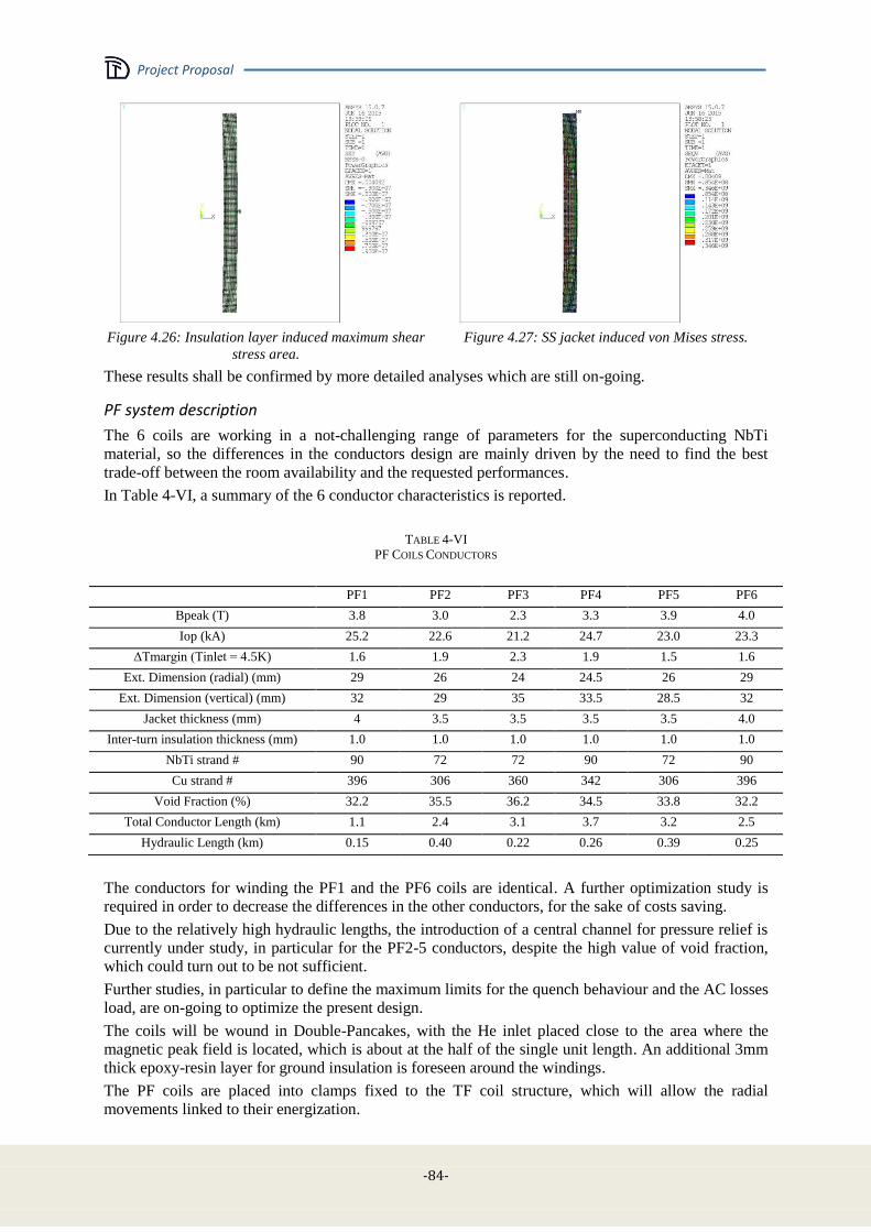
Project Proposal
-84-
Figure 4.26: Insulation layer induced maximum shear
stress area.
Figure 4.27: SS jacket induced von Mises stress.
These results shall be confirmed by more detailed analyses which are still on-going.
PF system description
The 6 coils are working in a not-challenging range of parameters for the superconducting NbTi
material, so the differences in the conductors design are mainly driven by the need to find the best
trade-off between the room availability and the requested performances.
In Table 4-VI, a summary of the 6 conductor characteristics is reported.
TABLE 4-VI
PF COILS CONDUCTORS
PF1 PF2 PF3 PF4 PF5 PF6
Bpeak (T) 3.8 3.0 2.3 3.3 3.9 4.0
Iop (kA) 25.2 22.6 21.2 24.7 23.0 23.3
ΔTmargin (Tinlet = 4.5K) 1.6 1.9 2.3 1.9 1.5 1.6
Ext. Dimension (radial) (mm) 29 26 24 24.5 26 29
Ext. Dimension (vertical) (mm) 32 29 35 33.5 28.5 32
Jacket thickness (mm) 4 3.5 3.5 3.5 3.5 4.0
Inter-turn insulation thickness (mm) 1.0 1.0 1.0 1.0 1.0 1.0
NbTi strand # 90 72 72 90 72 90
Cu strand # 396 306 360 342 306 396
Void Fraction (%) 32.2 35.5 36.2 34.5 33.8 32.2
Total Conductor Length (km) 1.1 2.4 3.1 3.7 3.2 2.5
Hydraulic Length (km) 0.15 0.40 0.22 0.26 0.39 0.25
The conductors for winding the PF1 and the PF6 coils are identical. A further optimization study is
required in order to decrease the differences in the other conductors, for the sake of costs saving.
Due to the relatively high hydraulic lengths, the introduction of a central channel for pressure relief is
currently under study, in particular for the PF2-5 conductors, despite the high value of void fraction,
which could turn out to be not sufficient.
Further studies, in particular to define the maximum limits for the quench behaviour and the AC losses
load, are on-going to optimize the present design.
The coils will be wound in Double-Pancakes, with the He inlet placed close to the area where the
magnetic peak field is located, which is about at the half of the single unit length. An additional 3mm
thick epoxy-resin layer for ground insulation is foreseen around the windings.
The PF coils are placed into clamps fixed to the TF coil structure, which will allow the radial
movements linked to their energization.
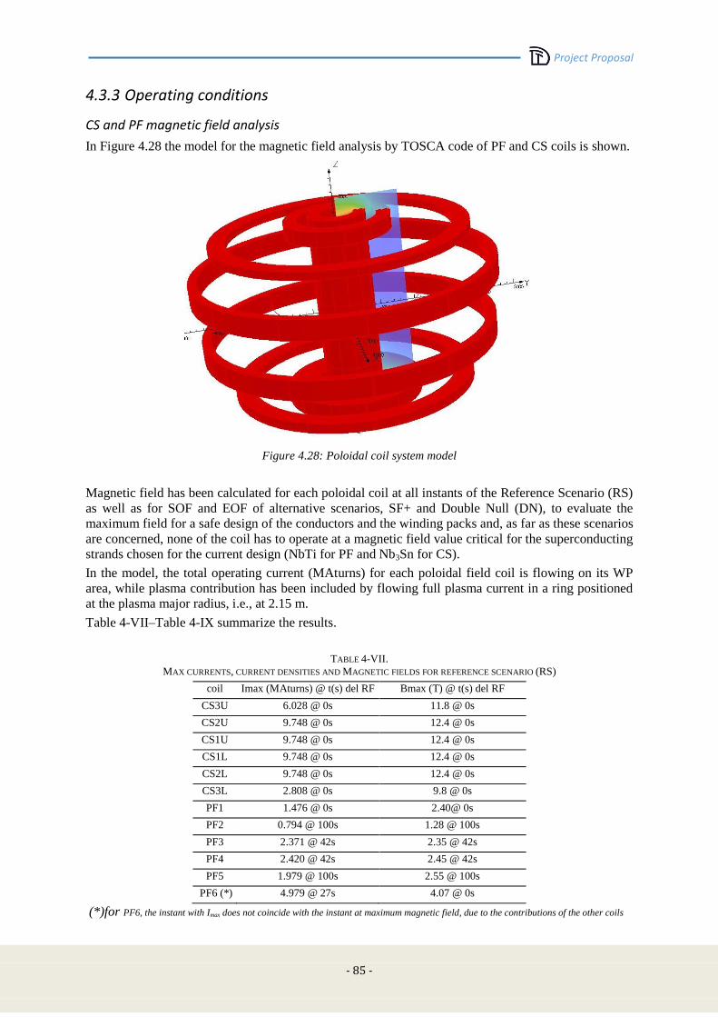
Project Proposal
- 85 -
4.3.3 Operating conditions
CS and PF magnetic field analysis
In Figure 4.28 the model for the magnetic field analysis by TOSCA code of PF and CS coils is shown.
Figure 4.28: Poloidal coil system model
Magnetic field has been calculated for each poloidal coil at all instants of the Reference Scenario (RS)
as well as for SOF and EOF of alternative scenarios, SF+ and Double Null (DN), to evaluate the
maximum field for a safe design of the conductors and the winding packs and, as far as these scenarios
are concerned, none of the coil has to operate at a magnetic field value critical for the superconducting
strands chosen for the current design (NbTi for PF and Nb3Sn for CS).
In the model, the total operating current (MAturns) for each poloidal field coil is flowing on its WP
area, while plasma contribution has been included by flowing full plasma current in a ring positioned
at the plasma major radius, i.e., at 2.15 m.
Table 4-VII–Table 4-IX summarize the results.
TABLE 4-VII.
MAX CURRENTS, CURRENT DENSITIES AND MAGNETIC FIELDS FOR REFERENCE SCENARIO (RS)
coil Imax (MAturns) @ t(s) del RF Bmax (T) @ t(s) del RF
CS3U 6.028 @ 0s 11.8 @ 0s
CS2U 9.748 @ 0s 12.4 @ 0s
CS1U 9.748 @ 0s 12.4 @ 0s
CS1L 9.748 @ 0s 12.4 @ 0s
CS2L 9.748 @ 0s 12.4 @ 0s
CS3L 2.808 @ 0s 9.8 @ 0s
PF1 1.476 @ 0s 2.40@ 0s
PF2 0.794 @ 100s 1.28 @ 100s
PF3 2.371 @ 42s 2.35 @ 42s
PF4 2.420 @ 42s 2.45 @ 42s
PF5 1.979 @ 100s 2.55 @ 100s
PF6 (*) 4.979 @ 27s 4.07 @ 0s
(*)for PF6, the instant with Imax does not coincide with the instant at maximum magnetic field, due to the contributions of the other coils
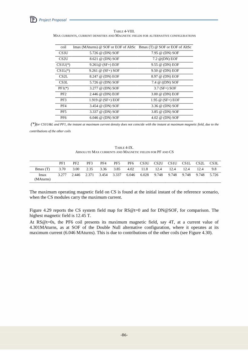
Project Proposal
-86-
TABLE 4-VIII.
MAX CURRENTS, CURRENT DENSITIES AND MAGNETIC FIELDS FOR ALTERNATIVE CONFIGURATIONS
coil Imax (MAturns) @ SOF or EOF of AltSc Bmax (T) @ SOF or EOF of AltSc
CS3U 5.726 @ (DN) SOF 7.95 @ (DN) SOF
CS2U 8.621 @ (DN) SOF 7.2 @(DN) EOF
CS1U(*) 9.261@ (SF+) EOF 9.55 @ (DN) EOF
CS1L(*) 9.261 @ (SF+) SOF 9.50 @ (DN) EOF
CS2L 8.247 @ (DN) EOF 8.97 @ (DN) EOF
CS3L 5.726 @ (DN) SOF 7.4 @ ((DN) SOF
PF1(*) 3.277 @ (DN) SOF 3.7 (SF+) SOF
PF2 2.446 @ (DN) EOF 3.00 @ (DN) EOF
PF3 1.919 @ (SF+) EOF 1.95 @ (SF+) EOF
PF4 3.454 @ (DN) SOF 3.36 @ (DN) SOF
PF5 3.337 @ (DN) SOF 3.85 @ (DN) SOF
PF6 6.046 @ (DN) SOF 4.02 @ (DN) SOF
(*)for CS1U&L and PF1, the instant at maximum current density does not coincide with the instant at maximum magnetic field, due to the
contributions of the other coils
TABLE 4-IX.
ABSOLUTE MAX CURRENTS AND MAGNETIC FIELDS FOR PF AND CS
PF1 PF2 PF3 PF4 PF5 PF6 CS3U CS2U CS1U CS1L CS2L CS3L
Bmax (T) 3.70 3.00 2.35 3.36 3.85 4.02 11.8 12.4 12.4 12.4 12.4 9.8
Imax
(MAturns)
3.277 2.446 2.371 3.454 3.337 6.046 6.028 9.748 9.748 9.748 9.748 5.726
The maximum operating magnetic field on CS is found at the initial instant of the reference scenario,
when the CS modules carry the maximum current.
Figure 4.29 reports the CS system field map for RS@t=0 and for DN@SOF, for comparison. The
highest magnetic field is 12.45 T.
At RS@t=0s, the PF6 coil presents its maximum magnetic field, say 4T, at a current value of
4.301MAturns, as at SOF of the Double Null alternative configuration, where it operates at its
maximum current (6.046 MAturns). This is due to contributions of the other coils (see Figure 4.30).
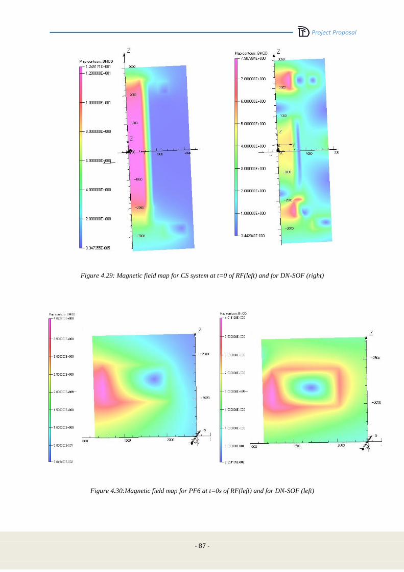
Project Proposal
- 87 -
Figure 4.29: Magnetic field map for CS system at t=0 of RF(left) and for DN-SOF (right)
Figure 4.30:Magnetic field map for PF6 at t=0s of RF(left) and for DN-SOF (left)

Project Proposal
-88-
As an example, in Figure 4.31 some field map details as calculated by TOSCA at flat top of alternative
configurations are shown.
Figure 4.31: Details of magnetic field map at SF+ @SOF for PF1 (left); DN@SOF for PF2,3,4,5 (right) .
Voltage, current and load limits for the PF system
Each coil is separately fed. Table 4-X reports the limits in terms of vertical force for each coil.
The forces on the internal coils are scaled from DEMO [4.23] where the maximum vertical force on
the central solenoid stack shall not exceed 300 MN, the maximum separation force in the central
solenoid stack shall not exceed 350 MN, and the maximum vertical force on a single PF coil shall be
450 MN (or a pair of coils at a distance of less than 3 m). We assume the force scaling with the square
of R0Btor. In DEMO Btor = 7 T and R0 = 9 m [4.24], whereas in DTT Btor = 6 T and R0 = 2.15 m,
therefore we assume a reduction of a factor of 24 with respect to DEMO.
The forces on the internal coils are scaled from ITER [4.25], where the maximum force is 744 kN/m
and the maximum current is 240 kA (up to 320 kA in short transients). Since in DTT we assume 60
kA, the maximum force should be reduced to 186 kN/m. Therefore, the limits of 4 MN for the
vertical force are taken for the coils connected to other structures (vacuum vessel or divertor) via rails
or other means.
In principle, the support can be designed to withstand much larger forces, however, the limits in Table
4-X guarantee that the DTT configurations can certainly obtained in DEMO.
Table 4-XI reports voltage and current limits for the amplifiers.

Project Proposal
- 89 -
TABLE 4-X
PF COIL LOAD LIMITS
Name Fzmax (MN)
CS3U
12.5 *
CS2U
CS1U
CS1L
CS2L
CS3L
PF1 19
PF2 19
PF3a 19 **
PF3b
PF4a 19 **
PF4b
PF5 19
PF6 19
* total with a maximum separation force of 14.5 MN
** total
TABLE 4-XI
VOLTAGE AND CURRENT LIMITS (FOUR QUADRANTS)
Name Isat (kA) Vsat (V) turns
CS3U 23 800 270
CS2U 23 800 420
CS1U 23 800 420
CS1L 23 800 420
CS2L 23 800 420
CS3L 23 800 270
PF1 25.2 800 130
PF2 22.6 800 108
PF3 21.2 1000 112
PF4 24.7 1000 140
PF5 23 800 152
PF6 23.3 800 260
C1 60 50 1
C2 60 50 1
C3 60 50 1
C4 60 50 1
C5 25 200 4
C6 25 200 4
C7 60 50 1
C8 60 50 1
* these limits are for the currents in the scenario: the plasma shape control system can use additional 2.0 kA in
PF2-PF3-PF4-PF5 and additional 1.0 kA in PF1 and PF6
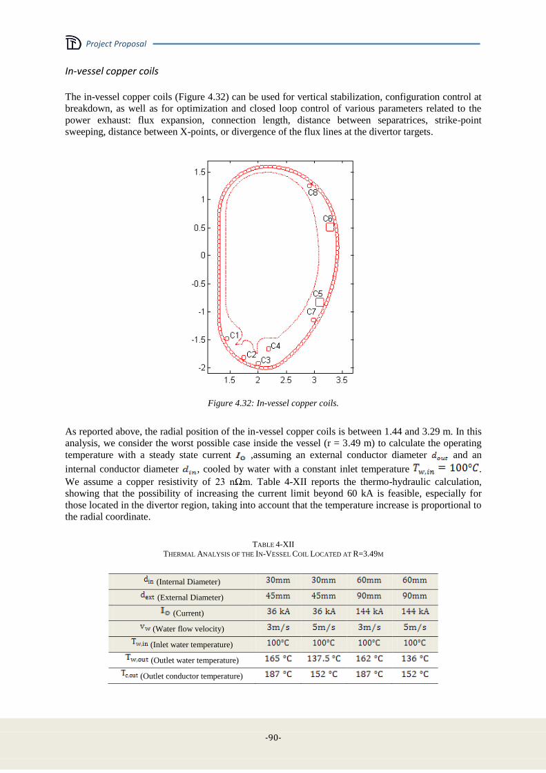
Project Proposal
-90-
In-vessel copper coils
The in-vessel copper coils (Figure 4.32) can be used for vertical stabilization, configuration control at
breakdown, as well as for optimization and closed loop control of various parameters related to the
power exhaust: flux expansion, connection length, distance between separatrices, strike-point
sweeping, distance between X-points, or divergence of the flux lines at the divertor targets.
Figure 4.32: In-vessel copper coils.
As reported above, the radial position of the in-vessel copper coils is between 1.44 and 3.29 m. In this
analysis, we consider the worst possible case inside the vessel (r = 3.49 m) to calculate the operating
temperature with a steady state current ,assuming an external conductor diameter and an
internal conductor diameter , cooled by water with a constant inlet temperature .
We assume a copper resistivity of 23 nΩm. Table 4-XII reports the thermo-hydraulic calculation,
showing that the possibility of increasing the current limit beyond 60 kA is feasible, especially for
those located in the divertor region, taking into account that the temperature increase is proportional to
the radial coordinate.
TABLE 4-XII
THERMAL ANALYSIS OF THE IN-VESSEL COIL LOCATED AT R=3.49M
(Internal Diameter)
(External Diameter)
(Current)
(Water flow velocity)
(Inlet water temperature)
(Outlet water temperature)
(Outlet conductor temperature)
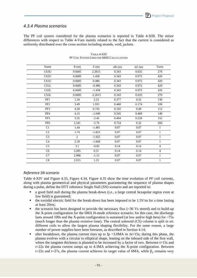
Project Proposal
- 91 -
4.3.4 Plasma scenarios
The PF coil system considered for the plasma scenarios is reported in Table 4-XIII. The minor
differences with respect to Table 4-Vare mainly related to the fact that the current is considered as
uniformly distributed over the cross section including strands, void, jackets.
TABLE 4-XIII
PF COIL SYSTEM USED FOR MHD CALCULATIONS
Name R (m) Z (m) R (m) Z (m) Turns
CS3U 0.6685 2.2615 0.343 0.635 270
CS2U 0.6685 1.458 0.343 0.972 420
CS1U 0.6685 0.486 0.343 0.972 420
CS1L 0.6685 -0.486 0.343 0.972 420
CS2L 0.6685 -1.458 0.343 0.972 420
CS3L 0.6685 -2.2615 0.343 0.635 270
PF1 1.34 2.23 0.377 0.32 130
PF2 3.49 1.931 0.468 0.174 108
PF3 4.28 0.745 0.192 0.49 112
PF4 4.15 -1.049 0.245 0.469 140
PF5 3.25 -2.45 0.494 0.228 152
PF6 1.541 -2.76 0.754 0.32 260
C1 1.44 -1.481 0.07 0.07 1
C2 1.74 -1.823 0.07 0.07 1
C3 2 -1.925 0.07 0.07 1
C4 2.18 -1.668 0.07 0.07 1
C5 3.1 -0.83 0.14 0.14 4
C6 3.285 0.51 0.14 0.14 4
C7 2.988 -1.15 0.07 0.07 1
C8 2.915 1.25 0.07 0.07 1
Reference SN scenario
Table 4-XIV and Figure 4.33, Figure 4.34, Figure 4.35 show the time evolution of PF coil currents,
along with plasma geometrical and physical parameters guaranteeing the sequence of plasma shapes
during a pulse, define the DTT reference Single Null (SN) scenario and are reported in:
a good field null during the plasma break-down (i.e., a large central hexapolar region even at
low field) is guaranteed;
the toroidal electric field for the break-down has been imposed to be 1.5V/m for a time lasting
at least 20ms;
the scenario has been designed to provide the necessary flux (~36 Vs stored) and to build-up
the X-point configuration for the 6MA H-mode reference scenario; for this case, the discharge
lasts around 100s and the X-point configuration is sustained (at low and/or high beta) for ~75s
(much longer than the plasma resistive time). The central solenoid (CS) column is split in six
different coils to allow the largest plasma shaping flexibility. For the same reason, a large
number of power supplies have been foreseen, as described in Section 4.14;
after breakdown, the plasma current rises up to Ip =3.0MA in t=15s; during this phase, the
plasma evolves with a circular to elliptical shape, leaning on the inboard side of the first wall,
where the tungsten thickness is planned to be increased by a factor of two. Between t=15s and
t=22s the plasma current ramps up to 4.3MA achieving the X-point configuration. Between
t=22s and t=27s, the plasma current achieves its target value of 6MA, while p remains very
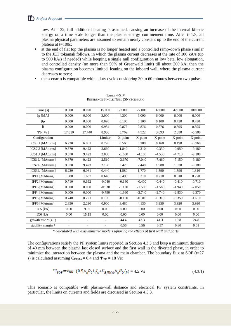
Project Proposal
-92-
low. At t=32, full additional heating is assumed, causing an increase of the internal kinetic
energy on a time scale longer than the plasma energy confinement time. After t=42s, all
plasma physical parameters are assumed to remain nearly constant up to the end of the current
plateau at t=100s;
at the end of flat top the plasma is no longer heated and a controlled ramp-down phase similar
to the JET tokamak follows, in which the plasma current decreases at the rate of 100 kA/s (up
to 500 kA/s if needed) while keeping a single null configuration at low beta, low elongation,
and controlled density (no more than 50% of Greenwald limit) till about 200 kA; then the
plasma configuration becomes limited, leaning on the inboard wall, where the plasma current
decreases to zero;
the scenario is compatible with a duty cycle considering 30 to 60 minutes between two pulses.
TABLE 4-XIV
REFERENCE SINGLE NULL (SN) SCENARIO
Time [s] 0.000 0.020 15.000 22.000 27.000 32.000 42.000 100.000
Ip [MA] 0.000 0.000 3.000 4.300 6.000 6.000 6.000 6.000
p 0.000 0.000 0.098 0.100 0.100 0.100 0.430 0.430
li 0.000 0.000 0.984 0.876 0.876 0.876 0.895 0.895
Ψb [Vs] 17.810 17.440 8.936 5.762 4.522 3.693 2.838 -5.588
Configuration - - Limiter X-point X-point X-point X-point X-point
ICS3U [MAturns] 6.220 6.061 0.720 0.560 0.280 0.160 0.190 -0.760
ICS2U [MAturns] 9.670 9.423 2.660 1.840 0.210 -0.330 -0.950 -9.180
ICS1U [MAturns] 9.670 9.423 2.000 -1.600 -4.160 -4.530 -4.710 -9.180
ICS1L [MAturns] 9.670 9.423 2.510 -3.670 -7.040 -7.460 -7.150 -9.180
ICS2L [MAturns] 9.670 9.423 2.190 3.420 2.440 1.980 1.030 -9.180
ICS3L [MAturns] 6.220 6.061 0.440 1.580 1.770 1.590 1.590 1.310
IPF1 [MAturns] 1.680 1.637 0.640 0.490 0.310 0.210 0.310 0.270
IPF2 [MAturns] 0.710 0.692 -0.040 -0.180 -0.400 -0.440 -0.410 -0.710
IPF3 [MAturns] 0.000 0.000 -0.930 -1.130 -1.580 -1.580 -1.940 -2.050
IPF4 [MAturns] 0.000 0.000 -0.790 -1.990 -2.740 -2.740 -2.830 -2.370
IPF5 [MAturns] 0.740 0.721 0.190 -0.150 -0.310 -0.310 -0.350 -1.510
IPF6 [MAturns] 2.350 2.290 0.900 3.480 4.130 3.950 3.920 3.990
IC5 [kA] 0.00 9.97 0.00 0.00 0.00 0.00 0.00 0.00
IC6 [kA] 0.00 15.15 0.00 0.00 0.00 0.00 0.00 0.00
growth rate * (s-1) - - - 44.4 42.3 41.3 19.8 24.8
stability margin * - - - 0.56 0.56 0.57 0.80 0.61
* calculated with axisymmetric models ignoring the effects of first wall and ports
The configurations satisfy the PF system limits reported in Section 4.3.3 and keep a minimum distance
of 40 mm between the plasma last closed surface and the first wall in the diverted phase, in order to
minimize the interaction between the plasma and the main chamber. The boundary flux at SOF (t=27
s) is calculated assuming CEJIMA = 0.4 and BD = 18 Vs:
+ ) = 4.5 Vs (4.3.1)
This scenario is compatible with plasma-wall distance and electrical PF system constraints. In
particular, the limits on currents and fields are discussed in Section 4.3.3.
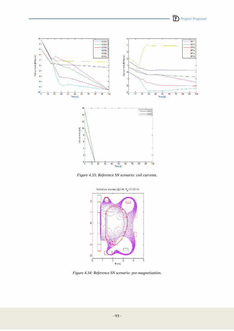
Project Proposal
- 93 -
Figure 4.33: Reference SN scenario: coil currents.
Figure 4.34: Reference SN scenario: pre-magnetization.
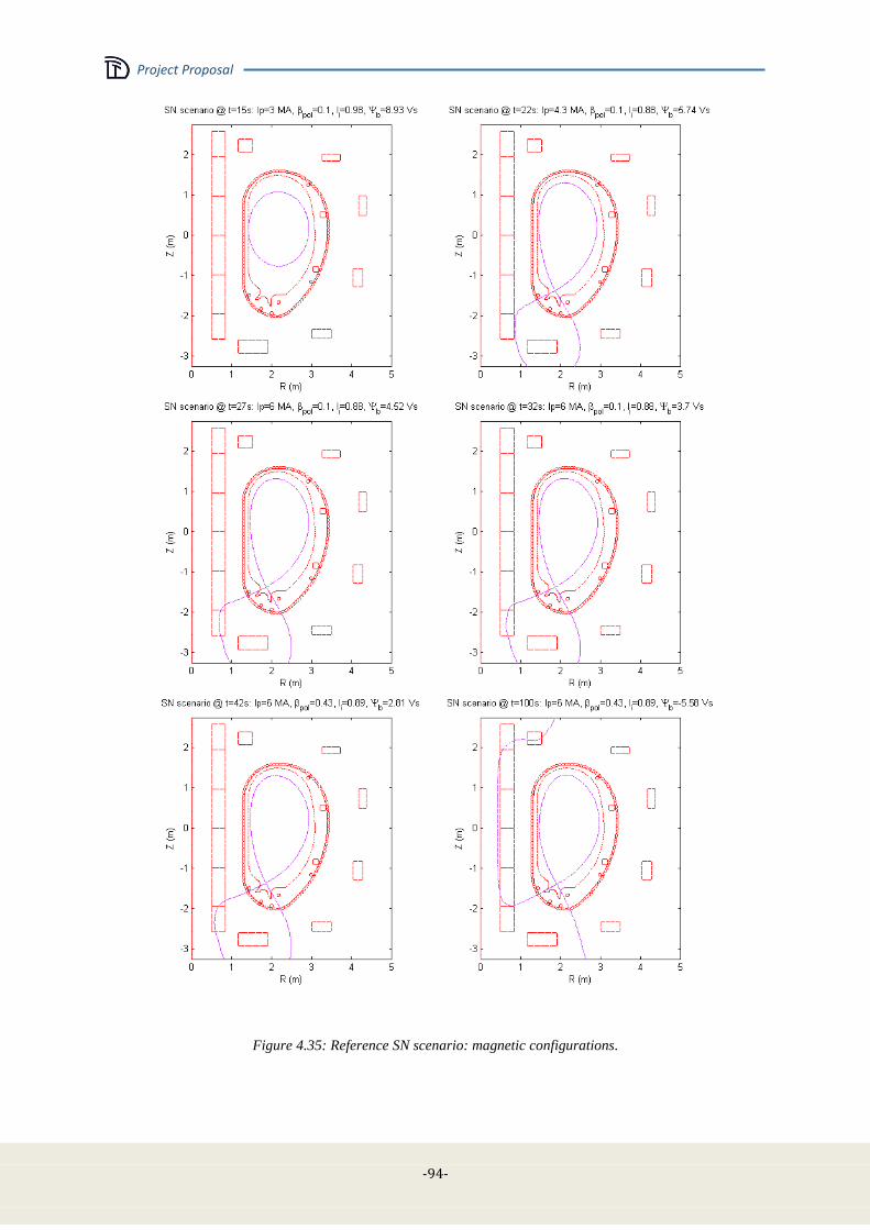
Project Proposal
-94-
Figure 4.35: Reference SN scenario: magnetic configurations.

Project Proposal
- 95 -
Alternative scenarios
DTT capabilities include various advanced configurations, including ideal snowflake (SF), quasi
snowflake (SF+ and SF
-), X-divertor (XD), and double null (DN) plasmas. Any advanced
configuration (AC) can be obtained via specific scenarios, or alternatively, during the flat top of a
reference scenario (at full or reduced current) by means of a transition for SN to AC and vice versa.
Figure 4.36 and Table 4-XV show an ideal 4 MA SF configuration with a flat top of 58 s.
Figure 4.37 and Table 4-XVI show a 5 MA SF+ configuration with a flat top of 44 s.
Figure 4.38 and Table 4-XVII show a 5 MA DN configuration with a flat top of 43 s.
These optimized configurations verify current, field and plasma-wall distance constraints.
Additional SF, QSF and XD configurations can be obtained using not only the superconducting coils,
but also the internal coils C1-C8.

Project Proposal
-96-
Figure 4.36:Alternative 4 MA SF scenario.
TABLE 4-XV
4 MA SF SCENARIO
Ip [MA] 4 4
p 4.000 4.000
li 0.430 0.430
Ψb [Vs] 7.606 -3.920
Configuration SF @ SOF SF @ EOF
ICS3U [MAturns] 0.372 -5.691
ICS2U [MAturns] 3.739 3.538
ICS1U [MAturns] 0.429 -8.742
ICS1L [MAturns] -4.400 -9.177
ICS2L [MAturns] 7.728 0.037
ICS3L [MAturns] 4.968 0.980
IPF1 [MAturns] 0.123 -3.042
IPF2 [MAturns] 0.473 0.857
IPF3 [MAturns] -1.594 -2.266
IPF4 [MAturns] -3.034 -2.782
IPF5 [MAturns] 2.839 2.383
IPF6 [MAturns] -0.901 -2.322
IC5 [kA] - -
IC6 [kA] - -
growth rate * (s-1) 166 325
stability margin * 0.21 0.12
* calculated with axisymmetric models ignoring the effects of first wall and ports
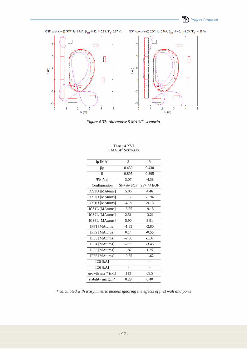
Project Proposal
- 97 -
Figure 4.37: Alternative 5 MA SF+ scenario.
TABLE 4-XVI
5 MA SF+ SCENARIO
Ip [MA] 5 5
p 0.430 0.430
li 0.895 0.895
Ψb [Vs] 3.07 -4.38
Configuration SF+ @ SOF SF+ @ EOF
ICS3U [MAturns] 5.86 4.46
ICS2U [MAturns] 1.17 -1.94
ICS1U [MAturns] -4.09 -9.18
ICS1L [MAturns] -6.55 -9.18
ICS2L [MAturns] 2.51 -3.21
ICS3L [MAturns] 5.90 3.91
IPF1 [MAturns] -1.65 -2.80
IPF2 [MAturns] 0.14 -0.55
IPF3 [MAturns] -2.06 -1.37
IPF4 [MAturns] -2.95 -3.45
IPF5 [MAturns] 1.87 1.75
IPF6 [MAturns] -0.65 -1.62
IC5 [kA] - -
IC6 [kA] - -
growth rate * (s-1) 113 69.5
stability margin * 0.29 0.40
* calculated with axisymmetric models ignoring the effects of first wall and ports

Project Proposal
-98-
Figure 4.38: Alternative 5 MA DN scenario.
TABLE 4-XVII
5 MA DN SCENARIO
Ip [MA] 5 5
p 0.430 0.430
li 0.895 0.895
Ψb [Vs] 2.681 -5.168
Configuration DN @ SOF DN @ EOF
ICS3U [MAturns] 5.900 2.484
ICS2U [MAturns] -0.103 -5.950
ICS1U [MAturns] -5.506 -9.177
ICS1L [MAturns] -6.304 -9.177
ICS2L [MAturns] -2.350 -9.177
ICS3L [MAturns] 2.795 0.868
IPF1 [MAturns] 2.992 2.809
IPF2 [MAturns] -2.003 -2.615
IPF3 [MAturns] -1.220 -0.968
IPF4 [MAturns] -1.151 -1.136
IPF5 [MAturns] -2.779 -3.165
IPF6 [MAturns] 5.616 4.893
IC5 [kA] - -
IC6 [kA] - -
growth rate * (s-1) 85.9 34.4
stability margin * 0.25 0.43
* calculated with axisymmetric models ignoring the effects of first wall and ports
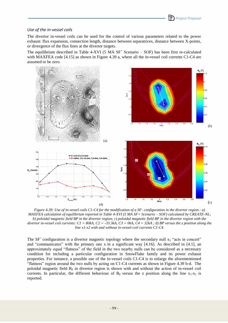
Project Proposal
- 99 -
Use of the in-vessel coils
The divertor in-vessel coils can be used for the control of various parameters related to the power
exhaust: flux expansion, connection length, distance between separatrices, distance between X-points,
or divergence of the flux lines at the divertor targets.
The equilibrium described in Table 4-XVI (5 MA SF+ Scenario – SOF) has been first re-calculated
with MAXFEA code [4.15] as shown in Figure 4.39 a, where all the in-vessel coil currents C1-C4 are
assumed to be zero.
(a)
(d)
(b)
(c)
Figure 4.39: Use of in-vessel coils C1-C4 for the modification of a SF- configuration in the divertor region.: a)
MAXFEA calculation of equilibrium reported in Table 4-XVI (5 MA SF+ Scenario – SOF) calculated by CREATE-NL;
b) poloidal magnetic field BP in the divertor region; c) poloidal magnetic field BP in the divertor region with the
divertor in-vessel coil currents: C1 = 80kA, C2 = -33.3kA, C3 = 0kA, C4 = 32kA ; d) BP versus the z position along the
line x1-x2 with and without in-vessel-coil currents C1-C4.
The SF+
configuration is a divertor magnetic topology where the secondary null x2 “acts in concert”
and “communicates” with the primary one x in a significant way [4.16]. As described in [4.1], an
approximately equal “flatness” of the field in the two nearby nulls can be considered as a necessary
condition for including a particular configuration in SnowFlake family and its power exhaust
properties. For instance, a possible use of the in-vessel coils C1-C4 is to enlarge the aforementioned
“flatness” region around the two nulls by acting on C1-C4 currents as shown in Figure 4.39 b-d. The
poloidal magnetic field BP in divertor region is shown with and without the action of in-vessel coil
currents. In particular, the different behaviour of BP versus the z position along the line x1-x2 is
reported.
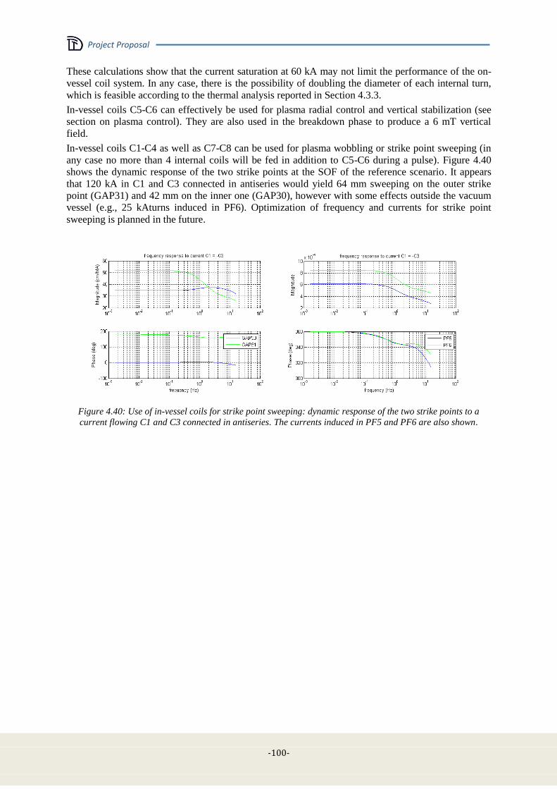
Project Proposal
-100-
These calculations show that the current saturation at 60 kA may not limit the performance of the on-
vessel coil system. In any case, there is the possibility of doubling the diameter of each internal turn,
which is feasible according to the thermal analysis reported in Section 4.3.3.
In-vessel coils C5-C6 can effectively be used for plasma radial control and vertical stabilization (see
section on plasma control). They are also used in the breakdown phase to produce a 6 mT vertical
field.
In-vessel coils C1-C4 as well as C7-C8 can be used for plasma wobbling or strike point sweeping (in
any case no more than 4 internal coils will be fed in addition to C5-C6 during a pulse). Figure 4.40
shows the dynamic response of the two strike points at the SOF of the reference scenario. It appears
that 120 kA in C1 and C3 connected in antiseries would yield 64 mm sweeping on the outer strike
point (GAP31) and 42 mm on the inner one (GAP30), however with some effects outside the vacuum
vessel (e.g., 25 kAturns induced in PF6). Optimization of frequency and currents for strike point
sweeping is planned in the future.
Figure 4.40: Use of in-vessel coils for strike point sweeping: dynamic response of the two strike points to a
current flowing C1 and C3 connected in antiseries. The currents induced in PF5 and PF6 are also shown.
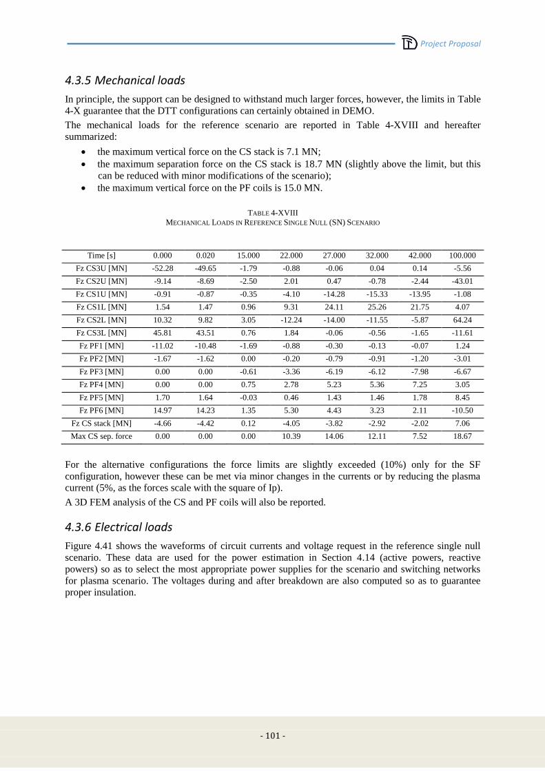
Project Proposal
- 101 -
4.3.5 Mechanical loads
In principle, the support can be designed to withstand much larger forces, however, the limits in Table
4-X guarantee that the DTT configurations can certainly obtained in DEMO.
The mechanical loads for the reference scenario are reported in Table 4-XVIII and hereafter
summarized:
the maximum vertical force on the CS stack is 7.1 MN;
the maximum separation force on the CS stack is 18.7 MN (slightly above the limit, but this
can be reduced with minor modifications of the scenario);
the maximum vertical force on the PF coils is 15.0 MN.
TABLE 4-XVIII
MECHANICAL LOADS IN REFERENCE SINGLE NULL (SN) SCENARIO
Time [s] 0.000 0.020 15.000 22.000 27.000 32.000 42.000 100.000
Fz CS3U [MN] -52.28 -49.65 -1.79 -0.88 -0.06 0.04 0.14 -5.56
Fz CS2U [MN] -9.14 -8.69 -2.50 2.01 0.47 -0.78 -2.44 -43.01
Fz CS1U [MN] -0.91 -0.87 -0.35 -4.10 -14.28 -15.33 -13.95 -1.08
Fz CS1L [MN] 1.54 1.47 0.96 9.31 24.11 25.26 21.75 4.07
Fz CS2L [MN] 10.32 9.82 3.05 -12.24 -14.00 -11.55 -5.87 64.24
Fz CS3L [MN] 45.81 43.51 0.76 1.84 -0.06 -0.56 -1.65 -11.61
Fz PF1 [MN] -11.02 -10.48 -1.69 -0.88 -0.30 -0.13 -0.07 1.24
Fz PF2 [MN] -1.67 -1.62 0.00 -0.20 -0.79 -0.91 -1.20 -3.01
Fz PF3 [MN] 0.00 0.00 -0.61 -3.36 -6.19 -6.12 -7.98 -6.67
Fz PF4 [MN] 0.00 0.00 0.75 2.78 5.23 5.36 7.25 3.05
Fz PF5 [MN] 1.70 1.64 -0.03 0.46 1.43 1.46 1.78 8.45
Fz PF6 [MN] 14.97 14.23 1.35 5.30 4.43 3.23 2.11 -10.50
Fz CS stack [MN] -4.66 -4.42 0.12 -4.05 -3.82 -2.92 -2.02 7.06
Max CS sep. force 0.00 0.00 0.00 10.39 14.06 12.11 7.52 18.67
For the alternative configurations the force limits are slightly exceeded (10%) only for the SF
configuration, however these can be met via minor changes in the currents or by reducing the plasma
current (5%, as the forces scale with the square of Ip).
A 3D FEM analysis of the CS and PF coils will also be reported.
4.3.6 Electrical loads
Figure 4.41 shows the waveforms of circuit currents and voltage request in the reference single null
scenario. These data are used for the power estimation in Section 4.14 (active powers, reactive
powers) so as to select the most appropriate power supplies for the scenario and switching networks
for plasma scenario. The voltages during and after breakdown are also computed so as to guarantee
proper insulation.

Project Proposal
-102-
Figure 4.41: Waveforms of circuit currents and voltage request in the reference single null scenario.
4.3.7 AC losses
The assessment of the ac losses can be a valid help for the choice of both the strand filament diameter,
deff, and the possible use of the sub-cable wrapping, in addition to the external wrapping. As a matter
of fact, deff has an impact on strand’s cost, with more complicated compaction steps for thin diameters,
whereas the sub-cable wrapping can impact on cable regularity and current distribution homogeneity
within the cable cross-section. Also, it should be pointed out that the sub-cable wrapping can induce
preferential cooling paths, thus decreasing the cooling capacity.
In this first analysis, we aim to evaluate the heat load due to AC losses in the Central Solenoid, being
the most critical one for the entire magnet system, in the plasma reference scenario. We won’t
consider here the case of the plasma disruption for neither the CS nor TF coils; such a scenario will be
detailed later.
Three types of AC losses are calculated: the hysteresis losses, Qhyst, derived from the irreversible
magnetization due to the pinning of fluxoids, which arises when the external magnetic field B is
swept; the coupling losses, Qcoupl, ascribed to the coupling currents in multifilamentary wires and
multistage cables, which flow in the superconducting material and close through the normal metal
(where Ohmic dissipation takes place); and the eddy current losses, Qeddy, which we consider to take
place only in the cable jacket.
As far as the term Qcoupl is concerned, this depends on the rate of change of the applied magnetic field.
Qcoupl can be modelled by means of a characteristic coupling constant, , which in turns depends on the
interfilament transverse resistivity. For sake of simplicity, in this model we will assume a single

Project Proposal
- 103 -
effective time constant, thus neglecting the actual multistage cable layout. On the contrary, Qhyst is
independent on the rate of change of the applied field.
If we assume that the system can be described in terms of isolated cylindrical wires in transversal
field, the formulae for the power dissipation per unit volume Qhyst and Qcoupl and Qeddy (in W/m3) are
[4.18]:
where Be and Bi are the external applied field and the induction field inside the cable, respectively,
is the normalized transport current, n is a geometrical factor (n = 2), Jc(B,T) is the critical
current density, and lout and jacket are the outer dimension of the jacket and its resistivity, respectively.
In order to simplify the computations, and consistently with the scope of the present preliminary study,
we consider a quasi-static regime (i.e., slow varying fields with respect to the time scale of transients)
in which the internal and external field variations are related through the expression [4.19]:
We further assume that BiBe and hence .
Power losses per unit length (W/m) can be obtained by multiplying Equations (1-2) by the wire’s
cross-section, ATOT, and Equation (3) by an effective jacket cross-section Ajacket = (l1*l2 – l33*l4/l1
2[4.20]
where l1 and l2 are the outer dimensions of the conduit, respectively normal and parallel to the
direction of the field change, while l3 and l4 are the corresponding inner dimensions.
We consider the DDT reference scenario for the CS coils, which can be divided in the following main
phases (see Figure 4.42for the magnetic field variations):
1) Charge of the coil (300 s)
2) Fast ramp down of the field (27 s)
3) Flat top (100 s)
4) Final discharge of the coil (300 s)

Project Proposal
-104-
Figure 4.42: Magnetic field (modulus) vs. Time for the CS reference scenario.
We take n = 55 ms and deff = 5 m as values representative for the time constant and the filament
size, respectively, whereas Jc 1000 A/mm2 and jacket = 7.8x10
-7m [4.21].
The total power loss is reported in Figure 4.43 along with the hysteresis, coupling and eddy current
contributions.
Figure 4.43: Total power loss and contributions due to various mechanisms, vs. time in the pancake subject to
the largest field.
The overall loss results (in Joule) for the case studied are summarized in Table 4-XIX
TABLE 4-XIX
TOTAL AC LOSSES BY CS REFERENCE SCENARIO
Qhyst (kJ) Qcoup (kJ) Qeddy (J) QTOT (J)
19.1 68.5 9 87.6
Coupling losses are more than four times larger than hysteresis losses, whereas the eddy currents on
the jacket can be neglected.
12
8
4
0
|B| (T
)
4002000-200
t (s)
10-2
10-1
100
101
102
103
104
105
106
Po
we
r L
oss (
W/m
3)
4002000-200
Time (s)
Hysteresis Coupling Eddy Current TOTAL
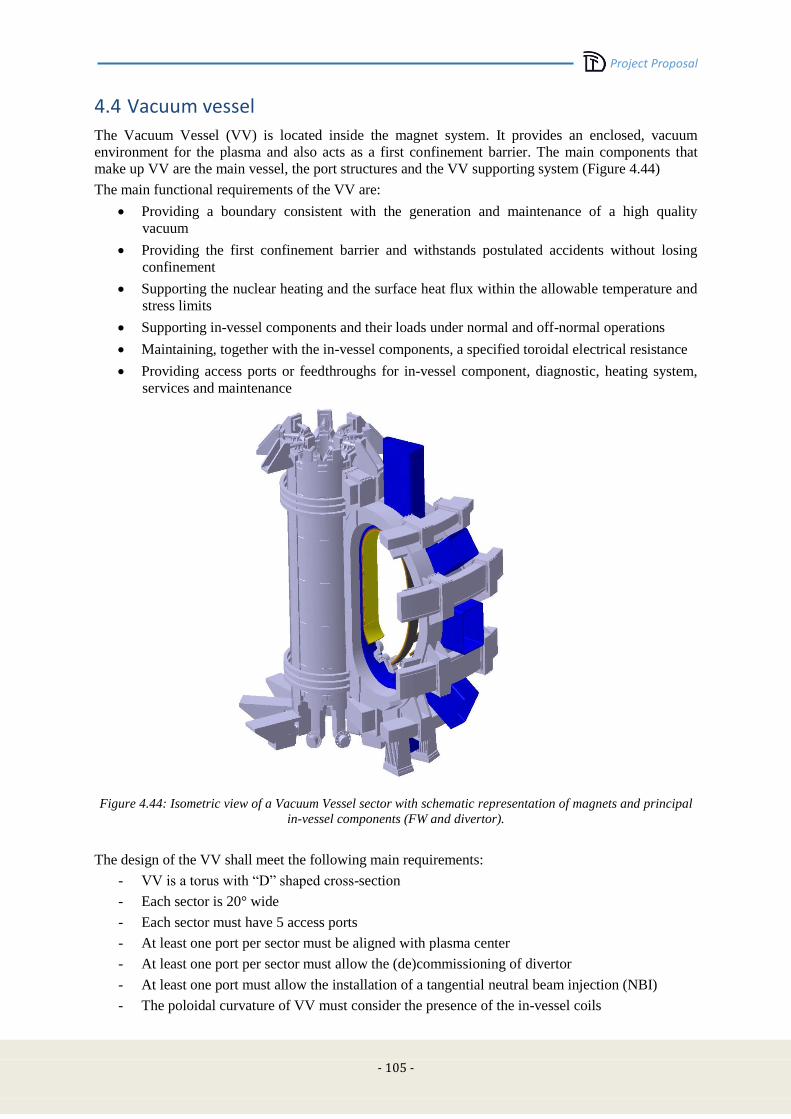
Project Proposal
- 105 -
4.4 Vacuum vessel
The Vacuum Vessel (VV) is located inside the magnet system. It provides an enclosed, vacuum
environment for the plasma and also acts as a first confinement barrier. The main components that
make up VV are the main vessel, the port structures and the VV supporting system (Figure 4.44)
The main functional requirements of the VV are:
Providing a boundary consistent with the generation and maintenance of a high quality
vacuum
Providing the first confinement barrier and withstands postulated accidents without losing
confinement
Supporting the nuclear heating and the surface heat flux within the allowable temperature and
stress limits
Supporting in-vessel components and their loads under normal and off-normal operations
Maintaining, together with the in-vessel components, a specified toroidal electrical resistance
Providing access ports or feedthroughs for in-vessel component, diagnostic, heating system,
services and maintenance
Figure 4.44: Isometric view of a Vacuum Vessel sector with schematic representation of magnets and principal
in-vessel components (FW and divertor).
The design of the VV shall meet the following main requirements:
- VV is a torus with “D” shaped cross-section
- Each sector is 20° wide
- Each sector must have 5 access ports
- At least one port per sector must be aligned with plasma center
- At least one port per sector must allow the (de)commissioning of divertor
- At least one port must allow the installation of a tangential neutral beam injection (NBI)
- The poloidal curvature of VV must consider the presence of the in-vessel coils

Project Proposal
-106-
- The ports position and geometry shall be defined taking into account the interface with PF
coil, TF coil and the inter-coil structure.
4.4.1 Main vessel
The main vessel is a torus with “D” shaped cross-section, segmented by 20 degree modules. The
operating scenarios of the VV are characterized by loads which are quite low during normal plasma
behaviour and rather large during plasma VDE [4.22] and disruptions. The worst disruption expected
for the VV is a strongly vertically asymmetric VDE.
We assumed a VDE model where the vertical displacement of the plasma column is followed by a
sudden loss of the plasma thermal energy (when the safety factor q goes below 1.5) and then by a fast
current quench (1.5 MA/ms).
The basic vessel design is an all-welded single wall structure. The 18 sectors are joined by field
welding. The maximum thickness of the shell is 35mm. The VV profile in a poloidal plane is made by
single curvature segments. Thus the resulting shell will have a double curvature at the outboard side
and a single curvature at the inboard side, where the shells of the central segment are cylindrical. The
shell will be manufactured by hot forming/bending and welding.
Overall external dimensions of the vacuum vessel are 3660 mm in height with a diameter of 2540 mm
at the inboard side and a diameter of 6890 mm at the outboard side (Figure 4.45).
Figure 4.45: Overall dimensions (in mm) of main vessel sector (top and side views)
The principle of material choice for vacuum vessel has a significant influence on performance,
fabrication characteristics, mechanical strength at operating temperature, chemistry properties, and
cost. Compared with other possible candidates, INCONEL 625 stainless steel has good mechanical
properties, good chemistry properties and higher resistivity than AISI316L(N). Thus it has
provisionally selected as main material of the vessel. Table 4-XX shows the main parameter of
vacuum vessel and material.
TABLE 4-XX - VV MAIN CHARACTERISTICS
Size
Toroidal Extent of Sector 20o
Shell Thickness 35mm
Ports Thickness 25mm
Material INCONEL 625
Resistivity [Ωm] 13.2e-07

Project Proposal
- 107 -
VV shall provide several openings for the plasma diagnostic systems, the vacuum system, the
auxiliary heating system, the in-vessel Remote Handling (RH) maintenance system, etc.
A minimal clearance of 100 mm between VV and the magnetic coils has been left to house proper
neutral (see sec. 4.7.3) and thermal shields (not presented in details at the current stage of the design).
1
2
4
3
5
11
22
44
33
5
Figure 4.46: DTT VV – 20° module with ports provisional numbering
4.4.2 Access ports
As mentioned, each vessel sector is equipped with 5 access ports which have been provisionally
numbered clockwise from top to bottom (Figure 4.46). These ports are used for the maintenance and
the replacement of the in-vessel components (divertor cassette, first wall) and for the allocation of
diagnostic and heating equipment. Access ports have been conceived as single-walled structures
welded to the main vessel. Their thickness has been provisionally determined in 25mm.
As required, port nr.2 is aligned to see plasma center (Figure 4.47).
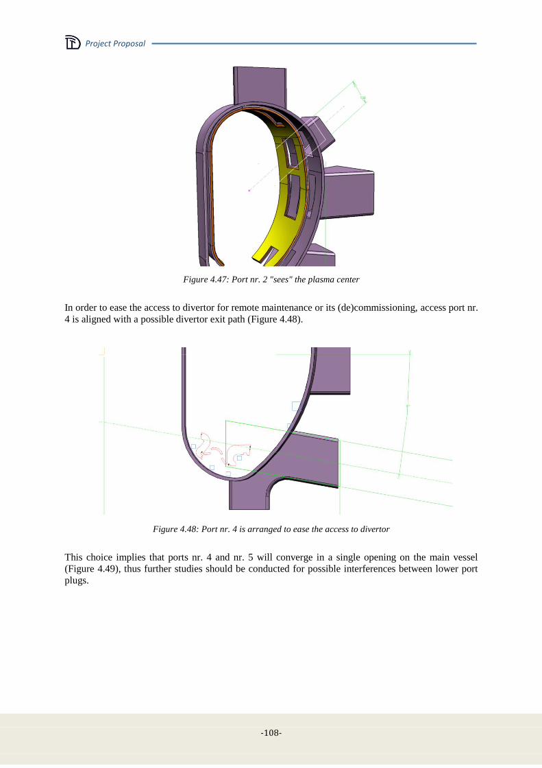
Project Proposal
-108-
Figure 4.47: Port nr. 2 "sees" the plasma center
In order to ease the access to divertor for remote maintenance or its (de)commissioning, access port nr.
4 is aligned with a possible divertor exit path (Figure 4.48).
Figure 4.48: Port nr. 4 is arranged to ease the access to divertor
This choice implies that ports nr. 4 and nr. 5 will converge in a single opening on the main vessel
(Figure 4.49), thus further studies should be conducted for possible interferences between lower port
plugs.
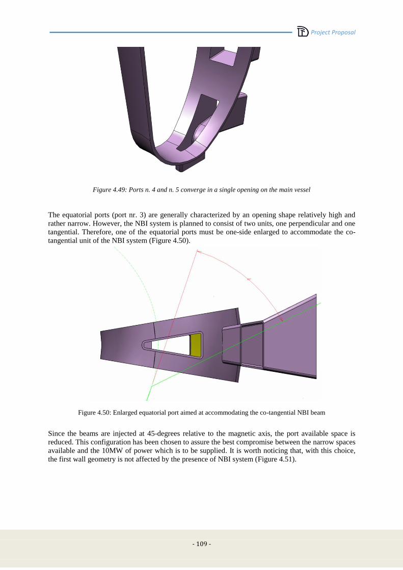
Project Proposal
- 109 -
Figure 4.49: Ports n. 4 and n. 5 converge in a single opening on the main vessel
The equatorial ports (port nr. 3) are generally characterized by an opening shape relatively high and
rather narrow. However, the NBI system is planned to consist of two units, one perpendicular and one
tangential. Therefore, one of the equatorial ports must be one-side enlarged to accommodate the co-
tangential unit of the NBI system (Figure 4.50).
Figure 4.50: Enlarged equatorial port aimed at accommodating the co-tangential NBI beam
Since the beams are injected at 45-degrees relative to the magnetic axis, the port available space is
reduced. This configuration has been chosen to assure the best compromise between the narrow spaces
available and the 10MW of power which is to be supplied. It is worth noticing that, with this choice,
the first wall geometry is not affected by the presence of NBI system (Figure 4.51).
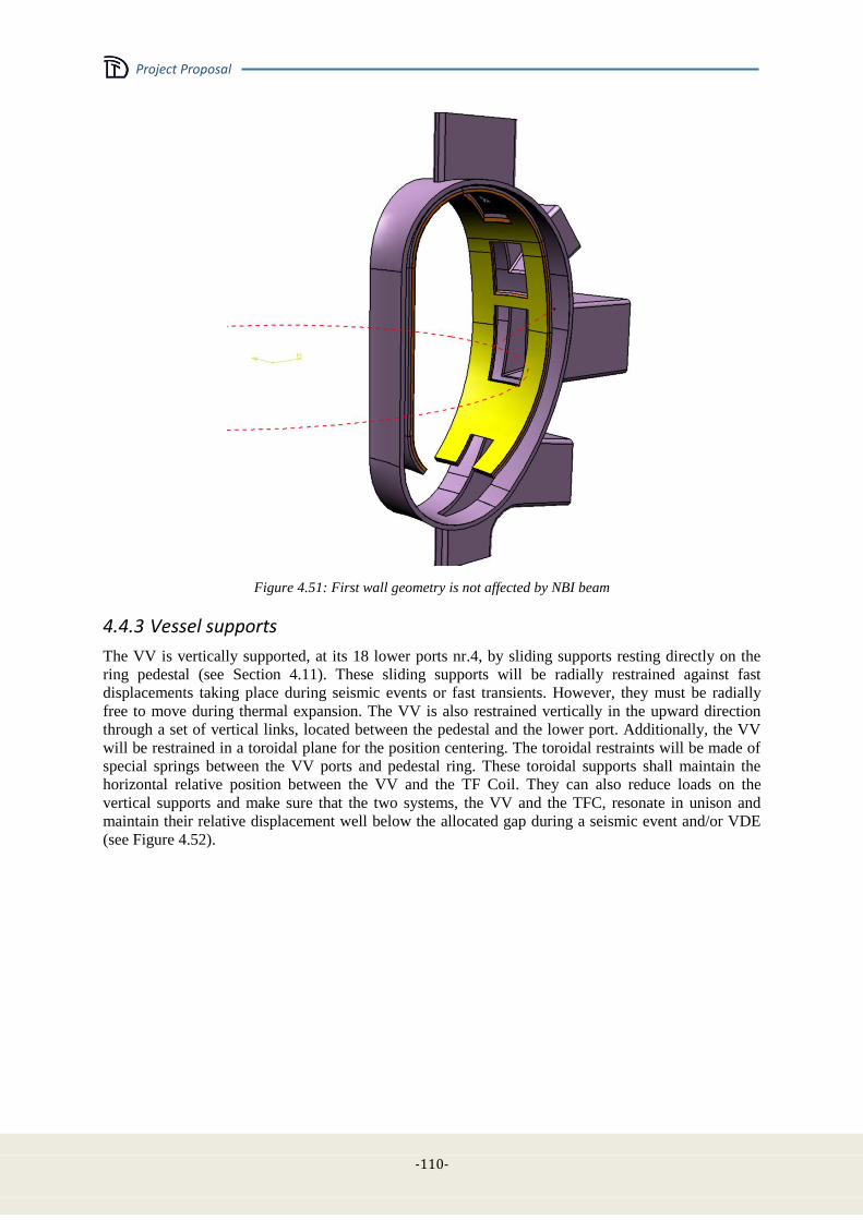
Project Proposal
-110-
Figure 4.51: First wall geometry is not affected by NBI beam
4.4.3 Vessel supports
The VV is vertically supported, at its 18 lower ports nr.4, by sliding supports resting directly on the
ring pedestal (see Section 4.11). These sliding supports will be radially restrained against fast
displacements taking place during seismic events or fast transients. However, they must be radially
free to move during thermal expansion. The VV is also restrained vertically in the upward direction
through a set of vertical links, located between the pedestal and the lower port. Additionally, the VV
will be restrained in a toroidal plane for the position centering. The toroidal restraints will be made of
special springs between the VV ports and pedestal ring. These toroidal supports shall maintain the
horizontal relative position between the VV and the TF Coil. They can also reduce loads on the
vertical supports and make sure that the two systems, the VV and the TFC, resonate in unison and
maintain their relative displacement well below the allocated gap during a seismic event and/or VDE
(see Figure 4.52).
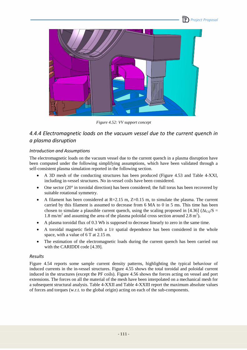
Project Proposal
- 111 -
Figure 4.52: VV support concept
4.4.4 Electromagnetic loads on the vacuum vessel due to the current quench in a plasma disruption
Introduction and Assumptions
The electromagnetic loads on the vacuum vessel due to the current quench in a plasma disruption have
been computed under the following simplifying assumptions, which have been validated through a
self-consistent plasma simulation reported in the following section.
A 3D mesh of the conducting structures has been produced (Figure 4.53 and Table 4-XXI,
including in-vessel structures. No in-vessel coils have been considered.
One sector (20° in toroidal direction) has been considered; the full torus has been recovered by
suitable rotational symmetry.
A filament has been considered at R=2.15 m, Z=0.15 m, to simulate the plasma. The current
carried by this filament is assumed to decrease from 6 MA to 0 in 5 ms. This time has been
chosen to simulate a plausible current quench, using the scaling proposed in [4.36] (tCQ/S =
1.8 ms/m2 and assuming the area of the plasma poloidal cross section around 2.8 m
2).
A plasma toroidal flux of 0.3 Wb is supposed to decrease linearly to zero in the same time.
A toroidal magnetic field with a 1/r spatial dependence has been considered in the whole
space, with a value of 6 T at 2.15 m.
The estimation of the electromagnetic loads during the current quench has been carried out
with the CARIDDI code [4.39].
Results
Figure 4.54 reports some sample current density patterns, highlighting the typical behaviour of
induced currents in the in-vessel structures. Figure 4.55 shows the total toroidal and poloidal current
induced in the structures (except the PF coils). Figure 4.56 shows the forces acting on vessel and port
extensions. The forces on all the material of the mesh have been interpolated on a mechanical mesh for
a subsequent structural analysis. Table 4-XXII and Table 4-XXIII report the maximum absolute values
of forces and torques (w.r.t. to the global origin) acting on each of the sub-components.

Project Proposal
-112-
Figure 4.53: 3D mesh used in the disruption analysis Figure 4.54: Sample current density pattern
Figure 4.55: Total toroidal and poloidal current induced in the structures (except the PF coils)

Project Proposal
- 113 -
TABLE 4-XXI
MATERIAL DESCRIPTION.
Material
index Description
Resistivity
[m]
Material
index Description
Resistivity
[m]
1 Vessel 1.61e-6 16 Backplate - toroidal
intermediate 1.61e-6
2 Port extension - 1 1.61e-6 17 Backplate - toroidal lower 1.61e-6
3 Port extension - 2 1.61e-6 18 Cooling plate - upper 8.e-6
4 Port extension - 3 1.61e-6 19 Cooling plate - intermediate 8.e-6
5 Port extension - 4 1.61e-6 20 Cooling plate - lower 8.e-6
6 Support - upper 1.61e-6 21 Cooling plate - toroidal upper 8.e-6
7 Support - intermediate 1.61e-6 22 Cooling plate - toroidal
intermediate 8.e-6
8 Support - lower 1.61e-6 23 Cooling plate - toroidal lower 8.e-6
9 Support - toroidal upper 1.61e-6 24 First wall - upper 5.6e-8
10 Support - toroidal
intermediate 1.61e-6 25 First wall - intermediate 5.6e-8
11 Support - toroidal lower 1.61e-6 26 First wall - lower 5.6e-8
12 Backplate - upper 1.61e-6 27 First wall - toroidal upper 5.6e-8
13 Backplate- intermediate 1.61e-6 28 First wall - toroidal
intermediate 5.6e-8
14 Backplate - lower 1.61e-6 29 First wall - toroidal lower 5.6e-8
15 Backplate - toroidal upper 1.61e-6 30-41 PF coils 0.
Figure 4.56: Forces acting on the vessel (material #1) and port extension #3 (material #4)
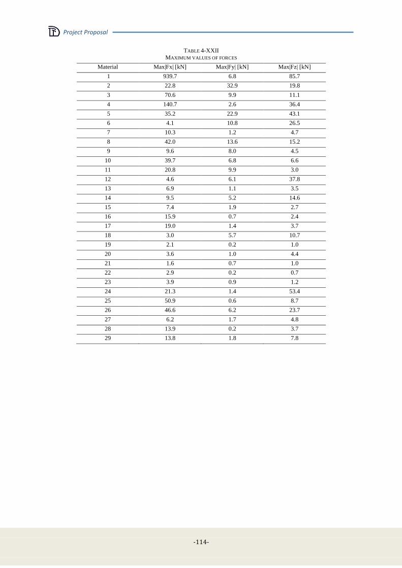
Project Proposal
-114-
TABLE 4-XXII
MAXIMUM VALUES OF FORCES
Material Max|Fx| [kN] Max|Fy| [kN] Max|Fz| [kN]
1 939.7 6.8 85.7
2 22.8 32.9 19.8
3 70.6 9.9 11.1
4 140.7 2.6 36.4
5 35.2 22.9 43.1
6 4.1 10.8 26.5
7 10.3 1.2 4.7
8 42.0 13.6 15.2
9 9.6 8.0 4.5
10 39.7 6.8 6.6
11 20.8 9.9 3.0
12 4.6 6.1 37.8
13 6.9 1.1 3.5
14 9.5 5.2 14.6
15 7.4 1.9 2.7
16 15.9 0.7 2.4
17 19.0 1.4 3.7
18 3.0 5.7 10.7
19 2.1 0.2 1.0
20 3.6 1.0 4.4
21 1.6 0.7 1.0
22 2.9 0.2 0.7
23 3.9 0.9 1.2
24 21.3 1.4 53.4
25 50.9 0.6 8.7
26 46.6 6.2 23.7
27 6.2 1.7 4.8
28 13.9 0.2 3.7
29 13.8 1.8 7.8
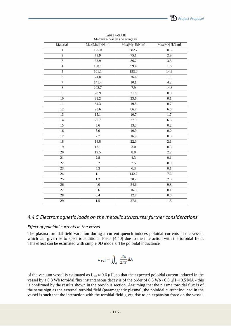
Project Proposal
- 115 -
TABLE 4-XXIII
MAXIMUM VALUES OF TORQUES
Material Max|Mx| [kN m] Max|My| [kN m] Max|Mz| [kN m]
1 125.0 382.7 8.6
2 72.9 75.1 2.9
3 68.9 86.7 3.3
4 168.1 99.4 1.6
5 101.1 153.0 14.6
6 74.8 76.6 11.0
7 141.4 10.1 4.2
8 202.7 7.9 14.8
9 28.9 21.8 0.3
10 88.2 33.6 0.1
11 84.3 19.5 0.7
12 23.6 86.7 6.6
13 15.1 10.7 1.7
14 20.7 27.9 6.6
15 3.6 13.3 0.2
16 5.0 10.9 0.0
17 7.7 16.9 0.3
18 18.8 22.3 2.1
19 13.1 3.0 0.5
20 19.5 8.0 2.2
21 2.8 4.3 0.1
22 3.2 2.5 0.0
23 5.3 6.3 0.1
24 1.1 142.2 7.6
25 1.2 30.7 2.5
26 4.0 54.6 9.8
27 0.6 16.9 0.1
28 0.4 12.7 0.0
29 1.5 27.6 1.3
4.4.5 Electromagnetic loads on the metallic structures: further considerations
Effect of poloidal currents in the vessel The plasma toroidal field variation during a current quench induces poloidal currents in the vessel,
which can give rise to specific additional loads [4.40] due to the interaction with the toroidal field.
This effect can be estimated with simple 0D models. The poloidal inductance
of the vacuum vessel is estimated as Lpol 0.6 H, so that the expected poloidal current induced in the
vessel by a 0.3 Wb toroidal flux instantaneous decay is of the order of 0.3 Wb / 0.6 H 0.5 MA - this
is confirmed by the results shown in the previous section. Assuming that the plasma toroidal flux is of
the same sign as the external toroidal field (paramagnetic plasma), the poloidal current induced in the
vessel is such that the interaction with the toroidal field gives rise to an expansion force on the vessel.
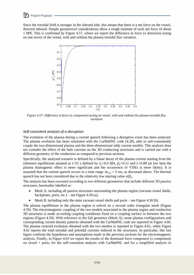
Project Proposal
-116-
Since the toroidal field is stronger in the inboard side, this means that there is a net force on the vessel,
directed inboard. Simple geometrical considerations allow a rough estimate of such net force of about
1 MN. This is confirmed by Figure 4.57, where we report the difference in force (x direction) acting
on one sector of the vessel, with and without the plasma toroidal flux variation.
Figure 4.57: Difference in force (x component) acting on vessel, with and without the plasma toroidal flux
variation
Self-consistent analysis of a disruption
The evolution of the plasma during a current quench following a disruptive event has been analysed.
The plasma evolution has been simulated with the CarMa0NL code [4.38], able to self-consistently
couple the two-dimensional plasma and the three-dimensional eddy current models. This analysis does
not consider the effect of the halo currents on the 3D conducting structures and is carried out with a
different geometry of the conductors as compared to previous sections.
Specifically, the analysed scenario is defined by a linear decay of the plasma current starting from the
reference equilibrium attained at t=32 s defined by Ip=6.0 MA, p=0.11 and li=0.88 (at low beta the
plasma diamagnetic effect is more significant and the occurrence of VDEs is more likely). It is
assumed that the current quench occurs in a time range tCQ = 5 ms, as discussed above. The thermal
quench has not been considered due to the relatively low starting value ofp.
The analysis has been executed according to two different geometries that include different 3D passive
structures, hereinafter labelled as:
Mesh A: including all passive structures surrounding the plasma region (vacuum vessel shells,
backplates, ports, etc.) – see Figure 4.58 (a).
Mesh B: including only the main vacuum vessel shells and ports – see Figure 4.58 (b).
The plasma equilibrium in the plasma region is solved on a second order triangular mesh (Figure
4.59). The electromagnetic coupling of the two models associated to the plasma region and conductive
3D structures is made according coupling conditions fixed on a coupling surface in between the two
regions (Figure 4.59). With reference to the full geometry (Mesh A), some plasma configurations and
corresponding current density patterns obtained with the CarMa0NL code are reported in Figure 4.60.
The plasma centroid evolution obtained with the two meshes is reported in Figure 4.61, while Figure
4.62 reports the total toroidal and poloidal currents induced in the structures. In particular, this last
figure confirms the hypotheses and assumptions made in the previous sections for the electromagnetic
analysis. Finally, in Figure 4.63 we report the results of the dominant force component (x component)
on vessel + ports, for the self-consistent analysis with CarMa0NL and for a simplified analysis in

Project Proposal
- 117 -
terms of a filament with a linearly decaying current, similarly to what was done in the previous
sections. The good agreement validates the assumptions made previously.
(a)
(b)
Figure 4.58: Discretizations used for self-consistent disruption analysis.
0 2 4-6
-4
-2
0
2
4
6
r [m]
z [
m]
1 2 3-2
-1.5
-1
-0.5
0
0.5
1
1.5
r [m]
z [
m]
Figure 4.59: Triangular finite elements mesh used in the plasma region. Green: coupling surface.
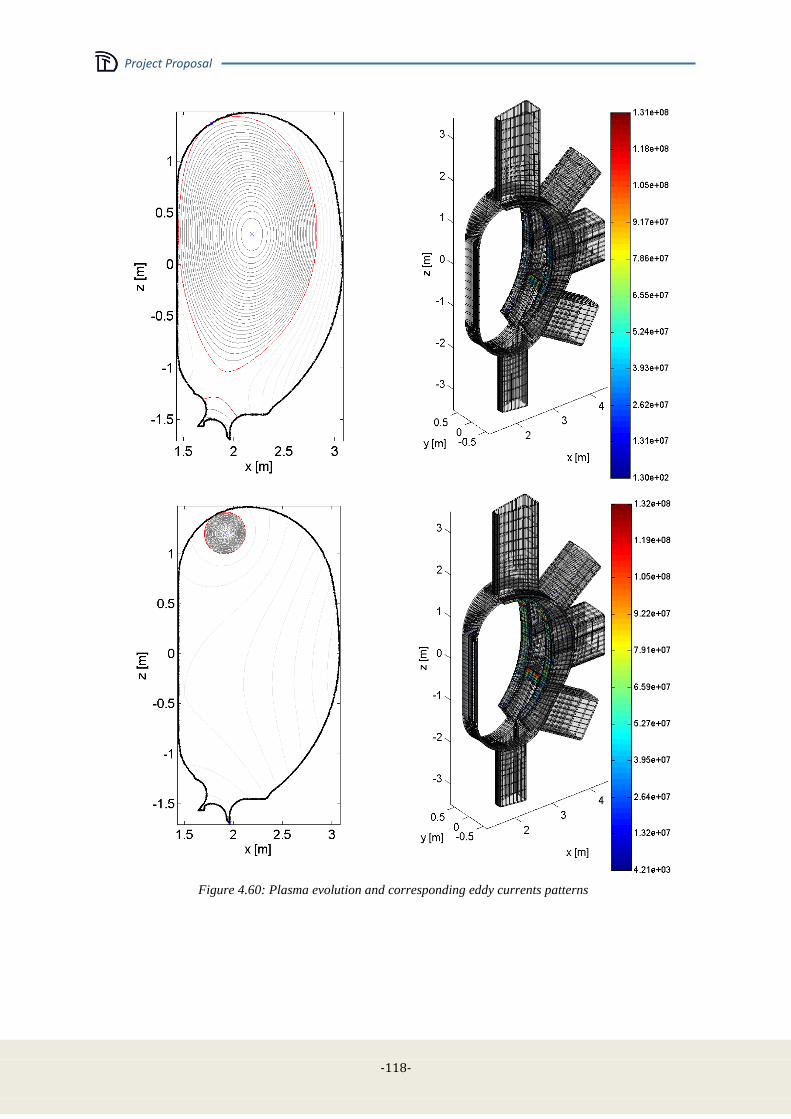
Project Proposal
-118-
Figure 4.60: Plasma evolution and corresponding eddy currents patterns

Project Proposal
- 119 -
0 0.02 0.04 0.060
0.2
0.4
0.6
0.8
1
1.2
1.4
Time [s]
Zc [
m]
MeshA
MeshB
0 0.02 0.04 0.061.85
1.9
1.95
2
2.05
2.1
2.15
2.2
2.25
Time [s]R
c [
m]
MeshA
MeshB
Figure 4.61: Comparison of the plasma position evolution obtained with the two meshes.
0 0.1 0.2 0.3 0.4 0.50
1
2
3
4
5
6x 10
6
Time [s]
I tor [
A]
0 0.1 0.2 0.3 0.4 0.5
0
1
2
3
4
5
6x 10
5
Time [s]
I po
l [A
]
Figure 4.62: Total toroidal and poloidal current induced in the vessel.
Figure 4.63: Assessment of force in the case of a purely filamentary current.

Project Proposal
-120-
Extrapolation to other cases
The previous analyses refer to what can be classified as a Major Disruption (MD), i.e. an event in
which the plasma current quench occurs before any intentional plasma movement. Previous detailed
analysis of disruptions in ITER [4.41] show that a MD provides a load on the vessel (in terms of
vertical component of force) which is comparable to other cases (e.g. fast VDEs) in which the load is
due mostly to eddy currents induced in the passive structures, i.e. when halo currents give a small
contribution. In this respect, the analysis carried out in previous sections provide significant
indications about the loads due to eddy currents induced in structures during disruptive events.
However, in ITER [4.41] it is shown that so-called "slow" events (e.g. slow downwards directed
VDEs) may provide significantly higher loads, essentially due to the effect of halo currents. Hence, a
detailed analysis should be carried out also considering the halo currents. A provisional indication
which can be recovered from [4.41] is that halo currents may provide a maximum load (in terms of
vertical force acting on vessel) around a factor 2 higher than in other cases. In addition, the effect of
toroidal asymmetries in halo currents (e.g. in terms of sideway forces) may be estimated by assuming
ITER prescriptions on toroidal peaking factor [4.36].
TF-coil discharge
A 0-th order model has been developed. We consider an axisymmetric vacuum vessel, of width d, in
which some currents in the poloidal direction can flow, so that it can be considered as a toroidal
inductor. Similarly, also the TF coil is supposed to behave like a toroidal inductor located outside the
vessel, with a prescribed current. This system of conductors can be described by:
where Lv =0.59 H is the poloidal self inductance of the vessel, M is the mutual inductance between
vessel and TF coil, Rv = 27 is the poloidal resistance of the vessel, ITF and Iv are the poloidal
currents in the TF and in the vessel respectively. Assuming
where I0 = 64.5 MAturns (giving rise to a toroidal magnetic field of 6 T at 2.15 m), and D = [1.5s, 3s],
we get the results shown in Figure 4.64, which are in very good agreement with the simple estimate:
which is valid assuming Iv << ITF.
The maximum value of the pressure on the vessel is, at each instant:
Since the highest values of Iv is at initial instants, we get:

Project Proposal
- 121 -
(A)
(B)
Figure 4.64: Poloidal current induced in the vessel by a TF discharge: (a) D = 1.5 s; (b) D = 3 s.
Hence, the maximum value of pressure is inversely proportional to D and is equal to:
FOR D=1.5 S
FOR D=3 S
4.4.6 Mechanical analysis
A stress analysis on the main vessel was conducted in order to validate the thicknesses and the
material provisionally defined and to identify possible critical areas. The electromagnetic loads on
metallic structures, as presented in Section 4.4.4, has been considered as an external forces field
applied to the vessel structures.
Simulation model
The model is made by the main vessel (35mm), the port structures (25 mm), the FW supports (25mm)
and the FW backplate (30mm) (Figure 4.65).
Figure 4.65: 3D models analyzed

Project Proposal
-122-
The coordinate system considered is cylindrical, its origin is aligned to the origin of CAD model at the
center of the tokamak on the equatorial plane. The directions are named as follows:
x is the radial direction
y is the angular coordinate
z is the vertical direction
The units used in this model are [mm, N].
A cyclic symmetry boundary condition has been imposed on the left and right surfaces of the vessel
sector (-10° and 10°) that are highlighted in Figure 4.66.
Figure 4.66: Cyclic boundary condition
The constraints have been placed on the external edge of lower port in order to allow rotations in x-z
planes and thermal deformation in radial direction. (see Figure 4.67)
Figure 4.67: boundary conditions
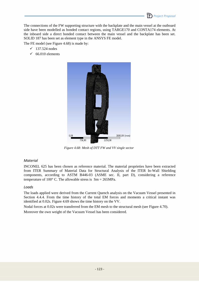
Project Proposal
- 123 -
The connections of the FW supporting structure with the backplate and the main vessel at the outboard
side have been modelled as bonded contact regions, using TARGE170 and CONTA174 elements. At
the inboard side a direct bonded contact between the main vessel and the backplate has been set.
SOLID 187 has been set as element type in the ANSYS FE model.
The FE model (see Figure 4.68) is made by:
137.524 nodes
66.010 elements
Figure 4.68: Mesh of DTT FW and VV single sector
Material
INCONEL 625 has been chosen as reference material. The material proprieties have been extracted
from ITER Summary of Material Data for Structural Analysis of the ITER In-Wall Shielding
components, according to ASTM B446-03 (ASME sec. II, part D), considering a reference
temperature of 100° C. The allowable stress is Sm = 265MPa.
Loads
The loads applied were derived from the Current Quench analysis on the Vacuum Vessel presented in
Section 4.4.4. From the time history of the total EM forces and moments a critical instant was
identified at 0.02s. Figure 4.69 shows the time history on the VV.
Nodal forces at 0.02s were transferred from the EM mesh to the structural mesh (see Figure 4.70).
Moreover the own weight of the Vacuum Vessel has been considered.
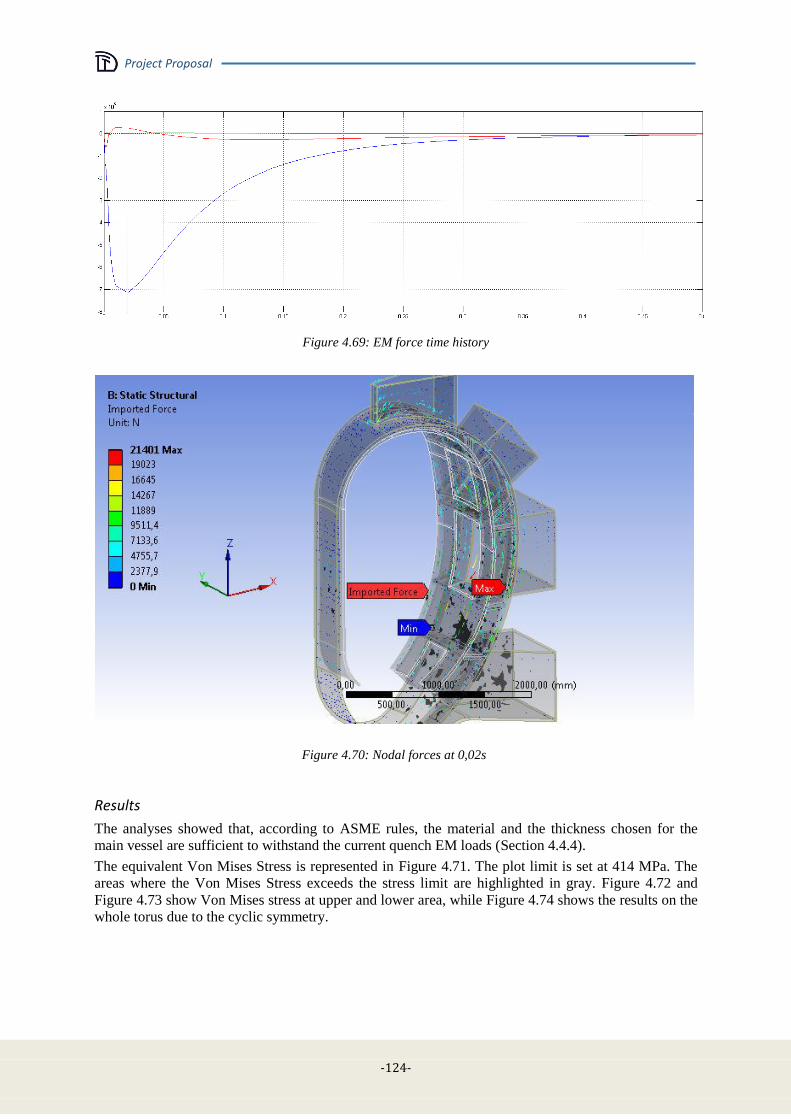
Project Proposal
-124-
Figure 4.69: EM force time history
Figure 4.70: Nodal forces at 0,02s
Results
The analyses showed that, according to ASME rules, the material and the thickness chosen for the
main vessel are sufficient to withstand the current quench EM loads (Section 4.4.4).
The equivalent Von Mises Stress is represented in Figure 4.71. The plot limit is set at 414 MPa. The
areas where the Von Mises Stress exceeds the stress limit are highlighted in gray. Figure 4.72 and
Figure 4.73 show Von Mises stress at upper and lower area, while Figure 4.74 shows the results on the
whole torus due to the cyclic symmetry.
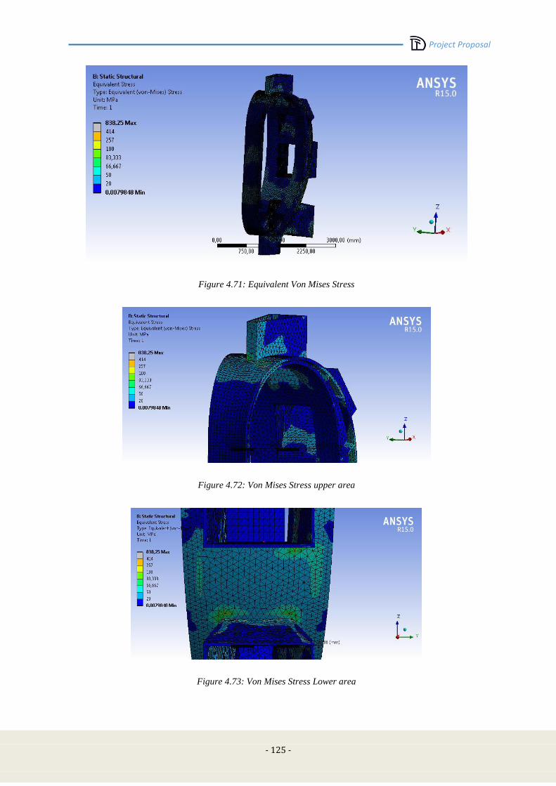
Project Proposal
- 125 -
Figure 4.71: Equivalent Von Mises Stress
Figure 4.72: Von Mises Stress upper area
Figure 4.73: Von Mises Stress Lower area
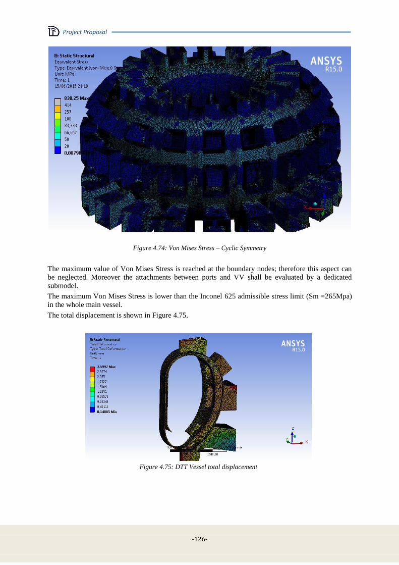
Project Proposal
-126-
Figure 4.74: Von Mises Stress – Cyclic Symmetry
The maximum value of Von Mises Stress is reached at the boundary nodes; therefore this aspect can
be neglected. Moreover the attachments between ports and VV shall be evaluated by a dedicated
submodel.
The maximum Von Mises Stress is lower than the Inconel 625 admissible stress limit (Sm =265Mpa)
in the whole main vessel.
The total displacement is shown in Figure 4.75.
Figure 4.75: DTT Vessel total displacement
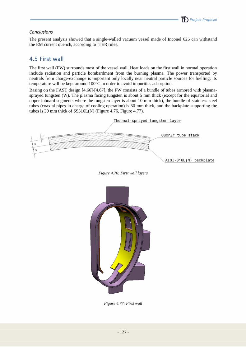
Project Proposal
- 127 -
Conclusions
The present analysis showed that a single-walled vacuum vessel made of Inconel 625 can withstand
the EM current quench, according to ITER rules.
4.5 First wall
The first wall (FW) surrounds most of the vessel wall. Heat loads on the first wall in normal operation
include radiation and particle bombardment from the burning plasma. The power transported by
neutrals from charge-exchange is important only locally near neutral particle sources for fuelling. Its
temperature will be kept around 100°C in order to avoid impurities adsorption.
Basing on the FAST design [4.66]-[4.67], the FW consists of a bundle of tubes armored with plasma-
sprayed tungsten (W). The plasma facing tungsten is about 5 mm thick (except for the equatorial and
upper inboard segments where the tungsten layer is about 10 mm thick), the bundle of stainless steel
tubes (coaxial pipes in charge of cooling operation) is 30 mm thick, and the backplate supporting the
tubes is 30 mm thick of SS316L(N) (Figure 4.76, Figure 4.77).
Figure 4.76: First wall layers
Figure 4.77: First wall

Project Proposal
-128-
During start-up and disruptions, abnormal loads are experienced in addition when the first wall acts as
a limiter and from the impact of run-away electrons. For this reason, the tungsten layer is doubled at
the upper and equatorial inboard side, where thermal loads of 2-3 MW/m2 are expected.
The definition of the curvature on a poloidal plane meets the necessity to optimize the space available
for the plasma within the chamber, principally in the inner part of the chamber due to its criticality
during plasma operations. Indeed, in several scenarios with diverted configuration, and mainly after an
L-H transition, the shape controller needs to counteract plasma drift phenomena towards the Central
Solenoid and avoid plasma disruptions, caused by contacts with surrounding physical structures and
yielding a sudden loss of confinement and energy content. Apart from the controller response times,
plasma-wall clearance can be improved by leaving plasma as much allowed area as possible, which
means a placing of the FW as close as possible to the VV, except for a minimum tolerance to fill with
the supporting structure (Figure 4.78). Furthermore, the poloidal curvature needs to take into account
the presence of the in-vessel coils, placed between the equatorial and the vertical ports and exploited
for magnetic control purposes (Edge Localized Modes, vertical stability, radial position).
Figure 4.78: DTT FW profile
The design has to be remote-handling compatible. The feasibility of a remote maintenance via the
equatorial port represents a further main requirement in FW design. Therefore, a proper modular
design for the FW must be provided. Figure 4.79 depicts a possible conceptual segmentation of the
FW, yet compatible with the motion simulations through the equatorial port. At the current stage, 15
modules per sector are provided.
The physical separation between adjacent quarters is obtained via the introduction of a 5 mm
clearance. However, further studies should be conducted on FW support structure to better define their
modular design.

Project Proposal
- 129 -
Figure 4.79: Provisional FW segmentation in poloidal plane
4.5.1 Support structure for the first wall
As mentioned, the plasma-facing FW panel is supported by a backplate that will be jointed to the
vacuum vessel through a mechanical attachment system of flexible supports and a system of keys.
However, at the outboard side, the first wall is about 200 mm far from the vacuum chamber internal
surface. This implies that a suitable structure must be designed capable to support the backplate. The
provisional solution is shown in Figure 4.80.
Figure 4.80: Conceptual FW support structure at outboard side of the vacuum chamber
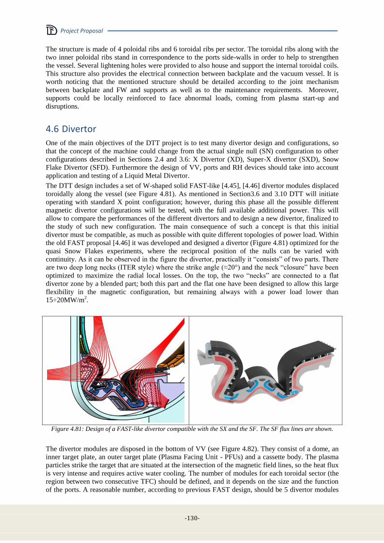
Project Proposal
-130-
The structure is made of 4 poloidal ribs and 6 toroidal ribs per sector. The toroidal ribs along with the
two inner poloidal ribs stand in correspondence to the ports side-walls in order to help to strengthen
the vessel. Several lightening holes were provided to also house and support the internal toroidal coils.
This structure also provides the electrical connection between backplate and the vacuum vessel. It is
worth noticing that the mentioned structure should be detailed according to the joint mechanism
between backplate and FW and supports as well as to the maintenance requirements. Moreover,
supports could be locally reinforced to face abnormal loads, coming from plasma start-up and
disruptions.
4.6 Divertor
One of the main objectives of the DTT project is to test many divertor design and configurations, so
that the concept of the machine could change from the actual single null (SN) configuration to other
configurations described in Sections 2.4 and 3.6: X Divertor (XD), Super-X divertor (SXD), Snow
Flake Divertor (SFD). Furthermore the design of VV, ports and RH devices should take into account
application and testing of a Liquid Metal Divertor.
The DTT design includes a set of W-shaped solid FAST-like [4.45], [4.46] divertor modules displaced
toroidally along the vessel (see Figure 4.81). As mentioned in Section3.6 and 3.10 DTT will initiate
operating with standard X point configuration; however, during this phase all the possible different
magnetic divertor configurations will be tested, with the full available additional power. This will
allow to compare the performances of the different divertors and to design a new divertor, finalized to
the study of such new configuration. The main consequence of such a concept is that this initial
divertor must be compatible, as much as possible with quite different topologies of power load. Within
the old FAST proposal [4.46] it was developed and designed a divertor (Figure 4.81) optimized for the
quasi Snow Flakes experiments, where the reciprocal position of the nulls can be varied with
continuity. As it can be observed in the figure the divertor, practically it “consists” of two parts. There
are two deep long necks (ITER style) where the strike angle (≈20°) and the neck “closure” have been
optimized to maximize the radial local losses. On the top, the two “necks” are connected to a flat
divertor zone by a blended part; both this part and the flat one have been designed to allow this large
flexibility in the magnetic configuration, but remaining always with a power load lower than
15÷20MW/m2.
Figure 4.81: Design of a FAST-like divertor compatible with the SX and the SF. The SF flux lines are shown.
The divertor modules are disposed in the bottom of VV (see Figure 4.82). They consist of a dome, an
inner target plate, an outer target plate (Plasma Facing Unit - PFUs) and a cassette body. The plasma
particles strike the target that are situated at the intersection of the magnetic field lines, so the heat flux
is very intense and requires active water cooling. The number of modules for each toroidal sector (the
region between two consecutive TFC) should be defined, and it depends on the size and the function
of the ports. A reasonable number, according to previous FAST design, should be 5 divertor modules
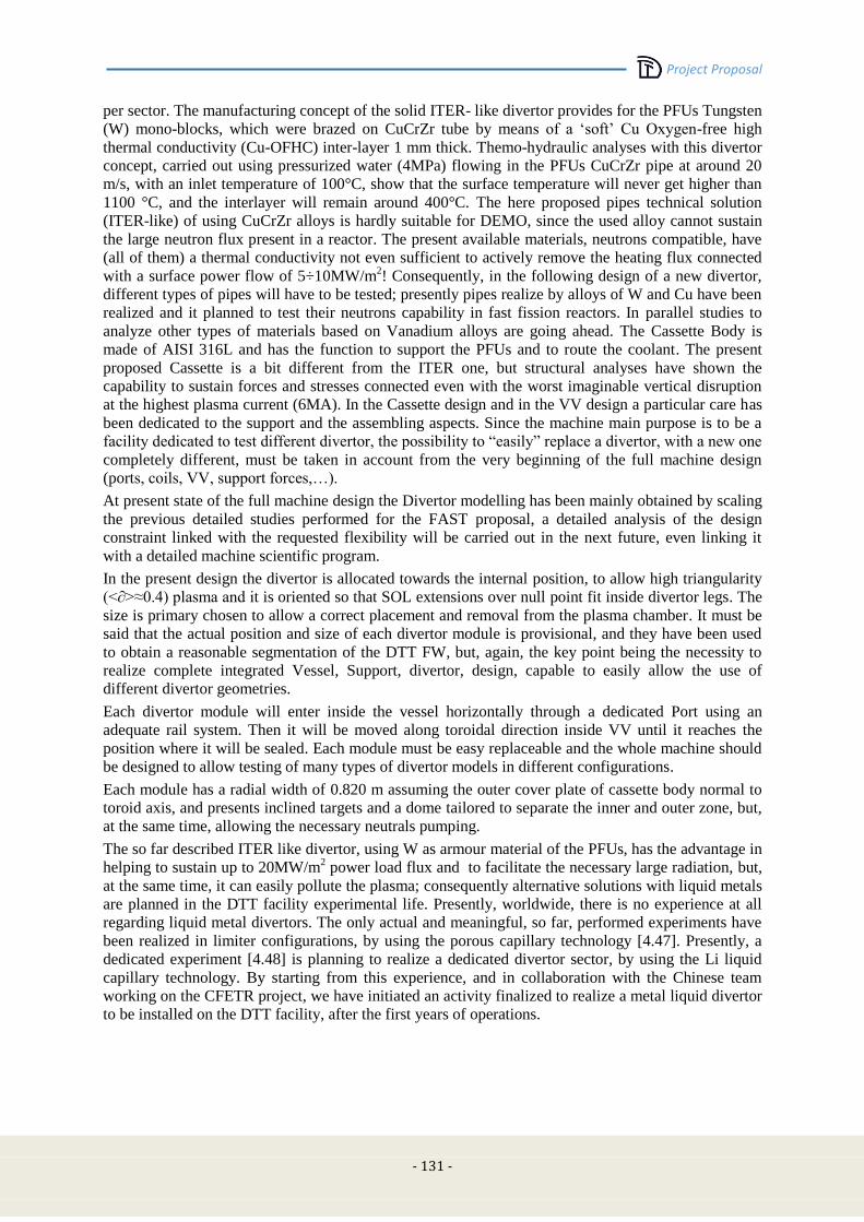
Project Proposal
- 131 -
per sector. The manufacturing concept of the solid ITER- like divertor provides for the PFUs Tungsten
(W) mono-blocks, which were brazed on CuCrZr tube by means of a ‘soft’ Cu Oxygen-free high
thermal conductivity (Cu-OFHC) inter-layer 1 mm thick. Themo-hydraulic analyses with this divertor
concept, carried out using pressurized water (4MPa) flowing in the PFUs CuCrZr pipe at around 20
m/s, with an inlet temperature of 100°C, show that the surface temperature will never get higher than
1100 °C, and the interlayer will remain around 400°C. The here proposed pipes technical solution
(ITER-like) of using CuCrZr alloys is hardly suitable for DEMO, since the used alloy cannot sustain
the large neutron flux present in a reactor. The present available materials, neutrons compatible, have
(all of them) a thermal conductivity not even sufficient to actively remove the heating flux connected
with a surface power flow of 5÷10MW/m2! Consequently, in the following design of a new divertor,
different types of pipes will have to be tested; presently pipes realize by alloys of W and Cu have been
realized and it planned to test their neutrons capability in fast fission reactors. In parallel studies to
analyze other types of materials based on Vanadium alloys are going ahead. The Cassette Body is
made of AISI 316L and has the function to support the PFUs and to route the coolant. The present
proposed Cassette is a bit different from the ITER one, but structural analyses have shown the
capability to sustain forces and stresses connected even with the worst imaginable vertical disruption
at the highest plasma current (6MA). In the Cassette design and in the VV design a particular care has
been dedicated to the support and the assembling aspects. Since the machine main purpose is to be a
facility dedicated to test different divertor, the possibility to “easily” replace a divertor, with a new one
completely different, must be taken in account from the very beginning of the full machine design
(ports, coils, VV, support forces,…).
At present state of the full machine design the Divertor modelling has been mainly obtained by scaling
the previous detailed studies performed for the FAST proposal, a detailed analysis of the design
constraint linked with the requested flexibility will be carried out in the next future, even linking it
with a detailed machine scientific program.
In the present design the divertor is allocated towards the internal position, to allow high triangularity
(<∂>≈0.4) plasma and it is oriented so that SOL extensions over null point fit inside divertor legs. The
size is primary chosen to allow a correct placement and removal from the plasma chamber. It must be
said that the actual position and size of each divertor module is provisional, and they have been used
to obtain a reasonable segmentation of the DTT FW, but, again, the key point being the necessity to
realize complete integrated Vessel, Support, divertor, design, capable to easily allow the use of
different divertor geometries.
Each divertor module will enter inside the vessel horizontally through a dedicated Port using an
adequate rail system. Then it will be moved along toroidal direction inside VV until it reaches the
position where it will be sealed. Each module must be easy replaceable and the whole machine should
be designed to allow testing of many types of divertor models in different configurations.
Each module has a radial width of 0.820 m assuming the outer cover plate of cassette body normal to
toroid axis, and presents inclined targets and a dome tailored to separate the inner and outer zone, but,
at the same time, allowing the necessary neutrals pumping.
The so far described ITER like divertor, using W as armour material of the PFUs, has the advantage in
helping to sustain up to 20MW/m2 power load flux and to facilitate the necessary large radiation, but,
at the same time, it can easily pollute the plasma; consequently alternative solutions with liquid metals
are planned in the DTT facility experimental life. Presently, worldwide, there is no experience at all
regarding liquid metal divertors. The only actual and meaningful, so far, performed experiments have
been realized in limiter configurations, by using the porous capillary technology [4.47]. Presently, a
dedicated experiment [4.48] is planning to realize a dedicated divertor sector, by using the Li liquid
capillary technology. By starting from this experience, and in collaboration with the Chinese team
working on the CFETR project, we have initiated an activity finalized to realize a metal liquid divertor
to be installed on the DTT facility, after the first years of operations.
Project Proposal
-132-
Figure 4.82: A possible DTT divertor for a single null configuration
4.7 Neutronics
4.7.1 Background
Although DTT is a machine operating without tritium, the assessment of the radiation fluxes,
loads and radiation damage is crucial in the design of the machine as a significant DD neutron
yield is expected. Concerning safety, the neutron-induced radioactivity, although not critical,
needs careful consideration for licensing, maintenance, and decommissioning, as well as for
waste management.
Nuclear analyses are then important to design DTT machine, for its licensing and diagnostics.
This chapter describes the first neutronic studies carried-out on DTT machine. After the
calculation of the neutron emissivity for H-mode reference scenario, 3-D neutronic
calculations were carried-out with MCNP5 Monte Carlo code [4.29] to assess the nuclear
loads in the toroidal-field coils. This is particularly crucial for the design of the
superconducting magnets because the heat deposited by neutrons and secondary gammas, if
not efficiently removed by liquid helium forced flow cooling, might produce the quench of
the superconductors.
On the basis of previous FAST studies, estimation of the neutron and gamma fluxes, nuclear
heating and dpa on plasma facing components (PFC) and neutron induced activation have
been performed as well.
4.7.2 DTT H-mode reference neutron rate
The neutron source (neutron emissivity [n m-3
s-1
] on a poloidal plasma section) foreseen for DTT
reference H-mode scenario (2.31020
peak electron density (ne), 11 keV peak electron temperature (Te)
was calculated using a code specifically developed in ENEA for ITER (Measurement Simulation
Software Tool (MSST) [4.30]. The source is evaluated by MSST using the equilibrium configuration
for the scenario, the ion temperature profile (Ti), the ion density profile (ni) and a parameterization of
the neutron reactivity in terms of the ion temperature [4.31]. Constant neutron emissivity on surfaces
of constant poloidal magnetic flux is assumed; moreover ni=ne and Ti=Te was assumed for DTT
calculations. Once the neutron source is given, the total neutron rate (n/s) is evaluated by integration of
the neutron source: a neutron rate value of 1.31017
n/s was obtained for DTT reference H-mode
scenario. It can be noted that this neutron rate is sensibly higher than the typical yield of current
machines operating in DD, but in line with modern tokamak performances (e.g. JT-60SA).

Project Proposal
- 133 -
4.7.3 Shielding assessment of TF coil
First calculations were performed to calculate the nuclear heating density of the first turn of the
toroidal field (TF) coil at the inboard equatorial zone. This zone has been selected because the higher
nuclear loads are on the equatorial plane and the space available for additional shielding at inboard
side is lower than in outboard zone. The MCNP model of FAST machine used for the assessment of
the nuclear heating of the FAST superconductive machine in 2010 [4.31]-[4.34] has been modified in
inboard leg in order to simulate the DTT radial layout from first wall (FW) to central solenoid (CS).
The deuterium-deuterium (DD) neutron source was described by a parametric representation of plasma
emissivity [4.35].
Figure 4.83 shows the modified MCNP neutronic model. It represents a 20° toroidal sector of the
machine. Reflecting boundary condition has been imposed to approximate the full extent of the
machine. For this pre-assessment only the thicknesses of FW, vacuum vessel (VV), TF and inner
space have been changed with respect to FAST model.
The nuclear heating has been calculated on the first turn of TF coil, without additional shield and
including various shielding options in the space between the VV and the TF front case (grey zone in
Figure 4.83). The results have been normalized to 1.3x10¹⁷
n/s, provided by MSST code, and corrected
by the neutron current on the first wall ratio in order to take into account the different dimensions of
DTT and FAST machine.
The following shielding configurations have been examined:
a) Reference configuration no additional shield
b) 5 cm 80% vol SS316+20% vol H20
c) 5 cm ITER-like VV mixture2
d) 5 cm B4C
e) 4 cm B4C
f) 3 cm B4C
g) 1 cm B4C
h) 2 cm 80% vol SS316+20% vol H20 + 3 cm B4C
The shielding material has been included in the grey zone in Figure 4.83. The thickness has also been
reduced for some configurations (Table 4-XXIV).
The nuclear heating densities in the first TF turn in inboard equatorial zone are reported in Table
4-XXIV and in Figure 4.84.
TABLE 4-XXIV
NUCLEAR HEATING DENSITY ON TF COIL INBOARD FIRST TURN
Shielding configuration mW/cm3
a) no shield 3.77
b) 5 cm 80% vol SS316+20% vol H20 3.23
c) 5 cm ITER VV-like mixture 2.03
d) 5 cm B4C 1.26
e) 4 cm B4C 1.45
f) 3 cm B4C 1.68
g) 1 cm B4C 2.32
h) 2 cm 80% vol SS316+20% vol H20 + 3 cm B4C 1.34
2 H20 41.0% , SS304B7 36. 9%, SS316L(N)-IG 15. 9%, Ti-6Al-4V 1. 9%, Inconel 625 0.5%
vol and CuNiBe, 0.4% (volume %), the remainder is void.
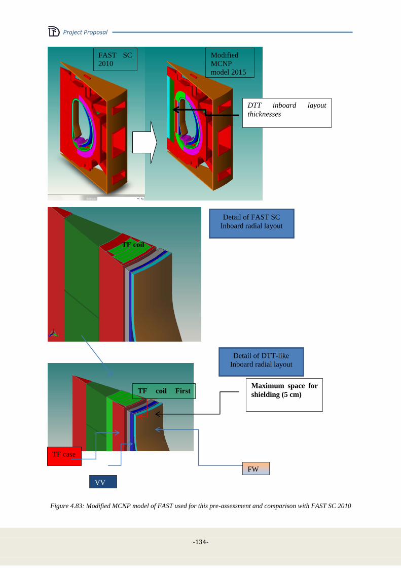
Project Proposal
-134-
Figure 4.83: Modified MCNP model of FAST used for this pre-assessment and comparison with FAST SC 2010
DTT inboard layout
thicknesses
Detail of DTT-like
Inboard radial layout
Maximum space for
shielding (5 cm)
FW
VV
Detail of FAST SC
Inboard radial layout
TF case
TF coil
TF coil First
turn
FAST SC
2010
Modified
MCNP
model 2015

Project Proposal
- 135 -
Figure 4.84: Nuclear heating density of the first TF coil inboard turn for different shielding configurations
Without any additional shield the TF coil nuclear heating density on the first inboard turn is 3.77
mW/cm3. Borated steel (as in VV-ITER like mixture) and/or boron carbide are more effective to
reduce the nuclear heating on the TF coil magnet with respect to simple steel-water mixture. With a 5
cm shield, the nuclear heating is 3.2 mW/cm3 using 80% SS-316+ 20% H20 SS mixture, 1.26
mW/cm3 with B4C, 2.03 mW/cm
3 with ITER VV-like mixture and 1.34 mW/cm
3considering 2 cm of
80% SS-316+ 20% H20 mixture followed by 3 cm of B4C. Figure 4.85 shows the attenuation of VV
inboard nuclear heating versus the shield thickness for boron carbide, steel-water and ITER-like VV
mixture to compare the shielding efficiency of the different options. The attenuation factor is
expressed as the ratio of the nuclear heating in the first TF coil turn with shield and without shield.
The best shielding option is based on boron carbide, indeed 5 cm shield of boron carbide can reduce
the nuclear heating of 67%, while the reduction with ITER VV like mixture is 45 % and 15% only
with 80% SS-316+ 20% H20.
Figure 4.85: Attenuation factor of TF coil nuclear heating (first turn) vs. thickness of additional shielding of
B4C, 80% SS-316+ 20% H20 and ITER-like VV mixture.
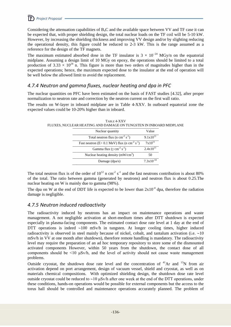
Project Proposal
-136-
Considering the attenuation capabilities of B4C and the available space between VV and TF case it can
be expected that, with proper shielding design, the total nuclear loads on the TF coil will be 5-10 kW.
However, by increasing the shielding thickness and improving VV design and/or by slighting reducing
the operational density, this figure could be reduced to 2-3 kW. This is the range assumed as a
reference for the design of the TF magnets.
The maximum estimated absorbed dose in the TF insulator is 3 × 10⁻²⁴
MGy/n on the equatorial
midplane. Assuming a design limit of 10 MGy on epoxy, the operations should be limited to a total
production of 3.33 × 1024
n. This figure is more than two orders of magnitudes higher than in the
expected operations; hence, the maximum expected dose to the insulator at the end of operation will
be well below the allowed limit to avoid the replacement.
4.7.4 Neutron and gamma fluxes, nuclear heating and dpa in PFC
The nuclear quantities on PFC have been estimated on the basis of FAST studies [4.32], after proper
normalization to neutron rate and correction by the neutron current on the first wall ratio.
The results on W-layer in inboard midplane are in Table 4-XXV. In outboard equatorial zone the
expected values could be 10-20% higher than in inboard.
TABLE 4-XXV
FLUXES, NUCLEAR HEATING AND DAMAGE ON TUNGSTEN IN INBOARD MIDPLANE
Nuclear quantity Value
Total neutron flux (n cm-2 s-1) 9.1x10¹¹
Fast neutron (E> 0.1 MeV) flux (n cm-2 s-1) 7x10¹¹
Gamma flux ( cm-2 s-1) 2.4x10¹¹
Nuclear heating density (mW/cm3) 50
Damage (dpa/s) 7.3x10⁻¹⁰
The total neutron flux is of the order of 1012
n cm-2
s-1
and the fast neutrons contribution is about 80%
of the total. The ratio between gamma (generated by neutrons) and neutron flux is about 0.25.The
nuclear heating on W is mainly due to gamma (98%).
The dpa on W at the end of DDT life is expected to be lower than 2x10⁻⁴
dpa, therefore the radiation
damage is negligible.
4.7.5 Neutron induced radioactivity
The radioactivity induced by neutrons has an impact on maintenance operations and waste
management. A not negligible activation at short-medium times after DTT shutdown is expected
especially in plasma-facing components. The estimated contact dose rate level at 1 day at the end of
DTT operations is indeed 100 mSv/h in tungsten. At longer cooling times, higher induced
radioactivity is observed in steel mainly because of nickel, cobalt, and tantalum activation (i.e. 10
mSv/h in VV at one month after shutdown), therefore remote handling is mandatory. The radioactivity
level may require the preparation of an ad hoc temporary repository to store some of the dismounted
activated components However, within 50 years from the shutdown, the contact dose of all
components should be <10 μSv/h, and the level of activity should not cause waste management
problems.
Outside cryostat, the shutdown dose rate level and the concentration of 41
Ar and 13
N from air
activation depend on port arrangement, design of vacuum vessel, shield and cryostat, as well as on
materials chemical compositions. With optimized shielding design, the shutdown dose rate level
outside cryostat could be reduced to 10 μSv/h after one week at the end of the DTT operations, under
these conditions, hands-on operations would be possible for external components but the access to the
torus hall should be controlled and maintenance operations accurately planned. The problem of
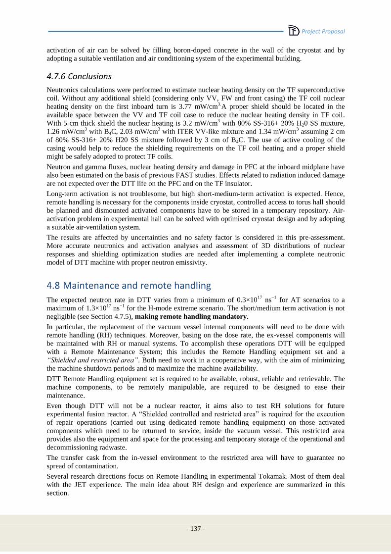
Project Proposal
- 137 -
activation of air can be solved by filling boron-doped concrete in the wall of the cryostat and by
adopting a suitable ventilation and air conditioning system of the experimental building.
4.7.6 Conclusions
Neutronics calculations were performed to estimate nuclear heating density on the TF superconductive
coil. Without any additional shield (considering only VV, FW and front casing) the TF coil nuclear
heating density on the first inboard turn is 3.77 mW/cm3.A proper shield should be located in the
available space between the VV and TF coil case to reduce the nuclear heating density in TF coil.
With 5 cm thick shield the nuclear heating is 3.2 mW/cm3 with 80% SS-316+ 20% H20 SS mixture,
1.26 mW/cm3 with B4C, 2.03 mW/cm
3 with ITER VV-like mixture and 1.34 mW/cm
3 assuming 2 cm
of 80% SS-316+ 20% H20 SS mixture followed by 3 cm of B4C. The use of active cooling of the
casing would help to reduce the shielding requirements on the TF coil heating and a proper shield
might be safely adopted to protect TF coils.
Neutron and gamma fluxes, nuclear heating density and damage in PFC at the inboard midplane have
also been estimated on the basis of previous FAST studies. Effects related to radiation induced damage
are not expected over the DTT life on the PFC and on the TF insulator.
Long-term activation is not troublesome, but high short-medium-term activation is expected. Hence,
remote handling is necessary for the components inside cryostat, controlled access to torus hall should
be planned and dismounted activated components have to be stored in a temporary repository. Air-
activation problem in experimental hall can be solved with optimised cryostat design and by adopting
a suitable air-ventilation system.
The results are affected by uncertainties and no safety factor is considered in this pre-assessment.
More accurate neutronics and activation analyses and assessment of 3D distributions of nuclear
responses and shielding optimization studies are needed after implementing a complete neutronic
model of DTT machine with proper neutron emissivity.
4.8 Maintenance and remote handling
The expected neutron rate in DTT varies from a minimum of 0.3×10¹⁷
ns−1
for AT scenarios to a
maximum of 1.3×10¹⁷
ns−1
for the H-mode extreme scenario. The short/medium term activation is not
negligible (see Section 4.7.5), making remote handling mandatory.
In particular, the replacement of the vacuum vessel internal components will need to be done with
remote handling (RH) techniques. Moreover, basing on the dose rate, the ex-vessel components will
be maintained with RH or manual systems. To accomplish these operations DTT will be equipped
with a Remote Maintenance System; this includes the Remote Handling equipment set and a
“Shielded and restricted area”. Both need to work in a cooperative way, with the aim of minimizing
the machine shutdown periods and to maximize the machine availability.
DTT Remote Handling equipment set is required to be available, robust, reliable and retrievable. The
machine components, to be remotely manipulable, are required to be designed to ease their
maintenance.
Even though DTT will not be a nuclear reactor, it aims also to test RH solutions for future
experimental fusion reactor. A “Shielded controlled and restricted area” is required for the execution
of repair operations (carried out using dedicated remote handling equipment) on those activated
components which need to be returned to service, inside the vacuum vessel. This restricted area
provides also the equipment and space for the processing and temporary storage of the operational and
decommissioning radwaste.
The transfer cask from the in-vessel environment to the restricted area will have to guarantee no
spread of contamination.
Several research directions focus on Remote Handling in experimental Tokamak. Most of them deal
with the JET experience. The main idea about RH design and experience are summarized in this
section.

Project Proposal
-138-
RH devices should be intended as a fully integrated system and not as an external system.
Thus, RH system must be considered from the very beginning of design process.
The component inside the tokamak must be RH-compatible, so RH engineers have to be
involved in the design of components from the earliest stages of design.
RH system has to be flexible. The configuration of an experimental Tokamak may change
during its lifetime, so RH devices have to be as much as possible independent from the
configuration of tokamak.
Different components need different maintenance operations. Thus RH system must be
suitable for all of the necessary tasks. RH system must be flexible enough to work during
normal operations as well as in case of failure.
RH operations shall be carefully planned. Given the strict environmental constraints, handling
operations must be computer simulated and then tested outside the Tokamak in order to get
some experience.
RH operators need feedback during operations. Forces and Torques sensors as well as cameras
are necessary to get information. Virtual reality techniques can help, given that cameras can
only show limited views of inside chamber.
Generally speaking, standard power and control equipment can be used for robots. However,
mechanical components are often customised solutions.
4.8.1 Divertor remote handling design
Considering the relevant problems about the interaction between plasma and surrounding materials,
the optimization of the divertor geometry represents one of the key points in the whole project. Such
an aim can be achieved, at first, via the study of the plasma boundaries, including all the real geometry
conditions, from the physics point of view and without a deep attention to engineering constraints,
which provides an optimized "conceptual" geometry. Then, in a second step, such a solution needs to
be tackled with all the mechanical design problems, including the remote maintenance facility.
Although the divertor discussed in Section 4.6 will be very flexible, as mentioned, it could not be the
optimal choice for a SF divertor; moreover, since one of the main DTT target is the study of the power
exhaust, the divertor choice cannot be limited on a SN and/or a SF, but the machine must have the
possibility to test also other possible options, like, for instance, a liquid Li divertor [4.41]. For this
reason the design of the present solution has been implemented having in mind the possibility of easily
replace the divertor by means of a remote handling facility [4.44]-[4.49] (see Figure 4.86).
Figure 4.86: Schematic view of the Divertor remote handling system
The divertor configuration must account for an easy maintenance operation via the lower ports,
considering the non-negligible possibility of substitution of several parts. Especially in plasma facing
components, the short and medium-term activation of modules, with the consequent wearing, is very
high, due to the foreseen large production of neutron.

Project Proposal
- 139 -
Such a non-negligible aspect is the main reason why the realization of a Remote Handling facility
plays a crucial role in operations of the whole DTT tokamak.
In addition to the capability of counteracting eventual damages, the possibility to remotely handle the
divertor can easily benefit the substitution of several parts of the modules, in order to test different
plate geometries or materials able to improve plasma performance. About it the test of liquid lithium,
used as an alternative option in view of very large power load foreseen for DEMO, has been already
planned.
Furthermore, the possibility of a complete substitution of the divertor modules, characterized by a
completely different geometry, must be considered. Such a possibility is usually dictated by a switch
of plasma configuration during the operation, when, for instance, plasma moves from a diverted shape
to a so called "snow flake" one.
The scheme of the divertor maintenance is based on a frame acting as a carousel around the machine
and on an ad hoc cassette tractor, using a technique similar to the one presently under development for
ITER [4.50]-[4.52]. Figure 4.87 shows a first possible motion sequence of the cassette during the
maintenance operation, compatible with DTT VV design. To allow such maintenance technique the
internal coil attached to the divertor should be modular and allow an easy dismounting.
Figure 4.87 – Motion sequence of the divertor cassette
The guideline of the future work (Figure 4.88) foresees several steps oriented to provide a series of
alternative or innovative proposals for FAST remote maintenance, starting from an ITER-like solution
and then proceeding through an interactive design review.
Figure 4.88: - Workflow scheme
The methodology that will be adopted in the next design stages is illustrated in Figure 4.89. The whole
process starts with the identification of several design issues. Technical conflicts present in the
considered system are translated in TRIZ language following the “contradiction matrix” approach,
generating different concepts from specific solutions derived from TRIZ principles. The concepts are
then designed in CAD software, performing kinematic simulations and analyses, where these can help
comparing the alternatives. A set of criteria is thus selected, on which the comparison of concepts will
be performed, following the AHP methodology [4.45]. The final evaluation session is carried out in

Project Proposal
-140-
virtual reality environment, involving several experts in the judgment, during participative design
review sessions (Figure 4.90).
Figure 4.89: - Flowchart of the methodology adopted
Figure 4.90: Comparison of concepts in Virtual Reality lab.
4.8.2 FW remote handling design
JET RH system includes two arms that are called octant-1 boom and octant-5 boom respectively,
named after the equatorial plug number they depend on. A concept of these two arms can be seen in
Figure 4.91. These octant booms look like a kind of "snake", that can go all around the torus starting
from an equatorial plug.
Figure 4.91: - Octant-1 boom (right) and octant-5 boom (left).

Project Proposal
- 141 -
The octant-5 boom (left) is conceived for handling and tooling operations while octant-1 boom (right)
is used as tool storage. The octant-5 boom can access ±190° in the torus of the TOKAMAK, which
means every components in the tokamak can be removed. The octant-1 boom can access ±120° in the
torus. Indeed, it does not need to access the whole tokamak because the other arm actually can. For
such system, it is necessary to have a long rail length (about 8m for JET) for the robot to access all
positions in the torus. Some space is left between every segment for a motor (in blue on the previous
picture).
The principle of two arms, one for RH and the other to bring the tools, seems to be a good concept for
DTT. As an experimental Tokamak, several equatorial ports may be used for diagnostics. As the space
around tokamak can be limited, using only two equatorial plugs can be a good solution.
On top of that, a limited number of hot cells are definitely easier to handle for a nuclear installation.
JET tokamak is not actively cooled, so the tiles that were used to cover the first wall were quite small
compared to the components of DTT first wall. Therefore, weights of JET tiles are less important than
DTT components. This means that the JET robots may not suit DTT requirements. The JET
manipulators are made of two small arms that can carry 20 kg. A similar system could be used for
DTT but it should be able to carry heavier loads. One "large arm" could be used to carry and hold a
component, while "lightweight" arm could be used to handle tools.
According to previous considerations, the concept of FW remote handling will be the following:
One "drawer arm” that will bring the different tool.
One "operational arm" that will perform tooling operations (welding, cutting, etc.) as well as
handling operations. As a consequence, at least two different end-effectors will be used on this
arm.
In this part a conceptual design for the "snake" part of the robot will be presented. The concept is very
similar to JET RH system. According to the size of the tokamak and the equatorial port plugs, the
following parameters have to be considered as input:
The robot is made of 6 parts: one "long" segment fixed on a rail system, 4 central segments of
same length, and an end-effectors, which is not being presented here
The length between two segments connections has to be 1.5 m for the arm to access ±190°.
The width of the first five segments is 250 mm. The width of the manipulator cannot exceed
500 mm in order to go through the equatorial port plugs.
The height of the first five segments is 740 mm.
Some simple schematic drawings were made in CATIA in order to check that this dimension could fit
DTT dimension (Figure 4.92). The minimum and maximum radiuses are represented as well as the
critical width of the equatorial port plug at the top (respectively the bottom) of the segment. A spine
line was created to simulate the trajectory of the robot.
The last segment - the end-effectors - is not presented here. This design is just a concept. Motors are
not represented, but some space was left between each segment in order to insert a motor, as for JET
design. Every segment is made of aluminium and is empty in order to reduce its weight. Some slanting
stiffeners were added inside in order to prevent torsion. Some shafts are used to link the segments
together. Every short segment weights 156 kg and the long segment weights 225 kg (see Figure 4.93).
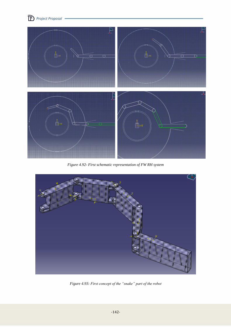
Project Proposal
-142-
Figure 4.92- First schematic representation of FW RH system
Figure 4.93: First concept of the “snake” part of the robot
Project Proposal
- 143 -
4.9 Heating and current drive systems
4.9.1 Background
The main requirements for the DTT heating and current drive (CD) system have been determined on
one side from the machine rationale and objectives, on the other on the basis of the first scenario
simulations. A heating power in the range of 30-40 MW is necessary to ensure the appropriate heat
load on the various divertor configurations that will be tested. In the following, a reference value of 25
MW coupled to the plasma will be assumed for the first phase of operation of DTT and the upgrade to
40-45 MW will be performed progressively. The system design will take full account of such an
upgrade."
In its present reference design, DTT will be equipped with superconducting magnetic field coils,
which would allow steady-state operation. However, this is not in the objectives of DTT, and long
pulse (~100 s) will be sufficient. Taking into account the main machine parameters (R = 2.15 m, ne ~ 2
1020
, Ip = 6 MA), full non-inductive CD would require an additional power > 100 MW, by far
exceeding that required for heating. This implies that bulk CD will not be one of the main objectives
of the system, although useful to assist the transformer and possibly to tailor the current density
profile. On the other hand, localised CD could be crucial to control MHD phenomena, i.e., the large
sawteeth that are expected in the reference DTT scenarios and classical or neoclassical tearing modes.
Concerning the choice of the heating and CD system, the relative merits of the various systems used
on tokamaks are well known: Lower Hybrid (LH) and Neutral Beam Injection (NBI) have higher CD
efficiencies; Electron Cyclotron (EC) waves have better localisation capabilities, both for heating and
CD; Ion Cyclotron (IC) waves are the cheapest system, mainly used for heating, both electrons and
ions. In order to make a choice, the following rationale has been employed:
In order to limit the complexity of the plant, it has been chosen to use not more than two
systems, at least in the first phase.
Since bulk CD is not a main objective, the high CD efficiency of LH and NBI is not
considered as a decisive advantage.
The need to heat both ions and electrons favours the use of IC waves.
The usefulness of MHD control, requiring localised CD, favours the use of EC waves.
As a consequence, it was chosen to use as a reference, for the first DTT phase, a system composed by
15 MW of ICRH and 10 MW of ECRH. Upgrade to 20+20 MW will be considered since the
beginning in the design of the two systems. NBI is also being considered as another possible candidate
for a subsequent power upgrade.
The main physics requirements and technology characteristics of the ICRH and ECRH systems are
described in Sec. 4.9.2 and 4.9.3, respectively. For both systems, the following elements are analysed
and briefly discussed:
- Physics requirements
- Wave frequency and injection parameters
- Wave generator
- Transmission lines
- Antenna
- Power supplies
- Auxiliaries & cooling
- Machine layout and interfaces
- CODAC / control systems
- Buildings
- Cost / Manpower / Time schedule for system design and construction
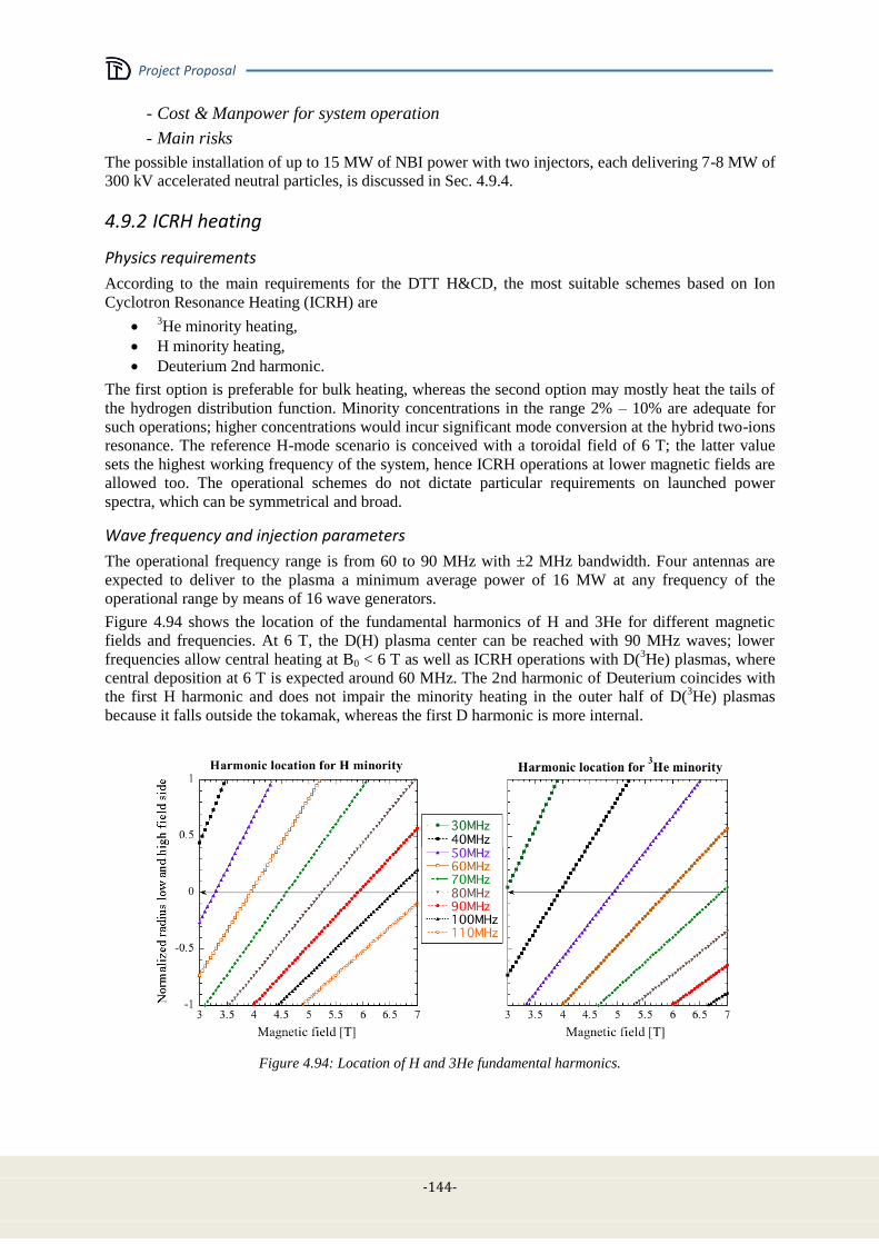
Project Proposal
-144-
- Cost & Manpower for system operation
- Main risks
The possible installation of up to 15 MW of NBI power with two injectors, each delivering 7-8 MW of
300 kV accelerated neutral particles, is discussed in Sec. 4.9.4.
4.9.2 ICRH heating
Physics requirements
According to the main requirements for the DTT H&CD, the most suitable schemes based on Ion
Cyclotron Resonance Heating (ICRH) are
3He minority heating,
H minority heating,
Deuterium 2nd harmonic.
The first option is preferable for bulk heating, whereas the second option may mostly heat the tails of
the hydrogen distribution function. Minority concentrations in the range 2% – 10% are adequate for
such operations; higher concentrations would incur significant mode conversion at the hybrid two-ions
resonance. The reference H-mode scenario is conceived with a toroidal field of 6 T; the latter value
sets the highest working frequency of the system, hence ICRH operations at lower magnetic fields are
allowed too. The operational schemes do not dictate particular requirements on launched power
spectra, which can be symmetrical and broad.
Wave frequency and injection parameters
The operational frequency range is from 60 to 90 MHz with ±2 MHz bandwidth. Four antennas are
expected to deliver to the plasma a minimum average power of 16 MW at any frequency of the
operational range by means of 16 wave generators.
Figure 4.94 shows the location of the fundamental harmonics of H and 3He for different magnetic
fields and frequencies. At 6 T, the D(H) plasma center can be reached with 90 MHz waves; lower
frequencies allow central heating at B0 < 6 T as well as ICRH operations with D(3He) plasmas, where
central deposition at 6 T is expected around 60 MHz. The 2nd harmonic of Deuterium coincides with
the first H harmonic and does not impair the minority heating in the outer half of D(3He) plasmas
because it falls outside the tokamak, whereas the first D harmonic is more internal.
Figure 4.94: Location of H and 3He fundamental harmonics.

Project Proposal
- 145 -
The coupled problem of ICRH wave propagation and quasi-linear absorption in DTT has been
addressed with the 2D full-wave code TORIC [4.53] by simulating two cases at 6 T:
a) 90 MHz, Deuterium plasma with 3% H minority, peak n|| = 7,
b) 60 MHz, Deuterium plasma with 3% 3He minority, peak n|| = 10.
The plasma profiles used in the simulation are shown in Figure 4.95; from the last closed magnetic
surface, exponential profiles with decay length of 5 mm have been assumed. DTT reference
equilibrium, kinetic profiles, and an ideal 2 straps antenna spectrum have been used, finding the
following outcomes for power absorption:
a) 27% to D, 49% to H, 24% to free electrons, absorbed via electron Landau damping;
b) 2% to D, 54% to 3He, 44% to free electrons, consisting of 31% via electron Landau damping
and 13% via mode conversion into ion Bernstein wave.
Figure 4.95: Plasma profiles.
Figure 4.96: Power deposition profiles [W/cm
3] normalized to 1 MW of coupled power.
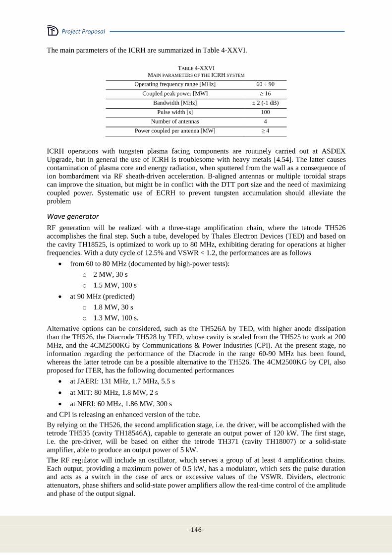
Project Proposal
-146-
The main parameters of the ICRH are summarized in Table 4-XXVI.
TABLE 4-XXVI
MAIN PARAMETERS OF THE ICRH SYSTEM
Operating frequency range [MHz] 60 ÷ 90
Coupled peak power [MW] ≥ 16
Bandwidth [MHz] ± 2 (-1 dB)
Pulse width [s] 100
Number of antennas 4
Power coupled per antenna [MW] ≥ 4
ICRH operations with tungsten plasma facing components are routinely carried out at ASDEX
Upgrade, but in general the use of ICRH is troublesome with heavy metals [4.54]. The latter causes
contamination of plasma core and energy radiation, when sputtered from the wall as a consequence of
ion bombardment via RF sheath-driven acceleration. B-aligned antennas or multiple toroidal straps
can improve the situation, but might be in conflict with the DTT port size and the need of maximizing
coupled power. Systematic use of ECRH to prevent tungsten accumulation should alleviate the
problem
Wave generator
RF generation will be realized with a three-stage amplification chain, where the tetrode TH526
accomplishes the final step. Such a tube, developed by Thales Electron Devices (TED) and based on
the cavity TH18525, is optimized to work up to 80 MHz, exhibiting derating for operations at higher
frequencies. With a duty cycle of 12.5% and VSWR < 1.2, the performances are as follows
from 60 to 80 MHz (documented by high-power tests):
o 2 MW, 30 s
o 1.5 MW, 100 s
at 90 MHz (predicted)
o 1.8 MW, 30 s
o 1.3 MW, 100 s.
Alternative options can be considered, such as the TH526A by TED, with higher anode dissipation
than the TH526, the Diacrode TH528 by TED, whose cavity is scaled from the TH525 to work at 200
MHz, and the 4CM2500KG by Communications & Power Industries (CPI). At the present stage, no
information regarding the performance of the Diacrode in the range 60-90 MHz has been found,
whereas the latter tetrode can be a possible alternative to the TH526. The 4CM2500KG by CPI, also
proposed for ITER, has the following documented performances
at JAERI: 131 MHz, 1.7 MHz, 5.5 s
at MIT: 80 MHz, 1.8 MW, 2 s
at NFRI: 60 MHz, 1.86 MW, 300 s
and CPI is releasing an enhanced version of the tube.
By relying on the TH526, the second amplification stage, i.e. the driver, will be accomplished with the
tetrode TH535 (cavity TH18546A), capable to generate an output power of 120 kW. The first stage,
i.e. the pre-driver, will be based on either the tetrode TH371 (cavity TH18007) or a solid-state
amplifier, able to produce an output power of 5 kW.
The RF regulator will include an oscillator, which serves a group of at least 4 amplification chains.
Each output, providing a maximum power of 0.5 kW, has a modulator, which sets the pulse duration
and acts as a switch in the case of arcs or excessive values of the VSWR. Dividers, electronic
attenuators, phase shifters and solid-state power amplifiers allow the real-time control of the amplitude
and phase of the output signal.
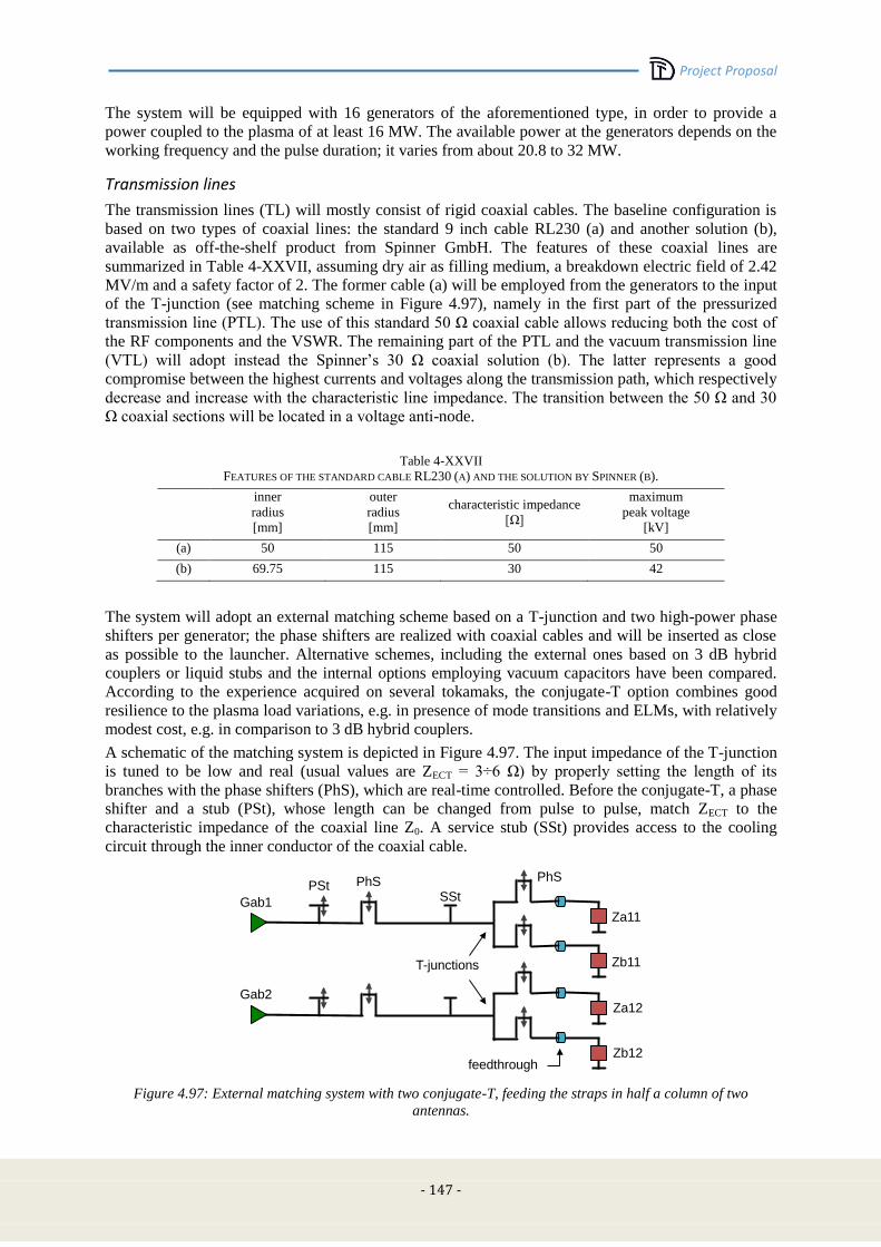
Project Proposal
- 147 -
The system will be equipped with 16 generators of the aforementioned type, in order to provide a
power coupled to the plasma of at least 16 MW. The available power at the generators depends on the
working frequency and the pulse duration; it varies from about 20.8 to 32 MW.
Transmission lines
The transmission lines (TL) will mostly consist of rigid coaxial cables. The baseline configuration is
based on two types of coaxial lines: the standard 9 inch cable RL230 (a) and another solution (b),
available as off-the-shelf product from Spinner GmbH. The features of these coaxial lines are
summarized in Table 4-XXVII, assuming dry air as filling medium, a breakdown electric field of 2.42
MV/m and a safety factor of 2. The former cable (a) will be employed from the generators to the input
of the T-junction (see matching scheme in Figure 4.97), namely in the first part of the pressurized
transmission line (PTL). The use of this standard 50 Ω coaxial cable allows reducing both the cost of
the RF components and the VSWR. The remaining part of the PTL and the vacuum transmission line
(VTL) will adopt instead the Spinner’s 30 Ω coaxial solution (b). The latter represents a good
compromise between the highest currents and voltages along the transmission path, which respectively
decrease and increase with the characteristic line impedance. The transition between the 50 Ω and 30
Ω coaxial sections will be located in a voltage anti-node.
Table 4-XXVII
FEATURES OF THE STANDARD CABLE RL230 (A) AND THE SOLUTION BY SPINNER (B).
inner
radius
[mm]
outer
radius
[mm]
characteristic impedance
[Ω]
maximum
peak voltage
[kV]
(a) 50 115 50 50
(b) 69.75 115 30 42
The system will adopt an external matching scheme based on a T-junction and two high-power phase
shifters per generator; the phase shifters are realized with coaxial cables and will be inserted as close
as possible to the launcher. Alternative schemes, including the external ones based on 3 dB hybrid
couplers or liquid stubs and the internal options employing vacuum capacitors have been compared.
According to the experience acquired on several tokamaks, the conjugate-T option combines good
resilience to the plasma load variations, e.g. in presence of mode transitions and ELMs, with relatively
modest cost, e.g. in comparison to 3 dB hybrid couplers.
A schematic of the matching system is depicted in Figure 4.97. The input impedance of the T-junction
is tuned to be low and real (usual values are ZECT = 3÷6 Ω) by properly setting the length of its
branches with the phase shifters (PhS), which are real-time controlled. Before the conjugate-T, a phase
shifter and a stub (PSt), whose length can be changed from pulse to pulse, match ZECT to the
characteristic impedance of the coaxial line Z0. A service stub (SSt) provides access to the cooling
circuit through the inner conductor of the coaxial cable.
Figure 4.97: External matching system with two conjugate-T, feeding the straps in half a column of two
antennas.
PhS
SSt PhS PSt
T-junctions
Za11
Zb11
Za12
Zb12
Gab1
Gab2
feedthrough
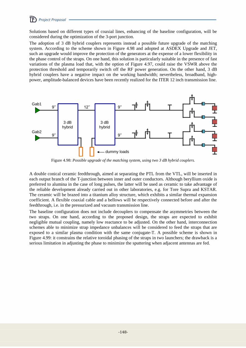
Project Proposal
-148-
Solutions based on different types of coaxial lines, enhancing of the baseline configuration, will be
considered during the optimization of the 3-port junction.
The adoption of 3 dB hybrid couplers represents instead a possible future upgrade of the matching
system. According to the scheme shown in Figure 4.98 and adopted at ASDEX Upgrade and JET,
such an upgrade would improve the protection of the generators at the expense of a lower flexibility in
the phase control of the straps. On one hand, this solution is particularly suitable in the presence of fast
variations of the plasma load that, with the option of Figure 4.97, could raise the VSWR above the
protection threshold and temporarily switch off the RF power generation. On the other hand, 3 dB
hybrid couplers have a negative impact on the working bandwidth; nevertheless, broadband, high-
power, amplitude-balanced devices have been recently realized for the ITER 12 inch transmission line.
Figure 4.98: Possible upgrade of the matching system, using two 3 dB hybrid couplers.
A double conical ceramic feedthrough, aimed at separating the PTL from the VTL, will be inserted in
each output branch of the T-junction between inner and outer conductors. Although beryllium oxide is
preferred to alumina in the case of long pulses, the latter will be used as ceramic to take advantage of
the reliable development already carried out in other laboratories, e.g. for Tore Supra and KSTAR.
The ceramic will be brazed into a titanium alloy structure, which exhibits a similar thermal expansion
coefficient. A flexible coaxial cable and a bellows will be respectively connected before and after the
feedthrough, i.e. in the pressurized and vacuum transmission line.
The baseline configuration does not include decouplers to compensate the asymmetries between the
two straps. On one hand, according to the proposed design, the straps are expected to exhibit
negligible mutual coupling, namely low reactance to be adjusted. On the other hand, interconnection
schemes able to minimize strap impedance unbalances will be considered to feed the straps that are
exposed to a similar plasma condition with the same conjugate-T. A possible scheme is shown in
Figure 4.99: it constrains the relative toroidal phasing of the straps in two launchers; the drawback is a
serious limitation in adjusting the phase to minimize the sputtering when adjacent antennas are fed.
dummy loads
Gab1
Gab2
3 dB hybrid
3 dB hybrid
12’’ 9’’
9’’
9’’
9’’

Project Proposal
- 149 -
HVPS
Launcher
Launcher
EMU
EMU
EMU
EMU
HVPS
HVPS
EMU
EMU
EMU
EMU
HVPS
Figure 4.99: Feeding scheme of the straps of two launchers with eight external matching units (EMU).
Antenna
The launcher is a port-plugged antenna with contacts grounded to the port and allowing for shimming
of the antenna front face. Each one is an array of 4 poloidal by 2 toroidal straps, an arrangement that is
mostly suitable for plasma heating operations and that minimizes the mutual coupling between
radiating elements.
The optimization of the antenna has been carried out by means of CST Microwave Studio using a flat
three-dimensional geometry in front of a seawater load in the frequency range 60-90 MHz. Accurate,
smooth shapes have been modelled with reference to the straps and the Faraday Screen (FS) rods.
Simulations with plasma load have been performed with TOPICA at 60 MHz for the optimized
antenna. Finally a curved three-dimensional geometry with simplified straps and FS shape has been
also modelled and simulated with TOPICA at 60 and 90 MHz. Both antenna models are depicted in
Figure 4.100 together with an enlargement of the straps. The preliminary studies assume that the
antenna protrudes from the first wall as far as a distance of around 5 cm from the fast wave cut-off,
calculated at 60 MHz for a phase difference of 180 deg between the straps of the same row. A plot of
the cut-off density in Deuterium plasmas is shown in Figure 4.101. Then a further shift of 3 cm
towards the last closed magnetic surface has been simulated too.
Figure 4.100: Antenna (left) and cutoff density in a Deuterium plasma (right) when the phase difference between
the straps of the same row is 180 deg.
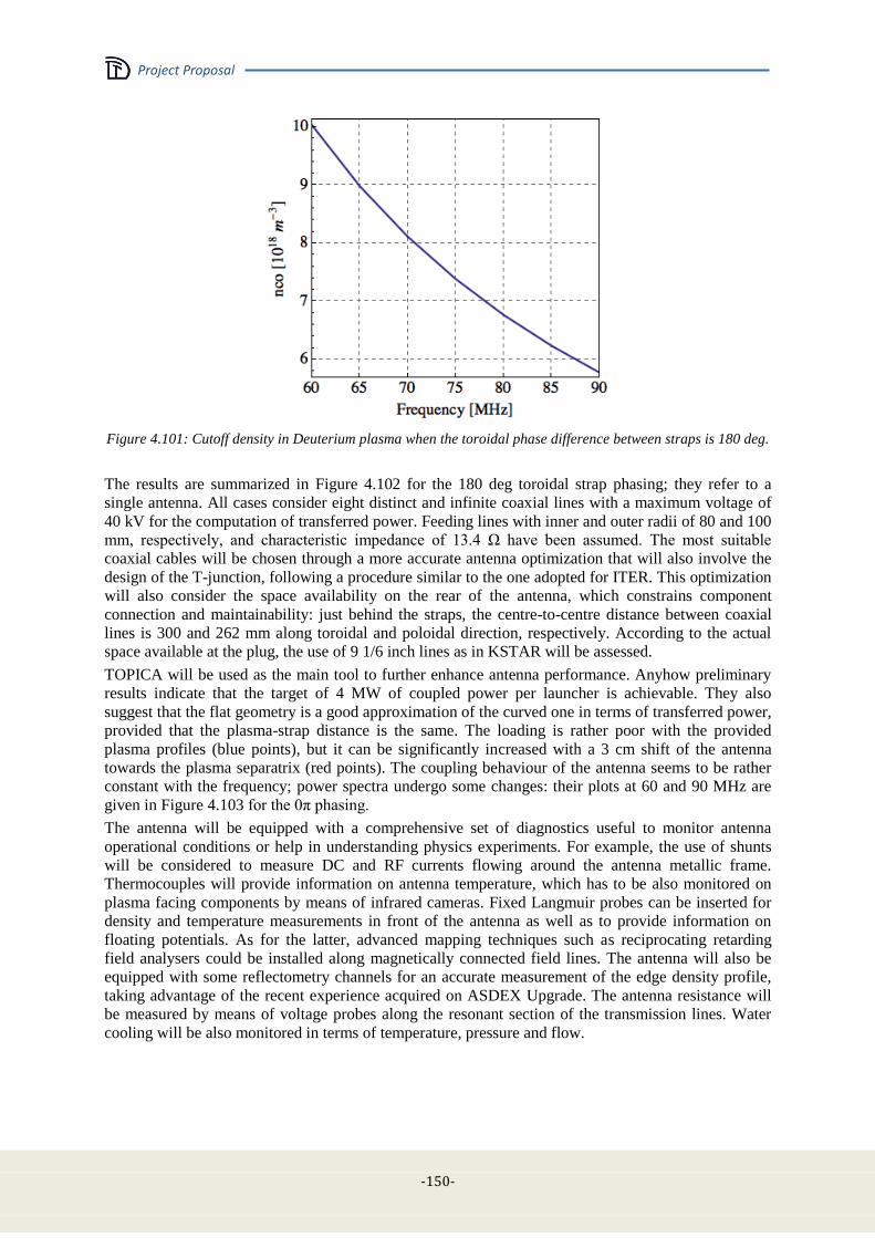
Project Proposal
-150-
Figure 4.101: Cutoff density in Deuterium plasma when the toroidal phase difference between straps is 180 deg.
The results are summarized in Figure 4.102 for the 180 deg toroidal strap phasing; they refer to a
single antenna. All cases consider eight distinct and infinite coaxial lines with a maximum voltage of
40 kV for the computation of transferred power. Feeding lines with inner and outer radii of 80 and 100
mm, respectively, and characteristic impedance of 13.4 Ω have been assumed. The most suitable
coaxial cables will be chosen through a more accurate antenna optimization that will also involve the
design of the T-junction, following a procedure similar to the one adopted for ITER. This optimization
will also consider the space availability on the rear of the antenna, which constrains component
connection and maintainability: just behind the straps, the centre-to-centre distance between coaxial
lines is 300 and 262 mm along toroidal and poloidal direction, respectively. According to the actual
space available at the plug, the use of 9 1/6 inch lines as in KSTAR will be assessed.
TOPICA will be used as the main tool to further enhance antenna performance. Anyhow preliminary
results indicate that the target of 4 MW of coupled power per launcher is achievable. They also
suggest that the flat geometry is a good approximation of the curved one in terms of transferred power,
provided that the plasma-strap distance is the same. The loading is rather poor with the provided
plasma profiles (blue points), but it can be significantly increased with a 3 cm shift of the antenna
towards the plasma separatrix (red points). The coupling behaviour of the antenna seems to be rather
constant with the frequency; power spectra undergo some changes: their plots at 60 and 90 MHz are
given in Figure 4.103 for the 0π phasing.
The antenna will be equipped with a comprehensive set of diagnostics useful to monitor antenna
operational conditions or help in understanding physics experiments. For example, the use of shunts
will be considered to measure DC and RF currents flowing around the antenna metallic frame.
Thermocouples will provide information on antenna temperature, which has to be also monitored on
plasma facing components by means of infrared cameras. Fixed Langmuir probes can be inserted for
density and temperature measurements in front of the antenna as well as to provide information on
floating potentials. As for the latter, advanced mapping techniques such as reciprocating retarding
field analysers could be installed along magnetically connected field lines. The antenna will also be
equipped with some reflectometry channels for an accurate measurement of the edge density profile,
taking advantage of the recent experience acquired on ASDEX Upgrade. The antenna resistance will
be measured by means of voltage probes along the resonant section of the transmission lines. Water
cooling will be also monitored in terms of temperature, pressure and flow.
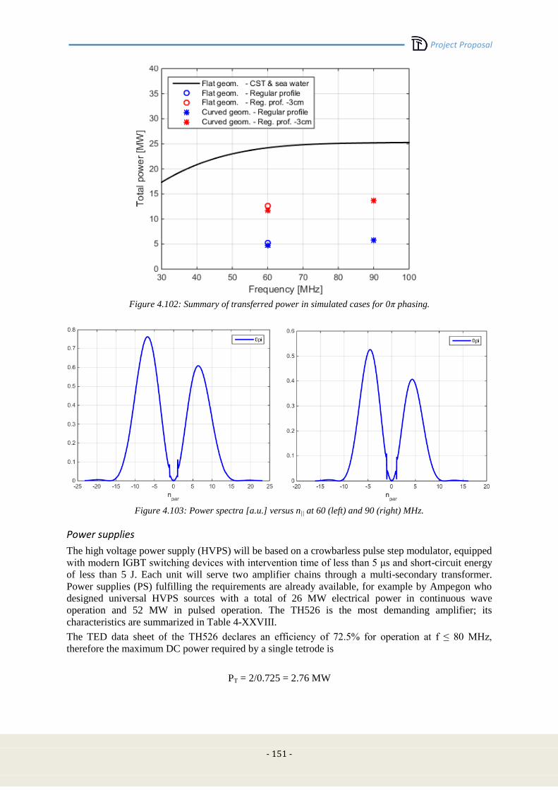
Project Proposal
- 151 -
Figure 4.102: Summary of transferred power in simulated cases for 0π phasing.
Figure 4.103: Power spectra [a.u.] versus n|| at 60 (left) and 90 (right) MHz.
Power supplies
The high voltage power supply (HVPS) will be based on a crowbarless pulse step modulator, equipped
with modern IGBT switching devices with intervention time of less than 5 μs and short-circuit energy
of less than 5 J. Each unit will serve two amplifier chains through a multi-secondary transformer.
Power supplies (PS) fulfilling the requirements are already available, for example by Ampegon who
designed universal HVPS sources with a total of 26 MW electrical power in continuous wave
operation and 52 MW in pulsed operation. The TH526 is the most demanding amplifier; its
characteristics are summarized in Table 4-XXVIII.
The TED data sheet of the TH526 declares an efficiency of 72.5% for operation at f ≤ 80 MHz,
therefore the maximum DC power required by a single tetrode is
PT = 2/0.725 = 2.76 MW

Project Proposal
-152-
The power delivered by the driver stage is 100 kW, with an efficiency of about 77%; that delivered by
the pre-driver is instead 5.5 kW with an efficiency of 50%. Thus, the cumulative DC power
requirements for the two stages are about 141 kW, to be added to the power requirement of the main
tetrode. This results in a total power of about 2.9 MW, rounded to 3 MW to include the powers for the
tetrodes’ grids and heaters. For the whole ICRH system this corresponds to an overall DC power of
about 48 MW.
TABLE 4-XXVIII
OPERATING POINT OF THE TH526 FOR 2 MW LONG-PULSE OPERATIONS AT 80 MHZ.
Anode voltage (dc) 24 kV
Screen grid voltage (dc) 1750 V
Control grid bias voltage (dc) -350 V
Anode direct current 115 A
Screen grid current 5 A
Control grid current 4 A
Anode dissipation 1.2 MW
Considering additional power losses of about 10% in the HVPS modules, the active power required
from the national grid is about 3.3 MW/unit, corresponding to an overall power for the ICRH system
of 51.3 MW.
The reactive power taken by each HVPS unit, accounting for the magnetizing current of the
transformers and for the stray inductances of the cabling, can be evaluated assuming a power factor
cosφ = 0.7, so that the total power got by the national grid should be:
Pg = 51.3/0.7 = 73.3 MVA.
If the national grid manager would require a load phasing in order to have a more acceptable power
factor (cosφ = 0.8), then the previous value could be reduced to 64 MVA.
Auxiliaries & cooling
Assuming the use of solid-state (SS) pre-drivers, three auxiliary dc power supplies for screen grid,
control grid and filament will be required for the other stages of the amplification chain, i.e. driver and
end stage). The latter will be also provided with ionic pumps and tuned by means of motors, which are
controlled by a control system according to the selected frequency request from the central control
unit. Seven motors are needed for both the driver and the TH526.
A cooling system will be required for the driver and end stage tubes as well as to cope with the RF
power dissipated in the transmission line and in the launcher. Cooling channels will be conceived to
remove heat in the VTL, PTL and antenna frames behind the limiters. Typical flow rates of 800 l/min
and 200 l/min are requested for each end stage and driver, respectively, with pressure drop of about 3
bar, while an approximate flow rate of 1 l/s can be predicted for each strap. Taking into account the
cooling of the antenna frame, transmission lines and power supplies, the rough order of magnitude for
the total flow rate of the cooling system has been estimated in the order of 400 l/s.
Machine layout and interfaces
Each antenna, provided in the rear with eight coaxial inputs, will fit the equatorial port with size 0.65
m x 1.098 m. Some margins have been taken into account in the antenna design to accommodate a
cooling frame and limiters. The four antennas will be grouped in pairs and placed on adjacent ports at
opposite sides of the tokamak. The external matching units, including conjugate T, phase shifters and
stubs, will be accommodated in the tokamak hall, in order to minimize the path of the unmatched
sections of the transmission lines. The access to the cooling circuit will be through the service stub SSt
of Figure 4.97, whereas a vacuum getter pump will be connected to the bellow after the feedthrough.
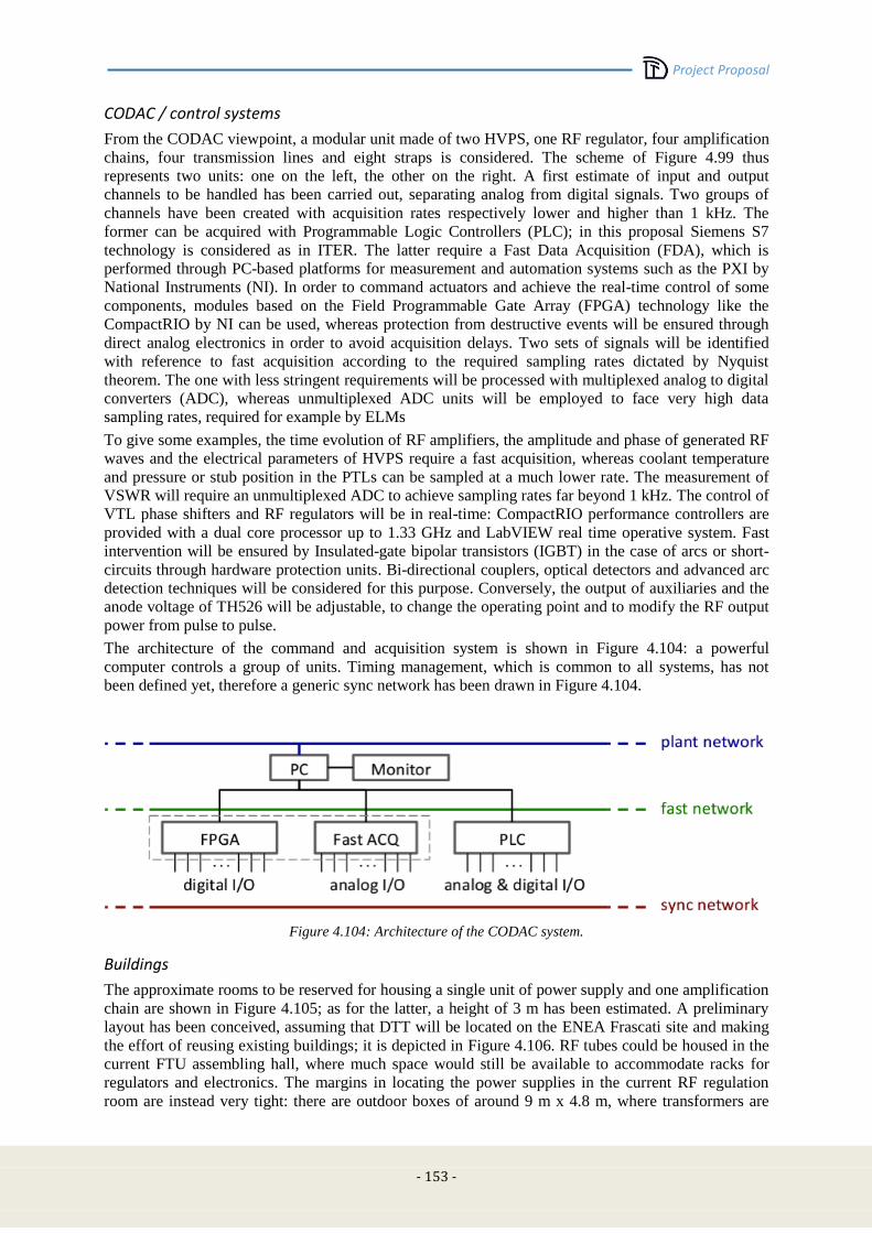
Project Proposal
- 153 -
CODAC / control systems
From the CODAC viewpoint, a modular unit made of two HVPS, one RF regulator, four amplification
chains, four transmission lines and eight straps is considered. The scheme of Figure 4.99 thus
represents two units: one on the left, the other on the right. A first estimate of input and output
channels to be handled has been carried out, separating analog from digital signals. Two groups of
channels have been created with acquisition rates respectively lower and higher than 1 kHz. The
former can be acquired with Programmable Logic Controllers (PLC); in this proposal Siemens S7
technology is considered as in ITER. The latter require a Fast Data Acquisition (FDA), which is
performed through PC-based platforms for measurement and automation systems such as the PXI by
National Instruments (NI). In order to command actuators and achieve the real-time control of some
components, modules based on the Field Programmable Gate Array (FPGA) technology like the
CompactRIO by NI can be used, whereas protection from destructive events will be ensured through
direct analog electronics in order to avoid acquisition delays. Two sets of signals will be identified
with reference to fast acquisition according to the required sampling rates dictated by Nyquist
theorem. The one with less stringent requirements will be processed with multiplexed analog to digital
converters (ADC), whereas unmultiplexed ADC units will be employed to face very high data
sampling rates, required for example by ELMs
To give some examples, the time evolution of RF amplifiers, the amplitude and phase of generated RF
waves and the electrical parameters of HVPS require a fast acquisition, whereas coolant temperature
and pressure or stub position in the PTLs can be sampled at a much lower rate. The measurement of
VSWR will require an unmultiplexed ADC to achieve sampling rates far beyond 1 kHz. The control of
VTL phase shifters and RF regulators will be in real-time: CompactRIO performance controllers are
provided with a dual core processor up to 1.33 GHz and LabVIEW real time operative system. Fast
intervention will be ensured by Insulated-gate bipolar transistors (IGBT) in the case of arcs or short-
circuits through hardware protection units. Bi-directional couplers, optical detectors and advanced arc
detection techniques will be considered for this purpose. Conversely, the output of auxiliaries and the
anode voltage of TH526 will be adjustable, to change the operating point and to modify the RF output
power from pulse to pulse.
The architecture of the command and acquisition system is shown in Figure 4.104: a powerful
computer controls a group of units. Timing management, which is common to all systems, has not
been defined yet, therefore a generic sync network has been drawn in Figure 4.104.
Figure 4.104: Architecture of the CODAC system.
Buildings
The approximate rooms to be reserved for housing a single unit of power supply and one amplification
chain are shown in Figure 4.105; as for the latter, a height of 3 m has been estimated. A preliminary
layout has been conceived, assuming that DTT will be located on the ENEA Frascati site and making
the effort of reusing existing buildings; it is depicted in Figure 4.106. RF tubes could be housed in the
current FTU assembling hall, where much space would still be available to accommodate racks for
regulators and electronics. The margins in locating the power supplies in the current RF regulation
room are instead very tight: there are outdoor boxes of around 9 m x 4.8 m, where transformers are
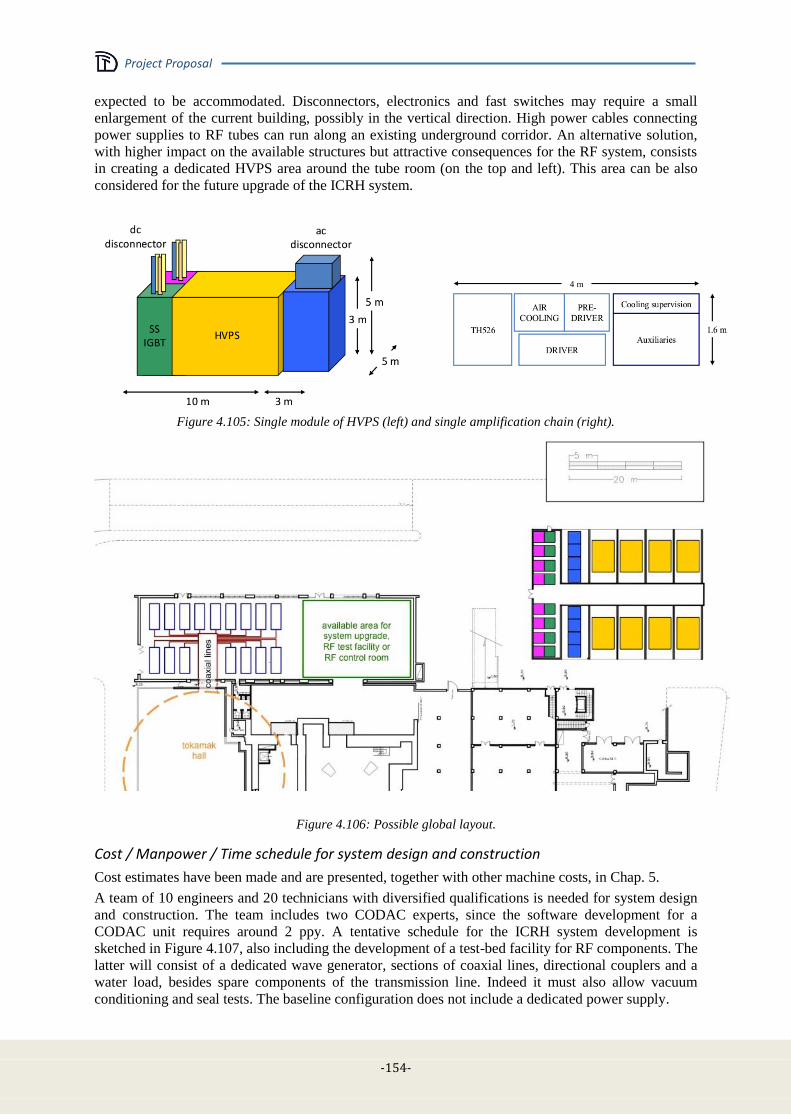
Project Proposal
-154-
expected to be accommodated. Disconnectors, electronics and fast switches may require a small
enlargement of the current building, possibly in the vertical direction. High power cables connecting
power supplies to RF tubes can run along an existing underground corridor. An alternative solution,
with higher impact on the available structures but attractive consequences for the RF system, consists
in creating a dedicated HVPS area around the tube room (on the top and left). This area can be also
considered for the future upgrade of the ICRH system.
Figure 4.105: Single module of HVPS (left) and single amplification chain (right).
Figure 4.106: Possible global layout.
Cost / Manpower / Time schedule for system design and construction
Cost estimates have been made and are presented, together with other machine costs, in Chap. 5.
A team of 10 engineers and 20 technicians with diversified qualifications is needed for system design
and construction. The team includes two CODAC experts, since the software development for a
CODAC unit requires around 2 ppy. A tentative schedule for the ICRH system development is
sketched in Figure 4.107, also including the development of a test-bed facility for RF components. The
latter will consist of a dedicated wave generator, sections of coaxial lines, directional couplers and a
water load, besides spare components of the transmission line. Indeed it must also allow vacuum
conditioning and seal tests. The baseline configuration does not include a dedicated power supply.
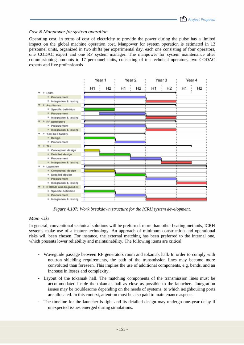
Project Proposal
- 155 -
Cost & Manpower for system operation
Operating cost, in terms of cost of electricity to provide the power during the pulse has a limited
impact on the global machine operation cost. Manpower for system operation is estimated in 12
personnel units, organized in two shifts per experimental day, each one consisting of four operators,
one CODAC expert and one RF system manager. The manpower for system maintenance after
commissioning amounts to 17 personnel units, consisting of ten technical operators, two CODAC
experts and five professionals.
Figure 4.107: Work breakdown structure for the ICRH system development.
Main risks
In general, conventional technical solutions will be preferred: more than other heating methods, ICRH
systems make use of a mature technology. An approach of minimum construction and operational
risks will been chosen. For instance, the external matching has been preferred to the internal one,
which presents lower reliability and maintainability. The following items are critical:
- Waveguide passage between RF generators room and tokamak hall. In order to comply with
neutron shielding requirements, the path of the transmission lines may become more
convoluted than foreseen. This implies the use of additional components, e.g. bends, and an
increase in losses and complexity.
- Layout of the tokamak hall. The matching components of the transmission lines must be
accommodated inside the tokamak hall as close as possible to the launchers. Integration
issues may be troublesome depending on the needs of systems, to which neighbouring ports
are allocated. In this context, attention must be also paid to maintenance aspects.
- The timeline for the launcher is tight and its detailed design may undergo one-year delay if
unexpected issues emerged during simulations.
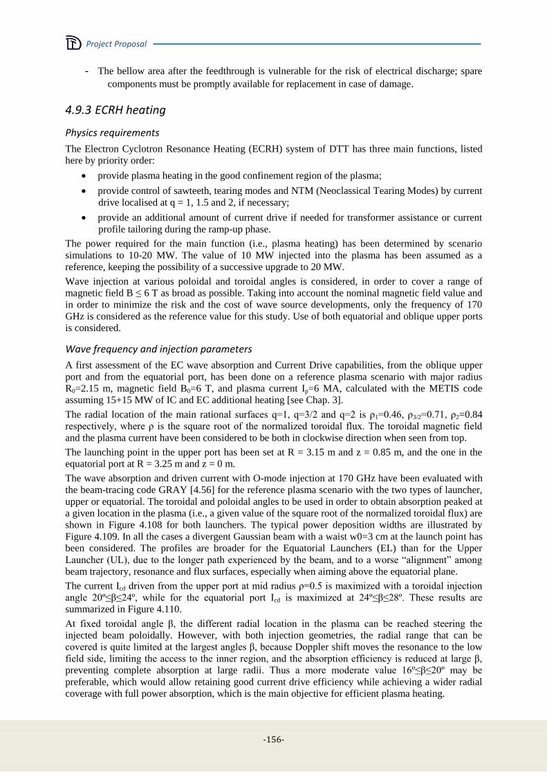
Project Proposal
-156-
- The bellow area after the feedthrough is vulnerable for the risk of electrical discharge; spare
components must be promptly available for replacement in case of damage.
4.9.3 ECRH heating
Physics requirements
The Electron Cyclotron Resonance Heating (ECRH) system of DTT has three main functions, listed
here by priority order:
provide plasma heating in the good confinement region of the plasma;
provide control of sawteeth, tearing modes and NTM (Neoclassical Tearing Modes) by current
drive localised at q = 1, 1.5 and 2, if necessary;
provide an additional amount of current drive if needed for transformer assistance or current
profile tailoring during the ramp-up phase.
The power required for the main function (i.e., plasma heating) has been determined by scenario
simulations to 10-20 MW. The value of 10 MW injected into the plasma has been assumed as a
reference, keeping the possibility of a successive upgrade to 20 MW.
Wave injection at various poloidal and toroidal angles is considered, in order to cover a range of
magnetic field B ≤ 6 T as broad as possible. Taking into account the nominal magnetic field value and
in order to minimize the risk and the cost of wave source developments, only the frequency of 170
GHz is considered as the reference value for this study. Use of both equatorial and oblique upper ports
is considered.
Wave frequency and injection parameters
A first assessment of the EC wave absorption and Current Drive capabilities, from the oblique upper
port and from the equatorial port, has been done on a reference plasma scenario with major radius
R0=2.15 m, magnetic field B0=6 T, and plasma current Ip=6 MA, calculated with the METIS code
assuming 15+15 MW of IC and EC additional heating [see Chap. 3].
The radial location of the main rational surfaces q=1, q=3/2 and q=2 is ρ1=0.46, ρ3/2=0.71, ρ2=0.84
respectively, where ρ is the square root of the normalized toroidal flux. The toroidal magnetic field
and the plasma current have been considered to be both in clockwise direction when seen from top.
The launching point in the upper port has been set at R = 3.15 m and z = 0.85 m, and the one in the
equatorial port at R = 3.25 m and z = 0 m.
The wave absorption and driven current with O-mode injection at 170 GHz have been evaluated with
the beam-tracing code GRAY [4.56] for the reference plasma scenario with the two types of launcher,
upper or equatorial. The toroidal and poloidal angles to be used in order to obtain absorption peaked at
a given location in the plasma (i.e., a given value of the square root of the normalized toroidal flux) are
shown in Figure 4.108 for both launchers. The typical power deposition widths are illustrated by
Figure 4.109. In all the cases a divergent Gaussian beam with a waist w0=3 cm at the launch point has
been considered. The profiles are broader for the Equatorial Launchers (EL) than for the Upper
Launcher (UL), due to the longer path experienced by the beam, and to a worse “alignment” among
beam trajectory, resonance and flux surfaces, especially when aiming above the equatorial plane.
The current Icd driven from the upper port at mid radius ρ=0.5 is maximized with a toroidal injection
angle 20º≤β≤24º, while for the equatorial port Icd is maximized at 24º≤β≤28º. These results are
summarized in Figure 4.110.
At fixed toroidal angle β, the different radial location in the plasma can be reached steering the
injected beam poloidally. However, with both injection geometries, the radial range that can be
covered is quite limited at the largest angles β, because Doppler shift moves the resonance to the low
field side, limiting the access to the inner region, and the absorption efficiency is reduced at large β,
preventing complete absorption at large radii. Thus a more moderate value 16º≤β≤20º may be
preferable, which would allow retaining good current drive efficiency while achieving a wider radial
coverage with full power absorption, which is the main objective for efficient plasma heating.
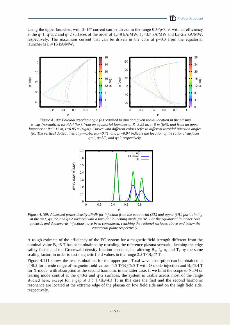
Project Proposal
- 157 -
Using the upper launcher, with β=16º current can be driven in the range 0.3≤ρ≤0.9, with an efficiency
at the q=1, q=3/2 and q=2 surfaces of the order of Icd=9 kA/MW, Icd=3.7 kA/MW and Icd=2.2 kA/MW,
respectively. The maximum current that can be driven in the core at ρ=0.3 from the equatorial
launcher is Icd=16 kA/MW.
Figure 4.108: Poloidal steering angle (α) required to aim at a given radial location in the plasma
ρ=sqrt(normalized toroidal flux), from an equatorial launcher at R=3.25 m, z=0 m (left), and from an upper
launcher at R=3.15 m, z=0.85 m (right). Curves with different colors refer to different toroidal injection angles
(β). The vertical dotted lines at ρ1=0.46, ρ3/2=0.71, and ρ2=0.84 indicate the location of the rational surfaces
q=1, q=3/2, and q=2 respectively.
Figure 4.109: Absorbed power density dP/dV for injection from the equatorial (EL) and upper (UL) port, aiming
at the q=1, q=3/2, and q=2 surfaces with a toroidal launching angle β=10º. For the equatorial launcher both
upwards and downwards injections have been considered, reaching the rational surfaces above and below the
equatorial plane respectively.
A rough estimate of the efficiency of the EC system for a magnetic field strength different from the
nominal value B0=6 T has been obtained by rescaling the reference plasma scenario, keeping the edge
safety factor and the Greenwald density fraction constant, i.e. altering B0, Ip, ne and Te by the same
scaling factor, in order to test magnetic field values in the range 2.5 T≤B0≤7 T.
Figure 4.111 shows the results obtained for the upper port. Total wave absorption can be obtained at
ρ≥0.5 for a wide range of magnetic field values: 4.5 T≤B0≤6.5 T with O-mode injection and B0≤3.4 T
for X-mode, with absorption at the second harmonic in the latter case. If we limit the scope to NTM or
tearing mode control at the q=3/2 and q=2 surfaces, the system is usable across most of the range
studied here, except for a gap at 3.5 T≤B0≤4.3 T: in this case the first and the second harmonic
resonance are located at the extreme edge of the plasma on low field side and on the high field side,
respectively.

Project Proposal
-158-
Figure 4.110: Current Icd driven from the equatorial port (left) and from the upper port (right), for a set of
toroidal injection angles in the range 0º≤β≤28º. The sign of β is chosen in order to drive co-current. The same
radial location ρ can be reached by aiming the beam both at the upper (solid) and at the lower (dashed) half of
the plasma, with different efficiency. Results are shown only if at least 95% of the injected power is absorbed.
Figure 4.111: Radial locations ρ that can be reached (vertical axis) at different magnetic field strengths B0, via
a poloidal steering of the beam for a toroidal injection angle β=16º. The respective driven current Icd is
indicated by the color code. Injection of both O-mode (full circles) and X-mode (open diamonds) is considered.
First results of NTM stabilization for the 2/1 and 3/2 modes have been obtained considering wave
injection from the Upper Port. The width of the driven current density profile wcd used here is only a
first estimate, since it depends on the beam shape which will be determined by the antenna design.
The NTM evolution has been calculated using a Modified Rutherford Equation, at this first stage
neglecting the mode rotation effects [4.57].
The modes are considered to evolve from an initial seed island (~ 1.5 cm) greater than a critical
threshold width (~ 0.6-1.4 cm) associated to an island width at which the mode growth rate has its
maximum (wd~ 2 – 3 cm).
As shown in Figure 4.112, the stabilization is achieved with 4 MW of EC power for the 2/1 mode for
wd=3 cm and Icd =2.5 kA/MW with wcd~ 4-5 . The full stabilization (w=0) is obtained also for Icd =2
kA/MW with wcd~ 4 cm. For the 3/2 mode, stabilization is obtained with 4 MW of EC power as well,
for wd=3 cm and Icd =4 kA/MW with wcd~ 4-5 cm.
It should be noted that the modes can be controlled at given amplitude even if the full stabilization is
not achieved.
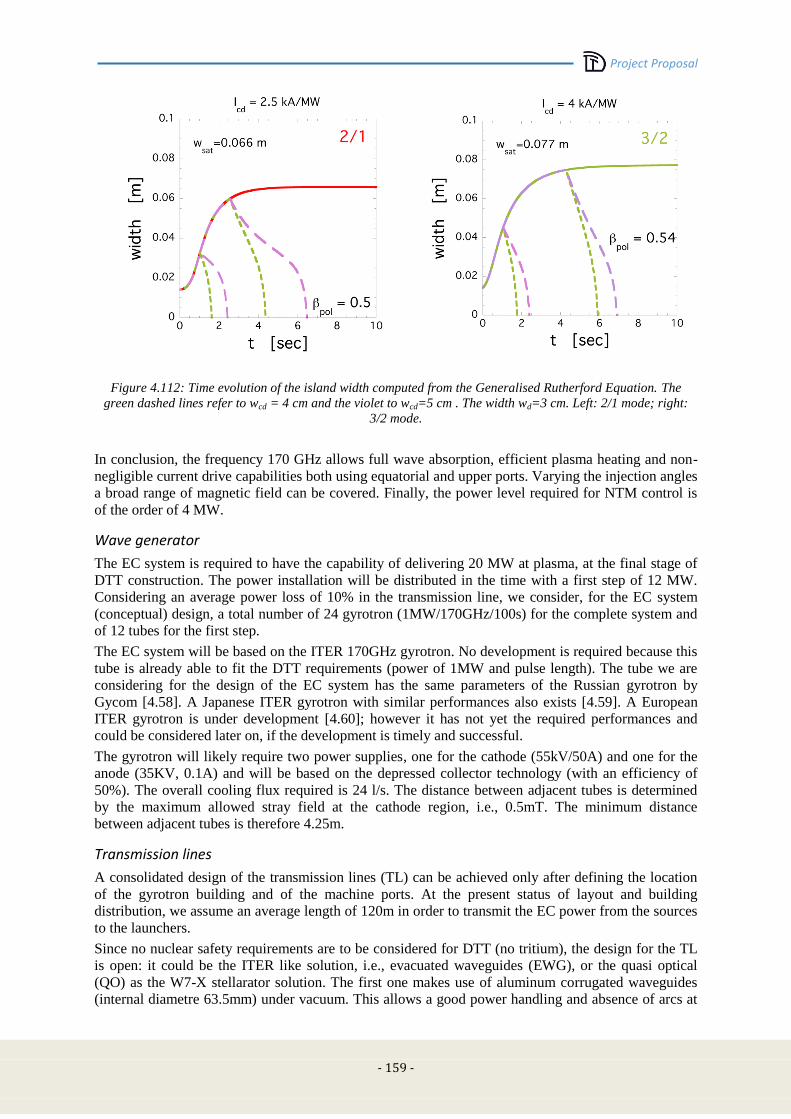
Project Proposal
- 159 -
Figure 4.112: Time evolution of the island width computed from the Generalised Rutherford Equation. The
green dashed lines refer to wcd = 4 cm and the violet to wcd=5 cm . The width wd=3 cm. Left: 2/1 mode; right:
3/2 mode.
In conclusion, the frequency 170 GHz allows full wave absorption, efficient plasma heating and non-
negligible current drive capabilities both using equatorial and upper ports. Varying the injection angles
a broad range of magnetic field can be covered. Finally, the power level required for NTM control is
of the order of 4 MW.
Wave generator
The EC system is required to have the capability of delivering 20 MW at plasma, at the final stage of
DTT construction. The power installation will be distributed in the time with a first step of 12 MW.
Considering an average power loss of 10% in the transmission line, we consider, for the EC system
(conceptual) design, a total number of 24 gyrotron (1MW/170GHz/100s) for the complete system and
of 12 tubes for the first step.
The EC system will be based on the ITER 170GHz gyrotron. No development is required because this
tube is already able to fit the DTT requirements (power of 1MW and pulse length). The tube we are
considering for the design of the EC system has the same parameters of the Russian gyrotron by
Gycom [4.58]. A Japanese ITER gyrotron with similar performances also exists [4.59]. A European
ITER gyrotron is under development [4.60]; however it has not yet the required performances and
could be considered later on, if the development is timely and successful.
The gyrotron will likely require two power supplies, one for the cathode (55kV/50A) and one for the
anode (35KV, 0.1A) and will be based on the depressed collector technology (with an efficiency of
50%). The overall cooling flux required is 24 l/s. The distance between adjacent tubes is determined
by the maximum allowed stray field at the cathode region, i.e., 0.5mT. The minimum distance
between adjacent tubes is therefore 4.25m.
Transmission lines
A consolidated design of the transmission lines (TL) can be achieved only after defining the location
of the gyrotron building and of the machine ports. At the present status of layout and building
distribution, we assume an average length of 120m in order to transmit the EC power from the sources
to the launchers.
Since no nuclear safety requirements are to be considered for DTT (no tritium), the design for the TL
is open: it could be the ITER like solution, i.e., evacuated waveguides (EWG), or the quasi optical
(QO) as the W7-X stellarator solution. The first one makes use of aluminum corrugated waveguides
(internal diametre 63.5mm) under vacuum. This allows a good power handling and absence of arcs at
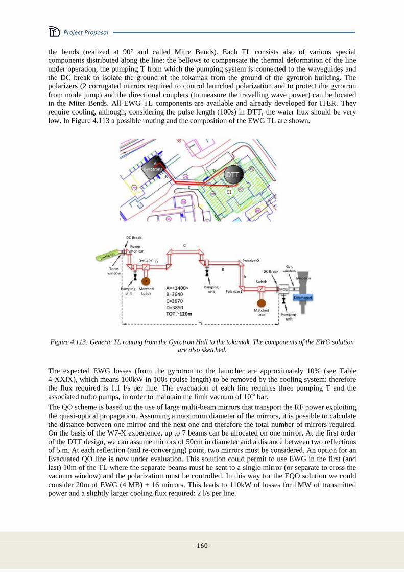
Project Proposal
-160-
the bends (realized at 90° and called Mitre Bends). Each TL consists also of various special
components distributed along the line: the bellows to compensate the thermal deformation of the line
under operation, the pumping T from which the pumping system is connected to the waveguides and
the DC break to isolate the ground of the tokamak from the ground of the gyrotron building. The
polarizers (2 corrugated mirrors required to control launched polarization and to protect the gyrotron
from mode jump) and the directional couplers (to measure the travelling wave power) can be located
in the Miter Bends. All EWG TL components are available and already developed for ITER. They
require cooling, although, considering the pulse length (100s) in DTT, the water flux should be very
low. In Figure 4.113 a possible routing and the composition of the EWG TL are shown.
Figure 4.113: Generic TL routing from the Gyrotron Hall to the tokamak. The components of the EWG solution
are also sketched.
The expected EWG losses (from the gyrotron to the launcher are approximately 10% (see Table
4-XXIX), which means 100kW in 100s (pulse length) to be removed by the cooling system: therefore
the flux required is 1.1 l/s per line. The evacuation of each line requires three pumping T and the
associated turbo pumps, in order to maintain the limit vacuum of 10-6
bar.
The QO scheme is based on the use of large multi-beam mirrors that transport the RF power exploiting
the quasi-optical propagation. Assuming a maximum diameter of the mirrors, it is possible to calculate
the distance between one mirror and the next one and therefore the total number of mirrors required.
On the basis of the W7-X experience, up to 7 beams can be allocated on one mirror. At the first order
of the DTT design, we can assume mirrors of 50cm in diameter and a distance between two reflections
of 5 m. At each reflection (and re-converging) point, two mirrors must be considered. An option for an
Evacuated QO line is now under evaluation. This solution could permit to use EWG in the first (and
last) 10m of the TL where the separate beams must be sent to a single mirror (or separate to cross the
vacuum window) and the polarization must be controlled. In this way for the EQO solution we could
consider 20m of EWG (4 MB) + 16 mirrors. This leads to 110kW of losses for 1MW of transmitted
power and a slightly larger cooling flux required: 2 l/s per line.
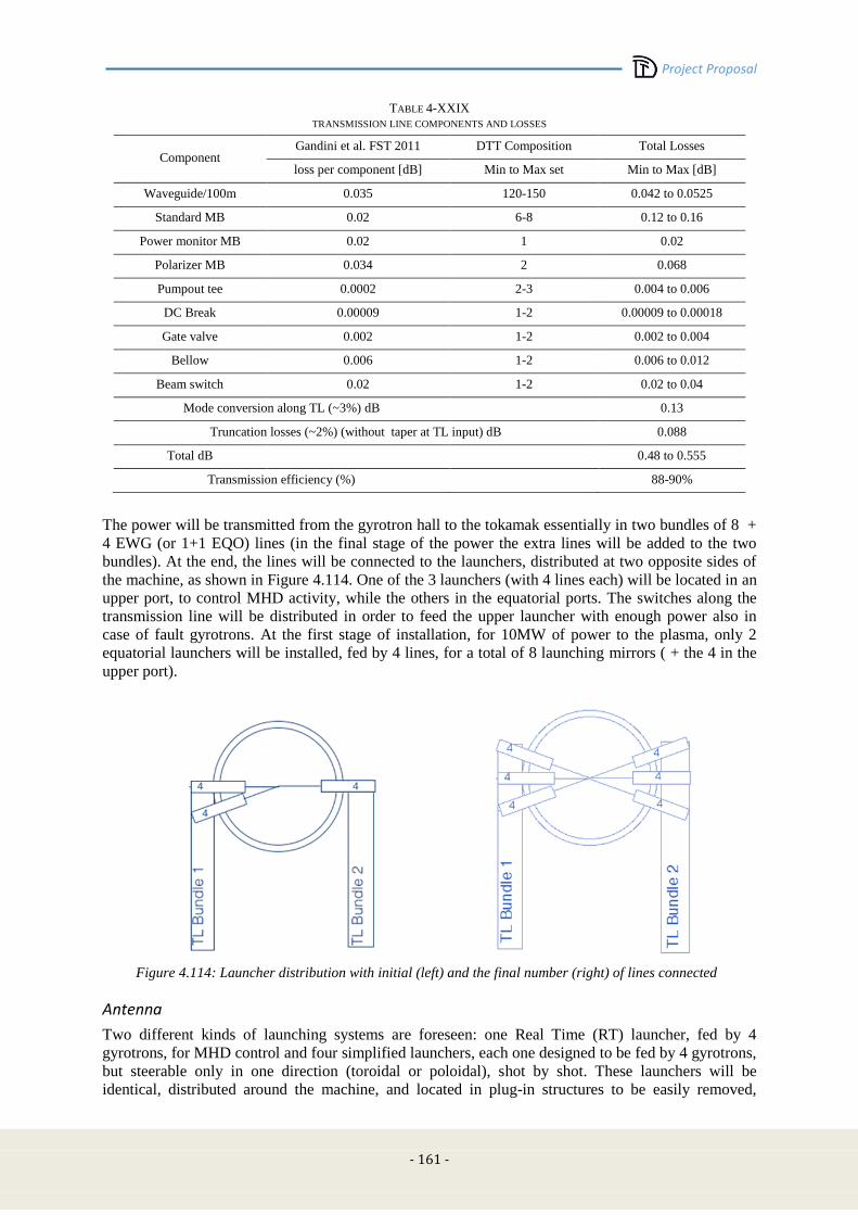
Project Proposal
- 161 -
TABLE 4-XXIX
TRANSMISSION LINE COMPONENTS AND LOSSES
Component Gandini et al. FST 2011 DTT Composition Total Losses
loss per component [dB] Min to Max set Min to Max [dB]
Waveguide/100m 0.035 120-150 0.042 to 0.0525
Standard MB 0.02 6-8 0.12 to 0.16
Power monitor MB 0.02 1 0.02
Polarizer MB 0.034 2 0.068
Pumpout tee 0.0002 2-3 0.004 to 0.006
DC Break 0.00009 1-2 0.00009 to 0.00018
Gate valve 0.002 1-2 0.002 to 0.004
Bellow 0.006 1-2 0.006 to 0.012
Beam switch 0.02 1-2 0.02 to 0.04
Mode conversion along TL (~3%) dB
0.13
Truncation losses (~2%) (without taper at TL input) dB 0.088
Total dB
0.48 to 0.555
Transmission efficiency (%)
88-90%
The power will be transmitted from the gyrotron hall to the tokamak essentially in two bundles of 8 +
4 EWG (or 1+1 EQO) lines (in the final stage of the power the extra lines will be added to the two
bundles). At the end, the lines will be connected to the launchers, distributed at two opposite sides of
the machine, as shown in Figure 4.114. One of the 3 launchers (with 4 lines each) will be located in an
upper port, to control MHD activity, while the others in the equatorial ports. The switches along the
transmission line will be distributed in order to feed the upper launcher with enough power also in
case of fault gyrotrons. At the first stage of installation, for 10MW of power to the plasma, only 2
equatorial launchers will be installed, fed by 4 lines, for a total of 8 launching mirrors ( + the 4 in the
upper port).
Figure 4.114: Launcher distribution with initial (left) and the final number (right) of lines connected
Antenna
Two different kinds of launching systems are foreseen: one Real Time (RT) launcher, fed by 4
gyrotrons, for MHD control and four simplified launchers, each one designed to be fed by 4 gyrotrons,
but steerable only in one direction (toroidal or poloidal), shot by shot. These launchers will be
identical, distributed around the machine, and located in plug-in structures to be easily removed,
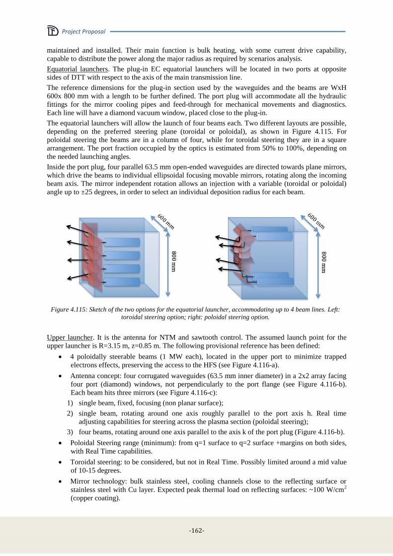
Project Proposal
-162-
maintained and installed. Their main function is bulk heating, with some current drive capability,
capable to distribute the power along the major radius as required by scenarios analysis.
Equatorial launchers. The plug-in EC equatorial launchers will be located in two ports at opposite
sides of DTT with respect to the axis of the main transmission line.
The reference dimensions for the plug-in section used by the waveguides and the beams are WxH
600x 800 mm with a length to be further defined. The port plug will accommodate all the hydraulic
fittings for the mirror cooling pipes and feed-through for mechanical movements and diagnostics.
Each line will have a diamond vacuum window, placed close to the plug-in.
The equatorial launchers will allow the launch of four beams each. Two different layouts are possible,
depending on the preferred steering plane (toroidal or poloidal), as shown in Figure 4.115. For
poloidal steering the beams are in a column of four, while for toroidal steering they are in a square
arrangement. The port fraction occupied by the optics is estimated from 50% to 100%, depending on
the needed launching angles.
Inside the port plug, four parallel 63.5 mm open-ended waveguides are directed towards plane mirrors,
which drive the beams to individual ellipsoidal focusing movable mirrors, rotating along the incoming
beam axis. The mirror independent rotation allows an injection with a variable (toroidal or poloidal)
angle up to ±25 degrees, in order to select an individual deposition radius for each beam.
Figure 4.115: Sketch of the two options for the equatorial launcher, accommodating up to 4 beam lines. Left:
toroidal steering option; right: poloidal steering option.
Upper launcher. It is the antenna for NTM and sawtooth control. The assumed launch point for the
upper launcher is R=3.15 m, z=0.85 m. The following provisional reference has been defined:
4 poloidally steerable beams (1 MW each), located in the upper port to minimize trapped
electrons effects, preserving the access to the HFS (see Figure 4.116-a).
Antenna concept: four corrugated waveguides (63.5 mm inner diameter) in a 2x2 array facing
four port (diamond) windows, not perpendicularly to the port flange (see Figure 4.116-b).
Each beam hits three mirrors (see Figure 4.116-c):
1) single beam, fixed, focusing (non planar surface);
2) single beam, rotating around one axis roughly parallel to the port axis h. Real time
adjusting capabilities for steering across the plasma section (poloidal steering);
3) four beams, rotating around one axis parallel to the axis k of the port plug (Figure 4.116-b).
Poloidal Steering range (minimum): from q=1 surface to q=2 surface +margins on both sides,
with Real Time capabilities.
Toroidal steering: to be considered, but not in Real Time. Possibly limited around a mid value
of 10-15 degrees.
Mirror technology: bulk stainless steel, cooling channels close to the reflecting surface or
stainless steel with Cu layer. Expected peak thermal load on reflecting surfaces: ~100 W/cm2
(copper coating).

Project Proposal
- 163 -
Cooling requirements: 0.5% absorption on mirror surfaces (5 kW/MW) equivalent to 5 l/min,
ΔT=15 °C of water flow per mirror (60 l/min total)
The supporting structure (plug-in) runs along the port sides. It hosts the cooling channels and
the push-pull rods of the moving mirrors. A reserved volume of 50 mm thickness has been
considered.
Figure 4.116: Upper launcher geometry, accommodating up to 4 beam lines.
Power supplies
The gyrotrons will be fed by Solid State High Voltage Power Supply (SSHVPS) in a configuration as
simple as possible. Each gyrotron requires two PSs, one for the main current supply (-55kV, 50A)
with relatively low stability (1%) (MHVPS) and a second stage called Body Power Supply (BPS, -35
KV, 0.1A) with a better control of the output voltage (~0.5%). Considering that the main task of the
EC system is bulk heating to sustain the power load on the divertor, a time-detailed control of the main
EC power is not required, therefore each MHVPS will feed up to 4 tubes simultaneously, while the
BPS will remain singular, as shown in Figure 4.117. The four tubes dedicated to MHD control could
be fed in pairs, if necessary. The MHVPS characteristics are summarized in Table 4-XXX.
For space allocation, cooling requirement and CODAS dimensioning we consider 3 modules in the
first stage and 6 for the final configuration.
The BPS will be based on a similar technology but with reduced voltage ripple. Each gyrotron will be
fed by a single BPS in order to independently control the power.
Figure 4.117: Scheme of a single MPS module feeding 4 gyrotrons

Project Proposal
-164-
TABLE 4-XXX
MAIN POWER SUPPLY FOR EC GYROTRON
Output voltage (kV) -55 kV
Output Current (A) 200 A
Voltage Ripple 1%
Efficiency 95%
Power Factor 0.96
Response Time 0.1 – 1ms
Duty Cycle 1/4
Water Cooling Requirement (l/s) 4.8
Dimension (m) 14 x 3.5 x 3.5 h
Weight (kg) 10000
Auxiliaries & cooling
From the gyrotron reference, the tentative list of relevant auxiliaries is at present:
filament PS: 37 A/ 8V;
sweeping coils collector: up to 22A;
protection system:
o arc sensor on the gyrotron window;
o output mode monitor to avoid parasitic oscillation in the gyrotron;
o ionic pump;
the cryomagnet will be based on cryofree technology (without cryogenic liquids inside). Each
magnet is connected to a compressor requiring 8kW of AC power and a moderate cooling. No
daily maintenance is necessary.
Machine layout and interfaces
The EC power will be delivered to the plasma using 2 different types of launcher, as previously
described. The port occupation by the EC plug-in launcher is partial for the equatorial one, leaving
space for other systems (cooling pipes) or diagnostics insertion, while it is full for the upper launcher.
The plug-in concept will be at the basis of the design, allowing also remote maintenance. The diamond
windows will be on the port plate and removed with the launcher during the maintenance periods. In
order to simplify installation and layout, all the equatorial launchers will be identical and located in a
symmetric position on the machine in order to duplicate also the interface component between the TL
and the launchers. In each TL and after each window a gate valve will be mounted in order to operate
the machine in case of failure.
CODAC / control systems
The architecture of EC Control system will take benefit from what has been under development for
ITER and for JET. The system is divided in sub-units:
- Power Supply (MPS and BPS)
- Gyrotrons (including cryomagnet and auxiliaries)
- Transmission Line
- Launchers
each of them controlled by local PLC and by a supervisor unit. Each supervisor unit exchanges in/out
with a Central Control System, interfaced with the DTT plant System and with the mimics.
Three different time scales are foreseen in the system:
- fast protection time: <10μs
- PLC control time: 100ms
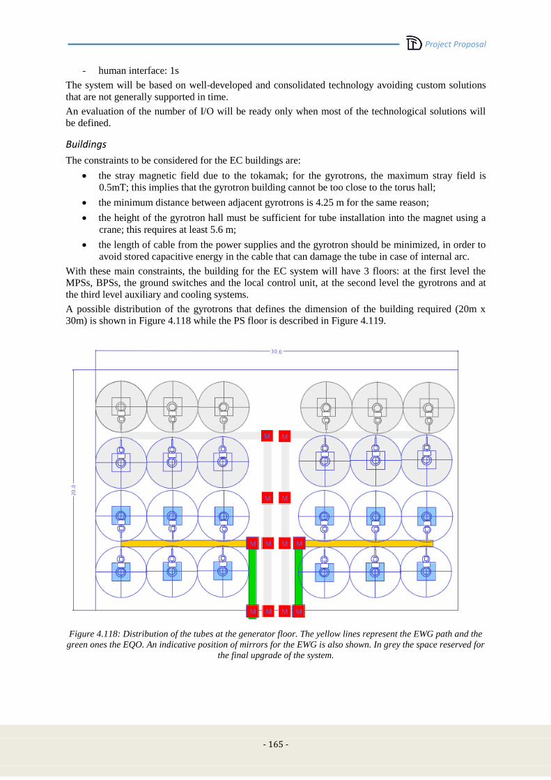
Project Proposal
- 165 -
- human interface: 1s
The system will be based on well-developed and consolidated technology avoiding custom solutions
that are not generally supported in time.
An evaluation of the number of I/O will be ready only when most of the technological solutions will
be defined.
Buildings
The constraints to be considered for the EC buildings are:
the stray magnetic field due to the tokamak; for the gyrotrons, the maximum stray field is
0.5mT; this implies that the gyrotron building cannot be too close to the torus hall;
the minimum distance between adjacent gyrotrons is 4.25 m for the same reason;
the height of the gyrotron hall must be sufficient for tube installation into the magnet using a
crane; this requires at least 5.6 m;
the length of cable from the power supplies and the gyrotron should be minimized, in order to
avoid stored capacitive energy in the cable that can damage the tube in case of internal arc.
With these main constraints, the building for the EC system will have 3 floors: at the first level the
MPSs, BPSs, the ground switches and the local control unit, at the second level the gyrotrons and at
the third level auxiliary and cooling systems.
A possible distribution of the gyrotrons that defines the dimension of the building required (20m x
30m) is shown in Figure 4.118 while the PS floor is described in Figure 4.119.
Figure 4.118: Distribution of the tubes at the generator floor. The yellow lines represent the EWG path and the
green ones the EQO. An indicative position of mirrors for the EWG is also shown. In grey the space reserved for
the final upgrade of the system.

Project Proposal
-166-
Figure 4.119: Distribution of PS for the gyrotrons, in yellow the MPS, in green the PS, in red the ground
switches and in blue the local control units. In grey the space reserved for the final set of the system
Cost / Manpower / Time schedule for system design and construction
Cost estimates have been made and are presented, together with other machine costs, in Chap. 5.
Using similarities with smaller projects, the following manpower resources have been evaluated:
Design& Procurement ECRH: 10 ppy for 2 yrs
Engineers/Technicians required:
Gyrotron 1/2
PS 2/4
TL 2/4
CODAC + DAS 2/4
Launcher 2/4
System Supervisor 1
Total: 10 engineers + 18-20 technicians
Regarding the time schedule, two years will be necessary for the design of the system and the start of
the procurement activity. The time for construction will be dominated by the gyrotrons and the TLs
(for the EWG solution more than 1 km of corrugated waveguides is necessary). A single company can
build 5 tubes/year (Gycom private communication, in the framework of the ECRH JET project);
therefore 2.5 years are necessary to construct the initial stage. The construction of other components
are less critical for the timing, therefore we can consider 3 years to build and to start the installation,
depending on the time of the construction of the tokamak.
Cost & Manpower for system operation
After the installation and the commissioning of the system, the number of dedicated persons will be
obviously reduced. An estimate of ppy required for system operation is given here for the
experimental shift:
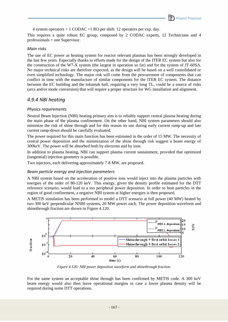
Project Proposal
- 167 -
4 system operators + 1 CODAC +1 RO per shift: 12 operators per exp. day.
This requires a quite robust EC group, composed by 2 CODAC experts, 12 Technicians and 4
professionals + one Supervisor.
Main risks
The use of EC power as heating system for reactor relevant plasmas has been strongly developed in
the last few years. Especially thanks to efforts made for the design of the ITER EC system but also for
the construction of the W7-X system (the largest in operation so far) and for the system of JT-60SA.
No major technical risks are therefore expected, as the design will be based on a well consolidated or
even simplified technology. The major risk will come from the procurement of components that can
conflict in time with the manufacture of similar components for the ITER EC system. The distance
between the EC building and the tokamak hall, requiring a very long TL, could be a source of risks
(arcs and/or mode conversion) that will require a proper structure for WG installation and alignment.
4.9.4 NBI heating
Physics requirements
Neutral Beam Injection (NBI) heating primary aim is to reliably support central plasma heating during
the main phase of the plasma confinement. On the other hand, NBI system parameters should also
minimize the risk of shine through and for this reason its use during early current ramp-up and late
current ramp-down should be carefully evaluated.
The power required for this main function has been estimated in the order of 15 MW. The necessity of
central power deposition and the minimization of the shine through risk suggest a beam energy of
300keV. The power will be absorbed both by electrons and by ions.
In addition to plasma heating, NBI can support plasma current sustainment, provided that optimized
(tangential) injection geometry is possible.
Two injectors, each delivering approximately 7-8 MW, are proposed.
Beam particle energy and injection parameters
A NBI system based on the acceleration of positive ions would inject into the plasma particles with
energies of the order of 80-120 keV. This energy, given the density profile estimated for the DTT
reference scenario, would lead to a too peripheral power deposition. In order to heat particles in the
region of good confinement, a negative NBI system at higher energies is then proposed.
A METIS simulation has been performed to model a DTT scenario at full power (40 MW) heated by
two 300 keV perpendicular NNBI systems, 20 MW power each. The power deposition waveform and
shinethrough fraction are shown in Figure 4.120.
Figure 4.120: NBI power deposition waveform and shinethrough fraction.
For the same system an acceptable shine through has been confirmed by METIS code. A 300 keV
beam energy would also then leave operational margins in case a lower plasma density will be
required during some DTT operations.

Project Proposal
-168-
As said, the main aim of this system being plasma heating, perpendicular injection of the beam is also
a valid option. This solution minimizes the impact of the NBI system on the overall design. In case
some current drive will be considered as an optional asset of the system, more tangential injection
geometries (on- or off-axis) could be considered.
In DTT one tangential port is provided for the installation of one injector, whereas the other will have
a perpendicular access to the plasma.
Design choices and concepts
Taking into account the previous simulation and assuming a conservative approach by the adoption of
the gas neutralizer, in which the negative ion neutralization yield is theoretically limited to 60%, and
taking into account additional losses, it is necessary to accelerate at 300 kV approximately 45 A of
negative ion current. This corresponds to extract approximately 50 A from the plasma source.
A layout scheme similar to those adopted in JT-60SA [4.61]-[4.62] and in LHD [4.63] is proposed, in
which four different sections can be identified: beam source (including negative ion source and
accelerator), neutralization section, residual ion dump (including beam dump) section and duct to
connect the injector to the vacuum vessel.
Figure 4.121: LHD Negative Neutral Beam injector. Similar layout is proposed for DTT. The same layout is also
adopted in JT-60SA.
For the plasma source it is proposed to use the same RF source concept adopted for ITER, instead of
the filament arcs concept adopted in both Japanese NNBI systems. The plasma grid will be coated by
Caesium in order to enhance the surface negative ion production that will be released by commercial
Caesium dispensers, accordingly to the development under progress for ITER MITICA/HNB [4.64]
and under EUROfusion WPHCD [4.65].
The accelerator system will foresee a two stage acceleration, with each stage accelerating the extracted
negative ion beam of 150 keV. The geometry of the grids is constituted by a four grid system
including: plasma grid (-310 kV), extraction grid (-300 kV), acceleration grid (-150 kV) and grounded
grid (0 V). The voltage level of plasma grid and extraction grid are tuned to guarantee the correct
divergence of the extracted beam. The first three grids will be manufactured with the beamlet
configuration, whereas the grounded grid could be developed according to the slot concept adopted in
LHD. This configuration guarantees higher acceleration efficiency.
In Figure 4.122 a layout sketch of the accelerator concept is shown.

Project Proposal
- 169 -
Plasma
Grid (PG)
Extraction
Grid (EG)Acceleration
Grid (AG)
Grounded
Grid (GG)
Beam
direction
Figure 4.122: acceleration stages concept
The accelerated negative ion beam will be neutralized by a gas neutraliser followed by a Residual Ion
Dump. The choice of concept for the RID will be defined on the basis of the results that will be
obtained in the first few years of MITICA operation, in which the electrostatic RID will be tested to
confirm the choice for ITER. This solution is more compact with respect to the magnetic deflection
RID that is the standard backup well experienced solution.
In order to optimize the vacuum level in the different sections of the injectors, the neutraliser
conductance will be minimized and NEG (Non-Evaporable Getter) pumps will be adopted in all four
sections of the injectors.
Since under the WPHCD of EUROfusion the concept of the photoneutraliser is under development to
increase the neutralization efficiency, this option could be considered if the concept will demonstrate
its validity under the present R&D activities. In this case, a theoretical increase of power up to 10-12
MW released to the plasma by each injector at the same energy could be expected.
The technologies involved in the concept of this NNBI are already available and adopted in the
presently operating injectors in Japan; further optimizations could be derived from present R&D
activities developed under the EUROfusion programme in view of the application in a reactor relevant
device.
Therefore the proposed negative NBI is on one hand sufficiently robust and, on the other, ready to
adopt new technologies to further improve efficiency, reliability and availability. An optimized NNBI
system will also have an optimized set of auxiliaries with optimized cooling system and with the
adoption of NEG pumps the cryogenic system will be excluded with significant reduction of costs and
risks and increased reliability, availability and safety.
Power supplies
With regard to the Power supply system, this could be developed as a down-scaled version, with
reduced number of components, with respect to the ITER-like 1 MV Power Supplies and source
Power Supplies based on a SF6 insulated High Voltage transmission line. This choice requires a deep
assessment and comparison with the alternative solution to adopt a full air insulated system.
The high voltage deck in air that will host the plasma source PS insulated at 300 kV will have the
similar size of SPIDER system (see Figure 4.123), where the main difference will be the insulation
distance that will be longer, in order to cope with the 300 kV insulation requirement.

Project Proposal
-170-
Figure 4.123: High voltage deck hosting all the power supplies and diagnostics dedicated to the plasma source
The layout of the two injectors could be functionally identified as in Figure 4.124 with reasonable
space allocated to the different PS sub-systems.
Cost estimate
Cost estimates have been made, scaled from the realization of SPIDER and MITICA and are
presented, together with other machine costs, in Chap. 5.
The competences and the technologies involved in the design, construction and operation are fully
available in the fusion research community in Italy and in Italian and European industries, since they
are fully involved in the development of the ITER HNB system and in the development of neutral
beam injectors for DEMO.
Figure 4.124: Layout of NNBI injector and PS
Project Proposal
- 171 -
4.10 Fueling and pumping systems
4.10.1 Divertor pumping
Scaling to ne,sep=1.0×10²⁰
m−3
the output of COREDIV for the DTT case:
Ip = 6.0 MA; BT = 6.0 T; <ne> = 1.8×10²⁰
m−3
; Paux= 40 MW; ne,sep= 7.4×10¹⁹
m−3
, a maximum particle
flux outgoing from the separatrix ion =5.7 1021
s-1
can be found.
To be conservative, from the point of view of divertor pumping requirements, let us assume that all the
particles outgoing from the separatrix are impinging on the divertor targets and result in the creation of
neutrals (fast reflected plus Franck-Condon), that means to consider null the probability of retention in
the PFCs (a not bad approximation for a full W machine).
Taking into account that the dome support structures have windows distributed periodically in the
toroidal direction and can be modelled with the transparency coefficient of 0.5, the flux of particles
available to be pumped out as neutrals is about n = 3 1021
s-1
. Before a neutral entering the plenum
reaches the pump duct, the deuterium has been thermalized (T = 0.025 eV) by multiple collisions with
the plenum structure. This corresponds to a total pumping throughput at the pump ducts of about 23 Pa
m3 s
-1. To maintain the neutral pressure in the PFR at a level suitable to guarantee an effective
pumping (1 – 10 Pa), the effective pumping speed at the entrance of pump duct should be Seff = n /
pPFR ~ 2.3 – 23 m3 s
-1.
For the sizing of pumps to be allocated in the divertor ports, the total conductance of the pumping
ducts (mainly defined by the opening connecting the volume under the dome with the outside) needs
to be known, the effective pumping speed probably mainly depending on the latter. At this stage what
can be fixed is that the total pumping speed of the pumps must be larger (by far) than 23 m3 s
-1.
4.10.2 Vacuum chamber pumping
For calculating the number of pumps needed for evacuating the DTT vacuum chamber, the total area
of DTT vacuum chamber, including ports and ICRH antennas is to be defined. By allowing for the
specific INCONEL 625 vacuum vessel and FW (the W coated part of the latter giving a minor
contribute) outgassing rate, after all cleaning procedures, of 6.7 10-9
Pa m3 s
-1 m
-2 at 100°C, the
effective pumping speed, needed for pumping the torus down to P =1.33 10-7
Pa, can be calculated
from Seff = out. rate / P. As a first approximation, the conductance between a pump, located at the
equatorial plane, and the vacuum chamber is dominated by the conductance of the pipe between the
pump and the port. In fact a realistic conductance of such a pipe, for a turbomolecular pump with
pumping speed S = 1.5 m3 s
-1 is about 1.1 m
3 s
-1 (T = 300 °K, M = 29 (air) and molecular regime have
been considered), while the conductance of the equatorial port is for sure much larger. Then the
overall required number and pumping speed of the pumps (p. e. turbomolecular) can be calculated
taking into account both required effective pumping speeds and conductance values.
4.10.3 Choice of pump type
As for the type of pumps to be installed in DTT (not only for divertor) the following approaches,
taking advantage from the development in progress under WPTFV in EUROfusion, could be adopted,
besides considering cryogenic pumps (that are not applicable to DEMO):
Option 1:
For the forevacuum pump stage to adopt the mercury driven liquid ring pump and for the high vacuum
stage a combination of mercury diffusion pump and NEG pump that are under development for both
Divertor and NBI for DEMO.
This option has many advantages and overcome the drawbacks of cryogenic pumping systems: costs
(investment and running costs), safety (explosion), availability (frequent regenerations) and reliability
(high maintenance costs of cryogenic systems).
Project Proposal
-172-
Option 2:
Same as Option 1 except that if the Mercury Diffusion pump is not available with the sufficient
pumping speed a combination of NEG pumps and turbomolecular pumps could be adopted. For the
forevacuum pump stages conventional screw-roots combined pumps could be adopted.
In this case more conservative approach is adopted minimizing costs and maximizing availability and
reliability.
The calculation of real conductance needs to be carried out with available ad hoc codes when the exact
geometry of the divertor and duct regions will be fixed. It will be also verified if in the pumping ducts
transitional flow regimes (intermediate between molecular and viscous flow regime) is to be taken into
account.
Problems related with possible massive gas injections for disruption mitigation will be also taken into
account as well as the requirements for the wall conditioning techniques that will be adopted. Mass
spectrometer stations will be used to monitor the residual gas and to detect vacuum leaks.
4.10.4 Cryostat pumping
Prior to cool-down of the ITER magnet system, the enveloping cryostat has to be evacuated to a low
enough pressure to reduce gas convection and conduction heat loads to the magnet structures to an
acceptable level (∼0.1 mPa). A dedicated pumping system will be allocated for this purpose. The
pumps could be the same allocated for the VV vacuum as well as standard turbomolecolar pumps.
4.10.5 Fuelling.
Fuelling system foreseen for a Deuterium operated device will have all the main features currently
installed in any divertor Tokamak with a particular emphasis in the central fuelling on one side and on
the other on the divertor fuelling to optimize the radiation in that region.
Therefore the fuelling system can be identified as having the following main sub systems:
Deuterium (and Hydrogen) plasma fuelling through valves and pellet injector, mainly
positioned in the mid-plane ;
local neutral density control in front of the ICRH antennas;
noble gas impurity injection in the main plasma and in the divertor region;
massive gas injection in the main plasma region for disruption mitigation in different poloidal
and toroidal location.
The order of magnitude for the gas injection for both H2/D2 and for impurity injection, excluding
massive gas injection for disruption mitigation is in the order of 200 Pam3/s.
4.11 Cryostat vessel
The Cryostat Vessel (CV) is a vacuum tight container, surrounding the entire Tokamak Basic
Machine, which provides the vacuum for the superconducting magnets and forms part of the
secondary confinement barrier. The vacuum environment is intended to avoid excessive thermal loads
from being applied to the components that are being operated at cryogenic temperatures by gas
conduction and convection. The CV provides ports and penetrations, with proper bellows, to the
vacuum vessel (see Figure 4.125).

Project Proposal
- 173 -
Figure 4.125: Sectional view of DTT tokamak basic machine
Bellows compensate for differential movements. These bellows have a rectangular shape and are made
of stainless steel materials. Development of suitable bellows will be completed during more detailed
design phases.
CV must also provide openings for pipes connecting equipment outside the Cryostat to the
corresponding elements inside the Cryostat (e.g. magnet feeders, water cooling pipes, instrumentation
feedthroughs, CV pumping systems).
CV design must allow maximum feasible personnel access inside the cryostat by having penetrations
for the deployment of shielded access ways through which personnel can access the required work
locations.
The design and construction of the CV shall be consistent with providing the required vacuum for
DTT. The maximum allowable leak rate shall be consistent with achieving the global leak rate
requirements for the Cryostat Vacuum boundary. The maximum acceptable outgassing rate and the
maximum allowable leak rate for DTT should be determined during the next design phases.
The Cryostat shall be designed and manufactured using the ASME section VIII-Div.2 as a reference
code.
The design principles of the cryostat are chiefly based on cost minimization and functionality. The
cryostat is a single-wall cylindrical vessel, with a vertical axis, a flat base and a tori-spherical top lid.
An elevation view is shown in Figure 4.126.

Project Proposal
-174-
Figure 4.126: Cryostat Vessel segmentation
The top lid has a tori-spherical shape, its weight can be estimated in about 27 tons while the internal
height is about 1.5 m (see Figure 4.128). The cylindrical section is bolted by flanges to top lid wall at
top and to base plate at bottom. Its external diameter (~10 m) is determined by the dimension of the
maximum diameter of the toroidal field coil with an additional small radial clearance of approximately
800 mm to facilitate the installation of components and to guarantee proper access space for in-situ
repair. The cylindrical section is about 7 m height; this dimension is determined by the size of
components inside as well as to provide adequate vertical space for penetrations through the cryostat
cylindrical shell needed to make the interconnections with external systems. The weight of cylindrical
portion of the CV is about 60 tons. At the current pre-conceptual stage, cryostat walls are provisionally
dimensioned as 40mm thick, while the stainless steel base plate is 60mm thick. The main dimensions
of the entire CV are shown in Figure 4.128.
The CV is a fully-welded, stainless steel (AISI 304L) vessel, with a large number of penetrations for
access to VV ports at five levels and further horizontal penetrations for coolant pipe work at upper and
lower levels, and cryo and current feed lines to magnets at the upper and lower levels.
Considering the top tori-spherical dome-shape lid and lower flat head, and particularly the large
penetrations for the port access through the cylindrical shell, the stability against the buckling will be
the main driver for the mechanical design, and cryostat structure shall be analyzed for buckling
strength.
It is understood that further analyses shall be conducted to better determine steel thickness during
more detailed design stages.
Furthermore, access penetrations for manned access for repair or inspection shall be included in the
lower cylindrical portion of the CV for horizontal and vertical entry and in the top lid of CV for
vertical entry.
Cryostat base plate is supported on a frame, which is mainly consisted of H-beams in radial and
toroidal directions (see Figure 4.127).
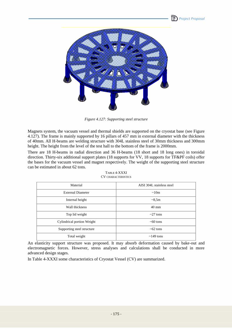
Project Proposal
- 175 -
Figure 4.127: Supporting steel structure
Magnets system, the vacuum vessel and thermal shields are supported on the cryostat base (see Figure
4.127). The frame is mainly supported by 16 pillars of 457 mm in external diameter with the thickness
of 40mm. All H-beams are welding structure with 304L stainless steel of 30mm thickness and 300mm
height. The height from the level of the test hall to the bottom of the frame is 2000mm.
There are 18 H-beams in radial direction and 36 H-beams (18 short and 18 long ones) in toroidal
direction. Thirty-six additional support plates (18 supports for VV, 18 supports for TF&PF coils) offer
the bases for the vacuum vessel and magnet respectively. The weight of the supporting steel structure
can be estimated in about 62 tons.
TABLE 4-XXXI
CV CHARACTERISTICS
An elasticity support structure was proposed. It may absorb deformation caused by bake-out and
electromagnetic forces. However, stress analyses and calculations shall be conducted in more
advanced design stages.
In Table 4-XXXI some characteristics of Cryostat Vessel (CV) are summarized.
Material AISI 304L stainless steel
External Diameter ~10m
Internal height ~8,5m
Wall thickness 40 mm
Top lid weight ~27 tons
Cylindrical portion Weight ~60 tons
Supporting steel structure ~62 tons
Total weight ~149 tons
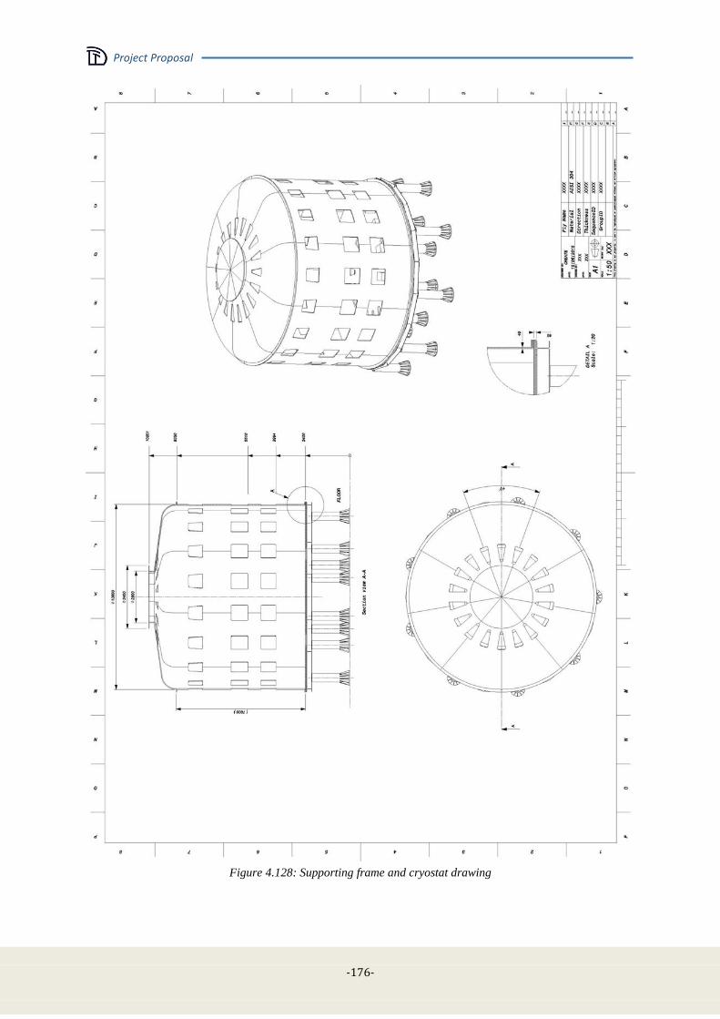
Project Proposal
-176-
Figure 4.128: Supporting frame and cryostat drawing
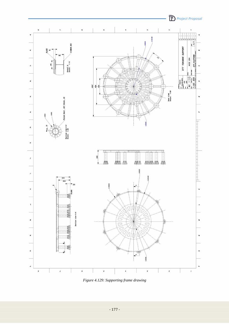
Project Proposal
- 177 -
Figure 4.129: Supporting frame drawing
Project Proposal
-178-
4.12 Cooling system - cryogenics
The main characteristics of the DTT cryogenic system have been estimated in order to cool down the
following components:
18 TF coils + 6 current leads
CS coil (6 modules) + 6 current leads
6 PF coils + 6 current leads
Cryostat thermal shields
Feeders
Cryo-lines
Heat loads and mass flow rates
The heat loads in a Tokamak magnetic system depend from the operating condition:
in the steady state condition the thermal loads are due to radiation, conduction through the
support structure and current leads, Joule-heat in the conductor joints and terminations.
during operation, the nuclear thermal heat, the eddy current losses in the massive support and
the AC losses in the conductors due to electromagnetic variations, must be added to the steady
state heat loads
Based on a first analysis of the heat loads, the worst thermal condition for the magnet system in the
reference scenario is found at the end of burn (EOB).
It is worth noting that in the present study, the shielding from neutrons and secondary gamma is
considered to be capable to keep the heat deposition in the 18 TF coils below a maximum value of
2kW.
The cooling temperature of each component will be different, but we foresee to group them in order to
use one He refrigerator which shall provide 3 different outlet temperatures: 4.2K, 20/50 K and 80K.
After further studies which are on-going, the refrigeration of the components at 50K and 80K with He,
could be replaced by refrigeration with Liquid Nitrogen, also considering that there’s the possibility of
adopting a cryoplant pre-cooled by this refrigerant.
In Table 4-XXXII all the heat loads taken into consideration for the present study, are reported.
A rough estimation of the necessary refrigeration mass flow rates is reported in Table 4-XXXIII.
The refrigeration system design is based on standard refrigerators available on the market.
In these machines, low pressure He gas is compressed in an oil screw compressor and, after
purification from oil contaminants, it is fed to the cold-box.
The cold-box is equipped with counter flow heat exchanger and turbo-expanders. The high pressure
(HP) gas is cooled down by returning cold low pressure gas. The HP gas is further cooled by
expansion in the turbo-expanders and liquefied by Joule-Thompson valve.
Intermediate helium gas outlets are foreseen on the heat exchanger for the 20K/50K and 80K.
Looking at the data collected in Table 4-XXXII and Table 4-XXXIII, we can estimate the necessary
power of the cryogenic plant for avoiding the thermal quench of the magnets during operation:
[email protected] (390g/s) + 72kW@50K (30g/s) + 4.5kW@80K (45g/s).
It can be summarized by saying that the cryogenic plant shall be designed to supply an equivalent
power of about [email protected].
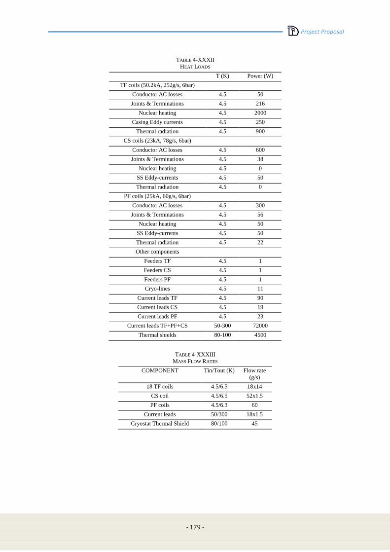
Project Proposal
- 179 -
TABLE 4-XXXII
HEAT LOADS
T (K) Power (W)
TF coils (50.2kA, 252g/s, 6bar)
Conductor AC losses 4.5 50
Joints & Terminations 4.5 216
Nuclear heating 4.5 2000
Casing Eddy currents 4.5 250
Thermal radiation 4.5 900
CS coils (23kA, 78g/s, 6bar)
Conductor AC losses 4.5 600
Joints & Terminations 4.5 38
Nuclear heating 4.5 0
SS Eddy-currents 4.5 50
Thermal radiation 4.5 0
PF coils (25kA, 60g/s, 6bar)
Conductor AC losses 4.5 300
Joints & Terminations 4.5 56
Nuclear heating 4.5 50
SS Eddy-currents 4.5 50
Thermal radiation 4.5 22
Other components
Feeders TF 4.5 1
Feeders CS 4.5 1
Feeders PF 4.5 1
Cryo-lines 4.5 11
Current leads TF 4.5 90
Current leads CS 4.5 19
Current leads PF 4.5 23
Current leads TF+PF+CS 50-300 72000
Thermal shields 80-100 4500
TABLE 4-XXXIII
MASS FLOW RATES
COMPONENT Tin/Tout (K) Flow rate
(g/s)
18 TF coils 4.5/6.5 18x14
CS coil 4.5/6.5 52x1.5
PF coils 4.5/6.3 60
Current leads 50/300 18x1.5
Cryostat Thermal Shield 80/100 45
Project Proposal
-180-
4.13 Cooling system - hydraulic
Due to the long pulse of DTT many systems require to be cooled during the shot. In most of the cases
the cooling water should be demineralized and this will require closed water loop with exchange heat
system.
In the following a list of the principal system using liquid demineralized water:
ECRH system (tubes, line, antennas etc.)
ICRH system (tubes, line, antennas etc.)
Power supplies (i.e., converters, resistors, breakers, switches etc.)
Divertor (cooling tubes)
Vacuum vessel (cooling tubes)
Limiter
Glow discharge
Diagnostics
NBI
and a list of the principal system using normal water:
Cooling and heating building plant
Pumping system (turbomolecular pump)
Auxiliary system (oil heat exchange, etc.)
Diagnostics
To a better definition of the project needs, it would be necessary to know the water capacity for each
system, the location and the building layout but probably, if the final site will be Frascati, it is quite
obvious that each system will need a own cooling water system with relative pumps, tubes, heat
exchangers, sensors and local/remote control system. Probably only the elements inside the cryostat
and in the main hall could be supplied with a unique circuit. Generally water pumps are located very
near the system but in a separated hall.
In a preliminary layout the ECRH building has already a pump hall for the motor flywheel generator
used to supply the FTU poloidal coils and ICRH could use the present pump hall of Lower Hybrid and
ECRH heating system installed on FTU.
An evaluation taking into account a power of 200 MW to be dissipated for each shot gives a total
request of about 2000 l/s subdivided among the different systems. ECRH and ICRH need about 500 l/s
each one.
Due to the long duty cycle, i.e., one shot lasting 100s each hour at full power to save money, instead to
install evaporative tower, we could built same relative small pools (approximately 5x5x2m) to
dissipate the heat.
4.14 Power supply
4.14.1 Introduction
The procedure used for the estimation of the electrical power needed for the DTT machine was based
on the separated forecasting of the power absorbed by the following components:
The electrical power required to feed the poloidal coils, including:
o The 6 superconducting modules of the Central Solenoid (CS3U, CS2U, CS1U, CS1L,
CS2L, CS3L).
o The 6 superconducting coils classified as PF1, PF2, PF3, PF4, PF5, PF6.
Project Proposal
- 181 -
o The two non-superconducting Internal Coils (IC).
The electrical power required to feed the Toroidal Field (TF) superconducting coils.
The power required by the additional heating systems (ECRH, ICRH and NBI).
The power of the auxiliary systems (vacuum pump, cooling and cryogenic systems, diagnostic
tools, computers, services and so on).
For the power estimation, these four contributions were considered independent.
This analysis was performed to assess the amount of electrical power needed to operate the system
grid, but also to determine the characteristics of the power supplies.
The poloidal power supply system consists of a series of:
A Base Power Supply (AC/DC converters);
A Quench Protection Circuit (QPC);
A commutation systems, denoted as Switching Network Unit (SNU).
This general scheme is different only for the coils PF3 and PF4, as they have a by-pass switch (BPS)
instead of the SNU. This BPS is closed only after the plasma breakdown.
The toroidal system does not include a SNU but may require more QPCs.
4.14.2 Summary of the mathematical model
The estimation of electric powers relating to poloidal and toroidal coils was performed by using the
following parameters and mathematical formulations:
1. The coils currents over time for each coil, the so-called “current scenario”, expressed by a
matrix I having size [K x N]. The number of columns N of the matrix is equal to the number of
coils and the number of rows K is equal to the time instants at which the coil currents are
defined.
2. The matrix M of the self and mutual inductances of the coils. It is a square matrix having size
[N x N], where the main diagonal are reported the self-inductances for each coil, whereas the
extra-diagonal of the matrix are included the mutual inductances due to the magnetic
interaction among coils. This matrix is then symmetrical.
The matrix M should include the values modelling the effect of the “passive” elements of the
tokamak. Since these values were not provided for DTT, they were not used for the calculations.
These approximations were compensated by introducing a safety margin in the final results.
The first step is the determination of the voltages for each coil by the following mathematical
expression:
dt
dT
IMV . (1)
The result achieved is expressed by a matrix V, where each element identifies a vector that describes
the voltages over time for each coil.
The values in V correspond to the voltage at the coil terminals. The actual voltage to be produced by
the power supply system should account also for the voltage drops in the circuit (DC bus bars,
connections, joints, switches and so on), while the resistance of the superconducting coils can be
neglected.
For the poloidal coils, this voltage is identical to the voltage produced by the Base Power Supply
during the entire scenario excluding the breakdown zones. In fact, the voltage at the breakdown
depends also on the voltage drop produced by the SNU resistance. For PF3 and PF4 the voltage takes
into account the effects of the currents in the other coils.
The SNU resistances needed for the voltage required by each coil were calculated. Moving from these
values, all the Base Power Supply voltages were estimated.
The combination of these values was used to calculate for each coil:
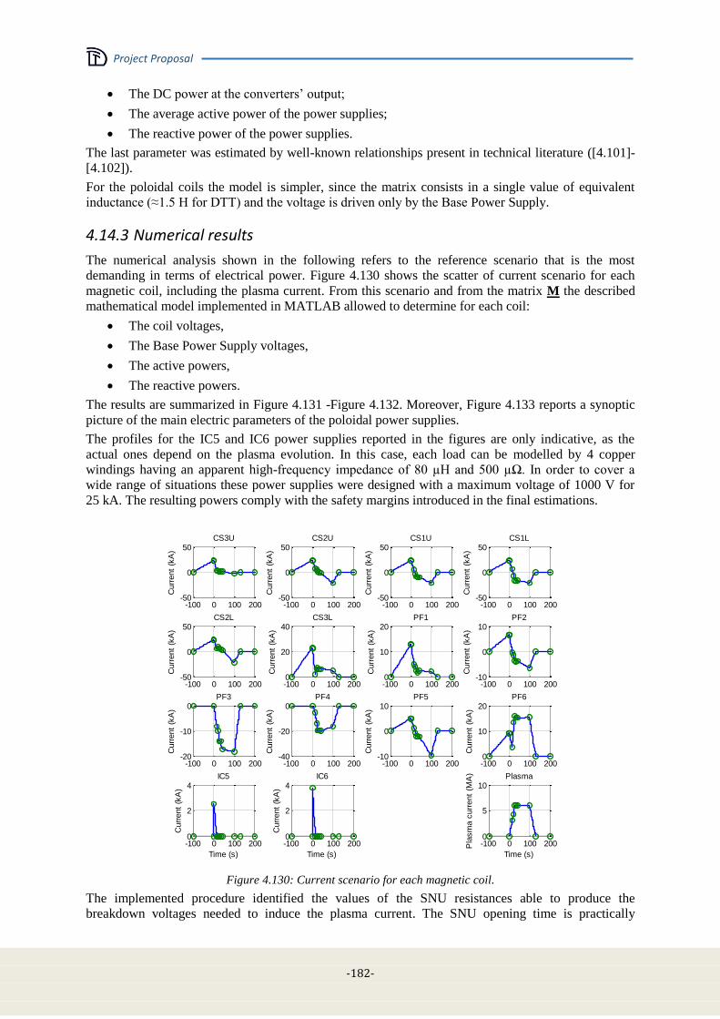
Project Proposal
-182-
The DC power at the converters’ output;
The average active power of the power supplies;
The reactive power of the power supplies.
The last parameter was estimated by well-known relationships present in technical literature ([4.101]-
[4.102]).
For the poloidal coils the model is simpler, since the matrix consists in a single value of equivalent
inductance (≈1.5 H for DTT) and the voltage is driven only by the Base Power Supply.
4.14.3 Numerical results
The numerical analysis shown in the following refers to the reference scenario that is the most
demanding in terms of electrical power. Figure 4.130 shows the scatter of current scenario for each
magnetic coil, including the plasma current. From this scenario and from the matrix M the described
mathematical model implemented in MATLAB allowed to determine for each coil:
The coil voltages,
The Base Power Supply voltages,
The active powers,
The reactive powers.
The results are summarized in Figure 4.131 -Figure 4.132. Moreover, Figure 4.133 reports a synoptic
picture of the main electric parameters of the poloidal power supplies.
The profiles for the IC5 and IC6 power supplies reported in the figures are only indicative, as the
actual ones depend on the plasma evolution. In this case, each load can be modelled by 4 copper
windings having an apparent high-frequency impedance of 80 µH and 500 µΩ. In order to cover a
wide range of situations these power supplies were designed with a maximum voltage of 1000 V for
25 kA. The resulting powers comply with the safety margins introduced in the final estimations.
-100 0 100 200-50
0
50
Curr
ent
(kA
)
CS3U
-100 0 100 200-50
0
50
Curr
ent
(kA
)
CS2U
-100 0 100 200-50
0
50
Curr
ent
(kA
)
CS1U
-100 0 100 200-50
0
50
Curr
ent
(kA
)
CS1L
-100 0 100 200-50
0
50
Curr
ent
(kA
)
CS2L
-100 0 100 2000
20
40
Curr
ent
(kA
)
CS3L
-100 0 100 2000
10
20
Curr
ent
(kA
)
PF1
-100 0 100 200-10
0
10
Curr
ent
(kA
)
PF2
-100 0 100 200-20
-10
0
Curr
ent
(kA
)
PF3
-100 0 100 200-40
-20
0
Curr
ent
(kA
)
PF4
-100 0 100 200-10
0
10
Curr
ent
(kA
)
PF5
-100 0 100 2000
10
20
Curr
ent
(kA
)
PF6
-100 0 100 2000
2
4
Time (s)
Curr
ent
(kA
)
IC5
-100 0 100 2000
2
4
Time (s)
Curr
ent
(kA
)
IC6
-100 0 100 2000
5
10
Time (s)
Pla
sm
a c
urr
ent
(MA
) Plasma
Figure 4.130: Current scenario for each magnetic coil.
The implemented procedure identified the values of the SNU resistances able to produce the
breakdown voltages needed to induce the plasma current. The SNU opening time is practically

Project Proposal
- 183 -
instantaneous in the model. In the final design, the synchronism of all the ten SNUs is the most critical
performance for the plasma initiation. The jitter is supposed to be lower than 1 ms that is compatible
with the experimental results of the JT-60SA SNU.
The estimated resistance values are implementable and quite homogenous, as well as values of
breakdown and PS output voltages (Figure 4.133).
-100 0 100 200-5
0
5
Voltage (
kV
)
CS3U
-100 0 100 200-10
0
10
Voltage (
kV
)
CS2U
-100 0 100 200-10
0
10
Voltage (
kV
)
CS1U
-100 0 100 200-10
0
10
Voltage (
kV
)
CS1L
-100 0 100 200-10
0
10
Voltage (
kV
)
CS2L
-100 0 100 200-5
0
5V
oltage (
kV
)CS3L
-100 0 100 200-5
0
5
Voltage (
kV
)
PF1
-100 0 100 200-5
0
5
Voltage (
kV
)
PF2
-100 0 100 200-2
0
2
Voltage (
kV
)
PF3
-100 0 100 200-5
0
5
Voltage (
kV
)
PF4
-100 0 100 200-5
0
5
Voltage (
kV
)
PF5
-100 0 100 200-10
0
10
Voltage (
kV
)
PF6
-100 0 100 200-0.05
0
0.05
Time (s)
Voltage (
kV
)
IC5
-100 0 100 200-0.05
0
0.05
Time (s)
Voltage (
kV
)
IC6
-100 0 100 200-20
0
20
Time (s)
Pla
sm
a v
oltage (
V) Plasma
Figure 4.131: Coil and PS voltage for each magnetic coil (blue and green line respectively).
-100 0 100 200-5
0
5
P,
Q (
MW
, M
var)
CS3U
-100 0 100 200-10
0
10CS2U
-100 0 100 200-10
0
10CS1U
-100 0 100 200-10
0
10CS1L
-100 0 100 200-10
0
10
P,
Q (
MW
, M
var)
CS2L
-100 0 100 200-5
0
5CS3L
-100 0 100 200-2
0
2PF1
-100 0 100 200-2
0
2PF2
-100 0 100 200-10
0
10
P,
Q (
MW
, M
var)
PF3
-100 0 100 200-20
0
20PF4
-100 0 100 200-5
0
5PF5
-100 0 100 200-10
0
10PF6
-100 0 100 200-0.2
0
0.2
P,
Q (
MW
, M
var)
Time (s)
IC5
-100 0 100 200-0.2
0
0.2
Time (s)
IC6
Figure 4.132: Active and reactive power for each magnetic coil (blue and green line respectively).

Project Proposal
-184-
CS3U CS2U CS1U CS1L CS2L CS3L PF1 PF2 PF3 PF4 PF5 PF6 IC5 IC60
100
200
300
400
500
600
700
800
900
Poloidal coil name
PS
curr
ent
and v
oltage,
SN
U R
and v
oltage
Ipos
(kA)
Ineg
(kA)
VPS
(V)
RSNU
(m)
VSNU
/10
Figure 4.133: Maximum and minimum current, Break-down and PS voltages, SNU resistances for each coil.
-100 -50 0 50 100 150 200-40
-30
-20
-10
0
10
20
30
40
50
60
Time (s)
Pow
er
(MW
, M
var,
MV
A)
P
Q
S
Figure 4.134: Total active, reactive and apparent power for poloidal coils (blue, green and red line
respectively).
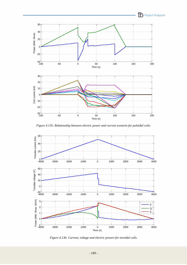
Project Proposal
- 185 -
-100 -50 0 50 100 150 200-40
-20
0
20
40
60
Time (s)
Pow
er
(MW
, M
var)
-100 -50 0 50 100 150 200-30
-20
-10
0
10
20
30
Time (s)
Coil
curr
ent
(kA
)
Figure 4.135: Relationship between electric power and current scenario for poloidal coils.
-4000 -3000 -2000 -1000 0 1000 2000 3000 40000
20
40
60
Toro
idal curr
ent
(kA
)
-4000 -3000 -2000 -1000 0 1000 2000 3000 4000-20
0
20
40
60
Toro
idal voltage (
V)
-4000 -3000 -2000 -1000 0 1000 2000 3000 4000-1
0
1
2
3
Time (s)
Pow
er
(MW
, M
var,
MV
A)
P
Q
S
Figure 4.136: Current, voltage and electric powers for toroidal coils.
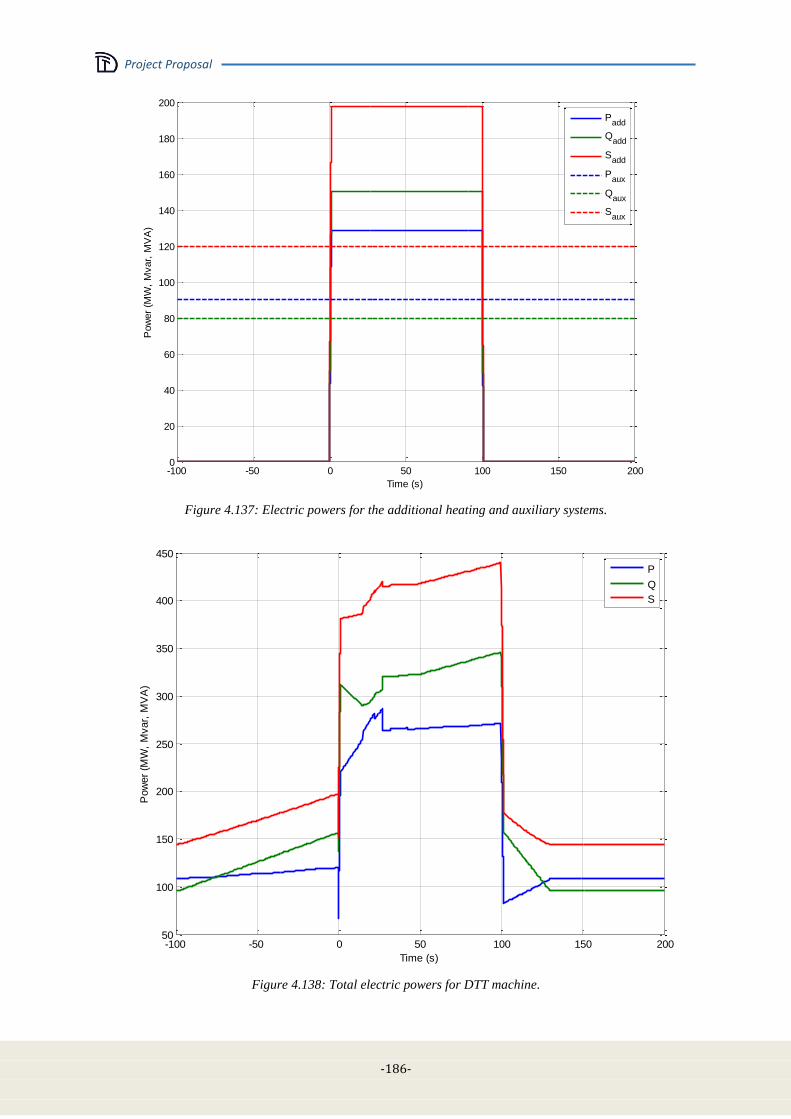
Project Proposal
-186-
-100 -50 0 50 100 150 2000
20
40
60
80
100
120
140
160
180
200
Time (s)
Pow
er
(MW
, M
var,
MV
A)
Padd
Qadd
Sadd
Paux
Qaux
Saux
Figure 4.137: Electric powers for the additional heating and auxiliary systems.
-100 -50 0 50 100 150 20050
100
150
200
250
300
350
400
450
Time (s)
Pow
er
(MW
, M
var,
MV
A)
P
Q
S
Figure 4.138: Total electric powers for DTT machine.
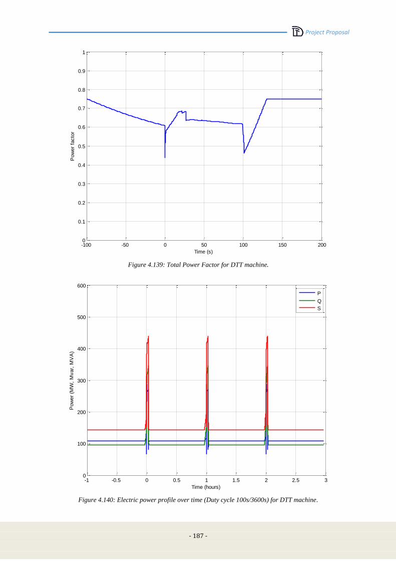
Project Proposal
- 187 -
-100 -50 0 50 100 150 2000
0.1
0.2
0.3
0.4
0.5
0.6
0.7
0.8
0.9
1
Time (s)
Pow
er
facto
r
Figure 4.139: Total Power Factor for DTT machine.
-1 -0.5 0 0.5 1 1.5 2 2.5 30
100
200
300
400
500
600
Time (hours)
Pow
er
(MW
, M
var,
MV
A)
P
Q
S
Figure 4.140: Electric power profile over time (Duty cycle 100s/3600s) for DTT machine.
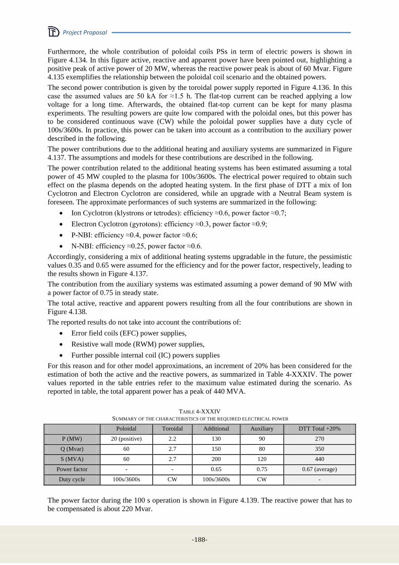
Project Proposal
-188-
Furthermore, the whole contribution of poloidal coils PSs in term of electric powers is shown in
Figure 4.134. In this figure active, reactive and apparent power have been pointed out, highlighting a
positive peak of active power of 20 MW, whereas the reactive power peak is about of 60 Mvar. Figure
4.135 exemplifies the relationship between the poloidal coil scenario and the obtained powers.
The second power contribution is given by the toroidal power supply reported in Figure 4.136. In this
case the assumed values are 50 kA for ≈1.5 h. The flat-top current can be reached applying a low
voltage for a long time. Afterwards, the obtained flat-top current can be kept for many plasma
experiments. The resulting powers are quite low compared with the poloidal ones, but this power has
to be considered continuous wave (CW) while the poloidal power supplies have a duty cycle of
100s/3600s. In practice, this power can be taken into account as a contribution to the auxiliary power
described in the following.
The power contributions due to the additional heating and auxiliary systems are summarized in Figure
4.137. The assumptions and models for these contributions are described in the following.
The power contribution related to the additional heating systems has been estimated assuming a total
power of 45 MW coupled to the plasma for 100s/3600s. The electrical power required to obtain such
effect on the plasma depends on the adopted heating system. In the first phase of DTT a mix of Ion
Cyclotron and Electron Cyclotron are considered, while an upgrade with a Neutral Beam system is
foreseen. The approximate performances of such systems are summarized in the following:
Ion Cyclotron (klystrons or tetrodes): efficiency ≈0.6, power factor ≈0.7;
Electron Cyclotron (gyrotons): efficiency ≈0.3, power factor ≈0.9;
P-NBI: efficiency ≈0.4, power factor ≈0.6;
N-NBI: efficiency ≈0.25, power factor ≈0.6.
Accordingly, considering a mix of additional heating systems upgradable in the future, the pessimistic
values 0.35 and 0.65 were assumed for the efficiency and for the power factor, respectively, leading to
the results shown in Figure 4.137.
The contribution from the auxiliary systems was estimated assuming a power demand of 90 MW with
a power factor of 0.75 in steady state.
The total active, reactive and apparent powers resulting from all the four contributions are shown in
Figure 4.138.
The reported results do not take into account the contributions of:
Error field coils (EFC) power supplies,
Resistive wall mode (RWM) power supplies,
Further possible internal coil (IC) powers supplies
For this reason and for other model approximations, an increment of 20% has been considered for the
estimation of both the active and the reactive powers, as summarized in Table 4-XXXIV. The power
values reported in the table entries refer to the maximum value estimated during the scenario. As
reported in table, the total apparent power has a peak of 440 MVA.
TABLE 4-XXXIV
SUMMARY OF THE CHARACTERISTICS OF THE REQUIRED ELECTRICAL POWER
Poloidal Toroidal Additional Auxiliary DTT Total +20%
P (MW) 20 (positive) 2.2 130 90 270
Q (Mvar) 60 2.7 150 80 350
S (MVA) 60 2.7 200 120 440
Power factor - - 0.65 0.75 0.67 (average)
Duty cycle 100s/3600s CW 100s/3600s CW -
The power factor during the 100 s operation is shown in Figure 4.139. The reactive power that has to
be compensated is about 220 Mvar.
Project Proposal
- 189 -
Finally, Figure 4.140 emphasizes the power profiles also considering the experiment duty cycle
(100s/3600s).
4.14.4 Electric characteristics of the DTT power supplies
The Table 4-XXXV points out the electric characteristics of DTT coil power supplies. All electric
devices have got electric characteristics quite similar. Almost all power supplies have output DC
current ±25 kA and output DC voltage ±800V (except PF3, PF4, IC5 and IC6 PSs that have an output
DC voltage ±1 kV). These AC/DC converters are four quadrants, thyristor based 12 pulses with
current circulating and sequential control to reduce the reactive power, except IC5 and IC6 PSs that
are IGCT based to be fast enough to control the vertical position of plasma (for more details see Table
4-XXXV).
Some considerations can be made in order to achieve savings like unifying the functions of the SNUs
and QPCs. These aspects are still under discussion. Table 4-XXXVI reports the electric characteristics
of DTT converter transformers.

Project Proposal
-190-
TABLE 4-XXXV
ELECTRIC CHARACTERISTICS OF DTT COIL POWER SUPPLIES

Project Proposal
- 191 -
TABLE 4-XXXVI
ELECTRIC CHARACTERISTICS OF DTT CONVERTER TRANSFORMERS
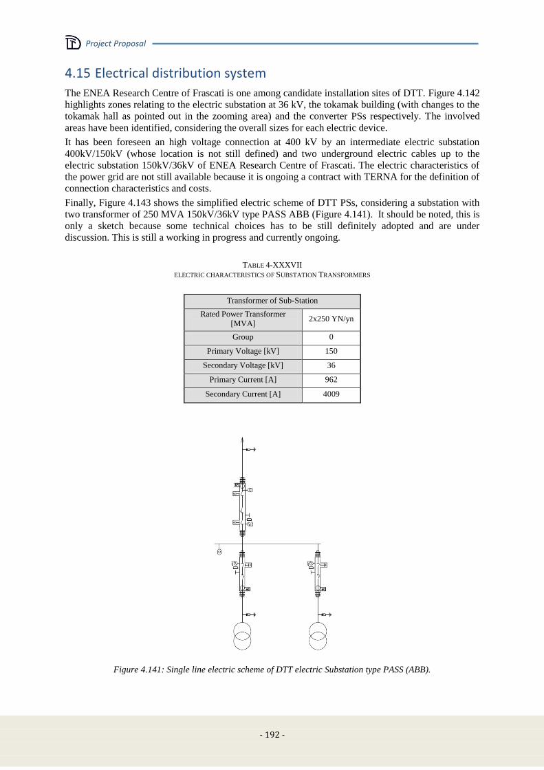
Project Proposal
- 192 -
4.15 Electrical distribution system
The ENEA Research Centre of Frascati is one among candidate installation sites of DTT. Figure 4.142
highlights zones relating to the electric substation at 36 kV, the tokamak building (with changes to the
tokamak hall as pointed out in the zooming area) and the converter PSs respectively. The involved
areas have been identified, considering the overall sizes for each electric device.
It has been foreseen an high voltage connection at 400 kV by an intermediate electric substation
400kV/150kV (whose location is not still defined) and two underground electric cables up to the
electric substation 150kV/36kV of ENEA Research Centre of Frascati. The electric characteristics of
the power grid are not still available because it is ongoing a contract with TERNA for the definition of
connection characteristics and costs.
Finally, Figure 4.143 shows the simplified electric scheme of DTT PSs, considering a substation with
two transformer of 250 MVA 150kV/36kV type PASS ABB (Figure 4.141). It should be noted, this is
only a sketch because some technical choices has to be still definitely adopted and are under
discussion. This is still a working in progress and currently ongoing.
TABLE 4-XXXVII
ELECTRIC CHARACTERISTICS OF SUBSTATION TRANSFORMERS
Transformer of Sub-Station
Rated Power Transformer
[MVA] 2x250 YN/yn
Group 0
Primary Voltage [kV] 150
Secondary Voltage [kV] 36
Primary Current [A] 962
Secondary Current [A] 4009
Figure 4.141: Single line electric scheme of DTT electric Substation type PASS (ABB).

Project Proposal
- 193 -
Figure 4.142: Installation site of Frascati for DTT machine, with details of tokamak hall and electric substation
DTT hall
Ele
ctri
c su
bst
ati
on
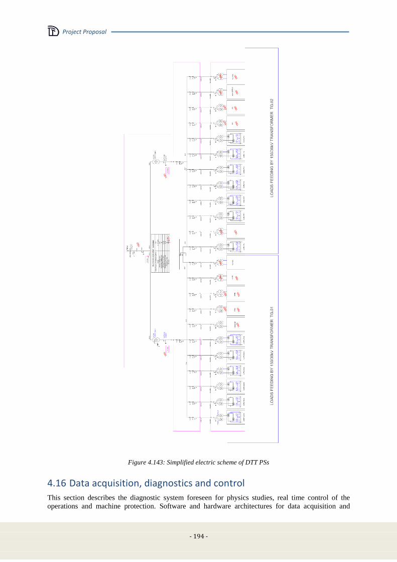
Project Proposal
- 194 -
Figure 4.143: Simplified electric scheme of DTT PSs
4.16 Data acquisition, diagnostics and control
This section describes the diagnostic system foreseen for physics studies, real time control of the
operations and machine protection. Software and hardware architectures for data acquisition and
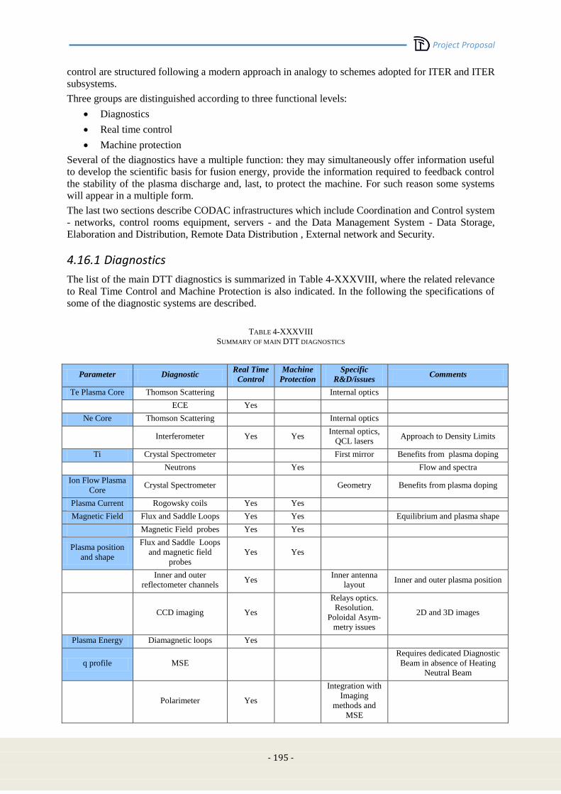
Project Proposal
- 195 -
control are structured following a modern approach in analogy to schemes adopted for ITER and ITER
subsystems.
Three groups are distinguished according to three functional levels:
Diagnostics
Real time control
Machine protection
Several of the diagnostics have a multiple function: they may simultaneously offer information useful
to develop the scientific basis for fusion energy, provide the information required to feedback control
the stability of the plasma discharge and, last, to protect the machine. For such reason some systems
will appear in a multiple form.
The last two sections describe CODAC infrastructures which include Coordination and Control system
- networks, control rooms equipment, servers - and the Data Management System - Data Storage,
Elaboration and Distribution, Remote Data Distribution , External network and Security.
4.16.1 Diagnostics
The list of the main DTT diagnostics is summarized in Table 4-XXXVIII, where the related relevance
to Real Time Control and Machine Protection is also indicated. In the following the specifications of
some of the diagnostic systems are described.
TABLE 4-XXXVIII
SUMMARY OF MAIN DTT DIAGNOSTICS
Parameter Diagnostic Real Time
Control
Machine
Protection
Specific
R&D/issues Comments
Te Plasma Core Thomson Scattering Internal optics
ECE Yes
Ne Core Thomson Scattering Internal optics
Interferometer Yes Yes Internal optics,
QCL lasers Approach to Density Limits
Ti Crystal Spectrometer First mirror Benefits from plasma doping
Neutrons Yes Flow and spectra
Ion Flow Plasma
Core Crystal Spectrometer Geometry Benefits from plasma doping
Plasma Current Rogowsky coils Yes Yes
Magnetic Field Flux and Saddle Loops Yes Yes Equilibrium and plasma shape
Magnetic Field probes Yes Yes
Plasma position
and shape
Flux and Saddle Loops
and magnetic field
probes
Yes Yes
Inner and outer
reflectometer channels Yes
Inner antenna
layout Inner and outer plasma position
CCD imaging Yes
Relays optics.
Resolution.
Poloidal Asym-
metry issues
2D and 3D images
Plasma Energy Diamagnetic loops Yes
q profile MSE
Requires dedicated Diagnostic
Beam in absence of Heating
Neutral Beam
Polarimeter Yes
Integration with
Imaging
methods and
MSE

Project Proposal
- 196 -
MHD Magnetic Field probes Yes Yes Locked modes/ unstable modes
ECE Yes
SXR Yes
Radiation Bolometer array Yes Tomography / Radiation Shield
SXR diodes array Yes Sensors (Solid
state /GEM’s)
Tomography / Control of
central accumulation
Zeff Vis and NIR Filters Yes Wall reflection Toroidal views
Spectrometers Spectrometer
stray light Continuum contribution
Impurities Core Crystal Spectrometer Geometry Core impurities <1 nm
VUV Survey
spectrometer Yes Yes
10<nmAlarm on
specific elements
Grazing Incidence
spectr.
1< nmSupport to
transport analysis
Laser Blow OFF
Impurities
SOL/Divertor, ni,
Ti, flow,
VUV/VIS spectrometer
Atomic physics
of low
ionization W
120< nmSupport to
transport analysis of divertor
impurity transport. Doppler
Shift, Doppler Broadening
Visible/ NIR
spectrometer
Divertor SOL
impurity/Recombination
Retarding field analyzer
Heterodyne Doppler
“flow imaging”
time resolved 2D images of
integrated line brightness,
velocity, ion temperature
CX spectroscopy
Divertor Te, ne. Thomson Scattering Inner optics
damages 1<Te<10 eV
VUV/VIS spectrometer Line Intensity ratios
Langmuir probes Yes
Divertor
Detachment CCD & Int. Filters Yes Yes
3D imaging
software
development
DIVERTOR 2D and 3D
radiation patterns/Detachment
Multiple Visible Survey
spectrometers
400<nm Balmer Series
/Recombination /detachment
Neutrals
(pressure) Filtered CCD cameras D-Alpha 2D /3d Images
NPA Energy lower
limit Time of flight
High resolution Spectr. Line Shape Analysis for neutral
pressure
Penning gauge
Wall Hot Spots CCD monitor Yes Main wall and
divertor/shinethrough of NBI
Escaping Fast ion Scintillator probes Yes Escaping ICRH generated fast
ions to divertor
Faraday cups
Wall temperature IR camera Yes Yes
Impact of
redeposition
layers
Surface temperature
Thermocouples/Calorim
eters Yes
Bulk temperature / also of
active cooling fluids
q IR camera/instrumented
tiles Space resolution
Instrumented tiles include
thermocouples, Langmuir
probes, calorimeter probes
Project Proposal
- 197 -
Runaway
electrons HXR / -Rays Yes
Visible Cameras Yes
Bremmsstrahlung detection (2
opposite toroidal views)/ hot
spots detection
Halo/Hiro
Currents
Halo sensors
(Rogowsky coils and
resistive shunts)
Yes Yes
Vessel
deformation/displ
acement
Strain Sensors/optical
sensors Yes
For disruption consequence
characterization
Redeposition
layers LIF In between shots redeposition
Microbalance Environment
compatibility
In situ and time resolved
redeposition
Magnetic diagnostic
In DTT, like in any other tokamak, the magnetic diagnostic shall provide some of the most
fundamental and essential information about the plasma, such as the total plasma current, the position
and shape of the discharge, its thermal energy, the currents in the magnet coils and the strength of the
magnetic fields confining the plasma [4.93]. The magnetic diagnostic contributes to all the basic
functions of the plasma diagnostics (machine protection, plasma control, physics studies and
performance evaluation) with a number of sub-systems divided on the base of different measurement
techniques: Magnetic flux sensors (Flux loops, Saddle loops, Diamagnetic loops); Magnetic field
probes (Pick-up coils, Hall probes); Current transducers (Rogowski coils, Resistive Shunts). Several
plasma parameters can be deduced by a combination of different magnetic sub-systems, which can
have different roles in the architecture of the magnetic diagnostic (primary, backup, supplemental).
Table 4-XXXVIII indicates the main plasma parameters and magnetic sensors involved in the
corresponding measurement. A more detailed description can be deduced from literature related to
generic magnetic diagnostics [4.93] or to the specific design of ITER [4.94], which can be directly
extended to the DTT design.
The actual layout of the magnetic diagnostic for DTT, with proper number and distribution of sensors,
will be defined once the main components, which have a direct interface with this system, are refined
(in particular Vacuum Vessel, First Wall and Divertor). A preliminary estimate of the total number of
magnetic sensors for DTT is expected to be of the order of one thousand (between the number of
sensors presently exploited at JET [4.95] and the corresponding figure foreseen for ITER [4.96],
approximately 500 and 1500 respectively).
Concerning the technological aspects related to the manufacture of magnetic sensors and the
maintenance by means of remote handling systems, the design for DTT could benefit from recent
developments carried on for the design of the magnetic sensors of ITER [4.97]-[4.98]. The latter
include in particular loops and windings made of Mineral Insulated Cables, typically used in existing
tokamaks, and magnetic field probes based on LTCC technology (Low-Temperature Co-fired
Ceramics), which allows the manufacture of equivalent magnetic pickup coils more compact and less
sensitive to detrimental radiation induced effects.
Core Thomson Scattering
A standard Thomson Scattering layout is considered for core measurements of Te and ne , with
scattering volumes defined by fiber optic images on the laser beam path and scattered light processed
by interferential filter polychromators. Several solutions are possible. Among them, the preferred ones
are those in which the laser path crosses the plasma throughout and is dumped in an upper or lower
port. For hardware considerations see Divertor Thomson Scattering below.
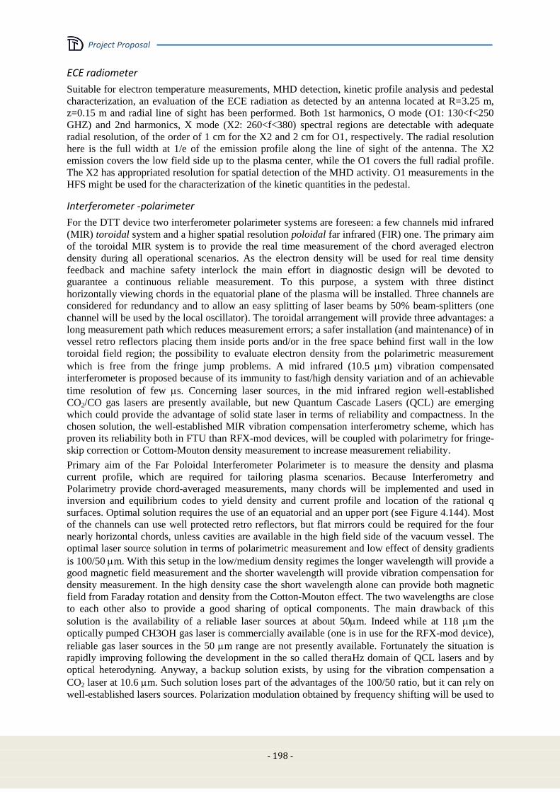
Project Proposal
- 198 -
ECE radiometer
Suitable for electron temperature measurements, MHD detection, kinetic profile analysis and pedestal
characterization, an evaluation of the ECE radiation as detected by an antenna located at R=3.25 m,
z=0.15 m and radial line of sight has been performed. Both 1st harmonics, O mode (O1: 130<f<250
GHZ) and 2nd harmonics, X mode (X2: 260<f<380) spectral regions are detectable with adequate
radial resolution, of the order of 1 cm for the X2 and 2 cm for O1, respectively. The radial resolution
here is the full width at 1/e of the emission profile along the line of sight of the antenna. The X2
emission covers the low field side up to the plasma center, while the O1 covers the full radial profile.
The X2 has appropriated resolution for spatial detection of the MHD activity. O1 measurements in the
HFS might be used for the characterization of the kinetic quantities in the pedestal.
Interferometer -polarimeter
For the DTT device two interferometer polarimeter systems are foreseen: a few channels mid infrared
(MIR) toroidal system and a higher spatial resolution poloidal far infrared (FIR) one. The primary aim
of the toroidal MIR system is to provide the real time measurement of the chord averaged electron
density during all operational scenarios. As the electron density will be used for real time density
feedback and machine safety interlock the main effort in diagnostic design will be devoted to
guarantee a continuous reliable measurement. To this purpose, a system with three distinct
horizontally viewing chords in the equatorial plane of the plasma will be installed. Three channels are
considered for redundancy and to allow an easy splitting of laser beams by 50% beam-splitters (one
channel will be used by the local oscillator). The toroidal arrangement will provide three advantages: a
long measurement path which reduces measurement errors; a safer installation (and maintenance) of in
vessel retro reflectors placing them inside ports and/or in the free space behind first wall in the low
toroidal field region; the possibility to evaluate electron density from the polarimetric measurement
which is free from the fringe jump problems. A mid infrared (10.5 m) vibration compensated
interferometer is proposed because of its immunity to fast/high density variation and of an achievable
time resolution of few s. Concerning laser sources, in the mid infrared region well-established
CO2/CO gas lasers are presently available, but new Quantum Cascade Lasers (QCL) are emerging
which could provide the advantage of solid state laser in terms of reliability and compactness. In the
chosen solution, the well-established MIR vibration compensation interferometry scheme, which has
proven its reliability both in FTU than RFX-mod devices, will be coupled with polarimetry for fringe-
skip correction or Cottom-Mouton density measurement to increase measurement reliability.
Primary aim of the Far Poloidal Interferometer Polarimeter is to measure the density and plasma
current profile, which are required for tailoring plasma scenarios. Because Interferometry and
Polarimetry provide chord-averaged measurements, many chords will be implemented and used in
inversion and equilibrium codes to yield density and current profile and location of the rational q
surfaces. Optimal solution requires the use of an equatorial and an upper port (see Figure 4.144). Most
of the channels can use well protected retro reflectors, but flat mirrors could be required for the four
nearly horizontal chords, unless cavities are available in the high field side of the vacuum vessel. The
optimal laser source solution in terms of polarimetric measurement and low effect of density gradients
is 100/50 m. With this setup in the low/medium density regimes the longer wavelength will provide a
good magnetic field measurement and the shorter wavelength will provide vibration compensation for
density measurement. In the high density case the short wavelength alone can provide both magnetic
field from Faraday rotation and density from the Cotton-Mouton effect. The two wavelengths are close
to each other also to provide a good sharing of optical components. The main drawback of this
solution is the availability of a reliable laser sources at about 50m. Indeed while at 118 m the
optically pumped CH3OH gas laser is commercially available (one is in use for the RFX-mod device),
reliable gas laser sources in the 50 m range are not presently available. Fortunately the situation is
rapidly improving following the development in the so called theraHz domain of QCL lasers and by
optical heterodyning. Anyway, a backup solution exists, by using for the vibration compensation a
CO2 laser at 10.6 m. Such solution loses part of the advantages of the 100/50 ratio, but it can rely on
well-established lasers sources. Polarization modulation obtained by frequency shifting will be used to
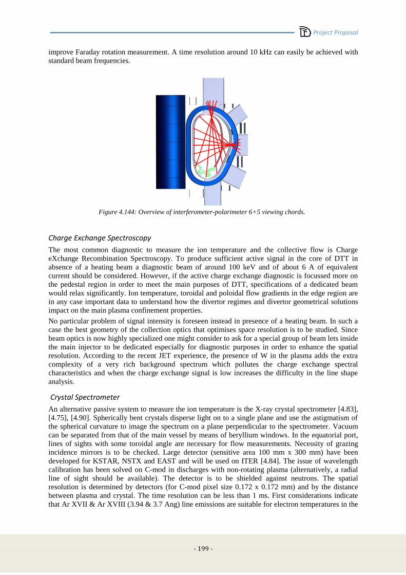
Project Proposal
- 199 -
improve Faraday rotation measurement. A time resolution around 10 kHz can easily be achieved with
standard beam frequencies.
Figure 4.144: Overview of interferometer-polarimeter 6+5 viewing chords.
Charge Exchange Spectroscopy
The most common diagnostic to measure the ion temperature and the collective flow is Charge
eXchange Recombination Spectroscopy. To produce sufficient active signal in the core of DTT in
absence of a heating beam a diagnostic beam of around 100 keV and of about 6 A of equivalent
current should be considered. However, if the active charge exchange diagnostic is focussed more on
the pedestal region in order to meet the main purposes of DTT, specifications of a dedicated beam
would relax significantly. Ion temperature, toroidal and poloidal flow gradients in the edge region are
in any case important data to understand how the divertor regimes and divertor geometrical solutions
impact on the main plasma confinement properties.
No particular problem of signal intensity is foreseen instead in presence of a heating beam. In such a
case the best geometry of the collection optics that optimises space resolution is to be studied. Since
beam optics is now highly specialized one might consider to ask for a special group of beam lets inside
the main injector to be dedicated especially for diagnostic purposes in order to enhance the spatial
resolution. According to the recent JET experience, the presence of W in the plasma adds the extra
complexity of a very rich background spectrum which pollutes the charge exchange spectral
characteristics and when the charge exchange signal is low increases the difficulty in the line shape
analysis.
Crystal Spectrometer
An alternative passive system to measure the ion temperature is the X-ray crystal spectrometer [4.83],
[4.75], [4.90]. Spherically bent crystals disperse light on to a single plane and use the astigmatism of
the spherical curvature to image the spectrum on a plane perpendicular to the spectrometer. Vacuum
can be separated from that of the main vessel by means of beryllium windows. In the equatorial port,
lines of sights with some toroidal angle are necessary for flow measurements. Necessity of grazing
incidence mirrors is to be checked. Large detector (sensitive area 100 mm x 300 mm) have been
developed for KSTAR, NSTX and EAST and will be used on ITER [4.84]. The issue of wavelength
calibration has been solved on C-mod in discharges with non-rotating plasma (alternatively, a radial
line of sight should be available). The detector is to be shielded against neutrons. The spatial
resolution is determined by detectors (for C-mod pixel size 0.172 x 0.172 mm) and by the distance
between plasma and crystal. The time resolution can be less than 1 ms. First considerations indicate
that Ar XVII & Ar XVIII (3.94 & 3.7 Ang) line emissions are suitable for electron temperatures in the
Project Proposal
- 200 -
range 0.5-6 keV, while Kr XXV (He-like) is to be preferred for higher Te; such noble gas will be
injected in trace just for diagnostic purposes.
Bolometry and impurities
Detailed measurements of total radiated power in the divertor region are required for heat flux active
control. Real-time bolometric measurements are used in ASDEX to optimize the divertor power
exhaust [4.80]. Bolometric detectors based on metal foil are being used [4.71] and a radiation hard
version has been developed for ITER [4.74]. Recently, a faster and compact detector, based on Silicon
photodiodes AXUV has been tested in ASDEX [4.68] and in C-mod [4.89], even though its spectral
sensitivity is not uniform in the VUV range and its performance degrades strongly over time.
Detailed radiated power reconstructions require multiple measurements along different lines of sight
in order to adopt tomographic techniques [4.72]. A state of the art bolometric diagnostic is installed in
ASDEX with 112 foil detectors and 256 AXUV detectors. A lower resolution bolometric tomography
with three fans is installed in JET, hosting 60 lines of sights [4.79]. The foil based tomography in DTT
could rely on 3 main heads hosting three fans covering the plasma core and three additional heads with
their fans directed towards the divertor as indicated in Figure 4.145.
Figure 4.145: Layout of bolometer arrays
The impurities that contribute to the radiation are identified by a set of spectrometers covering
altogether the spectral range from a few Angstroms to near infrared. In particular VUV and visible
survey spectrometers are specifically dedicated to this purpose. The link between 2D bolometry
images and single chord spectrometer signals is established by transport models, making use also of
the Soft X-Ray tomography (see below).
Soft X-Ray radiation
Soft x-ray tomography is a standard tool to diagnose both impurities accumulation in the core [4.100]
and MHD activity in the hot plasma core, such as ELMs, sawtooth activity, or Fast Particles induced
instabilities, e.g. Toroidal Alfven Eigenmodes.
Typical state of the art SXR diagnostics, designed for shaped plasmas have been installed in JET and
in ASDEX. In ASDEX 8 pinhole cameras are installed, each one housing approximately 30 detectors
giving about 200 lines of sight measurements of SXR emissivity. Silicon diodes are used screened by
a curved Be filter 75 um thick. Required bandwidth is 1MHz, in order to detect also high frequency
MHD. Several cameras are planned to be in other toroidal sections, in order to investigate deviations
from axi-simmetry due to plasma response to external perturbations at high beta.
In DTT, GEM could represent an alternative detector for SXR tomography [4.103]-[4.105]. These
have been chosen also for the new WEST SXR tomographic system. GEM detector technology

Project Proposal
- 201 -
exploits the photon counting mode and has the advantage of being cheap, offering good spatial and
temporal resolution, possessing energy discrimination capabilities . It has also the advantage to be
neutron resilient. Tangential views in the SXR region have been experimented on NSTX using GEMs
[4.103]. Sensitivity to magnetic field of GEM is to be carefully taken into account in the design phase.
Neutrons and Gamma-Rays
As shown in Section 4.7 a neutron yield up to 1.3x10¹⁷
n/s can be expected in the reference DTT H-
mode scenario. In presence of such flows, neutron diagnostics can support the DTT physics objectives
of providing safe and robust power handling solutions without degrading the plasma core
performance, which in fact can be monitored by suitable neutron measurements. To the purpose, a set
of neutron yield monitors based on fission chambers will be installed. These shall be used to measure
the neutron yield and its variations for different power handling solutions and pedestal parameters. A
more complete system of neutron diagnostics should also include a neutron camera and an advanced
2.5 MeV neutron spectrometer, both of great relevance to support physics studies on edge-core
coupling. EAST, JET and ASDEX-Upgrade have recently shown that edge perturbations may induce
favourable or vice-versa adverse effects in the core, which can be detected as different neutron
emission profiles. The neutron camera can be equipped with liquid scintillators (e.g., NE213) and/or
diamond detectors, the latter being insensitive to magnetic fields and suitable for high neutron yields.
The number of channels depends on the amplitude of the expected profile changes; it is expected to be
around 10.
An advanced single line of sight neutron spectrometer will support edge-core plasma coupling
investigations adding the information about the energy distribution of the fast ions generated by ICRH.
A flexible neutron camera design enables observations of gamma-ray emission due to the generation
of runaway electrons in the plasma, as needed for machine protection. One possibility is offered by
the present JET neutron/gamma-ray camera design, where two different sets of detectors (dedicated to
neutrons or gamma-rays) are interchangeable by means of a slider and can be chosen before each
plasma discharge. If, instead, neutron and gamma-ray measurements are to be performed
simultaneously, a different camera design with a few channels devoted to gamma-ray measurements
only may be considered.
A high resolution gamma-ray spectrometer (e.g., LaBr3(Ce) or high purity germanium) is also
proposed to measure details of the gamma-ray emission spectrum along a single line of sight, for
example to infer information on the energy distribution of the runaway electrons, complementing the
spatial profile information on gamma-ray emission provided by the camera.
Charge exchange neutrals
Neutral particles play an important role at the edge of the plasma and in the divertor region. Low
energy escaping neutrals can be detected by a time of flight neutral particle analyzer with an
adequately long path. The energy distribution information can be complemented by the analysis of the
shape of the D alpha emission line as detected by a high resolution spectrometer. Coupling energy and
density information yields the neutral pressure in the observed region.
Divertor Thomson Scattering
A standard Thomson Scattering layout is discussed, with scattering volumes defined by fiber optic
images on the laser beam path and scattered light processed by interferential filter polychromators.
The idea is applied to the provisional geometry. The main purpose is the capability to detect a
detachment status. The following design aspects are considered:
maximization of solid angle of collection optics
laser alignment reliability and stray light minimization
optimization of spectral channel ranges (depending on the expected Te)
detectors and amplifiers
Considering a target plasma with temperatures in the 1-10 eV range and densities around 1x10¹⁹
/m3,
two different layouts have been analyzed:
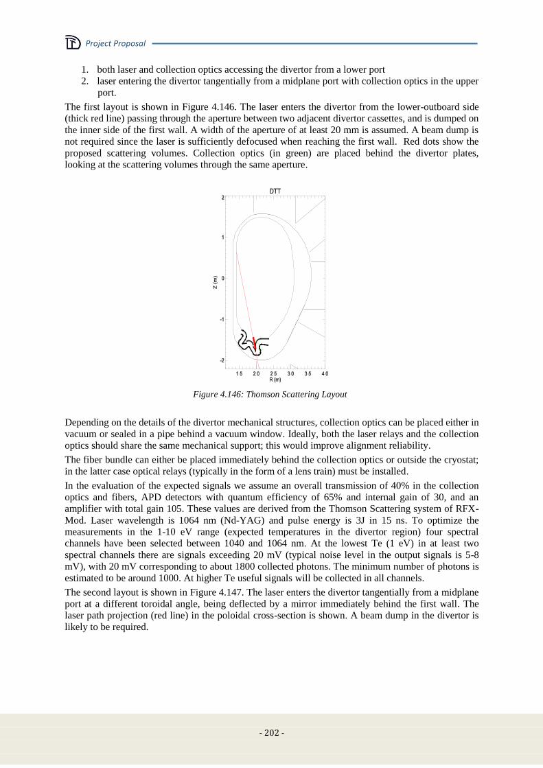
Project Proposal
- 202 -
1. both laser and collection optics accessing the divertor from a lower port
2. laser entering the divertor tangentially from a midplane port with collection optics in the upper
port.
The first layout is shown in Figure 4.146. The laser enters the divertor from the lower-outboard side
(thick red line) passing through the aperture between two adjacent divertor cassettes, and is dumped on
the inner side of the first wall. A width of the aperture of at least 20 mm is assumed. A beam dump is
not required since the laser is sufficiently defocused when reaching the first wall. Red dots show the
proposed scattering volumes. Collection optics (in green) are placed behind the divertor plates,
looking at the scattering volumes through the same aperture.
Figure 4.146: Thomson Scattering Layout
Depending on the details of the divertor mechanical structures, collection optics can be placed either in
vacuum or sealed in a pipe behind a vacuum window. Ideally, both the laser relays and the collection
optics should share the same mechanical support; this would improve alignment reliability.
The fiber bundle can either be placed immediately behind the collection optics or outside the cryostat;
in the latter case optical relays (typically in the form of a lens train) must be installed.
In the evaluation of the expected signals we assume an overall transmission of 40% in the collection
optics and fibers, APD detectors with quantum efficiency of 65% and internal gain of 30, and an
amplifier with total gain 105. These values are derived from the Thomson Scattering system of RFX-
Mod. Laser wavelength is 1064 nm (Nd-YAG) and pulse energy is 3J in 15 ns. To optimize the
measurements in the 1-10 eV range (expected temperatures in the divertor region) four spectral
channels have been selected between 1040 and 1064 nm. At the lowest Te (1 eV) in at least two
spectral channels there are signals exceeding 20 mV (typical noise level in the output signals is 5-8
mV), with 20 mV corresponding to about 1800 collected photons. The minimum number of photons is
estimated to be around 1000. At higher Te useful signals will be collected in all channels.
The second layout is shown in Figure 4.147. The laser enters the divertor tangentially from a midplane
port at a different toroidal angle, being deflected by a mirror immediately behind the first wall. The
laser path projection (red line) in the poloidal cross-section is shown. A beam dump in the divertor is
likely to be required.
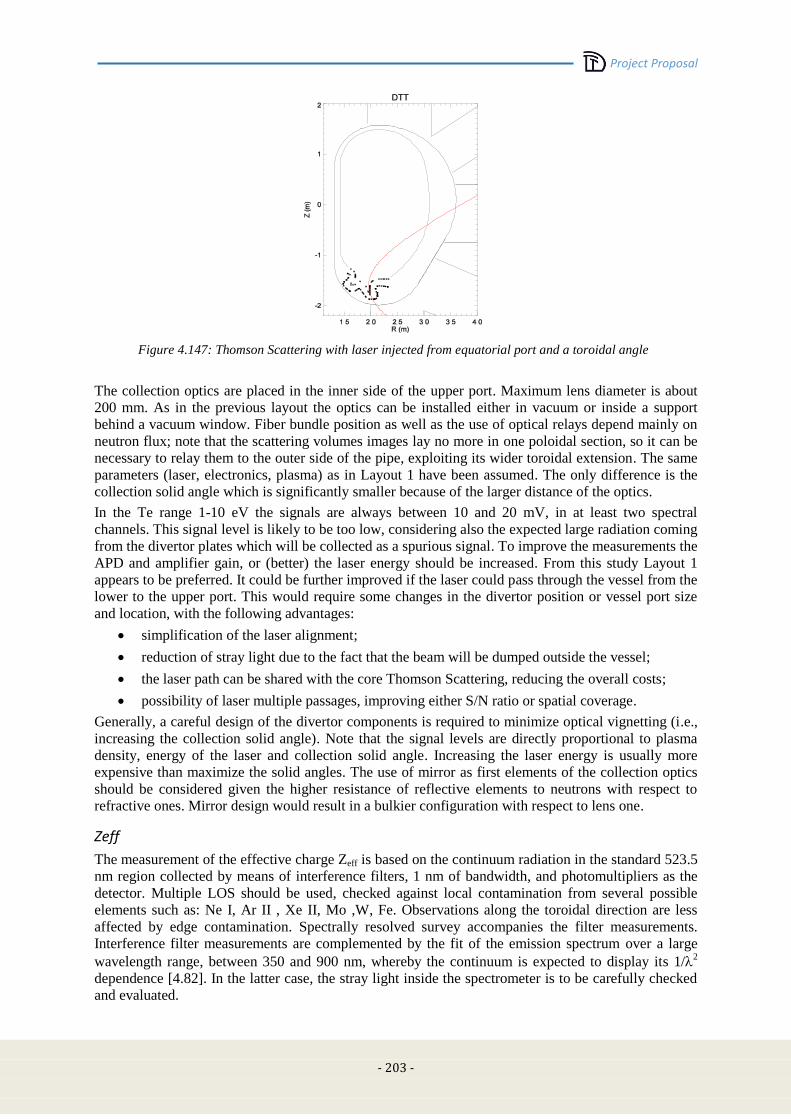
Project Proposal
- 203 -
Figure 4.147: Thomson Scattering with laser injected from equatorial port and a toroidal angle
The collection optics are placed in the inner side of the upper port. Maximum lens diameter is about
200 mm. As in the previous layout the optics can be installed either in vacuum or inside a support
behind a vacuum window. Fiber bundle position as well as the use of optical relays depend mainly on
neutron flux; note that the scattering volumes images lay no more in one poloidal section, so it can be
necessary to relay them to the outer side of the pipe, exploiting its wider toroidal extension. The same
parameters (laser, electronics, plasma) as in Layout 1 have been assumed. The only difference is the
collection solid angle which is significantly smaller because of the larger distance of the optics.
In the Te range 1-10 eV the signals are always between 10 and 20 mV, in at least two spectral
channels. This signal level is likely to be too low, considering also the expected large radiation coming
from the divertor plates which will be collected as a spurious signal. To improve the measurements the
APD and amplifier gain, or (better) the laser energy should be increased. From this study Layout 1
appears to be preferred. It could be further improved if the laser could pass through the vessel from the
lower to the upper port. This would require some changes in the divertor position or vessel port size
and location, with the following advantages:
simplification of the laser alignment;
reduction of stray light due to the fact that the beam will be dumped outside the vessel;
the laser path can be shared with the core Thomson Scattering, reducing the overall costs;
possibility of laser multiple passages, improving either S/N ratio or spatial coverage.
Generally, a careful design of the divertor components is required to minimize optical vignetting (i.e.,
increasing the collection solid angle). Note that the signal levels are directly proportional to plasma
density, energy of the laser and collection solid angle. Increasing the laser energy is usually more
expensive than maximize the solid angles. The use of mirror as first elements of the collection optics
should be considered given the higher resistance of reflective elements to neutrons with respect to
refractive ones. Mirror design would result in a bulkier configuration with respect to lens one.
Zeff
The measurement of the effective charge Zeff is based on the continuum radiation in the standard 523.5
nm region collected by means of interference filters, 1 nm of bandwidth, and photomultipliers as the
detector. Multiple LOS should be used, checked against local contamination from several possible
elements such as: Ne I, Ar II , Xe II, Mo ,W, Fe. Observations along the toroidal direction are less
affected by edge contamination. Spectrally resolved survey accompanies the filter measurements.
Interference filter measurements are complemented by the fit of the emission spectrum over a large
wavelength range, between 350 and 900 nm, whereby the continuum is expected to display its 1/2
dependence [4.82]. In the latter case, the stray light inside the spectrometer is to be carefully checked
and evaluated.

Project Proposal
- 204 -
Divertor Spectroscopy
Divertor spectroscopy will be covered by a series of optically filtered CCD cameras, tomographic
systems based on fiber optics and photomuliplier detectors or suitable solid state detectors, and a set of
spectrometers covering the wavelength range from about 1 to 800 nm. CCD cameras are relatively
cheap tools that can yield by means of modern software highly space resolved 2D and 3D
reconstructions. Spectrometers are necessary to analyse the spectral features and validate the CCD
images whenever they are meant to carry wavelength resolved information. Additionally, the analysis
of the emission line shape can yield information on ion temperature and flow of the specific ionization
stage. In the high magnetic field of DTT Doppler Zeeman features are important and have to be
included in the analysis.
Emission spectroscopy is able to characterize several aspects of the divertor plasma. In a low
temperature plasma (1-10 eV) several possibilities exist to measure electron temperature and density
from the ratio of the specific emission line intensities. In principle therefore, the use of optically
filtered cameras can provide two dimensional patterns of Te and ne, at least in the regions where the
considered lines emit. Care is to be taken about the possible contamination of the signal from other
emitters.
Examples of interesting line intensity ratios:
Te in the range 1-10 eV can be determined by using Ar I lines intensity ratio (e. g. 420.1 and
419.8 nm).
ne can be determined also from Stark broadening of Deuterium lines [4.88]
Te, ne from He line ratios useful in the range 2.0 × 10¹⁸
< ne <2.0 × 10¹⁹
m−3
and 10 eV < Te
< 250eV. Requires local puffing of small amount of He and imaging onto discrete fibers of
imaging spectrometer.
line ratio variation inside the Balmer series of Deuterium n5/n6 n5/n7 n5/n8 is a good monitor
of the recombining status of the plasma. The spectral range between 360 and 420 nm is to be
covered. This implies that short length fibers or alternative relay optics must be used. Hollow
fibres constitute another possibility.
Dα tomography can be achieved by means of 3 arrays of optical fibers coupled to photomultipliers or
suitable solid state detector arrays. Observations can be carried out from the upper port with a couple
of arrays from the side, through interspaces between divertor modules [4.85]. Dα tomography
complements CCD cameras that monitor the detachment level and are important in the attempt of
measuring the neutral pressure.
Impurity influxes are monitored by interference filters multi LOS (D, He Li B, C O W) coupled to
imaging CCD’s or again photomultipliers via fiber optics for high time resolution.
By monitoring Dα and singly ionized impurity lines a CCD camera system can thus evaluate the
ionization front. This system can be used in the context of the real time control of detached regimes.
Faster monitoring is obtained by arrays of fibers coupled to photomutipliers. Also changes in the
ionisation abundances revealed by a visible survey spectrometer should be included in the fast
algorithms for feedback control of the plasma detachment equilibrium. As matter of fact, after a
suitable learning curve, monitor of the detached state could be limited to few fast (MHz) monitors of
selected LOS and optical filters.
VUV sensitive CCD could be used with MgF2 lenses and relay mirrors to monitor directly strong
emission lines in that wavelength region, such as the 154.8 nm CIV line.
The flow profile is expected to have strong spatial variations in the divertor such that high resolution
2D measurements are needed, with a space resolution of the order of the heat exhaust layer width (few
mm) [4.90].
Two basic diagnostics for plasma flow in present tokamak divertors are used: Mach probes and
emission spectroscopy. Spectroscopy exploits low charge ions in the visible range. If long optical
fibers are to be used the lower limit for wavelength is around 450 nm. Possible lines: B II 703 nm, C II
658 nm, C III 464.9 nm.
Alternatively, mirror-based relays optics are to be considered. High resolution- high luminosity
spectrometers coupled to bi-dimensional CCDs are nowadays standard. Light collection by optical
Project Proposal
- 205 -
fibers allows to position the spectrometer far away from the device (but with some limitation on the
number of LOS), while techniques to transfer the image directly on to the spectrometers can provide
optimal spatial resolution.
Divertor should be viewed from an equatorial or vertical port and with a toroidal angle. Once the exact
geometry of the divertor is known, the use of suitable mirrors will be evaluated. As an example, in
ASDEX Upgrade 140 vertical LOS and 40 toroidal ones are installed. LOS from the top provide ion
temperature and, mapped on to the magnetic field, unshifted spectral line positions for wavelength
calibration (the visible spectrometers can also be calibrated off line, in principle). Of course all LOS
also provide brightnesses (influxes). Temperatures are low, so that Doppler broadening and shift can
be dominated by Zeeman splitting. Good tools must be available to deconvolve Zeeman splitting,
Doppler broadening and blue- and red-shifted components.
In DIIID for divertor flow imaging also a heterodyne Doppler “coherent imaging” system is used.
An optical light collection system through a tangential view produces a real image of the explored
divertor region at the view exit port, which is then transferred by an imaging fiber cable to the
polarization interferometer, equipped with a camera detector. The advantage of such a system is that
time resolved 2D images of integrated line brightness, velocity, ion temperature are observed.
Tomographic unfolding of flow and temperature can then be obtained.
Divertor and SOL probes
Full characterisation of the scrape off region will be obtained with insertable probes to determine local
kinetic parameters and turbulence microstuctures. It is important to understand the way coherent
structures such as filamentations propagate and transport energy along the divertor to the PFC.
Both inner and outer portion of the divertor components will be equipped with embedded Langmuir
probes to detect particle fluxes, electron temperature and electron density and plasma flow. Retarding
field analyzers will be used instead to characterize the ion temperature.
Information from Langmuir probes adds to spectroscopic evaluations of the ionization front made by
spectrometers and CCD images and represents a validation method of the latter, which is likely one
of the few systems that may survive in a DEMO like environment.
Additionally a set of embedded treble coils to measure the electromagnetic radiation and its mode
spectrum will allow the study of the discrete events that characterise the edge plasma, particularly
during ELM events.
Plasma Wall Interaction monitoring system
The wall and the divertor will be monitored by a set of visible cameras and Infrared cameras. Visible
cameras are meant to serve as a general monitor system during the discharge in particular with
recognition capability of hot spots or abnormal events. They will also be used as detectors for real time
control of the detachment phase and of the plasma position as a DEMO relevant alternative to
magnetic probes or thermocouples [4.76]-[4.77]. IR cameras will be installed to monitor surface
temperature of PFC’s and in particular to monitor the width of the plasma footprint on the divertor
target, for which purpose spatial resolution of millimiters is mandatory. The IR camera system should
be fast enough to resolve the local impact of ELM’s, which are expected to spread the plasma
footprint. The set of Langmuir probes and thermocouples integrate the monitor system.
Fast Ion losses
Fast ion detection is important as they represent a potential damage to the first wall. Furthermore it is
important to determine the contribution of the high energy escaping particles to the overall power
exhaust, particularly in presence of a large amount of ICRH power. High energy ions can be lost due
to magnetic field ripple, local error fields, MHD instabilities such as NTM [4.107], fishbones or
TAE’s. Diagnostics for the purpose will rely on gamma ray detection [4.81], faraday cups, and edge
scintillator probes [4.73], [4.70]. Scintillator probes are able to resolve the pitch angle and gyroradius
of the lost energetic ions and are often used in conjunction with Multiple Faraday cups embedded
behind the scintillator to allow absolute calibration of the diagnostic and to measure the energetic ion
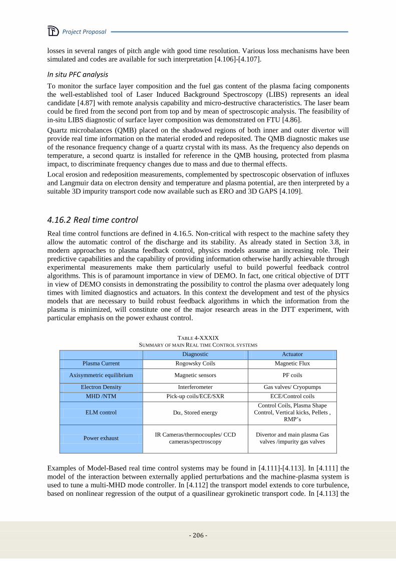
Project Proposal
- 206 -
losses in several ranges of pitch angle with good time resolution. Various loss mechanisms have been
simulated and codes are available for such interpretation [4.106]-[4.107].
In situ PFC analysis
To monitor the surface layer composition and the fuel gas content of the plasma facing components
the well-established tool of Laser Induced Background Spectroscopy (LIBS) represents an ideal
candidate [4.87] with remote analysis capability and micro-destructive characteristics. The laser beam
could be fired from the second port from top and by mean of spectroscopic analysis. The feasibility of
in-situ LIBS diagnostic of surface layer composition was demonstrated on FTU [4.86].
Quartz microbalances (QMB) placed on the shadowed regions of both inner and outer divertor will
provide real time information on the material eroded and redeposited. The QMB diagnostic makes use
of the resonance frequency change of a quartz crystal with its mass. As the frequency also depends on
temperature, a second quartz is installed for reference in the QMB housing, protected from plasma
impact, to discriminate frequency changes due to mass and due to thermal effects.
Local erosion and redeposition measurements, complemented by spectroscopic observation of influxes
and Langmuir data on electron density and temperature and plasma potential, are then interpreted by a
suitable 3D impurity transport code now available such as ERO and 3D GAPS [4.109].
4.16.2 Real time control
Real time control functions are defined in 4.16.5. Non-critical with respect to the machine safety they
allow the automatic control of the discharge and its stability. As already stated in Section 3.8, in
modern approaches to plasma feedback control, physics models assume an increasing role. Their
predictive capabilities and the capability of providing information otherwise hardly achievable through
experimental measurements make them particularly useful to build powerful feedback control
algorithms. This is of paramount importance in view of DEMO. In fact, one critical objective of DTT
in view of DEMO consists in demonstrating the possibility to control the plasma over adequately long
times with limited diagnostics and actuators. In this context the development and test of the physics
models that are necessary to build robust feedback algorithms in which the information from the
plasma is minimized, will constitute one of the major research areas in the DTT experiment, with
particular emphasis on the power exhaust control.
TABLE 4-XXXIX
SUMMARY OF MAIN REAL TIME CONTROL SYSTEMS
Diagnostic Actuator
Plasma Current Rogowsky Coils Magnetic Flux
Axisymmetric equilibrium Magnetic sensors PF coils
Electron Density Interferometer Gas valves/ Cryopumps
MHD /NTM Pick-up coils/ECE/SXR ECE/Control coils
ELM control D, Stored energy
Control Coils, Plasma Shape
Control, Vertical kicks, Pellets ,
RMP’s
Power exhaust IR Cameras/thermocouples/ CCD
cameras/spectroscopy
Divertor and main plasma Gas
valves /impurity gas valves
Examples of Model-Based real time control systems may be found in [4.111]-[4.113]. In [4.111] the
model of the interaction between externally applied perturbations and the machine-plasma system is
used to tune a multi-MHD mode controller. In [4.112] the transport model extends to core turbulence,
based on nonlinear regression of the output of a quasilinear gyrokinetic transport code. In [4.113] the
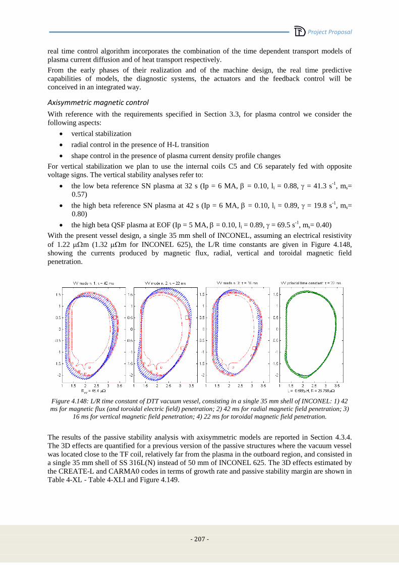
Project Proposal
- 207 -
real time control algorithm incorporates the combination of the time dependent transport models of
plasma current diffusion and of heat transport respectively.
From the early phases of their realization and of the machine design, the real time predictive
capabilities of models, the diagnostic systems, the actuators and the feedback control will be
conceived in an integrated way.
Axisymmetric magnetic control
With reference with the requirements specified in Section 3.3, for plasma control we consider the
following aspects:
vertical stabilization
radial control in the presence of H-L transition
shape control in the presence of plasma current density profile changes
For vertical stabilization we plan to use the internal coils C5 and C6 separately fed with opposite
voltage signs. The vertical stability analyses refer to:
the low beta reference SN plasma at 32 s (Ip = 6 MA, = 0.10, li = 0.88, = 41.3 s-1
, ms=
0.57)
the high beta reference SN plasma at 42 s (Ip = 6 MA, = 0.10, li = 0.89, = 19.8 s-1
, ms=
0.80)
the high beta QSF plasma at EOF (Ip = 5 MA, = 0.10, li = 0.89, = 69.5 s-1
, ms= 0.40)
With the present vessel design, a single 35 mm shell of INCONEL, assuming an electrical resistivity
of 1.22 m (1.32 m for INCONEL 625), the L/R time constants are given in Figure 4.148,
showing the currents produced by magnetic flux, radial, vertical and toroidal magnetic field
penetration.
Figure 4.148: L/R time constant of DTT vacuum vessel, consisting in a single 35 mm shell of INCONEL: 1) 42
ms for magnetic flux (and toroidal electric field) penetration; 2) 42 ms for radial magnetic field penetration; 3)
16 ms for vertical magnetic field penetration; 4) 22 ms for toroidal magnetic field penetration.
The results of the passive stability analysis with axisymmetric models are reported in Section 4.3.4.
The 3D effects are quantified for a previous version of the passive structures where the vacuum vessel
was located close to the TF coil, relatively far from the plasma in the outboard region, and consisted in
a single 35 mm shell of SS 316L(N) instead of 50 mm of INCONEL 625. The 3D effects estimated by
the CREATE-L and CARMA0 codes in terms of growth rate and passive stability margin are shown in
Table 4-XL - Table 4-XLI and Figure 4.149.
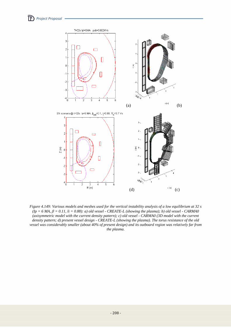
Project Proposal
- 208 -
(a) (b)
(d) (c)
Figure 4.149: Various models and meshes used for the vertical instability analysis of a low equilibrium at 32 s
(Ip = 6 MA, = 0.11, li = 0.88): a) old vessel - CREATE-L (showing the plasma); b) old vessel - CARMA0
(axisymmetric model with the current density pattern); c) old vessel - CARMA0 (3D model with the current
density pattern; d) present vessel design - CREATE-L (showing the plasma). The torus resistance of the old
vessel was considerably smaller (about 40% of present design) and its outboard region was relatively far from
the plasma.
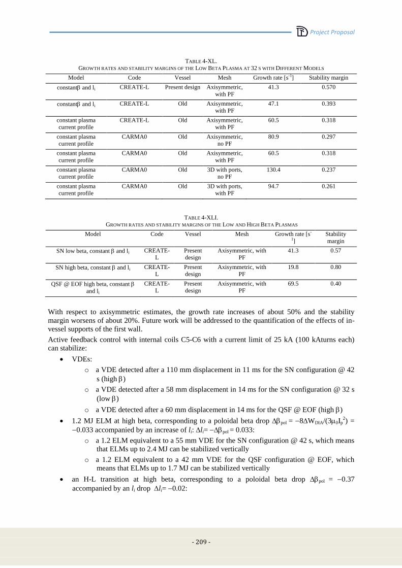
Project Proposal
- 209 -
TABLE 4-XL.
GROWTH RATES AND STABILITY MARGINS OF THE LOW BETA PLASMA AT 32 S WITH DIFFERENT MODELS
Model Code Vessel Mesh Growth rate [s-1] Stability margin
constant and li CREATE-L Present design Axisymmetric,
with PF
41.3 0.570
constant and li CREATE-L Old Axisymmetric,
with PF
47.1 0.393
constant plasma
current profile
CREATE-L Old Axisymmetric,
with PF
60.5 0.318
constant plasma
current profile
CARMA0 Old Axisymmetric,
no PF
80.9 0.297
constant plasma
current profile
CARMA0 Old Axisymmetric,
with PF
60.5 0.318
constant plasma
current profile
CARMA0 Old 3D with ports,
no PF
130.4 0.237
constant plasma
current profile
CARMA0 Old 3D with ports,
with PF
94.7 0.261
TABLE 4-XLI.
GROWTH RATES AND STABILITY MARGINS OF THE LOW AND HIGH BETA PLASMAS
Model Code Vessel Mesh Growth rate [s-
1]
Stability
margin
SN low beta, constant and li CREATE-
L
Present
design
Axisymmetric, with
PF
41.3 0.57
SN high beta, constant and li CREATE-
L
Present
design
Axisymmetric, with
PF
19.8 0.80
QSF @ EOF high beta, constant
and li
CREATE-
L
Present
design
Axisymmetric, with
PF
69.5 0.40
With respect to axisymmetric estimates, the growth rate increases of about 50% and the stability
margin worsens of about 20%. Future work will be addressed to the quantification of the effects of in-
vessel supports of the first wall.
Active feedback control with internal coils C5-C6 with a current limit of 25 kA (100 kAturns each)
can stabilize:
VDEs:
o a VDE detected after a 110 mm displacement in 11 ms for the SN configuration @ 42
s (high )
o a VDE detected after a 58 mm displacement in 14 ms for the SN configuration @ 32 s
(low )
o a VDE detected after a 60 mm displacement in 14 ms for the QSF @ EOF (high )
1.2 MJ ELM at high beta, corresponding to a poloidal beta drop pol = 8WDIA/(30Ip2) =
0.033 accompanied by an increase of li: li= pol = 0.033:
o a 1.2 ELM equivalent to a 55 mm VDE for the SN configuration @ 42 s, which means
that ELMs up to 2.4 MJ can be stabilized vertically
o a 1.2 ELM equivalent to a 42 mm VDE for the QSF configuration @ EOF, which
means that ELMs up to 1.7 MJ can be stabilized vertically
an H-L transition at high beta, corresponding to a poloidal beta drop pol = 0.37
accompanied by an li drop li= 0.02:
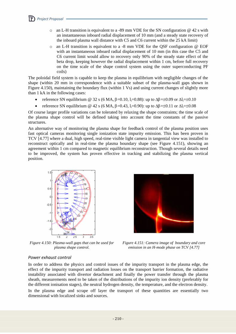
Project Proposal
- 210 -
o an L-H transition is equivalent to a -89 mm VDE for the SN configuration @ 42 s with
an instantaneous inboard radial displacement of 10 mm (and a steady state recovery of
the inboard plasma wall distance with C5 and C6 current within the 25 kA limit)
o an L-H transition is equivalent to a -8 mm VDE for the QSF configuration @ EOF
with an instantaneous inboard radial displacement of 10 mm (in this case the C5 and
C6 current limit would allow to recovery only 90% of the steady state effect of the
beta drop, keeping however the radial displacement within 1 cm, before full recovery
on the time scale of the shape control system using the outer superconducting PF
coils)
The poloidal field system is capable to keep the plasma in equilibrium with negligible changes of the
shape (within 20 mm in correspondence with a suitable subset of the plasma-wall gaps shown in
Figure 4.150), maintaining the boundary flux (within 1 Vs) and using current changes of slightly more
than 1 kA in the following cases:
reference SN equilibrium @ 32 s (6 MA, =0.10, li=0.88): up to =0.09 or li=0.10
reference SN equilibrium @ 42 s (6 MA, =0.43, li=0.90): up to =0.11 or li=0.08
Of course larger profile variations can be tolerated by relaxing the shape constraints; the time scale of
the plasma shape control will be defined taking into account the time constants of the passive
structures.
An alternative way of monitoring the plasma shape for feedback control of the plasma position uses
fast optical cameras monitoring single ionization state impurity emission. This has been proven in
TCV [4.77] where a dual, high speed, real-time visible light camera in tangential view was installed to
reconstruct optically and in real-time the plasma boundary shape (see Figure 4.151), showing an
agreement within 1 cm compared to magnetic equilibrium reconstruction. Though several details need
to be improved, the system has proven effective in tracking and stabilizing the plasma vertical
position.
Figure 4.150: Plasma-wall gaps that can be used for
plasma shape control.
Figure 4.151: Camera image of boundary and core
emission in an H-mode phase on TCV [4.77]
Power exhaust control
In order to address the physics and control issues of the impurity transport in the plasma edge, the
effect of the impurity transport and radiation losses on the transport barrier formation, the radiative
instability associated with divertor detachment and finally the power transfer through the plasma
sheath, measurements need to be taken of the distributions of the impurity ion density (preferably for
the different ionisation stages), the neutral hydrogen density, the temperature, and the electron density.
In the plasma edge and scrape off layer the transport of these quantities are essentially two
dimensional with localized sinks and sources.
Project Proposal
- 211 -
This calls for an imaging solution. Typically, images from tokamak plasmas are interpreted using
tomographic reconstruction, after which the radiation distribution needs to be mapped onto the
magnetic topology of the plasma. Bolometer tomography of the divertor region is described in Section
4.16.1. More recently, FOM and TU/e developed OFIT, which allows for a fast, non-iterative analysis
of the spectral images with low latency by identifying edges in the image-emissivity, and interprets
these as radiative shells [4.77]-[4.78]. A real time analysis method for the plasma periphery has been
demonstrated at 1kHz with two cameras [4.77], [4.80]. In the images, the radiation front, associated
with detachment can easily be identified (not published). At present, FOM is designing and
constructing a many-camera system to be mounted on TCV. Using interference filters a real-time
hyper-spectral imager is conceived. In order to obtain quantitative two-dimensional information on the
impurity density and temperature, the emission for the different ionization stages and spectral
transitions shall be pre-calculated as a function of plasma composition, temperature and density with
collisional-radiative models. A control oriented dynamic model for detachment needs set-up for
controller design, real-time observation and future states prediction. Ideally, the model flags proximity
to operational limits or actuator constraints. At present, the first principle physics codes cannot predict
the transition from attached to detached plasma and represent an area of R&D. The model can be used
to design a control system for detached high performance plasmas in DTT. Adding a fast heating
system with a sliding mode controller can possibly compensate overshoots of the radiative power.
Assuming that to induce the radiative losses in the SOL and divertor valves are used to release
impurities into the plasma periphery, the response time is long. Finally, we point out that the actuators
need to be redesigned: The present gas valves are designed for the non-critical density feed-back and
feature a strong non-linearity due to stick-and-slip of the piezo-valves. Also this non-linear behaviour
can be observed, and rejected. In the RFX experience it has been observed that valve reproducibility is
increased if the valve is used with series of fast blips, and is not left idle for too long; short blips with
very little gas release should be activated when the valve intervention is not requested for a
sufficiently long time. The final integration should yield a system that can control the distribution of
radiative power, ensuring detachment while remaining in H-mode.
MHD control
An ECRH launching system is planned to deliver 1st harmonic, O mode, 170 GHz for NTM and ST
control:
Provisional reference: 4 poloidally steerable beams (1 MW each) located in the upper port to
minimize trapped electron effects preserving the access to the HFS (see Figure 4.152a)
Poloidal Steering range (min): from q=1 surface to q=2 surface +margins on both sides, with
Real Time capabilities.
Toroidal steering: to be considered, not in Real Time, possibly limited around a value of 10-15
degrees.
Water Cooling foreseen on steering mirrors and on fixed mirrors. Cooling requirements: 0.5%
absorption on mirror surfaces (5 kW/MW) equivalent to 5 l/min, ΔT=15 °C of water flow per
mirror (60 l/min total).
Mirror technology: bulk stainless steel, cooling channels close to the reflecting surface or
stainless steel with Cu layer. The expected peak thermal load on reflecting surfaces is ~100
W/cm2 (copper coating).
Antenna concept: four 63.5 mm inner diameter corrugated waveguide in 2x2 array facing four
port (diamond) windows, not perpendicularly to the port flange (see Figure 4.152b) . Each
beam hits three mirrors (see Figure 4.152c):
o single beam, fixed, focusing (non-planar surface)
o single beam, rotating around one axis roughly parallel to the port axis h. Real time
adjusting capabilities for steering across the plasma section (poloidal steering)
o four beams, rotating around one axis parallel to k
The supporting structure (plug-in) runs along the port lateral sides. It hosts the cooling channels and
the push-pull rods of the moving mirrors. A reserved volume of 50 mm thickness has been considered.
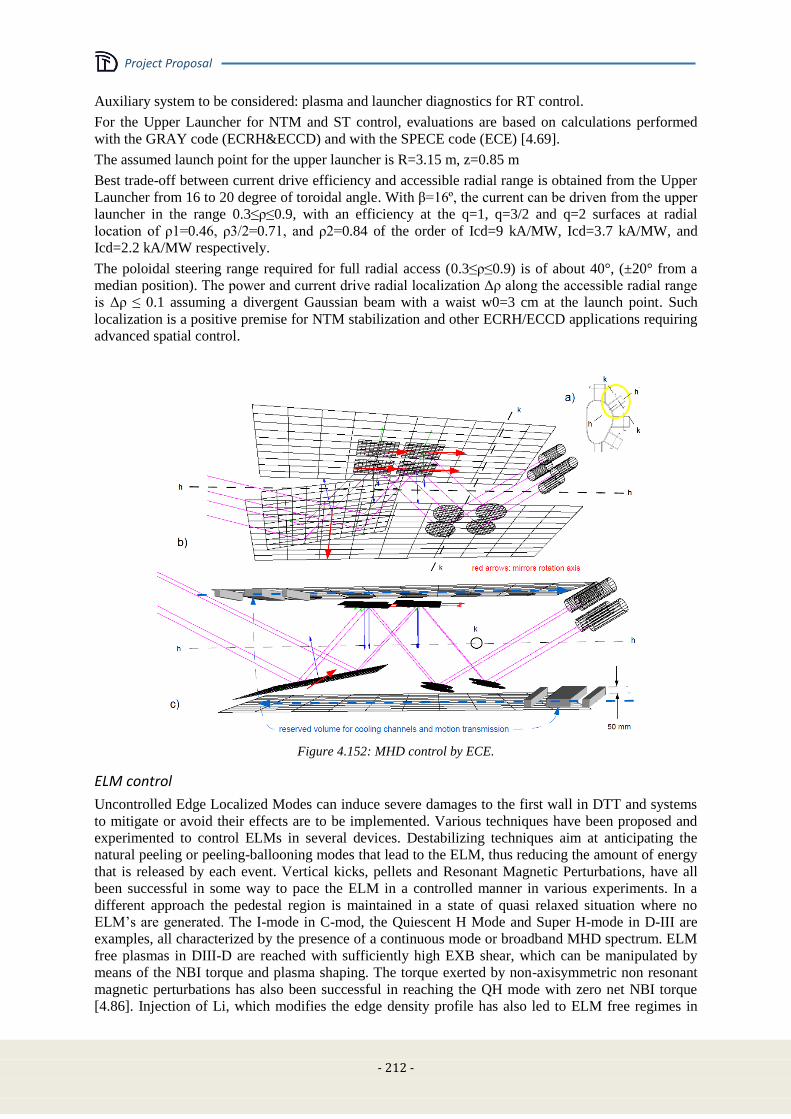
Project Proposal
- 212 -
Auxiliary system to be considered: plasma and launcher diagnostics for RT control.
For the Upper Launcher for NTM and ST control, evaluations are based on calculations performed
with the GRAY code (ECRH&ECCD) and with the SPECE code (ECE) [4.69].
The assumed launch point for the upper launcher is R=3.15 m, z=0.85 m
Best trade-off between current drive efficiency and accessible radial range is obtained from the Upper
Launcher from 16 to 20 degree of toroidal angle. With β=16º, the current can be driven from the upper
launcher in the range 0.3≤ρ≤0.9, with an efficiency at the q=1, q=3/2 and q=2 surfaces at radial
location of ρ1=0.46, ρ3/2=0.71, and ρ2=0.84 of the order of Icd=9 kA/MW, Icd=3.7 kA/MW, and
Icd=2.2 kA/MW respectively.
The poloidal steering range required for full radial access (0.3≤ρ≤0.9) is of about 40°, (±20° from a
median position). The power and current drive radial localization Δρ along the accessible radial range
is Δρ ≤ 0.1 assuming a divergent Gaussian beam with a waist w0=3 cm at the launch point. Such
localization is a positive premise for NTM stabilization and other ECRH/ECCD applications requiring
advanced spatial control.
Figure 4.152: MHD control by ECE.
ELM control
Uncontrolled Edge Localized Modes can induce severe damages to the first wall in DTT and systems
to mitigate or avoid their effects are to be implemented. Various techniques have been proposed and
experimented to control ELMs in several devices. Destabilizing techniques aim at anticipating the
natural peeling or peeling-ballooning modes that lead to the ELM, thus reducing the amount of energy
that is released by each event. Vertical kicks, pellets and Resonant Magnetic Perturbations, have all
been successful in some way to pace the ELM in a controlled manner in various experiments. In a
different approach the pedestal region is maintained in a state of quasi relaxed situation where no
ELM’s are generated. The I-mode in C-mod, the Quiescent H Mode and Super H-mode in D-III are
examples, all characterized by the presence of a continuous mode or broadband MHD spectrum. ELM
free plasmas in DIII-D are reached with sufficiently high EXB shear, which can be manipulated by
means of the NBI torque and plasma shaping. The torque exerted by non-axisymmetric non resonant
magnetic perturbations has also been successful in reaching the QH mode with zero net NBI torque
[4.86]. Injection of Li, which modifies the edge density profile has also led to ELM free regimes in
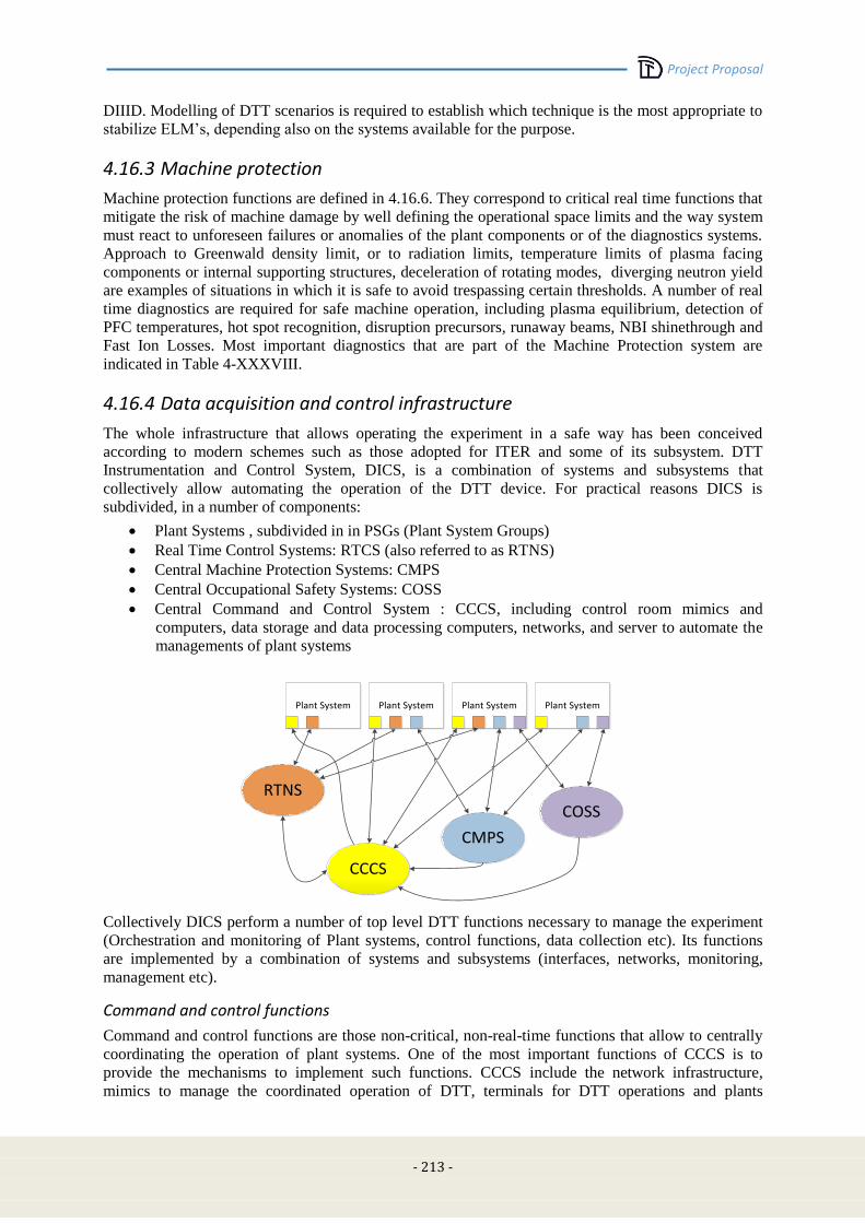
Project Proposal
- 213 -
DIIID. Modelling of DTT scenarios is required to establish which technique is the most appropriate to
stabilize ELM’s, depending also on the systems available for the purpose.
4.16.3 Machine protection
Machine protection functions are defined in 4.16.6. They correspond to critical real time functions that
mitigate the risk of machine damage by well defining the operational space limits and the way system
must react to unforeseen failures or anomalies of the plant components or of the diagnostics systems.
Approach to Greenwald density limit, or to radiation limits, temperature limits of plasma facing
components or internal supporting structures, deceleration of rotating modes, diverging neutron yield
are examples of situations in which it is safe to avoid trespassing certain thresholds. A number of real
time diagnostics are required for safe machine operation, including plasma equilibrium, detection of
PFC temperatures, hot spot recognition, disruption precursors, runaway beams, NBI shinethrough and
Fast Ion Losses. Most important diagnostics that are part of the Machine Protection system are
indicated in Table 4-XXXVIII.
4.16.4 Data acquisition and control infrastructure
The whole infrastructure that allows operating the experiment in a safe way has been conceived
according to modern schemes such as those adopted for ITER and some of its subsystem. DTT
Instrumentation and Control System, DICS, is a combination of systems and subsystems that
collectively allow automating the operation of the DTT device. For practical reasons DICS is
subdivided, in a number of components:
Plant Systems , subdivided in in PSGs (Plant System Groups)
Real Time Control Systems: RTCS (also referred to as RTNS)
Central Machine Protection Systems: CMPS
Central Occupational Safety Systems: COSS
Central Command and Control System : CCCS, including control room mimics and
computers, data storage and data processing computers, networks, and server to automate the
managements of plant systems
CCCS
RTNS
CMPS
COSS
Plant System Plant System Plant System Plant System
Collectively DICS perform a number of top level DTT functions necessary to manage the experiment
(Orchestration and monitoring of Plant systems, control functions, data collection etc). Its functions
are implemented by a combination of systems and subsystems (interfaces, networks, monitoring,
management etc).
Command and control functions
Command and control functions are those non-critical, non-real-time functions that allow to centrally
coordinating the operation of plant systems. One of the most important functions of CCCS is to
provide the mechanisms to implement such functions. CCCS include the network infrastructure,
mimics to manage the coordinated operation of DTT, terminals for DTT operations and plants

Project Proposal
- 214 -
management, structures to manage the plant database and system alarms, mechanisms of
communication to each plant systems. In turn each Plant Systems will possess the interface to CCCS
to support its functions:
CCCS network infrastructure
The network infrastructure (excluding real-time and event/time distribution) will be based on Ethernet
and will consist on a number of network segments organised in such a way to segregate local traffic
and implement a multi-level security. Such layers will regulate and secure communication between
CCCS central layer and PSG server, control room terminals, remote participants
CCCS plant database
CCCS Plant Database is the manager of the Plant System configuration and status. It acts as an
intermediary between central functions and Plant Systems. The PDB will handle safe changes to data,
access to Plant systems, correct loading of parameters setting being able of dealing with different
levels of segregation of a Plant System.
CCCS Plant Database is organised hierarchically over 3 (more when needed) levels. Each CCCS PDB
function will be implemented in the lower possible level of the architecture. This is to allow
segregating, for the purpose of control, the overall tokamak plant into sub-plants and allow parallel
and concurrent commissioning/test activities.
Plant System Plant System Plant System Plant System
PDB Level1
PDB Level2
PDB Level3
Communication to plant systems
The mechanism of communication to the plant systems will be chosen case by case depending on the
needs and the chosen manufacturer. Nevertheless CCCS will define the requirements of such
communication mechanism on the basis of the project needs.
Standard / Industrial Plant Systems will very likely be implemented by means of industrial automation
components, PLCs. A preferred technology will be selected for these systems. Nevertheless the glue
to communication layer to CCCS will, whenever possible, be based on industrial, PLC independent
standards: (OPC-OA for instance). This is to avoid being overly dependent on a technology. For these
systems, all the functions associated to the PDB are implemented in CCCS servers.
Bespoke / Fusion Plant Systems will very likely be implemented by a mix of PLCs and PC-based
servers. In these case the interface to CCCS will be normally be implemented by the PC-based server
as well as the interface to the PLCs. For these systems, the lower level PDB functions (distribute data
to higher level) will be implemented locally.
CCCS mimics
The overall set of mimics to manage coordinated operation and plant system local operation will be
based on standard industrial solutions. CCCS will select a default standard and apply it to the

Project Proposal
- 215 -
development of the central coordination mimics. Plant System providers will be encouraged to supply
according to this standard.
Plant System
Local HMI for standalone commissioning and maintenance
CCCS:Plant System Group Server
CCCS: Plant Database
CCCS: Operation Supervisor
Control room(s) terminals
Plant System mimics for industrial supplies will be provided as part of the supply. Additional synthetic
mimics for these Plant Systems (or group of) will be developed by CCCS to support the coordinated
operation of DTT.
CCCS operation supervisor
CCCS Operation Supervisor system is a central function that allows automatic coordination of the
status of all Plant Systems. This allows implementing automatic sequences like for instance a plasma
experiment. The supervisor will assure the consistency of the machine status and of all of the plant
systems, including coherence checks between CCCS and CMPS to avoid false protection system
interventions.
Experiment management functions
Experiment management functions are those non-critical, non-real-time functions that allow to manage
all the information associated with an experiment. In particular they provide the interface to edit
experiment plans, access to experimental data and check that experiment settings comply with
operating Instructions.
One of the most important functions of CCCS is to provide the mechanisms to implement such
functions, such as the network infrastructure, management of the information about the plant systems:
“the Plant Database” (PDB), the Operation Supervisor systems, the Historical Experiment Database
HEDB, the user Experiment Plans Editor interface for the management of the Experiment
Configuration Data.
CCS experiment database
Historical Experiment Database is a central function that allows maintaining a historical and coherent
record of experiment data and parameters. The HEDB will contain a short term database (one day of
operation) with maximum data rate and a long term database to store the full lifetime of DTT. A
remote data access portal, will allow intercontinental remote access to experiment data. A uniform
data access layer will be designed to allow uniform access to all DTT data.
CCS experiment plans editor
Experiment Plans Editors is a collection of tools and services that, by interacting with the PDB,
implements a user friendly (human factor) interface to allow as much as possible, easy and error free,
programming of the discharge. They include editing, comparing and verifying Experiment Plans and
management of control room roles and workflows.
Project Proposal
- 216 -
CCS fast data acquisition network
The Fast Data acquisition Network is a tcp/Ip based network dedicated to the transfer of data acquired
by Plant Systems to the Experiment Database. This network will be typically used when data rate
exceeds 100 Hz.
4.16.5 Real time control functions
Real Time Control functions are those (mostly) non-critical, real-time functions that allow to attain a
sufficient level of automatic coordinated plasma operation. Functions dedicated to complement
machine protection or to implement complex/experimental plasma protections are also included. Many
Diagnostic Plant Systems and many Plasma Actuator Plant Systems will contribute to this function.
RTCS Systems are dedicated to implementing these functions and they will:
generate control waveforms, read diagnostic data and generate real-time references to
actuators;
implement main plasma control and protection functions ,manage emergency termination;
implement majority of real-time calibrated synthetic plasma measurements (e.g. equilibrium).
Real Time network is the main mechanism of communication among all of the above systems through
point to multipoint (MULTICAST) communication and predictable and repeatable point to point data
transfer latency which is only function of the traffic. A stationary data traffic (periodic with a period
no longer than 1s) requires that all the nodes contribute to the network with periodic traffic patterns
that are all synchronised
Real time network
RTN is implemented using a managed switched network that allows the controlled introduction of new
Plant Systems. The network technology will be based on Gigabit Ethernet (GbE) with a User
Datagram Protocol (UDP).
The data-exchange between Plant Systems participating to the control functions will be based on a
switched network with fixed (within the experiment) data paths able to deliver datagrams from a
sender to (and only to) a list of pre-configured receivers. This approach guarantees that a Plant System
that is not fully commissioned cannot interfere with the RTCS unless authorised.
Plant Systems are expected to implement a prescribed payload on top of the UDP protocol. This
payload will contain a header with sufficient information to identify the data producer and the time of
the experiment. The remainder of the payload will contain the values of the produced data. Each
payload structure is static and not expected to change during operation. Any change to the payload
definition will require a full recommissioning of the global control functions to which the packet
participates to. The definition of the payload will be centrally managed by the CCCS and monitored
by the operation supervisor (which will inhibit an experiment if a change to the agreed payload
structure is detected).
Finally, this infrastructure does not impose any particular technical hardware or software platform on
the Plant System, naturally supporting different processing technologies (e.g. CPU and FPGA) and
many operating systems.
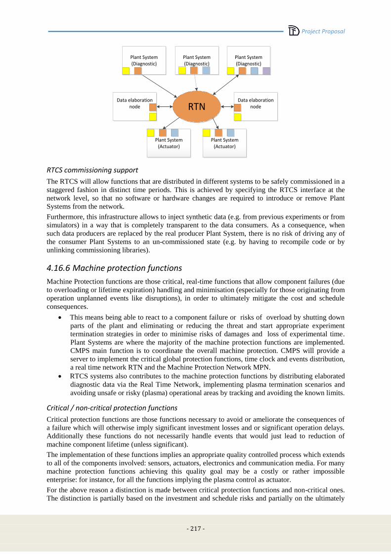
Project Proposal
- 217 -
RTN
Plant System (Diagnostic)
Plant System (Diagnostic)
Data elaboration node
Data elaboration node
Plant System (Diagnostic)
Plant System (Actuator)
Plant System (Actuator)
RTCS commissioning support
The RTCS will allow functions that are distributed in different systems to be safely commissioned in a
staggered fashion in distinct time periods. This is achieved by specifying the RTCS interface at the
network level, so that no software or hardware changes are required to introduce or remove Plant
Systems from the network.
Furthermore, this infrastructure allows to inject synthetic data (e.g. from previous experiments or from
simulators) in a way that is completely transparent to the data consumers. As a consequence, when
such data producers are replaced by the real producer Plant System, there is no risk of driving any of
the consumer Plant Systems to an un-commissioned state (e.g. by having to recompile code or by
unlinking commissioning libraries).
4.16.6 Machine protection functions
Machine Protection functions are those critical, real-time functions that allow component failures (due
to overloading or lifetime expiration) handling and minimisation (especially for those originating from
operation unplanned events like disruptions), in order to ultimately mitigate the cost and schedule
consequences.
This means being able to react to a component failure or risks of overload by shutting down
parts of the plant and eliminating or reducing the threat and start appropriate experiment
termination strategies in order to minimise risks of damages and loss of experimental time.
Plant Systems are where the majority of the machine protection functions are implemented.
CMPS main function is to coordinate the overall machine protection. CMPS will provide a
server to implement the critical global protection functions, time clock and events distribution,
a real time network RTN and the Machine Protection Network MPN.
RTCS systems also contributes to the machine protection functions by distributing elaborated
diagnostic data via the Real Time Network, implementing plasma termination scenarios and
avoiding unsafe or risky (plasma) operational areas by tracking and avoiding the known limits.
Critical / non-critical protection functions
Critical protection functions are those functions necessary to avoid or ameliorate the consequences of
a failure which will otherwise imply significant investment losses and or significant operation delays.
Additionally these functions do not necessarily handle events that would just lead to reduction of
machine component lifetime (unless significant).
The implementation of these functions implies an appropriate quality controlled process which extends
to all of the components involved: sensors, actuators, electronics and communication media. For many
machine protection functions achieving this quality goal may be a costly or rather impossible
enterprise: for instance, for all the functions implying the plasma control as actuator.
For the above reason a distinction is made between critical protection functions and non-critical ones.
The distinction is partially based on the investment and schedule risks and partially on the ultimately
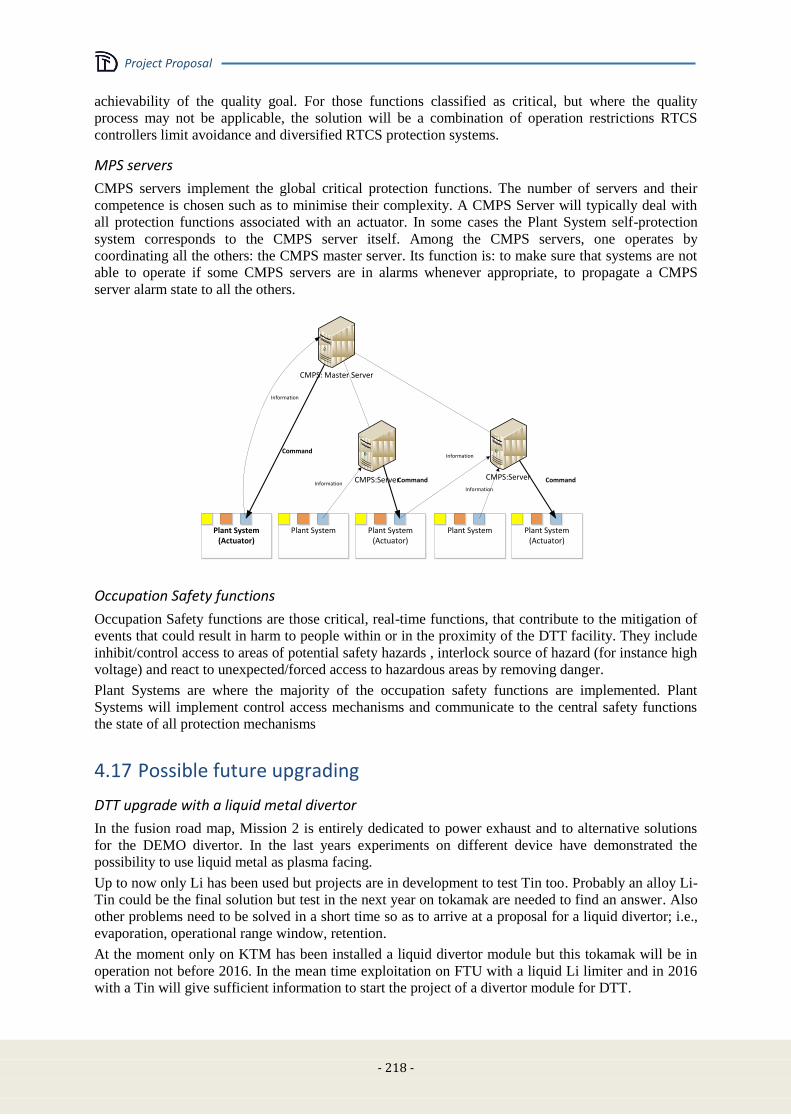
Project Proposal
- 218 -
achievability of the quality goal. For those functions classified as critical, but where the quality
process may not be applicable, the solution will be a combination of operation restrictions RTCS
controllers limit avoidance and diversified RTCS protection systems.
MPS servers
CMPS servers implement the global critical protection functions. The number of servers and their
competence is chosen such as to minimise their complexity. A CMPS Server will typically deal with
all protection functions associated with an actuator. In some cases the Plant System self-protection
system corresponds to the CMPS server itself. Among the CMPS servers, one operates by
coordinating all the others: the CMPS master server. Its function is: to make sure that systems are not
able to operate if some CMPS servers are in alarms whenever appropriate, to propagate a CMPS
server alarm state to all the others.
Plant System (Actuator)
CMPS:Server
CMPS: Master Server
Plant System (Actuator)
Plant System Plant System (Actuator)
CMPS:Server
Plant System
Information
Command
Command CommandInformation
Information
Information
Occupation Safety functions
Occupation Safety functions are those critical, real-time functions, that contribute to the mitigation of
events that could result in harm to people within or in the proximity of the DTT facility. They include
inhibit/control access to areas of potential safety hazards , interlock source of hazard (for instance high
voltage) and react to unexpected/forced access to hazardous areas by removing danger.
Plant Systems are where the majority of the occupation safety functions are implemented. Plant
Systems will implement control access mechanisms and communicate to the central safety functions
the state of all protection mechanisms
4.17 Possible future upgrading
DTT upgrade with a liquid metal divertor
In the fusion road map, Mission 2 is entirely dedicated to power exhaust and to alternative solutions
for the DEMO divertor. In the last years experiments on different device have demonstrated the
possibility to use liquid metal as plasma facing.
Up to now only Li has been used but projects are in development to test Tin too. Probably an alloy Li-
Tin could be the final solution but test in the next year on tokamak are needed to find an answer. Also
other problems need to be solved in a short time so as to arrive at a proposal for a liquid divertor; i.e.,
evaporation, operational range window, retention.
At the moment only on KTM has been installed a liquid divertor module but this tokamak will be in
operation not before 2016. In the mean time exploitation on FTU with a liquid Li limiter and in 2016
with a Tin will give sufficient information to start the project of a divertor module for DTT.

Project Proposal
- 219 -
In principle the divertor module should be able to withstand heat load exceeding 10 MW/m2 for all the
shot duration without polluting too much the plasma. Evaporation should be very limited unless
mechanism as vapour shield will be demonstrated to be efficient to shield the divertor module and at
same time to confine in the divertor region most of the evaporated atoms.
As stated in the projected plan of DTT1 the final assessment on liquid metals as possible alternative
solution to solid materials is scheduled for the end of 2016 and this date is on line for projecting the
divertor module for DTT also because we have to take into account that the starting operation phase
will be performed with a conventional divertor, i.e., tungsten.
The first experiments with liquid metals in the DIIID divertor have highlighted the problem of
opposing a force that counteracts the electromagnetic force JXB. After these initial negative results,
only the Russians have continued this line of research on T11 by adopting a new solution, the
Capillary Porous System (CPS), where the electromagnetic force is offset by the capillary force. If the
capillary force is greater than the electromagnetic force the liquid metal is confined and the interaction
with the plasma takes place almost as for solids, i.e., sputtering and evaporation. At the moment CPS
seems the best solution to be adopted for a divertor module and it will be the reference solution for
DTT. Different CPS layout has been tested in T-11 tokamak. Horizontal and vertical limier has been
exposed to the plasma without problems. No droplets have been observed that it means that this
technology can be easily adopted also for shaped divertors.
The choice between Li and Tin will be taken after the experiments performed on FTU. Tin has a
largest operating window that it is reflected in the ability to withstand higher heat loads. In steady state
the maximum heat loads for Li and Tin, assuming 1 mm of liquid metal on top of 3 mm of tungsten in
contact with water-cooling, are given in Table below:
Material Tmax
(K) q(MW/m
2)
Li 750
645
10
7.3
Tin 1550
1275
32
25
To be used on DEMO credible conceptual design of a closed-loop liquid metal heat and particle
removal system should be worked out and assessed. Present ideas are usually at a very sketchy level
and it is necessary to develop a credible project.
First wall (FW) and alternative divertors.
Since the machine is a facility dedicated to the study of the power exhaust problem, along its life will
be possible to replace both the FW and the divertor. For the FW solutions with different plasma facing
components (PFC) different materials could be utilized. For the divertor it will be possible to install
them with different magnetic geometries and with different PFC. It will also possible to test different
cooling systems for the divertor, changing the pipes, in order to realize a divertor full DEMO
compatible.
Double null divertor
Section 4.3.4 shows that the PF coil system is capable to sustain a high current (5 MA) double null
configuration for a long flat top (more than 40 s). The double null configuration can be tested in the
first phase of the scientific programme at low current and/or in L-mode. In a second phase it can be
tested for short periods also in H-mode with suitable precaution so as to prevent damages to the upper
part of the first wall (e.g., short duration, wobbling, sweeping, or suitable reinforcement plates).

Project Proposal
- 220 -
However, a significant double null experiment should be carried out not only with a symmetric
magnetic configuration (which is feasible) but also with an up-down symmetric structure of the
divertor and pumping system. For this reason, particular care will be taken in the design of a modular
first wall, so as to allow removing it and mounting another divertor in the upper part of the machine
(whenever required by the future scientific programme).
Increase of heating capabilities
Concerning the choice of the heating and CD system, the relative merits of the various systems used
on tokamaks are well known: Lower Hybrid (LH) and Neutral Beam Injection (NBI) have higher CD
efficiencies; Electron Cyclotron (EC) waves have better localisation capabilities, both for heating and
CD; Ion Cyclotron (IC) waves are the cheapest system, mainly used for heating, both electrons and
ions. In order to make a choice, the following rationale has been employed:
In order to limit the complexity of the plant, it has been chosen to use not more than two
systems, at least in the first phase.
Since bulk CD is not a main objective, the high CD efficiency of LH and NBI is not
considered as a decisive advantage.
The need to heat both ions and electrons favours the use of IC waves.
The usefulness of MHD control, requiring localised CD, favours the use of EC waves
As a consequence, it was chosen to use as a reference, for the first DTT phase, a system composed by
15 MW of ICRH and 10 MW of ECRH. NBI is being considered as the main candidate for a
subsequent power upgrade. Along the experimental exploitation (see chap. 3) the total amount of
heating will be upgraded up to 45 MW; the final sharing will be decided on the basis of the gained
experience, however NBI is being considered as the main candidate for a subsequent power upgrade
up to 15MW.
4.18 References [4.1] L. Muzzi, G. De Marzi, A. Di Zenobio and A. della Corte “Cable-in-conduit conductors: lessons from the
recent past for future developments with low and high temperature superconductors”, Topical
Review,Supercond. Sci. Technol. 28 (2015) 053001 (25pp)
[4.2] A. della Corte et al. , “Successful performances of the EU-AltTF sample, a large size Nb3Sn cable-in-
conduit conductor with rectangular geometry”, Supercond. Sci. Technol. 23 (2010) 045028 (6pp)
[4.3] A. Portone et al. , “Design and Procurement of the European Dipole (EDIPO) Superconducting Magnet”,
IEEE Trans. On Appl. Supercond. , Vol. 18,499 – 503, No. 2, June 2008
[4.4] Dixon I. R. et al. , 2009 IEEE Trans. Appl. Supercond. 19 1462; Dixon I. R. et al. , 2012 IEEE Trans. Appl.
Supercond. 22 4301004
[4.5] S. A. J. Wiegers Et Al. , “Conceptual Design Of The 45 T Hybrid Magnet At The Nijmegen High Field
Magnet Laboratory”, IEEE Trans. On Appl. Supercond. , Vol. 20, No. 3, 688 – 691, June 2010
[4.6] D. Bessette et al., “Design of a Nb3Sn CICC to withstand the 6000 electromagnetic cycles of the ITER
Central Solenoid”, IEEE Trans. On Appl. Supercond., Vol. 23 (2015) 4200505
[4.7] ITER Design Description Document DDD11-Magnets, Section 2-TF Coils and Structures,
ITER_D_2MVZNX v2.2, Sept. 2009”
[4.8] M. E. Biancolini, C. Brutti, L. Muzzi, S. Turtù, “A new meshless approach to determine electromagnetic
loads for FEM analysis on DEMO TF coil system,” accepted for publication in Fusion Engineering and
Design
[4.9] R. Albanese, G. Rubinacci, "Finite element methods for the solution of 3D eddy current problems", Adv.
Imaging Electron Phys. 102 (1998) 1–86.

Project Proposal
- 221 -
[4.10] Email from R. Albanese to F. Villone, 20/3/2015
[4.11] M. Mattei et al. , "Report on EFDA Task WP13‐SYS‐02: DEMO Single Null Equilibria and Vertical
Stability Assessment", EFDA_D_2LM3VX, Dec. 2013
[4.12] A. Di Zenobio et al. , Joint Design for the EDIPO, IEEE Trans. on Appl. Supercond. 18 (2008) 192
[4.13] Gade, P. V. , et al. "Conceptual design of a toroidal field coil for a fusion power plant using high
temperature superconductors. " Applied Superconductivity, IEEE Transactions on 24.3 (2014): 1-5.DOI:
10.1109/TASC. 2014.2299828
[4.14] Wang, Xianwei, Fei Xie, and Huan Jin. "Electromagnetic Analysis of the ITER Upper VS Coil. " Journal
of Superconductivity and Novel Magnetism 27.4 (2014): 1015-1019, DOI: 10.1007/s10948-013-2371-5
[4.15] Barabaschi P., “The MAXFEA code”, Plasma Cont. Techn. meeting, Naka (Japan), 1993
[4.16] Calabrò G, et al., Nucl. Fusion 55 (2015) 083005
[4.17] RYUTOV D.D., et al., Plasma Phys. Control. Fusion 52 (2010) 105001
[4.18] Martin N. Wilson, “Superconducting Magnets (Monographs on Cryogenics)”, Oxford University Press,
New edition (1987)
[4.19] G. Ries, IEEE Trans. on Magn.13, 524 (1977)
[4.20] “Magnet Superconducting and Electrical Design Criteria”, ITER D22GRQH v1.2 (2009)
[4.21] P. Bauer, H. Rajainmaki, E. Salpietro, “EFDA Material Data Compilation for Superconductor
Simulation”, (2007)
[4.22] R. Albanese et al., 2004 Nucl. Fusion 44 999
[4.23] M. Mattei et al. , "Report on EFDA Task WP13‐SYS‐02: DEMO Single Null Equilibria and Vertical
Stability Assessment", EFDA_D_2LM3VX, Dec. 2013
[4.24] Gade, P. V. , et al. "Conceptual design of a toroidal field coil for a fusion power plant using high
temperature superconductors. " Applied Superconductivity, IEEE Transactions on 24.3 (2014): 1-5.DOI:
10.1109/TASC. 2014.2299828
[4.25] Wang, Xianwei, Fei Xie, and Huan Jin. "Electromagnetic Analysis of the ITER Upper VS Coil. " Journal
of Superconductivity and Novel Magnetism 27.4 (2014): 1015-1019, DOI: 10.1007/s10948-013-2371-5
[4.26] R. Wenninger et al., Nucl. Fusion 55 (2015) 063003.
[4.27] Gade, P. V. , et al. "Conceptual design of a toroidal field coil for a fusion power plant using high
temperature superconductors. " Applied Superconductivity, IEEE Transactions on 24.3 (2014): 1-5.DOI:
10.1109/TASC. 2014.2299828
[4.28] Wang, Xianwei, Fei Xie, and Huan Jin. "Electromagnetic Analysis of the ITER Upper VS Coil. " Journal
of Superconductivity and Novel Magnetism 27.4 (2014): 1015-1019, DOI: 10.1007/s10948-013-2371-5
[4.29] X5 Monte Carlo Team, “MCNP—a general Monte Carlo N-Particle transport code: version5 user's
guide”, LANL report LA-CP-03-0245 (2005).
[4.30] D. Marocco et al, Neutron measurements in ITER using the Radial Neutron Camera, JINST 7 C03033
(2012).
[4.31] H. S Bosh and G. M. Hale, Improved formulas for fusion cross-sections and thermal reactivities, Nuclear
Fusion 32 (4), 611 (1992).
[4.32] R. Villari, A. Cucchiaro, B. Esposito, D. Marocco, F. Moro, L. Petrizzi, A. Pizzuto, G. Brolatti,
“Neutronic Analysis of FAST”, IEEE Trans. Plasma Sci. , 38, 3, 406-413 (2010)
[4.33] A. Di Zenobio, A. della Corte, L. Muzzi, G. M. Polli, L. Reccia, S. Turtù, F. Crisanti, A. Cucchiaro, A.
Pizzuto and R. Villari, “FAST: Feasibility Analysis for a Completely Superconducting Magnet System”,
IEEE Transactions on Applied Superconductivity, 21, 1934 – 1937 (2011)
Project Proposal
- 222 -
[4.34] G. M. Polli, A. della Corte, A. Di Zenobio, L. Muzzi, L. Reccia, S. Turtù, G. Brolatti, F. Crisanti, A.
Cucchiaro, A. Pizzuto, R. Villari, “A thermo-hydraulic analysis of the superconducting proposal for the TF
magnet system of FAST”, Fus. Eng. Des. , 86, 1454-1457 (2011)
[4.35] M. Pillon et al. , “Calibration of neutron yield activation measurements at JET using MCNP and
FURNACE neutron transport codes”, Fus. Eng. Des. , 9, 339-345 (1989)
[4.36] T. Hender et al Nucl. Fusion 47 (2007) S128
[4.37] E-mail from R. Ambrosino to F. Villone et al. , 19/4/2015
[4.38] F. Villone et al, Plasma Phys. Control. Fusion 55 (2013) 095008
[4.39] R. Albanese, G. Rubinacci, "Finite element methods for the solution of 3D eddy current problems", Adv.
Imaging Electron Phys.102 (1998) 1–86
[4.40] F. Villone et al., Fusion Engineering and Design 93 (2015) 57–68
[4.41] P. Testoni et al., Fusion Engineering and Design 88 (2013) 1934– 1937
[4.42] Barabash V., Appendix A, Materials Design Limit Data, ITER IDM UID 222RLN
[4.43] V. Pericoli Ridolfini et al. , Plas. Phys. Contr. Fus. , 49 S123 (2007)
[4.44] Di Gironimo, G. , Labate, C. V. , Renno, F. , Siuko, M. , Lanzotti, A. , Crisanti, F. (2014): An interactive
design approach for nuclear fusion purposes: remote handling system for FAST divertor. Int J Interact Des
Manuf (2014), 8(1):55–65.DOI 10.1007/s12008-013-0194-z. Publisher Springer Paris.
[4.45] Di Gironimo G. , Carfora D. , Esposito G. , Labate C. , Mozzillo R. , Renno F. , Lanzotti A. , Siuko M.
(2013). Improving concept design of divertor support system for FAST tokamak using TRIZ theory and
AHP approach, Fusion Eng. Des. 88 (2013), 3014-3020, DOI 10.1016/j. fusengdes.
2013.07.005.WOS:000327910000041.
[4.46] Pericoli Ridolfini V, et al., Fus. Eng. and Des., 88 (2013) 1677
[4.47] Mazzitelli G, et al., Nucl Fus., 51 (2011) 073006
[4.48] Lyublinsk I. E., et al Fus. Eng.and Des. 88, 1862, (2013)
[4.49] Di Gironimo G. , Labate C. , Renno F. , Brolatti G. , Crescenzi F. , Crisanti F. , Lanzotti A. , Lucca F. ,
Siuko M. (2013). Concept design of divertor remote handling system for the FAST machine. Fusion
Engineering and Design 88 (2013) 2052–2056, DOI: 10.1016/j. fusengdes. 2013.02.035, ISSN: 09203796,
Elsevier. WOS:000326903200131.
[4.50] F. Crisanti, et al. , “FAST: A European ITER satellite experiment in the view of DEMO”, Fusion
Engineering Design, Volume 86, Issues 6–8, October (2011), Pages 497–503.
[4.51] A. Cucchiaro, et al. “Engineering evolution of the FAST machine”. Fusion Engineering Design, Volume
86, Issues 6–8, October (2011), Pages 703–707.
[4.52] Calabrò G. et al. , “Toroidal Field Ripple reduction studies for ITER and FAST”, Fusion Engineering and
Design, 84, 2009.
[4.53] M. Brambilla, "Finite Larmor radius wave equations in Tokamak plasmas in the ion cyclotron frequency
range" Plasma Phys. Contr. Fusion vol. 31, pp. 723-757, May 1989.
[4.54] Vl. V. Bobkov, "Assessment of compatibility of ICRF antenna operation with full W wall in ASDEX
Upgrade". Nucl. Fusion, vol. 50, pp. 35004 (11pp), Feb. 2010.
[4.55] V. Lancellotti, D. Milanesio, R. Maggiora, G. Vecchi and V. Kyrytsya, "TOPICA: an accurate and
efficient numerical tool for analysis and design of ICRF antennas" Nucl. Fusion, vol. 46, pp. S476-S499,
Jul. 2006.
[4.56] D. Farina, "A quasi-optical beam-tracing code for electron cyclotron absorption and current drive:
GRAY", Fusion Sci. Technol. 52 (2007), 154.
[4.57] S. Nowak et al. , "Interpretation of the effects of electron cyclotron power absorption in pre-disruptive
tokamak discharges in ASDEX Upgrade", Physics of Plasmas 19 (2012), 092508
[4.58] G. G. Denisov et al. , "Development in Russia of high-power gyrotrons for fusion", Nucl. Fus. 48 (2008),
054007.
Project Proposal
- 223 -
[4.59] K. Kajiwara et al. ,"Repetitive gyrotron operation for ITER", Fus. Eng. Des. 86 (2011), 955.
[4.60] I. G. Pagonakis et al. ,"Status of the development of the EU 170 GHz/1 MW/CW gyrotron", Fus. Eng.
Des. (2015), to be published.
[4.61] A. Kojima et al. , "Progress in long-pulse production of powerful negative ion beams for JT-60SA and
ITER, Nucl. Fusion", Nucl. Fusion 55 (2015), 063006
[4.62] A. Kojima et al. , "Achievement and improvement of the JT-60U negative ion source for JT-60 Super
Advanced", Rev. Scient. Instr. 81 (2010), 02B112
[4.63] Y. Takeiri et al. , "High Performance of Neutral Beam Injectors for extension of LHD operational
regime", Fusion Science and Technology 58 (2010), 482
[4.64] P. Sonato et al. , "Status of PRIMA, the test facility for ITER neutral beam injectors", AIP Conf.
Proc.1515 (2013), 549
[4.65] M. Q. Tran et al. , "The DEMO Heating and Current Drive Programme", presented at 28th SOFT 2014,
San Sebastian (Spain), to be published.
[4.66] A. Pizzuto et al. FAST - THE FUSION ADVANCED STUDIES TORUS “A PROPOSAL FOR A
FACILITY IN SUPPORT OF THE DEVELOPMENT OF FUSION ENERGY
[4.67] Crisanti et al. Rapporto sulle soluzioni di sostituzione da remoto del divertore e della prima parete in
FAST e EAST
[4.68] M. Bernert et al. , Review of Scientific Instruments 85, 033503 (2014).
[4.69] L. Figini, D. Micheletti, D. Farina, private communication
[4.70] Fisher et al. Rev Sci Instrum. 2010; 81(10), 10D307.
[4.71] J. Fuchs et al. , Journal of Nuclear Materials 290–293, 525 (2001), proc.14th Int. Conf. on PlasmaSurface
Interactions in Controlled Fusion Devices (PSI-14), Rosenheim, Germany, May 2000
[4.72] G. Fuchs, Y. Miura, and M. Mori, Plasma Physics and Controlled Fusion 36, 307 (1994).
[4.73] M. Garcia-Munoz et al. 32nd EPS Conference on Plasma Phys. Tarragona, 27 June - 1 July 2005 ECA
Vol. 29C, P-5.085 (2005)
[4.74] L. Giannone et al. , Plasma Physics and Controlled Fusion 47, 2123 (2005).
[4.75] Hill K et al. , Rev. Sci. Instrum. 79, 10E320 (2008)
[4.76] G. Hommen et al., Review of scientific instruments 2010; 81(11), 113504
[4.77] G. Hommen et al., Nucl. Fusion 54 073018 (2014)
[4.78] G. Hommen et al., 2013 Plasma Phys. Control. Fusion 55 025007
[4.79] A. Huber et al. , Journal of Nuclear Materials 363–365, 365 (2007), proc.17th Int. Conf. on
PlasmaSurface Interactions in Controlled Fusion Devices (PSI-17), Hefei, China, May 2006
[4.80] A. Kallenbach et al. , Nuclear Fusion 52, 122003 (2012)
[4.81] V. G. Kiptily et al EFDA–JET–CP(07)04/02 report
[4.82] A M. Krychowiak, R. König, T. Klinger, and R. Fischer J. Appl. Phys. , Vol. 96, No. 9, 2004
[4.83] Ince-Cushman A. et al. Rev. Sci. Instrum. 79, 10E302 (2008)
[4.84] Lee S. G. et al. , Rev. Sci. Instrum. 78 063504 (2007)
[4.85] B. Lipschultz, J. L. Terry, et al. , Physics of Plasmas 6 (5), 1907 (1999).
[4.86] Maddaluno G et al. 40th EPS Conference on Plasma Physics P5.102
[4.87] A, Malaquias et al. , JNM, Volume 438, Supplement, July 2013, Pages S936–S939
[4.88] Meigs et al Deuterium Stark Balmer series CCFE-PR(13)35)
[4.89] M. L. Reinke and I. H. Hutchinson, Review of Scientific Instruments 79, 10F306 (2008)
[4.90] Shi Y. et al. , PPCF 52 085014 (2010)

Project Proposal
- 224 -
[4.91] Sugie T. et al. , J. Plasma Fusion Res. 79, 1051 (2003)
[4.92] J. L. Terry, B. Lipschultz, et al. , Physics of Plasmas 5 (5), 1759 (1998).
[4.93] E. J. Strait, et al, "Magnetic diagnostics", Fusion Science and Technology, 53, 2008, 304-334
[4.94] Vayakis G. et al., Rev. of Sci.Instrum., 83 (2012) 10D712
[4.95] JET Magnetic Diagnostics: <http://users.euro-fusion.org/pages/mags/index.html>
[4.96] D. Testa, et al., IEEE Transactions on Plasma Science 38 (2010), 284-294.
[4.97] G. Vayakis, et al., J. of Nucl.Mat. 417 (2011), 780
[4.98] S. Peruzzo, et al., “R&D on ITER in-vessel magnetic sensors”, Fus. Eng. and Design 88 (2013) 1302
[4.99] Ince-Cushman A. et al. Rev. Sci. Instrum. 79, 10E302 (2008)
[4.100] D. Mazon et al., 25th IAEA FEC Conference (2014) , paper EX/P1-24
[4.101] Moltgen, Converter Engineering An Introduction to Operation and Theory, Siemens, Edited by John
Wiley and Sons, 1984.
[4.102] Kloss A., A basic Guide to Power Electronics, Edited by John Wiley and Sons, 1984.
[4.103] D. Pacella Rev Sci. Instrum 72 (2001) 1372
[4.104] D Mazon Fus Eng Des. 2015 in Press
[4.105] Pacella Pl. Phys Cont. Fusion (2004) 1075
[4.106] S. Costa, et al. Rev. Sci. Instrum. 66 (1995) 330
[4.107] M. Gobbin Nucl. Fusion 49 (2009) 095021
[4.108] F. Nabais et al 2014 Nucl. Fusion 54 104011
[4.109] Kirschner A, Philipps V, Winter J and Kogler U 2000 ¨ Nucl. Fusion 40 989–100
[4.110] A KIRSCHNER Plasma and Fusion Research: Regular Articles Volume 8, 2402038 (2013)
[4.111] L Piron Nucl. Fusion 50 (2010) 115011
[4.112] Citrin http://arxiv.org/abs/1502.07402v2
[4.113] Felici Real-Time Control of Tokamak Plasmas: from Control of Physics to Physics-Based Control
THÈSE No 5203 (2011) EPFL

Project Proposal
- 225 -
Chapter 5
DTT COSTS, SAFETY AND MANAGEMENT ASPECTS
5.1 Quality, safety and environment
5.1.1 Overall quality management
DTT will be designed, constructed, assembled, commissioned, operated and decommissioned through
a Quality Management System that will be applied to all the chain of actors involved in DTT: Design
and Construction teams and later the Assembling, Commissioning, Operation and Maintenance teams.
The Quality Management System [5.1] will go through the all chain of suppliers and sub-suppliers too.
It will manage every quality matters and particularly: Documents and data, interfaces, requirements
and risks management.
The Structures, Systems and Components (SSCs) will be classified in Quality Classes according the
criticality of the functions of the SSCs from the safety and investment protection points of view.
Each quality class requires specific design procedures, fabrication, control and inspection techniques,
commissioning, operation, maintenance and test procedures and adequate skill of the staff.
International recognized standards and guidelines will be applied for the design and fabrication of
DTT structures, systems and components, such as IEC, ASME, EUROCODE 2H. Other similar codes
may be acceptable after an analysis of equivalence between the standards and considering the specific
requirements and conditions of DTT.
The IAEA quality management systems for nuclear installation (GS-R-3) will be applied to DTT.
The consolidated techniques of Quality Assurance will be applied through the all process: e.g. Design
Document Review and Approval, Design Change and Non-Conformities management; Notification or
Hold Points on the Fabrication and Control Plan, validated procedures for the critical activities (e.g.
insulation material impregnation, welding control), skill and experience of people involved, quality
and updated calibration of the instrumentation tools.
The organization of the DTT Project will reflect all that.

Project Proposal
- 226 -
5.1.2 Licensing
DTT will be classified, according to the Italian law [5.2], as a radiogenic machine of category A as
DTT will produce a neutronic flux greater than 107 n/s all over the solid angle averaged with time.
A machine classified in category A according to reference needs a licensing permit from the Industry
Minister in order to operate.
The Licensing Procedure is summarized in Figure 5.1.
In order to get such a permit, a series of documentation needs to be prepared and sent to the Minister
of Industry.
This will ask other Ministries (Ministry of Environment, Ministry of Labour and Social Security,
Ministry of Health, Ministry of the Interior) to review the documentation and to provide an advice.
Furthermore an important technical advice to the Industry Ministry has to come from ISPRA, the
Italian technical body for nuclear safety too and from the Region where DTT will be installed.
The request of Licensing to construct and operate DTT will be accompanied by a set of documents:
Description of the installation, plant and systems
Suitability of the area, buildings and structures
Radioprotection structures and organization
Operation programme and procedure
Qualification of personnel
Operation domain including possible foreseeable extensions
Accident analysis and relevant consequences with reference to the operation domain and to the
external and internal possible events
Radioactive wastes assessment and management
Operating experience of similar machines will be requested and considered with great interest by the
safety authority.
The Ministry of Industry, once obtained the positive opinions from all the above Ministries and
Organizations, will issue the licensing permit for construction and operation accompanied by specific
prescriptions relevant to Design, Construction, Commissioning, Operation, Test & Maintenance and
Decommissioning of DTT.
The prescriptions are preliminary proposed by the Ministry of Industry to the DTT operator for its
acceptance.
To begin the normal operations, after the integrated commissioning phase, the DTT plant has to be
included in the local emergency plan prepared by the Prefect.
Of course, a site that has already obtained licenses of the same type in the past is facilitated in terms of
simplicity and speed of the procedure. In the following of the Report chapter, to fix the general ideas,
the Frascati ENEA Lab. will be indicated as possible, but not exclusive choice. It should be noticed
that Frascati ENEA Lab, has already obtained licenses of the same type in the past.
5.1.3 Safety analysis and environmental impact
A brief description of the plant needs to be prepared, reporting the main parameters that define the
operation domain (including the foreseeable extensions) for which the permit of operation is
requested.
The safety analysis will start from the identification of the hazards (nuclear and conventional) present
in the plant and the relevant characteristics (neutron flux, inventories and mobilization factor, etc.).
The radioactive source terms foreseeable in DTT are:
The neutrons produced during the burn phase
The activated material of the PFC
The Activate Corrosion Production (ACP) in the cooling circuits
Project Proposal
- 227 -
The activated dust produced by plasma-wall interaction in the VV (particularly during the
plasma transients and disruption)
The small amount Tritium in the VV and in the pumps and fuel cycle due to the reaction D-D.
The planned neutronic calculations and the qualified codes available will identify, characterize and
quantify all the radioactive source terms.
From a first extrapolation from the present machines (e.g. FTU and JET) the radioactive inventories
will be limited and very little mobilizable in accidental conditions.
The safety functions necessary to control such neutron flux and radioactive inventories limiting the
doses to the staff and the releases to the environment in normal and accidental conditions are relevant
to the control of access to tokamak building (during operation) and to the confinement of radioactive
material implemented by the negative Δp of the tokamak building.
Finally the SSCs implementing those safety functions will be recognised with the relevant
characteristics to be implemented during the entire life of each SSC: design fabrication, assembling,
commission, operation, test and maintenance.
The energies, that in case of accident can mobilise such radioactive inventories, are the following:
magnetic energy (the dominant one is the TF magnetic energy equal to 0.7 GJ) that if not
discharged in case of quench can generate an electrical arc that might damage the VV or/and
mobilise activated material;
the cryogenic fluids, particularly the 4k He in the TF magnets (few hundred kg): in case of
loss of He in tokamak building the consequent pressure due to He expansion could challenge
the leak tightness of the building that constitute the secondary confinement;
the other coolants present in the plant with the associated enthalpies.
Non-nuclear risks with potential impact on personnel will be also identified and adequate protection
provisions adopted.
Personnel at the DTT facility will be subjected to a number of non-radiological hazards as for other
large industrial facilities. These include in particular:
- chemical risks,
- anoxia risk (presence of items under vacuum; SF6for NBI, CO2 for fire suppression),
- magnetic and electromagnetic fields,
- fire,
- high voltages,
- working at heights,
- working in confined spaces.
These hazards are addressed through compliance with industrial safety regulations and access control.
Internal and external events, as well as the environmental conditions, will be also identified for the
safety analysis and for the design of the DTT SSCs.
The external events are dependent on the specific site. Typically they are:
seismic events, two levels are defined, operating earthquake and a more unlikely earthquake to
which the safety system should be designed to resist to;
flooding (considering natural and accidental ones, e.g. the collapse of a dam);
fire;
loss of off-site power;
explosion (e.g. from activities on site external to the building, from the near routes and railway
lines);
hazards associated with nearby installations and routes (explosions, etc.);
extreme climatic conditions (wind, snow, rain, lightning, high and low temperatures).
The internal events are:

Project Proposal
- 228 -
plasma transients;
fire;
loss of coolant (including cryogenic ones);
flooding;
chemical risks;
mechanical risks;
electrical short circuit and electrical arc;
explosion (e.g. in the battery room, in the fuel cycle);
plasma transients, vertical displacement and plasma disruption;
pipe whipping
fast discharge of magnetic energy.
The environmental conditions are identified for all the areas of the plant in normal and accidental
conditions.
Particular attention will be given to the areas of the tokamak building for the complexity and severity
of the environmental conditions and for the presence of SSCs important to safety. The environmental
conditions will include:
neutron flux;
dose rate;
integrated dose;
Temperature:
Humidity;
Pressure:
Magnetic field;
EMI;
Seismic (flow response spectra).
The most important safety functions identified up to now for DTT are:
Shielding;
Confinement;
Access control to radiological zones;
Monitoring system;
TF magnet energy fast discharge;
Support functions for SSCs classified important for safety (emergency electric power and
compressed air).
A complete list of detailed safety functions will be identified during the systematic safety analysis of
DTT.
The control system plays a very important role in this complex machine from operation, scientific
availability and protection/safety point of view.
It will be constituted of 3 systems:
CODAC: control and data acquisition system devoted to the overall plant functioning and
monitoring, and to the acquisition and first elaboration of the experiment data. This system
will be mainly based on servers and PLC technologies. It is not classified critical for safety;
interlock system: protect all the active systems and components in order to maintain them
inside their operating limits and conditions established for the correct functioning. This system
will be mainly based on PLC technology. It is mainly devoted to the protection of
investment;

Project Proposal
- 229 -
safety control systems: coordinate and monitor safety functions through the relevant
implementing safety systems in order to bring and maintain the plant into a safe status from
any abnormal event and to protect staff from any radiological risk (e.g. during the pulse). This
system will be based mainly on hardware technologies and it will isolated as far as possible
from the external world in order to be better protected from hacker attack too. Any connection
to the other two systems should go just in one direction (towards them).
5.1.4 Radioprotection
Radioprotection criteria and relevant practices are considered since the design phase of DTT.
Adequate shielding, classification of DTT areas in radiological zoning as function of the dose rate,
access control, work permits, radiation monitors, remote handling facilities, hot cell design, specific
procedures, are tools and practices to meet the ALARA criterion for the minimization of the radiation
dose to the staff. With more refined neutronic and activation calculations and operation and
maintenance plans, the annual Occupation Radiation Exposure (ORE) will be assessed.
Considering the experience of the present tokamaks, the expected ORE for DTT should be in the order
of a few tens mSvperson/y.
5.1.5 Safety and quality classification and relevant implications
The safety analysis performed according to the scheme of Figure 5.2 will identify the radioactive
source terms.
Considering the possible initiating events of accident, through few Failure Mode and Effects Analyses
(FMEAs), the dominant accident sequence(s) will be identified and deterministic analyses will be done
in order to verify that the releases are very well below the admissible ones.
The SSCs performing a safety function will have a safety and QA class assigned.
This classification implies the adoption of standards and procedures in the life cycle of the relevant
SSC for the design, fabrication, operation, test and maintenance.
DTT will have also a classification of SSCs from investment protection of view considering the
criticality of each SSC from economical and RAMI point of view.
The final goal is to have a safe and harmonic design of the overall plant.
5.1.6 Possible upgrading
DTT, as all the other similar experimental plants, will have modifications during its life.
All these modifications will be managed as Design Change Request (DCR) and then also DTT Safety
RO will be involved in its reviewing, recommendation and approval process.
The DCR will be analysed in order to see if it can impact the operation safe domain and the technical
prescriptions associated to the operation license.
The DCR will be treated and implemented according to the QA programme of DTT.
If the operation domain or any technical prescription will be affected, a supplement of licensing needs
to be produced.
5.1.7 Waste management and decommissioning
DTT will produce radioactive wastes during operation and maintenance and during the dismantling
phase. They are expected to be low level radioactive wastes with negligible decay heat. Their amount
and characteristics will be determined by neutronic calculations, considering the operation plan of
DTT.
A radwaste area is considered in the project, classified as radiation controlled zone with the suitable
characteristics, such as an access control, a ventilation system with appropriate filters, and a radiation
monitor system.
Project Proposal
- 230 -
5.2 Operation, reliability, availability, maintainability and inspectability analysis
5.2.1 Operation
DTT will be operated similarly to the present tokamak.
The experimental programme will be developed through experimental campaigns of few weeks each
interspersed by short shutdown for maintenance and minor modifications. Longer shutdowns are
planned for configuration change of the machine, including major maintenance and inspection & test
and major modifications according to the experimental plan.
Two shifts are considered from 6:30 up to 22:00 for 5 days a week for the experimental campaigns
that should last few weeks each. The organization of DTT will consider the peculiarity of DTT as He
4k cryoplant and the TF coil that will remain energized for the all experimental campaign, including
weekend and short maintenance periods.
Operation at full power in special limited hours/periods might need to be agreed with the Italian
Electrical Grid Operator.
5.2.2 Reliability and availability target
Availability is a top level parameter vital for the efficient management of complex plants, like fusion
devices, for decision making and to judge the quality of design, manufacturing and operation.
Reliability and availability represent important performance parameters of a system, with respect to its
ability to fulfil the required mission during a given operational period. The availability (A) is affected
by anything preventing a 100 % loading factor:
where UT = Up Time and ∆T = Down Time.
The two main contributing factors are reliability and maintainability. Availability of a plant depends
on the availability of each system/component and on its design. It becomes more and more important,
in general, with the increase of the ratio between construction cost and operation cost.
Present Tokamaks in operation presents a quite low availability figure because of their nature of
experimental and complex machines. At the same time the cost of operation remains high almost
independently from the availability figure.
Therefore it is very important to maximise the availability of DTT.
Availability targets will be assigned to each main system taking into consideration the operating
experience and the lesson learned from the present tokamaks.
The availability (effective operating time versus scheduled operating time) is not so different in the
various tokamaks (about 75%). However, in tokamaks with magnets working at cryogenic
temperatures and with water actively cooled plasma facing components, as Tore Supra, the additional
delays, especially those related to the water leaks, lead in general to a lower availability (about 55%).
DTT will have an overall target of availability, as defined above, of 75%.
Specific availability target will be assigned to each main system and RAMI analyses will support such
targets.
5.2.3 RAMI analysis
The Reliability, Availability, Maintainability and Inspectability (RAMI) requirements shall be an input
in the design, procurement specifications, testing, operation and maintenance of the DTT systems.

Project Proposal
- 231 -
They integrate availability and reliability objectives have to match the machine operation requirements
and the DTT RAMI Analysis Program by using the rules defined in terms of the failure criticality
level.
The main drivers to define the DTT facility Reliability and Availability targets are the pulse number,
along with the scheduled maintenance/upgrade down-time necessary to be able to conduct the research
program with the expected availability.
Reliability and availability are targets that are assigned to the systems having in mind their function.
The reliability assessment refers as much as possible to the reference [5.4].
A functional analysis of the DTT system will identify all the detailed functions of DTT and relations
between functions and systems performing such functions. To be able to allocate separately RAMI
objectives to each function, the systems will be broken down as a hierarchy of functions on multiple
levels, through:
analysis of the overall machine;
analysis of the major components;
dependability analysis (components and assembly versus total system);
effects of failures; test procedure; redundancies, spare parts;
assessment of RAMI and revision-corrective action programme.
5.2.4 Operating experience
Operating experience and the relevant lessons learnt are essential information to consider into the
design, fabrication, assembling, commissioning and operation of a complex machine like tokamaks.
Operation of tokamaks has now reached few hundred device-years and provides important information
for the design of a new machine like DTT.
Based on such operating experience a “Fusion Component Failure Rate Database” has been built in
the last years [5.4] based on the detailed analysis of operating experience of several tokamaks and
tritium laboratories.
The operating experience on the present tokamaks shows that the delays during the experiments,
mostly due to troubles of components, are events that can be recovered in a relative short time (from
minutes to hours) and the experiment can be resumed. The relevant downtime is about 15-25% of the
planned operating time (decreasing in longer and double shifts). Power Supply components are the
main cause of delays in several machines (up to 50%), then CODAS (15-30%), AH and all the other
systems. Human factors can also be an important cause of delay in these complex experimental
machines: well-written detailed procedures, trials, skill of personnel, accurate design from man
machine interfaces and ergonomic point of view. Figure 5.3 shows the hours of delay per day
associated to each main system at JET.
Another important factor of the effectiveness of the experiment programme is the analysis of the
quality of the plasma pulse.
A certain number of pulses are usefulness, therefore it is important to achieve a “good pulse” to define
the success of the mission (however not straightforward measurable). At JET the pulses are rated from
unclassified (pulse failed or not for physics/technological programme), zero (pulse of no scientific
value), up to three stars (pulse of high scientific value, reaching the goal for which it was planned).
In the present machine the good pulse ratio towards the total number of pulses is between 50% and
80%.
To implement mid-long term corrective actions, a continuous analysis of troubles should be
undertaken, to find out the real causes, such as:
Staffing: Assess number of Personnel in support of key systems and skills. Identify areas of
weakness (including risk of loss of individuals): provide extra staff and cross training
Planning and implementation of modifications: systematically log and assess potential impact
on operations

Project Proposal
- 232 -
Operational documentation and procedures: fixes/improvements must be documented
Spares/Preventative Maintenance: review and optimize the maintenance plan and the spare
parts policy according to the operating experience. Spares should be known to be working and
ready to fit
System improvements: improve diagnostic capabilities to identify repetitive troubles and for a
timely maintenance
Accurate preparation of the experimental session.
During Manufacturing, Assembly, and Commissioning phases, QA and strict quality control should be
followed, in particular for vital components like VV, PFC and coils as well as validated procedures for
the critical activities like special processes (e.g. insulation material impregnation, welding control),
skill and experience of people involved, quality and updated calibration of the instrumentation tools.
Special attention should be given to prototypes, cooling circuits, in-vessel material/components and
cryogenics. Furthermore, a component database should be organized to support maintenance type and
planning, test procedures, spare parts, operating limits and conditions, operating instructions, assembly
procedures (and trials for the most complex ones), training of Personnel. Figure 5.4 shows an
overview of the availability improvement approach for a fusion device like DTT.

Project Proposal
- 233 -
Figure 5.1: DTT likely Licensing Scheme
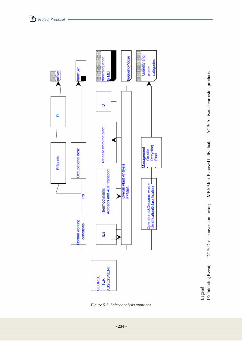
Project Proposal
- 234 -
Leg
end
IE:
Init
iati
ng
Even
t;
DC
F:
Do
se c
onver
sion f
acto
r;
M
EI:
Most
Expose
d i
ndiv
idual
;
A
CP
: A
ctiv
ated
co
rro
sio
n p
rod
uct
s
Figure 5.2: Safety analysis approach
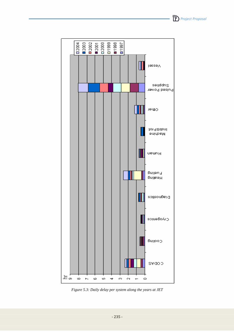
Project Proposal
- 235 -
Figure 5.3: Daily delay per system along the years at JET
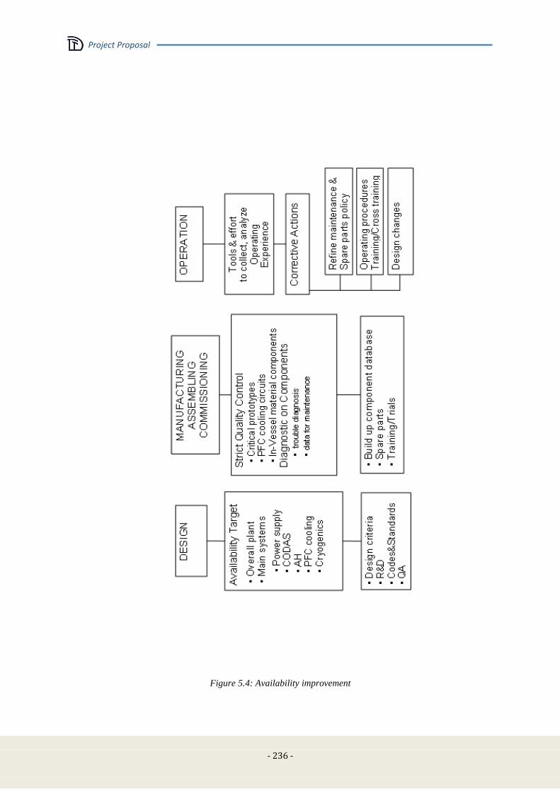
Project Proposal
- 236 -
Figure 5.4: Availability improvement
Project Proposal
- 237 -
5.3 Site assessment
In this section the problem of the site is analyzed from several points of view. The section discusses
the various aspects of the problem and specifically analyzes a well defined and justified choice, albeit
open to any possible well suited alternatives.
The choice of the site should take into account the role of DTT as “European facility” [5.5]. In this
view the accessibility and attractiveness for people (researchers, scientists, engineers) that will support
the project/construction and operational activity from many European (and not) countries, providing
an important beneficial impact also on the scientific and technical performance, has been considered.
On the basis of these considerations, the ENEA Frascati Research Center results to be the natural
candidate. More than fifty year ago first experimental activities on plasma research started in Frascati
Center. At the beginning linear and small toroidal devices were built then in 1976 the Frascati
Tokamak (FT) produced its first plasma and in 1990 the Frascati Tokamak Upgrade (FTU) started
plasma operations. FTU was classified as nuclear device and the licensing procedure took into account
the possibility to use tritium trace in the experiments so that the site meets all the safety regulation
requirements for DTT.
Here following in this section, the Frascati Site of ENEA [5.6]-[5.8] is considered and its capability to
meet the various technical requirements is verified as assessment of the feasibility and the robustness
of the solution.
However any possible alternative site can be easily analyzed and compared on the basis of the
assessment procedure here described.
5.3.1 Requirements
In this section the requirements and constraint imposed by the DTT design on the site are discussed.
Presently the main DTT characteristics are defined but a number of specific technical choices are still
under discussion; then the figures here reported have to be assessed in the future, according to the
general DTT design choices.
Buildings and open spaces requirements
In the following tables, the main characteristics of the buildings and open space required for the DTT
devices are listed and described.
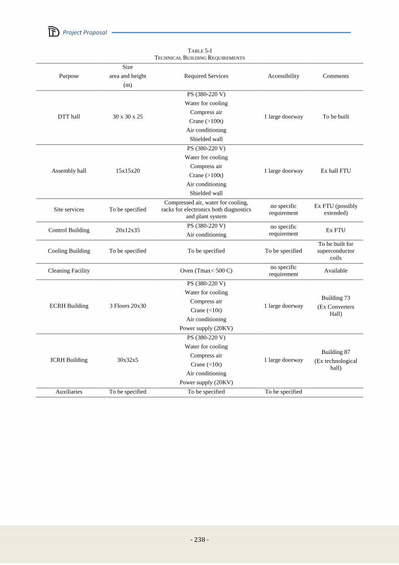
Project Proposal
- 238 -
TABLE 5-I
TECHNICAL BUILDING REQUIREMENTS
Purpose
Size
area and height
(m)
Required Services Accessibility Comments
DTT hall 30 x 30 x 25
PS (380-220 V)
Water for cooling
Compress air
Crane (>100t)
Air conditioning
Shielded wall
1 large doorway To be built
Assembly hall 15x15x20
PS (380-220 V)
Water for cooling
Compress air
Crane (>100t)
Air conditioning
Shielded wall
1 large doorway Ex hall FTU
Site services To be specified
Compressed air, water for cooling,
racks for electronics both diagnostics
and plant system
no specific
requirement
Ex FTU (possibly
extended)
Control Building 20x12x35 PS (380-220 V)
Air conditioning
no specific
requirement Ex FTU
Cooling Building To be specified To be specified To be specified
To be built for
superconductor
coils
Cleaning Facility Oven (Tmax< 500 C) no specific
requirement Available
ECRH Building 3 Floors 20x30
PS (380-220 V)
Water for cooling
Compress air
Crane (<10t)
Air conditioning
Power supply (20KV)
1 large doorway
Building 73
(Ex Converters
Hall)
ICRH Building 30x32x5
PS (380-220 V)
Water for cooling
Compress air
Crane (<10t)
Air conditioning
Power supply (20KV)
1 large doorway
Building 87
(Ex technological
hall)
Auxiliaries To be specified To be specified To be specified

Project Proposal
- 239 -
TABLE 5-II
TECHNICAL OPEN SPACE REQUIREMENTS
Purpose Size area (m2) Required Services Accessibility Comments
Power supplies 150x80 Water for cooling standard Available space in Frascati
Site
Cooling tower Not critical Not critical standard ----
Electrical Power Substation 100x50 Not critical standard Upgrading of existing
substation
Technical service requirements
In the following tables, the main services required in the site (and their characteristics) are listed and
described.
Electric power
TABLE 5-III
ELECTRIC POWER DEMAND
PF
System
PF
TF
System
TFS
Additional
power
Ad
Auxiliary
Power
Au
Required Power
RP =
PF+TF+Ad+Au
Total Power Demand
TPD = RP sf
Safety factor sf= 10%
Active Power
P [MW] 40 2 125 90 257 283
Presently at the Frascati Center the available electric power is limited to 50 MVA.
The improving is feasible in cooperation with TERNA (Italian company for transport and delivery of
electrical energy [5.9]). The solutions are based on the following elements:
Voltage 150 or 380 KV
Distance about 15 Km
Cost to be evaluated (not included here, because it could be a regional facility)
Cooling water
TABLE 5-IV
NON DE-MINERALIZED WATER DEMAND
Component Average Flux (l/s) Comments
TF System To be specified
PF System To be specified
ECRH System 476
432 for all gyrotrons
24l/s for all power supplies
20l/s for all transmission lines
ICRH System 450 Total (generators+lines+power supplies)
Divertor To be specified
Vacuum vessel To be specified
Diagnostics To be specified
TOTAL 927
To be noted: possible demand of demineralized water requires suitable machinery typically devoted to
specific component of DTT.
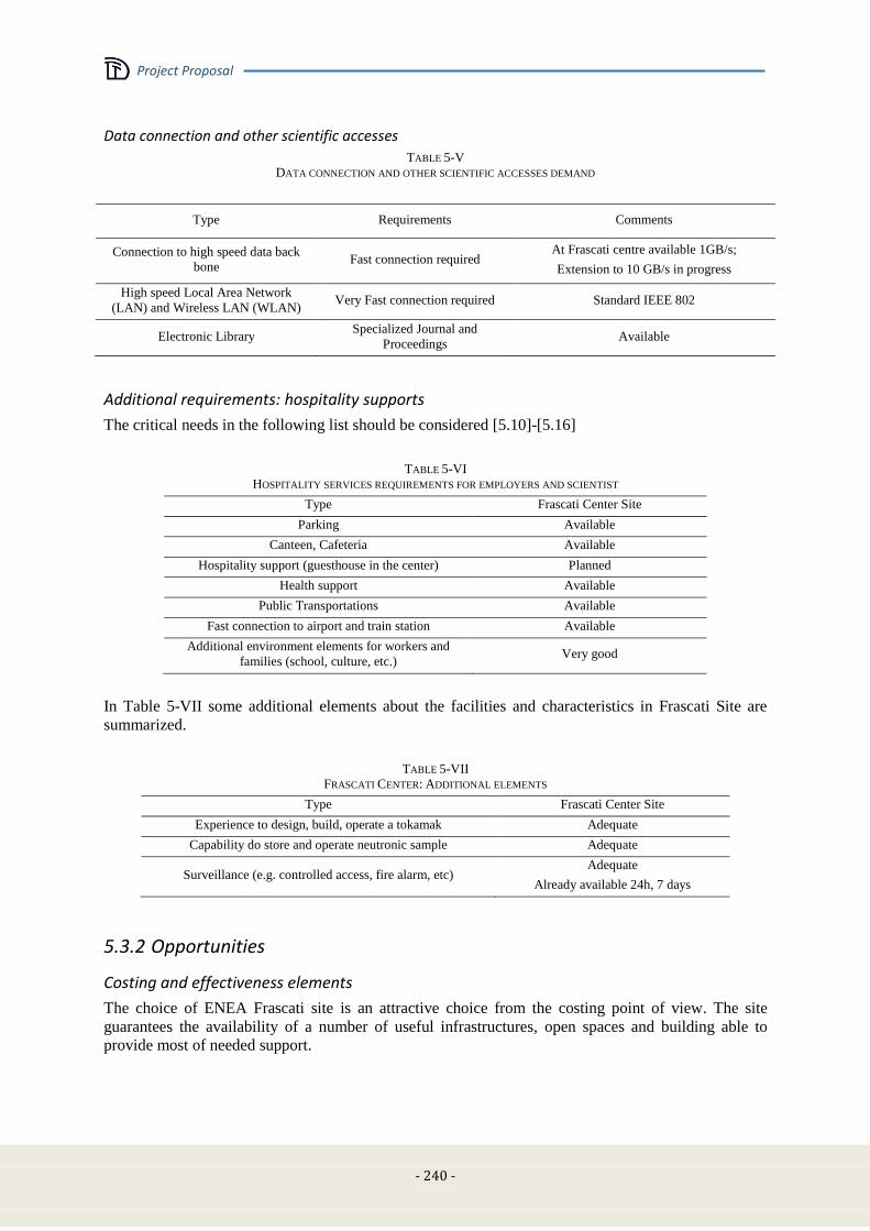
Project Proposal
- 240 -
Data connection and other scientific accesses
TABLE 5-V
DATA CONNECTION AND OTHER SCIENTIFIC ACCESSES DEMAND
Type Requirements Comments
Connection to high speed data back
bone Fast connection required
At Frascati centre available 1GB/s;
Extension to 10 GB/s in progress
High speed Local Area Network
(LAN) and Wireless LAN (WLAN) Very Fast connection required Standard IEEE 802
Electronic Library Specialized Journal and
Proceedings Available
Additional requirements: hospitality supports
The critical needs in the following list should be considered [5.10]-[5.16]
TABLE 5-VI
HOSPITALITY SERVICES REQUIREMENTS FOR EMPLOYERS AND SCIENTIST
Type Frascati Center Site
Parking Available
Canteen, Cafeteria Available
Hospitality support (guesthouse in the center) Planned
Health support Available
Public Transportations Available
Fast connection to airport and train station Available
Additional environment elements for workers and
families (school, culture, etc.) Very good
In Table 5-VII some additional elements about the facilities and characteristics in Frascati Site are
summarized.
TABLE 5-VII
FRASCATI CENTER: ADDITIONAL ELEMENTS
Type Frascati Center Site
Experience to design, build, operate a tokamak Adequate
Capability do store and operate neutronic sample Adequate
Surveillance (e.g. controlled access, fire alarm, etc) Adequate
Already available 24h, 7 days
5.3.2 Opportunities
Costing and effectiveness elements
The choice of ENEA Frascati site is an attractive choice from the costing point of view. The site
guarantees the availability of a number of useful infrastructures, open spaces and building able to
provide most of needed support.
Project Proposal
- 241 -
Conclusion
The requirements to provide a fully satisfying answer to all the technical questions of the DTT design
have been assessed and the final choice of the site will be a trade-off among the possible sites on the
basis of the lowest impact of the required infrastructures on the project cost.
Presently the Frascati center meets all the technical and hospitality requirements except for the
electricity power. However the connection is fully technically feasible.
5.4 Cost, manpower and time schedule
5.4.1 Cost analysis: general
The realization of the DTT project is a top priority for the European research community, since it
represents an important step towards the realization of a DEMO reactor.
A reliable assessment of the costs of the project is then a crucial component of the design proposal.
Aim of this section is to provide a budgetary but fairly accurate analysis of the expected costs, in order
to calibrate the financial effort needed for the implementation of the project. For this reason all the
quoted costs are based, either on previous well assessed projects (i.e. the heating systems) or on
quotation given by the Italian industrial system.
The cost analysis includes the following aspects:
Cost of the investment
The breakdown of the capital costs is referred to the main components of the plant.
In the present version of the design proposal an overall quotation of each component is provided.
The investments analysis takes into account the following main aspects and cost items:
Procurement costs. The complexity of the plant implies a strong involvement of the industry.
Based on the engineering design, specific call for tenders shall be launched, following the
European rules. The competitiveness of the European industry is guaranteed by the results of
the tenders for ITER.
Civil works on the experiment site. Whichever is the site for the experiment, the construction
of new buildings as well as the adaption of the existing ones is required. The quotation shall
be done once the site is selected and the layout of the buildings is finalized. Here we report the
cost for the Frascati site.
Electrical substation. The huge amount of electrical (active and reactive) power requires an
almost dedicated HV/MV substation. As for the civil works, this cost is strongly dependent on
the site selection. . Here we report the cost for the Frascati site.
Connection to the HV grid. This cost item is even more site dependent. In some sites a
connection to the HV line may be not required, whereas in some other cases the construction
of a new HV line cannot be avoided. In any case this could be a regional facility.
Assembly and testing on site. As far as possible, most of the components shall be delivered
fully assembled and tested at the factory.
Contingency. The construction of the facility shall last for some years, implying consideration
of contingency. Given the large European experience in realising Tokamak facilities, this cost
item is provisionally fixed in the amount of 5% on the total investment cost.
Engineering design. The engineering design, at care of the project team, is addressed to the
preparation of the technical specification of the components to be procured. It is expected that
this cost item (e.g. acquisition of design tools) is negligible with respect to the total investment
cost. The more specific engineering design costs for the components, as well as R&D, shall be
part of the procurements costs and then included in the related tenders.
Licensing. It is assumed that the site selected for the projects (Frascati ENEA Lab, as a
possible reference choice) has already obtained licenses of the same type in the past so that the
licensing cost can be expected negligible.

Project Proposal
- 242 -
Costs for the operation
The DTT project is conceived as a facility for testing various divertor concepts and materials. For this
reason the cost for the operation is not considered in the present version of the design proposal.
Cost of manpower
The implementation of the project requires the establishment of a project team, most of which residing
on site. During the construction phase of DTT, the activity of the project team includes design
activities, management of the project, follow up of the procurements, assembly and testing on site.
5.4.2 Cost analysis: breakdown of the investment
The breakdown of the capital costs is made in two levels.
The cost breakdown of some major components is reported hereafter (see Table 5-VIII-Table 5-X).
Then the global data are summarized in the Table 5-XI.
Load assembly
The costs of the main components of the basic machine are estimated by a direct evaluation performed
enquiring European firms already working on fusion activities for ITER large components:
In Table 5-VIII the main cost items are reported.
TABLE 5-VIII
BREAKDOWN OF THE INVESTMENT: LOAD ASSEMBLY
TF Coils SC cable 50 M€
winding 20 M€
casing 15 M€
TF Coils Total 85 M€
PF Coils SC cable 33 M€
winding 10 M€
rings 2 M€
PF Coils Total 45M€
Vacuum Vessel
including detailed engineering design,
industrial R&D, manufacturing and assembly
on site of the wall and ports
25 M€
Cryostat
including detailed engineering design,
industrial R&D, manufacturing and assembly
on site
5 M€
Divertor
including detailed engineering design,
industrial R&D, manufacturing and assembly
on site
30 M€
Layout including storage, logistics, cables, pipes,
instrumentation, etc. 9 M€
Assembly on
site
including lifting and transportation facilities,
mounting tools, etc. 10 M€
Grant Total 209 M€
Magnet power supplies
The cost of the power supply for the TF and PF magnets is estimated by a direct industrial evaluation
and, in addition, scaling the costs of the power supplies for JT60 SA and ITER. The main cost items
include the AC/DC converters for the TF coil system (6 M€), the CS coils (24 M€) and the PF coils
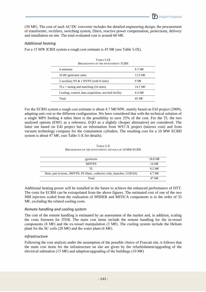
Project Proposal
- 243 -
(30 M€). The cost of each AC/DC converter includes the detailed engineering design, the procurement
of transformer, rectifiers, switching system, filters, reactive power compensation, protections, delivery
and installation on site. The total evaluated cost is around 60 M€.
Additional heating
For a 15 MW ICRH system a rough cost estimate is 45 M€ (see Table 5-IX).
TABLE 5-IX
BREAKDOWN OF THE INVESTMENT: ICRH
4 antennas 4.3 M€
16 RF generator units 12.8 M€
2 auxiliary PS & 1 HVPS (with 8 units) 9 M€
TLs + tuning and matching (16 units) 14.5 M€
Cooling, control, data acquisition, test bed facility 4.4 M€
Total 45 M€
For the ECRH system a rough cost estimate is about 4.7 M€/MW, mainly based on E4J project (2009),
adapting unit cost to the different configuration. We have considered that with the technical solution of
a single MPS feeding 4 tubes there is the possibility to save 25% of the cost. For the TL the two
analysed options (EWG as a reference, EQO as a slightly cheaper alternative) are considered. The
latter not based on E4J project but on information from WS7-X project (mirrors cost) and from
vacuum technology company for the containment cylinders. The resulting cost for a 10 MW ECRH
system is about 47 M€, (see Table 5-X for details).
TABLE 5-X
BREAKDOWN OF THE INVESTMENT: DETAILS OF 10 MW ECRH
gyrotrons 18.8 M€
MHVPS 14 M€
TL 9.5 M€
Rem. part (cryom., BHVPS, PS filam., collector coils, launcher, CODAS) 4.7 M€
Total 47 M€
Additional heating power will be installed in the future to achieve the enhanced performance of DTT.
The costs for ECRH can be extrapolated from the above figures. The estimated cost of one of the two
NBI injectors scaled from the realization of SPIDER and MITICA components is in the order of 35
M€, excluding the related cooling costs.
Remote handling and cooling system
The cost of the remote handling is estimated by an assessment of the market and, in addition, scaling
the costs foreseen for ITER. The main cost items include the remote handling for the in-vessel
components (8 M€) and the ex-vessel manipulation (3 M€). The cooling system include the Helium
plant for the SC coils (20 M€) and the water plant (6 M€).
Infrastructure
Following the cost analysis under the assumption of the possible choice of Frascati site, it follows that
the main cost items for the infrastructure on site are given by the refurbishment/upgrading of the
electrical substation (15 M€) and adaption/upgrading of the buildings (10 M€)
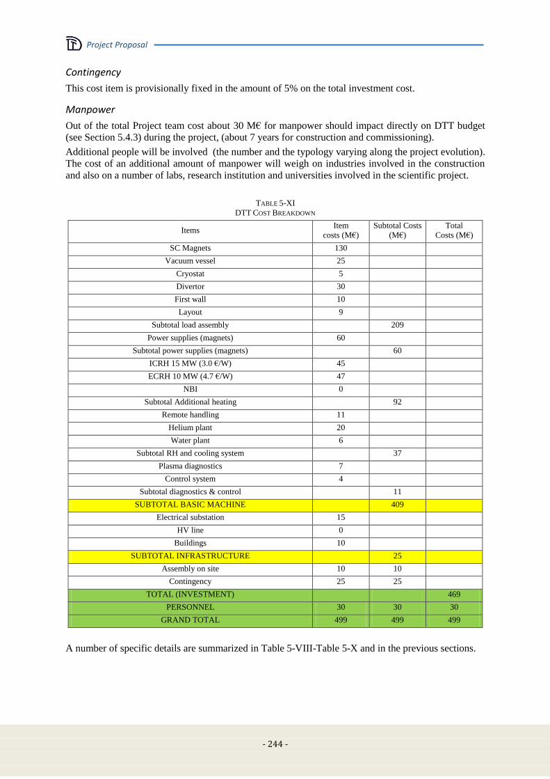
Project Proposal
- 244 -
Contingency
This cost item is provisionally fixed in the amount of 5% on the total investment cost.
Manpower
Out of the total Project team cost about 30 M€ for manpower should impact directly on DTT budget
(see Section 5.4.3) during the project, (about 7 years for construction and commissioning).
Additional people will be involved (the number and the typology varying along the project evolution).
The cost of an additional amount of manpower will weigh on industries involved in the construction
and also on a number of labs, research institution and universities involved in the scientific project.
TABLE 5-XI
DTT COST BREAKDOWN
Items Item
costs (M€)
Subtotal Costs
(M€)
Total
Costs (M€)
SC Magnets 130
Vacuum vessel 25
Cryostat 5
Divertor 30
First wall 10
Layout 9
Subtotal load assembly
209
Power supplies (magnets) 60
Subtotal power supplies (magnets)
60
ICRH 15 MW (3.0 €/W) 45
ECRH 10 MW (4.7 €/W) 47
NBI 0
Subtotal Additional heating
92
Remote handling 11
Helium plant 20
Water plant 6
Subtotal RH and cooling system
37
Plasma diagnostics 7
Control system 4
Subtotal diagnostics & control
11
SUBTOTAL BASIC MACHINE
409
Electrical substation 15
HV line 0
Buildings 10
SUBTOTAL INFRASTRUCTURE
25
Assembly on site 10 10
Contingency 25 25
TOTAL (INVESTMENT)
469
PERSONNEL 30 30 30
GRAND TOTAL 499 499 499
A number of specific details are summarized in Table 5-VIII-Table 5-X and in the previous sections.

Project Proposal
- 245 -
5.4.3 Cost analysis: manpower
The implementation of the project requires the establishment of a project team along the duration of
about 7 years.
The cost analysis includes an estimation of the personnel cost up to the start of the operation. In
personnel cost we include only the extra (not already working within the Italian Association)
personnel cost.
For a preliminary cost evaluation it is assumed a reference ppy cost of 100 k€ (including gross salary,
social and security cost, overheads in the measure of 25%).
The tasks of the project team are described in Table 5-XII.
The composition and the size of the team vary during the various phases of the project. An average
number of about 120 people is expected (see Section 5.4.5).
TABLE 5-XII
MANPOWER
Activity Manpower effort
Detailed engineering design. (including finalization and optimization of the
design, with the aim of preparing the technical specification of the procurements) about 60 ppy
Follow up procurements contracts about 30 ppy
S/T management and leadership. about 50 ppy
Assembly and installation. about 80 ppy
Testing and commissioning. about 50 ppy
Administration. about 30 ppy
5.4.4 Cost analysis: operation
As outlined in the introduction, these operation costs are beyond the scope of the project proposal.
5.4.5 Cost analysis: human and financial resources
The implementation of the project can take benefit from the existence of vast and well varied technical
and scientific community currently working in fusion research, at European and Italian level. In
particular the size of the Italian community is the range of 500 professionals. Therefore the amount of
human resources needed for the project is definitely compatible with the availability of skilled and
qualified personnel.
From the financial point of view, the project can rely on various potential sources. In particular:
Juncker's plan (EFSI: European Fund for Strategic Investments) which will provide the major
part of the budget
National and regional funds
EUROfusion
In kind contributions from fusion labs
Re-use of already existing devices and infrastructures
5.4.6 Timeline of the construction
The nominal duration of the project, up to the start of the exploitation phase is determined in about 7
years (6 for construction and 1 for commissioning), starting from the date the go ahead decision. Note
that in the case of getting the final approval within early autumn 2015, the first tender could be
completed around the end of 2016.

Project Proposal
- 246 -
The timeline for the procurements includes the following phases:
Finalization of the engineering design
Preparation of the technical specification for the calls for tender
Construction, assembly and testing at factory
Delivery, Assembly and testing on site
Installation and commissioning
The rate of expenditure is rather low in the first two years, then rapidly increases up to a maximum in
the third/fourth year and decreases in the last year, as illustrated in Table 5-XIII.
5.5 Project management
5.5.1 General
It is assumed that the project can be managed with a wide level of autonomy, in order to guarantee the
necessary maximum efficiency for a robust and fast implementation of the project. In particular, all
technical choices shall be taken at project level, as well as the use of the financial budget for
procurements. The project is implemented by a project team, established at European level, with
contributions coming from European fusion laboratories interested to the exploitation of the facility.
The high level governance and control of the DTT Project is outside the scope of the present project
proposal.
5.5.2 Organization of the project
The general organization chart of the project is shown in Figure 5.5. Here it follows a description of
main roles and responsibilities.
Project Leader (PL)
The PL is given full authority to take all technical decisions for the best interest of the project. He is
then responsible for the execution of the project.
Being responsible for the entire project, the PL has to be informed in advance for advice on all
relevant technical points and documents. To this purpose an efficient web based internal
communication system shall be established.
The PL is free to adopt all measures (including nomination of experts, ad hoc groups, delegates on
specific matters, etc.) he retains useful for the best implementation of the project.
The PL signs off for approval all major procurements orders.
The PL (directly or with his nominee) chairs all selection boards for recruitment of personnel for the
project team (with the exclusion of the members of the EPB).
On an annual basis, the PL shall prepare an activity report for the past year as well as an activity plan
for the current year.
Executive Project Board (EPB)
The EPB, which will meet at least once a month, supervises all technical aspects of the project,
resolves technical issues with the aim to serve the best overall interest of the project, supports the
Project Leader (PL) in all matters he submits to the EPB.
The EPB is collectively responsible for elaborating solutions involving constraints (financial or
otherwise), to problems that need to be submitted to governance.
However the final decision on the implementation of any action is up to the PL
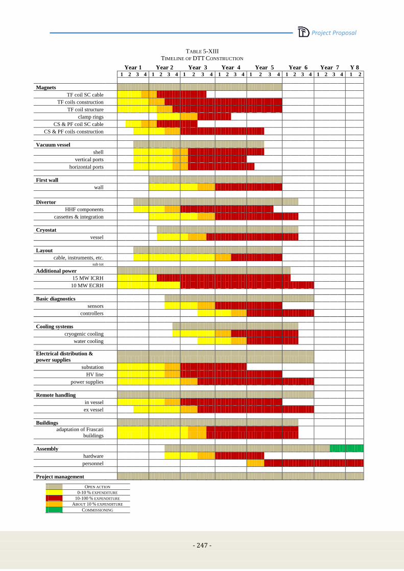
Project Proposal
- 247 -
TABLE 5-XIII
TIMELINE OF DTT CONSTRUCTION
Year 1 Year 2 Year 3 Year 4 Year 5 Year 6 Year 7 Y 8
1 2 3 4 1 2 3 4 1 2 3 4 1 2 3 4 1 2 3 4 1 2 3 4 1 2 3 4 1 2
Magnets
TF coil SC cable
TF coils construction
TF coil structure
clamp rings
CS & PF coil SC cable
CS & PF coils construction
Vacuum vessel
shell
vertical ports
horizontal ports
First wall
wall
Divertor
HHF components
cassettes & integration
Cryostat
vessel
Layout
cable, instruments, etc.
sub tot
Additional power
15 MW ICRH
10 MW ECRH
Basic diagnostics
sensors
controllers
Cooling systems
cryogenic cooling
water cooling
Electrical distribution &
power supplies
substation
HV line
power supplies
Remote handling
in vessel
ex vessel
Buildings
adaptation of Frascati
buildings
Assembly
hardware
personnel
Project management
OPEN ACTION
0-10 % EXPENDITURE
10-100 % EXPENDITURE
ABOUT 10 % EXPENDITURE
COMMISSIONING

Project Proposal
- 248 -
Scientific Advisory Board (SAB)
The SAB, which will meet at least quarterly, is made by senior experts covering the whole range of
competences needed for the implementation of the project.
None of the members of the SAB is directly involved in the project.
The SAB gives advice to the PL to the EPB on all scientific matters requiring a critical assessment,
and controls the progress of the Project
Administration (ADM)
The ADM department deals, taking the corresponding responsibility, with the matters indicated in the
organization chart.
The ADM holds, maintains and manages an adequate accounting system for all expenditures of the
project. On an annual basis, the ADM shall prepare a duly commented financial report.
The Head of the ADM department is member of the EPB.
Project Areas
The technical implementation of the project is subdivided in several project areas (as indicated in the
organization chart), each of them lead by responsible Project Area Leader (PAL)-
Central Integration Office (CIO)
The Central Integration Office (CIO) is a special project area acting, under the direct responsibility of
the PL (or his nominee), who takes care of the full integration of any part of the Project.
Figure 5.5: DTT Organizational Chart
5.6 Socio-economic aspects
An "Economic-Social Impact Analysis" (ESIA) of a scientific project is an essential tool to take the
final decision of financing and, in addition, to orient the project in the best way.
Project Proposal
- 249 -
In fact, behind the purely scientific purposes, a scientific research program could be also a "best social
practice" depending on the consistency and the quality of its impact in economics (both local and non
local), industry, knowledge transfers, employment and work amount. Therefore it could be a good
opportunity to enrich and multiply the positive effects of financing.
The methods of an ESIA can be very different, depending on the characteristics of the project
(national or international, pure research applied or industrial, medium or long-term consistency of
financing, etc.).
They still have to consider the impacts
Direct: orders for services and products, increase of employment, and so on
Indirect: orders among companies, purchases of inputs, services requested by the employees
and their families, and so on
Induced: change in household incomes, purchase of labor, and so on.
It is not easy to estimate these items. A widely used tool comes from considering similar experiences
made in the past and bringing them back to the characteristics of actual case. Few are the data that can
be measured directly, the majority (which the sense of satisfaction of employees, the ability to
integrate the territory, etc.) are difficult to quantify. Among those measurable we can mention, by way
of example:
Output of Business Activity: the increased output of goods and services in economy,
Employment: jobs created, increased and/or supported,
Earning: additional earning due to the project.
The economic evaluation of a project like the DTT (Divertor Tokamak Test) facility is particularly
complex both for the specificity of the experiment and because of the difficulty of finding similar
examples of comparison.
Here, when the case, the JET project is used to gain information and forecast possible impacts. The
DTT project is far in time (about 40 years from JET) and its site is still not defined; however, the JET
appears to be comparable from the point of view of scientific area and of the financial effort required.
In addition, some further trends are looked for analyzing same more recent data coming from ITER
experience.
Short, medium and long term benefit of the project
It is a well consolidated experience that the realization and the following operations of big
international research centres have a very large and positive socio-economic impact on the hosting
territory.
Among the national and international examples of advanced scientific activity in Fusion Technology,
we can refer to the National laboratories (ENEA, CNR) in the Frascati and Padua and, in addition, the
international experiments in Oxford (JET). More recently experiences are in progress related to the
final designing and construction in ITER Cadarache (France).
These large scientific infrastructures give the opportunity to use the very high level of developed
knowledge as synergetic flywheel for the global technical and economical grow of the surrounding
territory.
In the years 1993-95 the Oxford Brooks Universities carried out a deep analysis of the impact that the
European JET experiment on fusion had produced on the Oxfordshire, after about 15 years of
operations.
Similar studies were carried out in analyzing a possible allocation of ITER in Italian sites [5.17].
All the data converge in indicating the strong impacts of such decisions on the hosting territory.
Occupational impact
The total amount of people involved for the laboratory operation will change during the life of the
experiment, depending on the specific activity in progress.
Project Proposal
- 250 -
Construction. The budget plan includes 30 M€ for personnel (see Section 5.4.3). A significant fraction
of that will be personnel of very high scientific, technological and administrative level and the
remaining part would be staff dedicated to service activities. In addition, it should be taken into
account that there is also an occupational impact related to the procurements and the on-site activities.
Operation. The expected number of persons involved during the operations is similar to other medium
size tokamaks in Europe for about 20 years. During this phase there will be permanent needs of
consumables and maintenance operations, strongly involving companies on the territory, which will
further increase the occupation levels.
Industrial activities
The total amount of industries both in Europe and in local territory will be strong and qualified. Its
profile in time will depend on the specific activity in progress.
Construction. Strong involvement of the best industries in Europe is expected. In addition, during this
phase there will also be a very strong involvement of small and medium size local companies, mainly
in the mechanical, electronic and electric sectors; these companies will be involved in the realization
of a large fraction of small size part of the plant for a big fraction of the total investment.
Regarding the realization of the plant it is possible to expect a direct and significant fall back on the
hosting territory (for the buildings, the water needs, the electrical grid, …). The involvement profile
will be more or less constant along the years.
Operation. DTT is a test facility. Therefore a number o upgrading is expected involving a number of
high tech industries in Europe. Moreover, during this phase there will be permanent needs of
consumables and maintenance operations, strongly involving companies on the territory, so as to
further increase the occupation levels.
Additional impacts
On top of that, the continuous presence at the Laboratory of an International scientific staff has to be
added. On the basis of the Brooks University evaluation about the JET experience, this presence will
cause on the host territory a spin-off of some tens of MЄ per year in terms of guest family life and
additional items as lodging, transport, restaurants, etc.
Innovation and knowledge transfer
The experience gained in supplying high-tech research has a huge return in the development of
technological expertise of companies. Many companies thanks to such experiences have been able to
make a quantum leap.
For example, limiting ourselves to the frame of Italian industries, those involved in ITER construction
are important examples of industrial good practices in improving the technology level by means of
scientific challenges [5.18]-[5.19]
Quite interesting is also the capability of scientific experience in pushing cooperation among
companies: a very interesting example is just the Italian Consortium for Applied Superconductivity
(ICAS) of which ENEA is a partner.
DTT will be a powerful attractor and amplifier of technical and scientific knowledge.
In addition, the cooperation among laboratories and universities is one of the more qualifying
experience the most advanced scientific activities. As a matter of fact the possibility of involving
researchers and students, to enable collaboration with university laboratories or to compare opinions
and theories is an additional return effect of exceptional value.
5.7 References [5.1] IAEA Safety Requirements GS-R-3 (2006) – “The Management System for Facilities and activities”
[5.2] Decreto Legislativo del Governo 17 marzo 1995 n° 230 e successive modificazioni (dal D.Lgs. 26
maggio 2000, n.187; dal D.Lgs. 26 maggio 2000, n. 241; dal D.Lgs. 9 maggio 2001, n. 257; dal D.Lgs.
Project Proposal
- 251 -
26 marzo 2001, n.151; dalla Legge 1 marzo 2002, n. 39 "Attuazione delle direttive 89/618/Euratom,
90/641/Euratom, 92/3/Euratom e 96/29/Euratom in materia di radiazioni ionizzanti.")
[5.3] S. Ciattaglia et Al. ‘’Availability of the present fusion device’’, 21st SOFE 2005 1-4244-0150-
X/06/$20.00 (C) IEEE
[5.4] T.Pinna et Al. ‘’ Fusion component failure rate database (FCFR-DB)’. Fusion Engineering and Design
81 (2006) 1391–1395
[5.5] Romanelli F., et al., Fusion Electricity - A roadmap to the realisation of fusion energy. EFDA
November 2012. www.euro-fusion.org/wpcms/wp-content/uploads/2013/01/JG12.356-web.pdf.
[5.6] http://www.enea.it/en/
[5.7] http://www.enea.it/it/centro-ricerche-frascati and http://www.enea.it/en/where-we-are/research-centres-
and-laboratories/frascati-research-centre
[5.8] http://www.enea.it/en/where-we-are/research-centres-and-laboratories/frascati-research-centre
[5.9] http://www.terna.it/Default.aspx?tabid=101
[5.10] http://www.aslromah.it/cittadino/ospedali/frascati.php and
http://www.aslromab.it/cittadini/servizi/stranieri/docs_stranieri/Inglese_guida%201.pdf
[5.11] http://www.comune.frascati.rm.it
[5.12] http://www.comune.roma.it/wps/portal/ and
http://www.comune.roma.it/PCR/do/jpsite/Site/home?request_locale=en
[5.13] https://www.autostrade.it/en/home
[5.14] http://www.trenitalia.com/tcom-en
[5.15] https://www.adr.it/web/aeroporti-di-roma-en-/pax-fco-fiumicino
[5.16] https://www.adr.it/web/aeroporti-di-roma-en-/pax-cia-ciampino
[5.17] G Borrelli et Al: Socio-Economic Impact of experimental Thermonuclear Fusion Plant ITER, ENEA,
Direzione Studi, 1999
[5.18] Sole 24 Ore 31-05-2015, p. 10-11
[5.19] ITER web site with tenders

Project Proposal
- 253 -
Chapter 6
CONCLUDING REMARKS
6.1 Background
Energy demand is expected to more than double by 2050 for the combined effect of the increase of
population and energy consumption per person in developing countries. Nuclear Fusion, the process
that powers the sun and the stars making life on Earth possible, is nowadays considered as one of the
most promising technologies for a climate-friendly energy source, which will contribute to meet the
growing global energy demand while providing long-term sustainability and security of supply so as to
replace fossil fuels.
With the recent formation of the EUROfusion Consortium, all EU fusion research laboratories jointly
drafted a detailed goal-oriented programme, published in “Fusion Electricity – A roadmap to the
realisation of fusion energy” (F. Romanelli, ISBN 978-3-00-040720-8), highlighting the ambitious
objective of the generation of electrical power by a Demonstration Fusion Power Plant (DEMO) by
2050.
The intermediate step to DEMO is ITER, a large-scale international scientific experiment under
construction in Cadarache, which aims to demonstrate the technological and scientific feasibility of
fusion energy. The scientific goal of the ITER project is to achieve Q ≥ 10, where Q is the ratio of
fusion power to input power. During its operational lifetime, ITER will test key technologies
necessary for the next step, DEMO, which will prove that it is possible to exploit fusion energy for
commercial use.
The EU fusion roadmap elaborates 8 strategic missions to tackle the main challenges in achieving this
overall goal. The need for a Divertor Tokamak Test (DTT) Facility is derived from Roadmap Mission
2: “Heat-exhaust systems”. At the edge of the plasma a thin (~ 1 cm) region of open magnetic field
lines is created – the Scrape-Off Layer (SOL) – through which charged particles and heat flowing out
of the core plasma are guided into a so-called Divertor where the plasma impinges on a material
surface (the divertor target plates). The parallel heat flux in the SOL region of ITER and DEMO is
expected to be even higher than sun’s surface.
Project Proposal
- 254 -
The development of a reliable solution for the power and particle exhaust in a reactor is recognised as
one of the major challenges towards the realisation of a nuclear fusion power plant. The current
strategy for power exhaust is to optimise the operation with a conventional, divertor based on detached
conditions, to be tested on the ITER. However the successful operation of conventional divertor
solution for DEMO has to further extensively exploited:
the present experiments operate with SOL conditions that are very different from those
expected in ITER and DEMO;
the simulations with the present SOL models and codes are not reliable when extrapolating to
DEMO conditions;
the stability of the detachment front has to be assessed for ITER and DEMO conditions;
there might be problems of integration with the core plasma, e.g., impurity contamination of
the core with consequent reduction of fusion performance;
the compatibility of very high plasma radiation fraction should be assessed.
To mitigate the risk that the conventional divertor solution that will be tested in ITER may not
extrapolate to DEMO, several alternatives are being investigated in present devices, such as the use
liquid metal plasma facing components and alternative magnetic divertor configurations. The role of
the DTT facility is to bridge the gap between today's proof-of-principle experiments and DEMO.
Within the European Road Map 60 M€ have been allocated for the DTT Project. The Italian
Government has recently offered an opportunity to acquire additional funding for a dedicated exhaust
facility. The proposal is among the projects submitted to the 315 billion Euro of Juncker's plan (EFSI:
European Fund for Strategic Investments) with a budget of 500 million Euro.
6.2 Summary
DTT is planned to be a facility entirely devoted to integrate Physics and Technology divertor problems
with sufficient flexibility to develop innovative divertor configurations bringing them to a sufficient
level of maturity by 2030 for a positive and well assessed decision on DEMO. The present DTT
device is conceived to be flexible enough to have the possibility to test both alternative magnetic
configurations and advanced divertor technology, e.g. liquid metals, in DEMO relevant conditions,
demonstrating an integrated exhaust scenario.
A key parameter, for a scaled experiment, is the ratio between the power across the separatrix and the
major radius, which should be achieved for a safe DEMO operation, i.e.15 MW/m. In addition, to
scale the divertor physics of a large machine five parameters should be fitted:
the temperature, Te
the normalized local collisionality, *=Ld/λei, where Ld is the divertor field length
the neutrals free path, normalized to SOL thickness, λ0/Δd
the normalized Larmor radius, *=ρi/Δd
the normalized plasma pressure, β
Since most of these parameters depend on the magnetic divertor topology, this DTT proposal has been
worked out to allow testing several different magnetic divertor topologies. By using a Kadomtsev-
Lackner approach (based on preserving the dimensionless parameters *, β, *R0.75
, Te) and taking
into account a budget limit of 500 M€, a machine with a major radius of R = 2.15 m, a toroidal field
BT = 6T and a plasma current IP = 6MA has been selected so as to guarantee the fulfillment of the DTT
objectives. The coupled edge and bulk code COREDIV has been used to verify the expected edge
performance, whereas the use of the simplified energy transport code METIS confirmed the expected
bulk plasma performance.
The plasma scenarios (including standard single null and advanced configurations) will satisfy the
following constraints:
minimum distance of 40 mm between the plasma last closed surface and the first wall, in order
to minimize the interaction between the plasma and the main chamber (the power decay length
at 6 MA is 2 mm);
plasma shape parameters similar to the present design of DEMO: R/a≈3.1, k≈1.76, <δ>≈0.35;

Project Proposal
- 255 -
pulse length of more than 100 s with a total stored flux of about 45Vs.
The above requirements addressed to the decision of using superconducting coils:
18 TF coils: Bpeak: 12.0 T, Bplasma: 6.0 T, 65 MAt;
6 CS coils: Bpeak: 12.5 T, k |N kI k| =51 MAt; available poloidal flux: 17.6 Vs;
6 PFcoils: Bpeak: 4.0 T, k |N kI k| =21 MAt .
The PF system also includes eight copper in-vessel coils:
two in-vessel coil for radial and vertical stabilization and control;
four out of six in-vessel coil for magnetic control of SOL and strike point sweeping.
The latter are aimed at tuning plasma equilibrium (determined by the external coils) with two poloidal
field null in the divertor region, from a situation where the flux lines are strongly flaring in front of the
divertor plates up to a situation with the poloidal field and its derivative very close to zero on a large
divertor region. All the features of DTT are conceived to be extrapolated in the DEMO configuration.
Also the presence of these set of internal coils is intended to be utilized to determine the optimal
position of the external PF coils in DEMO. In fact, once an “optimal” magnetic configuration will be
selected, it will be possible to optimize, in a DEMO design (where internal coils likely will not be
allowed), the position and the shape of the external poloidal coils capable to best reproduce such a
magnetic topology. The possibility to easily replace the divertor will allow to test different divertor
geometries and the most suitable plasma facing material (from Tungsten up to different liquid metals).
Particular attention will be dedicated to the diagnostics and control issues, especially those relevant for
plasma control in the divertor region, designed to be as compatible as possible with a DEMO-like
environment.
The basic vessel design is an all-welded single wall structure made of INCONEL 625. The 18 sectors
are joined by field welding. The maximum thickness of the shell is 35 mm, while the 5 ports per sector
are 25 mm thick. The ports are designed large enough to easily allow human being, remote handling
maintenance, and replacement of the internal main components (i.e. divertor modules, first wall
panels, heating systems antennas and mirrors…).
The first wall consists of a bundle of tubes armored with plasma-sprayed tungsten. The plasma facing
tungsten is 5 mm (apart from some specific zones where the thickness is 10 mm), the bundle of copper
tubes (coaxial pipes for cooling operation) is 30 mm thick, and the backplate supporting the tubes is 30
mm thick of SS316LN.
As far as additional heating and current drive are concerned, the system for the first DTT phase
includes 15 MW of ICRH and 10 MW of ECRH. NBI and ECRH are being considered as the main
candidates for a subsequent power upgrade, up to the ultimate target of 45 MW.
To be coherent with the European Fusion Road Map a DTT facility needs to be ready in the early
2020s, so as to be able to bring at least one alternative divertor strategy to sufficient level of maturity
by 2030 for a positive decision on DEMO. The present DTT proposal will require a period of about 7
years from the first tender up to the production of the first plasma; consequently, the proposed design
has been realized in a way to be able to issue the first tender during 2016, if the necessary budget will
be allocated. Even if DTT will not necessarily be subjected to all physical and technological
constraints present in DEMO (for instance there will be no use of tritium in DTT), any alternative
divertor solution proposed and tested in DTT should be applicable to DEMO plasma regimes, in terms
of integrated physics and technology.
The construction of DTT will also be beneficial because it would allow:
the development of high level technologies in several different fields;
the European Community (and to the hosting Country) to remain in a dominant technology
position with respect to the fast developing Countries;
a strong economical and cultural positive impact in the hosting territory;
the EU fusion community to gain experience by building and operating a European DEMO-
relevant machine in the next decades, remaining in a leading international position on the
Fusion Energy Road Map.

DTT Divertor Tokamak Test facility
Project Proposal
ISBN: 978-88-8286-318-0