
Distributed Building Automation Systems - DiVA Portal
88
Distributed Building Automation Systems -Implementing the BACnet communication protocol LARS HANSSON Master of Science Thesis Stockholm, Sweden 2008
-
Upload
khangminh22 -
Category
Documents
-
view
0 -
download
0
Transcript of Distributed Building Automation Systems - DiVA Portal

Distributed
Building Automation Systems
-Implementing the
BACnet communication protocol
LARS HANSSON
Master of Science Thesis
Stockholm, Sweden 2008


- I -
Distributed Building Automation Systems
-Implementing the
BACnet communication protocol
By
Lars Hansson
Master of Science Thesis MMK 2008:75 MDA334
KTH Industrial Engineering and Management
Machine Design
SE-100 44 STOCKHOLM

- II -

- III -
PREFACE
Writing this report is the final milestone of a journey that started in the year of 2003. It is the result of an urge
to gain more knowledge in the field of embedded control systems. It is also the final criterion for being
awarded a Master of Science degree at the Royal institute of technology in Sweden. I have chosen this subject
to utilize my previous experiences from a career within the field of Building Technology and combine it with
newly gained knowledge in embedded control systems.
I would like to take this opportunity to thank all of those who have supported me during this project.
Especially, I want to thank
My academic supervisor Martin Törngren who, despite a heavy workload, have contributed with a lot of
valuable feedback and help with this thesis.
My supervisors at Regin: Anders Ågren who have been supporting and supplying me with the adequate
software tools to be able to debug the implementation. Lars Matsson for helping me with code
optimization and the temporary fixes to produce a lean Regio firmware.
My friends Simon Vanan and Ulrika Aronsson for taking the time and energy to proofread this report.
Finally I would like to thank my wonderful wife Anna. Without you, none of this would have been possible.
Lars Hansson
Stockholm 2008-12-21

- IV -

- V -
Examensarbete MMK 2008:75 MDA334
Distribuerade fastighetsautomationssystem
En implementation av
kommunikationsprotokollet BACnet
Lars Hansson
Godkänt
2008-12-22
Examinator
Mats Hanson
Handledare
Martin Törngren
Bengt Eriksson
Uppdragsgivare
REGIN AB
Kontaktperson
Anders Ågren
SAMMANFATTNING
Fastighetsautomationssystem i kommersiella byggnader konstrueras ofta av olika installatörer som använder
sig av utrustning och komponenter från olika tillverkare. Avsaknaden av ett allmänt vedertaget standardiserat
kommunikationsprotokoll har resulterat i att ett antal olika standarder har utvecklats. Tillverkare av
fastighetsautomationssystem stödjer antingen något, några eller inga av dessa standarder, samtidigt som de
utvecklar egna kommunikationslösningar.
Regin, som tillverkar fastighetsautomationssystem, har planer på att införa stöd för ett öppet
kommunikationsprotokoll, speciellt utvecklat för fastighetsautomation – BACnet. Som ett steg i den
riktningen utlystes detta examensarbete, med syfte att undersöka möjligheterna att implementera BACnet i en
av deras produkter samt att generellt höja Regins kunskapsnivå inom området BACnet.
En litteraturstudie inom datorkommunikation och distribuerade system har genomförts för att identifiera
krav som är relevanta för fastighetsautomation. BACnet standarden visar sig ha stöd för många av de krav
som ställs på sådana system. Det finns dock begränsningar som måste beaktas om BACnet implementeras i
säkerhetskritiska system. Det är till exempel inte tillåtet att ha redundant kommunikationsinfrastruktur mellan
två BACnet noder.
BACnet (med begränsad funktionalitet) har implementerats och testats i en Regio rumsregulator. Vissa
funktioner har skalats bort för att koden skulle få plats i programminnet. Genom att optimera koden och att
använda en annan kompilator finns det dock goda möjligheter att utveckla en fullt funktionell
“BACnetifierad” Regio som en fortsättning av detta projekt.

- VI -

- VII -
Master of Science Thesis MMK 2008:75 MDA334
Distributed Building Automation Systems
-Implementing the
BACnet communication protocol
Lars Hansson
Approved
2008-12-22
Examiner
Mats Hanson
Supervisor
Martin Törngren
Bengt Eriksson
Commissioner
REGIN AB
Contact person
Anders Ågren
ABSTRACT
Building Automation Systems in commercial buildings are often designed and installed by different
contractors, using equipment and components from different manufacturers. The lack of an accepted
communication standard has resulted in a few different standards. Many manufacturers of building
automation systems only support one, a few or none of these standards, while developing proprietary system
solutions.
Regin, who develop such equipment, are planning to adopt an open communication protocol specially
designed for building automation - BACnet. As a step in that direction this thesis was announced with the
purpose to investigate the possibility to implement BACnet in one of their products and to gain more
knowledge of the BACnet protocol.
Literature covering computer communication and distributed systems has been reviewed and relevant
requirements that apply to building automation systems have been identified. The BACnet standard has
proven to support many of the requirements on such systems. However, there are some limitations that need
to be considered if BACnet is implemented in safety critical systems, e.g. redundant communication
infrastructure between two BACnet nodes is not allowed.
The BACnet communication protocol (with limited functionality) has been implemented and tested in a
Regio zone controller. Some of the original Regio features had to be compromised to fit the code in memory.
However, by optimizing the code and using another compiler there is a good possibility that a fully functional
“BACnetified” Regio can be developed as an extension of this project.

- VIII -

- IX -
TABLE OF CONTENT
1 Introduction ....................................................................................................................... 1
1.1 Background ........................................................................................................................................................ 1
1.2 Cross Pollination ............................................................................................................................................... 3
1.3 Building Automation Control NETwork ...................................................................................................... 4
1.4 Objective ............................................................................................................................................................ 5
1.5 Disposition of thesis ......................................................................................................................................... 5
1.6 Delimitations ...................................................................................................................................................... 6
2 Computer Communication ................................................................................................ 8
2.1 Connecting Computers .................................................................................................................................... 8
2.2 Networking ........................................................................................................................................................ 8
2.3 Addressing Nodes .......................................................................................................................................... 10
2.4 Access method ................................................................................................................................................ 10
2.5 Layering ........................................................................................................................................................... 11
2.6 Open Systems Interconnection ................................................................................................................... 11
2.7 Application to Application communication .............................................................................................. 13
3 Integrating Building Automation Systems ....................................................................... 15
3.1 Requirements .................................................................................................................................................. 15
3.2 Existing standardized communication protocols ...................................................................................... 16
4 The BACnet communication protocol ............................................................................. 19
4.1 Overview ......................................................................................................................................................... 19
4.2 BACnet Architecture ..................................................................................................................................... 20
4.3 Control devices are modeled as Objects .................................................................................................... 30
4.4 Objects are accessed through services ........................................................................................................ 31
4.5 Encoding ......................................................................................................................................................... 32
4.6 Conformance and Testing ............................................................................................................................ 32
5 Case Study - Requirement Analysis ................................................................................. 34
5.1 Sensing and Influencing the Room ............................................................................................................. 34
5.2 Available BACnet zone controllers on the market ................................................................................... 35
5.3 Regio Platform ................................................................................................................................................ 36
6 Development environment for the case study ................................................................. 38
6.1 Hardware (system) ......................................................................................................................................... 38
6.2 Hardware (Programmers) ............................................................................................................................. 39
6.3 Software development tools ......................................................................................................................... 39
6.4 Analysis and testing tools .............................................................................................................................. 40
6.5 Discussing the choice and limitations of lab equipment ......................................................................... 40
7 Case study - Synthesis, Design and Implementation ...................................................... 42
7.1 Strategy ............................................................................................................................................................ 42
7.2 Charting the prerequisites ............................................................................................................................. 43
7.3 Integration ....................................................................................................................................................... 44
7.4 Software Design ............................................................................................................................................. 46
8 Case study - Testing ......................................................................................................... 51
8.1 What is tested? ................................................................................................................................................ 51

- X -
8.2 How is it tested ............................................................................................................................................... 51
8.3 Test results ...................................................................................................................................................... 52
9 Analysis – Proof of concept.............................................................................................. 53
9.1 Literature review (Theoretical analysis) ...................................................................................................... 53
9.2 The Regio-BACnet Implementation (Case Study) ................................................................................... 54
10 Conclusions ...................................................................................................................... 56
10.1 Benefits with BACnet .................................................................................................................................... 56
10.2 Drawbacks with BACnet .............................................................................................................................. 56
10.3 Successful Implementation ........................................................................................................................... 56
11 Further work .................................................................................................................... 57
11.1 BACnet compatible zone controllers survey ............................................................................................. 57
11.2 Code optimization ......................................................................................................................................... 57
11.3 Interrupt driven Tx routine .......................................................................................................................... 57
11.4 Port project to Regins standard compiler .................................................................................................. 57
11.5 Extensive testing ............................................................................................................................................ 57
12 References ........................................................................................................................ 58
Appendix A (BACnet object descriptors) ............................................................................... 60
Appendix B (State transition diagrams) ................................................................................. 64
Appendix C (BACnet compatible controllers)........................................................................ 66
Appendix D (Project C-code file listings) .............................................................................. 69
Appendix E (Test results) ....................................................................................................... 70

- XI -
ABBREVIATIONS & ACRONYMS
ADC Analog to Digital Converter ANSI American National Standards Institute APDU Application Protocol Data Unit API Application Program Interface ASHRAE American Society of Heating, Refrigerating and Air-Conditioning Engineers BACnet Building Automation Controller Network BAS Building Automation System BIBB BACnet Interoperability Building Blocks BIP BACnet/IP BTL BACnet Testing Laboratories CPU Central Processing Unit CRC Cyclic Redundancy Check CSMA/CA Carrier Sense Multiple Access / Collision Avoidance CSMA/CD Carrier Sense Multiple Access / Collision Detection DA Destination Address DSAP Destination Service Access Point EOF End Of Frame HMI Human Machine Interface HVAC Heating Ventilation Air Conditioning IC Integrated Circuit ICE In Circuit Emulator IDE Integrated Development Environment IP Internet Protocol ISP In System Programmer ISR Interrupt Service Routine LAN Local Area Network LCD Liquid Crystal Display LLC Logical Link Control LSAP Link Service Access Point LSB Least Significant Bit MAC Media Access Control MCU Micro Controller Unit MIPS Million Instruction Per Second MPDU MAC layer Protocol Data Unit MS Master Slave MS/TP Master-Slave/Token-Passing MTU Maximum Transmission Unit NPDU Network layer Protocol Data Unit NRZ None Return to Zero NSAP Network Service Access Point OSI Open Systems Interconnection PCI Protocol Control Information PICS Protocol Implementation Conformance Statement SA Source Address SOF Start Of Frame SSPC Standing Standard Project Committee TCP Transport Control Protocol UART Universal Asynchronous Receiver/Transmitter WAN Wide Area Network

- XII -

INTRODUCTION
- 1 -
1 INTRODUCTION
Building Automation is an area within the automation industry. Building Automation System (BAS) is a name
for a collection of systems that are designed to handle common applications involved in automating and
controlling building technology, e.g. Heating Ventilation and Air Condition systems (HVAC). Common tasks
include lighting and climate control but there are also more safety critical systems, e.g. fire detection (see
Figure 1:1). Modern systems are rather sophisticated and provide functions for alarm handling remote
control, automated analysis of building performance with respect to energy consumption, runtime, service
requirements etc.
HVAC
Lighting
Lighting
Lighting
FIRE FIRE FIRE
Security Security
Figure 1:1 Building technology - A variety aspect
1.1 BACKGROUND
As technology evolves, more functions are implemented in BAS to realize the concept of “Intelligent”
buildings. The desire to share information between different systems often requires integration of networks,
or the housing of different manufacturer’s components in the same infrastructure. Although proprietary
systems sometimes are physically interconnected (as in Figure 1:2), they often lack the possibility to exchange

INTRODUCTION
- 2 -
information. This has proven to be a challenge for the developers of BASs and it calls for a standardized way
of communicating.
Proprietary domain Vendor Z
Proprietary domain Vendor Y
Proprietary domain Vendor X
A
C
BD
1 32 4
65 7
Router
Internet
a
c
bd
Figure 1:2 Interconnected BAS networks
1.1.1 STAKEHOLDERS
To clarify what kind of obstacles that are involved in creating open systems, some of the stakeholders need to
be identified. This discussion is a mixture of opinions from different people involved in this project, the
author’s experiences prior to his master studies and newly gained knowledge in the field. It is more of a
discussion, intended to reflect some of the problems involved in system integration, than THE truth. The
area of building automation has a few different stakeholders that to some extent share the same interests.
However, in some aspects their interests diverge.
1.1.1.1 COMMON FACTORS
All parties are in general interested in cost effective and functional solutions.
Manufacturers of products, e.g. programmable logic controllers, fire detection systems etc, are interested in
developing functional components and systems with good quality at a low cost.
Users/Building Owners want functional “easy to use” systems at low cost. They are more interested in the
Human Machine Interface (HMI) than the underlying technology.
Technicians and System Integrators are interested in “easy to install” cost effective products in order to
achieve a profitable margin.

INTRODUCTION
- 3 -
1.1.1.2 DIVERGING FACTORS
Some standardization obstacles have also been identified in this discussion. By delivering proprietary system
solutions, the manufacturer assures that it will have a business advantage in the procurement of the next
system, i.e. if the customer wants the systems to be integrated. Luckily, from an integration perspective, the
same argument that causes manufacturers to restrict access to their system serves as a sales argument. It
provides an edge to gain market cuts by marketing their products as being interoperable and thus
“integratable” with other manufacturer products.
1.2 CROSS POLLINATION
In order to gain some perspective in the area of integration and distributed systems in general, this section is a
digression from the building automation area. In this document a distributed system is defined as a set of two
or more nodes that utilizes a media (e.g. a communication bus) to provide and/or gain access to shared
resources. Although the factors that drive the evolution of technology differ between different industries, the
models of digital control systems and computer communication are the same. Stand alone CPUs with many
locally connected signals can often be replaced with distributed systems.
1.2.1 DISTRIBUTED SYSTEMS
The process industry paved the way for the introduction of distributed control systems during the mid and
late 1970s. The automotive industry adopted the concept some 10 years later [9] and the technology is now
widely spread within the area of embedded control systems. Common factors and obvious advantages with
distributed systems are reduced cabling, and more modular systems. Other advantages, that are more central
to the building automation industry, include avoiding redundant objects, e.g. sensors and human-machine
interfaces supplying the same or similar functions. The level of distribution in a system can be defined in
different ways, e.g. by determining how much data that is shared or how much distributed hardware there is.
Another way is to consider how decentralized the decision making is. Distributed functionality can simply
provide the transport of information/objects and thus make the operation on the data a local matter.
Alternatively, it can provide access to actual objects, e.g. an actuator or sensor, to a central CPU where the
control algorithms are executed.
1.2.2 TRANSLATE OR INTEGRATE
If systems that are being connected speak different languages there is a need for a standardized way of
communicating i.e. a protocol that stipulates what rules that the participants in the communication must
obey. There are different ways to interconnect such systems and some of these are presented here.

INTRODUCTION
- 4 -
1.2.2.1 GATEWAYS
A gateway is software, hardware, or both that is configured to interconnect two or more networks. Main
purpose is to forward messages between networks that utilize different communication protocols. Tasks may
include translating electrical characteristics and or the logical content of the messages in a network exchange
point. For more information see [20].
1.2.2.2 MIDDLEWARE
Middleware is a name for intermediate software that can be implemented on top of e.g. operating systems or
communication protocols [21]. One purpose can be to provide access to resources or services that might be
distributed and remote but through middleware appears to be local to the application. Another function can
be to hide the heterogeneity of various hardware components.
1.2.2.3 STANDARDIZED COMMUNICATION PROTOCOLS
An alternative to Middleware and Gateways is to integrate the same communication protocol in all nodes that
want to exchange information with each other. The Internet Protocol (IP) or the TCP/IP suite is a good
example of a standardized protocol stack.
1.3 BUILDING AUTOMATION CONTROL NETWORK
BACnet is a Standardized Communication Protocol, a nonproprietary communication solution derived from
a wide area of techniques that exist for integrating systems. It is a response to the need for integrating
components from different manufacturers in the same physical infrastructure, especially designed for the
building automation industry. It also provides simple internetworking capabilities to enable communication
over Wide Area Networks (WANs). A conceptual illustration of a BACnet is shown in Figure 1:3. An
overview of BACnet functionality and a detailed description of the structure are provided in separate sections
of this document.

INTRODUCTION
- 5 -
Proprietary domain Vendor Z
Proprietary domain Vendor Y
Proprietary domain Vendor X
A
C
BD
1 32 4
65 7
Router
Internet
a
c
bd
BA
Cnet
BACnet
BACnet
Figure 1:3 BACnet implementation connecting nodes A, B, 1, 2, 5, 6 and d
1.4 OBJECTIVE
AB Regin is considering implementing BACnet in their products and this thesis is intended to be a part of the
grounds for such a business decision. The objective for this project is to investigate, design and implement
BACnet communication capabilities in a commercial product used for regulating room temperature – Regio
midi.
1.5 DISPOSITION OF THESIS
The thesis is divided into two parts. First, a theoretical literature review is performed and summarized in
chapter 2 through 4. Secondly, the literature review is complemented with a more experimental case study
which is documented in chapters 5 through 8. The essence of the literature review and the result of the
implementation are analyzed and concluded in chapter 9 and 10.
1.5.1 LITERATURE REVIEW
The general intention with the literature review is to identify requirements on distributed building automation
systems and analyze how these requirements are accounted for in the BACnet standard. To facilitate the
implementation, computer communication and integration are also studied. These are the essential elements
of the literature review:
Computer communication and distributed systems in general are studied. Relevant parts, such as
hardware topologies and the OSI reference model are described in chapter 2.

INTRODUCTION
- 6 -
Requirements concerning distributed systems have been studied in general, particularly their importance
in building automation systems.
A few available communication protocols with the same design idea as BACnet (i.e. where the purpose is
to integrate different types of building automation hardware) have been analyzed.
The ANSI/ASHRAE standard 135-2004 [12] defining the BACnet protocol has been studied in detail
and relevant parts for this project are presented in Chapter 4
1.5.2 CASE STUDY
The goal of the case study is to integrate a communication protocol in parallel with the original functionality
of a zone controller. In order to achieve this, theory on computer communication and open systems
interconnection models are studied as a part of the literature review. In addition some scheduling theory is
applied to avoid interference with the operation system that is running the applications in the zone controller.
To be able to decide which parts of the BACnet protocol to implement, the environment in which zone
controllers are used is analyzed. A set of common functions and objects has been identified and modeled as
corresponding BACnet services and objects. These primitives are also used to determine what type of profile
classification is suitable for a Regio zone controller. This part of the thesis is documented in chapter 5.
Documentation on the hardware and applications in Regio has been reviewed. Estimations of the ability to
implement the desired BACnet profile are based on this review. BACnet communication is implemented in
the Regio zone controller by following this course of actions:
1. A BACnet open source C-stack is adapted to fit the Regio hardware.
2. An isolated BACnet implementation is built on the Regio hardware
3. The isolated BACnet stack is prepared to run in parallel with the Regio firmware
4. Regio firmware is prepared and down scaled to build under GCC compiler
5. The two code bases are migrated by integrating the modified BACnet stack with Regio firmware
As a proof of concept, some of the BACnet objects and services derived in chapter 5 are implemented during
this development phase and it is documented in chapter 7.
1.6 DELIMITATIONS
Due to limitations in time and resources the following delimitations from the objective, described in section,
1.5 has been made.
The section describing computer communication is only a brief overview of common principles.
Only BACnet like protocols with connection to the building automation industry have been reviewed.
Only parts of the BACnet standard that are relevant to the implementation are covered in detail. Some
parts that are considered to be of small or no interest for the application have been omitted.

INTRODUCTION
- 7 -
Physical requirements such as voltage levels or other electrical characteristics are included in this report
only as references to relevant standards.

COMPUTER COMMUNICATION
- 8 -
2 COMPUTER COMMUNICATION
In this section a brief description of the principals in computer communication is presented. It is not the
intention to cover the whole area, which is a huge subject for various research groups all over the world. The
purpose is merely to introduce various methods of exchanging information between computers. More
extensive information within the area of computer communication can be found in TCP/IP protocol suite
[8].
2.1 CONNECTING COMPUTERS
To exchange information there must exist a communication path, which can be a wired or a wireless
connection between two or more nodes. In the simplest case two nodes are directly connected in such a way
that one is only able to talk and the other is only able to listen. This is called Simplex mode. A more
sophisticated connection is when both computers are able to talk and listen but not at the same time. This
mode is called half duplex. There is also a third mode, full duplex or simply duplex, which allows both
computers to speak and listen simultaneously.
2.2 NETWORKING
When more than two nodes are directly connected to each other they form a network. In this configuration
one node is independently able to communicate with any other node on the same local network. Networks
can also be interconnected to form Wide Area Networks or Internets. There are also different ways of
connecting nodes on the physical level. The most common ways, or the ones that are of special interest for
the understanding of this report are treated here

COMPUTER COMMUNICATION
- 9 -
A Fully Connected topology is the only configuration that allows unconditional full duplex on the physical
level. Each node is directly connected to every other node on the LAN (see Figure 2:1).
In a Ring Topology every node is connected to two neighbor nodes. The information is passed from one
node to the next in a ring like manner, see Figure 2:2. Dual ring enables full duplex between directly
connected nodes, but requires intermediate nodes to transfer messages traveling further than one hop.
A
C
BD
A
C
BD
Figure 2:1 Fully connected network Topology Figure 2:2 Dual ring Topology
Bus topologies are common in industrial IT. Nodes are connected to a common transmission media that
has exactly two endpoints (see Figure 2:3). The hardware architecture is simple and cost effective but the
mechanisms that control access to the media are more complex.
In a Star topology all nodes are connected to each other thru a central node, either a Hub or a Switch (see
Figure 2:4). If the central node is a Hub, all messages are relayed on all ports except the one it came from. If
it is a Switch the messages are only relayed to the true destination.
A EC G
DB F
A
C
BD
Figure 2:3 Linear Bus Topology Figure 2:4 Star Topology

COMPUTER COMMUNICATION
- 10 -
2.3 ADDRESSING NODES
Depending on the implemented support in the communication protocol stack, communication can be
conducted in several ways. A common communication pattern supported by most data link protocols is One
to One (Unicast). A typical Unicast distribution is when node A sends a message to node B by labeling the
message with destination address B. Another possibility supported by some protocols is One to Many
(Multicast) messages. For instance, if both nodes B and C are interested in the content of the message, A
could send the message to both nodes at the same time. This is particularly useful if the nodes are connected
to a broadcast media, like a star or bus. In this case all messages are picked up by all nodes but dropped by
nodes not matching the destination address in the message header. A third and very common method is the
delivery of a message from One to All (Broadcast). In this case, all recipients pick up the message and decide
if the information is relevant to them.
2.4 ACCESS METHOD
This section applies to physical topologies where the nodes are connected by a broadcast media, i.e. all the
messages are received by all of the nodes. All nodes that are connected to such media are able to initiate a
transmission simultaneously. To avoid the risk that collisions corrupt data transmissions, access to the media
has to be regulated. Some common access methods are presented therefore in this section.
2.4.1 MASTER SLAVE
The Master-Slave model is a hieratical organization of nodes into either Masters or Slaves. Masters control
who may initiate a transmission on a shared communication media. In central master based access methods, a
master maintains a list of variables that are to be distributed and the intervals in which they should be polled.
A slave responds to requests and/or listens to the responses from other slaves that hold the values that it is
interested in. For more information see [10].
2.4.2 TOKEN PASSING
With this method access is controlled by circulating a token. A node that currently is holding the token is
allowed to access the communication media. The number of packets a node is allowed to send before passing
the token, and the handling of lost tokens, are examples of issues that need to be regulated by these kinds of
protocols. More information can be found in [10].
2.4.3 CARRIER SENSE MULTIPLE ACCESS COLLISION DETECTION
Carrier Sense Multiple Access Collision Detection (CSMA/CD) is a stochastic access method. A node that
has a message to send listens to the media and will start the transmission as soon as the media becomes
available (Carries Sense). All the nodes have an equal right to access the media (Multiple Access). However,
this might result in a collision if two nodes decide to start a transmission simultaneously. A collision detection

COMPUTER COMMUNICATION
- 11 -
scheme in the protocol (Collision Detection) will detect a collision and initiate a retransmission after a
random time period.
2.4.4 CARRIER SENSE MULTIPLE ACCESS COLLISION AVOIDANCE
Carrier Sense Multiple Access Collision Avoidance (CSMA/CA) is similar to CSMA/CD but it is designed to
avoid collisions all together. One method is to design the physical communication infrastructure to enable
none destructive bitwise arbitration. The transmitting node will then determine if the physical signal on the
bus corresponds to the one being transmitted. If not, the node will stand by, awaiting the completion of the
ongoing transmission and then start a retransmission. Another method is to initiate the transmission by
sending a small frame to the receiver, referred to as a “Request To Send” frame. The receiver will then
respond by broadcasting a “Clear To Send” frame to all nodes. This is common method used to reduce the
risk of the “hidden terminal problem”, i.e. when a node is not able to hear and detect another transmitting
node. More information on both CSMA/CD and CA access methods can be found in [8].
2.5 LAYERING
As discussed earlier on in this Chapter, there are many different ways and possible communication
infrastructures to enable an exchange of information between nodes. The method chosen depends on
whether the destination node is on the local network or if it is further away or what transmission mode is
being used (i.e. full or half duplex). This issue is dealt with using a technique called layering. The key concept
is to divide the task of delivering a chunk of data into different subtasks. One layer is responsible for a well
defined part of the delivery service, for example controlling the integrity of the data or providing access to the
communication media.
2.6 OPEN SYSTEMS INTERCONNECTION
The Open Systems Interconnection (OSI) reference model (see Figure 2:5) is an ISO standard [5] developed
to facilitate communication between different systems regardless of the underlying technology, see chapter 2
[8]. Seen from a programmers perspective it is a way of organizing the service of delivering messages from
one application in one system, to another application in another system, in layers. The application
programmer is not required to have any knowledge of the communication path, duplex mode or any other
attributes concerned in delivering the message.

COMPUTER COMMUNICATION
- 12 -
Application
Presentation
Session
Transport
Network
Data Link
Physical
Application
Presentation
Session
Transport
Network
Data Link
Physical
Physical link
SYSTEM A SYSTEM B
Figure 2:5 OSI model showing a LAN connection
If messages are exchanged between nodes on different LANs intermediate equipment, such as routers and
gateways, needs to implement the lower layers of the OSI model (see Figure 2:6). For more information
regarding the OSI reference model see references [31].
Application
Presentation
Session
Transport
Network
Data Link
Physical
Application
Presentation
Session
Transport
Network
Data Link
Physical
Network
Data Link
Physical
Network
Data Link
Physical
Physical link Physical link Physical link
Application To Application Connection
(virtual)
Wide Area Network
Intermediate equipment (Routers, bridges, switches)
SYSTEM A SYSTEM B
Figure 2:6 OSI model showing a WAN implementation

COMPUTER COMMUNICATION
- 13 -
Physical (Layer 1)
The physical layer is where the actual signaling takes place. This protocol coordinates the functions and
mechanisms that carry the stream of bits. In the physical specification the representation of logical ones and
zeros are mapped to electrical specifications, e.g. voltage or current levels.
Data Link (Layer 2)
Data link is responsible for moving frames to and from the next node on the same LAN. It provides Media
Access Control, flow and error control.
Network (Layer 3)
The Network layer enables logical addressing. This service handles host to host delivery even if the host is
not link local i.e. the hosts are on separate networks.
Transport (Layer 4)
The transport layer is responsible for delivering data from one process to another. Other responsibilities that
can be realized in the transport layer include segmentation, error control, connection and flow control.
Session (Layer 5)
The session layer is responsible for dialog control and synchronization between processes in two systems.
Presentation (Layer 6)
This layer handles encryption, compression and interprets received data.
Application Layer (Layer 7)
The Application layer provides a communicating service for the applications, enabling them to exchange data
with applications that are running on other nodes.
2.7 APPLICATION TO APPLICATION COMMUNICATION
As described in section 2.2, nodes can be interconnected to form communication networks. Other
communicative entities can be described with similar topologies by utilizing different levels of abstraction. In
fact, they can even expand primitive physical topologies to more advanced functional ones. For instance, it is
in some cases possible to achieve a virtual full duplex communication between applications that reside on
computers connected by a half duplex links (see Figure 2:7). The performance of the duplex link is of course
subject to the constraints in the implementation and the underlying technology.

COMPUTER COMMUNICATION
- 14 -
Application
program A
Application
program B
Tx
Rx
Rx
Tx
A->B
A<-B
Communication
protocol layers
Communication
protocol layers
Multiple Access Medium (half duplex)
Figure 2:7 Virtual full duplex communication
Another example of different abstraction levels is the distributed feedback control loop in Figure 2:8.
Whether the actuator and sensor are locally connected to the controller or if they are distributed does not
have to be reflected in an application level model. In this case, even the reference value is supplied from a
distributed Human Machine Interface (HMI), e.g. a keypad. However, the fact that the nodes are distributed
has influence on the performance and needs to be considered when designing the regulator.
Controller Actuator
Sensor
HMIControlled
System
Real distributed
topology
Application
model topology
Figure 2:8 Model of feedback control loop

INTEGRATING HARDWARE IN BUILDING AUTOMATION
- 15 -
3 INTEGRATING BUILDING AUTOMATION SYSTEMS
The process of running and maintaining a building automation system is versatile. It includes a variety of
applications such as climate control, access control, lighting control, remote management, fire detection etc.
The wide range of applications is one of the challenges faced when identifying generic requirements for a
standardized communication protocol. This section addresses some of these requirements, and is also
intended to be an insight to some existing standardized protocols used within BAS.
3.1 REQUIREMENTS
There are of course several requirements that need to be considered when designing building automation
systems. However, this project is delimited to integration, thus only focusing on requirements concerning
interaction between nodes. For more extensive information about design and requirements in distributed
systems, see [9].
3.1.1 DISTRIBUTED CONTROL REQUIREMENTS
Distributed control systems in this context refer to systems that utilize a shared resource (the communication
media) to transport information that is anticipated and then acted upon. An example of this type of data
exchange is when the value of a temperature sensor periodically is retrieved by a controller that repeatedly
asks the sensor node for that specific data. This kind of system has certain requirements that can be referred
to as nonfunctional.
Latency and Jitter
If a control loop is closed over a distributed system, the characteristics of the communication system need to
be considered when designing the regulator. Systematic latency corresponding to ordinary busload, bit rates
and other deterministic factors can be considered and accounted for in the design. Other, nondeterministic
“jitter” is harder to anticipate and include in the design. The dynamics and the structure of the regulator have
to be robust enough, in terms of phase margin, to tolerate this kind of time varying delay.
This project focuses on applications within BAS which all have very slow dynamics, and therefore low
response time requirements compared to even very low communication baud rates. In addition, engineers
that design building automation networks have a tendency to purposely over dimension communication
capabilities, making this even less of a problem [24].
Reliability
The reliability of the link has to be considered and the event of a message not reaching the receiver has to be
handled. Communication failures can be either transient or permanent which require different handlers
depending on the fault condition that arises. One way to handle transient failures is to implement a model of
the controlled system in parallel with the control algorithm. This enables the controller to estimate the state

INTEGRATING HARDWARE IN BUILDING AUTOMATION
- 16 -
or value of an absent message. Permanent failures on the other hand might have to force the system to
change control strategy, transit into a “safe mode” or even shut down.
Uncertainty
Inconsistency is associated with transient failures, and is another issue that has to be dealt with when
designing distributed systems. Uncertainty arises if certain kinds of messages are lost, e.g. causing the state of
the system to be undefined. Therefore, messages intended to cause a system to change state (e.g. a shut down
message) are particularly sensitive to transient failures.
This kind of errors can in some cases be avoided in the system design, e.g. by transmitting such message in a
periodic scheme and/or utilizing a confirmed message services. The issues covered in this applies to several
types of building automation systems, especially safety critical systems e.g. fire alarms. Safety critical systems
in general may require redundant communication paths.
3.1.2 HUMAN MACHINE INTERFACE REQUIREMENTS
Building automation systems are often accessed and controlled by humans. This is usually achieved through a
local Human to Machine Interface (HMI), e.g. buttons, displays, keypads etc., but sometimes it is also
possible to access and manage them from remote places. These types of services requirements can be referred
to as functional requirements.
Latency
The human machine interaction requirements can be classified as soft real time requirements. They are
essentially the same as for an ordinary PC interface, i.e. it is disturbing but not critical when an update of the
screen is delayed. One could claim that decisions made by humans, based on delayed information, can
influence the performance and stability of a control system. In that case, the human would be considered as a
part of the distributed system.
Reliability and Uncertainty
Remote management capabilities of BAS often incorporate autonomous reporting of abnormal events and
states. The requirements of these kinds of “Alarm systems” are sensitive to transient failures in the same way
as distributed control systems are (see sections 3.1.1).
3.2 EXISTING STANDARDIZED COMMUNICATION PROTOCOLS
In this section a selection of protocols with similar purpose as BACnet is presented. The criterion for a
protocol to be listed here is it being designed to integrate different hardware, preferably from different
manufacturers. The section could be further sub divided into either proprietary or open protocols but this is
not the focus of this report. The purpose of this section is to look into how the same problem definition,
integrating hardware within building automation, has resulted in different solutions.

INTEGRATING HARDWARE IN BUILDING AUTOMATION
- 17 -
3.2.1 METER BUS
Meter Bus (M-bus) is a standardized communication protocol with the purpose of reading different types of
consumption meters (e.g. heat, gas, energy etc.). Because of the nature of the devices and their function
(collecting data used for billing) demands on integrity and robustness are high. On the other hand there are
no requirements on response time or speed. The following specifications are acquired from the M-bus
website [15].
The application layer contains objects that are specific for the consumer meter area. Parameters and values
such as media, physical units and tariffs etc. are examples of object primitives. Primary address space is 8 bits
which yields a decimal range from 0-255. Some addresses are reserved for broadcast and other special
features leaving the address range of 1-250 for slaves. It is possible to interconnect different M-bus networks
and uniquely identify a device by combining an identification number, manufacturer, version and media with
the reserved primary address 253.
The physical layer is well defined and the ideal design of a meter network assumes low power consuming
components. To prevent ground loops and to provide for a system with as few components as possible the
connected meters should be electrically isolated and if possible powered by the bus. Communication is
performed in a master/slave half duplex fashion where only the master may initiate the communication. The
slaves may respond to requests when spoken to.
To distinguish between the communication directions, the masters logical ones and zeros are represented by
different voltage levels while slaves sink different amounts of current. A master represents a “one” by driving
the bus to 36 Volts (Direct Current) (which is the idle mode of the bus) and a zero by a voltage drop of 12
Volts. Slaves signal by modulating the current consumption between a constant current of approximately 1.5
mA (representing a “one”) and 11-20 mA (representing a “zero”).
3.2.2 MODBUS
Modbus was introduced by Schneider Electric (former Modicon) in 1979. Modbus-IDA is an independent
organization composed of different stakeholders with the common interest to “provide the infrastructure to obtain
and share information about the protocols, their application and certification to simplify implementation by users resulting in
reduced costs” [25]. According to Modbus - IDA, it has been a de facto standard in multi vendor integration
since it was introduced.
Modbus is an application layer protocol (layer 7 in OSI) that can be implemented over any lower level
communication protocols. It can also be implemented over the internet protocol and in that case uses port
502. It defines one simple PDU for all types of requests and responses. The header is a one byte function
code identifying what kind of request or response that is conveyed in the data portion (if any) of the message.
It supports read and write properties on a 16 bit word- or on a single bit level. Data is accessed by composing
a function code that corresponds to what type of data that is requested, a start register address and a range.
INTEGRATING HARDWARE IN BUILDING AUTOMATION
- 18 -
It is implemented in a client/server architecture where the client initiates a request and the server responds
with the requested data or with an exception. There are also simple service request messages to maintain and
initiate Modbus communication. More information can be obtained on the MODBUS website [25.]
3.2.3 LON
Lon is a common name for the platform developed by Echelon Corporation, LONWORKS technology. It is
an ANSI/EIA standard protocol designed to facilitate interoperability between manufacturers of automation
equipment in general. The following information is obtained from the LonWorks website [16].
LonWorks is a concatenation of the communication protocol LoneTalk, the LonWorks platform transceivers
and the networking and application software used to configure Lon components. LonTalk defines objects
called Network Variables and Standard Network Variables Types, which are used to achieve interoperability
between manufacturer hardware. The LonWorks suite is complex and offers standardized application objects,
networking functions and different options on the choice of communication media. In addition there are also
several transceivers available that utilizes power lines, twisted pair, or coaxial cables as transport media.
It is possible to design a product that implements Lon by following the EIA/CEA-709.1 document, but the
requirements of conformance are however strict. A common alternative is to purchase a LON transceiver for
the preferred physical layer protocol and an IC from Echelon called the Neuron Chip. This facilitates the
implementation of desired objects and services in conformance with the LonWorks standard.

THE BACNET COMMUNICATION PROTOCOL
- 19 -
4 THE BACNET COMMUNICATION PROTOCOL
This section is an interpretation and a summation of the ASHREA/ANSI standard SSPC 135 – 2004,
commonly known as the BACnet standard. In some cases examples and digressions are made to simplify
understanding and to facilitate the case study which is documented in chapter 7. MS/TP has been
documented more thoroughly as it is the data link layer used in the implementation
4.1 OVERVIEW
BACnet is an acronym for “a data communication protocol for Building Automation and Control
NETwork”.
4.1.1 HISTORY & BACKGROUND
One of the reasons for developing this standardized protocol was to make it possible for different
manufacturer’s products to interact with each other. BACnet has been under active development since the
late 80’s. It was in June 1987 under the annual meeting of the ASHREA organization that the first standard
committee SPC 135 (Standard Project Committee) held its first meeting. SSPC 135 (Standing Standard
Project Committee), the follow on committee, was assigned to develop and maintain a standard for
communicating within Building Automation Controllers networks.
4.1.2 MAINTENANCE AND DEVELOPMENT
The Standard SSPC 135 2004 is an ANSI/ASHREA standard and is maintained by a Standing Standard
Project Committee (SSPC) assigned by ASHREA. The committee consists of a group of people with special
interests in the development and refinement of the standard. It is defined in the “Project Committee Manual
of Procedures”, available by contacting ASHREA Manager of Standards [14], that the membership must be
balanced with respect to "producers," "users," and those "generally interested" in the standard. The
committee is sub-divided into several working groups, each addressing a particular issue of interest for the
SSPC as a whole.
4.1.3 INTEREST GROUPS
There are a few BIGs (BACnet Interest Groups) spread out over the globe with various interests in BACnet.
Some of the goals for the BIGs are to share information on how to “Best Practice” BACnet, how to achieve
a higher level of interoperability, coordinate training and education etc. There is also a mutual interest for
those that have BACnet capable products to market the BACnet brand. Links to active BIGs are listed on
BACnet official Webpage [11].

THE BACNET COMMUNICATION PROTOCOL
- 20 -
4.2 BACNET ARCHITECTURE
BACnet is a protocol stack where selected layers of the OSI reference model are implemented. The decision
on what layers that are implemented is based on whether its functionality is necessary in a building control
application. Application and Network layers are defined in the BACnet, standard as well as several variants of
the Data Link layer. In addition it is also possible to implement BACnet Application and Network layers over
existing Data link and Physical layers (e.g. Ethernet or ARCNET). Hardware specifications like Network
topology or low level signaling characteristics are not defined in the BACnet standard.
As shown in Figure 4:1 the Application layer is directly attached to the Network layer. Although the
intermediate layers from the OSI model are omitted, some of their functionalities are to some extent
embedded in the remaining layers. Segmentation and Congestion control, functions normally provided by the
transport layer, is placed in the BACnet Application layer. Bit encoding is usually handled by the presentation
layer but is also defined in BACnet application layer.
Application
Network
Data Link
Physical
Figure 4:1 BACnet collapsed 4-layer reference model
BACnet communication principles are adopted from the Client – Server model. A device that acts as a client
that requests service from a server is called a “requesting BACnet-user”. The device (server) providing the
service for the client is called a “responding BACnet-user” (see Figure 4:2). It is defined in the standard that
all BACnet devices should be able to act as responding BACnet users i.e. act as a server. Note that it is
possible for a device to act as both server and client.
BACnet device A
BACnet-
Requesting User (Client)
BACnet
Responding User (Server)
BACnet device B
BACnet-
Requesting User (Client)
BACnet
Responding User (Server)Request
Response
Figure 4:2 Client - Server communication

THE BACNET COMMUNICATION PROTOCOL
- 21 -
4.2.1 APPLICATION LAYER
The application layer provides communication capabilities for application programs running on controllers. It
is achieved through an API, not defined in the BACnet standard, which passes requests and responses
between the application programs and the application layers services. Application programs are in this way
enabled to communicate with remote application programs on other controllers in a distributed fashion.
Exchange of information between peer applications can be acknowledged or unacknowledged by the
application processes. To distinguish between different types of messages BACnet defines four abstract
service primitives: request, indication, response and confirm. These primitives are represented in an object
orientated way. Messages from an application process requiring acknowledgements are denoted
“CONF_SERV.request”. When they arrive at the receiving device, they generate an indication denoted
“CONF_SERV.indication”. Upon receiving a message that indicates that the sender expects a reply, a
response is generated and sent back to confirm the reception of the message. An illustration of this course of
events is given in Figure 4:3. There are also unconfirmed messages. They can be illustrated in the same way,
but with the response (the right box in Figure 4:3) omitted.
Application process A
BACnet Stack
BACnet Stack
Layer
Layer
CONF_SERV.
request
Application process B
BACnet Stack
BACnet Stack
Layer
Layer
CONF_SERV.
indication
Application process A
BACnet Stack
BACnet Stack
Layer
Layer
CONF_SERV.
confirm
Application process B
BACnet Stack
BACnet Stack
Layer
Layer
CONF_SERV.
response
BACnet request for a confirmed service BACnet response
Figure 4:3 Confirmed Request triggering a Response

THE BACNET COMMUNICATION PROTOCOL
- 22 -
The application layer consists of two parts; the “BACnet User Element” and the “BACnet Application
Service Element” (see Figure 4:4).
Application
Network
Data Link
PhysicalLower layer delivery services
Application Program
BACnet
User Element
BACnet
Application Service Element
API
Application Program
Figure 4:4 BACnet Application layer
4.2.1.1 BACNET APPLICATION SERVICE ELEMENT
A BACnet Application Service Element represents a set of functions or application services defined in the
BACnet standard. The services are designed with the purpose of covering all common applications found in a
Building Automation System (e.g. Alarm handling, Object access, time sync etc.).
4.2.1.2 BACNET USER ELEMENT
A BACnet User Element supports the local API and represents the implementation of each application
service. When a request from an application program is transferred from the application program to the
lower layer delivery services, its context is uniquely handled by a BACnet user element. The state, ID,
response etc. of the transaction is monitored and abnormalities are reported to the user i.e. the application
program.
4.2.2 NETWORK LAYER
Network layer services and the remaining lower layer services are all transparent from an application
programs point of view. A BACnet device is uniquely identified by its network number and MAC address.
The purpose of the Network layer is to enable communication between BACnet devices on separate BACnet
networks. N-UNITDATA is the interface to the network layer and it requires the following parameters.
N-UNITDATA.request ( destination_address, data, network_priority data_expecting_reply )

THE BACNET COMMUNICATION PROTOCOL
- 23 -
N-UNITDATA.indication ( source_address, destination_address, data, network_priority data_expecting_reply )
4.2.2.1 MESSAGE TYPES
BACnet network layer supports Unicast and Broadcast. Three forms of Broadcast messages are defined:
local, remote and global. This enables a node to transmit a message to either, all nodes on this BACnet LAN,
all nodes on a remote LAN or to all nodes on all interconnected BACnet LANs, respectively. Broadcast
messages will NOT establish connections between non connected point to point bridged networks.
Multicast is not generally supported but might be, depending on the underlying technology.
4.2.2.2 NETWORK LAYER MESSAGES
Control messages are exchanged between network layer entities to establish and maintain routing tables,
control congestion, test connections etc. Routing functionality is defined in the network layer specification
and can, but does not necessarily have to be implemented. Messages of the type “Who-Is-Router-To-
Network-X” or “Establish-Connection-To-Network-Y” are examples of Network Layer Messages.
4.2.2.3 RESTRICTIONS
To minimize complexity, networking features are simple. It is defined in the standard that there shall be
exactly ONE path between two BACnet devices. This reduces complexity in routing algorithms but
introduces unreliability (see discussion in Chapter 9.1.1.2).
There is no support for IP fragmentation which is a common network feature. This reduces complexity but
might introduce instability (see discussion in Chapter 9.1.1.3).
4.2.3 DATA LINK/PHYSICAL LAYER
This section describes different concatenations of the Data link and the Physical layer. The access to the
media and the physical mechanisms that convey the signal are closely related and therefore treated in the
same section. All currently defined BACnet data link layers are represented here but only those of special
interest for this project are thoroughly described. MS/TP (sub section 4.2.3.5) is extensively documented as it
is the data link layer chosen for the implementation.

THE BACNET COMMUNICATION PROTOCOL
- 24 -
The data link primitives have the following structure.
DL-UNITDATA.request ( source_address, destination_address, data, priority ) DL-UNITDATA.indication ( source_address, destination_address, data, priority )
Not all parameters apply to all of the implementations. Which parameters should be provided or omitted
depend on the type of link layer being used. If the service or functionality is supported, it is generally used.
4.2.3.1 ISO 8802-3 (“ETHERNET”) LAN
A BACnet device may be configured to use the service of data link and physical mechanisms described in
ISO 8802 [3 & 4]. Details on which specific parts and functionalities a BACnet device is obligated to
implement can be found in SSPC 135 2004 [12]. ISO 8802-2 divides the data link layer into two sub functions
(see Figure 4:5).
Application
Network
Data Link
PhysicalPhysical Layer
Higher layer services
Logical Link Control
(LLC)
Medium Access Control
(MAC)
Figure 4:5 BACnet Data Link Layer "Ethernet"
Logical Link Control (LLC) is responsible for delivering the data unit to the right protocol stack. It also
provides data link maintenance by responding to various control messages. The socket that identifies the
protocol stack is a concatenation of the Media Access Control (MAC) address and the Link Service Access
Point (LSAP), referred to as the logical source or destination address in the data link layer. Specific for a
BACnet implementation is the LSAP, which has the single octet value X’82’.

THE BACNET COMMUNICATION PROTOCOL
- 25 -
MAC functions include controlling access to the multi drop1 media, error control and synchronization
specifications to enable delivery to the next directly connected node. A six octet address that is unique in the
LANs where the device resides is referred to as the MAC address. Figure 4:6 shows the MPDU including the
specified control fields from the LLC.
DA SALLC
LengthDSAP SSAP
LLC
ControlNPDU
6 octets 6 octets 2 octets 1 octet 1 octet 1 octet n octets
Figure 4:6 A MPDU on ISO 8802-3 LAN
Physical specifications are defined in the ISO 8802-3 standard [4].
4.2.3.2 ARCNET
It is possible to implement BACnet communication over an ARCNET LANs. For Data link and Physical
specifications regarding ARCNET LAN the reader is referred to ATA/ANSI 878.1 [6]. The parts of section
4.2.3.1 covering logical link control also apply to BACnet/ARCNET implementations. There are however
some differences in the MAC header (see Figure 4:7) and LLC functionality.
SID DID IL DSAP SSAPLLC
ControlDATA (NPDU)PAC SC
1 octet 1 octet 2 octet 1-2 octet 1 octet 1 octet 1 octet 1 octet N octets
Figure 4:7 A MPDU on ARCNET LAN
The LLC socket that determines what protocol stack the data unit is destined for is a concatenation of the
MAC-address, LSAP and an ARCNET specific System Code (SC).
Physical media is specified by the ARCNET standard.
4.2.3.3 POINT TO POINT
A Point To Point connection is usually used to interconnect different BACnet LANs. The protocol is only
used between devices that are half routers.
There is no physical definition in the Point to Point protocol so it requires an already established connection
such as EIA-232.
1 Multi drop defines that the physical media is accessible by multiple hosts simultaneously

THE BACNET COMMUNICATION PROTOCOL
- 26 -
4.2.3.4 LON
This section only exists to demonstrate that it is possible to implement BACnet over Lon. The mapping
between the application layer primitives and Lon standard primitives are described in clause 11 of the
BACnet standard [12]
4.2.3.5 MASTER-SLAVE/TOKEN-PASSING (“MS/TP”)
MS/TP is a data link protocol designed to implement the functionality of the ISO 8802-2 [3] specifications
corresponding to the LLC and MAC layers. The BACnet standard [12] fully defines this data link layer
protocol but refers to the ISO RS-485 standard for the services provided by the physical layer. Some of the
hardware specifications regarding timing and synchronization are however covered and are presented further
down in this section. Data is transmitted using an Universal Asynchronous Receiver Transmitter (UART) that
encapsulates whole octets with one start bit, eight data bits Least Significant Bit firts(LSB), one stop bit and
no parity bit (see Figure 4:8). All BACnet devices should support the baud rate 9600 bps and all or any of the
additional baud rates 19200, 38400, and 76800 bits per second (bps). The encoding should be NRZ where the
start bit is ZERO and the stop bit is ONE. Before the transmitting node starts transmitting, it should enable
the RS-485 driver while driving the bus to a logical ONE.
Start 0 Stop1 2 3 4 5 6 7
10 bits
Figure 4:8 Data Octet framed
4.2.3.5.1 FRAME FORMAT
The MAC frame starts with a two octet preamble that should have the value of X’55’, X’FF’ and is followed
by type, address, data and Cyclic Redundancy Check (CRC), (see Figure 4:9). Note that the CRC is performed
on both header and data separately (HCRC and DCRC in figure). For details on how to generate and check
CRC se annex G in the BACnet standard [12]. If optional padding is used after the final octet the value
should be X’FF’.
Type DA SA HCRC DATA (NPDU)Preamble Length
2 octets 1 octet 1 octet 1 octet 2 octets 1 octet 0-501 octets
DCRC Pad
2 octets 1 octet
Figure 4:9 A MPDU on MS/TP LAN

THE BACNET COMMUNICATION PROTOCOL
- 27 -
4.2.3.5.2 TIMING RESTRICTIONS
In order to regulate that data frames and single octets are being transmitted and received in an orderly
fashion, BACnet defines several timing parameters. Some of them are strictly defined in absolute time
periods, whilst others depend on the pace in which bits are transmitted. These parameters are presented in
Table 4:1 and described in more detail further down in this section.
Table 4:1 Timing parameters in BACnet MS/TP
Name Defined Value In milliseconds for baud rates
9600, 19200, 38400 and 76800 resp.
Tturnaround 40 bit times 4.2 ms, 2.1 ms 1.0 ms and 0.52 ms
Tframe_gap 20 bit times 2.1 ms, 1.0 ms, 0.52 ms and 0.26 ms
Tframe_abort 60 bit times (max 100 ms) 6.3 ms, 3.1 ms, 1.6 ms and 0.78 ms
Tno_token 500 ms
Tpostdrive 15 bit times 1.6 ms, 0.78 ms, 0.39 ms and 0.20 ms
Treply_delay 250 ms
Treply_timeout 255 ms (max 300 ms)
Tusage_delay 15 ms
Tusage_timeout 20 ms (max 100 ms)
Tturnaround
To enable the RS485-driver, the bus must have been idle for at least 40 bit times2 since the node received a
stop bit of any octet.
2 The bit time is the period of a data bit (e.g. 1/9600 seconds when transmitting with 9600 baud).

THE BACNET COMMUNICATION PROTOCOL
- 28 -
Tframe_gap
There should not elapse more than 20 bit times between two octets in a transmission (see Figure 4:10).
Maximum 20 bit timesData Octet 1 Data Octet 2
Figure 4:10 Illustration of 20 bit times
Tframe_abort
The minimum time a receiving node must wait on an octet in the middle of a transmission before it can
discard the frame is 60 bit times. The time may be longer but no more than 100 ms.
Tno_token
The time to wait before declaring a token as lost is 500 ms.
Tpostdrive
The maximum time that is allowed to elapse after the transmission of the last stop bit of the last octet in a
frame before the line driver is disabled is 15 bit times.
Treply_delay
The maximum time a node may wait after reception of a frame that expects a reply before sending the first
octet of a reply or Reply Postponed frame is 250 ms.
Treply_timeout
The minimum time without receiving a response that a node must wait for a station to begin replying to a
confirmed request: 255 ms. Implementations may use larger values for this timeout, not to exceed 300 ms.
Tusage_delay
The maximum time a node may wait after reception of the token or a Poll For Master frame before sending
the first octet of a frame: 15 ms.
Tusage_timeout
The minimum time that a node must wait for a remote node to begin using a token or replying to a Poll For
Master is 20 ms. Implementations may use larger values for this timeout, not to exceed 100 ms.

THE BACNET COMMUNICATION PROTOCOL
- 29 -
4.2.3.5.3 MS/TP ACTIVITY
All devices that are currently not holding the token shall listen to the communication media. If a transmission
is detected, the first fields of the header are examined to find out if it is a valid BACnet message. If it is a
BACnet message (i.e. the preamble is correct) and it is destined for this node, the data (if any) is passed to the
higher layers. A simplified state transition diagram of a MS/TP process for a device that is waiting for a
BACnet message is given in Figure 4:11. For detailed descriptions of the conditions for the transitions and
other types of messages see BACnet standard [12] p 81-85.
IDLE
CHECK
DATA
CHECK
HEADER
Message arrives
Bad Header/
Not for Me
My
Message
Bad data/
Data passed to
Network layer
Entry point
Figure 4:11 Simlplified “Whait for message process”

THE BACNET COMMUNICATION PROTOCOL
- 30 -
A device that wants to send data will wait until it has received a token and thus entered the Token Ring. After
a token is received the line driver can be enabled and transmission can start according to the specified rules in
the BACnet standard. A simplified transition diagram showing the process is illustrated in Figure 4:12.
WAIT FOR
TOKEN
PASS
TOKEN
SEND
MESSAGE
Token received
Maximum allowed
frames sent ||
No more
messages to send
Entry point
GENERATE
NEW TOKEN
Token
droped
Token
genetated
Token
passed
Figure 4:12 Simlplified "Send message process"
4.3 CONTROL DEVICES ARE MODELED AS OBJECTS
The structure of BACnet communication protocol is object oriented and the most central term is the BACnet
Object. There are currently 25 standardized BACnet objects and developers are free to define proprietary
object as well.
4.3.1 A BACNET DEVICE
A device that supports the BACnet protocol is a BACnet Device. It is uniquely identified by its NSAP, which
is the network number and MAC address.
4.3.2 BACNET DEVICE OBJECT
Each device contains exactly one object of the type “Device object” and zero or more objects of other types.
A BACnet object is uniquely identified within a BACnet device by its Object_Identifier property. The
Object_Identifier is of the type BACnetObjectIdentifier which is illustrated in Figure 4:13. No object shall

THE BACNET COMMUNICATION PROTOCOL
- 31 -
have the special instance number 4194303. Object properties that contain Object_Identifiers may however
use this instance number to indicate that the property is not initialized.
22 bits10 bits
012345678910111213141516171819202122232425262728293031
Object Type Instance Number
Figure 4:13 BACnet Object Identifier
4.4 OBJECTS ARE ACCESSED THROUGH SERVICES
There are several services providing different types of access to the properties in BACnet objects, see Table
4:2. Two services are central to this project: “Read property” and “Write property”. Detailed descriptions of
the other services are available in clause 15 of the BACnet standard [12].
Table 4:2 BACnet Services
Service Description
AddListElement Service Used by a client BACnet-user to add one or more list elements to an object
property that is a list
RemoveListElement Service The opposite of AddListElement
CreateObject Service The CreateObject service is used by a client BACnet-user to create a new
instance of an object
DeleteObject Service The opposite of CreateObject Service
ReadProperty Service The ReadProperty service is used by a client BACnet-user to request the value
of one property of one BACnet Object
ReadPropertyConditional
Service
As ReadProperty but instead of specifying a specific object, objects that meet a
certain criterion can be requested.
ReadPropertyMultiple
Service
As ReadProperty but with the possibility to read several properties of several objects
in the same request
ReadRange Service The ReadRange service is used by a client BACnet-user to read a specific range
of data items representing a subset of data available within a specified object

THE BACNET COMMUNICATION PROTOCOL
- 32 -
property
WriteProperty Service The WriteProperty service is used by a client BACnet-user to modify the value of a
single specified property of a BACnet object
WritePropertyMultiple
Service
As WriteProperty but with option to modify several properties of a BACnet object
4.4.1 READ PROPERTY
In the read property request there are two mandatory arguments. The Object Identifier which identifies the
object that holds the property that is requested and the Property Identifier that identifies the property itself.
If successful, the read property results in a response with the same mandatory arguments plus the Property
Value of the requested property. If the request fails and this is intercepted in the responding handler, this
should result in a response with an error code indicating the reason for the error.
4.4.2 WRITE PROPERTY
The write property request contains three mandatory arguments. Object Identifier, Property Identifier, and
Property Value where the descriptions of the arguments follow the same semantics as in read property
above. A response indicates if the operation was successful, or in the case it has failed an error code is
provided.
4.5 ENCODING
4.5.1 APPLICATION PROTOCOL DATA UNIT
The Application Protocol Data Unit (APDU) consists of two parts, header - Protocol Control Information
(PCI) and data, which are encoded in different ways. Since there are different types of APDUs, the type is
encoded in the first 4 bits in the PCI field. Each type has a header with predefined length and content.
Following the APDU type are fields containing the control information needed to administrate the
transaction. The data part (if any) is attached to the header and is encoded in a tagged format. This is user
specific data and it can be of variable length. Details on how to encode and decode both the fixed length
PCIs and the variable data in the APDU can be found in the BACnet standard clause 20-21 [12].
4.6 CONFORMANCE AND TESTING
A BACnet device that implements and conforms to the BACnet protocol is classified as a certain type of
device. The type is determined based on which type of object types and services that it supports.

THE BACNET COMMUNICATION PROTOCOL
- 33 -
Conformance to the BACnet standard and the specified type can be, but does not necessarily have to be,
tested and approved by the BACnet Testing Laboratories (BTL), see section 4.6.3.
4.6.1 BACNET DEVICE TYPES
BACnet devices are categorized to belong to one or more BACnet Interoperability Building Blocks, (BIBB).
These are specifications on what services the device supports and to what extent i.e. if it can initiate (request),
execute (respond to) or both. Detailed specifications on the BIBBs can be found in Annex K [12]. In addition
a manufacturer can claim that its device is of a certain type, or “Profile”. There are six standardized device
profiles. For detailed information on these profiles see BACnet standard Annex L [12].
4.6.2 PROTOCOL IMPLEMENTATION CONFORMANCE STATEMENT
All devices conforming to the BACnet communication protocol shall have a Protocol Implementation
Conformance Statement (PICS). This is a document that should convey the following information:
(a) Basic information identifying the vendor and describing the BACnet device.
(b) The BACnet Interoperability Building Blocks (BIBB) supported by the device. See Annex K [12].
(c) The standardized BACnet device profile to which the device conforms, if any. See Annex L [12].
(d) All non-standard application services that are supported along with an indication for each service of
whether the device can initiate the service request, respond to a service request, or both.
(e) A list of all standard and proprietary object types that are supported.
(f) For each object type supported,
1. any optional properties that are supported,
2. which properties can be written-to using BACnet services,
3. if the objects can be dynamically created or deleted using BACnet services,
4. any restrictions on the range of data values for properties.
(g) The data link layer option options, both real and virtual, supported. See Annexes H and J [12].
(h) Whether segmented requests are supported.
(i) Whether segmented responses are supported.
4.6.3 BACNET TESTING LABORATORIES
BACnet Testing Laboratories was established by BACnet International [18]. BTL publishes an
Implementation Guide to guide manufacturers and developers to comply with the standard. They also
perform compliance- and interoperability testing. Devices that pass such a test are awarded the BTL mark.

CASE STUDY – REQUIREMENT ANALYSIS
- 34 -
5 CASE STUDY - REQUIREMENT ANALYSIS
An example of a temperature regulating system is illustrated in Figure 5:1. In order to determine what type of
objects and services that might be expected to reside in a zone controller, an analysis of its basic perception
of the “real world” is performed in this chapter.
Figure 5:1 Typical zone controller application
5.1 SENSING AND INFLUENCING THE ROOM
5.1.1 SENSING ROOM TEMPERATURE
The temperature is measured by interpreting a value on an analog input. The BACnet standard defines this
type of primitive as an Analog Input Object. The parameters for this type of object are presented in
Appendix A
5.1.2 SENSING CONDITIONS
It might be interesting to detect a change of the conditions in the room. For example if a window is opened,
somebody enters the room or pushes a button. This information is typically derived from a physical contact
which can be either ACTIVE or INACTIVE. BACnet defines this as a Binary Input Object.
5.1.3 ANALOG ACTUATING
A control signal is realized by controlling an analog output that is connected to a physical actuator (e.g. a
motorized water valve). The interface to the actuator is an analog output which is defined in the BACnet
standard as an Analog Output Object].

CASE STUDY – REQUIREMENT ANALYSIS
- 35 -
5.1.4 DIGITALLY CONTROLLED DEVICES
Sometimes a zone controller controls dampers or fan coils. This is done using a Binary Output Object or, if
it is represented by a more than two states, as a Multi state Output Object.
5.1.5 CONTROL
To achieve a room temperature equal to or close to the reference value some sort of control algorithm is
used, e.g. a PID algorithm shown in Equation 5:1. To adjust the regulator to fit the dynamics of the room,
control parameters KP, KI and KD are tunable.
Equation 5:1 PID algorithm
dt
tdeKdteKteKtu D
t
IP
)()()()(
0
Temperature control is executed by calculating a suitable input signal to a heating or cooling device that
corresponds to the desired room temperature. This is usually done using a closed loop feedback control
structure which is defined in BACnet as a Loop Object. Through this object all control parameters can be
exposed and editable on a BACnet- network.
5.1.6 REFERENCE TEMPERATURE
The most important object in a zone controller application is the desired room temperature which is set as an
analog reference value. The variable maintained in the zone controller is made available through an Analog
Value Object.
5.2 AVAILABLE BACNET ZONE CONTROLLERS ON THE MARKET
A part of this project is to do a small survey of available zone controllers or similar products with BACnet
support. The purpose is to determine the availability of BACnet Zone controllers, or closely related products.
In addition an analysis of what type of objects that are implemented in two specific zone controllers is made.
These two controllers are available for experimental purposes during the implementation phase.
5.2.1 AVAILABLE BACNET ZONE CONTROLLERS
The survey is carried out by searching the internet for documents containing the words bacnet, zone controller
and vav controller. In addition different manufacturers have been contacted via e-mail or contact forms on their
webpage. The zone controllers (or controllers with similar functionality) derived in the survey are listed in a
table supplied in Appendix C. If the device is not specifically a zone controller or a Variable Air Volume

CASE STUDY – REQUIREMENT ANALYSIS
- 36 -
(VAV) device this is noted as a remark in the table. More information on BACnet compatible products can
be found on BACnet Test Laboratories website [32]
5.2.2 A CLOSER LOOK AT OBJECTS IN TWO REFERENCE DEVICES
Two zone controllers have been used as reference objects during the implementation in this project. As
reference BACnet devices and examples of “how to practice BACnet”, their objects are listed in Appendix C
(BACnet compatible controllers).
5.3 REGIO PLATFORM
In this section Regins zone controller Regio Midi [Figure 5:2] is analyzed. The objective is to determine what
functions and objects are suitable to implement and make visible in a BACnet domain.
Figure 5:2 Regio Midi RC-CDFO
5.3.1 REGIO MIDI IN GENERAL
Regio Midi is a zone controller with basic communication capabilities. It can be configured in several control
modes depending on the application e.g. “Heating”, “Heating and Cooling”, “Cooling” etc. Regio Midi will
also automatically detect changes in the environment and assume different operational modes according to
the situation e.g. Stand by, Occupied, Bypass etc. The following are some of the main features in a Regio
zone controller.
Control heating, cooling, fan coil speed and forced ventilation (e.g. opening a damper).
Sense room temperature.
Detect occupancy, frost risk, open window or condensation problems.
More detailed information can be retrieved from the data sheet [29]
5.3.2 REGIO VARIABLES MAPPED TO BACNET OBJECTS
Based on the previous analysis of the regulators perception of the room, the characteristics of Regio and the
BACnet standard, Regio variables are mapped into BACnet objects according to Table 5:1. This is only an

CASE STUDY – REQUIREMENT ANALYSIS
- 37 -
example of a few identified object mappings. A real implementation can and probably would contain several
more objects.
Table 5:1 Regio objects mapped into BACnet objects
Function BACnet object type
Internal temperature sensor Analog Input Object
External temperature sensor Analog Input Object
Actuator signal Analog Output Object
PID controller Loop Object
Reference value Analog Value Object
5.3.3 CLASSIFYING REGIO MIDI
As discussed in section 4.6.1 BACnet devices can be categorized in profiles based on what functionality they
support. The conformance to a specific device profile is application specific and depends therefore on the
implementation. Based on the requirements in the BACnet standard Annex L, Regio would classify as a
Bacnet Application Specific Controller (B-ASC). In addition, if Regio was configured to provide the
simple functionality of a distributed actuator or sensor, then it could be classified as a Bacnet Smart
Actuator (B-SA) or Sensor (B-SS). It does not conform to the requirements of any other device profile.
Primarily because it does not contain any objects in need of scheduling and support for scheduling is a
criterion for all other profiles.

DEVELOPMENT ENVIRONMENT FOR THE CASE STUDY
- 38 -
6 DEVELOPMENT ENVIRONMENT FOR THE CASE STUDY
This section describes the lab environment used during the implementation phase (see Figure 6:1).
Figure 6:1 Picture of lab setup
6.1 HARDWARE (SYSTEM)
A simple RS485 network bus with four nodes is established see Figure 6:2. The bus is connected to a PC
through an IP - MS/TP router (one of the four nodes) from Cimetrics [23]. One of the other nodes is the
Regio zone controller RC-CDFO, the device in focus of this project, is marked with a red circle in the figure.
It is powered by a 24 Volt (Direct Current) supply from OMRON. For comparison and to analyze the in-
system behavior of the BACnetified Regio, two other commercial BACnet zone controllers are connected to
the same bus see [27 & 28]. These regulators have passed the conformance test performed by the BACnet
testing laboratories, see section 4.6.3.
Debugging equipment
BACnet Devices
RS485 BUS
IP-MS/TP
Router
Signal
converter
Regio Delta Viconics
TCP/IP RS232
Temperature
sensor
Figure 6:2 RS485 bus with 4 nodes (Delta & Viconics, commersial controllers)

DEVELOPMENT ENVIRONMENT FOR THE CASE STUDY
- 39 -
6.2 HARDWARE (PROGRAMMERS)
Main part of the flash programming was done with an In System Programmer (ISP). A six pin connector is
soldered to a service port on the rear of the circuit board. The microcontroller is programmed using an AVR
RISP II (right module in Figure 6:3) that is connected to the 6 pin service port. Later in the project, an In
Circuit Emulator was available. A new 10 pin service port was soldered on to enable emulation with the AVR
JTAG ICE (left module in Figure 6:3).
Figure 6:3 JTAG ICE and AVR RISP II programmers
6.3 SOFTWARE DEVELOPMENT TOOLS
AVR Studio (see Figure 6:4) together with JTAG ICE emulator is used to develop and debug the programs.
AVR studio is configured to use GCC-complier to build and compile the target files.
Figure 6:4 AVR Studio IDE

DEVELOPMENT ENVIRONMENT FOR THE CASE STUDY
- 40 -
6.4 ANALYSIS AND TESTING TOOLS
BACnet explorer from Chipkin Automated Systems [22] is used to test connectivity and functions. This tool
can be used to detect and communicate with BACnet devices. Although the BACnet explorer is able to test
the services and objects that are implemented it does not present individual packets or the frames as they
appear on the wire. To be able to view such information the serial sniffer Comm Operator (see right frame in
Figure 6:5) is installed and connected to the bus. According to the discussion in section 6.5 this could
introduce instability in the system but since the sniffer only listens (acting as a receiver) it does not.
Figure 6:5 BACnet Explorer (left), and Comm Operator (right)
6.5 DISCUSSING THE CHOICE AND LIMITATIONS OF LAB EQUIPMENT
The reasons for choosing AVR Studio as Integrated Development Environment (IDE) were that it is free
and that it is provided by Atmel [34] who is the manufacturer of the target microcontroller.
Analysis and tests messages are mainly routed through the IP – MS/TP router. It is possible to perform the
analysis with BACnet explorer directly connected to the serial communication port. This has been tested in
this phase but the results are inconsistent and the connection is unstable. Some of the components in this test
setup that introduced uncertainty have been identified.
Packets are “sniffed” on an emulated serial port USB->RS232 (serial port). The I/O handling in this
mapping is unknown and out of scope of this thesis.
The PCs operating system service intervals for I/O handling are unknown and also out of scope of this
thesis.

DEVELOPMENT ENVIRONMENT FOR THE CASE STUDY
- 41 -
Packets are passed through a RS485->RS232 converter, i.e. half duplex to full duplex. The eventuality
that this might cause problems has not been investigated.
In general, to further investigate the instability in the PC-MS/TP connection is out of the scope of this thesis.

CASE STUDY – SYNTHESIS, DESIGN AND IMPLEMENTATION
- 42 -
7 CASE STUDY - SYNTHESIS, DESIGN AND IMPLEMENTATION
To demonstrate the potential of a BACnet implementation, two BACnet objects are implemented in a Regio
zone controller. One Analog Input Object is implemented to display the value of the temperature sensor. To
illustrate the ability to interact with the regulator, a writable reference value is also implemented and exposed
in the BACnet domain. This chapter is a walkthrough of the steps taken to implement BACnet functionality
in a Regio zone controller.
7.1 STRATEGY
The strategy is to import the required libraries from an existing BACnet stack into the Regio operating
system. The BACnet node is set up to act as a Master in a multi master environment according to the BACnet
standard. It is restricted so as to operate solely as a server and respond to valid requests issued by any BACnet
client, thus client features are omitted. To facilitate the implementation and minimize the source of error an
incremental approach is taken, as follows:
1. A BACnet C-stack is modified to run on the Regio hardware platform
2. An isolated BACnet implementation is built on the Regio hardware
3. The isolated BACnet stack is prepared to be migrated with the Regio firmware
4. Regio firmware is prepared to build under the GCC compiler. It is also down scaled, by removing
unnecessary functionality, to fit in program- and RAM- memory of the MCU
5. The two code bases are migrated by integrating the modified BACnet stack with Regio firmware
A fixed baud rate of 38400 bps is used during the integration stage but all other baud rates, prescribed by the
BACnet standard are tested.
7.1.1 CHOICE OF BACNET STACK
There are several commercial BACnet projects that offer both BACnet hardware and software. Some of these
are linked from the BACnet official website [11]. In addition there are also some open source projects found
at the Source forge website [17]. For this project, an open source BACnet Protocol Stack for embedded
systems is chosen [26]. The reasons for doing so are the availability and ability to control and modify the
source code to fit the application. The code is modular and written in C which simplifies porting it to the
Regio firmware (also written in C). This decision was made in consultation with the company supervisor
Anders Ågren and Lars Matsson.
7.1.2 CHOICE OF HARDWARE AND DATA LINK LAYER
The decision to perform the test implementation on a Regio Midi hardware platform was made by the
development manager at Regin, Anders Widén. In consultation with people within Regin R&D, who are
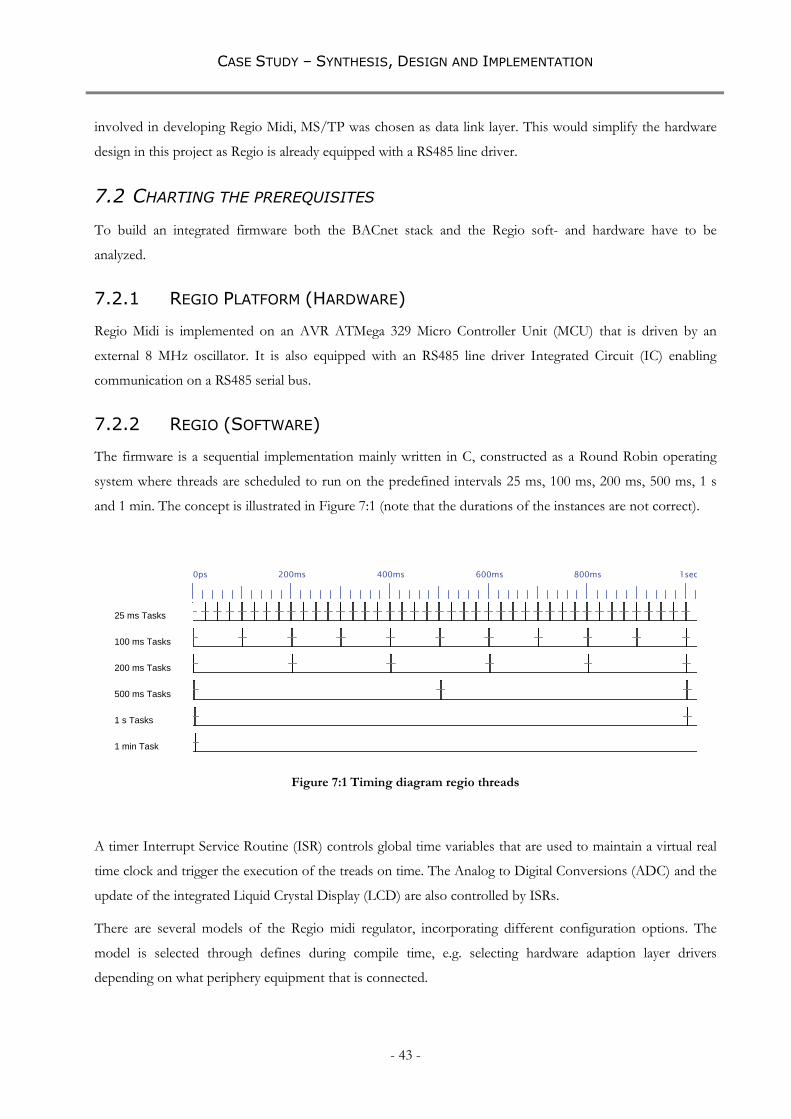
CASE STUDY – SYNTHESIS, DESIGN AND IMPLEMENTATION
- 43 -
involved in developing Regio Midi, MS/TP was chosen as data link layer. This would simplify the hardware
design in this project as Regio is already equipped with a RS485 line driver.
7.2 CHARTING THE PREREQUISITES
To build an integrated firmware both the BACnet stack and the Regio soft- and hardware have to be
analyzed.
7.2.1 REGIO PLATFORM (HARDWARE)
Regio Midi is implemented on an AVR ATMega 329 Micro Controller Unit (MCU) that is driven by an
external 8 MHz oscillator. It is also equipped with an RS485 line driver Integrated Circuit (IC) enabling
communication on a RS485 serial bus.
7.2.2 REGIO (SOFTWARE)
The firmware is a sequential implementation mainly written in C, constructed as a Round Robin operating
system where threads are scheduled to run on the predefined intervals 25 ms, 100 ms, 200 ms, 500 ms, 1 s
and 1 min. The concept is illustrated in Figure 7:1 (note that the durations of the instances are not correct).
0ps 200ms 400ms 600ms 800ms 1sec
25 ms Tasks
100 ms Tasks
200 ms Tasks
500 ms Tasks
1 s Tasks
1 min Task
Figure 7:1 Timing diagram regio threads
A timer Interrupt Service Routine (ISR) controls global time variables that are used to maintain a virtual real
time clock and trigger the execution of the treads on time. The Analog to Digital Conversions (ADC) and the
update of the integrated Liquid Crystal Display (LCD) are also controlled by ISRs.
There are several models of the Regio midi regulator, incorporating different configuration options. The
model is selected through defines during compile time, e.g. selecting hardware adaption layer drivers
depending on what periphery equipment that is connected.

CASE STUDY – SYNTHESIS, DESIGN AND IMPLEMENTATION
- 44 -
Communication capabilities include Regins proprietary protocol EXOline and Modbus. Both utilize the
services of the same physical layer (RS485), the same UART and they are interrupt driven.
7.2.3 BACNET SOURCE CODE
BACnet open source C-stack version 0.4.7 is the most recent release at the time this project started. The stack
is well documented and is written by Steve Skarg [33]. It contains several libraries, providing different options
on what features and BACnet functionality to implement. This is done, either by defines or by adding objects
and/or services in the code. There is a demonstration implementation for an Atmel ATmega 168
microcontroller available in the open source C-stack. This is a similar MCU to the one that the Regio is built
on. The demonstration implementation includes a device object, analog and binary value objects. These
objects are accessible through the read and write property services.
It is a polled communication implementation, meaning that it hangs the CPU in while loops when utilizing
the UART. The loops eventually times out allowing the CPU to handle other operations as well.
7.3 INTEGRATION
Relevant parts of the open source C-stack are used, and most of the functions are implemented as is. Analysis
of the BACnet protocol in chapter 4 shows that there a two essential parts of the protocol that need special
attention regarding timing requirements.
The device should be able to participate in token passing, i.e. receiving and passing the token according
to the timing requirements described in section 4.2.3.5.2.
The device should be able to respond to requests, both of the type “data expecting reply” and test
messages, within the timeout periods described in section 4.2.3.5.2.
In addition, the integrated machine code has to be small enough to fit in to the memory of the
microcontroller. As a result of porting the project from an IAR compiler to a GCC compiler, the compiled
machine code increased substantially. A lot f effort was put into reducing the code size to fulfill this
requirement and some functionality was scaled down, i.e. eeprom functionality and some advanced user menu
options were omitted.
7.3.1 COMMUNICATION INTEGRATION
The strategy is to replace the existing communication functionality from layer 2 (see section 2.6) and upwards,
with BACnet over MS/TP. BACnet application layer, network layer and data link layer are implemented and
their services are made available to the REGIO application.
UART handling in the open source stack is polled and the “receive module” is constructed in such a way that
it leaves the CPU in an occupied state during the reception of a frame. In a worst case scenario, i.e. maximum

CASE STUDY – SYNTHESIS, DESIGN AND IMPLEMENTATION
- 45 -
Tframe_gap and lowest bit rate, this means that the CPU will be occupied during 25 ms every time a transmission
is detected (see Equation 7:1). To avoid this ineffective polled reception, some modifications are made to the
module that is handling the reception of the frames. An interrupt service routine is created that is triggered
when the UART receives a data octet. When this interrupt occurs, the “receive frame function” is called. The
receive frame function is modified to check the UART data register once, takes the appropriate action and
then exit.
Equation 7:1 Worst case CPU occupancy due to reception
msbps
packetsbitsbitstimebitbitsdata 259600
18)2010(
7.3.2 OBJECT INTEGRATION
Although there are several Regio variables and functions identified as potential BACnet objects in chapter 5,
this project is limited to implement the objects presented in this subsection.
7.3.2.1 DEVICE
All BACnet devices must contain exactly one device object. The device object from the demo
implementation is modified to reflect the project specific data e.g. device name and what objects it contains.
The Binary objects are removed and one Analog Input Object is added to the “Device Object List” primitive.
7.3.2.2 ANALOG VALUE
A reference value is used as an input to the control algorithm. Regio incorporates this reference value by
defining an offset to a predefined fixed reference value. However, this is not an Input in a system wide sense
and is better mapped into a BACnet Analog Value Object. This object is named “Reference offset” and is
accessible through read and write property services.
7.3.2.3 ANALOG INPUT
The measured temperature is also an input to the control algorithm, and a typical example of inputting data to
the system. The current value of the temperature sensor is mapped into a “BACnet Analog Input Object”.
This object is named “Room temperature” and is accessible through the read property service.
7.3.3 APPLICATION PROGRAM INTERFACE
The values that are of interest for this implementation are the input from the temperature sensor and the
reference value for the regulator. In the Regio code, these are organized as elements in the globally accessible

CASE STUDY – SYNTHESIS, DESIGN AND IMPLEMENTATION
- 46 -
structs. A simple Application Program Interface (API) is created by providing access to these variables from
the implemented BACnet objects described in sections 7.3.2.2 and 7.3.2.3.
7.4 SOFTWARE DESIGN
The software design in this project is essentially a redesign and an adaptation of existing code. However, the
integration of code from different projects requires that some simple functions have to be written to glue
them together. The integrated firmware in this BACnet enabled Regio prototype consists of code that can be
described as either:
Original Regio code
Original BACnet open source code
Modified BACnet open source code or BACnet - Regio specific code (glue)
This distinction is emphasized to simplify code maintenance and further development of Regio and other
Regin products.
7.4.1 HARDWARE ADAPTION
A software driver that is used to enable and disable the RS485 line driver (which is a part of the protocol) is
provided by the demo port (in file RS485.c). This driver is modified to adapt it to this specific hardware
(ATmega329 in combination with the on board RS485 circuit).
7.4.2 TIMING CONSIDERATIONS
The BACnet protocol defines several different timing constraints (see section 4.2.3.5.2) that need to be
considered when implementing BACnet over MS/TP. The specified timing periods apply to different
situations (e.g. if transmitting or receiving data). Three separate cases will be considered in this
implementation and are presented separately in the following sections.
7.4.2.1 NODE POLLING FOR MASTER OR PASSING THE TOKEN
Before starting to transmit the poll for master frame, the node needs to resolve if the bus has been silence for
a period longer than, or equal to Tturnaround. After the transmission of the first octet there must not elapse
more time than Tframe_gap before transmitting the next octet. After transmitting the last stop bit of the last
octet there must not elapse more time than Tpostdrive before the line driver is disabled. An example of these
transitions, incorporated by a transmitting node that utilizes the maximum allowed time periods, is illustrated
in Figure 7:2. Note that the course of events is the same for a situation when the node is passing the token to
the next station.

CASE STUDY – SYNTHESIS, DESIGN AND IMPLEMENTATION
- 47 -
- 1ms - 500us 0us 500us 1ms 1.5ms
ReceiveO[0..0]
TransmitO[15..0]
40 bit times
Octet 1 20 bit times Octet 2 15 bit times
Tturnaround
Tframe_gap
Tpostdrive
Figure 7:2 Transmission timing diagram (38400 bps)
7.4.2.2 NODE RECEIVING POLL FOR MASTER REQUEST OR TOKEN
Besides conforming to the same rules that apply to the previously described poll for master situation, there
are additional timing constraints regarding the response time to the request.
When a node receives a poll for master request or the token, it must start transmitting within the time
Tusage_delay. If a response has not arrived at the polling node within Tusage_timeout, it will continue its quest for a
successor master by issuing a new PFM to the next potential node. Figure 7:3 shows a direct reply to a poll
for master request.
0ps 2ms 4ms 6ms 8ms 10ms 12ms 14ms 16ms 18ms
ReceiveO[15..0]
TransmitO[15..0]
Tturnaround
Tframe_gap
{20ms}
Tusage_timeout
Tusage_delay
Tpostdrive
{15ms}
Figure 7:3 Transmission timing diagram answer to PFM
A special exception related to the token maintenance occurs when the token is lost. If the bus has remained
silence for Tno_token, an algorithm based on the nodes address is triggered in all master nodes to determine
who is empowered to generate a new token.

CASE STUDY – SYNTHESIS, DESIGN AND IMPLEMENTATION
- 48 -
7.4.2.3 NODE RESPONDING TO A DATA EXPECTING REPLY
When receiving a request that is expecting a reply (not to be confused with the poll for master request), the
node needs to resolve if the bus have been silence long enough (Tturnaround). If a response to the request can be
computed within Treply_delay, the node can reply directly. If a response cannot be delivered before this time, a
reply of type “postponed answer” is issued. Such answer informs the requesting node that it will need more
time, and that it will deliver an answer next time it receives the token.
7.4.3 KEY FUNCTIONS
In this project there are many more functions required in order to implement BACnet functionality than can
easily be overviewed. In this section however, key functions are described on a high abstraction level, leaving
out detailed descriptions of further calls to sub routines within these functions. BACnet core files and specific
handler files are listed in Appendix D (Project C-code file listings).
7.4.3.1 INIT BACNET
This function initiates the UART with the desired baud rate. Further, it sets the device object instance, MAC
address and a few other important parameters for the BACnet functionality.
7.4.3.2 BACNET COMMUNICATION
When called, bacnet_communication() checks if the state of the MSTP_receive_frame_FSM() is Idle, i.e.
NOT in the middle of receiving a frame, to determine if it is should call MSTP_master_node_FSM(). If
MSTP_master_node_FSM() is called, the return value is used as an argument for a while loop, thus repeatedly
calling it until a pending state is reached (see 7.4.3.3).
7.4.3.3 MASTER FINITE STATE MACHINE
The function MSTP_master_node_FSM() consists of a few hundred lines of code, mainly composed of
switch case statements. It will return true unless it reaches a pending state, i.e. reaches a state where new input
is needed to transit to a new state.
7.4.3.4 RECEIVE FINITE STATE MACHINE
MSTP_receive_node_FSM() is called when an UART received data interrupt occurs. Similarly to
MSTP_master_node_FSM(), it is a function constructed by a couple of hundred lines of code. It examines
the received data octet and pile it on top of the previous BACnet data octet (if present) and then exit.
If a complete valid BACnet frame is reassembled or if an invalid frame is detected this will also be indicated
by setting an appropriate bit in a flag register.
The function will return true in any of these cases and false otherwise.

CASE STUDY – SYNTHESIS, DESIGN AND IMPLEMENTATION
- 49 -
7.4.3.5 HANDLE NPDU
npdu_handler() is executed if bacnet_communication() returns with a none zero value. It will decode the
received message and if required encode a reply. The scope of this function is hard to predict as it depends on
the kind of message that is received.
7.4.4 PROGRAM STRUCTURE
This section describes how the migrated program works, where the modules are placed and why they are
placed there. An overview of the migrated firmware is illustrated in Figure 7:5.
7.4.4.1 INIT_BACNET()
Before entering the main function, init_bacnet() is called. This function has to be called before any bacnet
communication is initiated.
7.4.4.2 BACNET_COMMUNICATION()
This function will trigger the poll for master state machine, unless we are in the middle of receiving a BACnet
frame. One option is to utilize a scheduled Regio thread to call this function, but the shortest available time
period in the OS is 25 ms. As discussed in section 7.4.2.2 the requirements of the response to a poll for
master is 15 ms. If the BACnet master finite state machine is executed as a scheduled thread with the period
25 ms, the response time would be too long. For instance, if a poll for master message is received within 10
ms after the execution of the 25 ms Tasks, the request will not be handle before the deadline of the Tusage_delay
(see Figure 7:4). The function is therefore placed in level 0 of the while(1) loop, thus calling it unconditionally
during system idle time.
0ps 2ms 4ms 6ms 8ms 10ms 12ms 14ms 16ms 18ms 20ms 22ms 24ms 26ms
Poll for MasterO
25 ms TasksO
Tusage_delay
{15ms}
Tusage_timeout
{20ms}
Figure 7:4 Maximum time slot to respond tom PFM

CASE STUDY – SYNTHESIS, DESIGN AND IMPLEMENTATION
- 50 -
7.4.4.3 NPDU_HANDLER()
The npdu handler is called if there is a valid BACnet message in the receive buffer. This is signaled from the
bacnet_communication() function and needs to be placed after the execution of the master state machine.
The npdu handler will identify what services and objects are requested and call upon the appropriate
functions.
Init
Received
NPDU?
BACnet
Communication()
Handle NPDU()
25ms?
Y
N
25ms Tasks
100ms?
Y
N
100ms TasksY
200ms? 200ms TasksY
500ms? 500ms Tasks
1s? 1s Tasks
1min?
Y
N
1min TasksY
Y
N
N
N
N
Init BACnet()
En
try
po
int
Rx FSM in
Idle?
Master Finite
State Machine()
Rx Packet
Pending?
Y
N
Received NPDU()Y
N
...Original Regio
modules
...Original BACnet
modules
ISR(UART Rx Data)
Rx Finite State
Machine()
En
try
po
int
Exit
po
int
...BACnet – Regio
modules
Figure 7:5 Integrated firmware overview

CASE STUDY - TESTING
- 51 -
8 CASE STUDY - TESTING
This section describes how, and to what extent the implemented BACnet functionality is tested. Due to lack
of time and resources, most of the implemented services and objects are only tested “black box”, i.e. the
request and response are issued and monitored from BACnet explorer. Some functions that are considered to
be of special interest are however tested more thoroughly.
There was no oscilloscope available, thus no tests have been performed on the electrical system i.e. analysis of
electrical signals or flanks carrying the information.
8.1 WHAT IS TESTED?
In system behavior, where the bus is seen as the system i.e. the token handling and timing requirements.
Read & Write property to one Analog Value Object. Read property to one Analog Input Object.
Communication tests at all baud rates as described in the BACnet standard.
8.2 HOW IS IT TESTED
All implemented services and objects are tested “Black Box” running BACnet explorer with the appropriate
primitives.
8.2.1 MASTER BEHAVIOR
Master node behavior is observed with Comm Operator by manually analyzing the packets and identifying
the token handling. The traffic during initiating (power up) stage is logged and the token handling is
observed. Although the individual packets are time stamped with a resolution of 1 ms, this accuracy cannot
be verified with the available lab equipment (see discussion in section 6.5). Instead, performance has been
compared with other BACnet devices acting as masters on the same bus.
8.2.2 READ AND WRITE PROPERTY
Read and write “Present value” to the Analog Value Object named Reference value is tested somewhat
“White Box”. Request and Response is logged on the PC using Wire shark. The same messages are
intercepted by the serial sniffer on the RS485 bus. The headers and parameters are compared. All other
implemented primitives have been tested by issuing a request from BACnet explorer and the responses are
documented.

CASE STUDY - TESTING
- 52 -
8.2.3 BAUD RATES
Read property service is tested at 9600, 19200, 38400 and 76800 bps by polling proprietary property 9600 of
the device object. If successful, the device will respond with its current baud rate. This property is polled
manually through BACnet explorer after changing baud rates in the Regio and the IP-MS/TP router.
8.3 TEST RESULTS
This section only confirms that all the tests were run successfully. For detailed information see Appendix E
(Test results).
8.3.1 MASTER BEHAVIOR
The Regio master acts in very much the same way as the other two masters. Two deviations are particularly
noteworthy. Both Delta Bacstat and Viconics utilize the possibility to add padding at the end of the frame
while Regio does not. The other deviation is the use of the defined Tusage_timeout. This time period varies
between all master nodes but is within the defined boundaries (approximately 90 ms for Regio).
8.3.2 READ AND WRITE PROPERTY
All the read and write operations specified were executed successfully.
8.3.3 BAUD RATES
Correct responses were obtained when issuing the proprietary Read property request specified in 8.2.3. All
valid BACnet baud rates were tested.

ANALYSIS – PROOF OF CONCEPT
- 53 -
9 ANALYSIS – PROOF OF CONCEPT
This chapter contains an analysis of the two main tasks in this project. The first part is a general reflection on
the literature review and BACnet from a distributed system perspective. The second part is an analysis of the
case study and the implementation. Included here are my personal experiences which, though not necessarily
of interest to all the stakeholders, are relevant to the Master Thesis.
9.1 LITERATURE REVIEW (THEORETICAL ANALYSIS)
9.1.1 BACNET IN GENERAL
9.1.1.1 GUIDELINES
There are guidelines intended to support developers to implement BACnet issued by BTL. Whilst these are
fine, they are used primarily to guide developers in nonfunctional decisions, i.e. they describe how objects,
alarms, services etc. are to be implemented. I have not found any extensive instructions on how to map
application objects to BACnet objects. For instance, all objects in BACstat 103 are analog value objects, even
binary in- and outputs. Viconics have more logical objects that reflect the applications better but instead uses
only one indexation series for all different object types, i.e. “analog-value [07]” is followed by “binary-value
[08]”.
9.1.1.2 UNRELIABLE AND NON DETERMINISTIC ROUTING
The BACnet standard stipulates that only one physical path may exist between any two BACnet nodes. If any
of the intermediate devices (routers, gateways, bridges etc.) fails, there are no backup options for relaying the
message.
9.1.1.3 MAXIMUM NPDU LENGTH WHEN ROUTING BACNET/IP
BACnet does not support IP fragmentation. In the absence of support for IP fragmentation, the BACnet
standard encourages a BACnet stack designer to consider the Maximum Transmission Unit (MTU) along the
path to a remote device when restricting the maximum NPDU. It is defined in the BACnet standard [12, p
47, Table 6-1] that the maximum NPDU length is 1497 bytes for BACnet/IP (BIP). This packet size does not
conform to the Internet Protocol (IPv4). This is a sufficient limitation for an Ethernet link with a Maximum
Transmission Unit (MTU) of 1500 and probably enough in most cases on the Internet. It is however
specified by the Internet Engineering Task Force [13] that the minimum packet size that a router is obligated
to route is 576 bytes (MTU 576 bytes). Defining that the maximum NPDU can be 1497 bytes when designing
BACnet/IP implementations, can result in inconsistent behavior.

ANALYSIS – PROOF OF CONCEPT
- 54 -
9.1.2 BACNET MS/TP
This project focuses on the link layer MS/TP and it is therefore given a substantial part in the analysis
section.
9.1.2.1 STABILE AND RELIABLE COLLISION AVOIDANCE
It is the designers of BACnet belief that it is easier to handle the loss of token than a collision. The media
access in MS/TP is strictly controlled by the timing constraints described in 4.2.3.5.2. This incorporates some
deterministic advantages over a stochastic Collision Detection protocol (e.g. Ethernet), and enables robust
bus maintenance by avoiding collisions.
9.1.2.2 INEFFECTIVE UTILIZATION
The robust media access is achieved at the expense of effective bus utilization. The bus is continuously
occupied by the token handling. In a stable, non varying system this might be a good thing which enables
periodical deterministic updates. However, when a new node is introduced or when one is recovering from an
outage it will poll the whole range of possible successor nodes.
9.1.2.3 LATENCY IS DEPENDING ON THE MAC ADDRESS
The token is passed from one node to the next by polling the “next” MAC address in an ascending order.
This implies that a node that is closer in the address space will reply sooner than one further away. This is
true when the reply is postponed, i.e. when the responding node cannot achieve a response within the time
Treply_delay.
9.2 THE REGIO-BACNET IMPLEMENTATION (CASE STUDY)
The implementation is done in two steps. First, BACnet is implemented on the Regio hardware platform.
Second BACnet functionality is integrated with Regio software.
9.2.1 BACNET ON REGIO HARDWARE PLATFORM
The isolated BACnet implementation made it possible to verify the communication functionality without the
disturbance of uncontrolled application threads and interrupts. This was important because there are strict
timing constraints involved in computer communication.
9.2.2 PUTTING THE PIECES TOGETHER
The integration of the BACnet stack in the Regio firmware was done when the isolated BACnet
implementation could be confirmed. Initially, the challenge was to reduce the unnecessarily large amount of
memory consumed by the Regio operation system. Bad memory utilization was the result of the port from

ANALYSIS – PROOF OF CONCEPT
- 55 -
IAR compiler to GCC. With the help of Lars Masson, the memory usage was reduced to the extent that it
was possible to build integrated machine code slim enough to fit the size of the program and data memory.
9.2.3 STACK OVERFLOW
The project was held up for a substantial amount of time searching for bugs caused by bad stack handling.
Every now and then during BACnet calls, the LCD on the Regio started to display unreasonable values and
symbols. The combination of high memory usage, many subroutines expanding many levels and the lack of
knowledge of stack handling caused this delay. Later, this was resolved by monitoring the stack pointer
registry and making enough memory available to avoid memory violation.
9.2.4 UTILIZING LAYERS
The integration of the firmware was successful and facilitated by the utilization the OSI reference model.
Layer 1 (physical layer) includes the hardware adaptation to Regio hardware. Layer 2 (data link) was adapted
to enable integration with the operation system whilst still conforming to the timing requirements controlling
the master state machine. Layer 3 (network) was implemented without modifications. Layer 7 (Application)
includes the API and the access point to the application process.

CONCLUSIONS
- 56 -
10 CONCLUSIONS
10.1 BENEFITS WITH BACNET
BACnet is one possible solution to achieve distributed building automation functionality in a standardized
way. It is a standardized communication protocol that supports many of the requirements derived in chapter
3.1, e.g. confirmed delivery of messages.
The protocol is truly open and comes with many optional features. It is easy to implement and there are many
optional physical and data link layers. In addition there are many demonstration implementations where
developers are encouraged to modify and port to their own devices
10.2 DRAWBACKS WITH BACNET
After have seen how objects are used in the two devices that were available during the implementation phase,
I would like to see guidelines on how to choose and utilize the objects. Even though the protocol describes
what the objects should look like and how they should be implemented, it does not describe how they should
be used. This undermines the credibility of the protocols level of standardization.
With reference to the discussion in section 9.1.1.2 there must not be any safety critical applications depending
only on BACnet routed paths. Nor is it wise to close distributed control loops or other time critical
applications over such paths.
Internet is a packet switched network based on best effort delivery service. This means that there are no
persistent connections and the particular path a packet travels cannot be predicted. This has not been
considered when defining the maximum packet sizes in the BACnet standard for BACnet/IP (BIP). Packets
bigger than the MTU for the link layer in IPv4 will be fragmented and the only device allowed to reassembly
the packet is the final receiver. The reassembly of a fragmented packet is a matter for the network layer and if
this feature is not supported it might result in inconsequent behavior and/or loss of data.
10.3 SUCCESSFUL IMPLEMENTATION
It is possible to implement BACnet over MS/TP in a Regio zone controller by following the steps described
in chapter 7. This was achieved by implementing a few limited BACnet features. Some functionality, such as
eeprom handling and all other communication features, had to be scaled down or removed to make room for
the rather memory consuming BACnet stack.

FURTHER WORK
- 57 -
11 FURTHER WORK
11.1 BACNET COMPATIBLE ZONE CONTROLLERS SURVEY
The quest to find BACnet compatible zoon regulators was a low prioritized task and not much effort was put
into it. Almost all the listed controllers in Appendix C (BACnet compatible controllers) have been retrieved
from BTLs webpage and are the result of approximately one day spent searching on the internet.
11.2 CODE OPTIMIZATION
The objects that have been included in the experimental implementation described in section 7.3.2 are coded
in a rather memory consuming and none effective way. Algorithms should be optimized to include an
arbitrary number of objects in a structured and memory effective way.
11.3 INTERRUPT DRIVEN TX ROUTINE
The UART transmission in this implementation is polled. In order to utilize the CPU more efficiently the
send_frame() routine should be modified to be interrupt driven.
11.4 PORT PROJECT TO REGINS STANDARD COMPILER
This project has been conducted using the AVR-GCC compiler. To facilitate further development of a
BACnet stack for use with Regin products, the essence of this project should be ported to a compiler of
choice. The compiled binary file can probably be made much smaller with another compiler, thus utilize the
memory in a better way.
11.5 EXTENSIVE TESTING
The integrated firmware should be exposed to more extensive testing than have been the case in this project.

REFERENCES
58
12 REFERENCES
LITERATURE AND PRINTED REGULATORY DOCUMENTS
1. Randal E. Bryant, David O'Hallaron. Computer Systems. New Jersey : Pearson Education, 2003.
2. Urban Fosseus. R 2002, The EXOline protocol. Sweden: REGIN Exomatic, 2003.
3. ISO 8802-2 Information processing systems- Local area networks- Part 2: Logical Link Control.
4. ISO/IEC 8802-3 Information processing systems- Local area networks- Part 3: Carrier sense multiple access with
collision detection (CSMA/CD) access method and physical layer specifications.
5. ISO 7498 Open Systems Interconnection
6. ATA/ANSI 878.1 ARCNET Local Area Network Standard
7. EIA-709.1
8. Behrouz A. Forouzan. TCP/IP Protocol Suite, Third edition. Mc Graw Hill 2006
9. Martin Törngren. Modelling and design of distributed real-time control applications/. Doctoral thesis,
Department of Machine Design, KTH, TRITA-MMK 1995:7, ISSN1400-1179, ISRN KTH/MMK--
95/7--SE
10. Karl-Erik Årsen, Jad El-Khoury, Janlin Shi, Martin Törngren. Real- Time Control Systems, Internal
report, Dep. of Machine Design, The Royal Institute of Technology, Stockholm 2007
WEBPAGES, ONLINE ARTICLES AND REPORTS
11. BACnet Official Website. BACnet.org. [Online] [Cited: 08 29, 2008.] www.bacnet.org.
12. ANSI/ASHRAE Standard 135-2004 BACnet® A Data Communication Protocol for Building Automation and
Control Networks. Available for purchase on ASHREA Website [Cited 09 03, 2008] www.ashrea.com.
13. IETF rfc 791 [Online] [Cited: 09 09, 2008.] http://www.ietf.org/rfc/rfc791.txt.
14. BACnet Contacts section [Online] [Cited: 09 29, 2008.] http://www.bacnet.org/Contact/ASHRAE.htm
15. M-bus Official Website. M-bus.com [Online] [Cited: 10 07, 2008.] www.m-bus.com
16. LonWorks Official Website Echelon Corporation [Online] [Cited: 10 08, 2008.] www.echelon.com/
17. Sourceforge Bacnet project website BACnet Protocol Stack [Online] [Cited: 10 07, 2008.]
http://sourceforge.net/projects/bacnet
18. BACnet International Website [Online] [Cited 22 10, 2008] www.bacnetinternational.org
19. BACnet Inplemention Guidelines [Online] [Cited 22 10, 2008]
http://www.bacnetinternational.org/associations/8066/files/BTLImplementersGuide-17.final.pdf
20. Wikipedia, The free enckopedia [Online] [Cited 23 10 2008]
http://en.wikipedia.org/wiki/Gateway_(telecommunications)
21. Objectweb What is Middleware [Online] [Cited 23 10 2008] http://middleware.objectweb.org/
22. Chipkin Automated Systems website[Online] [Cited 27 10 2008] http://www.chipkin.com/

REFERENCES
59
23. Cimetrics website[Online] [Cited 27 10 2008] http://www.cimetrics.com
24. Synthesis of Embedded Networks for Building Automation and Control Cited 18 12 2008]
http://www.eecs.berkeley.edu/~fischion/Publications/acc2008.pdf
25. Modbus official website [Online] [Cited 17 11 2008] www.modbus.org
26. BACnet open source official website [Online][cited 21 11 2008] http://bacnet.sourceforge.net/
27. Datasheet of Viconics zone controller VT7200 [Online] [Cited 25 11 2008]
http://www.viconics.com/products/thermostats/vt7200/domumentation/028-0122R6_LIT-VT7200-
E06.pdf
28. Datasheet of Delta Control zone controller DNT-103 [Online] [Cited 25 11 2008]
http://www.deltacontrols.com/solutions-products/products/hvac/sensors-thermostats/dnt-t103
29. Datasheet of Regin zone controller Regio midi RC-CDFO [Online] [Cited 25 11 2008]
http://www.regin.se/pub/filer/product_sheets_gb/RC_CDFO_en.pdf
30. Datasheed of Atmel MCU, ATmega 329 [Online] [Cited 27 11 2008]
329http://www.atmel.com/dyn/resources/prod_documents/doc2552.pdf
31. Webopedia describing OSI [Online] [Cited 28 11 2008]
http://www.webopedia.com/TERM/O/OSI.htm
32. BTL website Device listings [Online] [Cited 05 12 2008] http://www.bacnetinternational.net/btl/
33. Wikipedia on Steve Skarg [Online] [Cited 05 12 2008] http://en.wikipedia.org/wiki/User:Skarg
34. Atmel website [Online] [Cited 05 12 2008] http://www.atmel.com
35. Wikipedia describing Master Slave model [Online] [Cited 15 12 2008]
http://en.wikipedia.org/wiki/Master-slave_(technology)

60
APPENDIX A (BACNET OBJECT DESCRIPTORS)
ANALOG INPUT OBJECT PROPERTIES TYPE
Property Identifier Property Datatype Conformance Code
Object_Identifier BACnetObjectIdentifier R
Object_Name CharacterString R
Object_Type BACnetObjectType R
Present_Value REAL R1
Description CharacterString O
Device_Type CharacterString O
Status_Flags BACnetStatusFlags R
Event_State BACnetEventState R
Reliability BACnetReliability O
Out_Of_Service BOOLEAN R
Update_Interval Unsigned O
Units BACnetEngineeringUnits R
Min_Pres_Value REAL O
Max_Pres_Value REAL O
Resolution REAL O
COV_Increment REAL O2
Time_Delay Unsigned O3
Notification_Class Unsigned O3
High_Limit REAL O3
Low_Limit REAL O3
Deadband REAL O3
Limit_Enable BACnetLimitEnable O3
Event_Enable BACnetEventTransitionBits O3
Acked_Transitions BACnetEventTransitionBits O3
Notify_Type BACnetNotifyType O3
Event_Time_Stamps BACnetARRAY[3] of
BACnetTimeStamp
O3
Profile_Name CharacterString O 1 This property is required to be writable when Out_Of_Service is TRUE. 2 This property is required if the object supports COV reporting. 3 These properties are required if the object supports intrinsic reporting.

61
ANALOG VALUE OBJECT TYPE
Property Identifier Property Datatype Conformance Code
Object_Identifier BACnetObjectIdentifier R
Object_Name CharacterString R
Object_Type BACnetObjectType R
Present_Value REAL R4
Description CharacterString O
Status_Flags BACnetStatusFlags R
Event_State BACnetEventState R
Reliability BACnetReliability O
Out_Of_Service BOOLEAN R
Units BACnetEngineeringUnits R
Priority_Array BACnetPriorityArray O1
Relinquish_Default REAL O1
COV_Increment REAL O2
Time_Delay Unsigned O3
Notification_Class Unsigned O3
High_Limit REAL O3
Low_Limit REAL O3
Deadband REAL O3
Limit_Enable BACnetLimitEnable O3
Event_Enable BACnetEventTransitionBits O3
Acked_Transitions BACnetEventTransitionBits O3
Notify_Type BACnetNotifyType O3
Event_Time_Stamps BACnetARRAY[3] of
BACnetTimeStamp
O3
Profile_Name CharacterString O 1 If Present_Value is commandable, then both of these properties shall be present. 2 This property is required if the object supports COV reporting. 3 These properties are required if the object supports intrinsic reporting. 4 If Present_Value is commandable, then it is required to be writable. This property is required to be writable when Out_Of_Service is TRUE.

62
DEVICE OBJECT TYPE
Object_Identifier BACnetObjectIdentifier R
Object_Name CharacterString R
Object_Type BACnetObjectType R
System_Status BACnetDeviceStatus R
Vendor_Name CharacterString R
Vendor_Identifier Unsigned16 R
Model_Name CharacterString R
Firmware_Revision CharacterString R
Application_Software_Version CharacterString R
Location CharacterString O
Description CharacterString O
Protocol_Version Unsigned R
Protocol_Revision Unsigned R
Protocol_Services_Supported BACnetServicesSupported R
Protocol_Object_Types_Supported BACnetObjectTypesSupported R
Object_List BACnetARRAY[N]of
BACnetObjectIdentifier
R
Max_APDU_Length_Accepted Unsigned R
Segmentation_Supported BACnetSegmentation R
Max_Segments_Accepted Unsigned O1
VT_Classes_Supported List of BACnetVTClass O2
Active_VT_Sessions List of BACnetVTSession O2
Local_Time Time O3,4
Local_Date Date O3,4
UTC_Offset INTEGER O4
Daylight_Savings_Status BOOLEAN O4
APDU_Segment_Timeout Unsigned O1
APDU_Timeout Unsigned R
Number_Of_APDU_Retries Unsigned R
List_Of_Session_Keys List of BACnetSessionKey O
Time_Synchronization_Recipients List of BACnetRecipient O5
Max_Master Unsigned(1..127) O6
Max_Info_Frames Unsigned O6
Device_Address_Binding List of
BACnetAddressBinding
R
Database_Revision Unsigned R
Configuration_Files BACnetARRAY[N] of
BACnetObjectIdentifier
O7
Last_Restore_Time BACnetTimeStamp O7
Backup_Failure_Timeout Unsigned16 O8
Active_COV_Subscriptions List of
BACnetCOVSubscription
O9
Slave_Proxy_Enable BACnetArray[N] of
BOOLEAN
O10
Manual_Slave_Address_Binding List of
BACnetAddressBinding
O10
Auto_Slave_Discovery BACnetArray[N] of
BOOLEAN
O11
Slave_Address_Binding List of
BACnetAddressBinding
O12
Profile_Name CharacterString O 1 Required if segmentation of any kind is supported. 2 If one of the properties VT_Classes_Supported or Active_VT_Sessions is present, then both of these properties shall be present. Both properties are required if support for VT Services is indicated in the PICS.

63
3 If the device supports the execution of the TimeSynchronization service, then these properties shall be present. 4 If the device supports the execution of the UTCTimeSynchronization service, then these properties shall be present. 5 Required if PICS indicates that this device is a Time Master. If present, this property shall be writable. 6 These properties are required if the device is an MS/TP master node. 7 These properties are required if the device supports the backup and restore procedures. 8 This property must be present and writable if the device supports the backup and restore procedures. 9 This property is required if the device supports execution of either the SubscribeCOV or SubscribeCOVProperty service. 10 This property shall be present and writable if the device is capable of being a Slave-Proxy device. 11 This property shall be present if the device is capable of being a Slave-Proxy device that implements automatic discovery of slaves. 12 This property shall be present if the device is capable of being a Slave-Proxy device.

64
APPENDIX B (STATE TRANSITION DIAGRAMS)
STATE TRANSITION DIAGRAM RECEIVE FINITE STATE MACHINE
Source: SSPC-135 2004 (BACnet standard)

65
STATE TRANSITION DIAGRAM MASTER FINITE STATE MACHINE
Source: SSPC-135 2004 (BACnet standard)

66
APPENDIX C (BACNET COMPATIBLE CONTROLLERS)
RESULT OF SURVEY
BACnet compatible controllers
Manufacturer Product Remarks
Alreton VisualLogic Controller (BACtalk VLC) Programmable logic controller
Delta Controls Network Thermostat BACstat
Honeywell International Variable Air Volume Controller Programmable logic controller
iControls iVV702 VAV Controller VAV controller
Reliable Controls MACH-Air™ VAV Application
Controller
Programmable logic controller with
iontegrated actuator
Reliable Controls MACH-Zone™ Unitary Controller Programmable logic controller
Siemens BACnet Terminal Equipment
Controller - VAV
VAV controller
TAC I/A Series® MicroNet™ Unitary
Controller
Versatile logic controller
TAC I/A Series® MicroNet™ VAV
Controller
Versatile logic controller with
integrated actuator
TAC I/A Series® MicroNet™ Zone
Controller
Viconics VT7200 Thermostat Series
Viconics VT7300 Thermostat Series
VT7600 Thermostat Series
Johnson Controlls TEC2647Z-2 TEC Zoning Control System

67
OBJECTS IN DELTA BACSTAT 103
Delta Bacstat 103 is a zone controller with functionality similar to Regio. It contains the following objects.
analog-input [01] - Temperature
analog-input [02] - Input 2
analog-input [03] - Humidity
analog-value [01] - Output1 - REMOTE (BIN DIR)
analog-value [02] - Output2 - REMOTE (BIN DIR)
analog-value [03] - Output3 - REMOTE (BIN DIR)
analog-value [04] - KeyPress
analog-value [05] - External
analog-value [06] - Day Setpoint
analog-value [07] - Day Minimum
analog-value [08] - Day Maximum
analog-value [09] - Day Differential
analog-value [10] - Night Heat Setpoint
analog-value [11] - Night Cool Setpoint
analog-value [12] - Application - NONE
analog-value [13] - Alg Mode
analog-value [14] - Controller Status
analog-value [15] - Display Code
analog-value [16] - AI1 Calibration
analog-value [17] - AI2 Calibration
analog-value [18] - AI3 Calibration
analog-value [19] - Proportional Band
analog-value [20] - Reset Rate
analog-value [21] - Output1 Config
analog-value [22] - Output2 Config
analog-value [23] - Output3 Config
analog-value [24] - Setup1 Not Used
analog-value [25] - Setup2 Not Used
analog-value [26] - Setup3 Not Used
analog-value [27] - Setup4 Not Used
analog-value [28] - Setup5 Not Used
analog-value [29] - Setup6 Not Used
analog-value [30] - Baud Rate
analog-value [31] - PIN
analog-value [32] - Service Tool Mode

68
OBJECTS IN VICONICS VT7200
Delta Viconics VT7200 is another zone controller with functionality similar to Regio. It contains the
following objects.
analog-value [07] - Room Temperature
binary-value [08] - Room Temp Override
analog-value [09] - Outdoor Temperature
analog-input [12] - Supply Temperature
multi-state-value [13] - Occupancy Command
multi-state-value [14] - System Mode
group [16] - General Options 1
multi-state-value [17] - BI 1 Configuration
multi-state-value [18] - BI 2 Configuration
multi-state-value [19] - UI 3 Configuration
binary-value [20] - Menu Scroll
binary-value [22] - Temperature Scale
multi-state-value [24] - Out #1 Configuration
multi-state-value [25] - AUX Configuration
group [26] - General Options 2
analog-value [28] - Heating Setpoint Limit
analog-value [29] - Cooling Setpoint Limit
binary-value [30] - Setpoint Type
multi-state-value [31] - Temporary Occupancy Time
analog-value [32] - Deadband
binary-value [33] - Reheat Time Base
analog-value [34] - Stand-by Time
analog-value [35] - Unoccupied Time
group [36] - Output Options
binary-value [37] - Control Type
multi-state-value [38] - Floating Motor Timing
multi-state-value [39] - On Off Control CPH
multi-state-value [41] - Sequence of Operation
multi-state-value [42] - Keypad Lockout
binary-value [49] - Aux Output
group [50] - Temperature Setpoints
analog-value [51] - Occupied Heat Setpoint
analog-value [52] - Occupied Cool Setpoint
analog-value [53] - Unoccupied Heat Setpoint
analog-value [54] - Unoccupied Cool Setpoint
analog-value [55] - Stand-by Heat Setpoint
analog-value [56] - Stand-by Cool Setpoint
group [57] - Control Outputs
analog-value [58] - PI Heating Demand
analog-value [59] - PI Cooling Demand
group [61] - Controller Alarms
binary-input [62] - Window Alarm
binary-input [63] - Filter Alarm
binary-input [64] - Service Alarm
group [65] - Controller Status
binary-input [66] - BI 1 Status
binary-input [67] - BI 2 Status
binary-input [68] - UI 3 Status
binary-input [69] - AUX Status
multi-state-value [70] - Heating Valve Status
multi-state-value [71] - Cooling Valve Status
binary-input [73] - Local Motion
multi-state-value [74] - Effective Occupancy

69
APPENDIX D (PROJECT C-CODE FILE LISTINGS)
BACnet core c-files
File Description Modifications
bacdcode.c Primitive BACnet datatype encoding and decoding No
bacint.c Primitive BACnet integer datatype encoding and decoding No
bacreal.c Primitive BACnet REAL datatype encoding and decoding No
bacstr.c Primative BACnet string datatype encoding and decoding No
apdu.c Handles dispatching the services to the proper handlers Yes
npdu.c Handles dispatching of the network message to the apdu dispatcher. It would be where routing is handled
if the stack supported more than one physical layer
No
crc.c computes CRC checksum for MS/TP No
dllmstp.c MS/TP datalink layer Yes
BACnet implementation specific c-files
File Description Modifications
ai.c Analog Input Object Yes
av.c Analog Value Object Yes
h_rp.c BACnet ReadProperty service encode/decode Yes
h_wp.c WriteProperty service encode/ decode Yes
h_whois WhoIs service encode/decode No
bacnet4regio Handles initiation and variables needed for BACnet functionality n/a

70
APPENDIX E (TEST RESULTS)
BLACK BOX TESTS OF READ AND WRITE PROPERTY ON ALL IMPLEMENTED
OBJECTS
Test results Analog Input “Room Temperature”
Property R/W Response Remarks
OBJECT_IDENTIFIER R ObjectIdentifier: analog-input object, 0
OBJECT_NAME R object-name: 'Room Temperature'
OBJECT_TYPE R object-type: analog-input object
PRESENT_VALUE R present-value: 23,100000 (Real)
STATUS_FLAG_IN_ALARM R in-alarm = FALSE,
STATUS_FLAG_FAULT R fault = FALSE
STATUS_FLAG_OVERRIDDEN R overridden = FALSE
STATUS_FLAG_OUT_OF_SERVICE R out-of-service = FALSE
EVENT_STATE R event-state: 0 0 = Normal
OUT_OF_SERVICE R out-of-service: FALSE
UNITS R units: Degrees Celsius
Test results Analog Value”Setpoint Offset”
Property R/W Response Remarks
OBJECT_IDENTIFIER R ObjectIdentifier: analog-value object, 0
OBJECT_NAME R object-name: 'Setpoint Offset'
OBJECT_TYPE R object-type: analog-value object
PRESENT_VALUE R present-value: 0,000000 (Real)
PRESENT_VALUE W (1) SimpleACK (2)
PRESENT_VALUE R present-value: 1,000000 (Real)
HIGH_LIMIT R high-limit: 3,000000 (Real)
LOW_LIMIT R low-limit: 3,000000 (Real)
STATUS_FLAG_IN_ALARM R in-alarm = FALSE
STATUS_FLAG_FAULT R fault = FALSE
STATUS_FLAG_OVERRIDDEN R overridden = FALSE
STATUS_FLAG_OUT_OF_SERVICE R out-of-service = FALSE
EVENT_STATE R event-state: 0 0 = Normal
OUT_OF_SERVICE R out-of-service: FALSE
UNITS R units: Degrees Celsius

71
Test results Device Object ” Regio”
Property R/W Response Remarks
OBJECT_IDENTIFIER R ObjectIdentifier: device object, 102
OBJECT_IDENTIFIER W
(555)
Not possible to write to Device
object in BACnet explorer
OBJECT_NAME R object-name: 'Regio'
OBJECT_NAME W Not possible to write to Device
object in BACnet explorer
OBJECT_TYPE R object-type: 'RC-CDFO'
SYSTEM_STATUS R system-status: operational
VENDOR_NAME R vendor-name: 'REGIN AB'
VENDOR_IDENTIFIER R vendor-identifier: (Unsigned) 264
MODEL_NAME R model-name: 'RC-CDFO'
FIRMWARE_REVISION R firmware-revision: '0.4.7'
APPLICATION_SOFTWARE_VERSION R application-software-version: '1.0'
PROTOCOL_VERSION R protocol-version: (Unsigned) 1
PROTOCOL_REVISION R protocol-revision: (Unsigned) 5
PROTOCOL_SERVICES_SUPPORTED R writeProperty = TRUE, readProperty = TRUE All other services = False
PROTOCOL_OBJECT_TYPES_SUPPORTED R analog-input object = TRUE
analog-value object = TRUE
device object = TRUE
OBJECT_LIST R ObjectIdentifier: device object, 102
ObjectIdentifier: analog-input object, 0
ObjectIdentifier: analog-value object, 0
MAX_APDU_LENGTH_ACCEPTED max-apdu-length-accepted: (Unsigned) 50
SEGMENTATION_SUPPORTED segmentation-supported: no-segmentation
APDU_TIMEOUT apdu-timeout: (Unsigned) 60000
NUMBER_OF_APDU_RETRIES number-of-APDU-retries: (Unsigned) 0
DEVICE_ADDRESS_BINDING - Empty string (no bindings exists)
DATABASE_REVISION database-revision: (Unsigned) 0
MAX_INFO_FRAMES R max-info-frames: (Unsigned) 1
MAX_INFO_FRAMES W Not possible to write to Device
object in BACnet explorer
MAX_MASTER R max-master: (Unsigned) 127
MAX_MASTER W
(126)
Not possible to write to Device
object in BACnet explorer

72
WHITE BOX TESTS OF ONE READ AND ONE WRITE PROPERTY OPERATION
---------------------------- Wireshark IP packet Write Property ---------------------------------
No. Time Source Destination Protocol Info
379 47.021941 192.168.3.6 192.168.3.33 BACnet-APDU Confirmed-Request
[invoke:196]: writeProperty
Frame 379 (73 bytes on wire, 73 bytes captured)
Ethernet II, Src: HewlettP_71:17:cd (00:21:5a:71:17:cd), Dst: Pronet_a7:30:d2 (00:20:4a:a7:30:d2)
Internet Protocol, Src: 192.168.3.6 (192.168.3.6), Dst: 192.168.3.33 (192.168.3.33)
User Datagram Protocol, Src Port: bacnet (47808), Dst Port: bacnet (47808)
BACnet Virtual Link Control
Building Automation and Control Network NPDU
Building Automation and Control Network APDU
0000 .... = APDU Type: Confirmed-Request (0)
.... 0000 = PDU Flags: 0x00
.000 .... = Max Response Segments accepted: Unspecified (0)
.... 0101 = Size of Maximum ADPU accepted: Up to 1476 octets (fits in an ISO 8802-3 frame)
(5)
Invoke ID: 196
Service Choice: writeProperty (15)
ObjectIdentifier: analog-value object, 0
property Identifier: present-value
propertyValue
Opening Tag: 3
present-value: -1,000000 (Real)
Closing Tag: 3
Priority: (Unsigned) 8
---------------------------- Wireshark IP packet Write Property ---------------------------------
-------------------------- Wireshark IP packet Write Property ACK -------------------------------
No. Time Source Destination Protocol Info
388 47.113800 192.168.3.33 192.168.3.6 BACnet-APDU SimpleACK
[invoke:196]: writeProperty
Frame 388 (60 bytes on wire, 60 bytes captured)
Ethernet II, Src: Pronet_a7:30:d2 (00:20:4a:a7:30:d2), Dst: HewlettP_71:17:cd (00:21:5a:71:17:cd)
Internet Protocol, Src: 192.168.3.33 (192.168.3.33), Dst: 192.168.3.6 (192.168.3.6)
User Datagram Protocol, Src Port: bacnet (47808), Dst Port: bacnet (47808)
BACnet Virtual Link Control
Building Automation and Control Network NPDU
Building Automation and Control Network APDU
0010 .... = APDU Type: SimpleACK (2)
Invoke ID: 196
Service Choice: writeProperty (15)
-------------------------- Wireshark IP packet Write Property ACK -------------------------------
--------------------------- Comm operator sniffed MS/TP packets ---------------------------------
...
Recv: (10:21:49.312)00 00 8D FF 55 FF 00 02 01 00 00 73 55 FF 00 03 02 00 00 51 55 FF 00 05 03 00
00 FA
Recv: (10:21:49.328)55 FF 01 7B 05 00 00 E3 FF
Recv: (10:21:49.390)55 FF 00 01 05 00 00 8D FF
Recv: (10:21:49.406)55 FF 05 02 01 00 1F 1F 01 0C 00 01 06 C0 A8 03 06 BA C0 00 05 C4 0F 0C 00 80
00 00 19 55 3E 44 BF 80 00 00 3F 49 08 27 FF 55 FF 06 01 02 00 0F 54 01 20 00 01 06 C0 A8
Recv: (10:21:49.437)03 06 BA C0 FF 20 C4 0F 51 FF 55 FF 00 02 01 00 00 73 55 FF 00 03 02 00 00 51
55 FF 00 05 03 00 00 FA
Recv: (10:21:49.437)55 FF 01 7C 05 00 00 59 FF
Recv: (10:21:49.500)55 FF 00 01 05 00 00
Recv: (10:21:49.531)8D FF 55 FF 00 02 01 00 00 73 55 FF 00 03 02 00 00 51 55 FF 00 05 03 00 00 FA
...
--------------------------- Comm operator sniffed MS/TP packets ---------------------------------

73
---------------------------- Wireshark IP packet Read property ----------------------------------
No. Time Source Destination Protocol Info
442 54.572198 192.168.3.6 192.168.3.33 BACnet-APDU Confirmed-Request
[invoke:197]: readProperty
Frame 442 (64 bytes on wire, 64 bytes captured)
Ethernet II, Src: HewlettP_71:17:cd (00:21:5a:71:17:cd), Dst: Pronet_a7:30:d2 (00:20:4a:a7:30:d2)
Internet Protocol, Src: 192.168.3.6 (192.168.3.6), Dst: 192.168.3.33 (192.168.3.33)
User Datagram Protocol, Src Port: bacnet (47808), Dst Port: bacnet (47808)
BACnet Virtual Link Control
Building Automation and Control Network NPDU
Building Automation and Control Network APDU
0000 .... = APDU Type: Confirmed-Request (0)
.... 0000 = PDU Flags: 0x00
.000 .... = Max Response Segments accepted: Unspecified (0)
.... 0101 = Size of Maximum ADPU accepted: Up to 1476 octets (fits in an ISO 8802-3 frame)
(5)
Invoke ID: 197
Service Choice: readProperty (12)
ObjectIdentifier: analog-value object, 0
property Identifier: present-value
---------------------------- Wireshark IP packet Read property ----------------------------------
------------------------------- Wireshark IP packet Response ------------------------------------
No. Time Source Destination Protocol Info
443 54.675935 192.168.3.33 192.168.3.6 BACnet-APDU ComplexACK
[invoke:197]: readProperty
Frame 443 (69 bytes on wire, 69 bytes captured)
Ethernet II, Src: Pronet_a7:30:d2 (00:20:4a:a7:30:d2), Dst: HewlettP_71:17:cd (00:21:5a:71:17:cd)
Internet Protocol, Src: 192.168.3.33 (192.168.3.33), Dst: 192.168.3.6 (192.168.3.6)
User Datagram Protocol, Src Port: bacnet (47808), Dst Port: bacnet (47808)
BACnet Virtual Link Control
Building Automation and Control Network NPDU
Building Automation and Control Network APDU
0011 .... = APDU Type: ComplexACK (3)
.... 0000 = PDU Flags: 0x00
Invoke ID: 197
Service Choice: readProperty (12)
ObjectIdentifier: analog-value object, 0
property Identifier: present-value
propertyValue
Opening Tag: 3
present-value: -1,000000 (Real)
Closing Tag: 3
------------------------------- Wireshark IP packet Response ------------------------------------
--------------------------- Comm operator sniffed MS/TP packets ---------------------------------
...
Recv: (10:21:57.437)55 FF 00 01 05 00 00 8D FF 55 FF 05 02 01 00 16 18 01 0C 00 01 06 C0 A8
Recv: (10:21:57.453)03 06 BA C0 00 05 C9 0C 0C 00 80 00 00 19 67 09 26 55 FF 06 01 02 00 13 A1 01
20 00 01 06 C0 A8 03 06 C0 FF 50 C9 0C 91 02 91 20 94 AC
Recv: (10:21:57.468)55 FF 00 02 01 00 00 73 55 FF 00 03 02 00 00 51 55 FF 00 05 03 00 00 FA
Recv: (10:21:57.484)55 FF 01 49 05 00 00 69 FF
Recv: (10:21:57.546)55 FF 00 01 05 00 00 8D FF 55 FF 05 02 01 00 16 18
Recv: (10:21:57.578)01 0C 00 01 06 C0 A8 03 06 BA C0 00 05 CA 0C 0C 00 80 00 00 19 75 9D C3 55 FF
06 01 02 00 1A
Recv: (10:21:57.578)A6 01 20 00 01 06 C0 A8 03 06 BA C0 FF 30 CA 0C 0C 00 80 00 00 19 75 3E 91 3E
3F 93 01 55 FF 00 02 01
new lina 00 00 73 55 FF 00 03 02 00
Recv: (10:21:57.609)00 51 55 FF 00 05 03 00 00 FA 55 FF 01
...
--------------------------- Comm operator sniffed MS/TP packets ---------------------------------

74
Read property at different bit rates
Property R/W Response Remarks
9600 R (9600) Vendor Proprietary Value: (Unsigned) 9600 Tested at 9600 bps
9600 R (9600) Vendor Proprietary Value: (Unsigned) 19200 Tested at 19200 bps
9600 R (9600) Vendor Proprietary Value: (Unsigned) 38400 Tested at 38400 bps
9600 R (9600) Vendor Proprietary Value: (Unsigned) 76800 Tested at 76800 bps