Displaying POT Level with LEDs - Libero SoC and ...
54
Displaying POT Level with LEDs Libero SoC and SoftConsole Flow Tutorial for a SmartFusion cSoC .
-
Upload
khangminh22 -
Category
Documents
-
view
9 -
download
0
Transcript of Displaying POT Level with LEDs - Libero SoC and ...

Displaying POT Level with LEDs
Libero SoC and SoftConsole Flow Tutorial for a
SmartFusion cSoC .

Displaying POT Level with LEDs - Libero SoC and SoftConsole Flow Tutorial for a SmartFusion cSoC
Displaying POT Level with LEDs - Libero SoC and SoftConsole Flow Tutorial for a SmartFusion cSoC 2
Table of Contents
Introduction .................................................................................................... 3
Tutorial Requirements ................................................................................................................ 3
Objective .................................................................................................................................... 4
Working with Libero SoC and SoftConsole ................................................. 5
Step 1 - Creating a Libero SoC Project...................................................................................... 5
Step 2 - Configuring MSS Peripherals ....................................................................................... 7
Step 3 - Generating the MSS Component ............................................................................... 15
Step 4 - Generating the Program File ...................................................................................... 17
Step 5 - Programming SmartFusion Board Using FlashPro .................................................... 19
Step 6 - Building the Software Application Through SoftConsole ........................................... 21
Step 7 - Configuring Serial Terminal Emulation Program ........................................................ 26
Step 8 - Installing Drivers for the USB to RS232 Bridge .......................................................... 28
Step 9 - Debugging the Application Project using SoftConsole ............................................... 29
Step 10 - Building Executable Image in Release mode........................................................... 35
Appendix A – Libero SoC Catalog Settings ............................................... 37
Appendix B – Firmware Catalog Settings .................................................. 39
Appendix – C ................................................................................................ 41
List of Changes ............................................................................................ 49
Product Support .......................................................................................... 51
Customer Service ..................................................................................................................... 51
Customer Technical Support Center ........................................................................................ 51
Technical Support .................................................................................................................... 51
Website .................................................................................................................................... 51
Contacting the Customer Technical Support Center ............................................................... 51
ITAR Technical Support ........................................................................................................... 52

Displaying POT Level with LEDs - Libero SoC and SoftConsole Flow Tutorial for a SmartFusion cSoC 3
Introduction
This tutorial shows you how to use Microsemi tools to develop an application that can be implemented on
SmartFusion® customized system-on-chip (cSoC) device. After completing this tutorial you will be familiar
with the following:
Creating and implementing a Libero® system-on-chip (SoC) v10.0 project using SmartFusion cSoC
device.
Configure the peripherals using SmartDesign.
Configuring the analog compute engine (ACE).
Generating the microcontroller subsystem (MSS) Component.
Generating the programming file to program the SmartFusion cSoC device.
Opening the project in SoftConsole from Libero SoC and writing application code.
Compiling application code.
Creating and launching a debug session.
Debugging and running the code using SoftConsole.
Tutorial Requirements
Software Requirements
This tutorial requires the following software installed on your PC:
Libero SoC v10.0 (or later) can be downloaded from:
www.microsemi.com/soc/download/software/libero/default.aspx.
Microsemi SoftConsole v3.3 (or later), which is installed as a part of Libero SoC installation or can be
downloaded from www.microsemi.com/soc/download/software/softconsole/default.aspx.
Hardware Requirements
You will need the following hardware:
SmartFusion Evaluation Kit Board or SmartFusion Development Kit Board
Two USB cables (programming and communication) — one for connecting the programmer to your PC
and the other to connect the universal asynchronous receiver/transmitter (UART) interface on the board to
PC.
Associated Project Files
You can download the associated project files for this tutorial from the Microsemi website:
www.microsemi.com/soc/download/rsc/?f=SmartFusion_LiberoSC_POTlevel_tutorial_DF
You can download the programming file (*.stp) in release for this tutorial from the Microsemi website:
www.microsemi.com/soc/download/rsc/?f=SmartFusion_LiberoSC_POTlevel_tutorial_PF

Introduction
4 Displaying POT Level with LEDs - Libero SoC and SoftConsole Flow Tutorial for a SmartFusion cSoC
MSS Components Used
ARM® Cortex
™-M3 processor
Clock conditioning circuitry (CCC)
General purpose input/output (GPIO)
UART_0
Analog compute engine (ACE)
Target Board
SmartFusion Evaluation Kit Board (A2F-EVAL-KIT) or SmartFusion Development Kit Board (A2F-DEV-KIT).
Objective The objective of this tutorial is instruct how to configure SmartFusion cSoC analog channels and ACE that is
used to monitor the voltage across the potentiometer (POT). The UART is used to send the ADC results to a
terminal program.
Design Steps
Create a Libero SoC project and use the SmartFusion cSoC MSS Configurator to configure the ACE,
adding a voltage monitor with flags.
Perform synthesis and layout, and generate a programming file to program the SmartFusion cSoC device.
Open the software project in SoftConsole and write the application program.
Run an application to monitor the voltage across the POT on the SmartFusion Evaluation Kit Board or the
SmartFusion Development Kit Board.
The hardware configuration has four flags:
Over 1.0 V
Over 1.5 V
Over 2.0 V
Over 2.5 V
The design monitors the voltage across a POT and four flags are included for the voltage monitoring. These
flags are used to drive the four LEDs on the board.

Displaying POT Level with LEDs - Libero SoC and SoftConsole Flow Tutorial for a SmartFusion cSoC 5
Working with Libero SoC and SoftConsole
This section describes how to create a Libero SoC project, configure the microcontroller subsystem (MSS),
program the design on the SmartFusion board, and run an application program in the SoftConsole IDE.
Step 1 - Creating a Libero SoC Project 1. Launch Libero SoC v10.0 (or later).
2. From the Project menu, select New Project. Enter the information as displayed in Figure 1 · .
Name: Voltage_Monitor
Location: <..> (For example, C:\Microsemiprj\POT_LED_Libero_SoftConsole)
Family: SmartFusion
Die: If you are using SmartFusion Evaluation Kit Board, enter A2F200M3F; if you are using
SmartFusion Development Kit Board, enter A2F500M3F.
Package: 484 FBGA
Speed: STD
Leave others as default.
Figure 1 · New project Dialog Box

Working with Libero SoC and SoftConsole
6 Displaying POT Level with LEDs - Libero SoC and SoftConsole Flow Tutorial for a SmartFusion cSoC
3. Click Edit Tool Profiles and add SoftConsole by clicking on Software IDE as shown in Figure 2 · .
Figure 2 · Selecting SoftConsole as Software IDE
4. After adding the Profile, click OK to close the Add Profile dialog window.
Repeat the steps (3 and 4) above for Synthesis, Simulation, and Programming and then click OK to
close the Tool Profiles dialog window.
5. Select the MSS core in New Project dialog box and click OK.
6. The project is created and the Libero SoC window appears as shown in Figure 3 · . The SmartDesign
―Voltage_Monitor‖ is created with the instantiation of MSS component.
Figure 3 · The Libero Window After Completing New Project Wizard

Working with Libero SoC and SoftConsole
Displaying POT Level with LEDs - Libero SoC and SoftConsole Flow Tutorial for a SmartFusion cSoC 7
Step 2 - Configuring MSS Peripherals 1. Double click on Voltage_Monitor_MSS_0 component to configure the MSS. The MSS is displayed in
the SmartDesign Canvas opens in a new tab, as shown in Figure 4 · .
Figure 4 · MSS in the SmartDesign Canvas
The enabled MSS peripherals are highlighted in blue, and can be configured in the hardware. The
disabled peripherals are shown in gray.
To disable a peripheral that is not required, select the peripheral, right-click, and clear the Enabled
check box or, or clear the check box in the lower right corner of the peripheral box. The box turns grey
to indicate that the peripheral has been disabled. Disabled peripherals can be enabled by repeating the
procedure.
An enabled peripheral looks as shown in Figure 5 · .
Figure 5 · Enabling the Peripheral
This example uses only the clock management, ACE, GPIO, and UART_0 peripherals.

Working with Libero SoC and SoftConsole
8 Displaying POT Level with LEDs - Libero SoC and SoftConsole Flow Tutorial for a SmartFusion cSoC
2. Disable the following peripherals: MAC, WATCHDOG, Fabric Interface, SPI0, SPI1, I2C0, I2C1,
UART1, and EMC.
Figure 6 · Used MSS Peripherals
3. Double-click the Clock Management block and configure as shown below:
CLKA: On-Chip RC Oscillator
MSS clock source: PLL output
MSS clock frequency: 80 MHz
Use default settings for all other fields.
After completing the configuration, click OK.

Working with Libero SoC and SoftConsole
Displaying POT Level with LEDs - Libero SoC and SoftConsole Flow Tutorial for a SmartFusion cSoC 9
Figure 7 · MSS Clock Configuration
Configuring ACE
1. To configure ACE, double-click the ACE peripheral block and configure as follows:
Connect TM0 to the POT on the SmartFusion Evaluation Kit Board or the SmartFusion Development
Kit Board. Configure a voltage monitor to measure the voltage across the POT and also to create flags
to indicate when the voltage is greater than 1.0 V, 1.5 V, 2.0 V, and 2.5 V. These flags are used to
illuminate the LEDs on the SmartFusion Evaluation Kit Board or the SmartFusion Development Kit
Board.
Figure 8 · MSS ACE Configuration

Working with Libero SoC and SoftConsole
10 Displaying POT Level with LEDs - Libero SoC and SoftConsole Flow Tutorial for a SmartFusion cSoC
2. Select ADC Direct Input > Add (or, double-click ADC Direct Input) and enter the parameters as
shown in Figure 9 · .
Signal name: TM0_Voltage
Send raw results to DMA: Cleared check box
Acquisition time: 10 µs
Filtering factor: None
3. Next, add the flags as shown in Table 1:
Table 1 · Flag Definitions
Flag Name Flag Type Threshold (V) Hysteresis (mV)
over_1p0v OVER 1 1
over_1p5v OVER 1.5 1
over_2p0v OVER 2 1
over_2p5v OVER 2.5 1
Figure 9 · MSS ADC Direct Input Configuration
4. Click OK.

Working with Libero SoC and SoftConsole
Displaying POT Level with LEDs - Libero SoC and SoftConsole Flow Tutorial for a SmartFusion cSoC 11
5. Assign the ADC Direct Input Signal to package pin W8 in the Configure ACE dialog box. The
Configure ACE tab is displayed, as shown in Figure 10 · :
Figure 10 · MSS ACE Configuration With ADC Direct Input
6. The next step in configuring the ACE is to enable the sampling sequence. This configuration dialog is
launched by clicking on the Controller tab (next to the Configure ACE tab).
7. Select Manual as the Operating sequence entry in the Controller tab.

Working with Libero SoC and SoftConsole
12 Displaying POT Level with LEDs - Libero SoC and SoftConsole Flow Tutorial for a SmartFusion cSoC
Figure 11 · MSS ACE Configuration to Enable Sampling Sequence
8. Click Insert operating sequence slot as shown in Figure 11 · .
9. Select SAMPLE.
Figure 12 · Select SAMPLE
10. The Configure SAMPLE window is displayed. Select TM0_voltage as shown in Figure 13 · and click
OK.
Figure 13 · Configure SAMPLE
11. Click the Insert operating sequence slot again and select RESTART SEQUENCE.

Working with Libero SoC and SoftConsole
Displaying POT Level with LEDs - Libero SoC and SoftConsole Flow Tutorial for a SmartFusion cSoC 13
Figure 14 · Select Restart Sequence
12. Click Calculate Actual Rate.
Figure 15 · MSS ACE Configuration: Final Controller Tab
13. The Controller tab window is displayed as shown in Figure 16 · :
Figure 16 · MSS ACE Configuration: Controller Tab

Working with Libero SoC and SoftConsole
14 Displaying POT Level with LEDs - Libero SoC and SoftConsole Flow Tutorial for a SmartFusion cSoC
14. Click the Flags tab in the Configure ACE window. This tab lists the flags set from PPE registers.
15. Click the + sign to expand the Flag registers group. The PPE_FLAGSn registers contain the user-
defined flags.
16. Select PPE_FLAGS0 (FLAGBANK0). PPE_FLAGS0 contains the 4 threshold flags assigned earlier.
These are the flags that were defined when the direct input voltage service was configured. The flag
register can be read by the Cortex-M3 processor. The flags also generate interrupts to the Cortex-M3
processor.
Figure 17 · ACE Flag Mapping - PPE Flag Registers
17. Click OK to close the ACE configuration window.

Working with Libero SoC and SoftConsole
Displaying POT Level with LEDs - Libero SoC and SoftConsole Flow Tutorial for a SmartFusion cSoC 15
Configuring the GPIO Peripheral
Note: If you are not using the SmartFusion Evaluation Kit Board Revision 2 or later, or using the
SmartFusion Development Kit Board, follow Appendix – C. Skip Step 3 - Generating the MSS
Component and Step 4 - Generating the Program File.
1. Double-click the GPIO block in the MSS component, configure as shown in Figure 18 · , and click
OK.
Figure 18 · Configure MSS_GPIO_0
2. This example requires GPIO_31, GPIO_30, GPIO_29, and GPIO_28 to be connected to LED_8 to
LED_5 on the SmartFusion Evaluation Kit Board (A2F-EVAL-KIT Rev 2).
3. Click File > Save to save the Voltage_Monitor_MSS.
Step 3 - Generating the MSS Component 1. Right-click on Voltage_Monitor_MSS_0 component on the Voltage_Monitor tab and select Update
Instance(s) with Latest Component as shown in Figure 19 · .

Working with Libero SoC and SoftConsole
16 Displaying POT Level with LEDs - Libero SoC and SoftConsole Flow Tutorial for a SmartFusion cSoC
Figure 19 · Updating the MSS
2. Click Design > Configure Firmware as shown in Figure 20 · .
Figure 20 · Opening Design_Firmware
3. On the DESIGN_FIRMWARE tab, clear the Generate check boxes for all the peripherals for which you
do not need to generate the firmware. Click Configuration on the SmartFusion_CMSIS_PAL_0
instance and select SoftConsole as the configuration.
Figure 21 · Configuring SmartFusion_CMSIS_PAL_0
4. Check whether or not you are able to see the latest version of the drivers without any warning or error
indicating that firmware is missing from the Vault. If missing, refer to Appendix A – Libero SoC Catalog
Settings.
5. Click File > Save to Save the Design_Firmware.
6. Save the design and generate the component by clicking Generate Component or by selecting
SmartDesign > Generate Component.

Working with Libero SoC and SoftConsole
Displaying POT Level with LEDs - Libero SoC and SoftConsole Flow Tutorial for a SmartFusion cSoC 17
Figure 22 · Generating the MSS Component
7. After successful generation of project the log window displays the message ―Info: 'Voltage_Monitor'
was successfully generated. Open datasheet for details‖. The datasheet has the Project
information like Generated files, used IO’s, and Memory map etc.
8. Confirm that the SoftConsole folder is created with the folders and files as shown in Figure 23 · .
Figure 23 · Files Window
Step 4 - Generating the Program File Libero SoC provides the push-button flow for Generating programming data of the project in a single step.
By clicking Generate Programming Data, you can complete the synthesis, place and route, verify timing
and generating the programming file. You can also complete the flow by running the synthesis and place
and route tools in interactive mode (step-by-step), for more information refer Libero SoC Quick Start Guide.

Working with Libero SoC and SoftConsole
18 Displaying POT Level with LEDs - Libero SoC and SoftConsole Flow Tutorial for a SmartFusion cSoC
Push-button Design Flow
1. Click Generate Programming Data as shown in Figure 24 · to complete the place and route, verify
timing, and generate the programming file. This completes the.fdb file generation.
Figure 24 · Generating Programming Data
2. The Design Flow window looks as shown in Figure 25 · .
Figure 25 · Design Flow Window After Building the Project

Working with Libero SoC and SoftConsole
Displaying POT Level with LEDs - Libero SoC and SoftConsole Flow Tutorial for a SmartFusion cSoC 19
Step 5 - Programming SmartFusion Board Using FlashPro Before you proceed with programming the device, ensure that the low cost programming stick (LCPS) or
FlashPro4 is properly connected to the board. Use the following details to ensure the correct jumper
settings. Refer to the SmartFusion Evaluation Kit User’s Guide and the SmartFusion Development Kit User’s
Guide for additional information.
Jumper Settings for SmartFusion Evaluation Kit Board
JP10: Short pin 1 and 2 using a jumper.
JP7: Short pin 1 and 2 using a jumper for LCPS mode.
J6: Connect pin 1 and 2 using the jumper.
JP6: Connect pin 2 and 3 using the jumper.
J13: Connect the USB cable to J13 connector. Install the FlashPro4 or FlashPro drivers if they are not
already installed.
J14: Connect second USB cable for power.
JP11, JP12, JP13, and JP14: Short pin 2 and 3 using a jumper (in A2F - EVAL - REV 2).
Jumper Settings for SmartFusion Development Kit Board
SW9 must be off (JTAGSEL = H) in order to program the SmartFusion device. SW9 remains in the off
position for Libero SoC and SoftConsole programming. Make the jumper settings as shown in the following
table:
Table 2 · Jumper Settings for Development Kit Board
Factory Default Factory Default Factory Default
Programming the Device
Double click Program Device under Program Design in the Design Flow window to program the
SmartFusion cSoC device. Click Yes when it prompts that the timing constraints are not yet set.
Note: Do not interrupt the programming sequence; it may damage the device or the programmer. If you
face any problems, contact Microsemi Tech Support at [email protected].

Working with Libero SoC and SoftConsole
20 Displaying POT Level with LEDs - Libero SoC and SoftConsole Flow Tutorial for a SmartFusion cSoC
Figure 26 · Design Flow Window
You can also run flash pro interactively by right clicking on Program Device in Design Flow window and
selecting Open Interactively. For more information on FlashPro refer FlashPro user’s guide.
Working with Libero SoC and SoftConsole
Displaying POT Level with LEDs - Libero SoC and SoftConsole Flow Tutorial for a SmartFusion cSoC 21
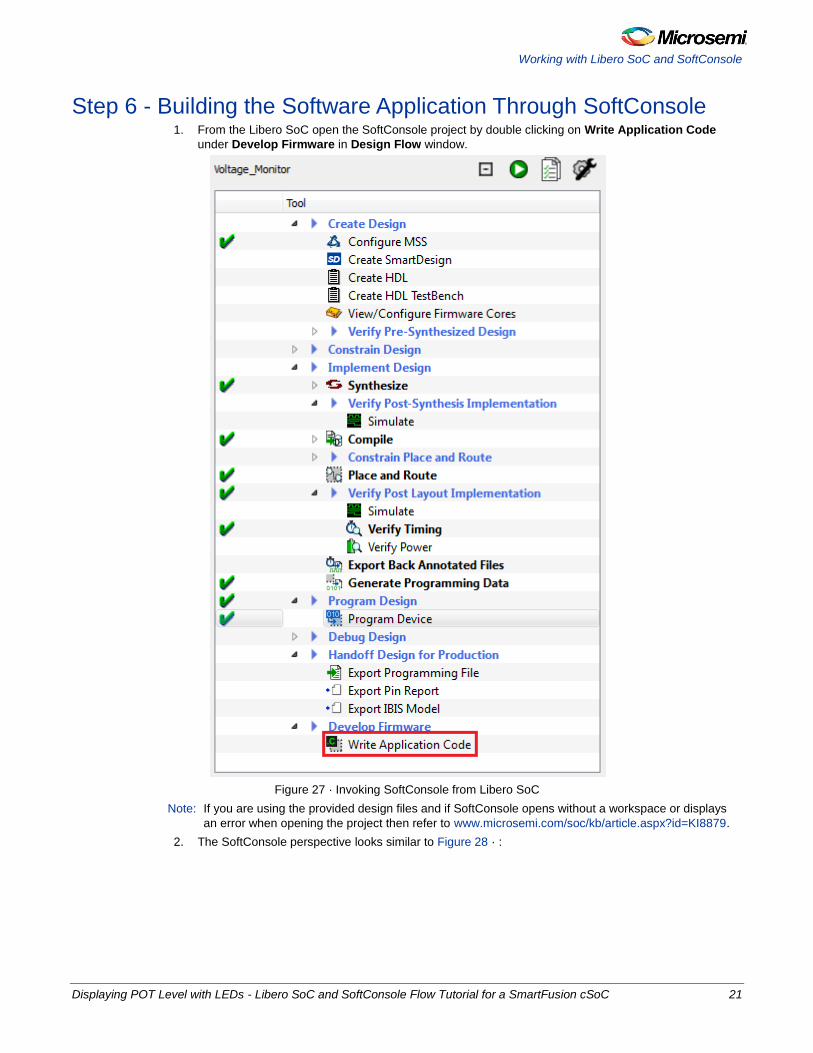
Step 6 - Building the Software Application Through SoftConsole 1. From the Libero SoC open the SoftConsole project by double clicking on Write Application Code
under Develop Firmware in Design Flow window.
Figure 27 · Invoking SoftConsole from Libero SoC
Note: If you are using the provided design files and if SoftConsole opens without a workspace or displays
an error when opening the project then refer to www.microsemi.com/soc/kb/article.aspx?id=KI8879.
2. The SoftConsole perspective looks similar to Figure 28 · :

Working with Libero SoC and SoftConsole
22 Displaying POT Level with LEDs - Libero SoC and SoftConsole Flow Tutorial for a SmartFusion cSoC
Figure 28 · SoftConsole Workspace
3. Copy the code provided below and paste it in main.c file under
Voltage_Monitor_MSS_MSS_CM3_0_app project in the SoftConsole editor and delete the existing
code.
#include "mss_uart.h"
#include "mss_ace.h"
#include "mss_gpio.h"
#include <stdio.h>
#define Microsemi_logo \
"\n\r \
** ** ******* ****** ***** **** ***** ****** ** ** ******* \n\r \
* * * * * * * * * * * * * * * * * \n\r \
* * * * * * ***** * * **** ****** * * * * * \n\r \
* * * * * * * * * * * * * * * \n\r \
* * ******* ****** * * **** ***** ****** * * ******* "
int main()
{
const uint8_t greeting[] = "\n\rWelcome to Microsemi's SmartFusion Voltage
Monitor\n\n\r";
const uint8_t * channel_name;
/*Initialize and Configure GPIO*/
MSS_GPIO_init();
MSS_GPIO_config( MSS_GPIO_31 , MSS_GPIO_OUTPUT_MODE );
MSS_GPIO_config( MSS_GPIO_30 , MSS_GPIO_OUTPUT_MODE );
MSS_GPIO_config( MSS_GPIO_29 , MSS_GPIO_OUTPUT_MODE );

Working with Libero SoC and SoftConsole
Displaying POT Level with LEDs - Libero SoC and SoftConsole Flow Tutorial for a SmartFusion cSoC 23
MSS_GPIO_config( MSS_GPIO_28 , MSS_GPIO_OUTPUT_MODE );
/*Initialize UART_0*/
MSS_UART_init(
&g_mss_uart0,
MSS_UART_57600_BAUD,
MSS_UART_DATA_8_BITS | MSS_UART_NO_PARITY | MSS_UART_ONE_STOP_BIT );
/*Initialize ACE*/
ACE_init( );
MSS_UART_polled_tx_string( &g_mss_uart0, (const uint8_t*)Microsemi_logo );
MSS_UART_polled_tx( &g_mss_uart0, greeting, sizeof(greeting) );
channel_name = ACE_get_channel_name( TM0_Voltage );
for (;;)
{
uint8_t display_buffer[32];
uint16_t adc_result;
int32_t adc_value_mv;
adc_result = ACE_get_ppe_sample( TM0_Voltage );
adc_value_mv = ACE_convert_to_mV( TM0_Voltage, adc_result );
if ( adc_value_mv < 0 )
{
snprintf( (char *)display_buffer, sizeof(display_buffer),
"%s : -%.3fV\r", channel_name, ((float)(-adc_value_mv) / (float)(1000)));
}
else
{
snprintf( (char *)display_buffer, sizeof(display_buffer),
"%s : %.3fV\r", channel_name, ((float)(adc_value_mv) / (float)(1000)));
}
MSS_UART_polled_tx_string( &g_mss_uart0, display_buffer );
/* Checking the status of Voltage flags */
int32_t flag_status_2p5v = ACE_get_flag_status(TM0_Voltage_over_2p5v);
int32_t flag_status_2p0v = ACE_get_flag_status(TM0_Voltage_over_2p0v);
int32_t flag_status_1p5v = ACE_get_flag_status(TM0_Voltage_over_1p5v);
int32_t flag_status_1p0v = ACE_get_flag_status(TM0_Voltage_over_1p0v);
/* Voltage flags are displayed on the LEDs through GPIO */
uint32_t gpio_output;
if ( flag_status_2p5v == FLAG_ASSERTED )

Working with Libero SoC and SoftConsole
24 Displaying POT Level with LEDs - Libero SoC and SoftConsole Flow Tutorial for a SmartFusion cSoC
gpio_output = ~(
MSS_GPIO_28_MASK |
MSS_GPIO_29_MASK |
MSS_GPIO_30_MASK |
MSS_GPIO_31_MASK );
else
if ( flag_status_2p0v == FLAG_ASSERTED )
gpio_output = ~(
MSS_GPIO_28_MASK |
MSS_GPIO_29_MASK |
MSS_GPIO_30_MASK );
else
if ( flag_status_1p5v == FLAG_ASSERTED )
gpio_output = ~(
MSS_GPIO_28_MASK |
MSS_GPIO_29_MASK );
else
if ( flag_status_1p0v == FLAG_ASSERTED )
gpio_output = ~(
MSS_GPIO_28_MASK );
else
gpio_output = (
MSS_GPIO_28_MASK |
MSS_GPIO_29_MASK |
MSS_GPIO_30_MASK |
MSS_GPIO_31_MASK );
MSS_GPIO_set_outputs( gpio_output );
}
return 0;
}
/***************************************************************************/
4. The SoftConsole window looks as shown in Figure 29 · .

Working with Libero SoC and SoftConsole
Displaying POT Level with LEDs - Libero SoC and SoftConsole Flow Tutorial for a SmartFusion cSoC 25
Figure 29 · SoftConsole Workspace
5. Perform a clean build by selecting Project > Clean. Accept the default settings in the Clean dialog box
and click OK.
Figure 30 · Settings for a Clean Build
6. Make sure there are no errors and warnings. Use the next steps to configure the HyperTerminal.

Working with Libero SoC and SoftConsole
26 Displaying POT Level with LEDs - Libero SoC and SoftConsole Flow Tutorial for a SmartFusion cSoC
Step 7 - Configuring Serial Terminal Emulation Program Prior to running the application program, you need to configure the terminal emulator program
(HyperTerminal, included with Windows®) on your PC. Perform the following steps to use the SmartFusion
Evaluation Kit Board or the SmartFusion Development Kit Board:
1. Connect a second mini USB cable between the USB connector on the SmartFusion Evaluation Kit
Board (or the SmartFusion Development Kit Board) and a USB port of your PC. If Windows prompts
you to connect to Windows Update, select No, not at this time and click Next.
2. If the Silicon Labs CP210x USB to UART Bridge drivers are automatically detected (this can be
verified in Device Manager), as shown in Figure 31 · , proceed to the next step; otherwise follow the
3. Step 8 - Installing Drivers for the USB to RS232 Bridge to install drivers for USB to RS232 Bridge.
Figure 31 · Device Manager Listing Silicon Labs CP210x USB to UART Bridge Drivers
4. From the Windows Start menu, select Programs > Accessories > Communications >
HyperTerminal. This opens HyperTerminal. If your computer does not have HyperTerminal, use any
free serial terminal emulation program like PuTTY or Tera Term. Refer to the Configuring Serial
Terminal Emulation Programs tutorial for configuring the HyperTerminal, Tera Term, and PuTTY.
5. Enter Hyperterminal in the Name field in the Connection Description dialog box and click OK.

Working with Libero SoC and SoftConsole
Displaying POT Level with LEDs - Libero SoC and SoftConsole Flow Tutorial for a SmartFusion cSoC 27
Figure 32 · New Connection
6. Select the appropriate COM port (to which USB-Rs232 drivers are pointed) from the Connect using
drop-down list and click OK.
Figure 33 · Selecting the COM Port

Working with Libero SoC and SoftConsole
28 Displaying POT Level with LEDs - Libero SoC and SoftConsole Flow Tutorial for a SmartFusion cSoC
7. Set the following in the COM Properties window and click OK:
Bits per second: 57600
Data bits: 8
Parity: None
Stop Bits: 1
Flow control: None
Figure 34 · Setting the COM Properties
8. Click OK to close the Hyperterminal Properties dialog box.
Next time you can directly open HyperTerminal (without configuring) by selecting
Programs > Accessories > Communications > HyperTerminal > Hyperterminal.
Step 8 - Installing Drivers for the USB to RS232 Bridge Note: You must have full administrative rights for your system to install the USB-RS232 drivers.
1. Download the USB to RS232 bridge drivers from
www.microsemi.com/soc/documents/CP2102_driver.zip.
2. Unzip the CP2102_driver.zip file.
3. Double-click (Run) the CP210x_VCP_Win_XP_S2K3_Vista_7.exe file.
4. Accept the default installation location and click Install.
5. Click Continue Anyway if prompted.
6. When the installation is complete, click OK. The Ports (COM & LPT) section of the Device Manager lists
Silicon Labs CP210x USB to UART Bridge under the Ports section of Device Manager.

Working with Libero SoC and SoftConsole
Displaying POT Level with LEDs - Libero SoC and SoftConsole Flow Tutorial for a SmartFusion cSoC 29
Use the following steps to install drivers for the USB to RS232 Bridge:
Step 9 - Debugging the Application Project using SoftConsole Use the following steps to debug the application project using SoftConsole:
1. Select Debug Configurations from the Run menu of the SoftConsole. The Debug dialog is displayed.
2. Double clicking on Microsemi Cortex-M3 RAM target displays an image similar to Figure 35 · :
Figure 35 · Debug Window
3. Confirm that the following appear on the Main tab in the Debug window:
Name: Voltage_Monitor_MSS_MSS_CM3_0_app Debug
Project: Voltage_Monitor_MSS_MSS_CM3_0_app
C/C++ application: Debug\ Voltage_Monitor_MSS_MSS_CM3_0_app

Working with Libero SoC and SoftConsole
30 Displaying POT Level with LEDs - Libero SoC and SoftConsole Flow Tutorial for a SmartFusion cSoC
4. Select the Commands tab. Confirm that commands appear in the Initialize and Run command
sections, as shown in Figure 36 · :
Figure 36 · Debugger Commands
5. Click Apply and Debug.
6. Click Yes when prompted for Confirm Perspective Switch. This displays the debug view mode.
Figure 37 · Confirm Perspective Switch

Working with Libero SoC and SoftConsole
Displaying POT Level with LEDs - Libero SoC and SoftConsole Flow Tutorial for a SmartFusion cSoC 31
7. Your Debug Prospective should resemble Figure 38 · :
Figure 38 · Debug Perspective
8. Run the application by clicking Run > Resume or by clicking the Run icon on the SoftConsole toolbar.
The voltage measurement along with the greeting message is displayed in the terminal program
window.
9. Turn the potentiometer (POT) on the SmartFusion Evaluation Kit Board or the SmartFusion
Development Kit Board. The voltage measurement will be displayed on HyperTerminal and the LEDs
on the SmartFusion Evaluation Kit Board or the SmartFusion Development Kit Board will illuminate
when one of the voltage monitor flags is asserted.

Working with Libero SoC and SoftConsole
32 Displaying POT Level with LEDs - Libero SoC and SoftConsole Flow Tutorial for a SmartFusion cSoC
10. Adjust the POT and observe that the voltage measurement is continuously updated.
Figure 39 · Voltage Monitor
Figure 40 · Voltage Measurement Continuous Update
11. Observe the state of the LEDs as the POT is adjusted. Confirm that the flags work as specified in the
ACE configurator.
12. Suspend the software application by clicking Run > Suspend from the SoftConsole menu.

Working with Libero SoC and SoftConsole
Displaying POT Level with LEDs - Libero SoC and SoftConsole Flow Tutorial for a SmartFusion cSoC 33
13. Select the Registers tab on the upper window pane to view the value of the Cortex-M3 processor
internal registers.
Figure 41 · The Registers Tab
14. Select the Variables tab in the upper left window pane to view the value of variables in the source
code.
Figure 42 · The Variables Tab
15. Choose Window > Show View > Disassembly to display the assembly level instructions. The
Assembly window is displayed on the right side of the Debug perspective.

Working with Libero SoC and SoftConsole
34 Displaying POT Level with LEDs - Libero SoC and SoftConsole Flow Tutorial for a SmartFusion cSoC
Figure 43 · Assembly Window
16. You can single-step through the source code by choosing Run > Step Into or Run > Step Over or by
clicking the Step Into or Step Over icons. Observe the changes in the source code window
and Disassembly view. Performing a Step Over allows for stepping over functions. The entire function
is executed but there is no need to single step through each instruction contained in the function.
17. Click the Instruction Stepping icon and then perform Step Into operations. Observe that Step
Into now executes a single line of assembly code.
18. Click the Instruction Stepping icon to exit the instruction stepping mode. Single-step through the
application and observe the instruction sequence in the source code window in the middle of the
Debug perspective, and the values of the variables and registers.
19. Resume execution of the code by choosing Run > Resume or by clicking the Resume icon. You can
even add breakpoints in the application for further debugging.

Working with Libero SoC and SoftConsole
Displaying POT Level with LEDs - Libero SoC and SoftConsole Flow Tutorial for a SmartFusion cSoC 35
20. Once you made the required changes, terminate the debugger by selecting
Voltage_Monitor_MSS_MSS_CM3_0_app Debug in the Debug view, then right-clicking and selecting
Terminate and Remove.
Figure 44 · Terminating the Program
21. Close the Debug perspective by selecting Close Perspective from the Window menu.
22. Close the voltage monitor project by selecting the project name in the SoftConsole Project Explorer
view, right–clicking, and selecting Close Project.
23. Close SoftConsole using File > Exit.
24. Close HyperTerminal using File > Exit. Click Yes when prompted for closing immediately.
Step 10 - Building Executable Image in Release mode You can build an application executable image in ―release mode‖ and load it into eNVM for executing code
in eNVM of SmartFusion cSoC device. You can load the application executable image into eNVM with the
help of eNVM data storage client from SmartDesign MSS Configurator and in-application programming (IAP)
or FlashPro programming software. In release mode, you cannot use SoftConsole debugger to load the
executable image into eNVM.
For steps to build an executable image for our application refer the tutorial SmartFusion: Building Executable
Image in Release Mode and Loading into eNVM.
This concludes the tutorial.

Displaying POT Level with LEDs - Libero SoC and SoftConsole Flow Tutorial for a SmartFusion cSoC 37
Appendix A – Libero SoC Catalog Settings
Listed below are the steps to show how to configure your vault location and set up the repositories in Libero
SoC.
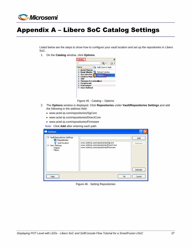
1. On the Catalog window, click Options.
Figure 45 · Catalog – Options
2. The Options window is displayed. Click Repositories under Vault/Repositeries Settings and add
the following in the address field:
www.actel-ip.com/repositories/SgCore
www.actel-ip.com/repositories/DirectCore
www.actel-ip.com/repositories/Firmware
Note: Click Add after entering each path.
Figure 46 · Setting Repositories

Appendix A – Libero SoC Catalog Settings
38 Displaying POT Level with LEDs - Libero SoC and SoftConsole Flow Tutorial for a SmartFusion cSoC
3. Click on Vault location under Vault/Repositeries Settings the Options window. Browse to a location
on your PC to set the vault location where the IPs can be downloaded from the repositories.
Figure 47 · Setting the Vault Location
4. Click OK.

Displaying POT Level with LEDs - Libero SoC and SoftConsole Flow Tutorial for a SmartFusion cSoC 39
Appendix B – Firmware Catalog Settings
1. Open the <Libero Installation directory>\Designer\bin\catalog.exe.
2. Select Tools > Vault/Repositories Settings, from the Firmware Catalog widow.
Figure 48 · Firmware Catalog Settings
3. Select Repositories under Vault/Repositories Settings in the Options dialog box.
4. Confirm that the following repositories are displayed (add them if needed):
www.actel-ip.com/repositories/SgCore
www.actel-ip.com/repositories/DirectCore
www.actel-ip.com/repositories/Firmware
5. Add the above mentioned paths in the address field if required by selecting the repository and clicking
Add.
If new cores are available for download, click Download them now! to download the new cores to the vault.


Displaying POT Level with LEDs - Libero SoC and SoftConsole Flow Tutorial for a SmartFusion cSoC 41
Appendix – C
Configuring the GPIO Peripheral
1. Double-click the GPIO block in the MSS component, configure as shown in Figure 49 · , and click
OK.
Figure 49 · Configure MSS_GPIO_0
This example requires GPIO_31, GPIO_30, GPIO_29, and GPIO_28 to be connected to LED_4 to
LED_1 on the SmartFusion Evaluation Kit Board, and D4 to D1 on the SmartFusion Development Kit
Board. These signals will be routed through the fabric to I/O pins H17, C19, B20, and B19, respectively.
2. Click File > Save to save the Voltage_Monitor_MSS.
Generating the MSS Component
1. Right-click on Voltage_Monitor_MSS_0 component on the Voltage_Monitor tab and select Update
Instance(s) with Latest Component as shown in Figure 50 · .

Appendix – C
42 Displaying POT Level with LEDs - Libero SoC and SoftConsole Flow Tutorial for a SmartFusion cSoC
Figure 50 · Updating the MSS
2. Promote the M2F_GPIO [31:28] pins to top level.
Figure 51 · GPIO Pins Promoted to Top Level
3. Click Design > Configure Firmware as shown in Figure 52 · .
Figure 52 · Opening Design_Firmware
4. On the DESIGN_FIRMWARE tab, clear the Generate check box for all the peripherals for which you
do not need to generate the firmware. Click Configuration on the SmartFusion_CMSIS_PAL_0
instance and select SoftConsole as the configuration.

Appendix – C
Displaying POT Level with LEDs - Libero SoC and SoftConsole Flow Tutorial for a SmartFusion cSoC 43
Figure 53 · Configuring SmartFusion_CMSIS_PAL_0
5. Check whether or not you are able to see the latest version of the drivers without any warning or error
indicating that firmware is missing from the Vault. If missing, refer to Appendix B – Firmware Catalog
Settings.
6. Click File > Save to save the Design_Firmware.
7. Save the design and generate the component by clicking Generate Component or by selecting
SmartDesign > Generate Component.
Figure 54 · Generating the MSS Component
8. After successful generation of project the log window displays the message ―Info: 'Voltage_Monitor'
was successfully generated. Open datasheet for details‖. The datasheet has the Project
information like Generated files, used IO’s, and Memory map etc.

Appendix – C
44 Displaying POT Level with LEDs - Libero SoC and SoftConsole Flow Tutorial for a SmartFusion cSoC
9. Confirm that the SoftConsole folder is created with the folders and files as shown in Figure 55 · .
Figure 55 · Files Window
Generating the Program File
Libero SoC provides the push-button flow for Generating programming data of the project in a single step.
By clicking Generating Programming Data, you can complete synthesis, place and route, verify timing and
generate the programming file. You can also complete the flow by running the synthesis and place and route
tools in interactive mode (step-by-step). For additional information, refer to the Libero SoC Quick Start
Guide.
Push-button Design Flow
1. Click Edit I/O Attributes under Constrain place and route in the Design Flow window.

Appendix – C
Displaying POT Level with LEDs - Libero SoC and SoftConsole Flow Tutorial for a SmartFusion cSoC 45
Figure 56 · Edit I/O Attributes

Appendix – C
46 Displaying POT Level with LEDs - Libero SoC and SoftConsole Flow Tutorial for a SmartFusion cSoC
2. Make the following pin assignments in MultiView Navigator window as shown in Figure 57 · :
GPO_28 to B19
GPO_29 to B20
GPO_30 to C19
GPO_31 to H17
Figure 57 · MultiView Navigator GUI
3. Commit and check the edits using File > Commit and Check. Connect any errors that are reported in
the MVN log window.
4. Close the MultiView Navigator using File > Exit.
5. Close the Designer window and select Yes when it prompts to save changes.
Figure 58 · Designer Window

Appendix – C
Displaying POT Level with LEDs - Libero SoC and SoftConsole Flow Tutorial for a SmartFusion cSoC 47
6. Click Generate Programming Data to complete the place and route, verify timing and generate the
programming file. This completes the.fdb file generation.
Figure 59 · Generating Programming Data

Appendix – C
48 Displaying POT Level with LEDs - Libero SoC and SoftConsole Flow Tutorial for a SmartFusion cSoC
7. The Design Flow window looks similar to Figure 60 · .
Figure 60 · Design Flow Window After Building The Project
8. Follow Step 5 - Programming SmartFusion Board Using FlashPro.

Displaying POT Level with LEDs - Libero SoC and SoftConsole Flow Tutorial for a SmartFusion cSoC 49
List of Changes
Revision Changes Page
Revision 6
(May 2012)
Modified Associated Project Files section (SAR 38282). 3
Modified Step 1 - Creating a Libero SoC Project section (SAR 38282). 5
Updated Figure 6 (SAR 38282). 8
Updated Figure 16 (SAR 38282). 13
Updated Figure 25 (SAR 38282). 18
Updated Figure 26 (SAR 38282). 20
Updated Figure 27 (SAR 38282). 21
Modified Step 6 - Building the Software Application Through SoftConsole section
(SAR 38282).
21
Updated Figure 59 (SAR 38282). 46
Updated Figure 60 (SAR 38282). 48
Revision 5
(February 2012)
Modified Associated Project Files section (SAR 36900). 3
Modified Step 6 - Building the Software Application Through SoftConsole section
(SAR 36900)
21
Modified Step 7 - Configuring Serial Terminal Emulation Program section
(SAR 36900).
26
Updated Figure 34 (SAR 36900). 26
Modified Step 8 - Installing Drivers for the USB to RS232 Bridge section
(SAR 36900).
28
Modified Step 9 - Debugging the Application Project using SoftConsole section
(SAR 36900).
29
Revision 4
(January 2012)
Modified Step 2 - Configuring MSS Peripherals section. (SAR 36492) 8 and 15
Modified Step 6 - Building the Software Application Through SoftConsole section
(SAR 36492)
21
Modified Step 9 - Debugging the Application Project using SoftConsole section
(SAR 36492)
29
Revision 3
(November 2011)
Updated the document for Libero SoC v10.0 (SAR 35045).
Note: The revision number is located in the part number after the hyphen. The part number is displayed at the bottom of the last page of the document. The digits following the slash indicate the month and year of publication.


Displaying POT Level with LEDs - Libero SoC and SoftConsole Flow Tutorial for a SmartFusion cSoC 51
Product Support
Microsemi SoC Products Group backs its products with various support services, including Customer
Service, Customer Technical Support Center, a website, electronic mail, and worldwide sales offices. This
appendix contains information about contacting Microsemi SoC Products Group and using these support
services.
Customer Service Contact Customer Service for non-technical product support, such as product pricing, product upgrades,
update information, order status, and authorization.
From North America, call 800-262-1060 From the rest of the world, call 650.318.4460 Fax, from anywhere in the world 650. 318.8044
Customer Technical Support Center Microsemi SoC Products Group staffs its Customer Technical Support Center with highly skilled engineers
who can help answer your hardware, software, and design questions about Microsemi SoC Products. The
Customer Technical Support Center spends a great deal of time creating application notes, common design
cycle questions, known issues and various FAQs. So, before you contact us, please visit our online
resources. It is very likely we have already answered your questions.
Technical Support Visit the Microsemi SoC Products Group Customer Support website
(www.microsemi.com/soc/support/search/default.aspx) for more information and support. Many answers
available on the searchable web resource include diagrams, illustrations, and links to other resources on
website.
Website You can browse a variety of technical and non-technical information on the Microsemi SoC Products Group
home page, at http://www.microsemi.com/soc/.
Contacting the Customer Technical Support Center Highly skilled engineers staff the Technical Support Center. The Technical Support Center can be contacted
by email or through the Microsemi SoC Products Group website.
You can communicate your technical questions to our email address and receive answers back by email,
fax, or phone. Also, if you have design problems, you can email your design files to receive assistance. We
constantly monitor the email account throughout the day. When sending your request to us, please be sure
to include your full name, company name, and your contact information for efficient processing of your
request.
The technical support email address is [email protected].

Product Support
52 Displaying POT Level with LEDs - Libero SoC and SoftConsole Flow Tutorial for a SmartFusion cSoC
My Cases
Microsemi SoC Products Group customers may submit and track technical cases online by going to My
Cases.
Outside the U.S.
Customers needing assistance outside the US time zones can either contact technical support via email
([email protected]) or contact a local sales office. Sales office listings can be found at
www.microsemi.com/soc/company/contact/default.aspx.
ITAR Technical Support For technical support on RH and RT FPGAs that are regulated by International Traffic in Arms Regulations
(ITAR), contact us via [email protected]. Alternatively, within My Cases, select Yes in the ITAR
dropdown list. For a complete list of ITAR-regulated Microsemi FPGAs, visit the ITAR web page.


50200213-6/05.12
Microsemi Corporate Headquarters One Enterprise, Aliso Viejo CA 92656 USA Within the USA: +1 (949) 380-6100 Sales: +1 (949) 380-6136 Fax: +1 (949) 215-4996
Microsemi Corporation (NASDAQ: MSCC) offers a comprehensive portfolio of semiconductor
solutions for: aerospace, defense and security; enterprise and communications; and industrial
and alternative energy markets. Products include high-performance, high-reliability analog and
RF devices, mixed signal and RF integrated circuits, customizable SoCs, FPGAs, and
complete subsystems. Microsemi is headquartered in Aliso Viejo, Calif. Learn more at
www.microsemi.com.
© 2012 Microsemi Corporation. All rights reserved. Microsemi and the Microsemi logo are trademarks of Microsemi Corporation. All other trademarks and service marks are the property of their respective owners.