Thermal Management of High Brightness LEDs at the System ...
36
© 2011 Bridgelux, Inc. Thermal Management of High Brightness LEDs at the System Level Michael N. Gershowitz, PE Bridgelux MEPTEC 2011
-
Upload
khangminh22 -
Category
Documents
-
view
0 -
download
0
Transcript of Thermal Management of High Brightness LEDs at the System ...
© 2011 Bridgelux, Inc.
Thermal Management
of High Brightness LEDs
at the System Level
Michael N. Gershowitz, PE Bridgelux MEPTEC 2011

© 2011 Bridgelux, Inc.
LEDs for Illumination – a paradigm shift
• Traditional incandescent light sources are very
inefficient, however most of the wasted heat
energy is radiated from the bulb
• LED light sources are very efficient, however
most of the wasted heat energy is conducted
from the package
© 2011 Bridgelux, Inc.
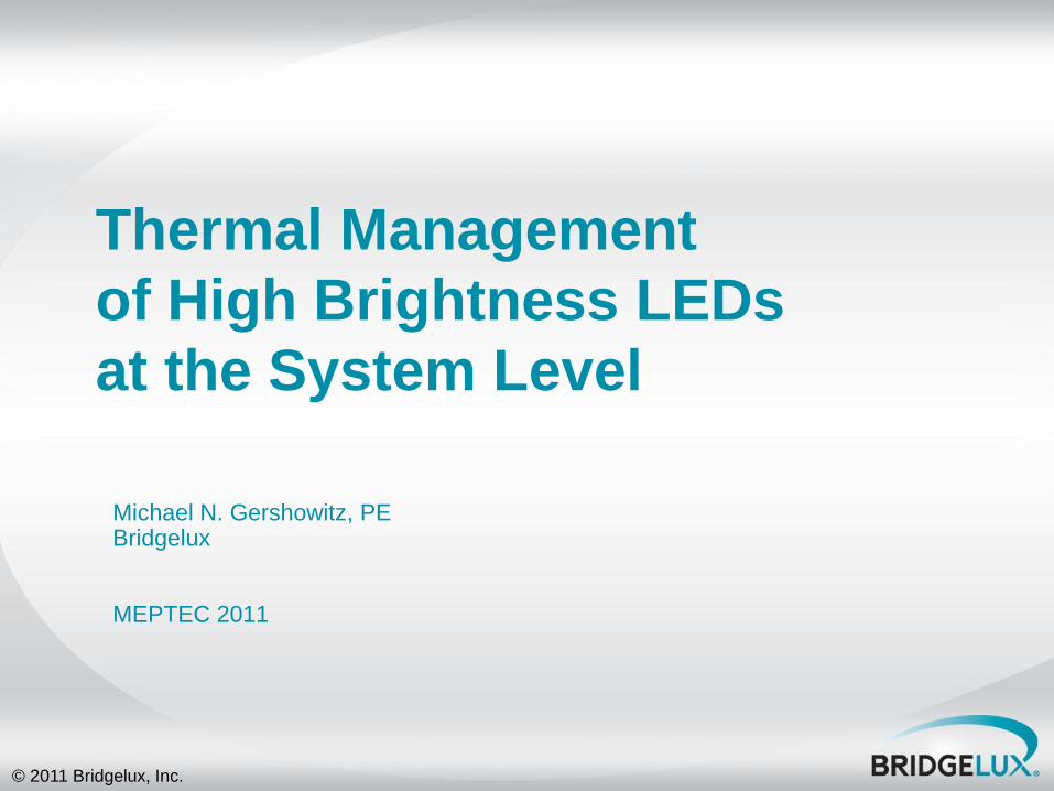
System Energy Equation
Electrical
Input to Array
Light
Heat
Driver Efficiency
Optical Losses Electrical
Input to
System
© 2011 Bridgelux, Inc.
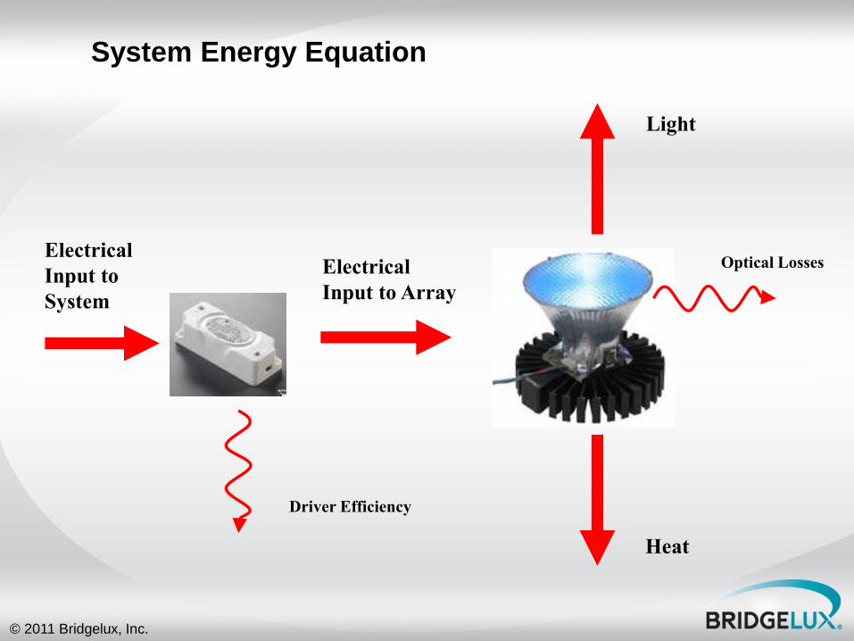
LED arrays vs. LED emitters – Thermal Perspective
• Different thermal resistance
– In application, Bridgelux arrays have one less thermal interface that emitters
– The thermal path (distance and thermal conductivity) are different due to different package construction
• Different die to die spacing
– Smaller surface area for same lumen output with arrays
– More concentrated heat source with arrays
• Materials compatibility - coefficient of expansion
– Arrays use compatibility materials and wire bonding technology „pre-engineered‟
– Emitters users must consider substrate materials and solder joint properties „customer engineered‟
VS.
© 2011 Bridgelux, Inc.
Importance of Thermal Management
Most problems in an LED
lighting solution are caused by
poor thermal management
© 2011 Bridgelux, Inc.
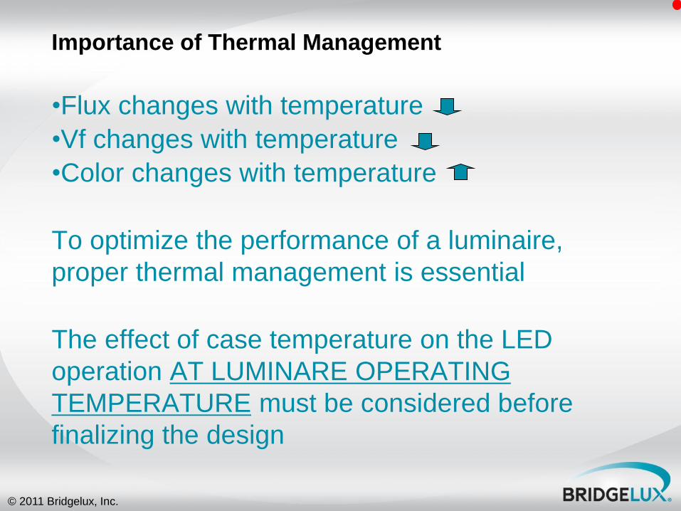
•Flux changes with temperature
•Vf changes with temperature
•Color changes with temperature
To optimize the performance of a luminaire,
proper thermal management is essential
The effect of case temperature on the LED
operation AT LUMINARE OPERATING
TEMPERATURE must be considered before
finalizing the design
Importance of Thermal Management
© 2011 Bridgelux, Inc.
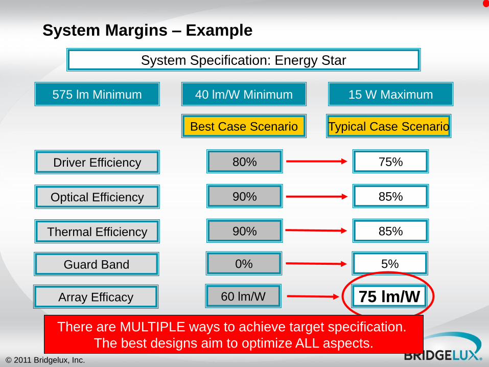
System Margins – Example
System Specification: Energy Star
575 lm Minimum 15 W Maximum 40 lm/W Minimum
Driver Efficiency
Best Case Scenario
Optical Efficiency
Guard Band
Array Efficacy
Thermal Efficiency
80%
90%
90%
0%
60 lm/W
Typical Case Scenario
75 lm/W
5%
85%
85%
75%
There are MULTIPLE ways to achieve target specification.
The best designs aim to optimize ALL aspects.
© 2011 Bridgelux, Inc.
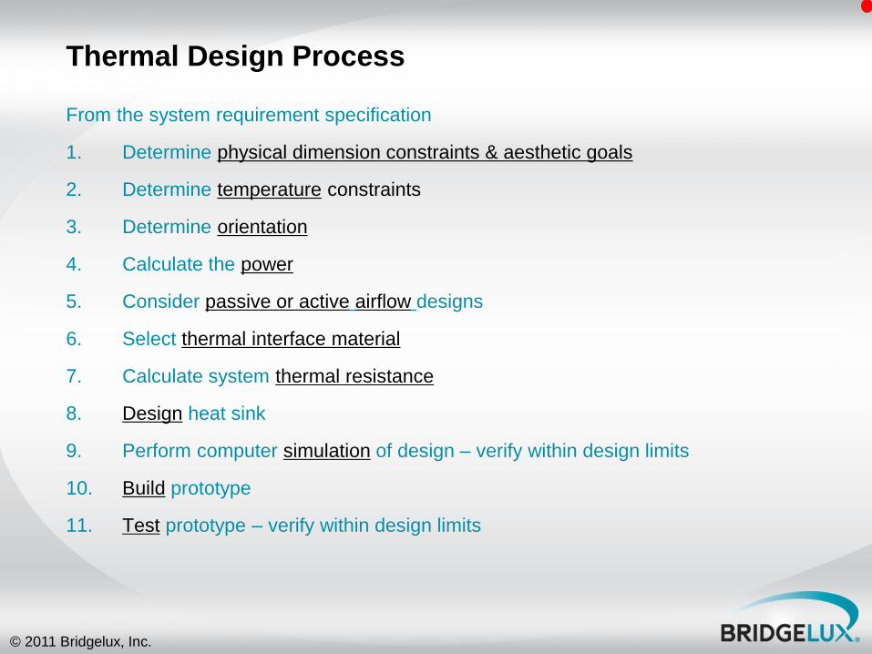
Thermal Design Process
From the system requirement specification
1. Determine physical dimension constraints & aesthetic goals
2. Determine temperature constraints
3. Determine orientation
4. Calculate the power
5. Consider passive or active airflow designs
6. Select thermal interface material
7. Calculate system thermal resistance
8. Design heat sink
9. Perform computer simulation of design – verify within design limits
10. Build prototype
11. Test prototype – verify within design limits

© 2011 Bridgelux, Inc.
1. Thermal Design Process: Physical Dimensions
Is the design intended for drop-in replacement of current fixture?
Is there a pre-determined size?
Is there a market standard? Ex. MR16, A19, PAR 30.
© 2011 Bridgelux, Inc.
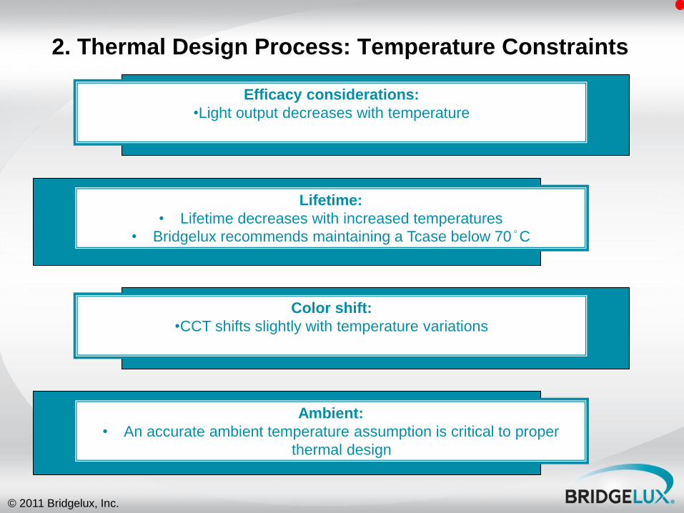
2. Thermal Design Process: Temperature Constraints
Lifetime:
• Lifetime decreases with increased temperatures
• Bridgelux recommends maintaining a Tcase below 70°C
Efficacy considerations:
•Light output decreases with temperature
Color shift:
•CCT shifts slightly with temperature variations
Ambient:
• An accurate ambient temperature assumption is critical to proper
thermal design
© 2011 Bridgelux, Inc.
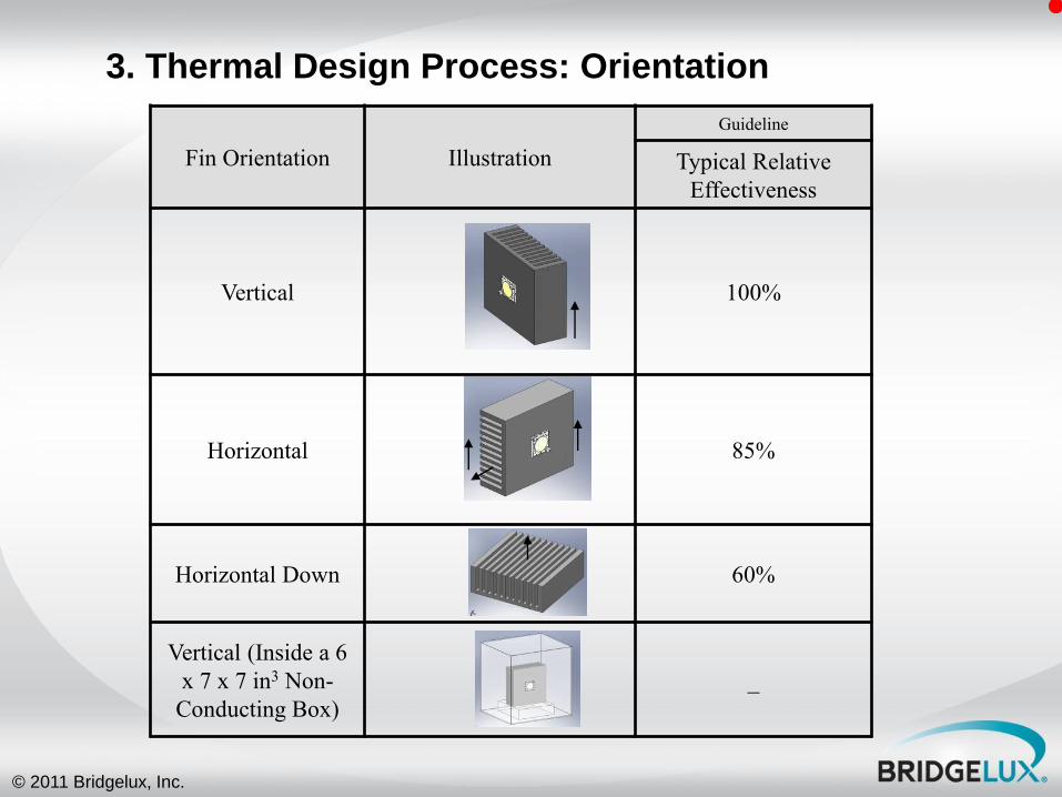
Fin Orientation Illustration
Guideline
Typical Relative
Effectiveness
Vertical 100%
Horizontal 85%
Horizontal Down 60%
Vertical (Inside a 6
x 7 x 7 in3 Non-
Conducting Box)
_
3. Thermal Design Process: Orientation
© 2011 Bridgelux, Inc.
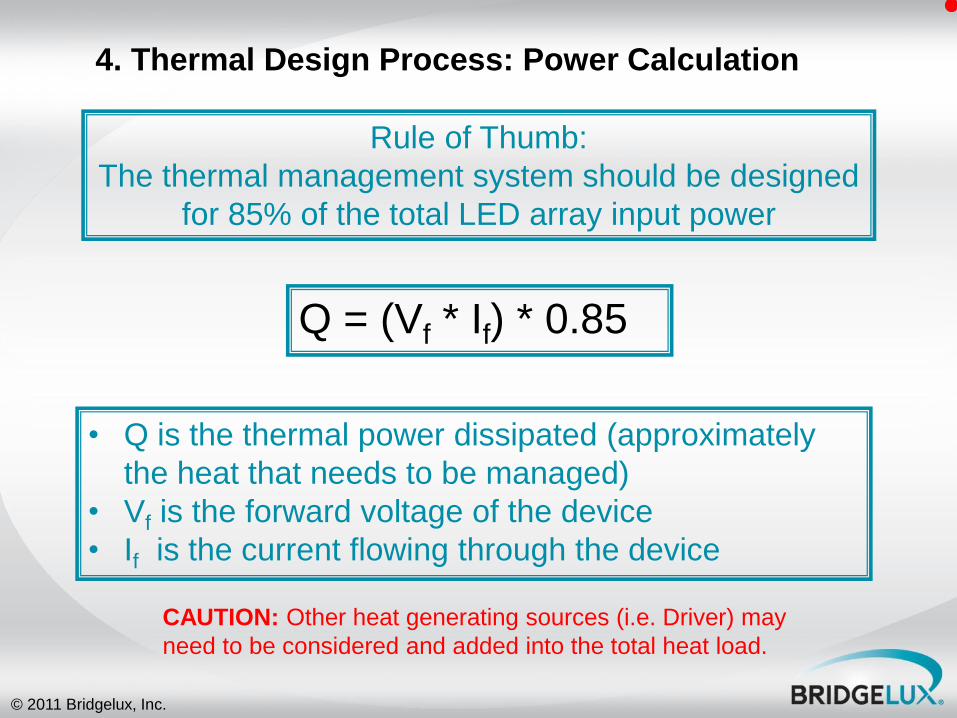
4. Thermal Design Process: Power Calculation
• Q is the thermal power dissipated (approximately
the heat that needs to be managed)
• Vf is the forward voltage of the device
• If is the current flowing through the device
Rule of Thumb:
The thermal management system should be designed
for 85% of the total LED array input power
Q = (Vf * If) * 0.85
CAUTION: Other heat generating sources (i.e. Driver) may
need to be considered and added into the total heat load.
© 2011 Bridgelux, Inc.
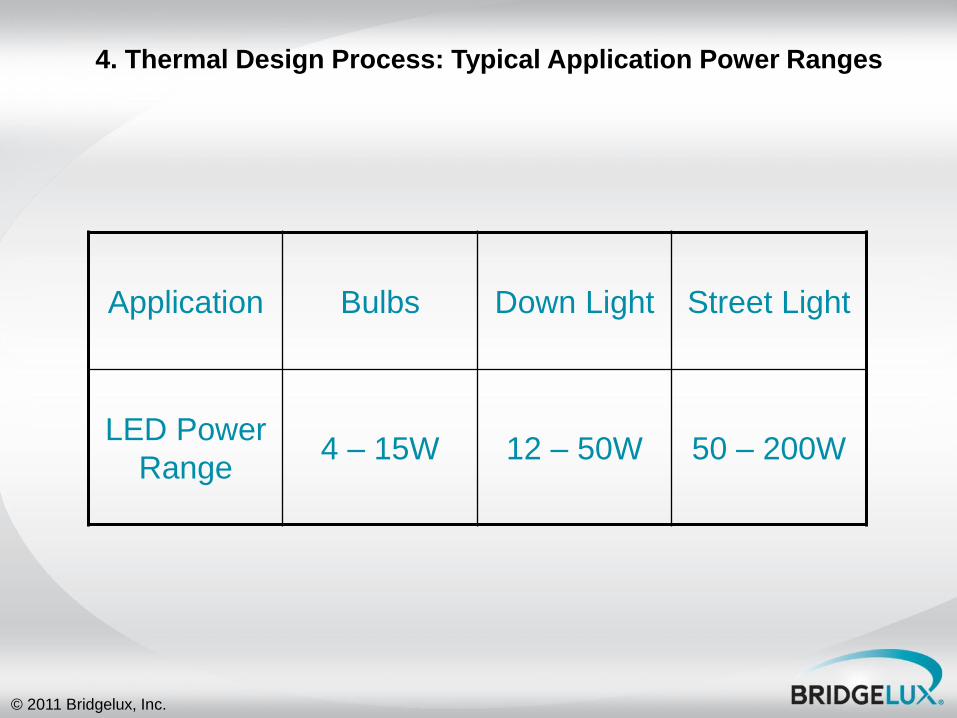
Application Bulbs Down Light Street Light
LED Power
Range 4 – 15W 12 – 50W 50 – 200W
4. Thermal Design Process: Typical Application Power Ranges
© 2011 Bridgelux, Inc.
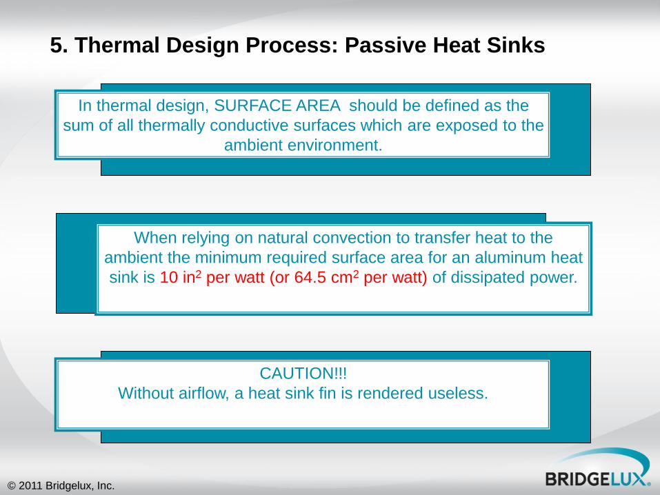
5. Thermal Design Process: Passive Heat Sinks
When relying on natural convection to transfer heat to the
ambient the minimum required surface area for an aluminum heat
sink is 10 in2 per watt (or 64.5 cm2 per watt) of dissipated power.
In thermal design, SURFACE AREA should be defined as the
sum of all thermally conductive surfaces which are exposed to the
ambient environment.
CAUTION!!!
Without airflow, a heat sink fin is rendered useless.
© 2011 Bridgelux, Inc.
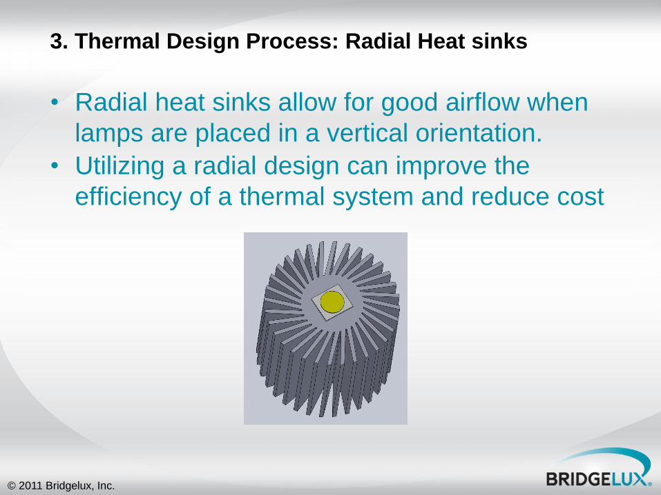
3. Thermal Design Process: Radial Heat sinks
• Radial heat sinks allow for good airflow when
lamps are placed in a vertical orientation.
• Utilizing a radial design can improve the
efficiency of a thermal system and reduce cost
© 2011 Bridgelux, Inc.
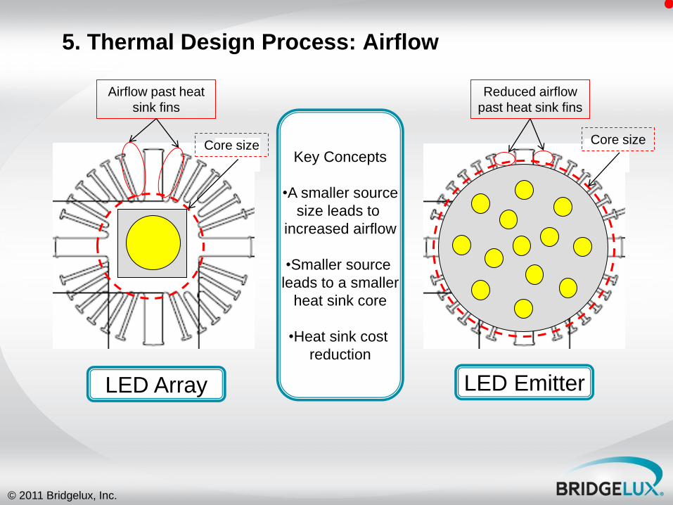
5. Thermal Design Process: Airflow
Key Concepts
•A smaller source
size leads to
increased airflow
•Smaller source
leads to a smaller
heat sink core
•Heat sink cost
reduction
LED Array LED Emitter
Airflow past heat
sink fins
Reduced airflow
past heat sink fins
Core size Core size
© 2011 Bridgelux, Inc.
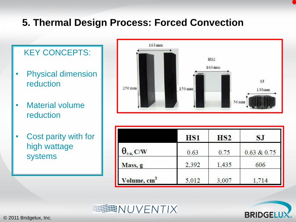
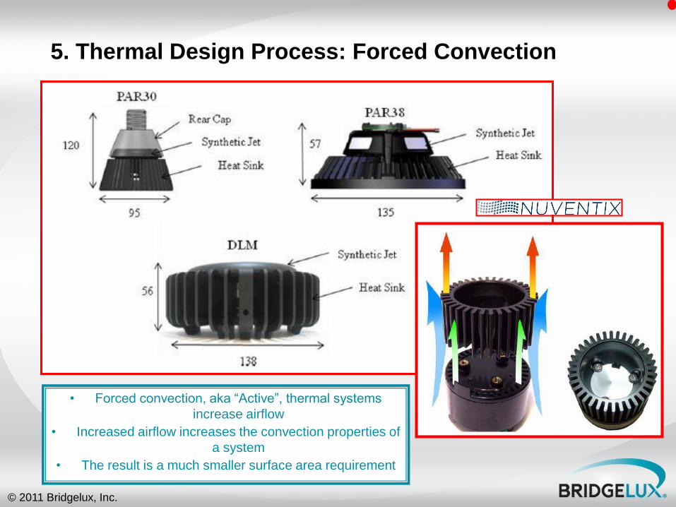
5. Thermal Design Process: Forced Convection
KEY CONCEPTS:
• Physical dimension
reduction
• Material volume
reduction
• Cost parity with for
high wattage
systems
© 2011 Bridgelux, Inc.
5. Thermal Design Process: Forced Convection
• Forced convection, aka “Active”, thermal systems
increase airflow
• Increased airflow increases the convection properties of
a system
• The result is a much smaller surface area requirement
© 2011 Bridgelux, Inc.
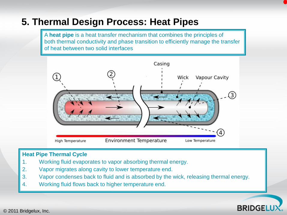
5. Thermal Design Process: Heat Pipes
Heat Pipe Thermal Cycle
1. Working fluid evaporates to vapor absorbing thermal energy.
2. Vapor migrates along cavity to lower temperature end.
3. Vapor condenses back to fluid and is absorbed by the wick, releasing thermal energy.
4. Working fluid flows back to higher temperature end.
A heat pipe is a heat transfer mechanism that combines the principles of
both thermal conductivity and phase transition to efficiently manage the transfer
of heat between two solid interfaces
© 2011 Bridgelux, Inc.
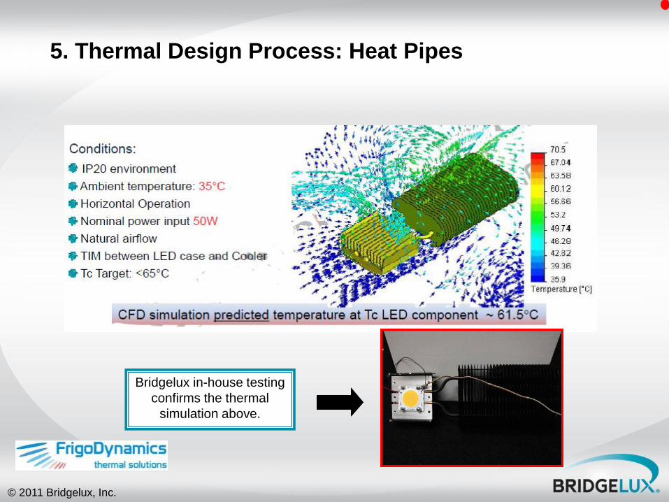
5. Thermal Design Process: Heat Pipes
Bridgelux in-house testing
confirms the thermal
simulation above.
© 2011 Bridgelux, Inc.
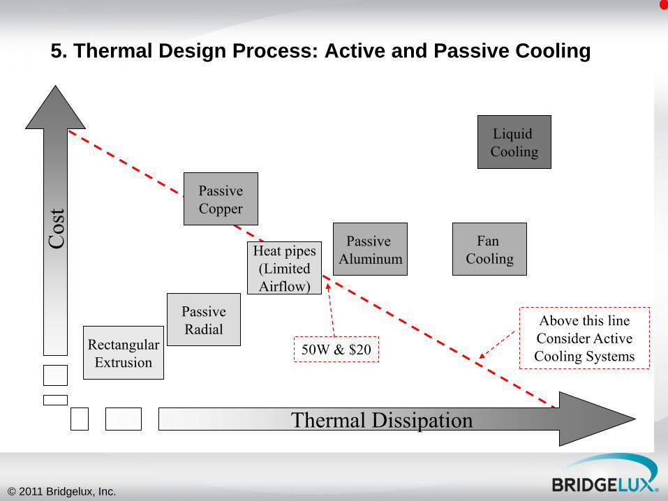
5. Thermal Design Process: Active and Passive Cooling
Passive
Aluminum
Liquid
Cooling
Heat pipes
(Limited
Airflow)
Passive
Copper
Rectangular
Extrusion
Passive
Radial
Fan
Cooling
Thermal Dissipation
Cost
50W & $20
Above this line
Consider Active
Cooling Systems
© 2011 Bridgelux, Inc.
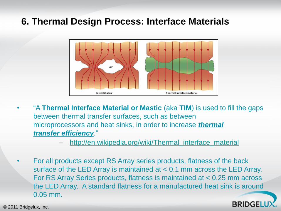
• “A Thermal Interface Material or Mastic (aka TIM) is used to fill the gaps
between thermal transfer surfaces, such as between
microprocessors and heat sinks, in order to increase thermal
transfer efficiency.”
– http://en.wikipedia.org/wiki/Thermal_interface_material
• For all products except RS Array series products, flatness of the back
surface of the LED Array is maintained at < 0.1 mm across the LED Array.
For RS Array Series products, flatness is maintained at < 0.25 mm across
the LED Array. A standard flatness for a manufactured heat sink is around
0.05 mm.
6. Thermal Design Process: Interface Materials

© 2011 Bridgelux, Inc.
Pad Thermal
Adhesive Thermal Grease Thermal Grease
Based Pad
Phase Changing
Materials Thermal Tape
Relative Thermal
Conductivity Various High High High High Med
Electrical Isolation Various None None None Various Various
Cost High Med/High Low Low/Med High Med
Manufacturability
Custom
stamping of
rolls
Screen
Printing /
Messy Screen Printing / Messy
Custom stamping
of rolls
Custom stamping
of rolls
Custom
stamping of
rolls
Reliability
Good Good
Potential Long Term
Silicone Oil Bleed
Potential Long
Term Silicone
Oil Bleed
Unproven:
Thermal Cycling
Unproven:
Peeling/Air
gaps
Attachment None Permanent None None None
Single or Dbl
Adhesive
Other Concerns Thermal Cycling Air gaps
Recommended for
Evaluation High High Medium Medium Low Low
6. Thermal Design Process: Interface Material Comparison

© 2011 Bridgelux, Inc.
7. Thermal Design Process: Thermal Resistance
Heat sinks can be defined by the thermal
resistance required to maintain a specified array
case temperature with knowledge of:
Ambient temperature
Thermal resistance of system
Thermal power

© 2011 Bridgelux, Inc.
7. Thermal Design Process: Thermal Resistance Equation
RƟsystem = (Tcase – Tambient) / Q
•RƟsystem is the thermal resistance from the case of the array to the ambient side of the heat sink.
•For a well assembled luminaire, RƟsystem is approximately the same as thermal resistance of the heat sink
•Tcase is the required case temperature of the array
•Tambient is the ambient temperature of the environment
•Q is heat flow
© 2011 Bridgelux, Inc.
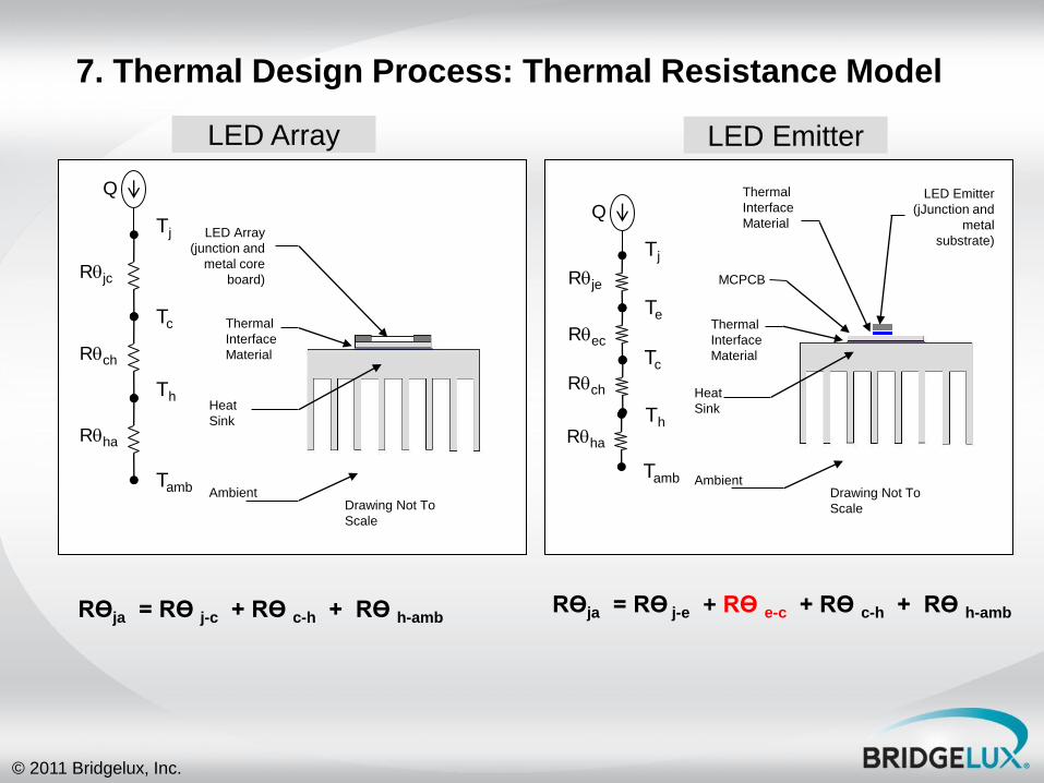
RƟja = RƟ j-c + RƟ c-h + RƟ h-amb RƟja = RƟ j-e + RƟ e-c + RƟ c-h + RƟ h-amb
Tj
Tc
Th
Tamb
Rqjc
Rqch
Rqha
Q
LED Array
(junction and
metal core
board)
Heat
Sink
Ambient
Thermal
Interface
Material
Drawing Not To
Scale
Tj
Te
Tamb
Rqje
Rqec
Rqha
Q
Tc
Th
Rqch
LED Emitter
(jJunction and
metal
substrate)
Heat
Sink
Ambient
Thermal
Interface
Material
Drawing Not To
Scale
Thermal
Interface
Material
MCPCB
LED Array LED Emitter
7. Thermal Design Process: Thermal Resistance Model
© 2011 Bridgelux, Inc.
8. Thermal Design Process: Heat Sink References
• Many heat sink companies produce heat
sink products (extrusions and castings)
that are suitable for use with Bridgelux
LED Arrays. These products can be
procured quickly directly from the
company or their distributor for
expediting concept and prototype testing
processes.
• Thermal Modeling Service Companies
can be used by companies in need of
thermal and mechanical engineering
assistance during their design, prototype
or manufacturing processes. These
companies offer services ranging from
mechanical design to thermal simulation.
© 2011 Bridgelux, Inc.
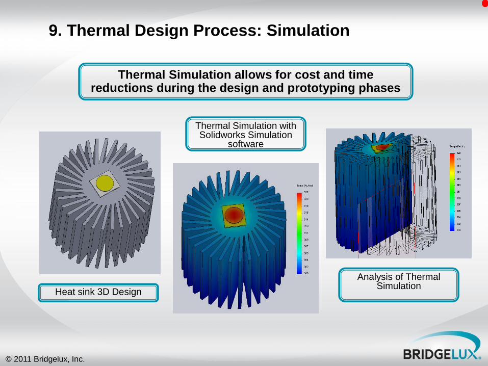
9. Thermal Design Process: Simulation
Heat sink 3D Design
Thermal Simulation with Solidworks Simulation
software
Analysis of Thermal Simulation
Thermal Simulation allows for cost and time reductions during the design and prototyping phases
© 2011 Bridgelux, Inc.
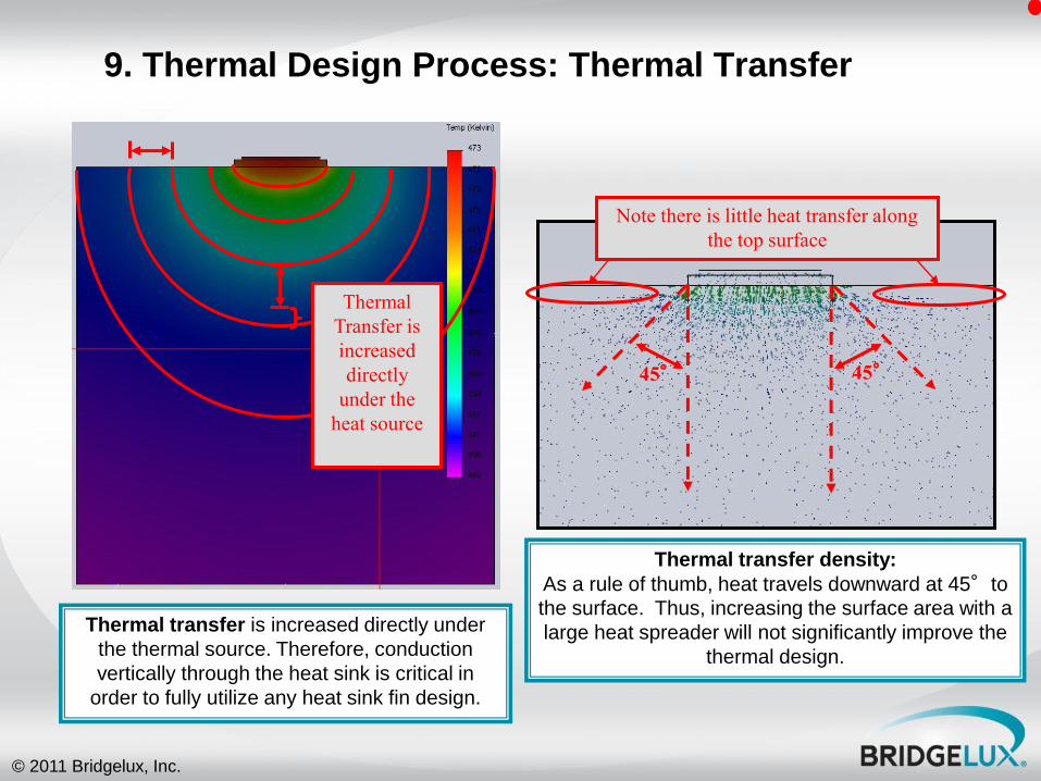
9. Thermal Design Process: Thermal Transfer
45° 45°
Thermal
Transfer is
increased
directly
under the
heat source
Thermal transfer is increased directly under
the thermal source. Therefore, conduction
vertically through the heat sink is critical in
order to fully utilize any heat sink fin design.
Thermal transfer density:
As a rule of thumb, heat travels downward at 45°to
the surface. Thus, increasing the surface area with a
large heat spreader will not significantly improve the
thermal design.
Note there is little heat transfer along
the top surface
© 2011 Bridgelux, Inc.
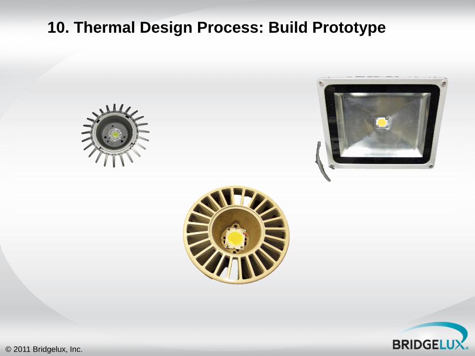
10. Thermal Design Process: Build Prototype
© 2011 Bridgelux, Inc.
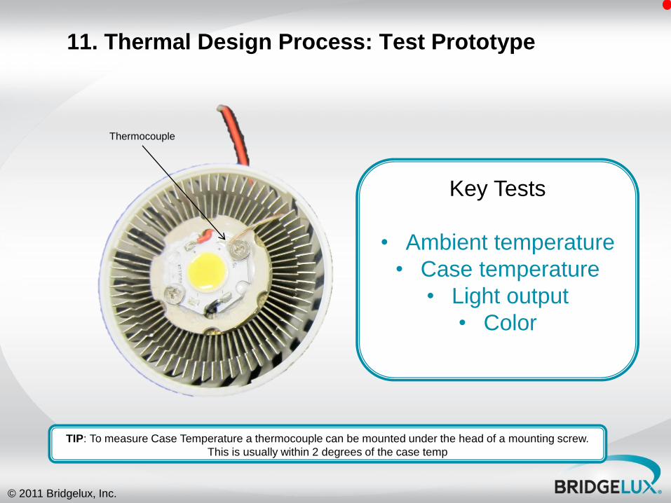
11. Thermal Design Process: Test Prototype
Key Tests
• Ambient temperature
• Case temperature
• Light output
• Color
Thermocouple
TIP: To measure Case Temperature a thermocouple can be mounted under the head of a mounting screw.
This is usually within 2 degrees of the case temp

© 2011 Bridgelux, Inc.
And don’t forget manufacturing
• Once you‟ve designed a good thermal system
solution, don‟t forget to be sure it is
implemented in production – TIM application
– Mounting to heat sink • Correct screw torque

© 2011 Bridgelux, Inc.
Thermal Interface Material – Greases/Epoxies
Insufficient thermal
grease coverage
Bond-line too thick
Insufficient coverage
• Excessive amounts of thermal paste
• Thermal paste fillet too high and could
cause electrical short
Excessive amounts thermal grease will result in a thick bond-line and possibly
an excessive fillet height
© 2011 Bridgelux, Inc.
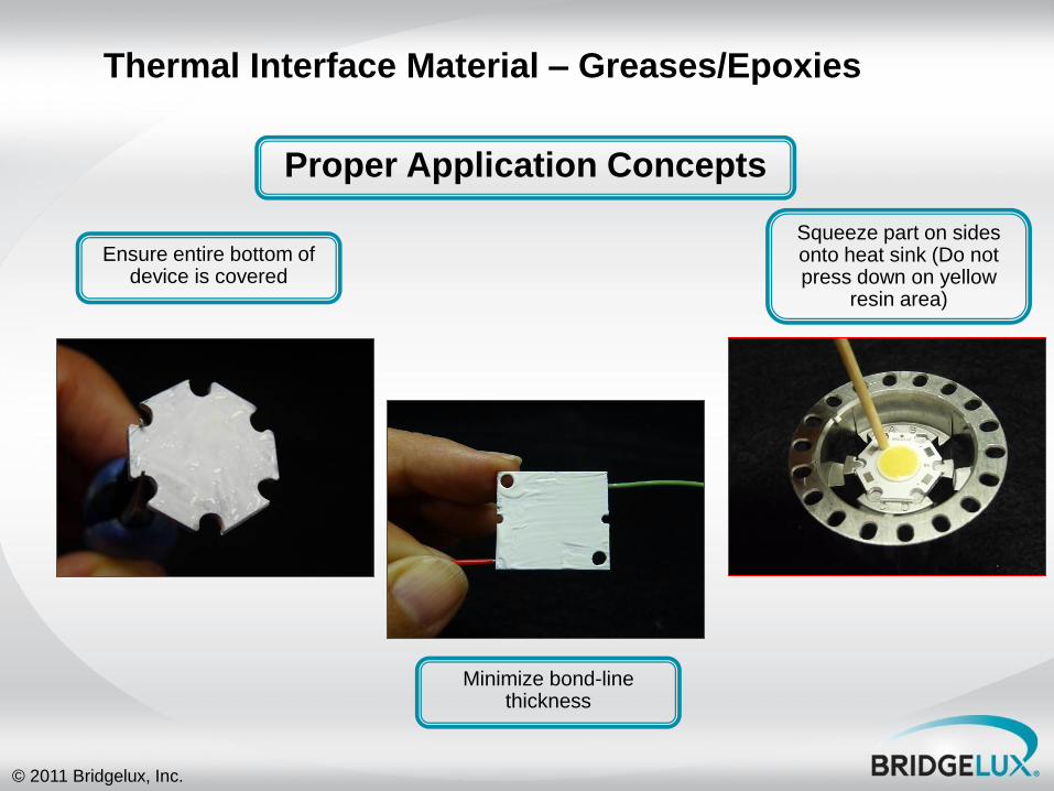
Thermal Interface Material – Greases/Epoxies
Ensure entire bottom of device is covered
Minimize bond-line thickness
Squeeze part on sides onto heat sink (Do not press down on yellow
resin area)
Proper Application Concepts
© 2011 Bridgelux, Inc.
Recap
• Most problems with LED applications are
related to system level thermal considerations
• Good thermal design is critical – Simulate
– Prototype
– Test
• Accounting for thermal effects to light output,
color and electrical properties are critical
© 2011 Bridgelux, Inc.
Thank You!