
SMEA1404 – THERMAL ENGINEERING
191
1 SCHOOL OF MECHANICAL ENGINEERING DEPARTMENT OF MECHANICAL ENGINEERING SMEA1404 – THERMAL ENGINEERING
-
Upload
khangminh22 -
Category
Documents
-
view
3 -
download
0
Transcript of SMEA1404 – THERMAL ENGINEERING
1
SCHOOL OF MECHANICAL ENGINEERING
DEPARTMENT OF MECHANICAL ENGINEERING
SMEA1404 – THERMAL ENGINEERING
2
Syllabus
Air Standard Cycle analysis - Otto, Diesel, Dual, Brayton cycle, Simple Rankine, Reheat and
Regeneration cycles performance.
Unit -1 - UNIT 1 GAS AND VAPOUR POWER CYCLES – SMEA1404

3
DEFINITION OF A CYCLE
A cycle isdefined as a repeated series of operations occurring in a certain order. It may be repeated
by repeating the processes in the same order. The cycle may be of imaginary perfectengine or
actual engine. The former is called ideal cycle and the latter actual cycle. In idealcycle all
accidental heat losses are prevented and the working substance is assumed to behave
like a perfect working substance.
AIR STANDARD EFFICIENCY
To compare the effects of different cycles, it is of paramount importance that the effect of the
calorific value of the fuel is altogether eliminated and this can be achieved by considering air
(which is assumed to behave as a perfect gas) as the working substance in the engine cylinder.
Theefficiency of engine using air as the working medium is known as an “Air standard
efficiency”.This efficiency is oftenly called ideal efficiency.
The actual efficiency of a cycle is always less than the air-standard efficiency of that cycleunder
ideal conditions. This is taken into account by introducing a new term “Relative efficiency”which
is defined as :
ηrelative = Actual thermal efficiency
Air standard efficiency
The analysis of all air standard cycles is based upon the following assumptions :
Assumptions :
1. The gas in the engine cylinder is a perfect gas i.e., it obeys the gas laws and has constant
specific heats.
2. The physical constants of the gas in the cylinder are the same as those of air at moderate
temperatures i.e., the molecular weight of cylinder gas is 29.
cp= 1.005 kJ/kg-K, cv= 0.718 kJ/kg-K.
3. The compression and expansion processes are adiabatic and they take place without
internal friction, i.e., these processes are isentropic.
4. No chemical reaction takes place in the cylinder. Heat is supplied or rejected by bringing a
hot body or a cold body in contact with cylinder at appropriate points during the process.
5. The cycle is considered closed with the same ‘air’ always remaining in the cylinder to
repeat the cycle.
THE CARNOT CYCLE
This cycle has the highest possible efficiency and consists of four simple operations namely,
(a) Isothermal expansion
(b) Adiabatic expansion
(c) Isothermal compression
(d) Adiabatic compression.
The condition of the Carnot cycle may be imagined to occur in the following way:
4
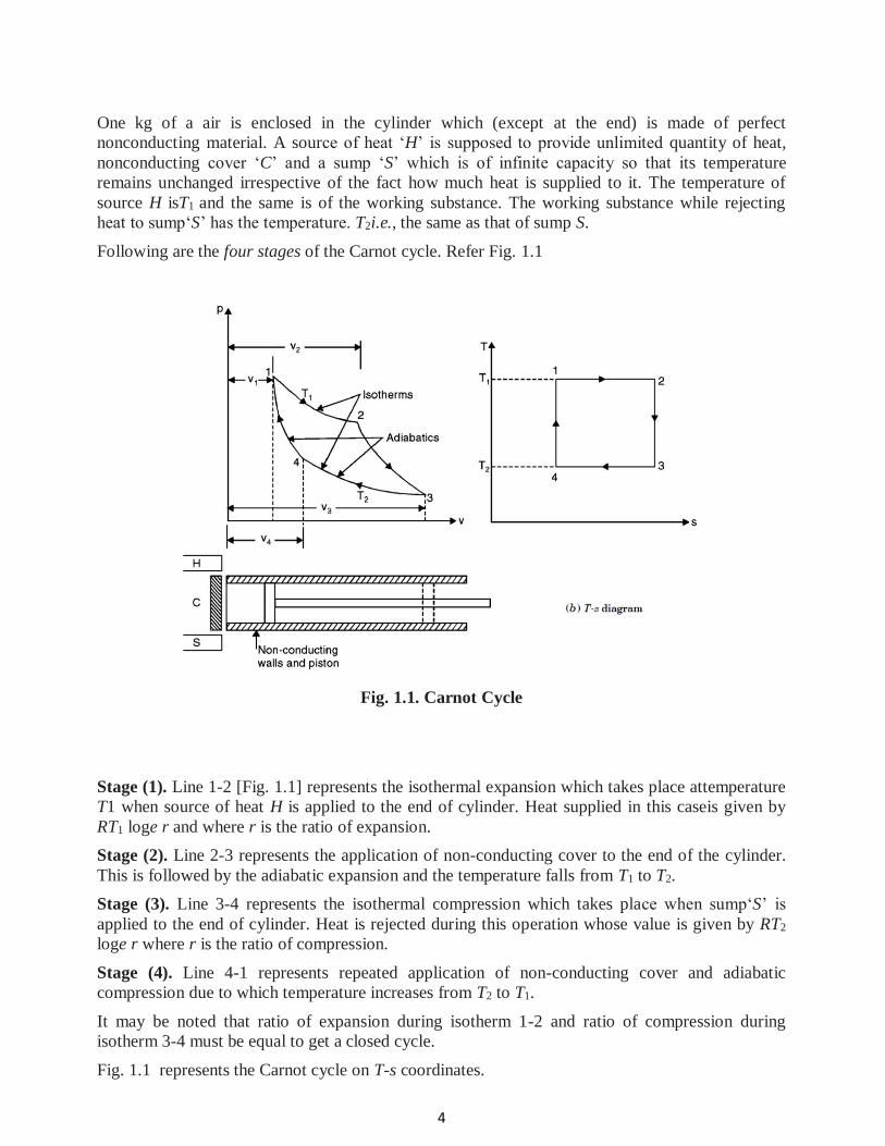
One kg of a air is enclosed in the cylinder which (except at the end) is made of perfect
nonconducting material. A source of heat ‘H’ is supposed to provide unlimited quantity of heat,
nonconducting cover ‘C’ and a sump ‘S’ which is of infinite capacity so that its temperature
remains unchanged irrespective of the fact how much heat is supplied to it. The temperature of
source H isT1 and the same is of the working substance. The working substance while rejecting
heat to sump‘S’ has the temperature. T2i.e., the same as that of sump S.
Following are the four stages of the Carnot cycle. Refer Fig. 1.1
Fig. 1.1. Carnot Cycle
Stage (1). Line 1-2 [Fig. 1.1] represents the isothermal expansion which takes place attemperature
T1 when source of heat H is applied to the end of cylinder. Heat supplied in this caseis given by
RT1 loge r and where r is the ratio of expansion.
Stage (2). Line 2-3 represents the application of non-conducting cover to the end of the cylinder.
This is followed by the adiabatic expansion and the temperature falls from T1 to T2.
Stage (3). Line 3-4 represents the isothermal compression which takes place when sump‘S’ is
applied to the end of cylinder. Heat is rejected during this operation whose value is given by RT2
loge r where r is the ratio of compression.
Stage (4). Line 4-1 represents repeated application of non-conducting cover and adiabatic
compression due to which temperature increases from T2 to T1.
It may be noted that ratio of expansion during isotherm 1-2 and ratio of compression during
isotherm 3-4 must be equal to get a closed cycle.
Fig. 1.1 represents the Carnot cycle on T-s coordinates.
5
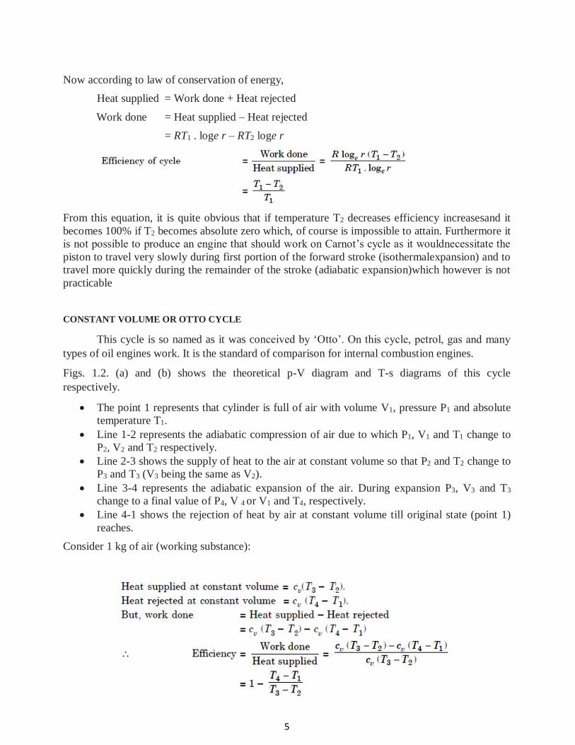
Now according to law of conservation of energy,
Heat supplied = Work done + Heat rejected
Work done = Heat supplied – Heat rejected
= RT1 . loge r – RT2 loge r
From this equation, it is quite obvious that if temperature T2 decreases efficiency increasesand it
becomes 100% if T2 becomes absolute zero which, of course is impossible to attain. Furthermore it
is not possible to produce an engine that should work on Carnot’s cycle as it wouldnecessitate the
piston to travel very slowly during first portion of the forward stroke (isothermalexpansion) and to
travel more quickly during the remainder of the stroke (adiabatic expansion)which however is not
practicable
CONSTANT VOLUME OR OTTO CYCLE
This cycle is so named as it was conceived by ‘Otto’. On this cycle, petrol, gas and many
types of oil engines work. It is the standard of comparison for internal combustion engines.
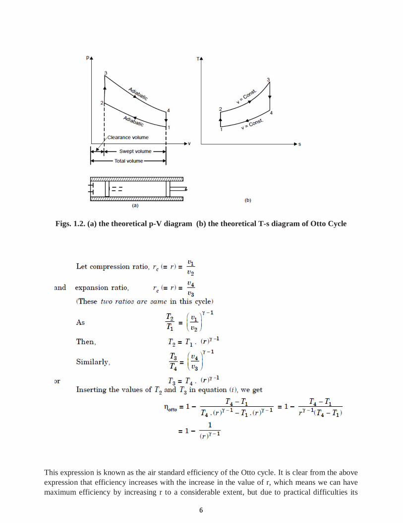
Figs. 1.2. (a) and (b) shows the theoretical p-V diagram and T-s diagrams of this cycle
respectively.
The point 1 represents that cylinder is full of air with volume V1, pressure P1 and absolute
temperature T1.
Line 1-2 represents the adiabatic compression of air due to which P1, V1 and T1 change to
P2, V2 and T2 respectively.
Line 2-3 shows the supply of heat to the air at constant volume so that P2 and T2 change to
P3 and T3 (V3 being the same as V2).
Line 3-4 represents the adiabatic expansion of the air. During expansion P3, V3 and T3
change to a final value of P4, V 4 or V1 and T4, respectively.
Line 4-1 shows the rejection of heat by air at constant volume till original state (point 1)
reaches.
Consider 1 kg of air (working substance):
6
Figs. 1.2. (a) the theoretical p-V diagram (b) the theoretical T-s diagram of Otto Cycle
This expression is known as the air standard efficiency of the Otto cycle. It is clear from the above
expression that efficiency increases with the increase in the value of r, which means we can have
maximum efficiency by increasing r to a considerable extent, but due to practical difficulties its
7
value is limited to about 8. The net work done per kg in the Otto cycle can also be expressed in
terms of p, v. If p is expressed in bar i.e., 105 N/m2, then work done
MEP may be thought of as the average pressure acting on a piston during different portions of its
cycle.It is the ratio of the work done to stoke volume of the cycle
8
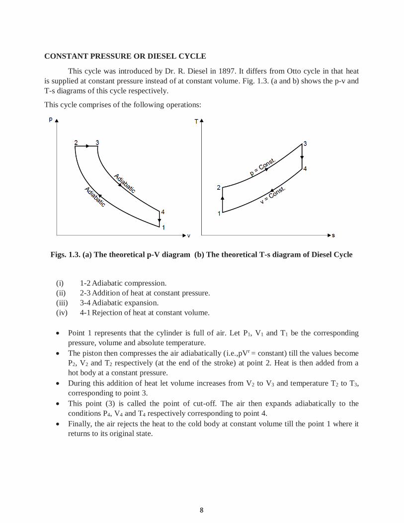
CONSTANT PRESSURE OR DIESEL CYCLE
This cycle was introduced by Dr. R. Diesel in 1897. It differs from Otto cycle in that heat
is supplied at constant pressure instead of at constant volume. Fig. 1.3. (a and b) shows the p-v and
T-s diagrams of this cycle respectively.
This cycle comprises of the following operations:
Figs. 1.3. (a) The theoretical p-V diagram (b) The theoretical T-s diagram of Diesel Cycle
(i) 1-2 Adiabatic compression.
(ii) 2-3 Addition of heat at constant pressure.
(iii) 3-4 Adiabatic expansion.
(iv) 4-1 Rejection of heat at constant volume.
Point 1 represents that the cylinder is full of air. Let P1, V1 and T1 be the corresponding
pressure, volume and absolute temperature.
The piston then compresses the air adiabatically (i.e.,pVr = constant) till the values become
P2, V2 and T2 respectively (at the end of the stroke) at point 2. Heat is then added from a
hot body at a constant pressure.
During this addition of heat let volume increases from V2 to V3 and temperature T2 to T3,
corresponding to point 3.
This point (3) is called the point of cut-off. The air then expands adiabatically to the
conditions P4, V4 and T4 respectively corresponding to point 4.
Finally, the air rejects the heat to the cold body at constant volume till the point 1 where it
returns to its original state.
9
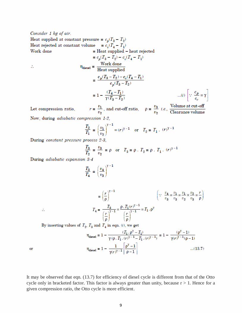
It may be observed that eqn. (13.7) for efficiency of diesel cycle is different from that of the Otto
cycle only in bracketed factor. This factor is always greater than unity, because r > 1. Hence for a
given compression ratio, the Otto cycle is more efficient.
10
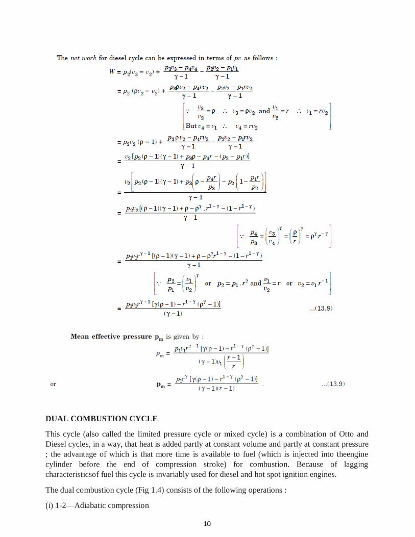
DUAL COMBUSTION CYCLE
This cycle (also called the limited pressure cycle or mixed cycle) is a combination of Otto and
Diesel cycles, in a way, that heat is added partly at constant volume and partly at constant pressure
; the advantage of which is that more time is available to fuel (which is injected into theengine
cylinder before the end of compression stroke) for combustion. Because of lagging
characteristicsof fuel this cycle is invariably used for diesel and hot spot ignition engines.
The dual combustion cycle (Fig 1.4) consists of the following operations :
(i) 1-2—Adiabatic compression
11
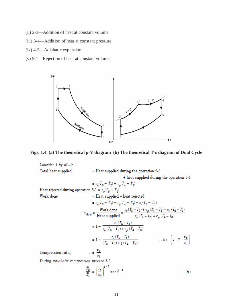
(ii) 2-3—Addition of heat at constant volume
(iii) 3-4—Addition of heat at constant pressure
(iv) 4-5—Adiabatic expansion
(v) 5-1—Rejection of heat at constant volume.
Figs. 1.4. (a) The theoretical p-V diagram (b) The theoretical T-s diagram of Dual Cycle
12
13
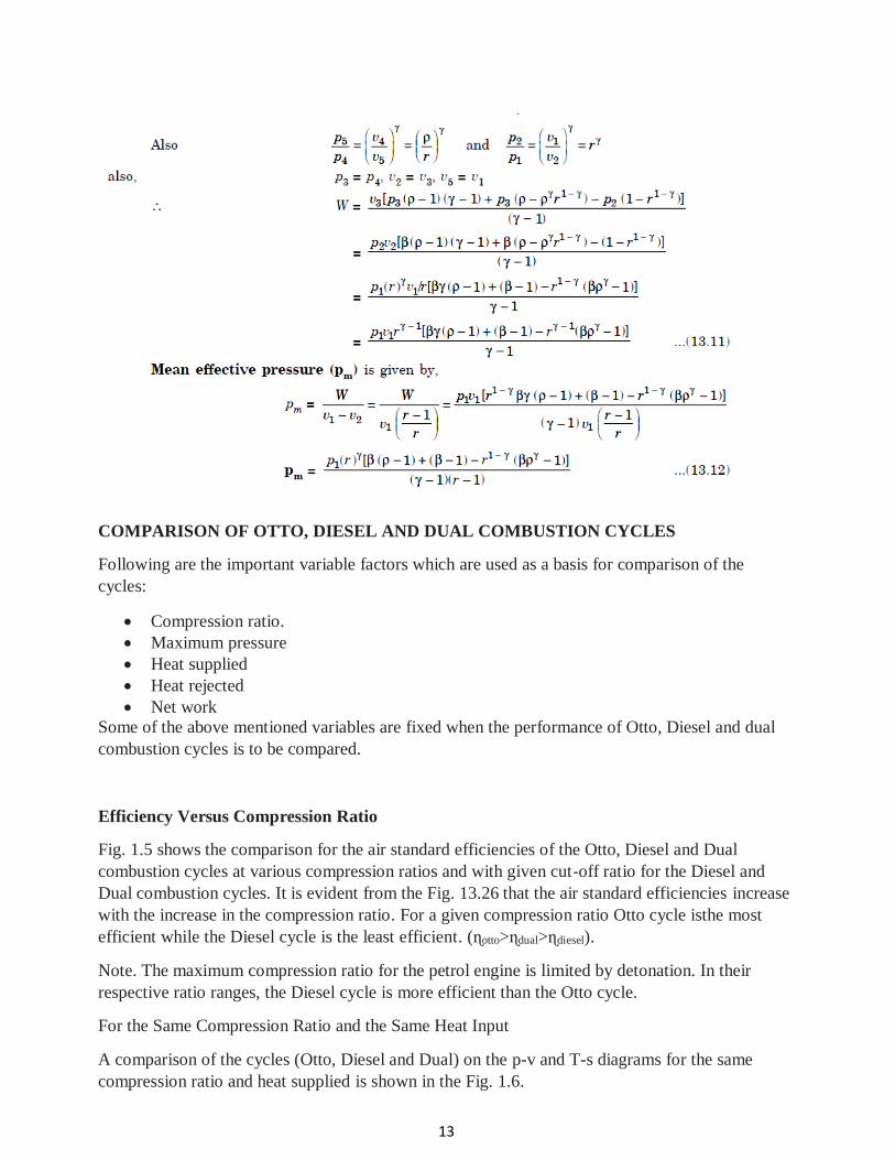
COMPARISON OF OTTO, DIESEL AND DUAL COMBUSTION CYCLES
Following are the important variable factors which are used as a basis for comparison of the
cycles:
Compression ratio.
Maximum pressure
Heat supplied
Heat rejected
Net work
Some of the above mentioned variables are fixed when the performance of Otto, Diesel and dual
combustion cycles is to be compared.
Efficiency Versus Compression Ratio
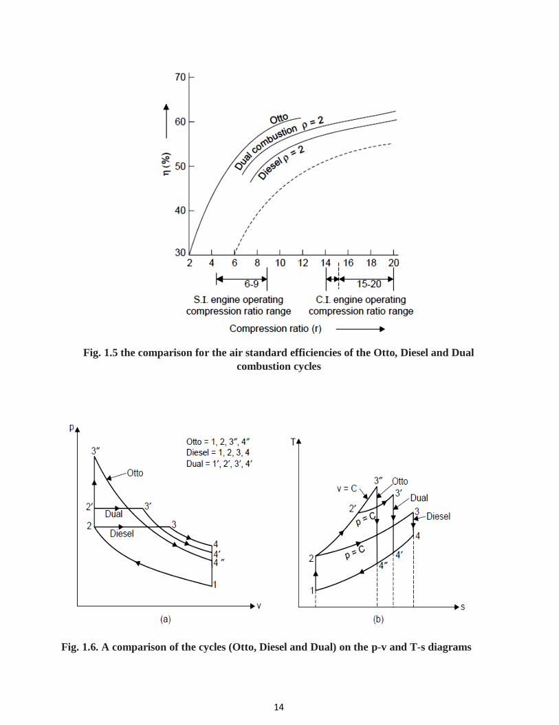
Fig. 1.5 shows the comparison for the air standard efficiencies of the Otto, Diesel and Dual
combustion cycles at various compression ratios and with given cut-off ratio for the Diesel and
Dual combustion cycles. It is evident from the Fig. 13.26 that the air standard efficiencies increase
with the increase in the compression ratio. For a given compression ratio Otto cycle isthe most
efficient while the Diesel cycle is the least efficient. (ɳotto>ɳdual>ɳdiesel).
Note. The maximum compression ratio for the petrol engine is limited by detonation. In their
respective ratio ranges, the Diesel cycle is more efficient than the Otto cycle.
For the Same Compression Ratio and the Same Heat Input
A comparison of the cycles (Otto, Diesel and Dual) on the p-v and T-s diagrams for the same
compression ratio and heat supplied is shown in the Fig. 1.6.
14
Fig. 1.5 the comparison for the air standard efficiencies of the Otto, Diesel and Dual
combustion cycles
Fig. 1.6. A comparison of the cycles (Otto, Diesel and Dual) on the p-v and T-s diagrams
15
Since all the cycles reject their heat at the same specific volume, process line from state 4 to 1, the
quantity of heat rejected from each cycle is represented by the appropriate area under theline 4 to 1
on the T-s diagram. As is evident from the eqn. (13.13) the cycle which has the least heat rejected
will have the highest efficiency. Thus, Otto cycle is the most efficient and Diesel cycle is the least
efficient of the three cycles.
otto >dual>diesel
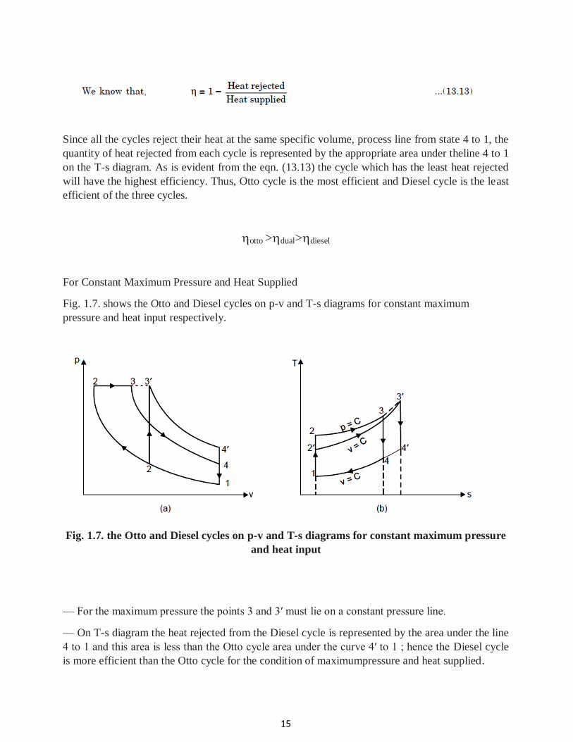
For Constant Maximum Pressure and Heat Supplied
Fig. 1.7. shows the Otto and Diesel cycles on p-v and T-s diagrams for constant maximum
pressure and heat input respectively.
Fig. 1.7. the Otto and Diesel cycles on p-v and T-s diagrams for constant maximum pressure
and heat input
— For the maximum pressure the points 3 and 3′ must lie on a constant pressure line.
— On T-s diagram the heat rejected from the Diesel cycle is represented by the area under the line
4 to 1 and this area is less than the Otto cycle area under the curve 4′ to 1 ; hence the Diesel cycle
is more efficient than the Otto cycle for the condition of maximumpressure and heat supplied.
16
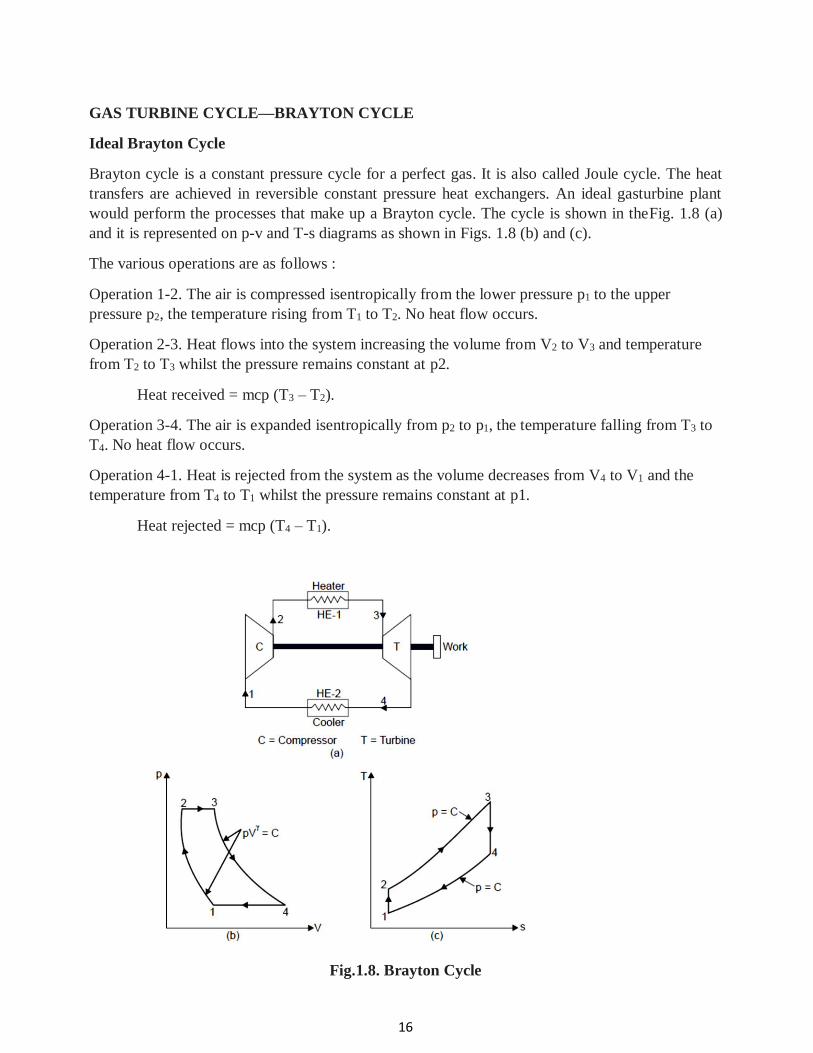
GAS TURBINE CYCLE—BRAYTON CYCLE
Ideal Brayton Cycle
Brayton cycle is a constant pressure cycle for a perfect gas. It is also called Joule cycle. The heat
transfers are achieved in reversible constant pressure heat exchangers. An ideal gasturbine plant
would perform the processes that make up a Brayton cycle. The cycle is shown in theFig. 1.8 (a)
and it is represented on p-v and T-s diagrams as shown in Figs. 1.8 (b) and (c).
The various operations are as follows :
Operation 1-2. The air is compressed isentropically from the lower pressure p1 to the upper
pressure p2, the temperature rising from T1 to T2. No heat flow occurs.
Operation 2-3. Heat flows into the system increasing the volume from V2 to V3 and temperature
from T2 to T3 whilst the pressure remains constant at p2.
Heat received = mcp (T3 – T2).
Operation 3-4. The air is expanded isentropically from p2 to p1, the temperature falling from T3 to
T4. No heat flow occurs.
Operation 4-1. Heat is rejected from the system as the volume decreases from V4 to V1 and the
temperature from T4 to T1 whilst the pressure remains constant at p1.
Heat rejected = mcp (T4 – T1).
Fig.1.8. Brayton Cycle
17
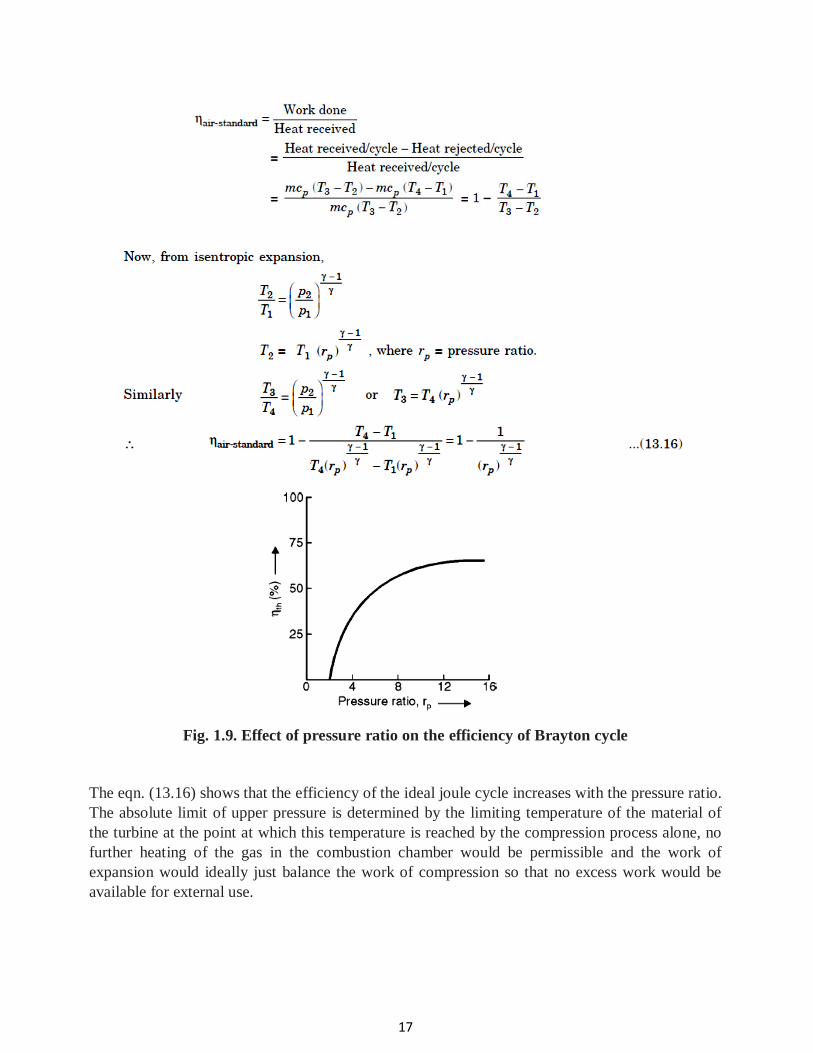
Fig. 1.9. Effect of pressure ratio on the efficiency of Brayton cycle
The eqn. (13.16) shows that the efficiency of the ideal joule cycle increases with the pressure ratio.
The absolute limit of upper pressure is determined by the limiting temperature of the material of
the turbine at the point at which this temperature is reached by the compression process alone, no
further heating of the gas in the combustion chamber would be permissible and the work of
expansion would ideally just balance the work of compression so that no excess work would be
available for external use.
18
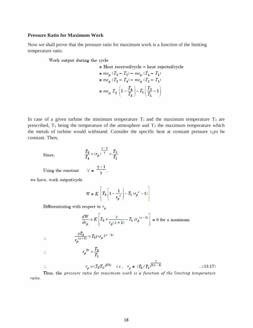
Pressure Ratio for Maximum Work
Now we shall prove that the pressure ratio for maximum work is a function of the limiting
temperature ratio.
In case of a given turbine the minimum temperature T1 and the maximum temperature T3 are
prescribed, T1 being the temperature of the atmosphere and T3 the maximum temperature which
the metals of turbine would withstand. Consider the specific heat at constant pressure cpto be
constant. Then,
19
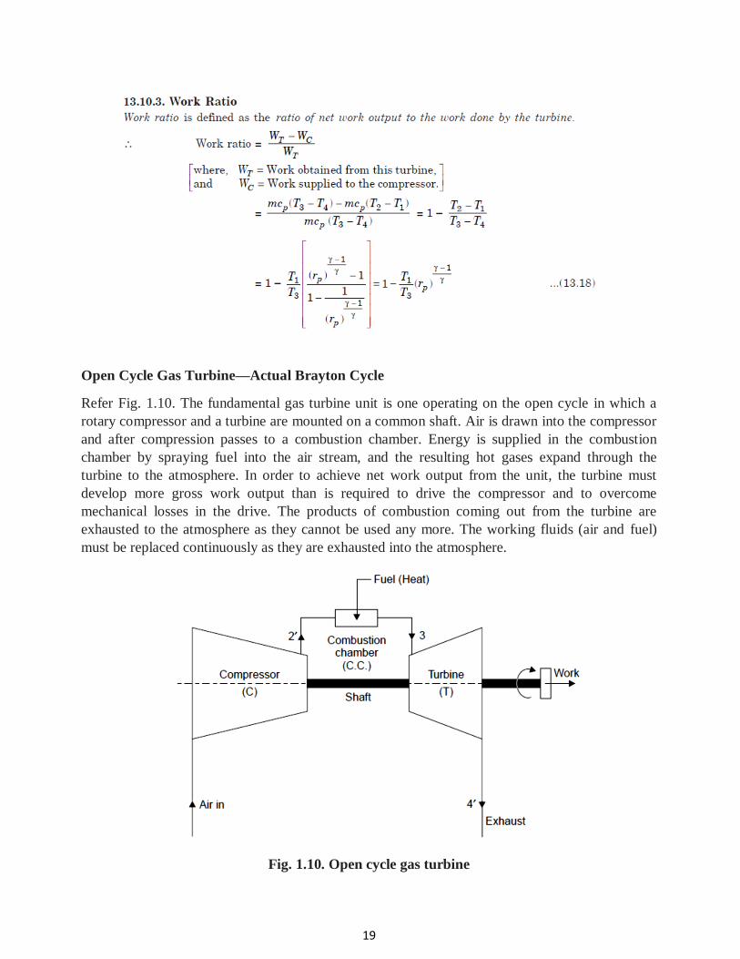
Open Cycle Gas Turbine—Actual Brayton Cycle
Refer Fig. 1.10. The fundamental gas turbine unit is one operating on the open cycle in which a
rotary compressor and a turbine are mounted on a common shaft. Air is drawn into the compressor
and after compression passes to a combustion chamber. Energy is supplied in the combustion
chamber by spraying fuel into the air stream, and the resulting hot gases expand through the
turbine to the atmosphere. In order to achieve net work output from the unit, the turbine must
develop more gross work output than is required to drive the compressor and to overcome
mechanical losses in the drive. The products of combustion coming out from the turbine are
exhausted to the atmosphere as they cannot be used any more. The working fluids (air and fuel)
must be replaced continuously as they are exhausted into the atmosphere.
Fig. 1.10. Open cycle gas turbine
20
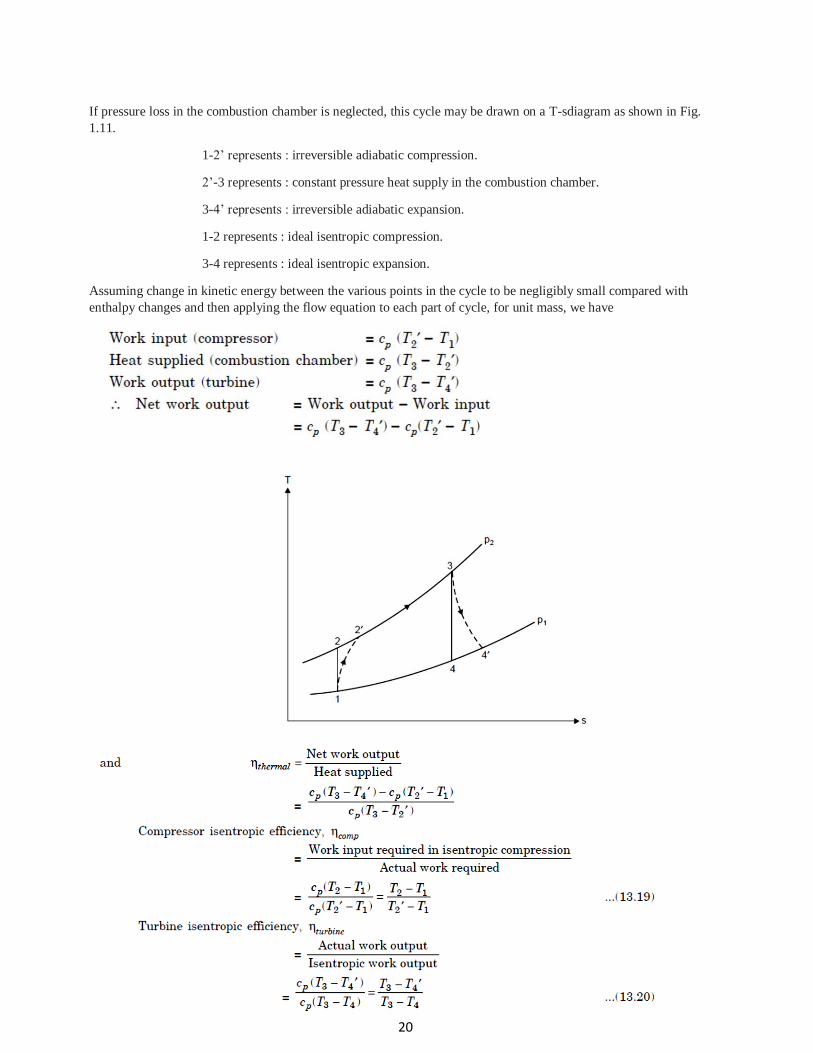
If pressure loss in the combustion chamber is neglected, this cycle may be drawn on a T-sdiagram as shown in Fig.
1.11.
1-2’ represents : irreversible adiabatic compression.
2’-3 represents : constant pressure heat supply in the combustion chamber.
3-4’ represents : irreversible adiabatic expansion.
1-2 represents : ideal isentropic compression.
3-4 represents : ideal isentropic expansion.
Assuming change in kinetic energy between the various points in the cycle to be negligibly small compared with
enthalpy changes and then applying the flow equation to each part of cycle, for unit mass, we have
21
Note. With the variation in temperature, the value of the specific heat of a real gas varies, and also
in the open cycle, the specific heat of the gases in the combustion chamber and in turbine is
different from that in the compressor because fuel has been added and a chemical change has taken
place. Curves showing the variation of cp with temperature and air/fuel ratio can be used, and a
suitable mean value of cp and hence g can be found out. It is usual in gas turbine practice to
assume fixed mean value of cp and g for the expansion process, and fixed mean values of cp and g
for the compression process. In an open cycle gas turbine unit the mass flow of gases in turbine is
greater than that in compressor due to mass of fuel burned, but it is possible to neglect mass of
fuel, since the air/ fuel ratios used are large. Also, in many cases, air is bled from the compressor
for cooling purposes, or in the case of air-craft at high altitudes, bled air is used for de-icing and
cabin air-conditioning. This amount of air bled is approximately the same as the mass of fuel
injected therein.
Methods for Improvement of Thermal Efficiency of Open Cycle Gas Turbine Plant
The following methods are employed to increase the specific output and thermal efficiency of the
plant :
1. Intercooling
2. Reheating
3. Regeneration.
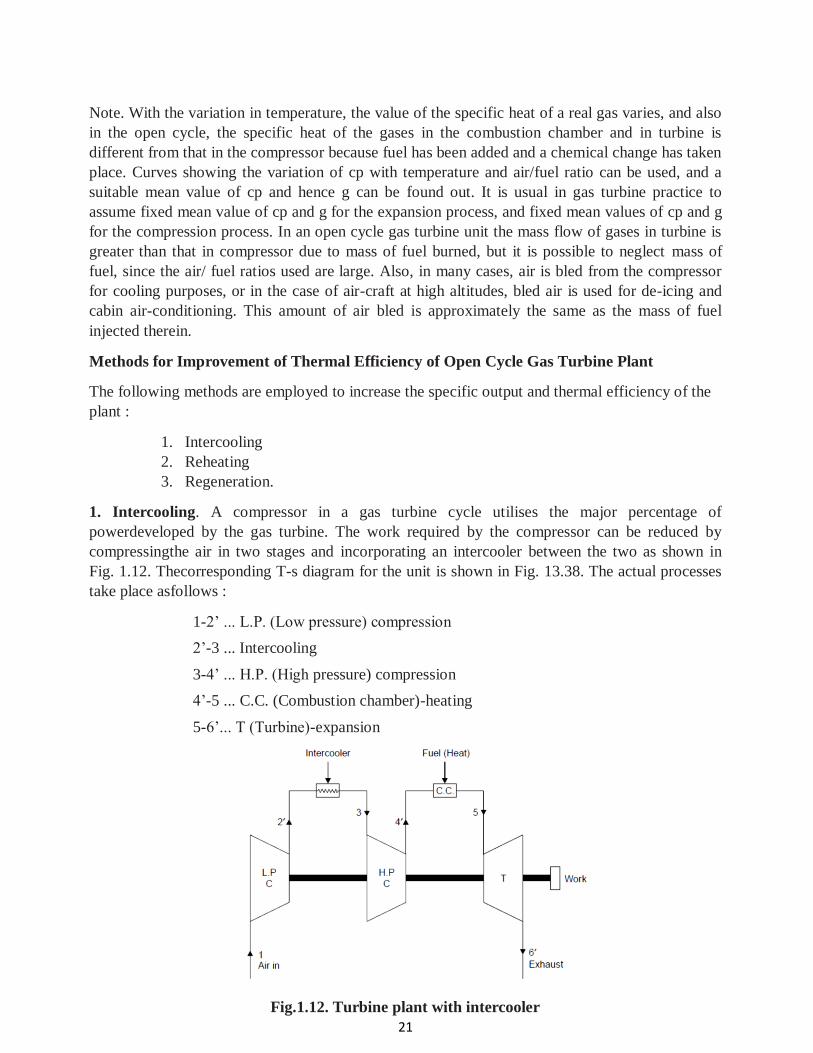
1. Intercooling. A compressor in a gas turbine cycle utilises the major percentage of
powerdeveloped by the gas turbine. The work required by the compressor can be reduced by
compressingthe air in two stages and incorporating an intercooler between the two as shown in
Fig. 1.12. Thecorresponding T-s diagram for the unit is shown in Fig. 13.38. The actual processes
take place asfollows :
1-2’ ... L.P. (Low pressure) compression
2’-3 ... Intercooling
3-4’ ... H.P. (High pressure) compression
4’-5 ... C.C. (Combustion chamber)-heating
5-6’... T (Turbine)-expansion
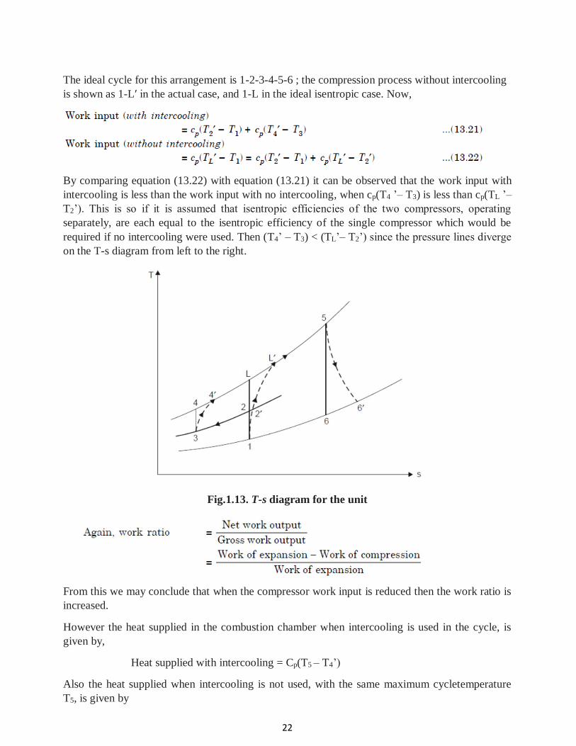
Fig.1.12. Turbine plant with intercooler
22
The ideal cycle for this arrangement is 1-2-3-4-5-6 ; the compression process without intercooling
is shown as 1-L′ in the actual case, and 1-L in the ideal isentropic case. Now,
By comparing equation (13.22) with equation (13.21) it can be observed that the work input with
intercooling is less than the work input with no intercooling, when cp(T4 ’– T3) is less than cp(TL ’–
T2’). This is so if it is assumed that isentropic efficiencies of the two compressors, operating
separately, are each equal to the isentropic efficiency of the single compressor which would be
required if no intercooling were used. Then (T4’ – T3) < (TL’– T2’) since the pressure lines diverge
on the T-s diagram from left to the right.
Fig.1.13. T-s diagram for the unit
From this we may conclude that when the compressor work input is reduced then the work ratio is
increased.
However the heat supplied in the combustion chamber when intercooling is used in the cycle, is
given by,
Heat supplied with intercooling = Cp(T5 – T4’)
Also the heat supplied when intercooling is not used, with the same maximum cycletemperature
T5, is given by
23
Heat supplied without intercooling = Cp(T5 – TL’)
Thus, the heat supplied when intercooling is used is greater than with no intercooling. Although
the net work output is increased by intercooling it is found in general that the increase in heat to be
supplied causes the thermal efficiency to decrease. When intercooling is used asupply of cooling
water must be readily available. The additional bulk of the unit may offset theadvantage to be
gained by increasing the work ratio.
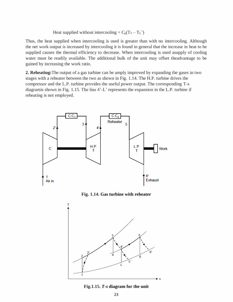
2. Reheating:The output of a gas turbine can be amply improved by expanding the gases in two
stages with a reheater between the two as shown in Fig. 1.14. The H.P. turbine drives the
compressor and the L.P. turbine provides the useful power output. The corresponding T-s
diagramis shown in Fig. 1.15. The line 4’-L’ represents the expansion in the L.P. turbine if
reheating is not employed.
Fig. 1.14. Gas turbine with reheater
Fig.1.15. T-s diagram for the unit
24
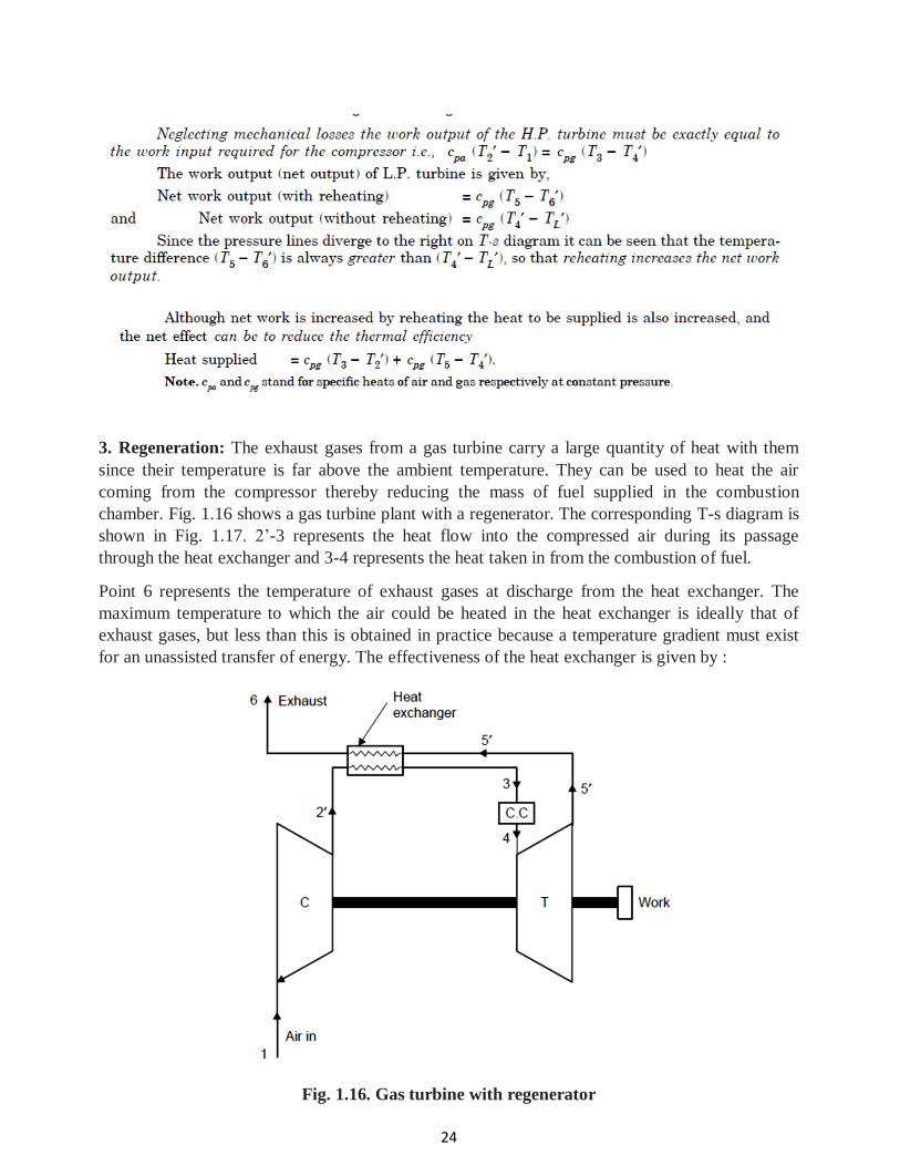
3. Regeneration: The exhaust gases from a gas turbine carry a large quantity of heat with them
since their temperature is far above the ambient temperature. They can be used to heat the air
coming from the compressor thereby reducing the mass of fuel supplied in the combustion
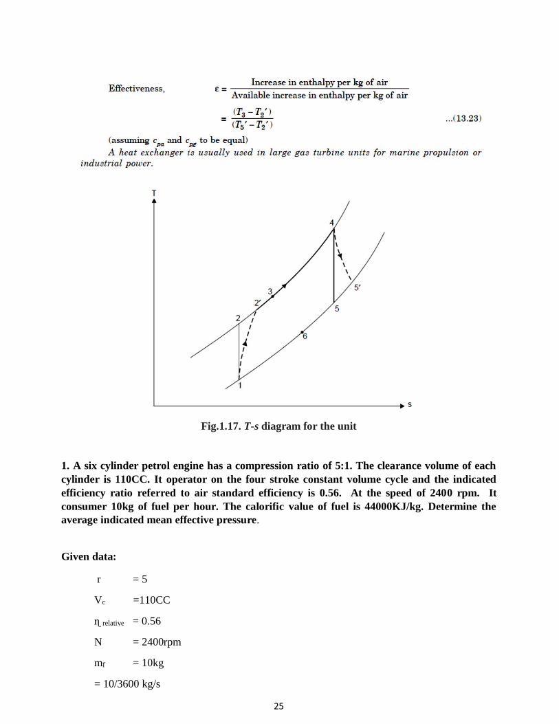
chamber. Fig. 1.16 shows a gas turbine plant with a regenerator. The corresponding T-s diagram is
shown in Fig. 1.17. 2’-3 represents the heat flow into the compressed air during its passage
through the heat exchanger and 3-4 represents the heat taken in from the combustion of fuel.
Point 6 represents the temperature of exhaust gases at discharge from the heat exchanger. The
maximum temperature to which the air could be heated in the heat exchanger is ideally that of
exhaust gases, but less than this is obtained in practice because a temperature gradient must exist
for an unassisted transfer of energy. The effectiveness of the heat exchanger is given by :
Fig. 1.16. Gas turbine with regenerator
25
Fig.1.17. T-s diagram for the unit
1. A six cylinder petrol engine has a compression ratio of 5:1. The clearance volume of each
cylinder is 110CC. It operator on the four stroke constant volume cycle and the indicated
efficiency ratio referred to air standard efficiency is 0.56. At the speed of 2400 rpm. It
consumer 10kg of fuel per hour. The calorific value of fuel is 44000KJ/kg. Determine the
average indicated mean effective pressure.
Given data:
r = 5
Vc =110CC
ɳ relative = 0.56
N = 2400rpm
mf = 10kg
= 10/3600 kg/s
26
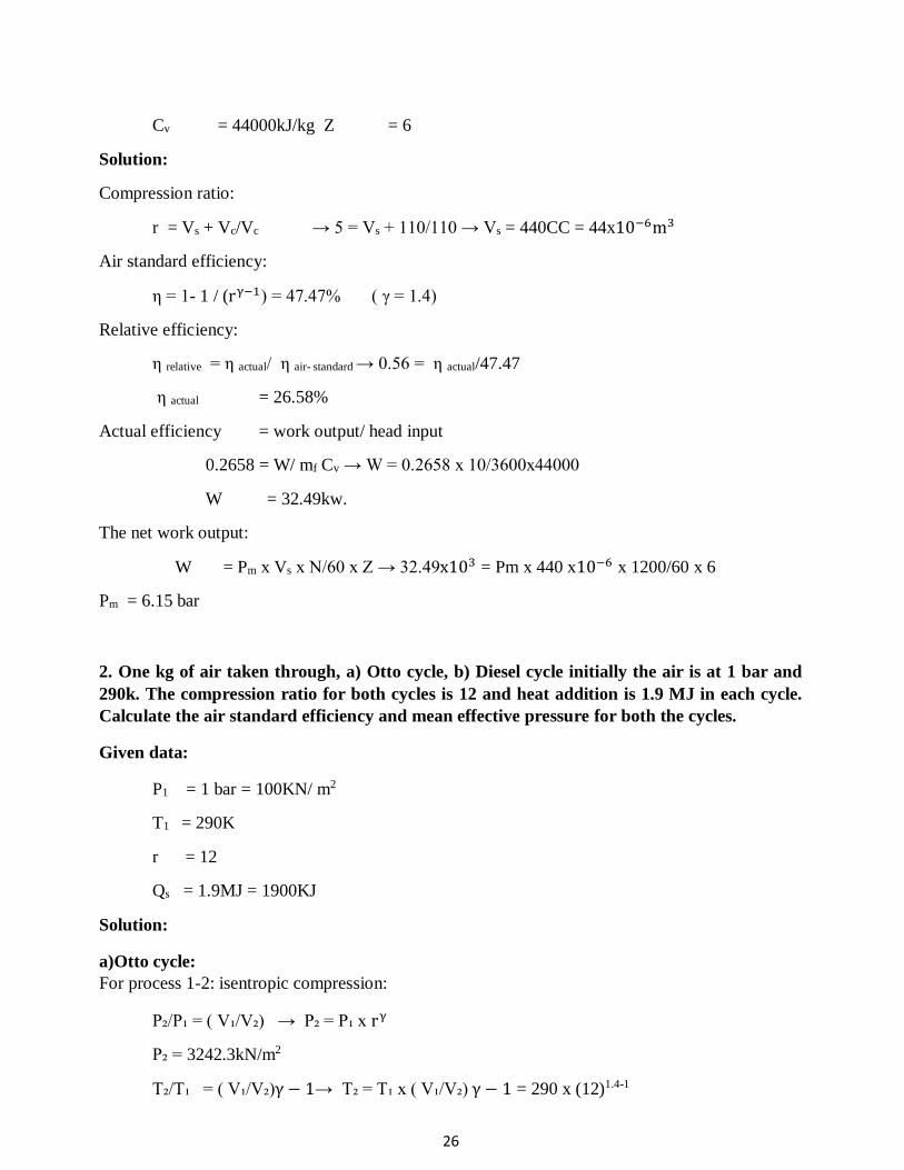
Cv = 44000kJ/kg Z = 6
Solution:
Compression ratio:
r = Vs + Vc/Vc → 5 = Vs + 110/110 → Vs = 440CC = 44x10−6m3
Air standard efficiency:
η = 1- 1 / (rγ−1) = 47.47% ( γ = 1.4)
Relative efficiency:
η relative = η actual/ η air- standard → 0.56 = η actual/47.47
η actual = 26.58%
Actual efficiency = work output/ head input
0.2658 = W/ mf Cv → W = 0.2658 x 10/3600x44000
W = 32.49kw.
The net work output:
W = Pm x Vs x N/60 x Z → 32.49x103 = Pm x 440 x10−6 x 1200/60 x 6
Pm = 6.15 bar
2. One kg of air taken through, a) Otto cycle, b) Diesel cycle initially the air is at 1 bar and
290k. The compression ratio for both cycles is 12 and heat addition is 1.9 MJ in each cycle.
Calculate the air standard efficiency and mean effective pressure for both the cycles.
Given data:
P1 = 1 bar = 100KN/ m2
T1 = 290K
r = 12
Qs = 1.9MJ = 1900KJ
Solution:
a)Otto cycle:
For process 1-2: isentropic compression:
P₂/P₁ = ( V₁/V₂) → P₂ = P₁ x rγ
P₂ = 3242.3kN/m2
T₂/T₁ = ( V₁/V₂)γ − 1→ T₂ = T₁ x ( V₁/V₂) γ − 1 = 290 x (12)1.4-1

27
T₂ = 783.55K
Heat supplied:
Q = m x Cv ( T₃ - T₂ )
1900 = 1 x 0.718 x (T₃ - 783.55)
T₃ = 3429.79K
For process 2-3 : constant volume process
P₃/P₂ = T₃/ T₂ → P₃ = P₂ x T₃/ T₂ = 3242.3 x 3429.79/783.55
P = 14196.7KN/m2
Air standard efficiency:
η = 1- 1 / (rγ−1) = 0.6298
η = 62.98%
Pressure ratio, K = P₃/P₂ = 14196.7/32423 = 4.378
Mean effective pressure,
Pm = p₁ r ( k-1/ γ − 1) (rγ−1-1/r-1) = 100 x 12 ( 4.378-1/1.4) [ ( 12 1.4-1-1/12-1)]
Pm = 1567.93KN/m2
b)Diesel cycle:
Consider 1-2 isentropic compression process:
T2 = (V1/V2)γ-1 x T1 = ( r )𝛄-1 x T1 = (12) 1.4-1 x 290
T2 = 783.56K
Consider 2-3 constant pressure heat addition:
Qs = Cp ( T3 – T2 )
1.9 x 10 3 = 1.005 x ( T3 – 783.56 )
T3 = 2674 K.
Cut off ratio:
ρ = V3/V2 =T3/T2 = 2674/783.56 = 3.413
Air standard efficiency:
η = 1-1/𝛄 (r) 𝛄-1 { ρ𝛄-1/ρ-1} = 1-1/ 1.4(12) 1.4-1 {3.413 1.4-1/3.413-1}
= 49.86%
Mean effective pressure:
28
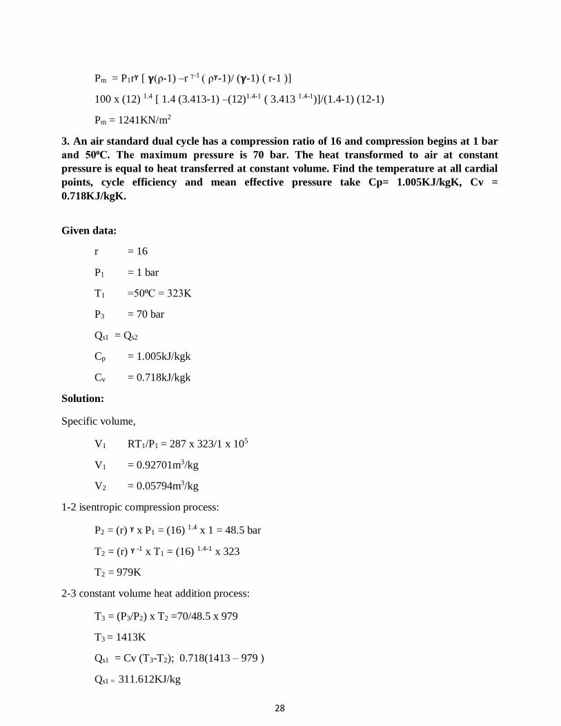
Pm = P1r𝛄 [ 𝛄(ρ-1) –r γ-1 ( ρ𝛄-1)/ (𝛄-1) ( r-1 )]
100 x (12) 1.4 [ 1.4 (3.413-1) –(12)1.4-1 ( 3.413 1.4-1)]/(1.4-1) (12-1)
Pm = 1241KN/m2
3. An air standard dual cycle has a compression ratio of 16 and compression begins at 1 bar
and 50⁰C. The maximum pressure is 70 bar. The heat transformed to air at constant
pressure is equal to heat transferred at constant volume. Find the temperature at all cardial
points, cycle efficiency and mean effective pressure take Cp= 1.005KJ/kgK, Cv =
0.718KJ/kgK.
Given data:
r = 16
P1 = 1 bar
T1 =50⁰C = 323K
P3 = 70 bar
Qs1 = Qs2
Cp = 1.005kJ/kgk
Cv = 0.718kJ/kgk
Solution:
Specific volume,
V1 RT1/P1 = 287 x 323/1 x 105
V1 = 0.92701m3/kg
V2 = 0.05794m3/kg
1-2 isentropic compression process:
P2 = (r) 𝛄 x P1 = (16) 1.4 x 1 = 48.5 bar
T2 = (r) 𝛄 -1 x T1 = (16) 1.4-1 x 323
T2 = 979K
2-3 constant volume heat addition process:
T3 = (P3/P2) x T2 =70/48.5 x 979
T3 = 1413K
Qs1 = Cv (T3-T2); 0.718(1413 – 979 )
Qs1 = 311.612KJ/kg
29
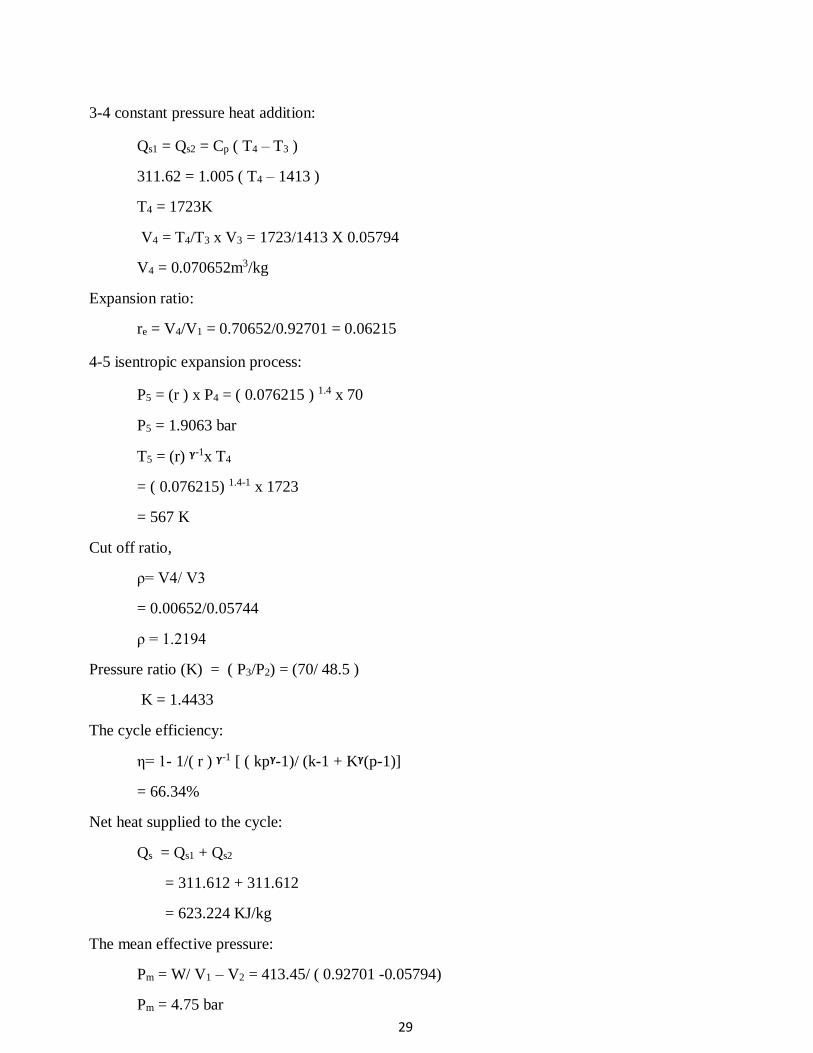
3-4 constant pressure heat addition:
Qs1 = Qs2 = Cp ( T4 – T3 )
311.62 = 1.005 ( T4 – 1413 )
T4 = 1723K
V4 = T4/T3 x V3 = 1723/1413 X 0.05794
V4 = 0.070652m3/kg
Expansion ratio:
re = V4/V1 = 0.70652/0.92701 = 0.06215
4-5 isentropic expansion process:
P5 = (r ) x P4 = ( 0.076215 ) 1.4 x 70
P5 = 1.9063 bar
T5 = (r) 𝛄-1x T4
= ( 0.076215) 1.4-1 x 1723
= 567 K
Cut off ratio,
ρ= V4/ V3
= 0.00652/0.05744
ρ = 1.2194
Pressure ratio (K) = ( P3/P2) = (70/ 48.5 )
K = 1.4433
The cycle efficiency:
η= 1- 1/( r ) 𝛄-1 [ ( kp𝛄-1)/ (k-1 + K𝛄(p-1)]
= 66.34%
Net heat supplied to the cycle:
Qs = Qs1 + Qs2
= 311.612 + 311.612
= 623.224 KJ/kg
The mean effective pressure:
Pm = W/ V1 – V2 = 413.45/ ( 0.92701 -0.05794)
Pm = 4.75 bar
30
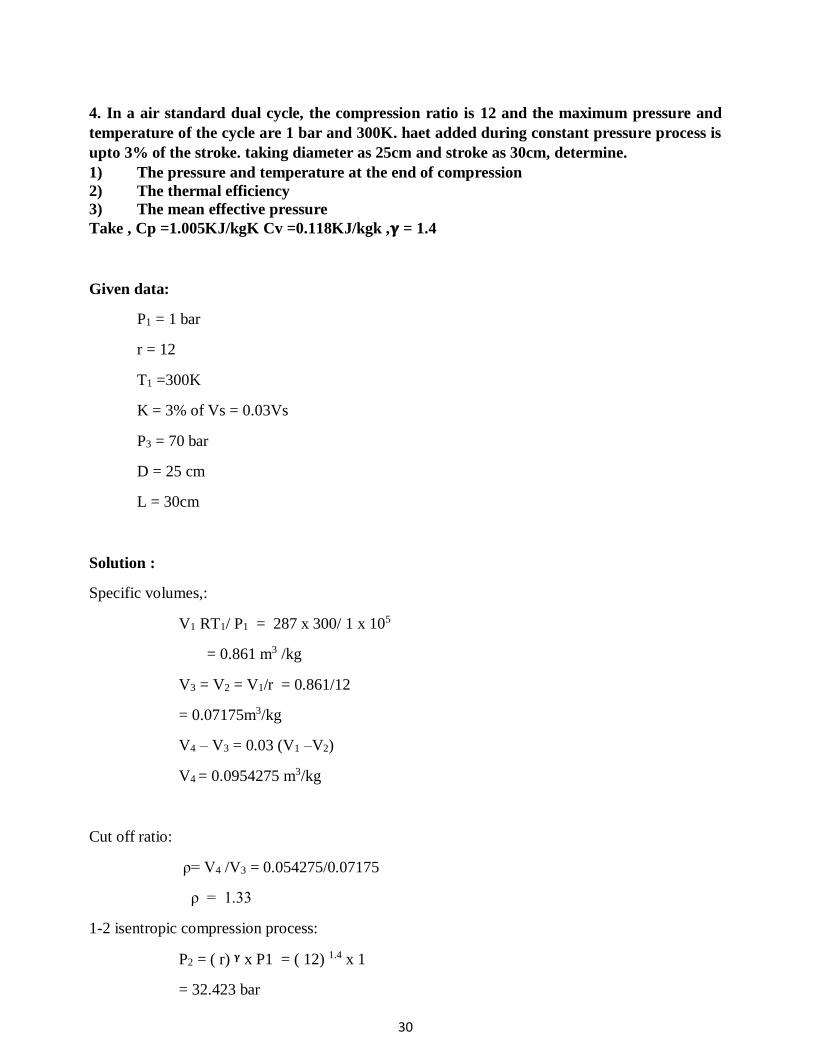
4. In a air standard dual cycle, the compression ratio is 12 and the maximum pressure and
temperature of the cycle are 1 bar and 300K. haet added during constant pressure process is
upto 3% of the stroke. taking diameter as 25cm and stroke as 30cm, determine.
1) The pressure and temperature at the end of compression
2) The thermal efficiency
3) The mean effective pressure
Take , Cp =1.005KJ/kgK Cv =0.118KJ/kgk ,𝛄 = 1.4
Given data:
P1 = 1 bar
r = 12
T1 =300K
K = 3% of Vs = 0.03Vs
P3 = 70 bar
D = 25 cm
L = 30cm
Solution :
Specific volumes,:
V1 RT1/ P1 = 287 x 300/ 1 x 105
= 0.861 m3 /kg
V3 = V2 = V1/r = 0.861/12
= 0.07175m3/kg
V4 – V3 = 0.03 (V1 –V2)
V4 = 0.0954275 m3/kg
Cut off ratio:
ρ= V4 /V3 = 0.054275/0.07175
ρ = 1.33
1-2 isentropic compression process:
P2 = ( r) 𝛄 x P1 = ( 12) 1.4 x 1
= 32.423 bar
31
V2 = ( r )𝛄-1 x T1 = ( 12) 1.4 -1 x 300
T2 = 810.57K.
2-3 constant volume heat addition process
P3/T3 = P2/T2
T3 = ( P3/P2) x T2 = ( 70 / 32.423) x 810.57
T3 = 1750K
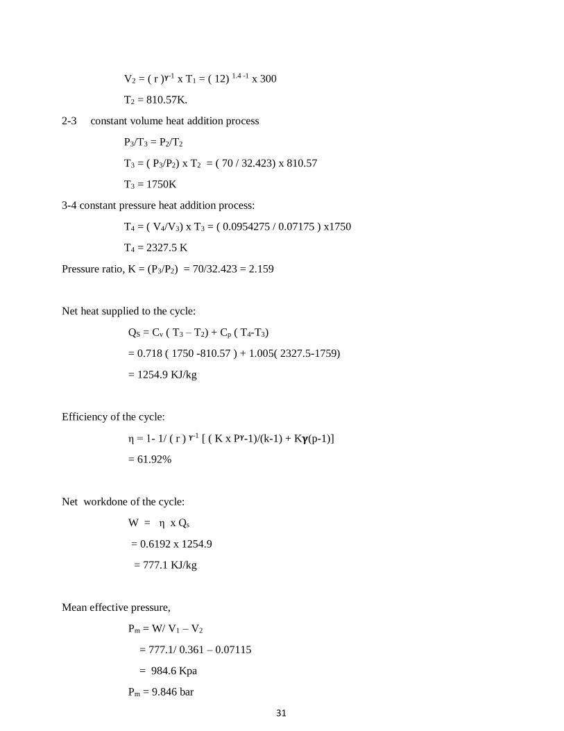
3-4 constant pressure heat addition process:
T4 = ( V4/V3) x T3 = ( 0.0954275 / 0.07175 ) x1750
T4 = 2327.5 K
Pressure ratio, K = (P3/P2) = 70/32.423 = 2.159
Net heat supplied to the cycle:
QS = Cv ( T3 – T2) + Cp ( T4-T3)
= 0.718 ( 1750 -810.57 ) + 1.005( 2327.5-1759)
= 1254.9 KJ/kg
Efficiency of the cycle:
η = 1- 1/ ( r ) 𝛄-1 [ ( K x P𝛄-1)/(k-1) + K𝛄(p-1)]
= 61.92%
Net workdone of the cycle:
W = η x Qs
= 0.6192 x 1254.9
= 777.1 KJ/kg
Mean effective pressure,
Pm = W/ V1 – V2
= 777.1/ 0.361 – 0.07115
= 984.6 Kpa
Pm = 9.846 bar
32
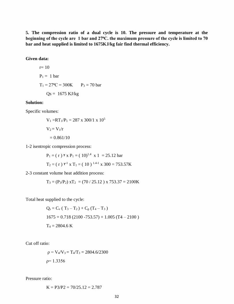
5. The compression ratio of a dual cycle is 10. The pressure and temperature at the
beginning of the cycle are 1 bar and 27⁰C. the maximum pressure of the cycle is limited to 70
bar and heat supplied is limited to 1675KJ/kg fair find thermal efficiency.
Given data:
r= 10
P1 = 1 bar
T1 = 27⁰C = 300K P3 = 70 bar
Qs = 1675 KJ/kg
Solution:
Specific volumes:
V1 =RT1/P1 = 287 x 300/1 x 105
V2 = V1/r
= 0.861/10
1-2 isentropic compression process:
P1 = ( r ) 𝛄 x P1 = ( 10)1.4 x 1 = 25.12 bar
T2 = ( r ) 𝛄-1 x T1 = ( 10 ) 1.4-1 x 300 = 753.57K
2-3 constant volume heat addition process:
T3 = (P3/P2) xT2 = (70 / 25.12 ) x 753.37 = 2100K
Total heat supplied to the cycle:
Qs = Cv ( T3 – T2 ) + Cp (T4 – T3 )
1675 = 0.718 (2100 -753.57) + 1.005 (T4 – 2100 )
T4 = 2804.6 K
Cut off ratio:
ρ = V4/V3 = T4/T3 = 2804.6/2300
ρ= 1.3356
Pressure ratio:
K = P3/P2 = 70/25.12 = 2.787
33
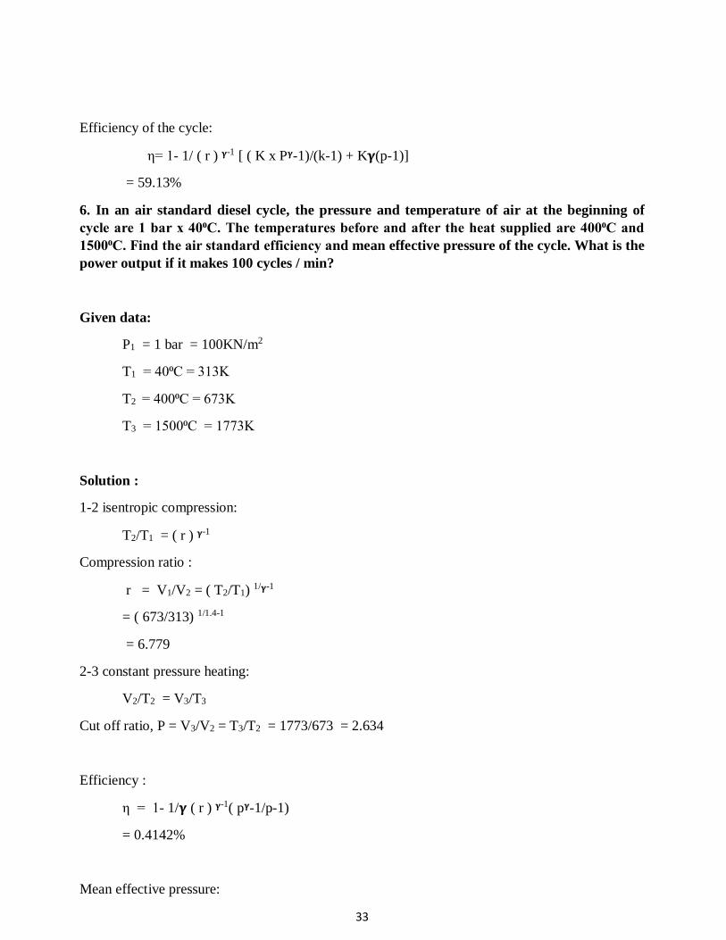
Efficiency of the cycle:
η= 1- 1/ ( r ) 𝛄-1 [ ( K x P𝛄-1)/(k-1) + K𝛄(p-1)]
= 59.13%
6. In an air standard diesel cycle, the pressure and temperature of air at the beginning of
cycle are 1 bar x 40⁰C. The temperatures before and after the heat supplied are 400⁰C and
1500⁰C. Find the air standard efficiency and mean effective pressure of the cycle. What is the
power output if it makes 100 cycles / min?
Given data:
P1 = 1 bar = 100KN/m2
T1 = 40⁰C = 313K
T2 = 400⁰C = 673K
T3 = 1500⁰C = 1773K
Solution :
1-2 isentropic compression:
T2/T1 = ( r ) 𝛄-1
Compression ratio :
r = V1/V2 = ( T2/T1) 1/𝛄-1
= ( 673/313) 1/1.4-1
= 6.779
2-3 constant pressure heating:
V2/T2 = V3/T3
Cut off ratio, P = V3/V2 = T3/T2 = 1773/673 = 2.634
Efficiency :
η = 1- 1/𝛄 ( r ) 𝛄-1( p𝛄-1/p-1)
= 0.4142%
Mean effective pressure:
34
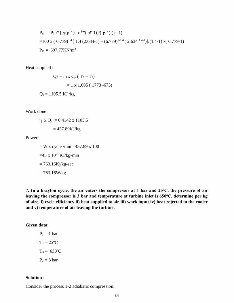
Pm = P1 r𝛄 [ 𝛄(ρ-1) –r 1-𝛄( ρ𝛄-1)]/( 𝛄-1) ( r -1)
=100 x ( 6.779)1.4 [ 1.4 (2.634-1) – (6.779)1-1.4 ( 2.634 1.4-1)]/(1.4-1) x( 6.779-1)
Pm = 597.77KN/m2
Heat supplied :
Qs = m x Cp ( T3 – T2)
= 1 x 1.005 ( 1773 -673)
Qs = 1105.5 KJ /kg
Work done :
η x Qs = 0.4142 x 1105.5
= 457.89KJ/kg
Power:
= W x cycle /min =457.89 x 100
=45 x 10-3 KJ/kg-min
= 763.16Kj/kg-sec
= 763.16W/kg
7. In a brayton cycle, the air enters the compressor at 1 bar and 25⁰C. the pressure of air
leaving the compressor is 3 bar and temperature at turbine inlet is 650⁰C. determine per kg
of aire, i) cycle efficiency ii) heat supplied to air iii) work input iv) heat rejected in the cooler
and v) temperature of air leaving the turbine.
Given data:
P1 = 1 bar
T1 = 25⁰C
T3 = 650⁰C
P2 = 3 bar
Solution :
Consider the process 1-2 adiabatic compression:

35
T2/T1 = (P2/P1) 𝛄-1/𝛄
T2 = (P2/P1) 𝛄-1/𝛄 x T1
T2 = (3/1) 1.4-1/1.4 x 298
3-4 adiabatic expansion:
T4/T3 = (P4/P3) 𝛄-1/𝛄
T4 = (P4/P3) 𝛄-1/𝛄 x 923 = 674.3k
Air standard efficiency :
η = 1- 1/(Rp) 𝛄-1/𝛄 = 1- 1/(3) 1.4-1/1.4 = 0.2694
= 26.94%
Heat supplied Qs = Cp ( T3 –T2) = 1.005 ( 923 – 408) = 517.575 KJ/kg
Heat rejected QR = Cp (T4 –T1) = 1.008 ( 673.4 – 298) = 377.277KJ/kg
Compressor work WC = Cp ( T2 –T1) = 1.005 x ( 408 – 298) = 110.55Kj/kg
Similarly for expander,:
We = Cp x ( T3 –T4 ) = 1.005 (923 – 6734)
We = 250.848 – 110.55 = 140.288KJ/kg
Temperature of air leaving the turbine = 673.4K
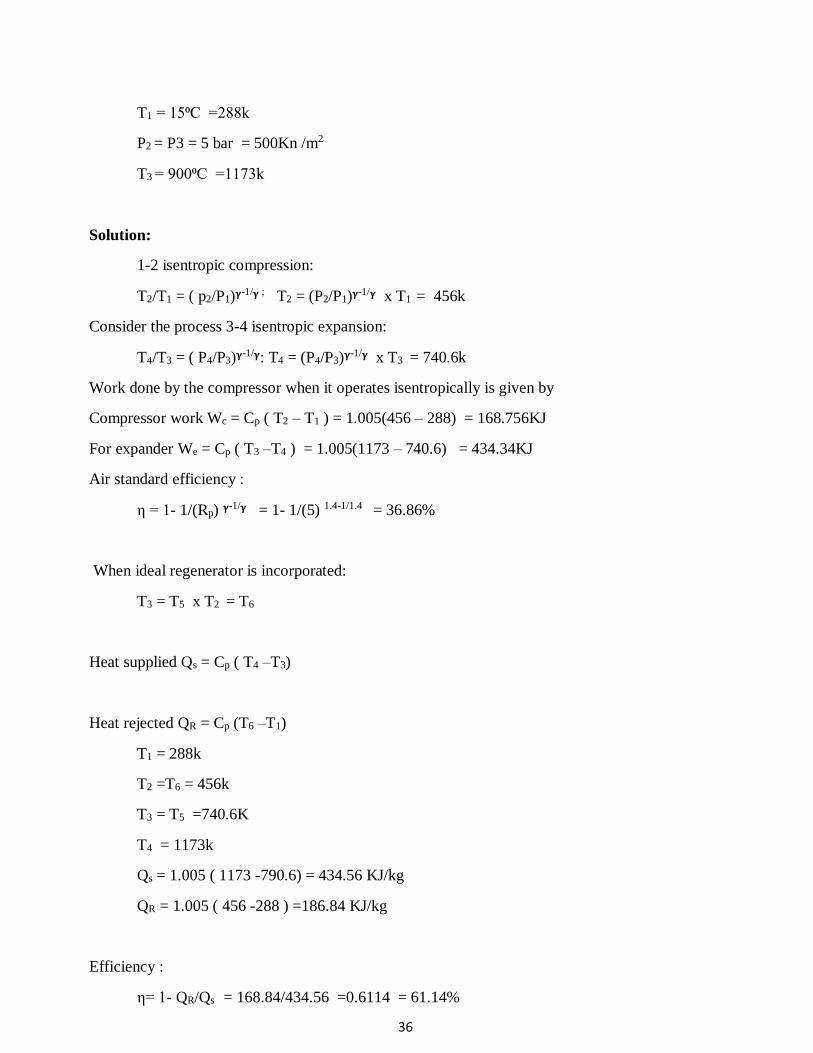
8. In an air standard brayton cycle, the air enter the compressor at 1 bar and 15⁰C. The
pressure leaving the compressor is 5 bar the maximum temperature in the cycle 900⁰C. Find
the following .
a) Compressor and expander work per kg of air. b) the cycle efficiency .
If an ideal regenerator is incorporated into the cycle, determine the percentage change in
efficiency.
Given data:
P1 = P4 = 1 bar = 100KN /m2
36
T1 = 15⁰C =288k
P2 = P3 = 5 bar = 500Kn /m2
T3 = 900⁰C =1173k
Solution:
1-2 isentropic compression:
T2/T1 = ( p2/P1)𝛄-1/𝛄 ; T2 = (P2/P1)𝛄
-1/𝛄 x T1 = 456k
Consider the process 3-4 isentropic expansion:
T4/T3 = ( P4/P3)𝛄-1/𝛄: T4 = (P4/P3)𝛄
-1/𝛄 x T3 = 740.6k
Work done by the compressor when it operates isentropically is given by
Compressor work Wc = Cp ( T2 – T1 ) = 1.005(456 – 288) = 168.756KJ
For expander We = Cp ( T3 –T4 ) = 1.005(1173 – 740.6) = 434.34KJ
Air standard efficiency :
η = 1- 1/(Rp) 𝛄-1/𝛄 = 1- 1/(5) 1.4-1/1.4 = 36.86%
When ideal regenerator is incorporated:
T3 = T5 x T2 = T6
Heat supplied Qs = Cp ( T4 –T3)
Heat rejected QR = Cp (T6 –T1)
T1 = 288k
T2 =T6 = 456k
T3 = T5 =740.6K
T4 = 1173k
Qs = 1.005 ( 1173 -790.6) = 434.56 KJ/kg
QR = 1.005 ( 456 -288 ) =186.84 KJ/kg
Efficiency :
η= 1- QR/Qs = 168.84/434.56 =0.6114 = 61.14%
37
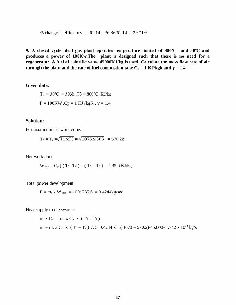
% change in efficiency : = 61.14 – 36.86/61.14 = 39.71%
9. A closed cycle ideal gas plant operates temperature limited of 800⁰C and 30⁰C and
produces a power of 100Kw.The plant is designed such that there is no need for a
regenerator. A fuel of calorific value 45000KJ/kg is used. Calculate the mass flow rate of air
through the plant and the rate of fuel combustion take Cp = 1 KJ/kgk and 𝛄 = 1.4
Given data:
T1 = 30⁰C = 303k ,T3 = 800⁰C KJ/kg
P = 100KW ,Cp = 1 KJ /kgK , 𝛄 = 1.4
Solution:
For maximum net work done:
T4 = T2 =√T1 xT3 = √1073 x 303 = 570.2k
Net work done
W net = Cp [ ( T3- T4 ) - ( T2 – T1 ) = 235.6 KJ/kg
Total power development
P = ma x W net = 100/ 235.6 = 0.4244kg/sec
Heat supply to the system:
mf x Cv = ma x Cp x ( T3 – T2 )
mf = ma x Cp x ( T3 – T2 ) /Cv 0.4244 x 1 ( 1073 – 570.2)/45.000=4.742 x 10-3 kg/s
38
Syllabus Working of S.I. and C.I engines, two stroke and four stroke engines – Valve timing, port timing
and PV diagrams of S.I and C.I engines - Estimation of brake power indicated power, thermal
efficiency, Heat balance sheet. Electronic and Common Rail Direct injection systems. Magneto
and Battery coil ignition systems, Lubrication and Cooling systems. Supercharging and
turbocharging systems.
Unit -2– INTERNAL COMBUSTION ENGINE PERFORMANCE AND
SYSTEMS– SMEA1404
39
INTRODUCTION
As the name implies or suggests, the internal combustion engines (briefly written as IC
engines) are those engines in which the combustion of fuel takes place inside the engine cylinder.
These are petrol, diesel, and gas engines. We have seen in steam engines or steam turbines that the
fuel, fed into the cylinder, is in the form of steam which is already heated (or superheated), and is
ready for working in the combustion cycle of the engine. But, in case of internal combustion
engines, the combustion of fuel takes place inside the engine cylinder by a spark and produces
very high temperature as compared to steam engines. The high temperature produced may ruin the
metal of cylinder, valves, etc. It is, therefore, necessary to abstract some of heat from the engine
cylinder. The abstraction of heat or the cooling of cylinder may be effected by the surrounding air
as in case of a motor cycle or aeroplane engine; or by circulating water through jackets
surrounding the cylinder barrel and cylinder head. The water cooling is mostly adopted for large
pistons.
CLASSIFICATION OF IC ENGINES The internal combustion engines may be classified in many ways, but the following are
important from the subject point of view
1. According to the type of fuel used
(a) Petrol engines. (b) Diesel engines or oil engines, and (c) Gas engines.
2. According to the method of igniting the fuel
(a) Spark ignition engines (briefly written as S.1. engines), (b) Compression ignition
engines (briefly written as C.I. engines), and (c) Hot spot ignition engines
3. According to the number of strokes per cycle
(a) Four stroke cycle engines, and (b) Two stroke cycle engines.
4. According to the cycle of operation
(a) Otto. cycle (also known as constant volume cycle) engines, (b) Diesel cycle (also
known as constant pressure cycle) engines, and (c) Dual combustion cycle (also known as
semi-diesel cycle) engines.
5. According to the speed of the engine
(a) Slow speed engines, (b) Medium speed engines, (c) High speed engines.
6. According to the cooling system
(a) Air-cooled engines. (b) Water-cooled engines. (c) Evaporative cooling engines.
7. According to the method of fuel injection
(a) Carburetor engines, (b) Air injection engines, (c) Airless or solid injection
engines.
8. According to the number of cylinders
(a) Single cylinder engines (b) Multi-cylinder engines.
9. According to the arrangement of cylinders
(a) Vertical engines, (b) Horizontal engines, (c) Radial engines, (d) In-line multi-cylinder
engines, (e)V-type multi-cylinder engines, (j) Opposite-cylinder engines, (g) Opposite-
piston engine
40
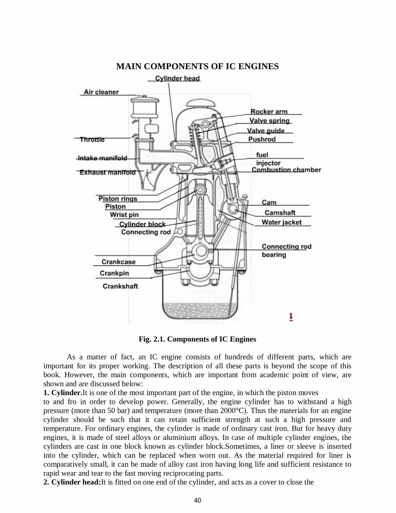
MAIN COMPONENTS OF IC ENGINES
Fig. 2.1. Components of IC Engines
As a matter of fact, an IC engine consists of hundreds of different parts, which are
important for its proper working. The description of all these parts is beyond the scope of this
book. However, the main components, which are important from academic point of view, are
shown and are discussed below:
1. Cylinder.It is one of the most important part of the engine, in which the piston moves
to and fro in order to develop power. Generally, the engine cylinder has to withstand a high
pressure (more than 50 bar) and temperature (more than 2000°C). Thus the materials for an engine
cylinder should be such that it can retain sufficient strength at such a high pressure and
temperature. For ordinary engines, the cylinder is made of ordinary cast iron. But for heavy duty
engines, it is made of steel alloys or aluminium alloys. In case of multiple cylinder engines, the
cylinders are cast in one block known as cylinder block.Sometimes, a liner or sleeve is inserted
into the cylinder, which can be replaced when worn out. As the material required for liner is
comparatively small, it can be made of alloy cast iron having long life and sufficient resistance to
rapid wear and tear to the fast moving reciprocating parts.
2. Cylinder head:It is fitted on one end of the cylinder, and acts as a cover to close the

41
cylinder bore. Generally, the cylinder head contains inlet and exit valves for admitting fresh charge
and exhausting the burnt gases. In petrol engines, the cylinder head also contains a spark plug for
igniting the fuel-air mixture, towards the end of compression stroke. But in diesel engines, the
cylinder head contains nozzle (i.e. fuel valve) for injecting the fuel into the cylinder. The cylinder
head is, usually, cast as one piece and bolted to one end of the cylinder. Generally, the cylinder
block and cylinder head are made from the same material. A copper or asbestos gasket is provided
between the engine cylinder and cylinder head to make an air-tight joint.
3. Piston:It is considered as the heart of an l.c. engine, whose main function is to transmit the
force exeI1ed by the burning of charge to the connecting rod. The pistons are generally made of
aluminium alloys which are light in weight. They have good heat conducting property and also
greater strength at higher temperatures.
4. Piston rings:These are circular rings and made of special steel alloys which retain elastic
properties even at high temperatures. The piston rings are housed in the circumferential grooves
provided on the outer surface of the piston. Generally, there are two sets of rings mounted for the
piston. The function of the upper rings is to provide air tight seal to prevent leakage of the burnt
gases into the lower portion. Similarly, the function of the lower rings is to provide effective seal
to prevent leakage of the oil into the engine cylinder.
5. Connecting rod: It is a link between the piston and crankshaft, whose main function is
to transmit force from the piston to the crankshaft. Moreover, it converts reciprocating motion of
the piston into circular motion of the crankshaft, in the working stroke. The upper (i.e. smaller)
end of the connecting rod is fitted to the piston and the lower (i.e. bigger) end to the crank. The
special steel alloys or aluminium alloys are used for the manufacture of connecting rods. A special
care is required for the design and manufacture of connecting rod, as it is subjected to alternatively
compressive and tensile stresses as well as bending stresses.
6. Crankshaft:It is considered as the backbone of an l.c. engine whose function is to
convert the reciprocating motion of the piston into the rotary motion with the help of connecting
rod. This shaft contains one or more eccentric portions called cranks. That part of the crank, to
which bigger end of the connecting rod is fitted, is called crank pin.It has been experienced that
too many main bearings create difficulty of correct alignment. Special steel alloys are used for the
manufacture of crankshaft. A special care is required for the design and manufacture of crankshaft.
7. Crank case:It is a cast iron case, which holds the cylinder and crankshaft of an I.c.
engine. It also serves as a sump for the lubricating oil. The lower portion of the crank case is
known as bed plate, which is fixed with the help of bolts.
8. Flywheel:It is a big wheel, mounted on the crankshaft, whose function is to maintain its speed
constant. It is done by storing excess energy during the power stroke, which is returned during
other strokes.
SEQUENCE OF OPERATIONS IN A CYCLE
Strictly speaking, when an engine is working continuously, we may consider a cycle
starting from any stroke. We know that when the engine returns back to the stroke where it started
we say that one cycle has been completed. The readers will find different sequence of operations
in different books. But in this chapter, we shall consider the following sequence of operation in a
cycle, which is widely used.
I. Suction stroke:In this stroke, the fuel vapor in correct proportion, is supplied to the
engine cylinder.
2. Compression stroke:In this stroke, the fuel vapor is compressed in the engine cylinder.
3. Expansion or working stroke:In this stroke, the fuel vapor is fired just before the
compression is complete. It results in the sudden rise of pressure, due to expansion of the
combustion products in the engine cylinder. This sudden rise of the pressure pushes the piston with

42
a great force, and rotates the crankshaft. The crankshaft, in turn, drives the machine connected to
it.
4. Exhaust stroke:In this stroke, the burnt gases (or combustion products) are exhausted
from the engine cylinder, so as to make space available for the fresh fuel vapor.
TWO STROKE AND FOUR STROKE CYCLE ENGINE
In a two-stroke engine, the working cycle is completed in two strokes of the piston or one
revolution of the crankshaft. This is achieved by carrying out the suction and compression
processes in one stroke (or more precisely in inward stroke), expansion and exhaust processes in
the second stroke (or more precisely in outward stroke). In a four-stroke engine, the working cycle
is completed in four-strokes of the piston or two-revolutions of the crankshaft. This is achieved by
carrying out suction, compression, expansion and exhaust processes in each stroke. It will be
interesting to know that from the thermodynamic point of view, there is no difference between
two-stroke and four-stroke cycle engines. The difference is purely mechanical.
Advantages and Disadvantage of Two-stroke over Four-stroke Cycle Engines
Advantages
1. A two stroke cycle engine gives twice the number of power strokes than the four stroke
cycle engine at the same engine speed. Theoretically, a two-stroke cycle engine should
develop twice the power as that of a four-stroke cycle engine. But in actual practice, a two-
stroke cycle engine develops 1.7 to 1.8 times greater value for slow speed engines the
power developed by four-stroke cycle engine of the same dimensions and speed. This is
due to lower compression ratio and effective stroke being less than thetheoretical stroke.
2. For the same power developed, a two-stroke cycle engine is lighter, less bulky and
occupies less floor area. Thus it makes, a two-stroke cycle engine suitable for marine
engines and other light vehicles.
3. As the number of working strokes in a two-stroke cycle engine are twice than the
four-stroke cycle engine, so the turning moment of a two-stroke cycle engine is more
uniform. Thus it makes a two-stroke cycle engine to have a lighter flywheel and
foundations. This also leads to a higher mechanical efficiency of a two-stroke cycle engine.
4. The initial cost of a two-stroke cycle engine is considerably less than a four-stroke cycle
engine.
5. The mechanism of a two-stroke cycle engine is much simpler than a four-stroke cycle
engine.
6. The two-stroke cycle engines are much easier to start.
Disadvantages
1. Thermal efficiency of a two-stroke cycle engine is less than that a four-stroke cycle
engine, because a two-stroke cycle engine has less compression ratio than that of a four-
stroke cycle engine.
2. Overall efficiency of a two stroke cycle engine is also less than that of a four-stroke cycle
engine because in a two-stroke cycle, inlet and exhaust ports remain open simultaneously
for some time. In spite of careful design, a small quantity of charge is lost from the engine
cylinder.
3. In case of a two-stroke cycle engine, the number of power strokes is twice as those of a
four-stroke cycle engine. Thus the capacity of the cooling system must be higher. Beyond
a certain limit, the cooling capacity offers a considerable difficulty. Moreover, there is a
greater wear and tear in a two-stroke cycle engine.

43
4. The consumption of lubricating oil is large in a two-stroke cycle engine because of high
operating temperature.
5. The exhaust gases in a two-stroke cycle engine create noise, because of short time
available for their exhaust.
VALVE TIMING DIAGRAM
A valve timing diagram is a graphical representation of the exact moments, in the sequence
of operations, at which the two valves (i.e. inlet and exhaust valves) open and close as well as
firing of the fuel. It is, generally, expressed in terms of angular positions of the crankshaft. Here
we shall discuss theoretical valve timing diagrams for four stroke and two stroke cycle engines.
Fig. 2.2. Valve Timing Diagram of Four-Stroke Engine
1. Theoretical valve timing diagram for four-stroke cycle engine The theoretical valve timing diagram for a four-stroke cycle engine is shown In this
diagram, the inlet valve opens at A and the suction takes place from A to B. The crankshaft
revolves through 1800 and the piston moves from T.D.C. to B.D.C. At B, theinlet valve closes and
the compression takes place from B to C. The crankshaft revolves through 1800 and the piston
moves from B.D. C. to T.D. C. At C, the fuel is fired and theexpansion takes place from C to D.
The crankshaft revolves through 1800 and the piston again moves from T.D.C. to B.D.C. At D, the
exhaust valve opens and the exhaust takes place from D to E. The crankshaft again revolves
through 1800 and the piston moves back to T.D.C.
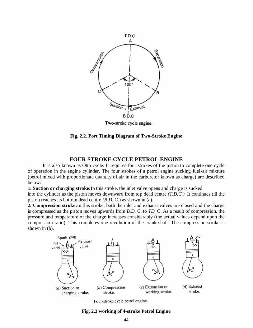
2. Theoretical valve timing diagram for two-stroke cycle engine.
The theoretical valve timing diagram for a two-stroke cycle engine is shown. In this
diagram, the fuel is fired at A and the expansion of gases takes place from A to B. The crankshaft
revolves through approximately 1200 and the piston moves from T.D.C. towards B.D.C. At B, the
valves open and suction as well as exhaust take place from B to C. The crankshaft revolves
through approximately 1200 and the piston moves first to B.D.C and then little upwards. At C. both
the valves close and compression takes place from C to A. The crankshaft revolves through
approximately 1200 and the piston moves to T.D.C
44
Fig. 2.2. Port Timing Diagram of Two-Stroke Engine
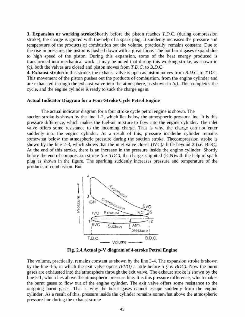
FOUR STROKE CYCLE PETROL ENGINE It is also known as Otto cycle. It requires four strokes of the piston to complete one cycle
of operation in the engine cylinder. The four strokes of a petrol engine sucking fuel-air mixture
(petrol mixed with proportionate quantity of air in the carburetor known as charge) are described
below:
1. Suction or charging stroke:In this stroke, the inlet valve opens and charge is sucked
into the cylinder as the piston moves downward from top dead centre (T.D.C.). It continues till the
piston reaches its bottom dead centre (B.D. C.) as shown in (a).
2. Compression stroke:In this stroke, both the inlet and exhaust valves are closed and the charge
is compressed as the piston moves upwards from B.D. C. to TD. C. As a result of compression, the
pressure and temperature of the charge increases considerably (the actual values depend upon the
compression ratio). This completes one revolution of the crank shaft. The compression stroke is
shown in (b).
Fig. 2.3 working of 4-stroke Petrol Engine
45
3. Expansion or working strokeShortly before the piston reaches T.D.C. (during compression
stroke), the charge is ignited with the help of a spark plug. It suddenly increases the pressure and
temperature of the products of combustion but the volume, practically, remains constant. Due to
the rise in pressure, the piston is pushed down with a great force. The hot burnt gases expand due
to high speed of the piston. During this expansion, some of the heat energy produced is
transformed into mechanical work. It may be noted that during this working stroke, as shown in
(c), both the valves are closed and piston moves from T.D.C. to B.D.C
4. Exhaust stroke:In this stroke, the exhaust valve is open as piston moves from B.D.C. to T.D.C.
This movement of the piston pushes out the products of combustion, from the engine cylinder and
are exhausted through the exhaust valve into the atmosphere, as shown in (d). This completes the
cycle, and the engine cylinder is ready to suck the charge again.
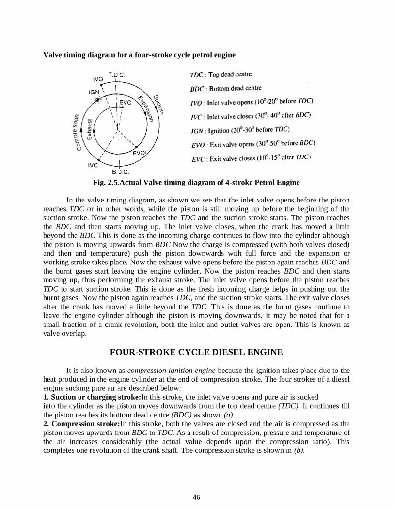
Actual Indicator Diagram for a Four-Stroke Cycle Petrol Engine
The actual indicator diagram for a four stroke cycle petrol engine is shown. The
suction stroke is shown by the line 1-2, which lies below the atmospheric pressure line. It is this
pressure difference, which makes the fuel-air mixture to flow into the engine cylinder. The inlet
valve offers some resistance to the incoming charge. That is why, the charge can not enter
suddenly into the engine cylinder. As a result of this, pressure insidethe cylinder remains
somewhat below the atmospheric pressure during the suction stroke. Thecompression stroke is
shown by the line 2-3, which shows that the inlet valve closes (lVC)a little beyond 2 (i.e. BDC).
At the end of this stroke, there is an increase in the pressure inside the engine cylinder. Shortly
before the end of compression stroke (i.e. TDC), the charge is ignited (lGN)with the help of spark
plug as shown in the figure. The sparking suddenly increases pressure and temperature of the
products of combustion. But
Fig. 2.4.Actual p-V diagram of 4-stroke Petrol Engine
The volume, practically, remains constant as shown by the line 3-4. The expansion stroke is shown
by the line 4-5, in which the exit valve opens (EVO) a little before 5 (i.e. BDC). Now the burnt
gases are exhausted into the atmosphere through the exit valve. The exhaust stroke is shown by the
line 5-1, which lies above the atmospheric pressure line. It is this pressure difference, which makes
the burnt gases to flow out of the engine cylinder. The exit valve offers some resistance to the
outgoing burnt gases. That is why the burnt gases cannot escape suddenly from the engine
cylinder. As a result of this, pressure inside the cylinder remains somewhat above the atmospheric
pressure line during the exhaust stroke
46
Valve timing diagram for a four-stroke cycle petrol engine
Fig. 2.5.Actual Valve timing diagram of 4-stroke Petrol Engine
In the valve timing diagram, as shown we see that the inlet valve opens before the piston
reaches TDC or in other words, while the piston is still moving up before the beginning of the
suction stroke. Now the piston reaches the TDC and the suction stroke starts. The piston reaches
the BDC and then starts moving up. The inlet valve closes, when the crank has moved a little
beyond the BDC This is done as the incoming charge continues to flow into the cylinder although
the piston is moving upwards from BDC Now the charge is compressed (with both valves closed)
and then and temperature) push the piston downwards with full force and the expansion or
working stroke takes place. Now the exhaust valve opens before the piston again reaches BDC and
the burnt gases start leaving the engine cylinder. Now the piston reaches BDC and then starts
moving up, thus performing the exhaust stroke. The inlet valve opens before the piston reaches
TDC to start suction stroke. This is done as the fresh incoming charge helps in pushing out the
burnt gases. Now the piston again reaches TDC, and the suction stroke starts. The exit valve closes
after the crank has moved a little beyond the TDC. This is done as the burnt gases continue to
leave the engine cylinder although the piston is moving downwards. It may be noted that for a
small fraction of a crank revolution, both the inlet and outlet valves are open. This is known as
valve overlap.
FOUR-STROKE CYCLE DIESEL ENGINE
It is also known as compression ignition engine because the ignition takes p\ace due to the
heat produced in the engine cylinder at the end of compression stroke. The four strokes of a diesel
engine sucking pure air are described below:
1. Suction or charging stroke:In this stroke, the inlet valve opens and pure air is sucked
into the cylinder as the piston moves downwards from the top dead centre (TDC). It continues till
the piston reaches its bottom dead centre (BDC) as shown (a).
2. Compression stroke:In this stroke, both the valves are closed and the air is compressed as the
piston moves upwards from BDC to TDC. As a result of compression, pressure and temperature of
the air increases considerably (the actual value depends upon the compression ratio). This
completes one revolution of the crank shaft. The compression stroke is shown in (b).
47
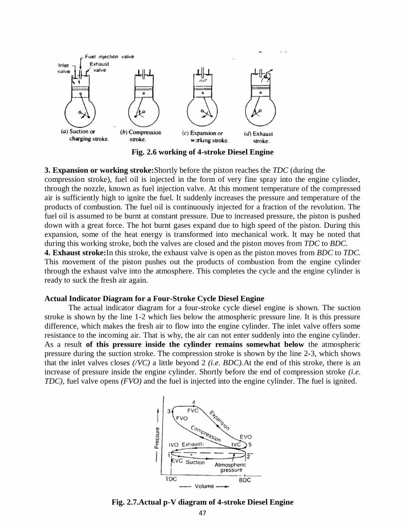
Fig. 2.6 working of 4-stroke Diesel Engine
3. Expansion or working stroke:Shortly before the piston reaches the TDC (during the
compression stroke), fuel oil is injected in the form of very fine spray into the engine cylinder,
through the nozzle, known as fuel injection valve. At this moment temperature of the compressed
air is sufficiently high to ignite the fuel. It suddenly increases the pressure and temperature of the
products of combustion. The fuel oil is continuously injected for a fraction of the revolution. The
fuel oil is assumed to be burnt at constant pressure. Due to increased pressure, the piston is pushed
down with a great force. The hot burnt gases expand due to high speed of the piston. During this
expansion, some of the heat energy is transformed into mechanical work. It may be noted that
during this working stroke, both the valves are closed and the piston moves from TDC to BDC.
4. Exhaust stroke:In this stroke, the exhaust valve is open as the piston moves from BDC to TDC.
This movement of the piston pushes out the products of combustion from the engine cylinder
through the exhaust valve into the atmosphere. This completes the cycle and the engine cylinder is
ready to suck the fresh air again.
Actual Indicator Diagram for a Four-Stroke Cycle Diesel Engine
The actual indicator diagram for a four-stroke cycle diesel engine is shown. The suction
stroke is shown by the line 1-2 which lies below the atmospheric pressure line. It is this pressure
difference, which makes the fresh air to flow into the engine cylinder. The inlet valve offers some
resistance to the incoming air. That is why, the air can not enter suddenly into the engine cylinder.
As a result of this pressure inside the cylinder remains somewhat below the atmospheric
pressure during the suction stroke. The compression stroke is shown by the line 2-3, which shows
that the inlet valves closes (/VC) a little beyond 2 (i.e. BDC).At the end of this stroke, there is an
increase of pressure inside the engine cylinder. Shortly before the end of compression stroke (i.e.
TDC), fuel valve opens (FVO) and the fuel is injected into the engine cylinder. The fuel is ignited.
Fig. 2.7.Actual p-V diagram of 4-stroke Diesel Engine
48
The ignition suddenly increases volume and temperature of the products of combustion. But the
pressure, practically, remains constant as shown by the line 3-4. The expansion stroke is shown by
the line 4-5, in which the exit valve opens a little before 5 (i.e. BDC). Now the burnt gases are
exhausted into the atmosphere through the exhaust valve. The exhaust stroke is shown by the line
5-1, which lies above the atmospheric pressure line. It is this pressure difference, which makes the
burnt gases to flow out of the engine cylinder. The exhaust valve offers some resistance to the
outgoing burnt gases. That is why, the burnt gases cannot (escape suddenly from the engine
cylinder. As a result of this, pressure inside the cylinder remains somewhat above the atmospheric
pressure during the exhaust stroke.
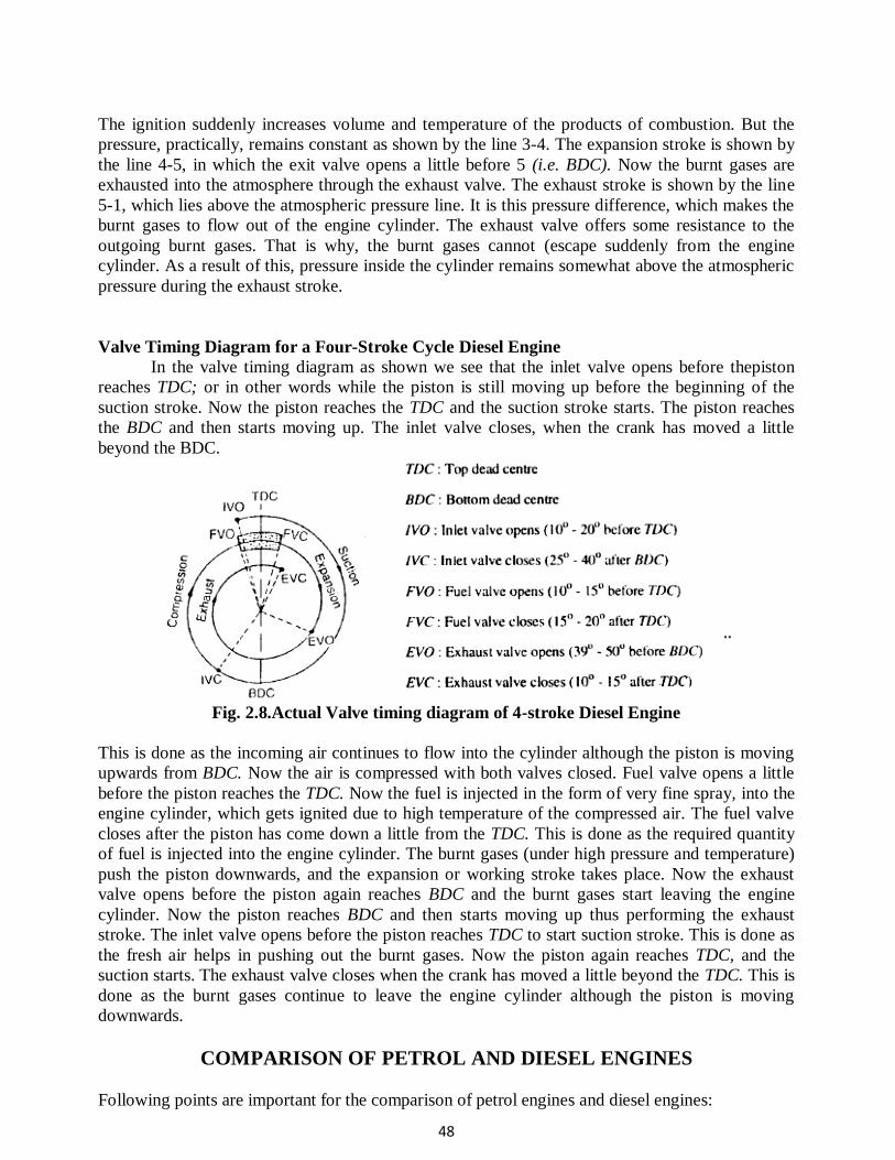
Valve Timing Diagram for a Four-Stroke Cycle Diesel Engine
In the valve timing diagram as shown we see that the inlet valve opens before thepiston
reaches TDC; or in other words while the piston is still moving up before the beginning of the
suction stroke. Now the piston reaches the TDC and the suction stroke starts. The piston reaches
the BDC and then starts moving up. The inlet valve closes, when the crank has moved a little
beyond the BDC.
Fig. 2.8.Actual Valve timing diagram of 4-stroke Diesel Engine
This is done as the incoming air continues to flow into the cylinder although the piston is moving
upwards from BDC. Now the air is compressed with both valves closed. Fuel valve opens a little
before the piston reaches the TDC. Now the fuel is injected in the form of very fine spray, into the
engine cylinder, which gets ignited due to high temperature of the compressed air. The fuel valve
closes after the piston has come down a little from the TDC. This is done as the required quantity
of fuel is injected into the engine cylinder. The burnt gases (under high pressure and temperature)
push the piston downwards, and the expansion or working stroke takes place. Now the exhaust
valve opens before the piston again reaches BDC and the burnt gases start leaving the engine
cylinder. Now the piston reaches BDC and then starts moving up thus performing the exhaust
stroke. The inlet valve opens before the piston reaches TDC to start suction stroke. This is done as
the fresh air helps in pushing out the burnt gases. Now the piston again reaches TDC, and the
suction starts. The exhaust valve closes when the crank has moved a little beyond the TDC. This is
done as the burnt gases continue to leave the engine cylinder although the piston is moving
downwards.
COMPARISON OF PETROL AND DIESEL ENGINES
Following points are important for the comparison of petrol engines and diesel engines:
49
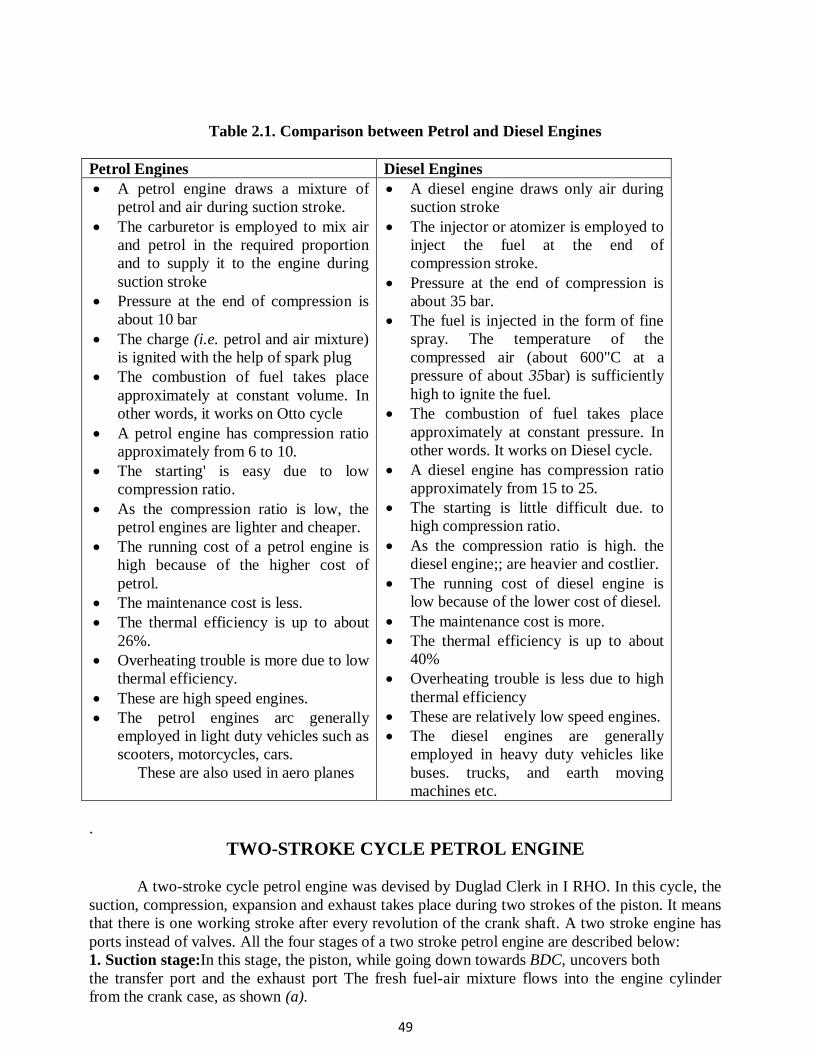
Table 2.1. Comparison between Petrol and Diesel Engines
Petrol Engines Diesel Engines
A petrol engine draws a mixture of
petrol and air during suction stroke.
The carburetor is employed to mix air
and petrol in the required proportion
and to supply it to the engine during
suction stroke
Pressure at the end of compression is
about 10 bar
The charge (i.e. petrol and air mixture)
is ignited with the help of spark plug
The combustion of fuel takes place
approximately at constant volume. In
other words, it works on Otto cycle
A petrol engine has compression ratio
approximately from 6 to 10.
The starting' is easy due to low
compression ratio.
As the compression ratio is low, the
petrol engines are lighter and cheaper.
The running cost of a petrol engine is
high because of the higher cost of
petrol.
The maintenance cost is less.
The thermal efficiency is up to about
26%.
Overheating trouble is more due to low
thermal efficiency.
These are high speed engines.
The petrol engines arc generally
employed in light duty vehicles such as
scooters, motorcycles, cars.
These are also used in aero planes
A diesel engine draws only air during
suction stroke
The injector or atomizer is employed to
inject the fuel at the end of
compression stroke.
Pressure at the end of compression is
about 35 bar.
The fuel is injected in the form of fine
spray. The temperature of the
compressed air (about 600"C at a
pressure of about 35bar) is sufficiently
high to ignite the fuel.
The combustion of fuel takes place
approximately at constant pressure. In
other words. It works on Diesel cycle.
A diesel engine has compression ratio
approximately from 15 to 25.
The starting is little difficult due. to
high compression ratio.
As the compression ratio is high. the
diesel engine;; are heavier and costlier.
The running cost of diesel engine is
low because of the lower cost of diesel.
The maintenance cost is more.
The thermal efficiency is up to about
40%
Overheating trouble is less due to high
thermal efficiency
These are relatively low speed engines.
The diesel engines are generally
employed in heavy duty vehicles like
buses. trucks, and earth moving
machines etc.
.
TWO-STROKE CYCLE PETROL ENGINE
A two-stroke cycle petrol engine was devised by Duglad Clerk in I RHO. In this cycle, the
suction, compression, expansion and exhaust takes place during two strokes of the piston. It means
that there is one working stroke after every revolution of the crank shaft. A two stroke engine has
ports instead of valves. All the four stages of a two stroke petrol engine are described below:
1. Suction stage:In this stage, the piston, while going down towards BDC, uncovers both
the transfer port and the exhaust port The fresh fuel-air mixture flows into the engine cylinder
from the crank case, as shown (a).
50
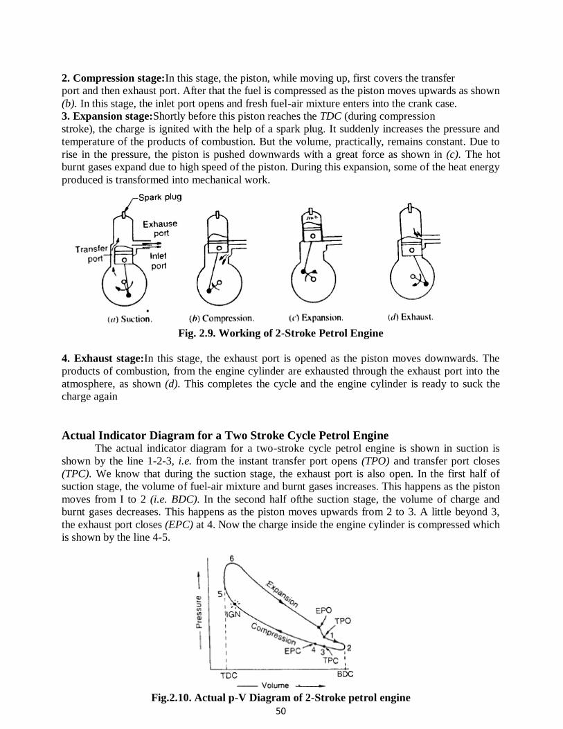
2. Compression stage:In this stage, the piston, while moving up, first covers the transfer
port and then exhaust port. After that the fuel is compressed as the piston moves upwards as shown
(b). In this stage, the inlet port opens and fresh fuel-air mixture enters into the crank case.
3. Expansion stage:Shortly before this piston reaches the TDC (during compression
stroke), the charge is ignited with the help of a spark plug. It suddenly increases the pressure and
temperature of the products of combustion. But the volume, practically, remains constant. Due to
rise in the pressure, the piston is pushed downwards with a great force as shown in (c). The hot
burnt gases expand due to high speed of the piston. During this expansion, some of the heat energy
produced is transformed into mechanical work.
Fig. 2.9. Working of 2-Stroke Petrol Engine
4. Exhaust stage:In this stage, the exhaust port is opened as the piston moves downwards. The
products of combustion, from the engine cylinder are exhausted through the exhaust port into the
atmosphere, as shown (d). This completes the cycle and the engine cylinder is ready to suck the
charge again
Actual Indicator Diagram for a Two Stroke Cycle Petrol Engine The actual indicator diagram for a two-stroke cycle petrol engine is shown in suction is
shown by the line 1-2-3, i.e. from the instant transfer port opens (TPO) and transfer port closes
(TPC). We know that during the suction stage, the exhaust port is also open. In the first half of
suction stage, the volume of fuel-air mixture and burnt gases increases. This happens as the piston
moves from I to 2 (i.e. BDC). In the second half ofthe suction stage, the volume of charge and
burnt gases decreases. This happens as the piston moves upwards from 2 to 3. A little beyond 3,
the exhaust port closes (EPC) at 4. Now the charge inside the engine cylinder is compressed which
is shown by the line 4-5.
Fig.2.10. Actual p-V Diagram of 2-Stroke petrol engine
51
At the end of the compression, there is an increase in the pressure inside the engine cylinder.
Shortly before the end of compression (i.e. TDC) the charge is ignited (IGN) with the help of spark
plug. The sparking suddenly increases pressure and temperature of the products of combustion.
But the volume, practically, remains constant as shown by the line 5-6. The expansion is shown by
the line 6-7. Now the exhaust port opens (EPO) at 7, and the burnt gases are exhausted into the
atmosphere through the exhaust port. It reduces the pressure. As the piston is moving towards
BDC, therefore volume of burnt gases increases from 7 to 1. At 1, the transfer port opens (TPO)
and the suction starts.
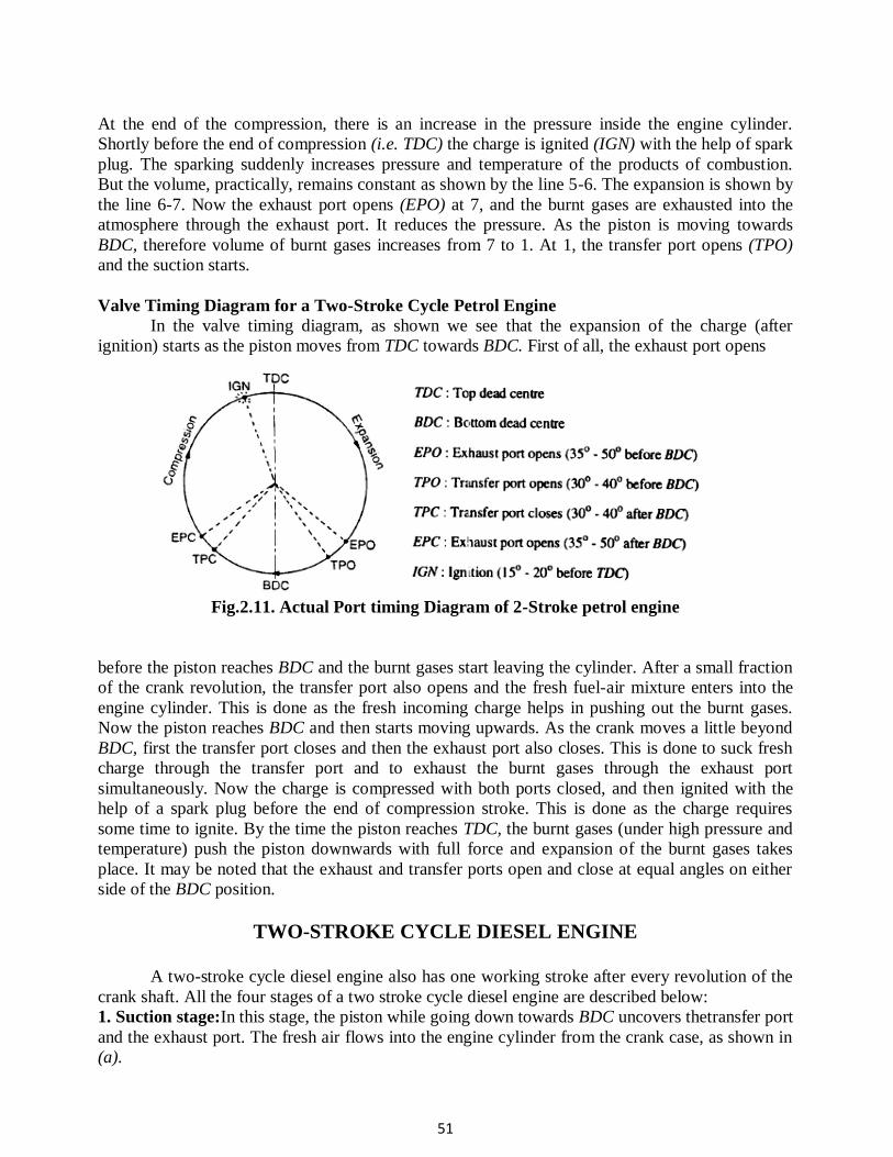
Valve Timing Diagram for a Two-Stroke Cycle Petrol Engine
In the valve timing diagram, as shown we see that the expansion of the charge (after
ignition) starts as the piston moves from TDC towards BDC. First of all, the exhaust port opens
Fig.2.11. Actual Port timing Diagram of 2-Stroke petrol engine
before the piston reaches BDC and the burnt gases start leaving the cylinder. After a small fraction
of the crank revolution, the transfer port also opens and the fresh fuel-air mixture enters into the
engine cylinder. This is done as the fresh incoming charge helps in pushing out the burnt gases.
Now the piston reaches BDC and then starts moving upwards. As the crank moves a little beyond
BDC, first the transfer port closes and then the exhaust port also closes. This is done to suck fresh
charge through the transfer port and to exhaust the burnt gases through the exhaust port
simultaneously. Now the charge is compressed with both ports closed, and then ignited with the
help of a spark plug before the end of compression stroke. This is done as the charge requires
some time to ignite. By the time the piston reaches TDC, the burnt gases (under high pressure and
temperature) push the piston downwards with full force and expansion of the burnt gases takes
place. It may be noted that the exhaust and transfer ports open and close at equal angles on either
side of the BDC position.
TWO-STROKE CYCLE DIESEL ENGINE
A two-stroke cycle diesel engine also has one working stroke after every revolution of the
crank shaft. All the four stages of a two stroke cycle diesel engine are described below:
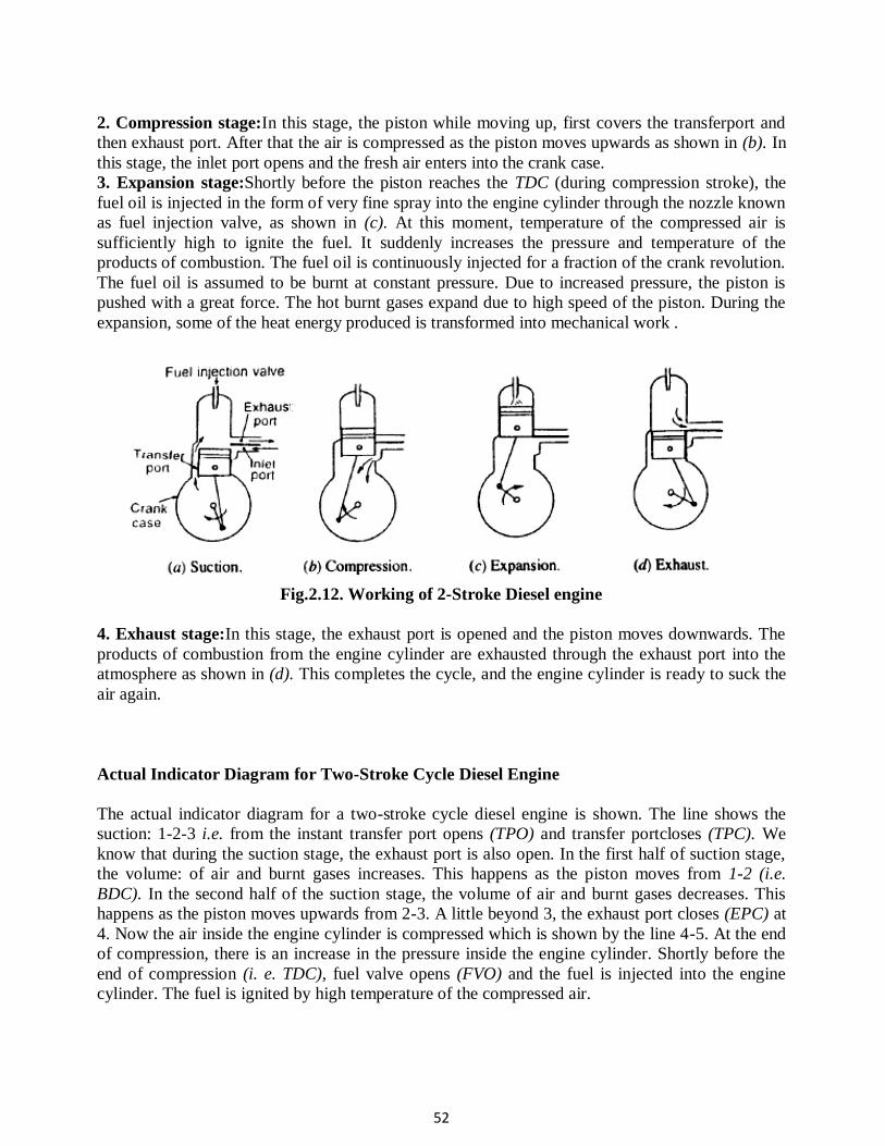
1. Suction stage:In this stage, the piston while going down towards BDC uncovers thetransfer port
and the exhaust port. The fresh air flows into the engine cylinder from the crank case, as shown in
(a).
52
2. Compression stage:In this stage, the piston while moving up, first covers the transferport and
then exhaust port. After that the air is compressed as the piston moves upwards as shown in (b). In
this stage, the inlet port opens and the fresh air enters into the crank case.
3. Expansion stage:Shortly before the piston reaches the TDC (during compression stroke), the
fuel oil is injected in the form of very fine spray into the engine cylinder through the nozzle known
as fuel injection valve, as shown in (c). At this moment, temperature of the compressed air is
sufficiently high to ignite the fuel. It suddenly increases the pressure and temperature of the
products of combustion. The fuel oil is continuously injected for a fraction of the crank revolution.
The fuel oil is assumed to be burnt at constant pressure. Due to increased pressure, the piston is
pushed with a great force. The hot burnt gases expand due to high speed of the piston. During the
expansion, some of the heat energy produced is transformed into mechanical work .
Fig.2.12. Working of 2-Stroke Diesel engine
4. Exhaust stage:In this stage, the exhaust port is opened and the piston moves downwards. The
products of combustion from the engine cylinder are exhausted through the exhaust port into the
atmosphere as shown in (d). This completes the cycle, and the engine cylinder is ready to suck the
air again.
Actual Indicator Diagram for Two-Stroke Cycle Diesel Engine
The actual indicator diagram for a two-stroke cycle diesel engine is shown. The line shows the
suction: 1-2-3 i.e. from the instant transfer port opens (TPO) and transfer portcloses (TPC). We
know that during the suction stage, the exhaust port is also open. In the first half of suction stage,
the volume: of air and burnt gases increases. This happens as the piston moves from 1-2 (i.e.
BDC). In the second half of the suction stage, the volume of air and burnt gases decreases. This
happens as the piston moves upwards from 2-3. A little beyond 3, the exhaust port closes (EPC) at
4. Now the air inside the engine cylinder is compressed which is shown by the line 4-5. At the end
of compression, there is an increase in the pressure inside the engine cylinder. Shortly before the
end of compression (i. e. TDC), fuel valve opens (FVO) and the fuel is injected into the engine
cylinder. The fuel is ignited by high temperature of the compressed air.
53
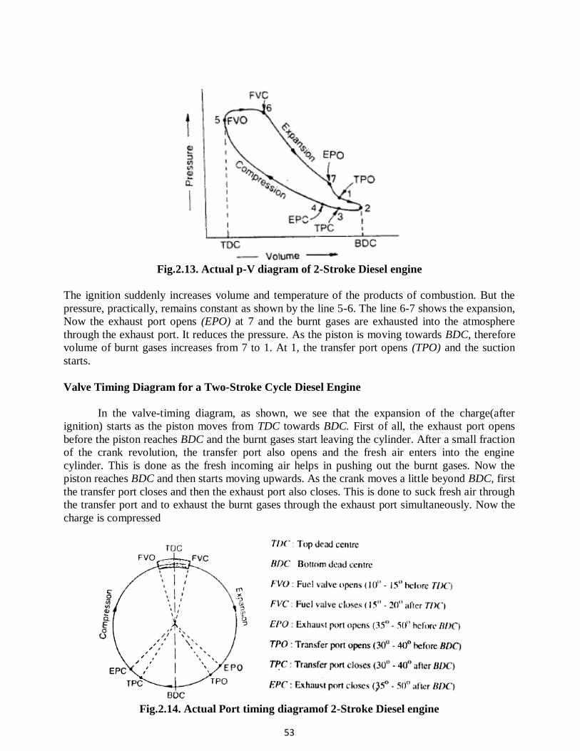
Fig.2.13. Actual p-V diagram of 2-Stroke Diesel engine
The ignition suddenly increases volume and temperature of the products of combustion. But the
pressure, practically, remains constant as shown by the line 5-6. The line 6-7 shows the expansion,
Now the exhaust port opens (EPO) at 7 and the burnt gases are exhausted into the atmosphere
through the exhaust port. It reduces the pressure. As the piston is moving towards BDC, therefore
volume of burnt gases increases from 7 to 1. At 1, the transfer port opens (TPO) and the suction
starts.
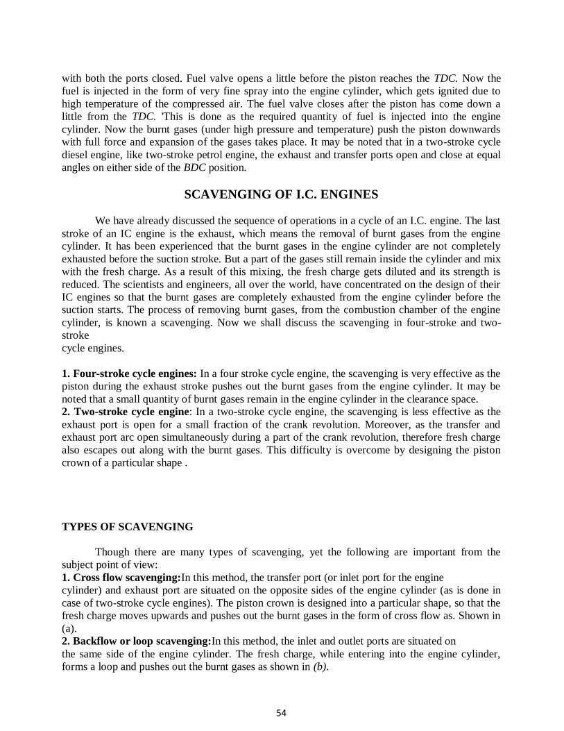
Valve Timing Diagram for a Two-Stroke Cycle Diesel Engine
In the valve-timing diagram, as shown, we see that the expansion of the charge(after
ignition) starts as the piston moves from TDC towards BDC. First of all, the exhaust port opens
before the piston reaches BDC and the burnt gases start leaving the cylinder. After a small fraction
of the crank revolution, the transfer port also opens and the fresh air enters into the engine
cylinder. This is done as the fresh incoming air helps in pushing out the burnt gases. Now the
piston reaches BDC and then starts moving upwards. As the crank moves a little beyond BDC, first
the transfer port closes and then the exhaust port also closes. This is done to suck fresh air through
the transfer port and to exhaust the burnt gases through the exhaust port simultaneously. Now the
charge is compressed
Fig.2.14. Actual Port timing diagramof 2-Stroke Diesel engine
54
with both the ports closed. Fuel valve opens a little before the piston reaches the TDC. Now the
fuel is injected in the form of very fine spray into the engine cylinder, which gets ignited due to
high temperature of the compressed air. The fuel valve closes after the piston has come down a
little from the TDC. 'This is done as the required quantity of fuel is injected into the engine
cylinder. Now the burnt gases (under high pressure and temperature) push the piston downwards
with full force and expansion of the gases takes place. It may be noted that in a two-stroke cycle
diesel engine, like two-stroke petrol engine, the exhaust and transfer ports open and close at equal
angles on either side of the BDC position.
SCAVENGING OF I.C. ENGINES
We have already discussed the sequence of operations in a cycle of an I.C. engine. The last
stroke of an IC engine is the exhaust, which means the removal of burnt gases from the engine
cylinder. It has been experienced that the burnt gases in the engine cylinder are not completely
exhausted before the suction stroke. But a part of the gases still remain inside the cylinder and mix
with the fresh charge. As a result of this mixing, the fresh charge gets diluted and its strength is
reduced. The scientists and engineers, all over the world, have concentrated on the design of their
IC engines so that the burnt gases are completely exhausted from the engine cylinder before the
suction starts. The process of removing burnt gases, from the combustion chamber of the engine
cylinder, is known a scavenging. Now we shall discuss the scavenging in four-stroke and two-
stroke
cycle engines.
1. Four-stroke cycle engines: In a four stroke cycle engine, the scavenging is very effective as the
piston during the exhaust stroke pushes out the burnt gases from the engine cylinder. It may be
noted that a small quantity of burnt gases remain in the engine cylinder in the clearance space.
2. Two-stroke cycle engine: In a two-stroke cycle engine, the scavenging is less effective as the
exhaust port is open for a small fraction of the crank revolution. Moreover, as the transfer and
exhaust port arc open simultaneously during a part of the crank revolution, therefore fresh charge
also escapes out along with the burnt gases. This difficulty is overcome by designing the piston
crown of a particular shape .
TYPES OF SCAVENGING
Though there are many types of scavenging, yet the following are important from the
subject point of view:
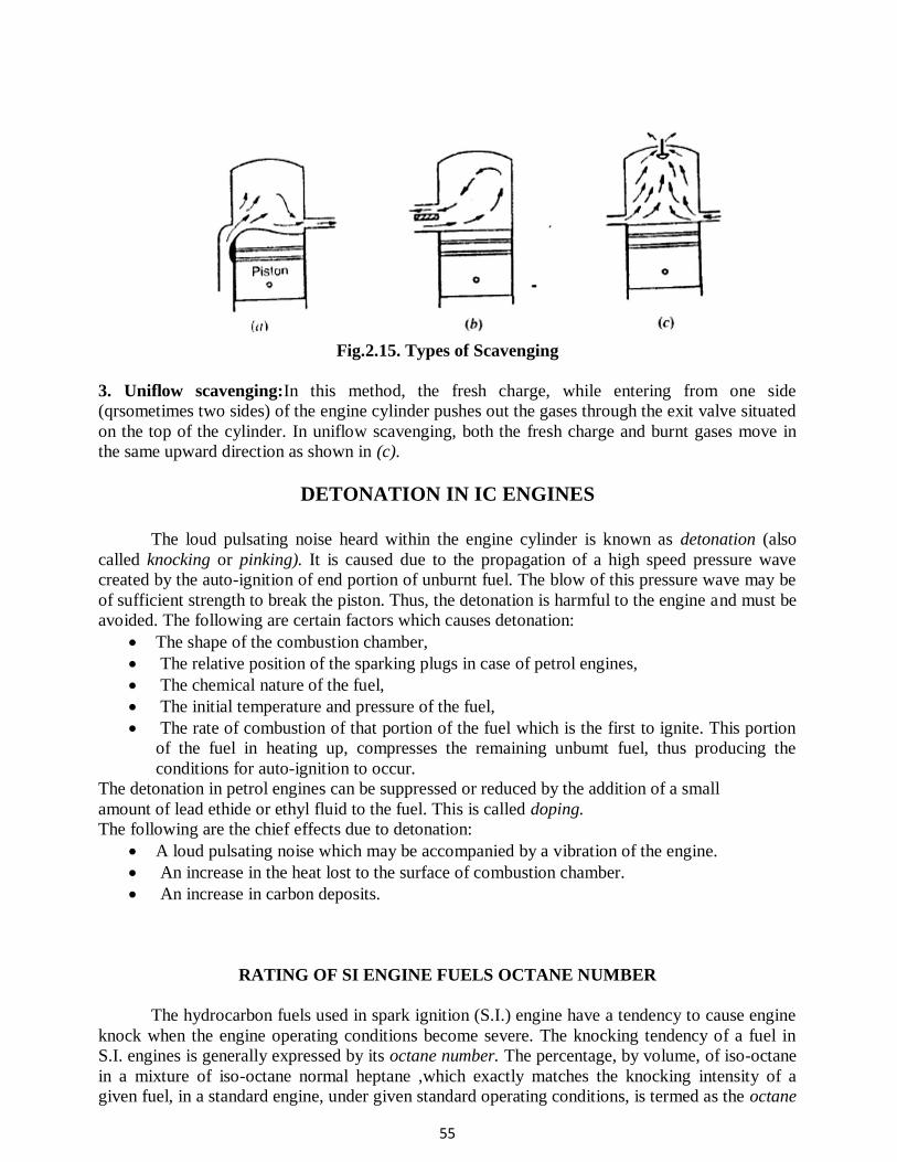
1. Cross flow scavenging:In this method, the transfer port (or inlet port for the engine
cylinder) and exhaust port are situated on the opposite sides of the engine cylinder (as is done in
case of two-stroke cycle engines). The piston crown is designed into a particular shape, so that the
fresh charge moves upwards and pushes out the burnt gases in the form of cross flow as. Shown in
(a).
2. Backflow or loop scavenging:In this method, the inlet and outlet ports are situated on
the same side of the engine cylinder. The fresh charge, while entering into the engine cylinder,
forms a loop and pushes out the burnt gases as shown in (b).
55
Fig.2.15. Types of Scavenging
3. Uniflow scavenging:In this method, the fresh charge, while entering from one side
(qrsometimes two sides) of the engine cylinder pushes out the gases through the exit valve situated
on the top of the cylinder. In uniflow scavenging, both the fresh charge and burnt gases move in
the same upward direction as shown in (c).
DETONATION IN IC ENGINES
The loud pulsating noise heard within the engine cylinder is known as detonation (also
called knocking or pinking). It is caused due to the propagation of a high speed pressure wave
created by the auto-ignition of end portion of unburnt fuel. The blow of this pressure wave may be
of sufficient strength to break the piston. Thus, the detonation is harmful to the engine and must be
avoided. The following are certain factors which causes detonation:
The shape of the combustion chamber,
The relative position of the sparking plugs in case of petrol engines,
The chemical nature of the fuel,
The initial temperature and pressure of the fuel,
The rate of combustion of that portion of the fuel which is the first to ignite. This portion
of the fuel in heating up, compresses the remaining unbumt fuel, thus producing the
conditions for auto-ignition to occur.
The detonation in petrol engines can be suppressed or reduced by the addition of a small
amount of lead ethide or ethyl fluid to the fuel. This is called doping.
The following are the chief effects due to detonation:
A loud pulsating noise which may be accompanied by a vibration of the engine.
An increase in the heat lost to the surface of combustion chamber.
An increase in carbon deposits.
RATING OF SI ENGINE FUELS OCTANE NUMBER
The hydrocarbon fuels used in spark ignition (S.I.) engine have a tendency to cause engine
knock when the engine operating conditions become severe. The knocking tendency of a fuel in
S.I. engines is generally expressed by its octane number. The percentage, by volume, of iso-octane
in a mixture of iso-octane normal heptane ,which exactly matches the knocking intensity of a
given fuel, in a standard engine, under given standard operating conditions, is termed as the octane
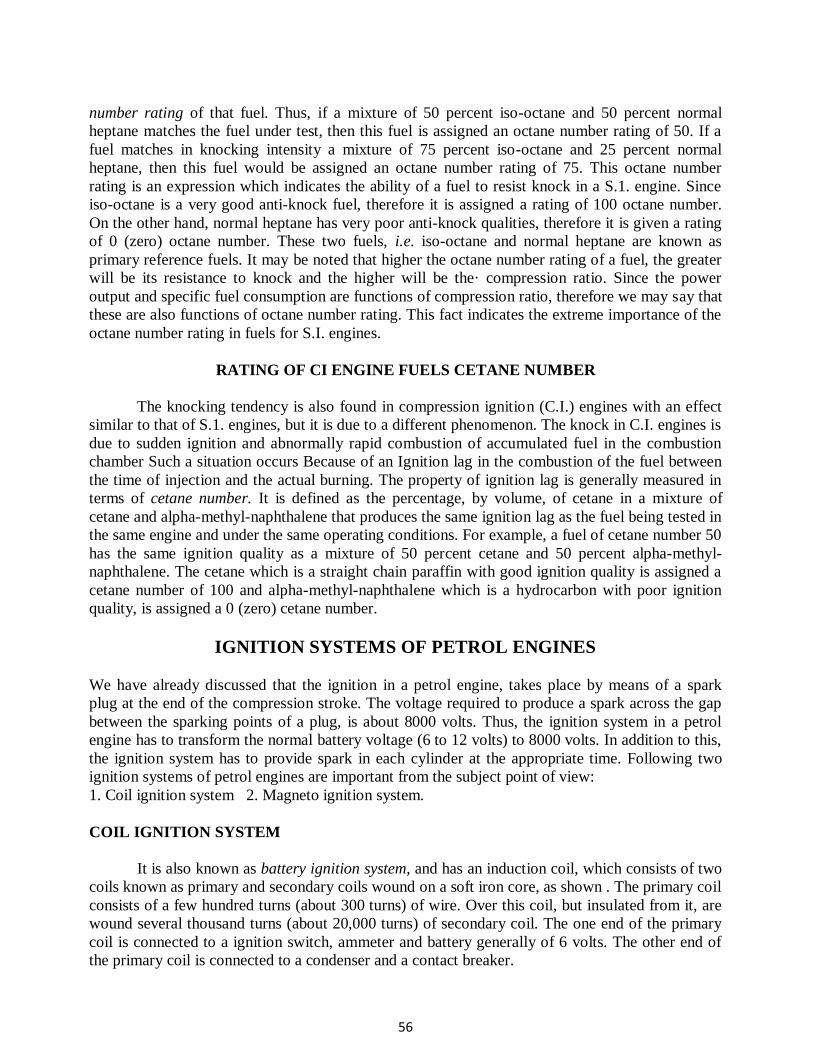
56
number rating of that fuel. Thus, if a mixture of 50 percent iso-octane and 50 percent normal
heptane matches the fuel under test, then this fuel is assigned an octane number rating of 50. If a
fuel matches in knocking intensity a mixture of 75 percent iso-octane and 25 percent normal
heptane, then this fuel would be assigned an octane number rating of 75. This octane number
rating is an expression which indicates the ability of a fuel to resist knock in a S.1. engine. Since
iso-octane is a very good anti-knock fuel, therefore it is assigned a rating of 100 octane number.
On the other hand, normal heptane has very poor anti-knock qualities, therefore it is given a rating
of 0 (zero) octane number. These two fuels, i.e. iso-octane and normal heptane are known as
primary reference fuels. It may be noted that higher the octane number rating of a fuel, the greater
will be its resistance to knock and the higher will be the· compression ratio. Since the power
output and specific fuel consumption are functions of compression ratio, therefore we may say that
these are also functions of octane number rating. This fact indicates the extreme importance of the
octane number rating in fuels for S.I. engines.
RATING OF CI ENGINE FUELS CETANE NUMBER
The knocking tendency is also found in compression ignition (C.I.) engines with an effect
similar to that of S.1. engines, but it is due to a different phenomenon. The knock in C.I. engines is
due to sudden ignition and abnormally rapid combustion of accumulated fuel in the combustion
chamber Such a situation occurs Because of an Ignition lag in the combustion of the fuel between
the time of injection and the actual burning. The property of ignition lag is generally measured in
terms of cetane number. It is defined as the percentage, by volume, of cetane in a mixture of
cetane and alpha-methyl-naphthalene that produces the same ignition lag as the fuel being tested in
the same engine and under the same operating conditions. For example, a fuel of cetane number 50
has the same ignition quality as a mixture of 50 percent cetane and 50 percent alpha-methyl-
naphthalene. The cetane which is a straight chain paraffin with good ignition quality is assigned a
cetane number of 100 and alpha-methyl-naphthalene which is a hydrocarbon with poor ignition
quality, is assigned a 0 (zero) cetane number.
IGNITION SYSTEMS OF PETROL ENGINES
We have already discussed that the ignition in a petrol engine, takes place by means of a spark
plug at the end of the compression stroke. The voltage required to produce a spark across the gap
between the sparking points of a plug, is about 8000 volts. Thus, the ignition system in a petrol
engine has to transform the normal battery voltage (6 to 12 volts) to 8000 volts. In addition to this,
the ignition system has to provide spark in each cylinder at the appropriate time. Following two
ignition systems of petrol engines are important from the subject point of view:
1. Coil ignition system 2. Magneto ignition system.
COIL IGNITION SYSTEM
It is also known as battery ignition system, and has an induction coil, which consists of two
coils known as primary and secondary coils wound on a soft iron core, as shown . The primary coil
consists of a few hundred turns (about 300 turns) of wire. Over this coil, but insulated from it, are
wound several thousand turns (about 20,000 turns) of secondary coil. The one end of the primary
coil is connected to a ignition switch, ammeter and battery generally of 6 volts. The other end of
the primary coil is connected to a condenser and a contact breaker.
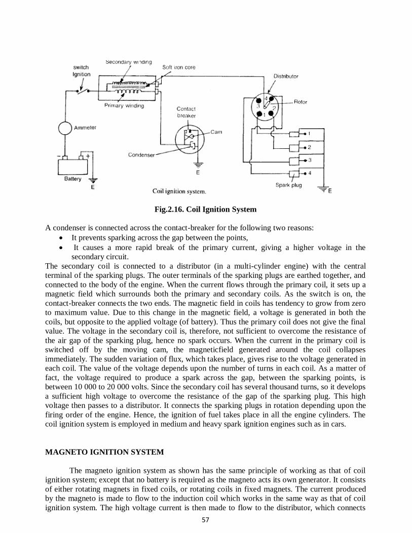
57
Fig.2.16. Coil Ignition System
A condenser is connected across the contact-breaker for the following two reasons:
It prevents sparking across the gap between the points,
It causes a more rapid break of the primary current, giving a higher voltage in the
secondary circuit.
The secondary coil is connected to a distributor (in a multi-cylinder engine) with the central
terminal of the sparking plugs. The outer terminals of the sparking plugs are earthed together, and
connected to the body of the engine. When the current flows through the primary coil, it sets up a
magnetic field which surrounds both the primary and secondary coils. As the switch is on, the
contact-breaker connects the two ends. The magnetic field in coils has tendency to grow from zero
to maximum value. Due to this change in the magnetic field, a voltage is generated in both the
coils, but opposite to the applied voltage (of battery). Thus the primary coil does not give the final
value. The voltage in the secondary coil is, therefore, not sufficient to overcome the resistance of
the air gap of the sparking plug, hence no spark occurs. When the current in the primary coil is
switched off by the moving cam, the magneticfield generated around the coil collapses
immediately. The sudden variation of flux, which takes place, gives rise to the voltage generated in
each coil. The value of the voltage depends upon the number of turns in each coil. As a matter of
fact, the voltage required to produce a spark across the gap, between the sparking points, is
between 10 000 to 20 000 volts. Since the secondary coil has several thousand turns, so it develops
a sufficient high voltage to overcome the resistance of the gap of the sparking plug. This high
voltage then passes to a distributor. It connects the sparking plugs in rotation depending upon the
firing order of the engine. Hence, the ignition of fuel takes place in all the engine cylinders. The
coil ignition system is employed in medium and heavy spark ignition engines such as in cars.
MAGNETO IGNITION SYSTEM
The magneto ignition system as shown has the same principle of working as that of coil
ignition system; except that no battery is required as the magneto acts its own generator. It consists
of either rotating magnets in fixed coils, or rotating coils in fixed magnets. The current produced
by the magneto is made to flow to the induction coil which works in the same way as that of coil
ignition system. The high voltage current is then made to flow to the distributor, which connects
58
the sparking plugs in rotation depending upon the firing order of the engine. This type of ignition
system is generally employed in small spark ignition engines such as scooters, motor cycles and
small motor boat engines.
Fig.2.17. Magneto Ignition System
FUEL INJECTION SYSTEM FOR DIESEL ENGINES
The fol1owing two methods of fuel injection system are generally employed with diesel
engines (i.e.compression ignition engines) :
1. Air injection method, and
2. Airless or solid injection method.
These methods are discussed, in detail, as follows:
1. Air injection method:In this method of fuel injection, a blast of compressed air is used to inject
the fuel into the engine cylinder. This method requires the aid of an air compressor which is driven
by the engine crankshaft. The air is compressed at a pressure higher than that of engine cylinder at
the end of its compression stroke. This method is not used now-a-days because of complicated and
expensive system.
2. Airless or solid injection method:The most modern compression ignition engines use, now-a-
days, the solid injection system. In this method, a separate fuel pump driven by the main
crankshaft is used for forcing the fuel. The fuel is compressed in this pump to a pressure higher
than that of engine cylinder at the end of compression. This fuel under pressure is directly sprayed
into the combustion chamber of the engine cylinder at the end of compression stroke, with the help
of an injector. The solid injection method may be further divided into the following two commonly
used systems.
Common rail system
Individual pump system
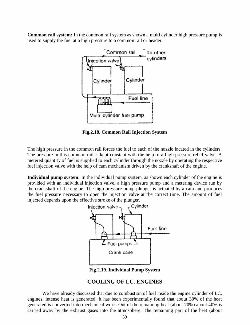
59
Common rail system: In the common rail system as shown a multi cylinder high pressure pump is
used to supply the fuel at a high pressure to a common rail or header.
Fig.2.18. Common Rail Injection System
The high pressure in the common rail forces the fuel to each of the nozzle located in the cylinders.
The pressure in this common rail is kept constant with the help of a high pressure relief valve. A
metered quantity of fuel is supplied to each cylinder through the nozzle by operating the respective
fuel injection valve with the help of cam mechanism driven by the crankshaft of the engine.
Individual pump system: In the individual pump system, as shown each cylinder of the engine is
provided with an individual injection valve, a high pressure pump and a metering device run by
the crankshaft of the engine. The high pressure pump plunger is actuated by a cam and produces
the fuel pressure necessary to open the injection valve at the correct time. The amount of fuel
injected depends upon the effective stroke of the plunger.
Fig.2.19. Individual Pump System
COOLING OF I.C. ENGINES
We have already discussed that due to combustion of fuel inside the engine cylinder of I.C.
engines, intense heat is generated. It has been experimentally found that about 30% of the heat
generated is converted into mechanical work. Out of the remaining heat (about 70%) about 40% is
carried away by the exhaust gases into the atmosphere. The remaining part of the heat (about
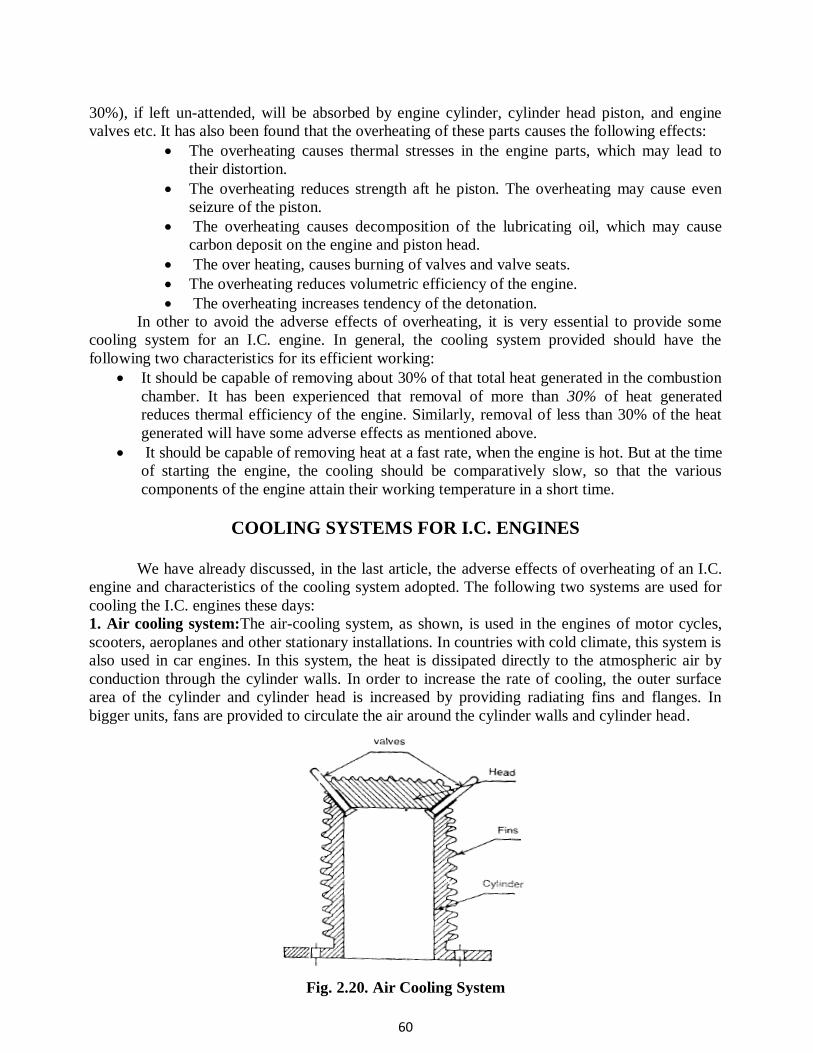
60
30%), if left un-attended, will be absorbed by engine cylinder, cylinder head piston, and engine
valves etc. It has also been found that the overheating of these parts causes the following effects:
The overheating causes thermal stresses in the engine parts, which may lead to
their distortion.
The overheating reduces strength aft he piston. The overheating may cause even
seizure of the piston.
The overheating causes decomposition of the lubricating oil, which may cause
carbon deposit on the engine and piston head.
The over heating, causes burning of valves and valve seats.
The overheating reduces volumetric efficiency of the engine.
The overheating increases tendency of the detonation.
In other to avoid the adverse effects of overheating, it is very essential to provide some
cooling system for an I.C. engine. In general, the cooling system provided should have the
following two characteristics for its efficient working:
It should be capable of removing about 30% of that total heat generated in the combustion
chamber. It has been experienced that removal of more than 30% of heat generated
reduces thermal efficiency of the engine. Similarly, removal of less than 30% of the heat
generated will have some adverse effects as mentioned above.
It should be capable of removing heat at a fast rate, when the engine is hot. But at the time
of starting the engine, the cooling should be comparatively slow, so that the various
components of the engine attain their working temperature in a short time.
COOLING SYSTEMS FOR I.C. ENGINES
We have already discussed, in the last article, the adverse effects of overheating of an I.C.
engine and characteristics of the cooling system adopted. The following two systems are used for
cooling the I.C. engines these days:
1. Air cooling system:The air-cooling system, as shown, is used in the engines of motor cycles,
scooters, aeroplanes and other stationary installations. In countries with cold climate, this system is
also used in car engines. In this system, the heat is dissipated directly to the atmospheric air by
conduction through the cylinder walls. In order to increase the rate of cooling, the outer surface
area of the cylinder and cylinder head is increased by providing radiating fins and flanges. In
bigger units, fans are provided to circulate the air around the cylinder walls and cylinder head.
Fig. 2.20. Air Cooling System
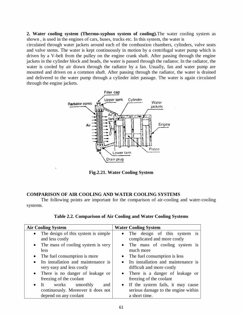
61
2. Water cooling system (Thermo-syphon system of cooling).The water cooling system as
shown , is used in the engines of cars, buses, trucks etc. In this system, the water is
circulated through water jackets around each of the combustion chambers, cylinders, valve seats
and valve stems. The water is kept continuously in motion by a centrifugal water pump which is
driven by a V-belt from the pulley on the engine crank shaft. After passing through the engine
jackets in the cylinder block and heads, the water is passed through the radiator. In the radiator, the
water is cooled by air drawn through the radiator by a fan. Usually, fan and water pump are
mounted and driven on a common shaft. After passing through the radiator, the water is drained
and delivered to the water pump through a cylinder inlet passage. The water is again circulated
through the engine jackets.
.
Fig.2.21. Water Cooling System
COMPARISON OF AIR COOLING AND WATER COOLING SYSTEMS
The following points are important for the comparison of air-cooling and water-cooling
systems.
Table 2.2. Comparison of Air Cooling and Water Cooling Systems
Air Cooling System Water Cooling System
The design of this system is simple
and less costly
The mass of cooling system is very
less
The fuel consumption is more
Its installation and maintenance is
very easy and less costly
There is no danger of leakage or
freezing of the coolant
It works smoothly and
continuously. Moreover it does not
depend on any coolant
The design of this system is
complicated and more costly
The mass of cooling system is
much more
The fuel consumption is less
Its installation and maintenance is
difficult and more costly
There is a danger of leakage or
freezing of the coolant
If the system fails, it may cause
serious damage to the engine within
a short time.
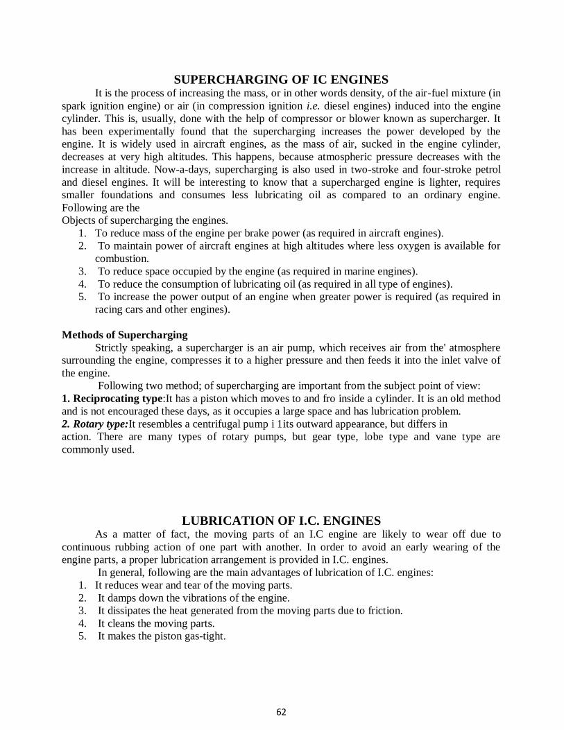
62
SUPERCHARGING OF IC ENGINES It is the process of increasing the mass, or in other words density, of the air-fuel mixture (in
spark ignition engine) or air (in compression ignition i.e. diesel engines) induced into the engine
cylinder. This is, usually, done with the help of compressor or blower known as supercharger. It
has been experimentally found that the supercharging increases the power developed by the
engine. It is widely used in aircraft engines, as the mass of air, sucked in the engine cylinder,
decreases at very high altitudes. This happens, because atmospheric pressure decreases with the
increase in altitude. Now-a-days, supercharging is also used in two-stroke and four-stroke petrol
and diesel engines. It will be interesting to know that a supercharged engine is lighter, requires
smaller foundations and consumes less lubricating oil as compared to an ordinary engine.
Following are the
Objects of supercharging the engines.
1. To reduce mass of the engine per brake power (as required in aircraft engines).
2. To maintain power of aircraft engines at high altitudes where less oxygen is available for
combustion.
3. To reduce space occupied by the engine (as required in marine engines).
4. To reduce the consumption of lubricating oil (as required in all type of engines).
5. To increase the power output of an engine when greater power is required (as required in
racing cars and other engines).
Methods of Supercharging
Strictly speaking, a supercharger is an air pump, which receives air from the' atmosphere
surrounding the engine, compresses it to a higher pressure and then feeds it into the inlet valve of
the engine.
Following two method; of supercharging are important from the subject point of view:
1. Reciprocating type:It has a piston which moves to and fro inside a cylinder. It is an old method
and is not encouraged these days, as it occupies a large space and has lubrication problem.
2. Rotary type:It resembles a centrifugal pump i 1its outward appearance, but differs in
action. There are many types of rotary pumps, but gear type, lobe type and vane type are
commonly used.
LUBRICATION OF I.C. ENGINES As a matter of fact, the moving parts of an I.C engine are likely to wear off due to
continuous rubbing action of one part with another. In order to avoid an early wearing of the
engine parts, a proper lubrication arrangement is provided in I.C. engines.
In general, following are the main advantages of lubrication of I.C. engines:
1. It reduces wear and tear of the moving parts.
2. It damps down the vibrations of the engine.
3. It dissipates the heat generated from the moving parts due to friction.
4. It cleans the moving parts.
5. It makes the piston gas-tight.
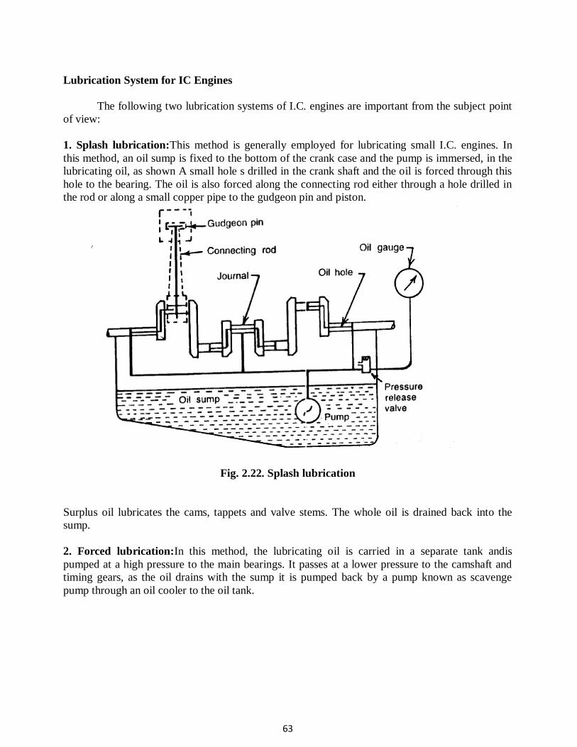
63
Lubrication System for IC Engines
The following two lubrication systems of I.C. engines are important from the subject point
of view:
1. Splash lubrication:This method is generally employed for lubricating small I.C. engines. In
this method, an oil sump is fixed to the bottom of the crank case and the pump is immersed, in the
lubricating oil, as shown A small hole s drilled in the crank shaft and the oil is forced through this
hole to the bearing. The oil is also forced along the connecting rod either through a hole drilled in
the rod or along a small copper pipe to the gudgeon pin and piston.
Fig. 2.22. Splash lubrication
Surplus oil lubricates the cams, tappets and valve stems. The whole oil is drained back into the
sump.
2. Forced lubrication:In this method, the lubricating oil is carried in a separate tank andis
pumped at a high pressure to the main bearings. It passes at a lower pressure to the camshaft and
timing gears, as the oil drains with the sump it is pumped back by a pump known as scavenge
pump through an oil cooler to the oil tank.
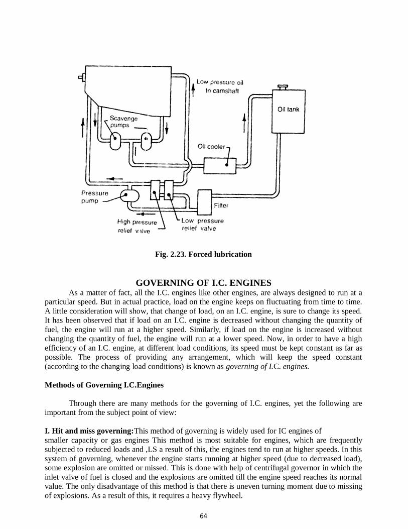
64
Fig. 2.23. Forced lubrication
GOVERNING OF I.C. ENGINES As a matter of fact, all the I.C. engines like other engines, are always designed to run at a
particular speed. But in actual practice, load on the engine keeps on fluctuating from time to time.
A little consideration will show, that change of load, on an I.C. engine, is sure to change its speed.
It has been observed that if load on an I.C. engine is decreased without changing the quantity of
fuel, the engine will run at a higher speed. Similarly, if load on the engine is increased without
changing the quantity of fuel, the engine will run at a lower speed. Now, in order to have a high
efficiency of an I.C. engine, at different load conditions, its speed must be kept constant as far as
possible. The process of providing any arrangement, which will keep the speed constant
(according to the changing load conditions) is known as governing of I.C. engines.
Methods of Governing I.C.Engines
Through there are many methods for the governing of I.C. engines, yet the following are
important from the subject point of view:
I. Hit and miss governing:This method of governing is widely used for IC engines of
smaller capacity or gas engines This method is most suitable for engines, which are frequently
subjected to reduced loads and ,LS a result of this, the engines tend to run at higher speeds. In this
system of governing, whenever the engine starts running at higher speed (due to decreased load),
some explosion are omitted or missed. This is done with help of centrifugal governor in which the
inlet valve of fuel is closed and the explosions are omitted till the engine speed reaches its normal
value. The only disadvantage of this method is that there is uneven turning moment due to missing
of explosions. As a result of this, it requires a heavy flywheel.
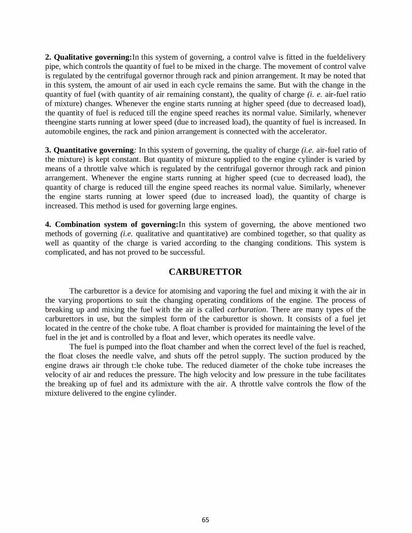
65
2. Qualitative governing:In this system of governing, a control valve is fitted in the fueldelivery
pipe, which controls the quantity of fuel to be mixed in the charge. The movement of control valve
is regulated by the centrifugal governor through rack and pinion arrangement. It may be noted that
in this system, the amount of air used in each cycle remains the same. But with the change in the
quantity of fuel (with quantity of air remaining constant), the quality of charge (i. e. air-fuel ratio
of mixture) changes. Whenever the engine starts running at higher speed (due to decreased load),
the quantity of fuel is reduced till the engine speed reaches its normal value. Similarly, whenever
theengine starts running at lower speed (due to increased load), the quantity of fuel is increased. In
automobile engines, the rack and pinion arrangement is connected with the accelerator.
3. Quantitative governing: In this system of governing, the quality of charge (i.e. air-fuel ratio of
the mixture) is kept constant. But quantity of mixture supplied to the engine cylinder is varied by
means of a throttle valve which is regulated by the centrifugal governor through rack and pinion
arrangement. Whenever the engine starts running at higher speed (cue to decreased load), the
quantity of charge is reduced till the engine speed reaches its normal value. Similarly, whenever
the engine starts running at lower speed (due to increased load), the quantity of charge is
increased. This method is used for governing large engines.
4. Combination system of governing:In this system of governing, the above mentioned two
methods of governing (i.e. qualitative and quantitative) are combined together, so that quality as
well as quantity of the charge is varied according to the changing conditions. This system is
complicated, and has not proved to be successful.
CARBURETTOR
The carburettor is a device for atomising and vaporing the fuel and mixing it with the air in
the varying proportions to suit the changing operating conditions of the engine. The process of
breaking up and mixing the fuel with the air is called carburation. There are many types of the
carburettors in use, but the simplest form of the carburettor is shown. It consists of a fuel jet
located in the centre of the choke tube. A float chamber is provided for maintaining the level of the
fuel in the jet and is controlled by a float and lever, which operates its needle valve.
The fuel is pumped into the float chamber and when the correct level of the fuel is reached,
the float closes the needle valve, and shuts off the petrol supply. The suction produced by the
engine draws air through t:le choke tube. The reduced diameter of the choke tube increases the
velocity of air and reduces the pressure. The high velocity and low pressure in the tube facilitates
the breaking up of fuel and its admixture with the air. A throttle valve controls the flow of the
mixture delivered to the engine cylinder.
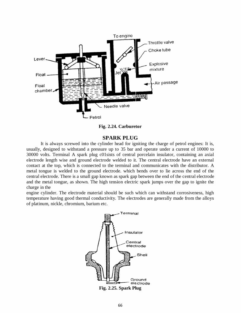
66
Fig. 2.24. Carburetor
SPARK PLUG It is always screwed into the cylinder head for igniting the charge of petrol engines: It is,
usually, designed to withstand a pressure up to 35 bar and operate under a current of 10000 to
30000 volts. Terminal A spark plug c01sists of central porcelain insulator, containing an axial
electrode length wise and ground electrode welded to it. The central electrode have an external
contact at the top, which is connected to the terminal and communicates with the distributor. A
metal tongue is welded to the ground electrode. which bends over to lie across the end of the
central electrode. There is a small gap known as spark gap between the end of the central electrode
and the metal tongue, as shown. The high tension electric spark jumps over the gap to ignite the
charge in the
engine cylinder. The electrode material should be such which can withstand corrosiveness, high
temperature having good thermal conductivity. The electrodes are generally made from the alloys
of platinum, nickle, chromium, barium etc.
Fig. 2.25. Spark Plug
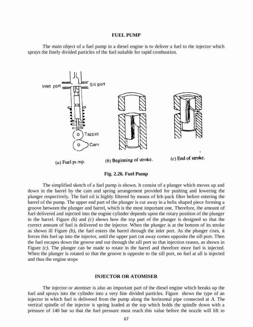
67
FUEL PUMP
The main object of a fuel pump in a diesel engine is to deliver a fuel to the injector which
sprays the finely divided particles of the fuel suitable for rapid combustion.
Fig. 2.26. Fuel Pump
The simplified sketch of a fuel pump is shown. It consist of a plunger which moves up and
down in the barrel by the cam and spring arrangement provided for pushing and lowering the
plunger respectively. The fuel oil is highly filtered by means of felt-pack filter before entering the
barrel of the pump. The upper end part of the plunger is cut away in a helix shaped piece forming a
groove between the plunger and barrel, which is the most important one. Therefore, the amount of
fuel delivered and injected into the engine cylinder depends upon the rotary position of the plunger
in the barrel. Figure (b) and (c) shows how the top part of the plunger is designed so that the
correct amount of fuel is delivered to the injector. When the plunger is at the bottom of its stroke
as shown ill Figure (b), the fuel enters the barrel through the inlet port. As the plunger rises, it
forces this fuel up into the injector, until the upper part cut away comes opposite the sill port. Then
the fuel escapes down the groove and out through the sill port so that injection ceases, as shown in
Figure (c). The plunger can be made to rotate in the barrel and therefore more fuel is injected.
When the plunger is rotated so that the groove is opposite to the sill port, no fuel at all is injected
and thus the engine stops
INJECTOR OR ATOMISER
The injector or atomiser is also an important part of the diesel engine which breaks up the
fuel and sprays into the cylinder into a very fine divided particles. Figure shows the type of an
injector in which fuel is delivered from the pump along the horizontal pipe connected at A. The
vertical spindle of the injector is spring loaded at the top which holds the spindle down with a
pressure of 140 bar so that the fuel pressure must reach this value before the nozzle will lift to
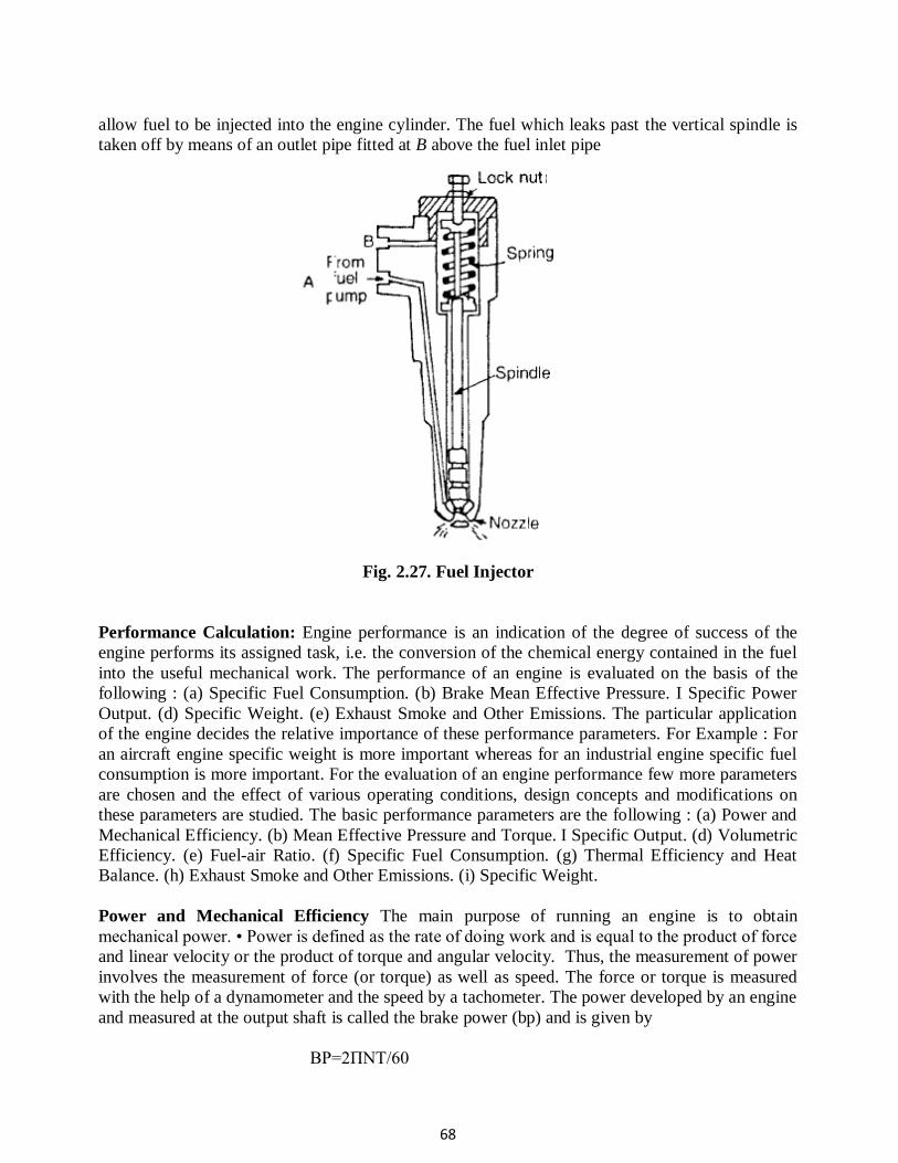
68
allow fuel to be injected into the engine cylinder. The fuel which leaks past the vertical spindle is
taken off by means of an outlet pipe fitted at B above the fuel inlet pipe
Fig. 2.27. Fuel Injector
Performance Calculation: Engine performance is an indication of the degree of success of the
engine performs its assigned task, i.e. the conversion of the chemical energy contained in the fuel
into the useful mechanical work. The performance of an engine is evaluated on the basis of the
following : (a) Specific Fuel Consumption. (b) Brake Mean Effective Pressure. I Specific Power
Output. (d) Specific Weight. (e) Exhaust Smoke and Other Emissions. The particular application
of the engine decides the relative importance of these performance parameters. For Example : For
an aircraft engine specific weight is more important whereas for an industrial engine specific fuel
consumption is more important. For the evaluation of an engine performance few more parameters
are chosen and the effect of various operating conditions, design concepts and modifications on
these parameters are studied. The basic performance parameters are the following : (a) Power and
Mechanical Efficiency. (b) Mean Effective Pressure and Torque. I Specific Output. (d) Volumetric
Efficiency. (e) Fuel-air Ratio. (f) Specific Fuel Consumption. (g) Thermal Efficiency and Heat
Balance. (h) Exhaust Smoke and Other Emissions. (i) Specific Weight.
Power and Mechanical Efficiency The main purpose of running an engine is to obtain
mechanical power. • Power is defined as the rate of doing work and is equal to the product of force
and linear velocity or the product of torque and angular velocity. Thus, the measurement of power
involves the measurement of force (or torque) as well as speed. The force or torque is measured
with the help of a dynamometer and the speed by a tachometer. The power developed by an engine
and measured at the output shaft is called the brake power (bp) and is given by
BP=2ΠNT/60
69
Where, T is torque in N-m and N is the rotational speed in revolutions per minute. The total power
developed by combustion of fuel in the combustion chamber is, however, more than the BP and is
called indicated power (IP). Of the power developed by the engine, i.e. IP, some power is
consumed in overcoming the friction between moving parts, some in the process of inducting the
air and removing the products of combustion from the engine combustion chamber.
Indicated Power It is the power developed in the cylinder and thus, forms the basis of evaluation
of combustion efficiency or the heat release in the cylinder.
I.P= PmLANK/60
Where,
Pm = Mean effective pressure, N/m2, L = Length of the stroke, m, A = Area of the piston, m2, N =
Rotational speed of the engine, rpm (It is N/2 for four stroke engine), and k = Number of
cylinders. Thus, we see that for a given engine the power output can be measured in terms of mean
effective pressure. The difference between the IP and BP is the indication of the power lost in the
mechanical components of the engine (due to friction) and forms the basis of mechanical
efficiency; which is defined as follows:
Mechanical efficiency=BP/IP
The difference between ip and bp is called friction power (FP). FP = IP − Bp Mechanical
efficiency= BP/(BP+FP)
Mean Effective Pressure and Torque Mean effective pressure is defined as a
hypothetical/average pressure which is assumed to be acting on the piston throughout the power
stroke. Therefore,
Pm=60XI.P/LANk
where, Pm = Mean effective pressure, N/m2, IP = Indicated power, Watt, L = Length of the stroke,
m, A = Area of the piston, m2, N = Rotational speed of the engine, rpm (It is N/2 for four stroke
engine), and k = Number of cylinders. If the mean effective pressure is based on BP it is called the
brake mean effective pressure( Pm), and if based on IP it is called indicated mean effective
pressure (imep). Similarly, the friction mean effective pressure (fmep) can be defined as,
fmep = imep – bmep
The torque is related to mean effective pressure by the relation
B.P=2ΠnT/60
I.P=PmLANk/60
2ΠnT/60=[bmep.A.L.(Nk/60)]
or, T=(bmep.A.L.k)/2π
Thus, the torque and the mean effective pressure are related by the engine size. A large engine
produces more torque for the same mean effective pressure. For this reason, torque is not the
70
measure of the ability of an engine to utilize its displacement for producing power from fuel. It is
the mean effective pressure which gives an indication of engine displacement utilization for this
conversion. Higher the mean effective pressure, higher will be the power developed by the engine
for a given displacement. Again we see that the power of an engine is dependent on its size and
speed. Therefore, it is not possible to compare engines on the basis of either power or torque.
Mean effective pressure is the true indication of the relative performance of different engines.
Specific Output Specific output of an engine is defined as the brake power (output) per unit of
piston displacement and is given by,
Specific output=B.P/A.L
Constant = bmep × rpm •
The specific output consists of two elements – the bmep (force) available to work and the speed
with which it is working. • Therefore, for the same piston displacement and bmep an engine
operating at higher speed will give more output. It is clear that the output of an engine can be
increased by increasing either speed or bmep. Increasing speed involves increase in the mechanical
stress of various engine parts whereas increasing bmep requires better heat release and more load
on engine cylinder.
Fuel-Air Ratio (F/A)
Fuel-air ratio (F/A) is the ratio of the mass of fuel to the mass of air in the fuel-air mixture. Air-
fuel ratio (A/F) is reciprocal of fuel-air ratio. Fuel-air ratio of the mixture affects the combustion
phenomenon in that it determines the flame propagation velocity, the heat release in the
combustion chamber, the maximum temperature and the completeness of combustion. Relative
fuel-air ratio is defined as the ratio of the actual fuel-air ratio to that of the stoichiometric fuel-air
ratio required to burn the fuel supplied. Stoichiometric fuel-air ratio is the ratio of fuel to air is one
in which case fuel is completely burned due to minimum quantity of air supplied.
Relative fuel-air ratio, =(Actual Fuel- Air ratio)/(Stoichiometric fuel-Air ratio)
Indicated Specific Fuel Consumption: This is defined as the mass of fuel
consumption per hour in order to produce an indicated power of one kilo watt.
3600 mf Thus, indicated specific fuel consumption = isfc = ---------------- kg/kWh
IP
Brake Specific fuel consumption:- This defined as the mass of fuel consumed per hour,
in order to develop a brake power of one kilowatt.
3600 mf Thus, brake specific fuel consumption = bsfc =---------------- kg/kWh
BP
Thermal Efficiency : There are two definitions of thermal efficiency as applied to IC engines.
One is based on indicated power and the other on brake power.The one based on indicated
power is called as ‘indicated thermal efficiency”, and the one based on brake power is known
as “brake thermal efficiency”.
71
Indicated thermal efficiency is defined as the ratio of indicated power to the energy
available due to combustion of the fuel.
ip
Or ith = ---------------
m x CV
Similarly brake thermal efficiency is defined as the ratio of brake power to energy
available due to combustion of the fuel.
bp
Or bth = ---------------
m x CV
Mechanical Efficiency: Mechanical efficiency takes into account the mechanical
losses in an engine. The mechanical losses include (i) frictional losses, (ii) power absorbed
by engine auxillaries like fuel pump, lubricating oil pump, water circulating pump,
magneto and distributor, electric generator for battery charging, radiator fan etc., and (iii)
work requited to charge the cylinder with fresh charge and work for discharging the
exhaust gases during the exhaust stroke. It is defined as the ratio of brake power to
indicated power. Thus bp
mech = --------
ip
Volumetric efficiency: Volumetric efficiency is the ratio of the actual mass of air
drawn into the cylinder during a given period of time to the theoretical mass which should
have been drawn in during the same interval of time based on the total piston
displacement, and the pressure and temperature of the surrounding atmosphere.
Va
Thus v = -----------------
Vth
where n is the number of intake strokes per minute and Vs is the stroke volume of the piston.
Heat balance Sheet
• The energy input to the engine goes out in various forms – a part is in the form of brake
output, a part into exhaust, and the rest is taken by cooling water and the lubricating oil. The
break-up of the total energy input into these different parts is called the heat balance. The main
components in a heat balance are brake output, coolant losses, heat going to exhaust, radiation
and other losses.
• Preparation of heat balance sheet gives us an idea about the amount of energy wasted in
various parts and allows us to think of methods to reduce the losses so incurred.
A heat balance sheet is an account of heat supplied and heat utilized in various ways in the
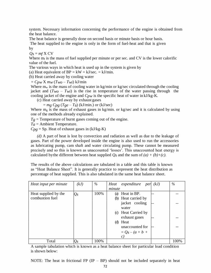
72
system. Necessary information concerning the performance of the engine is obtained from
the heat balance.
The heat balance is generally done on second basis or minute basis or hour basis.
The heat supplied to the engine is only in the form of fuel-heat and that is given
by
Qs = mf X CV Where mf is the mass of fuel supplied per minute or per sec. and CV is the lower calorific value of the fuel. The various ways in which heat is used up in the system is given by (a) Heat equivalent of BP = kW = kJ/sec. = kJ/min. (b) Heat carried away by cooling water
= Cpw X mw (Two – Twi) kJ/min
Where mw is the mass of cooling water in kg/min or kg/sec circulated through the cooling jacket and (Two – Twi) is the rise in temperature of the water passing through the cooling jacket of the engine and Cpw is the specific heat of water in kJ/kg-K.
(c) Heat carried away by exhaust gases
= mg Cpg (Tge – Ta) (kJ/min.) or (kJ/sec) Where mg is the mass of exhaust gases in kg/min. or kg/sec and it is calculated by using one of the methods already explained.
Tg = Temperature of burnt gases coming out of the engine.
Ta = Ambient Temperature.
Cpg = Sp. Heat of exhaust gases in (kJ/kg-K)
(d) A part of heat is lost by convection and radiation as well as due to the leakage of
gases. Part of the power developed inside the engine is also used to run the accessories
as lubricating pump, cam shaft and water circulating pump. These cannot be measured
precisely and so this is known as unaccounted ‘losses’. This unaccounted heat energy is
calculated by the different between heat supplied Qs and the sum of (a) + (b)+(c).
The results of the above calculations are tabulated in a table and this table is known
as “Heat Balance Sheet”. It is generally practice to represent the heat distribution as
percentage of heat supplied. This is also tabulated in the same heat balance sheet.
Heat input per minute (kJ) % Heat expenditure per
minute
(kJ) %
Heat supplied by the combustion fuel
Qs 100% (a) Heat in BP. (b) Heat carried by
jacket cooling
water
(c) Heat Carried by
exhaust gases
(d) Heat
unaccounted for
= Qs – (a + b + c)
-- --
-- --
--
--
-- --
Total Qs 100% 100%
A sample tabulation which is known as a heat balance sheet for particular load condition
is shown below:
NOTE: The heat in frictional FP (IP – BP) should not be included separately in heat
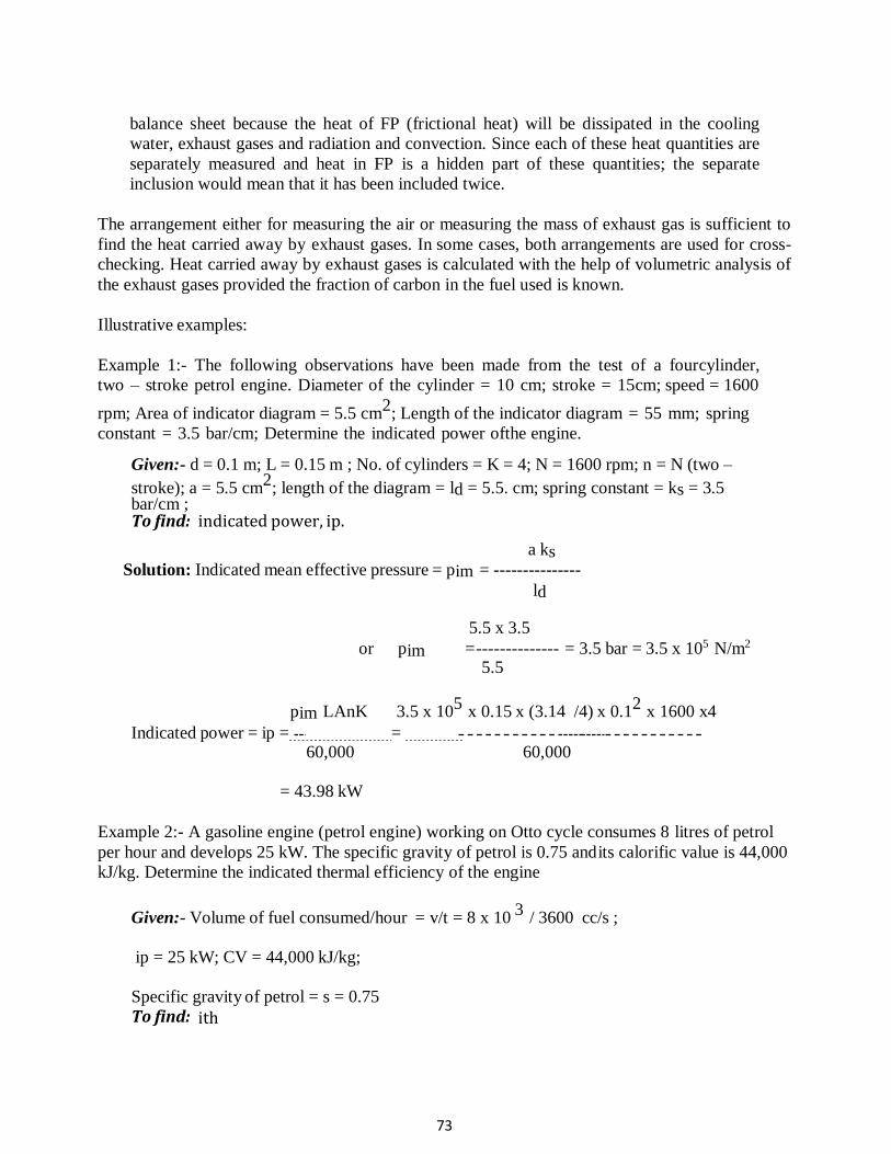
73
balance sheet because the heat of FP (frictional heat) will be dissipated in the cooling
water, exhaust gases and radiation and convection. Since each of these heat quantities are
separately measured and heat in FP is a hidden part of these quantities; the separate
inclusion would mean that it has been included twice.
The arrangement either for measuring the air or measuring the mass of exhaust gas is sufficient to
find the heat carried away by exhaust gases. In some cases, both arrangements are used for cross-
checking. Heat carried away by exhaust gases is calculated with the help of volumetric analysis of
the exhaust gases provided the fraction of carbon in the fuel used is known.
Illustrative examples:
Example 1:- The following observations have been made from the test of a four cylinder,
two – stroke petrol engine. Diameter of the cylinder = 10 cm; stroke = 15 cm; speed = 1600
rpm; Area of indicator diagram = 5.5 cm2
; Length of the indicator diagram = 55 mm; spring
constant = 3.5 bar/cm; Determine the indicated power of the engine.
Given:- d = 0.1 m; L = 0.15 m ; No. of cylinders = K = 4; N = 1600 rpm; n = N (two –
stroke); a = 5.5 cm2
; length of the diagram = ld = 5.5. cm; spring constant = ks = 3.5 bar/cm ; To find: indicated power, ip.
a ks
Solution: Indicated mean effective pressure = pim = ---------------
ld
5.5 x 3.5
or pim = -------------- = 3.5 bar = 3.5 x 10⁵ N/m2 5.5
pim LAnK 3.5 x 105
x 0.15 x (3.14 /4) x 0.12
x 1600 x4
Indicated power = ip = = 60,000 60,000
= 43.98 kW
Example 2:- A gasoline engine (petrol engine) working on Otto cycle consumes 8 litres of petrol
per hour and develops 25 kW. The specific gravity of petrol is 0.75 and its calorific value is 44,000
kJ/kg. Determine the indicated thermal efficiency of the engine
Given:- Volume of fuel consumed/hour = v/t = 8 x 10 3
/ 3600 cc/s ;
ip = 25 kW; CV = 44,000 kJ/kg;
Specific gravity of petrol = s = 0.75
To find: ith
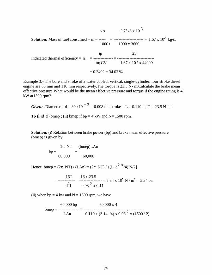
74
v s 0.75x8 x 10 3
Solution: Mass of fuel consumed = m = ----- = --------------------- = 1.67 x 10⁻³ kg/s.
1000 t 1000 x 3600
ip 25
Indicated thermal efficiency = ith = -------------- = --------------------------- mf CV 1.67 x 10-3 x 44000
= 0.3402 = 34.02 %.
Example 3:- The bore and stroke of a water cooled, vertical, single-cylinder, four stroke diesel
engine are 80 mm and 110 mm respectively.The torque is 23.5 N- m.Calculate the brake mean
effective pressure.What would be the mean effective pressure and torque if the engine rating is 4
kW at 1500 rpm?
Given:- Diameter = d = 80 x10 − 3
= 0.008 m ; stroke = L = 0.110 m; T = 23.5 N-m;
To find (i) bmep ; (ii) bmep if bp = 4 kW and N= 1500 rpm.
Solution: (i) Relation between brake power (bp) and brake mean effective pressure (bmep) is given by
2π NT (bmep)LAn
bp = =
60,000 60,000
Hence bmep = (2π NT) / (LAn) = (2π NT) / {(L d2 π
/4) N/2}
16T 16 x 23.5 = ------------- = ---------------- = 5.34 x 10⁵ N / m2 = 5.34 bar
d2L 0.08
2 x 0.11
(ii) when bp = 4 kw and N = 1500 rpm, we have
60,000 bp 60,000 x 4
bmep = LAn
=
0.110 x (3.14 /4) x 0.08 2
x (1500 / 2)
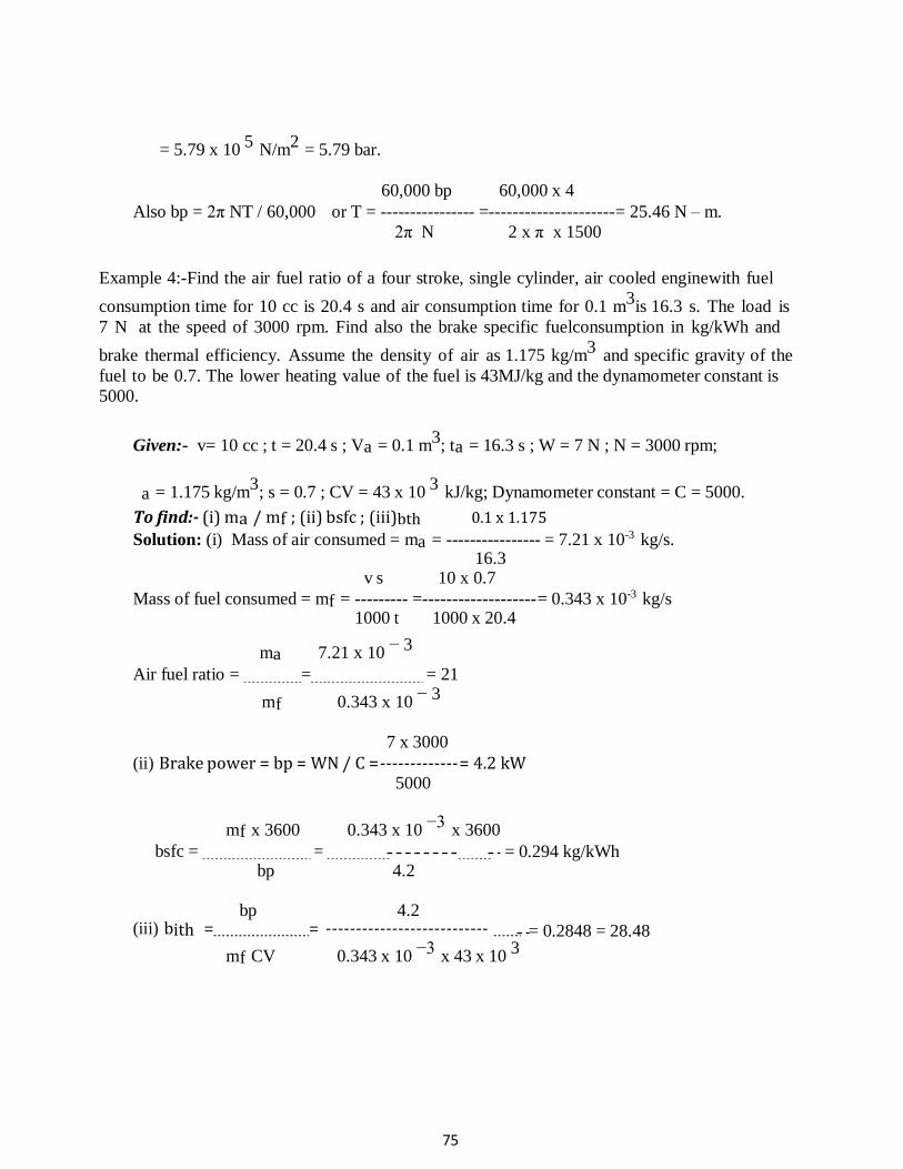
75
= 5.79 x 10 5
N/m2
= 5.79 bar.
60,000 bp 60,000 x 4
Also bp = 2π NT / 60,000 or T = ---------------- =--------------------- = 25.46 N – m.
2π N 2 x π x 1500
Example 4:-Find the air fuel ratio of a four stroke, single cylinder, air cooled engine with fuel
consumption time for 10 cc is 20.4 s and air consumption time for 0.1 m3
is 16.3 s. The load is
7 N at the speed of 3000 rpm. Find also the brake specific fuelconsumption in kg/kWh and
brake thermal efficiency. Assume the density of air as 1.175 kg/m3
and specific gravity of the
fuel to be 0.7. The lower heating value of the fuel is 43MJ/kg and the dynamometer constant is
5000.
Given:- v= 10 cc ; t = 20.4 s ; Va = 0.1 m3; ta = 16.3 s ; W = 7 N ; N = 3000 rpm;
a = 1.175 kg/m3
; s = 0.7 ; CV = 43 x 10 3
kJ/kg; Dynamometer constant = C = 5000.
To find:- (i) ma / mf ; (ii) bsfc ; (iii)bth 0.1 x 1.175
Solution: (i) Mass of air consumed = ma = ---------------- = 7.21 x 10⁻³ kg/s. 16.3
v s 10 x 0.7
Mass of fuel consumed = mf = --------- =------------------- = 0.343 x 10⁻³ kg/s 1000 t 1000 x 20.4
ma 7.21 x 10 − 3
Air fuel ratio = = = 21
mf 0.343 x 10 − 3
7 x 3000
(ii) Brake power = bp = WN / C = ------------- = 4.2 kW 5000
mf x 3600 0.343 x 10 −3
x 3600
bsfc = = bp 4.2
= 0.294 kg/kWh
bp 4.2 (iii) bith = = ---------------------------
mf CV 0.343 x 10 −3
x 43 x 10 3
= 0.2848 = 28.48
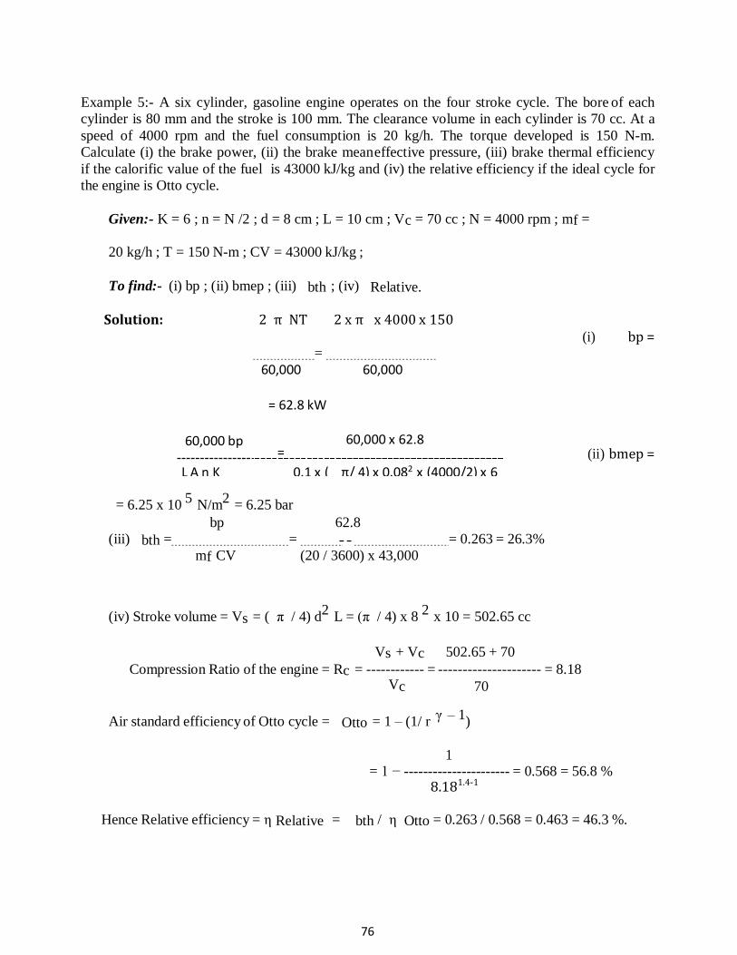
76
Example 5:- A six cylinder, gasoline engine operates on the four stroke cycle. The bore of each
cylinder is 80 mm and the stroke is 100 mm. The clearance volume in each cylinder is 70 cc. At a
speed of 4000 rpm and the fuel consumption is 20 kg/h. The torque developed is 150 N-m.
Calculate (i) the brake power, (ii) the brake mean effective pressure, (iii) brake thermal efficiency
if the calorific value of the fuel is 43000 kJ/kg and (iv) the relative efficiency if the ideal cycle for
the engine is Otto cycle.
Given:- K = 6 ; n = N /2 ; d = 8 cm ; L = 10 cm ; Vc = 70 cc ; N = 4000 rpm ; mf =
20 kg/h ; T = 150 N-m ; CV = 43000 kJ/kg ;
To find:- (i) bp ; (ii) bmep ; (iii) bth ; (iv) Relative.
Solution: 2 π NT 2 x π x 4000 x 150 (i) bp =
=
(ii) bmep =
= 6.25 x 10 5
N/m2
= 6.25 bar
bp 62.8
(iii) bth = = = 0.263 = 26.3%
mf CV (20 / 3600) x 43,000
(iv) Stroke volume = Vs = ( π / 4) d2
L = (π / 4) x 8 2
x 10 = 502.65 cc
Vs + Vc 502.65 + 70
Compression Ratio of the engine = Rc = ------------ = --------------------- = 8.18 Vc 70
Air standard efficiency of Otto cycle = Otto = 1 – (1/ r γ – 1
)
1 = 1 − ---------------------- = 0.568 = 56.8 %
8.181.4-1
Hence Relative efficiency = η Relative = bth / η Otto = 0.263 / 0.568 = 0.463 = 46.3 %.
60,000 bp
60,000
= 62.8 kW
=
60,000
60,000 x 62.8
L A n K 0.1 x ( π/ 4) x 0.082 x (4000/2) x 6
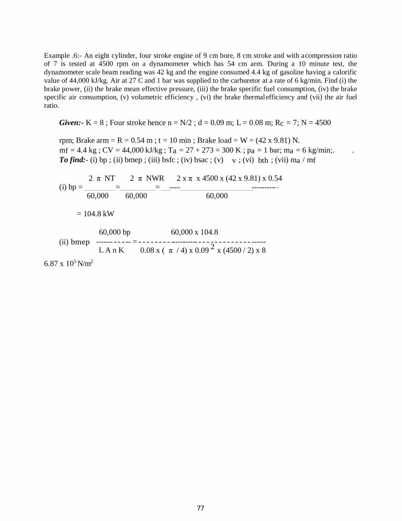
77
Example .6:- An eight cylinder, four stroke engine of 9 cm bore, 8 cm stroke and with a compression ratio of 7 is tested at 4500 rpm on a dynamometer which has 54 cm arm. During a 10 minute test, the
dynamometer scale beam reading was 42 kg and the engine consumed 4.4 kg of gasoline having a calorific
value of 44,000 kJ/kg. Air at 27 C and 1 bar was supplied to the carburetor at a rate of 6 kg/min. Find (i) the
brake power, (ii) the brake mean effective pressure, (iii) the brake specific fuel consumption, (iv) the brake specific air consumption, (v) volumetric efficiency , (vi) the brake thermal efficiency and (vii) the air fuel
ratio.
Given:- K = 8 ; Four stroke hence n = N/2 ; d = 0.09 m; L = 0.08 m; Rc = 7; N = 4500
rpm; Brake arm = R = 0.54 m ; t = 10 min ; Brake load = W = (42 x 9.81) N.
mf = 4.4 kg ; CV = 44,000 kJ/kg ; Ta = 27 + 273 = 300 K ; pa = 1 bar; ma = 6 kg/min;. .
To find:- (i) bp ; (ii) bmep ; (iii) bsfc ; (iv) bsac ; (v) v ; (vi) bth ; (vii) ma / mf
2 π NT 2 π NWR 2 x π x 4500 x (42 x 9.81) x 0.54
(i) bp = = = 60,000 60,000 60,000
= 104.8 kW
60,000 bp 60,000 x 104.8
(ii) bmep
6.87 x 10⁵ N/m2
L A n K - =
0.08 x ( π / 4) x 0.09 2
x (4500 / 2) x 8
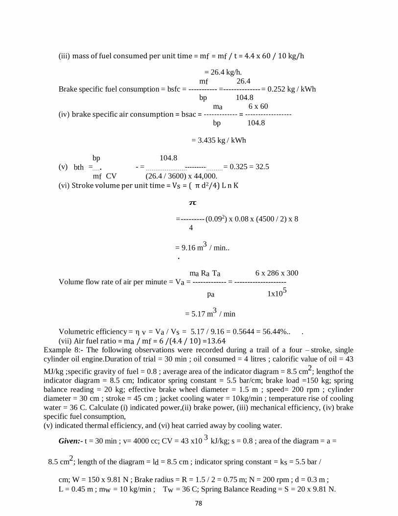
78
(iii) mass of fuel consumed per unit time = mf = mf / t = 4.4 x 60 / 10 kg/h
= 26.4 kg/h.
mf 26.4 Brake specific fuel consumption = bsfc = ----------- = -------------- = 0.252 kg / kWh
bp 104.8 ma 6 x 60
(iv) brake specific air consumption = bsac = ------------- = ------------------ bp 104.8
= 3.435 kg / kWh
bp 104.8 (v) bth = . - = = 0.325 = 32.5
mf CV (26.4 / 3600) x 44,000.
(vi) Stroke volume per unit time = Vs = ( π d2/4) L n K
π
= --------- (0.092) x 0.08 x (4500 / 2) x 8 4
= 9.16 m3
/ min.. .
ma Ra Ta 6 x 286 x 300 Volume flow rate of air per minute = Va = ------------- = --------------------
pa 1x105
= 5.17 m3
/ min
Volumetric efficiency = η v = Va / Vs = 5.17 / 9.16 = 0.5644 = 56.44%.. .
(vii) Air fuel ratio = ma / mf = 6 /(4.4 / 10) =13.64 Example 8:- The following observations were recorded during a trail of a four – stroke, single
cylinder oil engine.Duration of trial = 30 min ; oil consumed = 4 litres ; calorific value of oil = 43
MJ/kg ; specific gravity of fuel = 0.8 ; average area of the indicator diagram = 8.5 cm2
; lengthof the
indicator diagram = 8.5 cm; Indicator spring constant = 5.5 bar/cm; brake load =150 kg; spring
balance reading = 20 kg; effective brake wheel diameter = 1.5 m ; speed= 200 rpm ; cylinder
diameter = 30 cm ; stroke = 45 cm ; jacket cooling water = 10 kg/min ; temperature rise of cooling
water = 36 C. Calculate (i) indicated power,(ii) brake power, (iii) mechanical efficiency, (iv) brake
specific fuel consumption,
(v) indicated thermal efficiency, and (vi) heat carried away by cooling water.
Given:- t = 30 min ; v= 4000 cc; CV = 43 x10 3
kJ/kg; s = 0.8 ; area of the diagram = a =
8.5 cm2
; length of the diagram = ld = 8.5 cm ; indicator spring constant = ks = 5.5 bar /
cm; W = 150 x 9.81 N ; Brake radius = R = 1.5 / 2 = 0.75 m; N = 200 rpm ; d = 0.3 m ;
L = 0.45 m ; mw = 10 kg/min ; Tw = 36 C; Spring Balance Reading = S = 20 x 9.81 N.

79
To find:- (i) ip ; (ii) bp ; (iii) η mech ; (iv) bsfc ; (v) η ith ; (vi) Qw Solution:
a 8.5 5 2
(i) pim = ------- ks = ----------- x 5.5 = 5.5 bar = 5.5 x 10 N/m
ld 8.5 p L A n K
5.5 x 10 5
x 0.45 x (π / 4) x 0.32
x (200 / 2) x 1 PimLAnK
ip = = 60,000 60,000
= 29.16 kW
2π N(W – S) R 2 x π x 200 x (150 – 20)x 9.81 x 0.75 (ii) bp = =
60,000 60,000
= 20.03 kW
(iii) ηmech = bp / ip = 20.03 / 29.16 = 0.687 = 68.7 %.
. vs 4000 x 0.8
(iv) Mass of fuel consumed per hour = mf = ------------- x 60 = -------------------- 60 1000 t 1000 x 30
= 6.4 kg / h.
6.4
bsfc = mf / bp = ------------- = 0.3195 kg/kWh 20.03
ip 29.16
(v) η ith = . - = - - = 0.3814 = 38.14
mf CV (6.4 / 3600) x 43 x 10 3
(vi) Qw = m Cp Tw = (10 / 60) x 4.2 x 36 = 25.2 kW
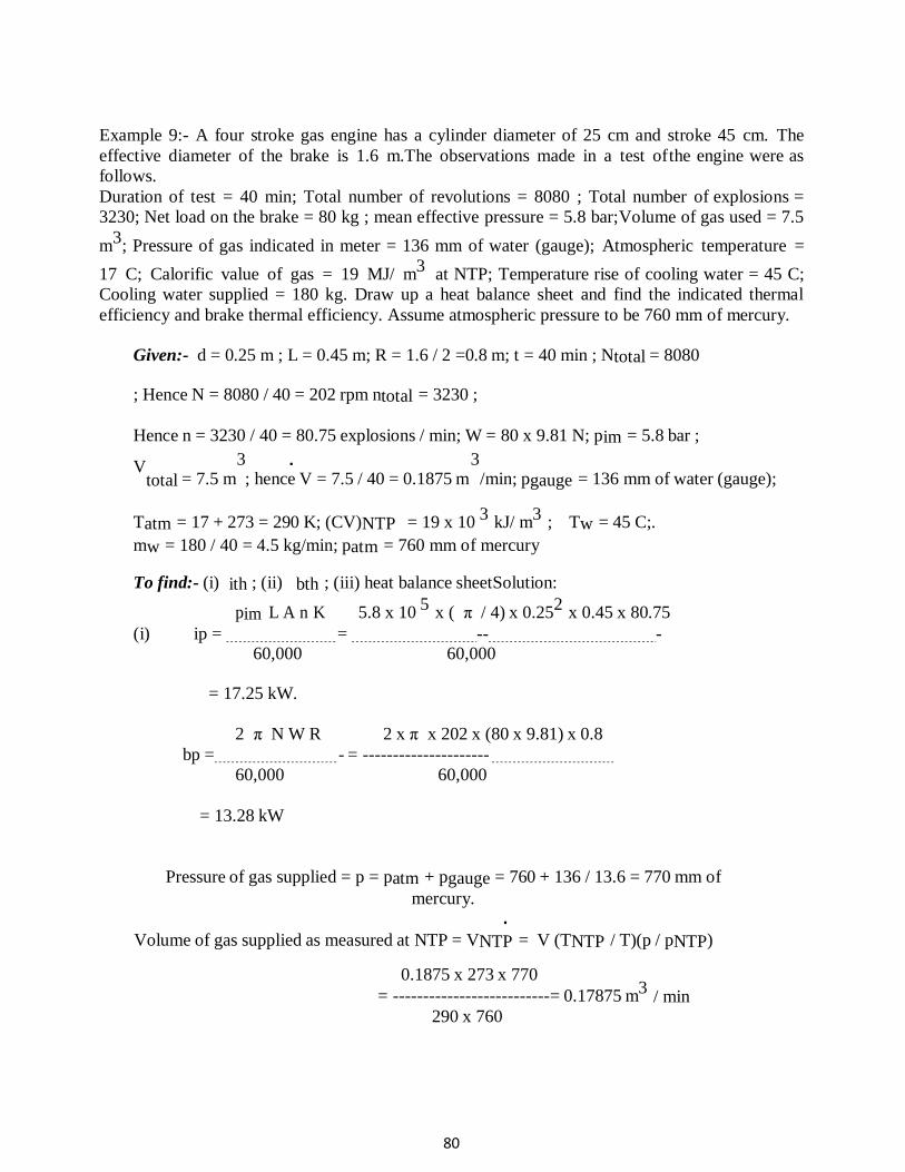
80
.
Example 9:- A four stroke gas engine has a cylinder diameter of 25 cm and stroke 45 cm. The
effective diameter of the brake is 1.6 m.The observations made in a test of the engine were as
follows.
Duration of test = 40 min; Total number of revolutions = 8080 ; Total number of explosions =
3230; Net load on the brake = 80 kg ; mean effective pressure = 5.8 bar; Volume of gas used = 7.5
m3
; Pressure of gas indicated in meter = 136 mm of water (gauge); Atmospheric temperature =
17 C; Calorific value of gas = 19 MJ/ m3
at NTP; Temperature rise of cooling water = 45 C;
Cooling water supplied = 180 kg. Draw up a heat balance sheet and find the indicated thermal
efficiency and brake thermal efficiency. Assume atmospheric pressure to be 760 mm of mercury.
Given:- d = 0.25 m ; L = 0.45 m; R = 1.6 / 2 =0.8 m; t = 40 min ; Ntotal = 8080
; Hence N = 8080 / 40 = 202 rpm ntotal = 3230 ;
Hence n = 3230 / 40 = 80.75 explosions / min; W = 80 x 9.81 N; pim = 5.8 bar ;
V 3 3
total = 7.5 m ; hence V = 7.5 / 40 = 0.1875 m /min; pgauge = 136 mm of water (gauge);
Tatm = 17 + 273 = 290 K; (CV)NTP = 19 x 10 3
kJ/ m3
; Tw = 45 C;.
mw = 180 / 40 = 4.5 kg/min; patm = 760 mm of mercury
To find:- (i) ith ; (ii) bth ; (iii) heat balance sheetSolution:
pim L A n K 5.8 x 10 5
x ( π / 4) x 0.252
x 0.45 x 80.75
(i) ip = = -- - 60,000 60,000
= 17.25 kW.
2 π N W R 2 x π x 202 x (80 x 9.81) x 0.8
bp = - = ---------------------
60,000 60,000
= 13.28 kW
Pressure of gas supplied = p = patm + pgauge = 760 + 136 / 13.6 = 770 mm of
mercury. .
Volume of gas supplied as measured at NTP = VNTP = V (TNTP / T)(p / pNTP)
0.1875 x 273 x 770
= --------------------------= 0.17875 m3
290 x 760
/ min
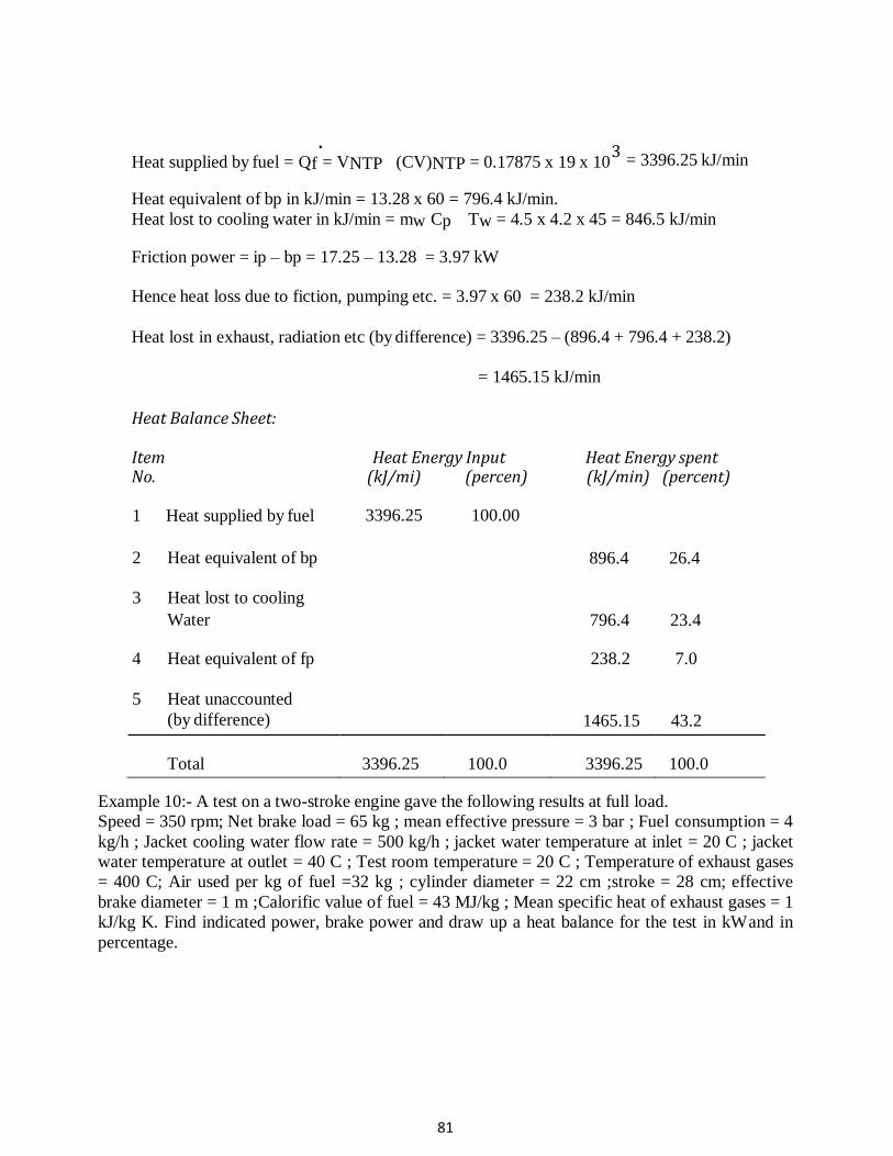
81
. 3
Heat supplied by fuel = Qf = VNTP (CV)NTP = 0.17875 x 19 x 10
Heat equivalent of bp in kJ/min = 13.28 x 60 = 796.4 kJ/min.
= 3396.25 kJ/min
Heat lost to cooling water in kJ/min = mw Cp Tw = 4.5 x 4.2 x 45 = 846.5 kJ/min
Friction power = ip – bp = 17.25 – 13.28 = 3.97 kW
Hence heat loss due to fiction, pumping etc. = 3.97 x 60 = 238.2 kJ/min
Heat lost in exhaust, radiation etc (by difference) = 3396.25 – (896.4 + 796.4 + 238.2)
= 1465.15 kJ/min
Heat Balance Sheet:
Item Heat Energy Input Heat Energy spent No. (kJ/mi) (percen) (kJ/min) (percent)
1 Heat supplied by fuel
2 Heat equivalent of bp
3 Heat lost to cooling
3396.25 100.00
896.4
26.4
Water 796.4 23.4
4 Heat equivalent of fp
238.2 7.0
5 Heat unaccounted
(by difference)
1465.15
43.2
Total
3396.25
100.0
3396.25
100.0
Example 10:- A test on a two-stroke engine gave the following results at full load.
Speed = 350 rpm; Net brake load = 65 kg ; mean effective pressure = 3 bar ; Fuel consumption = 4
kg/h ; Jacket cooling water flow rate = 500 kg/h ; jacket water temperature at inlet = 20 C ; jacket
water temperature at outlet = 40 C ; Test room temperature = 20 C ; Temperature of exhaust gases
= 400 C; Air used per kg of fuel =32 kg ; cylinder diameter = 22 cm ;stroke = 28 cm; effective
brake diameter = 1 m ; Calorific value of fuel = 43 MJ/kg ; Mean specific heat of exhaust gases = 1
kJ/kg K. Find indicated power, brake power and draw up a heat balance for the test in kW and in
percentage.
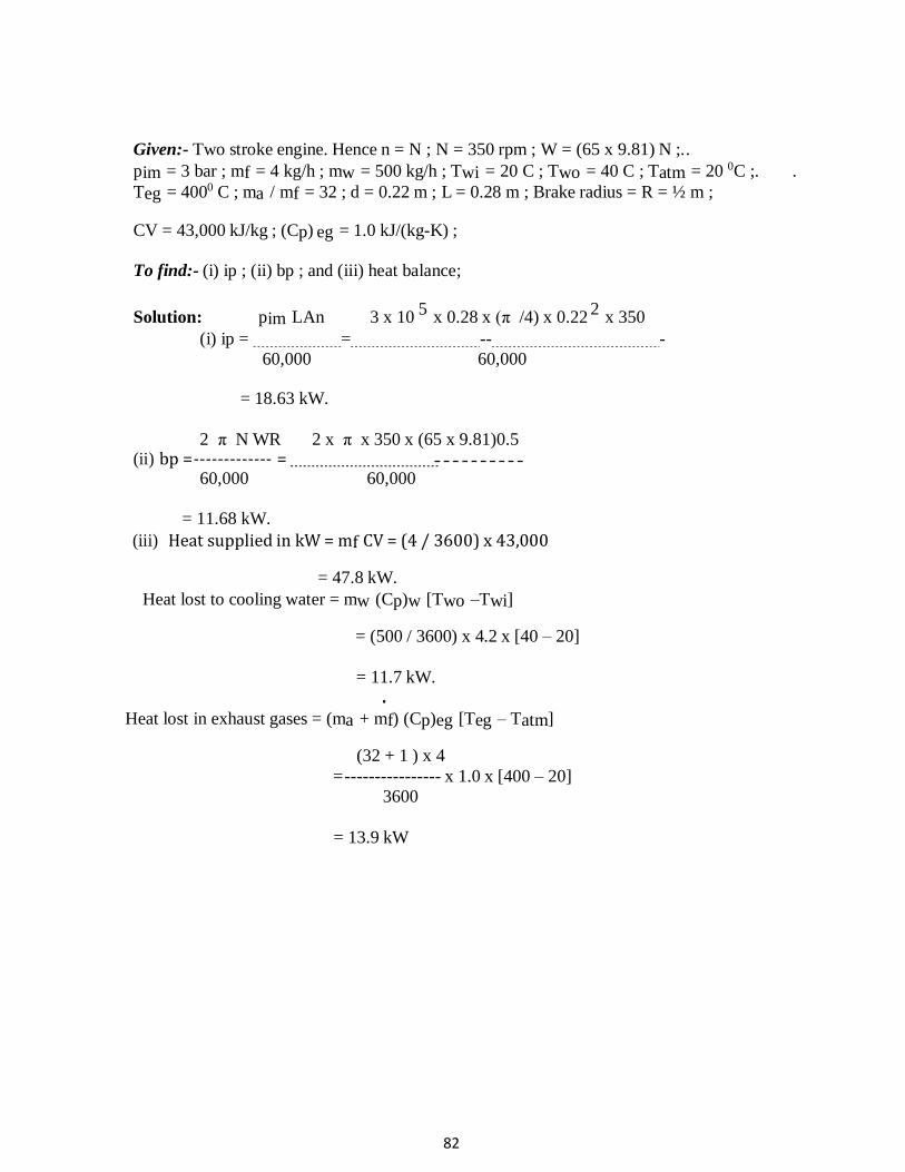
82
Given:- Two stroke engine. Hence n = N ; N = 350 rpm ; W = (65 x 9.81) N ;. .
pim = 3 bar ; mf = 4 kg/h ; mw = 500 kg/h ; Twi = 20 C ; Two = 40 C ; Tatm = 20 0C ;. .
Teg = 4000 C ; ma / mf = 32 ; d = 0.22 m ; L = 0.28 m ; Brake radius = R = ½ m ;
CV = 43,000 kJ/kg ; (Cp) eg = 1.0 kJ/(kg-K) ;
To find:- (i) ip ; (ii) bp ; and (iii) heat balance;
Solution: pim LAn 3 x 10 5
x 0.28 x (π /4) x 0.22 2
x 350
(i) ip = = -- -
60,000 60,000
= 18.63 kW.
2 π N WR 2 x π x 350 x (65 x 9.81)0.5 (ii) bp = ------------- =
60,000 60,000
= 11.68 kW.
(iii) Heat supplied in kW = mf CV = (4 / 3600) x 43,000
= 47.8 kW.
Heat lost to cooling water = mw (Cp)w [Two –Twi]
= (500 / 3600) x 4.2 x [40 – 20]
= 11.7 kW.
. Heat lost in exhaust gases = (ma + mf) (Cp)eg [Teg – Tatm]
(32 + 1 ) x 4
= ---------------- x 1.0 x [400 – 20]
3600
= 13.9 kW
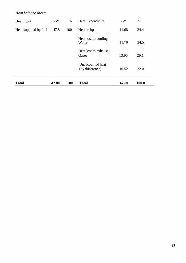
83
Heat balance sheet:
Heat Input kW % Heat Expenditure kW %
Heat supplied by fuel 47.8 100 Heat in bp 11.68 24.4
Heat lost to cooling Water
11.70
24.5
Heat lost to exhaust
Gases 13.90 29.1
Unaccounted heat
(by difference) 10.52 22.0
Total
47.80
100
Total
47.80
100.0
84
Syllabus
Classification and working of air compressors - Classification of compressors and their comparison -
Reciprocating air compressor-principle of operation, work requirement, isothermal efficiency, volumetric
efficiency and effect of clearance, Multi stage compression with inter cooling, saving work, Working of
Rotary Compressors and comparison with reciprocating air compressors.
Unit 3: Air Compressors
UNIT – 3 – AIR COMPRESSORS – SMEA1404
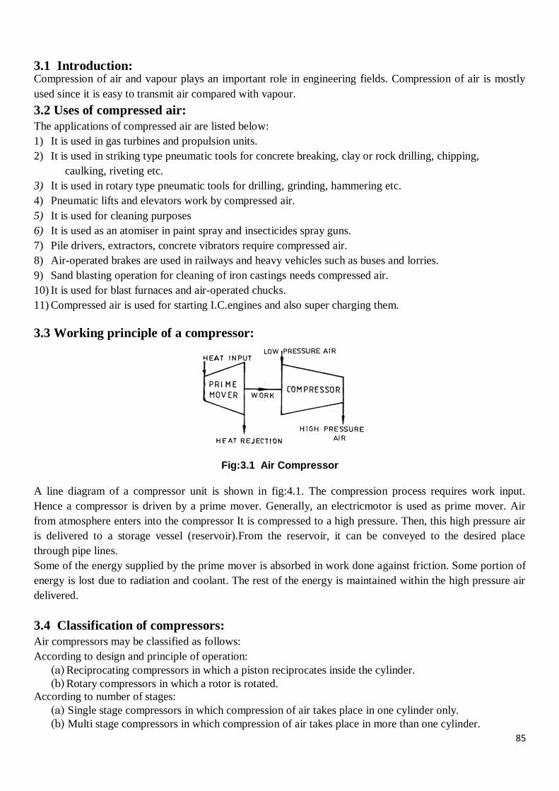
85
3.1 Introduction: Compression of air and vapour plays an important role in engineering fields. Compression of air is mostly
used since it is easy to transmit air compared with vapour.
3.2 Uses of compressed air:
The applications of compressed air are listed below:
1) It is used in gas turbines and propulsion units.
2) It is used in striking type pneumatic tools for concrete breaking, clay or rock drilling, chipping,
caulking, riveting etc.
3) It is used in rotary type pneumatic tools for drilling, grinding, hammering etc.
4) Pneumatic lifts and elevators work by compressed air.
5) It is used for cleaning purposes
6) It is used as an atomiser in paint spray and insecticides spray guns.
7) Pile drivers, extractors, concrete vibrators require compressed air.
8) Air-operated brakes are used in railways and heavy vehicles such as buses and lorries.
9) Sand blasting operation for cleaning of iron castings needs compressed air.
10) It is used for blast furnaces and air-operated chucks.
11) Compressed air is used for starting I.C.engines and also super charging them.
3.3 Working principle of a compressor:
Fig:3.1 Air Compressor
A line diagram of a compressor unit is shown in fig:4.1. The compression process requires work input.
Hence a compressor is driven by a prime mover. Generally, an electricmotor is used as prime mover. Air
from atmosphere enters into the compressor It is compressed to a high pressure. Then, this high pressure air
is delivered to a storage vessel (reservoir).From the reservoir, it can be conveyed to the desired place
through pipe lines.
Some of the energy supplied by the prime mover is absorbed in work done against friction. Some portion of
energy is lost due to radiation and coolant. The rest of the energy is maintained within the high pressure air
delivered.
3.4 Classification of compressors:
Air compressors may be classified as follows:
According to design and principle of operation:
(a) Reciprocating compressors in which a piston reciprocates inside the cylinder.
(b) Rotary compressors in which a rotor is rotated.
According to number of stages:
(a) Single stage compressors in which compression of air takes place in one cylinder only.
(b) Multi stage compressors in which compression of air takes place in more than one cylinder.
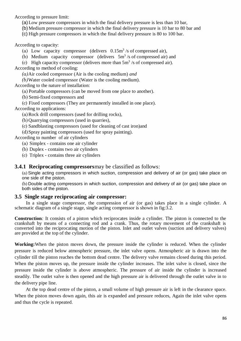
86
According to pressure limit:
(a) Low pressure compressors in which the final delivery pressure is less than 10 bar,
(b) Medium pressure compressor in which the final delivery pressure is 10 bar to 80 bar and
(c) High pressure compressors in which the final delivery pressure is 80 to 100 bar.
According to capacity:
(a) Low capacity compressor (delivers 0.15m3 /s of compressed air),
(b) Medium capacity compressor (delivers 5m3 /s of compressed air) and
(c) High capacity compressor (delivers more than 5m3 /s of compressed air).
According to method of cooling:
(a) Air cooled compressor (Air is the cooling medium) and
(b) Water cooled compressor (Water is the cooling medium).
According to the nature of installation:
(a) Portable compressors (can be moved from one place to another).
(b) Semi-fixed compressors and
(c) Fixed compressors (They are permanently installed in one place).
According to applications:
(a) Rock drill compressors (used for drilling rocks),
(b) Quarrying compressors (used in quarries),
(c) Sandblasting compressors (used for cleaning of cast iron)and
(d) Spray painting compressors (used for spray painting).
According to number of air cylinders
(a) Simplex - contains one air cylinder
(b) Duplex - contains two air cylinders
(c) Triplex - contains three air cylinders
3.4.1 Reciprocating compressorsmay be classified as follows: (a) Single acting compressors in which suction, compression and delivery of air (or gas) take place on one side of the piston.
(b) Double acting compressors in which suction, compression and delivery of air (or gas) take place on both sides of the piston.
3.5 Single stage reciprocating air compressor: In a single stage compressor, the compression of air (or gas) takes place in a single cylinder. A
schematic diagram of a single stage, single acting compressor is shown in fig:3.2.
Construction: It consists of a piston which reciprocates inside a cylinder. The piston is connected to the crankshaft by means of a connecting rod and a crank. Thus, the rotary movement of the crankshaft is converted into the reciprocating motion of the piston. Inlet and outlet valves (suction and delivery valves) are provided at the top of the cylinder.
Working:When the piston moves down, the pressure inside the cylinder is reduced. When the cylinder
pressure is reduced below atmospheric pressure, the inlet valve opens. Atmospheric air is drawn into the
cylinder till the piston reaches the bottom dead centre. The delivery valve remains closed during this period.
When the piston moves up, the pressure inside the cylinder increases. The inlet valve is closed, since the
pressure inside the cylinder is above atmospheric. The pressure of air inside the cylinder is increased
steadily. The outlet valve is then opened and the high pressure air is delivered through the outlet valve in to
the delivery pipe line.
At the top dead centre of the piston, a small volume of high pressure air is left in the clearance space.
When the piston moves down again, this air is expanded and pressure reduces, Again the inlet valve opens
and thus the cycle is repeated.
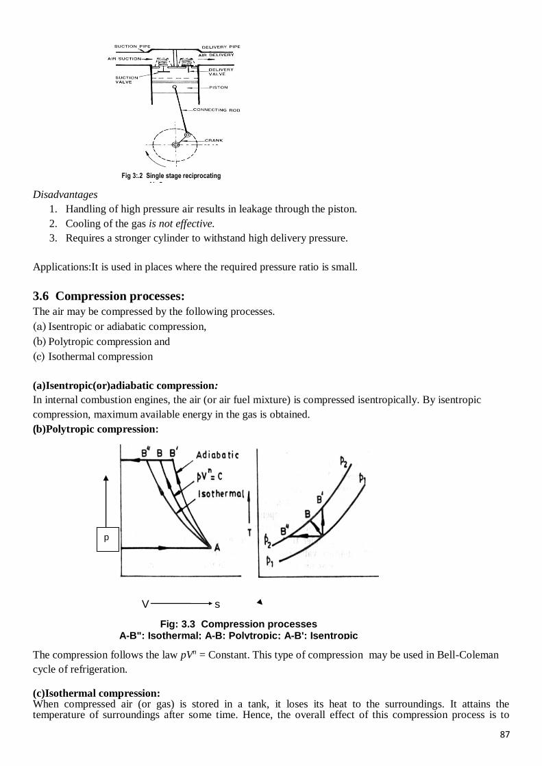
87
Disadvantages
1. Handling of high pressure air results in leakage through the piston.
2. Cooling of the gas is not effective.
3. Requires a stronger cylinder to withstand high delivery pressure.
Applications:It is used in places where the required pressure ratio is small.
3.6 Compression processes:
The air may be compressed by the following processes.
(a) Isentropic or adiabatic compression,
(b) Polytropic compression and
(c) Isothermal compression
(a)Isentropic(or)adiabatic compression:
In internal combustion engines, the air (or air fuel mixture) is compressed isentropically. By isentropic
compression, maximum available energy in the gas is obtained.
(b)Polytropic compression:
The compression follows the law pVn = Constant. This type of compression may be used in Bell-Coleman
cycle of refrigeration.
(c)Isothermal compression: When compressed air (or gas) is stored in a tank, it loses its heat to the surroundings. It attains the temperature of surroundings after some time. Hence, the overall effect of this compression process is to
V s
Fig: 3.3 Compression processes A-B": Isothermal; A-B: Polytropic; A-B': Isentropic
p
Fig 3:.2 Single stage reciprocating
Air Compressor
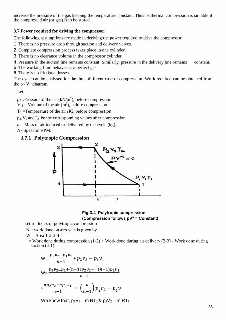
88
increase the pressure of the gas keeping the temperature constant. Thus isothermal compression is suitable if the compressed air (or gas) is to be stored.
3.7 Power required for driving the compressor:
The following assumptions are made in deriving the power required to drive the compressor.
1. There is no pressure drop through suction and delivery valves.
2. Complete compression process takes place in one cylinder.
3. There is no clearance volume in the compressor cylinder.
4. Pressure in the suction line remains constant. Similarly, pressure in the delivery line remains constant.
5. The working fluid behaves as a perfect gas.
6. There is no frictional losses.
The cycle can be analysed for the three different case of compression. Work required can be obtained from
the p - V diagram.
Let,
p1 =Pressure of the air (kN/m2), before compression
V 1 = Volume of the air (m3), before compression
T1 =Temperature of the air (K), before compression
p2, V2 andT2 be the corresponding values after compression.
m - Mass of air induced or delivered by the cycle (kg).
N - Speed in RPM.
3.7.1 Polytropic Compression
Fig:3.4 Polytropic compression
(Compression follows pVn = Constant)
Let n= Index of polytropic compression
Net work done on air/cycle is given by
W = Area 1-2-3-4-1
= Work done during compression (1-2) + Work done during air delivery (2-3) - Work done during suction (4-1).
W = 𝑝2𝑣2−𝑝1𝑣1
𝑛−1 + 𝑝2𝑣2 − 𝑝1𝑣1
W= 𝑝2𝑣2−𝑝1+(𝑛−1)𝑝2𝑣2− (𝑛−1)𝑝1𝑣1
𝑛−1
=𝑛𝑝2𝑣2−𝑛𝑝1𝑣1
𝑛−1 = (
𝑛
𝑛−1) 𝑝
2𝑣2 − 𝑝
1𝑣1
We know that, p1V1 = m RT1 & p2V2 = m RT2
89
Therefore, W = 𝒏
𝒏−𝟏 m R (T2 - T1)
W = 𝒏
𝒏−𝟏 m R T1[
𝑻𝟐
𝑻𝟏− 𝟏]
For polytropic process, 𝑇2
𝑇1 = (
𝑝2
𝑝1)
𝑛−1
𝑛
Therefore, W = 𝑛
𝑛−1 m R T1[(
𝑝2
𝑝1)
𝑛−1
𝑛− 1]kJ/cycle
W = 𝑛
𝑛−1 p1 V1[(
𝑝2
𝑝1)
𝑛−1
𝑛− 1] kJ/cycle
Indicated power (or) Power required, P = W x N , kW for single acting reciprocating compressor;
= W x 2N, kW for double acting reciprocating compressor.
3.7.2Isentropic compression
Compression follows, p𝑽𝛾= Constant
Let 𝛾= Index of isentropic compression
Net work done on air/cycle is given by
W = Area 1-2-3-4-1
= Work done during compression (1-2) + Work done during air delivery (2-3) - Work done during suction (4-1).
W = 𝑝2𝑣2−𝑝1𝑣1
𝛾−1 + 𝑝2𝑣2 − 𝑝1𝑣1
W= 𝑝2𝑣2− 𝑝1+(𝛾−1)𝑝2𝑣2− (𝛾−1)𝑝1𝑣1
𝛾−1
=𝛾𝑝2𝑣2− 𝛾𝑝1𝑣1
𝛾−1 = (
𝛾
𝛾−1) 𝑝
2𝑣2 − 𝑝
1𝑣1
We know that, p1V1 = m RT1 & p2V2 = m RT2
W = 𝜸
𝜸−𝟏 m R (T2 - T1)
W = 𝜸
𝜸−𝟏 m R T1[
𝑻𝟐
𝑻𝟏− 𝟏]
For isentropic process, 𝑇2
𝑇1 = (
𝑝2
𝑝1)
𝛾−1
𝛾
Therefore, W = 𝜸
𝜸−𝟏 m R T1[(
𝑝2
𝑝1)
𝛾−1
𝛾− 1]kJ/cycle

90
W = 𝜸
𝜸−𝟏 p1 V1[(
𝑝2
𝑝1)
𝛾−1
𝛾− 1] kJ/cycle
3.7.3 Isothermal Compression Compression follows, pV= Constant
Fig: 3.5 Isothermal Compression
Isothermal Work input, W = Area 1-2-3-4-1 = area under 1-2 + area under 2-3 - area under 4-1
W = 𝑝1𝑉1 𝑙𝑛 (𝑉1
𝑉2) + 𝑝2𝑉2 − 𝑝1𝑉1
But 𝑝1𝑉1 = 𝑝2𝑉2
W= 𝑝1𝑉1 𝑙𝑛 (𝑉1
𝑉2) 𝑎𝑛𝑑
𝑉1
𝑉2 =
𝑝2
𝑝1
Therefore, W = 𝑝2𝑉2 𝑙𝑛 (𝑝2
𝑝1) kJ/cycle
3.8 Isothermal efficiency: Isothermal efficiency is defined as the ratio of isothermal work input to the
actual work input. This is used for comparing the compressors.
Isothermal efficiency,ηiso = 𝐼𝑠𝑜𝑡ℎ𝑒𝑟𝑚𝑎𝑙𝑤𝑜𝑟𝑘𝑖𝑛𝑝𝑢𝑡
𝐴𝑐𝑡𝑢𝑎𝑙𝑤𝑜𝑟𝑘𝑜𝑢𝑡𝑝𝑢𝑡
3.9 Adiabatic efficiency: Adiabatic efficiency is defined as the ratio of adiabatic work input to the actual
work input. This is used for comparing the compressors.
Adiabatic efficiency,ηadia = 𝐴𝑑𝑖𝑎𝑏𝑎𝑡𝑖𝑐𝑤𝑜𝑟𝑘𝑖𝑛𝑝𝑢𝑡
𝐴𝑐𝑡𝑢𝑎𝑙𝑤𝑜𝑟𝑘𝑜𝑢𝑡𝑝𝑢𝑡
3.10 Mechanical efficiency:
The compressor is driven by a prime mover. The power input to the compressor is the shaft power (brake
power) of the prime mover. This is also known as brake power of the compressor.
Mechanical efficiency is defined as the ratio of indicated power of the compressor to the power input to the
compressor.
ηm= Indicated power of compressor
Power input
Indicated Power, IP =𝒑𝒎𝒍 𝒂𝑵𝒌
𝟔𝟎,
where, pm = mean effective pressure, kN/m² l = length of stroke of piston, m
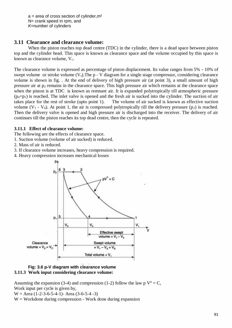
91
a = area of cross section of cylinder,m² N= crank speed in rpm, and K=number of cylinders
3.11 Clearance and clearance volume: When the piston reaches top dead centre (TDC) in the cylinder, there is a dead space between piston
top and the cylinder head. This space is known as clearance space and the volume occupied by this space is
known as clearance volume, Vc.
The clearance volume is expressed as percentage of piston displacement. Its value ranges from 5% - 10% of
swept volume or stroke volume (Vs).The p - V diagram for a single stage compressor, considering clearance
volume is shown in fig. . At the end of delivery of high pressure air (at point 3), a small amount of high
pressure air at p2 remains in the clearance space. This high pressure air which remains at the clearance space
when the piston is at TDC is known as remnant air. It is expanded polytropically till atmospheric pressure
(p4=p1) is reached. The inlet valve is opened and the fresh air is sucked into the cylinder. The suction of air
takes place for the rest of stroke (upto point 1). The volume of air sucked is known as effective suction
volume (V1 - V4). At point 1, the air is compressed polytropically till the delivery pressure (p2) is reached.
Then the delivery valve is opened and high pressure air is discharged into the receiver. The delivery of air
continues till the piston reaches its top dead centre, then the cycle is repeated.
3.11.1 Effect of clearance volume:
The following are the effects of clearance space.
1. Suction volume (volume of air sucked) is reduced.
2. Mass of air is reduced.
3. If clearance volume increases, heavy compression is required.
4. Heavy compression increases mechanical losses
Fig: 3.6 p-V diagram with clearance volume
3.11.3 Work input considering clearance volume:
Assuming the expansion (3-4) and compression (1-2) follow the law p Vn = C,
Work input per cycle is given by,
W = Area (1-2-3-6-5-4-1)- Area (3-6-5-4 -3)
W = Workdone during compression - Work done during expansion
92
W = 𝑛
𝑛−1 p1 V1[(
𝑝2
𝑝1)
𝑛−1
𝑛− 1] -
𝑛
𝑛−1 p4 V4[(
𝑝3
𝑝4)
𝑛−1
𝑛− 1]
But, p3 = p2 and p4 = p1
therefore
W = 𝑛
𝑛−1 p1 V1[(
𝑝2
𝑝1)
𝑛−1
𝑛− 1] -
𝑛
𝑛−1 p1 V4[(
𝑝2
𝑝1)
𝑛−1
𝑛− 1]
W = 𝑛
𝑛−1 p1(V1 – V4)[(
𝑝2
𝑝1)
𝑛−1
𝑛− 1] kJ/cycle
V1-V4 is called as effective suction volume.
3.12 Volumetric efficiency: The clearance volume in a compressor reduces the intake capacity of the cylinder. This leads to a term called
volumetric efficiency.
The volumetric efficiency is denned as the volume of free air sucked into the compressor per cycle to the
stroke volume of the cylinder,the volume measured at the intake pressure and temperature or at standard
atmospheric conditions,(ps =101.325 kN/m2 and Ts = 288K)
Volumetric efficiency, ηvol = Volume of free air taken in per cycle
Stroke volume of the cylinder
=Effective suction volume
Swept volume=
(𝑉1 − 𝑉4)
(𝑉1 – 𝑉3) =
𝑉1−𝑉4
𝑉𝑠
Clearance ratio: Clearance ratio is defined as, the ratio of clearance volume to swept volume. It is denoted
by the letter C.
Clearance ratio,C = 𝐶𝑙𝑒𝑎𝑟𝑎𝑛𝑐𝑒 𝑣𝑜𝑙𝑢𝑚𝑒
𝑆𝑤𝑒𝑝𝑡 𝑣𝑜𝑙𝑢𝑚𝑒 =
𝑉𝑐
𝑉𝑠 =
𝑉𝑐
𝑉1−𝑉3
Pressure ratio, Rp = 𝐷𝑒𝑙𝑖𝑣𝑒𝑟𝑦 𝑝𝑟𝑒𝑠𝑠𝑢𝑟𝑒
𝑆𝑢𝑐𝑡𝑖𝑜𝑛 𝑝𝑟𝑒𝑠𝑠𝑢𝑟𝑒 =
𝑝2
𝑝1 =
𝑝3
𝑝4
3.12.1 Expression for Volumetric efficiency
Let the compression and expansion follows the law, pVn =Constant.
Clearance ratio, C = 𝐶𝑙𝑒𝑎𝑟𝑎𝑛𝑐𝑒𝑣𝑜𝑙𝑢𝑚𝑒
𝑆𝑤𝑒𝑝𝑡𝑣𝑜𝑙𝑢𝑚𝑒 =
𝑉𝑐
𝑉𝑠 =
𝑉3
𝑉1−𝑉3
V1-V3 =𝑉3
𝐶-------------(1)
V1=𝑉3
𝐶 + V3
V1 = V3(1
𝐶 + 1)--------------------- (2)
We know that, Pressure ratio, Rp = 𝐷𝑒𝑙𝑖𝑣𝑒𝑟𝑦 𝑝𝑟𝑒𝑠𝑠𝑢𝑟𝑒
𝑆𝑢𝑐𝑡𝑖𝑜𝑛 𝑝𝑟𝑒𝑠𝑠𝑢𝑟𝑒 =
𝑝2
𝑝1 =
𝑝3
𝑝4
By polytropic expansionprocess 3-4:
𝑝3
𝑝4 = (
𝑉4
𝑉3)𝑛
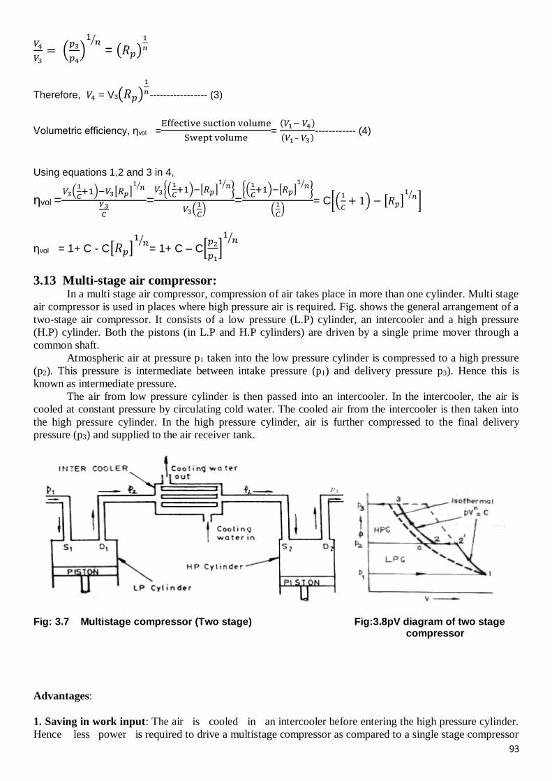
93
𝑉4
𝑉3= (
𝑝3
𝑝4)1
𝑛⁄
= (𝑅𝑝)1
𝑛
Therefore, 𝑉4 = V3(𝑅𝑝)1
𝑛----------------- (3)
Volumetric efficiency, ηvol =Effective suction volume
Swept volume=
(𝑉1− 𝑉4)
(𝑉1– 𝑉3)------------ (4)
Using equations 1,2 and 3 in 4,
ηvol =𝑉3(
1
𝐶+1)−𝑉3[𝑅𝑝]
1𝑛⁄
𝑉3𝐶
=𝑉3{(
1
𝐶+1)−[𝑅𝑝]
1𝑛⁄ }
𝑉3(1
𝐶)
={(
1
𝐶+1)−[𝑅𝑝]
1𝑛⁄ }
(1
𝐶)
= C[(1
𝐶+ 1) − [𝑅𝑝]
1𝑛⁄ ]
ηvol = 1+ C - C[𝑅𝑝]1
𝑛⁄= 1+ C – C[
𝑝2
𝑝1]1
𝑛⁄
3.13 Multi-stage air compressor: In a multi stage air compressor, compression of air takes place in more than one cylinder. Multi stage
air compressor is used in places where high pressure air is required. Fig. shows the general arrangement of a
two-stage air compressor. It consists of a low pressure (L.P) cylinder, an intercooler and a high pressure
(H.P) cylinder. Both the pistons (in L.P and H.P cylinders) are driven by a single prime mover through a
common shaft.
Atmospheric air at pressure p1 taken into the low pressure cylinder is compressed to a high pressure
(p2). This pressure is intermediate between intake pressure (p1) and delivery pressure p3). Hence this is
known as intermediate pressure.
The air from low pressure cylinder is then passed into an intercooler. In the intercooler, the air is
cooled at constant pressure by circulating cold water. The cooled air from the intercooler is then taken into
the high pressure cylinder. In the high pressure cylinder, air is further compressed to the final delivery
pressure (p3) and supplied to the air receiver tank.
Fig: 3.7 Multistage compressor (Two stage) Fig:3.8pV diagram of two stage
compressor
Advantages:
1. Saving in work input: The air is cooled in an intercooler before entering the high pressure cylinder.
Hence less power is required to drive a multistage compressor as compared to a single stage compressor
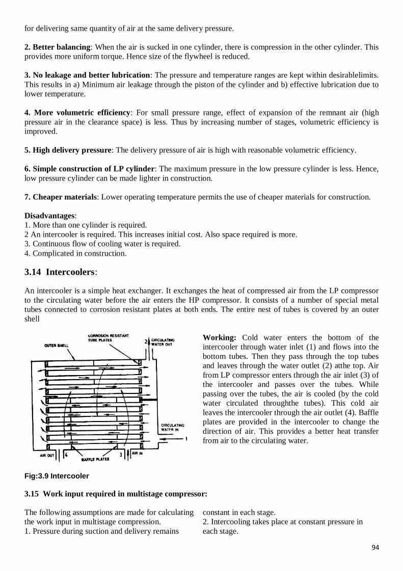
94
for delivering same quantity of air at the same delivery pressure.
2. Better balancing: When the air is sucked in one cylinder, there is compression in the other cylinder. This
provides more uniform torque. Hence size of the flywheel is reduced.
3. No leakage and better lubrication: The pressure and temperature ranges are kept within desirablelimits.
This results in a) Minimum air leakage through the piston of the cylinder and b) effective lubrication due to
lower temperature.
4. More volumetric efficiency: For small pressure range, effect of expansion of the remnant air (high
pressure air in the clearance space) is less. Thus by increasing number of stages, volumetric efficiency is
improved.
5. High delivery pressure: The delivery pressure of air is high with reasonable volumetric efficiency.
6. Simple construction of LP cylinder: The maximum pressure in the low pressure cylinder is less. Hence,
low pressure cylinder can be made lighter in construction.
7. Cheaper materials: Lower operating temperature permits the use of cheaper materials for construction.
Disadvantages:
1. More than one cylinder is required.
2 An intercooler is required. This increases initial cost. Also space required is more.
3. Continuous flow of cooling water is required.
4. Complicated in construction.
3.14 Intercoolers:
An intercooler is a simple heat exchanger. It exchanges the heat of compressed air from the LP compressor
to the circulating water before the air enters the HP compressor. It consists of a number of special metal
tubes connected to corrosion resistant plates at both ends. The entire nest of tubes is covered by an outer
shell
Working: Cold water enters the bottom of the
intercooler through water inlet (1) and flows into the
bottom tubes. Then they pass through the top tubes
and leaves through the water outlet (2) atthe top. Air
from LP compressor enters through the air inlet (3) of
the intercooler and passes over the tubes. While
passing over the tubes, the air is cooled (by the cold
water circulated throughthe tubes). This cold air
leaves the intercooler through the air outlet (4). Baffle
plates are provided in the intercooler to change the
direction of air. This provides a better heat transfer
from air to the circulating water.
Fig:3.9 Intercooler
3.15 Work input required in multistage compressor:
The following assumptions are made for calculating
the work input in multistage compression.
1. Pressure during suction and delivery remains
constant in each stage.
2. Intercooling takes place at constant pressure in
each stage.
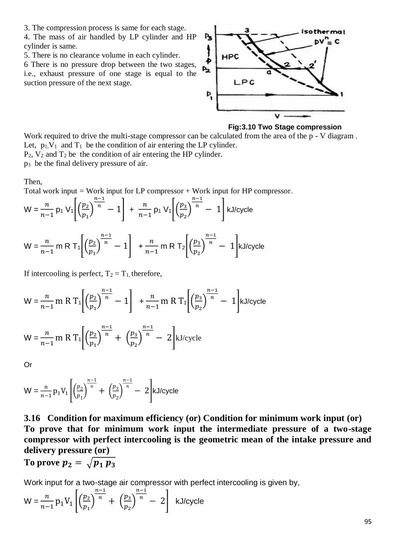
95
3. The compression process is same for each stage.
4. The mass of air handled by LP cylinder and HP
cylinder is same.
5. There is no clearance volume in each cylinder.
6 There is no pressure drop between the two stages,
i.e., exhaust pressure of one stage is equal to the
suction pressure of the next stage.
Fig:3.10 Two Stage compression
Work required to drive the multi-stage compressor can be calculated from the area of the p - V diagram .
Let, p1,V1 and T1 be the condition of air entering the LP cylinder.
P2, V2 and T2 be the condition of air entering the HP cylinder.
p3 be the final delivery pressure of air.
Then,
Total work input = Work input for LP compressor + Work input for HP compressor.
W = 𝑛
𝑛−1 p1 V1[(
𝑝2
𝑝1)
𝑛−1
𝑛− 1] +
𝑛
𝑛−1 p1 V1[(
𝑝3
𝑝2)
𝑛−1
𝑛− 1] kJ/cycle
W = 𝑛
𝑛−1 m R T1[(
𝑝2
𝑝1)
𝑛−1
𝑛− 1] +
𝑛
𝑛−1 m R T2[(
𝑝3
𝑝2)
𝑛−1
𝑛− 1]kJ/cycle
If intercooling is perfect, T2 = T1, therefore,
W = 𝑛
𝑛−1m R T1[(
𝑝2
𝑝1)
𝑛−1
𝑛− 1] +
𝑛
𝑛−1m R T1[(
𝑝3
𝑝2)
𝑛−1
𝑛− 1]kJ/cycle
W = 𝑛
𝑛−1m R T1[(
𝑝2
𝑝1)
𝑛−1
𝑛+ (
𝑝3
𝑝2)
𝑛−1
𝑛− 2]kJ/cycle
Or
W = 𝑛
𝑛−1p1V1 [(
𝑝2
𝑝1
)
𝑛−1
𝑛+ (
𝑝3
𝑝2
)
𝑛−1
𝑛− 2]kJ/cycle
3.16 Condition for maximum efficiency (or) Condition for minimum work input (or)
To prove that for minimum work input the intermediate pressure of a two-stage
compressor with perfect intercooling is the geometric mean of the intake pressure and
delivery pressure (or)
To prove 𝒑𝟐 = √𝒑𝟏 𝒑𝟑
Work input for a two-stage air compressor with perfect intercooling is given by,
W = 𝑛
𝑛−1p1V1 [(
𝑝2
𝑝1)
𝑛−1
𝑛+ (
𝑝3
𝑝2)
𝑛−1
𝑛− 2] kJ/cycle
96
If the initial pressure (p1) and final pressure (p3) are fixed, the value of intermediate pressure (p2) can be
determined by differentiating the above equation of work input in terms of p2 and equating it to zero.
Let, 𝑛
𝑛−1𝑝1𝑉1 = 𝑘 (𝑐𝑜𝑛𝑠𝑡𝑎𝑛𝑡) and
𝑛−1
𝑛= 𝑎
then,
W = 𝑘 [(𝑝2
𝑝1)𝑎
+ (𝑝3
𝑝2)𝑎
− 2]
or
W = 𝑘(𝑝2𝑎𝑝1
−𝑎 + 𝑝3𝑎𝑝2
−𝑎 − 2) -------------------- (1)
Differentiating the above equation (1) with respect to p2 and equating it to zero,
𝑑𝑊
𝑑𝑝2= 𝑘 𝑎 𝑝2
𝑎−1𝑝1−𝑎 + 𝑘 (– 𝑎)𝑝3
𝑎𝑝2−𝑎−1 = 0
𝑘 𝑎 𝑝2
𝑎
𝑝2𝑝1𝑎 − 𝑘 𝑎 𝑝3
𝑎1
𝑝2𝑎 𝑝2
= 0
or
𝑘 𝑎 𝑝2𝑎
𝑝2 𝑝1𝑎 =
𝑘 𝑎 𝑝3𝑎
𝑝2 𝑝2𝑎
(𝑝2
𝑝1)𝑎
= (𝑝3
𝑝2)𝑎
𝑜𝑟 𝑝2
𝑝1 =
𝑝3
𝑝2
=> 𝑝22 = 𝑝1𝑝3
𝑜𝑟
Intermediate pressure, 𝐩𝟐 = √𝐩𝟏𝐩𝟑
Thus for maximum efficiency the intermediate pressure is the geometric mean of the initial and final
pressures.
3.17 Minimum work input for multistage compression with perfect intercooling:
Work input for a two-stage compressor with perfect intercooling is given by
W = 𝑛
𝑛−1p1V1 [(
𝑝2
𝑝1)
𝑛−1
𝑛+ (
𝑝3
𝑝2)
𝑛−1
𝑛− 2]------------------------ (1)
Work input will be minimum if 𝑝2
𝑝1 =
𝑝3
𝑝2------------------------------(2)
𝑝22 = 𝑝1 𝑝3
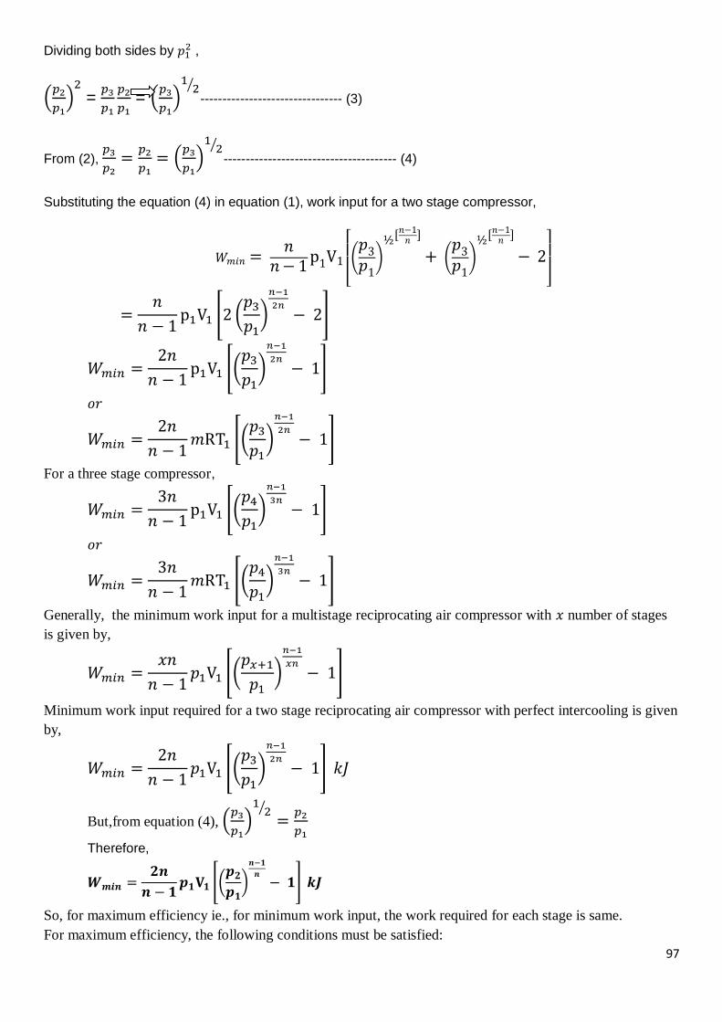
97
Dividing both sides by 𝑝12 ,
(𝑝2
𝑝1)2 =
𝑝3
𝑝1
𝑝2
𝑝1 = (
𝑝3
𝑝1)1
2⁄-------------------------------- (3)
From (2), 𝑝3
𝑝2=
𝑝2
𝑝1= (
𝑝3
𝑝1)1
2⁄--------------------------------------- (4)
Substituting the equation (4) in equation (1), work input for a two stage compressor,
𝑊𝑚𝑖𝑛 = 𝑛
𝑛− 1p1V1
[ (𝑝3
𝑝1)
½[𝑛−1𝑛
]
+ (𝑝3
𝑝1)
½[𝑛−1𝑛
]
− 2
]
=𝑛
𝑛 − 1p1V1 [2 (
𝑝3
𝑝1)
𝑛−1
2𝑛− 2]
𝑊𝑚𝑖𝑛 =2𝑛
𝑛 − 1p1V1 [(
𝑝3
𝑝1)
𝑛−1
2𝑛− 1]
𝑜𝑟
𝑊𝑚𝑖𝑛 =2𝑛
𝑛 − 1𝑚RT1 [(
𝑝3
𝑝1)
𝑛−1
2𝑛− 1]
For a three stage compressor,
𝑊𝑚𝑖𝑛 =3𝑛
𝑛 − 1p1V1 [(
𝑝4
𝑝1)
𝑛−1
3𝑛− 1]
𝑜𝑟
𝑊𝑚𝑖𝑛 =3𝑛
𝑛 − 1𝑚RT1 [(
𝑝4
𝑝1)
𝑛−1
3𝑛− 1]
Generally, the minimum work input for a multistage reciprocating air compressor with 𝑥 number of stages
is given by,
𝑊𝑚𝑖𝑛 =𝑥𝑛
𝑛 − 1𝑝1V1 [(
𝑝𝑥+1
𝑝1)
𝑛−1
𝑥𝑛− 1]
Minimum work input required for a two stage reciprocating air compressor with perfect intercooling is given
by,
𝑊𝑚𝑖𝑛 =2𝑛
𝑛 − 1𝑝1V1 [(
𝑝3
𝑝1)
𝑛−1
2𝑛− 1] 𝑘𝐽
But,from equation (4), (𝑝3
𝑝1)1
2⁄=
𝑝2
𝑝1
Therefore,
𝑾𝒎𝒊𝒏 =𝟐𝒏
𝒏 − 𝟏𝒑𝟏𝐕𝟏 [(
𝒑𝟐
𝒑𝟏)
𝒏−𝟏
𝒏− 𝟏] 𝒌𝑱
So, for maximum efficiency ie., for minimum work input, the work required for each stage is same.
For maximum efficiency, the following conditions must be satisfied:
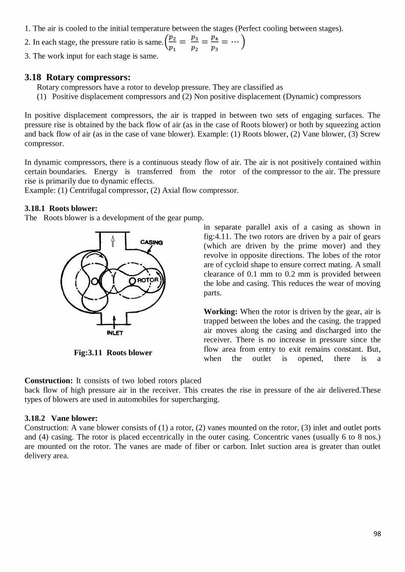
98
1. The air is cooled to the initial temperature between the stages (Perfect cooling between stages).
2. In each stage, the pressure ratio is same.(𝑝2
𝑝1=
𝑝3
𝑝2=
𝑝4
𝑝3= ⋯ )
3. The work input for each stage is same.
3.18 Rotary compressors: Rotary compressors have a rotor to develop pressure. They are classified as
(1) Positive displacement compressors and (2) Non positive displacement (Dynamic) compressors
In positive displacement compressors, the air is trapped in between two sets of engaging surfaces. The
pressure rise is obtained by the back flow of air (as in the case of Roots blower) or both by squeezing action
and back flow of air (as in the case of vane blower). Example: (1) Roots blower, (2) Vane blower, (3) Screw
compressor.
In dynamic compressors, there is a continuous steady flow of air. The air is not positively contained within
certain boundaries. Energy is transferred from the rotor of the compressor to the air. The pressure
rise is primarily due to dynamic effects.
Example: (1) Centrifugal compressor, (2) Axial flow compressor.
3.18.1 Roots blower:
The Roots blower is a development of the gear pump.
Fig:3.11 Roots blower
Construction: It consists of two lobed rotors placed
in separate parallel axis of a casing as shown in
fig:4.11. The two rotors are driven by a pair of gears
(which are driven by the prime mover) and they
revolve in opposite directions. The lobes of the rotor
are of cycloid shape to ensure correct mating. A small
clearance of 0.1 mm to 0.2 mm is provided between
the lobe and casing. This reduces the wear of moving
parts.
Working: When the rotor is driven by the gear, air is
trapped between the lobes and the casing. the trapped
air moves along the casing and discharged into the
receiver. There is no increase in pressure since the
flow area from entry to exit remains constant. But,
when the outlet is opened, there is a
back flow of high pressure air in the receiver. This creates the rise in pressure of the air delivered.These
types of blowers are used in automobiles for supercharging.
3.18.2 Vane blower:
Construction: A vane blower consists of (1) a rotor, (2) vanes mounted on the rotor, (3) inlet and outlet ports
and (4) casing. The rotor is placed eccentrically in the outer casing. Concentric vanes (usually 6 to 8 nos.)
are mounted on the rotor. The vanes are made of fiber or carbon. Inlet suction area is greater than outlet
delivery area.
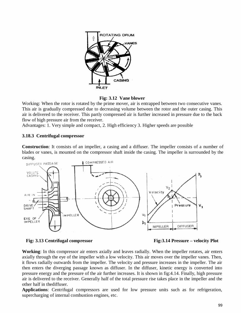
99
Fig: 3.12 Vane blower
Working: When the rotor is rotated by the prime mover, air is entrapped between two consecutive vanes.
This air is gradually compressed due to decreasing volume between the rotor and the outer casing. This
air is delivered to the receiver. This partly compressed air is further increased in pressure due to the back
flow of high pressure air from the receiver.
Advantages: 1. Very simple and compact, 2. High efficiency 3. Higher speeds are possible
3.18.3 Centrifugal compressor
Construction: It consists of an impeller, a casing and a diffuser. The impeller consists of a number of
blades or vanes, is mounted on the compressor shaft inside the casing. The impeller is surrounded by the
casing.
Fig: 3.13 Centrifugal compressor Fig:3.14 Pressure – velocity Plot
Working: In this compressor air enters axially and leaves radially. When the impeller rotates, air enters
axially through the eye of the impeller with a low velocity. This air moves over the impeller vanes. Then,
it flows radially outwards from the impeller. The velocity and pressure increases in the impeller. The air
then enters the diverging passage known as diffuser. In the diffuser, kinetic energy is converted into
pressure energy and the pressure of the air further increases. It is shown in fig:4.14. Finally, high pressure
air is delivered to the receiver. Generally half of the total pressure rise takes place in the impeller and the
other half in thediffuser.
Applications: Centrifugal compressors are used for low pressure units such as for refrigeration,
supercharging of internal combustion engines, etc.
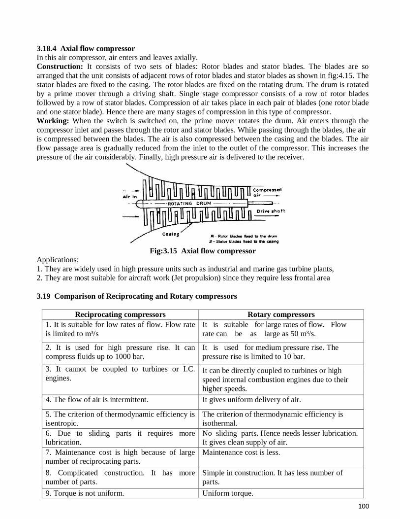
100
3.18.4 Axial flow compressor
In this air compressor, air enters and leaves axially.
Construction: It consists of two sets of blades: Rotor blades and stator blades. The blades are so
arranged that the unit consists of adjacent rows of rotor blades and stator blades as shown in fig:4.15. The
stator blades are fixed to the casing. The rotor blades are fixed on the rotating drum. The drum is rotated
by a prime mover through a driving shaft. Single stage compressor consists of a row of rotor blades
followed by a row of stator blades. Compression of air takes place in each pair of blades (one rotor blade
and one stator blade). Hence there are many stages of compression in this type of compressor.
Working: When the switch is switched on, the prime mover rotates the drum. Air enters through the
compressor inlet and passes through the rotor and stator blades. While passing through the blades, the air
is compressed between the blades. The air is also compressed between the casing and the blades. The air
flow passage area is gradually reduced from the inlet to the outlet of the compressor. This increases the
pressure of the air considerably. Finally, high pressure air is delivered to the receiver.
Fig:3.15 Axial flow compressor
Applications:
1. They are widely used in high pressure units such as industrial and marine gas turbine plants,
2. They are most suitable for aircraft work (Jet propulsion) since they require less frontal area
3.19 Comparison of Reciprocating and Rotary compressors
Reciprocating compressors Rotary compressors
1. It is suitable for low rates of flow. Flow rate
is limited to m³/s
It is suitable for large rates of flow. Flow
rate can be as large as 50 m³/s.
2. It is used for high pressure rise. It can
compress fluids up to 1000 bar.
It is used for medium pressure rise. The
pressure rise is limited to 10 bar.
3. It cannot be coupled to turbines or I.C.
engines. It can be directly coupled to turbines or high
speed internal combustion engines due to their
higher speeds.
4. The flow of air is intermittent. It gives uniform delivery of air.
5. The criterion of thermodynamic efficiency is
isentropic.
The criterion of thermodynamic efficiency is
isothermal.
6. Due to sliding parts it requires more
lubrication.
No sliding parts. Hence needs lesser lubrication.
It gives clean supply of air.
7. Maintenance cost is high because of large
number of reciprocating parts.
Maintenance cost is less.
8. Complicated construction. It has more
number of parts.
Simple in construction. It has less number of
parts.
9. Torque is not uniform. Uniform torque.
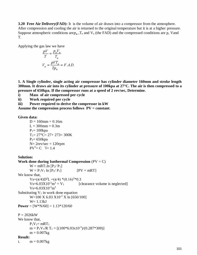
101
3.20 Free Air Delivery(FAD): It is the volume of air drawn into a compressor from the atmosphere.
After compression and cooling the air is returned to the original temperature but it is at a higher pressure.
Suppose atmospheric conditions are𝑝𝑎 ,Ta and Va (the FAD) and the compressed conditions are p, Vand
T.
Applying the gas law we have
1. A Single cylinder, single acting air compressor has cylinder diameter 160mm and stroke length
300mm. It draws air into its cylinder at pressure of 100kpa at 27°C. The air is then compressed to a
pressure of 650kpa. If the compressor runs at a speed of 2 rev/sec, Determine.
i) Mass of air compressed per cycle
ii) Work required per cycle
iii) Power required to derive the compressor in kW
Assume the compression process follows PV = constant.
Given data:
D = 160mm = 0.16m
L = 300mm = 0.3m
P1= 100kpa
T1= 27°C= 27+ 273= 300K
P2= 650kpa
N= 2rev/sec = 120rpm
PVال= C 1.4 =ال
Solution:
Work done during Isothermal Compression (PV = C)
W = mRT1ln [P2/ P1]
W = P1V1 ln [P2/ P1] [PV = mRT]
We know that,
Vs=(π/4)D2L =(π/4) *(0.16)2*0.3
Vs=6.03X10⁻³m3 = V1 [clearance volume is neglected]
Vs=6.03X10⁻³m3
Substituting V1 in work done equation
W=100 X 6.03 X10-3 X ln [650/100]
W= 1.13kJ
Power = [W*N/60] = 1.13*120/60
P = 2026kW
We know that,
P1V1= mRT1
m = P1V1/R T1 = [(100*6.03x10-3)/(0.287*300)]
m = 0.007kg
Result:
i. m = 0.007kg
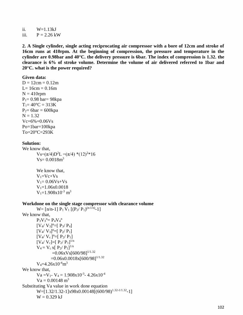
102
ii. W=1.13kJ
iii. P = 2.26 kW
2. A Single cylinder, single acting reciprocating air compressor with a bore of 12cm and stroke of
16cm runs at 410rpm. At the beginning of compression, the pressure and temperature in the
cylinder are 0.98bar and 40°C. the delivery pressure is 6bar. The index of compression is 1.32. the
clearance is 6% of stroke volume. Determine the volume of air delivered referred to 1bar and
20°C. what is the power required?
Given data:
D = 12cm = 0.12m
L= 16cm = 0.16m
N = 410rpm
P1= 0.98 bar= 98kpa
T1= 40°C = 313K
P2= 6bar = 600kpa
N = 1.32
Vc=6%=0.06Vs
Po=1bar=100kpa
To=20°C=293K
Solution:
We know that,
Vs=(π/4)D2L =(π/4) *(12)2*16
Vs= 0.0018m3
We know that,
V1=Vc+Vs
V1= 0.06Vs+Vs
V1=1.06x0.0018
V1=1.908x10⁻³ m3
Workdone on the single stage compressor with clearance volume
W= [n/n-1] P1 V1 [(P2/ P1)(n-1/n)-1]
We know that,
P3V3n= P4V4
n
[V4/ V3]n=[ P3/ P4]
[V4/ V3]n=[ P2/ P1]
[V4/ Vc ]n=[ P2/ P1]
[V4/ Vc]=[ P2/ P1]1/n
V4 = Vc x[ P2/ P1]1/n
=0.06xVs[600/98]1/1.32 =0.06x0.0018x[600/98]1/1.32
V4=4.26x10⁻⁴m3
We know that,
Va =V1- V4 = 1.908x10⁻³- 4.26x10⁻⁴
Va = 0.00148 m3
Substituting Va value in work done equation
W=[1.32/1.32-1]x98x0.00148[(600/98)1.32-1/1.32-1]
W = 0.329 kJ
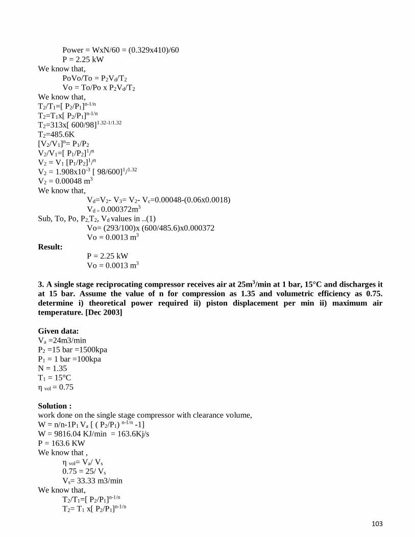
103
Power = WxN/60 = (0.329x410)/60
P = 2.25 kW
We know that,
PoVo/To = P2Vd/T2
Vo = To/Po x P2Vd/T2
We know that,
T2/T1=[ P2/P1]n-1/n
T2=T1x[ P2/P1]n-1/n
T2=313x[ 600/98]1.32-1/1.32
T2=485.6K
[V2/V1]n= P1/P2
V2/V1=[ P1/P2]1/n
V2 = V1 [P1/P2]1/n
V2 = 1.908x10⁻³ [ 98/600]1/1.32
V2 = 0.00048 m3
We know that,
Vd=V2- V3= V2- Vc=0.00048-(0.06x0.0018)
Vd = 0.000372m3
Sub, To, Po, P2,T2, Vd values in ..(1)
Vo= (293/100)x (600/485.6)x0.000372
Vo = 0.0013 m3
Result:
P = 2.25 kW
Vo = 0.0013 m3
3. A single stage reciprocating compressor receives air at 25m3/min at 1 bar, 15°C and discharges it
at 15 bar. Assume the value of n for compression as 1.35 and volumetric efficiency as 0.75.
determine i) theoretical power required ii) piston displacement per min ii) maximum air
temperature. [Dec 2003]
Given data:
Va =24m3/min
P2 =15 bar =1500kpa
P1 = 1 bar =100kpa
N = 1.35
T1 = 15°C
η vol = 0.75
Solution :
work done on the single stage compressor with clearance volume,
W = n/n-1P1 Va [ ( P2/P1) n-1/n -1]
W = 9816.04 KJ/min = 163.6Kj/s
P = 163.6 KW
We know that ,
η vol= Va/ Vs
0.75 = 25/ Vs
Vs= 33.33 m3/min
We know that,
T2/T1=[ P2/P1]n-1/n
T2= T1 x[ P2/P1]n-1/n
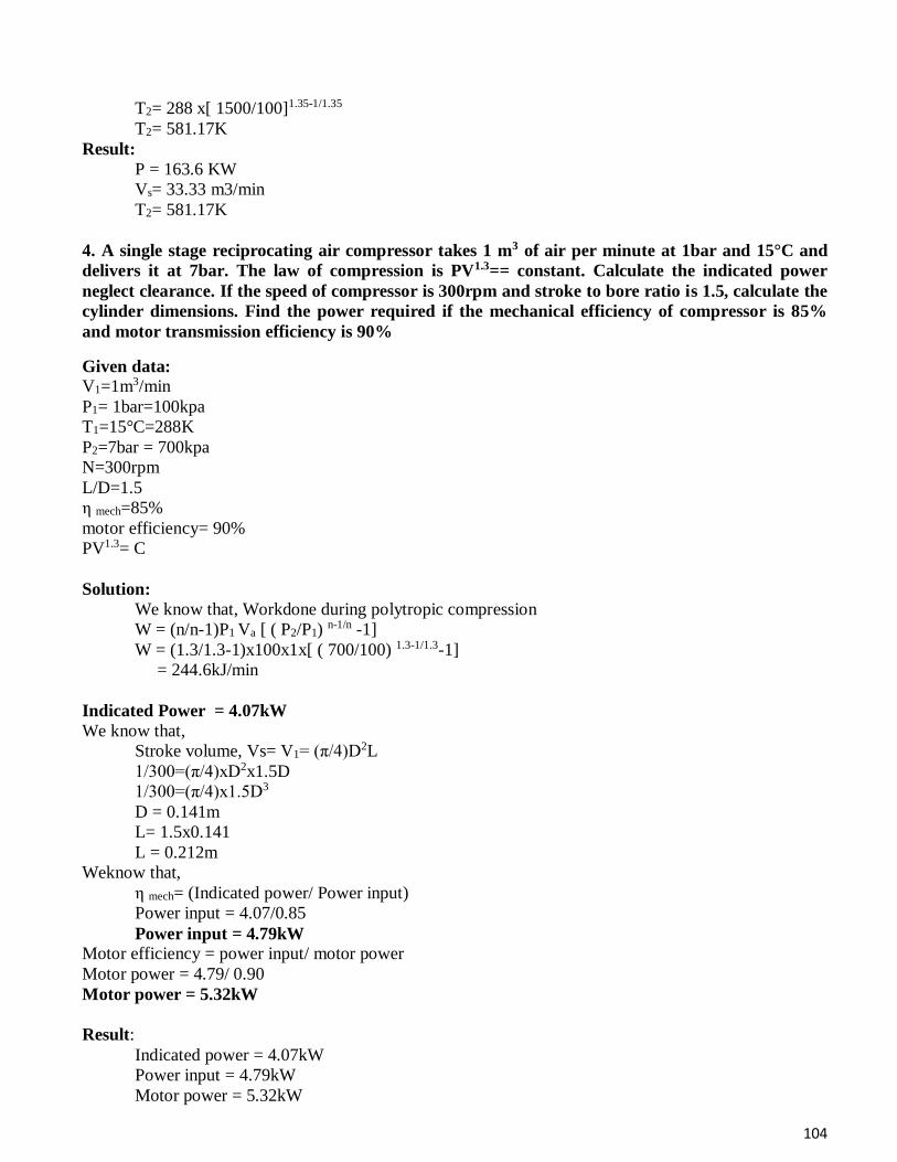
104
T2= 288 x[ 1500/100]1.35-1/1.35
T2= 581.17K
Result:
P = 163.6 KW
Vs= 33.33 m3/min
T2= 581.17K
4. A single stage reciprocating air compressor takes 1 m3 of air per minute at 1bar and 15°C and
delivers it at 7bar. The law of compression is PV1.3== constant. Calculate the indicated power
neglect clearance. If the speed of compressor is 300rpm and stroke to bore ratio is 1.5, calculate the
cylinder dimensions. Find the power required if the mechanical efficiency of compressor is 85%
and motor transmission efficiency is 90%
Given data:
V1=1m3/min
P1= 1bar=100kpa
T1=15°C=288K
P2=7bar = 700kpa
N=300rpm
L/D=1.5
η mech=85%
motor efficiency= 90%
PV1.3= C
Solution:
We know that, Workdone during polytropic compression
W = (n/n-1)P1 Va [ ( P2/P1) n-1/n -1]
W = (1.3/1.3-1)x100x1x[ ( 700/100) 1.3-1/1.3-1]
= 244.6kJ/min
Indicated Power = 4.07kW
We know that,
Stroke volume, Vs= V1= (π/4)D2L
1/300=(π/4)xD2x1.5D
1/300=(π/4)x1.5D3
D = 0.141m
L= 1.5x0.141
L = 0.212m
Weknow that,
η mech= (Indicated power/ Power input)
Power input = 4.07/0.85
Power input = 4.79kW
Motor efficiency = power input/ motor power
Motor power = 4.79/ 0.90
Motor power = 5.32kW
Result:
Indicated power = 4.07kW
Power input = 4.79kW
Motor power = 5.32kW

105
5. The free air delivered of a single cylinder single stage reciprocating air compressor 2.5 m3/min.
The ambient air is at STP conditions and delivery pressure is 7bar. The clearance volume is 5% of
the stroke volume and law of compression and expansion is PV1.25=C. if L= 1.2D and the
compressor runs at 150rpm, determine the size of the cylinders.
Given data:
Va = 2.5 m3/min= 0.04166 m3/sec
For STP condition, the pressure and temperature are
V1=1m3/min
P1= 1.013bar=101.3kpa
T1=15°C=288K
P2=7bar = 700kpa
N=150rpm
L=1.2D
Vc=5%Vs = 0.05Vs
PV1.25= C
n = 1.25
Solution:
The mass of free air delivered per second is given by
ma=PV/RT =(1.013x105x0.04166)/(287x288)=0.051kg/sec
We know that,
Work done, W = (n/n-1)PVa [ ( P2/P1) n-1/n -1]
W = maRT(n/n-1) [ ( P2/P1) n-1/n -1]
W = 0.054x0.287x288x (1.25/1.25-1) [ ( 700/101.3) 1.25-1/1.25 -1]
W = 9.95kW
We know that,
Indicated power, IP =PmLAN/1000
Pm = (n/n-1) P1xη vol[ ( P2/P1) n-1/n -1]
But, η vol=1+C-C (P2/P1) 1/n
Where C = Vc/Vs
η vol=1+ (Vc/Vs) – (Vc/Vs) (P2/P1) 1/n
η vol=1+ (0.05) – (0.05) (700/101.3) 1/1.25
η vol= 0.815
Substituting Pm value in eqn (2)
Pm = (1.25/1.25-1) x1 x 0.815 x [ ( 700/101.3) 1.25-1/1.25 -1]
Pm =1.923bar
Substituting Pm value in eqn (1)
Indicated Power IP (or) work out put
1.95 = [1.923x105 x 1.2 D x (π/4)D2 x 150/60] / 1000
D = 0.28m
Result:
L = 1.2 D = 1.2x 0.28 = 0.336m
D = 0.28 m
L = 0.336m
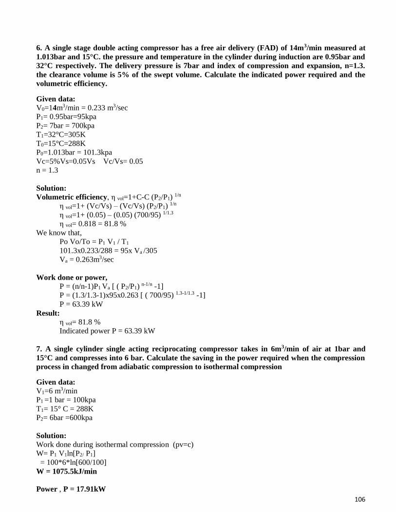
106
6. A single stage double acting compressor has a free air delivery (FAD) of 14m3/min measured at
1.013bar and 15°C. the pressure and temperature in the cylinder during induction are 0.95bar and
32°C respectively. The delivery pressure is 7bar and index of compression and expansion, n=1.3.
the clearance volume is 5% of the swept volume. Calculate the indicated power required and the
volumetric efficiency.
Given data:
V0=14m3/min = 0.233 m3/sec
P1= 0.95bar=95kpa
P2= 7bar = 700kpa
T1=32°C=305K
T0=15°C=288K
P0=1.013bar = 101.3kpa
Vc=5%Vs=0.05Vs Vc/Vs= 0.05
n = 1.3
Solution:
Volumetric efficiency, η vol=1+C-C (P2/P1) 1/n
η vol=1+ (Vc/Vs) – (Vc/Vs) (P2/P1) 1/n
η vol=1+ (0.05) – (0.05) (700/95) 1/1.3
η vol= 0.818 = 81.8 %
We know that,
Po Vo/To = P1 V1 / T1
101.3x0.233/288 = 95x Va /305
Va = 0.263m3/sec
Work done or power,
P = (n/n-1)P1 Va [ ( P2/P1) n-1/n -1]
P = (1.3/1.3-1)x95x0.263 [ ( 700/95) 1.3-1/1.3 -1]
P = 63.39 kW
Result:
η vol= 81.8 %
Indicated power P = 63.39 kW
7. A single cylinder single acting reciprocating compressor takes in 6m3/min of air at 1bar and
15°C and compresses into 6 bar. Calculate the saving in the power required when the compression
process in changed from adiabatic compression to isothermal compression
Given data:
V1=6 m3/min
P1 =1 bar = 100kpa
T1= 15° C = 288K
P2= 6bar =600kpa
Solution:
Work done during isothermal compression (pv=c)
W= P1 V1ln[P2/ P1]
= 100*6*ln[600/100]
W = 1075.5kJ/min
Power , P = 17.91kW
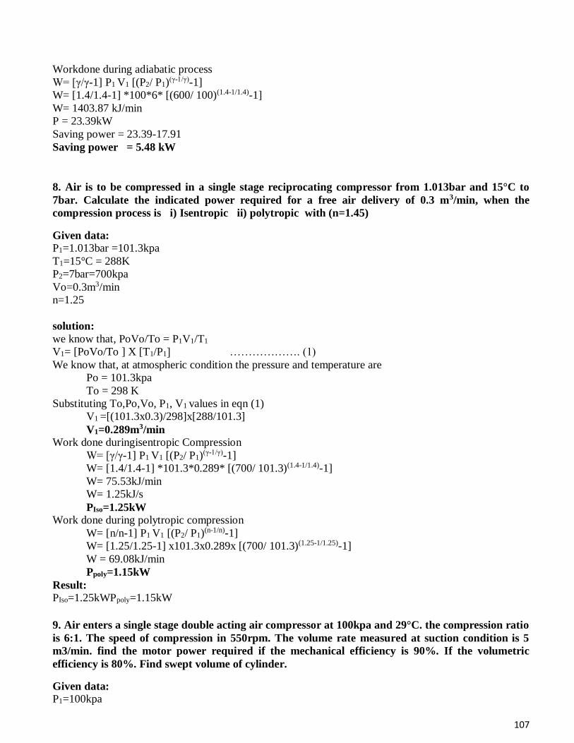
107
Workdone during adiabatic process
W= [γ/γ-1] P1 V1 [(P2/ P1)(γ-1/γ)-1]
W= [1.4/1.4-1] *100*6* [(600/ 100)(1.4-1/1.4)-1]
W= 1403.87 kJ/min
P = 23.39kW
Saving power = 23.39-17.91
Saving power = 5.48 kW
8. Air is to be compressed in a single stage reciprocating compressor from 1.013bar and 15°C to
7bar. Calculate the indicated power required for a free air delivery of 0.3 m3/min, when the
compression process is i) Isentropic ii) polytropic with (n=1.45)
Given data:
P1=1.013bar =101.3kpa
T1=15°C = 288K
P2=7bar=700kpa
Vo=0.3m3/min
n=1.25
solution:
we know that, PoVo/To = P1V1/T1
V1= [PoVo/To ] X [T1/P1] ………………. (1)
We know that, at atmospheric condition the pressure and temperature are
Po = 101.3kpa
To = 298 K
Substituting To,Po,Vo, P1, V1 values in eqn (1)
V1 =[(101.3x0.3)/298]x[288/101.3]
V1=0.289m3/min
Work done duringisentropic Compression
W= [γ/γ-1] P1 V1 [(P2/ P1)(γ-1/γ)-1]
W= [1.4/1.4-1] *101.3*0.289* [(700/ 101.3)(1.4-1/1.4)-1]
W= 75.53kJ/min
W= 1.25kJ/s
PIso=1.25kW
Work done during polytropic compression
W= [n/n-1] P1 V1 [(P2/ P1)(n-1/n)-1]
W= [1.25/1.25-1] x101.3x0.289x [(700/ 101.3)(1.25-1/1.25)-1]
W = 69.08kJ/min
Ppoly=1.15kW
Result:
PIso=1.25kWPpoly=1.15kW
9. Air enters a single stage double acting air compressor at 100kpa and 29°C. the compression ratio
is 6:1. The speed of compression in 550rpm. The volume rate measured at suction condition is 5
m3/min. find the motor power required if the mechanical efficiency is 90%. If the volumetric
efficiency is 80%. Find swept volume of cylinder.
Given data:
P1=100kpa
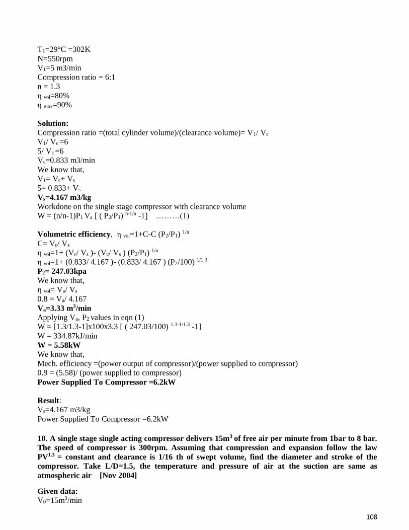
108
T1=29°C =302K
N=550rpm
V1=5 m3/min
Compression ratio = 6:1
n = 1.3
η vol=80%
η max=90%
Solution:
Compression ratio =(total cylinder volume)/(clearance volume)= V1/ Vc
V1/ Vc =6
5/ Vc =6
Vc=0.833 m3/min
We know that,
V1= Vc+ Vs
5= 0.833+ Vs
Vs=4.167 m3/kg
Workdone on the single stage compressor with clearance volume
W = (n/n-1)P1 Va [ ( P2/P1) n-1/n -1] ………(1)
Volumetric efficiency, η vol=1+C-C (P2/P1) 1/n
C= Vc/ Vs
η vol=1+ (Vc/ Vs )- (Vc/ Vs ) (P2/P1) 1/n
η vol=1+ (0.833/ 4.167 )- (0.833/ 4.167 ) (P2/100) 1/1.3
P2= 247.03kpa
We know that,
η vol= Va/ Vs
0.8 = Va/ 4.167
Va=3.33 m3/min
Applying Va, P2 values in eqn (1)
W = [1.3/1.3-1]x100x3.3 [ ( 247.03/100) 1.3-1/1.3 -1]
W = 334.87kJ/min
W = 5.58kW
We know that,
Mech. efficiency =(power output of compressor)/(power supplied to compressor)
0.9 = (5.58)/ (power supplied to compressor)
Power Supplied To Compressor =6.2kW
Result:
Vs=4.167 m3/kg
Power Supplied To Compressor =6.2kW
10. A single stage single acting compressor delivers 15m3 of free air per minute from 1bar to 8 bar.
The speed of compressor is 300rpm. Assuming that compression and expansion follow the law
PV1.3 = constant and clearance is 1/16 th of swept volume, find the diameter and stroke of the
compressor. Take L/D=1.5, the temperature and pressure of air at the suction are same as
atmospheric air [Nov 2004]
Given data:
V0=15m3/min
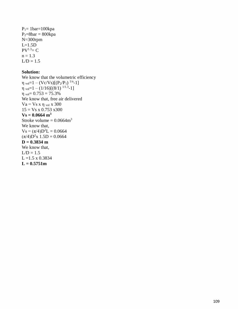
109
P1= 1bar=100kpa
P2=8bar = 800kpa
N=300rpm
L=1.5D
PV1.3= C
n = 1.3
L/D = 1.5
Solution:
We know that the volumetric efficiency
η vol=1 – (Vc/Vs)[(P2/P1) 1/n-1]
η vol=1 – (1/16)[(8/1) 1/1.3-1]
η vol= 0.753 = 75.3%
We know that, free air delivered
Va = Vs x η vol x 300
15 = Vs x 0.753 x300
Vs = 0.0664 m3
Stroke volume = 0.0664m3
We know that,
Vs = (π/4)D2L = 0.0664
(π/4)D2x 1.5D = 0.0664
D = 0.3834 m
We know that,
L/D = 1.5
L =1.5 x 0.3834
L = 0.5751m

110
Syllabus Flow of steam through nozzles, Isentropic flow, ideal and actual expansion in nozzle, condition for
maximum discharge, critical pressure ratio, Meta stable flow. Steam turbines, impulse and Reaction
principles, Compounding, Velocity diagrams for impulse and reaction blades, Work done on turbine
blades, optimization and efficiency.
Unit -4 - STEAM NOZZLES AND STEAM TURBINES – SMEA1404
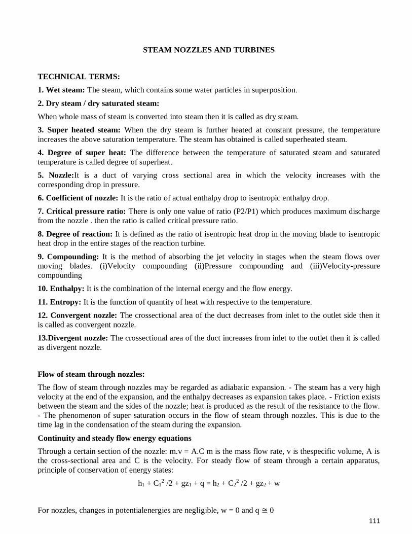
111
STEAM NOZZLES AND TURBINES
TECHNICAL TERMS:
1. Wet steam: The steam, which contains some water particles in superposition.
2. Dry steam / dry saturated steam:
When whole mass of steam is converted into steam then it is called as dry steam.
3. Super heated steam: When the dry steam is further heated at constant pressure, the temperature
increases the above saturation temperature. The steam has obtained is called superheated steam.
4. Degree of super heat: The difference between the temperature of saturated steam and saturated
temperature is called degree of superheat.
5. Nozzle:It is a duct of varying cross sectional area in which the velocity increases with the
corresponding drop in pressure.
6. Coefficient of nozzle: It is the ratio of actual enthalpy drop to isentropic enthalpy drop.
7. Critical pressure ratio: There is only one value of ratio (P2/P1) which produces maximum discharge
from the nozzle . then the ratio is called critical pressure ratio.
8. Degree of reaction: It is defined as the ratio of isentropic heat drop in the moving blade to isentropic
heat drop in the entire stages of the reaction turbine.
9. Compounding: It is the method of absorbing the jet velocity in stages when the steam flows over
moving blades. (i)Velocity compounding (ii)Pressure compounding and (iii)Velocity-pressure
compounding
10. Enthalpy: It is the combination of the internal energy and the flow energy.
11. Entropy: It is the function of quantity of heat with respective to the temperature.
12. Convergent nozzle: The crossectional area of the duct decreases from inlet to the outlet side then it
is called as convergent nozzle.
13.Divergent nozzle: The crossectional area of the duct increases from inlet to the outlet then it is called
as divergent nozzle.
Flow of steam through nozzles:
The flow of steam through nozzles may be regarded as adiabatic expansion. - The steam has a very high
velocity at the end of the expansion, and the enthalpy decreases as expansion takes place. - Friction exists
between the steam and the sides of the nozzle; heat is produced as the result of the resistance to the flow.
- The phenomenon of super saturation occurs in the flow of steam through nozzles. This is due to the
time lag in the condensation of the steam during the expansion.
Continuity and steady flow energy equations
Through a certain section of the nozzle: m.v = A.C m is the mass flow rate, v is thespecific volume, A is
the cross-sectional area and C is the velocity. For steady flow of steam through a certain apparatus,
principle of conservation of energy states:
h1 + C12 /2 + gz1 + q = h2 + C2
2 /2 + gz2 + w
For nozzles, changes in potentialenergies are negligible, w = 0 and q ≅ 0
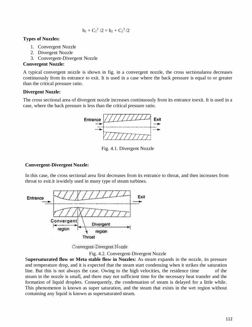
112
h1 + C12 /2 = h2 + C2
2 /2
Types of Nozzles:
1. Convergent Nozzle
2. Divergent Nozzle
3. Convergent-Divergent Nozzle
Convergent Nozzle:
A typical convergent nozzle is shown in fig. in a convergent nozzle, the cross sectionalarea decreases
continuously from its entrance to exit. It is used in a case where the back pressure is equal to or greater
than the critical pressure ratio.
Divergent Nozzle:
The cross sectional area of divergent nozzle increases continuously from its entrance toexit. It is used in a
case, where the back pressure is less than the critical pressure ratio.
Fig. 4.1. Divergent Nozzle
Convergent-Divergent Nozzle:
In this case, the cross sectional area first decreases from its entrance to throat, and then increases from
throat to exit.it is widely used in many type of steam turbines.
Fig. 4.2. Convergent-Divergent Nozzle
Supersaturated flow or Meta stable flow in Nozzles: As steam expands in the nozzle, its pressure
and temperature drop, and it is expected that the steam start condensing when it strikes the saturation
line. But this is not always the case. Owing to the high velocities, the residence time of the
steam in the nozzle is small, and there may not sufficient time for the necessary heat transfer and the
formation of liquid droplets. Consequently, the condensation of steam is delayed for a little while.
This phenomenon is known as super saturation, and the steam that exists in the wet region without
containing any liquid is known as supersaturated steam.
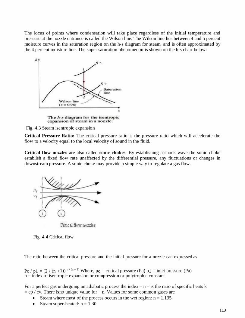
113
The locus of points where condensation will take place regardless of the initial temperature and
pressure at the nozzle entrance is called the Wilson line. The Wilson line lies between 4 and 5 percent
moisture curves in the saturation region on the h-s diagram for steam, and is often approximated by
the 4 percent moisture line. The super saturation phenomenon is shown on the h-s chart below:
Fig. 4.3 Steam isentropic expansion
Critical Pressure Ratio: The critical pressure ratio is the pressure ratio which will accelerate the
flow to a velocity equal to the local velocity of sound in the fluid.
Critical flow nozzles are also called sonic chokes. By establishing a shock wave the sonic choke
establish a fixed flow rate unaffected by the differential pressure, any fluctuations or changes in
downstream pressure. A sonic choke may provide a simple way to regulate a gas flow.
Fig. 4.4 Critical flow
The ratio between the critical pressure and the initial pressure for a nozzle can expressed as
Pc / p1 = (2 / (n + 1)) n / (n – 1) Where, pc = critical pressure (Pa) p1 = inlet pressure (Pa) n = index of isentropic expansion or compression or polytrophic constant
For a perfect gas undergoing an adiabatic process the index – n – is the ratio of specific heats k
= cp / cv. There is no unique value for – n. Values for some common gases are
Steam where most of the process occurs in the wet region: n = 1.135
Steam super-heated: n = 1.30
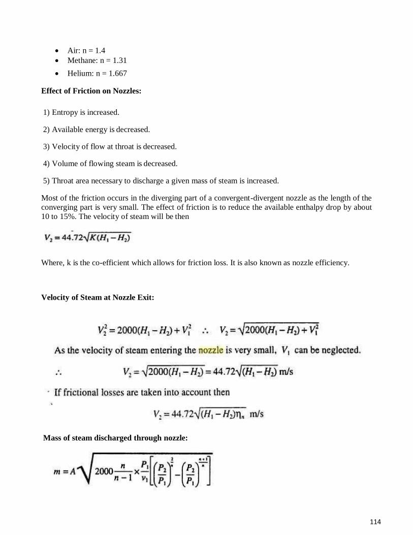
114
Air: n = 1.4
Methane: n = 1.31
Helium: n = 1.667
Effect of Friction on Nozzles:
1) Entropy is increased.
2) Available energy is decreased.
3) Velocity of flow at throat is decreased.
4) Volume of flowing steam is decreased.
5) Throat area necessary to discharge a given mass of steam is increased.
Most of the friction occurs in the diverging part of a convergent-divergent nozzle as the length of the
converging part is very small. The effect of friction is to reduce the available enthalpy drop by about
10 to 15%. The velocity of steam will be then
Where, k is the co-efficient which allows for friction loss. It is also known as nozzle efficiency.
Velocity of Steam at Nozzle Exit:
Mass of steam discharged through nozzle:
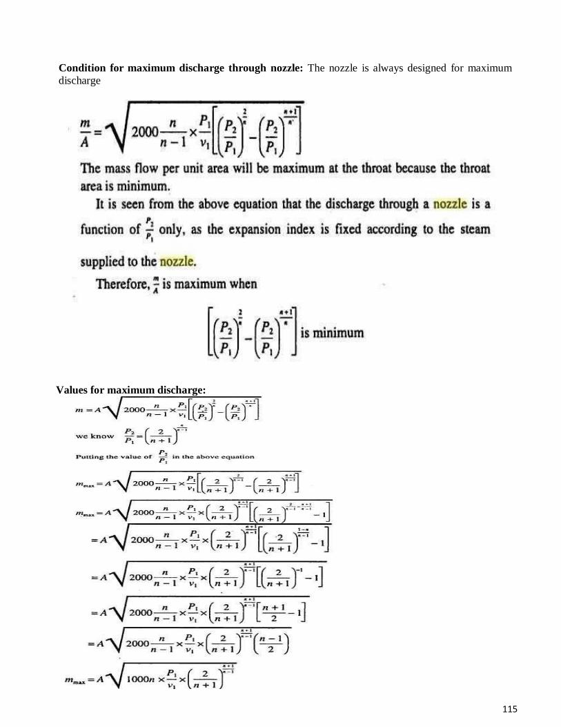
115
Condition for maximum discharge through nozzle: The nozzle is always designed for maximum
discharge
Values for maximum discharge:
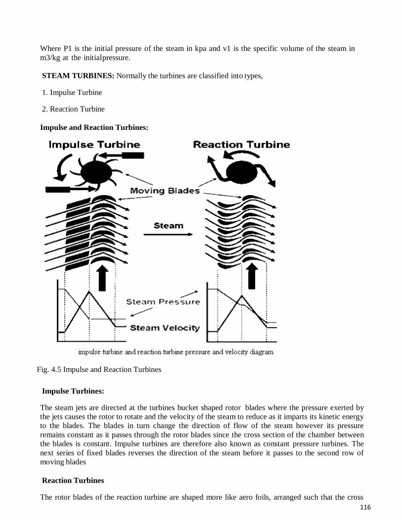
116
Where P1 is the initial pressure of the steam in kpa and v1 is the specific volume of the steam in
m3/kg at the initial pressure.
STEAM TURBINES: Normally the turbines are classified into types,
1. Impulse Turbine
2. Reaction Turbine
Impulse and Reaction Turbines:
Fig. 4.5 Impulse and Reaction Turbines
Impulse Turbines:
The steam jets are directed at the turbines bucket shaped rotor blades where the pressure exerted by
the jets causes the rotor to rotate and the velocity of the steam to reduce as it imparts its kinetic energy
to the blades. The blades in turn change the direction of flow of the steam however its pressure
remains constant as it passes through the rotor blades since the cross section of the chamber between
the blades is constant. Impulse turbines are therefore also known as constant pressure turbines. The
next series of fixed blades reverses the direction of the steam before it passes to the second row of
moving blades
Reaction Turbines
The rotor blades of the reaction turbine are shaped more like aero foils, arranged such that the cross
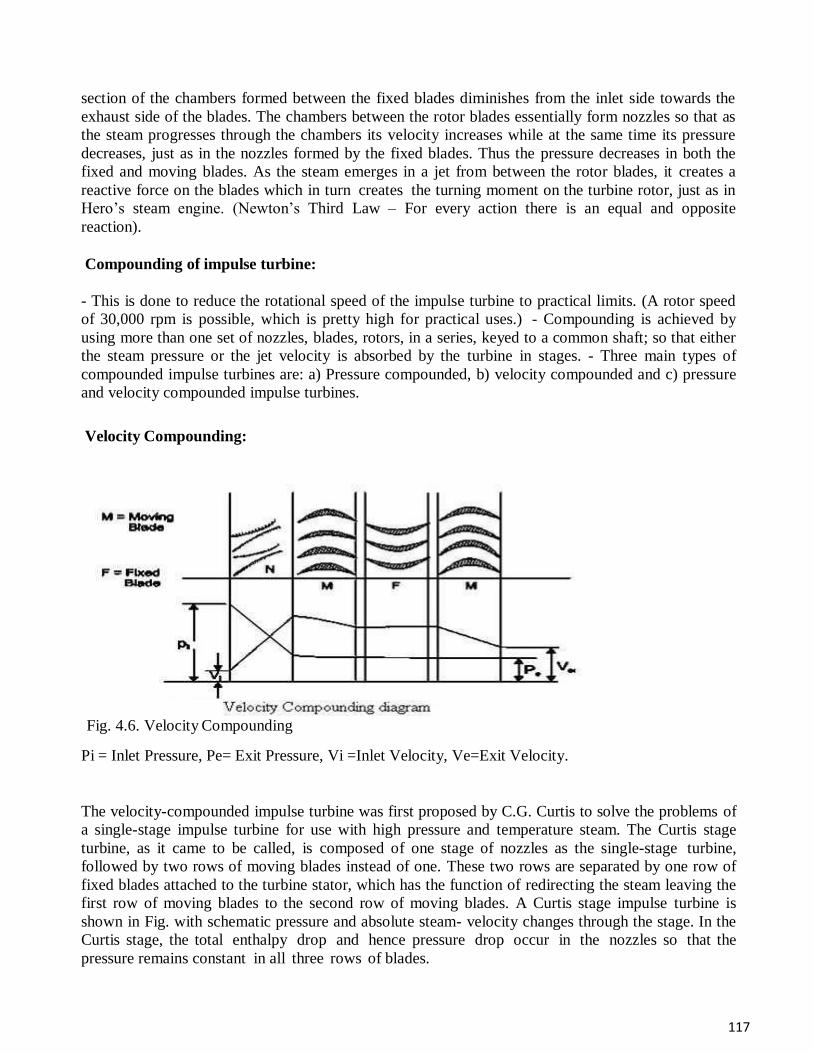
117
section of the chambers formed between the fixed blades diminishes from the inlet side towards the
exhaust side of the blades. The chambers between the rotor blades essentially form nozzles so that as
the steam progresses through the chambers its velocity increases while at the same time its pressure
decreases, just as in the nozzles formed by the fixed blades. Thus the pressure decreases in both the
fixed and moving blades. As the steam emerges in a jet from between the rotor blades, it creates a
reactive force on the blades which in turn creates the turning moment on the turbine rotor, just as in
Hero’s steam engine. (Newton’s Third Law – For every action there is an equal and opposite
reaction).
Compounding of impulse turbine:
- This is done to reduce the rotational speed of the impulse turbine to practical limits. (A rotor speed
of 30,000 rpm is possible, which is pretty high for practical uses.) - Compounding is achieved by
using more than one set of nozzles, blades, rotors, in a series, keyed to a common shaft; so that either
the steam pressure or the jet velocity is absorbed by the turbine in stages. - Three main types of
compounded impulse turbines are: a) Pressure compounded, b) velocity compounded and c) pressure
and velocity compounded impulse turbines.
Velocity Compounding:
Fig. 4.6. Velocity Compounding
Pi = Inlet Pressure, Pe= Exit Pressure, Vi =Inlet Velocity, Ve=Exit Velocity.
The velocity-compounded impulse turbine was first proposed by C.G. Curtis to solve the problems of
a single-stage impulse turbine for use with high pressure and temperature steam. The Curtis stage
turbine, as it came to be called, is composed of one stage of nozzles as the single-stage turbine,
followed by two rows of moving blades instead of one. These two rows are separated by one row of
fixed blades attached to the turbine stator, which has the function of redirecting the steam leaving the
first row of moving blades to the second row of moving blades. A Curtis stage impulse turbine is
shown in Fig. with schematic pressure and absolute steam- velocity changes through the stage. In the
Curtis stage, the total enthalpy drop and hence pressure drop occur in the nozzles so that the
pressure remains constant in all three rows of blades.
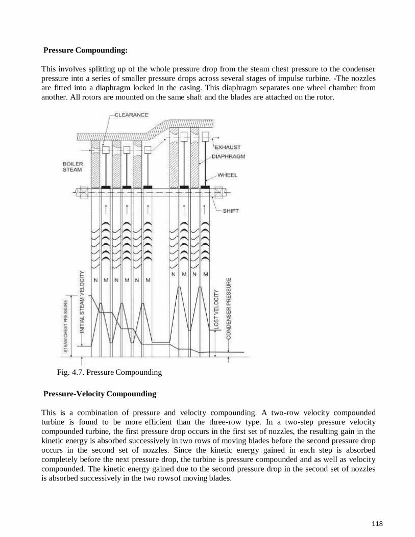
118
Pressure Compounding:
This involves splitting up of the whole pressure drop from the steam chest pressure to the condenser
pressure into a series of smaller pressure drops across several stages of impulse turbine. -The nozzles
are fitted into a diaphragm locked in the casing. This diaphragm separates one wheel chamber from
another. All rotors are mounted on the same shaft and the blades are attached on the rotor.
Fig. 4.7. Pressure Compounding
Pressure-Velocity Compounding
This is a combination of pressure and velocity compounding. A two-row velocity compounded
turbine is found to be more efficient than the three-row type. In a two-step pressure velocity
compounded turbine, the first pressure drop occurs in the first set of nozzles, the resulting gain in the
kinetic energy is absorbed successively in two rows of moving blades before the second pressure drop
occurs in the second set of nozzles. Since the kinetic energy gained in each step is absorbed
completely before the next pressure drop, the turbine is pressure compounded and as well as velocity
compounded. The kinetic energy gained due to the second pressure drop in the second set of nozzles
is absorbed successively in the two rows of moving blades.
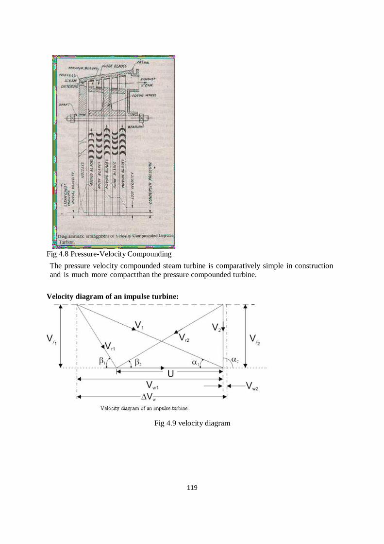
119
Fig 4.8 Pressure-Velocity Compounding
The pressure velocity compounded steam turbine is comparatively simple in construction
and is much more compact than the pressure compounded turbine.
Velocity diagram of an impulse turbine:
Fig 4.9 velocity diagram
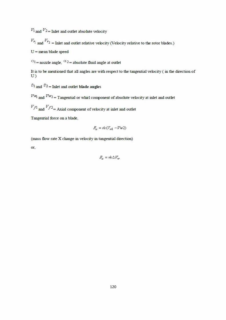
120
121
122
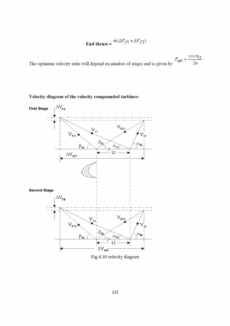
123
Fig 4.10 velocity diagram
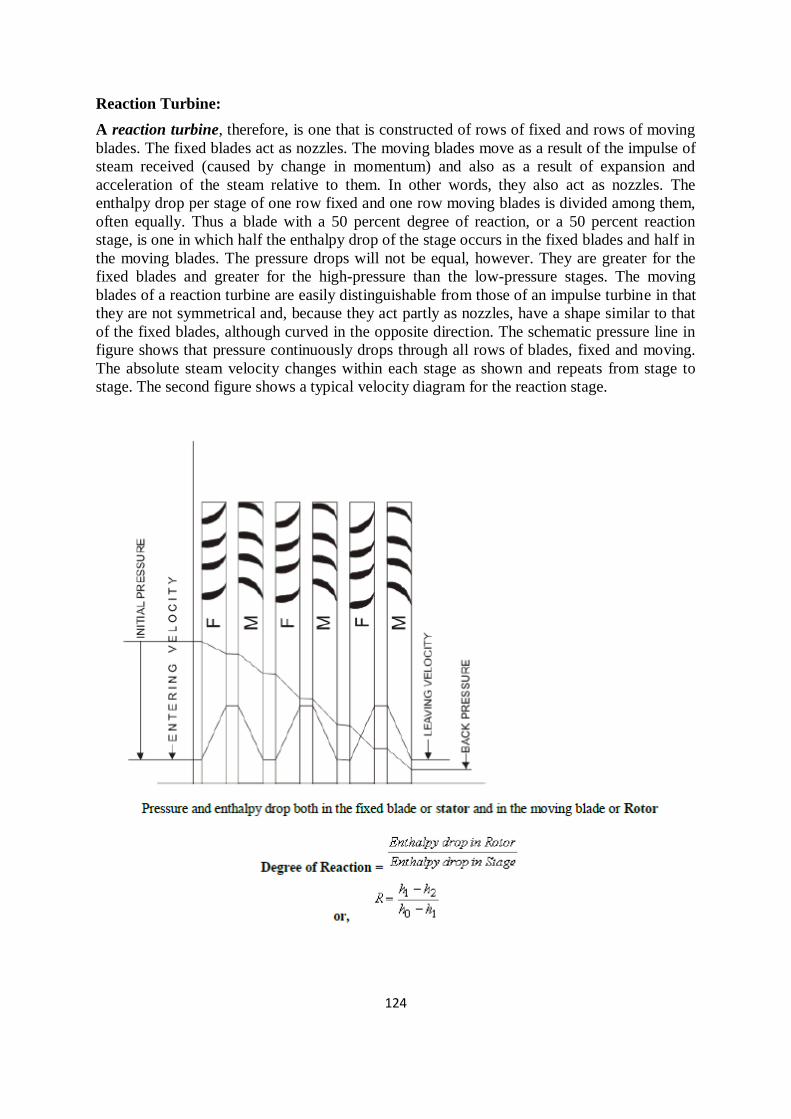
124
Reaction Turbine:
A reaction turbine, therefore, is one that is constructed of rows of fixed and rows of moving
blades. The fixed blades act as nozzles. The moving blades move as a result of the impulse of
steam received (caused by change in momentum) and also as a result of expansion and
acceleration of the steam relative to them. In other words, they also act as nozzles. The
enthalpy drop per stage of one row fixed and one row moving blades is divided among them,
often equally. Thus a blade with a 50 percent degree of reaction, or a 50 percent reaction
stage, is one in which half the enthalpy drop of the stage occurs in the fixed blades and half in
the moving blades. The pressure drops will not be equal, however. They are greater for the
fixed blades and greater for the high-pressure than the low-pressure stages. The moving
blades of a reaction turbine are easily distinguishable from those of an impulse turbine in that
they are not symmetrical and, because they act partly as nozzles, have a shape similar to that
of the fixed blades, although curved in the opposite direction. The schematic pressure line in
figure shows that pressure continuously drops through all rows of blades, fixed and moving.
The absolute steam velocity changes within each stage as shown and repeats from stage to
stage. The second figure shows a typical velocity diagram for the reaction stage.
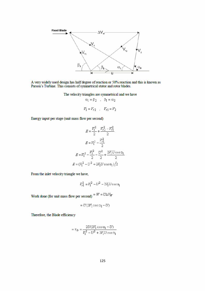
125
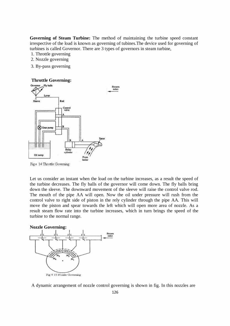
126
Governing of Steam Turbine: The method of maintaining the turbine speed constant
irrespective of the load is known as governing of tubines.The device used for governing of
turbines is called Governor. There are 3 types of governors in steam turbine,
1. Throttle governing
2. Nozzle governing
3. By-pass governing
Throttle Governing:
Let us consider an instant when the load on the turbine increases, as a result the speed of
the turbine decreases. The fly balls of the governor will come down. The fly balls bring
down the sleeve. The downward movement of the sleeve will raise the control valve rod.
The mouth of the pipe AA will open. Now the oil under pressure will rush from the
control valve to right side of piston in the rely cylinder through the pipe AA. This will
move the piston and spear towards the left which will open more area of nozzle. As a
result steam flow rate into the turbine increases, which in turn brings the speed of the
turbine to the normal range.
Nozzle Governing:
A dynamic arrangement of nozzle control governing is shown in fig. In this nozzles are
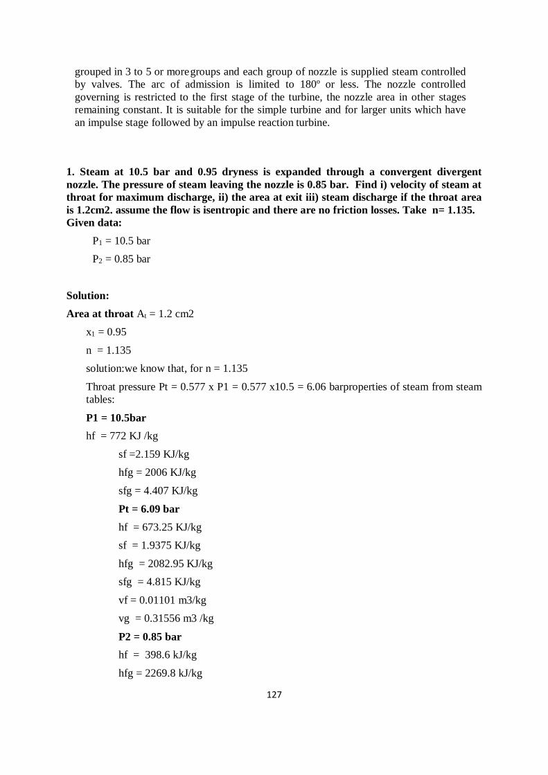
127
grouped in 3 to 5 or more groups and each group of nozzle is supplied steam controlled
by valves. The arc of admission is limited to 180º or less. The nozzle controlled
governing is restricted to the first stage of the turbine, the nozzle area in other stages
remaining constant. It is suitable for the simple turbine and for larger units which have
an impulse stage followed by an impulse reaction turbine.
1. Steam at 10.5 bar and 0.95 dryness is expanded through a convergent divergent
nozzle. The pressure of steam leaving the nozzle is 0.85 bar. Find i) velocity of steam at
throat for maximum discharge, ii) the area at exit iii) steam discharge if the throat area
is 1.2cm2. assume the flow is isentropic and there are no friction losses. Take n= 1.135.
Given data:
P1 = 10.5 bar
P2 = 0.85 bar
Solution:
Area at throat At = 1.2 cm2
x1 = 0.95
n = 1.135
solution:we know that, for n = 1.135
Throat pressure Pt = 0.577 x P1 = 0.577 x10.5 = 6.06 barproperties of steam from steam
tables:
P1 = 10.5bar
hf = 772 KJ /kg
sf =2.159 KJ/kg
hfg = 2006 KJ/kg
sfg = 4.407 KJ/kg
Pt = 6.09 bar
hf = 673.25 KJ/kg
sf = 1.9375 KJ/kg
hfg = 2082.95 KJ/kg
sfg = 4.815 KJ/kg
vf = 0.01101 m3/kg
vg = 0.31556 m3 /kg
P2 = 0.85 bar
hf = 398.6 kJ/kg
hfg = 2269.8 kJ/kg
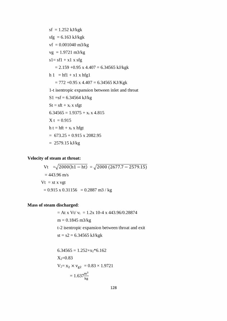
128
sf = 1.252 kJ/kgk
sfg = 6.163 kJ/kgk
vf = 0.001040 m3/kg
vg = 1.9721 m3/kg
s1= sf1 + x1 x sfg
= 2.159 +0.95 x 4.407 = 6.34565 kJ/kgk
h 1 = hf1 + x1 x hfg1
= 772 +0.95 x 4.407 = 6.34565 KJ/Kgk
1-t isentropic expansion between inlet and throat
S1 =sf = 6.34564 kJ/kg
St = sft + xt x sfgt
6.34565 = 1.9375 + xt x 4.815
X t = 0.915
h t = hft + xt x hfgt
= 673.25 + 0.915 x 2082.95
= 2579.15 kJ/kg
Velocity of steam at throat:
Vt =√2000(h1 − ht) = √2000 (2677.7 − 2579.15)
= 443.96 m/s
Vt = xt x vgt
= 0.915 x 0.31156 = 0.2887 m3 / kg
Mass of steam discharged:
= At x Vt/ vt = 1.2x 10-4 x 443.96/0.28874
m = 0.1845 m3/kg
t-2 isentropic expansion between throat and exit
st = s2 = 6.34565 kJ/kgk
6.34565 = 1.252+x2*6.162
X2=0.83
V2= x2 × vg2 = 0.83 × 1.9721
= 1.637m3
kg
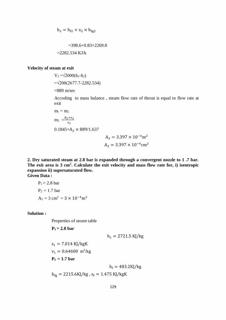
129
h2 = hf2 + x2 × hfg2
=398.6+0.83×2269.8
=2282.534 KJ/k
Velocity of steam at exit
V2 =√2000(h1-h2)
=√200(2677.7-2282.534)
=889 m/sec
Accoding to mass balance , steam flow rate of throat is equal to flow rate at
exit
mt = m2
m2 =A2×v2
v2
0.1845=A2 × 889/1.637
A2 = 3.397 × 10⁻⁴m2
A2 = 3.397 × 10⁻⁴cm2
2. Dry saturated steam at 2.8 bar is expanded through a convergent nozzle to 1 .7 bar.
The exit area is 3 cm2. Calculate the exit velocity and mass flow rate for, i) isentropic
expansion ii) supersaturated flow.
Given Data :
P1 = 2.8 bar
P2 = 1.7 bar
A2 = 3 cm2 = 3 × 10⁻⁴m2
Solution :
Properties of steam table
P1 = 2.8 bar
h1 = 2721.5 KJ/kg
s1 = 7.014 KJ/kgK
v1 = 0.64600 m3/kg
P2 = 1.7 bar
hf = 483.2KJ/kg
hfg = 2215.6KJ/kg , sf = 1.475 KJ/kgK
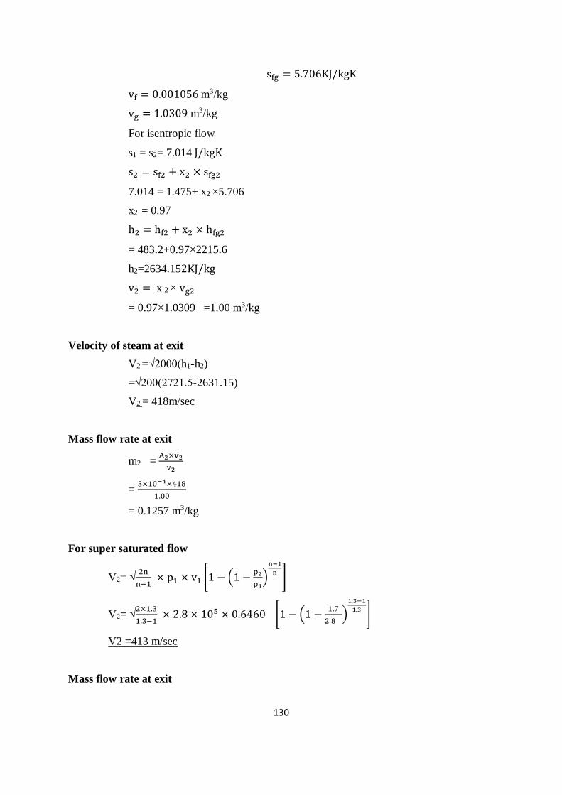
130
sfg = 5.706KJ/kgK
vf = 0.001056 m3/kg
vg = 1.0309 m3/kg
For isentropic flow
s1 = s2= 7.014 J/kgK
s2 = sf2 + x2 × sfg2
7.014 = 1.475+ x2 ×5.706
x2 = 0.97
h2 = hf2 + x2 × hfg2
= 483.2+0.97×2215.6
h2=2634.152KJ/kg
v2 = x 2 × vg2
= 0.97×1.0309 =1.00 m3/kg
Velocity of steam at exit
V2 =√2000(h1-h2)
=√200(2721.5-2631.15)
V2 = 418m/sec
Mass flow rate at exit
m2 = A2×v2
v2
= 3×10−4×418
1.00
= 0.1257 m3/kg
For super saturated flow
V2= √2n
n−1 × p1 × v1 [1 − (1 −
p2
p1)
n−1
n]
V2= √2×1.3
1.3−1 × 2.8 × 105 × 0.6460 [1 − (1 −
1.7
2.8)
1.3−1
1.3]
V2 =413 m/sec
Mass flow rate at exit
131
m2 = A2×v2
v2 =
3×10−4×413
0.94827
= 0.1306 kg/sec.
3. Dry saturated steam at a pressure of 8 bar enters a C-D nozzle and leaves it a
pressure of 1.5 bar. If the steam flow process is isentropic and if the corresponding
expanding index is 1.135, Find the ratio of cross sectional area at exit and throat for
maximum discharge.
Given Data:
P1 = 2.8 bar
P2 = 1.7 bar
n = 1.135
Solution:
We know that n= 1.135
Throat pressurept = 0.577×p1= 0.577×8 = 4.62 bar
Properties of steam at steam table
At 8 bar
h1 = 2769.1 KJ/kg
s1 = 6.6628 KJ/kgK
v1 = 0.2404 m3/kg
At 4.62 bar
hf = 626.7KJ/kg
hfg = 2117.2KJ/kg
sf = 1.829 KJ/kgK
sfg = 5.018KJ/kgK
vf = 0.001090 m3/kg
vg = 0.40526 m3/kg
At 1.5 bar
hf = 467.11KJ/kg
hfg = 2226.5KJ/kg
sf = 1.4336 KJ/kgK
132
sfg = 5.7897KJ/kgK
vf = 0.001053 m3/kg
= 626.7+0.963×2117.2
ht=2666.18 KJ/kg
vt = x t × vgt
= 0.963×040526 =0.39 m3/kg
Velocity of steam at throat
Vt =√2000(h1-ht)
=√200(2769.1-2666.18)
=477.749 m/sec
t-2 isentropic expansion
st = s2= 6.6628 KJ/kgK
s2 = sf2 + x2 × sfg2
6.6628 = 1.4336+ x2 ×5.7897
x2 = 0.903
v2 = x2 × vg2
=0.903 × 1.1593= 1.04695 m3/kg
h2 = hf2 + x2 × hfg2
=467.11+0.903×2226.5
h2=2477.6395 KJ/kg
Velocity of steam at exit
V2 =√2000(h1-h2)
=√200(2769.1-2477.639)
=763.5 m/sec
According to mass balance
Mass flow rate of steam at throat = Mass flow rate of steam at exit
mt = m2
At×Vt
vt=
A2×V2
v2
133
A2
At=
1.04695 × 477.749
763.5 × 0.39= 1.68
4. Steam enters a group of CD nozzles at 21 bars and 270℃. The discharge pressure of
the nozzle is 0.07 bars. The expansion is equilibrium throughout and the loss of friction
in convergent portion of the nozzle is negligible, but the loss by friction in the divergent
section of the nozzle is equivalent to 10% of the enthalpy drop available in that section.
Calculate the throat and exit area to discharge 14 kg/sec of steam.
Given Data:
P1 = 21 bar
T1 = 270℃
P2 = 0.07 bar
m = 14 kg / s.
since loss by friction is 10%.
The efficiency η= 90%.
Solution :
Properties of steam (from Mollier Diagram)
h1 = 2980KJ
kg (at 21 bar and 270℃)
Since the expansion is isentropic from
h1 =2980kj
kg draw a vertical line in the moiller diagram up to 0.07bar pressure line
now note the following values at that point.
h2 = 2052.213kj/kg(at 0.07bar)
v2 =16.1m3/kg
The critical pressure ratio when steam is initially super heated,
pt /p1 = 0.546
Throat pressure
pt = 0.546 ∗p1 =0.546*21=11.466bar
Properties of steam at throat
vt = √2000(h1− ht) =√2000(2980 − 2805) = 591.6𝑚/𝑠
134
Velocity of steam at exit
v2=√2000(ht−h2
)∗ ɳ = √2000(2980 − 2052.213) ∗ 0.9 =
1292.29m
s
Throat area of nozzle
A2=m*v2/V2=(14*16.1)/1292.29=0.174m2=1744.4cm2
5.The following data refer to a single stage impulse turbine.
Isentropic nozzle entropy drop=200kj/kg
Nozzle efficiency=90%
Nozzle angle=𝟐𝟓𝟎
Ratio of blade speed to whirl component of steam speed=0.5. blade coefficient =0.9. the
velocity of steam entering the nozzle 30m/s. find(1).blade angles at the inlet and outlet if
the steam enters the blade without shock and leaves the blade in the axial direction.(2).
Blade efficiency (3).power developed (4).axial thrust if the steam flow rate is 10kg/s.
[Nov 2003]
Given data:
ht=he=200kJ/kg
ηN=90%
α=250
vb
vw1=0.5
vr2
vr1=0.9
vi=30m/s
v2 = vf2
vw2=0
β=900 for axial discharge
Solution:
Actual enthalpy drop
hi − he = (hi − he)ηN
hi − he = 200 × 0.9
=180 KJ/kg

135
Ve =√2(hi-he)+vi2 = √2(1000-180)+302
= 600.75 m/sec.
Inlet velocity of steam to the turbine
v1 = v1 = 600m
sec
From triangle ABC , vω1 = v1 cos25°
= 600.75 cos 25°
= 544.46 m/sec
vf1 = v1 sin 25°
=60.75 × sin 25° = 253.89 m/sec
vb /vω1=0.5
vb = 0.5×544.46 = 272.3 m/sec
from triangle ACE vr1 = √[vf12 + (𝑣𝜔1 − 𝑣𝑏)
2]
= √[253.892 + (544.76 − 272.23)2]
=372.25 m/sec
tanvf1
vω1 − vb
=253.89/(544.46-272.23)
Θ=43°
vr2 = 0.9 × vr1 = 0.9 × 372.25=335.03 m/sec
from triangle ABD,
cosφ =AB
AD=
vb
vr2=
272.23
335.03
Φ=35°39∙
v2 = √ (𝑣𝑟2 − 𝑣𝑏)2
v2 = √ (335.03² − 272.03²)2
=195.28 m/sec
vf = v2 = 195.28m/sec
Power developed P = m(Vw1 + Vw2) x Vb = 10( 544.46 + 0 ) x 272.23
= 1482.18kW.
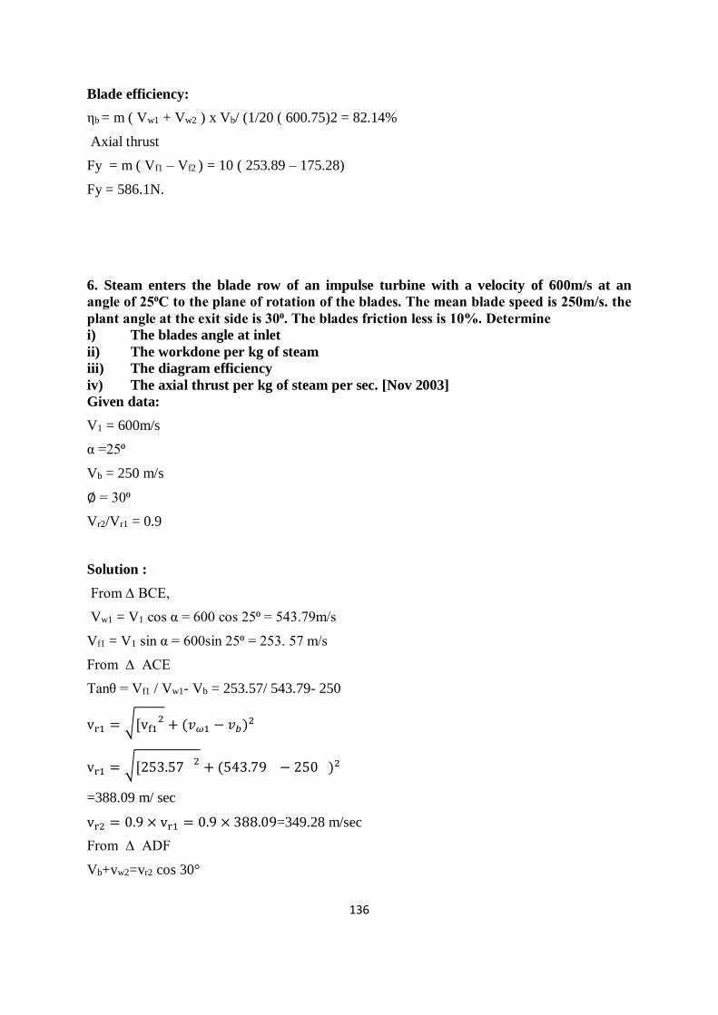
136
Blade efficiency:
ηb = m ( Vw1 + Vw2 ) x Vb/ (1/20 ( 600.75)2 = 82.14%
Axial thrust
Fy = m ( Vf1 – Vf2 ) = 10 ( 253.89 – 175.28)
Fy = 586.1N.
6. Steam enters the blade row of an impulse turbine with a velocity of 600m/s at an
angle of 25⁰C to the plane of rotation of the blades. The mean blade speed is 250m/s. the
plant angle at the exit side is 30⁰. The blades friction less is 10%. Determine
i) The blades angle at inlet
ii) The workdone per kg of steam
iii) The diagram efficiency
iv) The axial thrust per kg of steam per sec. [Nov 2003]
Given data:
V1 = 600m/s
α =25⁰
Vb = 250 m/s
∅ = 30⁰
Vr2/Vr1 = 0.9
Solution :
From ∆ BCE,
Vw1 = V1 cos α = 600 cos 25⁰ = 543.79m/s
Vf1 = V1 sin α = 600sin 25⁰ = 253. 57 m/s
From ∆ ACE
Tanθ = Vf1 / Vw1- Vb = 253.57/ 543.79- 250
vr1 = √[vf12 + (𝑣𝜔1 − 𝑣𝑏)
2
vr1 = √[253.57 2 + (543.79 − 250 )2
=388.09 m/ sec
vr2 = 0.9 × vr1 = 0.9 × 388.09=349.28 m/sec
From ∆ ADF
Vb+vw2=vr2 cos 30°
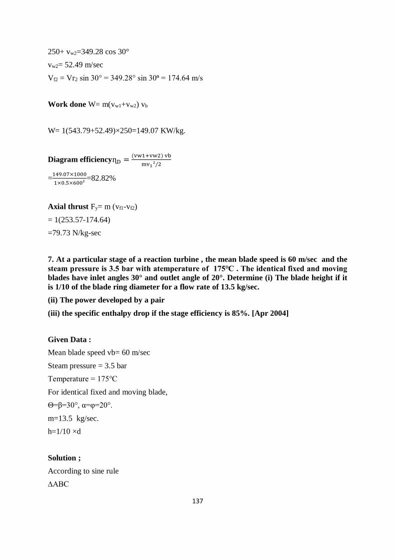
137
250+ vw2=349.28 cos 30°
vw2= 52.49 m/sec
Vf2 = Vr2 sin 30° = 349.28° sin 30⁰ = 174.64 m/s
Work done W= m(vw1+vw2) vb
W= 1(543.79+52.49)×250=149.07 KW/kg.
Diagram efficiencyɳD =(vw1+vw2) vb
mv1²/2
=149.07×1000
1×0.5×600²=82.82%
Axial thrust Fy= m (vf1-vf2)
= 1(253.57-174.64)
=79.73 N/kg-sec
7. At a particular stage of a reaction turbine , the mean blade speed is 60 m/sec and the
steam pressure is 3.5 bar with atemperature of 175℃ . The identical fixed and moving
blades have inlet angles 30° and outlet angle of 20°. Determine (i) The blade height if it
is 1/10 of the blade ring diameter for a flow rate of 13.5 kg/sec.
(ii) The power developed by a pair
(iii) the specific enthalpy drop if the stage efficiency is 85%. [Apr 2004]
Given Data :
Mean blade speed vb= 60 m/sec
Steam pressure = 3.5 bar
Temperature = 175℃
For identical fixed and moving blade,
Θ=β=30°, α=φ=20°.
m=13.5 kg/sec.
h=1/10 ×d
Solution ;
According to sine rule
∆ABC
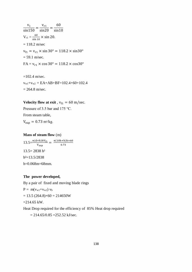
138
v1
sin150=
vr1
sin20=
60
sin10
Vr1 = 60
sin 10× sin 20.
= 118.2 m/sec
vf1 = vr1 × sin 30° = 118.2 × sin30°
= 59.1 m/sec.
FA = vr1 × cos30° = 118.2 × cos30°
=102.4 m/sec.
vw1+vw2 = EA+AB+BF=102.4+60+102.4
= 264.8 m/sec.
Velocity flow at exit , vf1 = 60 m/sec.
Pressure of 3.5 bar and 175 ℃.
From steam table,
Vsup = 0.73 mᶟ/kg.
Mass of steam flow (m)
13.5=π(d+h)hVf1
Vsup=
π(10h+h)h×60
0.73
13.5= 2838 h²
h²=13.5/2838
h=0.068m=68mm.
The power developed,
By a pair of fixed and moving blade rings
P = m(vw1+vw2) vb
= 13.5 (264.8)×60 = 214650W
=214.65 kW.
Heat Drop required for the efficiency of 85% Heat drop required
= 214.65/0.85 =252.52 kJ/sec.

Syllabus
Bell Coleman and vapour compression refrigeration systems, Performance calculations,
vapour absorption refrigeration system, Air conditioning systems and types, working
principle-Estimation of cooling load.
UNIT – 5 - REFRIGERATION AND AIR CONDITIONING SYSTEMS – SMEA1404
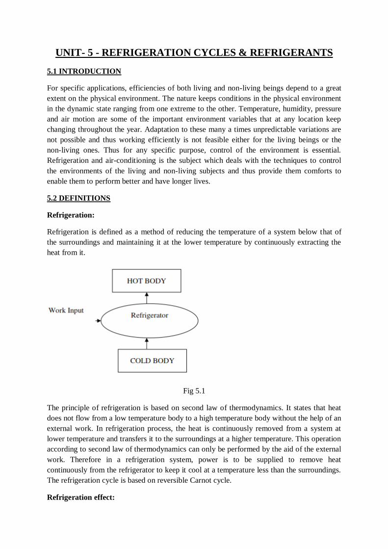
UNIT- 5 - REFRIGERATION CYCLES & REFRIGERANTS
5.1 INTRODUCTION
For specific applications, efficiencies of both living and non-living beings depend to a great
extent on the physical environment. The nature keeps conditions in the physical environment
in the dynamic state ranging from one extreme to the other. Temperature, humidity, pressure
and air motion are some of the important environment variables that at any location keep
changing throughout the year. Adaptation to these many a times unpredictable variations are
not possible and thus working efficiently is not feasible either for the living beings or the
non-living ones. Thus for any specific purpose, control of the environment is essential.
Refrigeration and air-conditioning is the subject which deals with the techniques to control
the environments of the living and non-living subjects and thus provide them comforts to
enable them to perform better and have longer lives.
5.2 DEFINITIONS
Refrigeration:
Refrigeration is defined as a method of reducing the temperature of a system below that of
the surroundings and maintaining it at the lower temperature by continuously extracting the
heat from it.
Fig 5.1
The principle of refrigeration is based on second law of thermodynamics. It states that heat
does not flow from a low temperature body to a high temperature body without the help of an
external work. In refrigeration process, the heat is continuously removed from a system at
lower temperature and transfers it to the surroundings at a higher temperature. This operation
according to second law of thermodynamics can only be performed by the aid of the external
work. Therefore in a refrigeration system, power is to be supplied to remove heat
continuously from the refrigerator to keep it cool at a temperature less than the surroundings.
The refrigeration cycle is based on reversible Carnot cycle.
Refrigeration effect:
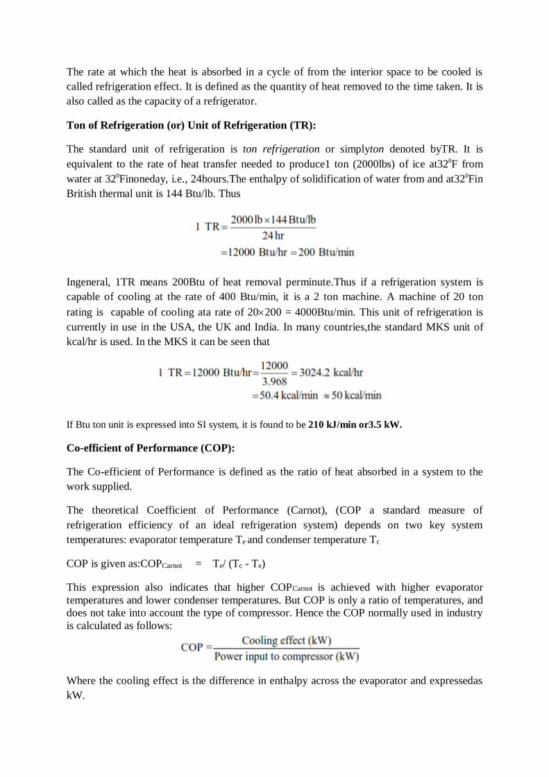
The rate at which the heat is absorbed in a cycle of from the interior space to be cooled is
called refrigeration effect. It is defined as the quantity of heat removed to the time taken. It is
also called as the capacity of a refrigerator.
Ton of Refrigeration (or) Unit of Refrigeration (TR):
The standard unit of refrigeration is ton refrigeration or simplyton denoted byTR. It is
equivalent to the rate of heat transfer needed to produce1 ton (2000lbs) of ice at320F from
water at 320Finoneday, i.e., 24hours.The enthalpy of solidification of water from and at320Fin
British thermal unit is 144 Btu/lb. Thus
Ingeneral, 1TR means 200Btu of heat removal perminute.Thus if a refrigeration system is
capable of cooling at the rate of 400 Btu/min, it is a 2 ton machine. A machine of 20 ton
rating is capable of cooling ata rate of 20200 = 4000Btu/min. This unit of refrigeration is
currently in use in the USA, the UK and India. In many countries,the standard MKS unit of
kcal/hr is used. In the MKS it can be seen that
If Btu ton unit is expressed into SI system, it is found to be 210 kJ/min or3.5 kW.
Co-efficient of Performance (COP):
The Co-efficient of Performance is defined as the ratio of heat absorbed in a system to the
work supplied.
The theoretical Coefficient of Performance (Carnot), (COP a standard measure of
refrigeration efficiency of an ideal refrigeration system) depends on two key system
temperatures: evaporator temperature Te and condenser temperature Tc
COP is given as:COPCarnot = Te/ (Tc - Te)
This expression also indicates that higher COPCarnot is achieved with higher evaporator
temperatures and lower condenser temperatures. But COP is only a ratio of temperatures, and
does not take into account the type of compressor. Hence the COP normally used in industry
is calculated as follows:
Where the cooling effect is the difference in enthalpy across the evaporator and expressedas
kW.

Ice making capacity:
It is the ability of the refrigeration system to make ice. In other words, it is the capacity of
refrigeration system to remove heat from water to make ice.
Relative COP:
It is the ratio of actual COP to the theoretical COP of a refrigerator.Actual COP is measured
during a test and theoretical COP is obtained by applying thelaws of thermodynamics.
5.3REFRIGERATOR AND HEAT PUMP
The vapor compression refrigeration cycle is a common method for transferring heat from a
low temperature to a high temperature.
Fig 5.2
The above figure shows the objectives of refrigerators and heat pumps. The purpose of a
refrigerator is the removal of heat, called the cooling load, from a low temperature medium.
The purpose of a heat pump is the transfer of heat to a high temperature medium, called the
heating load. When we are interested in the heat energy removed from a low temperature
space, the device is called a refrigerator. When we are interested in the heat energy supplied
to the high temperature space, the device is called a heat pump. In general, the term “heat
pump” is used to describe the cycle as heat energy is removed from the low temperature
space and rejected to the high temperature space.
The performance of refrigerators and heat pumps is expressed in terms of coefficient of
performance (COP), defined as
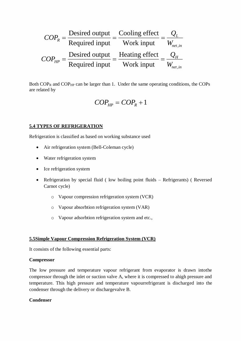
COPQ
W
COPQ
W
RL
net in
HPH
net in
Desired output
Required input
Cooling effect
Work input
Desired output
Required input
Heating effect
Work input
,
,
Both COPR and COPHP can be larger than 1. Under the same operating conditions, the COPs
are related by
COP COPHP R 1
5.4 TYPES OF REFRIGERATION
Refrigeration is classified as based on working substance used
Air refrigeration system (Bell-Coleman cycle)
Water refrigeration system
Ice refrigeration system
Refrigeration by special fluid ( low boiling point fluids – Refrigerants) ( Reversed
Carnot cycle)
o Vapour compression refrigeration system (VCR)
o Vapour absorbtion refrigeration system (VAR)
o Vapour adsorbtion refrigeration system and etc.,
5.5Simple Vapour Compression Refrigeration System (VCR)
It consists of the following essential parts:
Compressor
The low pressure and temperature vapour refrigerant from evaporator is drawn intothe
compressor through the inlet or suction valve A, where it is compressed to ahigh pressure and
temperature. This high pressure and temperature vapourrefrigerant is discharged into the
condenser through the delivery or dischargevalve B.
Condenser
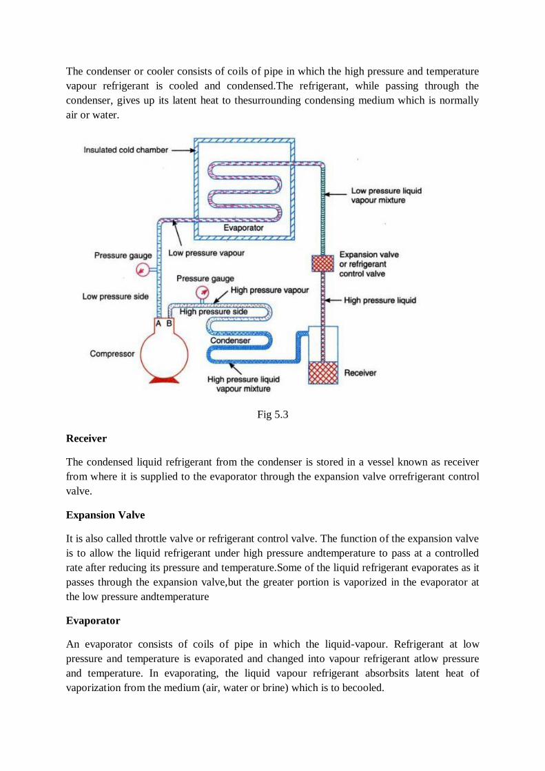
The condenser or cooler consists of coils of pipe in which the high pressure and temperature
vapour refrigerant is cooled and condensed.The refrigerant, while passing through the
condenser, gives up its latent heat to thesurrounding condensing medium which is normally
air or water.
Fig 5.3
Receiver
The condensed liquid refrigerant from the condenser is stored in a vessel known as receiver
from where it is supplied to the evaporator through the expansion valve orrefrigerant control
valve.
Expansion Valve
It is also called throttle valve or refrigerant control valve. The function of the expansion valve
is to allow the liquid refrigerant under high pressure andtemperature to pass at a controlled
rate after reducing its pressure and temperature.Some of the liquid refrigerant evaporates as it
passes through the expansion valve,but the greater portion is vaporized in the evaporator at
the low pressure andtemperature
Evaporator
An evaporator consists of coils of pipe in which the liquid-vapour. Refrigerant at low
pressure and temperature is evaporated and changed into vapour refrigerant atlow pressure
and temperature. In evaporating, the liquid vapour refrigerant absorbsits latent heat of
vaporization from the medium (air, water or brine) which is to becooled.

The Simple Vapor Compression Refrigeration Cycle
The vapor compression refrigeration cycle has four components: evaporator, compressor,
condenser, and expansion (or throttle) valve. The most widely used refrigeration cycle is the
vapor-compression refrigeration cycle. In an ideal or simple vapor-compression refrigeration
cycle, the refrigerant enters the compressor as a saturated vapor and is cooled to the saturated
liquid state in the condenser. It is then throttled to the evaporator pressure and vaporizes as it
absorbs heat from the refrigerated space.
The ideal vapor compression cycle consists of four processes.
Ideal Vapor-Compression Refrigeration Cycle
Process Description
1-2 Isentropic compression
2-3 Constant pressure heat rejection in the condenser
3-4 Throttling in an expansion valve
4-1 Constant pressure heat addition in the evaporator
Fig 5.4
The P-h diagram is another convenient diagram often used to illustrate the refrigeration cycle.
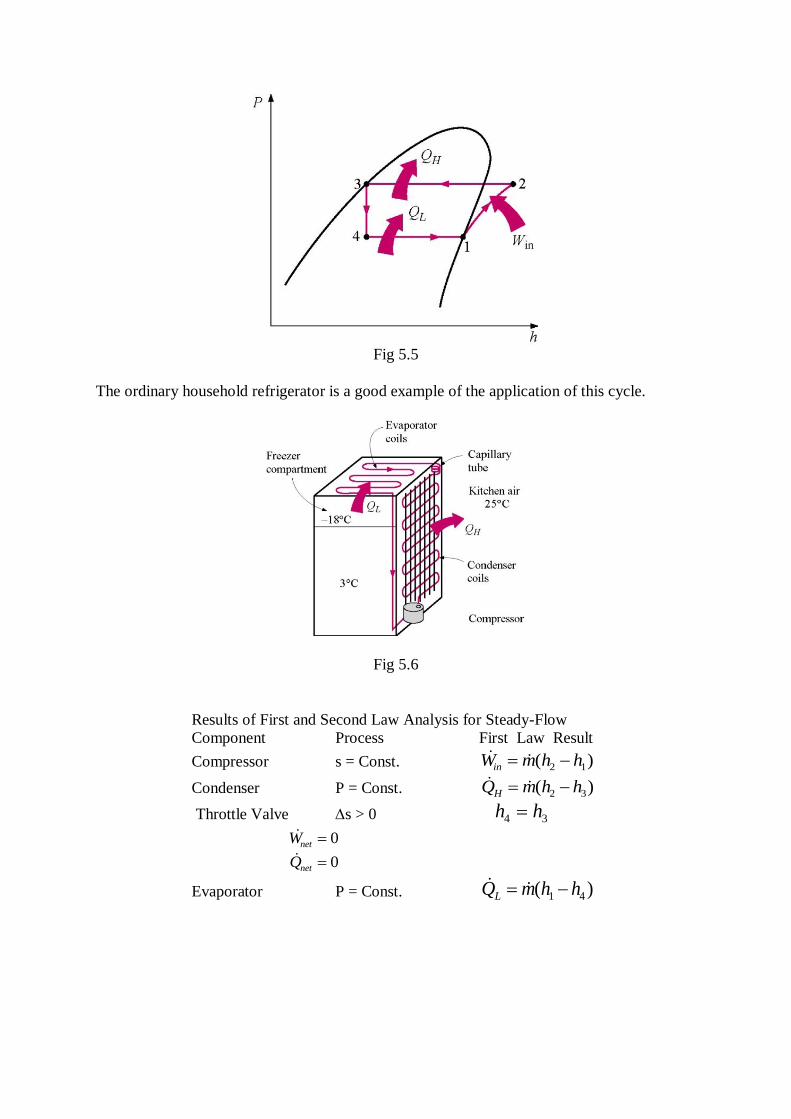
Fig 5.5
The ordinary household refrigerator is a good example of the application of this cycle.
Fig 5.6
Results of First and Second Law Analysis for Steady-Flow
Component Process First Law Result
Compressor s = Const. ( )W m h hin 2 1
Condenser P = Const. ( )Q m h hH 2 3
Throttle Valve s > 0 h h4 3
Wnet 0
Qnet 0
Evaporator P = Const. ( )Q m h hL 1 4
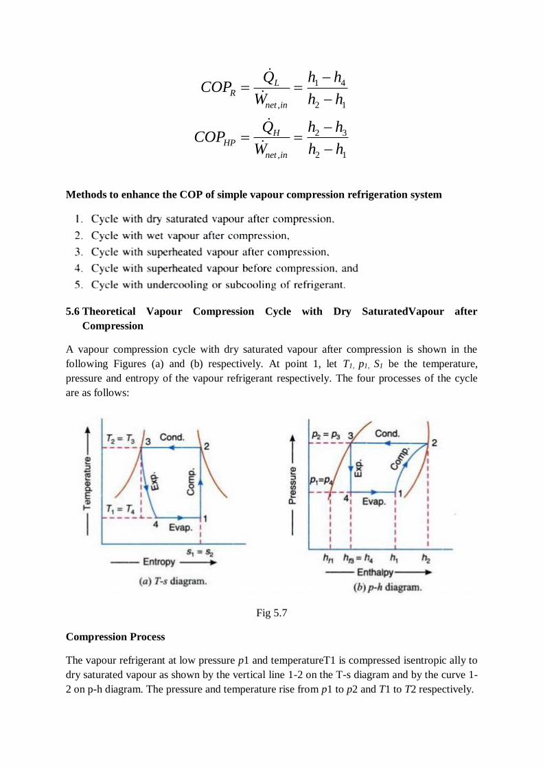
COPQ
W
h h
h h
COPQ
W
h h
h h
RL
net in
HPH
net in
,
,
1 4
2 1
2 3
2 1
Methods to enhance the COP of simple vapour compression refrigeration system
5.6 Theoretical Vapour Compression Cycle with Dry SaturatedVapour after
Compression
A vapour compression cycle with dry saturated vapour after compression is shown in the
following Figures (a) and (b) respectively. At point 1, let T1, p1, S1 be the temperature,
pressure and entropy of the vapour refrigerant respectively. The four processes of the cycle
are as follows:
Fig 5.7
Compression Process
The vapour refrigerant at low pressure p1 and temperatureT1 is compressed isentropic ally to
dry saturated vapour as shown by the vertical line 1-2 on the T-s diagram and by the curve 1-
2 on p-h diagram. The pressure and temperature rise from p1 to p2 and T1 to T2 respectively.
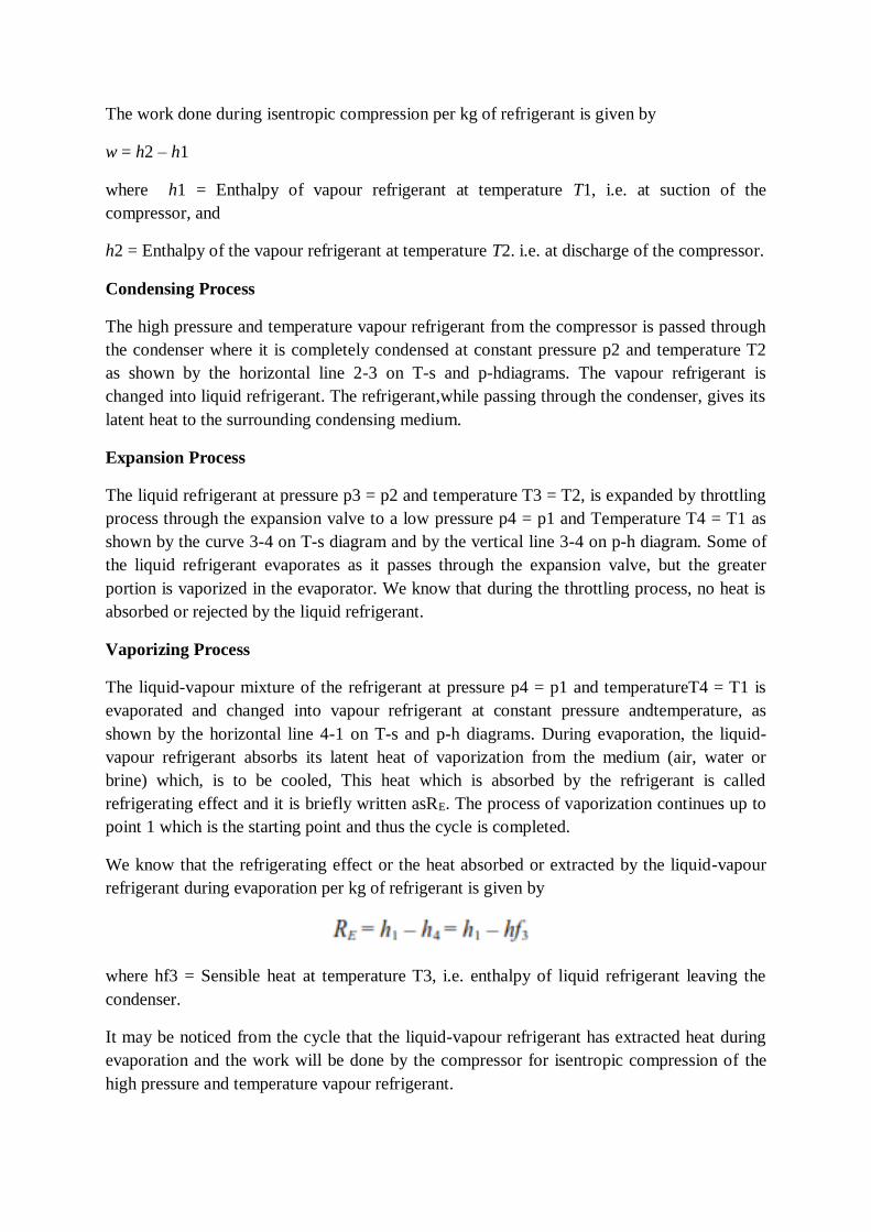
The work done during isentropic compression per kg of refrigerant is given by
w = h2 – h1
where h1 = Enthalpy of vapour refrigerant at temperature T1, i.e. at suction of the
compressor, and
h2 = Enthalpy of the vapour refrigerant at temperature T2. i.e. at discharge of the compressor.
Condensing Process
The high pressure and temperature vapour refrigerant from the compressor is passed through
the condenser where it is completely condensed at constant pressure p2 and temperature T2
as shown by the horizontal line 2-3 on T-s and p-hdiagrams. The vapour refrigerant is
changed into liquid refrigerant. The refrigerant,while passing through the condenser, gives its
latent heat to the surrounding condensing medium.
Expansion Process
The liquid refrigerant at pressure p3 = p2 and temperature T3 = T2, is expanded by throttling
process through the expansion valve to a low pressure p4 = p1 and Temperature T4 = T1 as
shown by the curve 3-4 on T-s diagram and by the vertical line 3-4 on p-h diagram. Some of
the liquid refrigerant evaporates as it passes through the expansion valve, but the greater
portion is vaporized in the evaporator. We know that during the throttling process, no heat is
absorbed or rejected by the liquid refrigerant.
Vaporizing Process
The liquid-vapour mixture of the refrigerant at pressure p4 = p1 and temperatureT4 = T1 is
evaporated and changed into vapour refrigerant at constant pressure andtemperature, as
shown by the horizontal line 4-1 on T-s and p-h diagrams. During evaporation, the liquid-
vapour refrigerant absorbs its latent heat of vaporization from the medium (air, water or
brine) which, is to be cooled, This heat which is absorbed by the refrigerant is called
refrigerating effect and it is briefly written asRE. The process of vaporization continues up to
point 1 which is the starting point and thus the cycle is completed.
We know that the refrigerating effect or the heat absorbed or extracted by the liquid-vapour
refrigerant during evaporation per kg of refrigerant is given by
where hf3 = Sensible heat at temperature T3, i.e. enthalpy of liquid refrigerant leaving the
condenser.
It may be noticed from the cycle that the liquid-vapour refrigerant has extracted heat during
evaporation and the work will be done by the compressor for isentropic compression of the
high pressure and temperature vapour refrigerant.
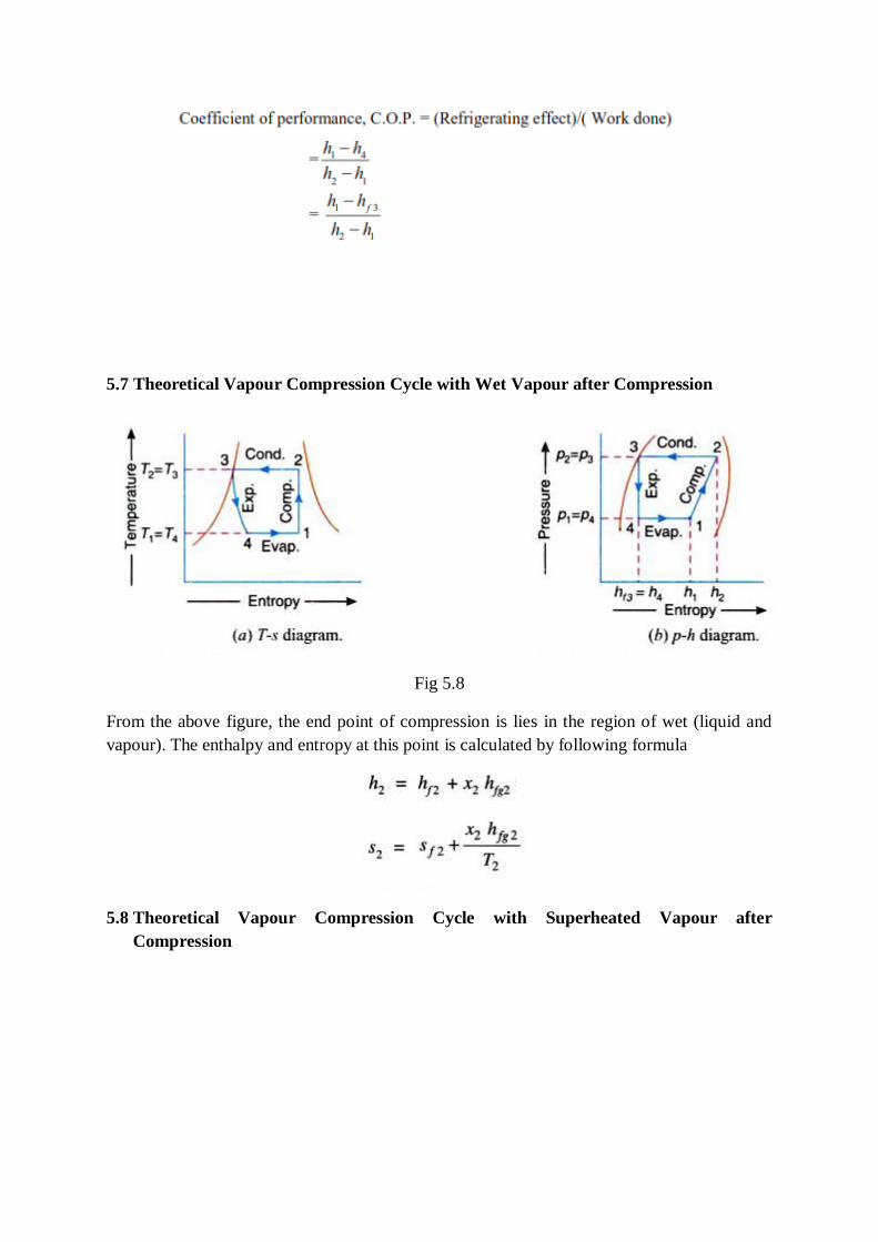
5.7 Theoretical Vapour Compression Cycle with Wet Vapour after Compression
Fig 5.8
From the above figure, the end point of compression is lies in the region of wet (liquid and
vapour). The enthalpy and entropy at this point is calculated by following formula
5.8 Theoretical Vapour Compression Cycle with Superheated Vapour after
Compression
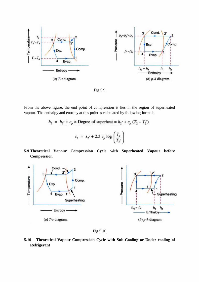
Fig 5.9
From the above figure, the end point of compression is lies in the region of superheated
vapour. The enthalpy and entropy at this point is calculated by following formula
5.9 Theoretical Vapour Compression Cycle with Superheated Vapour before
Compression
Fig 5.10
5.10 Theoretical Vapour Compression Cycle with Sub-Cooling or Under cooling of
Refrigerant
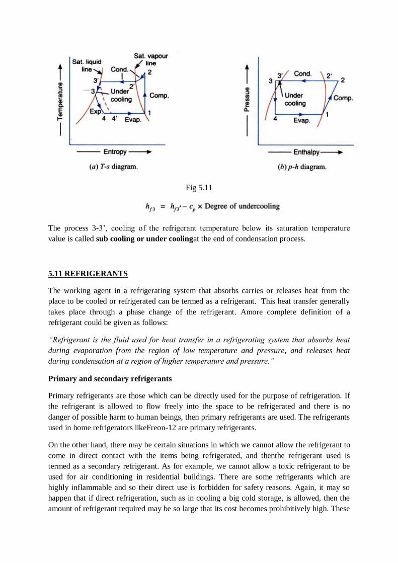
Fig 5.11
The process 3-3’, cooling of the refrigerant temperature below its saturation temperature
value is called sub cooling or under coolingat the end of condensation process.
5.11 REFRIGERANTS
The working agent in a refrigerating system that absorbs carries or releases heat from the
place to be cooled or refrigerated can be termed as a refrigerant. This heat transfer generally
takes place through a phase change of the refrigerant. Amore complete definition of a
refrigerant could be given as follows:
“Refrigerant is the fluid used for heat transfer in a refrigerating system that absorbs heat
during evaporation from the region of low temperature and pressure, and releases heat
during condensation at a region of higher temperature and pressure.”
Primary and secondary refrigerants
Primary refrigerants are those which can be directly used for the purpose of refrigeration. If
the refrigerant is allowed to flow freely into the space to be refrigerated and there is no
danger of possible harm to human beings, then primary refrigerants are used. The refrigerants
used in home refrigerators likeFreon-12 are primary refrigerants.
On the other hand, there may be certain situations in which we cannot allow the refrigerant to
come in direct contact with the items being refrigerated, and thenthe refrigerant used is
termed as a secondary refrigerant. As for example, we cannot allow a toxic refrigerant to be
used for air conditioning in residential buildings. There are some refrigerants which are
highly inflammable and so their direct use is forbidden for safety reasons. Again, it may so
happen that if direct refrigeration, such as in cooling a big cold storage, is allowed, then the
amount of refrigerant required may be so large that its cost becomes prohibitively high. These

are some typical situations for which we favor the use of secondary refrigerants. Water and
brine solutions are common examples of secondary refrigerants.
5.12Classification of refrigerants
Refrigerants can be broadly classified based on the following:
Working Principle
Under this heading, we have the primary or common refrigerants and the secondary
refrigerants.
The primary refrigerants are those that pass through the processes of compression, cooling or
condensation, expansion and evaporation or warming up during cyclic processes. Ammonia,
R12, R22, carbon dioxide come under this class of refrigerants. On the other hand, the
medium which does not go through the cyclic processes in a refrigeration system and is only
used as a medium for heat transfer are referred to as secondary refrigerants. Water, brine
solutions of sodium chloride and calcium chloride come under this category.
Safety Considerations
Under this heading, we have the following three sub-divisions.
Safe refrigerants
These are the non-toxic, non-flammable refrigerants such as R11, R12, R13, R14, R21, R22,
R113, R114, methyl chloride, carbon dioxide, water etc.
Toxic and moderately flammable
Dichloroethylene methyl format, ethylchloride, sulphur dioxide, ammonia etc. come under
this category.
Highly flammable refrigerants
The refrigerants under this category are butane, isobutene, propane, ethane, methane,
ethylene etc.
Chemical Compositions
Halocarbon compounds
These are obtained by replacing one or more hydrogen atoms in ethane or methane with
alogens.
Azeotropes
These are the mixtures of two or more refrigerants and behave as a compound.
Oxygen and Nitrogen Compounds
Refrigerants having either oxygen or nitrogen molecules in their structure, such as ammonia,
are grouped separately and have a separate nomenclature from the halogenated refrigerants.
Cyclic organic Compounds
The compounds coming under this class are R316, R317 and R318.
Inorganic Compounds
These are further divided into two categories: Cryogenic and Non-cryogenic. Cryogenic
fluids are those which are applied for achieving temperatures as low as – 160 0C to – 273 0C.
Above this temperature range, we can use a multi-stage refrigeration system to realise the
desired temperature. But below – 1600C, this is not possible since the COP of the cycle
becomes very low. To attain temperatures below –160 0C, we use refrigerants such as
nitrogen, oxygen, helium, hydrogen etc. and for temperatures close to – 2730C, magnetic
cooling is employed. The inorganic compounds which are employed above the cryogenic
temperature ranges come under the remaining sub-division of inorganic refrigerants.
Unsaturated Compounds
Compounds such as ethylene, propylene etc., are grouped under this head and grouped under
the 1000 series for convenience.
Miscellaneous
This group contains those compounds which cannot be grouped under the other components.
They are indicated by the 700 series with the last numbers being their molecular weight.
Examples include air, carbon dioxide, sulphur dioxide etc. As we can see from the above sub-
divisions, they are not mutually exclusive. A compound may come under more than one sub-
division. Hence, the importance of adopting the various naming conventions to designate the
different refrigerants cannot be underestimated.
5.13 Designation of refrigerants
The American Society of Refrigerating Engineers (ASRE) has developed certain conventions
for use in naming different types of refrigerants. These naming conventions differ according
to the type of refrigerant. Each refrigerant type is denoted by a different series. Thus, we have
separate series for halogenated refrigerants and other types. The naming conventions are
simple and easy to follow. These conventions are now accepted worldwide and help to name
the large variety of refrigerants available commercially nowadays.
Halocarbon Compounds
These are represented by a three digit nomenclature. Here, the first digit represents the
number of carbon atoms in the compound minus one, the second digit stands for the number
of hydrogen atoms plus one while thethird digit stands for the number of fluorine atoms. The
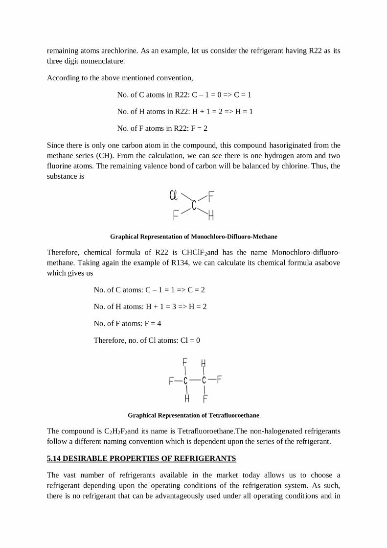
remaining atoms arechlorine. As an example, let us consider the refrigerant having R22 as its
three digit nomenclature.
According to the above mentioned convention,
No. of C atoms in R22: C – 1 = 0 => C = 1
No. of H atoms in R22: H + 1 = 2 => H = 1
No. of F atoms in R22: F = 2
Since there is only one carbon atom in the compound, this compound hasoriginated from the
methane series (CH). From the calculation, we can see there is one hydrogen atom and two
fluorine atoms. The remaining valence bond of carbon will be balanced by chlorine. Thus, the
substance is
Graphical Representation of Monochloro-Difluoro-Methane
Therefore, chemical formula of R22 is CHClF2and has the name Monochloro-difluoro-
methane. Taking again the example of R134, we can calculate its chemical formula asabove
which gives us
No. of C atoms: C – 1 = 1 => C = 2
No. of H atoms: H + 1 = 3 => H = 2
No. of F atoms: F = 4
Therefore, no. of Cl atoms: Cl = 0
Graphical Representation of Tetrafluoroethane
The compound is C2H2F2and its name is Tetrafluoroethane.The non-halogenated refrigerants
follow a different naming convention which is dependent upon the series of the refrigerant.
5.14 DESIRABLE PROPERTIES OF REFRIGERANTS
The vast number of refrigerants available in the market today allows us to choose a
refrigerant depending upon the operating conditions of the refrigeration system. As such,
there is no refrigerant that can be advantageously used under all operating conditions and in
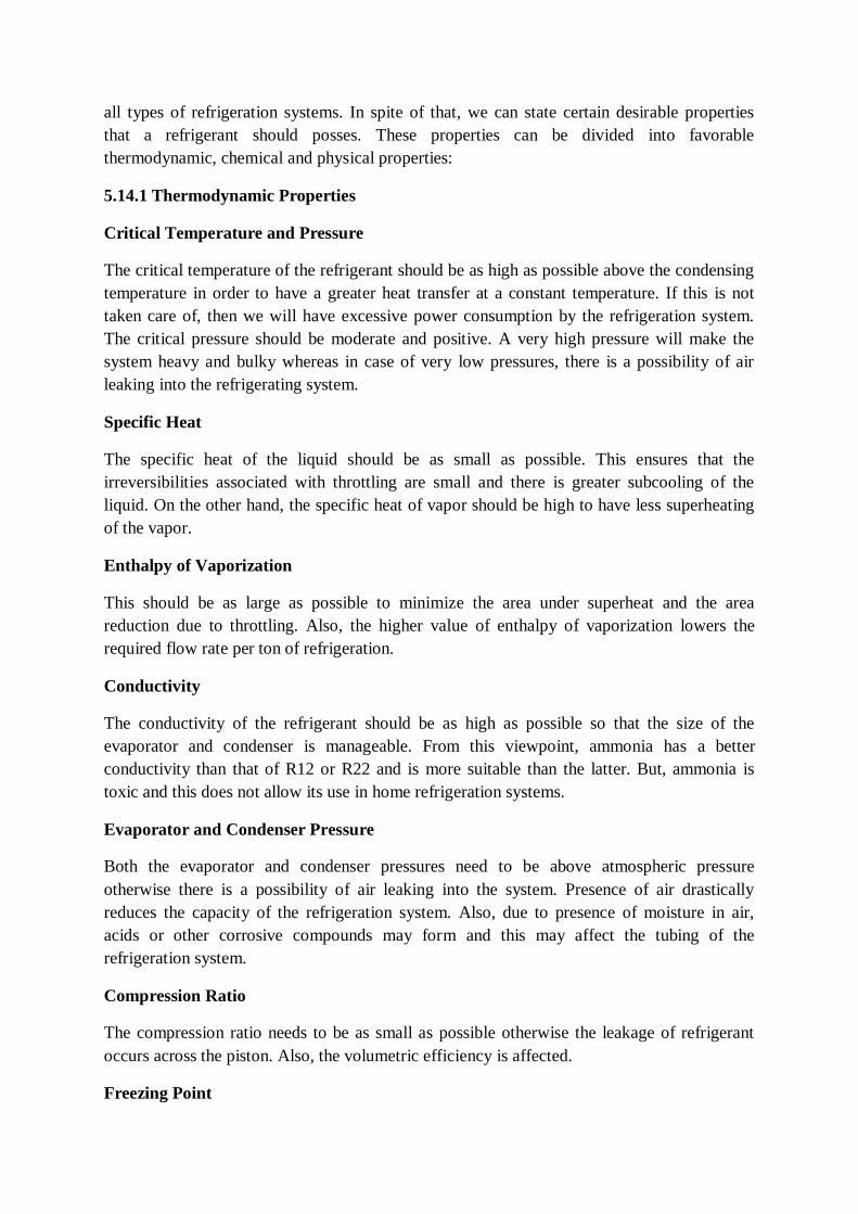
all types of refrigeration systems. In spite of that, we can state certain desirable properties
that a refrigerant should posses. These properties can be divided into favorable
thermodynamic, chemical and physical properties:
5.14.1 Thermodynamic Properties
Critical Temperature and Pressure
The critical temperature of the refrigerant should be as high as possible above the condensing
temperature in order to have a greater heat transfer at a constant temperature. If this is not
taken care of, then we will have excessive power consumption by the refrigeration system.
The critical pressure should be moderate and positive. A very high pressure will make the
system heavy and bulky whereas in case of very low pressures, there is a possibility of air
leaking into the refrigerating system.
Specific Heat
The specific heat of the liquid should be as small as possible. This ensures that the
irreversibilities associated with throttling are small and there is greater subcooling of the
liquid. On the other hand, the specific heat of vapor should be high to have less superheating
of the vapor.
Enthalpy of Vaporization
This should be as large as possible to minimize the area under superheat and the area
reduction due to throttling. Also, the higher value of enthalpy of vaporization lowers the
required flow rate per ton of refrigeration.
Conductivity
The conductivity of the refrigerant should be as high as possible so that the size of the
evaporator and condenser is manageable. From this viewpoint, ammonia has a better
conductivity than that of R12 or R22 and is more suitable than the latter. But, ammonia is
toxic and this does not allow its use in home refrigeration systems.
Evaporator and Condenser Pressure
Both the evaporator and condenser pressures need to be above atmospheric pressure
otherwise there is a possibility of air leaking into the system. Presence of air drastically
reduces the capacity of the refrigeration system. Also, due to presence of moisture in air,
acids or other corrosive compounds may form and this may affect the tubing of the
refrigeration system.
Compression Ratio
The compression ratio needs to be as small as possible otherwise the leakage of refrigerant
occurs across the piston. Also, the volumetric efficiency is affected.
Freezing Point
It should be as low as possible or else there will be a possibility of blockage of passages
during flow of fluid through evaporator.
Volume of Refrigerant Handled Per Ton of Refrigeration
This should be as small as possible in order to have a small size of the compressor. The type
of compressor is decided by this value. Forrefrigerants like R12, R500, R22 etc., a
reciprocating compressor is suitable. For others like R11 and water, a centrifugal compressor
is required to handle the large volume.
Coefficient of Performance
The Coefficient of performance or COP has a direct bearing on the running cost of the
refrigeration system. Higher the magnitude of COP, lower will be the running cost. Since, the
COP of any refrigeration system is limited by the Carnot COP, for large operating pressures a
multi-stage refrigeration system should be employed. CO2has a very low COP. Hence, it is
not suitable for use as a refrigerant.
Density
The density of the refrigerant should be as large as possible. In reciprocating compressors, the
pressure rise is accomplished by squeezing the entrapped fluid inside the piston-cylinder
assembly. Hence, densitydecides the size of the cylinder. Again in centrifugal compressors
pressurerise is related to the density of the vapor. A high value of density results in high
pressure rise.
Compression Temperature
Whenever a refrigerant gets compressed, there is a rise in the temperature of the refrigerant
resulting in the heating of the cylinder walls of the compressor. This necessitates external
cooling of the cylinder walls to prevent volumetric and material losses. Refrigerants having
lowest compression temperatures are thus better than others.
5.14.2 Chemical Properties
Chemical Stability and Inertness
It should be chemically stable for the operating ranges of temperature. Also, it should not
react with the materials of the refrigeration system or with which it comes into contact.
Further, it should be chemically inert and must not undergo polymerization reactions at either
the lower or higher ranges of temperatures.
Action on Rubber or Plastics
Rubber and plastics are used extensively in the refrigeration system. These materials are
mostly used in the seals and gaskets of the refrigeration system. They help to prevent the
leakage of the refrigerant and ensure the smooth functioning of the compressor. The

refrigerant should not react with them or else there might be leakage of refrigerant from the
system or loss of functioning of the compressor.
Flammability
The refrigerant should be inert and not catch fire when subjected to high temperatures. From
this viewpoint CO2is the most suitable as it is not onlynon-flammable, but also acts as a fire-
extinguisher. Ethane, butane,isobutene are highly undesirable as they catch fire quickly.
Effect on Oil
The refrigerant should not react with the lubricating oil else, there is a possibility of loss of
lubricating action due to either thickening or thinning of the oil. It should not be soluble in
the oil else there will be reduction in the viscosity of the lubricating oil.
Effect on Commodity
If the refrigerant is directly used for chilling, then it should not affect the commodity kept in
the conditioned space. Also, in case where direct cooling is not employed, the refrigerant
should still not affect the commodity if there is any leakage.
Toxicity
The refrigerant used in air conditioning, food preservation etc. should not be toxic as they
will come into contact with human beings.
5.14.3 Physical Properties
Leakage and Detection
Since pressures higher than atmospheric are usually employed in refrigeration systems, there
is a possibility of leakage of refrigerants after long period of operation. It is desirable to
detect this leak early else the system would operate under reduced capacity or stop
functioning altogether. Hence, it is desirable that the refrigerant has a pungent smell so that
its leakage can be detected immediately.
Miscibility with Oil
The refrigerant should not be miscible with the oil else the lubricating strength will be
reduced.
Viscosity
It should be as small as possible to ensure that the pressure drop in the system is as small as
possible. A low viscosity refrigerant will require less energy for its circulation through the
refrigeration system.
5.14.4 Safety Criteria
Under safety criteria, we consider the toxicity, flammability, action on perishablefood and
formation of explosive compound on exposure to air. An ideal refrigerant should be non-
toxic, non-flammable, have no effect on food product sand should not react with atmospheric
air. No refrigerant satisfy these criteria fully. We can therefore, group refrigerants into
different sub-groups based on their flammability and toxicity levels.
5.14.5 Economic Criteria
Apart from the thermodynamic, chemical, physical and safety criteria, there is another
criterion by which we judge an ideal refrigerant. The economic criterion takes into account
the cost of the refrigerant, the availability and supply levels of the refrigerant, cost of storage
and handling. We discuss each of these in detail below.
Cost of Refrigerant
The cost of the refrigerant has a big impact on the overall cost of the refrigeration system.
Hence, its cost should be as low as possible. From this view point, ammonia and water are
ideally suited, but their low thermodynamic and chemical properties restrict their use in all
types ofrefrigeration systems. Particularly, for flooded type evaporator or condenser, the
refrigerant amount required is high and their cost needs to be factored in while making the
initial investments.
Availability and Supply
The refrigerant should be easily available in the market and in abundant quantity. This
ensures that the cost of the refrigerant is not prohibitive. Anabundant and free supply of the
refrigerant ensures that refrigeration systems will be designed specifically for use with them.
Storage and Handling
The refrigerant should be such that it can be conveniently stored and handled during
transportation and charging. It should be stored in as small a pressure vessel as possible.
Also, if we have to handle a toxic or flammable refrigerant, then the cost involved will be
higher compared to handling and storage cost of non-toxic and non-flammable refrigerant.
5.15 COMMON REFRIGERANTS
The refrigerants which are available commercially in the market are numerous. Some of them
which are in common use are mentioned below:
Air
Air (molecular weight 28.97, specific heats Cp = 1.04 kJ/kgK and Cv = 0.712kJ/kg-K) is one
of the earliest refrigerant to be used in the refrigeration systems. Its advantages are that it is
available free of cost, is non-toxic and non-flammable and does not affect the commodity if
pure. However, airsuffers from a number of drawbacks. Air contains moisture and this reacts
with the material of the evaporator and condenser severely affecting their working capacity.
Further, there is a possibility that the passages may be blocked by the formation of ice from
this moisture. The COP of air is of the order of 0.6 and thus, not suitable for use in
refrigeration systems on a commercial scale. It is mainly used for air conditioning in aircrafts
where efficiency of operation is of secondary importance.
Ammonia
Ammonia (molecular weight 17) is one of the oldest refrigerants and it was commonly
employed in places where toxicity effects were of secondary importance. Its advantages are
its low cost, low specific volume, high COP(of the order of 4.0) and high refrigeration effect
per unit mass of the refrigerant. Its primary drawback is its toxicity which prevents its use in
airconditioning and food preservationsystems. Ammoniahasa boilingpointof-330C at
atmospheric pressure.
Carbon Dioxide
Carbon dioxide (molecular weight 44) is a non-toxic and non-poisonous refrigerant. Also, it
is not only non-flammable but and is an excellent extinguishing agent as well. Its other
advantages are that it is chemically stable, immiscible with the lubricating oil and does not
affect the metal used in the system. It has a low specific volume and this requires volume
displacement per ton of refrigeration. However, its critical pressure is too high. Also, its
critical temperature is only 310C which makes it unsuitable for use in countries with a hot
climate like India. It is an excellent refrigerant for low temperature refrigeration.
Sulphur Dioxide
Sulphur dioxide (molecular weight 64) is a colourless, suffocating and irritating gas and is
twice as heavy as air at atmospheric conditions. It was mostly used as a household refrigerant
in the older days, but has since been discarded for better refrigerants. It suffers from a lot of
disadvantages. Sulphur dioxide reacts with water forming sulphurous acid, which inpresence
of oxygen becomes sulphuric acid, a corrosive compound for metals. It is non-flammable but
attacks foodstuff on coming in contact with it. It is also partially miscible with the lubricating
oil.
Hydrocarbons
This group consists of colourless fluids normally in gaseous state and made up of various
combinations of carbon and hydrogen. Most of the refrigerants from this category are suitable
for low temperature refrigeration. Isobutane falls in this category and has been suitable for
domestic refrigeration. They are non-poisonous, but are flammable and highly explosive
when exposed to air. The molecular weight and boiling point of each gas varies according to
the number of hydrogen and carbon atoms. The larger the number of hydrogen and carbon
atoms, the heavier isthe gas and higher is its boiling point.
Halocarbon Refrigerants
The halocarbon refrigerants are formed by replacing one or more of hydrogen atoms of
methane or ethane by one or more atoms of the three halogens: fluorine, chlorine or bromine.
Some of the refrigerants coming under this category are mentioned below:
Refrigerant R12
The refrigerant R12 is the most widely used refrigerant in the domestic and large commercial
establishments. Its chemical formula is CCl2F2 and its boiling point is -300C at 1 bar. It is a
non-flammable,non-explosive, non-irritating, non-toxic and odourless refrigerant. It remains
chemically stable up to 5500C. Also, it does not affect the material of the refrigeration
system. It is available in abundance and is quite cheap. However, its use is being discontinued
nowadays for its contribution to ozone depletion which will be discussed later.
Refrigerant R13
Its chemical formula is CClF3. It is a non-flammable, non-toxic and stable refrigerant. It is
very suitable for achieving low temperatures in a cascade refrigeration system. Its specific
volume is high and therefore, it is suitable for centrifugal compressors. However, it also has a
negative effect on ozone depletion.
Refrigerant R22
Its chemical formula is CHClF2. It is also a non-toxic, non-flammable, non-corrosive and
non-irritating refrigerant. It is the most common refrigerant for use in large refrigeration
systems and is preferred toR12.
Refrigerant R114
Its chemical formula is C2Cl2F4. Its boiling point corresponding to 1bar is about 30C. It has
properties very similar to those of R12 with respect to water and oil combination. It is not
suitable for low temperature refrigeration since it has negative evaporator pressure even at
around 90C. It is non-toxic, non-explosive and non-corrosive even in the presence of water.
All refrigerants properties can be referred from standard refrigeration tables. Some refrigerant
properties are listed below
5.16 VAPOUR ABSORPTION SYSTEM
Introduction
In a vapour absorption system the refrigerant is absorbed on leaving the evaporator, the
absorbing medium being a solid or liquid. In order that the sequence of events should be
continuous it is necessary for the refrigerant to be separated from the absorbent and
subsequently condensed before being returned to the evaporator. The separation is
accomplished by the application of direct heat in a ‘generator’. The solubility of the
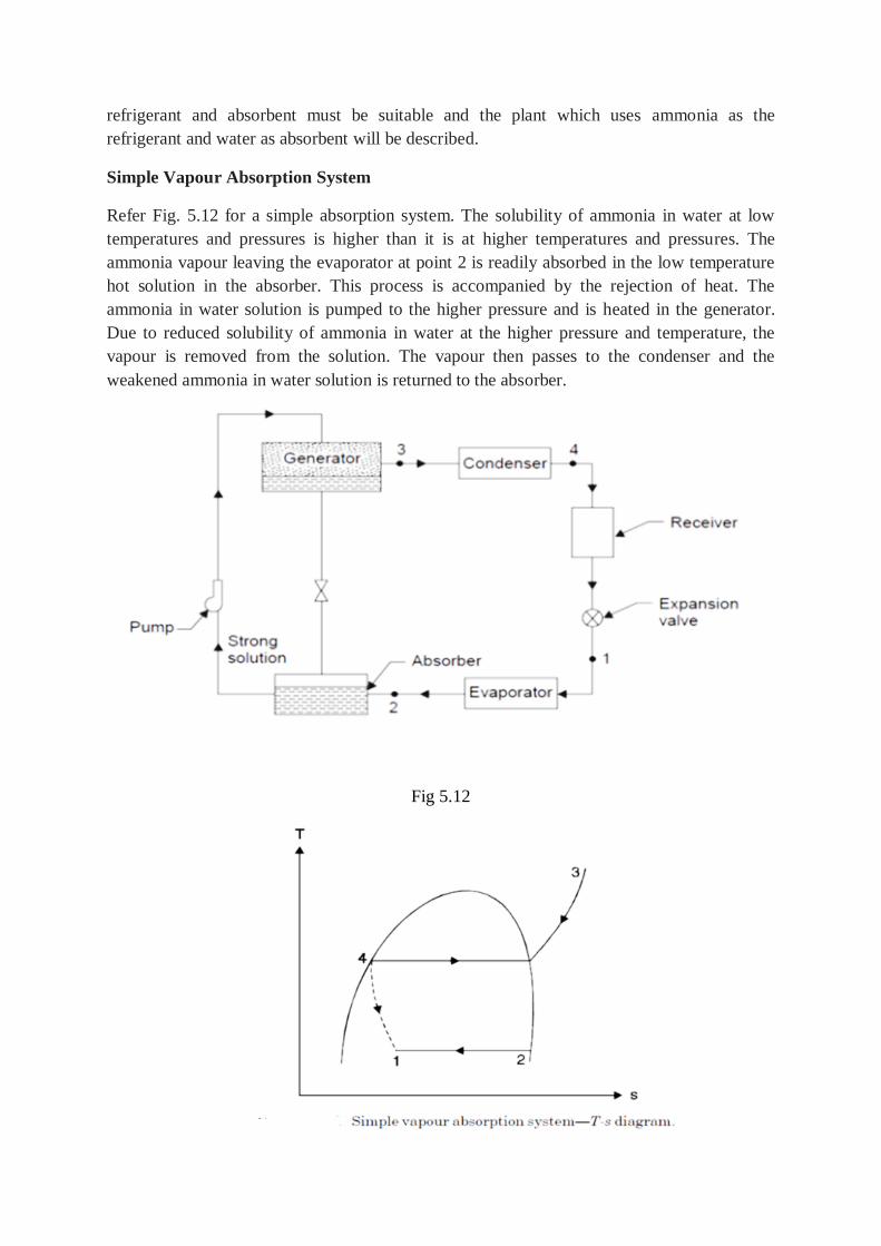
refrigerant and absorbent must be suitable and the plant which uses ammonia as the
refrigerant and water as absorbent will be described.
Simple Vapour Absorption System
Refer Fig. 5.12 for a simple absorption system. The solubility of ammonia in water at low
temperatures and pressures is higher than it is at higher temperatures and pressures. The
ammonia vapour leaving the evaporator at point 2 is readily absorbed in the low temperature
hot solution in the absorber. This process is accompanied by the rejection of heat. The
ammonia in water solution is pumped to the higher pressure and is heated in the generator.
Due to reduced solubility of ammonia in water at the higher pressure and temperature, the
vapour is removed from the solution. The vapour then passes to the condenser and the
weakened ammonia in water solution is returned to the absorber.
Fig 5.12
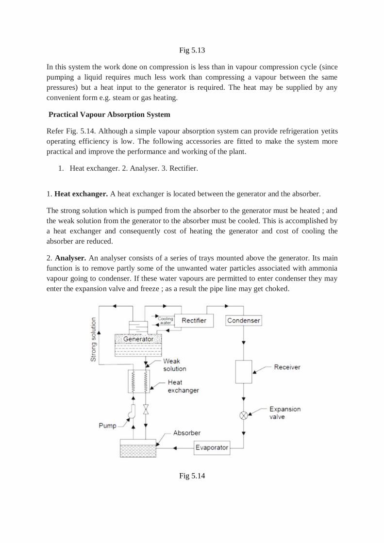
Fig 5.13
In this system the work done on compression is less than in vapour compression cycle (since
pumping a liquid requires much less work than compressing a vapour between the same
pressures) but a heat input to the generator is required. The heat may be supplied by any
convenient form e.g. steam or gas heating.
Practical Vapour Absorption System
Refer Fig. 5.14. Although a simple vapour absorption system can provide refrigeration yetits
operating efficiency is low. The following accessories are fitted to make the system more
practical and improve the performance and working of the plant.
1. Heat exchanger. 2. Analyser. 3. Rectifier.
1. Heat exchanger. A heat exchanger is located between the generator and the absorber.
The strong solution which is pumped from the absorber to the generator must be heated ; and
the weak solution from the generator to the absorber must be cooled. This is accomplished by
a heat exchanger and consequently cost of heating the generator and cost of cooling the
absorber are reduced.
2. Analyser. An analyser consists of a series of trays mounted above the generator. Its main
function is to remove partly some of the unwanted water particles associated with ammonia
vapour going to condenser. If these water vapours are permitted to enter condenser they may
enter the expansion valve and freeze ; as a result the pipe line may get choked.
Fig 5.14
3. Rectifier. A rectifier is a water-cooled heat exchanger which condenses water vapour and
some ammonia and sends back to the generator. Thus final reduction or elimination of the
percentage of water vapour takes place in a rectifier. The co-efficient of performance
(C.O.P.) of this system is given by :
5.17 PSYCHROMETRY AND AIR – CONDITIONING
Psychrometric properties, Use of psychrometric chart, Psychrometric process – Sensible heat
exchange process, Latent heat exchange process, Adiabatic mixing, Evaporative cooling,
Property calculations of air-vapour mixtures.
Principles of air-conditioning, Types of air conditioning systems – summer, winter, year
round air conditioners, Concept of RSHF, GSHF, ESHF, Simple problems.
5.17.1 CONCEPT OF PSYCHROMETRY AND PSYCHROMETRICS
Air comprises of fixed gases principally, nitrogen and oxygen with an admixture of water
vapour in varying amounts. In atmospheric air water is always present and its relative weight
averages less than 1% of the weight of atmospheric air in temperate climates and less than
3% by weight under the most extreme natural climatic conditions, it is nevertheless one of
most important factors in human comfort and has significant effects on many materials. Its
effect on human activities is in fact altogether disproportionate to its relative weights. The art
of measuring the moisture content of air is termed “psychrometry”. The science which
investigates the thermal properties of moist air, considers the measurement and control of the
moisture content of air, and studies the effect of atmospheric moisture on material and
human comfort may properly be termed “psychrometrics’’.
DEFINITIONS
Some of the more important definitions are given below :
1. Dry air. The international joint committee on Psychrometric Data has adopted the
following exact composition of air expressed in mole fractions (Volumetric) Oxygen 0.2095,
Nitrogen 0.7809, Argon 0.0093, Carbon dioxide 0.0003. Traces of rare gases are neglected.
Molecular weight of air for all air conditioning calculations will be taken as 28.97. Hence the
gas constant, Rair = 0.287 kJ/kg K Dry air is never found in practice. Air always contains
some moisture. Hence the common designation “air” usually means moist air. The term ‘dry
air’ is used to indicate the water free contents of air having any degree of moisture.
2. Saturated air. Moist air is said to be saturated when its condition is such that it can co-
exist in natural equilibrium with an associated condensed moisture phase presenting a flat
surface to it. For a given temperature, a given quantity of air can be saturated with a fixed
quantity of moisture. At higher temperatures, it requires a larger quantity of moisture to
saturate it. At saturation, vapour pressure of moisture in air corresponds to the saturation
pressure given in steam tables corresponding to the given temperature of air.
3. Dry-bulb temperature (DBT). It is the temperature of air as registered by an ordinary
thermometer (tdb).
4. Wet-bulb temperature (WBT). It is the temperature registered by a thermometer when
the bulb is covered by a wetted wick and is exposed to a current of rapidly moving air (twb).
5. Adiabatic saturation temperature. It is the temperature at which the water or ice can
saturate air by evaporating adiabatically into it. It is numerically equivalent to the measured
wet bulb temperature (as corrected, if necessary for radiation and conduction) (twb).
6. Wet bulb depression. It is the difference between dry-bulb and wet bulb temperatures (tdb
– twb).
7. Dew point temperature (DPT). It is the temperature to which air must be cooled at
constant pressure in order to cause condensation of any of its water vapour. It is equal to
steam table saturation temperature corresponding to the actual partial pressure of water
vapour in the air (tdp).
8. Dew point depression. It is the difference between the dry bulb and dew point
temperatures (tdb – tdp).
9. Specific humidity (Humidity ratio). It is the ratio of the mass of water vapour per unit
mass of dry air in the mixture of vapour and air, it is generally expressed as grams of water
per kg of dry air. For a given barometric pressure it is a function of dew point temperature
alone.
10. Relative humidity (RH), (φ). It is the ratio of the partial pressure of water vapour in the
mixture to the saturated partial pressure at the dry bulb temperature, expressed as
percentage.
11. Sensible heat. It is the heat that changes the temperature of a substance when added
to or abstracted from it.
12. Latent heat. It is the heat that does not affect the temperature but changes the state
of substance when added to or abstracted from it.
13. Enthalpy. It is the combination energy which represents the sum of internal and flow
energy in a steady flow process. It is determined from an arbitrary datum point for the air
mixture and is expressed as kJ per kg of dry air (h).
Note. When air is saturated DBT, WBT, DPT are equal.
5.17.2 PSYCHROMETRIC RELATIONS
Pressure
Dalton’s law of partial pressure is employed to determine the pressure of a mixture of gases.
This law states that the total pressure of a mixture of gases is equal to the sum of partial
pressures which the component gases would exert if each existed alone in the mixture volume
at the mixture temperature. Precise measurements made during the last few years indicate that
this law as well as Boyle’s and Charle’s laws are only approximately correct. Modern tables
of atmospheric air properties are based on the correct versions. For calculating partial
pressure of water vapour in the air many equations have been proposed, probably Dr.
Carrier’s equation is most widely used.
5.18 PSYCHROMETRIC CHARTS
The psychrometric charts are prepared to represent graphically all the necessary moist air
properties used for air conditioning calculations. The values are based on actual
measurements verified for thermodynamic consistency. For psychrometric charts the most
convenient co-ordinates are dry bulb temperature of air vapour mixture as the abcissa and
moisture content (kg/kg of dry air) or water vapour pressure as the ordinate. Depending upon
whether the humidity contents is abcissa or ordinate with temperature co-ordinate, the charts
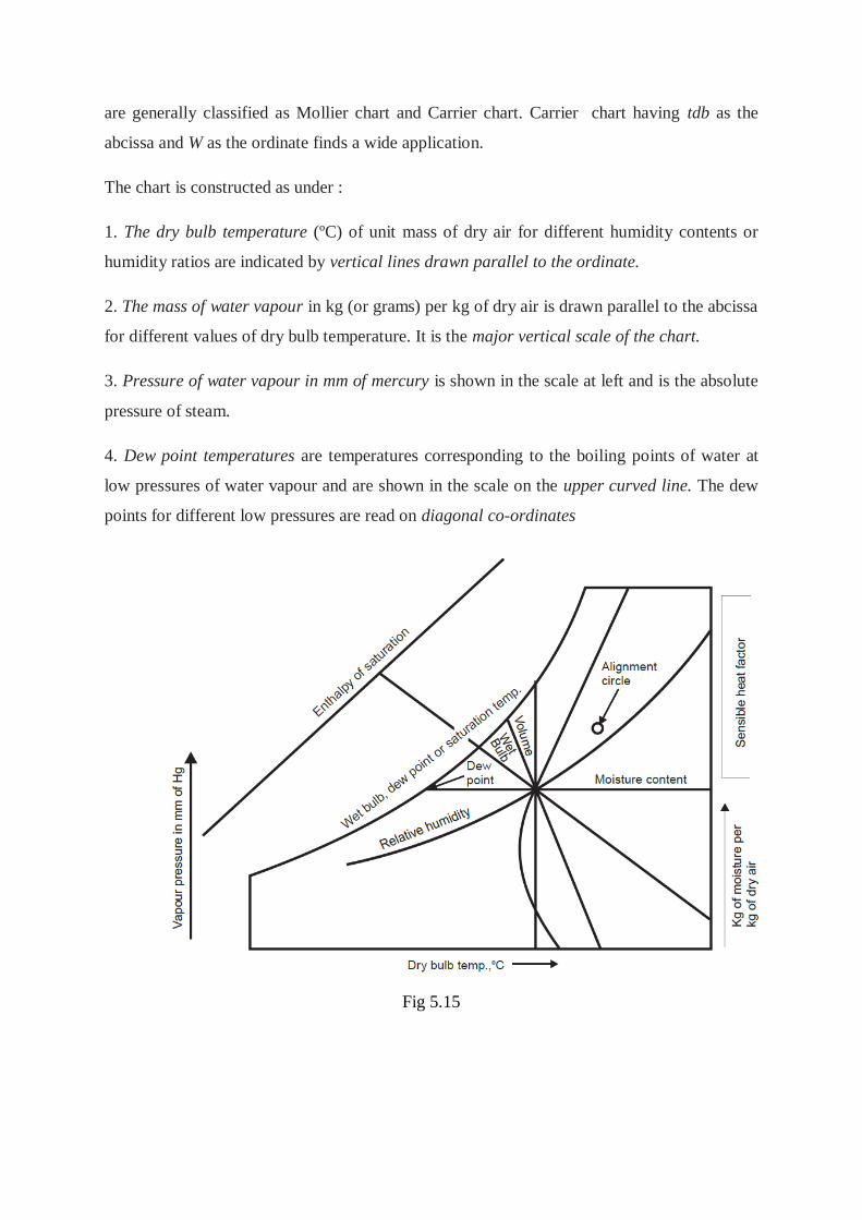
are generally classified as Mollier chart and Carrier chart. Carrier chart having tdb as the
abcissa and W as the ordinate finds a wide application.
The chart is constructed as under :
1. The dry bulb temperature (ºC) of unit mass of dry air for different humidity contents or
humidity ratios are indicated by vertical lines drawn parallel to the ordinate.
2. The mass of water vapour in kg (or grams) per kg of dry air is drawn parallel to the abcissa
for different values of dry bulb temperature. It is the major vertical scale of the chart.
3. Pressure of water vapour in mm of mercury is shown in the scale at left and is the absolute
pressure of steam.
4. Dew point temperatures are temperatures corresponding to the boiling points of water at
low pressures of water vapour and are shown in the scale on the upper curved line. The dew
points for different low pressures are read on diagonal co-ordinates
Fig 5.15
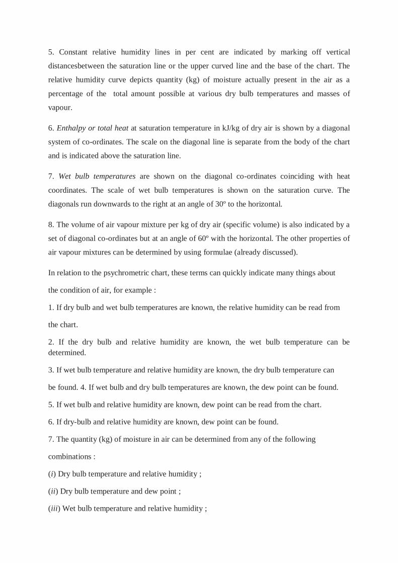
5. Constant relative humidity lines in per cent are indicated by marking off vertical
distancesbetween the saturation line or the upper curved line and the base of the chart. The
relative humidity curve depicts quantity (kg) of moisture actually present in the air as a
percentage of the total amount possible at various dry bulb temperatures and masses of
vapour.
6. Enthalpy or total heat at saturation temperature in kJ/kg of dry air is shown by a diagonal
system of co-ordinates. The scale on the diagonal line is separate from the body of the chart
and is indicated above the saturation line.
7. Wet bulb temperatures are shown on the diagonal co-ordinates coinciding with heat
coordinates. The scale of wet bulb temperatures is shown on the saturation curve. The
diagonals run downwards to the right at an angle of 30º to the horizontal.
8. The volume of air vapour mixture per kg of dry air (specific volume) is also indicated by a
set of diagonal co-ordinates but at an angle of 60º with the horizontal. The other properties of
air vapour mixtures can be determined by using formulae (already discussed).
In relation to the psychrometric chart, these terms can quickly indicate many things about
the condition of air, for example :
1. If dry bulb and wet bulb temperatures are known, the relative humidity can be read from
the chart.
2. If the dry bulb and relative humidity are known, the wet bulb temperature can be
determined.
3. If wet bulb temperature and relative humidity are known, the dry bulb temperature can
be found. 4. If wet bulb and dry bulb temperatures are known, the dew point can be found.
5. If wet bulb and relative humidity are known, dew point can be read from the chart.
6. If dry-bulb and relative humidity are known, dew point can be found.
7. The quantity (kg) of moisture in air can be determined from any of the following
combinations :
(i) Dry bulb temperature and relative humidity ;
(ii) Dry bulb temperature and dew point ;
(iii) Wet bulb temperature and relative humidity ;
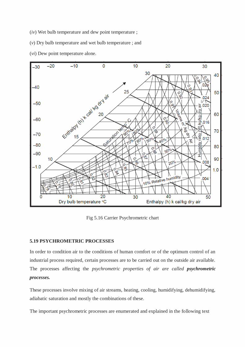
(iv) Wet bulb temperature and dew point temperature ;
(v) Dry bulb temperature and wet bulb temperature ; and
(vi) Dew point temperature alone.
Fig 5.16 Carrier Psychrometric chart
5.19 PSYCHROMETRIC PROCESSES
In order to condition air to the conditions of human comfort or of the optimum control of an
industrial process required, certain processes are to be carried out on the outside air available.
The processes affecting the psychrometric properties of air are called psychrometric
processes.
These processes involve mixing of air streams, heating, cooling, humidifying, dehumidifying,
adiabatic saturation and mostly the combinations of these.
The important psychrometric processes are enumerated and explained in the following text
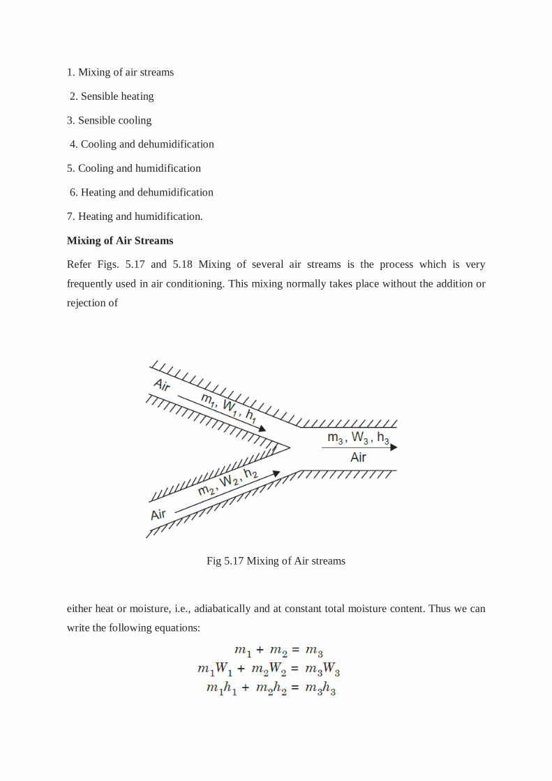
1. Mixing of air streams
2. Sensible heating
3. Sensible cooling
4. Cooling and dehumidification
5. Cooling and humidification
6. Heating and dehumidification
7. Heating and humidification.
Mixing of Air Streams
Refer Figs. 5.17 and 5.18 Mixing of several air streams is the process which is very
frequently used in air conditioning. This mixing normally takes place without the addition or
rejection of
Fig 5.17 Mixing of Air streams
either heat or moisture, i.e., adiabatically and at constant total moisture content. Thus we can
write the following equations:
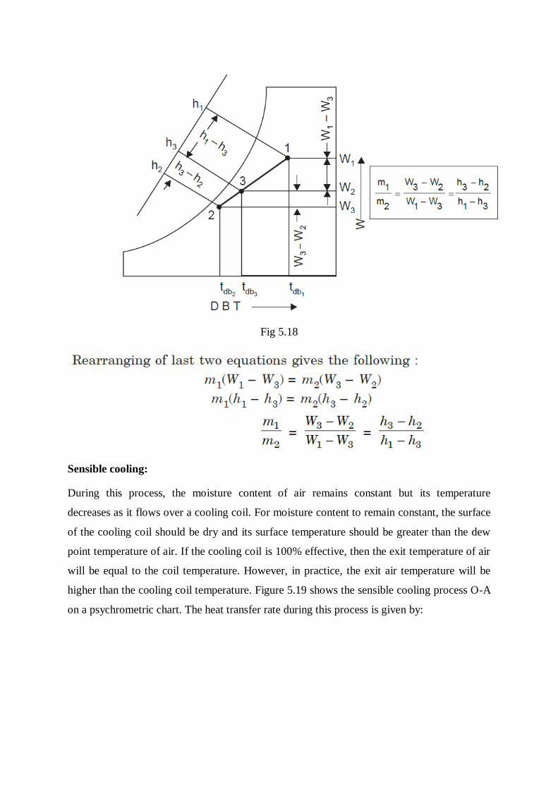
Fig 5.18
Sensible cooling:
During this process, the moisture content of air remains constant but its temperature
decreases as it flows over a cooling coil. For moisture content to remain constant, the surface
of the cooling coil should be dry and its surface temperature should be greater than the dew
point temperature of air. If the cooling coil is 100% effective, then the exit temperature of air
will be equal to the coil temperature. However, in practice, the exit air temperature will be
higher than the cooling coil temperature. Figure 5.19 shows the sensible cooling process O-A
on a psychrometric chart. The heat transfer rate during this process is given by:
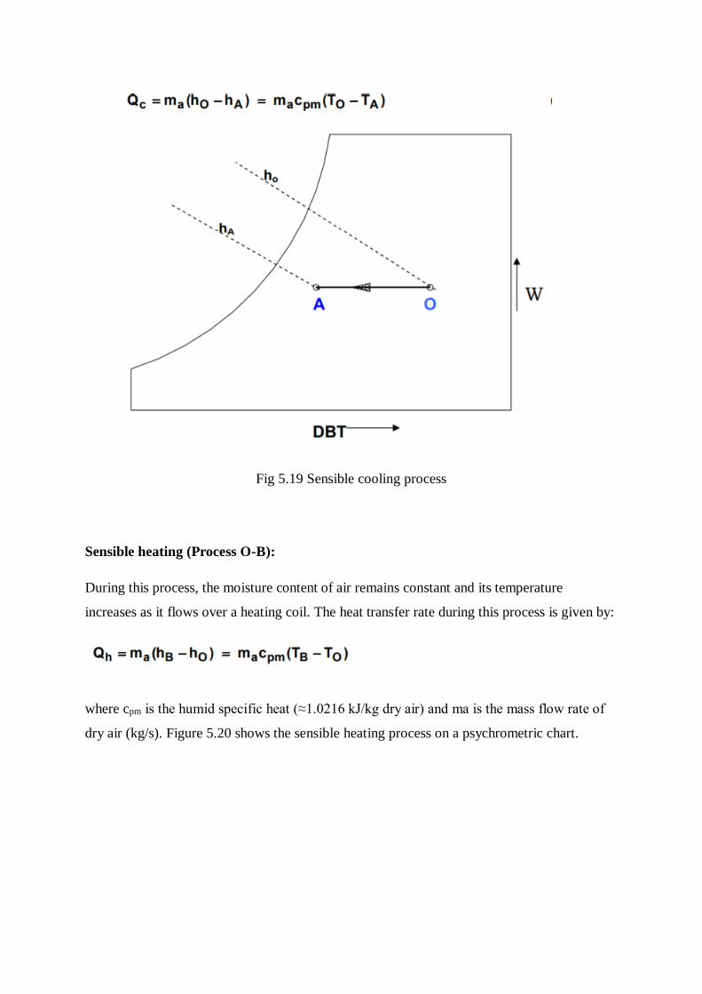
Fig 5.19 Sensible cooling process
Sensible heating (Process O-B):
During this process, the moisture content of air remains constant and its temperature
increases as it flows over a heating coil. The heat transfer rate during this process is given by:
where cpm is the humid specific heat (≈1.0216 kJ/kg dry air) and ma is the mass flow rate of
dry air (kg/s). Figure 5.20 shows the sensible heating process on a psychrometric chart.
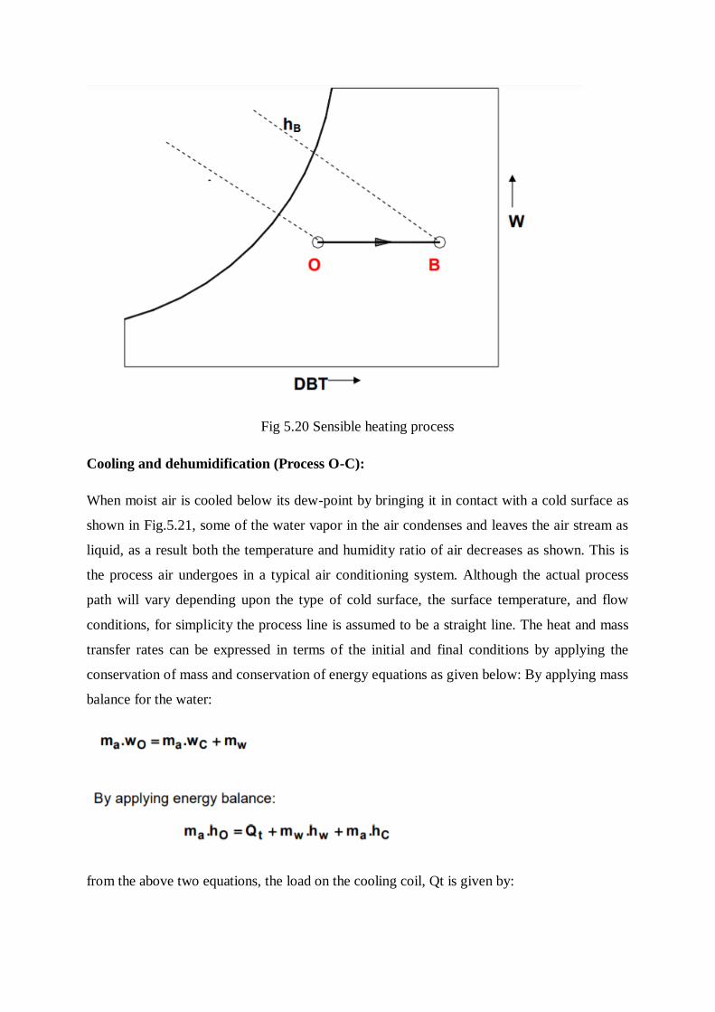
Fig 5.20 Sensible heating process
Cooling and dehumidification (Process O-C):
When moist air is cooled below its dew-point by bringing it in contact with a cold surface as
shown in Fig.5.21, some of the water vapor in the air condenses and leaves the air stream as
liquid, as a result both the temperature and humidity ratio of air decreases as shown. This is
the process air undergoes in a typical air conditioning system. Although the actual process
path will vary depending upon the type of cold surface, the surface temperature, and flow
conditions, for simplicity the process line is assumed to be a straight line. The heat and mass
transfer rates can be expressed in terms of the initial and final conditions by applying the
conservation of mass and conservation of energy equations as given below: By applying mass
balance for the water:
from the above two equations, the load on the cooling coil, Qt is given by:
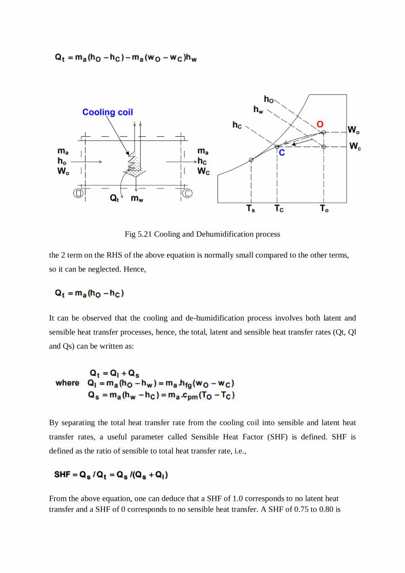
Fig 5.21 Cooling and Dehumidification process
the 2 term on the RHS of the above equation is normally small compared to the other terms,
so it can be neglected. Hence,
It can be observed that the cooling and de-humidification process involves both latent and
sensible heat transfer processes, hence, the total, latent and sensible heat transfer rates (Qt, Ql
and Qs) can be written as:
By separating the total heat transfer rate from the cooling coil into sensible and latent heat
transfer rates, a useful parameter called Sensible Heat Factor (SHF) is defined. SHF is
defined as the ratio of sensible to total heat transfer rate, i.e.,
From the above equation, one can deduce that a SHF of 1.0 corresponds to no latent heat
transfer and a SHF of 0 corresponds to no sensible heat transfer. A SHF of 0.75 to 0.80 is
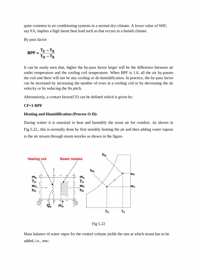
quite common in air conditioning systems in a normal dry-climate. A lower value of SHF,
say 0.6, implies a high latent heat load such as that occurs in a humid climate.
By pass factor
It can be easily seen that, higher the by-pass factor larger will be the difference between air
outlet temperature and the cooling coil temperature. When BPF is 1.0, all the air by-passes
the coil and there will not be any cooling or de-humidification. In practice, the by-pass factor
can be increased by increasing the number of rows in a cooling coil or by decreasing the air
velocity or by reducing the fin pitch.
Alternatively, a contact factor(CF) can be defined which is given by:
CF=1-BPF
Heating and Humidification (Process O-D):
During winter it is essential to heat and humidify the room air for comfort. As shown in
Fig.5.22., this is normally done by first sensibly heating the air and then adding water vapour
to the air stream through steam nozzles as shown in the figure.
Fig 5.22
Mass balance of water vapor for the control volume yields the rate at which steam has to be
added, i.e., mw:
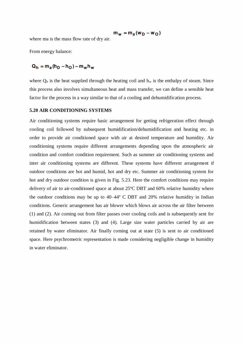
where ma is the mass flow rate of dry air.
From energy balance:
where Qh is the heat supplied through the heating coil and hw is the enthalpy of steam. Since
this process also involves simultaneous heat and mass transfer, we can define a sensible heat
factor for the process in a way similar to that of a cooling and dehumidification process.
5.20 AIR CONDITIONING SYSTEMS
Air conditioning systems require basic arrangement for getting refrigeration effect through
cooling coil followed by subsequent humidification/dehumidification and heating etc. in
order to provide air conditioned space with air at desired temperature and humidity. Air
conditioning systems require different arrangements depending upon the atmospheric air
condition and comfort condition requirement. Such as summer air conditioning systems and
inter air conditioning systems are different. These systems have different arrangement if
outdoor conditions are hot and humid, hot and dry etc. Summer air conditioning system for
hot and dry outdoor condition is given in Fig. 5.23. Here the comfort conditions may require
delivery of air to air-conditioned space at about 25ºC DBT and 60% relative humidity where
the outdoor conditions may be up to 40–44º C DBT and 20% relative humidity in Indian
conditions. Generic arrangement has air blower which blows air across the air filter between
(1) and (2). Air coming out from filter passes over cooling coils and is subsequently sent for
humidification between states (3) and (4). Large size water particles carried by air are
retained by water eliminator. Air finally coming out at state (5) is sent to air conditioned
space. Here psychrometric representation is made considering negligible change in humidity
in water eliminator.
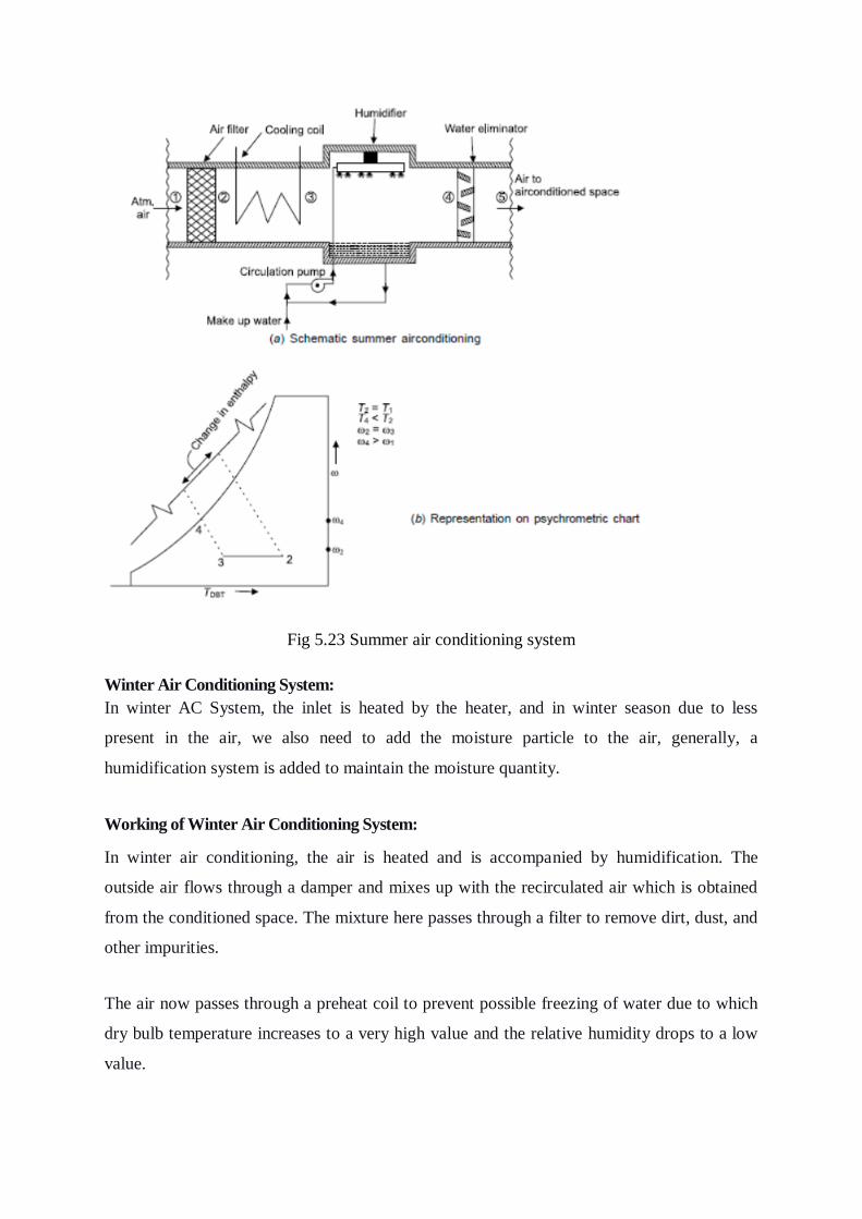
Fig 5.23 Summer air conditioning system
Winter Air Conditioning System:
In winter AC System, the inlet is heated by the heater, and in winter season due to less
present in the air, we also need to add the moisture particle to the air, generally, a
humidification system is added to maintain the moisture quantity.
Working of Winter Air Conditioning System:
In winter air conditioning, the air is heated and is accompanied by humidification. The
outside air flows through a damper and mixes up with the recirculated air which is obtained
from the conditioned space. The mixture here passes through a filter to remove dirt, dust, and
other impurities.
The air now passes through a preheat coil to prevent possible freezing of water due to which
dry bulb temperature increases to a very high value and the relative humidity drops to a low
value.
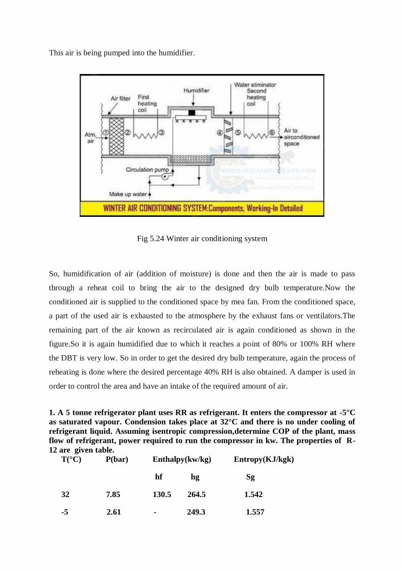
This air is being pumped into the humidifier.
Fig 5.24 Winter air conditioning system
So, humidification of air (addition of moisture) is done and then the air is made to pass
through a reheat coil to bring the air to the designed dry bulb temperature.Now the
conditioned air is supplied to the conditioned space by mea fan. From the conditioned space,
a part of the used air is exhausted to the atmosphere by the exhaust fans or ventilators.The
remaining part of the air known as recirculated air is again conditioned as shown in the
figure.So it is again humidified due to which it reaches a point of 80% or 100% RH where
the DBT is very low. So in order to get the desired dry bulb temperature, again the process of
reheating is done where the desired percentage 40% RH is also obtained. A damper is used in
order to control the area and have an intake of the required amount of air.
1. A 5 tonne refrigerator plant uses RR as refrigerant. It enters the compressor at -5°C
as saturated vapour. Condension takes place at 32°C and there is no under cooling of
refrigerant liquid. Assuming isentropic compression,determine COP of the plant, mass
flow of refrigerant, power required to run the compressor in kw. The properties of R-
12 are given table.
T(°C) P(bar) Enthalpy(kw/kg) Entropy(KJ/kgk)
hf hg Sg
32 7.85 130.5 264.5 1.542
-5 2.61 - 249.3 1.557
Solution:
Beginning of compression in dry and end of compression is superheated. So the P-h
and T-S diagrams are
From table, at point 1
T1=-5°C=268K
hg1=2493kJ/Kg , Sg1=1.557KJ/Kgk
At point 2
T2=32°C=305k, hf2=130.5KJ/Kg, hg2=264.5, Sg2=1.542KJ/KgK
From ph diagram, At point eqn(1) (dry).
At -5°C, i.e at 268k
hg1=249.3KJ/Kg=hg
h1=249.3KJ/Kg
At 32°C, i.e at 305K
hg2=264.5KJ/Kg=h2'
h2'=264.5KJ/Kg
Entropy is constant during the compression process so,
S1=S2
From T- S diagram
At point (1) dry,
S1=Sg at -5°C
S1=Sg1=1.557KJ/Kgk
S1=S2=1.557KJ/Kgk
At point (2) (super heated)
S1=S2' + Cp ln (T2/T2')
1.557=S2'+1.884 ln(T2/305) --------(1)
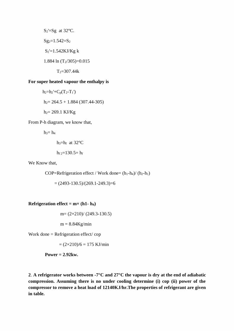
S2'=Sg at 32°C.
Sg2=1.542=S2
S2'=1.542KJ/Kg k
1.884 ln (T2/305)=0.015
T2=307.44k
For super heated vapour the enthalpy is
h2=h2'+Cp(T2-T1')
h2= 264.5 + 1.884 (307.44-305)
h2= 269.1 KJ/Kg
From P-h diagram, we know that,
h3= h4
h3=hf at 32°C
hf 2=130.5= hf
We Know that,
COP=Refrigeration effect / Work done= (h1-h4)/ (h2-h1)
= (2493-130.5)/(269.1-249.3)=6
Refrigeration effect = m× (h1- h4)
m= (2×210)/ (249.3-130.5)
m = 8.84Kg/min
Work done = Refrigeration effect/ cop
= (2×210)/6 = 175 KJ/min
Power = 2.92kw.
2. A refrigerator works between -7°C and 27°C the vapour is dry at the end of adiabatic
compression. Assuming there is no under cooling determine (i) cop (ii) power of the
compressor to remove a heat load of 12140KJ/hr.The properties of refrigerant are given
in table.
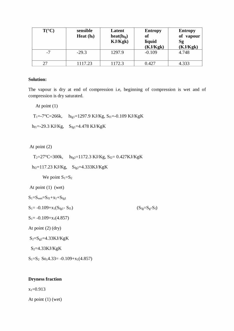
Solution:
The vapour is dry at end of compression i.e, beginning of compression is wet and of
compression is dry saturated.
At point (1)
T1=-7°C=266k, hfg1=1297.9 KJ/Kg, Sf1=-0.109 KJ/KgK
hf1=-29.3 KJ/Kg, Sfg1=4.478 KJ/KgK
At point (2)
T2=27°C=300k, hfg2=1172.3 KJ/Kg, Sf2= 0.427KJ/KgK
hf2=117.23 KJ/Kg, Sfg2=4.333KJ/KgK
We point S1=S2
At point (1) (wet)
S1=Swet=Sf1+x1+Sfg1
S1= -0.109+x1(Sfg1- Sf1) (Sfg=Sg-Sf)
S1= -0.109+x1(4.857)
At point (2) (dry)
S2=Sg2=4.33KJ/KgK
S2=4.33KJ/KgK
S1=S2 So,4.33= -0.109+x1(4.857)
Dryness fraction
x1=0.913
At point (1) (wet)
T(°C) sensible
Heat (hf)
Latent
heat(hfg)
KJ/Kgk)
Entropy
of
liquid
(KJ/Kgk)
Entropy
of vapour
Sg
(KJ/Kgk)
-7
-29.3 1297.9 -0.109 4.748
27 1117.23 1172.3 0.427 4.333
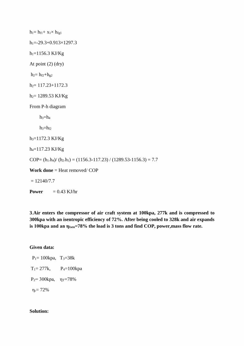
h1= hf1+ x1× hfg1
h1=-29.3+0.913×1297.3
h1=1156.3 KJ/Kg
At point (2) (dry)
h2= hf2+hg2
h2= 117.23+1172.3
h2= 1289.53 KJ/Kg
From P-h diagram
h3=h4
h3=hf2
h3=1172.3 KJ/Kg
h4=117.23 KJ/Kg
COP= (h1-h4)/ (h2-h1) = (1156.3-117.23) / (1289.53-1156.3) = 7.7
Work done = Heat removed/ COP
= 12140/7.7
Power = 0.43 KJ/hr
3.Air enters the compressor of air craft system at 100kpa, 277k and is compressed to
300kpa with an isentropic efficiency of 72%. After being cooled to 328k and air expands
is 100kpa and an ηIsen=78% the load is 3 tons and find COP, power,mass flow rate.
Given data:
P1= 100kpa, T3=38k
T1= 277k, P4=100kpa
P2= 300kpa, ηT=78%
ηc= 72%
Solution:
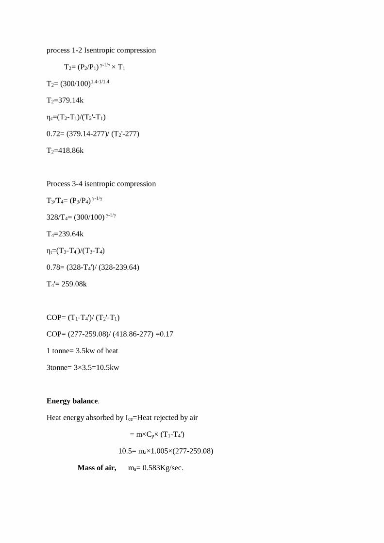
process 1-2 Isentropic compression
T2= (P2/P1) γ-1/γ × T1
T2= (300/100)1.4-1/1.4
T2=379.14k
ηc=(T2-T1)/(T2'-T1)
0.72= (379.14-277)/ (T2'-277)
T2=418.86k
Process 3-4 isentropic compression
T3/T4= (P3/P4) γ-1/γ
328/T4= (300/100) γ-1/γ
T4=239.64k
ηt=(T3-T4')/(T3-T4)
0.78= (328-T4')/ (328-239.64)
T4'= 259.08k
COP= (T1-T4')/ (T2'-T1)
COP= (277-259.08)/ (418.86-277) =0.17
1 tonne= 3.5kw of heat
3tonne= 3×3.5=10.5kw
Energy balance.
Heat energy absorbed by Ice=Heat rejected by air
= m×Cp× (T1-T4')
10.5= ma×1.005×(277-259.08)
Mass of air, ma= 0.583Kg/sec.
Power, P=ma×Cpa× (T2'-T1)
= 0.583×1.005× (418.86-277)
= 83.12kW
4. An ammonia refrigerator process 20tons of ice per day from and at 0°C.The
condensation and evaporation takes at 20°C and -20°C respectively the temperature
of the vapour at the end of Isentropic compression is 50°C and there is no under
cooling of the liquid.COP=70% of theoretical COP. Determine (i) Rate of NH3
circulation (ii) size of compressor, N=240rpm,L=D, ηvol=80%. Take Laten heat of
Icc=335kJ/Kg, Cp= 2.8 kJ/Kg,
Vs1=0.624m3kg. Use the following properties of ammonia.
Sat.Temp(°C) Enthalpy(kJ/Kg) Entropy(kJ/Kgk)
hf hg Sf Sg
20 274.98 1461.58 1.0434 5.0919
20 89.72 1419.05 0.3682 5.6204 [Apr 2003]
Given data: 20 tons of Icc per day at °C
T3= 20°C
T1=-20°C
T3=50°C
COP =70% of theoretical cop
N=240rpm
L=D
hv=80%
Latent heat of Ice=335KJ/Kg
Cp=2.8KJ/Kgk
Vs1=0.624m3/kg
Solution:-
The refrigeration effect=20×3.5=77.55kw
h1=1419.05KJ/Kg
hg2=1461.58KJ/Kg at 20°C
hf3=274.98 KJ/Kg
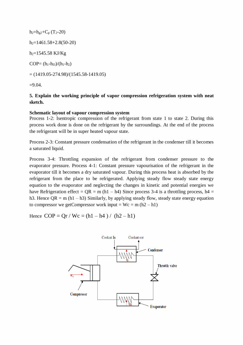
h2=hg2+Cp (T2-20)
h2=1461.58+2.8(50-20)
h2=1545.58 KJ/Kg
COP= (h1-hf3)/(h1-h2)
= (1419.05-274.98)/(1545.58-1419.05)
=9.04.
5. Explain the working principle of vapor compression refrigeration system with neat
sketch.
Schematic layout of vapour compression system
Process 1-2: Isentropic compression of the refrigerant from state 1 to state 2. During this
process work done is done on the refrigerant by the surroundings. At the end of the process
the refrigerant will be in super heated vapour state.
Process 2-3: Constant pressure condensation of the refrigerant in the condenser till it becomes
a saturated liquid.
Process 3-4: Throttling expansion of the refrigerant from condenser pressure to the
evaporator pressure. Process 4-1: Constant pressure vapourisation of the refrigerant in the
evaporator till it becomes a dry saturated vapour. During this process heat is absorbed by the
refrigerant from the place to be refrigerated. Applying steady flow steady state energy
equation to the evaporator and neglecting the changes in kinetic and potential energies we
have Refrigeration effect = QR = m (h1 – h4) Since process 3-4 is a throttling process, h4 =
h3. Hence QR = m (h1 – h3) Similarly, by applying steady flow, steady state energy equation
to compressor we getCompressor work input = Wc = m (h2 – h1)
Hence COP = Qr / Wc = (h1 – h4 ) / (h2 – h1)
Advantages of Vapour compression refrigeration system over air refrigeration system:
Since the working cycle approaches closer to carnot cycle, the C.O.P is quite high.
Operational cost of vapour compression system is just above 1/4th of air refrigeration system.
Since the heat
removed consists of the latent heat of vapour, the amount of liquid circulated is less and as a
result the size of the evaporator is smaller. Any desired temperature of the evaporator can be
achieved just by adjusting the throttle valve.
Disadvantages of Vapour compression refrigeration system over air refrigeration
system:
Initial investment is high Prevention of leakage of refrigerant is a major problem
6.Explain and working principles of Ammonia – water vapour absorption refrigeration
system with neat sketch. [May 2011]
1) Evaporator: It is in the evaporator where the refrigerant pure ammonia (NH3) in liquid
state produces the cooling effect. It absorbs the heat from the substance to be cooled and gets
evaporated. From here, the ammonia passes to the absorber in the gaseous state.
2) Absorber: In the absorber the weak solution of ammonia-water is already present. The
water,
used as the absorbent in the solution, is unsaturated and it has the capacity to absorb more
ammonia gas. As the ammonia from evaporator enters the absorber, it is readily absorbed by
water and the strong solution ofammonia-water is formed. During the process of absorption
heat is liberated which can reduce the ammonia absorption capacity of water; hence the
absorber is cooled by the cooling water. Due to absorption of ammonia, strong solution of
ammonia-water is formed in the absorber.
3) Pump: The strong solution of ammonia and water is pumped by the pump at high pressure
to the generator.
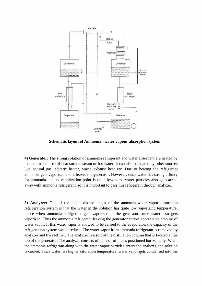
Schematic layout of Ammonia –water vapour absorption system
4) Generator: The strong solution of ammonia refrigerant and water absorbent are heated by
the external source of heat such as steam or hot water. It can also be heated by other sources
like natural gas, electric heater, waste exhaust heat etc. Due to heating the refrigerant
ammonia gets vaporized and it leaves the generator. However, since water has strong affinity
for ammonia and its vaporization point is quite low some water particles also get carried
away with ammonia refrigerant, so it is important to pass this refrigerant through analyzer.
5) Analyzer: One of the major disadvantages of the ammonia-water vapor absorption
refrigeration system is that the water in the solution has quite low vaporizing temperature,
hence when ammonia refrigerant gets vaporized in the generator some water also gets
vaporized. Thus the ammonia refrigerant leaving the generator carries appreciable amount of
water vapor. If this water vapor is allowed to be carried to the evaporator, the capacity of the
refrigeration system would reduce. The water vapor from ammonia refrigerant is removed by
analyzer and the rectifier. The analyzer is a sort of the distillation column that is located at the
top of the generator. The analyzer consists of number of plates positioned horizontally. When
the ammonia refrigerant along with the water vapor particles enters the analyzer, the solution
is cooled. Since water has higher saturation temperature, water vapor gets condensed into the
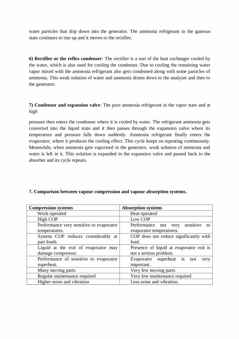
water particles that drip down into the generator. The ammonia refrigerant in the gaseous
state continues to rise up and it moves to the rectifier.
6) Rectifier or the reflex condenser: The rectifier is a sort of the heat exchanger cooled by
the water, which is also used for cooling the condenser. Due to cooling the remaining water
vapor mixed with the ammonia refrigerant also gets condensed along with some particles of
ammonia. This weak solution of water and ammonia drains down to the analyzer and then to
the generator.
7) Condenser and expansion valve: The pure ammonia refrigerant in the vapor state and at
high
pressure then enters the condenser where it is cooled by water. The refrigerant ammonia gets
converted into the liquid state and it then passes through the expansion valve where its
temperature and pressure falls down suddenly. Ammonia refrigerant finally enters the
evaporator, where it produces the cooling effect. This cycle keeps on repeating continuously.
Meanwhile, when ammonia gets vaporized in the generator, weak solution of ammonia and
water is left in it. This solution is expanded in the expansion valve and passed back to the
absorber and its cycle repeats.
7. Comparison between vapour compression and vapour absorption systems.
Compression systems Absorption systems
Work operated Heat operated
High COP Low COP
Performance very sensitive to evaporator
temperatures.
Performance not very sensitive to
evaporator temperatures.
System COP reduces considerably at
part loads.
COP does not reduce significantly with
load.
Liquid at the exit of evaporator may
damage compressor.
Presence of liquid at evaporator exit is
not a serious problem.
Performance of sensitive to evaporator
superheat.
Evaporator superheat is not very
important.
Many moving parts Very few moving parts
Regular maintenance required Very low maintenance required
Higher noise and vibration Less noise and vibration.

8. List out the Properties of Refrigerants
Toxicity: It obviously desirable that the refrigerant have little effect on people.
Inflammability: Although refrigerants are entirely sealed from the atmosphere, leaks are
bound to develop. If the refrigerant is inflammable and the system is located where ignition
of the refrigerant may occur, a great hazard is involved.
Boiling Point: An ideal refrigerant must have low boiling temperature at atmospheric
pressure.
Freezing Point:An ideal refrigerant must have a very low freezing point because the
refrigerant should not freeze at low evaporator temperatures.
Evaporator and condenser pressure:In order to avoid the leakage of the atmosphere air and
also to enable the detection of the leakage of the refrigerant, both the Evaporator and
condenser pressure should be slightly above the atmosphere pressure.
Chemical Stability: An ideal refrigerant must not decompose under operating conditions.
Latent heat of Evaporation: The Latent heat of Evaporation must be very high so that a
minimum amount of refrigerant will accomplish the desired result; in other words, it
increases the refrigeration effect.
Specific Volume:The Specific Volume of the refrigerant must be low. The lower specific
volume of the refrigerant at the compressor reduces the size of the compressor.
Specific heat of liquid vapour: A good refrigerant must have low specific heat when it is in
liquid state and high specific heat when it is vaporized.
Viscosity: The viscosity of the refrigerant t both the liquid and vapour state must be very low
as improved the heat transfer and reduces the pumping pressure.
Corrosiveness: A good refrigerant should be non-corrosive to prevent the corrosion of the
metallic parts of the refrigerator.
Odour: A good refrigerant must be odourless, otherwise some foodstuff such as meat,
butter, etc loses their taste.
Oil solvent properties: A good refrigerant must be not react with the lubricating oil used in
the refrigerator for lubricating the parts of the compressor.
TEXT / REFERENCE BOOKS
1. Nag P.K., “Engineering Thermodynamics”, Tata McGraw Hill Education, 2009.
2. Yunus A. Cengel, Michael A. Boles, “Thermodynamics: An Engineering
Approach”, McGraw Hill Education, 2014.
3. Rajput R.K., “Engineering Thermodynamics”, Laxmi Publications, 2010.
4. Khurmi R.S., Gupta J.K, “Thermal Engineering”, S Chand, 2006.
5. P.L. Ballaney,”Thermal Engineering”, Khanna Publisher, 2005.