Design of a high-brightness, high-duty factor photocathode electron gun
20
Presented at the Thirteenth International BNL— 46332 Free-Electron Laser Conference, C >- - ( - M > • ^ \' Santa Fe, NM, August 25-30, 1991 DESIGN OF A HIGH-BRIGHTNESS, HIGH-DUTY FACTOR PHOTOCATHODE ELECTRON GUN* I. S. Lehrman, I. A. Birnbaum, S. Z. Fixler, R. L. Heuer, S. Siddiqi, E. Sheedy Grumman Corporation, Princeton, NJ 08540 I. Ben-Zvi, K. Batchelor, J. C. Gallardo, H. G. Kirk, T. Srinivasan-Rao Brookhaven National Laboratory, Upton, NY 11973 G. D. Warren Mission Research Corporation, Newington, VA 22122 September 1991 *This research was supported by the Grumman Corporation and the Brookhaven National Laboratory under U. S. Department of Energy: Contract No. DE-AC02-76CH00016. — _.*" ' M * ;.»*, "..... M r A 1 7 iS J'•<•:.•
-
Upload
independent -
Category
Documents
-
view
5 -
download
0
Transcript of Design of a high-brightness, high-duty factor photocathode electron gun

Presented at the Thirteenth International BNL—46332Free-Electron Laser Conference, C >- - ( - M >• ̂ \'Santa Fe, NM, August 25-30, 1991
DESIGN OF A HIGH-BRIGHTNESS, HIGH-DUTY
FACTOR PHOTOCATHODE ELECTRON GUN*
I. S. Lehrman, I. A. Birnbaum, S. Z. Fixler,R. L. Heuer, S. Siddiqi, E. Sheedy
Grumman Corporation, Princeton, NJ 08540
I. Ben-Zvi, K. Batchelor, J. C. Gallardo,H. G. Kirk, T. Srinivasan-Rao
Brookhaven National Laboratory, Upton, NY 11973
G. D. Warren
Mission Research Corporation, Newington, VA 22122
September 1991
*This research was supported by the Grumman Corporation and theBrookhaven National Laboratory under U. S. Department of Energy:Contract No. DE-AC02-76CH00016.
— _.*" ' M * ; .»* , "..... M r A 1 7 i S J'•<•:.•

DESIGN OF A HIGH-BRIGHTNESS, HIGH-DUTY FACTOR
PHOTOCATHODE ELECTRON GUN*
BNL--46332
DE92 011003
I. S. Lehrman, I. A. Btrnbaum, S. Z. Fixler, R. L. Heuer, S. Siddiqi, E. Sheedy
Grumman Corporation, 4 Independence Way, Princeton, NJ 08540
I. Ben-Zvi, K. Batchelor, J. C. Gallardo, H. G. Kirk, T. Srinivasan-Rao
Brookhaven National Laboratory, Upton, NY 11973
G. D. Warren
Mission Research Corporation, 8560 Cinderbed Road, Newington, VA 22122
ABSTRACT
The proposed UV-FEL user's facility at Brookhaven National Laboratory will require a
photocathode gun capable of producing short (< 6 psec) bunches of electrons at high repetition
rates (5 kHz), low energy spread (< 1.5 %), a peak current of 300 A (after compression) and a
total bunch charge of up to 2 nC. At the highest charge the normalized transverse emittance should
be less than 7 Jt mm-mrad. We are presently designing a gun that is expected to exceed these
requirements. This gun will consist of 3 V2 cells, constructed of GlidCop-15, an aluminum oxide
dispersion strengthened copper alloy. The gun will be capable of operating at duty factors in
excess of 1%. Extensive beam dynamics studies of the gun were used to determine the effect of
varying the length of the first cell, shaping the apertures between cells, and increasing the number
of cells. In addition, a detailed thermal and mechanical study of the gun was performed to ensure
that the thermal stresses were well within the allowable limits and that copper erosion of the water
channels would not occur.
*This work is supported by the Grumman Corporation and the Brookhaven National Laboratoryunder U.S. Department of Energy contract DE-AC02-76-CH0016.
•> ' • '• •'•••• - . * • ; '«k i . K / . I j M t ' i V >& ,_lf\> , >-

1. INTRODUCTION
The free-electron laser (FEL) offers the opportunity of providing high power coherent
radiation sources in regions presently unattainable by conventional atomic and molecular lasers.
For this reason, it has been proposed to build an ultraviolet FEL user's facilityfl] capable of
producing radiation between 75 - 300 nra at a repetition rate of 5 kHz. Though the
superconducting linear accelerator for this faeility is considered to be proven technology, the RF
photocathode gun would be operating in a regime undemonstrated at this time. The gun would be
required to produce 2 pulses separated by 10 ns every 200 jisec. The emittance of the electron
bunches is required to be below 7 n mm-mrad (normalized RMS) with peak currents of 300 A after
compression. The RF filling times of these guns are on the order of 1 - 2 ^isec, thus the RF duty
factor would be nearly 1%.
Design and construction of such a gun (Gun II) has begun under a joint Grumman-
Brookhaven National Laboratory (BNL) research collaboration. The starting point for our design
is the present 1V2 cell BNL photocathode RF gun (Gun I) shown in Fig. 1. The beam dynamics
of the gun are modeled with the PARMELA[2] and MAGIC[3] panicle codes. These codes are
used to study the emittance growth of the electron bunch as it is accelerated through the gun, as
well as to determine how the operational parameters effect its characteristics (i.e. divergence,
momentum spread, energy, current).
The thermal and mechanical properties of the gun were modeled with the ANSYS14] finite
element code. Power deposition profiles were calculated with SUPERFISH.[5] A
thermal/structural analysis was performed to determine the temperature profiles and the pressure
and thermally induced stresses. The Von Mises (equivalent) [6] Stress Criteria was used to
determine stress level margins.
2. BEAM DYNAMICS MODELING
The majority of the beam dynamics modeling was done with the MAGIC particle-in-cell
code. This code includes the effect of image currents, space charge, and wakefields. The

axisymmetric gun geometry (2-D) was modelled with the exact gun fields. This is accomplished
by prescribing the magnetic field for the fundamental TMoi cylindrical cavity mode and allowing
the cavity to ring while numerically damping out higher order modes. The ratios of the electric and
magnetic fields are compared at various times to verify that the higher order modes are greater than
60 db down from the fundamental mode. The fields are then stored and used for later runs with
particles. The damping of higher order modes is turned off for the panicle runs. Figure 2 shows a
vector plot of the electric fields for a 3 V2 cell gun.
The advantage of using the MAGIC codes is that the field components at the cavity
apertures and beam exit are continuous and the method of calculating the space charge forces is
inherendy more stable. To properly resolve the electric fields of the electron bunch near the
cathode, where they are rapidly accelerated, the numerical grid for calculating the fields is made
very fine near Z, R = 0. In addition, the time steps are small enough to avoid plasma frequency
and grid type instabilities, and to properly resolve the temporal behavior of the wakefields.[7]
Typical simulations for a 3V2 cell gun consisted of a grid 2000 x 90 (Z x R), 1500 particles, and
required nearly 6 hours of computer time (Stardent 3000). Particles are emitted in nearly any
functional form in radius and time to model the laser illumination of the cathode. Figure 3 shows
contours of the wake field created by the bunch as it is accelerated through the gun.
The majority of our simulations used Gaussian profiles with a temporal extent of ± 2o"t (0t
= 2 psec), and a radial extent of lCTr (~ 1 — 5 mm). Table 1 lists the operational parameters for Gun
II. Statistics of the panicles are tracked through the length of the gun. Figure 4. shows the
emittance (calculated from the mechanical momentum), divergence, momentum and momentum
spread through the gun. The emitted electron bunch could be modeled as initial cold (en = 0 ), or
thermalized (by an amount equal to the difference between the photon energy of the laser and the
work function of the cathode material). The most recent experiments at BNL[8] have utilized a
copper photocathode whose work function is better matched to the photon energy of the laser than
the previous Yttrium cathode. The thermal energy for electrons emitted from the Cu cathode is 0.4
eV versus 1.5 eV for the Yt cathode. To improve the resolution of space charge and RF emittance

contributions, the particles were emitted cold in the majority of our simulations. Emittance values
are always reported with the addition (in quadrature) of the thermal emi nance.
Most of our simulations were done for a 1V2 cell gun since they require V4 of the computer
time and uncover most of the underlying physics. A number of aspects of the gun design were
investigated: temporal and spatial laser illumination profile shaping; total charge; electric field
strength; launch phase; field tilt; aperture shaping; and the length of the first cell. The brightness,
B, was used as one figure of merit for our gun design. We use the definition:
B , I
where I is the peak current, en is the RMS invariant emittance, Q is the total charge, and Oj, is the
bunch length (divided by the speed of light). After the beam exits the gun, it enters a transport line
whose function is to match the beam to the linac. In addition, the transport line may serve to
magnetically compress the bunch length, resulting in peak currents >1000 amps. The compression
results from differing path lengths for particles of differing momentum in bending magnets. The
compressibility was determined analytically and used to determine the ideally compressed current.
The divergence of the beam is inversely proportional to y, the relativistic factor, and the
space charge forces are inversely proportional to y2. Simulations of the full 3 V2 cell gun show that
the addition of 2 full cells for the gun (Gun II) will double the momentum of electrons to 10 MeV/c
which should result in a bunch that is more easily transported and compressed. Figure 5 shows
the longitudinal phase space (1 nC bunch) at the gun exit (Ob = 0.55 mm, dP/P = 1.5%) and after
being ideally compressed (c\y = 0.029 mm). Figure 6 shows the transverse phase space at the gun
exit (cx = 3.5 mm, ax ' = 8.3 mrad).
A study was made to determine the effect of varying the length of the half cell on the
emittance, divergence and compressibility. It was found that by increasing the length of the half
cell from 2.625 cm (^4) to 3.5 cm, the divergence was reduced by 20%, the compressibility
increased by a factor of 2, and the effect on the emittance was negligible. The 3.5 cm first cell
offers a number of other advantages. The peak electric field is on the cathode rather than on the

aperture as in the previous case. This should allow the cathode field to reach 110 MV/ra with the
same conditioning that it takes to reach 100 MV/m in the present BNL gun.
For the gun with the longer half cell, minimizing the emittance requires the launch phase to
be advanced by 6° for a 1 nC bunch. If one considers the transit time for a relativistic electron
bunch, the extra length of the first cell corresponds to 27° of RF phase. However, since the
electrons are launched at a lower electric field gradient, the dwell time in the first cell is increased as
is the effect of the non-linear transverse electric fields which increase the emittance. As a result,
the minimum emittance requires a launch phase advanced by 16° for a 0.1 nC bunch and 6° for a 1
nC bunch.
The smaller phase advance causes the particles to arrive ahead of the zero crossings at the
apertures. The final two cells of the gun will have independent phase control which will
compensate for the early of the particles. This provides a means of controlling the longitudinal
phase space (decreasing the momentum spread or increasing the compressibility), as well as a
means for matching the beam to the compression system.
It had been suggested that the transverse non-linear fields at the apertures between cavities
could contribute significantly to the emittance of the beam as it passed through the aperture. To
reduce the non-linear field components, the aperture can be shaped according to the prescription:[9]
r =
where a is the aperture radius and d is the length of the cell. We have verified that this prescription
does indeed significantly reduce the non-linear transverse fields, but does little to reduce the
emittance of the bunch. This results from the fact that most of the emittance growth occurs very
close to the cathode where the particle velocities are much less than the speed of light.
Our modeling activities are still continuing to determine the optimal operational parameters.
Table 2 summarizes the best modeling results to date. The impact of high compressibility can be

seen when comparing the exponential gain lengths for the UV-FEL[1]. The nearly factor of 5
reduction in wiggler length could significantly reduce the construction costs of such a device.
3. THERMAL AND MECHANICAL DESIGN
Operation at duty factors of 1 % present significant challenges in the heat removal aspects of
the gun as well as the pressure and thermally induced stresses and deformations. The half cell of
the gun will be 3.5 cm long followed by 3 full cells each 5.25 cm (V2) in length. The longer cell
simplifies the construction of the gun by reduced the space constraints.
The inner diameter of the half cell is 8.25 cm and it is 8.31 cm for the full cells. The peak
power is 12.5 MW, thus an average power of 125 kW most be removed from the structure. Since
Gun II will utilize a copper cathode, the cathode wall will be constructed of a solid copper plate
without penetrations. The cathode plate, four cylindrical spool pieces and four aperture pieces will
be brazed together. Two waveguides are used to power the cavities. The cathode plate is a 0.75
cm long cylinder 12.25 cm in diameter, with coolant channels milled in a circular pattern. A
second 0.75 cm long cylinder is brazed on the back to enclose the channels. A 2.5 cm long
cylindrical spool piece is used to connect the photocathode to the aperture. The spool pieces for the
full cells are 3.25 cm long. All of the spool piece are cooled by circular channel machined into
each end. Each aperture is designed as two cylindrical pieces, 1.0 cm long with two coolant
channels milled in a circular pattern, which are brazed together. The aperture opening is a separate
machining operation.
We have chosen to use GlidCop-15, an aluminum oxide dispersion strengthened copper
alloy, which combines good thermal, electrical, and structural properties. The GlidCop will be
electroplated with 0.001" of OFHC copper to provide the good electrical conductivity for the cavity
and a barrier for the silver based braze alloys.
The thermal/structural analysis entails determining the temperature distributions and the
corresponding deformations and stresses imposed on the cavity by the applied RF and laser

loading. The results are evaluated to insure that the design can adequately perform its function and
meet the requirements of the AS ME Boiler and Pressure Vessel Code.[10]
The Swanson Analysis System, ANSYS, was chosen as the finite element
thermal/structural code to perform the evaluation of the design. ANSYS provides 2-D and 3-D
modeling capability with thermal and structural elements compatible with the analysis
requirements. Steady state and transient analysis with temperature dependent material properties
can be performed. It is capable of post-processing the resulting stresses to check compliance with
the criteria of the ASME code.
The thermal management of the gun requires heat removal from a cavity only 8.31 cm in
diameter with peak power densities of 22 kW/cm2. Preliminary calculations indicated that 1%
duty factor is viable. The mode of heat transfer chosen is turbulent forced convection, the Dittus-
Boelter heat transfer correlation was used. The heat removal is provided by pumping pressurized
water through strategically placed coolant channels. Pressure drops through the channels were
addressed, to ensure that boiling does not occur, and to comply with facility capabilities. The flow
rates were limited by erosion considerations. Row velocity limits for copper were within the
recommended guidelines.! 11]
The power density was supplied by the SUPERFISH code for the cavity configurations
evaluated. The power density in the longer half cell is decreased by nearly 15%. Various 2-D
axisymmetric models of the gun were generated to determine flow rates, and the positions and
sizes of the coolant channels. Steady state thermal analysis was performed for the various
evaluations. A transient analysis with 2 usec pulses and 5 kHz was performed and compared with
a steady state analysis, the bulk and through the thickness temperature distributions were in good
agreement, and only a 15°C peak surface temperature variation was experienced.
The operating pressure and temperature distributions are input to the structural model and
the pressure and thermally induced deformations and stresses are calculated. The resulting
displacements are evaluated to determine the variation in cavity deformations impacting the
frequency and tuning of the cavity. The stresses are evaluated and compared to the various stress

categories in the ASME Boiler and Pressure Vessel Code. The combination of the stresses used
for comparing the ASME allowables are conservative, since they include the thermally induced
membrane stress in the Primary+Bending stress category, and the peak thermal stresses in the
Primary+Secondary stress category.
The temperature distribution and a Von Mises Stress Intensity contour plot of the most
recent analyses are shown in Figures 7 and 8, respectively, for a 2-D model of the first two cells of
the gun. The peak temperature reported is 130°C, with a corresponding frequency shift of 4.4
MHz. The maximum stress intensity is less than 18 ksi (124 MPa) with an allowable of 31 ksi
(214 MPa).
The effect of the waveguides and electric field pickup probes will be evaluated using a 3-D
model. The cavity inner diameters will be sized so that thermal growth will tune the cavities for the
operating frequency. Hot water will raise the temperature to proper levels to tune the cavities for
low power operation. Water circulation flow rates will be controlled to selectively detune cavities
so as to introduce field tilts between adjacent cells.

Number of cells
Laser radius (lGr)
Pulse length (± 2at)
Cathode electric field (nominal)
Beam momentum
Peak power
Duty factor
RF frequency
3V24 (mm)
8(psec)
100 (MV/m)
10 (MeV/c)
12.5 (MW)
1%
2.856 (GHz)
Table 1. Operational parameters of Gun II.
Charge
Transverse emittance
Divergence
Momentum spread
Exit radius (or)
Launch Phase
Current:
Uncompressed bunch
Compressed bunch
Brightness:
Uncompressed bunch
Compressed bunch
UV-FEL user facility gain length:
Uncompressed bunch
Compressed bunch
0.1 (nC)
1.9 (7t mm-mrad)
6.9 (mrad)
0.7%
4.2 (mm)
49°
25 (A)
428 (A)
6.9 (1012A/m2)
119(lO12A/m2)
2.62 (m)
0.54 (m)
0.5
2.3
7.9
1.1%
4.6
550
118
2705
22.3
511
1.20
0.23
1.0
3.4
8.3
1.5%4.9
59o
220
4224
19.0
365
1.030.21
3.0
8.9
9.5
2.3%5.4
63°
571
7429
7.2
93.7
1.00
0.25
Table 2. Modeling results for Gun II for electron bunches of 0.1, 0.5, 1.0, and 3.0 nC.

FIGURE CAPTIONS
Figure 1. Schematic of the present BNL 1V2 cell gun (Gun I).
Figure 2. Vector plot from MAGIC of the electric field in the 3V2 cell gun (Gun II).
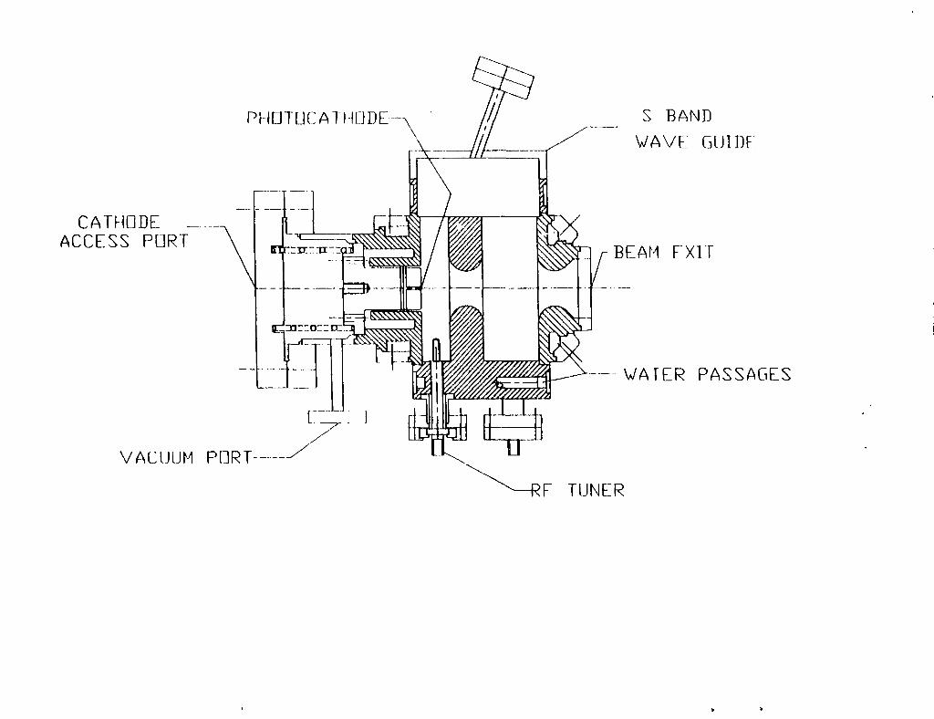
Figure 3. Wakefield contours of the electric field (Log of the magnitude) of the bunch at various
times a) 130° b) 145° c) 160° d) 175°.
Figure 4. Variation of parameters through the 3 V2 cell gun for a 1 nC bunch, admittance and
divergence, b)momentum (P) and momentum spread (dP/P).
Figure 5. Longitudinal phase space at the exit of Gun II and the longitudinal phase space after
ideally compressing the bunch (1 nC).
Figure 6. Transverse phase space at the exit of Gun II (1 nC).
Figure 7. Steady-state temperature distribution of the first cell and half of the following full cell for
Gun II operating at an accelerating gradient of 100 MV/m, 1% duty factor.
Figure 8. Von Mises Stress Intensity contours that result from the temperature distribution show
in Fig. 7.
10

REFERENCES
[1] Proposed UV FEL user facility at BNL, I. Ben-Zvi, L. F. Di Maura, S. Krinsky, M. G.White, and L. H. Yu, Nucl. Inst. Meth. A304 (1991) 181.
[2] K. R. Crandall and L. Young, "PARMELA," in the Compendium of Computer Codes forParticle Accelerator Design and Analysis, H. Deaven and K. C. Chan, Eds. Los Alamos Natl.Lab report LA-UR-90-1766, May (1990) 137.
[3] G. D. Warren, L. Ludeking, J. McDonald, K. Nguyen, and B. Goplen, "MAGIC UsersGroup Software," Proceedings of the Conference on Computer Codes and the LinearAccelerator Community, Los Alamos National Laboratory, Jan 22-25, 1990, Richard Cooper,Ed. LA-11857-Z(1990)57.
[4] ANSYS Engineering Analysis System, Rev 4.3A, Swanson Analysis Systems Inc., Houston,Pa. (1987).
[5] M. T. Menzel and H. K. Stokes, "Users guide for the POISSON/SUPERFISH group ofcodes,"Los Alamos Natl. Lab. Rep. LA-UR-87-115, Jan 1987.
[6] Equivalent Stress Theory, E. F. Bruhn, "Analysis and Design of Flight Vehicle Structures,"Pan C. Tri-State Offset Co. Cinn. OH. (1965)
[7] C. K. Birdsall and B Langdon, "Plasma Physics Via Computer Simulation," McGraw-Hill,New York (1985).
[8] H. G. Kirk et al., "Experimental Results from the BNL ATF Photocaihode Gun," theseproceedings.
[9] K. McDonald, IEEE Trans. Electron Dev. 35 (1988) 2052.
[10] Criteria of the ASME Boiler and Pressure Vessel Code for Design and Analysis, Sec. Ill,VIII: Division 2, Appendix 4, The American Society of Mechanical Engineering, NY,NY.U974)
[11] G. Stoner, "A Report on Corrosion Engineering Services for the Temperature Control of theATS and ATSU Accelerator Systems for LANL," Los Alamos internal report (1985)
11
CATHODE _.ACCESS PORT
PHDTUCATHDDE
VACUUM PORT
S BAND
WAVE GUIDE
BEAM EXIT
WATER PASSAGES
E TUNER

o2o
•o
a o
O> OOOi oO
d
UJ
8O
= Q-i
ooo
^ +UJ csmo
O 0 0 LU
Ui» i iA II» * • ! I!. * i X Z j i i
OO
o
M
8'W ^ 0 0

RF Phosa = 130 Dagraas Rf Phosa = 145 Dtgrcts
0.0
RF Phast = 160 Oegraas Rf Phos* = f75 Otgrtvs
0.0

mra
•
E
CDOcCO
Euu
CD
ft
25
20
15
10
5
0
12
10
8
6
4
(a)
> 1*
••. *
I- i
•
•t
# k
t«1t ^ %• / \
A \/ *. \\ \/ \ \/ i V-
/ I A/ \.A. v,
1 / A /* •
/\/ \/ \/ \/ \/ \
/ \\ \\\ \.%
• /v/
A/ \/ \
/ V/ A\ /]
AA -/ \/ \/ \/ \/ \/ \/ \/\ \
"" EmittanceDivergence
-
/ Av \ : :-* *10 15 20
20
50
40
:30
20
0
.: 10 Z
Z(cm)

Uncompressed current: 220 ampsCompressed current: 4224 amps
Compression factor: 19.2
0.0
clz (mm)1.5

Transverse phase in x and x'
XJP
NCD
XT5
-8.4 0.0dx (mm)