Positioning beacon system using digital camera and leds
14
406 IEEE TRANSACTIONS ON VEHICULAR TECHNOLOGY, VOL. 52, NO. 2, MARCH 2003 Positioning Beacon System Using Digital Camera and LEDs Hugh Sing Liu, Member, IEEE, and Grantham Pang, Senior Member, IEEE Abstract—This paper is on a novel use of lighting or signaling de- vices constructed by light-emitting diodes (LEDs) as a positioning beacon. The idea is that the surface of the LED lighting device is divided into regions and used to show different visual patterns that are not noticeable by the human eye due to the high-frequency switching of the LEDs. A digital camera is used as a receiver to capture a sequence of images of the LED positioning beacon trans- mitter. Image-processing algorithms are used to decode the loca- tion code that is encoded in the visual patterns transmitted by the LED device. This idea can be applied to any LED traffic lights or signaling devices on the road and turn them into parts of a po- sitioning beacon system. Such a system made up of high-bright- ness visible LEDs can provide the function of open-space wireless broadcasting of the positioning signal. The LED signaling method, transmission protocol, camera frame rate, LED flash rate, together with an implemented system and the experimental results, are pre- sented in this paper. Index Terms—Digital image processing, light-emitting diode (LED), location beacon, vehicle positioning. I. INTRODUCTION T HE growth of development in the area of light-emitting diodes (LEDs) is mainly due to the introduction of AlInGaP devices. Nowadays, billions of visible LEDs are produced each year, and the emergence of high-brightness AlGaAs and AlInGaP devices has given rise to many new markets [1]–[3]. More recently, AlGaInN materials have been introduced and led to improvements in the performance of bluish-green LEDs [1]. The luminous “efficacy peaks” are much higher than incandescent lamps [3], and the entire visible spectrum is not available. This advancement has led to the production of large-area full-color LED displays for outdoors applications. LEDs are increasingly being used in message display boards, traffic lights, signal devices, or other means of illumination on the road. They are superior to incandescent lights due to their long life expectancy, high tolerance to humidity, low power con- sumption, and minimal heat generation [4]. One important char- acteristic of LEDs is that they are semiconductor devices and are capable of switching on and off at a very fast rate. When the LEDs are arranged in a special pattern and switched in a partic- ular way, they could display a special code that is invisible to the human eye. Therefore, in addition to the normal function of being an indication and illumination device, an LED traffic light or signal device can be used as a location-code broadcasting de- Manuscript received July 2000; revised October 2002. H. S. Liu is with Saning Electronic Limited (e-mail: [email protected]). G. Pang is with the Department of Electrical and Electronic Engineering, The University of Hong Kong, Hong Kong, China (e-mail: [email protected]). Digital Object Identifier 10.1109/TVT.2002.808800 vice. Hence, it becomes part of a wireless positioning beacon system. This paper describes the architecture and design of such a system for the broadcasting of positioning information. Pre- vious research in beacon vehicle positioning and information system can be found in [5] and [6] It has been shown that visible light LEDs can be modulated for communication purpose [7]. This concurrent use of visible LEDs for simultaneous signaling and communication leads to many new and interesting applications. The idea of fast switching of LEDs and the modulation of the visible light waves for free space communications has been examined [8]–[12]. The feasibility of such an approach has been demonstrated and hardware has been implemented with experimental results. An optical data link has been implemented using an LED traffic signal head as a transmitter [9], [10]. The LED traffic light can be used for either audio or data transmission. Audio messages can be sent using the LED transmitter, and a receiver located at a distance around 20 m away can play back the messages with a speaker. For data transmission, digital data can be sent using the same LED transmitter, and experiments have been performed to send a speed-limit information. The work reported in this paper extends from the previous work in different ways. The view angle of the receiver of the previous work [11], [12] is only around 5 , which is very small. Hence, this gives a direct line-of-sight problem between the transmitter and the receiver. The new development reported in this paper can extend the field of view from 5 to 30 in a real application. Another extension is that in the previous work, the LEDs of the traffic light are turned on and off at the same time instance and the receiver is constructed from a photodiode. In this paper, the switching of the LEDs in the transmitter is more sophisticated and a digital camera is used as a receiver. Image-processing algorithms are developed to retrieve the loca- tion code from the LED positioning beacon. More about beacon location systems can be found in [13] and [14] II. SYSTEM ARCHITECTURE The location beacon system developed consists of an intelli- gent LED traffic light [10] and a camera-based receiver. A lo- cation code is transmitted by the intelligent LED traffic light. A passing-by vehicle equipped with the camera-based receiver can obtain this location code through this visible optical wire- less link. The scenario is shown in Fig. 1. A block diagram rep- resentation of the system is shown in Fig. 2. At the transmitter side, the three major components are the microcontroller, LED driver, and LED panel. The modulated signal is transmitted by the switching of the LEDs. The switching frequency is high enough that the perceivable light appears to be constantly il- 0018-9545/03$17.00 © 2003 IEEE
-
Upload
khangminh22 -
Category
Documents
-
view
0 -
download
0
Transcript of Positioning beacon system using digital camera and leds

406 IEEE TRANSACTIONS ON VEHICULAR TECHNOLOGY, VOL. 52, NO. 2, MARCH 2003
Positioning Beacon System Using Digital Cameraand LEDs
Hugh Sing Liu, Member, IEEE,and Grantham Pang, Senior Member, IEEE
Abstract—This paper is on a novel use of lighting or signaling de-vices constructed by light-emitting diodes (LEDs) as a positioningbeacon. The idea is that the surface of the LED lighting device isdivided into regions and used to show different visual patterns thatare not noticeable by the human eye due to the high-frequencyswitching of the LEDs. A digital camera is used as a receiver tocapture a sequence of images of the LED positioning beacon trans-mitter. Image-processing algorithms are used to decode the loca-tion code that is encoded in the visual patterns transmitted by theLED device. This idea can be applied to any LED traffic lights orsignaling devices on the road and turn them into parts of a po-sitioning beacon system. Such a system made up of high-bright-ness visible LEDs can provide the function of open-space wirelessbroadcasting of the positioning signal. The LED signaling method,transmission protocol, camera frame rate, LED flash rate, togetherwith an implemented system and the experimental results, are pre-sented in this paper.
Index Terms—Digital image processing, light-emitting diode(LED), location beacon, vehicle positioning.
I. INTRODUCTION
T HE growth of development in the area of light-emittingdiodes (LEDs) is mainly due to the introduction of
AlInGaP devices. Nowadays, billions of visible LEDs areproduced each year, and the emergence of high-brightnessAlGaAs and AlInGaP devices has given rise to many newmarkets [1]–[3]. More recently, AlGaInN materials have beenintroduced and led to improvements in the performance ofbluish-green LEDs [1]. The luminous “efficacy peaks” aremuch higher than incandescent lamps [3], and the entire visiblespectrum is not available. This advancement has led to theproduction of large-area full-color LED displays for outdoorsapplications.
LEDs are increasingly being used in message display boards,traffic lights, signal devices, or other means of illumination onthe road. They are superior to incandescent lights due to theirlong life expectancy, high tolerance to humidity, low power con-sumption, and minimal heat generation [4]. One important char-acteristic of LEDs is that they are semiconductor devices andare capable of switching on and off at a very fast rate. When theLEDs are arranged in a special pattern and switched in a partic-ular way, they could display a special code that is invisible tothe human eye. Therefore, in addition to the normal function ofbeing an indication and illumination device, an LED traffic lightor signal device can be used as a location-code broadcasting de-
Manuscript received July 2000; revised October 2002.H. S. Liu is with Saning Electronic Limited (e-mail: [email protected]).G. Pang is with the Department of Electrical and Electronic Engineering, The
University of Hong Kong, Hong Kong, China (e-mail: [email protected]).Digital Object Identifier 10.1109/TVT.2002.808800
vice. Hence, it becomes part of a wireless positioning beaconsystem. This paper describes the architecture and design of sucha system for the broadcasting of positioning information. Pre-vious research in beacon vehicle positioning and informationsystem can be found in [5] and [6]
It has been shown that visible light LEDs can be modulatedfor communication purpose [7]. This concurrent use of visibleLEDs for simultaneous signaling and communication leadsto many new and interesting applications. The idea of fastswitching of LEDs and the modulation of the visible light wavesfor free space communications has been examined [8]–[12].The feasibility of such an approach has been demonstrated andhardware has been implemented with experimental results. Anoptical data link has been implemented using an LED trafficsignal head as a transmitter [9], [10]. The LED traffic light canbe used for either audio or data transmission. Audio messagescan be sent using the LED transmitter, and a receiver locatedat a distance around 20 m away can play back the messageswith a speaker. For data transmission, digital data can be sentusing the same LED transmitter, and experiments have beenperformed to send a speed-limit information.
The work reported in this paper extends from the previouswork in different ways. The view angle of the receiver of theprevious work [11], [12] is only around 5, which is very small.Hence, this gives a direct line-of-sight problem between thetransmitter and the receiver. The new development reported inthis paper can extend the field of view from 5to 30 in areal application. Another extension is that in the previous work,the LEDs of the traffic light are turned on and off at the sametime instance and the receiver is constructed from a photodiode.In this paper, the switching of the LEDs in the transmitter ismore sophisticated and a digital camera is used as a receiver.Image-processing algorithms are developed to retrieve the loca-tion code from the LED positioning beacon. More about beaconlocation systems can be found in [13] and [14]
II. SYSTEM ARCHITECTURE
The location beacon system developed consists of an intelli-gent LED traffic light [10] and a camera-based receiver. A lo-cation code is transmitted by the intelligent LED traffic light.A passing-by vehicle equipped with the camera-based receivercan obtain this location code through this visible optical wire-less link. The scenario is shown in Fig. 1. A block diagram rep-resentation of the system is shown in Fig. 2. At the transmitterside, the three major components are the microcontroller, LEDdriver, and LED panel. The modulated signal is transmitted bythe switching of the LEDs. The switching frequency is highenough that the perceivable light appears to be constantly il-
0018-9545/03$17.00 © 2003 IEEE

LIU AND PANG: POSITIONING BEACON SYSTEM USING DIGITAL CAMERA AND LEDS 407
Fig. 1. A scenario of the proposed LED location beacon system based on adigital camera receiver.
Fig. 2. System architecture of the proposed location beacon system.
luminated to the human eye. The receiver consists of a digitalcamera, a camera controller, memory units for storing images,an image processor, and a transceiver for external communica-tion.
A. Intelligent LED Traffic Light
When a photodiode-based receiver is used, all the LEDs ina panel are switched on and off at the same time. When thiscamera-based receiver is used, the LED panel is partitioned (inthis paper, nine partitions are proposed). Within each partition,the LED is turned on and off simultaneously. However, differentpatterns can be shown on the LED panel at a time. A micro-controller unit (MCU), which contains a unique location code,mainly performs two tasks. First, it is responsible for control-ling the on-pattern of the LED panel in different periods. Thus,different patterns on the LED panel are actually being flashed,and the rate is fast enough that the human eye cannot detect it.The sequence of flashes is in accordance with a proposed pro-tocol described later. The second task of the microcontroller is tocontrol the intelligent traffic light so that it functions as a normaltraffic signaling device. Driver circuits are necessary to switchthe array of LEDs on and off in a fast way and at the same time
Fig. 3. The architecture of the intelligent LED traffic light for a camera-basedreceiver.
provides enough current to the LEDs. A power MOSFET canbe used in the intelligent LED traffic light design. Fig. 3 showsa diagrammatic illustration of the intelligent LED traffic light.
B. Digital Camera-Based LED Signal Receiver
The location beacon receiver consists of a digital camera, acamera controller, memories for storing images, an image pro-cessor, and a transceiver for external communication. Fig. 4shows the structure of the digital camera-based LED signal re-ceiver. A CMOS digital camera module is used to capture theimages of the intelligent LED traffic light. The operations ofthe digital camera are controlled by the control unit. The opera-tion of the digital camera is controlled for image capturing andparameter modification. The captured images are stored in thememory unit and then processed. The image processor wouldextract the location code from the images with the algorithmsdeveloped. The transceiver is used for sending out the extractedlocation code to a main navigation unit. It is a bridge for thecommunication between the digital camera-based LED signalreceiver and the main navigation unit.
III. T RANSMISSIONPROTOCOL
The design of the transmission protocol for the intelligentLED traffic light is based on the differencing of image se-quences, which can be used to extract the location code. A goodtransmission protocol would provide a simple and efficientsystem. The criteria of the protocol design, the proposedA-On-A’-Off protocol, and the method of transmitting morethan one digit are described in this section.
There are three requirements on the design of the transmis-sion protocol.
1) The LED panel should transmit information wirelesslyand optically.
2) The light emitted by the LED panel should be constant(undetectable flashing).
3) Asynchronous communications.The captured images are stored in the memory unit for pro-
cessing. The size of digital image is often large. For a 384288pixel, 8-bit gray-level image, the size is 108 Kbyte. Thus thetransmission protocol should minimize the number of imageframes required for the extraction of a location code. This couldsave the cost by using less memory and decrease the computa-tional time by processing fewer image frames.
The location beacon is a simplex communication link. Theprotocol is designed to be simple and workable. Thus, the pro-
408 IEEE TRANSACTIONS ON VEHICULAR TECHNOLOGY, VOL. 52, NO. 2, MARCH 2003
Fig. 4. The structure of the digital camera-based LED signal receiver.
tocol design should prevent the need of synchronization be-tween the transmitter and the receiver. This means that a vehiclecan receive a location code at any time it approaches the intelli-gent LED traffic light.
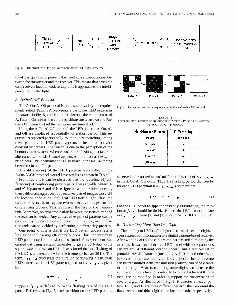
A. A-On-A’-Off Protocol
The A-On-A’-Off protocol is proposed to satisfy the require-ments stated. Pattern A represents a particular LED pattern asillustrated in Fig. 5, and Pattern A’ denotes the complement ofA. Pattern On means that all the partitions are turned on and Pat-tern Off means that all the partitions are turned off.
Using the A-On-A’-Off protocol, the LED patterns A, On, A’,and Off are displayed sequentially for a short period. This se-quence is repeated periodically. With the fast switching amongthese patterns, the LED panel appears to be turned on withconstant brightness. The reason is due to the perception of thehuman vision system. When A and A’ are flashing at a fast ratealternatively, the LED panel appears to be all on at the samebrightness. This phenomenon is also found in the fast switchingbetween On and Off patterns.
The differencing of the LED patterns transmitted in theA-On-A’-Off protocol would have results as shown in Table I.
From Table I, it can be observed that the (absolute of) dif-ferencing of neighboring pattern pairs always yields pattern Aand A’. If pattern A and A’ is assigned to a unique location code,then a differencing process of a received pair of images can yieldthe location code of an intelligent LED traffic light. Thus, thecamera only needs to capture two consecutive images for thedifferencing process. This minimizes the size of the memoryunit. Moreover, no synchronization between the transmitter andthe receiver is needed. Any consecutive pairs of patterns can becaptured by the camera-based receiver at any time, and a loca-tion code can be yielded by performing a differencing process.
One point to note is that if the LED pattern update rate islow, then the flickering effect can be seen. Thus, the minimumLED pattern update rate should be found. An experiment wascarried out using a signal generator to give a 50% duty cyclesquare wave to drive an LED. It was found that the flashing ofthe LED is undetectable when the frequency is over 50 Hz. Theterm represents the duration of showing a particularLED pattern, and the LED pattern update rate is givenby
(1)
Suppose is defined to be the flashing rate of the LEDpanel. Referring to Fig. 5, each partition on the LED panel is
Fig. 5. Pattern transmission sequence using the A-On-A’-Off protocol.
TABLE IDIFFERENCINGRESULTS OFNEIGHBORING PATTERN PAIRS TRANSMITTED IN
AN A-ON-A’-OFF PROTOCOL
observed to be turned on and off for the duration of 2in an A-On-A’-Off cycle. Thus the flashing period that resultsfor each LED partition is 4 and therefore
(2)
For the LED panel to appear constantly illuminating, the min-imum should be 50 Hz. Hence, the LED pattern updaterate , from (1) and (2), should be Hz Hz.
B. Transmitting More Than One Digit
The intelligent LED traffic light can transmit several digits oreven a stream of information to a digital camera-based receiver.After working out all possible combinations and eliminating theoverlaps, it was found that an LED panel with nine partitionscan present 61 different location codes. Thus a reduced set ofprintable ASCII character (including A-Z, 0–9, and other sym-bols) can be represented by an LED pattern. Thus a messagecan be transmitted if the transmission protocol can handle morethan one digit. Also, transmitting more digits can increase thenumber of unique location codes. In fact, the A-On-A’-Off pro-tocol can be modified in order to support the transmission ofseveral digits. As illustrated in Fig. 6, H denotes a header pat-tern. B, C, and D are three different patterns that represent thefirst, second, and third digit of the location code, respectively.
LIU AND PANG: POSITIONING BEACON SYSTEM USING DIGITAL CAMERA AND LEDS 409
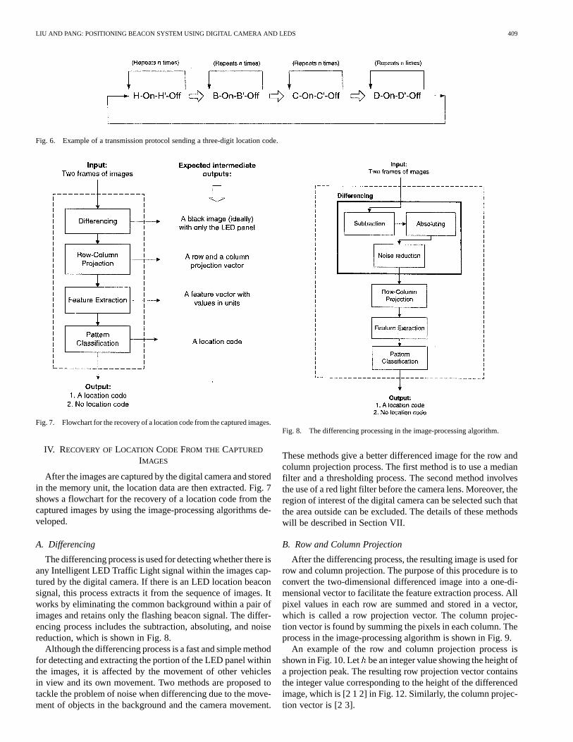
Fig. 6. Example of a transmission protocol sending a three-digit location code.
Fig. 7. Flowchart for the recovery of a location code from the captured images.
IV. RECOVERY OFLOCATION CODE FROM THE CAPTURED
IMAGES
After the images are captured by the digital camera and storedin the memory unit, the location data are then extracted. Fig. 7shows a flowchart for the recovery of a location code from thecaptured images by using the image-processing algorithms de-veloped.
A. Differencing
The differencing process is used for detecting whether there isany Intelligent LED Traffic Light signal within the images cap-tured by the digital camera. If there is an LED location beaconsignal, this process extracts it from the sequence of images. Itworks by eliminating the common background within a pair ofimages and retains only the flashing beacon signal. The differ-encing process includes the subtraction, absoluting, and noisereduction, which is shown in Fig. 8.
Although the differencing process is a fast and simple methodfor detecting and extracting the portion of the LED panel withinthe images, it is affected by the movement of other vehiclesin view and its own movement. Two methods are proposed totackle the problem of noise when differencing due to the move-ment of objects in the background and the camera movement.
Fig. 8. The differencing processing in the image-processing algorithm.
These methods give a better differenced image for the row andcolumn projection process. The first method is to use a medianfilter and a thresholding process. The second method involvesthe use of a red light filter before the camera lens. Moreover, theregion of interest of the digital camera can be selected such thatthe area outside can be excluded. The details of these methodswill be described in Section VII.
B. Row and Column Projection
After the differencing process, the resulting image is used forrow and column projection. The purpose of this procedure is toconvert the two-dimensional differenced image into a one-di-mensional vector to facilitate the feature extraction process. Allpixel values in each row are summed and stored in a vector,which is called a row projection vector. The column projec-tion vector is found by summing the pixels in each column. Theprocess in the image-processing algorithm is shown in Fig. 9.
An example of the row and column projection process isshown in Fig. 10. Let be an integer value showing the height ofa projection peak. The resulting row projection vector containsthe integer value corresponding to the height of the differencedimage, which is [2 1 2] in Fig. 12. Similarly, the column projec-tion vector is [2 3].

410 IEEE TRANSACTIONS ON VEHICULAR TECHNOLOGY, VOL. 52, NO. 2, MARCH 2003
Fig. 9. The row and column projection processing in the image-processingalgorithm.
C. Feature Extraction
The row and column projection vectors are cascaded to ob-tain the feature vector for the pattern. The feature extraction pro-cessing in the image process algorithms is shown in Fig. 11. Forexample, the feature vector for the pattern in Fig. 12 should be[2 1 2 2 3], which represents a unique location code. Elementsfrom the top down in the row projection and then left to right inthe column projection are processed and give the feature vector.In an actual situation, the row and column projections waveformmay not be so precise due to noise and distortion of the LEDpanel signal. Thus, a robust algorithm for finding the peaks andthe corresponding values in the differenced image is needed inorder to provide correct results.
1) Feature Vectors for the 3 3 LED Panel: For a 3 3LED panel, there should be 2or 512 different patterns. How-ever, not all of them can be used for representing a locationcode. This is due to the nature of the row and column projec-tion and the feature extraction process. The reason is illustratedin Fig. 12. In Fig. 12(a), the horizontal projection gives valuesof [2 1 0] for the three rows. For vertical projection, the threevalues are [2 1 0]. The value of zero (i.e., [0]) is then ignored.When the horizontal projection value is cascaded with the ver-tical projection value, we obtain the feature vector [2 1 2 1]. InFig. 12(b), horizontal projection gives [0 2 1] and vertical pro-jection gives [2 1 0], but the final feature vector is also [2 1 2 1].Similarly, all four different LED patterns have the same featurevector [2 1 2 1] and can represent just one location code. Thus,the number of usable patterns is reduced. Moreover, a patternand its complement pattern are both assigned the same uniquelocation code due to the design of the transmission protocol.This further reduces the number of location codes that can be
presented by the LED panel. Finally, only 61 pairs of the LEDpatterns with their complements can be used to present the lo-cation codes. As an example, nine of the LED patterns and theircomplements are shown in Fig. 13. These nine pairs of featurevectors represent nine LED pattern-complement pairs (referringto Fig. 13), as shown in Table II.
The number of location codes that can be presented by theLED panel can be increased by sending a multidigit code, asmentioned earlier. However, the multidigit code cannot containan identical neighboring digit due to the transmission protocoldesign. Also, there should be a digit reserved for the header.Thus, for a three-digit location code, the number of locationcodes supported should be .
D. Pattern Classification
Once the feature vector is obtained, the corresponding loca-tion code can be found by searching a lookup table relating thefeature vectors and the location codes. For a fast search, the fea-ture vector data can be organized into a tree structure with threebranches (for values of one, two, and three in the feature vector).For a 3 3 LED panel, the feature vector for a location codedigit contains zero to six elements. Thus, the tree structure con-tains six levels. A searching algorithm such as heuristic searchand bidirectional search can be used.
V. NOISE IN THE DIFFERENCING
Although the differencing process is a fast and simple methodfor detecting and extracting the portion of the LED panel withinthe images, it is affected by the movement of other vehicles inview and its own movement. The concept of differencing givenbefore is based on the assumption of a static background exceptthe signal and a static camera. In this section, an analysis ofnoise caused by the object and the camera movement is given.
A. Object Movement
The objects in the background could have moved between twoconsecutive image frames. Thus, the result of the differencingcontains the signal as well as the noise caused by the backgroundobjects that may have shifted slightly. An analysis is to be de-veloped for the study of how the system parameters are relatedto the noise.
The following terms are defined:camera capture rate in frame per second (fps);object speed (ms );perpendicular distance from the camera lens to theobject (m);pixel width of the digital camera (m);focal length of the camera lens (mm);distance between the lens and the camera sensorplane (m);magnification factor of the lens;displacement of the moving object between two con-secutive image frames (m);displacement of the image of the moving object onthe sensor plane between two consecutive imageframes (m);

LIU AND PANG: POSITIONING BEACON SYSTEM USING DIGITAL CAMERA AND LEDS 411
Fig. 10. An example of the row and column projection process.
Fig. 11. The feature extraction processing in the image process algorithms.
Fig. 12. Four different LED patterns having the same feature vector.
pix displacement of the image of the moving object de-noted by the number of pixel on the sensor planebetween two consecutive image frames.
The case when an object is moving laterally in front of thecamera system is studied and illustrated in Fig. 14.
Fig. 13. LED patterns and their complement (nine out of 61 pairs) used topresent the location codes.
TABLE IIFEATURE VECTORS OFLED PATTERN PAIRS
By the principle of optics
(3)
Then
(4)

412 IEEE TRANSACTIONS ON VEHICULAR TECHNOLOGY, VOL. 52, NO. 2, MARCH 2003
Fig. 14. Illustration of the case when an object is moving laterally in front ofthe camera system.
The displacement of the object between two image frames is
(5)
The displacement of the image of the object on the sensor planeis found by combining (4) and (5)
(6)
Hence, the displacement of the image on the sensor plate interms of the number of pixels is
(7)
A numerical example is given below. Assume that a digitalcamera is kept stationary and takes two pictures at a capturingrate of 50 frames per second. A vehicle is moving laterally ata speed of 45 km/h or 12.5 ms (the speed limit is 50 km/hfor the vast majority of urban roads [15]) at a distance of 15 mfrom the camera. The distance between the camera lens and theCMOS sensor plane is 0.02 m. The camera pixel width is 11
m. Then, the change in the distance of the object between thefirst and the second frame (in number of pixels) is
pix
This value is too large for the differencing process to be useful.However, if the camera capturing rate is 500 fps, then the re-sulting deviation, which could be only three pixels, is usable forthe location code extraction.
B. Camera Movement
If the camera has been moved laterally relative to an object,then the analysis is similar to the previous one. But supposethe camera is moving toward a point object. Fig. 16 shows anillustration for this case. Let be the perpendicular distance
from the point object to the principal axis of the lens in meters.Let be the perpendicular distance between the point image tothe principal axis of the lens in meters. As the camera movesforward, would increase.
By the principle of optics, assuming thatis changed ac-cording to in an autofocusing system
(8)
(9)
Suppose that the effect of on is of interest. By differen-tiating (8)
(10)
by (9)
Differentiating this equation gives
(11)
Combining (10) and (11)
Thus
but . Then
(12)
and the change of position of an image (in number of pixels) is
pix (13)
Assume that the digital camera is mounted on a vehicle movingat a speed of 45 km/h or 12.5 mstoward a point object. Thepoint object is at a perpendicular distance of 5 m to the principalaxis from the lens. Two pictures are captured at a rate of 50 fps.The object is stationary and initially at a perpendicular distanceof 15 m from the camera. The focal length of the camera lensis 7.4 mm. The camera pixel width is 11m. Then the distancechange of the object between the first and the second frame (innumber of pixels) is, by (13)
Thus, from this example, the effect of the vehicle movementtoward an object is less severe than the lateral object movementdescribed in the previous subsection.
LIU AND PANG: POSITIONING BEACON SYSTEM USING DIGITAL CAMERA AND LEDS 413
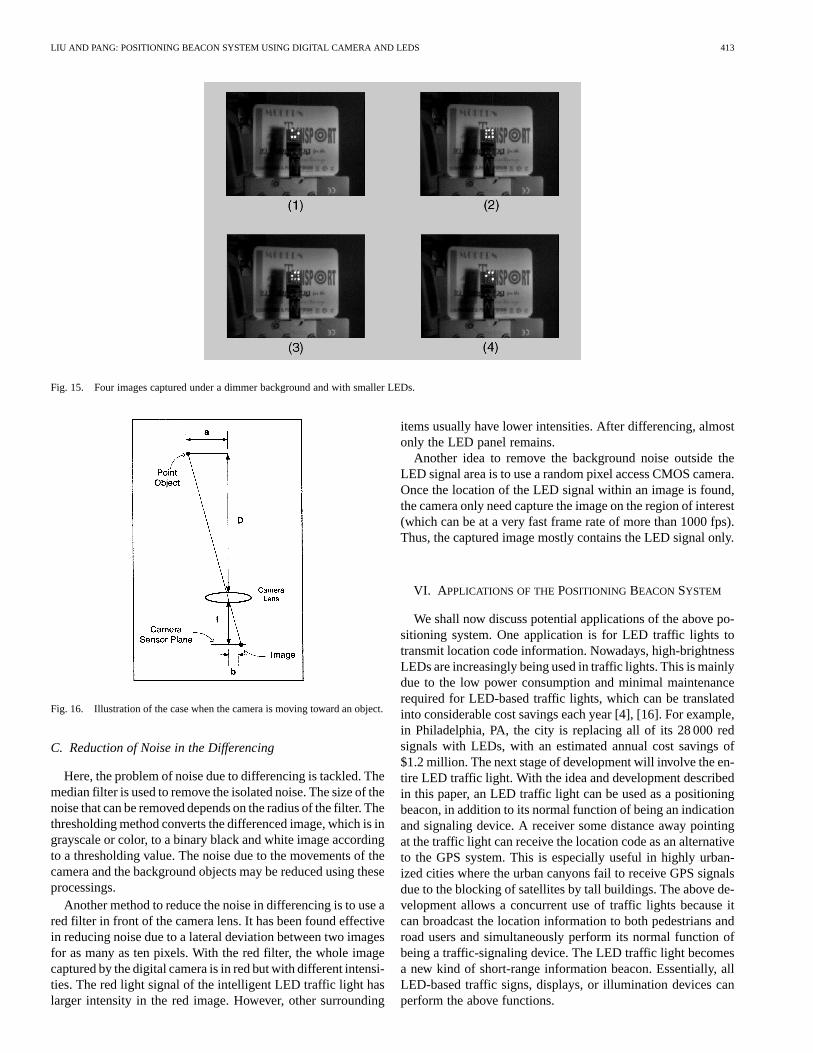
Fig. 15. Four images captured under a dimmer background and with smaller LEDs.
Fig. 16. Illustration of the case when the camera is moving toward an object.
C. Reduction of Noise in the Differencing
Here, the problem of noise due to differencing is tackled. Themedian filter is used to remove the isolated noise. The size of thenoise that can be removed depends on the radius of the filter. Thethresholding method converts the differenced image, which is ingrayscale or color, to a binary black and white image accordingto a thresholding value. The noise due to the movements of thecamera and the background objects may be reduced using theseprocessings.
Another method to reduce the noise in differencing is to use ared filter in front of the camera lens. It has been found effectivein reducing noise due to a lateral deviation between two imagesfor as many as ten pixels. With the red filter, the whole imagecaptured by the digital camera is in red but with different intensi-ties. The red light signal of the intelligent LED traffic light haslarger intensity in the red image. However, other surrounding
items usually have lower intensities. After differencing, almostonly the LED panel remains.
Another idea to remove the background noise outside theLED signal area is to use a random pixel access CMOS camera.Once the location of the LED signal within an image is found,the camera only need capture the image on the region of interest(which can be at a very fast frame rate of more than 1000 fps).Thus, the captured image mostly contains the LED signal only.
VI. A PPLICATIONS OF THEPOSITIONING BEACON SYSTEM
We shall now discuss potential applications of the above po-sitioning system. One application is for LED traffic lights totransmit location code information. Nowadays, high-brightnessLEDs are increasingly being used in traffic lights. This is mainlydue to the low power consumption and minimal maintenancerequired for LED-based traffic lights, which can be translatedinto considerable cost savings each year [4], [16]. For example,in Philadelphia, PA, the city is replacing all of its 28 000 redsignals with LEDs, with an estimated annual cost savings of$1.2 million. The next stage of development will involve the en-tire LED traffic light. With the idea and development describedin this paper, an LED traffic light can be used as a positioningbeacon, in addition to its normal function of being an indicationand signaling device. A receiver some distance away pointingat the traffic light can receive the location code as an alternativeto the GPS system. This is especially useful in highly urban-ized cities where the urban canyons fail to receive GPS signalsdue to the blocking of satellites by tall buildings. The above de-velopment allows a concurrent use of traffic lights because itcan broadcast the location information to both pedestrians androad users and simultaneously perform its normal function ofbeing a traffic-signaling device. The LED traffic light becomesa new kind of short-range information beacon. Essentially, allLED-based traffic signs, displays, or illumination devices canperform the above functions.
414 IEEE TRANSACTIONS ON VEHICULAR TECHNOLOGY, VOL. 52, NO. 2, MARCH 2003
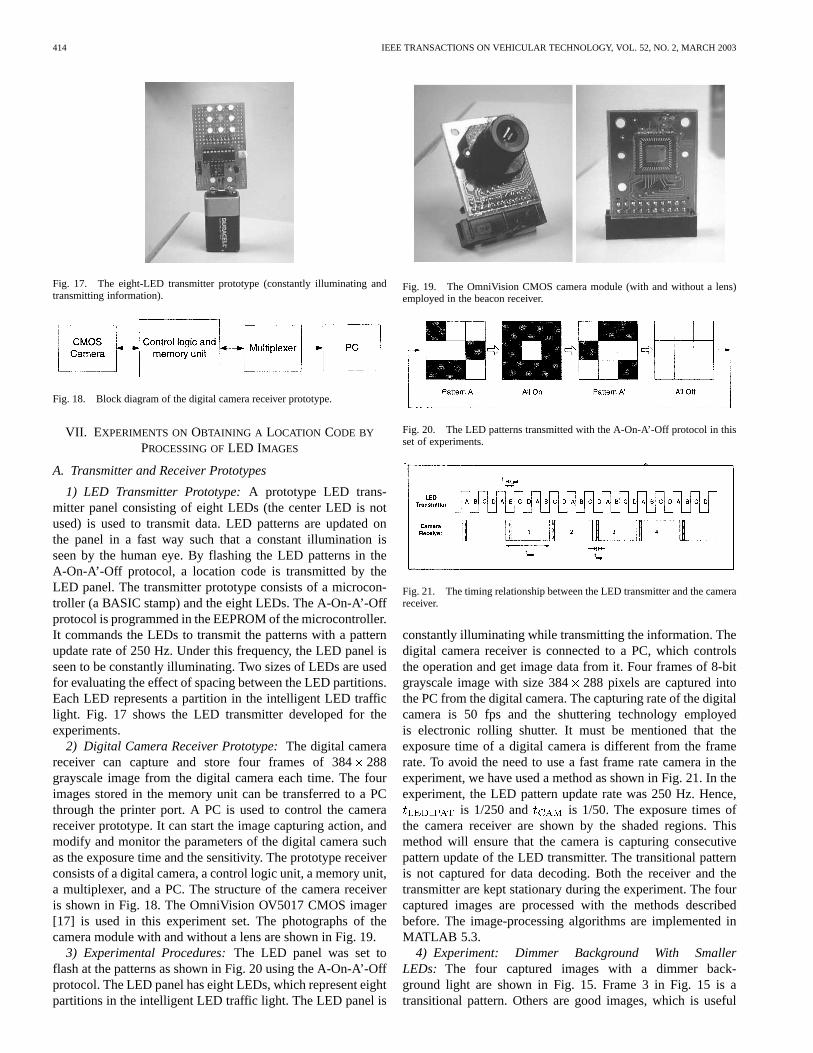
Fig. 17. The eight-LED transmitter prototype (constantly illuminating andtransmitting information).
Fig. 18. Block diagram of the digital camera receiver prototype.
VII. EXPERIMENTS ONOBTAINING A LOCATION CODE BY
PROCESSING OFLED IMAGES
A. Transmitter and Receiver Prototypes
1) LED Transmitter Prototype:A prototype LED trans-mitter panel consisting of eight LEDs (the center LED is notused) is used to transmit data. LED patterns are updated onthe panel in a fast way such that a constant illumination isseen by the human eye. By flashing the LED patterns in theA-On-A’-Off protocol, a location code is transmitted by theLED panel. The transmitter prototype consists of a microcon-troller (a BASIC stamp) and the eight LEDs. The A-On-A’-Offprotocol is programmed in the EEPROM of the microcontroller.It commands the LEDs to transmit the patterns with a patternupdate rate of 250 Hz. Under this frequency, the LED panel isseen to be constantly illuminating. Two sizes of LEDs are usedfor evaluating the effect of spacing between the LED partitions.Each LED represents a partition in the intelligent LED trafficlight. Fig. 17 shows the LED transmitter developed for theexperiments.
2) Digital Camera Receiver Prototype:The digital camerareceiver can capture and store four frames of 384288grayscale image from the digital camera each time. The fourimages stored in the memory unit can be transferred to a PCthrough the printer port. A PC is used to control the camerareceiver prototype. It can start the image capturing action, andmodify and monitor the parameters of the digital camera suchas the exposure time and the sensitivity. The prototype receiverconsists of a digital camera, a control logic unit, a memory unit,a multiplexer, and a PC. The structure of the camera receiveris shown in Fig. 18. The OmniVision OV5017 CMOS imager[17] is used in this experiment set. The photographs of thecamera module with and without a lens are shown in Fig. 19.
3) Experimental Procedures:The LED panel was set toflash at the patterns as shown in Fig. 20 using the A-On-A’-Offprotocol. The LED panel has eight LEDs, which represent eightpartitions in the intelligent LED traffic light. The LED panel is
Fig. 19. The OmniVision CMOS camera module (with and without a lens)employed in the beacon receiver.
Fig. 20. The LED patterns transmitted with the A-On-A’-Off protocol in thisset of experiments.
Fig. 21. The timing relationship between the LED transmitter and the camerareceiver.
constantly illuminating while transmitting the information. Thedigital camera receiver is connected to a PC, which controlsthe operation and get image data from it. Four frames of 8-bitgrayscale image with size 384288 pixels are captured intothe PC from the digital camera. The capturing rate of the digitalcamera is 50 fps and the shuttering technology employedis electronic rolling shutter. It must be mentioned that theexposure time of a digital camera is different from the framerate. To avoid the need to use a fast frame rate camera in theexperiment, we have used a method as shown in Fig. 21. In theexperiment, the LED pattern update rate was 250 Hz. Hence,
is 1/250 and is 1/50. The exposure times ofthe camera receiver are shown by the shaded regions. Thismethod will ensure that the camera is capturing consecutivepattern update of the LED transmitter. The transitional patternis not captured for data decoding. Both the receiver and thetransmitter are kept stationary during the experiment. The fourcaptured images are processed with the methods describedbefore. The image-processing algorithms are implemented inMATLAB 5.3.
4) Experiment: Dimmer Background With SmallerLEDs: The four captured images with a dimmer back-ground light are shown in Fig. 15. Frame 3 in Fig. 15 is atransitional pattern. Others are good images, which is useful

LIU AND PANG: POSITIONING BEACON SYSTEM USING DIGITAL CAMERA AND LEDS 415
Fig. 22. Closeup of the differenced image of frames 1 and 2 with the row and column projections.
Fig. 23. Image with a LED Traffic light showing a pattern A.
Fig. 24. Image with the LED traffic light turned all on and shifted 2 pixels tothe right.
for finding the location code. Fig. 22 shows the zoomeddifferenced images for patterns (1), (2) and the correspondingrow and column projection curves. A thresholding with index0.3 (ranges from zero to one) is used to convert the grayscaledifferenced image into a black and white image before the row
Fig. 25. A differenced image of Figs. 23 and 24 showing the complement (A’)of pattern A with noises.
Fig. 26. Image after applying a thresholding process of level 160 (of 256) andthree times the median filtering with radius of one pixel to Fig. 25.
and column projection procedure. The location code can beretrieved from the feature vector [2 1 1 1 1 2]. The computationtime required for the four stages of processing on a pair ofimages is 0.11 s. The result is obtained from running MATLAB
416 IEEE TRANSACTIONS ON VEHICULAR TECHNOLOGY, VOL. 52, NO. 2, MARCH 2003
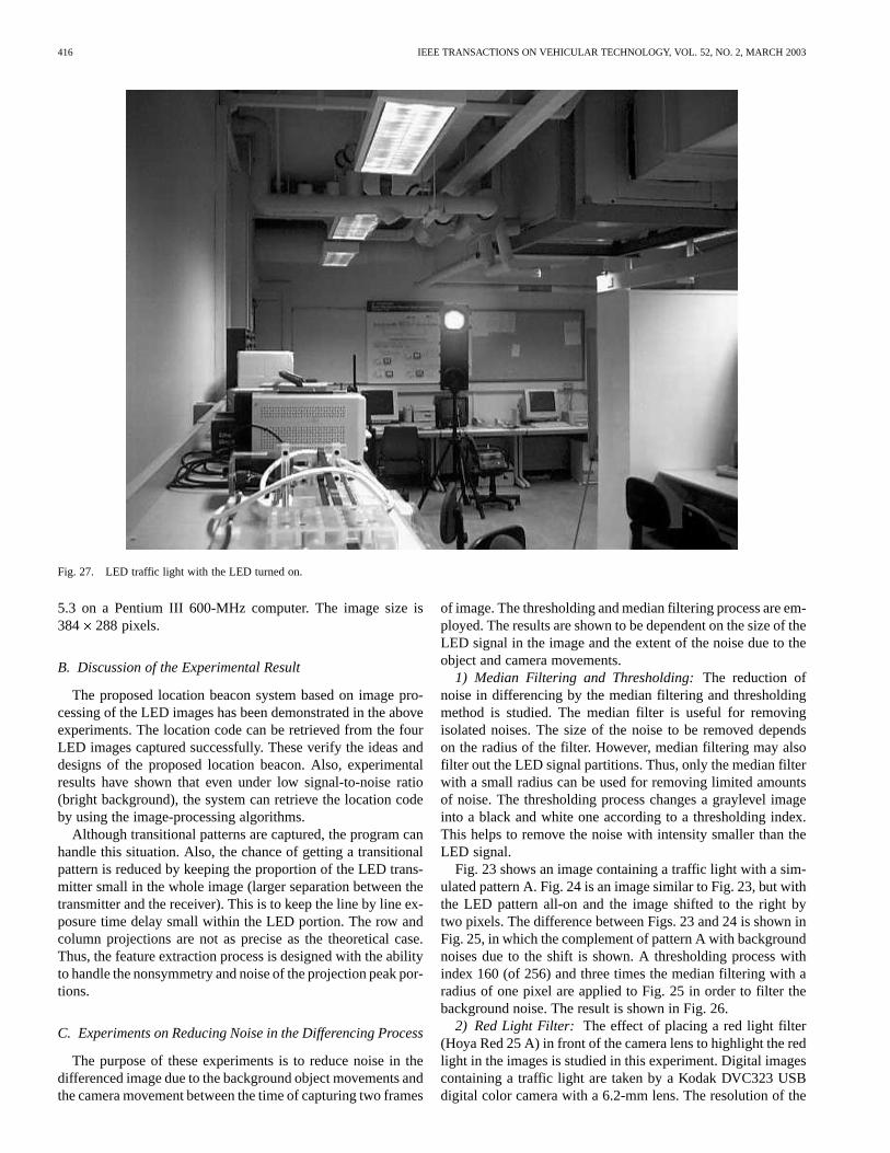
Fig. 27. LED traffic light with the LED turned on.
5.3 on a Pentium III 600-MHz computer. The image size is384 288 pixels.
B. Discussion of the Experimental Result
The proposed location beacon system based on image pro-cessing of the LED images has been demonstrated in the aboveexperiments. The location code can be retrieved from the fourLED images captured successfully. These verify the ideas anddesigns of the proposed location beacon. Also, experimentalresults have shown that even under low signal-to-noise ratio(bright background), the system can retrieve the location codeby using the image-processing algorithms.
Although transitional patterns are captured, the program canhandle this situation. Also, the chance of getting a transitionalpattern is reduced by keeping the proportion of the LED trans-mitter small in the whole image (larger separation between thetransmitter and the receiver). This is to keep the line by line ex-posure time delay small within the LED portion. The row andcolumn projections are not as precise as the theoretical case.Thus, the feature extraction process is designed with the abilityto handle the nonsymmetry and noise of the projection peak por-tions.
C. Experiments on Reducing Noise in the Differencing Process
The purpose of these experiments is to reduce noise in thedifferenced image due to the background object movements andthe camera movement between the time of capturing two frames
of image. The thresholding and median filtering process are em-ployed. The results are shown to be dependent on the size of theLED signal in the image and the extent of the noise due to theobject and camera movements.
1) Median Filtering and Thresholding:The reduction ofnoise in differencing by the median filtering and thresholdingmethod is studied. The median filter is useful for removingisolated noises. The size of the noise to be removed dependson the radius of the filter. However, median filtering may alsofilter out the LED signal partitions. Thus, only the median filterwith a small radius can be used for removing limited amountsof noise. The thresholding process changes a graylevel imageinto a black and white one according to a thresholding index.This helps to remove the noise with intensity smaller than theLED signal.
Fig. 23 shows an image containing a traffic light with a sim-ulated pattern A. Fig. 24 is an image similar to Fig. 23, but withthe LED pattern all-on and the image shifted to the right bytwo pixels. The difference between Figs. 23 and 24 is shown inFig. 25, in which the complement of pattern A with backgroundnoises due to the shift is shown. A thresholding process withindex 160 (of 256) and three times the median filtering with aradius of one pixel are applied to Fig. 25 in order to filter thebackground noise. The result is shown in Fig. 26.
2) Red Light Filter: The effect of placing a red light filter(Hoya Red 25 A) in front of the camera lens to highlight the redlight in the images is studied in this experiment. Digital imagescontaining a traffic light are taken by a Kodak DVC323 USBdigital color camera with a 6.2-mm lens. The resolution of the

LIU AND PANG: POSITIONING BEACON SYSTEM USING DIGITAL CAMERA AND LEDS 417
Fig. 28. Image with the LED traffic light turned off and shifted two pixels to the right.
Fig. 29. The differenced image of Figs. 27 and 28 with noise.
image is 640 480 pixels. The distance between the LED lightand the camera is about 8 m. An image captured with the LEDlight turned on is shown in Fig. 27. Another image was capturedwith the LED turned off. The whole picture was then shifted tothe right by two pixels, which is shown in Fig. 28. Figs. 27 and28 are differenced, and the result is shown in Fig. 29.
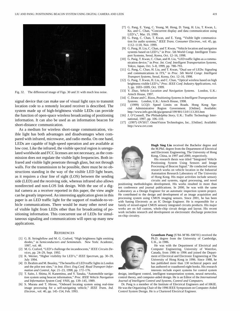
After installing the red filter in front of the camera lens, animage was captured, which is shown in Fig. 30. Another one wascaptured with the LED light turned off, which was shifted to theright by two pixels (Fig. 31). Figs. 30 and 31 are differenced,and the result is shown in Fig. 32.
3) Discussions on Noise Reduction for Differencing:Fromthe experimental results, the median filter is found to be effec-
tive for removing small differencing noise. The mask of the me-dian filter cannot be set to be too large. Otherwise, the LEDsignal may also be removed. The thresholding process is foundto be useful for removing noise with smaller intensity than theLED signal in the differenced image. From the experimental re-sults, much background noise is reduced.
The red light filter added before the camera lens is very effec-tive in reducing the noise of differencing caused by the objectand the camera movement. The filter can pass the red traffic lightsignal while reducing the intensity of the background. Thus, bydifferencing of the red images, the LED signal is readily seen.For an offset of two pixels without the red filter, the noise in thedifferenced image is high (Fig. 29). But for the same case with ared light filter (Fig. 32), the differenced noise is very low in sizeand intensity. Compared with the median filter and the thresh-olding method, the red filter method does not need extra pro-cessing time and gives better performance. For future research,a software filter can be used to select only the red signal insteadof a physical red light filter. Moreover, intelligent methods fortelling the camera to capture areas of interest (LED signal por-tion) can reduce much of the background noise.
VIII. D ISCUSSION ANDCONCLUSIONS
High-brightness LEDs are getting more popular and areopening up a number of new applications, especially withimproved efficiency and new colors. In this paper, the novelidea based on the fast switching of LEDs is developed into anew kind of positioning beacon system. An LED traffic light or

418 IEEE TRANSACTIONS ON VEHICULAR TECHNOLOGY, VOL. 52, NO. 2, MARCH 2003
Fig. 30. LED turned on and with red filter in front of the camera lens.
Fig. 31. LED traffic light turned off and with a red filter in front of the camera lens. This is shifted two pixels to the right relative to Fig. 30.
LIU AND PANG: POSITIONING BEACON SYSTEM USING DIGITAL CAMERA AND LEDS 419
Fig. 32. The differenced image of Figs. 30 and 31 with much less noise.
signal device that can make use of visual light rays to transmitlocation code to a remotely located receiver is described. Thesystem made up of high-brightness visible LEDs can providethe function of open-space wireless broadcasting of positioninginformation. It can also be used as an information beacon forshort-distance communication.
As a medium for wireless short-range communication, vis-ible light has both advantages and disadvantages when com-pared with infrared, microwave, and radio media. On one hand,LEDs are capable of high-speed operation and are available atlow cost. Like the infrared, the visible spectral region is unregu-lated worldwide and FCC licenses are not necessary, as the com-mission does not regulate the visible light frequencies. Both in-frared and visible light penetrate through glass, but not throughwalls. For the transmission to be possible, there must be no ob-structions standing in the way of the visible LED light beam,as it requires a clear line of sight (LOS) between the sendingside (LED) and the receiving side, whereas infrared also allowsnondirected and non-LOS link design. With the use of a dig-ital camera as a receiver reported in this paper, the view anglecan be greatly improved. An interesting application given in thispaper is an LED traffic light for the support of roadside-to-ve-hicle communications. There would be many other novel useof visible light from LEDs other than for broadcasting of po-sitioning information. This concurrent use of LEDs for simul-taneous signaling and communications will open up many newapplications.
REFERENCES
[1] G. B. Stringfellow and M. G. Craford, “High brightness light emittingdiodes,” inSemiconductors and Semimetals. New York: Academic,1997, vol. 48.
[2] M. G. Craford, “LED’s challenge the incandescents,”IEEE Circuits De-vices, pp. 24–29, Sept. 1992.
[3] K. Werner, “Higher visibility for LED’s,” IEEE Spectrum, pp. 30–39,July 1994.
[4] D. Ibrahim and M. Beasley, “The benefits of LED traffic lights in Londonand the pilot test sites,” inInst. Elect. Eng.Conf. Road Transport Infor-mation and Control, Apr. 21–23, 1998, pp. 172–176.
[5] T. Saito, J. Shima, H. Kanemitsu, and Y. Tanaka, “Automobile naviga-tion system using beacon information,”Proc. IEEE Vehicle Navigationand Information System Conf. VNIS, pp. 139–145, 1989.
[6] S. Murata and T. Hirose, “Onboard locating system using real-timeimage processing for a self-navigating vehicle,”IEEE Trans. Ind.Electron., vol. 40, pp. 145–154, Feb. 1993.
[7] G. Pang, E. Yang, C. Yeung, M. Hong, D. Yang, H. Liu, T. Kwan, L.Ko, and C. Chan, “Concurrent display and data communication usingLED’s,”, Mar. 19, 1999.
[8] G. Pang, C. Chan, T. Kwan, and E. Yang, “Visible light communica-tion for audio systems,”IEEE Trans. Consumer Electron., vol. 45, pp.1112–1118, Nov. 1999.
[9] G. Pang, H. Liu, C. Chan, and T. Kwan, “Vehicle location and navigationsystems based on LED’s,” in Proc. 5th World Congr. Intelligent Trans-port Systems, Seoul, Korea, Oct. 12–16, 1998.
[10] G. Pang, T. Kwan, C. Chan, and H. Liu, “LED traffic lights as a commu-nication device,” inProc. Int. Conf. Intelligent Transportation Systems,Tokyo, Japan, Oct. 5–8, 1999, pp. 788–793.
[11] G. Pang, C. Chan, H. Liu, and T. Kwan, “Dual use of LEDs: Signalingand communications in ITS,” inProc. 5th World Congr. IntelligentTransport Systems, Seoul, Korea, Oct. 12–16, 1998.
[12] G. Pang, T. Kwan, H. Liu, and C. Chan, “Optical wireless based on highbrightness visible LED’s,”Proc. IEEE Conf. Industry Applications, vol.3, pp. 1693–1699, Oct. 1999.
[13] Y. Zhao, Vehicle Location and Navigation Systems. London, U.K.:Artech House, 1997.
[14] C. Drane and C. Rizos,Positioning Systems in Intelligent TransportationSystems. London, U.K.: Artech House, 1998.
[15] (1999) LCQ3: Speed Limits on Roads. Hong Kong Spe-cial Administrative Region Government. [Online]. Available:http://www.info.gov.hk/gia/general/199 901/13/0 113 203.htm
[16] J. O’Connell,The Philadelphia Story, U.K.: Traffic Technology Inter-national, 1997, pp. 106–110.
[17] (1997) OV5017. OmniVision Technologies, Inc.. [Online]. Available:http://www.ovt.com
Hugh Sing Liu received the Bachelor degree andthe M.Phil. degree from the Department of Electricaland Electronic Engineering, The University of HongKong, China, in 1997 and 2000, respectively.
His research thesis was titled “Integrated VehiclePositioning System Using Sensors and ImageProcessing of Beacon Signal.” He conducted variousresearch works on vehicle location in the IndustrialAutomation Research Laboratory of The Universityof Hong Kong. His major activities include sensorycircuits and systems, signal processing, and novel
positioning methodologies development. His works resulted in more thanten conference and journal publications. In 2000, he was with the sameLaboratory as a Design Engineer for an automatic inspection system project.He contributed to the design and development of an image acquisition andprocessing system using CMOS imaging sensors. Since 2001, he has beenwith Saning Electronic as an IC Design Engineer. He is responsible for afamily of mixed-signal CMOS sensory integrated circuits products. His majorworks are on full custom, whole-chip circuit design and layout. His recentwork includes research and development on electrostatic discharge protectionon-chip circuitry.
Grantham Pang (S’84–M’86–SM’01) received thePh.D. degree from the University of Cambridge,U.K., in 1986.
He was with the Department of Electrical andComputer Engineering, University of Waterloo,Canada, from 1986 to 1996 and joined the Depart-ment of Electrical and Electronic Engineering at TheUniversity of Hong Kong in 1996. Since 1988, hehas published more than 130 technical papers andhas authored or coauthored eight books. His researchinterests include expert systems for control system
design, intelligent control, intelligent transportation system, neural networks,control theory, and computer-aided design. He is an Editor of theInternationalJournal of Intelligent Control and Systems, Control and Computers.
Dr. Pang is a member of the Institute of Electrical Engineers and of HKIE.He was the Organizing Chair of the 1996 IEEE Symposium on Computer-AidedControl System Design. He is a Chartered Electrical Engineer.