TU0546 Tutorial SoftConsole v4.0 and Libero SoC v11.7
41
TU0546 Tutorial SoftConsole v4.0 and Libero SoC v11.7
-
Upload
khangminh22 -
Category
Documents
-
view
3 -
download
0
Transcript of TU0546 Tutorial SoftConsole v4.0 and Libero SoC v11.7

TU0546 Tutorial
SoftConsole v4.0 and Libero SoC v11.7

50200546. 6.0 9.17
Microsemi Corporate HeadquartersOne Enterprise, Aliso Viejo,CA 92656 USAWithin the USA: +1 (800) 713-4113 Outside the USA: +1 (949) 380-6100Fax: +1 (949) 215-4996Email: [email protected]
© 2017 Microsemi Corporation. All rights reserved. Microsemi and the Microsemi logo are trademarks of Microsemi Corporation. All other trademarks and service marks are the property of their respective owners.
Microsemi makes no warranty, representation, or guarantee regarding the information contained herein or the suitability of its products and services for any particular purpose, nor does Microsemi assume any liability whatsoever arising out of the application or use of any product or circuit. The products sold hereunder and any other products sold by Microsemi have been subject to limited testing and should not be used in conjunction with mission-critical equipment or applications. Any performance specifications are believed to be reliable but are not verified, and Buyer must conduct and complete all performance and other testing of the products, alone and together with, or installed in, any end-products. Buyer shall not rely on any data and performance specifications or parameters provided by Microsemi. It is the Buyer's responsibility to independently determine suitability of any products and to test and verify the same. The information provided by Microsemi hereunder is provided “as is, where is” and with all faults, and the entire risk associated with such information is entirely with the Buyer. Microsemi does not grant, explicitly or implicitly, to any party any patent rights, licenses, or any other IP rights, whether with regard to such information itself or anything described by such information. Information provided in this document is proprietary to Microsemi, and Microsemi reserves the right to make any changes to the information in this document or to any products and services at any time without notice.
About Microsemi
Microsemi Corporation (Nasdaq: MSCC) offers a comprehensive portfolio of semiconductor and system solutions for aerospace & defense, communications, data center and industrial markets. Products include high-performance and radiation-hardened analog mixed-signal integrated circuits, FPGAs, SoCs and ASICs; power management products; timing and synchronization devices and precise time solutions, setting the world's standard for time; voice processing devices; RF solutions; discrete components; enterprise storage and communication solutions, security technologies and scalable anti-tamper products; Ethernet solutions; Power-over-Ethernet ICs and midspans; as well as custom design capabilities and services. Microsemi is headquartered in Aliso Viejo, California, and has approximately 4,800 employees globally. Learn more at www.microsemi.com.
TU0546 Tutorial Revision 6.0 iii
Contents
1 Revision History . . . . . . . . . . . . . . . . . . . . . . . . . . . . . . . . . . . . . . . . . . . . . . . . . . . . . 11.1 Revision 6.0 . . . . . . . . . . . . . . . . . . . . . . . . . . . . . . . . . . . . . . . . . . . . . . . . . . . . . . . . . . . . . . . . . . . . . . . 1
1.2 Revision 5.0 . . . . . . . . . . . . . . . . . . . . . . . . . . . . . . . . . . . . . . . . . . . . . . . . . . . . . . . . . . . . . . . . . . . . . . . 1
1.3 Revision 4.0 . . . . . . . . . . . . . . . . . . . . . . . . . . . . . . . . . . . . . . . . . . . . . . . . . . . . . . . . . . . . . . . . . . . . . . . 1
1.4 Revision 3.0 . . . . . . . . . . . . . . . . . . . . . . . . . . . . . . . . . . . . . . . . . . . . . . . . . . . . . . . . . . . . . . . . . . . . . . . 1
1.5 Revision 2.0 . . . . . . . . . . . . . . . . . . . . . . . . . . . . . . . . . . . . . . . . . . . . . . . . . . . . . . . . . . . . . . . . . . . . . . . 1
1.6 Revision 1.0 . . . . . . . . . . . . . . . . . . . . . . . . . . . . . . . . . . . . . . . . . . . . . . . . . . . . . . . . . . . . . . . . . . . . . . . 1
2 SoftConsole v4.0 and Libero SoC v11.7 . . . . . . . . . . . . . . . . . . . . . . . . . . . . . . . . . . 22.1 Introduction . . . . . . . . . . . . . . . . . . . . . . . . . . . . . . . . . . . . . . . . . . . . . . . . . . . . . . . . . . . . . . . . . . . . . . . 2
2.2 Design Requirements . . . . . . . . . . . . . . . . . . . . . . . . . . . . . . . . . . . . . . . . . . . . . . . . . . . . . . . . . . . . . . . 22.2.1 Associated Project Files . . . . . . . . . . . . . . . . . . . . . . . . . . . . . . . . . . . . . . . . . . . . . . . . . . . . . . 2
2.3 Design Overview . . . . . . . . . . . . . . . . . . . . . . . . . . . . . . . . . . . . . . . . . . . . . . . . . . . . . . . . . . . . . . . . . . . 3
2.4 Step 1: Creating a Libero SoC Project . . . . . . . . . . . . . . . . . . . . . . . . . . . . . . . . . . . . . . . . . . . . . . . . . . . 32.4.1 Launching Libero SoC . . . . . . . . . . . . . . . . . . . . . . . . . . . . . . . . . . . . . . . . . . . . . . . . . . . . . . . . 32.4.2 Connecting Components in LED_Blink SmartDesign . . . . . . . . . . . . . . . . . . . . . . . . . . . . . . . 10
2.5 Step 2: Generating the Program File . . . . . . . . . . . . . . . . . . . . . . . . . . . . . . . . . . . . . . . . . . . . . . . . . . . 11
2.6 Step 3: Programming the SmartFusion2 Board Using FlashPro . . . . . . . . . . . . . . . . . . . . . . . . . . . . . . 14
2.7 Step 4: Creating Software Project using SoftConsole 4.0 . . . . . . . . . . . . . . . . . . . . . . . . . . . . . . . . . . . 152.7.1 Export Firmware . . . . . . . . . . . . . . . . . . . . . . . . . . . . . . . . . . . . . . . . . . . . . . . . . . . . . . . . . . . 152.7.2 Download Firmware Drivers . . . . . . . . . . . . . . . . . . . . . . . . . . . . . . . . . . . . . . . . . . . . . . . . . . 162.7.3 Building Software Application using SoftConsole 4.0 . . . . . . . . . . . . . . . . . . . . . . . . . . . . . . . 182.7.4 Debugging the Application Project using SoftConsole v4.0 . . . . . . . . . . . . . . . . . . . . . . . . . . 25
2.8 Conclusion . . . . . . . . . . . . . . . . . . . . . . . . . . . . . . . . . . . . . . . . . . . . . . . . . . . . . . . . . . . . . . . . . . . . . . . 30
3 Appendix: Board Setup for SmartFusion2 Security Evaluation Kit . . . . . . . . . . . . . 31
4 Appendix: Board Setup for SmartFusion2 Advanced Development Kit . . . . . . . . . . 33
5 Appendix: Board Setup for SmartFusion2 Starter Kit . . . . . . . . . . . . . . . . . . . . . . . 35
Figures
Figure 1 Design Files Top-Level Structure . . . . . . . . . . . . . . . . . . . . . . . . . . . . . . . . . . . . . . . . . . . . . . . . . . . 3Figure 2 Libero SoC Project Manager . . . . . . . . . . . . . . . . . . . . . . . . . . . . . . . . . . . . . . . . . . . . . . . . . . . . . . 3Figure 3 Project Details Window . . . . . . . . . . . . . . . . . . . . . . . . . . . . . . . . . . . . . . . . . . . . . . . . . . . . . . . . . . . 4Figure 4 Device Selection Window . . . . . . . . . . . . . . . . . . . . . . . . . . . . . . . . . . . . . . . . . . . . . . . . . . . . . . . . . 5Figure 5 Device Settings . . . . . . . . . . . . . . . . . . . . . . . . . . . . . . . . . . . . . . . . . . . . . . . . . . . . . . . . . . . . . . . . . 5Figure 6 Design Template Window . . . . . . . . . . . . . . . . . . . . . . . . . . . . . . . . . . . . . . . . . . . . . . . . . . . . . . . . . 6Figure 7 New Project Information Window . . . . . . . . . . . . . . . . . . . . . . . . . . . . . . . . . . . . . . . . . . . . . . . . . . . 6Figure 8 System Builder Dialog Box . . . . . . . . . . . . . . . . . . . . . . . . . . . . . . . . . . . . . . . . . . . . . . . . . . . . . . . . 7Figure 9 System Builder – Device Features Page . . . . . . . . . . . . . . . . . . . . . . . . . . . . . . . . . . . . . . . . . . . . . 7Figure 10 System Builder Configurator – Select Peripherals Page . . . . . . . . . . . . . . . . . . . . . . . . . . . . . . . . . 8Figure 11 MSS_GPIO Configurator . . . . . . . . . . . . . . . . . . . . . . . . . . . . . . . . . . . . . . . . . . . . . . . . . . . . . . . . . 9Figure 12 System Builder Configurator – Clock Settings Page . . . . . . . . . . . . . . . . . . . . . . . . . . . . . . . . . . . 10Figure 13 System Builder Generated System . . . . . . . . . . . . . . . . . . . . . . . . . . . . . . . . . . . . . . . . . . . . . . . . . 10Figure 14 LED_Blink Design . . . . . . . . . . . . . . . . . . . . . . . . . . . . . . . . . . . . . . . . . . . . . . . . . . . . . . . . . . . . . . 11Figure 15 Generate Component . . . . . . . . . . . . . . . . . . . . . . . . . . . . . . . . . . . . . . . . . . . . . . . . . . . . . . . . . . . 11Figure 16 Log Window . . . . . . . . . . . . . . . . . . . . . . . . . . . . . . . . . . . . . . . . . . . . . . . . . . . . . . . . . . . . . . . . . . 11Figure 17 Design Flow Window . . . . . . . . . . . . . . . . . . . . . . . . . . . . . . . . . . . . . . . . . . . . . . . . . . . . . . . . . . . 11Figure 18 Manage Constraints . . . . . . . . . . . . . . . . . . . . . . . . . . . . . . . . . . . . . . . . . . . . . . . . . . . . . . . . . . . . 12Figure 19 I/O Attributes . . . . . . . . . . . . . . . . . . . . . . . . . . . . . . . . . . . . . . . . . . . . . . . . . . . . . . . . . . . . . . . . . . 12Figure 20 I/O Editor . . . . . . . . . . . . . . . . . . . . . . . . . . . . . . . . . . . . . . . . . . . . . . . . . . . . . . . . . . . . . . . . . . . . . 13Figure 21 Generate Bitstream . . . . . . . . . . . . . . . . . . . . . . . . . . . . . . . . . . . . . . . . . . . . . . . . . . . . . . . . . . . . . 14Figure 22 Run Programming Action . . . . . . . . . . . . . . . . . . . . . . . . . . . . . . . . . . . . . . . . . . . . . . . . . . . . . . . . 14Figure 23 Export Firmware . . . . . . . . . . . . . . . . . . . . . . . . . . . . . . . . . . . . . . . . . . . . . . . . . . . . . . . . . . . . . . . 15Figure 24 Export Firmware Dialog Box . . . . . . . . . . . . . . . . . . . . . . . . . . . . . . . . . . . . . . . . . . . . . . . . . . . . . . 15Figure 25 Firmware Export Successful . . . . . . . . . . . . . . . . . . . . . . . . . . . . . . . . . . . . . . . . . . . . . . . . . . . . . . 15Figure 26 Firmware Catalog . . . . . . . . . . . . . . . . . . . . . . . . . . . . . . . . . . . . . . . . . . . . . . . . . . . . . . . . . . . . . . 16Figure 27 Firmware Catalog . . . . . . . . . . . . . . . . . . . . . . . . . . . . . . . . . . . . . . . . . . . . . . . . . . . . . . . . . . . . . . 17Figure 28 Generate Options . . . . . . . . . . . . . . . . . . . . . . . . . . . . . . . . . . . . . . . . . . . . . . . . . . . . . . . . . . . . . . 17Figure 29 Warning Message . . . . . . . . . . . . . . . . . . . . . . . . . . . . . . . . . . . . . . . . . . . . . . . . . . . . . . . . . . . . . . 17Figure 30 Software Tool Chain . . . . . . . . . . . . . . . . . . . . . . . . . . . . . . . . . . . . . . . . . . . . . . . . . . . . . . . . . . . . 17Figure 31 Workspace Launcher . . . . . . . . . . . . . . . . . . . . . . . . . . . . . . . . . . . . . . . . . . . . . . . . . . . . . . . . . . . 18Figure 32 SoftConsole Window . . . . . . . . . . . . . . . . . . . . . . . . . . . . . . . . . . . . . . . . . . . . . . . . . . . . . . . . . . . 18Figure 33 Creating New C Project . . . . . . . . . . . . . . . . . . . . . . . . . . . . . . . . . . . . . . . . . . . . . . . . . . . . . . . . . 19Figure 34 C Project Window . . . . . . . . . . . . . . . . . . . . . . . . . . . . . . . . . . . . . . . . . . . . . . . . . . . . . . . . . . . . . . 19Figure 35 C Project - Select Configuration . . . . . . . . . . . . . . . . . . . . . . . . . . . . . . . . . . . . . . . . . . . . . . . . . . . 20Figure 36 C Project - Cross GNU ARM Tool Chain . . . . . . . . . . . . . . . . . . . . . . . . . . . . . . . . . . . . . . . . . . . . 20Figure 37 Project Explorer - Import . . . . . . . . . . . . . . . . . . . . . . . . . . . . . . . . . . . . . . . . . . . . . . . . . . . . . . . . . 20Figure 38 Import Window . . . . . . . . . . . . . . . . . . . . . . . . . . . . . . . . . . . . . . . . . . . . . . . . . . . . . . . . . . . . . . . . 21Figure 39 Import - File System . . . . . . . . . . . . . . . . . . . . . . . . . . . . . . . . . . . . . . . . . . . . . . . . . . . . . . . . . . . . 21Figure 40 Project Explorer . . . . . . . . . . . . . . . . . . . . . . . . . . . . . . . . . . . . . . . . . . . . . . . . . . . . . . . . . . . . . . . 22Figure 41 Project Explorer window - Properties . . . . . . . . . . . . . . . . . . . . . . . . . . . . . . . . . . . . . . . . . . . . . . . 22Figure 42 Properties for LED_Blink . . . . . . . . . . . . . . . . . . . . . . . . . . . . . . . . . . . . . . . . . . . . . . . . . . . . . . . . 23Figure 43 Properties for LED_Blink - Miscellaneous . . . . . . . . . . . . . . . . . . . . . . . . . . . . . . . . . . . . . . . . . . . 23Figure 44 Properties for LED_Blink - General . . . . . . . . . . . . . . . . . . . . . . . . . . . . . . . . . . . . . . . . . . . . . . . . 24Figure 45 Properties for LED_Blink - Miscellaneous . . . . . . . . . . . . . . . . . . . . . . . . . . . . . . . . . . . . . . . . . . . 24Figure 46 Project - Build All . . . . . . . . . . . . . . . . . . . . . . . . . . . . . . . . . . . . . . . . . . . . . . . . . . . . . . . . . . . . . . 25Figure 47 Problems Window . . . . . . . . . . . . . . . . . . . . . . . . . . . . . . . . . . . . . . . . . . . . . . . . . . . . . . . . . . . . . . 25Figure 48 Run - Debug Configurations . . . . . . . . . . . . . . . . . . . . . . . . . . . . . . . . . . . . . . . . . . . . . . . . . . . . . . 25Figure 49 Debug Configurations . . . . . . . . . . . . . . . . . . . . . . . . . . . . . . . . . . . . . . . . . . . . . . . . . . . . . . . . . . . 26Figure 50 Debug Tab . . . . . . . . . . . . . . . . . . . . . . . . . . . . . . . . . . . . . . . . . . . . . . . . . . . . . . . . . . . . . . . . . . . 27Figure 51 Confirm Perspective Switch . . . . . . . . . . . . . . . . . . . . . . . . . . . . . . . . . . . . . . . . . . . . . . . . . . . . . . 27Figure 52 Debugger Perspective Window . . . . . . . . . . . . . . . . . . . . . . . . . . . . . . . . . . . . . . . . . . . . . . . . . . . 28Figure 53 Debug Configurations Option . . . . . . . . . . . . . . . . . . . . . . . . . . . . . . . . . . . . . . . . . . . . . . . . . . . . . 28Figure 54 Values of Cortex-M3 Internal Registers . . . . . . . . . . . . . . . . . . . . . . . . . . . . . . . . . . . . . . . . . . . . . 29
TU0546 Tutorial Revision 6.0 iv

Figure 55 Values of the Variables in the Source Code . . . . . . . . . . . . . . . . . . . . . . . . . . . . . . . . . . . . . . . . . . 29Figure 56 Assembly Level Instructions . . . . . . . . . . . . . . . . . . . . . . . . . . . . . . . . . . . . . . . . . . . . . . . . . . . . . . 29Figure 57 SmartFusion2 Security Evaluation Kit Setup . . . . . . . . . . . . . . . . . . . . . . . . . . . . . . . . . . . . . . . . . 31Figure 58 SmartFusion2 Security Evaluation Kit Board Jumper Locations . . . . . . . . . . . . . . . . . . . . . . . . . . . 32Figure 59 SmartFusion2 Advanced Development Kit Setup . . . . . . . . . . . . . . . . . . . . . . . . . . . . . . . . . . . . . . 33Figure 60 SmartFusion2 Advanced Development Kit Board Jumper Locations . . . . . . . . . . . . . . . . . . . . . . . 34Figure 61 SmartFusion2 Starter Kit Setup . . . . . . . . . . . . . . . . . . . . . . . . . . . . . . . . . . . . . . . . . . . . . . . . . . . 35
TU0546 Tutorial Revision 6.0 v

TU0546 Tutorial Revision 6.0 vi
Tables
Table 1 Design Requirements . . . . . . . . . . . . . . . . . . . . . . . . . . . . . . . . . . . . . . . . . . . . . . . . . . . . . . . . . . . . 2Table 2 SmartFusion2 Devices Selection . . . . . . . . . . . . . . . . . . . . . . . . . . . . . . . . . . . . . . . . . . . . . . . . . . . 4Table 3 SmartFusion2 GPIO Configuration . . . . . . . . . . . . . . . . . . . . . . . . . . . . . . . . . . . . . . . . . . . . . . . . . . 8Table 4 Port to Pin Mapping . . . . . . . . . . . . . . . . . . . . . . . . . . . . . . . . . . . . . . . . . . . . . . . . . . . . . . . . . . . . 12Table 5 LED Target Board . . . . . . . . . . . . . . . . . . . . . . . . . . . . . . . . . . . . . . . . . . . . . . . . . . . . . . . . . . . . . . 28Table 6 SmartFusion2 Security Evaluation Kit Jumper Settings . . . . . . . . . . . . . . . . . . . . . . . . . . . . . . . . . 31Table 7 SmartFusion2 Advanced Development Kit Jumper Settings . . . . . . . . . . . . . . . . . . . . . . . . . . . . . 33Table 8 SmartFusion2 Starter Kit Jumper Settings . . . . . . . . . . . . . . . . . . . . . . . . . . . . . . . . . . . . . . . . . . . 35

Revision History
TU0546 Tutorial Revision 6.0 1
1 Revision History
The revision history describes the changes that were implemented in the document. The changes are listed by revision, starting with the current publication.
1.1 Revision 6.0The following changes are made in revision 6.0 of this document:
• A note about FlashPro5 Programmer is added in Debugging the Application Project using SoftConsole v4.0, page 25
• Three notes are added in Appendix: Board Setup for SmartFusion2 Security Evaluation Kit, page 31 to describe about J5 - FlashPro connector and J18 - FTDI programmer interface
1.2 Revision 5.0In revision 5.0, this document is updated for Libero SoC v11.7 software release.
1.3 Revision 4.0In revision 4.0, this document is updated for Libero SoC v11.6 and SoftConsole v4.0 software release.
1.4 Revision 3.0In revision 3.0, this document is updated for Libero SoC v11.5 software release.
1.5 Revision 2.0In revision 2.0, this document is updated for Libero SoC v11.4 software release.
1.6 Revision 1.0Revision 1.0 was the first publication of this document.

SoftConsole v4.0 and Libero SoC v11.7
2 SoftConsole v4.0 and Libero SoC v11.7
2.1 IntroductionThis tutorial describes how to implement an ARM Cortex-M3 design using Libero® System-on-Chip(SoC) v11.7 and build a simple LED blink application using SoftConsole v4.0.
After completing this tutorial, you will be able to perform the following tasks:
• Create a Libero SoC project using System Builder • Generate the programming file to program the SmartFusion®2 SoC field programmable gate array
(FPGA) device • Create a SoftConsole v4.0 project• Compile application code • Debug and run code using SoftConsole
2.2 Design Requirements
Note: This tutorial is applicable for any one of the SmartFusion2 boards listed in the preceding table.
2.2.1 Associated Project FilesDownload design files for this tutorial from the Microsemi website:http://soc.microsemi.com/download/rsc/?f=m2s_tu0546_liberov11p7_df
The demo design files include:
• Libero Project• Sourcefiles• Readme file
The following figure shows the top-level structure of the design files. See the Readme.txt file provided inthe design files directory for the complete directory structure.
Table 1 • Design Requirements
Design Requirements Description
Hardware Requirements
SmartFusion2 Security Evaluation Kit:• FlashPro4 or FlashPro5 programmer• 12 V adapter
Rev D or later
SmartFusion2 Advanced Development Kit:• FlashPro4 or FlashPro5 programmer• 12 V adapter
Rev B or later
SmartFusion2 Starter Kit:• FlashPro4 or FlashPro5 programmer• USB A to Mini-B cable
SmartFusion2-484-Starter-Kit (M2S010-FGG484)
Host PC or Laptop Any 64-bit Windows Operating System
Software Requirements
Libero SoC v11.7
SoftConsole v4.0
FlashPro programming software v11.7
TU0546 Tutorial Revision 6.0 2

SoftConsole v4.0 and Libero SoC v11.7
Figure 1 • Design Files Top-Level Structure
2.3 Design OverviewThis tutorial demonstrates a simple LED blinking application for SmartFusion2 device. Microcontrollersubsystem (MSS) general-purpose input/output (GPIOs) are configured as outputs and connected toLEDs using fabric I/Os. This tutorial is applicable on one of the following SmartFusion2 boards:
• SmartFusion2 Security Evaluation Kit• SmartFusion2 Advanced Development Kit• SmartFusion2 Starter Kit (M2S010-FGG484)
2.4 Step 1: Creating a Libero SoC ProjectThe following steps describe how to create a Libero SoC project:
2.4.1 Launching Libero SoC1. Click Start > Programs > Microsemi > Libero SoC v11.7 or double-click the shortcut on desktop to
open the Libero SoC v11.7 Project Manager.2. Create a new project by selecting New on the Start Page tab (highlighted in the following figure) or
by clicking Project > New Project from the Libero SoC menu.
Figure 2 • Libero SoC Project Manager
3. In the Project Details window, enter the following information as shown in Figure 3, page 4.• Project Name: LED_Blink• Project Location: Select an appropriate location (for example, D:/Microsemi_prj)• Preferred HDL type: Verilog or VHDL
Sourcefiles
LiberoProject
SF2_LED_Blink_SC_Tutorial_DF
<download_folder>
Readme.txt
TU0546 Tutorial Revision 6.0 3
SoftConsole v4.0 and Libero SoC v11.7
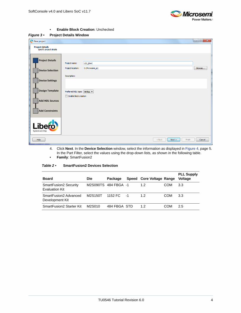
• Enable Block Creation: Unchecked
Figure 3 • Project Details Window
4. Click Next. In the Device Selection window, select the information as displayed in Figure 4, page 5. In the Part Filter, select the values using the drop-down lists, as shown in the following table.
• Family: SmartFusion2
Table 2 • SmartFusion2 Devices Selection
Board Die Package Speed Core Voltage RangePLL Supply Voltage
SmartFusion2 Security Evaluation Kit
M2S090TS 484 FBGA -1 1.2 COM 3.3
SmartFusion2 Advanced Development Kit
M2S150T 1152 FC -1 1.2 COM 3.3
SmartFusion2 Starter Kit M2S010 484 FBGA STD 1.2 COM 2.5
TU0546 Tutorial Revision 6.0 4

SoftConsole v4.0 and Libero SoC v11.7
Figure 4 • Device Selection Window
5. Click Next.,the Device settings window is displayed. Select PLL Supply Voltage (V), as shown in the following figure.
Figure 5 • Device Settings
See Table 2, page 4 for specific board values.
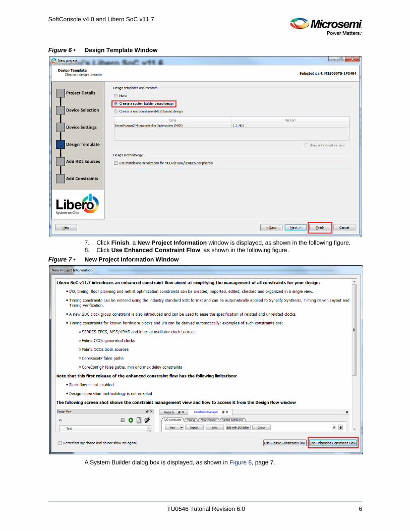
6. Click Next. In the Design Template page, select Create a system builder based design check box under the Design Templates and Creators as shown in the following figure.
TU0546 Tutorial Revision 6.0 5
SoftConsole v4.0 and Libero SoC v11.7
Figure 6 • Design Template Window
7. Click Finish. a New Project Information window is displayed, as shown in the following figure. 8. Click Use Enhanced Constraint Flow, as shown in the following figure.
Figure 7 • New Project Information Window
A System Builder dialog box is displayed, as shown in Figure 8, page 7.
TU0546 Tutorial Revision 6.0 6

SoftConsole v4.0 and Libero SoC v11.7
System builder is a graphical design wizard. It creates a design based on high-level design specificationsby taking the user through a set of high-level questions that define the intended system.
9. Enter a name for your system as LED_Blink and then click OK, as shown in the following figure.
Figure 8 • System Builder Dialog Box
System Builder – Device Features page is displayed, as shown in the following figure.
Figure 9 • System Builder – Device Features Page
10. Retain the default values. Click Next, the System Builder – Peripherals page is displayed. Under the MSS Peripherals section, uncheck all the check boxes except MSS_GPIO, as shown in the following figure.
TU0546 Tutorial Revision 6.0 7

SoftConsole v4.0 and Libero SoC v11.7
Figure 10 • System Builder Configurator – Select Peripherals Page
11. Double-click the wrench symbol for the MSS_GPIO peripheral to open the MSS_GPIO Configurator.
12. This design requires configuring GPIOs to drive LEDs on the board, configure the GPIOs as shown below:
• Set/Reset Definition accept default settings• Configure GPIO as shown in the following table
Table 3 • SmartFusion2 GPIO Configuration
Board Die GPIO ID Direction Package Pin Connectivity
SmartFusion2 Security Evaluation Kit
M2S090TS GPIO_0 to GPIO_7 Output NA FABRIC_A
SmartFusion2 Advanced Development Kit
M2S150T GPIO_0 to GPIO_7 Output NA FABRIC_A
SmartFusion2 Starter Kit M2S010 GPIO_0 to GPIO_1 Output NA FABRIC_A
TU0546 Tutorial Revision 6.0 8

SoftConsole v4.0 and Libero SoC v11.7
Figure 11 • MSS_GPIO Configurator
13. Click Next, the System Builder – Clocks Settings page is displayed, as shown in Figure 12, page 10. Select System Clock source as On-chip 25/50 MHz RC Oscillator. The M3_CLK is configured to 100 MHz by default.
TU0546 Tutorial Revision 6.0 9

SoftConsole v4.0 and Libero SoC v11.7
Figure 12 • System Builder Configurator – Clock Settings Page
14. Click Next, the System Builder – Microcontroller Options page is displayed.• Retain the default values.15. Click Next, the System Builder – SECDED Options page is displayed.• Retain the default values.16. Click Next, the System Builder – Security Options page is displayed.• Retain the default values.17. Click Next, the System Builder – Interrupts Options page is displayed.• Retain the default values.18. Click Next, the System Builder – Memory Map Options page is displayed.• Retain the default values.19. Click Finish.
System Builder generates the system based on the selected options.
System Builder block is created and added to the Libero SoC project, as shown in the following figure.
Figure 13 • System Builder Generated System
2.4.2 Connecting Components in LED_Blink SmartDesignThe following steps describe how to connect the components in LED_Blink SmartDesign:
1. Connect the pins as follows:• Tie the FAB_RESET_N to high by right-clicking and selecting Tie High.• Mark the output port POWER_ON_RESET_N as unused by right-clicking and selecting Mark
Unused.
TU0546 Tutorial Revision 6.0 10

SoftConsole v4.0 and Libero SoC v11.7
• Mark the output port MSS_READY as unused by right-clicking and selecting Mark Unused.• Expand INIT_PINS, right-click INIT_DONE and select Mark Unused.• Expand FAB_CCC_PINS, right-click FAB_CCC_GL0 and select Mark Unused.• Right-click FAB_CCC_LOCK and select Mark Unused.• Right-click GPIO_FABRIC and select Promote to Top Level.2. Click File > Save. The LED_Blink design is displayed, as shown in the following figure.
Figure 14 • LED_Blink Design
3. Generate the LED_Blink SmartDesign by clicking SmartDesign > Generate Component or by clicking Generate Component on the SmartDesign toolbar.
Figure 15 • Generate Component
After successful generation of the system, the message’ info: LED_Blink’ was successfully generatedis displayed on the Libero SoC Log window, as shown in the following figure.
Figure 16 • Log Window
2.5 Step 2: Generating the Program File1. Double-click Synthesize in the Design Flow window, as shown in the following figure to complete
the synthesis.
Figure 17 • Design Flow Window
TU0546 Tutorial Revision 6.0 11

SoftConsole v4.0 and Libero SoC v11.7
2. Double-click Manage Constraints in the Design Flow window, as shown in the following figure.
Figure 18 • Manage Constraints
3. Click Edit with I/O Editor under I/O Attributes, as shown in the following figure. The I/O Editor window is displayed, as shown in Figure 20, page 13.
Figure 19 • I/O Attributes
4. Make the pin assignments, as shown in the following table. After the pins are assigned, the I/O Editor is displayed, as shown in Figure 20, page 13.
Table 4 • Port to Pin Mapping
Port Name Pin Number
SmartFusion2 Security Evaluation Kit
GPIO_0_M2F H5
GPIO_1_M2F H6
GPIO_2_M2F J6
GPIO_3_M2F H7
GPIO_4_M2F G7
GPIO_5_M2F F3
GPIO_6_M2F F4
TU0546 Tutorial Revision 6.0 12

SoftConsole v4.0 and Libero SoC v11.7
Figure 20 • I/O Editor
5. After updating the I/O editor, click Commit and Check.6. Close the I/O Editor.7. Click Generate Bitstream in Design flow window, as shown in the following figure, to generate the
programming file.
GPIO_7_M2F E1
SmartFusion2 Advanced Development Kit
GPIO_0_M2F D26
GPIO_1_M2F F26
GPIO_2_M2F A27
GPIO_3_M2F C26
GPIO_4_M2F C28
GPIO_5_M2F B27
GPIO_6_M2F C27
GPIO_7_M2F E26
SmartFusion2 Starter Kit
GPIO_0_M2F AB18
GPIO_1_M2F P1
Table 4 • Port to Pin Mapping
TU0546 Tutorial Revision 6.0 13

SoftConsole v4.0 and Libero SoC v11.7
Figure 21 • Generate Bitstream
2.6 Step 3: Programming the SmartFusion2 Board Using FlashPro Jumper settings for the supported target boards and board setup for running the tutorial are given in thefollowing chapters:
• Appendix: Board Setup for SmartFusion2 Security Evaluation Kit, page 31.• Appendix: Board Setup for SmartFusion2 Advanced Development Kit, page 33.• Appendix: Board Setup for SmartFusion2 Starter Kit, page 35.1. To program the SmartFusion2 device, double-click Run PROGRAM Action in the Design Flow
window, as shown in the following figure.
Figure 22 • Run Programming Action
TU0546 Tutorial Revision 6.0 14

SoftConsole v4.0 and Libero SoC v11.7
2.7 Step 4: Creating Software Project using SoftConsole 4.0The following steps show how to create a software project using SoftConsole 4.0.
2.7.1 Export Firmware1. Double-click Export Firmware in Handoff design for Production in the Design Flow window, as
shown in the following figure.
Figure 23 • Export Firmware
Export Firmware dialog box is displayed as shown in the following figure.
2. Select Export hardware configuration (Software IDE independent), as shown in the following figure.
Figure 24 • Export Firmware Dialog Box
3. Click OK, a notification window appears saying Firmware project was successfully exported to <drive:\>Microsemi_prj\LED_Blink, as shown in the following figure.
Figure 25 • Firmware Export Successful
4. Click OK.
TU0546 Tutorial Revision 6.0 15

SoftConsole v4.0 and Libero SoC v11.7
2.7.2 Download Firmware DriversThe following drivers are used in this tutorial:
• CMSIS• GPIO
To generate the required drivers:
1. Open the Microsemi SoC Firmware catalog from: Start > Programs > Microsemi> Libero SoC v11.7>Firmware Catalog> Firmware Catalog.
A message, New cores are available for download is displayed at the bottom of the Firmware Catalog,as shown in the following figure.
Figure 26 • Firmware Catalog
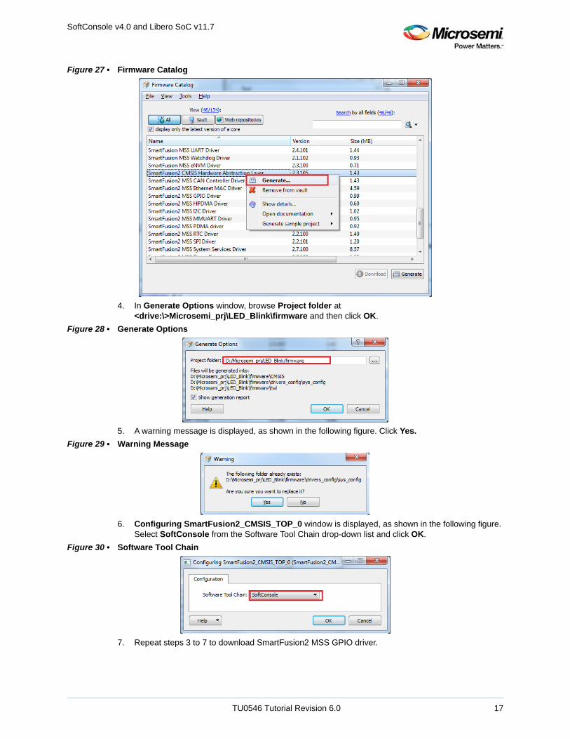
2. Click Download them now, to download most recent drivers for peripherals. 3. In Firmware catalog window, right-click SmartFusion2 CMSIS Hardware Abstraction Layer and
then click Generate, as shown in the following figure.
TU0546 Tutorial Revision 6.0 16
SoftConsole v4.0 and Libero SoC v11.7
Figure 27 • Firmware Catalog
4. In Generate Options window, browse Project folder at <drive:\>Microsemi_prj\LED_Blink\firmware and then click OK.
Figure 28 • Generate Options
5. A warning message is displayed, as shown in the following figure. Click Yes.
Figure 29 • Warning Message
6. Configuring SmartFusion2_CMSIS_TOP_0 window is displayed, as shown in the following figure. Select SoftConsole from the Software Tool Chain drop-down list and click OK.
Figure 30 • Software Tool Chain
7. Repeat steps 3 to 7 to download SmartFusion2 MSS GPIO driver.
TU0546 Tutorial Revision 6.0 17

SoftConsole v4.0 and Libero SoC v11.7
2.7.3 Building Software Application using SoftConsole 4.01. Click Start > Programs > Microsemi SoftConsole v4.0 > Microsemi SoftConsole v4.0 to open
the SoftConsole IDE. The SoftConsole Workspace Launcher window is displayed.2. Browse to the location to select D:\Microsemi_prj\LED_Blink\SoftConsole, as shown in the following
figure.
Figure 31 • Workspace Launcher
The SoftConsole workspace is displayed, as shown in the following figure.
Figure 32 • SoftConsole Window
3. Click File >New >C project as shown in the following figure.
TU0546 Tutorial Revision 6.0 18

SoftConsole v4.0 and Libero SoC v11.7
Figure 33 • Creating New C Project
4. Enter Project name as LED_Blink, as shown in the following figure.
Figure 34 • C Project Window
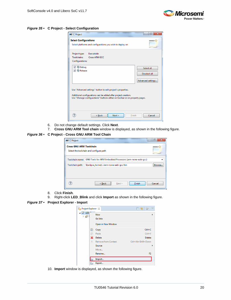
5. Click Next, Select Configurations window is displayed, as shown in the following figure.
TU0546 Tutorial Revision 6.0 19
SoftConsole v4.0 and Libero SoC v11.7
Figure 35 • C Project - Select Configuration
6. Do not change default settings. Click Next.7. Cross GNU ARM Tool chain window is displayed, as shown in the following figure.
Figure 36 • C Project - Cross GNU ARM Tool Chain
8. Click Finish.9. Right-click LED_Blink and click Import as shown in the following figure.
Figure 37 • Project Explorer - Import
10. Import window is displayed, as shown the following figure.
TU0546 Tutorial Revision 6.0 20

SoftConsole v4.0 and Libero SoC v11.7
11. Click File System and then click Next.
Figure 38 • Import Window
12. Browse to D:\Microsemi_prj\LED_Blink\firmware and check firmware check box, as shown in the following figure.
Figure 39 • Import - File System
13. Click Finish.Note: If any changes are made to the Libero SoC project, firmware needs to be exported from Libero and new
firmware must be imported to LED_Blink.
14. Using Windows explorer, browse to the main.c file location in the respective design files folder as follows:
• For SmartFusion2 Security Evaluation Kit: <download_folder>\SF2_LED_Blink_SC_Tutorial_DF\Sourcefiles\SF2_Security_Kit.
TU0546 Tutorial Revision 6.0 21

SoftConsole v4.0 and Libero SoC v11.7
• For SmartFusion2 Advanced Development Kit: <download_folder>\SF2_LED_Blink_SC_Tutorial_DF\Sourcefiles\SF2_Adv_Dev_Kit.
• For SmartFusion2 Starter Kit: <download_folder>\SF2_LED_Blink_SC_Tutorial_DF\Sourcefiles\SF2_Starter_Kit.
15. Copy the main.c file to the LED_Blink project in the SoftConsole workspace, as shown in the following figure.
Figure 40 • Project Explorer
16. Right-click LED_Blink and click Properties, as shown in the following figure.
Figure 41 • Project Explorer window - Properties
17. Click Settings under the C/C++ Build tab, as shown in the following figure.
TU0546 Tutorial Revision 6.0 22

SoftConsole v4.0 and Libero SoC v11.7
Figure 42 • Properties for LED_Blink
18. Under Cross ARM C compiler, click Miscellaneous and enter --specs=cmsis.specs, in Other compiler flags text box as shown in the following figure.
Figure 43 • Properties for LED_Blink - Miscellaneous
19. Under Cross ARM C Linker, click General as shown in Figure 44, page 24.20. Click add button and add following linker Script path:
“${workspace_loc:/${ProjName}/CMSIS/startup_gcc/debug-in-microsemi-smartfusion2-esram.ld}”
21. After adding Linker Script, Properties for LED_Blink, window is displayed, as shown in the following figure.
TU0546 Tutorial Revision 6.0 23

SoftConsole v4.0 and Libero SoC v11.7
Figure 44 • Properties for LED_Blink - General
22. Under Cross ARM C Linker, click Miscellaneous.23. Check Use newlib-nano(--specs=nano.specs) option, as shown in the following figure.
Figure 45 • Properties for LED_Blink - Miscellaneous
24. Click OK.25. Click Project and click Build All, as shown in the following figure.
TU0546 Tutorial Revision 6.0 24

SoftConsole v4.0 and Libero SoC v11.7
Figure 46 • Project - Build All
26. Ensure that the Problems tab in the displayed window must not have any errors, as shown in the following figure.
Figure 47 • Problems Window
2.7.4 Debugging the Application Project using SoftConsole v4.0The following steps describe how to debug the application project using SoftConsole v4.0:
1. Click Debug Configurations in the Run menu of the SoftConsole, as shown in the following figure. The Debug Configurations window is displayed, as shown in Figure 49, page 26.
Figure 48 • Run - Debug Configurations
2. Double-click GDB OpenOCD Debugging to view the configurations, as shown in the following figure.
TU0546 Tutorial Revision 6.0 25

SoftConsole v4.0 and Libero SoC v11.7
Figure 49 • Debug Configurations
3. Ensure that the following values are filled in the corresponding fields:• Name: LED_Blink Debug• Project: LED_Blink• C/C++ Application: Debug\LED_Blink.elf
4. Select the Debugger tab in the Debug Configurations dialog box. --command “set DEVICE M2S090” specifies the target device, as shown in Figure 50, page 27. This command needs to be modified based on the target silicon. • SmartFusion2 Security Evaluation Kit - set DEVICE M2S090 • SmartFusion2 Advanced Development Kit - set DEVICE M2S150• SmartFusion2 Starter Kit - set DEVICE M2S010
TU0546 Tutorial Revision 6.0 26

SoftConsole v4.0 and Libero SoC v11.7
Figure 50 • Debug Tab
5. Click Debug.6. On the Confirm Perspective Switch window, click Yes as shown in the following figure.
Figure 51 • Confirm Perspective Switch
The SoftConsole Debugger Perspective window is displayed, as shown in the following figure.
TU0546 Tutorial Revision 6.0 27

SoftConsole v4.0 and Libero SoC v11.7
Figure 52 • Debugger Perspective Window
7. Click Run > Resume to run the application. LEDs start blinking on the SmartFusion2 target boards. The following table shows which LEDs blink for the different SmartFusion2 target boards.
8. Launch the debug session:• By selecting Debug Configurations from the Run menu of SoftConsole.
or• By selecting the Debug Configurations using the Debug button as shown in the following figure.
Figure 53 • Debug Configurations Option
9. Click the Registers tab to view the values of the Cortex-M3 processor internal registers, as shown in the following figure.
Table 5 • LED Target Board
Target Board LEDs
SmartFusion2 Security Evaluation Kit H5, H6, J6, H7, G7, F3, F4, and E1
SmartFusion2 Advanced Development Kit DS0, DS1, DS2, DS3, DS4, DS5, DS6, and DS7
SmartFusion2 Starter Kit DS4, DS3
TU0546 Tutorial Revision 6.0 28

SoftConsole v4.0 and Libero SoC v11.7
Figure 54 • Values of Cortex-M3 Internal Registers
10. Click the Variables tab to view the values of variables in the source code, as shown in the following figure.
Figure 55 • Values of the Variables in the Source Code
11. In the Debug window, click Window > Show View > Disassembly to display the assembly level instructions. The Disassembly window with assembly instructions is displayed on the right-side of the Debug perspective window, as shown the following figure.
Figure 56 • Assembly Level Instructions
12. Source code can be single-stepped by choosing Run > Step Into or Run > Step Over. Observe the changes in the source code window and disassembly view. Performing a Step Over provides an option for stepping over functions. The entire function is run but there is no need to single-step through each instruction contained in the function.
13. Click Instruction Stepping ( ) and perform Step Into operations. Observe that Step Into executes a single line of assembly code.
14. Click Instruction Stepping to exit the instruction stepping mode. Single-step through the application and observe the instruction sequence in the source code window of the Debug perspective, and the values of the variables and registers.
15. Add breakpoints in the application to force the code to halt, single-step, and observe the instruction sequence.
TU0546 Tutorial Revision 6.0 29

SoftConsole v4.0 and Libero SoC v11.7
16. When debug process is finished, terminate execution of the code by choosing Run > Terminate.17. Close Debug Perspective by selecting Close Perspective from the Window menu.18. Close SoftConsole using File > Exit.19. Close the HyperTerminal using File > Exit.
Note: By default SoftConsole debugs using the first FlashPro5 programmer that it detects. If there is no FlashPro5 connected then it will use the first FlashPro3/4 that it detects
2.8 ConclusionThis tutorial provides steps to create a Libero SoC design using System Builder. It describes theprocedure to build, debug, and run a SoftConsole application. It also provides a simple design to blinkLEDs.
TU0546 Tutorial Revision 6.0 30

Appendix: Board Setup for SmartFusion2 Security Evaluation Kit
3 Appendix: Board Setup for SmartFusion2 Security Evaluation Kit
The following figure shows the board setup for running the tutorial on the SmartFusion2 SecurityEvaluation kit board.
Figure 57 • SmartFusion2 Security Evaluation Kit Setup
1. Connect the jumpers on the SmartFusion2 Security Evaluation kit board as listed in the following table. For more information on jumper locations, see Figure 58, page 32 for SmartFusion2 Security Evaluation kit board jumper locations.
CAUTION: While making the jumper connections, the SW7 power supply switch on the board must be inOFF position.
2. Connect the FlashPro4 or FlashPro5 programmer to the J5 connector of the SmartFusion2 Security Evaluation kit.
Note: J5 - FlashPro connector is normally used for FlashPro programming of the FPGA and SoftConsole debugging.
Table 6 • SmartFusion2 Security Evaluation Kit Jumper Settings
Jumper Pin (From) Pin (To) Comments
J22, J23, J8, and J3 1 2 These are the default jumper settings of the SmartFusion2 Security Evaluation Kit board. Ensure that these jumpers are set accordingly.
TU0546 Tutorial Revision 6.0 31

Appendix: Board Setup for SmartFusion2 Security Evaluation Kit
Note: J18 - FTDI programmer interface, used to program the external serial peripheral interface (SPI) flash cannot be used for SoftConsole debugging.
Note: If both J5 and J18 are connected to the host computer on which SoftConsole is running then SoftConsole must be configured to use J5 for debugging.
3. Connect the power supply to the J6 connector.4. Switch ON the SW7 power supply switch.
The following figure shows the jumper locations on the SmartFusion2 Security Evaluation kit board.
Figure 58 • SmartFusion2 Security Evaluation Kit Board Jumper Locations
Note: Jumpers highlighted in red are set by default.
Note: The locations of the jumpers in the preceding figure are searchable.
P1
J18
J24
CR3
CR4
U12
U19
TP8
TP6
CR1
CR2
X1
J6
U20
U11
SW7
D9
U4
U13
U26
C10
SW1
U25
TP9
J13
J3
C7
U14
J14
C103
J21
J17
Y1
U10
TC7
L1
CON1
TC8
TP4
TC4
U2TC2
TC3
D8
J25 J26
J22
U8
TP2TC5
TC1
J23
U18
Y3
Y2
J7TC6
TC10
TC9
L3
U6
DPR1
J12J11
U22
L2
U1
U9
L6
U7
U23
TP10
Y4
TP3
U24J28
J27
Y5
SW5
U21
C79
SW4
J5
TP14
L7
TP16
J8
TP17
U16
L5
TC19
TC18
SW6
TP7
U15
SW2
J4
J2
J1
SW3TP11
TP5
U5
TP18
H1
J29
J30TP15
TP19
J9
J20
J16
J15
J10
TP1
2
PROBE B
PROBE A
11
1P8V
16
GND
4
19
20
19
20
GND
1A
F3 F4
C3C4
G
3
4
K20
K21L1
8
L19
E1
B7C2
1020
1P2V_CUR_SENSE
1
J18
2
1
1
2
A7B5B6
G
1
1P2V
A5A6
510G
1A
9
10
A4
G
3
GND 4
3
4
B
B1
2
A
A1
1
2
1
GND2
1P8V_CUR_SENSE
GND
131
K16
1
1
G
1A
20
D7 D6 D5
40G
GND
D4 D3
G
H5 H6 J6
C7D2
1530
3
4
1
2
H7 G7
C5C6
G
GND
G
1
GND60
1
A
1
G G
A1
A
1
GND
50
17
20
2
L201
2
1
13
1
5
5
1
3
2
1
1
GND
3
1
1
4
3
4
L2
RXD2
NRX
D2P
TXD2
NTX
D2P
I2C0_SDA
I2C1_SDA
USB
FTDI
12V I/P
ETH PHY-SGMII
12V
3.3V
5V
ON
SWT
RMT
SERD
ES_R
EFCL
K1N
SERDES_REFCLK1P
B1L0
B11 B12
SMA
OSCSERDES_REFCLK1
CUR_VDDA_PLL
B18
HZ
Active
CLK_EN
L3
100MBPS LINK
LED2
1GMB
PS L
INK
CUR_PLL_L012P5V_LDO
LPDDR
CUR_PLL_L23
2P5V_LDO
XTAL
DVP-102-000402-001M2GL_M2S-EVAL-KIT
H
RMTJTAG_SEL
L
Rev D
PROG Header
DEVRST
SPI
RVI/
IAR
FTDI-GPIO
SF2-GPIO
I2C0_SCL
I2C1
_SCL
Trac
e DB
G
TU0546 Tutorial Revision 6.0 32

Appendix: Board Setup for SmartFusion2 Advanced Development Kit
4 Appendix: Board Setup for SmartFusion2 Advanced Development Kit
The following figure shows the board setup for running the demo on the SmartFusion2 AdvancedDevelopment kit board.
Figure 59 • SmartFusion2 Advanced Development Kit Setup
1. Connect the jumpers on the SmartFusion2 Advanced Development kit board as listed in the following table. For more information on jumper locations, see Figure 60, page 34 of SmartFusion2 Advanced Development kit board Jumper Locations.
CAUTION: While making the jumper connections, the SW7 power supply switch on the board must be inOFF position.
2. Connect the FlashPro4 or FlashPro5 programmer to the J37 connector of the SmartFusion2 Advanced Development kit.
3. Connect the power supply to the J42 connector.
Table 7 • SmartFusion2 Advanced Development Kit Jumper Settings
Jumper Pin (from) Pin (to) Comments
J116, J353, J354, and J54 1 2 These are the default jumper settings of the SmartFusion2 advanced development kit board. Ensure that these jumpers are set accordingly.
J123 2 3
J124, J121, and J32 2 3 JTAG programming via FTDI
TU0546 Tutorial Revision 6.0 33

Appendix: Board Setup for SmartFusion2 Advanced Development Kit
4. Switch ON the SW7 power supply switch.
The following figure shows the jumper locations on the SmartFusion2 Advanced Development kit board.
Figure 60 • SmartFusion2 Advanced Development Kit Board Jumper Locations
Notes:
• Jumpers highlighted in red are set by default.• Jumpers highlighted in green must be set manually.• The locations of the jumpers in the preceding figure are searchable.
SW4
C332
J125
C610DS0
R364
Y11
R343
R1217
TP17
R276
J123
R283
J28
J29
R255U25
J121
H1
R281
R300
R282
TP3
C600
J124
C604
DS17
TP11
U58
R155
U34
R162R330
R161J32
R292
C691
TP7
C596
J37
R301
TP20
U23
R313
U26
DS29
R260
C593
SW1
SW7
R354 TP4
J38
J36
R253 U24
J116
J60
D9
TP12
R267
J42
U27
J351
DS16
TP16
R136
P1
R167
R168
R169
R164
R170
D13
J34
C323
CR1
R298
C164
DS26
C670R327
R329
R165
R166
R171
R172
R173
J33
SW6
R142
R140
J23
R137
R139
R141
R143CR2
U49
C605
U16
L3
CR3
CR4
DS27
R134
R138
C606
U12
R396
J21J19
U36
U19
C351
X1C5
95R2
43
LED9
C316
U9
R126
R127
U10
C325
TP2
R325
R326R328
R163
C358C3
57
C592
U18
TP27
U11
C315
R131R133
R125R130
C324
R112TP1
R111
C313
R97R98
C303C668
TP14C6
66
U17
R373
R374
R294
R288
C699
R289
C700C701
J16
R113
R114
R100
R99
TP15
C623
TP23
C667 L4
D14
R174
R199
R197
R198
C703C704C705
U60
C702
J15
Y2
C282
U8
C255
J22
J20
TP24
U28
R178
R175
R176
R177
U162
R983R1
94R1
96
R192
R193
R985
TP26
L6
TP28
C674
C673
C292
R79
R46
R50
C214
D10
R5484C156
6
R1519
R257R986R984
R842
R840
R841
J354
C672
R156
U37
R372
C331
C283
C330
J14
R331U62
R5483C1
574
C157
5
C157
3C1579
R151
8
R839
R355R356
R351R352
R332
L5
R293
R303 J17
R103
R116
R117
R118
R119
R291
R290
C157
2R333R334
Y6
R270
R160
R295
DS11
J353
TP29
R286
C626
C624R81R76
J18
C382
R218
C305C304
C296C294
R101
R102
R40
R216
C378
TP31
TP33
R190
R191
D15
R975
R976R978
R973
R974
R977
C926
J352
CON1
DS12
DS13
DS14 DS8
C257
C671
C625
R107
R73R75
R78 R74
C306
C307
C308
R106R108R109R110
C297
C314R115R120R121
R95R96
C293C295
C302 R105
R91R92
R93R94
R104
TC20
TC21
R41
C98
R58
R63R188
R184
R189
R183
R808
DS10
DS9
C521
C394
C528
C526
C246
C530
R71R72
C471
C554
C484
C90C89
TC19
TC16
C209C103
TC18
TC17
C100
C144C181
R182
R179
R181
C374
C213
C210
C211
R42
R59
R60
U6
C136
C135
C138
C212
C102
C146
R64C148
R217
C142
C140
C139
C137
C183
C173
C172
C141
U2
R210
C174
C175
C179
C176
C177
U1
C178
C216
C215
U3
C94
C93
C91
C92
J4
J30
R266
R121
2R1
210R1
208
R120
7
R375
Y3
C359
C361
C360Y4
C362
C220C9
5C9
6
J7
U5
U4
Y20R120
9R1
215
R121
4 R378
R1211
R211
C371
R69
R213
C599
C463C422
C153
R70 C109
C150
U32
C645
TP10
C467
C519
C468
R209
R121
3
C518
C119C156
C236
C235
C199
R353
C648
R309
R311
C646
C644
C642
C641
TP22
R363
C460
C455
C328
C562
C465
C159
C116
J6
J5
DS28
R310C6
47
J118
R361
R150
C233
C197
C161
C118
C517
J13
R54R55
J12
J54
C628
TP30
C643
U13
C163
C476
C129
C113
TP32
J350
R308D8
R307
D7TP9
J119R366
TP21
R149
R220
R272C608
C630
DS7
R314
R316
U7
R158
R159
J9
J8
J11
C640
R305
R306
C636U35
SW3
SW2R222
R224
DS6 DS5
Y12
R47R48
J10
U31
R304
C638
C637
DS4 DS3
R318
R362
R369
C692
R277
C697
C696
TP35
DS2 DS1
SW5
R1216
C698
R280
U59
R279
R278
2
2
3 1
1
2
B
A
6
4
5
ON
19
20
A1
19
20
9
10
B1
3
ON
1
1
2
C1
C40
H1
H40
B
AB
AB
A
H
H
B1
A1B1
A1
B1
A1
L1
2
3
4
5
6
7
L8
1
A1
K1
1
A1 A1 A1 A1
K40
B32
A1
A40
B1 B11
1
5
1
5
1
B1
A1
A
B
6
6
PLL5
S3_PLL_L23
SERDES3_RXP_1
SERDES3_TXN_1
PLL1
PLL_
S3
PLL4
2P5V
3P3V
0P75V_REG
3P3V
SERDES3_RXN_1
SERDES3_TXP_1
GND
PLLMDDR
SERDES_3_REFCLK0_P
3P3V
_VPP
3P3V_LDO
SERDES_3_REFCLK0_N
3P3V
_LDO
3P3V_LDO
1P5V_REG
H H
L
GND
GND
L
C27
E26
H
H
H
H
B27
L
L
L
L
C26C28
F25
J23
G25
G27
J22
F23
H27
G23
GND
F26A27
GND
GND
L
H
D26
2P5V_LDO
1.2 V CURRENT SENSE
PRB
PRA
VDD_REG_CS
L
H
VDD
1P5V
OP75V
1P8V
VCCIO_HPC_VADJ
1P0V_PHY
VCCIO_LPC_
L
H
SDA
5P0V
VADJ
5P0V
L
H
SCL
VDD_REG
FTDI
JTAG_SEL
1
0
FP4_HEADER
GND
RMT
3P3V
SWT
3P3V
RVI_
HEAD
ER
TRAC
E_ET
M_HE
ADER
TCK
12V
12V/5A
TDI
GND
TMSTDO
12V
GND
TRST
_L
USB_5V
RST
SPK_R
RST
SPK_L
GND
VDDIO
GND
HSDACP
HSDACN
1P8V
TDI
TCK
TDO
TMS
TRSTN
N
GND
VCCIO_LPC_VADJ
1P0V_PHY
TRST_L
GND2.5V1.8V1.5V
1.2V
TMS TDO
KPLL6
TDI GND
P1_L
ED3
1.2V
2.5V1.8V1.5V
3.3V
VCCIO_HPC_VADJ
MDIO
MDC
3P3V
3P3V
2P5VGND
S2_PLL_L01
TCK
P1_L
ED2
P1_L
ED1
P1_L
ED0
P0_L
ED3
K
PLL7
N
S0_PLL_L012P5V
S1_P
LL_L
01
P0_L
ED0
P0_L
ED2
S0_PLL_L23
3P3V
3P3V
3P3V
S1_PLL_L23
M2S150-ADV-DEV-KIT Rev-B
PLL_S1
PLLFDDR
PLL_S0
2P5V
DVP-101-000408-001
PLL3
PLL2
S2_PLL_L23
3P3V
PLL0
www.microsemi.com
TU0546 Tutorial Revision 6.0 34

Appendix: Board Setup for SmartFusion2 Starter Kit
TU0546 Tutorial Revision 6.0 35
5 Appendix: Board Setup for SmartFusion2 Starter Kit
The following figure shows the board setup for running the demo on the SmartFusion2 starter kit board.
Figure 61 • SmartFusion2 Starter Kit Setup
1. Connect the jumpers on the SmartFusion2 Starter kit board as listed in Table 8, page 35.
2. Connect the FlashPro4 or FlashPro5 programmer to the P5 connector of the SmartFusion2 Starter kit.
3. Connect the host PC USB port to the P1 Mini USB connector on the SmartFusion2 Starter kit board using the USB Mini-B cable. As soon as the connection to the PC is made, the on-board LED DS2 will illuminate, indicating that the board has power.
Table 8 • SmartFusion2 Starter Kit Jumper Settings
Jumper Pin (From) Pin (To) Comments
JP1 1 2 These are the default jumper settings of SmartFusion2 Starter kit board. Ensure that these jumpers are set accordingly.
JP2 3 4
JP3 2 4