Discrete element simulation of transverse cracking during the pyrolysis of carbon fibre reinforced...
15
Discrete element simulation of transverse cracking during the pyrolysis of carbon fibre reinforced plastics to carbon/carbon composites Falk K. Wittel a, * , Jan Schulte-Fischedick b,1 , Ferenc Kun c , Bernd-H. Kr€ oplin a , Martin Frieß b a Institute for Statics and Dynamics of Aerospace Structures, University of Stuttgart, Pfaffenwaldring 27, 70569 Stuttgart, Germany b German Aerospace Center (DLR), Institute of Structures and Design, Pfaffenwaldring 38/40, D-70569 Stuttgart, Germany c Department of Theoretical Physics, University of Debrecen, P.O. Box 5, H-4010 Debrecen, Hungary Received 18 April 2002; accepted 11 July 2002 Abstract The fracture behavior of fiber-ceramics like carbon/carbon–silicon carbide strongly depends on the initial damage arising during the production process. We study the transverse cracking of the 90° ply in ½0=90 S crossply laminates due to the thermochemical degradation of the matrix material during the carbonization process by means of a discrete element method. The crack morphology strongly depends on the fiber–matrix interface properties, the transverse ply thickness as well as on the carbonization process itself. To model the 90° ply a two-dimensional triangular lattice of springs is constructed where nodes of the lattice represent fibers. Springs with random breaking thresholds model the disordered matrix material and interfaces. The spring-lattice is coupled by interface springs to two rigid bars which capture the two 0° plies or adjacent sublaminates in the model. Molecular dynamics simulation is used to follow the time evolution of the model system. It was found that under gradual heating of the specimen, after some distributed cracking, segmentation cracks occur in the 90° ply which then develop into a saturated state where the ply cannot support additional load. The dependence of the microstructure of damage on the ply thickness and on the disorder in spring properties is also studied. Crack density and porosity of the system are monitored as a function of the tem- perature and compared to an analytic approach and experiments. Ó 2003 Elsevier Science B.V. All rights reserved. PACS: 02.60; 85.40; 83.20; 82.20.Wt; 81.60.Hv Keywords: Discrete element model; Numerical simulation; Composite material; Pyrolysis; Thermal degradation 1. Introduction In the recent years extensive investigations were focused on enhancing high-temperature per- formance and reliability for fiber reinforced ce- ramic matrix composites (CMC), especially their Computational Materials Science 28 (2003) 1–15 www.elsevier.com/locate/commatsci * Corresponding author. Tel.:+49-0711-685-7093/684-7093; fax.:+49-0711-685-3706/684-3706. E-mail address: [email protected] (F.K. Wittel). 1 Present address: DLR, Institute of Technical Thermody- namics. 0927-0256/03/$ - see front matter Ó 2003 Elsevier Science B.V. All rights reserved. doi:10.1016/S0927-0256(03)00035-1
Transcript of Discrete element simulation of transverse cracking during the pyrolysis of carbon fibre reinforced...

Discrete element simulation of transverse cracking duringthe pyrolysis of carbon fibre reinforced plastics
to carbon/carbon composites
Falk K. Wittel a,*, Jan Schulte-Fischedick b,1, Ferenc Kun c,Bernd-H. Kr€ooplin a, Martin Frieß b
a Institute for Statics and Dynamics of Aerospace Structures, University of Stuttgart, Pfaffenwaldring 27, 70569 Stuttgart, Germanyb German Aerospace Center (DLR), Institute of Structures and Design, Pfaffenwaldring 38/40, D-70569 Stuttgart, Germany
c Department of Theoretical Physics, University of Debrecen, P.O. Box 5, H-4010 Debrecen, Hungary
Received 18 April 2002; accepted 11 July 2002
Abstract
The fracture behavior of fiber-ceramics like carbon/carbon–silicon carbide strongly depends on the initial damage
arising during the production process. We study the transverse cracking of the 90� ply in ½0=90�S crossply laminates dueto the thermochemical degradation of the matrix material during the carbonization process by means of a discrete
element method. The crack morphology strongly depends on the fiber–matrix interface properties, the transverse ply
thickness as well as on the carbonization process itself. To model the 90� ply a two-dimensional triangular lattice of
springs is constructed where nodes of the lattice represent fibers. Springs with random breaking thresholds model the
disordered matrix material and interfaces. The spring-lattice is coupled by interface springs to two rigid bars which
capture the two 0� plies or adjacent sublaminates in the model. Molecular dynamics simulation is used to follow the
time evolution of the model system. It was found that under gradual heating of the specimen, after some distributed
cracking, segmentation cracks occur in the 90� ply which then develop into a saturated state where the ply cannot
support additional load. The dependence of the microstructure of damage on the ply thickness and on the disorder in
spring properties is also studied. Crack density and porosity of the system are monitored as a function of the tem-
perature and compared to an analytic approach and experiments.
� 2003 Elsevier Science B.V. All rights reserved.
PACS: 02.60; 85.40; 83.20; 82.20.Wt; 81.60.Hv
Keywords: Discrete element model; Numerical simulation; Composite material; Pyrolysis; Thermal degradation
1. Introduction
In the recent years extensive investigations
were focused on enhancing high-temperature per-
formance and reliability for fiber reinforced ce-
ramic matrix composites (CMC), especially their
Computational Materials Science 28 (2003) 1–15
www.elsevier.com/locate/commatsci
* Corresponding author. Tel.:+49-0711-685-7093/684-7093;
fax.:+49-0711-685-3706/684-3706.
E-mail address: [email protected] (F.K. Wittel).1 Present address: DLR, Institute of Technical Thermody-
namics.
0927-0256/03/$ - see front matter � 2003 Elsevier Science B.V. All rights reserved.
doi:10.1016/S0927-0256(03)00035-1
strength, damage tolerance and reliability as
structural components. It was found that produc-
tion process parameters control the formation of
the material�s microstructure, and therefore, pre-
determine the activation of the micromechanisms,such as fiber–matrix debonding, fiber bridging and
fiber pull-out, leading to damage tolerant behavior
[1]. Therefore, one goal of ongoing research is to
optimize the fiber–matrix interface properties in a
way, that the interface is strong enough to avoid
excessive fiber pull-out, but weak enough to acti-
vate fiber–matrix debonding, in order to avoid a
catastrophic failure of the composite.The present paper focuses on carbon/carbon–
silicon carbide (C/C–SiC). This material shows a
distinctive crack pattern as a result of the pro-
duction process, which can be influenced by the
laminate layup as well as by the interface proper-
ties and the parameters of the production process
itself. C/C–SiC is manufactured by the liquid sili-
con infiltration (LSI) process [2,3], that consists ofthree major steps. At first a carbon fiber reinforced
plastic (CFRP) green compact is produced. This
CFRP is then pyrolysed at temperatures ranging
from normally 1100–2000 K, converting the ther-
mosetting resin matrix into a glassy carbon one. In
this step excessive cracking is observed, driven by
the heavy shrinkage of the matrix, which is ma-
croscopically prevented by the carbon fibers [4].Multiple defects like microcracks and microdel-
aminations appear. To achieve good mechanical
properties in combination with improved abrasive
and oxidation resistance of the final CMC, the
porous carbon/carbon (C/C) preform is infiltrated
with liquid silicon at temperatures higher than
1684 K (melting temperature of silicon). Silicon
reacts with both fibers and matrix to silicon car-bide resulting in a nearly dense CMC with good
overall properties [5,6]. The accessibility of crack
systems for liquid silicon during the LSI process
predetermines the later constitutive behavior of the
C/C–SiC material in a dramatic way. A thermal
fiber pretreatment can be employed to influence
the interface shear strength and consequently the
amount of degraded fibers [6–8]. In its extreme asiliconization of all fibers leads to a totally brittle
behavior of the composite. Therefore, the manip-
ulation of the fiber siliconization is crucial for
optimizing C/C–SiC with major influence on all
engineering properties as well as on the prediction
of the macroscopic failure behavior. Such efforts
call for a comprehensive understanding for the
development of the crack pattern during the pyr-olysis and of the effects of internal structure on the
macroscopic response. This paper presents an ap-
proach to understand the crack development
during the pyrolysis of crossply-CFRP that com-
bines a phenomenological study with a simulation
based on a discrete element method. The phe-
nomenological investigations are mainly based on
thermomicroscopic observations of the crack de-velopment. Additional information was obtained
by means of thermogravimetry, dilatometry and
optical microscopy.
Crossply material is built in thickness direction
of alternating longitudinal (0�) and transverse
(90�) plies. The mean topic of this study is the
simulation of the fracture process during carbon-
ization of crossply material and the characteriza-tion of the microstructure of the occurring damage
for different system sizes and disorder. Analytical
and numerical predictive methods for the failure of
the transverse ply were performed in the past at
different length scales ranging from the micro-
scopic scale, modeling single fibers [9,10] and
models for small fiber clusters [11–13] up to the
mesoscale studying homogenized plies [14] with avariety of model approaches, but mainly under
mechanical loading. Small clusters of fibers with
microstructural disorder, embedded in a matrix
material were modeled directly, employing ficti-
tious or discrete crack [12] models. Unfortunately,
these methods are very time consuming and results
have limited meaning for the simulation of multi-
ple cracking in thicker transverse plies. In addi-tion, they do not allow predictions about size
scaling and the possibility to model the dynamic
fracture process itself.
In the presented work, the 90� ply is representedby a two-dimensional triangular lattice of springs.
The nodes of the lattice model fibers, oriented
perpendicular to the plane of the lattice, and
springs represent the matrix material in between.The spring-lattice is coupled by interface springs to
two rigid bars which capture the two 0� plies oradjacent sublaminates in the model. Disorder is
2 F.K. Wittel et al. / Computational Materials Science 28 (2003) 1–15

introduced by assigning randomly distributed
breaking thresholds to the springs, i.e. a spring
breaks if the load on it exceeds its breaking
threshold. A detailed description of the model can
be found in [15]. To simulate cracking underthermal loading, internal load is imposed on the
triangular lattice by varying the initial length of
the lattice springs. The time evolution of the sys-
tem is followed by solving the equation of motion
of the nodes (molecular dynamics). With the dis-
crete element method used in this study, realistic
system sizes are possible, enabling simulation of
the fracture processes with multiple defect inter-actions of thousands of cracks. Multiple cracking
has been studied before, using random spring
networks with springs of random distribution of
strain to failure [16–18], but rarely in the field of
fiber composites research. This approach is par-
ticularly suited for studies on dynamic instability
in crack propagation, the collective behavior of
many interacting cracks and size effects of multipletransverse cracking. Therefore, the discrete ele-
ment method is practical for studying general
features of the statics and dynamics of fracturing,
like the crack morphology, global fracture pat-
terns due to the collective behavior of many in-
teracting cracks as well as the dynamic instability
in the propagation of cracks.
Our investigation is focused on the process ofdamaging, microstructure of damage, further-
more, on the relative importance of damage
mechanisms like segmentation and delamination,
driven by the resin thermal degradation during the
manufacturing process of the C/C from the CFRP,
exposed to a moderate heating environment. Even
though our model is capable to predict many
aspects of the fracture progress (see [15]), we focuson microstructural properties that can be com-
pared to experimental observations, like the de-
velopment of segmentation crack density and
porosity. Since considerable progress was made in
understanding chemical kinetics [19,20] and reac-
tion mechanisms [21,22] of the carbonization
process, this study is focused on the challenge of
combining complex bulk material behavior, com-posite fabrication and resulting global material
behavior. Results from our model can be used
for optimization of the production process of all
fiber composites that are pyrolysed as well as for
the design of functionally graded fiber composites.
It is important to note that the gradual cracking
of thin film composites and coatings exhibits cer-
tain analogies to the gradual degradation of matrixmaterials during the production process of com-
posites ([23–26]). In these systems a thin film or a
so-called coating is attached adhesively to a sub-
strate and the sequential cracking of the overlayer
is studied either under mechanical tensile loading
or under thermal processing. Especially, the frag-
mentation of coatings results in segmentation
crack scenarios which resemble very much to oursystem indicating that the underlying microscopic
dynamics of cracking is the same in the two cases.
The paper is organized as follows: Section 2
gives an overview of the carbonization process,
describing in situ observations and measurements.
The model construction, tests of the model and the
numerical results on cracking obtained by simu-
lations are presented in Section 3. An analyticapproach worked out in the literature to the
thermal transverse cracking problem is briefly
summarized in Section 4 and confronted with our
simulation and experimental results.
2. Experimental observations during pyrolysis
The goal of the phenomenological research is to
establish a hypothesis on the crack development
during the pyrolysis. This includes three major
questions: (i) what types of cracks do occur? (ii) At
what stage during pyrolysis do the different types
of cracks evolve? (iii) How do the different types of
cracks interact? Research was mainly done on
laminates of fabric, but for the study of specificquestions, experiments were carried out on pure
resin, uni-directional laminates and crossply lam-
inates. Since the simulation presented here is based
on crossply material, this section focuses on this
type of reinforcement.
2.1. Experimental procedure
Experiments were performed on CFRP speci-
mens made from Tenax HTA fibers and a highly
aromatic, nitrogen containing thermosetting resin
F.K. Wittel et al. / Computational Materials Science 28 (2003) 1–15 3
by resin transfer molding. Unidirectional speci-
mens were produced by winding the rovings on a
steel core before processing. Crossply material was
made by using woven laminates with parts of the
weft fibers being removed, reaching a fiber volumefraction of approximately 53%. All materials were
cured at 473 K and post-cured at 510 K before
processing them into samples.
Thermogravimetric (TGA) and dilatometric
analyses were performed to identify the main
stages of the pyrolysis as well as to obtain the
volumetric changes. The porosity was measured by
the water infiltration method [27] after cooling thespecimen from the given temperature. The crack
pattern after pyrolysis was observed with an op-
tical microscope with fluorescensic contrast. Note
that only cracks contributing to open porosity are
highlighted by this procedure. In situ observations
were performed under a microscope, equipped
with the heating stage (see [4]). The heating rate
in all experiments was 10 K/min.
2.2. Chemistry of the pyrolysis and its influence on
mass and volumetric changes
Chemical reactions start when the post-curing
temperature at 510 K is passed. It can be assumed
that the post-curing temperature represents the
stress-free state. This is used as a criterion for the
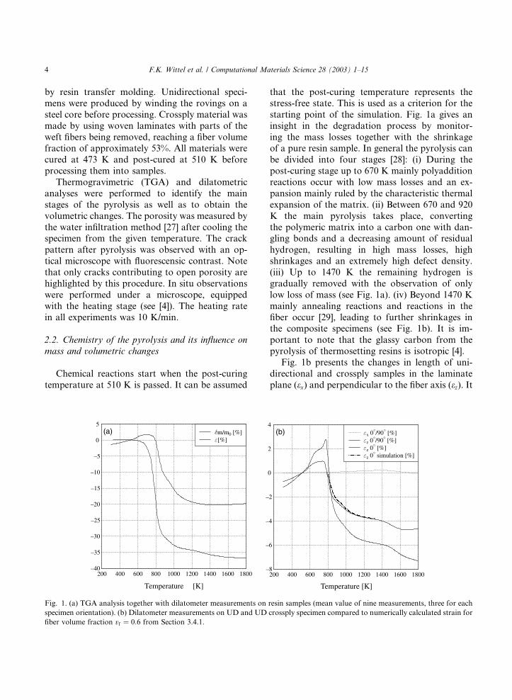
starting point of the simulation. Fig. 1a gives an
insight in the degradation process by monitor-
ing the mass losses together with the shrinkageof a pure resin sample. In general the pyrolysis can
be divided into four stages [28]: (i) During the
post-curing stage up to 670 K mainly polyaddition
reactions occur with low mass losses and an ex-
pansion mainly ruled by the characteristic thermal
expansion of the matrix. (ii) Between 670 and 920
K the main pyrolysis takes place, converting
the polymeric matrix into a carbon one with dan-gling bonds and a decreasing amount of residual
hydrogen, resulting in high mass losses, high
shrinkages and an extremely high defect density.
(iii) Up to 1470 K the remaining hydrogen is
gradually removed with the observation of only
low loss of mass (see Fig. 1a). (iv) Beyond 1470 K
mainly annealing reactions and reactions in the
fiber occur [29], leading to further shrinkages inthe composite specimens (see Fig. 1b). It is im-
portant to note that the glassy carbon from the
pyrolysis of thermosetting resins is isotropic [4].
Fig. 1b presents the changes in length of uni-
directional and crossply samples in the laminate
plane (ex) and perpendicular to the fiber axis (ez). It
200 400 600 800 1000 1200 1400 1600 1800
Temperature [K]
–40
–35
–30
–25
–20
–15
–10
–5
0
5
[%]m/m0 [%](a)
200 400 600 800 1000 1200 1400 1600 1800
Temperature [K]
–8
–6
–4
–2
0
2
4
z 0 simulation [%]z 0 [%]z 0 /90 [%]x 0 /90 [%](b)
Fig. 1. (a) TGA analysis together with dilatometer measurements on resin samples (mean value of nine measurements, three for each
specimen orientation). (b) Dilatometer measurements on UD and UD crossply specimen compared to numerically calculated strain for
fiber volume fraction vf ¼ 0:6 from Section 3.4.1.
4 F.K. Wittel et al. / Computational Materials Science 28 (2003) 1–15

is important to keep in mind, that all dilatometric
data are a superposition of the thermal expan-
sion of the constituents and the thermochemical
shrinkages of the matrix (comp. Fig. 1). It was
found that the stiff fibers result in expansion infiber direction that is one order of magnitude
smaller than the out of plane shrinkage. Conse-
quently we neglect the shrinkage in fiber direction
during the simulation. Note that the UD specimen
can shrink in two dimensions, while the crossply
one only has one direction, leading to a higher
shrinkage ez0�=90�. Additionally, a lower fiber
volume fraction of the crossply material caused anenlarged shrinkage of ez 0�/90� in comparison to
the unidirectional ez 0�. More details can be found
in [4].
2.3. Microscopic in situ observations of the pyrolysis
The typical microstructure developing during
the pyrolysis is presented in Fig. 2. Three majorcrack types, fiber–matrix debonding (fissures with-
out any preferred orientation), transverse cracks
and microdelaminations are observed [30]. The
crack development starts with the onset of pyrol-
ysis at �670 K: evolving gases are trapped in the
still compact CFRP, so they diffuse into pores
leading to a network of fine channels (on the
submicron scale) through which the gases can es-cape [22,31]. The main crack pattern is formed
between 750 and 900 K. First fiber–matrix deb-
ondings are observed followed by the coalescence
of debondings and pores forming transverse
cracks. The development of a crack pattern formed
by this crack type is observed within a small tem-
perature range. This can be seen from Fig. 3a,
where the transverse crack density of two ther-
momicroscopic specimens is shown as a function
of the pyrolysis temperature. Microdelaminations
evolve from 800 K onward by crack deflection of
the segmentation cracks and lead to a saturationof transversal cracking. As the general rule of
cracking during the pyrolysis, a linking mechanism
was found: Debondings evolve by linking smaller
cracks and pores while transverse cracks and
microdelaminations form debonded areas. This
mechanism is in good agreement with the results of
Sjoegren and Berglund [32] from investigations on
mechanically loaded crossply glass fiber reinforcedplastics.
The development of the open porosity (see Fig.
3b) reflects the development of the crack pattern.
The main increase takes place during the main
pyrolysis in the same temperature range in which
the mesoscopic cracks evolve. The maximum of
18% is reached after a pyrolysis up to 1170 K. Up
to now, the mechanisms leading to the decreaseof the porosity of 11% is not understood.
3. The discrete element model
For the study of the formation of defects, a
two-dimensional triangular spring network model
of composites containing rigid cells, is used, that isdescribed in detail in [15]. Molecular dynamics
(MD) simulation is used to follow the motion of
each cell by solving Newton�s equations of motion.In the present study we use a fourth order Gear
Predictor Corrector scheme [33]. A general over-
view of MD simulations applied to composite
materials can be found in [34].
Fig. 2. Side view on C/C crossply laminate after pyrolysis at 1173 K.
F.K. Wittel et al. / Computational Materials Science 28 (2003) 1–15 5

This method allows to simulate simultaneously
a conglomerate of cracks within rather large lattice
sizes with even small cracks being sharply defined.
The fundamental advantage of the lattice model
used in this investigation is its simplicity, givingdirect access and possible physical interpretation
to each step of the algorithm. Consequently, one
can modify the rules of the model for features of
interest, like the characteristic properties of size,
strength and of force in a rather straightforward
and transparent way.
The model is composed in three major steps,
namely, (i) the implementation of the microscopicstructure of the solid, (ii) the determination of the
constitutive behavior, and finally (iii) the breaking
of the solid.
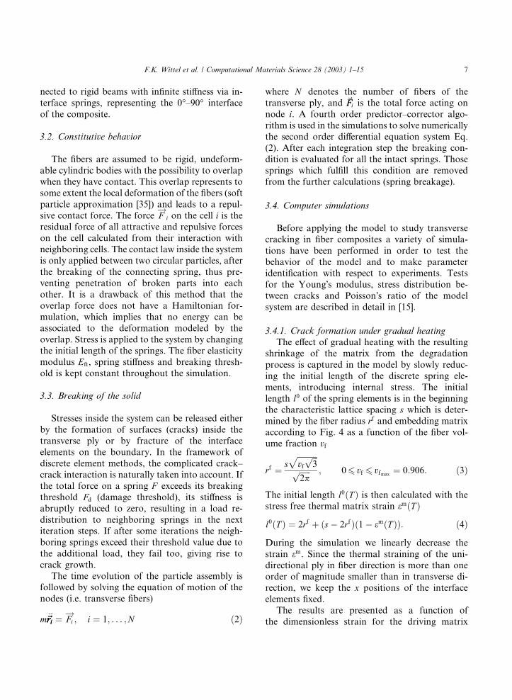
3.1. Microstructure
The model is composed of circular cells of
identical radius rf with their centers located at the
nodes of a regular triangular lattice built of sos-
celes triangles of side length s, which is the char-acteristic lattice spacing. The cells represent the
cross-sections of fibers which are perpendicular to
the model�s plane. The cell centers are connected
by linear elastic springs, representing the material
region with fiber, fiber matrix interface and em-
bedding matrix material. In our simulation, the
cells are the smallest particles interacting elasti-
cally with each other. We use a two-dimensional
simulation with cells of unit thickness, allowing
only motion in the observation plane, with the twodegrees of freedom being the two coordinates of
the position of the cell center of mass. The utili-
zation of a regular lattice is a clear neglect of the
topological disorder, symptomatic for realistic
fiber composite systems. Since we have no partic-
ular basis for a topological disorder, we make a
computational simplification by assuming the dis-
order in spring properties to account for all rele-vant disorder present in the material. Disorder is
given to the model by a Weibull distribution of
breaking thresholds Fd at the beginning of the
simulation in the form
P ðFdÞ ¼ 1� exp
�� Fd
F0
� �m�ð1Þ
and is kept constant during the fracture process
(quenched disorder). F0 represents the character-
istic strength of the material. The Weibull modulus
m controls the degree of disorder in the distribu-
tion and it is usually chosen in the range
26m6 10, experimentally found to describe a
variety of materials. The top and bottom row ofcells, as well as the left and right rows are con-
700 750 800 850 900 950 1000 1050 1100 1150 1200
Temperature [K]
0
1
2
3
4
5
6
7[1
/mm
]crossply 2crossply 1(a)
400 600 800 1000 1200 1400 1600 1800 2000
Temperature [K]
0
5
10
15
20
open
poro
sity
e’[%
]
0 /90 optical0 /90 -(XB)-crossply(b)
Fig. 3. (a) Development of the crack density q and (b) the open porosity e0, measured at room temperature. Since the in situ ob-
servation of the development of q during the degradation process was limited due to low magnifications of the microscope, we scale
these results to the saturation crack density evaluated for the whole specimen after pyrolysis.
6 F.K. Wittel et al. / Computational Materials Science 28 (2003) 1–15
nected to rigid beams with infinite stiffness via in-
terface springs, representing the 0�–90� interface
of the composite.
3.2. Constitutive behavior
The fibers are assumed to be rigid, undeform-
able cylindric bodies with the possibility to overlap
when they have contact. This overlap represents to
some extent the local deformation of the fibers (soft
particle approximation [35]) and leads to a repul-
sive contact force. The force F!
i on the cell i is theresidual force of all attractive and repulsive forces
on the cell calculated from their interaction with
neighboring cells. The contact law inside the system
is only applied between two circular particles, after
the breaking of the connecting spring, thus pre-
venting penetration of broken parts into each
other. It is a drawback of this method that the
overlap force does not have a Hamiltonian for-mulation, which implies that no energy can be
associated to the deformation modeled by the
overlap. Stress is applied to the system by changing
the initial length of the springs. The fiber elasticity
modulus Eft, spring stiffness and breaking thresh-
old is kept constant throughout the simulation.
3.3. Breaking of the solid
Stresses inside the system can be released either
by the formation of surfaces (cracks) inside the
transverse ply or by fracture of the interface
elements on the boundary. In the framework of
discrete element methods, the complicated crack–
crack interaction is naturally taken into account. If
the total force on a spring F exceeds its breakingthreshold Fd (damage threshold), its stiffness is
abruptly reduced to zero, resulting in a load re-
distribution to neighboring springs in the next
iteration steps. If after some iterations the neigh-
boring springs exceed their threshold value due to
the additional load, they fail too, giving rise to
crack growth.
The time evolution of the particle assembly isfollowed by solving the equation of motion of the
nodes (i.e. transverse fibers)
m €~riri~riri ¼ Fi!; i ¼ 1; . . . ;N ð2Þ
where N denotes the number of fibers of the
transverse ply, and ~FFi is the total force acting on
node i. A fourth order predictor–corrector algo-
rithm is used in the simulations to solve numericallythe second order differential equation system Eq.
(2). After each integration step the breaking con-
dition is evaluated for all the intact springs. Those
springs which fulfill this condition are removed
from the further calculations (spring breakage).
3.4. Computer simulations
Before applying the model to study transverse
cracking in fiber composites a variety of simula-
tions have been performed in order to test the
behavior of the model and to make parameter
identification with respect to experiments. Tests
for the Young�s modulus, stress distribution be-
tween cracks and Poisson�s ratio of the model
system are described in detail in [15].
3.4.1. Crack formation under gradual heating
The effect of gradual heating with the resulting
shrinkage of the matrix from the degradation
process is captured in the model by slowly reduc-
ing the initial length of the discrete spring ele-
ments, introducing internal stress. The initial
length l0 of the spring elements is in the beginningthe characteristic lattice spacing s which is deter-
mined by the fiber radius rf and embedding matrixaccording to Fig. 4 as a function of the fiber vol-
ume fraction vf
rf ¼ sffiffiffiffiffiffiffiffiffiffivf
ffiffiffi3
ppffiffiffiffiffiffi2p
p ; 06 vf 6 vfmax ¼ 0:906: ð3Þ
The initial length l0ðT Þ is then calculated with the
stress free thermal matrix strain emðT Þ
l0ðT Þ ¼ 2rf þ ðs� 2rfÞð1� emðT ÞÞ: ð4Þ
During the simulation we linearly decrease the
strain em. Since the thermal straining of the uni-
directional ply in fiber direction is more than oneorder of magnitude smaller than in transverse di-
rection, we keep the x positions of the interface
elements fixed.
The results are presented as a function of
the dimensionless strain for the driving matrix
F.K. Wittel et al. / Computational Materials Science 28 (2003) 1–15 7
shrinkage, giving general validity to the results.Later on we can map the results for comparative
reasons to a temperature range of interest, using
dilatometer measurements for the pure resin
specimen from Fig. 1a, starting at approximately
773 K. At this temperature the dilatometric spec-
imens reach the length they had at the temper-
ing temperature. Therefore, it is assumed that
the thermal mismatch between longitudinal andtransverse ply changes sign. The development of ezfrom the simulation shows good agreement with
measurements in Fig. 1b. At 773 K a regular net-
work of pore channels has already developed. As
the evolving gases can now escape the material, it
is assumed that they do not have any influence on
the further crack development and are therefore
neglected. TEM investigations on CFRP and C/C–SiC revealed a pore and pore channel diameter of
less than 1 lm, which is much less than the char-
acteristic lattice spacing s. The effect of the pore
channels and small cracks and debondings of this
size is therefore not taken into consideration ex-
plicitly, but through the disorder of the system
expressed by the Weibull-statistics in Eq. (1).
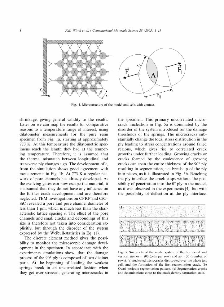
The discrete element method gives the possi-bility to monitor the microscopic damage devel-
opment in the specimen. In accordance with the
experiments simulations show, that the damage
process of the 90� ply is composed of two distinct
parts. At the beginning of loading the weakest
springs break in an uncorrelated fashion when
they get over-stressed, generating microcracks in
the specimen. This primary uncorrelated micro-crack nucleation in Fig. 5a is dominated by the
disorder of the system introduced for the damage
thresholds of the springs. The microcracks sub-
stantially change the local stress distribution in the
ply leading to stress concentrations around failed
regions, which gives rise to correlated crack
growths under further loading. Growing cracks or
cracks formed by the coalescence of growingcracks can span the entire thickness of the 90� plyresulting in segmentation, i.e. break-up of the ply
into pieces, as it is illustrated in Fig. 5b. Reaching
the ply interface the crack stops without the pos-
sibility of penetration into the 0� ply in the model,
as it was observed in the experiments [4], but with
the possibility of deflection at the ply interface.
Fig. 4. Microstructure of the model and cells with contact.
Fig. 5. Snapshots of the model system of the horizontal and
vertical size nx ¼ 800 (cells per row) and ny ¼ 30 (number of
rows). (a) nucleated microcracks distributed over the whole test
cell, and the formation of the first segmentation crack. (b)
Quasi periodic segmentation pattern. (c) Segmentation cracks
and delaminations close to the crack density saturation state.
8 F.K. Wittel et al. / Computational Materials Science 28 (2003) 1–15

Further segmentation cracks mainly form between
existing cracks until the crack density is saturated
due to occurring microdelaminations. Microdel-
aminations usually start to occur when the crack
density has already reached high values, dependingon the thickness of the transverse ply. Fig. 5c
shows that, as a result of the formation of span-
ning cracks, the ply gets segmented into pieces.
The delamination zones along the interface can
also be seen in Fig. 5c.
In order to obtain a quantitative characteriza-
tion of the microstructure of damage, we analyzed
the spatial distribution of microcracks, i.e. thedistribution of broken springs. A crack is identified
as a connected set of broken springs in the trian-
gular lattice taking into account solely nearest
neighbor connections. A crack is considered to be
a segmentation crack if it spans from one side of
the 90� ply to the other. Since cracks forming
along the interface of the plies complicate the
identification of segmentation cracks in the frame-work of our algorithm, first microcracks along the
interfaces are left out of the analysis. Identified
clusters with this method are demonstrated in
Fig. 6 for different values of disorder. The width of
the clusters increases with the disorder, but still a
good identification is possible even for large dis-
orders. The method is illustrated in detail in [15]. It
can be observed that the number of microcracksand also the number of segmentation cracks in-
creases with the strain and the segmentation cracks
have a more or less quasi-periodic spacing. The
formation of the segmentation cracks is very fast
and often with stable crack growth only during the
crack initiation. This behavior is in good agree-
ment with the experimental observations.
The fraction of microcracks Ncracks=Nbonds and
the dimensionless segmentation crack density
Nsegt=l are presented in Fig. 7 as a function of thestrain em=ec for several different values of the
Weibull-modulus m. ec is the average critical strainfor spring elements. Since t is the ply thickness andl the overall system length, Nsegt=l can be under-
stood as the thickness to width aspect ratio of
segments. Varying m can be interpreted as one
major effect of the thermal fiber pretreatment:
decreasing m corresponds to a reduction of func-tional groups on the fiber surface, resulting in a
clustering of functional groups along the fibers [36]
and consequently in larger disorder in the system.
The second major effect is the reduction of the
interface shear strength as the number of chemical
bonds in the fiber–matrix interface is reduced. It
can be observed that cracking initiates at a finite
strain value ein called damage initiation strain,and starting from this point Ncracks monotonically
Fig. 6. Snapshots of model systems of the size nx ¼ 800,
ny ¼ 20 and identified clusters with disorder parameter m.
(a)
(b)
Fig. 7. (a) The total number of microcracks Ncracks divided by
the total number of bonds Nbonds, and (b) the dimensionless
crack density Nsegt=l as a function of strain em=ec. The left rowshows results for constant ply thickness of 20 cells and varying
disorder, while in the right row disorder is fixed to m ¼ 4 and
ply thickness is varied. Smooth curves were obtained by aver-
aging over nine samples.
F.K. Wittel et al. / Computational Materials Science 28 (2003) 1–15 9

increases during the entire loading process. Seg-
mentation first occurs at a strain larger than einafter the number of microcracks reached a certain
value. The number of segmentation cracks Nsegt=lalso increases, however, its value approaches asaturation value for larger strains in accordance
with experimental observations.
Figs. 6 and 7 provide an insight into the role of
disorder in the damage process. Increasing the
value of m, i.e. making the Weibull distribution
narrower, the damage initiation strain ein and the
corresponding strain value for the start of seg-
mentation increase, furthermore, the saturationvalue of the segmentation cracks increases. The
slight decrease of Nseg for wider breaking threshold
distributions is an artifact of the cluster analysis. A
clear identification of segments becomes more
difficult as segmentation cracks, located close to
each other, are connected via delaminations and
cracks. For large disorder it is possible that they
are identified as one cluster, and consequently asone segmentation.
3.4.2. Microcracking in laminates with varying
crossply thickness
In order to get an insight into the dependence of
the microstructure of damage on the model
thickness, systems were simulated with thickness
ranging from approximately 0.1 mm up to 0.5 mm.The microstructure of damage in Fig. 8 shows a
quasi-periodic spacing for all calculated thick-
nesses. For the thicker models branching of the
segmentation cracks is observed close to the ply
interface. This effect can complicate the cluster
evaluation, since neighboring segmentation cracks
can coalesce. Thinner systems reach their satura-
tion crack densities at higher strains than the thickones. These results are compared to an analytical
approach and experiments in Section 4.
3.4.3. Development of the porosity
The porosity of the pyrolysed material governs
the constitutive behavior of the C/C–SiC material,
since the infiltration with liquid silicon mainly
depends on the accessibility of the crack systemsfrom the outside. This part of the porosity is called
open porosity, while the total porosity is defined as
the total volume of cracks, including those located
deep inside the material without any connection to
the outside. Therefore, all elementary cracks that
are not connected to the outside have to be iden-tified in a cluster analysis. These isolated cracks
are used to calculate the area of the closed porosity
Acc, by adding the crack area of all broken ele-
ments forming theses cracks. The crack area be-
tween element i and j is approximated with
equilateral triangles, computing the difference be-
tween the actual area and the uncracked, stress
free area at this temperature,
Accij ðT Þ ¼
1
2ffiffiffi3
p ðr2ijðT Þ � l02ðT ÞÞ: ð5Þ
Since segments delaminate from the ply interface
in the course of the simulation, the open porosity
can be evaluated by using the difference of the
areas
AocðT Þ ¼ AðT Þ � A0ðT Þ � AccðT Þ; ð6Þwith A0ðT Þ being the reference value of the stressfree system without any damage and consequently
with a porosity of 0%. Acc is the sum of the area of
all broken elements ij of all identified isolated
cracks. The total area of the model AðT Þ is calcu-lated from the positions of all edge elements. It is
obvious that the open porosity calculated before
Fig. 8. Microstructure of damage for varying model thickness.
The number of rows of cells ny is given in the figure.
10 F.K. Wittel et al. / Computational Materials Science 28 (2003) 1–15

stress can be released by forming cracks is artifi-
cial, but as soon as crack patterns form, the as-
sumptions for the calculations become realistic.
Nevertheless, the open porosity from measure-ments and from optical area analysis (see Fig. 3) is
approximately 13% and therefore larger than the
calculated ones that are 6–7% for this case. Even
though quantitative agreement is beyond the scope
of the model, the effects of disorder and ply
thickness on the porosity are obtained correctly.
Note that the two-dimensional model, which rep-
resents a small zone inside the material, is limitedto its characteristic scale and cannot take effects
into account, that are caused by the third dimen-
sion. A pyrolysed resin sample as well as a fiber
bundle, therefore, are calculated with the porosity
equal to 0%. On the other hand, the real material is
irregular with resin rich zones, small delamination
zones and a large specimen surface. It is also
possible, that water intrudes the small cracks andgas channels along the fibers below the model
scale. The dependence of the total porosity on the
disorder of the system in Fig. 9c is very small, but
for the system with low disorder, the closed po-
rosity (Fig. 9a) is smaller than for the highly dis-
ordered system. Even though thick systems have a
much smaller number of segmentations cracks
than thinner systems, the open porosity in Fig. 9edoes not show a strong dependence on the system
thickness. This is mainly due to increasing crack
openings in thicker systems. The closed porosity
shows a stronger dependence on the thickness,
with increasing values for increasing system sizes.
It is therefore responsible for the deviation of the
total porosity in Fig. 9f from a master curve.
4. Analytical model
The micromechanics of damage (MMD) anal-
ysis, used here for comparative reasons, is de-
scribed in detail in [37] and was employed in [15].
A MMD analysis is based on the individual pre-
diction of the initiation and propagation of thevarious types of damage, including possible inter-
actions between all identified relevant damage
mechanisms. The analysis consists of two steps, (i)
a stress analysis, and (ii) damage analysis for the
expected damage mechanisms. The stress analysis
has to be undertaken in the presence of observed
damage and is completely independent from the
postulate of a failure criterion for the initiationand evolution of damage, but of course not from
the damage itself.
4.1. Stress analysis
The stress field in the presence of microcracking
and delamination damage is calculated for a unit
cell bounded by cracks located at each end (Fig.10). The entire specimen is built by a sequential
formation of unit cells. A two-dimensional analy-
sis for the x–z-plane derived in Ref. [38] using a
variational mechanics analysis is employed. Fol-
lowing [38] we assume that the x-axis tensile stress
(a) (d)
(b) (e)
(c) (f)
Fig. 9. Development of the porosity for varying disorder and
constant model thickness ny ¼ 20 (a� c) and varying model
thickness but constant disorder m ¼ 4 (d � f ) respectively.
F.K. Wittel et al. / Computational Materials Science 28 (2003) 1–15 11

in each ply group is independent of z, that cracksspan the entire ply thickness and that delamina-
tions are always symmetric to the crack plane [37].
The x-axis tensile stress of a microcracked lami-
nate can be derived with force balance
rð1Þxx ¼ kð1Þm r0 � wðxÞ rð2Þ
xx ¼ kð2Þm r0 þwðxÞ
kð7Þ
with the undetermined function wðxÞ, the appliedglobal stress r0 and k ¼ t2=t1, expressing stress
perturbations caused by the segmentation cracks.
The integration of the stress equilibrium equations
with the unit cell boundary conditions gives the
shear and transverse stresses in the unit cell interms of wðxÞ. The function wðxÞ that minimizes
the complementary energy gives the best approxi-
mation to the microcracked crossply laminate
stress state. The solution of the Euler equation for
finding wðxÞ is dependent on the temperature and
can be found in detail in [38].
4.2. Damage analysis
The failure criterion used, is an energy criterion,
allowing a formation of a new segmentation crack,
whenever the strain energy release rate (ERR) Gm
associated to the formation of a new micro-
crack exceeds some critical value Gmc, also called
intralaminar fracture toughness or microcrack-
ing fracture toughness. The ERR is also calculatedwith the two dimensional, variational mechanics
analysis [37]. Microcrack induced delamination
competes with the formation of new microcracks.
Experimental and numerical studies show, that
microcrack induced delamination does not start
before a critical microcrack density is reached.
The two dimensional, variational mechanicsanalysis described above can be extended to ac-
count for delaminations emanating from micro-
crack tips. The assumption that rð1Þxx is independent
of z, indicates identical delamination lengths em-
anating from the top and bottom microcrack tips.
Following [37] we furthermore assume that Gmc
and the critical ERR associated with the growth of
delamination Gdc are equal. This way, the dimen-sionless crack saturation density in Fig. 11 was
calculated. In principal, it is possible to get better
agreement between MMD analysis and the ex-
perimental data by adapting Gmc and Gdc until a
satisfying fit is achieved, since these values have an
ample scope for physical interpretation. Never-
theless, we find qualitative agreement in the in-
crease of t=a as a function to the 90� ply thicknessfor numerical and analytical results (compare
Figs. 11 and 7).
4.3. Thermal ply degradation with MMD
During the carbonization process, the shrinkage
is opposed to the thermal expansion of the mate-
rial. Therefore, experimental data on the strain-temperature behavior of the material from Fig. 1 is
required. In situ experiments on the development
of material properties like Young�s modulus Ex;Ez
or material strength during the carbonization
process without influencing the process of crack
formation is believed to be beyond todays possi-
bilities. We use the experimentally evaluated lam-
inate properties ExUD ¼ 0:0235� T þ 138:9 GPa,EzUD ¼ 0:00917� T þ 3:93 GPa and mxzUD ¼166:17� T�1 þ 0:206 for T > 400 K, measured at
room temperature after incremental pyrolysis as
well as the values for GyzUD ¼ 3:36 GPa, GxzUD ¼6:25 GPa, myzUD ¼ 0:38, Gmc ¼ 55:7 J/m2, evaluated
at room temperature.
The behavior for segmentation initiation and
crack saturation shown in Fig. 11 was observed inthe numeric calculations. For very thin plies, del-
amination does not occur within the temperature
range. Transferred to laminate of fabric this means,
Fig. 10. Side view on a unit cell representing a crossply lami-
nate with segmentation cracks (a¼half crack spacing) and
delaminations d1; d2 in the transverse ply with half thickness t1.
12 F.K. Wittel et al. / Computational Materials Science 28 (2003) 1–15

that the onset of microdelaminations preferentially
occur at the thicker regions and are stopped at the
tip of the cross-sectioned fiber bundle. This effect
explains why microdelaminations normally do not
extend to macrodelaminations.For a comparison of experimental with numeric
and analytic results, we use a dimensionless strain
e ¼ e0=ec ec ¼ eB;resin ¼ 1:0176 in order to fit the
data to the temperature curve. Cracks were
counted only if they span the entire ply and if they
are clearly visible, using a microscope. Therefore,
the measured crack density of 5.98 1/mm (equiv-
alent to Nsegt=l ¼ 0:68) has to be considered as alower bound value. Note that the initiation tem-
peratures are only from two experiments and show
a large scatter. The analytic as well as the numeric
approach qualitatively capture the fast increase of
the dimensionless segmentation crack density or
segment ratio and the saturation in Fig. 12. Rea-
sonable agreement is achieved between the nu-
meric approach and the crack saturation value ofthe experiments (ny ¼ 10–20). The analytic solu-
tion for the saturation density is around 0.45 and
far from the experimental value of 0.68. This is
mainly due to the model assumption Gmc ¼ Gdc
and experimental problems of evaluating these
values. Nevertheless, the analytic solution provides
a qualitative insight on the role of ply thickness on
initiation values (comp. Fig. 11). Note that thesegment width in the analytical model is defined as
2a� d1 � d2. The assumption of nearly constantmaterial properties and no creep is believed to be
responsible for the difference in the initiation
temperature from the experiments.
5. Conclusions
We introduced a disordered spring networkmodel to study the transverse cracking of the 90�ply in ½0=90�S crossply laminates, applied for the
700 800 900 1000 1100 1200 1300 14000.0
0.1
0.2
0.3
0.4
0.5
0.6
0.7
0.8
0.9
1.0
...
.
... . .........
.
Fig. 12. Comparison of numerical and analytical approaches
with experimental data.
0.1 0.2 0.3 0.4 0.50.4
0.42
0.44
0.46
0.48
0.5
0.52
0.54
0.56
0.58
(a)
0.1 0.2 0.3 0.4 0.5
800
850
900
950
1000
delaminationsegmentation(b)
Fig. 11. (a) Segment thickness/width ratio for saturation and (b) initiation temperatures for segmentation and delamination as a
function of the ply thickness.
F.K. Wittel et al. / Computational Materials Science 28 (2003) 1–15 13

case of thermal degradation of the matrix material
during the pyrolysis process. The main advantage
of our modeling is that it naturally accounts for
the complicated local stress fields formed around
failed regions in the material, furthermore, itcaptures the gradual activation of the relevant
failure mechanisms and their interactions dur-
ing the fracture process. We have demonstrated
that our discrete element model provides an insight
into the damage process occurring under gradual
matrix degradation of crossply laminates. Quan-
titative results have been obtained on the micro-
structure of damage and on the development ofthe porosity for varying ply thickness and dis-
order.
The results obtained by numerical simulations
have been confronted with the experimental find-
ings and also with an analytic approach. Reason-
able agreement was found between the numerical,
analytical and experimental results. However, the
numerical simulations proved to be more realisticthan the simple analytic approaches, due to the
more detailed description of microstructure in the
discrete element model.
The results of the simulation support material
optimization efforts. It was found that with de-
creasing ply thickness, the tendency for the devel-
opment of delaminations is clearly reduced (see
Fig. 11b). Applied to CMC derived from wovenfabrics, this could be achieved by reducing the
number of filaments per roving, the so called K-
number. This result gains importance as the de-
velopment of delaminations is the size limiting
factor in pyrolytically produced CMC. Thus, lar-
ger components may be produced by using finer
woven laminates. On the other hand, this leads to
a higher open porosity (see Fig. 9) and in the caseof the LSI-process to a higher amount of fiber
degradation during siliconization. The increase in
open porosity with decreasing ply thickness can be
utilized in producing functionally graded CMCs
by the LSI-process. A single 1 K-laminate on top
of the standard C/C–SiC would give a gradual
transition for the SiC-content from the inner parts
to the totally converted surface of the material.This could give a better adherence of coatings like
environmental barrier coatings to the substrate.
Based on predictions for the development of crack
morphology, porosity and delamination behavior
for different system sizes and disorder, promising
approaches for new materials have been proposed.
Acknowledgements
The presented work is partly funded by the
German Science Foundation (DFG) within the
Collaborative Research Center SFB 381 �Charac-terization of Damage Development in Composite
Materials using Non-Destructive Test Methods�which is gratefully acknowledged, as well as thesupport under NATO grant PST.CLG.977311. F.
Kun is grateful for financial support of the Alex-
ander von Humboldt Stiftung (Roman Herzog
Fellowship), and also for the B�oolyai J�aanos fel-
lowship of the Hungarian Academy of Sciences
and for support of the research contract
FKFP0118/2001. J. Schulte-Fischedick is grateful
for the support within the Graduate Program(GRK 285) �Interfaces in Crystalline Materials�.
References
[1] F. Ansorge, Untersuchungen zum Versagensverhalten von
fl€uussigsilizierter C/SiC Faserkeramik, Technical Report
179, Fortschrittsbericht VDI 18, 1995.
[2] W. Krenkel, From polymer to ceramics: low cost manu-
facturing of CMC materials, in: Proc. 5th Int. Conf.
Frontiers of Polymer and Adv. Mat. (ICFPAM–5), 1999.
[3] W. Krenkel, N. L€uutzenburger, Near net shape manufactureof CMC components, in: T. Massard (Ed.), Proc. 12th Int.
Conf. Comp. Mat. (ICCM–12), 1999.
[4] J. Schulte-Fischedick, M. Frieß, W. Krenkel, R. Koc-
hend€oorfer, M. K€oonig, Crack microstructure during the
carbonization of carbon fibre reinforced plastics to carbon/
carbon composites, in: Proc. Int. Conf. on Comp. Mat.
(ICCM) 12, 1999.
[5] F.H. Gern, Interaction between capillary flow and macro-
scopic silicon concentration in liquid siliconized carbon/
carbon, in: Proc. 2nd Int. Conf. High Temp. Ceram.
Matrix Comp. (HTCMC–2), 1995.
[6] W. Krenkel, J. Fabig, Mikrostruktur und Eigenschaften
von C/C–SiC Werkstoffen, in: Proc. Werkstoffwoche �96,1996.
[7] J. Schulte-Fischedick, A. Zern, J. Mayer, M. R€uuhle, M.
Frieß, W. Krenkel, R. Kochend€oorfer, The morphology of
silicon carbide in C/C–SiC composites, Journal of Material
Science and Engineering A 332 (2002) 146–152.
[8] J. Schulte-Fischedick, M. Frieß, W. Krenkel, R. Koc-
hend€oorfer, B. Thielicke, The interlaminar shear strength of
14 F.K. Wittel et al. / Computational Materials Science 28 (2003) 1–15

C/C–SiC, in: W. Krenkel, R. Naslain, H. Schneider (Eds.),
High Temperature Ceramic Matrix Composites––Proc. 4th
Int. Conf. High Temp. Ceram. Matrix Comp., 2001.
[9] S. Weihe, M. K€oonig, B. Kr€ooplin, A treatment of mixed
mode fracture in debonding, Composites and Material
Science 3 (1994) 254–262.
[10] S. Weihe, B. Kr€ooplin, An interface formulation for the
micromechanical simulation of fiber–matrix debonding in
composites, in: European Forum of Young Researchers:
From Microscopic to Macroscopic, 1993, pp. 217–222.
[11] L.E. Asp, L.A. Berglund, R. Talreja, Prediction of matrix-
initiated transverse failure in polymer composites, Com-
posite Science Technology 56 (1996) 1089–1097.
[12] S. Weihe, B. Kr€ooplin, Micromechanical simulation of the
initiation of a delamination, in: Paris Eyrolles (Ed.),
MECAMAT�93: Micromechanics of Materials, 1993, pp.
485–498.
[13] H. Zhu, J.D. Achenbach, Radial matrix cracking and
interphase failure in transverse loaded fiber composites,
Mechanics of Materials 11 (1991) 347–356.
[14] B. Lebon, C. Baxevanakisnad, D. Jeulin, J. Renard,
Fracture statistics of a composite laminate, Composites
Science and Technology 58 (1998) 765–771.
[15] F.K. Wittel, F. Kun, B.H. Kroeplin, H.J. Herrmann, A
Study of Transverse Ply Cracking using a Discrete Element
Method, arXiv:cond-mat/0109231 v1 13 Sep 2001.
[16] W.A. Curtin, H. Scher, Brittle fracture in disordered
materials: A spring network model, Journal of Material
Research 5 (3) (1990) 535–553.
[17] E. Schlangen, E.J. Garboczi, New method for simulating
fracture using an elastically uniform random geometry
lattice, International Journal of Engineering Science 34
(10) (1996) 1131–1144.
[18] E. Schlangen, E.J. Garboczi, Fracture simulations of
concrete using lattice models: computational aspects,
Engineering Fracture Mechanics 57 (2/3) (1997) 319–332.
[19] K.A. Trick, T.E. Saliba, A kinetic model of the pyrolysis of
phenolic resin in a carbon/phenolic composite, Carbon 35
(3) (1997) 393–401.
[20] K.A. Trick, T.E. Saliba, Mechanisms of the pyrolysis of
phenolic resin in a carbon/phenolic composite, Carbon 33
(11) (1995) 1509–1515.
[21] J.-D. Nam, J.C. Seferis, Initial polymer degradation as a
process in the manufacture of carbon–carbon composites,
Carbon 30 (5) (1992) 751–761.
[22] C.J. Wang, The effects of resin thermal degradation on
thermostructural response of carbon–phenolic composites
and the manuacturing process of carbon-carbon compos-
ites, Journal of Reinforced Plastics and Composites 15
(1996) 1011–1026.
[23] J. Andersons, U.A. Handge, I.M. Sokolov, A. Bunde,
Analysis of brittle coating fragmentation under uniaxial
tension for weibull strength distributions, The European
Physics Journal B 17 (2) (2000) 261–268.
[24] U.A. Handge, Y. Leterrier, G. Rochat, I.M. Sokolov, A.
Blumen, Two scaling domains in multiple cracking phe-
nomena, Physical Review E 62 (6) (2000) 7807–7810.
[25] U.A. Handge, I.M. Sokolov, A. Blumen, Universal scaling
and nonlinearity in surface layer fragmentation, Physical
Review E 61 (3) (2000) 3216–3219.
[26] U.A. Handge, I.M. Sokolov, A. Blumen, Disorder and
plasticity in the fragmentation of coatings, Physical Review
E 64 (2001) 016109:5.
[27] DIN 51 056: Bestimmung der Wasseraufnahme und der
offenen Porosit€aat, Technical report, DIN 1985.
[28] G.M. Jenkins, K. Kawamura, Polymeric Carbons––Car-
bon Fibre, Glass and Char, Cambridge University Press,
1976.
[29] G. L€uudenbach, P.W.M. Peters, D. Ekenhorst, B.R. M€uuller,
The properties and structure of the carbon fibre in carbon/
carbon produced on the basis of carbon fibre reinforced
phenolic resin, Journal European Ceramic Society 18
(1998) 1531–1538.
[30] J.W. Patrick, A. Walker, The characterization of cracks
and voids in two dimensional carbon–carbon composites,
Carbon 31 (1) (1993) 103–108.
[31] J.-D. Nam, J.C. Seferis, Generalized composite degrada-
tion kinetics for polymeric systems under isothermal and
nonisothermal conditions, Journal of Polymer Science:
Part B: Polymer Physics 30 (1992) 455–463.
[32] B.A. Sjoegren, L.A. Berglund, The effects of matrix and
interface on damage in GRP crossply laminates, Compos-
ites Science and Technology 60 (2000) 9–21.
[33] M.P. Allen, D.J. Tildesley, Computer Simulation of
Liquids, Clarendon Press, Oxford, 1987.
[34] H.J. Herrmann, S. Roux, Statistical Models for the
Fracture of Disordered Media, Elsevier Science Publishers
B.V, 1990.
[35] H.J. Herrmann, J.-P. Hovi, S. Luding, Physics of Dry
Granular Media, Kluwer Academic Pubischers, 1998.
[36] D. Eckenhorst, B.R. M€uuller, K.-W. Brzezinka, M.P.
Hentschel, Faserinduziertes versagen von CFC-Werkstof-
fen, in: S. Heinrich, G. Ziegler, W. Hermel, H. Riedel
(Eds.), Werkstoffwoche, vol. 7, Wiley-VCH, Weinheim,
1998, pp. 619–624.
[37] J.A. Nairn, Matrix microcracking in composites, in:
Comprehensive Composite Materials, vol. 2, Elsevier
Science, 2000 (Chapter 2.12).
[38] Z. Hashin, Analysis of cracked laminates: a variational
approach, Mechanics of Materials 5 (1985) 121–136.
F.K. Wittel et al. / Computational Materials Science 28 (2003) 1–15 15