
Characterization of the Rotor Magnetic Field in a Brushless Doubly-Fed Induction Machine
Upload
independentCategory
view
1download
0
IEEE TRANSACTIONS ON INDUSTRIAL ELECTRONICS, VOL. 56, NO. 10, OCTOBER 2009 4163
Direct Virtual Torque Control for Doubly FedInduction Generator Grid Connection
Jihen Arbi, Manel Jebali-Ben Ghorbal, Ilhem Slama-Belkhodja, Member, IEEE, and Lotfi Charaabi
Abstract—This paper presents a grid-connection control strat-egy of doubly fed induction generator wind system based onthe direct control of both a virtual torque and rotor flux of thegenerator. This control is achieved with no proportional-integralregulator and requires the measurement of only grid voltages,rotor currents, and rotor position. The same switching table isused for grid synchronization and for running process. A field-programmable-gate-array-based design of the proposed control isdeveloped and tested on a 4-kW experimental prototype. Exper-imental results are provided to show the effectiveness of the fastand soft grid-connection method developed.
Index Terms—Direct torque control (DTC), doubly fed induc-tion generator (DFIG), field-programmable gate array (FPGA),grid connection, virtual torque, wind energy.
NOMENCLATURE
Tem Electromagnetic torque.�ϕs, �ϕr Stator and rotor flux space vectors.�Is, �Ir Stator and rotor current space vectors.�Vs, �Vr, �Vg Stator, rotor, and grid voltage space vectors.ωs, ωr Synchronous and slip speeds.Rs, Rr Stator and rotor resistances.Ls, Lr Stator and rotor self-inductances.Msr Mutual inductance.γ Angle between the stator and the rotor flux space
vectors.
I. INTRODUCTION
W IND ENERGY is considered nowadays as one ofthe most important and promising renewable energy
sources [1]. The increasing integration of wind turbine into thegrid over the years and, particularly, the growth in medium-and large-size wind farms have reached the point where theyhave a major impact on the power system [2], [3]. Thus, somecountries like Spain, Denmark, and Germany have definedconnection requirement of wind farms to the grid and codesin order to integrate wind power generation capacity withoutaffecting the quality and the stability of the power system. Oneof the main issues of the grid code requirements (GCRs) isthe power control and frequency range [4], [5]. For instance,
Manuscript received September 30, 2008; revised April 13, 2009. Firstpublished April 28, 2009; current version published September 16, 2009.
The authors are with the Laboratory of Electrical Systems, National SchoolEngineers of Tunis (ENIT), 1002 Tunis, Tunisia (e-mail: [email protected]; [email protected]; [email protected]; [email protected]).
Color versions of one or more of the figures in this paper are available onlineat http://ieeexplore.ieee.org.
Digital Object Identifier 10.1109/TIE.2009.2021590
in the wake of grid voltage loss, power has to be rampedup with a specified gradient per minute. This ramp can beachieved in steps by reconnection of a single wind turbine. Onthe other hand, when grid failures activate protective relays,leading to grid disconnection, the wind turbine can stay in atemporary running-up state. If the fault is cleared and the gridis reestablished before an overspeed situation is reached andbefore the supervisory control shuts down the wind turbine, afast synchronization allows rapid reclosing and rapid generatorloading [6]. For these reasons, soft and fast synchronization andgrid connection at any rotational speed within all the operationrange are an important issue with respect to the GCRs.
Wind turbine technology can be divided into fixed speedcategory (generally with squirrel cage induction generator)and variable speed one (with doubly fed induction generator(DFIG) or synchronous generator) [7], [8]. A variable-speedwind turbine with DFIG (Fig. 1) has the main advantage of a re-duced power converter size at around 30% of rated power. TheDFIG is connected to the grid directly from the stator sideand through a back-to-back converter from the rotor side, pro-viding frequency and voltage control. The control of the rotor-side converter (RsC) allows a decoupled control of active andreactive powers flowing between the stator side and the grid.
Moreover, it achieves a decoupled control of generator torqueand the rotor excitation current. The torque control perfor-mances are mainstream to reduce mechanical constraints andthen to reduce the wear process on the gearbox which has beenidentified as one of the most critical system components, witha relatively high failure frequency [9].
The most widely used control techniques for the RsC arethe field-oriented control (FOC) [10] and the direct controltechniques such as direct torque control (DTC), [6], [11], [12]and direct power control (DPC) [13], [14]. The latter techniquesdo not require current regulators, coordinate transformations,and specific modulations. DTC achieves better steady stateand transient torque control conditions, but it presents thedrawback of variable switching frequency behavior. However,switching frequency control can be performed using predictivecontrol [15].
The grid-side converter (GsC) can also be controlled by FOC[10], [16], [17] or direct control techniques like the DPC in [18].As grid connection is performed only with RsC control in theDFIG-based wind system, the GsC will not be detailed in thispaper [19].
The present research work will focus on the analysis of thegrid-connection and running processes of a DFIG using directvirtual torque control (DVTC) for grid synchronization andDTC for running process.
0278-0046/$26.00 © 2009 IEEE

4164 IEEE TRANSACTIONS ON INDUSTRIAL ELECTRONICS, VOL. 56, NO. 10, OCTOBER 2009
Fig. 1. Studied DFIG-based wind generation system.
The control of the RsC in a DFIG-based wind system hasbeen widely studied and discussed in literature, but only fewauthors handled the DFIG control for grid-connection process.Before connecting, synchronization between the generated sta-tor voltage vectors with the grid voltage vectors must beperformed. The most common approach is based on a vectorcontrol method, with a proportional–integral (PI) regulator toachieve magnitude voltage equality and another PI regulatoror a phased-locked loop (PLL) control to achieve phase andfrequency equality [20]–[22]. In [23], instead of the PLL, theauthors propose a turbine pitch angle controller to set thegenerator frequency equal to the grid one. The DTC approachfor grid connection has been presented in [6]. The switchingcontrol before and after connecting is easy since the sameDTC switching table is used in both cases. Nevertheless, theproposed strategy requires three PI regulators, rotor positionand currents, and both stator and grid voltage measurements.
This paper presents a control strategy based on the directcontrol of a virtual torque for grid connection and on a DTCfor running process, with the same DTC switching table likein [6], but no PI regulator is used and only grid voltage, rotorcurrent, and rotor position measurements are needed.
This paper is organized as follows. In Section II, the princi-ples of DTC control and DVTC are presented. In Section III,field-programmable gate-array (FPGA) design and implemen-tation details are developed. Evaluation results are provided todemonstrate the effectiveness of the proposed grid-connectioncontrol scheme in Section IV. Conclusions are drawn inSection V.
II. DVTC FOR DFIG GRID CONNECTION
A. DTC in Grid-Connected Mode
In grid-connected mode, the DTC is applied to the RsC [24].The DTC for DFIG is based on the same principle as for squirrelcage induction machine [25]. The difference is that, in DTC forDFIG, the rotor flux is regulated, while the DTC for squirrelcage induction machine is based on stator flux regulation. Thelatter is, indeed, constant in magnitude and frequency as statorwindings are directly connected to the grid.
Equation (1) depicts that the electromagnetic torque is afunction of stator and rotor flux linkages and the angle γbetween them. Hence, the generator torque can be controlledthrough the control of the magnitude and angle of rotor flux
Tem = K · |�ϕrr| · |�ϕr
s| · sin γ. (1)
The constant K is defined as
K =32p
Msr
σLsLr(2)
where σ is the leakage factor and p is the pole pair number.Two hysteresis controllers are used to achieve the direct
regulation of rotor flux and electromagnetic torque of the DFIG.The relation between the rotor flux and voltage vectors isgiven by
d�ϕr
dt= �Vr − Rr
�Ir. (3)
When the effect of the rotor resistance is neglected, (4) canbe deduced from (3)
�ϕr(k + 1) ≈ �ϕr(k) + �VrTs (4)
where �ϕr(k) and �ϕr(k + 1) are the rotor flux vectors at thesampling times k · Ts and (k + 1) · Ts, respectively.
Relation (4) leads to
Δ�ϕr ≈ �VrTs (5)
where Ts is the time step of the control algorithm and Δ�ϕr isthe rotor flux variation vector defined by
Δ�ϕr = �ϕr(k + 1) − �ϕr(k). (6)
Thus, according to (5), the variation of the rotor flux vectoris achieved through the application of the appropriate rotorvoltage �Vr.
The rotor flux vector rotates in the same direction as the ap-plied rotor voltage vector and with a rotation speed proportionalto the rotor voltage magnitude.

ARBI et al.: DIRECT VIRTUAL TORQUE CONTROL FOR DOUBLY FED INDUCTION GENERATOR GRID CONNECTION 4165
Fig. 2. Rotor voltage vectors and rotor flux control principle.
The DTC strategy is implemented as a lookup table thatgenerates the switching states of the power semiconductorscorresponding to the appropriate voltage vector �Vr.
Hence, the choice of the voltage vector depends on the logicoutputs of flux and torque controllers and on the position of theflux vector in the αr − βr rotor plane divided into six sectors(1–6) as shown in Fig. 2.
The DTC optimal switching table is given in Table II in theAppendix.
B. Principle of DVTC
The proposed DVTC is derived from the DTC by substitutingthe electromagnetic torque Tem of the generator by a virtualtorque Tv created by the real rotor flux of the machine �ϕr andthe so-called grid virtual flux �ϕg which will be defined furtherin this section. The grid virtual flux �ϕg substitutes, in its turn,the generator stator flux as given by (7). Indeed, �ϕg , similarto �ϕs in grid-connected mode, is constant in magnitude andfrequency. The grid virtual flux vector is defined as follows:
d�ϕg
dt= �Vg. (7)
Its phase θg and magnitude |�ϕg| in the grid stationary referenceframe αg − βg are given by
θg = arctan
(Vgβg
Vgαg
)− π
2(8)
|�ϕg| =|�Vg|ωs
(9)
where Vgαgand Vgβg
are the grid voltage vector (�Vg) compo-
nents in αg − βg . The grid voltage vector �Vg rotates at the gridpulsation ωs in αg − βg; thus,
ωs =dθg
dt. (10)
Fig. 3. Stator, rotor, and virtual grid flux vectors.
The virtual torque is then defined as
Tv = K∣∣�ϕr
g
∣∣ |�ϕrr| sin δ (11)
where �ϕrg and �ϕr
r are the defined flux vectors in the rotorreference frame αr − βr and δ is the angle between them. Fig. 3shows the different vectors where αr − βr, αs − βs, and αg −βg are rotor, stator, and grid reference frames, respectively.
According to (11), the virtual torque control is achievedthrough the control of the generator rotor flux in the sameway as the electromagnetic torque control in the DTC of grid-connected mode.
Note that the constant K, although dependent on machineparameters, does not affect the virtual torque regulation as Tv
will be kept equal to zero during synchronization process. Inaddition, based on (11), regulating virtual torque to zero impliesimposing sin δ = 0, independently on the value of the con-stant K.
C. DVTC for DFIG Grid Connection
Connection of DFIG to the grid terminals requires the adjust-ment of stator voltage to be synchronized with the grid voltage.The main objective of the RsC control, in the grid-connectionprocess, is meeting the synchronization conditions.
These conditions are equality in phase, frequency, and mag-nitude between the grid and stator voltage vectors (�Vg and �Vs,respectively).
The following equations recall the relation between statorvoltage and flux vectors:
d�ϕs
dt= �Vs (12)
θs = arctan(
Vsβs
Vsαs
)− π
2. (13)
Indeed, the stator flux vector phase in the stator referenceframe αs − βs shown in Fig. 2 is expressed in (13) as a functionof stator voltage components.
According to (7) and (12), equality in phase and frequencybetween grid and stator voltage vectors is equivalent to theequality in phase and frequency between grid virtual flux vector�ϕg and stator flux vector �ϕs.
Making use of the phasor diagram in Fig. 2, equality in phaseand frequency between the two voltage vectors, which are, asaforementioned, the first two synchronization conditions, can

4166 IEEE TRANSACTIONS ON INDUSTRIAL ELECTRONICS, VOL. 56, NO. 10, OCTOBER 2009
be met through bringing to collinearity virtual grid flux andstator flux vectors by eliminating the angle δ between them.
Furthermore, before grid connection, in the no-load mode,the DFIG develops no torque as the stator windings are open.This implies that �ϕs and �ϕr are collinear.
Thus, moving the stator flux direction to be collinear to thevirtual grid flux direction is actually equivalent to moving therotor flux vector to be collinear to the virtual grid flux vector.
Based on the aforementioned analysis and according to (11),one can state that the grid virtual flux and stator flux vectorsare collinear when the virtual torque Tv is null. This conditionis guaranteed through the torque control loop of the proposedDVTC by imposing a reference virtual torque Tv_ref equalto zero.
One of the important features of the proposed DVTC isthat, the way it has been developed, its corresponding optimalswitching table is, in fact, the same as that of the DTC.
Furthermore, all DVTC algorithm modules remain un-changed with regard to the DTC. Only torque estimator andexternal references for control loops have to be changed whenswitching from the DVTC in no-load mode to DTC in grid-connected mode.
However, the switching from a virtual torque estimator toan electromagnetic torque estimator does not affect the perfor-mance of the control system. This is due to the fact that duringthe transition between the no-load and grid-connected modes,both torques (Tv and Tem) are equal to zero.
In fact, on the one hand, before grid connection, Tv is nullin order to satisfy the first two synchronization conditions aspreviously explained. On the other hand, the generator is notimmediately loaded when the stator terminals are connected tothe grid. This implies that, in the first seconds after the gridconnection, the electromagnetic torque Tem is still null.
The third condition for the synchronization of grid and statorvoltages is equality in magnitude between them.
The amplitude of the induced stator voltage is indirectlycontrolled through adjusting the rotor excitation by means ofthe rotor flux control loop of the proposed DVTC.
In fact, the appropriate rotor flux reference is imposed tothe rotor flux hysteresis controller in order to guarantee therequired stator voltage amplitude. In this way, the proposedDVTC achieves a decoupled control of the instantaneous angleand amplitude of the stator voltage vector through the torqueand flux control loops, respectively.
In the following, we detail the computation method of therequired rotor flux reference. It is based mainly on the no-loadmode model of the generator.
The dynamic machine equations with a complex represen-tation are given in the following, in a synchronous referenceframe:
�Vs = Rs�Is +
d�ϕs
dt+ jωs�ϕs (14)
�Vr = Rr�Ir +
d�ϕr
dt+ jωr �ϕr (15)
�ϕs = Ls�Is + Msr
�Ir (16)
�ϕr = Lr�Ir + Msr
�Is. (17)
In no-load operation, the stator terminals are open; thus,
�Is = 0. (18)
In steady-state operation, (14), (16), and (18) become
�Vs = jωs�ϕs (19)
�ϕs =Msr�Ir (20)
�ϕr =Lr�Ir. (21)
Substituting (19) and (20) into (21), the reference of rotor fluxamplitude is given by
|�ϕr|ref =Lr
Msr
|�Vs|refωs
. (22)
The rotor flux command is then calculated through the es-timation of grid voltage magnitude and pulsation using onlymeasured grid voltages.
The overall control strategy scheme is shown in Fig. 4.The equations used for the estimation of rotor flux compo-
nents in rotor reference frame are given as follows:
ϕrαr= Lr · irαr
+ Msr · [isα · cos(θ) + isβ · sin(θ)]
ϕrβr= Lr · irβr
+ Msr · [isβ · cos(θ) − isα · sin(θ)] (23)
where θ is the rotor position provided by an incremental en-coder. The grid virtual flux components are estimated using (8)and (9) and polar to Cartesian transformation based on Cordicalgorithm [26].
The rotor flux command equation given in (22) depends onmachine parameters. However, this parameter dependence islow compared to the FOC where PI regulators are tuned usingmore machine parameters, including rotor and stator resistanceslike in [23], for instance.
Furthermore, as the rotor and grid virtual flux are bothrotating at the slip frequency in the rotor reference frame, theswitching frequency is reduced and thus the switching losses.However, the DVTC performances can be further improved byincluding switching frequency control [14].
At this stage, the main features of the developed DVTC canbe cited as follows.
1) Only grid feedback is needed for the control of the statorvoltage amplitude as given by (22). Thus, the measure-ment of stator voltages is useless here. This is not the casefor the majority of control strategies for grid connectionof DFIG already presented in the literature.
2) The control is further simplified by the elimination of PIregulators with regard to the previously presented DTC[6] and FOC for grid connection of DFIG. Obviously,these regulators make the controls more complicatedbecause of the difficulty related to their parameter tuningwhich, in some cases, is done intuitively. In the proposedDVTC, only two hysteresis controllers are used.
Further important features will be pointed out in the nextsections where both simulation and experimental results willbe presented and discussed.

ARBI et al.: DIRECT VIRTUAL TORQUE CONTROL FOR DOUBLY FED INDUCTION GENERATOR GRID CONNECTION 4167
Fig. 4. DVTC scheme for DFIG grid connection.
III. FPGA DESIGN AND CONTROL
ALGORITHM IMPLEMENTATION
With respect to control algorithm requirements, a system-on-module approach, combined with FPGA-based intellectualproperty (IP), is used for architecture development.
After the specification of the algorithm, we propose todevelop a custom modular architecture for the DVTC to beimplemented in an FPGA device. This architecture is developedfollowing a design methodology that allows the adequationbetween control performances and hardware implementationconstraints [27]. The control algorithm is implemented inFPGA as a mix of elementary IP-core functions accordingto the algorithmic decomposition, so that the resulted archi-tecture is built from a library of IP-core modules [28]. Eachmodule is described from the hardware level using struc-tural VHDL.
The control architecture is implemented in a low-cost XilinxSPARTAN3 XCS400PQ208 FPGA target device containing400 000 logical gates and a 50-MHz oscillator.
The control unit “global sequencer” initiates the algorithmby generating a suitable timing schedule to control severalmodules. Fig. 5 shows the top view of the module disposition ofthe DVTC architecture on the FPGA device. The label of each
module in the figure indicates the activation order generated bythe global sequencer.
The whole execution time of the DVTC is only 5.92 μs. Theimplementation results are given in Table I. Note that theseexecution performances are mainly due to the fast computationcapabilities of FPGAs, which represent one of their majorfeatures.
IV. EXPERIMENTAL RESULTS
The emulation of the wind turbine is done by means of a7.5-kW/3000-r/min induction motor under speed control us-ing a Danfoss VLT5011 frequency converter. The DFIG is a4.5-kW/1500-r/min wound rotor induction machine. The back-to-back converters connecting the DFIG to the grid in therotor side are two ac/dc insulated-gate-bipolar-transistor-basedconverters from SEMIKRON. An autotransformer allows a safedc voltage installation in the starting. The machine parametersare given in Table III in the Appendix. Hall-effect sensors(LEM 25NA) are used for current measuring, and Tektronixdifferential probes (P5200) are used for voltages. An interfaceboard (ARCU3I) allows the voltage level adaptation betweenthe LEM sensors and the analog-to-digital (AD) conversioninterface (2.5 V/20 A). Two 12-b circuits (AD9221) are used

4168 IEEE TRANSACTIONS ON INDUSTRIAL ELECTRONICS, VOL. 56, NO. 10, OCTOBER 2009
Fig. 5. DVTC modular architecture for FPGA implementation.
TABLE IFPGA TIME/AREA PERFORMANCES OF DVTC
FOR DFIG GRID CONNECTION
for AD conversion of measured rotor currents and grid voltageswith 100-μs sampling period. A 10-b incremental encoder isused to measure the DFIG rotor mechanical position. A voltage-source inverter (VSI) interface board and a host PC connectedwith the FPGA via serial interface are used as well. Thisplatform is modular and can be extended to more than oneFPGA (Fig. 6). The AD conversion time is equal to 2.4 μs. TheVSI is set with a 3-μs dead time for the sake of security. Fig. 7shows the waveforms of the stator and grid voltages at the grid-
connection instant. The two curves are in close agreement inphase, frequency, and magnitude. The grid-connection processcan be done in a safe way through closing the GC switch(Fig. 1).
As explained in Section II, to eliminate any phase differencebetween stator and grid voltages, the virtual torque Tv must beimposed equal to zero. Thus, when the virtual torque is differentfrom zero, the two voltage vectors are no more collinear. Aphase difference is then created between them. This result hasbeen confirmed both by simulation and experiments as shownin Fig. 8. Simulations are performed with MATLAB-Simulinkfor the control associated to PSIM from POWERSYS for thepower system.
In fact, a torque step is applied to the torque control loopof the proposed DTC from 0.2 to 0 p.u. It is obvious how thevirtual torque affects the phase difference between the statorand grid voltages. When the virtual torque is equal to 0.2 p.u.,the stator voltage is leading the grid voltage. When the torquestep is applied, the virtual torque is forced to be null. Thus, thetwo waveforms coincide.
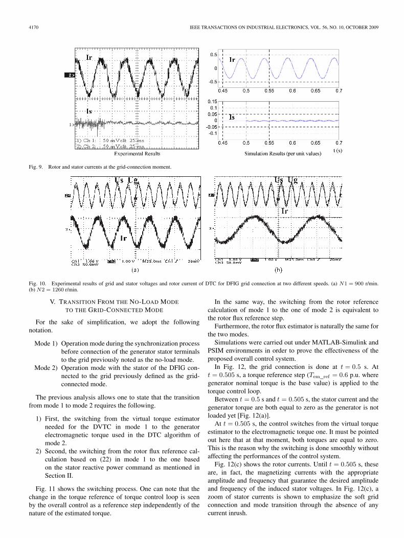
The control response is fast, as expected. The DFIG gridconnection is smooth. This is confirmed through Fig. 9. In-deed, no current inrush has been provoked at the connectioninstant.

ARBI et al.: DIRECT VIRTUAL TORQUE CONTROL FOR DOUBLY FED INDUCTION GENERATOR GRID CONNECTION 4169
Fig. 6. Experimental laboratory setup.
Fig. 7. Grid (Ug) and stator (Us) line-to-line voltages at grid-connection instant.
Fig. 8. Grid line-to-line voltage (Ug) and stator line-to-line voltage (Us) and virtual torque (Tv).
Fig. 10 shows the stator voltage, grid voltage, and rotorcurrent for two different angular speeds (N1 = 900 r/min andN2 = 1260 r/min) of the DFIG. The decoupling between statorand rotor frequencies, offered by the back-to-back converterconnected to the rotor of the DFIG, allows the grid connection
for different speeds. Indeed, for both angular velocities N1[Fig. 10(a)] and N2 [Fig. 10(b)], the synchronization betweenstator and grid voltages is kept. This represents one of thenumerous advantages and flexibilities of the DFIG-based windsystem.
4170 IEEE TRANSACTIONS ON INDUSTRIAL ELECTRONICS, VOL. 56, NO. 10, OCTOBER 2009
Fig. 9. Rotor and stator currents at the grid-connection moment.
Fig. 10. Experimental results of grid and stator voltages and rotor current of DTC for DFIG grid connection at two different speeds. (a) N1 = 900 r/min.(b) N2 = 1260 r/min.
V. TRANSITION FROM THE NO-LOAD MODE
TO THE GRID-CONNECTED MODE
For the sake of simplification, we adopt the followingnotation.
Mode 1) Operation mode during the synchronization processbefore connection of the generator stator terminalsto the grid previously noted as the no-load mode.
Mode 2) Operation mode with the stator of the DFIG con-nected to the grid previously defined as the grid-connected mode.
The previous analysis allows one to state that the transitionfrom mode 1 to mode 2 requires the following.
1) First, the switching from the virtual torque estimatorneeded for the DVTC in mode 1 to the generatorelectromagnetic torque used in the DTC algorithm ofmode 2.
2) Second, the switching from the rotor flux reference cal-culation based on (22) in mode 1 to the one basedon the stator reactive power command as mentioned inSection II.
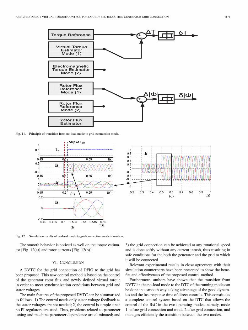
Fig. 11 shows the switching process. One can note that thechange in the torque reference of torque control loop is seenby the overall control as a reference step independently of thenature of the estimated torque.
In the same way, the switching from the rotor referencecalculation of mode 1 to the one of mode 2 is equivalent tothe rotor flux reference step.
Furthermore, the rotor flux estimator is naturally the same forthe two modes.
Simulations were carried out under MATLAB-Simulink andPSIM environments in order to prove the effectiveness of theproposed overall control system.
In Fig. 12, the grid connection is done at t = 0.5 s. Att = 0.505 s, a torque reference step (Tem_ref = 0.6 p.u. wheregenerator nominal torque is the base value) is applied to thetorque control loop.
Between t = 0.5 s and t = 0.505 s, the stator current and thegenerator torque are both equal to zero as the generator is notloaded yet [Fig. 12(a)].
At t = 0.505 s, the control switches from the virtual torqueestimator to the electromagnetic torque one. It must be pointedout here that at that moment, both torques are equal to zero.This is the reason why the switching is done smoothly withoutaffecting the performances of the control system.
Fig. 12(c) shows the rotor currents. Until t = 0.505 s, theseare, in fact, the magnetizing currents with the appropriateamplitude and frequency that guarantee the desired amplitudeand frequency of the induced stator voltages. In Fig. 12(c), azoom of stator currents is shown to emphasize the soft gridconnection and mode transition through the absence of anycurrent inrush.
ARBI et al.: DIRECT VIRTUAL TORQUE CONTROL FOR DOUBLY FED INDUCTION GENERATOR GRID CONNECTION 4171
Fig. 11. Principle of transition from no-load mode to grid-connection mode.
Fig. 12. Simulation results of no-load mode to grid-connection mode transition.
The smooth behavior is noticed as well on the torque estima-tor [Fig. 12(a)] and rotor currents [Fig. 12(b)].
VI. CONCLUSION
A DVTC for the grid connection of DFIG to the grid hasbeen proposed. This new control method is based on the controlof the generator rotor flux and newly defined virtual torquein order to meet synchronization conditions between grid andstator voltages.
The main features of the proposed DVTC can be summarizedas follows: 1) The control needs only stator voltage feedback asthe stator voltages are not needed; 2) the control is simple sinceno PI regulators are used. Thus, problems related to parametertuning and machine parameter dependence are eliminated; and
3) the grid connection can be achieved at any rotational speedand is done softly without any current inrush, thus resulting insafe conditions for the both the generator and the grid to whichit will be connected.
Relevant experimental results in close agreement with theirsimulation counterparts have been presented to show the bene-fits and effectiveness of the proposed control method.
Furthermore, authors have shown that the transition fromDVTC in the no-load mode to the DTC of the running mode canbe done in a smooth way, taking advantage of the good dynam-ics and the fast response time of direct controls. This constitutesa complete control system based on the DTC that allows thecontrol of the RsC in the two operating modes, namely, mode1 before grid connection and mode 2 after grid connection, andmanages efficiently the transition between the two modes.

4172 IEEE TRANSACTIONS ON INDUSTRIAL ELECTRONICS, VOL. 56, NO. 10, OCTOBER 2009
APPENDIX
TABLE IIDTC AND DVTC OPTIMAL SWITCHING TABLE
TABLE IIIMACHINE PARAMETERS
REFERENCES
[1] L. Jodziewicz, “Environmental and sitting status and needs of 20%electricity from wind power,” in Conf. IEEE Power Energy Soc. Gen.Meeting—Convers. Del. Elect. Energy 21st Century, Jul. 2008, pp. 1–6.
[2] J. Hu, Y. He, L. Xu, and B. W. Williams, “Improved control of DFIGsystems during network unbalance using PI–R current regulators,” IEEETrans. Ind. Electron., vol. 56, no. 2, pp. 439–451, Feb. 2009.
[3] S. Alepuz, S. Busquets-Monge, J. Bordonau, J. Gago, D. Gonzalez, andJ. Balcells, “Interfacing renewable energy sources to the utility grid us-ing a three-level inverter,” IEEE Trans. Ind. Electron., vol. 53, no. 5,pp. 1504–1511, Oct. 2006.
[4] B. Alboyaci and B. Dursun, “Grid connection requirements for wind tur-bine systems in selected countries. Comparison to Turkey,” Elect. PowerQuality Utilization Mag., vol. 3, no. 2, Jun. 2008. [Online]. Available:http://www.scribd.com/doc/
[5] G. Joos, “Turbine generator low voltage ride through requirements and so-lutions,” in Conf. Rec. IEEE Power Energy Soc. Gen. Meeting—Convers.Del. Elect. Energy 21st Century, Jul. 2008, pp. 1–7.
[6] S. A. Gomez and J. L. R. Amenedo, “Grid synchronisation of doubly fedinduction generators using direct torque control,” in Proc. IEEE IECONConf., Nov. 2002, pp. 3338–3343. CD-ROM.
[7] J. M. Carrasco, L. G. Franquelo, J. T. Bialasiewicz, E. Galvan, R. C.Portillo Guisado, M. A. M. Prats, J. I. Leon, and N. Moreno-Alfonso,“Electronic systems for the grid integration of renewable energy sources:A survey,” IEEE Trans. Ind. Electron., vol. 53, no. 4, pp. 1002–1016,Jun. 2006.
[8] M. Malinowski, S. Stynski, W. Kolomyjski, and M. P. Kazmierkowski,“Control of three-level PWM converter applied to variable-speed-typeturbines,” IEEE Trans. Ind. Electron., vol. 56, no. 1, pp. 69–77, Jan. 2009.
[9] J. Ribrant and L. Bertling, “Survey of failures in wind power systems withfocus on Swedish wind power plants during 1997–2005,” in Conf. Rec.IEEE Power Eng. Soc. Gen. Meeting, Jun. 2007, pp. 1–8.
[10] R. Pena, J. C. Clare, and G. M. Asher, “Doubly fed induction generatorusing back-to-back PWM converters and its application to variable-speedwind-energy generation,” Proc. Inst. Elect. Eng.—Electr. Power Appl.,vol. 143, no. 3, pp. 231–241, May 1996.
[11] J. Arbi, I. Slama-Belkhodja, and S. A. Gomez, “Control of a DFIG-basedwind system in presence of large grid faults: Analysis of voltage ridethrough capability,” in Proc. IEEE-EPQU, Barcelona, Spain, Oct. 2007,pp. 1–6.
[12] Z. Liu, O. A. Mohammed, and S. Liu, “A novel direct torque controlof doubly-fed induction generator used for variable speed wind powergeneration,” in Conf. Rec. IEEE Power Eng. Soc. Gen. Meeting, Jun. 2007,pp. 1–6.
[13] L. Xu and P. Cartwright, “Direct active and reactive power control ofDFIG for wind energy generation,” IEEE Trans. Energy Convers., vol. 21,no. 3, pp. 750–758, Sep. 2006.
[14] D. Zhi and L. Xu, “Direct power control of DFIG with constant switch-ing frequency and improved transient performance,” IEEE Trans. EnergyConvers., vol. 22, no. 1, pp. 110–118, Mar. 2007.
[15] G. Abad, M. A. Rodriguez, and J. Poza, “Two-level VSC based predictivedirect torque control of the doubly fed induction machine with reducedtorque and flux ripples at low constant switching frequency,” IEEE Trans.Power Electron., vol. 23, no. 3, pp. 1050–1061, May 2008.
[16] E. Figueres, G. Garcera, J. Sandia, F. Gonzalez-Espin, and J. C. Rubio,“Sensitivity study of the dynamics of three-phase photovoltaic inverterswith an LCL grid filter,” IEEE Trans. Ind. Electron., vol. 56, no. 3,pp. 706–717, Mar. 2009.
[17] J. Dannehl, C. Wessels, and F. W. Fuchs, “Limitations of voltage-orientedPI current control of grid-connected PWM rectifiers with LCL filters,”IEEE Trans. Ind. Electron., vol. 56, no. 2, pp. 380–388, Feb. 2009.
[18] B. Rueckert and W. Hofmann, “Common mode voltage minimized directpower control of the grid side connected converter in doubly fed inductiongenerators,” in Proc. IEEE-SDEMPED, Ischia, Italy, Jun. 11–13, 2008,pp. 1455–1459.
[19] F. Blaabjerg, R. Teodorescu, M. Liserre, and A. V. Timbus, “Overviewof control and grid synchronization for distributed power generationsystems,” IEEE Trans. Ind. Electron., vol. 53, no. 5, pp. 1398–1409,Oct. 2006.
[20] P. Jungwoo, L. Kiwook, K. Dongwook, L. Kwangsoo, and P. Jinsoon,“An encoder-free grid synchronization method for a doubly-fed induc-tion generator,” in Proc. EPE Conf., Aalborg, Denmark, Sep. 2–5, 2007,pp. 1–6.
[21] Z. Xueguang, X. Dianguo, L. Yongqiang, and M. Hongfei, “Study onstagewise control of connecting DFIG to the grid,” in Proc. IEEE-IPEMC,Shanghai, China, Aug. 14–16, 2006, pp. 1–5.
[22] G. Iwanski and W. Koczara, “Grid connection to stand alone transitionsof slip ring induction generator during grid faults,” in Conf. Rec. IEEE-IPEMC, Shanghai, China, Aug. 14–16, 2006, pp. 1–5.
[23] A. G. Abo-Khalil, L. Dong-Choon, and L. Se-Hyun, “Grid connection ofdoubly-fed induction generators in wind energy conversion system,” inConf. Rec. IEEE-IPEMC, Shanghai, China, Aug. 2006, pp. 1–5.
[24] S. Arnaltes, J. C. Burgos, and J. L. Rodriguez-Amenedo, “Direct torquecontrol of a doubly-fed induction generator for variable speed windturbines,” Elect. Power Compon. Syst., vol. 30, no. 2, pp. 199–216,Feb. 2002.
[25] I. Takahashi and T. Nouuchi, “A new quick-response and high-efficiencycontrol strategy of an induction motor,” IEEE Trans. Ind. Appl., vol. IA-22, no. 5, pp. 820–827, Sep./Oct. 1986.
[26] R. Andraka, A Survey of CORDIC Algorithms for FPGA BasedComputers. North Kingstown, RI: Consulting Group, Inc. [Online].Available: www.fpga-guru.com/files/crdcsrvy.pdf
[27] M.-W. Naouar, E. Monmasson, A. Naassani, I. Slama-Belkhodja, andN. Patin, “FPGA-based current controllers for AC machine drives—Areview,” IEEE Trans. Ind. Electron., vol. 54, no. 4, pp. 1907–1946,Aug. 2007.
[28] E. Monmasson and M. N. Cirstea, “FPGA design methodology for in-dustrial control systems—A review,” IEEE Trans. Ind. Electron., vol. 54,no. 4, pp. 1824–1842, Aug. 2007.
Jihen Arbi was born in Tunisia in 1978. She re-ceived the B.S., M.S., and Ph.D. degrees in electricalengineering from the Ecole Nationale d’Ingénieursde Tunis (ENIT), Tunis, Tunisia, in 2002, 2003, and2008, respectively.
She is currently a permanent Researcher in theLaboratory of Electrical Systems, ENIT. Her mainresearch interests are in the areas of ac machinedrives and variable-speed wind energy systems.

ARBI et al.: DIRECT VIRTUAL TORQUE CONTROL FOR DOUBLY FED INDUCTION GENERATOR GRID CONNECTION 4173
Manel Jebali-Ben Ghorbal was born in Nabeul,Tunisia, in 1983. She received the B.S. and M.S.degrees in electrical engineering from the Ecole Na-tionale d’Ingénieurs de Tunis (ENIT), Tunis, Tunisia,in 2007 and 2008, respectively, where she is cur-rently working toward the Ph.D. degree in electricalengineering in the Laboratory of Electrical Systems.
Her current research interests include machinedrives, control and operation of doubly fed inductiongenerators for wind energy generation, and field-programmable-gate-array-based controllers.
Ilhem Slama-Belkhodja (M’08) received theB.S. degree in electrical engineering from theEcole Nationale Supérieure d’Electrotechnique,d’Electronique, d’Informatique, d’Hydraulique etdes Télécommunications (ENSEEIHT)–InstitutNational Polytechnique de Toulouse (INPT),Toulouse, France, in 1983, the Ph.D. degree fromthe INPT in 1985, and the Doctorat d’Etat fromthe Ecole Nationale d’Ingénieurs de Tunis (ENIT),Tunis, Tunisia, in 1997.
She is currently a Professor and the Head of theLaboratory of Electrical Systems, ENIT. Her current research activities are inthe field of fault-tolerant control for electrical drives.
Lotfi Charaabi was born in Tunisia in 1977. Hereceived the B.S. and M.S. degrees in telecommu-nication from the Ecole Nationale d’Ingénieurs deTunis (ENIT), Tunis, Tunisia, in 2001 and 2002,respectively, and the Ph.D. degree in electrical en-gineering jointly from ENIT and the Ecole NormaleSupérieure de Cachan, Cachan, France, in 2006.
He is currently a Researcher in the Laboratoryof Electrical Systems, ENIT. His main research in-terests include embedded systems, system on chip,and design and integration of electrical system algo-
rithms on field-programmable gate arrays.
Copyright © 2022 FDOKUMEN