


Direct-Current Motor and Generator Troorlrs Operation and Repair
289
-
Upload
khangminh22 -
Category
Documents
-
view
1 -
download
0
Transcript of Direct-Current Motor and Generator Troorlrs Operation and Repair


PU B L I S H E R S O F B O O K S FO K /
B eetricalWorld 7 EngineeringNews-Record
Power V EngineeringandMiningjoumal-Press
Chemica l and Metal lurgical EngineeringElec tr ic Railway Journal V GoalAgeAmericanMach inist v lngenien
'
a InternacionalElectri cal Merchandising v B usTransportation
Journalof Electricity and Western Indus try
D I RE CT -CURRE N T
MOTORANDGENERATORTROORL‘
RS
OPERAT ION AN D RE PA IR
B Y
T HE ODORE S ; GANDYDE SI G N I N G E L E CT R ICA L E N G I N E E R OF DI RE CT CURRE N T
M ACH I N E RY , G E N E RA L E L E CT RI C COM PANY , S I N CE 1904
AN D
E LME R C . SCHACHT , LT . J . G . , U . S . N . R . F.
I N CHARG E OF E L E CT RI CAL I N ST RUCT I ON AT T HE U N I T E D ST A T E SN AVY SCHO O L OF T URB I N E E N G I N E E RI N G , SCHE N E CT ADY , N . Y .
“M b“.
Fms 'r E D I T I ON
‘ Q0 6 ‘
a5T HIRD IM PRE S S I ON
M CGRAW-H I LL B OOK COM PANY, I N C.
N EW YORK : 370 S E VE N TH AVE NUE
LON DON : 6 8 B OUVE RI E S T . , E . o. 4
192 0

COPYRI GHT , 1920, B Y T HE
M CGRAW -HI LL B OOK COM PANY, I N C.
PRI NT E D I N UN I T E D S T AT E S OF AM E RI CA
T H E M A P L E P R E S S Y O R K P A
PRE FACE
The chi ef purpose of this book is to give the methods,which
many years of experience have proved to be both simple and
eff ective,for tracing and remedying direct current motor and
generator troubles . In addition,the questions of the selec
tion,operation
,care and repair of direct current machi nery
are analyzed from the standpoint of the operator.
The theories of why a motor or generator will run, as well as
the problems and fundamentals underlying the design of
direct current machinery,have been very completely given
and expounded in numerous excellent books on the market .But it is ou r belief that there is a vast army of operators in
the electrical world who are greatly interested in why the
motor or generator will not run, and it is to supply informa
tion on this topic that the present work has been written .
Throughout, it is assumed that the operator is confronted
with the question of selection of the best machi ne for hi s
purpose ; then with the question of the best operation of that
machine and in case of troubles,with their tracing and effec
tive remedyi ng .In all cases
,an effort has been made to treat the subj ects
in as general a way as possible so as to include all methods in
good practice . S tandard machi nes are described and illus
trated so as to in no way limit and restrict the information
to the operation of special types . We are greatly indebted to
the General E lectri c Company, the Westinghouse E lectri c
Manufacturing Company, and the Allis-Chalmers Company
for their kindness in furni shing the illustrations for this
publication .
T HE AUTHORS .
S CHE NE CT ADY, N . Y.
,
Apri l, 1920.

IN TRODUCT ION
There are many books on matters electrical, some people
believe, more than necessary or desirable . There are bookson the theory of electrical engineering
,on the theory of elec
t rical apparatus,of electri c systems and methods of operation .
They are necessary,for on the theory of electrical engineering
rests ou r giant electrical industry,which could not have de
veloped without it . It was this thorough theoretical foundation which has enabled electrical engineering
,though the last
of the great engineering branches,to progress with the won
derful rapidity which outstripped all others . There are numerou s books on apparatus and machinery design . While
perhaps not one ou t of ten electrical engineers may become a
designer,they are necessary and useful . There are numerous
books on practical electrical engineering,good
,bad and in
difieren t .
But for every designer or theorist, there are two or three
electrical engineers who have to do with electric motors or
generators,their operation
,management and care
,and there
fore Messrs . Gandy S chacht ’s book appears to me as ex
t remely useful , filling a serious gap in our electrical literature .
I may call it a biology,pathology and therapy of the electric
machine .
It deals with the electric machine in all its conditions, in
health and when in trouble . It gives the characteristics , de
scribes the construction and the nature of the electric motor
and generator,shows and illustrates the numerous troubles
which may occur in motors and generators—almost as manyas there are diseases of mankind—t eaches how to diagnose
the trouble,that is
,to find ou t what is the matter, how to
cure it,to remedy the trouble
,and how to keep the machine
in good shape,that is
,in first class operating condition .
vii
I N TRODUCT I ON
Attempts to write such a book have been made before, but
it can be done successfully,so that the book is of real use to
the engineer who has to do with electrical machinery,only
by an engineer who has lived wi th motors and generators of
all kinds for many years in a large manuf acturing company,and so has been able to become fully fami liar with every
phase of the subj ect, and who by years of teaching experience
has become able also to transmit hi s know ledge and experi
ence to the reader . N ow this has been the case with the
authors of the following work,and therefore I consider it as
a most valuable addi tion to the electri cal literature,whi ch
will be of interest and value to every engineer .CHARLE S P . STE I NM E TZ .
M arch 25,1920.
T AB L E OF CON T EN T S
I NTRODUCT I ONCHA PT E R
I .
I I .
I I I .
IV.
V.
VI .
VI I .
VI I I .
T YPE S OF M OT ORS AND T HE IR US E S
fi PE s OF G E NE RAT ORS AN D T HE IR US E S
T HE E RE CT I ON AN D A S S E M B LY OF D IRE CT CURRE NT M OT ORS
AND G E NE RAT ORS
T HE S T ART ING AND OPE RAT I ON OF D IRE CT CURRE NT M OT ORS
T HE S T ART ING AND OPE RAT I ON OF D IRE CT CURRE NT G E NERAT ORS
D IRE CT CURRE NT SW I T CHB OARDS
T ROUB LE S AND T HE IR RE M E D I E S
T E S T S AN D RE PA IRS
US E FUL DAT A

DIRE CT -CURRE NT MOT ORAND
G E NE RA T OR T ROUB L E S
CHAPTE R I
TYPE S OF MOTORS AND THE IR USE S
GE N E RA L CON S TRUCTI ON—TYPE S OF MOTORS - STAN DARDE LE CTRI CAL CON N E CT I ON S FOR MOTORS - US E S OF D I F
FE RE N T TYPE S OF MOTORS - I N FORM ATI ON T O B E
SUPPLI E D T O T HE MA N UFA CTURE R W HE N ORDE RI NG
TYPE S OF M OT ORS AND T HE IR US E S
In ordering direct-current motors for new instal lations
or in replacing or adding to old units , the question arisesof
selecting the motor best suited for the purposes at hand .
Frequently defects in operation and more often great ineffi
ciency can be traced to the poor j udgment of the buyer
when selecting the motor .
It is the purpose here to outline the general construction
and characteristics of the different types of standard motors
upon the market . The details of construction and the illus
trat ions of the motor in the process of building , serve to
acquaint the operator with views of each individual part while
in assembly . The use to which the motor is to be put and the
conditions under which it is to operate Should be carefully
considered before a selection is made .
2 D. C. M OT OR AND GE N E RA T OR TROUB LE S
DE S CRIPT I ON OF DIRE CT -CURRE NT M OT ORS
GE NE RAL CON S TRUCT I ON
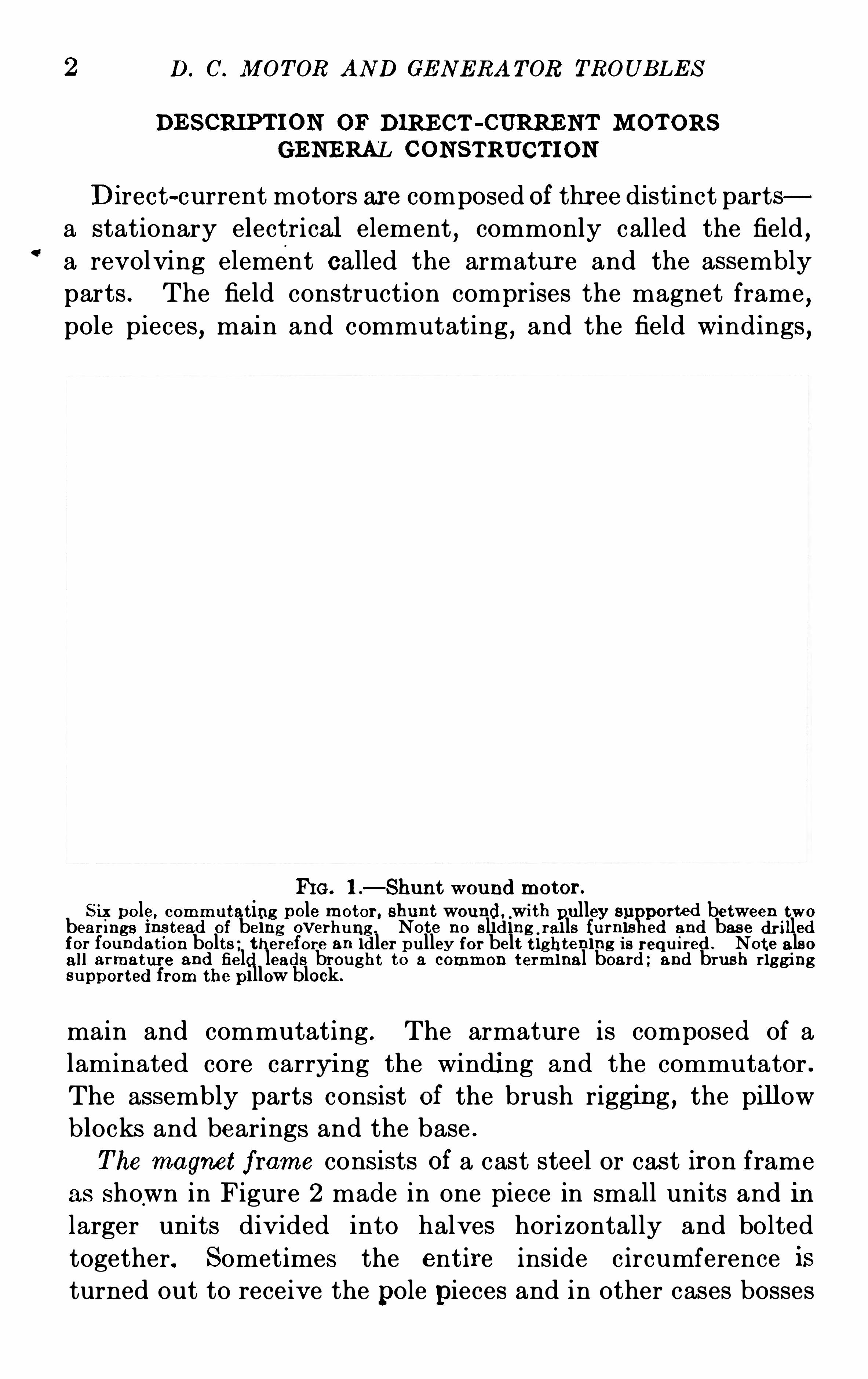
D irect-current motors ar e composed of thr ee distinct parts
a stationary electrical element,commonly called the field
,
a revolving element called the armatur e and the assembly
parts . The field construction comprises the magnet frame,
pole pieces , main and commutating , and the field windings ,
FI G . 1.
—Shunt wound motor .
S ix pole, comm utat ing pole motor . shunt wound,with pu lley su ported between t wobear ings Instead Of being overhu ng . Note no sliding rails furnia ed and base dr i lled
for fou ndat ion bolts ; t h erefore an idler pu lley for belt t ighten ing is requ ired . Note als oall armatur e and field leads brought to a common term inal board ; and brush r ig gi ngsupported from the pillow block.
main and commutating . The armature is composed of a
laminated core carryi ng the windi ng and the commutator .
The assembly parts consist of the brush rigging , the pillow
blocks and bearings and the base .T he magnet frame consists of a cast steel or cast iron frame
as shown in Figure 2 made in one piece in small units and in
larger units divided into halves horizontally and bolted
together. Sometimes the entire inside circumference isturned out to receive the pole pieces and in other cases bosses
T YPE S OF M OTORS AN D THE I R US E S 3
or pads are cast on the casting and turned or machined to fit
the poles . The frame is then drilled and tapped to aecom
modate the bolts holding the pole pieces . Feet are cast onthe lower half of the frame and drilled to receive the holding
down bol ts .
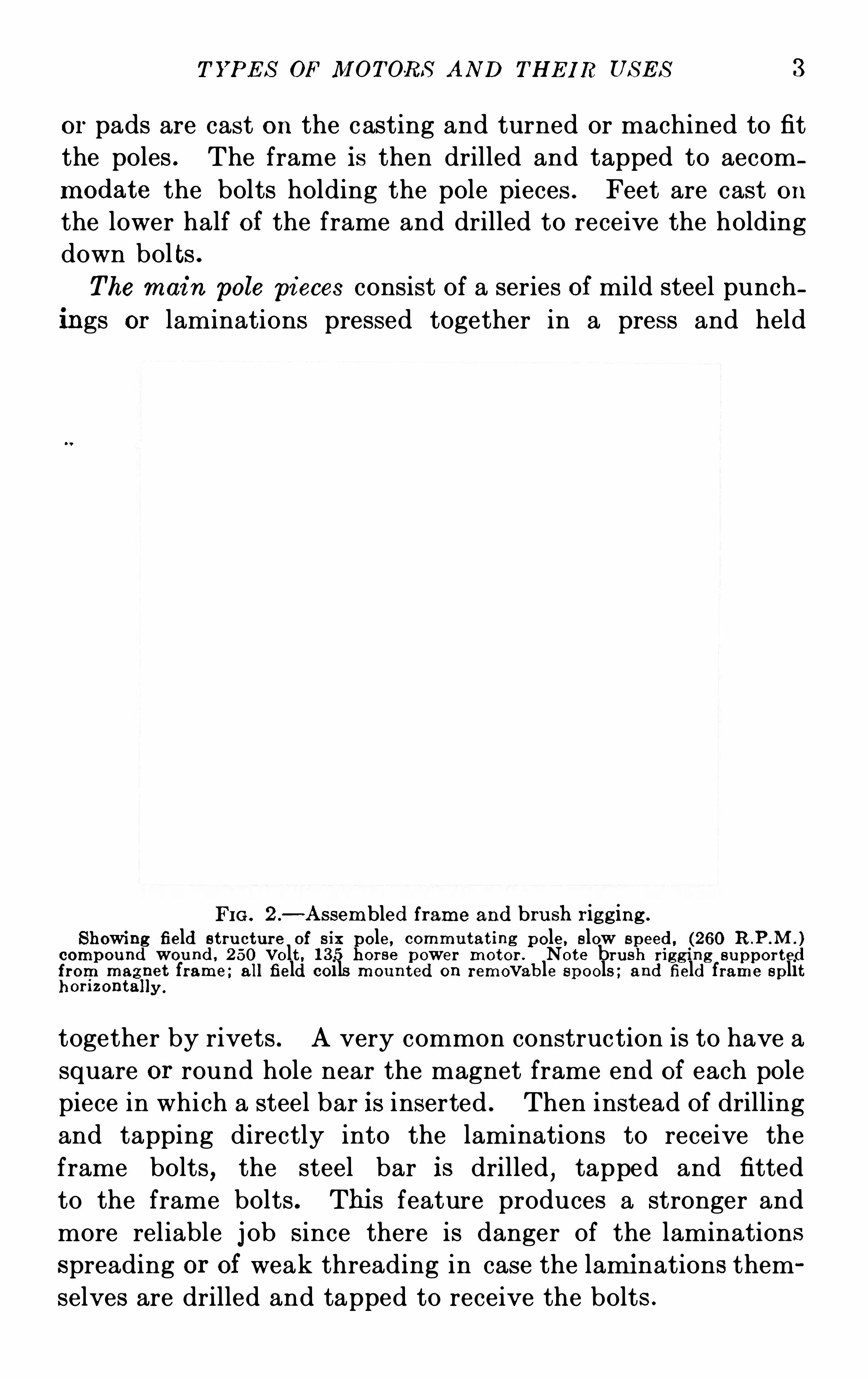
The mai n pole pi eces consist of a series of mild steel punch
ings or laminations pressed together in a press and held
FI G . 2 .
—Assembled frame and bru sh r ig g ing .
Showi ng field st ru cture of s ixgole, commu tat ing pole, slow speed , (260
compound wou nd , 250 volt , 135 or se power motor . Note br ush r ig g ing suppor ted
from mag
lr
li et frame ; all field coils moun ted on removable spools ; and field frame S plit
or izonta y .
together by rivets . A very common construction is to have a
square or round hole near the magnet frame end of each pole
piece in which a steel bar is inserted . Then instead of drilling
and tapping directly into the laminations to receive the
frame bolts,the steel bar is drilled
,tapped and fitted
to the frame bolts . Thi s feature produces a stronger and
more reliable j ob S ince there is danger of the laminations
spreading or of weak threading in case the lami nations them
selves are drilled and tapped to receive the bolts .
4 D. C. M OT OR AND GE N ERA T OR TROUB LE S
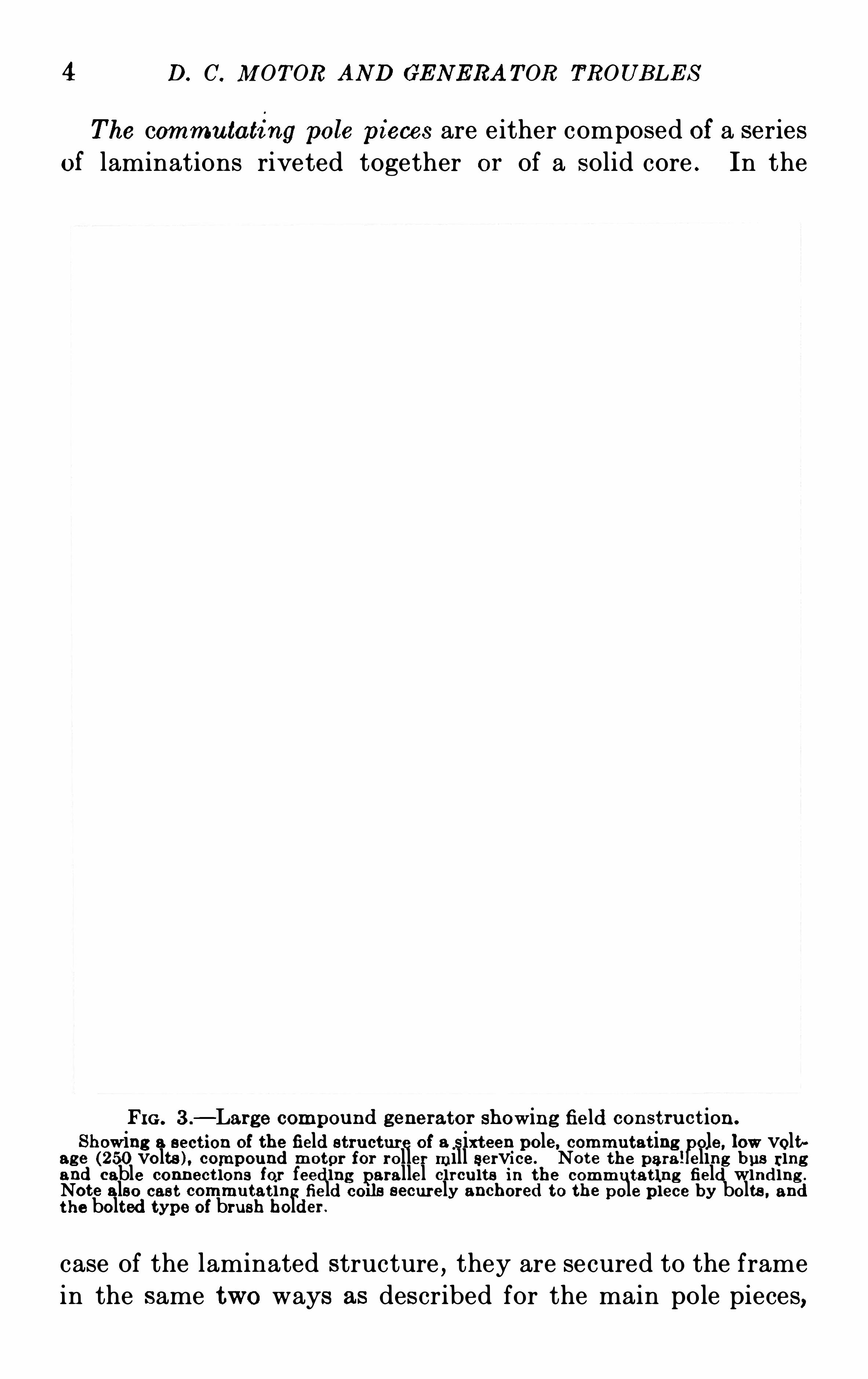
The commu tating pole pieces are either composed of a seriesof laminations riveted together or of a solid core . In the
FI G . 3 .
—Large compound generator Showing field con st ru ct ion .
S howing a sect ion of the field stru cture of a sixt een pole, commu tat ingpole, low volt
age (250 volts ) , compound motor for roller mill service. Note the para! eling bus r ingand cable connect ions for feeding parallel circu its in the commu tat ing field winding .
Note also cas t commutat ing field corls securely anchored to the pole piece by bolts , andt he bolted type of brush holder .
case of the laminated structure,they are secured to the frame
in the same two ways as described for the main pole pieces,
T YPE S OF M OT ORS AND THE I R US E S 5
namely by drilling and tapping into the laminations dir ectlyto receive the frame bolts or by tapping into a steel barinserted in the pole pieces .
The mai n field wi ndi ng consists of a spool , wound with the
series or shunt or a combination of the two windings,as shown
in Figure 3 . The spool itself consists of a sheet iron or copper
body with flanges of insulating material such as wood,fibre
or asbestos lumber . This spool is thoroughly insulated and
is then wound with the shunt winding consisting of the nec
essary turns of small insulated wire . E ntirely separated and
insulated away from this shunt winding is the series winding
which is made up of relatively few turns of heavy copper
strips .
I n some types of machi nes the spool body is omitted and the
field windings are made upon forms after which the coils
are thoroughly insulated and mounted directly on the pole
pieces . I nstead of wi ndi n g the shun t and series windings one
over the other on a single spool,some practice favors the
separation of these windings,such as placing them side by
side,for the purpose of better ventil ation and on account of
greater accessibility for repairs .
T he commu tati ng field is wound with the required number
of turns of copper strips or heavy wire,similar to the series
winding . In the case of large machines the commutating
coils are generally east or formed from copper bars pressed
into shape . The windings may be mounted on a separate
spool or directly upon the insulated pole piece .
T he armature of the motor is illustrated in Figure 4. It
consists of a cast iron or cast steel spider upon which the mild
steel laminations are assembled and divided into sections by
small spacer blocks provided for ventilation . The laminations
are pressed together and held in place by the flange rings and
through bolts . In some machines these laminations are
assembled directly upon a key on the shaft . The windings
are then laid in the slots,held in place by means of small
wooden wedges and binding wire and then soldered directly
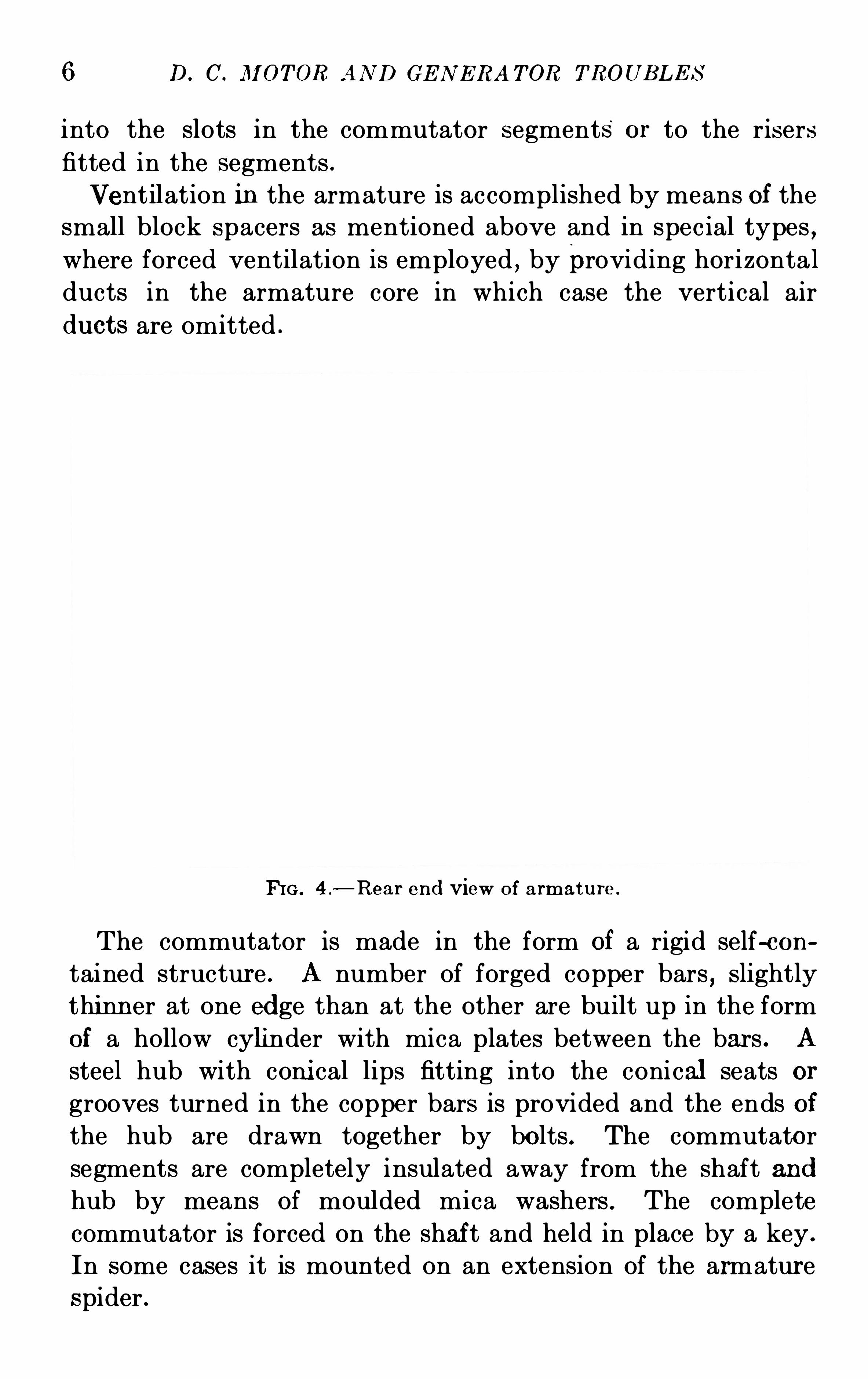
6 D. C . JlI OT OR AN D GE N E RA T OR TROUB LE S
into the slots in the commutator segments or to the risers
fitted in the segments .
Ventilation in the armature is accomplished by means of the
small block spacers as mentioned above and in special types ,where forced ventilation is employed , by providing horizontalducts in the armature core in which case the vertical air
ducts are omitted .
FHG . 4 .
—Rear end view of armatu re .
The commutator is made in the form of a rigid self-con
tained structur e . A number of forged copper bars,slightly
thinn er at one edge than at the other are built up in the form
of a hollow cylinder with mica plates between the bars . A
steel hub with coni cal lips fitting into the conical seats or
grooves turned in the copper bars is provided and the ends of
the hub are drawn together by bolts . The commutator
segments are completely insulated away from the shaft and
hub by means of moulded mica washers . The complete
commutator is forced on the shaf t and held in place by a key .
In some cases it is mounted on an extension of the armatur e
spider .
8 D. C. M OT OR AN D GE N E RA TOR TROUB LE S
AS S EM B LY PART S
T hebrush ri ggi ng is supported from the magnet frame . The
brush holder yoke is fitted with lugs to which the brush holder
brackets are bolted . Brush holders are bolted or clamped to
these brackets with all brushes connected to a common bus
bar or to the brush holder bracket itself .
In other types of machi nes , the brush rigging is supported
on the pillow block or hear ing housing and in larger sizes
directly by the base or foundation . The brackets and holders
are supported as stated above .
The brush holder brackets are insulated from the brush
holder yokes by fibre bushings and collars . The bus rings
for connecting brackets of like polarity are supported by con
nect ing strips or“ears .
”
The bearings are supported by pedestals bolted dir ectly
to the base or foundation or by end shields supported by the
field frame . Where pedestals are employed , liners or shims
of sheet iron are provided for adjustment . Bearings except
in special cases are of the ring oiled type . These special
cases refer to motors on board ship or mounted on movable
machinery,where there is danger of spilling of oil due to tilting
or rocking . Such bearings are usually of the waste packed type
although ball or roller bearings packed in grease are sometimes
employed .
The base is usually made as a rigid structure of cast iron .
Sometimes I -beams or channel irons are used as supports .
Bol t holes for foundation bolts are placed in the base where the
unit is to be used for direct drive or geared connection . When
belted , chain or rope driven , the bases are fitted with sliding
rails unless an external tightening device is fitted .
TYP E S OF M OT ORS
S hunt Motors—I n a shunt wound motor one winding onlyis furn ished on the main field spools to supply the entire ex
citation . This field is usually connected to the same power
supply as that for the'
armature but the fields may be excited
T YPE S OF M OT ORS AN D THE I R US E S 9
from a separate source if i t is so desired . The speed regulation
is obtained by an adjustable resistance in the shunt field
current or by a resistance in series with the armature . S hunt
motors have practically a constant speed at all loads .
Compound Wound Motors .—Motors of thi s type are
equipped with a shunt winding , as men tioned above and
have in addition a series winding wound on the same spool
with the shunt . The series winding is connected in series
with the armature circuit and the field excitation is varied as
the load on the motor changes . Compound or series windings
are usually connected to assist the shunt windings but in
some special work the series windin g may be set to oppose the
shunt ; this arrangement being known as a differential com
pound motor . An adjustable resistance across the series wind
ing is furnished to permit a change in the strength of the
series excitation . The speed of compound wound motors
drops as the load comes on .
S er ies Motors—A series motor differs from the shunt andcompound types just described
,in that all of the excitation
is supplied by a winding on the main spools connected in
series with the armature . The speed changes with the load
on the motor . Under maximum load the speed is minimum
since the field is strongest . At no load and with constant
voltage applied,the series motor will race or run away and
thus a provision should be made when installing a series
motor to guard against the removal of the load while voltage
is being applied to the machine .
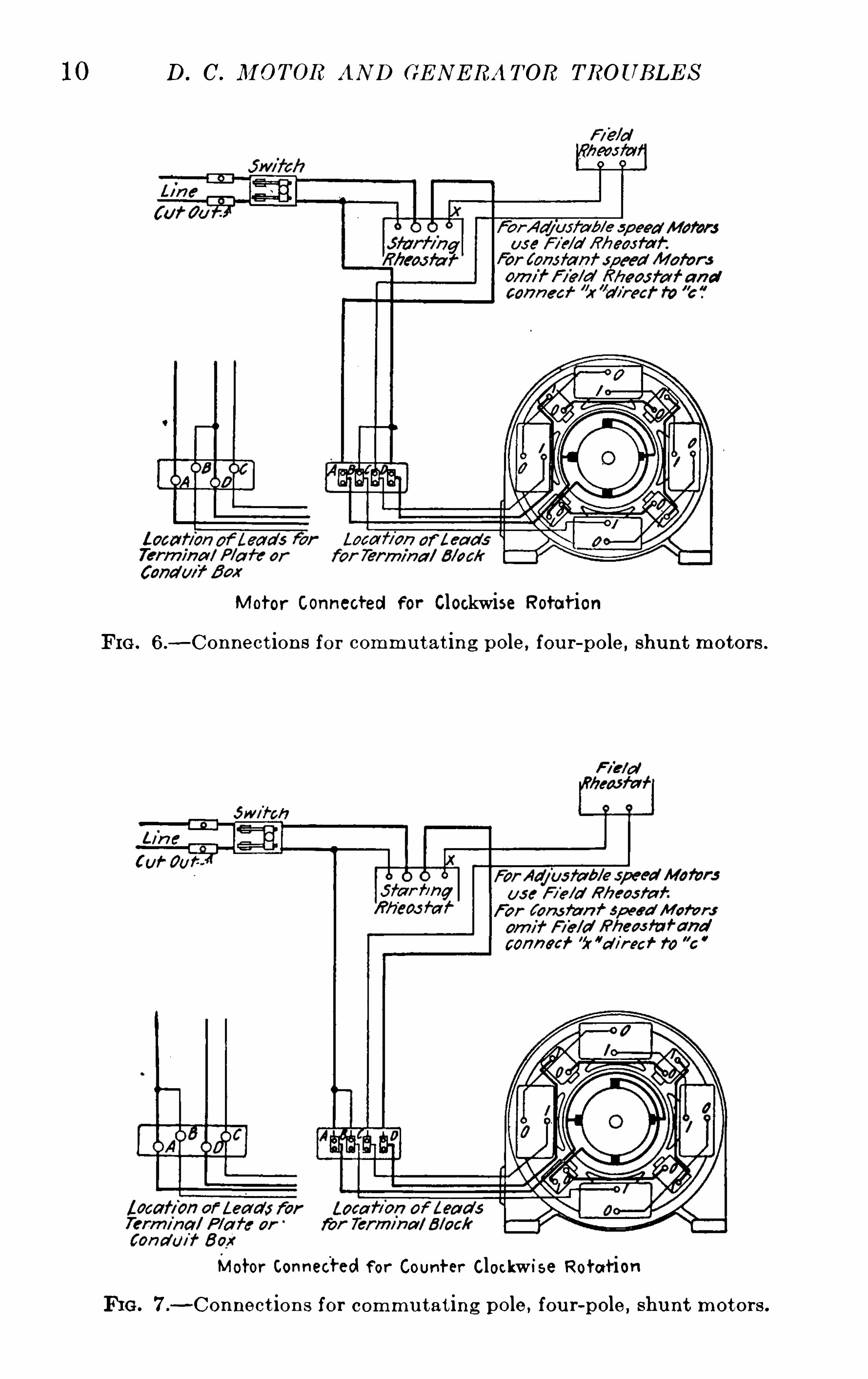
CONNE CT I ON S FOR M OT ORS
Standard connections for motors are shown below but no
attempt is made to cover the many special or“freak ” connec
tions which are possible in wiring motors for service of a
special natur e . In each case a line diagram as well as a
complete connection drawing is shown to enable the reader
to see at a glance the general scheme of connections .
The diagrams show motors fitted with commutating poles
10 D. C . IlI OT OR AN D GE N E RA T OR TROUB LE S
M otor Connected For Clockwise Rotat ion
FI G . 6.
—Connect ion s for commu t at in g pole, fou r-pole, shu n t motor s .
Cuf' Our:
conned’5r ”
cl/r eef 729 ”c
Motor Connected f or Count er Clockwi se Rotat ion
FI G . 7.-Connect ion s for commu tat ing pole, fou r-pole, shunt motors .
T YPE S OF IDI OTORS AND THE I R US E S 11
55am
fib rr fi n g An n a/fare
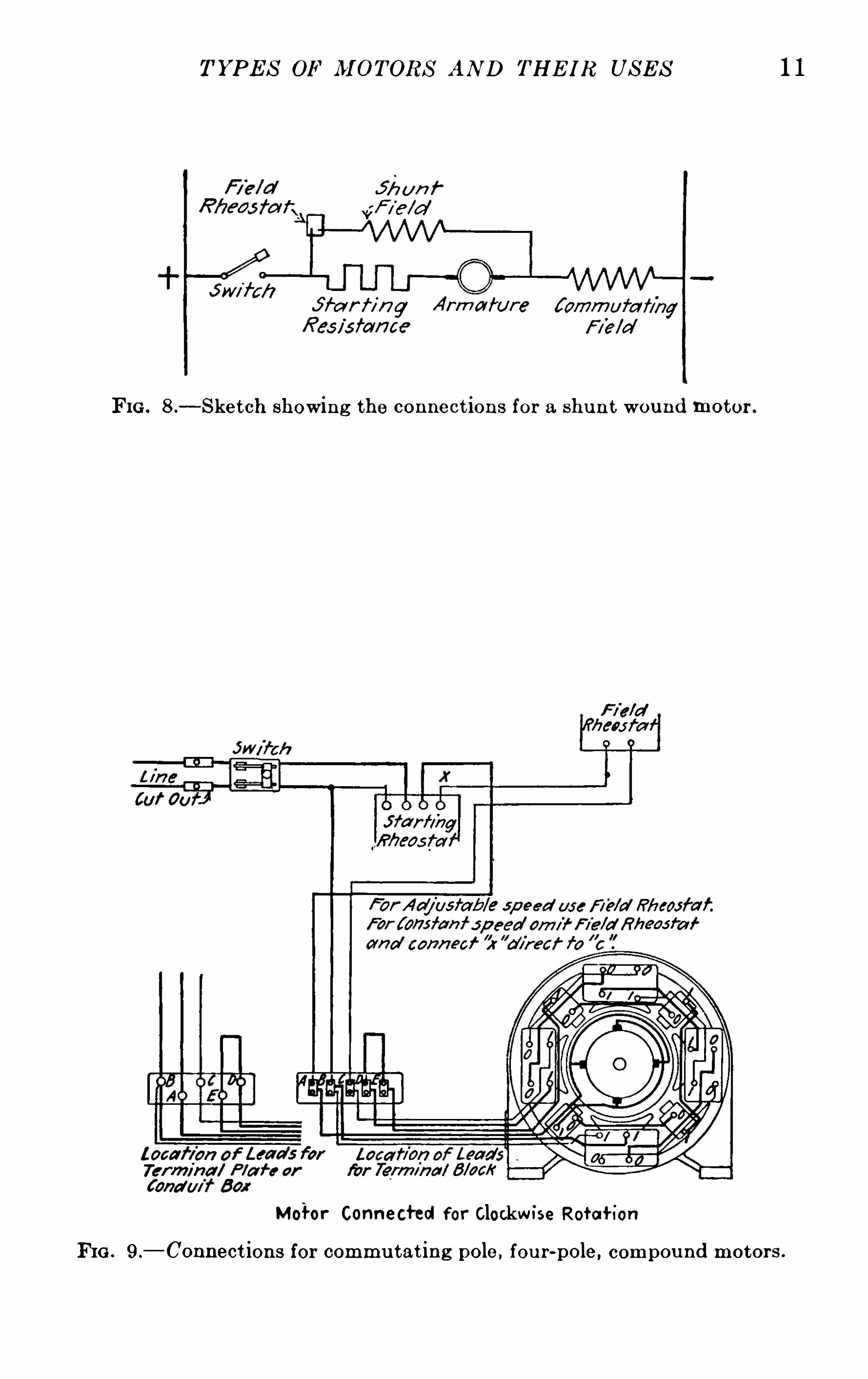
FIG . 8 .—S ket ch showing the connect ions for a shu n t wound motor .
Motor Connected for Clockw ise Retell-ion
FIG . 9.
—Connect ions for commu tat ing pole , fou r-pole, compou nd motors .
12 D.C’. M OTOR AND GE N E RA TOR. TROUBLE S
Motor Connected for Counter Clockwise RotaHOn
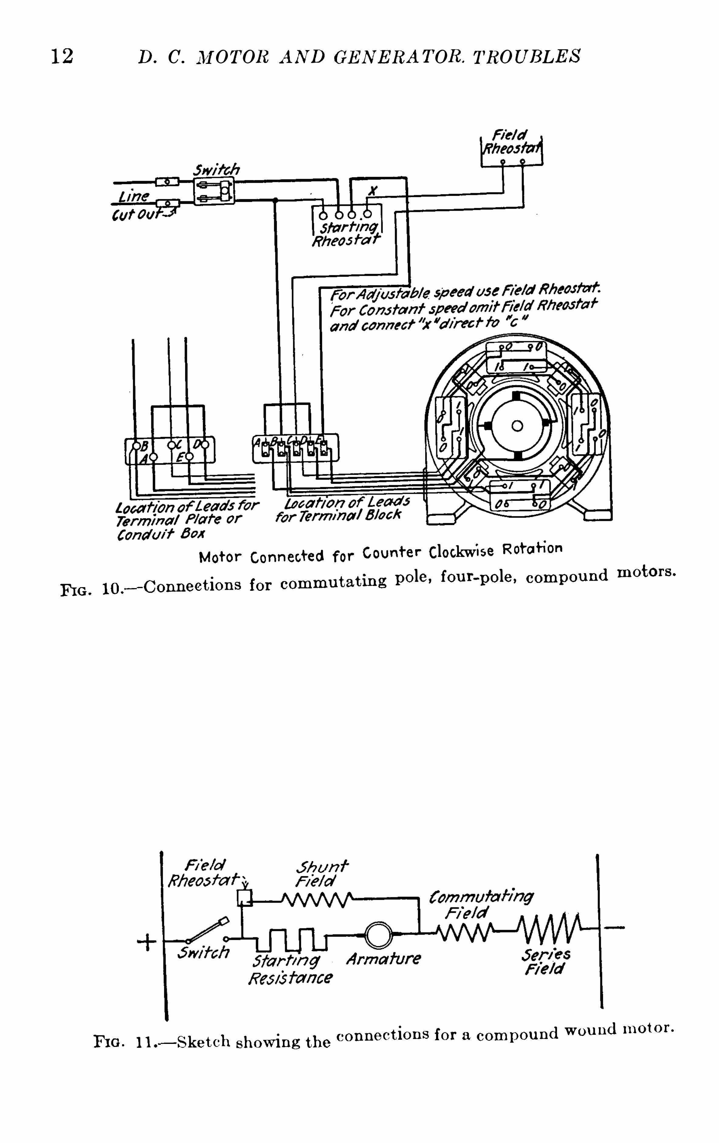
FI G . 10.
-Connect ion s for commu tat ing pole,fou r-pole, compou nd motors .
FI G . l i .—S ket ch show ing the connect ion s for a compou nd wou nd motor .
T YPE S OF M OTORS AND THE IR US E S
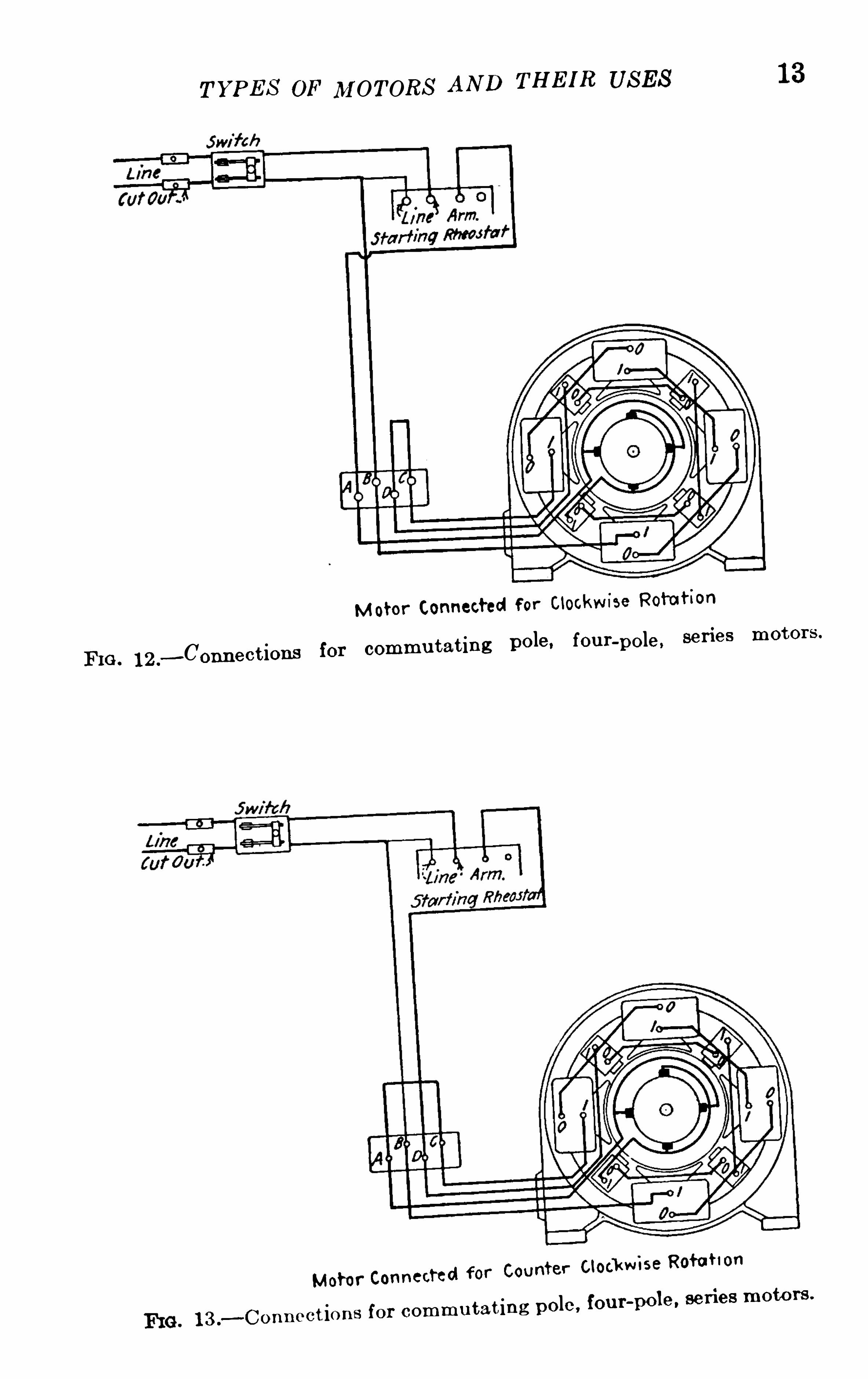
FI G . 12 .
—Connect ions for commu tat ing pole, fou r-pole,
l 3 .
—Connect ions for comm u tat ing pole ,
13
14: D. C. M OT OR AND GE N E RA T OR TROUB LE S
but the same connections may be used for motors without thepole
The connections for a shunt wound motor are shown in
Figures 6 and 8. For reversed rotation refer to Figure 7.
The shunt fields are connected in each case to permit full
excitation of the field as soon as the switch in the line is closed
Swi ft /7
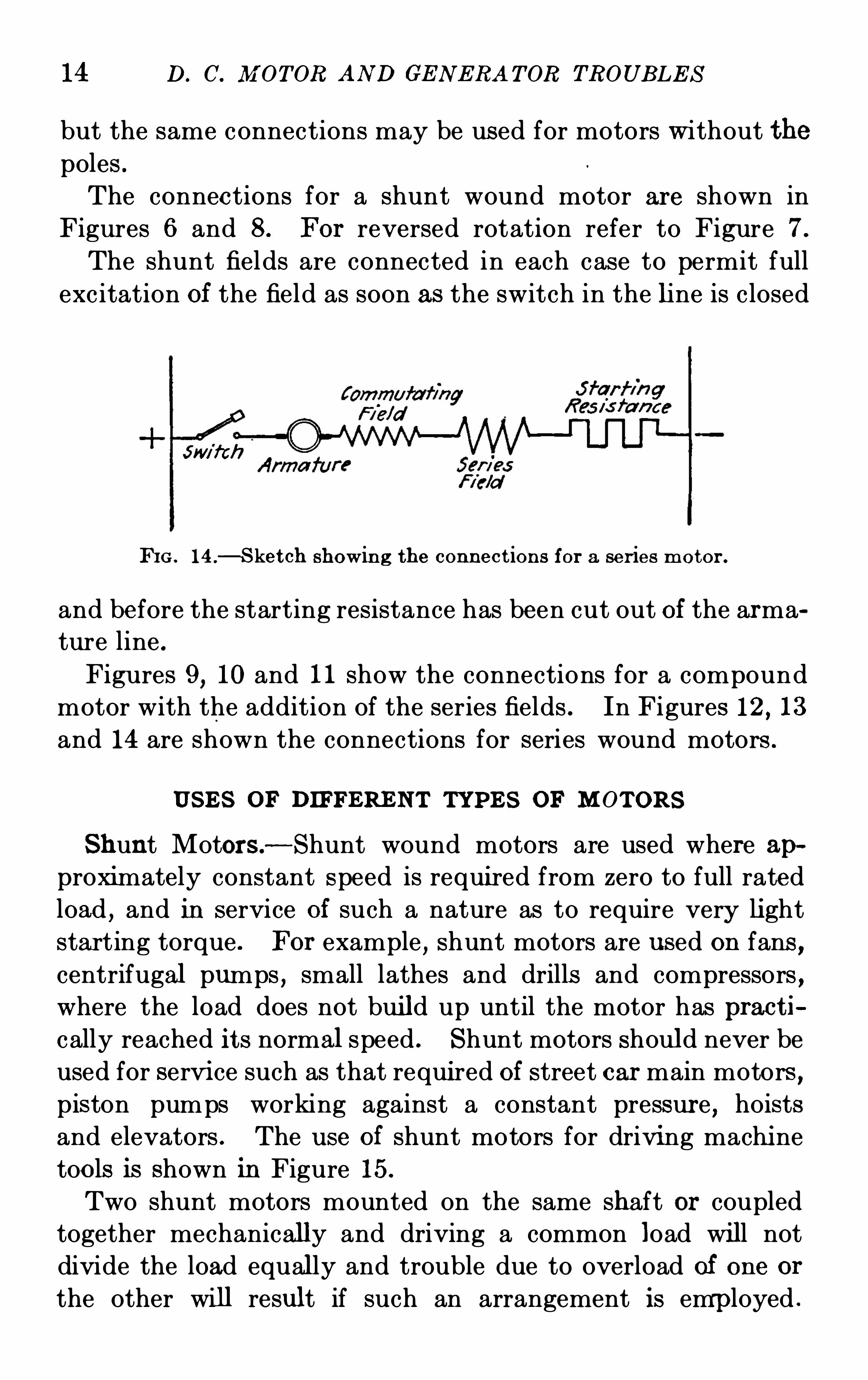
FI G . 14 .
—S ket ch showin g the connect ions for a ser ies motor .
and before the starting resistance has been cut out of the arma
ture line .
Figures 9, 10 and 11 show the connections for a compound
motor with the addition of the series fields . In Figures 12 , 13
and 14 are shown the connections for series wound motors .
US E S OF DIFFERE N T TYPE S OF M OT ORS
S hunt Motors—Shunt wound motors are used where approximately constant speed is required from zero to full rated
load , and in service of such a nature as to require very li ght
starting torque . For example , shunt motors are used on fans ,centrifugal pumps , small lathes and drills and compressors ,where the load does not build up until the motor has pract i
cally reached its normal speed . S hunt motors should never be
used for servi ce such as that required of street car main motors ,piston pumps working against a constant pressur e , hoists
and elevators . The use of shunt motors for driving machi ne
tools is shown in Figure 15.
Two shunt motors mounted on the same shaft or coupled
together mechanically and driving a common load will not
divide the load equally and trouble due to overload of one or
the other will result if such an arrangement is emp loyed .
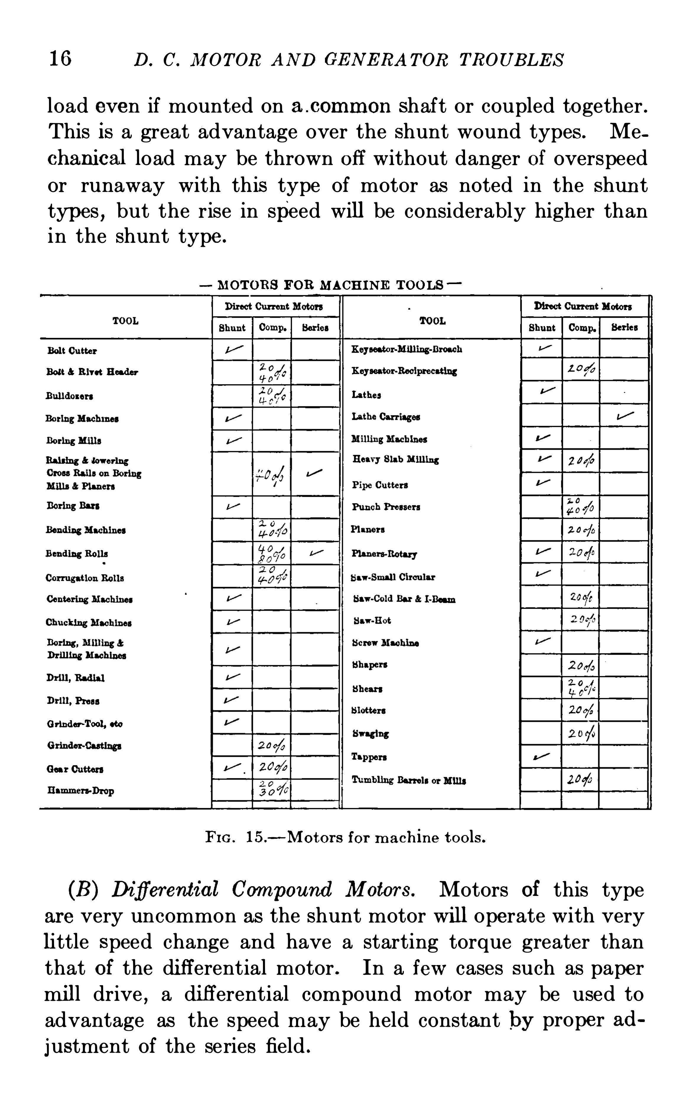
16 D. C. M OT OR AND GE N E RA TOR TROUB LE S
load even if mounted on a .common shaft or coupled together.
This is a great advantage over the shunt wound types .Me
chanical load may be thrown off without danger of overspeed
or runaway with this type of motor as noted in the shun t
types , but the rise in speed will be considerably higher thanin the shunt type.
MOT ORS FOR MACHINE T OOLS
Bolt Rivet Reader
Bai l ing lowering
Grinder-Tool, coo
FIG . 15.
—M otor s for m ach ine t ools .
(B ) Difi'
e'
rential Compound M etar s . Motors of this type
are very uncommon as the shunt motor wi ll operate with very
little speed change and have a starting torque greater than
that of the di fferential motor . In a few cases such as paper
mill drive,a di fferential compound motor may be used to
advantage as the speed may be held constant by proper ad
justment of the series field .
T YPE S OF M OTORS AND THE I R US E S 17
S eries Motors .
—S eries motors are used where the servicerequires very heavy starting torque and where practically
constant speeds at all loads are not required . For example,
they are used as street car main motors , or on electric locomo
t ives , and on cranes and hoists for heavy service .
The mechanical load must be so attached to series motors
that there is no danger of the loss of the load . A removal of
the mechanical load where the applied voltage is constant,re
sults in the racing or runaway of the armatur e and wr ecking
due to overspeed . Racing is caused by the loss of the field,
since the field strength of a series motor is dependent on the
current in the line .
S eries motors may be Operated in series or multiple without
trouble . They have a fixed speed for each load and are not
suitable for service where constant speed is requi red with
variable loads .
The uses of series and compound wound motors for driving
machi ne tools are shown in Figure 15.
I NFORM AT I ON T O B E SUPPLIE D T O THE M ANUFACTURER
WHE N ORDERI N G M OT ORS
The Purchasers of direct-current motors should consider
with great care the class and type of machine required and in
cases of doubt consult the representatives of electrical manu
factu ring concerns , who keep up to date data on the product
of their companies . A motor may be ordered for a service
for which it is not designed and in such cases satisfactory opera
tion is never obtained . For example a motor of the open
type of construction should not be placed where it would be
exposed to cement dust,oil or water spray, acid fumes , turn
ings or chippings from lathes or chippin g devices , smoke , etc .
The Purchaser should take advantage of the experience of the
manufacturer in placing motors for various kinds of service
and if the following general questions are answered when the
request for motor equipment is made,a better and more satis
factory service will always be obtained :
18 D. C. M OTOR AND GE N ERA TOR TROUB LE S
1. What is the average load required?2 . What overload is required and for what length of time is suchan overload necessary?
3 . What is the voltage of the circuit furni shing power to the
motor? If the voltage is not constant , the maximum and minimumvalues should be given.4. Does the motor start under load?5. I s the load steady or variable ? (G ive when poss ible , natureOf the load to be driven.)6. I s the motor located any considerable distance from the gen
erator or supply lines ? G ive distance approximately7. I s the motor belted, geared or direct connected to the load ?8 . What is the diameter and face of the pulley to be driven ifalready ins talled?9. What is the speed of the driven shaft ?10. What speed variation if any is required?11. What is the distance between the center lines of the motor
and the driven shafts if belted?12 . Is the belt to Operate in a hori zontal or vertical pos it ion?
Give approximate Operating angle of the belt .13 . Are sliding rails required or a belt tightening device ?14. I f the motor is direct connected or geared to the load is a
separate base requir ed w ith the mach ine or is the extens ion of thebase supporting the driven parts arranged to take the motor frameand bearings?
0
15. I s a coupl ing, pinion or pulley required and if so what si ze ?16. Do the motor bearings support any weight of the revolvingparts other than the armature? State how much and give thelocation of the load with respect to the center line of the nearestbearing .
17. I s a fixed length of shaft extens ion required? G ive length .
18. What direction of rotation is required (facing the commutatorend)?19. Does the motor reverse?20. What is the local condition under which the motor is to
operate? S tate if damp or hot or both and if acid fumes , smoke,grit or O il vapors are present .2 1. Does the motor Operate where it is exposed to flying ch ips
or shavings from steel or iron working machines?22 . I s the motor located where quiet operation is necessary?
T YPE S OF M OTORS AN D THE IR US E S 19
23. What control is required ? State whether armature or field?24. I s the space l imited in wh ich the motor is to be installed ?
G ive the approximate maximum length , height and width .
25. What temperature guarantees are required , if any?26. Must the motor terminals have a special location? Statewhere .27. Does the motor operate on the floor, side wall or ceiling?
I s a vertical type requ ired?28. Does the motor operate as a generator and if so are revers ing
switches required ?29. Does the motor require separate excitation?30. Must weight of motor be lim ited?31. Does the motor operate on board ship or under conditionsin wh ich it is liable to be suddenly moved or t ilted out of its ordinaryoperating position ?
32 . I s a flexible coupling necessary?
CHAPTE R II
TYPE S OF GE N ERATORS AND THE IR USE S
TYPE S OF GE N E RATORS- STAN DARD E LE CTRI CAL CON N E CT I ON s FOR G E N E RATORS - US E S OF D IFFE RE N T TYPE SOF G E N E RATORS— I N FORM ATI ON T o B E SUPPLI E D T o
T HE MAN UFA CTUR E R W HE N ORDE RI N G
The construction of the direct-current generator is exactly
the same as that of the direct-current motor briefly described
in the preceding chapter . In fact the generator can be opcrated as a motor or vice versa
,by simply changing the con
nect ions as covered later in this work in Chapter I V on the“S tarting and Operation of Motors .
The uses for which the various types of generators are best
suited are gi ven with the view of acquainting the operator or
purchaser with the qualifications which ea ch type of machine
possesses to fit it for a particu lar duty. Great care should be
exercised in the selection and the information furnished to the
manuf acturers, as given later , when ordering .
TYPE S OF GE NE RAT ORS
S hunt Generator.—I n a shunt generator , the field windingis connected in multiple with the outside connecting circuit ,so that when the outside circuit is Open
,the field magnet coils
receive the entire current supplied by the armature but when‘
it is closed,the current through the field circuit depends upon
the resistance of the field circuit as compared with that of the
outside connecting circui t . By connecting a rheostat or
adj ustable resistance in series with the field winding , a greater
or less amount of current may be permi tted to pass through20
T YPE S OF GE N E RA T ORS A N D THE I R US E S
the field coils at any one time and the voltage of the machine
is thereby controlled .
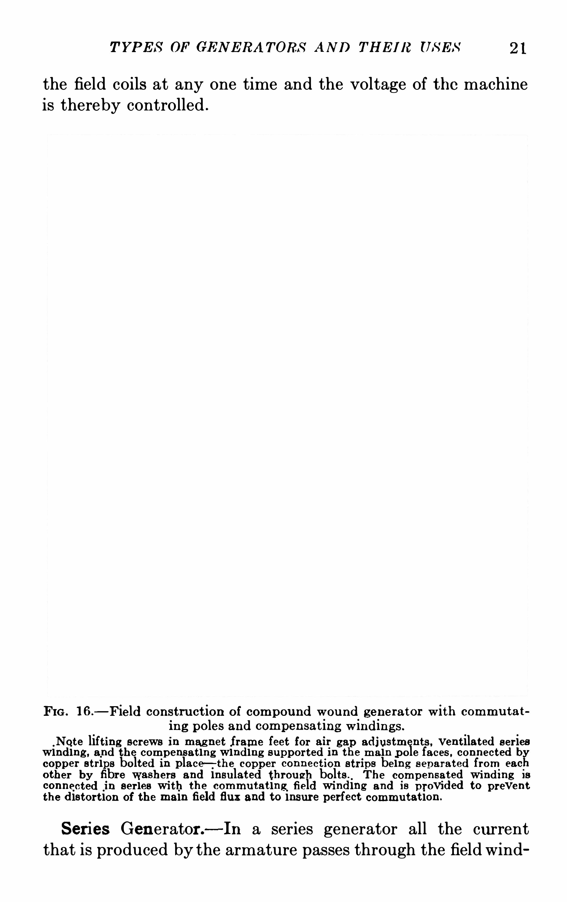
FIG . l 6.
—Field construct ion of compound wou nd generator with commu tat
ing poles and compensat ing windings .
Note lift ing screws in magnet frame feet for air gap adjustments , vent ilated ser ieswinding , and the compensat ing winding suppor ted in the main pole faces . connected bcopper s t rips bolted in place—the copper connect ion s trips being s ep arated from eac
.
other by fibre washers and insu lated throu gh bolts . T he compensat ed wind i ng 18
connected in ser ies wi th the commu tat ing field wi nding and is provided to preventthe distort ion of the main field flux and to insure perfect commu tat ion .
S eries Gen erator .-In a series generator all the current
that is produced by the armature passes through the field wind
22 D. C. M OT OR AND GE N E RA T OR TROUB LE S
ing and therefore the field winding must be in series with the
outside circuit . For regulating the voltage of a series genera
tor , it is customary to connect an adj us table resistance , called
a rheostat, across the entire field windi ng ; by varyi ng the
resistance thus introduced,more or less current is shunted
from the field coils and the number of lines of force in the field
thereby changed .
Compound Gen erators .—In compound generators
,both
and shunt field windings are employed to produce a
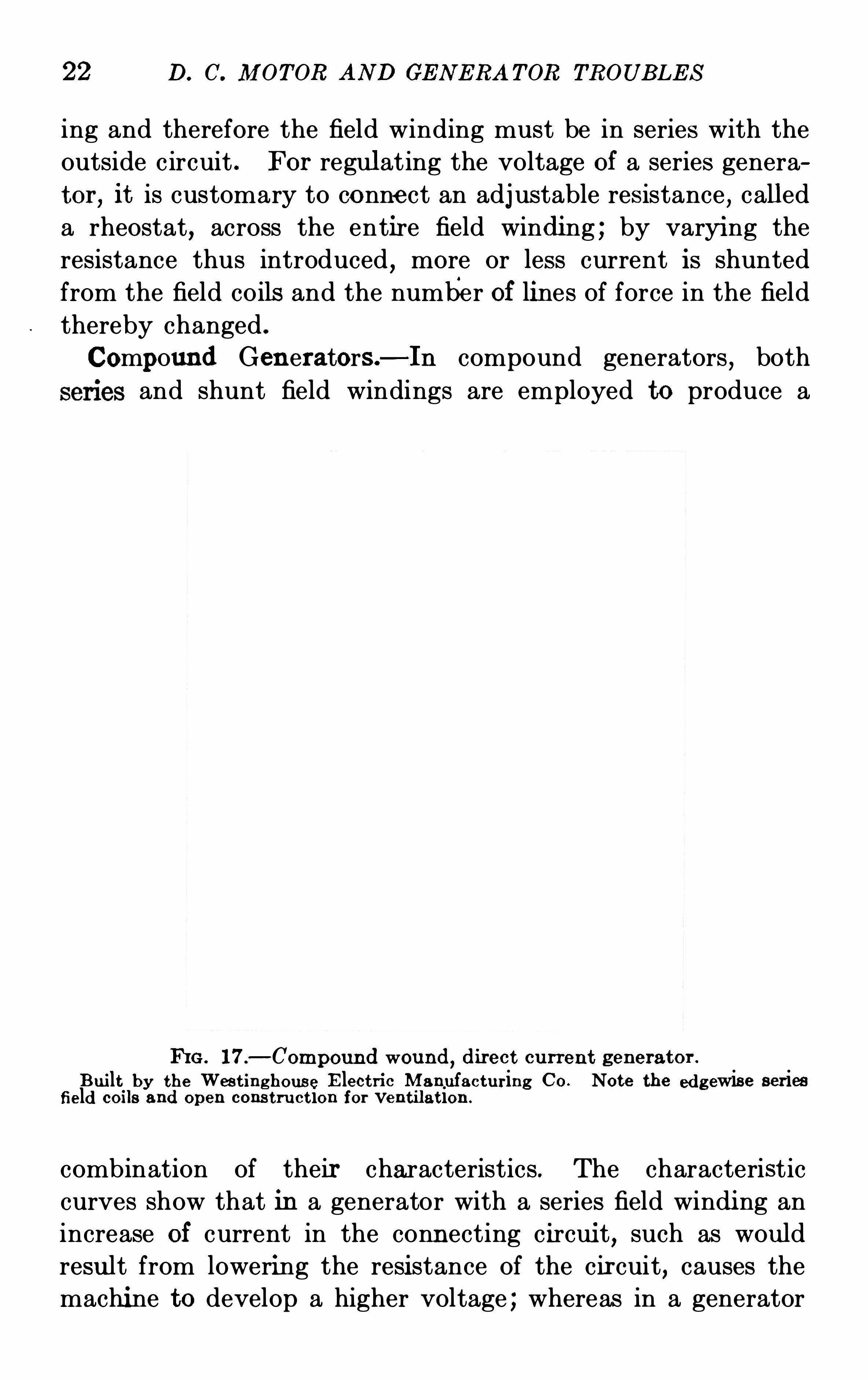
IfiG . 17.
—Compound wound, direct cu rren t generator .
B ui lt.
by the Wes t inghous e E lect ri c M anufacturing Co. Note the edgewise seriesfield 00118 and open cons t ru ct ion for ventilat ion .
combination of their characteristics . The characteristic
curves show that in a generator with a series field windi ng an
increase of current in the conn ecting c ircui t, such as wou ld
resu lt from lowering the resi stance of the cir cuit, causes the
machi ne to develop a higher voltage ; whereas in a generator
24 D. C. M OT OR AND GE N E RA TOR TROUB LE S
there is less maintenance because there are fewer part s to be
cared for . There is also a higher efficiency because one
machine has smaller losses than any greater number of equal
total output , and less floor space is requir ed .
Three-wire generators are so arranged that a third or neutral
line is brought out. midway in potential between the positive
and negative leads , thus providing for load at half of the
generator voltage . This mi d-voltage point is derived by
connecting a reactance coil,known as an autotransformer
,
across the armature winding , the neutral line being connected
to the middle point of the autotransformer . Connections
between the autotransformer and the revolving armature are
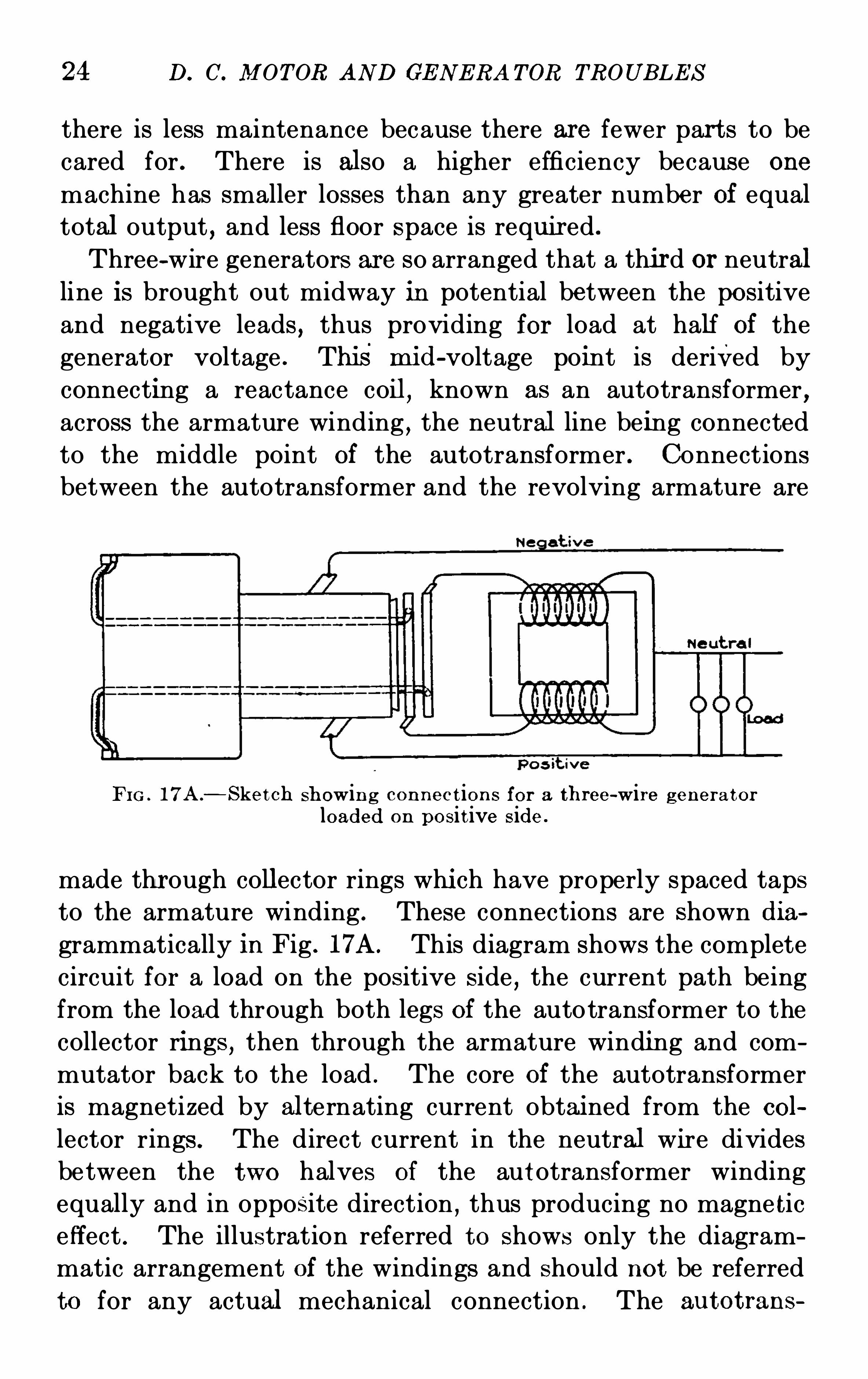
FI G . 17A .
—S ket ch showin g con nec t ion s for a three-wire g enera tor
loaded on posit ive side .
made thr ough collector rings whi ch have properly spaced taps
to the armature winding . These connections are shown dia
grammatically in Fig . 17A . This diagram shows the complete
circuit for a load on the positive side,the current path being
from the load through both legs of the autotransformer to the
collector rings,then through the armature winding and com
mutator back to the load . The core of the autotransformer
is magnetized by al ternating current obtai ned from the col
lector rings . The direct current in the neutral wire divides
between the two halves of the autotransformer winding
equally and in opposite direction,thus producing no magne tic
effect . The illustration referred to shows only the diagram
matic arrangement of the windings and should not be referred
to for any actual mechanical connection . The au tot rans
T YPE S OF GE N E RA T ORS AN D T I I E I R US E S 25
former itself consists of a laminated core with suitably
insulated winding immersed in a cast iron tank of specialinsulating Oil .
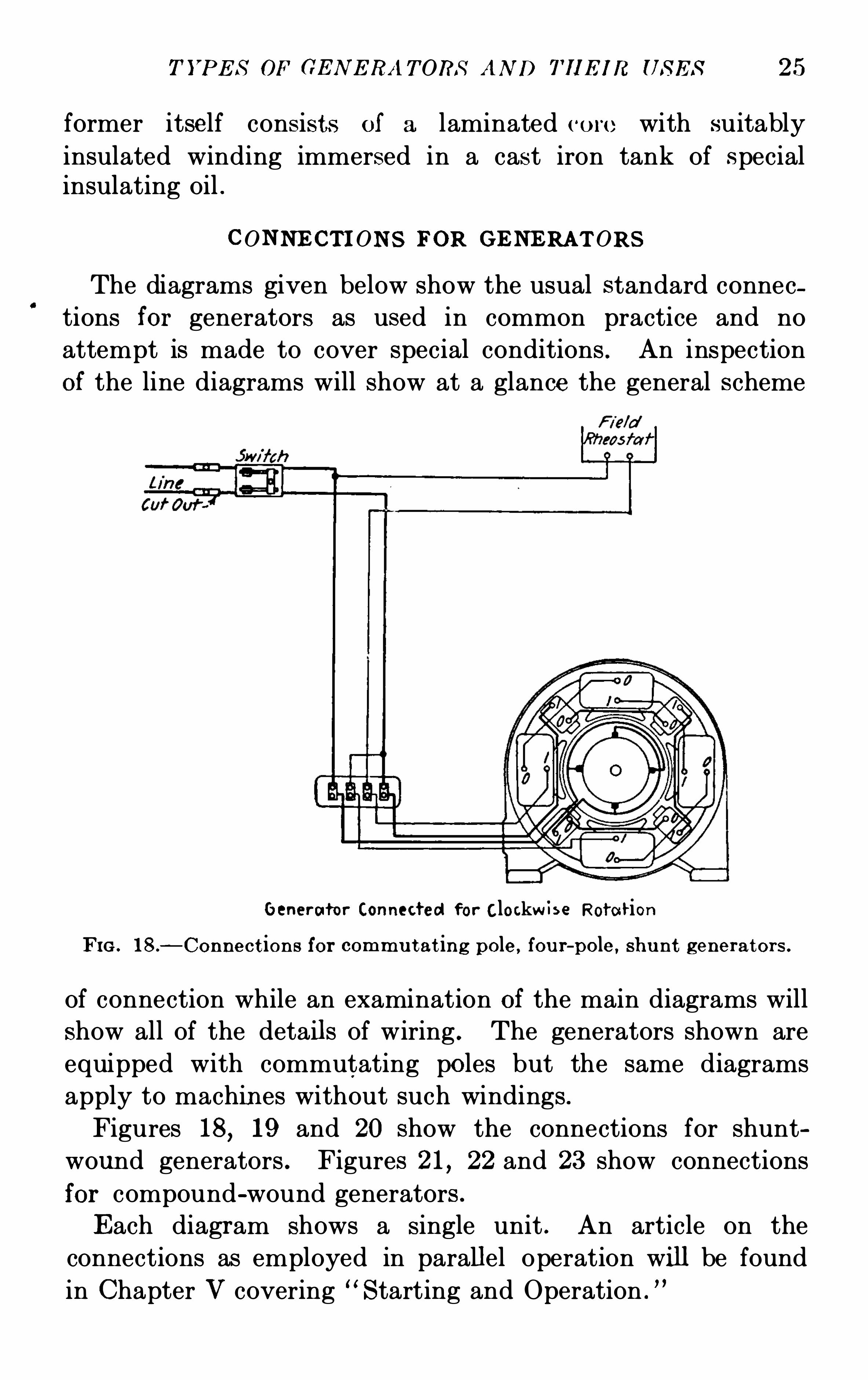
CON NE CTI ON S FOR GE NE RAT ORS
The diagrams given below show the usual standard connec
tions for generators as used in common practice and no
attempt is made to cover special conditions . An inspectionOf the line diagrams will show at a glance the general scheme
Generator Connected for Clockw i se Rotation
FIG . 18.
—Connect ions for commu t at ing pole, fou r-pole, shu nt generator s .
of connection while an examination of the main diagrams will
show all of the details of wiring . The generators shown are
equipped with commutating poles but the same diagrams
apply to machin es without such windings .
Figures 18, 19 and 20 show the connections for shunt
wound generators . Figures 21, 22 and 23 show connections
for compound-wound generators .
E ach diagram shows a single unit . An article on the
connections as employed in parallel operation will be found
in Chapter V covering “S tarting and Operation .
”
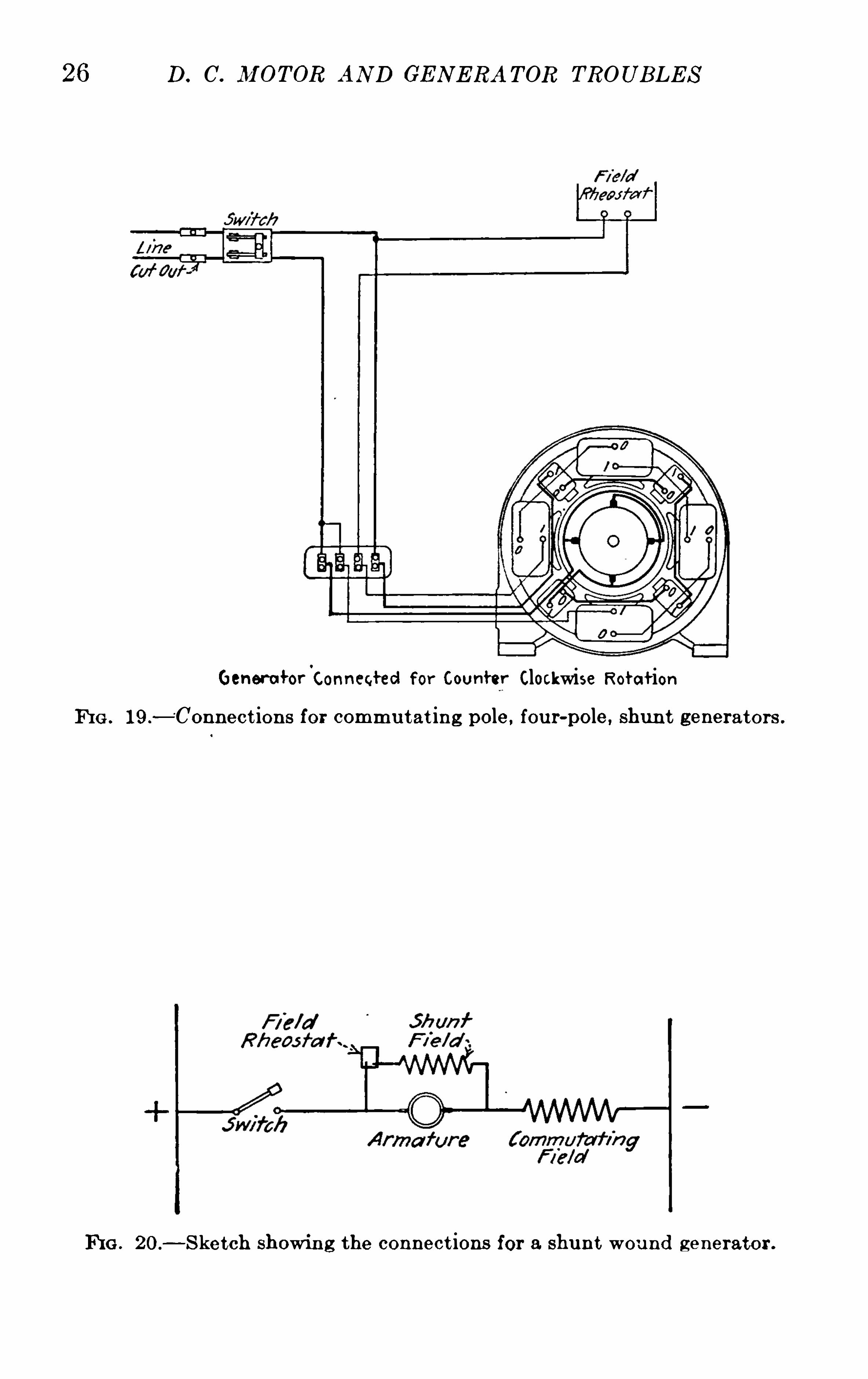
26 D. C. Jl/I OTOR AND GE N E RA TOR TROUB LE S
GeneratorConnected for Counter Clockwise Rotat ion
FI G . 19.
—Connect ions for commu tat ing pole, four-pole, shunt generators .
FI G . 20.
—S ketch showin g the connect ions for a shun t wou nd generator .
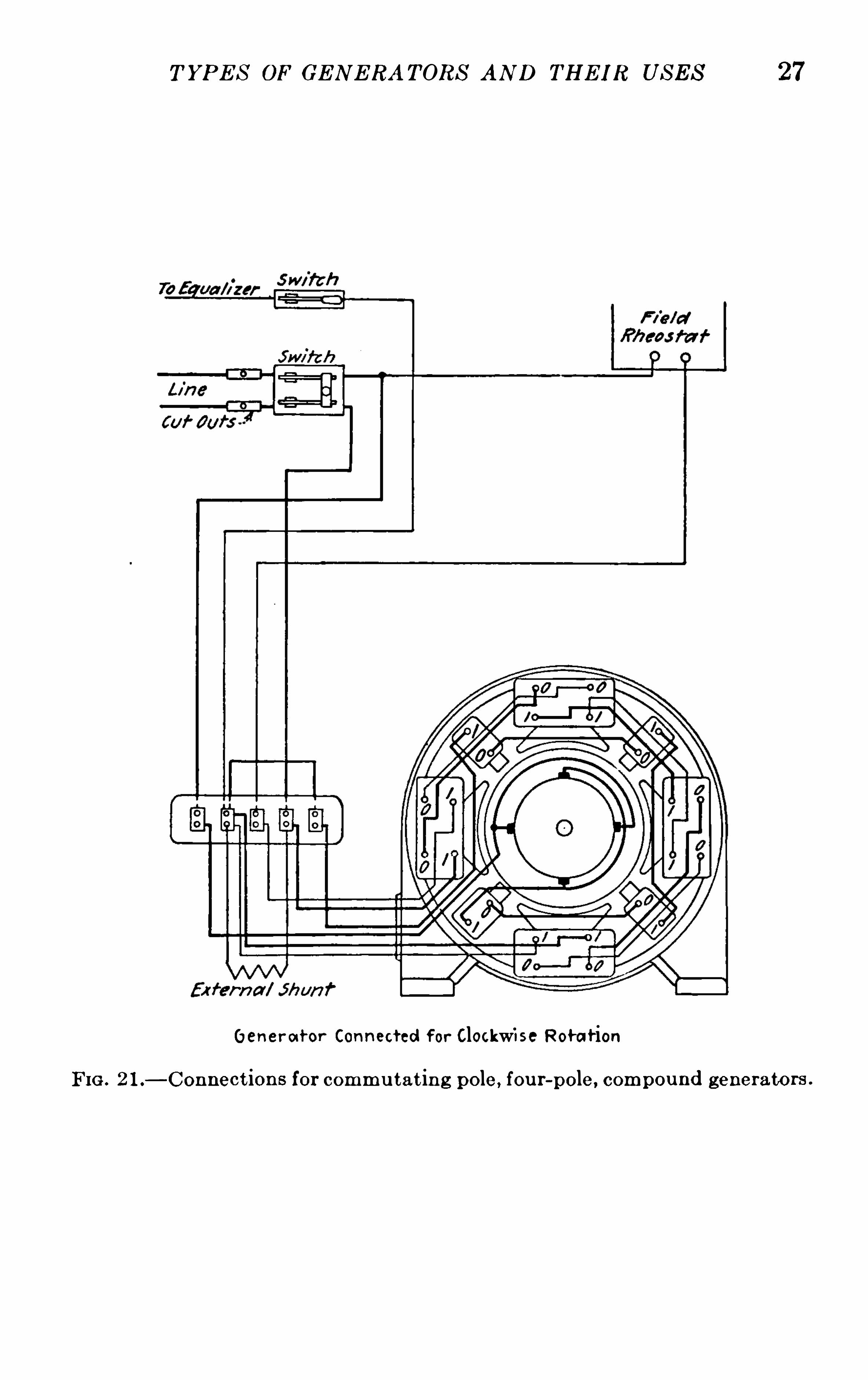
T YPE S OF GE N E RA TORS AN D THE I R US E S 27
Gener a t or Connected f or Clockwi se Rotat ion
FIG . 2 1.—Connect ions for commu tat in g pole, fou r-pole, compou nd generators .
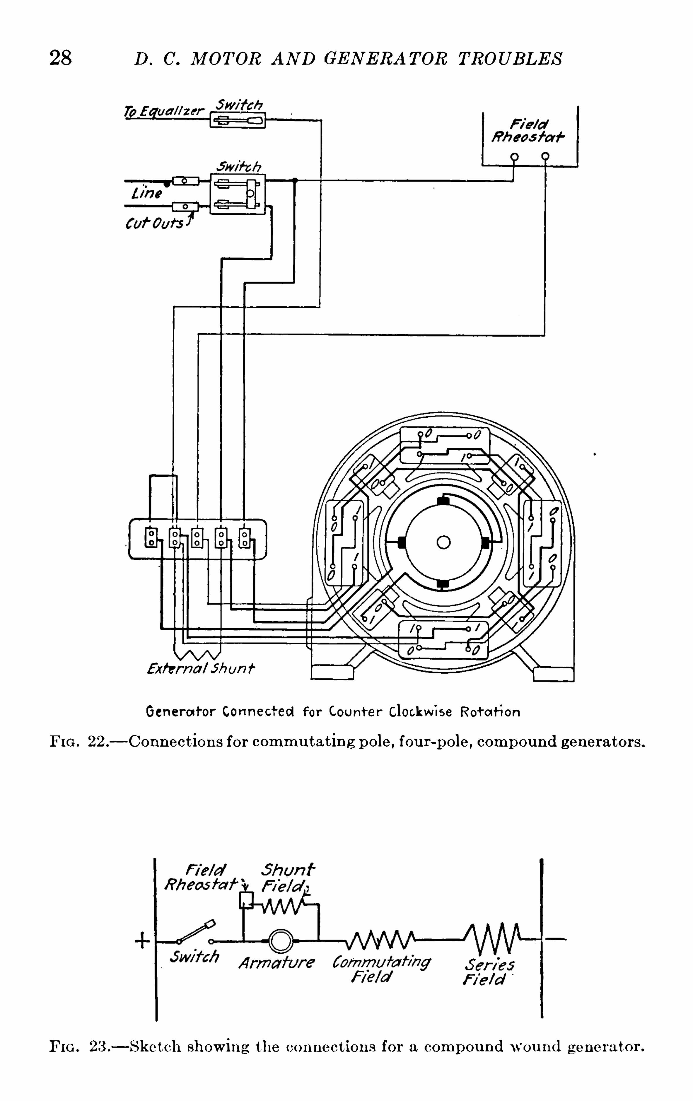
28 D . C. M OT OR AN D GE N ERA T OR TROUB LE S
External on f
Genera tor Connected for Count er Clockw ise Rot a t ion
FI G . 22 . Connect ion s for commu tat in g pole, fou r-pole , compound generator s .
FIG . 23 .
—S ketch showing the con nect ions for a compou nd w ou nd g enera tor .
T YPE S OF GE N E RA T ORS AN D THE IR US E S 29
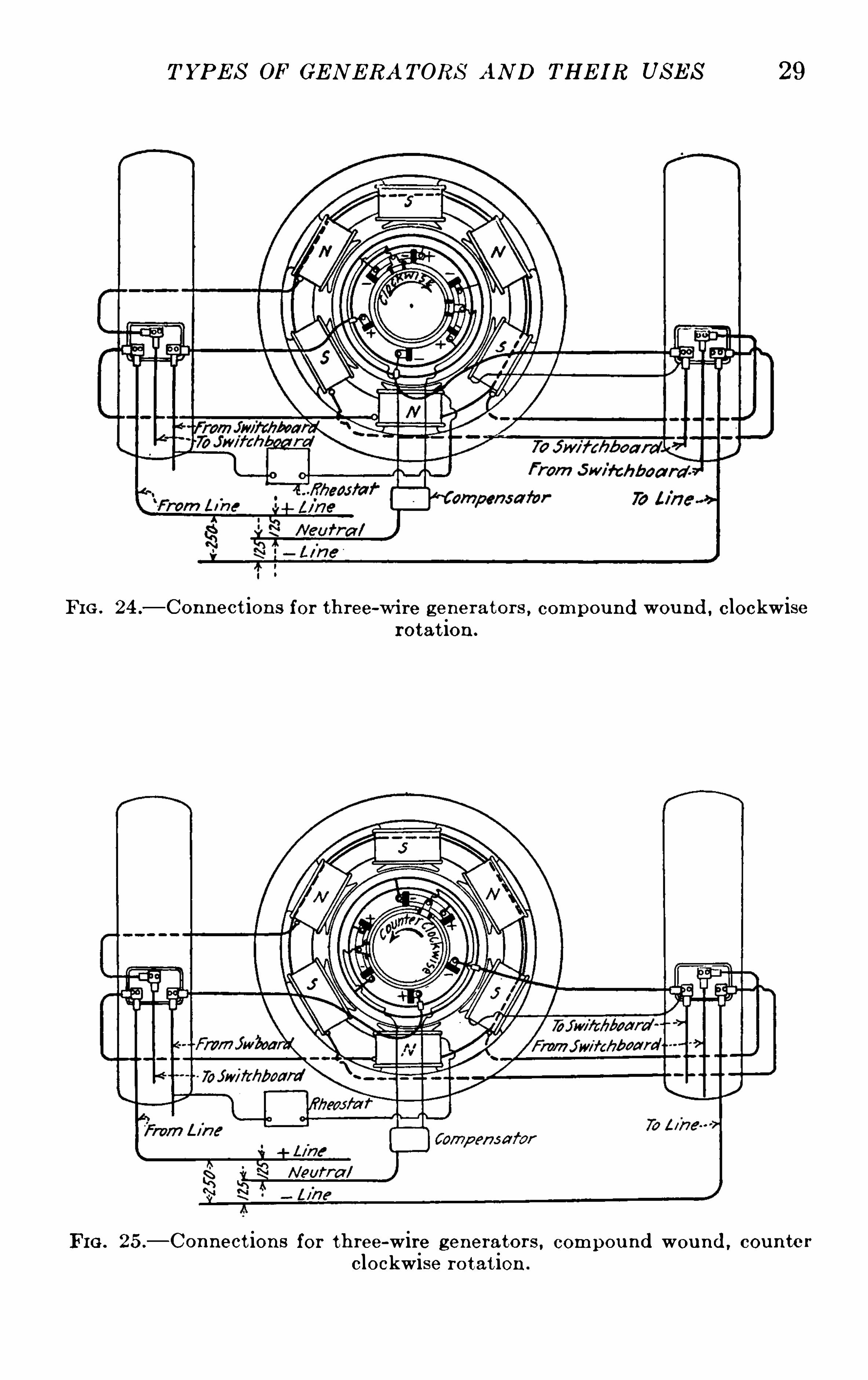
FI G . 24 .—Connect ions for three-wi re genera tor s , compound wou nd , clockwise
rotat ion .
FI G . 25.
—Connect ions for th ree-wire generators , compou nd wou nd , coun te r
clockwise rotat ion .
30 D . C. M OT OR AN D GE N E RA T OR TROUB LE S
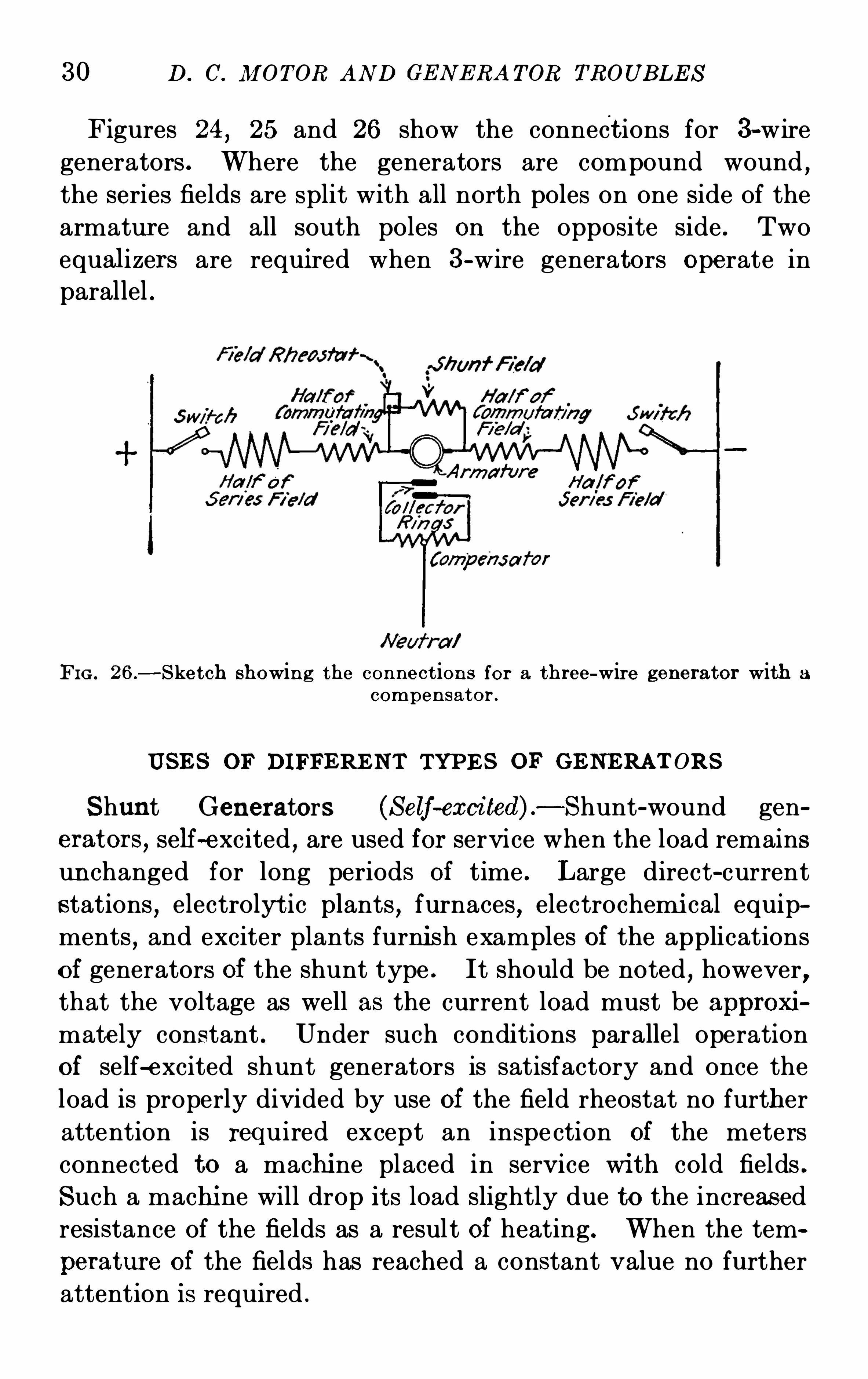
Figures 24, 25 and 26 show the connect ions for 3-wire
generators . Where the generators are compound wound,
the series fields are split with all north poles on one side of the
armatur e and all south poles on the Opposite side . Two
equal izers are requi red when 3-wire generators Operate inparallel .
FI G . 26.
—S ket ch showing the con nect ions for a three-wire generator with a
compen sator .
US E S OF DI FFE RE NT TYPE S OF GE NE RAT ORS
S hunt Generators (S elf-exci ted) . —Shunt-wound generators , self—excited , are used for service when the load remainsun changed for long periods of time . L arge direct-current
stations,electrolyt ic plants , furnaces, electrochemi cal equip
ments,and exciter plants furni sh examples of the applications
of generators of the shunt type . It should be noted , however,that the voltage as well as the current load must be approxi
mately constant . Under such conditions parallel operationof self-excited shunt generators is satisfactory and once the
load is properly divided by use of the field rheostat no further
attention is required except an inspe ction of the meters
connected to a machi ne placed in service wi th cold fields .
S uch a machi ne will drop it s load slightly due to the increas ed
resistance of the fields as a result of heating. When the tem
peratur e of the fields has reached a constant value no further
attention is required .
32 D. C. M OTOR AND GE N E RA T OR TROUB LE S
to prevent undue heating of the shunt fields if full voltage is
generated with the shun t winding without the assistance of the
series fields .
S eries Generator .—Series generators are used only in cases
where boostin g of the voltage is required,such as at the end of
a long railway feeder carrying heavy current loads . Care
should be taken to equip such units with protective devices
against overspeed as the failure of the power driving -a series
generator results in the instantaneous operation of the gen
erator as a series motor with practically no load . Such a con
dition wi ll wreck the unit from overspeed if it is not provided
with a protective device .
Mechanically operated speed-limiting switches are mounted
dir ectly on the shaft extension , being equipped with a tripping
lever Operated by centrifugal force arranged to open the main
line circui t breaker when the speed of the machi ne reaches a
value approximately 15 per cent . over the normal rated speed .
In some cases an electrical speed-limiting device is employed
consisting of a small magneto type generator driven directly
by the main shaft and arranged so as to trip the main circuit
breaker when the voltage which it generates reaches a fixed
value .
Three-wire Generators—Generators of the 3—wire typeare used when the natur e of the load is such as to requ ire two
different voltages,for example 125 volts for lights and 250
volts for motors . When the load can be balanced between the
two sides of the system wi thin 25 per cent . , the compensator
type of 3-wir e generator is employed . E xcept in special
cases where the unbalancing is more than 25 per cent . , balancer
sets are recommended or the E dison 3-wire system .
Three-wire generators operate satisfactorily with motor and
li ghting loads and also for elevator and hoist servi ce using the
high voltage for motor drive . On electrolytic work 3-wire
machin es are used to only a limited extent as operators
complain of shock from the high voltage when accidental con
tact is made . The regulation between the two sides of the
system is approximately 2 to 3 per cent . of the outside wi re
T YPE S OF GE N E RA T ORS AND THE IR US E S 33
voltage and while the variation is not noticed in most lines
of work, where very close regulation is required and it isnot practical to throw loads from one side of the system to the
other for balancing , the 3-wire generator cannot be used .
In E dison 3-wire systems the voltage remains constant and
full output is obtainable from either side . Balancer sets
are designed to take care of a fixed percentage of unbalancing .
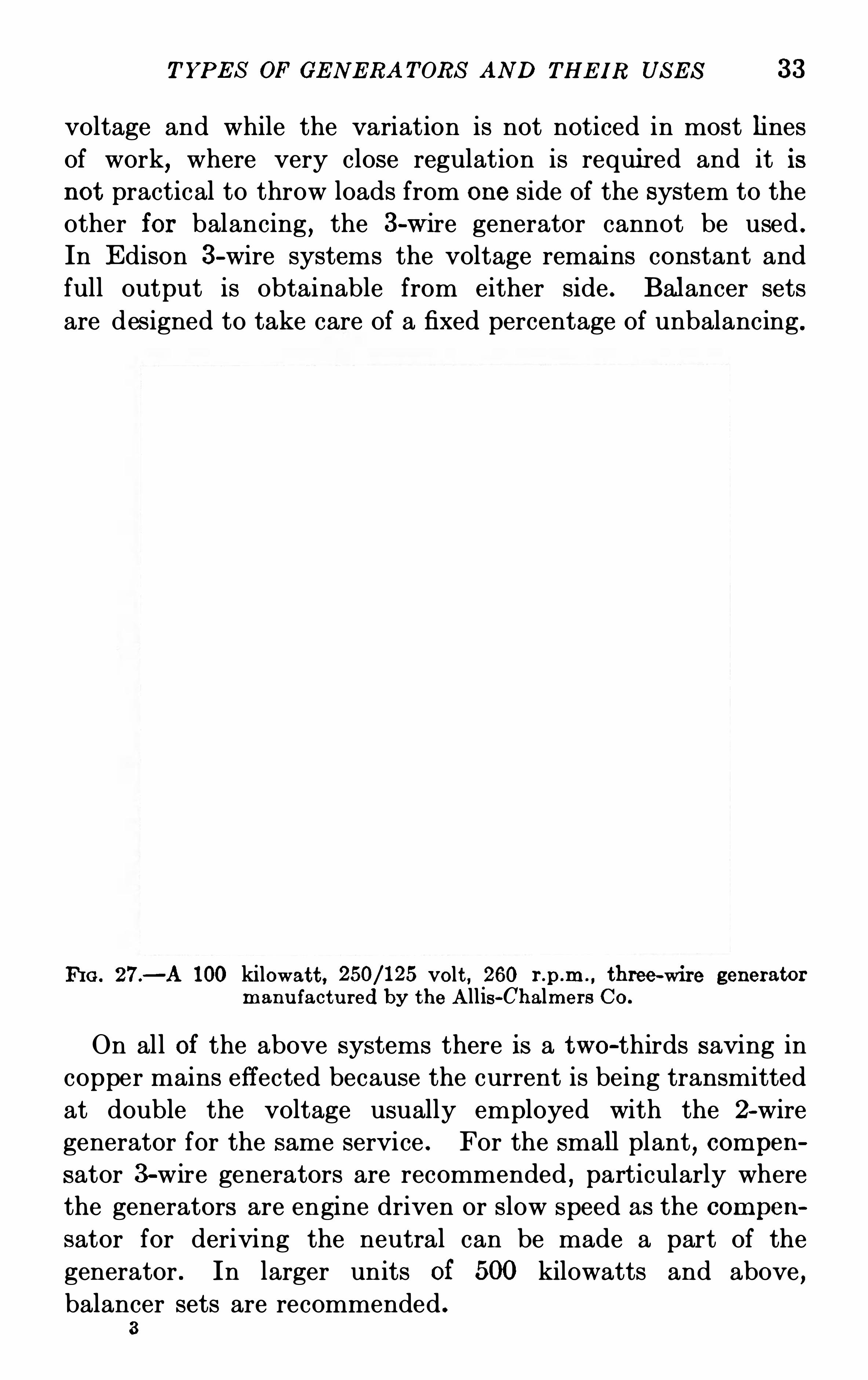
FI G . 27.—A 100 kilowatt , volt , 260 three-wire generator
manu factu red by the A llis-Chalmers Co.
On all of the above systems there is a two-thirds saving in
copper mains effected because the current is being transmitted
at double the voltage usually employed with the 2-wire
generator for the same service . For the small plant, compen
sator 3-wire generators are recommended , particularly where
the generators are engine driven or slow speed as the compen
sator for deriving the neutral can be made a part of the
generator . In larger units of 500 kilowatts and above ,balancer sets are recommended .
3
34 D. C. M OT OR AN D GE N E RA T OR TROUB LE S
INFORMAT I ON T O B E SUPPLIE D T O THE MANUFACTURER
WHE N ORDERI NG GE NE RAT ORS
The choice of a generator for a given service is best made
after making a careful survey of the actual working conditions .A great deal of trouble and expense may be saved in case the
purchaser is not familiar with general practice and the uses
of different types of machines by consulting a competent
representative of the manuf acturers of electrical machi nery .
E ach type of generator has i ts special fields of use and it is
not always safe to place a generator in service without giving
due consideration to the conditions of its service . The fol
lowing questions will suggest point s to be brought out when
a request is made for quotations,in ordering a generator from
the manufacturer
1. What is the voltage required? G ive the average as well as
the maximum and minimum values .
2 . What is the nature of the load—general power,l ights , elevators ,
hoists , battery charging, electrolytic work , railway or m ining ?
3 . What is the maximum swing or peak ?4. What kind of a prime mover is employed ? If a water wheel isused what runaway speed is required ?5. What temperature guarantees if any are required ?
6. What are the nO-load and full -load voltages of machines alreadyinstalled if the generator is to Operate in parallel ?7. Are the generators already installed equal i zed on the pos itive
or the negative s ide ?8 . I s the generator to be exposed to grit, dust, oil, grease or acidfumes ? I s the generator room hot or damp or both ?
9. I s a base required or does the generator frame rest on an ex
tens ion of the prime mover base?10. I s the armature mounted on an extens ion of the engine shaft ?
M ust the bearings be furni shed w ith the generator ?
11. What location of terminals is required ? Are special s i zedlugs necessary? G ive s izes .
12 . M ust the generator clear the floor or is the construction of a
pit beneath it possi ble?13 . I s the generator belted , geared, or direct connected to the
T YPE S OF GE N E RA T ORS AN D T II E IR US E S 35
prime mover ? G ive the s i ze of the pulley and speed if the generator is belted and a driv ing pul ley is already instal led .
14. Are sliding rails required or is a belt tightening devicenecessary?15. I s the machine to be of the 3-wire type?16. I s the voltage range over 20 per cent . of the normal and if sowhat is the voltage from which separate exc itation may be obtained?17. I s the generator to be required to operate as a motor? If
so,are revers ing switches necessary on the frame of the machine or
on the switchboard ?18. Is a line res istance necessary? G ive the machine number,ratings and name of manufacturer of generator already installed .
19. What is the direction of rotation facing the commutator end ?20. Do the generator bear ings take any load other than the
armature weights? State how much if any.
21. I s a coupl ing , pulley, pinion or special shaft extension required?G ive detai ls .
22 . Are overspeed devices necessary?23 . Must the generator Operate without noise ?24. Must the generator meet special space requi rements ? G ivelimits .
25. Does the generator operate on board sh ip or under conditionswhere it is l iable to be suddenly thrown out of its normal operatingpos ition?
CHAPTE R III
E RE CTION AND ASSEMBLY OF DIRE CT-CURRE NT
MOTORS AND GE NERATORS
STORA GE UN PA CKI N G LOCATI ON FoUN DA T I ON s HAN D
LI N G—US E S OF SLI N GS - I N S PE CTI ON—AS S E MB LYE RE CTI ON—PRE S S IN G T HE ARM ATURE ON T HE SHAFT
ERE CT I ON AND AS S E M B LY OF DIRE CT -CURRE NT M OT ORS
AND GE NE RAT ORS
The proper and efficient operation of motors and generators
depends in a large measure upon their erection and assembly .
Good results cannot be obtain ed where the machi nes are
carelessly assembled and erected in unsui table locations and
upon faulty foundations . Poorly erected sets are a cause of
constant trouble and manufactur ers have found that in a
great many cases where the proper results have not been
obtained , the defects were directly traceable to the poor judg
men t of those responsible for assembling and erecting the
machinery . L ocal conditions,of course
,often demand special
instructions in regard to the foundations,but in general the
rules and methods described here,are those in use in the best
practice and recommended by the manuf acturers .
S T ORAGE
When a motor or generator must be stored before being put
into service it should be put in a dry place,well sheltered .
The original crates in whi ch the machine and it s parts were
shipped should not be opened un til everything is in readi nessfor installing the un it .
E RE CT I ON AN D AS S E M BLY 37
UNPACKI N G
The greatest possible care is necessary in unpacking and
handling the machines in order to avoid damaging the windings and other conducting parts .
Take particular care in removing the crates,that the in
sulat ion of the field or armature coils is not damaged by the
points of nails, or by the tools being used .
Should any slight defects be caused or noted during un
packing , such as damaged insulation , they should be repair ed
before the generator is assembled,as described in the chapter
on“Tests and Repairs on Page 247.
LOCAT I ON
The following conditions must be met in arranging the
motor or generator sets in order to insure satisfactory operation .
Moisture .—The machines should be placed in a dry placeand must be protected from moisture of any kind . S team
must not be allowed to escape around them from leaking
glands , pipes and fittings , and moisture condensing on pipes
or on the ceiling , or leaking from them ,must be caught by a
shield and prevented from falling on the units . Machines
to Operate under moist conditions are usually designed with a
special vi ew to meet the requirements of such service . In
order to fit an ordinary machine not so designed , for operating
where there is a great deal of moisture , the armature and
fields should be heated,dipped and baked as described on
Page 248 in Chapter VI II .
Ventilation—The arrangement should be such as to providefor a constant supply of cool air . The question of ventilation
of electrical machinery is a very important one and directly
affects the capacity of the machine . Machines running in
hot places will show a decided falling off I n load capacity as
compared with those located in cooler places .
The ventilation however should be as eff ective as possible
and as cool a running temperature secured as is consistent with
the proper protection from dirt and moisture . In one case
38 D. C. IlI OTOR AN D GE N E RA TOR TROUB LE S
on record,very cool air was secured for ventilation of a genera
tor from an open window nearby . A mica plant was situated
in the neighborhood and in a short while,a great deal of
Sparking was developed on the commutator of the generator
due to fine mica particles getting in between the commutator
segments and the brushes . A case of brush wear recently
resulted from a large volume of cement dust from a concrete
mixer,blowing in through an open window . Such occur rences
as these illustrate the necessity of using care in securing venti
lation so that cool air is not procured at the expense of bad
operating conditions .
The length of life of the machi ne will also be materially
increased if the proper attention is paid to securing good
ventilation .
Dust, Dirt, Acid Fumes , E tc.—The machine must be pro
tected from dust , dirt or lint of any character . When it
becomes necessary to do construction work of any nature in
the immediate vicinity,care should be exercised to see that
the sets run under as clean conditions as possible , covering
usually with a piece of clean canvas or oil cloth . Acid fumes
or corrosive gases such as chlorine, etc . must be excluded from
the station .
Accessibility for Repair and Inspecti on—The location of theset and the surrounding equipment should allow easy access
to the commutator and brush rigging for cleaning and
inspection .
FOUNDAT I ON S
The foundation must be so firm that the generator or motor
will operate at full load without appreciable vibration and
should be capable of sustaining the weight of the machine
without undue settling . The bases furnished with modern
machines except in very special cases,such as portable sub
stations, are not designed to be self-supporting and therefore
the foundation should be made so as to support the base under
all points .
Substantial concrete foundations should be built for all
40 D. C. M OT ORAND GE N E RA T OR TROUB L E S
pends upon the nature of the ground, but the footing should
not be less than eighteen inches thick .
If it is necessary to bu ild a foun dation in freezing weather,
special precautions should be taken . S alt may be added tothe water
,or the water and sand may be warmed just before
it is used . S hould the ground upon whi ch the footin g is to
be built be frozen,it should be thawed ou t before work on the
footing is commenced . These foundations should be allowed
to set for at least two or three weeks before the machi ne is
placed upon them .
The foundation proper rests on this. footing and is thoroughly
bonded to it . It may be built as is the footing , of stone , brick
or concrete and the same method of laying the courses should
be pur sued as has been described for the footing . The sides
of the foundation are usually given a batter of one and onehalf inches to the foot .
The top of the foundation should be leveled off carefully
and finished to receive the capping as here described .
Foundation bolts should be located accur ately,as shown on
the foundation plans,and a space of at least an inch should
be left all around them to allow for adjustment after the frame,
rails or timbers are in place ; the holes should then be filled with
thin cement or grout . N o holding down bolts are necessary
for motor generator sets whi ch have bases and no bolts are
provided in the bases .
Motors and generators may be supported by parallel walls
or I—beams under the sides of the base if rectangular foundations are not desirable . In thi s case reinf orced concrete or
I—beams of sufficient stiff ness should be run from wal l to wal l
as a gir der under the center lin e of each bearing to take the
load of the rotor . S uch support is necessary as cast ir on bases
are not rigid enough to support their load wi thout yieldi ng
too much and thus causing mi sali gninent of the parts of the
machine .HANDLI NG
When erecting apparatus and especially in the case of large
uni ts,methods of handli ng and transportation are of prime
E RE CT I ON AN D AS S E M BLY 41
importance . E ach piece of apparatus must of course behandled with reference to it s special construction . The follow
ing observations , however , apply to the handling of apparatusin general
T he Rotor .—The rotor must never be lifted or supported
by the collector rings or commutator,or by any part of the
end windings or bindi ng bands , nor should the rotors of three
or four bear ing sets, whose separate units are formed by coup
lin gs , be li fted by placing slings under the shaft extensions at
the ends only . A sling shou ld be used near the coupling also,
thus preventing inj urious deflection and undue strains .The only safe method of supporting the rotor whi le either
moving or stationary is by slings or blocking under the shaft .In lif ting large diameter direct-cur rent armatures by means of
short slings which may bear against the end windings or the
commutator,the slings should be forced apart by a spreader
resting on top of the armature so that the sli ngs approach the
shaft vert ically, thus bringing no pressur e on the end windings .
The commutator clamping ring may in some cases be protected
against pressure from the slings by means of a block of su ffi
cient thickness placed inside the ring against the bolt heads .
T he Magn et Frame—Where there are eye bolts or lugs onthe upper half of the magnet frame they are provided for
li fting the complete magnet frame,with poles and spools
assembled . Both halves of the frame bolted together,may be
laid down horizontally by means of these eye bolts or lugs,but they must not be used for lifting the complete machi ne ,or the frame and armatur e , wi thout additional support under
the shaft extensions or bearing housings .
The weight of the armature and magnet frame should not
be allowed to rest on the base without substantial support
dir ectly under the points where the weight comes .
THE US E OF SLIN G S
It is important to have a good knowledge of the correct use
of slings in order to secur e good results in the handling of
heavy parts .
42 D . C. IlI OT OR AND GE N E RA T OR TROUB LE S
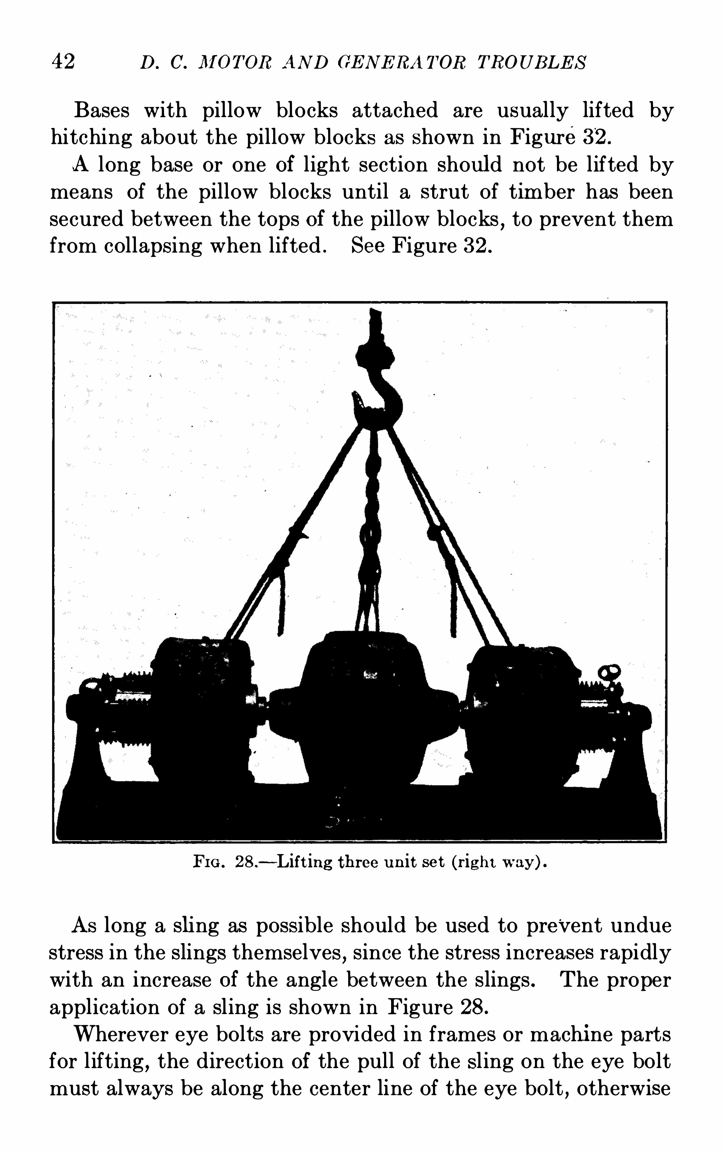
Bases with pillow blocks attached are usually lifted by
hitching about the pillow blocks as shown in Figure32 .
-A long base or one of light section should not be lifted by
means of the pillow blocks until a strut of timber has been
secured between the tops of the pillow blocks,to prevent them
from collapsing when lifted . See Figure 32 .
FI G . 28.
—Lift ing three u n it set (r ight way) .
As long a sling as possible should be used to prevent undue
stress in the slings themselves,since the stress increases rapidly
with an increase of the angle between the slings . The proper
application of a sling is shown in Figure 28.
Wherever eye bolts are provided in frames or machi ne parts
for lifting , the direction of the pull of the sling on the eye bolt
must always be along the center line of the eye bolt , otherwise
ERE CT I ON AND AS S E M BLY 43
FIG . 29.—Lift ing three unit set (wrong way) .
I n this case there are a number of sharp
corners unprotected while the mani la ropes li ng passes through the loop p f thewire ca la, and the arrangement of the outs ide sling sdoes not permi t of an even d is t r ibut i on of the load .
44 D. C. M OT OR AND GE N E RA T OR TROUB LE S
a bending st ress is produced whi ch may fracture or bend the
eye bolt,even under a load that it should eas ily carry if applied
properly . Where the proper pull on the bolt cannot be oh
tained, a spreader must be inserted between the slings . The
spreader must be secured so that it cannot slip out of position .
FIG . 30.—Hit ch with one cable FIG . 3 1.
—Hit ch wi th u nequalequ aliz ing st rain on fou r part s . s t rain on two cables .
When lifting the top half of a direct-current machi ne , thesling is usually passed around the top frame between twospools . Care is necessary to prevent slings from pressing
against the spool windings or veneer flanges and damaging
them . A thi ck soft pad of canvas,leather
,or similar material
can be often used to advantage when making such lifts . It
must be understood however that this is not a cert ain preventa

E RE CT I ON AND AS S E M B LY
FIG . 32 .
—M ethod of lif t ing base and standards .
Frequent ly a base and s tandard are li fted and no provis ion is made for any lateralst rains that may occur . tend ing to place an unnecessary s t rain on the
.
bolts fas temng
the s tandards to the base. When such a li ft is to be made, a piece of t imber should beplaced between the bear i ngs to relieve the st rain, as shown.
46 D. C . M OT OR AN D GE N E RA T OR TROUB LE S
tive agai nst damage . Unless great care is taken,spools may
be damaged by the sli ngs rubbing against them when turning
the frame from a horizontal to a vertical position .
FI G . 33 .
—S in g le cable slin g for l ift ing base.
I N SPE CT I ON
Before starting the assembly of a new machine a careful
ins pection should be made to see that none of the parts have
been damaged since leaving the factory . Frequently slight
defects , such as damaged insulation , can easily be repaired
D. C. M OT OR AND GE N E RA T OR TROUB L E S
FIG . 35.—S ing le cable S ling FI G . 36.
—Dou ble cable sl inglift ing load (wrong way) . lift ing load (r ight way) .
Showing the use of protect ive padsto preven t damage to the laminat ionso f t h e 1 ieee
E RE CT I ON AND A S S E M B LY 49
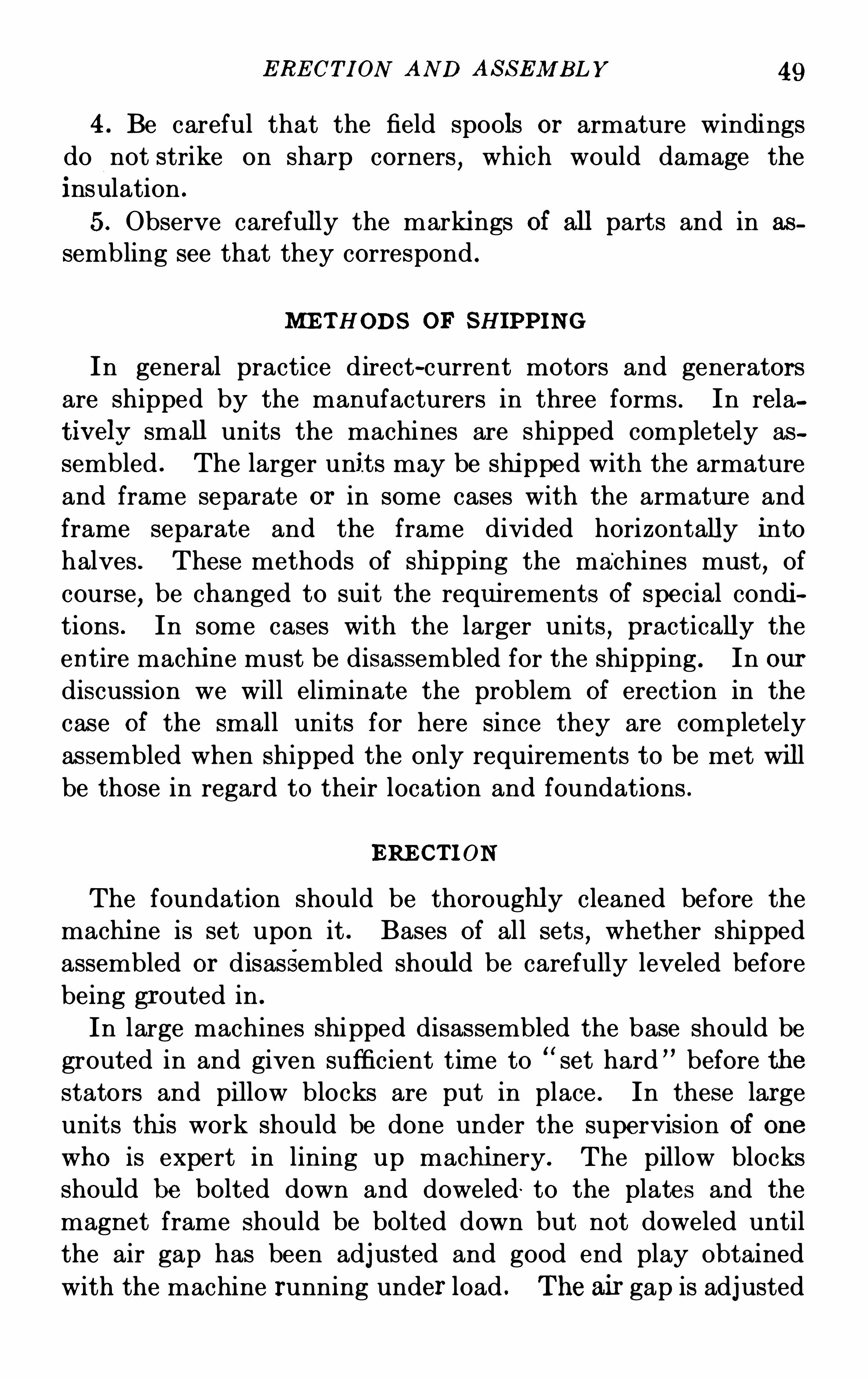
4. Be careful that the field spools or armature windings
do not strike on sharp corners,which would damage the
i nsulation .
5. Observe carefully the marki ngs of all parts and in as
sembling see that they correspond .
M E THODS OF SHIPPI N G
In general practice direct-current motors and generators
are shipped by the manufacturers in three forms . In rela
t ively small units the machines are shipped completely as
sembled . The larger units may be shi pped with the armature
and frame separate or in some cases with the armatur e and
frame separate and the frame divided horizontally into
halves . These methods of shi pping the machines must,of
course,be changed to suit the requ irements of special condi
tions . In some cases with the larger units , practically the
entire machi ne must be disassembled for the shipping . In ourdiscussion we will eliminate the problem of erection in the
case of the small units for here since they are completely
assembled when shipped the only requirements to be met will
be those in regard to their location and foundations .
ERE CT I ON
The foundation should be thoroughly cleaned before the
machi ne is set upon it . Bases of all sets,whether shipped
assembled or disassembled should be carefully leveled before
being gr outed in .
In large machines shipped disassembled the base should be
grouted in and given sufficient time to“set hard ” before the
stators and pi llow blocks are put in place . In these large
units thi s work should be done under the supervision of one
who is expert in lining up machinery . The pillow blocks
should be bolted down and doweled to the plates and the
magnet frame should be bolted down but not doweled until
the air gap has been adjusted and good end play obtained
with the machine running under load . T he air gap is adjusted
50 D. C. M OT OR AN D GE N E RA T OR TROUB LE S
by moving the frame horizontally on the sole plates until the
gap is equalized at each side of the armatur e and then by
ins erting or removing shims under the feet until the gap at
the top and bottom is similarly equalized . The raising screws,
if provided in the feet, facilitate this vertical adj ustment .
E nd play is adjusted by moving the magnet frame horizontal ly
along the line of the shaft .
For machines equipped with separate cast iron bases, the
bases should be located in the proper position and temporarily
supported on iron wedges driven under the pillow block and
magnet frame points of support . Care should be taken that
the wedges are evenly and closely spaced and driven to divide
the weight properly to reduce strains in the cast iron base,
and that the inside flange of the base is wedged up under the
pillow blocks to prevent their leaning in or out and reducing
the end play . The base should be carefully leveled , usingan accurate straight edge and good level on the machi ned
surf aces .
The base should be grouted by building a low dam around
the inside and outside and floating in a mixture of one part
Portland cement to one part of clean sharp sand to a height of
one-quarter inch above the lower face of the base . The
wedges should not be removed until the grouting has set .
Deep grouting should not be put in owing to the difficulty of
subsequently removing the base if at any time desirable .
The machi ned surface of the base , the pillow blocks , and theend of the magnet frame feet should be cleaned before assem
bling . The heights of the pillow blocks and magnet frame are
adjusted at the factory by means of sheet iron shims,one or
more pillow blocks being provided with a fibre shim and
insulated bolts and dowel pins . When not assembled,
the shims are tied in bundles and marked so that their proper
locations on the base can be identified . With the shims in
place,the lower half of the magnet frame and the pillow blocks
can be bolted in place as located by the dowel pins . It is
well to meas'
ure the distance between pillow blocks after the
base and lower half of frame are in place (in the case of split
E RE CT I ON AN D A S S E M B LY 51
frame machines) before the rotating parts are placed in thebearings . If the distance between the bearings is shorter
than that given by the drawings or dimension sheets the base
has been distorted and its center is lower than its end . To
remedy this,shim up under the foot of the pillow block until
proper ali gnment results and the correct bearing spacing isobtained .
The oil wells should then be cleaned carefully and filled
to the proper level with good quality mineral oil. The lower
halves of the bearing lini ng should be cleaned , placed in posi
tion and coated with oil. The rotor should then be lowered
into the bearings after cleaning the shaft where it runs in the
bearings,removing any roughness and oili ng it . The oil rings
should be put in and the'
top halves of the linings placed in
position . The oil rings should be tried to see if they revolve
freely and the bearing caps put on and bolted down . In
cases where the magnet frame is in - two halves,the top half
of the frame can then be put in place and the brush rigging
assembled .
In sets having three or more bearings,the alignment should
be checked again after the set has been completely erected .
Thi s is best done by backin g off the coupling bolts slightly and
turni ng the machine over by hand or with a crane . The coup
ling halves will separate if the two shafts are out of line , the
space between the halves indicating the direction in which the
alignment must be adjusted . In thi s connection it must be
remembered that the shoulder between the halves of the coup
ling carries the weight,the bolts do the driving and must not
be used to draw the two halves of the coupling together unless
the faces are perfectly parallel Great care must be used in
this checking as large shafts may be broken from crystalli
zat ion after a few weeks operation when out of al ignment ,although there are no indications of undue vibration or heating
of the bearings .
In erecting machines care should be taken to see that both
coupling faces are true and at right angles with the center line
of their respective shafts before ali gning the machine . It is
52 D. C. M OT OR AN D GE N E RA T OR TROUB LE S
also advisable to check the outside of both halves of the coup
li ng to see that they are concentric with the center of the shaf t .Coupli ngs are frequently distorted in installation so that they
are not concentric with the shaf t and the face is not at right
angles wi th the center line of the shaft .
After erecting a new machi ne it is advi sable to oil slightly
all finished iron and steel surfaces to prevent rusting .
BRUS HE S AND B RUSH RI G GI N G
AS S E M B LY
To insure the correct assembly of the magnet frame and
brush-holder yoke , the drawings of the generator supplied by
the manufacturer should be referred to . These drawings or
diagrams locate the position of the field openi ngs or leads with
respect to the commutator end of the machine . The outline
drawing shows the relation of the lugs on the brush-holder
yoke for bolting on the brush-holder bracket with respect to
the field coils,thus indicating the correct assembly of the yoke
in its supporting brackets .
S PACI NG THE BRUSHE S
To obtain fir st class commutation , the studs supporting the
direct-current brushes must be more carefully set than if merely
bolted in the yokes and allowed to come where they will .
Spacing by counting of segments is not sufficiently accur ate in
all cases,as mica thi ckness varies sufficiently to give slightly
di ff erent spacing to different sections of the commutator . To
obtain proper spacing,the studs should be set up with the
brush holders in place,and the comm utator should be wrapped
tightly with a long strip of paper covering its whole circumf er
ence and tied in place . The lapping point of this paper should
then be marked,the paper should be removed , spread on a flat
sur face and stepped off with a large pair of dividers or simi l ar
tool into exactly equal sections,equal in number to the number
of poles . The strip should then be replaced on the commutator
and the studs so adjusted that the toes of the brushes on the
diff erent studs j ust touch these marks .
E RE CT I ON AN D A S S E M B L Y 53
BRUS H HOLDE RS
The brush holders should be mounted on the studs accord
ing to the instructions furnished with the generator. Paral
lelism of the studs and commutator segments is usually
insured by the factory machining of the insulating collars,but
should be checked if these become warped,sprung or swollen .
All brush holders should be at the same distance from the
commutator , not over one-eighth of an inch at the inboard and
outboard ends , and the toes of all brushes on one stud should
line with the edge of the one segment . If a stud is out of line
in either of these directions , the insulating collars should be
filed to correct it .
S TAGGERI NG OF BRUSHE S
The brushes should be staggered so that they will not follow
each other ’s tracks on the commutator . Better results are
obtained by staggering the brushes on all positive studs with
reference to each other,and those on all negative studs w ith
reference to each other . Colle ctor ring brushes on 3—wiremachines , should be staggered so as to distribute the wear
over the ful l width of the collector rings,thus preventing theformation of gr ooves in the rings .
FIT T I NG THE BRUSHE S
After the parts are all assembled , the brushes should be
fitted as closely as possible to the cur vature of the commutator,the final fitting being done with very fine sandpaper . Best
results are obtained by pressing the brush down in the box
with one hand and drawing the sandpaper under it in the
direction of rotation with the other , raising the brush between
cuts ” and always holding the sandpaper down against the
curvature of the commutator to guard against cutting away
the edge of the brush . This method of sanding will minimize
the leng th of time that the machine must be run light before
load may be put on . A proper fit cannot be obtained by
working a s trip of sandpaper back and forth under the brushheld in the brush holder by the spring . N ever u se emery or
54 D. C. IlI OT OR AN D GE N E RA TOR TROUB L E S
carborundum as the particles will imbed in the brush and
commutator , producing continuous cutting.
B RUSH PRE S SURE
The proper adjustment of spring pressur e on the generator
brushes depends upon the material and size of the bru sh .
Carbon brushes should be run at a pressure of two pounds
per square inch of cross sectional (not contact) area on allsizes up to thr ee-quarters of an inch thick . One and three
quarter poun ds per square inch is sufficient on larger sizes .
Graphi te brushes may be run at pressure as low as one pound
per square inch for all sizes . The motor brush pressure should
be from one and three-quarters to two pounds per square inch .
S E T T I N G OF B RUSHE S OF COM M UTATI N G -POLE G E NE RAT ORS
The brushes of commutating-pole generators are general ly
set on the mechanical neutral,that is
,opposite the mid-point
of the main pole are. It may be necessary in some cases to
shift the brushes slightly from the neutral point in order to
secure the best commutation, or more stable par allel operation .
A tram,with directions for its use in locating the brushes
properly with respect to the poles is sent out with some ma
chi nes . The brush position shou ld be marked on the commu
tator by means of this tram before the brush-holder brackets
are assembled,as the brackets may interfere with the use of
the tram . When a tram is not furni shed the mechani cal
neutral may be determ ined from the factory marks on the
armature slots and commutator bars,or by other methods
given in the detailed instructions shipped with the machi ne .
The brushes of the nearest stud should be set on the center of
the group of commutator bars at the neutral point .
OIL RIN G S AND PULLEYS
It should be remembered that in a machi ne which has solid
oil rings,these rings should be placed on the shaft before the
pulley in case a machi ne is so fitted,and the pulley should be
placed on the shaft before the armature is slung into place .
56 D. C. M OT OR AND GE N E RA T OR TROUB LE S
obviate the necessity of press ing the armature over the entire
length of the shaf t .
All bolts , straps and blocks used on the work should be
ready before starting the operation of pressing,which
,when
once started should be completed as soon as possible . If the
armature is allowed to stand over night half pressed on , an
abnormal amount of pressure wi ll be required to start it again .
The long rods which are used for drawing the armature on
should be placed as near ly parallel with the shaf t as possible,
in order to keep the armature from twisting . If the keyway
runs the whole length of the part over which the armature
is to slide , this will not be so important , as a temporary or
permanent key can be used to keep the keyways parallel .
The long rods used for drawing on the armatur e should be
from one and one-half to three and one-half inches diameter
with a short thread on one end for a nut , and the long thread
should be cut up from three to six feet,as the case may require .
Blocking from 6 inches square to 10 inches square or any
suitable combination of blocking that can be picked up , or
pieces 4 inches X 10 inches set on edge with a st rap across
for the rods might be used instead of boring holes in solid
timbers .
If the shaft has had the hi gh spots filed off and is still so
large as to render the pressing difficult , the hub may be heated .
A variation of .015 inches to .020 in ches will cause a con
siderable diff erence in the ease of pressing .
Great care should be taken to heat the hub unif ormlyso that the hole may not be twisted out of round and be
larger in one direction and smal ler in the other than before
heating. Care must be taken not to damage the insulation
either by heating or in cooling off with water .
It sometimes happens that the shaft has been stored in a
much warmer place than the spider for some time previous
to the pressing on of the lat ter . In this case the temperature
may be reduced by packing the shaft in ice for a few hours ,thus contracting it to it s proper size . This requirement 3
seldom met in practice however .
E RE CT I ON AN D AS S E M BLY 57
If a considerable amoun t is to be gained , cracked ice mixedwith salt is recommended , as the resulting temperature will beat least 15 or 20 degrees lower . It may be noted that the
coefficient of expansion for untempered steel is practically
per degree Fahrenheit ; that is , each inch of steel will
expand this amount for each degree Fahrenheit that it isheated .
If the shaf t and armature are to be put together while one
is hot and the other cold it will be very important to have
everything ready before starting , as the work must be finished
quickly. The shaft should be‘
very carefully marked in advance for the position of the armature so that no time will
be wasted .
S hould an excessive variation be found between the arma
ture bore and shaft diameter , the shaft should be checked
with the gauges furnished by the manufactur er to the engine
builder,and if the error is in the shaft the engine builder
should correct it before proceeding with the assembly .
It is customary to make the following allowances for pressing
Shafts up to 5 inches in diameter in chB etween 5 in ches and 12 inches inchB etween 12 inches and 18 inches inchAbove 18 inches . inch
The amount of pressure required to force shafts of different
diameters depends so much on conditions and comparative
temperatures of the shaft and spider , that it is quite impossible
to set any definite pressure required for assembling .
It may be expected that for shafts up to 5 inches in diameter
a pressure of between 10 and 35 tons is necessary . Up to
12 inches pressure between 25 and 90 tons . Up to 18 inchesbetween 50 and 140 tons . Above 18 inches between 80 and
200, or even 300 tons would be required .
A difference in temperature of a very few degrees may
change the above maximum and minimum amounts very
materially in any particular case,but with all conditions
favorable the above may be considered good press ing fits .
CHAPTE R IV
THE STARTI NG AND OPERATION OF DIRECTCURRE NT MOTORS .
GE N E RA L I N S PE CTI ON STARTI N G UP OPE RATION STOP
P I N G—RE V E RS I N G—OPERATI ON As A GE N E RA TOR—CAREAN D MA I N TE N AN CE COM MUTATOR GRI N DI N G AN D TURNI N G TRE ATM E N T or COMMUTATOR AN D BRUS HE SBE ARI N G LUB RI CATI ON
T he S tarting and Operation of Direct-cur rent Motors—TheManufacturers of electrical machinery furnish as far as possible
,
apparatus which will perform the service required without
delay or trouble,making tests before shipments to insure
against failure of any part after delivery to the purchaser ’s
plant . However,it is not possible to locate all defects and
weaknesses during the factory tests,and in many cases ship
ment has to be made without these tests due to urgent need
of the machines for emergency conditions . For these reasons
and very often on account of damages done in shipments , the
apparatus when first installed and started immediately develops slight troubles . It is important that the cause of such
troubles,whether due to improper adjustments at the factory
or to damage received in transit,be removed at once as a delay
in correcting even a trifling defect may result in a serious fail
ure of the units or the parts of units,whi ch wou ld shut down
the entire plant and require the services of tra ined experts to
make repairs . In case of trouble upon starting,the unit should
be shut down at once and a thorough examination made to
locate the cause of the faulty operation but if no apparent
cause for the action is found , no experiments upon the units
should be permitted by inexperienced hands .58
S T ART I NG AND OPE RA T I ON OF M OTORS 59
GE NERAL IN S PE CT I ON
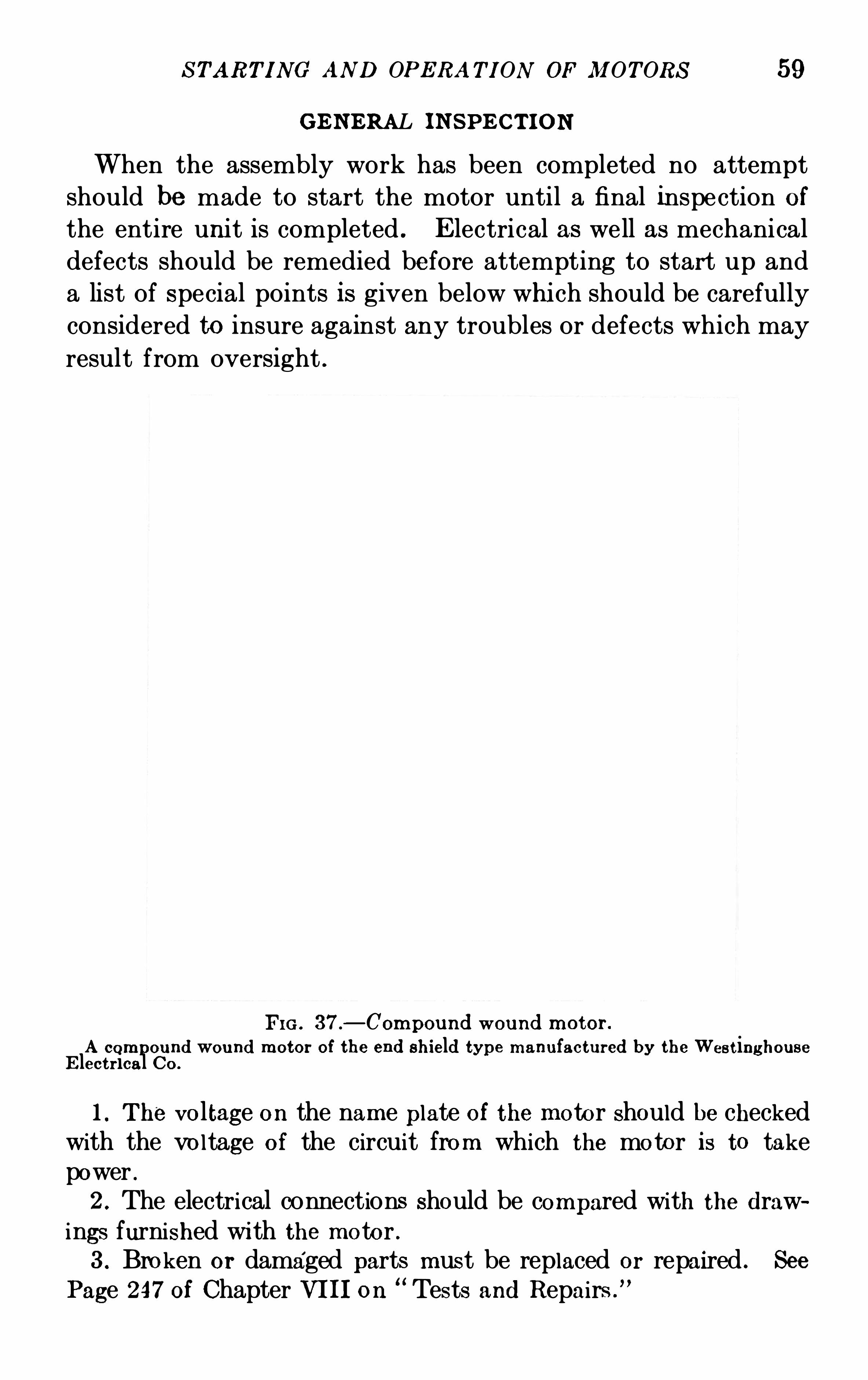
When the assembly work has been completed no attempt
should be made to start the motor until a final inspection ofthe entire unit is completed . E lectrical as well as mechanical
defects should be remedied before attempting to start up and
a list of special points is given below which should be carefully
considered to insure against any troubles or defects which may
result from oversight .
FIG . 37.
—Compound wound motor .
A compound wound motor of the end shield type manufactured by the Wes t inghouseE lect r ical Co.
1. T he voltage on the name plate of the motor should be checkedwith the voltage of the circuit from which the motor is to takepower .2 . The electrical connections should be compared with the drawings furnished wi th the motor .3 . Broken or damaged parts mus t be replaced or repaired . See
Page 247of Chapter VI I I on“Tests and Repairs .
”
60 D. C. M OTOR AND GE N E RA TOR TROUBLE S
4. Loose bolts , nuts , washers or tools must be removed fromall moving parts and so placed as to prevent falling into the motorwhi le running .
5. All bolts holding poles to the frames and those holding thebrush-holder brackets to the yoke should be tight to prevent movement of the poles or brush holders when power is applied . T he
ho lding down and foundation bolts should all be in place and tight .T he brush holders should be tight on the bracket or studs .
6. Loose connections at the brushes or at the po ints of contactw ith the brackets or studs will cause commutation trouble andthese contacts must be perfect , clean and tight .7. The main field air gaps must be uniform as well as the gapsunder the commutating poles, but it should be noted that the two
gaps may not be of the same s i ze . The air gap should be measuredw ith the armature stat ionary, after which the armature should berotated and the gap measured in several pos itions to avo id errordue to the armature being out of round . The air gaps should bemeasured from iron to iron whenever poss ible .8 . The commutator segments should be examined carefully toguard against short circuits between bars due to bridges of copperor damage caused by a blow or in rough handl ing . Where them ica between the segments is grooved or ou t below the surfaceof the Copper segments the grooves should be clear of all dirt ormetal part icles .
9. The armature should turn free in its bearings and it is advisableto turn the revolving part by hand before starting when the si zeof the unit permi ts .
10. The commutator leads and clips , also all of the armaturec l ips both front and back , should be straightened out if bent togetherin assembling or handling.11. Damaged insulation at the ends of the commutator
,on the
armature binding bands , field coils,and pole face connections
should be given a treatment of good insulating varnish to close all
openings through which di rt or oil might enter .12 . The clearances between li ve parts where full voltage exis ts
to the ground or where ful l potential exists between connections,
must be ample to prevent arcing or grounding. Voltages up to
125 should be gi ven a clearance not less than three-eighth inch andabove 125 volts at least one-half inch to three-fourth inch shouldbe allowed . Where the connection strips are not stiff enough to
S TART I NG AND OPE RA T I ON OF M OT ORS 61
be self-support ing, spacers should be supplied to prevent contactwhen the power is applied .
13 . The pole tips should be straight and all laminations not inline should be forced back into place .14. The center line of the armature core should be the same
as the center l ine of the pole pieces .
15. The bearings should be filled with a l ight grade of goodm ineral oil to the proper level as shown by the s ight gauges . T he
oil rings should turn free on the shaft and in the oil well .16. The bearings must not leak oi l particularly around the commutator end of the unit .17. The connection strip must not rub on the binding bands
of the armature . The brush holders must be clear of the commu
tator surface by at least one-sixteenth inch .
18. The brushes must be free to move in the holders and thesprings set to give an average pressure of one and three—fourthpounds per square inch of contact surface . The brushes shouldbe carefully fitted to the commutator surface .19. The brushes should be equally spaced around the commutator and the brackets or studs carrying the holders must be set
so that all holders are at an equal distance from the commutatorsurface . The center l ine of all of the brushes must be parallel tothe commutator segments or side mi ca .20. The brushes should be staggered in such a way as to cover
the entire surface of the commutator in order to prevent groovingor scoring . The brush holders should be staggered in pairs of studs .
The holders should be placed in position as directed by the instructions furnished with the machine .
‘
21. The pulley or coupl ing should be t ight to prevent slipping.22 . All dirt, grit, carbon dust, l int, etc.
,must be blown ou t of
the machine by compressed air or by the use of a smal l hand bellows .
The best results from blowing out are obtained by the blowing fromthe back end of the machine toward the commutator .23 . The copper connections between the brushes and the brackets
or bus bars must not be allowed to touch rotating parts of thearmature or parts not insulated from the ground .
S T ART I NG UP
S hunt Motors —After the general inspection has been madethe machine may be started . Very small motors such as
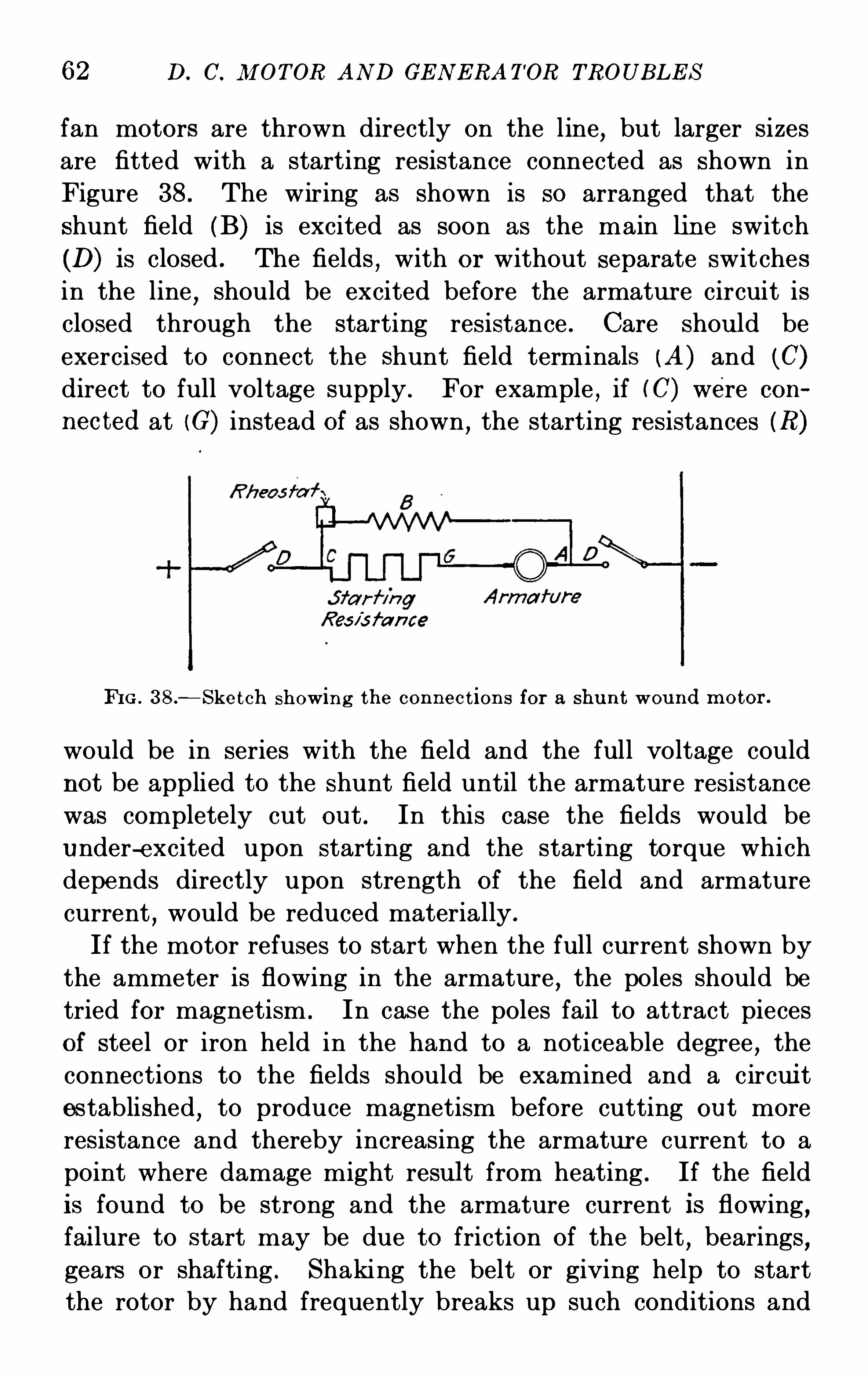
62 D. C. M OTOR AND GE N E RA T OR TROUB LE S
fan motors are thrown directly on the line, but larger sizes
are fitted with a starting resistance connected as Shown in
Figure 38. The wiring as shown is so arranged that the
shunt field (B) is excited as soon as the main lin e switch
(D) is closed . The fields,with or without separate switches
in the line,should be excited before the armatur e circuit is
closed through the starting resistance . Care shou ld be
exercised to connect the Shunt field terminals (A ) and (C)direct to full voltage supply . For example , if (C) were con
nected at (G) instead of as shown , the starting resistances (R)
Res /$5 fance
E G . 38.—Sketch showin g the connect ion s for a shun t wou nd motor .
would be in series with the field and the full voltage could
not be applied to the shunt field until the armature resistance
was completely cut ou t . In this case the fields would be
under-excited upon starting and the starting torque which
depends directly upon strength of the field and armature
current,would be reduced materially .
If the motor refuses to start when the full current Shown by
the ammeter is flowing in the armature,the poles should be
tried for magnetism . In case the poles fail to attract piecesof steel or iron held in the hand to a noticeable degree
,the
connections to the fields should be examined and a circui testablished , to produce magnetism before cutting ou t more
resistance and thereby increasing the armatur e current to a
point where damage might result from heating . If the fieldis found to be strong and the armature current is flowing
,
failure to start may be due to friction of the belt,bearings
,
gears or shafting . Shaking the belt or giving help to start
the rotor by hand frequently breaks up such conditions and
64 D. C. IVI OTOR AND GE N E RA T OR TROUB LE S
after which the resistance of the field and excitation cur rent
will not change .
Once started , shun t motors require very little attention
excepting to see that the brushes are kept free in the holders
and that the machine is kept as free as possible from dirt and
dust by frequent cleani ng and blowing out . The oil in the
bear ings should be changed at regular intervals depending on
the service . Bearings exposed so as to collect grit,concrete
dust and such material requi re a change of oil every two weeks
as compared with pump motors or motors operating in loca»
tions free from foreign matter where a change of oil every sixty
days will sufli ce. The mica between the commutator segments,
if flush w ith the su rface , should be sand papered down when
an examination shows this mica to be above the surface of the
copper . If grooved or undercut mi ca is used,it should be
kept below surface by slotting when necessary .
The brushes should be changed before they become worn
to a point where the metal connections damage the commu
tator . The springs should be notched up to keep the pressure
constant as the brushes wear down .
Oil leaks must not be permitted,particularly about the com
mutator,as failure of insulation would result in a short t ime .
S T OPPIN G
S hunt Motors—Fir st , pull the line switch or thr ow ou t the
cir cuit breaker,then open the shunt field circui t .
N ever open the field circuit of any motor to shut it down asthe machi ne will run away or race or flash over , doing damag e
to the brushes,commutator and connections . After shutting
down , make su re that the starting resistance , if not automatic ,is thr own in posit ion to place all resistance in the line . N ever
leave the starting box in a running position after shuttin g
down .
RE VE RS I N G
Shunt Motors—To reverse the dir ection of rotation of ashunt motor , reverse either the shunt field terminal connections
S TART I NG AND OPE RA T I ON OF M OTORS 65
or the armature terminals . Do not reverse both as the direction of rotation will then remain the same . In motorsequipped with commutating poles , no shifting of the brusheswill be necessary upon reversal of rotation but motors without
commutating poles require that the brushes be shifted against
rotation the same amount as with the previous rotation .
Motors equipped with brushes set at an angle with the hori
zontal greater than 20 degrees , should have their brushes
or studs turned when reversed rotation is required . Below
this angle no change is necessary . Most motors are equipped
with a brush rigging to permit operation in either direction
of ro tation but in large sizes where the rotation is fixed , holders
with a large angle,20 degrees or more , may be employed ,
which require changing as mentioned above , when reversed
Opera tion is desired .
THE S T ART I NG AND OPERAT IN G OF COM POUND M OT ORS
After a careful inspection , the compound-wound motor may
be started,operated and stopped according to the instructions
given under shunt-motor operation , with the exception of the
reversal of rotation . T o change the direction of rotation of a
compound motor it is necessary to reverse both the series and
Shunt fields or to change the connections to the armatur e .
When the motor is fitted with commutating poles no shifting
of the brushes is necessary upon -reversal and when not so
equipped,the precautions to be observed in Shifting the brushes
will be as noted under shunt-motor Operation .
THE S T ART I N G AND OPERAT I N G OF S ERIE S M OT ORS
Series motors are controlled by a resistance placed in the
armature and field circuits . The general instructions cover
ing the starting and operating of series motors will be the same
as those given under shunt-motor operation and it should be
noted that a change in the direction of rotation is obtained by
reversing either the field or armature leads but not both at
the s ame time . The starting equipment is the same as that5
66 D. C. M OT OR AN D GE N E RA T OR TROUB LE S
used for the shunt and compound motors , omitting the shunt
field connections where the motors are operating on a constant
load and at a constant speed,such as in the case of fans or
pumps . Where the motor is operating at variable speeds
and loads , the starting equipment must have ample current
carrying capacity to operate in the line continuously for the
FIG . 39.
-Ser ies wound motor .
purpose of regulating the speed . S eries motors should be
connected to a load which cannot be dropped,as racing will
follow as a result of the loss of load .
GE NERAL
Direct-current motors of any type may be operated as
generators by supplying mechanical en ergy to the shaft and
changing the field connections for voltage g eneration . Unless
the machine has been designed for operation both as a motor
and generator however,it will be found that the fields are
S TART I N G AN D OP E R AT I ON OF i l I O T ORS 67
not of sufficient strength to generate the full rated line volt
age without high field temperatures , since the drop Or loss Of
voltage in the generator has to be generated in addition to
the terminal voltage . Full-lin e voltage may be obtained by
increasing the speed without danger mechanically and this isqui te common practice .
To Operate a shunt motor as a generator no change is necessary in the field or armature connections .
To Operate a compound-wound motor as a generator it isnecessary to reverse the series field only
,leaving the armature
and shunt field connections in their original positions .
CARE AND M AI N T E NANCE
A systematic inspection of the set should be made at least
once a week,keeping the following points in mind .
Cleanliness .
—See that both the interior and exterior of themachines are kept free from metal dust
,dirt of any descr ip
tion, oil or water . Take particular pains to prevent dirt or
metal dust from collecting inside the end windings of the arma
ture,both in the coupling and the commutator ends . E very
precaution is taken in the construction of machines to avoid
trouble from thi s sou rce,but an excessive accumu l ation of
dirt may eventually ground the armature and burn it out .
Compressed air is the most effective means of cleansing the
interior part s , but a smal l bellows can be used if compressed air
is not available . Wipe the brush holder studs and leads care
fully to remove all traces of metal dust worn from the commu
ta ’lor and clean the motor brushes and brush holders .
Blow the machine out at least once a day ; if it cannot betaken out of service and shut down
,blow it out while running .
After blowing out a machine standing stationary, start it up
and blow it out again while running on half voltage .
Oil.—See that the oil wells are filled with a good qualityof clean mineral oil nearly to the top of the overflow hole of
the oil filler,or half-way up the glass gauge , if one is provided .
Use heavy oil on large machines . After'
the first week, the Oil
should,under average conditions be drained out about every
68 D. C. M OTOR AN D GE N E RA T OR TROUB LE S
sixty days and replaced with fresh , clean oil. In replacing
the drainage plug,it should be dipped in a mixture of red lead
and shellac and securely tightened to prevent leakage . When
a new machi ne, or an old machine that. has been changed or
repaired,is initially started , the oil rings should be watched
carefully to see that they revolve freely and carry a sufficient
amount of oil to the shaft . Thereafter , the rings need prae
tically no attention as long as a proper supply of oil is main
tained in the oil well .
Brushes .—See that the bru shes move freely in the holders
and make contact properly with the commutator . See that
the brushes are properly staggered , so as not to wear grooves
in the segments . Try the pressure and keep it up to theproper value as the brushes wear .
Commutator .—See that the commutator maintains a polishedsurface . Blackening of all the bars indicates poor adj ustment
of the commutating field, or incorrect brush position . Black
ening of groups of bars at regu lar intervals may be due to the
same cause or to poor contacts . Blackening at irregular
intervals indicates a rough or eccentric commutator . Ordi
nar ily the commutator will require only an occasional wiping
with a piece of dry canvas , or other non-linting material , but
if blackening appears and grows worse , the cause must be
determined upon and remedied . Use no lubricant on thecommutator . N oisy brushes are due to a rough commutator,or to too much clearance between the commutator and brush
holders . The u se of any lubricant will only cause sparking
and aggravate the trouble . The above causes Of faulty com
mutation are discussed in detail in Chapter VI I .
COLLE CT OR RI N G S (THRE E -W IRE G E NERATORS )
See that the collector rings maintain a smooth , highlypolished sur face . Ordinarily
,the rings will require no at
tention,provided the brushes are in good condition, but in
case the rings cut,or score , a slight amount of oil (not grease)
applied at intervals,together with an increase in the brush
pressure,will help to restore the desired smooth sur face .
S TART I NG AND OPE RA T I ON OF AIOT ORS 69
Remove any sharp edges that may appear on the rings dueto wear .
Bolts—Go over the bolts and nuts occ asionally and tigh tenthem—part icularly those in the generator brush rigging .
Speed-limit Devi ces—The speed-limi t devices should
be tested at regular periods . They are designed to operate
at 15 per cent . above normal speed . Those furni shed on
motor generator sets should be tested by cutting off the
machine from the alternating-current supply,running it
from the dir ect-current bus bar and gradually weakening the
field until the speed rises to a point at which the switch
should operate , as noted by a tachometer held against the
end of the shaft . If the speed limit device does not operate
below 20 per cent . above normal , the machine should be shut
down and the defect corrected .
Commutator Grinding or Turn ing—I n many cases wherea commutator is rough but is concentric
,it is possible to
stone it smooth with sandstone instead of turning . Whenever
possible this is to be preferred,for a commutator can usually
be smoothed by the removal of a few thousandths in thi s way,
whereas if it were turned,a man would probably cut away
one-sixteenth of an inch and possiblymore before completing the
work .
Before stoning,all traces of Oil or grease must be removed
from the commutator or the stone will glaze over with copper
and will not cut . A piece of grindstone or medium grade
scythe-stone will answer the pur pose ; the stone Should be
worked from end to end of the commutator and the surface
ground down evenly . While stoni ng, the brushes should be
lifted from the commutator as the grit will cut them rapidly .
After stoning,the commutator should be smoothed with
fine quartz (not garnet) sandpaper and then polished by using
the back of the paper . Before stoni ng or turning the com
mutator,the clamping bolts should be tested for tightness
while the machine is warm . E xt reme caution should be
used in tightening the belt s ; in many commutators the bolts
are strong enough to distort the clamping ring and dis
70 D. C. M OT OR AND GE N E RA T OR TROUB LE S
tort ion of the ring will cause serious trouble in the commutator .
All commutators are carefully tightened before leaving the
factory and should not be tightened afterward unless there
is dir ect evidence of looseness .
When the commutator is too rough or eccentric to be stoned
down successfully by hand,the stone may be held by a tool
post on a pair of ways,but better results will be obtained by
the use of a revolving wheel grinder , Figure 40, or it may even
be advisable to turn the commutator before grinding .
FIG . 40.
-Commu t ator g r ind ing mach ine.
Before grinding a commutator,a suitable head should
be made to prevent chips or dust from working into the
armature . Thi s head is best applied by taking a strip of
cotton several inches wider than the length of the end con
nect ions and long enough to encir cle the commutator,wrap
ping it around the commutator and binding the inside edge
with cord as closely as possible to the end connections , the
cloth Should then be turned up over the end connections and
bound wi th cord to the outside of the armature .
The ins ide Of the machine,field coils
,etc .
,should be care
fully covered with oilcloth or some such protection .
Two wheels are shipped with the gr inding tool,one a
roughing wheel and the other a fini sh wheel . General ly itis necessary to use the finish wheel only .
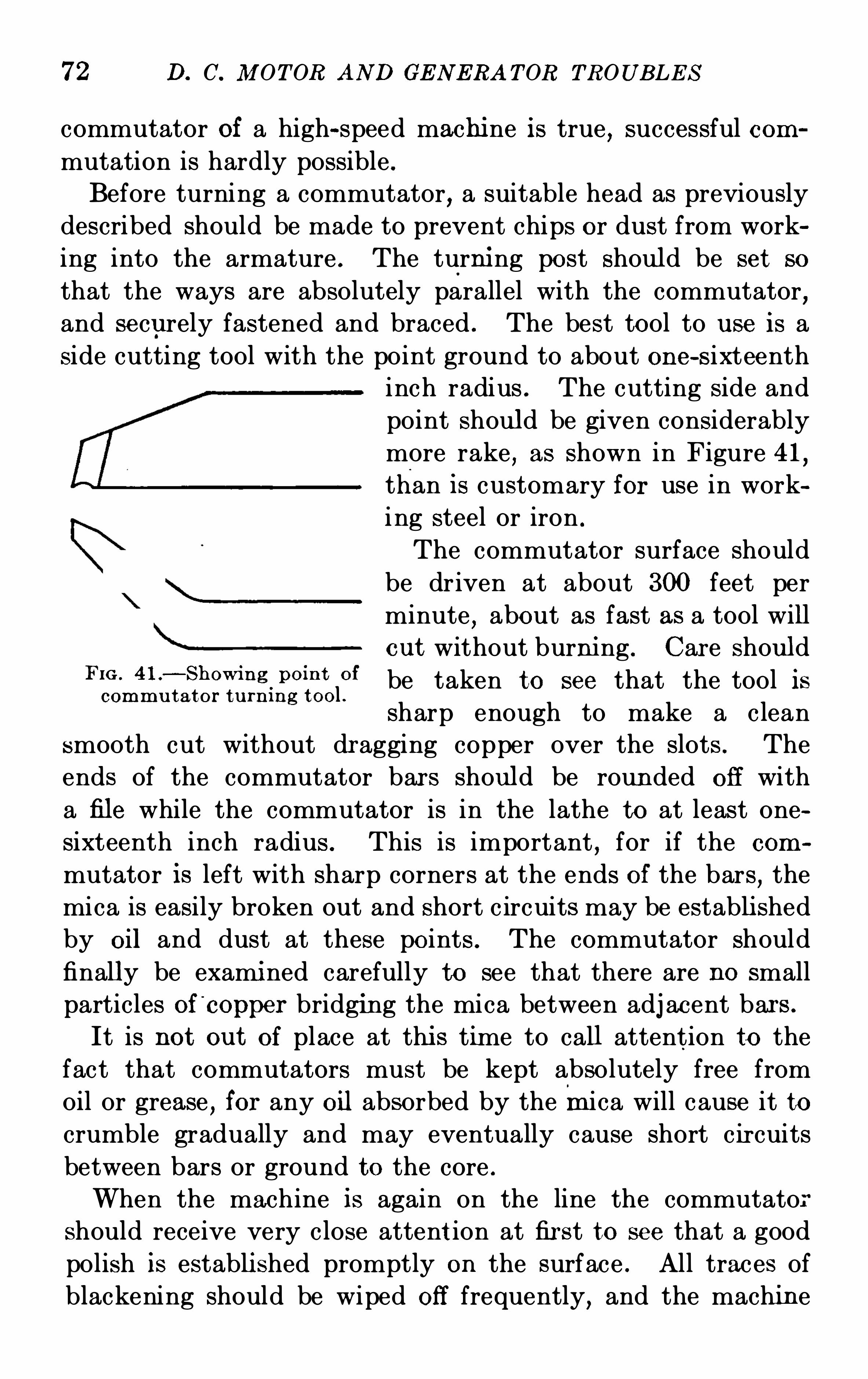
72 D. C. M OT OR AND GE N E RA T OR TROUB LE S
commutator of a high-speed machi ne is true , successful com
mutation is hardly possible .
Before turning a commutator,a suitable head as previously
described should be made to prevent chips or dust from work
ing into the armature . The turni ng post should be set so
that the ways are absolutely parallel with the commutator,and securely fastened and braced . The best tool to u se is a
side cutting tool with the point ground to about one—sixteenthinch radius . The cutting S ide and
point should be given considerably
more rake,as shown in Figure 41
,
than is customary for use in work
ing steel or iron .
The commutator surface should
be driven at about 300 feet per
minute,about as fast as a tool will
out without burni ng . Car e shouldFm ' O f be taken to see that the tool iscommu t ator tu r n i ng tool .
sharp enough to make a clean
smooth cut without dr agging copper over the slots . The
ends of the commutator bar s should be roun ded off with
a file while the commutator is in the lathe to at least one
sixteenth inch radius . This is important,for if the com
mutator is left with sharp corners at the ends of the bars,the
mica is easily broken out and short c ircuits may be establi shed
by oil and dust at these points . The commutator should
finally be exami ned carefully to see that there are no small
particles of'
copper bridging the mica between adj acent bar s .
It is not ou t of place at thi s time to call attention to the
fact that commutators must be kept absolutely free from
oil or grease,for any oil absorbed by themica will c ause it to
crumble gradually and may eventually cause short cir cuits
between bars or ground to the core .
When the machine is again on the line the commutato
should receive very close attent ion at fir st to see that a good
polish is establi shed promptly on the surface . All traces of
blackening should be wiped off frequently, and the machin e
S TART I NG AN D OPE RA T I ON OF M OTORS 73
should not be operated for any length of time with poorcommutation .
TREATM E NT OF COM M UTATOR AND BRUSHE S
Generators are frequently shipped with the commutatorsfreshly turned . Thi s and the initial condition of the brush
faces do not constitute a fit condition for car rying loads,and
heavy leads must not be put upon a generator when fir st put
in service . Thi s point must be insisted upon,for if the
machi ne I S m i sused in this respect,its commutator may reach
such a condition as to require turning,and a great deal of
trouble may be experienced before proper condit ion is obtained .
If,on the other hand , the following instructions are followed
good results are assured .
When the armatur e is received with the commutator
poli shed from factory testing,the generator may be loaded
at once as heavily as the condition of the brush surf aces will
permit with good commutation,but if the commutator is not
polished,the machine should be run for at least twenty-four
hours with normal brush pressur e , and then an additional
twenty-four hour s approximately half load,in order to establi sh
a polish on the commutator surface . The desired surface wi ll
show a very hi gh polish by reflected light and will vary in
color from a light straw to a dar k brown,or even a blue
gray,the actual color being of no consequence as long as the
bars are polished uniformly from edge to edge .
N o lubricant should be used on the commutator either
during the polishing period or subsequently . Both the carbon
and the graphite brushes now fur nished on direct—currentgenerators are self-lubricating
,and their characteristics
are seriously impair ed by the u se of any external lubrication .
S elf-lubricating carbon brushes may in some instances leave
a black deposit on the commutator when first put into service .
This deposit should be wiped off as rapidly as it appears by
means of a piece of dry canvas or other hard , non-linting material which should be wound around a block and held against
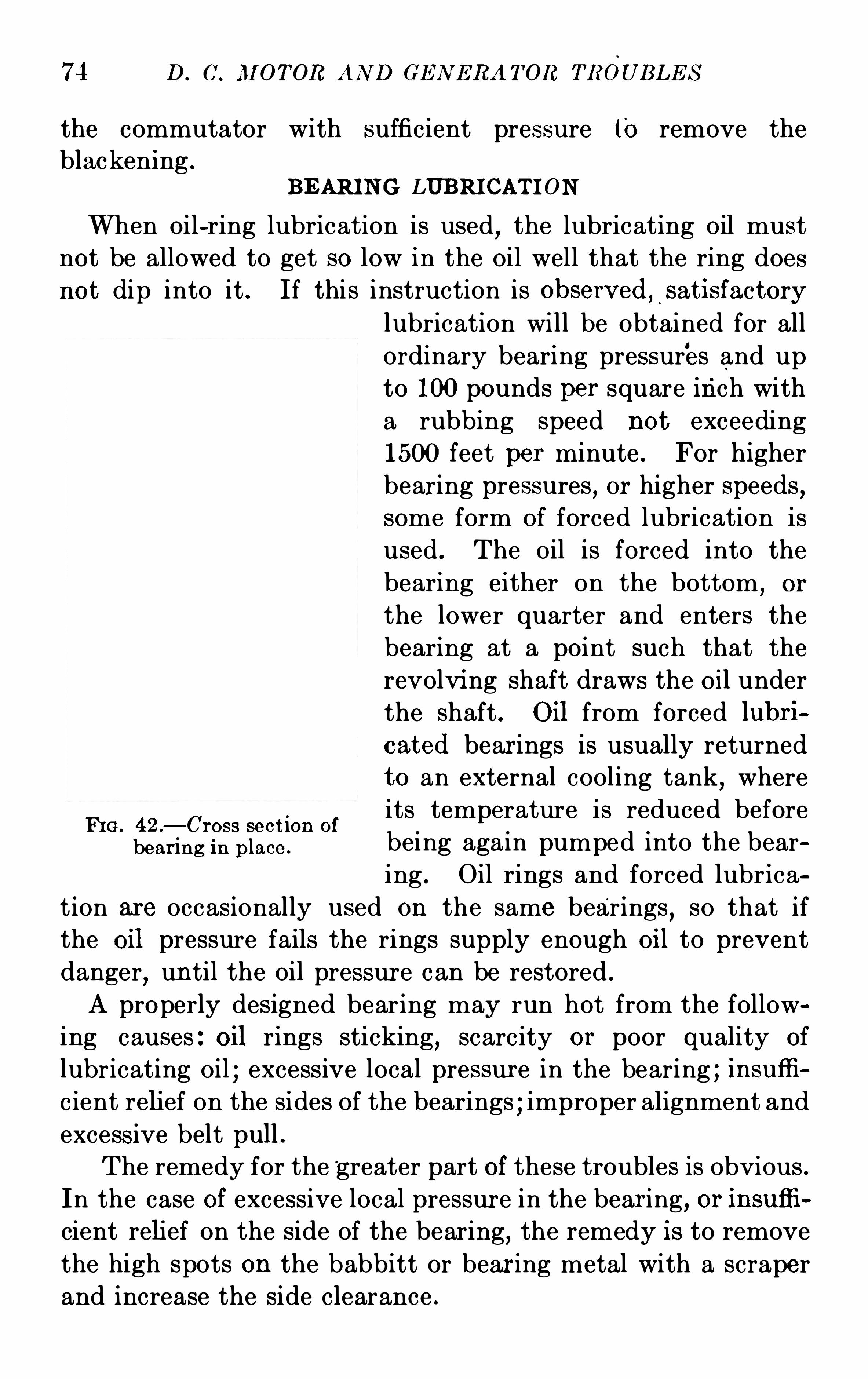
74 D. c. MOT OR AN D GE N E RA T OR TROUB LE S
the commutator with sufficient pressure to remove theblackeni ng .
B E ARI N G LUBRICAT I ON
When oil-ring lubrication is used,the lubricating oil must
not be allowed to get so low in the oil well that the ring doesnot dip into it . If thi s instruction is observed
, _
sat isfactory
FI G . 42 .
—Cross sect ion of
bear ing in p lace .
lubrication will be obtained for all
ordinary bearing pressures and up
to 100 pounds per square inch with
a rubbing speed not exceeding1500 feet per minute . For higher
bearing pressures , or higher speeds ,some form of forced lubrication is
used . The Oil is forced into the
bearing either on the bottom,or
the lower quarter and enters the
bearing at a point such that the
revolvi ng shaft draws the oil under
the shaft . Oil from forced lubr i
cated bear ings is usually returned
to an external cooling tank,where
its temperature is reduced before
being again pumped into the bear
ing . Oil rings and forced lubrica
tion are occasionally used on the same bearings,so that if
the oil pressure fails the rings supply enough oil to prevent
danger,un til the oil pressur e can be restored .
A properly designed bearing may run hot from the follow
ing causes : oil rings sticking, scarcity or poor quality of
lubricating oil ; excessive local pressur e in the bearing ; insu ffi
cient relief on the sides of the bearings ; improper alignment and
excessive belt pull .
The remedy for the greater part of these troubles is obvious .
In the case of excessive local pressur e in the bear ing, or insufli
cient relief on the side of the bearing,the remedy is to remove
the high spots on the babbitt or bear ing metal with a scraper
and increase the side clearance .
S TART I NG AND OPERA T I ON OF M OTORS 75
The following formula can be used as a rough guide to estimate the si ze necessary for a given bearing . If P equals the
pressur e per square inch of the proj ected area of the j ournal and
V equals the peripheral velocity of the j our nal in ft . per min .,
then PV equals a cons tant for oil bearings . Ordinary bearings with a constant PV equals can be operated success
fully where the peripheral speed of the shaft does not exceed
1200 ft . per min .
Before starting a machine all bearings must be filled with
the proper amount of oil . Bearings with the end of the bearingshell visible
,should be filled with oil until it touches the lower
part of the shell at the end of the bearing housing . Where
the end of the bearing shell cannot be seen,the bearing should
be filled to withi n three-eighths inch of the top of the visible
portion of the oil gauge glass ; in the case of sight gauges to
withi n one—eighth inch of the top of the gauge .
Bearings should be inspected to see they have not beencarelessly filled ; viz . , that oil has not been spilled on the bear
ing housing,or hearing shell , or upon other parts associated
with the bearing, otherwise , a fal se impression may be oh
tained as to oil leakage or throwing when under test . To
give the bearing a critical test for oil leaking or throwing,the dividing line between cap and bearing pedestal and be
tween bearing brackets,should be painted wi th white chalk .
The end of the commutator or field spider adj acent to the
bearing should also be given a white coating, so that it is
possible to detect,after a comparatively short run
,the slight
est leakage or thr owing of oil.
N o oil should be all owed to leak or be thr own from the bear
ings upon the rotating par ts,or windi ngs . This is especially
true with reference to commutating machines where it is
important that lubri cating oil be kept away from the commuta
tor,brushes and fittings . S hould oil leaking or throwing on
these parts be detected during operation , the machine should
be immediately shut down and the leak stopped by refitting
or tightening j oints . If the bearings during operation rise
in temperature 40 degrees or more , above the room tempera
76 D. C. M OTOR AND GE N E RA T OR TROUB LE S
ture,it should be taken as a defect ; since no properly designed
bearing should heat above 40 degrees under normal condi
tions . It will usually be found that a greater temperatur e rise
is due to a faulty bearing, resulting from misalignment, loose
babbitt,sticking of oil rings
,scored shaft
,or pitti ng of the
shaft due to circulating electrical currents through the pillow
blocks and the base . Faulty bearing action is described in
detail under Troubles and Their Remedies” in Chapter VI I .
CHAPTER V
THE STARTIN G AND OPERATION OF DIRECT-CURRE NT GENERATORS
GE N E RAL IN S PE OT I ON—STARTI N G UP—OPE RATI ON—STOPPIN G—PARALLE L OPE RATI ON OF SHUN T
,COM POUND
AND THRE E -W IRE G E N E RAT ORs—EQUAL I ZE Rs—SE RI E SOPE RATI ON—OPE RATI ON As A M OTOR
As was stated in the preceding chapter on The S tarting
and Operation of Dir ect-current Motors,” it is important that
slight defects and imperfections should be remedied as soon
as noted to prevent trouble from growing to such an extent as
to cause a serious Shutdown . With generators this is all the
more important,since one motor might be only a small part
of the equipment while the generating unit is in many cases
the supply of power for many motors as well as lights . N o
experimenting should be permitted by operators u nless ex
per ienced in handling electrical machinery .
GE NERAL I NSPECT ION
In the previous chapter,attention was called to the special
points to be noted before any attempt is made to start the
machi ne . Thi s inspection should be made in case of a genera
tor but in addition,all switches
,c ircuit breakers and connec
tions to the generator should be opened . All wiring diagrams
should be checked with the machine connections . Fill the
bearings with a good grade of light mineral Oi l but do not allow
the oil to overflow from the bearings .
Rotate the armature by hand to make sure it turns freely
in the bear ings and note if oil rings turn .
S tart ing the Generator .—After the inspection is completedthe machine is ready to start . Bring i t up to speed slowly
77
78 D. C. M OTOR AND GE N ERA TOR TROUB LE S
with all switches open and all resistance cut in on the field
rheostat . E xamine the oil rings at once and make sure the
oil is circulating in the bearings . The brushes should be
examined and made free to move in the holders,without chat
ter or undue noise . The commutator should run true and the
mechanical balance should be such as to produce no appreci
able vibration,which may be noted if the hand is placed on the
bearings carrying the revolving parts .
Bring the prime mover up to full speed and close the shunt
field cir cuit . Allow the voltage to come up slowly,watching
the commutator and the brushes,also the armature for any
indications of sparking or trouble due to heating , which might
come from dirt between the segments or short circuits in the
armatur e not found during inspection . The generator should
be brought up to full voltage by cutting ou t resistance in the
shunt field rheostat . (Failur e of the generator to“pick up”
or generate is due to causes given in Chapter VI I covering“Troubles and Remedies ”
)After the generator has operated at full voltage for a short
time and no trouble has developed from heating or sparking,the circuit breaker and then the switches to the line may be
closed and power furnished to the line for u se in service .
A shunt-wound generator will require hand regulation to
keep the voltage constant if the load is not a steady one. If
the generator is compound wound,the voltage regu lation will
be automatic with steady or variable loads .
The load may exceed the rating of the machine or short
circuits on the line may cause the cir cuit breaker to Open .
As a precaution against bur ning the breaker or against per
sonal danger,Open the line switch as soon a the breaker has
been Opened by the overload,then close the breaker and finally
the line switch . This system will allow the breaker to Open again
immedi ately in case the trouble on the line has not been cleared .
N o attempt is made at this point to cover troubles which
may arise after the machi ne is placed in the service . The
reader is referred to the chapter covering“Troubles and
Remedies ” should trouble arise from heating,sparki ng, etc .
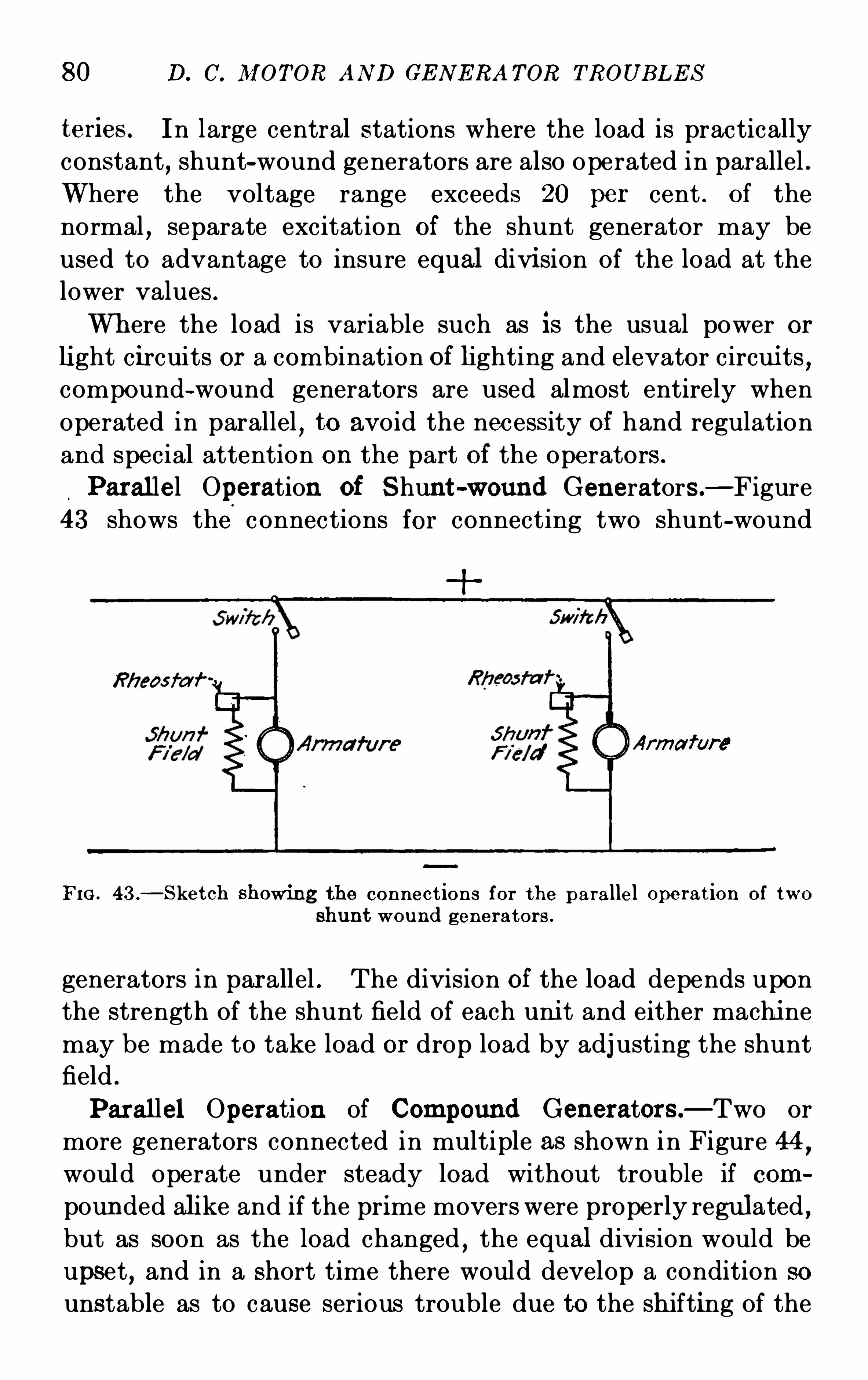
80 D. C. M OTOR AND GE N E RA TOR TROUB LE S
teries . In large central stations where the load is practically
constant,shunt-wound generators are also Operated in parallel .
Where the voltage range exceeds 20 per cent . of the
normal,separate excitation of the shunt generator may. be
used to advantage to insure equal divi sion of the load at the
lower values .
Where the load is variable such as is the usual power or
li ght circuits or a combination of lighting and elevator circui ts ,compound-wound generators are used almost entirely when
operated in parallel,to avoid the necessity of hand regulation
and special attention on the part Of the operators .
Parallel Operation of S hunt-wound Generators—Figure43 shows the
.
connections for connecting two shunt-wound
Arma fur‘
e
FIG . 43 .
—S ket ch showi ng the connect ions for the parallel operat ion of two
shunt wound generators .
generators in parallel . The division of the load depends upon
the strength of the shunt field of each uni t and either machi ne
may be made to take load or drop load by adj usting the shunt
field .
Parallel Operation of Compound Generator s—Two ormore generators connected in multiple as shown in Figure 44,would operate under steady load without trouble if com
pounded alike and if the prime movers were properly regulated ,but as soon as the load changed
,the equal division would be
upset , and in a short time there would develop a condition so
unstable as to cause serious trouble due to the shifting of the
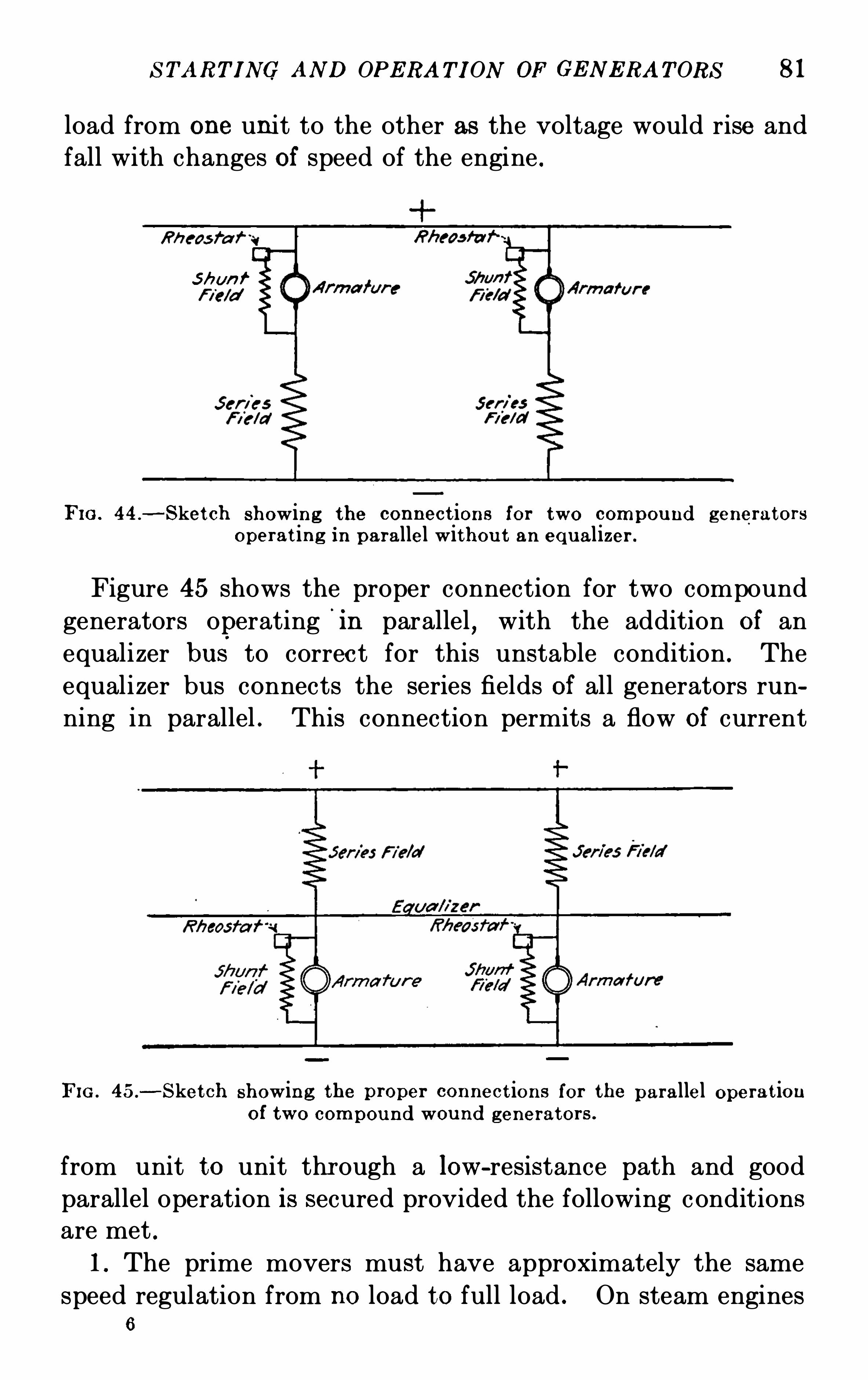
S TART I NG AND OPE RA T I ON OF GE N E RA T ORS 81
load from one unit to the other as the voltage would rise and
fall with changes of speed of the engine .
S hun f
FI G . 44 .
—S ket ch showing the connect ions for two compou nd generators
operat ing in parallel withou t an equalizer .
Figure 45 shows the proper connection for two compound
generators operating'
in parallel,with the addition of an
equalizer bus to correct for this unstable condition . The
equalizer bus connects the series fields of all generators run
ning in parallel . This connection permits a flow of current
FI G . 45.
-S ket ch showing the p roper connect ions for the parallel operat ionof two compound wou nd generators .
from unit to unit thr ough a low-resistance path and good
parallel operation is secured provided the following conditions
are met .1. The prime movers must have approximately the same
speed regulation from no load to full load . On steam engines6
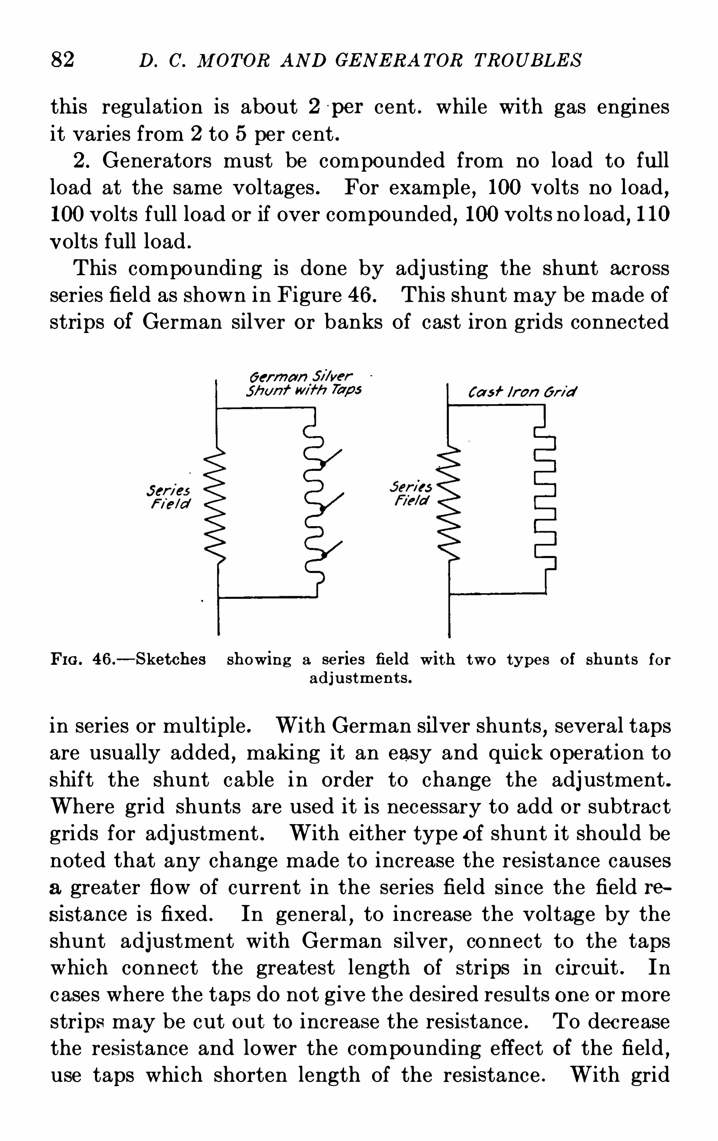
82 D. C. M OTOR AND GE N ERA TOR TROUB LE S
thi s regulation is about 2 p er cent . while with gas engines
it varies from 2 to 5 per cent .
2 . Generators must be compounded from no load to fu ll
load at the same voltages . For example , 100 volts no load,
100volts full load or if over compounded, 100volts no load, 110
volts full load .
This compounding is done by adj usting the shunt across
series field as shown in Figure 46. This shunt may be made of
strips of German silver or banks of cast iron grids connected
!a s f /r an Gr id
FIG . 46.—S ketches showing a series field with two types of shu nt s for
adju stmen t s .
in series or multiple . With German silver shunts,several taps
are usually added,making it an easy and qu ick Operation to
shift the shunt cable i n order to change the adj ustment .
Where grid shunts are used it is necessary to add or subtract
grids for adj ustment . With either type of shunt it should be
noted that any change made to increase the resistance causes
a greater flow of current in the series field since the field re
sistance is fixed . In general,to increase the voltage by the
shunt adjustment with German silver,connect to the taps
which connect the greatest length of strips in cir cui t . In
c ases where the taps do not give the desired results one or more
strips may be cut out to increase the resistance . To dec rease
the resistance and lower the compounding effect of the field ,use taps which shorten length of the resistance . With grid
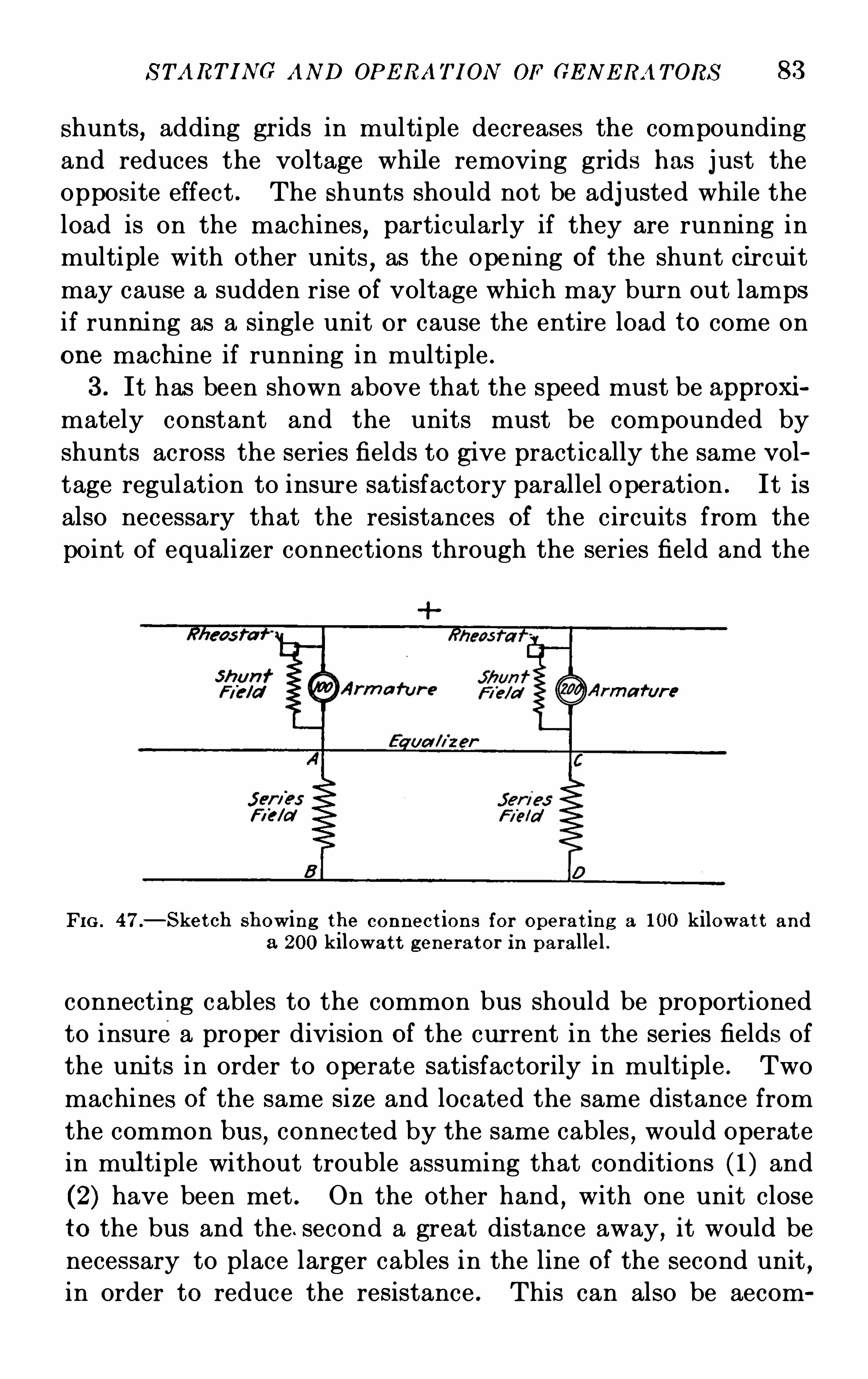
S TART I NG AND OPE RA T I ON OF GE N E RA T ORS 83
shunts, adding gr ids in multiple decreases the compounding
and reduces the voltage while removing grids has j ust the
opposite effect . The shunts should not be adj usted while the
load is on the machines, particularly if they are running in
multiple with other units,as the opening of the shunt c ircuit
may cause a sudden rise of voltage whi ch may burn out lamps
if running as a single unit or cause the entire load to come on
one machine if running in multiple .
3 . It has been shown above that the speed must be approxi
mately constant and the units must be compounded by
shunts across the series fields to give practically the same vol
tage regulation to insure satisfactory parallel operation . It is
also necessary that the resistances of the circuits from the
point of equalizer connections through the series field and the
FI G . 47.—S ket ch showing the connect ions for operat ing a 100 kilowat t and
a 200 kilowat t generator in parallel .
connecting cables to the common bus should be proportioned
to insurea proper division of the cur rent in the series fields Of
the uni ts in order to operate satisfactorily in multiple . Two
machines of the same size and located the same distance from
the common bu s,connected by the same cables
,would Operate
in multiple without trouble assuming that conditions (1) and
(2) have been met . On the other hand,with one unit close
to the bus and the . second a great distance away,it would be
necessary to place larger cables in the line of the second unit ,in order to reduce the resistance . This can also be aecom
84 D. C. M OTOR AND GE N ERA TOR TROUB LE S
plished by adding a line resistance in the short leads of the
first unit thereby increasing its resistance .
In units of diff erent sizes or machines of diff erent types or
designs where there is an appreciable diff erence in the resist
ances of the series fields , special adj ustments to equalize the
resistances of the circuits are necessary to secure a satisfactory
division of the load . For example,if a 100-kilowatt unit
is in multiple with a 200-kilowatt unit as shown in Figure
47,and both are located at the same distances from a common
bus,there must be twice the resistance in the circuit from A
to B as from C to D . This is usually taken care of by the
size of the cables but the use of the resistance is necessary
where an up-to-date type of uni t, equ ipped with commutating
poles or compensating windings,or both
,is placed in multiple
with an old unit .
Parallel Operation of Commutating-pole Generator s .The addition of commutating poles to a generator changes
its characteristics to qui te a large extent besides improving
commutation . Due to the neutralization of the demagnetizing
armature reaction,the voltage of shunt-wound generators
with commutating poles does not droop as rapidly as that of
non-commutating pole generators . If paralleled with one of
the latter generators,the commutating pole machine would
tend to take more than its share of the load . Due to this
smaller drop,a compound-wound commutating-pole generator
requires less series field for a given compounding ; in some
cases one turn around every other pole is more than enough .
S uch a compound generator would probably requ ire a series
resistance to make it share the load proportionately with a
non-commutating-pole generator having more turns of series
field .
Brushes set back of neutral or an over strong commutating
field,will often give a shunt generator a rising instead of a
drooping voltage curve . The commutating field then tends to
have a compounding eff ect,dueto the commutating field flux .
Referring to Figure 48, if the brushes are set on neutralon the commutator bars connected to the armature conductors
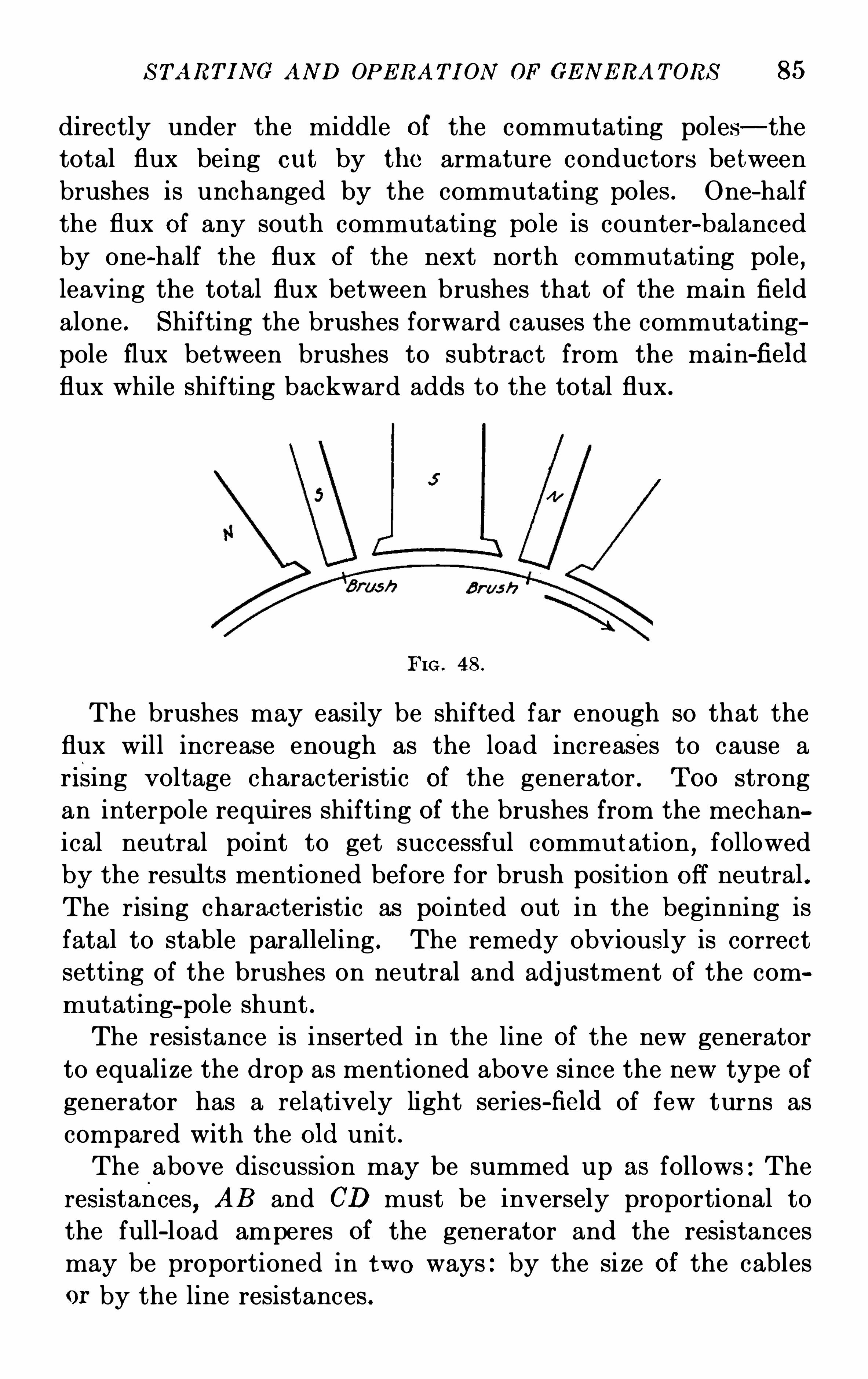
S TART I NG AND OPE RAT I ON OF GE N E RA T ORS 85
directly under the middle of the commutating poles—thetotal flux being cu t by the armature conductors between
brushes is unchanged by the commutating poles . One-half
the flux of any south commutating pole is counter-balanced
by one-half the flux of the next north commutating pole,
leaving the total flux between brushes that of the main field
alone . Shifting the brushes forward causes the commutating
pole flux between brushes to subtract from the main-field
flux while shifting backward adds to the total flux .
FIG . 48 .
The brushes may easily be shifted far enough so that the
flux will increase enough as the load increases to cause a
rising voltage characteristic of the generator . T oo strong
an interpole requ ires shifting of the brushes from the mechan
ical neutral point to get successful commut ation,followed
by the results mentioned before for brush position Off neutral .The rising characteristic as pointed out in the beginning is
fatal to stable paralleling . The remedy obviously is correct
setting of the brushes on neutral and adj ustment of the com
mutating—pole shunt .The resistance is inserted in the line of the new generator
to equalize the drop as mentioned above since the new type of
generator has a relatively light series-field of few turns as
compared with the old unit .
The above discussion may be summed up as follows : The
resistances,AB and CD must be inversely proportional to
the full-load amperes of the gen erator and the resistances
may be proportioned in two ways : by the si ze of the cables
or by the line resistances .
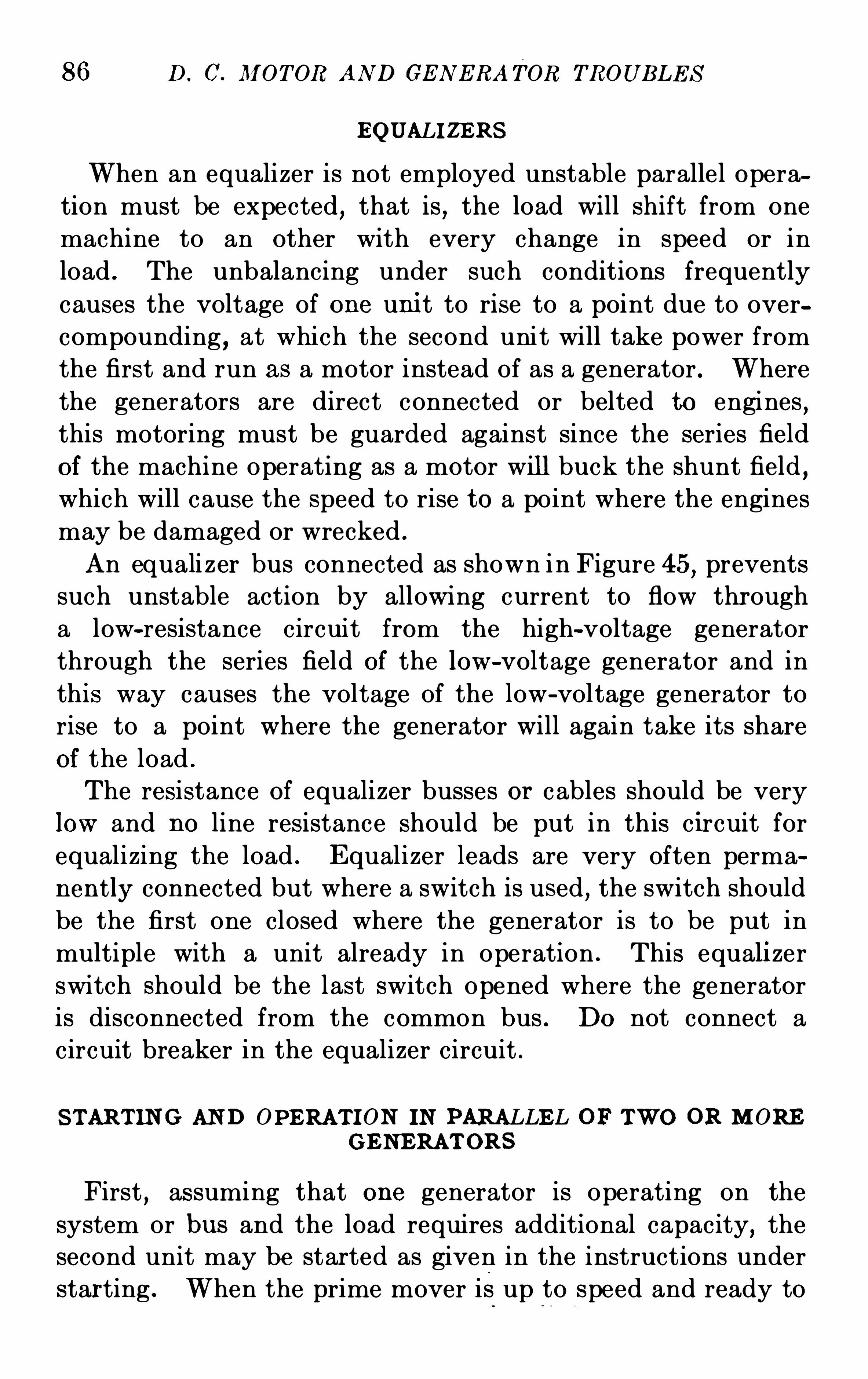
86 D . C. M OT OR AN D GE N E RATOR TROUB LE S
EQUALI ZE RS
When an equalizer is not employed unstable parallel opera
tion must be expected, that is , the load will shift from one
machine to an other with every change in speed or in
load . The unbalancing under such conditions frequently
causes the voltage of one uni t to rise to a point due to over
compounding , at which the second unit will take power from
the first and run as a motor instead of as a generator . Where
the generators are direct connected or belted to engines,
this motoring must be guarded against since the series field
of the machine operating as a motor will buck the shunt field,
which will cause the speed to rise to a point where the engines
may be damaged or wrecked .
An equali zer bus connected as shown in Figure 45,prevents
such unstable action by allowing current to flow through
a low-resistance circuit from the high-voltage generator
through the series field of the low-voltage generator and in
this way causes the voltage of the low-voltage generator to
rise to a point where the generator will again take its share
of the load .
The resistance of equalizer busses or cables should be very
low and no line resistance should be put in this c ircuit for
equalizing the load . E qualizer leads are very often perma
nen tly connected but where a switch is used , the switch should
be the first one closed where the generator is to be put in
multiple with a unit already in operation . This equali zer
switch should be the last switch opened where the generator
is disconnected from the common bus . Do not connect a
circuit breaker in the equalizer circuit .
S TART IN G AN D OPERAT I ON IN PARALLE L OF TWO OR M OREG E NE RAT ORS
First,assuming that one generator is operating on the
system or bus and the load requires additional capacity, the
second unit may be started as given in the instructions under
star ting . When the prime mover is up to speed and ready to
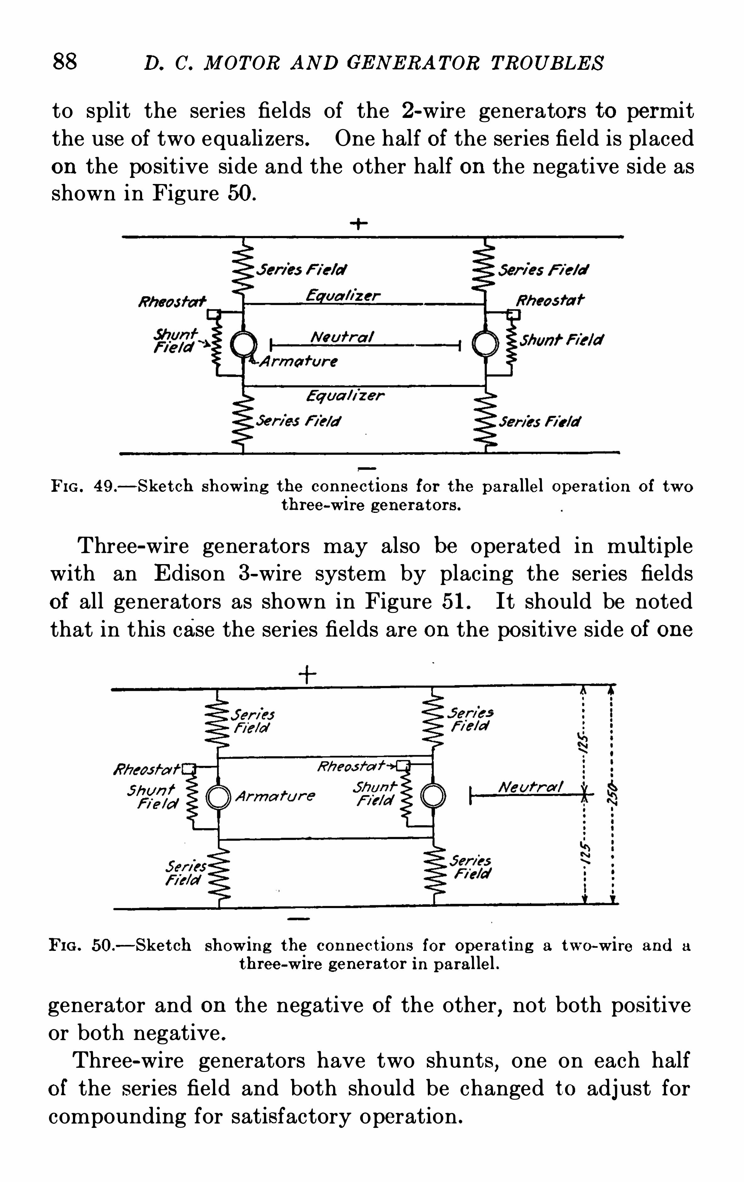
88 D. C. M OT OR AND GE N E RA T OR TROUB LE S
to split the series fields of the 2-wire generators to permit
the use of two equalizers . One half of the series field is placedon the positive side and the other half on the negative side asshown in Figure 50.
FIG . 49.—S ket ch showing the con nect ion s for the parallel Operat ion of two
three-wire generator s .
Three-wire generators may also be operated in multiple
with an E dison 3-wire system by placing the series fields
of all generators as shown in Figure 51. It should be noted
that in this case the series fields are on the positive side of one
S hun f
FI G . 50.
—S ket ch showing the con nect ion s for operat ing a two-wire and a
three-wire generator in parallel .
generator and on the negative of the other,not both positive
or both negative .
Three-wire generators have two shunts,one on each half
of the series field and both should be changed to adj ust for
compounding for satisfactory operation .
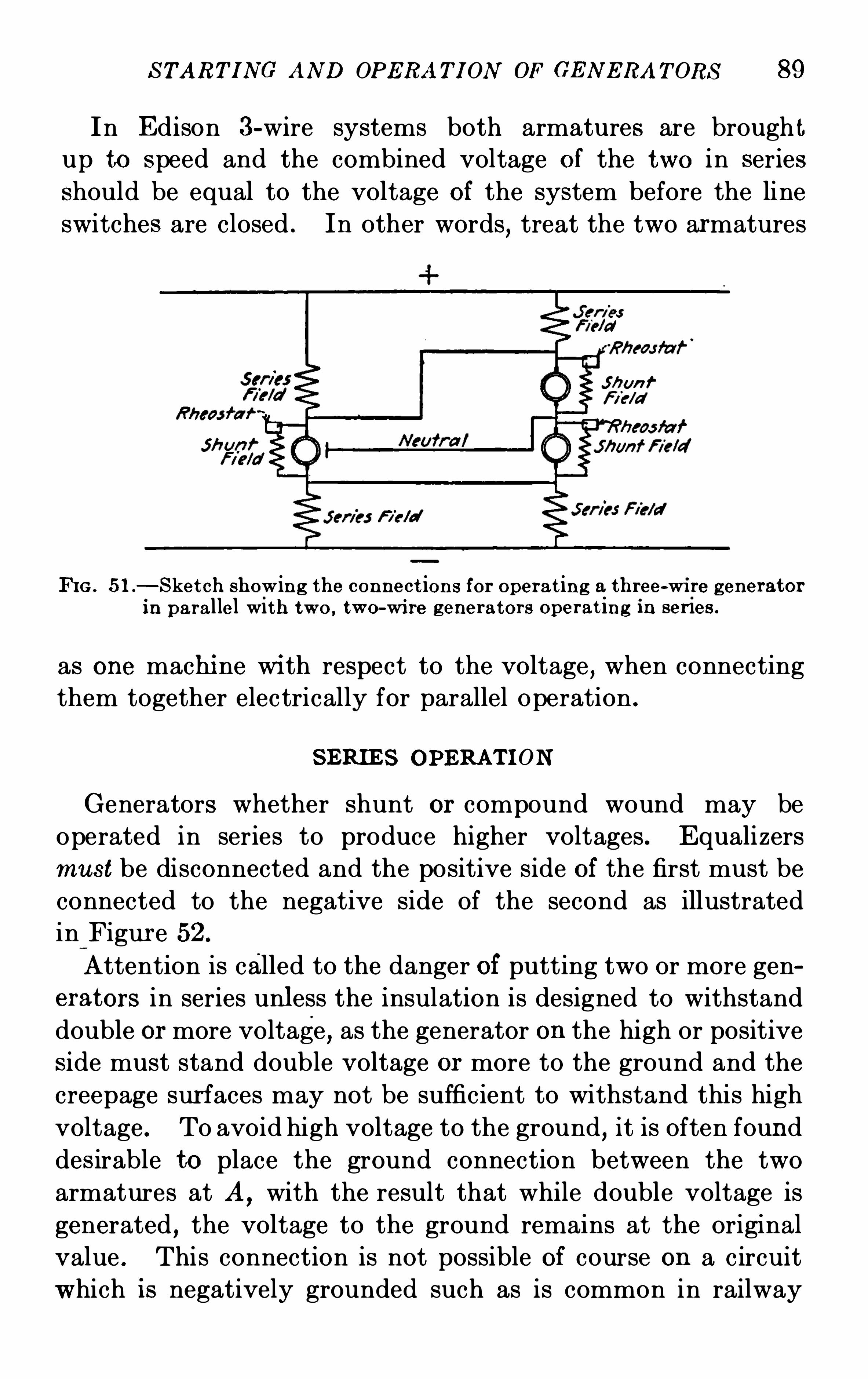
S TART I NG AND OPERAT I ON OF GE N E RA T ORS 89
In E dison 3-wire systems both armatures are brough tup to speed and the combined voltage of the two in seriesshould be equal to the voltage of the system before the line
switches are closed . In other words,treat the two armatures
K G . 51 .
—S ket ch showing the connect ion s for Operat ing a three-wi re generatorin parallel with two, two-wi re gener ators operat ing in ser ies .
as one machi ne wi th respect to the voltage,when connecting
them together electrically for parallel Operation .
S ERIE S OPERAT I ON
Generators whether shunt or compound wound may be
operated in series to produce higher voltages . E qualizersmus t be disconnected and the positive side of the first must be
connected to the negative side of the second as illustrated
in Figur e 52 .
Attention is called to the danger of putting two or more generators in series unless the insulation is designed to withstand
double or more voltage, as the generator on the high or positiveside must stand double voltage or more to the ground and the
creepage sur faces may not be sufficient to withstand this high
voltage . To avoid high voltage to the ground, it is often found
des irable to place the ground connection between the two
armatures at A,with the result that while double voltage is
generated , the voltage to the ground remains at the original
value . This connection is not possible of course on a circuit
which is negatively grounded such as is common in railway
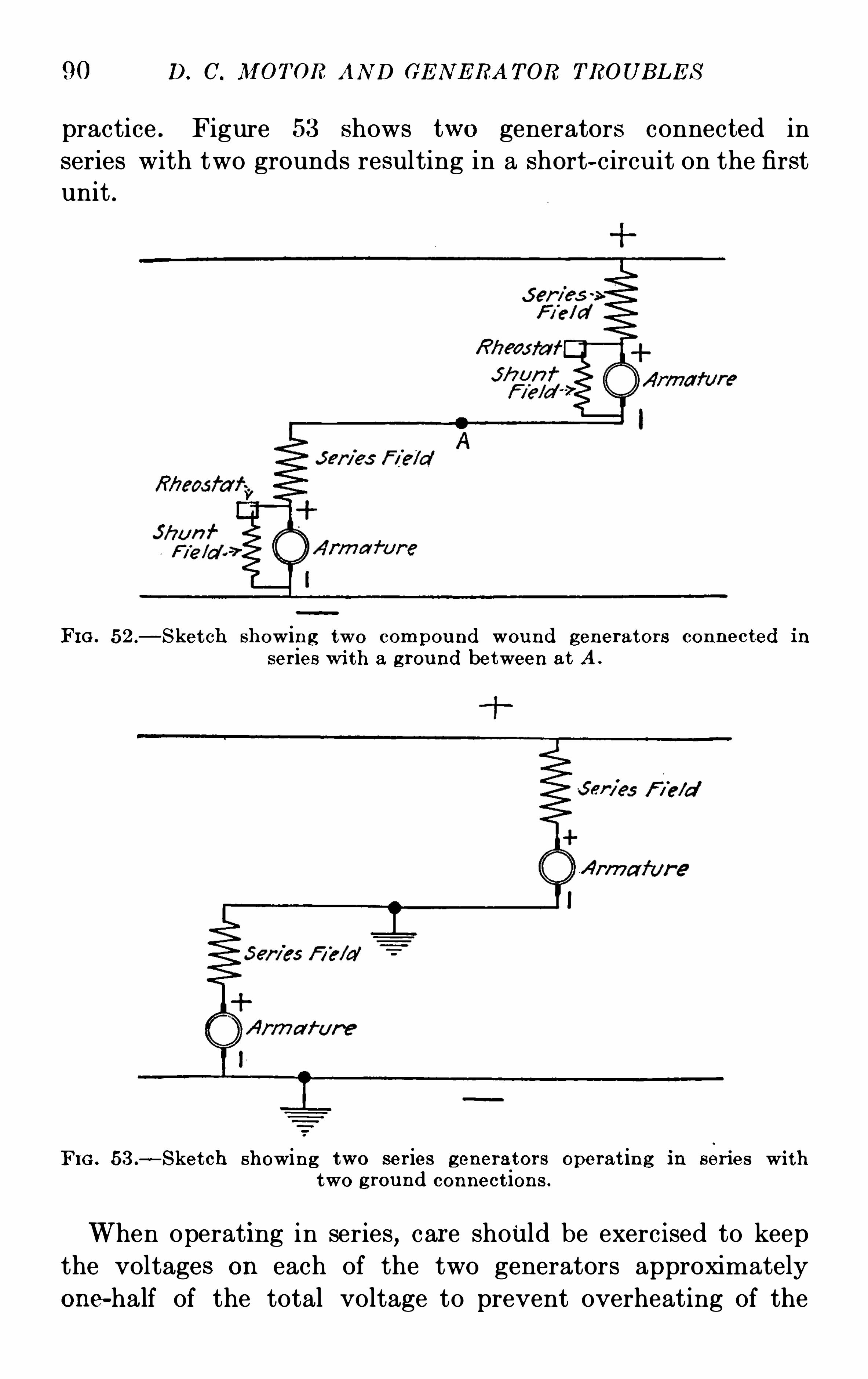
90 D. C. IVI OTOR AN D GE N E RA T OR TROUB LE S
practice . Figure 53 shows two generators connected in
series with two grounds resulting in a short-circuit on the firstunit .
FI G . 52 .—S ket ch showin g two compou nd wou nd generators con nected in
ser ies wi th a g rou nd between at A .
FIG . 53 .—S ket ch showing two ser ies generator s operat in g in series wi th
t wo g rou nd connect ions .
When operating in series,care should be exercised to keep
the voltages on each of the two generators approximately
one-half of the total voltage to prevent overheating of the
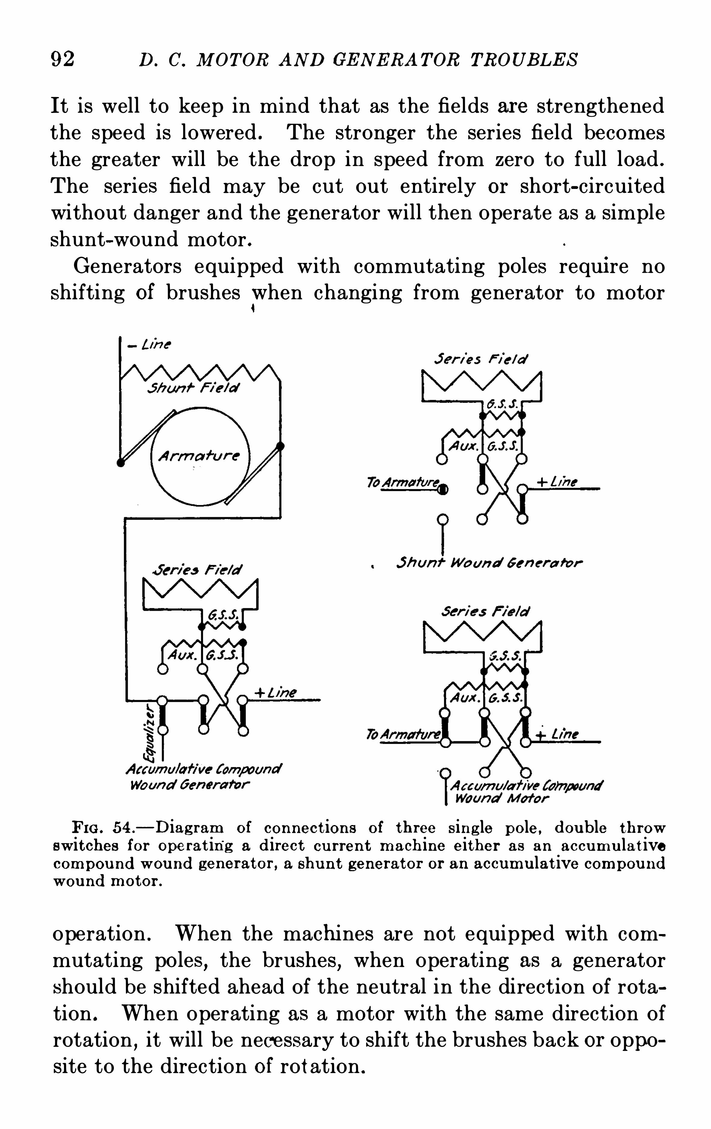
92 D. C. M OT OR AND GE N E RA T OR TROUB LE S
It is well to keep in mind that as the fields are strengthened
the speed is lowered . The stronger the series field becomes
the greater will be the drop in speed from zero to full load .
The series field may be cut out entirely or short-circuited
without danger and the generator will then operate as a simple
shunt-wound motor .
Generators equipped with commutating poles requi re no
shifting of brushes when changing from generator to motor
J h un Woun d Gen et-a for
FIG . 54 .
—D iag ram of connect ions of three s ing le pole , double throwswitches for Operat ing a d irect cu rren t mach ine either as an accumu lat ivecompou nd wound generator , a shu nt generator or an accumu lat ive compou nd
wou nd motor .
operation . When the machines are not equipped with com
mutating poles,the brushes
,when Operating as a generator
should be shifted ahead of the neutral in the direction of rota
tion . When operating as a motor with the same direction of
rotation,it will be necessary to shift the brushes back or oppo
site to the direction of rotation .
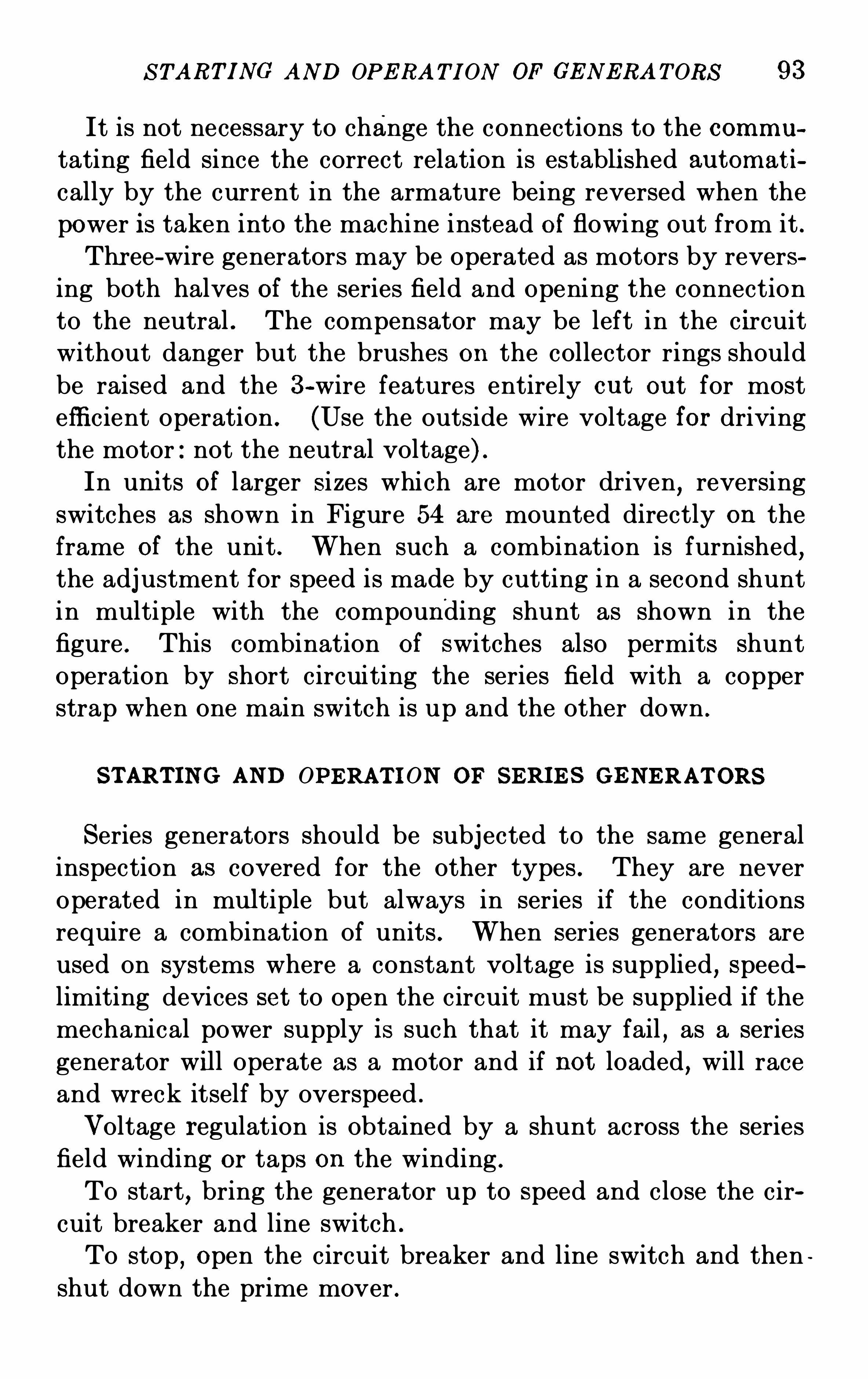
S TART I NG AND OPE RA T I ON OF GE N E RA T ORS 93
It is not necessary to change the connections to the commu
tating field since the correct relation is establi shed au tomat i
cally by the current in the armature being reversed when the
power is taken into the machine instead of flowing out from it .Thr ee-wire generators may be operated as motors by revers
ing both halves of the series field and Opening the connection
to the neutral . The compensator may be left in the c ircuit
without danger but the brushes on the collector rings should
be raised and the 3-wire features entirely ou t ou t for most
effi cient operation . (Use the outside wire voltage for drivingthe motor : not the neutral voltage) .
In uni ts of larger sizes which are motor dr iven,reversing
switches as shown in Figure 54 are mounted directly on the
frame of the unit . When such a combination is furnished,
the adj ustment for speed is made by cutting in a second shunt
in multiple with the compounding shunt as shown in the
figure . This combination of switches also permits shunt
Operation by short circuiting the series field with a copper
strap when one main switch is up and the other down .
S TART IN G AND OPERAT I ON OF S ERI E S G E NE RAT ORS
S eries generators should be subjected to the same general
inspection as covered for the other types . They are never
operated in multiple but always in series if the conditions
require a combination of units . When series generators are
used on systems where a constant voltage is supplied,speed
limiting devices set to open the circuit must be supplied if the
mechanical power supply is such that it may fail , as a series
generator will operate as a motor and if not loaded, will race
and wreck itself by overspeed .
Voltage regulation is obtained by a shunt across the series
field winding or taps on the winding .
To start,bring the generator up to speed and close the cir
cuit breaker and line switch .
To stop, Open the circuit breaker and line switch and then
shut down the prime mover .
94 D. C. M OT OR AND GE N E RA TOR TROUBLE S
OPERAT I ON AS A M OT OR
A series generator may be operated as a motor by supplying
power to its terminals . The direction of rotation can be
reversed by changing either the armature or field terminals
but not both . N ever connect it to a load which can be lost
or dropped on account of the danger of overspeeding given in
the above paragraph . A starting box is necessary for motor
operation and speed control .

96 D. C. M OT OR AND GE N E RA TOR TROUB LE S
regard to conveni ence of connections and safety from fire andin handli ng .
Rheostats should be so located that proper ventilation is
secured . When this is impossible,special means for venti
lating must be provided .
FI G . 55.
—A standard direct cu rren t swit chboard (front view) .
Foundation .
—The switchboard should stand on a level
foundation made of har d wood or channel iron . The sill
must be heavy enough so that the panels will not be thrown
ou t of line by settling . S tandard six inch chann els , or hard
wood sills,seven by twelve inches should be used .
As sembly.—The first thi ng to be done is to set up the supporting framework
,preferably for the first three or four
panels . The first two panels should then be placed in position
DIRE CT-CURRE N T S WI TCHB OARD 97
and bolted loosely to the supporting irons . The reason for
bolting loosely at first is to avoid cracking the marble or slate
when lining up the panels,as these materials have no flexibility
and are comparatively brittle . With all panel bolts,either
FIG . 56.-A standard direct cu rren t swit chboard showing connect ions
(rear view) .
paper or fibre washers should be used between the panel and
the iron work . The panels should then be c arefully leveled
and when in correct alignment,the panel bolts should be se
curely tightened . Proceed similarly with the other panels,always having the supporting framework for one or two panels
in place and lined up ahead of the panels which are being placed
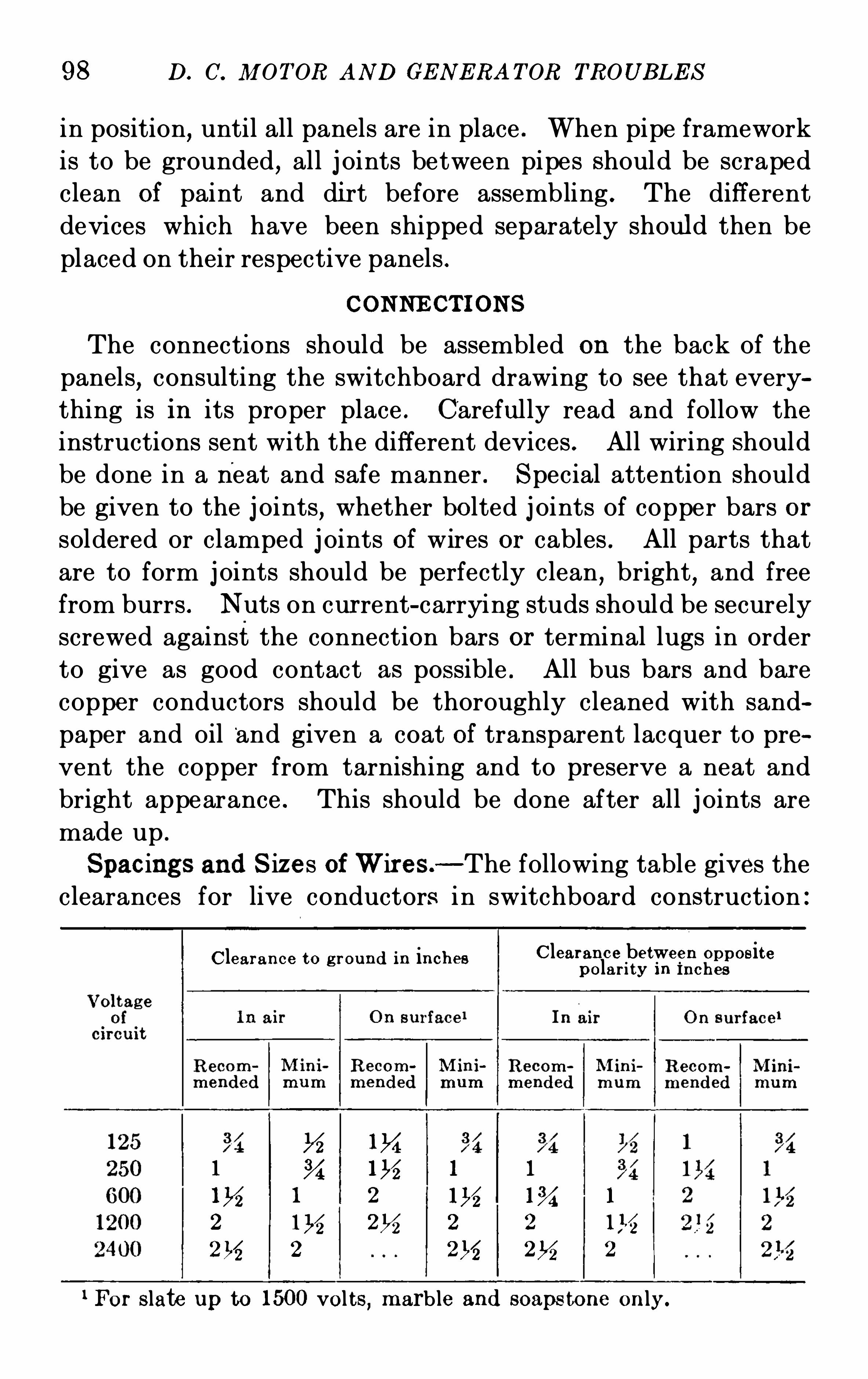
98 D. C. M OT OR AND GE N E RA T OR TROUB LE S
in position,until all panels are in place . When pipe framework
is to be grounded,all j oints between pipes should be scraped
clean of paint and dirt before assembling . The diff erent
devices which have been shipped separately should then be
placed on their respective panels .
CONNE CT I ON S
The connections should be assembled on the back of the
panels,consulting the switchboard drawing to see that every
thing is in its proper place . Carefully read and follow the
instructions sent with the different devices . All wiring should
be done in a neat and safe manner . S pecial attention should
be given to the j oints,whether bolted j oints of copper bars or
soldered or clamped j oints of wires or cables . All parts that
are to form j oints should be perfectly clean,bright
,and free
from burrs . N uts on current-carrying studs should be securely
screwed against the connection bars or terminal lugs in order
to give as good contact as possible . All bus bars and bar e
copper conductors should be thoroughly cleaned with sand
paper and oil‘
and given a coat of transparent lacquer to pre
vent the copper from tarnishing and to preserve a neat and
bright appearance . This should be done after all j oints are
made up .
Spacings and S izes of W ires .
—The following table gives theclearances for live conductors i n switchboard construction :
Clearance to g r ound in inches Clearance between Oppositepolar i ty I n Inches
1M1 1% 1 1
1 2 mg 1% 1
2 116 2% 2 2
2 2% 2V2 2
For slate up to 1500 vol ts, marble and soaps tone on ly.
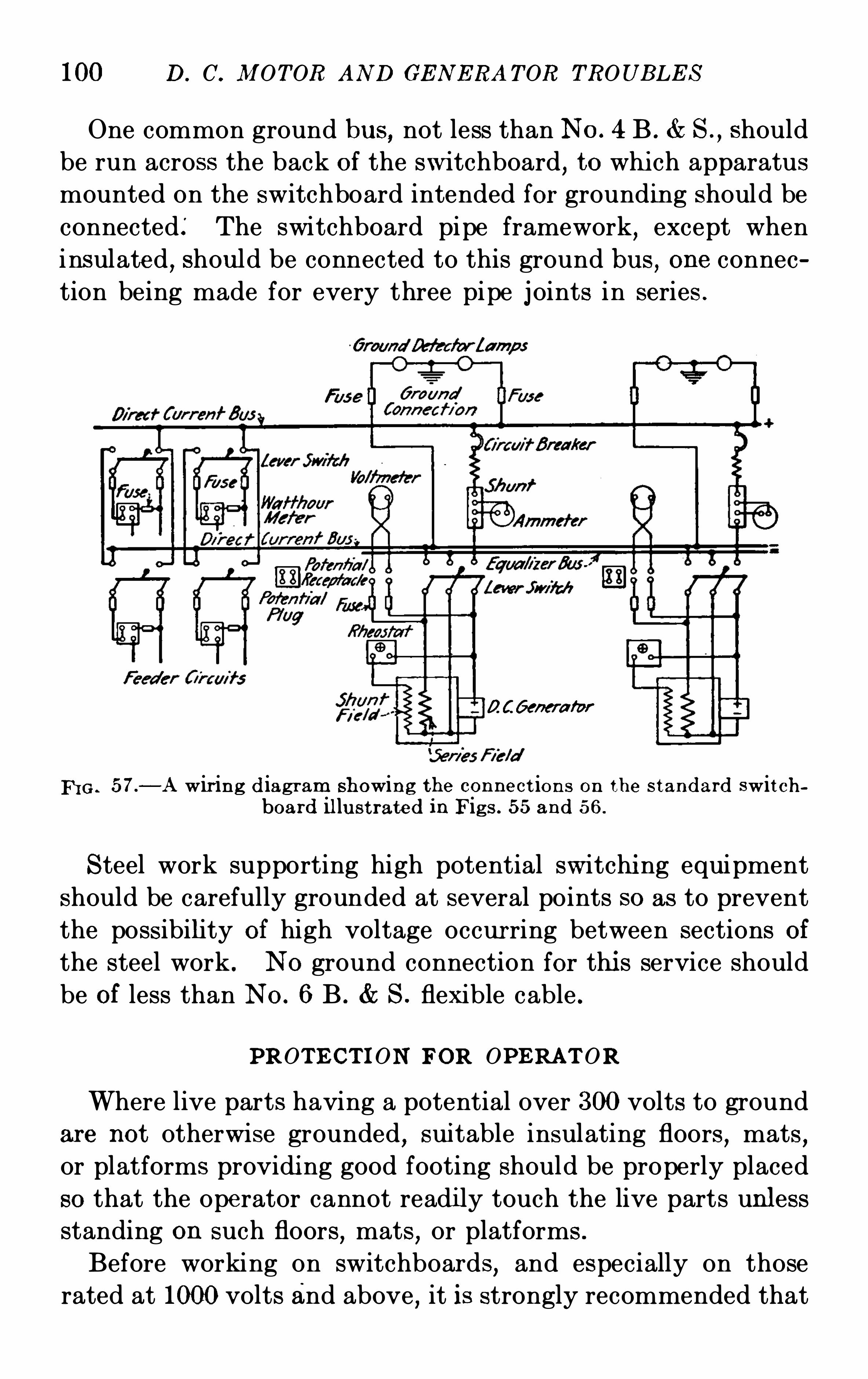
100 D. C. M OTOR AND GE N E RA TOR TROUB LE S
One common ground bus,not less than N o. 4 B . S .
,Should
be run across the back of the switchboard,to whi ch apparatus
mounted on the switchboard intended for grounding should be
connected: The switchboard pipe framework,except when
insulated,shou ld be connected to this ground bus
,one connec
tion being made for every three pipe j oints in series .
QCGenera fvr
FI G . 57.
—A wir ing d iagram showing the con nect ions on the s tandard swit chboard il lu st rated in Fig s . 55 and 56.
S teel work supporting high potential switchi ng equipment
should be carefully grounded at several points so as to prevent
the possibility of high voltage occur ring between sections of
the steel work . N o ground connection for thi s service should
be of less than N o. 6 B . S . flexible cable .
PROT E CT I ON FOR OPE RAT OR
Where live parts having a potential over 300 volts to ground
are not otherwise grounded,sui table insulating floors
,mats
,
or platforms providi ng good footing should be properly placed
so that the operator cannot readi ly touch the live parts unless
standing on such floors,mats
,or platforms .
Before working on switchboards,and especially on those
rated at 1000 volts and above , it is strongly recommended that
DIRE CT -CURRE N T S WI TCHB OARD 101
all live par ts be made dead and furthermore,that they be
connected to ground .
OPERAT I ON
Before putting the switchboard into service,all connections
to instrum ents, meters, relays, etc . , should be carefully traced
and checked with the drawings . A preliminary trial should
then be made to see that instruments, watthour meters, etc . ,read or record in the proper direction . In fact
,before putting
a switchboard into actual service,it is advisable to put cur rent
through all parts at reduced voltage in order to bring out any
weak spots .
When first putting the switchboard into actual service,
every detail should be closely watched and anything ou t of
the ordinary should be carefully noted and investigated . The
switchboard should be subj ected to periodical inspections of
all parts . Attention should be given to the j oints in cables,
busses,connection bars
,cur rent-carrying studs
,and to tem
perature rise , insu lation, cleanl iness, etc .
In making an inspection or repair ing work near live parts,
special care should be exercised to avoid accidentally short
circuiting or grounding any of the connections . The following
instructions cover only in a general way the routine to follow,
as it is obvious that details given, for instance , for a direct
cur rent railway power plant would not apply to a high-voltage,
alternating-current power plant . The Operator, however, is
urged to familiarize himself with these detail s .
1. B efore each starting of the plant, be sure that all switchesand circuit breakers involved are Open and that no other devi ce isin such condition as to cause trouble when throwing voltage on thepanels .
2 . Af ter everything is adjusted and running,take frequent
readings of instruments to see that no device is overloaded to adangerous point . This applies to conductors as well as to switchesand instruments .
3 . Make occas ional but regular tests of instruments and metersto locate any inaccuracies , at the same time noting any parts whichmay need adjus ting or repairing .
102 D. C. M OT OR AND GE N E RA TOR TROUB LE S
4. Regularly inspect switches , circuit breakers , and relays to see
that contacts are in good condition and that there is no sticking .5. When circu it breakers or switches w ith carbon or other secondary contacts are furnished, see that the secondary contacts are ingood shape and properly adjus ted so that they will take the finalbreak of the arc and prevent arcing at the main contact. See alsothat there is sufficient contact between the main brush and thecontact block .
6. Regularly inspect the back of panels and keep all joints inperfect condi tion .
7. Regularly clean the sw itchboard, es pecially in buildings wherethere are inflammable particles flying around. In cleaning theback of a board
,compressed air applied through a flexible hose and
nozzle is the simplest and safest method . If this equipment is notavai lable
,a hand bellows may be used . Wiping is not recommended
back of the board, although this method of cleaning may be employed on ins truments on the front of the board when they are notdirectly connected to hi gh-tens ion c ircuits .
8. To renew the finish of dull black marine slate , black marineslate
,and marble panels
,soap and cold water should be applied
with a soft cloth . A marble panel may also be brightened by rubbing with a cloth dipped in gasolene . Natural black slate may berestored to its original freshness by rubbingwith a soft cloth immersedin good engine oil.9. Knife switches in series with circuit breakers of the carbonbreak or magnetic blowout type should be closed or Opened afterthe circuit breakers have been
'
closed or Opened . When closingthe switches , it is well to turn the face away from the switchboardto avo id having the eyes
“flashed ” in case the circuit breaker shouldOpen .
ILLUM I NAT ION
Sufficient illumi nation should be provided in the station,
both for the front and the rear of the switchboard so that the
switchboard may be readily Operated and instruments and
meters conveni ently read . It has been found that insu fficient
i llumination,and a badly arranged system of li ghting uni ts
are responsible for considerable eyestrain and subsequent
fatigue and possible accident . The illumination should be
so arranged that all instruments and other parts which are to
104 D. C. M OTOR AND GE N E RA T OR TROUB LE S
and anticipated overloads on these . For 3-wire systems,state
if neutral is to be grounded or not .
3 . S tate if any special order of assembly is desired .
4. Advise fully regarding the space available for installing
the switchboard equipment proper and for rheostats when these
are driven by sprocket wheel and chain mechanisms . Designate the location desired for sprocket wheel and chain-driven
rheostats .
Advice regarding available space should peferably be given
in the form Of dimensioned prints and sketches,and should
include data as to the thickness and construction of the stationfloor .
5. Designate the size of cables to be used, and if these are
to be hemp core or not .
CHAPTE R VI I
TROUBLE S AND THE IR REMEDIE S
COMMUTATI ON—OPE RA TI ON OF I N TE RPOLE DIRE CT-CURRE N TMA CHI N E S - BRUSH POS I TI ON ON N ON-COM M UTATI N G
POLE M ACHI N E S- COMM UTATI ON TROUB LE S As CAUS E D
B Y T HE BRUSHE S , COMM UTATOR AND OTHE R PARTS
ARM ATURE—FI E LD—MOTOR—GE N E RATOR—SHA FT AN D
BE ARI N G TROUB LE S AND N OI S E
Pecul iar to the operation of every direct-cur rent motor or
generator are certain troubles,which although they may
scarcely be considered as casualties,often present a bafl‘ling
problem to the operator . In many cases it is possible to pre
elude the probabili ty of trouble by systematic inspection and
rigid upkeep but with the best of operation and the finest of
equipment,there is always the possibil ity of its occurrence .
Where the failure of a generator will mean the shut down of a
whole system or the stopping of a motor may mean the inter
ruption or cessation of an important process with costly
results,it is really the paramount duty of the operator to pre
clude all probability of trouble and to possess a complete
knowledge of eff ective remedies in its advent . Theory, while
a valuable asset,alone proves a slight solace when the opera
tion of the machi ne is faulty or it has completely stopped or
refused to generate . It is then that experience and a practical
knowledge of all of the operating conditions will aid the operator
in locating and combating the defective condition .
In the following chapter,no reference to theory will be made
unless it is necessary for a clear conception of the trouble, but
instead,the symptoms
,causes and remedies of direct-current
motor and generator troubles will be given . The natural
cour se of events provi des practically all operators with a105
106 I ) . C . M OTOR AN D GE N E RA TOR TROUB LE S
knowledge of and resourcefulness to Overcome many of the
minor casualties but. the most material assistance can be
gained from the experiences of designers and manuf acturers
of electrical machinery, who in the regular course of their
duties become acquainted with every possible electrical and
mechanical trouble and i ts remedies . The greatest of all of
these troubles in direct-current work is faulty commutation .
COM M UT AT ION
Commutation may be defined as the process of rectifying
the alternating current produced in the armature and collecting
and distributing it to the external circuits as direct-current
power . All direct-current armatur es generate alternating
current in their windings due to the cutting of flux alternately
from N orth and S outh poles,and the commutator presents a
medium for the changing of this current to direct current .
Commutation is an important and difficult subj ect,both in
theory and in Operation and a thorough knowledge of it such
as can be obtained from any standard electrical text-book will
prove a valuable asset to any operator . Faulty or poor com
mutation may result from incorrect design but even when
direct-current machines are designed with liberal commutat ing
constants,there are a whole host of commutation troubles
both electrical and mechanical,which may occur . Brush
and commutator troubles present the greatest sources of poor
commutation although there are a few other causes,which are
described . Of these,the defect s in brushes or brush Operation
represent the most serious menace .
Both in machines not fitted with commutating poles and
those of commutating pole design,the position of the brush
upon the commutator directly affects commutation,since for
the best operation the brushes should always be upon the
electrical neutral . With the kind permission of the author,Mr . J ustin Lebovici
,we are reprinting two articles which
appeared in the E lectrical World upon The Operation of
Interpole Direct-current Machines,
” which present a study
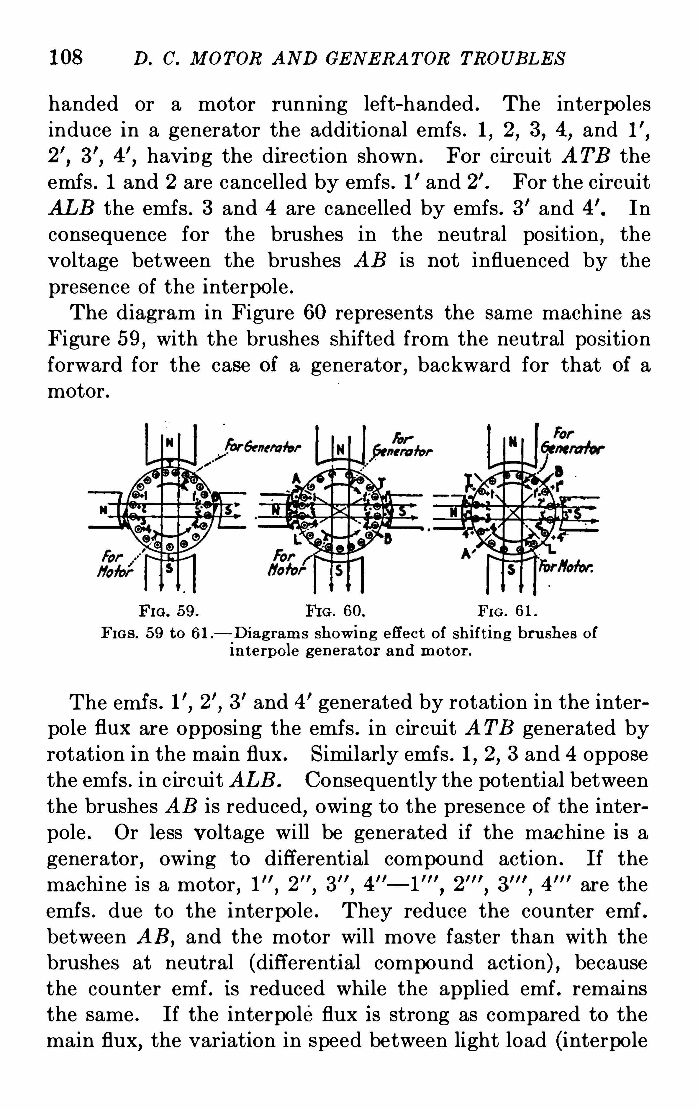
108 D. C. M OT OR AND GE N E RA T OR TROUB LE S
handed or a motor running left-handed . The interpoles
induce in a generator the additional emfs . 1,2,3,4,and
having the direction shown . For circuit A T B the
emfs . 1 and 2 are cancelled by emfs . 1’ and For the circuit
AL B the emf s . 3 and 4 are cancelled by emfs . 3' and In
consequence for the brushes in the neutral position,the
voltage between the brushes AB is not influenced by the
presence of the interpole .
The diagram in Figure 60 represents the same machine as
Figure 59, with the brushes shifted from the neutral position
forward for the case of a generator , backward for that of a
motor .
FI G . 59. FI G . 60. FI G . 61.
FIGS . 59 to 61 .—Di ag ram s showing eff ect of shift ing bru shes ofin terpole generator and motor .
The emf s . 3’ and 4’ generated by rotation in the inter
pole flux are opposing the emf s . in c ircui t A T B generated by
rotation in the main flux . S imilarly emf s . 1, 2, 3 and 4 oppose
the emfs . in c ircuit AL B . Consequently the potential between
the brushes AB is reduced,owing to the presence of the inter
pole . Or less Voltage will be generated if the mac hine is a
generator,owing to diff erential compound action . If the
machine is a motor,1 are the
emf s . due to the interpole . They reduce the counter emf .
between AB,and the motor will move faster than with the
brushes at neutral (diff erential compound action) , because
the counter emf . is reduced whi le the applied emf . remains
the same . If the interpoleflux is strong as compared to the
main flux,the variation in speed between light load (interpole
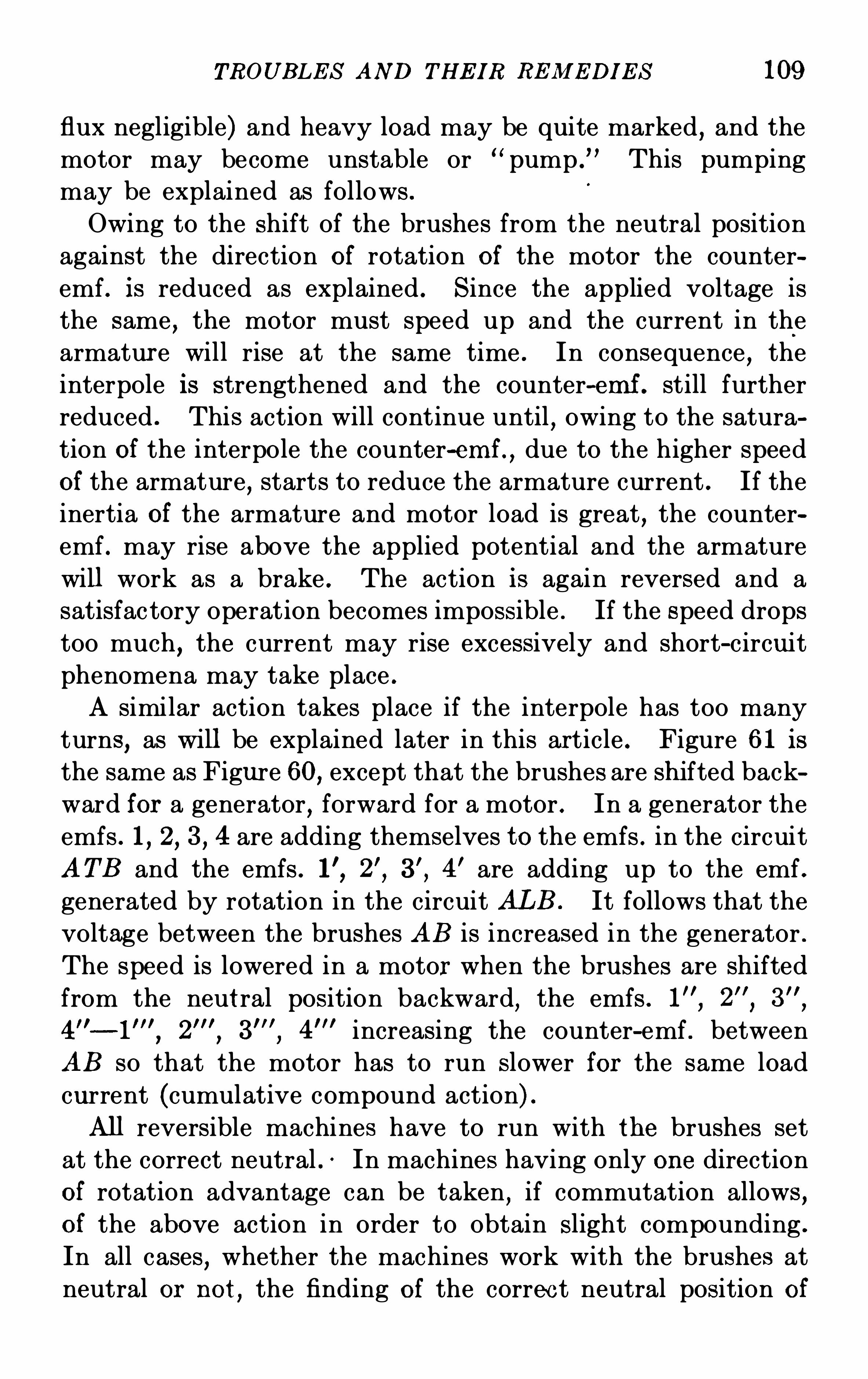
TROUBLE S AND THE IR RE M E DI E S 109
flux negligible) and heavy load may be quite marked, and themotor may become unstable or “pump .
” This pumping
may be explained as follows .
Owing to the shift of the brushes from the neutral position
against the direction of rotation of the motor the counter
emf . is reduced as explained . S ince the applied voltage is
the same,the motor must speed up and the current in the
armatur e will rise at the same time . In consequence,the
interpole is strengthened and the counter—emf . still furtherreduced . This action will continue until , owing to the satura
tion of the interpole the counter-emf ,due to the higher speed
of the armature, starts to reduce the armature current . If the
inertia of the armature and motor load is great , the counter
emf . may rise above the applied potential and the armature
will work as a brake . The action is again reversed and a
satisfac tory operation becomes impossible . If the speed drops
too much,the current may rise excessively and short-circuit
phenomena may take place .
A similar action takes place if the interpole has too many
turns,as will be explained later in this article . Figure 61 is
the same as Figure 60, except that the brushes are shifted back
ward for a generator, forward for a motor . In a generator the
emfs . 1, 2, 3 , 4 are adding themselves to the emfs . in the circuit
AT B and the emfs . 4’ are adding up to the emf .
generated by rotation in the circuit AL B . It follows that the
voltage between the brushes AB is increased in the generator .
The speed is lowered in a motor when the brushes are shifted
from the neutral position backward,the emfs .
4” —1 increasing the counter-emf . between
AB so that the motor has to run slower for the same load
current (cumulative compound action) .
All reversible machines have to run with the brushes set
at the correct neutral . In machines having only one direction
of rotation advantage can be taken,if commutation allows ,
of the above action in order to obtain S light compounding .
In all cases,whether the machines work with the brushes at
neutral or not,the finding of the correc t neutral position of
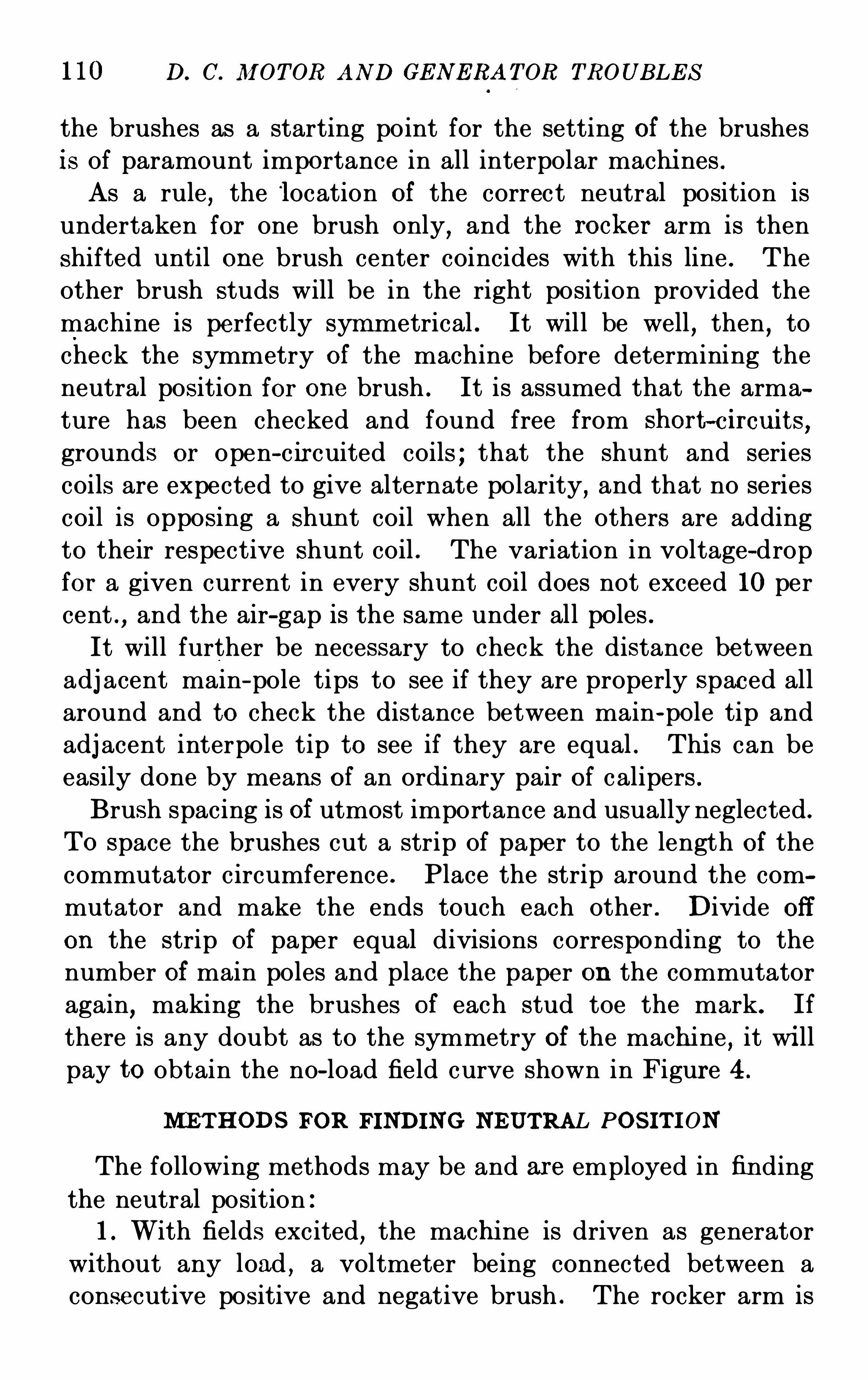
110 D. C. M OTOR AN D GE N E RA T OR TROUB LE S
the brushes as a starting point for the setting of the brushes
is of paramount importance in all interpolar machi nes .As a rule
,the location of the correct neutral position is
undertaken for one brush only, and the rocker arm is then
shifted until one brush center coincides with this line . The
other brush studs will be in the right position provided the
machine is perfectly symmetrical . It will be well,then
,to
check the symmetry of the machine before determining the
neutral position for one brush . It is assumed that the arma
ture has been checked and found free from Short~circu its ,
grounds or open—c ir cuited coils ; that the shunt and seriescoils are expected to give alternate polarity, and that no series
coil is opposing a Shun t coil when all the others are adding
to their respective shunt coil . The variation in voltage-drop
for a given current in every shunt coil does not exceed 10 per
cent .,and the air-gap is the same under all poles .
It will further be necessary to check the distance between
adj acent main-pole tips to see if they are properly spaced all
around and to check the distance between main-pole tip and
adj acent interpole tip to see if they are equal . Thi s can be
easily done by means of an ordinary pair of calipers .
Brush spacing is of utmost importance and usually neglected .
T o space the brushes cut a strip of paper to the length of the
commutator circumference . Place the strip around the com
mutator and make the ends touch each other . Divide Off
on the strip of paper equal divisions corresponding to the
number of main poles and place the paper on the commutator
again,making the brushes of each stud toe the mark. If
there is any doubt as to the symmetry of the machine,it wi ll
pay to obtain the no-load field curve shown in Figure 4 .
NIE T HODS FOR FINDING NE UTRAL POS IT I ON
The following methods may be and are employed in finding
the neutral position :
1. With fields excited, the machine is driven as generator
without any load , a voltmeter being connected between a
consecutive positive and negative brush . The rocker arm is
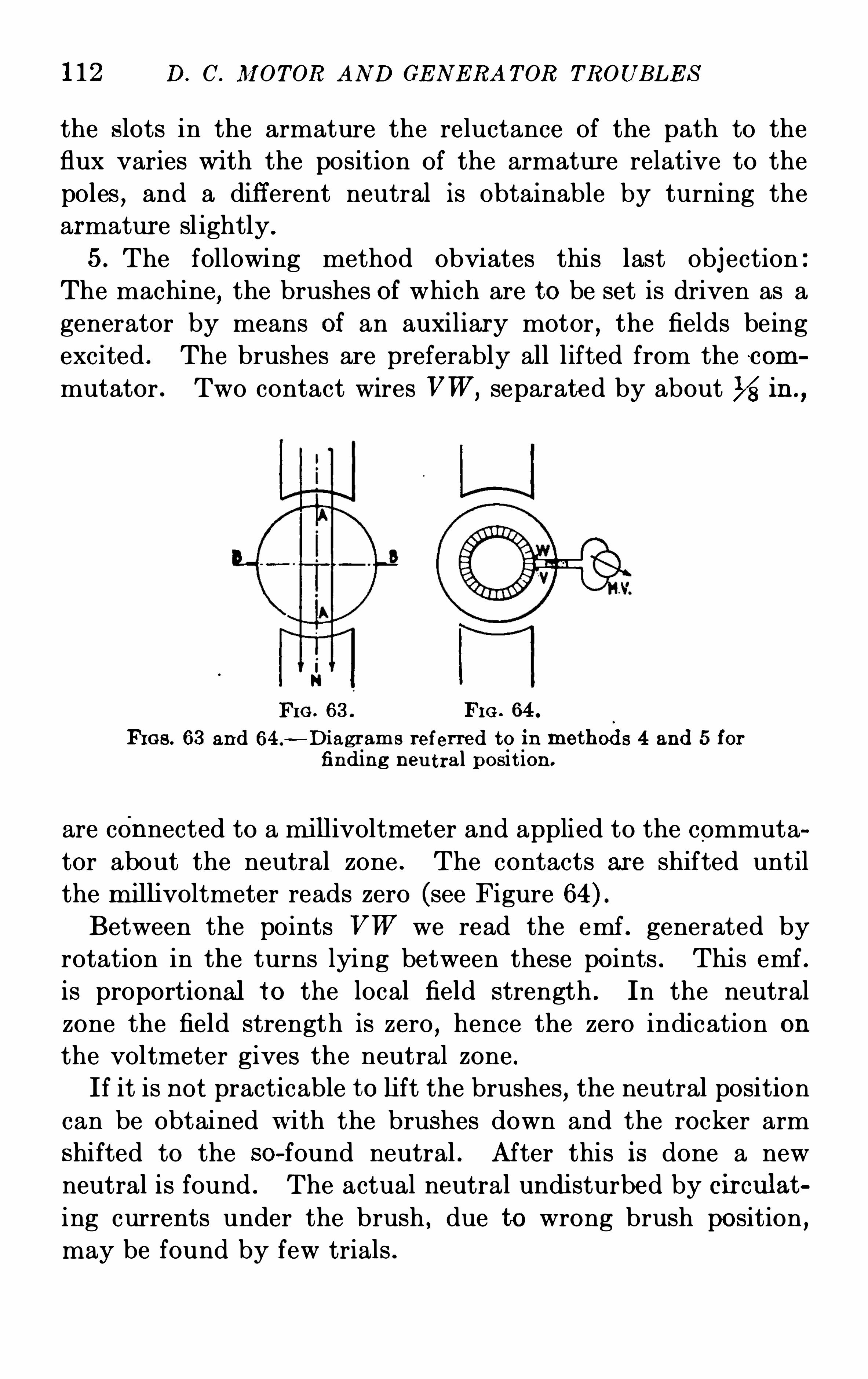
112 D. C . M OTOR AND GE N E RA T OR TROUB LE S
the s lots in the armature the reluctance of the path to the
flux varies wi th the position of the armatur e relative to the
poles,and a diff erent neutral is obtainable by turning the
armatur e sl ightly.
5. The following method obviates this last obj ection
The machine,the brushes of which are to be set is driven as a
generator by means of an auxiliary motor,the fields being
excited . The brushes are preferably all lifted from the com
mutator . Two contact wires VW ,separated by about in .,
FI G . 63 . FI G . 64.
h es . 63 and 64.—Di agram s referred to in methods 4 and 5 for
finding neu t ral posit ion .
are connected to a mi llivoltmeter and applied to the commuta
tor about the neutral zone . The contacts are shifted until
the mi lli voltmeter reads zero (see Figure
Between the points VW we read the emf . generated byrotation in the turns lying between these points . Thi s emf .
is proportional to the local field strength . In the neutral
zone the field strength is zero,hence the zero indication on
the voltmeter gives the neutral zone .If it is not practicable to lift the brushes
,the neutral position
can be obtained w ith the brushes down and the rocker arm
shifted to the so-found neutral . After this is done a new
neutral is found . The actual neutral undi sturbed by circulat
ing currents under the brush , due to wrong brush position ,may be found by few trials .
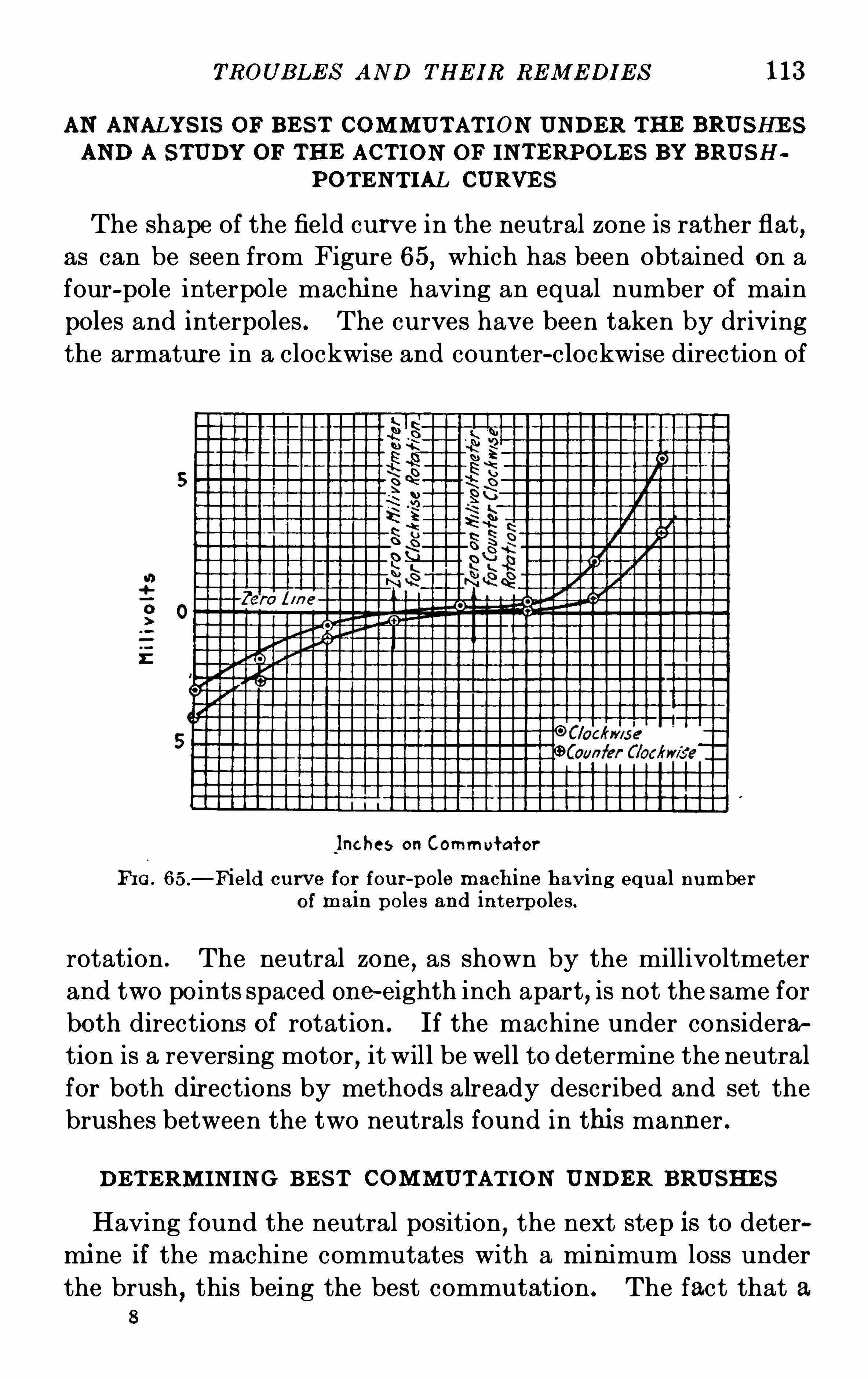
TROUB LE S AND THE IR RE M E DI E S 113
AN ANALYS I S OF B E S T COM M UTAT I ON UNDER THE BRUSHE SAND A S TUDY OF THE ACT I ON OF IN T ERPOLE S BY BRUSH
POT E N T IAL CURVE S
The shape of the field curve in the neutral zone is rather flat,
as can be seen from Figure 65, which has been obtained on a
four-pole interpole machi ne having an equal number of main
poles and interpoles . The curves have been taken by driving
the armatur e in a clockwise and counter-clockwise direction of
Inches on Commutator
FI G . 65.
—Field cu rve for fou r-pole mach ine having equ al numberof main poles and in terpoles .
rotation . The neutral zone,as shown by the millivoltmeter
and two points spaced one-eighth inch apart, is not the same for
both directions of rotation . If the machine under considera
tion is a reversing motor,it will be well to determine the neutral
for both directions by methods already described and set the
brushes between the two neutrals found in thi s manner .
DE T ERM I N I N G B E S T COM M UT AT ION UNDER BRUSHE S
Having found the neutral position,the next step is to deter
mi ne if the machine commutates with a minimum loss under
the brush,this being the best commutation . The fact that a
8
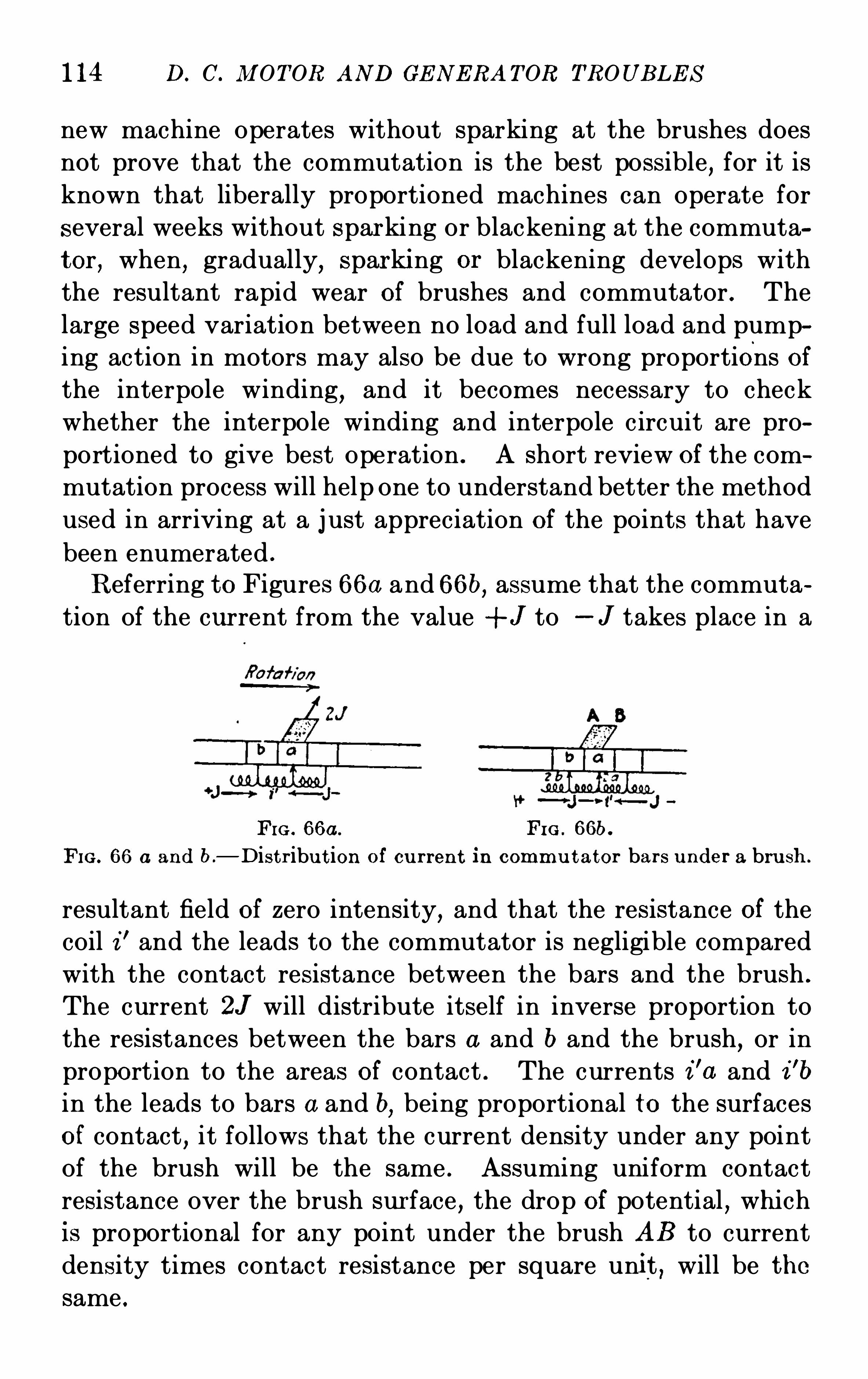
114 D. C. M OTOR AND GE N E RA TOR TROUB LE S
new machine operates without sparking at the brushes does
not prove that the commutation is the best possible,for it is
known that liberally proportioned machines can operate for
several weeks without S par king or blackening at the commuta
tor , when, gradually, sparki ng or blackening develops with
the resultant rapid wear of brushes and commutator . The
large speed variation between no load and full load and pump
ing action in motors may also be due to wrong proportions ofthe interpole winding
,and it becomes necessary to check
whether the interpole winding and interpole c ircuit are pro
portioned to give best Operation . A short review of the com
mutation process will help one to understand better the method
used in arriving at a j ust appreciation of the points that have
been enumerated .
Referring to Figures 66a and 66b, assume that the commuta
tion of the current from the value + J to —J takes place in a
FIG . 66a . FI G . 66b.
FIG . 66 a and b.
—D is t r ibu t ion of cu r ren t in commu t ator bar s u nder a bru sh .
resultant field of zero intensity,and that the resistance of the
coil z” and the leads to the commutator is negligible compared
with the contact resistance between the bars and the brush .
The current 2J will distribute itself in inverse proportion to
the resistances between the bars a and b and the brush, or in
proportion to the areas of contact . The currents i ’a and i 'b
in the leads to bars a and b,being proportional to the surfaces
of contact,it follows that the current density under any point
of the brush will be the same . Assuming uniform contact
resistance over the brush sur face , the drop of potential , which
is proportional for any point under the brush AB to current
density times contact resistance per square unit , will be thesame .
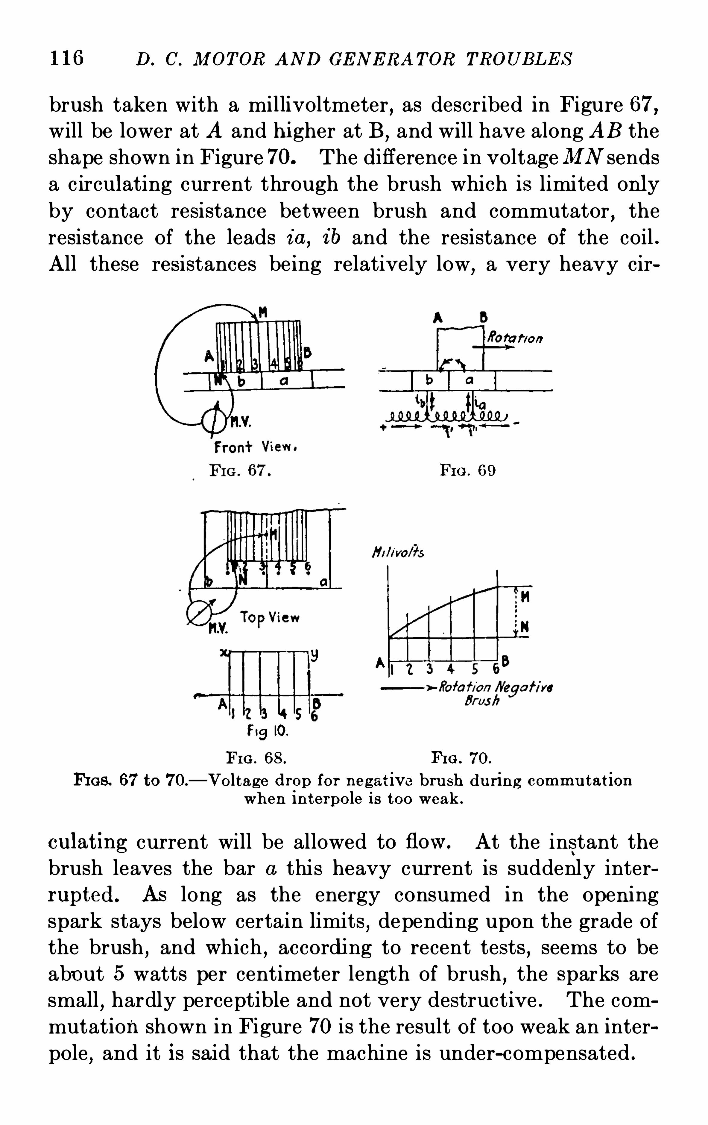
116 D. C. M OT OR AND GE N E RA T OR TROUB L E S
brush taken with a millivoltmeter , as described in Figure 67,will be lower at A and hi gher at B , and will have along AB the
shape shown in Figure70. The diff erence in voltageM N sends
a circulating current through the brush which is limited only
by contact resistance between brush and commutator , the
resistance of the leads i a , i b and the resistance of the coil .
All these resistances being relatively low, a very heavy cir
fa r/on
FI G . 69
FigIO.
FIG . 68. FI G . 70.
FI GS . 67to 70.
—Voltage drop for negat ive bru sh du r ing commu tat ionwhen in terpole i s too weak .
culat ing cur rent will be allowed to flow. At the instant the
brush leaves the bar a this heavy cur rent is suddenly interrupted. AS long as the energy consumed in the opening
spark stays below certain limits,depending upon the grade of
the brush,and which
,accordi ng to recent tests
,seems to be
about 5 watts per centimeter length of brush,the sparks are
small,hardly perceptible and not very destructive . The com
mutation shown in Figure 70 is the result of too weak an inter
pole , and it is said that the machine is under-compensated .
TROUB LE S AN D THE I R RE M E DI E S 117
Provided the section of the interpole proper is ample and
the magnetic circuit of the interpole is not saturated , a reduc
tion in the air-gap under the interpole by addition of sheet
iron shims will materially help to improve commutation .
The addition of more turns of the interpole would be the next
step toward correcting the trouble . If the magnetic circuit is
saturated,then a reduction in face area of the interpole, by
cutting down the edges in a tangential direction,will bring
relief through increasing the magnetic induction in the air
gap,while the total interpole flux continues to be constant .
S TUDYING ACTI ON OF I NT ERPOLE BY BRUSH-POT E NT IALCURVE S
The conditions j ust described are very much accentuated
if the interpole is reversed,for then the interpole flux
,instead
of tending to produce a neutral zone,adds its flux to the arma
ture reaction flux and the flux of the short-circuited coil .
The brush-potential curve shown in Figure71 depicts the condi
tion under the brush with a reversed interpole and is a very
good indication of thi s trouble . In taki ng the curve the milli
voltmeter reverses its reading whi le we move the contact
point along the brush in the direction of rotation . If the
interpole flux is too strong,then the coil while under the brush
tends to carry current in the di rection after the commutation
has been completed . Thi s action i s shown from Figur e 72 ,where the current i ' (double arrow) produced by the excessinterpole flux is increasing the current density under the bar
b or leading brush tip A,and decreasing the current density
under bar a or trailing brush-tip B . For a negative brush
the brush-potential curve,taken as explained by means of
Figure 67,will have the shape shown in Figure 73 . This action
of the interpole is expressed by saying that the machine is over
compensated . If the machine is very much over-compensated,the brush-potential curve will take the form shown in Figure
74 . For a negative bru sh and taking the readings under the
brush in the direction of rotation,the millivoltmeter readings
may change from a positive value to a negative value .
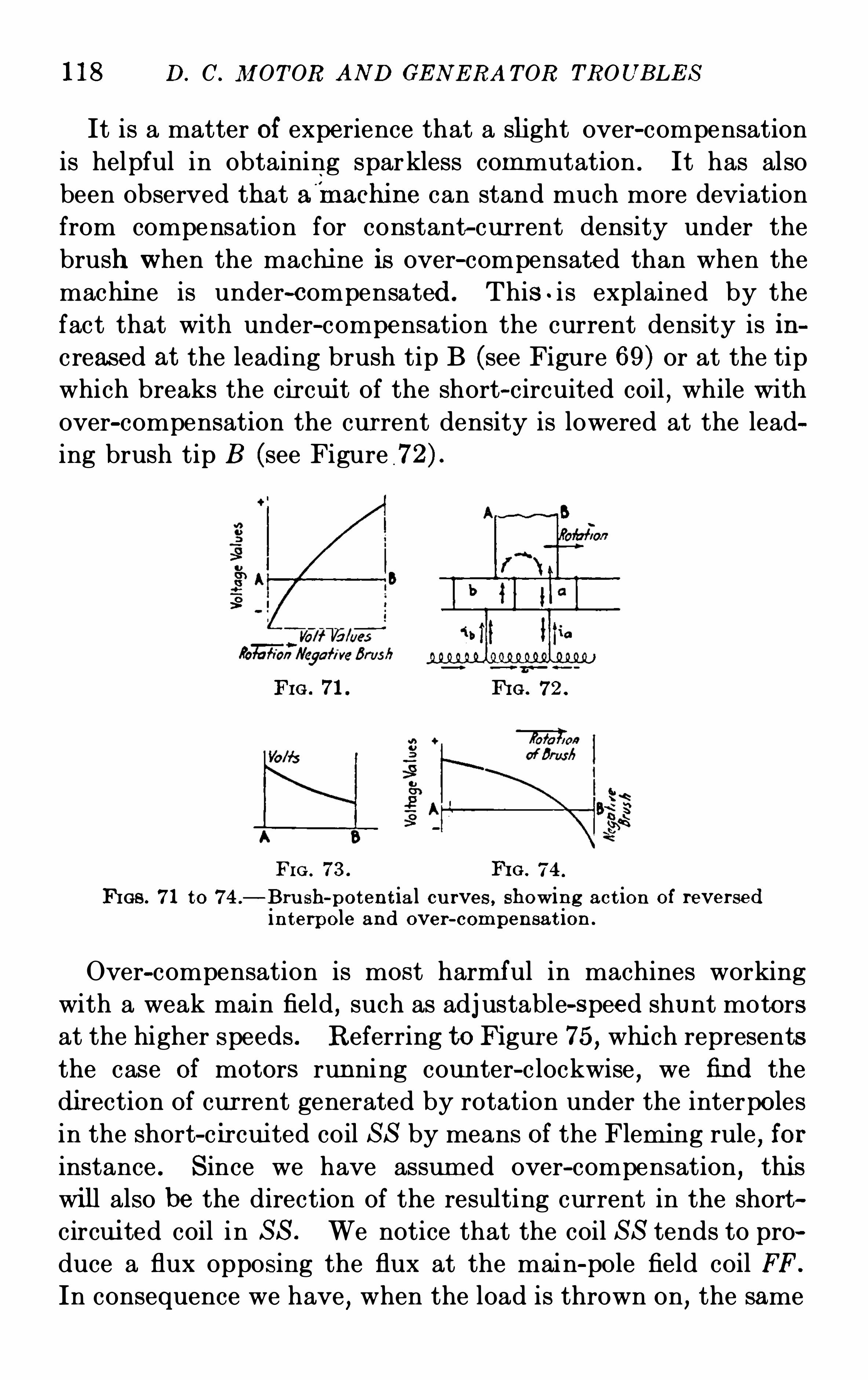
118 D. C. M OT OR AN D GE N E RA T OR TROUB LE S
It is a matter of experience that a slight over-compensation
is helpful in obtaining sparkless commutation . It has also
been observed that a'
rnachine can stand much more deviation
from compensation for constant-cur rent density under the
brush when the machi ne is over-compensated than when the
machine is under-compensated . This . i s explained by the
fact that with under-compensation the current density is in
creased at the leading brush tip B (see Figure 69) or at the tip
which breaks the cir cui t of the short-circuited coil,while with
over-compensation the cur rent density is lowered at the lead
ing brush tip B (see Figure
Fro. 71. FI G . 72 .
FI G . 73 . I‘HG . 74 .
FIGS . 71 to 74 .
—B ru sh-poten t ia l cu rves , showing act ion of reversedin terpole and over-compensat ion .
Over-compensation is most harmful in machines working
with a weak main field , such as adj ustable-speed shunt motors
at the higher speeds . Referring toFigur e 75, whi ch represents
the case of motors running counter-c lockwise , we find the
di rection of cur rent generated by rotation under the interpoles
in the short-c ircui ted coil S S by means of the Flemi ng rule , for
instance . S ince we have assum ed over-compensation, thi s
wi ll also be the direction of the resulting current in the short
circui ted coil in S S . We notice that the coil S S tends to pro
duce a flux opposing the flux at the main-pole field coil FF.
In consequence we have,when the load is thrown on
,the same
120 D. C. M OT OR AND GE N E RA TOR TROUB LE S
Further conditions aff ecting instability
1. Ratio Of armature ampere turns to field ampere turns .Any increase in this ratio will increase the liability to pumping
(or hunting, as it is sometimes called) .2 . S aturation Of main magnetic circuit . The lower on the
saturation curve the motor works the greater the danger Of
instability .
3 . The greater the ratio Of self-induction to resistance
(including rheostat resistance) in the shunt winding, the less
danger Of instability . Hence increasing the size Of the shunt
field wire without changing the number Of tur ns will reduce the
tendency to hunt .
A few turns Of compound windi ng will effectively oppose the
tendency Of the short-c ircuited coil to weaken the main pole .
Many interpole motors now on the market have such a windi ng
on the main pole—this winding being called a stabilizing winding . Short—circuited sleeves around the interpole are Of littlevalue
,in the writer ’s experience .
All motors showing a rising-speed characteristic from no
load to full load at any speed will be in danger of being unstable
in Operation,and for thi s reason it should be required from
any machi ne working with field weakening to show a dropping
speed characteristic at the high speed between no load and
about 50 per cent . overload . The remedy,if we find the ma
chi ne over-compensated,is obvious . Increase the interpole
air-gap if possible . Take some Of the turns Off from the inter
pole if thi s can be easily accomplished . It is not recommended
to shunt part Of the interpole current thr ough a resistance .
A non-inductive resistance should never be used where the
load is sudden and fluctuating,as in railway generators for
instance .
It sometimes occurs that an interpole machi ne Operates
quite well at light loads but sparks badly at over-loads . If
the brush-potential curve Obtained at light load has the shape
of Figure 73 , indicating over-compensation, whi le the brush
potential curve Obtained at overload has the shape of Figure
70, indicating under-compensation , it is a sure sign that the
TROUB LE S AN D THE IR RE M E DI E S 121
interpole magnetic circuit is saturated and probably the section
of the interpole too small . Cutting down the face of the inter
pole in a tangential direction will help . If the distance between main and interpole tip is small
,thi s will at the same
time reduce the interpole leakage and thus further improve
commutation .
With wide brushes the brush-potential curve sometimes
takes the shape shown in Figure 78. If sparking occur s,it
can be reduced by reducing the width of the brush from AB
to A ’B
’
,provided the current density under the brush is not
unduly increased by doing that . The brush-potential curve
is also valuable in cases where the unit is large,making it
impracticable to test the machine under full-load conditions .
All that is necessary is to take the brush potential curve with
the armature short-c ircuited,the fields being j ust enough ex
cited to send full-load cur rent through the armature and inter
poles . The same applies to high-voltage machines where it
would be dangerous for the Operator to take brush-potential
curves under full-voltage condition .
Owing to the diff erent distribution Of leakage flux under
full-field condition,this is theoretically not quite correct ,
though it is quite close enough for practical work .
M E THOD OF OB TAI NIN G B RUSH-POT E N T IAL CURVE S
The following procedure has proved satisfactory in taking
brush-potential curves : S ince the shape Of the curve is the
point Of interest,in order to facilitate comparisons it is advi s
able always to take the curve at the brush,the potential Of
which is hi gher than the potential Of the commutator—thenegative brush in a generator
,for instance
,and the same ro
tat ion (clockwise in the above curves) . To take the curve
two copper needles can be used , but two ordi nary writing pencils
well sharpened have proved very useful for the purpose .
A strip of cardboard paper , perforated with holes about one
sixteenth inch in diameter and spaced about one-eighth inch
apar t,will do good service in Obtaining the points on the curve .
122 D. C. M OT OR AND GE N E RA T OR TROUB LE S
The strip can be laid over t he commutator sur face and fastened
to the two brush-holder studs adj acent to the brush under
examination . A uniform pressure on the contacts is desirable
for Obtaini ng most consistent results . If the curve is taken
as suggested at the negative brush , care must be exercised to
apply the positive terminal Of the millivoltmeter to the brush
and the negative terminal to the commutator copper . A
positive reading on the voltmeter will be plotted as a positive
ordinate . If the voltmeter leads have to be reversed the
reading will be plotted as a negative ordinate .
In the deduction Of the brush-potential curves it is assumed
that drops in voltage between commutator and brush are
proportional to the local current density . Thi s is only true
in the case Of ideal commutation,for then the density is con
stant under the brush . As a matter Of fact,the drop in voltage
is not proportional to the current density ; but if we should
plot the drop in voltage against the current density we should
Obtain a curve approximating a hyperbola,the drop in voltage
becoming constant when the current increases indefinitely.
Furthermore,we have to keep in mind that the cur rent
density varies along the brush not only in space but also in
time . In consequence,we cannot attribute any quantitative
signi ficance to the brush-potential curve and cannot from the
brush-potential curve construct the curve of distribution
Of current density under the brush . The disparity between the
actual distribution Of cur rent density and the distribution
deducted from the brush-potential curve will be the greater
the more the commutation departs from the ideal commutation
with constant-cur rent dens ity over the entire surface Of the
brush . S till , as a qualitative j udgment Of commutation,
the brush-potential curve is an invaluable asset Of the Operat
ing engineer . Qualitatively, all the above deductions stay ,in spite Of the fact that the assumption Of uniform contact
resistance between commutator and brush is incorrect . But
it should be kept in mi nd that the better the commutation,the
more nearly correct these curves are .
N O attempt has been made in the above discussion to enter
124 D. C. M OT OR .AND GE N ERA T OR TROUB LE S
the fit Of the brushes on the commutator is being constantly
changed resulting in sparking and blackeni ng Of the commu
tator sur face . Then, too, there is the probability of having
the load suddenly drop after the brushes have been shi fted
to produce perfect commutation at full load with the result
that serious sparking, damaging both brushes and commuta
tor, will occur .
On a motor,the brushes should be shi fted backward or
against rotation when sparking begins to appear as the load
increases,returning the brushes to their original position as the
load decreases again . With the two brush position limits
determined at no load and full load,an average point may be
easily found by shifting,which gives the best commutation
over the entire range . If the direction Of rotat ion is changed,it is necessary to place the brushes on the Opposite side Of the
neutral point,the same distance as that previously Obtained
to secur e satisfactory results . It is necessary where reversals
are frequently made,to place the brushes on theno-load neutral
so as to eliminate their continual shifting . A motor designed
for rotation in one direction only, when applied to a service
requiring frequent reversals may spark continuously if oper
ated with the brushes on the no-load neutral . This difficulty
may be overcome,however
,by increasing the air gap by re
moving shims or liners from between the pole pieces and the
frame thus reducing the eff ect Of the cross magnet i zation Of
the armature conductors,resulting in less shifting Of the neutral .
It should be remembered,however, that an increase in the air
gap will be accompani ed by an increase in speed requiring a
strengthening Of the field cur rent . An excessive shift Of the
brushes against rotation on a motor will produce a rising speed
characteristic as the load is increased due to the increase Of
the demagnet i zing effect Of the current in the armature con
ductors upon the main-pole flux . The manufacturer should
be informed,when a motor is being ordered, whether or not
reversed Operation is to be required as the design Of the ma
chine will be materially different with respect to the fields,
brushes and brush holders .
TROUB LE S AN D THE IR RE M E DI E S 125
The shi fting Of the brushes from the no—load neutral pointon a generator to prevent sparking as the load is increased isexactly opposite to the procedur e in the case Of a motor . In
the generator,the shifting is in the direction Of rotation and
the same method is adopted for locating the best average Oper
ating posit ion as previously described for the motor . The
nO-load and full-load brush positions may in some designs be
so far apart that no satisfactory average position can be Oh
tained. In such a case,an increase in the air gap will reduce
the maximum brush shift necessary to such an extent as to
make it possible to Obtain a good working neutral . The
decrease in voltage occasioned by the increase in the air gap
must be overcome by increasing the strength Of the field cur
rent . It is not usually necessary to change the air gap where
the generator is Operated within its normal rated limits pro
viding that correct adj ustments have been made at the fac
tory . If such adj ustments have not been made or if it is
desired to Operate the generator at above its rated capacity,since the temperature rises permi t an increase in load
,the com
muta tion constants may be materially improved by the increase
in air gap .
126 D. C. M OT OR AN D GE N E RA T OR TROUB LE S
BRUSH DE FE CTS CAUSIN G FAULTY COMMUTATION
CHOI CE OF B RU SHE s—BRUSH AND CON TA CT RE S I S TAN CE
BRUSH DE N S ITY—UN EQUAL BRUSH SPA C I N G AROUN D
COMMUTATOR—I N CORRE CT BRUSH AN GLE—WRON GBRUSH PRE S S URE—M I S ALI GNM E N T OF T HE BRUSH
HOLDE R BRA CKE TS—BRUS H CHATTE R—BRUSHE S B I N DlN G I N HOLDE RS—BRUSH W E AR —GLOW I N G AN D FI T T ING
OF BRUSHE S—LOOS E CON N E CTI ON S : BURN T-OFF'
PI G
TAI LS—VIB RATI ON OFrrHE BRUSH RI GGI N G
CHO ICE OF B RUSHE S
Successful commutation depends to a large extent upon the
selection Of the brush to sui t the demands Of the servi ce .
Manufacturers Of brushes for electrical machi nery vary widely
in their recommendations and oftentimes troubles from faulty
commutation,as well as troubles with commutators come as
a di rect result Of the Operator following out instructions and
recommendations made by brush agents . E xperience with the
various types Of brushes is un doubtedly the best criterion in
the selection,but manufacturers of electrical machinery should
be consulted wherever possible before a change in the brush
equipment Of a machine is made, as the design Of the unit should
be considered .
While machi nes are shipped with the proper brushes at
tached for Operation under ordinary conditions,it frequently
happens that local surroundings,with which the manufacturer
is unacquainted,make necessary a complete change Of the
brush equi pment for successful Operation . For example,units
exposed to Oil vapors should never be equipped with graphite
brushes for the reason that the additional lubrication caused
by the Oil will uni te with the graphite and coat the surface
Of the commutator with smut , causing serious sparking . This
smut may be removed by wiping the commutator with clean
canvas,but unless continuous attention is given
,the sparking
will reappear . In Oil-laden atmospheres,dry-carbon brushes
should be substituted as they will absorb the Oil condensing
128 D. C . M OT OR AN D GE N E RA T OR TROUB LE S
excess lubricant inherent in the brush , Composition brushes
containing metal,known as metal graphite brushes are used on
collector rings on 3-wire generators and on commutators
Of electrolyt ic machinery where very high cur rents,up to
thousands Of amperes,with voltages Of ten and below are
generated . Here the u se Of metal brushes is permissible be
cause the voltage between commutator bars is very low and
high current-carrying capacities in the brushes are required
as well as low-voltage drops in the contact and brushes . The
hi gh current densities required,from seventy-five to eighty-five
amperes per square inch,are necessary in order to decrease
the size Of the commutator to dimensions which are mechan
ically possible in construction . The low contact and brush
drop,under one volt
,is essential because Of the low voltage
generated . Using other types Of brushes,the brush and con
tact drop would amount to from two to three volts,which in
this case would be a large percentage Of the total generated
voltage . The meta l graphite brush has a low transverse
resistance as compared with carbon and pure graphi te brushes
and for this reason in its substitution for other types,a thinner
brush should be installed,if underbrush sparking
,glowing and
pitting appear,as the trouble will be due to the fact that the
low-resistance brush is short-circui ting too many armature
coils . When commutation trouble develops after metal
brushes have been substituted,it is not necessary to keep the
machi ne out Of service while new holders are being secured
to accommodate the thinner brush,for a temporary adj ustment
Of the thickness may easily be made by filing Off the toes or
heels Of the brushes without changing the holders . The center
line Of the brushes , however, after the filing, has to be shi fted
until it coincides with the same point on the commutator as
intersected by the original center line .
Graphite,graphitized carbon and carbon brushes are used
on direct-current machines,where the voltages carried vary
from ten to thirty-five hundred volts . Where the voltage
generated drops below ten volts,metal graphite brushes should
be installed .
TROUB LE S AN D THE IR RE M E DI E S 129
A brush should be free from air holes and foreign matter
and its ingredients should be thoroughly mixed to insureuniformity . All Of the brushes on the commutator should
be Of the same quality since an inequality will produce selective
commutation due to the hogging Of the current by the good
brushes . An exception to the general rule is sometimes
found in the case Of electrolyt ic machines where carbon brushes
are fitted to cut through the film caused by the fumes . If no
lubrication is supplied these carbon brushes will chatter and
it is customary to substitute a sufficient number Of graphite
brushes,sO arranged on the various studs as to cover the entire
commutator sur face at each revolution and supply the nec
essary lubrication .
BRUSH AND CONTACT RE S I S TANCE
The resistance Of the brushes and Of the contacts between
the brushes and the commutator directly affects the speed Of a
motor and the voltage regulation Of a generator In the case
Of a motor,a drop in speed will result as the load comes on
when any resistance is placed in series with the armature .
This decrease Of the speed will be directly in propor
tion to the amount Of the armature resistance . For example,
if the sum Of this resistance in series with the armature and
the resistance Of the armature itself is represented by R,the
applied voltage upon the armature being E and the current
C,the actual voltage produced by the revolutions Of the
armatur e is E equals CR. N ow if in another case , a total
resistance Of R, was used and the applied voltage and current
remained the same,the actual voltage produced by the
revolutions Of the armature would be E equals CRx . There
fore if the CR, Of the second case is greater than the CR Of the
first,the speed Of the motor will be less . The action in the
case Of the generator will be the same except that the voltage
regulation will be aff ected instead Of the speed .
The drop at the contact is very large as compared with
that due to the resistance Of the brush itself,in fact the brush
9
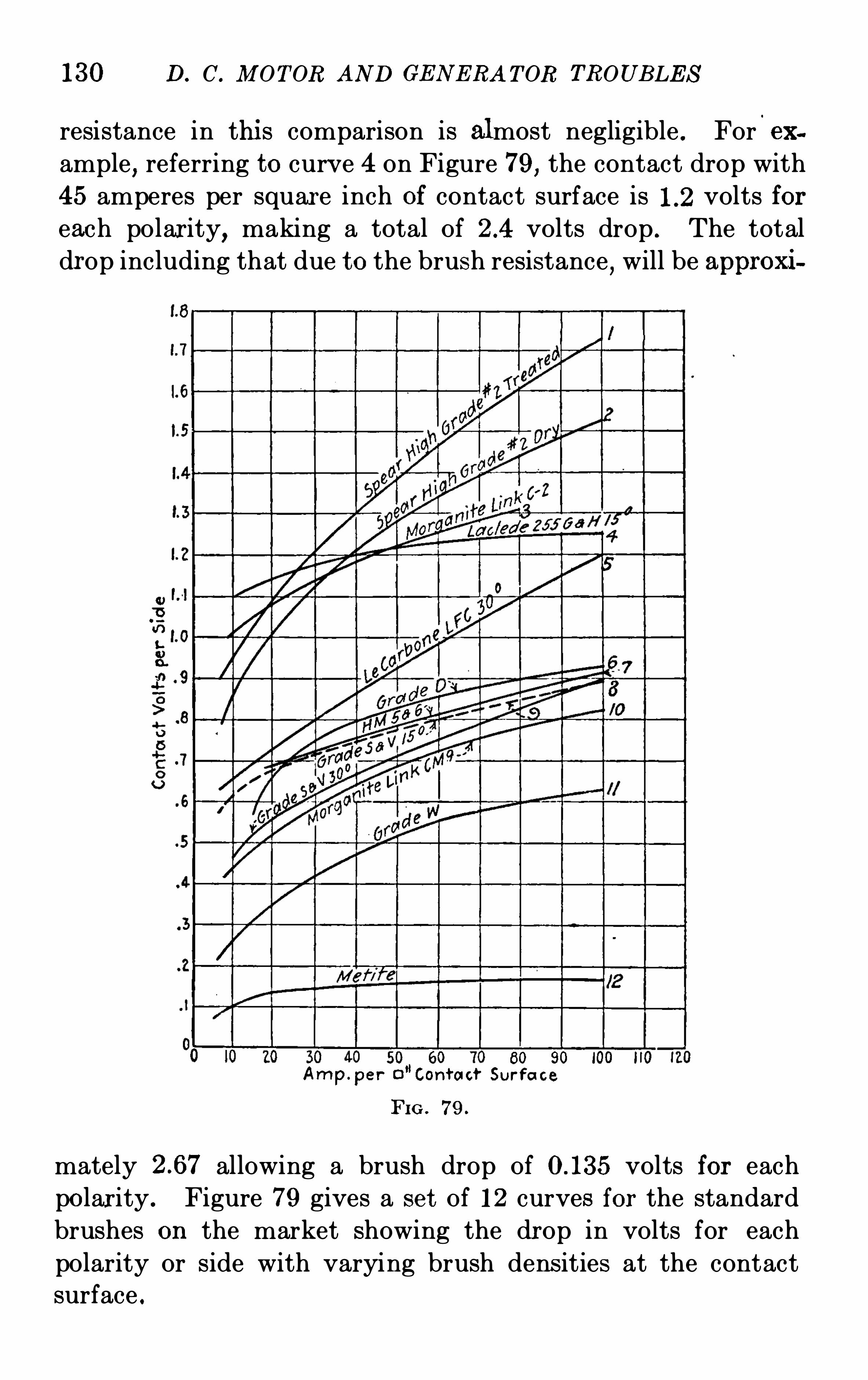
130 D. C. M OTOR AND GE N E RA T OR TROUB LE S
resistance in thi s comparison is almost negligible . For.
ex
ample, referring to curve 4 on Figure 79, the contact drop with45 amperes per squar e inch Of contact surface is volts foreach polarity, making a total Of volts drop
.The total
drop including that due to the brush resistance,will be approxi
80 90
Amp. per 0”Contact Sur fa ce
FIG . 79.
mately allowing a brush drop Of volts for each
polar ity . Figure 79 gives a set Of 12 curves for the standard
brushes on the market showing the drop in volts for each
polarity or side with varying brush dens ities at the contactsurface .
D. C. M OT OR AND GE N E RA T OR TROUB LE S
The entire cur rent is car ried by the brushes Of each polarity .
For example , in an 8-pOle machine, the cur rent shou ld bedivided equally between four sets Of brushes . The current
carrying capacity Of the brush varies with its composition, a
carbon brush being used to carry thir ty-five to forty amperes
per square inch when requir ed at t imes to handle a 50 per
cent . overload for two hours , or forty to forty-five amperes
per square inch where the overload is 25 per cent . for
two hours . For continuous duty, where the load is con
stant over long periods,carbon brushes should not be run with
a density exceeding for ty-five amperes per square inch . Graph
ite brushes will Operate satisfactorily with a brush density Of
fifty to fif ty-five amperes per square inch when requi red to
carry a 50 per cent . overload for two hours,fifty-five to
sixty amperes when the overload is 25 per cent . for two
hours and up to sixty amperes per square inch when the
Cur rent is constant . Composition brushes made up Of carbon ,
graphite and metal are fitted on machines whose duty cycle
requi res continuous service with a fixed current where the
brush density may be run at values Up to seventy-five amperes
per square inch . Copper gauze or Oopper leaf brushes will
handle a density Of one hundred to one hundred fifty amperes
per squar e inch successfully,but are used on collector rings
only .
Assumi ng a total currentOf fif teen hundred amperes,carried
by eight studs,with five one and one-fourth inch by one inch
brushes at an angle Of thi rty-seven and one-half degrees , the
brush density can be computed to be forty-eight amperes per
square inch from the formula
C
S X W X T X A X N
where,
C Total curr ent in amperes .
S N umber of studs Of each polarity,or the number Of
poles divided by 2.
W Width Of the brush in inches .
TROUBLE S AN D THE I R RE ME DI E S 133
Thickness Of the brush .
Cons tant corresponding to the brush angle , for
37% degrees , for 20 degrees and for 15
degrees .
N umber of brushes per stud .
Density in amperes per sq . in . of constant area .
1500
4 x 94 x 1 X X 548 amperes per sq . in .
When it is desired to change the type Of brushes used,and
the best Operating density Of the new type is known , the
number Of brushes which will be needed may also be found by
use Of the above formula .
When brushes are Operated for any great length at densities
exceeding the values given above,disintegration due to heating
will result . Should the overload cur rent on the brush become
two and one-half to three times as great as the normal capac ity,
the brush would become red hot and disintegrate very rapidly .
Where a machine Operates continuously under its rated ampere
load,i ts efficiency may be increased by removing a percentage
of the brushes until the proper density has been established .
The gain in efficiency is effected by the reduction in brush
friction .
UNE QUAL BRUSH SPACIN G AROUND COM M UTAT OR
S ymptoms—Sparking at One or All S tuds .
Selective Commu tat ion .
T O secure satisfactory commutation it is necessary that the
brushes be equally spaced around the commutator .Unequal spacing Of the brushes may cause sparking to occurunder all Of the brushes due to all Of the di ff erent studs not
being at the neutral points . However,the sparking may take
place at only one stud or at any number Of them while the
neighboring studs commutate perfectly . This latter condi
tion is caused by unbalanced circuits in the armatur e windings
result ing from a larger or smaller number Of commutator seg
134 D. C . AI OT OR AND GE N E RA T OR TROUB LE S
ments and armature conductors connected thereto , deliveringan unequal voltage and current to the various sets Of brushes .The current flowing in the armatur e circuits divides in propor
tion to the resistances Of the cir cui ts and if the brush spacing
is such as to cause unequal resistances of these circui ts due to
differences in their length,the cur rent distribution will be
such as to cause a large current to flow in the shorter
circuits and a small current in the longer circuits . Unbalanc
ing Of the armature circuits may also result from loose con
nect ions at the brushes or studs as described in the succeeding
articles .
T O Obtain equal spacing, the studs should be set up with
the brush holders in place,and the commutator should be
wrapped tightly with a long strip Of paper about an inch wide
covering its entir e circumference and tied in place . The lap
ping point Of this paper should then be marked,the paper
should be removed,spread ou a flat surface and s tepped Off
with a large pair Of dividers or similar tool into exactly equal
sections,equal in number to the number Of poles . The strip
should then be replaced on the commutator and the studs so
adj usted that the toes Of the brushes on the diff erent studs
j ust touch these marks .
Another method for Obtaining the correct brush spacing is
by counting Off and making equal the number Of commutator
segments between studs . This method is relatively ac curate
in spite Of the slight variation in the thicknesses Of the mica
and the segments, where the number Of commutator segments
i s evenly divisible by the number of poles,which is the case in
multiple-wound armatur es . Where the armature is series
wound and the number Of segments is not evenly divisible by
the number Of poles,a certain amount Of estimating is neces
sary to split up the Odd segment and the resulting inaccuracy
is liable to be the cause Of poor spacing .The above methods outlined for Obtaining the correct brush
spacing are applicable either to machines designed with or
without commutating poles .
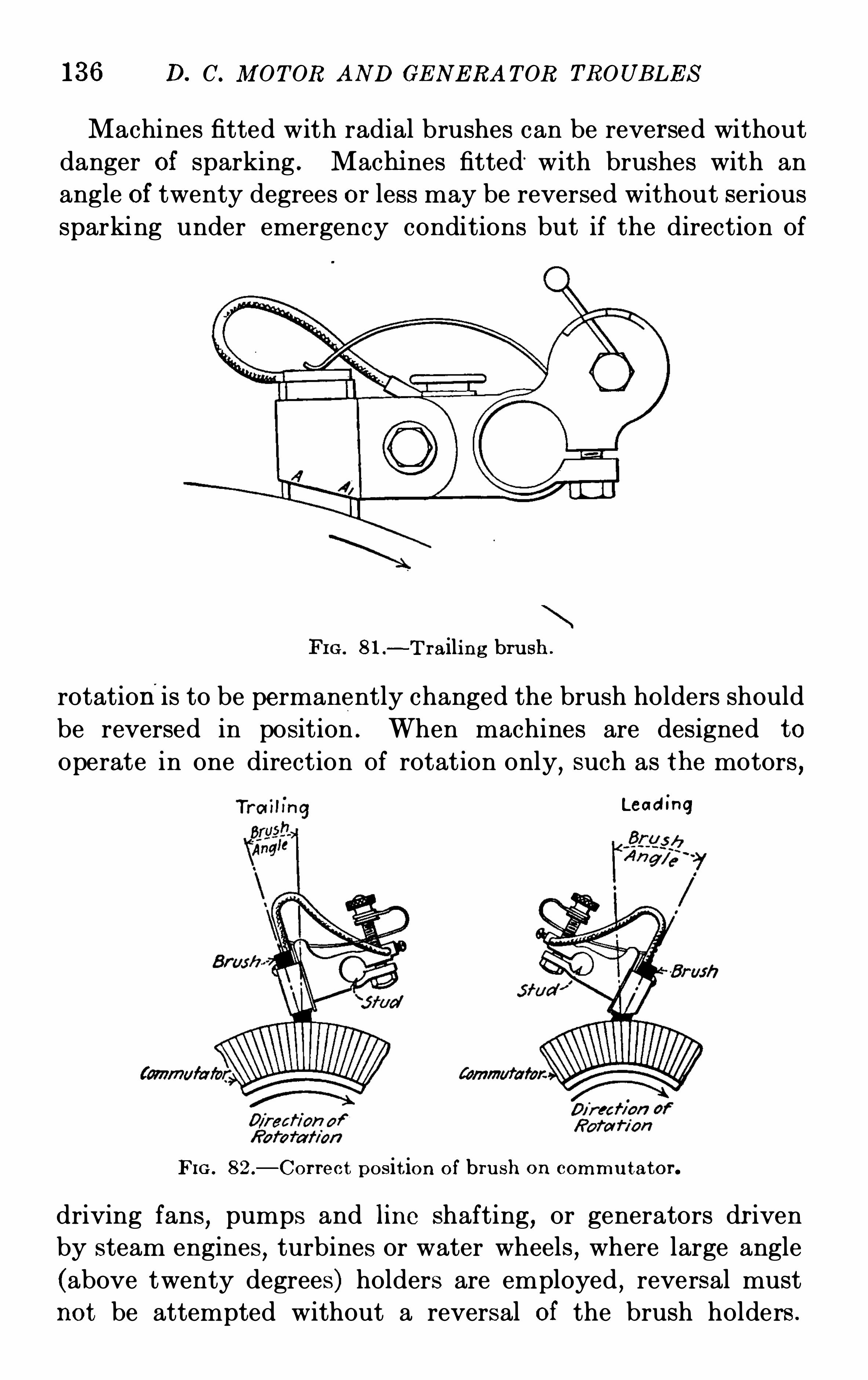
136 D. C. M OT OR AND GE N E RA T OR TROUB LE S
Machines fitted with radial brushes can be reversed without
danger Of sparking . Machi nes fitted with brushes with an
angle Of twenty degrees or less may be reversed without serious
sparking under emergency conditions but if the direction Of
81 —T raili ng bru sh .
rotationis to be permanently changed the brush holders should
be reversed in position . When machines are designed to
Operate in one direction Of rotation only,such as the motors ,
Lead ing
FIG . 82 .
—Cor rect pos it ion O f bru sh on commu tator.
driving fans,pumps and line shafting
,or generators dr iven
by steam engines,turbines or water wheels
,where large angle
(above twenty degrees) holders are employed , reversal mustnot be attempted without a reversal Of the brush holders .
TROUB I .E S AN D THE I R RE M E DI E S 137
L arge angle brushes operated trailing will bind in the holdersand cause a great deal Of sparking as well as scoring of the
commutator S LU'face and breaking Off Of the toes of all brushes .
The breaking Of the brushes is due to the pressur e of the commutator surface against the brush contact surface at a large
angle resulting in an undue stress being set up by the brush
against the holder . The sparking results from the brush not
riding properly on the commutator caused by the sticking in
the holder boxes and also from the carbon particles broken
from the brush toes being carried around the commutator .Motors designed for continuous reversing
,such as those dr iv
ing planers and roller mi lls are usually fitted with brushes setat an angle of twenty degrees from the vertical for experience
has shown that the brushes will operate at this angle under
such service without changing the fit Of the brush with each
reversal and thus will produce satisfactory commutation.
If a brush whose angle with the vert ical is less than twenty
degrees is employed for continuous reversing service,sparking
will result due to the rocking Of the brush in the holder,causing
two separate brush fits . Brushes with an angle greater than
twenty degrees will cause brush breaking and sparking as
mentioned previously in this paragraph .
Where the reversal Of the brush holders On the stud is required when the direction Of rotation is changed
,the stud
must be shifted so that the brushes are again placed on the
neutral p‘
oint . Instead Of redetermining this neutral point
by experiment,it is advisable to mark a point on the com
mutator at the center line Of the brushes in their original
position before disturbing the holders and then bring the
brushes back to this same position after reversal .
WRONG B RUSH PRE S SURE
S ymptoms—Sparking .
B rush and Commutator Wear.Selective Commutat ion .
Poor Fi t of B rushes .
When the pressure forcing the brush against the commutator
is too great , sparking, brush wear, friction , excessive commuta
138 D. C. M OT OR AND GE N E RA T OR TROUB LE S
tor wear and grooving, and crumbli ng Of the brushes will
resul t . Insufficient spring pressur e will cau se sparki ng,
selective commutation, unbalanced circuits in the armature ,and unsteady voltage . It is impossible to give a fixed value
for the spring pressure that will hold for the many diff erent
kinds Of brushes and holders upon the market but in this
article on the wrong brush pressure,the troubles resulting
from too much or too li ttle pressur e will be covered,no matter
what the proper amount Of spring tens ion may be .
T OO much spring pressur e on the brushes will cause them to
bind in the holders,due to the combined action Of the heavy
pressure and the tangential force exerted by the commutator .The brush under such condition cannot follow the slight
irregularities whi ch always exist on the commutator with the
result that sparking occurs and the brush may be fractured at
the heel or the toe. Rapid brush wear and excessive wearing
or grooving Of the commutator as well as high temperatures
from the undue friction are also directly traceable to too much
spring pressure .
Insufficient brush pressur e will cause Sparking due to poor
and irregular contacts and the shifting of the brush fit . Spark
ing will also result from the unbalancing of the armature
circuits when all Of the brush sets are not making uniform
contact . Thi s Often happens on machines Operated in hori
zontal positions since the total pressure Of the brushes on topOf the commutator is the sum Of the spring pressure and that
exerted by the weight Of the brush,while at the bottom the
eff ective pressur e is the diff erence between the spring pressur e
and the brush weight . S elective commutation due to inade
quate spring pressure,considered either from brush to brush
on the same stud or from stud to stud Of the same polarity,causes sparking on some or all studs
,burning Of pigtai ls
resulting from an unequal distribution Of the cur rent and
glowing Of the brushes .
The pressure Of the brush on the commutator should be
sufficient to insure good electrical contact without causing
undue friction or excessive wear of the commutator . As
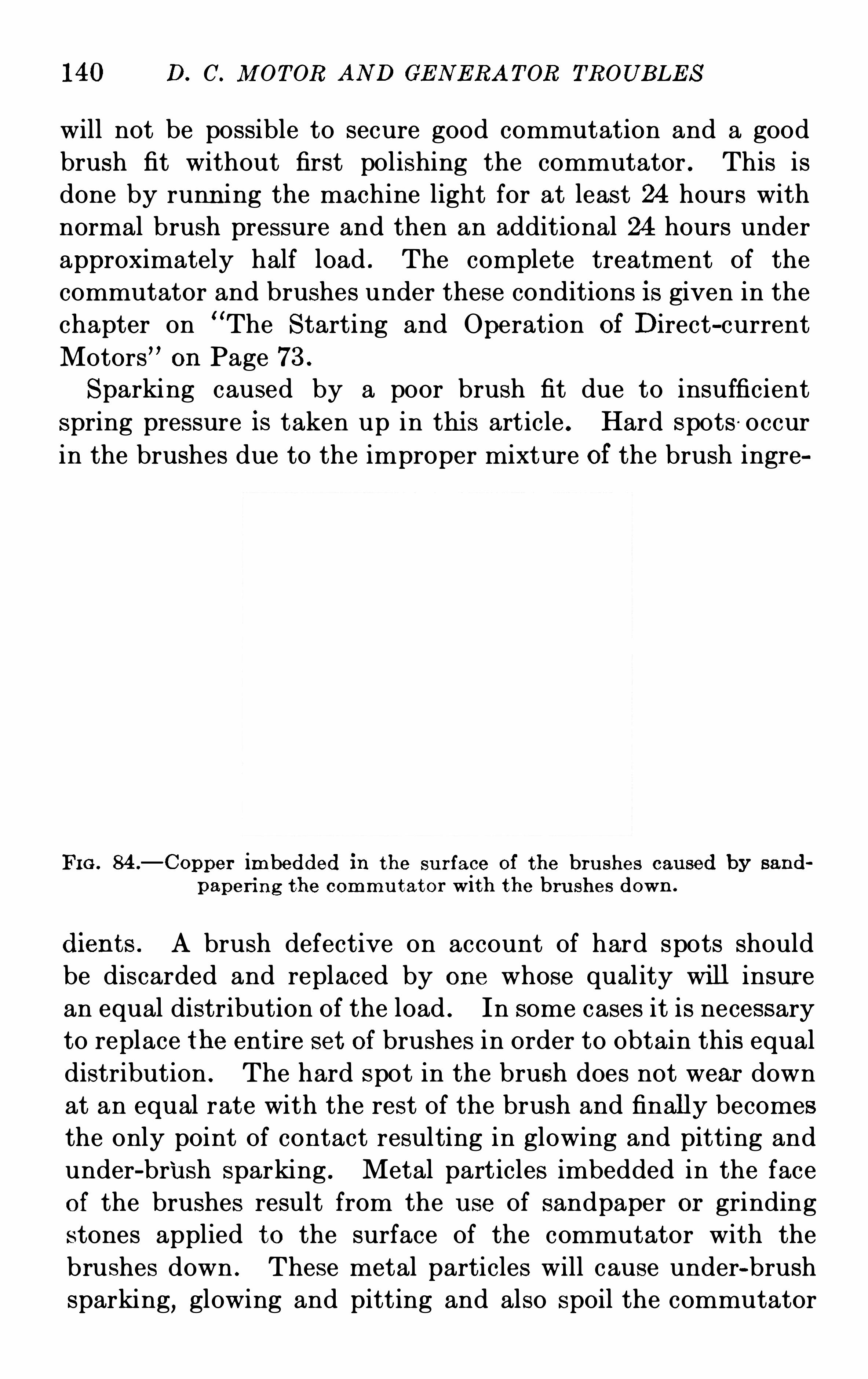
140 D. C. M OT OR AND GE N E RA T OR TROUB LE S
will not be possible to secure good commutation and a good
brush fit without first polishing the commutator . This is
done by runn ing the machine light for at least 24 hours with
normal brush pressure and then an additional 24 hours under
approximately half load . The complete treatment Of the
commutator and brushes under these conditions is given in the
chapter on “The S tarting and Operation of Direct-current
Motors” on Page 73 .
S parking caused by a poor brush fit due to insufficient
spring pressure is taken up in thi s article . Hard spots occur
in the brushes due to the improper mixture of the brush ingre
FI G . 84 .
—Copper imbedded in the su r face Of the bru shes cau sed by sand
paperi ng the commu tator with the bru shes down .
dien ts . A brush defective on account Of hard spots should
be discarded and replaced by one whose quality will insure
an equal distribution Of the load . In some cases it is necessary
to replace the entire set Of brushes in Order to Obtain this equal
distribution . The hard spot in the brush does not wear down
at an equal rate with the rest Of the brush and finally becomes
the only point Of contact resulting in glowing and pitting and
under-brush sparking . Metal particles imbedded in the faceof the brushes result from the u se Of sandpaper or grinding
stones applied to the surface of the commutator with the
brushes down . These metal particles will cause under-brush
sparking, glowing and pitting and also spoil the commutator
TROUB LE S AN D THE I R RE M E DI E S 141
polish . When excess lubr icant is applied to the commutator,it will combine with dust and lint and roll up under the brushes
,
causing poor contacts resulting in burning, pitting and
sparking .The brushes should not be fitted to the sur face Of the com
mutator by drawing strips of sandpaper back and forth under
the brush but the sandpaper should be drawn under the brush
in the direction Of rotation with the spring lifted between cuts .
Brush fitting is di scussed in detail in the chapter on“E rection
and Assembly” on Page 53 .
M I SALI GNM E N T OF THE B RUS H-HOLDER BRACKE T S
S ymptoms—Sparking at One or M or e S tuds .
G low ing O f B ru shes .
S parking may occur under the brushes Of one or more studs
if the brush-holder brackets are not properly lined up withthe commutator segments . In case Of this misalignment
,all
Of the brushes Of the stud which is ou t Of line will spark
because they are short-circuiting a greater number Of commu
tator segments and armature conductors than the design of
the machine will permit,since coils outside of the neutral zone
may be included . Improper alignment can be readily de
tected by noting if all of the toes Of the brushes Of one stud are
in line with one edge Of a commutator segment .
Misalignment of the brush-holder bracket may result from
the loosening Of bolts or from the distortion Of the insulating
collars,through warping or swelli ng, produced by heat or
moisture,or both . Where there are ten or more brushes on
each stud or bracket,it is necessary to support the outer end
by the use Of tie rings made Of wood or fibre and misalignment
is frequently due to the tightening Of the bolts holding these
tie pieces to the ends Of the studs before the brush spacing
has been determined . The correct alignment and spacing
Of the brushes and brackets should be secured before the bolts
holding the tie pieces are tightened up . It will be found that
the tie pieces are fitted with slots to permit adj ustment Of the
bracket position .
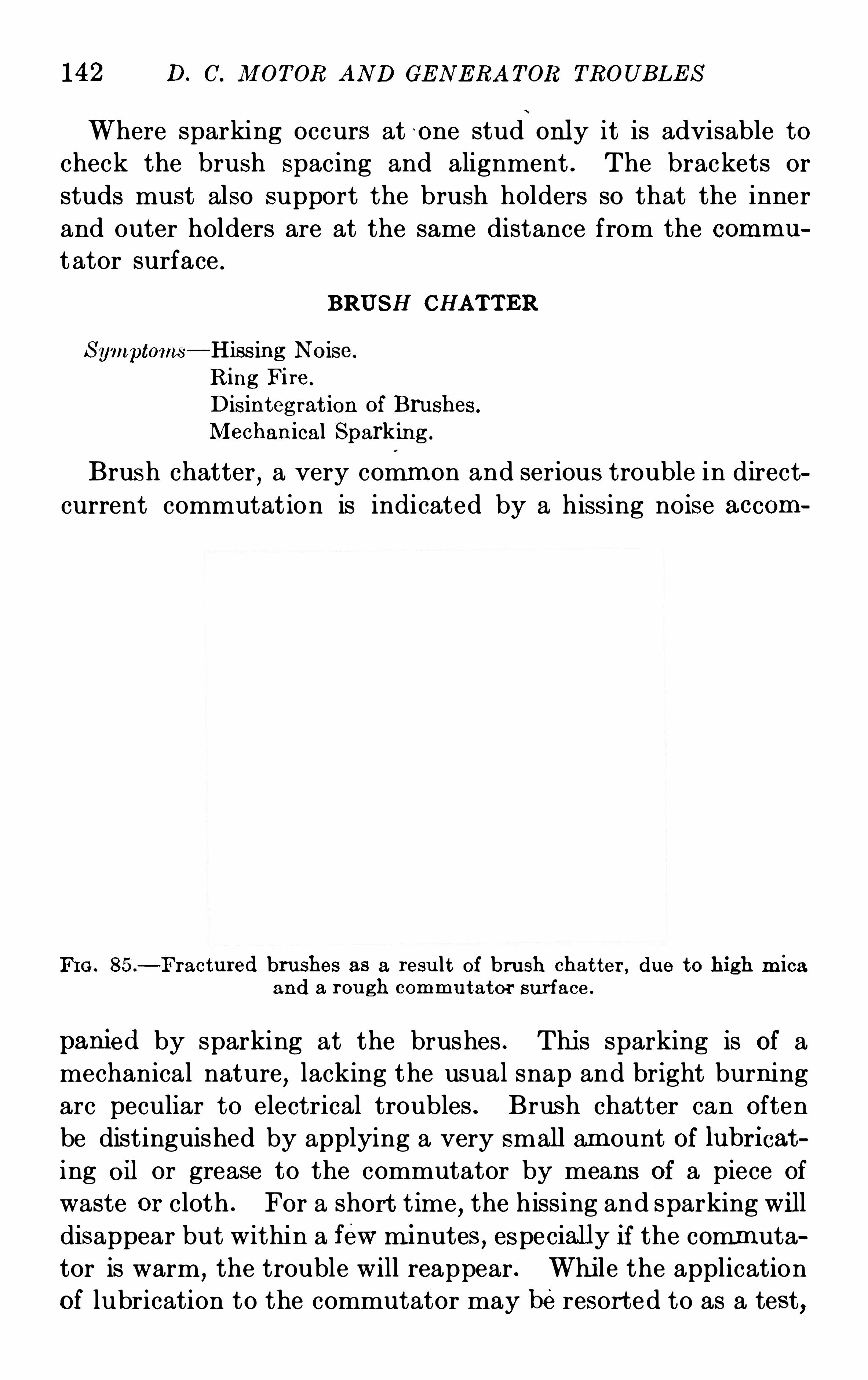
142 D. C. M OT OR AND GE N E RA T OR TROUB LE S
Where sparking occurs at o ne stud only it is advisable to
check the brush spacing and alignment . The brackets or
studs must also support the brush holders so that the inner
and outer holders are at the same distance from the commu
t ator surface .
BRUSH CHAT T ER
S ymptoms—Hiss ing N oise.
Ring Fi re.
Dis in teg rat ion Of B ru shes .
M echan ical Sparking .
Brush chatter,a very comm on and serious trouble in direct
current commutat ion is indicated by a hiss ing noise accom
FI G . 85.
- Fractu red bru shes as a resu lt of bru sh chat ter , due to high m icaand a rou gh commu tator sur face .
panied by sparking at the brushes . Thi s sparking is Of a
mechanical nature,lacking the usual snap and bright burning
arc peculiar to electrical troubles . Brush chatter can often
be distinguished by applying a very small am ount Of lubr icat
ing Oil or grease to the commutator by means Of a piece Of
waste or cloth . For a shor t time,the hissing and sparking wi ll
disappear but within a few mi nutes , especially if the commuta
tor is warm,the trouble will reappear . Whi le the application
Of lubrication to the commutator may beresort ed to as a test,
144 D. C. flI OTOR AND GE N E RA T OR TROUB LE S
When the commutator speed is greater than 2000 feet perminute the brushes are set at a leading angle Of from twenty
to forty degrees as a measure against chatter, but this angle
cannot be employed where frequent reversals Of rotation are
required . Here an angle Of twenty degrees is used . I nsu ffi
cient spring pressure will allow the brus hes to jump up and
down in the holders . The remedy Of course is to correctly
adj us t the tens ion Of the spring and recommendations for the
correct values to use are made in the article on Brush Pres
sures . High mica prevents thebrush from riding smoothly onthe commutator
,which may be remedied by making the mica
flush with the commutator sur face by the use of fine sandpaper
or by undercutting the mica s lightly with a hack-saw blade .
W hen the sandpaper is being used the brushes should all be
raised and the machi ne careful ly blown out before voltage is
applied . For highs peed commutation graphite brushes
should be used as dry, non-self—lubricating carbon brusheswill cause chattering at high speeds with any angle .
B RUSHE S B I NDI N G I N HOLDERS
S ymptoms—G lowing .
Sparking .
M echan ically Unbalanced Armature
B urnt-O ff Pigta ils .
When a brush does not move freely in its holder,sparking
,
glowing and heating of the brush will result . This trouble
can usually be recognized by the glowing Of the sticking brush
and the very bright or snappy arc under it . The failure of
this brush to take its normal proportion Of the current will
cause the remainder Of the brushes on the stud to be overloaded
whi ch may result in the heating and burning Off Of the pigt ails .
When the pigtails or connections between the brushes and the
brackets are destroyed, the on ly path remaini ng for the current
is directly through the brus h holder . Owing to the hi gh
res istance contact between the box and the brush , sufficient
heat will be generated to actually melt the metal parts and
cause the brush and box to freeze or run together . E xtreme
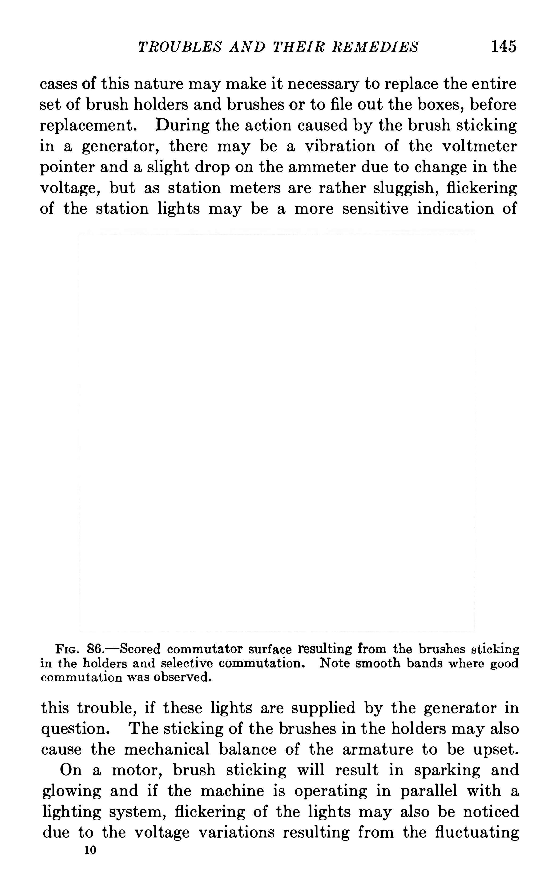
TROUB LE S AN D THE I R RE M E DI E S 145
cases Of this nature may make it necessary to replace the entire
set Of brush holders and brushes or to file ou t the boxes,before
replacement . During the action caused by the brush sticking
in a generator,there may be a vibration of the voltmeter
pointer and a slight drop on the ammeter due to change in the
voltage,but as station meters are rather sluggish
,flickering
Of the station lights may be a more sensitive indication Of
FI G . 86.
—S cored commu tator surface result ing from the bru shes st ickin gin the holder s and select ive commutat ion . N ote smooth bands W here goodcommu tat ion was Observed.
this trouble , if these lights are supplied by the generator in
question . The sticking of the brushes in the holders may also
cause the mechanical balance Of the armature to be upset .
On a motor,brush sticking will result in sparking and
glowing and if the machine is operating in parallel with a
lighting system,flickering Of the lights may also be noticed
due to the voltage variations resulting from the fluctuating10
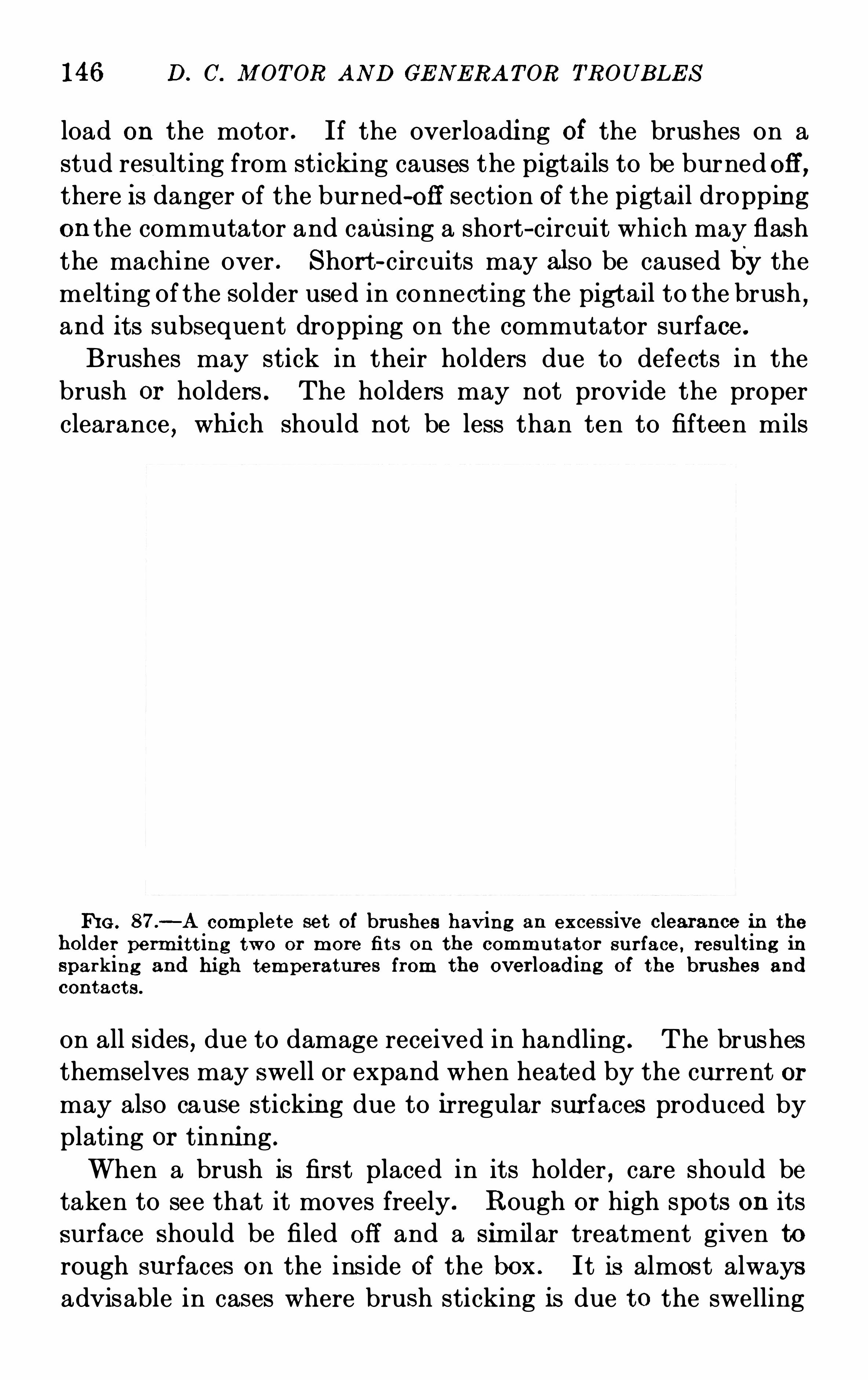
146 D. C. M OT OR AN D GE N E RA T OR TROUB LE S
load on the motor . If the overloading Of the brushes on a
stud resulting from sticking causes the pigtails to be burned Off ,there I s danger Of the burned-Off section Of the pigtail dropping
on the commutator and caus ing a short—circuit which may flashthe machine over . S hort-circuits may also be caused by the
melting of the solder used in connect ing the pigtail to the brush ,and its subsequent dropping on the commutator surface .Brushes may stick in their holders due to defects in the
brush or holders . The holders may not provide the proper
clearance,whi ch should not be less than ten to fifteen mils
FIG . 87.
—A complete set Of bru shes hav ing an excess ive clearance in the
holder permi t t ing two or more fit s on the commu tator su r face , resu lt ing insparking and hi gh temperatures from the over loading Of the bru shes and
contact s .
on all s ides , due to damage received in handling . The brushes
themselves may swell or expand when heated by the current or
may also cause stickin g due to irregular surfaces produced by
plating or tinning .
When a brush is first placed in its holder , care should be
taken to see that it moves freely . Rough or high spots on its
surface should be filed Off and a similar treatment given to
rough surfaces on the ins ide Of the box . It is almost always
advisable in cases where brush sticking is due to the swelling
148 D . C. Jl I OT OR AN D GE N E RA T OR TROUB LE S
or undercut mica . Where the mica is flush with the com
mutator surface the life of the brush is from one to two years .T O prevent rapid brush wear , guard against excessive spring
pressures and adjust the holders for the proper angle (do not
use large angle brushes trailing) . Where the machine operates
in an atmosphere charged with cement dust or fine iron par
t icles,it is advis able to use a totally enclosed unit and pipe
the cooling air from a clean source . It may be necessary to
build a separate room for the electrical machinery although
usually a protective shield will suffi ce . Acid or alkali fumes
or smoke tend to disintegrate the brushes through a chemi cal
or elec trolyt ic action . Brushes should not be permi tted to
wear down to such an ext ent as to permit the metal connec
tions holding the pigtails to cut or score the commutator
surface . The length Of the standard brush is two and one
half inches and at least one and one-half inches may be worn
down before removal,provided the springs are adjustable to
permit the proper tension . A rough commutator surface
resu lting from high or low bars or high mica will also shorten
the life Of the brushes but one Of the greatest causes Of rapid
brush wear is the sanding or stoning Of the commutator while
the brushes are down .
GLOWI N G AND PI T T ING OF BRUSHE S
S ymptoms—G lowing .
Under-bru sh Sparking .
Deterioration Of B rushes .
When a brush glows , it becomes red hot and indicates that
too much current is flowing in the brush . G lowing is rarely
caused by an excessive line current but is due to a current
generated by the armature conductors which are short-cir
cu ited by the brush . The armature conductors while in a
neutral zone may enclose the stray flux from the pole tips
and a heavy current will flow through the low resis tance made
up Of the armature conductors short-circuited by the brush .
Thi s current added to the line current causes the overload which
results in glowing . Glowing may come as a result of selective
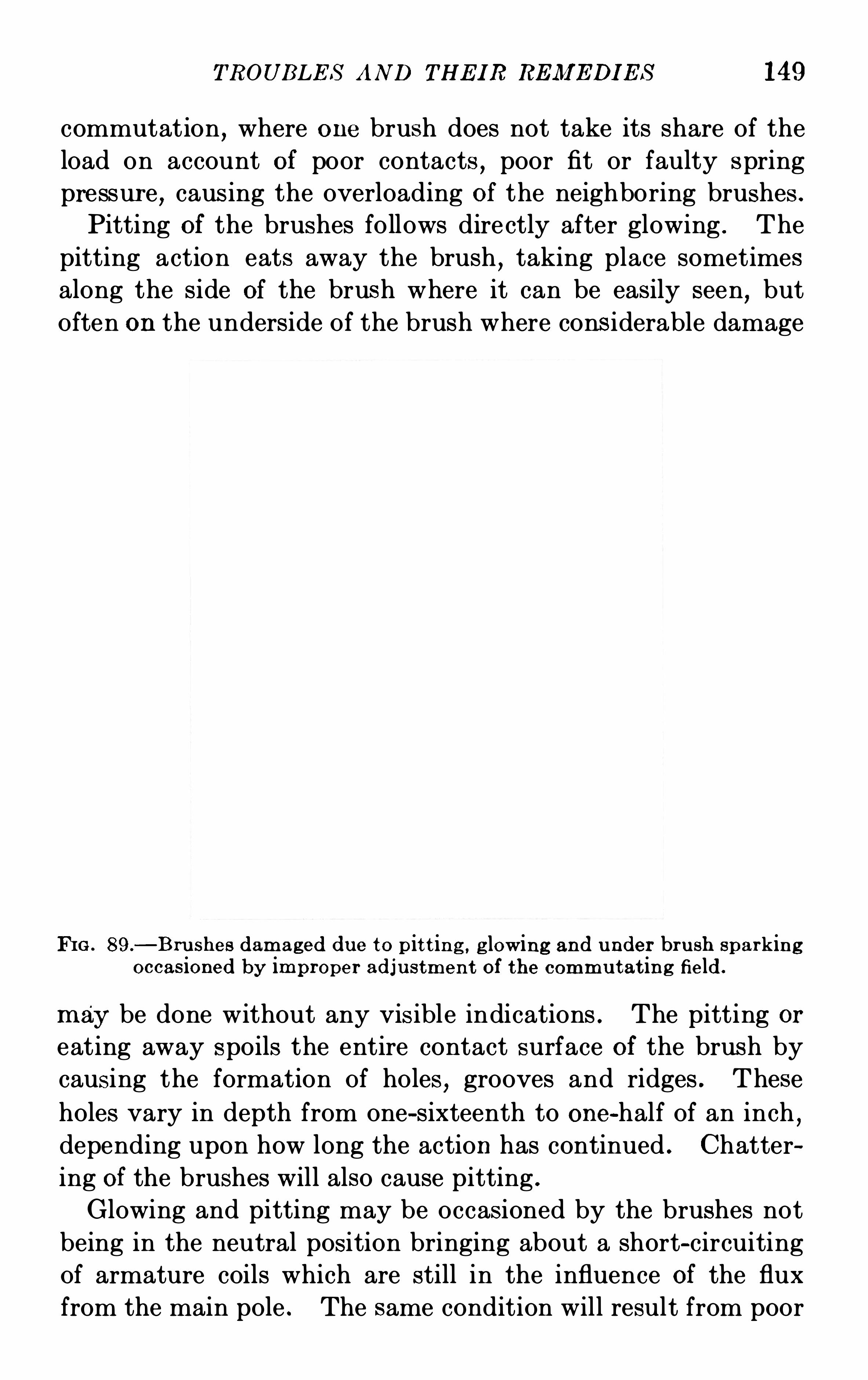
TROUB LE S AND THE I R REM E DI E S 149
commutation,where one brush does not take its share of the
load on account Of poor contacts,poor fit or faulty spring
pressur e , caus ing the overloading Of the neighboring brushes .
Pitting of the brushes follows dire ctly after glowing . The
pitting action eats away the brush,taking place sometimes
along the side Of the brush where it can be easily seen,but
Often on the underside Of the brush where cons iderable damage
FI G . 89.
—B ru shes damaged due to p it t in g , g lowing and u nder brush sparkingoccas ioned by improper adju stmen t of the commu tat ing field .
may be done without any vis ible indications . The pitting or
eating away spoils the entire contact surface of the brush by
causing the formation Of holes , grooves and ridges . These
holes vary in depth from one-sixteenth to one-half of an inch ,depending upon how long the action has continued . Chatter
ing Of the brushes will also cause pitting .
Glowing and pitting may be occasioned by the brushes not
being in the neutral position bringing about a short-circuiting
Of armature coils which are still in the influence Of the flux
from the main pole . The same condition will result from poor
150 D . C. M OT OR AN D GE N E RA T OR TROUB LE S
design if a brush which is too wide is employed,as this will
short-circuit too large a number Of commutator bars .
As a check upon faulty design , the heels or toes Of the
brushes can be filed down one-sixteenth or one-eighth Of an inch,
and the effect Of the thinner brush noted . This,if successful
,
can be used as a temporary measure until new holders and thin
ner brushes have been secured . S hifting Of the brushes should
also be resorted to,to prevent glowing
,in order to get a better
neutral setting by removing the short-circuited armature coils
from the influence from the flux from the main-pole tips .
Brushes on machines not equipped with commuta ting poles will
somet imes glow excessively at no load if the shift from the
neutral is too great (too far forward in the direction Of rotation
in the case Of a generator and too far backward against the
direction Of rotation,in the case Of a motor)
LOOS E CON NE CT I ON S—B URNT -OFF PI GTAILS
S ymptoms—Sparking .
Selective Commutat ion .
G low ing Fol lowing from B ru sh to B rush .
A loose connection between the brush and the pigtail while
not an especially serious t rouble,unless 10 per cent . or more Of
the brushes are faulty in this particular , will result in poor
and selec t ive commutation . Ordinarily when the connection
on a single brush is loose,no outward evidences Of trouble
will appear unless the machine is heavily overloaded , when
sparking and glowing at the brushes on the same stud will
occur . When 10 per cent . or more Of the connections are
loose,unless the machine is very lightly loaded , the sparking
and glowing wi ll become so serious that it may be necessary
to dimini sh the load or remove the unit from the line . A good
di agnos is Of thi s condition,can frequently be made when the
S parking and glowing follows from one brush to another across
the entire stud or from stud to stud Of the same polarity .
This symptom can also be noticed when the brushes stick in
the holders but it is a pretty sure evidence of poor contac ts .
L oose connections result from defective workmanship , poor
tinning and soldering,damage incurred in handling
,chattering
152 D. C. M OTOR AND GE N E RA T OR TROUB LE S
to hold the brush-holder yoke firmly in position . With the
pillow-block construction most trouble is experienced as the
bearing fit for the supporting yoke must necessarily be small
and the overhang Of the brush rigging gives a large leverage .
Vibration in the yoke is increased by vibration in the bearing
pedestals whi ch support the revolving parts . The fit Of the
yoke on the bearing hous ing should be tight and the j oints
between the halves should be so machined as to allow the
yoke to be in contact over the entire inside circumference. If
the yoke is supported by the set screw used for locking the
yoke in place instead Of by a perfect fit throughout the circum
ference,a great deal Of vibration will be noted . In such cases
,
the two halves Of the yokes should be disassembled and the
j oints filed until a good fit is Obtained . If this does not entirely
suffice to remove the vibration,it may be necessary where
the overhang Of the brus h rigging is eighteen inches or more ,to connect together the ends of all Of the studs next to the
commutator leads by means Of tie rings made up of wood ,fibre or other insulating materials , and support these rings
from the upper or lower half Of the magnet frame with a tie
piece Of non-magnetic material . A roller may be used in connect ion with the tie piece support where it is necessary to
shif t the brushes during Operation . Vibration Of the bearing
pedestal should be corrected by tighteni ng of the holding
down bolts or wedging up under the base at the points where
the vibration is noticeable when the finger tips are placed at
the junction Of the base and the foundation . When the brush
rigging is supported by the base or foundation , vibration is
usually caused by loose bolts or a slight movement of the
foundation under the brush-holder yoke . If the tightening
Of the bolts does not remedy the trouble,a tie piece placed
between the upper half Of the magnet yoke and the upper
section Of the ring supporting the brush rigging wi ll generally
accomplish the result .
Brushes sticking in the holders or eccentricity Of the commutator will cause excessive vibration in any Of the types Of
bru sh rigging supports .
T ROUBLE S AND THE IR RE M E DI E S 153
COMMUTATOR TROUBLE S AFFE CTINGCOMMUTATION
HI GHM I CA—HI GH AN D L ow COM MUTATOR B ARs—OrL-S OAKE DMI CA—ROUGH AN D GROOVE D COMMUTATOR SURFA CEDIRTY SURFACE —SHORT-CI RCUI TE D SE GM E N TS—BROKE NCOMMUTATOR BOLTS
HIGH M ICA
S ymptoms—E xcess ive B rush Wear .Ring Fire.
B ru sh Chat ter .B lacken ing Of Commu tator Segmen t s .
S ide mica, or the mica between the commutator segments ,which extends above the commutator surface
,will cause
sparking at the brushes and the burning and blackening of all
Of the commutator segments . This S parking is usually ac
companied by ring fire,that is
,a fine ring Of fire encircling the
commutator,resulting from the short-circuiting Of segments by
particles Of the brushes worn away by the high mica. Ring
fire at first is not serious but gradually growing worse,it may
cause the machine to flash over from stud to stud doing serious
damage to the commutator and brushes . The blackening Of
all Of the bars,when high mica is present begins at the
leaving edge and gradually works across the bar until the entire
surface is burnt . High mica is also evidenced by the chatter
Of the brushes,and usually results from the u se Of brushes
which do not contain suffi cient abrasive material to cut the
mica at the same rate as the copper .
In the manufacture of a commutator,after assembly it is
baked out thoroughly in an oven at high temperatures rang
ing from 100 degrees to 200degrees Centigrade to remove all
solvent matter from the mica insulation . During this baking
process,a commutator should be vented by drilling holes in the
clamping rings or spider to permit the easy exit Of the gases
formed . When this treatment is omitted,the commutator wil l
not be properly seasoned or settled and after a short period Of
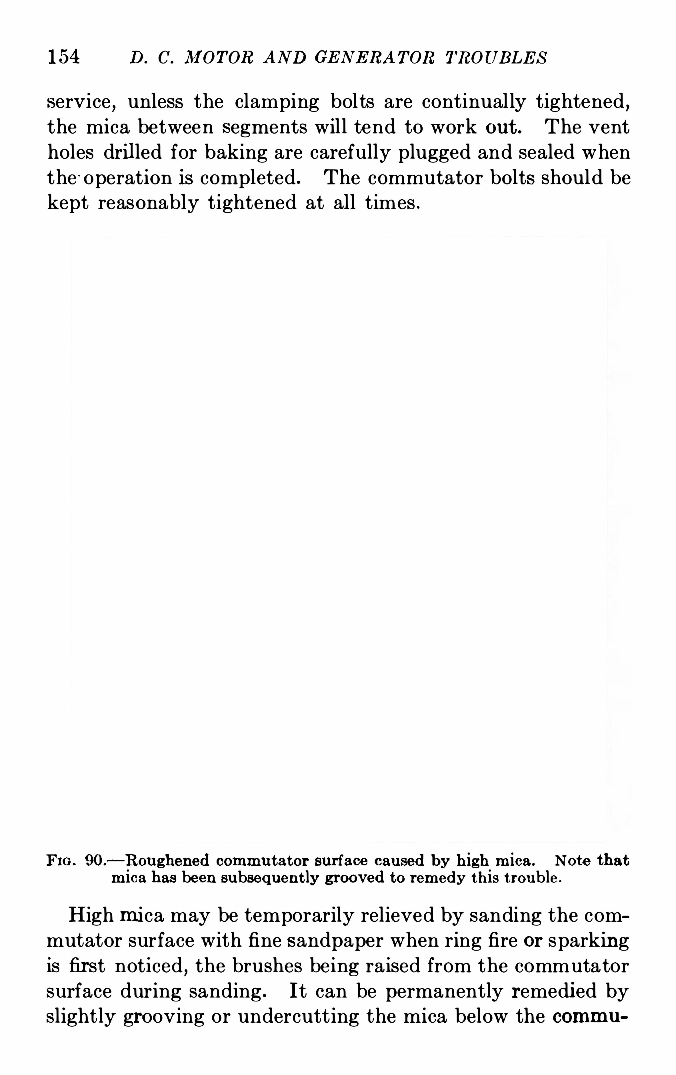
154 D. C. M OTOR AND GE N E RA TOR TROUB LE S
service , unless the clamping bolts are continually tightened ,the mica between segments will tend to work out . The vent
holes drilled for baking are carefully plugged and sealed when
the -Operation is completed . The commutator bolts should be
kept reasonably tightened at all times .
FIG . 90.
—Roughened commu tator surface caused by h igh m ica . Note thatm ica has been subsequen t ly grooved to remedy this t rouble.
High mica may be temporarily relieved by sanding the commutator surface with fine sandpaper when ring fire or sparking
is first noticed , the brushes being raised from the commutator
surface during sanding . It can be permanently remedi ed by
slightly grooving or undercutting the mica below the commu
156 D. C. M OT OR AND GE N E RA T OR TROUBLE S
Commutator mica may be grooved by means Of a slotting
machine, many Of which are on the market and usually cons ist
Of a smal l motor-driven circular saw . Grooving may also be
accomplished by the use Of a hack-saw blade or a curved three
cornered or r itfle file . Af ter grooving , great care should be
exercised to see that all Of the mica has been undercut to the
full depth Of the groove and that no small fins remain on either
s ide . Mica fins will gradually work out and cause continuous
FIG . 92 .
—A later view of the commu t ator shown in Fig . 90after operat ingwith grooved m ica . A perfect su r face has been p rodu ced ,
free from rough
ness , r idges and blackened spot s .
trouble from faulty commutation and spotting of the commu
tator surface . A usual method is to remove the fin after
grooving by means Of a sharp knife or tool .
HIGH AND LOW COM M UTAT OR B ARS
S ymptoms—C lickin g Noise at Low Speeds
B reaking off O f B rushesSpark ing at Success ive Studs
When a commutator develops a high bar or bars,it is
readily noticeable at low s peeds,that is
,when starting or
TROUB LE S AND THE IR RE M E DI E S 157
stepping , by a clicking noise when the high spot touches each
set Of. brushes . This noise is usually accompanied,if the
machine is under voltage,by a mechanica l S park passing
successively around the commutator, that is , successively at
each set Of brushes . If the machine is Operated for any lengt h
Of t ime after the high bar has developed, a black spot will
appear on the commutator at the point where the high bar islocated due to a poor contact or arcing over when the brushes
j ump from the sur face .A high spot may be due to one or more bars or an entire
section Of high bars . This is usually due to a soft spot in the
cone or ring mica which permits the bar or a section Of bars to
rise out Of place due to centrifugal force . The number Of
hi gh bars will depend upon the extent of the soft spot in the
mica . S ometimes the commutator bolts , holding the rings
in place are drawn up to such a tension as to break the bar at
the conical seat . Here again j ust one bar may be broken and
caused to ext end above the surface or a number Of bars under
the influence Of the bolt may be aff ected . A breaking Of one
Of the conical seats may be recognized by the fact that one end
Of the commutator only gives evidence Of having high bars .In cases Of too much tension on the comm utator bolts, es
pecially in long commutators , where the conical seat does not
break,the en tire central section Of the comm utator may bow
up while the ends remain in place or drop slightly . The
excessive centrifugal force produced when the machine over
speeds may also cause hi gh bars. Where the conical seat is
broken it is necessary to rebuild the commutator but it is pos
sible in the case Of soft mica,to remove the clamping ring and
shim up the soft spot with thin sheets Of mica. The ring is
then replaced and tightened and the commutator surface
turned or ground and smoothed . When the tension on the
commutator bolts is too great,producing a bowing up Of the
central section,it is possible where the elastic limit Of the
copper has not been exceeded,to relieve the excessive tens ion
on the bolts and true up the commutator surface by grinding
or turning .
158 D. C. MOT OR AN D GE N E RA T OR TROUB LE S
Low commutator bars present a real serious trouble and onewhich is diffi cult to remedy save by the complete rebuilding
Of the comm utator . Low bars are discernible in practically the
same ways as high bars , namely by the clicking nois e produced
at low speeds and the blackeni ng Of the commutator surface
at the low section . It is only infrequently that j ust one bar
will fall below the surface but usually an entire section will be
affected. When the commutator is assembled , the segments
and s ide mica are arranged to form an arch and held in place
by an external ring or rings . After machining,the S pider and
clamping ring are assembled to support the arch from the
inside . In the advent Of rough handling such as dropping or
striking, the arch is broken and while it may be possible in a
few instances to restore the sur face by grinding and turning,
it is usually necessary to restorethe arch by rebui l ding the
entire commutator . In case the arch is not broken over the
entire length Of the comm utator , but s imply low at either
end , it is poss ible to remove the clamping ring and increase
the thi ckness Of the mica by the insertion Of thin sheets under
the low points . Thi s in many cases,however , results in loose
S ide mi ca on the aff ected end .
OI L -S OAKE D M I CA
S ymptoms—Ring E re.
Honeycomb ing Of M ica.
Grounds .
If the mica insulation on a commutator becomes Oil soaked ,it will be necessary in a short while to rebuild the commutator
and furnish new mica throughout . For this reason it is
imperative that all possibilities Of O il being thrown upon the
commutator be removed . S ources of this danger are very
common,such as leaky bearings which permit Oil to creep
along the shaft and enter the spider and rings Of the commute.
tor,revolving parts Of engines such as cranks or eccentri cs
being improperly or insufficiently guarded or operation in anoily atmosphere particularly around gas engines . Frequent
160 D. C. MOT OR AND GE N E RA TOR TROUB LE S
will explode when applied to a hot commutator surface where
there is any sparking at the brushes . For this reason,the
voltage should not be on the machi ne while cleaning .
ROUGH AND GRO OVE D COM MUTAT OR S URFACE
S ymptoms—S parking .
Chat ter .
B urn ing .
Format ion Of Grooves .
A rough commutator surface may present a deceiving il
lusion while the machine is standing s til l,as the commutator
may appear to be relatively smooth and in good condition .
When in opera tion,however
,its uneven surface will be evi
deuced by sparking at the brushes,chatter and in some cases
vibration Of the entire unit . The causes for a rough commuta
tor surface are hi gh or low bars,hi gh mi ca
,improper commu
tator seasoni ng,metal beads on the surface formed by flashovers ,
burns from short-c ircui ts , bowing up or deformation due
to high temperatures,eccentri city due to the flexu re of the
shaft and the failure to turn or grind at the proper speed, that
is 300 feet per minute for turning and 1800 feet per min ute for
grinding,or taking too large a cut in the turning or grinding .
When the surface Of the commutator has become rough for anyOf the above reasons
,it may in mi ld cases
,be poss ible to restore
it to it s original condition by the use Of fine sandpaper applied
by hand , with a block Of wood fitte d to the commutator sur
face (the brushes Of course being lifted during this Operation) .
Where the use Of sandpaper wi ll not produce the desired
results,a commutator sandstone may be applied by hand but
in no cases shoul d carborundum or emery be employed , since
fine particles of these hard substances wi ll become imbedded
in the brushes and cause sparking , commutator wear and
short-circuits between bars . If the commutator is appreci
ably eccentric, it is practically always necessary to turn or
grind it and finis h with fine sandpaper before satisfactory
results will be secured . During the process Of sandpapering
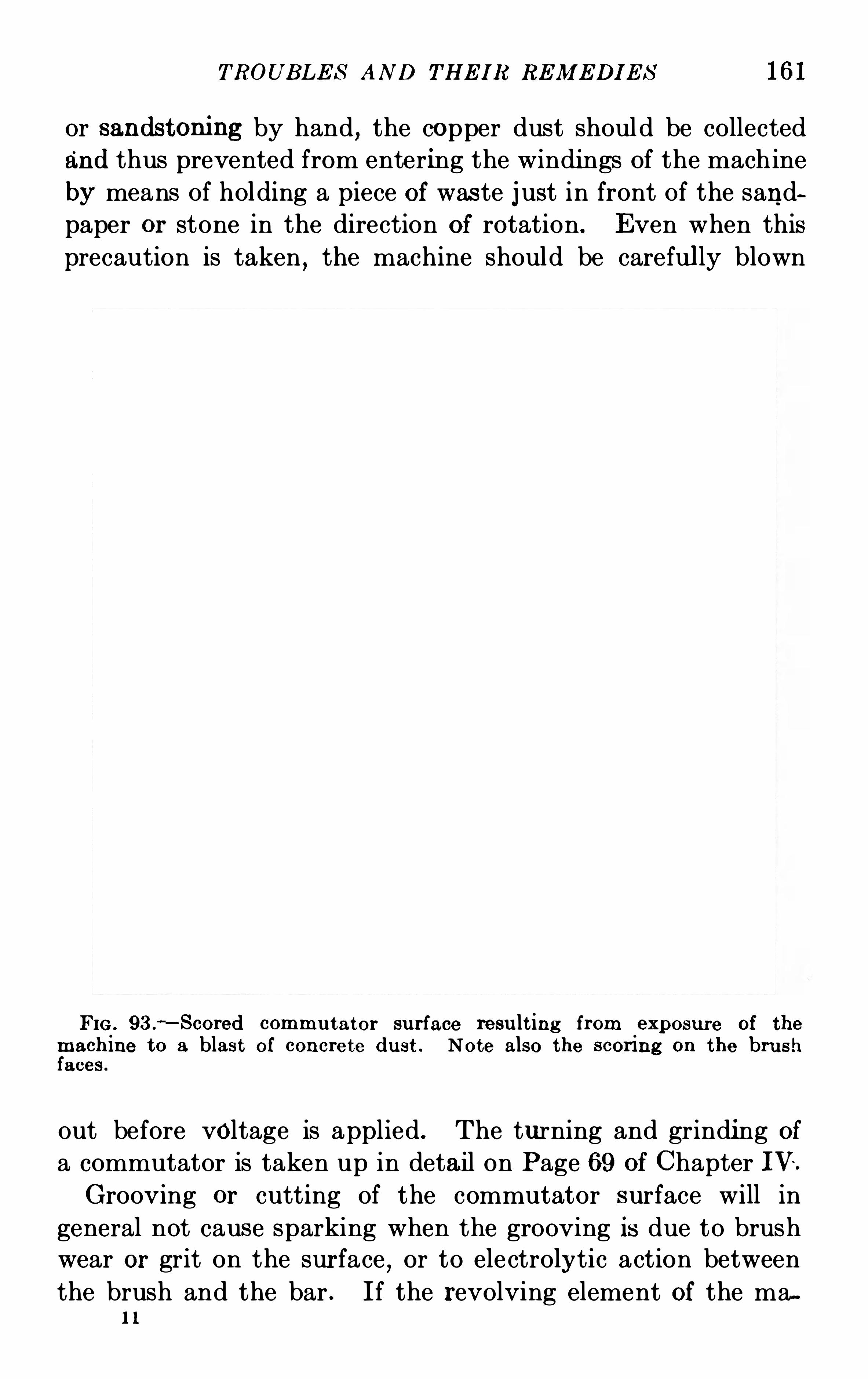
TROUB LE S AN D THE I R RE M E DI E S 161
or sandstoning by hand , the copper dust should be collected
and thus prevented from entering the windi ngs Of the machine
by means Of holding a piece Of was te j ust in front Of the sand
paper Or stone in the direction Of rotation. E ven when thisprecaution is taken , the machine should be carefully blown
FIG . 93 .
—S cored commu tator su rface resu lt ing from exposu re of themachine to a blast O f concrete du st . Note also the scor ing on the bru shfaces .
out before voltage is applied . The turning and grinding Ofa commutator is taken up in detail on Page 69 Of Chapter IV .
Grooving or cutting of the commutator surface will in
general not cause sparking when the grooving is due to brushwear or grit on the surface
,or to electrolytic action between
the brush and the bar . If the revolving element Of the mau
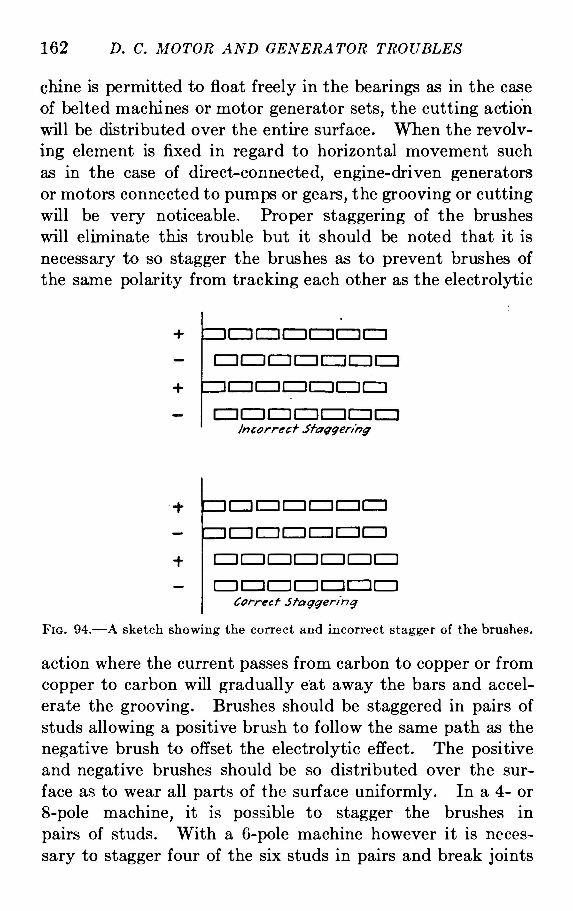
162 D. C. M OT OR AND GE N E RA T OR TROUB LE S
chi ne is permitted to float freely in the bearings as in the case
of belted machi nes or motor generator sets , the cutting act ion
will be distributed over the entire surface . When the revolv
ing element is fixed in regard to horizontal movement such
as in the case of directp connected,engine-driven generators
or motors connected to pum ps or gears,the grooving or cutting
will be very noticeable . Proper staggering of the brushes
wi ll eliminate thi s trouble but it should be noted that it is
necessary to so stagger the brushes as to prevent brushes of
the same polarity from tracking each other as the electrolyt ic
/n car r eai j fa qgen'
ng
DDDDDDD
DC !DD E E !DCar
-r eef J f a gger in g
FIG . 94 .
—A sket ch showi ng the correct and in cor rect s t ag ger of the bru shes .
action where the current passes from carbon to copper or from
Copper to carbon will gradually e 'at away the bars and accel
erate the grooving . Brushes should be staggered in pairs ofstuds allowing a positive brush to follow the same path as the
negative brush to off set the electrolytic effect . The positive
and negative brushes should be so distributed over the sur
face as to wear all part s of the surface uniformly . In a 4 or8-pole machine
,it is possible to stagger the brushes in
pairs of studs . With a 6-pole machine however it is neces
sary to stagger four of the six studs in pairs and break joints
164 D. C. AI OTOR AN D GE N ERAT OR TROUB LE S
DIRTY SURFACE
S ymptoms—Sparking .
G lowing .
Flu ctuat ion in Voltage or Failure to S tart .
A di rty commutator surface very frequently results from
the use of a lubricant on the commutator or the fitting of
brushes containing lubricant which will exude when the brush
becomes heated . A graphite brush will produce a smut uponthe commutator surface if the machine is operating in an oil
charged atmosphere on account of the mixi ng of the graphite
with the oil. In the advent of flashing over on a machine,the
commutator surface will become covered with burnt particles
of insulation , copper mica and carbon.
When the commutator becomes dirty from any of these
causes and especially where a lubricant is used,the collection
of dirt and lint upon the surface will work up under the brushes
or between the brushes and the brush holders preventing the
proper free movement . This produces sparking on account
of the poor electrical contact and will be accompanied by
heating of the brushes . In a generator,a very dirty commu
tator may cause the machine to fail to pick up or if running ,to drop , in voltage appreciably . In a motor
,a decrease in
speed will be noticed as well as sparking at the commutator .
In fractional horse-power motors,such as those installed on
washing machines or electric fans , where the spring pressure
on the brushes is very light,the motor will fail to start until
the commutator surface is clean .
Avoid the use of all lubricant on the commutator and guard
agains t the fitting of brushes which contain an excessive
amount of lubricant,which will exude upon heating . The
commutator surface should be cleaned with fine sandpaper
with the brushes up and each brush should be carefully wiped
off with waste . If a coat of smut alone exists no sandpaper
will be required,as a slight amount of kerosene , gasoline or
‘
alcohol applied with a rag (with the brushes raised) will usuallysuffice .
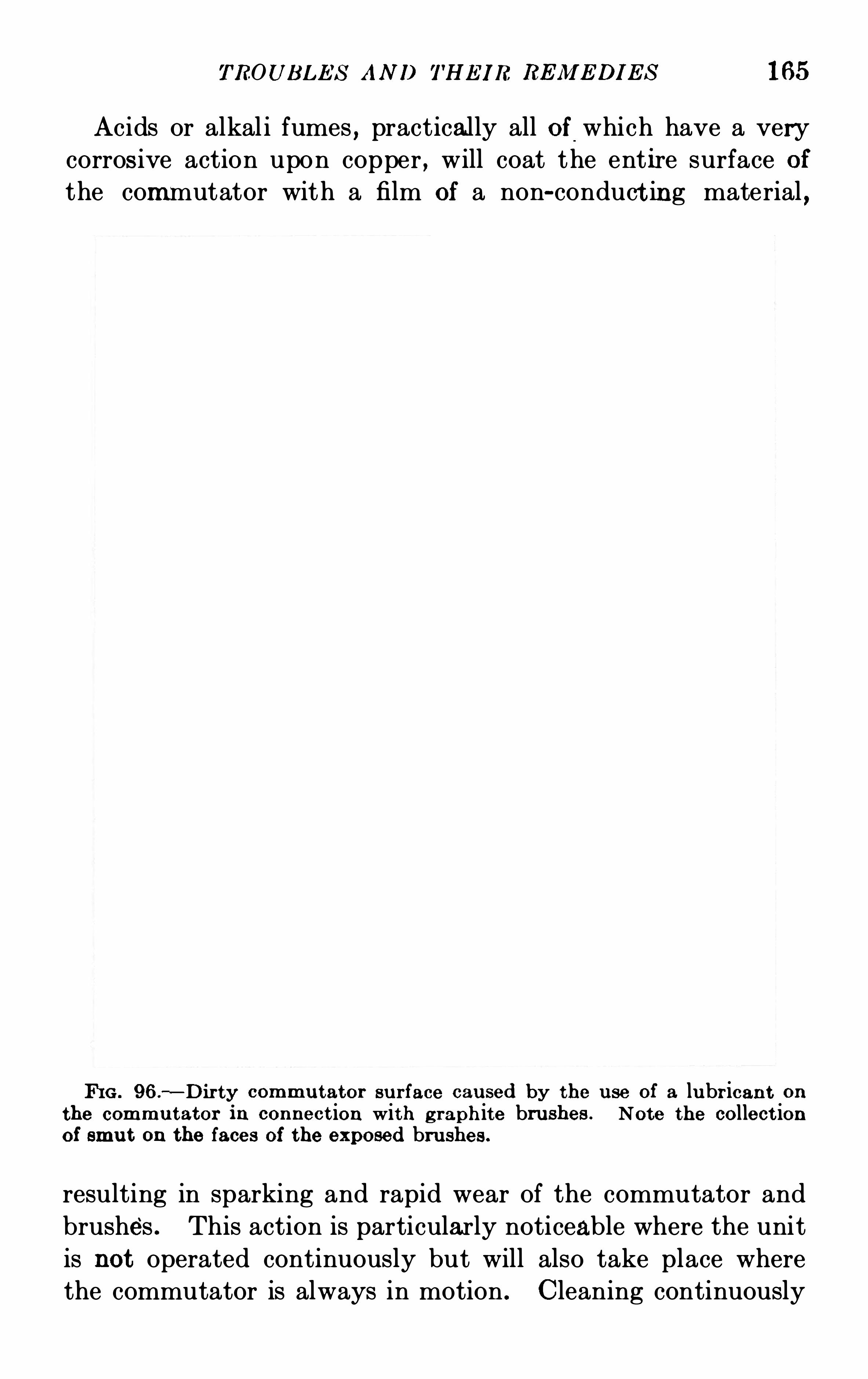
TROUB L E S AN D THE I R RE IWE DI E S l 65
Acids or alkal i fumes , practically all of which have a very
corros ive action upon copper , will coat the ent ire surface ofthe commutator with a film of a non-conduct ing material ,
FI G . 96.
—D ir ty commu tator su r face cau sed by the use of a lu br ican t on
the commu tator in connect ion with g raph ite brushes . Note the collect ionof smu t on the faces of the exposed brushes .
resulting in sparking and rapid wear of the commutator and
brushes . This action is particularly noticeable where the unit
is not operated continuously but will also take place where
the commutator is always in motion . Cleaning continuously
166 D. C. M OT OR AND GE N E RA T OR TROUB LE S
with canvas or porous cloths will reduce the sparki ng
to a minimum but the only permanent remedy is to completely
enclose the machi ne either with end shields or a separate com
partment and then furnish clean cooling air . Where it is
not possible to remove the unit from such local conditions ,both carbon and graphi te brushes are used ; the carbon
brus hes supply the necessary abras ive to cut through the
insulating fi lm while the graphite brushes aff ord sufficient
lubrication .
Flashi ng at the commutator, burni ng or grounding can be
oftentimes traced to the failure to properly clean the creepage
FI G . 97. Coated bru sh surface cau sed by collect ion of dirt on commu t ator .
surfaces,at the ends of the segments where the clamping
rings and the copper come very close together . This creepage
surface varies in length from one-half inch in one hundred
twenty-five volt machines to thr ee to four inches where voltages
of fifteen hundred to two thousand are obtained . The creep
age sur face is made by placing an ins ulating collar of mi ca
around the clampin g ring,held in place by cord
,whi ch in
varnished,shellaced or painted . If collections of copper
,
carbon dust,water or grease are permi tted to remain upon this
surface,a low-resistance path from the copper bars to the
ground is formed and the machine will be grounded . Burningand flashing w ill take place
,destroying the insulation on the
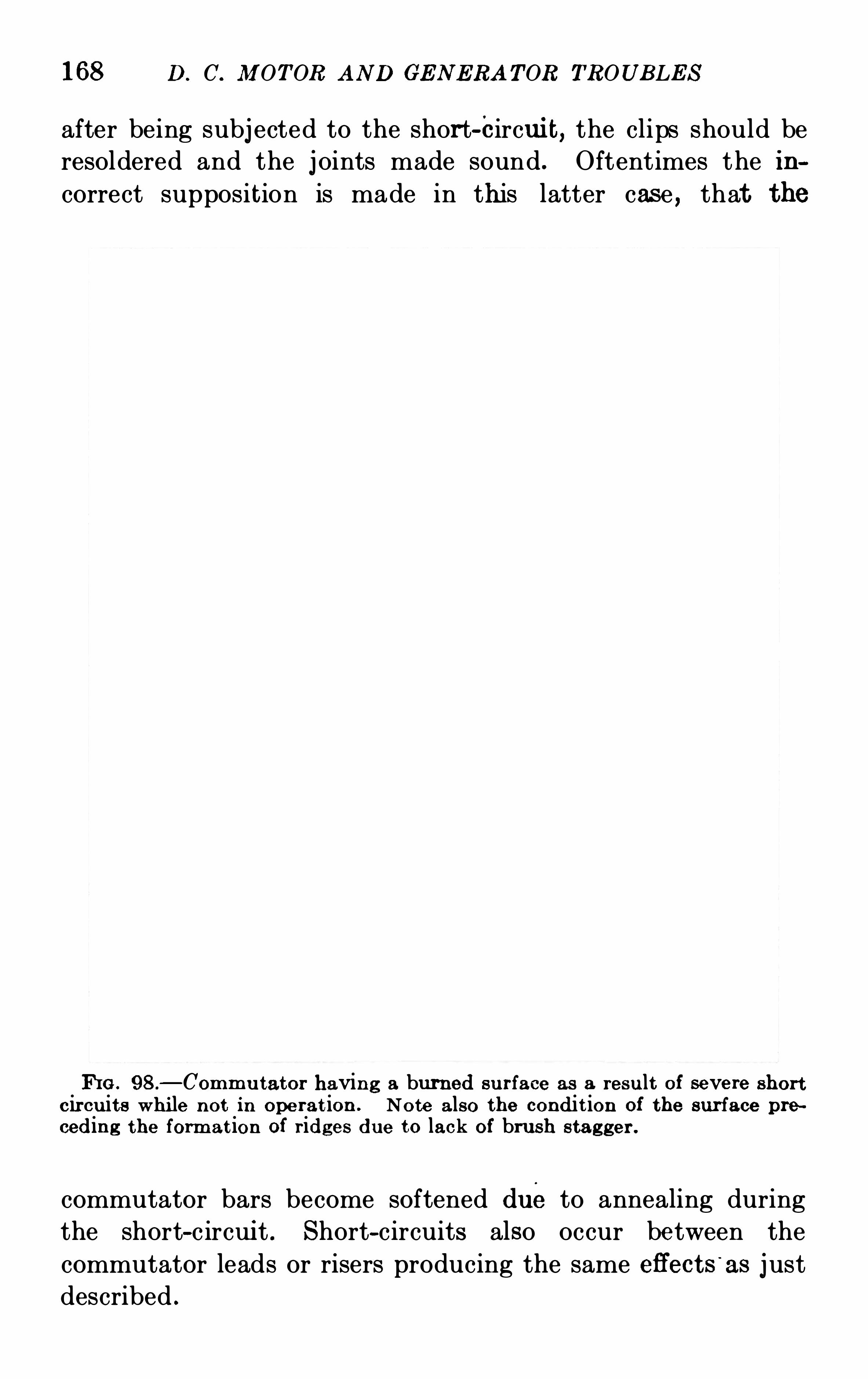
168 D. C. M OT OR AND GE N E RA T OR TROUB LE S
after being subj ected to the short-circui t, the clips should be
resoldered and the j oints made sound . Oftentimes the in
correct supposition is made in this latter case , that the
FIG . 98 .
—Commu tator having a burned su rface as a resu lt of severe shor t
circu its whi le not in operat ion . Note also the condit ion of the sur face pre
ceding the format ion oi r idges due to lack of brush stagger .
commutator bars become softened dueto annealing duringthe short-c ircui t . Short-circuits also occur between the
commutator leads or risers producing the same effects‘
as j ust
described .
TROUB LE S AND THE I R RE M E DI E S 169
BROKE N COM MUTAT OR B OLT S
S ymptoms—Flying B olts .
Loosened Commutator Segmen t s .
Broken commutator bolts are a somewhat infrequent causeof trouble but may present a serious danger to the safety
of the operator and the operation of the machine . When the
defect is fir st noticed by the breaking of the first bolt, the unit
should be immediately removed from service and permanent
repairs made . The fracture of the bolt is caused by the ex
pansion of the commutator segments due to high temperatures
or in some cases,to an unequal distribution of the tension in
the commutator resulting in an overstressing of one of the
bolts . Where comparatively short bolts are employed for
holding the clamping rings instead of long through bolts,the
unequal expansions of the short bolts and the longer copper
segments produces the excessive tension . Replacing the short
bolts with bolts of the same length but a higher tensile strength
will not eff ect the anticipated remedy as the conical seat of the
segments will break or the central section of the commutator
will bow up if the bolts hold . A short bolt usually extends
through the ring and into the spider approximately one and
one-hal f diameters . Bolts of a sufficient length to permit of considerable expansion should be substituted in this case . The
drilling for the short bolt in . the commutator spider should
be continued until a depth is reached which permits the useof a bolt from two and one-half to thr ee times the length of theoriginal bolt . The new bolt should be “necked down ” j ust
above the threads for a distance equal to at least two diameters .The reduction in diameter or “necking down ” should not
bring the size of the bolt below the dimension at the bottom
of the thread . Both ends of the commutator should be given
this treatment even though the trouble may have developed
on one end only . In case it is mechanically possible to drill
the spider the entire length and u se long through bolts,to
hold both front and back clamping rings,it is advisable to adopt
this arrangement . The through bolts should be reduced in
170 D. C. JlI OTOR AN D GE N E RA T OR TROUB LE S
diameter in the center over a space of from three to four
diameters as mentioned above . Commutators constructed
with thr ough bolts instead of short bolts,give best results and
in case such a bolt breaks it is due to unequal strains produced
when the commutator is assembled,and a new bolt may be
inserted without renewing the remaining bolts although an
exami nation of their condition is advised . A commutator
should not be operated with one or more of its bolts defective
whether of the long or short-bolt type . Clamping rings are
frequently strained ou t of shape by excess tightening and
when making an exami nation for defective bolts it is well to
remove the clamping ring and test its surfaces with a straight
edge . Unless the clamping ring has been stressed far beyond
its elastic limit,it can be readily pulled back into shape . S teel
chi ps produced by a breaking bolt may cause a ground and
care should be taken to see that all fragments are removed
particularly after a ring has been taken out for examination .
172 D. C. M OT OR AND GE N E RA T OR TROUB LE S
in the voltage~
at constant rated amperage occur s. I n'
drdi
nary cases,the weakness of the field may be caused by too
small a field current resulting from too much resistance in the
field circuit,poor contacts or high temperatures of the field
coils . A reversed connection of one or more field coils causing
it to oppose the others or an improper connection of the series
field on a compound-wound motor or generator with respectto the shunt coils will also cause a weakened field . If the
series coils are improperly connected with respect to the shunt
field on a compound-wound generator,the series field will lower
the voltage with an increase of load instead of raising it while
on a compound-wound motor,it will cause an increase in
speed due to a weakeni ng of the field .
The improper connect ion of the individual field coils with
res pect to each other may be detected by holding a compass
needle near the poles while the field current is passi ng through
the coils . Adj acent poles should attract opposite ends of the
needle . A weak field caus ed by an im proper connect ion of the
individual coils requires only the reversal of the connecting
leads . The proper or improper connections of the series coils
on a compound-wound generator or motor with respect to the
shunt coils may be determined by noting if the current passes
through both sets in the same direction which it should do in
order to produce the proper results . When the low field cur
rent is due to too much resistance in the field circuit,cutting
out resistance in the field rheostat should of course be resorted
to .
Motors operating under a weakened field condition , spark
at the commutator on account of overloads as well as the shift
ing of the neutral point as mentioned above,where the me
chan ical load is great enough to prevent the increase in speed
of the armature corresponding to the weakened field condition .
The counter-electromotive force can only be increased where
the field value is fixed by an increase in speed,prevented in
this case by the mechanical lead . It should be remembered
that the current in the motor armature is limited by the
counter-electromotive force and also by the resistance of the
TROUB LE S AN D THE IR RE M E DI E S 173
winding,brushes and connections . This res istance is fixed
and unless the speed can change with a variable field current ,over-loading will result .
OPE N CIRCUIT I N THE ARM ATURE
S ymptoms—Flashing at S uccessive S tuds .
B lackened B ar .
Failure to S tart in Case of M otor.Variation in Voltage in Generator.
An open circuit in an armature win ding always results in
the blackening and burning of the commutator segment
connected to the open-circuited conductor . The entire set of
brushes on each stud will flash and spark success ively around the
machine as the bar connected to the defective cir cuit passes
under it . The flashing is not s imilar to the usual spark noticed
at the comm utator due to other causes but is violent , snappy
and very destructive . On a generator,a variation in the vol
tage accompanied by a fl icker in the lights will be noted . In a
motor,if the circuit has been broken before the original starting ,
it will refuse to start unless one set of brushes happens to
be in the proper position to close the circuit . If,however
,
the motor gets up to speed or the cir cuit is broken during
operation,the motor wi ll continue to run providing the me
chami cal load is light . The speed regulation will be unsteady
and the rotary motion . when the motor is relatively well
loaded,will be j erky .
The open circuit may be caused by a breaking of the commutator leads or risers due to vibration or movement between
the commutator and the armature core . These connections
may be opened by the removal of the solder due to high tem
peratures occasioned by overloads or by faulty contacts .Where the armature is wound with fine wire
,as is the case
with small machines,no commutator leads or risers are used
,
and the open circuit usually is found where the wir e conductori s soldered to the commutator segment . Wire-wound arma
tures may be open circuited by burning due to short-circuits
174 D . C. M OTOR AN D GE N E RA TOR TROUB LE S
between adj acent conductors . Rough handling is a frequent
cause of broken connections .
All conductors in an armature winding are connected in a
closed circuit through the commutator segments . When oneconductor is opened the commutator segment to whi ch it is
connected is removed from the continuous circui t and as this
segment passes in success ion under each set of brushes,it is
bridged by the brushes and the circuit is closed and current
builds up . The breaking of this circui t will produce a violent
flashing due to the inertia of the current whi ch has built up .
Upon noticing the above symptoms,the machine should be
immediately removed from service . If a comm utator lead
or riser is found to be broken , a copper sleeve may be made
from a thin sheet of copper and soldered around the broken
points of the lead to make ‘ a firm j oint . If an end clip has
thrown i ts solder,due to overheating
,it should be securely
resoldered . A coil open circui ted in the core or slot due to
burni ng must be replaced or a soldered repair made where
mechani cally possible . Replacing an armature coil is de
scribed on Page 242 . Temporary repairs for emergency condi
tions may be made in case of an open circuit by connecting
together the two comm utator segments adj oining the defec
tive bar and the defective segment with a copper stud firmly
soldered into position . This connection may also be made
by poundi ng the copper segments at the ends to make a con
tact between the bars thus forming a closed circui t or bysoldering a strip on the commutator leads or end clips on the
armature winding . In hi gh-speed machines , where it is di ffi
cul t to solder connecting strips securely enough to stand the
centrifugal strain,the repair is sometimes effected by drilli ng
and tapping between the two adj oining segments and the
defective bar and introducing a short screw between each bar .
This practice,however
,is not recommended as it is apt to
destroy the mica insulation and cause trouble in the future .
It is also possible to bridge over the open segment by throwing
the brush holder studs s lightly out of line so as to span one or
more commutator segments than are covered when in the nor
176 D. C. M OT OR AND GE N E RA TOR TROUB LE S
windings,ventilating ducts or flange rings free from accumu
lat ion s of copper, carbon dust or other current-carrying ma
ter ials . When an armature is exposed to flying metal chips
from lathes or other machine tools,grounds may appear
when these particles happen to fall into positions so that they
connect the live parts of the machine to the ground . The
usual places where these chips cause trouble are in the end
windi ngs , soldered clips , ventilating air ducts or j ust in back
of the commutator leads . Af ter rewinding or initial assembly,the machi ne may develop a ground , due to metal particles ,which have been permitted to remain under the windings or
in the slots, chafing through the coil insulation on account
of the slight movement of the coil in service . If an armatur e
core becomes loose on its dovetails or between its flanges or if
the space blocks in the ventilating air ducts become loosened
and work out,the pu nchings will shift due to centrifugal force
and result in cutting through the insulation on the conductors
usually at the ends of the core or at the air ducts , producing
serious grounds . If the bindi ng bands ever the end windings
or core portions become loose due to the shrinkage of the in
su lat ion or to overs peed , or if the retaining wedges in the core
portion shrink as a result of high temperatures or improper
seasoning and permit of movement of the conductors in the
slots or on the end flanges,grounds will shortly appear due to
chafing or rubbing of the insulation . Grounds are als o
caused by the application of high potential tests before all
accumu lations have been carefully removed from all parts of
the machine and especially the end windings . Before hi gh
potential tests are applied all machines should be thoroughly
cleaned by carefully wiping and blowing out and Where the
un it has been runni ng or standing under mois t conditions a
complete drying out should be eff ected by baking .
S ometimes a high resistance ground is first detected by the
operator coming in contact wi th live parts of the c ircuit on
either the positive or negative side and receiving a shock when
the unit is operating on a system which is not intentionally
grounded . The extent of the ground should be determined
TROUB LE S AN D THE I R RE M E DI E S 177
with a voltmeter by measur ing the drop and insulation resistance from the live circui t to the ground
,as described on Page
2 19, and if the insulation resistance is found to be un der
ohms,it is necessary to remove the machine from
service and make repairs . An indicated resistance of above
ohms will insure safe operating conditions . Amagneto
fitted with a bell connected between the live circuit and the
ground preferably between the commutator and the shaft will
indicate a ground by the ringing of the bell . Where it is
difficult to locate the defini te point of ground , a voltage , pref
erably alternating current , should be applied between the
commutator and shaft with a resistance in the circuit to limit
the flow of cur rent,and continued until smoke appears at the
grounded point .
After the point of ground has been located,the repair of
course will depend upon the condition found . If the trouble
is due to chi ps or metal part icles,'
they should be removed
and the damaged insulation repaired as described on Page 247.
A ground resulting from moisture or collections of dirt or
current-carryi ng material can be easily removed by thorough
cleaning unless the insulation has been impaired . Armatur e
coils,grounded in the slot portions or end windings as a result
of loose laminations or space blocks,chafing or rough handling
,
usually require replacement of the damaged coils . Flashing
over to the ground due to short-circuits or sudden swings of
load results in the formation of a carbonized path from the
live circuit to the ground and such paths should be given a
coat of insulating varnish after all of the carboni zed material
has been completely removed . Where a ground is due to
loose laminations cutting through the coil insulation,it is use
less to attempt to rewind the armature until effective repairs
have been made upon the core,as given on Page 195.
OVERLOADS AND VARIAB LE LOADSS ymptoms—Sparking .
H i gh T emperat ures .
Overloading a machine beyond its rated capacity results in
sparking,accompanied by heating and glowing of the brushes
12
178 D. C. M OT OR AND GE N E RA T OR TROUB LE S
due to the excessive current which they are car rying . A
machine sparks when overloaded because of the hi gh current
density in the brushes,high maximum volts between segments
due to a change in the wave shape of the voltage curve,high
armature reaction causing a shifting of the neutral point,im
proper adj ustment of the fields caused by the overheating of
adj usting shunts and unbalanced circuits in the armature
winding . The sparking is of such a natur e as to damage both
the brushes and the commutator,whose surface will be bur ned
and discolored due to heating especially if the overload is
allowed to continue over too long a period . The manufac turer ’s
guarantee is stamped on the nameplate on modern machines
and the condi tions outlined should not be exceeded . When
the normal load is exceeded for short periods, commutation
is usually the limiting feature . Unless the overload exceeds
25 per cent . for more than two hours on machines up to three
hundred kilowatts with voltages up to two hundred fifty,no
permanent damage should result . The momentary overload
for such machines is from 50 to 75 per cent . Above 250 volts,
the usual two hour overload guarantee is 50 per cent . with a
possible momentary overload of 100 per cent . Machines
which are maximum rated are design ed to operate with a high
brush density and no overload is provided for,such machines
will be seriously damaged by the overheating of the brushes
and the commutator as well as the windings,if an overload is
al lowed to exist .
S parking resul ts from a var iable load because of the con
t inuous shifting of the neutral point in machin es not equipped
with commutating poles . S parking on a machi ne designed
with commutating poles is due to the failure of the cur rent to
pass through the commutating fields whi ch are inductive ascompar ed with the shunt across the commutating field whichis
'
pract ically non-inductive except in special cases . Swi ngsin the load current will pass through the non-inductive circuitand sparking results because the armature reaction is not
compensated for by the commutatin g pole as the current does
not pass through the commutating pole windings at the time
180 D. C. M OT OR AN D GE N ERA TOR TROUB LE S
POORLY B ALAN CED ARM ATURE
S ymptoms—M echani cal Sparking .
Vibrat ion of Supporting B earings .
An armature should be in perfect electrical and mechanical
balance . The electrical balance , that is , the equalizing ofthe resistances of the conductor paths so as to cause equal
currents to flow in all parts of the armature is eff ected in
multiple-wound armatures by the use of equalizers,which
consist of copper conductors connecting all points of equal
potential . They are usually placed on the back end of the
armature but may be located on the front end just back ofand connected to the commutator risers or leads . N 0 equal
izers are used on series-wound armatures since each conductor
passes under all of the poles in succession before it is connected
to the next conductor at the commutator segments and the
coil is therefore electrically balanced within itself . T o insure
against electrical unbalancing,even though the armature is
equipped with equali zers,care should be exercised to see that
all air gaps are made uniform by means of the liners or shims
provided under the pole pieces . Unbalanced armature circuitscome as a result of unequal brush spacing , loose connectionsand unequal spring pressure on all brushes
,the eff ects of and
remedi es for whi ch have been discussed in previous articles .
So important is the mechani cal balance of an armature that
manufacturers give each part,such as the commutator
,arma
ture spider,and assembled core
,with and without windings
,a
separate static balance and after all assembly and winding,
including the final dipping or spraying of the insulating com
pound and fini shi ng of the commutator has been completed,
a very accurate static and dynamic balance is given . A poorly
balanced armature will cause vibration resul ting in sparking
at the brushes and increased wear of the bearings . The
sparking is of a mechanical nature , existing at all loads and
doing no particular harm to the brushes or commutator , and
is lacking in the snap of the electrical spark . All brushes
may spark at the same time or they may spark successively
TROUB LE S AN D THE I R RE M E DI E S 181
around the commutator . An intermittent vibration may be
set up in the brush rigging so that the brushes will alternately
vibrate and settle down . The unbalancing may be caused by
careless workmanship in the factory but frequently the failure
to bring both halves of the coupling into perfect alignment ,in the case of engin e-driven or motor-generator sets
,will upset
the entire balance . This will also occur if the faces of the
half couplings are not perfectly true or if burrs or ridges pre
vent a perfect j oint . A sprung shaft , damaged in shipment
or handling will also cause this trouble . When armatures are
rewound in service , careful attention should be given to the
proper location of binding bands , clips and soldered spots,
particularly in smaller machines as some manufacturers de
pend upon these features for their final balance An infre
quent but serious cause of unbalancing is due to some of the
brushes sticking in the holders instead of moving freely with
the commutator .
The remedies for the above causes of mechanical unbal
ancing are obvious and all points mentioned should be checked ,particularly the shaft for springing . This may be done with
a shaft indicator or by means of a piece of chalk held firmly in
position so that it will just touch the high side of the shaft
in case it runs out of true . If all tests indicate that the
armature was poorly balanced when shipped from the factory,
weights must be added by drilling and tapping in screws in
the armature spider arms or end flanges as far from the shaft
axis as possible so as to reduce the size of the weight to a
minimum The location of these weights must be determined
by experiment or cut and try methods if the armature is to
be balanced in i ts own bearings . The use of a piece of chalk
held rigidly against a pole piece in such a position that the
high side of the armature core will j ust touch at each revo
lut ion,will give a starting point for adding the balancing
weight which,of course
,should be placed diametrically
opposite to the center of the chalk mark .
Pockets for receiving lead balancers are provided on the
inside circumference of armature flanges in most machines .
182 D. C. M OTOR AN D GE N E RA T OR TROUB LE S
Where it is necessary to add a very substantial weight this
weight should be divided into two parts placed one at each end
of the armature .
FAULTY DE SI GN
Poorly designed motors and generators never give real
satisfaction,because they possess inherent faults whi ch limi t
the operation to such an extent as to practically remove all
flexibility and adaptabili ty to diflerent ranges of service .
A well-designed machine offers a generous leeway in heating ,
commutation,voltage and speed regulation and thereby
greatly in creases its sphere of usefulness . The most common
faults in design whi ch aff ect the successful commutation of
the machine are toomuch voltage between segments,too great
an armature reaction with a low main field flux,hi gh brush
density,too few equalizers
,insufficient air gap
,excess ive
commutator speed and improperly located connection strips .
In a great many cases,troubles attributed to faulty design are
directly traceable to incorrect application and a study of the
local conditions surrounding the installation and of the
fitness of the machine to meet the demands of the serviceshould be made .
The permiss ible voltage between segments depends upon
the type of machine and the requirements of the service .
Machi nes designed for constant loads will Operate successfully
with a voltage between segments as high as twenty volts while
a machine operating on a highly fluctuating load shoul d be
des igned with an average voltage between segments not to
exceed fifteen volts . These values refer to machines equi pped
with commutating poles as units without commutating polesshould have the values reduced 25 to 50 per cent . Gener
ators even though des igned with”
commutating poles , oper
ating in locations where exposed to moisture or collections
of di rt , should likewis e be considered under thi s latter class
and should carry the reduced voltage between segments .
While it is desirable to have a low voltage between segments,
184 D. C. M OT OR AND GE N E RA TOR TROUB LE S
commutation have already been given on Page 132 . If it
should be desired to operate a machi ne for a greater output and
stay within the limits of the current-carrying capacities of the
brushes,another brush may be added to each stud if the length
of the commutator permits or a wider brush may be sub
stituted, provided that the design of the unit is such as to
permit the change . Heating and comm utation should be
considered as the limiting features in the event of increasing
the output of the machi ne . It is advisable to consult the
manuf acturer when such changes are contemplated unless the
operator is fam iliar with the design .
Modern armatures of the multiple wound type are equipped
with at least one equalizer tap for each slot, which results in
an evenly balanced armature and more satisfactory commuta
tion than if t he armature had no or too few equal izers . These
equalizers are copper connections of low res istance, connecting
together all points of equal potential in the armature winding .
For example,the armature conductors exactly under the center
of all poles of like polar ity are j oined together since the rela
tion of al l of these conductors with respect to the fields is not
changed throughout the revolution of the armatur e . After
the first connection has been made a complete set of equalizers
may be correctly ins talled by s imply progress ing around the
armature . E qualizers may be connected either at the back
end of the armature or directly to the commutator segments
on the front end .
The lack of equalizers or an insufficient number of them
will produce blackened segments on the commutator,usually
unevenly spaced on the surface and caused by an excess ive
flow of current through the brushes and bus rings where
the unbalancing in the armature cir cuits is an appreci
able amount . The blackened segments may also appear
where the armature is fu lly equalized and in the advent of
such a condition,soldered conn ections either on the equalizers
and clips or commutator risers should be examined, as it
will be found that the blackening is practically always due to
a loose or poor connection . T he heavy exchanges of current
T ROUB LE S AN D THE I R RE M E DI E S 185
through the various armature paths , where the machine hasno or too few equalizers
,will result in the eventual annealing
of the commutator segment accompanied by sparking and the
formation of low and flat spots on the commutator . T o
determine whether or not trouble is being experienced because
of too few equalizers,first examine all soldered connections
on the armature and insure their tightness . Then remove the
blackened spots on the commutator with fine sandpaper and
prick punch the affected segments . Upon again placing the
machi ne in service, it should be noted whether or not the
same bars blacken again . I n the advent of the reappearance
of the blackening at the same points , the machi ne should be
fitted with additional equalizers , preferably with a sufficient
number to provide a tap for each slot . When an armature is
wound with more than two bars per slot and each bar is con
nected to a commutator segment , one equalizer connectionper slot may not be sufficient, in which case it is good practice
to connect an equalizer tap to every other end clip . Where
the armature bars are so connected by end clips as to make up
an armature coil cons isting of more than one turn , one equa
lizer tap per coil is sufficient .
The actual addition and placing of the equalizers on the
armature is described on page 2118 .
Insufficient air gap will cause sparking at all of the brushes
on machines designed without commutating poles by permit
ting the shifting of the neutral , due to cross magnetization of
the armature conductors . If the air gap is very small on a
commutating pole unit,sparking will result from the local
magnetic circuit because two or more armature teeth are
being practically closed by the commutating pole tip . Shift
ing of the neutral in this case is prevented by the commutating
pole and very small main gaps may be employed as compared
with those on non-commutating pole types . However, i t
should also be remembered that the use of very small air gaps
is accompanied by high temperatures of the armature and
pole face laminations due to excessive core loss . The obvious
remedy for an insufficient air gap is to increase the gap by the
186 D. C. M OTOR AND GE N E RA T OR TROUB LE S
removal of shims or l iners under the poles,being carefu l to
keep the gap uni form .
In modern practice,commutators will Operate successfully
with a surface speed as high as 6000 feet per minute . Above
this value successful commutation is difficult to obtain as the
brus hes cannot follow the slight irregularities in the commu
tator surface and spar king will result . When sparking results
from excessive commutator speed , a reactive or leading type
brush holder should be fitted with an angle of from thirty to
forty degrees from the vertical .
If the connection strips connecting the series and commu tat
ing coils are not arranged so as to prevent the forc ing of the
armature in one direction at all times when under load,spark
ing may result from a continuous pounding of the thr us t
collars or oil deflectors against the bearing lini ngs and grooving
of the commutator is very apt to follow . The cu rrent in the
connection strips should be car ried in opposite directions
around the shaf t so as to permit the armature to float freely
in its bearings and not be aff ected by the fields set up by the
current in the strips . Causing the current to flow in opposite
directions neutralizes the magnetic eff ect because one field
opposes the other . Where it is not convenient on machines
already installed to change the connections to the fields so as
to neutrali ze the magnetic eff ect,the line current may be
carried’
around the shaft through a cable in a direction which
will rectify the trouble and this remedy is often resorted to.
The cable may be either cleated to the magnet frame or to
the bearing housing .
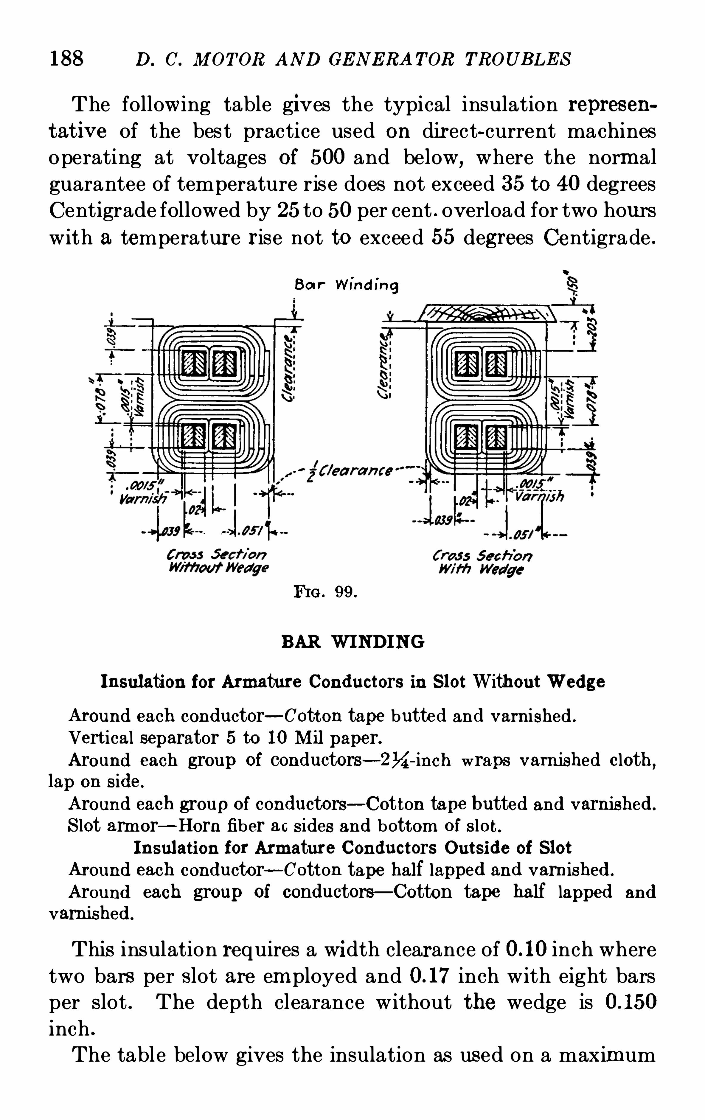
188 D. C. M OT OR AND GE N E RA TOR TROUB LE S
The following table gives the typical insulation represen
tat ive of the best practice used on dir ect-current machines
operating at voltages of 500 and below, where the normal
guarantee of temperature rise does not exceed 35 to 40 degrees
Centigrade followed by 25to 50per cent . overload for two hours
with a temperatur e r ise not to exceed 55 degrees Centigrade .
Ba r W ind in g
FI G . 99.
B AR WI NDING
Insulation for Armature Conductors in S lot Without Wedge
Around each conductor—Cotton tape butted and varnished .
Vert ical separator 5 to 10 M il paper.Around each group of conductors—2ki -inch wraps varn ished cloth
,
lap on s ide.
Around each group of conductors—Cot ton tape butted and varnished.
S lot armor—Horn fiber ac sides and bottom of s lot .I nsulation for Armature Conductors Outside of S lot
Around each conductor—Cotton tape half lapped and varn ished .
Around each group of conductors—Cotton tape half lapped and
varn ished.
This insulation requires a width clearance of inch where
two bars per s lot are employed and inch with eight bars
per slot . The depth clearance without the wedge is
inch .
The table below gives the insulation as used on a maximum
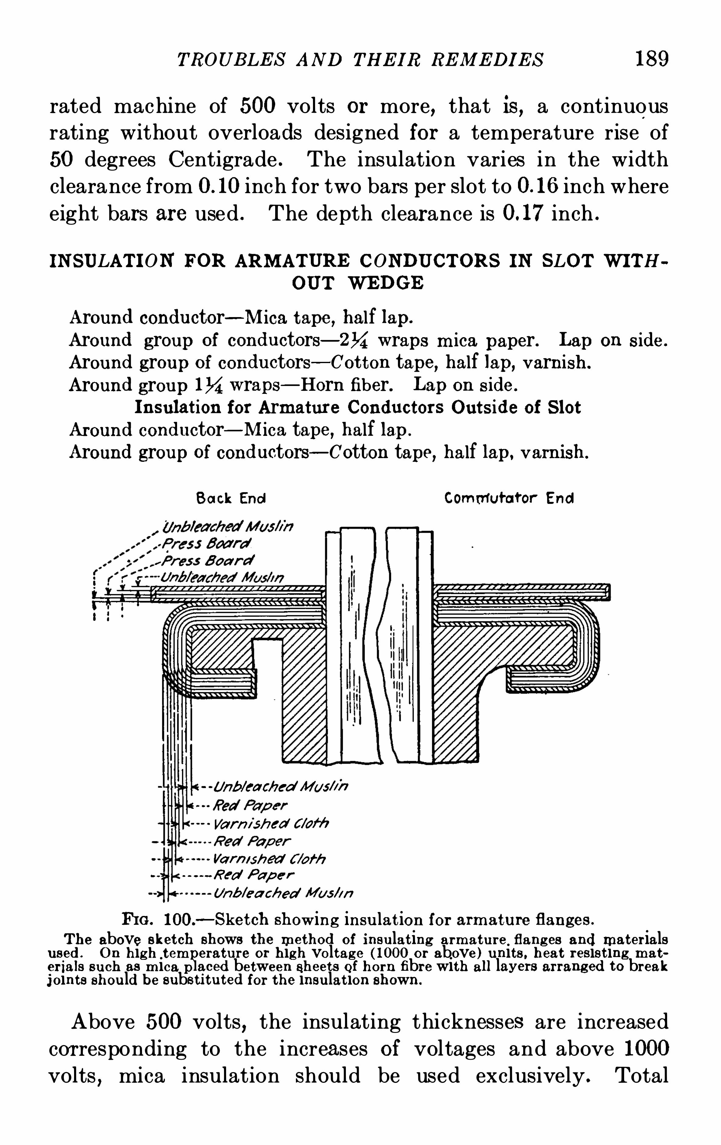
TROUB LE S AND THE IR RE M E DI E S 189
rated machine of 500 volts or more, that is, a continuous
rating without overloads designed for a temperature rise of
50 degrees Centigrade . The insulation varies in the width
clearance from inch for two bars per slot to inch where
eight bars are used . The depth clearance is inch .
IN SULAT I ON FOR ARM ATURE CONDUCT ORS IN SLOT WI TH
OUT WEDGE
Around conductor—M ica tape, half lap.
Around group of conductors—2M wraps m ica paper. Lap on s ide.
Around group of conductors—Cot ton tape, half lap, varnish .
Around group IM wraps—Horn fiber. L ap on s ide.
I nsulat ion for Armatur e Conductor s Outs ide of S lotAround conductor—M ica tape, half lap .
Around group of conductors—Cotton tape, half lap, varnish.
B ack End Comrfl utator End
(M b/cached M us/x};
Varn i sh ed c/w‘fi
Var /”shed f /ofh
Red Pap e r
Unb/ea c/zed Mus/m
IfiG . 100.—S ketch showing insu lat ion for armature flanges .
T he above sket ch shows the method of insu lat ing armat ure flang es and mater ialsused . On high tem arature or high voltage (1000 or above) u nits , heat resist ing mater ials such as m ica p aced between sheets of horn fibre with all layers arranged to breakjoints shou ld be substi tu ted for the insu lat ion shown .
Above 500 volts, the insulating thicknesses are increased
cor responding to the increases of voltages and above 1000
volts , mica insulation should be used exclusively . Total
190 D. C. M OT OR AN D GE N E RA T OR TROUB LE S
width clearan ces in machines above 500 volts vary from
inch with two bars per slot to inch with eight bars while
the depth clearance not including the wedge thi ckn ess is
inch . Armatur e conductors made up of two or more
laminations in multiple should have the individual laminations
thoroughly varni shed before assembling . E quali zer rings are
insulated in the same manner as the armature windings to
whi ch they are connected . The insulation between upper
and lower layers of end w indings is made up of fibre where
the voltage does not exceed 500 and of mica sheets placed
between two layers of fibre with higher voltages .
SHORT -CIRCUI T ED AND REVERS ED ARM ATURE COILS
A short-circui ted armature coil,usually caused by a failure
of the insulation between the conductors and the ground,or
more particularly between adj acent conductors resulting from
movement of the coils in service will be evidenced by severe
heating of the short-circui ted coil,smoke and
,if the action is
allowed to continue , by the complete destruction of the insula
tion . The unit should be completely shut down immediately,
(it is not sufficient to simply open the field-circuit as the resid
ual magnetism will continue the action) , and the location of thefaulty coil determi ned by noting with the hand whi ch conductor
has the hi ghest temperature . When the coil has been located
a careful inspection should be made to determine the sour ce of
the trouble . Particular attention should be pai d to the con
nect ions at the commutator and those segments directly
connected to the hot coils to insu re that the trouble is not at
the surface before removing the wedges and binding bands
prelimi nary to removing the coils . If a careful search fails to
reveal any external causes for the short-circuit, the binding
bands should be cut,the wedges removed and the coils care
fully li fted out . Should no damage to the i nsulation on the
coils be apparent,due to the excessive cur rent whi ch it has been
carrying except at the point of break down , repairs may be
effected by the application of insulating varnish , varnished
192 D. C . M OT OR AND GE N E RA T OR TROUB LE S
si nce the counter electromotive force is reduced by the amount
of voltage generated in the reversed coil and the diff erence
must be compensated for by a rise in speed . A reversed coil
may or may not produce comm utation trouble depending upon
the degree Of liberal ity Of design Of the unit or whether one
coil is but a smal l percentage of the total num ber of coils in the
armature . The faulty commutation is evidenced by sparking
at each set of brushes successively as the reversed coil pas ses
beneath it .
Transposing the leads of the revers ed coils where they are
connected to the commutator segments , is the obvious remedy
for a revers ed coil in the armature .
HE AT I N G
The two limits in the design of di rect current machinery
are those established by comm utation and heating . Heating
results from copper , iron and friction losses and even in a well
designed machine these may vary from 5 to 20 per cent . of the
total power output , dependi ng upon the size of the unit .
Modern machines equi pped with varnish treated,fire proof
and heat resis ting insulation will not be damaged if a final
temperature of 100° Centigrade is not exceeded . In older
units,in which the special varnish treatments were not em
ployed and such insulating material s as cotton, Oiled linen
and varnished cambric were made use of , 75 to 80° should be
considered as the maximum safe operating temperature .
Where the latter insulating materials are in use,h igher tem
peratures are permissible if the entire insulation is treated with
a bath of insulating varnish Of a mineral or asphaltum base .
Iron losses in di rect cur rent machines exist principally
in the armature core and air ducts are provided for the dissipa
tion of the heat thus engendered . The core loss is di rectly
proportional to the thi cknesses of the laminations making up
the core , the frequency Of the generated current and the effec
t iveness of the insulation between laminations . Core heating
is Often occasioned by an insumcient air gap and this should
TROUB LE S AND THE IR RE M E DI E S 193
be borne in mind when i t is desired to operateamachi ne above
its rated voltage, since an increase in speed or a reduction in
air gap, while producing the des ired voltage will also materially
increase the core heating . In the rebui ldi ng of a core the
insulation between laminations must be made as perfect as
possible, in order to reduce the eddy currents to a minimum ,
by the use of quick drying j apan or by oxidation,that is
,
by s imply permitting the laminations to gather an accumula
tion of rust where the preceding insulating material has been
removed . Iron losses are also found to a lesser degree in the
pole pieces,part icularly at the pole faces . Copper losses
(Current2 X Resistance) in the armatur e and fields produce
another source Of heating and combined with that caused
by the iron losses,present a trouble which must be
combatted by successful ventilation . Inasmuch as the copper
loss varies as the square Of the load current,extremely hi gh
swings of load must be avoided unless the machine is designed
for such service . E ddy currents producing heating in the
armature conductors are guarded against and reduced by
providing in the design for thi n laminations Of copper ins tead
of a solid copper bar—each copper strip being insulated by a
film of insulating varni sh .
Failure to keep the air ducts clear and free from all depos its
of dirt and grease will obstruct the pro per vent ilation with
resulting high temperatures . If the heating generated by
the iron and copper losses is not d issipated by a free and
continuous supply of cooling air , the efficiency of the unit and
its length of l ife will be greatly decreased . The lowering Of
the effi ciency is due to the fact that the res istance of the con
ductors increases with a rise in their temperature . A unit
which is not limited by commutation in regard to overloads
may be operated satisfactorily during overload if the tempera
ture is kept within the limits mentioned above by means of a .
fan mounted directly on the shaft or an independent blower
unit . S hould the commutator temperature be the limiting
feature during overload , slots may be sawed in the ends of the
bars,or ventilating vanes from 1 to 1% inches high by 1 to13
194 D. C. M OT OR AN D GE N E RA T OR TROUBLE S
1% inches wide by%6 to of an inch thi ck , may be added on
the outer ends of the bars to increase the radiation surface .It is customary to ins tall the vent ilating vanes by forcing
them into slots in the bars and soldering to insur e good contact .
Attempts made to lower commutator temperatures by the
use of separate blowers rather than by an increase of the
radiation surface, have given disappointing results and no
material advantage can be gained from such practice . Parts
of prime movers such as engine ec centrics or fly Wheel hubs ,couplings , pulleys , gears and bearings should not be so placed
as to obstruct the free passage of air to the commutator spider
on the one end and the armature spider on the other,as these
two points are the locations of the intakes for the cooling airpass ing to the revolving part s .
DIRTY ARMATURE
Failure of insulation resulting in grounds and short circui ts
in dir ect current machi nes is most frequently directly traceable
to inattention and neglect of the proper cleani ng of the unit ;while hi gh temperatures and flashing at the commutator can
often be attributed to the same source . The creepage sur
faces at both ends of the commutator and around the armature
flanges,the air ducts in the core , spaces between adj acent
coils,end windings
,binding bands and wedges and all pockets
where dirt and grease may collect should be subjected to a
thorough periodic inspection and cleaning at least once each
week . In the cleaning , the armatur e should be first blown
ou t with compressed air or by means of a hand bellows,be
ginning at the back or coupling end and blowing toward the
commutator . Parts of the armatur e inaccessible to the air
blast,must be cleaned by hand by rubbing with a piece of
waste or cloth . If the collections of dust and lint upon the
surfaces and in the crevices have combined and become satu
rated with Oil,grease or moisture
,the air blast wi ll be ineffec
tive and the coating of dirt must be removed by rubbing with
waste or cloth dampened in gasoline or kerosene . Lubri cating
196 D. C. M OTOR AND GE N E RA T OR TROUB LE S
tail in the spider arms must be perfect to prevent the sectional
punchi ngs from moving out due to centrifugal forces . Thismovement is particularly noticeable at the air ducts and here
the slot armor as well as the armature coil insulation may be
cut completely through . The loosening of a core of this con
struction will be accompani ed by a poundi ng and grinding
nois e, noticeable at start ing and stopping . Mechanical u nbalancing will also be evident as the unit comes up to its
normal speed . A trial by feelers will show which portion of
the core has become loosened and should be made as soon as
the noise is detected so as to prevent the destruction of the
insulation by the protruding laminations . It is useless in
such cases to attempt to dowel the laminations to the end
rings and the placing Of metal shims in the bottom of the slots
under the armature conductors to prevent the outward move
ment of the punchi ngs has proved unavaili ng . The core mus t
be rebuil t and the dovetails shimm ed where the machi ne work
on the armature spider arms is found to be defective . At the
air ducts a metal piece corresponding in shape to that of the
dovetail shoul d be put in position to prevent the buckling of
the doveta il at thi s point and thus allowing the lamination to
rise . This metal block shou l d have the same thickness as
the air duct in the core .
In rare instances of severe short c ircuiting in the armatur e,sufficient heat has been developed to burn ou t a large section
Of the lami nations in the core . The mistake has been made
in the replacement of such burned out sections of substituting
a solid metal piece with the result that the immense amount of
heat generated by the hysteresis and eddy currents soon melted
the iron . L aminated sections should always be substituted
when making repairs of this nature on the cores .
TROUB LE S AN D THE I R RE M E DI E S 197
FIE LD TROUBLE S
SHORT CIRCU I T s AN D OPE N C IRCUI TS I N FI E LD Coi L s—REV E RS E D S pooL s—S HUNT ADJ US TM E N T—LOOS E POLE
P I E CE S - COM PE N SATIN G WIN DI N GS .
SHORT CIRCUIT S AND OPE N CIRCUIT S I N FIE LD COILS
Short circuits in field windings whether they occur in the
shunt,series or commutating fields are due in practically all
cases to a failure of the insulation between turns or layers . A
short circuit in the shunt winding of a generator will cause a
reduction in the generated voltage,since the ampere turns are
reduced by the flow of the cur rent directly from one turn to
the next without passing around the core . In a motor, the
speed will be increased by a short circuit in the shunt field
due to the weakening Of the field strength . All of the field
coils including the defective onewill show a higher temperature
than under normal conditions since the field current is
increased as the resistance Of the field circuit is reduced by
the short circuited turns . The failure Of the insulation causing
the short circuit may result from high temperatures or from
the kick of the induced voltage when the field switch is suddenlyOpened . To insure against this latter trouble a small coil
having a resistance equal approximately to that of the shunt
field should be connected to the field switch and the field termi
nals in such a way as to allow the field to discharge through the
resistance which is thrown in multiple with the field as the
switch is opened . This discharge resistance is connected to
additional clips fitted on the field switch so that the blade Of
the switch throws the resistance in the circuit at the instant
the field is opened . Upon rewinding a coil whose insulationhas failed due to high temperatur es , it is inadvisable to wind
the turns more than one and one quarter inches deep unless a
ventilating air duct is introduced or the layers of wire are
thoroughly filled with insulating varnish .
A short circuit in the series coil of a generator will cause the
machi ne to drop its voltage and also to drop its load if it is
198 D. C. M OT OR AND GE N E RA T OR TROUB LE S
operating in multiple with other units . A rise in speed will
be noticed in a motor . In the commuta ting field a short
circuit will be noted by sparking at the commutator,partien
larly at the stud affected by the defective coil although all
studs may spark due to the increase of the current thr ough
the windings when the resistance of the field is reduced by the
short circuit . The Obvious remedy for a short c ircuited coil
is to rewind and renew the damaged insulation although under
emergency conditions if the short c ircuit occurs in the outside
of the coil,it will suffi ce temporarily to insert insulating ma te
rial or mechani cal separators to keep the layers apart .
An open circuit in the field winding occurs in some cases
where the temperature is allowed to reach a point at whi ch
the soldered j oints will fuse and run but usually results from
accidents or rough handling . The voltage of a generator wil l
drop and the speed of a motor will increase to a dangerous
point unless the circui t breaker or fuse Opens the circuit . If
an open cir cuit is caused by damage whi le the uni t is not in
operation, the generator will fai l to pick up and the motor
will refuse to start . A coil in which an open circuit occurs
must be repaired by completing the circuit so as to connect
the damaged coil in its proper relation . The coil cannot be
bridged over or cut out for high temperatures and commu
tat ion trouble will imm ediately set in .
Grounds in the field cir cui t may cut out or open circuit one
or more coils by al lowing the current to flow thr ough the
grounded path ins tead of the field cir cuit . The generator or
motor with a grounded field coil behaves as though it contained
a short circuited or open circuited coil and for this reason a test
should be made for grounds as soon as the sym ptoms appear
instead of attempting immediately to treat the coil for a short
or open circuit . The test and repair for a grounded coil is
explained on pages 221 and 222 . The coils may be grounded
temporarily due to mois ture where the unit is l ocated i n a
damp place and not operated for a long period of time . S uch
a ground may be readily removed by thoroughly drying out
provided no attempt is made to Operate the machine before
200 D. C. M OTOR AN D GE N E RA TOR TROUB LE S
Reversed series or commutating coils can be eas ily detected
by a drop in voltage or faul ty commutation as the load comes
on while the reversed shunt spool may be found by noting the
failure to pick up or to generate full rated voltage before loadis appli ed . The use of a compass to locate a reversed shunt
coil is a qui ck but not always certain method since the compass
needle may become reversed and for thi s reason it is advisable
to test the shunt polarity by bringing the field up to its normal
strength and introducing two nai ls on adj acent pole tips,
noting whether they attract or repel each other . This test
should be made around all pairs of poles and when the point
of reversed polarity is located,the nails will repel each other
showing that the poles of l ike polarity lie adj acent . The con
nect ing wires should then be changed to reverse the direction
Of the cur rent to establish the correct polarity .
S HUNT ADJUS T M E N T
Both series and commutating fields are fitted with an
adjustable resistance made of German s ilver and provided
with taps or iron grids connected in series or multiple .
The adjustment of the commutating field is made at the
factory .
This field is designed to secure good commutation and no
adjus tment is ordinarily required in practice to suit load con
dit ions . However a service constantly requiring rapid changes
of load may necessitate a readj ustment of the comm utating
field with a view to eliminating Or reducing to a mi nimum the
noninductive res istance across the field . Thi s may be ao
complished by increasing the air gap by the removal of shims
or l iners between the commutating pole pieces and the frame
bu t in most cases,it is advis able to replace the iron shims or
liners with pieces of z inc or brass , keeping the air gap at the
armature end as close to the factory adjustment as possible .
I nstabil ity of speed in a motor and occasionally a weakseries field in a generator may be traced directly to exces sive
commutat ing field strength which does not upset thecommuta
TROUB LE S AND THE IR RE M E DI E S 201
tion on account of the liberal des ign of the uni t wi th respect to
commutation constants bu t which saturates the magnetic
circuit to such a degree as to nul lify in a measure the eff ect
of the series field. Here a shunt shoul d be ins talled across the
commutating field even though the factory adjustment omitted
such regulation . Rapid load changes such as are met in rail
way service where adjus tments for full field, that is without
shunts,cannot be made by changing the air gap demand
shunts of the inductive type . The inductance of this shun t
must be equal to the inductance of the commutating field
circuit and in such cases it is best to get the advice of the manu
facturer of the unit or to order directly from the fact ory an
inductive shunt to meet the requirements .
The shunt field is fitted with a regulating rheostat for ad
j usting voltages at no load and equalizing loads on machines
operating in parallel where the units are shunt wound . On
compound wound generators or motors the voltage or speed
regulation is acéomplished by the adj ustment of the strengthof the series field . Adjustable shunts are furnished as it is
nearly always necessary to change the voltage or speed regu
lation to suit the exact power requirements after the machine
is installed . Adding resistance to the shunt increases the
strength of the series field which raises the voltage of the gen
erator and reduces the speed in a cumulative compound wound
motor . Subtracting resistance,on the other hand
,weakens
the series field with the opposite effect on voltage and speed .
A change in the air gap under the main pole pieces may be
introduced to advantage where the voltage or speed is un
stable but very little change,if any
,can be made in the effect
of the series field by the change of gap and this method is
usually unavailing where the strength Of the series field is in
question .
When adjustments in the commutating or series fields are
being made,care should be exercised to allow the unit to
operate between trials for a sufficient period of time to bring
the temperature of the shunts to a running heat since the
resistance varies with the temperatures in both field and shunt .
202 D. C . M OTOR AN D GE N E RA T OR TROUB LE S
The cold adjustment should hold when the uni t has reached
its normal working temperature .
LOOS E POLE PIE CE S
L oose pole pieces either main or commutating , are rarely
met with in practice unless improper attention has been given
to the tightening of the pole piece bolts when assembling the
unit or in adj ustments requi ring the removal of shims . In
the latter instance,the length of the bolts may be such
as to bottom in the hole of the pole piece before the head
comes in contact with the frame,permitting movement of
the pole piece . Spool bodies made with a fixed lengt h may
also prevent sufi cient tightening Of the pole piece against the
frame after shims have been removed . Loose pole pieces will
not remain in their true position and an unequal distribution
of flux will result due to the varying contacts between the
pole and the frame . Pole pieces not on the vertical will sagbringing the tips of adj acent poles closer together than other
parts of the magnetic circui t occasioning excessive flux leak
age as well as a general magnetic inequality . Unless the loose
pole pieces are tightened to insure a good uniform contact
between the poles and the frame,good voltage or speed regu
lation and successful commutation cannot be expected .
COM PE N SAT IN G WINDIN G
Compensating or pole face windi ngs are in effect a part of
the usual commutating field,the turns being carried or sup
ported in the faces of the main poles in stead of being wound
around the commutating pole piece . Shunt adjustments on
machines equi pped with compensating wi ndings are made by
placing a resistance across the turns on the commutating
pole proper,allowing the pole face windings to carry full line
current . Grounds or short circuits in the pole face winding
or between the connection strips connecting the pole face conductors, will result in faulty commutation and for thi s reason
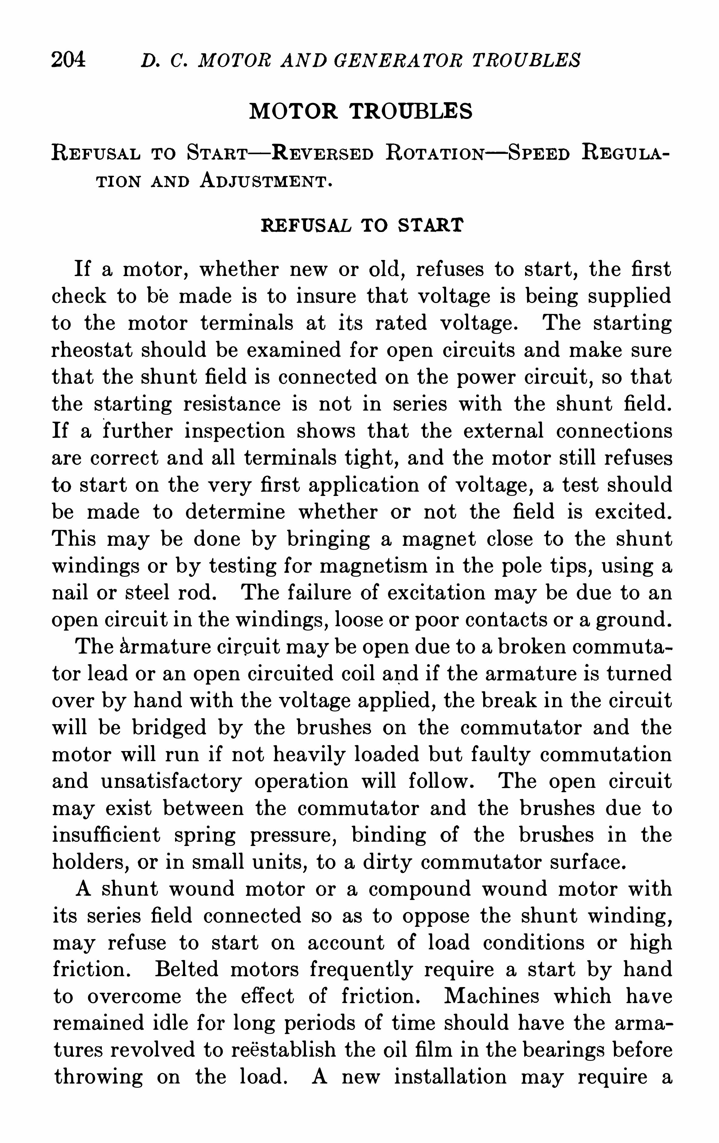
204 D. C. M OTOR AND GE N ERA T OR TROUB LE S
MOTOR TROUBLE S
RE FUSAL T o START—RE VE RS E D ROTATI ON—SPE E D RE GULATI ON AN D ADJU STM E N T .
RE FUSAL T O S TART
If a motor,whether new or old
,refuses to start
,the first
check to be made is to insure that voltage is being supplied
to the motor termi nals at i ts rated voltage . The starting
rheostat should be examined for Open circuits and make sure
that the shunt field is connected on the power circui t,so that
the starting resistance is not in series with the shunt field .
If a further inspection shows that the external connections
are correct and all termi nals tight,and the motor still refuses
to start on the very first application of voltage,a test should
be made to determine whether or not the field is excited .
This may be done by bringing a magnet close to the shunt
windings or by testing for magnetism in the pole tips , using a
nail or steel rod . The failure of excitation may be due to an
open circuit in the windings,loose or poor contacts or a ground .
The armature circuit may be open due to a broken commuta
tor lead or an open circuited coil and if the armature is turned
over by hand with the voltage applied,the break in the circui t
will be bridged by the brushes on the commutator and the
motor will run if not heavily loaded but faulty commutation
and unsatisfactory operation will follow . The open circuit
may exist between the commutator and the brushes due to
insufficient spring pressure,binding of the brushes in the
holders,or in small units
,to a dirty commutator surface .
A shunt wound motor or a compound wound motor with
its series field connected S O as to oppose the shunt winding ,may refuse to start on account of load conditions or high
friction . Belted motors frequently require a start by hand
to overcome the eff ect Of friction . Machines which have
remained idle for long periods Of time Should have the arma
tures revolved to reestablish the Oil film in the bearings before
throwing on the load . A new installation may require a
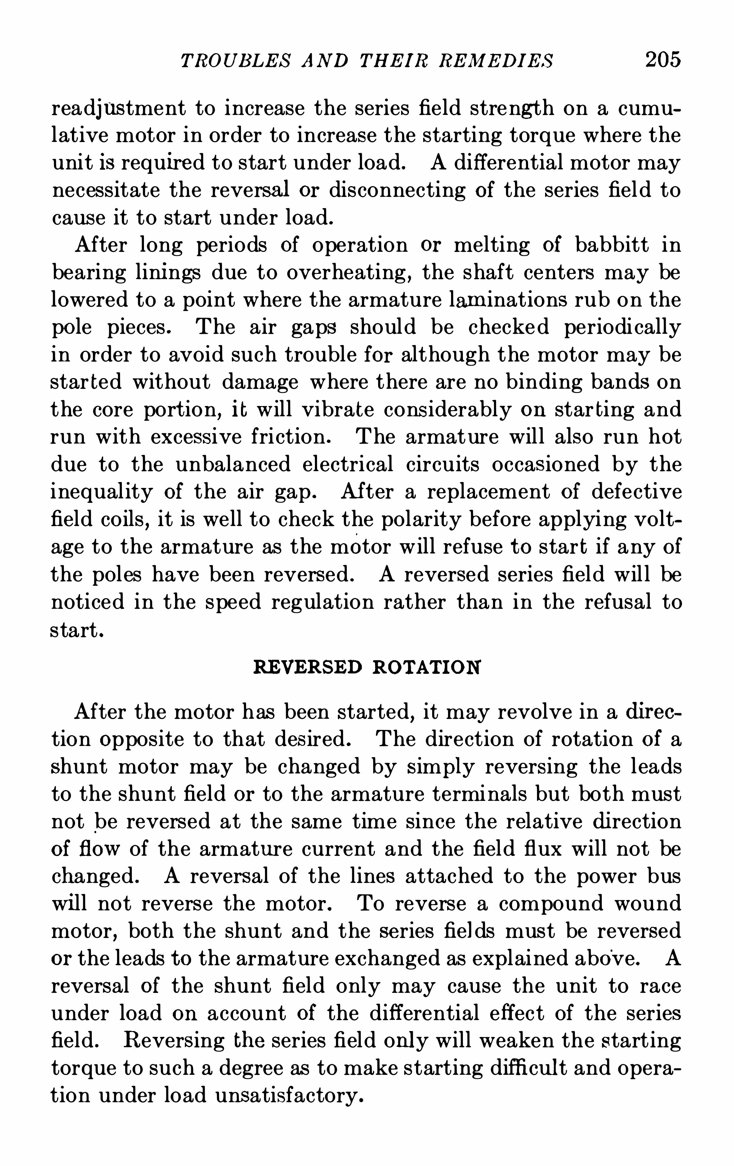
TROUB LE S AND THE IR RE M E DI E S 205
readjus tment to increase the series field strength on a cumu
lative motor in order to increase the starting torque where the
unit is required to start under load . A diff erential motor may
necessitate the reversal or disconnecting of the series field to
cause it to start under load .
After long periods of operation or melting of babbitt in
bearing lini ngs due to overheating , the shaft centers may be
lowered to a point where the armature lam inations rub on the
pole pieces . The air gaps should be checked periodi cally
in order to avoid such trouble for although the motor may be
star ted without damage where there are no binding bands on
the core port ion, i t will vibrate cons iderably on star ting and
run with excessive friction . The armature will also run hot
due to the unbalanced electrical circuits occas ioned by the
inequality of the air gap . Af ter a replacement of defective
field coils,it is well to check the polarity before applying volt
age to the armature as the motor will refuse to star t if any ofthe poles have been reversed . A reversed series field wil l be
noticed in the speed regulation rather than in the refusal to
start .
REVERS ED ROTAT ION
After the motor has been started, it may revolve in a direction Opposite to that desired . The direction Of rotation of a
shunt motor may be changed by S immy reversing the leadsto the shunt field or to the armature terminals but both must
not be reversed at the same time since the relative di rection
of flow of the armature current and the field flux will not be
changed . A reversal of the lines attached to the power bus
wi ll not reverse the motor . To reverse a compound wound
motor, both the shunt and the series fields must be reversed
or the leads to the armature exchanged as explained above. A
reversal of the shunt field only may cause the unit to race
under load on account of the diff erential effect of the series
field . Revers ing the series field only will weaken the starting
torque to such a degree as to make starting difficult and Opera
tion under load unsatisfactory .
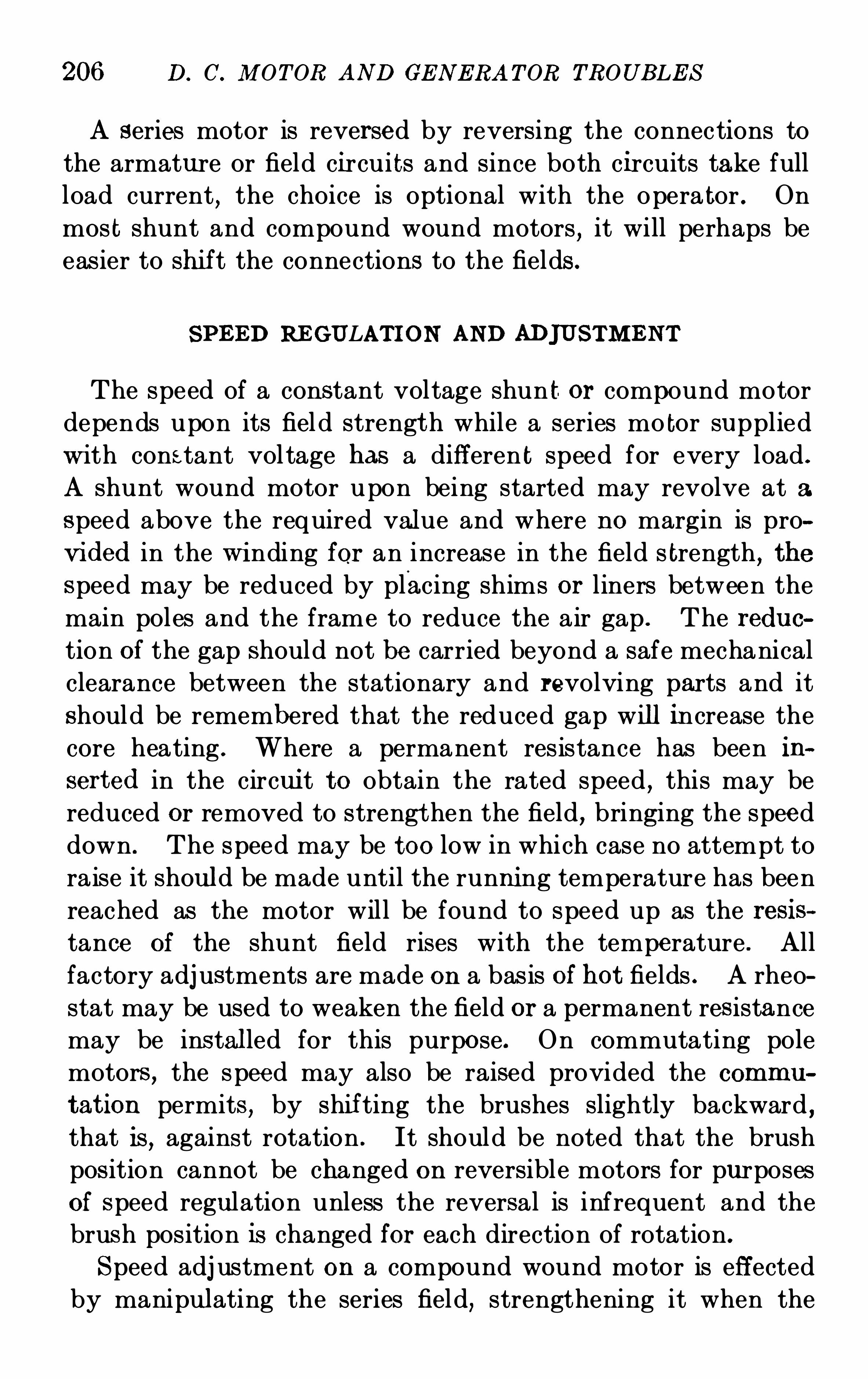
206 D. C. M OT OR AND GE N E RA T OR TROUB LE S
A series motor is reversed by reversing the connections to
the armature or field circuits and since both circuits take full
load current,the choice is optional with the opera tor . On
mos t shunt and compound wound motors, it will perhaps be
easier to shif t the connections to the fields .
SPE ED RE GULAT I ON AND ADJUS TM E NT
The speed of a cons tant voltage shun t or compound motor
depends upon its fiel d strengt h while a series mo tor supplied
w ith constant vol tage has a diff eren t speed for every load .
A shunt wound motor upon being started may revolve at aspeed above the required value and where no margin is pro
vided in the wi nding for an increase in the field s trength, thespeed may be reduced by placing shims or liners between the
main poles and the frame to reduce the air gap . The reduction of the gap Should not be carried beyond a safe mechanical
clearance between the stationary and revolving parts and it
should be remembered that the reduced gap will increase the
core heating . Where a permanent resistance has been in
serted in the circui t to obtain the rated speed , this may be
reduced or removed to strengt hen the field, bringing the speed
down . The speed may be too low in which case no attempt to
raise it should be made until the runni ng temperature has been
reached as the motor will be found to speed up as the resis
tance of the shunt field rises with the temperature . All
factory adj ustments are made on a basis of hot fields . A rheo
stat may be used to weaken the field or a permanent res istance
may be ins tal led for this purpose. On commutating pole
motors , the speed may also be raised provided the commu
tat ion permits , by shif ting the brushes slightly backward ,that is, against rotation . It should be noted that the brush
pos ition cannot be changed on reversible motors for purposes
of speed regulation unless the reversal is infrequent and the
brush position is changed for each direction of rotation.
S peed adj ustment on a compound wound motor is eff ected
by manipulating the series field, strengthening it when the
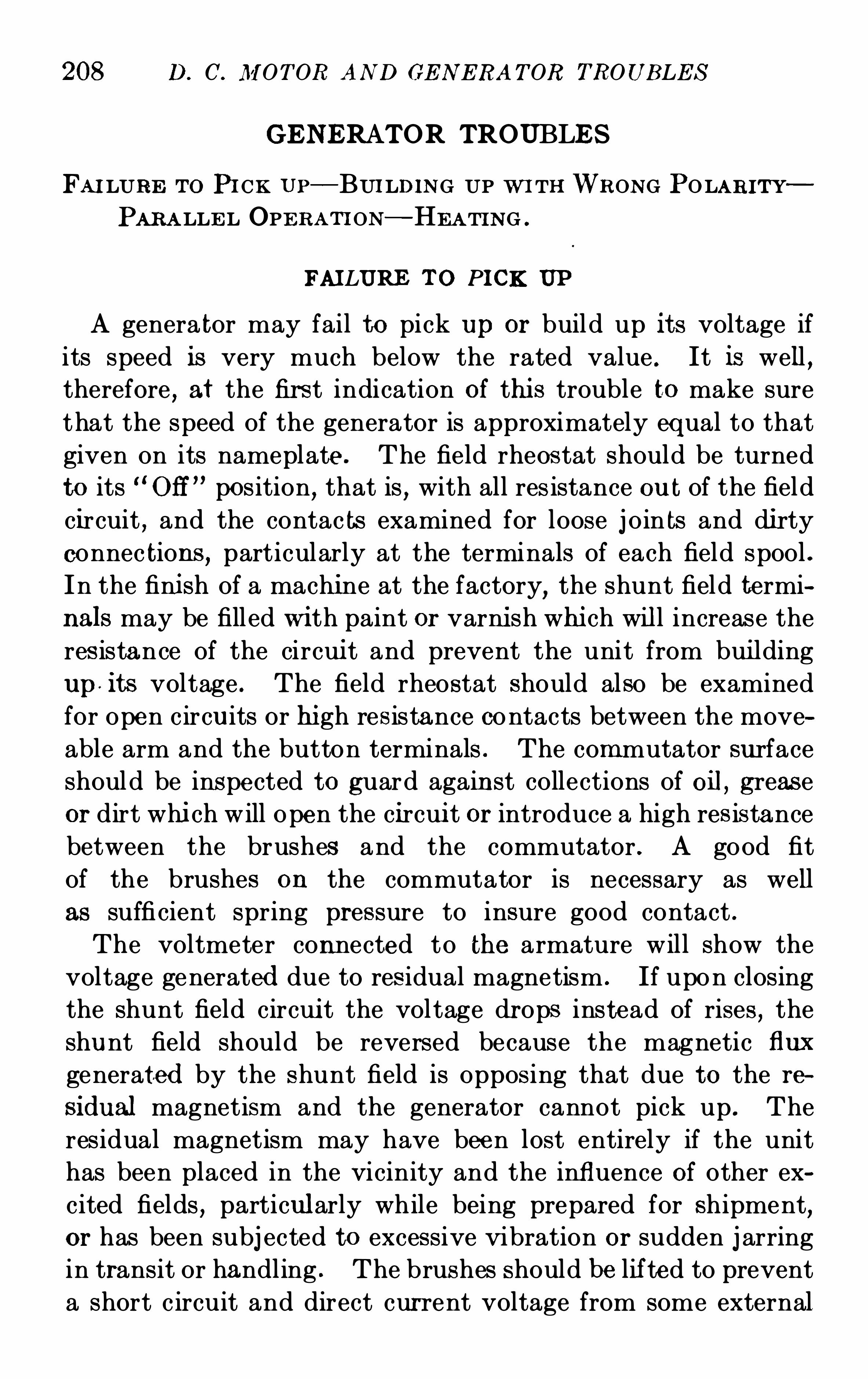
208 D. C. M OT OR AN D GE N E RA T OR TROUB LE S
GE NERATOR TROUBLE S
FAI LURE T o PI CK UP—BUI LDI N G UP W I TH WRON G POLARI T Y
PARA LLE L OPE RA T I ON—HE A TI N G .
FAI LURE T O PICK UP
A genera tor may fail to pick up or build up its voltage if
its speed is very much below the rated value . It is well ,therefore
,at the fir st indication of thi s trouble to make sure
that the speed of the generator is approximately equal to that
given on its nameplate. The field rheos tat should be turned
to its Off” position
,that is
,with all res istance ou t of the field
circuit , and the contac ts examined for loose j oin ts and di rty
connec tions , particularly at the terminals of each field spool .
In the fini sh of a machi ne at the factory, the shunt field termi
nals may be fill ed wi th paint or varni sh whi ch will increase the
res istance of the circui t and prevent the unit from bui lding
up its voltage . The field rheostat should also be examined
for open circu its or hi gh res istance contacts between the move
able arm and the button terminals . The commutator surface
should be ins pected to guard again st collections of oil, greas e
or dirt whi ch will Open the circui t or introduce a high res istance
between the brushes and the commutator . A good fit
of the brushes on the commutator is necessary as well
as suffi cient spring pressure to insure good contact .
The voltmeter connected to the armature will show the
voltage generated due to res idual magnetism . If upon closing
the shunt field circui t the voltage dr ops instead of rises , the
shunt field should be reversed because the magnetic flux
generated by the shunt field is Opposing that due to the re
sidual magnetism and the generator cannot pick up . The
residual magnetism may have been lost entirely if the unit
has been placed in the vicinity and the influence of other ex
cited fields , particularly while being prepared for shipment,or has been subj ected to excessive V ibration or sudden j arring
in transit or handling . The brushes should be lif ted to prevent
a short c ircuit and direct cur rent voltage from some external
TROUB LE S AN D THE I R RE M E DI E S 209
source should be applied to the terminals of the shunt field
for a few seconds in order to restore the res idual magnetism .
The voltage may be secured from another generator , a storage
bat tery or a number of dry cells in series . In the latter case
where the voltage is low as compared with the machine voltage,
it is sometimes necessary to apply the battery connections to
two or more S pools instead of to the entire number in series .If a compound wound unit which has lost its residual magnet
ism is to operate in multiple with other machines,the equal
i zer switch may be closed as well as the necessary line switches
to complete the circuit from the live machine through the
equalizer and series field to the bus bar, and the flow of current
through the series field will restore the residual .
BUILDI NG UP WI TH WRON G POLARI TY
In an ungrounded power or lighting circuit the polarity
with which the generator builds up is of no consequence
because the polarity in no way affects the ordinary incandes
cent lights or the direction of rotation of direct current motors .However
,instruments on switch boards , c ircuits with the
negative side grounded , storage battery charging and electro
lytic processes . all require a fixed polarity for satisfactory
operation . S hould a generator build up its voltage with the
wrong polarity the residual may be changed by applying volt
age from a separate source and the correct polarity will thus
be established. It is sometimes more convenient especially
with compound wound generators operat i ng In multiple
to correct the polarity by closing the equalizer and line switches
where necessary to complete the circuit .
PARALLE L OPERAT I ON
A new generator installed to operate in parallel with other
units should be given a polarity test before any line switches
are closed to insure against connecting in series instead of
multiple with the danger Of heavy overloads of current, high14
210 D. C. M OTOR AND GE N ERA TOR TROUB LE S
voltages , flashi ng and burni ng of the commutator and brush
rigging . A shunt wound generator may have its polarity
corrected by applyi ng current from the other uni ts to the
shunt field in such a direction as to reverse its residual magnetism . The residual of a compound wound generator may be
reversed in a similar manner but it may be more conveniently
done by using the equalizer circuit to deliver current to theseries windings .
The newly installed unit may fail to take its share of the
total load if the speed regulation from no load to ful l load is
greater or less than that of the Old units, and this must be
corrected by adjus ting the speed of the prime mover . The
location of the brus hes back of the neutral agains t rotation
on a commutating pole machine will caus e a generator voltage
to rise S harply when load is applied and a heavy overload
usually results . Unless the circuit breakers Open or the prime
mover drops in speed on account Of the overload , the generator
voltage will rise to a point whi ch may cause the other units
i n parallel with it to operate as motors , thereby increasing
its own load . If the brushes are ahead.
of the neutral in the
direction of rotation on a commutating pole machine,the
generator will refuse to take load and its voltage will drop
sharply when load is applied .
E qual division of load in multiple operation cannot be Oh
tained unless the compounding of the individual units is similar.
For example a generator overcompounded from 120 volts at
no load to 125 volts at full load or 250 volts at no load to 275
volts at full load , S hould not be connected in multiple with
generators flat compounded from 125 volts at no load to 125
volts at ful l load or from 275 volts at no load to 275 volts at
fu ll load as the overcompounded generator will take all Of the
load due to its rising voltage characteristic, as compared with
the flat voltage characteristic of the other unit . The com
poundin gs may be made simi lar by readjus tment Of the series
field shunts where such shunts are furnished , but it is also
possible to adjust the compoundings by shifting the brushes
on machines of the commutating pole type where the commu
212 D. C. M OTOR AND GE N E RA TOR TROUB LE S
SHAFT AND BEARING TROUBLE S
SHA FT FI TTI N G—OI L RIN G S—BE ARIN G LIN I N GS OI L SLI NG
E Rs—BE ARI N G FI TTI N G .
SHAFT AND B EARING TROUB LE S
Due to the abs ence of reciprocating parts very little trouble
is experienced with bearings and Shafts on electrical machi nery ,when the rubbing speeds and pressure are kept within the
limits already given . Heating , however, may appear due toshaft pitting
,the fai lure of the Oil rings to function properly
,
loose babbitt and the improper adjustment of the arma ture
and field for end play .
Shaft pitting comes as a result of a flow of current through
the shaft,bearings and bas e whi ch form a low resistance path .
The Oil film in the j ournal is a good insulator and the flow of
the current is usually from the shaft to the oil ring resulting
in the scoring of both . The scoring on the shaft gradually
S preads and the rough surface drags the babbitt lining causing
high temperatures . The current usually flows through the
shaft as a resu lt of leakage flux cut by the armatur e spider and
shaft . The most reliable remedy for the pitting lies in stop
ping the flow of current by insulating one or more of the
bearing pedestals at the j unction of the pedes tal and the base
with mica sheets between fibre layers having a total thi ckness
of from Me to of an inch . In addition to thi s insulation
it is necessary to insulate the dowel pins and holding down
bolts by fibre sleeves and washers . Unless the edges of the
bolt holes in the base and the bo ttom of the bearing pedes tal
are chamfered off or countersunk to provide a creepage surface
of at least one half an inch,the insulation will usually fail
around the holdi ng down bolts at the junction of the two sur
faces due to moisture or collections of di rt . It is unnecessaryto insulate all bearing pedestals on a unit but jus t a suffi cient
number to interrupt the path of the current . On two bearing
machines,it is suffi cient to insulate but one bearing while with
thr ee or more bearings all pedestals should be insulated except
TROUB LE S AN D THE IR RE M E DI E S 213
one . Uni ts subj ected to severe flashing may develop pittingtrouble with the pedestals insulated due to the flow of line
current to ground . Here grounding rings should be placed
on the shaft preferably on the machine side of the bearing
housing fitted with a low resistance brush grounded in such a
way as to prevent the current from passing through the bear
ing . Grounding rings are usually made of copper or brassfitted directly to the shaft at any convenient point . Units
equipped with ball bearings are part i cularly suscep tible to
trouble from pit ting from either of the above-mentioned
cau ses .
The function Of the Oil ring is to raise the oil from the oil
well to the S haft surface and to do thi s it must be kept in cont inuous motion . If the oil ring revolves too slowly the Oil
will run back into the well before it reaches the shaft . If onthe other hand the ring revolves at an excessive speed the Oil
is thrown into the bearing housing . For these reasons in case
of replacement,it is advisable to install the same type of ring
as that.
originally furnished . Many cases of bearing trouble
can be traced directly to the use of wire and chains in place of
the correct ring . Such substitutes should be used in emer
genoy cases only . While oil rings may always be used where
the machine operates continuously in a horizontal position,
waste packed bearings are necessary where the unit constantly
shi fts in position as the rings will bind or catch in the grooves .
The waste must be kept thoroughly saturated with oil and a
screen made up of perforated metal should be placed so as to
rub against the shaft at the bottom of the waste pocket to
prevent small particles of waste from being carried under
neath the shaft and forming burned rings with resultant
heating .
Bearing lini ngs,if improperly anchored may become loose
and cause a rapid heating of the shaft and bearing . The
movement Of the babbitt may be de tected on the ends by
noting the oil oozing out between the lining and the housing .
The movement may also be noted by placing the tips Of the
fingers at the j unction of the babbitt and hou'
sing . Such a
2 14 D. C. M OTOR AND GE N ERA T OR TROUB LE S
bearing should be immediately removed from service and re
babbitted,taking care to anchor the li ning by dovetails .
If the end play is not properly adj usted and the armatur e
fails to float in the bearings,the end thrust of the armatur e
wi ll cause the Oil sli ngers on the shaft to rub against the end
of the bearing housing or lini ng . This condition may also
result from improper alignment or failure to level the base on
the foundation . Where the cause of the end thrus t in one
direction is magneti c, it may be remedied by moving the
magnet frame along the shaft in a di rection opposite to that
of the end thrust .
When a bearing surface becomes damaged or roughened from
any cause or when the temperature reaches a point where the
babbitt wipes or the bearing freezes , it is necessary to rebabbitt
and refit the lini ng to the shaft . In many cases this must be
done in a very S hort time and a satisfactory job cannot be
done by the scraping and trying method . In such emer
gencies the bearings may be fitted qui ckly by removing the
high spots with a scraper after which the bearing cap may be
put into place but not bolted down too secur ely . A mixture
of lubricating oils and pulverized hand sapolio or powdered
pumice stone may be slowly pour ed into the sight holes in the
bearing while the shaft is slowly revolved . The mixture
shou ld be suppli ed continuously allowing the surplus to drain
from the Oil well . The bearing will be quickly fitted in this
way after whi ch it must be thoroughly flushed with pure Oil
and all of the grinding material removed . The bearing cap
should be tightened from time to time as the bearing wears in
until the normal operating position is reached .
216 D. C. M OT OR AND GE N ERA T OR TROUB LE S
equalize the air gap . Where the armature conductors have
become loose due to a shrinkage of i nsulation,the bindi ng
bands and wedges should be removed and spacers of fibre,
mica or insulating material placed on top of the bars to make
up for the shrinkage . A loose armatur e core, that is, loosened
laminations,is generally evidenced by a thumping or grind
ing sound parti cularly noti ceable when starting or stopping
and immediate treatment shoul d be given as outlined on page
195. Movement of the commutator will also produce a
thumping noise and if allowed to continue,the commutator
leads will be broken . The commutator bolts holding the
spider in place should be tightened and in some cases it
may be necessary to drill a hole at the j oint between the
commutator and armature parts and to insert round steel
dowels or keys .
An unbalanced armatur e or pulley will set up a vibration
of the entire unit and after a very short period Of operation
the bearings will wear excessively permitting an eccentric
motion of the revolving element . Accompanying the vibra
tion will be a pounding noise in the bearings,a rattle of the
oil rings and a chattering sound at the commutator as the
brushes try to follow the eccentri c motion . The unit S hould
be removed from service and the cause Of the unbalancing
determined . The armature and the pulley may be balanced
by the addition of weights as previous ly des cribed . The pulley ,if tightened on the shaft by means of set s crews or a key may
need recentering , especially if the s ize of the shaft is not
exactly the same as the bore of the pulley,in which case thin
metal collars are fitted .
A noise caused by the striking Of the belt or pulley agains t
the bearings of the machine is easily remedied by mounting
the pulley a l ittle further out on the shaft so as to make the
contact impossible . A laced or j ointed belt will produce a
periodic pounding at each revolution when the lacing or j oint
comes in contact wi th the pulley . An endless belt should be
subs t ituted,and it may be added should always be employed
on electrical machinery . If the belt is loose or insuffi ciently
TROUBLE S AND THE IR RE M E DI E S 217
tightened for the load or to accommodate sudden swings in
load,a squeaking noise at the pulley will be noted accompanied
by a flapping and scraping at the middle point of the belt,
on the floor or at the machine base . In case Of overload, the
load should be reduced or the belt tightened by means of an
idler or sliding rails . If this does not prove an eff ective rem
edy,a wider pulley and a Wider bel t mus t be substituted .
In an emergency,where the bearing temperatures w il l not
permi t tightening of the belt to carry the load without squeak
ing,the noise may be eliminated by stopping the slipping of
the belt . This is accomplished by rubbing a bar of turpentine
or yellow washing soap on the belt surface whi ch comes in
contact with the pulley . The soap Should be applied without
oil or water as such application will increase the slippage and
the belt may leave the pulley .
Incorrect brush angle,defective brushes or a roughened
commutator surface or collector rings produce a harsh , disagree
able noise readi ly located at the commutator or rings . The
brush chatter and hissing may come from hard spots in the
brushes or from an excessive S lant or brush pressure whi l e the
roughened commutator surface may in addition provide a
singing and screeching noise. The application of a lubricant
to the commutator surfaces may relieve this condition tempo
rarily but continued use of the lubricant in any form will
eventually destroy the mica insulation in the commutator
and di rty its surface . The brush angle should be corrected or
a new set of brushes substituted or if the commutator surface
is at fault , it should be subjected to a smoothing process .
It is difficult to discriminate between the noises due to
windage and those due to magnetic disturbance . L oose lam i
nations in the pole pieces,particularly at the tips will vibrate
and set up a humming sound while a similar noise is created
by the windage Of the armature due to the impinging Of theair from the air ducts in the armature against the pole tips .
Units equipped with pole face conductors supported by holesor slots in the pole
‘
faces are very s us ceptible to magnetic
noises due to a vibration of the tips of the laminations in the
218 D. C . M OT OR AND GE N ERA TOR TROUBLE S
proj ections between the pol e face slots . A remedy for this
has been found in securely anchoring the firs t inch of lamina
tions on either S ide by drilling and inserting a machine screw .
At the edge of the pole tip, where there is insufficient stock for
the insert ion of the screw or rive t, spot weldi ng may be used
to advantage . Where the main pol es on a machine are made
up of lami nations assembled with open spaces in the pole tips
in order to reduce the ir on in them , and arranged by cutting
back the tip on every other lam ination, the hum from magnetic
vibration and the increased windage is very noticeable .
S ince the introduction of a metal anchor of any description
in the pole tip would defea t the purpose of the spaced lamina
tions,it is necessary to fill the spaces with putty
,pain t or a
compound whi ch will harden in place and not melt or shake
out . S houl d thi s remedy fail , the noise is purely magnetic
and a slight chamfer of the pol e tips extending from one to
one and one-half inches back toward the center of the pole wi ll
in many cases eliminate the trouble . A change in the air gap
is also effective as the amount of fringing is changed and an
even number of slots and teeth are in the field flux at al l times .
N oise directly traceable to windage caused by the fan eff ect
Of the commutator leads , end clips , equal izer windings and
supports may be materially reduced by the application of
canvas heads or barriers arranged to in terrupt the flow of air
but the sound should not be diminished at the expense of good
ventilation . The unit may be total ly enclosed to obliterate
the noise, in which case a supply of cooling air must be furn ished by external blowers or fans . S ound proof rooms are
also recommended where machines are operated in office
bui ldings or residential distric ts .
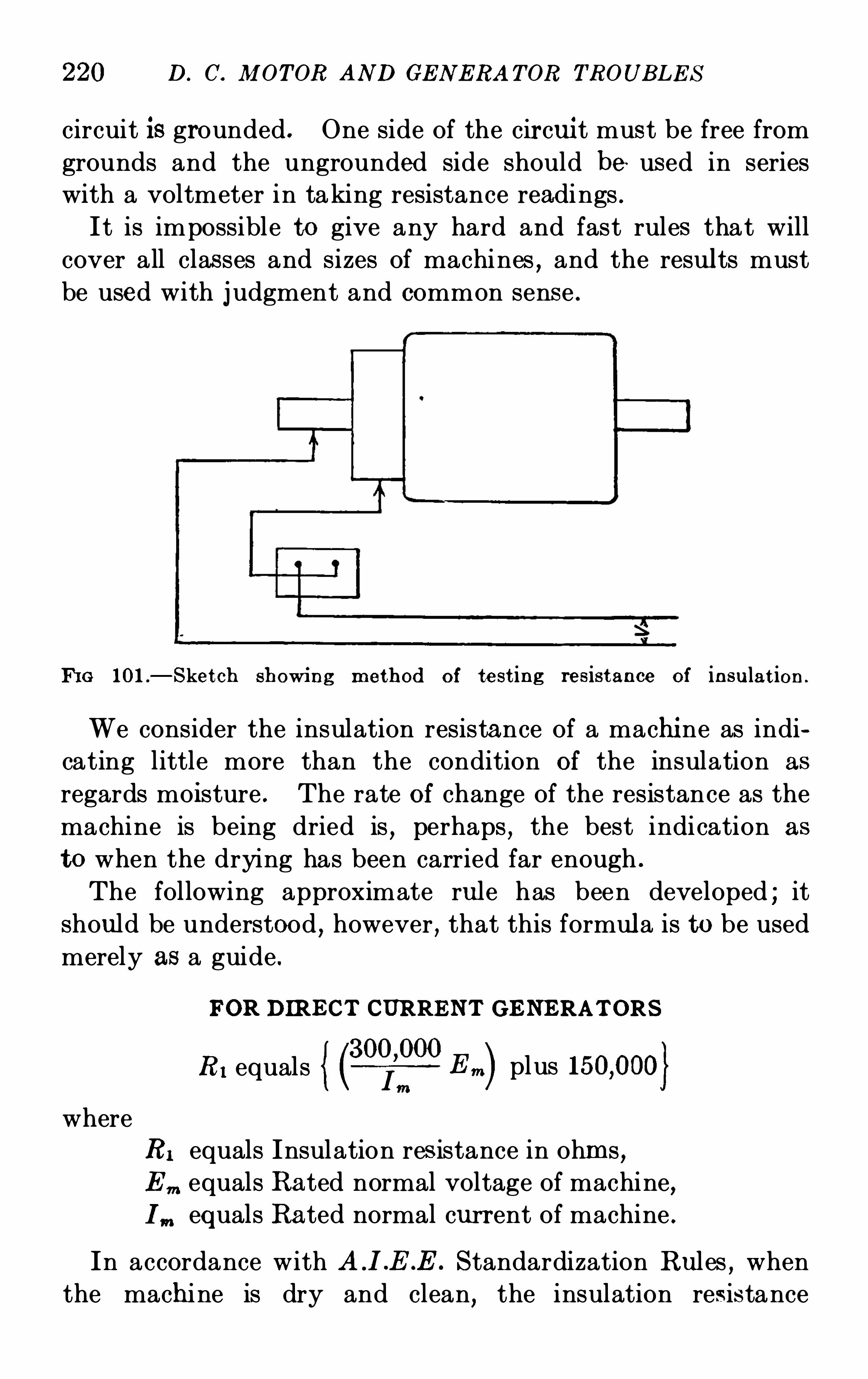
220 D. C. M OT OR AND GE N E RA T OR TROUB LE S
circuit is grounded . One side of the cir cui t mus t be free from
grounds and the ungrounded side should be used in series
with a voltmeter in taking resistance readings .
I t is impossible to give any hard and fast rules that will
cover all classes and sizes of machines,and the results must
be used with j udgment and common sense .
FI G 101 .
—S ket ch showi ng method of test ing res ist ance of in su lat ion .
We consider the insulation resistance of a machi ne as indi
cating little more than the condition of the insulation as
regards moisture . The rate of change of the resistance as the
machine is being dried is,perhaps , the best indication as
to when the drying has been carried far enough .
The following approximate ru le has been developed ; it
should be understood , however , that this formula is to be used
merely as a guide .
FOR DIRE CT CURRE NT GE NERAT ORS
RI equalsL ”
plus
where
RI equals Insulation res istance in ohms,E m equals Rated normal voltage of machine,I m equals Rated normal current of machine .
In accordance with S tandardization Rul es , when
the machi ne is dry and clean, the insulation resistance
M OTOR AND GE N E RA TOR T E S T S AND RE PA IRS 221
in megohms should not be less than the voltage of themachi ne
divided by the kilowatt rating plus 1000, or
Rated VoltageResi stance equals
Rated kw . plus 1000
GROUNDS
A test of the insulation resistance of the armature conductors , field windings Or current carrying parts with respect to
the iron portion of the machines,as outlined on page 219 is
the most direct way of detecting grounds . Where a voltage
supply is not available, a magneto testing set with one terminal
connected to the live part Of the machi ne and the other in
contact with the frame,will ring upon the turning Of its crank
if the live part is grounded at one or more places .When the unit behaves as though a ground or grounds
existed in its stationary or revolving parts,the ground test
shou ld be applied to the machine as a whole . L ifting the
brushes from the commutator and repeating the test individu
al ly Ou the stationary and revolving elements w ill indi cate thelocation of the ground with respect to the division of themachine . If a ground is found to exi st in the stationary part
the search for the exact location must be continued by sepa
rately tes ting the individual elements such as field spools,brush rigging , connection boards and shunts .
S hould the general test indicate the presence of a ground in
the armature,a test for the exact location of the defect can be
made by disconnecting the armature conductors at the com
mutator and applying the insulation or magneto test to each
individual coil . To avoid the necessity of disconnecting all
of the armature leads from the commutator it is advisable
to test the coils in sections . I t should be remembered that
the equalizer rings on multiple wound generators must be
disconnected while applying this test . If two or more grounds
exist in the armature the most expedient tes t to apply is the
drop of potential method . A fixed current is supplied to
adjacent commutator s egments successively and the voltage
222 D. C. M OT OR AND GE N E RA T OR TROUB LE S
drop read on the low voltage scal e of a voltmeter . CoilsS howing a drop of 10 per cent . or more below the average
indicate the location of the grounded points .
'
The brushes
should be raised dur ing this test but it is not necessary to
disconnect the conductors at the commutator or equalizer
taps . S houl d the drop on all coils prove to be approximately
equal,the ground will be found to exist in the commutator
which requi res tha t all armature leads be disconnected and the
individual bars tested from bar to shaft . The drop of poten
tial method has proved unsatisfactory in so many ins tances
that it is usually more efficient to disconnect the individual
coils or sections of coils and locate the ground by the insulation
or magneto test . Where a high potential testing set is
avai lable, voltage may be applied and held until smoke
appears at the point of ground , but thi s method increases the
damage to the insulation and thus augments the difficulty of
making repairs at the grounded point .
Where a galvanometer is available , a low resistance ground
may be quickly and accurately located by the followingmethod :
A low voltage current is passed through the armature windi ng
from a commutator bar to the one adj acen t to it, which is
sufficient to give a deflec tion on a galvanometer or mill ivolt
meter . A line is connected to a galvanometer to ground , the
other galvanometer connection being placed on one Of the
commutator bars . Then pass the supply and galvanometerleads from segment to segment
, until a full deflection is ob
tained and zero reading when the leads are moved one segment
further. The.
grounded coil then lies between the bars , for
which full deflection was obtained .
OPE N CIRCUI T S
An Open circuit in the field winding of a generator is located
by cutting out one spool at a time by short circuiting the
terminal w ith a low resistance copper wire . When the copper
wire is applied to the spool in which the defect occurs,it will
bridge the break and the unit will begin to pick up . The
224 D. C. M OT OR AN D GE N E RA T OR TROUB LE S
the exact S pot or coil can generally be located by noting the
point of high temperature , or blackening and Charring . S hort
circuits in field S pools are evidenced by a decrease in the volt
age of a generator or an increase in the speed of a motor . Un
like the armature coils,the field coils
,if S hort circuited
,in
most cases Operate cooler than under normal conditions since
a percentage of the exciting current does not pass around the
total num ber of turns thu s reducing the heat loss .
The magneti c strength of a field coil having a large part of
its turns short circu ited , wil l be much weaker than that of a
companion coil wi th normal turns ; consequently , a bar of
iron held midway between the two adj acent S pools wi ll be
pulled toward the stronger pole . It should be remembered
that a double ground affecting any part Of the’
electric circuit
is equivalent to a Short circu it .A Short circuit in an armature or field coil when evidenced
in operation , is tested for by the drop of potential method .
In rewinding an armature,it is well to test the coils for S hort
circuits before connecting them to the commutator . Field
or armature coils showing a reading approximately 10 per
cent . below the average in the drop Of potential method indi
cate a short circuit . A test for a short circui t in the commu
tator is made by means of the insulation resistance or magneto
test .
SATURATI ON
In order to as certain the characteristi cs of the magneti c
cir cuit,a test known as “saturation ” is made . The character
ist ic curve may be obtained by either of the following methods ;“generator satura tion ” and “motor saturation .
”
The test usually made is “generator saturation . To
obtain a saturation curve by this method , the machine is
driven as a generator,preferably at constant speed . If,
however, a set of readi ngs is known for one speed , they can be
obtained for any other by di rect proportion . Hence a satu
ration curve taken at any constant speed at once gives the
saturation curve at any other S peed . The brushes of direct
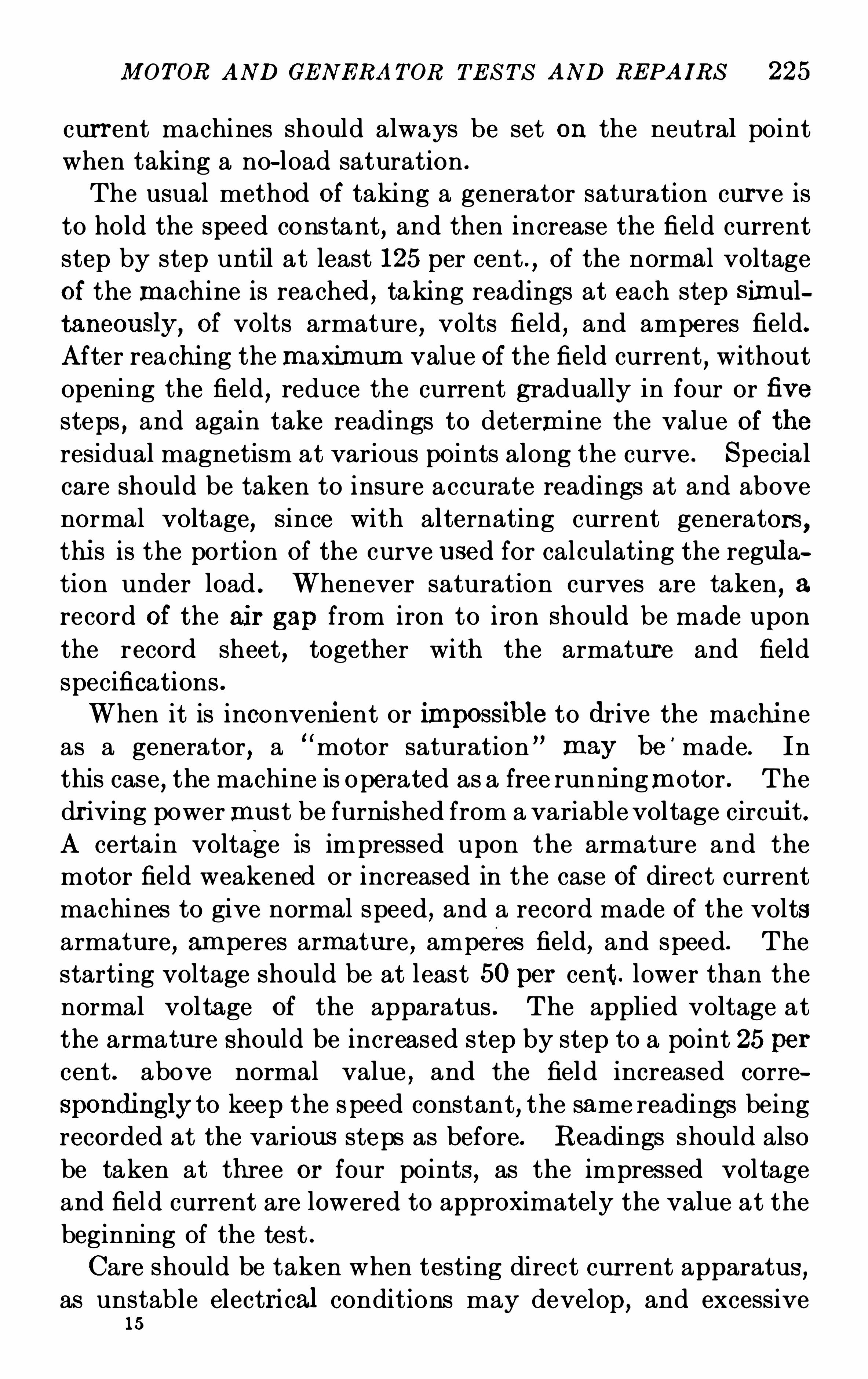
M OTOR AND GE N ERA TOR T E S T S AND RE PAIRS 225
current machines should always be set on the neutral point
when taking a no-load saturation .
The usual method Of taking a generator saturation curve is
to hold the speed constant, and then increase the field current
step by step until at least 125 per cent . , of the normal voltage
of the machine is reached , taking readings at each step S imul
taneously,of volts armature , volts field , and amperes field.
After reachi ng themaximum value Of the field current,without
opening the field,reduce the current gradually in four or five
steps,and again take readings to determine the value of the
residual magnetism at various points along the curve . S pecial
care should be taken to insure accurate readings at and above
normal voltage,since with alternating current generators ,
thi s is the portion of the curve u sed for calculating the regula
tion under load . Whenever saturation curves are taken, a
record Of the air gap from iron to iron Should be made upon
the record sheet,together with the armature and field
specifications .
When it is inconveni ent or M possible to drive the machi ne
as a generator, a“motor saturation ” may be
'
made. In
this case,the machine is operated as a free runni ngmotor . The
dr iving powermust be furni shed from a variable voltage circui t.
A certain voltage is impressed upon the armature and themotor field weakened or increased in the case Of direct current
machines to give normal speed, and a record made of the voltsarmature , am peres armature , amperes field, and speed. The
starting voltage should be at least 50per cent . lower than the
normal voltage of the apparatus . The applied voltage at
the armature Should be increased step by step to a point 25 per
cent . above normal value , and the field increased corre
Spondingly to keep the s peed constant, the same readings being
recorded at the various steps as before. Readings should also
be taken at three or four points , as the impressed voltage
and field current are lowered to approximately the value at the
beginning of the test .
Care should be taken when testing direct cur rent apparatus ,as unstable electri cal conditions may develop, and excessive
15
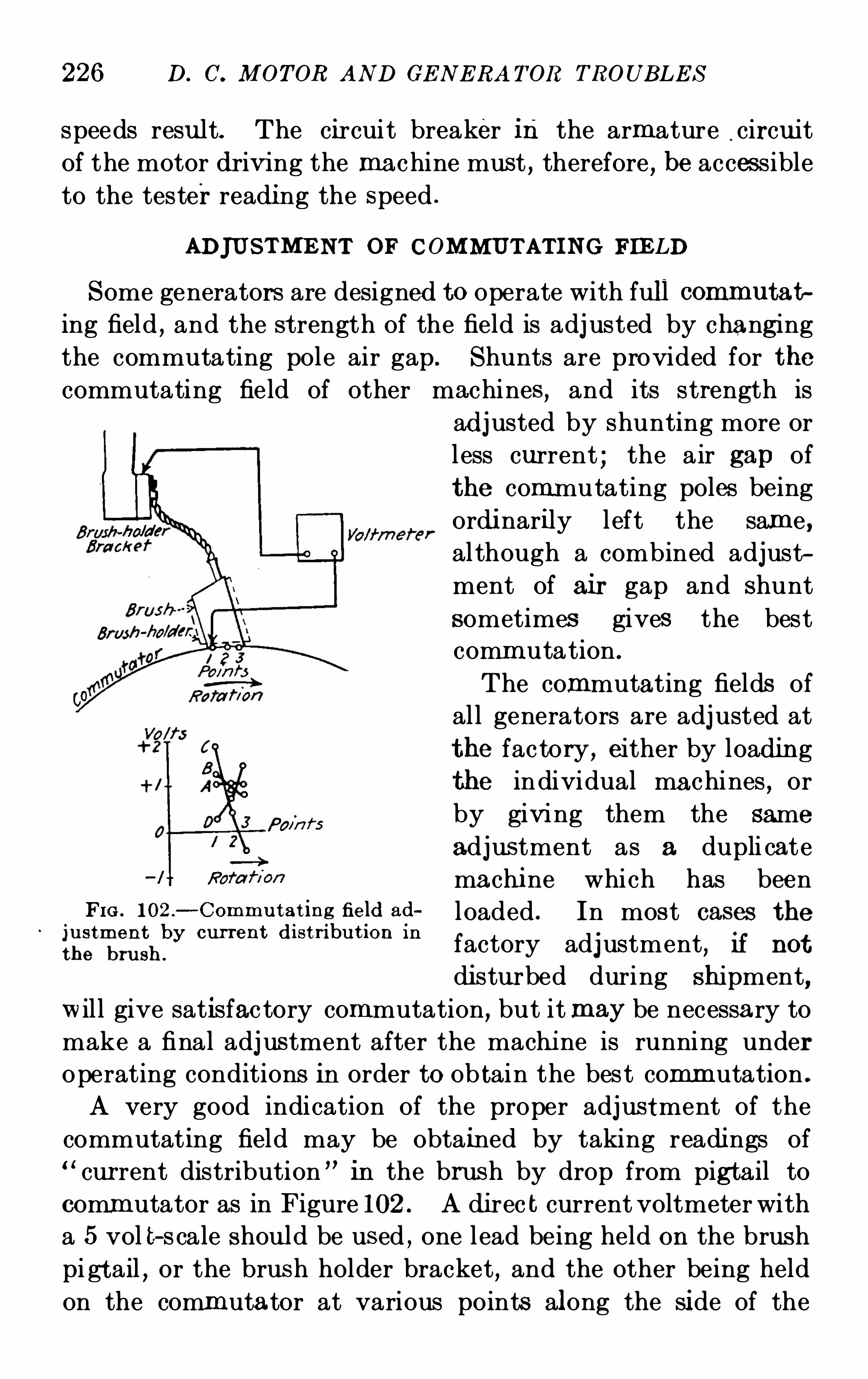
226 D. C. M OT OR AND GE N E RA TOR TROUB LE S
speeds resu lt. The circui t breaker in the armature.circu it
of the motor driving the machine must , therefore , be accessible
to the tester readi ng the speed .
ADJU S TM E NT OF COM MUT AT I N G FIE LD
S ome generators are designed to operate with full commutat
ing field,and the st rength of the field is adj usted by changing
the commutating pole air gap . Shunts are provided for the
commutating field of other machines , and its strength is
adj usted by shunting more or
less current ; the air gap of
the commutating poles being
ordi narily l eft the same ,al though a combined adjust
ment of ai r gap and Shunt
sometimes gives the bestcomm utation .
The commutating fields of
al l generators are adj usted at
the fac tory , either by loadin g
the individual machines , or
by givi ng them the same
adjus tment as a dupli cate
machi ne which has beenFI G . 102 .
—Commu tat ing field ad l oaded , In mos t Cases thet
‘ b t'
ji
trzt r
iffishby cur ren t d i s n u Ion I n
factory adjustment, If not
di stur bed during Shipment,w il l give satisfac tory commutation, but itmay be necessary to
make a final adj ustment after the machi ne is running under
operating conditions in order to Ob tain the best commutation .
A very good indication of the proper adjus tment of the
commutating field may be obtained by taking readings of“cur rent distribution ” in the brush by drop from pig tail to
commutator as in Figure 102 . A di rec t current voltmeter with
a 5 vol t—s cale S hould be us ed , one lead being held on the brushpi gt ail , or the brus h holder bracket , and the other being held
on the commutator at various points along the si de of the
228 D. C. IlI OTOR AND GE N E RA T OR TROUB LE S
ing field , these mechanical featur es S hould be gone over thor
oughly, trying the commutation after any change is made and
noting the eff ect produced .
GO over all contacts and make certain that none are loose .
Check the connections and make certain that the commu tat
ing field or any part of it is not reversed,i
and that one or
more of the main spools are not reversed .
Check the brush spacing and alignment both with paper
tape, and by the commutator mica , revolving the armature to
two or three positions to detect errors due to variation in the
thickness of bars or mica . The brush spacing Should always
be checked with reference to the trailing side of the brush,that is, the side on whi ch the commuta tor bars leave , and on
which sparking usually appears . Machines of certain des igns
are very sensitive to brush spacing, and a variation of over
% 6 of an inch should be corrected . In general , the more
accurate the brush spacing , the more uniformly good will be
the commutation .
Check the mechani cal neutral, and try shi fting the
brushes each way from neu tral . Very Often a slight shift is
advantageous .
Go over the brushes and see that they move freely in the
holders,and that the pigtails do not interfere with any part
of the rigging . Check the pressure and see that the fit is
good . Look for burni ng or roughness of the contact surfaces .
Inspect the sur face of the commutator and wipe Off any
blackeni ng . If it is rough or eccentri c , causing the brushes
to chatter or move in the holders , it S hould be ground or
stoned,and perhaps turned . Directions for doing thi s work
are given in Chapter IV
Check the centering of the comm utating poles between the
main poles,and check both the main and commutating pole
air gap .
These adj ustments for commutation should be supervised
if possible by someone who underatands the theory and Opera
tion of dir ect current machines , and is experienced in adjus ting
them .
M OTOR AN D G E N ERA T OR T E S T S AND RE PA IRS 229
VOLTAGE RE GULATI ON
The voltage regulation Of a self excited shun t wound gen
erator equipped with commutating poles and pole face windings
can be tested by first bringing the voltage to the normal
rated value at no load ; then , bringing the machine up to full
load by quarter load increments , without adj usting the field
rheostat , note the voltage reading at each point . These
results if plotted in the form of a curve whose ordinates are
volts and loads will give the voltage charact eristic of the ma
chine showing the voltage obtainable at all loads without
field adjustment . A separately excited shunt wound gen
erator will operate with much less droop in the voltage curve
than that of self excited machines . If commutation permits ,the droop in the curve of either type may be decreased by
shifting the brushes backward against rotation,where the
unit is designed with commutating poles . Generators without
commutating poles will operate with the least amount of
droop if the brushes are placed as near as possible to the no
load neutral .
A tes t of the vol tage regulation of a self excited shunt wound
generator not equi pped with commutating poles or pole face
windings cannot be made by the method outlined above S ince
the armature reaction is not compensated for and the voltage
will drop to practically zero before the normal load point is
reached . In such instances,the following test should be em
ployed to secure the necessary data for plotting the regulation
curve . A reading S hould be taken first at the no load normal
voltage . Without changing the rheostat,one-quarter load
should be thrown on and a reading taken of amperes armature ,volts armature, amperes field and volts field . Holding onequarter load , the voltage should be brought up to normal and
the same readi ngs taken . The load should now be increased
to one-half full load and with the rheostat in the same posit ion,similar readings repeated . This test is repeated for three
quarter and full load . With full load on the machine the
voltage should be brought up to normal . With the field
rheostat in this position, the load is then taken off the machi ne
230 D. AND GE N E RA T OR TROUB LE S
and the rise in voltage Observed . All of these entries Should
be made on a record S heet and a curve plotted with amperes
armature as abscissae and volts as ordi nates . If the voltage
S hould drop to zero when one-quart er load is put on the
machine,the load should be applied in smaller increments .
The speed should always be kept constant throughout
the test .
The voltage regulation of compound wound generators is
adjusted at the no load and ful l load points . The regula tion
between these points can be Obtained by loadi ng the generator
with successive increments of one-quarter load each and plot
ting a curve with the resulting data , providing no adjustment
of the shunt field rheostat is made . Tests S hould be made
while the load is being increased and decreased . A departure
from a straight line drawn between the no load and full load
points indicates the voltage regulation of the generator . The
departure or hum p between the curve and the straight linewill be found to vary in amount with the different types of
machines running from 2 to 10 per cent . Flat compounded
machines S how less hum p than over compounded units . The
shape of the compounding curve is typical of each machi ne
and practically no change can be made in the uni t to alter its
curve.
SPE ED RE GULAT I ON
Speed regu lation is important in the operation Of direct
current motors . In all cases adj ustments should be made hot,
that is,with the machine at its normal operating temperature .
The voltage must be held at a constant value throughout the
test for both shunt and compound motors . Data for plotting
the speed regulation curve is Obtained by loading the machine
beginning at no load and advancing to ful l load in small
increments, recording carefully the S peeds at the intermedi ate
points . The curve of shunt wound motors without commu
tating poles will Show a dr ooping characteristic whi le similar
machines equipped with commutating poles will Operate at a
more constant S peed from no load to ful l load and in some
232 D. C. M OT OR AND GE N E RA T OR TROUB LE S
box or by the “feeding back method,described at the end of
this arti cle . Constant load on a motor may be Obtained by
the use of a brake .
The time required for reachi ng a constant temperature
varies in proport ion to the size of the unit . From three to
four hours continuous run will suffice for uni ts whose rating
does not exceed three hundr ed ki lowatts while above thi s
value it is necess ary to continue the run from five to eight
hours . Thermometers should be attached to all stationa ry
parts such as field coils , connections , bearings , magnet frameand where possible , at the outlets of the armatur e venti lating
ducts . I t is customary to attach these thermometers by
means of putty or cord covering in either case the bulb of the
thermometer to exclude the air . When the thermometers
register a constant temperature for at least thirty minutes,it
is safe to assume that the revolving parts have reached the
maximum temperature and that the unit may be stopped.
Additional thermometers should be immedi ately placed on
the armatur e coils , end windings , soldered clips , equalizer
rings , laminations and the commutator bars, and their tem
peratures recorded .
S hould the test under normal conditions i ndicate a cool
runni ng machine,the rating may be increased and the heat
run repeated providing the commutation will permit . The
temperature limits for the various classes of insulation have
already been given on page 187. In making a check on the
overload temperature gu arantees , it is necessary to first con
duct the tes t un der normal conditions . When cons tant tem
peratures have been reached and without shutting down , the
overload Should be appli ed for the specified time, after which
the unit should be S hut down and all temperatures taken .
The water box method previ ously referred to in this article ,as the name implies
,consists in driving the machine either by
a motor of engine and loading it with a water rheostat or“box .
”See Figure 103 . Thi s method entails considerable
expense , since all the power generated is lost . To obviate
this loss and reduce the cost of testing, the“Feeding Back ”

M OTOR AN D GE N E RATOR T E S T S AN D RE PA I RS 233
method is used when possible , especially in the case of largedirect current machines or motor generator sets .
In this method the total machine losses are supplied either
mechanically or electrically from an external source . In the
mechanical loss supply method,two machines of the same
FIG . 103 .
—S ket ch showing connect ion s for loading a D .C . generator on a
water box .
S ize and voltage shou ld be belted or di rect connected together
and driven by a machine largeenough to carry the loss of the
set . Connections are made as shown in Fig . 104 . If the
machines have series fields,each field should be connected to
boost its Shunt winding which requires that the machine, to
Operate as a motor must have its series field reversed and
accumulatively compounded . Both machines Should then be
FI G . 104.—S ket ch showing connect ions for mechanical loss supply pump
back .
run up as generators and thrown together by closing the switch
between them when the voltage across it is zero . The field of
the machine to act as motor should then be weakened, which
thr ows load on both machi nes . The speed is held constantby the loss supply motor . After running at the proper load
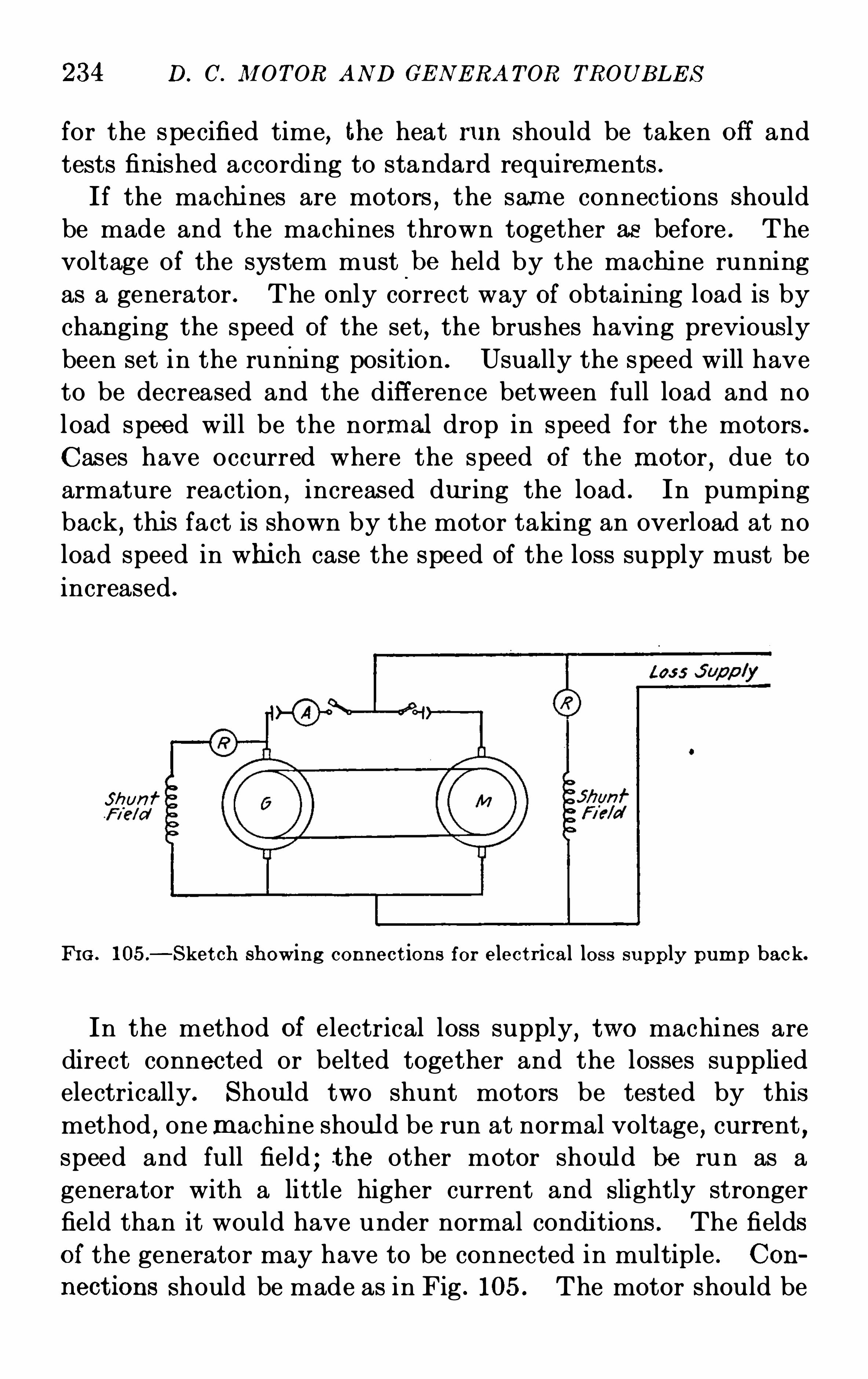
234 D. C. M OTOR AND GE N E RA T OR TROUB LE S
for the specified time, the heat r un S hould be taken Off and
tests fini shed according to standard requirements .
If the machi nes are motors , the same connections Should
be made and the machines thrown together as before . The
voltage of the system must-
be held by the machi ne running
as a generator . The only correct way of obtaini ng load is by
changing the speed of the set , the brushes having previous ly
been set in the running position . Usually the speed will have
to be decreased and the diff erence between full load and no
load speed will be the normal drop in speed for the motors .
Cases have occurred where the speed of the motor, due to
armature reaction,increased during the load . In pumping
back,this fact is shown by the motor taking an overload at no
load speed in whi ch case the speed of the loss supply must be
increased .
Shun f
FI G . 105.
—S ket ch showing connect ion s for elect r ical loss su pp ly pump back.
In the method of electrical loss supply, two machines are
direct connected or belted together and the losses supplied
electrically. Should two shunt motors be tested by this
method,onemachine should be run at normal voltage , current ,
speed and full field ; t he other motor should be run as a
generator with a little higher current and slightly stronger
field than it would have under normal condi tions . The fields
of the generator may have to be connected in multiple . Con
nect ions should be made as in Fig . 105. The motor should be
236 D. C. M OT OR AND GE N E RA TOR TROUB LE S
The following conditions must be obtained with direct
current apparatus in order to give satisfactory results : the
brushes must be shifted on the commutator to the no-load
neutral point ; they must have their normal tension and the
commutator must be clean,so that the normal Operating com
mutator and brush friction values are obtained . This test,
wherever possible, should be made after all the others have been
finished,in order to have a glossy commutator with it s surface
in good operating condition . The driving power should be
suppl ied from a variable voltage c ircuit that is not subj ect to
sudden fluctuation . S ince the power input required to drive the
machine runni ng free as motor must be obtained,its value
must not be read when the rotating parts are either accelerat
ing or decelerating . A steady voltage must be kept on the
armature and the field current must have a constant value .When “running light ” tests are made on direct-current
generators,the Observations must be made with full load field
flux . The potential applied to the armature must be equal to
the normal rated voltage Of the generator increased by the
I R drop in the armature at full load . With this voltage im
pressed,the field current is varied until normal speed is Ob
tained, when careful readings must be made of armature cur
rent,armature Voltage
,field current
,field voltage and Speed .
If the machine in test is a direct-current motor,the voltage
applied to the armature should be equal to the normal rated
voltage of the motor,less the I R drop in the armature under
full load . The field current is then adj usted to give normal
spéed and electric al and speed readings taken, as ou lt ined
above for direct—current generators .The power supplied to machines runni ng free will equal that
absorbed in bearing friction,bru sh fric tion
,windage
,and core
loss,when the armature I 2R losses have been subtracted .
In making records of these tests,the testing record Should
Show clearly whether the running light current consists of the
armatur e current plus the shunt field current , or whether it is
the armature current alone . To check this point,Open the
armature c ircuit with the shunt field circuit closed,and note
M OTOR AND GE N ERA T OR T E S T S AND RE PA IRS 237
whether any current is indicated , on the ammeter, reading the
power supplied . If no current is indicated , the reading indi
cates the armature current alone , otherwise, the running
current is equal to the sum of the armature and field currents .To obtain running light ” core loss tests
,only a single field
windin g must be used for excitation ; this must be a shunt field
winding
The belted core loss method separates the core loss from
the bearing friction,brush friction
,and windage . A smal l
direct-current motor is used to drive the machine under test
as a generator at its rated Speed . A belt drive between these
machines is most commonly used . However,wherever great
accuracy or a high speed is .necessary,direct driving by a
coupling is often used .
The driving motor for this test must be carefully chosen .
It must be operated through the range Of load required for
the core loss test with good commutation and with a fixed
setting Of the brushes . Ordinarily a safe rule to follow is that
the motor Should be approximately 10per cent . of the capacity
of the machine under test . The maximum lead which this
motor should carry with the heaviest field on the machine
under test should not exceed 50 per cent . of its normal rated
capacity . The driving motor should be Operated as nearly
as possible at its rated speed and field strength . The brushes
should be carefully set at the best position for good commuta
tion at all the loads requir ed by the test . The commutator
surface should be in first c lass condition .
The weight and width of the belt must be selected to give
minimum loss . When testing motor-generator sets,rotary
converters,and apparatus which does not use belts , the tension
of the belt must be kept as low as practicable, so that the
bear ing friction is not increased due to the belt pull . E ndless
belts Should be used in preference to laced belts .
The driving motor must be wired so that readings may be
taken of amperes . armature,volts armature
,amperes field
,
and speed . A reading should be taken on the motor corre
sponding to normal speed of the machine under test . The
238 D. C . M OTOR AND GE N E RA T OR TROUB LE S
machine under test Should be wired with its field separately
excited and provision made for reading amperes field , volts
field,and volts armature . Previous to startin g the test
,careful
resistance measur ements of the armature of the dr iving motor,
must be made .
The test is then car ried ou t , as follows : The field of the
dr iving motor is ad j usted to about normal value and excited
from a sour ce of cons tant voltage so that i ts value may be
held constant throughout the test . The speed of the drivingmotor is regulated by varying the voltage applied to its arma
ture terminals . Fi rst , run the driving motor and the machine
under test a sufficient length of time to allow the friction to
reach a constant value . This wi ll be Obtained when the input
on the driving motor becomes cons tant when driving the
machine ‘ un der test without any field excitation . Careful
readi ngs should then be taken firs t of the input to the driving
motor with the machine under test unexcited and all brushes
down on the commutator . Following this reading,a second
should be taken with all brushes raised from the commutator
of the machine under test . The difl’erence between these two
sets of readings wi ll give the brush frict ion on the machine
receiving the test . S tarting with the zero field on the machine
under test,observations of the input to the driving motor
should be made at various values Of the field up to that whi ch
will give 125 per cent . normal load voltage . Correcting the
motor input at these various field strengths by taking out
the I 2R loss in the armature of the driving motor, and sub
tracting the power input to the driving motor with zero field,
the core loss is left corresponding to the various field strengths .
In order to insur e constancy of friction losses during the
entire test,the readings Of the motor input with zero field
should be repeated at least three times during the progressof the test ; namely, at the beginni ng, agai n near the middle
point of the curve,and lastly at the end of the test . Readings
should also be taken at the end of the test with normal voltage,field cur rent and with brushes raised from the commutator,to compare with the reading in which the same field was used
240 D. C. M OTOR AND GE N E RA T OR TROUB LE S
On the test floor the exact electrical losses are determi ned
by careful measurements of the load values,resistances of the
various circuits,friction
,windage and core losses . These
losses are added to the machine’s output measured on ac
curately cali brated instruments . The efl‘iciency of a generatoris then calculated by dividing the output by the input and thatof a motor is obtained by dividing the product of the volts
times the amperes input,mi nus the losses, by the volts times
the amperes input .
B E ARI N G I N SULAT I ON
In testing the insulation between the bearing pedestal and
the base,it should be borne in mind that this insulation is not
requir ed to resist high voltages to prevent the flow Of current
through the Shaft . For this reason in testing,a voltage Of
125 volts or under should be applied across the insulation
which is suspected of being defective . A ground or a partial
ground between the base and the bearing pedestal will be
Shown by a voltmeter in series with the voltage supply,one
of whose termin als is connected to the base and the other to
the pedestal . In making this test,the path Of the current
through the shaft and the other pedestal or other mechanical
parts,back through the base must be broken up . Thi s is
usually accomplished by S lightly raising the armature and
fitting a support which permits the bearing and oil ring to be
separated from the Shaft,thus interrupting the mechanical
path .
S TARTI N G T E S T
A starting test on a motor is made to determine whether or
not the lights or other apparatus operating in the same cir cuit
are aff ected when the motor is thrown on the line . The test
may be made as follows : Place an ammeter in series with the
motor line,the instrument having a sufficient capacity to take
the maximum load required . The line voltage Should be
noted and compared with the voltage rating on the name
M OTOR AND GE N ERA T OR TE S TS AND RE PA IRS 241
plate . Close the Shunt field circuit as in usual practice and
place the starting switch on the first point . The maximum
swing of current should be read on the ammeter and also the
drop in voltage . As soon as the current reaches a constant
value,the starting box is moved to the second point again
recording the current and voltage . This process is continued
over the entire range of resistance until the motor is running
directly on the line,that is
,with all resistance cut out . Should
it be found that the starting of the motor is responsible for a
line disturbance aff ecting the other units or lights,a starting
box with a greater number of points should be installed to
relieve the trouble by reducing the amount of current required
in each step .
HI GH POT E N T IAL T E S T S
All direct current machines are given a high potential test
before testing,using an alternating current voltage which is
applied for one minute for all standard work . The voltage
is varied to suit the voltage of the machine and the type of
insulation with which it is fitted . S tandard practice requires
a test of double the working voltage plus one thousand but
fifteen hundred volts is the minimum value used for new
machines . Rebuilt or repaired direct current units should
not be subj ected to voltages of ‘
more than one-half of the values
given due to the aging and depreciation of the insulation in
service . The usual insulation test by use of a voltmeter in
series with the power cir cuit is sufficient to indicate a weaken
ing of the insulation without applying the high potential test
which may result in a complete failure of the insulation . N o
machine should be subj ected to a high potential test unless it
has been previously cleaned thoroughly and dried out if
necessary.
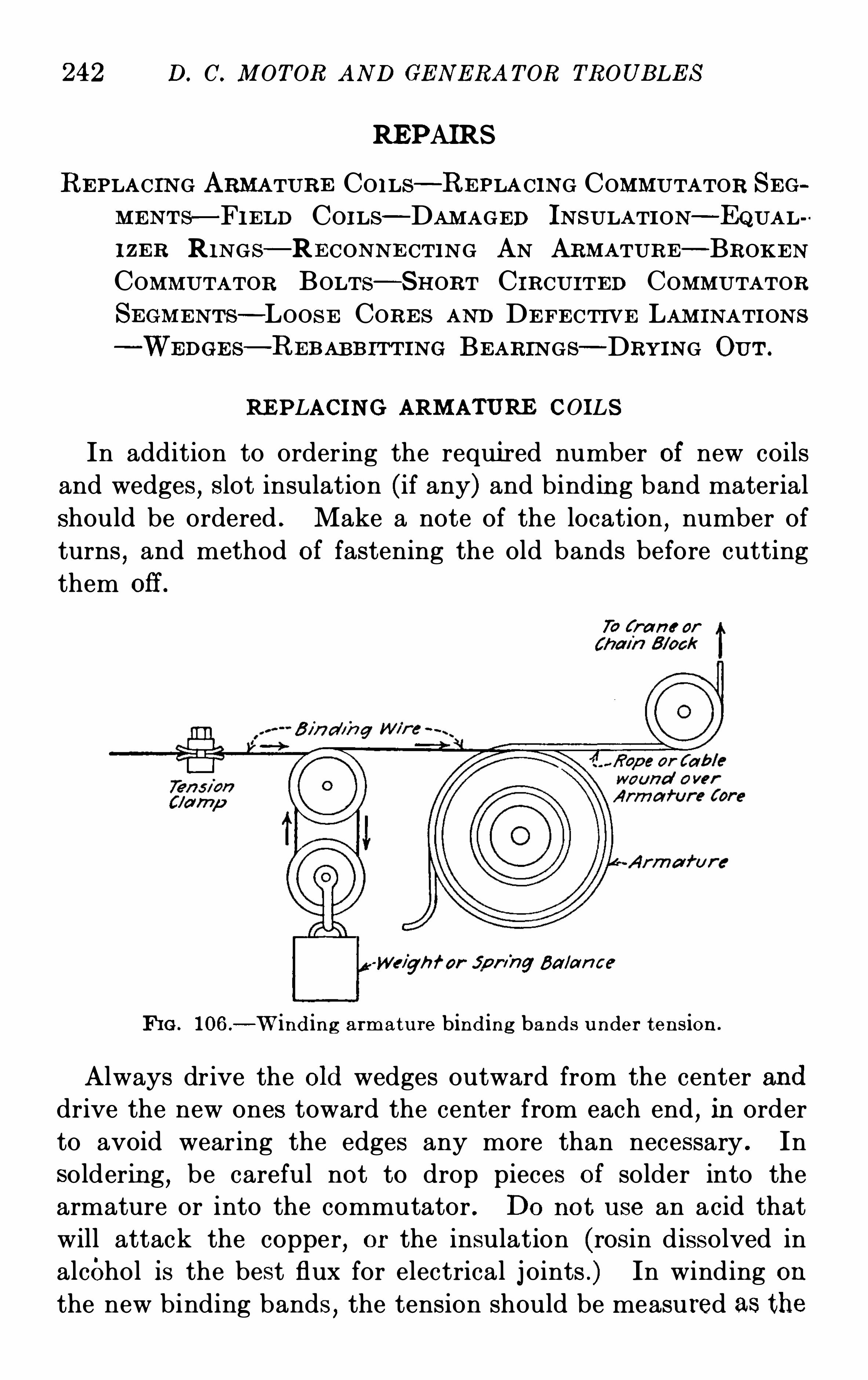
242 D. C. M OT OR AND GE N E RA T OR TROUB LE S
RE PAIRS
RE PLACI N G ARMATURE CO I LS—RE PLA CING COMMUTATOR S E GM E N T s—FI E LD COI LS - DAM AGED IN SULATI ON—EQUALI ZE R R I N GS—RE CON N E CTI N G AN ARMATURE—BROKE NCOMM UTATOR BOLTS - SHORT C IRCUI TE D COMMUTATOR
S E GM E N T s—LOOS E CORE S AND DE FE CTI VE LAM I NATI ON S
WE DG E s—RE B AB B I T T I N G BE ARIN GS—DRYIN G OUT .
RE PLACIN G ARM ATURE COILS
In addition to ordering the requi red number Of new coils
and wedges , S lot insulation (if any) and binding band materialshould be ordered . Make a note of the location
,number of
turns,and method of fastening the old bands before cutting
them off .
70 ( r an : or
Weigh f or' jpn
'
ng Balan ce
FI G . 106.
—W indin g armatu re bind ing bands u nder ten sion .
Always drive the Old wedges outward from the center and
drive the new ones toward the center from each end , in order
to avoid wearing the edges any more than necessary . Insoldering
,be careful not to drop pieces of solder into the
armature or into the commutator . Do not use an acid that
will attack the copper,or the insulation (rosin dissolved in
alcohol is the best flux for electrical j oints .) In winding on
the new binding bands,the tension should be measured as the
244 D . C. M OTOR AND GE N E RA TOR TROUBLE S
they will remain tight,the windings will chafe and finally
break down .
In removing a defective armature coil,it is necessary to
disturb the conductors over one or more pole pitches and care
must be taken to prevent damage to the insulation where it is
necessary to bend or spring the coils during removal . Before
the conductors are replaced they Should be given a thorough
coating of insulating varnish to close all breaks or cracks .
S ince full diff erence of potential occurs between the upper and
lower conductors in the slot and between the end windings
c lose to the end of the core,the insulation at these points
should be mad e as perfect as possible when new coils are in
stalled or when an armature is rewound . S lot armor,whether
moulded on the bars or used as a trough in the slot,should be
closely examined for indications of cutting caused by loose
laminations . Flange insulation under the end windings should
be of uniform thickness,ir oned in place under pressure and
heat to form a solid bed supporting the conductors when the
pressure of the binding bands is brought to bear .
REPLACI N G COM MUT AT OR S E GM E NT S
When it is necessary to replace a commutator segment in
service,first cut or unsolder the connection of the faulty bar
to the armature . Wrap the commutator circumferentially
with sufl‘icien t turns of ordinary binding wire or apply special
steel rings fitted with sectional tightening and clamping blocks,to insure the integrity of the commutator while the front clamp
ring is removed . Then remove the clamping ring bolts and
withdraw the clamping ring on the outer end of the commu
tator . If this ring is sectional,remove only the section which
the defective bar aff ects . L oosen and slide ou t the faulty
segment and replace with a new one; where necessary insert
new side mica . Repair commutator segments are usually
shipped with the V notch unfinished,which must be filed to
an accurate fit,using one of the old bars as a templet . T oo
much care cannot be used in fitting the new bars, as a poor
M OTOR AND GE N E RA T OR T E S T S AND RE PA IRS 245
fit may cause considerable trouble in getting the commutator
settled and smooth . Damaged bed or ring mica should be
built up to a uniform thi ckness,using thin sheets of mica .
The front cone mi ca can be replaced without disturbing the
commutator,but replacement of the bed mica demands a
complete rebui lding of the commutator . In replacing the
cone mica on the inn er ring,the commutator Should be dis
connected from the armature windings and pressed off the
shaft or Spider in order to expose the bolts and clamping ring .
Commutators constructed with through bolts Should be
handled with great care to prevent the back end from be
coming displaced by the removal of the bolts dur ing repairs .
When shrink rings are fitted,in addition to the clamping
rings,it is necessary to heat the Shrink ring and remove the
ring together with its insulation before a bar can be inserted .
After replac ing bars,the commutator bolts must not be tight
ened to such an extent as to distort the clamping rings,break
the mica insulation,or spring and break the copper segments .
It is always necessary to turn or grind the commutator to
insure a smooth running surface where a replacement of seg
ments has been made .
When a commutator must be rebuilt,the correct number
of segments and pieces of mica are assembled in the form of a
circle,Shellacing the mica strips as they are placed between
the bars . The segments are made to conform to a circular
Shape by placing them in an assembly ring adjusted by screw
ing segmental blocks in or ou t . The segments held firmly in
the ring are then placed in a lathe and the V notches cut ou t at
each end . Bed mica is fitted around the spider and cone mica
on each clamping ring . The bars are then clamped tightly
and evenly between the two rings making sure that the
center line of the bars is parallel with the center line of the
machine .
After the cone or bed mica has been replaced or the cem
mutator completely rebuilt,it must be seasoned or baked to
remove the solvents from the mica insulation and thus prevent
shrinkage and loosening of the commutator in service . This
246 D. C. M OT OR AND GE N E RA TOR TROUB LE S
may be accomplished by plac ing the entire commutator in an
oven and heatin g for from ten to twenty hours , depending upon
the size of the commutator, at a temperature of from 150
degrees to 200 degrees Centigrade . Vent holes should be
drilled to facilitate the easy exit of the gases from the commuta
tor as desc ribed under “Drying out . ”
FIE LD COIL S
A defective field coil may be removed from a direct current
machine for repairs or replacement by withdrawing the bolts
holding the pole to the frame structure or by removing the
bolts holding the pole faces to the main pole cores . After
the connection strips are disconn ected,the pole piece with the
Spool in place is carried along the armature to a position where
the core may be slid out without disturbing the armature . It
is well to place a strip of cardboard,fibre or padding in the air
gap at the po int where the pole is to be moved in order to
protect the armature . Where it is necessary to unbolt the
pole face,the armature must be first withdrawn or the magnet
frame separated if it is constructed in two halves .
If the coil is damaged beyond repair it should be replaced
with a new coil or rewound . The insulation on the spool body
should be examined and replaced if damaged,punctured or
rendered ineffective by age. N ew collars are substituted for
those which have become S plit,warped or burned . This is
done by straightening out the sheet iron body and Constructing
new collars of laminated maple wood or fibre . N ew shunt
wire may be rewound where short circuits between turns have
developed but the series turns usually require s imply a re
newal of the insulation unless the copper has been badly
burned . M umm ified coils have no collar s or spool bodies and
are generally mounted dir ectly on the core necessitating a
heavy outside insulation . Commutating fields are sometimes
wound upon the insulated core held in place by insulated bolts
and washers but are most always mounted on spools in a similar
manner to that employed on the main field poles . Pole face
248 D. C. M OTOR AN D GE N E RA T OR TROUB LE S
all of the pores and cracks have been completely filled . A
thorough baking in an oven should then be given at a tem
perature of 100 degrees Centigrade, unless the operating value
exceeds this value in which case the temperature should be
raised to a point slightly above the maximum run ning tem
perature to prevent a softening and running out of the insul
ating material in service . The baking should be continued
for from 10 to 15 hours,that is
,until all solvents have been
completely vaporized . The above treatment should be given
to machines whose service requir es them to operate under
moist conditions where no provision has been made for such
operation in their design . In addition to dipping and baking
the armature and fields it is well to spray the metal parts such
as the pole pieces , the inside of the frame and the brush holder
yoke,with air drying j apan or varnish to exclude moisture
and thus prevent rust ing . Small bolts under one-half an inch
in diameter,Springs
,nuts and washers should be sherardized
or copper plated and all bushings and insulating washers
dipped in hot linseed or varnish to prevent warping and dis
tort ion during Operation .
S ide mica on the commutator, burned , charred or honey
combed with carbonized paths must be replaced by Sheets of
new mi ca if the burning has extended to a depth of more than
one-half inch . Temporary repairs can be made by cutting
away the carboni zed mica and removing all burnt particles
and filling the slot with commutator compound . If it is
impossible to secure this compound already prepared for use
or if the emergency demands immediate action,a paste made
of water glass and Plaster of Paris may be applied after the
burned particles have been thoroughly scraped out .
EQUALIZER RING S
E quali zer rings connecting equal potential points on mult Iple wound armatures are mounted either at the back or coup
ling end,or at the commutator end . In the latter case
,the
connections are made dir ectly to the risers or leads . Repairs
.MOTOR AN D GE N E RA TOR T E S T S AN D RE PA IRS 249
to defective equalizers consist in a replacement of burnt ordamaged conductors, repairs to insulation and perfecting
mechanical j oints . Faulty rings should be disconnected from
the armature coils at either end and the insulation completely
replaced over the entire length of the damaged portion . Where
the equalizer r ings and leads are separated by air spaces,it
is unn ecessary to remove the entir e number dur ing replace
ment,but on an armature which is equali zed at every S lot
,
having the rings mounted so that they fit one in the other, it
is advisable to remove all of the rings after first loosening the
holding brackets or cords . The damaged insulation or defect
ive rings Should be replaced and the entire group blown out
with compressed air . The rings are then reassembled,corded
and fitted to the machine . Where an oven is available to
gether with a tank Of sufficient size to permit the assembled
rings to be dipped as a unit,a thorough filling with a good
insulating varnish can be applied after first heating the set of
rings and then finally drying by baking in the oven to a tem
peratu re of from 100 degrees to 150 degrees Centigrade .
Additional equalizers are fitted on an armature when trouble
has developed due to too few equali zers, without disturbing
the rings already in place,by inserting the new rings either
above or below the old ones and connecting them to the
proper armature end clips . The new spacing is determined
from the old Spacing,counting the number of end clips between
connections to locate the new equal potential points . Wher
ever possible a complete set of equalizers Should be installed
wi th a connection for at least each slot in the armature and
preferably,for each end clip . This requi res discarding
entirely the old equalizers and making up an involute type
which may be mounted horizontally or vertically on the arma
ture Spider or special ring provided for the purpose . It should
be remembered that a machine with an Odd number of slots ,that is
,a number not divisible by the number of poles
,cannot
be equalized . Taps for the firs t equali zer ring Should be
located by marking the armature end cli p directly under the
center of all poles of like polarity and j oining these clips
250 D. C. AI OTOR AND GE N E RA T OR TRO UE LE S
together with a copper connection . The other rings will
follow in the regular order,after the proper relation of the
first ring is established . Armatures having four, S ix,eight
or more conductors per S lot may present a mechanically im
possible problem to equalize all of the end clips and in such
cases care must be taken to select for connections the end
clips in the same relation in all of the slots around the armature .
RE CON NE CT I N G AN ARM ATURE
After an armature has been rewound,the wiring diagram
Of the machine Should be consulted in order to determine the
proper connection to the commutator . If the wiring diagram
is unavailable,a sketch of the connections should be made
before the Old winding is stripped and it is also advisable to
mark one or more slots and one or more corresponding com
mutator segments as a starting point for connecting the new
coils .
Armatures designed for 600 or 250 volt service may be
reconnected for 300 or 125 volt service,providing that the
number of conductors per s lot is such that two conductors
may be placed in multiple . For example,reconnection for a
lower voltage is possible where four or eight conductors per
slot are found,s ince a conversion to two or four conductors
can be eff ected by connecting the bars in multiple at the end
c lips or at the commutator . Reconnection for half voltage
cannot be made where S ix or ten conductors per slot are fitted
since connecting pairs in multiple will still leave an odd con
ductor . The commutator segments must also be placed in
multiple,which may be done by soldering the end clips to
gether at the risers or by solderin g a copper strap at the end
of each pair Of bars to be paralleled . The current carrying
capacity of the armature conductors after reconnection will
be doubled,while the generated voltage is reduced to one-half
it s former value . Operation under the double current depends
upon the brush capacity,which is the usual limiting feature .
The new kilowatt rating must be based upon the brush and
252 D. C. M OT OR AND GE N E RA TOR TROUB LE S
or necking down should not bring the size of the bolt below
the dimension at the bottom of the thread . Both ends of the
commutator should be given this treatment even though the
trouble may have developed in one end only . In case it is
mechani cally possible to drill the spider the entire length and
u se long through bolts , to hold both front and back clamping
rings,it is advisable to adopt this arrangement . The through
bolts should be reduced in diameter in the center over a space
of from three to four diameters as mentioned above . The
commutator bolts should be carefully and evenly tightened
after replacement .
S HORT -CIRCUI T ED COM M UT AT OR S E G M E N T
The repair for a short-circuited commutator segment is
described in Chapter VI I on page 167.
LOOS E CORE S AND DE FE CT IVE LAM I NAT I ON S
The repair for these failures has been outlined in Chapter
VI I on“Troubles and Their Remedies” on page 195.
WE DG E S
Wedges cause trouble when improperly seasoned,due to
shrinkage . In service they tend to loosen and fly ou t thus
permi tting the armature conductor to move in the slot and
chafe its insulation,or even to fly ou t against the pole piece
with the danger of wrecking the machine . Various materials
are used in the manufactur e of wedges such as fibre , brass,wood and steel . Of these
,cross grained hard wood has given
the best results . S ince the wedges when driven into place
are sli ghtly reduced in size,it is inadvisable to make u se of the
same wedge when rewinding the armature,especially in the
case of hi gh speed armatures where a great strain is placed
upon the wedges .
RE B AB B ITT I N G B EARING S
Before melting ou t the old babbitt , take particular note Of
the oil grooves and holes, and the beveling at the j oint , maki ng

M OT OR AND GE N E RA T OR T E S TS AND RE PA I RS 253
a sketch,if necessary
,so that these features can be duplicated .
A piece of pipe, or other metal cylinder of the proper si ze may
be used for a mold , closing the openings between the Shell
and the mold at the ends,with felt or putty . When the new
babbitt is cool,the two halves of the bearing Should be put
together, and bored or reamed to the proper size . The oil
holes should be drilled ou t and the grooves bored or chipped .
The shaft may be used as a mold,if necessary
,wrapping a thin
piece of paper around it to prevent sticking,and the bearing
fitted by filing and scraping .
DRYING OUT
If a machine has not been exposed to rain or unusual damp
ness and has been set up in a dry operating station,no drying
out will be necessary . If,on the other hand
,a machine has
been long exposed to the weather,or has been wet , or has been
set up in a new station not warmed,or damp owing to fresh
concrete or other causes, the following precautions should be
taken .
A simple Shunt machine should haveits field Opened and
its armature short-circuited by a cable which will carry two
or three times the normal armature current and which is also
of sufficiently low resistance to constitute a “dead short
circuit . ” When a generator of standard design is driven at
normal speed under such conditions,the residual magnetism
will cause a c irculating current to flow in the armature,its
value being between normal full-load current and twice this
amount,which is a good workin g value for drying ou t . Should
it be found that the residual magnetism will not cause a suffi
cient current flow ,
'
the shunt field should be very weakly
excited from some external sour ce (the low field current nec
essary can be obtained either from a very low-voltage source
direct or from an ordinary voltage sour ce by inserting a high
resistance in the field cir cuit) . If severe Sparking takes placeat the commutator when operating under these conditions it
can be minimi zed by giving the brushes a forward shift .
D. C . M OT OR AN D GE N E RA T OR TROUB LE S
Ordinarily enough heated air will be thrown off the rotati ng
armature to dry ou t the field . In case this proves to be insuffi
c ient,or only the field is damp
,heat can be localized in the
field winding while the machine is at rest by connectin g the
Spool to an external source of excitation . From quarter to
normal voltage should be applied , depending on the dampness
of the spools.
It has been suggested that a machine can be dried out by
applying alternating-current to the field winding while the
armature is short-c ircuited . This method is open to the
serious obj ection that the alternating flux will cause excessive
heating in those parts of the magnetic c ir cuit which are not
laminated .
A commutating-pole machine that has no series field windingshould be dried out in the same manner as described for a
simple Shunt machine . Care Should be taken that the brushes
are not back of the neutral but are s lightly forward of it . The
commutating-pole winding is to be wired in exact accordance
with the standard diagram of connections for operation ;and the short-circuit placed on the machine is to include the
commutating-pole winding as well as the armature .
A compound machine should be dried out as described inthe foregoing except that the series—field winding should be cutout of circuit entirely . The latter is a precaution to prevent
the possibility of the machine build ing up as a series generator
in case no external excitation is applied to the shunt field .
Whi l e the above instructions apply to all s izes of machines ,where the unit is small and easily handled and where an oven
is available,it may be more conveni ent to thoroughly dry ou t
the machine by baking it in the oven at a temperature of from
100 to 150 degrees Centigrade , until the°
insulation resistan ce
measures approxim ately Ohms . If,after an extended
baking , this value cannot be obtained , it is an in dication that
moisture is pocketed in such a way that it cannot escape even
though vaporized . This trouble is usually found to exist in
the commutator at the c lamping ring in sulation or the body
mica . As a remedy,vent holes
,not exceeding one-half an inch
CHAPTE R IX
USEFUL DATA
SAFE TY RULE S - RE S US CI TATI ON ME THODS - STANDARD SI ZE SOF CAB L E S T O B E US E D I N CON N E CTI ON W I TH D .
-C.
G E N E RATORS - WIDTH OF BE LTS - DATA ON COPPE RWIRE .
S AFE TY RULE S
FOR M E N HANDLI NG E LE CT RI CAL CI RCUI T S OR APPARATU S
Rules .
—These safety rules should be carefully read and
studied .
Warn ings .—Employees whose duties do not requir e them to
approach or handle electrical equipment and lines Should keep
away from such equi pment or lines .
They should cultivate the habit of being cautious,heed
warning signs and signals, and always warn others when seen
in danger near li ve equipment or lines .Inexper ienced Employees . N o employee Should do work
for which he is not properly qualified on or about live equip
ment or lines,except under the dir ect supervision of an ex
per ienced or properly qualified person .
If an employee is in doubt as to the proper performance of
any work assigned,he should request instructions of foreman
or other responsible person . DON ’
T TAKE CHAN CE S .
Workmen whose employment incidentally brings them in
the neighborhood of electrical supply equipment or lines, with
the dangers of whi ch they are not familiar, should proceed with
their work only when authorized . They should be aecom
panied by a properly quali fied and authorized person, whose
instructions must be strictly obeyed .
256
US EFUL DA TA 257
Personal Caution.—Employees about live equipment or li nes
should consider the effect of each act,and do nothing which
may endanger themselves or others . Employees should be
careful always to place themselves in a safe and secure position
to avoid slipping,stumbling, or moving backward against
live parts . The care exercised by others should not be relied
on for protection .
REMEMBER,PERSON AL CAUTION I S THE GREAT
E ST SAFE GUARD AFTE R ALL
Clothing—Employees should wear suitable clothing whileworking on or about live equipment and lines . In particular,they Should keep sleeves down and should avoid wearing
unnecessary metal articles, celluloid collars, celluloid or metal
cap visors or sim ilar articles . N ear live or movi ng parts,loose
clothing and shoes that slip easily on floors worked upon
should not be worn .
S af ety Devices—S afety devices provided to make the workless hazardous
,should always be used
,but entire reliance
should not be placed on them as any safety device may get
ou t of order and become ineff ective , therefore , such devices or
tools should be first examined to make sure that they are
suitable and in good condition .
S afetyBelts.—Employees should not work in elevated posi
tions unless secured from falling by approved safety belts or
by other adequate means .
S afety belts,whether owned by the company or by the
individual workmen,should be periodically inspected .
Eye Protectors .
—Suitable eye protectors should be wornby men working where an electric arc may be drawn
,wi th
resultant flash to eyes .
Approved safety goggles should be worn to prevent injury
by flying particles when chiseling concrete,stone or brick for
the support Of wiring devices or electrical apparatus .Rubber Gloves—Rubber gloves should be used only in
special cases,and care must be taken to see that they are in
good condition .
17
258 D. C. M OT OR AND GE N E RA TOR TROUB LE S
Danger S igns.—Approved danger signs should be placed
at all points where men may accidentally come in contact
with live wires, and Should also be placed at suitable places
when men are working overhead , to prevent passerby from
inj ury from falling tools, etc . Danger signs should be re
moved when the danger is past .
M anholes .
—When a cover is removed from a manhole,the
hole must be properly guarded by railing,danger S ign or red
flag . An additional man stationed at the opening is Often
advisable .
Ladder s .
—N o imperfect or defective ladders should be used .
All ladders Should be provided with approved non-slip shoes
to prevent slipping . On cement , tile or iron floors, or other
smooth sur faces , a board should be placed under the non-s lip
shoes .
T ools .
—N O imperfect or defective tool Should be used .
The handles of tools should be covered with rubber tapeto prevent S lipping and to reduce the possibility Of short-cir
cuits across them . Such taping,however
,should not be
rel ied upon for protection Of workmen from shock . Heads of
cold Chi sels, center punches, etc . , shouldbeoccasionallydressed
and not allowed to become mushroomed . Avoid the use of
measuring tapes of metal or with metal woven in to the fabric
also brass bound rules and steel scales .
Rubber S h ields .
—When workin g on poles car rying lines of apotential hi gher than 600 volts
,wiremen may u se
‘
rubber
shields across the wires to protect themselves while working
on a selected wir e .
Insulating S tands—Employees should be properly in
sulated from the ground by a li noleum or rubber mat,insulated
stool,wooden slat platform
,or other suitable insulating ma
terial when working on c ircuits or operating high tension
switches,especially the disconn ecting lever type.
Circui ts —N o repairs , alterations or examinations requir
ing handling of live circuits above 750 volts Should be made ,except in case of urgent need
,and only when under the per
sonal supervision of the foreman . All voltages must be con
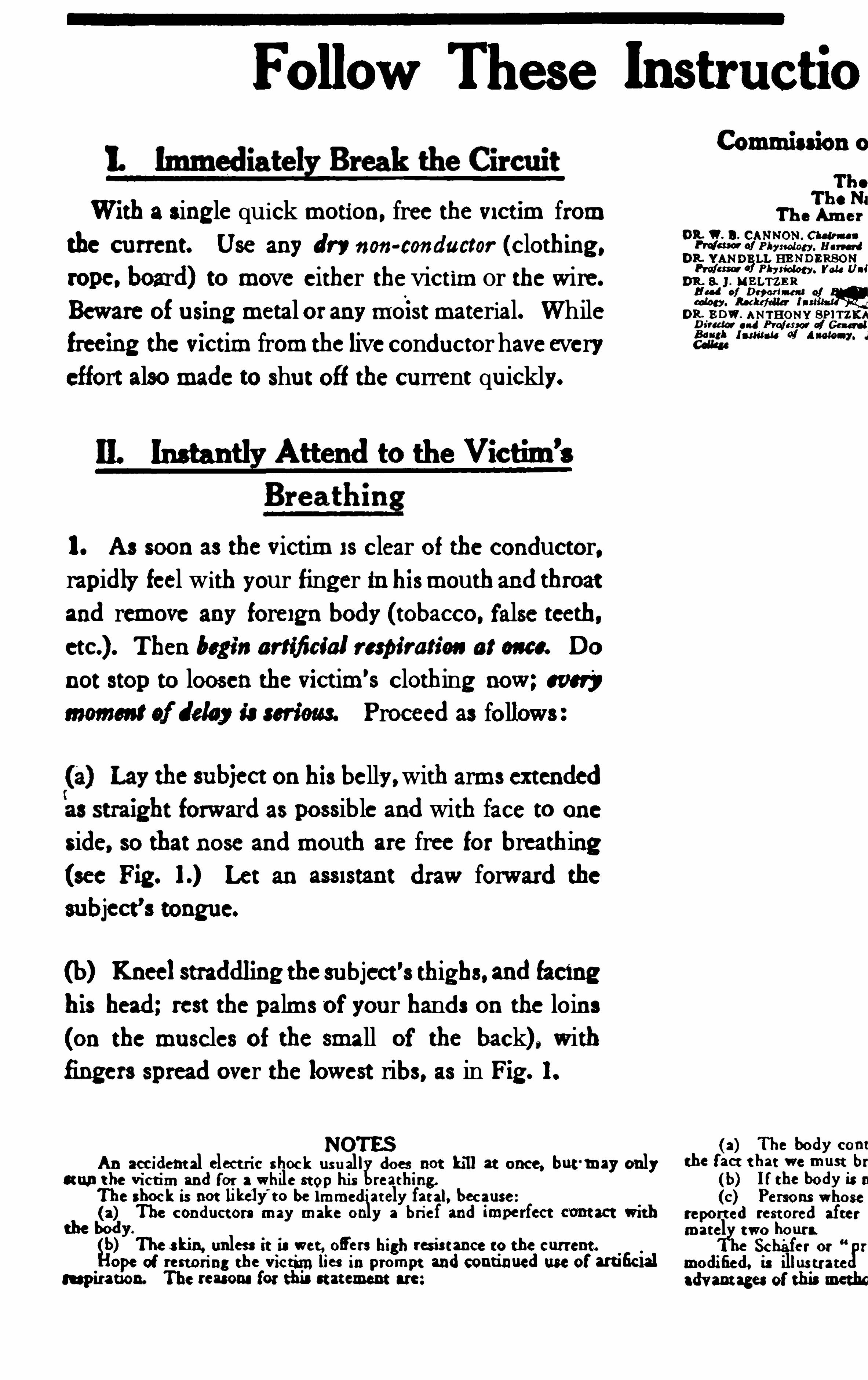
Follow These
W i th a single quick motion, free the victim from
the current. Use any dry non-conductor (clothing ,rope. board) to move either thevictim or the wire.
Beware of using metal or anymoist material. While
freeing the victim from the liveconductor haveeveryeffort alsomade to shut off the current quickly.
!L M Attend to the Victim’s
1. As soon as the victim i s clear of the conductor,rapidly feel with your finger in hismouthand throat
and remove any foreign body (tobacco, false teeth,T hen begin artificial respi ration at on e. Do
not stop to loosen the vict im’s clothing now ; every
mommt of lday iam'im Proceed as follows :
the subiect on his belly,with arms extended
forward as possible and with face to one
side, so that nose and mouth are free for breathing
(see Fig . Let an assistant draw forward the
subject’s tongue.
(b) Knee!straddling thesubject's thighs, and facing
his head; rest the palms of your hands on the loins
(on the muscles of the small of the back) , with
fingers spread over the lowest ribs, as in Fig . 1.
NOT ESAn accident al elect ric shock usual! does not kill at once, but
'may onlycumt he Vict im and for a while stop his reathing.
The shock is not likely’
t o be immediat ely fat al, because(a) The conductors may make only a brief and imperfect comt with
the body.
g)T he skin, unless it is wet, ofl
'
ers high resis tance to the current .
ope of restoring the vic tim lies in prompt and continued use of artificialrespiration. The rem na for this stat ement are:
(a) The body cont
the facr t hat we must br
(b) l f the body is n
(c) Persons whosereport ed rest ored aftermatel two hours
Sch'
afer or r
modified, is illustrateadvant ages of th emoth
lnstructio
OR. B . CANNON . Choli n e
PM of Pbyrwlm . HarvardDR. YAN DE LL HE NDERSONPru/m d Physiology. you Uni
D%‘ZJ ;IN B LTZBR
eaten . Rockefeller 1DR. E DW . ANTHONY SPITZKA
and Pro/arm a! General!mit-u ol 4
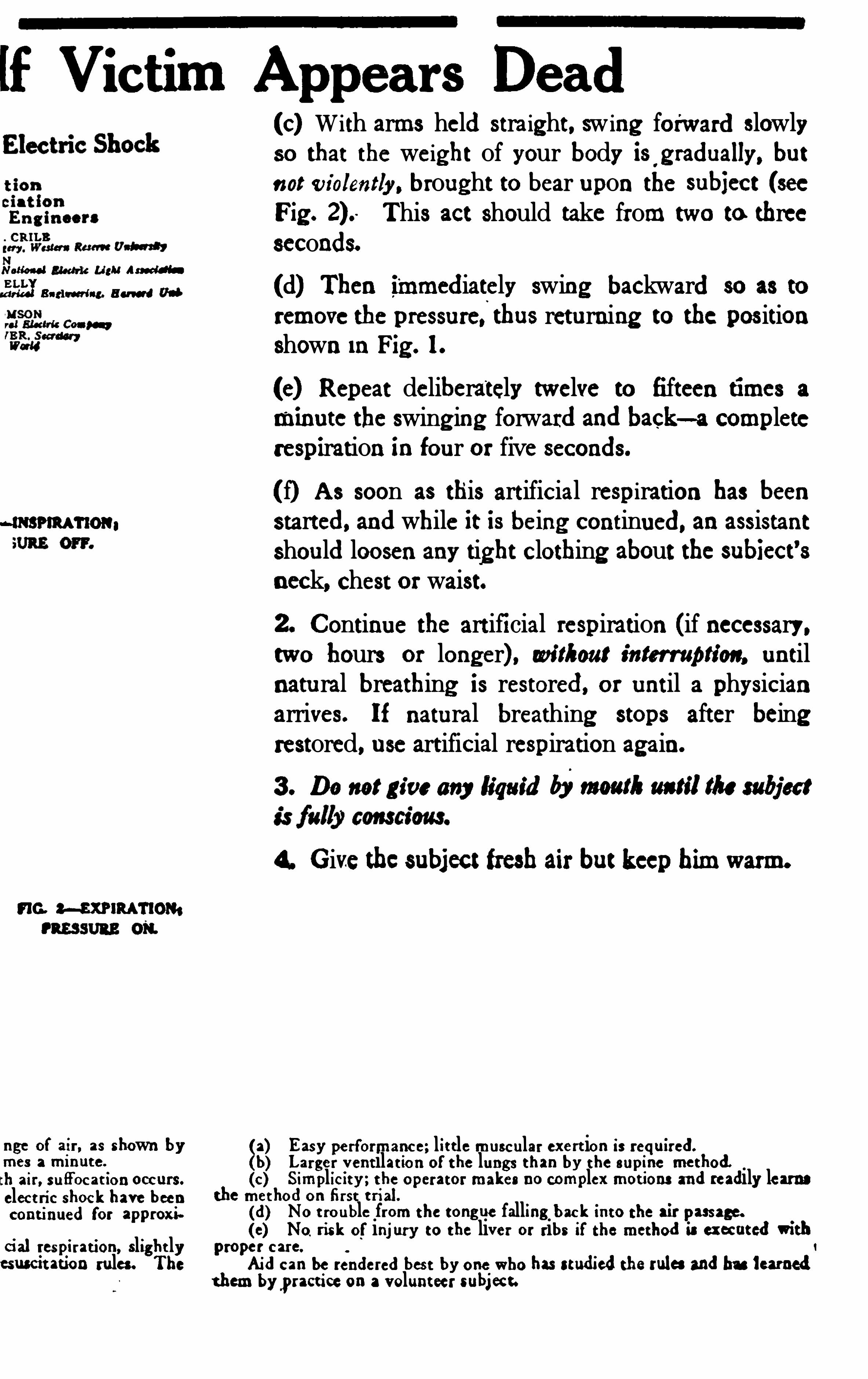
!f Victim Appears Dead
NNotional Electric Light Assad“E LLm u: Bari-reel i ng. B a u d
“G. M XN RATIOM
nge of air, as shown bymes a minute.
tll air, su ffocat ion occurs.
elect ric shock have beencontinued for approxi
cial respi ration, slight lyesusctt ation rules. T he
8
(c) With arms held straight, sw ing forward slowlyso that the weight of your body is ' g radually, but
not violently, brought to bear upon the subiect (seeFig . This act should take from two to threeseconds.
(d) Then immediately swing backward so as to
remove the pressure,thus returning to the positionshown in Fig . l .
(e) Repeat deliberately twelve to fifteen times a
minute the swing ing forward and back—a completerespiration in four or five seconds.
(f) A s soon as this artificial respiration has beenstarted, and while it is being continued, an assistantshould loosen any tight clothing about the subiect’sneck, chest or waist.
2. Continue the artifi cial respiration (if necessary.two hours or longer) , wi thout interruption, untilnatural breathing is restored, or until a physicianarrives. If natural breathing stops after beingrestored, use artificial respiration again.
3 . Do not gt'
ve any liquid S w am i/im am:
4. Give thesubject fresh air but keep him warm.
Easy performance; lit tle muscular exert ion is required.
Larger vent ilat ion of the lungs than by the supine method.(c) S implicity; t he operator makes no complex mot ions and readily learns
the method on first t rial.
(d)(0)
No t rouble from the tong ue falling back into the air passage.No. risk of injury to the liver or ribs if the method is executed with
proper care.
Aid can be rendered bes t by one who has studied themiss and has learnedt hem bypracticeon a volunteer subject.
l

260 D. C. M OT OR AN D GE N ERA TOR TROUB LE S
over , should be short-circuited and grounded even if the rulespreviously stated are observed .
Wir ing—All wiring must be done in accordance with Underwriter ’s Rules
,N ational Bureau of S tandards or local ordi
nances . Wir es carelessly installed are dangerous and often
are the cause of short-circuits and fir es . E nds of wires should
not be left exposed after cutting . If wires cann ot be removed
altogether,the ends should be well insulated .
The insulation on a wire should not be trusted for protection from shock . While the insulation may look perfect it
may have deteriorated from age or exposure so it cannot be
relied on .
When tapping live insulated wires, insulation Should be
removed from only one wir e at a time . A second wir e should
not be exposed until the fir st tap is made and the j oint
insulated .
Connections between wires must be well made, the wires
bound and soldered and the j oint carefully insulated . When
wir es are held in contact by means of screws , car e must be
taken to see that the screws are set down tight . A slight
movement of the wire while setting down screws will tend to
make the j oint tight .
Grounding—Employees should assume that all c ircuitsare grounded and in sulate their bodies properly against all
w ires .
Frames of motors,swi tch boxes, transformers, etc . , must
be substantially grounded .
To avoid possible shock due to gr ounding when work is
being done in damp places,extra precautions must be taken to
insulate the body. This can generally be satisfactorily done
by using a dry plank or boar d to stand on .
Operating Sw itches .—Switches Should be left wide openwhen in open position
,and fully closed when in the closed
pos ition .
Switches should not be closed in a hesitating manner or by
tapping the blades against the contacts to ascertain if the
circuit is on,but should be closed in a firm
,positive manner ,
US E FUL DA T A 261
using sufficient force to make full Contact of blades . A switch
should not be closed without full knowledge of the condition
of the circuit .
Fuses and Cutouts—Fuses should be pulled or replaced,
using insulated fuse pullers . The live end of the fuse should
be pulled ou t first and when replacing fuses the live end should
be put in last .
Power Plant and Motor Attendants—DO not allow oilcans
,tools
,clusters or wiping cloths to catch in moving parts
of machines . In passing any switchboard or machine in
operation,do not touch it unnecessarily nor allow metal
tools or other metal obj ects to touch the apparatus or its
connections . Do not use iron or tin Oil cans near field mag
nets . Use only oilers,dusters
,or wipers with insulated
handles in or about commutators,switches
,switchboards or
other electrical equipment .
Resuscitation .
—The prone pressure method of resuscita
tion should be used in all cases of electrical shock . This
method should therefore be thoroughly understood by all
men handling electrical c ircuits or apparatus .
Observance of Rules.—The above rules cover some of the
duties and precautions for the protection of wiremen and
electricians ; they must be observed by all men handling
electrical circui ts or apparatus .
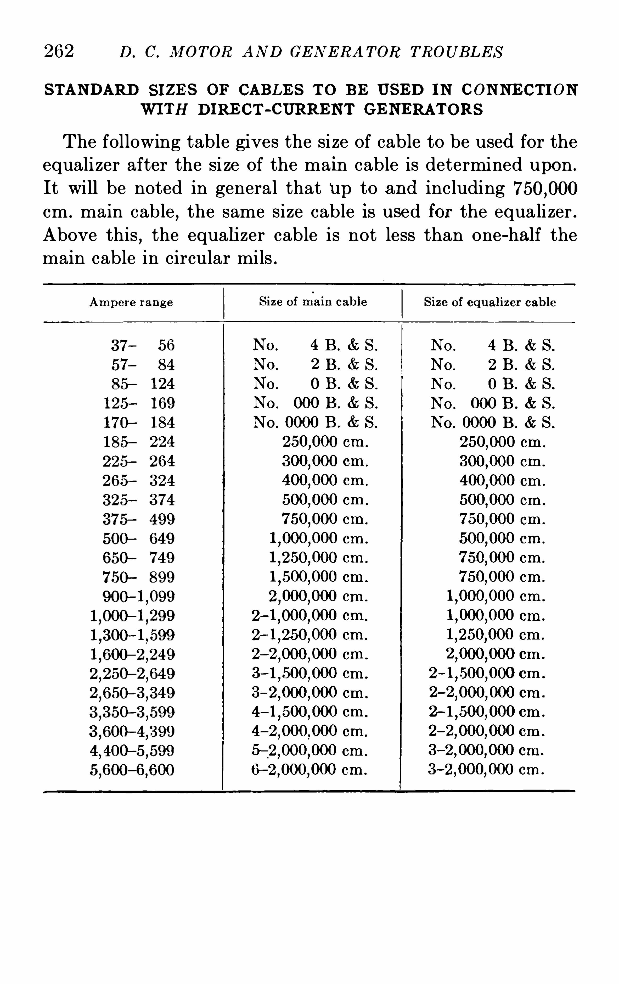
262 D. C. M OT OR AND GE N E RA T OR TROUB LE S
S TANDARD S I ZE S OF CAB LE S T O B E US ED I N CONNE CT I ONWI TH DIRE CT -CURRE NT GE NERAT ORS
The following table gives the size of cable to be used for the
equalizer after the si ze of the main cable is determined upon .
It will be noted in general that Up to and including
cm . main cable,the same size cable is used for the equalizer .
Above this,the equalizer cable is not less than one-half the
main cable in circular mils .
Ampere rang e
4 B . & S .
Z E . & S .
0 B . & S .
N o. 4 B . S .
N o. 2 B . S .
N o. 0 B . S .
N O . 000 B . S .
No. 0000 B . S .
cm .
cm .
cm .
cm .
cm .
cm .
cm .
cm .
cm .
cm .
cm .
2 cm .
3—l,500
,000 cm .
3 cm .
cm .
4 cm .
5 cm .
6 cm .
cm .
cm .
cm .
cm .
cm .
cm .
cm .
cm .
cm .
cm .
cm .
cm .
cm .
2 cm .
cm .
2 cm .
3 cm .
3 cm .
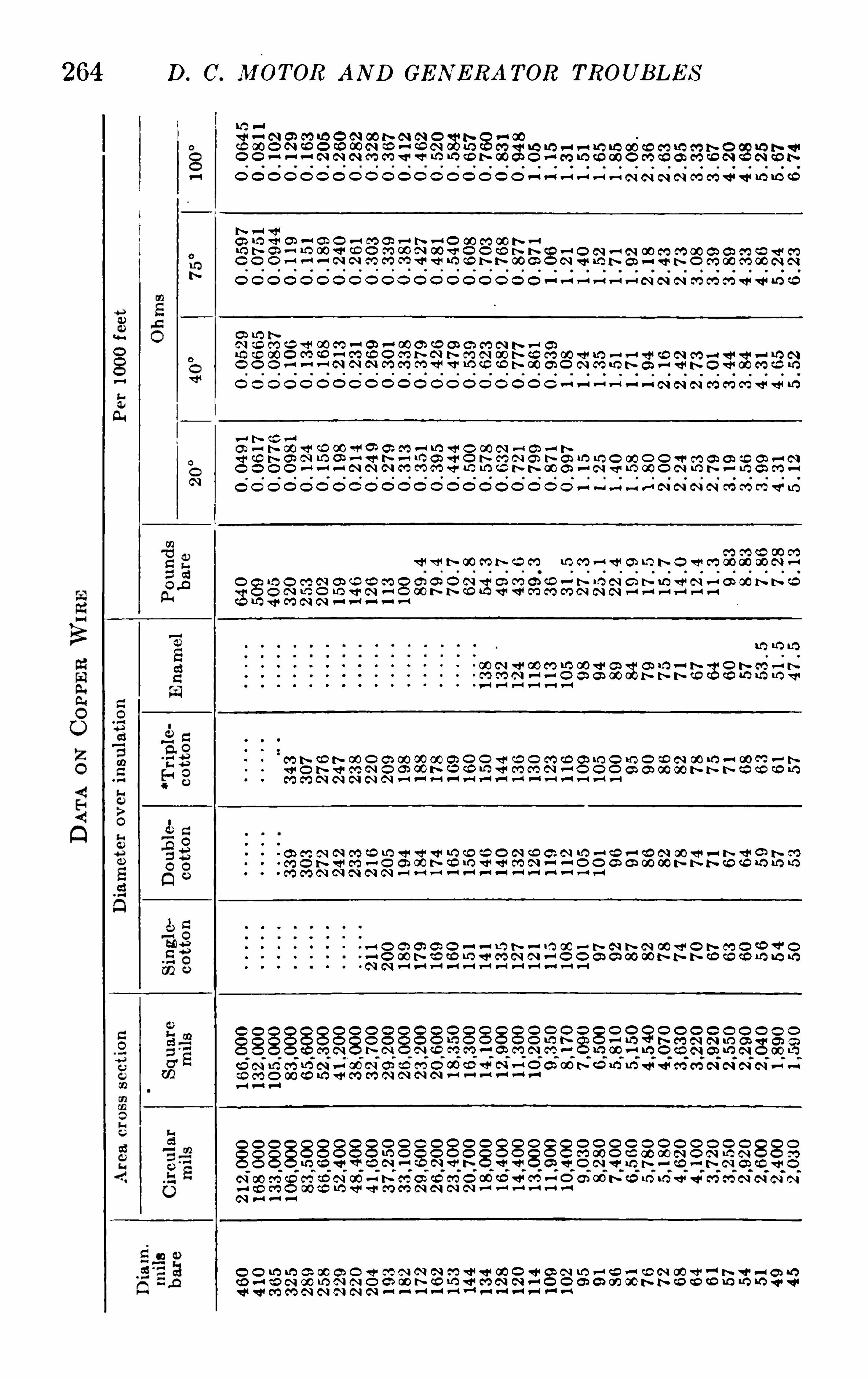
D. C. MOTOR AND GE N E RA TOR TROUB LE S264
N CO NO O O O O O O N O
QO h v
O O O O O O O O N3a
nOO
O
O
3~OO
CON
NOO
wwm.
ONO
NOv
N
:VNON
ONO
NON
OON
OON
OO~
ON~
NO
“OOvO
ON
ON
ON
mm
NO
NO
NO
ON.
Or
vw~
NO2.
NO
Ow
~N
T3
hum
OON
OON.
OOO
Ovm.
~mvt5m
OOO
OOO
~ON
OQN
OO~Sa
9a
vO
SNO
N
OO
O
NO
OO
a
nvw
New
N
OON.
Nv
O~“toz.3.
an
«N
OO
OOO
N
ON
h
t.NOO
ONO
OOO
one
ONv
Ohm
OOO
~Om
OON
~ON
Ofi
N
wOfi
fin
OO~
NOOO
OOOO
ONOO
-an t :
N“
a
nOO
Om.
OON.
mm.
«.N
OO
OO
Om
Ov
ON
m4
NOOSN
OON
fi
NN
NOO
ONO
OOO
«we
OOO
~OO
mu
m
ONN
OvN
wfi
N
OO~
OO~
wNfi
a
wOO
ONNO
h—OO
~O
3m.O O O O O O O O O O O O O O O O O O O O O—u—u—n v-u -GN N N N M M C’DQ ‘
mw fi fi ci hfi h o w m
mow
mi
tt
O
ém.
O
OO
hm-O
O
OOO
Oh
ON.
NO
ON
ON
ON
OO~
OON
OO~
O
:ON~
Om:
Om:
v
3OO~
OO~
OO~
Ob”
ww~
ON”
OON
ONN
OONSN
OhN
>mom
OOO
0
0
0
.
NO
NO
NO
¢O
NO
fi
nme»
On.
NO
ON~O
OO
~O~
OO~
N
:O
:O
N~
Nmfi
O
iO
iOm:
OO~v:
vwfi
vaa
OON
O
NNON
N
vN
NNN
OOO
OOO.
O
l
0
OOO
fl
OOO
fl
Ovo
N
OON
N
OOO
N
ONO
N
ONN
m
OOO
m
ONO
a.
3m.v
Om~O
O~O
m
OOO
O
OOO
N
O
:O
OOO
O
OON
Oa
OOO
OOO
N~
OO~
3
OOO
O~
OOO
O~
OOO
ON
OON
ON
OOO
ON
OON
ON
OON.
NO
OOO
Om
OON
so
OOO
NO
OOO
OO
OOO
Ow
OOO
OO~
OOO
NM:
OOO
OO~
Cov oN N N
ONO
N
OON
m
ON»O
OO
v
ONO
v
Ow~O
OON.
m
OOO
O
OOv
N.
OON
w
OOO
O
OOO
Oa
OOO
OOO
m”
gm
3
OOmeO~
OOO
O
OON.
ON
OOv
ON
OON
ON
OOO
ON
OO~Om
OON
hm.
OOO
Se
86
we
OOv
Nm.
OOO
OO
OOO
Ow
OOO
OO~
OOO
mm;
OOO
OO~
OOO
Na
N
3.On.5
vn
Nb
g
O«O
OO
N
bO
N.
fi
wOw~O
OO
N
O“
OO~
e
;ON
ON“x:
3;
OO~
NOa
N
ZNO~
OO~
OON
ONN
ONN
OON
OON
ONO
OOO
O
3.OOv
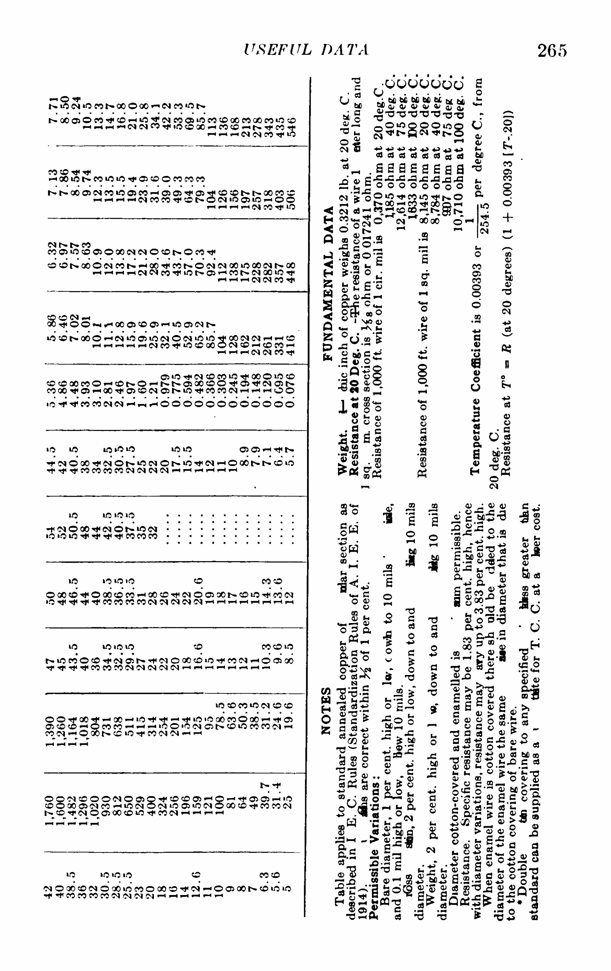
265US E FUL DA TA
vS N lO fl t‘ w O w r-‘ N CO IQ N
N OO O Ov-i
O
EmO
v
OvO
ONN
O
NOm:
OO~
O
:OO
M v'Q—u fl fl ‘mfi v-t—A N N C'O Q
Vh m lfi lfi v a w o mmm
S N O O N
ON.
NO
Na
v
NO
O
ON.
O
hm.
N.
OO
O
«O
O
ON
N
~N
N
ha
O
O~
O
Na
OO
O
NO
N
NO
O
NO
O
N—dO O v-‘ v-‘ w G CD GN -‘ Q O’ N N
Ow
Ow
vOOO
ON.»
ONO—N
OO
NO
Ow~O
O~
OO
Ow
Ow
OO
m. Q ‘ Q‘ M M N N fl—u—‘ O Q O O
lo t-Q t!)
«A
m~
N;
ON
NN
ON
hN
NO
«O
OO
ow
N
O3.
10 m“)
.
O~
N~
Ofi2
m:
.
Om
O.
m.
m.
O~
ON
NN
«N
NN
ON
NO
NO
OO
On
vOv
m6
hv
“DCO GO IO N CD QO
Oa
«N
~O
OO
on
OO
ON.
OO
ON”
«.mé
~ON
N
ON
v—O
O
S.2m.
OOO
~Oh
O~O
«A:
OON
OOO
AO
.
OO
Ow
«CO
~O
OOA
~N~
Om:
OO~
OON
ONO
OONN
ONO
OOO
Nfi
w
OOO
ONO
OONv
OOO
OON.
ON
-.
N
O
.
O
So
:
0ooe
wo
v
.
.
ma
MO
MiN
0
se
e
8a
s
Ego
Sh
e
0
us
e
2.as
ago
25
5
oar
e
cs
3
Ego
3
5
o.
ws
v
8
2
ago
3
5a
E
on
a
we
was
0.
wo
e
2:
a
s
Ego
29
2
o.
ws
o
3.a
s
ago
Se
e:
0.
ms
e
9.a
s
Eco
31
2
Cas
e
8
2
ago
33:
a
a
s
as2
L
o
SE
.
2
.
s
S
8:
3
5a
m
.
Eso
fi
vNu—O
O.
.
o
Eco
wwm
mm
comaoem
.
55
Om
Ono
M
E:
585a
o
bidO
0
oo
ceo
mmw
so
Bal
d.
oON“a
oo
a
fiwmmo
m
.
.
u
ar
e
83
Sumo
Ba
ss
as
8d
o
a
s:0
33“l
ane
s
?
<H<Q
A<HZmS<QZDh
.
amoo
332a
a
s
.
O.
O.
8n
o
835216
a
me
fie
on
go
O
ga
sm
523
L
385
3252
5Oocm
ooam
has
0»
wc
fo
>oo
”
3300
296
G
O
FS
we
wc
to
>oo
no
fioo
93ca
26
mm
g
aze
uoao
Edmv
E0
882:0
8am
9:
23w
e
Bu
ms-ammo
93
3
835
on
390
m
co
fioo
mm
don
g
A
BE
.
a
coo
SQ
OO
Oca
9
5
5>
5:
.
mco
s
fiu
ara
h
on-w
ait
co
co:
.
sw
E.
a
coo
SQ
OO
on
ha
sac
ade
mies
c
50
o.
oo
aeu
flwo
m
.
o
SEE
ELo
Q
85
83
88
vozo
aoco
One
Oo~o>00
éo
$oo
SE
ESQ
deo
o
fiam
v
mO
E
O”
9
2
94
2:
was
3c
ac
v.
30
.
8cmE
.
a
uwe
SQ
N
.
uooo
ae
ao
mO
EO
9
55
32:
«in
3s
kew
.
Bo
n
o
sw
E.
u
coo
L
ea
N
60
50
8880
as.
23
2
3.
so
s
o
a
s:
a
s
3E;
6
333
5QO
EOa
0»
Es
s
a
y
$5
2L
o
.
waoo
£
30
8
ao
3m
a
dama
n
t-5o—n
fimflnuo
m
deco
SQ
a
0
mm
9
5251
518
30
A
22
.
Q.
mA
.«o
mo
fi
s
fi
ao
s
gm
vuavceu
mO
a
fls
fi.
O.
E
a
5non
fooov
we
comooom
3326we
Cameo
Oo
ioace
O
SOC
Sm
3
0
3a
?
mmHOZ

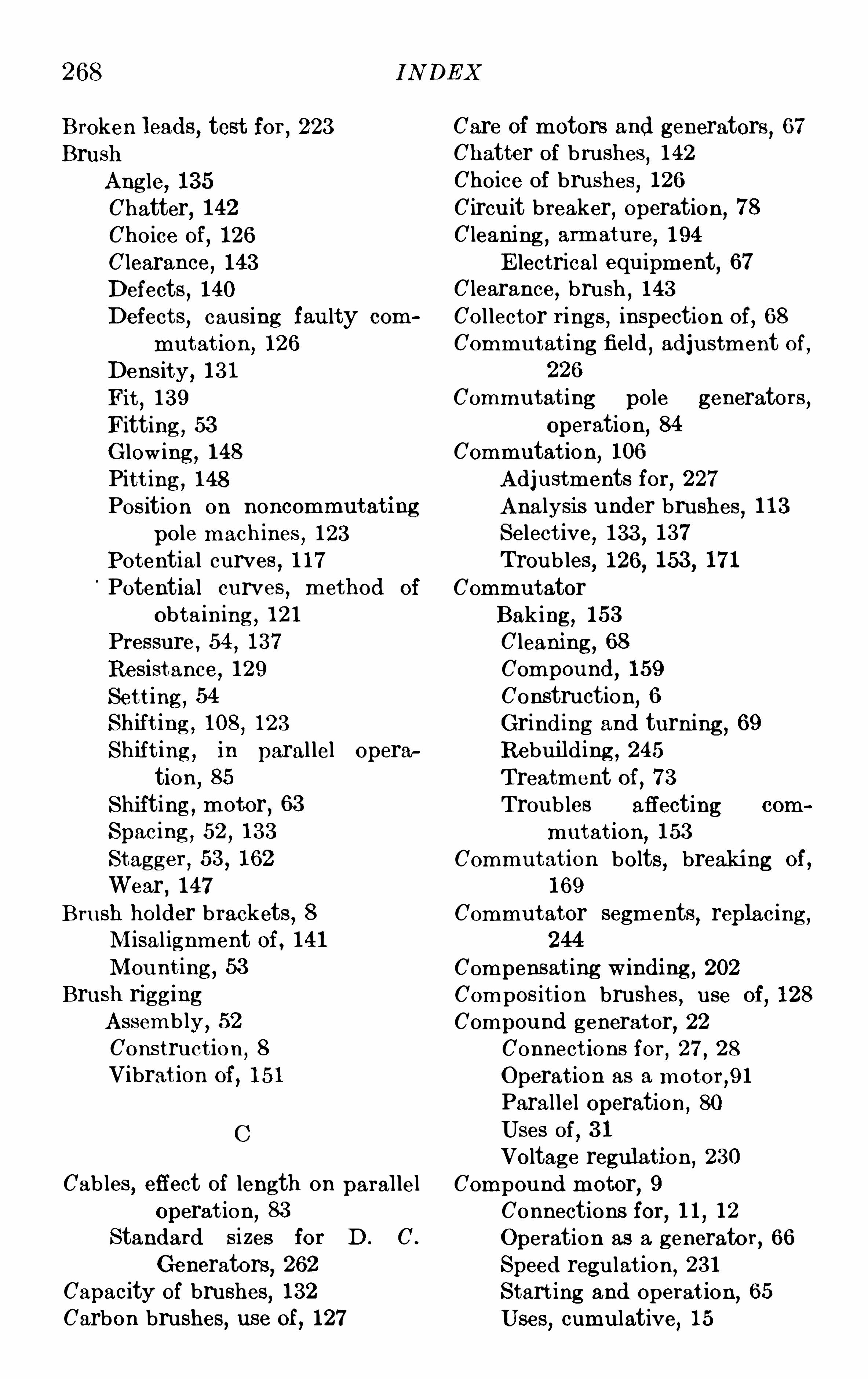
268 I N DE X
B roken leads, test for , 223B rush
Ang le, 135Chatter, 142Choice of , 126C learance, 143Defects
,140
Defect s,cau sing fau lty com
mu t at ion,126
Dens ity, 131Fit
,139
Fitting , 53G lowing , 148Pit t ing , 148Position on noncommu tat ing
pole mach ines , 123Potential curves , 117Potential curves
,method of
obt ain ing , 121Pressure,
54,137
Resist ance, 129Set t ing , 54Shif t ing ,
108,123
Shif t ing , in paral lel operation
,85
Shi fting , motor, 63
Spac ing , 52 , 133S tagger , 53 , 162
Wear,147
B ru sh holder brackets, 8
M isal ignment of , 141M ou nt ing , 53
B rush rigg ingAssembly, 52Cons truct ion
,8
Vibrat ion of,151
Cables,effect of length on paralleloperat ion, 83
Standard si zes for D . C .
Generators,262
Capacity of brushes,132
Carbon bru shes, use of , 127
Care of motors and generators , 67Chatter of brushes
,142
Choice of bru shes,126
Circu it breaker,operation, 78
Cleaning ,armatu re
,194
E lectrical equ ipment,67
C learance,bru sh
,143
Col lector r ings , inspection of,68
Commu t at ing field,adjustment of
,
226
Commu tat ing pole generators ,Operation, 84
Commutat ion,106
Adju stments for,227
Analysis u nder bru shes , 113Select ive
,133
,137
T roubles, 126, 153 , 171Commu t ator
B aking , 153C leani ng , 68Compou nd, 159
Constru ction,6
Grinding and turning , 69Rebu ilding ,
245
T reatment of, 73
T roubles affecting com
mut at ion,153
Commu t at ion bolts,breaking of ,
169
Commu tator segments,replacing ,
244
Compensat ing w indi ng , 202Compos it ion brushes , u se of
,128
Compou nd generator, 22Connect ions for
,27, 28
Operat ion as a motor,91
Parallel operation ,80
Uses of,31
Voltage regulat ion ,230
Compou nd motor,9
Connections for,11
,12
Operation as a generator , 66Speed regu lat ion ,
231
S tart ing and Operat ion, 65Uses
,cumu lative
,15
I N DE X
Compou nd motor,Uses
,differen
t ial,16
Compounding effect on paralleloperation ,
82
T hree wire generators , 88Concrete foundations, 39Connect ions
Generator, 25Loose
,150
M otor,9
Swit chboard, 98Connection st rips , 186Construct ion
,motor
,2
Contact drop for standard brushes130
Contact resistance, 129Copper w ire, data on
,264
Core loss, 235Core
,loose
,195
Creepage, surf ace, care of , 166Cumu lat ive compou nd motors
,15
Current dist ribution cu rve,226
Data on copper w ire, 264Defective laminateoris
,195
Defect s,brush
,140
Density, brush , 131Design, fau lty, 182D ifferent ial compou nd motors
,16
Dirty armature, 194Dirty commutator surface
,164
Drying ou t , 253Dust
, danger to operat ion ,38
E ddy current s , 193E dison three wire system ,
23
Parallel operation ,38
E fficiency test, 239E lectrical loss supply method , 234
E lectrolyt ic act ion in bru shstagger, 162
269
E nd play,adjus tment
, 50, 2 14
E qual izer rings , addit ion of,184
Lack Of,184
Repairing and fitt ing , 249E qual izers
,86
E rect ion and assembly,36
E rection, motors and generators49
GeneratorsAdju stment for contact
drop, 131B ru sh shif t ing , 108, 125Connect ions for
,25
E ffect of st icking brushes , 145
Failure of insu lation,187
Failure to pick up, generator, 208Fau lty desig n,
182
Feeding back , heat ru ns,231
Field coi lsImproper connect ion ,
172
Open circu it s,197
Repairing , 246Reversed
,199
Short circu its , 197Field curve in neutral zone
,113
Field troub les,197
Field, weak , 171Field winding
main,5
Commutating , 5Fit of bru shes
,139
Fit t ing bearing linings , 214Fitting brushes , 53Foot ings , const ruct ion ,
39
Foundations,38
Fou ndation bolts,locat ion and
grout ing , 40Fou ndation,
switchboard,9 6
270
G enerators , Failure to pick up,208
I nformat ion when ordering ,34
I nspection ,77
Operation as motors,91
Operation with reversed coi l,
191,199
Parallel Operation , 79, 209
Reversed polarity,209
S aturat ion test,225
Series operation ,89
Star t ing and operat ion ,77
S topping , 79T roubles
,208
T ypes of , 20
Uses of difierent types, 30
G low ing of brushes,148
G raph ite brushes, u se of,127
Grids , 82G rinding commutator
,69
G rinding mach ine for
mu tator,70
Grooved commutator surface,160
Grooving ,commutator
,155
GroundConnections to
,on sw itch
boards,99
High voltage to,
operat ion ,89
Grou nds , 175, 198Grounds, test for , 221
com
in series
Handl ing , motors and generators ,40
Hard spots in brushes, 140Heat ing
B earings, 76Causes
,193
Generator,211
Limi t s,192
Ser ies Operation, 90Heat runs
,231
High commutator bars,156
I N DE X
High m ica, 153High potent ial tests , 241Holders
,reversal of
,137
Kick method of finding neutral ,111
Lam inations , defective, 195Leadi ng brushes, 135Li nings , refitting in bearings , 214Locat ion of motors and generators ,
37
I beam support s, 40I llum inat ion
,sw itchboard, 102
I ncorrect brush ang le, 135I nformation supplied to manu
facturers when orderinggenerators, 34
I nformat ion suppl ied to manu
factu rers when orderingmotors
,17
I nspectionB efore starting motor
,59
G enerator, 77
Swi t chboard,101
When assembli ng ,46
I nst ability, motor,120
I nstallat ion,switchboard
,95
I nsufficient air gap, 185I nsu lation
Failur e of , 187
Renewing treatment,247
Repair, 247Resist ance test, 219Sw itchboard
,99
T hi ckness,188
T ypes of , 187
I nterpole, act ion of,107
,117
272 I N DE X
Paral lel operation ,Compou nding ,
82
Length of cables , 83Operation ,
86
Speed regu lation ,81
Starting , 86Stopping , 87T hree wire generators ,. 87
Picking up generator, 208Pigtails , burnt off, 150Pillow blocks
E rect ion,49
Height adjustment, 50Pitting
B rushes,148
Shaft,212
Polarity affecting paral lel operation
,87
Polarity, reversed, 209Pole pieces, cons tru ction
Commutating , 4M ain
,3
Pole pieces , loose, 202Pos ition of brushes on commu tator,
Press ing armature on shaft , 55Pressure
B earing , 75B rush, 54, 137
Pu l leys , 55Pumping , motor
,108, 119
Rebabbit ing bearing s , 252Rebu ilding commu tator, 245Reconnecting armature, 250Refusal to start motor, 204Regu lat ion
Speed , 206, 230
Voltage, 229Repairs , 242
B roken commutator bol ts,251
Damaged insu lation, 247
Repairs , Field coi ls , 246S hort c ircu ited commutator
segment,167, 252
ReplacingArmature coils
,242
B urned core sect ion,196
Commutator segments , 244Wedges , 252
Res istance
B rush and contact,129
Insu lation test , 219Of equal izers
,86
Resuscitation from electric shock ,262
Reversal of brush holders,137
Reversed armature coils,191
Reversed field spools , 199Reversed rotation , motor, 205Revers ing motor
,64
Revers ing switches,92
Rotation reversed,205
Rotor, l ifting and supporting , 41Rough commutator surface, 160Rou nd ing off commutator bars , 72Running l ight core loss test, 236
Safety ru les, 256Sanding bru shes, 53Saturation test , 224Saving in three wire system,
33
Selective commutat ion , 133, 137Series generators , 2 1
Operation as motor,94
Start ing and operat ion,93
Uses of,32
Series motors,9
Connect ions for , 13 , 14Operat ion as generator , 66Rac ing , 17S tarting and operat ion ,
65
Uses of,17
Series operat ion, generator, 89, 91S et t ing of brushes , 54
I N DE X 273
Shaft Speed lim it devices, 69Allowances for press ing fits , 57 S pring ing of shaft
,tes t for
,181
Pi t t ing , 212 S tagger of brushes , 53 , 162Spring ing test , 181 S tandard s izes of cables for D . C .
T roubles , 212 generators, 262Shifting brushes in parallel opera
tion, 85S hipping , methods of, 49S hort circu its
Field,197
T est for, 223Series operation, 89, 90
S hort circu ited armature coi ls,190
Short circu ited segments,167
S hu nt adjustment, 200S hunt generators , 20
Connections , 25, 26Operat ion as motors , 91Paral lel operation, 80Self excited
,u ses of, 30
Separately excited,u ses of , 31
Voltage regulation, 229Shunt motors, 8
Connect ions for,10
,11
M echanically coupled, 14Operation, 63Operation as generators , 66Revers ing , 64Speed regu lat ion , 230S peed rise due to fields heat
ing , 63
Starting , 61Stopping , 64Uses of
,14
S lings , u se of , 41S pacing of bru shes , 133Spacing and s izes of wire
,switch
board, 98S peed
Commutator,135
,186
Commutator when turning , 72Regu lat ion ,
206
Regulation in parallel operation
,81
Regu lation ,motors
,230
StartingGenerator
,77
M otor,61
,204
Starting test , 240Stoning commutator
, 69
StoppingGenerator, 79M otor, 64
Storage, 36Sw itchboards , 95
Assembly, 96Connections , 98Connections to ground, 99Foundation
,96
Il lum ination ,102
I nspection, 101I nstallation
,95
I nsulation,99
Operation , 101Ordering , 103Protect ion for operator 100
S hipment,95
Spacing and s izes of w ire, 98
Unpacking, 95
T ests and repairs , 219T ests
B earing insu lation, 240Core less
,235
E fficiency, 239For oil in m ica
,159
For oil leaking , 75Ground ,
221
Heating , 23 1Heat ru ns
, 23 1
High potent ial , 241I nsu lat ion res istance
,219
Open circu it,222
274 I N DE X
T estsSaturat ion , 224Short circu it
,223
Starting, 240T hree wire generator, 23
Connections , 29Operation as motor , 93
Parallel operation ,87
Uses of,32
T rail ing brushes , 136T reatment of commutator and
brushes , 73T roubles and their remedies
,105
T roublesArmature, 187Commutation, 126, 153, 171Field, 197G enerator, 208M otor, 204Shaft and bearing , 212
T ur ing commutator, 69T urning tool for commutator, 72
U
Unbalanced armature,180
,216
Unequal bru sh spacing , 133Unpacking machinery, 37
V
Var iable loads, 177Venti lating vanes, addition of
,193
Ventilation,6,37
Vibrat ion of brush rigg ing , 151Voltage between segments
,182
Voltage regu lation, 229
W
Water box method, heat run,Weak field, 171Wear of brushes
,147
Wedges, replacing , 252
Wedges, u nder base, 50Width of belt s
,263
Winding , bar , 188Winding , compensating , 202