Diploma thesis - DSpace TUL
47
HOCHSCHULE ZITTAU/GÖRLITZ TECHNICKÁ UNIVERZITA V LIBERCI Hardware and software development for a mobile robot based on Raspberry Pi and OpenCV Diploma thesis Bc. Marek Valšík Study course: Mechatronics Assessor: Prof. Dr. rer. nat. Stefan Bischoff Supervisor: Prof. Dr. rer. nat. Stefan Bischoff
-
Upload
khangminh22 -
Category
Documents
-
view
1 -
download
0
Transcript of Diploma thesis - DSpace TUL
HOCHSCHULE ZITTAU/GÖRLITZ
TECHNICKÁ UNIVERZITA V LIBERCI
Hardware and software development for a mobile
robot based on Raspberry Pi and OpenCV
Diploma thesis
Bc. Marek Valšík
Study course: Mechatronics
Assessor: Prof. Dr. rer. nat. Stefan Bischoff
Supervisor: Prof. Dr. rer. nat. Stefan Bischoff
Zittau 2015
2

Zittau 2015
3

Zittau 2015
4
Assignment

Zittau 2015
5
Declaration
Hereby I declare that I have written my master thesis myself using literature listed
therein and consulting it with my thesis supervisor. Also I declare that I have not used other
literature than listed.
Date:
Signature:

Zittau 2015
6
Acknowledgement
I would like to thank Prof. Stefan Bischoff for leadership of this master thesis. Thanks
to him, I was able to work on a topic that I was interested.
I would also like to thank Dipl.-Ing. (FH) Egmont Schreiter for providing hardware
parts of the robot.

Zittau 2015
7
The abstract
The aim of this work is to describe the possible solution of using Raspberry Pi as the
“brain” of the robot. The main intent was design one of these solutions. Next step was to
describe the parts of the constructed system (mechanics, electronics, and software) and provide
explanation of the system principles. In the final part there are written advantages and
disadvantages of this solution.
The key words:
Robot, OmniBot, Raspberry Pi, OpenCV

Zittau 2015
8
Content
1 Introduction .......................................................................................................... 12
2 Hardware .............................................................................................................. 13
2.1. OmniBot ........................................................................................................ 13
2.2. Motors ........................................................................................................... 14
2.3. SoccerBoard .................................................................................................. 15
2.4. Sensors .......................................................................................................... 16
2.5. Raspberry Pi 2 ............................................................................................... 17
2.6. Camera module.............................................................................................. 18
2.7. WiFi .............................................................................................................. 19
2.8. DC/DC converter ........................................................................................... 19
2.9. Battery ........................................................................................................... 20
2.10. Charger ...................................................................................................... 20
2.11. Battery safety module................................................................................. 21
2.12. Rest of parts ............................................................................................... 22
3 Software ............................................................................................................... 23
3.1. Program for SoccerBoard .............................................................................. 23
3.2. Preparation of Raspberry Pi and OpenCV ...................................................... 27
3.3. Usage of prepared image of SD card .............................................................. 38
3.4. Example programs used on Raspberry Pi ....................................................... 39
3.5. Main program called “Omnibot” .................................................................... 41
4 Conclusion............................................................................................................ 42

Zittau 2015
9
List of figures
Pic. [1] Base plate of anodized aluminium with diameter 210 mm .......................... 13
Pic. [2] Motors with omni-directional wheels ......................................................... 14
Pic. [3] The SoccerBoard ........................................................................................ 15
Pic. [4] The distance sensors (left), proximity sensor (right) ................................... 16
Pic. [5] The Raspberry Pi 2 model B....................................................................... 17
Pic. [6] The Raspberry Pi Camera module with opened case ................................... 18
Pic. [7] WiFi dongle with external antenna ............................................................. 19
Pic. [8] The DC/DC Converter ............................................................................... 19
Pic. [9] The Li-Pol battery ...................................................................................... 20
Pic. [10] The charger ................................................................................................ 20
Pic. [11] The Li-pol battery checker ......................................................................... 21
Pic. [12] The rest of parts ......................................................................................... 22
Pic. [13] Programming environment qfix Editor ....................................................... 23
Pic. [14] Win32 Disk Imager .................................................................................... 27
Pic. [15] Raspberry Pi Software Configuration Tool ................................................. 28
Pic. [16] Raspberry Pi - Desktop .............................................................................. 29
Pic. [17] TightVNC – one of suitable VNC client ..................................................... 33
Pic. [18] noVNC – web interface of VNC client ....................................................... 35
Pic. [19] Qt Creator – tool chain ............................................................................... 36
Pic. [20] Main window of the program “Omnibot” ................................................... 41
Pic. [21] Picture of used 3D printer........................................................................... 46
Pic. [22] Raspberry Pi diagram ................................................................................. 47

Zittau 2015
10
List of abbreviations
OpenCV open computer vision
mini-pc mini personal computer
DVD Digital Video Disc
Pic. picture
PWM pulse width modulation
DC direct current
V Volt
A Ampere
LED Light-Emitting Diode
I2C (IIC) Inter-Integrated Circuit
USB Universal Serial Bus
UART Universal Synchronous / Asynchronous Receiver
ARM Advanced RISC Machine
SDRAM Synchronous Dynamic Random Access Memory
OpenVG Open Vector Graphic
LPDDR2 Low power double data rate 2
GPU Graphic process unit
HDMI High-Definition Multimedia Interface
SDHC Secure Digital High Capacity
CSI Camera serial interface
DSI Display serial interface
CMOS Complementary metal–oxide–semiconductor
QSXGA Quad Super Extended Graphics Array
VGA Video Graphics Array
V4L2 Video4Linux2
CPU central processing unit
FPS frames per second

Zittau 2015
11
WiFi Wireless fidelity
AP Access point
GHz Giga hertz
Li-pol lithium polymer
Li-Ion lithium-ion
LiFe lithium iron
NiCd nickel–cadmium
NiMH nickel–metal hydride
3D 3 dimensions
STL STereoLithography
MicroSD micro secure digital
AD analog-digital
IDE Integrated development environment
ASCII American Standard Code for Information Interchange
LCD liquid-crystal display
SSH Secure shell
SPI serial peripheral interface
VNC Virtual Network Computing
HTML5 HyperText Markup Language 5
GCC GNU Compiler Collection
SSID service set identifier
DHCP Dynamic Host Configuration Protocol

Zittau 2015
12
1 Introduction
In the recent years the development of the robotics has increased. This is the reason why
it is necessary for the students to have a lot of possibilities to access the robots.
Nowadays, a lot of robotic platforms exist on the market. For our purposes we have
chosen a robotic platform “OmniBot”, which is described below. The main reason is that this
robotic platform has already been presented at the school (HOCHSCHULE
ZITTAU/GÖRLITZ). Another reason is that platform is based on the three omni-directional
wheels. It is much different than differential steering. Omnidrive has an advantage in unlimited
moves and it can move in all direction.
As the brain of the robot is a used Raspberry Pi 2 – it is cheap, powerful mini-pc, which
is worldwide known and sold over 4 million pieces. Raspberry Pi has a big community users
and programmers. Thanks to them the development is much easier. As a platform OmniBot,
Raspberry Pi is also part of equipment at the school.

Zittau 2015
13
2 Hardware
In this chapter are described all parts of the robot. The pictures of all parts are also
included on the attached DVD. There are also photographed every steps of the construction of
the robot.
2.1. OmniBot
The OmniBot is robotic platform made by the company “qfix-robotics”. As shown in
the picture (Pic. [1]), all holes are already prepared for an assembling of the robot. Only a few
screws are needed of which are included in the package. In the picture you can see glued
velcro, which is used for the mounting of the battery. White velcros with the numbers are used
for the easier clearly programing and debugging. It represents a numbers of the motor in the
program.
Pic. [1] Base plate of anodized aluminium with diameter 210 mm

Zittau 2015
14
2.2. Motors
The motors (Pic. [2]) provided by a company “qfix-robotics” are “qfix Motor Ceiec
RBAC008”. They can be powered by 6V - 12V DC power supply. In our case they are powered
by higher voltage (from the battery we can obtain about 16 V), but we use PWM for controlling
the speed. The gears attached to motors have ratio 30:1.
These wheels allow movements in all directions.
Pic. [2] Motors with omni-directional wheels
Zittau 2015
15
2.3. SoccerBoard
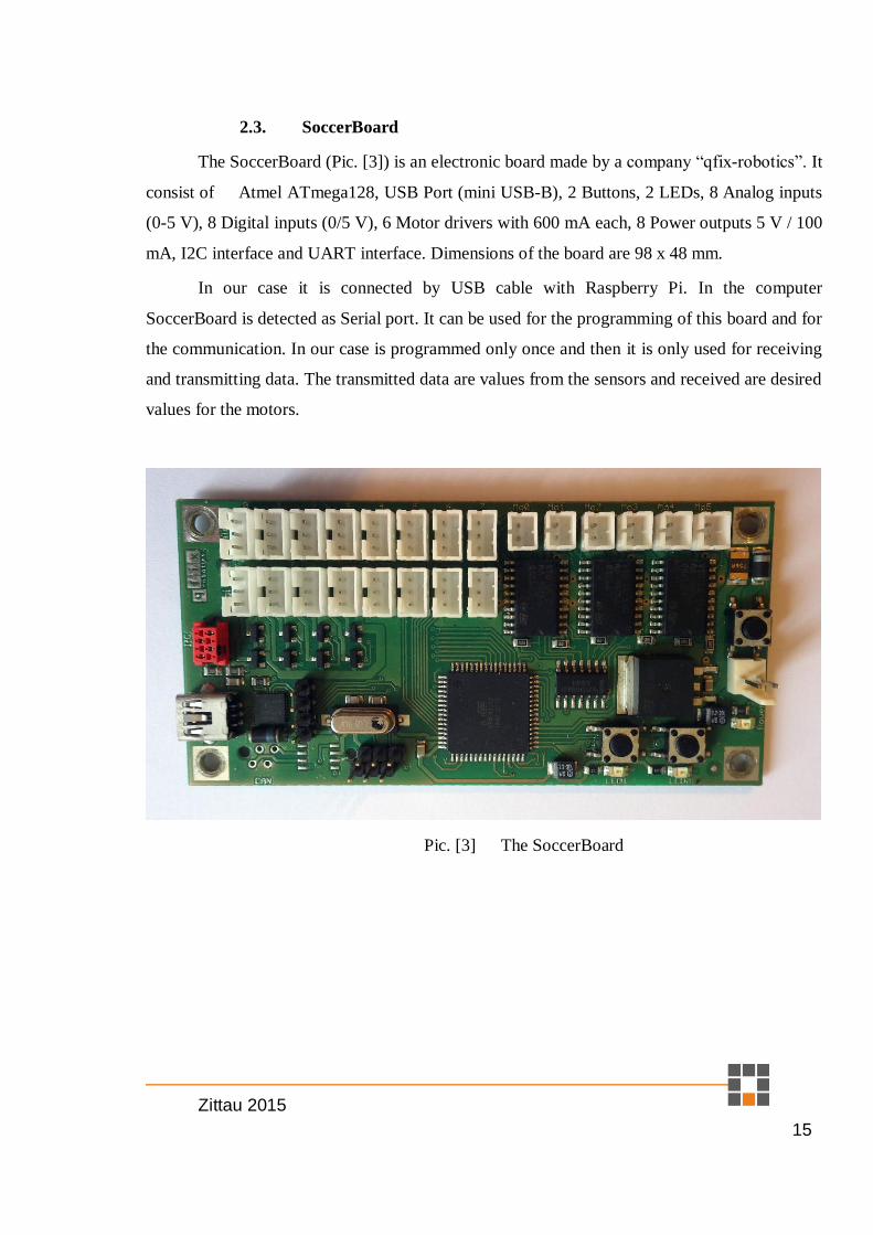
The SoccerBoard (Pic. [3]) is an electronic board made by a company “qfix-robotics”. It
consist of Atmel ATmega128, USB Port (mini USB-B), 2 Buttons, 2 LEDs, 8 Analog inputs
(0-5 V), 8 Digital inputs (0/5 V), 6 Motor drivers with 600 mA each, 8 Power outputs 5 V / 100
mA, I2C interface and UART interface. Dimensions of the board are 98 x 48 mm.
In our case it is connected by USB cable with Raspberry Pi. In the computer
SoccerBoard is detected as Serial port. It can be used for the programming of this board and for
the communication. In our case is programmed only once and then it is only used for receiving
and transmitting data. The transmitted data are values from the sensors and received are desired
values for the motors.
Pic. [3] The SoccerBoard

Zittau 2015
16
2.4. Sensors
The sensor (Pic. [4]) mounted on the robot are Sharp GP2D120X and CNY-70.
Sharp GP2D120X is the distance measuring sensor with signal processing and analog output
(0-3,1 V). This sensor can be used for avoidance of contact with obstacles. In our case it is not
implemented, because for autonomous driving a more sensors are needed. In a case of the face
tracking is the robot turning around and in the case of ball tracking we want to hit the ball, not
to avoid it. CNY-70 is the reflective optical sensor. This sensor is normally used for task of the
line following. It detects the difference between the white and black colour. White is reflecting
infrared beam and black absorbs it.
The sensors are mounted on the robot, but not used in the program. Values from them
are transmitted to the Raspberry Pi and prepared for future usage.
Pic. [4] The distance sensors (left), proximity sensor (right)

Zittau 2015
17
2.5. Raspberry Pi 2
The Raspberry Pi 2 model B (Pic. [5]) is the most used platform for teaching and
learning embedded systems. It is based on the Broadcom BCM2836 900 MHz ARM Cortex-A7
quad-core processor with VideoCore IV dual-core GPU and 1GB LPDDR2 SDRAM. Graphic
process unit provides hardware accelerated OpenVG and 1080p30 H.264 decoding.
It has 4 USB ports, 1 Ethernet port, 40 pins of GPIO, 4-pin 3,5mm, jack for the stereo
audio output and one video output, CSI connector for camera module, DSI connector for
display module, HDMI connector and micro USB for power supply. The memory drive is made
by micro SDHC card. On this card is operating system. It should be at least class 10 if you want
a faster response of the system.
More information can be found in Appendix 1.
Pic. [5] The Raspberry Pi 2 model B
Zittau 2015
18
2.6. Camera module
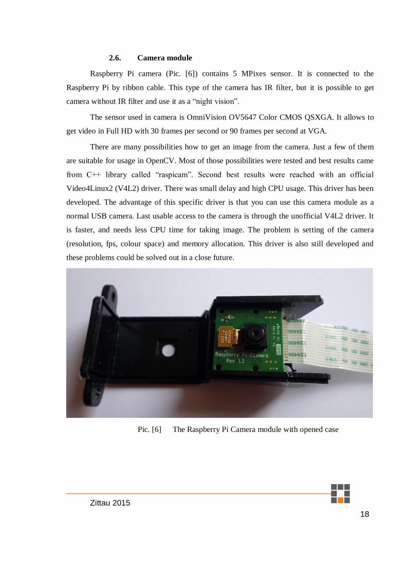
Raspberry Pi camera (Pic. [6]) contains 5 MPixes sensor. It is connected to the
Raspberry Pi by ribbon cable. This type of the camera has IR filter, but it is possible to get
camera without IR filter and use it as a “night vision”.
The sensor used in camera is OmniVision OV5647 Color CMOS QSXGA. It allows to
get video in Full HD with 30 frames per second or 90 frames per second at VGA.
There are many possibilities how to get an image from the camera. Just a few of them
are suitable for usage in OpenCV. Most of those possibilities were tested and best results came
from C++ library called “raspicam”. Second best results were reached with an official
Video4Linux2 (V4L2) driver. There was small delay and high CPU usage. This driver has been
developed. The advantage of this specific driver is that you can use this camera module as a
normal USB camera. Last usable access to the camera is through the unofficial V4L2 driver. It
is faster, and needs less CPU time for taking image. The problem is setting of the camera
(resolution, fps, colour space) and memory allocation. This driver is also still developed and
these problems could be solved out in a close future.
Pic. [6] The Raspberry Pi Camera module with opened case

Zittau 2015
19
2.7. WiFi
WiFi adapter, which is based on Ralink RT5370 chipset, plugged into Raspberry Pi,
allows Raspberry Pi connect to WiFi AP or create a new one. It works on standard 2,4 GHz
frequency. At protocol 802.11n it can theoretically reach 150 Mbit/s. It is more than enough for
video transmission.
Pic. [7] WiFi dongle with external antenna
2.8. DC/DC converter
This DC/DC converter (Pic. [8]) is based on integrated circuit LM2577S. In this case is
connected as a buck boost adjustable 2A converter. It means that it can be connected to lower
voltage and convert it to the higher voltage, or opposite way. It is useful, if you need invariant
12V power supply from 12V lead acid battery. This type of battery can be used in 10,5 – 14,5V
range. However we used it just for power supply Raspberry Pi (5V).
Pic. [8] The DC/DC Converter

Zittau 2015
20
2.9. Battery
For this robot we have chosen the Li-Pol battery (Pic. [9]) with 2200 mAh capacity,
which is the 4-cell battery (all cells are connected in series). Nominal voltage is 14,8 V and
battery can handle 66A discharge rate (2,2A*30=66A). This is more than enough, because
robot can take about 3 A at peak.
Pic. [9] The Li-Pol battery
2.10. Charger
The charger Power 80 (Pic. [10]) is an universal battery charger. It can charge LiPo,
LiIon, LiFe, NiCd, NiMH and Lead batteries. The charger has integrated voltage balancer,
which is necessary for proper charging of Li-pol batteries.
Pic. [10] The charger
Zittau 2015
21
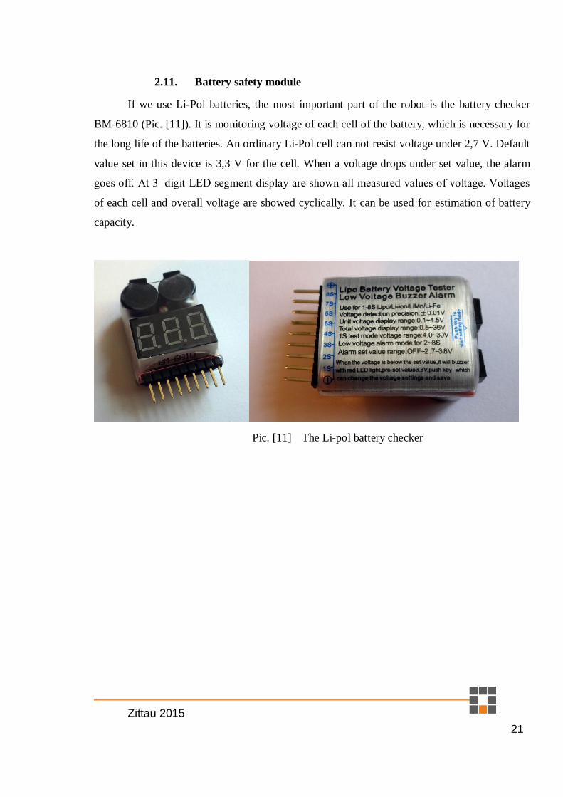
2.11. Battery safety module
If we use Li-Pol batteries, the most important part of the robot is the battery checker
BM-6810 (Pic. [11]). It is monitoring voltage of each cell of the battery, which is necessary for
the long life of the batteries. An ordinary Li-Pol cell can not resist voltage under 2,7 V. Default
value set in this device is 3,3 V for the cell. When a voltage drops under set value, the alarm
goes off. At 3¬digit LED segment display are shown all measured values of voltage. Voltages
of each cell and overall voltage are showed cyclically. It can be used for estimation of battery
capacity.
Pic. [11] The Li-pol battery checker

Zittau 2015
22
2.12. Rest of parts
Rest of used parts can be seen in the picture (Pic. [12]).
Some screws and spacers are included in OmniBot kit.
Mounting plate for Raspberry Pi was designed in Google SketchUp and printed by
homemade 3D printer. STL file (3D model) of this mounting plate is included on attached
DVD.
MicroSD card for the Raspberry Pi has the 16GB storage. It is class 10, which means
that it has a guaranteed 10MB/s speed of reading and writing of data.
On attached DVD you can also find a picture of connections of the power switch.
Connections are too simple so there is no schema. Power switch is between battery and
the rest of the robot. The DC converter for Raspberry Pi, and resistive voltage divider for
measuring voltage of the battery (useless because SoccerBoard has only 8-bit AD converter)
are powered by this switch.
The zip ties are used for neat situation of cables.
Pic. [12] The rest of parts

Zittau 2015
23
3 Software
In this chapter is described software part of the robot. Software for the SoccerBoard
consists only from reading values from sensors, sending them to the Raspberry Pi, receiving
commands for motors and setting PWM values for motors.
For the Raspberry Pi is made manual how to set up all necessary libraries, IDE (Qt
creator), WiFi, etc...
And the last thing in this chapter is example for Raspberry Pi and OpenCV.
3.1. Program for SoccerBoard
Program for the SoccerBoard is written in qfix Editor Pic. [13].
Pic. [13] Programming environment qfix Editor
Whole program is included on attached DVD.

Zittau 2015
24
Program consists of few functions. First of them is
USART1_Init( unsigned int ubrr )
This function initializes USART1 (universal synchronous/asynchronous receiver and
transmitter). “ubrr” is variable which determines Baud rate (divider for timer). USART1 is
communication interface of ATmega128. It is connected to integrated circuit CP2102. It is
USB to UART Bridge.
Basic functions for communication are
USART1_Transmit( unsigned char data )
for transmission of data and
USART1_Receive( void )
for receive data.
Higher function of this program is
void Transmit(unsigned char len){
for (int i=0; i<len; i++) {
USART1_Transmit(tx_buffer[i]);
}
}
This function is for transmitting the whole message through USART1. Variable “len” is
length of the message. For the composition of the message was made a function
void Concatenate(unsigned char len){
tx_buffer[0]=0x02;
tx_buffer[1]=len+2;
tx_buffer[2]=message_number;
for (int i=0; i<len; i++) {
tx_buffer[3+i]=message[i];
}
tx_buffer[len+3]=CRC(&tx_buffer[1],len+1);
Transmit(len+4); //send message
}
First character of a message is “STX” (0x02), second is the length of the message and
third is the number of message – for easier identification of the problems in the communication.
Next is message and at the end is CRC.
Zittau 2015
25
The function for checking properly received message is
unsigned char CRC(unsigned char * buf, unsigned char len)
{
unsigned char CRC_byte = 0;
for (int i=0; i < len; i++) {
CRC_byte = CrcTable[CRC_byte ^ *buf++];
}
return CRC_byte;
}
This function uses lookup table. It is much easier and faster than computing the
polynomial x8 + x2 + x + 1 with an initial value of zero.
Finally the main function consists of waiting for received data. If the first character is a
the number, it means, it is received direct controlling of robot.
rcv=USART1_Receive();
if ((rcv>'0')&(rcv<'a')) {
switch (rcv) {
case '1':
board.motor(0,speed_manual_forward);
board.motor(1,-speed_manual_forward);
board.motor(2,speed_manual_turn);
break;
case '2':
board.motor(0,speed_manual_forward);
board.motor(1,-speed_manual_forward);
board.motor(2,0);
break;
…
For manual driving are used three variables which declare speeds in each movement.
They are
int speed_manual_forward=30;
int speed_manual_turn=80;
int speed_manual_rotate=20;
Commands for the robot are numbers (1-9). Eight is for straight forward, five for stop,
four for rotation to the right, etc.
If the first received character is equal to 2 (in ASCII it is “STX”) then is expected length
of message. This value is used for “FOR cycle” where is received whole message. After
receiving message, it is checked for the mistakes by mentioned checksum. If the message is
without the mistakes, it is decided what type of message it is.
First type of message can be command Set Motors (characters ‘S’ and ‘M’ in message).
In this message are sent values for PWM and information about direction. Response on this
message is ‘R’ ‘M’ ‘O’ ‘K’.

Zittau 2015
26
Second type of message is the request for the values from sensors (‘G’ and ‘S’).
Response for this request is generated by following part of code.
if ((rx_buffer[2]=='G')&(rx_buffer[3]=='S')){//get sensors
message[0]='R';//response
message[1]='S';//sensors
for (int i=0; i < 8; i++) {
message[i+2]=board.digital(i);
message[i+10]=board.analog(i);
}
Concatenate(18);
}
First eight values are information from digital inputs and second part of message is
filled by values from analog inputs.

Zittau 2015
27
3.2. Preparation of Raspberry Pi and OpenCV
There is described process of manual setting up and installation. It is not necessary if
you use included image on DVD of adjusted system. There is everything set as it is described
below.
a) Preparation of SD card
First what we need is an operating system for Raspberry Pi. It can be found on the
webpage https://www.raspberrypi.org/downloads/ . In our case we need RASPBIAN. It is
modified distribution of Debian Wheezy.
After downloading current version of RASPBIAN, we need to extract ZIP file and we
get the “.img” file. It is image of SD card. Next tool which we need is Win32 Disk Imager (Pic.
[14]) (http://sourceforge.net/projects/win32diskimager/). It is a software for Windows. If you
need to write an image to SD card on another operating system look for “image installations
guides” on the same webpage as RASPBIAN image.
Pic. [14] Win32 Disk Imager
After the setting up correct path to image file and SD card plugged into the computer. It
is necessary to press the button “Write”. It will take few minutes.
Next logical step is to put SD card into the Raspberry Pi. For the first booting up we
will use LCD monitor connected by HDMI cable. It is needed to have connected standard USB
keyboard and a mouse to the Raspberry Pi. The reason for this is easier setting up important
settings.

Zittau 2015
28
b) First setup
After powering on we will see Raspberry Pi Software Configuration Tool (Pic. [15]).
Pic. [15] Raspberry Pi Software Configuration Tool
First thing we need to set is “Expand File-system”. It will extend available storage to
whole SD card.
Second choice is “Change User Password”. We will set “pi” password for default user
“pi”. Now we have account “pi” with password “pi”. It is not secure, however it is faster for
logging in.
Third item is “Enable Boot to Desktop/Scratch”. There we choose “Desktop Log in as
user “pi” at graphical desktop.
Fourth entry is “Internationalization Options”. There can be changed time-zone,
keyboard layout, or language and regional setting. I did not make any changes.
Fifth entry is very important for future work with camera. It is “Enable Camera”. Of
course we want to enable it.
Sixth is “Add to Rastrack”. It is only for fun – it will add Raspberry Pi to the map of all
registered Raspberry Pi.
Seventh option is overclock. Here we choose last entry “Pi2”. It will overclock
Raspberry Pi to the 1 GHz.

Zittau 2015
29
Eighth entry is “Advanced options”. Here we changed Overscan to disable, SSH to
enable, SPI to enable and I2C to enable.
In the end we will choose “Finish” and it will reboot Raspberry Pi with the new setting.
All choices can be changed in the future by command “sudo raspi-config” in the terminal.
c) Installation of the libraries
After rebooting of the Raspberry Pi we will see “classic” linux desktop (Pic. [16]).
Pic. [16] Raspberry Pi - Desktop
From this point we will need internet connection. It is possible by WiFi or Ethernet.
First commands before installing something should be
sudo apt-get update
sudo apt-get upgrade
sudo rpi-update
sudo apt-get dist-upgrade
It will update software and firmware in Raspberry Pi. Next step is to install all necessary
libraries and programs for the proper function of the OpenCV.

Zittau 2015
30
sudo apt-get install ant bison build-essential cmake cmake-curses-gui
default-jdk ffmpeg firebird-dev freetds-dev g++ gcc gstreamer0.10-
plugins-bad gstreamer0.10-plugins-good gstreamer-tools guvcview
ipython-notebook libasound2-dev libavcodec53 libavformat53
libavformat-dev libcups2-dev libcv-dev libdbus-1-dev libdrm-dev
libeigen3-dev libfontconfig1-dev libfreetype6-dev libglib2.0-dev
libgraphicsmagick1-dev libgst-dev libgstreamer0.10-0-dbg
libgstreamer0.10-dev libgstreamer-plugins-base0.10-dev libgtkglext1-
dev libhighgui-dev libicu-dev libiodbc2-dev libjpeg8 libjpeg8-dbg
libjpeg8-dev libjpeg-progs libmysqlclient-dev libpng++-dev libpng12-0
libpng12-dev libpng3 libpnglite-dev libpulse-dev libqt4-core libqt4-
dev libraspberrypi-dev libsqlite0-dev libsqlite3-dev libssl-dev
libswscale-dev libtiff4 libtiff4-dev libtiff-tools libtiffxx0c2
libudev-dev libunicap2 libunicap2-dev libv4l-0 libv4l-dev libx11-dev
libx11-xcb1 libx11-xcb-dev libxcb1 libxcb1-dev libxcb-glx0-dev libxcb-
icccm4 libxcb-icccm4-dev libxcb-image0 libxcb-image0-dev libxcb-
keysyms1 libxcb-keysyms1-dev libxcb-randr0-dev libxcb-render-util0
libxcb-render-util0-dev libxcb-shape0-dev libxcb-shm0 libxcb-shm0-dev
libxcb-sync0 libxcb-sync0-dev libxcb-xfixes0-dev libxext-dev libxi-dev
libxine1-bin libxine1-ffmpeg python2.7-dev libxine-dev libxslt1-dev
libxt-dev python-pandas pkg-config pngtools python-matplotlib zlib1g
python-nose python-scipy qt4-dev-tools qtcreator subversion swig
synaptic v4l-utils xterm zlib1g-dbg zlib1g-dev
It will take some time. It is all what we need for proper function of OpenCV. Library
OpenCV can be downloaded by command
wget http://sourceforge.net/projects/opencvlibrary/files/opencv-
unix/2.4.11/opencv-2.4.11.zip/download -O opencv-2.4.11.zip
Now it is downloaded, but it is packed in “zip” file. For unpacking this file we will use
unzip opencv-2.4.11.zip
Then we open created folder
cd opencv-2.4.11
Create folder “build”
mkdir build
Open created folder
cd build
Create makefile
cmake -D CMAKE_BUILD_TYPE=RELEASE -D INSTALL_C_EXAMPLES=ON -D
INSTALL_CPP_EXAMPLES=ON -D INSTALL_PYTHON_EXAMPLES=ON -D
BUILD_EXAMPLES=ON -D WITH_QT=ON -D CMAKE_INSTALL_PREFIX=/usr/local -D
WITH_OPENGL=ON -D WITH_V4L=ON ..
Compilation – “-j3” will use 3 cores of CPU for compilation
sudo make -j3
Finally installation
sudo make install
Create file

Zittau 2015
31
sudo nano /etc/ld.so.conf.d/opencv.conf
Put this line into the file and save it
/usr/local/lib
After closing the file run this command
sudo ldconfig
Open file bash.bashrc
sudo nano /etc/bash.bashrc
In the end add these two lines
PKG_CONFIG_PATH=$PKG_CONFIG_PATH:/usr/local/lib/pkgconfig
export PKG_CONFIG_PATH
Save it and close the file. At this point should be OpenCV installed and configured.
Close the terminal and reboot Raspberry Pi.
Now we can open terminal and open folder with samples.
cd ~/opencv-2.4.11/samples/c
Set file access rights
chmod +x build_all.sh
Build all examples
./build_all.sh
And now can be executed for example facedetect
./facedetect
If it is not working, it is because you do not have plugged in USB camera or you did not
have loaded up official V4L2 driver which will make virtual USB camera from Raspberry Pi
Camera module.
It can be made by executing command
sudo modprobe bcm2835-v4l2
At this point we have installed OpenCV. For the basic operations (take one picture) it is
enough to have a v4l2 driver. But for the tracking of moving object we need faster access to the
image from camera. We will use user library. It is based on “mmal” access to the camera
Check your current directory. If you are still in the folder with the samples go back to
home directory by command
cd ~
Write command
wget http://sourceforge.net/projects/raspicam/files/raspicam-
0.1.3.zip/download -O raspicam.zip

Zittau 2015
32
It will download “raspicam.zip” and we need to extract it. It does command
unzip raspicam.zip
Next command is for renaming folder
mv raspicam-0.1.3 raspicam
Go into the renamed folder
cd raspicam/
Make a build folder
mkdir build
Open build folder
cd build
Run command
cmake ..
Complile it
make
Install it
sudo make install
Update links to libraries
sudo ldconfig
And the last not necessary library is well known “wiringPi”.
cd ~
Download folder “wiringPi”
git clone git://git.drogon.net/wiringPi
open folder “wiringPi”
cd wiringPi
start install script
./build
d) Setting up VNC connection
Download required programs
sudo apt-get install tightvncserver screen
Start VNC server. At first start-up it will ask for password
vncserver :1
We have chosen “raspberr”. It is because of the maximal length of the password is 8
characters. Next step is for configuring automatic start of VNC server.

Zittau 2015
33
Open hidden directory “config”
cd .config
Create folder “autostart”
mkdir autostart
Open folder “autostart”
cd autostart
Create new file in text editor nano
nano tightvnc.desktop
Enter following text
[Desktop Entry]
Type=Application
Name=TightVNC
Exec=vncserver :2
StartupNotify=false
And save it. After reboot of Raspberry Pi it should start VNC server.
Connection Raspberry Pi with almost any VNC client program is possible by writing
“ip address:number of session” and password. At this case it was 10.0.0.28:2 and password is
“raspberr”
Pic. [17] TightVNC – one of suitable VNC client

Zittau 2015
34
e) Setting up VNC connection with web browser
For remote control by any device without requirement of installing any program we will
set up web interface.
Open “/usr/local/share/”
cd /usr/local/share/
Download prepared program for web interface
sudo git clone git://github.com/kanaka/noVNC
Open downloaded folder
cd noVNC
And copy prepared html page vnc_auto.html as index.html
sudo cp vnc_auto.html index.html¨
Open folder “utils”
cd utils
Launch script
sudo ./launch.sh
Terminate script by presing
CTRL+C
For automatic start of this, we need following script
Open “/etc/inid.d”
cd /etc/init.d/
And download mentioned script
sudo wget
https://raw.githubusercontent.com/raspberrypilearning/teachers-
classroom-guide/master/vncboot --no-check-certificate
Open configuration file in text editor
sudo nano vncboot
And adjust “-geometry 1280x800” to wanted resolution. It was changed to 1366x768.
For registration of the script we need to run following commands
sudo chmod 755 vncboot
sudo update-rc.d vncboot defaults
Second part of this we get by
sudo wget
https://raw.githubusercontent.com/raspberrypilearning/teachers-
classroom-guide/master/vncproxy --no-check-certificate
And again registration of the script
sudo chmod 755 vncproxy
sudo update-rc.d vncproxy defaults 98

Zittau 2015
35
Next command is for rebooting of Raspberry Pi.
sudo reboot
At this point we should be able to connect to Raspberry Pi by any web browser which
supports HTML5 (Pic. [18]). Into the address bar write ip address of Raspberry Pi. Then you
will be asked for the password. It is the same as for normal VNC connection (raspberr).
Pic. [18] noVNC – web interface of VNC client
And after entering of the password you will see Raspbian desktop.
f) Setting up Qt Creator
Unfortunately Qt Creator does not detect automatically installed compilers and it is
necessary to set tool chains manually.
First step is logically open Qt Creator. There open
Tools>Options>Build&Run>Tool chains
Add GCC complier and set the Compiler path
/usr/bin/arm-linux-gnueabihf-gcc-4.8
And for the debugger
/usr/bin/gdb
It should look like in the picture (Pic. [19])

Zittau 2015
36
Pic. [19] Qt Creator – tool chain
Next problem is with the detection of the environment. We do not want to program
remote device so we need to disable this option. It can be done by tick off plugin, which
enables it.
Go to the
Help>About plugins
And uncheck at Device support “RemoteLinux” and restart Qt Creator.
Go back to the
Tools>Options>Build&Run>Qt Versions
Add and set path to the
/usr/bin/qmake-qt4
Last thing we need to change is terminal. Go to
Tools>Options>Environment>General
And change path to the terminal to
/usr/bin/xterm -e
And it should be enough to run program written in Qt Creator.

Zittau 2015
37
g) Download of prepared programs
For download of the prepared programs use command
git clone https://github.com/MarekValsik/hszittau
It will download at least two directories (maybe I will add more examples in the future).
One directory is the final result of this master thesis and second is simple example of grabbing
image from camera.
h) Turn Raspberry Pi into the WiFi AP
If we want to be able to connect to the robot remotely we need wireless connection. If
we are still in the same area with WiFi AP there is no need to do this procedure. However in
our case we need to connect to the robot independent to the access to any WiFi AP. The most
logical solution is that the robot will create its own WiFi AP. First thing what we need is
compatible USB WiFi adapter. Our adapter with chipset RT5370 is compatible. Next step is to
install necessary services:
sudo apt-get instal hostapd dnsmasq
We need to set static IP at Raspberry Pi. Open
sudo nano /etc/network/interfaces
And “wlan0” section rewrite with this
allow-hotplug wlan0
iface wlan0 inet static
address 192.168.10.1
netmask 255.255.255.0
#wpa-roam /etc/wpa_supplicant/wpa_supplicant.conf
iface default inet manual
At this point I recommend to restart network interfaces:
sudo /etc/init.d/networking restart
And we should specify wireless network which we want to create. Create file by
command:
sudo nano /etc/hostapd/hostapd.conf
And fill it with these lines:
interface=wlan0
driver=nl80211
ssid=Omnibot
hw_mode=g
channel=6
macaddr_acl=0
auth_algs=1
ignore_broadcast_ssid=0
wpa=2

Zittau 2015
38
wpa_passphrase=raspberr
wpa_key_mgmt=WPA-PSK
wpa_pairwise=TKIP
rsn_pairwise=CCMP
You can change SSID, password, WiFi channel (if channel 6 is already used by WiFi in
near area). And now we need to set path to this configuration file. Open file:
sudo nano /etc/default/hostapd
And at the end of this file add line
DAEMON_CONF="/etc/hostapd/hostapd.conf"
Because we want to have everything working after each booting up, it is required to run
this command:
update-rc.d hostapd enable
At this point we have created WiFi AP (after reboot). But for easy connecting with
Raspberry Pi we need also DHCP server. For configuration of DHCP server open file:
nano /etc/dnsmasq.conf
And at the end of the file put these lines
interface=wlan0
except-interface=eth0
dhcp-range=192.168.10.2,192.168.10.150,255.255.255.0,12h
It will set DHCP server for range 192.168.10.2 to 192.168.10.150 and assigned ip
address will be valid for 12 hours. Final step is to make start of DHCP server automatically.
update-rc.d dnsmasq enable
All these changes will be used after reboot.
sudo reboot
3.3. Usage of prepared image of SD card
If you do not want to go through all previous steps, you can use prepared image of SD
card where are all these steps already made.
At attached DVD you will find file “Omnibot.rar”. In this archive is file
“Omnibot.img”. It is the image of SD card. Extract it and flash it to the SD card as in chapter
3.2a). Just short recapitulation: user name is “pi” password is also “pi”. For remote access
through VPN (both: client and web browser) is password “raspberr”. This password was chosen
because in one step was limitation of 8 characters and there is no more problem with “y” and
“z” placement on the keyboard. SSID of created WiFi AP is Omnibot and passphrase is also
“raspberr”. Static IP address is now set to 192.168.10.1.

Zittau 2015
39
3.4. Example programs used on Raspberry Pi
It does not matter if you went through chapter 3.2 or 3.3. In both cases you have in
home directory folder named hszittau. In this folder are directories “Example”,
“Example_bcm2835 and “Omnibot”. In this chapter are described both examples.
First of them (“Example”) is based on “raspicam” library. Main attention should be
given to the content of file Example.pro.
QT = core
QT += gui
TARGET = Example
CONFIG += console
CONFIG -= app_bundle
TEMPLATE = app
SOURCES += main.cpp
INCLUDEPATH += /usr/local/lib/
LIBS += `pkg-config opencv --libs`
LIBS += -lraspicam_cv
LIBS += -lraspicam
If you want to use other libraries it is necessary to add some rows to this file. In this
case there are libraries for “raspicam”. The content of the program – file “main.cpp” is
following:
#include <QApplication>
#include <cstdio>
#include "opencv2/opencv.hpp"
#include <iostream>
#include <raspicam/raspicam_cv.h>
using namespace cv;
using namespace std;
raspicam::RaspiCam_Cv Camera;
Mat image;
int main(int argc, char *argv[])
{
QApplication a(argc, argv);
printf("Hello everyone :-)\n");
Camera.set( CV_CAP_PROP_FORMAT, CV_8UC3 );
Camera.set( CV_CAP_PROP_FRAME_WIDTH, 640 );
Camera.set( CV_CAP_PROP_FRAME_HEIGHT, 480 );
//Camera.set(CV_CAP_PROP_FPS, 15);
if (!Camera.open()) {cerr<<"Error opening the camera"<<endl;return -
1;}
namedWindow("main", WINDOW_AUTOSIZE);
while(1) {
Camera.grab();
Camera.retrieve (image);
imshow("main", image);
if (waitKey(10)>=0) break;
}
cvDestroyWindow("main");
return (0);
}

Zittau 2015
40
This example shows how to take an image through the library “raspicam” and show it.
After many tests and tries of other libraries this library had the best results.
Second example is only for comparison with previous example. This uses “standard”
access to the camera.
It is necessary to run command “sudo modprobe bcm2835-v4l2” before running this
example. This command will load official driver v4l2 for Raspberry Pi Camera module. It
means we have an access to this camera same as for any camera connected to USB port.
#include <QApplication>
#include <cstdio>
#include "opencv2/opencv.hpp"
#include <iostream>
using namespace cv;
using namespace std;
//load driver!!!
// sudo modprobe bcm2835-v4l2
int main(int argc, char *argv[])
{
QApplication a(argc, argv);
VideoCapture cap(0);
if( !cap.isOpened() ) {
printf("Camera failed to open!\n");
return -1;
}
namedWindow("main", WINDOW_AUTOSIZE);
Mat frame;
for(;;)
{
cap >> frame;
imshow("main", frame);
if(waitKey(10) >= 0) break;
}
cvDestroyWindow("main");
return (0);
}
Both examples take picture from camera module and shows on the display. First
example is faster than second one. Second example is also useful if we need simple solution
and does not matter the small delay (about 0,5 s).

Zittau 2015
41
3.5. Main program called “Omnibot”
The main program consist of three functions. First of them is manual control. Manual
control uses numerical keyboard and the control is the same as described in chapter 3.1
(Commands for the robot are numbers (1-9). Eight is for straight forward, five for stop, four for
rotation to the right, etc.). Second function is the face detection. The face detection turns robot
to the direction where it sees the face. Main goal of this function is to get face into the centre of
image grabbed from camera. Last function is for the ball tracking. Goal of this function is
follow ball – have centre of the ball in centre of the picture grabbed from camera and get drive
close to it.
The program consists of threads. One thread is always used for communication with
“Soccer Board”. Another is for grabbing image from camera. Others depend on chosen
function. In this chapter there are no examples of written functions, because whole program is
too complex. Program is enough commented and placed on SD card in Raspberry Pi, internet
repository GitHub and naturally on attached DVD.
Pic. [20] Main window of the program “Omnibot”
Function of the program can be changed by track bar (Pic. [20]) (1-manual control, 2-
face detection, 3-ball tracking).

Zittau 2015
42
4 Conclusion
The robot was developed due to requirements of the school. This is the reason why there
are included two examples. Main program fulfils given task. Robot is able to detect face and
follow it (keep it in the centre of picture from camera). Also is able to track colour balls –
follow them. Power consumption of the robot is at 15 V about 0,4 A at steady state and 1,2 A
while moving. Li-pol battery with capacity 2,2 Ah is able to keep robot moving almost an hour.
Usage of image of SD card is fastest way how to set up Raspberry Pi for programming
with OpenCV. To keep this system update are necessary only 4 commands:
sudo apt-get update
sudo apt-get upgrade
sudo rpi-update
sudo apt-get dist-upgrade
This will download and update system including firmware for camera module. Update
firmware for camera module is important for proper function of library “raspicam” used for
faster grabbing image from camera.
Raspberry Pi 2 with 4 cores overclocked to 1 GHz is able to process images from
camera very fast (with the possibility of multiprocessing). Communication with “Soccer board”
is via USB cable (emulated serial port) with baud rate 57600. Information from sensors and
commands for motors are updated 20 times per second. It is enough for this small robot. There
is a space for improvements of communication but in this solution it is clear and reliable.

Zittau 2015
43
List of the References
There is a list of webpages where I get all information and inspiration. All of them have
been available on 23.8.2015.
https://docs.google.com/document/d/1bgVo24hCK0huoxm9zGC9djL6K0yy0z9GldzSy6SZ
UQY/pub
https://www.raspberrypi.org/forums/viewtopic.php?f=31&t=43545
http://www.raspberrypi.org/forums/viewtopic.php?f=43&t=63276#p468491
http://elinux.org/RPi-Cam-Web-Interface
http://elinux.org/RPi_Serial_Connection
https://theredblacktree.wordpress.com/2015/02/08/compiled-binaries-of-qt-5-
3-for-the-raspberry-pi-and-pi-2/
http://www.raspberry-projects.com/pi/programming-in-c/uart-serial-
port/using-the-uart
http://stackoverflow.com/questions/421860/capture-characters-from-standard-
input-without-waiting-for-enter-to-be-pressed
http://michael.dipperstein.com/keypress.html
http://www.raspberrypi.org/forums/viewtopic.php?f=31&t=43545
http://www.raspberrypi.org/forums/viewtopic.php?f=33&t=33881
http://wiringpi.com/wiringpi-updated-for-the-new-pi-v2/
http://raspi.tv/2013/how-to-stream-video-from-your-raspicam-to-your-nexus-7-
tablet-using-vlc
http://www.instructables.com/id/Create-an-internet-controlled-robot-using-
Livebots/step5/Get-the-webcam-streamer-for-Raspberry-Pi/
https://www.raspberrypi.org/forums/viewtopic.php?f=43&t=105019
https://www.raspberrypi.org/forums/viewtopic.php?f=33&t=81503
https://www.raspberrypi.org/an-image-processing-robot-for-robocup-junior/
https://robidouille.wordpress.com/2013/10/19/raspberry-pi-camera-with-
opencv/
http://www.jayrambhia.com/blog/capture-v4l2/
http://www.uco.es/investiga/grupos/ava/node/40
https://github.com/robidouille/robidouille/tree/master/raspicam_cv
https://wiki.qt.io/Native_Build_of_Qt_5.4.1_on_a_Raspberry_Pi
https://wiki.qt.io/Native_Build_of_Qt5_on_a_Raspberry_Pi
http://www.linux-
projects.org/modules/sections/index.php?op=viewarticle&artid=14
http://teycode.com/blog/raspberry-uv4l-opencv/
http://helloraspberrypi.blogspot.cz/2015/04/install-qt5-on-raspberry-
piraspbian.html
http://www.stemapks.com/opencv.html
https://github.com/neutmute/PiCamCV
https://github.com/robidouille/robidouille/issues/7
http://sourceforge.net/p/asrob/svn/1065/tree/rpc/projects/rpi/src/c++/cam/si
mpletest_raspicam.cpp
https://www.raspberrypi.org/learning/teachers-classroom-guide/vnc-browser-
guide/
https://www.raspberrypi.org/forums/viewtopic.php?f=99&t=81165
https://code.google.com/p/qt-opencv-multithreaded/
http://www.jayrambhia.com/blog/opencv-with-tbb/
http://www.bogotobogo.com/cplusplus/multithreading_pthread.php
https://www.raspberrypi.org/forums/viewforum.php?f=43&sid=6b58967a41999cf16c
01cec4394f8653
http://docs.opencv.org/modules/highgui/doc/qt_new_functions.html
http://opencv-srf.blogspot.cz/2011/11/mouse-events.html
http://docs.opencv.org/modules/highgui/doc/qt_new_functions.html

Zittau 2015
44
https://github.com/robidouille/robidouille/tree/master/raspicam_cv
http://mintguide.org/tools/260-wifi-hostapd-ap-a-simple-application-to-
create-wifi-hotspot-on-linux-mint.html
https://help.github.com/articles/fork-a-repo/
https://github.com/oblique/create_ap
http://rpi.vypni.net/wifi-ap-rt5370-on-raspberry-pi/
http://www.qfix-robotics.de/

Zittau 2015
45
Content of attached DVD
On DVD are placed 6 folders:
3D
In this folder there are two files, one of them is SketchUp model of mounting plate for
Raspberry Pi on Omnibot. Second one is exported STL file for printing on 3D printer.
Examples
In this folder there are two basic programs for testing installed OpenCV library and
connected Rasperry Pi camera module.
MainProgram
There is located final program for manual and autonomous driving of the robot. This
program includes function for communication with Soccer Board.
PIC
This folder consists of another two folders. One of them contains pictures used in
master thesis and second one all pictures of the robot.
RaspberryPi
There can be found an image of SD card (Omnibot.rar), program for formatting SD card
(SDFormat.exe) and program for flashing image of SD card to SD card (image writer).
SoccerBoard
Program for Soccer Board is included in this folder. Program receives commands from
Raspberry and can be used for manual driving over UART.

Zittau 2015
46
Appendix 1 - Used 3D printer
Used 3D printer was developed as a part of bachelor thesis in 2013 by me (Marek
Valšík - Konstrukce 3D tiskárny / Construction of 3D printer )
Resolution in axes x, y: 1/160 mm
Resolution in axe z: 1/2560 mm
Diameter of the nozzle: 0,35 mm
Resolution of the extruder: 0,005 mm3
Smallest height of layer: 0,05 mm
Pic. [21] Picture of used 3D printer

Zittau 2015
47
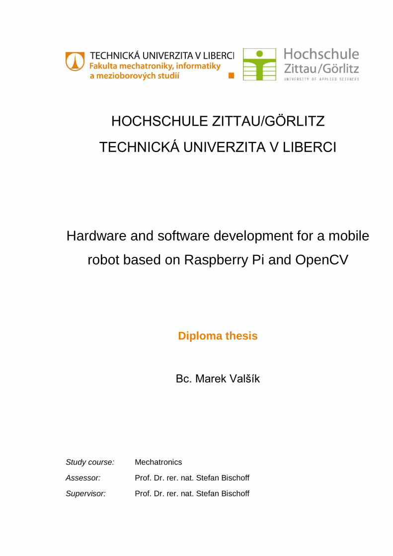
Appendix 2 - Raspberry Pi
This diagram is for older version of Raspberry Pi. Raspberry Pi 2 used for robot has
better CPU. The rest of it is the same – GPIO Pinout Diagram.
Pic. [22] Raspberry Pi diagram
This picture is from web page:
http://www.jameco.com/Jameco/workshop/circuitnotes/raspberry_pi_circuit_note
_fig2a.jpg