DIPLOMA IN CIVIL ENGINEERING III SEMESTER
333
STATE BOARD OF TECHNICAL EDUCATION & TRAINING::AP, VIJAYAWADA DIPLOMA IN CIVIL ENGINEERING III SEMESTER SURVEYING-II PRACTICE & PLOTING ( C-308 ) (AS PER C-20 CURRICULUM)
-
Upload
khangminh22 -
Category
Documents
-
view
2 -
download
0
Transcript of DIPLOMA IN CIVIL ENGINEERING III SEMESTER

STATE BOARD OF TECHNICAL EDUCATION & TRAINING::AP,
VIJAYAWADA
DIPLOMA IN CIVIL ENGINEERING
III SEMESTER
SURVEYING-II PRACTICE & PLOTING ( C-308 )
(AS PER C-20 CURRICULUM)

1.0 INTRODUCTION
The Curriculum of Technical Education should invariably provide for knowledge, attitudes and skills required by the
technicians /technologists in the country. In this context the laboratory courses form a vital portion in the entire curriculum
of technician education. The laboratory courses shall therefore be so designed and delivered that they help the students
acquire attitudes and motor skills that are essential to function effectively as technicians/technologists.
The planning, organization and implementation of lab courses need a detailed description of tasks to be performed by the
students. Well thought out instructional objectives to a large extent give these descriptions. The analysis of tasks (by
identifying the activities the students are expected to do) help prepare the objectives meticulously. In other words the
objectives would be clearer, when the task analysis is done to spell out the sub tasks for each objective.
A survey of the practices currently followed in the technical/technician education shows an urgent need to plug in gaps in
instructional procedures. The reasons for these gaps are ambiguity in the minds of the teachers regarding tasks to be
performed, levels of competency to be achieved by the students and the weightage to be allocated for each task. This aids
in scientific design of instructional plan (optimizing the resources, budgeting the time & content).
The task analysis, teaching points and the structured scheme of evaluation are very important in focusing the instruction
on specific skill of desired outcome and in evaluating the same. The Instruction and evaluation in Laboratory courses are
different from that of cognitive lessons in the sense that adequate importance and hence weightage needs to be given for
all three domains of learning viz. cognitive, psychomotor and affective. Since both training and evaluation of traits of
affective domain are practically difficult, a few traits (called values) most relevant and essential to occupations/professions
after the Course may be identified for the purpose. It is imperative to integrate these values during instruction and
evaluation and also overtly notify the same to the students.
A technician, in addition to performing a skill needs to prepare a report of testing that includes the description of
procedure, details of measurements made, reasoning based inferences and so on.,. The current practice of record writing
has failed to achieve this purpose as most of the time students end up with making copies of available material.
Therefore, for sensitizing the need for the changes in laboratory instruction, the present hand book has been prepared to
meet the above requirements. As such the hand book comprises four parts that intend to :
Present task analysis, teaching points which can be used for effective design of instruction
provide a scheme of evaluation with rationally allocated weightage to each significant skill component
offer a set of questions designed at different levels of competencies for assessment enabling the teacher to set
the question paper with balanced levels of competencies
present preset worksheets that cultivate the habit of systematic recording of observations and writing the
technical report.
Provide all important data related to particular laboratory activity at one point in the form of annexure
1.1. STRUCTURE OF THE BOOK
The hand book is presented in four parts viz., Laboratory sheets, Worksheet, Experimental Methodology and Annexure.
The description of each part is given in the following sections

Part I. Laboratory Sheet
The information provided in this part is useful for the teacher for designing the instruction, planning & organization
of the experiment and for scientific evaluation of the students. The major features of the Laboratory sheet are
further explained below.
1. Objective It indicates the Task to be performed and completed by the student during the specified duration of time.
2. Task Analysis
It is the process of identifying the component activities (sub tasks) to be carried out by the student in order to
achieve the stipulated objective. As the task analysis aim at fitting the instructional objectives into various
classes of behaviour, it would help the teacher to determine any particular type of behaviour the student has
learnt / failed to perform.
The task analysis would help the teacher in identifying the specific activities to be performed by the students.
This could also be used as some kind of check list to compare with activities planned for the laboratory. Further
it would give clue to the teacher to make students think originally & act independently. It includes both
psychomotor learning and the related cognitive information and hence the task analysis is presented as
Knowledge and skill parts.
A. Knowledge Part: That includes the cognitive aspects of the task.
B. Skill Part: That includes Psychomotor & Affective aspects of the task.
3. Teaching Points:
This includes the points based on the SKILL identified with suggested duration for each point and total
duration which helps the teacher for the time and content budgeting during instruction.
4. Need and Scope: The purpose, application and scope of the task to be performed are normally included in this sub section.
5. Planning and Organisation:
It lists actions to be taken to perform various activities and hence useful in planning the instruction and
organizing the resources and equipment
6. Scheme of Valuation: The information provided in this section helps the teacher to devise a tool for rational measurement
assessment of the competencies accomplished by the student.
Part II. Work Sheet
It is designed for the student, where in the student enters his personal data of identification, details of the
experiment, stepwise procedure, observations made during experiment, a sample calculation, free hand typical
graph, graph from experimental data and inference with discussion.
Part III. Experimental Methodology
This section furnishes information with regard to standard procedure to conduct the experiment along with the
description of equipment/apparatus and the basic theory/concept involved in the conduct of the experiment. Thus

this section is very useful for both teacher and student as well to conduct the experiment systematically. Thus this
section is presented in four sub section as described below:
Description
It gives the detailed description of apparatus / tools / equipment / materials to be used for the task.
Theory / Concept
It gives the concept of the task to be performed with formulae and units.
Procedure
It provides the idea of step wise procedure to perform the task.
Observation and Calculation
It includes sample observation, sample graph, sample calculation for reference
Part IV. Annexure
All important and useful information that may help in accomplishment of tasks like conversion tables for units,
technical & scientific data like material properities, standard trend or characteristic curves (graphs) etc are compiled
and presented at one place in this section.
1.2. WHO IS TO USE AND HOW TO USE.
The hand book is so designed that it can be beneficially used by different sections of the technical education viz., the
teacher, the student, the examiner and the administrator convenient to individual’s requirements. A few uses of
this hand book each stakeholder could make is outlined in the following sections.
1. Teacher A. The laboratory sheet is designed keeping the teacher in mind for the teacher has key responsibility of
imparting the skills to the student and hence the information given in the lab sheets may be useful for planning &
organizing the experimental set up and designing an effective instruction. Thus the teacher may
Plan and organize as per section 4,
Instruct the students as per section 2,
Demonstrate each sub task as per section1.B.and
Evaluate the students as per section 5, according to the level of competency.
Values: The values in a person are an important personality trait that needs to be nurtured in the learning
environment. Further it is also a driving component in any individual to deliver the best and hence this
component is also included in the evaluation. However only five key dimensions, that are important in the
teaching-learning environment, are taken into consideration for nurturing and evaluation. A little information
about these five dimensions is given below as a guideline for the teacher while assessing students.
1. Co-operation: It is the voluntary arrangement in which two or more students engage in a mutually
beneficial exchange, instead of competition. Cooperation can happen where resources adequate for both
students exist or are created by their interaction.

2. Co-ordination: It is the unification, integration, synchronization of the effect of group members so as
provide unity of action in the pursuit of common goals. It is an integral element and required in each &
every function and at each & every stage & therefore it cannot be separated.
3. Communication; Communication skill is the set of skills that enables a student to convey information
so that it is received and understood.
4. Sharing: A part or portion belonging to, distributed to, contributed by, owed by a person or a group Or
To participate in, use, enjoy or experience jointly or in turns.
5. Leadership: Students with the following leadership qualities are almost always the ones that rise above
the crowd.
1. Trustworthiness: This refers to integrity.
2. Inspiration: Guides, leads and inspiring others to want to participate in the process of moving
towards the vision.
3. Self awareness: It is the individual awareness of him or her self – their abilities and the impact that
they have on others.
4. Acceptance of responsibility: True leaders are accepting responsibility for all that comes their way
and taking ownership and responsibilities for getting things back on track. Blaming, justifying and
excuse making just is not in their responsibility.
B. The Experimental methodology is designed for both teacher and student. The teacher can refer the
experimental methodology for the details of equipment/apparatus/ materials/tools, procedure to be followed,
observations to be made, graphs to be drawn and calculations to be done for the task to be performed
2. Student
The Worksheet is designed keeping in view the needs, deficiencies and the adolescent characteristics of the
student for student.
The students submit the filled in work sheet given by the teacher on the day of experiment after referring to
experimental methodology and listening to instructions of teacher. The design of the worksheet is made user
friendly and the contents are so logically sequenced that the student finds it easy to understand and develop
the skill of recording and report writing skill. It also helps the student to actively participate in skill learning. More
importantly the student gets immediate meaningful feedback of his performance since the competency wise
assessment is done and that too on the same day.
3. Examiner
The examiner may find this hand book very useful as Laboratory sheets and Scheme of evaluation provides information
with regard to various competencies (skills) the students is expected to acquire during the course of study and the
relative weightages of each competency. This information helps him to design a well balance question
paper/measurement tool for assessment


Lab sheet-4.1
PERFORMING TEMPORARY ADJUSTMENTS FOR A THEODOLITE
OBJECTIVE
To perform series of tasks involved in Temporary adjustments of a theodolite
EQUIPMENT/APPARATUS
• Theodolite • Tripod • Levelling staff .
TASK ANALYSIS
A.KNOWLEDGE
• Parts of theodolite
• knowledge on fundamental lines of theodolite.
• rotating foot screws.
• use of clampscrews and tangent screws
• focusing eye piece and objective.
• using plumb bob
B.SKILLS
Category of Skill Sub task
1. Handling of apparatus
• Lifting the telescope from the box
• spreading the legs of tripod
• fixing the theodolite to the tripod
• operating foot screws
• removing the lid from objective glass
• rotating clamp screws and tangent screws
2. Manipulation of
apparatus
• centering the instrument exactly over station using
plumbob
• rotating the telescope parallel to bubble tube
• bringing the bubble to the center of bubble tube using
appropriate foot screws
• moving eyepiece in and out for focusing
• directing the telescope towards the staff
• focusing the objective glass
3. Precise
operation /activity
• rotating telescope 180 degrees to check bubble remains
central or not
• focusing the eyepiece until cross hairs are distinctly visible
• focusing the objective glass to bring image clearly in the
plane of crosshairs
• elimination of parallax
TEMPORARY ADJUSTMENTS OF ATHEODOLITE

• TEACHING POINTS
S. No Teaching points Suggestive
Duration (min.)
1. Parts of theodolite
4
2. Fundamental lines of theodolite and their basic relation
3. Why temporary adjustments are needed
4. Steps involved in performing temporary adjustments
5
5. Explanation of focusing of eye piece and objective
6. Parallax elimination
6
7. Intercepting object through crosshairs
8 Precautions
A .Procedural precautions
A. Care should be taken in direction of rotation of footscrews
B. care should be taken not to rotate telescope with both clamp screws fixed
C. Proper care should be taken centering will not
get disturbed while levelling
.
B. Safety precautions
• Care should be taken that staff or ranging rods
to not touch electric items and wires
Total 15
• NEED AND SCOPE OF THE EXPERIMENT
The theodolite is one of the most precise survey instruments and is suitable for
measurement of angles( horizontal and vertical), prolonging a straight line,
measurements of bearings, traversing etc. Experiments involving theodolite requires
performing temporary adjustments at each and every setup of the instrument

• PLANNING AND ORGANIZATION
Action Activity
Check for
• functioning of foot screws.
• bubble tube sluggishness.
• check for permanent adjustments
• check whether the clamp screws are tightened or loosened
• legs and adjusting screws of tripod
For Instructions
Read the teaching points carefully.
• SCHEME OF EVALUATION
Category of skill Sub Task Weight with
competency
level
individually
Awarded
(50)
1. Handling of
apparatus
• fixing the theodolite to
the tripod
• operating foot screws
appropriately
10
2.Manipulation
of
apparatus
• centering the instrument
exactly over station using plumbob
• rotating the telescope parallel /perpendicular to the bubble tube
• bringing bubble to the center of bubble tube using approproiate foot screws
15

3.Precise
Operation/Activity
• focusing the eyepiece
until crosshairs are
distinctly visible
• focusing the object
glass to bring image
clearly in the plane of
crosshairs
• elimination of parallax
and sighting the staff
20
4. Values
• Co-operation
• Co-ordination
• Communication
• Sharing
• Leadership
5
Total 50
ASSESSMENT QUESTIONS (Only suggestive)
• Perform temporary adjustments of theodolite.
VIVA QUESTIONS
(Only suggestive. The teacher may add questions depending upon the Context of examination)
• What is centering?
• Differences between temporary and permanent adjustments?
• When do we go for permanent adjustments?
• Explain use of any 5 parts of theodolite?
• What is focusing ?
• What happens if focusing is not done properly?
• What is the use of plumbbo?
• What is transiting?
• What is swinging?

MEASUREMENT OF HORIZONTAL ANGLE USING THEODOLITE
OBJECTIVE
To perform the task of measuring the horizontal angle between two accessible points using
theodolite.
EQUIPMENT/APPARATUS/RESOURSES
1. Theodolite
2. Ranging rods
3. pegs
4. Tripod stand
5. Plumb bob
1. TASK ANALYSIS
A. KNOWLEDGE
Purpose of Theodolite Instrument
Operating theodolite
Transiting of telescope
Set the vernier to zero
Reading vernier and Main scale readings, Least count of vernier.
Face left and face right of the theodolite
Unit conversions
Identifying the two accessible points.
Purpose of plumb bob
Temporary adjustments of theodolite.
Fixing the theodolite to the tripod stand.
B.SKILLS
Category of Skill Sub task
1. Handling of
apparatus
Using Ranging rods, fixing them at points A and B.
Using peg, fixing ‘A’ at point ‘O’.
Setting up of theodolite.
Using plumb bob, making the instrument level.
Using Theodolite, taking the readings on both verniers.
For theodolite, performing temporary adjustments.
2.Manipulation of apparatus
Focusing the telescope to the points ‘A’ and ‘B’.
Bisecting the points ‘A’ and ‘B’ using tangent screw.
Checking for instrument level after rotation of telescope from ‘A’ to ‘B’.
Noting down the readings of main scale and vernier scale from the instrument.
Changing the face of the telescope.
LABORATORY SHEET 2.1a
MEASUREMENT OF HORIZONTAL ANGLE USING
THEODOLITE

3. Precise
operation /activity
Convert all measurements into single unit.
Observing the readings on the vernier scale and main
scale.
Noting the readings in the field book.
Calculating horizontal angle.
2. TEACHING POINTS
S. No. Teaching points Suggestive
Duration (Min.)
1.
Description about Theodolite
A. Purpose of theodolite B. Types of theodolites C. Components of theodolite D. Functions of components of theodolite E. Applications of theodolite F. Temporary adjustments of theodolite
8
2.
What is a horizontal angle? Methods to find the
horizontal angle?
3. Readings on main scale and vernier scale of the
Theodolite
4. Conversion of angles into minutes and seconds 2
5. Tabulating the observed readings
5
6. Calculating the horizontal angle
7. Precautions
A. Procedural precautions
Clamping and loosening the screws of the theodolite.
After rotating the telescope to 1800, temporary adjustments must be checked.
Readings from the vernier should be taken carefully.
B. Safety measures Transporting the theodolite from lab to the field
safely.
Lifting and placing of the theodolite from the box and in to the box gently.
Fixing of ranging rods in the ground safely.

Total 15
3. NEED AND SCOPE OF THE EXPERIMENT
Horizontal angle:
These angles are used to determine the bearings and directions in surveys and for setting out all types of structure.
Horizontal angle can also be measured using magnetic compass, but the
theodolite is more precise than the magnetic compass. Magnetic compass measures the
angle upto an accuracy of 30’, but a theodolite can measure upto an accuracy of 20” or
10”.
4. PLANNING AND ORGANIZATION
5. SCHEME OF EVALUATION
Action Activity
Check for
1. Working condition of theodolite.
2. Working condition of ranging rods.
3. Working condition of plumb bob.
For design of
Instructions
Read the teaching points carefully.
Category of skill Sub Task Weight with
competency level
individually
Awarded
(50)
1. Handling of
apparatus
A. Fixing of theodolite to
the tripod stand.
B. Checking for centering
of instrument using
plumb bob.
C. Making temporary
adjustments of the
instrument.
A 2
B 3
C 5
Total 10

6. ASSESSMENT QUESTIONS (Only suggestive)
1. Note down the readings on main scale and vernier scale of the theodlite.
2. Tabulate observations in the field book.
3. Determine the horizontal angle between two accessible points.
7. VIVA QUESTIONS
(Only suggestive) The teacher may add questions depending upon the Context of examination
1. What is a horizontal angle? 2. what is transiting in a theodolite? 3. What are the uses of a theodolite? 4. How a theodolite can be levelled using foot screws? 5. What is the least count of vernier in the theodolite?
2.Manipulation
Of apparatus
A. Focusing the telescope to the points ‘A’ and ‘B’.
B. Bisecting the points ‘A’ and ‘B’.
C. Reading vernier scale and main scale of the theodolite.
D. Changing the face of the telescope
A B C D tot
2 5 5 3 15
3.Precise
Operation/Activity
A. Convert all measurements
into single unit
B. Observing the readings on
vernier scale and main
scale of the thedolite.
C. Noting the readings in field
book.
D. Calculating the horizontal
angle.
A 2
B 8
C 2
D 8
Tot 20
4. Values
A. Co-operation
B. Co-ordination
C. Communication
D. Sharing
E. Leadership
5
Total 50

MEASUREMENT OF HORIZENTAL ANGLES BY REPETITION METHOD
OBJECTIVE
To Measure the horizontal angle by repetition method.
EQUIPMENT/APPARATUS/RESOURCES
1. Transit theodolite with tripod
2. Ranging rods
3. Arrows
TASK ANALYSIS
A.KNOWLEDGE
Identifying the parts of Theodolite.
Knowledge on operating the Theodolite.
Measurement of horizontal angles.
Reading the angles on both Vernier and main scales.
Recording the angles on field book.
B.SKILLS
Category of Skill Sub task
1. Handling of
Apparatus
Lifting the Theodolite from the box.
Fixing the instrument on tripod.
Removing the instrument from tripod.
Placing the Theodolite in to the box properly.
2. Manipulation of
Apparatus
Identifying the component parts of the Theodolite.
Making temporary adjustments.
Rotating eye piece to view cross hairs clearly.
Maintaining the verticality of the ranging rods over the stations.
Noting the readings on main scale & Vernier scale.
3. Precise
operation /activity
Centring the instrument over the given station.
.Levelling the bubble by adjusting the foot screws.
Bisecting the ranging rods accurately.
Calculating the angles from the observations.
2. TEACHING POINTS
S. No Teaching points Suggestive Duration (min.)
1. Purpose of Repetition method. 2

2. Explanation of set up the instrument and other tools on field 3
3. Operation of theodolite for taking readings. 4
4. Note down the readings in the field book. 2
5. Calculation of readings.
4
6. Precautions
A. Procedural precautions
Care should be taken while fixing the Theodolite on tripod.
Care should be taken while taking readings on main scale and Vernier scale.
Get the connections checked by the concerned staff member.
Care should be taken while placing the Theodolite in box properly.
B. Safety precautions Ensure that should have to maintain the First aid kit
and should have to wear Hat and Safety shoes.
Total 15
3. NEED AND SCOPE OF THE EXPERIMENT
This method is generally used for accurate and precise works. In this method the same
angle is obtained by dividing the accumulated readings by the number of repetitions.
4. PLANNING AND ORGANIZATION
Action Activity
Check for
1. Working condition of Theodolite.
2. Checking the telescope and cross hairs of Theodolite.
3. Checking the legs and screws of tripod.
4. Checking the bubble centring.
For design of
Instruction
Read the teaching points carefully.
5. SCHEME OF EVALUATION
Category of skill Sub Task Weight with competency level
individually
Awarded
(50)
1. Handling of
apparatus
A. Lifting the Theodolite from the box.
B. Fixing the instrument on tripod.
C. Removing the instrument from
tripod.
D. Placing the Theodolite in to the box properly
A B C D Tot
2 3 2 3 10

2.Manipulation of apparatus
A. Identifying the component parts of
the Theodolite.
B. Making temporary adjustments.
C. Rotating eye piece to view cross
hairs clearly.
D. Maintaining the verticality of the
ranging rods over the stations.
E. Noting the readings on main scale & Vernier scale
A B C D E Tot
3 5 2 5 5 20
3.Precise Operation/Activity
A. Centring the instrument over the
given station.
B. Levelling the bubble by adjusting
the foot screws.
C. Bisecting the ranging rods
accurately.
D. Calculating the angles from the
observations.
A B C D Tot
2 5 3 5 15
4. Values
A. Co-operation
B. Co-ordination
C. Communication
D. Sharing
E. Leadership
5
Total 50
6. ASSESSMENT QUESTIONS (Only suggestive)
1. Tabulate observations made for the experiment. 2. Precision of measurement of horizontal angles by repetition.
7. VIVA QUESTIONS
(Only suggestive. The teacher may add questions depending upon the Context of examination)
1. What is the purpose of repetition method?
2. What is the least count of theodolite?
3. Define face left and face right of theodolite?
4. How to make bubble centre?

5. How to view cross hairs clearly?
6. How to bisect the ranging rods?

MEASUREMENT OF HORIZONTAL ANGLE USING THEODOLITE
OBJECTIVE
To perform the task of measuring the horizontal angle between two accessible points using
theodolite.
EQUIPMENT/APPARATUS/RESOURSES
1. Theodolite
2. Ranging rods
3. pegs
4. Tripod stand
5. Plumb bob
1. TASK ANALYSIS
A. KNOWLEDGE
Purpose of Theodolite Instrument
Operating theodolite
Transiting of telescope
Set the vernier to zero
Reading vernier and Main scale readings, Least count of vernier.
Face left and face right of the theodolite
Unit conversions
Identifying the two accessible points.
Purpose of plumb bob
Temporary adjustments of theodolite.
Fixing the theodolite to the tripod stand.
B.SKILLS
Category of Skill Sub task
1. Handling of
apparatus
Using Ranging rods, fixing them at points A and B.
Using peg, fixing ‘A’ at point ‘O’.
Setting up of theodolite.
Using plumb bob, making the instrument level.
Using Theodolite, taking the readings on both verniers.
For theodolite, performing temporary adjustments.
2.Manipulation of apparatus
Focusing the telescope to the points ‘A’ and ‘B’.
Bisecting the points ‘A’ and ‘B’ using tangent screw.
Checking for instrument level after rotation of telescope from ‘A’ to ‘B’.
Noting down the readings of main scale and vernier scale from the instrument.
Changing the face of the telescope.
LABORATORY SHEET 2.1a
MEASUREMENT OF HORIZONTAL ANGLE USING
THEODOLITE

3. Precise
operation /activity
Convert all measurements into single unit.
Observing the readings on the vernier scale and main
scale.
Noting the readings in the field book.
Calculating horizontal angle.
2. TEACHING POINTS
S. No. Teaching points Suggestive
Duration (Min.)
1.
Description about Theodolite
A. Purpose of theodolite B. Types of theodolites C. Components of theodolite D. Functions of components of theodolite E. Applications of theodolite F. Temporary adjustments of theodolite
8
2.
What is a horizontal angle? Methods to find the
horizontal angle?
3. Readings on main scale and vernier scale of the
Theodolite
4. Conversion of angles into minutes and seconds 2
5. Tabulating the observed readings
5 6. Calculating the horizontal angle
7. Precautions

A. Procedural precautions
Clamping and loosening the screws of the theodolite.
After rotating the telescope to 1800, temporary
adjustments must be checked.
Readings from the vernier should be taken carefully.
B. Safety measures Transporting the theodolite from lab to the field
safely.
Lifting and placing of the theodolite from the box and in to the box gently.
Fixing of ranging rods in the ground safely.
Total 15
3. NEED AND SCOPE OF THE EXPERIMENT
Horizontal angle:
These angles are used to determine the bearings and directions in surveys and for setting out all types of structure.
Horizontal angle can also be measured using magnetic compass, but the
theodolite is more precise than the magnetic compass. Magnetic compass measures
the angle upto an accuracy of 30’, but a theodolite can measure upto an accuracy of
20” or 10”.
4. PLANNING AND ORGANIZATION
Action Activity
Check for
1. Working condition of theodolite.
2. Working condition of ranging rods.
3. Working condition of plumb bob.
For design of
Instructions
Read the teaching points carefully.

5. SCHEME OF EVALUATION
Category of skill Sub Task Weight with
competency level
individually
Awarded
(50)
1. Handling of
apparatus
A. Fixing of theodolite to
the tripod stand.
B. Checking for centering
of instrument using
plumb bob.
C. Making temporary
adjustments of the
instrument.
A 2
B 3
C 5
Total 10
2.Manipulation
Of apparatus
A. Focusing the telescope to the points ‘A’ and ‘B’.
B. Bisecting the points ‘A’ and ‘B’.
C. Reading vernier scale and main scale of the theodolite.
D. Changing the face of the telescope
A B C D tot
2 5 5 3 15
3.Precise
Operation/Activity
A. Convert all measurements
into single unit
B. Observing the readings on
vernier scale and main
scale of the thedolite.
C. Noting the readings in field
book.
D. Calculating the horizontal
angle.
A 2
B 8
C 2
D 8
Tot 20
4. Values
A. Co-operation
B. Co-ordination
C. Communication
D. Sharing
E. Leadership
5
Total 50

6. ASSESSMENT QUESTIONS (Only suggestive)
1. Note down the readings on main scale and vernier scale of the theodlite.
2. Tabulate observations in the field book.
3. Determine the horizontal angle between two accessible points.
7. VIVA QUESTIONS
(Only suggestive) The teacher may add questions depending upon the Context of examination
1. What is a horizontal angle? 2. what is transiting in a theodolite? 3. What are the uses of a theodolite? 4. How a theodolite can be levelled using foot screws? 5. What is the least count of vernier in the theodolite?

Lab sheet
MEASUREMENT OF HORIZENTAL ANGLES BY REPETITION METHOD
OBJECTIVE
To Measure the horizontal angle by repetition method.
EQUIPMENT/APPARATUS/RESOURCES
1. Transit theodolite with tripod
2. Ranging rods
3. Arrows
TASK ANALYSIS
A.KNOWLEDGE
Identifying the parts of Theodolite.
Knowledge on operating the Theodolite.
Measurement of horizontal angles.
Reading the angles on both Vernier and main scales.
Recording the angles on field book.
B.SKILLS
Category of Skill Sub task
1. Handling of
Apparatus
Lifting the Theodolite from the box.
Fixing the instrument on tripod.
Removing the instrument from tripod.
Placing the Theodolite in to the box properly.
2. Manipulation
of
Apparatus
Identifying the component parts of the Theodolite.
Making temporary adjustments.
Rotating eye piece to view cross hairs clearly.
Maintaining the verticality of the ranging rods over the stations.
Noting the readings on main scale & Vernier scale.
3. Precise
operation /activity
Centring the instrument over the given station.
.Levelling the bubble by adjusting the foot screws.
Bisecting the ranging rods accurately.
Calculating the angles from the observations.

Lab sheet
2. TEACHING POINTS
S. No Teaching points Suggestive Duration (min.)
1. Purpose of Repetition method. 2
2. Explanation of set up the instrument and other tools on field 3
3. Operation of theodolite for taking readings. 4
4. Note down the readings in the field book. 2
5. Calculation of readings.
4
6. Precautions
A. Procedural precautions
Care should be taken while fixing the Theodolite on tripod.
Care should be taken while taking readings on main scale and Vernier scale.
Get the connections checked by the concerned staff member.
Care should be taken while placing the Theodolite in box properly.
B. Safety precautions Ensure that should have to maintain the First aid kit
and should have to wear Hat and Safety shoes.
Total 15
3. NEED AND SCOPE OF THE EXPERIMENT
This method is generally used for accurate and precise works. In this method the
same angle is obtained by dividing the accumulated readings by the number of repetitions.
4. PLANNING AND ORGANIZATION
Action Activity
Check for
1. Working condition of Theodolite.
2. Checking the telescope and cross hairs of Theodolite.
3. Checking the legs and screws of tripod.
4. Checking the bubble centring.
For design of
Instruction
Read the teaching points carefully.

Lab sheet 5. SCHEME OF EVALUATION
Category of skill Sub Task Weight with
competency level individually
Awarded
(50)
1. Handling of
apparatus
A. Lifting the Theodolite from the box.
B. Fixing the instrument on tripod.
C. Removing the instrument from
tripod.
D. Placing the Theodolite in to the box properly
A B C D Tot
2 3 2 3 10
2.Manipulation of apparatus
A. Identifying the component parts of
the Theodolite.
B. Making temporary adjustments.
C. Rotating eye piece to view cross
hairs clearly.
D. Maintaining the verticality of the
ranging rods over the stations.
E. Noting the readings on main scale & Vernier scale
A B C D E Tot
3 5 2 5 5 20
3.Precise Operation/Activity
A. Centring the instrument over the
given station.
B. Levelling the bubble by adjusting
the foot screws.
C. Bisecting the ranging rods
accurately.
D. Calculating the angles from the
observations.
A B C D Tot
2 5 3 5 15
4. Values
A. Co-operation
B. Co-ordination
C. Communication
D. Sharing
E. Leadership
5
Total 50

Lab sheet
6. ASSESSMENT QUESTIONS (Only suggestive)
1. Tabulate observations made for the experiment. 2. Precision of measurement of horizontal angles by repetition.
7. VIVA QUESTIONS
(Only suggestive. The teacher may add questions depending upon the Context of examination)
1. What is the purpose of repetition method?
2. What is the least count of theodolite?
3. Define face left and face right of theodolite?
4. How to make bubble centre?
5. How to view cross hairs clearly?
6. How to bisect the ranging rods?

Lab sheet
MEASUREMENT OF HORIZONTAL ANGLE BY REITERATION METHOD
OBJECTIVE
To Measure the horizontal angle by Reiteration method.
EQUIPMENT/APPARATUS/RESOURCES
1. Transit theodolite with tripod
2. Ranging rods
3. Arrows
TASK ANALYSIS
A.KNOWLEDGE
Identifying the parts of Theodolite.
Knowledge on operating the Theodolite.
Measurement of horizontal angles.
Reading the angles on both Vernier and main scales.
Recording the angles on field book.
B.SKILLS
Category of Skill Sub task
1. Handling of
Apparatus
Lifting the Theodolite from the box.
Fixing the instrument on tripod.
Removing the instrument from tripod.
Placing the Theodolite in to the box properly.
2. Manipulation
of
Apparatus
Identifying the component parts of the Theodolite.
Making temporary adjustments.
Rotating eye piece to view cross hairs clearly.
Maintaining the verticality of the ranging rods over the stations.
Noting the readings on main scale & Vernier scale.
3. Precise
operation /activity
Centring the instrument over the given station.
.Levelling the bubble by adjusting the foot screws.
Bisecting the ranging rods accurately.
Calculating the angles from the observations.

Lab sheet
2. TEACHING POINTS
S. No Teaching points Suggestive Duration (min.)
1. Purpose of Reiteration method. 2
2. Explanation of set up the instrument and other tools on field 3
3. Operation of theodolite for taking readings. 4
4. Note down the readings in the field book. 2
5. Calculation of readings.
4
6. Precautions
A. Procedural precautions
Care should be taken while fixing the Theodolite on tripod.
Care should be taken while taking readings on main scale and Vernier scale.
Get the connections checked by the concerned staff member.
Care should be taken while placing the Theodolite in box properly.
B. Safety precautions Ensure that should have to maintain the First aid kit
and should have to wear Hat and Safety shoes.
Total 15
3. NEED AND SCOPE OF THE EXPERIMENT
This method is generally used for accurate and precise works. In this method
Several angles are measured successively and finally the horizon is closed. Closing the
horizon is the process of measuring the angles around a point to obtain a check on their sum
which should be equal to 3600.
4. PLANNING AND ORGANIZATION
Action Activity
Check for
1. Working condition of Theodolite.
2. Checking the telescope and cross hairs of Theodolite.
3. Checking the legs and screws of tripod.
4. Checking the bubble centring.
For design of Instruction
Read the teaching points carefully.

Lab sheet 5. SCHEME OF EVALUATION
Category of skill Sub Task Weight with
competency level individually
Awarded
(50)
1. Handling of
apparatus
A. Lifting the Theodolite from the box.
B. Fixing the instrument on tripod.
C. Removing the instrument from
tripod.
D. Placing the Theodolite in to the box properly
A B C D Tot
2 3 2 3 10
2.Manipulation of apparatus
A. Identifying the component parts of
the Theodolite.
B. Making temporary adjustments.
C. Rotating eye piece to view cross
hairs clearly.
D. Maintaining the verticality of the
ranging rods over the stations.
E. Noting the readings on main scale & Vernier scale
A B C D E Tot
3 5 2 5 5 20
3.Precise Operation/Activity
A. Centring the instrument over the
given station.
B. Levelling the bubble by adjusting
the foot screws.
C. Bisecting the ranging rods
accurately.
D. Calculating the angles from the
observations.
A B C D Tot
2 5 3 5 15
4. Values
A. Co-operation
B. Co-ordination
C. Communication
D. Sharing
E. Leadership
5
Total 50

Lab sheet
6. ASSESSMENT QUESTIONS (Only suggestive)
1. Tabulate observations made for the experiment. 2. Precision of measurement of horizontal angles by reiteraition.
7. VIVA QUESTIONS
(Few questions were given here. The teacher may add questions depending upon the Context of examination)
1. What is the purpose of reiteration method?
2. What is the least count of theodolite?
3. Define face left and face right of theodolite?
4. How to make bubble centre?
5. How to view cross hairs clearly?
6. How to bisect the ranging rods?

MEASUREMENT OF VERTICAL ANGLES
A) OBJECTIVE: Perform the set of tasks in determining the height of an object by measuring vertical
angles.
B) PROCEDURE
1) Set up the tripod, and theodolite at a convenient point nearer to the object whose
height is to be determine
2) Perform the temporary adjustments, and eliminate the parallax
3) Using the tape or chain measure the distance between theodolite and the object
4) Set the zero reading in C and D verniers for face left observation
5) Measure the angle of elevation by pointing the telescope to the top of the object
6) Set the zero reading in C and D verniers for face left observation
7) Measure the angle of depression by pointing the telescope to the top of the object
8) Set the zero reading in C and D verniers for face right observation
9) Measure the angle of elevation by pointing the telescope to the top of the object
10) Set the zero reading in C and D verniers for face right observation
11) Measure the angle of depression by pointing the telescope to the top of the object
C) SKETCH:
D) OBSERVATIONS AND TABULATIONS:
LABORATORY SHEET: Ex.4.6 Measurement of Vertical angles using Theodolite

Distance between Theodolite and Object D = 20.20 mts
S. No.
Inst. Station
Sight to
Face of observation
Vernier C ° ' "
Vernier D ° ' "
Mean of C & D Angle ° ' "
Average Vertical Angle ° ' "
Remarks
1 P A Left 28°10' 20" 0°10' 00" 28°10' 15"
28°10' 22.5"
Angle of Elevation
(+α1)
2 P A Right 28°10' 20" 0°10' 40" 28°10' 30" Angle of
Elevation (+α1)
3 P B Left 18°10' 40" 0°10' 20" 18°10' 30"
18°10' 27.5"
Angle of Depression
(-α2)
4 P B Right 18°10' 20" 0°10' 10" 18°10' 25" Angle of
Depression (-α2)
E) SPECIMEN CALCULATION: Distance between Theodolite and Object D = 20.2 m
Calculate the height h1 = D X tan α1 = 20.2 X tan 28°10' 22.5" = 10.818 m
Calculate the height h2 = D X tan α2 = 20.2 X tan 18°10' 27.5" = 6.631 m
Calculate the height of the object ‘AB’ = (h1 + h2) m
= (10.818 + 6.631) m
= 17.449 m
F) RESULT: Average Angle of elevation = 28°10' 22.5"
Average angle of depression = 18°10' 27.5"
Height of the object AB = 17.449 m
G) INFERENCE:
_________________________________________________________________________
_________________________________________________________________________
_________________________________________________________________________
_________________________________________________________________________

PROLONG A GIVEN SURVEY LINE BY DOUBLE TRANSITING METHOD
OBJECTIVE :
To perform prolonging of a given survey line by double transiting method.
EQUIPMENT/APPARATUS/RESOURSES:
1. Theodolite,
2. Tripod,
3. Plumb bob,
4. Ranging rods,
5. Tape
1. TASK ANALYSIS
A. KNOWLEDGE
Level the tripod
Lifting the tripod from box
Fixing of Theodolite on tripod
Identifying parts of theodolite
Centering theodolite
Levelling the bubble tube
Reading the vernier scale and main scale reading
Focusing telescope
Exactly bisecting the object
B.SKILLS
Category of Skill Sub task
1. Handling of
apparatus
A. Lifting the instrument from box B. Fixing the tripod over station C. Fixing theodolite on tripod D. Approximate leveling of tripod with legs
2.Manipulation of apparatus
Centering by using plumb bob
Operating clamp screws and tangential screws
Swinging the instrument
3. Precise
operation /activity
Centering the instrument
Levelling the instrument by operating foot screws
Focusing telescope by operating focusing screw
Transiting the theodolite by operating clamp screws
Fixing of ranging rods on newly established stations.
LABORATORY SHEET 2.1 a Prolong a given survey line by double transiting method

2. TEACHING POINTS
S. No. Teaching points Suggestive
Duration (Min.)
1. Fixing of the instrument
5
2. Centering the instrument
3. Levelling the instrument
4. Focusing telescope
5. Operating clamp screws to tighten the lower and upper
plates 4
6. Swinging and transiting the instrument
6
7. Fixing ranging rods
8. Precautions
A. Procedural precautions
Care should be taken while lifting the instrument
Care should be taken while fixing the instrument
Proper care should be taken while operating clamp screws
care should be taken while focusing
Proper care should be taken in fixing the rods on survey line.
Precautions for taking care of instrument while changing the instrument station.
Total 15
3. NEED AND SCOPE OF THE EXPERIMENT
This experimental procedure will be helpful when chaining is not applicable due to
site conditions. With this method we can complete the prolonging of a given survey line
fastly and with accuracy.
.
LABORATORY SHEET 2.1a
LABORATORY SHEET 2.1a Prolong a given survey line by double
transiting method
Prolong a given survey line by double transiting method

4. PLANNING AND ORGANIZATION
5. SCHEME OF EVALUATION:
Action Activity
Check for
1. Working condition of theodolite and tripod.
2. Functioning of clamps.
3. Fixing of lower plate and upper plate by clamp screws
4. Temporary adjustments
5. Exact focusing of object
6. Fixing of rods on new point along survey line 7. Precautions for taking care of instrument while
changing the instrument station.
For design of
Instruction
Read the teaching points carefully.
Category of skill Sub Task Weight with
competency level
individually
Awarded
(50)
1. Handling of
apparatus
A. Lifting the instrument from box
B. Fixing the tripod over station
C. Fixing theodolite on tripod D. Approximate leveling of
tripod with legs
A 1
B 1
C 1
D 2
Total 5
2.Manipulation
Of apparatus
A. Centering by using plumb
bob
B. Operating clamp screws
and tangential screws
C. Swinging the instrument
A B C Tot
2 5 3 10
3.Precise
Operation/Activi
ty
A. Centering the instrument
B. Levelling the instrument
by operating foot screws
C. Focusing telescope by
operating focusing screw
D. Transiting the theodolite
by operating clamp screws
E. Fixing of ranging rods on newly established stations.
A 5
B 5
C 5
D 10
E 5
Tot 30

6. ASSESSMENT QUESTIONS(Only suggestive)
1. Describe the Operation of foot screws for levelling
2. Explain the precautions to be taken while shifting the instrument.
3. Explain Transiting from face left to face right
7. VIVA QUESTIONS
(Only suggestive) The teacher may add questions depending upon the Context of examination
1. Purpose of theodolite? 2. What is the principle of theodolite? 3. What is double transiting method? 4. What is transiting? 5. What is swinging? 6. Which Plate is fixed to not to change the readings? 7. What is swinging? 8. What is face left? 9. What is face right? 10. Which screw is operated to focus the telescope?
4. Values
A. Co-operation
B. Co-ordination
C. Communication
D. Sharing
E. Leadership
5
Total 50
LABORATORY SHEET 3. Prolong a given survey line by double transiting method

DETERMINATION OF HORIZONTAL DISTANCE BETWEEN TWO INACCESSIBLE
POINTS BY USING THEODOLITE
OBJECTIVE
To Perform Theodolite surveying to determine the horizontal distance between two
inaccessible points.
EQUIPMENT/APPARATUS/RESOURSES
1. Theodolite,
2. Ranging rod,
3. Pegs,
4. Tape,
5. Plumb-bob
1. TASK ANALYSIS
A. KNOWLEDGE Setting up of tripod.
Proper using of plumb-bob.
Centering the theodolite over the instrument station.
Levelling the theodolite/centering of bubble.
Focusing the eye piece.
Focusing the object.
Releasing of clamps to rotate the telescope.
Reading the horizontal plate angles in theodolite.
Measuring the horizontal distance using tape.
B.SKILLS
Category of Skill Sub task
1. Handling of
apparatus
Using tape to measure the horizontal distance.
Using plumb bob to centering the theodolite
Adjusting tripod legs to required line of sight
Rotating foot screws to levelling the theodolite
Eliminating parallax error by focusing.
2.Manipulation of apparatus
Maintaining Centre of the bubble tube of the theodolite
Releasing of clamps to rotate the telescope
Setting horizontal plate angle to zero
3. Precise
operation /activity
Convert all measurements into single unit
Noting down the horizontal angle accurately
Drawing plot in proto type.
Applying sine and cosine rules.
Calculating the horizontal distance.
Laboratory sheet 1.f Determination of horizontal distance between two inaccessible points
by using theodolite

C.TEACHING POINTS
S. No.
Teaching points
Suggestive
Duration (Min.)
1. Description about theodolite
A. Importance of theodolite B. Types of theodolite C. Uses of theodolite
5
2. Selecting the stations to measure angles
3. Setting up of theodolite and making temporary
adjustments
4. Releasing of clamps to rotate the telescope 4
5. Measuring horizontal angle in theodolite 6
6. Calculating horizontal distance by applying sine and
cosine rules
7. Precautions
A. Procedural precautions
Care should be taken in releasing clamps.
Horizontal angle should be noted very carefully and accurately. Proper care should be taken in applying sine and
cosine rules to triangles to calculating horizontal
distance.
Total 15
3. NEED AND SCOPE OF THE EXPERIMENT
The horizontal distance between two inaccessible points cannot be measured directly.by using
compass we can measure but it should be limited.so to get the accurate results we will use
theodolite to measure the horizontal distance between two inaccessible points.
Suppose that you can measure the distance between A and B and the angles from A and B
to two inaccessible points P and For example, A and B might be on a straight road in a valley
and P and Q might be two visible mountain peaks. Then you can calculate the distance
between C and D using the law of sines and cosines.
4. PLANNING AND ORGANIZATION
Action Activity
Check for
1. Working condition of tripod.
2. Functioning of theodolite.
3. Centering of theodolite.
4. Levelling of theodolite.
5. Elimination of parallax.
Determination of horizontal distance between two inaccessible points
by using theodolite
Laboratory sheet 1.f

5. SCHEME OF EVALUATION
Category of skill Sub Task Weight with competency
level
individually
Awarded
(50)
1. Handling of
apparatus
A. Using tape to measure the horizontal distance.
B. Using plumb bob to centering the theodolite.
C. Adjusting tripod legs to
required line of sight.
D. Rotating foot screws to
levelling the theodolite.
E. Eliminating parallax error
by focusing.
A 1
B 3
C 3
D 2
E 1
Total 10
2.Manipulation
of
apparatus
A. Maintaining Centre of the bubble tube of the theodolite.
B. Releasing of clamps to rotate the telescope.
C. Setting horizontal plate angle to zero.
A B C Tot
5 5 5 15
3.Precise
Operation/Activity
A. Convert all measurements into single unit
B. Noting down the horizontal angle accurately
C. Drawing plot in proto type. D. Applying sine and cosine
rules.
E. Calculating the horizontal distance.
A 2
B 5
C 5
D 3
E 5
Total 20
4. Values
A. Co-operation
B. Co-ordination
C. Communication
D. Sharing
E. Leadership
5
Total 50
Laboratory sheet 1.f Determination of horizontal distance between two inaccessible points by using
theodolite

6. ASSESSMENT QUESTIONS (Only suggestive)
1. Note down horizontal angle plate readings accurately.
2. Drawing the plot in rough and applying the sine and cosine rules to triangles.
3. Calculating the inaccessible horizontal distance.
7. VIVA QUESTIONS
(Only suggestive. The teacher may add questions depending upon the Context of examination)
1. What are the uses of a theodolite? 2. Why a type of theodolite is called a transit theodolite? 3. What are the temporary adjustments of a theodolite? 4. Name different types of theodolite. 5. What are the fundamental parts of a theodolite? 6. What is the difference between level and theodolite? 7. What is meant by size of a theodolite? What’s it? 8. What is face left, face right observation in a theodolite?
Laboratory sheet 1.f Determination of horizontal distance between two inaccessible points
by using theodolite

Measurement Of Magnetic Bearing Of Survey Line
OBJECTIVE
To perform the measurement of magnetic bearing of survey line
EQUIPMENTS/INSTRUMENTS/RESOURSES
1. Vernier transit Theodolite(20”)-01No
2. Measuring Tape (30m)-01No
3. Ranging rods (3m)-02Nos,
4. Arrows(40cm)-01Nos
5. Pegs -02 Nos,
1. TASK ANALYSIS
A. KNOWLEDGE
Component parts of theodolite
Component parts of trough compass
Centering the theodolite
Temporary adjustments of theodolite
Use of ranging rod
Reading the horizontal angle in theodolite
Plotting the survey line
B.SKILLS
Category of Skill Sub task
1. Handling of
Instruments
Pick the theodolite from box
Fixing the theodolite on tripod
Releasing lockingnob of trough compass
Erecting the pegs on survey line
2.Manipulation of Instruments
Setting up of theodolite over the tripod
Approximate levelling by the tripod
Centering of instrument over a station
Levelling the theodolite
Focussing the eye piece
Focussing the the objective
Fixing the trough compass to the theodolite
Loosen the lower clamp and trough compass needle and swing the telescope until magnetic needle on N-S graduation on trough compass
3. Precise
operation /activity
Average Reading on vernier A and Veriner B
Magnetic bearing should be read on both the face (face
left and face right)
Compare and average both face left and face right
observations.
LABORATORY SHEET 4.8
Measure the bearing of survey line

2. TEACHING POINTS
S. No. Teaching points Suggestive
Duration (Min.)
1. Component parts of theodolite
5
2.
Temporary adjustments of theodolite
Approximate levelling by the tripod
Centering of instrument over a station
Levelling the theodolite
Focussing the eye piece
Focussing the the objective
3. Fixing the trough compass to the theodolite
4.
Reading the vernier scale readings
4
5. Recording the observations table form
6
6. Average the face left and face right observations
7. Precautions
A. Procedural precautions
Care should be taken in operating clamping screws.
Booking observation carefully
Care should be taken while placing the instrument in box
Total 15
LABORATORY SHEET 4.9 a Measure the bearing of survey line

3. NEED AND SCOPE OF THE EXPERIMENT
Theodolite
So far we have been measuring horizontal angles by using a Compass with respect
to meridian, which is less accurate and also it is not possible to measure vertical
angles with a Compass.
So when the objects are at a considerable distance or situated at a considerable
elevation or depression ,it becomes necessary to measure horizontal and vertical
angles more precisely. So these measurements are taken by an instrument known as
a theodolite.
Trough compass
The trough compass is used for marking the magnetic north line on the drawing sheet
of the plane table. In this case, the magnetic needle point to 0° - 0° of the graduated
scale and a line drawn parallel to the edge of the trough compass is along the
magnetic meridian.
Bearing of survey line
The bearing of a point is the number of degrees in the angle measured in a
clockwise direction from the north line to the line joining the centre of the
compass with the point. A bearing is used to represent the direction of one
point relative to another point
4. PLANNING AND ORGANIZATION
Action Activity
Check for
1. Field conditions 2. Physical condition of ranging rods 3. Working condition of theodolite 4. Presence of objects causing local attraction
For design of
Instruction
Read the teaching points carefully.
LABORATORY SHEET 4.9
Measure the bearing of survey line

5. SCHEME OF EVALUATION
Category of skill Sub Task Weight with
competency level
individually
Awarded
(50)
1. Handling of
apparatus
A. Pick the theodolite from
box
B. Fixing the theodolite on
tripod
C. Releasing lockingnob of
trough compass
D. Erecting the pegs on
survey line
A 1
B 2
C 1
D 1
Total 5
2.Manipulation
Of apparatus
A. Setting up of theodolite over the tripod
B. Approximate levelling by the tripod
C. Centering of instrument over a station
D. Levelling the theodolite E. Focussing the eye piece F. Focussing the the objective G. Fixing the trough compass
to the theodolite H. Loosen the lower clamp
and trough compass needle and swing the telescope until magnetic needle on N-S graduation on trough compass
A 3
B 3
C 6
D 6
E 2
F 2
G 3
H 5
Total 30
3.Precise
Operation/Activity
A. Average Reading on
vernier A and Veriner B
B. Magnetic bearing
should be read on both
the face (face left and
face right)
C. Compare and average
both face left and face
right observations
A 5
B 2
C 3
Total 10
LABOATORY SHEET 4.9
Measure the bearing of survey line

6. ASSESSMENT QUESTIONS (Only suggestive)
1. Identify the component parts of theodolite.
2. Establish the survey line on the field and measure the magnetic bearing of survey line.
3. Note down the observation in standard format
7. VIVA QUESTIONS
(Only suggestive) The teacher may add questions depending upon the Context of examination
1. What is the use of trough compass 2. Difference between true bearing and magnetic bearing 3. How to orient telescope to north direction 4. How to read vernier readings 5. What is the use of vernier A and vernier B 6. What is centering of instrument
4. Values
A. Co-operation
B. Co-ordination
C. Communication
D. Sharing
E. Leadership
5
Total 50
LABORATORY SHEET 4.9 Measure the bearing of survey line

OBJECTIVE
Perform the task of theodolite traversing (closed), to Compute latitudes and
departures, and the area of closed traverse.
EQUIPMENT/APPARATUS/RESOURSES
1. Theodolite 1 no.,
2. Magnetic compasss 01 no.,
3. Pegs (suitable nos)
4. Plumb Bob 01 no.,
5. Tripod stand 01 no.,
6. Ranging rods (minimum 3nos)
7. Measuring tape 01 no
1. TASK ANALYSIS: A. KNOWLEDGE
Lifting the Theodolite from Box / case,
Fixing the Theodolite to Tripod,
Fixing the Tripod on ground,
Hold/fix the ranging staff,
Leveling the instrument
Focusing the Objective Lens,
Focusing the Eye-piece,
Bisect the ranging rod through Theodolite
Observing the horizontal vernier readings
Noting the (observed) reading (mean reading) in work sheet,
Measuring the distance between given (two) points,
B. SKILLS:
Category of Skill Sub task
1. Handling of
apparatus
Fixing the Tripod on ground.
Lifting the theodolite from Box / case.
Fixing the theodolite to Tripod.
Fitting magnetic compass to theodolite
Measuring linear measurements
Hold/fix the ranging rods
Measuring horizontal angle (magnetic bearing)
2.Manipulation of apparatus
Observing the reading of horizontal main scale and vernier readings through theodolite.
Measuring the distance between given (two) points.
LABORATORY SHEET 4.10
Perform the task of theodolite traversing (closed), to Compute latitudes
and departures, and the area of closed traverse.

3. Precise
operation /activity
Focusing the Objective Lens.
Focusing the Eye-piece.
Leveling the instrument
Noting the (observed) reading (magnetic bearing) in work
sheet
2. TEACHING POINTS
S. No. Teaching points Suggestive
Duration (Min.)
1.
Description about Theodolite
A. Importance of Theodolite
1
B. Parts Theodolite
1
C. Applications of Theodolite 1
2. What is traversing, methods of traversing and
importance of theodolite traversing
1
3. observation and recording of readings of linear
measurements and magnetic bearing in field book
1
4. How to check the closure error in traverse 1
5. How to balance the traverse by bow ditch method 3
6. How to calculate area of closed traverse by co-
ordinates method
3
7. Precautions
LABORATORY SHEET 4,10
Perform the task of theodolite traversing (closed), to Compute
latitudes and departures, and the area of closed traverse.

A. Procedural precautions
Care should be taken in operating the objective and eye piece of Theodolite.
Care should be taken to avoids local attraction due to magnetic compass.
Exact bisecting of the ranging rods by using horizontal screws
Properly measure the distance between the given two points without sag, bends, etc.
Care should be taken while taking main scale
readings in Vernier A and Vernier coincidence in
Vernier B
Checking the lower and upper clamp screws while
taking readings without any slippage
3
Total 15
2. NEED AND SCOPE OF THE EXPERIMENT
It is a convenient ,rapid method for establishing horizontal control particularly
when the line of sight are short due to heavily built up areas where
triangulation are not applicable.
The purpose include:
1. Property surveys to locate or establish boundaries
2. Supplementary horizontal control for topographic mapping surveys
3. Location and construction layout surveys
4. PLANNING AND ORGANIZATION
Action Activity
Check for
1. Working condition of Theodolite.
2. Tripod Legs 3. Magnetic compass working conditions
For design of
Instruction
Read the teaching points carefully.
LABORATORY SHEET 4,10
Perform the task of theodolite traversing (closed), to Compute
latitudes and departures, and the area of closed traverse.

5. SCHEME OF EVALUATION
Category of skill Sub Task Weight with
competency level
individually
Awarded
(50)
1. Handling of
apparatus
A. Fixing the Tripod on
ground.
B. Lifting the Theodolite
Level from Box / case.
C. Fixing the Theodolite to
Tripod and magnetic
compass to theodolite
D. Hold/fix the ranging rod
A 1
B 2
C 4
D 3
Total 10
2.Manipulation
Of apparatus
A. Observing the reading from verniers through Theodolite
B. Measuring the distance between given (two) points
C. Exact bisection of object
(ranging rod) using horizontal focusing screws
A 1
B 1
C 3
Total 10
3.Precise
Operation /
Activity
A. Focusing the Objective
Lens
B. Focusing the Eye-piece
C. Leveling the instrument
D. Measuring the linear
distances.
E. Observing the horizontal
plate main scale readings
and Vernier scale readings
F. Fitting magnetic compass ,
fixing ranging rods , pegs .
To form closed traverse
A 3
B 3
C 5
D 4
E 5
F 5
Total 25
4. Values
A. Co-operation
B. Co-ordination
C. Communication
D. Sharing
E. Leadership
A 1
B 1
C 1
D 1
E 1
Total 5
Total 50
LABORATORY SHEET 4,10 Perform the task of theodolite traversing (closed), to Compute
latitudes and departures, and the area of closed traverse.

6. ASSESSMENT QUESTIONS (suggestive only)
(this is for Formative Assessment only)
1. What is theodolite traversing?
2. What is the necessity of theodolite traversing?
3. How to calculate the magnitude and direction of error of closure?
4. What are the various methods of traversing ?
5. What are methods of balance the traversing?
6. What are methods to calculate the area of closed traverse?
7. How to calculate area of closed traverse by co-ordinate method?
8. What are independent co-ordinates?
9. How to balance the traverse by using bow ditch rule?
7. VIVA QUESTIONS (suggestive only)
(this is for Summative Assessment) The teacher may add questions depending upon the Context of examination
1. What is traversing? 2. Define traverse? 3. What is the necessity of theodolite traversing? 4. State the temporary adjustments of theodolite? 5. What are methods of traversing? 6. List types of traverse? 7. What is error of closure? 8. What the various methods of balancing the traverse?
9. What are methods to calculate area of closed traverse?
10. What is the meant by face left and face right observation
11. What is meant by latitude and departure?
12. What is total departure?
LABORATORY SHEET 4,10 Perform the task of theodolite traversing (closed), to Compute
latitudes and departures, and the area of closed traverse.

DETERMINATION OF HORIZONTAL AND VERTICAL DISTANCE OF AN OBJECT WHOSE BASE IS ACCESSIBLE
OBJECTIVE
To Determine the Horizontal and Vertical Distance of an object whose base is accessible
EQUIPMENT/APPARATUS/RESOURSES
1. Transit Theodolite 2. Tripod 3. Plumb bob 4. Tape 5. Leveling Staff 6. Pegs.
1. TASK ANALYSIS
A. KNOWLEDGE
Fixing Theodolite to tripod
Leveling the instrument
Elimination of Paralax
Focusing the Eye piece
Focusing the object
Bisecting the point with cross hairs
Reading the Main scale and
Vernier scale
Transiting theodolite
B.SKILLS
Category of Skill Sub task
1. Handling of
Instrument
1. SETTING UP:
Centering a theodolite over a station
Moving tripod legs radially or circumferentially. 2. LEVELING UP:
Levelling the instrument accurately with the help of foot screws
3. ELIMINATION OF PARALLAX:
Focussing the eye-piece
Focussing the object
2.Manipulation of apparatus
Reading the Main scale and vernier scale
Operating Lower clamp screw and tangent screw
Operating upper clamp and tangent screw
Transiting the Telescope
Swinging the Telescope
3. Precise
operation /activity
Entering the face left and face right readings in tabular form
Calculating average vertical angle
Calculating vertical distance

Calculating RL of top and bottom of an object
2. TEACHING POINTS
S. No. Teaching points Suggestive
Duration (Min.)
1.
Description about Theodolite
A. Setting up and leveling the instrument B. Importance of Horizontal Angles and vertical
angles C. Applications of angles
5
2. How to set up the instrument over a station
3. Leveling the instrument using foot screws
4. Face left and face right operations
6 5.
Reading the main scale and vernier scale and
measuring the angle
6. Calculating horizontal distance and vertical distance
7. Calculating RL of top and bottom of an object
8. Precautions
4
A. Procedural precautions
Care should be taken in while fixing the instrument over tripod
Reading of main scale and vernier scale without Parallax error
Proper Care should be taken while Transiting and swinging the telescope
Proper care should be taken in calculating average angles and calculating the horizontal and vertical distances.
Total 15

3. NEED AND SCOPE OF THE EXPERIMENT
HORIZONTAL AND VERTICAL DISTANCES:
This method is useful for determining the horizontal distances, heights of buildings,
towers etc. and RLs of top and bottom of buildings towers etc., accurately.
4. PLANNING AND ORGANIZATION
Action Activity
Check for
1. Working condition of Theodolite, tripod and leveling
staff.
2. Functioning of foot screws of Theodolote.
3. Functioning of Bubble tube, eye piece and focusing
screw.
For design of
Instruction
Read the teaching points carefully.

5. SCHEME OF EVALUATION
Category of skill Sub Task Weight with
competency level
individually
Awarded
(50)
1. Handling of
apparatus
A. Fixing the Theodolite over a tripod
B. Centering a theodolite over a station
C. Levelling the instrument accurately with the help of foot screws
D. D.Focussing the eye-piece E. Focussing the object
A 1
B 2
C 4
D 2
E 1
Total 10
2.Manipulation
Of apparatus
A. Reading the Main scale and vernier scale
B. Operating Lower clamp screw and tangent screw and upper clamp and tangent screw
C. Transiting and Swinging the Telescope
A B C Tot
5 5 5 15
3.Precise
Operation/Activity
A. Entering the face left and face right readings in tabular form
B. Calculating the average horizontal angle
C. Calculating horizontal distance
D. Calculating vertical distance
E. Calculating RL
A 6
B 4
C 4
D 3
E 3
Tot 20
4. Values
A. Co-operation
B. Co-ordination
C. Communication
D. Sharing
E. Leadership
5
Total 50

6. ASSESSMENT QUESTIONS (Only suggestive)
1. Note down the face left and face right readings in tabular form 2. Enter Vertical angles and Calculate the average vertical angle 3. Determine vertical distance and RL of the top and bottom of the object.
7. VIVA QUESTIONS
(Only suggestive) The teacher may add questions depending upon the Context of examination
1. What are the temporary adjustments of theodolite? 2. Why both Verniers are read in theodolite? 3. What is the purpose of using theodolite primarily? 4. What is transiting in theodolite surveying? 5. What is swinging in theodolite surveying? 6. What is the principle of theodolite? 7. Where are the cross hairs in the telescope placed? 8. What happens to the sensitivity of bubble tube if the temperature increases? 9. What is the least count of vernier of transit theodolote? 10. For survey in India which is MSL ?

DETERMINATION OF HORIZONTAL AND VERTICAL DISTANCE OF
AN OBJECT WHOSE BASE IS INACCESSIBLE WHEN THE TWO
INSTRUMENT STATIONS AND THE OBJECT ARE IN THE SAME
VERTICAL PLANE.
OBJECTIVE:
To perform the set of tasks in order to determine the horizontal and vertical distance
of an object whose base is inaccessible when the two instrument stations and the object are
in the same vertical plane.
EQUIPMENT/APPARATUS/RESOURSES:
1. Theodolite
2. Tripod
3. Plumb bob
4. Ranging rod
5. Tape (or) chain
6. Wooden pegs (or) arrows
7. Levelling staff
FIELD SKETCH:
a) Instrument axes at the same level
LABORATORY SHEET: Ex.4.11 Determine the horizontal and vertical distance of an object whose
base is inaccessible when the two instrument stations and the object
are in the same vertical plane.

b) Instrument axes at the different level with instrument axis at A is higher
c) Instrument axes at the different level with instrument axis at B is higher
1. TASK ANALYSIS:
A. KNOWLEDGE:
Component parts of the theodolite.
Uses of theodolite.
Temporary adjustments of theodolite.
Terms such as transiting, swinging, Face left and Face right.
Bench mark.
Back sight reading

Observation of readings on levelling staff.
Basic principles of trigonometry.
B.SKILLS
CATEGORY OF SKILL SUB TASK
Handling of apparatus A. Identifying the convenient point and pressing the tripod
legs into the ground firmly.
B. Lifting the theodolite from the instrument box properly.
C. Fixing the theodolite over the tripod head using screws.
D. Removing the theodolite from the tripod head using
screws.
E. Keeping the theodolite in the instrument box in correct
position.
F. Carrying the ranging rods properly.
G. Holding the levelling staff vertically.
H. Holding the chain (or) tape in correct position while
measuring the distances.
Manipulation of apparatus
Temporary adjustments:
A. Centering the theodolite over the station mark using
plumb bob and by moving tripod legs radially as well as
circumferentially.
B. Swinging the telescope such that plate level is parallel as
well as perpendicular to the line joining the pair of
levelling screws.
C. Bringing the bubble to the centre of its run by turning the
levelling screws uniformly.
D. Setting the zero of the vertical vernier exactly to the zero
of the vertical circle by means of the vertical clamp screw
and tangent screw.
E. Swinging the telescope such that altitude level is parallel
to the line joining the pair of levelling screws.
F. Bringing the bubble to the centre of its run by turning the
levelling screws uniformly.
G. Turning the telescope through 900 by unclamping the
vernier plate.
H. Bringing the bubble to the centre of its run by turning the
third levelling screw.
I. Making the cross hairs to look distinct and clear by
focusing eye piece.

J. Bringing the image of the object in the plane of cross hairs
by focusing objective piece.
Measurement of vertical angles:
K. Directing the telescope towards the object by loosening
vertical clamp screw.
L. Sighting the object approximately and clamp the vertical
circle using clamp screw.
M. Bisecting the object accurately using tangent screw.
N. Changing the face of the instrument by transiting and
swinging the telescope.
Precise operation
/activity
A. Taking the vernier readings in both face left and face
right.
B. Calculating the average vertical angle between two
instrument stations and top of the object α1 and α2.
C. Measuring the horizontal distance between two
instrument stations.
D. Observing and noting down the readings of levelling staff
on bench mark.
E. Calculating the horizontal distance between instrument
station and object.
F. Calculating the reduced level of the object.
Safety of the
Equipment
A. Placing the theodolite in instrument box duly identifying
the respective position of the component parts.
B. Clamping the screws to avoid the movement of parts in
instrument box.

2. TEACHING POINTS:
S. NO. TEACHING POINTS SUGGESTIVE
DURATION (MIN.)
1.
Description about
A. Trigonometric levelling.
B. Component parts of the theodolite.
C. Uses of theodolite
3
2. About Face left , face right, swinging, transiting 2
3. Observation & recording of vernier readings on vertical
circle
3
4. Observation of staff readings 1
5. Calculation of horizontal distance between instrument
station and object
2
6. Calculation of reduced level of the object 2
7.
Procedural precautions:
A. Care should be taken while observing the vernier
readings.
B. Care should be taken while operating clamp screws
and tangent screws.
C. Proper care should be taken while taking the staff
readings and measuring the horizontal distances.
D. Readings should be carefully recorded in appropriate
columns of the field book.
2
Total 15
3. NEED AND SCOPE OF THE EXPERIMENT:
To measure the horizontal distance and vertical distance of an object whose base is
inaccessible due to the presence of obstacles when the two instrument stations and the
object are in the same vertical plane.

4. PLANNING AND ORGANIZATION:
ACTION ACTIVITY
Check for
A. Working condition of theodolite.
B. Actual length of chain or tape.
C. Readings on the levelling staff.
D. Verticality of ranging rods.
For design of Instruction Read the teaching points carefully.

5. SCHEME OF EVALUATION:
CATEGORY OF
SKILL SUB TASK
WEIGHT WITH
COMPETENCY LEVEL
INDIVIDUALLY
AWARDED
(50)
Handling of
apparatus
A. Identifying the convenient
point and pressing the
tripod legs into the ground
firmly.
B. Lifting the theodolite from
the instrument box
properly.
C. Fixing the theodolite over
the tripod head using
screws.
D. Removing the theodolite
from the tripod head using
screws.
E. Keeping the theodolite in
the instrument box in
correct position.
F. Carrying the ranging rods
properly.
G. Holding the levelling staff
vertically.
H. Holding the chain (or) tape
in correct position while
measuring the distances.
A 1
B & E 1
C & D 1
F & H 1
G 1
Total 5
Manipulation of
apparatus
Temporary adjustments:
A. Centering the theodolite
over the station mark using
plumb bob and by moving
tripod legs radially as well
as circumferentially.
B. Swinging the telescope
such that plate level is
parallel as well as
perpendicular to the line
joining the pair of levelling
A 1
B 1
C 1
D 1
E 1
F 1
G 1
H 1
I 1
J 1
K 1
L 1
M 2
N 1
Total 15

screws.
C. Bringing the bubble to the
centre of its run by turning
the levelling screws
uniformly.
D. Setting the zero of the
vertical vernier exactly to
the zero of the vertical
circle by means of the
vertical clamp screw and
tangent screw.
E. Swinging the telescope
such that altitude level is
parallel to the line joining
the pair of levelling screws.
F. Bringing the bubble to the
centre of its run by turning
the levelling screws
uniformly.
G. Turning the telescope
through 900 by unclamping
the vernier plate.
H. Bringing the bubble to the
centre of its run by turning
the third levelling screw.
I. Making the cross hairs to
look distinct and clear by
focusing eye piece.
J. Bringing the image of the
object in the plane of cross
hairs by focusing objective
piece.
Measurement of vertical angles:
K. Directing the telescope
towards the object by
loosening vertical clamp
screw.
L. Sighting the object
approximately and clamp

the vertical circle using
clamp screw.
M. Bisecting the object
accurately using tangent
screw.
N. Changing the face of the
instrument by transiting and
swinging the telescope
Precise
operation/
Activity
A. Taking the vernier readings
in both face left and face
right.
B. Calculating the average
vertical angle between two
instrument stations and top
of the object α1 and α2.
C. Measuring the horizontal
distance between two
instrument stations.
D. Observing and noting down
the readings of levelling
staff on bench mark.
E. Calculating the horizontal
distance between
instrument station and
object.
F. Calculating the reduced
level of the object.
A 5
B 5
C 2
D 3
E 5
F 5
Total 25
Values A. Co-operation
B. Co-ordination
C. Communication
D. Sharing
E. Leadership
A 1
B 1
C 1
D 1
E 1
Total 5
Total 50

6. ASSESSMENT QUESTIONS (Only suggestive):
1. Calculate the horizontal distance between Theodolite and the object.
2. Tabulate observations and calculate the average vertical angle.
3. Determine height of the object.
4. Determine the reduced level of the object.
7. VIVA QUESTIONS:
(Only suggestive) The teacher may add questions depending upon the Context of examination
1. How do you calculate the vertical angle?
2. How do you calculate the height of the object?
3. What is the function of clip screw in theodolite?
4. What are verniers A, B, C, and D?
5. What are the functions of theodolite?
6. What is telescope normal position?
7. What is telescope inverted position?
8. What is face left and face right observations
9. What is the least count of theodolite?
10. When do you operate tangent screw?
11. When do you operate clamp screw?
12. What are the fundamental lines of transit theodolite?
13. What are the different sources of errors in theodolite survey?
14. What is the length of the levelling staff?
15. What are the different types of bench mark?
16. How do you get the reduced level of temporary bench mark?
17. What is called plus sight?
18. How do you calculate the height of the instrument station?

OBJECTIVE
To Perform the different tasks for determining the horizontal and vertical distances of an object
whose base is inaccessible when the instrument stations and objects are not in same vertical
plane.
EQUIPMENT/APPARATUS/RESOURSES
1. Theodolite 1 no.,
2. Level Staff 01 no.,
3. Pegs 04nos.,
4. Plumb Bob 01 no.,
5. Tripod stand 01 no.,
1. TASK ANALYSIS A. KNOWLEDGE
Lifting the Theodolite l from Box / case,
Fixing the Theodolite to Tripod,
Fixing the Tripod on ground,
Holding the Level Staff,
Leveling the instrument
Focusing the Objective Lens,
Focusing the Eye-piece,
Observing the reading of level staff through Theodolite
Noting the (observed) reading (from the level staff) in work sheet,
Measuring the distance between given (two) points,
B. SKILLS
Category of Skill Sub task
1. Handling of
apparatus
Fixing the Tripod on ground.
Lifting the theodolite from Box / case.
Fixing the theodolite to Tripod.
Holding the Level Staff.
2.Manipulation of apparatus
Observing the reading of level staff through theodolite.
Measuring the distance between given (two) points.
3. Precise
operation /activity
Focusing the Objective Lens.
Focusing the Eye-piece.
Leveling the instrument
Noting the (observed) reading (from the level staff) in
work sheet
LABORATORY SHEET 4.12
To Perform the different tasks for determining the horizontal and vertical
distances of an object whose base is inaccessible when the instrument
stations and objects are not in same vertical plane

2. TEACHING POINTS
S. No. Teaching points Suggestive
Duration (Min.)
1.
Description about Theodolite
A. Importance of Theodolite
1
B. Parts Theodolite
1
C. Applications of Theodolite 1
2. Meaning of instrument stations not in same vertical
plane
1
3. observation and recording of readings in horizontal
plate Vernier A and Vernier B
1
4. observation and recording of readings in vertical circle
consisting of Vernier C and Vernier D
1
5. formula derivation for horizontal distances from object 3
6. formula derivation for Vertical distances from object 3
7. Precautions
3
A. Procedural precautions
Care should be taken in operating the objective and eye piece of Theodolite.
Exact bisecting of the level staff by using horizontal and vertical focusing screws
Proper care should be taken in noting the staff reading.
Properly measure the distance between the given two points without kinks, bends, etc.
Care should be taken while taking main scale
readings in Vernier A and Vernier coincidence in
Vernier B
Checking the lower and upper clamp screws while
taking readings without any slippage
Total 15
LABORATORY SHEET 4,12
To Perform the different tasks for determining the horizontal
and vertical distances of an object whose base is inaccessible
when the instrument stations and objects are not in same
vertical plane

2. NEED AND SCOPE OF THE EXPERIMENT
When the instrument stations are not possible to keep in same vertical plane
as per the field conditions, then the procedure adopted and formula derivation
is required so that two stations from the object form a well conditioned
triangle
By applying sine rule to the two formed well conditioned triangles,the
elevation of the object whose base is inaccessible can be found out.
4. PLANNING AND ORGANIZATION
Action Activity
Check for
1. Working condition of Theodolite.
2. Tripod Legs 3. Level Staff in both unfolded and folded conditions.
For design of
Instruction
Read the teaching points carefully.
LABOATORY SHEET
4.124.13334.134,133135
To Perform the different tasks for determining the horizontal and
vertical distances of an object whose base is inaccessible when
the instrument stations and objects are not in same vertical
LABORATORY SHEET 4,12

5. SCHEME OF EVALUATION
Category of skill Sub Task Weight with
competency level
individually
Awarded
(50)
1. Handling of
apparatus
A. Fixing the Tripod on
ground.
B. Lifting the Theodolite
Level from Box / case.
C. Fixing the Theodolitel to
Tripod
D. Holding the Level Staff
A 1
B 2
C 4
D 3
Total 10
2.Manipulation
Of apparatus
A. Observing the reading from level staff through Theodolite
B. Measuring the distance between given (two) points
C. Exact bisection of object using horizontal and vertical focusing screws
A 1
B 1
C 3
Total 10
3.Precise
Operation /
Activity
A. Focusing the Objective
Lens
B. Focusing the Eye-piece
C. Leveling the instrument
D. Calculating the horizontal
and vertical distances.
E. Observing the horizontal
plate main scale readings
and Vernier scale readings
F. 0bserving the vertical circle
readings Vernier C and
Vernier D
A 3
B 3
C 5
D 4
E 5
F 5
Tot 25
4. Values
A. Co-operation
B. Co-ordination
C. Communication
D. Sharing
E. Leadership
A 1
B 1
C 1
D 1
E 1
Tot 5
Total 50

6. ASSESSMENT QUESTIONS (suggestive only)
(this is for Formative Assessment only)
1. What is Trignometric levelling?
2. What is the necessity of Trignometric levelling?
3. What are the various methods to find the elevation of the object under different field
conditions?
4. State the various components of theodolite?
5. State the fundamental lines of theodolite
6. What are the various uses of theodolite
7. What is Line of Collimation?
8. What is Reduced Level?
9. What is Bench Mark?
10. What are the various methods of finding the horizontal angle using theodolite
11. What the various methods of setting out a curve by using theodolite
7. VIVA QUESTIONS (suggestive only) (this is for Summative Assessment) The teacher may add questions depending upon the Context of examination
1. What is the Principle of Leveling? 2. Define Surveying. 3. What is the necessity of trigonometric levelling 4. State the temporary adjustments of theodolite 5. What is a Level Surface? 6. List any three minor instruments. 7. Why focusing of the objective and eyepiece is required 8. What the various methods of setting out a curve by using theodolite
9. What is the least count of main scale and Vernier scale in horizontal plate
10. What is the meant by face left and face right observation
11. What is meant by transiting and swinging
12. State the function of upper and lower plate clamping screws in theodolite
13. Why a theodolite surveying is required in the field
LABORATORY SHEET 4.12
3.14 3.14
To Perform the different tasks for determining the horizontal
and vertical distances of an object whose base is inaccessible
when the instrument stations and objects are not in same
vertical plane

LAB SHEET
DETERMINATION OF CONSTANTS OF TACHEOMETER
OBJECTIVE
To perform a set of tasks in order to determine the constants ‘K’ and ‘C’ of the given tacheometer
EQUIPMENT/APPARATUS/RESOURCES
1. Theodolite
2. Tripod
3. Plumb bob
4. Tape or chain
5. Wooden pegs or arrows
6. Levelling staff
1. TASK ANALYSIS
A. KNOWLEDGE
. Fixing theodolite to stand
. Centering
. Levelling
. Reading staff
. Measuring length
B. SKILLS
Category of skill Sub task
HANDING OF APPARATUS
Collecting Equipments required and carrying it to site
Removing the theodolite from the box.
Fixing the theodolite to the tripod.
Measuring the land with tape or chain
Unscrewing the theodolite from the tripod after completion of experiment.
Placing the theodolite in the box
MANIPULATION OF APPARATUS
Centering the tripod over the station
Levelling the theodolite
Focussing the eye piece
Focussing the objective

Bringing vertical angle to 0 ‘ 0’ O”in the theodolite
Reading the staff
PRECISE OPERATION / ACTIVITY
Calculating the staff intercept
Substituting the values of distance and staff intercept in the tacheometric equation.
Solving the equations in pairs
Calculating the value of tacheometric constants K&C
Calculating the average values of K&C.
2. TEACHING POINTS
SlNo
Teaching points Suggestive Duration
1 Description about tacheometer
6 A. What is Tacheometer
B. Principle of tacheometer
C. Uses of tacheometer
2 Define constants K & C 3
3 Standard values of K & C
4 Different methods of determination of constants
4
5 Calculating the staff intercept
6 Calculating the constants K & C 3
7
PRECAUTIONS
4
Care should be taken in handling of the theodolite
Care should be taken in setting
vertical angle to 0 ‘ 0’ O”
Care should be taken in taking staff readings
Care should be taken while
calculating K & C

3. NEED AND SCOPE OF THE EXPERIMENT
To determine to tacheometric constants K & C of the Tacheometer
Accuracy of constants gives the accurate results of distance.
4. PLANNING AND ORGANISATION
ACTION ACTIVITY
Check for 1. Working condition of Theodolite
2. functioning of all the screws
3. chain and tape in good condition
4. Readings on leveling staff
For design of instruction
Read the teaching points carefully
5. SCHEME OF EVALUATION
SlNo Category of skill
Sub task Weight with competency level individually
Awarded
(50)
1
HANDING OF APPARATUS
A Collecting Equipments required and carrying it to site
A
B
C
D
E
F
Total
B Removing the theodolite from the box.
C Fixing the theodolite to the tripod.
D Measuring the land with tape or chain
E Unscrewing the theodolite from
the tripod after completion of experiment.
F Placing the theodolite in the box
MANIPULATION OF APPARATUS
A Centering the tripod over the station
A
B
C
2 B Levelling the theodolite

C Focussing the eYe piece
D
E
F
Total
D Focussing the objective
E Bringing vertical angle to 0 ‘ 0’0” in the theodolite
F Reading the staff
3
PRECEIES OPERATION/
ACTIVITY
A Calculating the staff intercept
A
B
C
D
E
Total
B Substituting the values of distance
and staff intercept in the tacheometer equation.
C Solving the equations in pears
D Calculating the3 value of tacheometric constants
E Calculating the average values of K&C.
4 VALUES
A Co-operation
B Coordination
C Communication
D Sharing
E Leadership
A
B
C
D
E
Total
6.ASSESSMENT QUESTIONS
1. Fix the distance of 20m,40m &60m with chain.
2.Tabulate the observations taken in the filed.
3. Calculate the values of K & C
7. VIVA QUESTIONS
1.what is the process of centering the instrument over the station.
2. How do you bring the bubble to centre.
3. How can you make the line of collination horizontal .
4. What are constants K & C
5. Why should we calculate K & C of the instruments.
6. Describe any other methods for finding K & C
7. What is the Distance Equation of Tacheometer.

8. What is a Tacheometer
9. What is the principle of Tacheometry.
10. What is the use of Tacheometer.

Lab sheet
4.14 DETERMINATION THE HORIZONTAL DISTANCE & ELEVATION BY THE PRINCIPLE OF STADIA TACHEOMETRY (
CONSIDERING ANGLE OF ELEVATION )
OBJECTIVE
To Measure the horizontal distance & elevation by the principle of stadia tacheometry (considering angle of elevation )
EQUIPMENT/APPARATUS/RESOURCES
1. Transit theodolite with tripod
2. Ranging rods
TASK ANALYSIS
A.KNOWLEDGE
Identifying the parts of Theodolite.
Knowledge on operating the Theodolite.
Measurement of horizontal angles.
Reading the angles on both Vernier and main scales.
Recording the angles on field book.

Lab sheet B.SKILLS
Category of Skill Sub task
1. Handling of
Apparatus
Lifting the Theodolite from the box.
Fixing the instrument on tripod.
Removing the instrument from tripod.
Placing the Theodolite in to the box properly.
2. Manipulation
of
Apparatus
Identifying the component parts of the Theodolite.
Making temporary adjustments.
Rotating eye piece to view cross hairs clearly.
Maintaining the verticality of the ranging rods over the stations.
Noting the readings on main scale & Vernier scale.
3. Precise
operation /activity
Centring the instrument over the given station.
.Levelling the bubble by adjusting the foot screws.
Bisecting the ranging rods accurately.
Calculating the angles from the observations.
2. TEACHING POINTS
S. No Teaching points Suggestive Duration (min.)
1. Purposeof Repetition method. 2
2. Explanation of set up the instrument and other tools on field 3
3. Operation of theodolite for taking readings. 4
4. Note down the readings in the field book. 2
5. Calculation of readings.
4
6. Precautions
A. Procedural precautions
Care should be taken while fixing the Theodolite on tripod.
Care shouldbe taken while taking readings on main scale and Vernier scale.
Get the connections checked by the concerned staff member.
Care should be taken while placing the Theodolite in box properly.
B. Safety precautions

Lab sheet
Ensure that should have to maintain the First aid kit and should have to wear Hat and Safety shoes.
Total 15
3. NEED AND SCOPE OF THE EXPERIMENT
This method is generally used for Measure the horizontal distance & elevation by
the principle of stadia tacheometry (considering angle of elevation )
4. PLANNING AND ORGANIZATION
Action Activity
Check for
1. Working condition of Theodolite.
2. Checking the telescope and cross hairs of Theodolite.
3. Checking the legs and screws of tripod.
4. Checking the bubble centring.
For design of
Instruction
Read the teaching points carefully.
5. SCHEME OF EVALUATION
Category of skill Sub Task Weight with competency level
individually
Awarded
(50)
1. Handling of
apparatus
A. Lifting the Theodolite from the box.
B. Fixing the instrument on tripod.
C. Removing the instrument from
tripod.
D. Placing the Theodolite in to the box properly
A B C D Tot
2 3 2 3 10
2.Manipulation of apparatus
A. Identifying the component parts of
the Theodolite.
B. Making temporary adjustments.
C. Rotating eye piece to view cross
hairs clearly.
D. Maintaining the verticality of the
ranging rods over the stations.
A B C D E Tot
3 5 2 5 5 20

Lab sheet E. Noting the readings on main scale & Vernier scale
3.Precise Operation/Activity
A. Centring the instrument over the
given station.
B. Levelling the bubble by adjusting
the foot screws.
C. Bisecting the ranging rods
accurately.
D. Calculating the angles from the
observations.
A B C D Tot
2 5 3 5 15
4. Values
A. Co-operation
B. Co-ordination
C. Communication
D. Sharing
E. Leadership
5
Total 50
6. ASSESSMENT QUESTIONS(Only suggestive)
1. Tabulate observations made for the experiment. 2. Precision of measurement of horizontal angles by repetition.
7. VIVA QUESTIONS
(Only suggestive. The teacher may add questions depending upon the Context of examination)
1. What is the Stadia Tacheometry?
2. What is the least count of theodolite?
3. Define face left and face right of theodolite?
4. How to make bubble centre?

Lab sheet 5. How to view cross hairs clearly?
6. How to bisect the ranging rods?

OBJECTIVE: Determination of Horizontal Distance and Elevation by Principle of Stadia
Tacheometry (Considering Angle of Depression)
EQUIPMENT/APPARATUS/RESOURSES:
1. Transit Theodolite fitted with a stadia diaphragm
2. Tripod
3. Plumb bob
4. Cross staff
1. TASK ANALYSIS
A. KNOWLEDGE
Level the tripod
Lifting the Theodolite from the box
Fixing of Theodolite on tripod
Identifying parts of Theodolite
Centering Theodolite
Leveling the bubble tube
Reading the vernier scale and main scale reading
Focusing telescope
Exactly bisecting the object
B.SKILLS
Category of Skill Sub task
1. Handling of
apparatus
A. Lifting the instrument from box B. Fixing the tripod over station C. Fixing theodolite on tripod D. Approximate leveling of tripod with legs
2.Manipulation of apparatus
Centering by using plumb bob
Operating clamp screws and tangential screws
Swinging and Transiting the instrument
3. Precise
operation /activity
Centering the instrument
Leveling the instrument by operating foot screws
Focusing telescope by operating focusing screw
Transiting the theodolite by operating clamp screws
Placing the Leveling staff on the given station.
Determination of Horizontal Distance and Elevation by principle of stadia Tacheometry (considering angle of depression) LABORATORY SHEET 4.15
Determination of Horizontal Distance and Elevation by principle of
stadia Tacheometry (considering angle of depression)

2. TEACHING POINTS
S. No. Teaching points Suggestive
Duration (Min.)
1. Fixing of the instrument
5
2. Centering the instrument
3. Leveling the instrument
4. Focusing telescope
5. Operating clamp screws to tighten the lower and upper
plates 4
6. Swinging and transiting the instrument
6
7. Placing Leveling staff
8. Precautions
A. Procedural precautions
Care should be taken while lifting the instrument
Care should be taken while fixing the instrument
Care should be taken while operating clamp screws
Care should be taken while focusing
Proper care should be taken in placing the leveling staff over the given station
Precautions for taking care of instrument while changing the instrument station.
Total 15
3. NEED AND SCOPE OF THE EXPERIMENT
This experimental procedure will be helpful when chaining is not applicable due to
site conditions. With this method we can calculate the horizontal distance and elevations of
the given stations by using Tacheometry.
LABORATORY SHEET 4.15

.
4. PLANNING AND ORGANIZATION
5. SCHEME OF EVALUATION:
Action Activity
Check for
1. Working condition of theodolite and tripod.
2. Functioning of clamps.
3. Fixing of lower plate and upper plate by clamp screws
4. Temporary adjustments
5. Exact focusing of object
6. Fixing of leveling staff on the given point
For design of
Instruction
Read the teaching points carefully.
Category of skill Sub Task Weight with
competency level
individually
Awarded
(50)
1. Handling of
apparatus
A. Lifting the instrument from box
B. Fixing the tripod over station
C. Fixing theodolite on tripod D. Approximate leveling of
tripod with legs
A 1
B 1
C 1
D 2
Total 5
2.Manipulation
Of apparatus
A. Centering by using plumb
bob
B. Operating clamp screws
and tangential screws
C. Swinging the instrument
A B C Tot
2 5 3 10
3.Precise
Operation/Activi
ty
A. Centering the instrument
B. Leveling the instrument
by operating foot screws
C. Focusing telescope by
operating focusing screw
D. Transiting the theodolite
by operating clamp screws
E. Placing of leveling staff on newly established stations.
A 5
B 5
C 5
D 10
E 5
Total 30
LABORATORY SHEET 4.15
Determination of Horizontal Distance and Elevation by principle
of stadia Tacheometry (considering angle of depression)

6. ASSESSMENT QUESTIONS (Only suggestive)
1. Describe the Operation of foot screws for leveling
2. Explain the precautions to be taken while shifting the instrument.
3. Explain Transiting from face left to face right
7. VIVA QUESTIONS
(Only suggestive) The teacher may add questions depending upon the Context of examination
1. Purpose of Tacheometry? 2. What is the principle of Tacheometry? 3. What is transiting? 4. What is swinging? 5. Which Plate is fixed to not to change the readings? 6. What is face left? 7. What is face right? 8. Which screw is operated to focus the telescope?
4. Values
A. Co-operation
B. Co-ordination
C. Communication
D. Sharing
E. Leadership
5
Total 50

OFFSETS FROM LONG CHORD METHOD
A) OBJECTIVE: Performing the set of tasks in setting out simple circular curve by offsets from
long chord method
B) PROCEDURE
1) Set the long chord on the ground with the help of chain.
2) To set out the curve, the long chord is divided into an even number of equal parts.
3) Offsets are then calculated from equation Ox= √𝑅2 − 𝑥2 − ( 𝑅 − 𝑂𝑥)
4) The calculated offsets are then set out at each interval and pegs are driven at there
points.
5) Then the points are joined to obtain the required curve on the ground.
6) It should be clearly noted that the distance x in this method is measured from the mid
point of the chord.
C) SKETCH:
Ø = 30°, R = 100m , Chainage at B= 150.50m
D) OBSERVATIONS: Observing Elements of Curves
E) CALCULATIONS AND TABULATIONS:
1. Tangent length, T1B = R tan Ø/2 = 100 tan (30/2) = 26.79 m
2. Chainage at T1 = Chainage at B – Tangent Length =150.50 – 26.79 =123.71m.
3. Length of the curve, CL = ΠR Ø
180=
Π x 100x 30°
180 = 52.36 m
Data Sheet : 4.16
Setting of curve by offsets from long chord method

4. Chainage of T2 = Chainage of T1 + Curve Length = 123.71 + 52.36 = 176.07m.
5. Length of the long chord (L) = 2R sin Ø /2 = 2 x 100 x Sin (30/2) = 51.76m.
6. The Long Chord is divided into two equal parts
Each half Part = 51.76/2 =25.88m.
7. Mid Ordinate = Oo = R – √R2 − (L
2)2 = 100 – √1002 − (51.76
2)2 =3.41m
Distance from the mid-point of Long chord x in m
Ordinate Ox
Ox = √𝑹𝟐 − 𝒙𝟐 − ( 𝑹 − 𝑶𝒙)
0 O0 3.41
5 O5 3.28
10 O10 2.90
15 O15 2.278
20 O20 1.389
25 O25 0.23
25.88 O25.88 0
F) RESULT:
The calculated offsets are set on the ground and the required curve is observed.
G) INFERENCE:
_________________________________________________________________________
_________________________________________________________________________
_________________________________________________________________________
_________________________________________________________________________

SETTING OUT A CURVE BY SUCCESSIVE BISECTION OF ARCS
A) OBJECTIVE:
Performing the set of tasks in setting out simple circular curve by the method of successive
bisection of arcs using chain and tape.
B) PROCEDURE
1) Join the tangent points T1 & T2
2) Bisect the long chord at D.
3) Erect the perpendicular DC
4) Set the zero reading in C and D verniers for face left observation
5) Measure the angle of elevation by pointing the telescope to the top of the object
6) Set the zero reading in C and D verniers for face left observation
7) Measure the angle of depression by pointing the telescope to the top of the object
8) Set the zero reading in C and D verniers for face right observation
9) Measure the angle of elevation by pointing the telescope to the top of the object
10) Set the zero reading in C and D verniers for face right observation
11) Measure the angle of depression by pointing the telescope to the top of the object
C) SKETCH:
LABORATORY SHEET: Ex.4.17 SIMPLE CURVE SETTING

D) OBSERVATIONS AND TABULATIONS: Distance between Theodolite and Object D =20.20mts
S. No.
Inst. Station
Sight to
Face of observation
Vernier C ° ' "
Vernier D ° ' "
Mean of C & D Angle
° ' "
Average Vertical Angle
° ' "
Remarks
1 P A Left 28°10' 20" 0°10' 00" 28°10' 15"
28°10' 22.5"
Angle of Elevation (
+α1)
2 P A Right 28°10' 20" 0°10' 40" 28°10' 30" Angle of
Elevation (+α1)
3 P B Left 18°10' 40" 0°10' 20" 18°10' 30"
18°10' 27.5"
Angle of Depression
(-α2)
4 P B Right 18°10' 20" 0°10' 10" 18°10' 25" Angle of
Depression(-α2)
E) SPECIMEN CALCULATION: Distance between Theodolite and Object D =20.2 m
Calculate the height h1 = D X tan α1 = 20.2 X tan 28°10' 22.5" = 10.818 m

Calculate the height h2 = D X tan α2 = 20.2 X tan 18°10' 27.5" = 6.631 m
Calculate the height of the object ‘AB’ = (h1 + h2)m
= (10.818 + 6.631) m
= 17.449 m
F) RESULT: Average Angle of elevation = 28°10' 22.5"
Average angle of depression = 18°10' 27.5"
Height of the object AB = 17.449 m
G) INFERENCE:
_________________________________________________________________________
_________________________________________________________________________
_________________________________________________________________________
_________________________________________________________________________
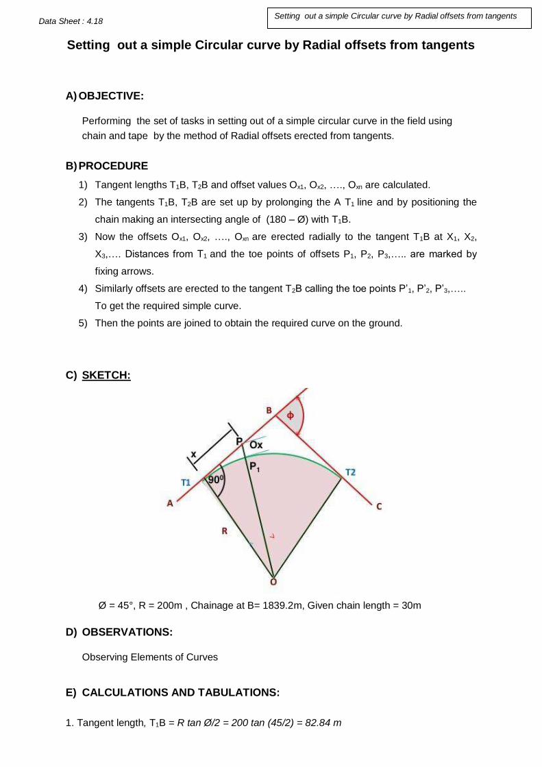
Setting out a simple Circular curve by Radial offsets from tangents
A) OBJECTIVE: Performing the set of tasks in setting out of a simple circular curve in the field using
chain and tape by the method of Radial offsets erected from tangents.
B) PROCEDURE
1) Tangent lengths T1B, T2B and offset values Ox1, Ox2, …., Oxn are calculated.
2) The tangents T1B, T2B are set up by prolonging the A T1 line and by positioning the
chain making an intersecting angle of (180 – Ø) with T1B.
3) Now the offsets Ox1, Ox2, …., Oxn are erected radially to the tangent T1B at X1, X2,
X3,…. Distances from T1 and the toe points of offsets P1, P2, P3,….. are marked by
fixing arrows.
4) Similarly offsets are erected to the tangent T2B calling the toe points P’1, P’2, P’3,…..
To get the required simple curve.
5) Then the points are joined to obtain the required curve on the ground.
C) SKETCH:
Ø = 45°, R = 200m , Chainage at B= 1839.2m, Given chain length = 30m
D) OBSERVATIONS: Observing Elements of Curves
E) CALCULATIONS AND TABULATIONS:
1. Tangent length, T1B = R tan Ø/2 = 200 tan (45/2) = 82.84 m
Data Sheet : 4.18
Setting out a simple Circular curve by Radial offsets from tangents

2. Chainage at T1 = Chainage at B – Tangent Length =1839.2 – 82.84 =1756.36m.
3. Length of the curve, CL = ΠR Ø
180=
Π x 200x 45°
180 = 157.08 m
4. Chainage of T2 = Chainage of T1 + Curve Length = 1756.36 + 157.08 = 1913.44m.
7. Calculation of Radial Offsets, Ox = √R2 + x2 − R
Chainage of T1 = 1756.36 m
For 30 m chain, it is at = 58 chains + 16.36 m.
x1 = 30 – 16.36 = 13.64
x2 = 43.64 m
x3 = 73.64 m
and the last is at x4 = tangent length = 82.84 m
Distance from the tangent point x in m
Ordinate Ox
Ox = √R2 + x2 − R
13.64 O13.64 0.46
43.64 O43.64 4.71
73.64 O73.64 13.13
82.84 O82.84 16.48
F) RESULT:
The calculated offsets are set on the ground and the required curve is observed.
G) INFERENCE:
_________________________________________________________________________
_________________________________________________________________________
_________________________________________________________________________
_________________________________________________________________________

Setting out a simple circular curve by perpendicular offsets from tangents
A) OBJECTIVE:
Performing the set of tasks in setting out simple circular curve by the method of
perpendicular offsets from tangents.
B) PROCEDURE
1) Tangent lengths T1B, T2B and offset values Ox1, Ox2, …., Oxn are calculated.
2) The tangents T1B, T2B are set up by prolonging the A T1 line and by positioning the
chain making an intersecting angle of (180 – Ø) with T1B.
3) Now the offsets Ox1, Ox2, …., Oxn are erected perpendicular to the tangent T1B at X1,
X2, X3,…. Distances from T1 and the toe points of offsets P1, P2, P3,….. are marked by
fixing arrows.
4) Similarly offsets are erected to the tangent T2B calling the toe points P’1, P’2, P’3,…..
To get the required simple curve.
5) Then the points are joined to obtain the required curve on the ground.
6) When the distance ‘x’ increase the offset becomes too large to set out accurately.
7) In such case ,the central point position of the curve may be set out from a third tangent drawn through apex of the curve.
1. SKETCH:
Ø = 45°, R = 200m , Chainage at B= 1839.2m, Given chain length = 30m
C) OBSERVATIONS: Observing Elements of Curves
Data Sheet : 4.19
Setting out a simple circular curve by perpendicular offsets from tangents

D) CALCULATIONS AND TABULATIONS:
1. Tangent length, T1B = R tan Ø/2 = 200 tan (45/2) = 82.84 m
2. Chainage at T1 = Chainage at B – Tangent Length =1839.2 – 82.84 =1756.36m.
3. Length of the curve, CL = ΠR Ø
180=
Π x 200x 45°
180 = 157.08 m
4. Chainage of T2 = Chainage of T1 + Curve Length = 1756.36 + 157.08 = 1913.44m.
7. Calculation of Radial Offsets, Ox = 𝑅 − √R2 − x2
Chainage of T1 = 1756.36 m
For 30 m chain, it is at = 58 chains + 16.36 m.
x1 = 30 – 16.36 = 13.64
x2 = 43.64 m
x3 = 73.64 m
and the last is at x4 = tangent length = 82.84 m
Distance from the tangent point x in m
Ordinate Ox
Ox = 𝑅 − √R2 − x2
13.64 O13.64 0.46
43.64 O43.64 4.82
73.64 O73.64 14.05
82.84 O82.84 17.96
2. RESULT:
The calculated offsets are set on the ground and the required curve is observed.
3. INFERENCE:
_________________________________________________________________________
_________________________________________________________________________
_________________________________________________________________________
_________________________________________________________________________

OFFSETS FROM EXTENDED CHORDS
A) OBJECTIVE:
Performing the set of tasks in setting out of a simple circular curve in the field using
chain and tape by the method of Extended chords.
B) PROCEDURE
1) On the line AT1, T1 is located and AT1 line is prolonged to a value of C1and a
perpendicular offset O1 is erected and denote the toe point of offset as E.
2) Now change the chain position into T1E direction and prolong it beyond E to a value of
C2 and erect the calculated perpendicular offset O2 at E2 by denoting it’s toe point as F
and make it by fixing an arrow. F is a point on the curve.
3) Now change the chain position into EF direction and prolong the line beyond F to a
value of C3 and at the point erect a perpendicular offset O3 and denote the toe point
as G. G is a point on the curve.
4) Like wise shift the chain to all other positions FG,GH, HI… and it’s corresponding O4,
O5, O6…. Erections are done and hence H,I,J points are obtained.
5) By joining all points E,F,G,H,I,J,….. the required curve is obtained by extended chords
method.
C) SKETCH:
Ø = 50°30', R = 300m , Chainage at B= 1192m, Given chain length = 20m
D) OBSERVATIONS: Observing Elements of Curves
E) CALCULATIONS AND TABULATIONS:
Data Sheet : 4.20
Setting of curve by offsets from Extended chords

1. Tangent length, T1B = R tan Ø/2 = 300 tan (50°30'/2) = 141.48 m
2. Chainage at T1 = Chainage at B – Tangent Length =1192 – 141.48 =1050.52.
3. Length of the curve, CL = ΠR Ø
180=
Π x 300x50°30′
180 = 264.42 m
4. Chainage of T2 = Chainage of T1 + Curve Length = 1050.52 + 264.42 = 1314.94m.
5. Initial sub-chord = C1 = 1060 – 1050.52 = 9.48 m
6. No. of full chords of length 20m = (1300-1060)/20 = 240/20 =12
7. Final sub-chord = 1314.94 – 1300 = 14.94 m
8. Total No of chords = 1+12+1 =14
9. First offset for initial sub-chord = O1 = C12/2R = (9.48)2 / (2 x 300) = 0.15m
10. Second offset for full chord = O2 = C2 (C1+ C2)/2R = [20(9.48+20)] / (2 x 300) = 0.98m
11. Similarly O3 to On-1 = C2 /R = (202)/300 =1.33m
12. Last offset for final sub-chord = Cn(Cn-1+ Cn)/2R = [14.94(20+14.94)]/ (2 x 300) = 0.87m
F) RESULT:
The calculated offsets are set on the ground and the required curve is observed.
G) INFERENCE:
_________________________________________________________________________
_________________________________________________________________________
_________________________________________________________________________
_________________________________________________________________________

SETTING OUT OF THE CURVE BY USING ONE THEODOLITE
A) OBJECTIVE: To perform the set of tasks in Setting out of the curve by using one
Theodolite (Rankine’s Deflection angle method).
B) PROCEDURE
1) Set up the tripod, and theodolite at the point of commencement of the curve. This
point can be arrived by knowing the length of tangent and point of intersection.
2) Let the chainage of the point of commencement finally occurs at M chains and N links.
3) Calculate the length of first sub chord to have a continuous chainage.
4) Calculate the deflection angles for the first sub chord, normal chord and last sub
chord.
5) Center the theodolite over the point of commencement and level it.
6) Make the vernier to zero degree, zero minutes and zero seconds using the upper
clamp and tangent screw and then clamp the upper clamp.
7) With the help of the lower clamp and lower tangent screw sight the point of
intersection of the curve I.
8) Unclamp the upper plate of theodolite and set the vernier to read the deflection angle
∆1 for the first sub chord – C1 . Now the line of sight is along the first sub chord.
9) With T1 as center and C1 as radius swing chain or tape and fix arrow in the line of
sight.
10) Set the vernier to read the deflection angle ∆2 for the first normal chord, to point the
telescope in the direction of the other and the first normal chord.
11) Keeping the one end of the chain at the point a previously fixed on the curve swing
the chain until other end of the chain falls in the line of sight of the telescope. Pull the
chain straight to fix the point b on the curve.
12) This procedure will be continued till the point of tangency is located.
LABORATORY SHEET: Ex.4.21 Setting out of curve by using using one Theodolite

C) SKETCH:
D) OBSERVATIONS AND TABULATIONS: Calculate the elements of the curve Tangent length= R tan Φ/2 Length of long chord= 2 R sin Φ/2 Arc length = πR Φ/360 Length of first sub chord = Length of normal chord = Length of last sub chord= Deflection angle for first sub chord δ1 = 1718.9 C1/R Deflection angle for normal chord δ2 = 1718.9 C/R Deflection angle for last sub chord δn = 1718.9 C2/R ∆1 = δ1
∆2 = δ1+ δ2 ∆3 = δ1+ δ2+ δ3 ∆n = δ1+ δ2+ δ3+………+ δn

Table of Deflection angles:
S.No Chainage in m
Length of chord
Deflection angle
Total deflection
angle
Theodolite readings
Remarks
1
2
3
4
5
6
E. Comments:

SETTING OUT OF THE CURVE BY USING TWO THEODOLITES
A) OBJECTIVE: To perform the set of tasks in Setting out of the curve by using Two
Theodolites.
B) INFORMATION REQUIRED & SKETCH:
This method is very useful in the absence of chain or tape and also when ground is not
favourable for accurate chaining. This is simple and accurate method but requires essentially
two instruments and two surveyors to operate upon them, so it is not as commonly used as
the method of deflection angles. In this method, the property of circle ‘that the angle between
the tangent and the chord equals the angle which that chord subtends in the opposite
segment’ is used.
Let D, E, F, etc. be the points on the curve. The angle (Δ1) between the tangent T1B and the
chord T1D i.e. ∠BT1 D = ∠T1T2D. Similarly, ∠BT1E = ∆2 = ∠T1T2 E, and ∠BT1F = ∆3 =
∠T1T2F etc. The total deflection angles ∆1, ∆2, ∆3, etc. are calculated from the given data
as in the previous method (i.e. as in Rankine’s method of deflection angles).
C) PROCEDURE:
1. Set up two theodolites, one at T1 and the other at T2.
2. Set Vernier of the horizontal circle of each of the theodolites to zero.
3. Turn the instrument at T1 to sight the intersection point B and that at T2 to sight T1.
4. Set the Vernier of each of the instruments to read the first deflection angle Δ1. Now
the line of sight of the instrument at T1 is along T1D and that of the instrument at
T2 is along T2D. Their point of intersection is the required point on the curve Direct
LABORATORY SHEET: Ex.4.3 Setting out of curve by using Two Theodolites

the assistant to move the ranging rod until it is sighted exactly by both the
theodolites, thus fixing the point D on the curve.
5. Then set the Vernier of each of the instrument to the second deflection angle Δ2,
proceed as before to obtained the second point (E) on the curve.
6. Repeat the process until the whole curve is set out.
D) OBSERVATIONS AND TABULATIONS:
Calculate the elements of the curve Tangent length= R tan Φ/2 Length of long chord= 2 R sin Φ/2 Arc length = πR Φ/360 Length of first sub chord = Length of normal chord = Length of last sub chord= Deflection angle for first sub chord δ1 = 1718.9 C1/R Deflection angle for normal chord δ2 = 1718.9 C/R Deflection angle for last sub chord δn = 1718.9 C2/R ∆1 = δ1, ∆2 = δ1+ δ2, ∆3 = δ1+ δ2+ δ3, ∆n = δ1+ δ2+ δ3+………+ δn
Table of Deflection angles:
Point Chainage
(m)
Chord Length
(m)
Deflection angle for
chord (d)
Total Deflection
angle (D)
Theodolite Vernier Reading
Remarks
1
2
3
4
5
6
E) COMMENTS:

Plot the data observed in measuring the horizontal distance between two inaccessible points using Theodolite and obtained the inaccessible distance from the plot
LABORATORY SHEET 4.23
OBJECTIVE: Plot the Data Observed in Measuring the Horizontal
Disance between Two Inaccessible Points Using Theodolie and Obtained
he Inaccessible distance from the Plot
APPARATUS/RESOURSES FOR PLOTTING:
1. Drawing Sheet
2. Drawing Board
3. Mini Drafter
4. Protractor
5. T. Square
6. Set Squares
7. Compass
8. Divider
9. Clips
10. Pencil
11. Eraser
12. Scale
1. TASK ANALYSIS
A. KNOWLEDGE
Drawing sheet Sizes like A0, A1, A2, A3, A4 etc.,
Fixing the Mini Drafter
North Direction Marking with compass
Usages of Set squares
Selection of Scale According to measurements
B.SKILLS
Category of Skill Sub task
1. Handling of
apparatus
A. Fixing the Drawing Sheet B. Fixing the Drafter
C. Drawing the Title Box
2.Manipulation
Of apparatus
A. Assume Scale as Required
B. Draw angles According to given Measurements
C. Check the measurements , scales & Angles

Plot the data observed in measuring the horizontal distance between two inaccessible points using Theodolite and obtained the inaccessible distance from the plot
LABORATORY SHEET 4.23
3.Precise
Operation/Activity
A. Marking the North direction
B. Measurements are drawn with suitable scales
C. Check the Accuracy of angles
D. Completion of the work using measurements with
assumed Scales
E. Plot with Neatness
2. TEACHING POINTS:
S. No. Teaching points Suggestive
Duration (Min.)
1. Fix the Drawing Sheet to Drawing table
5
2.
Mark the North Direction on the Drawing sheet by using compass
3.
Draw the Dimensions accurately with given scales,
Measurements & angles
10
3. EXPLANATORY NOTES:
The procedure of measurement of horizontal distance between two inaccessible points by using
Theodolite is described in the experiment no 4.7. The faculty is requested to ascertain two
inaccessible points in the field, practice the procedure to the students and note all the actual required
length, angles etc in the field and calculate them the horizontal distance as per procedure.
Let P and Q be the in accessible points the distance from P to Q is to be determined.
Let at‘d’ = Distance between two instrument station.
From at (A) = The angles Ɵ1 and Ɵ2 can be measured.

Plot the data observed in measuring the horizontal distance between two inaccessible points using Theodolite and obtained the inaccessible distance from the plot
LABORATORY SHEET 4.23
From at (B) = The angle Ɵ3 and Ɵ4 can be measured.
With above information using the formulas in experiment no 4.7. The distance can be obtained. All
the measurements can be plotted to a suitable scale and confirm.
4. NEED AND SCOPE OF THE EXPERIMENT: The Experiment Procedure will be Helpful to
find the distance between two inaccessible points and plotting will help to draw the drawing according
to a suitable scale for any other Reference.
5. PLANNING AND ORGANIZATION
5. SCHEME OF EVALUATION: For Plotting operation
Action Activity
Check for
1. Drawing Sheet is fixed to Drawing Table tightly.
2. According to scale the Measurements are plotted on the
Drawing Sheet.
3. The angles will be Plotted Accurately in the Drawing sheet.
For design of
Instruction
Read the teaching points carefully.
Category of skill Sub Task Weight with
competency level
individually
Awarded
(50)
1. Handling of
apparatus
D. Fixing the Drawing Sheet
E. Fixing the Drafter
F. Drawing the Title Box
A 1.5
B 1.5
C 2
Total 5

Plot the data observed in measuring the horizontal distance between two inaccessible points using Theodolite and obtained the inaccessible distance from the plot
LABORATORY SHEET 4.23
6. ASSESSEMENT QUESTIONS :( Only Suggestive)
1. What is the Necessity of Scale in Plotting?
2. Explain the types of Scale?
3. Explain the types of Drawing sheet Sizes?
2.Manipulation
Of apparatus
D. Assume Scale as Required
E. Draw angles According to
given Measurements
F. Check the measurements ,
scales & Angles
A B C Tot
3 4 3 10
3.Precise
Operation/Activity
F. Marking the North direction
G. Measurements are drawn with
suitable scales
H. Check the Accuracy of angles
I. Completion of the work using
measurements with assumed
Scales
J. Plot with Neatness
A 5
B 5
C 5
D 10
E 5
Total 30
4. Values
A. Co-operation
B. Co-ordination C. Communication
D. Sharing
E. Leadership
5
Total 50

OBJECTIVE
To Perform the different tasks for Plot the closed traverse of theodolite, distribute the closing
error by Bowditch/transit rule calculate the area of traverse.
EQUIPMENT/APPARATUS/RESOURSES
1. A Drawing board,
2. A Tee Square,
3. Set squares,
4. A drawing instrument box,
5. Drawing-paper of good-quality of required size.
6. Pencils of grade 2H, 3H or 4H.
7. Sundries such as rubber, brushes, drawing-pins, weights, sandpaper, knife etc.
1. TASK ANALYSIS A. KNOWLEDGE
Knowledge of field work,
Assuming suitable scale,
Using of plotting instruments,
Fixing drawing board and drawing sheet,
Bowditch’s rule & Transit rule.
Error correction in traversing,
Area calculation of traverse
B. SKILLS
Category of Skill Sub task
1. Handling of
apparatus
Fixing the drawing board without tilt.
Proper Use of plotting instruments,
Fixing of Drawing sheet to drawing board.
Units of measurements on scale.
2.Manipulation of apparatus
Assuming suitable scale to plot on drawing sheet.
Plotting the closed traverse as per scale assumed.
Measuring with scales as plotted measurements are correct
3. Precise
operation /activity
Plotting procedure.
Identifying mistakes while plotting
Checking the errors using formulae.
Calculating area of traverse.
LABORATORY SHEET 4.24
Plot the closed traverse of theodolite, distribute the closing error by
Bowditch/transit rule calculate the area of traverse.

2. TEACHING POINTS
S. No. Teaching points Suggestive
Duration (Min.)
1.
Description about Theodolite
A. Importance of Plotting of closed traverse
1
B. Method of plotting closed traverse
1
C. Size of drawing sheet to be used for plotting. 1
2. Fixing of drawing sheet to drawing board. 1
3. Using of instruments for plotting 1
4. Errors involved in closed traverse. 1
5. Balancing a closed traverse by Bowditch’s rule and
Transit rule
3
6. Calculation of area of closed traverse. 3
7. Precautions
3
A. Procedural precautions
Care should be taken while fixing the drawing board and drawing sheet.
Any errors in scales and instruments should be observe.
Proper scale should be selected.
Proper care should be taken for selection of suitable position of the base line, because the entire accuracy of the frame-work depends upon it.
Check the accuracy of the plotted frame work.
Total 15
LABORATORY SHEET 4,24 Plot the closed traverse of theodolite, distribute the closing
error by Bowditch/transit rule calculate the area of traverse.

2. NEED AND SCOPE OF THE EXPERIMENT
Plotting means to represent on paper, to a suitable scale, the previously
surveyed objects in accordance with their shape and size. Plotting is
commenced after the field-work is over.
By Plotting the closed traverse on paper, we can eliminate errors occurred
during field work. Area of closed traverse can be calculated easily.
4. PLANNING AND ORGANIZATION
Action Activity
Check for
1. Drawing board and drawing sheet.
2. Field measurements before plotting commencing. 3. The accuracy of the plotted frame work according to
field measurements.
For design of
Instruction
Observe the field work and measurements before
plotting
LABORATORY SHEET 4,24 Plot the closed traverse of theodolite, distribute the closing
error by Bowditch/transit rule calculate the area of traverse.

5. SCHEME OF EVALUATION
Category of skill Sub Task Weight with
competency level
individually
Awarded
(50)
1. Handling of
apparatus
A. Fixing the drawing
board without tilt.
B. Proper use of plotting
instruments.
C. Fixing the base line at
suitable position with
scales.
D. Errors in instruments.
A 1
B 2
C 4
D 3
Total 10
2.Manipulation
Of apparatus
A. Assuming of suitable scale. B. Units of measurements on
scales. C. Method of plotting closed
traverse.
A 1
B 1
C 3
Total 10
3.Precise
Operation /
Activity
A. Plotting procedure
B. Identifying mistakes while
plotting.
C. Observation of field work.
D. Bowditch’s rule and transit
rule.
E. Calculation of area of
closed traverse.
F. The accuracy of the plotted
frame work according to
field measurements
A 3
B 3
C 5
D 4
E 5
F 5
Tot 25
4. Values
A. Co-operation
B. Co-ordination
C. Communication
D. Sharing
E. Leadership
A 1
B 1
C 1
D 1
E 1
Tot 5
Total 50
LABOATORY SHEET 4.24
4.4.254.254.124.13334.13
4,133135
Plot the closed traverse of theodolite, distribute the closing error
by Bowditch/transit rule calculate the area of traverse.

6. ASSESSMENT QUESTIONS (suggestive only)
(this is for Formative Assessment only)
1. What is plotting?
2. What is the necessity of plotting?
3. What sizes of drawing sheets available in market?
4. What instrument should be used for plotting of closed traverse.
5. What are the errors involved in closed traverse?
6. How to eliminate the errors?
7. What method used for plotting of closed traverse by theodolite.
8. What is Bowditch’s rule and its use in closed traverse?
9. What is Transit rule and its use in closed traverse?
10. How the area will be calculated in closed traverse.
7. VIVA QUESTIONS (suggestive only)
(this is for Summative Assessment) The teacher may add questions depending upon the Context of examination
1. What is traversing? 2. Define Surveying. 3. What is the necessity of plotting the traversing? 4. State the instruments used for plotting closed traverse. 5. What are the uses of theodolite? 6. What are the errors involved in traversing. 7. What is Latitude and departure in traversing. 8. What is the least count of main scale and Vernier scale in horizontal plate
9. What is the meant by face left and face right observation
10. What is principle of surveying?
LABORATORY SHEET 4.24
3.14 3.14
Plot the closed traverse of theodolite, distribute the closing
error by Bowditch/transit rule calculate the area of traverse.

Plot the Simple Curve after setting out the Curve in the Field by
Ordinates from long chord method
OBJECTIVE
Performing the set of tasks to Plot the Simple curve after setting out the curve in the field by Ordinates from long chord method
EQUIPMENT/APPARATUS/RESOURSES
1. Chain – 1 No.
2. Tape – 1 No.
3. Ranging rods – 4 No
4. Arrows – 10 No.
5. Cross staff - 01 No
6. Lime
7. Rope or Thread
FIELD SKETCH:
1. TASK ANALYSIS
A. KNOWLEDGE
Unfolding chain and joining Tangent points (Long Chord)
Fixing ranging rods at Tangent points
Erecting mid ordinate on long chord using cross staff.
Joining Tangent points with mid ordinate using tape.
Laboratory sheet: 4.25
Plot the Simple curve after setting out the curve in the field

Erecting mid ordinate at mid-point of long chord using cross staff.
Erecting Ordinates on both sides of the mid ordinate on long chord.
B.SKILLS
Category of Skill Sub task
1. Handling of
apparatus
Unfolding the chain and making it into straight.
Fixing the Ranging rods at station.
Driving arrows / Pegs at required points.
Using Cross staff to mark Perpendicular Offsets.
Using tape to measure the horizontal distance.
2.Manipulation of apparatus
Stretching the chain in between Points T1 and T2 mark the long chord.
Bisect the long chord to obtain the point M.
Using cross staff mark the perpendicular offset ME. Using cross staff mark the ordinates at regular intervals
on both sides of mid ordinate on long chord.
Joining the all the points in between T1 E T2 to get the smooth Curve.
3. Precise
operation /activity
Calculating the Length of long chord, using the formula,
L = 2R sin Ø /2
Calculating the mid ordinate of the long chord, using the
formula, Oo = R – √R2 − (L
2)2
Calculating the ordinates at regular intervals on both sides
of mid ordinate, using the formula,
Ox =√𝑅2 − 𝑥2 − ( 𝑅 − 𝑂𝑥)
4. Safety of the
Equipment
Unfolding the chain on level and smooth ground toavoid detaching of links and tallies.
Holding the ranging rod at certain height above the ground so as to avoid touching its tip to ground while carrying.
Driving ranging rods firmly into the ground so as to avoid falling on to the ground frequently and loosing its verticality
Avoiding driving of cross staff, ranging rods, arrows on stones/rocks.

2. TEACHING POINTS
S. No. Teaching points Suggestive
Duration (Min.)
1.
Description about
A. Deflection Angle B. Tangent Points C. Long Chord D. Mid ordinates
5
2. Using of Chain &Tape in the field
3. Using of Ranging rods and Arrows in the field
4. Calculating the length of long chord
10
5. Calculating the mid ordinate of long chord
6. Calculating the ordinates on long chord on both sides
of mid ordinate.
7. Fixing the Pegs / Arrows at ordinates on both sides of
mid ordinate.
8. Joining the all marked ordinates to get required curve

8.
Procedural precautions
Care should be taken while measuring horizontal distance
Care should be taken while folding and unfolding the chain.
Care should be taken while erecting ranging rods vertically
Care should be taken while bisecting the chords
Care should be taken while placing the Arrows.
Care should be taken while erecting perpendiculars with cross staff
Care should be taken while joining the all ordinates obtained to get smooth curve
Total 15
3. NEED AND SCOPE OF THE EXPERIMENT
The curves required in the horizontal plane are known as Horizontal Curves. Whenever the
direction of a road or railway line is to be changed, curves are provided between the
intersecting straights. This is necessary for smooth and safe movement of the vehicles and
for the comfort of passengers.
4. PLANNING AND ORGANIZATION
Action Activity
Check for
1. All Links and Tallies in the chain.
2. Actual length of Chain and Tape
3. Opened links in chain and Tape. 4. Marked readings on Tape. 5. Straightness of ranging rods. 6. Fixing the pegs at ordinates
5. SCHEME OF EVALUATION
Category of skill Sub Task Weight with
competency level
individually
Awarded
(50)

6. ASSESSMENT QUESTIONS (Only suggestive)
1. Give the formula for calculatingthe length of Long Chord.
2. Give the formula for calculating the mid ordinate.
1. Handling of
apparatus
A. Unfolding the chain B. Fixing the Ranging rods at
stations C. Driving arrows / pegs at
required points. D. Using Cross staff to mark
perpendicular offsets
E. Folding the Chain
A 2
B 2
C 2
D 2
E 2
Total 10
2.Manipulation
Ofapparatus
A. Stretching the chain in between Points T1 and T2 mark the long chord Bisect the long chord to obtain the point M
B. Bisect the long chord to obtain the point E.
C. Using cross staff mark the perpendicular offset ME
D. Using cross staff,mark the ordinates at regular intervals on both sides of mid ordinate on long chord.
E. Joining the all ordinates to get the smooth Curve.
A 4
B 4
C 4
D 4
E 4
Total 20
3.Precise
Operation/Activity
A. Calculating the Length of
long chord using the
formula, L = 2R sin Ø /2
B. Calculating the mid
ordinate of the long chord,
using the formula DE =
R(1-cos (Ø/2) ) or Oo = R
– √R2 − (L
2)2
C. Calculating the ordinates at
regular intervals on both
sides of mid ordinate, using
the formula,
Ox =√𝑅2 − 𝑥2 − ( 𝑅 − 𝑂𝑥)
A 5
B 5
C 5
Tot 15
4. Values
A. Co-operation
B. Co-ordination
C. Communication
D. Sharing
E. Leadership
5
Total 50

3. Determine the Ordinates from long chord at various Intervals.
4. List the linear methods of setting out a simple curve.
5. Give the formula for calculating the ordinates by offsets from long chord method.
7. VIVA QUESTIONS
(Only suggestive) The teacher may add questions depending upon the Context of examination
1. What are the significance of curves?
2. What are the Various Methods of Setting out the curves?
3. What are the various elements of the Curves?
4. How to calculate the Chainage of T1 and T2?
5. What is the procedure for Setting of Curve by Offsets from long Chord method?
6. What is simple curve?
7. Is the simple curve radius uniform throughout?

WORKSHEET 4.1
Name of the student: Date of experiment:
PIN: Branch:
Institution: Experiment No:
• Title of the experiment: Temporary adjustments of a Theodolite
• Objective of the experiment:
• Apparatus/Tools required:
• PROCEDURE:
1)
2)
3)
4)
5)
6)
7)
8)
TEMPORARY ADJUSTMENTS OF THEODOLITE

• INFERENCE:
• DEFICIENCIES/MALFUNCTIONING OF ANY APPARATUS:
Check for
• functioning of foot screws.
• bubble tube sluggishness.
• check for permanent adjustments
• check whether the clamp screws are tightened or loosened
• legs and adjusting screws of tripod
For Instructions
Read the teaching points carefully.

Scheme of Evaluation
Category of skill Sub
Task Weight with
competency
level
individually
Awarded
(50)
1. Handling of
apparatus
• fixing the theodolite
to the tripod
• operating foot
screws appropriately
10
2.Manipulation
of
apparatus
• centering the instrument
exactly over station using plumbob
• rotating the telescope parallel /perpendicular to the bubble tube
• bringing bubble to the center of bubble tube using approproiate foot screws
15
3.Precise
Operation/Activity
• focusing the eyepiece
until crosshairs are
distinctly visible
• focusing the object
glass to bring image
clearly in the plane of
crosshairs
• elimination of parallax
and sighting the staff
20
4. Values
• Co-operation
• Co-ordination
• Communication
• Sharing
• Leadership
5
Total 50

WORK SHEET
1. Title of the experiment: MEASUREMENT OF HORIZONTAL ANGLE USING THEODOLITE
2. Objective of the experiment: _______________________________________________
______________________________________________
3. Apparatus/Tools required: _______________________________________________
_________________________________________________
4. PROCEDURE:
Name of the student: Date of experiment:
PIN: Branch:
Institution: Experiment No:
1)
2)
3)
4)
5)
6)
7)
8)
WORK SHEET 3.1a
WORK SHEET 3.1a

5. OBSERVATIONS:
Instrument
station object face Readings on verniers Mean angle Remarks
7.INFERENCE:_____________________________________________________________
_________________________________________________________________________
_
_________________________________________________________________________
_
_________________________________________________________________________
_
_________________________________________________________________________
_
8. DEFICIENCIES/MALFUNCTIONING OF ANY APPARATUS:
_______________________

_________________________________________________________________________
_
_________________________________________________________________________
_
9. SCHEME OF EVALUATION
Category of skill Sub Task Weight with
competency level
individually
Awarded
(50)
1. Handling of
apparatus
A. Fixing of theodolite to the
tripod stand.
B. Checking for centering of
instrument using plumb
bob.
Making temporary
adjustments of the
instrument.
A.
10
2.Manipulation
of
apparatus
A. Focusing the telescope to the points ‘A’ and ‘B’.
B. Bisecting the points ‘A’ and ‘B’.
C. Reading vernier scale and
WORK SHEET 3.1a

main scale of the theodolite.
15
3.Precise
Operation/Activity
A. Convert all measurements
into single unit
B. Finding the distanace
between two points ‘A’ and
‘B’.
C. Observing the readings on
vernier scale and main scale
of the thedolite.
D. Noting the readings in field
book.
A. Calculating the horizontal angle.
20
4. Values
A. Co-operation
B. Co-ordination
C. Communication
D. Sharing
E. Leadership
5
Total 50

WORK SHEET
Name of the student : Date of experiment:
PIN : Branch:
Institution:
Experiment No.
1. Title of the Experiment: Measure the horizontal angles by repetition method.
2. Objective of the Experiment: _________________________________________
3. Equipment Required: _________________________________________
_________________________________________
5. Procedure:

Face left swing right Face right swing left In
str
um
ent
at
Sig
hte
d to
A B Mean Horizental angle
A B Mean Horizental angle
Average Horizental
angle
6. RESULT:
7. INFERENCE: 8. DEFICIENCIES/MALFUNCTIONING OF ANY APPARATUS:

9. SCHEME OF EVALUATION
CATEGORY OF
SKILL
SUB TASK
WEIGHTAGE WITH
COMPETENCY LEVEL
INDIVIDUALLY
Marks
Awarded
1. Handling of
apparatus
A. Lifting the Theodolite from the box
B. Fixing the instrument on tripod.
C. Removing the instrument from
tripod.
D. Placing the Theodolite in to the
box properly
10
2. Manipulation of
apparatus
A. Identifying the component parts of
the Theodolite.
B. Making temporary adjustments.
C. Rotating eye piece to view cross
hairs clearly.
D. Maintaining the verticality of the
ranging rods over the stations.
E. Noting the readings on main scale &
Vernier scale
20
3.Precise
operations/Activities
.
A. Centering the instrument over the
given station.
B. Levelling the bubble by adjusting the
foot screws.
C. Bisecting the ranging rods
accurately.
D. Calculating the angles from the
observations.
15
4.Values
A. Co Operation
B. Co-Ordination
C. Communication
D. Sharing
E. Leadership
5
Total
50
Signature of the Staff Signature of the Student

WORK SHEET
Name of the student : Date of experiment:
PIN : Branch:
Institution:
Experiment No.
1. Title of the Experiment: Measurement of horizontal angle by Reiteration method.
2. Objective of the Experiment: _________________________________________
3. Equipment Required: _________________________________________
_________________________________________
5. Procedure:

Face left swing right Face right swing left In
str
um
ent
at
Sig
hte
d to
A B Mean Horizontal angle
A B Mean Horizontal angle
Average Horizontal
angle
O P
Q
R
S
T
6. RESULT:
7. INFERENCE: 8. DEFICIENCIES/MALFUNCTIONING OF ANY APPARATUS:

9. SCHEME OF EVALUATION
CATEGORY OF
SKILL
SUB TASK
WEIGHTAGE WITH
COMPETENCY LEVEL
INDIVIDUALLY
Marks
Awarded
1. Handling of
apparatus
A. Lifting the Theodolite from the box
B. Fixing the instrument on tripod.
C. Removing the instrument from
tripod.
D. Placing the Theodolite in to the
box properly
10
2. Manipulation of
apparatus
A. Identifying the component parts of
the Theodolite.
B. Making temporary adjustments.
C. Rotating eye piece to view cross
hairs clearly.
D. Maintaining the verticality of the
ranging rods over the stations.
E. Noting the readings on main scale &
Vernier scale
20
3.Precise
operations/Activities
.
A. Centering the instrument over the
given station.
B. Levelling the bubble by adjusting the
foot screws.
C. Bisecting the ranging rods
accurately.
D. Calculating the angles from the
observations.
15
4.Values
A. Co Operation
B. Co-Ordination
C. Communication
D. Sharing
E. Leadership
5
Total
50
Signature of the Lab Incharge Signature of the Student

WORK SHEET
1. Title of the experiment: MEASUREMENT OF VERTICAL ANGLES
2. Objective of the experiment: _____________________________________________
_____________________________________________
3. Apparatus/Tools required: _____________________________________________
_____________________________________________
4. Rough Sketch:
5. Survey Group Details:
6. Distribution of work among survey group if any
S.No. Name of the student Work allotted Time
from to
Name of the student: Date of experiment:
PIN: Branch:
Institution: Experiment No:
WORK SHEET: Ex.4.6
Measurement of Vertical angles using Theodolite
method

7. PROCEDURE:
1)
2)
3)
4)
5)
6)
7)
9)
10)
11)
12)
13)
14)
15)
16)
17)
18)
19)
20)

8. OBSERVATIONS:
Distance between Theodolite and Object D = mts
S. No.
Inst. Station
Sight to
Face of observation
Vernier C ° ' "
Vernier D ° ' "
Mean of C & D Angle
° ' "
Average Vertical Angle
° ' "
Remarks
1 P A Left
Angle of Elevation
(+α1)
2 P A Right Angle of
Elevation (+α1)
3 P B Left
Angle of Depression
(-α2)
4 P B Right Angle of
Depression (-α2)
SPECIMENS CALCULATIONS
Calculate the height h1 (instrument horizontal position to top of object) = D X tan α1 =________ m
Calculate the height h1 (instrument horizontal position to top of object) = D X tan α2 =________ m
Height of the object AB = h1+h2 = _________ + __________ = ____________ m
6.RESULT:_______________________________________________________________
7. COMMENTS / REMARKS: ( Not mandatory )
_________________________________________________________________________
_________________________________________________________________________
8. DEFICIENCIES/MALFUNCTIONING OF ANY APPARATUS:
_________________________________________________________________________
_________________________________________________________________________
_________________________________________________________________________

9. SCHEME OF EVALUATION
Category of skill Sub Task Weight with
competency level
individually
Awarded
(50)
1. Handling of
apparatus
A. Fixing the Theodolite to
the tripod
B. Unclamp the upper
clamps of the
Theodolite and observe
the movement of
theodolite in horizontal
direction and telescope
in vertical plane.
C. Carry out the temporary
adjustments of
Theodolite using foot
screws and altitude
bubble tube
D. Using the tape or chain
measure the horizontal
distance, ‘D’ between
the Theodolite and the
object whose height is
to be measured
E. Identifying the
situations of using
ranging rod and pegs
A 1
B 3
C 3
D 2
E 1
Total 10
2.Manipulation
Of apparatus
A. Bisecting the top accurately and measuring the angle of elevation in face left and right observations
B. Bisecting the bottom accurately and measuring the angle of depression in face left and right observations
C. Reading values carefully
A B C Tot
5 5 5 15

3.Precise
Operation/Activity
A. Convert all measurements
into single unit viz, distance
and angles
B. Measuring the distance
between theodolite and
object
C. Calculating the average
angle of elevation.
D. Calculating the average
angle of depression.
E. Calculating the Height of
the object
A 2
B 5
C 5
D 3
E 5
Tot 20
4. Values
A. Co-operation
B. Co-ordination
C. Communication
D. Sharing
E. Leadership
5
Total 50
SIGNATURE OF THE STUDENT SIGNATURE OF THE FACULTY WITH DATE

WORK SHEET
1. Title of the experiment: To perform prolonging of a given survey line by double
transiting method
2. Objective of the experiment: __ To perform prolonging of a given survey line
______________________________________________
3. Apparatus/Tools required: _ Theodolite, Tripod, Plumb bob, Ranging rods, Arrows,
4. PROCEDURE:
.
Name of the student: Date of experiment:
PIN: Branch:
Institution: Experiment No:
1) Fix the ranging rod at station A on survey line AB
2) Fix the tripod at station B and approximately level by adjusting the legs, then legs
fixed firmly into the ground.
3) Lift theodolite carefully from the box and fix it on tripod stand
4) Temporary adjustments were carried out.
5. With the face of instrument left, focus ranging road at station A and tight both the upper and
lower clamp screws.
6. Transit the telescope and set a point C1 ahead in line AB.
7) Now change the face of the instrument right by loosening the lower clamp, then revolve the
telescope in the horizontal plane and focus (back sight) on A, Bisect A exactly by using the
lower clamp & its tangent screw.
WORK SHEET 3.
Prolong a given survey line by double transiting method
method

5. OBSERVATIONS:
8. DEFICIENCIES/MALFUNCTIONING OF ANY APPARATUS:
8) Transit the telescope and establish a point C2 in line beside the point C1.
9)The exact position of the true point C must be midway between C1 and C2.
10) Measure C1, C2 and establish a point C exactly mid-way, which lies on the true
prolongation of AB.
11) Shift the instrument to C, double-sight on B, establish the points D1 and D2 and establish
the true point D as before.
12) Continue the process until the last point Z is established
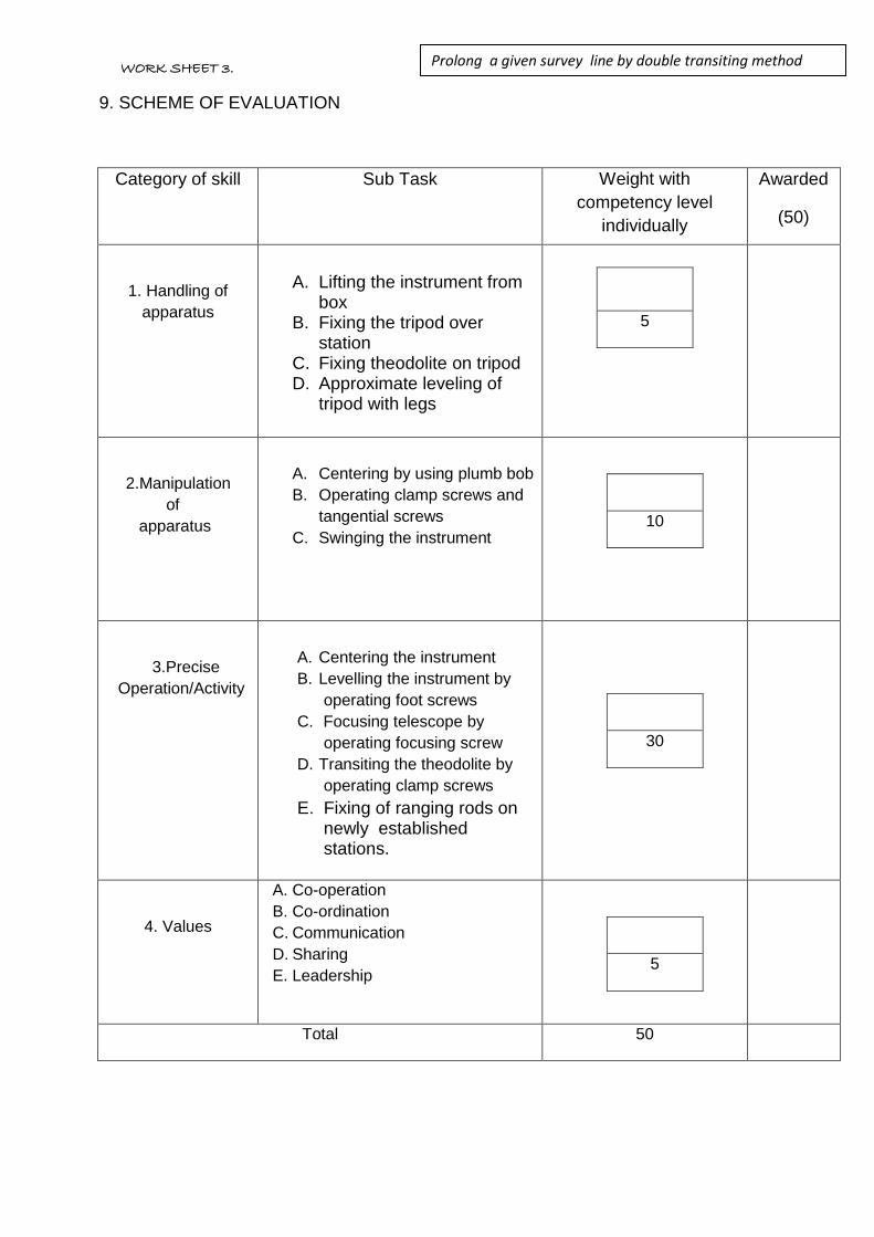
9. SCHEME OF EVALUATION
Category of skill Sub Task Weight with
competency level
individually
Awarded
(50)
1. Handling of
apparatus
A. Lifting the instrument from box
B. Fixing the tripod over station
C. Fixing theodolite on tripod D. Approximate leveling of
tripod with legs
5
2.Manipulation
of
apparatus
A. Centering by using plumb bob
B. Operating clamp screws and
tangential screws
C. Swinging the instrument
10
3.Precise
Operation/Activity
A. Centering the instrument
B. Levelling the instrument by
operating foot screws
C. Focusing telescope by
operating focusing screw
D. Transiting the theodolite by
operating clamp screws
E. Fixing of ranging rods on newly established stations.
30
4. Values
A. Co-operation
B. Co-ordination
C. Communication
D. Sharing
E. Leadership
5
Total 50
Prolong a given survey line by double transiting method
method
WORK SHEET 3.

WORK SHEET
1. Title of the experiment: To Perform Theodolite surveying to determine the horizontal
distance between two inaccessible points.
2. Objective of the experiment: To perform Theodolite surveying to determine the
horizontal distance between two inaccessible points.
3. Apparatus/Tools required: _ Theodolite, Tripod, Plumb bob, Ranging rods,
Arrows,
4. PROCEDURE:
.
D P Q
.
Ɵ1 Ɵ4
Ɵ2 Ɵ3
A B
Name of the student: Date of experiment:
PIN: Branch:
Institution: Experiment No:
1. Set up the theodolite at A by making the temporary adjustments level it accurately with
respect to the altitude bubble.
2. Sight the point P by keeping the horizontal circle reading at zero.
3. Loosen the upper clamp and rotate the telescope to sight Q and get the horizontal angle PAQ
(Ɵ1).
WORK SHEET 3.
Determination of horizontal distance between two inaccessible
points by using theodolite
method

5. OBSERVATIONS:
D P Q
.
Ɵ1 Ɵ4
Ɵ2 Ɵ3
A B
8. DEFICIENCIES/MALFUNCTIONING OF ANY APPARATUS:
4. Sight the point Q by keeping the horizontal circle reading at zero.
5.Loosen the upper clamp and rotate the telescope to sight B and get the horizontal angle QAB
(Ɵ2).
6.Shift the instrument to station B and do the temporary adjustments.
7.Sight the point A by keeping the horizontal circle reading at zero.
8. Loosen the upper clamp and rotate the telescope to sight P and get the horizontal angle ABP
(Ɵ3).
9.Sight the point P by keeping the horizontal circle reading at zero.
10. Loosen the upper clamp and rotate the telescope to sight Q and get the horizontal angle PBQ
(Ɵ4).
11.Measure the horizontal distance between and A and B using tape accurately.
WORK SHEET 3.
Determination of horizontal distance between two inaccessible
points by using theodolite
method

9. SCHEME OF EVALUATION
Category of skill Sub Task Weight with
competency level
individually
Awarded
(50)
1. Handling of
apparatus
A. Using tape to measure the horizontal distance.
B. Using plumb bob to centering the theodolite.
C. Adjusting tripod legs to
required line of sight.
D. Rotating foot screws to
levelling the theodolite.
E. Eliminating parallax error by
focusing.
5
2.Manipulation
of
apparatus
A. Maintaining Centre of the bubble tube of the theodolite.
B. Releasing of clamps to rotate the telescope.
C. Setting horizontal plate angle to zero.
10
3.Precise
Operation/Activity
A. Convert all measurements into single unit
B. Noting down the horizontal angle accurately
C. Drawing plot in proto type. D. Applying sine and cosine
rules. E. Calculating the horizontal
distance.
30
4. Values
A. Co-operation
B. Co-ordination
C. Communication
D. Sharing
E. Leadership
5
Total 50
Determination of horizontal distance between two inaccessible
points by using theodolite
method
WORK SHEET 3.

WORK SHEET
1. Title of the experiment: Measurement Of Magnetic Bearing Of Survey
Line
2. Objective of the experiment: _______________________________________________
______________________________________________
3. Apparatus/Tools required: _______________________________________________
_________________________________________________
4. PROCEDURE:
Name of the student: Date of experiment:
PIN: Branch:
Institution: Experiment No:
1)
2)
3)
4)
5)
6)
7)
8)
WORK SHEET 4.8 Measure the bearing of survey line
method

5. OBSERVATIONS:
Length of survey line = m
Inst.at
Sighted to
Face Left Swing Right Face Right Swing Right Average
Bearin
g of AB
Remarks
A B Mean Bearing of AB
A B Mean Bearing of AB
6.RESULT:________________________________________________________________
________________________________________________________________________
7.INFERENCE:_____________________________________________________________
_________________________________________________________________________
_________________________________________________________________________
_________________________________________________________________________
8. DEFICIENCIES/MALFUNCTIONING OF ANY APPARATUS:
_________________________________________________________________________
_________________________________________________________________________
Measure the bearing of survey line
method
WORK SHEET 4.9

9. SCHEME OF EVALUATION
Category of skill Sub Task Weight with
competency level
individually
Awarded
(50)
1. Handling of
apparatus
A. Pick the theodolite from box
B. Fixing the theodolite on tripod
C. Releasing lockingnob of
trough compass
D. Erecting the pegs on survey
line
5
2.Manipulation
of
apparatus
A. Setting up of theodolite over the tripod
B. Approximate levelling by the tripod
C. Centering of instrument over a station
D. Levelling the theodolite E. Focussing the eye piece F. Focussing the the objective G. Fixing the trough compass to
the theodolite H. Loosen the lower clamp and
trough compass needle and swing the telescope until magnetic needle on N-S graduation on trough compass
30
3.Precise
Operation/Activity
A. Average Reading on vernier A
and Veriner B
B. Magnetic bearing should be
read on both the face (face left
and face right)
C. Compare and average both face left and face right observations
10
4. Values
A. Co-operation
B. Co-ordination
C. Communication
D. Sharing
E. Leadership
5
Total 50
WORK SHEET 4.9
Measure the bearing of survey line
method
WORK SHEET 4.9


WORK SHEET
1. Title of the experiment: To Perform the task of theodolite traversing
(closed), to Compute latitudes and departures, and the area of closed traverse.
2. Objective of the experiment:
_________________________________________________________________________
_________________________________________________________________________
3. Apparatus/Tools required:
_________________________________________________________________________
________________________________________________________________________
4. PROCEDURE:
Name of the student: Date of experiment:
PIN: Branch:
Institution: Experiment No:
1)
2)
3)
4)
5)
6)
7)
8)
9)
10)
11)
12)
13)
14)
WORK SHEET 4.9
Perform the task of theodolite traversing (closed), to
Compute latitudes and departures, and the area of closed
traverse.

5. OBSERVATIONS:
6.CALCULATIONS:
Latitude and Departure Calculations:
S.no Iine Whole circle bearing
Reduced bearing
Latitude Departure
1 AB
2 BC
3 CD
4 DE
S.no Inst at
Sighted to
Length of line (m)
Fore bearing (whole circle bearing)
1. A B
2. B C
3. C D
4. D E
5. E A
To Perform the task of theodolite traversing (closed), to
Compute latitudes and departures, and the area of closed
traverse.
Collimation error of Dumpy Level by conducting Reciprocal Levelling
method
WORK SHEET 4,10

5 EA
Total latitude and departure ΣL ΣD
Check for error closure: The algebraic sum of all latitudes should be equal to zero
The algebraic sum of all departures should be equal to zero
Traverse Balance By Bowditch method:
Correction to latitude or departure of any side
1
1 X `L (CL) latitude toCorrection
1
1 X `D (CD) departure toCorrection
AREA CALCULATION BY CO-ORDINATE METHOD:
Independent coordinates
WORK SHEET 4.10
To Perform the task of theodolite traversing (closed), to
Compute latitudes and departures, and the area of
closed traverse

Line Corected
Latitude
Corrected
Departure
Station North (y) East (x)
AB
BC
CD
DE
EA
Formula :
In terms of X and Y coordinates
.. )x-(xy )x-(xy)x-(x{y ½ Area
get westations, n’‘ have weif general,In •
243132421
)}x-(xy 1-n1n
6.RESULT:________________________________________________________________
________________________________________________________________________
WORK SHEET 4.10
To Perform the task of theodolite traversing (closed), to
Compute latitudes and departures, and the area of
closed traverse

7. INFERENCE:____________________________________________________________
_________________________________________________________________________
_________________________________________________________________________
_________________________________________________________________________
_________________________________________________________________________
8. DEFICIENCIES / MALFUNCTIONING OF ANY APPARATUS:
_________________________________________________________________________
9. SCHEME OF EVALUATION
To Perform the task of theodolite traversing (closed), to
Compute latitudes and departures, and the area of closed
traverse
WORK SHEET 4.9
0

Category of skill Sub Task Weight with
competency level
individually
Awarded
(50)
1. Handling of
apparatus
A. Fixing the Tripod on
ground.
B. Lifting the Theodolite
Level from Box / case.
C. Fixing the Theodolite to
Tripod and magnetic
compass to theodolite
D. Hold/fix the ranging rod
A 1
B 2
C 4
D 3
Total 10
2.Manipulation
Of apparatus
A. Observing the reading from vernier through Theodolite
B. Measuring the distance between given (two) points
C. Exact bisection of object
(ranging rod) using horizontal focusing screws
A 3
B 3
C 4
Total 10
3.Precise
Operation /
Activity
A. Focusing the Objective
Lens
B. Focusing the Eye-piece
C. Leveling the instrument
D. Measuring the linear
distances.
E. Observing the horizontal
plate main scale readings
and Vernier scale readings
F. Fitting magnetic compass ,
fixing ranging rods , pegs .
To form closed traverse
A 3
B 3
C 5
D 4
E 5
F 5
Total 25
4. Values
A. Co-operation
B. Co-ordination
C. Communication
D. Sharing
E. Leadership
A 1
B 1
C 1
D 1
E 1
Total 5
Total 50

WORK SHEET
1. Title of the experiment: Determination of horizontal and vertical distance of an object
whose base is accessible
2. Objective of the experiment: Measuring Horizontal and Vertical Distances of an object
whose base is accessible
3. APPARATUS/TOOLS REQUIRED:
1. Transit Theodolite
2. Tripod
3. Plumb bob
4. Tape
5. Leveling Staff
6. Pegs.
4. FIELD/ROUGH SHETCH
Let, FROM FIG 1.0
P = instrument station
Q = Point to be observed
A = Center of the instrument
α = Angle of elevation from A to Q
h’ = height of the instrument at P
Q1 =Projection of Q on horizontal plane
D = horizontal distance between P and Q1( Measured with Tape/Chain)
S = Reading on staff kept on B.M, with line of sight on horizontal
Name of the student: Date of experiment:
PIN: Branch:
Institution: Experiment No:
FIG 1.0

Horizontal Distance PQ1 = D= Measured with tape / chain
Vertical Distance QQ’ = h = D. tanα
RL of Q (m) = RL of P + h’ + h
5. TEAM MEMBERS:
6. WORK DISTRIBUTION, IF ANY:
S.NO NAME OF THE
STUDENT
WORK ALLOTED /
PERFORMED
TIME TAKEN TO
PERFORM

7. PROCEDURE:
8. FIELD BOOK:
1) Setting up the instrument over station ‘O’ in such a way that all the points should be visible from the
instrument station.
2) Carrying out the temporary adjustments, setting vernier zero reading and making line of sight
horizontal.
3) Taking the first staff reading on Benchmark and determining height of instrument.
4) Swinging the telescope towards the object.
5) Release the vertical clamp screw, sight the top of the object Q, and clamp the vertical
clamp screw.
6) Read vernier readings and enter in the tabular form.
7) The above procedure will be repeated with the face right observation.
8) The average of the two observations by transiting the telescope taken with different
faces will be vertical angle.
9) Measure the Horizontal distance between the instrument station and the object (PQ1 – FIG 1.0)
10) Determining the vertical height of an object and R.L top and bottom of an object using appropriate
equations

9. CALCULATIONS:

10. RESULT:_________________________________________________________
_______
________________________________________________________________________
11. INFERENCE:_____________________________________________________
_________________________________________________________________________
12. DEFICIENCIES/MALFUNCTIONING OF ANY APPARATUS:
________________________________________________________________
_________________________________________________________________________
_________________________________________________________________________
SIGNATURE OF THE STUDENT SIGNATURE OF THE FACULTY
DATE: DATE:

13. SCHEME OF EVALUATION
Category of skill Sub Task Weight with
competency level
individually
Awarded
(50)
1. Handling of
apparatus
A. Fixing the Theodolite over a tripod
B. Centering a theodolite over a station
C. Levelling the instrument accurately with the help of foot screws
D. D.Focussing the eye-piece E. Focussing the object
10
2.Manipulation
of
apparatus
A. Reading the Main scale and vernier scale
B. Operating Lower clamp screw and tangent screw and upper clamp and tangent screw
C. Transiting and Swinging the Telescope
15
3.Precise
Operation/Activity
A. Entering the face left and face right readings in tabular form
B. Calculating the average horizontal angle
C. Calculating average vertical angle
D. Calculating horizontal and vertical distance
E. Calculating RL
20
4. Values
A. Co-operation
B. Co-ordination
C. Communication
D. Sharing
E. Leadership
5
Total 50

WORK SHEET
1. TITLE OF THE EXPERIMENT:
Measurement of horizontal and vertical distance of an object
whose base is inaccessible when the two instrument stations
and the object are in the same vertical plane.
2. OBJECTIVE OF THE EXPERIMENT:
3. APPARATUS/TOOLS REQUIRED:
4. ROUGH SKETCH:
Name of the student: Date of experiment:
PIN: Branch:
Institution: Experiment No:
WORK SHEET: Ex.4.11
Determine the horizontal and vertical distance of an object
whose base is inaccessible when the two instrument
stations and the object are in the same vertical plane.
method

5. SURVEY GROUP DETAILS:
6. DISTRIBUTION OF WORK AMONG SURVEY GROUPIF ANY
S.No. Name of the
student Work allotted/ Performed
Time
from to
7. PROCEDURE:
1)
2)
3)
4)
5)
6)

8. OBSERVATIONS:
Horizontal Distance between two instrument stations b = m.
Staff reading on bench mark taken from A and B, S = ________ m.
Reduced level of the bench mark R.L = + ___________ m.
S. No.
Inst. Station
Sight to
Face of observation
Vernier C ° ' "
Vernier D ° ' "
Mean of C & D Angle
° ' "
Average Vertical Angle
° ' "
Remarks
1 A Q Left Angle of
Elevation (+α1)
7)
9)
10)
11)
12)
13)
14)
15)
16)
17)
18)
19)
20)

2 A Q Right Angle of
Elevation (+α1)
3 B Q Left
Angle of Elevation
(+α2)
4 B Q Right Angle of
Elevation (+α2)
9.SPECIMENS CALCULATIONS:
a) Instrument axes at the same level:
Calculate the horizontal distance between P and Q, D = b tan α2 / (tanα1 – tanα2)
D = _________m.
Calculate the height of the object, h = b sinα1 sinα2/ sin (α1-α2)
h = __________ m.
Calculate reduced level of Q = Reduced level of BM + S + h
= ____________m.
b) Instrument axes at the different level:
If S1 and S2 are the corresponding staff readings on staff kept at Bench mark, the
difference in levels of the instrument axes will be S2 – S1.
Staff reading S1 =
Staff reading S2 =
s = S2 – S1
Calculate the horizontal distance between P and Q, D = (b + s cot α2) tan α2 / (tanα1 –
tanα2)
D = _________m.
Calculate the height of the object, h1 = (b + s cot α2) sinα1 sinα2 / sin (α1-α2)
h1 = __________ m.
(use + sign with s cot α2 when the instrument axis at A is lower and – sign when it is
higher than at B)
Calculate reduced level of Q = Reduced level of BM + S1 + h1

= ____________m.
10. RESULT:
11. COMMENTS / REMARKS :( Not mandatory)
12. DEFICIENCIES/MALFUNCTIONING OF ANY APPARATUS:

C
CATEGORY OF
SKILL SUB TASK
WEIGHT WITH
COMPETENCY LEVEL
INDIVIDUALLY
AWARDE
D
(50)
Handling of
apparatus
A. Identifying the convenient
point and pressing the
tripod legs into the ground
firmly.
B. Lifting the theodolite from
the instrument box
properly.
C. Fixing the theodolite over
the tripod head using
screws.
D. Removing the theodolite
from the tripod head using
screws.
E. Keeping the theodolite in
the instrument box in
correct position.
F. Carrying the ranging rods
properly.
G. Holding the levelling staff
vertically.
H. Holding the chain (or) tape
in correct position while
measuring the distances.
A 1
B & E 1
C & D 1
F & H 1
G 1
Total 5

Manipulation of
apparatus
Temporary adjustments:
A. Centering the theodolite
over the station mark using
plumb bob and by moving
tripod legs radially as well
as circumferentially.
B. Swinging the telescope
such that plate level is
parallel as well as
perpendicular to the line
joining the pair of levelling
screws.
C. Bringing the bubble to the
centre of its run by turning
the levelling screws
uniformly.
D. Setting the zero of the
vertical vernier exactly to
the zero of the vertical
circle by means of the
vertical clamp screw and
tangent screw.
E. Swinging the telescope
such that altitude level is
parallel to the line joining
the pair of levelling screws.
F. Bringing the bubble to the
centre of its run by turning
the levelling screws
uniformly.
G. Turning the telescope
through 900 by unclamping
the vernier plate.
H. Bringing the bubble to the
centre of its run by turning
the third levelling screw.
I. Making the cross hairs to
look distinct and clear by
A 1
B 1
C 1
D 1
E 1
F 1
G 1
H 1
I 1
J 1
K 1
L 1
M 2
N 1
Total 15

focusing eye piece.
J. Bringing the image of the
object in the plane of cross
hairs by focusing objective
piece.
Measurement of vertical angles:
K. Directing the telescope
towards the object by
loosening vertical clamp
screw.
L. Sighting the object
approximately and clamp
the vertical circle using
clamp screw.
M. Bisecting the object
accurately using tangent
screw.
N. Changing the face of the
instrument by transiting and
swinging the telescope
Precise
operation/
Activity
A. Taking the vernier readings
in both face left and face
right.
B. Calculating the average
vertical angle between two
instrument stations and top
of the object α1 and α2.
C. Measuring the horizontal
distance between two
instrument stations.
D. Observing and noting down
the readings of levelling
staff on bench mark.
E. Calculating the horizontal
distance between
instrument station and
object.
A 5
B 5
C 2
D 3
E 5
F 5
Total 25

14. CERTIFICATION:
SIGNATURE OF THE STUDENT SIGNATURE OF THE FACULTY
WITH DATE WITH DATE
F. Calculating the reduced
level of the object.
Values A. Co-operation
B. Co-ordination
C. Communication
D. Sharing
E. Leadership
A 1
B 1
C 1
D 1
E 1
Total 5
Total 50

WORK SHEET
1. Title of the experiment: To Perform the different tasks for determining the horizontal
and vertical distances of an object whose base is inaccessible when the instrument stations
and objects are not in same vertical
2. Objective of the experiment: _______________________________________________
______________________________________________
3. Apparatus/Tools required: _______________________________________________
_________________________________________________
4. PROCEDURE:
Name of the student: Date of experiment:
PIN: Branch:
Institution: Experiment No:
1)
2)
3)
4)
5)
6)
7)
8)
9)
10)
11)
12)
13)
14)
15)
WORK SHEET 4.12
To Perform the different tasks for determining the horizontal and
vertical distances of an object whose base is inaccessible when
the instrument stations and objects are not in same vertical
plane

5. OBSERVATIONS:
d = __________ m (distance between P and R)
S. No Instrum
ent at Sight to
Horizontal
angle
Vertical
angle Staff Readings
Remarks
1 P Q α1 S1 Reading on Bench
mark from instrument
at P
2 P R,Q θ1
Horizontal angle
RPQ
3 R Q α2 S2 Reading on Bench
mark from instrument
at R
4 R θ2
Horizontal angle
PRQ
CALCULATIONS
3 -------- ) sin(
sin b RQ
2 -------- ) sin(
sin b PQ
21
13
21
23
To Perform the different tasks for determining the horizontal and
vertical distances of an object whose base is inaccessible when
the instrument stations and objects are not in same vertical plane
Collimation error of Dumpy Level by conducting Reciprocal Levelling
method
WORK SHEET 4,12

. h s B.M of R.L Q of R.LThen
2) 1(sin
2 tan 1sin b tan RQ h
22
232
6.RESULT:________________________________________________________________
________________________________________________________________________
7. INFERENCE:____________________________________________________________
_________________________________________________________________________
_________________________________________________________________________
_________________________________________________________________________
_________________________________________________________________________
8. DEFICIENCIES / MALFUNCTIONING OF ANY APPARATUS:
_________________________________________________________________________
WORK SHEET 4.12
To Perform the different tasks for determining the horizontal
and vertical distances of an object whose base is
inaccessible when the instrument stations and objects are
not in same vertical plane

9. SCHEME OF EVALUATION
Category of skill Sub Task Weight with
competency level
individually
Awarded
(50)
1. Handling of
apparatus
A. Fixing the Tripod on
ground.
B. Lifting the Theodolite
Level from Box / case.
C. Fixing the Theodolitel to
Tripod
D. Holding the Level Staff
A 1
B 2
C 4
D 3
Total 10
2.Manipulation
Of apparatus
A. Observing the reading from level staff through Theodolite
B. Measuring the distance between given (two) points
C. Exact bisection of object using horizontal and vertical focusing screws
A 1
B 1
C 3
Total 10
3.Precise
Operation /
Activity
A. Focusing the Objective
Lens
B. Focusing the Eye-piece
C. Leveling the instrument
D. Calculating the horizontal
and vertical distances.
E. Observing the horizontal
plate main scale readings
and Vernier scale readings
F. 0bserving the vertical circle
readings Vernier C and
Vernier D
A 3
B 3
C 5
D 4
E 5
F 5
Tot 25
4. Values
A. Co-operation
B. Co-ordination
C. Communication
D. Sharing
E. Leadership
A 1
B 1
C 1
D 1
E 1
Tot 5
Total 50
To Perform the different tasks for determining the horizontal
and vertical distances of an object whose base is
inaccessible when the instrument stations and objects are not
in same vertical plan
WORK SHEET 4.12

WORK SHEET
WORK SHEET
Name of the student Date of Experiment
Pin Branch
Institution Experiment Number
1. Title of experiment : Determine the Tacheometric constants K & C
2. Objective of the experiment :
______________________________________________________________________
______________________________________________________________________
3. Apparatus/Equipment required:
______________________________________________________________________
______________________________________________________________________
4. Field Rough sketch
5. Team Members
6. Distribution of work
SlNo Name of student Work allotted
7. Procedure .

1
2
3
4
5
6
7
8
9
10
11
8. Observation / Tabulation of Readings
SlNo Distance D (M)
Stadia Hair Reading (M) Staff intercept S (m)
Top Middle Bottom
1 20
2 40
3 60
9. SPECIMAN CALCUATIONS
S1= Top hair Reading 1 – Bottom hair reading 1 = -------- m
S2= Top hair Reading 2 – Bottom hair reading 2 = -------- m.
S3= Top hair Reading 3 – Bottom hair reading 3 = -------- m
D1= KS1+C------------- (1)
D2= KS2+C------------- (2)
D3= KS3+C------------- (3)
Solving equations above
Multiplying constant K=___________
Additive Constant C=___________

10. Result __________________________________________________________________________
___________________________________________________________________________________
11. Inference ________________________________________________________________________
___________________________________________________________________________________
12. Deficiencies / malfunctioning of any Apparatus
___________________________________________________________________________________
___________________________________________________________________________________
13. Scheme of Evaluation
SlNo Category of skill
Sub task Weight with competency level individually
AWARDED (50)
1
HANDING OF APPARATUS
A Collecting Equipments
required and carrying it to site
10
B Removing the theodolite from the box.
C Fixing the theodolite to the tripod.
D Measuring the land with tape or chain
E Unscrewing the theodolite
from the tripod after completion of experiment.
F Placing the theodolite in the box
MANIPULATION OF APPARATUS
A Centering the tripod over the station
15
2
B Levelling the theodolite
C Focussing the eYe piece
D Focussing the objective
E Bringing vertical angle to 0 ‘ 0’0” in the theodolite
F Reading the staff

3
PRECEIES OPERATION/
ACTIVITY
A Calculating the staff intercept
20
B Substituting the values of
distance and staff intercept in the tacheometer equation.
C Solving the equations in pears
D Calculating the3 value
of tacheometric constants
E Calculating the average values of K&C.
4 VALUES
A Co-operation
B Coordination
C Communication
D Sharing
E Leadership
5
TOTAL 50

WORK SHEET
Name of the student : Date of experiment:
PIN : Branch:
Institution:
Experiment No.
1. Title of the Experiment: Determination of horizontal distance and elevation by principle of
stadia tacheometry ( considering angle of elevation )
2. Objective of the Experiment: _________________________________________
3. Equipment Required: _________________________________________
_________________________________________
5. Procedure:

Face left Observation
( Angle of elevation )
Face right Observation
( Angle of elevation )
In
str
um
ent
at
Sig
hte
d to
C D Mean Vertical angle
C D Mean Vertical angle
Average Vertical angle
6. RESULT:
7. INFERENCE: 8. DEFICIENCIES/MALFUNCTIONING OF ANY APPARATUS:

9. SCHEME OF EVALUATION
CATEGORY OF
SKILL
SUB TASK
WEIGHTAGE WITH
COMPETENCY LEVEL
INDIVIDUALLY
Marks
Awarded
1. Handling of
apparatus
A. Lifting the Theodolite from the box
B. Fixing the instrument on tripod.
C. Removing the instrument from
tripod.
D. Placing the Theodolite in to the
box properly
10
2. Manipulation of
apparatus
A. Identifying the component parts of
the Theodolite.
B. Making temporary adjustments.
C. Rotating eye piece to view cross
hairs clearly.
D. Maintaining the verticality of the
ranging rods over the stations.
E. Noting the readings on main scale &
Vernier scale
20
3.Precise
operations/Activities
.
A. Centering the instrument over the
given station.
B. Levelling the bubble by adjusting the
foot screws.
C. Bisecting the object accurately.
D. Calculating the angles from the
observations.
15
4.Values
A. Co Operation
B. Co-Ordination
C. Communication
D. Sharing
E. Leadership
5
Total
50
Signature of the Staff Signature of the Student

WORK SHEET
1. Title of the experiment: Determination of Horizontal Distance and Elevation by principle
Of stadia Tacheometry (considering angle of depression
2. Objective of the experiment: Determination of Horizontal Distance and Elevation by
Principle of stadia Tacheometry (considering angle of depression)
3. Apparatus/Tools required: Theodolite, Tripod, Plumb bob and cross staff
B. PROCEDURE:
Fix the Theodolite on station O
Fix the tripod at station O and approximately level by adjusting the legs, then legs
fixed firmly into the ground.
Lift theodolite carefully from the box and fix it on tripod stand
Temporary adjustments were carried out.
With the face of instrument left, focus leveling staff at station P and tight both the
upper and lower clamp screws.
Name of the student: Date of experiment:
PIN: Branch:
Institution: Experiment No:
WORK SHEET 4.15
Determination of Horizontal Distance and Elevation by principle of
stadia Tacheometry (considering angle of depression)

Transit the telescope and focus towards the leveling staff.
Adjust the focusing screw and use transit screws if necessary for clear vision.
By observing C and D verniers note the vertical angle of depression.
Also note down the corresponding staff readings.
The horizontal distance
D = L cosӨ = (k s cosӨ + C) cosӨ
D = k s cos2Ө + C cosӨ . . . . . . (1)
V = L sin Ө
= (k s cosӨ + C) sinӨ
= k s cosӨ . sinӨ + C sinӨ
V = k s sin2Ө/2+ C sinӨ…….. (2)
Thus equations (1) and (2) are the distance and Vertical component formulae for inclined line of sight.
R.L of Station P= RL of Line of axis – V- h
C.RESULT
The horizontal distance and elevation of the given station are determined by using
Stadia tachometry.
4. SCHEME OF EVALUATION
WORK SHEET 4.15

Category of skill Sub Task Weight with
competency level
individually
Awarded
(50)
1. Handling of
apparatus
A. Lifting the instrument from box
B. Fixing the tripod over station
C. Fixing Theodolite on tripod D. Approximate leveling of
tripod with legs
5
2.Manipulation
of
apparatus
A. Centering by using plumb bob
B. Operating clamp screws and
tangential screws
C. Swinging the instrument
10
3.Precise
Operation/Activity
A. Centering the instrument
B. Leveling the instrument by
operating foot screws
C. Focusing telescope by
operating focusing screw
D. Transiting the Theodolite by
operating clamp screws
E. Fixing of ranging rods on newly established stations.
30
4. Values
A. Co-operation
B. Co-ordination
C. Communication
D. Sharing
E. Leadership
5
Total 50

WORK SHEET
1. Title of the experiment: CURVE SETTING (Offsets from Long chord method)
2. Objective of the experiment: ___________________________________________
3. Apparatus/Tools required:_____________________________________________
4. Rough Sketch:
5. Survey Group Details:
6. Distribution of work among survey group if any
S.No. Name of the
student Work allotted
Time
FROM TO
Name of the student: Date of experiment:
PIN: Branch:
Institution: Experiment No:
Work Sheet : 4.16 Setting of curve by offsets from long chord method
method

7. PROCEDURE:
1)
2)
3)
4)
5)
6)
7)
9)
10)
11)
12)
13)
14)
15)
16)
17)
18)
19)
20)

8. CALCULATIONS
1. Tangent length, TL = R tan Ø/2 = ________ m
2. Length of the curve, CL = ΠR Ø
180= ________ m
3. Length of the long chord (L) = 2R sin Ø /2 = ________ m
4. Mid-Ordinate Oo = R(1- cos Ø/2) = ________ m
5. Chainage of T1 = Chainage of POI – TL
6. Chainage of T2 = Chainage of T1 + CL
7. Calculation of Ordinates, Ox = √R2 − x2 − ( R − Ox)
x = Length of Interval
9.RESULT:_______________________________________________________________
10. COMMENTS / REMARKS:( Not mandatory )
_________________________________________________________________________
_________________________________________________________________________
11. DEFICIENCIES/MALFUNCTIONING OF ANY APPARATUS:
_________________________________________________________________________
_________________________________________________________________________
_________________________________________________________________________
12. SCHEME OF EVALUATION:

SIGNATURE OF THE STUDENT SIGNATURE OF THE FACULTY WITH DATE
Category of
skill Sub Task
Weight with
competency level
individually
Awarded
(50)
1. Handling of
apparatus
A. Unfolding the chain B. Fixing the Ranging rods at
stations C. Driving arrows / pegs at
required points. D. Using Cross staff to mark
perpendicular offsets
E. . Folding the Chain
A 2
B 2
C 2
D 2
E 2
Total 10
2.Manipulation
Ofapparatus
A. Stretching the chain in between Points T1 and T2 mark the long chord Bisect the long chord to obtain the point D
B. Bisect the long chord to obtain the point E.
C. Using cross staff mark the perpendicular offset DE
D. Using cross staff, mark the ordinates at regular intervals on both sides of mid ordinate on long chord.
E. Joining the points T1DT2 to get the smooth Curve.
A 3
B 3
C 3
D 3
E 3
Total 15
3.Precise
Operation/Activity
A. Calculating the Length of
long chord using the
formula, L = 2R sin Ø /2
B. Calculating the mid
ordinate of the long chord,
using the formula
DE = R(1-cos (Ø/2) ) or
Oo = R – √R2 − (L
2)2
C. Calculating the ordinates at
regular intervals on both
sides of mid ordinate, using
the formula,
Ox = √𝑅2 − 𝑥2 − ( 𝑅 − 𝑂𝑥)
A 5
B 5
C 10
Tot 20
4. Values
A. Co-operation
B. Co-ordination
C. Communication
D. Sharing
E. Leadership
5
Total 50

WORK SHEET
1. Title of the experiment: CURVE SETTING BY SUCCESSIVE BISECTION OF
ARCS
2. Objective of the experiment: _____________________________________________
_____________________________________________
3. Apparatus/Tools required:_____________________________________________
_____________________________________________
4. Rough Sketch:
5. Survey Group Details:
Name of the student: Date of experiment:
PIN: Branch:
Institution: Experiment No:
WORK SHEET: Ex.4.17
SETTING OF CURVE OF BY SUCCESSIVE BISECTION OF ARCS
aaAAAAAARCS

6. Distribution of work among survey group if any
S.No. Name of the student Work allotted Time
from to
7. PROCEDURE:
1)
2)
3)
4)
5)
6)
7)
9)
10)
11)
12)
13)
14)
15)
16)
17)
18)

8. CALCULATIONS
The Perpendicular CD length = R(1-cos (θ/2) )
The Perpendicular lengths C1D1 = C2D2 = R(1-cos (θ/4) )
The Perpendicular lengths C3D3 = C4D4 = R(1-cos (θ/8) )
9.RESULT:_______________________________________________________________
10. COMMENTS / REMARKS: ( Not mandatory )
_________________________________________________________________________
_________________________________________________________________________
11. DEFICIENCIES/MALFUNCTIONING OF ANY APPARATUS:
_________________________________________________________________________
_________________________________________________________________________
19)
20)

_________________________________________________________________________
12. SCHEME OF EVALUATION
Category of skill Sub Task Weight with
competency level
individually
Awarded(50)
1. Handling of
apparatus
A. Unfolding the chain .
B. Fixing th Ranging rods
at stations
C. Driving arrows / pegs at
required points
D. Using Cross staff to mark perpendicular
offset
E. Folding the Chain
A 2
B 2
C 2
D 2
E 2
Total 10
2.Manipulation
Of apparatus
A. Stretching the chain in between Points T1 and T2
mark the long chord.Bisect the long chord to obtain the point D.
B. Using cross staff, mark the perpendicular offset DC.
C. Using tape join T1 and T2
with C. D. Bisecting the sub chords
T1C and T2C E. Joining C, C1, C2,…….to
obtain smooth curve
A 3
B 3
C 3
D 3
E 3
Tot 15

3.Precise
Operation/Activity
A. Calculating the Length of
long chord
B. Calculating the mid
ordinate of the long chord,
using the formula DC =
R(1-cos (θ/2) ) ( or )
R-√𝑅2 − (𝐿2)2.
C. Calculating the mid
ordinate of sub chord,
using the formula
D1C1 = D2C2= R(1-cos (θ/4))
D. Calculating the mid
ordinate of sub chords,
using the formula
D3C3 =D4C4= R(1-cos (θ/8) )
A 5
B 5
C 5
D 5
Tot 20
4. Values
A. Co-operation
B. Co-ordination
C. Communication
D. Sharing
E. Leadership
5
Total 50
SIGNATURE OF THE STUDENT SIGNATURE OF THE FACULTY WITH DATE

WORK SHEET
1. Title of the experiment: CURVE SETTING (Radial offsets from tangents)
2. Objective of the experiment: ___________________________________________
3. Apparatus/Tools required:_____________________________________________
4. Rough Sketch:
5. Survey Group Details:
6. Distribution of work among survey group if any
S.No. Name of the
student Work allotted
Time
FROM TO
Name of the student: Date of experiment:
PIN: Branch:
Institution: Experiment No:
Work Sheet : 4.18 Setting out a simple Circular curve by Radial offsets from tangents

7. PROCEDURE:
1)
2)
3)
4)
5)
6)
7)
9)
10)
11)
12)
13)
14)
15)
16)
17)
18)
19)
20)

8. CALCULATIONS
1. Tangent length, TL = R tan Ø/2 = ________ m
2. Length of the curve, CL = ΠR Ø
180= ________ m
3. Chainage of T1 = Chainage of POI – TL
4. Chainage of T2 = Chainage of T1 + CL
5. Calculation of Radial Offsets, Ox = √R2 + x2 − R
x = Length of Interval
9.RESULT:_______________________________________________________________
10. COMMENTS / REMARKS:( Not mandatory )
_________________________________________________________________________
_________________________________________________________________________
11. DEFICIENCIES/MALFUNCTIONING OF ANY APPARATUS:
_________________________________________________________________________
_________________________________________________________________________
_________________________________________________________________________
12. SCHEME OF EVALUATION:

SIGNATURE OF THE STUDENT SIGNATURE OF THE FACULTY WITH DATE
Category of skill Sub Task Weight with
competency level
individually
Awarded
(50)
1. Handling of
apparatus
A. Unfolding the chain B. Fixing the Ranging rods at
stations C. Driving arrows / pegs at
required points. D. Using tape to mark the
radial offsets
E. . Folding the Chain
A 2
B 2
C 2
D 2
E 2
Total 10
2.Manipulation
Ofapparatus
A. Stretching the chain in between Points T1 and B mark the Tangent Length.
B. Offsets Ox1, Ox2, Ox3……..are erected radially to the tangent T1B with tape to get P1, P2, P3…… points on the curve.
C. Check the apex distance using tape to checkthe accuracy of work.
D. Joining the points P1, P2, P3,… to get the smooth curve.
A 2
B 9
C 2
D 2
Total 15
3.Precise
Operation/Activity
A. Calculating the Length of
tangent, T1B = R tan Ø/2
B. Calculating the radial
Offsets Ox1, Ox2, Ox3…….. ,
are calculated using the
formula, Ox = √R2 + x2 − R
C. Check should be made by
measuring the apex
distance, which should be
equal to R[sec Ø/2 - 1]
A 5
B 10
C 5
Tot 20
4. Values
A. Co-operation
B. Co-ordination
C. Communication
D. Sharing
E. Leadership
5
Total 50

WORK SHEET
1. Title of the experiment: CURVE SETTING(perpendicular offsets from tangents)
2. Objective of the experiment: _____________________________________________
_____________________________________________
3. Apparatus/Tools required:_____________________________________________
_____________________________________________
4. Rough Sketch:
5. Survey Group Details:
Name of the student: Date of experiment:
PIN: Branch:
Institution: Experiment No:
WORK SHEET: Ex.4.19
Setting out a simple circular curve by perpendicular offsets from tangents
ttttYGBTTTTAFROMTTTANTTTTTTTANGEN

6. Distribution of work among survey group if any
S.No. Name of the student Work allotted Time
from to
7. PROCEDURE:
1)
2)
3)
4)
5)
6)
7)
9)
10)
11)
12)
13)
14)
15)
16)
17)
18)

8. CALCULATIONS
1. Tangent length, TL = R tan Ø/2 = ________ m
2. Length of the curve, CL = ΠR Ø
180= ________ m
3. Chainage of T1 = Chainage of POI – TL
4. Chainage of T2 = Chainage of T1 + CL
5. Calculation of Ordinates, Ox = 𝑅 − √R2 − x2
x = Length of Interval
9.RESULT:_______________________________________________________________
10. COMMENTS / REMARKS: ( Not mandatory )
_________________________________________________________________________
_________________________________________________________________________
11. DEFICIENCIES/MALFUNCTIONING OF ANY APPARATUS:
_________________________________________________________________________
_________________________________________________________________________
_________________________________________________________________________
19)
20)

12. SCHEME OF EVALUATION
Category of skill Sub Task Weight with
competency level
individually
Awarded(50)
1. Handling of
apparatus
A. Unfolding the chain .
B. Fixing th Ranging rods at
stations
C. Driving arrows / pegs at
required points
D. Using Cross staff to mark perpendicular
offset
E. Folding the Chain
A 2
B 2
C 2
D 2
E 2
Total 10
2.Manipulation
Of apparatus
Stretching the chain in between Points T1 and B mark the tangent length.
Using compass or theodolite mark the deflection angle to obtain other tangent T2B.
Using cross staff mark the perpendicular offsets from tangents at regular intervals.
Using tape mark the calculated ordinates on perpendicular offsets.
Joining the toe points of the offsets , smooth Curve may be observed
A 3
B 3
C 3
D 3
E 3
Tot 15
3.Precise
Operation/Activity
Calculating the Length of
tangent , L = R tan Ø/2
Length of the curve, CL = ΠR Ø
180
Chainage of T2 = Chainage of
T1 + Curve Length
Calculating the perpendicular
offsets at regular intervals,
from tangents Oo = R –
√(R2 − x2)
A 5
B 5
C 3
D 07
Tot 20

4. Values
A. Co-operation
B. Co-ordination
C. Communication
D. Sharing
E. Leadership
5
Total 50
SIGNATURE OF THE STUDENT SIGNATURE OF THE FACULTY WITH DATE

WORK SHEET
1. Title of the experiment: CURVE SETTING (Offsets from chord Produced method)
2. Objective of the experiment: ___________________________________________
3. Apparatus/Tools required:_____________________________________________
4. Rough Sketch:
5. Survey Group Details:
Name of the student: Date of experiment:
PIN: Branch:
Institution: Experiment No:
Work Sheet : 4.20 Setting of curve by offsets from chords produced method

6. Distribution of work among survey group if any
S.No. Name of the
student Work allotted
Time
FROM TO
7. PROCEDURE:
1)
2)
3)
4)
5)
6)
7)
9)
10)
11)
12)
13)
14)
15)
16)
17)
18)

8. CALCULATIONS
1. Tangent length, TL = R tan Ø/2 = ________ m
2. Length of the curve, CL = ΠR Ø
180= ________ m
3. Chainage of T1 = Chainage of POI – TL
4. Chainage of T2 = Chainage of T1 + CL
5. Initial sub-chord = C1 = -------------- m
6. No. of full chords of length 30m =
7. Chainage covered = ----------------- m
8. Final sub-chord = ------------- m
9. First offset for initial sub-chord = O1 = C12/2R = ------------ m
10. Second offset for full chord = O2 = C2 (C1+ C2)/2R = ---------- m
11. Similarly O3 to On-1 = C2 /R = ------------ m
12. Last offset for final sub-chord = Cn(Cn-1+ Cn)/2R = ------------ m
9.RESULT:_______________________________________________________________
10. COMMENTS / REMARKS:( Not mandatory )
_________________________________________________________________________
_________________________________________________________________________
11. DEFICIENCIES/MALFUNCTIONING OF ANY APPARATUS:
_________________________________________________________________________
19)
20)

12. SCHEME OF EVALUATION:
Category of skill Sub Task Weight with
competency level
individually
Awarded
(50)
1. Handling of
apparatus
A. Unfolding the chain B. Fixing the Ranging rods at
stations C. Driving arrows / pegs at
required points. D. Using tape to mark the
radial offsets
E. . Folding the Chain
A 2
B 2
C 2
D 2
E 2
Total 10
2.Manipulation
Ofapparatus
A. Stretching the chain in between Points T1 and A mark the tangent length.
B. Marking the calculated chord length C1 on tangent using tape.
C. Using cross staff mark the perpendicular offset at C1 to denote the toe point E.
D. Positioning of chain be changed into direction T1E and prolonged it to beyond E to a value of C2.
E. Joining the toe points of the offsets, smooth Curve may be observed.
A 3
B 3
C 2
D 3
E 3
F 3
G 3
Tot 20
3.Precise
Operation/Activity
A. Calculating the Length of
tangent, T1B = R tan Ø/2
B. Calculating the radial
Offsets Ox1, Ox2, Ox3…….. ,
are calculated using the
formula, Ox = √R2 + x2 − R
C. Check should be made by
measuring the apex
distance, which should be
equal to R[sec Ø/2 - 1]
A 3
B 3
C 2
D 3
E 3
F 3
G 3
Tot 20
4. Values
A. Co-operation
B. Co-ordination
C. Communication
D. Sharing
E. Leadership
5

SIGNATURE OF THE STUDENT SIGNATURE OF THE FACULTY WITH DATE
Total 50

WORK SHEET
1. Title of the experiment: Setting out of curve by using one theodolite
2. Objective of the experiment: _____________________________________________
_____________________________________________
3. Apparatus/Tools required:_____________________________________________
_____________________________________________
4. Rough Sketch:
5. Survey Group Details:
6. Distribution of work among survey groupif any
S.No. Name of the student Work allotted Time
from to
Name of the student: Date of experiment:
PIN: Branch:
Institution: Experiment No:
WORK SHEET: Ex.4.21
Setting out of curve by using one Theodolite
method

7. PROCEDURE:
1)
2)
3)
4)
5)
6)
7)
9)
10)
11)
12)
13)
14)
15)
16)
17)
18)
19)
20)

8. OBSERVATIONS AND TABULATIONS:
Calculate the elements of the curve Tangent length= R tan Φ/2 Length of long chord= 2 R sin Φ/2 Arc length = πR Φ/360 Length of first sub chord = Length of normal chord = Length of last sub chord= Deflection angle for first sub chord δ1 = 1718.9 C1/R Deflection angle for normal chord δ2 = 1718.9 C/R Deflection angle for last sub chord δn = 1718.9 C2/R ∆1 = δ1
∆2 = δ1+ δ2 ∆3 = δ1+ δ2+ δ3 ∆n = δ1+ δ2+ δ3+………+ δn Table of Deflection angles:
S.No Chainage in m
Length of chord
Deflection angle
Total deflection
angle
Theodolite readings
Remarks
1
2
3
4
5
6
9. COMMENTS / REMARKS:( Not mandatory )

10. SCHEME OF EVALUATION
Category of skill Sub Task Weight with competency
level
individually
Awarded
(50)
1. Handling of
apparatus
A. Fixing the Theodolite to
the tripod
B. Unclamp the upper
clamps of the
Theodolite and observe
the movement of
theodolite in horizontal
direction and telescope
in vertical plane.
C. Carry out the temporary
adjustments of
Theodolite using foot
screws and altitude
bubble tube
D. Using the tape or chain
measure the chord
length along the
deflection angle line
E. Identifying the
situations of using
ranging rod and pegs
A 1
B 3
C 3
D 2
E 1
Total 10
2.Manipulation
Of apparatus
A. Setting the horizontal circle should be zero by using the upper clamp and upper tangent screw
B. Setting the point of intersection by sighting the object and place the arrow
C. Setting the center point of the curve by using tape with arrow
D. Measuring the chord length by using chain or tape
E. bisecting the ranging rod along the deflection angles
A 2
B 3
C 2
D 3
E 5
Tot 15
3.Precise
Operation/Activity
A. setting the deflection angles in the theodolite by using upper clamp and upper tangent screw
B. bisecting the deflection angles through chain and tape and fix the arrow on point of curve
A 5
B 5
C 5
D 5
Tot 20

SIGNATURE OF THE STUDENT SIGNATURE OF THE FACULTY WITH DATE
C. placing the points on curve
reaching up to point of tangency
D. checking the deflection angle at the point of tangency
4. Values
A. Co-operation
B. Co-ordination
C. Communication
D. Sharing
E. Leadership
5
Total 50

WORK SHEET
Name of the student: Date of experiment:
PIN: Branch:
Institution: Experiment No:
1. Title of the experiment: Setting out of the Curve using two Theodolites.
2. Objective of the experiment:
________________________________________________________________________
________________________________________________________________________
3. Apparatus/Tools required: ________________________________________________________________________
________________________________________________________________________
4. Rough Sketch:
5. Survey Group Details:
6. Distribution of work among survey group if any
S.No. Name of the student Work allotted Time
from to
WORK SHEET: Ex.4.3
Setting out of curve by using Two Theodolites
method

7. PROCEDURE:
1)
2)
3)
4)
5)
6)
7)
9)
10)
11)
12)
13)
14)
15)
16)
17)
18)
19)

8. OBSERVATIONS AND TABULATIONS:
Calculate the elements of the curve
Tangent length= R tan Φ/2
Length of long chord= 2 R sin Φ/2
Arc length = πR Φ/360
Length of first sub chord =
Length of normal chord =
Length of last sub chord=
Deflection angle for first sub chord δ1 = 1718.9 C1/R
Deflection angle for normal chord δ2 = 1718.9 C/R
Deflection angle for last sub chord δn = 1718.9 C2/R
∆1 = δ1, ∆2 = δ1+ δ2, ∆3 = δ1+ δ2+ δ3, ∆n = δ1+ δ2+ δ3+………+ δn
Table of Deflection angles:
Point Chainage
(m)
Chord Length
(m)
Deflection angle for
chord (d)
Total Deflection
angle (D)
Theodolite Vernier Reading
Remarks
1
2
3
4
5
6
9. COMMENTS / REMARKS :( Not mandatory)

10. SCHEME OF EVALUATION:
Category of
skill
Sub task
Weight with
competency level
individually
Awarded
(50)
1. Handling of
Instrument
A. Setting up of the tripod stand on
the ground.
B. Taking the instrument from the
box and fixing it on the tripod
stand.
C. Adjusting the tripod stand legs
and fix firmly in to the ground by
pressing the legs.
D. Adjusting the legs of tripod to
place the instrument over the
station point approximately.
A B C D Tot
2 2 3 3 10
2. Manipulation
of Instrument
A. Setting up of the theodolites over
tangent points.
B. Performing all the temporary
adjustments accurately.
C. Sighting and bisecting the
ranging rods by turning the
telescope and by focussing.
A B C Tot
5 5 5 15
3. Precision
A. Calculating the values of
deflection angles from the given
data.
B. Setting the horizontal angle to
read Zero degrees using
horizontal circle clamp.
C. Fixing the exact required
deflection angle in the
instrument by the two people.
A B C Tot
10 5 5 20
4. Values
A. Co-operation
B. Co-ordination
C. Communication
D. Sharing
E. Leadership
5
TOTAL 50
Signature of the Student Signature of the Staff Member

WORK SHEET
1. Title of the experiment: Plot the data observed in measuring the horizontal distance
between two inaccessible points using Theodolite and
Obtain the inaccessible distance from the plot
2. Objective of the experiment: Plot the data observed in measuring the horizontal distance
between two inaccessible points using Theodolite and obtain
the inaccessible distance from the plot
3. Apparatus/Tools required: Theodolite, Tripod, Plumb bob and cross staff
B. PROCEDURE:
1. Set up the Theodolite at A by making the temporary adjustments level it accurately
with respect to the altitude bubble.
2. Sight the point P by keeping the horizontal circle reading at zero.
3. Loosen the upper clamp and rotate the telescope to sight Q and get the horizontal
angle PAQ (Ɵ1).
4. Sight the point Q by keeping the horizontal circle reading at zero.
Name of the student: Date of experiment:
PIN: Branch:
Institution: Experiment No:
WORK SHEET 4.23
Plot the data observed in measuring the horizontal distance between
two inaccessible points using Theodolite and obtain the inaccessible
distance from the plot

WORK SHEET 4.23
5. Loosen the upper clamp and rotate the telescope to sight B and get the horizontal
angle QAB (Ɵ2).
6. Shift the instrument to station B and do the temporary adjustments
7. Sight the point A by keeping the horizontal circle reading at zero.
8. Loosen the upper clamp and rotate the telescope to sight P and get the horizontal
angle ABP (Ɵ3).
9. Sight the point P by keeping the horizontal circle reading at zero.
10. Loosen the upper clamp and rotate the telescope to sight Q and get the horizontal
angle PBQ (Ɵ4).
11. Measure the horizontal distance between and A and B using tape accurately.
12. After Measuring the distance between Two Inaccessible points A and B. Plot the data
on a drawing sheet according to the given Scale.
Instrument At A :
Ref from Figure, h1= D1 tan α1
Where D1 is the horizontal distance between A and P
H2= D2 tan α2
Where D2 is the horizontal distance between A and Q
4. SCHEME OF EVALUATION:
Plot the data observed in measuring the horizontal distance between
two inaccessible points using Theodolite and obtain the inaccessible
distance from the plot
Category of skill Sub Task Weight with competency
level
individually
Awarded
(50)
1. Handling of
apparatus
A. Fixing the Drawing Sheet
B. Fixing the Drafter C. Drawing the Title Box
A 1.5
B 1.5
C 2
Total 5

C.RESULT: Plot the data observed in measuring the horizontal distance between two
inaccessible points using Theodolite and Obtain the inaccessible distance from the plot
2.Manipulation
Of apparatus
A. Assume Scale as Required
B. Draw angles According to
given Measurements
C. Check the measurements ,
scales & Angles
A B C Tot
3 4 3 10
3.Precise
Operation/Activity
A. Marking the North direction
B. Measurements are drawn with
suitable scales
C. Check the Accuracy of angles
D. Completion of the work using
measurements with assumed
Scales
E. Plot with Neatness
A 5
B 5
C 5
D 10
E 5
Total 30
4. Values
A. Co-operation
B. Co-ordination C. Communication
D. Sharing
E. Leadership
5
Total 50


WORK SHEET
1. Title of the experiment: To Perform the different tasks for Plot the closed
traverse of theodolite, distribute the closing error by
Bowditch/transit rule calculate the area of traverse.
2. Objective of the experiment: _______________________________________________
______________________________________________
3. Apparatus/Tools required: _______________________________________________
_________________________________________________
4. PROCEDURE:
Name of the student: Date of experiment:
PIN: Branch:
Institution: Experiment No:
1)
2)
3)
4)
5)
6)
7)
8)
9)
10)
11)
12)
13)
14)
15)
WORK SHEET 4.24
Plot the closed traverse of theodolite, distribute the closing error
by Bowditch/transit rule calculate the area of traverse.
plane

5. OBSERVATIONS:
Bowditch’s rule
Correction to latitude/departure of any side = Total error in latitude/departure x𝑙𝑒𝑛𝑔𝑡ℎ 𝑜𝑓 𝑡ℎ𝑎𝑡 𝑠𝑖𝑑𝑒
𝑝𝑒𝑟𝑖𝑚𝑒𝑡𝑒𝑟 𝑜𝑓 𝑡𝑟𝑎𝑣𝑒𝑟𝑠𝑒
Thus if CL = correction of latitude of any side
CD = correction of departure of any side
ΣL = Total error in latitude
ΣD = Total error in departure
Σl = length of the perimeter
l = length of any side.
We have CL = ΣL x𝑙
Σl
CD = ΣD x𝑙
Σl
Transit’s rule
Correction to latitude/departure of any side =
Total error in latitude/departure x𝑙𝑎𝑡𝑖𝑡𝑢𝑑𝑒/𝑑𝑒𝑝𝑎𝑟𝑡𝑢𝑟𝑒 𝑜𝑓 𝑡ℎ𝑒 𝑙𝑖𝑛𝑒
𝐴𝑟𝑖𝑡ℎ𝑒𝑚𝑒𝑡𝑖𝑐 𝑠𝑢𝑚 𝑜𝑓 𝑙𝑎𝑡𝑖𝑡𝑢𝑑𝑒𝑠/𝑑𝑒𝑝𝑎𝑟𝑡𝑢𝑟𝑒𝑠
If
L= Latitude of any line.
D= departure of any line
LT= Arithmetic sum of latitudes
DT= Arithmetic sum of departures
We have CL = ΣL x𝐿
LT
CD = ΣD x𝐷
DT
Plot the closed traverse of theodolite, distribute the closing error by
Bowditch/transit rule calculate the area of traverse.
WORK SHEET 4,24

Area of closed traverse by co-ordinate method
The sum of the products of coordinates joined by solid lines,
ΣP = (y1x2 + y2x3 +y3x4 +y4x5 +y5x1) The sum of products of coordinates joined by dotted lines,
ΣQ = (x1 y2 + x2 y3 +x3 y4 + x4y5 +x5y1) Double area = ΣP – ΣQ
Required area = = 1
2 (ΣP – ΣQ)
6.RESULT:________________________________________________________________
________________________________________________________________________
7. INFERENCE:____________________________________________________________
_________________________________________________________________________
_________________________________________________________________________
_________________________________________________________________________
_________________________________________________________________________
8. DEFICIENCIES / MALFUNCTIONING OF ANY APPARATUS:
_________________________________________________________________________
WORK SHEET 4.25
Plot the closed traverse of theodolite, distribute the closing
error by Bowditch/transit rule calculate the area of traverse.

9. SCHEME OF EVALUATION
Category of skill Sub Task Weight with
competency level
individually
Awarded
(50)
1. Handling of
apparatus
A. Fixing the drawing
board without tilt.
B. Proper use of plotting
instruments.
C. Fixing the base line at
suitable position with
scales.
Errors in instruments.
A 1
B 2
C 4
D 3
Total 10
2.Manipulation
Of apparatus
A. Assuming of suitable scale. B. Units of measurements on
scales. C. Method of plotting closed
traverse.
A 1
B 1
C 3
Total 10
3.Precise
Operation /
Activity
A. Plotting procedure
B. Identifying mistakes while
plotting.
C. Observation of field work.
D. Bowditch’s rule and transit
rule.
E. Calculation of area of
closed traverse.
F. The accuracy of the plotted
frame work according to
field measurements
A 3
B 3
C 5
D 4
E 5
F 5
Tot 25
4. Values
A. Co-operation
B. Co-ordination
C. Communication
D. Sharing
E. Leadership
A 1
B 1
C 1
D 1
E 1
Tot 5
Total 50
Plot the closed traverse of theodolite, distribute the closing
error by Bowditch/transit rule calculate the area of traverse.
WORK SHEET 4.24

WORK SHEET
1. Title of the experiment: Simple Curve Plotting in the Field
2. Objective of the experiment:___________________________________________
3. Apparatus/Tools required: _____________________________________________
4. Rough Sketch:
5. Survey Group Details:
6. Distribution of work among survey groupif any
S.No. Name of the
student Work allotted
Time
FROM TO
Name of the student: Date of experiment:
PIN: Branch:
Institution: Experiment No:
Work Sheet: 4.25 Plot the Simple curve after setting out the curve in the field
method

7. PROCEDURE:
1)
2)
3)
4)
5)
6)
7)
9)
10)
11)
12)
13)
14)
15)
16)
17)
18)
19)
20)

8. CALCULATIONS
1. Tangent length, TL = R tan Ø/2 = ________ m
2. Length of the curve,CL =ΠRØ
180= ________ m
3. Length of the long chord (L) = 2R sin Ø /2 = ________ m
4. Mid-Ordinate Oo = R(1- cos Ø/2) = ________ m
5. Chainage of T1 = Chainage of POI – TL
6. Chainage of T2 = Chainage of T1 + CL
7. Calculation of Ordinates, Ox = √R2 − x2 − ( R − Ox)
x = Length of Interval
9.RESULT:_______________________________________________________________
10.COMMENTS / REMARKS:( Not mandatory
)________________________________________________________________________
_
_________________________________________________________________________
11. DEFICIENCIES/MALFUNCTIONING OF ANY APPARATUS:
_________________________________________________________________________
_________________________________________________________________________
_________________________________________________________________________
12. SCHEME OF EVALUATION:

SIGNATURE OF THE STUDENT SIGNATURE OF THE FACULTY WITH DATE
Category of
skill Sub Task
Weight with
competency level
individually
Awarded
(50)
1. Handling of
apparatus
A. Unfolding the chain B. Fixing the Ranging rods at
stations C. Driving arrows / pegs at
required points. D. Using Cross staff to mark
perpendicular offsets
E. .Folding the Chain
A 2
B 2
C 2
D 2
E 2
Total 10
2.Manipulation
Of apparatus
A. Stretching the chain in between Points T1 and T2 mark the long chord Bisect the long chord to obtain the point M
B. Bisect the long chord to obtain the point E.
C. Using cross staff mark the perpendicular offset ME
D. Using cross staff, mark the ordinates at regular intervals on both sides of mid ordinate on long chord.
E. Joining the all ordinates to get the smooth Curve.
A 4
B 4
C 4
D 4
E 4
Total 20
3.Precise
Operation/Activity
A. Calculating the Length of
long chord using the
formula,L = 2R sin Ø /2
B. Calculating the mid
ordinate of the long chord,
using the formula DE =
R(1-cos (Ø/2) ) orOo = R –
√R2 − (L
2)2
C. Calculating the ordinates at
regular intervals on both
sides of mid ordinate, using
the formula,Ox=√𝑅2 − 𝑥2 −
( 𝑅 − 𝑂𝑥)
A 5
B 5
C 5
Tot 15
4. Values
A. Co-operation
B. Co-ordination
C. Communication
D. Sharing
E. Leadership
5
Total 50

Experiment methodology -4.1
PERFORMING TEMPORARY ADJUSTMENTS FOR A THEODOLITE
A. THEORY
The theodolite is one of the most precise survey instruments and is suitable for
measurement of angles (horizontal and vertical), prolonging a straight line,
measurements of bearings, traversing etc. Experiments involving theodolite
requires performing temporary adjustments at each and every setup of the
instrument
B. Objective: To perform series of tasks involved in Temporary adjustments of theodolite
C. PROCEDURE
There are three temporary adjustments of a theodolite. These are
1. Setting up the theodolite over a station.
2. Leveling up.
3. Elimination of parallax.
1.SETTING UP:
It includes two operations
1. Centering a theodolite over a station: Done by means of plumb bob.
2. Approximately leveling it by tripod legs only: Done by moving tripod legs radially
2.LEVELING UP:
Having centered and approximately leveled the instrument, accurate leveling is done
with the help of foot screws with reference to the plate levels, so that the vertical axis shall
be truly vertical.
TEMPORARY ADJUSTMENTS OF THEODOLITE

To level the instrument the following operations have to be done.
1. Turn the upper plate until the longitudinal axis of the plate level is roughly parallel to a
line joining any two of the leveling screws (A & B).
2. Hold these two leveling screws between the thumb and first finger of each hand uniformly
so that the thumb moves either towards each other or away from each other until the
bubble comes to the center.
3. Turn the upper plate through 90º i.e until the axes of the level passes over the position of
the third leveling screw ‘C’.
4. Turn this leveling screw until the bubble comes to the center.
5. Rotate the upper plate through 90º to its original position in the same quadrant of circle
and as shown in fig and repeat step(2) till the bubble comes to the center.
6. Turn back again through 90º and repeat step 4.
7. Repeat the steps 2 and 4 till the bubble is central in both the positions.
8. Now rotate the instrument through 180º. The bubble should be remaining in the center of
its run, provided it is in correct adjustment. The vertical axis will then be truly vertical.

3. ELIMINATION OF PARALLAX:
Parallax is a condition arising when the image formed by the objective is not in the plane of
the cross hairs. Unless parallax is eliminated, accurate sighting is not possible. Parallax can
be eliminated in two steps.
a. FOCUSSING THE EYE-PIECE: Point the telescope to the sky or hold a piece of white paper in front of the telescope.
Move the eyepiece in and out until a distant and sharp black image of the cross-hairs is
seen.
b. FOCUSSING THE OBJECT:
Telescope is now turned towards object to be sighted and the focusing screw is
turned until image appears clear and sharp.
D. PRECAUTIONS
• Care should be taken in direction of rotation of footscrews
• care should be taken not to rotate telescope with both clamp screws fixed
• Proper care should be taken centering will not get disturbed while levelling

MEASUREMENT OF HORIZONTAL ANGLE USING THEODOLITE
A. THEORY
In topography, the angle made by two ground lines is measured horizontally, and is
called a horizontal angle. These angles are used to determine the bearings and directions in
surveys and for setting out all types of structure
The theodolite is a precise instrument used for measuring both horizontal an dverticla
angles up to 20” or 10”.
.
B. PROCEDURE
1. i) Set up the theodolite at station point O and level it accurately.
ii) Set the vernier A to the zero or 3600 of the horizontal circle. Tighten the upper clamp.
iii) Loosen the lower clamp. Turn the instrument and direct the telescope towards A to bisect it accurately with the use of tangent screw. After bisecting accurately check the reading which must still read zero. Read the vernier B and record both the readings.
EXPERIMENTAL METHODOLOGY 4. 1a
MEASUREMENT OF HORIZONTAL ANGLE USING THEODOLITE

iv) Loosen the upper clamp and turn the telescope clockwise until line of sight bisects point B on the right hand side. Then tighten the upper clamp and bisect it accurately by turning its tangent screw.
v) Read both verniers. The reading of the vernier a which was initially set at zero gives the value of the angle AOB directly and that of the other vernier B by deducting 180 .The mean of the two vernier readings gives the value of the required angle AOB.
vi) Change the face of the instrument and repeat the whole process. The mean of the two vernier readings gives the second value of the angle AOB which should be approximately or exactly equal to the previous value.
vii) The mean of the two values of the angle AOB ,one with face left and the other with face right ,gives the required angle free from all instrumental errors. `

B. OBSERVATIONS AND TABULATIONS:
Instrument
station object face Readings on verniers Mean
angle Remarks


EXPERIMENTAL METHODOLOGY MEASURE HORIZENTAL ANGLES BY REPETITION METHOD
MEASUREMENT OF HORIZENTAL ANGLES BY REPETITION METHOD
A. THEORY
When the precision of measurement of a horizontal angle is desired to be more than
the least count of the instrument, repetition method is used. In this method the desired angle
is measured several times, and average of the observed values is considered as the values
of the angle. The precision thus attained is to much a finer degree than the least count of the
Vernier.
B. PROCEDURE
1. Set up the theodolite exactly over selected station point “Q”. And do the temporary
adjustments.
2.With the help of upper clamp screw and tangent screw, set 00, reading on Vernier “A”
and note the reading of Vernier “B”.
3. Release the lower clamp and sight the telescope towards point “P” exactly using lower
clamp and tangent screw.
4. Release the upper clamp and turn the telescope clockwise and bisect the object “R”.
Clamp the upper clamp screw and bisect “R” exactly using tangent screw.
5. Note the readings of Vernier A&B to get the approximate value of angle PQR.
6. Release the lower clamp and turn the telescope anti-clock wise to sight “P” again.
Clamp the lower clamp and tangent screw and bisect “P” exactly. In this condition Vernier
readings will not be changed.
7. Release the upper clamp and turn the telescope clock wise to sight “R”. Bisect “R”
exactly by using the upper clamp and tangent screw. In this condition Vernier readings will
be twice the angle PQR.
8. Repeat the process until the angle is repeated the required number of times. The average
angle is obtained by dividing the final reading by the number of repetitions.
9. Similarly repeat the procedure by changing left.
10. The average horizontal angle is determined by taking average of the two angles
obtained with face left and face right.

EXPERIMENTAL METHODOLOGY MEASURE HORIZENTAL ANGLES BY REPETITION METHOD
C. OBERVATIONS AND TABULATIONS
Face left swing right Face right swing left
Instr
um
ent at
Sig
hte
d t
o
A B Mean Horizental angle
A B Mean Horizental angle
Average Horizental
angle
D. SPECIMEN CALCULATIONS
E. RESULT
G.INFERENCES
H. PRECAUTIONS
1. Note down the readings carefully.

EXPERIMENTAL METHODOLOGY MEASURE HORIZONTAL ANGLES BY REITERATION METHOD
MEASUREMENT OF HORIZONTAL ANGLE BY REITERATION METHOD
A. THEORY
Reiteration is a method of measuring horizontal angles with high precision. It is less
tedious and is generally preferred when there are several angles to be measured at a
station. Several angles are measured successively and finally the horizon is closed. Closing
the horizon is the process of measuring the angles around a point to obtain a check on their
sum which should be equal to 3600.
B. PROCEDURE
1. Select a station point O.
2. Set the theodolite at O and do the temporary adjustments. The telescope is adjusted for right face right swing.
3. Set the Vernier A to zero using upper clamp. Loosen the lower clamp, direct the telescope to the station point P and bisect A exactly by using the lower clamp and lower tangent screw.
4. Note the Vernier readings (A and B).
5. Loosen the upper clamp and turn the telescope clockwise until the point Q is exactly bisected.
6. Note the Vernier readings (A and B).
7. The mean of the two Vernier readings gives the value of angle POQ.
8. Bisect all the points successively(R,S & T) and note the readings of both Vernier’s at each bisection.
9. Finally close the horizon by sighting the station point P. The A Vernier should be 3600. If not, note the closing error.
10. Adjust the telescope for left face left swing.
11. Repeat the whole process by turning the telescope in anticlockwise direction.
12. Distribute the closing error proportionately the several observed angles.
13. Take the average of face left and face right observations to give the corresponding horizontal angles.

EXPERIMENTAL METHODOLOGY MEASURE HORIZONTAL ANGLES BY REITERATION METHOD
C. OBERVATIONS AND TABULATIONS
Face left swing right Face right swing left
Instr
um
ent at
Sig
hte
d to
A B Mean Horizontal angle
A B Mean Horizontal angle
Average Horizontal
angle
O P
Q
R
S
T
D. SPECIMEN CALCULATIONS
E. RESULT
G.INFERENCES
H. PRECAUTIONS
1. Note down the readings carefully.

MEASUREMENT OF VERTICAL ANGLES – RECORDING THE OBSERVATIONS IN
FIELD BOOK
OBJECTIVE
To perform the set of tasks in determining the height of an object by measuring vertical
angles.
EQUIPMENT / RESOURSES
1. Theodolite – 1 No.,
2. Tripod – 1 No.,
3. Tape (or chain ) – 01 No.,
4. Plumb bob – 01 No.,
5. Ranging rods – 03 No., (if the object height is more)
6. Pegs – 04 No. (if the object height is more)
FIELD SKETCH:
1. TASK ANALYSIS
A. KNOWLEDGE
Approximate centering and levelling of tripod
Identification and functioning of parts of theodolite
Temporary adjustments of theodolite
Focusing and Elimination of parallax
To read the vernier readings
LABORATORY SHEET: Ex.4.6 Measurement of Vertical angles using Theodolite

B.SKILLS
Category of Skill Sub task
1. Handling of
apparatus
Identifying the convenient point and set up the tripod and
approximately center over the point and level it ( use
tripod bubble if available)
Fixing the Theodolite to the tripod
Unclamping the upper clamps of the Theodolite and
observe the movement of theodolite in horizontal direction
and telescope in vertical plane.
Carrying out the temporary adjustments of Theodolite
using foot screws and altitude bubble tube
Using the tape or chain measure the horizontal distance,
‘D’ between the Theodolite and the object whose height is
to be measured in meters. ( Use ranging rods and pegs if
the distance is more)
2.Manipulation of apparatus
Angle of Elevation (α1):
a) Setting the vertical verniers C and D exactly to zero by using the vertical circle clamp and tangent screw, while the altitude level remain in the center of its run and keeping the face of the theodolite to left.
b) Releasing the vertical circle clamp screw and rotate the telescope in vertical plane so as to bisect the top point A of the object. Tighten the vertical circle clamp and exactly bisect the object by slow motion screw.
c) Reading both verniers C and D in degrees, minutes and seconds. The mean of the two readings gives the value of
the required angle α1. These observations are called face
left observations d) Plunging the telescope so that the vertical scale is to the
right of the telescope while viewing the object. e) Similar observation may be taken which is called face
right observation
Angle of Depression (α2):
1) Repeating the steps from (a) to (e) as above and pointing the telescope to point B, the bottom of the object.
2) Reading and recording the face left observations of both C and D verniers
3) Reading and recording the face right observation of both C and D verniers
4) Calculating average of 2 and 4 gives α2.

3. Precise
operation /activity
Recording the Vernier reading of C and D for face
left and face right observations in one row for each
position of telescope viz., at top,and bottom at each
instrument station.
Calculating the average angle of elevation (α1) for
face left and face right observations
Calculating the average angle of depression (α2) for
face left and face right observations
Calculating the height h1 = D X tan α1
Calculating the height h2 = D X tan α2
Calculating the height of the object ‘AB’ using the
following equation = ( h1 + h2 ) meters
4. Safety of the
Equipment
Unclamping of clamp screws for properly placing the theodolite into safety box
Unfixing of theodolite to tripod
Placing the theodolite in safety box properly identifying the position
Clamping the clamp screws to avoid the movement of parts in safety box.
2. TEACHING POINTS
S. No. Teaching points Suggestive
Duration (Min.)
1.
Description about
A. Face left and face right observations B. Verniers readings of verniers C. Angle of elevation and depression
5
2.
Relationship between three sides of triangle and
definition of tanα
3. Least count of Theodolite and tape
4. Calculating angle of elevation with face left and face
right observations
10 5.
Calculating angle of depression with face left and face
right observations
6. Calculating the height of the object

7.
Procedural precautions
Care should be taken while measuring horizontal distance
Care should be taken in operating clamps and screws.
Bisection of the top and bottom points should be precise
Proper care should be taken in recording the reading the verniers
Total 15
3. NEED AND SCOPE OF THE EXPERIMENT
To measure the height of objects so as to identify their correct elevation and for
further continuation of work, location of position of electric cables, to assess the cost
of scaffolding, painting, plastering, height of structure is within bylaws etc.
4. PLANNING AND ORGANIZATION
Action Activity
Check for
1. Working condition of theodolite, tripod, tape or chain.
2. Actual length of chain or tape
3. marked reading on verniers, tape readings 4. Straightness of ranging rods and pegs
For design of
Instruction
Read the teaching points carefully.

5. SCHEME OF EVALUATION
Category of skill Sub Task Weight with competency
level
individually
Awarded
(50)
1. Handling of
apparatus
A. Fixing the Theodolite to
the tripod
B. Unclamp the upper
clamps of the
Theodolite and observe
the movement of
theodolite in horizontal
direction and telescope
in vertical plane.
C. Carry out the temporary
adjustments of
Theodolite using foot
screws and altitude
bubble tube
D. Using the tape or chain
measure the horizontal
distance, ‘D’ between
the Theodolite and the
object whose height is
to be measured
E. Identifying the
situations of using
ranging rod and pegs
A 1
B 3
C 3
D 2
E 1
Total 10
2.Manipulation
Of apparatus
A. Bisecting the top accurately and measuring the angle of elevation in face left and right observations
B. Bisecting the bottom accurately and measuring the angle of depression in face left and right observations
C. Reading values carefully
A B C Tot
5 5 5 15
3.Precise
Operation/Activity
A. Convert all measurements
into single unit viz, distance
and angles
B. Measuring the distance
between theodolite and
object
C. Calculating the average
angle of elevation.
D. Calculating the average
angle of depression.
E. Calculating the Height of
the object
A 2
B 5
C 5
D 3
E 5
Tot 20

6. ASSESSMENT QUESTIONS (Only suggestive)
1. Calculate the horizontal distance between Theodolite and the object.
2. Tabulate observations and calculate the average angle of elevation and average angle
of depression.
3. Determine height of the object.
7. VIVA QUESTIONS
(Only suggestive) The teacher may add questions depending upon the Context of examination
1. How to calculate the angle of elevation?
2. How to calculate the height of the object?
3. What is the difference between level and Theodolite?
4. What are verniers A, B, C, and D?
5. What is the difference between a compass and a theodolite?
6. What is telescope normal position?
7. What is face left and face right observations
8. What is the least count of theodolite?
9. What are clamp screws and when to use them?
10. When to use a tangent screw? What is the prerequisite of operating a tangent
screw?
4. Values
A. Co-operation
B. Co-ordination
C. Communication
D. Sharing
E. Leadership
5
Total 50

PROLONG A GIVEN SURVEY LINE BY DOUBLE TRANSITING METHOD
A. THEORY : A theodolite is an instrument used in surveying to measure horizontal
and vertical angles.it is also used for levelling, indirect measure of distances and
prolonging a line etc. The line of sight of theodolite can be rotated through 180o in
vertical plane about its horizontal axis. If a line is prolonged with high precision
double sighting method is adopted.
B. PROCEDURE:
Fix the ranging rod at station A on survey line AB
Fix the tripod at station B and approximately level by adjusting the legs, then legs
fixed firmly into the ground.
Lift theodolite carefully from the box and fix it on tripod stand
Temporary adjustments were carried out.
With the face of instrument left, focus ranging road at station A and tight both the
upper and lower clamp screws.
Transit the telescope and set a point C1 ahead in line AB.
Now change the face of the instrument right by loosening the lower clamp, then
revolve the telescope in the horizontal plane and focus (back sight) on A, Bisect A
exactly by using the lower clamp & its tangent screw.
Transit the telescope and establish a point C2 in line beside the point C1.
The exact position of the true point C must be midway between C1 and C2.
Experimental methodology 4. PROLONG A GIVEN SURVEY LINE BY DOUBLE TRANSITING METHOD

Measure C1, C2 and establish a point C exactly mid-way, which lies on the true
prolongation of AB.
Shift the instrument to C, double-sight on B, establish the points D1 and D2 and establish the true point D as before.
Continue the process until the last point Z is established.
C.RESULT
The survey line A,B is prolonged up to Z by double transmitting method.
Experimental methodology 1.f PROLONG A GIVEN SURVEY LINE BY DOUBLE TRANSITING METHOD

MEASUREMENT OF HORIZONTAL DISTANCE BETWEEN TWO
INACCESSIBLE POINTS BY USING THEODOLITE
A. THEORY A theodolite is an instrument used in surveying to measure horizontal and vertical
angles.it is also used for levelling, indirect measure of distances and prolonging a line
etc. The line of sight of theodolite can be rotated through 180o in vertical plane about
its horizontal axis.
B. PROCEDURE
Let P and Q be the two inaccessible points which the horizontal distance has to be measure. Select a base line AB on fairly level ground approximately equal to 1/3 rd length of PQ (to get well conditioned triangles).
1. Set up the theodolite at A by making the temporary adjustments level it accurately
with respect to the altitude bubble.
2. Sight the point P by keeping the horizontal circle reading at zero.
3. Loosen the upper clamp and rotate the telescope to sight Q and get the horizontal
angle PAQ (Ɵ1).
4. Sight the point Q by keeping the horizontal circle reading at zero.
5. Loosen the upper clamp and rotate the telescope to sight B and get the horizontal
angle QAB (Ɵ2).
6. Shift the instrument to station B and do the temporary adjustments.
7. Sight the point A by keeping the horizontal circle reading at zero.
8. Loosen the upper clamp and rotate the telescope to sight P and get the horizontal
angle ABP (Ɵ3).
9. Sight the point P by keeping the horizontal circle reading at zero.
10. Loosen the upper clamp and rotate the telescope to sight Q and get the horizontal
angle PBQ (Ɵ4).
11. Measure the horizontal distance between and A and B using tape accurately.
D P Q
.
Ɵ1 Ɵ4
Ɵ2 Ɵ3
A B
Fig 1.f1
Page no.1
Experimental methodology 1.f Measurement of horizontal distance between two inaccessible points by
using theodolite

page
B. OBSERVATIONS AND CALCULATIONS
Horizontal angle < PAQ = Ɵ1
Horizontal angle < QAB = Ɵ2
Horizontal angle < ABP = Ɵ3
Horizontal angle < PBQ =Ɵ4
Horizontal distance between A and B = d
From the Fig1.f1
From Δ ABP
<APB = 180° - (Ɵ1+ Ɵ2+ Ɵ3)
Applying the sine rule
AB PB PA = = =
Sin (180°-(Ɵ1+ Ɵ2+ Ɵ3)) Sin (Ɵ1+ Ɵ2) sinƟ3
d
PB = X Sin (Ɵ1+ Ɵ2 )
Sin (180°-(Ɵ1+ Ɵ2+ Ɵ3))
d
PA = X Sin Ɵ3
Sin (180°-(Ɵ1+ Ɵ2+ Ɵ3))
Again From Δ AQB
<AQB = 180° - (Ɵ2+ Ɵ3+ Ɵ4)
Applying the sine rule
AB QA QB = = =
Sin (180°-(Ɵ2+ Ɵ3+ Ɵ4)) Sin (Ɵ3+ Ɵ4) sinƟ2
Page no.2
Experimental methodology 1.f Determination of horizontal distance between two inaccessible points
by using theodolite

d
QA = X Sin (Ɵ3+ Ɵ4 )
Sin (180°-(Ɵ2+ Ɵ3+ Ɵ4))
d
QB = X Sin Ɵ2
Sin (180°-(Ɵ1+ Ɵ2+ Ɵ3))
Horizontal distance between P and Q :
(a) From ΔPAQ
By applying cosine rule
PQ² = PA² + QA² -2.PA.QA.COS Ɵ1
PA, QA, and Ɵ1 are known PQ can be calculated
(b) From ΔPQB
By applying cosine rule
PQ² = PB² + QB² -2.PB.QB.COS Ɵ4
PB, QB, and Ɵ4 are known PQ can be calculated
C.RESULT
Horizontal distance between two inaccessible points P and Q = D
Page no.3
Experimental methodology 1.f Determination of horizontal distance between two inaccessible points
by using theodolite

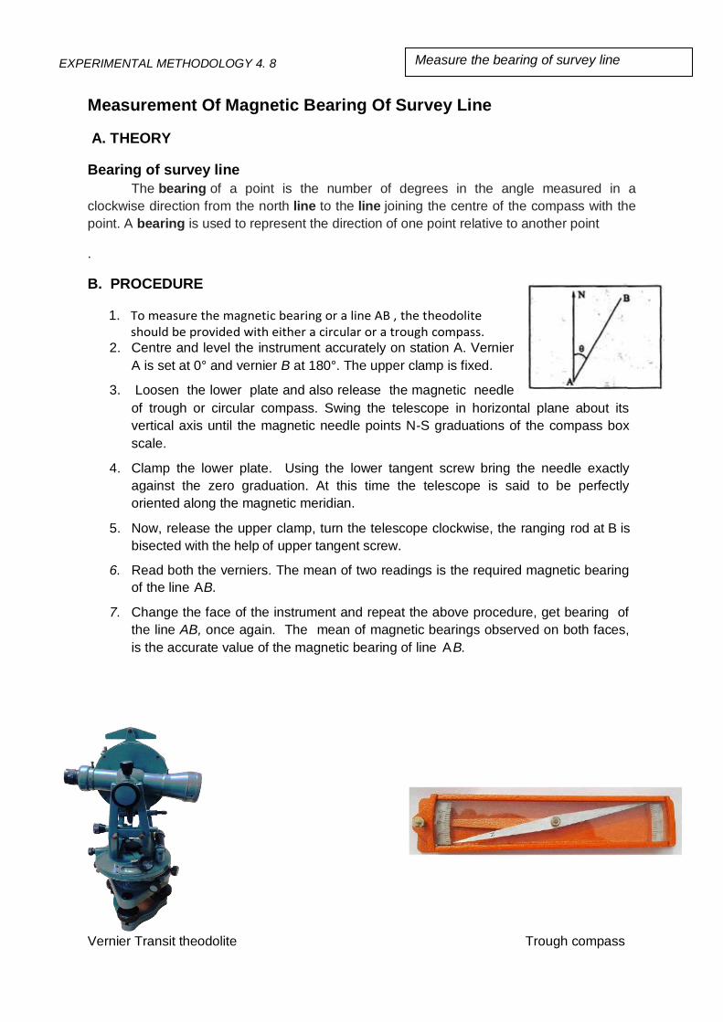
Measurement Of Magnetic Bearing Of Survey Line
A. THEORY
Bearing of survey line
The bearing of a point is the number of degrees in the angle measured in a
clockwise direction from the north line to the line joining the centre of the compass with the
point. A bearing is used to represent the direction of one point relative to another point
.
B. PROCEDURE
1. To measure the magnetic bearing or a line AB , the theodolite should be provided with either a circular or a trough compass.
2. Centre and level the instrument accurately on station A. Vernier
A is set at 0° and vernier B at 180°. The upper clamp is fixed.
3. Loosen the lower plate and also release the magnetic needle
of trough or circular compass. Swing the telescope in horizontal plane about its
vertical axis until the magnetic needle points N-S graduations of the compass box
scale.
4. Clamp the lower plate. Using the lower tangent screw bring the needle exactly
against the zero graduation. At this time the telescope is said to be perfectly
oriented along the magnetic meridian.
5. Now, release the upper clamp, turn the telescope clockwise, the ranging rod at B is
bisected with the help of upper tangent screw.
6. Read both the verniers. The mean of two readings is the required magnetic bearing
of the line AB.
7. Change the face of the instrument and repeat the above procedure, get bearing of
the line AB, once again. The mean of magnetic bearings observed on both faces,
is the accurate value of the magnetic bearing of line AB.
Vernier Transit theodolite Trough compass
EXPERIMENTAL METHODOLOGY 4. 8
Measure the bearing of survey line

B. OBSERVATIONS AND TABULATIONS
a) Length of the survey line= 12 m
C. RESULT
The Bering of survey line AB is 45034’10”
D.INFERENCE:
_______________________________________________________________
_______________________________________________________________
_______________________________________________________________
_______________________________________________________________
EXPERIMENTAL METHODOLOGY 4. 9
Measure the bearing of survey line

snAverage value of Cd =0.62
C.SPECIMEN CALCULATIONS
Inst.at
Sighted to
Face Left Swing Right Face Right Swing Right Average
Bearing
of AB
Remar
ks A 0 ‘ “
B ‘ “
Mean Bearing of AB
A 0 ‘ “
B ‘ “
Mean Bearing of AB
A N 0 0 0 0 0 0 0 0
0 0
B 45 34
20
34
20
45034’20”
45034’20”
45
34
00
34 00
45034’00”
45034’00”
45034’10”

Perform the task of theodolite traversing (closed), to Compute latitudes and departures,
and the area of closed traverse.
A. PRINCIPLE
In theodolite traversing, the directions are measured in the form of bearings, deflection angle, angle to the right, interior angles or azimuths using a theodolite and distance with a tape, electric distance measurement (EDM) equipment or by a tachometer. Bearings are measured by theodolite fitted with a compass by loose needle method or fast needle method.
If the angles measured by deflection angles method, angle to the right, traverse they are called deflection angle traverse.
It is specially used in an urban survey where triangulation is not possible.
The theodolite is an intricate instrument used mainly for accurate measurement of horizontal and vertical angles up to 10″ or 20″, depending upon the least count of the instrument.
B.THEORY
A traverse is a series of connected lines whose lengths and directions are to be
measured and process of surveying to find such measurements is called
traversing
A Traverse may be open or closed
Methods of traversing are chain,compass,theodolite,plane table
In theodolite traversing ,the linear measurements are done by using chain or
stadia method and angular measurements are done by theodolite
EXPERIMENTAL METHODOLOGY 4.10 Perform the task of theodolite traversing (closed), to
Compute latitudes and departures, and the area of
closed traverse.

This method is very accurate compared to other method
C.PROCEDURE:
• Set up the instrument at A and level it accuarately
• Set up vernier the zero of the horiztontal circle
• Release the magnetic needle and loosen the lower clamp
• Rotate the instrument till magnetic needle points to north now clamp
the lower clamp
• With the help of lower tangent screw bring the line of sight along
magnetic meridian
• Now loose the upper clamp and point towards B with the help of upper
tangent screw bisect B accurately read both verniers the mean of two
readings recorded as fore bearing of line AB
• Measure the linear distance between two points along traverse AB
with chain/tape
• Now shift instrument to B
• Repeat above steps in station B,C,D,E
D . OBSERVATIONS AND CALCULATIONS

Observations:
Calculations:
S.no Iine Whole circle bearing
Reduced bearing
Latitude Departure
1 AB
2 BC
3 CD
4 DE
5 EA
ΣL ΣD
Measurement of Latitude and Departure Latitude of a line = L cos θ
Departure of a line = L sin θ
Where :
L = Length of a line
θ = Reduced bearing of a line
Check for closure error:
The algebraic sum of all latitudes should be equal to zero
The algebraic sum of all departures should be equal to zero
S.no Inst at Sighted to Length of line (m) Fore bearing (whole circle bearing)
1. A B
2. B C
3. C D
4. D E
5. E A

lieserror closing e which th
inquadrant thedefine willL and D ofsign The
Balancing the traverse : (1) Bowditch’s Rule:
By this rule, the total error in latitude and that in departure is distributed in proportion to
the lengths of the sides.
Correction to latitude or departure of any side
1
1 X `L (CL) latitude toCorrection
1
1 X `D (CD) departure toCorrection
sideany of departure toCorrection CD
sideany of latitude toCorrection CL
: Where

Area of traverse by co-ordinates method:
Line
Corected
Latitude
Corrected
Departure
Station
Independent coordinates
North (y) East (x)
AB
BC
CD
DE
EA
∑L` = Total error in latitude
∑D` = Total error in departure
∑l = length of perimeter of the traverse
l = length of the side

This can be done by taking the coordinates of A as (+100,+100).
Formula :
In terms of X and Y coordinates
.. )x-(xy )x-(xy)x-(x{y ½ Area
get westations, n’‘ have weif general,In •
243132421
)}x-(xy 1-n1n E.GRAPH NIL F.RESULT
1. AREA OF CLOSED TRAVERSE ------------------------------------SQ.METERS
G.INFERENCE
___________________________________________________________________________
___________________________________________________________________________
___________________________________________________________________________
___________________________________________________________________________

DETERMINATION OF HORIZONTAL AND VERTICAL DISTANCE OF AN OBJECT WHOSE BASE IS ACCESSIBLE
(USING TRIGNOMETRIC LEVELLING)
A. THEORY
The Theodolite is an instrument which is generally used to determine the horizontal as well as
vertical distance.It can also be used to determine the elevation of various points which cannot be
determine by ordinary leveling. When one of the sight is horizontal and staff held vertical then the
RLs of staff station can be determined as we determine in ordinary leveling .But if the staff station
is below or above the line of collimation then the elevation or depression of such point can be
determined by calculating vertical distances from instrument axis to the central hair reading and
taking the angle of elevation or depression made by line of sight to the instrument made by line
of sight to the instrument axis.
B. PROCEDURE
1. Setting up the instrument at station P.
2. Performing all temporary adjustments.
3. Bring the line of collimation horizontal
4. Entering the initial readings in the tabular form.
5. Swing the telescope and take staff reading over the given B.M.
6. Swing the telescope towards the object.
7. Releasing the vertical clamp screw, sight the top of the object Q1, and clamp the
vertical clamp screw.
8. Reading C and D verniers and enter the readings.
9. Repeating the above procedure with the face right observation.
10. Calculating the average of the two observations will be vertical angle.
11. Measure the Horizontal distance between the instrument station and the object.
12. Determining the vertical height of an object and R.L top and bottom of an object using
appropriate equations and using formula h = d tanα
C. OBSERVATIONS AND TABULATIONS
Vertical Angle, = α =
Height of Instrument (m) = h1 =
Horizontal Distance, D (measured with tape /chain in m) =
From Triangle AQQ’: h = D tanα
R.L. of Q (m) = R.L of P + h’ + D tanα, if R.L of P is Known

D.RESULT
Horizontal Distance = D =
Vertical Distance = V =
R.L of point Q = ……………….. ….. m
E.INFERENCE
___________________________________________________________________________
___________________________________________________________________________
___________________________________________________________________________
___________________________________________________________________________
SIGNATURE OF THE STUDENT SIGNATURE OF THE FACULTY
DATE: DATE:

DETERMINATION OF HORIZONTAL AND VERTICAL DISTANCE OF
AN OBJECT WHOSE BASE IS INACCESSIBLE WHEN THE TWO
INSTRUMENT STATIONS AND THE OBJECT ARE IN THE SAME
VERTICAL PLANE.
A) OBJECTIVE:
To perform the set of tasks in order to determine the horizontal and vertical distance
of an object whose base is inaccessible when the two instrument stations and the object
are in the same vertical plane.
B) PROCEDURE:
a) Instrument axes at the same level
1. Set up theodolite over the station P.
2. Direct the telescope towards the top of the object Q.
3. Bisect Q accurately and clamp both the plates.
4. Read both verniers C and D and determine the vertical angle Q’AQ.
5. Determine again the vertical angle Q’AQ with face right.
6. Find the mean value α1 of the angle Q’AQ.
7. Transit the telescope and mark the station R on the ground in the line such that P,Q
and R are in the same vertical plane.
8. Measure the distance ’b’ between P and R accurately with tape.
9. Set the vertical vernier to zero.
10. With the altitude bubble central, take a back sight on the staff held on bench mark.
Let ‘S’ be the staff reading.
11. Shift the instrument station to R and set it such that the line of collimation is at the
same level of the line of collimation at the station P. In other words, staff reading on
bench mark should be ‘S’ when the altitude bubble is central.
12. Sight the point Q and measure the vertical angle Q’BQ.
13. Determine again the vertical angle Q’BQ with face right.
14. Find the mean value α1 of the angle Q’BQ.
C) SKETCH:
a) Instrument axes at the same level
LABORATORY SHEET: Ex.4.11 Determine the horizontal and vertical distance of an object
whose base is inaccessible when the two instrument stations
and the object are in the same vertical plane.

b) Instrument axes at the different level
D) OBSERVATIONS AND TABULATIONS:
Horizontal Distance between two instrument stations b = 10 m.
Staff reading on bench mark taken from A and B, S = 1.650 m.
Reduced level of the bench mark R.L = + 150.000 m.
S. No.
Inst. Station
Sight to
Face of observat
ion
Vernier C ° ' "
Vernier D ° ' "
Mean of C & D Angle
° ' "
Average Vertical Angle
° ' "
Remarks
1 P q Left 28°10' 20" 0°10' 00" 28°10' 10"
28°10' 20"
Angle of Elevation
(+α1)
2 P A Right 28°10' 20" 0°10' 40" 28°10' 30" Angle of
Elevation (+α1)
3 P B Left 18°10' 40" 0°10' 20" 18°10' 30"
18°10' 25"
Angle of Elevation
(+α2)
4 P B Right 18°10' 20" 0°10' 20" 18°10' 20" Angle of Elevation
(+α2)

E) SPECIMEN CALCULATION:
a) Instrument axes at the same level:
Calculate the horizontal distance between P and Q, D = b tan α2 / (tanα1 – tanα2)
D = 10 tan 18010’25” / (tan 28°10' 20" - tan18°10' 25”)
D = _15.836_m.
Calculate the height of the object, h = b sinα1 sinα2/ sin (α1-α2)
h = 10 sin28°10' 20" sin18°10' 25" / sin (28°10' 20" - 18°10' 25" )
h = 8.481 m.
Calculate reduced level of Q = Reduced level of BM + S + h
= 150.000 + 1.650 + 8.481
= 160.131 m.
b) Instrument axes at the different level:
Horizontal Distance between two instrument stations b = 10 m.
Reduced level of the bench mark R.L = + 150.000 m.
If S1 and S2 are the corresponding staff readings on staff kept at Bench mark, the
difference in levels of the instrument axes will be S2 – S1.
Staff reading S1 = 1.650 m
Staff reading S2 = 1.550 m
s = S2 – S1
= 1.650-1.550 = 0.10 m
Calculate the horizontal distance between P and Q,
D = (b + s cot α2) tan α2 / (tanα1 – tanα2) {assuming instrument axis at A is lower}
D = (10 + 0.10 x cot 18°10' 25" ) tan 18°10' 25" / (tan 28°10' 20" - tan18°10' 25”)
D = 16.318 m.

Calculate the height of the object, h1 = (b + s cot α2) sinα1 sinα2 / sin (α1-α2)
{assuming instrument axis at A is lower}
h1 = (10 + 0.10 x cot 18°10' 25" ) sin 28°10' 20" sin 18°10' 25" / sin (28°10' 20" - 18°10' 25" )
h1 = 8.740 m.
Calculate reduced level of Q = Reduced level of BM + S1 + h1
= 150.000 + 1.650 +8.740
= 160.39 m.
F) RESULT:
a) Instrument axes at the same level:
Horizontal distance between P and Q, D = _15.836_m.
Height of the object, h = 8.481 m.
Reduced level of Q = 160.131 m.
b) Instrument axes at the different level:
Horizontal distance between P and Q, D = _16.318_m.
Height of the object, h = 8.740 m.
Reduced level of Q = 160.390 m.
G) INFERENCE:

To Perform the different tasks for determining the horizontal and vertical distances of an
object whose base is inaccessible when the instrument stations and objects are not in
same vertical plane.
A. PRINCIPLE
A. Whenever the instrument stations are not possible to keep in same vertical plane as per
the field conditions, then two instrument stations are taken such that it forms a well
conditional triangle with the object i.e. third point
B. From three points (two instrument station and object station) we will get two well
conditioned triangles. By applying sine rule, the elevation of the object whose base is
inaccessible can be found out.
C. THEORY
Trigonometric levelling is defined as process of determining of difference of elevations and horizontal distances of both accessible and inaccessible points by observing vertical angles and measuring horizontal distances.
Normally the vertical angles are measured by using theodolite and the horizontal distances ae measured directly or computed.
Trignometric levelling is adopted in three cases. 1. When the base of the object is accessible and height of an object cannot be measured directly 2. When the base of the object is inaccessible due to obstacle between instrument station and object.
3. when the base of the object is inaccessible due to undulating ground.
D. PROCEDURE:
• Set the instrument at P and level it accurately with
respect to the altitude bubble.
• Measure the angle of elevation α1 to Q.
EXPERIMENTAL METHODOLOGY 4.12
To Perform the different tasks for determining the
horizontal and vertical distances of an object whose base
is inaccessible when the instrument stations and objects
are not in same vertical plane.
Collimation error of Dumpy Level by conducting Reciprocal
Leveling

• Sight the point R with reading on horizontal circle as zero,
and measure the angle RPQ i.e., θ1 at P.
Take the back sight ‘s’ on the staff kept at B.M.
Shift the instrument to R and measure angle of elevation α2 by sighting to Q
and horizontal angle PRQ θ2 i.e. θ2 at R
S1 = Back sight on BM from A
S2 = Back sight on BM from B
Notations Let , P and R be the two instrument station not in the same vertical plane as that of Q Q1= projection of Q on the horizontal line thought A, Q2= projection of Q on the horizontal line thought B, AQ1= horizontal line though A,

BQ2= horizontal line though B, AQQ1 is the vertical plane simultaneously, BQQ2 is the vertical plane simultaneously
PRQ3 is a horizontal plane θ1= Horizontal angle measured at P, θ2= Horizontal angle measured at R, α1= vertical angle measure at A, α2= vertical angle measure at B. OBSERVATIONS AND CALCULATIONS
) (– ) (– 180 RPQ PRQ From 21213 3
-1----- tan D h QQ AQQ From 1111
) sin(
b
)] (– sin[
RP
sin
RQ
sin
PQ
rule sine theFrom
21211
3
2
3
3 -------- ) sin(
sin b RQ
2 -------- ) sin(
sin b PQ
21
13
21
23

. h s B.M of R.L Q of R.LThen
2) 1(sin
2 tan 1sin b tan RQ h
22
232
F.GRAPH NIL G.RESULT
1. The horizontal distance of an object from the instrument station is -------metre
2, The Reduced level of the object Q fom the TBM is -------- metre.
H.INFERENCE
___________________________________________________________________________
___________________________________________________________________________
___________________________________________________________________________
___________________________________________________________________________

Experimental methodology
DETERMINATION OF TACHEOMETRIC CONSTANT ‘K’ & ‘C’
A Theory
Tacheometer is a transit theodolite fitted with a stadia diaphragm.
The stadia interval factor (k) and the stadia constant (C) are known as Tacheometric
constants. Before using the Tacheometer it is requested to determine these
constants.
B Procedure
1. Fix the theodolite to the tripod stand.
2. Centre the theodolite over selected station from where the chain line is run.
3. Level the theodolite using foot screws until both the plate and attitude bubble are at
the centre.
4. Unfold and stretch a metric chain or tape of 20m/30m from the centre of the tripod.
5. Set the vernier C & D on the vertical circle at 0’0’0”.
6. Drive the pegs/arrows at 20m,40m & 60m on the chain line.
7. Hold vertically the leveling staff on the stations of 20m,40m & 60m on the chain line.
8. Sight the staff through the telescope
9. Observe the stadia hair readings for very staff station.
10. Record the readings along with the distance of the station from the instrument.
11. Calculate the staff intercept for every observation.
12. Substitute the staff intercept and horizontal distance in distance equation
13. Formulate three equations of distance for 20m,40m & 60m.
14. Solve these equations for the values of ‘K’ & ‘C’.
Top hair
Middle hair
Bottom hair
20M
40M
60M

C. OBSERVATIONS AND TABULATION
SlNo Distance D (M)
Stadia Hair Reading (M)
Staff intercept S (m) Bottom - Top Top Middle Bottom
1 20 0.95 1.00 1.15 0.2
2 40 0.85 1.05 1.25 0.4
3 60 0.75 1.00 1.35 0.6
D = KS+C
20=K X0.2+C ------------(1)
40=K X04+C-------------(2)
60=K X0.6+C------------(3)
Solving (1) &(2)
40=0.4 K + C
20=0.2 K + C ____________ subtracting 20=0.2 K + C
Solving K=100
C=0
Solving (2) &(3)
60=0.6 K + C
40=0.4K +C ____________ 20=0.2 K + C
Solving K=100
C=0
Solving (3) &(1)
60=0.6 K + C
20=0.2 K + C _____________ 40=0.4 K + C
Solving K=100 C=0
Average of above three values of K & C
D. RESULT K=100
C=0

E.INFERENCE________________________________________________________________
____________________________________________________________________________
____________________________________________________________________________
____________________

4.14 EXPERIMENTAL METHODOLOGY
Determination of horizontal distance and elevation by principle of stadia tacheometry ( considering angle of elevation )
A. THEORY
When the horizontal distance and elevation are determined by principle of stadia
tacheometry ( considering angle of elevation ) this method is used.
B. PROCEDURE
1.Set up the theodolite exactly over selected station point “Q”.And do the temporary
adjustments.
2.With the help of vertical clamp screw and vertical tangent screw, set 00, reading on
Vernier “C” and note the reading of Vernier “D”.
3.Release the telescope clamp screw and sight the telescope towards point “P” exactly
using telescope clamp screw & vertical tangent screw.
5. Note the three readings of bisected by upper, middle and lower cross hairs. Also
note down the reading on Vernier C & Vernier D.
6.Similarly repeat the procedure by changing left.
7. The average vertical angle is determined by taking average of the two angles
obtained with face left and face right.
8. Calculate the horizontal distance by the formula

4.14 EXPERIMENTAL METHODOLOGY
9. Calculate vertical distance between instrument axis and central hair by the formula
10. calculate R.L of Staff station by the formula

4.14 EXPERIMENTAL METHODOLOGY
C. OBERVATIONS AND TABULATIONS
Face left swing right Face right swing left
Instr
um
ent at
Sig
hte
d t
o
C D Mean Vertical angle
C D Mean Vertical angle
Average Vertical angle
D. SPECIMEN CALCULATIONS
E. RESULT
G.INFERENCES
H. PRECAUTIONS
1. Note down the readings carefully.

Determination of Horizontal Distance and Elevation by principle of stadia
Tacheometry (considering angle of depression)
A. THEORY : A Tacheometry is an instrument used in surveying to measure horizontal
distances and elevations of different stations without using a chain or tape.
B. PROCEDURE:
Fix the Theodolite on station O
Fix the tripod at station O and approximately level by adjusting the legs, then legs
fixed firmly into the ground.
Lift theodolite carefully from the box and fix it on tripod stand
Temporary adjustments were carried out.
With the face of instrument left, focus leveling staff at station P and tight both the
upper and lower clamp screws.
Transit the telescope and focus towards the leveling staff.
Adjust the focusing screw and use transit screws if necessary for clear vision.
By observing C and D verniers note the vertical angle of depression.
Also note down the corresponding staff readings.
The horizontal distance
D = L cosӨ = (k s cosӨ + C) cosӨ
D = k s cos2Ө + C cosӨ . . . . . . (1)
V = L sin Ө
= (k s cosӨ + C) sinӨ
= k s cosӨ . sinӨ + C sinӨ
Experimental methodology 4.15 Determination of Horizontal Distance and Elevation by principle of stadia
Tacheometry (considering angle of depression)

V = k s sin2Ө/2+ C sinӨ…….. (2)
Thus equations (1) and (2) are the distance and Vertical component formulae for inclined line of sight.
R.L of Station P= RL of Line of axis – V- h
C.RESULT
The horizontal distance and elevation of the given station are determined by using
Stadia tachometry.

OFFSETS FROM LONG CHORD METHOD
OBJECTIVE
Performing the set of tasks in setting out simple circular curve by offsets from long chord
method
EQUIPMENT /RESOURSES
1. Chain – 1 No.,
2. Tape – 01 No.,
3. Ranging rods – 02 No
4. Arrows – 10 No.
5. Cross staff - 01 No
6. Lime
FIELD SKETCH:
1. TASK ANALYSIS
A. KNOWLEDGE
Unfolding chain and joining Tangent points (Long Chord)
Fixing ranging rods at Tangent points points
Erecting mid ordinate on long chord using cross staff.
Joining Tangent points with mid ordinate using tape.
Erecting mid ordinate at mid-point of long chord using cross staff.
Erecting Ordinates on both sides of the mid ordinate on long chord.
Methodology : 4.16
Setting of curve by offsets from long chord method

B.SKILLS
Category of Skill Sub task
1. Handling of
apparatus
Unfolding the chain and making it into straight.
Fixing the Ranging rods at station.
Driving arrows / Pegs at required points.
Using Cross staff to mark Perpendicular Offsets.
Using tape to measure the horizontal distance.
2.Manipulation of apparatus
Stretching the chain in between Points T1 and T2 mark the long chord.
Bisect the long chord to obtain the point E.
Using cross staff mark the perpendicular offset DE. Using cross staff mark the ordinates at regular intervals
on both sides of mid ordinate on long chord.
Joining the points T1DT2 to get the smooth Curve.
3. Precise
operation /activity
Calculating the Length of long chord,using the formula,
L = 2R sin Ø /2
Calculating the mid ordinate of the long chord, using the
formula, Oo = R – √R2 − (L
2)2
Calculating the ordinates at regular intervals on both sides
of mid ordinate, using the formula,
Ox = √𝑅2 − 𝑥2 − ( 𝑅 − 𝑂𝑥)
4. Safety of the
Equipment
Unfolding the chain on level and smooth ground to avoid detaching of links and tallies.
Holding the ranging rod at certain height above the ground so as to avoid touching its tip to ground while carrying.
Driving ranging rods firmly into the ground so as to avoid falling on to the ground frequently and loosing its verticality
Avoiding driving of cross staff, ranging rods, arrows on stones/rocks.

2. TEACHING POINTS
S. No. Teaching points Suggestive
Duration (Min.)
1.
Description about
A. Deflection Angle B. Tangent Points C. Long Chord D. Mid ordinates
5
2. Using of Chain &Tape in the field
3. Using of Ranging rods and Arrows in the field
4. Calculating the length of long chord
10
5. Calculating the mid ordinate of long chord
6. Calculating the ordinates on long chord on both
sides of mid ordinates.
7.
Procedural precautions
Care should be taken while measuring horizontal distance
Care should be taken while folding and unfolding the chain.
Care should be taken while erecting ranging rods vertically
Care should be taken while bisecting the chords
Care should be taken while placing the Arrows.
Care should be taken while erecting perpendiculars with cross staff
Total 15
3. NEED AND SCOPE OF THE EXPERIMENT
The curves required in the horizontal plane are known as Horizontal Curves. Whenever the
direction of a road or railway line is to be changed, curves are provided between the
intersecting straights. This is necessary for smooth and safe movement of the vehicles and
for the comfort of passengers.

4. PLANNING AND ORGANIZATION
Action Activity
Check for
1. All Links and Tallies in the chain.
2. Actual length of Chain and Tape
3. Opened links in chain and Tape. 4. Marked readings on Tape. 5. Straightness of Ranging rods .
For design of
Instruction
Read the teaching points carefully.
5. SCHEME OF EVALUATION
Category of skill Sub Task Weight with
competency level
individually
Awarded
(50)
1. Handling of
apparatus
A. Unfolding the chain B. Fixing the Ranging rods at
stations C. Driving arrows / pegs at
required points. D. Using Cross staff to mark
perpendicular offsets
E. . Folding the Chain
A 2
B 2
C 2
D 2
E 2
Total 10
2.Manipulation
Ofapparatus
A. Stretching the chain in between Points T1 and T2 mark the long chord Bisect the long chord to obtain the point D
B. Bisect the long chord to obtain the point E.
C. Using cross staff mark the perpendicular offset DE
D. Using cross staff, mark the ordinates at regular intervals on both sides of mid ordinate on long chord.
E. Joining the points T1DT2 to get the smooth Curve.
A 3
B 3
C 3
D 3
E 3
Total 15

6. ASSESSMENT QUESTIONS(Only suggestive)
1. Give the formula for calculating the length of Long Chord.
2. Give the formula for calculating the mid ordinate.
3. Determine the Ordinates from long chord at various Intervals.
4. List the linear methods of setting out a simple curve.
5. Give the formula for calculating the ordinates by offsets from long chord method.
7. VIVA QUESTIONS
(Only suggestive) The teacher may add questions depending upon the Context of examination
1. What are the significance of curves?
2. What are the Various Methods of Setting out the curves?
3. What are the various elements of the Curves?
4. How to calculate the Chainage of T1 and T2?
5. What is the procedure for Setting of Curve by Offsets from long Chord method?
6. What is simple curve?
7. . Is the simple curve radius uniform through out?
3.Precise
Operation/Activity
A. Calculating the Length of
long chord using the
formula, L = 2R sin Ø /2
B. Calculating the mid
ordinate of the long chord,
using the formula
DE = R(1-cos (Ø/2) ) or
Oo = R – √R2 − (L
2)2
C. Calculating the ordinates at
regular intervals on both
sides of mid ordinate, using
the formula,
Ox = √𝑅2 − 𝑥2 − ( 𝑅 − 𝑂𝑥)
A 5
B 5
C 10
Tot 20
4. Values
A. Co-operation
B. Co-ordination
C. Communication
D. Sharing
E. Leadership
5
Total 50


SETTING OUT A CURVE BY SUCCESSIVE BISECTION OF ARCS
OBJECTIVE
Performing the set of tasks in setting out simple circular curve by the method of successive
bisection of arcs using chain and tape.
EQUIPMENT /RESOURSES
1. Chain – 1 No.,
2. Tape – 1 No.,
3. Arrows – 10 No.,
4. Ranging Rods – 02 No.,
5. Cross staff – 01 No.
FIELD SKETCH:
METHODOLOGY : Ex.4.17
SIMPLE CURVE SETTING

1. TASK ANALYSIS
A. KNOWLEDGE
Unfolding chain and joining Tangent points (Long Chord)
Fixing ranging rods at Tangent points points.
Erecting mid ordinate on long chord using cross staff.
Joining Tangent points with mid ordinate using tape.
Erecting mid ordinate on sub chord using cross staff.
Joining the points T1, C1, C2………T2 to Obtain smooth Curve.
B.SKILLS
Category of Skill Sub task
1. Handling of
apparatus
Unfolding the chain and making it into straight
Fixing the Ranging rods at stations
Driving arrows / pegs at required points.
Using Cross staff to mark perpendicular offsets
2.Manipulation of apparatus
Stretching the chain in between Points T1 and T2 mark the long chord.
Bisect the long chord to obtain the point D.
Using cross staff mark the perpendicular offset DC.
Using tape join T1 and T2 with C.
Bisecting the sub chords T1C and T2C
Using cross staff mark the perpendicular offset D1C1 and D2C2
Joining T1,C, C1, C2,……T2.can obtain smooth curve
3. Precise
operation /activity
Calculating the mid ordinate of the long chord, using the
formula
DC = R(1-cos (θ/2) ) ( or ) R-√𝑅2 − (𝐿2)2.
Calculating the mid ordinate of sub chord, using the
formula
D1C1 = D2C2= R(1-cos (θ/4) )
Calculating the mid ordinate of sub chord, using the
formula
D3C3 =D4C4= R(1-cos (θ/8) )

4. Safety of the
Equipment
Unfolding the chain on level and smooth ground to avoid detaching of links and tallies.
Holding the ranging rod at certain height above the ground so as to avoid touching its tip to ground while carrying.
Driving ranging rods firmly into the ground so as to avoid falling on to the ground frequently and loosing its verticality.
Avoiding driving of cross staff, ranging rods, arrows on stones/rocks.
2. TEACHING POINTS
S. No. Teaching points Suggestive
Duration (Min.)
1.
Description about
A. Deflection Angle B. Tangent Points C. Long Chord D. Sub Chord E. Mid ordinates
5
2. Using of Chain &Tape in the field
3. Using of Ranging rods and Arrows in the field
4. Calculating the length of long chord if necessary
10
5. Calculating the mid ordinate of long chord
6. Calculating the mid ordinate of sub chords
7.
Procedural precautions
Care should be taken while measuring horizontal distance.
Care should be taken while folding and unfolding the chain.
Care should be taken while erecting ranging rods vertically.
Care should be taken while bisecting the chords.
Care should be taken while placing the Arrows.
Care should be taken while erecting perpendiculars with cross staff
Total 15

3. NEED AND SCOPE OF THE EXPERIMENT
The curves required in the horizontal plane are known as Horizontal Curves. Whenever the
direction of a road or railway line is to be changed, curves are provided between the
intersecting straights. This is necessary for smooth and safe movement of the vehicles and
for the comfort of passengers.
4. PLANNING AND ORGANIZATION
Action Activity
Check for
1. All links and tallies in chain.
2. Opened links and rings in chain.
3. Actual length of chain and tape.
4. marked readings on tape. 5. Straightness of ranging rods.
For design of
Instruction
Read the teaching points carefully.
5. SCHEME OF EVALUATION
Category of skill Sub Task Weight with competency
level
individually
Awarded
(50)
1. Handling of
apparatus
A. Unfolding the chain
B. Fixing the Ranging rods at
stations
C. Driving arrows / pegs at
required points.
D. Using Cross staff to mark
perpendicular offsets
E. Folding the Chain
A 2
B 2
C 2
D 2
E 2
Total 10

6. ASSESSMENT QUESTIONS(Only suggestive)
1. Give the formula for calculating the length of Long Chord.
2. Give the formula for calculating the mid ordinate.
3. Give the formula for calculating the mid ordinates for Sub chords .
4. List the linear methods of setting out a simple curves.
5. Give the formula for calculating by successive bisection of Arcs or Chords
2.Manipulation
of apparatus
A. Stretching the chain in between Points T1 and T2
mark the long chord.Bisect the long chord to obtain the point D.
B. Using cross staff, mark the perpendicular offset DC.
C. Using tape join T1 and T2
with C. D. Bisecting the sub chords
T1C and T2C E. Joining C, C1, C2,…….to
obtain smooth curve
A 3
B 3
C 3
D 3
E 3
Tot 15
3.Precise
Operation/Activity
A. Calculating the Length of
long chord
B. Calculating the mid
ordinate of the long chord,
using the formula DC =
R(1-cos (θ/2) ) ( or )
R-√𝑅2 − (𝐿2)2.
C. Calculating the mid
ordinate of sub chord,
using the formula
D1C1 = D2C2= R(1-cos (θ/4))
D. Calculating the mid
ordinate of sub chords,
using the formula
D3C3 =D4C4= R(1-cos (θ/8) )
A 5
B 5
C 5
D 5
Tot 20
4. Values
A. Co-operation
B. Co-ordination
C. Communication
D. Sharing
E. Leadership
5
Total 50

7. VIVA QUESTIONS
(Only suggestive) The teacher may add questions depending upon the Context of examination
1. What is the significance of curves?
2. What are the Various Methods of Setting out the curves?
3. What are the various elements of the Curves?
4. How to calculate the Chainage of T1 and T2?
5. What is the procedure for Setting of Curve by Successive bisection of arc method?
6. What is simple curve?
7. Is the simple curve radius uniform through out?

Setting out a simple Circular curve by Radial offsets from tangents
OBJECTIVE
Performing the set of tasks in setting out of a simple circular curve in the field using chain
and tape by the method of Radial offsets erected from tangents.
EQUIPMENT /RESOURSES
1. Chain – 1 No.,
2. Tape – 01 No.,
3. Ranging rods – 06 No
4. Arrows – 10 No.
5. Cross staff - 01 No
FIELD SKETCH:
1. TASK ANALYSIS
A. KNOWLEDGE
Unfolding the chain, the tangents T1B, T2B are Identified.
Offsets are erected Radial to the tangents.
The Toe points are fixed on the radial Offsets.
Joining the Toe points the required curve may be obtained.
Methodology : 4.18 Setting out a simple Circular curve by Radial offsets from tangents

B.SKILLS
Category of Skill Sub task
1. Handling of
apparatus
Unfolding the chain and making it into straight.
Fixing the Ranging rods at station.
Driving arrows / Pegs at required points.
Using Cross staff to mark Perpendicular Offsets.
Using tape to measure the radial distance.
2.Manipulation of apparatus
Stretching the chain in between Points T1 and B mark the Tangent Length.
Offsets Ox1, Ox2, Ox3……..are erected radially to the tangent T1B with tape to get P1, P2, P3…… points on the curve.
Joining the points P1, P2, P3,… to get the smooth curve.
3. Precise
operation /activity
Calculating the Length of tangent, T1B = R tan Ø/2
Calculating the radial Offsets Ox1, Ox2, Ox3…….. , are
calculated using the formula, Ox = √R2 + x2 − R
Check should be made by measuring the apex distance,
which should be equal to R[sec Ø/2 - 1]
4. Safety of the
Equipment
Unfolding the chain on level and smooth ground to avoid detaching of links and tallies.
Holding the ranging rod at certain height above the ground so as to avoid touching its tip to ground while carrying.
Driving ranging rods firmly into the ground so as to avoid falling on to the ground frequently and loosing its verticality
Avoiding driving of cross staff, ranging rods, arrows on stones/rocks.

2. TEACHING POINTS
S. No. Teaching points Suggestive
Duration (Min.)
1.
Description about
A. Tangent Length B. Chainage of T1 C. Chainage of T2 D. Curve length
5
2. Using of Chain &Tape in the field
3. Using of Ranging rods and Arrows in the field
4. Calculating the Tangent Length
10
5. Calculating the radial offsets from the tangents
6. Checking the apex distance to get the accuracy
7.
Procedural precautions
Care should be taken while measuring Tangent length
Care should be taken while folding and unfolding the chain.
Care should be taken while erecting ranging rods vertically
Care should be taken while setting the radial offsets
Care should be taken while placing the Arrows.
Care should be taken while erecting perpendiculars with cross staff
Total 15

3. NEED AND SCOPE OF THE EXPERIMENT
The curves required in the horizontal plane are known as Horizontal Curves. Whenever the
direction of a road or railway line is to be changed, curves are provided between the
intersecting straights. This is necessary for smooth and safe movement of the vehicles and
for the comfort of passengers.
4. PLANNING AND ORGANIZATION
Action Activity
Check for
1. All Links and Tallies in the chain.
2. Actual length of Chain and Tape
3. Opened links in chain and Tape. 4. Marked readings on Tape. 5. Straightness of Ranging rods .
For design of
Instruction
Read the teaching points carefully.

5. SCHEME OF EVALUATION
Category of skill Sub Task Weight with
competency level
individually
Awarded
(50)
1. Handling of
apparatus
A. Unfolding the chain B. Fixing the Ranging rods at
stations C. Driving arrows / pegs at
required points. D. Using tape to mark the
radial offsets
E. . Folding the Chain
A 2
B 2
C 2
D 2
E 2
Total 10
2.Manipulation
Ofapparatus
A. Stretching the chain in between Points T1 and B mark the Tangent Length.
B. Offsets Ox1, Ox2, Ox3……..are erected radially to the tangent T1B with tape to get P1, P2, P3…… points on the curve.
C. Check the apex distance using tape to checkthe accuracy of work.
D. Joining the points P1, P2, P3,… to get the smooth curve.
A 2
B 9
C 2
D 2
Total 15
3.Precise
Operation/Activity
A. Calculating the Length of
tangent, T1B = R tan Ø/2
B. Calculating the radial
Offsets Ox1, Ox2, Ox3…….. ,
are calculated using the
formula, Ox = √R2 + x2 − R
C. Check should be made by
measuring the apex
distance, which should be
equal to R[sec Ø/2 - 1]
A 5
B 10
C 5
Tot 20
4. Values
A. Co-operation
B. Co-ordination
C. Communication
D. Sharing
E. Leadership
5
Total 50

6. ASSESSMENT QUESTIONS(Only suggestive)
1. List the linear methods of setting out a simple curve.
2. Give the formula for calculating the Radial offsets.
3. In Radial & Perpendicular methods which method do you feel is more simple and nearer
to the actual situation?
4. How many parameters are required for laying the curve by the method of tangents?
5. If two roads AB & BC are intersecting at (180 – Ø) angle, then where would you start
laying the curve between them and why?
6. Find the degree of curve setup by you in the field.
7. VIVA QUESTIONS
(Only suggestive) The teacher may add questions depending upon the Context of examination
1. What are the significance of curves?
2. What are the Various Methods of Setting out the curves?
3. What are the various elements of the Curves?
4. How to calculate the Chainage of T1 and T2?
5. What is the procedure for Setting of Curve by Radial offsets method?
6. What is simple curve?
7. . Is the simple curve radius uniform through out?

Setting out a simple circular curve by perpendicular offsets from tangents
OBJECTIVE
Performing the set of tasks in setting out simple circular curve in the field using chain and
tape by the method of perpendicular offsets erected from tangents.
EQUIPMENT /RESOURSES
1. Chain – 1 No.,
2. Tape – 01 No.,
3. Ranging rods – 02 No
4. Arrows – 10 No.
5. Cross staff - 01 No
FIELD SKETCH:
1. TASK ANALYSIS
A. KNOWLEDGE
Unfolding chain , the tangent length T1B is marked.
Using compass or theodolite mark the deflection angle to obtain other tangent T2B.
Using cross staff erect perpendiculars to the tangents
Offset lengths are calculated.
Offset lengths fixed on perpendiculars.
Joining the toe points of offset lengths required curve may obtained
Methodology : 4.19
Setting out a simple circular curve by perpendicular offsets from tangents

B.SKILLS
Category of Skill Sub task
1. Handling of
apparatus
Unfolding the chain and making it into straight.
Fixing the Ranging rods at station.
Driving arrows / Pegs at required points.
Using Cross staff to mark Perpendicular Offsets.
Using tape to measure the perpendicular distance.
2.Manipulation of apparatus
Stretching the chain in between Points T1 and B mark the tangent length.
Using compass mark the deflection angle to obtain other tangent T2B.
Using cross staff mark the perpendicular offsets from tangents at regular intervals.
Using tape mark the calculated ordinates on perpendicular offsets.
Joining the toe points of the offsets , smooth Curve may be observed.
3. Precise
operation /activity
Calculating the Length of tangent , L = R tan Ø/2
Length of the curve, CL = ΠR Ø
180
Chainage of T2 = Chainage of T1 + Curve Length
Calculating the perpendicular offsets at regular intervals,
from tangents Oo = R – √(R2 − x2)
4. Safety of the
Equipment
Unfolding the chain on level and smooth ground to avoid detaching of links and tallies.
Holding the ranging rod at certain height above the ground so as to avoid touching its tip to ground while carrying.
Driving ranging rods firmly into the ground so as to avoid falling on to the ground frequently and loosing its verticality
Avoiding driving of cross staff, ranging rods, arrows on stones/rocks.

2. TEACHING POINTS
S. No. Teaching points Suggestive
Duration (Min.)
1.
Description about
A. Deflection Angle B. Tangent Points C. Tangent lengths D. Perpendicular offsets
5
2. Using of Chain &Tape in the field
3. Using of Ranging rods and Arrows in the field
4. Calculating the length of tangent
10
5. Calculating the perpendicular off sets
7.
Procedural precautions
Care should be taken while measuring perpendicularl distance
Care should be taken while folding and unfolding the chain.
Care should be taken while erecting ranging rods vertically
Care should be taken while bisecting the chords
Care should be taken while placing the Arrows.
Care should be taken while erecting perpendiculars with cross staff
Total 15
3. NEED AND SCOPE OF THE EXPERIMENT
The curves required in the horizontal plane are known as Horizontal Curves. Whenever the
direction of a road or railway line is to be changed, curves are provided between the

intersecting straights. This is necessary for smooth and safe movement of the vehicles and
for the comfort of passengers.
4. PLANNING AND ORGANIZATION
Action Activity
Check for
1. All Links and Tallies in the chain.
2. Actual length of Chain and Tape
3. Opened links in chain and Tape. 4. Marked readings on Tape. 5. Straightness of Ranging rods .
For design of
Instruction
Read the teaching points carefully.

5. SCHEME OF EVALUATION
Category of skill Sub Task Weight with
competency level
individually
Awarded
(50)
1. Handling of
apparatus
A. Unfolding the chain B. Fixing the Ranging rods at
stations C. Driving arrows / pegs at
required points. D. Using Cross staff to mark
perpendicular offsets
E. . Folding the Chain
A 2
B 2
C 2
D 2
E 2
Total 10
2.Manipulation
Ofapparatus
A. Stretching the chain in between Points T1 and T2 mark the long chord Bisect the long chord to obtain the point D
B. Bisect the long chord to obtain the point E.
C. Using cross staff mark the perpendicular offset DE
D. Using cross staff, mark the ordinates at regular intervals on both sides of mid ordinate on long chord.
E. Joining the points T1DT2 to get the smooth Curve.
A 3
B 3
C 3
D 3
E 3
Total 15
3.Precise
Operation/Activity
Calculating the Length of
tangent , L = R tan Ø/2
Length of the curve, CL = ΠR Ø
180
Chainage of T2 = Chainage
of T1 + Curve Length
Calculating the
perpendicular offsets at
regular intervals, from
tangents Oo = R – √(R2 −
x2)
A 5
B 5
C 3
D 07
Tot 20
4. Values
A. Co-operation
B. Co-ordination
C. Communication
D. Sharing
E. Leadership
5
Total 50

6. ASSESSMENT QUESTIONS(Only suggestive)
1. How many parameters are required for laying the curve by the method of tangents.
2. Give the formula for calculating the perpendicular offset.
3. Which method do you feel more simple and nearer to actual situation
a) Perpendicular offsets b) radial offsets.
4. List the linear methods of setting out a simple curve.
5. Find the degree of curve set up by you.
7. VIVA QUESTIONS
(Only suggestive) The teacher may add questions depending upon the Context of examination
1. What are the significance of curves?
2. What are the Various Methods of Setting out the curves?
3. What are the various elements of the Curves?
4. How to calculate the Chainage of T1 and T2?
5. What is the procedure for Setting of Curve by perpendicular Offsets from tangents?
6. What is simple curve?
7. . Is the simple curve radius uniform through out?

Setting out a simple circular curve by offsets from extended chords
OBJECTIVE
Performing the set of tasks in setting out of a simple circular curve in the field using chain
and tape by the method of Extended chords.
EQUIPMENT /RESOURSES
1. Chain – 1 No.,
2. Tape – 01 No.,
3. Ranging rods – 02 No
4. Arrows – 10 No.
5. Cross staff - 01 No
FIELD SKETCH:
1. TASK ANALYSIS
A. KNOWLEDGE
Unfolding chain , the tangent length T1B is marked.
Using cross staff erect perpendiculars to the tangents
Offset lengths are calculated.
Offset lengths fixed on perpendiculars.
Joining the toe points of offset lengths required curve may obtained
Methodology : 4.20
Setting out a simple circular curve by offsets from extended chords

B.SKILLS
Category of Skill Sub task
1. Handling of
apparatus
Unfolding the chain and making it into straight to mark
tangents.
Fixing the Ranging rods at station.
Driving arrows / Pegs at required points.
Using tape marking chords.
prolonging the chords using chain.
Using Cross staff ,to mark Perpendicular Offsets on
chords.
Using chain to mark arc on perpendicular offset.
2.Manipulation of apparatus
Stretching the chain in between Points T1 and A mark the tangent length.
Marking the calculated chord length C1 on tangent using tape.
Using cross staff mark the perpendicular offset at C1 to denote the toe point E.
Positioning of chain be changed into direction T1E and prolonged it to beyond E to a value of C2.
Joining the toe points of the offsets , smooth Curve may be observed.
3. Precise
operation /activity
Calculating Length of first sub-chord (C1)
Calculating length of last sub-chord (Cn)
Calculating No.of full chords
Length of first off set O1= (C12)/2R
Second offset for full chord = O2 = C2 (C1+ C2)/2R
Similarly O3 to On-1 = C2 /R
Last offset for final sub-chord = Cn(Cn-1+ Cn)/2R
4. Safety of the
Equipment
Unfolding the chain on level and smooth ground to avoid detaching of links and tallies.
Holding the ranging rod at certain height above the ground so as to avoid touching its tip to ground while carrying.
Driving ranging rods firmly into the ground so as to avoid falling on to the ground frequently and loosing its verticality
Avoiding driving of cross staff, ranging rods, arrows on stones/rocks.

2. TEACHING POINTS
S. No. Teaching points Suggestive
Duration (Min.)
1.
Description about
A. Deflection Angle B. Tangent Points C. Tangent lengths D. Sub chords E. Offsets
5
2. Using of Chain &Tape in the field
3. Using of Ranging rods and Arrows in the field
4. Calculating the length of tangent
10
5. Calculating the perpendicular off sets
7.
Procedural precautions
Care should be taken while measuring perpendicularl distance
Care should be taken while folding and unfolding the chain.
Care should be taken while erecting ranging rods vertically
Care should be taken while placing the Arrows.
Care should be taken while erecting perpendiculars with cross staff
Total 15
3. NEED AND SCOPE OF THE EXPERIMENT

The curves required in the horizontal plane are known as Horizontal Curves. Whenever the
direction of a road or railway line is to be changed, curves are provided between the
intersecting straights. This is necessary for smooth and safe movement of the vehicles and
for the comfort of passengers.
4. PLANNING AND ORGANIZATION
Action Activity
Check for
1. All Links and Tallies in the chain.
2. Actual length of Chain and Tape
3. Opened links in chain and Tape. 4. Marked readings on Tape. 5. Straightness of Ranging rods .
For design of
Instruction
Read the teaching points carefully.

5. SCHEME OF EVALUATION
Category of skill Sub Task Weight with
competency level
individually
Awarded
(50)
1. Handling of
apparatus
A. Unfolding the chain B. Fixing the Ranging rods at
stations C. Driving arrows / pegs at
required points. D. Using Cross staff to mark
perpendicular offsets
E. . Folding the Chain
A 2
B 2
C 2
D 2
E 2
Total 10
2.Manipulation
Ofapparatus
A. Stretching the chain in between Points T1 and A mark the tangent length.
B. Marking the calculated chord length C1 on tangent using tape.
C. Using cross staff mark the perpendicular offset at C1 to denote the toe point E.
D. Positioning of chain be changed into direction T1E and prolonged it to beyond E to a value of C2.
E. Joining the toe points of the offsets, smooth Curve may be observed.
A 3
B 3
C 3
D 3
E 3
Total 15
3.Precise
Operation/Activity
A. Calculating Length of
first sub-chord (C1)
B. Calculating length of last
sub-chord (Cn)
C. Calculating No.of full
chords
D. Length of first off set O1=
(C12)/2R
E. Second offset for full chord
= O2 = C2 (C1+ C2)/2R
F. Similarly O3 to On-1 = C2 /R
G. Last offset for final sub-
chord = Cn(Cn-1+ Cn)/2R
A 3
B 3
C 2
D 3
E 3
F 3
G 3
Tot 20
4. Values
A. Co-operation
B. Co-ordination
C. Communication
D. Sharing
E. Leadership
5
Total 50

6. ASSESSMENT QUESTIONS(Only suggestive)
1. How many parameters are required for laying the curve by the method of tangents.
2. List the linear methods of setting out a simple curve.
3. The tangent length is the distance from…………to……………..
4. How do you calculate chainage of second tangent point.
5. The angle between tangents is called…………………
7. VIVA QUESTIONS
(Only suggestive) The teacher may add questions depending upon the Context of examination
1. What are the significance of curves?
2. What are the Various Methods of Setting out the curves?
3. What are the various elements of the Curves?
4. What is the procedure for Setting of Curve by extended chords method?
5. What is simple curve?
OFFSETS FROM EXTENDED CHORDS
Data Sheet : 4.20
Setting of curve by offsets from Extended chords


SETTING OUT OF CURVE BY USING ONE THEODOLITE
OBJECTIVE
To perform the set of tasks in Setting out of the curve by using one Theodolite (Rankine’s
Deflection angle method).
EQUIPMENT /RESOURSES
1. Theodolite – 1 No.,
2. Tripod – 1 No.,
3. Tape (or chain ) – 01 No.,
4. Plumb bob – 01 No.,
5. Ranging rods – 03 No.
6. Pegs – 08 No.
FIELD SKETCH:
1. TASK ANALYSIS
A. KNOWLEDGE
Approximate centering and levelling of tripod
Identification and functioning of parts of theodolite
Temporary adjustments of theodolite
Focusing and Elimination of parallax
To read the vernier readings
LABORATORY METHODOLOGY SHEET: Ex.4.21 Setting out of curve by using one Theodolite

B.SKILLS
Category of Skill Sub task
1. Handling of
apparatus
Identifying the point of commencement and set up the
tripod and approximately center over the point and level it
( use tripod bubble if available)
Fixing the Theodolite to the tripod
Unclamping the upper clamps of the Theodolite and
observe the movement of theodolite in horizontal
direction.
Carrying out the temporary adjustments of Theodolite
using foot screws and altitude bubble tube
Using the tape or chain to measure the tangent length
and chord length
2.Manipulation of apparatus
1) Setting the horizontal circle should be zero by using the
upper clamp and upper tangent screw
2) Setting the point of intersection by sighting the object and place the arrow
3) Setting the center point of the curve by using tape with arrow
4) Measuring the chord length by using chain or tape
5) bisecting the ranging rod along the deflection angles
3. Precise
operation /activity
1. setting the deflection angles in the theodolite by using upper clamp and upper tangent screw
2. bisecting the deflection angles through chain and tape and fix the arrow on point of curve
3. placing the points on curve reaching up to point of tangency
4. checking the deflection angle at the point of tangency
4. Safety of the
Equipment
Unclamping of clamp screws for properly placing the theodolite into safety box
Unfixing of theodolite to tripod
Placing the theodolite in safety box properly identifying the position
Clamping the clamp screws to avoid the movement of parts in safety box.

2. TEACHING POINTS
S. No. Teaching points Suggestive
Duration (Min.)
1. Description about setting of point of commencement, point of intersection and center point of curve.
5
2.
Measuring the chord length on the line of deflection
angle
3. Placing the arrows
4. Calculating the elements of curve
10
5. Calculating the deflection angles according to chord
length
6. Setting the deflection angles in the theodolite
7.
Procedural precautions
Care should be taken while setting the deflection angle
Care should be taken in operating clamps and screws.
Bisection of the object should be precise
Proper care should be taken in measuring the chord length along the deflection angle line and fix the arrow
Total 15
3. NEED AND SCOPE OF THE EXPERIMENT
When the alignment is changed in horizontal or vertical direction curve should be needed. In
highways and railways horizontal curves are used.

4. PLANNING AND ORGANIZATION
Action Activity
Check for
1. Working condition of theodolite, tripod, tape or chain.
2. Actual length of chain or tape
3. marked reading on verniers, tape readings 4. Straightness of ranging rods and pegs
For design of
Instruction
Read the teaching points carefully.
5. SCHEME OF EVALUATION
Category of skill Sub Task Weight with competency
level
individually
Awarded
(50)
1. Handling of
apparatus
A. Fixing the Theodolite to
the tripod
B. Unclamp the upper
clamps of the
Theodolite and observe
the movement of
theodolite in horizontal
direction and telescope
in vertical plane.
C. Carry out the temporary
adjustments of
Theodolite using foot
screws and altitude
bubble tube
D. Using the tape or chain
measure the chord
length along the
deflection angle line
E. Identifying the
situations of using
ranging rod and pegs
A 1
B 3
C 3
D 2
E 1
Total 10
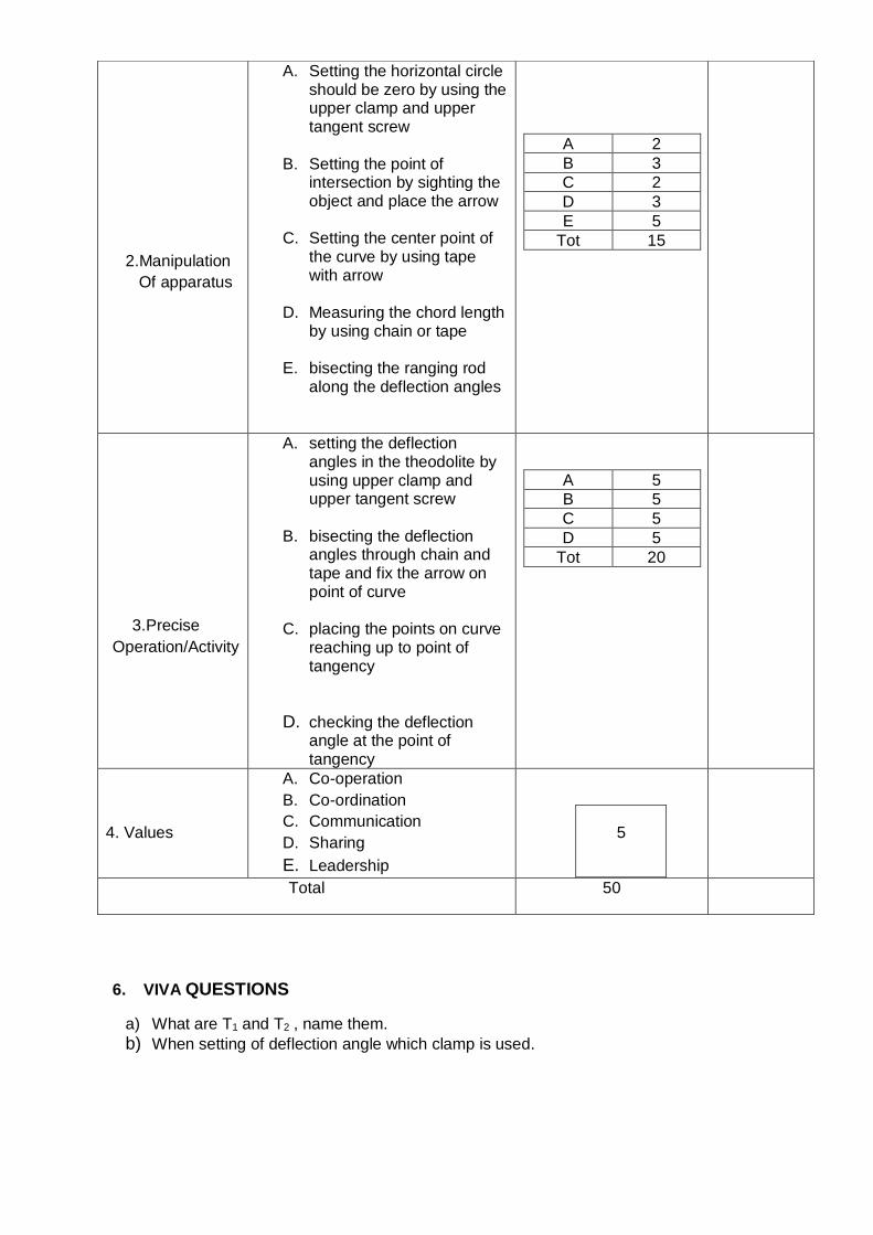
6. VIVA QUESTIONS
a) What are T1 and T2 , name them.
b) When setting of deflection angle which clamp is used.
2.Manipulation
Of apparatus
A. Setting the horizontal circle should be zero by using the upper clamp and upper tangent screw
B. Setting the point of intersection by sighting the object and place the arrow
C. Setting the center point of the curve by using tape with arrow
D. Measuring the chord length by using chain or tape
E. bisecting the ranging rod along the deflection angles
A 2
B 3
C 2
D 3
E 5
Tot 15
3.Precise
Operation/Activity
A. setting the deflection angles in the theodolite by using upper clamp and upper tangent screw
B. bisecting the deflection angles through chain and tape and fix the arrow on point of curve
C. placing the points on curve reaching up to point of tangency
D. checking the deflection angle at the point of tangency
A 5
B 5
C 5
D 5
Tot 20
4. Values
A. Co-operation
B. Co-ordination
C. Communication
D. Sharing
E. Leadership
5
Total 50

SETTING OUT OF THE CURVE BY USING TWO THEODOLITES
OBJECTIVE
To perform the set of tasks in setting out of the curve using two theodolites.
EQUIPMENT /RESOURSES
1. Theodolites - 2 Nos
2. Tripods - 2 Nos
3. Plumb bob - 1 No
4. Ranging rods - 3 Nos
5. Pegs - 10 Nos
FIELD SKETCH:
1. TASK ANALYSIS
A. KNOWLEDGE
Calculation of necessary data required to set out a curve from the given information.
Preparation of the table of deflection angles for first sub chord, normal chord and the last sub
chord.
Identification of Tangent points in the field.
Performing all the temporary adjustments required for the theodolite.
Setting the required deflection angles exactly in the instrument.
LABORATORY METHODOLOGY SHEET: Ex.4.3 Setting out of curve by using Two Theodolites

Coordination is required with the surveyor at other instrument station and with helper.
Basic terminology required – Back Tangent, Forward Tangent, point of Intersection, Angle of
Intersection, Point of Commencement, Point of Tangency, Tangent Distance, Length of the
Curve, Long Chord, Mid ordinate, Normal Chord and Sub Chord.
B. SKILLS
Category of Skill Sub Task
1. Handling of
Instrument
A. Setting up of the tripod stand on the ground with required
height.
B. Taking the instrument from the box and fixing it on the tripod
stand.
C. Adjusting the tripod stand legs and fix firmly in to the ground
by pressing the legs.
D. Adjusting the legs of tripod to place the instrument over the
station point approximately.
2. Manipulation of
Instrument
E. Setting up of the theodolites over tangent points.
F. Performing all the temporary adjustments accurately.
G. Sighting and bisecting the ranging rods by turning the
telescope and by focussing.
3. Precise Operation
/ Activity
A. Calculating the values of deflection angles from the given
data.
B. Setting the horizontal angle to read Zero degrees using
horizontal circle clamp.
C. Fixing the exact required deflection angle in the instrument
by the two people.
D. Giving instructions to the helper (ranging rod holder) for his
movement accordingly from both the instrument stations.
E. Placing the pegs at exact located points by the two
instrument people.

2. TEACHING POINTS
S. No Teaching points
Suggestive
Duration
(minutes)
1.
Importance of curve setting using two theodolites, especially
where the ground is undulating. (Chain & Tape methods are
very difficult to use).
5
2. Explanation on Calculation & Tabulation of deflection angles,
used for curve setting.
3. Instruments to be used for the activity.
4. Explaining the procedure to be followed to perform the
activity (It may be done in the field) 5
5. Precautions
5
Procedural Precautions
1. Care should be taken in handling the instrument.
2. Precise calculations must be required.
3. Care should be taken in setting the angles in
theodolites, only then curve will be perfect.
4. Pegs should be marked at exact points.
5. Two surveyors must be careful enough in performing
the activity.
6. Helpers should follow the instructions carefully.
Total 15

3. NEED AND SCOPE OF THE EXPERIMENT
1. To set out a simple curve using two theodolites.
2. This method is very useful in the absence of chain or tape and also when ground is not
favourable for accurate chaining.
3. This is simple and accurate method but requires essentially two instruments and two
surveyors to operate upon them, so it is not as commonly used as the method of
deflection angles.
4. PLANNING AND ORGANIZATION
Action Activity
Check for
The accuracy of the theodolites used
The bubble position (It should be centre of its run
while performing the task).
The deflection angles set in the two theodolites each
time.
For design of
instruction Read teaching points carefully

5. SCHEME OF EVALUATION
Category of
skill
Sub task
Weight with
competency level
individually
Awarded
(50)
1. Handling of
Instrument
A. Setting up of the tripod stand on
the ground.
B. Taking the instrument from the
box and fixing it on the tripod
stand.
C. Adjusting the tripod stand legs
and fix firmly in to the ground by
pressing the legs.
D. Adjusting the legs of tripod to
place the instrument over the
station point approximately.
A B C D Tot
2 2 3 3 10
2. Manipulation
of Instrument
A. Setting up of the theodolites over
tangent points.
B. Performing all the temporary
adjustments accurately.
C. Sighting and bisecting the
ranging rods by turning the
telescope and by focussing.
A B C Tot
5 5 5 15
3. Precision
A. Calculating the values of
deflection angles from the given
data.
B. Setting the horizontal angle to
read Zero degrees using
horizontal circle clamp.
C. Fixing the exact required
deflection angle in the
instrument by the two people.
A B C Tot
10 5 5 20
4. Values
A. Co-operation
B. Co-ordination
C. Communication
D. Sharing
E. Leadership
5
TOTAL 50

6. VIVA QUESTIONS
(Only suggestive. The teacher may add questions depending upon the Context of
Examination)
1. What is the data required for setting out a simple curve using two theodolites?
2. What type of measurement involves in Setting out a curve by two theodolite method?
3. Which process can be used for setting a small curve?
4. In Rankine’s method, it is assumed that the length of arc is equal to its chord.
True or False?
5. Rankine’s method can be applied for setting curves of large radius. True or False?
6. The angle between the back tangent and forward tangent of a curve is known as -
------------------.
7. The angle by which the forward tangent deflects from the back tangent of a curve is
called -------------------.

Plot the Data Observed in Measuring the Horizontal Distance between
Two Inaccessible Points Using Theodolie and Obtained the Inaccessible
distance from the Plot
A. THEORY : Theodolite is a instrument is used to measure the horizontal distance
between two inaccessible points and obtain the distance between two inaccessible
distance from the plot.
B. PROCEDURE:
Let P and Q be the in accessible points the distance from P to Q is to be determined.
Let at‘d’ = Distance between two instrument station.
From at (A) = The angles Ɵ1 and Ɵ2 can be measured.
From at (B) = The angle Ɵ3 and Ɵ4 can be measured.
With above information using the formulas in experiment no 4.7. The distance can be obtained. All
the measurements can be plotted to a suitable scale and confirm.
1. Set up the Theodolite at A by making the temporary adjustments level it accurately
with respect to the altitude bubble.
2. Sight the point P by keeping the horizontal circle reading at zero.
3. Loosen the upper clamp and rotate the telescope to sight Q and get the horizontal
angle PAQ (Ɵ1).
4. Sight the point Q by keeping the horizontal circle reading at zero.
Experimental methodology 4.23 Plot the data observed in measuring the horizontal distance between two
inaccessible points using Theodolite and obtained the inaccessible
distance from the plot distance from the plot

5. Loosen the upper clamp and rotate the telescope to sight B and get the horizontal
angle QAB (Ɵ2).
6. Shift the instrument to station B and do the temporary adjustments
7. Sight the point A by keeping the horizontal circle reading at zero.
8. Loosen the upper clamp and rotate the telescope to sight P and get the horizontal
angle ABP (Ɵ3).
9. Sight the point P by keeping the horizontal circle reading at zero.
10. Loosen the upper clamp and rotate the telescope to sight Q and get the horizontal
angle PBQ (Ɵ4).
11. Measure the horizontal distance between and A and B using tape accurately.
12. After Measuring the distance between Two Inaccessible points A and B. Plot the data
on a drawing sheet according to the given Scale. B. OBSERVATIONS AND CALCULATIONS
Horizontal angle < PAQ = Ɵ1
Horizontal angle < QAB = Ɵ2
Horizontal angle < ABP = Ɵ3
Horizontal angle < PBQ =Ɵ4
Horizontal distance between A and B =d
From the Fig1.f1
From Δ ABP
<APB = 180°- (Ɵ1+ Ɵ2+ Ɵ3)
Applying the sine rule
AB PB PA = = =
Sin (180°-(Ɵ1+ Ɵ2+ Ɵ3)) Sin (Ɵ1+Ɵ2)sinƟ3 Sin Ɵ3
d
PB = X Sin (Ɵ1+ Ɵ2)
Sin (180°-(Ɵ1+ Ɵ2+ Ɵ3))
d
PA = X Sin Ɵ3
Sin (180°-(Ɵ1+ Ɵ2+ Ɵ3))

Again From Δ AQB
<AQB = 180° - (Ɵ2+ Ɵ3+ Ɵ4)
Applying the sine rule
AB QA QB = = =
Sin (180°-(Ɵ2+ Ɵ3+ Ɵ4)) Sin (Ɵ3+ Ɵ4) sinƟ2
d
QA = X Sin (Ɵ3+Ɵ4)
Sin (180°-(Ɵ2+ Ɵ3+ Ɵ4))
d
QB = X Sin Ɵ2
Sin (180°-(Ɵ1+ Ɵ2+ Ɵ3))
Horizontal distance between P and Q:
(a) From ΔPAQ
By applying cosine rule
PQ² = PA² + QA² -2.PA.QA.COS Ɵ1
PA, QA, and Ɵ1are known PQ can be calculated
(b) From ΔPQB
By applying cosine rule
PQ² = PB² + QB² -2.PB.QB.COS Ɵ4
PB, QB, and Ɵ4 are known PQ can be calculated
C.RESULT: Plot the data observed in measuring the horizontal distance between two
inaccessible points using Theodolite and obtain the inaccessible distance from the plot


To Perform the different tasks for Plot the closed traverse of theodolite, distribute the
closing error by Bowditch/transit rule calculate the area of traverse.
A. PRINCIPLE
Plotting means to represent on paper, to a suitable scale, the previously surveyed objects in
accordance with their shape and size. Plotting is commenced after the field-work is over.
A. THEORY
A traverse is a series of connected lines whose lengths and directions are measured in the field.
Closed traverse should be used to have check on the measured angles and distances.
A suitable scale is chosen before starting the plotting work. The scale depends upon the
importance of the work and extent of survey. Leave a suitable margin (2 cm to 4 cm) all round the
paper. Select a suitable position of the base line so that the map or plan is shown to the best
advantages. The base line should be plotted as accurately as possible because the entire
accuracy of the frame-work depends upon it.
Theodolite traverse can be plotted by rectangular co-ordinate method. In this method, the position
of different points is plotted on a plan with reference to two lines yy1 (y-axis) and xx1 (x-axis)
which are respectively parallel and perpendicular to the meridian (Fig. 5.25). These reference
lines are called the axes of the co-ordinates, and the point of their intersection O, called the origin.
B. PROCEDURE:
• Set the drawing table and fix the drawing sheet properly.
• Choose a suitable scale before starting the plotting work.
EXPERIMENTAL METHODOLOGY 4.24
Plot the closed traverse of theodolite, distribute the closing
error by Bowditch/transit rule calculate the area of traverse.

• Select suitable position of the base line so that the entire accuracy of plotting work
depends upon it.
• Draw yy1(y-axis) and xx1 (x-axis) which are parallel and perpendicular to the
meridian.
• Plot the closed traverse of the known lengths and bearings of a lines on y-axis and
x-axis by calculating length to scale assumed.
• After completion of plotting of closed traverse. If any errors are there can be
balanced by Bowditch’s rule and transit rule.
• Calculate the area of closed traverse by co-ordinates method.
OBSERVATIONS AND CALCULATIONS
Balancing a closed traverse survey can be done by two methods. 1. Bowditch’s rule
2. Transit’s rule

Bowditch’s rule This method is on the assumption that the errors in linear measurements are proportional
to root of length and that the errors in angular measurements are inversely proportional to
root of length.
The Bowditch’s rule is :
Correction to latitude/departure of any side = Total error in latitude/departure x𝑙𝑒𝑛𝑔𝑡ℎ 𝑜𝑓 𝑡ℎ𝑎𝑡 𝑠𝑖𝑑𝑒
𝑝𝑒𝑟𝑖𝑚𝑒𝑡𝑒𝑟 𝑜𝑓 𝑡𝑟𝑎𝑣𝑒𝑟𝑠𝑒
Thus if CL = correction of latitude of any side
CD = correction of departure of any side
ΣL = Total error in latitude
ΣD = Total error in departure
Σl = length of the perimeter
l = length of any side.
We have CL = ΣL x𝑙
Σl
CD = ΣD x𝑙
Σl
Transit’s rule
The transit rule is applicable where angular measurements are more precise than the
linear measurements.
The transit rule is:
Correction to latitude/departure of any side = Total error in latitude/departure x𝑙𝑎𝑡𝑖𝑡𝑢𝑑𝑒/𝑑𝑒𝑝𝑎𝑟𝑡𝑢𝑟𝑒 𝑜𝑓 𝑡ℎ𝑒 𝑙𝑖𝑛𝑒
𝐴𝑟𝑖𝑡ℎ𝑒𝑚𝑒𝑡𝑖𝑐 𝑠𝑢𝑚 𝑜𝑓 𝑙𝑎𝑡𝑖𝑡𝑢𝑑𝑒𝑠/𝑑𝑒𝑝𝑎𝑟𝑡𝑢𝑟𝑒𝑠
If
L= Latitude of any line.
D= departure of any line
LT= Arithmetic sum of latitudes
DT= Arithmetic sum of departures
We have CL = ΣL x𝐿
LT
CD = ΣD x𝐷
DT

Area of closed traverse by co-ordinate method
The given consecutive co-ordinates of traverse are converted into independent coordinates
with reference to the coordinates of the most westerly station. Thus, whole traverse is
transferred to first quadrant. In figure A is the most westerly station.
Then the coordinates are arranged in determinant form as follows
The sum of the products of coordinates joined by solid lines,
ΣP = (y1x2 + y2x3 +y3x4 +y4x5 +y5x1) The sum of products of coordinates joined by dotted lines,
ΣQ = (x1 y2 + x2 y3 +x3 y4 + x4y5 +x5y1) Double area = ΣP – ΣQ
Required area = = 1
2 (ΣP – ΣQ)

F.GRAPH
NIL G.RESULT
1, The area of closed traverse -------- m2.
H.INFERENCE
___________________________________________________________________________
___________________________________________________________________________
___________________________________________________________________________
___________________________________________________________________________

Plot the Simple curve after setting out the Curve in the Field by Ordinates from long
chord method
A) OBJECTIVE:
Performing the set of tasks to Plot the Simple curve after setting out the curve in the field by
Ordinates from long chord method
B) PROCEDURE
1) Let AB and BC be two tangents meeting at a point B, with defection angle ɸ.
2) The tangents length is calculated from the usual formula, and points T1 and T2 are
marked on the ground with pegs.
3) The length of the chord, T1 T2 is calculated from the usual formula. The long chord is
bisected at point M. The curve will be symmetrical on the both sides of M.
4) The ordinates are calculated for the left half at some regular intervals. Points 1 ,2, 3
and 4 are marked with the pegs along the long chord as shown in figure
5) Ordinates O1, O2, O3, and O4 are calculated from the usual formula
6) Perpendiculars are set out at points 1, 2, 3 and 4. The calculated ordinates O1, O2,
O3, and O4 identified along these perpendiculars and points P1 ,P2, P3 and P4 are
marked with pegs
7) In the right half, points 1’, 2’, 3’ and 4’ are marked with the pegs and corresponding
ordinates (ordinates for the left half) are set out to mark the points P’1, P’2, P’3 and P’4.
8) All these points P1, P2,…. and P’1, P’2,…. are on the curve. These points are joined
by rope or thread to show the shape of the curve along the alignment.
C) SKETCH:
Experimental Methodology: EX. 4.25
Plot the Simple curve after setting out the curve in the field

D) OBSERVATIONS: Observing the Elements of Curves
E) FORMULAS, CALCULATIONS AND TABULATION :
1. Tangent length, T1B = R tan Ø/2
2. Chainage at T1 = Chainage at B – Tangent Length.
3. Length of the curve, CL = ΠR Ø
180
4. Chainage of T2 = Chainage of T1 + Curve Length
5. Length of the long chord (L) = 2R sin Ø /2
6. The Long Chord is divided into two equal parts
7. Mid Ordinate = Oo = R – √R2 − (L
2)2
Distance from the mid-point of Long chord x in m
Ordinate Ox
Ox=√𝑹𝟐 − 𝒙𝟐 − ( 𝑹 − 𝑶𝒙)

F) RESULT:
The Calculated Ordinates are marked on the ground and hence the required curve is plotted.
G) INFERENCE:
_________________________________________________________________________
_________________________________________________________________________
_________________________________________________________________________
_________________________________________________________________________

UNIT TEST –I Model Question Paper (C-20)
C-309 Surveying –II Practice & Plotting Lab
TIME: 3 hours Total Marks: 60
Instructions: (1) Any one full question of the following shall be allotted to the students on lottery
basis.
(2)All the questions are competency based and are for assessing the candidate’s
psychomotor skills
(3) Underpinning knowledge shall be assessed through viva voce -4 M
1. A. What are the temporary adjustment to be carried out for theodolite?
8 M (CO1)
B. Perform temporary adjustments of theodolite.
CRO. 20 M (CO2)
C. What are the various permanent adjustments of theodolite?
CRO 26 M (CO1)
2 A. Note down the readings on main scale and vernier scale of the theodlite.
8 M (CO1)
B. Tabulate observations in the field book
CRO. 20 M (CO2)
C. Determine the horizontal angle between two accessible points.
26 M (CO1)
3 A. How do you measure the horizontal angle by repetition theodolite?
8 M (CO1) B. What are the errors eliminated by repetition method?
CRO. 20 M (CO2)
C. What are the methods of measurement of horizontal angle?
. 26 M (CO1)

4 A. What is reiteration method in surveying?
6M (CO1)
B. Tabulate observations made for the experiment.
CRO. 10M (CO2)
C. Precision of measurement of horizontal angles by reiteraition (C01)
5 A. Describe the Operation of foot screws for levelling
6M (CO2)
B. Explain the precautions to be taken while shifting the instrument.
CRO. 10M (CO1)
C. Explain Transiting from face left to face right
CRO. 20M (CO1)
6 A. Note down horizontal angle plate readings accurately.
6M (CO1)
B. Drawing the plot in rough and applying the sine and cosine rules to triangles.
CRO. 10M (CO2)
C. Calculating the inaccessible horizontal distance.
CRO. 20M (CO2)
7 A. Identify the component parts of theodolite.
6M (CO2)
B. Note down the observation in standard format
CRO. 10M (CO1)
C. Establish the survey line on the field and measure the magnetic bearing of survey
line.
CRO. 20M (CO2)
8 A. What is the necessity of theodolite traversing?
6M (CO1)
B. What are the various methods of traversing?

CRO. 10M (CO1)
C. What are the various methods of traversing?
CRO. 20M (CO2)

UNIT TEST-II Model Question Paper (C-20)
C-309 Surveying –II Practice & Plotting Lab
TIME: 3 hours Total Marks: 60
Instructions: (1) Any one full question of the following shall be allotted to the students on lottery
basis.
(2)All the questions are competency based and are for assessing the candidate’s
psychomotor skills
(3) Underpinning knowledge shall be assessed through viva voce -6 M
1. A. Note down the face left and face right readings in tabular form.
8 M (CO1)
B. Enter Vertical angles and Calculate the average vertical angle.
CRO. 20 M (CO2)
C. Determine vertical distance and RL of the top and bottom of the object.
CRO 26 M (CO1)
2. A. How to find height of the object.
8 M (CO1)
B. Tabulate observations and calculate the average vertical angle.
CRO. 20 M (CO2)
C. Calculate the horizontal distance between Theodolite and the object.
.
26 M (CO1)
3. A. What is the necessity of Trignometric levelling?

8 M (CO1)
B. What are the various methods to find the elevation of the object under different field
conditions?
CRO. 20 M (CO2)
C. What are the methods of measurement of horizontal angle?
. 26 M (CO1)
4 A. What is reiteration method in surveying?
6M (CO1)
B. Tabulate observations made for the experiment.
CRO. 10M (CO2)
C. Precision of measurement of horizontal angles by reiteraition (C01)
2 A. Describe the Operation of foot screws for levelling
6M (CO2)
B. Explain the precautions to be taken while shifting the instrument.
CRO. 10M (CO1)
C. Explain Transiting from face left to face right
CRO. 20M (CO1)
3 A. Note down horizontal angle plate readings accurately.
6M (CO1)
B. Drawing the plot in rough and applying the sine and cosine rules to triangles.
CRO. 10M (CO2)
C. Calculating the inaccessible horizontal distance.
CRO. 20M (CO2)
4 A. Tabulate the observations taken in the filed..

8 M (CO2)
B. Fix the distance of 20m,40m &60m with chain.
CRO. 20 M (CO1)
C. Calculate the values of K & C
CRO. 26 M (CO2)
5. A. Describe the Operation of foot screws for leveling
8 M (CO1)
B. Explain the precautions to be taken while shifting the instrument.
CRO. 20 M (CO1)
C. Explain Transiting from face left to face right
CRO. 26 M (CO2)
6. A. How do you calculate PC and PT?
8 M (CO1)
B. Explain the precautions to be taken .How do you find the radius of a circular curve?
.
CRO. 20 M (CO1)
C. Explain Transiting from face left to face right & How can we take offsets from tangent for
setting out a curve?
CRO. 26 M (CO2)


![Semester V (Third year] Branch/Course Civil Engineering V ...](https://static.fdokumen.com/doc/165x107/6321a517ae0f5e8191058b94/semester-v-third-year-branchcourse-civil-engineering-v-.jpg)