
Consent process to effect changes in wastewater discharges (Otago, New Zealand)
Upload
ruhr-uni-bochumCategory
view
1download
0
Different modes of electron heating in dual-frequency capacitively coupled radio frequency
discharges
This article has been downloaded from IOPscience. Please scroll down to see the full text article.
2009 Plasma Sources Sci. Technol. 18 034011
(http://iopscience.iop.org/0963-0252/18/3/034011)
Download details:
IP Address: 148.6.27.70
The article was downloaded on 26/07/2010 at 10:12
Please note that terms and conditions apply.
View the table of contents for this issue, or go to the journal homepage for more
Home Search Collections Journals About Contact us My IOPscience

IOP PUBLISHING PLASMA SOURCES SCIENCE AND TECHNOLOGY
Plasma Sources Sci. Technol. 18 (2009) 034011 (11pp) doi:10.1088/0963-0252/18/3/034011
Different modes of electron heating indual-frequency capacitively coupled radiofrequency dischargesJ Schulze1, Z Donko2, D Luggenholscher1 and U Czarnetzki1
1 Institute for Plasma and Atomic Physics, Ruhr-University, Bochum, Germany2 Research Institute for Solid State Physics and Optics of the Hungarian Academy of Sciences,Budapest, Hungary
E-mail: [email protected]
Received 10 July 2008, in final form 20 November 2008Published 15 July 2009Online at stacks.iop.org/PSST/18/034011
AbstractA systematic study of different modes of electron heating in dual-frequency capacitivelycoupled radio frequency (CCRF) discharges is performed using a particle-in-cell simulation.Spatio-temporal distributions of the total excitation/ionization rates under variation of gaspressure, applied frequencies and gas species are discussed. Some results are comparedqualitatively with an experiment (phase resolved optical emission spectroscopy) operatedunder conditions similar to a parameter set used in the simulation. Different modes of electronheating are identified and compared with α- and γ -mode operation of single-frequency CCRFdischarges. In this context the frequency coupling and its relation to the ion density profile inthe sheath are discussed and quantified. In light gases the ion density in the sheath is timemodulated. This temporal modulation is well described by an analytical model and is found toaffect the excitation dynamics via the frequency coupling. It is shown that the frequencycoupling strongly affects the generation of beams of highly energetic electrons by theexpanding sheath and field reversals caused by the collapsing sheath. The role of secondaryelectrons at intermediate and high pressures is clarified and the transition from α- to γ -modeoperation is discussed. Depending on the gas and the corresponding cross sections forexcitation/ionization the excitation does not generally probe the ionization as is usuallyassumed.
(Some figures in this article are in colour only in the electronic version)
1. Introduction
Capacitively coupled radio frequency (CCRF) discharges arefrequently used for etching and deposition processes in thesemiconductor industry [1]. In particular, dual-frequencyCCRF discharges have become more important during recentyears, since they allow separate control of ion flux and energy[2–6]. Such separate control is essential for applications,since the ion flux determines the throughput of a givenprocess and the ion energy controls the etching and depositionprocesses at the wafer’s surface.
Separate control of ion flux and energy in dual-frequencyCCRF discharges can be achieved in two ways.
One option is the operation of the discharge at twosubstantially different frequencies (typically 2 and 27 MHz)
with a low frequency (lf) voltage amplitude that is much higherthan the high frequency (hf) voltage amplitude. Under suchconditions the ion flux is assumed to be controlled mainly bythe hf component, since electron heating is more efficient athigh frequencies. The ion energy is assumed to be controlledmainly by the lf component, since the lf voltage amplitude ismuch higher than the hf voltage amplitude [2–6]. However,recent investigations have shown that under such conditionsthe separate control might be limited due to the coupling ofboth frequencies [7–11].
Another way to achieve separate control of ion flux andenergy in dual-frequency CCRF discharges is based on thenewly discovered electrical asymmetry effect (EAE) [12–14].If the voltage waveform applied to a CCRF discharge containsan even harmonic of its fundamental frequency, the two sheaths
0963-0252/09/034011+11$30.00 1 © 2009 IOP Publishing Ltd Printed in the UK

Plasma Sources Sci. Technol. 18 (2009) 034011 J Schulze et al
will not be electrically symmetric. In order to balance electronand ion fluxes at each electrode a dc self-bias develops. Theself-bias and, consequently, the ion energy can be controlledby tuning the phase between the two applied RF voltages.At the same time the ion flux remains constant, while thephase is changed, since the voltage amplitude is kept constant.This technique works in geometrically symmetric as wellas asymmetric discharges and is maximized by using thesecond harmonic of the fundamental frequency, e.g. 13.56 and27.12 MHz.
Electron heating in single-frequency CCRF dischargeshas been investigated for many years and a long list ofrecords exists [15–41]. It was found that single-frequencyCCRF discharges can be operated in different heating modesdepending on the discharge conditions [35]. At low pressuressingle-frequency discharges are usually operated in α-mode.In α-mode excitation and ionization dynamics are dominatedby beamlike highly energetic electrons accelerated by theexpanding sheaths [15–33]. Electric field reversals at thephase of sheath collapse are found to contribute to electronheating [19, 24–26, 28, 31, 36–38]. At high pressures, high RFvoltages and electrode materials with high secondary electronemission coefficients such discharges operate in γ -mode. Inγ -mode excitation and ionization dynamics are dominated bysecondary electrons [22, 27, 34, 35].
However, in the case of dual-frequency CCRF dischargesonly a few investigations of electron heating exist, which arerestricted to particular conditions [2–11]. Among these, phaseresolved optical emission spectroscopy (PROES) has providedvaluable insights into electron heating [10, 11]. Recently, theimportance of secondary electrons in dual-frequency CCRFdischarges was pointed out by Turner [42]. However, theexistence of different modes of electron heating and the roleand nature of the frequency coupling in the respective modeshave not been investigated yet.
The understanding of these fundamental phenomenais essential for the optimization of industrial applicationsusing dual-frequency discharges. Therefore, in this worka systematic investigation of electron heating and frequencycoupling in dual-frequency discharges is performed. Using aPIC simulation of a geometrically symmetric helium dischargeand comparisons with experimentally obtained spatio-temporal excitation profiles [10, 11] the nature of the frequencycoupling is understood. Simulations of geometricallysymmetric helium and argon discharges show several differentheating modes depending on the choice of pressure, gasand applied frequencies. Analogies and differences in α-and γ -mode operation of single-frequency discharges arepointed out.
The paper is structured in the following way: in section 2the particle-in-cell (PIC) simulation used for the investigationof electron heating is briefly described. In section 3 the resultsare presented. This section is divided into four parts. First,the nature of the frequency coupling in dual-frequency CCRFdischarges operated at substantially different frequencies isexplained via a comparison of simulation and experimentalresults. Furthermore, the observed temporal modulation ofthe ion density in the sheath region in light gases is explained
using a simple analytical model. Second, the role of secondaryelectrons at intermediate pressures is investigated. Third,γ -mode operation at high pressures is discussed and, fourth,excitation dynamics under different discharge conditions isdiscussed. In section 4 conclusions are drawn.
2. PIC simulation
The dual-frequency discharges studied here are describedby a one-dimensional (1d3v) bounded plasma PIC model,complemented with Monte Carlo treatment of collisionprocesses (PIC/MCC). The electrodes are assumed to beinfinite, planar and parallel. Only geometrically symmetricdischarges are investigated. Two different kinds of dual-frequency discharges are investigated: discharges operated atsignificantly different frequencies of 1.937 and 27.118 MHzand discharges operated at similar frequencies of 13.56 and27.12 MHz. In the case of substantially different frequenciesone of the electrodes is driven by a voltage
V (t) = Vhf sin(2πfhf t) + Vlf sin(2πflf t), (1)
while the other electrode is grounded [43]. The two excitationvoltages are locked in phase, as was done in the experiments.
In the case of similar frequencies one of the electrodes isdriven by a voltage
VAC(t) = V0 (cos (2πf t + �) + cos (4πf t)) , (2)
wheref = 13.56 MHz and� is a variable phase angle betweenthe applied voltage waveforms.
In both cases secondary electrons emitted from theelectrode surfaces by ion bombardment and electron reflectionat the electrodes are taken into account. Details of thesimulation technique can be found elsewhere [31, 43].
3. Results
3.1. Frequency coupling in dual-frequency CCRF discharges
In this section the nature of the frequency coupling indual-frequency CCRF discharges operated at substantiallydifferent frequencies is investigated and its relation to thetime modulated ion density profile in the sheath is quantified.Comparisons of the resulting spatio-temporal excitationprofiles with an experiment (PROES) operated under similar,but not identical, conditions are made.
In order to investigate the frequency coupling in detaila PIC simulation under conditions similar to an experiment[10, 11, 31] is performed. For simplicity, helium has beenchosen as a model gas, since it is the main constituent of theexperimentally used gas mixture. The applied frequencies are1.937 and 27.118 MHz and the electrode gap is 12 mm. Theapplied low and high frequency voltages are Vlf = 800 Vand Vhf = 550 V, respectively. A gas pressure of 65 Pa,a gas temperature of 400 K, a secondary electron emissioncoefficient of γ = 0.45 [44] and an electron reflectioncoefficient of α = 0.2 are used as input parameters. Theleft plot in figure 1 shows the total spatio-temporal excitation
2

Plasma Sources Sci. Technol. 18 (2009) 034011 J Schulze et al
.
.
..
.
.
.
.
.
..
.
.
.
.
.
.
Figure 1. Left: spatio-temporal excitation resulting from the PIC simulation (He, 65 Pa, Vlf = 800 V, Vhf = 550 V, Tg = 400 K, γ = 0.45,α = 0.2). Right: experimentally determined spatio-temporal electron impact excitation into the Ne 2p1 state at 65 Pa [11, 31] and sketch ofthe RF potential at the powered bottom electrode.
rate as it results from the PIC simulation. The spatio-temporalexcitation profile is complex and a strong coupling of bothfrequencies is obvious [10, 11, 31].
The right plot of figure 1 shows a spatio-temporal profile ofthe experimentally determined excitation into the Ne 2p1 statein a symmetric, industrial, dual-frequency CCRF discharge(Lam Exelan) operated at 65 Pa (same as in the simulation)in He (72%)–O2 (19%) with a small neon admixture (9%)[11, 31]. In the experiment the applied RF voltage waveformsare also fixed in frequency at 1.937 and 27.118 MHz with acommon phase reference (fhf = 14flf ). The gap between theelectrodes is also 12 mm and the electrode radius is 110 mm.The discharge is operated at Phf = 800 W and Plf = 200 W.A detailed description of these experimental results can befound elsewhere [11, 31].
Good qualitative agreement between experiment andsimulation is found. In the experiment the processing gasesare different from those in the simulation. In particular,oxygen ions, which might play an important role in theexperiment, are not taken into account in the simulation.The total helium excitation rate (simulation) is comparedwith the excitation rate into a specific neon energy level(experiment). Although the corresponding cross sections arenot the same, their shapes are still sufficiently similar tojustify this comparison [45, 46]. Certainly the claim of thiscomparison cannot be a quantitative reproduction of details ofthe experimentally observed excitation profiles. Nevertheless,the gross spatio-temporal structure of the measured excitationis qualitatively reproduced well by the simulation taking intoaccount only helium gas. The excitation dynamics seemsto be dominated by processes generally typical for dual-frequency CCRF discharges operated at substantially differentfrequencies. These processes will be discussed in detail in thispaper based on simulation results.
Figure 2 shows two different temporal sections of theleft plot of figure 1, one during the first half of one lf period
(70–180 ns) and the other during the second half (310–430 ns).Similar results have been obtained experimentally [47]. Theexcitation maxima are tilted to the right during the first half,whereas they are tilted to the left during the second half. Inanalogy to the results of PIC simulations in single-frequencyCCRF discharges performed by Vender and Boswell [20]and Wood [21] and experimental investigations using PROES[29–33] the tilt of the excitation maxima is a consequence ofa retardation caused by beams of highly energetic electronsgenerated by the expanding sheath. Obviously, electronbeams are generated by the expanding sheath at the bottomelectrode during the first half of one lf RF period and at thetop electrode during the second half. Here, the term highlyenergetic directed electrons is understood as an anisotropicelectron velocity distribution with a strong drift component in(or near) the direction of the discharge axis. If the propagationvelocity of such electron beams is lower than the thermalvelocity, the velocity obtained from the tilt of the observedexcitation maxima will correspond to the threshold energy ofthe observed excitation. If the propagation velocity of the beamis higher than the thermal velocity, the velocity obtained fromthe tilt will be higher than the velocity corresponding to thethreshold for excitation. Here the tilt of the arrows in figure 2yields a velocity of about 2.5 × 10⁶ m s−1 (corresponding toapproximately 20 eV energy). This agrees fairly well withthe threshold energy for excitation used in the simulation.This result is also in good agreement with a previous detailedexperimental analysis under similar discharge conditions [11].
The question why electron beams are only generated at agiven electrode during distinct phases of one lf RF period isclosely related to the frequency coupling.
Figure 3 shows the ion density space and phase resolvedin front of the bottom powered electrode as it results from thesimulation. The oscillation of the sheath width s (solid blackline) is also shown. The sheath width is calculated by the
3

Plasma Sources Sci. Technol. 18 (2009) 034011 J Schulze et al
.
.
.
.
.
.
.
.
.
.
.
.
.
.
Figure 2. Spatio-temporal excitation within the first and second halves of one lf RF period as it results from the PIC simulation under thesame conditions as before [31].
.
.
.
.
.
.
.
Figure 3. Spatio-temporal plot of the ion density in front of thebottom powered electrode as it results from the PIC simulationunder the same conditions as before. The solid black linecorresponds to the sheath width s calculated using equation (3).
following criterion introduced by Brinkmann [48]:
∫ s
0ne(x) dx =
∫ d/2
s
(ni − ne) dx, (3)
where d is the electrode gap. In dual-frequency CCRFdischarges the sheath can be considered to be a superpositionof lf and hf components. In this picture the hf sheath oscillatesaround the position of the lf sheath edge. The total sheathoscillation is the sum of lf and hf oscillations. Under theconditions investigated here, the velocity of the total sheathoscillation is dominated by the hf component (fhf = 14flf ).However, the spatial position of the hf sheath oscillation isdetermined by the lf voltage.
In CCRF discharges the ion density is high in the plasmabulk and decreases monotonically towards the electrode dueto flux continuity. The sheath width s is a function of the iondensity. At a given sheath voltage the sheath width is big, ifthe ion density at the position of sheath oscillation is low. Asthe ion density decreases towards the electrode, the lf sheath
voltage component determines the local ion density at theposition of hf sheath oscillation (lf sheath edge). Consequently,it determines the amplitude of the hf sheath oscillation at agiven hf sheath voltage via controlling the position of the lfsheath edge.
Due to the coupling of both frequencies the hf sheathoscillates in a region of low ion density during lf sheathcollapse. Therefore, maximum excitation is observed duringthe period of lf sheath collapse at phases of hf sheath expansion(figure 1). Due to the high γ value of 0.45 and the relativelyhigh pressure, secondary electrons also contribute to theexcitation. They mainly cause a modulation of the excitationwith twice the lf. The modulation by the hf component islow if the hf voltage amplitude is smaller than the lf voltageamplitude. The contribution of secondary electrons to theexcitation is maximum at phases of maximum sheath voltageat either side. Due to the superposition of excitation caused bysecondary electrons and electrons accelerated by the expandingsheath maximum excitation is not observed at the phase ofabsolute fastest sheath expansion velocity (see figures 1 and 3),but slightly later. The influence of secondary electrons on theexcitation/ionization will be discussed in detail later.
Figure 3 shows that the ion density in the sheath istime modulated under the conditions investigated here. It ismodulated with the low as well as with the high frequency. Themodulation of the ion density with the hf is most pronouncedduring the second half of one lf RF period, when the lf sheathis expanded. This temporal modulation is a consequence ofthe choice of a light gas (helium) and the high ion density. Fora typical ion density in the sheath ni,s = 4 × 10¹⁶ m−3 thelocal ion plasma frequency in the sheath is fpi,s = 1
2π· ωpi,s =
12π
·√
e2ni,s
ε0mHe≈ 21 MHz. This is comparable to the applied hf.
Therefore, the ions can react even to potential changes inducedby the hf component. If a heavier gas is used and if the iondensity in the sheath remains the same, the ions will react moreslowly to potential changes in the sheath. However, the localion plasma frequency depends only on m−1/2. For oxygenions, which might play an important role in the experiment
4

Plasma Sources Sci. Technol. 18 (2009) 034011 J Schulze et al
Figure 4. Left: comparison between the temporal modulation of the ion density 0.15 cm in front of the bottom electrode during the secondhalf of one lf RF period as it results from the PIC simulation (black solid line) and from the analytical model (red dashed line, equation (7)).Right: contribution of the first and second terms in equation (7) to the temporal modulation of the ion density 0.15 cm in front of the bottomelectrode and the sum of the two terms.
discussed above, ωpi,s will be reduced by a factor of less than 3.Therefore, the ion density will probably not be modulated bythe hf (27 MHz), but still by the lf (2 MHz). The case of aneven heavier gas (argon) is discussed explicitly in section 3.4(see figure 9).
The temporal modulation of the ion density in the sheathcan be described quantitatively by a simple analytical modelbased on the continuity equation, the Poisson equation and anequation describing the ion motion in the sheath:
∂ni
∂t+
∂
∂z(niui) = 0, (4)
∂E
∂z= eni
ε0, (5)
ui = −c ·√
|E|. (6)
Equation (4) is the one-dimensional continuity equation,where ni is the ion density and ui is the ion velocity. Ionizationin the sheath is neglected (see figure 1). Equation (5) isthe one-dimensional Poisson equation [49], where E is theelectric field, e the elementary charge and ε0 the dielectricconstant. Here ne = 0 is assumed in the sheath. Equation (6)describes the ion motion in the sheath. It is based on theassumption that ion inertia can be neglected and the ion velocityadjusts itself instantaneously to the electric field. The squareroot relation applies only at sufficiently high E/p, whichis fulfilled well within the sheath [50]. Neglect of the ioninertia terms is justified at a sufficiently high collision rate(pressure) and slow field changes. A rough estimation showsthat these conditions are fulfilled marginally here. However,as shown below, applying this simplification still captures themajor physics involved. For helium c ≈ 56 (kg mC)−1/2 [50].As the applicability of equations (4)–(6) is limited to thesheath region, this model is valid only inside the sheath (about270–500 ns, z < s, see figure 3). Combining equations (4)–(6)
the following expression for the temporal modulation of the iondensity in the sheath is derived:
∂ni
∂t= c
(√|E|∂ni
∂z− en2
i
2ε0√|E|
). (7)
Based on flux continuity and the electrostatic approxima-tion [49] the electric field is expressed by the sheath potential Uin dependence on z, where z is the distance from the electrode:
√|E| =
√53 s−5/6(s − z)1/3
√U. (8)
Equation (8) is based on the assumption of a quasi-staticion density and a constant sheath width. Both are, of course,not exactly true. The electric field resulting from equation (8)agrees well with the electric field resulting directly from thesimulation inside the sheath during the second half of one lfRF period.
The left plot in figure 4 shows a comparison between themodulation of the ion density 0.15 cm in front of the bottomelectrode during the second half of one lf RF period as itresults from the PIC simulation (black solid line) and fromthe analytical model (red dashed line, equation (7)). Forthis comparison the ion density and the electric field directlyresulting from the simulation are used as input parametersin equation (7). Equation (8) is not used. Good agreementbetween model and simulation results is found. Deviations arefound at phases, when s � 0.15 cm, since the model is onlyvalid in the sheath. Similar results are obtained at differentpositions in the sheath.
Using this analytical model the physical mechanismsleading to the strong hf modulations of the ion density onlyduring the second half of one lf RF period are understood,since the contributions of the individual terms in equation (7)can be distinguished. The right plot in figure 4 shows thesecontributions for a given position in the sheath. Obviously,both terms are out of phase and have different signs. Theion density increases with time if the absolute value of the
5
Plasma Sources Sci. Technol. 18 (2009) 034011 J Schulze et al
.
.
.
.
.
.
.. . . . . . .
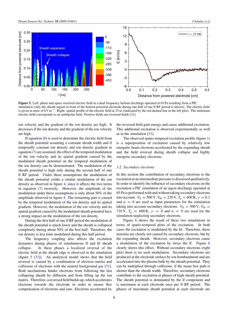
Figure 5. Left: phase and space resolved electric field in a dual frequency helium discharge operated at 65 Pa resulting from a PICsimulation (only the sheath region in front of the bottom powered electrode during one half of one lf RF period is shown). The electric fieldis given in units of kV m−1. Right: spatial profile of the electric field at 25 ns (indicated by the red dashed line in the left plot). The minimumelectric field corresponds to an ambipolar field. Positive fields are reversed fields [31].
ion velocity and the gradient of the ion density are high. Itdecreases if the ion density and the gradient of the ion velocityare high.
If equation (8) is used to determine the electric field fromthe sheath potential assuming a constant sheath width and iftemporally constant ion density and ion density gradient inequation (7) are assumed, the effect of the temporal modulationof the ion velocity and its spatial gradient caused by themodulated sheath potential on the temporal modulation ofthe ion density can be demonstrated. The modulation of thesheath potential is high only during the second half of onelf RF period. Under these assumptions the modulation ofthe sheath potential yields a similar modulation of the iondensity as observed in figure 4, since it affects the two termsin equation (7) inversely. However, the amplitude of themodulation under these assumptions is only about 50% of theamplitude observed in figure 4. The remaining part is causedby the temporal modulation of the ion density and its spatialgradient. However, the modulation of the ion velocity and itsspatial gradient caused by the modulated sheath potential havea strong impact on the modulation of the ion density.
During the first half of one lf RF period the modulation ofthe sheath potential is much lower and the sheath is collapsedcompletely during about 50% of the first half. Therefore, theion density is less time modulated during this half period.
The frequency coupling also affects the excitationdynamics during phases of simultaneous lf and hf sheathcollapse. At these phases a localized reversal of theelectric field at the sheath edge is observed in the simulation(figure 5 [31]). An analytical model shows that the fieldreversal is caused by a combination of electron inertia andcollisions of electrons with the neutral background gas [31].Both mechanisms hinder electrons from following the fastcollapsing sheath by diffusion and from filling up the ionmatrix. Therefore, a reversed field builds up, which accelerateselectrons towards the electrode in order to ensure fluxcompensation of electrons and ions. Electrons accelerated by
the reversed field gain energy and cause additional excitation.This additional excitation is observed experimentally as wellas in the simulation [31].
The observed spatio-temporal excitation profile (figure 1)is a superposition of excitation caused by relatively lowenergetic beam electrons accelerated by the expanding sheathand the field reversal during sheath collapse and highlyenergetic secondary electrons.
3.2. Secondary electrons
In this section the contribution of secondary electrons to theexcitation at an intermediate pressure is discussed qualitatively.In order to identify the influence of secondary electrons on theexcitation a PIC simulation of an argon discharge operated at65 Pa is performed with and without taking secondary electronsinto account. Vlf = 500 V, Vhf = 220 V, Tg = 600 K, γ = 0.1and α = 0 are used as input parameters for the simulationtaking into account secondary electrons. Vlf = 500 V, Vhf =710 V, Tg = 600 K, γ = 0 and α = 0 are used for thesimulation neglecting secondary electrons.
Figure 6 shows the result of these two simulations interms of spatio-temporal plots of the excitation. In bothcases the excitation is modulated by the hf. Therefore, thesemaxima are clearly not caused by secondary electrons, but bythe expanding sheath. However, secondary electrons causea modulation of the excitation by twice the lf. Figure 6clearly shows this effect. Without secondary electrons (rightplot) there is no such modulation. Secondary electrons areproduced at the electrode surface by ion bombardment and areaccelerated into the plasma bulk by the sheath potential. Theycan be multiplied through collisions, if the mean free path isshorter than the sheath width. Therefore, secondary electronscontribute to the excitation at phases of high sheath potential.The sheath potential is dominated by the lf component andis maximum at each electrode once per lf RF period. Thephases of maximum sheath potential at each electrode are
6

Plasma Sources Sci. Technol. 18 (2009) 034011 J Schulze et al
.
.
.
.
.
.
Figure 6. Spatio-temporal excitation plots in an argon discharge operated at 65 Pa with (left) and without (right) secondary electrons.
180◦ phase shifted. Therefore, secondary electrons originatingfrom the top electrode contribute to the excitation during thefirst half of one lf RF period (70–200 ns). During the secondhalf (330–460 ns) secondary electrons originating from thebottom electrode contribute to the excitation. In betweenthe contribution of secondary electrons is lower causing amodulation of the excitation with twice the lf. The hfcomponent might lead to small hf modulations of the excitationdue to secondary electrons, which cannot be identified in thiscase.
Under these conditions and taking into account secondaryelectrons the discharge is operated in a hybrid mode. Bothsheath expansion and secondary electrons contribute to theexcitation dynamics. At lower pressures, the discharge is ratheroperated in α-mode and mostly sheath expansion and collapse(field reversal) contribute to the excitation. However, α-modeoperation of dual-frequency discharges differs significantlyfrom α-mode operation of single-frequency discharges, sincethe frequency coupling plays an important role.
Besides the frequency coupling described in the previoussections secondary electrons can also limit separate control ofion flux and ion energy in dual-frequency discharges operatedat substantially different frequencies. If secondary electronsplay an important role, the lf component will contributesignificantly to ionization, since it dominates the sheathpotential under conditions typical for industrial applications.
3.3. γ -mode operation
With increasing pressure the mean free path for electronsdecreases. At 65 Pa (see figure 1) the mean free path for highlyenergetic electrons (E > 40 eV) in helium is about 4.3 mm[51]. The maximum sheath width under these conditions isabout 3 mm (see figure 3). Therefore, most of the secondaryelectrons leave the sheath without collision and, therefore,without multiplication.
.
.
.
.
.
.
.
Figure 7. Phase and space resolved excitation as it results from thePIC simulation of a dual-frequency CCRF discharge operated at1.937 and 27.118 MHz in helium at 120 Pa.
At a higher pressure of 120 Pa the mean free path is only2.3 mm (Vlf = 280 V, Vhf = 140 V, Tg = 400 K, γ = 0.45and α = 0.2). This is similar to the sheath width under theseconditions. Therefore, secondary electrons are multipliedin the sheath and the excitation/ionization is dominated bysecondary electrons (see figure 7). The modulation of theexcitation due to secondary electrons by the hf componentis significantly less pronounced than the modulation of theexcitation by the hf caused by sheath expansion heating.
Another interesting phenomenon related to secondaryelectrons is observed in the simulation: in experiments onlythe excitation can be calculated from the measured space and
7
Plasma Sources Sci. Technol. 18 (2009) 034011 J Schulze et al
.
.
.
.
.
.
.
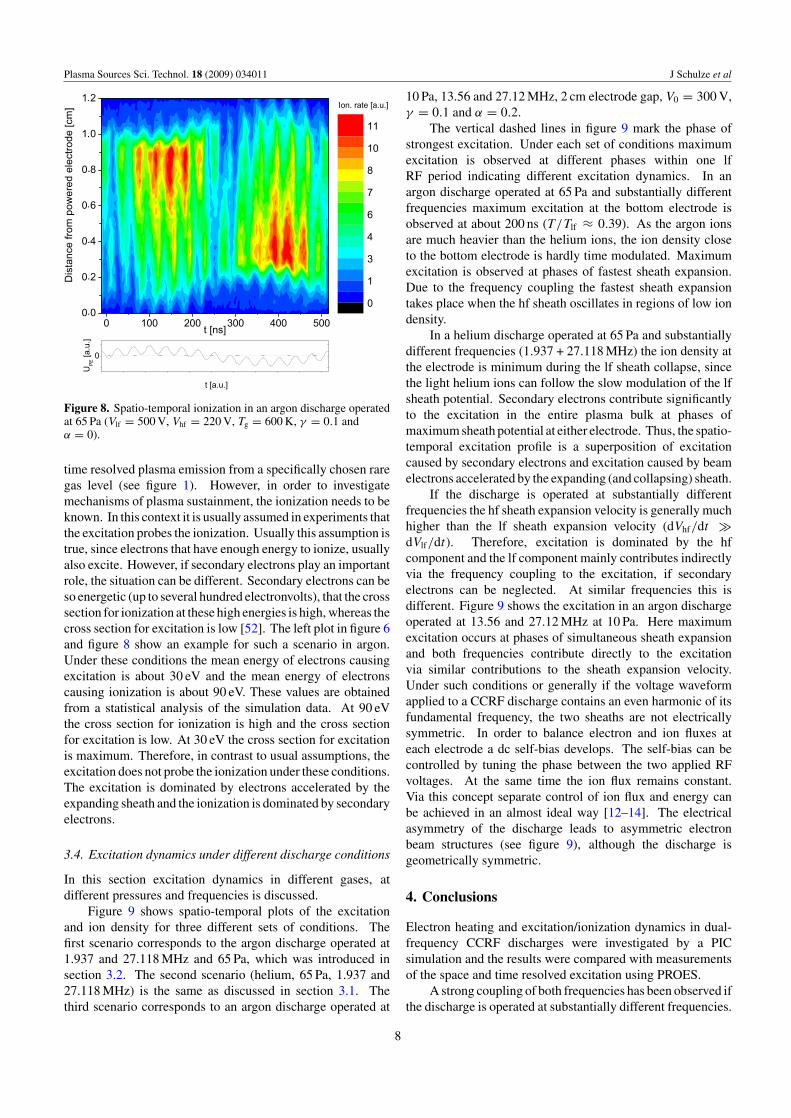
Figure 8. Spatio-temporal ionization in an argon discharge operatedat 65 Pa (Vlf = 500 V, Vhf = 220 V, Tg = 600 K, γ = 0.1 andα = 0).
time resolved plasma emission from a specifically chosen raregas level (see figure 1). However, in order to investigatemechanisms of plasma sustainment, the ionization needs to beknown. In this context it is usually assumed in experiments thatthe excitation probes the ionization. Usually this assumption istrue, since electrons that have enough energy to ionize, usuallyalso excite. However, if secondary electrons play an importantrole, the situation can be different. Secondary electrons can beso energetic (up to several hundred electronvolts), that the crosssection for ionization at these high energies is high, whereas thecross section for excitation is low [52]. The left plot in figure 6and figure 8 show an example for such a scenario in argon.Under these conditions the mean energy of electrons causingexcitation is about 30 eV and the mean energy of electronscausing ionization is about 90 eV. These values are obtainedfrom a statistical analysis of the simulation data. At 90 eVthe cross section for ionization is high and the cross sectionfor excitation is low. At 30 eV the cross section for excitationis maximum. Therefore, in contrast to usual assumptions, theexcitation does not probe the ionization under these conditions.The excitation is dominated by electrons accelerated by theexpanding sheath and the ionization is dominated by secondaryelectrons.
3.4. Excitation dynamics under different discharge conditions
In this section excitation dynamics in different gases, atdifferent pressures and frequencies is discussed.
Figure 9 shows spatio-temporal plots of the excitationand ion density for three different sets of conditions. Thefirst scenario corresponds to the argon discharge operated at1.937 and 27.118 MHz and 65 Pa, which was introduced insection 3.2. The second scenario (helium, 65 Pa, 1.937 and27.118 MHz) is the same as discussed in section 3.1. Thethird scenario corresponds to an argon discharge operated at
10 Pa, 13.56 and 27.12 MHz, 2 cm electrode gap, V0 = 300 V,γ = 0.1 and α = 0.2.
The vertical dashed lines in figure 9 mark the phase ofstrongest excitation. Under each set of conditions maximumexcitation is observed at different phases within one lfRF period indicating different excitation dynamics. In anargon discharge operated at 65 Pa and substantially differentfrequencies maximum excitation at the bottom electrode isobserved at about 200 ns (T/Tlf ≈ 0.39). As the argon ionsare much heavier than the helium ions, the ion density closeto the bottom electrode is hardly time modulated. Maximumexcitation is observed at phases of fastest sheath expansion.Due to the frequency coupling the fastest sheath expansiontakes place when the hf sheath oscillates in regions of low iondensity.
In a helium discharge operated at 65 Pa and substantiallydifferent frequencies (1.937 + 27.118 MHz) the ion density atthe electrode is minimum during the lf sheath collapse, sincethe light helium ions can follow the slow modulation of the lfsheath potential. Secondary electrons contribute significantlyto the excitation in the entire plasma bulk at phases ofmaximum sheath potential at either electrode. Thus, the spatio-temporal excitation profile is a superposition of excitationcaused by secondary electrons and excitation caused by beamelectrons accelerated by the expanding (and collapsing) sheath.
If the discharge is operated at substantially differentfrequencies the hf sheath expansion velocity is generally muchhigher than the lf sheath expansion velocity (dVhf/dt �dVlf/dt). Therefore, excitation is dominated by the hfcomponent and the lf component mainly contributes indirectlyvia the frequency coupling to the excitation, if secondaryelectrons can be neglected. At similar frequencies this isdifferent. Figure 9 shows the excitation in an argon dischargeoperated at 13.56 and 27.12 MHz at 10 Pa. Here maximumexcitation occurs at phases of simultaneous sheath expansionand both frequencies contribute directly to the excitationvia similar contributions to the sheath expansion velocity.Under such conditions or generally if the voltage waveformapplied to a CCRF discharge contains an even harmonic of itsfundamental frequency, the two sheaths are not electricallysymmetric. In order to balance electron and ion fluxes ateach electrode a dc self-bias develops. The self-bias can becontrolled by tuning the phase between the two applied RFvoltages. At the same time the ion flux remains constant.Via this concept separate control of ion flux and energy canbe achieved in an almost ideal way [12–14]. The electricalasymmetry of the discharge leads to asymmetric electronbeam structures (see figure 9), although the discharge isgeometrically symmetric.
4. Conclusions
Electron heating and excitation/ionization dynamics in dual-frequency CCRF discharges were investigated by a PICsimulation and the results were compared with measurementsof the space and time resolved excitation using PROES.
A strong coupling of both frequencies has been observed ifthe discharge is operated at substantially different frequencies.
8

Plasma Sources Sci. Technol. 18 (2009) 034011 J Schulze et al
.
.
.
.
.
.
.. . . . . .
.
.
.
.
.
.
.
.
.. . . . . .
.
.
.
.
.
.
.
.
.
.
.
.
.
.
.. . . . . .
.
.
.
.
.
.. . . . . .
.
.
.
.
.
.
.
.
.
.
.. . . . . .
.
.
.
.
.
.
.
.
.. . . . . .
.
.
.
.
.
.
.
.
.
.
.
Figure 9. Left: spatio-temporal plots of the excitation as resulting from the PIC simulation in different gases, at different pressures andfrequencies. Right: spatio-temporal plots of the ion density under the same conditions (only the sheath region at the bottom poweredelectrode is shown). The vertical dashed lines mark the phases of strongest excitation.
9

Plasma Sources Sci. Technol. 18 (2009) 034011 J Schulze et al
The momentary lf sheath voltage determines the position of thehf sheath oscillation. As the ion density decreases towards theelectrode, this coupling mechanism determines the momentarysheath expansion velocity. Maximum excitation/ionization hasbeen observed at phases when the hf sheath oscillates in regionsof low ion density in front of the electrode. This is the nature offrequency coupling. If sheath expansion heating dominates theexcitation/ionization dynamics, this coupling mechanism willaffect the excitation/ionization significantly and might limitseparate control of ion flux and ion energy. Electric fieldreversals during phases of simultaneous sheath collapse canalso contribute to the excitation.
With increasing pressure, at high sheath voltagesand if electrode materials with high γ values are used,secondary electrons become more important and can affectthe excitation/ionization significantly. If the sheath voltage isdominated by the lf component, secondary electrons mainlylead to a modulation of the excitation with twice the lf.
At intermediate pressures the discharge can be operatedin a hybrid mode. Secondary electrons as well as sheathexpansion heating contribute to excitation/ionization. At highpressures, if the electron mean free path is smaller than thesheath width, secondary electrons are multiplied in the sheathand the discharge is operated in γ -mode. Excitation/ionizationare dominated by secondary electrons. If secondary electronsdominate the ionization, separate control of ion flux andenergy is expected to be limited, since ionization by secondaryelectrons is determined mainly by the lf voltage.
At particular conditions ionization was found to bedominated by secondary electrons, whereas excitation isdominated by sheath expansion heating. This phenomenonis related to the shape of the cross sections for excitation andionization, respectively. It might be relevant to experimentalinvestigations using PROES, since it shows that the ionizationis not always probed by the excitation as is usually assumed.
If the discharge is operated at significantly differentfrequencies, the hf component generally dominates theexcitation/ionization dynamics and the lf component onlycontributes indirectly via the frequency coupling or, at highpressures, via the generation of secondary electrons.
The choice of the gas affects the spatio-temporal iondensity profiles. If light gases such as helium are used and if theion densities are high, the ion density in front of each electrodeis modulated with the low and even with the hf. These temporalmodulations are well reproduced by an analytical model. Viathe frequency coupling this temporal modulation can affect theexcitation/ionization dynamics.
If similar frequencies are used and if the ion density is nottime modulated, the sheath expansion velocities of lf and hfsheaths are similar and the lf component contributes directlyto the excitation/ionization. Therefore, maximum excitationis observed at phases of simultaneous sheath expansion.
Acknowledgments
This work has been funded by the DFG through SFB591 and GRK 1051, the Ruhr University Research Schooland the Hungarian Scientific Research Fund through grants
OTKA-T-48389 and OTKA-IN-69892. The dual-frequencymeasurements were performed in collaboration with TimoGans, Deborah O’Connell, Bert Ellingboe and Miles Turnerand supported by Lam Research Inc., the EU (FP5), the DFG(SFB 591 and GRK 1051) and the Studienstiftung des dt.Volkes.
References
[1] Lieberman M A and Lichtenberg A J 2005 Principles ofPlasma Discharges and Materials Processing 2nd edn(New Jersey: Wiley Interscience)
[2] Boyle P C , Ellingboe A R and Turner M M 2004 PlasmaSources Sci. Technol. 13 493–503
[3] Boyle P C, Ellingboe A R and Turner M M 2004 J. Phys. D:Appl. Phys. 37 697
[4] Kitajima T, Takeo Y, Petrovic Z L and Makabe T 2000 Appl.Phys. Lett. 77 489
[5] Denda T, Miyoshi Y, Komukai Y, Goto T, Petrovic Z L andMakabe T 2004 J. Appl. Phys. 95 870
[6] Lee J K, Manuilenko O V, Babaeva N Yu, Kim H C andShon J W 2005 Plasma Sources Sci. Technol. 14 89
[7] Kawamura E, Lieberman M A and Lichtenberg A J 2006Phys. Plasmas 13 053506
[8] Turner M M and Chabert P 2006 Phys. Rev. Lett. 96 205001[9] Semmler E, Awakowicz P and von Keudell A 2007 Plasma
Sources Sci. Technol. 16 839[10] Gans T, Schulze J, O’Connell D, Czarnetzki U, Faulkner R,
Ellingboe A R and Turner M M 2006 Appl. Phys. Lett.89 261502
[11] Schulze J, Gans T, O’Connell D, Czarnetzki U, Ellingboe A Rand Turner M M 2007 J. Phys. D: Appl. Phys. 40 7008–18
[12] Heil B G, Schulze J, Mussenbrock T, Brinkmann R P andCzarnetzki U 2008 IEEE Trans. Plasma Sci. 36 1404
[13] Heil B G, Czarnetzki U, Brinkmann R P and Mussenbrock T2008 J. Phys. D: Appl. Phys. 41 165202
[14] Donko Z, Schulze J, Heil B G and Czarnetzki U 2009 J. Phys.D: Appl. Phys. 42 025205
[15] Lieberman M A and Godyak V A 1998 IEEE Trans. PlasmaSci. 26 955
[16] Surendra M and Graves D B 1991 Phys. Rev. Lett. 66 1469[17] Turner M M 1995 Phys. Rev. Lett. 75 1312[18] Gozadinos G, Turner M M and Vender D 1995 Phys. Rev. Lett.
87 135004[19] Salabas A, Marques L, Jolly J and Alves L L 2004 J. Appl.
Phys. 95 4605–20[20] Vender D and Boswell R W 1990 IEEE Trans. Plasma Sci.
18 725[21] Wood B P 1991 PhD Thesis University of California at
Berkeley[22] Tochikubo F, Suzuki A, Kakuta S, Terazono Y and Makabe T
1990 J. Appl. Phys. 68 5532[23] Tochikubo F, Makabe T, Kakuta S and Suzuki A 1993 J. Appl.
Phys. 73 2163[24] Petrovic Z Lj, Tochikubo F, Kakuta S and Makabe T 1992
J. Appl. Phys. 71 2143[25] Leroy O L, Stratil P, Perrin J, Jolly J and Bellenguer Ph 1995
J. Phys. D: Appl. Phys. 28 500[26] Czarnetzki U, Luggenholscher D and Dobele H F 1999
Plasma Sources Sci. Technol. 8 230–48[27] Gans T, Schulz-von der Gathen V and Dobele H F 2004
Europhys. Lett. 66 232–8[28] Mahony C M O, Wazzan R Al and Graham W G 1997
Appl. Phys. Lett. 71 608–10[29] Schulze J, Heil B G, Luggenholscher D, Czarnetzki U
and Brinkmann R P J. Phys. D: Appl. Phys. 41 042003(FTC)
10
Plasma Sources Sci. Technol. 18 (2009) 034011 J Schulze et al
[30] Schulze J, Kampschulte T, Luggenholscher D andCzarnetzki U 2007 Inst. Phys. Conf. Ser. 86 012010
[31] Schulze J, Donko Z, Heil B G, Luggenholscher D,Mussenbrock T, Brinkmann R P and Czarnetzki U 2008J. Phys. D: Appl. Phys. 41 105214
[32] Schulze J, Heil B G, Luggenholscher D and Czarnetzki U2008 IEEE Trans. Plasma Sci. 36 1400
[33] Schulze J, Heil B G, Luggenholscher D, Brinkmann R P andCzarnetzki U 2008 J. Phys. D: Appl. Phys. 41 195212
[34] Godyak V A, Piejak R B and Alexandrovich B M 1992Plasma Sources. Sci. Technol. 1 36
[35] Belenguer Ph and Boeuf J P 1990 Phys. Rev. A 41 4447[36] Sato A H and Lieberman M A 1990 J. Appl. Phys. 68 6117[37] Vender D and Boswell R W 1992 J. Vac. Sci. Technol. A
10 1331[38] Turner M M and Hopkins M B 1992 Phys. Rev. Lett. 69 3511[39] Mussenbrock T and Brinkmann R P 2006 Appl. Phys. Lett.
88 151503[40] Mussenbrock T and Brinkmann R P 2007 Plasma Sources Sci.
Technol. 16 377–85
[41] Czarnetzki U, Mussenbrock T and Brinkmann R P 2006Phys. Plasmas 13 123503
[42] Turner M M, Chabert P, Levif P, Boyle P, and Robiche J 2007Conf. Proc. 18th ICPIG (Prague)
[43] Donko Z and Petrovic Z Lj 2006 Japan. J. Appl. Phys. 45 8151[44] Bohm C and Perrin J 1992 Rev. Sci. Instrum. 64 31–44[45] Morgan W L, Boeuf J P, and Pitchford L C The Siglo Database,
CPAT and Kinema Software http://www.siglo-kinema.com[46] Chilton J E, Stewart M D and Lin C C 2000 Phys. Rev. A
61 52708[47] Gans T, Schulze J, Czarnetzki U and Turner M M 2005
Bull. Am. Phys. Soc. 58th Gaseous Electronics Conf. (SanJose, CA) p 30
[48] Brinkmann R P 2007 J. Appl. Phys. 102 093302[49] Mussenbrock T, Hemke T, Ziegler D, Brinkmann R P and
Klick M 2008 Plasma Sources Sci. Technol. 17 025018[50] Hornbeck J A 1951 Phys. Rev. 84 615[51] Raizer Y P 1991 Gas Discharge Physics (Berlin: Springer)[52] Phelps A V and Petrovic Z Lj 1999 Plasma Sources Sci.
Technol. 8 R21
11
Copyright © 2022 FDOKUMEN