Metastatic duodenal GIST: role of surgery combined with imatinib mesylate
Upload
independentCategory
view
5download
0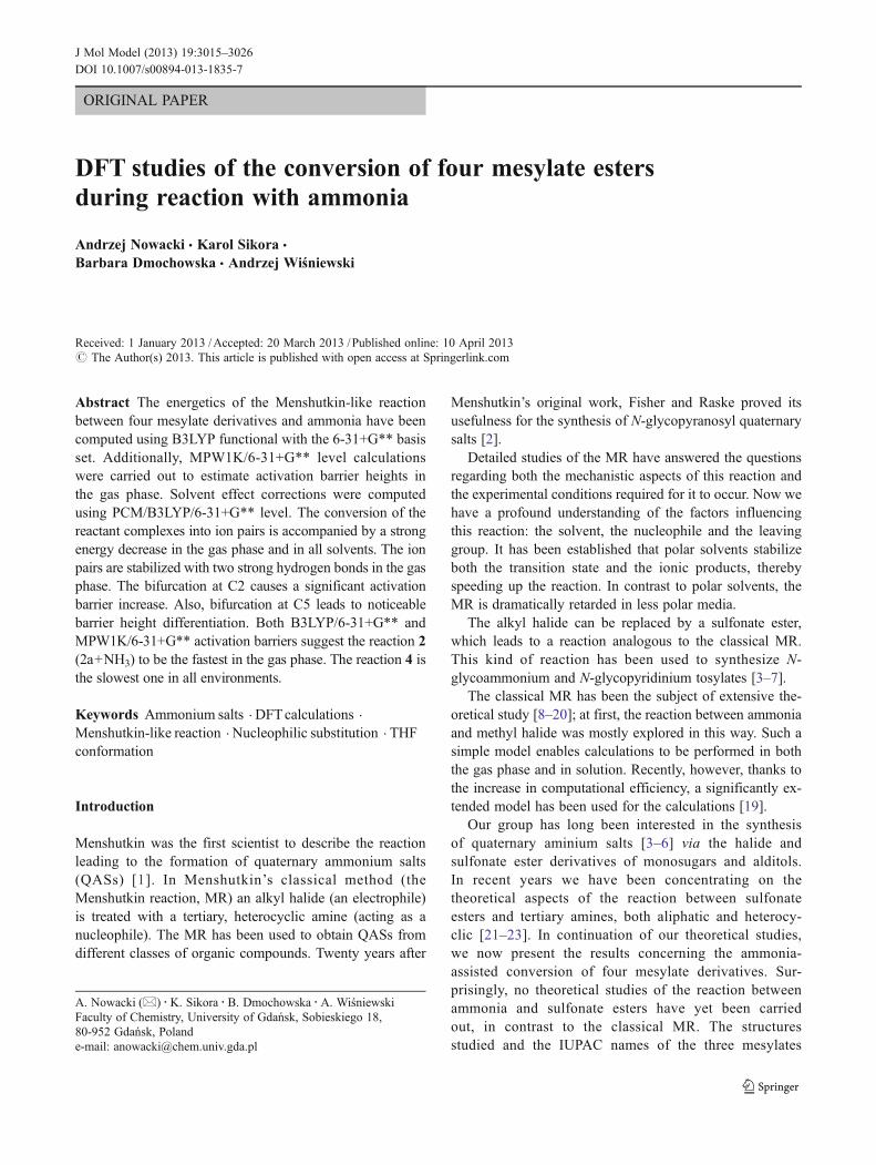
ORIGINAL PAPER
DFT studies of the conversion of four mesylate estersduring reaction with ammonia
Andrzej Nowacki amp Karol Sikora amp
Barbara Dmochowska amp Andrzej Wiśniewski
Received 1 January 2013 Accepted 20 March 2013 Published online 10 April 2013 The Author(s) 2013 This article is published with open access at Springerlinkcom
Abstract The energetics of the Menshutkin-like reactionbetween four mesylate derivatives and ammonia have beencomputed using B3LYP functional with the 6-31+G basisset Additionally MPW1K6-31+G level calculationswere carried out to estimate activation barrier heights inthe gas phase Solvent effect corrections were computedusing PCMB3LYP6-31+G level The conversion of thereactant complexes into ion pairs is accompanied by a strongenergy decrease in the gas phase and in all solvents The ionpairs are stabilized with two strong hydrogen bonds in the gasphase The bifurcation at C2 causes a significant activationbarrier increase Also bifurcation at C5 leads to noticeablebarrier height differentiation Both B3LYP6-31+G andMPW1K6-31+G activation barriers suggest the reaction 2(2a+NH3) to be the fastest in the gas phase The reaction 4 isthe slowest one in all environments
Keywords Ammonium salts DFTcalculations
Menshutkin-like reaction Nucleophilic substitution THFconformation
Introduction
Menshutkin was the first scientist to describe the reactionleading to the formation of quaternary ammonium salts(QASs) [1] In Menshutkinrsquos classical method (theMenshutkin reaction MR) an alkyl halide (an electrophile)is treated with a tertiary heterocyclic amine (acting as anucleophile) The MR has been used to obtain QASs fromdifferent classes of organic compounds Twenty years after
Menshutkinrsquos original work Fisher and Raske proved itsusefulness for the synthesis of N-glycopyranosyl quaternarysalts [2]
Detailed studies of the MR have answered the questionsregarding both the mechanistic aspects of this reaction andthe experimental conditions required for it to occur Now wehave a profound understanding of the factors influencingthis reaction the solvent the nucleophile and the leavinggroup It has been established that polar solvents stabilizeboth the transition state and the ionic products therebyspeeding up the reaction In contrast to polar solvents theMR is dramatically retarded in less polar media
The alkyl halide can be replaced by a sulfonate esterwhich leads to a reaction analogous to the classical MRThis kind of reaction has been used to synthesize N-glycoammonium and N-glycopyridinium tosylates [3ndash7]
The classical MR has been the subject of extensive the-oretical study [8ndash20] at first the reaction between ammoniaand methyl halide was mostly explored in this way Such asimple model enables calculations to be performed in boththe gas phase and in solution Recently however thanks tothe increase in computational efficiency a significantly ex-tended model has been used for the calculations [19]
Our group has long been interested in the synthesisof quaternary aminium salts [3ndash6] via the halide andsulfonate ester derivatives of monosugars and alditolsIn recent years we have been concentrating on thetheoretical aspects of the reaction between sulfonateesters and tertiary amines both aliphatic and heterocy-clic [21ndash23] In continuation of our theoretical studieswe now present the results concerning the ammonia-assisted conversion of four mesylate derivatives Sur-prisingly no theoretical studies of the reaction betweenammonia and sulfonate esters have yet been carriedout in contrast to the classical MR The structuresstudied and the IUPAC names of the three mesylates
A Nowacki () K Sikora B Dmochowska A WiśniewskiFaculty of Chemistry University of Gdańsk Sobieskiego 1880-952 Gdańsk Polande-mail anowackichemunivgdapl
J Mol Model (2013) 193015ndash3026DOI 101007s00894-013-1835-7
are shown in Fig 1 The salts under discussion areanalogues of (+)-muscarine the principal alkaloid insome poisonous fungi There has been a resurgence ofinterest in muscarine in recent years following thediscovery of a relationship between a cholinergic deficitand the pathology of Alzheimerrsquos disease [24] We alsodid the calculations for the conversion of methylmesylate Our aim was to produce a kinetic and ther-modynamic description of this type of modified MRAs before we also wanted to assess the influence ofthe branching three bonds distant from the reactioncenter (the methyl or methoxy group bound to C5 ofthe THF ring is cis-oriented in relation to C1) Withthis work we have completed the review of differentnucleophilic agents typically used in the classic variantof the MR
Computational details
All the calculated structures were prepared in theMOLDEN program [25] The geometries were thenoptimized using density functional theory (DFT) basedon Beckersquos three-parameter hybrid exchange functional[26] involving the gradient-corrected correlation func-tional of Lee Yang and Parr [27] with the split-valence basis set including polarized and diffuse func-tions [28 29] mdash (B3LYP6-31+G method) Optimi-zations for reactant complexes and transition states wereadditionally done using the MPW1K6-31+G method[30] This functional (Pedrew-Wang 1-parameter modelfor kinetics MPW1K) gives remarkably accurate activa-tion barrier heights The optimization was consideredsatisfactory if the energy difference between optimiza-tion cycles was less than 1times10minus6 Hartree and a gradientof lt1times10minus4 au was achieved The convergence of allthe systems studied was checked by harmonic vibration-al analysis No imaginary frequencies were observed forthe ground state and there was only one for the transi-tion state
Solvent effects were included in the calculationsemploying the self-consistent reaction field SCRF-PCM solvation model [31] for the reactions studied inchloroform (isin=49) and water (isin=7839) at theB3LYP6-31+G level Implicit solvent calculationsimply the generation of a vacuum cavity inside acontinuous and homogeneous dielectric field In PCMmodel the cavity is built up by a series of interlockingatomic spheres We used UA0 with scale factor alpha=12for water and 14 for chloroform [18] Individual spheres werecentered on acidic hydrogen atoms
All DFT calculations were done with the aid of theGaussian 03 program [32]
Results and discussion
General characteristic of the reaction pathway
The studied reactions together with atom numbering orderare shown in Scheme 1 The atom numbering orderpresented in Scheme 1 is not compatible with the namesshown in Fig 1 and IUPAC recommendations but we use itin order to make the presentation of our results clearer
Reaction 1 is closely related to the classical MR differingonly in the leaving group We carried out calculations forthis reaction to compare the influence of leaving groupexchange on the reaction
The next two reactions (2 and 3) involve anhydroalditolswhereas the last one (4) relates to the glycoside The spatialarrangement of the aglycone (here the OCH3 group) inrelation to the THF ring in glycosides is governed by thesteric factor and by the so-called exo-anomeric effect Thiseffect forces the aglycone to be located in a position wherean acute torsion angle is formed in relation to the endocyclicoxygen atom This requirement is satisfied in two orien-tations minussc and +sc (Fig 2) but the steric hindrancepresent in the +sc conformation disqualifies it so thepreferred one is minussc
The H3CndashO5ndashC5ndashO2 torsion angle ranges from minus65deg tominus82deg all along the reaction pathway (Table 1) However this isnot a golden rule since we showed previously that in thereaction of mesylate derivative 4a with a bulky trimethylaminethe minussc orientation of the methoxyl group appeared to beunfavorable because of steric hindrance and thus changed toap [21]
The steps of the reactions under discussion are analogousto those reported previously [21ndash23] The energy (E0) andpseudochemical potential (U0) [33] profiles for the conver-sion of the mesylates into the corresponding ammoniumsalts (Fig 3) in the gas phase and in solvents consists ofan asymmetric double-well potential with five stationarypoints corresponding to the separated reactants (R)reactant complex (RC) transition state (TS) productcomplex (PC) and separated ionic products (P) Tworeactants (electrophile mdash mesylate derivative and nu-cleophile mdash ammonia) approach one another forming avan der Waals reactant complex This complex convertsinto an ionic pair which requires an activation barrier tobe overcome Finally the constituents of the ionic pairare separated to an infinitely great distance The maindifference between the energy diagrams shown in Fig3and those presented elsewhere [21ndash23] is on the productside Previously the last stage of the reaction was endergonicin the gas phase and in chloroform whereas it was exergonicin polar solvents In the reactions being studied here separa-tion of the ion pair constituents requires the application energyin the gas phase and in all solvents
3016 J Mol Model (2013) 193015ndash3026
Gas-phase calculations
Table 1 lists the activation and reaction energies forboth the gas state and solutions together with importantgeometrical parameters of all the stationary points onPES A scaling factor of 09877 was used for the zero-point vibrational energy (ZPVE) correction of the cal-culated total energies [34]
To discuss the conformational details of the THF ring theAltonandashSundaralingam (AS) pseudorotational phase angle(P) and the AS puckering amplitude (ϕm) were considered[35 36] The THF ring conformations P and ϕm values aregiven in Table 2 together with the set of the endocyclictorsion angles ϕ0ndashϕ4 whereas the definition of these anglesis shown in Fig 4 The conformational descriptors that weadopted differ from the classical ones because of the
different atom numbering scheme Table 2 also lists twotorsion angles (χ) describing the spatial disposition of theexocyclic groups
The calculated geometries together with selected bonddistances valence angles and relative energies correspond-ing to all the stationary points along the reaction pathwayare presented in Figs 5 and 6 The relative energies refer tothe sum of the separate reactant energies
The first point on the energy curves (Fig 3) correspondsto the separate reactants ie mesylate derivative and am-monia In the case of reaction 2 (Table 2) the THF ring takesthe E4 conformation (P=349deg ϕm=36deg) in which C1 atomis in the pseudo-equatorial position (χ1=minus1445deg) Thesame ring conformation is found for the individualmesylate in reaction 4 (P=336deg ϕm=36deg) whereasthe 4E conformation is observed for the separate
Scheme 1 Reactions ofammonium salt formation
Fig 1 Structures of mesylatederivatives converted intoammonium salts
J Mol Model (2013) 193015ndash3026 3017
mesylate in reaction 3 (P=155deg ϕm=minus36deg) The E4 con-formation is free of 13-diaxial-like steric interactions and theeclipsed orientation of the substituents as we described pre-viously [23] The mesylate C1 atom in reaction 4 is in thepseudo-equatorial orientation (χ1=minus1385deg) whereas theOCH3 group is in the pseudo-axial position (χ2=846deg) Thusthe THF ring avoids the unfavorable 13-diaxial-like stericinteractions between these two groups The THF ring inreaction 3 bears two bulky substituents on the same side ofthe ring hence two reverse conformations should be consid-ered namely those in which the C1 or C6 atom is in thepseudo-equatorial orientation (the 3E or 4E conformation re-spectively) Both conformations have features thought to sta-bilize five-membered rings because they hold two bulkygroups moved away from one another avoiding steric repul-sion and there are no eclipse orientations of any substituentsin the THF ring According to the B3LYP functional 4Econformation that with the pseudo-equatorially located CH3
group (χ2=1567deg) and pseudo-axially oriented CH2OMsgroup (χ1=minus1007deg) is more stable by about 1 kcal molminus1
The next point on the energy diagrams represents thereactant complex In all the cases studied the approach ofthe individual reactants is accompanied by a slight energydecrease (Table 1 Figs 5 and 6) in the gas phase Gibbs freeenergies however predict that reactant complex formationwill be unfavorable (ΔG=50ndash62 kcal molminus1)
The small value of the complexation energy(minus29 kcal molminus1 minus22 kcal molminus1 minus21 kcal molminus1
and minus24 kcal molminus1 for 1a 2a 3a and 4a respective-ly) indicates that the interaction (hydrogen bond) be-tween these two molecules in this complex isrelatively weak The intermolecular interaction be-tween mesylate and ammonia in reactant complexesis slightly stronger than the one for trimethylamine[21] and comparable with that for pyridine [22 23]This may be related to the type of intermolecularinteraction A typical SndashOHndashN hydrogen bond stabilizesthe reactant complex in these reactions whereas an atypicalSndashOHndashC hydrogen bond interaction was observed for thereactions with trimethylamine [21] After decades of the con-troversy on whether OHndashC hydrogen bonds really exist it isaccepted now that they do exist although OHndashC hydrogenbonds are mostly weak in comparison with classical ones [37] T
able
1Geometry
parametersrelativ
eenergies
andrelativ
eGibbs
free
energies
oftherelevant
stationary
pointson
thePESin
thegasph
aseat
B3L
YP6-31+
G
calculated
forreactio
ns1ndash4
Reaction1
Reaction2
Reaction3
Reaction4
(R)
(RC)
(TS)
(IP)
(P)
(R)
(RC)
(TS)
(IP)
(P)
(R)
(RC)
(TS)
(IP)
(P)
(R)
(RC)
(TS)
(IP)
(P)
R(CO)
1450
1461
2060
3619a
infin1458
1470
2059
3430a
infin1458
1470
2069
3451a
infin1458
1470
2057
3466
ainfin
R(CN)
infin3488
1932
1483
1516
infin3482
2077
1490
1519
infin3480
2078
1489
1519
infin3489
2068
1489
1521
ΔR
ndashinfin
minus2027
0128
2136
infinminusinfin
minus2012
minus0011
1940
infinminusinfin
minus2010
minus0009
1962
infin-infin
minus2019
minus0011
1977
infin
angOCN
1000
1788
381
a
967
1573
453a
945
1642
447
a
964
1628
439
a
A
minus669
minus637
minus130
1732
1610
minus733
minus710
04
1723
1587
minus673
minus649
minus159
1730
1632
B
1633
1784
1795
1762
C
minus663
minus653
minus643
minus693
minus818
ΔE
00
minus29
293
minus125
1052
00
minus22
288
minus152
940
00
minus21
292
minus149
934
00
minus24
308
minus147
944
ΔG
00
50
382
minus41
1043
00
58
386
minus57
936
00
62
388
minus56
930
00
58
413
minus50
938
Allenergy
values
inkcal
mol
minus1Rin
Aringandangles
indeg
ReactioncoordinateΔR=R(CO)-R(CN)The
smallestvalueof
thedistance
betweenCandO
was
takento
define
thereactio
ncoordinate(R)separate
reactants(RC)reactant
complex(TS)
transitio
nstate(IP)ionpairand(P)separate
ions
Atorsionangle
(OndashC
1ndashC2ndash
C3)
forRRCandTS
(NndashC
1ndashC2ndash
C3)
forIP
andP
InRthistorsionanglecorrespo
ndsto
mesylatewhereas
inPthisanglecorrespo
ndsto
thecatio
n
Bdeform
ationangleC2ndash
C1ndash
H1 andashH
1 b(for
thereactio
n1
HndashC
ndashHandashHb)describing
theplanarity
ofthetransitio
nstategeom
etry
Ctorsionangledefining
thepo
sitio
nof
theaglycone
inrelatio
nto
THFring
(H3CndashO
ndashC5ndash
O2)
atheO
atom
closestto
thereactio
ncenter
carbon
atom
was
used
toob
tain
thisvalue
Fig 2 Rotamers exhibiting possible spatial arrangements of the OCH3
group in relation to the heterocyclic oxygen atom The preferredorientation is in the box
3018 J Mol Model (2013) 193015ndash3026
The shape of the THF ring does not change whilereactants are approaching one another The E4 confor-mation is observed for THF ring in reactant complexes2a and 4a whereas the 4E conformation is noted in 3a(Table 2) A noteworthy fact is that in reaction 4 twodifferent conformations (E4 for the separate mesylateand 2E for the reactant complex) were preferred forthe THF ring when the conversion with pyridine wasbeing studied and described [23]
The next stationary point on the energy curve shown inFig 3 corresponds to the transition state The relativeenergy values matching the transition states with respect tothe separated reactants are given in Table 1 and in Figs 5and 6 whereas the activation barriers relating to the reactantcomplexes are listed in Table 3
The geometry of the relevant transition state can becharacterized by the CO and CN distances OCN
valence angles and two torsion angles (A B Table 1)Whereas the CO and CN distances are roughly the samein all TSs (about 206 Aring and 208 Aring respectively) the CNdistance in reaction 1 is much shorter (193 Aring)
Table 1 and Fig 5 indicate that the transition state forreaction 1 is linear the valence angle OCN being1788deg The other three TSs are slightly bent the citedvalence angle ranging from sim156deg to sim164deg which is theresult of the steric hindrance
The approach of the ammonia molecule to C1 induces achange in the OndashC1ndashC2ndashC3 torsion angle (Table 1) In thereactant complex this angle is about minus65deg whereas in thetransition state it takes values of minus130deg 04deg and minus159deg forreactions 2 3 and 4 respectively The observed differencesin values of the torsion angle come from the variation of theTHF ring conformation The preferred conformation of theTHF ring in the transition state corresponding to conversions 2
Fig 3 Energy (E0) and pseudochemical potential (U0) profiles for reactions 1ndash4 calculated at B3LYP6-31+G level in the gas phase chloroform and water
J Mol Model (2013) 193015ndash3026 3019
and 4 is 3T4 (P=2deg ϕm=39deg and P=358deg ϕm=40deg for 2 and 4respectively Table 2) This conformation is free of theeclipsed orientation of the substituents and 13-diaxial-likesteric interactions (in reaction 4) as C1 is moved away fromthe THF ring (χ1=minus154deg Table 2) In consequence the MsOleaving group is also located beside the THF ring In reac-tion 3 the THF ring adopts the 4T3 conformation (P=174degϕm=minus37deg) in which the C6 atom is moved away from thering (χ2=153deg Table 2) In this conformation the MsOleaving group is located above the THF ring
The C2ndashC1ndashH1andashH1b deformation torsion angle (B Table 1)reflects the planar placing of substituents at the C1 atom in thetransition state This indicates that the transition state geometry isexactly halfway between the reactant and product complex forreactions 2 3 and 4 whereas the late transition state is observedfor reaction 1
The calculated barriers are higher than those for the re-actions with trimethylamine [21] and pyridine [22 23]which corresponds to the lower basicity of ammonia in avacuum (Fig 7) The proton affinity of ammonia is2040 kcal molminus1 but is 2251 kcal molminus1 and2208 kcal molminus1 for trimethylamine and pyridine respec-tively [38] The energy barrier is the lowest for reaction 2but the highest for reaction 4 Interestingly the energybarrier for reaction 1 is higher than for reactions 2 and 3according to both B3LYP and MPW1K methods Thisstands in contrast to the reactions of the same mesylatederivatives with other nucleophiles studied earlier [21ndash23]where the barrier was the lowest for the reaction of methylmesylate with the corresponding nucleophile (Fig 7) Pre-sumably hydrogen bond formation between the endocyclic
oxygen atom and the hydrogen atom attached to the nitrogenatom stabilizes the transition state geometry Such an inter-action cannot occur in reaction 1
The second minimum on the reaction pathway corre-sponds to ion pairs Both ΔE and ΔG predict that theconversion of the reactant complexes to the respective ionpairs is accompanied by an energy decrease in the gas phaseThis effect is smallest in reaction 1 and the energy of the ionpair 1b is ca 10 kcal molminus1 lower than that of the reactantcomplex Interestingly ΔE and ΔG at this stage wereexpected to be unfavorable for the reaction of methylmesylate and pyridine [22] On the other hand ion pairformation was slightly favorable (ΔE=minus15 kcal molminus1)when trimethylamine was the nucleophile [21] The conver-sion of complexes into ion pairs is rather more favorable forthe remaining three reactions (about 12 kcal molminus1) than forreaction 1 The constituents of ion pair 1b are oriented insuch a way that the whole geometry has the Cs symmetry(Fig 8) with two carbons oxygen sulfur and nitrogenbeing planar The anion and the cation are held togetherdue to two strong hydrogen bonds which may be
Table 2 Selected torsion anglesand calculated values of thepseudorotational phase angle (P)and of the puckering amplitude(ϕm) of the THF ring for all sta-tionary points for conversions 2ndash4
aDefinition of the torsion anglesϕ0 ndash C5ndashC4ndashC3ndashC2 ϕ1 ndash C4ndashC3ndashC2ndashO2 ϕ2 ndash C3ndashC2ndashO2ndashC5 ϕ3 ndash C2ndashO2ndashC5ndashC4 ϕ4 ndashO2ndashC5ndashC4ndashC3 χ1 ndash C1ndashC2ndashC3ndashC4 χ2 ndash RndashC5ndashC4ndashC3where R represents the substitu-ent attached to C5
P ϕm ϕ0 ϕ1 ϕ2 ϕ3 ϕ4 χ1 χ2
Reaction 2
R E4 349 36 356 minus260 52 182 minus336 minus1445 RC E4 345 36 352 minus241 23 208 minus349 minus1426 TS 3T4 2 39 391 minus334 143 110 minus316 minus1545 IP 3T4 4 36 362 minus319 146 91 minus287 minus1506 P 3T4 2 36 365 minus311 134 104 minus295 minus1481 Reaction 3
R 4E 155 minus36 minus330 186 44 minus258 363 minus985 1562
RC 4E 151 minus37 minus320 165 70 minus278 368 minus1007 1567
TS 4T3 174 minus37 minus371 285 minus84 minus154 327 minus923 1530
IP E5 117 minus39 minus177 minus50 279 minus394 345 minus1232 1540
P 4E 149 minus37 minus313 148 85 minus285 365 minus1015 1561
Reaction 4
R E4 336 36 328 minus193 minus31 247 minus357 minus1383 846
RC E4 337 36 330 minus198 minus25 242 minus355 minus1389 848
TS 3T4 358 40 397 minus318 113 143 minus339 minus1540 860
IP E4 342 36 345 minus223 05 220 minus352 minus1421 849
P E4 334 37 334 minus183 minus47 261 minus368 minus1364 820
Fig 4 Definition of the endocyclic torsion angles ϕ0ndashϕ4
3020 J Mol Model (2013) 193015ndash3026
responsible for the stronger stability of the ion pairSuch interactions are also found in the ion pairs formedin the other reactions studied
In ion pair 2b the THF ring has the 3T4 conforma-tion (P=4deg ϕm=36deg) as in the corresponding transitionstate whereas in ion pair 3b the almost ideal E5 conformationof the THF ring (P=117deg ϕm=minus39deg) is preferred (Table 2)This means that a conformational change occurs on goingdownhill from the energy maximum to the valley In the caseof reaction 4 the THF ring adopts the same conformation as inthe reactant complex ie E4 (P=342deg ϕm =36deg)
The last stage of the reactions studied consists in theseparation of the ion pair constituents Again this pro-cess is extremely unfavorable in the gas phase Morethan 90 kcal molminus1 in relation to the sum of the ener-gies of the individual reactants must be supplied tomove the ions to an infinite distance from one another(Table 1) Ion pair dissociation is more endoenergetichere than it was in the reactions with trimethylamineand pyridine [21ndash23]
Calculations in solution (SCRF-PCM)
Tomasirsquos polarizable continuum model (PCM) was used toinvestigate the influence of the liquid phase on the course ofthe reactions under scrutiny [31] The PCM model permits
the self-consistent computation of free energies of solvationincluding polarized solutesolvent interactions and non-electrostatic terms in the Hamiltonian On the other hand itshould be emphasized that reaction field models are incapa-ble of modeling specific (short range) solutesolvent inter-actions that is those occurring in the first solvation sphereThus the conclusions drawn based on the calculationswhere such interactions occur should be interpreted withcare Although PCM operates better in aprotic solvents ithas also been used to predict the solvation effect in proticsolvents [15 39]
Keeping in mind the limitations of the implicit sol-vent models PCM approach was applied to both mini-mum energy structures and saddle point configurationsIn our previous papers [23] we showed that almost theentire solvent effect is achieved after single point PCMcalculations and no significant energy changes wereobserved during the optimization in water Moreoverwe showed that the TS geometry changes were not soprofound as those experienced with the classicalMenshutkin reaction [17 40] Although previously westudied the solvent effect in three solvents this time wedecided to carry out full optimization only in two sol-vents that is chloroform and water We resigned fromdoing the calculation in ethanol because energy changesin ethanol and water were roughly the same
Fig 5 Geometries of the stationary points and ΔE (kcal molminus1) computed at the B3LYP6-31+G level for reactions 1 and 2 in the gas phaseSelected distances in Aring and valence angles in degrees
J Mol Model (2013) 193015ndash3026 3021
The results of calculations in chloroform and in water arelisted in Table 4 whereas Fig 9 illustrates the geometries ofthe transition states optimized in water
Significant changes in the energy diagrams are observedalong the reaction path in both solvents as compared withthe gas phase (Fig 3) especially on the product side Inchloroform a solvent of low polarity the energy sum of theseparated ions decreases dramatically but the overall pro-cess is still endothermic relative energy ranges from23 kcal molminus1 (reactions 2 and 3) to almost 29 kcal molminus1
(reaction 1) with respect to individual reactants (Table 4)The Gibbs free energy also predicts the process to be slight-ly unfavorable (ΔGasymp4 kcal molminus1) In very polar solvent inturn the reactions are exothermic and favorable The ener-gies of the separated ions are less than those of the individ-ual reactants by about minus2 kcal molminus1 (reaction 1) and about5 kcal molminus1 for other reactions
According to the ΔU0 values complexation is slightlyexothermic in chloroform (Table 4) On the other hand ΔGsindicate that this step of the reaction is strongly unfavorableabout 6 kcal molminus1 on average must be supplied to form thereactant complex Also in water medium the reactant complexformation is unfavorable It means that interactions betweenthe constituents of the reactant complex are rather weak Thesame conclusions were drawn previously [21ndash23]
Castejon et al [17] studied the relationship between thestability of the reactant complexes (and ion pairs as well)and solvent polarity for the Menshutkin reaction Theynoticed that neither the reactant complex nor the ion pairwere energy minima in very polar solvents like dimethylsulfoxide However in our case they appeared to be realenergy minima in water although certain geometry differ-ences were observed The geometries of reactant complexesand ion pairs are roughly the same within the mesylatederivatives in the gas phase and in water However thereactant complexes differ in the relative positions of theirconstituents The CN distance is 3488 Aring on average inthe gas phase whereas in water it is much longer about37 Aring The reactant complexes and ion pairs formed in thereactions under discussion owe their stability to the hydro-gen bonds formed between H and O atoms from the nucle-ophile and mesylate moiety respectively
BothΔU0 and ΔG showed that ion pair formation was anexoenergetic process in solvents with respect to the reactantcomplex as in a vacuum In reaction 1 taking place in chlo-roform the decrease in energy is minus129 kcal molminus1 (ΔG)whereas in water the conversion of the reactant complex intothe ion pair is more exoenergetic (minus168 kcal molminus1) than inchloroform The free energy changes accompanying ion pairformation in the other three reactions are roughly the same
Fig 6 Geometries of the stationary points and ΔE (kcal molminus1) computed at the B3LYP6-31+G level for reactions 3 and 4 in the gas phaseSelected distances in Aring and valence angles in degrees
3022 J Mol Model (2013) 193015ndash3026
(about minus14 kcal molminus1 and 17 kcal molminus1 in chloroform andwater respectively) as for the reaction 1
Optimization of transition states in chloroform leads torather insignificant geometry changes These changes arethe greatest for the reaction 1 where the CO distancedecreases from 2060 Aring in the gas phase to 1967 Aring inchloroform and the CN distance increases from 1932 Aringto 2040 Aring (Table 4) This means that the transition state isshifted toward an earlier stage of the reaction For the otherthree reactions the transition state geometry changes areeven less
In turn more significant changes in transition state ge-ometry in relation to the gas phase take place duringoptimization in water especially for reactions 1 and 4 Inreaction 1 the CO distance decreases to 1909 Aring whereasthe CN distance increases to 2113 Aring with respect to thevalues found in the gas phase Analogous geometry changesin transition state geometries occur for reactions 2 and 3however here the CO distance decreases by about 005 Aringwhereas the CN distance increases by about 01 Aring Thedescribed geometrical changes are not as profound as in theclassical Menshutkin reaction [17 40] Like in chloroformthese geometrical changes shifts transition states back to anearlier stage of the reaction
Apart from the geometry changes at the reactioncenter there is an additional variation of the transitionstates in reactions 2ndash4 particularly in water In reaction2 the OndashC1ndashC2ndashC3 torsion angle (A Table 4) increasesfrom minus130deg in the gas phase to 538deg in water Thevalue is similar for reaction 3 (432deg) whereas forconversion 4 it is 60deg This indicates that in two TSs(reactions 2 and 3) the leaving group is shifted abovethe THF ring Rotation about the C1ndashC2 bond inducesthe ring conformation switch (4T3 rarr E5) in reaction 3In reactions 2 and 4 the THF ring conformation changesare not significant (3T4 rarr E4)
It is well recognize that the transfer from the gas phase tosolvent leads to a significant energy barrier drop Indeed theB3LYP level barriers calculated in both solvents are muchlower than those calculated for the gas phase In the case ofthe reaction 1 occurring in chloroform calculated barrier islower by about 8 kcal molminus1 whereas in water it is ca13 kcal molminus1 less For the other three reactions the differ-ences between barriers in the gas phase and in solvents aresignificantly lower For the reaction 4 barriers are lower byabout 5 kcal molminus1 and 8 kcal molminus1 in chloroform andwater respectively
A different barriers height order is found in the gas phaseand in solvents In the gas phase the lowest barrier wasfound for the reaction 2 In turn for the reaction 1 takingplace in chloroform the barrier is by about 3 kcal molminus1
lower than for the reaction 2 The difference between barrierheight are even greater in water This may suggest thathydrogen bond stabilizing TS in the gas phase is weakerin solvents
Like in the gas phase also in solvents the barrier heightdepends on the type of the substituent at C5 The presenceof a spatial group attached to this carbon atom slightlyincreases the barrier although the differences are rathersmall in chloroform It is difficult to judge which reaction2 or 3 should be faster based on the free energy barrierscalculated in water
The transfer from the gas phase to the solvent leadsto a significant energy drop in the final step of thesereactions While separating the ion pair constituents re-quires about 100 kcal molminus1 (ΔG) in a vacuum inchloroform over 30 kcal molminus1 need to be supplied toaccomplish this step of the reaction In water in turnonly about 5 kcal molminus1 are required
Table 3 Activation energies calculated for the conversion of reactantcomplexes 1a 2a 3a and 4a in the gas phase All energy values inkcal molminus1
B3LYP6-31+G MPW1K6-31+G
ΔEDagger ΔGDagger ΔEDagger ΔGDagger
Reaction 1 3222 3313 3478 3562
Reaction 2 3098 3279 3388 3561
Reaction 3 3126 3266 3410 3603
Reaction 4 3318 3550 3617 3873
Fig 7 Comparison of activation barriers for reactions 1 and 2 withdifferent nucleophiles in the gas phase
Fig 8 Geometry of the ion pair in reaction 1
J Mol Model (2013) 193015ndash3026 3023
Tab
le4
Geometry
parametersrelativ
eenergies
andrelativ
eGibbs
free
energies
ofrelevant
stationary
pointson
theFESatB3L
YP6-31+
G
calculated
forreactio
ns1ndash
4in
chloroform
andwater
Reaction1
Reaction2
Reaction3
Reaction4
(R)
(RC)
(TS)
(IP)
(P)
(R)
(RC)
(TS)
(IP)
(P)
(R)
(RC)
(TS)
(IP)
(P)
(R)
(RC)
(TS)
(IP)
(P)
Chloroform
R(CO)
145
1146
1196
7364
6ainfin
145
9146
9200
3343
1ainfin
145
9147
0202
5358
6ainfin
145
9146
92011
358
5ainfin
R(CN)
infin350
6204
0148
8150
0infin
353
1215
6149
0151
6infin
353
4214
4149
2151
4infin
351
5213
9149
2151
6
ΔR
minusinfin
minus204
5minus007
3215
8infin
minusinfin
minus206
2minus015
3194
1infin
minusinfin
minus206
4minus0119
209
4infin
minusinfin
minus204
6minus012
8209
3infin
angOCN
10
01
1771
395a
971
1656
453
a
93
616
45
421
a
96
216
40
417
a
A
minus66
7minus63
9minus54
1732
1643
8minus73
3minus70
993
1690
1624
minus67
0minus64
5minus10
217
34
1681
B
17
55
1745
1755
1766
C
minus67
0minus66
1minus64
9minus70
4minus76
5
ΔU0
00
minus15
227
minus15
628
700
minus11
259
minus17
023
100
minus09
268
minus17
323
200
minus11
278
minus16
924
5
ΔG
00
69
320
minus60
285
00
69
363
minus73
232
00
82
379
minus71
239
00
73
379
minus69
243
ΔU0Dagger
243
270
277
289
ΔGDagger
251
294
296
307
Water
R(CO)
145
4146
2190
9346
0ainfin
146
1146
7200
8369
1ainfin
146
1146
9201
3364
9ainfin
146
1146
7198
0365
4ainfin
R(CN)
infin359
82113
149
5150
6infin
376
1216
4149
5151
0infin
369
1217
8149
5150
9infin
368
6220
5149
6151
0
ΔR
minusinfin
minus213
6minus020
4196
5infin
minusinfin
minus229
4minus015
6219
6infin
minusinfin
minus222
2minus016
5215
4infin
minusinfin
minus221
9minus022
5215
8infin
angOCN
10
09
1767
456a
992
1635
411
a
90
116
28
420
a
95
016
52
416
a
A
minus66
0minus66
753
817
13
1677
minus72
2minus73
143
216
72
1640
minus67
0minus64
960
1741
1709
B
17
49
1783
1773
1697
C
minus66
9minus67
1minus65
0minus67
8minus71
8
ΔU0
00
minus02
184
minus18
7minus25
00
minus01
238
minus20
4minus53
00
minus01
238
minus20
4minus54
00
minus01
247
minus19
9minus45
ΔG
00
76
285
minus92
minus27
00
76
349
minus114
minus52
00
72
344
minus91
minus55
00
71
348
minus10
3minus49
ΔU0Dagger
186
239
239
248
ΔGDagger
209
272
272
277
Allenergy
values
inkcal
mol
minus1Rin
Aringandangles
indeg
ReactioncoordinateΔR=R(CO)-R(CN)The
smallestvalueof
thedistance
betweenCandO
was
takento
define
thereactio
ncoordinate(R)separate
reactants(RC)reactant
complex(TS)
transitio
nstate(IP)ndashionpair(P)separate
ions
Atorsionangle
(OndashC
1ndashC2ndash
C3)
forRRCandTS
(NndashC
1ndashC2ndash
C3)
forIP
andP
InRthistorsionanglecorrespo
ndsto
mesylatewhereas
inPthisanglecorrespo
ndsto
thecatio
n
Bdeform
ationangleC2ndash
C1ndash
H1 andashH
1 b(for
thereactio
n1
HndashC
ndashHandashHb)describing
theplanarity
ofthetransitio
nstategeom
etry
Ctorsionangledefining
thepo
sitio
nof
theaglycone
inrelatio
nto
THFring
(H3CndashO
ndashC5ndash
O2)
atheO
atom
closestto
thereactio
ncenter
carbon
atom
was
used
toob
tain
thisvalue
3024 J Mol Model (2013) 193015ndash3026
Conclusions
In this work we continued our DFT study into ammoniumsalt formation in a Menshutkin-like reaction between am-monia and four mesylate derivatives methyl mesylate (1a)(S)-14-andydro-23-dideoxy-5-O-mesylpentitol (2a)(2S5S)-25-andydro-134-trideoxy-6-O-mesylhexitol (3a)and methyl 23-dideoxy-5-O-mesyl-β-D-pentofuranoside(4a) The reactions were investigated using the B3LYPfunctional with the 6-31+G basis set in the gas phaseand in solvents Additionally MPW1K6-31+G level cal-culations were carried out to estimate activation barrierheights Apart from that the reactions were studied in twosolvents (chloroform and water) using the PCM model
The energy diagrams presented in Fig 3 exhibit twominima corresponding to the reactant complex and the ionpair in the gas phase Clearly ion pairs are more stable thanthe respective reactant complexes but this is not a goldenrule For example in the reaction between methyl mesylateand pyridine the reactant complex is more stable The twostrong hydrogen bonds formed between the mesylate anionand the ammonium cation are responsible for the extraordi-nary stability of the ion pair with respect to the individualreactants The ion pair stability is even greater in solventsThis unusual stabilization of ion pairs causes the final stepof the reaction to be endergonic in solvents
Energy and Gibbs free energy values indicate that theoverall process is highly unfavorable in the gas phase Inchloroform it is still unfavorable but in more polar solventsthe sum of the energies of the individual ions is less than thatof the separate reactants
According to B3LYP and MPW1K functionals the ener-gy barrier is the lowest for reaction 2 and not reaction 1 incontrast to the reactions with trimethylamine or pyridineHowever reaction 1 should be the fastest one in solventsused in the calculations In turn reaction 4 seems to be theslowest both in the gas phase and in chloroform In waterhowever the difference between calculated barriers are in-significantly small thus do not indicate univocally the reac-tion 4 to be the slowest one It should be emphasized onceagain at this place that reaction field models do notdescribe hydrogen bonding interaction which could af-fect the energetics of reactions studied thus results ofthe calculations in water should be taken with carePossibly the solution for this problem would beachieved based on the calculation of the model withdiscrete water molecule
We have also discussed the conformational behaviorof the THF ring along the reaction pathway noting thatin reactions 2 and 4 the THF ring adopts a conforma-tion from the narrow region of the northern half of thepseudorotational circle In turn the THF ring is solelyin conformations located in the southern half in reaction3 The THF ring conformation switch (4T3 rarr E5) wasobserved for the reaction 3 transition state geometryduring the optimization in water which is the result ofrotation about the C1ndashC2 bond
Acknowledgments This workwas supported byDS530-8451-D193-13All DFT calculations were carried out using the resources of the
Informatics Centre of the Metropolitan Academic Network in Gdańsk(CI TASK)
Fig 9 Geometries of thetransition states optimized at theB3LYP6-31+G level inwater Selected distances in Aringand valence angles in degrees
J Mol Model (2013) 193015ndash3026 3025
Open Access This article is distributed under the terms of the CreativeCommons Attribution License which permits any use distribution andreproduction in any medium provided the original author(s) and thesource are credited
References
1 Menschutkin N (1890) Z Physik Chem 5589ndash6012 Fischer E Raske K (1910) Chem Ber 431750ndash17533 Pellowska-Januszek L Dmochowska B Skorupa E Chojnacki J
WojnowskiWWiśniewski A (2004) Carbohydr Res 3391537ndash15444 Skorupa E Dmochowska B Pellowska-Januszek L Wojnowski W
Chojnacki J Wiśniewski A (2004) Carbohydr Res 3392355ndash23625 Dmochowska B Skorupa E Pellowska-Januszek L Czarkowska M
Sikorski A Wiśniewski A (2006) Carbohydr Res 3411916ndash19216 Dmochowska B Skorupa E Świtecka P Sikorski A Łącka I
Milewski S Wiśniewski AJ (2009) Carbohydr Chem 28222ndash2337 Mantell SJ Ford PS Watkin DJ Fleet GWJ Brown D (1993)
Tetrahedron 493343ndash33588 Viers JW Schug JC Stovall MD Seeman JI (1984) J Comput
Chem 5598ndash6059 Solagrave M Lledoacutes A Duran M Bertraacuten J Abboud J-LM (1991) J Am
Chem Soc 1132873ndash287910 Gao J Xia X (1993) J Am Chem Soc 1159667ndash967511 Maran U Pakkanen TA Karelson M (1994) J Chem Soc Perkin
Trans 22445ndash245212 Shaik S Ioffe A Reddy AC Pross A (1994) J Am Chem Soc
116262ndash27313 Fradera X Amat L Torrent AM Mestres J Constans P Besaluacute E
Martiacute J Simon S Lobato M Oliva JM Luis JM Andreacutes M Solagrave MCarboacute R DuranM (1996) J Mol Struct (THEOCHEM) 371171ndash183
14 Truong TN Truong T-TT Stefanovich EV (1997) J Chem Phys1071881ndash1889
15 Amovilli C Mennucci B Floris FM (1998) J Phys Chem B1023023ndash3028
16 Webb SP Gordon MS (1999) J Phys Chem A 1031265ndash127317 Castejon H Wiberg KB (1999) J Am Chem Soc 1212139ndash214618 Poater J Solagrave M Duran M Fradera X (2001) J Phys Chem A
1056249ndash625719 Faacutebiaacuten A Ruff F Farkas Ouml (2008) J Phys Org Chem 21988ndash99620 Acevedo O Jorgensen WL (2010) J Phys Chem B 1148425ndash843021 Nowacki A Dmochowska B Jączkowska E Sikora K
Wiśniewski A (2011) Comput Theor Chem 97353ndash6122 Nowacki A Dmochowska B Sikora K Madaj J Wiśniewski A
(2012) Comput Theor Chem 98685ndash92
23 Nowacki A Sikora K Dmochowska B Wiśniewski A (2012)Comput Theor Chem 100033ndash41
24 Wu ESC Griffith RC Loch JT III Kover A Murray RJ MullenGB Blosser JC Machulskis AC McCreedy SA (1995) J MedChem 381558ndash1570
25 Schaftenaar G Noordik JH (2000) J Comput Aided Mol Des14123ndash134
26 Becke AD (1993) J Chem Phys 985648ndash565227 Lee C Yang W Parr RG (1988) Phys Rev B 37785ndash78928 Hehre WJ Ditchfield R Pople JA (1972) J Chem Phys 562257ndash
226129 Clark T Chandrasekhar J Spitznagel GW von Ragueacute Schleyer P
(1983) J Comp Chem 4294ndash30130 Lynch BJ Fast PL Harris M Truhlar DG (2000) J Phys Chem A
1044811ndash481531 Tomasi J Persico M (1994) Chem Rev 942027ndash209432 Frisch MJ Trucks GW Schlegel HB Scuseria GE Robb MA
Cheeseman JR Montgomery JA Jr Vreven T Kudin KNBurant JC Millam JM Iyengar SS Tomasi J Barone VMennucci B Cossi M Scalmani G Rega N Petersson GANakatsuji H Hada M Ehara M Toyota K Fukuda RHasegawa J Ishida M Nakajima T Honda Y Kitao O NakaiH Klene M Li X Knox JE Hratchian HP Cross JB BakkenV Adamo C Jaramillo J Gomperts R Stratmann RE YazyevO Austin AJ Cammi R Pomelli C Ochterski JW Ayala PYMorokuma K Voth GA Salvador P Dannenberg JJZakrzewski VG Dapprich S Daniels AD Strain MC FarkasO Malick DK Rabuck AD Raghavachari K Foresman JBOrtiz JV Cui Q Baboul AG Clifford S Cioslowski JStefanov BB Liu G Liashenko A Piskorz P Komaromi IMartin RL Fox DJ Keith T Al-Laham MA Peng CYNanayakkara A Challacombe M Gill PMW Johnson B ChenW Wong MW Gonzalez C Pople JA (2004) Gaussian 03revision E01 Gaussian Inc Wallingford
33 Kim Y Mohring JR Truhlar DG (2010) J Am Chem Soc13211071ndash11082
34 Andersson MP Uvdal P (2005) J Phys Chem A 1092937ndash294135 Altona C Sundaralingam M (1972) J Am Chem Soc 948205ndash
821236 Houseknecht JB Altona C Hadad CM Lowary TL (2002) J Org
Chem 674647ndash465137 Koch U Popelier PLA (1995) J Phys Chem 999747ndash975438 Lias SG Lieberman JF Levin RD (1984) J Phys Chem Ref Data
13695ndash80839 Martiacutenez AG Vilar ET Barcina JO de la Moya Cerero S (2005) J
Org Chem 7010238ndash1024640 Acevedo O Jorgensen WL (2010) Acc Chem Res 43142ndash151
3026 J Mol Model (2013) 193015ndash3026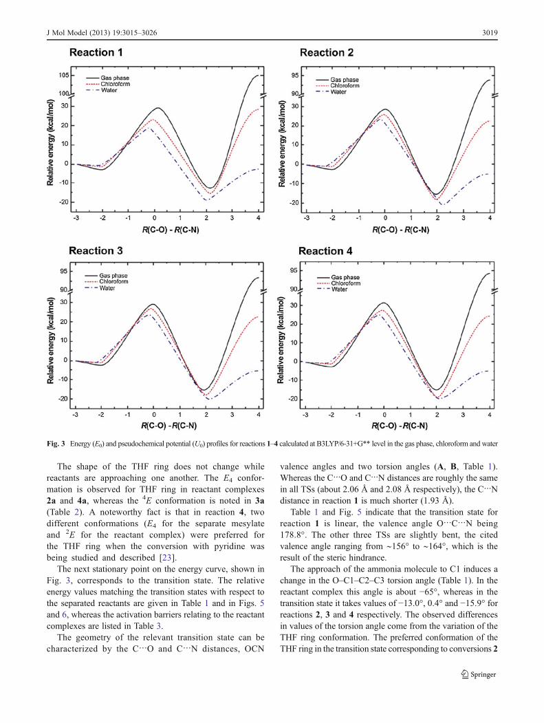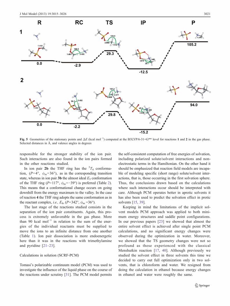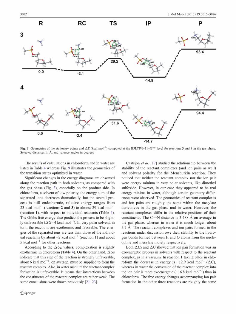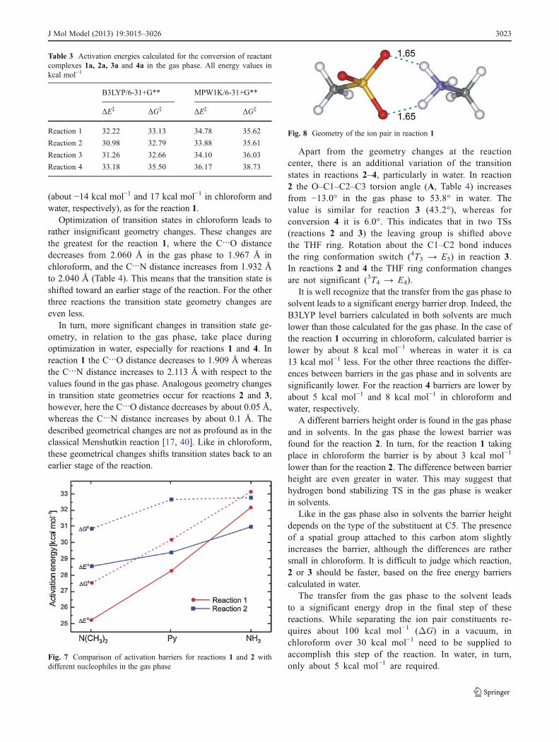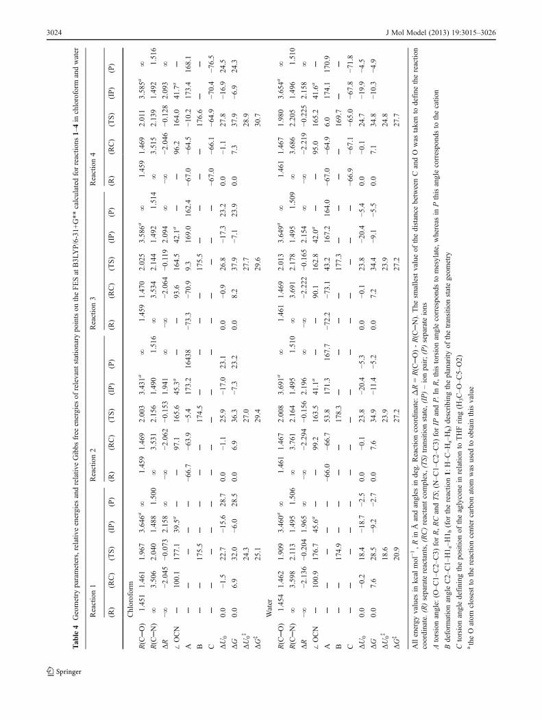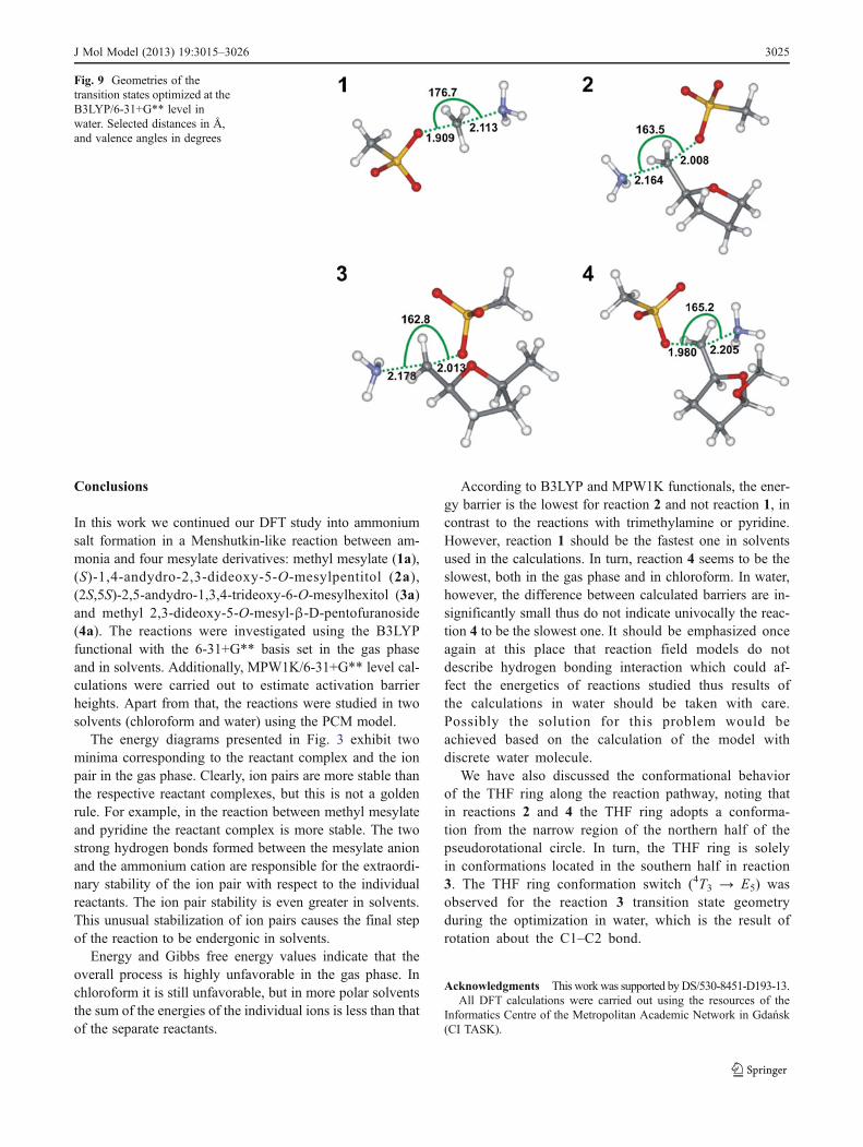
Copyright © 2022 FDOKUMEN