Development of the high performance magnesium based hydrogen storage alloy
10
Development of the high performance magnesium based hydrogen storage alloy Mustafa Anik*, Fatma Karanfil, Nilu ¨ fer Ku ¨c ¸u ¨ kdeveci Department of Metallurgical and Materials Engineering, Eskisehir Osmangazi University, 26480 Eskisehir, Turkey article info Article history: Received 23 July 2011 Received in revised form 14 September 2011 Accepted 16 September 2011 Available online 15 October 2011 Keywords: MgNi Mechanical alloying Electrochemical hydrogen storage Impedance spectroscopy Hydrogen diffusion coefficient abstract Series of MgNi type alloys with Ti, Al, Zr, Pd and Co additive elements were synthesized by mechanical alloying and their electrochemical hydrogen storage characteristics were investigated. Systematical alloy designing indicated that Mg 0.80 Ti 0.15 Al 0.05 Zr 0.05 Ni 0.95 alloy has the best electrode performance. The atomic fractions in this alloy were believed to be optimum to get the reasonable amount of hydrogen storage with the improved cyclic stability. Titanium was estimated to enter into Mg(OH) 2 layer during the discharging process and make this barrier layer more penetrable by elemental hydrogen. Al and/or Al- oxides were predicted to dissolve selectively throughout the barrier hydroxide layer and thus reduce the stability of this layer. The main contribution of Zr was estimated to arise from its large atomic size that Zr atoms can create extra sites for the elemental hydrogen in the alloy structure. As the alloy charge transfer resistances decreased, the alloy retention rates increased. Improvement in the alloy capacity retaining rate was also closely related with the hydrogen diffusion coefficients in the alloy. Copyright ª 2011, Hydrogen Energy Publications, LLC. Published by Elsevier Ltd. All rights reserved. 1. Introduction The potential of metal hydrides to be used as hydrogen storage media especially in the automotive industry makes Mg very promising material due to its high theoretical hydrogen storage capacity (7.6 wt%) and low cost [1]. The slow absorption kinetics and an elevated hydride decomposition temperature, however, hinder the utilization of Mg effectively [2]. Alloying of Mg with transition metals appears to be the only way to overcome the poor kinetics of Mg at the expense of a reduced hydrogen storage capacity. Especially Ni is known with its beneficial effects to improve kinetics and reduce the hydride formation enthalpy of Mg. Mg 2 Ni and MgNi alloys synthesized with mechanical alloying have attracted great attention of many researchers involved in the hydrogen storage [3e6]. The discharge capacity of amorphous MgNi alloy was observed to be higher than that of nanocrystalline Mg 2 Ni alloy [5,6]. The increase in Ni content was believed to accelerate the amorphization process in the alloy and create relatively catalytic alloy surface for the hydrogen reactions [5,6]. Despite the limited improvements in the surface kinetics, the cyclic stability of MgeNi alloys was still far below the desired level [6]. Addition of the third, fourth or even fifth alloying element to MgeNi alloys has become common method to improve the cyclic stability of the alloy [7e22]. Titanium is the most beneficial alloying element for Mg- based hydrogen storage alloys since it improves the cyclic stability of the alloy without causing any considerable reduction in the alloy discharge capacity [7e9,12,17e19,21,22]. Aluminum also improves the alloy cyclic stability but it brings about significant reduction in the initial discharge capacity * Corresponding author. Tel.: þ90 222 239 3750; fax: þ90 222 239 3613. E-mail address: [email protected] (M. Anik). Available online at www.sciencedirect.com journal homepage: www.elsevier.com/locate/he international journal of hydrogen energy 37 (2012) 299 e308 0360-3199/$ e see front matter Copyright ª 2011, Hydrogen Energy Publications, LLC. Published by Elsevier Ltd. All rights reserved. doi:10.1016/j.ijhydene.2011.09.057
-
Upload
independent -
Category
Documents
-
view
0 -
download
0
Transcript of Development of the high performance magnesium based hydrogen storage alloy

ww.sciencedirect.com
i n t e r n a t i o n a l j o u rn a l o f h y d r o g e n en e r g y 3 7 ( 2 0 1 2 ) 2 9 9e3 0 8
Available online at w
journal homepage: www.elsevier .com/locate/he
Development of the high performance magnesium basedhydrogen storage alloy
Mustafa Anik*, Fatma Karanfil, Nilufer Kucukdeveci
Department of Metallurgical and Materials Engineering, Eskisehir Osmangazi University, 26480 Eskisehir, Turkey
a r t i c l e i n f o
Article history:
Received 23 July 2011
Received in revised form
14 September 2011
Accepted 16 September 2011
Available online 15 October 2011
Keywords:
MgNi
Mechanical alloying
Electrochemical hydrogen storage
Impedance spectroscopy
Hydrogen diffusion coefficient
* Corresponding author. Tel.: þ90 222 239 37E-mail address: [email protected] (M. An
0360-3199/$ e see front matter Copyright ªdoi:10.1016/j.ijhydene.2011.09.057
a b s t r a c t
Series of MgNi type alloys with Ti, Al, Zr, Pd and Co additive elements were synthesized by
mechanical alloying and their electrochemical hydrogen storage characteristics were
investigated. Systematical alloy designing indicated that Mg0.80Ti0.15Al0.05Zr0.05Ni0.95 alloy
has the best electrode performance. The atomic fractions in this alloy were believed to be
optimum to get the reasonable amount of hydrogen storage with the improved cyclic
stability. Titanium was estimated to enter into Mg(OH)2 layer during the discharging
process and make this barrier layer more penetrable by elemental hydrogen. Al and/or Al-
oxides were predicted to dissolve selectively throughout the barrier hydroxide layer and
thus reduce the stability of this layer. The main contribution of Zr was estimated to arise
from its large atomic size that Zr atoms can create extra sites for the elemental hydrogen in
the alloy structure. As the alloy charge transfer resistances decreased, the alloy retention
rates increased. Improvement in the alloy capacity retaining rate was also closely related
with the hydrogen diffusion coefficients in the alloy.
Copyright ª 2011, Hydrogen Energy Publications, LLC. Published by Elsevier Ltd. All rights
reserved.
1. Introduction capacity of amorphous MgNi alloy was observed to be higher
The potential of metal hydrides to be used as hydrogen
storage media especially in the automotive industry makes
Mg very promising material due to its high theoretical
hydrogen storage capacity (7.6 wt%) and low cost [1]. The slow
absorption kinetics and an elevated hydride decomposition
temperature, however, hinder the utilization of Mg effectively
[2]. Alloying of Mg with transition metals appears to be the
onlyway to overcome the poor kinetics ofMg at the expense of
a reduced hydrogen storage capacity. Especially Ni is known
with its beneficial effects to improve kinetics and reduce the
hydride formation enthalpy of Mg.
Mg2Ni and MgNi alloys synthesized with mechanical
alloying have attracted great attention of many researchers
involved in the hydrogen storage [3e6]. The discharge
50; fax: þ90 222 239 3613.ik).2011, Hydrogen Energy P
than that of nanocrystalline Mg2Ni alloy [5,6]. The increase
in Ni content was believed to accelerate the amorphization
process in the alloy and create relatively catalytic alloy
surface for the hydrogen reactions [5,6]. Despite the limited
improvements in the surface kinetics, the cyclic stability of
MgeNi alloys was still far below the desired level [6]. Addition
of the third, fourth or even fifth alloying element to MgeNi
alloys has become common method to improve the cyclic
stability of the alloy [7e22].
Titanium is the most beneficial alloying element for Mg-
based hydrogen storage alloys since it improves the cyclic
stability of the alloy without causing any considerable
reduction in the alloy discharge capacity [7e9,12,17e19,21,22].
Aluminum also improves the alloy cyclic stability but it brings
about significant reduction in the initial discharge capacity
ublications, LLC. Published by Elsevier Ltd. All rights reserved.

Fig. 1 e Overlaid XRD patterns of Mg0.80Ti0.15Al0.10Ni0.95,
Mg0.80Ti0.20Al0.05Zr0.05Ni0.90 and Mg0.80Ti0.15Al0.05Zr0.05Ni0.95 alloys.
0
100
200
300
400
500
0 5 10 15 20 25
Disch
arg
e C
ap
acity / m
A h
g
-1
Cycle Number / n
Mg0.85Ti0.10Zr0.05Ni
Mg0.85Ti0.10Pd0.05Ni
Mg0.85Ti0.10Al0.05Ni
Mg0.85Ti0.10Co0.05Ni
0
10
20
30
40
50
60
70
80
90
100
0 5 10 15 20 25
Cn
/C
maxx
10
0
Cycle Number / n
Mg0.85Ti0.10Zr0.05Ni
Mg0.85Ti0.10Pd0.05Ni
Mg0.85Ti0.10Al0.05Ni
Mg0.85Ti0.10Co0.05Ni
a
b
Fig. 2 e (a) Discharge capacity and (b) cyclic stability as
a function of cycle number for Mg0.85Ti0.10(M)0.05Ni (M [ Al,
Co, Pd and Zr) quaternary alloys.
i n t e rn a t i o n a l j o u r n a l o f h y d r o g e n en e r g y 3 7 ( 2 0 1 2 ) 2 9 9e3 0 8300
[15e17,19,21]. Zirconium is known with its limited positive
contribution to the alloy cyclic stability and the initial
discharge capacity [15e19,21]. The beneficial effect of palla-
dium, which is a very well known catalyst for hydrogen, as the
alloying element is not as high as expected [20]. In fact if Pd is
added more than a critical value, it degrades the electrode
performance of the Mg-based alloys [20]. Although they are
not very common additive elements, Co and Fe are reported to
have considerable contribution to the hydrogen storage
performance [8,10,21]. Boron is another disappointing additive
element for the Mg-based alloys since it induces poor cyclic
reversibility [19].
In this work series of MgNi type alloys with Ti, Al, Zr, Pd
and Co additive elements were synthesized by mechanical
alloying to investigate the electrochemical hydrogen storage
characteristics. Alloy compositions were designed to get the
maximum electrode performance by combining the positive
contributions of the additive elements. Atomic ratios of both
Mg and Ni were reduced in the alloy designing to synthesize
four- or five-component alloys.
0
100
200
300
400
500
0 5 10 15 20 25
Disch
arg
e C
ap
acity / m
A h
g
-1
Cycle Number / n
Mg0.85Ti0.15Zr0.05Ni0.95
Mg0.85Ti0.15Pd0.05Ni0.95
Mg0.85Ti0.15Al0.05Ni0.95
Mg0.85Ti0.15Co0.05Ni0.95
0
0
10
20
30
40
50
60
70
80
90
100
5 10 15 20 25
Cn /C
max*100
Cycle Number / n
Mg0.85Ti0.15Zr0.05Ni0.95
Mg0.85Ti0.15Pd0.05Ni0.95
Mg0.85Ti0.15Al0.05Ni0.95
Mg0.85Ti0.15Co0.05Ni0.95
a
b
Fig. 3 e (a) Discharge capacity and (b) cyclic stability as
a function of cycle number for Mg0.85Ti0.15(M)0.05Ni0.95(M [ Al, Co, Pd and Zr) quaternary alloys.

i n t e r n a t i o n a l j o u rn a l o f h y d r o g e n en e r g y 3 7 ( 2 0 1 2 ) 2 9 9e3 0 8 301
2. Materials and methods
Elemental Mg, Ni, Ti, Al, Zr, Pd and Co powders (�325 mesh
powders with at least 99.9% purity were obtained from Alfa
Aesar) were mixed in various compositions and charged into
the stainless steel vials under the high purity Ar atmosphere
(in the glove box). The diameter of the stainless steel balls was
5mmand the ball to powder weight ratio was selected as 20:1.
The mechanical alloying was performed with a planetary ball
mill (Fritsch, Pulverisette P-7) and the milling speed was
500 rpm. The ball milling duration was selected as 25 h. The
mechanical alloying was carried out by milling for 30 min in
the forward direction then cooling for 15min and thenmilling
for 30 min in the reverse direction. By this procedure the
increase in the temperature of the vial was prevented and the
0
100
200
300
400
500
0 5 10 15 20 25
Dis
ch
arg
e C
ap
ac
ity
/ m
A h
g
-1
Cycle Number / n
Mg0.80Ti0.15Al0.10Ni0.95
Mg0.80Ti0.15Al0.05Zr0.05Ni0.95
Mg0.80Ti0.15Al0.05Pd0.05Ni0.95
Mg0.80Ti0.15Al0.05Co0.05Ni0.95
0
10
20
30
40
50
60
70
80
90
100
0 5 10 15 20 25
Cn /C
maxx
10
0
Cycle Number / n
Mg0.80Ti0.15Al0.10Ni0.95
Mg0.80Ti0.15Al0.05Zr0.05Ni0.95
Mg0.80Ti0.15Al0.05Pd0.05Ni0.95
Mg0.80Ti0.15Al0.05Co0.05Ni0.95
a
b
Fig. 4 e (a) Discharge capacity and (b) cyclic stability as
a function of cycle number for Mg0.80Ti0.15Al0.05(M)0.05Ni0.95(M [ Al, Co, Pd and Zr) five-component alloys.
better homogeneity was obtained. The vials, which have the
special lids, were vacuumed and the high purity Ar gas was re-
charged into them at every 10 h during the ball milling to
prevent the possible oxidation of the alloy powders.
The phase structure of the alloy powders was examined by
the X-ray diffractometer (Bruker axs D8) using Cu Ka
radiation.
Working electrodes were prepared by mixing 0.2 g alloy
powder with 0.6 g nickel powder and then cold pressing into
pellets of 10 mm in diameter, under a pressure of 10 ton cm�2.
NiOOH/Ni(OH)2 counter electrode and a Hg/HgO reference
electrodewere used to set up a three-electrode cell in 6 M KOH
solution. Tests were performed with PARSTAT Model 2273
potentiostat/galvanostat unit. The charge current density was
100 mA g�1 and the charging was carried out down to the
severe gassing potential. The discharge current density was
0
100
200
300
400
500
0 5 10 15 20 25
Disch
arg
e C
ap
acity / m
A h
g
-1
Cycle Number / n
Mg0.85Ti0.15Al0.10Ni0.90
Mg0.85Ti0.15Al0.05Zr0.05Ni0.90
Mg0.80Ti0.20Al0.05Zr0.05Ni0.90
Mg0.85Ti0.20Al0.05Zr0.05Ni0.85
Mg0.85Ti0.25Al0.05Zr0.05Ni0.80
Mg0.80Ti0.30Al0.05Zr0.05Ni0.80
0
10
20
30
40
50
60
70
80
90
100
0 5 10 15 20 25
Cn /C
maxx100
Cycle Number / n
Mg0.85Ti0.15Al0.10Ni0.90
Mg0.85Ti0.15Al0.05Zr0.05Ni0.90
Mg0.80Ti0.20Al0.05Zr0.05Ni0.90
Mg0.85Ti0.20Al0.05Zr0.05Ni0.85
Mg0.85Ti0.25Al0.05Zr0.05Ni0.80
Mg0.80Ti0.30Al0.05Zr0.05Ni0.80
a
b
Fig. 5 e (a) Discharge capacity and (b) cyclic stability as
a function of cycle number for various MgeTieAleZreNi
five-component alloys.
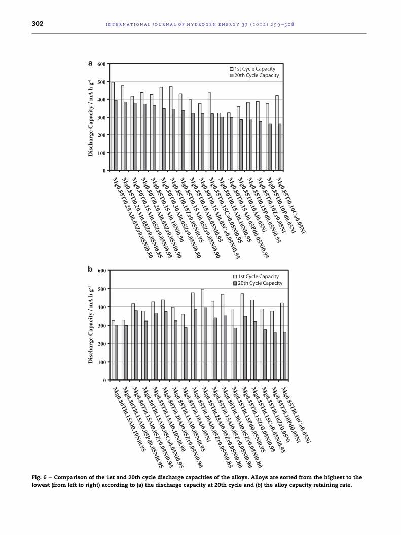
Fig. 6 e Comparison of the 1st and 20th cycle discharge capacities of the alloys. Alloys are sorted from the highest to the
lowest (from left to right) according to (a) the discharge capacity at 20th cycle and (b) the alloy capacity retaining rate.
i n t e rn a t i o n a l j o u r n a l o f h y d r o g e n en e r g y 3 7 ( 2 0 1 2 ) 2 9 9e3 0 8302

i n t e r n a t i o n a l j o u rn a l o f h y d r o g e n en e r g y 3 7 ( 2 0 1 2 ) 2 9 9e3 0 8 303
25 mA g�1 and the discharge cut-off potential was �0.6 VHg/
HgO. The excitation voltage was 10 mV (peak to peak) and the
applied frequency varied from 100 kHz to 0.01 Hz in the elec-
trochemical impedance measurements.
3. Experimental results and discussion
3.1. The structural characteristics of alloys
The previously reported ball milling time dependence of the
alloy discharge capacities indicated that the Mg-based alloys
shouldbemilledfor25hfor theoptimumelectrodeperformance
[19]. Therefore all the investigated alloys in this study were
synthesized by 25 hmilling. The XRD patterns of the developed
structures of Mg0.80Ti0.15Al0.10Ni0.95, Mg0.80Ti0.20Al0.05Zr0.05Ni0.90and Mg0.80Ti0.15Al0.05Zr0.05Ni0.95 alloys are compared in Fig. 1.
Only these three alloys were selected to present the XRD
patterns since they perfectly reflect the XRD patterns of all
the synthesized alloys in this study. All the alloys have a broad
peak around 41.5� which can be assigned to amorphous/nano-
crystalline structure in Fig. 1. The presence of small Ni peaks
at Mg0.80Ti0.15Al0.10Ni0.95 and Mg0.80Ti0.15Al0.05Zr0.05Ni0.95 alloy
patterns shows that the additive elements (Ti, Al, Zr) slightly
0
100
200
300
400
500
600
Dis
char
ge C
apac
ity
/ mA
h g
-1
Fig. 7 e Comparison of the 1st and 20th cycle discharge capacitie
(from left to right) by considering the discharge capacity at 20th c
decrease the solubility ofNi in themain phase [19]. If Ni content
is reduced slightly, however, then these small Ni peaks tend
to disappear, as in Mg0.80Ti0.20Al0.05Zr0.05Ni0.90 alloy pattern
in Fig. 1.
Powder morphologies and the average powder size of the
synthesized alloys were not presented in this study since they
are exactly same with those of the alloys reported in our very
recent publications [19e22].
3.2. The cyclic stabilities of the alloys
The variations in the discharge capacities of Mg0.85Ti0.10(M)0.05Ni (M ¼ Al, Co, Pd and Zr) quaternary alloys
depending on the charge/discharge cycle numbers are indi-
cated in Fig. 2a. The cyclic stabilities of the alloys are also
evaluated by observing the capacity retaining rates as in
Fig. 2b. Aluminum-including alloy exhibits the best perfor-
mance in Fig. 2a and b. Despite its high initial discharge
capacity (Fig. 2a), Co-including alloy has relatively low
capacity retaining rate (Fig. 2b). The electrode performances of
Zr- and Pd-including alloys stay between that of Al-including
and Co-including alloys.
If the atomic fraction of Mg is kept same and that of Ti is
increased by reducing the same amount of atomic fraction of
s of the alloys. Alloys are sorted from the best to the worst
ycle and alloy capacity retaining rate are equally important.

a
b
Fig. 8 e (a) Experimental and simulated impedance
diagrams of the selected alloys at 100% depth of discharges
(DOD) and (b) the equivalent circuit used in the simulation
of the experimental impedance data of the alloys.
i n t e rn a t i o n a l j o u r n a l o f h y d r o g e n en e r g y 3 7 ( 2 0 1 2 ) 2 9 9e3 0 8304
Ni (Mg0.85Ti0.15(M)0.05Ni0.95 (M ¼ Al, Co, Pd and Zr)) as in Fig. 3a
and b, both the initial discharge capacities (Fig. 3a) and
capacity retaining rates (Fig. 3b) look improved for all the
alloys. When the relative effects of additive elements (Al, Co,
Pd, Zr) on the alloy electrode performance are compared, the
results appear very similar to those in Fig. 2a and b.
The alloy electrode performances in Figs. 2 and 3 indicate
that Al additive element must definitely present in the
Mg-based alloys. By taking into account this observation
Mg0.80Ti0.15Al0.05(M)0.05Ni0.95 (M ¼ Al, Co, Pd and Zr) five-
component alloys were synthesized and their electrode
performances are compared in Fig. 4a and b. Aluminum and
Pd-including alloys need few cycles to reach their maximum
discharge capacities. All the alloys, except Co-including alloy,
have more than 90% capacity retaining rate at 20th charge/
discharge cycle in Fig. 4b. The initial discharge capacities,
however, looks reduced slightly in Fig. 4a. Upon comparison, it
is clearly observable in Fig. 4a that Zr-including five-compo-
nent alloy has very distinctive performance.
Overall result of Figs. 2e4 is that five-component
alloy should include Ti, Al and Zr additive elements in
addition to main Mg and Ni elements. The relative atomic
fractions of these elements can be optimized to get the best
electrode performance. Various MgeTieAleZreNi alloys
were synthesized and their performances are compared as
in Fig. 5a and b. If the atomic fractions of Al and Zr are kept
constant at 0.05, then Ti atomic fraction shouldn’t exceed
0.20 in order to get the best combination of the initial
discharge capacity and the alloy capacity retaining rate.
Another important point is that the atomic fractions of Mg
and Ni should be comparable.
Comparison of all the synthesized alloys in the same figure
may be more helpful especially in determining the optimum
atomic fractions of the best performance alloy. For this purpose
the 1st and 20th cycle discharge capacities of all the alloys are
compared in Fig. 6a and b. Alloys are sorted from the highest to
the lowest (from left to right) according to the discharge
capacity at 20th cycle and the alloy capacity retaining rate in
Fig. 6a and b, respectively. By considering the discharge
capacity at 20th cycle and the alloy capacity retaining rate are
equally important, the alloys are re-sorted from the best to the
worst in Fig. 7. Mg0.80Ti0.15Al0.05Zr0.05Ni0.95 alloy appears to have
the best electrode performance with at least 90% capacity
retaining rate at 20th cycle and the relatively high initial
discharge capacity (420 mA h g�1) in Fig. 7. The performance of
this alloy is very promising in developing the commercial
negative electrodes for the NieMH secondary batteries.
In five-componentMgeTieAleZreNi alloys, Mg is themain
hydride forming element. Magnesium atomic fraction
shouldn’t be less than 0.80 in order to get reasonable amount
of hydrogen storage. The poor cyclic stability of the alloys
arises also from the presence of Mg. Formation of Mg(OH)2layer in the strongly basic media makes in and out hydrogen
diffusion very difficult [15e21]. Thickening of Mg(OH)2 layer
and the formation of new Mg(OH)2 layers on the freshly
opened surfaces (due to the volume expansion) upon charge/
discharge cycles are globally accepted as the main reasons in
the degradation of the Mg-based alloy electrodes [1e22].
Therefore increase in the Mg atomic ratio (for example above
0.80) causes alloys to have poor cyclic stability.
Nickel, as the transition metal, reduces the stability of the
hydride to facilitate the cyclic reversibility and provides the
electro-active sites for hydrogen reactions. Therefore its
presence is very critical and according to the results exhibited
in Fig. 7 its atomic fraction shouldn’t be less than 0.90 in order
to get desired level of the cyclic stability.
Titanium, which is another hydride forming element,
probably enters into Mg(OH)2 layer during the discharging
process and makes this barrier layer more penetrable by
elemental hydrogen [7,19]. The stability of Ti and/or Ti-
oxides is lower than that of Mg(OH)2 layer in basic media
[17]. Therefore disseminated Ti and/or Ti-oxides may
decrease the stability of the hydroxide layer and make it
more permeable for the elemental hydrogen. According to
Fig. 7 the optimum atomic fraction of Ti looks as 0.15 or
maximum 0.20. Increasing the atomic fraction of Ti above
0.20 requires a decrease in the content of other useful
elements. In fact if selective dissolution occurs, then the
overall stability of the electrode may decrease with the
increase in Ti content.
The dissolution rate of Al and/or Al-oxides are extremely
higher in basic media [17]. Therefore Al and/or Al-oxides may
dissolve selectively throughout the barrier hydroxide layer
and reduce the stability of this layer [15,17,19]. Of course,
selective dissolution of Al and/or Al-oxides is expected to be
muchmore pronounced than that of Ti and/or Ti-oxides. Thus

i n t e r n a t i o n a l j o u rn a l o f h y d r o g e n en e r g y 3 7 ( 2 0 1 2 ) 2 9 9e3 0 8 305
exposition of the underlying electro-catalytic Ni sites upon
selective dissolution is probably more effective in the pres-
ence of Al additive element [15,17,19,23]. Due to its extreme
dissolution rate the atomic fraction of Al additive element
shouldn’t exceed 0.05 in five-component alloy. But according
to Fig. 7 if Zr additive element is excluded (four-component
alloy), then the increase in the Al atomic fraction up to 0.10
can be considered.
The positive contribution of Zr to the electrode perfor-
mance of the five-component alloy is limited. The selective
dissolution of Zr and/or Zr-oxides may also be expected in
the basic media [17]. But the selective dissolution cannot
be the only contribution of Zr since this contribution
Fig. 9 e (a) The calculated charge transfer resistances for all the in
charge transfer resistances and the alloy capacity retaining rate
cannot be observed in the presence of Al. Probably the
extra contribution of Zr arises from its large atomic size
[15e19]. With larger atomic size Zr atoms can create extra
sites for the elemental hydrogen in the alloy structure and
thus the hydrogen storage capacity of the alloy increases
[15e19]. The atomic fraction of 0.05 looks enough for Zr in
Fig. 7.
Finally, the presence of Co and Pd additive elements
appears to be not necessary to develop a high performance
Mg-based hydrogen storage alloy. It was also observed in our
previous studies that Fe, B and C additive elements cannot
make any critical contribution to the electrode performance of
the Mg-based alloys [21].
vestigated alloys and (b) the relationship between the alloy
s.

i n t e rn a t i o n a l j o u r n a l o f h y d r o g e n en e r g y 3 7 ( 2 0 1 2 ) 2 9 9e3 0 8306
3.3. Electrochemical impedance spectroscopy (EIS)analysis of the alloys
The AC impedance spectra measured at 100% depth of
discharge (DOD) are given for Mg0.85Ti0.15Zr0.05Ni0.95, Mg0.85-
Ti0.10Co0.05Ni, Mg0.80Ti0.15Al0.05Pd0.05Ni0.95 and Mg0.80Ti0.15Al0.05-
Zr0.05Ni0.95 alloys in Fig. 8a. Only the spectra of these four alloys
were selected since all the other alloys have similar impedance
spectra. The impedance data in Fig. 8a (data points) can be
modeled by the equivalent circuit in Fig. 8b [24] and then the
value of the each component in the equivalent circuit can be
calculated by the curve fitting method. The charge transfer
Fig. 10 e (a) Potentiostatic discharge plots of the selected alloys
from discharge plots, for all the investigated alloys.
resistances calculated according to the equivalent circuit in
Fig. 8b are presented for all the alloys investigated in this study
in Fig. 9a. As reported previously [19] the big portion of the alloy
degradation takes place during the final stage of the discharge.
Therefore the comparison of the charge transfer resistances
obtainedat100%DOD isveryuseful inevaluationof the effect of
the additive elements on the alloy performance.
The calculated charge transfer resistances are sorted from
the lowest to the highest in Fig. 9a. The alloy ranking in Fig. 9a
is very similar to that in Fig. 6b which presents the ranking in
alloy retaining rate from the highest to the lowest. Obviously
as the alloy charge transfer resistances decrease, i.e., as the
and (b) the dependence of D/a2 ratios, which are obtained

i n t e r n a t i o n a l j o u rn a l o f h y d r o g e n en e r g y 3 7 ( 2 0 1 2 ) 2 9 9e3 0 8 307
alloy surfaces become electro-catalytic, the alloy retaining
rates increase. This inverse relationship is clearly exhibited in
Fig. 9b. Therefore in getting high performance electrode the
alloy design should be made such that the surface charge
transfer resistance should be as low as possible. This criterion,
in this study, is fulfilled by getting the unstable hydroxide
barrier layer through selective dissolutions and allowing the
underlying electro-catalytic Ni sites to expose [19].
3.4. Determination of the hydrogen diffusion coefficients
Zheng at al. proposed a potentiostatic polarization discharge
technique to estimate an average diffusion coefficient of
hydrogen over a defined concentration range in the metal
hydride electrodes [25]. They reported that during the poten-
tiostatic polarization of fully charged electrode the current
becomes totally diffusion controlled after certain discharging
period [25]. In 100% diffusion controlled regime the constant
slope of log iet (i: current density in A g�1; t is time in second)
plot yields D/a2 ratio where D is the average diffusion coeffi-
cient of hydrogen in cm2 s�1 and a is the average particle
radius in cm [25].
Mg0.85Ti0.15Zr0.05Ni0.95, Mg0.85Ti0.10Co0.05Ni, Mg0.80Ti0.15Al0.05Pd0.05Ni0.95 and Mg0.80Ti0.15Al0.05Zr0.05Ni0.95 alloys are selected
as an example and their log iet plots are presented in Fig. 10a.
D/a2 ratios, which are obtained from the slope of log iet plots
as in Fig. 10a, are provided for all the investigated alloys in
Fig. 10b. If the average particle radius (a) is accepted same for
all the alloys, then the data in Fig. 10b can be assumed to
reflect the average hydrogen diffusion coefficient values.
The calculated D/a2 ratios are sorted from the highest to the
lowest in Fig. 10b. The alloy ranking in Fig. 10b is again very
similar to that in Fig. 6b. Clearly improved alloy capacity
retaining rate is closely related with hydrogen diffusion coef-
ficient, as presented one more time in Fig. 11, that as the
average hydrogen diffusion coefficient increases the alloy
capacity retaining rate also increases. It has to be pointed out,
however, that there are large data scattering in Figs. 9b and 11.
Obviously the improved performances of the designed alloys in
this study cannot only be explained by the charge transfer
Fig. 11 e Relationship between the D/a2 ratios and the alloy
capacity retaining rates.
resistances and average hydrogen diffusion coefficients. The
detailed alloy surface characterizations, like XPS characteriza-
tions, are also needed formuchmore satisfactory explanations.
This kind of study, of course, should be subject of another work
which is going to be conducted on the same alloys.
4. Conclusions
Series of MgNi type alloys with Ti, Al, Zr, Pd and Co additive
elements were synthesized by mechanical alloying and their
electrochemical hydrogen storage characteristics were
investigated. The following conclusions may be deduced:
� Systematical designing showed that Mg0.80Ti0.15Al0.05Zr0.05Ni0.95 alloy has the best electrode performance among
the synthesized alloys.
� Increase in the atomic fraction of Mgwas accompaniedwith
higher hydrogen storage but lower cyclic stability. Therefore
the competition between the hydrogen storage and the
cyclic stability indicated that Mg atomic fraction should be
at around 0.80 in five-component alloys.
� The atomic fraction of nickel, which facilitated the cyclic
reversibility in alloys, was observed to be not less than 0.90
in five-component alloys.
� Titanium was estimated to enter into Mg(OH)2 layer during
the discharging process and make this barrier layer more
penetrable by elemental hydrogen. The optimum atomic
fraction of Ti was predicted to be 0.15 or 0.20 in five-
component alloys.
� Al and/or Al-oxides were believed to dissolve selectively
throughout the barrier hydroxide layer and thus reduce the
stability of this layer. Due to its extreme dissolution rate the
atomic fraction of Al additive element was selected as 0.05
in five-component alloys.
� The main contribution of Zr was estimated to arise from its
large atomic size that Zr atoms can create extra sites for the
elemental hydrogen in the alloy structure. The atomic
fraction of Zr additive element was selected as 0.05 in five-
component alloys.
� The presence of Co and Pd additive elements were believed
to not necessary to develop a high performance Mg-based
hydrogen storage alloy.
� As the alloy charge transfer resistances decreased, the alloy
retention rates increased.
� Improvement in the alloy capacity retaining ratewas closely
related with hydrogen diffusion coefficients in the alloy.
r e f e r e n c e s
[1] Selvam P, Viswanathan B, Swamy CS, Srinivasan V.Magnesium and magnesium alloy hydrides. Int J HydrogenEnergy 1986;11:169e92.
[2] Schwarz RB. Hydrogen storage in magnesium-based alloys.MRS Bull 1999;24:40e4.
[3] Orimo S, Fujii H. Effects of nanometer-scale structure onhydriding properties of MgNi alloys: a review. Intermetallics1998;6:185e92.

i n t e rn a t i o n a l j o u r n a l o f h y d r o g e n en e r g y 3 7 ( 2 0 1 2 ) 2 9 9e3 0 8308
[4] Ruggeri S, Lenain C, Roue L, Liang G, Huot J, Schultz R.Mechanically driven crystallization of amorphous MgNi alloyduring prolonged milling: application in NieMH batteries. JAlloys Comp 2002;339:195e201.
[5] Shengqi X, Penglian L, Jingen Z, Ruihua Z, Ning W. Researchon the structure and discharge capacities of MgeNi alloywith different Ni contents synthesized by high energymilling. Mater Sci Eng A 2006;418:81e5.
[6] Anik M. Electrochemical hydrogen storage capacities ofMg2Ni and MgNi alloys synthesized by mechanical alloying. JAlloys Comp 2010;491:565e70.
[7] Jiang JJ, Gasik M. An electrochemical investigation ofmechanical alloying of MgNi-based hydrogen storage alloys. JPower Sources 2000;89:117e24.
[8] Ye H, Lei YQ, Chen LS, Zhang H. Electrochemicalcharacteristics of amorphous Mg0.9M0.1Ni (M ¼ Ni, Ti, Zr, Coand Si) ternary alloys prepared by mechanical alloying. JAlloys Comp 2000;311:194e9.
[9] Zhang Y, Zhang SK, Chen LX, Lei YQ, Wang QD. The study onthe electrochemical performance of mechanically alloyedMgeTieNi-based ternary and quaternary hydrogen storageelectrode alloys. Int J Hydrogen Energy 2001;26:801e6.
[10] Wang M, Zhang L, Zhang Y, Sun L, Tan Z, Xu F, et al. Theeffects of partial substitution of Fe and Co for Ni in the Mg1.75Al0.25Ni electrode alloy on electrochemical performances.Int J Hydrogen Energy 2006;31:621e5.
[11] Dornheim M, Doppiu S, Barkhordarian G, Boesenberg U,Klassen T, Gutfleisch O, et al. Hydrogen storage inmagnesium-based hydrides and hydride composites. ScriptaMater 2007;56:841e6.
[12] Souza EC, Ticianelli EA. Structural and electrochemicalproperties of MgNi-based alloys with Ti, Pt and Pd additives.Int J Hydrogen Energy 2007;32:4917e24.
[13] Jurczyk M, Smardz L, Okonska I, Jankowska E, Nowak M,Smardz K. Nanoscale Mg-based materials for hydrogenstorage. Int J Hydrogen Energy 2008;33:374e80.
[14] Andreasen A. Hydrogenation properties of MgeAl alloys. Int JHydrogen Energy 2008;33:7489e97.
[15] Anik M, Gasan H, Topcu S, Akay I, Aydinbeyli N.Electrochemicalhydrogenstorage characteristics ofMg1.5Al0.5-
xZrxNi (x ¼ 0, 0.1, 0.2, 0.3, 0.4, 0.5) alloys synthesized bymechanical alloying. Int J Hydrogen Energy 2009;34:2692e700.
[16] Anik M, Akay I, Topcu S. Effect of electroless nickel coatingon the electrochemical hydrogen storage characteristics ofAl and Zr including Mg-based alloys. Int J Hydrogen Energy2009;34:5449e57.
[17] Anik M. Improvements of the electrochemical hydrogenstorage performance of Mg2Ni by the partialreplacements of Mg by Al, Ti and Zr. J Alloys Comp2009;486:109e14.
[18] Anik M, Akay I, Ozdemir G, Baksan B. Electrochemicalhydrogen storage performance of MgeTieZreNi alloys. Int JHydrogen Energy 2009;34:9765e72.
[19] Anik M, Ozdemir G, Kucukdeveci N, Baksan B. Effect of Al, B,Ti and Zr additive elements on the electrochemical hydrogenstorage performance of MgNi alloy. Int J Hydrogen Energy2011;36:1568e77.
[20] Anik M, Ozdemir G, Kucukdeveci N. Electrochemicalhydrogen storage characteristics of MgePdeNi ternaryalloys. Int J Hydrogen Energy 2011;36:6744e50.
[21] Anik M. Improvements of the electrochemical hydrogenstorage performance of magnesium based alloys by variousadditive elements. Int J Hydrogen Energy. doi:10.1016/j.ijhydene.2011.06.107.
[22] Anik M. Effect of titanium additive element on thedischarging behavior of MgNi alloy electrode. Int J HydrogenEnergy 2011;36(23):15075e80.
[23] Zhang SG, Yorimitsu K, Nohara S, Morikawa T,Inoue H, Iwakura C. Surface analysis of an amorphousMgNi alloy prepared by mechanical alloying for use innickel-metal hydride batteries. J Alloys Comp 1998;270:123e6.
[24] Kuriyama N, Sakai T, Miyamura H, Uehara I, Ishikawa H.Electrochemical impedance and deterioration behaviourof metal hydride electrodes. J Alloys Comp 1993;202:183e97.
[25] Zheng G, Papov BN, White RE. Electrochemicaldetermination of the diffusion coefficient of hydrogenthrough an LaNi4.25Al0.75 electrode in alkaline aqueoussolution. J Electrochem Soc 1995;142:2695e8.