Perfusion of medium improves growth of human oral neomucosal tissue constructs
Development of ‘Multi-arm Bioprinter’ for hybrid biofabricationof tissue engineering constructs
Ibrahim T. Ozbolat a,c,n, Howard Chen a, Yin Yu b,c
a Department of Mechanical and Industrial Engineering, The University of Iowa, Iowa City, IA 52242, USAb Department of Biomedical Engineering, The University of Iowa, Iowa City, IA 52242, USAc Biomanufacturing Laboratory, Center for Computer-Aided Design, The University of Iowa, 139 Engineering Research Facility, Iowa City, IA 52242, USA
a r t i c l e i n f o
Article history:Received 18 June 2013Received in revised form27 September 2013Accepted 22 October 2013
Keywords:BioprintingTissue engineeringAdditive manufacturing
a b s t r a c t
This paper highlights the development of ‘Multi-arm Bioprinter (MABP)’ capable of concurrent multi-material deposition with independent motion path and dispensing parameters including depositionspeed, material dispensing rate, and nozzle travel velocity for use in tissue engineering. In this research,the system is designed to concurrently print a filament structure and deposit cell spheroids between thefilaments to create a hybrid structure to support the cell spheroids in three dimensions (3Ds). Thisprocess can be used with multiple cell types and is capable of reducing the fabrication time while usingoptimized dispensing parameters for each material. A novel method of dispensing the crosslinkingsolution using a co-axial nozzle was also developed and demonstrated in this paper. Cell-laden structureswere fabricated through concurrent deposition of cell-encapsulated filaments and with cell spheroids tovalidate this concept. Rheology studies were then conducted to determine the effects of crosslink flow onfilament width, hydrogel dispensing pressure on filament width, and dispensing time interval onspheroid diameter.
& 2013 Elsevier Ltd. All rights reserved.
1. Introduction and literature review
Tissue engineering is most promising in alleviating organ shortageswhile minimizing side effects and maximizing the patient's quality oflife [1]. The majority of strategies currently used in tissue engineeringemploy a scaffold, which is used to organize cells in a three-dimensional (3D) structure to direct the growth and formation ofthe desired tissue [2]. Additive manufacturing (AM) processes, whichbuild parts layer by layer through the addition of material, arefrequently used in scaffold fabrication because of their ability to createparts with highly reproducible architecture and compositional varia-tion [3]. Despite the various developments in scaffold-based tissueengineering, precise placement of multiple cell types in high celldensities inside a 3D porous architecture still requires major progresstowards functional tissue generation [4]. A possible method forprecisely placing multiple cell types inside a 3D porous structure isto use spheroids or cell aggregates, in which cells aggregate to formspheroids through self-assembly, organizing into functional tissue-likeunits [5]. These units are designed to fuse into the desired shape andare less susceptible to cell damage during the deposition process dueto a higher cell density [4,6]. Using this method, a structure will need
to be printed to hold the spheroids in its desired location in 3D space,which requires a hybrid, multi-material bioprinting system.
Multi-material bioprinting systems exist in various developmentalphases. Established commercial bioprinting systems include the 3DBioplotter [7] and the Novogen MMX Bioprinter [8]. The Envision TEC3D Bioplotter can print with various biomaterials at a resolution of50 mm in a working area of 300�300�130mm containing up to5 different materials using a tool changer system and a vision systemto control filament diameter [9]. System specifications for the Novo-gen MMX Bioprinter are currently unavailable. The bioprinter itself isdesigned to deposit tissue spheroids one drop at a time. 3D shapes arebuilt layer by layer, with a non-invasive gel placed between the layers[8]. Research-based bioprinting systems tend to focus on developingmore novel printing methods to solve specific problems. Geng et al.used such a system to concurrently dispense chitosan and sodiumhydroxide, a coagulation medium for chitosan, to prevent the pooradhesion and clumping that was caused by premature coagulation atthe nozzle tip in a single-nozzle setup [10]. Multi-nozzle depositionsystems have also been used to print support materials for low-viscosity biomaterials [11], tissue scaffolds containing multiple types ofhydrogels [12], and deposition of biopolymer solutions, growth factors,and living cells to increase cell attachment [13]. These depositionsystems have recently evolved into hybrid bioprinting, which com-bines multiple methods for scaffold fabrication, such as electrospin-ning and inkjet printing [14]. While these machines can depositmultiple materials, potentially including multiple cell types, they are
Contents lists available at ScienceDirect
journal homepage: www.elsevier.com/locate/rcim
Robotics and Computer-Integrated Manufacturing
0736-5845/$ - see front matter & 2013 Elsevier Ltd. All rights reserved.http://dx.doi.org/10.1016/j.rcim.2013.10.005
n Corresponding author at: Department of Mechanical and Industrial Engineer-ing, The University of Iowa, Iowa City, IA 52242, USA. Tel.: þ1 319 384 08 10;fax: þ1 319 335 5669.
E-mail address: [email protected] (I.T. Ozbolat).
Robotics and Computer-Integrated Manufacturing 30 (2014) 295–304
only capable of depositing one material at a time or concurrentlydepositing multiple materials at a fixed spacing and nozzle travelvelocity. Concurrent printing, in contrast, has the potential to reducethe fabrication time, which is crucial for the development of scale-uptechnologies [6] and would enable continuous deposition, whichyields more consistent results since material deposition during startsand stops are not as uniform as the rest of the process [15]. Continuousdeposition will also alleviate nozzle clogging since it generally occurswhen the material is in static conditions.
In this paper, the application of this specific system is toconcurrently print a structure and deposit cell spheroids betweenthe filaments. This enables increasing the cell density of cell-ladenhybrid structures compared to traditional scaffolding approacheswhere cells are seeded following fabrication and subsequent pro-cesses. Printing encapsulated cells in spheroids greatly reduces shear-stress-induced cell damage compared to printing cells directly loadedwithin biomaterial media and can also allow inclusion of multiplecell types in a spatially organized way by integrating another printerunit [6]. In addition, the structure supports cell spheroids mechani-cally in 3D. Using two nozzles mounted on independent arms willalso allow for the filament structure to be deposited continuously,minimizing filament variations due to the starting and stopping ofthe dispensing unit.
2. Materials and methods
2.1. Materials
The sodium alginate solution was formed by dissolving 4% (w/v)sodium alginate (Sigma Aldrich, United Kingdom) in deionizedwater, and the calcium chloride solution was formed by dissolving4% (w/v) calcium chloride (CaCl2) (Sigma Aldrich, Japan) in deio-nized water. These parameters were considered for material pre-paration due to structural integrity and acceptable cell viability inhybrid printed structures. Food dye (August Thomsen Corporation,USA) was added to the alginate mixture for visualization purposes.Food dye was omitted for the cell viability studies. The crosslinkingbetween the alginate solution and the calcium chloride solutionforms the hydrogel.
2.2. Cell preparation
Cartilage progenitor cells (CPCs) were isolated using the pre-vious developed method [16]. Cells were cultured at 37 1C in 5%CO2 in DMEM/F12 (1:1) supplemented with 10% fetal bovineserum (FBS), 50 μg/μl L-ascorbate, 100 μg/μl penicillin, 100 μg/ml
streptomycin, and 2.5 μg/μl fungi zone. Culture media was changedevery other day. CPCs were passaged onto tissue culture dishes,and passage 3 cells were used for bioprinting. Cells were harvestedusing 0.25% Trypsin-EDTA (Life Technologies, NY) prior to printing.An alginate solution was prepared by adding UV-sterilized sodiumalginate powder into a DMEM-base culture media. In this research,4 million cells/ml was used. Cells were mixed with the sodiumalginate solution (4% w/v in deionized water) immediately afterharvesting and were kept at room temperature before printing.A vortex mixer was used multiple times to get uniform celldistribution in alginate precursor solution.
2.3. Experimental setup
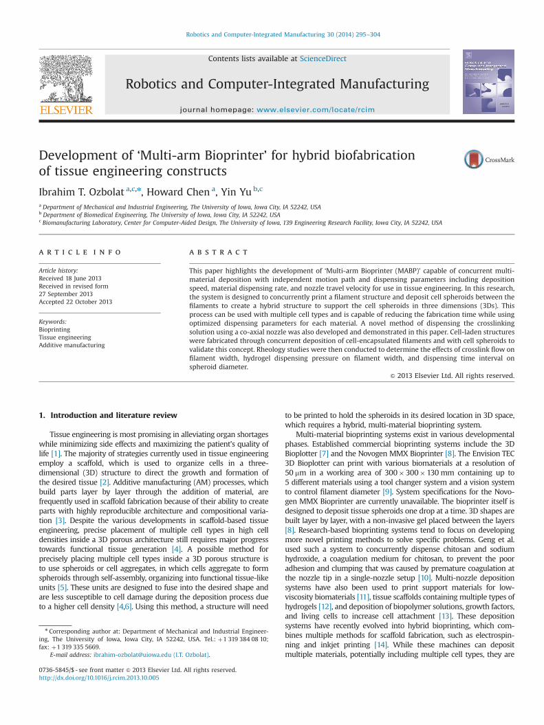
The experimental setup (see Fig. 1) consists of an in-house-builtbioprinter called the ‘Multi-arm Bioprinter (MABP)’, a fluid deposi-tion system, and a computer to run the motion control system andthe fluid deposition system. The MABP unit was placed in alaminar flow hood (Air Science, Fort Meyers, FL, USA) for steriliza-tion purposes during the printing process. The motion controlsystem translates the tool paths for material deposition intosignals to drive the motors on the MABP. The stepper motordrivers actuate the motors on the MABP based on the signalsgenerated from the motion control software. The fluid depositionsystem controls the deposition rate of the alginate and calciumchloride throughout the deposition process. The following sectionsdescribe the MABP design, implementation, and operation indetail.
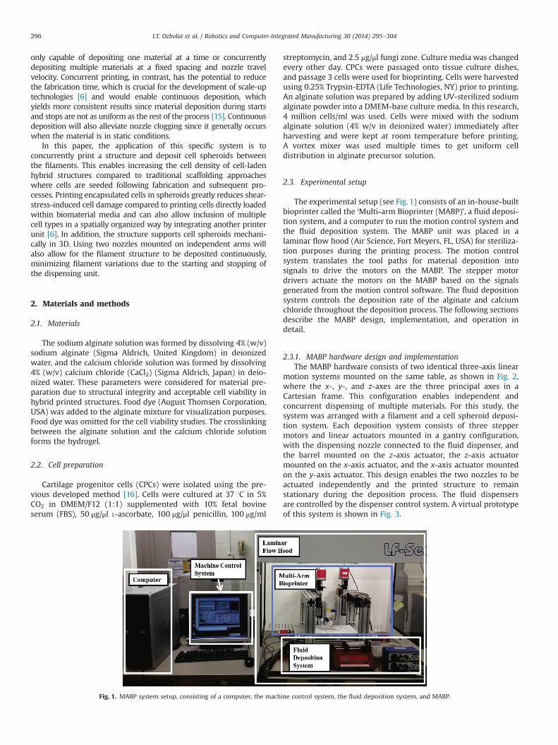
2.3.1. MABP hardware design and implementationThe MABP hardware consists of two identical three-axis linear
motion systems mounted on the same table, as shown in Fig. 2,where the x-, y-, and z-axes are the three principal axes in aCartesian frame. This configuration enables independent andconcurrent dispensing of multiple materials. For this study, thesystem was arranged with a filament and a cell spheroid deposi-tion system. Each deposition system consists of three steppermotors and linear actuators mounted in a gantry configuration,with the dispensing nozzle connected to the fluid dispenser, andthe barrel mounted on the z-axis actuator, the z-axis actuatormounted on the x-axis actuator, and the x-axis actuator mountedon the y-axis actuator. This design enables the two nozzles to beactuated independently and the printed structure to remainstationary during the deposition process. The fluid dispensersare controlled by the dispenser control system. A virtual prototypeof this system is shown in Fig. 3.
Fig. 1. MABP system setup, consisting of a computer, the machine control system, the fluid deposition system, and MABP.
I.T. Ozbolat et al. / Robotics and Computer-Integrated Manufacturing 30 (2014) 295–304296
The fabrication of the MABP emphasized the use of standardparts to minimize development time. The frame was constructedusing an aluminum T-slotted framing system (80/20 Inc., ColumbiaCity, IN, USA) due to ease of construction and reconfiguration.Linear actuators (Thomson Industries Inc., Radford, VA, USA )capable of actuating 200 mm in the x-direction, 300 mm in they-direction, and 100 mm in the z-direction were used to translatethe rotational motion of the stepper motor (Probotix, Peoria, IL,USA) into a linear motion. These components enable the machineto achieve a theoretical maximum linear velocity of 30 mm/s witha resolution of 0.016 mm. A 15 mm profile bearing (McMaster-CarrSupply Company, Chicago, IL, USA) was mounted on each end ofthe x-axis frame to support the static and dynamic loads in the x-direction to prevent the y-axis linear actuator from reaching itsmaximum payload capacity. The profile bearings are mounted on15 mm wide hardened steel guide rails that are 460 mm in length(McMaster-Carr Supply Company, Chicago, IL, USA). The table topwas fabricated from a precision ground 7075 aluminum plate(12.7 mm thick). Individual components were aligned using a dialindicator mounted on the spindle of a CNC mill. The entire systemwas aligned using a dial indicator on a granite table.
2.3.2. Machine control systemThe machine control system (see Fig. 4) actuates the motors
based on the signal generated from the control software. Themotion control system consists of a breakout board, power supply,and motor drivers (see Fig. 4(b)). The breakout board providesaccess to the individual pins of the parallel port, which are used toconnect motor drivers and limit switches. The motor driversactuate the motors at the desired rotational acceleration, velocity,and distance based on the signal sent from the computer throughthe parallel port. The MABP motion control system, which is anopen loop system, consists of two identical 3-axis motion controlsystems. Each motion control system contains an RF-isolated CNCBreakout Board (Probotix, Pekin, IL, USA), three stepper motordrivers (Probotix, Pekin, IL, USA), and one power supply (Probotix,Pekin, IL, USA).
2.3.3. Fluid deposition systemThe fluid deposition system (see Fig. 5(a) and (b)) consists of two
pneumatic dispensers (Nordson Corp., Westlake, OH, USA), a mechan-ical dispenser (New Era Pump System Inc., Farmingdale, NY),
Fig. 2. Systems diagram of the multi-arm bioprinter.
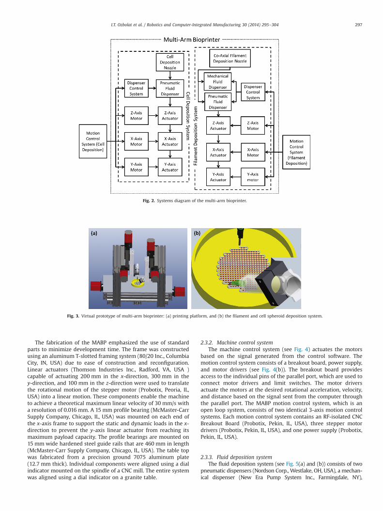
Fig. 3. Virtual prototype of multi-arm bioprinter: (a) printing platform, and (b) the filament and cell spheroid deposition system.
I.T. Ozbolat et al. / Robotics and Computer-Integrated Manufacturing 30 (2014) 295–304 297
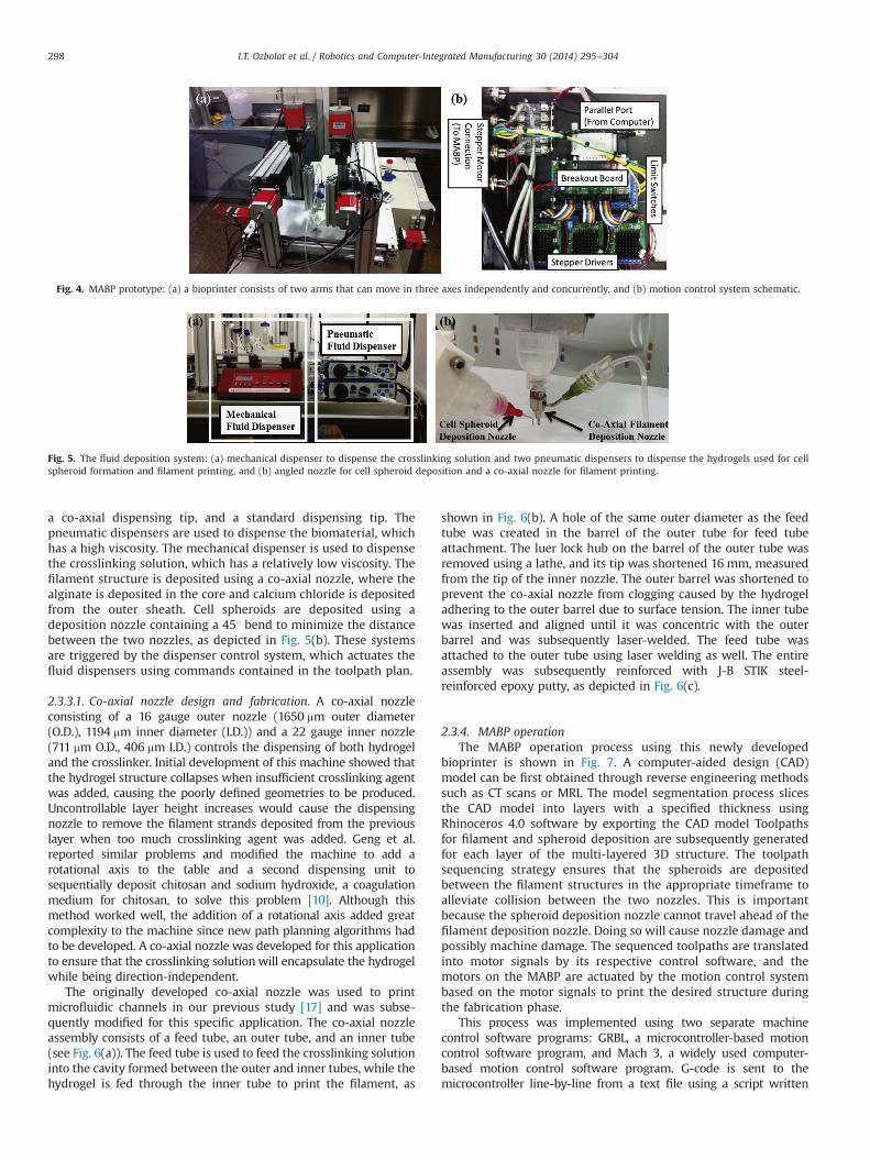
a co-axial dispensing tip, and a standard dispensing tip. Thepneumatic dispensers are used to dispense the biomaterial, whichhas a high viscosity. The mechanical dispenser is used to dispensethe crosslinking solution, which has a relatively low viscosity. Thefilament structure is deposited using a co-axial nozzle, where thealginate is deposited in the core and calcium chloride is depositedfrom the outer sheath. Cell spheroids are deposited using adeposition nozzle containing a 451 bend to minimize the distancebetween the two nozzles, as depicted in Fig. 5(b). These systemsare triggered by the dispenser control system, which actuates thefluid dispensers using commands contained in the toolpath plan.
2.3.3.1. Co-axial nozzle design and fabrication. A co-axial nozzleconsisting of a 16 gauge outer nozzle (1650 mm outer diameter(O.D.), 1194 mm inner diameter (I.D.)) and a 22 gauge inner nozzle(711 mm O.D., 406 mm I.D.) controls the dispensing of both hydrogeland the crosslinker. Initial development of this machine showed thatthe hydrogel structure collapses when insufficient crosslinking agentwas added, causing the poorly defined geometries to be produced.Uncontrollable layer height increases would cause the dispensingnozzle to remove the filament strands deposited from the previouslayer when too much crosslinking agent was added. Geng et al.reported similar problems and modified the machine to add arotational axis to the table and a second dispensing unit tosequentially deposit chitosan and sodium hydroxide, a coagulationmedium for chitosan, to solve this problem [10]. Although thismethod worked well, the addition of a rotational axis added greatcomplexity to the machine since new path planning algorithms hadto be developed. A co-axial nozzle was developed for this applicationto ensure that the crosslinking solution will encapsulate the hydrogelwhile being direction-independent.
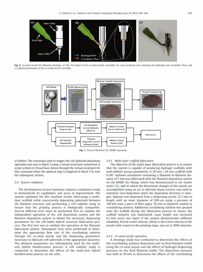
The originally developed co-axial nozzle was used to printmicrofluidic channels in our previous study [17] and was subse-quently modified for this specific application. The co-axial nozzleassembly consists of a feed tube, an outer tube, and an inner tube(see Fig. 6(a)). The feed tube is used to feed the crosslinking solutioninto the cavity formed between the outer and inner tubes, while thehydrogel is fed through the inner tube to print the filament, as
shown in Fig. 6(b). A hole of the same outer diameter as the feedtube was created in the barrel of the outer tube for feed tubeattachment. The luer lock hub on the barrel of the outer tube wasremoved using a lathe, and its tip was shortened 16 mm, measuredfrom the tip of the inner nozzle. The outer barrel was shortened toprevent the co-axial nozzle from clogging caused by the hydrogeladhering to the outer barrel due to surface tension. The inner tubewas inserted and aligned until it was concentric with the outerbarrel and was subsequently laser-welded. The feed tube wasattached to the outer tube using laser welding as well. The entireassembly was subsequently reinforced with J-B STIK steel-reinforced epoxy putty, as depicted in Fig. 6(c).
2.3.4. MABP operationThe MABP operation process using this newly developed
bioprinter is shown in Fig. 7. A computer-aided design (CAD)model can be first obtained through reverse engineering methodssuch as CT scans or MRI. The model segmentation process slicesthe CAD model into layers with a specified thickness usingRhinoceros 4.0 software by exporting the CAD model Toolpathsfor filament and spheroid deposition are subsequently generatedfor each layer of the multi-layered 3D structure. The toolpathsequencing strategy ensures that the spheroids are depositedbetween the filament structures in the appropriate timeframe toalleviate collision between the two nozzles. This is importantbecause the spheroid deposition nozzle cannot travel ahead of thefilament deposition nozzle. Doing so will cause nozzle damage andpossibly machine damage. The sequenced toolpaths are translatedinto motor signals by its respective control software, and themotors on the MABP are actuated by the motion control systembased on the motor signals to print the desired structure duringthe fabrication phase.
This process was implemented using two separate machinecontrol software programs: GRBL, a microcontroller-based motioncontrol software program, and Mach 3, a widely used computer-based motion control software program. G-code is sent to themicrocontroller line-by-line from a text file using a script written
Fig. 5. The fluid deposition system: (a) mechanical dispenser to dispense the crosslinking solution and two pneumatic dispensers to dispense the hydrogels used for cellspheroid formation and filament printing, and (b) angled nozzle for cell spheroid deposition and a co-axial nozzle for filament printing.
Fig. 4. MABP prototype: (a) a bioprinter consists of two arms that can move in three axes independently and concurrently, and (b) motion control system schematic.
I.T. Ozbolat et al. / Robotics and Computer-Integrated Manufacturing 30 (2014) 295–304298
in Python. The command used to trigger the cell spheroid depositionoperationwas sent to Mach 3 using a virtual serial port connection. Ascript written in Visual Basic listens through the virtual serial port forthis command when the optional stop is triggered in Mach 3 to startthe subsequent section.
2.4. System validation
The development of new hardware requires a validation studyto demonstrate its capabilities and areas of improvement. Thesystem validation for this machine entails fabricating a multi-layer scaffold while concurrently depositing spheroids betweenthe filament structure and performing a cell viability study toensure that the printing process is biologically compatible.Several different tests must be performed first to validate theindependent operation of the cell deposition system and thefilament deposition system to obtain the necessary dispensingparameters for the cell-laden hybrid structure fabrication pro-cess. The first test was to validate the operation of the filamentfabrication system. Subsequent tests were performed to deter-mine the appropriate flow rate of the crosslinking solutionthrough the co-axial nozzle and the dispensing parametersnecessary to fabricate cell spheroids of the appropriate diameter.The obtained parameters are subsequently used for the multi-arm hybrid biofabrication process. A cell viability study isconducted to determine the effects of the multi-arm hybridbiofabrication process on the cells.
2.4.1. Multi-layer scaffold fabricationThe objective of the multi-layer fabrication process is to ensure
that the system is capable of producing hydrogel scaffolds withwell-defined porous geometries. A 20 mm�20 mm scaffold with0–901 laydown orientation containing a filament-to-filament dis-tance of 2 mmwas fabricated with the filament deposition systemon the MABP. Arc fitting, which was demonstrated in our earlierwork [18], and in which the directional changes of the nozzle areaccomplished using an arc to alleviate sharp corners, was used tominimize over-deposition when the deposition direction is chan-ged. Alginate was dispensed from a dispensing nozzle 12.7 mm inlength with an inner diameter of 200 mm using a pressure of100 kPa onto a piece of filter paper 70 mm in diameter soaked incrosslinking solution. Additional crosslinking solution was sprayedonto the scaffold during the fabrication process to ensure thescaffold integrity was maintained. Layer height was increased0.1 mm every two layers if the system demonstrated sufficientreliability. Nozzle travel velocity, which is the travel velocity of thenozzle with respect to the printing stage, was set at 1000 mm/min.
2.4.2. Co-axial nozzle operationA rheology study was conducted to determine the effects of
the crosslinking solution deposition rate on final filament widthusing the co-axial nozzle and the effects of hydrogel dispensingpressure on the final filament width. The deposition pressurewas held at 45 kPa to determine the effects of the crosslinking
Fig. 7. Process flowchart for MABP operation.
Fig. 6. Co-axial nozzle for filament printing: (a) The 3D model of the co-axial nozzle assembly, (b) cross-sectional view showing the hydrogel and crosslinker flow, and(c) physical prototype of the co-axial nozzle assembly.
I.T. Ozbolat et al. / Robotics and Computer-Integrated Manufacturing 30 (2014) 295–304 299
solution deposition rate on the final filament width. The cross-linking deposition rate was held at 400 μm/min to determinethe effects of the deposition pressure on final filament width.Nozzle travel velocity was set at 1000 mm/min, the maximumtravel speed of the MABP to minimize filament width. A two-layer 20 mm�20 mm scaffold with 0–901 laydown orientationcontaining a filament-to-filament distance of 2 mm was printedonto a piece of filter paper containing the crosslinking solutionplaced on a petri dish for the rheology study. The crosslinkingsolution on the filter paper was used to provide adherence of thepaper onto the petri dish. The first layer of the scaffold was40 mm�20 mm because of filament inconsistency during thebeginning of the filament extrusion. The extended section wassubsequently trimmed and removed. Nozzle height remainedunchanged for the two layers. One width measurement wastaken at the center of each filament strand on the second layerof the scaffold using a digital microscope (BA310, Motic Incor-poration Inc., Canada). The second layer was measured insteadof the first since it was less likely to be subjected to thecrosslinking solution contained on the filter paper. Measure-ments were taken at the center of the scaffold to minimizewidth variation due to directional changes. The filament strandson the scaffold edges were not measured due to significantvariations.
2.4.3. Cell spheroid fabricationA separate rheology study was conducted to determine the effects
of dispensing time on spheroid diameter. Cell spheroids were
fabricated by setting a time interval and dispensing pressure on thepressure dispenser, causing a spheroid to form on the dispensing tip.The nozzle is then lowered onto a microscope slide, and the surfacetension between the droplet and the crosslink solution removed thedroplet from the nozzle. The spheroids were made with a 27 gauge(420 mm O.D., 200 mm I.D) dispensing nozzle using a dispensingpressure of 241 kPa, while varying the dispensing time interval.
2.4.4. Cell-laden hybrid structure fabricationThe goal of the cell-laden hybrid structure validation is to
fabricate a multi-layer 20 mm�20 mm scaffold with 0–901 lay-down orientation containing a filament-to-filament distance of2 mmwhile having cell spheroids concurrently deposited betweenthe filaments. Cell spheroid deposition was initiated after thesecond arc was made on the second layer using the obtainedcrosslinking flow rate for filament fabrication and time interval forspheroid formation. Nozzle travel velocity and dispensing pressurewere identical to previous experiments.
2.5. Cell viability analysis
An 8-layer 20 mm�20 mm hybrid structure was printed in a0–901 laydown orientation with a filament-to-filament distance of2 mm using the alginate solution with the co-axial nozzle at adispensing pressure of 42 kPa and nozzle travel velocity of 1000mm/mm using the filament deposition system on the MABP.Crosslinking solution flowed at 350 mm/min. Spheroids wereformed with a dispensing pressure of 124 kpa and a dispensing
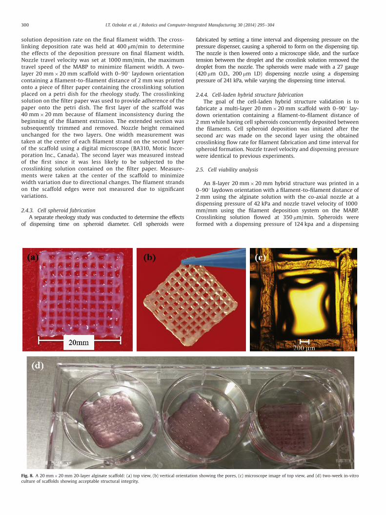
Fig. 8. A 20 mm�20 mm 20-layer alginate scaffold: (a) top view, (b) vertical orientation showing the pores, (c) microscope image of top view, and (d) two-week in-vitroculture of scaffolds showing acceptable structural integrity.
I.T. Ozbolat et al. / Robotics and Computer-Integrated Manufacturing 30 (2014) 295–304300

time of 200 ms. Cell viability assay was carried out by LIVE/DEADstaining as previously described [17] to both alginate filaments andspheroids at days 1, 4, and 7. Briefly, Calcein acetoxymethylester(calcein AM) and ethidiumhomodimer-2 (Invitrogen™ Life Tech-nologies, Carlsbad, CA), at a concentration of 1.0 mM each, wereused for labeling living cells with bright green fluorescent andnon-viable cells with red fluorophore. A 30-min incubationperiod was carried out during staining, and samples were imagedusing a fluorescent microscope (Leica Microsystems Inc., BuffaloGrove, IL, USA).
2.6. Statistical analysis
Statistical significance of the experimental data for the filamentwidth and spheroid diameter was determined by one-way analysisof variance (ANOVA) with a significance level of po0.05using Microsoft Excel. Nine Filament width measurements wereobtained for each scaffold, and a total of five scaffolds were fabricatedfor each dispensing parameter. Forty-five samples were obtained ateach dispensing parameter for cell spheroid diameter measurements.Statistical significance of the experimental data for cell functionalitywas determined by a paired-wise combined with the Tukey post-hoctest at a significance level po0.05. The percentage of viable cells foreach experimental group was calculated by averaging the values ofthree different samples. All measurements were presented asmean7standard deviation.
3. Results and discussion
3.1. Multi-layer scaffold fabrication
Scaffolds with 20 layers were fabricated using the filamentdeposition system. The scaffolds show that the system was ableto produce scaffolds with highly reproducible architecture withwell-defined geometries in well-integrated shape (see Fig. 8(a–c)). Ourtwo-week culture studies showed that the printed scaffolds in cell-type oxygenized media were still structurally integrated, demonstrat-ing its potential for long-term cultures as well (see Fig. 8(d)).
3.2. Co-axial nozzle operation
Filament width was measured at crosslinking fluid dispensingrates of 300 μl/min, 400 μl/min, and 500 μl/min. The filamentmeasurements were 579729 μm at a dispensing rate of 300 μl/min, 562713 μm at 400 μl/min, and 575720 μm at 500 μl/min, asshown in Fig. 9(a). The results show that there is no statisticalsignificance, and therefore filament width does not vary with theflow rate of the crosslinking solution at the range in which themeasurements were obtained. This was due to continuous cross-linker flow (regardless of flow rate) enclosing hydrogel flow andkeeping its diameter nearly constant. The structure started tocollapse when the flow rate was less than 300 μl/min due to weakcrosslinking of the extruded filament that did not allow quickdiffusion of calcium ions into the filament [17]. Poor layer adhesionwas noted when the flow rate was above 500 μl/min, which may
Fig. 9. Co-axial nozzle operation: (a) filament width measured at various cross-linking fluid dispensing rates at 45 kPa hydrogel dispensing pressure, and(b) filament width measured at various hydrogel dispensing pressures at a cross-linking fluid dispensing rate of 400 μl/min.
Fig. 10. Cell spheroid fabrication: (a) cell spheroid diameter measured at varioustime intervals, and (b) sample measurement of spheroid diameter.
I.T. Ozbolat et al. / Robotics and Computer-Integrated Manufacturing 30 (2014) 295–304 301
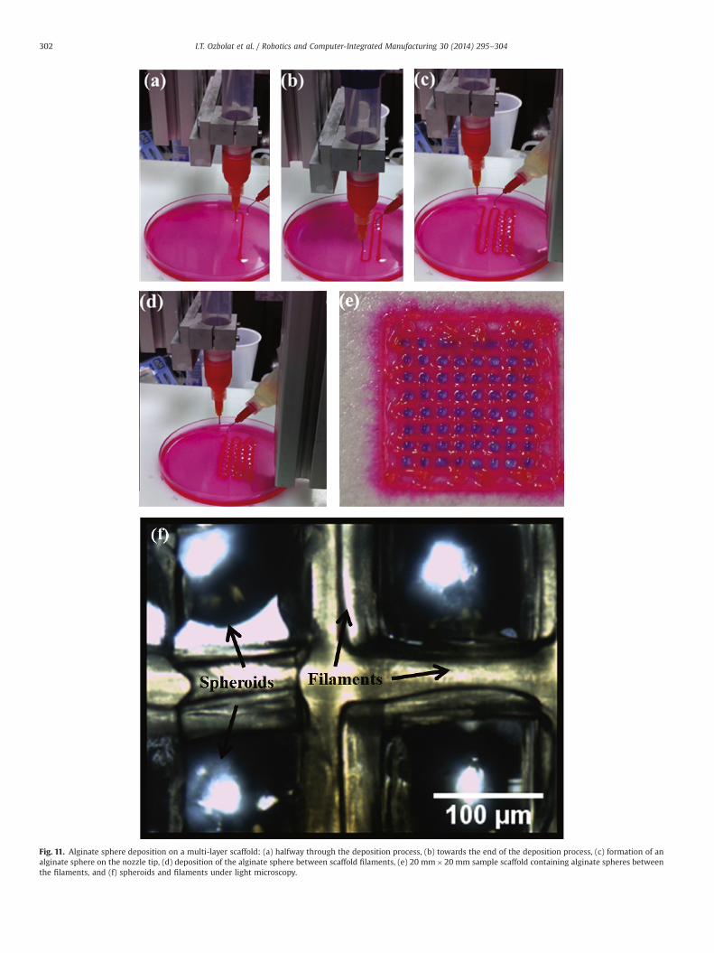
Fig. 11. Alginate sphere deposition on a multi-layer scaffold: (a) halfway through the deposition process, (b) towards the end of the deposition process, (c) formation of analginate sphere on the nozzle tip, (d) deposition of the alginate sphere between scaffold filaments, (e) 20 mm�20 mm sample scaffold containing alginate spheres betweenthe filaments, and (f) spheroids and filaments under light microscopy.
I.T. Ozbolat et al. / Robotics and Computer-Integrated Manufacturing 30 (2014) 295–304302
cause the structure to dissolve when submerged in cell culturingmedium. Due to the high flow rate of the crosslinker above 500 μl/min, crosslinking was nearly completed during the extrusionprocess that did not allow further crosslinking of the filament afterthe extrusion process. Hence, filaments did not adhere to otherfilaments strongly. One could speculate that other biomaterialswith crosslinking-based gelation mechanism such as chitosanwould behave similarly due to the above-mentioned phenomena.The higher measurement variation at 300 μl/min can be attributedto inconsistent flow of the crosslinking solution, causing some partsof the hydrogel to crosslink while others did not.
Filament width was also measured at hydrogel dispensing pres-sures of 35 kPa, 40 kPa, 45 kPa, and 50 kPa. The filament measure-ments were 406718 μm at a dispensing pressure of 35 kPa, 479728 μm at 40 kPa, 562713 μm at 45 kPa, and 630732 μm at 50 kPa,as shown in Fig. 9(b). The results showed a linear relationshipbetween dispensing pressure and filament width. The high varianceat a dispensing pressure of 50 kPa could be attributed to a relativelyslow nozzle travel velocity with respect to the given pressure, resultingin an uneven filament width and poorly defined geometries.
3.3. Cell spheroid fabrication
The cell spheroid fabrication measurements showed that thesphere diameter was 1323720 μm at a time interval of 250 ms,1608735 μm at 275 ms, 1703720 μm at 300 ms, and 1853739 μm at 350 ms. The results showed little variability in cellspheroid diameter at a given time interval and also showed thatthe correlation was non-linear from a dispensing time intervalbetween 250 ms and 350 ms, as shown in Fig. 10(a). A samplemeasurement of the spheroid is provided in Fig. 10(b).
3.4. Cell-laden hybrid structure
The cell-laden hybrid structure study used parametersobtained from the co-axial nozzle and the spheroid diametervalidation. The co-axial nozzle validation shows that the filament
width is 572712 μm regardless of the crosslinking depositingrate. A crosslinking deposition rate of 400 μl/min was used sincethe data showed that it provided the greatest filament consistency.The cell spheroid should ideally be 1500 μm for the spheroid to fitin the space between the adjacent filament, being that thefilament-to-filament distance was 2000 μm and the filamentwidth was 572 μm using the given parameters. 2000 μm distancewas preferred while cell spheroids were slightly interfering withthe filaments and crosslinking that enabled attachment of thespheroids to the filaments. This provided structural integrity of thehybrid constructs, where spheroids did not spread around inculture after the fabrication. The spheroid deposition data showedthat a time interval of 250 ms will yield the desired results.However, a time interval of 275 ms was used to ensure that thespheroid would be attached to the adjacent filament strands sinceit will produce a larger spheroid diameter. The spheroid depositionphase is shown in Fig. 11. The deposition process revealed that thespheroid deposition system was operating much slower than thefilament fabrication system. Approximately 6 of the 64 spheroidswere deposited before the filament deposition process wascompleted, which showed negligible savings in fabrication time.The resulting structure, however, shows well-defined filament andconstruct geometry as shown in Fig. 11(d). Fig. 11(e) demonstratesprecisely place spheroids between filaments in a multi-layer hybridstructure under light microscopy. The hybrid structure showsgreat promise for tissue engineering with increased cell densityand potential to develop heterocellular architecture. This printingprocess can be further refined to print multiple cell types byimplementing a secondary dispensing system onto the celldeposition arm.
3.5. Cell viability
Fluorescent microscopy was used to check cell viability afterthe printing process with live/dead fluorescent staining fromrandom filaments and spheroids on the scaffolds. Viable cellswere labeled with calcein AM (green), while dead cells were
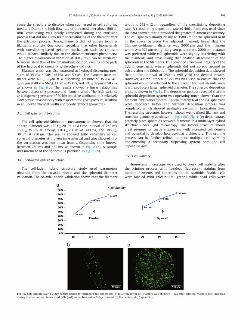
Fig. 12. Cell viability over a 7-day culture period for filaments and spheroids: (a) relatively lower cell viability was obtained 1 day after printing; viability rate increasedduring in vitro culture; fewer dead cells (red) were observed in 7-day cultured (b) filaments and (c) spheroids.
I.T. Ozbolat et al. / Robotics and Computer-Integrated Manufacturing 30 (2014) 295–304 303
stained with ethidium homodimer (red). Cells did not proliferatemuch within first 12 h post-printing. One day after printing, cellviability of both filaments and spheroids were relatively low:43.9270.04% and 60.1570.05%, respectively. During in vitroculture, cell viability increased after 3 days and reached up to76.0670.04% for filaments and 79.9970.06% for spheroids.Although the initial printing process may result in noticeable celldamage and death for both spheroids and filaments due to shearstress generated at the interface of the metal nozzle tip and thecellular alginate solution, as well as compressive stress generatedby high pneumatic dispensing pressure, injured cells were reco-vering and other cells were proliferating during prolonged culture,and viability was 87.2370.03 and 92.8770.02% at day 7 post-printing for filament and spheroids, respectively (see Fig. 12(a)).As can be seen in Fig. 12(b) and (c), most of the cells were stainedwith calcein AM at the end of 7-day in vitro culture. Although cellscould be seeded after the fabrication as well, seeding cells duringthe fabrication (which can be enriched with more cells seededafter fabrication) increases the cell density in the scaffold. Inaddition, seeding cells after fabrication might not be successfulfor some hydrogels such as alginate without surface modifications.Cells may not be able to attach on the surface of the hydrogel. Inthis case, encapsulating cells during fabrication is the only way forseeding cells inside the tissue construct.
4. Conclusion
This paper highlights the development of ‘Multi-arm Bioprin-ter’ of concurrent multi-material deposition with independentdispensing parameters, including deposition speed and materialdispensing rate, for use in tissue engineering. In this work, thesystem is designed to concurrently print a filament structure anddeposit cell spheroids between the filaments to create a structureto support the cell spheroids in 3D. The cell-laden hybrid structurefabrication showed that the structure could be printed throughconcurrent deposition with well-defined filament and spheroidgeometry. However, the time savings of concurrent deposition atits current state is negligible.
The potential uses of the MABP include using a secondary andtertiary dispensing unit mounted on the cell deposition system todo deposition of multiple cell types. Applications that may benefitfrom this technology include fabricating articular cartilage, whichhas compositional variations depending on the region and hybridtissue, or organ-like structures, which require a continuous vas-cular network with the tissue construct to facilitate nutrientdiffusion and waste removal [6]. We are currently in the processof implementing more sensors on the machine to enable the armsto reposition themselves automatically through cross-talking. We
are also increasing the deposition speed of the cell spheroiddeposition system to reduce fabrication time while fabricationtime is crucial for scale-up fabrication technologies. Additionalwork is also being done to fabricate pancreatic organs by printingvascular networks [17] with the rest of the tissue constructs.
Acknowledgment
The authors wish to thank Yahui Zhang for her insights indeposition rheology and the Ignacio V. Ponseti Biochemistry andCell Biology Laboratory for providing CPCs. The authors would alsolike to thank the University of Iowa's Instructional TechnologyServices for its support and the Center for Computer-Aided Designfor the development of the MABP.
References
[1] Boland T, Xu T, Damon B. Application of inkjet printing to tissue engineering.Biotechnol J 2006;1(9):910–7.
[2] Drury JL, Mooney DJ. Hydrogels for tissue engineering: scaffold designvariables and applications. Biomaterials 2003;24(24):4337–51.
[3] Hutmacher DW, Sittinger M, Risbud MV. Scaffold-based tissue engineering:rationale for computer-aided design and solid free-form fabrication systems.Trends Biotechnol 2004;22(7):354–62.
[4] Mironov V, Visconti RP, Kasyanov V. Organ printing: tissue spheroids asbuilding blocks. Biomaterials 2009;30(12):2164–74.
[5] Kelm JM, Djonov V, Ittner LM. Design of custom-shaped vascularized tissuesusing microtissue spheroids as minimal building units. Tissue Eng 2006;12(8):2151–60.
[6] Ozbolat I, Yu Y. Bioprinting towards organ fabrication: challenges and futuretrends. IEEE Trans Biomed Eng 2013;60(3):691–9.
[7] Envision TEC, 2011, “3D-Bioplotter,” Envision TEC Technical Data; 2013(03/01).p. 1.
[8] Organovo, 2012, “Science Overview,” Organovo; 2012(9/25).[9] Envision TEC, 2011, “3D-Bioplotter Technical Data”; 2012(9/25). p. 1.[10] Geng L, Feng W, Hutmacher DW. Direct writing of chitosan scaffolds using a
robotic system. Rapid Prototyp J 2005;11(2):90–7.[11] Yan Y, Xiong Z, Hu Y. Layered manufacturing of tissue engineering scaffolds via
multi-nozzle deposition. Mater Lett 2003;57(18):2623–8.[12] Li S, Xiong Z, Wang X. Direct fabrication of a hybrid cell/hydrogel construct by
a double-nozzle assembling technology. J Bioact Compat Polym 2009;24(3):249–65.
[13] Khalil S, Sun W. Biopolymer deposition for freeform fabrication of hydrogeltissue constructs. Mater Sci Eng C 2007;27(3):469–78.
[14] Xu T, Binder KW, Albanna MZ. Hybrid printing of mechanically and biologi-cally improved constructs for cartilage tissue engineering applications. Bio-fabrication 2013;5(1):015001.
[15] Khoda A, Ozbolat IT, Koc B. Engineered tissue scaffolds with variational porousarchitecture. J Biomech Eng 2011;133(1):011001.
[16] Yu Y. Identification and characterization of cartilage progenitor cells by singlecell sorting and cloning (Master's thesis). The University of Iowa; 2012.
[17] Zhang Y, Yu Y, Chen H. Characterization of printable cellular micro-fluidicchannels for tissue engineering. Biofabrication 2013;5(2):025004.
[18] Ozbolat IT. Path planning for functionally graded materials in hollow tissuescaffold printing. International mechanical engineering congress & exposition(IMECE); November 11–17, Denver, Colorado; 2011.
I.T. Ozbolat et al. / Robotics and Computer-Integrated Manufacturing 30 (2014) 295–304304
Copyright © 2022 FDOKUMEN