Cycle Model Compiler User Manual - Arm
84
Copyright © 2017 ARM Limited. All rights reserved. ARM DUI 0957G (ID021417) Cycle Model Compiler Version 9.1.0 User Manual Non-Confidential
-
Upload
khangminh22 -
Category
Documents
-
view
0 -
download
0
Transcript of Cycle Model Compiler User Manual - Arm
Cycle Model CompilerVersion 9.1.0
User ManualNon-Confidential
Copyright © 2017 ARM Limited. All rights reserved.ARM DUI 0957G (ID021417)

Cycle Model CompilerUser Manual
Copyright © 2017 ARM Limited. All rights reserved.
Release Information
The following changes have been made to this document.
Non-Confidential Proprietary Notice
This document is protected by copyright and other related rights and the practice or implementation of the information contained in this document may be protected by one or more patents or pending patent applications. No part of this document may be reproduced in any form by any means without the express prior written permission of ARM Limited (“ARM”). No license, express or implied, by estoppel or otherwise to any intellectual property rights is granted by this document unless specifically stated.
Your access to the information in this document is conditional upon your acceptance that you will not use or permit others to use the information for the purposes of determining whether implementations infringe any patents.
THIS DOCUMENT IS PROVIDED “AS IS”. ARM PROVIDES NO REPRESENTATIONS AND NO WARRANTIES, EXPRESS, IMPLIED OR STATUTORY, INCLUDING, WITHOUT LIMITATION, THE IMPLIED WARRANTIES OF MERCHANTABILITY, SATISFACTORY QUALITY, NON-INFRINGEMENT OR FITNESS FOR A PARTICULAR PURPOSE WITH RESPECT TO THE DOCUMENT. For the avoidance of doubt, ARM makes no representation with respect to, and has undertaken no analysis to identify or understand the scope and content of, third party patents, copyrights, trade secrets, or other rights.
This document may include technical inaccuracies or typographical errors.
This document may be translated into other languages for convenience, and you agree that if there is any conflict between the English version of this document and any translation, the terms of the English version shall prevail.
TO THE EXTENT NOT PROHIBITED BY LAW, IN NO EVENT WILL ARM BE LIABLE FOR ANY DAMAGES, INCLUDING WITHOUT LIMITATION ANY DIRECT, INDIRECT, SPECIAL, INCIDENTAL, PUNITIVE, OR CONSEQUENTIAL DAMAGES, HOWEVER CAUSED AND REGARDLESS OF THE THEORY OF LIABILITY, ARISING OUT OF ANY USE OF THIS DOCUMENT, EVEN IF ARM HAS BEEN ADVISED OF THE POSSIBILITY OF SUCH DAMAGES.
This document consists solely of commercial items. You shall be responsible for ensuring that any use, duplication or disclosure of this document complies fully with any relevant export laws and regulations to assure that this document or any portion thereof is not exported, directly or indirectly, in violation of such export laws. Use of the word “partner” in reference to ARM’s customers is not intended to create or refer to any partnership relationship with any other company. ARM may make changes to this document at any time and without notice.
If any of the provisions contained in these terms conflict with any of the provisions of any signed written agreement specifically covering this document with ARM, then the signed written agreement prevails over and supersedes the conflicting provisions of these terms.
Words and logos marked with ® or ™ are registered trademarks or trademarks of ARM Limited or its affiliates in the EU and/or elsewhere. All rights reserved. Other brands and names mentioned in this document may be the trademarks of their respective owners. You must follow the ARM trademark usage guidelines http://www.arm.com/about/trademarks/guidelines/index.php.
Change History
Date Issue Confidentiality Change
February 2016 A Non-Confidential Update for 8.1
May 2016 B Non-Confidential Update for 8.2
June 2016 C Non-Confidential Update for 8.2.1
July 2016 D Non-Confidential Update for 8.2.2
August 2016 E Non-Confidential Update for 8.3.0
November 2016 F Non-Confidential Update for 9.0.0
February 2017 G Non-Confidential Update for 9.1.0
ARM DUI 0957G Copyright © 2017 ARM Limited. All rights reserved. 2ID021417 Non-Confidential

Copyright © ARM Limited or its affiliates. All rights reserved.ARM Limited. Company 02557590 registered in England.110 Fulbourn Road, Cambridge, England CB1 9NJ.
In this document, where the term ARM is used to refer to the company it means “ARM or any of its subsidiaries as appropriate”.
Confidentiality Status
This document is Non-Confidential. The right to use, copy and disclose this document may be subject to license restrictions in accordance with the terms of the agreement entered into by ARM and the party that ARM delivered this document to.
Product Status
The information in this document is final, that is for a developed product.
Web Address
http://www.arm.com
ARM DUI 0957G Copyright © 2017 ARM Limited. All rights reserved. 3ID021417 Non-Confidential

ARM DUI 0957G Copyright © 2017 ARM Limited. All rights reserved. 4ID021417 Non-Confidential

Contents
Chapter 1.Introduction to the Cycle Model Compiler
Validation Methodology . . . . . . . . . . . . . . . . . . . . . . . . . . . . . . . . . . . . . . . . . . . . . . . . . . . . . 7Compiler Inputs . . . . . . . . . . . . . . . . . . . . . . . . . . . . . . . . . . . . . . . . . . . . . . . . . . . . . . . . . . . . 7What is a Cycle Model? . . . . . . . . . . . . . . . . . . . . . . . . . . . . . . . . . . . . . . . . . . . . . . . . . . . . . . 8
Using a Cycle Model . . . . . . . . . . . . . . . . . . . . . . . . . . . . . . . . . . . . . . . . . . . . . . . . . . . . . 9The Cycle Model API . . . . . . . . . . . . . . . . . . . . . . . . . . . . . . . . . . . . . . . . . . . . . . . . . . . . . . 10RTL Remodeling Tasks . . . . . . . . . . . . . . . . . . . . . . . . . . . . . . . . . . . . . . . . . . . . . . . . . . . . . 10
Chapter 2.Getting Started with the Cycle Model Compiler
Setting up the Example Environment . . . . . . . . . . . . . . . . . . . . . . . . . . . . . . . . . . . . . . . . . . 11The Example Hardware Design . . . . . . . . . . . . . . . . . . . . . . . . . . . . . . . . . . . . . . . . . . . . . . . 12
Verilog Twocounter Example . . . . . . . . . . . . . . . . . . . . . . . . . . . . . . . . . . . . . . . . . . . . . 12The Makefile . . . . . . . . . . . . . . . . . . . . . . . . . . . . . . . . . . . . . . . . . . . . . . . . . . . . . . . . . . . . . 12Running the Example . . . . . . . . . . . . . . . . . . . . . . . . . . . . . . . . . . . . . . . . . . . . . . . . . . . . . . . 13Cycle Model Compiler Output Files . . . . . . . . . . . . . . . . . . . . . . . . . . . . . . . . . . . . . . . . . . . 15
Chapter 3.Cycle Model Compiler Command Line Options
Command Syntax . . . . . . . . . . . . . . . . . . . . . . . . . . . . . . . . . . . . . . . . . . . . . . . . . . . . . . . . . . 17Command Options . . . . . . . . . . . . . . . . . . . . . . . . . . . . . . . . . . . . . . . . . . . . . . . . . . . . . . . . . 18
General Compile Control . . . . . . . . . . . . . . . . . . . . . . . . . . . . . . . . . . . . . . . . . . . . . . . . 18Input File Control . . . . . . . . . . . . . . . . . . . . . . . . . . . . . . . . . . . . . . . . . . . . . . . . . . . . . . 21Module Control . . . . . . . . . . . . . . . . . . . . . . . . . . . . . . . . . . . . . . . . . . . . . . . . . . . . . . . . 22Net Control . . . . . . . . . . . . . . . . . . . . . . . . . . . . . . . . . . . . . . . . . . . . . . . . . . . . . . . . . . . 24Verilog- and SystemVerilog-Specific Options . . . . . . . . . . . . . . . . . . . . . . . . . . . . . . . . 28Output Control . . . . . . . . . . . . . . . . . . . . . . . . . . . . . . . . . . . . . . . . . . . . . . . . . . . . . . . . . 32
Chapter 4.Cycle Model Compiler Directives
Using Directives . . . . . . . . . . . . . . . . . . . . . . . . . . . . . . . . . . . . . . . . . . . . . . . . . . . . . . . . . . . 39Using a Directives File . . . . . . . . . . . . . . . . . . . . . . . . . . . . . . . . . . . . . . . . . . . . . . . . . . 39Embedding Directives in Comments . . . . . . . . . . . . . . . . . . . . . . . . . . . . . . . . . . . . . . . . 41
Net Control . . . . . . . . . . . . . . . . . . . . . . . . . . . . . . . . . . . . . . . . . . . . . . . . . . . . . . . . . . . . . . . 43Module Control . . . . . . . . . . . . . . . . . . . . . . . . . . . . . . . . . . . . . . . . . . . . . . . . . . . . . . . . . . . 46
Flattening . . . . . . . . . . . . . . . . . . . . . . . . . . . . . . . . . . . . . . . . . . . . . . . . . . . . . . . . . . . . . 48Output Control . . . . . . . . . . . . . . . . . . . . . . . . . . . . . . . . . . . . . . . . . . . . . . . . . . . . . . . . . . . . 50
ARM DUI 0957G Copyright © 2017 ARM Limited. All rights reserved. 5ID021417 Non-Confidential

Chapter 5.Language Support
Verilog Support . . . . . . . . . . . . . . . . . . . . . . . . . . . . . . . . . . . . . . . . . . . . . . . . . . . . . . . . . . . . 52General Constructs . . . . . . . . . . . . . . . . . . . . . . . . . . . . . . . . . . . . . . . . . . . . . . . . . . . . . . 52Hierarchical References . . . . . . . . . . . . . . . . . . . . . . . . . . . . . . . . . . . . . . . . . . . . . . . . . . 54Net Types . . . . . . . . . . . . . . . . . . . . . . . . . . . . . . . . . . . . . . . . . . . . . . . . . . . . . . . . . . . . . 56Gate-level Constructs . . . . . . . . . . . . . . . . . . . . . . . . . . . . . . . . . . . . . . . . . . . . . . . . . . . . 58Behavioral Constructs . . . . . . . . . . . . . . . . . . . . . . . . . . . . . . . . . . . . . . . . . . . . . . . . . . . 59Switch-level Constructs . . . . . . . . . . . . . . . . . . . . . . . . . . . . . . . . . . . . . . . . . . . . . . . . . . 61User-Defined Primitives . . . . . . . . . . . . . . . . . . . . . . . . . . . . . . . . . . . . . . . . . . . . . . . . . . 62Synthesizable Subset . . . . . . . . . . . . . . . . . . . . . . . . . . . . . . . . . . . . . . . . . . . . . . . . . . . . 63Z State Propagation . . . . . . . . . . . . . . . . . . . . . . . . . . . . . . . . . . . . . . . . . . . . . . . . . . . . . 63Exponent Operator Support . . . . . . . . . . . . . . . . . . . . . . . . . . . . . . . . . . . . . . . . . . . . . . . 65
SystemVerilog Support . . . . . . . . . . . . . . . . . . . . . . . . . . . . . . . . . . . . . . . . . . . . . . . . . . . . . . 66Supported Constructs . . . . . . . . . . . . . . . . . . . . . . . . . . . . . . . . . . . . . . . . . . . . . . . . . . . . 66Constructs with Limited Support . . . . . . . . . . . . . . . . . . . . . . . . . . . . . . . . . . . . . . . . . . . 67Support for New Data Types . . . . . . . . . . . . . . . . . . . . . . . . . . . . . . . . . . . . . . . . . . . . . . 70
Appendix A.Dumping Waveforms in Different Environments
Waveform Dumping Implementation Notes . . . . . . . . . . . . . . . . . . . . . . . . . . . . . . . . . . . . . . 71Basic C/C++ Testbench . . . . . . . . . . . . . . . . . . . . . . . . . . . . . . . . . . . . . . . . . . . . . . . . . . . . . 72SystemC Environment . . . . . . . . . . . . . . . . . . . . . . . . . . . . . . . . . . . . . . . . . . . . . . . . . . . . . . 73
Appendix B.Using DesignWare Replacement Modules
Replacing DesignWare Modules . . . . . . . . . . . . . . . . . . . . . . . . . . . . . . . . . . . . . . . . . . . . . . 75List of Replacement Modules for DesignWare . . . . . . . . . . . . . . . . . . . . . . . . . . . . . . . . . . . 76Troubleshooting . . . . . . . . . . . . . . . . . . . . . . . . . . . . . . . . . . . . . . . . . . . . . . . . . . . . . . . . . . . 77
Appendix C.Using Profiling to Find Performance Problems
Types of Performance Problems . . . . . . . . . . . . . . . . . . . . . . . . . . . . . . . . . . . . . . . . . . . . . . . 79Locating the RTL Source of a Profiling Hotspot . . . . . . . . . . . . . . . . . . . . . . . . . . . . . . . . . . 80
Using the Hierarchy File . . . . . . . . . . . . . . . . . . . . . . . . . . . . . . . . . . . . . . . . . . . . . . . . . 80Commenting Out the Problem Function . . . . . . . . . . . . . . . . . . . . . . . . . . . . . . . . . . . . . 80
Confirming that the Identified Calling Code Leads to the Profiling Hotspot . . . . . . . . . . . . . 81Re-writing RTL to Improve Performance . . . . . . . . . . . . . . . . . . . . . . . . . . . . . . . . . . . . . . . 81
Example 1: A Simple Library Cell as a Profiling Hotspot . . . . . . . . . . . . . . . . . . . . . . . . 81Example 2: Infrequently Occurring Architectures/Modules as Profiling Hotspots . . . . . 82Example 3: Profiling is an Iterative Process . . . . . . . . . . . . . . . . . . . . . . . . . . . . . . . . . . 82
Summary . . . . . . . . . . . . . . . . . . . . . . . . . . . . . . . . . . . . . . . . . . . . . . . . . . . . . . . . . . . . . . . . . 83
ARM DUI 0957G Copyright © 2017 ARM Limited. All rights reserved. 6ID021417 Non-Confidential

Chapter 1
Introduction to the Cycle Model Compiler
This chapter provides an overview of the Cycle Model Compiler product and how it fits into the ARM Cycle Model system validation workflow.
1.1 Validation MethodologyARM Cycle Model tools provide an integrated environment that places system validation in parallel with the hardware development flow, as shown in Figure 1.1. The Cycle Model Compiler takes an RTL hardware model and creates a high-performance linkable object, called the Cycle Model, that is cycle and register accurate. The Cycle Model provides an API for interfacing with your validation environment.
1.2 Compiler InputsA Cycle Model is exclusive to ARM and can be generated only by the Cycle Model Com-piler. The Cycle Model Compiler reads the following files, in order, and generates a Cycle Model for the design.
1. Options files – Contain command options that provide control and guidance to the Cycle Model Compiler.
2. Directives files – Contain directives that control how the Cycle Model Compiler inter-prets and builds a Cycle Model.
Figure 1.1 Validation Environment
Cycle Model Compiler
Cycle Model
API
KHz Engine
VCD
RTL
Debugger
SoftwareDriver
ARM DUI 0957G Copyright © 2017 ARM Limited. All rights reserved. 7ID021417 Non-Confidential

3. Verilog® design and library files – Golden RTL of the hardware design.
For more details about the Cycle Model Compiler command-line options and directives see Chapter 3 and Chapter 4 respectively.
1.3 What is a Cycle Model?A Cycle Model is a high-performance linkable software object that is generated by the Cycle Model Compiler directly from RTL design files. The Cycle Model contains a cycle and register-accurate model of the hardware design in the form of a software object file, header file, and sup-porting binary database. By default, the Cycle Model Compiler generates these files in the cur-rent working directory (./) as listed below:
• libdesign.a – Cycle Model object library (Linux)libdesign.lib – Cycle Model object library (Windows)
• libdesign.h – Cycle Model header file
• libdesign.symtab.db – database with information about all internal signals
• libdesign.io.db – a subset of libdesign.symtab.db that includes top-level inputs, outputs, inouts, and those signals marked as observable or depositable (to the external envi-ronment)
In general, when integrating the Cycle Model into a simulation environment, you should use the symtab.db. The io.db file is provided for use if you are passing your Cycle Model on to a third-party customer and you want to restrict the visibility of your design.
For information about the Cycle Model Compiler output files, see “Cycle Model Compiler Out-put Files” on page 2-15.
Figure 1.2 Generating a Cycle Model
Cycle Model
Options
Directives
Design
Cycle Model
Compiler
ARM DUI 0957G Copyright © 2017 ARM Limited. All rights reserved. 8ID021417 Non-Confidential

1.3.1 Using a Cycle ModelCycle Model files must be linked with a standard software compiler, such as gcc or Microsoft® Visual C++™, before they can be run in the software test environment. The following files are required to create a proper executable:
• libdesign.a – Cycle Model
• libdesign.h – Cycle Model header file
• libcarbon5.so – Cycle Model shell
• carbon_capi.h – API header file
Note that libcarbon5.so and carbon_capi.h are provided in the installation package.
The following file is required in a Windows environment:
• libdesign.lib – Windows static library implementation
In addition, the .db file must be accessible to the Cycle Model at runtime (it should be located in the same directory as the validation executable).
The Cycle Model is controlled by your software test environment. A software program, such as a driver, can communicate with the hardware model directly through sockets, through the Cycle Model API, or through an Instruction Set Simulator (ISS). For embedded software—where the software is loaded into a hardware memory model—a software debugger may be linked to the embedded software through the Cycle Model API.
Figure 1.3 Generating an Executable Model
gcc
Cycle Model
libcarbon5.so
carbon_capi.h
validation.exe
(libdesign.a)
ARM DUI 0957G Copyright © 2017 ARM Limited. All rights reserved. 9ID021417 Non-Confidential

1.4 The Cycle Model APIThe Cycle Model API provides the C functions necessary to link a Cycle Model into a software test environment. You can access the value of any net in the design—including memories—deposit values on nets, dump signal waveforms, and supply time and timescale information to the design.
The Cycle Model API is “handle” based—meaning that in order to query and manipulate a spe-cific design structure in a Cycle Model, you must use its handle or ID (rather than the full HDL path name). Following are the primary reference structures that provide access into a Cycle Model.
• CarbonObjectID – Provides the context for a design, and is used to run the design’s core function(s).
• CarbonWaveID – Provides signal waveform dump control. Standard Verilog VCD and Debussy’s FSDB formats are supported.
• CarbonNetID – Used to access nets in the design. API functions allow you to examine sig-nal values, deposit values on signals, and force signals to specific values.
• CarbonMemoryID – Used to access memories in the design. API functions allow you to examine memory values and deposit values into memories.
See the Cycle Model API Reference Manual for detailed information about all API files and functions.
1.5 RTL Remodeling TasksThere are certain hardware constructs that the Cycle Model Compiler does not currently sup-port; they must be remodeled using supported constructs.
Phase-Locked LoopsPLLs implement behavior that occurs without cycle dependencies, and therefore are not sup-ported. Designs that use PLLs must be modeled to bypass the PLL and drive the generated clocks from the external environment via the API, or to provide pass-through logic. The Cycle Model API will be able to drive PLL-generated clocks without needing to bring the clock to a primary input.
MemoriesVendor-provided memory libraries often use behavioral constructs that the Cycle Model Com-piler does not support. These memories need to be remodeled using constructs supported by ARM.
Low-level Constructs & Gate-level ModelingThough the Cycle Model Compiler supports gate-level constructs, the use of high-level Verilog constructs generally yields higher performance Cycle Models and is highly recommended. A common example of a gate-level construct that can be improved with high-level modeling is a pad cell.
The above remodeling is required for proper Cycle Model Compiler function. Tips for addi-tional remodeling that can improve performance can be found in the RTL Style Guide.
ARM DUI 0957G Copyright © 2017 ARM Limited. All rights reserved. 10ID021417 Non-Confidential
Chapter 2
Getting Started with the Cycle Model Compiler
This chapter shows you how to compile a design with the Cycle Model Compiler from the appropriate input files and then link the resulting software executable to a testbench. For a complete list of system requirements, see the Cycle Model Studio Installation Guide (ARM DUI.
2.1 Setting up the Example Environment
To obtain the source files for this example, perform the following steps:
1. Using syntax appropriate to your shell, make sure that the following environment vari-ables are set.
CARBON_HOME =<install dir>PATH =$CARBON_HOME/bin:$PATH
where <install dir> is the installation directory.
2. Create a working directory for your experiments. For example:
mkdir ~/cycle_model_experiment
cd ~/cycle_model_experiment
3. Copy the example files into your local work directory.
cp -r $CARBON_HOME/examples/twocounter ./twocounter
4. Change to the twocounter directory.
cd twocounter
The files in this directory include the following:
• Makefile
• Makefile.shared
• Makefile.notes
• twocounter.v – HDL code for the design
• twocounter.c – C code for test harness
• twocounter.gold – expected output for test harness
ARM DUI 0957G Copyright © 2017 ARM Limited. All rights reserved. 11ID021417 Non-Confidential

2.2 The Example Hardware Design
This example is a simple design with two counters driven by two clocks.
2.2.1 Verilog Twocounter Example
Note: To run the Verilog version with SystemVerilog, use the -sverilog command line switch.
module twocounter(clk1, clk2, reset1, reset2, out1, out2);
input clk1, clk2, reset1, reset2;output [31:0] out1, out2;reg [31:0] out1, out2;
always @(posedge clk1)if (reset1)
out1 <= 32'b0;else
out1 <= out1 + 32'd1;
always @(posedge clk2)if (reset2)
out2 <= 32'b0;else
out2 <= out2 + 32'd3;
endmodule
2.3 The Makefile
Before you run any of the examples, examine the Makefile. This is typically how the valida-tion process is run, rather than invoking each tool separately. This Makefile uses variables to invoke the Cycle Model Compiler, to invoke GNU compilers, and to access a list of link librar-ies. Using these variables in your projects’ Makefiles will help ensure smooth operation, and facilitate future product upgrades. The Makefile does the following:
1. Compiles the design file into a Cycle Model using the Cycle Model Compiler.
2. Compiles the software harness into a software harness object using gcc.
3. Links the Cycle Model with the software harness object using g++ to produce a software validation executable.
4. Invokes the software validation executable to generate run-time output.
5. Compares the run-time output with the expected values (twocounter.gold file).
Note: The CARBON_LIB_LIST make variable links the program so that LD_LIBRARY_PATH over-rides -rpath, therefore, a single GCC version should be used within your environment to avoid library conflicts. While a Cycle Model itself has no dependencies on compiler libraries, custom code compiled with the ARM-provided GCC may. If this code is integrated into an environment that uses a different version of GCC (for example, a third-party tool), runtime errors may occur. In environments such as this, it is recommended that the GCC provided by the third-part tool be used to compile the custom code.
ARM DUI 0957G Copyright © 2017 ARM Limited. All rights reserved. 12ID021417 Non-Confidential

Following is an excerpt from the Makefile.
# Makefile for twocounter example.## Notes on Makefile variable definitions are in# $(CARBON_HOME)/examples/twocounter/Makefile.notes## Common Makefile for all languages, platforms.
include $(CARBON_HOME)/examples/twocounter/Makefile.common
# Makefile targets for twocounter example.
twocounter.exe: twocounter.o libtwocounter.a$(CARBON_LINK) twocounter.o -o twocounter.exe \libtwocounter.a $(CARBON_LIB_LIST)
twocounter.o: twocounter.c libtwocounter.a$(CARBON_CC) -c twocounter.c -I$(CARBON_HOME)/include
# The following line is found in Makefiles when the top module # is written in Verilog
libtwocounter.a: twocounter.v$(CARBON_CBUILD) twocounter.v -o libtwocounter.a
Note: If you want to test the installation, you can simply run the Makefile with the Linux make command.
2.4 Running the Example
In this example, you first create a Cycle Model from your design and then create and test a val-idation executable using your Cycle Model. For an example using C-models and Cycle Models, see the Cycle Model API Reference Manual.
1. To compile a Cycle Model for this design, issue the following command:
make libtwocounter.a
You could also compile the Cycle Model using the cbuild command:
Verilog: cbuild twocounter.v -o libtwocounter.a.
SystemVerilog: cbuild twocounter.v -sverilog -o \libtwocounter.a
The -o option specifies a name for the Cycle Model Compiler output files; the .a extension generates a traditional object archive.
The Cycle Model Compiler compiles a Cycle Model object for the specified design. The following message is generated upon successful completion of the compilation (provided the -q command option has not been specified):
Note 111: Successfully created libtwocounter.
The Cycle Model Compiler creates many output files; for a description of the important files, see “Cycle Model Compiler Output Files” on page 2-15.
ARM DUI 0957G Copyright © 2017 ARM Limited. All rights reserved. 13ID021417 Non-Confidential
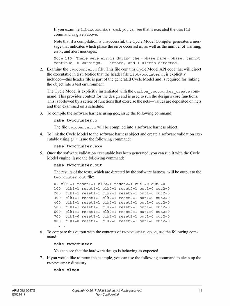
If you examine libtwocounter.cmd, you can see that it executed the cbuild command as given above.
Note that if a compilation is unsuccessful, the Cycle Model Compiler generates a mes-sage that indicates which phase the error occurred in, as well as the number of warning, error, and alert messages:
Note 110: There were errors during the <phase name> phase, cannot continue. 0 warnings, 1 errors, and 1 alerts detected.
2. Examine the twocounter.c file. This file contains Cycle Model API code that will direct the executable in test. Notice that the header file libtwocounter.h is explicitly included—this header file is part of the generated Cycle Model and is required for linking the object into a test environment.
The Cycle Model is explicitly instantiated with the carbon_twocounter_create com-mand. This provides context for the design and is used to run the design’s core functions. This is followed by a series of functions that exercise the nets—values are deposited on nets and then examined on a schedule.
3. To compile the software harness using gcc, issue the following command:
make twocounter.o
The file twocounter.c will be compiled into a software harness object.
4. To link the Cycle Model to the software harness object and create a software validation exe-cutable using g++, issue the following command:
make twocounter.exe
5. Once the software validation executable has been generated, you can run it with the Cycle Model engine. Issue the following command:
make twocounter.out
The results of the tests, which are directed by the software harness, will be output to the twocounter.out file:
0: clk1=1 reset1=1 clk2=1 reset2=1 out1=0 out2=0100: clk1=1 reset1=1 clk2=1 reset2=1 out1=0 out2=0200: clk1=1 reset1=1 clk2=1 reset2=1 out1=0 out2=0300: clk1=1 reset1=1 clk2=1 reset2=1 out1=0 out2=0400: clk1=1 reset1=1 clk2=1 reset2=1 out1=0 out2=0500: clk1=1 reset1=1 clk2=1 reset2=1 out1=0 out2=0600: clk1=1 reset1=1 clk2=1 reset2=1 out1=0 out2=0700: clk1=0 reset1=1 clk2=1 reset2=1 out1=0 out2=0800: clk1=0 reset1=1 clk2=0 reset2=1 out1=0 out2=0. . .
6. To compare this output with the contents of twocounter.gold, use the following com-mand:
make twocounter
You can see that the hardware design is behaving as expected.
7. If you would like to rerun the example, you can use the following command to clean up the twocounter directory:
make clean
ARM DUI 0957G Copyright © 2017 ARM Limited. All rights reserved. 14ID021417 Non-Confidential

2.5 Cycle Model Compiler Output FilesThe Cycle Model Compiler writes many files to the working directory. You may find the following files useful for interpreting the Cycle Model:
File Description
./libtwocounter.a
./libtwocounter.libThe Cycle Model file. The type of file cre-ated depends on which extension is speci-fied with the -o option (*.a is the default). The .a file is for Linux, the .lib file is for Windows.
./libtwocounter.h Cycle Model header file.
./libtwocounter.symtab.db Database containing information about all internal signals.
./libtwocounter.io.db Database containing information about only those IOs marked as observable (to the external environment). Used instead of the *.symtab.db file if you are passing your Cycle Model to a third-party customer, and you want to restrict the visibility of your design.
./libtwocounter.cmd All commands passed to Cycle Model Com-piler, including those passed on the com-mand line and those passed in a command file.
./libtwocounter.dir All directives that were parsed during the compile, including those in a directives file and any embedded (inline) directives.
./libtwocounter.hierarchy Table of every module instance in the design and its corresponding RTL file.
./libtwocounter.designHierarchy The instance hierarchy, with the architecture name, for all the design units used in the design. It also includes the library for each design unit, the location of the design unit, and the ports and generics used.
./libtwocounter.warnings Warnings encountered during the compile.
./libtwocounter.errors Errors encountered during the compile. If the compilation succeeds, this file is created anyway, but is empty.
./libtwocounter.suppress Messages suppressed during the compile.
ARM DUI 0957G Copyright © 2017 ARM Limited. All rights reserved. 15ID021417 Non-Confidential
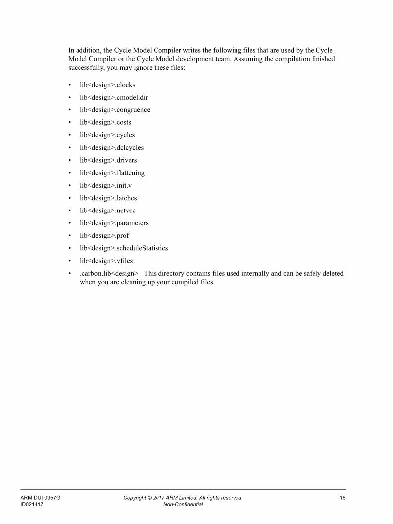
In addition, the Cycle Model Compiler writes the following files that are used by the Cycle Model Compiler or the Cycle Model development team. Assuming the compilation finished successfully, you may ignore these files:
• lib<design>.clocks
• lib<design>.cmodel.dir
• lib<design>.congruence
• lib<design>.costs
• lib<design>.cycles
• lib<design>.dclcycles
• lib<design>.drivers
• lib<design>.flattening
• lib<design>.init.v
• lib<design>.latches
• lib<design>.netvec
• lib<design>.parameters
• lib<design>.prof
• lib<design>.scheduleStatistics
• lib<design>.vfiles
• .carbon.lib<design> This directory contains files used internally and can be safely deleted when you are cleaning up your compiled files.
ARM DUI 0957G Copyright © 2017 ARM Limited. All rights reserved. 16ID021417 Non-Confidential

Chapter 3
Cycle Model Compiler Command Line Options
This chapter provides detailed information about the cbuild command-line syntax and options. You can use these options, along with directives, to provide control and guidance to the Cycle Model Compiler. See Chapter 4 for information about directives.
3.1 Command Syntax
The cbuild command invokes the Cycle Model Compiler. It compiles the design files, libraries, and directives that you specify into a Cycle Model. The command syntax is as follows:
cbuild [options] <design file list>
Where <design file list> is the list of design files you want to include in the com-pile. A Cycle Model may be compiled from several design and library files. When you invoke the Cycle Model Compiler, list all necessary design files and referenced library files. In addition, you may want to specify the top-level module in a Verilog or SystemVer-ilog design (see “-vlogTop <string>” on page 3-28).
Note that the Cycle Model Compiler processes files in the following order:
1. Command options files (specified with the -f option)
2. Directives files (specified with the -directive option)
3. Design and library files
If any errors are encountered during the compile, they are displayed to standard output. The error will consist of an error number and a brief error description.
ARM DUI 0957G Copyright © 2017 ARM Limited. All rights reserved. 17ID021417 Non-Confidential
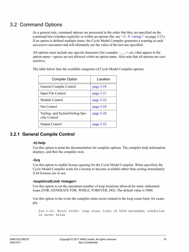
3.2 Command Options
As a general rule, command options are processed in the order that they are specified on the command line (whether explicitly or within an options file, see “-f | -F <string>” on page 3-21). If an option is defined multiple times, the Cycle Model Compiler generates a warning at each successive encounter and will ultimately use the value of the last one specified.
All options must include any special characters (for example, -, _, +, etc.) that appear in the option name—spaces are not allowed within an option name. Also note that all options are case sensitive.
The table below lists the available categories of Cycle Model Compiler options:
3.2.1 General Compile Control
-h|-helpUse this option to print the documentation for compiler options. The compiler help information displays, and then the compiler exits.
-licqUse this option to enable license queuing for the Cycle Model Compiler. When specified, the Cycle Model Compiler waits for a license to become available rather than exiting immediately if all licenses are in use.
-loopUnrollLimit <integer>Use this option to set the maximum number of loop iterations allowed for static elaborated loops (FOR, GENERATE FOR, WHILE, FOREVER, DO). The default value is 5000.
Use this option in the event the compiler emits errors related to the loop count limit; for exam-ple:
foo.v:22: Error 51066: loop count limit of 5000 exceeded; condition is never false
Compiler Option Location
General Compile Control page 3-18
Input File Control page 3-21
Module Control page 3-22
Net Control page 3-24
Verilog- and SystemVerilog-Spe-cific Control
page 3-28
Output Control page 3-32
ARM DUI 0957G Copyright © 2017 ARM Limited. All rights reserved. 18ID021417 Non-Confidential

-j <integer>Use this option to limit the number of parallel make sub-jobs—the number of Cycle Model compilations running in parallel. The default value is 4. Set this value to 1 for serial runs.
Note: You may set this option to any positive integer value you want, however the Cycle Model Compiler performance may not be optimal if it is set too high. Also note that you may need to use a smaller number if the compile process produces errors that point to a possible memory issue.
-multi-threadUse this option to generate a thread-safe Cycle Model. Enable this option if you want the gener-ated Cycle Model to be used in a multi-threaded environment. Multi-threading is supported in the Cycle Model API, with some exceptions. Note that using this option may impact the perfor-mance of the resulting Cycle Model.
If you are generating a Cycle Model for Windows and linking with the multi-threaded Windows libraries (library names ending in MT.lib or MTD.lib) it is recommended that you use this option.
Caution: Consult your ARM Cycle Models Applications Engineer for guidance when using this option.
-O <string>Use this option to control the design optimization level—higher optimizations may result in a faster Cycle Model. The optimization levels are defined in the following table. Note that the s value is case sensitive, meaning that S is not equivalent to s.
-phaseStatsUse the -phaseStats option to print the time and memory statistics for each compile phase.
-profileGenerateYou can use this option with the -profileUse option to generate more efficient (faster) Cycle Models as follows:
1. Run the Cycle Model Compiler using -profileGenerate.
2. Link using gcc’s -fprofile-generate option.
3. Run the Cycle Model in your simulation environment.
4. Rerun the Cycle Model Compiler using the -profileUse option.
Level Passes to g++ Optimizations
0 -O0 None
1 -O1 Basic
2 -O2 Advanced (the default setting)
3 -O3 Advanced, aggressive inlining
s -Os Generates a smaller code size for the Cycle Model, which can improve performance for certain designs.
ARM DUI 0957G Copyright © 2017 ARM Limited. All rights reserved. 19ID021417 Non-Confidential

Note: This option and the -profileUse option are not related to the -profile option. The -profileGenerate and -profileUse optionsresult in a more efficient Cycle Model, but the output is not displayed foryour analysis.
Note: The flow with -profileGenerate and -profileUse options is currently NOT sup-ported with Windows.
-profileUseRecompile using feedback from profile directed optimization. As shown in the flow above, use this option after compiling with -profileGenerate and linking with gcc’s -fprofile-generate option and simulating the Cycle Model in your validation environ-ment. This option reuses much of the previous compilation, so HDL changes and many of the Cycle Model Compiler options are ignored.
-clockGlitchDetect-noClockGlitchDetectThe default behavior is to create a model that supports glitch detection (-ClockGlitchDe-tect). This provides a way to use glitch detection when the model is run, which enables the names of internal clocks to be reported from the model. When glitch detection is disabled at compile time (using -noClockGlitchDetect), there is no way to enable it at runtime in the resulting model.
-annotateCodeUse this option to annotate the generated C++ code for C++ fault diagnosis. By default, both HDL and implementation annotations are disabled. An HDL annotation associates a location in the generated C++ model with a file name and line number in the HDL design. An implementa-tion annotation associates a location in the generated C++ model with a location in the Cycle Model Compiler implementation. Please consult with your ARM Cycle Models Applications Engineer before using this option.
-topLevelParam <parameter/generic>=<value>Use this option to specify new values for Verilog parameters of top-level modules. By default, the Cycle Model Compiler compiles parameters using their default values.
You can specify this option multiple times to account for all the parameters and generics in the top level design unit. Any parameters and generics not specified using this option retain their default values. For parameters, the case of the parameter name has to match.
Note: If special characters, such as single or double quotes, are to be used as part of the value for the parameter, you must use the Escape sequence (backslash) before the spe-cial character; for example, -topLevelParam ABC=20\'h1234. This allows the compiler to properly convert and store the value. This method works both on the com-mand line and within a -f file.
Errors are generated under the following conditions:
• If a parameter or generic specified using this option does not exist in the top-level module.
• If the top-level module does not have any parameters .
ARM DUI 0957G Copyright © 2017 ARM Limited. All rights reserved. 20ID021417 Non-Confidential

3.2.2 Input File Control
-f | -F <string>Use this option to specify a command file name from which the Cycle Model Compiler reads command-line options. The compiler treats these options as if they have been entered on the command line. Note that options specified in files are cumulative. Enter the full path or relative file name after the -f. There is no restriction on file naming.
The syntax of the file is simply a white-space separated list of options and arguments; each option does not need to be specified on a new line. The file may also contain comments that use any of the following delimiters: # (shell), // or /* ... */ (C++ style).
The file may also include entries that include environment variable expansion, as follows:
For example, the following items show valid variables usage in a command file:
$TEST_DIR/test1.v - valid because / is a recognized delimiter
${TEST_DIR}test1.v - the curly braces are required because no / is used
${TEST_DIR}/test1.v - the curly braces are not required in this case, but they are ignored when not needed
Note that the environment variable TEST_DIR must be defined before the Cycle Model Com-piler uses the environment variable or you will receive an error.
-directive <string>Use this option to include a directives file on the command line. Multiple instances of the -directive option are allowed. Note that directives specified in files are cumulative. The syn-tax of a directives file is line oriented—each directive and its values must be specified on its own line. Enter the full path or relative file name after the -directive. There is no restriction on file naming, however it is standard to use a ‘.dir’ or ‘.dct’ suffix for directives files. See Chapter 4 for more information about directives.
-attributeFile <string>Use this option to specify a file name from which the Cycle Model Compiler will read Cycle Model attributes. These attributes are used by the generated model at runtime. In general, the attribute file is generated by Cycle Model Studio and should not be edited.
$varname Supported. The variable name must be followed by a space or a recognized delimiter.
${varname} Supported. Curly braces can be used in cases where there is no recognized delimiter.
$(varname) Not supported. Parenthesis are not recognized as valid delimiters for environment variables. This follows the same rules as the tcsh, csh, bash, and sh shells, as well as the nc and mti simulators.
ARM DUI 0957G Copyright © 2017 ARM Limited. All rights reserved. 21ID021417 Non-Confidential

-showParseMessagesIf you specify this option, the Cycle Model Compiler writes messages to stdout as it analyzes HDL source files. The current source file being analyzed is printed, and the modules found within each source file are printed. This can be useful during initial model compilation when you want to ensure that the Cycle Model Compiler uses the correct source files.
Example output:
Note 20001: Analyzing source file "test.v" ...test.v:1: Note 20004: Analyzing module (top).test.v:5: Note 20004: Analyzing module (child).Note 20025: 0 error(s) 0 warning(s).
3.2.3 Module Control
-tristate <string>Use this option to set how tristate data will appear in waveforms. You can set tristate mode to one of the following values: 1, 0, x, and z. Note that the value is case insensitive. The following table defines the tristate propagation and waveform display for each tristate mode. Note that X/Z propagation will always result in x and z=don’t care.
Setting this option to x provides the best Cycle Model performance; setting it to z provides maximum visibility into the model.
-checkpoint-noCheckpointBy default, -checkpoint is enabled, causing the Cycle Model Compiler to generate check-point save/restore support in the compiled Cycle Model. API functions can then be used to save and restore a given state of the Cycle Model during validation runtime. To disable this option, use -noCheckpoint.
-noFlattenBy default, the Cycle Model Compiler flattens design modules into their instantiating parent module based on the value of -flattenThreshold (see next). Use this option to disable flat-tening completely. This can improve design visibility, but may produce a slower Cycle Model.
Note that you may use the directives described in “Flattening” on page 4-48 to conditionally or unconditionally flatten modules. However, these directives are effective only if this option has not been specified.
Setting Tristate Propagation / Waveform Display
-tristate 0 don’t care / 0
-tristate 1 don’t care / 1
-tristate z don’t care / Z
-tristate x don’t care / don’t care (the default value)
ARM DUI 0957G Copyright © 2017 ARM Limited. All rights reserved. 22ID021417 Non-Confidential

-flattenThreshold <integer>Use this option to specify the largest child module that will be considered for flattening into their parent module. The size of a module is computed based on the number of assignment statements (blocking and non-blocking) contained within that module. The default value is 25.
In general, threshold values between 10 and 50 yield the best results. However, the best thresh-old is really design dependent, so recompiling your design with different values will help deter-mine the optimal value.
-flattenParentThreshold <integer>Modules that are too large can decrease the performance of your model. Use this option to spec-ify the maximum parent module size during flattening. Once a module reaches the size speci-fied in this option, no more children will be flattened into the module unless the child modules are tiny (see -flattenTinyThreshold). The default value is 10000.
-flattenTinyThreshold <integer>Use this option to flatten modules of this size or smaller, even if their parent modules have reached the limit defined in -flattenParentThreshold. The default value is 10. This value should be less than the value specified in -flattenThreshold.
-inlineTasksUse this option to replace all task and function calls with the contents of the called task or func-tion. This option may enable further optimization, resulting in a faster Cycle Model. However, be aware that inlining large tasks/functions that have multiple calls may increase the size of the Cycle Model and therefore produce a slower model.
To inline selected tasks or functions, see the -inlineSingleTaskCalls option (next) and the inline directive (see page 4-48).
Tasks with hierarchical referrers are not considered for inlining; for example, if module a calls task x through the hierarchical path a.b.x, then no call of x is inlined.
Note: Using the -inlineTasks option on designs that require a great deal of memory to compile may cause a memory allocation error. For these cases, we recommend using the inline directive.
-inlineSingleTaskCallsUse this option to inline any tasks and functions that have only a single call. In other words, if a task or function is only called once, that call is replaced with the contents of the task or function. This option may enable further optimization, resulting in a faster Cycle Model.
Tasks and functions with hierarchical referrers are not considered for inlining; for example, if module a calls task x through the hierarchical path a.b.x, then no call of x is inlined.
ARM DUI 0957G Copyright © 2017 ARM Limited. All rights reserved. 23ID021417 Non-Confidential
3.2.4 Net Control
-gUse this option to increase visibility of design nets for debugging purposes. Note that not all nets in the design will be preserved. Dead nets—nets that do not reach primary outputs—are not livened by this option. See “observeSignal <list of signals>” on page 4-43 for more information about making signals observable.
-waveformDumpSizeLimit <integer>Use this option to specify the maximum size (in bits) of design elements that should be dumped to waveform files. The default value is 1024 bits. Set this value to 0 in order to dump all wave-forms; regardless of size. This is an alternative to the carbonDumpSizeLimit() API func-tion, although the API function has precedence if both are specified. Multiple instances of this option are allowed.
-memoryCapacity <integer>Use this option to specify the total amount of runtime memory (in bytes) allocated to memories. The default value is 4194304 (4Mb). Memories which cause the model to require more than this amount of space will be coded as sparse memories. By default, memories use a fast array based representation. Sparse memories use a memory-efficient, hash table based implementation. A value of 0 will generate only sparse memories. A value of -1 will not generate any sparse mem-ories.
Note: This option replaces the -sparseMemoryThreshold option.
-bufferedMemoryThreshold <integer>Use this option to set the threshold size to allow larger memories to be buffered. The default is 16384 bits.
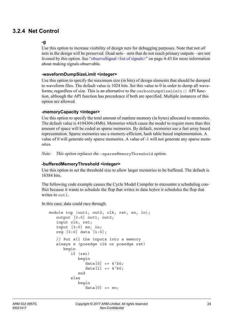
The following code example causes the Cycle Model Compiler to encounter a scheduling con-flict because it wants to schedule the flop that writes to data before it schedules the flop that writes to out1.
In this case, data could race through.
module top (out1, out2, clk, rst, en, in);output [3:0] out1, out2;input clk, rst;input [3:0] en, in;reg [3:0] data [1:0];
// Put all the inputs into a memoryalways @ (posedge clk or posedge rst)
beginif (rst)
begindata[0] <= 4'b0;data[1] <= 4'b0;
endelse
begindata[0] <= en;
ARM DUI 0957G Copyright © 2017 ARM Limited. All rights reserved. 24ID021417 Non-Confidential

data[1] <= in;end
end
// Create a clock from the enablewire [3:0] ren = data[0];wire dclk = clk & ren[0];reg [3:0] out2;always @ (posedge dclk)
out2 <= data[1];
// Use those clocks and the datareg [3:0] out1;always @ (posedge clk)
beginout1 <= data[1];
end
endmodule
The Cycle Model Compiler resolves this scheduling conflict by introducing a delay in the data before it gets to out1. However, for performance reasons it only does so if the memory is 16384 bits or less. If the memory is larger than 16384 bits, then the Cycle Model Compiler issues an alert. For example:
bufmem.v:57 top.out1: Alert 1054: A memory `top.data` that is writ-ten as part of clock logic is read in a flop; the conflict could not be resolved. See the documentation for -bufferedMemoryThreshold for information on this problem.
There are three options for dealing with this alert. The first option is to demote the alert to a warning if the race condition does not matter. The second is to increase the buffer memory threshold using this option. Lastly, you can remodel the above code by writing to the data mem-ory in different always blocks for the clock enable and data portions.
-no-OOBUse this option to disable checking for out-of-bounds bit references. This means the Cycle Model Compiler should not check for such references. As a result, the Cycle Model runtime will be faster.
Warning: If you specify this option, the Cycle Model will exhibit unpredictable behavior dur-ing runtime if there are out-of-bounds bit references in your design.
Consider the following:
wire [7:0] value;wire [7:0] index;. . .. . .result = value [index];
If index can take on a value larger than 7, this may produce incorrect answers when -no-OOB is specified. The index values greater than 7 are out of bounds.
ARM DUI 0957G Copyright © 2017 ARM Limited. All rights reserved. 25ID021417 Non-Confidential

-checkOOBUse this option to generate warning messages during validation runtime if any out-of-bounds bit or memory references are made. Ideally, you would use -checkOOB to ensure that your design has no out-of-bounds references and then recompile using -no-OOB to generate a Cycle Model with a faster execution time.
If -checkOOB detects any out-of-bounds references, fix the out-of-bounds references in your design as necessary and then recompile with -no-OOB. The warning message generated by -checkOOB does not pinpoint the name of the vector or memory containing the out-of-bounds reference, but gives the following information to help your search:
• Whether the out-of-bounds access occurs on a read or write.
• Whether the accessed object is a memory, register, wire, or net.
• The declared range of the object.
• The invalid index value.
-noCoercePortsUse this option to disable port analysis (as described in the following paragraphs). Note that turning off the port analysis functionality disables the Cycle Model Compiler’s ability to pro-cess complex bidirectional ports.
Port Analysis:
By default, the Cycle Model Compiler performs a design-wide port analysis and may alter port directions based on the characteristics of the design. In particular, these modifications may occur when the declared port directions do not model the flow of data within the design. For example:
...wire data;sub s0(en1,data,out1);sub s1(en2,data,out2);...
module sub(en,data,ndata);input en;output data;output ndata;assign data = en ? 1'b1 : 1'bz;assign ndata = ~data;
endmodule
In this design, the sub.data wire has multiple drivers. Converting sub.data from output to inout properly models the fact that a value written in the s0 instance can be read in the s1 instance, and vice-versa.
Primary Ports:
The assumption today is that a unidirectional primary port is a stronger statement than a bidirectional primary port. This means that a user-declared primary input must at least behave as an input. A user-declared primary output must at least behave as an output. Therefore, inputs/outputs may be coerced to inouts, but not to output/input.
ARM DUI 0957G Copyright © 2017 ARM Limited. All rights reserved. 26ID021417 Non-Confidential

Primary inouts are handled differently—their bidirectional nature is considered a weaker statement, therefore coercion from inout to either directional port type is allowed.
Per-bit Port Behavior:
Port analysis may determine that all bits in a primary port do not behave in a uniform fash-ion. If this occurs, different bits may be identified as having different port direction. For example:
module top(a,out1,out2);input [1:0] a;output out1,out2;pullsub p0(a[0],out1);assign out2 = a[1];
endmodule
module pullsub(in,out);input in;output out;pullup(in);assign out = in;
endmodule
In this design, the top.a net will be split into two components. The a[0] bit will be con-verted to a bidirectional port to reflect the fact that it is driven by the model. The a[1] com-ponent of top.a remains an input.
-sanitizeCheckUse this option to check for dirty writes. After every write to a net, it will check for non-zero bits outside the declared size of the net. This helps to detect out-of-bound reads/writes permitted by the -no-OOB flag in order to help diagnose problems.
3.2.4.1 Port Vectorization
To improve runtime performance, the Cycle Model Compiler replaces selected scalar ports and scalar local variables with a vector port or local nets.
-doNetVecEnable port vectorization. Port vectorization is on by default.
-noNetVecDisable port vectorization. You might want to turn off port vectorization if you suspect that 1) a modeling error has resulted from port vectorization, or 2) port vectorization has broken visibil-ity for some signals. In either of these cases, you should initiate a bug report with ARM.
Three Options for Vectorizing Primary PortsThe following three options are mutually exclusive. The default is -netVecThroughPrimary.
Note: -netVec line options have been replaced by -netVec. If used, a warning message will appear notifying you to switch to the -netVec options.
ARM DUI 0957G Copyright © 2017 ARM Limited. All rights reserved. 27ID021417 Non-Confidential

-netVecPrimaryVectorize the primary ports of the design.
Warning: This option breaks visibility of any primary ports that are vectorized. When scalar primary ports are combined into vectorized ports, the original port names are replaced with a new vectorized port name. At the moment, you cannot make any Cycle Model API calls (such as observeSignal or depositSignal) using either the old or new port names.
-netVecThroughPrimaryDo not vectorize the primary ports; however, allow vectorization opportunities inferred between the primary ports to propagate down the module hierarchy (default).
-nonetVecThroughPrimaryDo not infer any vectorization opportunities from the primary ports and do not allow propa-gation of opportunities through the primary ports.
-netVecMinCluster <integer>Specifies the minimum size of a vector created during net vectorization.
-verboseNetVecOutput information on the vectorized nets.
-reportNetVec <filename>Write a report to the specified <filename>, enumerating the vectorizations discovered by port vectorization.
3.2.5 Verilog- and SystemVerilog-Specific Options
The following options are for use only with Verilog and SystemVerilog design files.
-sverilogThis option enables SystemVerilog compilation mode. All Verilog files encountered during compilation will be treated as SystemVerilog source files. All Verilog command line options work with SystemVerilog, provided -sverilog is specified.
-vlogTop <string>Use this option to specify the top-most module in the Verilog design hierarchy. The Cycle Model Compiler parses only the specified module and its descendents. If you do not specify this option, all modules from the top down in the given design are compiled.
Note: Currently, only one top-level module is supported.
-v <string>Use the -v option to specify a Verilog source library file. The Cycle Model Compiler scans the file for module definitions that have not been resolved in the specified design files. Enter the full path or relative file name after the -v. For example:
cbuild -v ../library/vendor.lib 2clock.v
ARM DUI 0957G Copyright © 2017 ARM Limited. All rights reserved. 28ID021417 Non-Confidential

Note: Without this option, the Cycle Model Compiler processes only those library modules that are explicitly referenced by the Verilog source files.
-y <string>Use the -y option to specify a library directory. The Cycle Model Compiler scans the directory for module definitions that have not been resolved in the specified design and library files. Enter the full or relative directory path after the option. For example:
cbuild -y library/cells 2clock.v
This command references the library directory /library/cells for input design files.
Note: The file names within the specified library directory must match the module names that are being searched for.
In the event two subdirectories contain a file with the same name and the top level design file in the current directory uses a single instance of that file, the Cycle Model Compiler uses the defi-nition of the file from the directory that appears first on the command line:
cbuild -q -y foo -y bar +libext+.v test.v
In the above case, the definition of the file from the foo directory is used.
+libext+<ext1>+...Use the +libext+ option to specify extensions on the files you want to reference in a library directory. Note that this option has the default value of '.v'. However, if you specify this option on the command line then the default is replaced.
To specify multiple extensions, enter the list of extensions after the option linked with plus signs (+). For example:
cbuild -y library/cells +libext+.v 2clock.v
This command references the library directory library/cells, but uses only those files in that directory with the extension '.v'.
Note that only one +libext+ option can appear on the command line, however it can specify multiple extensions. For example, +libext++.v+.vlog+, indicates that there are three possi-ble extensions: a null string, '.v', and '.vlog'.
+incdir+<path1>+... Use the +incdir+ option to specify the directories in which the Cycle Model Compiler should search for include files. Enter the list of relative or absolute paths, linked with plus signs (+). The paths will be searched in the order specified. (Note that -incdir can be used by NC-Ver-ilog simulation users to specify a single directory.)
You can enter multiple +incdir+ options on the command line. If there is a conflict between values in include files, the last one encountered will be used.
ARM DUI 0957G Copyright © 2017 ARM Limited. All rights reserved. 29ID021417 Non-Confidential

-2001Use this option to enable Verilog-2001 compilation mode. This includes partial support for Ver-ilog-2005 (IEEE Std 1364-2005) language features (refer to “General Constructs” on page 5-52 for supported constructs). All files encountered during the compilation are treated as Verilog 2001. Note that you may also use -2000 or -v2k to enable this compilation mode—these three options are equivalent.
-uUse this option to convert all identifiers in all referenced Verilog files to upper case. Performing this option makes the design insensitive to identifiers’ case.
Note: All references to Verilog identifiers in options and identifiers within directives must be changed to upper case.
For example, when using -u:
-vlogTop top should be changed to -vlogTop TOP
+define+<string>Use the +define+ option to specify Verilog macros to be used during compilation. Enter the variables with values, linked with plus signs (+). Syntax:
+define+<var1>+<var2>+ ... +<varN>=<value>
Note that an equals sign (=) in effect terminates the string. That is, anything after the equals sign will be treated as part of the value of the variable with which it is associated. For example:
cbuild 2clock.v +define+WORD_LENGTH=8
In this example, whenever 'WORD_LENGTH appears in the Verilog text, it will be replaced with 8. Note that the <value> parameter is optional. For example:
cbuild 2clock.v +define+MYDEF
will make 'ifdef MYDEF statements true in the code.
The following example is equivalent to placing 'define var val statements in the code.
cbuild 2clock.v +define+var=val
Multiple +define+ options can be specified on the command line. Later +define+ options take precedence over earlier ones.
+mindelay+typdelay+maxdelay
Use these options to specify the use of the minimum, typical, or maximum value respectively for all expressions.
Note: These options have no real effect—they are provided only for compatibility.
ARM DUI 0957G Copyright © 2017 ARM Limited. All rights reserved. 30ID021417 Non-Confidential

-pragma_prefix <string>When embedding directives in comments, use this option to specify the prefix used for:
• Synthesis-specific compiler directives, such as translate_off/translate_on and full_case/parallel_case.
• Cyle Model-specific compiler directives, such as observeSignal and depositSignal. (For a complete list, see “Embedding Directives in Comments” on page 4-41.)
This option takes a single string argument. To specify multiple prefixes, you must specify -pragma_prefix multiple times. Subsequent prefix specifications do not cancel earlier ones.
For example, to make the following signal observable:
reg a; // myPrefix observeSignal
you must include the following on the command line:
-pragma_prefix myPrefix
If you do not use this option to specify a prefix, the synthesis and directives are ignored for all prefixes except carbon. The Cycle Model Compiler automatically recognizes the prefix car-bon.
-synth_prefix <string>This option is the same as the -pragma_prefix option.
-enableOutputSysTasksBy default, the Cycle Model Compiler issues a warning and ignores the following system tasks. Use this option to enable support for these system tasks throughout your design. Note that using this option may impact the performance of the resulting Cycle Model.
• $display
• $fclose
• $fdisplay
• $fflush
• $fopen
• $fwrite
• $sformat
• $write
A system task that appears within an edge-sensitive always block is scheduled with that clock. For example, the system task in the following example is scheduled with clk.
always @(posedge clk)$display (a1, a2);
Note that the values displayed from calls to $time functions may not match the times that are generated by a Verilog simulator. This can result in the following example output. Notice that in the Cycle Model Compiler output the time does not appear to change, but it does display identi-cal values to the Verilog output for the out variable.
ARM DUI 0957G Copyright © 2017 ARM Limited. All rights reserved. 31ID021417 Non-Confidential

source verilog...always @(posedge clk) beginbegin
a = 1;b = 0;out = a$display("a time: %t a=%b b=%b out=%b", $time, a, b, out);a = 0;out = #10 b;$display("b time: %t a=%b b=%b out=%b", $time, a, b, out);#10 $display("c time: %t a=%b b=%b out=%b", $time, a, b, out);
...
veriloga time:0 a=1 b=0 out=1b time:10 a=0 b=0 out=0c time:20 a=0 b=0 out=0
carbona time:0 a=1 b=0 out=1b time:0 a=0 b=0 out=0c time:0 a=0 b=0 out=0
Note that you may enable or disable output system tasks by module using the directives described in “Module Control” on page 4-46.
-topModuleListDumpFile <string>Use this option to specify the name of the file into which the Cycle Model Compiler will place the names of the top level modules of the Verilog design.
3.2.6 Output Control
Warning: Do not edit any files that are generated by the Cycle Model Compiler. Doing so will result in unexpected behavior or failure of subsequent processes.
-o <string>Use this option to specify the name of the compiled Cycle Model. The default is ./libde-sign.a. Use the appropriate extension for the operating system on which you will run the com-piled design:
• .a – generates a Linux archive
• .lib – generates a Windows library
Enter the full path or relative file name after -o. You may use alphanumeric characters, period (.), hyphen (-), underscore (_), and plus sign (+) characters in your specification (either on the command line or within a Makefile). You must use the lib prefix for the file name. Do not use white spaces in the string, and do not use existing system library names (for example, libc, libm, carbon).
The Cycle Model Compiler creates additional files whose base names are the same as that used for the Cycle Model. For a list of output files created by Cycle Model Compiler, see “Cycle Model Compiler Output Files” on page 2-15.
ARM DUI 0957G Copyright © 2017 ARM Limited. All rights reserved. 32ID021417 Non-Confidential

Note: If your next step after creating the Cycle Model involves a new working directory, the following files must be copied to that working directory: 1) The Cycle Model (*.a or *.lib) file2) The header (*.h) file
$CARBON_HOME/examples/twocounter/Makefile.cygwin shows how to use Visual Stu-dio 2013 to compile and link a testbench with a Cycle Model that was built using the Windows cross-development tools. The Makefile assumes you have a Windows machine with the Cygwin environment installed.
Note that you can use the -o option to direct model output for multiple platforms from the same directory substructure. For example, if you specify -o Linux/obj/libtest.a on the com-mand line, the Cycle Model Compiler writes the output files to the Linux/obj directory.
-noFullDB | -nodbThis option can be used with -embedIODB to turn off generation of the .symtab.db. Only the .io.db will be created and embedded into the library.
-embedIODBBy default, the Cycle Model Compiler creates and embeds the .symtab.db file into the Cycle Model, eliminating the need to search for it during runtime. This option additionally creates and embeds the .io.db file into the generated libdesign.*library file. This option is enabled by default.
Note: The component for SystemC and Cycle Model Validation currently require the full data-base.
-profileUse this option to enable block profiling of the Cycle Model. This is sample-based profiling that records information, approximately 100 times/second, about which HDL block or Cycle Model API function is currently executing. Due to sampling, the data is an estimate only, but serves to give a rough idea of which blocks take the most time during your validation run.
Note: To enable profiling of Cycle Model API functions, a profile-enabled version of the library must be used. This library is selected by using $(CARBON_PROFILE_LIB_LIST) instead of $(CARBON_LIB_LIST) in the Makefile used to link the executable.
To use profiling:
1. Add the -profile option to the command line during compilation.
The Cycle Model Compiler creates a file named lib<design>.prof containing compile-time information needed for profiling. During simulation, ARM tracks how many samples occur in each block and writes this data to carbon_profile.dat when the simulation ends.
2. Following simulation, run carbon profile at the command prompt.
The carbon profile command reads carbon_profile.dat and all files matching *.prof and corresponding *.hierarchy files in the current directory. You can override which files are read by specifying specific files on the command line when you issue the carbon profile command.
ARM DUI 0957G Copyright © 2017 ARM Limited. All rights reserved. 33ID021417 Non-Confidential
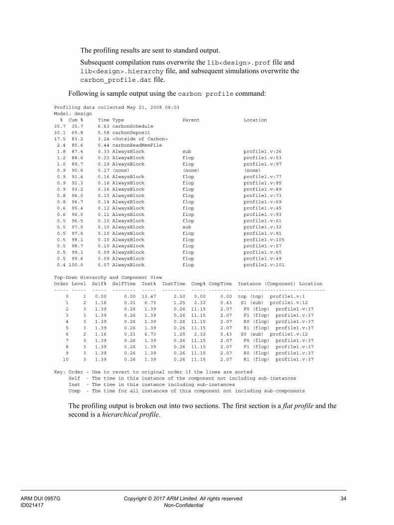
The profiling results are sent to standard output.
Subsequent compilation runs overwrite the lib<design>.prof file and lib<design>.hierarchy file, and subsequent simulations overwrite the carbon_profile.dat file.
Following is sample output using the carbon profile command:
Profiling data collected May 21, 2008 08:03Model: design % Cum % Time Type Parent Location35.7 35.7 6.63 carbonSchedule 30.1 65.8 5.58 carbonDeposit 17.5 83.2 3.24 <Outside of Carbon> 2.4 85.6 0.44 carbonReadMemFile 1.8 87.4 0.33 AlwaysBlock sub profile1.v:26 1.2 88.6 0.23 AlwaysBlock flop profile1.v:53 1.0 89.7 0.19 AlwaysBlock flop profile1.v:97 0.9 90.6 0.17 (none) (none) (none) 0.9 91.4 0.16 AlwaysBlock flop profile1.v:77 0.9 92.3 0.16 AlwaysBlock flop profile1.v:85 0.9 93.2 0.16 AlwaysBlock flop profile1.v:89 0.8 94.0 0.15 AlwaysBlock flop profile1.v:73 0.8 94.7 0.14 AlwaysBlock flop profile1.v:69 0.6 95.4 0.12 AlwaysBlock flop profile1.v:45 0.6 96.0 0.11 AlwaysBlock flop profile1.v:93 0.5 96.5 0.10 AlwaysBlock flop profile1.v:61 0.5 97.0 0.10 AlwaysBlock sub profile1.v:32 0.5 97.6 0.10 AlwaysBlock flop profile1.v:81 0.5 98.1 0.10 AlwaysBlock flop profile1.v:105 0.5 98.7 0.10 AlwaysBlock flop profile1.v:57 0.5 99.1 0.09 AlwaysBlock flop profile1.v:65 0.5 99.6 0.09 AlwaysBlock flop profile1.v:49 0.4 100.0 0.07 AlwaysBlock flop profile1.v:101
Top-Down Hierarchy and Component ViewOrder Level Self% SelfTime Inst% InstTime Comp% CompTime Instance (Component) Location----- ----- ----- -------- ----- -------- ----- -------- ------------------------------ 0 1 0.00 0.00 13.47 2.50 0.00 0.00 top (top) profile1.v:1 1 2 1.16 0.21 6.73 1.25 2.32 0.43 S1 (sub) profile1.v:12 2 3 1.39 0.26 1.39 0.26 11.15 2.07 F0 (flop) profile1.v:37 3 3 1.39 0.26 1.39 0.26 11.15 2.07 F1 (flop) profile1.v:37 4 3 1.39 0.26 1.39 0.26 11.15 2.07 R0 (flop) profile1.v:37 5 3 1.39 0.26 1.39 0.26 11.15 2.07 R1 (flop) profile1.v:37 6 2 1.16 0.21 6.73 1.25 2.32 0.43 S0 (sub) profile1.v:12 7 3 1.39 0.26 1.39 0.26 11.15 2.07 F0 (flop) profile1.v:37 8 3 1.39 0.26 1.39 0.26 11.15 2.07 F1 (flop) profile1.v:37 9 3 1.39 0.26 1.39 0.26 11.15 2.07 R0 (flop) profile1.v:37 10 3 1.39 0.26 1.39 0.26 11.15 2.07 R1 (flop) profile1.v:37
Key: Order - Use to revert to original order if the lines are sorted Self - The time in this instance of the component not including sub-instances Inst - The time in this instance including sub-instances Comp - The time for all instances of this component not including sub-components
The profiling output is broken out into two sections. The first section is a flat profile and the second is a hierarchical profile.
ARM DUI 0957G Copyright © 2017 ARM Limited. All rights reserved. 34ID021417 Non-Confidential
Flat Profile
The flat profile lists sampled blocks in decreasing order of runtime usage. The first column is the percent of time spent in the block, the second column is the running total (cumulative) per-centage, and the third column is the number of seconds spent executing the block.
The <Outside of Carbon> category contains 1) time spent executing non-Cycle Model code; that is, user code or third-party code, and 2) time spent by the testbench waiting for user interaction. The sample output above shows that the model design spends approximately 17% of its time outside of Cycle Model code, and almost two-thirds of its time running carbonDe-posit and carbonSchedule API calls. Approximately 13% of the time is spent in the listed always and continuous assignment blocks.
The Parent column indicates the Verilog module for that block of code.
The Location column specifies the source locator for blocks that correspond to RTL. Note that locations are not specified for API functions, such as carbonSchedule, or testbench code, found in the <Outside of Carbon> category, as these items are not found in the original RTL.
Note: The time displayed for carbonSchedule does not include time spent in blocks.
Hierarchical Profile
The hierarchical profile takes the exact same profile data and reorganizes it into a hierarchical view. This takes the logic buckets and groups them together into components (modules or enti-ties) and instances. There are two sub-views of the data, elaborated and unelaborated. See the column descriptions below for more details.
The Order column is a number that indicates the original order of the profiling lines. This is useful if the data is loaded into a spreadsheet and sorted by different data columns. It allows the spreadsheet to easily return to the original order.
The Level column is the elaborated depth for the next four columns from the top of the design, where 1 indicates the top level component. The elaborated view is an instance based view of the data. This means that if there are multiple instances of a component, the time in the instance is a fraction of the time for the component as a whole.
The Self% and SelfTime columns are the percentage and time for any given component instance. It does not include the time for any sub-instances. If there are multiple instances of the compo-nent, then the time in this instance is the total time for the component divided by the total num-ber of instances. For example, in the above profile, sub has two instances S0 and S1. Each takes 1.16% of the time. This means the component takes 2.32% of the time.
The Inst% and InstTime columns are the percentage and time for any given instance and all its children instances. For example in the above profile, the Instance time for S1 (sub) is the Self time for S1 (.21s) plus the Self time for each of its four children F0 (.26s), F1 (.26s), R0 (.26s), and R1 (.26s). This adds up to 1.25 seconds, or 6.73% of the time.
The Comp% and CompTime columns show the unelaborated view of the design. For each com-ponent, this is the time for all instances of that component, excluding any sub-components. For example, there are eight instances of the flop component. Each instance takes 1.39% of the time and the component as a whole takes 11.15% of the time.
ARM DUI 0957G Copyright © 2017 ARM Limited. All rights reserved. 35ID021417 Non-Confidential

The last column shows the design hierarchy. It includes the instance name, the component name (in parentheses), and the file location for the component.
For tips on using profiling to improve performance, see Appendix C.
+protect[.ext]Use this option to generate protected source versions of all given Verilog input files. Modified Verilog output files are generated for each input; the output files contain all source between `protect and `endprotect compiler directives in encrypted form. Unless a different exten-sion is specified on the command line, the output file is named with a .vp extension. (Verilog only.)
Note the following:
• Only Verilog 2001-style `protect and `endprotect are supported. The use of the -v2001 switch does not cause this support to advance to Verilog 2005 style.
• +protect handles the following restrictions on text:
• Conditional code blocks are bounded by`ifdef (or `ifndef) and `endif. All condi-tional code blocks must be closed or completed before a `protect region starts or ends. This means that you can have conditional code blocks before or after a protected block, or even within a `protected block; however, no conditional code block may be open at the point that the `protect or `endprotect line is encountered if that file is to be processed by the +protect command.
• The +protect command line option only protects code in the files that are listed on the command line. Files that are included (with the `include "filename" line) in the source Verilog files remain unprotected.
-verboseFlattening <integer>Use this option to output a trace of flattening operations to stdout. The default value is 0—no output.
The following is an example of a flattening success. It will display if this option is non zero.
Flatten: {case.v:7} instance CASE2 of module mycase into module case_top (SUCCESS)--> Successfully flattened. [parent=2 child=2 comb=4]
The following message will appear only when the flattening verbosity level is non zero.
Flatten: {big.v:5} instance big of module big into module big_top (FAILURE)--> Both the parent and sub modules were too large. [parent=7 child=7 comb=14]
The child=<num> provides the Cycle Model Compiler’s perceived size for that instantiated submodule. Increasing the -flattenThreshold option larger than <num> would allow flat-tening for that specific submodule (see “-flattenThreshold <integer>” on page 3-23).
The following is an example of a final flattening summary when the flattening verbosity level is non zero.
Flattening Summary: 2 instances flattened into 1 parent modules.
ARM DUI 0957G Copyright © 2017 ARM Limited. All rights reserved. 36ID021417 Non-Confidential

-verboseLatchesUse this option to output a list of latches found in the design to stdout. For example:
foo.v: 9 Net is a latch.
-q By default, the Cycle Model Compiler outputs the progress of the build including elapsed time and estimated percent-done. Note that it also prints out a phase number, which is useful to your ARM Applications Engineer should you encounter any problems. Use this option to enable quiet mode and suppress all Cycle Model Compiler banner output.
Note: This option has no effect on other information, such as warnings and errors, that are written to stdout.
-wSpecify this option to suppress all Warnings generated by the Cycle Model Compiler. See “Out-put Control” on page 4-50 for additional information about message severity levels.
-statsUse this option to print time and memory statistics for the compilation to stdout.
-versionUse this option to obtain the product version of the Cycle Model Compiler. The version infor-mation displays, and then the Cycle Model Compiler exits. Sample version output is shown below:
v8.0.0
-verboseVersionUse this option to print various internal version strings. The version information displays, and then the Cycle Model Compiler exits. Sample verbose version output is shown below:
Release identifier: v8.0.0CVS id string $Revision: 1.7516.2.15 $, $Date: 2015/02/03 02:33:35 $Cycle Model Compiler platform: Linux
Verific version: Mar14_SW_Release, URL: http://svn/svn/CMS/branches/BR01_cbuild, Revision: 2716
Your ARM representative may ask you to run this command to confirm product version infor-mation.
ARM DUI 0957G Copyright © 2017 ARM Limited. All rights reserved. 37ID021417 Non-Confidential

ARM DUI 0957G Copyright © 2017 ARM Limited. All rights reserved. 38ID021417 Non-Confidential

Chapter 4
Cycle Model Compiler Directives
This chapter provides detailed information about the Cycle Model Compiler directives.
4.1 Using Directives
Directives are compiler commands that can be contained in a directives file, or embedded in the HDL source code. Directives control how the Cycle Model Compiler interprets and builds a linkable object.
The table below lists the available categories of Cycle Model Compiler directives:
4.1.1 Using a Directives File
A directives file is passed to the Cycle Model Compiler using the -directive com-mand-line option (see page 3-21). The syntax of a directives file is line oriented—each directive and its values must be specified on a single line separated only by spaces. You must use the back slash (\) to indicate line continuation when necessary. Any extra white space between the directive name and values is ignored.
Multiple instances of the -directive option are allowed. Directives specified in a file are cumulative, meaning there is no precedence—all directives are used.
You may use the pound sign (#) to specify comments in your directives file. You may also use wildcards (*) and single character match (?) within a directives file. Note, however, that they apply only to one level of hierarchy in the design. To traverse multiple levels, use the following format:
observeSignal top.* top.*.* top.*.*.*
This would apply the observeSignal directive to three levels of the design hierarchy.
observeSignal *.*
In this example, the observeSignal directive would apply to all nets in the design.
Compiler Directives Location
Net Control page 4-43
Module Control page 4-46
Output Control page 4-50
ARM DUI 0957G Copyright © 2017 ARM Limited. All rights reserved. 39ID021417 Non-Confidential
For directives that take a <list of signals>, you may specify a single signal by hierarchy or you can specify signals by module—in which case every instance of the module is affected.
observeSignal sub2.sig3
This would apply the observeSignal directive to all instances of sig3 under module sub2.
Note that you can specify only one level of hierarchy when using this syntax. You cannot enter “observeSignal u1.sub2.sig4”.
4.1.1.1 Using Directives on Signals Inside Generate Blocks
Adding directives on signals inside generate blocks, and blocks under generate blocks, is done in a slightly different fashion. The following example illustrates the hierarchical names of the two registers declared inside a generate for loop.
module top(in, out, clk);
parameter genblk2 = 0;input in;output out, clk;
genvar i;
generate
for (i=0; i<1; i = i+1)begin: named_block
if (1)begin
reg c; // top.named_block[0].genblk1.cend
if (1)begin
reg d; // top.named_block[0].genblk02.dend
end
endgenerate
endmodule
The reason the second unnamed generate block is called genblk02 is because the parameter genblk2 is already using that name in the module scope. This follows the Verilog Language Reference Manual guidelines when naming generate blocks uniquely.
To make these signals observable, add the following information in a directives file:
observeSignal top.named_block[0].genblk1.cobserveSignal top.named_block[0].genblk02.d
Note: Beginning with CMS Version 5.16, the command line switch -verboseUniquify no lon-ger reports uniquified names for unnamed generate blocks.
Unnamed generate begin/end blocks have a specific name defined for them by the Veri-
ARM DUI 0957G Copyright © 2017 ARM Limited. All rights reserved. 40ID021417 Non-Confidential

fic parser that follows the naming convention defined in the Language Reference Man-ual. These names are no longer reported by the -verboseUniquify switch.
4.1.2 Embedding Directives in Comments
As an alternative to a directives file, a limited set of directives (see “Supported Embedded Net Directives” on page 4-41) may be embedded in the Verilog or SystemVerilog source as com-ments, with a syntax similar to synthesis pragmas. The prefix carbon, shown in the examples below, is automatically recognized by the Cycle Model Compiler. An embedded directive is associated with a net or a module.
To use a prefix other than carbon to identify embedded directives, specify it on the command-line. For Verilog or SystemVerilog: Use the -synth_prefix option.
A sample section of a Verilog file is shown below:
...
module top(in1, in2, clk1, clk2, out, ena);input in1, in2;input ena; // carbon tieNet 1'b1output out;input clk1;input clk2; // carbon collapseClock top.clk1
reg a; // carbon observeSignal// carbon depositSignal
always @(posedge clk1)if (ena)
a <= ~in1;
wire out; // carbon depositSignalflop u2(out, in2, clk2, ena);
endmodule
...
4.1.2.1 Supported Embedded Net Directives
The net directives supported in this fashion are listed below. Net directives apply to the speci-fied net in every instance of the module.
• observeSignal
• depositSignal
• forceSignal
• exposeSignal
• tieNet
• ignoreSynthCheck
• collapseClock
• slowClock
• fastReset
• asyncReset
• scObserveSignal
ARM DUI 0957G Copyright © 2017 ARM Limited. All rights reserved. 41ID021417 Non-Confidential

• scDepositSignal
Net directives apply to the last wire or register declared prior to the embedded directive. If mul-tiple wires or registers are declared on the same line, the directive is applied only to the last wire or register declared. For the following, depositSignal is applied only to cff:
reg aff, bff, cff; // carbon depositSignal
For the following, observeSignal is applied to absig:
wire absig = en ? a_in : b_in; // carbon observeSignal
If multiple directives are to be to placed on a wire or register, the directives must be placed on separate lines prior to the declaration of other wires or registers. The following shows how to put both observeSignal and depositSignal directives on reg a:
reg a; // carbon observeSignal // carbon depositSignal
4.1.2.2 Supported Embedded Module Directives
Supported module directives are listed below. Module directives apply to every instance of the module in which they are declared.
• hideModule
• flattenModule
• flattenModuleContents
• allowFlattening
• disallowFlattening
• enableOutputSysTasks
• disableOutputSysTasks
To apply a module directive as an embedded directive, add the comment to the same line as the module declaration. To apply multiple embedded module directives, specify the directives on separate lines.
In the following example, the disallowFlattening directive is applied to the module called top and the allowFlattening and enableOutputSysTasks directives are applied to the module called bottom:
module top(clock, in1, in2, out1); // carbon disallowFlattening...
bottom u1(clock, in1, in2, out1);endmodule
module bottom(clock, in1, in2, out1); // carbon allowFlattening// carbon enableOutputSysTasks
...endmodule
ARM DUI 0957G Copyright © 2017 ARM Limited. All rights reserved. 42ID021417 Non-Confidential

4.2 Net Control
In effect, the observeSignal, depositSignal, and forceSignal directives provide access to specified signals in the Cycle Model from the external environment. The Cycle Model API functions can be used to observe, deposit, and force signal values.
observeSignal <list of signals>Identifies the nets in the design that must be observable during runtime; the current values may be retrieved. In order for a signal to be observable during validation runtime, it must be marked before compilation. Note that marking a signal as observable does not imply that it will accept deposited values.
Nets marked as observable are never optimized away by the Cycle Model Compiler, and their values are guaranteed to be correct at all times (match what the hardware is intended to do). In addition, any dead signal that is marked observable, for example, a signal that does not reach an output of the design, will be reanimated.
Nets not marked as observable may be visible when the full symbol table is loaded via the Cycle Model API. However, any unmarked net may be optimized away by the Cycle Model Compiler making the validation runtime faster.
When you plan to use the Cycle Model Studio tool to create a Cycle Model component, you must mark any internal signals with observeSignal to make them available in Cycle Model Studio as debug registers or for profiling.
depositSignal <list of signals>
depositSignalFrequent <list of signals>
depositSignalInfrequent <list of signals>
These directives identify the nets in the design that will accept deposited values. The nets may be inputs, registers, or un-driven logic. In order to allow values to be deposited on a signal dur-ing validation runtime, the signal must be marked before compilation. Note that marking a sig-nal as depositable does not imply observability. The Cycle Model Compiler does not process deposits as outputs; the driving logic of a depositable net may be eliminated due to liveness checks.
Deposits on nets can occur frequently, as with a clock, or infrequently, as with a control pin. In some situations, your Cycle Model will run faster if you specify depositable nets as frequent or infrequent during compilation. Follow these guidelines to decide which variation of this directive to use:
• depositSignal: The Cycle Model Compiler automatically categorizes a net as frequent or infrequent. In general, all deposits are marked as infrequent unless part of a clock tree, in which case they are marked as frequent. If you are using very few depositSignal and forceSignal directives, then the depositSignal directive is probably sufficient and should not noticeably impact Cycle Model performance.
• depositSignalInfrequent: If your design has many nets that you intend to mark with depositSignal or forceSignal directives, use the depositSignalInfrequent directive to improve performance. To identify infrequently accessed nets, analyze the nets noted in message 1057 in the compile output and re-run the design, using the deposit-
ARM DUI 0957G Copyright © 2017 ARM Limited. All rights reserved. 43ID021417 Non-Confidential

SignalInfrequent directive to mark all infrequently accessed nets (such as control pins and enables).
• depositSignalFrequent: To improve performance, specify the depositSignalFrequent directive for data pins that change every four schedule calls or more. You do not have to specify the depositSignalFrequent directive for clocks and clock tree inputs as the Cycle Model Compiler automatically marks them as frequent.
If both depositSignal and one of the other two variations are specified, the Cycle Model Compiler assigns the net according to your more detailed directive. If both of the other two vari-ations are specified simultaneously, the Cycle Model Compiler uses the first one given and prints a warning.
When you plan to use the Cycle Model Studio tool to create a Cycle Model component, you must mark any internal signals with depositSignal in order for Cycle Model Studio to make them depositable in the component.
Note: An error occurs if depositSignal is used on the output of combinational logic. You can use forceSignal as an alternative.
forceSignal <list of signals>Identifies the nets in the design that are forcible; the listed signals can be forced to specified val-ues. In order for a signal to be forcible during validation runtime, it must be marked before com-pilation.
collapseClockUse this directive to indicate that the specified clocks are equivalent, meaning that the values are the same (but they may have completely different logical paths). The syntax for this direc-tive is:
collapseClock <master clock> <list of subordinate clocks>
where <master clock> must be a single, specific hierarchical signal in the design. Note that the Cycle Model Compiler will substitute <master clock> for each <subordinate clock> it finds in the design. This may improve the performance of the generated object.
A clock equivalency table will be generated automatically and written to the file ./<design name>.clocks (./libdesign.clocks by default). The table shows all clocks that will be treated as equivalent either because they were proven equivalent, or because they were specified to be equivalent with the collapseClock directive.
Caution: Equivalent does not mean aliased. The use of this directive is an assertion that the subordinate clocks have the same value as the master clock. The Cycle Model Com-piler may or may not alias these clocks together (i.e., they may or may not share storage), and does not guarantee changes to data propagation. Setting this option incorrectly can also introduce errors which are very difficult to debug if non-equiv-alent clocks are collapsed.
slowClock <clock names>Use this directive to identify clocks that are routed slowly in the chip, so that they are slower than async resets. If a slow clock rises at the same time as a reset is deasserted, then the code with the clock block runs. By default, clocks are assumed to be faster than resets, and so resets
ARM DUI 0957G Copyright © 2017 ARM Limited. All rights reserved. 44ID021417 Non-Confidential

will be assumed to still be deasserted in a race. See also fastReset, below. A slowClock will be slower than any reset, but those resets are not necessarily faster than other clocks.
fastReset <reset names>Use this directive to identify resets that are routed fast in the chip, so that they are faster than clocks. If a clock rises at the same time as a reset is deasserted, then the code with the clock block runs. By default, clocks are assumed to be faster than resets, and so resets will be assumed to still be deasserted in a race. See also slowClock, above. A fastReset will be faster than any clock, but those clocks will not necessarily be slower than other resets.
asyncReset <reset names>Use this directive to identify synchronous resets that the Cycle Model Compiler should treat as asynchronous resets, if possible. Combined with fastReset or slowClock, this directive allows reset data to be scheduled faster than clocks.
tieNetThis directive allows you to disable logic within a design by tying it to a constant. Note that this applies to all instances of a module. The syntax for this directive is:
tieNet <HDL constant> <list of module nets>
where <HDL constant> is a Verilog constant expression of the form N'h<number> or N'b<number>. If there are any Xs or Zs in the constant, the Cycle Model Compiler issues an error and the compile fails. If the integer is constrained, the Cycle Model Compiler does not check if the constant is out of the constrained range.
The <list of module nets> is a white-space separated list of <module-name>.<net-name> strings. For vectors, the specified constant applies to the entire net (part or bit selects are not supported). If an instance-based name is used, the Cycle Model Compiler issues an error and the compile fails. This directive does not currently support parameterized module nets.
Note that tie net constants are treated as unsigned constants. If the net is signed, its value will be equivalent to a simple cast. If the net is smaller than the constant, it is truncated. If the net is larger than the constant, it is zero-extended.
All module nets specified with the tieNet directive will be processed as follows:
1. All assignments to the net will be removed.
2. A new continuous assign will be added to the module with the constant on the right-hand side.
This process will be done before optimizations, and will occur even if they are turned off (see “-O <string>” on page 3-19 for more information). Note that this process could lead to further optimizations, which may improve performance of the resulting Cycle Model.
Note: tieNet can be applied only to simple types, like wires in Verilog. Anything more compli-cated than these types, for example, arrays of arrays, records, or enumerations, are not currently supported.
ARM DUI 0957G Copyright © 2017 ARM Limited. All rights reserved. 45ID021417 Non-Confidential

ignoreSynthCheck <list of signals>This directive will suppress sensitivity list checking for the specified nets in Verilog designs. By default, the Cycle Model Compiler performs synthesis checking in the sensitivity list of always blocks during the build. You may receive errors and warnings about unsynthesizable constructs in your design. If there are sensitivity list constructs that cannot be fixed, or that you know will not cause issues in your design, use this directive to selectively suppress sensitivity list check-ing for those nets.
scDepositSignal <list of signals>scObserveSignal <list of signals>These directives are used for Cycle Model components for both SystemC and SoC Designer. They must be set prior to compilation of the Cycle Model.
When creating a SystemC component, whether using the command line carbon systemCWrapper tool or Cycle Model Studio, use these directives to make internal nets available as members of the SystemC component. The member signals can be read/written from SystemC to examine/deposit the values of the scObserveSignal/scDepositSignal nets.
For Cycle Model components for SoC Designer, use these directives in Cycle Model Studio to mark any internal signals that you want to make into ports on the Cycle Model component. In other words, these internal signals will become ports that SoC Designer can access directly.
Note that scDepositSignal and scObserveSignal provide the same functionality as the depositSignal and observeSignal command-line options—making the nets available from the Cycle Model API, displaying the nets in waveforms, etc. They also may be used in HDL comments, for example:
reg foo; // carbon scObserveSignal
4.3 Module Control
hideModule <list of module names>This directive identifies a module in the design hierarchy that you intend to be hidden in the Cycle Model. Note that this directive applies to all instances of the specified module(s). All waveforms for the specified module and its descendents will be suppressed.
Note: The Cycle Model Compiler issues a warning if the specified module names are not found.
enableOutputSysTasks <list of module names>disableOutputSysTasks <list of module names>Use these directives to enable or disable output system tasks by module.
Note: The -enableOutputSysTasks command-line option, described on page 3-31, is used to enable support for $display-type system tasks throughout a design.
Wild cards are not supported in the module specification. Verilog and SystemVerilog users may specify these directives in the source code if you use the HDL comment form:
// carbon enableOutputSysTasks
ARM DUI 0957G Copyright © 2017 ARM Limited. All rights reserved. 46ID021417 Non-Confidential

substituteModuleUse this directive to replace the body of one Verilog module with the body of another Verilog module.
Note: The term 'body' refers to the functional implementation of the module.
There are two forms of the directive:
• Form 1: substituteModule <old_module_name> <new_module_name>
• Form 2: substituteModule \
<old_module_name> portsBegin <old_port1_name> \
<old_port2_name> <old_port3_name> portsEnd \
<new_module_name> portsBegin <new_port1_name> \
<new_port2_name> <new_port3_name> portsEnd
The body of all instances of <old_module> is replaced with the body of <new_module>.
Use Form 1 if:
• The module instantiation uses positional port connections for the port list AND the order of the ports in the <old_module> and the <new_module> positionally match up one-for-one.
• The module instantiation uses named port connections AND the formal port names in the <old_module> and the <new_module> match one-for-one.
Use Form 2 if:
• The module instantiation uses named port connection for the port list and there is a need to rename one or more of the formal port names. In this case the named port names are paired up:
old_port1_name:new_port1_name, old_port2_name:new_port2_name, old_port3_name:new_port3_name ...
and the old formal port names in the instantiation line are replaced with the new_port names. Using this form does not require that the order of the ports in the old_module and new_module definitions be identical.
It is an error if there are not an equal number of named ports in the two portsBegin .. portsEnd regions.
Examples of module instantiations with two forms of port connection lists:
module1 u1(a,b,c); // positional port
module2 u2(.fA(a), .fB(b), .fC(c)); // named port
ARM DUI 0957G Copyright © 2017 ARM Limited. All rights reserved. 47ID021417 Non-Confidential

Restrictions:
• The definition for new_module must be included and compiled without errors. The defini-tion for old_module is not needed and is ignored.
• If the module instantiation specifies parameter values and lists just values in the parameter_port_list then the parameter values are mapped by position from old_module to new_module.
• If the module instantiation uses parameter assignments in the parameter_port_list then the values are mapped by the indicated name; e.g., param1 and param2 in this instan-tiation:
module3 #(parm1=5,param2=2) u3(a,b,c)
inline <module>.<task>inline <module>.<function>Use these directives to force the inlining of the specified <module>.<task> or <mod-ule>.<function> into all calling scopes; that is, the Cycle Model Compiler replaces all spec-ified task and function calls with the contents of the called task or function. Wildcards are allowed for both the module and task/function names.
The inline directive for functions in a package is not supported.
If the specified modules or tasks/functions do not exist in the RTL code, the following warnings are produced:
Warning 57: Module x does not exist; 'inline' directive ignored.
Warning 106: Task/Function x does not exist in module top; 'inline' directive ignored within this module.
If the specified task or function is called via hierarchical references, the following warning is generated:
Warning 107: Task/Function t in module declarations has hierarchi-cal referrers which may prevent inlining.
4.3.1 Flattening
The following four directives are used to flatten hierarchy in designs—conditionally or uncon-ditionally, as described. These directives are effective only if flattening has not been disabled (see “-noFlatten” on page 3-22 for additional information).
flattenModule <module name>This directive identifies a module to be fully flattened, including the module itself, disregarding any thresholds (specified with command options). This operation will flatten all instances of the named module into the instantiating parent module. For example:
flattenModule flop
All submodules of flop will be flattened into flop. All instances of flop will be flattened into the instantiating parent module.
ARM DUI 0957G Copyright © 2017 ARM Limited. All rights reserved. 48ID021417 Non-Confidential
flattenModuleContents <module name>This directive identifies a module whose contained hierarchy is to be fully flattened, disregard-ing any thresholds (specified with command options). The specified module will become a con-tainer for all of the flattened contents. This operation will occur for all instances of the named module. For example:
flattenModuleContents pad_block
All submodules of pad_block will be flattened into pad_block.
allowFlattening <module name>Allows flattening to occur under a specified module, respecting thresholds defined by command options. This directive can be used in conjunction with disallowFlattening (see next).
Note that this directive may be applied to a descendant module under a module marked with the disallowFlattening directive.
disallowFlattening <module name>Disallows flattening to occur under a specified module, respecting thresholds defined by com-mand options. This directive can be used in conjunction with allowFlattening (see previ-ous). For example (assume top.machine):
disallowFlattening topallowFlattening machine
In this example, flattening is disabled except for submodules under instantiations of the machine module. The contents of the top.machine hierarchy could be flattened.
Note that this directive may be applied to a descendant module under a module marked with the allowFlattening directive. For example (assume top.machine.crc32):
disallowFlattening topallowFlattening machinedisallowFlattening crc32
4.3.1.1 Flattening Directive Interactions
Note the following interactions when using flattening directives:
• If disallowFlattening and allowFlattening reference the same module, an error will occur.
• The flattenModule and flattenModuleContents directives may be applied to a descendant module of a module marked allowFlattening or disallowFlattening.
• The flattenModule and flattenModuleContents directives mark areas for uncondi-tional flattening. If allowFlattening references a module marked by, or contained within, a flattenModule or flattenModuleContents module, a warning will be generated; the allowFlattening has no affect.
• If disallowFlattening references a module marked by or contained within a flattenModule or flattenModuleContents module, an error will occur.
• If flattenModule and flattenModuleContents reference the same module, a warning will be generated and flattenModule prevails.
ARM DUI 0957G Copyright © 2017 ARM Limited. All rights reserved. 49ID021417 Non-Confidential

• If a flattenModuleContents sub-module occurs within a flattenModule module, an error will occur.
• If a flattenModule sub-module occurs within a flattenModuleContents module, a warning will be generated; the flattenModule directive has no affect.
• A warning will be generated if any of these directives are present and flattening has been disabled with the -noFlatten command-line option.
• An error will be generated if the specified module does not exist.
4.4 Output Control
By default, the Cycle Model Compiler outputs the following message severity levels:
• Note – Informational only.
• Warning – Indicates a condition that will not cause the operation to fail. However, if not addressed may resurface at run time.
• Alert – Indicates a demotable error (may be demoted to a Warning or Note, or may be sup-pressed).
• Error – Indicates a condition that will cause the generated Cycle Model to be incorrect, i.e., the operation will fail. In this case, the Cycle Model Compiler continues to run and search for additional errors before it exits.
• Fatal – Indicates a condition that will cause the generated Cycle Model to be incorrect; the Cycle Model Compiler exits immediately.
You can “promote” the severity of any message using the following directives. For example, you can make a Note be an Error. You can also “demote” the severity of Alerts, Warnings, and Notes. You cannot demote Fatal or Error messages.
errorMsg <message IDs>Identifies the Cycle Model Compiler message numbers that should be treated as Errors.
warningMsg <message IDs>Identifies the Cycle Model Compiler message numbers that should be treated as Warnings.
infoMsg <message IDs>Identifies the Cycle Model Compiler message numbers that should be treated as informational (as a Note).
silentMsg <message IDs>Identifies the Cycle Model Compiler message numbers that are to be suppressed. Note that sup-pressed messages will still be output to the ./libdesign.suppress file (by default). Note that you can suppress only Notes, Warnings, and Alerts (Errors and Fatals cannot be sup-pressed).
ARM DUI 0957G Copyright © 2017 ARM Limited. All rights reserved. 50ID021417 Non-Confidential

Chapter 5
Language Support
This chapter covers the support provided by the Cycle Model Compiler software for Ver-ilog and SystemVerilog. Syntactic elements are grouped into the following categories: supported, limited support, unsupported, and ignored.
If the Cycle Model Compiler encounters a construct that is unsupported, it:
• issues a warning and continues, or
• issues an alert or error and exits.
In cases where errors are reported, the offending constructs must be removed through remodeling. In cases where an alert is reported, the construct must be fixed or the alert demoted. See “Output Control” on page 4-50 for additional information about the Cycle Model Compiler messages.
If the Cycle Model Compiler encounters a construct that is ignored, it may or may not issue a message and will continue compiling (with some exceptions; see the following command-line options for additional information: “-2001” on page 3-30 and “-enableOut-putSysTasks” on page 3-31).
The following sections are provided in this chapter:
• Verilog Support
• SystemVerilog Support
ARM DUI 0957G Copyright © 2017 ARM Limited. All rights reserved. 51ID021417 Non-Confidential

5.1 Verilog Support
In general, the Cycle Model Compiler supports the synthesizable subset of the Verilog lan-guage. This section describes the specific support for:
• General Constructs
• Hierarchical References
• Net Types
• Gate-level Constructs
• Behavioral Constructs
• Switch-level Constructs
• User-Defined Primitives
• Synthesizable Subset
• Z State Propagation
• Exponent Operator Support
5.1.1 General Constructs
Supported
• modules (macromodule) and instances
• ANSI style port declarations
• identifiers (including escaped identifiers)
• memories (2 or more dimensional reg arrays)
Maximum bit size of the array is 232 bits. See also memory index expressions in Limited Support section, below.
• parameters, localparams, and parameterized instances
• expressions (with all operators)
• bit selects and variable indices
• strings
• directives'define, 'default_nettype, 'ifdef, 'ifndef, 'else, 'endif, 'undef, 'include, 'resetall, 'timescale (used to scale clock time)
By default, 'define CARBON is inserted in all Verilog files.
Usage Notes for conditional code blocks: Conditional code blocks must open ('ifdef, 'ifndef) and close ('endif) in the same file. For example, placing an 'ifdef in one file and its corresponding 'endif in an 'included file is illegal. 'else directives must also be placed in the same file as their associated 'ifdef or 'ifndef.
Similarly, when used in a 'protected section, conditional code blocks must open and close within that section. When used in a file with one or more 'protected sections, paired 'ifdef and 'endif directives must be placed outside of 'protected sections.
ARM DUI 0957G Copyright © 2017 ARM Limited. All rights reserved. 52ID021417 Non-Confidential

For example, placing an 'ifdef in a file and its corresponding 'endif inside of a 'pro-tect/'endprotect is not supported.
• Unsized Constants. In both self-determined and context-determined conditions, these con-stants are truncated according to the rules in the Language Reference Manual.
• ifnone Conditions. As mandated by the Language Reference Manual, only simple module paths may be described with an ifnone condition.
Limited support
• Port specifications in module declarations are generally supported; however the following cases are not supported:
Concatenation expression in the module declaration port list is not supported:
module foo ( {a,b}, .d{e,f} );
A bit or part select that is not for the full identifier is not supported:
module foo ( in1[3:1] ) ; // full width not selectedinput [3:0] in1;
Multiple occurrences of the same identifier in a module declaration is not supported, except when all bits are specified and listed in declaration order:
module foo (b[2], b[1], b[0]) // supportedinput [2:0] b;
module foo ( a, a); // not supportedinput a;
• Port connections at module instantiation are supported except when the port connection is a hierarchical reference:
mod inst1 (out, top.mid.foo); // out is supported// top.mid.foo is not supported
• Multiply driven netsThe Cycle Model Compiler selects a driver and will not perform conflict resolution; the exception is tristates, which are handled correctly.
• Specify blocks
The Cycle Model Compiler does not ignore specify blocks, however it does ignore most of the contents of specify blocks. Only the following two optional and implicit connections are recognized: 1) between the net of the reference_event and the delayed_reference net, and 2) between the net of the data_event and the delayed_data net.
If the $setuphold includes a specification for a delayed_reference net and it is the same width as the net of the reference_event, then a continuous assignment is created: assign delayed_reference = reference_event_net;.
If the $setuphold includes a specification for a delayed_data net and it is the same width as the net of the data_event, then a continuous assignment is created: assign delayed_data = data_event_net;.
Note that this partial support $setuphold does not imply that the timing check that is speci-fied by the $setuphold is supported or even considered by the Cycle Model Compiler.
• Memory index expressions
ARM DUI 0957G Copyright © 2017 ARM Limited. All rights reserved. 53ID021417 Non-Confidential

The Cycle Model Compiler does not support memory index expressions that are wider than 32 bits. If a memory index expression wider than 32 bits is found, the Cycle Model Com-piler prints a warning and truncates the expression to the least significant 32 bits. The Cycle Model Compiler implements the equivalent of the following transformation:
Original Verilog:
... reg [7:0] mem [1023:0];reg [63:0] index; ... always @(...) beginmem[index] = value;
The Cycle Model Compiler transformation:
... reg [7:0] mem [1023:0]; reg [63:0] index; reg [31:0] short_index; ... always @(...) beginshort_index = index[31:0]; mem[short_index] = value; end
In addition, the Cycle Model Compiler prints an error if it finds that it must truncate an index expression and the memory has been declared with a range that includes negative val-ues.
Unsupported
• realtime
Ignored
• #delaysFor example, in a = #5 b; the #5 is ignored.
5.1.2 Hierarchical References
The Cycle Model Compiler supports hierarchical references only to nets, tasks, and functions with the restrictions discussed below. Hierarchical references to anything other than nets, tasks, and functions are not currently supported.
A hierarchical reference to a net must reference a module-scoped net. Hierarchical references to nets that are declared in other types of scopes are not supported (i.e., named blocks, tasks, func-tions).
A hierarchical reference to a net must resolve to the same type, size, and bounds in all instantia-tions. For example, the following is not supported by the Cycle Model Compiler because the hierarchical reference data.d in module child resolves to reg [31:0] d for the top.child instance, but to reg [0:31] d for the top.middle.child instance.
ARM DUI 0957G Copyright © 2017 ARM Limited. All rights reserved. 54ID021417 Non-Confidential

module top;middle middle();child child();topdata data();
endmodule
module middle;child child();middata data();
endmodule
module child;wire w;assign w = data.d[0];
endmodule
module topdata;reg [31:0] d;endmodule
module middata;reg [0:31] d;
endmodule
The Cycle Model Compiler issues the following error in this case:
unsupported1.v:14: Error 3063: Hierarchical reference resolves to different net ranges in different instantiations
A hierarchical reference to a task must resolve to the same task in all instantiations. For exam-ple, the following is supported because the hierarchical reference to task data.t in all instances of child resolve to the same task t in module data.
module top;middle middle();child child();data data();
endmodule
module middle;child child();data data();
endmodule
module child;reg r;alwaysbegin
data.t(r);end
endmodule
module data;task t;
output o;o = 1'b0;
endtaskendmodule
ARM DUI 0957G Copyright © 2017 ARM Limited. All rights reserved. 55ID021417 Non-Confidential

The following is not supported because the hierarchical reference to task data.t in module child resolves to task t in module topdata in one instance, but to task t in module mid-data in another instance.
module top;middle middle();child child();topdata data();
endmodule
module middle;child child();middata data();
endmodule
module child;reg r;alwaysbegin
data.t(r);end
endmodule
module topdata;task t;
output o;o = 1'b0;
endtaskendmodule
module middata;task t;
inout o;o = ~o;
endtaskendmodule
The Cycle Model Compiler issues the following error in this case:
unsupported2.v:16: Error 3063: Hierarchical task enable resolves to different tasks in different instantiations
5.1.3 Net Types
Supported
• tri
• trireg
• tri1, tri0
• wire
ARM DUI 0957G Copyright © 2017 ARM Limited. All rights reserved. 56ID021417 Non-Confidential

Limited support
• wor, wand, trior, triandthese are treated as wire; the Cycle Model Compiler issues an alert and selects only one driver
ARM DUI 0957G Copyright © 2017 ARM Limited. All rights reserved. 57ID021417 Non-Confidential

5.1.4 Gate-level Constructs
Supported
• and
• nand
• or
• nor
• xor
• xnor
• buf
• bufif1, bufif0
• not
• notif1, notif0
ARM DUI 0957G Copyright © 2017 ARM Limited. All rights reserved. 58ID021417 Non-Confidential

5.1.5 Behavioral Constructs
Table 5.1 describes the Cycle Model Compiler support for Verilog behavioral constructs.
Example: disable statement
The Cycle Model Compiler does not support the disable statement when the target of the disable is outside of the execution scope of the disable statement. Consider the following where only the first disable statement is supported because it is within the execution of the target block.
Table 5.1: Supported and Unsupported Behavioral Constructs
Unsupported Fully Supported Supported with Limitations
$bitstorealevents$feof$fgetc$fgets$fread$fmonitor{b,h,o}$fscanf$fseek$fstrobe{b,h,o}$finishforce and releasefork-join blocks$ftell$itor$monitor$monitor{b,h,o,on,off}$random$realtime$realtobits$recordon$rewind$rtoi$sformatf$stime$stop$sscanf$strobe{b,h,o} $swrite{b,h,o}$ungetc$writemem{b,h}$time$timeformat
$dumpvar variants
$fclosea
$fflusha
for statements$fsdbDumpvar variantsrepeat statementssensitivity lists
$sformata
while statements
$writea
disable The target of the disable statement must be within the execution scope of the disable statement and must not be a hierarchical reference (see “Example: disable statement” on page 5-59).
$displaya
a. The system tasks $display, $fdisplay, $sformat, $write, $fwrite, $fopen, $fclose, and $fflush must be enabled with the -enableOutputSysTasks command line option. Otherwise, the Cycle Model Compiler issues a warning and ignores them. See “-enableOutputSysTasks” on page 3-31 for additional information.
$display is supported.$display{b,h,o} is not supported.
$fdisplaya $fdisplay is supported.$fdisplay{b,h,o} is not supported.
$fopena Filenames must be constants at Cycle Model Compiler runtime (see “Example: $fopen and filenames” below).
$readmemb and $readmemh
Filenames specified as strings (e.g. “data.dat”) are sup-ported. Filenames specified with variables are not supported.
$fwritea $fwrite is supported. $fwrite{b,h,o} is unsupported.
$write $write is supported. $write{b,h,o} is not supported.
ARM DUI 0957G Copyright © 2017 ARM Limited. All rights reserved. 59ID021417 Non-Confidential

always @(posedge clock)begin
begin : block_1if (a == 0)
disable block_1; // supportedelse
task1();enddisable block_1; // not supported
end
always @(posedge clock)begin
begin : block_2if (a == 0)
disable block_1; // not supportedenddisable block_1; // not supported
end
In addition, disable statements are only supported when the target is not a hierarchical refer-ence. For example:
always @(...) begin
if (in1 | in2)disable task1a.b1; // not supported
end
Example: $fopen and filenames
The following examples show uses of filenames with $fopen.
$fopen("file1.dat"); // supported; filename is a constant
reg [72:1] filename1;...initial
beginfilename1 = "file2.dau";filename1[1] = 1'b0; // change file extension from
// .dau to .datend
$fopen(filename1); // supported; filename is a constant at // Cycle Model Compiler runtime
----------------------------------------------------------
reg [72:1] filename2;...initial
beginfilename2 = "file2.dau";if (in1) filename2[1] = 1'b0; // conditionally change
// extension from .dau to .datend
$fopen(filename2); // not supported; filename is not // a constant at Cycle Model Compiler runtime
ARM DUI 0957G Copyright © 2017 ARM Limited. All rights reserved. 60ID021417 Non-Confidential
5.1.5.1 Format Specifications
Supported
• The Cycle Model Compiler supports the following escape sequences used for format speci-fications as defined in the Verilog standard (IEEE Std 1364™-2005):%h, %d, %o, %b, %c, %m, %s, %t, %u, and %z.
Note: The %u and %z format specifiers are supported only for the $fwrite system output func-tion.
Note: The current implementation produces only zeros and ones, not x or z values, for %h, %o, %b, %v, and %z.
• The following format specifications for real numbers are supported: %e, %f, and %g.
Unsupported
• %l and %v format specifiers.
5.1.6 Switch-level Constructs
Supported
• cmos
• nmos
• pmos
Limited support
• pullup sources are supported with the restriction: If a pullup source is connected to one or more bits of a vector, then a pullup source must be connected to all other bits of that vector.
• pulldown sources are supported with the restriction: If a pulldown source is connected to one or more bits of a vector then a pulldown source must be connected to all bits of that vector.
• strength ordering is supported, but limited to strong and pull strengths; strength propagation is not supported
• rcmosconverted to cmos
• rnmosconverted to nmos
• rpmosconverted to pmos
Unsupported
• tran (alias), rtran
• tranif1, tranif0
• rtranif1, rtranif0
ARM DUI 0957G Copyright © 2017 ARM Limited. All rights reserved. 61ID021417 Non-Confidential

5.1.7 User-Defined Primitives
The Cycle Model Compiler supports most commonly-modeled UDPs, thereby decreasing the time required to get a design compiled and into a test environment.
Note: UDP descriptions generally do not yield the best performance from generated objects. ARM encourages replacing UDPs with RTL models whenever possible.
Supported
• latch models such as the following:
Limited support
• notifiersUDPs with notifiers will be handled, the notifier itself will be ignored
• special optimization of separate Q, QbarOften Q and Qbar of a single flop are modeled with separate UDPs. The Cycle Model Com-piler should optimize the result to a single state element, but it may not always do so. In such cases, performance may be improved by remodeling the UDP pair, or adding UDP pair optimization to recognize this common situation.
Unsupported
• latch models such as the following:
• level behavior or combinational logic modeled with edges
• look-up-table implementation of UDPs
table
// D G : Q : Qnext
1 1 : ? : 1
0 1 : ? : 0
? 0 : ? : -
endtable
table
// D G : Q : Qnext
(01) 1 : ? : 1
(10) 1 : ? : 0
1 * : ? : 1
0 * : ? : 0
? 0 : ? : -
endtable
ARM DUI 0957G Copyright © 2017 ARM Limited. All rights reserved. 62ID021417 Non-Confidential

5.1.8 Synthesizable Subset
Supported
• always constructs that can be mapped:
– into flops with 1 clock and asynchronous sets and resets; limited to one edge per signal
– into latches with 1 clock and asynchronous sets and resets
– to purely combinational logic
• blocksbegin-end and named
• blocking and non-blocking assignments
• conditional statements
• full_case and parallel_case in comments
• translate_off/translate_on
• tasks and functions
• genvars
• generate blocks that contain any of the following:declarations of variables, UDPs, gate primitives, continuous assignments, initial blocks, always blocks, functions, and tasks
• generate statements:generate-loop (generate-for), generate-conditional (generate-if), and generate-case
Limited support
• initial blocks with statements that can be evaluated to constants, or expressions that evalu-ate to constants
Unsupported
• procedural continuous assignments
• implicit state machines in always or initial blocks
• UDFs
5.1.9 Z State PropagationThe Cycle Model Compiler has limited support for Z state propagation. The Z propagation is supported in simple assignment statements only. For example, in the code below the Z state is propagated to the dout.
module top(clk, rst, dout, re, din);
input rst, re, clk; input [3:0] din; output [3:0] dout;
reg [3:0] dtemp;
always @(posedge clk) if (re) dtemp <= din; else
ARM DUI 0957G Copyright © 2017 ARM Limited. All rights reserved. 63ID021417 Non-Confidential

dtemp <= 'bz;
assign dout = dtemp;
endmodule
Z propagation is implemented using aliasing, therefore any pullup or pulldown on one of the nets will be applied to both nets. This can cause a simulation mismatch between the Cycle Model and other event-driven simulators.
Unsupported
• Any directives applied to the nets used in the assignment will stop the Z propagation from occurring because aliasing will not occur.
• The Cycle Model Compiler does not support cases in which both of the nets in the assign are formal module ports, as in the following example:
module top(b1, b2, en, d);
output b1;
output b2;
input en,d;
assign b1 = b2;
assign b2 = en ? d : 'bz;
endmodule
Notes
The following warnings can be reported when either the net is undriven (weakly driven) or one of the nets in the chain is undriven (weakly driven): Warning 4020: Net is undriven and Warning 4063: Net is weakly driven. An example for each type of warning is shown below:
Undriven Examplemodule top(b1);
output b1;
wire w1, w2;
assign b1 = w1;
assign w1 = w2;
endmodule
d.v:2 top.b1: Warning 4020: Net is undriven.
This warning reports that b1 is undriven because the chain of nets w2->w1->b1 is undriven.
Weakly Driven Examplemodule foo(i1, o1, o2, o3);
input i1;
output o1;
output o2;
output o3;
tri1 w2;
tri0 w3;
assign o2 = w2;
assign o3 = w3;
assign o1 = i1;
ARM DUI 0957G Copyright © 2017 ARM Limited. All rights reserved. 64ID021417 Non-Confidential
endmodule
tristate_30.v:4 foo.o2: Warning 4063: Net is weakly driven.
tristate_30.v:5 foo.o3: Warning 4063: Net is weakly driven.
These warnings report that o2 and o3 are weakly driven because the chain of nets w2->o2 and w3->o3 are weakly driven.
5.1.10 Exponent Operator Support
Support for the exponent operator (a ** b ) is limited to the following:
• At least one of the bases or exponents must be a constant.
• For non-constant bases the exponent must be constant power of 2.
• For non-constant exponents the base must be a constant power of 2.
ARM DUI 0957G Copyright © 2017 ARM Limited. All rights reserved. 65ID021417 Non-Confidential
5.2 SystemVerilog Support
For specific details about the SystemVerilog standard, refer to the IEEE Standard for System-Verilog—Unified Hardware Design, Specification, and Verification Language (IEEE Std 1800™-2012).
5.2.1 Supported Constructs
The following SystemVerilog language constructs are supported. This is not a definitive list; additional constructs may be supported. In general, unsupported constructs emit an error:
• Packed unions
• Directives on packed unions, or on members of packed unions.
• cast operator (') (For example, casting_type ' (expression))
• Use of packages to define typedefs, enums, and functions
• Integer declared in begin/end block
• Integer/genvar declared as localParam
• Use of inc_or_dec operator (++ or --)
• Continuous assigns to reg, blocking/non-blocking assigns to logic
• Assignment of multi-dimensional array in blocking/non-blocking assignments
• Full and slices of multi-dimensional arrays in port connections
• Use of combined assignment operators such as += , |=, &=
• Arrays of regs declared within named block of a generate_for loop shall have hierarchical names
• Timeunit and timeprecision
• Endmodule : <modulename> construct
• Case statements with case_inside_items
• User-defined types defined with the typedef syntax
• Enumeration declaration with typedef syntax, and usage of variables & values declared with this type. Built-in functions .first(), .last(), .size() are supported. Built-in functions .next(), .prev() and .name() are not supported.
• Output and inout ports for functions (independent of port data type) are supported.
• Ignoring the value returned by a function is supported.
ARM DUI 0957G Copyright © 2017 ARM Limited. All rights reserved. 66ID021417 Non-Confidential

5.2.2 Constructs with Limited Support
The following SystemVerilog language constructs are partially supported:
• Variables in SystemVerilog functions default to static or automatic as defined in the Language Reference Manual. Static variables can be initialized provided that initialization does not depend on an automatic or port.
• Inout ports with an associated memory type are not supported. Inout ports with structure or union type are supported, provided that they do not contain nested memories.
• The function $clog2() is supported in the case where the argument is a constant. The fol-lowing alert is emitted if the argument is non-constant:
Alert 3271: Non-constant argument for $clog2 is unsupported.
• The priority, unique, and unique0 keywords are ignored, but do not cause errors. The related Violation Checks are not performed and Violation Reports are not created. A warn-ing is emitted that states that these keywords are ignored.
• Wildcard equality binary operators (“==?” and “!=?”) are supported only when the right-hand operand is a constant. For example:
a ==? 3'b1x0; // supported3'b00x ==? c; // not supported
• case inside is fully supported except when ‘x’, ‘z’ or ‘?’ values appear in the case select expression. If ‘x’, ‘z’ or ‘?’ values are specified in the case select expression, the following alert is printed:
Alert 3273: 'x','z','?' values are unsupported for case statement select expression.
The following table shows examples of supported and unsupported case inside expres-sions:
• If you use the always_comb, always_ff, or always_latch construct, be aware of the following limitations:
– Section 9.2.2.2 of the Language Reference Manual specifies that variables written on the left-hand side of assignments must not be written to by other processes. The Cycle Model Compiler does not perform this check or issue a warning if this language requirement is not met.
Supported Unsupported
Case (a) inside4’b10x0:4’b1xz1:4’b??00:
Case (4’b1x10) insidea:4’b1010:c:
Case (4’b1010) insidea:b:4’b1010:
Case (4’b1?zx) insidea:b:c:
ARM DUI 0957G Copyright © 2017 ARM Limited. All rights reserved. 67ID021417 Non-Confidential

– The Cycle Model Compiler does not check or warn the user if the logic within the always_comb does not represent combinational logic. Similarly, checks are not per-formed and warnings are not issued if the logic within always_ff does not represent flip-flop logic, or if the logic within always_latch does not represent latch logic.
– Auto-trigger of body of block may not be performed at time 0
– Implicit sensitivity list of always_comb block may not include inputs to functions called from within the always_comb
5.2.2.1 Partial Support for Unions
Unions are partially supported; the following limitations apply:
• For both packed and unpacked unions, nesting an array of unions inside a union or structure is not supported.
• Unpacked unions are not supported in the port list of the top-level module. This is because the SystemVerilog standard does not specify how many bits are required to represent an unpacked union. Therefore, it is impossible to know how many bits to reserve for an unpacked union port. This construct is probably unsynthesizable.
• The observeSignal or forceSignal directive does not work on some members of an unpacked union - specifically on members whose datatype matches an earlier member of the same union.
This is because these members are not uniquely represented in the union; instead, they share the same value as the earlier member. All references to these 'duplicate' members are mapped onto the earlier member, which is represented in the union. So any attempt to apply an 'observeSignal' on a duplicate member of the union results in an error similar to the fol-lowing:
Alert 8: No match was found for signal union_struct1.u1.s2.a
5.2.2.2 Partial Support for Structures
Structures are partially supported:
• Nesting an array of structures inside a structure or union (or array of structures or unions) is not supported.
• For arrays of structures, out of bounds references using a variable index does not return the value defined in the Language Reference Manual.
• Unpacked structures are supported with the following limitations:
– Assignments to objects defined as structures are supported, but any initial value assign-ments to structure members (values defined in the structure definition) are not sup-ported. (Language Reference Manual 1800-2012 7.2.2)
– Module inputs declared using the ANSI style declaration, and using an unpacked struc-ture type, and specifying a default value are only partially supported. The declaration is supported but the default value is not applied. (Language Reference Manual 1800-2012 23.2.2.4, for instantiation rules - 23.3.2.1-23.3.2.4)
ARM DUI 0957G Copyright © 2017 ARM Limited. All rights reserved. 68ID021417 Non-Confidential

5.2.2.3 Partial Support for Interfaces
Interfaces are partially supported:
Supported interface features:
• interface declaration/instantiation (LRM 1800-2012, section 25.3)
• interface ports (LRM 1800-2012, section 25.4)
• interface as a module port
• modports (LRM 1800-2012, section 25.5)
• generic interfaces and generic interfaces with modports (LRM 1800-2012, section 25.3.3, section 25.10)
• parametric interfaces (LRM 1800-2012, section 25.8)
• arrays of interfaces
• non-ansi style interface/modport module port declarations
• command-line directives on interface module ports on interface instances and interface members
• embedded directives on interface module ports
• hierarchical references to interface/modport or to members of interface/modport
Unsupported interface features:
• tasks and functions in interfaces (LRM 1800-2012, section 25.7)
• nested interface declarations (interface declared inside interface)
• use of interface in the port list of another interface declaration
• use of a generate statement within the declaration of an interface
• modport expressions (LRM 1800-2012, 25.5.4)
• clocking blocks under interfaces (LRM 1800-2012, section 25.5.5)
• interfaces with specify blocks (LRM 1800-2012, section 25.6)
• virtual interfaces (LRM 1800-2012, section 25.9)
• non-ANSI style module port declarations using 'modports'
• Interface or modport usage in the portlist of the top-level module
• always block/initial block or continuous assign statements specified inside interface decla-rations
• Embedded directives on interface instance
ARM DUI 0957G Copyright © 2017 ARM Limited. All rights reserved. 69ID021417 Non-Confidential

5.2.3 Support for New Data Types
The following new data types are supported:
• logic
• bit
• byte
• shortint
• int
• longint
ARM DUI 0957G Copyright © 2017 ARM Limited. All rights reserved. 70ID021417 Non-Confidential

Appendix A
Dumping Waveforms in Different Environments
Dumping waveforms from a simulation is very important to the debug process. This appendix describes waveform dumping procedures for various environments.
• Waveform Dumping Implementation Notes
• Basic C/C++ Testbench
• SystemC Environment
A.1 Waveform Dumping Implementation Notes
This section applies specifically to hierarchy paths to nets and instances that are declared below a Verilog generate block. These paths are used in FSDB and VCD files when the Cycle Model is dumping waveforms.
Cycle Model Studio follows standard Verilog naming conventions for hierarchy paths to nets and instances that are declared below a Verilog generate block. Previously, Cycle Model Studio used a different format for these hierarchy paths:
• Verilog naming convention example: CORTEXA5MP.cortexa5_1.u_cortexa5_1
• Legacy naming convention example: CORTEXA5MP.cortexa5_1_u_cortexa5_1
(Note the underscore between the 1 and the “u”.)
Note: If you are using the SpringSoft Novas™ VCD-to-FSDB converter (VFast) be aware that the switches -orig_scopename and -orig_varname force VFast to convert the name according to standard Verilog naming conventions.
ARM DUI 0957G Copyright © 2017 ARM Limited. All rights reserved. 71ID021417 Non-Confidential

A.2 Basic C/C++ Testbench
In a simple C or C++ testbench, the Cycle Model API is used to dump waveforms. This should be done after the Cycle Model is created, but before any calls to carbonSchedule() have occurred. First, the wave file needs to be created and its handle saved for future API calls. Depending on the desired file type (VCD or FSDB), one of the following functions should be called:
CarbonWaveID *wave = carbonWaveInitVCD(obj, "design.vcd", e1ns);CarbonWaveID *wave = carbonWaveInitFSDB(obj, "design.fsdb", e1ns);
In either case, the first argument to the function is the CarbonObjectID handle acquired when the Cycle Model was created. The second argument is the output file name, and the third argu-ment is the desired timescale for the waveform. A full list of the enumerated types for times-cales is available in the Cycle Model API Reference.
After the waveform file is created, there are several functions that can be used to control the actual waveform dumping. To dump a portion of a design’s hierarchy, use carbonDumpVars():
carbonDumpVars(wave, 0, "top");
The first argument is the CarbonWaveID for the file that was created. The second argument is the number of levels of hierarchy that should be dumped; a value of zero means to dump all lev-els. The third argument is the hierarchy in the design that should be dumped. This can be a mod-ule instance or signal instance in the design.
Note that the level and hierarchy arguments operate in the same manner as in the $dumpvars Verilog system task. As with $dumpvars, multiple calls to carbonDumpVars() can be made to dump multiple parts of a design’s hierarchy:
carbonDumpVars(wave, 1, "top");carbonDumpVars(wave, 0, "top.core.fifo0");carbonDumpVars(wave, 0, "top.core.fifo1");
When a waveform file is created, signals will automatically be dumped starting with the first carbonSchedule() call. During the course of the simulation, you can suspend and re-enable dumping using the following functions:
carbonDumpOff(wave);carbonDumpOn(wave);
When dumping waveforms, it is important that the carbonDestroy() function be called at the end of the simulation. This function properly flushes and closes its waveform file (it also frees up memory used by structures, and invalidates the Cycle Model).
A program that uses these API functions can be found in the twocounter example of the Cycle Model Studio distribution; see $CARBON_HOME/examples/twocounter/twocounter.c.
ARM DUI 0957G Copyright © 2017 ARM Limited. All rights reserved. 72ID021417 Non-Confidential

A.3 SystemC Environment
The auto-generated SystemC module (the ARM Cycle Models component for SystemC), has built-in support for waveform dumping. This can be enabled in two ways: on the command line, and by calling Cycle Model Compiler functions.
The first way is to unconditionally enable waveform dumping by adding one of two defines (depending on the desired file type) to the g++ command line when compiling libde-sign.systemc.cpp:
g++ -DCARBON_DUMP_VCD ...g++ -DCARBON_DUMP_FSDB ...
These commands activate carbonSchedule on all clock edges and dump all variables.
The second way to enable waveform dumping is by calling the appropriate functions of the gen-erated SC_MODULE. Assuming the instance of the SC_MODULE is called “dut”, you can do the following in your SystemC testbench to dump VCD/FSDB:
dut.carbonSCWaveInitVCD("design.vcd", SC_NS);dut.carbonSCWaveInitFSDB("design.fsdb", SC_NS);
Note that the timescale in this case is the SystemC type. Then, you can specify the level and hierarchy to dump, similar to carbonDumpVars():
dut.carbonSCDumpVars(0, "top");
Note: Since the Cycle Model component for SystemC is optimized for speed, the scheduler only runs when necessary. You can specify on the command line, using -D, for wave-forms to be updated on every clock edge, as shown below:
-DCARBON_SCHED_ALL_CLKEDGES=1
Be aware that defining this on the compile line will cause all SystemC modules to schedule on every clock edge. This functionality will impact performance.
These functions have default parameters, so in many cases you can simply call:
dut.carbonSCWaveInitVCD();dut.carbonSCDumpVars();
This will create a VCD file whose name is the same as the module name, with timescale SC_PS, and dump the entire design hierarchy to it.
ARM DUI 0957G Copyright © 2017 ARM Limited. All rights reserved. 73ID021417 Non-Confidential

ARM DUI 0957G Copyright © 2017 ARM Limited. All rights reserved. 74ID021417 Non-Confidential
Appendix B
Using DesignWare Replacement Modules
B.1 Replacing DesignWare Modules
ARM’s accelerated DesignWare replacement modules can be used to replace existing Syn-opsys DesignWare® components in your design. These replacement modules are opti-mized for the Cycle Model Compiler and generally yield faster validation runtimes.
The replacement modules cannot be used independently of DesignWare modules; your design must include DesignWare libraries for the replacements to be used.
If not replacing DesignWare modules
cbuild -y <Synopsys_DW_path> +libext+.v+ -vlogTop <myTop> <myTop>.v
If replacing DesignWare modules
cbuild -y <Synopsys_DW_path> +libext+.v+ -vlogTop <myTop> <myTop>.v \-f $CARBON_HOME/lib/dw/DW.f
To replace DesignWare modules, include the following on the command line:
1. The directory containing your DesignWare files, -y <Synopsys_DW_path>.
2. The name of the top module in your design, -vlogTop <myTop>, and the top module itself, <myTop>.v.
3. The provided command file, -f $CARBON_HOME/lib/dw/DW.f, that includes:
• The -2001 option to enable Verilog-2005 compilation mode.
• The full path to the DesignWare replacement library, $CARBON_HOME/lib/dw/DW_all.vp.
• The directive file $CARBON_HOME/lib/dw/DW.dir. This file contains the full list of substituteModule directives.
Note: Instead of specifying the original DesignWare libraries with –y <Synopsys_DW_path> +libext+.v+, you can reference them with–v <Synopsys_DW_Path>/dwlib.v.
ARM DUI 0957G Copyright © 2017 ARM Limited. All rights reserved. 75ID021417 Non-Confidential
Verifying the Replacements
The DesignWare replacement modules have a “_carbon” appended to the original DesignWare name. To see a list of replacements made by the Cycle Model Compiler, type:
grep DW lib*.hierarchy
B.2 List of Replacement Modules for DesignWare
Check the directive file DW.dir for an up-to-date list of replacement modules. The current list of replacement modules includes:
DW01_absval_carbonDW01_add_carbonDW01_addsub_carbonDW01_ash_carbonDW01_binenc_carbonDW01_bsh_carbonDW01_cmp2_carbonDW01_cmp6_carbon
DW01_csa_carbonDW01_dec_carbonDW01_decode_carbonDW01_inc_carbonDW01_mux_any_carbonDW01_prienc_carbonDW01_satrnd_carbonDW01_sub_carbonDW02_mac_carbonDW02_mult_2_stage_carbonDW02_mult_3_stage_carbonDW02_mult_4_stage_carbonDW02_mult_5_stage_carbonDW02_mult_6_stage_carbonDW02_mult_carbonDW02_multp_carbonDW02_prod_sum1_carbonDW02_prod_sum_carbonDW02_sum_carbonDW02_tree_carbonDW_addsub_dx_carbonDW_asymfifoctl_s2_sf_carbonDW_bin2gray_carbonDW_cmp_dx_carbonDW_cntr_gray_carbonDW_crc_s_carbonDW_div_carbonDW_div_pipe_carbonDW_fifoctl_s1_sf_carbonDW_fifoctl_s2_sf_carbon
ARM DUI 0957G Copyright © 2017 ARM Limited. All rights reserved. 76ID021417 Non-Confidential
DW_gray2bin_carbonDW_inc_gray_carbonDW_minmax_carbonDW_mult_dx_carbonDW_mult_pipe_carbonDW_prod_sum_pipe_carbonDW_ram_2r_w_s_dff_carbonDW_ram_r_w_s_dff_carbonDW_shifter_carbonDW_sqrt_carbonDW_sqrt_pipe_carbonDW_square_carbonDW_squarep_carbon
B.3 Troubleshooting
Failure to specify replacement library path
Warning 3096: substituteModule directive could not find module: DW01_add_carbonWarning 3096: substituteModule directive could not find module: DW01_add
If the module that cannot be found ends in “_carbon” as in the first example, then add $CARBON_HOME/lib/dw/DW_all.vp to the cbuild command.
You may ignore the warning if the unfound module does not end in “_carbon” as in the second example. This merely indicates that the Synopsys DesignWare module is not being used in the original design, but that a substitution exists for that unused module.
Failure to identify the top-level module
Error 3030: Multiple top-level modules found: <myTop>, DW01_absval_carbon, DW01_sub_carbon …
The solution is to add the option -vlogTop <myTop> to identify the top-level module in your design.
Failure to specify the Synopsys DesignWare libraries
Alert 43003: Design unit DW01_add is not found.
The Synopsys DesignWare libraries are not being referenced correctly. Verify that the Design-Ware libraries are referenced correctly in your cbuild command.
ARM DUI 0957G Copyright © 2017 ARM Limited. All rights reserved. 77ID021417 Non-Confidential

ARM DUI 0957G Copyright © 2017 ARM Limited. All rights reserved. 78ID021417 Non-Confidential

Appendix C
Using Profiling to Find Performance Problems
This appendix provides information about how to use the ARM profiling tools to analyze your designs. Profiling allows you to learn where a program spends time and which func-tions call which other functions during execution. This information can help pinpoint per-formance issues and/or bugs.
For general information about compiling, running and interpreting the output of the ARM profiling tools, see “-profile” on page 3-33.
After running profiling to identify the functions that take the most time, examine the items that show up at the top of the profile list, called profiling hotspots, to see if something can be done to speed up the Cycle Model simulation time. The following tips can help you locate and fix performance problems in your code.
C.1 Types of Performance Problems
Performance problems can have many causes, some may seem unexpected. The following is a partial list of causes of performance problems:
1. Time-consuming functions can appear as profiling hotspots. This may be reasonable; however, you can examine these functions to see if it is possible to re-write them to run faster. See the RTL Style Guide for suggestions for remodeling code to improve performance.
2. Even a fast function, if executed often, takes a significant amount of runtime. There-fore, profiling may point to a small function as being a profiling hotspot. In this case, you can verify that the number of calls to the function are justified.
3. If there are multiple calls to a function, it may be that some of the function calls are slow and some are fast.
4. The profiler looks at the lowest levels of the design and therefore may identify a sim-ple library cell as a profiling hotspot. While this may seem counterintuitive, often the use of the cell is important, as shown in “Example 1: A Simple Library Cell as a Pro-filing Hotspot” on page C-81.
ARM DUI 0957G Copyright © 2017 ARM Limited. All rights reserved. 79ID021417 Non-Confidential

C.2 Locating the RTL Source of a Profiling Hotspot
At first glance, the RTL code identified as a profiling hotspot may not seem obviously time-consuming. The next step is to search for how the hotspot’s RTL code is used in the design to see why it is taking so much time.
Two techniques that can be used to find how the hotspots are used in the RTL design are 1) using the hierarchy file and 2) commenting out the hotspots. These techniques are explained below.
C.2.1 Using the Hierarchy File
This is the simplest approach, but it only works for architectures/modules, not for functions.
1. Check the hierarchy file, lib<design>.hierarchy, to find the parent instances for any module.
2. The hierarchy file lists the architecture/module name in the first column, with child archi-tectures/modules indented under their parent, the instance name in the second column and the source file name and line number in the last column. A sample hierarchy file is:
Module Instance Location--------------------------------bug5391_1 clock1.v:8m0 u0 clock1.v:27m1 a1 clock1.v:40
m1_1 u1 clock1.v:52m2 u2 clock1.v:66
3. Match the location (source file and line number) from the profiling output to the location in the hierarchy file to find the name of the hotspot’s RTL code and also to find the parent architecture/module (the “calling code”) for that hotspot.
4. Examine the calling code to see if you can identify the reason for the performance problem (see examples below).
C.2.2 Commenting Out the Problem Function1. In the RTL source, comment out the hotspot’s code block.
2. Recompile the design with the Cycle Model Compiler.
3. The Cycle Model Compiler prints error messages when a part of the code attempts to call the commented-out function. Therefore, these error messages point to the RTL code that calls the hotspot (the “calling code”).
4. Examine the calling code to see if you can identify the reason for the performance problem (see examples below).
5. The above only identifies one calling source at a time. To locate other sections of code that call the identified hotspot, repeat steps 1-4 above, except in step 1, in addition to comment-ing out the identified hotspot, also comment out any previously identified calling code.
ARM DUI 0957G Copyright © 2017 ARM Limited. All rights reserved. 80ID021417 Non-Confidential
C.3 Confirming that the Identified Calling Code Leads to the Profiling Hotspot
After identifying the RTL “calling code” for a profiling hotspot, you can confirm that these code sections are responsible for the profiling hotspot as follows:
1. Cut-and-paste the hotspot’s RTL code and create an exact duplicate with a different name, for example DUPLICATE_HOTSPOT.
2. Alter the identified calling code to make it call the newly created duplicate function.
3. Rerun the profiling. If the duplicate replaces its original as a profiling hotspot, you have identified the correct calling code for that hotspot.
4. Consider the interaction between the calling code and the hotspot and, if possible, re-write one or the other to try to speed up the Cycle Model (see below for examples of remodeling slow code).
C.4 Re-writing RTL to Improve Performance
The following examples demonstrate how to improve performance in the RTL source.
C.4.1 Example 1: A Simple Library Cell as a Profiling Hotspot
After running the profiler, the following AND function appears as a profiling hotspot:
TEMP := (others => R);return (TEMP and L);
where R is a scalar and L is a variable sized vector. As a Cycle Model is a 2-state simulator, this logic returns either L or a vector of zeroes depending on the value of R.
At first glance, this AND function is not obviously time-consuming. The next step is to search for how the AND function is used in the code to see why it is taking so much time. Using the bucket number approach, we find that in the calling section of C++-code, L is a memory read.
Finding the corresponding RTL calling code shows that it is a six-way mux built out of AND and OR gates. The AND gate has memory reads in each leg which are executed unconditionally. This is not necessary because, by design, only one leg of the mux is used. The RTL calling code is:
OUT:=(mem1[addr] AND en1) OR(mem2[addr] AND en2) OR(mem3[addr] AND en3) OR(mem4[addr] AND en4) OR(mem5[addr] AND en5) OR(mem6[addr] AND en6) OR
Thus, the L leg of the AND function (the profiling hotspot) is an expensive unconditional mem-ory read and the R leg is inexpensive. The solution is to remodel the AND function as follows to minimize computation of the expensive leg:
ARM DUI 0957G Copyright © 2017 ARM Limited. All rights reserved. 81ID021417 Non-Confidential

TEMP = (OTHERS => '0');if (R) then
return L;else
return TEMP;end if;
This moves the memory read inside an IF statement, making the mux much cheaper.
C.4.2 Example 2: Infrequently Occurring Architectures/Modules as Profil-ing Hotspots
Occasionally performance gains occur from improved modeling of infrequently occurring modules. Consider an example in which a reg function, which is essentially a scalar flop, shows up a profiling hotspot. A check of the lib<design>.hierarchy file shows that there are not many instances of this reg function.
However, an examination of the hierarchy files indicates a few places where the reg function is used in generates. Converting the reg instances to reg_vec instances, which do vectored oper-ations, results in slightly better performance.
C.4.3 Example 3: Profiling is an Iterative Process
After fixing some performance problems, you can rerun profiling to find which logic is now at the top of the profile. Logic that didn’t look expensive before may now look more expensive, demonstrating that profiling is an iterative process.
For example, let’s take a case where rerunning profiling after converting the reg instances to reg_vec instances results in the reg_vec function showing up as a profiling hotspot. Looking in the lib<design>.hierarchy file shows a number of FIFOs that are built with registers.
In this case, the performance issue is the decoder logic used to access the entries of the FIFO. Each register's write enable is computed with logic such as
(WADDR == i)
in a generate statement. If instead the memory is accessed directly with WADDR, none of this logic would be necessary. The write logic can be remodeled as a memory write process as fol-lows:
if (WCLK == '1')DATA_REG[WADDR] <= DIN;
This remodeling improves the performance a bit. The greatest performance gain is from remod-eling the most used architectures; remodeling the smaller and less used FIFOs may not yield a big gain.
ARM DUI 0957G Copyright © 2017 ARM Limited. All rights reserved. 82ID021417 Non-Confidential

C.5 Summary• Trust the profiler. As shown in “Example 1: A Simple Library Cell as a Profiling Hotspot”
on page C-81, the profiler is finding hotspots even though they may not make sense at first. The key is to find how a hotspot is used even when the code itself doesn’t look heavy.
• Two techniques for locating the RTL source and calling code for a profiling hotspot are:
– Use the lib<design>.hierarchy file to find all instances and parent architectures/modules.
– Comment out functions/architectures/modules to find all instances in the RTL.
• Create a duplicate of a function/module and change the calling code to point to the dupli-cate function/module. This isolates the instances of that function/module in the profile report, enabling you to verify that the identified calling code and instance are indeed a per-formance problem.
• Iteratively rerun profiling as you fix performance problems.
ARM DUI 0957G Copyright © 2017 ARM Limited. All rights reserved. 83ID021417 Non-Confidential

ARM DUI 0957G Copyright © 2017 ARM Limited. All rights reserved. 84ID021417 Non-Confidential