Using Functional Tissue Engineering and Bioreactors to Mechanically Stimulate Tissue-Engineered...
10
SPECIAL FOCUS Using Functional Tissue Engineering and Bioreactors to Mechanically Stimulate Tissue-Engineered Constructs David L. Butler, Ph.D., 1 Shawn A. Hunter, Ph.D., 2 Kumar Chokalingam, M.S., 1 Michael J. Cordray, B.S., 3 Jason Shearn, Ph.D., 1 Natalia Juncosa-Melvin, Ph.D., 4 Sanjit Nirmalanandhan, Ph.D., 5 and Abhishek Jain, M.S. 1 Bioreactors precondition tissue-engineered constructs (TECs) to improve integrity and hopefully repair. In this paper, we use functional tissue engineering to suggest criteria for preconditioning TECs. Bioreactors should (1) control environment during mechanical stimulation; (2) stimulate multiple constructs with identical or in- dividual waveforms; (3) deliver precise displacements, including those that mimic in vivo activities of daily living (ADLs); and (4) adjust displacement patterns based on reaction loads and biological activity. We apply these criteria to three bioreactors. We have placed a pneumatic stimulator in a conventional incubator and stretched four constructs in each of five silicone dishes. We have also programmed displacement-limited stimuli that replicate frequencies and peak in vivo patellar tendon (PT) strains. Cellular activity can be monitored from spent media. However, our design prevents direct TEC force measurement. We have improved TEC stiffness as well as PT repair stiffness and shown correlations between the two. We have also designed an incubator to fit within each of two electromagnetic stimulators. Each incubator provides cell viability like a commercial incubator. Multiple constructs are stimulated with precise displacements that can mimic ADL strain patterns and record individual forces. Future bioreactors could be further improved by controlling and measuring TEC displace- ments and forces to create more functional tissues for surgeons and their patients. Introduction B ioreactors are designed to mechanically and chem- ically stimulate cells and tissue-engineered constructs (TECs) in culture. Spinning flasks and rotating vessels pro- mote perfusion, while other systems deliver hydrodynamic pressure or rotational forces to control stresses and strains. 1,2 Systems can stretch cells on monolayer and in 3D using flexible membranes 3–5 or directly compress tissue explants. 6 Some investigators design and fabricate their own special- ized systems to fit within standard incubators. 7–9 In 1998, the U.S. National Committee on Biomechanics (USNCB) proposed functional tissue engineering (FTE) to improve repair by changing how TECs are designed. 10 The USNCB cited the need ‘‘to increase awareness … about … restoring function in construct designs, to identify critical mechanical requirements needed for tissue engineered con- structs, and to encourage tissue engineers to incorporate these functional criteria into design … of tissue engineered constructs.’’ 10,11 USNCB emphasized the need to measure mechanical signals in vivo and to use these signals to ‘‘pre- condition’’ TECs to their future in vivo setting. 10 Such me- chanical stimulation could enhance protein expression and matrix organization as well as tissue stiffness in culture and shorten fabrication time. We have applied these principles of FTE in designing bioreactors to deliver more precise and relevant mechani- cal stimuli to TECs in culture. Applied to tendon repair, we have (1) recorded force transducer voltages in tendons in the goat (patellar tendon, PT) and rabbit (patellar, Achil- les, and flexor digitorum profundus tendons) for activities of daily living (ADL), and (2) calibrated the instrumented tendons in vitro to determine patterns and peak in vivo forces. 12–15 We have then estimated strains from these re- cordings using tissue constitutive properties. We have found that in vivo forces range between 11% and almost 40% of failure force, 12–15 that peak strains can reach 2.4%, 12–15 and that these patterns are more complex than typically delivered by most systems. Others have estimated using human cadaveric tissues that peak joint compressive 1 Department of Biomedical Engineering, Colleges of Engineering and Medicine, University of Cincinnati, Cincinnati, Ohio. 2 Community Tissue Services, Dayton, Ohio. 3 Zimmer, Inc., Warsaw, Indiana. 4 Cardioenergetics, Cincinnati, Ohio. 5 University of Kansas Medical Center, Kansas City, Kansas. TISSUE ENGINEERING: Part A Volume 15, Number 4, 2009 ª Mary Ann Liebert, Inc. DOI: 10.1089=ten.tea.2008.0292 741
-
Upload
independent -
Category
Documents
-
view
0 -
download
0
Transcript of Using Functional Tissue Engineering and Bioreactors to Mechanically Stimulate Tissue-Engineered...

SPECIAL FOCUS
Using Functional Tissue Engineering and Bioreactorsto Mechanically Stimulate Tissue-Engineered Constructs
David L. Butler, Ph.D.,1 Shawn A. Hunter, Ph.D.,2 Kumar Chokalingam, M.S.,1
Michael J. Cordray, B.S.,3 Jason Shearn, Ph.D.,1 Natalia Juncosa-Melvin, Ph.D.,4
Sanjit Nirmalanandhan, Ph.D.,5 and Abhishek Jain, M.S.1
Bioreactors precondition tissue-engineered constructs (TECs) to improve integrity and hopefully repair. In thispaper, we use functional tissue engineering to suggest criteria for preconditioning TECs. Bioreactors should(1) control environment during mechanical stimulation; (2) stimulate multiple constructs with identical or in-dividual waveforms; (3) deliver precise displacements, including those that mimic in vivo activities of daily living(ADLs); and (4) adjust displacement patterns based on reaction loads and biological activity. We apply thesecriteria to three bioreactors. We have placed a pneumatic stimulator in a conventional incubator and stretchedfour constructs in each of five silicone dishes. We have also programmed displacement-limited stimuli thatreplicate frequencies and peak in vivo patellar tendon (PT) strains. Cellular activity can be monitored from spentmedia. However, our design prevents direct TEC force measurement. We have improved TEC stiffness as well asPT repair stiffness and shown correlations between the two. We have also designed an incubator to fit withineach of two electromagnetic stimulators. Each incubator provides cell viability like a commercial incubator.Multiple constructs are stimulated with precise displacements that can mimic ADL strain patterns and recordindividual forces. Future bioreactors could be further improved by controlling and measuring TEC displace-ments and forces to create more functional tissues for surgeons and their patients.
Introduction
Bioreactors are designed to mechanically and chem-ically stimulate cells and tissue-engineered constructs
(TECs) in culture. Spinning flasks and rotating vessels pro-mote perfusion, while other systems deliver hydrodynamicpressure or rotational forces to control stresses and strains.1,2
Systems can stretch cells on monolayer and in 3D usingflexible membranes3–5 or directly compress tissue explants.6
Some investigators design and fabricate their own special-ized systems to fit within standard incubators.7–9
In 1998, the U.S. National Committee on Biomechanics(USNCB) proposed functional tissue engineering (FTE) toimprove repair by changing how TECs are designed.10 TheUSNCB cited the need ‘‘to increase awareness … about …restoring function in construct designs, to identify criticalmechanical requirements needed for tissue engineered con-structs, and to encourage tissue engineers to incorporatethese functional criteria into design … of tissue engineeredconstructs.’’10,11 USNCB emphasized the need to measure
mechanical signals in vivo and to use these signals to ‘‘pre-condition’’ TECs to their future in vivo setting.10 Such me-chanical stimulation could enhance protein expression andmatrix organization as well as tissue stiffness in culture andshorten fabrication time.
We have applied these principles of FTE in designingbioreactors to deliver more precise and relevant mechani-cal stimuli to TECs in culture. Applied to tendon repair,we have (1) recorded force transducer voltages in tendonsin the goat (patellar tendon, PT) and rabbit (patellar, Achil-les, and flexor digitorum profundus tendons) for activitiesof daily living (ADL), and (2) calibrated the instrumentedtendons in vitro to determine patterns and peak in vivoforces.12–15 We have then estimated strains from these re-cordings using tissue constitutive properties. We havefound that in vivo forces range between 11% and almost 40%of failure force,12–15 that peak strains can reach 2.4%,12–15
and that these patterns are more complex than typicallydelivered by most systems. Others have estimated usinghuman cadaveric tissues that peak joint compressive
1Department of Biomedical Engineering, Colleges of Engineering and Medicine, University of Cincinnati, Cincinnati, Ohio.2Community Tissue Services, Dayton, Ohio.3Zimmer, Inc., Warsaw, Indiana.4Cardioenergetics, Cincinnati, Ohio.5University of Kansas Medical Center, Kansas City, Kansas.
TISSUE ENGINEERING: Part AVolume 15, Number 4, 2009ª Mary Ann Liebert, Inc.DOI: 10.1089=ten.tea.2008.0292
741
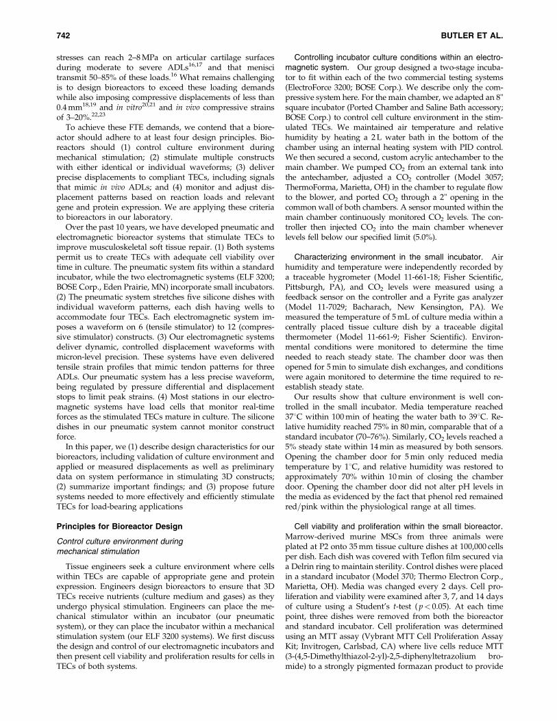
stresses can reach 2–8 MPa on articular cartilage surfacesduring moderate to severe ADLs16,17 and that meniscitransmit 50–85% of these loads.16 What remains challengingis to design bioreactors to exceed these loading demandswhile also imposing compressive displacements of less than0.4 mm18,19 and in vitro20,21 and in vivo compressive strainsof 3–20%.22,23
To achieve these FTE demands, we contend that a biore-actor should adhere to at least four design principles. Bio-reactors should (1) control culture environment duringmechanical stimulation; (2) stimulate multiple constructswith either identical or individual waveforms; (3) deliverprecise displacements to compliant TECs, including signalsthat mimic in vivo ADLs; and (4) monitor and adjust dis-placement patterns based on reaction loads and relevantgene and protein expression. We are applying these criteriato bioreactors in our laboratory.
Over the past 10 years, we have developed pneumatic andelectromagnetic bioreactor systems that stimulate TECs toimprove musculoskeletal soft tissue repair. (1) Both systemspermit us to create TECs with adequate cell viability overtime in culture. The pneumatic system fits within a standardincubator, while the two electromagnetic systems (ELF 3200;BOSE Corp., Eden Prairie, MN) incorporate small incubators.(2) The pneumatic system stretches five silicone dishes withindividual waveform patterns, each dish having wells toaccommodate four TECs. Each electromagnetic system im-poses a waveform on 6 (tensile stimulator) to 12 (compres-sive stimulator) constructs. (3) Our electromagnetic systemsdeliver dynamic, controlled displacement waveforms withmicron-level precision. These systems have even deliveredtensile strain profiles that mimic tendon patterns for threeADLs. Our pneumatic system has a less precise waveform,being regulated by pressure differential and displacementstops to limit peak strains. (4) Most stations in our electro-magnetic systems have load cells that monitor real-timeforces as the stimulated TECs mature in culture. The siliconedishes in our pneumatic system cannot monitor constructforce.
In this paper, we (1) describe design characteristics for ourbioreactors, including validation of culture environment andapplied or measured displacements as well as preliminarydata on system performance in stimulating 3D constructs;(2) summarize important findings; and (3) propose futuresystems needed to more effectively and efficiently stimulateTECs for load-bearing applications
Principles for Bioreactor Design
Control culture environment duringmechanical stimulation
Tissue engineers seek a culture environment where cellswithin TECs are capable of appropriate gene and proteinexpression. Engineers design bioreactors to ensure that 3DTECs receive nutrients (culture medium and gases) as theyundergo physical stimulation. Engineers can place the me-chanical stimulator within an incubator (our pneumaticsystem), or they can place the incubator within a mechanicalstimulation system (our ELF 3200 systems). We first discussthe design and control of our electromagnetic incubators andthen present cell viability and proliferation results for cells inTECs of both systems.
Controlling incubator culture conditions within an electro-magnetic system. Our group designed a two-stage incuba-tor to fit within each of the two commercial testing systems(ElectroForce 3200; BOSE Corp.). We describe only the com-pressive system here. For the main chamber, we adapted an 8"square incubator (Ported Chamber and Saline Bath accessory;BOSE Corp.) to control cell culture environment in the stim-ulated TECs. We maintained air temperature and relativehumidity by heating a 2 L water bath in the bottom of thechamber using an internal heating system with PID control.We then secured a second, custom acrylic antechamber to themain chamber. We pumped CO2 from an external tank intothe antechamber, adjusted a CO2 controller (Model 3057;ThermoForma, Marietta, OH) in the chamber to regulate flowto the blower, and ported CO2 through a 2" opening in thecommon wall of both chambers. A sensor mounted within themain chamber continuously monitored CO2 levels. The con-troller then injected CO2 into the main chamber wheneverlevels fell below our specified limit (5.0%).
Characterizing environment in the small incubator. Airhumidity and temperature were independently recorded bya traceable hygrometer (Model 11-661-18; Fisher Scientific,Pittsburgh, PA), and CO2 levels were measured using afeedback sensor on the controller and a Fyrite gas analyzer(Model 11-7029; Bacharach, New Kensington, PA). Wemeasured the temperature of 5 mL of culture media within acentrally placed tissue culture dish by a traceable digitalthermometer (Model 11-661-9; Fisher Scientific). Environ-mental conditions were monitored to determine the timeneeded to reach steady state. The chamber door was thenopened for 5 min to simulate dish exchanges, and conditionswere again monitored to determine the time required to re-establish steady state.
Our results show that culture environment is well con-trolled in the small incubator. Media temperature reached378C within 100 min of heating the water bath to 398C. Re-lative humidity reached 75% in 80 min, comparable that of astandard incubator (70–76%). Similarly, CO2 levels reached a5% steady state within 14 min as measured by both sensors.Opening the chamber door for 5 min only reduced mediatemperature by 18C, and relative humidity was restored toapproximately 70% within 10 min of closing the chamberdoor. Opening the chamber door did not alter pH levels inthe media as evidenced by the fact that phenol red remainedred=pink within the physiological range at all times.
Cell viability and proliferation within the small bioreactor.Marrow-derived murine MSCs from three animals wereplated at P2 onto 35 mm tissue culture dishes at 100,000 cellsper dish. Each dish was covered with Teflon film secured viaa Delrin ring to maintain sterility. Control dishes were placedin a standard incubator (Model 370; Thermo Electron Corp.,Marietta, OH). Media was changed every 2 days. Cell pro-liferation and viability were examined after 3, 7, and 14 daysof culture using a Student’s t-test ( p< 0.05). At each timepoint, three dishes were removed from both the bioreactorand standard incubator. Cell proliferation was determinedusing an MTT assay (Vybrant MTT Cell Proliferation AssayKit; Invitrogen, Carlsbad, CA) where live cells reduce MTT(3-(4,5-Dimethylthiazol-2-yl)-2,5-diphenyltetrazolium bro-mide) to a strongly pigmented formazan product to provide
742 BUTLER ET AL.

colorimetric indicators of cell viability. Absorbance of for-mazan was measured at 570 nm in a microplate spectro-photometer (Spectra Max M2; Molecular Devices, Sunnyvale,CA), and absorbance values were plotted on a known stan-dard curve to give cell numbers.
Using a Student’s t-test, no differences were found in thenumber of viable, proliferative cells for the small vs. stan-dard incubators up to 14 days of culture ( p> 0.25; Fig. 1).Cell numbers first increased 61–64% in both systems between3 and 7 days but then decreased by a total of 6–10% at day 14relative to the peak values that we measured on day 7.
Cell viability and proliferation in the pneumatic sys-tem. TECs were created using MSCs and collagen scaffolds.
Cell isolation and proliferation: MSCs were isolated fromthe iliac crest of 89 one-year-old, skeletally-mature, femaleNew Zealand white rabbits and passaged to P2 (see Refs.24–30).
TEC fabrication: Four groups of TECs were created bymixing each of two MSC concentrations (0.1�106 cells=mL[K] or 1�106 cells=mL [M]) from 16 rabbits with each of twobovine collagen gel concentrations (1.3 mg=mL [L] or2.6 mg=mL [H]; Vitrogen at 2.9 mg=mL, 95–98% type I col-lagen; Cohesion Technologies, Palo Alto, CA). Each cell–gelmixture was then pipetted into our silicone dishes thatpermitted contraction around posts (Fig. 2). All constructsremained in an incubator for 2 weeks and were fed high-glucose Dulbecco’s modified Eagle’s medium (DMEM) withascorbic acid and 10% fetal bovine serum twice weekly.ANOVA was used to determine significant differences inviability among groups ( p< 0.05).
Cell separation and viability: After 14 days, cells wereretrieved from the gel using collagenase (0.25 mg=mL; GibcoBRL=Life Technologies, Inc., Gaithersburg, MD) and viabilitywas measured using a Trypan blue (Sigma Chemical, St.Louis, MO) exclusion method and hemacytometer (seeRef.24). After 14 days of contraction, cell viabilities in the KH,KL, MH, and ML (cell–gel) constructs averaged 92%, 89%,79% and 72%, respectively. Only KH versus MH and KHversus ML showed significant differences in viability( p¼ 0.001). No significant differences were found among the
other groups ( p¼ 0.1). Collagenase digestion times were thesame in each case.
Simultaneously stimulate multiple constructswith identical or individual waveforms
We typically use our computer-controlled system ofpneumatic actuators to mechanically stimulate our TECs (seeRefs.24–31). Five stimulation stations fit within a framemounted within the incubator (Steri-Cult Model 3033; FormaScientific, Marietta, OH). Air pressure independently con-trols pressure differential at each station between adjustabledisplacement limits, allowing us to manipulate strain am-plitude, frequency, and rest period between cycles. Eachstation can stimulate one silicone dish (Fig. 2) containing upto four TECs. End-to-end dish displacements are monitoredby linear variable differential transducers in line with eachactuator. The advantages of this system are that it can beplaced within an incubator and has high throughput capac-ity, permitting us to stimulate dishes with different wave-forms and to measure multiple responses (e.g., constructstiffness, histology, and gene expression).
Our two Enduratec–Bose ElectroForce 3200 systems canalso stimulate multiple TECs in tension or compression. Foreach system, we designed and manufactured a fixture tosimultaneously apply controlled displacement profiles usingone actuator. For the compressive bioreactor (Fig. 3a), thefixture consisted of an anodized aluminum top platemounted to the actuator and a parallel bottom plate attachedto an adjustable arm fed through the bottom of the chamberand water bath (Fig. 3b). Each plate slid on low frictionbearings along stainless steel rods (12.5 mm diameter) forsmooth movement and proper plate alignment. The bottomplate had 12 recessed stations to house 35-mm-diameter tis-sue culture dishes. Twelve thin aluminum rods extendeddown from the top plate above the dish locations. The po-sition of these rods could be modified when not in operationby adjusting the threaded portion of the rod near the topplate. Each rod also had a female component of a quick-connect coupler (MC1002; Colder Products, St. Paul, MN)attached to its free end (Fig. 3b).
0
20000
40000
60000
80000
100000
120000
140000
160000
180000
200000
3 7 14Time in Culture
Nu
mb
ero
fC
ells
IncubatorBioreactor
FIG. 1. Viability of cells cultured in the bioreactor is com-parable to that of cells cultured in a standard incubator over14 days, increasing 61–64% by day 7 before decreasing 6–10% relative to day 7 values (n¼ 3 for each time and con-dition in culture; meanþ 1 SEM).
FIG. 2. Each silicone dish consists of four wells into whichwe pipette cells and collagen gels. Cells contract the gelsaround two posts (from Ref.25).
BIOREACTORS FOR FUNCTIONAL TISSUE ENGINEERING 743

A specialized culture dish system was also developed tospeed development time so that multiple constructs could bestimulated while ensuring TEC sterility. The male end of thecoupler (MC281032; Colder Products) was attached to apolymer disk (8 mm thick�15 mm diameter) through a 100-mm-thick film (4@�4@; Teflon FEP 100A; DuPont, Circleville,OH). We stretched and secured the film over the dish using apolymer ring with a small threaded hole for media exchange(Fig. 3c). The film, permeable to O2 and CO2, preventedmedia evaporation and reduced contamination without im-peding actuator motion. This coupler allowed each dish to beeasily removed from the system, its media exchanged, andspecimen groups to be rotated to increase daily throughput.Once assembled, TECs could be mechanically stimulatedusing the system actuator, which smoothly moved the topplate and pressed the polymer disk onto the specimen dish.
We then adapted a second ELF3200 system to stimulateconstructs in tension. As with its compressive counterpart,we designed and manufactured a custom, rigid, stainlesssteel fixture to apply controlled displacements to multipleconstructs from a single actuator shaft. The six-station fixture(Fig. 4) was placed within an environmental chamber like inour compressive system. The system is nearly frictionless
and includes a quick-release mechanism allowing rapid at-tachment and removal of construct batches from the fixture.
Deliver precise displacements, includingthose that mimic in vivo ADLs
Cell–scaffold constructs are usually stimulated in dis-placement rather than load control due to their weak andcompliant nature during early maturation. Stimulating TECswith actual in vivo forces would certainly damage them beforesurgery unless they can be placed in a load-protected envi-ronment like a central PT defect (e.g., Refs.24–30). In ourpneumatic actuator, we actually measure end-to-end dishdisplacements using our LVDTs. We then know the corre-sponding displacements between the posts in the base of eachwell from prior calibrations. We currently suspend rabbitMSCs (0.14�106 cells) in 0.4 mL of high-glucose DMEM mediaon top of a type I collagen sponge (P1076; Kensey NashCorporation, Exton, PA) cut to fit over the well posts (Fig. 2).28
After 2 days of incubation and regular feeding (high-glucoseDMEM, 5% ascorbic acid, 1% antibiotic=antimycotic, and10% fetal bovine serum), the dishes containing TECs aretypically stretched using a simple trapezoidal stimulus up to2.4% peak strain, the largest PT strain for inclined hopping.12
We stimulate once every 5 min for 8 h=day for up to 2 weeks.Stimulated constructs show 2.5 and 4 times the linear stiffnessand linear modulus of nonstimulated constructs, respectively(Fig. 5a). While we still do not know if such improvements ingene expression are biologically relevant, it is important torecognize that these observed changes might increase proteinexpression and assembly and result in improvements inconstruct stiffness. The exact temporal relationships amonggene expression, protein production, and biomechanical im-provements must still be elucidated. These preconditionedTECs also significantly improve repair of rabbit PT defectinjuries at 12 weeks postsurgery compared to nonstimulatedconstructs.28,30 We are now using the pneumatic system tooptimize construct stiffness for different signal components31
and scaffold materials.29 However, we also recognize thatadjusting pressure differential cannot precisely control allaspects of a displacement waveform (e.g., rise and fall timesand complex shape).
FIG. 3. (A) Compressive stimulus bioreactor. (B) Environ-mental chamber and loading apparatus within the com-pressive bioreactor. (C) Schematic of culture dish with Delrindisk, ring, and film assembly.
FIG. 4. Environmental chamber and loading apparatuswithin the tensile bioreactor. Color images available online atwww.liebertonline.com=ten.
744 BUTLER ET AL.
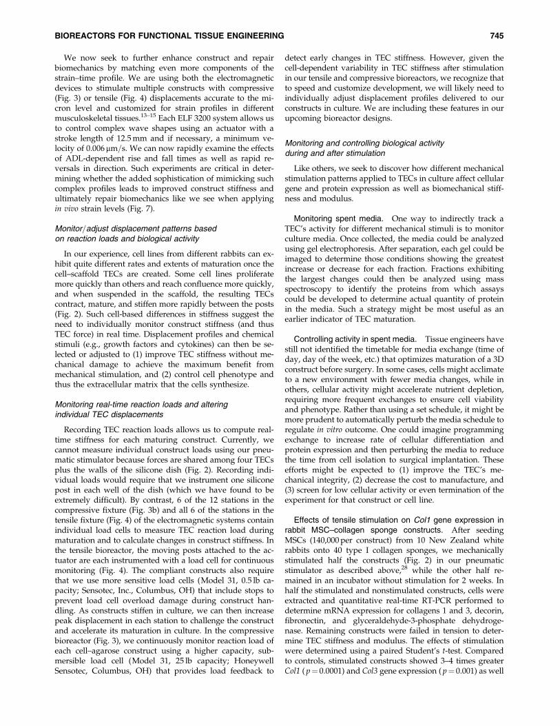
We now seek to further enhance construct and repairbiomechanics by matching even more components of thestrain–time profile. We are using both the electromagneticdevices to stimulate multiple constructs with compressive(Fig. 3) or tensile (Fig. 4) displacements accurate to the mi-cron level and customized for strain profiles in differentmusculoskeletal tissues.13–15 Each ELF 3200 system allows usto control complex wave shapes using an actuator with astroke length of 12.5 mm and if necessary, a minimum ve-locity of 0.006 mm=s. We can now rapidly examine the effectsof ADL-dependent rise and fall times as well as rapid re-versals in direction. Such experiments are critical in deter-mining whether the added sophistication of mimicking suchcomplex profiles leads to improved construct stiffness andultimately repair biomechanics like we see when applyingin vivo strain levels (Fig. 7).
Monitor=adjust displacement patterns basedon reaction loads and biological activity
In our experience, cell lines from different rabbits can ex-hibit quite different rates and extents of maturation once thecell–scaffold TECs are created. Some cell lines proliferatemore quickly than others and reach confluence more quickly,and when suspended in the scaffold, the resulting TECscontract, mature, and stiffen more rapidly between the posts(Fig. 2). Such cell-based differences in stiffness suggest theneed to individually monitor construct stiffness (and thusTEC force) in real time. Displacement profiles and chemicalstimuli (e.g., growth factors and cytokines) can then be se-lected or adjusted to (1) improve TEC stiffness without me-chanical damage to achieve the maximum benefit frommechanical stimulation, and (2) control cell phenotype andthus the extracellular matrix that the cells synthesize.
Monitoring real-time reaction loads and alteringindividual TEC displacements
Recording TEC reaction loads allows us to compute real-time stiffness for each maturing construct. Currently, wecannot measure individual construct loads using our pneu-matic stimulator because forces are shared among four TECsplus the walls of the silicone dish (Fig. 2). Recording indi-vidual loads would require that we instrument one siliconepost in each well of the dish (which we have found to beextremely difficult). By contrast, 6 of the 12 stations in thecompressive fixture (Fig. 3b) and all 6 of the stations in thetensile fixture (Fig. 4) of the electromagnetic systems containindividual load cells to measure TEC reaction load duringmaturation and to calculate changes in construct stiffness. Inthe tensile bioreactor, the moving posts attached to the ac-tuator are each instrumented with a load cell for continuousmonitoring (Fig. 4). The compliant constructs also requirethat we use more sensitive load cells (Model 31, 0.5 lb ca-pacity; Sensotec, Inc., Columbus, OH) that include stops toprevent load cell overload damage during construct han-dling. As constructs stiffen in culture, we can then increasepeak displacement in each station to challenge the constructand accelerate its maturation in culture. In the compressivebioreactor (Fig. 3), we continuously monitor reaction load ofeach cell–agarose construct using a higher capacity, sub-mersible load cell (Model 31, 25 lb capacity; HoneywellSensotec, Columbus, OH) that provides load feedback to
detect early changes in TEC stiffness. However, given thecell-dependent variability in TEC stiffness after stimulationin our tensile and compressive bioreactors, we recognize thatto speed and customize development, we will likely need toindividually adjust displacement profiles delivered to ourconstructs in culture. We are including these features in ourupcoming bioreactor designs.
Monitoring and controlling biological activityduring and after stimulation
Like others, we seek to discover how different mechanicalstimulation patterns applied to TECs in culture affect cellulargene and protein expression as well as biomechanical stiff-ness and modulus.
Monitoring spent media. One way to indirectly track aTEC’s activity for different mechanical stimuli is to monitorculture media. Once collected, the media could be analyzedusing gel electrophoresis. After separation, each gel could beimaged to determine those conditions showing the greatestincrease or decrease for each fraction. Fractions exhibitingthe largest changes could then be analyzed using massspectroscopy to identify the proteins from which assayscould be developed to determine actual quantity of proteinin the media. Such a strategy might be most useful as anearlier indicator of TEC maturation.
Controlling activity in spent media. Tissue engineers havestill not identified the timetable for media exchange (time ofday, day of the week, etc.) that optimizes maturation of a 3Dconstruct before surgery. In some cases, cells might acclimateto a new environment with fewer media changes, while inothers, cellular activity might accelerate nutrient depletion,requiring more frequent exchanges to ensure cell viabilityand phenotype. Rather than using a set schedule, it might bemore prudent to automatically perturb the media schedule toregulate in vitro outcome. One could imagine programmingexchange to increase rate of cellular differentiation andprotein expression and then perturbing the media to reducethe time from cell isolation to surgical implantation. Theseefforts might be expected to (1) improve the TEC’s me-chanical integrity, (2) decrease the cost to manufacture, and(3) screen for low cellular activity or even termination of theexperiment for that construct or cell line.
Effects of tensile stimulation on Col1 gene expression inrabbit MSC–collagen sponge constructs. After seedingMSCs (140,000 per construct) from 10 New Zealand whiterabbits onto 40 type I collagen sponges, we mechanicallystimulated half the constructs (Fig. 2) in our pneumaticstimulator as described above,28 while the other half re-mained in an incubator without stimulation for 2 weeks. Inhalf the stimulated and nonstimulated constructs, cells wereextracted and quantitative real-time RT-PCR performed todetermine mRNA expression for collagens 1 and 3, decorin,fibronectin, and glyceraldehyde-3-phosphate dehydroge-nase. Remaining constructs were failed in tension to deter-mine TEC stiffness and modulus. The effects of stimulationwere determined using a paired Student’s t-test. Comparedto controls, stimulated constructs showed 3–4 times greaterCol1 ( p¼ 0.0001) and Col3 gene expression ( p¼ 0.001) as well
BIOREACTORS FOR FUNCTIONAL TISSUE ENGINEERING 745

as 2.5 times the linear stiffness and 4 times the linear mod-ulus (Fig. 5a). Stimulation did not affect either decorin orfibronectin gene expression ( p¼ 0.2).27 This study offers onemethod to assess the potential benefits of stimulation inculture on gene expression before initiating more expensiveand time-consuming in vivo repair studies. The observedincrease in gene expression coupled with improved TECstiffness suggests corresponding improvements in type Icollagen protein, but this cannot be readily measured whenusing type I collagen sponges as scaffolds.
Effects of compressive stimulation on Col2 gene expres-sion in murine chondrocyte–agarose constructs. To mea-sure changes in gene and protein expression as well asaggregate modulus due to mechanical stimulation, we cul-tured chondrocytes from the ribs of six singly transgenicmice32 in media (BGJbþ 10% fetal calf serum), and thenmixed these passage 1 cells with equal volumes of 4% (w=v)agarose (Sigma Chemical). Half the constructs were cycli-cally compressed (at 1 Hz to 10% peak strain for 1 h followedby a 1 h rest period for 6 h=day for 7, 14, 21, and 28 days inculture).9 Nonstimulated constructs were cultured in thesame bioreactor for 0, 7, 14, 21, and 28 days. Media waschanged daily. Constructs were mechanically homogenized,
Enhanced Cyan Fluorescent Protein (ECFP) was quantifiedin Relative Fluorescence Units (RFUs) using a spectropho-tometer (Spectra Max M2; Molecular Devices), and mRNAexpression was tracked using quantitative real-time RT-PCR.Type II collagen content was also measured at each timeinterval using ELIZA. Significant differences were examinedusing two-way ANOVA ( p< 0.05). Stimulated constructsshowed 20.2%, 14.5%, and 17.1% higher RFU values at 7, 14,and 28 days, compared to time-matched, nonstimulatedcontrols, respectively (Fig. 5B, p< 0.005). These stimulatedTECs also showed 33.5%, 22.7%, 25.1%, and 31.1% higherCol2 mRNA values at 7, 14, 21, and 28 days relative to con-trols, respectively ( p< 0.002). Moreover, stimulated con-structs showed 33.3% and 25.1% higher type II collagencontent at 21 and 28 days, respectively ( p< 0.001), and anaverage 41.3% increase in aggregate modulus at day 28compared to time-matched, nonstimulated controls( p< 0.0001). When all results are synthesized, stimulatedconstructs showed earlier increases in Col2 gene expression,leading to later increases in type II collagen content, and stilllater increases in aggregate modulus (Fig. 5C). Comparingthe magnitude and temporal relationships among thesein vitro measures due to stimulation combined with the re-pair outcomes from preclinical studies offers tissue engineers
5
4
3
2
1
0Collagen Type I
Gen
e ex
pres
sion
rel
ativ
e to
co
ntro
ls
Collagen Type III
Non-stimulatedStimulated
Non-stimulated Stimulated Non-stimulated Stimulated
a0.07
0.06
0.05
0.04
0.03
0.02
0.01
0
Line
ar s
tiffn
ess
(N/m
m) b 0.04
0.03
0.02
0.01
0
Line
ar m
odul
us (
MP
a)
c
*
*
0
0.5
1
1.5
2
2.5
3
3.5
Day 7 Day 14 Day 28 Day 7 Day 14 Day 28Day 21
EC
FP
RF
U/D
ay 0
Non-stimulated
Stimuated
*
*
*
0
0.5
1
1.5
2
2.5
3
3.5
Fol
d In
crea
se F
rom
Day
0
Aggregate Modulus
Col2 Gene Expression
Type II Collagen Content
A
B C
FIG. 5. (A) Tensile stimulation of rabbit MSC–seeded sponge constructs increases (a) linear stiffness and (b) linear moduluswhen compared with nonstimulated constructs but also increases (c) Col1 and Col3 gene expression.27 Shown are meanþSEM. (B) Compressive stimulation significantly increases ECFP RFU at all time points investigated (n¼ 6, meanþ SEM).(C) Fold increase from day 0 in stimulated murine chondrocyte–agarose constructs. Note the earlier increase in Col2 ex-pression, followed by delayed increase in type II collagen content, then followed by an increase TEC construct modulus(n¼ 6, mean� SEM).
746 BUTLER ET AL.
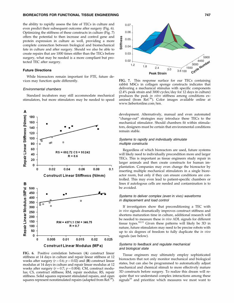
the ability to rapidly assess the fate of TECs in culture andeven predict their subsequent outcome after surgery (Fig. 6).Optimizing the stiffness of these constructs in culture (Fig. 7)offers the potential to then increase and control gene andprotein expression in culture as well, providing a morecomplete connection between biological and biomechanicalfate in culture and after surgery. Should we also be able tocreate repairs that are 1000 times stiffer than the TECs beforesurgery, what may be needed is a more compliant but pro-tected TEC after surgery.
Future Directions
While bioreactors remain important for FTE, future de-vices may function quite differently.
Environmental chambers
Standard incubators may still accommodate mechanicalstimulators, but more stimulators may be needed to speed
development. Alternatively, manual and even automated‘‘change-out’’ strategies may introduce these TECs to themechanical stimulator. Should chambers fit within stimula-tors, designers must be certain that environmental conditionsremain stable.
Systems to rapidly and individually stimulatemultiple constructs
Regardless of which bioreactors are used, future systemswill likely need to individually precondition more and largerTECs. This is important as tissue engineers study repair inlarger animals and then create constructs for human im-plantation. Companies may even change the bioreactor byinserting multiple mechanical stimulators in a single biore-actor room, but only if they can ensure conditions are con-trolled. This may even lead to patient-specific chambers orlines if autologous cells are needed and contamination is tobe avoided.
Systems to deliver complex (even in vivo) waveformsin displacement and load control
If investigators show that preconditioning a TEC within vivo signals dramatically improves construct stiffness andshortens maturation time in culture, additional research willbe needed to measure these in vivo ADL signals for differenttissue types.10,11 Given these patterns will likely be 3D innature, future stimulators may need to be precise robots withup to six degrees of freedom to fully duplicate the in vivosignals (see below).
Systems to feedback and regulate mechanicaland biological state
Tissue engineers may ultimately employ sophisticatedbioreactors that not only monitor mechanical and biologicalstates, but can also be programmed to automatically adjustmechanical and chemical stimuli to more effectively mature3D constructs before surgery. To realize this dream will re-quire that we understand complex interactions among thesesignals33 and prioritize which measures we most want to
FIG. 6. Positive correlation between (A) construct linearstiffness at 14 days in culture and repair linear stiffness at 12weeks after surgery (r¼ 0.6; p¼ 0.02) and (B) construct linearmodulus at 14 days in culture and repair linear modulus at 12weeks after surgery (r¼ 0.7; p¼ 0.004). CM, construct modu-lus; CS, construct stiffness; RM, repair modulus; RS, repairstiffness. Solid squares represent stimulated repairs, and opensquares represent nonstimulated repairs (adapted from Ref.28).
0.07
0.06
0.05
0.04
0.03
0.02
1.2 1.8 2.4
Peak Strain Cycle Number
Sti
ffn
ess
3.0 3.6 1001550
30004450
5900
FIG. 7. This response surface for our TECs containingrabbit MSCs in collagen sponge constructs indicates thatdelivering a mechanical stimulus with specific components(2.4% peak strain and 3000 cycles=day for 12 days in culture)produces the peak in vitro stiffness among conditions ex-amined (from Ref.36). Color images available online atwww.liebertonline.com=ten.
BIOREACTORS FOR FUNCTIONAL TISSUE ENGINEERING 747

improve. This strategy will be difficult to establish and likelyapplication and species dependent.34
Controlling cost
One of the greatest challenges facing tissue engineers intranslating their research is to be financially competitive withcurrent clinical approaches. The initial boon of tissue engi-neering companies faltered under the mounting costs of longproduct development cycles, regulatory hurdles requiringexhaustive in vitro and in vivo data, and scale-up efforts tomeet an expanding market demand.34 To keep these thera-pies financially viable during development, our field needsto consider how culture environment is established andmaintained, and how to keep the cost of custom chamberscompetitive with standard incubators. Bioreactor capacitywill also need to be maximized. A system with limitedthroughput has little utility as basic research translates intoclinical practice. Finally, we must discover how complex amechanical signal really needs to be and then engineerstimulators specific to that application. Full-scale robots withmultiple actuators may be ideal but too expensive andcumbersome unless they can precisely stimulate large num-bers of constructs with just enough degrees of freedom toeffect the desired outcome.35 Performing such mass stimu-lation will challenge our goal to deliver individual mechan-ical signals to different constructs unless certain degrees offreedom are assigned to individual stimulation stations.Controlling bioreactor costs may ultimately dictate how so-phisticated our stimulation efforts will be unless researchabsolutely mandates their inclusion in the developmentprocess.
Acknowledgments
We acknowledge the support of NIH Grants AR46574-08,EB004859, and EB002361. We also thank Ms. Cindi Gooch forassistance with cell culture and animal care, and Mr. DenisBailey for assistance with robotics and animal care.
Disclosure Statement
No competing financial interests exist.
References
1. Freed, L.E., Langer, R., Martin, I., Pellis, N.R., and Vunjak-Novakovic, G. Tissue engineering of cartilage in space. ProcNatl Acad Sci USA 94, 13885, 1997.
2. Vunjak-Novakovic, G., Obradovic, B., Martin, I., and Freed,L.E. Bioreactor studies of native and tissue engineered car-tilage. Biorheology 39, 259, 2002.
3. Banes, A.J., Gilbert, J., Taylor, D., and Monbureau, O. A newvacuum-operated stress-providing instrument that appliesstatic or variable duration cyclic tension or compression tocells in vitro. J Cell Sci 75, 35, 1985.
4. Carvalho, R.S., Yen, E.H., and Suga, D.M. Glycosaminogly-can synthesis in the rat articular disk in response to me-chanical stress. Am J Orthod Dentofacial Orthop 107, 401,1995.
5. Sambajon, V.V., Cillo, J.E., Jr., Gassner, R.J., and Buckley,M.J. The effects of mechanical strain on synovial fibroblasts.J Oral Maxillofac Surg 61, 707, 2003.
6. Upton, M.L., Chen, J., Guilak, F., and Setton, L.A. Differ-ential effects of static and dynamic compression on meniscalcell gene expression. J Orthop Res 21, 963, 2003.
7. Aufderheide, A.C., and Athanasiou, K.A. A direct com-pression stimulator for articular cartilage and meniscal ex-plants. Ann Biomed Eng 34, 1463, 2006.
8. Frank, E.H., Jin, M., Loening, A.M., Levenston, M.E., andGrodzinsky, A.J. A versatile shear and compression appa-ratus for mechanical stimulation of tissue culture explants.J Biomech 33, 1523, 2000.
9. Mauck, R.L., Soltz, M.A., Wang, C.C.B., Wong, D.D., Chao,P.H.G., Valhmu, W.B., Hung, C.T., and Ateshian, G.A.Functional tissue engineering of articular cartilage throughdynamic loading of chondrocyte-seeded agarose gels.J Biomech Eng 122, 252, 2000.
10. Butler, D.L., Goldstein, S.A., and Guilak, F. Functional tissueengineering: the role of biomechanics. J Biomech Eng 122,
570, 2000.11. Guilak, F., Butler, D.L., Goldstein, S.A., and Mooney, D.J.
Functional Tissue Engineering. New York: Springer-Verlag,2003.
12. Juncosa, N., West, J.R., Galloway, M.T., Boivin, G.P., andButler, D.L. In vivo forces used to develop design parametersfor tissue engineered implants for rabbit patellar tendonrepair. J Biomech 36, 483, 2003.
13. Korvick, D., Cummings, J., Grood, E., Holden, J., Feder, S.,and Butler, D. The use of an implantable force transducer tomeasure patellar tendon forces in goats [see comments].J Biomech 29, 557, 1996.
14. Malaviya, P., Butler, D., Korvick, D., and Proch, F. In vivotendon forces correlate with activity level and remainbounded: evidence in a rabbit flexor tendon model. J Bio-mech 31, 1043, 1998.
15. West, J.R., Juncosa, N., Galloway, M.T., Boivin, G.P., andButler, D.L. Characterization of in vivo Achilles tendon for-ces in rabbits during treadmill locomotion at varying speedsand inclinations. J Biomech 37, 1647, 2004.
16. Ahmed, A.M., and Burke, D.L. In-vitro measurement ofstatic pressure distribution in synovial joints. Part I: Tibialsurface of the knee. J Biomech Eng 105, 216, 1983.
17. Brown, T.D., and Shaw, D.T. In vitro contact stress distri-bution on the femoral condyles. J Orthop Res 2, 190, 1984.
18. Rankin, M., Noyes, F.R., Barber-Westin, S.D., Hushek, S.G.,and Seow, A. Human meniscus allografts’ in vivo size andmotion characteristics: magnetic resonance imaging assess-ment under weightbearing conditions. Am J Sports Med 34,
98, 2006.19. Vedi, V., Williams, A., Tennant, S.J., Spouse, E., Hunt, D.M.,
and Gedroyc, W.M.W. Meniscal movement: an in vivo studyusing dynamic MRI. J Bone Joint Surg Ser B 81, 37, 1999.
20. Armstrong, C.G., Bahrani, A.S., and Gardner, D.L. In vitromeasurement of articular cartilage deformations in the intacthuman hip joint under load. J Bone Joint Surg Ser A 61, 744,1979.
21. Macirowski, T., Tepic, S., and Mann, R.W. Cartilage stressesin the human hip joint. J Biomech Eng 116, 10, 1994.
22. Eckstein, F., Lemberger, B., Gratzke, C., Hudelmaier, M.,Glaser, C., Englmeier, K.H., and Reiser, M. In vivo cartilagedeformation after different types of actvity and its depen-dence on physical training status. Ann Rheum Dis 64, 291,2005.
23. Eckstein, F., Tieschky, M., Faber, S., Englmeier, K.H., andReiser, M. Functional analysis of articular cartilage defor-
748 BUTLER ET AL.

mation, recovery, and fluid flow following dynamic exercisein vivo. Anat Embryol 200, 419, 1999.
24. Juncosa-Melvin, N., Boivin, G.P., Galloway, M.T., Gooch, C.,West, J.R., and Butler, D.L. Effects of cell-to-collagen ratio instem cell-seeded constructs for Achilles tendon repair. TissueEng 12, 681, 2006.
25. Juncosa-Melvin, N., Boivin, G.P., Galloway, M.T., Gooch, C.,West, J.R., Sklenka, A.M., and Butler, D.L. Effects of cell-to-collagen ratio in mesenchymal stem cell-seeded implantson tendon repair biomechanics and histology. Tissue Eng 11,
448, 2005.26. Juncosa-Melvin, N., Boivin, G.P., Gooch, C., Galloway, M.T.,
West, J.R., Dunn, M.G., and Butler, D.L. The effect of au-tologous mesenchymal stem cells on the biomechanics andhistology of gel-collagen sponge constructs used for rabbitpatellar tendon repair. Tissue Eng 12, 369, 2006.
27. Juncosa-Melvin, N., Matlin, K.S., Holdcraft, R.W., Nirmala-nandhan, V.S., and Butler, D.L. Mechanical stimulationincreases collagen type I and collagen type III gene expres-sion of stem cell–collagen sponge constructs for patel-lar tendon repair. Proceedings of the ASME SummerBioengineering Conference 2007, SBC 2007, 2007, pp. 981–982.
28. Juncosa-Melvin, N., Shearn, J.T., Boivin, G.P., Gooch, C.,Galloway, M.T., West, J.R., Nirmalanandhan, V.S., Bradica,G., and Butler, D.L. Effects of mechanical stimulation on thebiomechanics and histology of stem cell-collagen spongeconstructs for rabbit patellar tendon repair. Tissue Eng 12,
2291, 2006.29. Nirmalanandhan, V.S., Dressler, M.R., Shearn, J.T., Juncosa-
Melvin, N., Rao, M., Gooch, C., Bradica, G., and Butler, D.L.Mechanical stimulation of tissue engineered tendon con-structs: effect of scaffold materials. J Biomech Eng 129, 919,2007.
30. Shearn, J.T., Juncosa-Melvin, N., Boivin, G.P., Galloway,M.T., Goodwin, W., Gooch, C., Dunn, M.G., and Butler, D.L.Mechanical stimulation of tendon tissue engineered con-
structs: effects on construct stiffness, repair biomechanics,and their correlation. J Biomech Eng 129, 848, 2007.
31. Nirmalanandhan, V.S., Shearn, J.T., Juncosa-Melvin, N., Rao,M., Gooch, C., Bradica, G., and Butler, D.L. Improving linearstiffness of the cell-seeded collagen sponge constructs byvarying the components of the mechanical stimulus. TissueEng 14, 1883, 2008.
32. Thirion, S., and Berenbaum, F. Culture and phenotyping ofchondrocytes in primary culture. Methods Mol Med 100, 1, 2004.
33. Butler, D.L., Juncosa-Melvin, N., Boivin, G.P., Galloway,M.T., Shearn, J.T., Gooch, C., and Awad, H. Functional tis-sue engineering for tendon repair: a multidisciplinarystrategy using mesenchymal stem cells, bioscaffolds, andmechanical stimulation. J Orthop Res 26, 1, 2008.
34. Lysaght, M.J., Nguy, N.A.P., and Sullivan, K. An economicsurvey of the emerging tissue engineering industry. TissueEng 4, 231, 1998.
35. Altman, G.H., Lu, H.H., Horan, R.L., Calabro, T., Ryder, D.,Kaplan, D.L., Stark, P., Martin, I., Richmond, J.C., andVunjak-Novakovic, G. Advanced bioreactor with controlledapplication of multi-dimensional strain for tissue engineer-ing. J Biomech Eng 124, 742, 2002.
Address reprint requests to:David L. Butler, Ph.D.
Department of Biomedical Engineering840 Engineering Research Center
University of Cincinnati2901 Woodside Drive
Cincinnati, OH 45221-0048
E-mail: [email protected]
Received: May 19, 2008Accepted: November 13, 2008
Online Publication Date: January 7, 2009
BIOREACTORS FOR FUNCTIONAL TISSUE ENGINEERING 749