Development of generic multibody road vehicle models for crashworthiness
26
Multibody Syst Dyn (2008) 19: 133–158 DOI 10.1007/s11044-007-9093-z Development of generic multibody road vehicle models for crashworthiness Luís Sousa · Paulo Veríssimo · Jorge Ambrósio Received: 17 October 2006 / Accepted: 26 July 2007 / Published online: 20 September 2007 © Springer Science+Business Media B.V. 2007 Abstract The crashworthiness analysis of road vehicles requires detailed data of the vehi- cles that the automotive manufacturers are, generally, unable to release due to commercial or legal restrictions. In the development of passive safety subsystems or substructures, the overall crash response of a vehicle model used to support it, must mimic that of the real ve- hicle; if this exists, regardless of any particular constructive detail of its structure provided that it is not located in the vicinity of such subsystem. This work proposes a methodology for the development of multibody models of road vehicles, for passive safety analysis, which include all general structural and mechanical features of real vehicles and start by exhibiting impact dynamic responses similar to the top of line vehicles. These vehicle models, desig- nated as generic, do not require the knowledge of most of the particular details of the design of the real vehicle, which the manufacturers are unable to release, but can be adjusted to have crash responses similar to those of the real vehicle. Based on an existing finite ele- ment model of a car, which has all constructive features of vehicles of the chosen class, a multibody model is built applying the plastic hinge approach. By using a selected number of crash scenarios, defined in international standards such as the EuroNCAP, selected para- meters of the vehicle multibody model are adjusted to ensure a good correlation between its impact responses and those of the finite element model. The crash responses are measured in terms of structural deformations, velocities and accelerations, occupant injury measures and structural energy absorption capabilities. Assuming that the plastic hinge constitutive equations of the multibody model are not exactly known, their parameters are used here as the multibody vehicle model that are adjusted. The methodology proposed is demonstrated by its application to the identification of the vehicle multibody model of a large family car for which the reference vehicle is available as a detailed finite element model. L. Sousa ( ) · P. Veríssimo · J. Ambrósio IDMEC—Instituto Superior Técnico, Technical University of Lisbon, Av. Rovisco Pais 1, 1049-001, Lisboa, Portugal e-mail: [email protected] P. Veríssimo e-mail: [email protected] J. Ambrósio e-mail: [email protected]
Transcript of Development of generic multibody road vehicle models for crashworthiness

Multibody Syst Dyn (2008) 19: 133–158DOI 10.1007/s11044-007-9093-z
Development of generic multibody road vehicle modelsfor crashworthiness
Luís Sousa · Paulo Veríssimo · Jorge Ambrósio
Received: 17 October 2006 / Accepted: 26 July 2007 / Published online: 20 September 2007© Springer Science+Business Media B.V. 2007
Abstract The crashworthiness analysis of road vehicles requires detailed data of the vehi-cles that the automotive manufacturers are, generally, unable to release due to commercialor legal restrictions. In the development of passive safety subsystems or substructures, theoverall crash response of a vehicle model used to support it, must mimic that of the real ve-hicle; if this exists, regardless of any particular constructive detail of its structure providedthat it is not located in the vicinity of such subsystem. This work proposes a methodologyfor the development of multibody models of road vehicles, for passive safety analysis, whichinclude all general structural and mechanical features of real vehicles and start by exhibitingimpact dynamic responses similar to the top of line vehicles. These vehicle models, desig-nated as generic, do not require the knowledge of most of the particular details of the designof the real vehicle, which the manufacturers are unable to release, but can be adjusted tohave crash responses similar to those of the real vehicle. Based on an existing finite ele-ment model of a car, which has all constructive features of vehicles of the chosen class, amultibody model is built applying the plastic hinge approach. By using a selected numberof crash scenarios, defined in international standards such as the EuroNCAP, selected para-meters of the vehicle multibody model are adjusted to ensure a good correlation between itsimpact responses and those of the finite element model. The crash responses are measuredin terms of structural deformations, velocities and accelerations, occupant injury measuresand structural energy absorption capabilities. Assuming that the plastic hinge constitutiveequations of the multibody model are not exactly known, their parameters are used here asthe multibody vehicle model that are adjusted. The methodology proposed is demonstratedby its application to the identification of the vehicle multibody model of a large family carfor which the reference vehicle is available as a detailed finite element model.
L. Sousa (�) · P. Veríssimo · J. AmbrósioIDMEC—Instituto Superior Técnico, Technical University of Lisbon, Av. Rovisco Pais 1,1049-001, Lisboa, Portugale-mail: [email protected]
P. Veríssimoe-mail: [email protected]
J. Ambrósioe-mail: [email protected]

134 L. Sousa et al.
Keywords Crashworthiness · Front impact · Side impact · Vehicle dynamics · Structuraldeformations · Virtual testing
1 Introduction
In vehicle modeling, the details concerning many of its design aspects are of major impor-tance. However, such aspects may also be regarded as confidential by the vehicle developer,either because they represent technological advances or due to legal reasons associated toliability. Therefore, these technical details cannot be disclosed even to commercial or devel-oper partners, impairing a more meaningful vehicle model development. A solution to thisproblem is the development of virtual vehicle models that have the same crash response ofthe detailed models for selected crash scenarios studies. Such response can be measured interms of accelerations of given points in the vehicle structure or dummy component, energyabsorption characteristics of subsystems, intrusion measures or by any other measurablecharacteristic of the crash. As an example of application of this virtual model, a developerwould be able to tackle the task of devising a subcomponent or protective system for aselected part of the vehicle, such as a new airbag or an anti-intrusion door device, beingassured that the overall behavior of such vehicle is indeed correct.
Finite element (FE) models for road vehicles, suitable for crashworthiness analysis, aregenerally very detailed using hundreds of thousand elements. Due to the need to describeaccurately the nonlinear deformations and the contact involved in realistic crash scenarios ofroad vehicles, these models require long computational periods. With the actual computertechnology, the computational time for the simulation of vehicle FE models is measuredin terms of days. During the design of a new vehicle or a particular safety device or theredesign of a structural or mechanical component, many simulations must be performedto appraise different solutions. In this design phase, simplified models that contain all theimportant features of the detailed vehicle or subsystem can be used efficiently to support theeffective selection of the best features for the new device or structure. Only in the final stageof the design, a detailed finite element model for the vehicle, or vehicle subsystem, may berequired to fine-tune the design solution devised. It is shown here that multibody models(MB) of road vehicles are well suited for the early design phases of vehicles, components ormechanical devices, being the computational time required for any specific crash analysisperformed with these models just a fraction of that of equivalent FE models. In the case ofmultibody analysis of a given crash scenario, the computation time is measured in minuteswhere the computation time for the finite element analysis is measured in days.
This type of generic multibody vehicle model can also be used in the design of new ve-hicles from scratch. Because the vehicle model has all the structural characteristics of anyreal vehicle and its crash performance is close to the best in its class, it can be modifiedto present a crash response that is an improvement relative to that of the reference vehicle.Now, in the context of a new design, such reference crash response can be designed to beoptimal in some sense. The generic can be used to devise what parts of its structure shouldbe modified in order to match the targeted crash performance. The next stage on the useof the new vehicle model would be the identification of real structural components, or me-chanical systems for which the multibody model would be valid, using inverse engineeringmethodologies.
In this work, the development of a generic road vehicle model, including suspensions,tires, occupants and structural components, is achieved by using multibody systems [1].Particular emphasis is put on the representation of the structural components by using the

Development of generic multibody road vehicle model 135
plastic hinge approach [2]. In this methodology, the structural components are divided inrigid bodies connected by kinematic joints. Nonlinear spring elements are applied to eachdegree of freedom of the kinematic joints representing the structural behavior of the struc-tural members due to lumped deformations in the region where the kinematic joint is located.These deformations are either a result of bending, torsion or axial loading. According to theprocedures proposed in Refs. [3, 4] for applications of the plastic hinge concept, the charac-teristics of the nonlinear spring associated to the kinematic joint are obtained by local finiteelement analysis of the detailed structural component, by experimental testing or even by us-ing predefined functions for which a structural element with proper geometric and materialcharacteristics has to be identified, at a later stage.
The development of a complete multibody road vehicle model, to be used in front andside impact crash scenarios, is presented here. After devising the topological structure ofthe multibody system that represents the structure of the vehicle and that is able to describethe most relevant mechanisms of deformation, it is necessary to identify the constitutivebehavior of the plastic hinges, so that the multibody vehicle model response is that of areference vehicle. This task is undertaken by using an updating procedure based on theminimization of deviation between the crash responses of the model and reference vehicle,measured in terms of displacements, intrusions, velocities, accelerations, energy absorption,dummy accelerations or contact forces in the dummy. Are of particular importance referencecrash responses supplied by the vehicle manufacturer or resulting from publicly availablecrash tests, such as those carried within the EuroNCAP test programme. The vehicle modelobtained is said to be validated and constitutes a virtual model of the reference vehicle. Ifthe reference vehicle is a generic finite element model, the model obtained is designated asa generic road vehicle multibody model.
2 Multibody dynamics
There are different coordinates and formalisms that lead to suitable descriptions of multi-body systems, each of them presenting relative advantages and drawbacks. In this work,the Cartesian coordinates are used in the multibody formulation that supports the crash im-pact vehicle design. This formulation leads to a set of differential–algebraic equations thatneed to be solved. The objective of this work is to present a methodology to develop vehi-cle multibody models for crashworthiness applications that can be used with any multibodyformulation selected. The numerical problems that arise from the existence of redundantconstraints and the possibility of achieving singular positions are assumed to be solved. Formore information on this subject, the readers are suggested references [1, 5, 6].
A typical multibody model is defined as a collection of rigid or flexible bodies that havetheir relative motion constrained by kinematic joints and that are acted upon by externalforces, as represented in Fig. 1. In the particular case of a vehicle, the suspensions, engine,transmission, body components and interior components can be identified as multibody sub-systems.
For a multibody system made of nb rigid bodies and having nc kinematic constraints, theequations of motion are written as
[M DT
D 0
][q̈λ
]=
[gγ
](1)
where M is the mass matrix, which includes the masses and inertia tensors of the individualbodies, q̈ is the nb acceleration vector and g the vector with applied forces and gyroscopic

136 L. Sousa et al.
Fig. 1 Generic multibodysystem
terms. In (1), D is the Jacobian matrix, λ is a vector with nc unknown Lagrange multipliersand γ is a vector containing the velocity and position dependent terms of the accelerationconstraint equations. When using the plastic hinge technique to describe structural deforma-tions, the structural members are divided in rigid bodies, with mass and inertia calculatedby the segmentation of the structure, connected by kinematic joints that allow represent-ing the mechanisms of deformation, and by nonlinear spring–damper arrangements that areincluded in the force vector g of (1).
3 Structural impact of vehicles
The most important outcomes of a crash event that require analysis are the characterizationof mechanisms of deformation of the structural components, identification and quantifica-tion of intrusions, amount of energy absorption due to structural deformation of the vehicleand its subsystems, acceleration levels of vehicle structural components and occupants andtheir velocities. Some of the fundamental issues that have to be ensured during the construc-tion of a suitable multibody vehicle model concern a proper description of the deformationprocess, including the mechanisms of deformation, and the contact between the components.The plastic hinge approach is used here to represent the vehicle structural deformations inthe context of multibody dynamics [2]. The characterization of the contacts involving dif-ferent system components, outside barriers or bullet vehicles requires the description of therigid bodies geometries. In this work, hyper-ellipsoids are used to represent the geometryof rigid bodies allowing for the identification of the contact points. A continuous contactforce model, based on penalty formulations [7], is applied to represent the actual forces thatdevelop during contact.
3.1 Plastic hinges in multibody nonlinear deformations
The methodology reported here uses the plastic hinge approach, suitable for overloadedmembers in which localized areas of the structure experience the plastic deformations. Plas-tic hinges usually occur near member’s joints, weak areas of the element and load applica-tion points. This observation is very important since it allows identifying their location wellin advance of the simulation. The concept of plastic hinge can be visualized graphically inFig. 2 for the bending of a simple supported beam component.
At the plastic hinge point, it is necessary to apply a kinematic joint, that describes thekinematics of the deformation, and a generalized spring element which is used to represent
Development of generic multibody road vehicle model 137
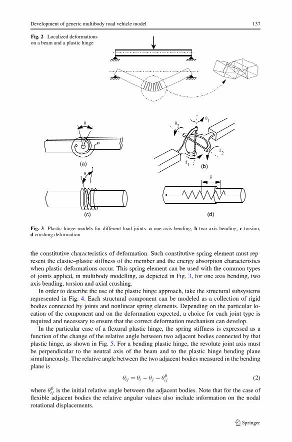
Fig. 2 Localized deformationson a beam and a plastic hinge
Fig. 3 Plastic hinge models for different load joints: a one axis bending; b two-axis bending; c torsion;d crushing deformation
the constitutive characteristics of deformation. Such constitutive spring element must rep-resent the elastic–plastic stiffness of the member and the energy absorption characteristicswhen plastic deformations occur. This spring element can be used with the common typesof joints applied, in multibody modelling, as depicted in Fig. 3, for one axis bending, twoaxis bending, torsion and axial crushing.
In order to describe the use of the plastic hinge approach, take the structural subsystemsrepresented in Fig. 4. Each structural component can be modeled as a collection of rigidbodies connected by joints and nonlinear spring elements. Depending on the particular lo-cation of the component and on the deformation expected, a choice for each joint type isrequired and necessary to ensure that the correct deformation mechanism can develop.
In the particular case of a flexural plastic hinge, the spring stiffness is expressed as afunction of the change of the relative angle between two adjacent bodies connected by thatplastic hinge, as shown in Fig. 5. For a bending plastic hinge, the revolute joint axis mustbe perpendicular to the neutral axis of the beam and to the plastic hinge bending planesimultaneously. The relative angle between the two adjacent bodies measured in the bendingplane is
θij = θi − θj − θ0ij (2)
where θ0ij is the initial relative angle between the adjacent bodies. Note that for the case of
flexible adjacent bodies the relative angular values also include information on the nodalrotational displacements.

138 L. Sousa et al.
Fig. 4 Plastic hinge models for vehicle substructures: bumper and frame
Fig. 5 Plastic hinge bendingmoment versus rotation angle
Fig. 6 Plastic hinge bendingmoment constitutive relationship
The constitutive relation of the plastic hinge is represented by a load–deformation curve,such as the one presented in Fig. 6. These constitutive relations are obtained through ana-lytical, experimental or computational results. In this work, the methodology of identifyingthe constitutive laws of the plastic hinges is based on the use of finite element models ofthe structural subsystems. A nonlinear static finite element analysis is performed for eachstructural member to identify the force–displacement curve of each plastic hinge.
The constitutive models identified by static finite element analysis do not take into ac-count some of the dynamic effects that are exhibited by structural elements when subjectedto relatively fast deformation processes. In fact, some of the materials used in vehicle struc-tures are strain rate sensitive, which requires a modification of the constitutive models iden-tified by static elastic–plastic analysis. Steels exemplify the type of materials that are strainrate sensitive while aluminums are not. A dynamic correction factor is used to account forthe strain rate sensitivity [8]
Pd/Ps = 1 + 0.07V 0.820 . (3)
Development of generic multibody road vehicle model 139
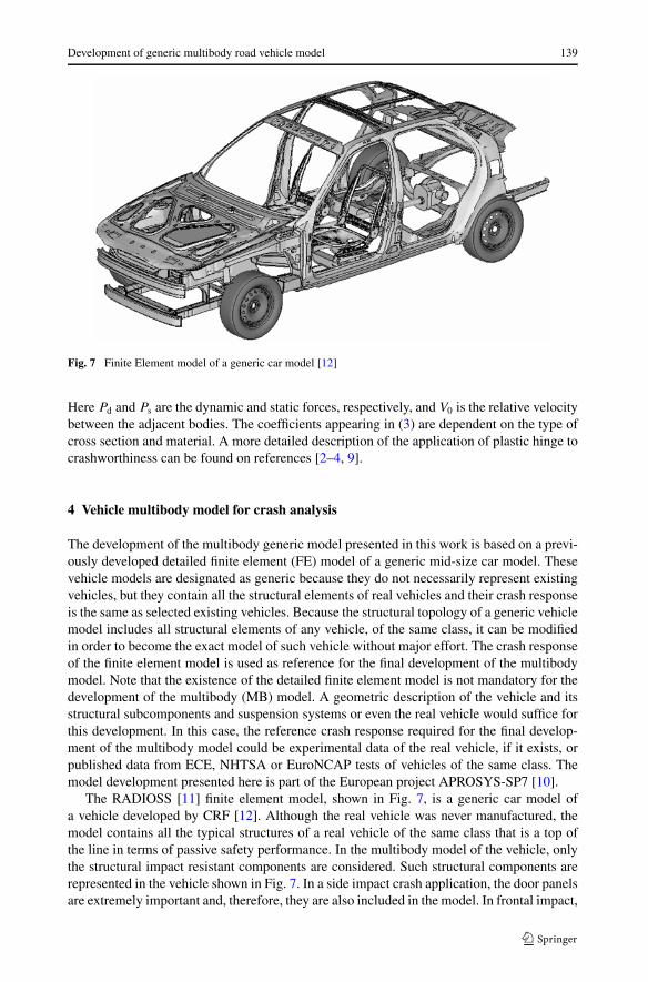
Fig. 7 Finite Element model of a generic car model [12]
Here Pd and Ps are the dynamic and static forces, respectively, and V0 is the relative velocitybetween the adjacent bodies. The coefficients appearing in (3) are dependent on the type ofcross section and material. A more detailed description of the application of plastic hinge tocrashworthiness can be found on references [2–4, 9].
4 Vehicle multibody model for crash analysis
The development of the multibody generic model presented in this work is based on a previ-ously developed detailed finite element (FE) model of a generic mid-size car model. Thesevehicle models are designated as generic because they do not necessarily represent existingvehicles, but they contain all the structural elements of real vehicles and their crash responseis the same as selected existing vehicles. Because the structural topology of a generic vehiclemodel includes all structural elements of any vehicle, of the same class, it can be modifiedin order to become the exact model of such vehicle without major effort. The crash responseof the finite element model is used as reference for the final development of the multibodymodel. Note that the existence of the detailed finite element model is not mandatory for thedevelopment of the multibody (MB) model. A geometric description of the vehicle and itsstructural subcomponents and suspension systems or even the real vehicle would suffice forthis development. In this case, the reference crash response required for the final develop-ment of the multibody model could be experimental data of the real vehicle, if it exists, orpublished data from ECE, NHTSA or EuroNCAP tests of vehicles of the same class. Themodel development presented here is part of the European project APROSYS-SP7 [10].
The RADIOSS [11] finite element model, shown in Fig. 7, is a generic car model ofa vehicle developed by CRF [12]. Although the real vehicle was never manufactured, themodel contains all the typical structures of a real vehicle of the same class that is a top ofthe line in terms of passive safety performance. In the multibody model of the vehicle, onlythe structural impact resistant components are considered. Such structural components arerepresented in the vehicle shown in Fig. 7. In a side impact crash application, the door panelsare extremely important and, therefore, they are also included in the model. In frontal impact,
140 L. Sousa et al.
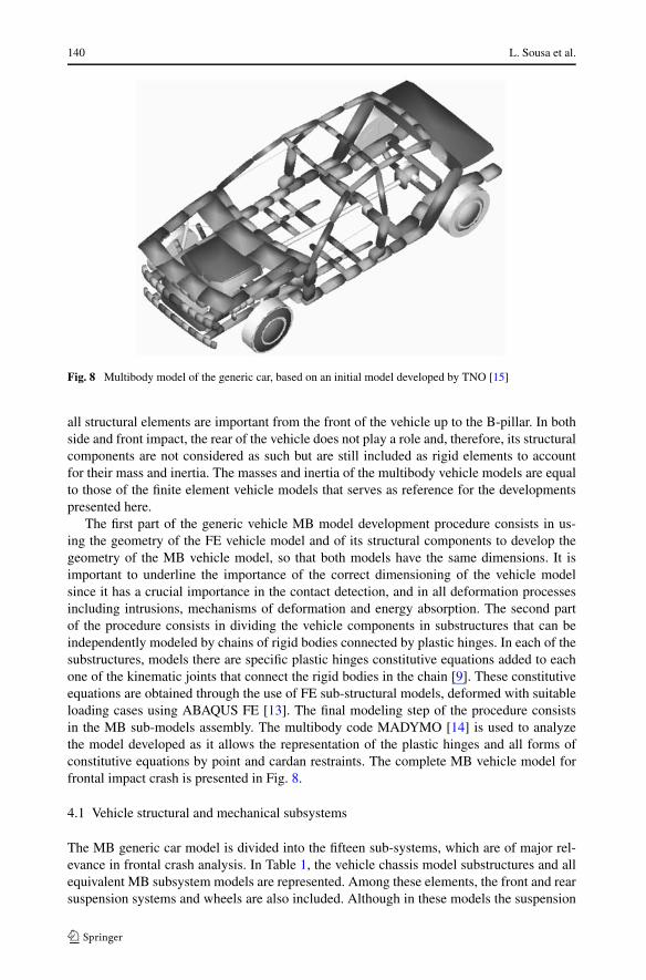
Fig. 8 Multibody model of the generic car, based on an initial model developed by TNO [15]
all structural elements are important from the front of the vehicle up to the B-pillar. In bothside and front impact, the rear of the vehicle does not play a role and, therefore, its structuralcomponents are not considered as such but are still included as rigid elements to accountfor their mass and inertia. The masses and inertia of the multibody vehicle models are equalto those of the finite element vehicle models that serves as reference for the developmentspresented here.
The first part of the generic vehicle MB model development procedure consists in us-ing the geometry of the FE vehicle model and of its structural components to develop thegeometry of the MB vehicle model, so that both models have the same dimensions. It isimportant to underline the importance of the correct dimensioning of the vehicle modelsince it has a crucial importance in the contact detection, and in all deformation processesincluding intrusions, mechanisms of deformation and energy absorption. The second partof the procedure consists in dividing the vehicle components in substructures that can beindependently modeled by chains of rigid bodies connected by plastic hinges. In each of thesubstructures, models there are specific plastic hinges constitutive equations added to eachone of the kinematic joints that connect the rigid bodies in the chain [9]. These constitutiveequations are obtained through the use of FE sub-structural models, deformed with suitableloading cases using ABAQUS FE [13]. The final modeling step of the procedure consistsin the MB sub-models assembly. The multibody code MADYMO [14] is used to analyzethe model developed as it allows the representation of the plastic hinges and all forms ofconstitutive equations by point and cardan restraints. The complete MB vehicle model forfrontal impact crash is presented in Fig. 8.
4.1 Vehicle structural and mechanical subsystems
The MB generic car model is divided into the fifteen sub-systems, which are of major rel-evance in frontal crash analysis. In Table 1, the vehicle chassis model substructures and allequivalent MB subsystem models are represented. Among these elements, the front and rearsuspension systems and wheels are also included. Although in these models the suspension

Development of generic multibody road vehicle model 141
Table 1 FE and MB subsystems for vehicle structural and mechanical components

142 L. Sousa et al.
elements are considered mechanisms made of rigid bodies, connected by kinematic jointsand by spring and damper elements, their behavior greatly influences the crash outcome,especially for lower speeds of impact. Also, the interaction between the road surface and thetire is included in the models. Because the emphasis of the development of the MB vehiclemodel is on the structural components and not on other mechanical parts, no more detailson the suspension systems are presented here.
4.2 Topology of a sub-structure MB model
Take the right hand-side of the chassis as a representative substructure of the MB vehiclemodel. The multibody description of the subsystem corresponding to the substructure re-quires the identification of the mass, moments of inertia and center of mass of all bodiesincluded in the MB sub-system model. Moreover, the attachment points of all kinematicjoints used in the plastic hinges must also be identified [10]. Figure 9 shows the right-handside MB model of the subsystem of the car, including references for the bodies and jointsnames.
If the vehicle model is to be used for side impact only, it is not necessary to have a modelfor the left-hand side of the chassis. However, if the application of the model is to be donein the framework of front impact or of any other particular case of side impact, then the MBmodel must contain both sides of the vehicle modeled. The left body side data is simplysymmetric of the right body side data described here and, therefore, its generation simplyuses its mirror description.
The rear of the vehicle does not play a role in any of the crash cases for which the MBmodel is developed. Figure 10 represents the rear of the vehicle as a collection of rigid bodiesconnected by bracket joints, i.e., kinematic joints that restrain any relative degree of freedombetween the bodies they connect. Thus, for computational purposes, the whole rear vehiclesubsystem is considered as a single rigid body that has the mass and inertia properties of thesame substructure of the reference vehicle.
At this point, it should be noted that the model of the rear of the vehicle as a collectionof rigid bodies connected by bracket joints is not strictly necessary as a single rigid bodywould suffice. However, if it is necessary to apply the MB vehicle model for cases in whichrear crashes are observed, the bracket joints can be substituted by other kinematic joints andconstitutive equations can be associated to them completing in this form the plastic hingemodeling that enables the subsystem MB model to be used for rear crash analysis. Note thatsome of the rigid bodies may have to be split into several more bodies connected by plastichinges if the crash is directly in the rear of the vehicle.
4.3 Plastic hinges constitutive equations
The constitutive equations for the plastic hinges used to represent the deformation of thevehicle structures are identified through nonlinear FE static analysis of each of the struc-tural components for different loading cases. Although any suitable nonlinear finite elementcode can be used for this purpose, the finite elements code ABAQUS is used here for thenonlinear static analysis. The ABAQUS FE model of each component is obtained from theFE vehicle model developed in the RADIOSS format. The structural characteristics of theplastic hinges are identified using the explicit method in ABAQUS. The methodology usedto get the plastic hinges constitutive equations of a simple joint is described here as a meanto exemplify the procedure. The remaining constitutive equations for all other plastic hingesused in the model are obtained in the same manner and presented in reference [10].

Development of generic multibody road vehicle model 143
Fig
.9R
ight
-han
dsi
deof
the
MB
chas
sis
mod
el:a
body
nam
es;b
join
tref
eren
ces
144 L. Sousa et al.
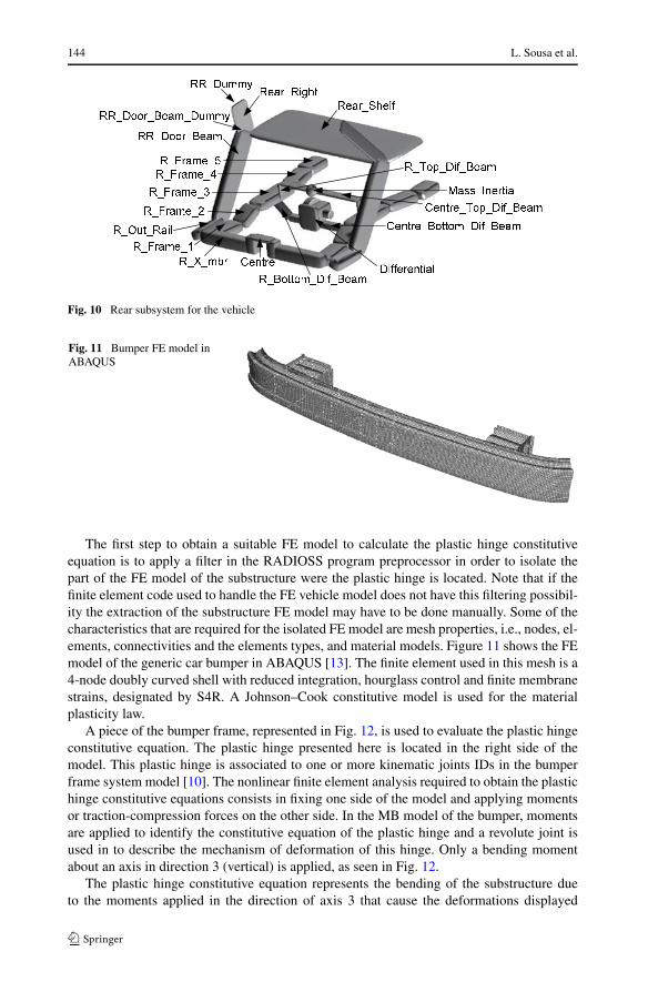
Fig. 10 Rear subsystem for the vehicle
Fig. 11 Bumper FE model inABAQUS
The first step to obtain a suitable FE model to calculate the plastic hinge constitutiveequation is to apply a filter in the RADIOSS program preprocessor in order to isolate thepart of the FE model of the substructure were the plastic hinge is located. Note that if thefinite element code used to handle the FE vehicle model does not have this filtering possibil-ity the extraction of the substructure FE model may have to be done manually. Some of thecharacteristics that are required for the isolated FE model are mesh properties, i.e., nodes, el-ements, connectivities and the elements types, and material models. Figure 11 shows the FEmodel of the generic car bumper in ABAQUS [13]. The finite element used in this mesh is a4-node doubly curved shell with reduced integration, hourglass control and finite membranestrains, designated by S4R. A Johnson–Cook constitutive model is used for the materialplasticity law.
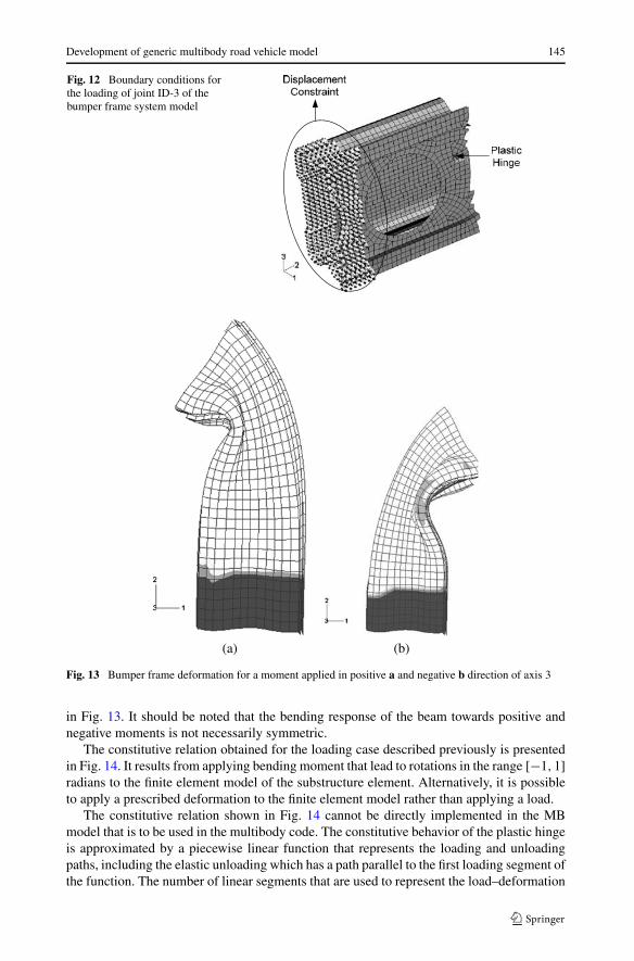
A piece of the bumper frame, represented in Fig. 12, is used to evaluate the plastic hingeconstitutive equation. The plastic hinge presented here is located in the right side of themodel. This plastic hinge is associated to one or more kinematic joints IDs in the bumperframe system model [10]. The nonlinear finite element analysis required to obtain the plastichinge constitutive equations consists in fixing one side of the model and applying momentsor traction-compression forces on the other side. In the MB model of the bumper, momentsare applied to identify the constitutive equation of the plastic hinge and a revolute joint isused in to describe the mechanism of deformation of this hinge. Only a bending momentabout an axis in direction 3 (vertical) is applied, as seen in Fig. 12.
The plastic hinge constitutive equation represents the bending of the substructure dueto the moments applied in the direction of axis 3 that cause the deformations displayed
Development of generic multibody road vehicle model 145
Fig. 12 Boundary conditions forthe loading of joint ID-3 of thebumper frame system model
(a) (b)
Fig. 13 Bumper frame deformation for a moment applied in positive a and negative b direction of axis 3
in Fig. 13. It should be noted that the bending response of the beam towards positive andnegative moments is not necessarily symmetric.
The constitutive relation obtained for the loading case described previously is presentedin Fig. 14. It results from applying bending moment that lead to rotations in the range [−1,1]radians to the finite element model of the substructure element. Alternatively, it is possibleto apply a prescribed deformation to the finite element model rather than applying a load.
The constitutive relation shown in Fig. 14 cannot be directly implemented in the MBmodel that is to be used in the multibody code. The constitutive behavior of the plastic hingeis approximated by a piecewise linear function that represents the loading and unloadingpaths, including the elastic unloading which has a path parallel to the first loading segment ofthe function. The number of linear segments that are used to represent the load–deformation

146 L. Sousa et al.
Fig. 14 Constitutive function for the plastic hinge associated to joint ID-3 in the bumper frame MB model
Fig. 15 Constitutive relation for the revolute plastic hinge about joint Z axis
curve should be as small as possible, and, if possible, without large oscillations in the loadingpath to avoid numeric problems. Consequently, each curve obtained from the finite elementscode must be represented by a piecewise linear function as that exemplified in Fig. 15.
The elastic deformations that are observed in the FE model in the structural componentsbetween the plastic hinges are not represented in the MB model. Instead, rigid bodies areused to represent such components. This leads to an increased stiffness of the MB structuralmodels that can be compensated by artificially decreasing the stiffness of the plastic hinges.Such corrective measures are applied during the correlation of the MB model crash responsewith the reference crash behavior.
5 Crash tests simulations
The generic car models developed are to be used in crash test scenarios described by theregulations approved in Europe and, if possible, in the US. Of particular relevance are theECE regulations for frontal and side impact that must be fulfilled by any new vehicle thatseeks approval for release in the EU countries.

Development of generic multibody road vehicle model 147
Table 2 ECE Norms used for crash tests scenarios [16]
Collision type ECENorm
Impact speed[km/h]
Test conditions Comments
Frontal impactR33 48.53 Rigid wall Stability of passenger compartment
Frontal impactR94 56 40% overlap deformable barrier 2 Hybrid III dummies
Side impact R95 50 Moveable; deformable 1 EuroSID at driver position
barrier at 90° angle
Table 3 Frontal impactthreshold values [16] Body area ECE 94
Dummies 2 Hybrid III
Head HPC < 1000
a3ms < 80 g
Neck M < 57 Mm
Thorax Deflection < 50 mm
Femur Not exceeding defined force corridor
Knee Deflection < 15 mm
Tibia Axial force < 8 kN; TI < 1.3
Table 4 Side impact thresholdvalues [16] Body area ECE 95
dummies 1 EuroSID
Head HPC < 1000
Thorax VC < 1.0
Abdomen Internal force < 2.5 kN
Pelvis Pubic force < 6 kN
5.1 Crash tests scenarios
The norms that are applicable to the description of the crash scenarios in which the MBmodel has to be tested are referred in Table 2 [16].
The thresholds that the different dynamic responses of the vehicle subcomponents haveto meet, according to the European regulations, are summarized in Tables 3 and 4.
It should be noted at this time that the threshold values listed are minimums requiredfor approval of the vehicle. In each car class the top vehicles may have thresholds valuesfor the different ECE norm that are far better than the ones listed. In order for the genericcar model to be of any practical use, its different responses must approach those of the topmodel selected and not simply the values of some generic limits.
5.2 Crash tests simulation for a frontal impact
The MB model of the vehicle is simulated in a crash test that corresponds to the ECE R33front crash with a rigid barrier. The vehicle model is used as developed with the procedureoutlined, and therefore, it is not yet validated. The crash response of the vehicle can be
148 L. Sousa et al.
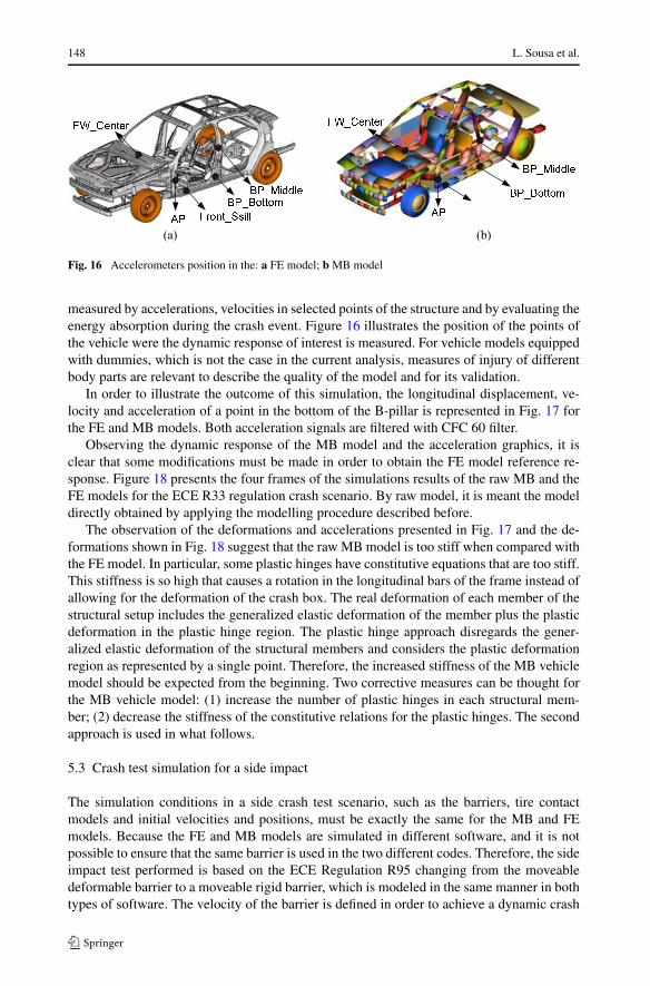
Fig. 16 Accelerometers position in the: a FE model; b MB model
measured by accelerations, velocities in selected points of the structure and by evaluating theenergy absorption during the crash event. Figure 16 illustrates the position of the points ofthe vehicle were the dynamic response of interest is measured. For vehicle models equippedwith dummies, which is not the case in the current analysis, measures of injury of differentbody parts are relevant to describe the quality of the model and for its validation.
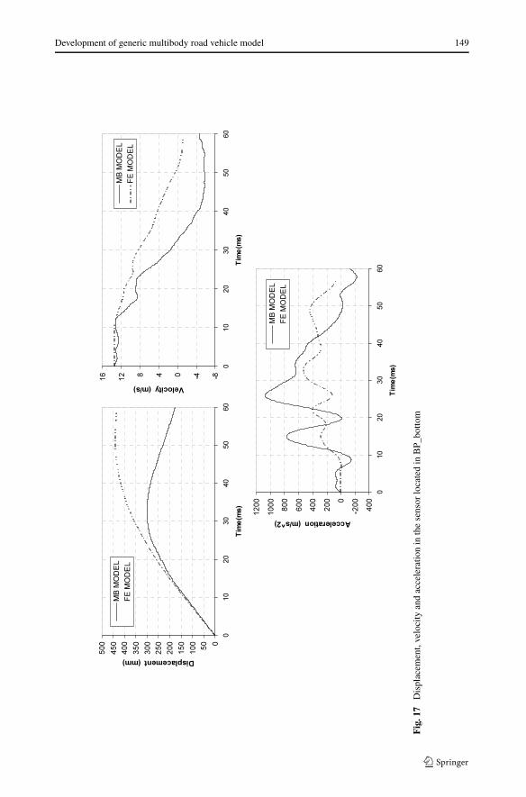
In order to illustrate the outcome of this simulation, the longitudinal displacement, ve-locity and acceleration of a point in the bottom of the B-pillar is represented in Fig. 17 forthe FE and MB models. Both acceleration signals are filtered with CFC 60 filter.
Observing the dynamic response of the MB model and the acceleration graphics, it isclear that some modifications must be made in order to obtain the FE model reference re-sponse. Figure 18 presents the four frames of the simulations results of the raw MB and theFE models for the ECE R33 regulation crash scenario. By raw model, it is meant the modeldirectly obtained by applying the modelling procedure described before.
The observation of the deformations and accelerations presented in Fig. 17 and the de-formations shown in Fig. 18 suggest that the raw MB model is too stiff when compared withthe FE model. In particular, some plastic hinges have constitutive equations that are too stiff.This stiffness is so high that causes a rotation in the longitudinal bars of the frame instead ofallowing for the deformation of the crash box. The real deformation of each member of thestructural setup includes the generalized elastic deformation of the member plus the plasticdeformation in the plastic hinge region. The plastic hinge approach disregards the gener-alized elastic deformation of the structural members and considers the plastic deformationregion as represented by a single point. Therefore, the increased stiffness of the MB vehiclemodel should be expected from the beginning. Two corrective measures can be thought forthe MB vehicle model: (1) increase the number of plastic hinges in each structural mem-ber; (2) decrease the stiffness of the constitutive relations for the plastic hinges. The secondapproach is used in what follows.
5.3 Crash test simulation for a side impact
The simulation conditions in a side crash test scenario, such as the barriers, tire contactmodels and initial velocities and positions, must be exactly the same for the MB and FEmodels. Because the FE and MB models are simulated in different software, and it is notpossible to ensure that the same barrier is used in the two different codes. Therefore, the sideimpact test performed is based on the ECE Regulation R95 changing from the moveabledeformable barrier to a moveable rigid barrier, which is modeled in the same manner in bothtypes of software. The velocity of the barrier is defined in order to achieve a dynamic crash
Development of generic multibody road vehicle model 149
Fig
.17
Dis
plac
emen
t,ve
loci
tyan
dac
cele
ratio
nin
the
sens
orlo
cate
din
BP_
botto
m

150 L. Sousa et al.
Fig. 18 Initial and final configuration of the vehicle in the frontal crash test for the raw MB model and thereference FE model
response of the FE model similar to that obtained with a deformable barrier animated withthe speed prescribed in the regulation. It is established that a rigid barrier with a mass of951 Kg must have a velocity of 30 km/h, or 8.33 m/s, to lead to a deformation equivalent tothat of the deformable barrier. The barrier hits the left side of the vehicle, which is initiallystopped, according to the configuration defined in regulation ECE R95.
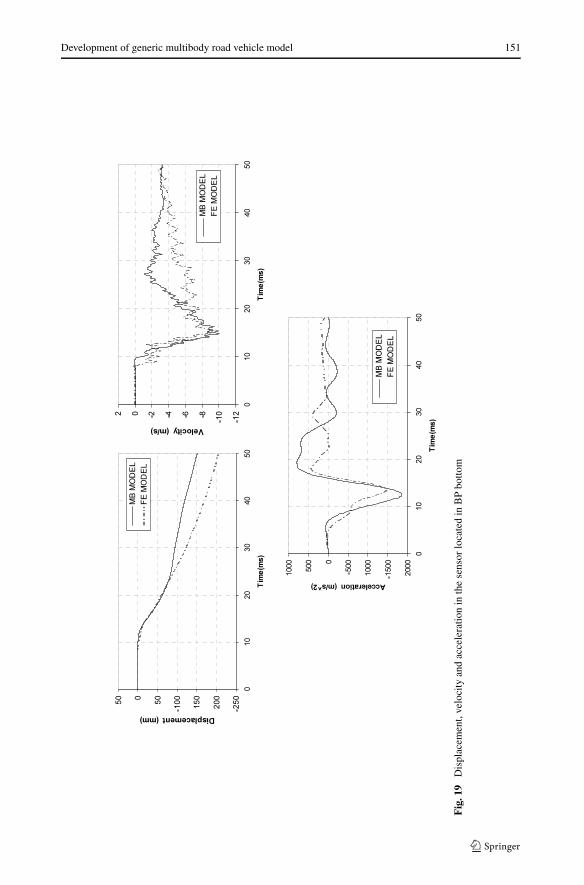
In Fig. 19, the acceleration, velocity and displacements measured in the bottom of theB-pillar for both FE and MB vehicle models are presented. It is noticeable that the dynamicresponse of the raw MB model is much stiffer than the FE reference model. The accelera-tions are much higher, the velocities decrease faster and the displacement measured in thebottom of the B pillar, in the multibody model, is smaller than the equivalent values forthe reference FE model. This dynamic response is characteristic of models that have lesspotential for energy absorbing.
The initial and final vehicle configurations for the side crash are displayed in Fig. 20. It isnoticeable that the raw MB model has a lower ability to deform due to its higher stiffness. Infact, the MB model exhibits higher rotation, as a rigid body, while the FE model presents anoticeable intrusion on the side due to the impact, as expected. From these results,it is clearthat a correction of the initial MB model is required before it can be used. The procedureof reducing the stiffness of the plastic hinges functions in the multibody model so that theresponses are better correlated with the reference ones is designated as fine tuning or modelvalidation.
5.4 Validation of the MB vehicle model
The vehicle model used in the tests described here is not validated, i.e., its dynamic behav-iour does not match any reference behavior obtained experimentally, through finite elementanalysis or otherwise. However, the original model, in which the current model is based, hasbeen validated for frontal impact as reported by Zweep [15]. The model validation is thelast step in the model development where the constitutive equations of the plastic hinges,the location of the plastic hinges and the potential mechanisms of deformation are adjusted,within a given range of variation, to increase the correlation between the observed behaviorof the reference vehicle and the actual behaviour of the vehicle multibody model. This hasbeen the procedure used by other researchers, one way or another [17, 18]. The acceptablerange of variation of the model data in the validation step is related to the approximationsmade when defining the discretization of the model and the constitutive equations of theplastic hinges. In this work, the variations of the constitutive behavior of the plastic hingesare represented as corridors inside which different force–displacement behaviours are ac-cepted. The validation process involves the following steps:
Development of generic multibody road vehicle model 151
Fig
.19
Dis
plac
emen
t,ve
loci
tyan
dac
cele
ratio
nin
the
sens
orlo
cate
din
BP
botto
m

152 L. Sousa et al.
Fig. 20 Initial and final configuration of the vehicle in the side crash test for the raw MB model and thereference FE model
Fig. 21 Constitutive relation fora generic plastic hinge andaccepted corridor for its variation
(1) Collect the dynamic responses of the reference vehicle in terms of velocity and acceler-ation of selected points of the body structure or occupant models. This data is obtainedsimulating crash tests of a validated FE model of the vehicle or using the data directlymeasured in a EuroNCAP test of a top performing vehicle of the generic model class.
(2) Define for the MB model which are the parameters that are allowed to vary and whatthe variation range is accepted for each of such parameters, as defined in Fig. 21.
The procedure outlined for the variation constitutes in fact an optimization processto identify the MB model that best represents the reference vehicle. Other optimizationbased procedures have been reported in the literature and are also candidates to applica-tion [19, 20]. Although the use of optimization procedures is very promising in this work, atrial and error strategy is used to obtain the correlated vehicle MB model from the raw MBmodel.
The strategy pursued here consists in reducing by a common factor the stiffness of theconstitutive functions of all plastic hinges in each subcomponent. Several frontal crash simu-lations are performed attempting different multiplying factors for the constitutive functions.As an example of the procedure, in Fig. 22, the original and modified functions for a se-lected plastic hinge of the subframe are presented. The results that lead to the best correla-

Development of generic multibody road vehicle model 153
Fig. 22 Plastic hingeconstitutive laws for joint ID 9, inthe Y direction, for the sub-framestructure
tion between the MB and FE models responses in the ECE R33 crash test are achieved bymultiplying all the constitutive functions of the plastic hinges of the different subsystems
(1) Body structure forces of the plastic hinges are multiplied by 0.1.(2) Forces on the plastic hinges of the frame are multiplied by 0.2.(3) Forces on the plastic hinges of the bumper frame are multiplied by 0.35.(4) Forces on the plastic hinges of the subframe are multiplied by 0.6.(5) Forces in the plastic hinges of the bumper subframe are multiplied by 0.65.
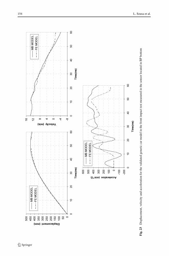
The response of the validated multibody model and of the reference finite element modelsare presented in Fig. 23 for the displacement, velocity and acceleration of the bottom ofthe B-pillar, measured in the locations depicted in Fig. 16, for the frontal crash scenariodescribed by the ECE R33 regulation. Figure 24 presents the deformation of the MB andFE models in selected time steps, for the frontal crash test. The results presented in Figs. 23and 24, and in all other measures taken in other sensors, but not reported here for the sakeof conciseness, show a good correlation between the MB and the FE model, in what theimportant crash resulting quantities are concerned. The generic vehicle multibody model forfrontal impact tests is therefore validated when compared with the reference finite elementmodel.
The strategy pursued for obtaining the validated MB model for the side impact test is sim-ilar to that used for the frontal impact test. Again, several simulations of the side impact testhave been performed attempting different multiplying factors for the constitutive functionsof the plastic hinges relevant to the side impact response. The results that lead to the bestcorrelation between the MB and FE models are achieved by multiplying all the constitutivefunctions of the plastic hinges of the different subsystems by the following factors:
(1) Moments in the sills are multiplied by 0.1.(2) Moments in the B-pillar plastic hinges are multiplied by 0.03.(3) Moments in the front and rear doors are multiplied by 0.2.(4) Forces on the plastic hinges of the front and rear doors are multiplied by 0.1.
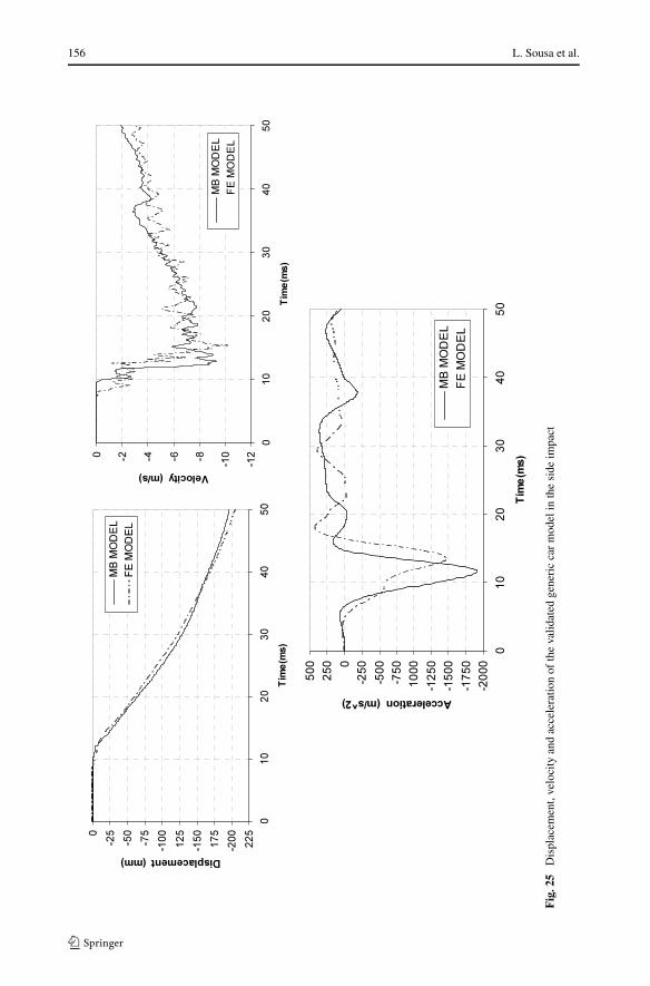
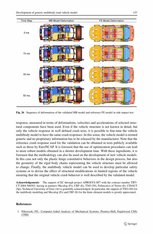
The response of the validated multibody and the reference finite element model are pre-sented in Fig. 25 for selected displacement, velocity and acceleration measured in the bottomof the B-pillar, for the side impact crash scenario. The deformation of the MB and FE modelsare depicted in Fig. 26. Not only both Figs. 25 and 26, but also a large number of other crashresponses, not reported here, show a good correlation between the MB and FE models, inwhat the important crash resulting quantities are concerned. The generic vehicle multibody
154 L. Sousa et al.
Fig
.23
Dis
plac
emen
t,ve
loci
tyan
dac
cele
ratio
nfo
rth
eva
lidat
edge
neri
cca
rm
odel
inth
efr
onti
mpa
ctte
stm
easu
red
inth
ese
nsor
loca
ted
inB
Pbo
ttom

Development of generic multibody road vehicle model 155
Fig. 24 Sequence of deformation of the validated MB model and reference FE model in ECE R33 test
model for side impact tests is, therefore, validated when compared with the reference finiteelement model.
One of the advantages of using MB vehicle models during different phases of the vehicledesign, instead of FE models concerns the computational efficiency of the multibody analy-sis. In the different simulations performed in this work, the computational time required forthe finite element analysis of the models considered has been measured in days while forthe multibody models it is measured in terms of minutes. Each of the side crash simulationstakes about 3 minutes in a single processor computer for the MB simulation, while the FEsimulation, in the same computer, takes about 3 days.
6 Conclusions
A systematic procedure for the development of multibody road vehicle models for crashapplications in analysis and design was presented in this work. The first step of the method-ology consists in defining a discretization for the vehicle structural components that is ableto lead to the relevant mechanisms of deformation that are expected to appear in the crashscenarios foreseen. The second step consists in obtaining the plastic hinge constitutive rela-tions by using nonlinear finite element static analysis of parts of the structural components.It was shown that the vehicle multibody models obtained, using the theoretical approachwithout any modification, are unrealistically stiff with decreased capabilities to absorb en-ergy during crash. Therefore, a third step consisting in a modification of the constitutiverelations of the plastic hinges, in order for the crash response of the model to match a refer-ence crash response, is deemed fundamental for the final model to be of any use. Althoughthe methodology of building validated vehicle models for crashworthiness has been demon-strated using as reference a completely known finite element vehicle model, only the crash
156 L. Sousa et al.
Fig
.25
Dis
plac
emen
t,ve
loci
tyan
dac
cele
ratio
nof
the
valid
ated
gene
ric
car
mod
elin
the
side
impa
ct
Development of generic multibody road vehicle model 157
Fig. 26 Sequence of deformation of the validated MB model and reference FE model in side impact test
response, measured in terms of deformations, velocities and accelerations of selected struc-tural components have been used. Even if the vehicle structure is not known in detail, butonly the vehicle response in well defined crash tests, it is possible to fine-tune the vehiclemultibody model to have the same crash responses. In this sense, the vehicle model is termedgeneric and no proprietary information has to be released by the manufacturer. Note that thereference crash response used for the validation can be obtained in tests publicly availablesuch as those by EuroNCAP. It is foreseen that the use of optimization procedures can leadto more robust models obtained in a shorter development time. With these ingredients, it isforeseen that the methodology can also be used on the development of new vehicle models.In this case not only the plastic hinge constitutive behaviors in the design process, but alsothe geometry of the rigid body chains representing the vehicle structure must be allowedto change. Finally, the multibody vehicle model can be used to develop particular safetysystems or to devise the effect of structural modifications in limited regions of the vehicleensuring that the original vehicle crash behavior is well described by the validated model.
Acknowledgements The support of EC through project APROSYS-SP7 with the contract number TIP3-CT-2004-506503, having as partners Mecalog (Fr), CRF (It), TNO (Nl), Politecnico of Turim (It), CIDAUT(Sp), Technical University of Graz (At) is gratefully acknowledged. In particular, the support of TNO (Nl) forthe multibody modeling and Mecalog (Fr) and CRF (It) for the finite element models is greatly appreciated.
References
1. Nikravesh, P.E.: Computer-Aided Analysis of Mechanical Systems. Prentice-Hall, Englewood Cliffs(1988)

158 L. Sousa et al.
2. Ambrósio, J.: Crashworthiness: Energy Management and Occupant Protection. Springer, Wien (2001)3. Ambrósio, J.: Crash analysis and dynamical behavior of light road and rail vehicles. Veh. Syst. Dyn.
43(6–7), 385–411 (2005)4. Pereira, M., Ambrósio, J.: Crashworthiness analysis and design using rigid-flexible multibody dynamics
with application to train vehicles. Int. J. Num. Method. Eng. 40, 655–687 (1997)5. Petzold, L.: Computational challenges in mechanical systems simulation, in computer-aided analysis of
rigid and flexible mechanical systems. In: Pereira, M., Ambrósio, J. (eds.) Computer Aided Analysis ofRigid and Flexible Mechanical Systems, pp. 483–499. Kluwer Academic, Dordrecht (1994)
6. Augusta Neto, M., Ambrósio, J.: Stabilization methods for the integration of differential–algebraic equa-tions in the presence of redundant constraints. Multibody Syst. Dyn. 10(1), 81–105 (2003)
7. Lankarani, H.M., Nikravesh, P.E.: A contact force model with hysteresis damping for impact analysis ofmultibody systems. J. Mech. Des. 112, 369–376 (1990)
8. Winmer, A.: Einfluss der Lelastungsgeschwindigkeit auf das Festigkeits und Verformungsverhalten amBeispiel von Kraftfarhzeugen. Automob. Z. 77(10), 281–286 (1977)
9. Nikravesh, P.E., Chung, I.S., Benedict, R.L.: Plastic hinge approach to vehicle crash simulation. Comput.Struct. 16(1–4), 395–400 (1983)
10. Sousa, L., Veríssimo, P., Ambrósio, J.: Generic multi-body car models. Technical Report IST—APROSYS-SP7, Instituto Superior Técnico, Technical University of Lisbon, Lisbon, Portugal (2006)
11. MECALOG: RADIOSS Theory Manual version 4.4. Paris, France (2005)12. Puppini, R., Diez, M., Avalle, M., Ciglaric, I., Feist, F.: Generic car (FE) models for categories su-
per minis, small family cars, large family executive cars, MPV and heavy vehicle. Technical ReportAPROSYS AP-SP7-0029-A (2005)
13. ABAQUS: ABAQUS Analysis User’s Manual. ABAQUS Inc. (2004)14. MADYMO: Madymo Manuals, version 6.2. TNO MADYMO BV., Delft, The Netherlands (2004)15. van der Zweep, C.D., Kellendonk, G.: Evaluation of accident parameters in a numerical fleet for assessing
compatibility. Paper No. 2005-01-0707. SAE 2005 Trans. J. Passeng. Cars—Mech. Syst. (2005)16. Schmitt, K.-U., Niederer, P.F., Walz, F.: Trauma, Biomechanics Introduction to Accidental Injury.
Springer, Berlin (2004)17. Mooi, H.G., Huibers, J.H.A.M.: Simple and effective lumped mass model for determining kinetics and
dynamics of car-to-car crashes. In: Proceedings of the International Crashworthiness Conference, De-troit, Michigan, 9–11 September 1998
18. van der Zweep, C.D., Kellendonk, G., Lemmen, P.: Evaluation of fleet systems model for vehicle com-patibility. Int. J. Crashworth. 10(5), 483–494 (2005)
19. Mooi, H.G., Nastic, T., Huibers, J.H.A.M.: Modelling and optimization of car-to-car compatibility. In:VDI berichte Nr 1471, Delft, The Netherlands, pp. 239–255 (1999)
20. Gielen, A.W.J., Mooi, H.G., Huibers, J.H.A.M.: An optimization methodology for improving car-to-carcompatibility. ImechE Trans. C567/047/2000 (2000)