Development of etch hillocks on different Si( h k l) planes in silicon anisotropic etching
10
Development of etch hillocks on different Si(hkl) planes in silicon anisotropic etching I. Zubel * , M. Kramkowska Wrocław University of Technology, Faculty of Microsystem Electronics and Photonics, Janiszewskiego 11/17, 50-372 Wrocław, Poland article info Article history: Received 12 December 2007 Accepted for publication 6 March 2008 Available online 15 March 2008 Keywords: Silicon Anisotropic etching Etch hillocks (hkl) Substrates abstract The connection between the way of development and appearance of mesa structures and typical hillocks developing during anisotropic etching of monocrystalline silicon in 5 M KOH saturated with isopropanol has been studied both theoretically and experimentally. A simple geometrical model of mesa formation was presented. Then, the process of hillock growth in result of mesa transformation caused by etch mask underetching was analyzed. At the second part of the paper, the model of hillocks formation was verified experimentally. For this purpose, a series of experiments with etching of mini-mesas through the masks with various patterns in the conditions favoring hillock formation was carried out. It was shown that at the final stage of the etching process the mesas transform into hillocks, bounded by the planes close to {1 1 1}. Probably at the first stage of hillocks formation, mini-mesas develop. Such stable mini-mesas, pro- duced in the presence of random micro-masks, may transform into typical hillocks in effect of successive releasing of {1 1 1} mini-faces. It seems that the process of hillock formation is similar to mesa etching. The shapes of hillocks produced on the substrates with different from (0 0 1) crystallographic orientations have been also analyzed. The similarities of the hillocks and intentionally prepared mesas were under- lined. It was stated that the morphologies of hillocks are strictly connected with crystallographic orien- tation of etched substrate. Different shapes of hillocks developing on the substrates with different crystallographic orientations, reflect the arrangement and inclination of {1 1 1} planes on considered substrate. Ó 2008 Elsevier B.V. All rights reserved. 1. Introduction Silicon anisotropic etching in alkaline solutions is commonly used in MEMS and MOEMS fabrication. In more and more sophis- ticated designs, the requirements concerning the shapes and sur- face morphology of etched structures are growing all the time. The issues of roughness of (0 0 1) surfaces, which are commonly used in majority of produced structures, as well as of the roughness of other high-index (hkl) planes, which either evolve spontane- ously during the etching process or are imposed by complex mask patterns, are still drawing a lot of attention. The factor deteriorating the quality of etched surfaces is hillocks formation. The hillocks are small pyramidal structures restricted by the planes close to {1 1 1}. The problem of hillocks formation has been widely discussed in the literature concerning silicon etch- ing in KOH and TMAH, especially in KOH solution saturated with isopropanol or other additives [1–5]. Among the reasons of hillocks formation, the following are most often mentioned in the litera- ture: incomplete dissolution of reaction products remaining on the etched surface [1,3,6–8], hydrogen bubbles created in the dis- solution process [2,8–10], oxygen precipitates in bulk crystal and stress following the thermal treatment of the substrates [2,4,11,12], metal impurities [7,13–15]. It is evident that all heter- ogeneities coming from the bulk of crystal or encountered on its surface can disturb the homogeneity of etching process and cause its temporary stopping. Such stopping of etching can act as a tem- porary micromask that initializes formation of the pyramidal structure. Many works in the literature discuss the problem how to avoid the hillocks formation. Eliminating of all heterogeneities, which are the source of this occurrence, could be very beneficial. To reduce the number of developing hillocks, the measures which ensure removing of reaction products sufficiently fast, like addition of oxidizing agent [8,9,16,17], saturation of etching solution with O 2 [8] , stirring by ultrasounds [9,17], can be undertaken. Similar ef- fects can be achieved by adding of surfactants, which reduce the surface tension and facilitate removal of gaseous hydrogen, gather- ing on the etched surface [3,5,8,17,18]. Suppression of micromasks can be also achieved by taking out the substrate from the etchant, washing it up and re-etching [1,2,4,6]. In the literature there are many descriptions of hillocks mor- phologies and evolution during the etching process [1–7,19–21]. The appearance of the hillock resembling a pyramid composed of stepped {1 1 1} faces is not simple to explain. The steps and their 0039-6028/$ - see front matter Ó 2008 Elsevier B.V. All rights reserved. doi:10.1016/j.susc.2008.03.010 * Corresponding author. Tel.: +48 71 355 97 95; fax: +48 71 328 35 04. E-mail address: [email protected] (I. Zubel). Surface Science 602 (2008) 1712–1721 Contents lists available at ScienceDirect Surface Science journal homepage: www.elsevier.com/locate/susc
-
Upload
independent -
Category
Documents
-
view
0 -
download
0
Transcript of Development of etch hillocks on different Si( h k l) planes in silicon anisotropic etching

Surface Science 602 (2008) 1712–1721
Contents lists available at ScienceDirect
Surface Science
journal homepage: www.elsevier .com/locate /susc
Development of etch hillocks on different Si(hkl) planes in siliconanisotropic etching
I. Zubel *, M. KramkowskaWrocław University of Technology, Faculty of Microsystem Electronics and Photonics, Janiszewskiego 11/17, 50-372 Wrocław, Poland
a r t i c l e i n f o a b s t r a c t
Article history:Received 12 December 2007Accepted for publication 6 March 2008Available online 15 March 2008
Keywords:SiliconAnisotropic etchingEtch hillocks(hkl) Substrates
0039-6028/$ - see front matter � 2008 Elsevier B.V. Adoi:10.1016/j.susc.2008.03.010
* Corresponding author. Tel.: +48 71 355 97 95; faxE-mail address: [email protected] (I. Zubel)
The connection between the way of development and appearance of mesa structures and typical hillocksdeveloping during anisotropic etching of monocrystalline silicon in 5 M KOH saturated with isopropanolhas been studied both theoretically and experimentally. A simple geometrical model of mesa formationwas presented. Then, the process of hillock growth in result of mesa transformation caused by etch maskunderetching was analyzed. At the second part of the paper, the model of hillocks formation was verifiedexperimentally. For this purpose, a series of experiments with etching of mini-mesas through the maskswith various patterns in the conditions favoring hillock formation was carried out. It was shown that atthe final stage of the etching process the mesas transform into hillocks, bounded by the planes close to{111}. Probably at the first stage of hillocks formation, mini-mesas develop. Such stable mini-mesas, pro-duced in the presence of random micro-masks, may transform into typical hillocks in effect of successivereleasing of {111} mini-faces. It seems that the process of hillock formation is similar to mesa etching.The shapes of hillocks produced on the substrates with different from (001) crystallographic orientationshave been also analyzed. The similarities of the hillocks and intentionally prepared mesas were under-lined. It was stated that the morphologies of hillocks are strictly connected with crystallographic orien-tation of etched substrate. Different shapes of hillocks developing on the substrates with differentcrystallographic orientations, reflect the arrangement and inclination of {111} planes on consideredsubstrate.
� 2008 Elsevier B.V. All rights reserved.
1. Introduction
Silicon anisotropic etching in alkaline solutions is commonlyused in MEMS and MOEMS fabrication. In more and more sophis-ticated designs, the requirements concerning the shapes and sur-face morphology of etched structures are growing all the time.The issues of roughness of (001) surfaces, which are commonlyused in majority of produced structures, as well as of the roughnessof other high-index (hkl) planes, which either evolve spontane-ously during the etching process or are imposed by complex maskpatterns, are still drawing a lot of attention.
The factor deteriorating the quality of etched surfaces is hillocksformation. The hillocks are small pyramidal structures restrictedby the planes close to {111}. The problem of hillocks formationhas been widely discussed in the literature concerning silicon etch-ing in KOH and TMAH, especially in KOH solution saturated withisopropanol or other additives [1–5]. Among the reasons of hillocksformation, the following are most often mentioned in the litera-ture: incomplete dissolution of reaction products remaining onthe etched surface [1,3,6–8], hydrogen bubbles created in the dis-
ll rights reserved.
: +48 71 328 35 04..
solution process [2,8–10], oxygen precipitates in bulk crystal andstress following the thermal treatment of the substrates[2,4,11,12], metal impurities [7,13–15]. It is evident that all heter-ogeneities coming from the bulk of crystal or encountered on itssurface can disturb the homogeneity of etching process and causeits temporary stopping. Such stopping of etching can act as a tem-porary micromask that initializes formation of the pyramidalstructure. Many works in the literature discuss the problem howto avoid the hillocks formation. Eliminating of all heterogeneities,which are the source of this occurrence, could be very beneficial.To reduce the number of developing hillocks, the measures whichensure removing of reaction products sufficiently fast, like additionof oxidizing agent [8,9,16,17], saturation of etching solution withO2 [8], stirring by ultrasounds [9,17], can be undertaken. Similar ef-fects can be achieved by adding of surfactants, which reduce thesurface tension and facilitate removal of gaseous hydrogen, gather-ing on the etched surface [3,5,8,17,18]. Suppression of micromaskscan be also achieved by taking out the substrate from the etchant,washing it up and re-etching [1,2,4,6].
In the literature there are many descriptions of hillocks mor-phologies and evolution during the etching process [1–7,19–21].The appearance of the hillock resembling a pyramid composed ofstepped {111} faces is not simple to explain. The steps and their

0
0.5
1
1.5
2
2.5
0 20 40 60 80 100
inclination of (hkl) toward (110) plane [deg]
V(h
kl) /
V(1
00)
10M KOH 5M KOH+IPA
(110
)
(331
)
(111
)
(112
)
(113
)
(001
)
(335
)(5
57)
Fig. 1. Etch rates of selected planes from [110] crystallographic direction versusthe angle of inclination toward (110) plane, at 75 �C [22].
I. Zubel, M. Kramkowska / Surface Science 602 (2008) 1712–1721 1713
movement were considered in the step flow model [15,20]. Thereare several simulations of hillocks on atomistic level, based onMonte Carlo methods [4,6,7,15]. Theoretical considerations sup-ported by numerous experiments, enabled formulation of the con-ditions necessary for hillocks formation. Commonly acceptedmodel assumes the presence of micromasks, relatively fast etchrate of the bottom, stable edges and faces of evolving structure[1,5,6,15].
In the work, we have performed an experimental verification ofhillocks formation in the solution where the above-mentioned con-ditions are fulfilled. For this purpose, a series of experiments withmini-mesas etching through differently shaped mask patterns hasbeen done. The gradual transformation of the mini-mesas into hill-ock structures has been observed. We have also demonstrated aclose connection between the shapes of artificially made mesastructures and self-generated hillocks on Si wafers with differentcrystallographic orientations.
2. The model of hillocks formation on Si (001) plane
The experiments carried out in low concentrated KOH or TMAHsolutions have shown that silicon wafers with (001) crystallo-graphic orientation, tend to cover by numerous features with pyra-midal shapes. The reason of their formation is probably poorremoval of reaction products, which adhere to the surface, formingnumerous micromasks, which temporarily and locally inhibit theetching process. The substrates etched in hydroxide solutions withrelatively high concentrations (10 M KOH, 25% TMAH) are free ofhillocks. Addition of isopropyl alcohol (IPA) or other alcohol addi-tives to low concentrated KOH or TMAH solution considerably re-duces the number of developing hillocks. The alcohols probablyreduce surface tension, facilitating the removal of reaction prod-ucts and hydrogen bubbles from the etched surface. In spite ofthe fact that the number of hillocks in low concentrated alcoholadded solutions significantly drops when compared with the solu-tions without the additives, it is not possible to obtain the (001)surfaces completely free of hillocks. Bulky isolated stable hillocksare prone to develop on Si (001) surfaces etched in alcohol addedsolutions. Such behavior is a consequence of the fact that the alco-hols change the etch rate anisotropy. Etch rates of different crystal-lographic planes in two etching solutions: 10 M KOH, where thehillocks do not develop and 5 M KOH saturated with isopropylalcohol are shown in Fig. 1 [22]. In 10 M KOH solution, only{111} planes or their vicinal are etched very slowly. IPA additionto low concentrated KOH solution results in significant reductionof etch rates of some specific planes, like {110} and {331}. Thereduction is the reason of hillocks formation since the conditionV(hkl) < V(001) (i.e. etch rate of sidewalls of a pyramidal structure islower than etch rate of the bottom) is then fulfilled [1,5,6,15].
To follow the hillocks formation let’s first consider the processof etching of a mesa structure through a circular mask pattern, inKOH + IPA solution. For the analysis, we use a fragment of stereo-graphic projection onto (001) plane (Fig. 2a). The etching processimposes developing of the planes with the lowest etch rates inevery crystallographic direction. Therefore, among the planesmarked on the stereographic projection, the planes with the lowestetch rates in all selected crystallographic directions have been indi-cated (Fig. 2b). For example, in [310] direction, (313) plane ischaracterized by the lowest etch rate (see Fig. 1). In [100] and[110] directions, the planes (101) and (111) are the slowest ones.The mentioned planes will form the sidewalls of etched structuresince the etching process stops at the slowest plane. Below, wetry to analyze which of the planes are decisive for the shape ofetched structure. For simplicity, only three families of the planesi.e. {111}, {110} and {331} have been analysed. They are the slow-
est planes in the three considered crystallographic directions, butin the etch rate diagram shown in Fig. 1, the {111} and {331}planes form a local minimum and local maximum, respectively.It assures that the analysis encompasses the whole spectrum ofetch rates. The planes with intermediate etch rates are not soimportant for the final shape of etched convex structure.
In the geometrical model of mesa etching, every plane, has itsown etch rate vector, whose projection onto (001) plane is markedby an arrow (Fig. 2c). The model assumes that the planes arrangedat the mask edge tend to move at their specific etch rates towardsthe mask center (Fig. 2d). After some time, the planes with the low-est etch rates are left behind (dashed lines) and the mesa contourstarts to be confined by the faster planes (in the case {331} ones).SEM image of a real structure etched through the circular maskpattern, shown in Fig. 2e confirms the correctness of used model.The final conclusion is that the planes with the highest etch rate,selected from the set of the slowest planes, determine the shapeof the mesa at a relatively stable stage of etching.
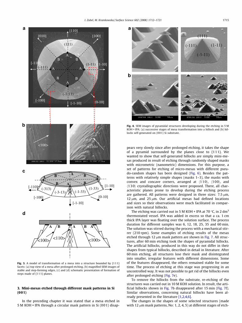
Further etching causes that the structure starts to transforminto a typical hillock and takes the shapes shown in Fig. 3a, c, d.Every corner of the upper outline of etched structure, where two{331} planes and one {111} plane overlap, denoted with A inFig. 3a, c, d, becomes a source of steps composed of the slowest{111} planes. The {331} planes, whose etch rate is higher thanV(111), cause the underetching of the mask at A corners and releas-ing of the mini-structures bounded by {111} planes. The followingstages of mask undercut result in the development of successivesteps. The edge of intersection of {331} planes in <110> directions,gradually transforms into the stepped planes close to {111}. Onthe other hand, in <100> direction where no {111} planes areencountered, the {110} planes are ‘‘the slowest” ones. Their etchrate is comparable with the etch rate of (331} planes what makesthat at the corners, denoted with B, the edge remains sharp (Fig. 3a,c and d). Magnified SEM images let us recognize stable edges ofintersection of {331} planes along <100> direction and irregularstep forming planes close to {111} planes in <110> direction(Fig. 3b).
It is difficult to explain successive stages of mesa etching and itstransformation into a hillock based on geometrical model. In manyworks, the hillock development has been considered on atomic le-vel with single atoms on the vertex forming an etching mask[4,6,7,15]. A stepped pyramidal structure with the edges in<110> directions was the result of such simulations. Accordingto common rules governing the etching process, the hillock re-stricted by {111} planes should not exist since in the consider-ations of mesa etching, such planes would not develop (seeFig. 2d). The faces bounding the hillock structure are not smooth{111} planes but the planes composed of numerous mini-faces,
[100]
[110]
[410]
[2-10]
[210]
[310]
[1-10][3-10]
[4-10]
(111)(001)
(101)
(212)
(313)
(1-11)
(414)
(2-12)(3-13)
(4-14)
[-100]
(-1-33)
(1-3
3)(3
-13)
(133)
(-133)(-313)
(-3-13)
[0-10]
(313)
[1-10]
[-1-10]
[-110]
[100][010]
[100]
[110]
[410]
[2-10]
[210]
[310]
[1-10][3-10]
[4-10]
(110)
(211)
(111)
(100)
(001)
(101)
(112) (221)
(212)
(311)
(113)
(313)
(331)
(210)
(310)(201)
(102)
(103)
(301)
(1-13)(1-12)
(1-11)
(2-21)
(3-31)
(1-10)
(411)
(414)
(2-12)(3-13)
(4-14)
(4-11)(3-11)(2-11)
(410)
(4-10)(3-10)
(2-10)
V{111}
V{110}
V{331}
(-1-33)
(1-33)
(1-11)
(3-13)
(313)(133)
(-133)
(-111)
(-313)
(-3-13) (-1-11)
(0-11)
(101)(011)
(-101)
(111)
initial shape of the mask shape of etched mesa
[010]
[-100] [0-10]
[110]
[1-10]
[-1-10]
[-110]
[310]
[-3-10]
[-130] [3-10]
[1-30]
[130]
[-1-30]
[-310](-1-33)
(1-33)
(1-11)(3-13)
(313)
(111)(133)
(-133)(-111)
(-313)
(-3-13)
(-1-11)
(0-11)
(101)(011)
(-101)
(001
[100]
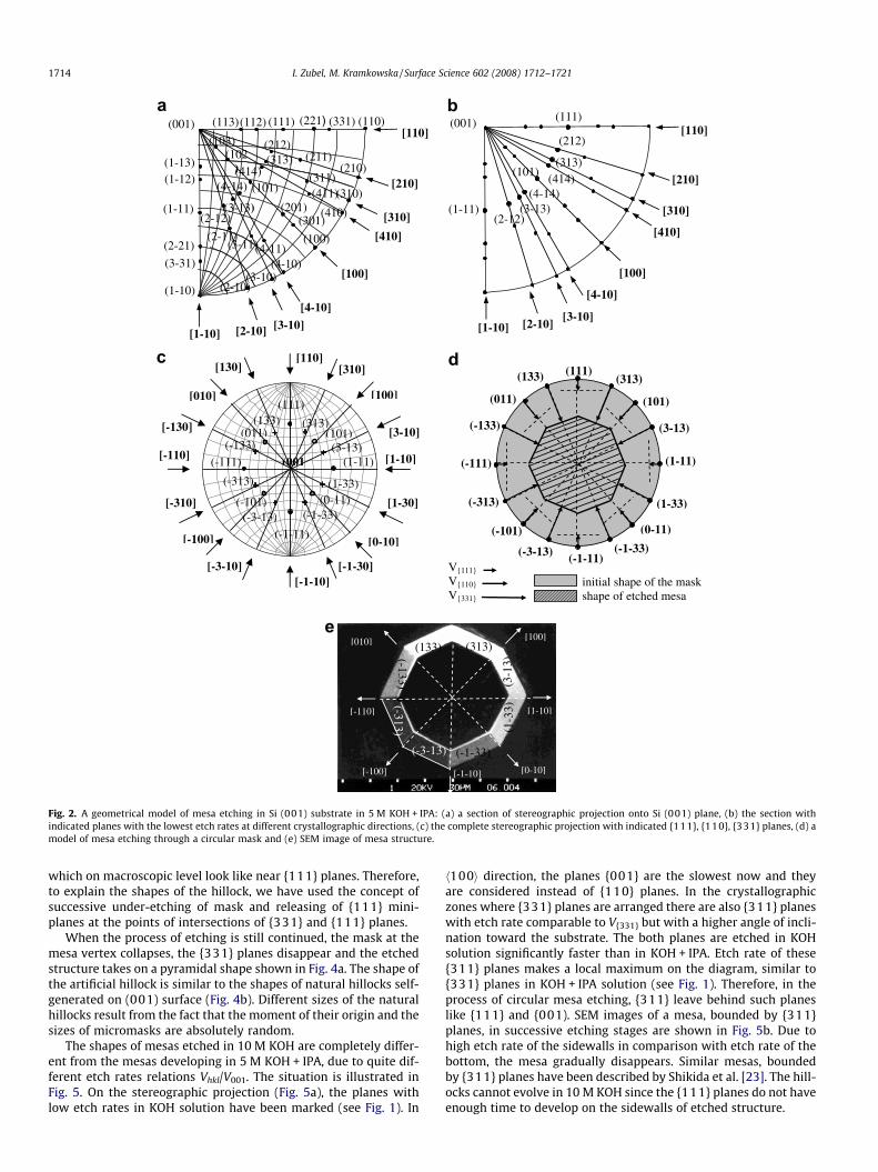
Fig. 2. A geometrical model of mesa etching in Si (001) substrate in 5 M KOH + IPA: (a) a section of stereographic projection onto Si (001) plane, (b) the section withindicated planes with the lowest etch rates at different crystallographic directions, (c) the complete stereographic projection with indicated {111}, {110}, {331} planes, (d) amodel of mesa etching through a circular mask and (e) SEM image of mesa structure.
1714 I. Zubel, M. Kramkowska / Surface Science 602 (2008) 1712–1721
which on macroscopic level look like near {111} planes. Therefore,to explain the shapes of the hillock, we have used the concept ofsuccessive under-etching of mask and releasing of {111} mini-planes at the points of intersections of {331} and {111} planes.
When the process of etching is still continued, the mask at themesa vertex collapses, the {331} planes disappear and the etchedstructure takes on a pyramidal shape shown in Fig. 4a. The shape ofthe artificial hillock is similar to the shapes of natural hillocks self-generated on (001) surface (Fig. 4b). Different sizes of the naturalhillocks result from the fact that the moment of their origin and thesizes of micromasks are absolutely random.
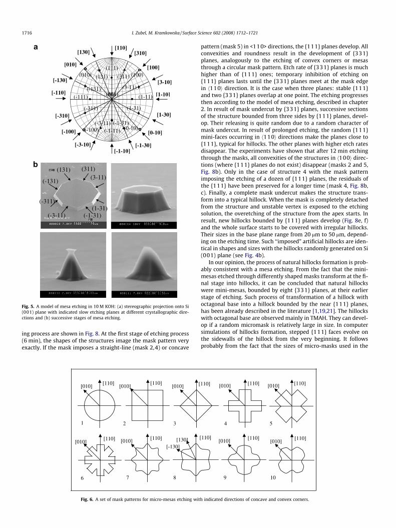
The shapes of mesas etched in 10 M KOH are completely differ-ent from the mesas developing in 5 M KOH + IPA, due to quite dif-ferent etch rates relations Vhkl/V001. The situation is illustrated inFig. 5. On the stereographic projection (Fig. 5a), the planes withlow etch rates in KOH solution have been marked (see Fig. 1). In
h100i direction, the planes {001} are the slowest now and theyare considered instead of {110} planes. In the crystallographiczones where {331} planes are arranged there are also {311} planeswith etch rate comparable to V{331} but with a higher angle of incli-nation toward the substrate. The both planes are etched in KOHsolution significantly faster than in KOH + IPA. Etch rate of these{311} planes makes a local maximum on the diagram, similar to{331} planes in KOH + IPA solution (see Fig. 1). Therefore, in theprocess of circular mesa etching, {311} leave behind such planeslike {111} and {001). SEM images of a mesa, bounded by {311}planes, in successive etching stages are shown in Fig. 5b. Due tohigh etch rate of the sidewalls in comparison with etch rate of thebottom, the mesa gradually disappears. Similar mesas, boundedby {311} planes have been described by Shikida et al. [23]. The hill-ocks cannot evolve in 10 M KOH since the {111} planes do not haveenough time to develop on the sidewalls of etched structure.
<110> <100>
(1-11)
(111)
(-111)
(-1-11)
[100][010]
[-100]
AA
A
A
[110]
[-1-10]
[-110] [1-10]
[0-10]
B
BB
B
<100><100> <110>
A B A B A
[1-10]
[0-10]
[-1-10]
[-110]
[-100]
A
AA
B B
A BB
(-313)(-3-13) (-1-33)
(1-33)
Fig. 3. A model of transformation of a mesa into a structure bounded by {111}facets: (a) top view of a mesa after prolonged etching, (b) magnified SEM images ofstable and step-forming edges, (c) and (d) schematic presentation of formation ofsteps made of {111} planes.
Fig. 4. SEM images of pyramidal structures developing during the etching in 5 MKOH + IPA: (a) successive stages of mesa transformation into a hillock and (b) hil-locks self-generated on (001) Si substrate.
I. Zubel, M. Kramkowska / Surface Science 602 (2008) 1712–1721 1715
3. Mini-mesas etched through different mask patterns in Si(001)
In the preceding chapter it was stated that a mesa etched in5 M KOH + IPA through a circular mask pattern in Si (001) disap-
pears very slowly since after prolonged etching, it takes the shapeof a pyramid surrounded by the planes close to {111}. Wewanted to show that self-generated hillocks are simply mini-me-sas produced in result of etching through randomly shaped maskswith micrometric (nanometric) dimensions. For this purpose, aset of patterns for etching of micro-mesas with different pseu-do-random shapes has been designed (Fig. 6). Besides the pat-terns with relatively simple shapes (masks 1–3), the masks withconvex and concave corners, arranged at h110i, h100i, andh130i crystallographic directions were proposed. There, all char-acteristic planes prone to develop during the etching processare gathered. All patterns were designed in three sizes: 7.5 lm,12 lm, and 25 lm. Our artificial mesas had defined locationsand sizes so their observations were much facilitated in compar-ison with natural hillocks.
The etching was carried out in 5 M KOH + IPA at 70 �C, in 2 dm3
thermostated vessel. IPA was added in excess so that a ca. 1 cmthick IPA layer was floating over the solution surface. The processduration for different samples was 6, 12, 18, 25, 35 and 60 min.The solution was stirred during the process with a mechanical stir-rer (210 rpm). Some examples of etching results of the mesasetched through 12 lm mask pattern are shown in Fig. 7. All struc-tures, after 60 min etching took the shapes of pyramidal hillocks.The artificial hillocks, produced in this way do not differ in theirshapes from typical hillocks, described in detail in literature. After60 min etching, all structures lose their mask and disintegratedinto smaller, irregular features with different dimensions. Someof the features disappeared, the others remained stable for sometime. The process of etching at this stage was progressing in anuncontrolled way. It was not possible to get rid of the hillocks evenafter prolonged etching (Fig. 7e).
To remove the hillocks from the substrate, re-etching of thestructures was carried out in 10 M KOH solution. In result, the arti-ficial hillocks shown in Fig. 7b disappeared after 15 min (Fig. 7f).Similar observations, concerning natural hillocks have been al-ready presented in the literature [1,2,4,6].
The changes in the shapes of some selected structures (madewith 12 lm mask patterns, No: 1, 2, 4, 5) at different stages of etch-
(1-11)
(111)
(-111)
(-1-11)
(-1-31)
(1-31)
(3-11)
(311)(131)
(-131)
(-311)
(-3-11)(0-10)
(100)(010)
(-100)
(001)
[100][010]
[-100] [0-10]
[110]
[1-10]
[-1-10]
[-110]
[310]
[-3-10]
[-130] [3-10]
[1-30]
[130]
[-1-30]
[-310]
(131) (311)
(-1-31)
(3-11)
(-3-11) (1-31)
(-311)
(-131)
Fig. 5. A model of mesa etching in 10 M KOH: (a) stereographic projection onto Si(001) plane with indicated slow etching planes at different crystallographic dire-ctions and (b) successive stages of mesa etching.
1716 I. Zubel, M. Kramkowska / Surface Science 602 (2008) 1712–1721
ing process are shown in Fig. 8. At the first stage of etching process(6 min), the shapes of the structures image the mask pattern veryexactly. If the mask imposes a straight-line (mask 2,4) or concave
[110]
[110]
[[110]
[110]
[010]
[130][010][010]
[010][010]
[-130]
1 2 3
6 7 8
Fig. 6. A set of mask patterns for micro-mesas etching wit
pattern (mask 5) in <110> directions, the {111} planes develop. Allconvexities and roundness result in the development of {331}planes, analogously to the etching of convex corners or mesasthrough a circular mask pattern. Etch rate of {331} planes is muchhigher than of {111} ones; temporary inhibition of etching on{111} planes lasts until the {331} planes meet at the mask edgein h110i direction. It is the case when three planes: stable {111}and two {331} planes overlap at one point. The etching progressesthen according to the model of mesa etching, described in chapter2. In result of mask undercut by {331} planes, successive sectionsof the structure bounded from three sides by {111} planes, devel-op. Their releasing is quite random due to a random character ofmask undercut. In result of prolonged etching, the random {111}mini-faces occurring in h110i directions make the planes close to{111}, typical for hillocks. The other planes with higher etch ratesdisappear. The experiments have shown that after 12 min etchingthrough the masks, all convexities of the structures in h100i direc-tions (where {111} planes do not exist) disappear (masks 2 and 5,Fig. 8b). Only in the case of structure 4 with the mask patternimposing the etching of a dozen of {111} planes, the residuals ofthe {111} have been preserved for a longer time (mask 4, Fig. 8b,c). Finally, a complete mask undercut makes the structure trans-form into a typical hillock. When the mask is completely detachedfrom the structure and unstable vertex is exposed to the etchingsolution, the overetching of the structure from the apex starts. Inresult, new hillocks bounded by {111} planes develop (Fig. 8e, f)and the whole surface starts to be covered with irregular hillocks.Their sizes in the base plane range from 20 lm to 50 lm, depend-ing on the etching time. Such ‘‘imposed” artificial hillocks are iden-tical in shapes and sizes with the hillocks randomly generated on Si(001) plane (see Fig. 4b).
In our opinion, the process of natural hillocks formation is prob-ably consistent with a mesa etching. From the fact that the mini-mesas etched through differently shaped masks transform at the fi-nal stage into hillocks, it can be concluded that natural hillockswere mini-mesas, bounded by eight {331} planes, at their earlierstage of etching. Such process of transformation of a hillock withoctagonal base into a hillock bounded by the near {111} planes,has been already described in the literature [1,19,21]. The hillockswith octagonal base are observed mainly in TMAH. They can devel-op if a random micromask is relatively large in size. In computersimulations of hillocks formation, stepped {111} faces evolve onthe sidewalls of the hillock from the very beginning. It followsprobably from the fact that the sizes of micro-masks used in the
[110][110]110]
[110] [110] [110][010] [010]
[010] [010]
4 5
9 10
h indicated directions of concave and convex corners.
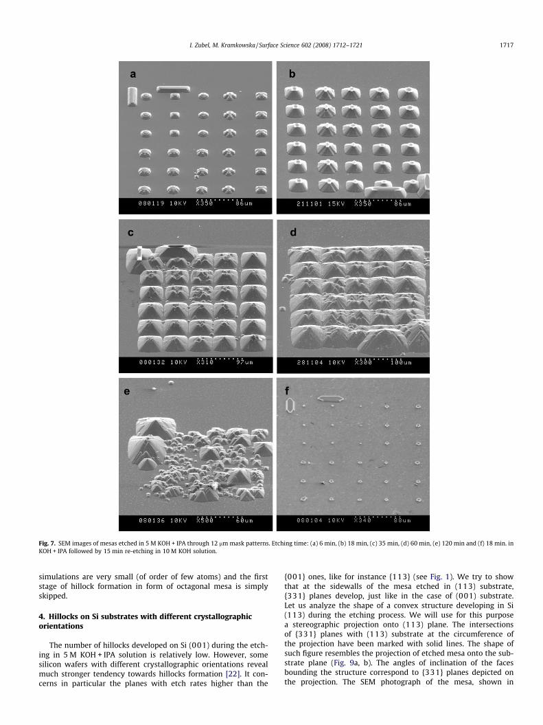
Fig. 7. SEM images of mesas etched in 5 M KOH + IPA through 12 lm mask patterns. Etching time: (a) 6 min, (b) 18 min, (c) 35 min, (d) 60 min, (e) 120 min and (f) 18 min. inKOH + IPA followed by 15 min re-etching in 10 M KOH solution.
I. Zubel, M. Kramkowska / Surface Science 602 (2008) 1712–1721 1717
simulations are very small (of order of few atoms) and the firststage of hillock formation in form of octagonal mesa is simplyskipped.
4. Hillocks on Si substrates with different crystallographicorientations
The number of hillocks developed on Si (001) during the etch-ing in 5 M KOH + IPA solution is relatively low. However, somesilicon wafers with different crystallographic orientations revealmuch stronger tendency towards hillocks formation [22]. It con-cerns in particular the planes with etch rates higher than the
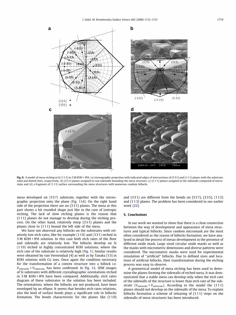
{001} ones, like for instance {113} (see Fig. 1). We try to showthat at the sidewalls of the mesa etched in (113) substrate,{331} planes develop, just like in the case of (001) substrate.Let us analyze the shape of a convex structure developing in Si(113) during the etching process. We will use for this purposea stereographic projection onto (113) plane. The intersectionsof {331} planes with (113) substrate at the circumference ofthe projection have been marked with solid lines. The shape ofsuch figure resembles the projection of etched mesa onto the sub-strate plane (Fig. 9a, b). The angles of inclination of the facesbounding the structure correspond to {331} planes depicted onthe projection. The SEM photograph of the mesa, shown in
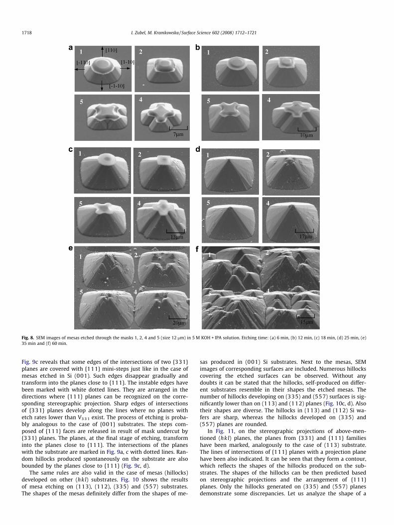
Fig. 8. SEM images of mesas etched through the masks 1, 2, 4 and 5 (size 12 lm) in 5 M KOH + IPA solution. Etching time: (a) 6 min, (b) 12 min, (c) 18 min, (d) 25 min, (e)35 min and (f) 60 min.
1718 I. Zubel, M. Kramkowska / Surface Science 602 (2008) 1712–1721
Fig. 9c reveals that some edges of the intersections of two {331}planes are covered with {111} mini-steps just like in the case ofmesas etched in Si (001). Such edges disappear gradually andtransform into the planes close to {111}. The instable edges havebeen marked with white dotted lines. They are arranged in thedirections where {111} planes can be recognized on the corre-sponding stereographic projection. Sharp edges of intersectionsof {331} planes develop along the lines where no planes withetch rates lower than V3 3 1 exist. The process of etching is proba-bly analogous to the case of {001} substrates. The steps com-posed of {111} faces are released in result of mask undercut by{331} planes. The planes, at the final stage of etching, transforminto the planes close to {111}. The intersections of the planeswith the substrate are marked in Fig. 9a, c with dotted lines. Ran-dom hillocks produced spontaneously on the substrate are alsobounded by the planes close to {111} (Fig. 9c, d).
The same rules are also valid in the case of mesas (hillocks)developed on other (hkl) substrates. Fig. 10 shows the resultsof mesa etching on (113), (112), (335) and (557) substrates.The shapes of the mesas definitely differ from the shapes of me-
sas produced in (001) Si substrates. Next to the mesas, SEMimages of corresponding surfaces are included. Numerous hillockscovering the etched surfaces can be observed. Without anydoubts it can be stated that the hillocks, self-produced on differ-ent substrates resemble in their shapes the etched mesas. Thenumber of hillocks developing on (335) and (557) surfaces is sig-nificantly lower than on (113) and (112) planes (Fig. 10c, d). Alsotheir shapes are diverse. The hillocks in (113) and (112) Si wa-fers are sharp, whereas the hillocks developed on (335) and(557) planes are rounded.
In Fig. 11, on the stereographic projections of above-men-tioned (hkl) planes, the planes from {331} and {111} familieshave been marked, analogously to the case of (113) substrate.The lines of intersections of {111} planes with a projection planehave been also indicated. It can be seen that they form a contour,which reflects the shapes of the hillocks produced on the sub-strates. The shapes of the hillocks can be then predicted basedon stereographic projections and the arrangement of {111}planes. Only the hillocks generated on (335) and (557) planesdemonstrate some discrepancies. Let us analyze the shape of a
{111}{331}
(-1-11)
(-3-13)
(-313)(-111)
(133)
(-133)
(111)
(3-13)
(313)
(1-11)
(1-33)
(-1-33)
(-331)
(3-31)
(113)
(111)
(313)
(3-13)
(1-11)
(1-33)
(-133)
(-1-11)
(-3-13) (-313)
(-111)
(-133)(133)
(3-31)(-331)
(111)
(-11-1)
(1-11)
(-1-11)
Fig. 9. A model of mesa etching in Si (113) in 5 M KOH + IPA: (a) stereographic projection with indicated edges of intersections of {331} and {111} planes with the substrate,solid and dotted lines, respectively, (b) {331} planes assigned to real sidewalls bounding the mesa structure, (c) {111} planes assigned to the sidewalls composed of micro-steps and (d) a fragment of (113) surface surrounding the mesa structures with numerous random hillocks.
I. Zubel, M. Kramkowska / Surface Science 602 (2008) 1712–1721 1719
mesa developed on (557) substrate, together with the stereo-graphic projection onto the plane (Fig. 11d). On the right handside of the projection there are no {331} planes. The mesa at thispart shows a bit rounded shape just like in the case of isotropicetching. The lack of slow etching planes is the reason that{111} planes do not manage to develop during the etching pro-cess. On the other hand, relatively steep {331} planes and theplanes close to {111} bound the left side of the mesa.
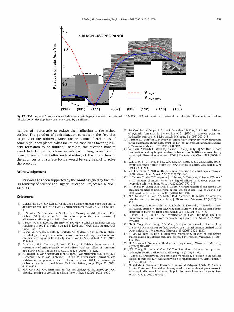
We have not observed any hillocks on the substrates with rel-atively low etch rates, like for example (110) and (331) etched in5 M KOH + IPA solution. In this case both etch rates of the floorand sidewalls are relatively low. The hillocks develop on Si(110) etched in highly concentrated KOH solutions, where theetch rate of the substrate is relatively high (Fig. 1). Similar resultswere obtained by van Veenendaal [4] as well as by Tanaka [13] inKOH solution with Cu ions. Once again the condition necessaryfor the transformation of a convex structure into a hillock i.e.Vsidewalls < Vsubstrate, has been confirmed. In Fig. 12, SEM imagesof Si substrates with different crystallographic orientations etchedin 5 M KOH + IPA have been compared. Additionally, etch ratesdiagram of these substrates in the solution has been included.The orientations, where the hillocks are not produced, have beenenveloped by an ellipse. It seems that besides etch rates relations,also the kind of surface bonds plays a significant role in hillocksformation. The bonds characteristic for the planes like {110}
and {331} are different from the bonds on {557}, {335}, (112}and {113} planes. The problem has been considered in our earlierwork [22].
5. Conclusions
In our work we wanted to show that there is a close connectionbetween the way of development and appearance of mesa struc-tures and typical hillocks. Since random micromask are the mostoften considered as the reason of hillocks formation, we have ana-lysed in detail the process of mesas development in the presence ofdifferent oxide mask. Large sized circular oxide masks as well asthe masks with micrometric dimensions and diverse patterns wereconsidered. The micrometric masks were used for experimentalsimulation of ‘‘artificial” hillocks. Due to defined sizes and loca-tions of artificial hillocks, their transformation during the etchingprocess was easy to observe.
A geometrical model of mesa etching has been used to deter-mine the planes forming the sidewalls of etched mesa. It was dem-onstrated that a stable mesa can develop only when the etch rateof the sidewalls of the structure is lower than etch rate of the sub-strate (Vsidewalls < Vsubstrate). According to the model the {111}planes should not develop on the sidewalls of the mesa. To explainhillocks formation a scheme of releasing of {111} steps on thesidewalls of mesa structures has been introduced.
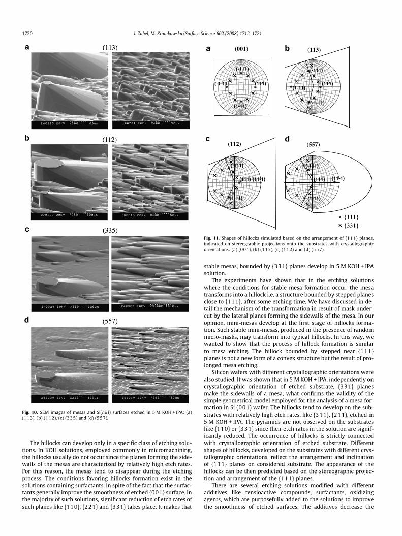
Fig. 10. SEM images of mesas and Si(hkl) surfaces etched in 5 M KOH + IPA: (a)(113), (b) (112), (c) (335) and (d) (557).
(-1-11)
(001)
(-111)
(1-11)
(111)
(113)
(-111)
(-1-11)
(1-11)(111)
(112)
(1-11)
(-111)
(111) (11-1)
(1-11)
(-111)
(111)
(557)
(11-1)
{111} {331}
Fig. 11. Shapes of hillocks simulated based on the arrangement of {111} planes,indicated on stereographic projections onto the substrates with crystallographicorientations: (a) (001), (b) (113), (c) (112) and (d) (557).
1720 I. Zubel, M. Kramkowska / Surface Science 602 (2008) 1712–1721
The hillocks can develop only in a specific class of etching solu-tions. In KOH solutions, employed commonly in micromachining,the hillocks usually do not occur since the planes forming the side-walls of the mesas are characterized by relatively high etch rates.For this reason, the mesas tend to disappear during the etchingprocess. The conditions favoring hillocks formation exist in thesolutions containing surfactants, in spite of the fact that the surfac-tants generally improve the smoothness of etched {001} surface. Inthe majority of such solutions, significant reduction of etch rates ofsuch planes like {110}, {221} and {331} takes place. It makes that
stable mesas, bounded by {331} planes develop in 5 M KOH + IPAsolution.
The experiments have shown that in the etching solutionswhere the conditions for stable mesa formation occur, the mesatransforms into a hillock i.e. a structure bounded by stepped planesclose to {111}, after some etching time. We have discussed in de-tail the mechanism of the transformation in result of mask under-cut by the lateral planes forming the sidewalls of the mesa. In ouropinion, mini-mesas develop at the first stage of hillocks forma-tion. Such stable mini-mesas, produced in the presence of randommicro-masks, may transform into typical hillocks. In this way, wewanted to show that the process of hillock formation is similarto mesa etching. The hillock bounded by stepped near {111}planes is not a new form of a convex structure but the result of pro-longed mesa etching.
Silicon wafers with different crystallographic orientations werealso studied. It was shown that in 5 M KOH + IPA, independently oncrystallographic orientation of etched substrate, {331} planesmake the sidewalls of a mesa, what confirms the validity of thesimple geometrical model employed for the analysis of a mesa for-mation in Si (001) wafer. The hillocks tend to develop on the sub-strates with relatively high etch rates, like {311}, {211}, etched in5 M KOH + IPA. The pyramids are not observed on the substrateslike {110} or {331} since their etch rates in the solution are signif-icantly reduced. The occurrence of hillocks is strictly connectedwith crystallographic orientation of etched substrate. Differentshapes of hillocks, developed on the substrates with different crys-tallographic orientations, reflect the arrangement and inclinationof {111} planes on considered substrate. The appearance of thehillocks can be then predicted based on the stereographic projec-tion and arrangement of the {111} planes.
There are several etching solutions modified with differentadditives like tensioactive compounds, surfactants, oxidizingagents, which are purposefully added to the solutions to improvethe smoothness of etched surfaces. The additives decrease the
5 M KOH +ISOPROPANOL
(110) (331) (111) (557) (335) (112) ( 113) (100)
V KOH
V KOH+IPA
Rel
ativ
e et
ch r
ate
Vh
kl /
V10
0
1
1
2
0.5
1.5
Fig. 12. SEM images of Si substrates with different crystallographic orientations, etched in 5 M KOH + IPA, set up with etch rates of the substrates. The orientations, wherehillocks do not develop, have been enveloped by an ellipse.
I. Zubel, M. Kramkowska / Surface Science 602 (2008) 1712–1721 1721
number of micromasks or reduce their adhesion to the etchedsurface. The paradox of such situation consists in the fact thatmajority of the additives cause the reduction of etch rates ofsome high-index planes, what makes the conditions favoring hill-ocks formation to be fulfilled. Therefore, the question how toavoid hillocks during silicon anisotropic etching remains stillopen. It seems that better understanding of the interaction ofthe additives with surface bonds would be very helpful to solvethe problem.
Acknowledgement
This work has been supported by the Grant assigned by the Pol-ish Ministry of Science and Higher Education; Project No. N N5154405 33.
References
[1] L.M. Landsberger, S. Naseh, M. Kahrizi, M. Paranjape, Hillocks generated duringanisotropic etching of Si in TMAH, J. Microelectromech. Syst. 5 (2) (1996) 106–116.
[2] H. Schröder, V. Obermeier, A. Steckenborn, Micropyramidal hillocks on KOHetched {001} silicon surfaces: formations, prevention and removal, J.Micromech. Microeng. 9 (1999) 139–145.
[3] I. Zubel, M. Kramkowska, The effect of isopropyl alcohol on etching rates androughness of (001) Si surface etched in KOH and TMAH, Sens. Actuat. A 93(2001) 138–147.
[4] E. Van veenendaal, K. Sato, M. Shikida, A.J. Nijdam, J. Van suchteln, Micro-morphology of single crystalline silicon surfaces during anisotropic wetchemical etching in KOH: velocity source forests, Sens. Actuat. A 93 (2001)232–242.
[5] Di Cheng, M.A. Gosalvez, T. Hori, K. Sato, M. Shikida, Improvement insmoothness of anisotropically etched silicon surfaces: effect of surfactantand TMAH concentration, Sens. Actuat. A 125 (2006) 415–421.
[6] A.J. Nijdam, E. Van Veenendaal, H.M. Cuppen, J. Van Suchtelen, M.L. Reed, J.G.E.Gardeniers, W.J.P. Van Enckevort, E. Vlieg, M. Elwenspoek, Formation andstabilization of pyramidal etch hillocks on silicon {001} in anisotropicetchants: experiments and Monte Carlo simulation, J. Appl. Phys. 89 (2001)4113–4123.
[7] M.A. Gosalvez, R.M. Nieminen, Surface morphology during anisotropic wetchemical etching of crystalline silicon, New J. Phys. 5 (2003) 100.1–100.2.
[8] S.A. Campbell, K. Cooper, L. Dixon, R. Earwaker, S.N. Port, D. Schiffrin, Inhibitionof pyramid formation in the etching of Si p{001} in aqueous potassiumhydroxide-isopropanol, J. Micromech. Microeng. 5 (1995) 209–218.
[9] T. Baum, D.J. Schiffrin, AFM study of surface finish improvement by ultrasoundin the anisotropic etching of Si {001} in KOH for micromachining applications,J. Micromech. Microeng. 7 (1997) 338–342.
[10] W. Haiss, P. Raisch, L. Bitsch, R.J. Nichols, X. Xia, J.J. Kelly, D.J. Schiffrin, Surfacetermination and hydrogen bubbles adhesion on Si(100) surfaces duringanisotropic dissolution in aqueous KOH, J. Electroanalyt. Chem. 597 (2006) 1–12.
[11] W.K. Choi, J.T.L. Thong, P. Luo, C.M. Tan, T.H. Chua, Y. Bai, Characterisation ofpyramid formation arising from the TMAH etching of silicon, Sens. Actuat. A 71(1998) 238–243.
[12] Y.K. Bhatnagar, A. Nathan, On pyramidal protrusion in anisotropic etching of(100) silicon, Sens. Actuat. A 36 (1993) 233–240.
[13] H. Tanaka, Y. Abe, T. Yoneyama, J. Ishikawa, O. Takenaka, K. Inoue, Effects ofsmall amount of impurities on etching of silicon in aqueous potassiumhydroxide solutions, Sens. Actuat. A 82 (2000) 270–273.
[14] H. Tanaka, D. Cheng, A.M. Shikid, K. Sato, Characterization of anisotropic wetetching properties of single crystal silicon: effects of ppb – level of Cu and Pb inKOH solution, Sens. Actuat. A 128 (2006) 125–131.
[15] M.A. Gosalvez, K. Sato, A.S. Foster, R.M. Nieminen, H. Tanaka, An atomisticintroduction to anisotropic etching, J. Micromech. Microeng. 17 (2007) S1–S26.
[16] N. Fujitsuka, K. Hamaguchi, H. Funabashi, E. Kawasaki, T. Fukuda, Siliconanisotropic etching without attacking aluminium with Si and oxidizing agentdissolved in TMAH solution, Sens. Actuat. A 114 (2004) 510–515.
[17] J. Tsuar, Ch.-H. Du, Ch. Lee, Investigation of TMAH for front side bulkmicromachining process from manufacturing aspect, Sens. Actuat. A 92 (2001)375–383.
[18] Ch.-R. Yang, Ch.-H. Yang, P.-Y. Chen, Study on anisotropic silicon etchingcharacteristics in various surfactant-added tetramethyl ammonium hydroxidewater solutions, J. Micromech. Microeng. 15 (2005) 2028–2037.
[19] S. Tan, M. Reed, H. Han, R. Boudreau, Morphology of etch hillock defectscreated during anisotropic etching of silicon, J. Micromech. Microeng. 4 (1994)147–155.
[20] M. Elwenspoek, Stationary hillocks on etching silicon, J. Micromech. Microeng.9 (1999) 180–185.
[21] J.T.L. Thong, P. Luo, W.K. Choi, S.C. Tan, Evolution of hillocks during siliconetching in TMAH, J. Micromech. Microeng. 11 (2001) 61–69.
[22] I. Zubel, M. Kramkowska, Etch rates and morphology of silicon (hkl) surfacesetched in KOH and KOH saturated with isopropanol solutions, Sens. Actuat. A115 (2004) 549–556.
[23] M. Shikida, K. Nanbara, T. Koizumi, H. Sasaki, M. Odagaki, K. Sato, M. Ando, S.Furuta, K. Asaumi, A model explaining mask-corner undercut phenomena inanisotropic silicon etching: a saddle point in the etching-rate diagram, Sens.Actuat. A 97 (2003) 758–763.