Development of Aerobots for Satellite Emula- tion, Architecture ...
15
Development of Aerobots for Satellite Emula- tion, Architecture and Art I. Sharf and M. S. Persson Centre for Intelligent Machines, McGill University D. St-Onge and N. Reeves NXI Gestatio Design Lab, School of Design, University of Quebec in Montreal Abstract In this paper, we present two unique aerobots: a spherical blimp used for satellite emulation and a cubic blimp developed for use in floating architecture and visual art. The blimp designs bear a number of similarities, in particular, their construction with an exoskeleton, full actuation to enable six-dof motion and re- quirement for autonomous localization. Experimental results are presented to demonstrate the closed-loop control for station-keeping, as well as the selected performance statistics such as maximum speeds attained and time the aerobots can remain afloat. Additional qualitative results are presented from the experiments with satellite capture and artistic performances and common challenges with fur- ther use in the intended and new applications will be outlined. 1. Introduction The concept of aerobot, i.e., an autonomous flying robot, has been around for several decades. The use of balloons or airships as aerobots has been explored in- depth in the context of planetary exploration [1]. Indoor applications of such sys- tems, beyond their use for educational purposes, are rare. In this paper, we would like to present two aerobots developed for two very different purposes, yet with a design and features which have much in common. The first platform, developed in the Aerospace Mechatronics Laboratory at McGill (AML) is a spherical airship, the design of which was motivated by one of the authors’ research on the problem of robotic grasping of objects in space. In particular, the airship represents a novel concept for emulating gravity-free conditions in a laboratory setting and has been used to develop autonomous algorithms for satellite capture in the context of satel- lite rescue and on-orbit servicing operation. The second platform was designed and constructed at the NXI Gestatio Design Laboratory of the University of Que-
-
Upload
khangminh22 -
Category
Documents
-
view
0 -
download
0
Transcript of Development of Aerobots for Satellite Emula- tion, Architecture ...

Development of Aerobots for Satellite Emula-
tion, Architecture and Art
I. Sharf and M. S. Persson
Centre for Intelligent Machines, McGill University
D. St-Onge and N. Reeves
NXI Gestatio Design Lab, School of Design, University of Quebec in Montreal
Abstract In this paper, we present two unique aerobots: a spherical blimp used
for satellite emulation and a cubic blimp developed for use in floating architecture
and visual art. The blimp designs bear a number of similarities, in particular, their
construction with an exoskeleton, full actuation to enable six-dof motion and re-
quirement for autonomous localization. Experimental results are presented to
demonstrate the closed-loop control for station-keeping, as well as the selected
performance statistics such as maximum speeds attained and time the aerobots can
remain afloat. Additional qualitative results are presented from the experiments
with satellite capture and artistic performances and common challenges with fur-
ther use in the intended and new applications will be outlined.
1. Introduction
The concept of aerobot, i.e., an autonomous flying robot, has been around for
several decades. The use of balloons or airships as aerobots has been explored in-
depth in the context of planetary exploration [1]. Indoor applications of such sys-
tems, beyond their use for educational purposes, are rare. In this paper, we would
like to present two aerobots developed for two very different purposes, yet with a
design and features which have much in common. The first platform, developed in
the Aerospace Mechatronics Laboratory at McGill (AML) is a spherical airship,
the design of which was motivated by one of the authors’ research on the problem
of robotic grasping of objects in space. In particular, the airship represents a novel
concept for emulating gravity-free conditions in a laboratory setting and has been
used to develop autonomous algorithms for satellite capture in the context of satel-
lite rescue and on-orbit servicing operation. The second platform was designed
and constructed at the NXI Gestatio Design Laboratory of the University of Que-

bec in Montreal originates from an architectural myth studied by its creator, pro-
fessor Reeves, architect and artist. Reeves envisioned more than 10 years ago the
possibility of developing flying objects whose shape would be in strong contradic-
tion with the idea of flying or hovering. Such hovering structures as well as the
paradox they represent (see Fig. 1) would constitute an architectural statement by
themselves: they somewhat materialize the old and mythical dream of an architec-
ture freed from the law of gravity --- an image that can be found along the whole
history of architecture, in many civilizations [2]. The cubic shape, chosen for the
[Voiles|SAILS] aerobot prototypes (see Fig. 1), makes them conceptually similar
to bricks, the basic unit of construction, and gives them the potential to assemble
into bigger structures. From that conceptual starting point, the first prototypes de-
veloped to date show a high potential for visual art installations, as well as for
hybrid theatrical performances where aerobots interact with human actors. The
cubic aerobot described in this paper, called Tryphon, evolved into a research-
creation platform bringing the disciplines of engineering, performing art, architec-
ture and visual art together.
Fig. 1 [Voiles|SAILS] Concept: a) Krutikov flying cities and b) Simulation of interactively
assembled Tryphons.
1.1 Related Work
The description of related work will be presented in relation to the two applica-
tions for which the aerobots were designed. Starting with the application of satel-
lite emulation in the laboratory setting, previously developed experimental facili-
ties for satellite emulation are usually built by using a spherical air bearing [3].
Experimental test-beds for space robotics research typically use one of the follow-
ing concepts to emulate weightless environment of space on earth: (a) the robot
moves on a flat horizontal surface; (b) a neutral buoyancy water tank; (c) compli-
cated gravity compensation systems and (d) a free-fall tower.
To the best of our knowledge, no other aerobot has been used to date for archi-
tectural research and exploration. The closest systems somewhat comparable to

the concepts used in the [Voiles|SAILS] program for architectural research are the
rapid prototyping printers. From a computer generated, or a computer assisted
design, the architect can get a small scale version to better visualize the 3D pres-
ence of the building. In terms of robots and art, many examples may be found
since the Norman White installation “Facing Out Laying Low” in 1977 [4]. Ro-
botic art is a field of media art that is increasingly explored by contemporary art-
ists; this helped by the development of easy to use systems such as the Arduino
open-source computing platform [5]. Hybrid performances are still very rare, but
among the most known are the “Grace State Machines” of Bill Vorn (University
of Concordia) or the “Hexapod” of Stelarc (University of Western Sydney) [6].
This manuscript describes the design, development and experiments conducted
with the two aerobots. Where appropriate, similarities between the two aerobot
platforms are highlighted and commonality of issues related to the development of
autonomous capabilities and autonomous operations are discussed. Results are
presented which demonstrate the performance of the two aerobots for each of their
intended applications. In particular, for the spherical airship, we showcase its ca-
pability to produce general rotational motion and the free-floating nature of its
response as a result of interaction with a robotic arm during capture. For the
Tryphon robot, we focus on the high reliability and reproducibility of generated
interactions with a human, as well as its long lasting autonomy for standalone in-
stallations. The geometry is also mandatory to describe as it is key to floating ar-
chitecture explorations.
2. Aerobots Design, Construction and Control
2.1 Design
The balloon employed for satellite emulation is a custom design spherical airship
equipped with six propellers, accompanying control electronics, onboard power,
and sensors for pose estimation. The design (see Fig. 2a) was motivated by three
principal requirements: 1) the balloon must closely emulate a free-floating object
which requires it to be neutrally buoyant and balanced; 2) it must carry a grapple
fixture, initially, a simple design and ultimately more sophisticated designs; 3) it
has to be capable of a range of motions including rotation about a fixed axis and
tumbling to emulate, for example, a spin-stabilized satellite or a spacecraft out of
control. Moreover, these motions need to be generated in a controlled manner to
allow multiple experimental tests under the same conditions. After several design

iterations over a period 2003-2007, the current design, shown in Figure 2 incorpo-
rates the following main components:
1) A light 6-ft diameter spherical bladder bag, made of 2.5 mil thick polyure-
thane for a maximum net lift of 3.34 kg.
2) A rigid frame (Fig. 2), designed and manufactured in-house, made up of
three carbon-fiber hoops with light-weight honey-comb cores arranged nor-
mal to each other. Each ring is made up of quarter-length arcs interconnected
at small carbon-fibre extensions (see Figure 2b). The frame allows for easy
and reliable balloon assembly and to eliminate the inaccuracies introduced by
the deformable blimp bag on the airship dynamics and control. The balloon
bag is inflated inside this structure and supports it through a friction fit.
3) Six identical propellers mounted in ducted fans, consisting of DC motors
driving 48 mm diameter propellers within 35 mm long plastic cylinders (see
Figure 3a). At a nominal voltage of 8.4 VDC, each thruster is capable of pro-
ducing up to 0.45 N thrust in its primary direction or up to 0.25 N in its re-
verse direction. The propellers are mounted in custom-made supports, in a
symmetrical arrangement on the sphere. With the chosen arrangement of the
propellers the balloon is fully actuated and in theory, is capable of producing
decoupled motions in all three translations and rotations.
4) Six speed controls for the propellers. The ducted fan speed control electronics
perform two main functions: signal conditioning and amplification of the con-
trol signal. The incoming standard PWM signal is converted to a bipolar
PWM signal zeroed around 50% duty cycle, allowing for forward and reverse
thrusting of the ducted fans.
5) The sensor suite on the airship includes two types of sensors: an Inertial
Measurement Unit (IMU) Microstrain GX1 and a laser rangefinder (Hokuyo
URG-04LX). The sensors communicate wirelessly with the ground station via
two pairs of Bluetooth transceivers.
6) The battery used on the balloon to power the propellers and the speed control
electronics is an 8.4 VDC, 4000 mAh lithium-polymer battery. A second bat-
tery powers the IMU, the laser rangefinder and the Bluetooth transceivers.
7) A composite-material grapple fixture affixed to the structure for experiments
in capture of the airship by the robotic arm.
Fig. 2 Helium airship for satellite emulation: a) Current airship configuration; b) Joint of
two hoops of the rigidizing structure

Fig. 3 Balloon propellers in the mount on the structure and Vicon marker cluster around
one of the propellers
In order for the airship to closely emulate a free-floating object in space it must be
both neutrally buoyant and balanced, thereby eliminating the effects of gravity.
With these conditions met, the unactuated airship freely floats in air and has no
preferred orientation. An additional desirable property is for the airship to have a
diagonal inertia matrix in the body-fixed frame, the axes of which are aligned with
the three orthogonal propeller thrusts. To meet these requirements, the locations of
components which can be placed freely on the ring structure were determined to
achieve the center of mass close to the geometric center of the 6-ft sphere and a
nearly diagonal inertia matrix. The airship is also equipped with 6 posts affixed to
the propeller mounts on which balancing masses can be easily placed to aid with
the balancing procedure. The final balancing is carried out manually by the opera-
tor, again with the aid of balancing masses.
The Tryphon robot flies thanks to an inflatable cubic blimp, 2.05 metres on the
side, and similarly to the spherical blimp, it is filled with helium. The material
used for the blimp is 3.5 mil thick polyurethane, which weighs 3.5 oz per square
yard (0.12kg/m2). The blimp itself is made of six square faces welded together. As
with any other balloon shape, the faces become convex when the balloon is inflat-
ed and more pressure tends to make it more spherical. To maintain a cubic shape,
the blimp has to be constrained by a rigid structure --- an exoskeleton. Therefore,
unlike the case of the spherical blimp, where the exoskeleton is primarily used for
mounting equipment on the blimp, the structure confining Tryphon is there to
maintain its cubic shape. The structure is made of carbon fiber tubes, strips and
rods (see Fig. 4a). Each edge is a triangular truss of 2.25 metres length and the
whole structure weighs approximately 1 kg. Assembly of the cube, including fill-
ing it with helium, can be completed in less than two hours by two people.
Similarly to the spherical airship, the structure of Tryphon also supports all the
electronics as well as the propulsion system. The actuators consist of small ducted
fans, with ducts and propellers made of carbon fiber. Four are located at the mid-

point of each bottom edge and oriented in the x and y positive directions. Another
four motors are similarly placed along the vertical edges (see Fig.4b). Positioning
the motors this way allows an independent control of the translations of the robot
along the x, y and z axes. Since there is no motor on the top trusses, and since
most of the batteries are fixed to the bottom trusses, the global centre of mass of
the system lies about 20 cm below the centroid of the cube. Thus, the robot cannot
turn upside down and its roll and pitch angles are thus stabilized in a passive way.
To fix the body reference frame, for both the spherical airship and the cubic
blimp, the origin of the frame is located at the blimp centroid. This choice is made
to simplify the formulation of the dynamics equations since the centre of mass can
easily change, depending on the equipment mounted on the robot. For example,
the use of textiles to hide the edges of Tryphon, or a change in the sensors' config-
uration, will modify the mass distribution.
In the current prototype of the cubic blimps, the bladder used is made of thicker
material, which allows the blimp to maintain nearly perfect equilibrium for several
days: usually 3 to 6 days, depending on the room temperature variations. The 8
batteries allow a soft control of the oscillation when stabilizing, installation known
as the “Paradoxal Sleep”, for about 6 to 8 hours in optimal room conditions (no
ventilation, and constant temperature). In harsh environment, like a building hall,
or with heavy interaction, like in hybrid performances, the airship can operate for
approximately 2 to 3 hours with its current set of batteries. Table 1 presents a
comparison of the design of the two blimps.
Fig. 4 Tryphon design: a) Structure of one carbon fiber truss and its polycarbonate ducts;
b) Layout of actuators and sensors
2.2 Control of Aerobots
The spherical airship is controlled from a ground-station PC that transmits
commands to the airship wirelessly over a Futaba radio. The ground-station PC
performs all computations for the controller. The controller resides in the Sim-

ulink environment with the QuaRC toolbox and soft real-time target developed by
Quanser. Initially [7], a PD controller was implemented on the airship with gains
adjusted through simulation and by a trial and error process. The state feedback
for the controller in [7] was obtained from the measurements by the Vicon mo-
tion-capture system, which is a set of six infrared cameras mounted along the pe-
riphery of the lab. They track retro-reflective markers affixed to the spherical air-
ship (see Figure 2b). The system therefore provides position and orientation data
for the blimp; velocities were calculated by taking finite differences of the previ-
ous 10 samples. Recently [8], we have implemented optimal LQR and LQG con-
trollers on the airship and improved the state estimation from Vicon measurements
by using the Unscented Kalman filter with angular velocity measurements from
the onboard IMU.
Table 1: Design comparison of two blimps
Satellite emulator Tryphon
Structure Molded carbon fiber
rings
Assembled carbon fiber
rods, tubes and strips in
12 triangular sections
trusses
Balloon Spherical white bladder,
2.5mil polyurethane.
Truncated white cube
bladder, 3.5mil polyure-
thane.
Motors 6 GWS fans 8 to 12 Alfa carbon fiber
propellers and duct
mount on Mega brush-
less motors
Sensors IMU, Laser range finder,
MoCap external system
16 sonars, 8 light sen-
sors, compass, accel-
erometer
Batteries 8.4 VDC, 4000 mAh
LiPo
8.4 VDC, 850 mAh
8 LiPo 2500mAh
Brain Computer off board Gumstix onboard com-
putation
Other 20 hubs to allow differ-
ent sensor configurations
The control architecture of the [Voiles|SAILS] aerobots evolved over the
course of many performances and installations created by actors, visual artists and
other artists involved in the project [9]. In 2006, the first autonomous control was
reactive to the physical attributes of the space. Compass and sonars were the only

sensor inputs used to stabilize the aerobots relatively to a fixed setup. A simple
distributed PID controller (one by sensor, one by motor and one by robot state)
was sufficient for these needs at that time. Since then, an accelerometer and a gy-
roscope were added to provide the aerobots with more information on its state.
Light sensors and microphones were also implemented for human interactions. A
study of different controller approaches led to the use of a fuzzy controller in
completely autonomous and stand-alone installations (without human interaction)
while the performances with actors or dancers rely on a PID controller onboard
and a trajectory planning algorithm used in parallel with the fuzzy controller.
The development focus was set on embedding the hardware and control in the
robot, with only a laptop running a custom designed java interface to allow the
technician operating the aerobots in their installations to monitor its battery and
mechatronic states. For research and creation purposes, the team is currently ex-
ploring the potential of external motion capture systems, such as the Vicon system
used for the AML spherical blimp. Such a system could be used to detect visitors,
to enhance the interactions as well as to control the motion of the blimp and to
better understand the dynamics of its unique shape.
3. Closed-Loop Control Experiments with Aerobots
In this section, we present a sampling of experimental results obtained for the
aerobots to demonstrate the hovering performance of the two blimps under the PD
control. As mentioned earlier, the Tryphon usually relies on its onboard computer
and sensors for control. For the experimental results presented here, however, ex-
periments were conducted in a large room equipped with a Vicon tracking system
in order to understand the aerobot dynamics and to evaluate the controller perfor-
mance. Specifically, a PD controller combined with a Kalman filter of Vicon pose
measurements was implemented in Matlab for off-board closed-loop control.
The relevant experimental response statistics of the controllers are stated in Ta-
ble 2 in addition to “application” related statistics, such as the time that the aero-
bots can remain afloat and the maximum translational and rotational speeds
achieved in our laboratory environments. Fig. 5 displays the hovering performance
(position response) of the spherical and Tryphon blimps under PD control, with
pose feedback provided by the Vicon motion capture system. The corresponding
results for attitude response are shown in Fig. 6. Fig. 7 presents the response of the
spherical blimp to light translational and rotational disturbances, demonstrating
the rise times of approximately 5 seconds, settling times of 15 seconds, and over-
shoot of approximately 10%, although the latter is rather difficult to determine
because of the poorly defined steady state. Analogously, in Fig. 8, we include the
step position response of the Tryphon aerobot, showing the rise time of 15 se-
conds, settling time of approximately 50 seconds and overshoot of around 25%.

From the results in Table 2, we observe that the station-keeping control of the
spherical blimp is better than of Tryphon. In particular, the RMS errors for posi-
tion regulation of the two blimps are 0.028 m and 0.101 m respectively, while the
corresponding errors for attitude regulation are 0.017 rad and 0.122 rad. On the
other hand, Tryphon can maintain neutral buoyancy for a significantly longer time
period, nearly one day. Tryphon is also able to reach a higher translational speed,
although the results obtained for the AML spherical blimp were quite limited by
the size of the laboratory at McGill. At the same time, the spherical blimp can
reach a higher rotational speed, because of better aerodynamic characteristics.
Table 2: Experimental performance comparison of two blimps
Satellite emulator Tryphon
Regulation position error
(RMS)
0.028 m 0.101 m
Regulation attitude error
(RMS)
0.017 rad 0.122 rad
Neutral buoyancy time ~1 hour ~24 hours
Max. translational speed 0.3 m/s 0.75 m/s
Max. rotational speed 2.3 rad/s 1.6 rad/s
4. Applications of Aerobots
4.1 Satellite Emulation Experiments and Potential Applications
A number of experiments have been carried out with the spherical airship em-
ployed as a free-floating target for capture by the seven-dof robotic arm housed in
the laboratory. Snapshots of the satellite capture experiments are shown in Fig. 8
for a successful capture of the slowly translating airship by its grapple fixture. The
fiducial three-dot mark on the airship is employed for visual servoing of the robot
when its end-effector is sufficiently close to the grapple fixture. The capture also
involves the planning of the optimal interception trajectory, as per the algorithm
described in [10]. Currently, we are working on probabilistic path planning meth-
ods to allow capture of the spherical blimp under uncertainty in its state, and for
arbitrary motions, including tumbling and motion on a collision course with the
robot itself.

10
Fig. 5 Position regulation of the AML spherical (left) and Tryphon (right) blimps.
Fig. 6 Attitude regulation of the AML spherical (left) and Tryphon (right) blimps.
Fig. 7 Recovery from position disturbance (left) and attitude disturbance (right) of the
AML spherical blimp.
420 430 440 450 460 470 480 490 500-0.15
-0.1
-0.05
0
0.05
0.1
Position Regulation with PD Controller
Time (s)
Po
sitio
n (
m)
Position X
Position Y
Position Z
115 120 125 130 135 140 145 150 155-0.2
-0.1
0
0.1
0.2
0.3
0.4
0.5
Position Regulation with PD Controller
Time (s)
Po
sitio
n (
m)
Position X
Position Y
Position Z
420 430 440 450 460 470 480 490 500-0.05
0
0.05
0.1
0.15
0.2
Attitude Regulation with PD Controller - Euler angles XYZ
Time (s)
An
gle
(ra
d)
115 120 125 130 135 140 145 150 155-0.2
-0.15
-0.1
-0.05
0
0.05
0.1
0.15
Attitude Regulation with PD Controller - Euler Angles
Time (s)
An
gle
s (
rad
)
Yaw
Pitch
Roll
155 160 165 170 175 180 185-0.2
-0.1
0
0.1
0.2
0.3
0.4
0.5
Position Recovery from Light Push with PD Controller
Time (s)
Po
sitio
n (
m)
Position X
Position Y
Position Z
195 200 205 210 215 220 225 230 235-0.2
-0.1
0
0.1
0.2
0.3
0.4
0.5
0.6
0.7
Attitude Recovery with PD Controller - Euler Angles
Time (s)
An
gle
s (
rad
)
Yaw
Pitch
Roll

11
0 50 100 150-0.2
0
0.2
0.4
0.6
0.8
1
1.2
1.4
Step Response with PD Controller
Time (s)
Po
sitio
n (
m)
Position X
Fig. 8 Step response in X-position of Tryphon.
Fig. 9 Snapshots of airship capture maneuver with seven-dof robotic arm.
12
Another potential application of the spherical blimp that has been explored in
AML is as an autonomous aerial vehicle for safety and security missions. Possible
scenarios envisioned are where the airship is deployed in a large facility, in the
event of an accident, for instance. The airship would fly inside the facility and
take measurements and/or video of the scene. Note that the size of the spherical
blimp would also permit it to negotiate a wide staircase. In this type of scenario,
the airship has to be able to navigate its environment autonomously, and hence it
must be equipped with sensors for autonomous localization-not a trivial task given
the blimps limited payload. Some efforts to solve the localization problem by us-
ing optical flow and Monte Carlo Localization with a laser range finder have been
made and we are continuing further research in this direction.
The airship has been recently used as an aerial platform for partial testing of
state estimation and localization algorithms that we have developed for an entirely
different unmanned aerial vehicle: a quadrotor platform [11]. Indeed, because of
its inherent safety and user-friendliness, the airship represents an ideal platform
for testing and evaluation of path planning, localization and some aspects of con-
trol of unmanned rotary vehicles.
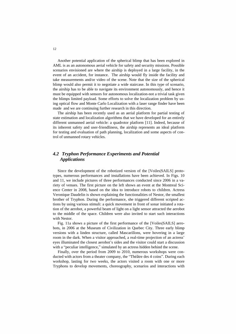
4.2 Tryphon Performance Experiments and Potential
Applications
Since the development of the robotized version of the [Voiles|SAILS] proto-
types, numerous performances and installations have been achieved. In Figs. 10
and 11, we include pictures of three performances conducted since 2006 in a va-
riety of venues. The first picture on the left shows an event at the Montreal Sci-
ence Center in 2008, based on the idea to introduce robots to children. Actress
Veronique Daudelin is shown explaining the functionalities of Nestor, the smallest
brother of Tryphon. During the performance, she triggered different scripted ac-
tions by using various stimuli: a quick movement in front of sonar initiated a rota-
tion of the aerobot, a powerful beam of light on a light sensor attracted the aerobot
to the middle of the space. Children were also invited to start such interactions
with Nestor.
Fig. 11a shows a picture of the first performance of the [Voiles|SAILS] aero-
bots, in 2006 at the Museum of Civilization in Quebec City. Three early blimp
versions with a linden structure, called Mascarillons, were hovering in a large
room in the dark. When a visitor approached, a real-time projection of an actress’
eyes illuminated the closest aerobot’s sides and the visitor could start a discussion
with a “peculiar intelligence,” simulated by an actress hidden behind the scene.
Finally, over the period from 2009 to 2010, numerous workshops were con-
ducted with actors from a theater company, the “Théâtre des 4 coins”. During each
workshop, lasting for two weeks, the actors visited a room with one or more
Tryphons to develop movements, choreography, scenarios and interactions with

13
the blimps (see Fig. 11b). The first public demonstration based on these work-
shops will be held in Sao Paulo FILE festival in July 2012. The show will be
based on a partially improvised choreography and the aerobot will be controlled
by the dancer’s movements and singing.
Fig. 10 Interactive Performance in Montreal Science Center. Actress: Véronique Daudelin.
Fig. 11 Left: discussion with an aerobot at the Quebec Museum of Civilization, 2006; right:
art residency with the Theatre des Quatre Coins at Laval University, Quebec, 2010.
The above example events illustrate the specific constraints that determined the
design of the Tryphons, which are quite different from those that defined the AML
spherical aerobot. The Tryphons were planned from the very beginning with artis-
tic/performance objectives in mind. Thus, their abilities and functionalities were to
be used for the sake of conveying expressions and emotions through combinations
of translations, rotations, states and behaviours; they were seen as embedding no-
tions of personality and identity. While the first installations involved only reac-
tions from visitors, the cubes were designed to interact with humans (audience or
performers) through a variety of sensors. Scripted interactions with actors have
been possible for the past three years, and many relevant observations were made

14
prior to that from the visitors’ reactions to the cubes. These observations allowed
us to refine the aerobot’s sensing abilities in order to create full interactive per-
formances, in which performers and aerobots interact through real hybrid choreog-
raphies. In particular, they influenced the number and positioning of sonar sensors
on the cube’s periphery, and led us to use information from different sensor mo-
dalities, in order to compensate for the imprecisions inherent to any kind of sens-
ing device.
Interactions with humans can lead to applications in the fields of museology or
event design. The cubes “have been invited” to fashion design shows; with a prop-
er sensor configuration, they could be used as individual or group guides for exhi-
bitions or historical places. In addition to the possibility for them to speak through
sound transducers, they could display written information on their faces thanks to
micro video projectors inserted in the helium bladder.
Similarly to the AML spherical blimp, the cubes can also be used for engineer-
ing applications. Profiting from their cubic shape, which allows assembly of
Tryphons into structures, several horizontal or vertically connected cubes can lift
multi-kilogram payloads, like flying cranes. In indoor large spaces, they could be
used to carry objects or pieces with excellent degree of precision. The cubes can
become test-beds for the development of control algorithms for six-dof objects in
zero-gravity environment. In this case though, their particular geometry imposes
certain limits: because of the cubic shape, their moments of inertia depend on their
rotation axis. However, that very same shape allows for implementation and test-
ing of autonomous assembly algorithms for applications to space structure assem-
bly and other space missions.
5 Conclusions and Future Work
We have summarized the development and experiments conducted with two
unique indoor aerobots: the spherical blimp developed at McGill and the square
Tryphon blimp developed at UQAM. The aerobots represent a significant depar-
ture from conventional lighter-than-air vehicles, both in their design and intended
applications. Future work holds many more challenges with respect to developing
motion planning, state estimation and control strategies for fully autonomous op-
eration of the blimps for the intended applications: accurate trajectory tracking for
satellite emulation and for indoor navigation, docking of airships for recharging,
self-assembly of Tryphons into free-floating structures and autonomous behav-
iours in response to artists’ commands for hybrid performances.

15
Acknowledgements
Sharf would like to thank former graduate students Joel Robert, Yin Yang and
Mikelis Valdmanis for their dedication and perseverance with the development
and experiments on the spherical airship. Funding support from NSERC, PRE-
CARN and Canadian Space Agency is also gratefully acknowledged.
The [Voiles|SAILS] project was possible thanks to the work of more than sev-
en graduate students in computer science and engineering. The authors would like
to acknowledge the financial support of NSERC, the Canada Research Chair Pro-
gram, the MCCCF, the CALQ, the Canadian Council for the Arts, the FQRSC, the
Hexagram|CIAM Institute as well as of the UQAM fund for support to research
and creation (PAFARC).
References
[1] Kerzhanovich, V.V. and J.A., “Aerobots in planetary exploration,” 2000 IEEE Aerospace Conference. Proceedings (Cat. No.00TH8484), pp. 547-555 vol.7, 2000.
[2] C. Cooke et al., "See in particular Krutikov's flying cities", Editions of The
Museum of Modern Art, New York, USA, 1990.
[3] Agrawal, B.N. and Rasmussen, R.E., “Air-bearing-based satellite attitude dynamics
simulator for control software research and development,” Proceedings of the SPIE - The International Society for Optical Engineering, v 4366, 204-14, 2001.
[4] Wilson, S. “Information Arts”, MIT Press, Cambridge, USA, 2003. [5] Warren J-D, Adams J., Molle H. “Arduino Robotics”, Apress, New
York, USA, 2011. [6] Moura, L. et al. “INSIDE [art and science]”, LxXL, Lisbon, Portugal,
2009.
[7] Sharf, I., B. Laumonier, M. Persson and J. Robert, “Control of a Fully-
actuated Airship for Satellite Emulation,” Video Proceedings of IEEE Inter-
national Conference on Robotics and Automation, ICRA2008, Pasadena, CA,
May 19-23, 2008.
[8] Yang, Y., “Nonlinear Control and State Estimation of Holonomic Indoor Air-
ship,” M.Eng., Mechanical Engineering, McGill University, 2011.
[9] D. St-Onge, N. Reeves and C. Gosselin. “[VOILES|SAILS]: a modular architecture for
fast parallel development in an international multidisciplinary project.” Proceedings of the
ICAR'11, Tallinn, Estonia.
[10] Robert, J., “Autonomous Capture of a Free-floating Object Using a Predictive
Approach,” M.Eng., Mechanical Engineering, McGill University, 2008.
[11] Harmat, A., I. Sharf and M. Trentini, “Parallel Tracking and Mapping with
Multiple Cameras on an Unmanned Aerial Vehicle,” submitted to ICIRA2012.