A Reference Architecture for Satellite Systems Operations
145
sid.inpe.br/mtc-m21c/2018/09.11.17.51-TDI A REFERENCE ARCHITECTURE FOR SATELLITE SYSTEMS OPERATIONS Adair José Rohling Doctorate Thesis of the Graduate Course in Space Technology and Engineering, guided by Drs. Walter Abrahão dos Santos, and Maurício Gonçalves Vieira Ferreira, approved in October 10, 2018. URL of the original document: <http://urlib.net/8JMKD3MGP3W34R/3RQJ3F2> INPE São José dos Campos 2018
-
Upload
khangminh22 -
Category
Documents
-
view
0 -
download
0
Transcript of A Reference Architecture for Satellite Systems Operations

sid.inpe.br/mtc-m21c/2018/09.11.17.51-TDI
A REFERENCE ARCHITECTURE FOR SATELLITESYSTEMS OPERATIONS
Adair José Rohling
Doctorate Thesis of the GraduateCourse in Space Technologyand Engineering, guided by Drs.Walter Abrahão dos Santos,and Maurício Gonçalves VieiraFerreira, approved in October 10,2018.
URL of the original document:<http://urlib.net/8JMKD3MGP3W34R/3RQJ3F2>
INPESão José dos Campos
2018
PUBLISHED BY:
Instituto Nacional de Pesquisas Espaciais - INPEGabinete do Diretor (GBDIR)Serviço de Informação e Documentação (SESID)CEP 12.227-010São José dos Campos - SP - BrasilTel.:(012) 3208-6923/7348E-mail: [email protected]
COMMISSION OF BOARD OF PUBLISHING AND PRESERVATIONOF INPE INTELLECTUAL PRODUCTION (DE/DIR-544):Chairperson:Dr. Marley Cavalcante de Lima Moscati - Centro de Previsão de Tempo e EstudosClimáticos (CGCPT)Members:Dra. Carina Barros Mello - Coordenação de Laboratórios Associados (COCTE)Dr. Alisson Dal Lago - Coordenação-Geral de Ciências Espaciais e Atmosféricas(CGCEA)Dr. Evandro Albiach Branco - Centro de Ciência do Sistema Terrestre (COCST)Dr. Evandro Marconi Rocco - Coordenação-Geral de Engenharia e TecnologiaEspacial (CGETE)Dr. Hermann Johann Heinrich Kux - Coordenação-Geral de Observação da Terra(CGOBT)Dra. Ieda Del Arco Sanches - Conselho de Pós-Graduação - (CPG)Silvia Castro Marcelino - Serviço de Informação e Documentação (SESID)DIGITAL LIBRARY:Dr. Gerald Jean Francis BanonClayton Martins Pereira - Serviço de Informação e Documentação (SESID)DOCUMENT REVIEW:Simone Angélica Del Ducca Barbedo - Serviço de Informação e Documentação(SESID)André Luis Dias Fernandes - Serviço de Informação e Documentação (SESID)ELECTRONIC EDITING:Marcelo de Castro Pazos - Serviço de Informação e Documentação (SESID)Murilo Luiz Silva Gino - Serviço de Informação e Documentação (SESID)
sid.inpe.br/mtc-m21c/2018/09.11.17.51-TDI
A REFERENCE ARCHITECTURE FOR SATELLITESYSTEMS OPERATIONS
Adair José Rohling
Doctorate Thesis of the GraduateCourse in Space Technologyand Engineering, guided by Drs.Walter Abrahão dos Santos,and Maurício Gonçalves VieiraFerreira, approved in October 10,2018.
URL of the original document:<http://urlib.net/8JMKD3MGP3W34R/3RQJ3F2>
INPESão José dos Campos
2018
Cataloging in Publication Data
Rohling, Adair José.R636r A reference architecture for satellite systems
operations / Adair José Rohling. – São José dos Campos :INPE, 2018.
xx + 122 p. ; (sid.inpe.br/mtc-m21c/2018/09.11.17.51-TDI)
Thesis (Doctorate in Space Technology and Engineering) –Instituto Nacional de Pesquisas Espaciais, São José dos Campos,2018.
Guiding : Drs. Walter Abrahão dos Santos, and MaurícioGonçalves Vieira Ferreira.
1. Satellites control. 2. Reference architecture. 3. Softwarecomponent. I.Title.
CDU 629.783:004.4
Esta obra foi licenciada sob uma Licença Creative Commons Atribuição-NãoComercial 3.0 NãoAdaptada.
This work is licensed under a Creative Commons Attribution-NonCommercial 3.0 UnportedLicense.
ii


ACKNOWLEDGEMENTS
(In Portuguese)
A Deus pela minha vida e saúde.
Agradeço especialmente minha família, minha mãe e meu pai pela vida e educação.Também às minhas irmãs e especialmente minha esposa e filhas Ana Clara, Mariae Dayana, que apesar das dificuldades sempre me fortaleceram.
Aos Drs. Mauricio Gonçalves Vieira Ferreira e Walter Abrahão dos Santos: obrigadopor todas as orientações, incentivos e pela confiança depositada. À professora ElizaYumi Nakagawa e ao amigo Valdemar Vicente Graciano Neto pelos ensinamentosrecebidos durante o período de doutorado sanduíche na USP.
Agradeço ao INPE, UTFPR e ao CNPq. E também a todas as pessoas que se fizerampresentes e contribuíram na realização deste trabalho.
v


ABSTRACT
Software for Satellite Control Systems (SCS) domain performs a relevant role inspace systems, being responsible for ensuring the functioning of the satellites, fromthe orbit launch to the end of their lifetime. Systems in this domain are complex andare constantly evolving due to technological advancement of satellites, the significantincrease of controlled satellites, and the interoperability among space organizations.However, in order to meet such complexity and such evolution, the architectures ofthese systems have been usually designed in an isolated way by each organization,hence may be prone to recurrent efforts and difficulties of interoperability. In parallelto this scenario, reference architecture, a special type of software architecture thataggregates knowledge of a specific domain, has performed an important role forthe success in development, standardization, and evolution of systems in severaldomains. Nevertheless, the usage of reference architecture has not been explored inthe SCS domain. Thus, this thesis presents a Reference Architecture for SatelliteOperations Systems. Results achieved from using this reference architecture in thedevelopment of a Microsatellite Control System for National Institute for SpaceResearch (INPE) showed a significant reduction of effort, benefits of interoperability,scalability, and sharing of ground resources.
Keywords: Satellites Control. Reference Architecture. Software Component.
vii

UMA ARQUITETURA DE REFERÊNCIA PARA SISTEMAS DECONTROLE DE SATÉLITES
RESUMO
Software para o domínio de Sistemas de Controle de Satélites(SCS) desempenhamum papel relevante em sistemas espaciais, sendo responsável por assegurar o fun-cionamento dos satélites, desde seu lançamento em órbita até o final de sua vidaútil. Sistemas deste domínio são complexos e permanecem em constante evoluçãoem conseqüência dos avanços tecnológicos dos satélites, do aumento significativo desatélites controlados e da interoperabilidade entre as organizações espaciais. No en-tanto, para atender essas complexidade e evoluções, as arquiteturas desses sistemasgeralmente são projetadas de forma isolada em cada organização, e assim podemestar propensas a esforços recorrentes e dificuldades de interoperabilidade. Parale-lamente a este cenário, arquitetura de referência, um tipo especial de arquiteturade software que agrega conhecimento de um domínio específico, desempenha umpapel importante para o sucesso no desenvolvimento, padronização e evolução desistemas em vários domínios. No entanto, o uso de arquitetura de referência nãotem sido explorada em sua completude no domínio de SCS. Assim, o objetivo destetrabalho é estabelecer uma Arquitetura de Referência para Sistemas de Controle deSatélites. Resultados obtidos com o uso desta arquitetura de referência no desen-volvimento de um Sistema de Controle de Microssatélites para o Instituto Nacionalde Pesquisas Espaciais (INPE) apresentou uma redução significativa de esforços,benefícios de interoperabilidade, escalabilidade e compartilhamento de recursos emsolo. Como consequência, custos geralmente gastos no desenvolvimento e evoluçãode SCS podem ser reduzidos.
Palavras-chave: Controle de Satélites. Arquitetura de Referência. Componentes deSoftware.
ix

LIST OF FIGURES
Page
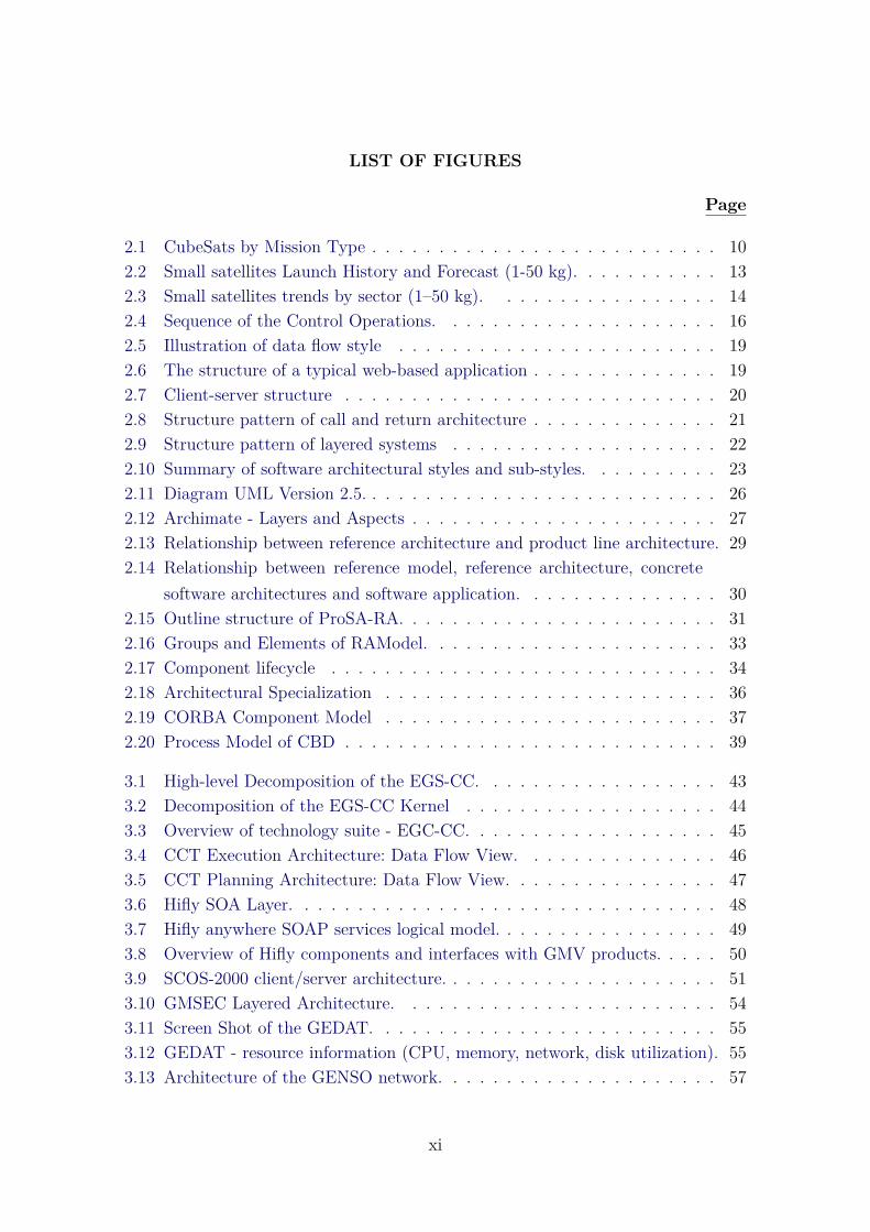
2.1 CubeSats by Mission Type . . . . . . . . . . . . . . . . . . . . . . . . . . 102.2 Small satellites Launch History and Forecast (1-50 kg). . . . . . . . . . . 132.3 Small satellites trends by sector (1–50 kg). . . . . . . . . . . . . . . . . 142.4 Sequence of the Control Operations. . . . . . . . . . . . . . . . . . . . . 162.5 Illustration of data flow style . . . . . . . . . . . . . . . . . . . . . . . . 192.6 The structure of a typical web-based application . . . . . . . . . . . . . . 192.7 Client-server structure . . . . . . . . . . . . . . . . . . . . . . . . . . . . 202.8 Structure pattern of call and return architecture . . . . . . . . . . . . . . 212.9 Structure pattern of layered systems . . . . . . . . . . . . . . . . . . . . 222.10 Summary of software architectural styles and sub-styles. . . . . . . . . . 232.11 Diagram UML Version 2.5. . . . . . . . . . . . . . . . . . . . . . . . . . . 262.12 Archimate - Layers and Aspects . . . . . . . . . . . . . . . . . . . . . . . 272.13 Relationship between reference architecture and product line architecture. 292.14 Relationship between reference model, reference architecture, concrete
software architectures and software application. . . . . . . . . . . . . . . 302.15 Outline structure of ProSA-RA. . . . . . . . . . . . . . . . . . . . . . . . 312.16 Groups and Elements of RAModel. . . . . . . . . . . . . . . . . . . . . . 332.17 Component lifecycle . . . . . . . . . . . . . . . . . . . . . . . . . . . . . 342.18 Architectural Specialization . . . . . . . . . . . . . . . . . . . . . . . . . 362.19 CORBA Component Model . . . . . . . . . . . . . . . . . . . . . . . . . 372.20 Process Model of CBD . . . . . . . . . . . . . . . . . . . . . . . . . . . . 39
3.1 High-level Decomposition of the EGS-CC. . . . . . . . . . . . . . . . . . 433.2 Decomposition of the EGS-CC Kernel . . . . . . . . . . . . . . . . . . . 443.3 Overview of technology suite - EGC-CC. . . . . . . . . . . . . . . . . . . 453.4 CCT Execution Architecture: Data Flow View. . . . . . . . . . . . . . . 463.5 CCT Planning Architecture: Data Flow View. . . . . . . . . . . . . . . . 473.6 Hifly SOA Layer. . . . . . . . . . . . . . . . . . . . . . . . . . . . . . . . 483.7 Hifly anywhere SOAP services logical model. . . . . . . . . . . . . . . . . 493.8 Overview of Hifly components and interfaces with GMV products. . . . . 503.9 SCOS-2000 client/server architecture. . . . . . . . . . . . . . . . . . . . . 513.10 GMSEC Layered Architecture. . . . . . . . . . . . . . . . . . . . . . . . 543.11 Screen Shot of the GEDAT. . . . . . . . . . . . . . . . . . . . . . . . . . 553.12 GEDAT - resource information (CPU, memory, network, disk utilization). 553.13 Architecture of the GENSO network. . . . . . . . . . . . . . . . . . . . . 57
xi
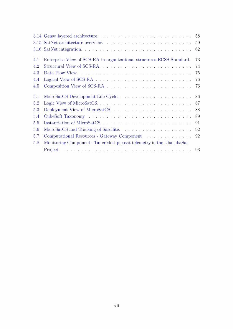
3.14 Genso layered architecture. . . . . . . . . . . . . . . . . . . . . . . . . . 583.15 SatNet architecture overview. . . . . . . . . . . . . . . . . . . . . . . . . 593.16 SatNet integration. . . . . . . . . . . . . . . . . . . . . . . . . . . . . . . 62
4.1 Enterprise View of SCS-RA in organizational structures ECSS Standard. 734.2 Structural View of SCS-RA. . . . . . . . . . . . . . . . . . . . . . . . . . 744.3 Data Flow View. . . . . . . . . . . . . . . . . . . . . . . . . . . . . . . . 754.4 Logical View of SCS-RA. . . . . . . . . . . . . . . . . . . . . . . . . . . . 764.5 Composition View of SCS-RA. . . . . . . . . . . . . . . . . . . . . . . . . 76
5.1 MicroSatCS Development Life Cycle. . . . . . . . . . . . . . . . . . . . . 865.2 Logic View of MicroSatCS. . . . . . . . . . . . . . . . . . . . . . . . . . . 875.3 Deployment View of MicroSatCS. . . . . . . . . . . . . . . . . . . . . . . 885.4 CubeSoft Taxonomy . . . . . . . . . . . . . . . . . . . . . . . . . . . . . 895.5 Instantiation of MicroSatCS. . . . . . . . . . . . . . . . . . . . . . . . . . 915.6 MicroSatCS and Tracking of Satellite. . . . . . . . . . . . . . . . . . . . 925.7 Computational Resources - Gateway Component . . . . . . . . . . . . . 925.8 Monitoring Component - Tancredo-I picosat telemetry in the UbatubaSat
Project. . . . . . . . . . . . . . . . . . . . . . . . . . . . . . . . . . . . . 93
xii
LIST OF TABLES
Page
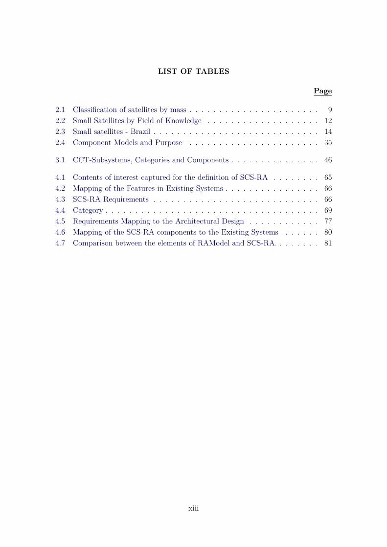
2.1 Classification of satellites by mass . . . . . . . . . . . . . . . . . . . . . . 92.2 Small Satellites by Field of Knowledge . . . . . . . . . . . . . . . . . . . 122.3 Small satellites - Brazil . . . . . . . . . . . . . . . . . . . . . . . . . . . . 142.4 Component Models and Purpose . . . . . . . . . . . . . . . . . . . . . . 35
3.1 CCT-Subsystems, Categories and Components . . . . . . . . . . . . . . . 46
4.1 Contents of interest captured for the definition of SCS-RA . . . . . . . . 654.2 Mapping of the Features in Existing Systems . . . . . . . . . . . . . . . . 664.3 SCS-RA Requirements . . . . . . . . . . . . . . . . . . . . . . . . . . . . 664.4 Category . . . . . . . . . . . . . . . . . . . . . . . . . . . . . . . . . . . . 694.5 Requirements Mapping to the Architectural Design . . . . . . . . . . . . 774.6 Mapping of the SCS-RA components to the Existing Systems . . . . . . 804.7 Comparison between the elements of RAModel and SCS-RA. . . . . . . . 81
xiii

LIST OF ABBREVIATIONS
ADL – Architectural Description LanguageATAM – Architecture Tradeoff Analysis MethodCAT – Criteria Action TableCBD – Component Based DevelopmentCCM – CORBA Component ModelCORBA – Common Object Request Bro-ker ArchitectureCCSDS – Consultative Committee for Space Data SystemsCCT – Control Channel ToolkitCOTS – Commercial off-the-shelfEGS-CC – European Ground Systems – Common CoreEJB – Enterprise Java BeansESOC – European Space Operations CenterFERA – Framework for Evaluation of Reference ArchitecturesGEDAT – GMSEC Environment Diagnostic Analysis ToolGMSEC – The Goddard Mission Services Evolution CenterGRASP – GMSEC Remote Access Service ProviderGREAT – GMSEC Reusable Event Analysis ToolkitGSFC – Goddard Space Flight CenterHTTPS – Hypertext Transfer Protocol SecureMOM – Message Oriented MiddlewareNRO – United States National Reconnais-sance OfficeOSGi – Open Services Gateway InitiativeRAModel – Reference Architecture ModelRASIM – Reference Architecture for Space Information ManagementRASDS – Reference Architecture for Space Data SystemsRPC – Remote Procedure CallsSA – System AgentSAAM – Software Architecture Analysis MethodSCS – Satellites Control SystemSCOS 2000 – Satellite Control and Operation System 2000SEI – Software Engineering InstituteSOA – Service Oriented ArchitectureSOAP – Simple Object Access Protocol
xv

CONTENTS
Page
1 INTRODUCTION . . . . . . . . . . . . . . . . . . . . . . . . . . . 11.1 Problem Statement and Justification for the Research . . . . . . . . . . . 21.2 Objectives . . . . . . . . . . . . . . . . . . . . . . . . . . . . . . . . . . . 41.3 Thesis Structure . . . . . . . . . . . . . . . . . . . . . . . . . . . . . . . 4
2 BACKGROUND . . . . . . . . . . . . . . . . . . . . . . . . . . . . 72.1 Space System . . . . . . . . . . . . . . . . . . . . . . . . . . . . . . . . . 72.2 Satellites . . . . . . . . . . . . . . . . . . . . . . . . . . . . . . . . . . . . 72.2.1 Historical Context . . . . . . . . . . . . . . . . . . . . . . . . . . . . . 82.2.2 Classification . . . . . . . . . . . . . . . . . . . . . . . . . . . . . . . . 92.2.3 CubeSat . . . . . . . . . . . . . . . . . . . . . . . . . . . . . . . . . . . 92.2.4 Applications for Small Satellites . . . . . . . . . . . . . . . . . . . . . . 112.2.5 Prospects for Small Satellites . . . . . . . . . . . . . . . . . . . . . . . 122.2.6 Small Satellites in Brazil . . . . . . . . . . . . . . . . . . . . . . . . . . 132.3 Satellite Control . . . . . . . . . . . . . . . . . . . . . . . . . . . . . . . 132.3.1 Satellite Control Center . . . . . . . . . . . . . . . . . . . . . . . . . . 152.3.1.1 INPE’s Satellites Control Center . . . . . . . . . . . . . . . . . . . . 172.4 Software Architecture . . . . . . . . . . . . . . . . . . . . . . . . . . . . 172.4.1 Architectural Style . . . . . . . . . . . . . . . . . . . . . . . . . . . . . 182.4.1.1 Data Flow Architectural Style . . . . . . . . . . . . . . . . . . . . . . 192.4.1.2 Independent Component Architectural Style . . . . . . . . . . . . . . 202.4.1.3 Call and Return Architectural Style . . . . . . . . . . . . . . . . . . 212.4.1.4 Data-Center Architectural Style . . . . . . . . . . . . . . . . . . . . . 222.4.1.5 Virtual Machine Architectural Style . . . . . . . . . . . . . . . . . . 222.4.2 Architectural View . . . . . . . . . . . . . . . . . . . . . . . . . . . . . 222.4.3 Architectural Representation . . . . . . . . . . . . . . . . . . . . . . . 252.5 Reference Architecture . . . . . . . . . . . . . . . . . . . . . . . . . . . . 272.5.1 ProSA-RA: A Process to Build Reference Architectures . . . . . . . . . 312.5.1.1 Step RA-1: Information Source Investigation . . . . . . . . . . . . . . 312.5.1.2 Step RA-2: Architectural Analysis . . . . . . . . . . . . . . . . . . . 322.5.1.3 Step RA-3: Architectural Synthesis . . . . . . . . . . . . . . . . . . . 322.5.1.4 Step RA-4: Architectural Evaluation . . . . . . . . . . . . . . . . . . 32
xvii
2.6 Software Components . . . . . . . . . . . . . . . . . . . . . . . . . . . . 322.6.1 Components Model . . . . . . . . . . . . . . . . . . . . . . . . . . . . . 342.6.1.1 Enterprise Java Beans (EJB) . . . . . . . . . . . . . . . . . . . . . . 362.6.1.2 CORBA Component Model (CCM) . . . . . . . . . . . . . . . . . . . 362.6.1.3 Open Services Gateway Initiative (OSGi) . . . . . . . . . . . . . . . 372.7 Component-Based Development . . . . . . . . . . . . . . . . . . . . . . . 382.7.1 Component-Based Development Process . . . . . . . . . . . . . . . . . 39
3 RELATED WORK . . . . . . . . . . . . . . . . . . . . . . . . . . . 413.1 Reference Architecture for Space Systems . . . . . . . . . . . . . . . . . 413.2 Software Application for Satellites Control Systems . . . . . . . . . . . . 423.2.1 The European Ground Systems – Common Core (EGS-CC) . . . . . . 423.2.2 Control Channel Toolkit (CCT) . . . . . . . . . . . . . . . . . . . . . . 443.2.3 Hifly . . . . . . . . . . . . . . . . . . . . . . . . . . . . . . . . . . . . . 473.2.4 Satellite Control and Operation System 2000 (SCOS-2000) . . . . . . . 513.2.5 Goddard Mission Services Evolution Center (GMSEC) . . . . . . . . . 523.2.6 Global Educational Network for Satellite Operations (Genso) . . . . . 563.2.7 Satellite Network (SatNet) . . . . . . . . . . . . . . . . . . . . . . . . . 583.2.7.1 SatNet Architecture . . . . . . . . . . . . . . . . . . . . . . . . . . . 583.2.7.2 SatNet Services . . . . . . . . . . . . . . . . . . . . . . . . . . . . . . 603.2.7.3 SatNet Integration . . . . . . . . . . . . . . . . . . . . . . . . . . . . 61
4 ESTABLISHMENT OF A REFERENCE ARCHITECTUREFOR SATELLITES CONTROL SYSTEM . . . . . . . . . . . . . 63
4.1 Step RA-1: Information Source Investigation . . . . . . . . . . . . . . . . 634.2 Step RA-2: Architectural Analysis . . . . . . . . . . . . . . . . . . . . . . 664.2.1 Architectural Requirements of SCS Domain . . . . . . . . . . . . . . . 664.2.2 Components of SCS Domain . . . . . . . . . . . . . . . . . . . . . . . . 684.2.2.1 Registry Component . . . . . . . . . . . . . . . . . . . . . . . . . . . 694.2.2.2 Mashup Component . . . . . . . . . . . . . . . . . . . . . . . . . . . 694.2.2.3 Discovery Component . . . . . . . . . . . . . . . . . . . . . . . . . . 704.2.2.4 Composition Component . . . . . . . . . . . . . . . . . . . . . . . . 704.2.2.5 Orbit Calculator Component . . . . . . . . . . . . . . . . . . . . . . 704.2.2.6 Telemetry Component . . . . . . . . . . . . . . . . . . . . . . . . . . 714.2.2.7 Maneuver Component . . . . . . . . . . . . . . . . . . . . . . . . . . 714.2.2.8 Telecommand Component . . . . . . . . . . . . . . . . . . . . . . . . 714.2.2.9 Schedule Component . . . . . . . . . . . . . . . . . . . . . . . . . . . 714.2.2.10 Spacecraft Component . . . . . . . . . . . . . . . . . . . . . . . . . . 71
xviii
4.2.2.11 Ground Station Component . . . . . . . . . . . . . . . . . . . . . . . 724.2.2.12 Tracking Component . . . . . . . . . . . . . . . . . . . . . . . . . . . 724.2.2.13 Gateway Component . . . . . . . . . . . . . . . . . . . . . . . . . . . 724.3 Step RA-3: Architectural Synthesis . . . . . . . . . . . . . . . . . . . . . 724.3.1 Enterprise View . . . . . . . . . . . . . . . . . . . . . . . . . . . . . . . 724.3.2 Structural View . . . . . . . . . . . . . . . . . . . . . . . . . . . . . . . 734.3.3 Data Flow View . . . . . . . . . . . . . . . . . . . . . . . . . . . . . . 744.3.4 Logical View . . . . . . . . . . . . . . . . . . . . . . . . . . . . . . . . 744.3.5 Composition View . . . . . . . . . . . . . . . . . . . . . . . . . . . . . 754.4 Step RA-4: Architectural Evaluation . . . . . . . . . . . . . . . . . . . . 774.4.1 Requirements Mapping to the Architectural Design . . . . . . . . . . . 774.4.2 Validation of the SCS-RA by Mapping of the SCS-RA Components to
the Existing Systems . . . . . . . . . . . . . . . . . . . . . . . . . . . . 804.4.3 Validation through the RAModel . . . . . . . . . . . . . . . . . . . . . 814.5 Final Remarks . . . . . . . . . . . . . . . . . . . . . . . . . . . . . . . . 84
5 CASE STUDY - USING SCS-RA FOR DEVELOPMENT OFMICROSATELLITES CONTROL SYSTEM . . . . . . . . . . . . 85
5.1 MicroSatCS Overview . . . . . . . . . . . . . . . . . . . . . . . . . . . . 855.2 The MicroSatCS Development Process . . . . . . . . . . . . . . . . . . . 855.3 Architectural Design Process . . . . . . . . . . . . . . . . . . . . . . . . . 875.4 Software Design & Implementation Process . . . . . . . . . . . . . . . . . 885.5 Software Operation Process . . . . . . . . . . . . . . . . . . . . . . . . . 915.6 Final Remarks . . . . . . . . . . . . . . . . . . . . . . . . . . . . . . . . 93
6 CONCLUSIONS AND FUTURE WORKS . . . . . . . . . . . . . 956.1 Discussion . . . . . . . . . . . . . . . . . . . . . . . . . . . . . . . . . . . 956.2 Final Remarks . . . . . . . . . . . . . . . . . . . . . . . . . . . . . . . . 956.3 List of Publications Attained . . . . . . . . . . . . . . . . . . . . . . . . 96
REFERENCES . . . . . . . . . . . . . . . . . . . . . . . . . . . . . . . 101
xix

1 INTRODUCTION
Satellites currently comprise an essential technology with high impact to society.They support and offer important services, such as telecommunication, global posi-tioning system (GPS), weather forecast, earth and space observation, meteorology,resource monitoring, military observation, and many others. INPE, as one of themain Brazilian organization for space technology, has concentrated its efforts topromote studies and scientific research for the technological and space environment,since its creation in 1961. There are numerous projects being developed and exe-cuted in the space area, including satellites SCD1, SCD2, SACI1, SACI2, SATEC,CBERS-1, CBERS-2, CBERS-2B, CBERS-3, CBERS-4 e CBERS-4A, Amazonia-1 and EQUARS. INPE has a Satellite Control Center (SCC) responsible for theplanning and execution of satellite control operations. The SCC has developed soft-ware solutions for Satellites Control Systems (SCS)1 since 1980s is always proposingadvances and technological innovations to contribute in this domain.
In order to keep them properly functioning, satellites are controlled during theirwhole lifetime by SCS. These systems control satellites in orbit by performing op-erations developed on the ground. Software solutions for SCS are complex and haveseveral functions, among which we can highlight: (i) sending telecommands; (ii)telemetry reception; (iii) mission data reception; (iv) satellites tracking; (v) at-titude control; (vi) maneuver calculation; (vii) orbit propagation and determina-tion; and (viii) flight plans generation. In addition to their various functionalities,such solutions must have scalability to meet the significant increase in the numberof controlled satellites. According to United Nations Office for Outer Space Af-fairs (UNOOSA) (UNITED NATIONS OFFICE FOR OUTER SPACE AFFAIRS (UNOOSA),2017), 7,853 objects were launched into outer space, excluding space debris and non-functional objects. As reported to Union of Concerned Scientists (UCS) (UNION OF
CONCERNED SCIENTISTS (UCS), 2017), there were 1,459 operational satellites bythe end of 2016. The Nano / Microsatellite market forecast (SPACEWORKS ENTER-
PRISES, 2017) shows a 70% increase in the number of launches of small satellites(up to 50 kg) from 2017 to 2023. In Brazil, for example, there is also a significantincrease in the number of projects and initiatives for the development and launch ofsmall satellites, such as NANOSATC-BR1, NANOSATC-BR2, AESP, CONASAT,ITASAT, EQUARS, UbatubaSat, SERPENS and FLORIPA-SAT.
Space organizations have several ground-based infrastructure resources to control
1For sake of simplicity, henceforth, we use this acronym to express both singular and plural.
1
satellites. Examples of these resources are antennas, rotors, modems, radio, Termi-nal Node Controller (TNC), computers, softwares, and data links. Most of themare only used during the satellites passages over their ground stations. The shar-ing of these resources among space organizations increases the number of accessesto the satellites, provides greater capacity to control and track them, and signifi-cantly reduces entire cost of a space mission (WERTZ; LARSON, 1999). The sharingof ground resources is addressed by the Consultative Committee for Space Data Sys-tems (CCSDS) through the standardization of Cross Support Services(CSS) (THE
CONSULTATIVE COMMITTEE FOR SPACE DATA SYSTEMS, 2006). The cross supportoccurs when one organization provides part of its resources to service the space datatransfer requirements of another organization (THE CONSULTATIVE COMMITTEE
FOR SPACE DATA SYSTEMS, 2005). On the ground segment, CSS are defined throughSpace Link Extension (SLE) services. In recent years, European Space Agency (ESA)has adopted the CCSDS Recommendations for SLE transfer services as a standardinterface for network ESTRACK (ARZA; DREIHAHN, 2012). The NASA/JPL alsoadopted the CCSDS Recommendations SLE for using in Deep Space Network(DSN)(NASA, 2014; NASA, 2015). The sharing of resources in ground is fundamental andhas several advantages, so that when we develop softwares for SCS, they can meet in-teroperability requirements among space organizations to make possible the sharingof ground resources.
In short, Software systems for SCS are complex and remain in constant evolution tocope with: (i) the diversity and complexity of space missions (as a consequence of theadvances in electronics and the increase of computational power, which enable satel-lites to perform diverse and extremely complex tasks in the space) (DVORAK, 2009;SHAMES; YAMADA, 2003); (ii) the significant increase in the number of controlledsatellites, mainly small ones (SORENSEN et al., 2012; SPACEWORKS ENTERPRISES,2017); and (iii) the interoperability and sharing of ground resources among spaceorganizations (SORENSEN et al., 2012; SHAMES; YAMADA, 2003; THE CONSULTATIVE
COMMITTEE FOR SPACE DATA SYSTEMS, 2005; THE CONSULTATIVE COMMITTEE
FOR SPACE DATA SYSTEMS, 2006; SHAMES; YAMADA, 2004).
1.1 Problem Statement and Justification for the Research
Several software applications have been developed, both in academia and in the in-dustry, to meet the evolution and complex scenario of SCS. However, during devel-opment and upgrades of such applications, each organization designs their softwarearchitecture in an isolated way and without an architectural model, causing signif-
2
icant and recurrent rework efforts. These software architectures may also furtherrequire adaptations during the process of interoperability among organizations thatadopt different SCS (CHAMOUN et al., 2006; SULLIVAN et al., 2009). Besides that,new adaptations may be necessary when performing new interoperability processes,interfering directly or indirectly with the existing ones. In Shames and Yamada(2003), Shames and Yamada (2004), THE CONSULTATIVE COMMITTEE FORSPACE DATA SYSTEMS (2013), it is stated that elements of a given SCS cannotbe easily used by others and it is also sometimes difficult even to describe the prob-lems associated with interoperability among SCS. In this sense, there are severalfactors which should be considered when developing interoperable SCS solutions,e.g., high security, availability, dependability, heterogeneity, and low cost (SMITH et
al., 2008). However, the lack of any type of architectural model or standard serviceshas led to non-interoperable systems (THE CONSULTATIVE COMMITTEE FOR SPACE
DATA SYSTEMS, 2013). As SCS becomes more complex, having architectural modelsthat can be used as a guideline to develop SCS architectures seem to be a suitablesolution.
In this context, Reference Architectures(RA)2 arise, encompassing the knowledgeabout how to design concrete architectures of systems by (i) capturing the essenceof software architectures of a particular application domain (OUSSALAH, 2014;MARTÍNEZ-FERNÁNDEZ, 2013), (ii) serving as standardization and evolution of soft-ware systems of a given domain (NAKAGAWA et al., 2011); (iii) avoiding the rein-vention or revalidation of solutions to problems already solved (CLOUTIER et al.,2010); and (iv) reducing costs of maintenance and development of software appli-cations (JONES, 1986; TRACZ, 1988; WENTZEL, 1994). Due to their advantages,RA has been proposed and also successfully used in several domains, including inthe industry (MARTÍNEZ-FERNÁNDEZ et al., 2015; CLEMENT et al., 2017; FERRO et al.,2015; KLEIN et al., 2016; PANUNZIO, 2011; NAKAGAWA et al., 2011; GUESSI et al., 2015;WEYRICH; EBERT, 2016; FILHO; BARBOSA, 2015; SHETH et al., 2010). Some importantinitiatives have encouraged the creation of RA in space systems (SHAMES; YAMADA,2003; THE CONSULTATIVE COMMITTEE FOR SPACE DATA SYSTEMS, 2013; THE CON-
SULTATIVE COMMITTEE FOR SPACE DATA SYSTEMS, 2008; PANUNZIO; VARDANEGA,2013; DURO et al., 2005). Nevertheless, the use of RA has not been explored in thedevelopment of systems for the SCS domain.
2For sake of simplicity, this acronym will be used interchangeably to express singular and pluralforms.
3
1.2 Objectives
According to the research gap characterized in the previous section, the general re-search question to be investigated in this thesis is whether or not the systematizationof the reference architecture can positively impact on the quality of SCS softwarearchitectures.
Motivated by this scenario, the main goal of this work is to establish a ReferenceArchitecture for Satellite Systems Operations. This reference architecture will be de-fined in the sequence as Reference Architecture for Satellite Control Systems (SCS-RA). SCS-RA has the following goals: (i) supporting the development and evolutionof SCS; (ii) contributing to improve interoperability, structuring and maintainingSCS; and (iii) contributing to improve reuse of software components when devel-oped based on SCS-RA. In order to establish SCS-RA, ProSA-RA (NAKAGAWA
et al., 2014) was used as a systematized process to design, represent, and evaluateRA. The validation of SCS-RA was carried out during the development of a Mi-crosatellites Control System (MicroSatCS). Results achieved through the adoptionof SCS-RA brought evidence of its feasibility and other advantages of its applica-bility. An additional contribution of this research is the definition of a SoftwareComponent Model for Satellite Control Domain (CubeSoft).
1.3 Thesis Structure
This thesis report is comprised of 6 chapters structured as described hereafter.
An overview of the background information that supports the topics investigated inthis thesis are explored in Chapter 2. Initially, key concepts related to Space Systemand Satellite Control are discussed. After that, theory associated with SoftwareArchitecture, Software Components, and Reference Architecture are addressed.
Chapter 3 comprises the related works and introduces some important initiativeswhich encourage the creation of RA in space systems. It explores some softwareapplication for Satellites Control Systems and their architectures. The EuropeanGround Systems – Common Core (EGS-CC), Control Channel Toolkit (CCT), Hiflysystem, Satellite Control and Operation System 2000 (SCOS-2000), Goddard Mis-sion Services Evolution Center (GMSEC), Global Educational Network for SatelliteOperations (Genso), and Satellite Network (SatNet) are parts of this study.
Chapter 4 describes the establishment of Reference Architecture for SCS (SCS-RA).We adopted the systematic process ProSA-RA to establish the SCS-RA. The estab-
4
lishment of SCS-RA involved the steps of ProSA-RA: Information Source Investiga-tion, Architectural Analysis, Architectural Synthesis, and Architectural Evaluation.The evaluation of SCS-RA was accomplished through the requirements mappingto the architectural design, mapping of the SCS-RA components to the existingsystems, and through the use RAModel. This chapter too shows final remarks.
Chapter 5 shows a case study of the use of SCS-RA in the development of a Mi-croSatellites Control System (MicroSatCS). The development of MicroSatCS con-tributed to observe benefits of adopting SCS-RA and to supply evidence on itsviability.
Finally, chapter 6 presents the conclusions of this study, revisiting the achievedcontributions, summarizing limitations, and brings the final remarks and futurework perspectives. The list of publications attained from this work is presented.
5

2 BACKGROUND
This chapter provides an overview of the subjects that underlie the research de-veloped in this thesis. The organization of the chapter is as follows. Section 2.1introduces the Space System. Section 2.2 presents key concepts about satellites.Section 2.3 shows an overview of Satellite Control. Sections 2.4, 2.5, and 2.6 char-acterizes the state-of-the-art of Software Architecture. Reference Architecture, andSoftware Components, respectively.
2.1 Space System
A space system is composed of all necessary elements for the development of aproduct which, at any given moment of its life cycle, should be in contact with thespace environment, whether it orbits the earth as any other celestial body, any othercelestial body or as it travels through space. Satellites, rockets and probes are themost visible of these products, projected in a space system.
The space system is better understood in its development through the constitutionof physical structural divisions based on peculiar functions. These divisions are de-nominated segments, according to (PISACANE, 2005). A segment is a set of elementswhich is grouped to form a larger component or main function within a system. Themain sections of a space system are:
a) Space segment: this is the part placed into orbit, denominated as satellites,probes, space stations;
b) Launch segment: it is the part used to place the space section into orbit,denominated rockets, spaceships, etc. ;
c) Ground segment: it is the part charged with supervision of the satellitefunctioning. It allows controlling the satellite during its life cycle, datacontrol and reception. It is constituted mainly by ground stations, datacommunication networks and the Satellite Control Center (SCC).
From now on, we will present details on satellites, which constitute the main elementof the space segment.
2.2 Satellites
The artificial satellite is a vehicle developed by man and placed in an orbit withthe aim of scientific investigation. Satellites are conceptually divided in two parts:
7
payload and the platform. The payload is constituted of specialized instruments des-tined to accomplish the mission proposed for the flight. This way, a remote sensingsatellite’s payload is typically a camera or a set of cameras. The platform is con-stituted by the necessary parts to support the launching and to serve the payload’soperations.
Each satellite performs functions in a space mission, which may be telecommunica-tions, remote sensing, data collection and scientific and technological testing (EURO-
PEAN COOPERATION FOR SPACE STANDARDIZATION (ECSS), 2000; WERTZ; LARSON,1999).
Satellites are equipped with devices to send and receive data. To keep adequatefunctioning, satellites are controlled by ground stations, which send instructions andreceive data from the mission and telemetry data from the satellite. This way, theground stations perform a fundamental role in the communication with the orbitingsatellites.
Today, we may verify a constant reduction in the size of satellites concurrentlywith an increase in the operational capability. The electronic miniaturization andthe increase in computational power resulted, resulted in an enormous increase innumber and importance of small satellites in the last years.
The new generations of small satellites are creating significant opportunities forresearch and industry. Some missions which were performed by large-sized satellitesbefore, now may be performed by small satellites (COUNCIL, 1994).
In the small satellites there is an important characteristic: the standardization ofvariables such as mass, form and dimensions. Because of that, the time for devel-opment and the construction costs may be significantly reduced (PUIG-SUARI et al.,2001).
2.2.1 Historical Context
The origin of satellites goes back to the development of small satellites, since 1957,when the former USSR launched the first satellite to space, the Sputnik I, weighting83.6kg. Other small satellites also inhabited space, as did the Explorer and theVanguard, launched by the USA, weighting 8.3kg and 1.47kg, respectively. Duringthat time, the limited capability of launchers set the restrictions for the mass and thedimensions of the satellites. The Sputnik, the Explorer and the Vanguard programshad a high success level and opened the doors to the space race. They were also
8
the forerunners for technologies as space thermal control, telemetry transmissionand reception in orbit, and solar power and transistors, which contributed to thereduction in the size of satellites (HELVAJIAN; JANSON, 2008).
2.2.2 Classification
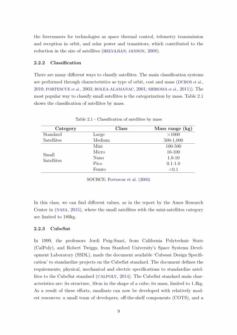
There are many different ways to classify satellites. The main classification systemsare performed through characteristics as type of orbit, cost and mass (DUBOS et al.,2010; FORTESCUE et al., 2003; BOLEA-ALAMANAC, 2001; SHIROMA et al., 2011)). Themost popular way to classify small satellites is the categorization by mass. Table 2.1shows the classification of satellites by mass.
Table 2.1 - Classification of satellites by mass
Category Class Mass range (kg)StandardSatellites
Large >1000Medium 500-1,000
SmallSatellites
Mini 100-500Micro 10-100Nano 1.0-10Pico 0.1-1.0Femto <0.1
SOURCE: Fortescue et al. (2003)
In this class, we can find different values, as in the report by the Ames ResearchCenter in (NASA, 2015), where the small satellites with the mini-satellites categoryare limited to 180kg.
2.2.3 CubeSat
In 1999, the professors Jordi Puig-Suari, from California Polytechnic State(CalPoly), and Robert Twiggs, from Stanford University’s Space Systems Devel-opment Laboratory (SSDL), made the document available ‘Cubesat Design Specifi-cation’ to standardize projects on the CubeSat standard. The document defines therequirements, physical, mechanical and electric specifications to standardize satel-lites to the CubeSat standard (CALPOLY, 2014). The CubeSat standard main char-acteristics are: its structure, 10cm in the shape of a cube; its mass, limited to 1.3kg.As a result of these efforts, smallsats can now be developed with relatively mod-est resources: a small team of developers, off-the-shelf components (COTS), and a
9
budget that is feasible and affordable for smaller organizations.
The main goal aimed by the professors by creating the CubeSat standard was tomake possible for students to design, build, test and operate a satellite with sim-ilar capabilities as the first satellites developed (CHIN et al., 2008a; PUIG-SUARI et
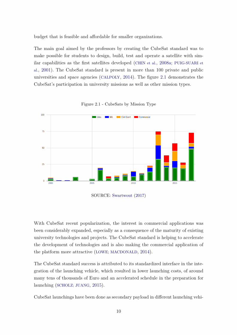
al., 2001). The CubeSat standard is present in more than 100 private and publicuniversities and space agencies (CALPOLY, 2014). The figure 2.1 demonstrates theCubeSat’s participation in university missions as well as other mission types.
Figure 2.1 - CubeSats by Mission Type
SOURCE: Swartwout (2017)
With CubeSat recent popularization, the interest in commercial applications wasbeen considerably expanded, especially as a consequence of the maturity of existinguniversity technologies and projects. The CubeSat standard is helping to acceleratethe development of technologies and is also making the commercial application ofthe platform more attractive (LOWE; MACDONALD, 2014).
The CubeSat standard success is attributed to its standardized interface in the inte-gration of the launching vehicle, which resulted in lower launching costs, of aroundmany tens of thousands of Euro and an accelerated schedule in the preparation forlaunching (SCHOLZ; JUANG, 2015).
CubeSat launchings have been done as secondary payload in different launching vehi-
10
cles (CHIN et al., 2008b). Shared launching between payloads is increasingly common,being good for all parties involved. The costs for producing and launching a CubeSatamount to approximately 65 to 80 thousand dollars (DAVID, 2004), and the approx-imate cost for launching averages 20 thousand dollars by kilogram (SUTHERLAND,2012; LOWE; MACDONALD, 2014).
2.2.4 Applications for Small Satellites
The micro-electronics technologies give small satellites the possibility to provideservices in the main areas of the space section. Areas such as telecommunications,geosciences, space science and teaching have small satellites as a resource to reachthe mission goals in the space section.
In the telecommunications area, there are some examples as the Brazilian satellites,SCD1 and SCD2, which provide transmission services for environmental data. Thereare also the American Teledesic satellites used for transmission of broadband Internetand the Globalstar satellite used to provide with telephone service to remote areas.
In the geosciences area, the small satellites have many applications, as in earth,atmosphere and ocean surveillance services. Miniaturization of technologies as elec-tronic cameras, optical telescopes and sensors were the main factors to contributeto this progress.
The small satellites have also been used in space science, accomplishing useful func-tions especially in the areas of astronomy and astrophysics, such as the observationof the celestial electromagnetic spectrum. In the educational area, the small satel-lite enabled the students to practice the development of space systems (HEIDT et al.,2000; BOLEA-ALAMANAC, 2001; THYAGARAJAN et al., 2005). Among the small satel-lites with mass lower than 10kg and built until 2010, around 52% had educationalpurposes (BOUWMEESTER; GUO, 2010). Table 2.2 presents some of the principalprojects for small satellites classified by field of knowledge.
There are other uses for small satellites, as in the use of experimental technology inthe space environment, due to the cost and to the fast development of components. Inmilitary activity, the small satellites can contribute to defense systems and also in thedemonstration of technology, signals intelligence, communication and observations.
11
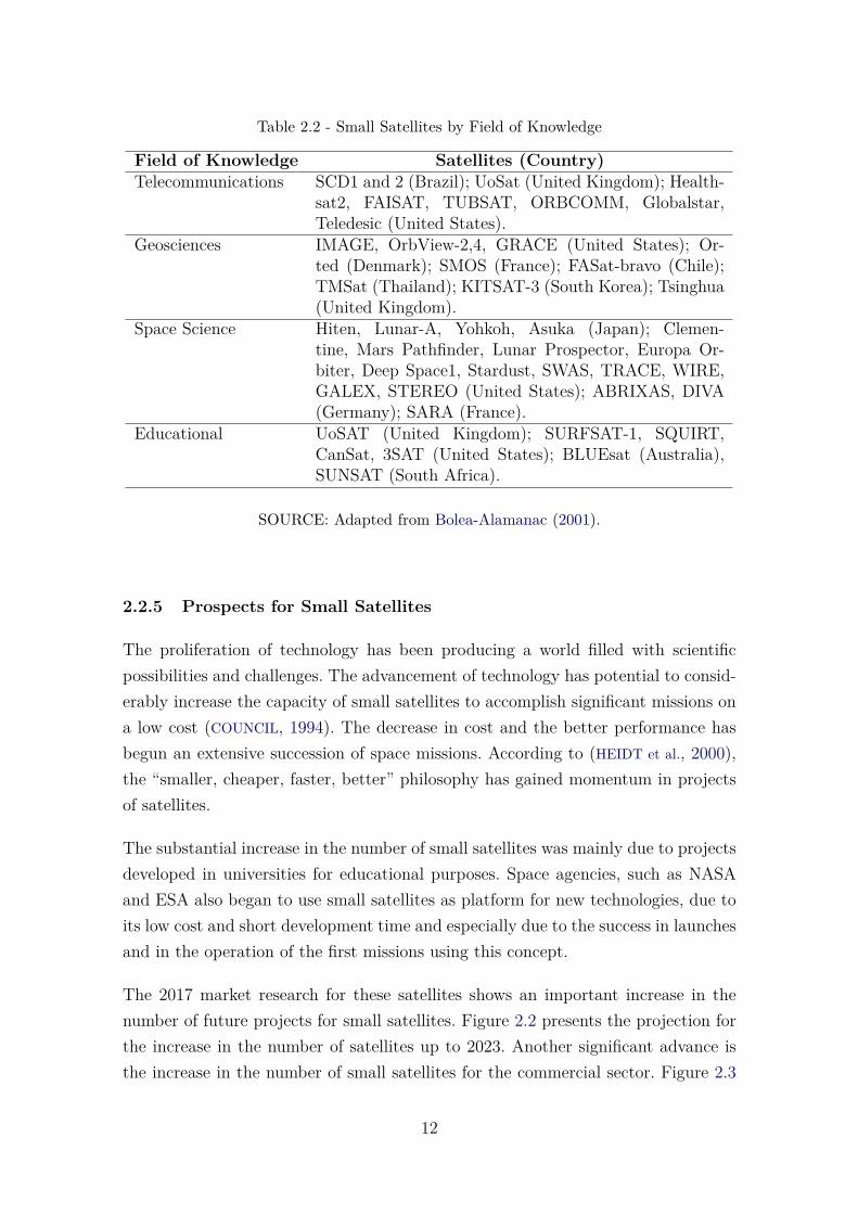
Table 2.2 - Small Satellites by Field of Knowledge
Field of Knowledge Satellites (Country)Telecommunications SCD1 and 2 (Brazil); UoSat (United Kingdom); Health-
sat2, FAISAT, TUBSAT, ORBCOMM, Globalstar,Teledesic (United States).
Geosciences IMAGE, OrbView-2,4, GRACE (United States); Or-ted (Denmark); SMOS (France); FASat-bravo (Chile);TMSat (Thailand); KITSAT-3 (South Korea); Tsinghua(United Kingdom).
Space Science Hiten, Lunar-A, Yohkoh, Asuka (Japan); Clemen-tine, Mars Pathfinder, Lunar Prospector, Europa Or-biter, Deep Space1, Stardust, SWAS, TRACE, WIRE,GALEX, STEREO (United States); ABRIXAS, DIVA(Germany); SARA (France).
Educational UoSAT (United Kingdom); SURFSAT-1, SQUIRT,CanSat, 3SAT (United States); BLUEsat (Australia),SUNSAT (South Africa).
SOURCE: Adapted from Bolea-Alamanac (2001).
2.2.5 Prospects for Small Satellites
The proliferation of technology has been producing a world filled with scientificpossibilities and challenges. The advancement of technology has potential to consid-erably increase the capacity of small satellites to accomplish significant missions ona low cost (COUNCIL, 1994). The decrease in cost and the better performance hasbegun an extensive succession of space missions. According to (HEIDT et al., 2000),the “smaller, cheaper, faster, better” philosophy has gained momentum in projectsof satellites.
The substantial increase in the number of small satellites was mainly due to projectsdeveloped in universities for educational purposes. Space agencies, such as NASAand ESA also began to use small satellites as platform for new technologies, due toits low cost and short development time and especially due to the success in launchesand in the operation of the first missions using this concept.
The 2017 market research for these satellites shows an important increase in thenumber of future projects for small satellites. Figure 2.2 presents the projection forthe increase in the number of satellites up to 2023. Another significant advance isthe increase in the number of small satellites for the commercial sector. Figure 2.3
12
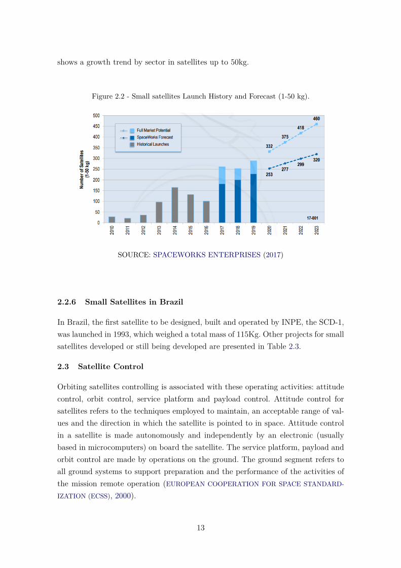
shows a growth trend by sector in satellites up to 50kg.
Figure 2.2 - Small satellites Launch History and Forecast (1-50 kg).
SOURCE: SPACEWORKS ENTERPRISES (2017)
2.2.6 Small Satellites in Brazil
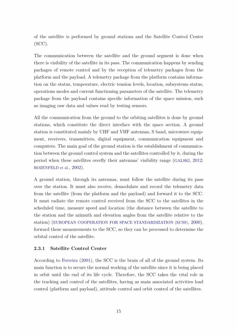
In Brazil, the first satellite to be designed, built and operated by INPE, the SCD-1,was launched in 1993, which weighed a total mass of 115Kg. Other projects for smallsatellites developed or still being developed are presented in Table 2.3.
2.3 Satellite Control
Orbiting satellites controlling is associated with these operating activities: attitudecontrol, orbit control, service platform and payload control. Attitude control forsatellites refers to the techniques employed to maintain, an acceptable range of val-ues and the direction in which the satellite is pointed to in space. Attitude controlin a satellite is made autonomously and independently by an electronic (usuallybased in microcomputers) on board the satellite. The service platform, payload andorbit control are made by operations on the ground. The ground segment refers toall ground systems to support preparation and the performance of the activities ofthe mission remote operation (EUROPEAN COOPERATION FOR SPACE STANDARD-
IZATION (ECSS), 2000).
13
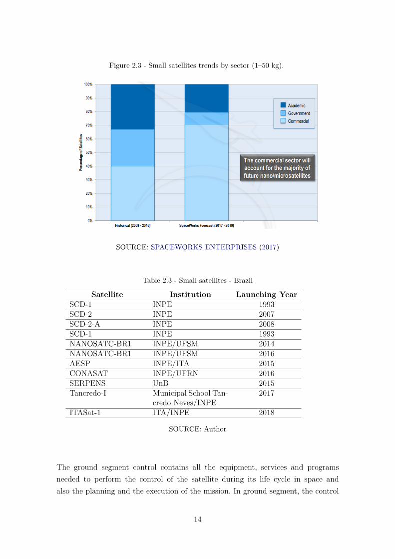
Figure 2.3 - Small satellites trends by sector (1–50 kg).
SOURCE: SPACEWORKS ENTERPRISES (2017)
Table 2.3 - Small satellites - Brazil
Satellite Institution Launching YearSCD-1 INPE 1993SCD-2 INPE 2007SCD-2-A INPE 2008SCD-1 INPE 1993NANOSATC-BR1 INPE/UFSM 2014NANOSATC-BR1 INPE/UFSM 2016AESP INPE/ITA 2015CONASAT INPE/UFRN 2016SERPENS UnB 2015Tancredo-I Municipal School Tan-
credo Neves/INPE2017
ITASat-1 ITA/INPE 2018
SOURCE: Author
The ground segment control contains all the equipment, services and programsneeded to perform the control of the satellite during its life cycle in space andalso the planning and the execution of the mission. In ground segment, the control
14
of the satellite is performed by ground stations and the Satellite Control Center(SCC).
The communication between the satellite and the ground segment is done whenthere is visibility of the satellite in its pass. The communication happens by sendingpackages of remote control and by the reception of telemetry packages from theplatform and the payload. A telemetry package from the platform contains informa-tion on the status, temperature, electric tension levels, location, subsystems status,operations modes and current functioning parameters of the satellite. The telemetrypackage from the payload contains specific information of the space mission, suchas imaging raw data and values read by testing sensors.
All the communication from the ground to the orbiting satellites is done by groundstations, which constitute the direct interface with the space section. A groundstation is constituted mainly by UHF and VHF antennas, S band, microwave equip-ment, receivers, transmitters, digital equipment, communication equipment andcomputers. The main goal of the ground station is the establishment of communica-tion between the ground control system and the satellites controlled by it, during theperiod when these satellites overfly their antennas’ visibility range (GALSKI, 2012;ROZENFELD et al., 2002).
A ground station, through its antennas, must follow the satellite during its passover the station. It must also receive, demodulate and record the telemetry datafrom the satellite (from the platform and the payload) and forward it to the SCC.It must radiate the remote control received from the SCC to the satellites in thescheduled time, measure speed and location (the distance between the satellite tothe station and the azimuth and elevation angles from the satellite relative to thestation) (EUROPEAN COOPERATION FOR SPACE STANDARDIZATION (ECSS), 2000),forward these measurements to the SCC, so they can be processed to determine theorbital control of the satellite.
2.3.1 Satellite Control Center
According to Ferreira (2001), the SCC is the brain of all of the ground system. Itsmain function is to secure the normal working of the satellite since it is being placedin orbit until the end of its life cycle. Therefore, the SCC takes the vital role inthe tracking and control of the satellites, having as main associated activities loadcontrol (platform and payload), attitude control and orbit control of the satellites.
15
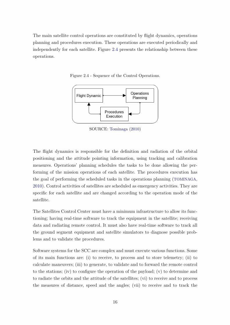
The main satellite control operations are constituted by flight dynamics, operationsplanning and procedures execution. These operations are executed periodically andindependently for each satellite. Figure 2.4 presents the relationship between theseoperations.
Figure 2.4 - Sequence of the Control Operations.
SOURCE: Tominaga (2010)
The flight dynamics is responsible for the definition and radiation of the orbitalpositioning and the attitude pointing information, using tracking and calibrationmeasures. Operations’ planning schedules the tasks to be done allowing the per-forming of the mission operations of each satellite. The procedures execution hasthe goal of performing the scheduled tasks in the operations planning (TOMINAGA,2010). Control activities of satellites are scheduled as emergency activities. They arespecific for each satellite and are changed according to the operation mode of thesatellite.
The Satellites Control Center must have a minimum infrastructure to allow its func-tioning; having real-time software to track the equipment in the satellite; receivingdata and radiating remote control. It must also have real-time software to track allthe ground segment equipment and satellite simulators to diagnose possible prob-lems and to validate the procedures.
Software systems for the SCC are complex and must execute various functions. Someof its main functions are: (i) to receive, to process and to store telemetry; (ii) tocalculate maneuvers; (iii) to generate, to validate and to forward the remote controlto the stations; (iv) to configure the operation of the payload; (v) to determine andto radiate the orbits and the attitude of the satellites; (vi) to receive and to processthe measures of distance, speed and the angles; (vii) to receive and to track the
16
ground segment status; (viii) to store, to retrieve and to present historical data; (ix)to prepare and to perform maneuvers with the satellites; (x) to generate the passingprojections for satellites over the stations; and (xi) to generate flight plans for thecontrolled satellites. The CCS also performs preparation stages to control and tosupport launches, involving adaptation of the ground infrastructure (ROZENFELD et
al., 2002).
2.3.1.1 INPE’s Satellites Control Center
The system of Satellite Tracking and Control Center (CRC), of the INPE locatedin São José dos Campos (SP) is constituted by the CCS; remote ground stationslocated in Cuiabá (MT) and Alcântara (MA). The CRC also have data and voicecommunication networks linking these places, which operates 24 hours per day, 365days per year (INSTITUTO NACIONAL DE PESQUISAS ESPACIAIS, 2017). Through thisnetwork, satellite signals are received and sent to the CCS, where telemetry messagescontained by the signal are decoded, seen in real-time and stored in digital format.On the opposite side, the remote control generated by the CCS is transmitted tothe station which, in its turn, transmits it to the satellite. To control its activities,the CCS has the software SATellite Control System (SATCS), which was developedespecially to control satellites developed by the INPE.
2.4 Software Architecture
The concept of software architecture is presented in the literature through vari-ous definitions. These definitions usually include words like structure, connections,elements and components. The following are some of these definitions.
Software architecture can be defined as a structure, or set of system structures, whichincludes software elements; externally visible properties of these elements; and therelationships between them (BRITO et al., 2007). In Bass et al. (2003), software ar-chitecture is defined as a high-level structure of the system in terms of architecturalelements, abstracting details from its implementation. In Garlan (2000), the ar-chitecture is: the structure of components of a system; the relationships betweenthese components, the principles and guidelines that govern the projects; and theevolution of the software. The ISO/IEC 42010 (INSTITUTO FOR ELECTRICAL AND
ELECTRONICS ENGINEERS, 2007), defines architecture as the fundamental organi-zation of a system, represented by its components, relationships, and the principlesthat drive its design and evolution. On the website of the Software Engineering In-stitute (SEI), there is a list of definitions with definitions accepted by the software
17
community for the definition of the software architecture term1.
Software architecture becomes very important in the development process, contribut-ing as a communication guide among project stakeholders, manifesting design de-cisions in advance, and facilitating the transfer of knowledge from the system. Inthe process of developing architecture, elements are organized to represent a system.When the architecture is defined for a given application, this architecture is termedas an architectural instance.
The development of a software architecture is the activity that determines the qual-ity and maintainability of the software (WASSERMAN, 1996). During development,its components have the function of processing and storing the data for a certainfunctionality of the system (PERRY; WOLF, 1992). In addition to the components,another element of the architecture is the connector, which is responsible for thecommunication between the architectural components. A set of architectural com-ponents connected by architectural connectors define an architectural configuration(KRUGER; MATHEW, 2004).
2.4.1 Architectural Style
In the development of a software architecture, some structural patterns are used,which determine how the elements will relate. The type of communication and thedata inputs and outputs for each element in the architecture are also defined. Thus,this process of establishing the type of structures, communication and interfaces tobe applied in software architecture, defines its architectural style. Architectural stylecan also constrain the kind of design elements and the formal relationships amongthem.
An architectural style defines a family of systems in terms of a pattern of struc-tural organizations. It is an abstraction for a set of architectures that have a setof common architectural features. According to Zhu (2005), a architectural style isdetermined by the following types of features: a set of components; a set of con-nectors; a topological structure; and a set of semantic constraints. In Monroe etal. (1997), architectural styles have important properties, such as a vocabulary ofhigh-level design elements; design rules for component compositions; and semanticinterpretation. In order to present recurring solutions for the design of architectures,some styles were proposed, in the software engineering community. In the following,there is described some of the major architectural styles. The classification of the
1https://www.sei.cmu.edu/architecture/start/glossary/community.cfm
18
styles presented is based in (ZHU, 2005), a more complete set of architectural stylescan be obtained in (GARLAN et al., 2010; SHAW; GARLAN, 1996).
2.4.1.1 Data Flow Architectural Style
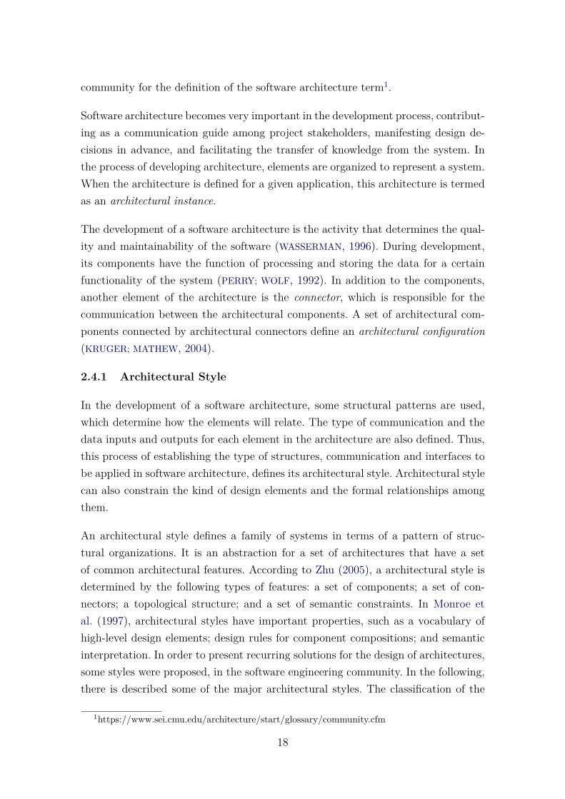
This style is widely used in various application domains where data processing playsa significant role. It is characterized by viewing the system as a series of transforma-tions on successive pieces of input data. The structure of the design is dominated byorderly motion of data from component to component. A data flow system can beviewed as a directed graph, where nodes are processing elements and arcs are dataflows between the elements (ZHU, 2005). Figure 2.5 illustrates the data flow style.Web-based applications can be regarded as in the data flow architectural style. Forexample, a typical e-business system depicted in the following Figure 2.6.
Figure 2.5 - Illustration of data flow style
SOURCE: Zhu (2005)
Figure 2.6 - The structure of a typical web-based application
SOURCE: Zhu (2005)
19
A way of understanding what can be different for systems in a style is to recognizeits sub-styles. There are two main sub-types of data flow style, sequential processingand pipe-and-filter.
2.4.1.2 Independent Component Architectural Style
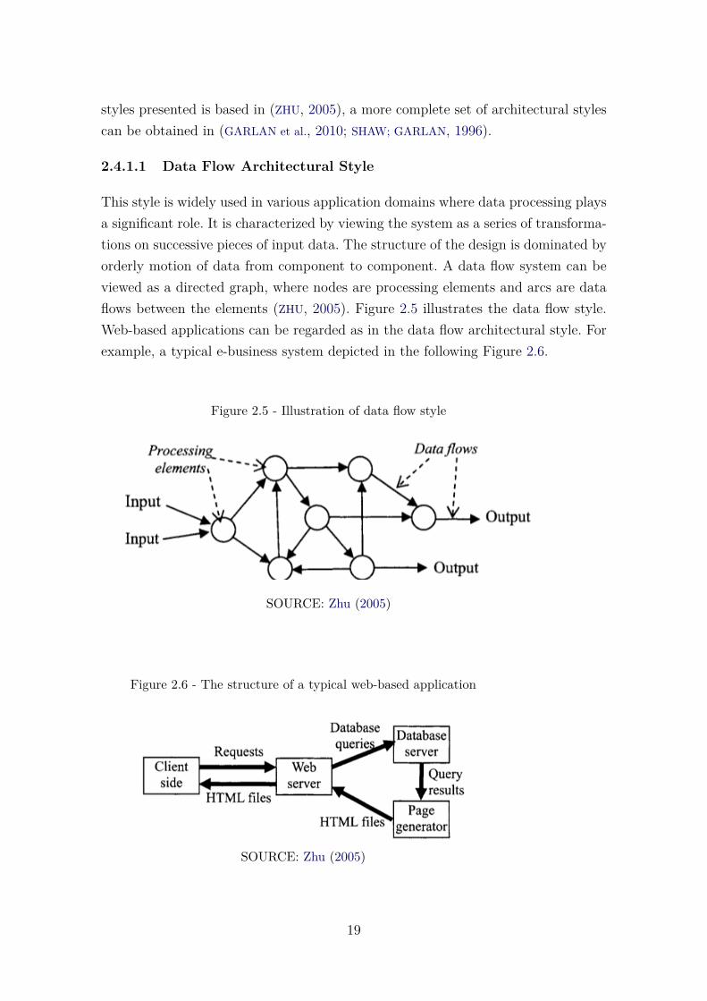
This architectural style consists of a number of independent components that com-municate asynchronously via messages. The message may be passed to named partic-ipants or passed among unnamed participants in case of using the publish/subscribeparadigm. The components send data to each other, but typically do not directlycontrol each other. This style has attracted increasing interest recently for its strongsupport to software reuse and evolution due to the ease it provides for the integrationof components into a system (ZHU, 2005).
The independent component style does not present a general pattern of system topo-logical structure. A typical example of independent component architecture is theclient-server architecture, which consists of a number of clients and one or moreservers, as shown in Figure 2.7. This style has the following sub-types of style: com-municating processes; event-based implicit invocation; and multi-agent systems. Inaddition to these sub-types, there is also C2 sub-style, which is designed to sup-port the particular needs of applications that have a graphical user interface aspect.However, this sub-style clearly has the potential for supporting other types of ap-plications (TAYLOR et al., 1996).
Figure 2.7 - Client-server structure
SOURCE: Zhu (2005)
20
2.4.1.3 Call and Return Architectural Style
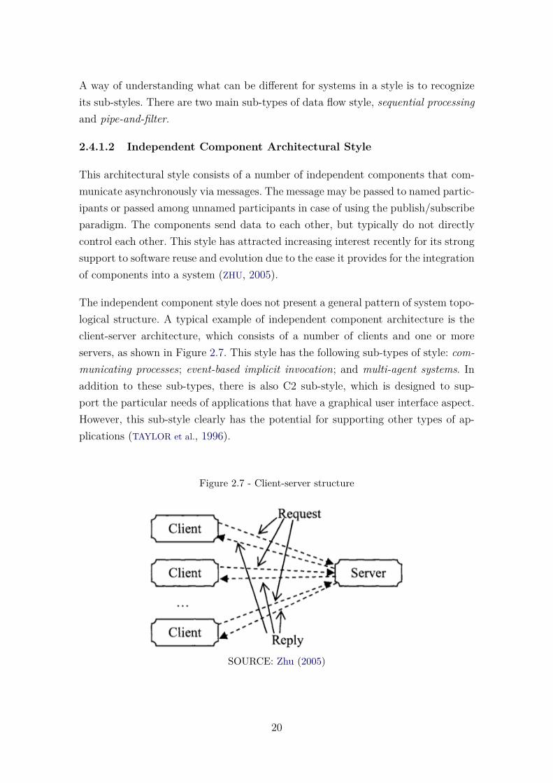
In software development, it is necessary to partition the system into cohesive andweakly coupled subsystems (LARMAN, 2005). Subsystems are usually identified bythe services they offer, defined through the operations of their interfaces. A softwaresystem in call and return style is essentially decomposed into smaller pieces to dealwith complexity and to help achieve modifiability.
Call and return style are directly supported by almost all high-level programminglanguages with the procedure/function facility, also called subroutine. Figure 2.8illustrates a structural pattern of a system in the call and return style. It can haveany topological structure that links subroutines by subroutine calls.
Figure 2.8 - Structure pattern of call and return architecture
SOURCE: Zhu (2005)
There are two main sub-types of call return style: one is layered systems, the other isdata abstraction including abstract data types and its advanced form object-orientedsystems. The main characteristic of the layered sub-style is its way of organizingsubroutines into a simple topological structure. Figure 2.9 shows a layered system.The subroutines are organized into a number of groups, which are called layers. Eachlayer contains a collection of subroutines that provide services at a certain abstractlevel to the layer or layers above it. Layers are widely used for building web systems,which consists of using three layers: (i) one responsible for the interaction betweenthe system and the user; (ii) another responsible for implementing the business rules;and (iii) a third which handles the storage of data. Software architectures organized
21
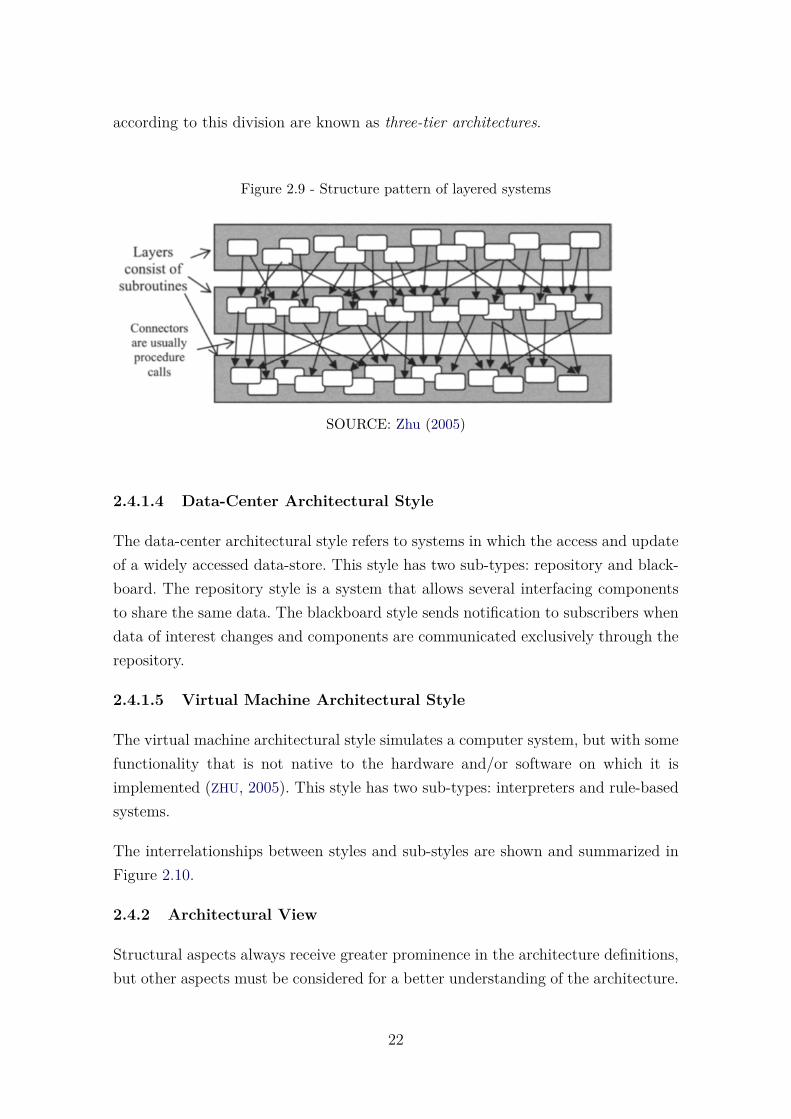
according to this division are known as three-tier architectures.
Figure 2.9 - Structure pattern of layered systems
SOURCE: Zhu (2005)
2.4.1.4 Data-Center Architectural Style
The data-center architectural style refers to systems in which the access and updateof a widely accessed data-store. This style has two sub-types: repository and black-board. The repository style is a system that allows several interfacing componentsto share the same data. The blackboard style sends notification to subscribers whendata of interest changes and components are communicated exclusively through therepository.
2.4.1.5 Virtual Machine Architectural Style
The virtual machine architectural style simulates a computer system, but with somefunctionality that is not native to the hardware and/or software on which it isimplemented (ZHU, 2005). This style has two sub-types: interpreters and rule-basedsystems.
The interrelationships between styles and sub-styles are shown and summarized inFigure 2.10.
2.4.2 Architectural View
Structural aspects always receive greater prominence in the architecture definitions,but other aspects must be considered for a better understanding of the architecture.
22

Figure 2.10 - Summary of software architectural styles and sub-styles.
SOURCE: Zhu (2005)
In Garlan et al. (2010), for the complete understanding of the architecture of a soft-ware, it is necessary to consider not only the structural perspective, but also aspectssuch as physical distribution, communication process, and synchronization. Thus,the software architecture must be seen and described under different views thatmust define its components, relationships, interactions, properties, characteristics,and constraints.
A architectural view is the representation of a coherent set of architectural elements,duly written and read by system stakeholders. It consists of a representation ofa set of elements and the relations among them. One of the models proposed inthe literature to organize the different architectural view is the model proposed by(KRUCHTEN, 1995), known as the “4+1 View Model of Architecture”. In this modelthe software architecture is defined in the five competing views, which are detailedin the sequence:
a) Logical View: a description of the data within the system and the decom-position of the system into logical abstractions. The behavior is distributedamong these abstractions;
b) Process View: a description of the organization of the data elements, in
23
terms of process and threads executing that will run on the hardware;
c) Development View: focuses on the organization of software in relation tothe development environment. In this view, the elements are libraries, sub-systems, files, class, and others;
d) Physical View: also known as the deployment view, this view shows thephysical organization of the system. It is concerned with the topology ofsoftware components on the physical layer as well as the physical connec-tions between these components;
e) Scenarios View: used to illustrate the behavior of the system in its archi-tecture through the main scenarios of use cases.
Another proposal that presents the architecture through views is the model definedby (HOFMEISTER et al., 1999). In this proposal, the classification of the descriptionof a software architecture is presented in four views: conceptual, module, execution,and code. Because of these four views, the model is called “The 4 Views ArchitecturalModel”.
In Herzum and Sims (2000), the following views are characterized as the most rele-vant visions for definition of software architecture:
a) Technical Architecture: refers to the components of the execution environ-ment, tools and other technical facilities required to develop and run acomponent-based system;
b) Application Architecture: refers to the set of architectural decisions, stan-dards and guides required to build a system based on components;
c) Project Management Architecture: presents concepts, guides, principlesand management tools needed to build a large system;
d) Functional Architecture: where the specification and implementation of thesystem is performed.
In Clements (2003), three categories of views are presented to represent the softwarearchitecture: Module View, Component-and-Connector View, and Allocation View.These views are detailed in the sequence:
24
a) Module View: it considers the elements as modules, which are units ofimplementation. Modules represent a code-based way of considering thesystem. Modules are assigned responsibilities or functionalities;
b) Component-and-connector View: elements are run-time components (maincomputing units) and connectors (which represent communication pathsamong components);
c) Allocation View: this view presents the relationship between the elementsof the software and the elements of the external environments where thesystem is executed.
2.4.3 Architectural Representation
Architectural representation plays an important role in communication, quality as-sessment, evaluation, and evolution in software architecture. The architecture of asystem is usually expressed through a set of diagrams representing different archi-tectural views of the system.
However, considering the importance of the software architecture, it is essential toproperly represent software architecture during the life-cycle of software systems.
Software architecture can be represented in different forms. An Architectural De-scription Language (ADL) can define different forms of representation of a softwarearchitecture (INSTITUTO FOR ELECTRICAL AND ELECTRONICS ENGINEERS, 2007).As examples of ADLs, we can mention the languages: Architecture Analysis & De-sign Language(AADL)2, Systems Modelling Language (SYSML)3, Unified ModelingLanguage (UML)4, ArchiMate5.
Among the existing architectural description languages, it is important to highlightthe UML. The UML has been the basis for modeling many software systems, ithas a wide variety of diagrams and also various tools that support its adoption atdifferent stages of the software life cycle. From its version 2.0, in addition to systemmodeling, UML presented technical characteristics and capabilities for architecturalsoftware description (IVERS et al., 2004). In its version 2.5, the UML provides a set ofdiagrams divided into three categories (Structure, Behavior, Interaction), as shownin Figure 2.11.
2http://www.aadl.info3http://www.omgsysml.org4http://www.uml.org/5http://www.opengroup.org/subjectareas/enterprise/archimate-overview
25
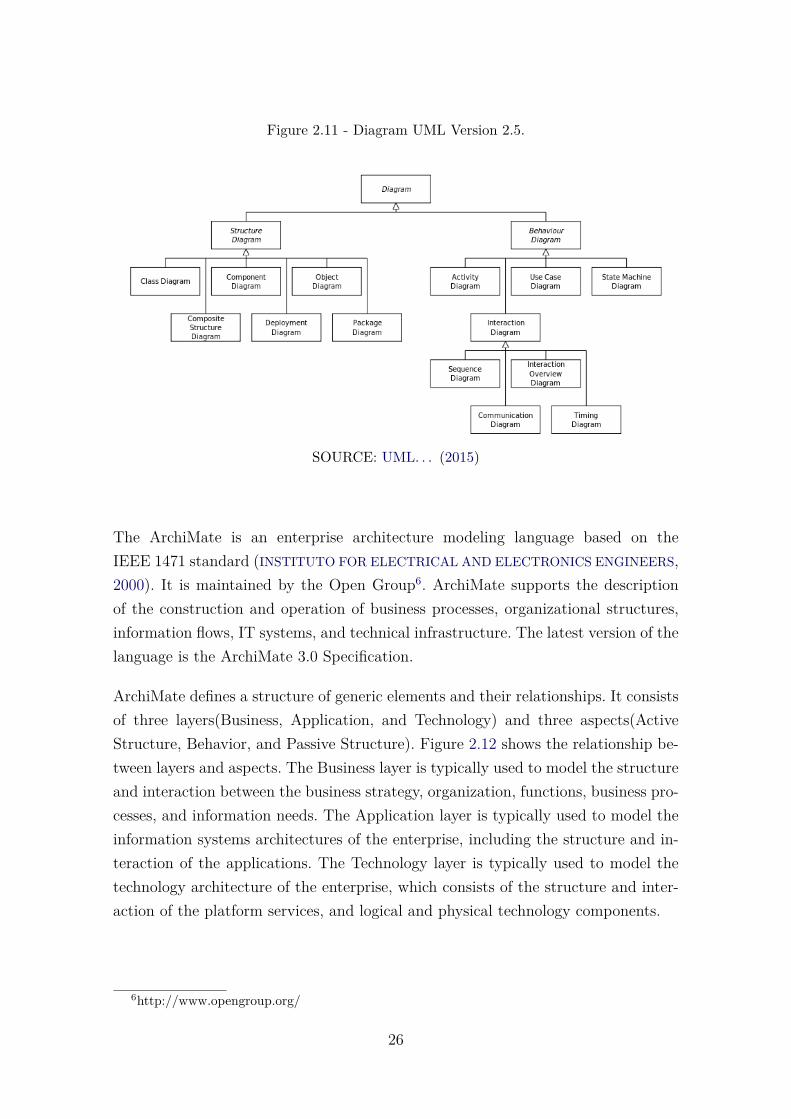
Figure 2.11 - Diagram UML Version 2.5.
SOURCE: UML. . . (2015)
The ArchiMate is an enterprise architecture modeling language based on theIEEE 1471 standard (INSTITUTO FOR ELECTRICAL AND ELECTRONICS ENGINEERS,2000). It is maintained by the Open Group6. ArchiMate supports the descriptionof the construction and operation of business processes, organizational structures,information flows, IT systems, and technical infrastructure. The latest version of thelanguage is the ArchiMate 3.0 Specification.
ArchiMate defines a structure of generic elements and their relationships. It consistsof three layers(Business, Application, and Technology) and three aspects(ActiveStructure, Behavior, and Passive Structure). Figure 2.12 shows the relationship be-tween layers and aspects. The Business layer is typically used to model the structureand interaction between the business strategy, organization, functions, business pro-cesses, and information needs. The Application layer is typically used to model theinformation systems architectures of the enterprise, including the structure and in-teraction of the applications. The Technology layer is typically used to model thetechnology architecture of the enterprise, which consists of the structure and inter-action of the platform services, and logical and physical technology components.
6http://www.opengroup.org/
26
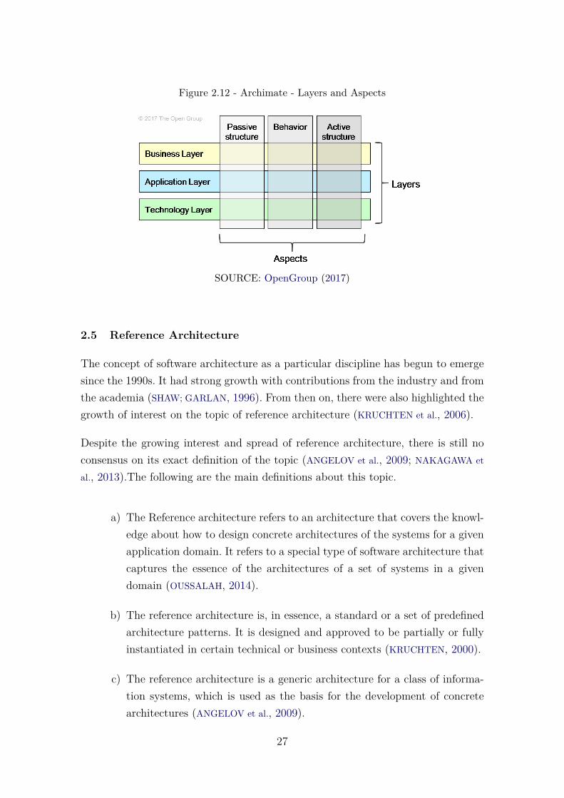
Figure 2.12 - Archimate - Layers and Aspects
SOURCE: OpenGroup (2017)
2.5 Reference Architecture
The concept of software architecture as a particular discipline has begun to emergesince the 1990s. It had strong growth with contributions from the industry and fromthe academia (SHAW; GARLAN, 1996). From then on, there were also highlighted thegrowth of interest on the topic of reference architecture (KRUCHTEN et al., 2006).
Despite the growing interest and spread of reference architecture, there is still noconsensus on its exact definition of the topic (ANGELOV et al., 2009; NAKAGAWA et
al., 2013).The following are the main definitions about this topic.
a) The Reference architecture refers to an architecture that covers the knowl-edge about how to design concrete architectures of the systems for a givenapplication domain. It refers to a special type of software architecture thatcaptures the essence of the architectures of a set of systems in a givendomain (OUSSALAH, 2014).
b) The reference architecture is, in essence, a standard or a set of predefinedarchitecture patterns. It is designed and approved to be partially or fullyinstantiated in certain technical or business contexts (KRUCHTEN, 2000).
c) The reference architecture is a generic architecture for a class of informa-tion systems, which is used as the basis for the development of concretearchitectures (ANGELOV et al., 2009).
27

d) The reference architecture consists of a repository of domain knowledgethat promotes architectural reuse and supports the development of systems(BASS et al., 2003).
The ’reference architecture’ term is generally considered synonymous with the term’product line architecture’ when assigned in the context of domain engineering, espe-cially in the design phase during the creation of the architecture artifact. However,despite the similarities of the terms, there are several differences between the refer-ence architecture and the product line architecture (NAKAGAWA et al., 2011):
a) Product line architectures are more specialized, sometimes focusing on aspecific subset of one domain system and providing standardized solutionsfor a smaller family of systems;
b) Reference architectures are used to standardize the external structure ofthe systems (interfaces and protocols) and consider the subsystems in-volved as black boxes. However, in product line architecture the focus isto build systems from a common set of artifacts. The internal structure isstandardized, aiming at the reuse of existing components that are consid-ered white boxes. Thus, reference architectures focus on external standard-ization, while product line architectures address internal standardization.
c) Product line architectures work with variabilities (information on how eachproduct differentiates itself into a software product line).
Typically, reference architectures have a higher level of abstraction if compared to theproduct line architecture, so they can also be the basis for product line architectures.In Nakagawa et al. (2013), a process is presented to systematize the use of thereference architecture in the context of software product lines, this relationship isshown in Figure 2.13.
Reference architecture is the abstraction of architectural knowledge for a particulardomain (OUSSALAH, 2014; MARTÍNEZ-FERNÁNDEZ, 2013), providing major guide-lines for the specification of software architectures (NAKAGAWA et al., 2011) thatconstitutes the main artifact to the success of software systems (KRUCHTEN et al.,2006; SHAW; CLEMENTS, 2006). Among the several goals of the software referencearchitecture is to serve as a guideline for the development, standardization andevolution of several software architectures of a specific domain (NAKAGAWA et al.,
28

Figure 2.13 - Relationship between reference architecture and product line architecture.
SOURCE: Nakagawa et al. (2014)
2011). This is possible because the software reference architecture is abstract enoughto allow its use in different contexts (ANGELOV et al., 2012).
Since Reference architecture is an important area of research in software architec-ture, several studies have focused on this special architecture type. Diverse domains,both in academy and industry, understood the advantages of such architecture andalready possess their own. Examples of such domains are Automotive (MARTÍNEZ-
FERNÁNDEZ et al., 2015), Smart City (CLEMENT et al., 2017), Ambient Assisted Liv-ing (FERRO et al., 2015), Big Data (KLEIN et al., 2016), On-board Space Applications(PANUNZIO, 2011), Software Engineering (NAKAGAWA et al., 2011), Embedded Sys-tems (GUESSI et al., 2015), Internet of Things (WEYRICH; EBERT, 2016), HealthcareSupportive Home Systems (RODRíGUEZ et al., 2015), Mobile Learning Environments(FILHO; BARBOSA, 2015), Recommender Systems (SHETH et al., 2010), and manyothers.
There are several types of reference architecture. A classification is presented inAngelov et al. (2012), which defines that the reference architecture can be classifiedthrough multidimensional space, based on the dimensions of context, goals, anddesign. The following classification of the reference architecture defines them as:
a) Type 1: These are classical, standardized architectures, designed to beimplemented in multiple organizations, and have a representative set ofusers and software.
b) Type 2: These are classical, standardized architectures, designed to beimplemented in an organization. Groups of software users provide require-
29
ments that designers of the software design groups.
c) Type 3: These are classic facilitation architectures, designed by an inde-pendent organization to be implemented in multiple organizations.
d) Type 4: These are classic facilitation architectures, designed to be imple-mented in a single organization. Their representation may be semi-formalor informal.
e) Type 5: These are preliminary architectures, designed to be deployed inmultiple organizations to facilitate future architecture projects.
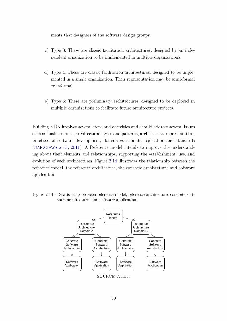
Building a RA involves several steps and activities and should address several issuessuch as business rules, architectural styles and patterns, architectural representation,practices of software development, domain constraints, legislation and standards(NAKAGAWA et al., 2011). A Reference model intends to improve the understand-ing about their elements and relationships, supporting the establishment, use, andevolution of such architectures. Figure 2.14 illustrates the relationship between thereference model, the reference architecture, the concrete architectures and softwareapplication.
Figure 2.14 - Relationship between reference model, reference architecture, concrete soft-ware architectures and software application.
SOURCE: Author
30
2.5.1 ProSA-RA: A Process to Build Reference Architectures
Diverse works have focused on the building of reference architectures (NAKAGAWA
et al., 2014; ANGELOV et al., 2012; BAYER et al., 2004; CLOUTIER et al., 2010; DO-
BRICA; NIEMELÄ, 2008) and their validation (NAKAGAWA et al., 2012; ANGELOV et
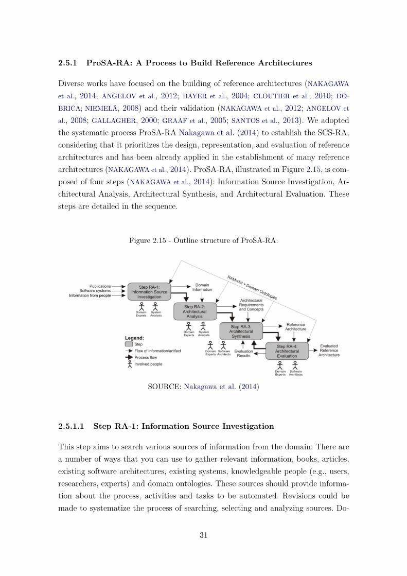
al., 2008; GALLAGHER, 2000; GRAAF et al., 2005; SANTOS et al., 2013). We adoptedthe systematic process ProSA-RA Nakagawa et al. (2014) to establish the SCS-RA,considering that it prioritizes the design, representation, and evaluation of referencearchitectures and has been already applied in the establishment of many referencearchitectures (NAKAGAWA et al., 2014). ProSA-RA, illustrated in Figure 2.15, is com-posed of four steps (NAKAGAWA et al., 2014): Information Source Investigation, Ar-chitectural Analysis, Architectural Synthesis, and Architectural Evaluation. Thesesteps are detailed in the sequence.
Figure 2.15 - Outline structure of ProSA-RA.
SOURCE: Nakagawa et al. (2014)
2.5.1.1 Step RA-1: Information Source Investigation
This step aims to search various sources of information from the domain. There area number of ways that you can use to gather relevant information, books, articles,existing software architectures, existing systems, knowledgeable people (e.g., users,researchers, experts) and domain ontologies. These sources should provide informa-tion about the process, activities and tasks to be automated. Revisions could bemade to systematize the process of searching, selecting and analyzing sources. Do-
31
main experts and system analysts actively participate in this step. As output fromthis step, a group of information sources is presented.
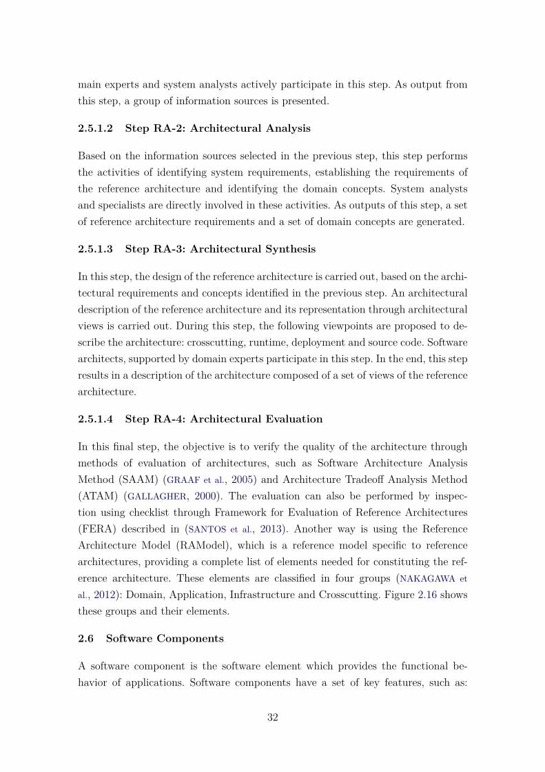
2.5.1.2 Step RA-2: Architectural Analysis
Based on the information sources selected in the previous step, this step performsthe activities of identifying system requirements, establishing the requirements ofthe reference architecture and identifying the domain concepts. System analystsand specialists are directly involved in these activities. As outputs of this step, a setof reference architecture requirements and a set of domain concepts are generated.
2.5.1.3 Step RA-3: Architectural Synthesis
In this step, the design of the reference architecture is carried out, based on the archi-tectural requirements and concepts identified in the previous step. An architecturaldescription of the reference architecture and its representation through architecturalviews is carried out. During this step, the following viewpoints are proposed to de-scribe the architecture: crosscutting, runtime, deployment and source code. Softwarearchitects, supported by domain experts participate in this step. In the end, this stepresults in a description of the architecture composed of a set of views of the referencearchitecture.
2.5.1.4 Step RA-4: Architectural Evaluation
In this final step, the objective is to verify the quality of the architecture throughmethods of evaluation of architectures, such as Software Architecture AnalysisMethod (SAAM) (GRAAF et al., 2005) and Architecture Tradeoff Analysis Method(ATAM) (GALLAGHER, 2000). The evaluation can also be performed by inspec-tion using checklist through Framework for Evaluation of Reference Architectures(FERA) described in (SANTOS et al., 2013). Another way is using the ReferenceArchitecture Model (RAModel), which is a reference model specific to referencearchitectures, providing a complete list of elements needed for constituting the ref-erence architecture. These elements are classified in four groups (NAKAGAWA et
al., 2012): Domain, Application, Infrastructure and Crosscutting. Figure 2.16 showsthese groups and their elements.
2.6 Software Components
A software component is the software element which provides the functional be-havior of applications. Software components have a set of key features, such as:
32
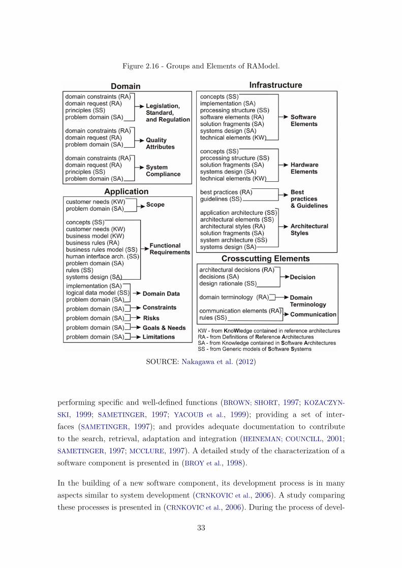
Figure 2.16 - Groups and Elements of RAModel.
SOURCE: Nakagawa et al. (2012)
performing specific and well-defined functions (BROWN; SHORT, 1997; KOZACZYN-
SKI, 1999; SAMETINGER, 1997; YACOUB et al., 1999); providing a set of inter-faces (SAMETINGER, 1997); and provides adequate documentation to contributeto the search, retrieval, adaptation and integration (HEINEMAN; COUNCILL, 2001;SAMETINGER, 1997; MCCLURE, 1997). A detailed study of the characterization of asoftware component is presented in (BROY et al., 1998).
In the building of a new software component, its development process is in manyaspects similar to system development (CRNKOVIC et al., 2006). A study comparingthese processes is presented in (CRNKOVIC et al., 2006). During the process of devel-
33
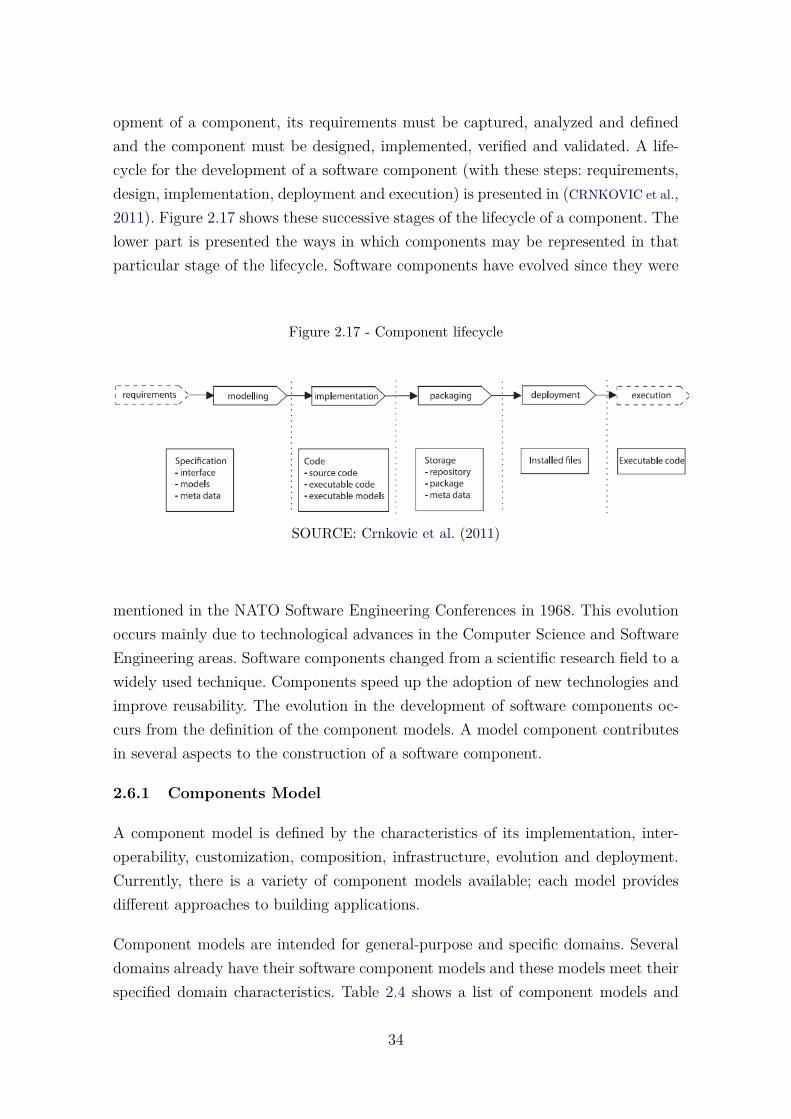
opment of a component, its requirements must be captured, analyzed and definedand the component must be designed, implemented, verified and validated. A life-cycle for the development of a software component (with these steps: requirements,design, implementation, deployment and execution) is presented in (CRNKOVIC et al.,2011). Figure 2.17 shows these successive stages of the lifecycle of a component. Thelower part is presented the ways in which components may be represented in thatparticular stage of the lifecycle. Software components have evolved since they were
Figure 2.17 - Component lifecycle
SOURCE: Crnkovic et al. (2011)
mentioned in the NATO Software Engineering Conferences in 1968. This evolutionoccurs mainly due to technological advances in the Computer Science and SoftwareEngineering areas. Software components changed from a scientific research field to awidely used technique. Components speed up the adoption of new technologies andimprove reusability. The evolution in the development of software components oc-curs from the definition of the component models. A model component contributesin several aspects to the construction of a software component.
2.6.1 Components Model
A component model is defined by the characteristics of its implementation, inter-operability, customization, composition, infrastructure, evolution and deployment.Currently, there is a variety of component models available; each model providesdifferent approaches to building applications.
Component models are intended for general-purpose and specific domains. Severaldomains already have their software component models and these models meet theirspecified domain characteristics. Table 2.4 shows a list of component models and
34
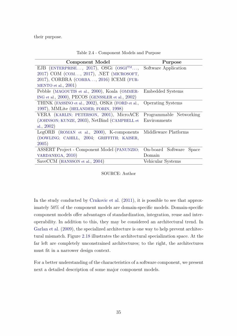
their purpose.
Table 2.4 - Component Models and Purpose
Component Model PurposeEJB (ENTERPRISE. . . , 2017), OSGi (OSGITM. . . ,2017) COM (COM. . . , 2017), .NET (MICROSOFT,2017), CORBRA (CORBA. . . , 2016) ICEMI (FUR-MENTO et al., 2001)
Software Application
Pebble (MAGOUTIS et al., 2000), Koala (OMMER-ING et al., 2000), PECOS (GENSSLER et al., 2002)
Embedded Systems
THINK (FASSINO et al., 2002), OSKit (FORD et al.,1997), MMLite (HELANDER; FORIN, 1998)
Operating Systems
VERA (KARLIN; PETERSON, 2001), MicroACE(JOHNSON; KUNZE, 2003), NetBind (CAMPBELL etal., 2002)
Programmable NetworkingEnvironments
LegORB (ROMAN et al., 2000), K-components(DOWLING; CAHILL, 2004; GRIFFITH; KAISER,2005)
Middleware Platforms
ASSERT Project - Component Model (PANUNZIO;VARDANEGA, 2010)
On-board Software SpaceDomain
SaveCCM (HANSSON et al., 2004) Vehicular Systems
SOURCE: Author
In the study conducted by Crnkovic et al. (2011), it is possible to see that approx-imately 50% of the component models are domain-specific models. Domain-specificcomponent models offer advantages of standardization, integration, reuse and inter-operability. In addition to this, they may be considered an architectural trend. InGarlan et al. (2009), the specialized architecture is one way to help prevent architec-tural mismatch. Figure 2.18 illustrates the architectural specialization space. At thefar left are completely unconstrained architectures; to the right, the architecturesmust fit in a narrower design context.
For a better understanding of the characteristics of a software component, we presentnext a detailed description of some major component models.
35
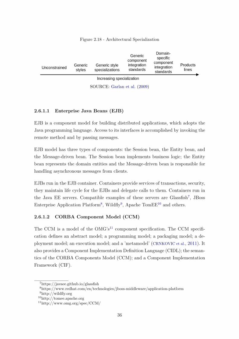
Figure 2.18 - Architectural Specialization
SOURCE: Garlan et al. (2009)
2.6.1.1 Enterprise Java Beans (EJB)
EJB is a component model for building distributed applications, which adopts theJava programming language. Access to its interfaces is accomplished by invoking theremote method and by passing messages.
EJB model has three types of components: the Session bean, the Entity bean, andthe Message-driven bean. The Session bean implements business logic; the Entitybean represents the domain entities and the Message-driven bean is responsible forhandling asynchronous messages from clients.
EJBs run in the EJB container. Containers provide services of transactions, security,they maintain life cycle for the EJBs and delegate calls to them. Containers run inthe Java EE servers. Compatible examples of these servers are Glassfish7, JBossEnterprise Application Platform8, Wildfly9, Apache TomEE10 and others.
2.6.1.2 CORBA Component Model (CCM)
The CCM is a model of the OMG’s11 component specification. The CCM specifi-cation defines an abstract model; a programming model; a packaging model; a de-ployment model; an execution model; and a ’metamodel’ (CRNKOVIC et al., 2011). Italso provides a Component Implementation Definition Language (CIDL); the seman-tics of the CORBA Components Model (CCM); and a Component ImplementationFramework (CIF).
7https://javaee.github.io/glassfish8https://www.redhat.com/en/technologies/jboss-middleware/application-platform9http://wildfly.org
10http://tomee.apache.org11http://www.omg.org/spec/CCM/
36
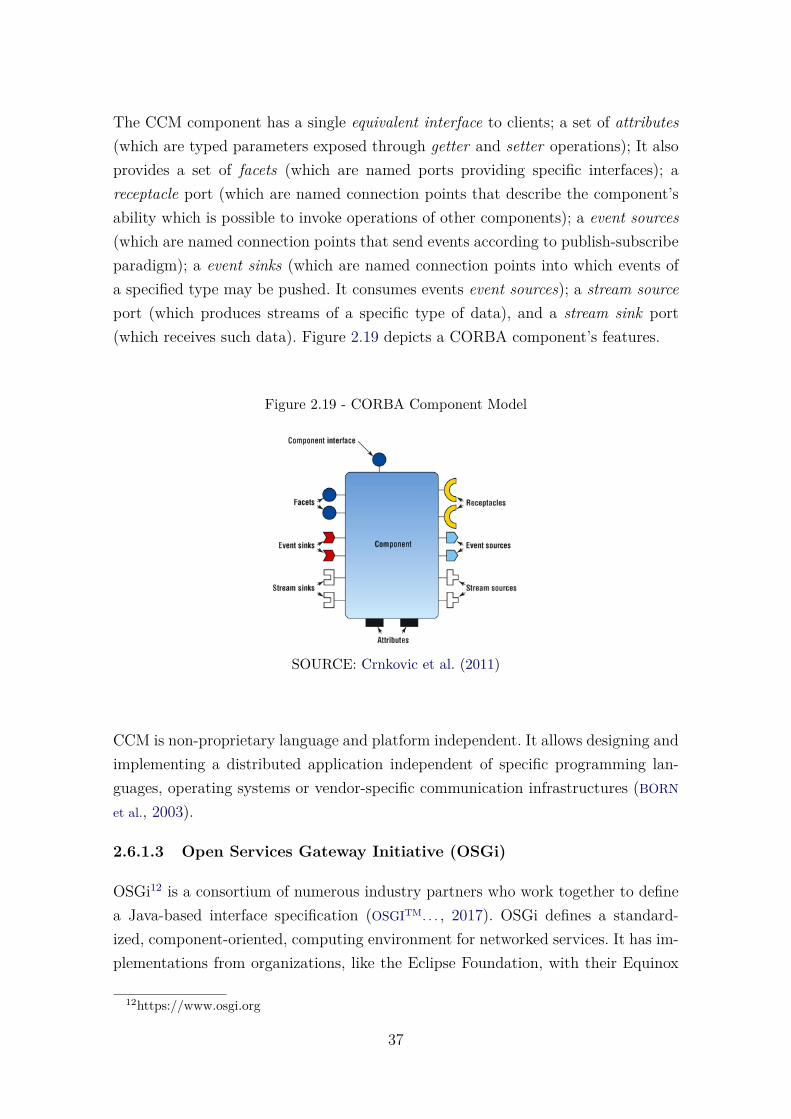
The CCM component has a single equivalent interface to clients; a set of attributes(which are typed parameters exposed through getter and setter operations); It alsoprovides a set of facets (which are named ports providing specific interfaces); areceptacle port (which are named connection points that describe the component’sability which is possible to invoke operations of other components); a event sources(which are named connection points that send events according to publish-subscribeparadigm); a event sinks (which are named connection points into which events ofa specified type may be pushed. It consumes events event sources); a stream sourceport (which produces streams of a specific type of data), and a stream sink port(which receives such data). Figure 2.19 depicts a CORBA component’s features.
Figure 2.19 - CORBA Component Model
SOURCE: Crnkovic et al. (2011)
CCM is non-proprietary language and platform independent. It allows designing andimplementing a distributed application independent of specific programming lan-guages, operating systems or vendor-specific communication infrastructures (BORN
et al., 2003).
2.6.1.3 Open Services Gateway Initiative (OSGi)
OSGi12 is a consortium of numerous industry partners who work together to definea Java-based interface specification (OSGITM. . . , 2017). OSGi defines a standard-ized, component-oriented, computing environment for networked services. It has im-plementations from organizations, like the Eclipse Foundation, with their Equinox
12https://www.osgi.org
37
framework (MCAFFER et al., 2010) and the Apache foundation, with the frameworkFelix (GÉDÉON, 2010).
The OSGi framework separates the components for deployment and run-time intobundles and services respectively. A bundle is comprised of java classes and otherresources, which together provide functions to end users.
OSGi is specific to Java. It is not platform-specific, requiring runtime container tomanage the component registration. The components are independent and can beadded, removed, or modified at runtime.
2.7 Component-Based Development
The Component Based Development (CBD) is a software development techniquethat builds on the rapid building of systems from existing components (BACHMANN
et al., 2000). A system is developed not as a monolithic entity, but from the composi-tion of parts that have already been constructed separately. The concept of reusingparts of existing systems arose primarily to amortize development costs, to reducecomplexity in software development and to increase the quality of systems produced(SZYPERSKI, 2011).
An important feature of CBD is the separation between the process of the devel-opment of the general system and the process of the development of the individualcomponents. The CBD, like any other software development process, involves devel-opmental phases with activities resulting in software artifacts, the difference beingthat the system is constituted with the base unit of components. In Brown andShort (1997), McClure (1997), Pour (1998), the predominant phases in the processmodels of CBD are: analysis of requirements, acquisition, component understand-ing, adaptation, composition and certification of the component. These phases arealso present in the process model proposed by (PRESSMAN, 2001), which is shownin Figure 2.20
The main activities of component-based development are the creation of compo-nents to be reused and the development of software based on existing compo-nents (KRUEGER, 1992). In Kotonya et al. (2003), these activities are defined ascomponent engineering and application engineering.
Component engineering aims to develop reusable components for the constructionof systems. The main steps are: domain analysis, component building, maintenanceand publication, and certification of software components relevant to a domain.
38
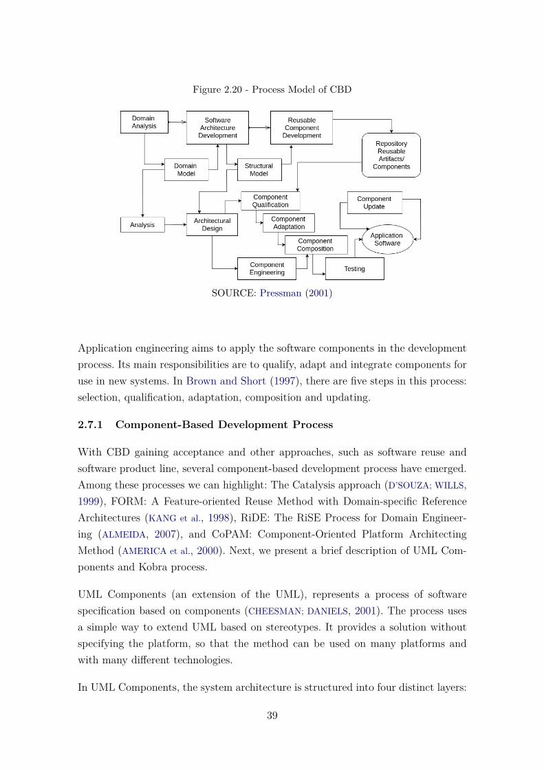
Figure 2.20 - Process Model of CBD
SOURCE: Pressman (2001)
Application engineering aims to apply the software components in the developmentprocess. Its main responsibilities are to qualify, adapt and integrate components foruse in new systems. In Brown and Short (1997), there are five steps in this process:selection, qualification, adaptation, composition and updating.
2.7.1 Component-Based Development Process
With CBD gaining acceptance and other approaches, such as software reuse andsoftware product line, several component-based development process have emerged.Among these processes we can highlight: The Catalysis approach (D’SOUZA; WILLS,1999), FORM: A Feature-oriented Reuse Method with Domain-specific ReferenceArchitectures (KANG et al., 1998), RiDE: The RiSE Process for Domain Engineer-ing (ALMEIDA, 2007), and CoPAM: Component-Oriented Platform ArchitectingMethod (AMERICA et al., 2000). Next, we present a brief description of UML Com-ponents and Kobra process.
UML Components (an extension of the UML), represents a process of softwarespecification based on components (CHEESMAN; DANIELS, 2001). The process usesa simple way to extend UML based on stereotypes. It provides a solution withoutspecifying the platform, so that the method can be used on many platforms andwith many different technologies.
In UML Components, the system architecture is structured into four distinct layers:
39

user interface, user communication, system services, and business services. In addi-tion, the process is compatible with UML for modeling all phases of development,including activities such as requirements definition, identification and description ofcomponent interfaces, modeling, specification implementation and composition.
The KobrA approach (ATKINSON et al., 2000), which has been developed at theFraunhofer Institute for Experimental Software Engineering (IESE), aims at pro-viding a systematic approach to the development of high-quality, component-basedapplication frameworks. KobrA has two main activities: initially, framework engi-neering creates and maintains a generic framework.
In KobrA, a framework is the static representation of a set of Komponents (KobrAcomponent). Each Komponent is described at three levels of abstraction: specifica-tion, realization and implementation. For each level of abstraction there is a set ofartifacts recommended for its specification as well as a set of activities associatedwith its production. Most of these specifications use UML diagrams and textualdescription. The complete list is presented in (ATKINSON et al., 2002).
40
3 RELATED WORK
This chapter presents the related work and introduces some important initiativeswhich encourage the creation of reference architecture for space systems. It exploressome software application for Satellites Control Systems and their architectures. TheEuropean Ground Systems – Common Core (EGS-CC), Control Channel Toolkit(CCT), Hifly system, Satellite Control and Operation System 2000 (SCOS-2000),Goddard Mission Services Evolution Center (GMSEC), Global Educational Networkfor Satellite Operations (Genso), and Satellite Network (SatNet) are part of thischapter.
3.1 Reference Architecture for Space Systems
CCSDS Recommended Practice entitled “Reference Architecture for Space DataSystems (RASDS)” (THE CONSULTATIVE COMMITTEE FOR SPACE DATA SYSTEMS,2008) provides guidelines for the description of space data system architectures andhigh-level designs that take into account the issues of operations in the space en-vironment. RASDS provides the structure for a full semi-formal representation ofspace data systems and also introduces a set of conventions for representing spacedata systems from several viewpoints1. The development of a semi-formal represen-tation using SysML2 is the subject of future proposed works (THE CONSULTATIVE
COMMITTEE FOR SPACE DATA SYSTEMS, 2008). RASDS provides five specific andcomplementary viewpoints on the system and its environment (THE CONSULTA-
TIVE COMMITTEE FOR SPACE DATA SYSTEMS, 2008): enterprise viewpoint, func-tional viewpoint, connectivity viewpoint, communications viewpoint, and informa-tion viewpoint.
RASDS is intended to be soon used by CCSDS to establish an overall methodologyfor defining and developing domain-specific architectures, as well as for defininga common language, a taxonomy, and representations. ESA is applying RASDSto a European technology harmonization to Ground Software Systems (SHAMES;
YAMADA, 2003; DURO et al., 2005; REID, 2012). Another related work is shown inShames and Yamada (2003) that presents how RASDS can be used to reduce thecost of development of space data systems. In addition, an architectural framework
1Software architectures are often structured in views and viewpoints. A view is often materi-alized in a model, and corresponds to one of the facets of a software. For example, a logical view(usually represented in class diagrams UML), or a physical view, often represented as a deploymentdiagram. In turn, a viewpoint corresponds to a collection of patterns, templates, and conventionsfor constructing one type of view (KRUCHTEN, 1995; ROZANSKI; WOODS, 2005).
2http://www.omgsysml.org
41
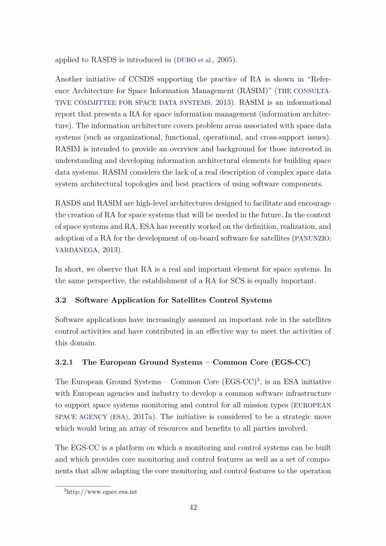
applied to RASDS is introduced in (DURO et al., 2005).
Another initiative of CCSDS supporting the practice of RA is shown in “Refer-ence Architecture for Space Information Management (RASIM)” (THE CONSULTA-
TIVE COMMITTEE FOR SPACE DATA SYSTEMS, 2013). RASIM is an informationalreport that presents a RA for space information management (information architec-ture). The information architecture covers problem areas associated with space datasystems (such as organizational, functional, operational, and cross-support issues).RASIM is intended to provide an overview and background for those interested inunderstanding and developing information architectural elements for building spacedata systems. RASIM considers the lack of a real description of complex space datasystem architectural topologies and best practices of using software components.
RASDS and RASIM are high-level architectures designed to facilitate and encouragethe creation of RA for space systems that will be needed in the future. In the contextof space systems and RA, ESA has recently worked on the definition, realization, andadoption of a RA for the development of on-board software for satellites (PANUNZIO;
VARDANEGA, 2013).
In short, we observe that RA is a real and important element for space systems. Inthe same perspective, the establishment of a RA for SCS is equally important.
3.2 Software Application for Satellites Control Systems
Software applications have increasingly assumed an important role in the satellitescontrol activities and have contributed in an effective way to meet the activities ofthis domain.
3.2.1 The European Ground Systems – Common Core (EGS-CC)
The European Ground Systems – Common Core (EGS-CC)3, is an ESA initiativewith European agencies and industry to develop a common software infrastructureto support space systems monitoring and control for all mission types (EUROPEAN
SPACE AGENCY (ESA), 2017a). The initiative is considered to be a strategic movewhich would bring an array of resources and benefits to all parties involved.
The EGS-CC is a platform on which a monitoring and control systems can be builtand which provides core monitoring and control features as well as a set of compo-nents that allow adapting the core monitoring and control features to the operation
3http://www.egscc.esa.int
42
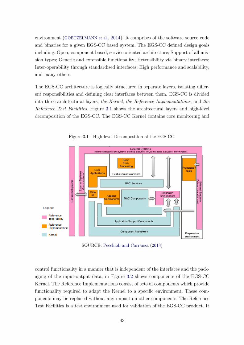
environment (GOETZELMANN et al., 2014). It comprises of the software source codeand binaries for a given EGS-CC based system. The EGS-CC defined design goalsincluding: Open, component based, service oriented architecture; Support of all mis-sion types; Generic and extensible functionality; Extensibility via binary interfaces;Inter-operability through standardised interfaces; High performance and scalability,and many others.
The EGS-CC architecture is logically structured in separate layers, isolating differ-ent responsibilities and defining clear interfaces between them. EGS-CC is dividedinto three architectural layers, the Kernel, the Reference Implementations, and theReference Test Facilities. Figure 3.1 shows the architectural layers and high-leveldecomposition of the EGS-CC. The EGS-CC Kernel contains core monitoring and
Figure 3.1 - High-level Decomposition of the EGS-CC.
SOURCE: Pecchioli and Carranza (2013)
control functionality in a manner that is independent of the interfaces and the pack-aging of the input-output data, in Figure 3.2 shows components of the EGS-CCKernel. The Reference Implementations consist of sets of components which providefunctionality required to adapt the Kernel to a specific environment. These com-ponents may be replaced without any impact on other components. The ReferenceTest Facilities is a test environment used for validation of the EGS-CC product. It
43
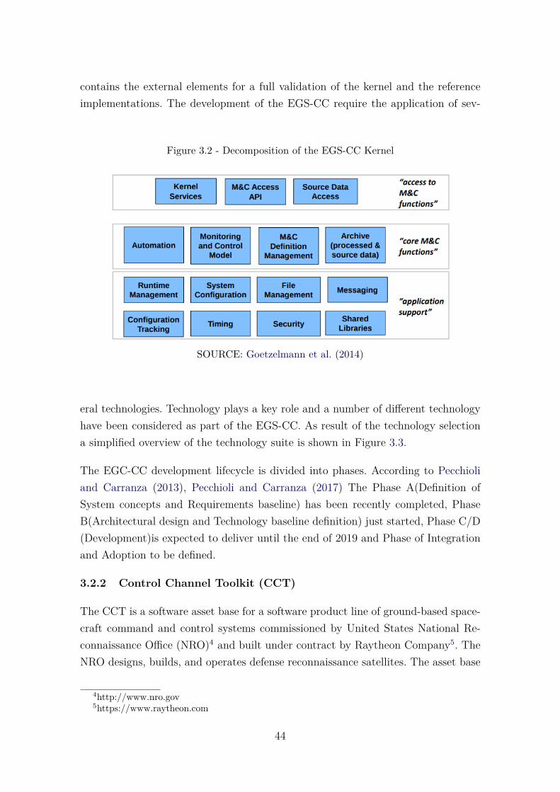
contains the external elements for a full validation of the kernel and the referenceimplementations. The development of the EGS-CC require the application of sev-
Figure 3.2 - Decomposition of the EGS-CC Kernel
SOURCE: Goetzelmann et al. (2014)
eral technologies. Technology plays a key role and a number of different technologyhave been considered as part of the EGS-CC. As result of the technology selectiona simplified overview of the technology suite is shown in Figure 3.3.
The EGC-CC development lifecycle is divided into phases. According to Pecchioliand Carranza (2013), Pecchioli and Carranza (2017) The Phase A(Definition ofSystem concepts and Requirements baseline) has been recently completed, PhaseB(Architectural design and Technology baseline definition) just started, Phase C/D(Development)is expected to deliver until the end of 2019 and Phase of Integrationand Adoption to be defined.
3.2.2 Control Channel Toolkit (CCT)
The CCT is a software asset base for a software product line of ground-based space-craft command and control systems commissioned by United States National Re-connaissance Office (NRO)4 and built under contract by Raytheon Company5. TheNRO designs, builds, and operates defense reconnaissance satellites. The asset base
4http://www.nro.gov5https://www.raytheon.com
44
Figure 3.3 - Overview of technology suite - EGC-CC.
SOURCE: EUROPEAN SPACE AGENCY (ESA) (2017a)
consists of the different artifacts such as generalized requirements, a software ar-chitecture, a development environment definition, a set of reusable software compo-nents, and a guide for reusing the architecture and components (CLEMENTS et al.,2001).
The CCT architecture is organized in two primary subsystems: planning and exe-cution. These subsystems are organized by component categories and each categoryhas its components. Component categories across these two subsystems did not in-teract(except by shared files). Components of a subsystem might use each otherand system functions are accomplished through the operating and interaction ofcomponents across different categories. The basis for the architecture’s intercompo-nent communication infrastructure was accomplished with Common Object RequestBroker Architecture (CORBA)6. Table 3.1 shows this architectural organization.
The execution subsystem referred to the time-critical component categories. Thesecomponents are responsible for the operations of communication directly with thesatellites, examples of such operations are telemetry and telecommand. Figure 3.4shows the data flow view of CCT execution architecture. The planning architecture
6http://www.corba.org
45
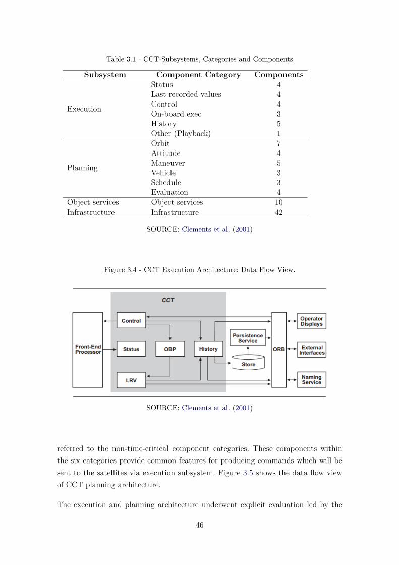
Table 3.1 - CCT-Subsystems, Categories and Components
Subsystem Component Category Components
Execution
Status 4Last recorded values 4Control 4On-board exec 3History 5Other (Playback) 1
Planning
Orbit 7Attitude 4Maneuver 5Vehicle 3Schedule 3Evaluation 4
Object services Object services 10Infrastructure Infrastructure 42
SOURCE: Clements et al. (2001)
Figure 3.4 - CCT Execution Architecture: Data Flow View.
SOURCE: Clements et al. (2001)
referred to the non-time-critical component categories. These components withinthe six categories provide common features for producing commands which will besent to the satellites via execution subsystem. Figure 3.5 shows the data flow viewof CCT planning architecture.
The execution and planning architecture underwent explicit evaluation led by the
46
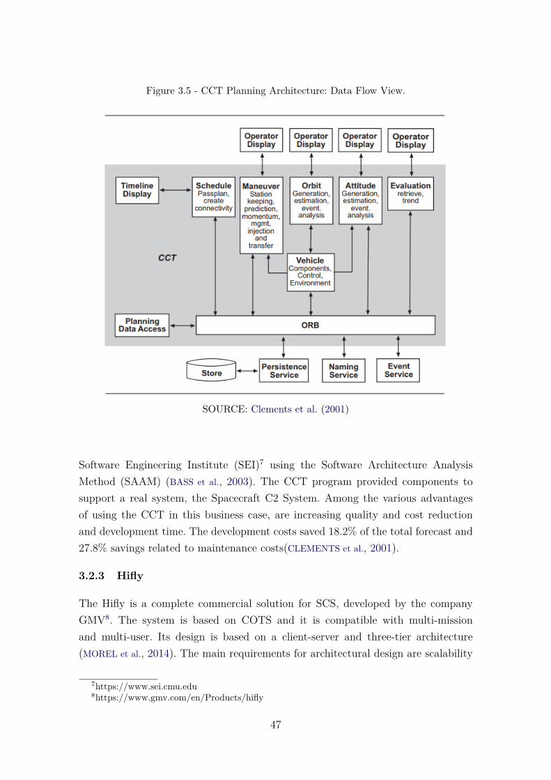
Figure 3.5 - CCT Planning Architecture: Data Flow View.
SOURCE: Clements et al. (2001)
Software Engineering Institute (SEI)7 using the Software Architecture AnalysisMethod (SAAM) (BASS et al., 2003). The CCT program provided components tosupport a real system, the Spacecraft C2 System. Among the various advantagesof using the CCT in this business case, are increasing quality and cost reductionand development time. The development costs saved 18.2% of the total forecast and27.8% savings related to maintenance costs(CLEMENTS et al., 2001).
3.2.3 Hifly
The Hifly is a complete commercial solution for SCS, developed by the companyGMV8. The system is based on COTS and it is compatible with multi-missionand multi-user. Its design is based on a client-server and three-tier architecture(MOREL et al., 2014). The main requirements for architectural design are scalability
7https://www.sei.cmu.edu8https://www.gmv.com/en/Products/hifly
47
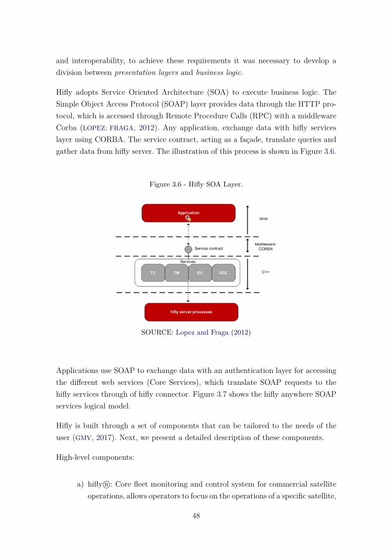
and interoperability, to achieve these requirements it was necessary to develop adivision between presentation layers and business logic.
Hifly adopts Service Oriented Architecture (SOA) to execute business logic. TheSimple Object Access Protocol (SOAP) layer provides data through the HTTP pro-tocol, which is accessed through Remote Procedure Calls (RPC) with a middlewareCorba (LOPEZ; FRAGA, 2012). Any application, exchange data with hifly serviceslayer using CORBA. The service contract, acting as a façade, translate queries andgather data from hifly server. The illustration of this process is shown in Figure 3.6.
Figure 3.6 - Hifly SOA Layer.
SOURCE: Lopez and Fraga (2012)
Applications use SOAP to exchange data with an authentication layer for accessingthe different web services (Core Services), which translate SOAP requests to thehifly services through of hifly connector. Figure 3.7 shows the hifly anywhere SOAPservices logical model.
Hifly is built through a set of components that can be tailored to the needs of theuser (GMV, 2017). Next, we present a detailed description of these components.
High-level components:
a) hifly R©: Core fleet monitoring and control system for commercial satelliteoperations, allows operators to focus on the operations of a specific satellite,
48
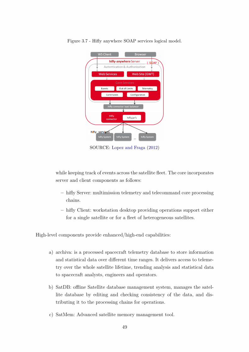
Figure 3.7 - Hifly anywhere SOAP services logical model.
SOURCE: Lopez and Fraga (2012)
while keeping track of events across the satellite fleet. The core incorporatesserver and client components as follows:
– hifly Server: multimission telemetry and telecommand core processingchains.
– hifly Client: workstation desktop providing operations support eitherfor a single satellite or for a fleet of heterogeneous satellites.
High-level components provide enhanced/high-end capabilities:
a) archiva: is a processed spacecraft telemetry database to store informationand statistical data over different time ranges. It delivers access to teleme-try over the whole satellite lifetime, trending analysis and statistical datato spacecraft analysts, engineers and operators.
b) SatDB: offline Satellite database management system, manages the satel-lite database by editing and checking consistency of the data, and dis-tributing it to the processing chains for operations.
c) SatMem: Advanced satellite memory management tool.
49
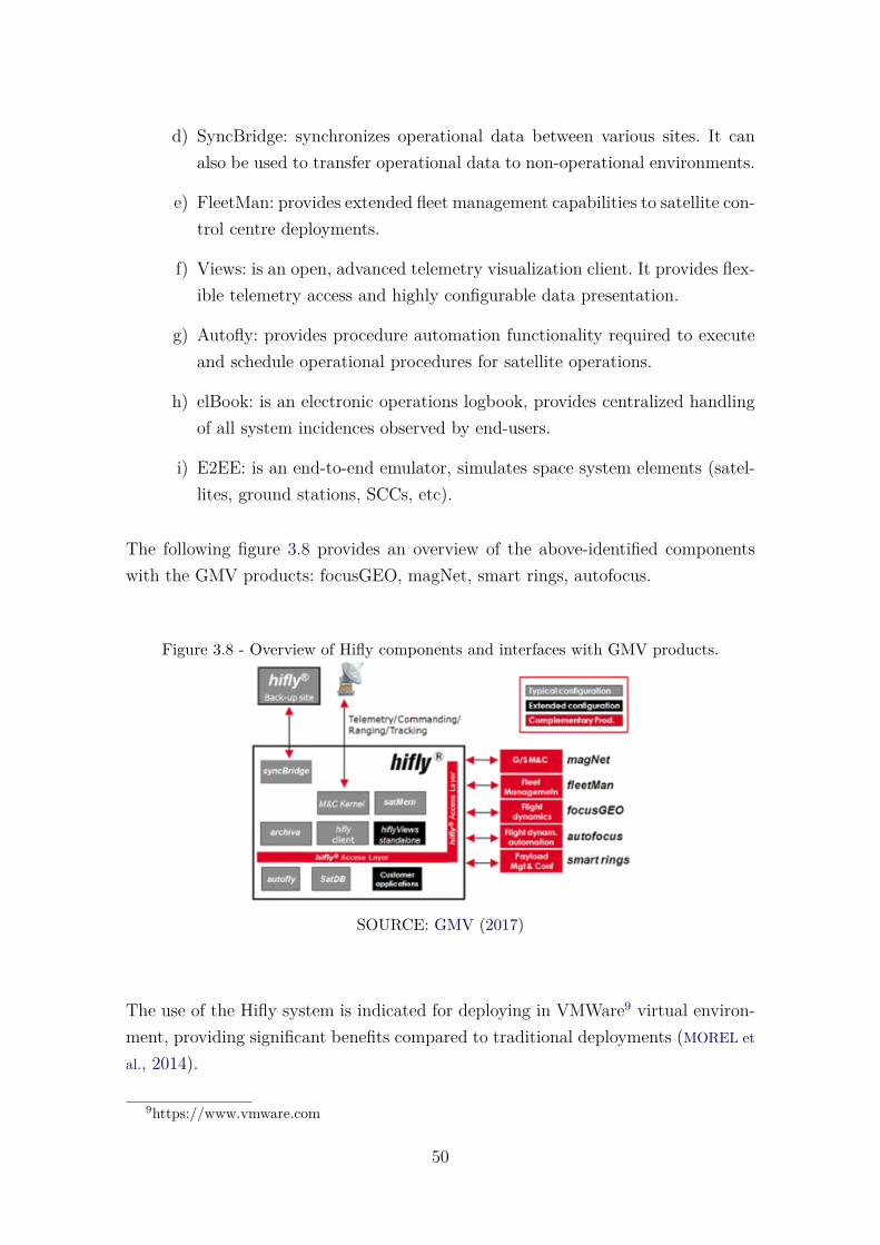
d) SyncBridge: synchronizes operational data between various sites. It canalso be used to transfer operational data to non-operational environments.
e) FleetMan: provides extended fleet management capabilities to satellite con-trol centre deployments.
f) Views: is an open, advanced telemetry visualization client. It provides flex-ible telemetry access and highly configurable data presentation.
g) Autofly: provides procedure automation functionality required to executeand schedule operational procedures for satellite operations.
h) elBook: is an electronic operations logbook, provides centralized handlingof all system incidences observed by end-users.
i) E2EE: is an end-to-end emulator, simulates space system elements (satel-lites, ground stations, SCCs, etc).
The following figure 3.8 provides an overview of the above-identified componentswith the GMV products: focusGEO, magNet, smart rings, autofocus.
Figure 3.8 - Overview of Hifly components and interfaces with GMV products.
SOURCE: GMV (2017)
The use of the Hifly system is indicated for deploying in VMWare9 virtual environ-ment, providing significant benefits compared to traditional deployments (MOREL et
al., 2014).
9https://www.vmware.com
50
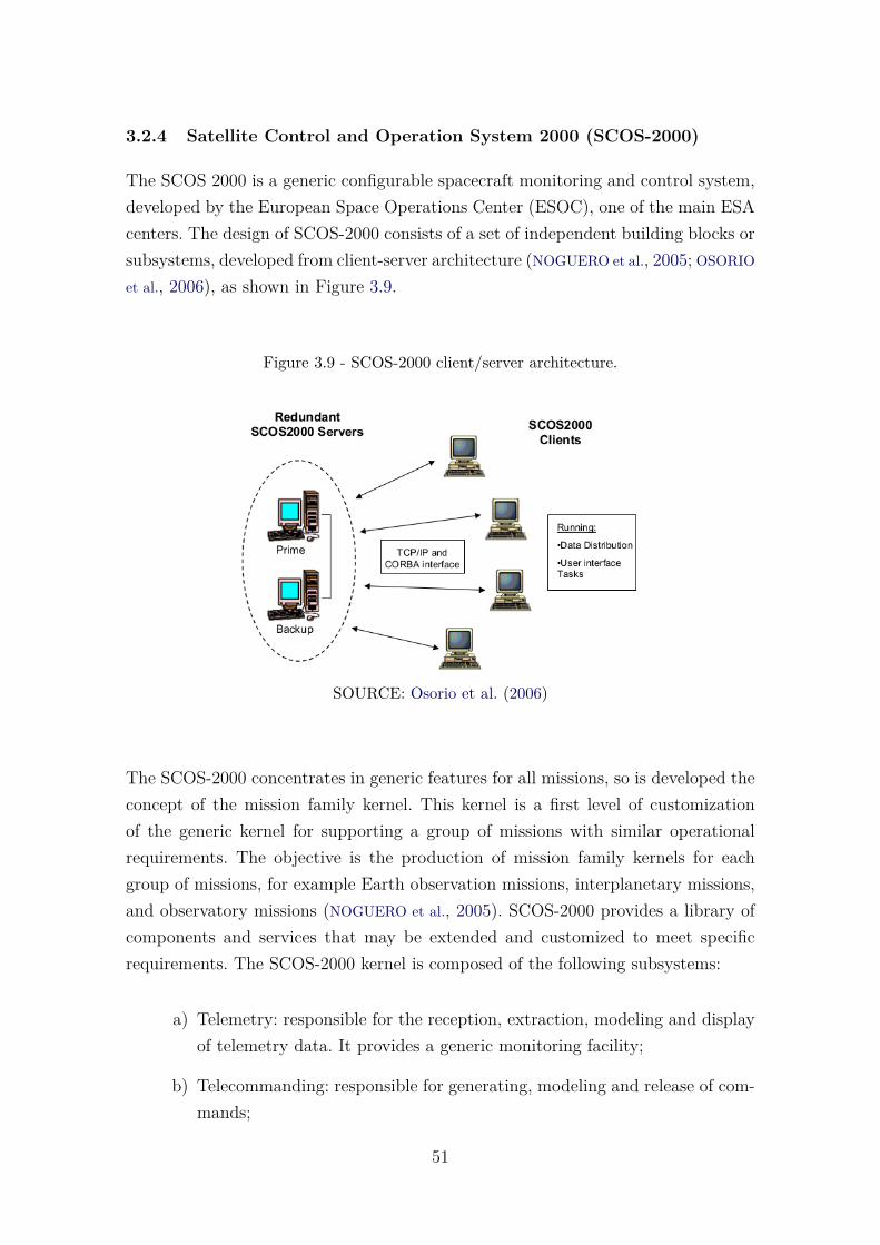
3.2.4 Satellite Control and Operation System 2000 (SCOS-2000)
The SCOS 2000 is a generic configurable spacecraft monitoring and control system,developed by the European Space Operations Center (ESOC), one of the main ESAcenters. The design of SCOS-2000 consists of a set of independent building blocks orsubsystems, developed from client-server architecture (NOGUERO et al., 2005; OSORIO
et al., 2006), as shown in Figure 3.9.
Figure 3.9 - SCOS-2000 client/server architecture.
SOURCE: Osorio et al. (2006)
The SCOS-2000 concentrates in generic features for all missions, so is developed theconcept of the mission family kernel. This kernel is a first level of customizationof the generic kernel for supporting a group of missions with similar operationalrequirements. The objective is the production of mission family kernels for eachgroup of missions, for example Earth observation missions, interplanetary missions,and observatory missions (NOGUERO et al., 2005). SCOS-2000 provides a library ofcomponents and services that may be extended and customized to meet specificrequirements. The SCOS-2000 kernel is composed of the following subsystems:
a) Telemetry: responsible for the reception, extraction, modeling and displayof telemetry data. It provides a generic monitoring facility;
b) Telecommanding: responsible for generating, modeling and release of com-mands;
51
c) Online Database: responsible for maintaining the online static mission in-formation base, it contains the definitions of all static elements needed bySCOS-2000 for run-time management;
d) Data Archiving & Distribution: responsible for filing, retrieval and distri-bution of data generated (telemetry, telecommands and events);
e) User Management: responsible by access control to the system functions,and the management of privileges;
f) Events & Action: responsible for providing event message generation, trac-ing and handling;
g) Onboard Software Maintenance: responsible for providing of memory im-ages and memory uplink data;
h) External Interfaces: responsible for supporting the provision and receptionof data to/from external systems.
A common CORBA interface is used throughout components to make the processof TCP/IP connection established between clients and servers. CORBA is a basicmiddleware for sharing common configuration. It uses a name service to enable serverprocesses to register their location and client processes to retrieve the location inorder to connect to the servers (OSORIO et al., 2006).
3.2.5 Goddard Mission Services Evolution Center (GMSEC)
The GMSEC is a satellite command and control system. It is designed and definedby NASA’s Goddard Space Flight Center (GSFC)10 to support its satellite missions.The purpose of GMSEC is to simplify integration, allow increased automation, facil-itate new adaptations to flight operations components (e.g. Command and Control,Flight Dynamics, Mission Planning, Automation, etc.) with minimum impact to theoverall system (CHAMOUN et al., 2006; MAYORGA, 2006; GUDMUNDSSON et al., 2015).
The GMSEC system was developed with the following architectural principles(SMITH et al., 2006):
a) Standardize interfaces: GMSEC prioritizes the standardization of interfaces- not components. It encourages the access to a broad range of technologiesby standardizing interfaces;
10https://gmsec.gsfc.nasa.gov
52
b) Middleware infrastructure: GMSEC provides a message oriented middle-ware (MOM) at the center of the architecture;
c) User choice: GMSEC doesn’t decide which components are best nor dictatewhich components a mission must use. The architecture allows the user ormission to select the most appropriate products based on functional needor personal preference and easily integrate them into a ground system;
d) General-purpose approach with flight-ground capabilities: The architectureitself should be designed to be adaptable to any number of missions.
The GMSEC architecture is based on middleware, message-oriented communica-tions and implemented as the message bus. The message-oriented middleware keepstrack of the locations of the software components so hard-code node routing is notneeded and logical/physical location transitions can occur instantly in the case offailovers. The message bus provides publish/subscribe message passing mechanisms.Applications “publish” messages to the bus. Each message contains a subject nameand the standard message contents.
The GMSEC API provides the generalized interface between applications programsand the system middleware. Multiple languages, middleware products, platformsand operating systems are supported. In addition, the API normalizes the behaviorof the middleware while allowing access to special functions or capabilities of indi-vidual middleware products, in this way, changes in the middleware product doesnot require changes to the software components. The Figure 3.10 shows an overviewof the GMSEC layered architecture.
Some other components or variations that could be part of a component above oreven its own subsystem are (HANDY, 2016):
• Maneuver (prediction, control, analysis, product generation);
• Data Processing;
• Data Analysis and Modeling;
• Data Archive and Data Management;
• Product Generation;
• Data Distribution;
53
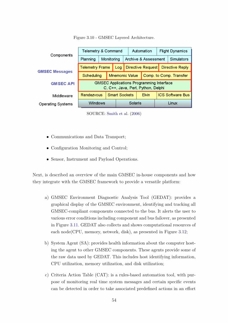
Figure 3.10 - GMSEC Layered Architecture.
SOURCE: Smith et al. (2006)
• Communications and Data Transport;
• Configuration Monitoring and Control;
• Sensor, Instrument and Payload Operations.
Next, is described an overview of the main GMSEC in-house components and howthey integrate with the GMSEC framework to provide a versatile platform:
a) GMSEC Environment Diagnostic Analysis Tool (GEDAT): provides agraphical display of the GMSEC environment, identifying and tracking allGMSEC-compliant components connected to the bus. It alerts the user tovarious error conditions including component and bus failover, as presentedin Figure 3.11. GEDAT also collects and shows computational resources ofeach node(CPU, memory, network, disk), as presented in Figure 3.12;
b) System Agent (SA): provides health information about the computer host-ing the agent to other GMSEC components. These agents provide some ofthe raw data used by GEDAT. This includes host identifying information,CPU utilization, memory utilization, and disk utilization;
c) Criteria Action Table (CAT): is a rules-based automation tool, with pur-pose of monitoring real time system messages and certain specific eventscan be detected in order to take associated predefined actions in an effort
54
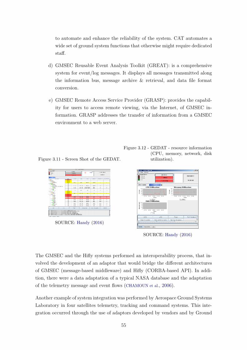
to automate and enhance the reliability of the system. CAT automates awide set of ground system functions that otherwise might require dedicatedstaff.
d) GMSEC Reusable Event Analysis Toolkit (GREAT): is a comprehensivesystem for event/log messages. It displays all messages transmitted alongthe information bus, message archive & retrieval, and data file formatconversion.
e) GMSEC Remote Access Service Provider (GRASP): provides the capabil-ity for users to access remote viewing, via the Internet, of GMSEC in-formation. GRASP addresses the transfer of information from a GMSECenvironment to a web server.
Figure 3.11 - Screen Shot of the GEDAT.
SOURCE: Handy (2016)
Figure 3.12 - GEDAT - resource information(CPU, memory, network, diskutilization).
SOURCE: Handy (2016)
The GMSEC and the Hifly systems performed an interoperability process, that in-volved the development of an adaptor that would bridge the different architecturesof GMSEC (message-based middleware) and Hifly (CORBA-based API). In addi-tion, there were a data adaptation of a typical NASA database and the adaptationof the telemetry message and event flows (CHAMOUN et al., 2006).
Another example of system integration was performed by Aerospace Ground SystemsLaboratory in four satellites telemetry, tracking and command systems. This inte-gration occurred through the use of adaptors developed by vendors and by Ground
55

Systems Laboratory (SULLIVAN et al., 2009).
3.2.6 Global Educational Network for Satellite Operations (Genso)
The Genso is an ESA initiative collaborating with the International Space EducationBoard(ISEB), with the participation of several universities, such as University ofTokyo, Vienna University of Technology, Cal Poly State University, Jean MonnetUniversity (LEVEQUE et al., 2007). It was officially created in October 2006 withits main objective being the provision of communications to university satellitesand, moreover, to create an international network of university ground stations.The objective of the project is to train students in space system and increase thelevel of access to orbital spacecraft through the sharing of earth stations(CASTRO et
al., 2012). Among other GENSO’s objectives are the following (EUROPEAN SPACE
AGENCY (ESA), 2017b):
• Global access to mission operators of educational and amateur radio space-craft.
• Remote access for operators to real-time mission data, even in cases whentheir local ground station is experiencing technical difficulties.
• Scheduling of uplinks through ground stations.
• Definition of standard solution for the educational ground-segment hard-ware, designed to optimize GENSO’s performance at minimal cost.
• Close collaboration with amateur radio to support a common interface inorder to apply for frequency allocation and coordination.
In the Genso network, satellite operators can control their satellite remotely fromany shared earth station in the network, regardless of their geographic location.Communication between operators and stations is done through the Internet, aswell as the main elements of the Genso architecture that are deployed in distantlocations geographically.
Genso network has three main elements in its architecture: Authentication Server(AUS), single point of authentication in the network; Ground Station Server (GSS),which is deployed at earth stations; and Mission Control Client (MCC) used bysatellite operators (LEVEQUE et al., 2007). Figure 3.13 presents an overview of theelements of Genso’s architecture.
56
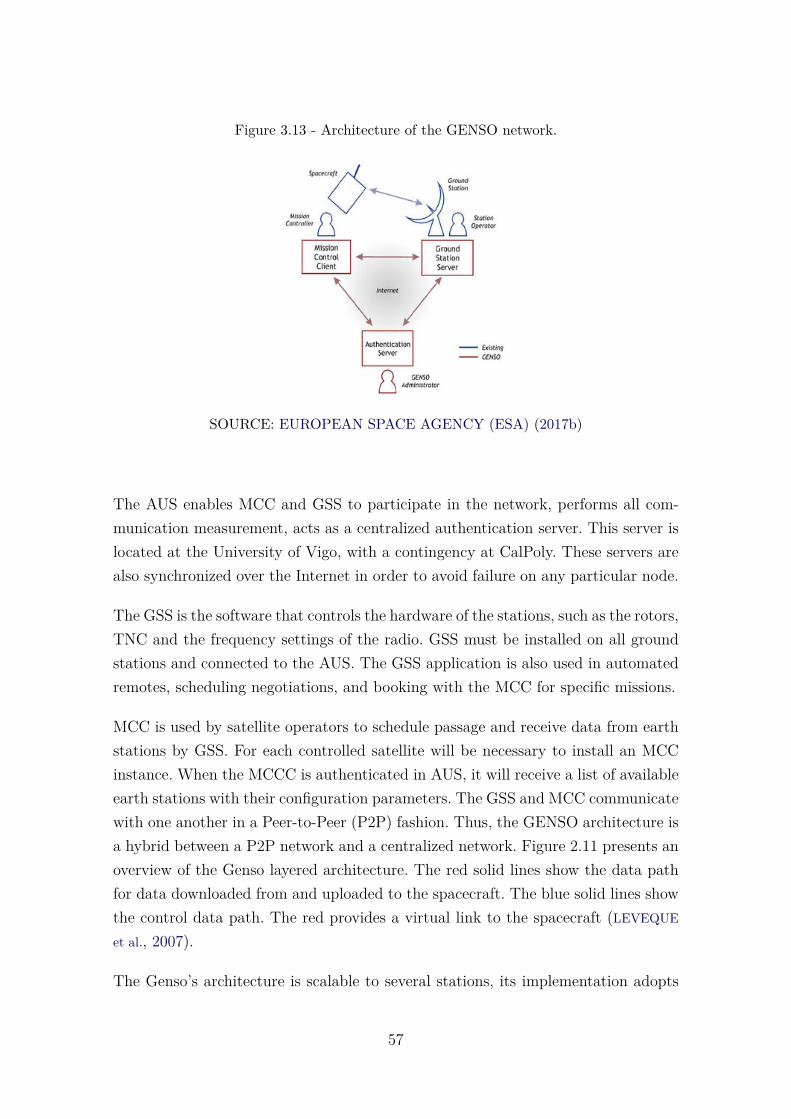
Figure 3.13 - Architecture of the GENSO network.
SOURCE: EUROPEAN SPACE AGENCY (ESA) (2017b)
The AUS enables MCC and GSS to participate in the network, performs all com-munication measurement, acts as a centralized authentication server. This server islocated at the University of Vigo, with a contingency at CalPoly. These servers arealso synchronized over the Internet in order to avoid failure on any particular node.
The GSS is the software that controls the hardware of the stations, such as the rotors,TNC and the frequency settings of the radio. GSS must be installed on all groundstations and connected to the AUS. The GSS application is also used in automatedremotes, scheduling negotiations, and booking with the MCC for specific missions.
MCC is used by satellite operators to schedule passage and receive data from earthstations by GSS. For each controlled satellite will be necessary to install an MCCinstance. When the MCCC is authenticated in AUS, it will receive a list of availableearth stations with their configuration parameters. The GSS and MCC communicatewith one another in a Peer-to-Peer (P2P) fashion. Thus, the GENSO architecture isa hybrid between a P2P network and a centralized network. Figure 2.11 presents anoverview of the Genso layered architecture. The red solid lines show the data pathfor data downloaded from and uploaded to the spacecraft. The blue solid lines showthe control data path. The red provides a virtual link to the spacecraft (LEVEQUE
et al., 2007).
The Genso’s architecture is scalable to several stations, its implementation adopts
57
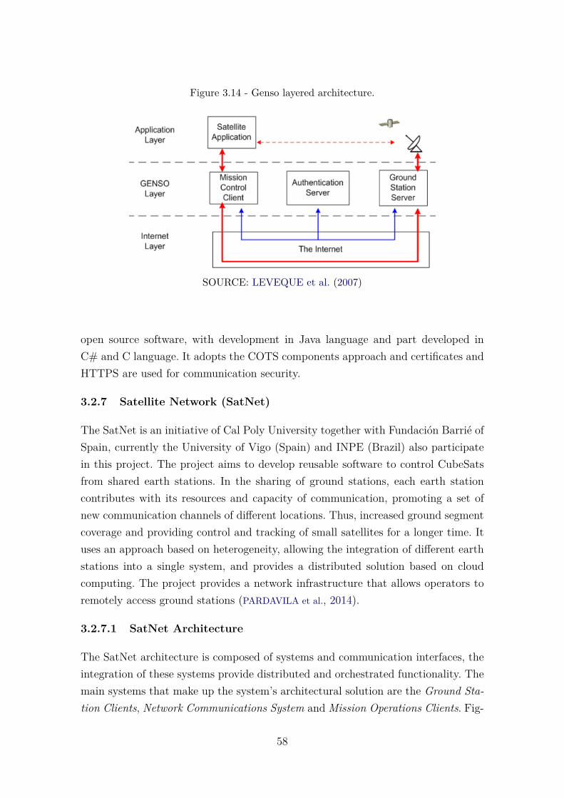
Figure 3.14 - Genso layered architecture.
SOURCE: LEVEQUE et al. (2007)
open source software, with development in Java language and part developed inC# and C language. It adopts the COTS components approach and certificates andHTTPS are used for communication security.
3.2.7 Satellite Network (SatNet)
The SatNet is an initiative of Cal Poly University together with Fundación Barrié ofSpain, currently the University of Vigo (Spain) and INPE (Brazil) also participatein this project. The project aims to develop reusable software to control CubeSatsfrom shared earth stations. In the sharing of ground stations, each earth stationcontributes with its resources and capacity of communication, promoting a set ofnew communication channels of different locations. Thus, increased ground segmentcoverage and providing control and tracking of small satellites for a longer time. Ituses an approach based on heterogeneity, allowing the integration of different earthstations into a single system, and provides a distributed solution based on cloudcomputing. The project provides a network infrastructure that allows operators toremotely access ground stations (PARDAVILA et al., 2014).
3.2.7.1 SatNet Architecture
The SatNet architecture is composed of systems and communication interfaces, theintegration of these systems provide distributed and orchestrated functionality. Themain systems that make up the system’s architectural solution are the Ground Sta-tion Clients, Network Communications System and Mission Operations Clients. Fig-
58
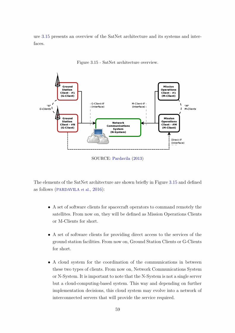
ure 3.15 presents an overview of the SatNet architecture and its systems and inter-faces.
Figure 3.15 - SatNet architecture overview.
SOURCE: Pardavila (2013)
The elements of the SatNet architecture are shown briefly in Figure 3.15 and definedas follows (PARDAVILA et al., 2016):
• A set of software clients for spacecraft operators to command remotely thesatellites. From now on, they will be defined as Mission Operations Clientsor M-Clients for short.
• A set of software clients for providing direct access to the services of theground station facilities. From now on, Ground Station Clients or G-Clientsfor short.
• A cloud system for the coordination of the communications in betweenthese two types of clients. From now on, Network Communications Systemor N-System. It is important to note that the N-System is not a single serverbut a cloud-computing-based system. This way and depending on furtherimplementation decisions, this cloud system may evolve into a network ofinterconnected servers that will provide the service required.
59
The N-System implements the following interfaces for permitting an automatic com-munication among software entities, without the need of direct human interaction:
• G-Client Interface (G-Client-IF), that permits the ground station clientsto connect to the network services.
• M-Client Interface (M-Client-IF), that permits the mission operationsclients to connect to the network services.
• Direct Client Interface (Direct-IF), that permits the mission operationsclients to connect directly to the ground station clients.
The current implementation of the SatNet network provides only the M-Client-IFand the G-Client-IF interfaces, being the Direct-IF left for future releases (PAR-
DAVILA et al., 2016). It provides all source code needed to connect ground stationsand control centers under apache version 2.0 license 11. On the website 12 it’s foundthe user interface that gives access and control to the network.
3.2.7.2 SatNet Services
SatNet is based on services, these services are made available to meet the main func-tionalities and the integration between the systems. SatNet provides the followingservices (classified in accordance with three categories) (PARDAVILA, 2013):
• Management Services Category
– Registration Service.
– Configuration Service.
– Information Service.
• Scheduling Services Category
– Assisted Scheduling Service.
– Private Scheduling Service.
• Communication Services Category
– Assisted Communications Service.
11https://github.com/SatNet-project12https://SatNet.aero.calpoly.edu
60
– Private Communications Service.
– Non-Scheduled Communications Service.
The SatNet network is designed to give a solution based on flexible computing in thecloud. This solution allows the use of its resources in the cloud so that the CubeSattype ground stations can have access.
3.2.7.3 SatNet Integration
SatNet still in development allows having a global ground station network, withglobal coverage of the satellites willing to be a part of the network. SatNet currentlyhas an increasing number of integration of earth stations, the United States andSpain are countries that are part of the project.
At present, some trial activities are taking place for the integration of the groundstation INPE in the SatNet network. The envisaged scenario is shown in Figure3.16, where the current SatNet deployed network server is located at CalPoly whereit is already providing operational services. In the near future, two more serversare planned to be deployed, namely: one at Vigo in Spain and the one prospec-tively located at INPE so that it will provide coverage for the southern hemisphere(PARDAVILA et al., 2016).
61
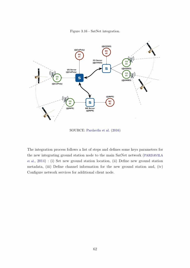
Figure 3.16 - SatNet integration.
SOURCE: Pardavila et al. (2016)
The integration process follows a list of steps and defines some keys parameters forthe new integrating ground station node to the main SatNet network (PARDAVILA
et al., 2014) : (i) Set new ground station location, (ii) Define new ground stationmetadata, (iii) Define channel information for the new ground station and, (iv)Configure network services for additional client node.
62
4 ESTABLISHMENT OF A REFERENCE ARCHITECTURE FORSATELLITES CONTROL SYSTEM
This chapter reports on the establishment of Reference Architecture for SCS (SCS-RA). This reference architecture is aligned with the ProSA-RA process. We adoptedthe systematic process ProSA-RA (NAKAGAWA et al., 2014) to establish the SCS-RA,considering that it prioritizes the design, representation, and evaluation of referencearchitectures and has been already applied in the establishment of many referencearchitectures (NAKAGAWA et al., 2014). The establishment of SCS-RA involved thedevelopment of different steps and according to ProSA-RA process. Next, we presenta detailed description of these steps and activities.
The organization of this chapter follows the steps of ProSA-RA. Section 4.1 detailsthe sources of information used to establish SCS-RA. Section 4.2 reports on therequirements of the reference architecture elicited from these information sources.Section 4.3 describes architectural views of SCS-RA. Finally, Section 4.4 presents aarchitectural evaluation of SCS-RA.
4.1 Step RA-1: Information Source Investigation
In this first step, two main groups of information sources related to satellites whichcontrol activities were identified: (i) CCSDS recommendations and reports; (ii) ECSSstandards. These groups are initiatives established to develop a coherent set of stan-dards for use in all space activities. The following is a summary of the main guidelinesconsidered in this stage:
a) ECSS-E-ST-70C: It has some principles and requirements to apply in theengineering of the ground segment and in the mission operations. It alsopresents the general view and the elements of a space system (EUROPEAN
COOPERATION FOR SPACE STANDARDIZATION (ECSS), 2000).
b) CCSDS-520.1-M-1: It is a recommended practice which defines a referencemodel for the mission operations. It provides a common base to supportthe development of the CCSDS’ recommended standards (which specify themission service operations). It also provides a reference to keep consistencyof these standards (CCSDS, 2010a).
c) CCSDS-520.0-G-3: It presents a general view of the concepts of missionservice operations. It also defines a framework of mission service operationsto use for monitoring and controlling the satellites (CCSDS, 2010b).
63
d) CCSDS-521.1-R-1: It defines in an abstract way the common services tomonitor and control the satellites. These services offer support to missionoperations present in most systems. This standard defines specifications ofthe interfaces of these services as to allow interoperability among agenciesthrough the installed software. It also allows the interoperability wherethe collaborating agencies may share resources and obtain advantages ofshared installations (CCSDS, 2009).
e) CCSDS-522.0-R-2: It contains a high level formal specification to define amodel of a common object. The common object is applied to the missionservice operations defined in (CCSDS, 2010b). The specification defines astandard for the services of the common object model and a standard forthe support services for the model of these objects (CCSDS, 2008).
f) CCSDS-311.0-M-1: It aims at providing a standardized approach to highlevel description of architectures and a pool of conventions for space datasystems. It defines concepts; it presents advantages and examples of ar-chitectural views. Among the objectives there is the goal to establish ageneral view of the CCSD’s recommended methodologies, as to define anddevelop the reference architecture to the domain. It was inspired by themodel RM-ODP and is compatible with the best software architecturepractices available at ANSI/IEEE 1471-2000 (INSTITUTO FOR ELECTRI-
CAL AND ELECTRONICS ENGINEERS, 2000). This recommendation presentsconcepts and conventions representing the perspectives of: business, func-tional, connectivity, communication and information views (THE CONSUL-
TATIVE COMMITTEE FOR SPACE DATA SYSTEMS, 2008).
g) ECSS-E-ST-40: It encompasses the software engineering aspects of a spacesystem. It aims at contributing to formulate the requirements of the spaceenvironment. It presents a general view of engineering of the requirementsfor the whole life cycle of the space systems projects (ECSS, 2009a).
Hence, SCS-RA should be consistent with these initiatives. Thus, the guidelines andtheir contents that contribute to the definition of the architectural requirements werefirst identified. An example of this is the API specification for cross support definedin (THE CONSULTATIVE COMMITTEE FOR SPACE DATA SYSTEMS, 2005), so the SCS-RA should be compatible with this specification. Table 4.1 shows the reference andcontents of interest captured for the definition of SCS-RA.
64
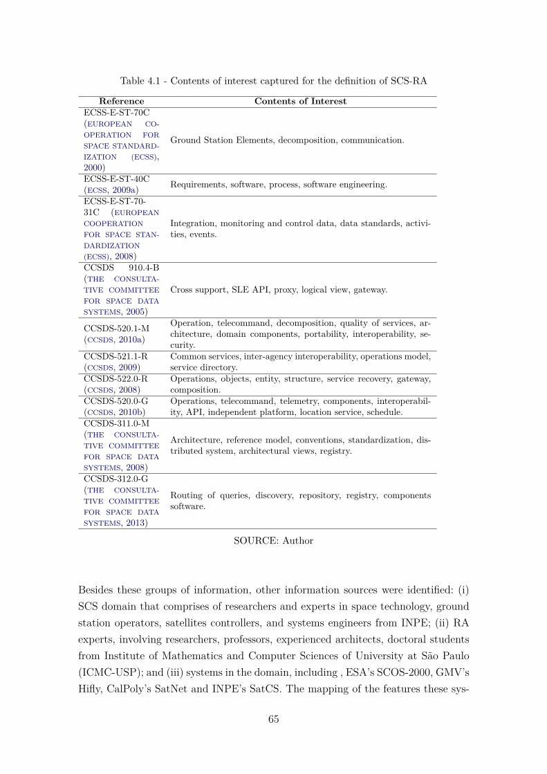
Table 4.1 - Contents of interest captured for the definition of SCS-RA
Reference Contents of InterestECSS-E-ST-70C(EUROPEAN CO-OPERATION FORSPACE STANDARD-IZATION (ECSS),2000)
Ground Station Elements, decomposition, communication.
ECSS-E-ST-40C(ECSS, 2009a) Requirements, software, process, software engineering.
ECSS-E-ST-70-31C (EUROPEANCOOPERATIONFOR SPACE STAN-DARDIZATION(ECSS), 2008)
Integration, monitoring and control data, data standards, activi-ties, events.
CCSDS 910.4-B(THE CONSULTA-TIVE COMMITTEEFOR SPACE DATASYSTEMS, 2005)
Cross support, SLE API, proxy, logical view, gateway.
CCSDS-520.1-M(CCSDS, 2010a)
Operation, telecommand, decomposition, quality of services, ar-chitecture, domain components, portability, interoperability, se-curity.
CCSDS-521.1-R(CCSDS, 2009)
Common services, inter-agency interoperability, operations model,service directory.
CCSDS-522.0-R(CCSDS, 2008)
Operations, objects, entity, structure, service recovery, gateway,composition.
CCSDS-520.0-G(CCSDS, 2010b)
Operations, telecommand, telemetry, components, interoperabil-ity, API, independent platform, location service, schedule.
CCSDS-311.0-M(THE CONSULTA-TIVE COMMITTEEFOR SPACE DATASYSTEMS, 2008)
Architecture, reference model, conventions, standardization, dis-tributed system, architectural views, registry.
CCSDS-312.0-G(THE CONSULTA-TIVE COMMITTEEFOR SPACE DATASYSTEMS, 2013)
Routing of queries, discovery, repository, registry, componentssoftware.
SOURCE: Author
Besides these groups of information, other information sources were identified: (i)SCS domain that comprises of researchers and experts in space technology, groundstation operators, satellites controllers, and systems engineers from INPE; (ii) RAexperts, involving researchers, professors, experienced architects, doctoral studentsfrom Institute of Mathematics and Computer Sciences of University at São Paulo(ICMC-USP); and (iii) systems in the domain, including , ESA’s SCOS-2000, GMV’sHifly, CalPoly’s SatNet and INPE’s SatCS. The mapping of the features these sys-
65
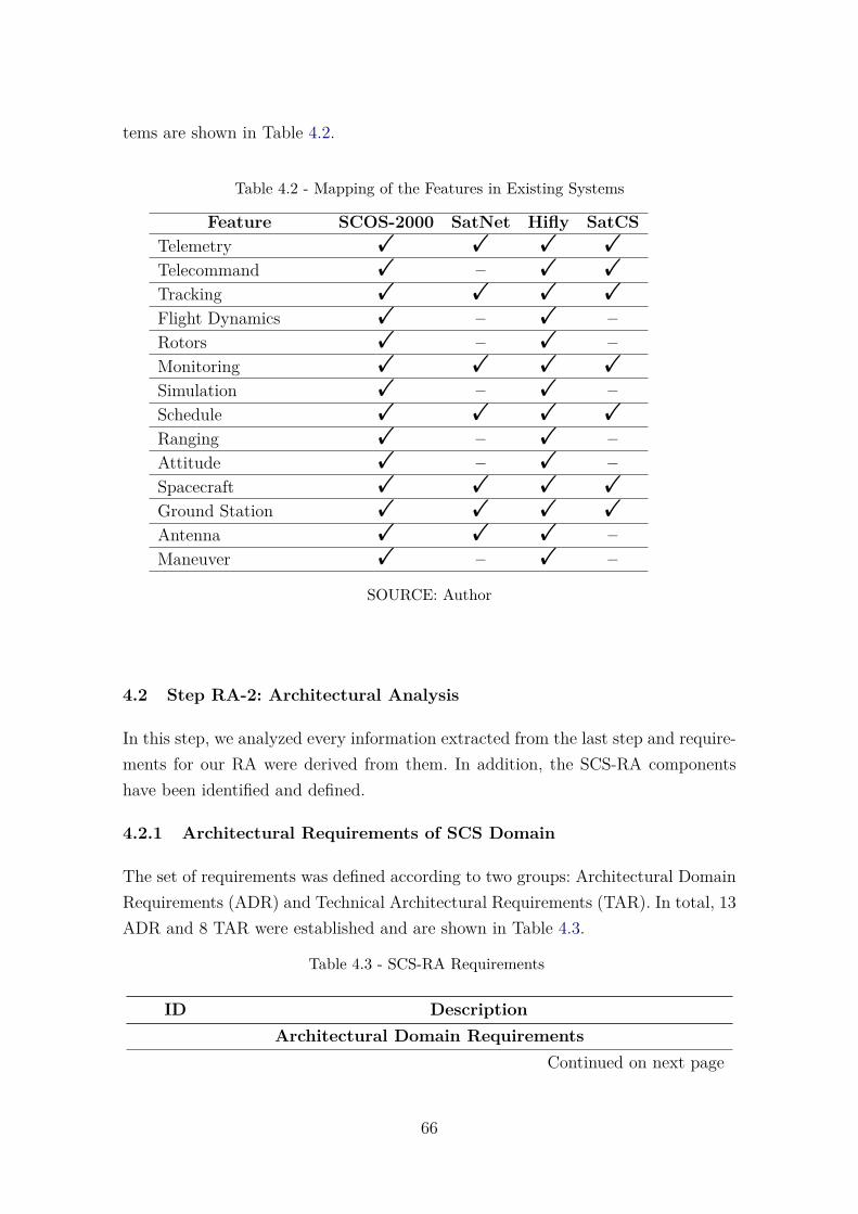
tems are shown in Table 4.2.
Table 4.2 - Mapping of the Features in Existing Systems
Feature SCOS-2000 SatNet Hifly SatCSTelemetry ! ! ! !
Telecommand ! – ! !
Tracking ! ! ! !
Flight Dynamics ! – ! –Rotors ! – ! –Monitoring ! ! ! !
Simulation ! – ! –Schedule ! ! ! !
Ranging ! – ! –Attitude ! – ! –Spacecraft ! ! ! !
Ground Station ! ! ! !
Antenna ! ! ! –Maneuver ! – ! –
SOURCE: Author
4.2 Step RA-2: Architectural Analysis
In this step, we analyzed every information extracted from the last step and require-ments for our RA were derived from them. In addition, the SCS-RA componentshave been identified and defined.
4.2.1 Architectural Requirements of SCS Domain
The set of requirements was defined according to two groups: Architectural DomainRequirements (ADR) and Technical Architectural Requirements (TAR). In total, 13ADR and 8 TAR were established and are shown in Table 4.3.
Table 4.3 - SCS-RA Requirements
ID DescriptionArchitectural Domain Requirements
Continued on next page
66
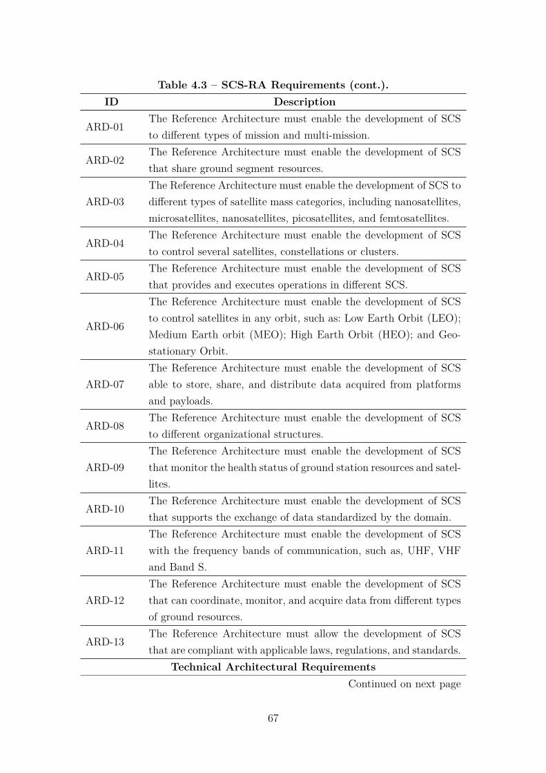
Table 4.3 – SCS-RA Requirements (cont.).ID Description
ARD-01The Reference Architecture must enable the development of SCSto different types of mission and multi-mission.
ARD-02The Reference Architecture must enable the development of SCSthat share ground segment resources.
ARD-03The Reference Architecture must enable the development of SCS todifferent types of satellite mass categories, including nanosatellites,microsatellites, nanosatellites, picosatellites, and femtosatellites.
ARD-04The Reference Architecture must enable the development of SCSto control several satellites, constellations or clusters.
ARD-05The Reference Architecture must enable the development of SCSthat provides and executes operations in different SCS.
ARD-06
The Reference Architecture must enable the development of SCSto control satellites in any orbit, such as: Low Earth Orbit (LEO);Medium Earth orbit (MEO); High Earth Orbit (HEO); and Geo-stationary Orbit.
ARD-07The Reference Architecture must enable the development of SCSable to store, share, and distribute data acquired from platformsand payloads.
ARD-08The Reference Architecture must enable the development of SCSto different organizational structures.
ARD-09The Reference Architecture must enable the development of SCSthat monitor the health status of ground station resources and satel-lites.
ARD-10The Reference Architecture must enable the development of SCSthat supports the exchange of data standardized by the domain.
ARD-11The Reference Architecture must enable the development of SCSwith the frequency bands of communication, such as, UHF, VHFand Band S.
ARD-12The Reference Architecture must enable the development of SCSthat can coordinate, monitor, and acquire data from different typesof ground resources.
ARD-13The Reference Architecture must allow the development of SCSthat are compliant with applicable laws, regulations, and standards.
Technical Architectural RequirementsContinued on next page
67
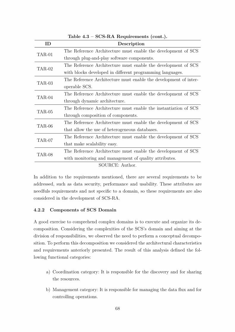
Table 4.3 – SCS-RA Requirements (cont.).ID Description
TAR-01The Reference Architecture must enable the development of SCSthrough plug-and-play software components.
TAR-02The Reference Architecture must enable the development of SCSwith blocks developed in different programming languages.
TAR-03The Reference Architecture must enable the development of inter-operable SCS.
TAR-04The Reference Architecture must enable the development of SCSthrough dynamic architecture.
TAR-05The Reference Architecture must enable the instantiation of SCSthrough composition of components.
TAR-06The Reference Architecture must enable the development of SCSthat allow the use of heterogeneous databases.
TAR-07The Reference Architecture must enable the development of SCSthat make scalability easy.
TAR-08The Reference Architecture must enable the development of SCSwith monitoring and management of quality attributes.
SOURCE: Author.
In addition to the requirements mentioned, there are several requirements to beaddressed, such as data security, performance and usability. These attributes areneedfuls requirements and not specific to a domain, so these requirements are alsoconsidered in the development of SCS-RA.
4.2.2 Components of SCS Domain
A good exercise to comprehend complex domains is to execute and organize its de-composition. Considering the complexities of the SCS’s domain and aiming at thedivision of responsibilities, we observed the need to perform a conceptual decompo-sition. To perform this decomposition we considered the architectural characteristicsand requirements anteriorly presented. The result of this analysis defined the fol-lowing functional categories:
a) Coordination category: It is responsible for the discovery and for sharingthe resources.
b) Management category: It is responsible for managing the data flux and forcontrolling operations.
68

c) Business category: It is responsible for the functionalities of the SCS’sdomain.
d) Persistence category: It is responsible for the persistence and for recoveringthe data.
The conceptual decomposition aims at separating the complexity of the domain toidentify the components and their categorization. The decomposition of the domaindoes not refer to the definition of architectural layers or to the modularization ofthe domain.
Identification of the Domain’s components The identification of the componentsconsists in describing the functionalities of each identified component. Table 4.4presents the previously defined functional categories and their components. Theidentification and description of SCS components are detailed in the sequence.
Table 4.4 - Category
Category Components
BusinessTelecommand, Telemetry, Tracking, Flight Dynamics, Space-craft, Ground Station, Rotors, Antenna, Simulation, Monitor-ing, Schedule, Ranging, Attitude, Maneuver
Management Gateway, Security, Routing, GUI, RegistryCoordination Discovery, Composity, Administrator, Mashup
SOURCE: Author
4.2.2.1 Registry Component
All running components must be registered. In this register, they need to informtheir location through an IP address, their access port, and available interfaces. TheRegistry Component stores this data and provides it to the Discovery Component.The information of the components is dynamic and the Registry Component needsto update these data dynamically.
4.2.2.2 Mashup Component
When organizations are interoperating, some information must be provided in aunified way. The Mashup Component is responsible for researching and providing
69
this information. The information refers to the satellites, ground stations and thescheduling of operations.
4.2.2.3 Discovery Component
The SCS-RA components are independent, have execution responsibilities and, workin a collaborative way. These components are registered during its execution and theDiscovery Component provides information from these components. The informationprovided are: physical execution location; its access address; interfaces; etc.
4.2.2.4 Composition Component
The Composition Component is responsible for instantiating an SCS, which uses acomposition process. This process searches and selects components stored in reposi-tories and the computational resources are set up. After the download and initiationof components, the instance of SCS is provided for use.
Administrator Component: This component manages and monitors the computa-tional resources(memory, CPU, and disk) of each component running. Resourcesconsumed by the components are assigned according to the requirements of eachcomponent and can be changed at runtime.
4.2.2.5 Orbit Calculator Component
This component is responsible for projecting orbit parameters for the satellite andits passes over ground stations. These parameters base themselves on the observeddata (determination of the state) and then propagate the orbit along time. Thedetermination of the orbit and the project for the positioning of the satellites isdone considering the Keplerian elements, such as the angular momentum, orbitalinclination, right ascension of the ascending node, eccentricity, argument of perigee,etc.
The Keplerian elements are also included in the TLEs (Two Line Elements)1, whichcorrespond to a data format with two lines of 69 digits. With this format (TLE),it is possible to define the orbit trajectory, through the application of formulas andalso considering the identification of the space element provided in a defined formataccording to (ASSOCIAÇÃO BRASILEIRA DE NORMAS TÉCNICAS, 2007).
1https://www.celestrak.com/NORAD/elements/
70
4.2.2.6 Telemetry Component
The Telemetry Component does the functionalities of the platform telemetry and ofthe payload telemetry. The platform telemetry is stored and decoded to verify thestate values of the many subsystems of a satellite. These values are used to monitorand to control the functioning of the satellite. The payload telemetry is received,stored and forwarded to the mission center.
4.2.2.7 Maneuver Component
The Maneuver Component refers to the process responsible for designing and gen-erating the sequences of maneuvers and it is done sending remote control. Thesesequences usually use propulsion shots to change the orbit of the satellite. The ma-neuver is the key to maintain the orbit, the attitude, and the planning activities forthe maneuvers depend heavily on the satellite’s and the mission’s details.
4.2.2.8 Telecommand Component
The telecommand component consists in the activities of planning, monitoring andsending the remote control to the ground stations. The telecommand is formed bya data structure, which defines a data package. The telecommand has a schedule toexecute, a sequence of execution and it may be scheduled in many ground stations.
4.2.2.9 Schedule Component
The schedule component refers to the scheduling of all the SCS’s activities. Theseactivities consist of the scheduling of telemetry, remote control and maneuvers. Thescheduling process results in a chronological pool of scheduled activities. Through co-operation among space agencies, the scheduling of activities is done in a distributedand collaborative way.
4.2.2.10 Spacecraft Component
The spacecraft component contains all the functionalities and the specification of thesatellite. These are data such as: unique spacecraft identifier, its subsystems with itsoperational parameters, mass values, attitude values, orbit values, etc. These valuesare stored, recovered and afterwards they are compared during the monitoring andcontrolling process of the satellite.
71
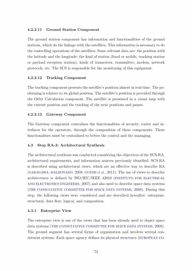
4.2.2.11 Ground Station Component
The ground station component has information and functionalities of the groundstations, which do the linkage with the satellites. This information is necessary to dothe controlling operations of the satellites. Some relevant data are: the position withthe latitude and the longitude; the kind of station (fixed or mobile, tracking stationor payload reception station); kinds of transceiver, transmitter, modem, networkprotocols, etc. The SCS is responsible for the monitoring of this equipment.
4.2.2.12 Tracking Component
The tracking component presents the satellite’s position almost in real-time. The po-sitioning is relative to its global position. The satellite’s position is provided throughthe Orbit Calculation component. The satellite is presented in a visual map withthe current position and the tracking of the next positions and passes.
4.2.2.13 Gateway Component
The Gateway component centralizes the functionalities of security, router and in-terfaces for the operators, through the composition of these components. Thesefunctionalities must be centralized to better the control and the managing.
4.3 Step RA-3: Architectural Synthesis
The architectural synthesis was conducted considering the objectives of the SCS-RA,architectural requirements, and information sources previously identified. SCS-RAis described using architectural views, which are an effective way to describe RA(NAKAGAWA; MALDONADO, 2008; GUESSI et al., 2011). The use of views to describearchitectures is defined by ISO/IEC/IEEE 42010 (INSTITUTO FOR ELECTRICAL
AND ELECTRONICS ENGINEERS, 2007) and also used to describe space data systems(THE CONSULTATIVE COMMITTEE FOR SPACE DATA SYSTEMS, 2008). During thisstep, the following views were considered and are described hereafter: enterprise,structural, data flow, logical, and composition.
4.3.1 Enterprise View
The enterprise view is one of the views that has been already used to depict spacedata systems (THE CONSULTATIVE COMMITTEE FOR SPACE DATA SYSTEMS, 2008).The ground segment has several forms of organization and involves several con-stituent systems. Each space agency defines its physical structures (EUROPEAN CO-
72
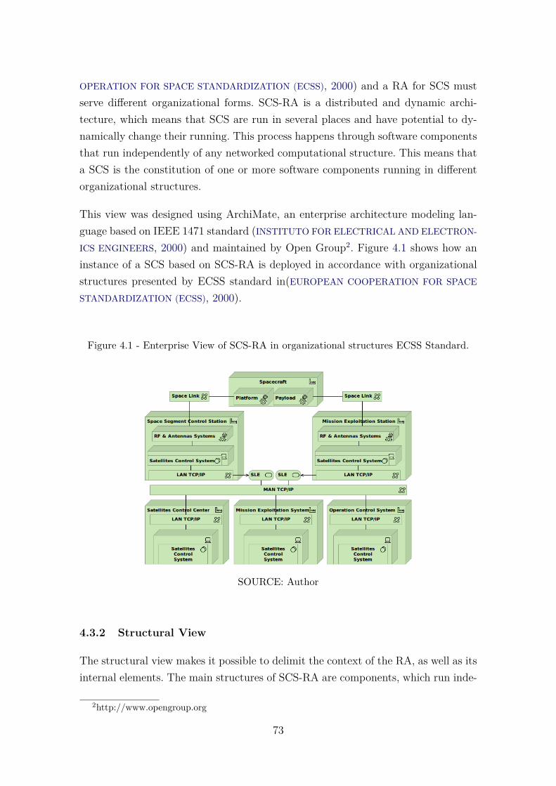
OPERATION FOR SPACE STANDARDIZATION (ECSS), 2000) and a RA for SCS mustserve different organizational forms. SCS-RA is a distributed and dynamic archi-tecture, which means that SCS are run in several places and have potential to dy-namically change their running. This process happens through software componentsthat run independently of any networked computational structure. This means thata SCS is the constitution of one or more software components running in differentorganizational structures.
This view was designed using ArchiMate, an enterprise architecture modeling lan-guage based on IEEE 1471 standard (INSTITUTO FOR ELECTRICAL AND ELECTRON-
ICS ENGINEERS, 2000) and maintained by Open Group2. Figure 4.1 shows how aninstance of a SCS based on SCS-RA is deployed in accordance with organizationalstructures presented by ECSS standard in(EUROPEAN COOPERATION FOR SPACE
STANDARDIZATION (ECSS), 2000).
Figure 4.1 - Enterprise View of SCS-RA in organizational structures ECSS Standard.
SOURCE: Author
4.3.2 Structural View
The structural view makes it possible to delimit the context of the RA, as well as itsinternal elements. The main structures of SCS-RA are components, which run inde-
2http://www.opengroup.org
73
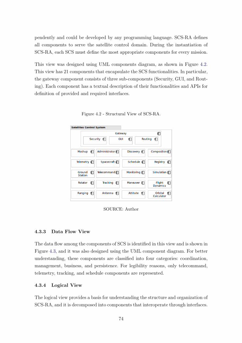
pendently and could be developed by any programming language. SCS-RA definesall components to serve the satellite control domain. During the instantiation ofSCS-RA, each SCS must define the most appropriate components for every mission.
This view was designed using UML components diagram, as shown in Figure 4.2.This view has 21 components that encapsulate the SCS functionalities. In particular,the gateway component consists of three sub-components (Security, GUI, and Rout-ing). Each component has a textual description of their functionalities and APIs fordefinition of provided and required interfaces.
Figure 4.2 - Structural View of SCS-RA.
SOURCE: Author
4.3.3 Data Flow View
The data flow among the components of SCS is identified in this view and is shown inFigure 4.3, and it was also designed using the UML component diagram. For betterunderstanding, these components are classified into four categories: coordination,management, business, and persistence. For legibility reasons, only telecommand,telemetry, tracking, and schedule components are represented.
4.3.4 Logical View
The logical view provides a basis for understanding the structure and organization ofSCS-RA, and it is decomposed into components that interoperate through interfaces.
74
Figure 4.3 - Data Flow View.
SOURCE: Author
Components encapsulate the SCS functionalities and are decomposed into packagesthat have several objects. ArchiMate was once again used to design this view andFigure 4.4 shows the components of SCS and in particular the Spacecraft componentdecomposition in packages and the objects that encompass the service package.
4.3.5 Composition View
SCS-RA enables the addition, deletion, and exchange of software components thatare selected to better meet the operational needs of a particular SCS. The instan-tiation of an SCS is performed through the components composition process. Thisprocess is performed visually, textually or through models by Composition compo-nent. This component searches for components stored in repositories, componentsrequired for a specified SCS are selected and computational resources are set up.After the download and initiation of components, the instance of SCS is providedfor use. The illustration of this process is shown in the composition view of SCS-RAin Figure 4.5.
75
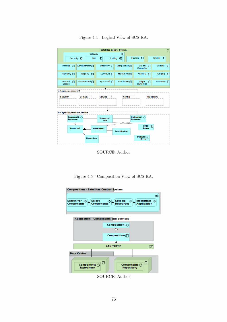
Figure 4.4 - Logical View of SCS-RA.
SOURCE: Author
Figure 4.5 - Composition View of SCS-RA.
SOURCE: Author
76
4.4 Step RA-4: Architectural Evaluation
The last step to be accomplished for the construction of a RA refers to its evaluation.To further complete this important step, we conducted the evaluation in differentways. First, the reference architecture was verified by checking the requirements withthe architectural design. Second, a conceptual validation is presented in which theSCS-RA components were used for mapping the existing SCS. Finally, an validationthrough the RAModel was performed.
4.4.1 Requirements Mapping to the Architectural Design
In Step RA-2 requirements regarding SCS-RA are presented. As a verification theserequirements and our architectural design are compared in Table 4.5. For each re-quirement we describe what part of the reference architecture addresses the require-ment. During this mapping, we conclude that all requirements of SCS-RA havecorrelation with the architectural design of our RA.
Table 4.5 - Requirements Mapping to the Architectural Design
Requirement Architectural Verification
TAR-01
The development of SCS through plug-and-play software com-ponents is addressed in the SCS-RA part:
• Definition of components as main structure;
• Non-dependency of frameworks or applicationservers to execute the components;
• Use of components with portability regarding theplatform.
Continued on next page
77
Table 4.5 – Requirements Mapping to the Architectural Design (cont.).Requirement Architectural Verification
TAR-02
The development of SCS with blocks developed in differentprogramming languages is addressed in the SCS-RA part:
• Definition of components as independent of the pro-gramming language;
• Definition of APIs as a way to provide the compo-nents’ functionalities;
• Definition of open-source and standardized protocolsas access way to the component.
TAR-03
The development of interoperable SCS is addressed in theSCS-RA part:
• Definition of components as independent of the pro-gramming language;
• Definition of open-source and standardized protocolsas access way to the component.
TAR-04
The development of SCS through dynamic architecture is ad-dressed in the SCS-RA part:
• Definition of instantiation in the components’ level;
• Configuration and definition of quality attributes incomponents’ level;
• Instantiation of new components considering thecomputational resources;
• Definition of the functionalities in the components’level.
Continued on next page
78
Table 4.5 – Requirements Mapping to the Architectural Design (cont.).Requirement Architectural Verification
TAR-05
The instantiation of SCS through composition of componentsis addressed in the SCS-RA part:
• Creation of components repository;
• Creation of Composition component;
• Creation of Registry component;
• Registration of components during their execution.
TAR-06
The development of SCS that allow the use of heterogeneousdatabases is addressed in the SCS-RA part:
• Definition of data persistence for each component;
• Each persistent component is responsible for defin-ing its database.
TAR-07
The development of SCS that make scalability easy is ad-dressed in the SCS-RA part:
• Definition of components as independent structures;
• Scalability in the components’ level;
• Horizontal scalability by functionalities defined incomponents;
• Scalability done in different platforms.
Continued on next page
79
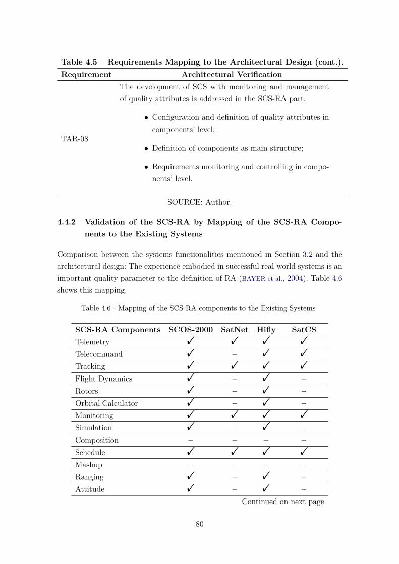
Table 4.5 – Requirements Mapping to the Architectural Design (cont.).Requirement Architectural Verification
TAR-08
The development of SCS with monitoring and managementof quality attributes is addressed in the SCS-RA part:
• Configuration and definition of quality attributes incomponents’ level;
• Definition of components as main structure;
• Requirements monitoring and controlling in compo-nents’ level.
SOURCE: Author.
4.4.2 Validation of the SCS-RA by Mapping of the SCS-RA Compo-nents to the Existing Systems
Comparison between the systems functionalities mentioned in Section 3.2 and thearchitectural design: The experience embodied in successful real-world systems is animportant quality parameter to the definition of RA (BAYER et al., 2004). Table 4.6shows this mapping.
Table 4.6 - Mapping of the SCS-RA components to the Existing Systems
SCS-RA Components SCOS-2000 SatNet Hifly SatCSTelemetry ! ! ! !
Telecommand ! – ! !
Tracking ! ! ! !
Flight Dynamics ! – ! –Rotors ! – ! –Orbital Calculator ! – ! –Monitoring ! ! ! !
Simulation ! – ! –Composition – – – –Schedule ! ! ! !
Mashup – – – –Ranging ! – ! –Attitude ! – ! –
Continued on next page
80
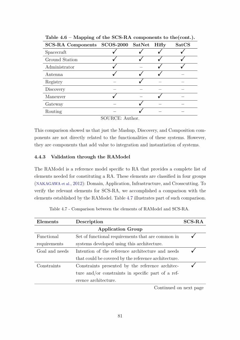
Table 4.6 – Mapping of the SCS-RA components to the(cont.).SCS-RA Components SCOS-2000 SatNet Hifly SatCSSpacecraft ! ! ! !
Ground Station ! ! ! !
Administrator ! – ! !
Antenna ! ! ! –Registry – ! – –Discovery – – – –Maneuver ! – ! –Gateway – ! – –Routing – ! – –
SOURCE: Author.
This comparison showed us that just the Mashup, Discovery, and Composition com-ponents are not directly related to the functionalities of these systems. However,they are components that add value to integration and instantiation of systems.
4.4.3 Validation through the RAModel
The RAModel is a reference model specific to RA that provides a complete list ofelements needed for constituting a RA. These elements are classified in four groups(NAKAGAWA et al., 2012): Domain, Application, Infrastructure, and Crosscutting. Toverify the relevant elements for SCS-RA, we accomplished a comparison with theelements established by the RAModel. Table 4.7 illustrates part of such comparison.
Table 4.7 - Comparison between the elements of RAModel and SCS-RA.
Elements Description SCS-RAApplication Group
Functionalrequirements
Set of functional requirements that are common insystems developed using this architecture.
!
Goal and needs Intention of the reference architecture and needsthat could be covered by the reference architecture.
!
Constraints Constraints presented by the reference architec-ture and/or constraints in specific part of a ref-erence architecture.
!
Continued on next page
81
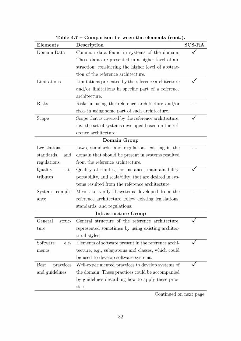
Table 4.7 – Comparison between the elements (cont.).Elements Description SCS-RADomain Data Common data found in systems of the domain.
These data are presented in a higher level of ab-straction, considering the higher level of abstrac-tion of the reference architecture.
!
Limitations Limitations presented by the reference architectureand/or limitations in specific part of a referencearchitecture.
!
Risks Risks in using the reference architecture and/orrisks in using some part of such architecture.
- -
Scope Scope that is covered by the reference architecture,i.e., the set of systems developed based on the ref-erence architecture.
!
Domain GroupLegislations,standards andregulations
Laws, standards, and regulations existing in thedomain that should be present in systems resultedfrom the reference architecture.
- -
Quality at-tributes
Quality attributes, for instance, maintainability,portability, and scalability, that are desired in sys-tems resulted from the reference architecture.
!
System compli-ance
Means to verify if systems developed from thereference architecture follow existing legislations,standards, and regulations.
- -
Infrastructure GroupGeneral struc-ture
General structure of the reference architecture,represented sometimes by using existing architec-tural styles.
!
Software ele-ments
Elements of software present in the reference archi-tecture, e.g., subsystems and classes, which couldbe used to develop software systems.
!
Best practicesand guidelines
Well-experimented practices to develop systems ofthe domain, These practices could be accompaniedby guidelines describing how to apply these prac-tices.
!
Continued on next page
82

Table 4.7 – Comparison between the elements (cont.).Elements Description SCS-RAHardware ele-ments
Elements of hardware, such as server and devices,which host systems resulted from the reference ar-chitecture.
- -
Crosscutting GroupGeneral struc-ture
General structure of the reference architecture,represented sometimes by using existing architec-tural styles.
!
Internal commu-nication
Means by which occur exchange of informationamong internal parts of systems resulted from thereference architecture.
!
Decisions Decisions, including description of the decision, op-tions (alternatives), rationale, and tradeoffs, mustbe reported during the development of the refer-ence architecture.
- -
Domain Termi-nology
Set of terms of the domain that are widely ac-cepted by the community related to that domainand are, therefore, used in the description of thereference architecture.
- -
SOURCE: Author.
As a result, we can notice that SCS-RA conforms to almost all elements of RAModel.Nevertheless, some of the missing elements refer to limitations of SCS-RA and otherfactors such as risks, decisions, terminology, legislations and system compliance,which are due to the particularities of the application domain and can still be furtheradded to this RA.
83
4.5 Final Remarks
This chapter presented SCS-RA, a reference architecture for SCS. The establishmentof SCS-RA was guided by ProSA-RA. Several sources of information were investi-gated and requirements were defined according to two groups: Architectural DomainRequirements and Technical Architectural Requirements. SCS-RA was described inviews, represented in semi-formal notations by ArchiMate and UML language, toaddress different concerns and stakeholders. The following views were described:enterprise, structural, data flow, logical, and composition.
SCS-Ra has the capacity to compose systems in which: components may be writtenin different programming languages, components may be running concurrently ina distributed, heterogeneous environment without shared address spaces, and ar-chitectures may be changed at runtime. SCS-RA contributes to support the devel-opment and evolution of SCS, contributing to improve interoperability, structuringand maintaining SCS, and contributing to improve reuse of software componentswhen developed based on SCS-RA.
The evaluation of SCS-RA was accomplished through the requirements mappingto the architectural design, mapping of the SCS-RA components to the existingsystems, and through the use RAModel. In addition to, the architectural evaluation,we also conducted a case study to provide evidences on the viability of SCS-RA andobserve possible benefits of its adoption. This case study is discussed in the nextchapter.
84
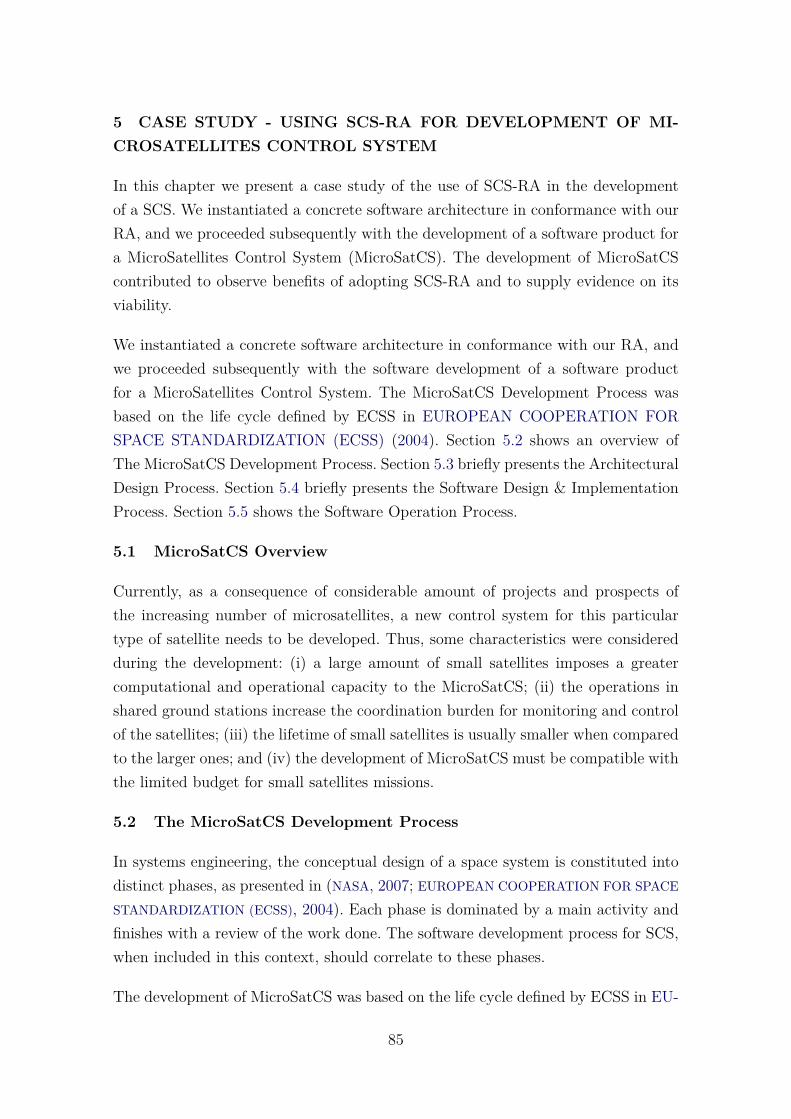
5 CASE STUDY - USING SCS-RA FOR DEVELOPMENT OF MI-CROSATELLITES CONTROL SYSTEM
In this chapter we present a case study of the use of SCS-RA in the developmentof a SCS. We instantiated a concrete software architecture in conformance with ourRA, and we proceeded subsequently with the development of a software product fora MicroSatellites Control System (MicroSatCS). The development of MicroSatCScontributed to observe benefits of adopting SCS-RA and to supply evidence on itsviability.
We instantiated a concrete software architecture in conformance with our RA, andwe proceeded subsequently with the software development of a software productfor a MicroSatellites Control System. The MicroSatCS Development Process wasbased on the life cycle defined by ECSS in EUROPEAN COOPERATION FORSPACE STANDARDIZATION (ECSS) (2004). Section 5.2 shows an overview ofThe MicroSatCS Development Process. Section 5.3 briefly presents the ArchitecturalDesign Process. Section 5.4 briefly presents the Software Design & ImplementationProcess. Section 5.5 shows the Software Operation Process.
5.1 MicroSatCS Overview
Currently, as a consequence of considerable amount of projects and prospects ofthe increasing number of microsatellites, a new control system for this particulartype of satellite needs to be developed. Thus, some characteristics were consideredduring the development: (i) a large amount of small satellites imposes a greatercomputational and operational capacity to the MicroSatCS; (ii) the operations inshared ground stations increase the coordination burden for monitoring and controlof the satellites; (iii) the lifetime of small satellites is usually smaller when comparedto the larger ones; and (iv) the development of MicroSatCS must be compatible withthe limited budget for small satellites missions.
5.2 The MicroSatCS Development Process
In systems engineering, the conceptual design of a space system is constituted intodistinct phases, as presented in (NASA, 2007; EUROPEAN COOPERATION FOR SPACE
STANDARDIZATION (ECSS), 2004). Each phase is dominated by a main activity andfinishes with a review of the work done. The software development process for SCS,when included in this context, should correlate to these phases.
The development of MicroSatCS was based on the life cycle defined by ECSS in EU-
85

ROPEAN COOPERATION FOR SPACE STANDARDIZATION (ECSS) (2004),which consists of phases: 0: Mission analysis/needs identification; A: Feasibility; B:Preliminary definition: C: Detailed definition; D: Qualification and production; E:Operations/utilization; and F: Disposal. The transition of one phase to the next oneis controlled by reviews (System Requirements Review (SRR), Preliminary DesignReview (PDR), Critical Design Review (CDR), Qualification Review (QR), Accep-tance Review (AR), and Operational Readiness Review (ORR)). These reviews arerelevant to the software engineering standard process defined by ECSS in ECSS(2009b), which offers the possibility to anticipate the PDR in a Software Require-ments Review (SWRR) and the CDR into a Design Dedicated Reviews (DDR). Incompliance with these standards, Figure 5.1 shows the MicroSatCS development lifecycle. The architectural design process was guided by SCS-RA, as detailed in thesequence.
Figure 5.1 - MicroSatCS Development Life Cycle.
SOURCE: Adapted from ECSS (2009b).
86
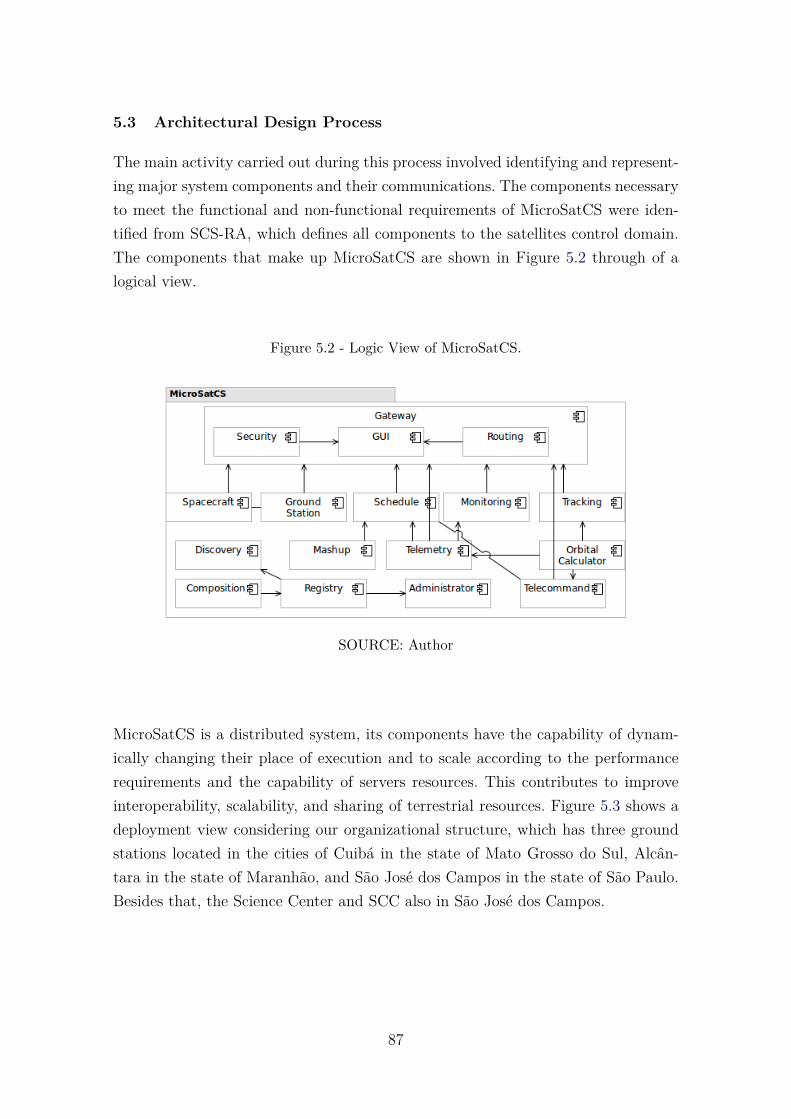
5.3 Architectural Design Process
The main activity carried out during this process involved identifying and represent-ing major system components and their communications. The components necessaryto meet the functional and non-functional requirements of MicroSatCS were iden-tified from SCS-RA, which defines all components to the satellites control domain.The components that make up MicroSatCS are shown in Figure 5.2 through of alogical view.
Figure 5.2 - Logic View of MicroSatCS.
SOURCE: Author
MicroSatCS is a distributed system, its components have the capability of dynam-ically changing their place of execution and to scale according to the performancerequirements and the capability of servers resources. This contributes to improveinteroperability, scalability, and sharing of terrestrial resources. Figure 5.3 shows adeployment view considering our organizational structure, which has three groundstations located in the cities of Cuibá in the state of Mato Grosso do Sul, Alcân-tara in the state of Maranhão, and São José dos Campos in the state of São Paulo.Besides that, the Science Center and SCC also in São José dos Campos.
87
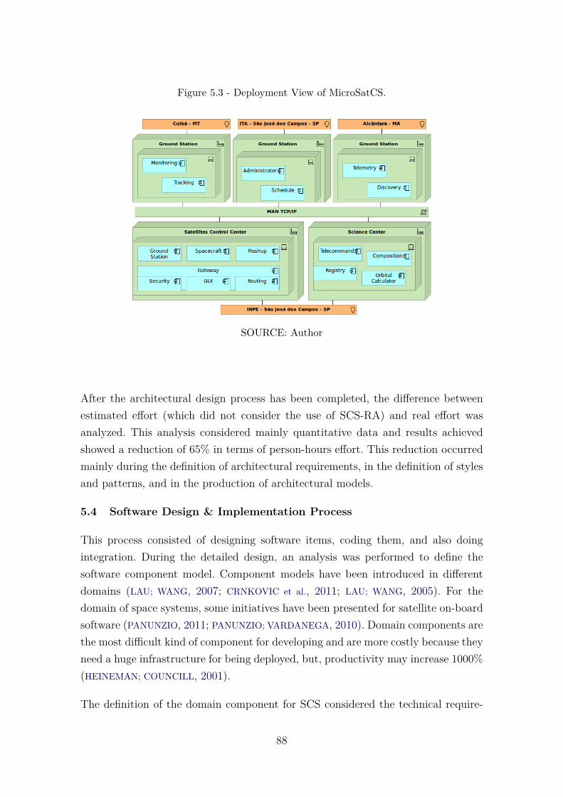
Figure 5.3 - Deployment View of MicroSatCS.
SOURCE: Author
After the architectural design process has been completed, the difference betweenestimated effort (which did not consider the use of SCS-RA) and real effort wasanalyzed. This analysis considered mainly quantitative data and results achievedshowed a reduction of 65% in terms of person-hours effort. This reduction occurredmainly during the definition of architectural requirements, in the definition of stylesand patterns, and in the production of architectural models.
5.4 Software Design & Implementation Process
This process consisted of designing software items, coding them, and also doingintegration. During the detailed design, an analysis was performed to define thesoftware component model. Component models have been introduced in differentdomains (LAU; WANG, 2007; CRNKOVIC et al., 2011; LAU; WANG, 2005). For thedomain of space systems, some initiatives have been presented for satellite on-boardsoftware (PANUNZIO, 2011; PANUNZIO; VARDANEGA, 2010). Domain components arethe most difficult kind of component for developing and are more costly because theyneed a huge infrastructure for being deployed, but, productivity may increase 1000%(HEINEMAN; COUNCILL, 2001).
The definition of the domain component for SCS considered the technical require-
88
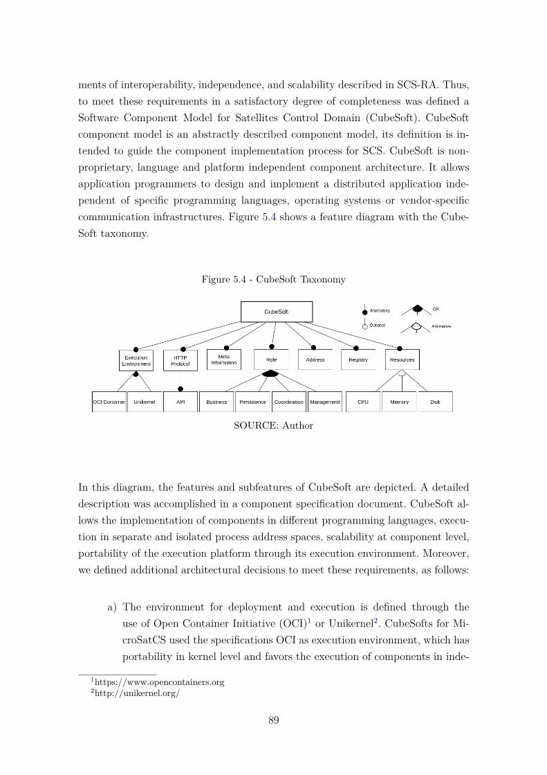
ments of interoperability, independence, and scalability described in SCS-RA. Thus,to meet these requirements in a satisfactory degree of completeness was defined aSoftware Component Model for Satellites Control Domain (CubeSoft). CubeSoftcomponent model is an abstractly described component model, its definition is in-tended to guide the component implementation process for SCS. CubeSoft is non-proprietary, language and platform independent component architecture. It allowsapplication programmers to design and implement a distributed application inde-pendent of specific programming languages, operating systems or vendor-specificcommunication infrastructures. Figure 5.4 shows a feature diagram with the Cube-Soft taxonomy.
Figure 5.4 - CubeSoft Taxonomy
SOURCE: Author
In this diagram, the features and subfeatures of CubeSoft are depicted. A detaileddescription was accomplished in a component specification document. CubeSoft al-lows the implementation of components in different programming languages, execu-tion in separate and isolated process address spaces, scalability at component level,portability of the execution platform through its execution environment. Moreover,we defined additional architectural decisions to meet these requirements, as follows:
a) The environment for deployment and execution is defined through theuse of Open Container Initiative (OCI)1 or Unikernel2. CubeSofts for Mi-croSatCS used the specifications OCI as execution environment, which hasportability in kernel level and favors the execution of components in inde-
1https://www.opencontainers.org2http://unikernel.org/
89
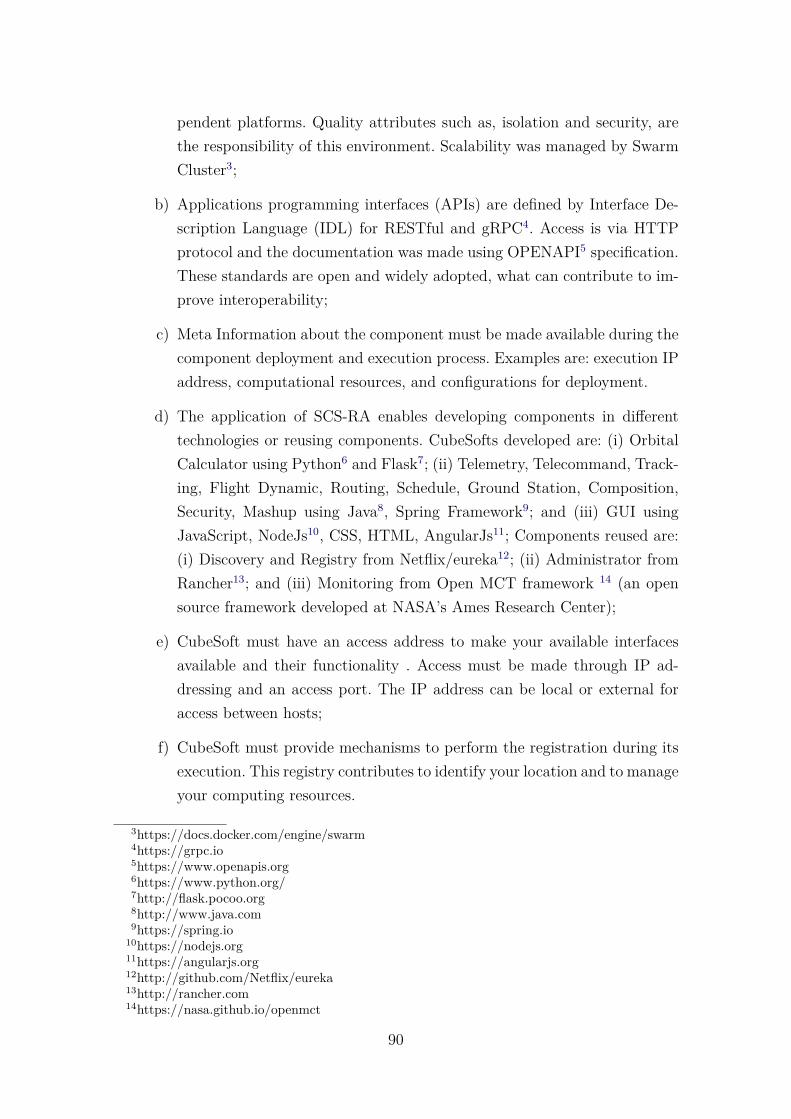
pendent platforms. Quality attributes such as, isolation and security, arethe responsibility of this environment. Scalability was managed by SwarmCluster3;
b) Applications programming interfaces (APIs) are defined by Interface De-scription Language (IDL) for RESTful and gRPC4. Access is via HTTPprotocol and the documentation was made using OPENAPI5 specification.These standards are open and widely adopted, what can contribute to im-prove interoperability;
c) Meta Information about the component must be made available during thecomponent deployment and execution process. Examples are: execution IPaddress, computational resources, and configurations for deployment.
d) The application of SCS-RA enables developing components in differenttechnologies or reusing components. CubeSofts developed are: (i) OrbitalCalculator using Python6 and Flask7; (ii) Telemetry, Telecommand, Track-ing, Flight Dynamic, Routing, Schedule, Ground Station, Composition,Security, Mashup using Java8, Spring Framework9; and (iii) GUI usingJavaScript, NodeJs10, CSS, HTML, AngularJs11; Components reused are:(i) Discovery and Registry from Netflix/eureka12; (ii) Administrator fromRancher13; and (iii) Monitoring from Open MCT framework 14 (an opensource framework developed at NASA’s Ames Research Center);
e) CubeSoft must have an access address to make your available interfacesavailable and their functionality . Access must be made through IP ad-dressing and an access port. The IP address can be local or external foraccess between hosts;
f) CubeSoft must provide mechanisms to perform the registration during itsexecution. This registry contributes to identify your location and to manageyour computing resources.
3https://docs.docker.com/engine/swarm4https://grpc.io5https://www.openapis.org6https://www.python.org/7http://flask.pocoo.org8http://www.java.com9https://spring.io
10https://nodejs.org11https://angularjs.org12http://github.com/Netflix/eureka13http://rancher.com14https://nasa.github.io/openmct
90

5.5 Software Operation Process
This section briefly presents the MicroSatCS in operation. MicroSatCS was instan-tiated visually from the Composition component, as shown in Figure 5.5. The in-stantiation allows to define computational resources such as memory, CPU and diskfor each component. The components were stored in the Docker repository15.
Figure 5.5 - Instantiation of MicroSatCS.
SOURCE: Author
The GUI component provides the operations of MicroSatCS through a browser andFigure 5.6 shows some typical operations of MicroSatCS and, in particular, thetracking of UbatubaSat Picosatellite.
The computational resources consumed by the components during their execution,such as capacities of memory, CPU, network, and storage, are assigned accord-ing to each components requirements. The Administrator component monitors andmanages the computational resources of each component as Figure 5.7 shows, forexample, those being the resources consumed by Gateway Component in operation.
15https://hub.docker.com
91
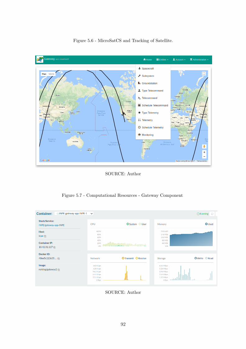
Figure 5.6 - MicroSatCS and Tracking of Satellite.
SOURCE: Author
Figure 5.7 - Computational Resources - Gateway Component
SOURCE: Author
92
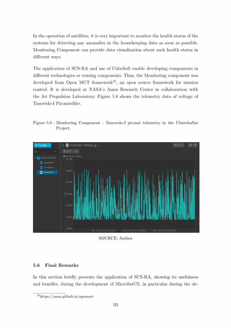
In the operation of satellites, it is very important to monitor the health status of thesystems for detecting any anomalies in the housekeeping data as soon as possible.Monitoring Component can provide data visualization about such health status indifferent ways.
The application of SCS-RA and use of CubeSoft enable developing components indifferent technologies or reusing components. Thus, the Monitoring component wasdeveloped from Open MCT framework16, an open source framework for missioncontrol. It is developed at NASA’s Ames Research Center in collaboration withthe Jet Propulsion Laboratory. Figure 5.8 shows the telemetry data of voltage ofTancredo-I Picosatellite.
Figure 5.8 - Monitoring Component - Tancredo-I picosat telemetry in the UbatubaSatProject.
SOURCE: Author
5.6 Final Remarks
In this section briefly presents the application of SCS-RA, showing its usefulnessand benefits, during the development of MicroSatCS, in particular during the de-
16https://nasa.github.io/openmct
93
sign, implementation and operation processes. Results indicate that SCS-RA cancontribute to the development of SCS software architectures. However, other casestudies are necessary and will be conducted to confirm the obtained results, identifypossible improvements for the reference architecture, and increase the confidence onits adoption.
The next chapter concludes this thesis, summarizing the main contributions, dis-cussing general limitations, and mentioning future work.
94
6 CONCLUSIONS AND FUTURE WORKS
6.1 Discussion
The establishment of SCS-RA requires a deep knowledge on diverse subjects fromdifferent stakeholders, as well as, the need of an initial investment with regard totime and cost. However, a significant reduction of time and effort was observedduring the comparison of the initial effort estimate, which did not consider theuse of SCS-RA, with the real effort of development with the use of SCS-RA. Thisanalysis considered mainly quantitative data and results achieved showed an effortreduction of 65% in terms of person-hours during architectural design process. Inaddition to the effort reduction observed in our analysis, a cost-benefit analysis couldbe carried out through a particular economic model for RA (MARTÍNEZ-FERNÁNDEZ
et al., 2013).
Using SCS-RA, best practices of SCS development increase the productivity of de-velopers. MicroSatCS functionalities were more easily built with components devel-oped and provided from different providers. Hence, MicroSatCS has benefited fromreduced development and integration effort, besides reuse, which is an approach thathas several other benefits (LAU; WANG, 2007; LI et al., 2007; MILI et al., 1995).
6.2 Final Remarks
In this thesis, we presented a RA for SCS, referred to as SCS-RA. The main con-tribution of SCS-RA lies in providing guidelines for the development and evolutionof SCS. Therefore, these systems could be easily built from this architecture, reduc-ing time, efforts, and rework and improving interoperability and sharing of groundresources among space organizations. SCS-RA was proposed following a systematicprocess and during the evaluations performed, it was observed that SCS-RA is com-plete, since it presents the most important elements that should be present in a RA.In addition, the development of MicroSatCS contributed to observe the benefits ofadopting SCS-RA and to supply evidence on its viability.
An important contribution of this work is to make the reference architecture avail-able for any government or research institution that intends to create a satellitearchitecture control system. We deliver knowledge and expertise about this domainencapsulated as a reference architecture, and make it available for world-wide adop-tion and improvement, fostering the advancements of sciences and supporting thedevelopment of space technologies for other countries.
95
Results achieved from usage of SCS-RA during the development of a Microsatel-lite Control System for INPE, a Brazilian National Institute for Space Research,showed a significant reduction of time and effort. Furthermore during operationalphase, benefits of interoperability, scalability, and sharing of ground resources wereobserved. As a RA gathers knowledge acquired from a domain and structures it ina reusable and extensible form (GRACIANO NETO et al., 2015), forthcoming softwareproducts for SCS could be inherently interoperable, as they could be instantiatedfrom a common RA, following shared standards, and facilitating resources sharing.As a consequence, several other SCS could be built from SCS-RA.
Besides the positive results obtained so far, we highlight the need to conduct amore complete evaluation involving different integrated SCS. From this work, it canbe concluded that there are still challenges to be met, especially, in the descrip-tion, maintenance, and sustainability of SCS-RA to be performed by several spaceorganizations.
6.3 List of Publications Attained
Excerpts of this thesis have been either published or submitted for the appreciationof editorial boards of journals, conferences, symposiums, and workshops, accordingto the abstracts and articles presented below.
Event: II Latin American IAA CubeSat Workshop. February 28 to March 2, 2016.Ingleses Beach, Florianopolis, Brazil
Title: Integration of the INPE Ground Station into the SatNet Network
Authors: Ricardo Tubío-Pardavia, Jorge Enrique Espindola Diaz, Adair JoséRohling, Mauricio Gonçalves Vieira Ferreira, Walter Abrahao Dos Santos, JordiPuig-Suari, Fernando Aguado-Agelet.
Abstract: The researchers of the Ground Station at the National Institute forSpace Research (INPE) in Brazil have started working, together with the maindevelopers of the SATNet network, in the integration of their ground segment intothat very same network. This paper presents the description of that integrationprocess together with the results obtained and with a description of the currentand upcoming small satellite projects in Brazil and in Latin America. The SATNetnetwork aims at incorporating the capabilities of all the already deployed universityGround Stations into a single, coherent and usable resource. The approach usedfor this network is based on heterogeneity, allowing the integration of very different
96
ground stations into a single ground system.
Event: 7o Workshop em Engenharia e Tecnologia Espaciais 2016, September 23-24,2016. São Jose dos Campos, Brazil.
Title: CubeSoft : Componentes de Software para Desenvolvimento de Sistemas deControle de Satélites
Authors: Adair José Rohling, Mauricio Gonçalves Vieira Ferreira, Walter AbrahaoDos Santos.
Abstract: Aplicações do domínio de controle de satélites são complexas e estãoem constante evolução em consequência de avanços tecnológicos. Atender requisi-tos de portabilidade, desenvolvimento e reúso de componentes torna-se um desafio,principalmente para aplicações monolíticas que utilizam camadas como estruturaprincipal de decomposição e para aplicações desenvolvidas em diferentes modelos decomponentes de software. Neste contexto, este trabalho propõe o uso de CubeSoftscomo estrutura principal para aplicações deste domínio. CubeSofts são componentesde software definidos através de unidades funcionais independentes encapsuladas emcontainers. O estilo arquitetural microservices é aplicado na definição de CubeSoftscomo estrutura principal das aplicações e containers são usados como ambiente deexecução para diferentes modelos de componentes. Uma arquitetura de software éapresentada como resultado da aplicação de CubeSofts em sistemas de controle desatélites.
Event: 26th Annual INCOSE International Symposium (IS2016) Edinburgh, July18-21, 2016
Title: Concurrent Structured Analysis SE method applied to a solar irradiancemonitor satellite
Authors: Rodrigo Britto Maria, Halph Macedo Fraulob, Adrielle Chiaki, GabrielGustavo Coronel Mariño, Adair José Rohling, Geilson Loureiro.
Abstract: The traditional Systems Engineering approach on systems developmentleans toward the product in development, in all levels of abstraction, while the tra-ditional concurrent engineering approach focuses on both product and organizationsimultaneous development, although considering only lower levels of abstraction. Forcomplex systems, the Concurrent Structured Analysis method is a better fit for theSE process, since it considers both the product and organization simultaneous de-
97
velopment, in all levels of abstraction. The underlying concepts of this method wereapplied to the development of a solar irradiance monitor satellite. Several analyseswere performed on selected scenarios of the system life cycle processes to exemplifythe application of the concepts. The final outcome was a proposal design of theproduct and the organization needed to implement its life cycle processes. It wasnoted that the same scenario can influence the product and the organization, bothrequiring to be considered in the analysis.
Event: Symposium on Applied Computing, Pau, France, April 9–13, 2018 (SAC’18).
Title: Externalizing Patterns for Simulations in Software Engineering of Systems-of-Systems
Authors: Valdemar Vicente Graciano Neto, Wallace Manzano, Adair José Rohling,Mauricio Gonçalves Vieira Ferreira, Tiago Volpato, Elisa Yumi Nakagawa.
Abstract: Systems-of-Systems (SoS) often support critical domains. They mustbe trustworthy, i.e., they must keep their operation in progress, being not subjectto failures, as they can cause potential damages and hazards to human integrity.Simulations are a recurrent approach in SoS development, as they can anticipatepotential failures, consequently increasing the level of trustworthiness and qualityexhibited by a SoS. Nevertheless, simulation is still software and demands engineer-ing. Moreover, many simulation formalisms are not trivial of specifying, sometimestangling software an hardware details to program an executable simulation. Thus,the aim of this paper is contributing for software engineering of SoS by externalizingtwo patterns for the conception of SoS simulations. We evaluated our patterns byapplying them in a case study in two different domains. For both, patterns weresuccessfully applied during automatic generation of functional code, supporting theexecution of SoS simulations and prediction of SoS behavior at design-time.
Event: XIV Simpósio Brasileiro de Sistemas de Informação (SBSI 2018).
Title: A Study on Goals Specification for Systems-of-Information Systems: DesignPrinciples and Conceptual Model
Authors: Valdemar Vicente Graciano Neto, Flavio Horita, Everton Cavalcante,Adair José Rohling, Jamal El-Hachem, Daniel Santos, Elisa Yumi Nakagawa.
Abstract: Software-intensive information systems can be aggregated to formSystems-of-Information Systems (SoIS) and provide novel functionalities to achieve
98
high-level goals, also known as missions. Missions represent an important concernin this context since they are related to both capabilities of constituent systems andhow they shall interact with each other within a SoIS. Due to such a relevant role,we conducted an exploratory study to evaluate how a state-of-the-art language formission specification has supported mission (renamed as goal in this study) specifi-cation for SoIS. This investigation has been carried out in the context of a space SoIScomposed of independent ground information systems, satellites and other systemsto provide territory monitoring and environmental data distribution. Results indi-cate a lack of support for the specificities of SoIS goals, such as the representation ofinterdependency among activities and dynamicity support. As main contributions,this paper comes up with a set of design principles and a corresponding conceptualmodel to be followed by languages tailored to support goal specification in SoIS.
Journal: Innovations in Systems and Software Engineering - A NASA Journal
Title: A Reference Architecture for Satellite Control Systems
Authors: Adair José Rohling, Valdemar Vicente Graciano Neto, MauricioGonçalves Vieira Ferreira, Walter Abrahão Dos Santos, Elisa Yumi Nakagawa.
Abstract: Software for Satellite Control Systems (SCS) domain performs a rele-vant role in space systems, being responsible for ensuring the functioning of thesatellites, from the orbit launch to the end of their lifetime. Systems in this domainare complex and are constantly evolving due to technological advancement of satel-lites, the significant increase of controlled satellites, and the interoperability amongspace organizations. However, in order to meet such complexity and such evolution,the architectures of these systems have been usually designed in an isolated wayby each organization, hence may be prone to recurrent efforts and difficulties of in-teroperability. In parallel to this scenario, reference architecture, a special type ofsoftware architecture that aggregates knowledge of a specific domain, has performedan important role for the success in development, standardization, and evolutionof systems in several domains. Nevertheless, the usage of reference architecture hasnot been explored in the SCS domain. Thus, this article presents a Reference Ar-chitecture for Satellite Control Systems (SCS-RA). Results achieved from usage ofSCS-RA in the development of a Microsatellite Control System for National Insti-tute for Space Research (INPE) showed a significant reduction of effort, benefits ofinteroperability, scalability, and sharing of ground resources.
99

REFERENCES
ALMEIDA, E. S. de. RiDE: The RiSE process for domain engineering. PhDThesis (Ph.D. Thesis) — Federal University of Pernambuco, Recife-PE, Brazil,2007. 39
AMERICA, P.; OBBINK, H.; OMMERING, R. van; LINDEN, F. van der. Copam:A component-oriented platform architecting method family for product familyengineering. In: . Software product lines: experience and researchdirections. Boston, MA: Springer US, 2000. p. 167–180. ISBN 978-1-4615-4339-8.Available from: <https://doi.org/10.1007/978-1-4615-4339-8_9>. 39
ANGELOV, S.; GREFEN, P.; GREEFHORST, D. A classification of softwarereference architectures: analyzing their success and effectiveness. In: JOINTWORKING IEEE/IFIP CONFERENCE ON SOFTWARE ARCHITECTUREEUROPEAN CONFERENCE ON SOFTWARE ARCHITECTURE, 2009.Proceedings... Cambridge: IEEE, 2009. p. 141–150. 27
. A framework for analysis and design of software reference architectures.Information and Software Technology, v. 54, n. 4, p. 417–431, apr. 2012.ISSN 0950-5849. Available from:<http://dx.doi.org/10.1016/j.infsof.2011.11.009>. 29, 31
ANGELOV, S.; TRIENEKENS, J. J.; GREFEN, P. Towards a method for theevaluation of reference architectures: experiences from a case. In: EUROPEANCONFERENCE ON SOFTWARE ARCHITECTURE (ECSA), 2., 2008.Proceedings... Berlin: Springer, 2008. p. 225–240. ISBN 978-3-540-88029-5.Available from: <http://dx.doi.org/10.1007/978-3-540-88030-1_17>. 31
ARZA, M.; DREIHAHN, H. SLE Routing – simplified station access for missionoperations. In: INTERNATIONAL CONFERENCE ON SPACE OPERATIONS(SPACEOPS), 2012. Proceedings... Stockholm, 2012. Available from: <http://www.spaceops2012.org/proceedings/documents/id1294305-Paper-001.pdf>.2
ASSOCIAÇÃO BRASILEIRA DE NORMAS TÉCNICAS. Campo CCSDS paraidentificação global de espaçonaves: procedimentos de controle paraatribuição de códigos - CCSDS 320.0-B-5-S. São José dos Campos, 2007.29 p. Access in: 19 dez. 2017. 70
101
ATKINSON, C.; BAYER, J.; BUNSE, C.; KAMSTIES, E.; LAITENBERGER, O.;LAQUA, R.; MUTHIG, D.; PAECH, B.; WüST, J.; ZETTEL, J.Component-based product line engineering with UML. Boston, MA, USA:Addison-Wesley Longman Publishing, 2002. ISBN 0-201-73791-4. 40
ATKINSON, C.; BAYER, J.; MUTHIG, D. Component-based product linedevelopment: the kobra approach. In: PROCEEDINGS OF THE FIRSTCONFERENCE ON SOFTWARE PRODUCT LINES : EXPERIENCE ANDRESEARCH DIRECTIONS: EXPERIENCE AND RESEARCH DIRECTIONS,1.,2000. Proceedings... Norwell, MA: Kluwer Academic Publishers, 2000. p.289–309. ISBN 0-79237-940-3. Available from:<http://dl.acm.org/citation.cfm?id=355461.357556>. 40
BACHMANN, F.; BASS, L.; BUHMAN, C.; COMELLA-DORDA, S.; LONG, F.;ROBERT, J.; SEACORD, R.; WALLNAU, K. Technical concepts ofcomponent-based software engineering. 2. ed. Pittsburgh, PA, 2000.Available from:<http://resources.sei.cmu.edu/library/asset-view.cfm?AssetID=5203>.38
BASS, L.; CLEMENTS, P.; KAZMAN, R. Software architecture in practice.2. ed. Boston, MA, USA: Addison-Wesley Longman Publishing, 2003. ISBN0321154959. 17, 28, 47
BAYER, J.; GANESAN, D.; GIRARD, J.-F.; KNODEL, J.; KOLB, R.; SCHMID,K. Definition of reference architecture based on existing systems. [S.l.],2004. Available from:<http://publica.fraunhofer.de/dokumente/N-21572.html>. 31, 80
BOLEA-ALAMANAC, A. A. . L. A. . A. ISIS: ISU small satelliteinterdisciplinary survey. 2001. Available from: <https://isulibrary.isunet.edu/opac/index.php?lvl=notice_display&id=4686>.9, 11, 12
BORN, M.; HOFFMANN, A.; RENNOCH, A.; REZNIK, J.; RITTER, T.;VOUFFO, A. The european corba components open source initiative. ERCIMNews n.55, Oct 2003. Available from:<https://www.ercim.eu/publication/Ercim_News/enw55/rennoch.html>. 37
BOUWMEESTER, J.; GUO, J. Survey of worldwide pico- and nanosatellitemissions, distributions and subsystem technology. Acta Astronautica, v. 67,
102
n. 7, p. 854 – 862, 2010. ISSN 0094-5765. Available from: <http://www.sciencedirect.com/science/article/pii/S0094576510001955>. 11
BRITO, P. H. da S.; GUERRA, P. A. de C.; RUBIRA, C. M. F. Estudo sobreestilos arquiteturais para sistemas de software baseados emcomponentes. [S.l.], March 2007. 17
BROWN, A. W.; SHORT, K. On components and objects: the foundations ofcomponent-based development. In: INTERNATIONAL SYMPOSIUM ONASSESSMENT OF SOFTWARE TOOLS AND TECHNOLOGIES, 5., 1997.Proceedings... [S.l.], 1997. p. 112–121. 33, 38, 39
BROY, M.; DEIMEL, A.; HENN, J.; KOSKIMIES, K.; PLASIL, F.;POMBERGER, G.; PREE, W.; STAL, M.; SZYPERSKI, C. A. Whatcharacterizes a (software) component? Software - Concepts and Tools, v. 19,n. 1, p. 49–56, 1998. 33
CALPOLY. CubeSat design specification rev. 13. California, 2014. Availablefrom: <http://www.cubesat.org/s/cds_rev13_final2.pdf>. Access in: 05 Feb.2016. 9, 10
CAMPBELL, A. T.; CHOU, S. T.; KOUNAVIS, M. E.; STACHTOS, V. D.;VICENTE, J. Netbind: a binding tool for constructing data paths in networkprocessor-based routers. In: IEEE OPEN ARCHITECTURES AND NETWORKPROGRAMMING PROCEEDINGS (OPENARCH), 2002. Proceedings... [S.l.],2002. p. 91–103. 35
CASTRO, A.; PAGE, H.; WALKER, R.; EMMA, F.; AGUADO, F.; VAZQUEZ,A. J. Connecting students with space: genso pre-operational activities andpreparation for geoid/humsat operations. ESA bulletin, v. 2012, p. 38–43, 022012. 56
CHAMOUN, J. P.; RISNER, S.; BEECH, T.; GARCIA, G. Bridging ESA andNASA worlds: lessons learned from the integration of Hifly R©/SCOS-2000 inNASA’s GMSEC. In: IEEE AEROSPACE CONFERENCE, 2006. Proceedings...[S.l.]: IEEE, 2006. p. 1–8. ISSN 1095-323X. 3, 52, 55
CHEESMAN, J.; DANIELS, J. UML components - a simple process forspecifying component-based software. [S.l.]: Addison-Wesley, 2001.(Component Software Series). 39
103

CHIN, A.; COELHO, R.; NUGENT, R.; MUNAKATA, R.; PUIG-SUARI, J.CubeSat: the pico-satellite standard for research and education. In: AIAA SPACECONFERENCE AND EXPOSITION, 2008. Proceedings... AIAA, 2008.Available from: <https://doi.org/10.2514%2F6.2008-7734>. 10
CHIN, E.; BROOKS, L.; NUGENT, R.; PUIG-SUARI, D. J.; POLY, C.; OBISPO,S. L.; CHIN, A.; COELHO, R.; BROOKS, L.; NUGENT, R.; JORDI, D.; SUARI,P. Standardization promotes flexibility: a review of cubesats. In: AIAARESPONSIVE SPACE CONFERENCE, 6., 2008. Proceedings... [S.l.]: AIAA,2008. p. 1–6. 11
CLEMENT, S. J.; MCKEE, D. W.; XU, J. Service-oriented reference architecturefor smart cities. In: IEEE SYMPOSIUM ON SERVICE-ORIENTED SYSTEMENGINEERING, 2017. Proceedings... [S.l.]: IEEE, 2017. p. 81–85. 3, 29
CLEMENTS, P. Documenting Software Architectures: Views and Beyond.Addison-Wesley, 2003. (SEI series in software engineering). ISBN 9780201703726.Available from: <https://books.google.com.br/books?id=ASc9HYPkr4sC>. 24
CLEMENTS, P.; COHEN, S.; DONOHOE, P.; NORTHROP, L. Control channeltoolkit: a software product line case study. Pittsburgh, PA, 2001. Availablefrom:<http://resources.sei.cmu.edu/library/asset-view.cfm?AssetID=5765>.45, 46, 47
CLOUTIER, R.; MULLER, G.; VERMA, D.; NILCHIANI, R.; HOLE, E.; BONE,M. The concept of reference architectures. Systems Engineering, v. 13, n. 1, p.14–27, feb. 2010. ISSN 1098-1241. Available from:<http://dx.doi.org/10.1002/sys.v13:1>. 3, 31
COM: Component Object Model Technologies. 2017. Available from:https://www.microsoft.com/com/default.mspx. (Access in: 30 Oct. 2017). 35
CONSULTATIVE COMMITTEE FOR SPACE DATA SYSTEMS (CCSDS).Spacecraft monitor and control-core services, draft recommendation forspace data system standards, CCSDS-522.0-R-2, proposed red book .[S.l.], Abr 2008. 121 p. 64, 65
. Mission operations common object model, draft recommendationfor space data system standards, CCSDS-521.1-R-1, proposed red book.[S.l.], Abr 2009. 64, 65
104
. Mission operations reference model, recommended practice,CCSDS 520.1-M, magenta book. [S.l.], Jul 2010. 71 p. 63, 65
. Mission operations services concept, informational report,CCSDS-520.0-G-3, green book. [S.l.], Dec 2010. 62 p. 63, 64, 65
CORBA component model specification version 4.0. 2016. Available from:http://www.omg.org/spec/CCM/. (Access in: 30 Oct. 2017). 35
COUNCIL, N. R. Technology for small spacecraft. Washington, DC: TheNational Academies Press, 1994. ISBN 978-0-309-05075-3. Available from:<https://www.nap.edu/catalog/2351/technology-for-small-spacecraft>.8, 12
CRNKOVIC, I.; CHAUDRON, M.; LARSSON, S. Component-based developmentprocess and component lifecycle. In: INTERNATIONAL CONFERENCE ONSOFTWARE ENGINEERING ADVANCES, 2006. Proceedings... [S.l.], 2006. p.44–44. 33
CRNKOVIC, I.; SENTILLES, S.; VULGARAKIS, A.; CHAUDRON, M. R. V. Aclassification framework for software component models. IEEE Transactions onSoftware Engineering, v. 37, n. 5, p. 593–615, Sept 2011. ISSN 0098-5589. 34,35, 36, 37, 88
DAVID, L. Cubesats: tiny spacecraft, huge payoffs. Set 2004. Available from:<https://www.space.com/308-cubesats-tiny-spacecraft-huge-payoffs.html>.Access in: 24 Nov. 2017. 11
DOBRICA, L.; NIEMELÄ, E. An approach to reference architecture design fordifferent domains of embedded systems. In: INTERNATIONAL CONFERENCEON SOFTWARE ENGINEERING RESEARCH AND PRACTICE, 2008.Proceedings... [S.l.], 2008. p. 287–293. 31
DOWLING, J.; CAHILL, V. Self-managed decentralised systems usingk-components and collaborative reinforcement learning. In: ACM SIGSOFTWORKSHOP ON SELF-MANAGED SYSTEMS, 1., 2004. Proceedings... NewYork: ACM, 2004. p. 39–43. ISBN 1-58113-989-6. Available from:<http://doi.acm.org/10.1145/1075405.1075413>. 35
105

D’SOUZA, D. F.; WILLS, A. C. Objects, components, and frameworks withUML: the catalysis approach. Boston, MA, USA: Addison-Wesley LongmanPublishing, 1999. ISBN 0-201-31012-0. 39
DUBOS, G. F.; CASTET, J.-F.; SALEH, J. H. Statistical reliability analysis ofsatellites by mass category: does spacecraft size matter? Acta Astronautica,v. 67, n. 5, p. 584 – 595, 2010. ISSN 0094-5765. Available from: <http://www.sciencedirect.com/science/article/pii/S0094576510001347>. 9
DURO, N.; MOREIRA, F.; ROGADO, J.; REIS, J.; PECCIA, N. Technologyharmonization - developing a reference architecture for the ground segmentsoftware. In: IEEE AEROSPACE CONFERENCE, 2005. Proceedings... [S.l.],2005. p. 3968–3979. ISSN 1095-323X. 3, 41, 42
DVORAK, D. NASA study on flight software complexity. In: AIAA INFOTECHAEROSPACE CONFERENCE, 2009. Proceedings... AIAA, 2009. Availablefrom: <https://doi.org/10.2514/6.2009-1882>. 2
ENTERPRISE JavaBeans Technology. 2017. Available from:<http://www.oracle.com/technetwork/java/javaee/ejb/index.html>.Access in: 30 Oct. 2017. 35
EUROPEAN COOPERATION FOR SPACE STANDARDIZATION (ECSS).ECSS-E-ST-70C: space engineering – ground systems and operations –part 1: principles and requirements. [S.l.], 2000. 8, 13, 15, 63, 65, 73
. ECSS-E-10 Part 1B - system engineering — part 1: requirementsand process. [S.l.], 2004. 85, 86
. ECSS-E-ST-70-31C: space engineering – ground systems andoperations – monitoring and control data. [S.l.], 2008. 65
. ECSS-E-ST-40: space engineering – software generalrequirements. Noordwijk, The Netherlands, Mar 2009. 64, 65
. ECSS-E-ST-40C - software. Noordwijk, The Netherlands, Mar 2009. 86
EUROPEAN SPACE AGENCY (ESA). EGS-CC- european ground systemscommon core. Oct. 2017. Available from: http://www.egscc.esa.int/. (Accessin: 02 Nov. 2017). 42, 45
. Global educational network for satellite operations / education /ESA. Nov 2017. Available from: http://www.esa.int/Education/Global_
106
Educational_Network_for_Satellite_Operations. ( Access in: 25 Nov. 2017).56, 57
FASSINO, J.-P.; STEFANI, J.-B.; LAWALL, J. L.; MULLER, G. Think: asoftware framework for component-based operating system kernels. In: GENERALTRACK OF THE ANNUAL CONFERENCE ON USENIX ANNUALTECHNICAL CONFERENCE, 2002. Proceedings... Berkeley, CA, USA:USENIX Association, 2002. p. 73–86. ISBN 1-880446-00-6. Available from:<http://dl.acm.org/citation.cfm?id=647057.713860>. 35
FERREIRA, M. G. V. Uma arquitetura flexível e dinâmica para objetosdistribuídos aplicada ao software de controle de satélites. 244 p. PhDThesis (Doctor in Applied Computation) — Instituto Nacional de PesquisasEspaciais (INPE), São José dos Campos, 2001-03-23 2001. Available from:<http://urlib.net/dpi.inpe.br/lise/2003/01.16.09.56>. Access in: 24 nov.2017. 15
FERRO, E.; GIROLAMI, M.; SALVI, D.; MAYER, C.; GORMAN, J.; GRGURIC,A.; RAM, R.; SADAT, R. The UniversAAL platform for AAL (Ambient AssistedLiving). Journal of Intelligent Systems, p. 301–319, 2015. 3, 29
FILHO, N. F. D.; BARBOSA, E. F. A Contribution to the establishment ofreference architectures for mobile learning environments. IEEE RevistaIberoamericana de Tecnologias del Aprendizaje, v. 10, n. 4, p. 234–241, Nov2015. ISSN 1932-8540. 3, 29
FORD, B.; BACK, G.; BENSON, G.; LEPREAU, J.; LIN, A.; SHIVERS, O. Theflux oskit: a substrate for kernel and language research. SIGOPS - OperatingSystems Review, v. 31, n. 5, p. 38–51, oct. 1997. ISSN 0163-5980. Availablefrom: <http://doi.acm.org/10.1145/269005.266642>. 35
FORTESCUE, P.; STARK, J.; SWINERD, G. Spacecraft systemsengineering. New York: Wiley, 2003. ISBN 9780470851029. Available from:<http://onlinelibrary.wiley.com/book/10.1002/9781119971009>. 9
FURMENTO, N.; MAYER, A.; MCGOUGH, S.; NEWHOUSE, S.; FIELD, T.;DARLINGTON, J. Optimisation of component-based applications within a gridenvironment. In: ACM/IEEE CONFERENCE ON SUPERCOMPUTING, 2001.Proceedings... New York: ACM, 2001. p. 30–30. ISBN 1-58113-293-X. Availablefrom: <http://doi.acm.org/10.1145/582034.582064>. 35
107

GALLAGHER, B. Using the architecture tradeoff analysis method toevaluate a reference architecture: a case study. Pittsburgh, PA, 2000.Available from:<http://resources.sei.cmu.edu/library/asset-view.cfm?AssetID=5109>.31, 32
GALSKI, R. L. Capacidades técnologicas do inpe em rastreio e controle desátelites: diagnóstico da situação atual e tendências de curto e médio prazo. In:MOREIRA, M. L. (Ed.). Coletânea do I curso de pós-graduação em gestãoestratégica da ciência e tecnologia em institutos públicos de pesquisa.São José dos Campos: Instituto Nacional de Pesquisas Espaciais (INPE), 2012.Available from:<http://urlib.net/sid.inpe.br/mtc-m19/2011/04.15.11.27>. Access in: 24nov. 2017. 15
GARLAN, D. Software architecture: a roadmap. In: CONFERENCE ON THEFUTURE OF SOFTWARE ENGINEERING, 2000. Proceedings... New York,NY, USA: ACM, 2000. p. 91–101. ISBN 1-58113-253-0. Available from:<http://doi.acm.org/10.1145/336512.336537>. 17
GARLAN, D.; ALLEN, R.; OCKERBLOOM, J. Architectural mismatch: whyreuse is still so hard. IEEE Software, v. 26, n. 4, p. 66–69, July 2009. ISSN0740-7459. 35, 36
GARLAN, D.; BACHMANN, F.; IVERS, J.; STAFFORD, J.; BASS, L.;CLEMENTS, P.; MERSON, P. Documenting software architectures: viewsand beyond. 2nd. ed. [S.l.]: Addison-Wesley Professional, 2010. ISBN0321552687, 9780321552686. 19, 23
GÉDÉON, W. OSGi and apache felix 3.0 beginnerś guide : build yourvery own OSGi applications using the flexible and powerful felixframework. Birmingham, U.K: Packt Pub, 2010. ISBN 978-1-849511-38-4. 38
GENSSLER, T.; CHRISTOPH, A.; WINTER, M.; NIERSTRASZ, O.; DUCASSE,S.; WUYTS, R.; ARÉVALO, G.; SCHöNHAGE, B.; MüLLER, P.; STICH, C.Components for embedded software: the pecos approach. In: INTERNATIONALCONFERENCE ON COMPILERS, ARCHITECTURE, AND SYNTHESIS FOREMBEDDED SYSTEMS, 2002. Proceedings... New York, NY, USA: ACM,2002. p. 19–26. ISBN 1-58113-575-0. Available from:<http://doi.acm.org/10.1145/581630.581634>. 35
108
GMV. hifly satellite control system. Nov 2017. Available from:https://www.gmv.com/en/Products/hifly/. (Access in: 21 Nov. 2017.). 48, 50
GOETZELMANN, M.; TUCKER, L.; MECREDY, N.; SANMARTI, J. The designof the european ground systems - common core (egs-cc). In: SPACEOPSCONFERENCE, 2014. Proceedings... AIAA, 2014. Available from:<https://doi.org/10.2514/6.2014-1768>. 43, 44
GRAAF, B.; DIJK, H. van; DEURSEN, A. van. Evaluating an EmbeddedSoftware Reference Architecture - Industrial Experience Report. In: EUROPEANCONFERENCE ON SOFTWARE MAINTENANCE AND REENGINEERING,9., 2005. Proceedings... [S.l.], 2005. p. 354–363. ISSN 1534-5351. 31, 32
GRACIANO NETO, V. V.; GARCÉS, L.; GUESSI, M.; OLIVEIRA, L. B. R. de;OQUENDO, F. On the equivalence between reference architectures andmetamodels. In: INTERNATIONAL WORKSHOP ON EXPLORINGCOMPONENT-BASED TECHNIQUES FOR CONSTRUCTING REFERENCEARCHITECTURES, 1., 2015. Proceedings... New York, NY, USA, 2015. p.21–24. ISBN 978-1-4503-3445-7. Available from:<http://doi.acm.org/10.1145/2755567.2755572>. 96
GRIFFITH, R.; KAISER, G. Manipulating managed execution runtimes tosupport self-healing systems. SIGSOFT - Software Engineering Notes, v. 30,n. 4, p. 1–7, may 2005. ISSN 0163-5948. Available from:<http://doi.acm.org/10.1145/1082983.1083066>. 35
GUDMUNDSSON, V.; SCHULZE, C.; GANESAN, D.; LINDVALL, M.;WIEGAND, R. Model-based testing of NASA’s GMSEC, a reusable framework forground system software. Innovations in Systems and Software Engineering(ISSE), v. 11, n. 3, p. 217–232, 2015. 52
GUESSI, M.; BUENO, L.; OLIVEIRA, R.; NAKAGAWA, E. Y. Representation ofreference architectures: a systematic review. In: SOFTWARE ENGINEERINGAND KNOWLEDGE ENGINEERING, 2011. Proceedings... Montreal: ACM,2011. p. 782–785. ISBN 1891706292. 72
GUESSI, M.; OLIVEIRA, L. B. R.; GARCÉS, L.; OQUENDO, F. Towards aformal description of reference architectures for embedded systems. In:INTERNATIONAL WORKSHOP ON EXPLORING COMPONENT-BASEDTECHNIQUES FOR CONSTRUCTING REFERENCE ARCHITECTURES, 1.,2015. Proceedings... New York, NY, USA: ACM, 2015. p. 17–20. ISBN
109
978-1-4503-3445-7. Available from:<http://doi.acm.org/10.1145/2755567.2755571>. 3, 29
HANDY, M. NASA technical reports server (NTRS) - GMSEC interfacespecification document. [S.l.], Mar 2016. Available from: <https://ntrs.nasa.gov/archive/nasa/casi.ntrs.nasa.gov/20160005641.pdf>.Access in: (22 nov. 2017). 53, 55
HANSSON, H.; AKERHOLM, M.; CRNKOVIC, I.; TORNGREN, M. Saveccm - acomponent model for safety-critical real-time systems. In: EUROMICROCONFERENCE, 30., 2004. Proceedings... Washington, DC, USA: IEEE, 2004.p. 627–635. ISBN 0-7695-2199-1. Available from:<https://doi.org/10.1109/EUROMICRO.2004.72>. 35
HEIDT, M. H.; PUIG-SUARI, P. J.; AUGUSTUS, P.; MOORE, S.; NAKASUKA,P. S.; ROBERT, P.; TWIGGS, J. Cubesat: a new generation of picosatellite foreducation and industry low-cost space experimentation. In: ANNUAL USUCONFERENCE ON SMALL SATELLITES, 14., 2000. Proceedings... [S.l.],2000. 11, 12
HEINEMAN, G. T.; COUNCILL, W. T. (Ed.). Component-based softwareengineering: putting the pieces together. Boston, MA, USA: Addison-WesleyLongman Publishing, 2001. ISBN 0-201-70485-4. 33, 88
HELANDER, J.; FORIN, A. Mmlite: a highly componentized system architecture.In: ACM SIGOPS EUROPEAN WORKSHOP ON SUPPORT FORCOMPOSING DISTRIBUTED APPLICATIONS, 8., 1998. Proceedings... NewYork, NY, USA: ACM, 1998. p. 96–103. Available from:<http://doi.acm.org/10.1145/319195.319210>. 35
HELVAJIAN, H.; JANSON, S. Small satellites: past, present, and future.Aerospace Press, 2008. ISBN 9781884989223. Available from:<https://books.google.com.br/books?id=aJMsPAAACAAJ>. 9
HERZUM, P.; SIMS, O. Business components factory: a comprehensiveoverview of component-based development for the enterprise. New York,NY, USA: John Wiley & Sons, 2000. ISBN 0471327603. 24
HOFMEISTER, C.; NORD, R. L.; SONI, D. Describing software architecture withuml. In: WORKIN IFIP CONFERENCE ON SOFTWARE ARCHITECTURE, 1.,1999. Proceedings... Deventer, The Netherlands, The Netherlands: Kluwer, 1999.
110
p. 145–160. ISBN 0-7923-8453-9. Available from:<http://dl.acm.org/citation.cfm?id=646545.696368>. 24
INSTITUTO FOR ELECTRICAL AND ELECTRONICS ENGINEERS. IEEERecommended practice for architectural description ofsoftware-intensive systems. [S.l.], 2000. i–23 p. Available from:<http://dx.doi.org/10.1109/ieeestd.2000.91944>. 26, 64, 73
. Systems and software engineering - recommended practice forarchitectural description of software-intensive systems (ISO/IEC 42010IEEE Std 1471-2000). [S.l.], jul. 2007. c1–24 p. Available from:<http://dx.doi.org/10.1109/ieeestd.2007.386501>. 17, 25, 72
INSTITUTO NACIONAL DE PESQUISAS ESPACIAIS. CRC - Centro deRastreio e Controle de Satélites. nov 2017. Available from:<http://www.inpe.br/crc/>. Access in: 29 nov. 2017. 17
IVERS, J.; CLEMENTS, P.; GARLAN, D.; NORD, R.; SCHMERL, B.; SILVA, O.Documenting component and connector views with UML 2.0. Pittsburgh,PA, 2004. Available from:<http://resources.sei.cmu.edu/library/asset-view.cfm?AssetID=7095>.25
JOHNSON, E. J.; KUNZE, A. R. Ixp2400-2800 programming: the completemicroengine coding guide. [S.l.]: Intel Press, 2003. ISBN 097178616X. 35
JONES, T. C. Programming productivity : steps toward a science. NewYork, United States: McGraw-Hill, 1986. 276 p. ISSN 0070328110. 3
KANG, K. C.; KIM, S.; LEE, J.; KIM, K.; SHIN, E.; HUH, M. Form: afeature-oriented reuse method with domain-specific reference architectures.Annals of Software Engineering, v. 5, n. 1, p. 143–168, jan. 1998. ISSN1022-7091. Available from:<http://dl.acm.org/citation.cfm?id=590631.590645>. 39
KARLIN, S.; PETERSON, L. Vera: an extensible router architecture. In: IEEEOPEN ARCHITECTURES AND NETWORK PROGRAMMING, 2001.Proceedings... [S.l.]: IEEE, 2001. p. 3–14. 35
KLEIN, J.; BUGLAK, R.; BLOCKOW, D.; WUTTKE, T.; COOPER, B. Areference architecture for big data systems in the national security domain. In:INTERNATIONAL WORKSHOP ON BIG DATA SOFTWARE ENGINEERING,
111
2., 2016. Proceedings... New York, NY, USA: ACM, 2016. p. 51–57. ISBN978-1-4503-4152-3. Available from:<http://doi.acm.org/10.1145/2896825.2896834>. 3, 29
KOTONYA, G.; ONYINO, W.; HUTCHINSON, J.; SAWYER, P.; CANAL, J.Cots component-based system development. In: . Businesscomponent-based software engineering. Boston, MA: Springer US, 2003. p.227–245. ISBN 978-1-4615-1175-5. Available from:<https://doi.org/10.1007/978-1-4615-1175-5_13>. 38
KOZACZYNSKI, W. Composite nature of component. Los Angeles, EUA:Internacional Workshop on ComponentBased Software Engineering, May 1999. 33
KRUCHTEN, P. The 4+1 view model of architecture. IEEE Software, IEEE,v. 12, n. 6, p. 42–50, nov. 1995. ISSN 0740-7459. Available from:<http://dx.doi.org/10.1109/52.469759>. 23, 41
. The rational unified process: an introduction. 2. ed. Boston, MA,USA: Addison-Wesley Longman Publishing, 2000. ISBN 0201707101. 27
KRUCHTEN, P.; OBBINK, H.; STAFFORD, J. The past, present, and future forsoftware architecture. IEEE Software, v. 23, n. 2, p. 22–30, mar. 2006. ISSN0740-7459. Available from: <http://dx.doi.org/10.1109/MS.2006.59>. 27, 28
KRUEGER, C. W. Software reuse. ACM Computing Surveys, v. 24, n. 2, p.131–183, jun. 1992. ISSN 0360-0300. Available from:<http://doi.acm.org/10.1145/130844.130856>. 38
KRUGER, I. H.; MATHEW, R. Systematic development and exploration ofservice-oriented software architectures. In: WORKING IFIP CONFERENCE ONSOFTWARE ARCHITECTURE, 4., 2004. Proceedings... [S.l.], 2004. p.177–187. 18
LARMAN, C. Applying UML and patterns : an introduction toobject-oriented analysis and design and iterative development. UpperSaddle River, N.J: Prentice Hall PTR, 2005. ISBN 0131489062. 21
LAU, K.-K.; WANG, Z. A taxonomy of software component models. In:EUROMICRO CONFERENCE ON SOFTWARE ENGINEERING ANDADVANCED APPLICATIONS, 2005. Proceedings... 2005. p. 88–95. ISBN0-7695-2431-1. Available from:<http://dx.doi.org/10.1109/EUROMICRO.2005.8>. 88
112
LAU, K. K.; WANG, Z. Software component models. IEEE Transactions onSoftware Engineering, v. 33, n. 10, p. 709–724, Oct 2007. ISSN 0098-5589. 88,95
LEVEQUE, K.; PUIG-SUARI, J.; TURNER, C. Global educational network forsatellite operations (genso). ANNUAL AIAA USU CONFERENCE ONSMALL SATELLITES, 21., 2007, San Luis Obispo: California PolytechnicState University, 2007. Available from:<https://digitalcommons.usu.edu/smallsat/2007/all2007/73/>. 56, 57, 58
LI, J.; GUPTA, A.; ARVID, J.; BORRETZEN, B.; CONRADI, R. The empiricalstudies on quality benefits of reusing software components. In: ANNUALINTERNATIONAL COMPUTER SOFTWARE AND APPLICATIONSCONFERENCE, 31., 2007. Proceedings... [S.l.], 2007. v. 2, p. 399–402. ISSN0730-3157. 95
LOPEZ, T.; FRAGA, E. hifly anywhere remote web operations. In:INTERNATIONAL CONFERENCE ON SPACE OPERATIONS, 2012.Proceedings... Stockholm, Sweden, 2012. ISBN 978-1-62993-433-4. Availablefrom: <http://www.spaceops2012.org/proceedings/documents/id1294607-Paper-002.pdf>. 48, 49
LOWE, C.; MACDONALD, M. Rapid model-based inter-disciplinary design of acubesat mission. Acta Astronautica, v. 105, n. 1, p. 321–332, 12 2014. ISSN0094-5765. Date of Acceptance: 02/10/2014. 10, 11
MAGOUTIS, K.; BRUSTOLONI, J. C.; GABBER, E.; NG, W. T.;SILBERSCHATZ, A. Building appliances out of components using pebble. In:WORKSHOP ON ACEM SIGOPS EUROPEAN WORKSHOP: BEYOND THEPC: NEW CHALLENGES FOR THE OPERATING SYSTEM, 9., 2000.Proceedings... New York, NY, USA: ACM, 2000. p. 211–216. Available from:<http://doi.acm.org/10.1145/566726.566769>. 35
MARTÍNEZ-FERNÁNDEZ, S. Towards supporting the adoption of softwarereference architectures: an empirically-grounded framework. In:INTERNATIONAL DOCTORAL SYMPOSIUM ON EMPIRICAL SOFTWAREENGINEERING, 2013. Proceedings... 2013. p. 1–8. Available from:<http://hdl.handle.net/2117/21144;http://umbc.edu/eseiw2013/idoese/program.shtml>. 3, 28
113
MARTÍNEZ-FERNÁNDEZ, S.; AYALA, C. P.; FRANCH, X.; MARQUES, H. M.Rearm: a reuse-based economic model for software reference architectures. In:INTERNATIONAL CONFERENCE ON SOFTWARE REUSE, 13., 2013.Proceedings... Berlin, Heidelberg, 2013. p. 97–112. ISBN 978-3-642-38977-1.Available from: <https://doi.org/10.1007/978-3-642-38977-1_7>. 95
MARTÍNEZ-FERNÁNDEZ, S.; AYALA, C. P.; FRANCH, X.; NAKAGAWA,E. Y. A survey on the benefits and drawbacks of AUTOSAR. In:INTERNATIONAL WORKSHOP ON AUTOMOTIVE SOFTWAREARCHITECTURE, 1., 2015. Proceedings... [S.l.], 2015. p. 19–26. 3, 29
MAYORGA, A. An auto configuration system for the GMSEC architecture andAPI. In: IEEE INTERNATIONAL CONFERENCE ON SPACE MISSIONCHALLENGES FOR INFORMATION TECHNOLOGY, 2., 2006.Proceedings... [S.l.]: IEEE, 2006. p. 1–485. 52
MCAFFER, J.; VANDERLEI, P.; ARCHER, S. OSGi and equinox: creatinghighly modular java systems. Upper Saddle River, NJ: Addison-Wesley, 2010.(Eclipse Series). ISBN 978-0-321-58571-4. Available from: <https://www.safaribooksonline.com/library/view/osgi-and-equinox/9780321561510/>.38
MCCLURE, C. Software reuse techniques: adding reuse to the systemdevelopment process. Upper Saddle River, NJ, USA: Prentice-Hall, 1997. ISBN0-13-661000-5. 33, 38
MICROSOFT. NET: architectural components | Microsoft Docs. 2017.Available from:<https://docs.microsoft.com/en-us/dotnet/standard/components>. Accessin: 30 Oct. 2017. 35
MILI, H.; MILI, F.; MILI, A. Reusing software: issues and research directions.IEEE Transactions on Software Engineering, v. 21, n. 6, p. 528–562, Jun1995. ISSN 0098-5589. 95
MONROE, R. T.; KOMPANEK, A.; MELTON, R.; GARLAN, D. Architecturalstyles, design patterns, and objects. IEEE Software, v. 14, n. 1, p. 43–52, jan.1997. ISSN 0740-7459. Available from:<http://dx.doi.org/10.1109/52.566427>. 18
114
MOREL, T.; LOPEZ, T.; CASAS, N. Deploying operational multi-satellite controlcentres on virtual environments. In: INTERNATIONAL CONFERENCE ONSPACE OPERATIONS, 2014. Proceedings... Pasadena, CA, 2014. 47, 50
NAKAGAWA, E. Y.; ANTONINO, P. O.; BECKER, M. Reference architectureand product line architecture: a subtle but critical difference. In: EUROPEANCONFERENCE ON SOFTWARE ARCHITECTURE, 5., 2011. Proceedings...Berlin, Heidelberg: Springer-Verlag, 2011. p. 207–211. ISBN 978-3-642-23797-3.Available from: <http://dl.acm.org/citation.cfm?id=2041790.2041818>. 3,28, 29, 30
NAKAGAWA, E. Y.; BECKER, M.; MALDONADO, J. C. Towards a process todesign product line architectures based on reference architectures. In:INTERNATIONAL SOFTWARE PRODUCT LINE CONFERENCE, 17., 2013.Proceedings... New York, NY, USA: ACM, 2013. p. 157–161. ISBN978-1-4503-1968-3. Available from:<http://doi.acm.org/10.1145/2491627.2491651>. 27, 28
NAKAGAWA, E. Y.; FERRARI, F. C.; SASAKI, M. M. F.; MALDONADO, J. C.An aspect-oriented reference architecture for software engineering environments.Journal of Systems and Software, v. 84, n. 10, p. 1670–1684, oct. 2011. ISSN0164-1212. Available from: <http://dx.doi.org/10.1016/j.jss.2011.04.052>.3, 29
NAKAGAWA, E. Y.; GUESSI, M.; MALDONADO, J. C.; FEITOSA, D.;OQUENDO, F. Consolidating a process for the design, representation, andevaluation of reference architectures. In: WORKING IEEE/IFIP CONFERENCEON SOFTWARE ARCHITECTURE, 2014. Proceedings... [S.l.], 2014. p.143–152. 4, 31, 63
NAKAGAWA, E. Y.; MALDONADO, J. C. Reference architecture knowledgerepresentation: an experience. In: INTERNATIONAL WORKSHOP ONSHARING AND REUSING ARCHITECTURAL KNOWLEDGE, 3., 2008.Proceedings... 2008. p. 51–54. ISBN 978-1-60558-038-8. Available from:<http://doi.acm.org/10.1145/1370062.1370077>. 72
NAKAGAWA, E. Y.; OQUENDO, F.; BECKER, M. RAModel: A reference modelfor reference architectures. In: JOINT WORKING IEEE/IFIP CONFERENCEON SOFTWARE ARCHITECTURE AND EUROPEAN CONFERENCE ONSOFTWARE ARCHITECTURE, 2012. Proceedings... [S.l.]: IEEE, 2012. p.297–301. 31, 32, 33, 81
115
NAKAGAWA, E. Y.; OQUENDO, F.; MALDONADO, J. C. Referencearchitectures. In: OUSSALAH, M. C. (Ed.). Software Architecture 1. NewYork: John Wiley & Sons, 2014. p. 55–82. Available from:<https://doi.org/10.1002%2F9781118930960.ch2>. 29
NASA. NASA systems engineering handbook revision 2. [S.l.], 2007.Available from: <https://www.nasa.gov/connect/ebooks/nasa-systems-engineering-handbook>. 85
NASA. NASA mission operations and communications services. [S.l.],2014. Available from: <https://deepspace.jpl.nasa.gov/files/dsn/6_NASA_MOCS_2014_10_01_14.pdf>. 2
. Deep space network services catalog. [S.l.], 2015. Available from:<https://deepspace.jpl.nasa.gov/files/dsn/820-100-F1.pdf>. 2
NASA. Small spacecraft technology state of the art. [S.l.], 2015. Availablefrom: <https://www.nasa.gov/sites/default/files/atoms/files/state_of_the_art-aug2016.pdf>. 9
NOGUERO, J.; JULIAN, G. G.; BEECH, T. W. Mission control system for earthobservation missions based on SCOS-2000. In: IEEE AEROSPACECONFERENCE, 2005. Proceedings... [S.l.]: IEEE, 2005. p. 4088–4099. ISSN1095-323X. 51
OMMERING, R. van; LINDEN, F. van der; KRAMER, J.; MAGEE, J. The koalacomponent model for consumer electronics software. Computer, v. 33, n. 3, p.78–85, mar. 2000. ISSN 0018-9162. Available from:<http://dx.doi.org/10.1109/2.825699>. 35
OPENGROUP. ArchiMate 3.0.1 specification. Nov 2017. Available from:<http://pubs.opengroup.org/architecture/archimate3-doc/toc.html>.Access in: 30 Oct. 2017. 27
OSGITM Alliance - Architecture. Oct 2017. Available from:<https://www.osgi.org/developer/architecture>. Access in: 30 Oct. 2017.35, 37
OSORIO, R. V.; LEMOS, J. P.; BEECH, T. W.; JULIAN, G. G.; CHAUMON,J. P. SCOS-2000 release 4.0 : Multi-mission/multi-domain capabilities in ESASCOS-2000 MCS kernel, 2006. In: IEEE AEROSPACE CONFERENCE, 2006.Proceedings... [S.l.]: IEEE, 2006. p. 1–17. ISSN 1095-323X. 51, 52
116
OUSSALAH, M. Software architecture 2. [S.l.]: Wiley, 2014. (Computerengineering series). ISBN 9781118945100. 3, 27, 28
PANUNZIO, M. Definition, realization and evaluation of a softwarereference architecture for use in space applications. PhD Thesis (PhD) —University of Bologna, Italy, 2011. 3, 29, 88
PANUNZIO, M.; VARDANEGA, T. A component model for on-board softwareapplications. In: EUROMICRO CONFERENCE ON SOFTWAREENGINEERING AND ADVANCED APPLICATIONS, 36., 2010. Proceedings...[S.l.], 2010. p. 57–64. ISSN 1089-6503. 35, 88
. On software reference architectures and their application to the spacedomain. In: FAVARO, J. M.; MORISIO, M. (Ed.). Safe and Secure SoftwareReuse. Springer, 2013. (Lecture Notes in Computer Science, v. 7925), p. 144–159.ISBN 978-3-642-38976-4. Available from:<https://doi.org/10.1007/978-3-642-38977-1_10>. 3, 42
PARDAVILA, R. T. SATNet project Documentation. Nov 2013. Availablefrom: <https://github.com/satnet-project/documentation>. Access in: 25Nov. 2017. 59, 60
PARDAVILA, R. T.; ESPINDOLA, J. E. D.; ROHLING, A. J.; FERREIRA, M.G. V.; SANTOS, W. A.; PUIG-SUARI, J.; AGUADO, A. F. Integration of theINPE ground station into the satnet network for supporting small satellitesprograms in brazil. In: LATIN AMERICAN IAA CUBESAT WORKSHOP, 2.,2016. Proceedings... Florianopolis, Brazil, 2016. 59, 60, 61, 62
PARDAVILA, R. T.; VAZQUEZ, A.; PUIG, J.; KURAHARA, N.; BELLARDO, J.Towards an open-source ground stations network for cubesats. In: ANNUALCUBESAT DEVELOPERS WORKSHOP, 11., 2014. Proceedings... San LuisObispo: California Polytechnic State University, 2014. Available from: <http://mstl.atl.calpoly.edu/~bklofas/Presentations/DevelopersWorkshop2014/>.58, 62
PECCHIOLI, M.; CARRANZA, J. M. The main concepts of the european groundsystems – common core (EGS-CC). In: GSAW-GROUND SYSTEMARCHITECTURES WORKSHOP. Proceedings... 2013. Available from:<http://gsaw.org/past-proceedings/2013-2/>. Access in: 02 Nov. 2017. 43,44
117

. Highlights of the european ground system – common core initiative. In:INTERNATIONAL CONFERENCE ON ACCELERATOR AND LARGEEXPERIMENTAL PHYSICS CONTROL SYSTEMS, 2017. Proceedings... 2017.Available from: <http://icalepcs2017.vrws.de>. Access in: 02 Nov. 2017. 44
PERRY, D. E.; WOLF, A. L. Foundations for the study of software architecture.Software Engineering Notes., v. 17, n. 4, p. 40–52, oct. 1992. ISSN 0163-5948.Available from: <http://doi.acm.org/10.1145/141874.141884>. 18
PISACANE, V. Fundamentals of space systems. [S.l.]: Oxford UniversityPress, 2005. (Applied Physics Laboratory series in science and engineering). ISBN9780195162059. 7
POUR, G. Component-based software development approach: new opportunitiesand challenges. In: TECHNOLOGY OF OBJECT-ORIENTED LANGUAGESTOOLS, 1998. Proceedings... [S.l.], 1998. p. 376–383. 38
PRESSMAN, R. Software engineering : a practitioner’s approach. Boston,Mass: McGraw Hill, 2001. ISBN 0-07-365578-3. 38, 39
PUIG-SUARI, J.; TURNER, C.; AHLGREN, W. Development of the standardcubesat deployer and a cubesat class picosatellite. In: IEEE AEROSPACECONFERENCE, 2011. Proceedings... [S.l.]: IEEE, 2001. p. 1/347–1/353 vol.1. 8,10
REID, S. European technology harmonisation on ground software systems:reference architecture and ICDs. In: SPACEOPS CONFERENCE, 2012.Proceedings... AIAA, 2012. Available from:<https://doi.org/10.2514%2F6.2012-1295675>. 41
RODRíGUEZ, L. M. G.; AMPATZOGLOU, A.; AVGERIOU, P.; NAKAGAWA,E. Y. A reference architecture for healthcare supportive home systems. In:INTERNATIONAL SYMPOSIUM ON COMPUTER-BASED MEDICALSYSTEMS, 28., 2015. Proceedings... [S.l.]: IEEE, 2015. p. 358–359. ISSN1063-7125. 29
ROMAN, M.; MICKUNAS, M. D.; KON, F.; CAMPBELL, R. Legorb andubiquitous CORBA. In: IFIP/ACM WORKSHOP ON REFLECTIVEMIDDLEWARE, 2000. Proceedings... [S.l.]: ACM, 2000. p. 1–2. 35
118
ROZANSKI, N.; WOODS, E. Software systems architecture: working withstakeholders using viewpoints and perspectives. [S.l.]: Addison-WesleyProfessional, 2005. ISBN 0321112296. 41
ROZENFELD, P.; ORLANDO, V.; FERREIRA, M. Applying the 21st centurytechnology to the 20th century mission control. In: SPACEOPS CONFERENCE,2002. Proceedings... AIAA, 2002. Available from:<https://doi.org/10.2514%2F6.2002-t2-78>. 15, 17
SAMETINGER, J. Software engineering with reusable components. NewYork, USA: Springer-Verlag, 1997. ISBN 3-540-62695-6. 33
SANTOS, J. F. M.; GUESSI, M.; GALSTER, M.; FEITOSA, D.; NAKAGAWA,E. Y. A checklist for evaluation of reference architectures of embedded systems. In:INTERNATIONAL CONFERENCE ON SOFTWARE ENGINEERING ANDKNOWLEDGE ENGINEERING, 25., 2013. Proceedings... 2013. p. 451–454.Available from: <http://dblp.org/rec/bib/conf/seke/SantosGGFN13>. 31, 32
SCHOLZ, A.; JUANG, J.-N. Toward open source cubesat design. ActaAstronautica, v. 115, n. Supplement C, p. 384 – 392, 2015. ISSN 0094-5765.Available from: <http://www.sciencedirect.com/science/article/pii/S0094576515002507>. 10
SHAMES, P.; YAMADA, T. Reference architecture for space data systems. In:INTERNATIONAL SYMPOSIUM ON REDUCING THE COST OFSPACECRAFT GROND SYSTEMS AND OPERATIONS, 5., 2003.Proceedings... Jet Propulsion Laboratory, 2003. p. 8–11. Available from:<https://descanso.jpl.nasa.gov/RCSGSO/program.html>. Access in: 03 Oct.2017. 2, 3, 41
. Tools for Describing the Reference Architecture for Space DataSystems. Jet Propulsion Laboratory, National Aeronautics and SpaceAdministration Pasadena, CA, 05 2004. Available from:<https://trs.jpl.nasa.gov/handle/2014/38436>. Access in: 04 Nov. 2017. 2,3
SHAW, M.; CLEMENTS, P. The golden age of software architecture. IEEESoftware, v. 23, n. 2, p. 31–39, March 2006. ISSN 0740-7459. 28
SHAW, M.; GARLAN, D. Software architecture: perspectives on anemerging discipline. Upper Saddle River, NJ, USA: Prentice-Hall, 1996. ISBN0-13-182957-2. 19, 27
119
SHETH, S.; ARORA, N.; MURPHY, C.; KAISER, G. The wehelp referencearchitecture for community-driven recommender systems. In: INTERNATIONALWORKSHOP ON RECOMMENDATION SYSTEMS FOR SOFTWAREENGINEERING, 2., 2010. Proceedings... New York, NY, USA: ACM, 2010. p.46–47. ISBN 978-1-60558-974-9. Available from:<http://doi.acm.org/10.1145/1808920.1808930>. 3, 29
SHIROMA, W. A.; MARTIN, L. K.; AKAGI, J. M.; AKAGI, J. T.; WOLFE,B. L.; FEWELL, B. A.; OHTA, A. T. Cubesats: a bright future for nanosatellites.Central European Journal of Engineering, v. 1, n. 1, p. 9–15, Mar 2011. ISSN2081-9927. Available from: <https://doi.org/10.2478/s13531-011-0007-8>. 9
SMITH, D.; BRISTOW, J.; WILMOT, J. A successful component architecture forinteroperable and evolvable ground data systems. In: SPACEOPSCONFERENCE, 2006. Proceedings... AIAA, 2006. Available from:<https://doi.org/10.2514%2F6.2006-5743>. 52, 54
SMITH, D.; GRUBB, T.; ESPER, J. Linking and combining distributedoperations facilities using NASA’s GMSEC systems architectures. In: SPACEOPSCONFERENCE, 2008. Proceedings... [S.l.]: AIAA, 2008. 3
SORENSEN, T.; PILGER, E.; YOST, B.; NUNES, M.; DIFFERDING, J. Plugand play mission operations. In: IEEE AEROSPACE CONFERENCE, 2012.Proceedings... [S.l.]: IEEE, 2012. p. 1–13. ISSN 1095-323X. 2
SPACEWORKS ENTERPRISES. 2017 Nano/Microsatellite MarketForecast. Atlanta, GA, 2017. Available from: <http://spaceworksforecast.com/docs/SpaceWorks_Nano_Microsatellite_Market_Forecast_2017.pdf>. 1,2
SPACEWORKS ENTERPRISES. Small satellite report - trends and marketobservations. [S.l.], 2017. Available from: <http://spaceworksforecast.com>.Access in: 02 Out. 2017. 13, 14
SULLIVAN, T.; SATHER, D.; NISHINAGA, R. A flexible satellite command andcontrol framework: developing responsive and agile space systems. In:Crosslink R© Magazine - The Aerospace Corporation. Los Angeles, CA,USA: [s.n.], 2009. ISSN 1527-5264. Available from:<http://www.aerospace.org/crosslinkmag/summer-2009/a-flexible-satellite-command-and-control-framework>. 3, 56
120
SUTHERLAND, B. Modern warfare, intelligence and deterrence: thetechnologies that are transforming them. Wiley, 2012. (The Economist).ISBN 9781118240441. Available from: <https://profilebooks.com/the-economist-modern-warfare-intelligence-and-deterrence.html>. 11
SWARTWOUT, M. CubeSat database. Nov 2017. Available from: <https://sites.google.com/a/slu.edu/swartwout/home/cubesat-database>. Accessin: 24 Nov. 2017). 10
SZYPERSKI, C. Component software : beyond object-orientedprogramming. London: Addison-Wesley, 2011. ISBN 978-0321753021. 38
TAYLOR, R. N.; MEDVIDOVIC, N.; ANDERSON, K. M.; WHITEHEAD, E. J.;ROBBINS, J. E.; NIES, K. A.; OREIZY, P.; DUBROW, D. L. A component- andmessage-based architectural style for gui software. IEEE Transactions onSoftware Engineering, v. 22, n. 6, p. 390–406, Jun 1996. ISSN 0098-5589. 20
THE CONSULTATIVE COMMITTEE FOR SPACE DATA SYSTEMS. Crosssupport reference model — Part 1: space link extension services. [S.l.],2005. 95 p. p. 2, 64, 65
. Cross support concept — Part 1: space link extension servicesCCSDS-910.3-G-3 . [S.l.], 2006. 100 p. p. 2
. Reference architecture for space data systems, recommendedpractice, CCSDS 311.0-M-1. Washington, D.C, USA, 2008. 3, 41, 64, 65, 72
. Reference architecture for space information management,informational report. Washington, D.C, USA, 2013. 3, 42, 65
THYAGARAJAN, K.; GUPTA, J.; GOEL, P.; JAYARAMAN, K. University smallsatellite program—anusat. Acta Astronautica, v. 56, n. 1, p. 89 – 97, 2005. ISSN0094-5765. 4th IAA International Symposium on Small Satellites for EarthObservation. Available from: <http://www.sciencedirect.com/science/article/pii/S0094576504002863>. 11
TOMINAGA, J. Simulador de satélites para verificação de planos deoperações em voo. 174 p. Master Thesis (Mestrado em Computação Aplicada)— Instituto Nacional de Pesquisas Espaciais, São José dos Campos, 2010. Availablefrom: <http://urlib.net/sid.inpe.br/mtc-m19@80/2010/05.24.18.55>.Access in: 30 Nov. 2017. 16
121
TRACZ, W. Software reuse myths. SIGSOFT Software Engineering Notes,v. 13, n. 1, p. 17–21, jan. 1988. ISSN 0163-5948. Available from:<http://doi.acm.org/10.1145/43857.43859>. 3
UML Unified Modeling Language, Specification V 2.5. Mar 2015. Available from:<http://www.omg.org/spec/UML/2.5>. Access in: 05 Nov. 2017. 26
UNION OF CONCERNED SCIENTISTS (UCS). UCS Satellite Database.[S.l.], 2017. Available from: <http://www.ucsusa.org/nuclear-weapons/space-weapons/satellite-database>.Access in: 03 Oct. 2017. 1
UNITED NATIONS OFFICE FOR OUTER SPACE AFFAIRS (UNOOSA).Online index of objects launched into outer space. 2017. Available from:<http://www.unoosa.org/oosa/osoindex/search-ng.jspx>. Access in: 01Nov. 2017. 1
WASSERMAN, A. I. Toward a discipline of software engineering. IEEESoftware, v. 13, n. 6, p. 23–31, nov. 1996. ISSN 0740-7459. Available from:<http://dx.doi.org/10.1109/52.542291>. 18
WENTZEL, K. D. Software reuse - facts and myths. In: INTERNATIONALCONFERENCE ON SOFTWARE ENGINEERING, 16., 1994. Proceedings...Los Alamitos, CA, USA: IEEE, 1994. p. 267–268. ISBN 0-8186-5855-X. Availablefrom: <http://dl.acm.org/citation.cfm?id=257734.257779>. 3
WERTZ, J.; LARSON, W. Space mission analysis and design. [S.l.]: Springer,1999. (Space Technology Library). ISBN 9780792359012. 2, 8
WEYRICH, M.; EBERT, C. Reference architectures for the internet of things.IEEE Software, v. 33, n. 1, p. 112–116, Jan 2016. ISSN 0740-7459. 3, 29
YACOUB, S.; AMMAR, H.; MILI, A. A model for classifying componentinterfaces. In: WORKSHOP ON COMPONENT-BASED SOFTWAREENGINEERING, 1999. Proceedings... 1999. Available from: <https://www.bibsonomy.org/bibtex/25b53fc9d984583b54978ede7a4e51ad5/pbrada>.33
ZHU, H. Software design methodology. Oxford: Elsevier, 2005. ISBN9780750660754. 18, 19, 20, 21, 22, 23
122

PUBLICAÇÕES TÉCNICO-CIENTÍFICAS EDITADAS PELO INPE
Teses e Dissertações (TDI) Manuais Técnicos (MAN)
Teses e Dissertações apresentadas nosCursos de Pós-Graduação do INPE.
São publicações de caráter técnico queincluem normas, procedimentos, in-struções e orientações.
Notas Técnico-Científicas (NTC) Relatórios de Pesquisa (RPQ)
Incluem resultados preliminares depesquisa, descrição de equipamentos,descrição e ou documentação de progra-mas de computador, descrição de sis-temas e experimentos, apresentação detestes, dados, atlas, e documentação deprojetos de engenharia.
Reportam resultados ou progressos depesquisas tanto de natureza técnicaquanto científica, cujo nível seja com-patível com o de uma publicação emperiódico nacional ou internacional.
Propostas e Relatórios de Projetos(PRP)
Publicações Didáticas (PUD)
São propostas de projetos técnico-científicos e relatórios de acompan-hamento de projetos, atividades e con-vênios.
Incluem apostilas, notas de aula e man-uais didáticos.
Publicações Seriadas Programas de Computador (PDC)
São os seriados técnico-científicos: bo-letins, periódicos, anuários e anais deeventos (simpósios e congressos). Con-stam destas publicações o InternacionalStandard Serial Number (ISSN), que éum código único e definitivo para iden-tificação de títulos de seriados.
São a seqüência de instruções ou códi-gos, expressos em uma linguagem deprogramação compilada ou interpre-tada, a ser executada por um computa-dor para alcançar um determinado obje-tivo. Aceitam-se tanto programas fontequanto os executáveis.
Pré-publicações (PRE)
Todos os artigos publicados em periódi-cos, anais e como capítulos de livros.