
Development of a new photocatalytic reactor for water purification
11
Development of a new photocatalytic reactor for water purification Ajay K. Ray * , Antonie A.C.M. Beenackers Department of Chemical Engineering, University of Groningen, 9747 AG Groningen, Netherlands Abstract The purification of water by heterogeneous photocatalysis is one of the most rapidly growing areas of interest to both research workers and water purification plants. Recent literature has demonstrated on a laboratory scale the potential of this promising technology to completely destroy organic pollutants dissolved or dispersed in water into harmless substances. However, to date no viable pilot plant exists using this technology. New reactor design ideas are necessary that must be able to address the two most important parameters, namely, light distribution inside the reactor through the absorbing and scattering liquid to the catalyst, and providing high surface areas for catalyst per unit volume of reactor. In this paper, a new reactor design addressing the solution to both the above problems is proposed for water treatment. The reactor consists of several hollow tubes coated on its outside surface with the catalysts. The hollow tubes have been employed as a means of light delivery to the catalyst. Experiments performed in a reactor containing 54 densely packed hollow tubes of 0.006 m diameter showed promising results. The new reactor aims at developing a technical solution to the design of a commercial photocatalytic reactor. # 1998 Elsevier Science B.V. Keywords: Semiconductor photocatalysis; Advanced oxidation; Photoreactor; Titanium dioxide 1. Introduction The treatment of water contaminated with traces of toxic organic compoundsis a commonproblem through- out the world. In recent years, application of advanced oxidation technologies involving strongly oxidising hydroxyl radical has gained increasing interest for treatment of industrial waste waters, and contaminated ground and drinking water [1,2]. In particular, hetero- geneous photocatalytic degradation in the presence of a semiconductor catalyst has been shown to be a promising method for the destruction of toxic chemi- cals [3]. The appeal of this process technology is the prospect of complete mineralisation of the pollutants into environmentally harmless compounds. In recent years, interest has focused on the use of TiO 2 as a photocatalyst for the destruction of polluting materials [1,2]. Activation of the semiconductor cat- alyst is achieved through the absorption of a photon of ultraviolet band gap energy resulting in the formation of electron donor (reducing) sites and electron accep- tor (oxidising) sites. The carbon containing pollutants are oxidised to carbon dioxide and water, while the other elements bonded to the organic compounds are converted to anions such as nitrate, sulphate or chloride. The semiconductor catalyst can be employed either in a colloidal form or as an immobilised film. In photoreactors operated with catalyst particles as a slurry [4], the reaction rate is predominantly deter- Catalysis Today 40 (1998) 73–83 *Corresponding author. Present address: Department of Chemi- cal Engineering, National University of Singapore, 10 Kent Ridge Crescent, Singapore 119260, Singapore. Fax: +65 779 1936; e-mail: [email protected] 0920-5861/98/$32.00 # 1998 Elsevier Science B.V. All rights reserved. PII S0920-5861(97)00123-5
Transcript of Development of a new photocatalytic reactor for water purification
Development of a new photocatalytic reactor for water puri®cation
Ajay K. Ray*, Antonie A.C.M. Beenackers
Department of Chemical Engineering, University of Groningen, 9747 AG Groningen, Netherlands
Abstract
The puri®cation of water by heterogeneous photocatalysis is one of the most rapidly growing areas of interest to both
research workers and water puri®cation plants. Recent literature has demonstrated on a laboratory scale the potential of this
promising technology to completely destroy organic pollutants dissolved or dispersed in water into harmless substances.
However, to date no viable pilot plant exists using this technology. New reactor design ideas are necessary that must be able to
address the two most important parameters, namely, light distribution inside the reactor through the absorbing and scattering
liquid to the catalyst, and providing high surface areas for catalyst per unit volume of reactor. In this paper, a new reactor
design addressing the solution to both the above problems is proposed for water treatment. The reactor consists of several
hollow tubes coated on its outside surface with the catalysts. The hollow tubes have been employed as a means of light
delivery to the catalyst. Experiments performed in a reactor containing 54 densely packed hollow tubes of 0.006 m diameter
showed promising results. The new reactor aims at developing a technical solution to the design of a commercial
photocatalytic reactor. # 1998 Elsevier Science B.V.
Keywords: Semiconductor photocatalysis; Advanced oxidation; Photoreactor; Titanium dioxide
1. Introduction
The treatment of water contaminated with traces of
toxicorganiccompoundsisacommonproblemthrough-
out the world. In recent years, application of advanced
oxidation technologies involving strongly oxidising
hydroxyl radical has gained increasing interest for
treatment of industrial waste waters, and contaminated
ground and drinking water [1,2]. In particular, hetero-
geneous photocatalytic degradation in the presence of
a semiconductor catalyst has been shown to be a
promising method for the destruction of toxic chemi-
cals [3]. The appeal of this process technology is the
prospect of complete mineralisation of the pollutants
into environmentally harmless compounds.
In recent years, interest has focused on the use of
TiO2 as a photocatalyst for the destruction of polluting
materials [1,2]. Activation of the semiconductor cat-
alyst is achieved through the absorption of a photon of
ultraviolet band gap energy resulting in the formation
of electron donor (reducing) sites and electron accep-
tor (oxidising) sites. The carbon containing pollutants
are oxidised to carbon dioxide and water, while the
other elements bonded to the organic compounds are
converted to anions such as nitrate, sulphate or chloride.
The semiconductor catalyst can be employed either
in a colloidal form or as an immobilised ®lm. In
photoreactors operated with catalyst particles as a
slurry [4], the reaction rate is predominantly deter-
Catalysis Today 40 (1998) 73±83
*Corresponding author. Present address: Department of Chemi-
cal Engineering, National University of Singapore, 10 Kent Ridge
Crescent, Singapore 119260, Singapore. Fax: +65 779 1936;
e-mail: [email protected]
0920-5861/98/$32.00 # 1998 Elsevier Science B.V. All rights reserved.
P I I S 0 9 2 0 - 5 8 6 1 ( 9 7 ) 0 0 1 2 3 - 5
mined by the light intensity on the surface, the quan-
tum ef®ciency of the catalyst and the adsorption
properties of the reacting and non-reacting compo-
nents in solution. However, the use of suspensions
requires the separation and recycling of the ultra®ne
catalyst from the treated liquid and can be an incon-
venient, time consuming expensive process. In addi-
tion, the depth of penetration of UV light is limited
because of strong absorptions by both catalyst parti-
cles and dissolved organic species. The above pro-
blems could be avoided in photoreactors where
catalyst particles are immobilised [5]. However,
immobilisation of a semiconductor on a support gen-
erates a unique problem. The reaction occurs at the
liquid±solid interface and mass transfer from the bulk
of the liquid to the catalyst surface may now play an
important role in the overall rate.
Research on photocatalytic processes to achieve
complete mineralisation of both organic and inorganic
pollutants has been widely tested, but only on a
laboratory scale [3,6,7]. However, to date no viable
pilot plant has yet been developed successfully using
this technology. Several engineering and scale-up
issues must be addressed before commercial process
units can be realised. In this paper, design concepts of
a new photocatalytic reactor for water puri®cation are
presented.
2. Major challenges in the developmentof photocatalytic reactor
The problem of scale-up of multiphase photocata-
lytic reactors is considerably more complex than that
of conventional chemical reactors. The demand for
catalyst illumination is an added engineering factor in
the reactor design, besides conventional reactor scale-
up complications such as mixing and mass transfer,
reactant±catalyst contacting, ¯ow patterns, reaction
kinetics, catalyst installation, temperature control, etc.
The illumination factor is of utmost importance since
the amount of catalyst that can be activated determines
the water treatment capacity of the reactor. The volume
of the photocatalytic reactor can be expressed as
VR � QCinX
�R; (1)
where Q is the volumetric ¯ow rate (m3/s), Cin the inlet
pollutant concentration (mol/m3), X the fractional
conversion desired, � the illuminated catalyst surface
area in contact with reaction liquid inside the reactor
volume (m2/m3) and R is the average mass destruction
rate (mol/m2 s). Hence, the smallest reactor volume
will result when � and R are as large as possible for
speci®ed values of Q, Cin, and X. R is a reaction
speci®c parameter as it expresses the performance of a
catalyst for the breakdown of a speci®c model com-
ponent, while � is a reactor speci®c parameter repre-
senting the amount of catalyst inside the reactor that is
suf®ciently illuminated so that it is active and is in
contact with the reaction liquid.
One major barrier in the development of a photo-
catalytic reactor is that the reaction rate is usually slow
compared to conventional chemical reaction rates, due
to low concentration levels of the pollutants. An
increase in R can be accomplished by modifying
the physical nature of the catalyst in terms of its
structure and morphology or by the addition of addi-
tional oxidising agents. Improving the breakdown
rates would lead to the need of a less demanding
amount of catalyst to be illuminated and therefore, a
smaller reactor volume.
Other crucial hurdle in the development of photo-
catalytic reactor design is the need to provide large
amounts of active catalyst inside the reactor. Even
though the effective surface area of the porous anatase
catalyst coating is high, there can only be a thin
coating (about 1 mm thick) applied to a surface. Thus,
the amount of active catalyst in the reactor is limited
and, even if individual degradation processes can be
made relatively ef®cient, the overall conversion ef®-
ciency will still be low. This problem severely restricts
the processing capacity of the reactor and the time
required to achieve high conversions are measured in
hours, if not days.
New reactor con®gurations, therefore, must address
the two most important parameters, namely, light
distribution inside the reactor through the absorbing
and scattering liquid to the catalyst, and providing
high surface areas for catalyst coating per unit volume
of reactor. New reactor design concepts must provide a
high ratio of activated immobilised catalyst to illumi-
nated surface and also must have a high density of
active catalyst in contact with the liquid to be treated
inside the reactor. For comparison of the design
ef®ciency of different photocatalytic reactors in terms
of their ef®cacy to install as much as activated catalyst
74 A.K. Ray, A.A.C.M. Beenackers / Catalysis Today 40 (1998) 73±83

per unit volume of reaction liquid inside the reactor,
we propose a parameter �, namely the illuminated
speci®c surface area, representing the total illuminated
surface area of catalyst within the reactor in contact
with the reaction liquid.
A number of photocatalytic reactors have been
patented in recent years but none has so far been
developed to pilot scale level. Based on the arrange-
ment of the light source and reactor vessel, all these
reactor con®gurations fall under the categories of
immersion type with lamp(s) immersed within the
reactor, external type with lamps outside the reactor
or distributive type with the light distributed from the
source to the reactor by optical means such as re¯ec-
tors or optical ®bres. � is de®ned as total illuminated
speci®c surface area and derivation of its formula for
different reactor con®gurations is shown in Appen-
dix A. In calculating �, total surface area illuminated
was determined and was divided by the volume reac-
tion liquid present inside the reactor. Of course, at
times it may be dif®cult to determine the actual sur-
face area that is illuminated. In such cases, it was
assumed that entire catalyst present on the surface is
illuminated. Hence, for those situations � value cal-
culated is larger and consequently, the value is safer to
be used for comparison purposes. Majority of reactors
patented are in fact variation of the classical annular
reactor of immersion or external type in which catalyst
is immobilised on reactor wall [8,9], on pipes intern-
ally [10], on ceramic membranes [11], on glass wool
matrix between plates [12], on semipermeable mem-
branes [13,14] embedded in water permeable capsules
[15], on a mesh of ®breglass [16], on beads [17], on
fused silica glass ®bres [18], on porous ®lter pipes
[19], on glass ®bre cloth [20], etc. The reactors are
either helical [21], spiral [22], shallow cross ¯ow
basins [23] or optical ®bre [24]. However, all these
reactor designs are limited solely to small scales by the
low values of the key parameter �. The only way to
apply these systems for large-scale applications is by
using multiple units of more than 10 000 for treatment
capacity of 10 m3/h.
In order to overcome some of these de®ciencies
inherent in conventional photocatalytic reactor
designs, we believe that distributive type of photo-
catalytic reactor design in which catalyst is ®xed to a
structure in the form of glass slabs (plates), rods or
tubes inside the reactor, has the greatest potential for
scale-up. This will allow for high values of � and will
also eliminate light passage through the reaction
liquid. This is advantageous because when light
approaches the catalyst through the bulk liquid phase,
some radiation is lost due to absorption in the liquid. In
particular this effect is more pronounced for highly
coloured dye pollutants as they are strong UVabsorber
and will therefore, signi®cantly screen the TiO2 from
receiving UV light. In this paper a new reactor design
based on hollow glass tubes is presented that allows
for a much higher illuminated surface area per unit
reactor volume and is ¯exible enough to be scaled-up
for commercial scale applications.
3. Basic concept of the reactor
In photocatalytic reactor scale-up, consideration
must be addressed for high surface areas to volume
and ef®cient light distribution to the catalyst phase.
The limitation in the size of the reactor with light
conductors is the UV transparency of the material and
the light distribution to the catalyst particles. The
critical and probably the most intricate factor is the
distribution of the available light in the conductors to
the catalyst particles, and to ensure that each particle
receives at least the minimum amount of light neces-
sary for activation. Top view of one such con®guration
conceptually applicable to photocatalysts satisfying
most of the above mentioned requirements is shown in
Fig. 1. The reactor is a rectangular vessel in which
light conductors as glass slabs (or rods) coated on its
outside surface with catalysts are embedded vertically.
The lamps together with re¯ectors are placed on two
Fig. 1. Top view of a distributive type photocatalytic reactor where
glass slabs or rods are applied as a light conducting material.
A.K. Ray, A.A.C.M. Beenackers / Catalysis Today 40 (1998) 73±83 75
sides of the reactor while liquid enters and exits from
the other two sides. Light rays entering the conductors
through one end are repeatedly internally re¯ected
down the length and at each re¯ection come in contact
with the catalyst present around the outer surface of
the conductors. Thus, conducting materials might be
considered as a means of light carrier to the catalyst.
Since the ratio of the surface area on which catalyst is
present to the light entering area could be as high as
500, a large catalyst area can be illuminated. More-
over, a large number of such light conducting material
may be packed inside the reactor, the con®guration
provides a high total light transfer area and allows for a
higher illuminated catalyst area per unit reactor
volume. By densely packing the reactor with light
conducting objects it not only increases the surface to
volume ratio, but also reduces the effective mass
transfer diffusion length for the pollutant to catalyst
surface.
The vital issue in the distributive type reactor con-
cept is how to introduce light from the external source
ef®ciently into the light conductors, and likewise, how
to get it out again at the proper location and in the
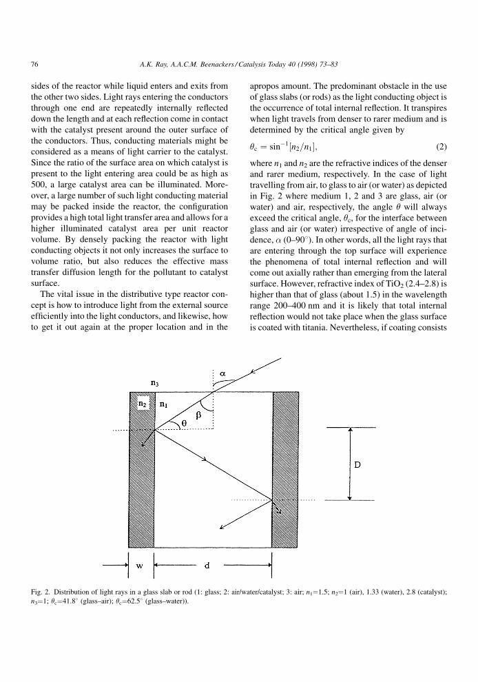
apropos amount. The predominant obstacle in the use
of glass slabs (or rods) as the light conducting object is
the occurrence of total internal re¯ection. It transpires
when light travels from denser to rarer medium and is
determined by the critical angle given by
�c � sinÿ1 n2=n1� �; (2)
where n1 and n2 are the refractive indices of the denser
and rarer medium, respectively. In the case of light
travelling from air, to glass to air (or water) as depicted
in Fig. 2 where medium 1, 2 and 3 are glass, air (or
water) and air, respectively, the angle � will always
exceed the critical angle, �c, for the interface between
glass and air (or water) irrespective of angle of inci-
dence, � (0±908). In other words, all the light rays that
are entering through the top surface will experience
the phenomena of total internal re¯ection and will
come out axially rather than emerging from the lateral
surface. However, refractive index of TiO2 (2.4±2.8) is
higher than that of glass (about 1.5) in the wavelength
range 200±400 nm and it is likely that total internal
re¯ection would not take place when the glass surface
is coated with titania. Nevertheless, if coating consists
Fig. 2. Distribution of light rays in a glass slab or rod (1: glass; 2: air/water/catalyst; 3: air; n1�1.5; n2�1 (air), 1.33 (water), 2.8 (catalyst);
n3�1; �c�41.88 (glass±air); �c�62.58 (glass±water)).
76 A.K. Ray, A.A.C.M. Beenackers / Catalysis Today 40 (1998) 73±83
of small spheres of catalyst particles dispersed along
the surface, the actual glass±titania interface will be
small as most of the glass surface will still be in
contact with water.
One way of avoiding total internal re¯ection is by
surface roughening. Moreover, surface roughening
assists in achieving better catalyst adhesion to the
substrate. Both are indeed found out to be the case
experimentally. In fact, when lateral surface was
roughened by sand blasting most of the light emerged
within few centimetres, and hardly any light remained
thereafter in the axial direction. This is not only
because roughenings desist total internal re¯ection
phenomena but also UV-transparency of most light
conducting material is very poor. Use of Quartz as
light conductors will naturally help to overcome light
transmission problem, but it will certainly make the
overall reactor set-up more expensive.
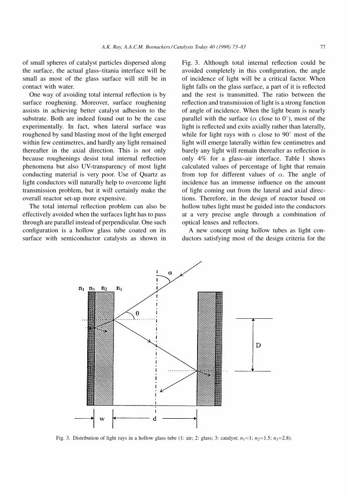
The total internal re¯ection problem can also be
effectively avoided when the surfaces light has to pass
through are parallel instead of perpendicular. One such
con®guration is a hollow glass tube coated on its
surface with semiconductor catalysts as shown in
Fig. 3. Although total internal re¯ection could be
avoided completely in this con®guration, the angle
of incidence of light will be a critical factor. When
light falls on the glass surface, a part of it is re¯ected
and the rest is transmitted. The ratio between the
re¯ection and transmission of light is a strong function
of angle of incidence. When the light beam is nearly
parallel with the surface (� close to 08), most of the
light is re¯ected and exits axially rather than laterally,
while for light rays with � close to 908 most of the
light will emerge laterally within few centimetres and
barely any light will remain thereafter as re¯ection is
only 4% for a glass±air interface. Table 1 shows
calculated values of percentage of light that remain
from top for different values of �. The angle of
incidence has an immense in¯uence on the amount
of light coming out from the lateral and axial direc-
tions. Therefore, in the design of reactor based on
hollow tubes light must be guided into the conductors
at a very precise angle through a combination of
optical lenses and re¯ectors.
A new concept using hollow tubes as light con-
ductors satisfying most of the design criteria for the
Fig. 3. Distribution of light rays in a hollow glass tube (1: air; 2: glass; 3: catalyst; n1�1; n2�1.5; n3�2.8).
A.K. Ray, A.A.C.M. Beenackers / Catalysis Today 40 (1998) 73±83 77
scale-up of photocatalytic reactor is considered. The
new design allows for a large surface area of catalyst
within a relatively small reactor volume compared to
classical reactor consisting of several lamps externally
surrounding a cylindrical vessel. A 70±100 fold
increase in surface area per m3 reactor volume can
be obtained over classical annular reactor design. The
hollow tube might be considered as a pore carrying
light to the catalyst. In this novel con®guration, light
rays entering through one end of the hollow tube are
repeatedly internally re¯ected down the length of the
tube and at each re¯ection came across the annular
catalyst coating present around the outer surface of the
tube. Since the ratio of the cylindrical surface area to
the circular end surface (light entrance area) of the
tube is of the order of 500, evidently a very large
catalyst area can be illuminated. This new con®gura-
tion provides a high light transfer area and allows for a
higher illuminated catalyst area per reactor volume.
Another potential advantage of distributing light
within hollow tubes is that light does not have to pass
through the reactant and product phases in the reactor.
The reactor is abbreviated in this paper as `̀ MTR'' for
multiple tube reactor.
4. Experimental details
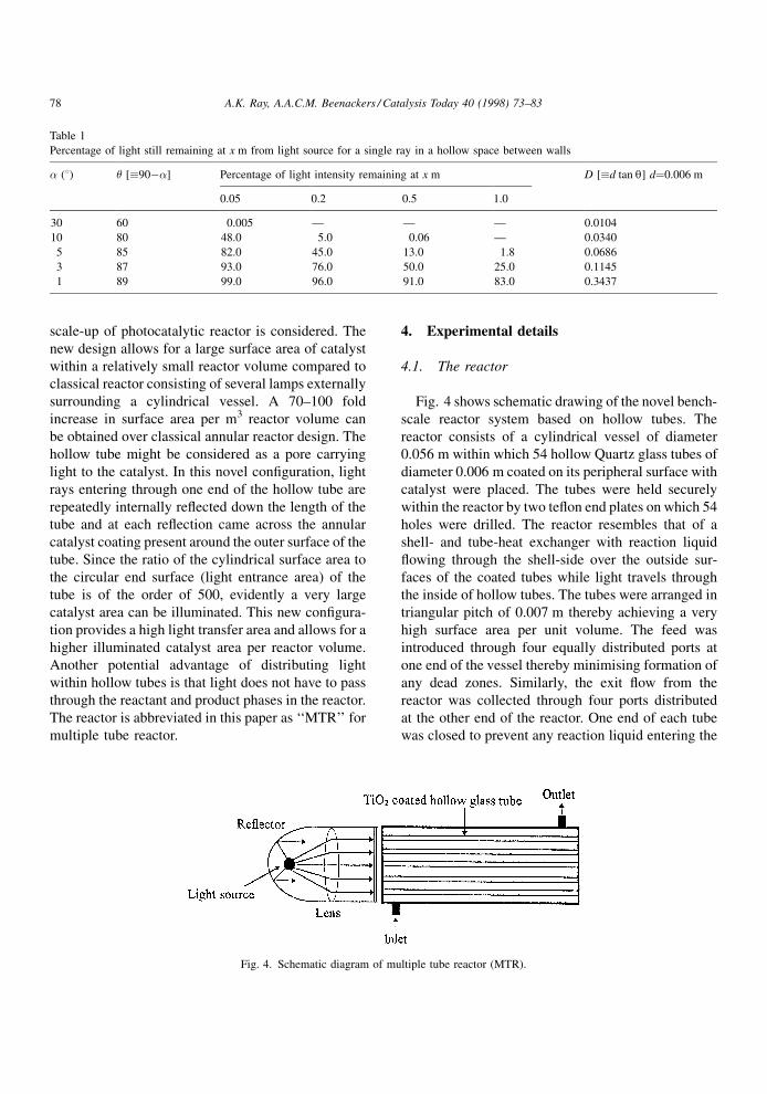
4.1. The reactor
Fig. 4 shows schematic drawing of the novel bench-
scale reactor system based on hollow tubes. The
reactor consists of a cylindrical vessel of diameter
0.056 m within which 54 hollow Quartz glass tubes of
diameter 0.006 m coated on its peripheral surface with
catalyst were placed. The tubes were held securely
within the reactor by two te¯on end plates on which 54
holes were drilled. The reactor resembles that of a
shell- and tube-heat exchanger with reaction liquid
¯owing through the shell-side over the outside sur-
faces of the coated tubes while light travels through
the inside of hollow tubes. The tubes were arranged in
triangular pitch of 0.007 m thereby achieving a very
high surface area per unit volume. The feed was
introduced through four equally distributed ports at
one end of the vessel thereby minimising formation of
any dead zones. Similarly, the exit ¯ow from the
reactor was collected through four ports distributed
at the other end of the reactor. One end of each tube
was closed to prevent any reaction liquid entering the
Table 1
Percentage of light still remaining at x m from light source for a single ray in a hollow space between walls
� (8) � [�90ÿ�] Percentage of light intensity remaining at x m D [�d tan q] d�0.006 m
0.05 0.2 0.5 1.0
30 60 0.005 Ð Ð Ð 0.0104
10 80 48.0 5.0 0.06 Ð 0.0340
5 85 82.0 45.0 13.0 1.8 0.0686
3 87 93.0 76.0 50.0 25.0 0.1145
1 89 99.0 96.0 91.0 83.0 0.3437
Fig. 4. Schematic diagram of multiple tube reactor (MTR).
78 A.K. Ray, A.A.C.M. Beenackers / Catalysis Today 40 (1998) 73±83
inside of the tubes. The closed ends were also coated
with aluminium for better utilisation of axially exiting
light. The glass material used was quartz instead of
Pyrex. Although quartz is expensive than Pyrex glass
when glass slabs or rods are considered, but the price
difference is not that appreciable when glass test tubes
are considered. The quartz was used in the set-up
particularly for two reasons: (a) transmission of light
in Pyrex is very poor compared to quartz and there-
fore, the length of hollow glass tubes that can be used
in the reactor will be restricted, and (b) when using
large number of 5±6 mm test tubes, use of quartz tubes
will increase the strength of the reactor and it will be
much easier to handle bundle of long but narrow
diameter hollow test tubes without worrying about
breakage of the tubes. Of course, if one uses Pyrex
tubes, reactor will be cheaper but then the length of the
reactor has to be reduced.
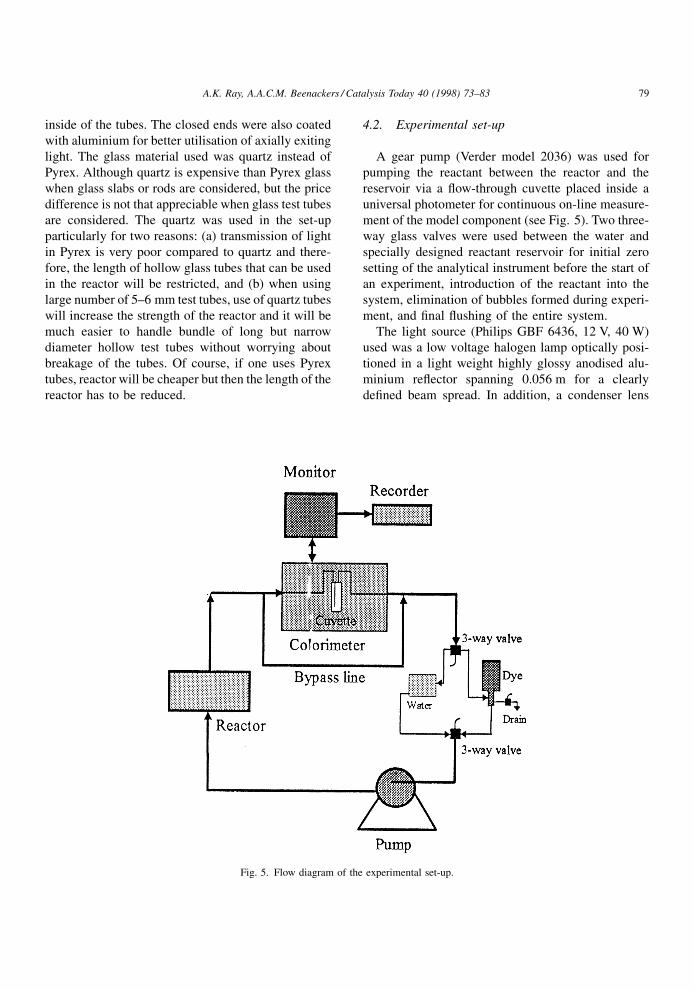
4.2. Experimental set-up
A gear pump (Verder model 2036) was used for
pumping the reactant between the reactor and the
reservoir via a ¯ow-through cuvette placed inside a
universal photometer for continuous on-line measure-
ment of the model component (see Fig. 5). Two three-
way glass valves were used between the water and
specially designed reactant reservoir for initial zero
setting of the analytical instrument before the start of
an experiment, introduction of the reactant into the
system, elimination of bubbles formed during experi-
ment, and ®nal ¯ushing of the entire system.
The light source (Philips GBF 6436, 12 V, 40 W)
used was a low voltage halogen lamp optically posi-
tioned in a light weight highly glossy anodised alu-
minium re¯ector spanning 0.056 m for a clearly
de®ned beam spread. In addition, a condenser lens
Fig. 5. Flow diagram of the experimental set-up.
A.K. Ray, A.A.C.M. Beenackers / Catalysis Today 40 (1998) 73±83 79
of focal length 0.04 m was placed between the lamp
and the reactor to obtain light beam at a half intensity
beam angle between 28 and 48.
4.3. Catalyst
Degussa P25 grade TiO2 was used as catalyst for all
the experiments. The crystalline product is non-porous
primarily in the anatase form (70:30 anatase to rutile)
and is used without further treatment. It has a BET
surface area of (5.5�1.5)�104 m2/kg and crystallite
sizes of 30 nm.
4.4. Catalyst immobilisation
For better catalyst ®xation and its durability, the
glass surface of the tubes on which titania was depos-
ited was roughened by sand blasting. This makes the
catalyst surface uneven but increases the strength and
amount of catalyst per unit area that could be depos-
ited. The tube surfaces were coated with catalyst in a
dip-coating apparatus [25].
4.5. Model component
The model component used was a brightly coloured
water soluble acid dye, Special Brilliant Blue (SBB,
MW 812), laboratory reagent grade (in 20% solution)
of which was obtained from Bayer (catalogue number
42735).
4.6. Analysis
Changes in SBB dye concentration were measured
on-line by ¯owing a bypass stream of the dye from
reactor outlet continuously through a bottom loader
¯ow-through cuvette (Hellma, path length 0.001 m)
placed inside a Colorimeter (Vitatron Universal
Photometer 6000).
4.7. Experimental procedure
At the start of every experiment the reactor was
rinsed with Milli-Q water for several times before
zero-setting the analytical instrument. The reactor and
connecting lines were then ®lled with the dye solution
with the help of the three-way valves and it was
ensured that no air bubbles remained in the system.
The change in the dye concentration was continuously
analysed and recorded. New silicon connecting tubes
and fresh catalyst were found to adsorb the dye for
about an hour, but no noticeable adsorption by the
entire system was observed afterwards. Light was
turned on only when the colorimeter reading was
stabilised.
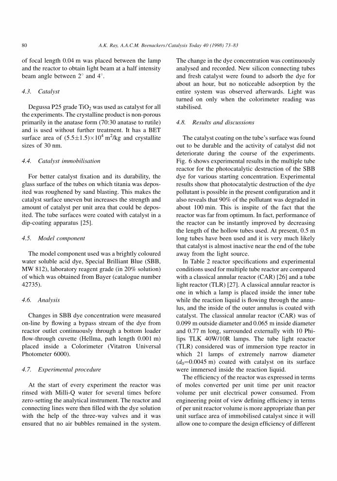
4.8. Results and discussions
The catalyst coating on the tube's surface was found
out to be durable and the activity of catalyst did not
deteriorate during the course of the experiments.
Fig. 6 shows experimental results in the multiple tube
reactor for the photocatalytic destruction of the SBB
dye for various starting concentration. Experimental
results show that photocatalytic destruction of the dye
pollutant is possible in the present con®guration and it
also reveals that 90% of the pollutant was degraded in
about 100 min. This is inspite of the fact that the
reactor was far from optimum. In fact, performance of
the reactor can be instantly improved by decreasing
the length of the hollow tubes used. At present, 0.5 m
long tubes have been used and it is very much likely
that catalyst is almost inactive near the end of the tube
away from the light source.
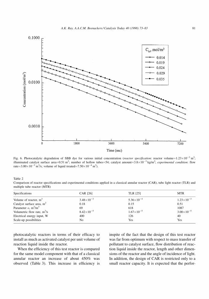
In Table 2 reactor speci®cations and experimental
conditions used for multiple tube reactor are compared
with a classical annular reactor (CAR) [26] and a tube
light reactor (TLR) [27]. A classical annular reactor is
one in which a lamp is placed inside the inner tube
while the reaction liquid is ¯owing through the annu-
lus, and the inside of the outer annulus is coated with
catalyst. The classical annular reactor (CAR) was of
0.099 m outside diameter and 0.065 m inside diameter
and 0.77 m long, surrounded externally with 10 Phi-
lips TLK 40W/10R lamps. The tube light reactor
(TLR) considered was of immersion type reactor in
which 21 lamps of extremely narrow diameter
(d0�0.0045 m) coated with catalyst on its surface
were immersed inside the reaction liquid.
The ef®ciency of the reactor was expressed in terms
of moles converted per unit time per unit reactor
volume per unit electrical power consumed. From
engineering point of view de®ning ef®ciency in terms
of per unit reactor volume is more appropriate than per
unit surface area of immobilised catalyst since it will
allow one to compare the design ef®ciency of different
80 A.K. Ray, A.A.C.M. Beenackers / Catalysis Today 40 (1998) 73±83
photocatalytic reactors in terms of their ef®cacy to
install as much as activated catalyst per unit volume of
reaction liquid inside the reactor.
When the ef®ciency of this test reactor is compared
for the same model component with that of a classical
annular reactor an increase of about 450% was
observed (Table 3). This increase in ef®ciency is
inspite of the fact that the design of this test reactor
was far from optimum with respect to mass transfer of
pollutant to catalyst surface, ¯ow distribution of reac-
tion liquid inside the reactor, length and other dimen-
sions of the reactor and the angle of incidence of light.
In addition, the design of CAR is restricted only to a
small reactor capacity. It is expected that the perfor-
Fig. 6. Photocatalytic degradation of SBB dye for various initial concentration (reactor specification: reactor volume�1.23�10ÿ3 m3;
illuminated catalyst surface area�0.51 m2; number of hollow tubes�54; catalyst amount�3.8�10ÿ3 kg/m2; experimental condition: flow
rate�3.00�10ÿ5 m3/s; volume of liquid treated�7.50�10ÿ4 m3).
Table 2
Comparison of reactor specifications and experimental conditions applied in a classical annular reactor (CAR), tube light reactor (TLR) and
multiple tube reactor (MTR)
Specifications CAR [26] TLR [25] MTR
Volume of reactor, m3 3.48�10ÿ3 5.36�10ÿ4 1.23�10ÿ3
Catalyst surface area, m2 0.18 0.15 0.51
Parameter �, m2/m3 69 618 1087
Volumetric flow rate, m3/s 8.42�10ÿ5 1.67�10ÿ5 3.00�10ÿ5
Electrical energy input, W 400 126 40
Scale-up possibilities No Yes Yes
A.K. Ray, A.A.C.M. Beenackers / Catalysis Today 40 (1998) 73±83 81
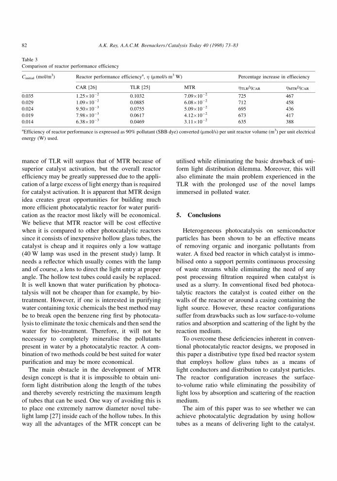
mance of TLR will surpass that of MTR because of
superior catalyst activation, but the overall reactor
ef®ciency may be greatly suppressed due to the appli-
cation of a large excess of light energy than is required
for catalyst activation. It is apparent that MTR design
idea creates great opportunities for building much
more ef®cient photocatalytic reactor for water puri®-
cation as the reactor most likely will be economical.
We believe that MTR reactor will be cost effective
when it is compared to other photocatalytic reactors
since it consists of inexpensive hollow glass tubes, the
catalyst is cheap and it requires only a low wattage
(40 W lamp was used in the present study) lamp. It
needs a re¯ector which usually comes with the lamp
and of course, a lens to direct the light entry at proper
angle. The hollow test tubes could easily be replaced.
It is well known that water puri®cation by photoca-
talysis will not be cheaper than for example, by bio-
treatment. However, if one is interested in purifying
water containing toxic chemicals the best method may
be to break open the benzene ring ®rst by photocata-
lysis to eliminate the toxic chemicals and then send the
water for bio-treatment. Therefore, it will not be
necessary to completely mineralise the pollutants
present in water by a photocatalytic reactor. A com-
bination of two methods could be best suited for water
puri®cation and may be more economical.
The main obstacle in the development of MTR
design concept is that it is impossible to obtain uni-
form light distribution along the length of the tubes
and thereby severely restricting the maximum length
of tubes that can be used. One way of avoiding this is
to place one extremely narrow diameter novel tube-
light lamp [27] inside each of the hollow tubes. In this
way all the advantages of the MTR concept can be
utilised while eliminating the basic drawback of uni-
form light distribution dilemma. Moreover, this will
also eliminate the main problem experienced in the
TLR with the prolonged use of the novel lamps
immersed in polluted water.
5. Conclusions
Heterogeneous photocatalysis on semiconductor
particles has been shown to be an effective means
of removing organic and inorganic pollutants from
water. A ®xed bed reactor in which catalyst is immo-
bilised onto a support permits continuous processing
of waste streams while eliminating the need of any
post processing ®ltration required when catalyst is
used as a slurry. In conventional ®xed bed photoca-
talytic reactors the catalyst is coated either on the
walls of the reactor or around a casing containing the
light source. However, these reactor con®gurations
suffer from drawbacks such as low surface-to-volume
ratios and absorption and scattering of the light by the
reaction medium.
To overcome these de®ciencies inherent in conven-
tional photocatalytic reactor designs, we proposed in
this paper a distributive type ®xed bed reactor system
that employs hollow glass tubes as a means of
light conductors and distribution to catalyst particles.
The reactor con®guration increases the surface-
to-volume ratio while eliminating the possibility of
light loss by absorption and scattering of the reaction
medium.
The aim of this paper was to see whether we can
achieve photocatalytic degradation by using hollow
tubes as a means of delivering light to the catalyst.
Table 3
Comparison of reactor performance efficiency
Cinitial (mol/m3) Reactor performance efficiencya, � (mmol/s m3 W) Percentage increase in effieciency
CAR [26] TLR [25] MTR �TLR/�CAR �MTR/�CAR
0.035 1.25�10ÿ2 0.1032 7.09�10ÿ2 725 467
0.029 1.09�10ÿ2 0.0885 6.08�10ÿ2 712 458
0.024 9.50�10ÿ3 0.0755 5.09�10ÿ2 695 436
0.019 7.98�10ÿ3 0.0617 4.12�10ÿ2 673 417
0.014 6.38�10ÿ3 0.0469 3.11�10ÿ2 635 388
aEfficiency of reactor performance is expressed as 90% pollutant (SBB dye) converted (mmol/s) per unit reactor volume (m3) per unit electrical
energy (W) used.
82 A.K. Ray, A.A.C.M. Beenackers / Catalysis Today 40 (1998) 73±83
Experiments performed to study the degradation of a
textile dye showed very promising results.
Acknowledgements
The authors wish to express their sincere apprecia-
tion to Philips Lighting, TNO and Akzo/Nobel for
their advice and many helpful discussions. We also
gratefully acknowledge the ®nancial support provided
by the Senter, division of Environmental and Energy
under IOP Prevention contract no. IMP 91512.
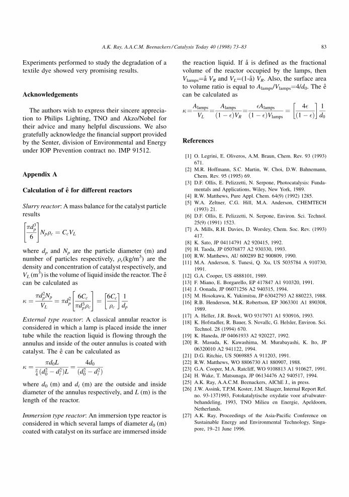
Appendix A
Calculation of eà for different reactors
Slurry reactor: A mass balance for the catalyst particle
results
�d3p
6
" #Np�c � CcVL
where dp and Np are the particle diameter (m) and
number of particles respectively, �c(kg/m3) are the
density and concentration of catalyst respectively, and
VL (m3) is the volume of liquid inside the reactor. The eÃ
can be calculated as
� � �d2pNp
VL
� �d2p
6Cc
�d3p�c
" #� 6Cc
�c
� �1
dp
External type reactor: A classical annular reactor is
considered in which a lamp is placed inside the inner
tube while the reaction liquid is flowing through the
annulus and inside of the outer annulus is coated with
catalyst. The eà can be calculated as
� � �d0L�4�d2
0 ÿ d2i �L� 4d0
�d20 ÿ d2
i �where d0 (m) and di (m) are the outside and inside
diameter of the annulus respectively, and L (m) is the
length of the reactor.
Immersion type reactor: An immersion type reactor is
considered in which several lamps of diameter d0 (m)
coated with catalyst on its surface are immersed inside
the reaction liquid. If aÊ is defined as the fractional
volume of the reactor occupied by the lamps, then
Vlamps�aÊ VR and VL�(1-aÊ) VR. Also, the surface area
to volume ratio is equal to Alamps/Vlamps�4/d0. The eÃ
can be calculated as
��Alamps
VL
� Alamps
�1ÿ ��VR
� �Alamps
�1ÿ ��Vlamps� 4�
�1ÿ ��� �
1
d0
References
[1] O. Legrini, E. Oliveros, A.M. Braun, Chem. Rev. 93 (1993)
671.
[2] M.R. Hoffmann, S.C. Martin, W. Choi, D.W. Bahnemann,
Chem. Rev. 95 (1995) 69.
[3] D.F. Ollis, E. Pelizzetti, N. Serpone, Photocatalysis: Funda-
mentals and Applications, Wiley, New York, 1989.
[4] R.W. Matthews, Pure Appl. Chem. 64(9) (1992) 1285.
[5] W.A. Zeltner, C.G. Hill, M.A. Anderson, CHEMTECH
(1993) 21.
[6] D.F. Ollis, E. Pelizzetti, N. Serpone, Environ. Sci. Technol.
25(9) (1991) 1523.
[7] A. Mills, R.H. Davies, D. Worsley, Chem. Soc. Rev. (1993)
417.
[8] K. Sato, JP 04114791 A2 920415, 1992.
[9] H. Taoda, JP 05076877 A2 930330, 1993.
[10] R.W. Matthews, AU 600289 B2 900809, 1990.
[11] M.A. Anderson, S. Tunesi, Q. Xu, US 5035784 A 910730,
1991.
[12] G.A. Cooper, US 4888101, 1989.
[13] F. Miano, E. Borgarello, EP 417847 A1 910320, 1991.
[14] J. Oonada, JP 06071256 A2 940315, 1994.
[15] M. Hosokawa, K. Yukimitsu, JP 63042793 A2 880223, 1988.
[16] R.B. Henderson, M.K. Robertson, EP 3063301 A1 890308,
1989.
[17] A. Heller, J.R. Brock, WO 9317971 A1 930916, 1993.
[18] K. Hofstadler, R. Bauer, S. Novallc, G. Helsler, Environ. Sci.
Technol. 28 (1994) 670.
[19] K. Haneda, JP 04061933 A2 920227, 1992.
[20] R. Masuda, K. Kawashima, M. Murabayashi, K. Ito, JP
06320010 A2 941122, 1994.
[21] D.G. Ritchie, US 5069885 A 911203, 1991.
[22] R.W. Matthews, WO 8806730 A1 880907, 1988.
[23] G.A. Cooper, M.A. Ratcliff, WO 9108813 A1 910627, 1991.
[24] H. Wake, T. Matsunaga, JP 06134476 A2 940517, 1994.
[25] A.K. Ray, A.A.C.M. Beenackers, AIChE J., in press.
[26] J.W. Assink, T.P.M. Koster, J.M. Slaager, Internal Report Ref.
no. 93-1371993, Fotokatalytische oxydatie voor afvalwater-
behandeling, 1993, TNO Milieu en Energie, Apeldoorn,
Netherlands.
[27] A.K. Ray, Proceedings of the Asia-Pacific Conference on
Sustainable Energy and Environmental Technology, Singa-
pore, 19±21 June 1996.
A.K. Ray, A.A.C.M. Beenackers / Catalysis Today 40 (1998) 73±83 83