Development and Research of Crosshead-Free Piston Hybrid ...
38
machines Article Development and Research of Crosshead-Free Piston Hybrid Power Machine Viktor Shcherba 1, * , Viktor Shalay 2 , Evgeniy Nosov 1 , Evgeniy Pavlyuchenko 1 and Ablai-Khan Tegzhanov 1 Citation: Shcherba, V.; Shalay, V.; Nosov, E.; Pavlyuchenko, E.; Tegzhanov, A.-K. Development and Research of Crosshead-Free Piston Hybrid Power Machine. Machines 2021, 9, 32. https://doi.org/10.3390/ machines9020032 Academic Editor: Hamid Reza Karimi Received: 16 December 2020 Accepted: 31 January 2021 Published: 5 February 2021 Publisher’s Note: MDPI stays neutral with regard to jurisdictional claims in published maps and institutional affil- iations. Copyright: © 2021 by the authors. Licensee MDPI, Basel, Switzerland. This article is an open access article distributed under the terms and conditions of the Creative Commons Attribution (CC BY) license (https:// creativecommons.org/licenses/by/ 4.0/). 1 Hydromechanics and Machines Department, Omsk State Technical University, Prospect Mira st., 11, 644050 Omsk, Russia; [email protected] (E.N.); [email protected] (E.P.); [email protected] (A.-K.T.) 2 Transport, Oil and Gas Storage, Standardization and Certification Department, Omsk State Technical University, Prospect Mira st., 11, 644050 Omsk, Russia; [email protected] * Correspondence: [email protected] or [email protected]; Tel.: +7-3812-65-31-77 Abstract: This article considers the development and research of a new design of crosshead-free piston hybrid power machine. After verification of a system of simplifying assumptions based on the fundamental laws of energy, mass, and motion conservation, as well as using the equation of state, mathematical models of the work processes of the compressor section, pump section, and liquid flow in a groove seal have been developed. In accordance with the patent for the invention, a prototype of a crosshead-free piston hybrid power machine (PHPM) was developed; it was equipped with the necessary measuring equipment and a stand for studying the prototype. Using the developed mathematical model, the physical picture of the ongoing work processes in the compressor and pump sections is considered, taking into account their interaction through a groove seal. Using the developed plan, a set of experimental studies was carried out with the main operational parameters of the crosshead-free PHPM: operating processes, temperature of the cylinder–piston group and integral parameters (supply coefficient of the compressor section, volumetric efficiency of the pump section, etc.). As a result of numerical and experimental studies, it was determined that this PHPM design has better cooling of the compressor section (decrease in temperature of the valve plate is from 10 to 15 K; decrease in temperature of intake air is from 6 to 8 K, as well as there is increase in compressor and pump section efficiency up to 5%). Keywords: reciprocating compressor; piston pump; piston hybrid power machine; work processes; indicator efficiency of the compressor 1. Introduction Pumps and compressors designed for the compression and displacement of low- compressible liquids and gases are widely used as in traditional industries: power, oil and gas, transport [1] and aviation, as in new ones: measuring equipment [2], medical industry, etc. In general, from the point of liquid and gas mechanics, “liquid” as a term includes low-compressible (droplet) liquid and compressible liquid (gaseous). They simply use “liquid” instead of “low-compressible liquid” as a term in the theory of pumps, and “gas” is used instead of “compressible liquid” in the theory of compressors. Thus, we also use “liquid” and “gas” in the article. Due to the fact that 20% of the energy used in industry is spent on pump units’ drive [3], the task to increase their efficiency is important and relevant. At present, one of the main ways to increase the work efficiency and effectivity of compressors and displacement pumps, as well as to improve their weight and size indicators, is to unite them into a single unit called a piston hybrid power machine. Piston hybrid power machines have the leading role among variety of hybrid power machines. When a pump and a compressor are combined into a single power unit, the compressor cooling is improved, leaks and overflows of the compressed gas are eliminated in the Machines 2021, 9, 32. https://doi.org/10.3390/machines9020032 https://www.mdpi.com/journal/machines
-
Upload
khangminh22 -
Category
Documents
-
view
1 -
download
0
Transcript of Development and Research of Crosshead-Free Piston Hybrid ...

machines
Article
Development and Research of Crosshead-Free Piston HybridPower Machine
Viktor Shcherba 1,* , Viktor Shalay 2, Evgeniy Nosov 1, Evgeniy Pavlyuchenko 1 and Ablai-Khan Tegzhanov 1
�����������������
Citation: Shcherba, V.; Shalay, V.;
Nosov, E.; Pavlyuchenko, E.;
Tegzhanov, A.-K. Development and
Research of Crosshead-Free Piston
Hybrid Power Machine. Machines
2021, 9, 32. https://doi.org/10.3390/
machines9020032
Academic Editor: Hamid Reza Karimi
Received: 16 December 2020
Accepted: 31 January 2021
Published: 5 February 2021
Publisher’s Note: MDPI stays neutral
with regard to jurisdictional claims in
published maps and institutional affil-
iations.
Copyright: © 2021 by the authors.
Licensee MDPI, Basel, Switzerland.
This article is an open access article
distributed under the terms and
conditions of the Creative Commons
Attribution (CC BY) license (https://
creativecommons.org/licenses/by/
4.0/).
1 Hydromechanics and Machines Department, Omsk State Technical University, Prospect Mira st., 11,644050 Omsk, Russia; [email protected] (E.N.); [email protected] (E.P.);[email protected] (A.-K.T.)
2 Transport, Oil and Gas Storage, Standardization and Certification Department,Omsk State Technical University, Prospect Mira st., 11, 644050 Omsk, Russia; [email protected]
* Correspondence: [email protected] or [email protected]; Tel.: +7-3812-65-31-77
Abstract: This article considers the development and research of a new design of crosshead-freepiston hybrid power machine. After verification of a system of simplifying assumptions based on thefundamental laws of energy, mass, and motion conservation, as well as using the equation of state,mathematical models of the work processes of the compressor section, pump section, and liquid flowin a groove seal have been developed. In accordance with the patent for the invention, a prototypeof a crosshead-free piston hybrid power machine (PHPM) was developed; it was equipped withthe necessary measuring equipment and a stand for studying the prototype. Using the developedmathematical model, the physical picture of the ongoing work processes in the compressor andpump sections is considered, taking into account their interaction through a groove seal. Using thedeveloped plan, a set of experimental studies was carried out with the main operational parametersof the crosshead-free PHPM: operating processes, temperature of the cylinder–piston group andintegral parameters (supply coefficient of the compressor section, volumetric efficiency of the pumpsection, etc.). As a result of numerical and experimental studies, it was determined that this PHPMdesign has better cooling of the compressor section (decrease in temperature of the valve plate isfrom 10 to 15 K; decrease in temperature of intake air is from 6 to 8 K, as well as there is increase incompressor and pump section efficiency up to 5%).
Keywords: reciprocating compressor; piston pump; piston hybrid power machine; work processes;indicator efficiency of the compressor
1. Introduction
Pumps and compressors designed for the compression and displacement of low-compressible liquids and gases are widely used as in traditional industries: power, oil andgas, transport [1] and aviation, as in new ones: measuring equipment [2], medical industry,etc. In general, from the point of liquid and gas mechanics, “liquid” as a term includeslow-compressible (droplet) liquid and compressible liquid (gaseous). They simply use“liquid” instead of “low-compressible liquid” as a term in the theory of pumps, and “gas”is used instead of “compressible liquid” in the theory of compressors. Thus, we also use“liquid” and “gas” in the article.
Due to the fact that 20% of the energy used in industry is spent on pump units’drive [3], the task to increase their efficiency is important and relevant.
At present, one of the main ways to increase the work efficiency and effectivityof compressors and displacement pumps, as well as to improve their weight and sizeindicators, is to unite them into a single unit called a piston hybrid power machine. Pistonhybrid power machines have the leading role among variety of hybrid power machines.When a pump and a compressor are combined into a single power unit, the compressorcooling is improved, leaks and overflows of the compressed gas are eliminated in the
Machines 2021, 9, 32. https://doi.org/10.3390/machines9020032 https://www.mdpi.com/journal/machines

Machines 2021, 9, 32 2 of 38
cylinder–piston group, friction forces are reduced in the cylinder–piston group, positivesuction head is increased, and gas compression heat is to be utilized in the pump section [4].There are two main line diagrams among hybrid power machines.
The first diagram is a crosshead hybrid power machine (see Figure 1), in which adisk piston divides the working space of the cylinder into two working chambers: thecompressor section is located above the piston and the pump section is located underthe piston.
Machines 2021, 9, x FOR PEER REVIEW 2 of 39
cooling is improved, leaks and overflows of the compressed gas are eliminated in the cyl-inder–piston group, friction forces are reduced in the cylinder–piston group, positive suc-tion head is increased, and gas compression heat is to be utilized in the pump section [4]. There are two main line diagrams among hybrid power machines.
The first diagram is a crosshead hybrid power machine (see Figure 1), in which a disk piston divides the working space of the cylinder into two working chambers: the com-pressor section is located above the piston and the pump section is located under the pis-ton.
Figure 1. Construction diagram of piston hybrid power machine (PHPM). (1—cylinder; 2—piston; 3, 4—compressor and pump chamber; 5, 6—discharge and suction liquid nozzles; 7—plunger).
The second diagram has a differential piston and two working chambers. The inner working chamber is a compressor section, and the external working chamber is a pump section (see Figure 2).
Design, development, and research of the crosshead PHPM operation are given in [4]. Experimental and numerical studies of crosshead PHPM with various types of groove seals were carried out there. Findings presented that the crosshead PHPM with a step-like groove seal is the most effective. The crosshead PHPM defects are: − Poor cooling of the cylinder–piston group and the compressed gas; − Many moving parts with reciprocating movement; − Specific weight and size indicators have low values.
Figure 2. Construction diagram of crosshead-free PHPM (1—crankcase; 2—piston; 3—pumping working chamber; 4—gas working chamber).
Figure 1. Construction diagram of piston hybrid power machine (PHPM). (1—cylinder; 2—piston; 3,4—compressor and pump chamber; 5, 6—discharge and suction liquid nozzles; 7—plunger).
The second diagram has a differential piston and two working chambers. The innerworking chamber is a compressor section, and the external working chamber is a pumpsection (see Figure 2).
Machines 2021, 9, x FOR PEER REVIEW 2 of 39
cooling is improved, leaks and overflows of the compressed gas are eliminated in the cyl-inder–piston group, friction forces are reduced in the cylinder–piston group, positive suc-tion head is increased, and gas compression heat is to be utilized in the pump section [4]. There are two main line diagrams among hybrid power machines.
The first diagram is a crosshead hybrid power machine (see Figure 1), in which a disk piston divides the working space of the cylinder into two working chambers: the com-pressor section is located above the piston and the pump section is located under the pis-ton.
Figure 1. Construction diagram of piston hybrid power machine (PHPM). (1—cylinder; 2—piston; 3, 4—compressor and pump chamber; 5, 6—discharge and suction liquid nozzles; 7—plunger).
The second diagram has a differential piston and two working chambers. The inner working chamber is a compressor section, and the external working chamber is a pump section (see Figure 2).
Design, development, and research of the crosshead PHPM operation are given in [4]. Experimental and numerical studies of crosshead PHPM with various types of groove seals were carried out there. Findings presented that the crosshead PHPM with a step-like groove seal is the most effective. The crosshead PHPM defects are: − Poor cooling of the cylinder–piston group and the compressed gas; − Many moving parts with reciprocating movement; − Specific weight and size indicators have low values.
Figure 2. Construction diagram of crosshead-free PHPM (1—crankcase; 2—piston; 3—pumping working chamber; 4—gas working chamber). Figure 2. Construction diagram of crosshead-free PHPM (1—crankcase; 2—piston; 3—pumpingworking chamber; 4—gas working chamber).
Design, development, and research of the crosshead PHPM operation are given in [4].Experimental and numerical studies of crosshead PHPM with various types of grooveseals were carried out there. Findings presented that the crosshead PHPM with a step-likegroove seal is the most effective. The crosshead PHPM defects are:
- Poor cooling of the cylinder–piston group and the compressed gas;- Many moving parts with reciprocating movement;- Specific weight and size indicators have low values.

Machines 2021, 9, 32 3 of 38
These defects are partially eliminated in the crosshead-free PHPM [5].We developed a new powerful design of crosshead-free PHPM based on the analysis
of the above-mentioned defects typical for crosshead and crosshead-free PHPM; its linediagram is shown in Figure 3.
Machines 2021, 9, x FOR PEER REVIEW 3 of 39
These defects are partially eliminated in the crosshead-free PHPM [5]. We developed a new powerful design of crosshead-free PHPM based on the analysis
of the above-mentioned defects typical for crosshead and crosshead-free PHPM; its line diagram is shown in Figure 3.
Figure 3. Scheme of longitudinal section of crosshead-free PHPM test model. 1—crankcase; 2—crankshaft; 3—connecting rod; 4—piston pin; 5—piston; 6—cylindrical surface of the working chamber of the compressor section; 7—outer cylinder; 8—suction valve of the compressor section; 9—discharge valve of the compressor section; 10, 13—channels for supplying and removing com-pressible gas; 11—suction valve of the pump section; 12—pressure valve of the pump section; 14—inner cylinder attaching to the outer cylinder; 15—working chamber of the compressor section; 16—annular П-shaped protrusion of the piston; 17—inner cylinder; 18—working clearance; 19—O-rings; 20—screw; 21—working chamber of the pump section.
In the developed PHPM, there is annular П-shaped protrusion 16 installed on piston 5 forming two working chambers with the inner surface of outer cylinder 7 and outer surface of inner cylinder 17: working chamber 15 is for gas compressing and moving, working chamber 21 is for liquid compressing and moving. Inner cylinder 17 is mounted concentrically to outer cylinder 7. Pipe 10 is for gas supply and pipe 13 is for its removal in inner cylinder 17. The pipes have suction valve 8 and discharge valve 9, which allow gas to be sucked into working chamber 15 of the compressor section and its supply from the working chamber to the consumer. There are pipes in inner cylinder 17, where suction valve 11 and discharge valve 12 are installed; they supply liquid to the working cavity of pump section 21 and then to the discharge.
The developed assembly of the power machine, including inner cylinder 17 centered relative to working surface of cylinder 7, produces parallel cylindrical surfaces; piston 5 is centered with П-shaped annular protrusion 16 along them. Both external and inner working surfaces of П-shaped protrusion 16 are cylindrical surfaces of one part located on the same axis and can be made concentrically in one assembling on processing equip-ment.
Reed valves were used as gas distribution bodies in the compressor section; their photos are shown in Figure 4.
Figure 3. Scheme of longitudinal section of crosshead-free PHPM test model. 1—crankcase;2—crankshaft; 3—connecting rod; 4—piston pin; 5—piston; 6—cylindrical surface of the work-ing chamber of the compressor section; 7—outer cylinder; 8—suction valve of the compressorsection; 9—discharge valve of the compressor section; 10, 13—channels for supplying and removingcompressible gas; 11—suction valve of the pump section; 12—pressure valve of the pump section;14—inner cylinder attaching to the outer cylinder; 15—working chamber of the compressor sec-tion; 16—annular Π-shaped protrusion of the piston; 17—inner cylinder; 18—working clearance;19—O-rings; 20—screw; 21—working chamber of the pump section.
In the developed PHPM, there is annular Π-shaped protrusion 16 installed on piston5 forming two working chambers with the inner surface of outer cylinder 7 and outersurface of inner cylinder 17: working chamber 15 is for gas compressing and moving,working chamber 21 is for liquid compressing and moving. Inner cylinder 17 is mountedconcentrically to outer cylinder 7. Pipe 10 is for gas supply and pipe 13 is for its removalin inner cylinder 17. The pipes have suction valve 8 and discharge valve 9, which allowgas to be sucked into working chamber 15 of the compressor section and its supply fromthe working chamber to the consumer. There are pipes in inner cylinder 17, where suctionvalve 11 and discharge valve 12 are installed; they supply liquid to the working cavity ofpump section 21 and then to the discharge.
The developed assembly of the power machine, including inner cylinder 17 centeredrelative to working surface of cylinder 7, produces parallel cylindrical surfaces; piston 5is centered with Π-shaped annular protrusion 16 along them. Both external and innerworking surfaces of Π-shaped protrusion 16 are cylindrical surfaces of one part located onthe same axis and can be made concentrically in one assembling on processing equipment.
Reed valves were used as gas distribution bodies in the compressor section; theirphotos are shown in Figure 4.

Machines 2021, 9, 32 4 of 38Machines 2021, 9, x FOR PEER REVIEW 4 of 39
Figure 4. Reed valves installed in the valve body of the compressor section.
The inner cylinder of the compressor section (Figure 5, item 2) is T-shaped and is shown in Figure 6. It has pipes for connecting suction and discharge lines to valve plate 8 of the compressor section; the valve plate is installed in the lower part of inner cylinder 2. Holes are made in the pump cavity in the upper part of inner cylinder 2; they are united by crescent-shaped windows for connection with the suction and discharge lines of the pump.
The crosshead-free piston hybrid power machine operates as follows (see Figure 3): when piston 5 with annular П-shaped protrusion 6 mounted on it is up (from bottom dead center to top dead center), gas is compressed in working cavity of compressor section 15, and liquid is compressed in the working cavity of pump section 21. When the nominal discharge pressure is in the pump section, valve 12 opens, and the liquid flows from cavity 21 to the consumer. With further upward stroke and reaching the nominal gas compres-sion pressure in the working cavity of compressor section 15, discharge valve 9 opens, and gas flows to the consumer through pipe 13.
Figure 5. Three-dimensional (3D) image of the layout of the test model of a piston hybrid machine. 1—piston unit of the base compressor; 2—inner cylinder; 3—annular П-shaped protrusion of the piston; 4—outer cylinder; 5—pump cavity suction lines; 6—pump cavity discharge lines; 7—com-pressor section discharge lines; 8—valve body of compressor section.
Figure 4. Reed valves installed in the valve body of the compressor section.
The inner cylinder of the compressor section (Figure 5, item 2) is T-shaped and isshown in Figure 6. It has pipes for connecting suction and discharge lines to valve plate 8of the compressor section; the valve plate is installed in the lower part of inner cylinder 2.Holes are made in the pump cavity in the upper part of inner cylinder 2; they are united bycrescent-shaped windows for connection with the suction and discharge lines of the pump.
Machines 2021, 9, x FOR PEER REVIEW 4 of 39
Figure 4. Reed valves installed in the valve body of the compressor section.
The inner cylinder of the compressor section (Figure 5, item 2) is T-shaped and is shown in Figure 6. It has pipes for connecting suction and discharge lines to valve plate 8 of the compressor section; the valve plate is installed in the lower part of inner cylinder 2. Holes are made in the pump cavity in the upper part of inner cylinder 2; they are united by crescent-shaped windows for connection with the suction and discharge lines of the pump.
The crosshead-free piston hybrid power machine operates as follows (see Figure 3): when piston 5 with annular П-shaped protrusion 6 mounted on it is up (from bottom dead center to top dead center), gas is compressed in working cavity of compressor section 15, and liquid is compressed in the working cavity of pump section 21. When the nominal discharge pressure is in the pump section, valve 12 opens, and the liquid flows from cavity 21 to the consumer. With further upward stroke and reaching the nominal gas compres-sion pressure in the working cavity of compressor section 15, discharge valve 9 opens, and gas flows to the consumer through pipe 13.
Figure 5. Three-dimensional (3D) image of the layout of the test model of a piston hybrid machine. 1—piston unit of the base compressor; 2—inner cylinder; 3—annular П-shaped protrusion of the piston; 4—outer cylinder; 5—pump cavity suction lines; 6—pump cavity discharge lines; 7—com-pressor section discharge lines; 8—valve body of compressor section.
Figure 5. Three-dimensional (3D) image of the layout of the test model of a piston hybrid machine.1—piston unit of the base compressor; 2—inner cylinder; 3—annular Π-shaped protrusion of the pis-ton; 4—outer cylinder; 5—pump cavity suction lines; 6—pump cavity discharge lines; 7—compressorsection discharge lines; 8—valve body of compressor section.
The crosshead-free piston hybrid power machine operates as follows (see Figure 3):when piston 5 with annular Π-shaped protrusion 6 mounted on it is up (from bottom deadcenter to top dead center), gas is compressed in working cavity of compressor section 15,and liquid is compressed in the working cavity of pump section 21. When the nominaldischarge pressure is in the pump section, valve 12 opens, and the liquid flows from cavity21 to the consumer. With further upward stroke and reaching the nominal gas compressionpressure in the working cavity of compressor section 15, discharge valve 9 opens, and gasflows to the consumer through pipe 13.

Machines 2021, 9, 32 5 of 38Machines 2021, 9, x FOR PEER REVIEW 5 of 39
Figure 6. Inner cylinder: (a) assembled with the valve body, (b) top view, (c) bottom view. 1—holes for positioning pins; 2—fixation holes; 3—holes into the pump section; 4—channel to the discharge valve of the compressor section; 5—channel to the suction valve of the compressor section; 6—hole for assembling the instant pressure sensor in the compressor sec-tion.
Thus, when the piston moves upward, liquid and gas are compressed and move to the discharge; it should be noted that the discharge valve of the pump section opens ear-lier than the discharge valve of the compressor section and the liquid is supplied to the discharge from the pump section at a larger crank angle. When the piston reaches the top dead center, the discharge valve from the pump section and compressor section closes, and the flow of liquid and gas to the discharge stopped. When the piston moves down (from top dead center to bottom dead center), there is an expansion process and a pressure drop to the suction pressure in the pump and compressor section. Then, with a further piston stroke, the suction valves open (11—in the pump section, 8—in the compressor section), and working chambers 21 and 15 are filled with liquid and gas.
The process of back expansion is much shorter in the pump section than in the com-pressor section, and suction valve 11 opens in the pump section before suction valve 8 of the compressor section opens. Then, the cycle repeats.
The certain advantages of this diagram are enhanced cooling of the cylinder–piston group and compressed gas, as the pump section is located around the compressor section and there are pipes operating as heat exchangers in the valve plate. This design should reduce the temperature of suction gas, improve the compressed gas cooling, and have high economic efficiency as well as specific weight and size indicators.
Currently, when simulating the working processes of compressors and displacement pumps, mathematical models with lumped and distributed parameters are used [6–8]. Unlike vane machines [9,10], models with lumped parameters are most widely used in displacement machines. This is due to following reasons: − Working chamber volume and boundaries change, the computational grid is to be
rebuilt constantly, and it complicates the implementation of existing software for non-steady flow of viscous compressible liquid as for laminar and turbulent flows;
− Linear dimensions of positive displacement machines are rather small, so there is no need to use models with distributed parameters, as when there are small linear di-mensions, uneven distribution of thermodynamic parameters is very small in the working chamber. This is true for displacement pumps, as the speed of sound (speed of propagation of simple waves of compression and expansion) is greater than in gas;
− The existing patterns of distribution of thermodynamic parameters in the working chambers of compressors and displacement pumps according to the angle of rotation are well-known, and researchers are often interested in averaged parameters at each point of the process under study. Therefore, when using models with distributed pa-rameters, averaging at each angle of rotation is to be carried out, and the results of averaged thermodynamic parameters will be close to the thermodynamic parameters obtained when using models with lumped parameters;
Figure 6. Inner cylinder: (a) assembled with the valve body, (b) top view, (c) bottom view. 1—holes for positioning pins;2—fixation holes; 3—holes into the pump section; 4—channel to the discharge valve of the compressor section; 5—channelto the suction valve of the compressor section; 6—hole for assembling the instant pressure sensor in the compressor section.
Thus, when the piston moves upward, liquid and gas are compressed and moveto the discharge; it should be noted that the discharge valve of the pump section opensearlier than the discharge valve of the compressor section and the liquid is supplied to thedischarge from the pump section at a larger crank angle. When the piston reaches the topdead center, the discharge valve from the pump section and compressor section closes, andthe flow of liquid and gas to the discharge stopped. When the piston moves down (fromtop dead center to bottom dead center), there is an expansion process and a pressure dropto the suction pressure in the pump and compressor section. Then, with a further pistonstroke, the suction valves open (11—in the pump section, 8—in the compressor section),and working chambers 21 and 15 are filled with liquid and gas.
The process of back expansion is much shorter in the pump section than in thecompressor section, and suction valve 11 opens in the pump section before suction valve 8of the compressor section opens. Then, the cycle repeats.
The certain advantages of this diagram are enhanced cooling of the cylinder–pistongroup and compressed gas, as the pump section is located around the compressor sectionand there are pipes operating as heat exchangers in the valve plate. This design shouldreduce the temperature of suction gas, improve the compressed gas cooling, and have higheconomic efficiency as well as specific weight and size indicators.
Currently, when simulating the working processes of compressors and displacementpumps, mathematical models with lumped and distributed parameters are used [6–8].Unlike vane machines [9,10], models with lumped parameters are most widely used indisplacement machines. This is due to following reasons:
- Working chamber volume and boundaries change, the computational grid is to berebuilt constantly, and it complicates the implementation of existing software fornon-steady flow of viscous compressible liquid as for laminar and turbulent flows;
- Linear dimensions of positive displacement machines are rather small, so there isno need to use models with distributed parameters, as when there are small lineardimensions, uneven distribution of thermodynamic parameters is very small in theworking chamber. This is true for displacement pumps, as the speed of sound (speedof propagation of simple waves of compression and expansion) is greater than in gas;
- The existing patterns of distribution of thermodynamic parameters in the workingchambers of compressors and displacement pumps according to the angle of rotationare well-known, and researchers are often interested in averaged parameters at eachpoint of the process under study. Therefore, when using models with distributedparameters, averaging at each angle of rotation is to be carried out, and the results ofaveraged thermodynamic parameters will be close to the thermodynamic parametersobtained when using models with lumped parameters;

Machines 2021, 9, 32 6 of 38
- Costs of material and physical resources necessary for the development and imple-mentation of models with distributed parameters are higher than for models withlumped parameters;
- The time to implement models with distributed parameters is higher than the time to im-plement models with lumped parameters; the difference in the results is nominal [6,7].
Thus, the aim of this article is a comprehensive numerical and experimental studyof a crosshead-free piston hybrid power machine to identify the main physical laws inwork processes and to establish the influence of the main operational parameters on thework processes and integral characteristics of the machine for their further use in thedevelopment and operation of the machine.
The results obtained on the cooling of the cylinder–piston group and the work pro-cesses of the machine under study are to be compared with the results of previous studiesfor crosshead PHPM. The article will make a significant contribution to the study of thework processes of PHPM and will be useful for readers engaged in the research and designof reciprocating compressors, pumps, and hybrid power machines.
2. Mathematical Simulating of Work Processes of the Machine
Considering the above aspects, it seems appropriate to use a model with lumpedparameters when developing mathematical models of a crosshead-free PHPM. The schemeof the crosshead-free PHPM is shown in Figure 7.
Machines 2021, 9, x FOR PEER REVIEW 6 of 39
− Costs of material and physical resources necessary for the development and imple-mentation of models with distributed parameters are higher than for models with lumped parameters;
− The time to implement models with distributed parameters is higher than the time to implement models with lumped parameters; the difference in the results is nomi-nal [6,7]. Thus, the aim of this article is a comprehensive numerical and experimental study of
a crosshead-free piston hybrid power machine to identify the main physical laws in work processes and to establish the influence of the main operational parameters on the work processes and integral characteristics of the machine for their further use in the develop-ment and operation of the machine.
The results obtained on the cooling of the cylinder–piston group and the work pro-cesses of the machine under study are to be compared with the results of previous studies for crosshead PHPM. The article will make a significant contribution to the study of the work processes of PHPM and will be useful for readers engaged in the research and de-sign of reciprocating compressors, pumps, and hybrid power machines.
2. Mathematical Simulating of Work Processes of the Machine Considering the above aspects, it seems appropriate to use a model with lumped pa-
rameters when developing mathematical models of a crosshead-free PHPM. The scheme of the crosshead-free PHPM is shown in Figure 7.
When developing a mathematical model of work processes, we distinguish three main stages: the mathematical model of the compressor section (see Figure 7, item 3); the mathematical model of the pump section (see Figure 7, item 1); and the mathematical model of a piston seal (see Figure 7, item 2) connecting the pump and compressor sections. The allocated working volumes in figures are shown with dashed lines.
Figure 7. Construction diagram of a crosshead-free PHPM for developing a mathematical model of work processes. (1—displacement of the pump section; 2—gap clearance between the pump and compressor sections; 3—displacement of the compressor section).
Figure 7. Construction diagram of a crosshead-free PHPM for developing a mathematical model ofwork processes. (1—displacement of the pump section; 2—gap clearance between the pump andcompressor sections; 3—displacement of the compressor section).
When developing a mathematical model of work processes, we distinguish threemain stages: the mathematical model of the compressor section (see Figure 7, item 3); themathematical model of the pump section (see Figure 7, item 1); and the mathematicalmodel of a piston seal (see Figure 7, item 2) connecting the pump and compressor sections.The allocated working volumes in figures are shown with dashed lines.

Machines 2021, 9, 32 7 of 38
2.1. Mathematical Simulation of Work Processes of Compressor Section
Based on the analysis of existing assumptions accepted when constructing the math-ematical model of displacement compressors with lumped parameters, we accept thefollowing system of assumptions without additional justification [11]:
- Simulated processes are reversible and equilibrium.- Working liquid is continuous.- Liquid entering the working chamber is localized as liquid layer on the piston surface.- Compressible gas is clean air.- Changing in gas potential and kinetic energy is negligible.- Working liquid is perfect gas.- Heat exchange of the working liquid with the walls of the working chambers of
the compressor section is carried out only by convection and is described by theNewton–Richmann hypothesis.
When simulating mass flows through valves and leaks, there are assumptions typicalfor mathematical models with lumped parameters [12,13]: gas flow is one-dimensional,isotropic; dependencies for steady flow are used to describe the flow; flow coefficientsobtained with stationary purges are used, etc.
Operation of a piston hybrid power machine can be carried out in the followingmain modes:
- PHPM operating mode with priority liquid flow from the pump section to the com-pressor (discharge pressure in the pump section is equal or higher than the dischargepressure in the compressor section);
- PHPM operating mode with priority gas flow from the compressor section to thepump section (discharge pressure in the compressor section exceeds the dischargepressure in the pump section);
- PHPM operating mode with equality of liquid mass per cycle from the pump sectionto the compressor section and back (the discharge pressure in the compressor sectionand the pump section are comparable).
The first and third modes of PHPM operation are the most effective. Implementationof the third mode is very difficult, so the first two modes of operation are the most practical.We consider a mathematical model of work processes in the compressor section withpriority liquid flow from the pump section to the compressor.
The following basic fundamental laws are the basis of the mathematical model of thecompressor section work processes:
- Energy conservation equation as the first law of thermodynamics of a variablemass body;
- Mass conservation equation;- Equation of motion;- Equation of state.
The system of differential equations in full derivatives describing changes in thermo-dynamic parameters of gas in the compressor section is written as:
dU = dQ − p(
dVkin − dM16−dM17ρw
)+
N1∑
i=1inidMni −
N2∑
i=1i0dM0i
dM =N1∑
i=1dMni −
N2∑
i=1dM0i = dM3 − dM4 + dM5 + dM10 − dM9
p =(k − 1)U/VT =pV/MRmspr
d2hcdτ2 = ∑
i=1Fi = Fg + Fspr + Ff r ± msprg
(1)
Machines 2021, 9, 32 8 of 38
where dU = d(Cv MT); dVkin = υpFpdτ is elementary change in the control volume
due to the kinematics of the drive mechanism; υp = Sh2 ω(
sin φ + λt2 sin 2φ
); Fp =
πd21
4 ;ini = CpiTni.
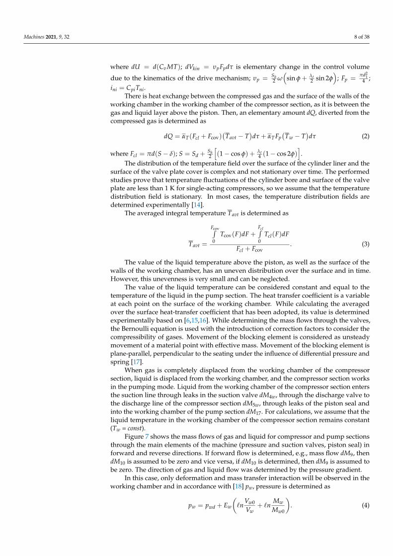
There is heat exchange between the compressed gas and the surface of the walls of theworking chamber in the working chamber of the compressor section, as it is between thegas and liquid layer above the piston. Then, an elementary amount dQ, diverted from thecompressed gas is determined as
dQ = αT(Fcl + Fcov)(Tavt − T
)dτ + αT Fp
(Tw − T
)dτ (2)
where Fcl = πd(S − δ); S = Sd +Sh2
[(1 − cos φ) + λt
4 (1 − cos 2φ)].
The distribution of the temperature field over the surface of the cylinder liner and thesurface of the valve plate cover is complex and not stationary over time. The performedstudies prove that temperature fluctuations of the cylinder bore and surface of the valveplate are less than 1 K for single-acting compressors, so we assume that the temperaturedistribution field is stationary. In most cases, the temperature distribution fields aredetermined experimentally [14].
The averaged integral temperature Tavt is determined as
Tavt =
Fcov∫0
Tcov(F)dF +Fcl∫0
Tcl(F)dF
Fcl + Fcov. (3)
The value of the liquid temperature above the piston, as well as the surface of thewalls of the working chamber, has an uneven distribution over the surface and in time.However, this unevenness is very small and can be neglected.
The value of the liquid temperature can be considered constant and equal to thetemperature of the liquid in the pump section. The heat transfer coefficient is a variableat each point on the surface of the working chamber. While calculating the averagedover the surface heat-transfer coefficient that has been adopted, its value is determinedexperimentally based on [6,15,16]. While determining the mass flows through the valves,the Bernoulli equation is used with the introduction of correction factors to consider thecompressibility of gases. Movement of the blocking element is considered as unsteadymovement of a material point with effective mass. Movement of the blocking element isplane-parallel, perpendicular to the seating under the influence of differential pressure andspring [17].
When gas is completely displaced from the working chamber of the compressorsection, liquid is displaced from the working chamber, and the compressor section worksin the pumping mode. Liquid from the working chamber of the compressor section entersthe suction line through leaks in the suction valve dM4w, through the discharge valve tothe discharge line of the compressor section dM5w, through leaks of the piston seal andinto the working chamber of the pump section dM17. For calculations, we assume that theliquid temperature in the working chamber of the compressor section remains constant(Tw = const).
Figure 7 shows the mass flows of gas and liquid for compressor and pump sectionsthrough the main elements of the machine (pressure and suction valves, piston seal) inforward and reverse directions. If forward flow is determined, e.g., mass flow dM9, thendM10 is assumed to be zero and vice versa, if dM10 is determined, then dM9 is assumed tobe zero. The direction of gas and liquid flow was determined by the pressure gradient.
In this case, only deformation and mass transfer interaction will be observed in theworking chamber and in accordance with [18] pw, pressure is determined as
pw = pwd + Ew
(`n
Vw0
Vw+ `n
Mw
Mw0
). (4)

Machines 2021, 9, 32 9 of 38
The system of equations describing change in the thermodynamic parameters of liquidis written as
Vw =Vh2
[(1 − cos φ) + λt
4 (1 − cos 2φ)]+ Vdc
pw =pwd + Ew
(`n Vw0
Vw+ `n Mw
Mw0
)dMw =
N4∑
i=1dMwni −
N5∑
i=1dMw0i = dM6w − dM4w − dM16.
Tw =const
msprd2hcdτ2 =
N6∑
i=1Fwi
(5)
It should be noted that acting forces on the blocking elementN6∑
i=1Fwi when injecting
liquid are the same as when injecting gas. However, their definition differs and will beconsidered later when there is simulating of work processes in the pump section.
Elementary masses of liquid passing through the valves can be determined as
dMw0 = αgrw fgr
√ρw(pw − pi)dτ. (6)
2.2. Mathematical Model of the Work Processes of the Pump Section
The main assumptions while developing a mathematical model of the pump sectionwork processes are written as follows:
- The working liquid of the pump section is viscous compressible dropping liquid thatfollows the laws of Newton and Hooke.
- Mass transfer processes at the gas–liquid interface can be neglected.- The interface between liquid and gas is a plane parallel to the earth.- Coefficients of local resistances and the coefficient of friction along the length obtained
in stationary modes of liquid flow can be used in unsteady flow.
Displacement pump cycle consists of four processes: compression, discharge, reverseexpansion, and suction. According to physical phenomena, four processes can be dividedinto two groups. The first group includes compression and expansion. In these processes,an increase (decrease) in pressure occurs due to deformation interaction. The second groupincludes processes of discharge and suction. Mass transfer has a decisive effect.
It should be noted that all four processes are connected with thermal interaction,which is insignificant and neglected. We made a sequential review of the calculations ofthe above work processes.
Compression and reverse expansion processesIn the processes of compression and reverse expansion, the processes of deformation
(reduction in the working chamber volume due to piston movement), mass transfer (leaksand leakage of liquid), and heat transfer (convective heat transfer with surface of the wallsof the working chamber) interactions take place when there is no liquid movement, i.e.,kinetic energy.
The main fundamental work on the calculation of compression and reverse expansionprocesses is [19]. Recently published work [18] continues [19] and determines the changein pressure in the working chamber as if there is separately deformation, mass transfer,and thermal interactions, as in their combination.

Machines 2021, 9, 32 10 of 38
Due to the fact that change in liquid temperature is very small in the processesof compression and reverse expansion, the system of equations written in [19] can beconverted as:
Vw =Vdw + Vh2
[(1 − cos φ) + λt
4 (1 − cos 2φ)]
dMw =N3∑
i=1dMniw −
N4∑
i=1dM0iw
pw =pscw + Ew
(`n Vscw
Vw+ `n Mw
Mscw
)Tw =const
(7)
where Vscw = Vdw + Vhp; Vhp = π4(d2
2 − d21)S; Mscw = Vscw · ρw, Vh =
Shπ(d22−d2
1)4 .
The current liquid mass change is determined as
dMw = −dM12 + dM14 − dM17. (8)
Mathematical model of discharge and suctionDeformation, mass transfer, and thermal interactions are followed with conversion
of the flow kinetic energy into pressure potential energy and back in the processes ofdischarge and suction.
A method was developed in [20] for calculating the processes of discharge and suctionbased on the first law of thermodynamics for an open moving thermodynamic system.
The calculation is carried out in two stages. At first, using the Bernoulli equation, wedetermine change in liquid pressure in the working chamber of the pump as a result ofconversion of potential energy into kinetic and pressure loss (pressure process). At thesecond stage using the first law of thermodynamics, we determine change in temperatureand pressure of the working liquid due to deformation, heat, and mass transfer processes;then, we determine the change in pressure, temperature, and mass of the working liquid.
Considering that the external heat transfer is insignificant, the compressibility of thedroplet liquid is insignificant, and leakages and overflows of the working liquid are smallcompared to the main flow; thus, the Bernoulli equation supplemented by the equationof dynamics of a self-acting valve in a single-mass formulation [21] should be based onthe calculation
pw =pwd + ρwg(SDw + Sw) cos α + ρww2
2−w21
2 + ∆hT1−2 + ∆h1−2
mdrwd2hwdτ2 =
N6∑
i=1Fiw
. (9)
The pressure loss due to inner friction is the sum of pressure loss along the length andthe pressure loss to overcome local resistance.
∆h1−2 = ∆h` + ∆hζ (10)
Values ∆h` and ∆hζ are determined according to Darcy–Weisbach law
∆h` = λ f r(SDw + Sw)
d1
w21
2g(11)
∆hζ =w2
12g
(12)
where λ f r is length friction coefficient determined using [22,23].As first approximation, we can assume that the main pressure losses occur during a
sudden flow expansion in the valve, which can be determined as
ζ =(1 − fgr/ f2
)2 (13)
Machines 2021, 9, 32 11 of 38
where fgr = πdvlhw; f2 =πd2
p4 .
2.3. Mathematical Model of Liquid Flow in a Groove Seal
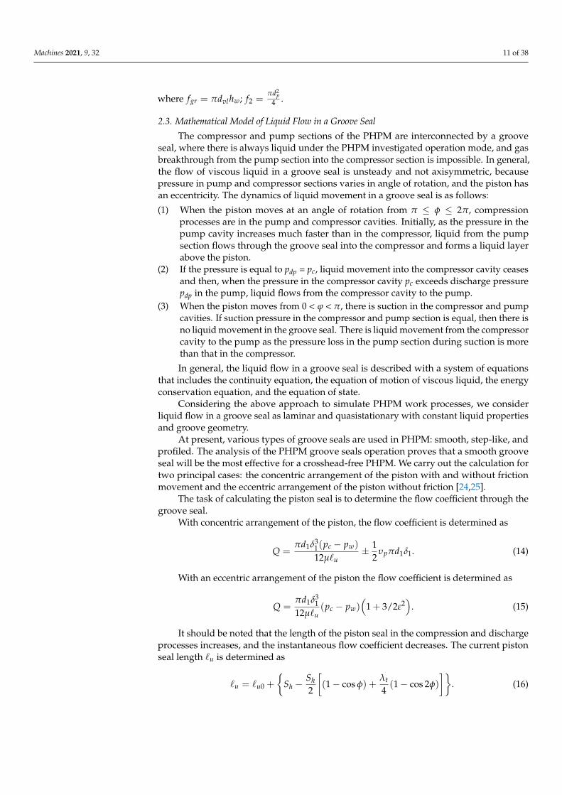
The compressor and pump sections of the PHPM are interconnected by a grooveseal, where there is always liquid under the PHPM investigated operation mode, and gasbreakthrough from the pump section into the compressor section is impossible. In general,the flow of viscous liquid in a groove seal is unsteady and not axisymmetric, becausepressure in pump and compressor sections varies in angle of rotation, and the piston hasan eccentricity. The dynamics of liquid movement in a groove seal is as follows:
(1) When the piston moves at an angle of rotation from π ≤ φ ≤ 2π, compressionprocesses are in the pump and compressor cavities. Initially, as the pressure in thepump cavity increases much faster than in the compressor, liquid from the pumpsection flows through the groove seal into the compressor and forms a liquid layerabove the piston.
(2) If the pressure is equal to pdp = pc, liquid movement into the compressor cavity ceasesand then, when the pressure in the compressor cavity pc exceeds discharge pressurepdp in the pump, liquid flows from the compressor cavity to the pump.
(3) When the piston moves from 0 < ϕ < π, there is suction in the compressor and pumpcavities. If suction pressure in the compressor and pump section is equal, then there isno liquid movement in the groove seal. There is liquid movement from the compressorcavity to the pump as the pressure loss in the pump section during suction is morethan that in the compressor.
In general, the liquid flow in a groove seal is described with a system of equationsthat includes the continuity equation, the equation of motion of viscous liquid, the energyconservation equation, and the equation of state.
Considering the above approach to simulate PHPM work processes, we considerliquid flow in a groove seal as laminar and quasistationary with constant liquid propertiesand groove geometry.
At present, various types of groove seals are used in PHPM: smooth, step-like, andprofiled. The analysis of the PHPM groove seals operation proves that a smooth grooveseal will be the most effective for a crosshead-free PHPM. We carry out the calculation fortwo principal cases: the concentric arrangement of the piston with and without frictionmovement and the eccentric arrangement of the piston without friction [24,25].
The task of calculating the piston seal is to determine the flow coefficient through thegroove seal.
With concentric arrangement of the piston, the flow coefficient is determined as
Q =πd1δ3
1(pc − pw)
12µ`u± 1
2υpπd1δ1. (14)
With an eccentric arrangement of the piston the flow coefficient is determined as
Q =πd1δ3
112µ`u
(pc − pw)(
1 + 3/2ε2)
. (15)
It should be noted that the length of the piston seal in the compression and dischargeprocesses increases, and the instantaneous flow coefficient decreases. The current pistonseal length `u is determined as
`u = `u0 +
{Sh −
Sh2
[(1 − cos φ) +
λt
4(1 − cos 2φ)
]}. (16)

Machines 2021, 9, 32 12 of 38
3. Experimental Study
The main aim of the experimental research is to obtain new knowledge about theobject under study and to verify the developed mathematical model. That is why anexperimental model of a crosshead-free PHPM was designed.
3.1. Object, Stand for Its Research, Measuring Equipment
The developed experimental model of crosshead-free PHPM has the following maindesign and operational parameters:
- Inner diameter of the piston is 55 mm;- The outer diameter of the piston is 65 mm;- Connecting rod length is 81 mm;- Piston stroke is 47 mm;- Total piston length is 119 mm;- Discharge pressure in the compressor section is up to 10 bar;- Discharge pressure in the pump section is up to 20 bar;- Crank angular velocity is from 250 to 750 min−1;- Suction pressure in the pump section is 1 bar;- Suction pressure in the compressor section is 1 bar.
When designing a crosshead-free PHPM, the Solid Works software was used. Air wasused as working liquid for the compressor section, and MGE-46V hydrolic oil (specificationsare shown in Table 1) was used for the pump section.
Table 1. Rosneft MGE-46V hydraulic oil specifications.
Indicator GOST Standart (TU)
Kinematic viscosity, mm2/s:at 100 ◦C, not less than 6.0
at 50 ◦C -at 40 ◦C 41.4–50.6
at 0 ◦C, not more than 1000Viscosity index, not less 90
Temperature, ◦C:flashes in an open crucible, not lower 190
solidification, not more −32Acid number, mg KOH/g 0.7–1.5
Mass fraction:mechanical impurities, no more absence
water absenceMetal Corrosion Test pass
density at 20 ◦C, kg/m3, no more 890Oxidation stability:
sediment, %, no more 0.05change in acid number, mg KOH/g oil, not more than 0.15
Tribological characteristics at FBM:wear indicator at axial load 196 N, mm, no more 0.45
The prototype was tested at the developed stand to perform the following functions:
- To change smoothly the speed of the drive shaft while fixing the frequency of thepiston reciprocating movement;
- Measurement and maintenance of stationary parameters on the lines of liquid andgas suction and discharge;
- Measurement of instantaneous values of pressures in working chambers with theirindicator diagrams in digital and graphic forms;
- Measuring the productivity of gas and liquid working chambers;- Measurement of leaks of working liquid;- High ergonomics to influence the main initial parameters;

Machines 2021, 9, 32 13 of 38
- Measuring the temperature of gas and liquid at suction and discharge, the temperatureof the inner surface of the valve plate of the compressor section.
A hydropneumatic diagram of the stand is shown in Figure 8.
Machines 2021, 9, x FOR PEER REVIEW 13 of 39
− To change smoothly the speed of the drive shaft while fixing the frequency of the piston reciprocating movement;
− Measurement and maintenance of stationary parameters on the lines of liquid and gas suction and discharge;
− Measurement of instantaneous values of pressures in working chambers with their indicator diagrams in digital and graphic forms;
− Measuring the productivity of gas and liquid working chambers; − Measurement of leaks of working liquid; − High ergonomics to influence the main initial parameters; − Measuring the temperature of gas and liquid at suction and discharge, the tempera-
ture of the inner surface of the valve plate of the compressor section. A hydropneumatic diagram of the stand is shown in Figure 8.
Figure 8. Hydro pneumatic diagram of the test bench to study a crosshead-free PHPM. Legend: 1—fluid control valve; 2, 46—tank; 3—electromotor; 4, 54—pump; 5, 34, 45, 47—oil filter; 6, 20, 29—safety valve; 7, 15, 26, 35, 41, 55—pressure sensor; 8—air filter; 9, 24, 40, 51—ratemeter; 10, 14, 16, 31, 37, 44, 52, 56—temperature sensor; 11, 23, 28—manometer; 12—rotation sensor; 13—com-pressor; 17—oil-and-moisture separator; 18, 21, 25—globe valve; 19—receiver; 22—pressure switch gauge; 27—fluid-power motor; 30—heat exchanger; 32—throttle; 33, 39, 42, 43, 50—ball valve; 36—hydropneumatic accumulator; 38—measuring container; 48—fluid level gauge; 49—filler neck strainer; SV1-SV3—safety valve; GV1-GV3—globe valve; PSG1—pressure switch gauge; RC1—receiver; MN1-MN3—manometer; RM1-RM4—ratemeter; OS1—oil-and-moisture separator; TS1-TS8—temperature sensor; PS1-PS7—pressure sensor; CM1—compressor; AF1—air filter; F1-F4—oil filter; FN1—filler neck strainer; T1, T2—tank; P1, P2—pump; RS1—rotation sensor; FM1—fluid-power motor; FV1—fluid control valve; TT1—throttle; HE1—heat exchanger; BV1-BV5—ball valve; AC1—hydropneumatic accumulator; FL1—fluid level gauge; MC1—measuring container.
To change the speed of rotation of the drive shaft, a displacement hydraulic drive is used, which includes a displacement axial piston pump model 313.3.56.804 with a dis-charge pressure 6.3 MPa and an axial piston hydraulic motor 310.3.56.01.03.V.U. model. Static pressures are measured with pressure gauges; instant pressures are measured with tensometric sensors.
To reduce the unevenness of the pump cavity supply, a pneumatic accumulator with a Danfoss MBS 3000 (Danfoss, Chelyabinsk, Russia) pressure sensor is installed on the discharge line. The same sensor is used to measure the liquid suction pressure. Liquid flow rates are measured with TPR 20-8 (“Arzamas instrument-making plant named after P.I. Plandin”, Chelyabinsk, Russia) flow meters, suction and discharge temperatures are
Figure 8. Hydro pneumatic diagram of the test bench to study a crosshead-free PHPM. Leg-end: 1—fluid control valve; 2, 46—tank; 3—electromotor; 4, 54—pump; 5, 34, 45, 47—oil fil-ter; 6, 20, 29—safety valve; 7, 15, 26, 35, 41, 55—pressure sensor; 8—air filter; 9, 24, 40,51—ratemeter; 10, 14, 16, 31, 37, 44, 52, 56—temperature sensor; 11, 23, 28—manometer; 12—rotationsensor; 13—compressor; 17—oil-and-moisture separator; 18, 21, 25—globe valve; 19—receiver;22—pressure switch gauge; 27—fluid-power motor; 30—heat exchanger; 32—throttle; 33, 39, 42,43, 50—ball valve; 36—hydropneumatic accumulator; 38—measuring container; 48—fluid levelgauge; 49—filler neck strainer; SV1-SV3—safety valve; GV1-GV3—globe valve; PSG1—pressureswitch gauge; RC1—receiver; MN1-MN3—manometer; RM1-RM4—ratemeter; OS1—oil-and-moisture separator; TS1-TS8—temperature sensor; PS1-PS7—pressure sensor; CM1—compressor;AF1—air filter; F1-F4—oil filter; FN1—filler neck strainer; T1, T2—tank; P1, P2—pump;RS1—rotation sensor; FM1—fluid-power motor; FV1—fluid control valve; TT1—throttle; HE1—heatexchanger; BV1-BV5—ball valve; AC1—hydropneumatic accumulator; FL1—fluid level gauge;MC1—measuring container.
To change the speed of rotation of the drive shaft, a displacement hydraulic driveis used, which includes a displacement axial piston pump model 313.3.56.804 with adischarge pressure 6.3 MPa and an axial piston hydraulic motor 310.3.56.01.03.V.U. model.Static pressures are measured with pressure gauges; instant pressures are measured withtensometric sensors.
To reduce the unevenness of the pump cavity supply, a pneumatic accumulator witha Danfoss MBS 3000 (Danfoss, Chelyabinsk, Russia) pressure sensor is installed on thedischarge line. The same sensor is used to measure the liquid suction pressure. Liquidflow rates are measured with TPR 20-8 (“Arzamas instrument-making plant named afterP.I. Plandin”, Chelyabinsk, Russia) flow meters, suction and discharge temperatures aremeasured with TW N PT100 (Autonics, Chelyabinsk, Russia) sensors, and the liquidtemperature in tanks is controlled with DTS 035 50M.V3 (OVEN, Chelyabinsk, Russia)sensors. Leakage is measured with volumetric method.
Air flow is measured with SMCPF2A751-F04-67N-M (SMC Corporation, Lukhovitsy,Russia), Vector-04 (NPP SKYMETER, Chelyabinsk, Russia), and SGV-15 Betar modelflowmeters (OOO PKF “BETAR”, Chelyabinsk, Russia) at suction and discharge of the

Machines 2021, 9, 32 14 of 38
compressor cavity; we used PSE530 M5 l sensors (SMC Corporation, Lukhovitsy, Russia)for measuring suction and discharge pressures. An AD22100 STZ sensor (Analog Devices,Chelyabinsk, Russia) is used to measure the stationary temperature of the valve plate andthe upper part of the cylinder.
The hydraulic and pneumatic lines of the stand are equipped with liquid and gaspurification devices, safety devices, and controllers to organize the work of the testedmachine in different modes. A general view of the tested machine installed on the stand isshown in Figure 9.
Machines 2021, 9, x FOR PEER REVIEW 14 of 39
measured with TW N PT100 (Autonics, Chelyabinsk, Russia) sensors, and the liquid tem-perature in tanks is controlled with DTS 035 50M.V3 (OVEN, Chelyabinsk, Russia) sen-sors. Leakage is measured with volumetric method.
Air flow is measured with SMCPF2A751-F04-67N-M (SMC Corporation, Lukhovitsy, Russia), Vector-04 (NPP SKYMETER, Chelyabinsk, Russia), and SGV-15 Betar model flowmeters (OOO PKF "BETAR", Chelyabinsk, Russia) at suction and discharge of the compressor cavity; we used PSE530 M5 l sensors (SMC Corporation, Lukhovitsy, Russia) for measuring suction and discharge pressures. An AD22100 STZ sensor (Analog Devices, Chelyabinsk, Russia) is used to measure the stationary temperature of the valve plate and the upper part of the cylinder.
The hydraulic and pneumatic lines of the stand are equipped with liquid and gas purification devices, safety devices, and controllers to organize the work of the tested ma-chine in different modes. A general view of the tested machine installed on the stand is shown in Figure 9.
Figure 9. PHPM of crosshead-free and test bench in the installation area of crosshead-free PHPM.
3.2. Verification of the Mathematical Model of Work Processes of Crosshead-Free PHPM Verification of the developed mathematical model is based on the qualitative and
quantitative matching of the results of numerical simulating and experimental studies; i.e., it is to verify that the mathematical model responds to changes in operational param-eters and how it describes the work processes and integral parameters of the compressor and pump sections.
Verification of the developed mathematical model was confirmed over the range of changes in the independent parameters: pdp, pdc, and nrev.
We compared the indicator diagrams in the compressor and pump cavities, the main integral characteristics: compressor section feed coefficient, volumetric efficiency for the pump section, and the amount of liquid carried into the discharge line of the compressor section.
Figures 10–13 compare indicator diagrams for the compressor and pump sections at different nominal discharge pressures.
Figure 9. PHPM of crosshead-free and test bench in the installation area of crosshead-free PHPM.
3.2. Verification of the Mathematical Model of Work Processes of Crosshead-Free PHPM
Verification of the developed mathematical model is based on the qualitative andquantitative matching of the results of numerical simulating and experimental studies; i.e.,it is to verify that the mathematical model responds to changes in operational parametersand how it describes the work processes and integral parameters of the compressor andpump sections.
Verification of the developed mathematical model was confirmed over the range ofchanges in the independent parameters: pdp, pdc, and nrev.
We compared the indicator diagrams in the compressor and pump cavities, themain integral characteristics: compressor section feed coefficient, volumetric efficiencyfor the pump section, and the amount of liquid carried into the discharge line of thecompressor section.
Figures 10–13 compare indicator diagrams for the compressor and pump sections atdifferent nominal discharge pressures.
A comparative analysis of the indicator diagrams in the compressor section proves:
- Discrepancy in determining instant pressure is insignificant in compression, expan-sion, and suction, and it is less than 5%.
- Maximum discrepancy from 10% to 15% is observed during discharge, due to sig-nificant inertial forces acting on the liquid when the valve is opened, leading to asignificant pressure jump in the experimental data.
We compared indicator diagrams in the pump section and made conclusions:
- Compression and suction are described with an error 5% max.
The maximum discrepancy in determining instant pressure is observed during thedischarge, at the beginning and end of the process when the discharge valve is opened

Machines 2021, 9, 32 15 of 38
and closed. The maximum discrepancy from 10% to 15% is because inertial forces of liquiddisplacement are not considered while calculating the discharge process.
It should be noted that the test bench has long discharge and suction pipelines;investigated PHPM has a significant irregularity in the liquid supply—π. According to [24],it leads to significant pressure fluctuation in pipelines (primarily on the discharge line),despite the installed gas cap (see Figures 8 and 9).
Machines 2021, 9, x FOR PEER REVIEW 15 of 39
Figure 10. Dependence of the instantaneous pressure in the compressor section in the crosshead-free PHPM determined experimentally and by calculation (1—Calculation; 2—Experiment).
Figure 11. Dependence of the instantaneous pressure in the pump section in a crosshead-free PHPM determined experi-mentally and by calculation (1—Calculation; 2—Experiment).
Figure 10. Dependence of the instantaneous pressure in the compressor section in the crosshead-freePHPM determined experimentally and by calculation (1—Calculation; 2—Experiment).
Machines 2021, 9, x FOR PEER REVIEW 15 of 39
Figure 10. Dependence of the instantaneous pressure in the compressor section in the crosshead-free PHPM determined experimentally and by calculation (1—Calculation; 2—Experiment).
Figure 11. Dependence of the instantaneous pressure in the pump section in a crosshead-free PHPM determined experi-mentally and by calculation (1—Calculation; 2—Experiment). Figure 11. Dependence of the instantaneous pressure in the pump section in a crosshead-free PHPM determined experi-mentally and by calculation (1—Calculation; 2—Experiment).

Machines 2021, 9, 32 16 of 38Machines 2021, 9, x FOR PEER REVIEW 16 of 39
Figure 12. The dependence of the instantaneous pressure in the compressor section in crosshead-free PHPM determined experimentally and by calculation (1—Calculation; 2—Experiment).
Figure 13. Dependence of the instantaneous pressure in the pump section in a crosshead-free PHPM determined experi-mentally and by calculation (1—Calculation; 2—Experiment).
A comparative analysis of the indicator diagrams in the compressor section proves: − Discrepancy in determining instant pressure is insignificant in compression, expan-
sion, and suction, and it is less than 5%. − Maximum discrepancy from 10% to 15% is observed during discharge, due to signif-
icant inertial forces acting on the liquid when the valve is opened, leading to a signif-icant pressure jump in the experimental data. We compared indicator diagrams in the pump section and made conclusions:
Figure 12. The dependence of the instantaneous pressure in the compressor section in crosshead-free PHPM determinedexperimentally and by calculation (1—Calculation; 2—Experiment).
Machines 2021, 9, x FOR PEER REVIEW 16 of 39
Figure 12. The dependence of the instantaneous pressure in the compressor section in crosshead-free PHPM determined experimentally and by calculation (1—Calculation; 2—Experiment).
Figure 13. Dependence of the instantaneous pressure in the pump section in a crosshead-free PHPM determined experi-mentally and by calculation (1—Calculation; 2—Experiment).
A comparative analysis of the indicator diagrams in the compressor section proves: − Discrepancy in determining instant pressure is insignificant in compression, expan-
sion, and suction, and it is less than 5%. − Maximum discrepancy from 10% to 15% is observed during discharge, due to signif-
icant inertial forces acting on the liquid when the valve is opened, leading to a signif-icant pressure jump in the experimental data. We compared indicator diagrams in the pump section and made conclusions:
Figure 13. Dependence of the instantaneous pressure in the pump section in a crosshead-free PHPM determined experi-mentally and by calculation (1—Calculation; 2—Experiment).
Table 2 presents the results of numerical and experimental studies. The flow coefficientof the compressor section was determined as
λ =
∮dM6 −
∮dM5
ρscVhc. (17)

Machines 2021, 9, 32 17 of 38
Table 2. The results of numerical and experimental studies of crosshead-free PHPM.
№ pdc,bar
pdp,bar
nrev,rpm
λnum.
λexp.
ηvolnum.
ηvolexp.
¯Tavt, K
∆VwmL/min
num.
∆VwmL/min
exp.
1 6 3 300 0.737 0.687 0.7475 0.86 320 0 0.72 6 5 300 0.738 0.7467 0.742 0.82 320 0 113 6 7 300 0.739 0.7168 0.737 0.774 320 0 144 6 9 300 0.739 0.7168 0.733 0.7 320 0 205 4 3 300 0.84 0.836 0.747 0.674 310 0 86 5 3 300 0.739 0.8064 0.747 0.686 310 0 57 6 3 300 0.737 0.7467 0.747 0.704 320 0 38 7 3 300 0.6934 0.7168 0.747 0.716 320 0 19 8 3 300 0.644 0.6868 0.747 0.728 325 0 0.5
The volumetric efficiency of the pump section was determined as
ηvol =
∮dM13 −
∮dM14
ρwVhw. (18)
Table 2 presents ∆Vw as the amount of liquid carried out from the compressor sectionto the discharge line. The distribution bodies in the compressor and pump sections inthe experimental prototype had the following parameters: maximum lift height of theshut-off element of the suction valve in the pump section hscpmax = 0.0016 m; minimum liftheight of the shut-off element of the suction valve in the pump section hscpmin = 5×10⁻⁶ m;spring stiffness of the suction valve in the pump section csprscp = 716 N/m; mass of theshut-off element of the suction valve in the pump section mshscp = 9 gr; passage width inthe seating of the suction valve of the pump section dvlscp = 0.03 m; maximum lift heightof the shut-off element of the suction valve in the compressor section hsccmax = 0.00175 m;minimum lift height (conditional clearance) of the shut-off element of the suction valve inthe compressor section hsccmin = 3.5×10⁻⁶ m; passage width in the seating of the suctionvalve of the compressor section dvlscc = 0.01775 m; spring stiffness of the suction valve inthe compressor section csprscc = 2052 N/m; mass of the shut-off element of the suction valveof the compressor section mshscc = 0.624 gr.
The parameters for the discharge valve of the compressor section are similar:hdcmax = 0.00175 m; hdcmin = 3.5×10⁻⁶ m; dvldc = 0.01775 m; csprdc = 2052 N/m; mshdvl = 0.624 gr.The parameters for discharge valve of the pump section are similar as well: hdpmax = 0.0016 m;hdpmin = 5×10⁻⁶ m; dvldp = 0.03 m; csprdc = 338 N/m; mshdp = 23 gr.
Figures 14 and 15 show changes in the compressor feed coefficient obtained experi-mentally and numerically with change in the discharge pressure in the compressor sectionwith a fixed pdc and vice versa. According to the theory of the work processes of reciprocat-ing compressors, an increase in the discharge pressure in the compressor section decreasesthe productivity of the reciprocating compressor due to a decrease in the volumetric ratioand leakage ratio (see Figure 14). Increasing the discharge pressure in the pump sectionincreases the amount of liquid coming to the compressor section. If not all the dead spacein the compressor section is filled with liquid (see curve 2 in Figure 15), then there isan increase in the delivery coefficient. If the dead space is completely filled with liquid,the delivery coefficient does not change (see curve 1 in Figure 15). Incomplete fillingof the dead space with liquid in a real machine is due to partial removal of the liquidin the form of drops by compressed gas, which was not considered when developing amathematical model.

Machines 2021, 9, 32 18 of 38
Machines 2021, 9, x FOR PEER REVIEW 18 of 39
with a fixed pdc and vice versa. According to the theory of the work processes of recipro-cating compressors, an increase in the discharge pressure in the compressor section de-creases the productivity of the reciprocating compressor due to a decrease in the volumet-ric ratio and leakage ratio (see Figure 14). Increasing the discharge pressure in the pump section increases the amount of liquid coming to the compressor section. If not all the dead space in the compressor section is filled with liquid (see curve 2 in Figure 15), then there is an increase in the delivery coefficient. If the dead space is completely filled with liquid, the delivery coefficient does not change (see curve 1 in Figure 15). Incomplete filling of the dead space with liquid in a real machine is due to partial removal of the liquid in the form of drops by compressed gas, which was not considered when developing a mathe-matical model.
It should be noted that increasing the discharge pressure in the pump section, we improve cooling of the suction gas and decrease its leaks and overflows. This leads to an increase in the flow ratio and the capacity of the compressor section.
The presented results prove that we observe a good qualitative and quantitative matching. The discrepancy between the results of numerical and experimental studies is from 3% to 5%.
Figure 14. Dependence of the supply coefficient of the compressor section on the discharge pres-sure of the compressor section (1—Theory; 2—Experiment).
Figure 14. Dependence of the supply coefficient of the compressor section on the discharge pressureof the compressor section (1—Theory; 2—Experiment).
Machines 2021, 9, x FOR PEER REVIEW 19 of 39
Figure 15. Dependence of the supply coefficient of the compressor section on the discharge pres-sure of the pump section (1—Theory; 2—Experiment).
Figures 16 and 17 show the changes in volumetric efficiency of the pump sections obtained experimentally and numerically by changing pdc at fixed pdp and vice versa.
By increasing the discharge pressure in the compressor section, we increase the amount of liquid flowing from the compressor section to the pump section. This increase is during pumping in the pump section and increases the volumetric efficiency. It is ob-served due to the underfilling of the working chamber in the real pump; there is no such underfilling in the developed mathematical model (see Figure 16).
Figure 16. Volumetric efficiency the pump section from the discharge pressure of the compressor section (1—Theory; 2—Experiment).
Figure 15. Dependence of the supply coefficient of the compressor section on the discharge pressureof the pump section (1—Theory; 2—Experiment).
It should be noted that increasing the discharge pressure in the pump section, weimprove cooling of the suction gas and decrease its leaks and overflows. This leads to anincrease in the flow ratio and the capacity of the compressor section.
The presented results prove that we observe a good qualitative and quantitativematching. The discrepancy between the results of numerical and experimental studies isfrom 3% to 5%.
Figures 16 and 17 show the changes in volumetric efficiency of the pump sectionsobtained experimentally and numerically by changing pdc at fixed pdp and vice versa.

Machines 2021, 9, 32 19 of 38
Machines 2021, 9, x FOR PEER REVIEW 19 of 39
Figure 15. Dependence of the supply coefficient of the compressor section on the discharge pres-sure of the pump section (1—Theory; 2—Experiment).
Figures 16 and 17 show the changes in volumetric efficiency of the pump sections obtained experimentally and numerically by changing pdc at fixed pdp and vice versa.
By increasing the discharge pressure in the compressor section, we increase the amount of liquid flowing from the compressor section to the pump section. This increase is during pumping in the pump section and increases the volumetric efficiency. It is ob-served due to the underfilling of the working chamber in the real pump; there is no such underfilling in the developed mathematical model (see Figure 16).
Figure 16. Volumetric efficiency the pump section from the discharge pressure of the compressor section (1—Theory; 2—Experiment). Figure 16. Volumetric efficiency the pump section from the discharge pressure of the compressorsection (1—Theory; 2—Experiment).
Machines 2021, 9, x FOR PEER REVIEW 20 of 39
Figure 17. Volumetric efficiency of the pump section from the discharge pressure of the pump section (1—Theory; 2—Experiment).
As the discharge pressure in the pump section increases, leaks and liquid spills in-crease and lead to a decrease in volumetric efficiency of the pump section both in the real machine and in the mathematical model (see Figure 17).
The presented results prove correct qualitative and satisfactory quantitative match-ing. The maximum discrepancy in definition ηvol is within 10%.
Thus, taking into account the complete qualitative matching between the numerical and experimental methods, and the allowable quantitative discrepancy (in determining instant pressures, it is from 10 to 15% and in integral parameters, it is from 5 to 10%), we can conclude that the developed mathematical model of the work processes is true to life.
4. The Results of Numerical and Experimental Studies When conducting experimental and numerical studies, a classical plan with frac-
tional replicas was used [26]. These operational parameters with following ranges were selected as independent parameters in experimental studies: − Pressure in the compressor discharge line (receiver) pdc (from 3 to 7 bar); − Pump discharge pressure pdp (from 2 up to 10 bar); − Crankshaft speed nrev (from 250 up to 600 rpm).
The experimental studies were carried out as follows: − At pdp = 3 bar and nrev = 250 rpm, discharge pressure of the compressor section varied
in the range 3 bar ≤ pdc ≤ 7 bar. − At pdc = 5 bar and nrev = 250 rpm, the pump section discharge pressure varied in the
range 2 bar ≤ pdp ≤ 10 bar. − At constant discharge pressures in the compressor and pump sections: pdp = 2 bar; pdc
= 4 bar angular speed of the crankshaft varied from 250 to 450 rpm. Water was used as liquid, and air was also used as gas in numerical simulating. In
addition, when conducting numerical studies, the following independent parameters were added to the independent operational parameters listed above: − Relative dead space value (ad). − Radial clearance in the piston seal (δ1). − Initial groove seal length (lu0).
Figure 17. Volumetric efficiency of the pump section from the discharge pressure of the pump section(1—Theory; 2—Experiment).
By increasing the discharge pressure in the compressor section, we increase the amountof liquid flowing from the compressor section to the pump section. This increase is duringpumping in the pump section and increases the volumetric efficiency. It is observed due tothe underfilling of the working chamber in the real pump; there is no such underfilling inthe developed mathematical model (see Figure 16).
As the discharge pressure in the pump section increases, leaks and liquid spills increaseand lead to a decrease in volumetric efficiency of the pump section both in the real machineand in the mathematical model (see Figure 17).
The presented results prove correct qualitative and satisfactory quantitative matching.The maximum discrepancy in definition ηvol is within 10%.

Machines 2021, 9, 32 20 of 38
Thus, taking into account the complete qualitative matching between the numericaland experimental methods, and the allowable quantitative discrepancy (in determininginstant pressures, it is from 10 to 15% and in integral parameters, it is from 5 to 10%), wecan conclude that the developed mathematical model of the work processes is true to life.
4. The Results of Numerical and Experimental Studies
When conducting experimental and numerical studies, a classical plan with fractionalreplicas was used [26]. These operational parameters with following ranges were selectedas independent parameters in experimental studies:
- Pressure in the compressor discharge line (receiver) pdc (from 3 to 7 bar);- Pump discharge pressure pdp (from 2 up to 10 bar);- Crankshaft speed nrev (from 250 up to 600 rpm).
The experimental studies were carried out as follows:
- At pdp = 3 bar and nrev = 250 rpm, discharge pressure of the compressor section variedin the range 3 bar ≤ pdc ≤ 7 bar.
- At pdc = 5 bar and nrev = 250 rpm, the pump section discharge pressure varied in therange 2 bar ≤ pdp ≤ 10 bar.
- At constant discharge pressures in the compressor and pump sections: pdp = 2 bar;pdc = 4 bar angular speed of the crankshaft varied from 250 to 450 rpm.
Water was used as liquid, and air was also used as gas in numerical simulating. Inaddition, when conducting numerical studies, the following independent parameters wereadded to the independent operational parameters listed above:
- Relative dead space value (ad).- Radial clearance in the piston seal (δ1).- Initial groove seal length (lu0).
The developed mathematical model considers a physical picture of the work processesin the compressor and pump sections of the crosshead-free PHPM.
4.1. Physical Picture of Ongoing Work Processes (Based on the Results of Numerical Analysis)
We consider bottom dead center as a starting point. There is a liquid layer δ ≈ 0.001 m(Figure 18) above the piston that corresponds to the amount of dead space in the compres-sor section. When the piston moves up to the top dead center, there is a decrease in volumein the compressor and pump sections, which causes an increase in pressure. Consider-ing a high modulus of elasticity of liquid, pressure in the pump cavity increases almostimmediately, but it increases rather slowly in the compressor section (Figures 19 and 20).
At ϕ ≈ 3.4 rad, the pumping process begins in the pump section. Due to the sig-nificant pressure difference between the pump and compressor sections, the liquid fromthe pump section flows into the compressor section and the height of the liquid layerincreases. It should be noted that with an increase in the angle of rotation, the length ofthe groove seal increases (Figure 21) and the pressure drop between the cavities decreases(Figures 19 and 20), leading to a decrease in the instant liquid flow rate from the pumpsection to the compressor section and the growth rate of the total liquid flow from thepump section to the compressor section (Figure 22).

Machines 2021, 9, 32 21 of 38
Machines 2021, 9, x FOR PEER REVIEW 21 of 39
The developed mathematical model considers a physical picture of the work pro-cesses in the compressor and pump sections of the crosshead-free PHPM.
4.1. Physical Picture of Ongoing Work Processes (Based on the Results of Numerical Analysis) We consider bottom dead center as a starting point. There is a liquid layer ≈ 0.001
m (Figure 18) above the piston that corresponds to the amount of dead space in the com-pressor section. When the piston moves up to the top dead center, there is a decrease in volume in the compressor and pump sections, which causes an increase in pressure. Con-sidering a high modulus of elasticity of liquid, pressure in the pump cavity increases al-most immediately, but it increases rather slowly in the compressor section (Figures 19 and 20).
Figure 18. Dependence of the current height of the liquid above the piston in the compressor sec-tion on the angle of rotation of the crankshaft at different speeds. (1— = 400 rpm; 2— =500 rpm; 3— = 600 rpm).
At φ ≈ 3.4 rad, the pumping process begins in the pump section. Due to the significant pressure difference between the pump and compressor sections, the liquid from the pump section flows into the compressor section and the height of the liquid layer increases. It should be noted that with an increase in the angle of rotation, the length of the groove seal increases (Figure 21) and the pressure drop between the cavities decreases (Figures 19 and 20), leading to a decrease in the instant liquid flow rate from the pump section to the com-pressor section and the growth rate of the total liquid flow from the pump section to the compressor section (Figure 22).
Figure 18. Dependence of the current height of the liquid above the piston in the compressor section on the angle of rotationof the crankshaft at different speeds. (1—nrev = 400 rpm; 2—nrev = 500 rpm; 3—nrev = 600 rpm).
Machines 2021, 9, x FOR PEER REVIEW 22 of 39
Figure 19. The indicator diagram of the compressor section at different speeds of the crankshaft (1— = 400 rpm; 2—= 500 rpm; 3— = 600 rpm).
Figure 20. The indicator diagram of the pump section at different speeds of the crankshaft (1— = 400 rpm; 2— =500 rpm; 3— = 600 rpm).
Figure 19. The indicator diagram of the compressor section at different speeds of the crankshaft (1—nrev = 400 rpm;2—nrev = 500 rpm; 3—nrev = 600 rpm).

Machines 2021, 9, 32 22 of 38
Machines 2021, 9, x FOR PEER REVIEW 22 of 39
Figure 19. The indicator diagram of the compressor section at different speeds of the crankshaft (1— = 400 rpm; 2—= 500 rpm; 3— = 600 rpm).
Figure 20. The indicator diagram of the pump section at different speeds of the crankshaft (1— = 400 rpm; 2— =500 rpm; 3— = 600 rpm).
Figure 20. The indicator diagram of the pump section at different speeds of the crankshaft (1—nrev = 400 rpm;2—nrev = 500 rpm; 3—nrev = 600 rpm).
Machines 2021, 9, x FOR PEER REVIEW 23 of 39
Figure 21. Dependence of the length of the gap seal on the angle of rotation of the crankshaft.
Figure 22. The dependence of the total liquid flow from the pump section to the compressor section on the angle of rotation of the crankshaft at different speeds (1— = 400 rpm; 2— = 500 rpm; 3— = 600 rpm).
At the angle of rotation φ ≈ 5.3 rad, the pressure in the compressor section exceeds the pressure in the pump section (Figures 19 and 20), liquid moves into the opposite di-rection, and the total amount of liquid flowing from the compressor section to the pump section increases (Figure 23). It should be noted that there is a discharge process in the compressor and pump sections this time. When the piston reaches the top dead center, the height of the liquid layer above the piston exceeds the dead volume and all gas from the compressor section is pushed into the discharge line (Figure 24); then, the “pump”
Figure 21. Dependence of the length of the gap seal on the angle of rotation of the crankshaft.

Machines 2021, 9, 32 23 of 38
Machines 2021, 9, x FOR PEER REVIEW 23 of 39
Figure 21. Dependence of the length of the gap seal on the angle of rotation of the crankshaft.
Figure 22. The dependence of the total liquid flow from the pump section to the compressor section on the angle of rotation of the crankshaft at different speeds (1— = 400 rpm; 2— = 500 rpm; 3— = 600 rpm).
At the angle of rotation φ ≈ 5.3 rad, the pressure in the compressor section exceeds the pressure in the pump section (Figures 19 and 20), liquid moves into the opposite di-rection, and the total amount of liquid flowing from the compressor section to the pump section increases (Figure 23). It should be noted that there is a discharge process in the compressor and pump sections this time. When the piston reaches the top dead center, the height of the liquid layer above the piston exceeds the dead volume and all gas from the compressor section is pushed into the discharge line (Figure 24); then, the “pump”
Figure 22. The dependence of the total liquid flow from the pump section to the compressor section on the angle of rotationof the crankshaft at different speeds (1—nrev = 400 rpm; 2—nrev = 500 rpm; 3—nrev = 600 rpm).
At the angle of rotation ϕ ≈ 5.3 rad, the pressure in the compressor section exceedsthe pressure in the pump section (Figures 19 and 20), liquid moves into the oppositedirection, and the total amount of liquid flowing from the compressor section to the pumpsection increases (Figure 23). It should be noted that there is a discharge process in thecompressor and pump sections this time. When the piston reaches the top dead center, theheight of the liquid layer above the piston exceeds the dead volume and all gas from thecompressor section is pushed into the discharge line (Figure 24); then, the “pump” strokestarts, and part of the liquid from the compressor cavity enters the discharge line throughthe discharge valve of the compressor section (Figure 18).
Machines 2021, 9, x FOR PEER REVIEW 24 of 39
stroke starts, and part of the liquid from the compressor cavity enters the discharge line through the discharge valve of the compressor section (Figure 18).
Figure 23. Dependence of the total liquid flow from the compressor section to the pump section on the angle of rotation of the crankshaft at different speeds (1— = 400 rpm; 2— = 500 rpm; 3— = 600 rpm).
Figure 24. Dependence of the height of the gas volume of the compressor section on the angle of rotation of the crankshaft at different speeds.
By the end of the discharge process, the height of the liquid layer will be equal to the linear dead volume—0.001 m. It should be noted that the amount of liquid flowing from the compressor section to the pump section (Figure 23) sharply increases at the end of the discharge process. This is due to a sharp increase in the discharge pressure of the com-
Figure 23. Dependence of the total liquid flow from the compressor section to the pump section on the angle of rotation ofthe crankshaft at different speeds (1—nrev = 400 rpm; 2—nrev = 500 rpm; 3—nrev = 600 rpm).

Machines 2021, 9, 32 24 of 38
Machines 2021, 9, x FOR PEER REVIEW 24 of 39
stroke starts, and part of the liquid from the compressor cavity enters the discharge line through the discharge valve of the compressor section (Figure 18).
Figure 23. Dependence of the total liquid flow from the compressor section to the pump section on the angle of rotation of the crankshaft at different speeds (1— = 400 rpm; 2— = 500 rpm; 3— = 600 rpm).
Figure 24. Dependence of the height of the gas volume of the compressor section on the angle of rotation of the crankshaft at different speeds.
By the end of the discharge process, the height of the liquid layer will be equal to the linear dead volume—0.001 m. It should be noted that the amount of liquid flowing from the compressor section to the pump section (Figure 23) sharply increases at the end of the discharge process. This is due to a sharp increase in the discharge pressure of the com-
Figure 24. Dependence of the height of the gas volume of the compressor section on the angle of rotation of the crankshaftat different speeds.
By the end of the discharge process, the height of the liquid layer will be equal tothe linear dead volume—0.001 m. It should be noted that the amount of liquid flowingfrom the compressor section to the pump section (Figure 23) sharply increases at the endof the discharge process. This is due to a sharp increase in the discharge pressure of thecompressor section (Figure 19) due to the implementation of the “pump” stroke in thecompressor section. When implementing the pump stroke, the increase in pressure is dueto an increase in the density of the working liquid tens of times, and dropping liquid isdischarged instead of gas.
When the piston moves down, there are reverse expansion processes in the compressorand pump sections of the hybrid power machine. If all the dead space is filled with liquidin the compressor section, the reverse expansion processes in the pump and compressorsections are identical and proceed almost the same, especially if the dead volumes arethe same.
If there is compressed gas in the dead space of the compressor section, the reverseexpansion will take place at a larger angle of rotation of the crankshaft, and the suctionwill be in the pump cavity. This will lead to liquid flow into the pump section from thecompressor section and thereby will prevent the flow of “fresh” portions of liquid throughthe suction valve into the pump section reducing volumetric efficiency.
During the suction process, when the nominal suction pressures and pressure lossesin the pump and compressor sections are equal, there will be no liquid flow through thegroove seal into forward and reverse directions (see Figures 22 and 23). If the pressure lossin the pump section exceeds the pressure loss in the compressor section, the liquid will flowfrom the compressor section to the pump section (Figure 23, end of the suction process).
If the pressure loss in the compressor section is more than in the pump section, liquidfrom the pump section through the groove seal enters the compressor section (Figure 22).
Thus, in the suction process, the liquid fills not only the entire space of the workingchamber of the pump section but also part of the space of the compressor section.

Machines 2021, 9, 32 25 of 38
4.2. Analysis of the Influence of the Main Operational Parameters on the Work Processes ofCrosshead-Free PHPM (Based on the Results of Experimental Studies)
Discharge pressure in the pump section pdp (pdc = 0.6 MPa, nrev = 300 rpm)
For PHPM operation with liquid supply from pump section to the compressor section,the liquid removal into the discharge line of the compressor section is typical. If there isincrease in the discharge pressure of the pump section, then the amount of dischargedliquid increases.
Figure 25 shows that at pdp with 0.3 MPa, there is an intensive removal of liquid ∆Vwto the discharge line of the compressor section. This dependence (curve 3) has a parabolicnature (inverted parabola). At pdp = 0.7 MPa, ∆Vw is 15 mL/min. This value is less than∆Vw for PHPM with a stepped groove seal (curve 1). Thus, the crosshead-free PHPMin terms of the amount of liquid taken out is an intermediate between the PHPM with asmooth groove seal and the PHPM with a stepped groove seal, and it is closer to the last.
Machines 2021, 9, x FOR PEER REVIEW 26 of 39
Figure 25. Dependence ΔVw on the discharge pressure of the pump section (1—PHPM with step-type gap seals; 2—PHPM with smooth gap seals; 3—Crosshead-free PHPM).
Figure 26. Dependence of the temperature of the valve body on the discharge pressure of the pump section (1—PHPM with step-type gap seals; 2—PHPM with smooth gap seals; 3—Cross-head-free PHPM).
Figure 27 shows the dependence of the temperature of the suction gas on pdp. It should be noted that in this case, as for Tvl, we observe the above trends. For a crosshead-free PHPM, the maximum value of the intake air temperature is observed at pdp = 0.5 MPa. Change in intake gas temperature when changing pdp from 0.3 to 0.9 MPa is about 1 K. The presented results prove that a decrease in temperature of intake air throughout the change pdp amounts to about 8 K, which is a very significant result and leads to an increase in the flow coefficient of the compressor section (Figure 28) and to the following conclusions:
− In the range of pressure change 0.3 MPa ≤ pdp ≤ 0.6 MPa, the feed coefficient of the compressor section for the crosshead-free PHPM exceeds the values of the feed coef-ficients for the PHPM with smooth and stepped groove seals. So, at pdp = 0.5 MPa, the excess feed rate is 0.2 and 0.1 compared with smooth and stepped groove seals, which is, respectively, 27% and 13.5%. Such increase is due to , which is a high-tem-perature coefficient.
Figure 25. Dependence ∆Vw on the discharge pressure of the pump section (1—PHPM with step-typegap seals; 2—PHPM with smooth gap seals; 3—Crosshead-free PHPM).
Due to enhanced cooling of the cylinder in the developed new design, as well as thesuction and discharge pipes, there is intensive cooling of the entire cylinder–piston groupand, in particular, the valve plate as one of the most heated parts.
Experimental results presented in Figure 26 lead to conclusions:
- Valve plate temperature has a maximum at pdp = 5 bar–314 K. If pdp increases,Tvl decreases.
- Decreasing Tvl causes an increase in the discharge pressure of the pump section, whichis also typical for earlier studies (curves 1 and 2). The most significant decrease Tvl isobserved for a PHPM with a stepped groove seal, which is due to a more intensiveliquid flow from the pump section to the compressor section.
The temperature of the valve plate of the crosshead-free PHPM is from 10 to 12 Klower than the temperature of the cover of the PHPM with a stepped groove seal, which isa very significant result and fully corresponds to the stated aim

Machines 2021, 9, 32 26 of 38
Machines 2021, 9, x FOR PEER REVIEW 26 of 39
Figure 25. Dependence ΔVw on the discharge pressure of the pump section (1—PHPM with step-type gap seals; 2—PHPM with smooth gap seals; 3—Crosshead-free PHPM).
Figure 26. Dependence of the temperature of the valve body on the discharge pressure of the pump section (1—PHPM with step-type gap seals; 2—PHPM with smooth gap seals; 3—Cross-head-free PHPM).
Figure 27 shows the dependence of the temperature of the suction gas on pdp. It should be noted that in this case, as for Tvl, we observe the above trends. For a crosshead-free PHPM, the maximum value of the intake air temperature is observed at pdp = 0.5 MPa. Change in intake gas temperature when changing pdp from 0.3 to 0.9 MPa is about 1 K. The presented results prove that a decrease in temperature of intake air throughout the change pdp amounts to about 8 K, which is a very significant result and leads to an increase in the flow coefficient of the compressor section (Figure 28) and to the following conclusions:
− In the range of pressure change 0.3 MPa ≤ pdp ≤ 0.6 MPa, the feed coefficient of the compressor section for the crosshead-free PHPM exceeds the values of the feed coef-ficients for the PHPM with smooth and stepped groove seals. So, at pdp = 0.5 MPa, the excess feed rate is 0.2 and 0.1 compared with smooth and stepped groove seals, which is, respectively, 27% and 13.5%. Such increase is due to , which is a high-tem-perature coefficient.
Figure 26. Dependence of the temperature of the valve body on the discharge pressure of thepump section (1—PHPM with step-type gap seals; 2—PHPM with smooth gap seals; 3—Crosshead-free PHPM).
Figure 27 shows the dependence of the temperature of the suction gas on pdp. It shouldbe noted that in this case, as for Tvl, we observe the above trends. For a crosshead-freePHPM, the maximum value of the intake air temperature is observed at pdp = 0.5 MPa.Change in intake gas temperature when changing pdp from 0.3 to 0.9 MPa is about 1 K. Thepresented results prove that a decrease in temperature of intake air throughout the changepdp amounts to about 8 K, which is a very significant result and leads to an increase in theflow coefficient of the compressor section (Figure 28) and to the following conclusions:
- In the range of pressure change 0.3 MPa ≤ pdp ≤ 0.6 MPa, the feed coefficient ofthe compressor section for the crosshead-free PHPM exceeds the values of the feedcoefficients for the PHPM with smooth and stepped groove seals. So, at pdp = 0.5 MPa,the excess feed rate is 0.2 and 0.1 compared with smooth and stepped groove seals,which is, respectively, 27% and 13.5%. Such λ increase is due to λT , which is ahigh-temperature coefficient.
- In the range 0.6 MPa ≤ pdp ≤ 0.9 MPa, the λ feed coefficient for the crosshead-freePHPM exceeds the values of the feed coefficients for the PHPM with smooth grooveseals, but λ is lower for the PHPM with stepped groove seals. This is due to the factthat in the PHPM with a stepped groove seal, the amount of incoming liquid from thepump section to the compressor is the maximum among the options considered. Thisleads to a decrease in dead space and an increase in λ0 volumetric coefficient and λ.
Increasing pdp, the volumetric efficiency of the pump section decreases (Figure 29).This decrease is typical for all types of positive displacement pumps. Decreasing ηvolis significant and amounts to ∆ηvol = 0.15 when increasing pdp from 0.3 to 0.9 MPa. Itshould be noted that this dependence is close to linear, and the angle of inclination forall three of the presented dependences is approximately the same. Crosshead-free PHPMηvol exceeds the volumetric efficiency of PHPM with stepped and smooth groove seals for5–10%, respectively.

Machines 2021, 9, 32 27 of 38
Machines 2021, 9, x FOR PEER REVIEW 27 of 39
− In the range 0.6 MPa ≤ pdp ≤ 0.9 MPa, the feed coefficient for the crosshead-free PHPM exceeds the values of the feed coefficients for the PHPM with smooth groove seals, but is lower for the PHPM with stepped groove seals. This is due to the fact that in the PHPM with a stepped groove seal, the amount of incoming liquid from the pump section to the compressor is the maximum among the options considered. This leads to a decrease in dead space and an increase in volumetric coefficient and . Increasing pdp, the volumetric efficiency of the pump section decreases (Figure 29).
This decrease is typical for all types of positive displacement pumps. Decreasing is significant and amounts to Δ = 0.15 when increasing pdp from 0.3 to 0.9 MPa. It should be noted that this dependence is close to linear, and the angle of inclination for all three of the presented dependences is approximately the same. Crosshead-free PHPM ex-ceeds the volumetric efficiency of PHPM with stepped and smooth groove seals for 5–10%, respectively.
Figure 27. Dependence of the temperature of the suction gas on the discharge pressure of the pump section (1—PHPM with step-type gap seals; 2—PHPM with smooth gap seals; 3—Cross-head-free PHPM).
Figure 27. Dependence of the temperature of the suction gas on the discharge pressure of thepump section (1—PHPM with step-type gap seals; 2—PHPM with smooth gap seals; 3—Crosshead-free PHPM).
Machines 2021, 9, x FOR PEER REVIEW 27 of 39
− In the range 0.6 MPa ≤ pdp ≤ 0.9 MPa, the feed coefficient for the crosshead-free PHPM exceeds the values of the feed coefficients for the PHPM with smooth groove seals, but is lower for the PHPM with stepped groove seals. This is due to the fact that in the PHPM with a stepped groove seal, the amount of incoming liquid from the pump section to the compressor is the maximum among the options considered. This leads to a decrease in dead space and an increase in volumetric coefficient and . Increasing pdp, the volumetric efficiency of the pump section decreases (Figure 29).
This decrease is typical for all types of positive displacement pumps. Decreasing is significant and amounts to Δ = 0.15 when increasing pdp from 0.3 to 0.9 MPa. It should be noted that this dependence is close to linear, and the angle of inclination for all three of the presented dependences is approximately the same. Crosshead-free PHPM ex-ceeds the volumetric efficiency of PHPM with stepped and smooth groove seals for 5–10%, respectively.
Figure 27. Dependence of the temperature of the suction gas on the discharge pressure of the pump section (1—PHPM with step-type gap seals; 2—PHPM with smooth gap seals; 3—Cross-head-free PHPM).
Figure 28. Dependence of the flow coefficient of the compressor section on the discharge pres-sure of the pump section (1—PHPM with step-type gap seals, 2—PHPM with smooth gap seals,3—Crosshead-free PHPM).

Machines 2021, 9, 32 28 of 38
Machines 2021, 9, x FOR PEER REVIEW 28 of 39
Figure 28. Dependence of the flow coefficient of the compressor section on the discharge pressure of the pump section (1—PHPM with step-type gap seals, 2—PHPM with smooth gap seals, 3—Crosshead-free PHPM).
Figure 29. Dependence of volumetric efficiency of the pump section from the discharge pressure of the pump section: (1—PHPM with step-type gap seals; 2—PHPM with a smooth gap seal; 3—Cross-head-free PHPM).
Discharge pressure in the compressor section pdc (pdp = 0.3 MPa, nrev = 300 rpm) Increasing pdc, the amount of liquid carried into the discharge line of the compressor
section is reduced (Figure 30).
Figure 30. Dependence ΔVw from the discharge pressure of the compressor section (1—PHPM with step-type gap seals; 2—PHPM with a smooth gap seal; 3—Crosshead-free PHPM).
Figure 29. Dependence of volumetric efficiency of the pump section from the discharge pressureof the pump section: (1—PHPM with step-type gap seals; 2—PHPM with a smooth gap seal;3—Crosshead-free PHPM).
Discharge pressure in the compressor section pdc (pdp = 0.3 MPa, nrev = 300 rpm)
Increasing pdc, the amount of liquid carried into the discharge line of the compressorsection is reduced (Figure 30).
Machines 2021, 9, x FOR PEER REVIEW 28 of 39
Figure 28. Dependence of the flow coefficient of the compressor section on the discharge pressure of the pump section (1—PHPM with step-type gap seals, 2—PHPM with smooth gap seals, 3—Crosshead-free PHPM).
Figure 29. Dependence of volumetric efficiency of the pump section from the discharge pressure of the pump section: (1—PHPM with step-type gap seals; 2—PHPM with a smooth gap seal; 3—Cross-head-free PHPM).
Discharge pressure in the compressor section pdc (pdp = 0.3 MPa, nrev = 300 rpm) Increasing pdc, the amount of liquid carried into the discharge line of the compressor
section is reduced (Figure 30).
Figure 30. Dependence ΔVw from the discharge pressure of the compressor section (1—PHPM with step-type gap seals; 2—PHPM with a smooth gap seal; 3—Crosshead-free PHPM).
Figure 30. Dependence ∆Vw from the discharge pressure of the compressor section (1—PHPM withstep-type gap seals; 2—PHPM with a smooth gap seal; 3—Crosshead-free PHPM).
In terms of the discharged liquid amount, the crosshead-free PHPM is close to thePHPM with a smooth groove seal and at pdc = 0.7 MPa, the amount of liquid they carryis the same and equal to 2 mL/min. It should be noted that the amount of liquid to beremoved from the PHPM with a stepped groove seal is 5–10 times higher than the amountof liquid to be removed from the above-mentioned devices.
Decreasing the amount of liquid leads to increase in temperature of the valve plate(Figure 31) and temperature of the intake gas (Figure 32).

Machines 2021, 9, 32 29 of 38
Machines 2021, 9, x FOR PEER REVIEW 29 of 39
In terms of the discharged liquid amount, the crosshead-free PHPM is close to the PHPM with a smooth groove seal and at pdc = 0.7 MPa, the amount of liquid they carry is the same and equal to 2 mL/min. It should be noted that the amount of liquid to be re-moved from the PHPM with a stepped groove seal is 5–10 times higher than the amount of liquid to be removed from the above-mentioned devices.
Decreasing the amount of liquid leads to increase in temperature of the valve plate (Figure 31) and temperature of the intake gas (Figure 32).
Figure 31. Dependence of the temperature of the valve plate on the discharge pressure of the com-pressor section (1—PHPM with step-type gap seals; 2—PHPM with smooth gap seals; 3—Cross-head-free PHPM).
Figure 32. Dependence of the temperature of the suction gas on the discharge pressure of the com-pressor section (1—PHPM with step-type gap seals; 2—PHPM with smooth gap seals; 3—Cross-head-free PHPM).
Dependences Tvl and Tscc have a linear nature due to pdc. The presented results lead to the following conclusions:
Figure 31. Dependence of the temperature of the valve plate on the discharge pressure ofthe compressor section (1—PHPM with step-type gap seals; 2—PHPM with smooth gap seals;3—Crosshead-free PHPM).
Machines 2021, 9, x FOR PEER REVIEW 29 of 39
In terms of the discharged liquid amount, the crosshead-free PHPM is close to the PHPM with a smooth groove seal and at pdc = 0.7 MPa, the amount of liquid they carry is the same and equal to 2 mL/min. It should be noted that the amount of liquid to be re-moved from the PHPM with a stepped groove seal is 5–10 times higher than the amount of liquid to be removed from the above-mentioned devices.
Decreasing the amount of liquid leads to increase in temperature of the valve plate (Figure 31) and temperature of the intake gas (Figure 32).
Figure 31. Dependence of the temperature of the valve plate on the discharge pressure of the com-pressor section (1—PHPM with step-type gap seals; 2—PHPM with smooth gap seals; 3—Cross-head-free PHPM).
Figure 32. Dependence of the temperature of the suction gas on the discharge pressure of the com-pressor section (1—PHPM with step-type gap seals; 2—PHPM with smooth gap seals; 3—Cross-head-free PHPM).
Dependences Tvl and Tscc have a linear nature due to pdc. The presented results lead to the following conclusions:
Figure 32. Dependence of the temperature of the suction gas on the discharge pressure ofthe compressor section (1—PHPM with step-type gap seals; 2—PHPM with smooth gap seals;3—Crosshead-free PHPM).
Dependences Tvl and Tscc have a linear nature due to pdc. The presented results leadto the following conclusions:
- The temperature of the valve plate for the crosshead-free PHPM is 10 K and 15 K,respectively; it is lower than that of the PHPM with a stepped and smooth groove seal.
- Intake gas temperature Tscc of the crosshead-free PHPM is lower by 6 K and 8 K,respectively, than PHPM with a stepped and smooth groove seal.
Increasing the temperature of the intake gas and an increase in the dead space byreducing the liquid flow from the pump section to the compressor leads to a decrease inthe temperature coefficient λT and volumetric coefficient λ0, and therefore the entire feedrate λ. Crosshead-free PHPM value λ is equal with λ for PHPM with a stepped grooveseal (Figure 33) and exceeds λ for PHPM with a smooth groove seal from 10 to 20%.

Machines 2021, 9, 32 30 of 38
Machines 2021, 9, x FOR PEER REVIEW 30 of 39
− The temperature of the valve plate for the crosshead-free PHPM is 10 K and 15 K, respectively; it is lower than that of the PHPM with a stepped and smooth groove seal.
− Intake gas temperature Tscc of the crosshead-free PHPM is lower by 6 K and 8 K, re-spectively, than PHPM with a stepped and smooth groove seal. Increasing the temperature of the intake gas and an increase in the dead space by
reducing the liquid flow from the pump section to the compressor leads to a decrease in the temperature coefficient and volumetric coefficient , and therefore the entire feed rate . Crosshead-free PHPM value is equal with for PHPM with a stepped groove seal (Figure 33) and exceeds for PHPM with a smooth groove seal from 10 to 20%.
Figure 33. Dependence of the supply coefficient of the compressor section on the discharge pres-sure of the compressor section (1—PHPM with step-type gap seals; 2—PHPM with smooth gap seals; 3—Crosshead-free PHPM).
With increasing pdc, there is an increase in volumetric efficiency (Figure 34). It should be noted that for crosshead-free PHPM exceeds for PHPM with a stepped and smooth groove seal from 2 to 4%.
Figure 33. Dependence of the supply coefficient of the compressor section on the discharge pressure of the compressorsection (1—PHPM with step-type gap seals; 2—PHPM with smooth gap seals; 3—Crosshead-free PHPM).
With increasing pdc, there is an increase in volumetric efficiency (Figure 34). It shouldbe noted that ηvol for crosshead-free PHPM exceeds ηvol for PHPM with a stepped andsmooth groove seal from 2 to 4%.
Machines 2021, 9, x FOR PEER REVIEW 31 of 39
Figure 34. Volumetric efficiency of the pump section from the discharge pressure of the compressor section (1—PHPM with step-type gap seals; 2—PHPM with a smooth gap seal; 3—Crosshead-free PHPM).
Crank angular velocity (pdc = 0.6 MPa, pdp = 0.3 MPa) With an increase in the crank angular velocity, the amount of discharged liquid per
unit time decreases for a crosshead-free PHPM (Figure 35), and it increases for PHPM with smooth and stepped groove seals.
The amount of liquid to be discharged into the discharge line of the compressor sec-tion for a crosshead-free PHPM is practically equal to the quantity of liquid to be dis-charged to the PHPM with a smooth groove seal and is significantly less ΔVw for PHPM with stepped groove seals. If there is an increase in , then the valve plate temperature increases for all considered PHPM options.
Figure 35. Dependence ΔVw from the angular velocity of the crankshaft (1—PHPM with step-type gap seals; 2—PHPM with smooth gap seals; 3—Crosshead-free PHPM).
Figure 34. Volumetric efficiency of the pump section from the discharge pressure of the compressor section (1—PHPM withstep-type gap seals; 2—PHPM with a smooth gap seal; 3—Crosshead-free PHPM).
Crank angular velocity (pdc = 0.6 MPa, pdp = 0.3 MPa)
With an increase in the crank angular velocity, the amount of discharged liquid perunit time decreases for a crosshead-free PHPM (Figure 35), and it increases for PHPM withsmooth and stepped groove seals.

Machines 2021, 9, 32 31 of 38
Machines 2021, 9, x FOR PEER REVIEW 31 of 39
Figure 34. Volumetric efficiency of the pump section from the discharge pressure of the compressor section (1—PHPM with step-type gap seals; 2—PHPM with a smooth gap seal; 3—Crosshead-free PHPM).
Crank angular velocity (pdc = 0.6 MPa, pdp = 0.3 MPa) With an increase in the crank angular velocity, the amount of discharged liquid per
unit time decreases for a crosshead-free PHPM (Figure 35), and it increases for PHPM with smooth and stepped groove seals.
The amount of liquid to be discharged into the discharge line of the compressor sec-tion for a crosshead-free PHPM is practically equal to the quantity of liquid to be dis-charged to the PHPM with a smooth groove seal and is significantly less ΔVw for PHPM with stepped groove seals. If there is an increase in , then the valve plate temperature increases for all considered PHPM options.
Figure 35. Dependence ΔVw from the angular velocity of the crankshaft (1—PHPM with step-type gap seals; 2—PHPM with smooth gap seals; 3—Crosshead-free PHPM). Figure 35. Dependence ∆Vw from the angular velocity of the crankshaft (1—PHPM with step-typegap seals; 2—PHPM with smooth gap seals; 3—Crosshead-free PHPM).
The amount of liquid to be discharged into the discharge line of the compressor sectionfor a crosshead-free PHPM is practically equal to the quantity of liquid to be discharged tothe PHPM with a smooth groove seal and is significantly less ∆Vw for PHPM with steppedgroove seals. If there is an increase in ηvol , then the valve plate temperature increases forall considered PHPM options.
It should be noted that its values from 314 to 318 K and its values from 12.5 to 22 Kare lower than the temperature of the valve plate for the PHPM with smooth and steppedgroove seals, respectively (Figure 36).
Machines 2021, 9, x FOR PEER REVIEW 32 of 39
It should be noted that its values from 314 to 318 K and its values from 12.5 to 22 K are lower than the temperature of the valve plate for the PHPM with smooth and stepped groove seals, respectively (Figure 36).
Figure 36. The dependence of the temperature of the valve plate on the angular velocity of the crankshaft (1—PHPM with step-type gap seals; 2—PHPM with a smooth gap seal; 3—Crosshead-free PHPM).
If there is an increase in nrev, the temperature of the intake gas decreases both for the crosshead-free PHPM and for the PHPM with a smooth groove seal. For the PHPM with stepped groove seals, an inverse tendency is typical (Figure 37). It should be noted that for a crosshead-free PHPM, the temperature of the intake air is from 8 to 10 K lower than all the options considered, which is very important and leads to an increase in productiv-ity and indicator efficiency.
Figure 37. Dependence of the temperature of the suction gas on the angular veloci ty of the crank-shaft (1—PHPM with step-type gap seals; 2—PHPM with smooth gap seals; 3—Crosshead-free PHPM).
Figure 36. The dependence of the temperature of the valve plate on the angular velocity of thecrankshaft (1—PHPM with step-type gap seals; 2—PHPM with a smooth gap seal; 3—Crosshead-free PHPM).
If there is an increase in nrev, the temperature of the intake gas decreases both for thecrosshead-free PHPM and for the PHPM with a smooth groove seal. For the PHPM withstepped groove seals, an inverse tendency is typical (Figure 37). It should be noted that fora crosshead-free PHPM, the temperature of the intake air is from 8 to 10 K lower than all

Machines 2021, 9, 32 32 of 38
the options considered, which is very important and leads to an increase in productivityand indicator efficiency.
Machines 2021, 9, x FOR PEER REVIEW 32 of 39
It should be noted that its values from 314 to 318 K and its values from 12.5 to 22 K are lower than the temperature of the valve plate for the PHPM with smooth and stepped groove seals, respectively (Figure 36).
Figure 36. The dependence of the temperature of the valve plate on the angular velocity of the crankshaft (1—PHPM with step-type gap seals; 2—PHPM with a smooth gap seal; 3—Crosshead-free PHPM).
If there is an increase in nrev, the temperature of the intake gas decreases both for the crosshead-free PHPM and for the PHPM with a smooth groove seal. For the PHPM with stepped groove seals, an inverse tendency is typical (Figure 37). It should be noted that for a crosshead-free PHPM, the temperature of the intake air is from 8 to 10 K lower than all the options considered, which is very important and leads to an increase in productiv-ity and indicator efficiency.
Figure 37. Dependence of the temperature of the suction gas on the angular veloci ty of the crank-shaft (1—PHPM with step-type gap seals; 2—PHPM with smooth gap seals; 3—Crosshead-free PHPM).
Figure 37. Dependence of the temperature of the suction gas on the angular veloci ty of the crankshaft(1—PHPM with step-type gap seals; 2—PHPM with smooth gap seals; 3—Crosshead-free PHPM).
If there is increase in crank angular velocity, λT and λp values decrease, as well as λ0,due to decrease in the amount of liquid coming from the pump section to the compressor.This leads to a decrease in the flow rate of the compressor section λ (Figure 38). It shouldbe noted that in the range of the investigated crank angular velocity, the feed coefficient forthe compressor section of the crosshead-free PHPM exceeds λ for PHPM with smooth andstepped groove seals from 5 to 10%.
Machines 2021, 9, x FOR PEER REVIEW 33 of 39
If there is increase in crank angular velocity, and values decrease, as well as , due to decrease in the amount of liquid coming from the pump section to the compres-
sor. This leads to a decrease in the flow rate of the compressor section (Figure 38). It should be noted that in the range of the investigated crank angular velocity, the feed co-efficient for the compressor section of the crosshead-free PHPM exceeds for PHPM with smooth and stepped groove seals from 5 to 10%.
Figure 38. Dependence of the supply coefficient of the compressor section on the angular velocity of the crankshaft (1—PHPM with step-type gap seals; 2—PHPM with smooth gap seals; 3—Cross-head-free PHPM).
If there is increase in the crank angular velocity, then the amount of under filling of the working chamber of the pump section increases due to friction forces and inertial pres-sure losses, which leads to a decrease in the volumetric efficiency of the pump section (Figure 39).
It should be noted that with nrev, the increase of for the crosshead-free PHPM de-creases less—less than 5%, unlike for PHPM with smooth and stepped groove seals. In addition, it is essential that for the crosshead-free PHPM significantly exceeds nrev (more than 20%) for other options under consideration.
Figure 38. Dependence of the supply coefficient of the compressor section on the angular velocity ofthe crankshaft (1—PHPM with step-type gap seals; 2—PHPM with smooth gap seals; 3—Crosshead-free PHPM).
If there is increase in the crank angular velocity, then the amount of under fillingof the working chamber of the pump section increases due to friction forces and inertialpressure losses, which leads to a decrease in the volumetric efficiency of the pump section(Figure 39).

Machines 2021, 9, 32 33 of 38Machines 2021, 9, x FOR PEER REVIEW 34 of 39
Figure 39. Dependence of volumetric efficiency the pump section from the angular velocity of the crankshaft (1—PHPM with step-type gap seals; 2—PHPM with a smooth gap seal; 3—Crosshead-free PHPM).
5. Conclusions (1) Analysis of the advantages and disadvantages of existing PHPM constructions
helped to develop a new design of crosshead-free PHPM, which is protected by a Patent for Invention of the Russian Federation.
(2) Based on the fundamental laws of energy, mass, and motion conservation, after ver-ification and adoption of a system of simplifying assumptions, a mathematical model of a crosshead-free PHPM with the primary liquid flow from the pump section to the compressor section has been developed, which includes a mathematical model of the compressor section, operating both in compressor mode and in pump mode, a math-ematical model of the pump section, and a mathematical model of groove seals. The mathematical model determines the main integral characteristics of the compressor and pump sections: compressor delivery ratio, indicator efficiency, volumetric effi-ciency, mass of liquid removed from the compressor section per cycle, etc.
(3) The developed mathematical model considers the physical picture of the ongoing work processes in the compressor and pump sections, as well as in the groove seals of the crosshead-free PHPM, which include: − Changes in thermodynamic parameters in the compressor and pump sections in
terms of crankshaft angle; − Changes in the mass of liquid in the compressor section by the crankshaft angle; − The current height of the liquid layer above the piston in the compressor section
according to the crankshaft angle; − Implementation of the “pumping stroke” in the compressor section determim-
ing the pressure and flow rate of the liquid in the compressor discharge line. (4) Based on the proposed new design of the crosshead-free PHPM, a prototype was
developed, and an experimental stand equipped with modern measuring equipment was created. Experimental studies proved the operability of the created prototype in the range of operational parameters; they confirmed the operability of the developed mathematical model with primary liquid flow from the pump section to the com-pressor section. The verification of the mathematical model was carried out at differ-ent discharge pressures of the compressor and pump sections. The comparison was
Figure 39. Dependence of volumetric efficiency the pump section from the angular velocity of the crankshaft (1—PHPMwith step-type gap seals; 2—PHPM with a smooth gap seal; 3—Crosshead-free PHPM).
It should be noted that with nrev, the increase of λ for the crosshead-free PHPMdecreases less—less than 5%, unlike λ for PHPM with smooth and stepped groove seals. Inaddition, it is essential that λ for the crosshead-free PHPM significantly exceeds nrev (morethan 20%) for other options under consideration.
5. Conclusions
(1) Analysis of the advantages and disadvantages of existing PHPM constructions helpedto develop a new design of crosshead-free PHPM, which is protected by a Patent forInvention of the Russian Federation.
(2) Based on the fundamental laws of energy, mass, and motion conservation, after verifi-cation and adoption of a system of simplifying assumptions, a mathematical modelof a crosshead-free PHPM with the primary liquid flow from the pump section tothe compressor section has been developed, which includes a mathematical model ofthe compressor section, operating both in compressor mode and in pump mode, amathematical model of the pump section, and a mathematical model of groove seals.The mathematical model determines the main integral characteristics of the compres-sor and pump sections: compressor delivery ratio, indicator efficiency, volumetricefficiency, mass of liquid removed from the compressor section per cycle, etc.
(3) The developed mathematical model considers the physical picture of the ongoingwork processes in the compressor and pump sections, as well as in the groove seals ofthe crosshead-free PHPM, which include:
- Changes in thermodynamic parameters in the compressor and pump sections interms of crankshaft angle;
- Changes in the mass of liquid in the compressor section by the crankshaft angle;- The current height of the liquid layer above the piston in the compressor section
according to the crankshaft angle;- Implementation of the “pumping stroke” in the compressor section determiming
the pressure and flow rate of the liquid in the compressor discharge line.
(4) Based on the proposed new design of the crosshead-free PHPM, a prototype wasdeveloped, and an experimental stand equipped with modern measuring equipmentwas created. Experimental studies proved the operability of the created prototype

Machines 2021, 9, 32 34 of 38
in the range of operational parameters; they confirmed the operability of the devel-oped mathematical model with primary liquid flow from the pump section to thecompressor section. The verification of the mathematical model was carried out atdifferent discharge pressures of the compressor and pump sections. The comparisonwas completed using indicator diagrams, feed rate, volumetric efficiency and thevolume of liquid removed to the compressor discharge line per cycle. The maximumdiscrepancy in the instantaneous pressure was observed in the process of injectionboth in the pump section and in the compressor section, and it was from 10 to 15%.The discrepancy in integral characteristics was within 5–10%. The developed mathe-matical model qualitatively and quantitatively describes real physical processes andis true to life.
(5) As a result of the experimental and theoretical studies, it was established:
- Temperature of the valve plate of the crosshead-free PHPM is from 10 to 15 Kless than that of the crosshead PHPM with smooth and step-like groove;
- Due to more intensive cooling of the cylinder–piston group in the crosshead-freePHPM, a decrease in the temperature of the suction gas by 6–8 K is observed inthe entire range of the studied parameters as compared to the crosshead PHPMwith smooth and step-like groove;
- Due to more intensive cooling of the suction gas, there is an increase in the feedcoefficient and indicator efficiency of the compressor section by 3–5% on average,and in some cases, it is higher if compared with analogs;
- Due to the design features of the crosshead-free PHPM, there is an increase in vol-umetric efficiency of the pump section by 5–10% compared to the studied analogs;
- The liquid carryover in the crosshead-free PHPM from the compressor sectioninto the discharge line is at the level of the liquid carryover in the crossheadPHPM with a smooth groove and significantly less than liquid carryover in thecrosshead PHPM with a step-like groove. So, it is possible to reduce energy costsfor separating liquid from the compressed gas.
Author Contributions: Conceptualization, V.S. (Viktor Shcherba), E.N., E.P. and A.-K.T.; method-ology, V.S. (Viktor Shcherba) and E.N.; software, E.P.; validation, V.S. (Viktor Shcherba) and E.P.;formal analysis, V.S. (Viktor Shcherba); investigation, V.S. (Viktor Shcherba); writing—original draftpreparation, V.S. (Viktor Shcherba); writing—review and editing, V.S. (Viktor Shcherba), E.P. and E.N.;visualization, E.P., E.N. and A.-K.T.; supervision, V.S. (Viktor Shcherba); project administration, V.S.(Viktor Shcherba); funding acquisition, V.S. (Viktor Shcherba) and V.S. (Viktor Shalay). All authorshave read and agreed to the published version of the manuscript.
Funding: This research did not receive any specific grant from funding agencies in the public,commercial, or not-for-profit sectors.
Conflicts of Interest: The authors declare no conflict of interest.
AbbreviationsThe nomenclature of the paper is shown below:pc gas pressure in the compressor section;Tc gas temperature in the compressor section;Vc gas volume in the compressor section;Mc mass of gas in the compressor section;pw liquid pressure in the pump section;pscw liquid pressure in the beginning of suction into the pump section;Tw liquid temperature in the pump section;
Tavtaveraged integral temperature of the working chamber surface in thecompressor section;
Vw liquid volume in the pump section;Vh working volume of the compressor section;
p, V, T, Mactual thermodynamic parameters in the working chamber of the compressorsection-pressure, volume, temperature, and mass, respectively;

Machines 2021, 9, 32 35 of 38
Mw liquid mass in the pump section;R gas constant;Ew liquid elastic modulus;k adiabatic index of the compressible gas;U internal energy of the compressible gas;Uc total internal energy of the compressible gas;dQc elementary amount of heat supplied to the gas;dMni elementary attachable gas mass;dMoi elementary detachable gas mass;υp instantaneous speed of piston;λt ratio of the piston stroke to twice the length of the rod;ω crank angular velocity;ϕ crank angle;τ process life;Cv specific isochoric heat capacity;Fp piston area in the compressor section;ini specific enthalpy of the attached gas mass;Tni temperature of the attached gas;Cpi specific isochoric heat capacity of the attached gas;N1, N2 number of attached and detachable gas mass;i0 specific enthalpy of the detached gas;ρw liquid density;N4, N5 number of attached and detachable liquid mass;mspr reduced valve closure mass in the compressor section;hc degree of valve closure in the compressor section;N3=4
∑i=1
FiKsum of effective forces to valve closure in the compressor section;
Fg gas force;Fsprc elastic force of the valve spring in the compressor section;Ffr friction force of the valve in the compressor section;Fcl current side surface of the cylinder in the compressor section;g gravitational acceleration;Sh full piston stroke;
dVkinelementary change of compressor section volume during dτ time derived fromkinematics of drive mechanism;
Fcov heat-transfer area between gas and fluid liner;pcd discharge pressure in the compressor section;S current piston stroke;δ liquid layer thickness over the piston;Fvl valve body area;
αTaveraged heat-transfer coefficient in the working chamber of thecompressor section;
Tw averaged liquid temperature over the piston;T(F)cov, Tcl(F) thermal fields along valve body cover and fluid liner;Mw0, Vw0 mass and volume of liquid in the beginning of liquid discharge process;pwd pressure of liquid in the beginning of discharge process;Vw, Mw current volume and mass of liquid in the working chamber;dMwni, dMw0i elementary masses of attached and detached liquid;dMw elementary change of liquid mass;Vdc dead volume in the working chamber of the compressor section;αgrw, fgr flow coefficient during liquid flow and valve cross-sectional area;pi pressure in the control volume where liquid flows;Tw current temperature of the working liquid;Vdw dead volume in the pump section;d2, d1 inner and outer diameter of the piston;Vscw liquid volume in the beginning of compression process;Mscw actuation liquid mass in the beginning of compression process;dMniw i-th liquid leakage;dM0iw i-th liquid leak;

Machines 2021, 9, 32 36 of 38
w1 liquid velocity in I–I cross-section matching with piston head;w2 liquid velocity in II–II cross-section located behind the discharge valve;
∆hT1−2friction losses derived by performing technical work between theselected sections;
∆h1−2 friction losses (along the length and local losses);∆h` friction losses;∆hζ friction losses for local losses;α angle between the cylinder vertical and axis;mdrw derived mass of the valve closure of the self-acting valve of the pump section;hw current degree of the valve closure of the self-acting valve of the pump section;N6
∑i=1
Fwisum of forces acting on closures of self-acting valves during “pump stroke”into the compressor section;
N6
∑i=1
Fiwsum of forces acting on valve closure of the self-acting valve;
λ f r friction coefficient along the length;λ actual volumetric efficiency;Sd linear dead space in the compressor section;SDw linear dead space in the pump section;Sw current piston stroke in the pump section;f2 discharge pipe area;fgr current discharge valve gap area;dp diameter of the discharge valve;dvl diameter of the valve closure;ρsc density of the suction gas;Vhc piston displacement volume in the compressor section;Vhp current pump section volume without considering dead volume;Vhw piston displacement volume in the pump section;∆Vw volume of liquid from the compressor section to the discharge line;ε excentricity of the piston placement in the cylinder;pdp rated delivery pressure in the pump section;pdc rated delivery pressure in the compressor section;ad relative dead space;δ1 radial clearance in piston seal;µ coefficient of shear viscosity;lu0 initial length of the groove seal;lu current piston seal lengthnrev rpm per minute;
dM3elementary gas mass supplied from the suction line through suction valve intoworking chamber 3 of the compressor section during dτ time;
dM4
elementary gas mass supplied from the working chamber 3 into suction line ofthe compressor section during dτ time (gas leaks through suctionvalve leakages);
dM4welementary liquid capacity supplied through the discharge valve during“pump stroke” into the compressor section;
dM6elementary gas mass supplied from the working chamber 3 of the compressorsection into the discharge line through the discharge valve during dτ time;
dM5
elementary gas mass supplied from the discharge line of the compressorsection into working chamber 3 during dτ time (gas overflows throughdischarge valve leakages);
dM6welementary liquid capacity supplied through suction valve gaps during “pumpstroke” into the compressor section per time;
dM9elementary gas mass supplied from the working chamber 3 into the grooveseal gap during dτ time;
dM10elementary gas mass supplied from the groove seal gap into working chamber3 during dτ time;
dM14elementary liquid capacity supplied through the discharge pump gaps into thepump section working chamber;
dM17elementary liquid mass supplied from the pump section into the groove sealgap during dτ time;

Machines 2021, 9, 32 37 of 38
dM16elementary liquid mass supplied from the compressor section through grooveseal gap into pump section during dτ time;
dM11elementary liquid mass supplied from the suction line into working chamber 1of the pump section through the suction valve during dτ time;
dM12
elementary liquid mass supplied from the working chamber 1 of the pumpsection in to suction line during dτ time (liquid overflows through suctionvalve leakages of the pump section);
dM15elementary mass of liquid supplied from working chamber 1 of the pumpsection into discharge line during dτ time;
λTtemperature coefficient of actual volumetric efficiency of thecompressor section;
λ0 clearance volumetric efficiency;λp throttling coefficient into compressor section;ηvol pump section volumetric efficiency;Tscc temperature of the suction gas in the compressor section;∆Vw volume of liquid supplied into discharge line of the compressor section.
References1. Barbosa, T.P.; Da Silva, L.A.R.; Pujatti, F.J.P.; Gutiérrez, J.C.H. Hydraulic hybrid passenger vehicle: Fuel savings possibilities.
Mech. Based Des. Struct. Mach. 2020, 1–19. [CrossRef]2. Song, Q.; Zhang, G.; Qiu, Z. Improvements in Microflow Feeding Pump and Measurement Software of the Optoelectronic Liquid
Signature Analyzer #. Mech. Based Des. Struct. Mach. 2007, 35, 245–266. [CrossRef]3. Kleinmann, S.; Dabrowska, A.; Koller-Hodac, A.; Leonardo, D.; Stetter, R. Model of a Combined Pump and Drive System for
Advanced Control and Diagnosis. Arch. Mech. Eng. 2010, 57, 405–414. [CrossRef]4. Shcherba, V.E. Pump-Compressors. Work Processes and Design Fundamentals; Mashinostrojenii: Moscow, Russia, 2013; p. 368.5. Shcherba, V.E.; Tegzhanov, A.S.; Bolshtyansky, A.P.; Nosov, E.Y. A Hybrid Displacement Machine with a Trunk Piston. RUS
Patent Application No. 2,686,536, 29 April 2019.6. Plastinin, P.I. Reciprocating Compressors; Kolos: Moscow, Russia, 2006; p. 456.7. Corvaglia, A.; Rundo, M. Comparison of 0D and 3D Hydraulic Models for Axial Piston Pumps. Energy Procedia 2018, 148,
114–121. [CrossRef]8. Rundo, M.; Corvaglia, A. Lumped Parameters Model of a Crescent Pump. Energies 2016, 9, 876. [CrossRef]9. Zharkovskiy, A.; Borshchev, I.; Ivanov, E.; Donskoy, A.; Klyuyev, A. Assessment of acoustic and pulsation characteristics of
centrifugal pumps. E3S Web Conf. 2019, 91, 07006. [CrossRef]10. Svoboda, D.; Zharkovskii, A.A.; Ivanov, E. Influence of the Geometric Parameters of the Impeller of a Free-Vortex Pump on the
Energy and Cavitation Characteristics of the Pump. Chem. Pet. Eng. 2019, 54, 673–680. [CrossRef]11. Roskosch, D.; Venzik, V.; Atakan, B. Thermodynamic model for reciprocating compressors with the focus on fluid dependent
efficiencies. Int. J. Refrig. 2017, 84, 104–116. [CrossRef]12. Busarov, I.S.; Yusha, V.L.; Kobyl’Skii, R.E. Comparative Evaluation of Methods for Calculating the Dynamics of Self-Acting Valves
in Reciprocating Compressor Units. Chem. Pet. Eng. 2020, 56, 664–672. [CrossRef]13. Shcherba, V.E. Theory, Calculation and Design of Positive Displacement Piston Compressors: Study Guide for Bachelor’s and Master’s
Degrees, 2nd ed.; Yurayt Publishing House: Moscow, Russia, 2019; p. 323.14. Tuhovcak, J.; Hejcik, J.; Jicha, M. Comparison of heat transfer models for reciprocating compressor. Appl. Therm. Eng. 2016, 103,
607–615. [CrossRef]15. Fotin, B.S.; Pirumov, I.B.; Prilutsky, I.K.; Plastinin, P.I. Reciprocating Compressors. Textbook. Manual for University Students;
Mechanical Engineering: Leningrad, Russia, 1987.16. Tuhovcak, J.; Hejcik, J.; Jicha, M. Modelling of fluid flow and heat transfer in a reciprocating compressor. IOP Conf. Ser. Mater. Sci.
Eng. 2015, 90, 012018. [CrossRef]17. Matos, F.F.S.; Prata, A.T.; Deschamps, C.J. Numerical simulation of the dynamics of reed type valves. In Proceedings of the
International Compressor Engineering Conference at Purdue, West Lafayette, IN, USA, 16–19 July 2002.18. Evgen’Yevich, S.V.; Shalai, V.V.; Kondyurin, A.Y.; Ovsyannikov, A.Y.; Dorofeev, E.A.; Kryukov, K.S. Influence of Deformation,
Mass Transfer, and Heating on Pump Compression. Russ. Eng. Res. 2019, 39, 1–5. [CrossRef]19. Shcherba, V.E.; Shalai, V.V.; Pavlyuchenko, E.A.; Khodareva, E.V.; Grigoriev, A.V. Thermodynamic foundations for the analysis of
processes compression and expansion in a positive-displacement pump. Chem. Pet. Eng. 2015, 51, 183–187. [CrossRef]20. Shcherba, V.E.; Shalai, V.V.; Grigoriev, A.V.; Khodoreva, E.V.; Pavlyuchenko, E.A. A generalized thermodynamic approach to the
calculation of processes of suction and discharge in positive-displacement pumps and compressors. Chem. Pet. Eng. 2015, 51,408–413. [CrossRef]
21. Chen, S. Computer Simulation for Movement Law of a 4L-20/8 Piston Compressor Valve. Appl. Mech. Mater. 2011, 52–54,1021–1025. [CrossRef]
22. Idelchik, I.E. Hydraulic Resistance Guide; YOYO Media: Moscow, Russia, 2012; p. 466.

Machines 2021, 9, 32 38 of 38
23. Kundu, P.K.; Cohen, I.M.; Dowling, D.R. Fluid Mechanics; Academic Press: London, UK, 2012.24. Bashta, T.M. Positive Displacement Pumps and Hydraulic Motors for Hydraulic Systems; Mashinostrojenii: Moscow, Russia, 1979;
p. 606.25. Loitsyanskii, L.G. Mechanics of Liquids and Gases: International Series of Monographs in Aeronautics and Astronautics: Division II:
Aerodynamics; Pergamon Press: Oxford, UK, 1966.26. Fisher, R.A. Statistical Methods, Experimental Design, and Scientific Inference; Oxford University Press: Oxford, UK; New York, NY,
USA, 1990.