DevelopersGuide.pdf - Size
68
-
Upload
khangminh22 -
Category
Documents
-
view
3 -
download
0
Transcript of DevelopersGuide.pdf - Size

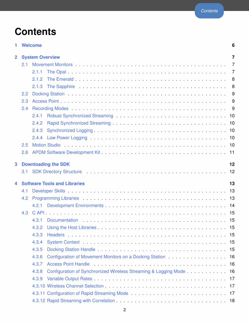
Contents
Contents1 Welcome 6
2 System Overview 7
2.1 Movement Monitors . . . . . . . . . . . . . . . . . . . . . . . . . . . . . . . . . . . . . . . . . 7
2.1.1 The Opal . . . . . . . . . . . . . . . . . . . . . . . . . . . . . . . . . . . . . . . . . . . 7
2.1.2 The Emerald . . . . . . . . . . . . . . . . . . . . . . . . . . . . . . . . . . . . . . . . . 8
2.1.3 The Sapphire . . . . . . . . . . . . . . . . . . . . . . . . . . . . . . . . . . . . . . . . 8
2.2 Docking Station . . . . . . . . . . . . . . . . . . . . . . . . . . . . . . . . . . . . . . . . . . . 9
2.3 Access Point . . . . . . . . . . . . . . . . . . . . . . . . . . . . . . . . . . . . . . . . . . . . . 9
2.4 Recording Modes . . . . . . . . . . . . . . . . . . . . . . . . . . . . . . . . . . . . . . . . . . 9
2.4.1 Robust Synchronized Streaming . . . . . . . . . . . . . . . . . . . . . . . . . . . . . . 10
2.4.2 Rapid Synchronized Streaming . . . . . . . . . . . . . . . . . . . . . . . . . . . . . . . 10
2.4.3 Synchronized Logging . . . . . . . . . . . . . . . . . . . . . . . . . . . . . . . . . . . . 10
2.4.4 Low Power Logging . . . . . . . . . . . . . . . . . . . . . . . . . . . . . . . . . . . . . 10
2.5 Motion Studio . . . . . . . . . . . . . . . . . . . . . . . . . . . . . . . . . . . . . . . . . . . . 10
2.6 APDM Software Development Kit . . . . . . . . . . . . . . . . . . . . . . . . . . . . . . . . . . 11
3 Downloading the SDK 12
3.1 SDK Directory Structure . . . . . . . . . . . . . . . . . . . . . . . . . . . . . . . . . . . . . . 12
4 Software Tools and Libraries 13
4.1 Developer Skills . . . . . . . . . . . . . . . . . . . . . . . . . . . . . . . . . . . . . . . . . . . 13
4.2 Programming Libraries . . . . . . . . . . . . . . . . . . . . . . . . . . . . . . . . . . . . . . . 13
4.2.1 Development Environments . . . . . . . . . . . . . . . . . . . . . . . . . . . . . . . . . 14
4.3 C API . . . . . . . . . . . . . . . . . . . . . . . . . . . . . . . . . . . . . . . . . . . . . . . . . 15
4.3.1 Documentation . . . . . . . . . . . . . . . . . . . . . . . . . . . . . . . . . . . . . . . 15
4.3.2 Using the Host Libraries . . . . . . . . . . . . . . . . . . . . . . . . . . . . . . . . . . . 15
4.3.3 Headers . . . . . . . . . . . . . . . . . . . . . . . . . . . . . . . . . . . . . . . . . . . 15
4.3.4 System Context . . . . . . . . . . . . . . . . . . . . . . . . . . . . . . . . . . . . . . . 15
4.3.5 Docking Station Handle . . . . . . . . . . . . . . . . . . . . . . . . . . . . . . . . . . . 15
4.3.6 Configuration of Movement Monitors on a Docking Station . . . . . . . . . . . . . . . . 16
4.3.7 Access Point Handle . . . . . . . . . . . . . . . . . . . . . . . . . . . . . . . . . . . . 16
4.3.8 Configuration of Synchronized Wireless Streaming & Logging Mode . . . . . . . . . . . 16
4.3.9 Variable Output Rates . . . . . . . . . . . . . . . . . . . . . . . . . . . . . . . . . . . . 17
4.3.10 Wireless Channel Selection . . . . . . . . . . . . . . . . . . . . . . . . . . . . . . . . . 17
4.3.11 Configuration of Rapid Streaming Mode . . . . . . . . . . . . . . . . . . . . . . . . . . 17
4.3.12 Rapid Streaming with Correlation . . . . . . . . . . . . . . . . . . . . . . . . . . . . . . 18
2
Contents
4.3.13 Rapid Streaming without Correlation . . . . . . . . . . . . . . . . . . . . . . . . . . . . 18
4.3.14 Persisting Configurations to Disk . . . . . . . . . . . . . . . . . . . . . . . . . . . . . . 18
4.3.15 Configuration of Synchronized Logging Mode . . . . . . . . . . . . . . . . . . . . . . . 19
4.3.16 Configuration of Low Power Logging Mode . . . . . . . . . . . . . . . . . . . . . . . . 19
4.3.17 Storing streaming data in HDF5 or CSV format . . . . . . . . . . . . . . . . . . . . . . 19
4.3.18 Converting .apdm files to HDF5 or CSV . . . . . . . . . . . . . . . . . . . . . . . . . . 19
4.3.19 Return Codes . . . . . . . . . . . . . . . . . . . . . . . . . . . . . . . . . . . . . . . . 20
4.3.20 Logging . . . . . . . . . . . . . . . . . . . . . . . . . . . . . . . . . . . . . . . . . . . 20
4.3.21 Threading . . . . . . . . . . . . . . . . . . . . . . . . . . . . . . . . . . . . . . . . . . 20
4.4 Wireless Buffering and Data Correlation . . . . . . . . . . . . . . . . . . . . . . . . . . . . . . 20
4.4.1 Max Delay / Max Latency . . . . . . . . . . . . . . . . . . . . . . . . . . . . . . . . . . 21
4.5 Real-time Systems . . . . . . . . . . . . . . . . . . . . . . . . . . . . . . . . . . . . . . . . . 22
4.6 Timing and Protocol Properties . . . . . . . . . . . . . . . . . . . . . . . . . . . . . . . . . . . 22
4.7 DLL’s, DYLIB’s and SO’s . . . . . . . . . . . . . . . . . . . . . . . . . . . . . . . . . . . . . . 23
4.7.1 Java . . . . . . . . . . . . . . . . . . . . . . . . . . . . . . . . . . . . . . . . . . . . . 24
4.7.2 Other Systems . . . . . . . . . . . . . . . . . . . . . . . . . . . . . . . . . . . . . . . . 24
4.7.3 External Sync . . . . . . . . . . . . . . . . . . . . . . . . . . . . . . . . . . . . . . . . 24
5 External Synchronization 25
5.1 Synchronization Overview . . . . . . . . . . . . . . . . . . . . . . . . . . . . . . . . . . . . . 25
5.2 Synchronization Hardware . . . . . . . . . . . . . . . . . . . . . . . . . . . . . . . . . . . . . 25
5.3 Configuration . . . . . . . . . . . . . . . . . . . . . . . . . . . . . . . . . . . . . . . . . . . . 27
5.3.1 Input Trigger Shape . . . . . . . . . . . . . . . . . . . . . . . . . . . . . . . . . . . . . 27
5.3.2 Input Trigger Level . . . . . . . . . . . . . . . . . . . . . . . . . . . . . . . . . . . . . . 28
5.4 Input Synchronization . . . . . . . . . . . . . . . . . . . . . . . . . . . . . . . . . . . . . . . . 28
5.4.1 Input Trigger . . . . . . . . . . . . . . . . . . . . . . . . . . . . . . . . . . . . . . . . . 28
5.4.2 Sample Selection with External Input Trigger Events . . . . . . . . . . . . . . . . . . . 28
5.4.3 Annotation of Externally Triggered Recordings . . . . . . . . . . . . . . . . . . . . . . 29
5.4.4 Output Trigger Shape . . . . . . . . . . . . . . . . . . . . . . . . . . . . . . . . . . . . 29
5.4.5 Output Trigger Level . . . . . . . . . . . . . . . . . . . . . . . . . . . . . . . . . . . . . 29
5.5 Output Synchronization . . . . . . . . . . . . . . . . . . . . . . . . . . . . . . . . . . . . . . . 29
5.5.1 Output Trigger . . . . . . . . . . . . . . . . . . . . . . . . . . . . . . . . . . . . . . . . 30
5.6 Schematics . . . . . . . . . . . . . . . . . . . . . . . . . . . . . . . . . . . . . . . . . . . . . 30
6 Programming Examples 31
6.1 Example Code Provided with the SDK . . . . . . . . . . . . . . . . . . . . . . . . . . . . . . . 31
6.2 Simple Configuration and Streaming Example . . . . . . . . . . . . . . . . . . . . . . . . . . . 31
6.2.1 High Level Psuedocode . . . . . . . . . . . . . . . . . . . . . . . . . . . . . . . . . . . 31
6.2.2 C Programming Example . . . . . . . . . . . . . . . . . . . . . . . . . . . . . . . . . . 32
3
Contents
6.2.3 Java Programming Example . . . . . . . . . . . . . . . . . . . . . . . . . . . . . . . . 34
6.2.4 Matlab Programming Examples . . . . . . . . . . . . . . . . . . . . . . . . . . . . . . 38
7 Working with HDF5 Files 39
7.1 HDFView . . . . . . . . . . . . . . . . . . . . . . . . . . . . . . . . . . . . . . . . . . . . . . . 39
7.2 Python . . . . . . . . . . . . . . . . . . . . . . . . . . . . . . . . . . . . . . . . . . . . . . . . 39
7.3 Data Organization . . . . . . . . . . . . . . . . . . . . . . . . . . . . . . . . . . . . . . . . . . 39
7.4 File Structure . . . . . . . . . . . . . . . . . . . . . . . . . . . . . . . . . . . . . . . . . . . . 39
7.4.1 Version 5 . . . . . . . . . . . . . . . . . . . . . . . . . . . . . . . . . . . . . . . . . . . 40
7.4.2 Versions 3 and 4 . . . . . . . . . . . . . . . . . . . . . . . . . . . . . . . . . . . . . . . 41
7.4.3 Version 3 . . . . . . . . . . . . . . . . . . . . . . . . . . . . . . . . . . . . . . . . . . . 42
7.4.4 Version 2 . . . . . . . . . . . . . . . . . . . . . . . . . . . . . . . . . . . . . . . . . . . 44
7.4.5 Version 1 . . . . . . . . . . . . . . . . . . . . . . . . . . . . . . . . . . . . . . . . . . . 45
7.5 Working with HDF 5 in MATLAB . . . . . . . . . . . . . . . . . . . . . . . . . . . . . . . . . . 46
7.5.1 Matlab, hdf5read, Version 4 of APDM’s HDF format . . . . . . . . . . . . . . . . . . . . 46
7.5.2 Matlab, h5read, Version 5 of APDM’s HDF format . . . . . . . . . . . . . . . . . . . . . 48
7.5.3 Notes . . . . . . . . . . . . . . . . . . . . . . . . . . . . . . . . . . . . . . . . . . . . . 48
7.6 Working with HDF 5 in Python . . . . . . . . . . . . . . . . . . . . . . . . . . . . . . . . . . . 49
8 Calibration 50
8.1 File Format . . . . . . . . . . . . . . . . . . . . . . . . . . . . . . . . . . . . . . . . . . . . . 50
8.2 Data Format . . . . . . . . . . . . . . . . . . . . . . . . . . . . . . . . . . . . . . . . . . . . . 51
8.2.1 Calibration version 5 . . . . . . . . . . . . . . . . . . . . . . . . . . . . . . . . . . . . . 51
9 Firmware Updates 55
9.1 Automatic Firmware Updates . . . . . . . . . . . . . . . . . . . . . . . . . . . . . . . . . . . . 55
9.2 Manual Firmware Updates . . . . . . . . . . . . . . . . . . . . . . . . . . . . . . . . . . . . . 55
9.2.1 Flash Default Firmware . . . . . . . . . . . . . . . . . . . . . . . . . . . . . . . . . . . 55
9.2.2 Flash Alternate Firmware . . . . . . . . . . . . . . . . . . . . . . . . . . . . . . . . . . 55
9.2.3 Force Update . . . . . . . . . . . . . . . . . . . . . . . . . . . . . . . . . . . . . . . . 55
10 Movement Monitor Reference 56
10.1 Charging . . . . . . . . . . . . . . . . . . . . . . . . . . . . . . . . . . . . . . . . . . . . . . . 56
10.2 Powering Down . . . . . . . . . . . . . . . . . . . . . . . . . . . . . . . . . . . . . . . . . . . 56
10.3 Data Storage . . . . . . . . . . . . . . . . . . . . . . . . . . . . . . . . . . . . . . . . . . . . 56
10.4 Cleaning . . . . . . . . . . . . . . . . . . . . . . . . . . . . . . . . . . . . . . . . . . . . . . . 56
10.5 Storage . . . . . . . . . . . . . . . . . . . . . . . . . . . . . . . . . . . . . . . . . . . . . . . 57
10.6 Drivers . . . . . . . . . . . . . . . . . . . . . . . . . . . . . . . . . . . . . . . . . . . . . . . . 57
10.7 Firmware Updates . . . . . . . . . . . . . . . . . . . . . . . . . . . . . . . . . . . . . . . . . . 57
4
Contents
10.8 Technical Specifications . . . . . . . . . . . . . . . . . . . . . . . . . . . . . . . . . . . . . . . 57
10.9 LED Reference . . . . . . . . . . . . . . . . . . . . . . . . . . . . . . . . . . . . . . . . . . . 58
10.9.1 Status Codes and LED Colors/Patterns . . . . . . . . . . . . . . . . . . . . . . . . . . 58
10.9.2 Movement Monitor LED Reference . . . . . . . . . . . . . . . . . . . . . . . . . . . . . 58
10.10Technical Drawing . . . . . . . . . . . . . . . . . . . . . . . . . . . . . . . . . . . . . . . . . . 61
11 Access Point Reference 62
11.1 Drivers . . . . . . . . . . . . . . . . . . . . . . . . . . . . . . . . . . . . . . . . . . . . . . . . 62
11.2 Firmware Updates . . . . . . . . . . . . . . . . . . . . . . . . . . . . . . . . . . . . . . . . . . 62
11.3 Mounting and Placement . . . . . . . . . . . . . . . . . . . . . . . . . . . . . . . . . . . . . . 62
11.4 Using Multiple Access Points . . . . . . . . . . . . . . . . . . . . . . . . . . . . . . . . . . . . 62
11.4.1 Redundancy . . . . . . . . . . . . . . . . . . . . . . . . . . . . . . . . . . . . . . . . . 62
11.4.2 Streaming from more than 6 Opals . . . . . . . . . . . . . . . . . . . . . . . . . . . . . 62
11.5 LED Reference . . . . . . . . . . . . . . . . . . . . . . . . . . . . . . . . . . . . . . . . . . . 63
11.6 Mechanical and Electrical Specifications . . . . . . . . . . . . . . . . . . . . . . . . . . . . . . 63
11.7 Technical Drawing . . . . . . . . . . . . . . . . . . . . . . . . . . . . . . . . . . . . . . . . . . 64
12 Docking Station Reference 65
12.1 Drivers . . . . . . . . . . . . . . . . . . . . . . . . . . . . . . . . . . . . . . . . . . . . . . . . 65
12.2 Power . . . . . . . . . . . . . . . . . . . . . . . . . . . . . . . . . . . . . . . . . . . . . . . . 65
12.3 Mechanical and Electrical Specifications . . . . . . . . . . . . . . . . . . . . . . . . . . . . . . 65
12.4 LED Reference . . . . . . . . . . . . . . . . . . . . . . . . . . . . . . . . . . . . . . . . . . . 66
12.5 Technical Drawing . . . . . . . . . . . . . . . . . . . . . . . . . . . . . . . . . . . . . . . . . . 67
13 Technical Support 68
5

1 Welcome
1 WelcomeThe following documentation will guide you through understanding the architecture of the system and how
to use it as a developer. The core SDK documentation will focus on the C language implementation utilizing
a dynamically linked library. Other language bindings such as Java will be documented as well. For the C
language or any language binding not provided it is assumed that the end user should know how to properly
load the dynamically linked library and call its functions using the correct calling convention. Most of the
documentation will use a cross platform approach with specific platform specific notes if needed. Example
code will be provided for all included language bindings to assist in getting the user up and running.
6
2 System Overview
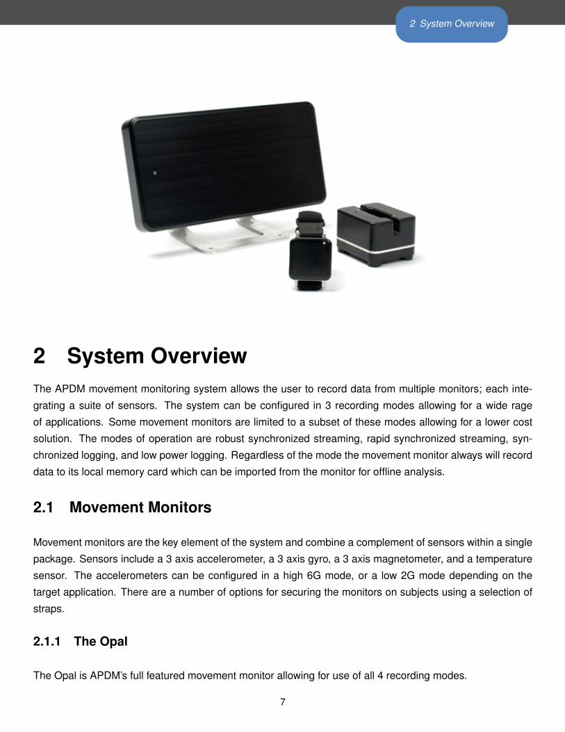
2 System OverviewThe APDM movement monitoring system allows the user to record data from multiple monitors; each inte-
grating a suite of sensors. The system can be configured in 3 recording modes allowing for a wide rage
of applications. Some movement monitors are limited to a subset of these modes allowing for a lower cost
solution. The modes of operation are robust synchronized streaming, rapid synchronized streaming, syn-
chronized logging, and low power logging. Regardless of the mode the movement monitor always will record
data to its local memory card which can be imported from the monitor for offline analysis.
2.1 Movement Monitors
Movement monitors are the key element of the system and combine a complement of sensors within a single
package. Sensors include a 3 axis accelerometer, a 3 axis gyro, a 3 axis magnetometer, and a temperature
sensor. The accelerometers can be configured in a high 6G mode, or a low 2G mode depending on the
target application. There are a number of options for securing the monitors on subjects using a selection of
straps.
2.1.1 The Opal
The Opal is APDM’s full featured movement monitor allowing for use of all 4 recording modes.
7
2 System Overview
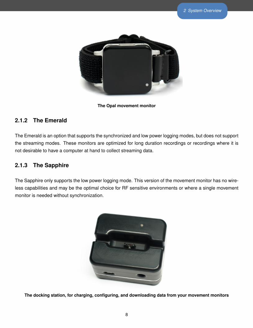
The Opal movement monitor
2.1.2 The Emerald
The Emerald is an option that supports the synchronized and low power logging modes, but does not support
the streaming modes. These monitors are optimized for long duration recordings or recordings where it is
not desirable to have a computer at hand to collect streaming data.
2.1.3 The Sapphire
The Sapphire only supports the low power logging mode. This version of the movement monitor has no wire-
less capabilities and may be the optimal choice for RF sensitive environments or where a single movement
monitor is needed without synchronization.
The docking station, for charging, configuring, and downloading data from your movement monitors
8
2 System Overview
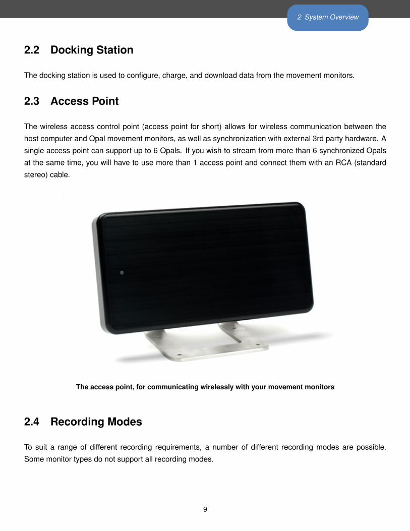
2.2 Docking Station
The docking station is used to configure, charge, and download data from the movement monitors.
2.3 Access Point
The wireless access control point (access point for short) allows for wireless communication between the
host computer and Opal movement monitors, as well as synchronization with external 3rd party hardware. A
single access point can support up to 6 Opals. If you wish to stream from more than 6 synchronized Opals
at the same time, you will have to use more than 1 access point and connect them with an RCA (standard
stereo) cable.
The access point, for communicating wirelessly with your movement monitors
2.4 Recording Modes
To suit a range of different recording requirements, a number of different recording modes are possible.
Some monitor types do not support all recording modes.
9
2 System Overview
2.4.1 Robust Synchronized Streaming
In the robust synchronized streaming mode, you can stream data from multiple, synchronized monitors di-
rectly to your computer. Data is buffered on the monitors, so no data is lost even if there are interruptions in
the wireless signal. Only the Opals can be used in this mode.
2.4.2 Rapid Synchronized Streaming
The rapid synchronized streaming mode is similar to the robust synchronized streaming mode, except data
is not buffered on the monitors in order to minimize the latency of the streaming data. Latency on Linux and
Mac OS is typically in the range of 8ms to 25ms, while latency on Windows is typically in the range of 10ms
to 75ms. This recording mode is appropriate for biofeedback applications. In the event of interruptions in the
wireless signal, data will be dropped from the steram. Only the Opals can be used in this mode.
2.4.3 Synchronized Logging
In the synchronized logging mode, monitors log recorded data to their on-board flash memory. The monitors
are synchronized wirelessly with each other while recording, so the individual logs can easily be synchronized
with each other after the data has been imported from your monitor(s). In this mode, up to 24 monitors can
be synchronized within a single “mesh”. Only Emeralds and Opals are able to use this mode.
2.4.4 Low Power Logging
All movement monitor products (Opals, Emeralds, and Sapphires) are able to operate in the low power
logging mode. In this mode, the monitors’ wireless radios are disabled, decreasing the power required for
operation and enabling the monitors to run for longer periods of time. Since the mode does not use any
wireless synchronization, each movement monitor will collect data independently and potentially at slightly
different rates due to clock drift.
2.5 Motion Studio
Motion Studio is the default software suite bundled with the APDM movement monitor system. It provides an
easy way to get up and running collecting data with your movement monitors.
10
2 System Overview
2.6 APDM Software Development Kit
The APDM Software Development Kit (SDK) provides programming tools for software developers. These
tools enable developers to write their own software capable of configuring and streaming data from the
movement monitors. In addition, it also provides functions for converting the raw data files found on the
monitor’s memory card into either a HDF5 (recommended) format or CSV. The SDK provides the same low
level interface to the hardware that Motion Studio is built upon.
11
3 Downloading the SDK
3 Downloading the SDKTo obtain the latest version of the SDK, download the following archive:
http://share.apdm.com/libraries/release/apdm_sdk.zip
and unzip it to your desired location.
3.1 SDK Directory Structure
The SDK contains a number of folders useful to the developer. Their descriptions are as follows:
/doc Documentation for users, developers guide and API references.
/include Header files to be included in C or C++ applications.
/libs Libraries (DLL’s, SO’s, DYLIBS’s) to be dynamically loaded into applications providing pro-
grammatic access to the hardware.
/samples Sample applications in C, Java and Matlab utilizing the libraries.
/Java Java APIs for programmatic access to hardware
/Matlab Matlab prototypes allowing for access to DLL’s, SO’s or DYLIBS’s
12
4 Software Tools and Libraries
4 Software Tools and Libraries
4.1 Developer Skills
Use of the SDK will require some basic development skills:
• Loading, using, and unloading dynamic libraries (DLL’s, SO’s, DYLIB’s).
• Proficiency in the target language or development environment.
• General understanding of error handling strategies, in particular, return error codes and/or exceptions
in languages that support exceptions.
• General understanding of memory management (allocation, deallocation).
• General understanding of API usage (initialization, usage, teardown).
• General understanding of the differences between bandwidth and latency as it relates to sampled data.
4.2 Programming Libraries
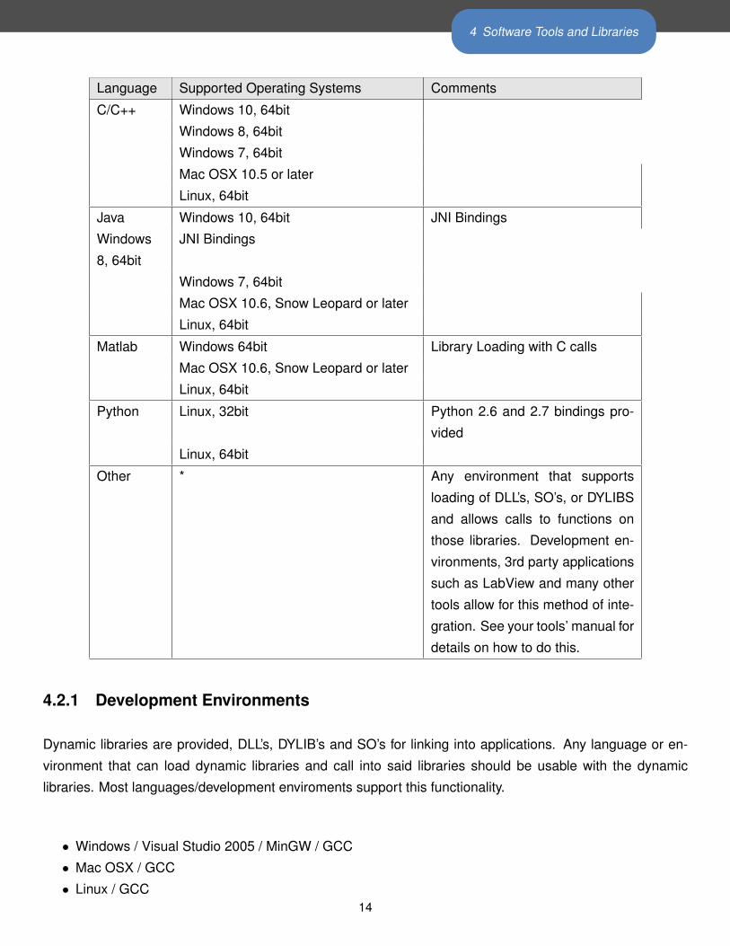
APDM provides programming libraries to allow integration on the following operating systems and versions:
13
4 Software Tools and Libraries
Language Supported Operating Systems Comments
C/C++ Windows 10, 64bit
Windows 8, 64bit
Windows 7, 64bit
Mac OSX 10.5 or later
Linux, 64bit
Java Windows 10, 64bit JNI Bindings
Windows
8, 64bit
JNI Bindings
Windows 7, 64bit
Mac OSX 10.6, Snow Leopard or later
Linux, 64bit
Matlab Windows 64bit Library Loading with C calls
Mac OSX 10.6, Snow Leopard or later
Linux, 64bit
Python Linux, 32bit Python 2.6 and 2.7 bindings pro-
vided
Linux, 64bit
Other * Any environment that supports
loading of DLL’s, SO’s, or DYLIBS
and allows calls to functions on
those libraries. Development en-
vironments, 3rd party applications
such as LabView and many other
tools allow for this method of inte-
gration. See your tools’ manual for
details on how to do this.
4.2.1 Development Environments
Dynamic libraries are provided, DLL’s, DYLIB’s and SO’s for linking into applications. Any language or en-
vironment that can load dynamic libraries and call into said libraries should be usable with the dynamic
libraries. Most languages/development enviroments support this functionality.
• Windows / Visual Studio 2005 / MinGW / GCC
• Mac OSX / GCC
• Linux / GCC14
4 Software Tools and Libraries
4.3 C API
4.3.1 Documentation
Included in the APDM software distribution is function API documentation, including descriptions of functions
purpose, parameters and return values. This can be found under “docs” in the software distribution.
4.3.2 Using the Host Libraries
The host libraries allow you to create handles to any given access point or docking station attached to the
system. With an AP handle or docking station handle, you can query the given device for information, and
send configuration commands to the given device. If there is an movement monitor attached to a docking
station, then you can also send commands to the movement monitor through the docking station handle.
4.3.3 Headers
Two headers will be necessary to include in your project, apdm.h and apdm_types.h.
4.3.4 System Context
The host libraries provide the notion of a system context. A context is a logical collection of access points
and docking stations (movement monitors attached therein) that can be configured as a group and work
in concert with each other. The context allows you to correctly configure wireless channels and redundant
wireless streaming AP’s, as well as provide correlation of the samples sent out by all the sensors (correlation
in time by sync value).
The data type used for a context is: apdm_ctx_t
and can be allocated with the apdm_ctx_allocate_new_context() function, and freed with the
apdm_ctx_free_context() function .
4.3.5 Docking Station Handle
The data type used for a docking station handle is: apdm_device_handle_t
The easiest way to create a handle is to use the apdm_sensor_allocate_and_open() function, pass-
15
4 Software Tools and Libraries
ing in the index of the given docking station number that you want a handle on. Similarly, calling the
apdm_sensor_close_and_free_handle() function to cleanly close the handle and free it’s respective mem-
ory.
4.3.6 Configuration of Movement Monitors on a Docking Station
The host libraries contain a number of functions, starting with apdm_sensor_cmd_XXXX() that are used to
configure movement monitors. Settings such as sampling rates, enabling and disabling different sensors,
configuration of wireless parameters etc can be done using thees function calls. See low level API documen-
tation for details on these commands.
4.3.7 Access Point Handle
The data type used for an access point handle is: apdm_ap_handle_t
An AP handle can be allocated with the apdm_allocate_ap_handle() function, freed with the
apdm_free_ap_handle() function. Once a handle is allocated, you can open a given access point by index
using the apdm_ap_connect() function. Once you’ve connected, you can then send commands to the AP
and query the AP for information using AP specific functions.
Access Point specific functions are of the form with apdm_ap_XXXX().
4.3.8 Configuration of Synchronized Wireless Streaming & Logging Mode
The host libraries provide a function apdm_autoconfigure_devices_and_accesspoint4() that can be
used to configure a group of AP’s and movement monitors for streaming mode. After a context has been al-
located and initialized, and the apdm_ctx_open_all_access_points() function has been called with the re-
spective context, you can call auto configure to configure the system. Once the system is configured, you can
disconnect the movement monitors from the docking station to allow them to stream data, and begin to use
the apdm_ctx_get_next_access_point_record_list() and apdm_ctx_extract_data_by_device_id()
functions to stream data.
The maximum number of movement monitors in a single configuration is 36
The maximum number of access points in a single configuration is 6
16
4 Software Tools and Libraries
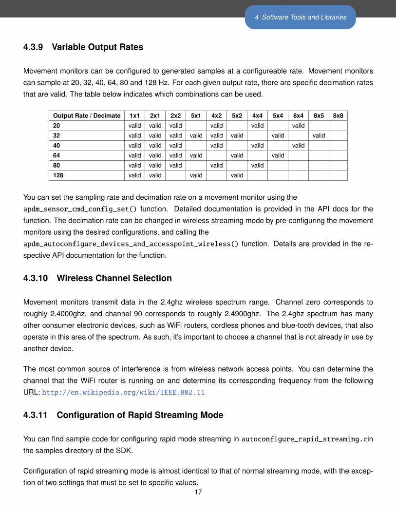
4.3.9 Variable Output Rates
Movement monitors can be configured to generated samples at a configureable rate. Movement monitors
can sample at 20, 32, 40, 64, 80 and 128 Hz. For each given output rate, there are specific decimation rates
that are valid. The table below indicates which combinations can be used.
Output Rate / Decimate 1x1 2x1 2x2 5x1 4x2 5x2 4x4 5x4 8x4 8x5 8x8
20 valid valid valid valid valid valid
32 valid valid valid valid valid valid valid valid
40 valid valid valid valid valid valid
64 valid valid valid valid valid valid
80 valid valid valid valid valid
128 valid valid valid valid
You can set the sampling rate and decimation rate on a movement monitor using the
apdm_sensor_cmd_config_set() function. Detailed documentation is provided in the API docs for the
function. The decimation rate can be changed in wireless streaming mode by pre-configuring the movement
monitors using the desired configurations, and calling the
apdm_autoconfigure_devices_and_accesspoint_wireless() function. Details are provided in the re-
spective API documentation for the function.
4.3.10 Wireless Channel Selection
Movement monitors transmit data in the 2.4ghz wireless spectrum range. Channel zero corresponds to
roughly 2.4000ghz, and channel 90 corresponds to roughly 2.4900ghz. The 2.4ghz spectrum has many
other consumer electronic devices, such as WiFi routers, cordless phones and blue-tooth devices, that also
operate in this area of the spectrum. As such, it’s important to choose a channel that is not already in use by
another device.
The most common source of interference is from wireless network access points. You can determine the
channel that the WiFi router is running on and determine its corresponding frequency from the following
URL: http://en.wikipedia.org/wiki/IEEE_802.11
4.3.11 Configuration of Rapid Streaming Mode
You can find sample code for configuring rapid mode streaming in autoconfigure_rapid_streaming.cin
the samples directory of the SDK.
Configuration of rapid streaming mode is almost identical to that of normal streaming mode, with the excep-
tion of two settings that must be set to specific values.17
4 Software Tools and Libraries
To configure rapid streaming mode, call the apdm_ctx_autoconfigure_devices_and_accesspoint5()
function, making sure to set ‘decimation_rate’ to ‘APDM_DECIMATE_1x1’ , and ‘enable_sd_card’ to
‘false’.
There are two variants of rapid streaming mode. The first uses the correlation code provided by APDM, which
will emit sets of correlated samples, and deal with duplicate transmissions or cases where opals switch from
one AP to a second. From the perspective of the application, this will be identical to other normal modes
of streaming. The second mode, which will remove some additional latency (on the order of 5ms to 10ms),
retrieves individual samples as soon as they are available on the AP. However, in this mode of operation, the
application will have to deal with duplicate samples and gaps in the data if transient wireless/RF problems
occur.
4.3.12 Rapid Streaming with Correlation
This mode of operation is identical to normal streaming mode, with the exception of configuring the system
to disable the SD card and to set the decimation rate to ‘APDM-DECIMATE_1x1’.
4.3.13 Rapid Streaming without Correlation
This mode of operation requires slightly different library interfacing function calls. Example code can be
found in stream_data_rapid.c in the samples directory of the SDK. The basic function call sequence is as
follows:
apdm_ctx_allocate_new_context()
apdm_ctx_open_all_access_points()
apdm_ctx_flush_ap_fifos()
apdm_ctx_extract_next_sample() (called many times)
apdm_ctx_disconnect(context)
apdm_ctx_free_context(context)
4.3.14 Persisting Configurations to Disk
When streaming, after auto configuration, the configuration of the AP’s and all the Opals can be persisted to
disk, such that at a later time (after restarting a system for example), the configuration can be re-read from
disk, re-applied to the AP’s, and streaming can be started again without having to go thru autoconfiguration.
The apdm_ctx_persist_context_to_disk() function and the apdm_ctx_restore_context_from_disk()
functions allow you to do this. An example of auto configuration with persisting to disk can be found in18
4 Software Tools and Libraries
autoconfigure_system.c in the examples directory of the SDK. An example of streaming data utilizing a
persisted context can be found in stream_data_recover_context.c in the examples directory of the SDK.
4.3.15 Configuration of Synchronized Logging Mode
The host libraries provide a function, apdm_autoconfigure_mesh_sync()that will allow you to configure all
movement monitors attached to the host in mesh time synchronization and data logging mode.
In synchronized logging mode, the movement monitors will transmit and receive their current time values, to
and from each other such that their internal clocks all maintain the same notion of time.
There can be a maximum of 24 devices used in synchronized logging mode.
4.3.16 Configuration of Low Power Logging Mode
Low power logging mode consists of enabling/disabling the sensors of interest on the movement monitor, and
disabling wireless. Wireless can be disabled with a call to apdm_sensor_cmd_config_set() and passing in
CONFIG_ENABLE_WIRELESS and a value of 0.
4.3.17 Storing streaming data in HDF5 or CSV format
In addition to streaming data into an application, functionality exists to stream data to a .h5 file or a .csv file.
The basic process is as follows:
1. Create a file with apdm_create_file_hdf() or apdm_create_file_csv().
2. Get the device info structure for each device that’s streaming using the
apdm_sensor_populate_device_info() function.
3. Pass an array of records and device info structures to the apdm_write_record_hdf() or
apdm_write_record_csv() function for each new sample.
4. Close the data file with apdm_close_file_hdf() or apdm_close_file_csv() when done.
4.3.18 Converting .apdm files to HDF5 or CSV
Data stored on the movement monitor is in a binary .apdm format. APDM libraries provide functionality
to convert this data to a more usable format, apply calibration to the raw data, and generate orientation
estimates. apdm_process_raw() is used to convert .apdm files to HDF5 or CSV. Raw data can also be
optionally stored in the output format. To convert a raw data, first locate the .apdm files you wish to convert
in the filesystem. Only one .apdm file for each monitor can be converted, but files from multiple monitors
can be combined into a single output file. Files will appear in the filesystem of the host operating system19
4 Software Tools and Libraries
while docked as removable storage drives with names corresponding. Then call apdm_convert_raw()with
an array of the .apdm filenames. You can specify the output file and output file format. Calibration files do
not need to be specified. Calibration data is stored in the raw .apdm files and will be used in the conversion
process.
4.3.19 Return Codes
Most library functions return a value of type int, which has a value from enumAPDM_Status (defined in
apdm_types.h), which indicates success or failure code of the given function that was called. A convenience
function, apdm_strerror() is provided for converting these error codes to strings if necessary. Refer to
function specific documentation for the details of each function.
4.3.20 Logging
The APDM libraries have logging information that is generated at various points of it’s internal processing.
Each log event that occurs has a specified severity, all logging funnels through a single piece of common
infrastructure. By default, log messages are sent to STDOUT, but by calling apdm_set_log_file() you can
re-direct logging output to a file.
4.3.21 Threading
The APDM host libraries are not thread safe. Thread safety, synchronization and enforcement of mutual
exclusion are left up to the application in which the libraries are to be used.
4.4 Wireless Buffering and Data Correlation
In wireless streaming mode, the system utilizes numerous levels of buffering, including on-device buffering,
in access point buffering, and buffering in the host libraries. There are many reasons that this buffing is
necessary, including temporary wireless issues, scenarios where the host application does not retrieve data
from the access point and times when the application wants to wait a short amount of time for a movement
monitor to retransmit data after the wireless issues pass.
Due to the hardware level properties of the system, it becomes necessary to process data from sensors and
access points knowing about potential transient problems at the hardware level. Some of the issues include
the following:
• Duplicate data transmission by a sensor to one or more access points in the event that the sensor does
not receive the ACK from the access point
20
4 Software Tools and Libraries
• Variable delay in the relative streams of data from the movement sensors. e.g. one sensor may be
transmitting data that is older then then the other sensors while it is catching up from a transient wireless
problem.
• Missing data from a sensor, in the event that the sensor is turned off, or goes out of range for an
extended period of time.
By in large, when the system context is used for streaming data, it will resolve these issues prior to emitting
data from the libraries. There are some configuration parameters that will affect the behavior of the libraries
with regard to timing and potentially missing data.
apdm_ctx_sync_record_list_head()
Before the application begins to received data, it should call the apdm_ctx_sync_record_list_head()
function. This will cause the host libraries and access point to clear out all it’s buffers, stream in a few
samples such that a subsequent call to apdm_ctx_get_next_access_point_record_list() will return a
full sample set, with data from all sensors in the system.
If this function is not called, you may get old data, or partial sets of data from a call to
apdm_ctx_get_next_access_point_record_list()
4.4.1 Max Delay / Max Latency
During auto configuration, and via library calls to apdm_ctx_set_max_sample_delay_seconds() you can
specify the maximum amount of time to wait for sample(s) to be re-transmitted from an movement sensor.
This setting has some important implications with regards to data reliability and the latency of data by the
time it’s received by the user application.
• If a movement monitor is unable to transmit samples to an access point, the host libraries will stall their
data output, waiting until max-latency seconds elapse, before giving up and emitting a partial sample
set. E.G. If there are 6 sensors configured, and one of them is unable to transmit, the libraries will emit
5 samples, and indicate that they have missed the 6th sample.
• For as long as the given sensor is having problems transmitting, the host libraries will continue to delay
outputting of data until the max-latency threshold for data age has elapses. So, if you have max-latency
set to 15 seconds, and a sensor goes out of range, you’ll find an initial pause of 15 seconds while the
max-latency period elapses, then you will continue to receive data from the libraries, but as long as the
sensor cannot transmit, the data will be 15 seconds old.
21
4 Software Tools and Libraries
• The default max-latency setting is 15 seconds
4.5 Real-time Systems
The phrase ”realtime” is a context sensitive phrase, which according to Wikipedia has a few dozen meanings
depending on when and where it’s used (http://en.wikipedia.org/wiki/Real-time). As it applies to
data streaming and possible uses of opals, there are two classes that will need to be distinguished.
1. The computer science definition, where real-time refers to a system that has hard timing deadlines,
which if not meet, will cause the system to behave in an undesirable manor or fail outright.
(see http://en.wikipedia.org/wiki/Real-time_computing)
2. The end-user description, which often means ”really fast”, or ”fast enough that a human cannot notice
the latency”. In this context, the consequences of not satisfying the timing requirements are no more
then an annoyance to the end user. This is often the case with strip-charting of data, or on screen visual
feedback to a user.
The engineering techniques used to solve the two classes of problems above are significantly different.
In the case of an end-user real-time system, it’s fairly simple. Almost all mainstream operating systems and
hardware are capable of operating fast enough, and with low enough latency, to satisfy what a human can
notice with timing.
In the case of a hard real time system, it requires an operating system or embedded system that is capable
of providing timing guarantees. This is not a normal operating system such as Windows or Mac OS. With
the appropriate configuration, Linux can provide real-time functionality. There are many real-time operating
systems in existence
(see http://en.wikipedia.org/wiki/List_of_real-time_operating_systems). With respect to sup-
ported operating systems, Linux is the only operating system, also supporting real-time features, that can
be used with APDM hardware. If your intention is to use opals as sensor data to control something in
real time, you will likely find the subject of ”closed loop feedback control systems” to be useful (http:
//en.wikipedia.org/wiki/Control_theory).
4.6 Timing and Protocol Properties
If APDM hardware is to be used in a hard real-time system, the developer must understand exactly what
timing properties are provided by the APDM software/hardware stack.
1. The USB bus was not intended to be used in hard real time systems. However, depending on the
22
4 Software Tools and Libraries
requirements of the problem at hand, the USB bus may be good enough if the limitations of the bus are
taken into account in the application.
2. Transfers between the host and the access point are done via USB bulk transfers. Bulk transfers
provided guaranteed delivery, but not guaranteed timing. In general, on a Linux machine, it takes 1ms
to 2ms to do a transfer from the AP to the host computer. This 1ms to 2ms is not guaranteed however,
due to the underlying properties of USB bulk transfers. There are some things that can be done to
increase the probability of transfers falling into this latency range, such as making sure that each AP is
on it’s own root hub of the host.
3. The issue of late data, or missing data all together, is not limited to USB. In fact, almost all buses
can have some scenario in which data will be late and/or not get to the recipient. In buses that are
designed for critical controls, this tends to be due to hardware failures (electrical problem on the bus,
broken wires, bad bus transceiver etc). In all cases, the application should handle this in a manor that
is reasonable and appropriate for the problem at hand.
4. The opals are transmitting data in the 2.40-2.49 GHz wireless spectrum. There are many devices that
operate in this frequency range that can cause interference and problems during data transmission. If
this occurs, the opal has logic to retry the transmission of the sample a certain number of times before
giving up. In the event that it gives up, the host application will see a gap in the data (e.g. a missing
sample). The application should handle this in a manor that is reasonable and appropriate for the
problem at hand.
5. Sometimes the system will be running in a marginal wireless environment, or will encounter RF asym-
metries during the TX/RX process. This can have an effect of an opal successfully transmitting data
to the AP, and the opal not receiving the ACK from the AP. In this scenario, the opal will think that the
sample didn’t get through to the AP, and re-transmit the sample. Usually, the second time, the ACK
will be RX’ed by the opal. From the perspective of the host application however, this will manifest as a
duplicate sample (based on the 64bit synchronization value in the sample). Again, the application will
need to handle this in an appropriate manor for the problem at hand.
6. The opals use time division multiplexing when transmitting data to the AP’s. During a given opals time
slice, the opal has multiple opportunities to transmit data. When looking at the latency of samples as
they come in, you may observe burstiness in the latencies, in the range of 10ms differences in latency
values as they come in from the AP.
4.7 DLL’s, DYLIB’s and SO’s
Depending on platform, a DLL, DYLIB or SO will be linked in with your application at run time. These library
files provide access to all the functions necessary to configure and communicate with movement monitors,
docking stations and access points.
These libraries are written in C and provide standard C-symbols so as to facilitate linking with as many other
23
4 Software Tools and Libraries
languages, systems and platforms as possible.
Common ways of getting the dynamic library to load include, but are not limited to the following:
• compile time flags in your build system and making available the dynamic library for the system in one
of the standard library search paths
• a call to the LoadLibrary() function on Microsoft platforms
4.7.1 Java
Java language bindings are provided with the SDK. These provide an object oriented interface to access
points, docking stations, movement monitors and contexts. When using the Java bindings, you’ll need to
make sure the DLL/DYLIB/SO library file is in one of the library search paths. Environmental variables can
be set to achieve this or command line parameters can be passed into the JVM to indicate where it should
search for these libraries.
4.7.2 Other Systems
Many other systems, such as MatLab and LabView provide the ability to load 3rd party DLL’s and call func-
tions provided in those DLL’s. Please refer to the documentation provided by your application or system on
how to load and call functions from external libraries.
4.7.3 External Sync
The host libraries make available functions for manipulating and reading the I/O signals on each AP. The func-
tions are as follows: apdm_ap_get_io_value(), apdm_ap_set_io_value(), apdm_ctx_ap_get_io_value(),
apdm_ctx_ap_set_io_value().
Using these functions, you can read the current value from the digital input signal and the analog input signal,
and you can set the values for the digital output signal and the analog output signal. The apdm.h header file
contains documentation on the exact input and output parameters for the I/O functions listed.
Changes to input pins on the access point can also be handled in an event oriented manor. The apdm_ctx_get_next_synchronization_event()function,
when called while streaming data, will populate a apdm_external_sync_data_tdata structure if an event
has occured on the AP.
24
5 External Synchronization
5 External Synchronization
5.1 Synchronization Overview
Opal recordings can be precisely time synchronized with external equipment. There are two supported
synchronization modes:
• Output synchronization: when the Opal system begins recording data, it will output a signal to external
equipment when the recording starts. Output signals can be edge or level triggered.
• Input synchronization: the Opal system will immediately begin recording when it receives a signal from
external equipment. Input signals can be edge or level triggered as well.
External Synchronization requires:
• An APDM External Synchronization Box, or “Sync Box”
• A 3.5 mm 4-conductor cable to connect the Sync Box to the access point
• An APDM access point
• That the Opal system is configured for wireless streaming
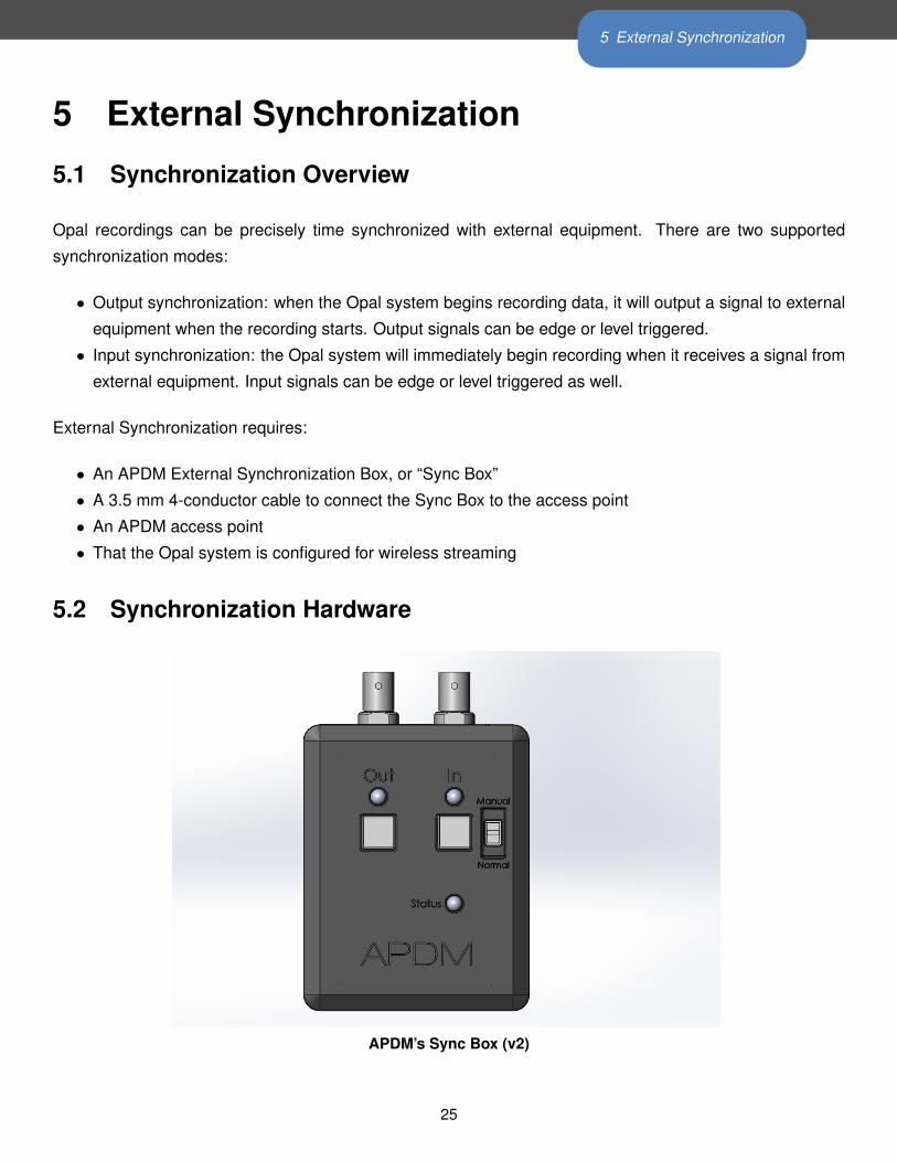
5.2 Synchronization Hardware
APDM’s Sync Box (v2)
25
5 External Synchronization
Access Point↔ Sync Box Connectors and Cable Both the access point and Sync Box have a 4-conductor
3.5 mm receptacle. A standard 1 m long, 4-conductor, 3.5 mm cable is included with the Sync Box to connect
it to the access point. These cables are often called “AV” cables becaus they contain 4, not the usual 3,
conductors. A regular stereo audio cable will not operate correctly. A longer 4-conductor, 3.5 mm cable
may be used, up to 10 m. This cable provides power from the access point to the Sync Box, and provides
bidirectional communication between the two (using the Controller Area Network, or CAN, protocol). A green
light on the side of the access point, near the 3.5 mm receptable, indicates that the access point is providing
power to the Sync Box.
Mode Switch A toggle switch on the top of the Sync Box allows you to switch the operational “mode” of the
Sync Box:
• Normal Mode: When in normal mode, the In and Out signals are controlled by software, and the square
buttons on the top of the Sync Box are ignored.
• Manual Mode: When in manual mode, the square push buttons just below the “Out” and “In” LEDs
allow the user to manually trigger input and output events. Pressing the “Out” button will toggle the
output synchronization signal on the “Out” BNC connector high and low. Pressing the “In” button will
toggle the input synchronization signal that goes into the access point high and low. In Manual mode,
output signals sent by APDM software and actual input signals from external equipment are ignored.
Status indicator The Status LED is illuminated when the Sync Box has power. It is green when the Sync
Box is in “Normal” mode, and blue when in “Manual” mode (described above).
External Synchronization Connectors (BNC Connectors) The Sync Box has two external BNC connec-
tors, labeled “In” and “Out”.
• In BNC Connector: The In signal is designed to receive a 0 to 3.3 V (5V maximum) signal from external
equipment. The logic high threshold is at 2.3V and the logic low threshold is 0.99V. This means a valid
input signal must be below 0.99V when low, and above 2.3V when high. When the input signal is low,
the In LED is off. When input is high), the In LED is green. For more technical details on the In signal,
please see the Schematic of Sync Box Input and Output Signals (below).
• Out BNC Connector: The Out signal sends a 0 to 3.3V signal to external equipment. When not
excessively loaded, the output high signal is greater than or equal to 2.9V and is typically 3.3V. When
the output signal is low, it will be 0.4V or less. When output is low, the Out LED is off, and when output
is high, the Out LED is green. For more technical details on the Out signal, please see the Schematic
of Sync Box Input and Output Signals (below).
Firmware Updates If there is ever a need to update the Sync Box’s firmware in the field, there is a small
panel on the side of the Sync Box which exposes a USB port that can be used to perform the update.
26
5 External Synchronization
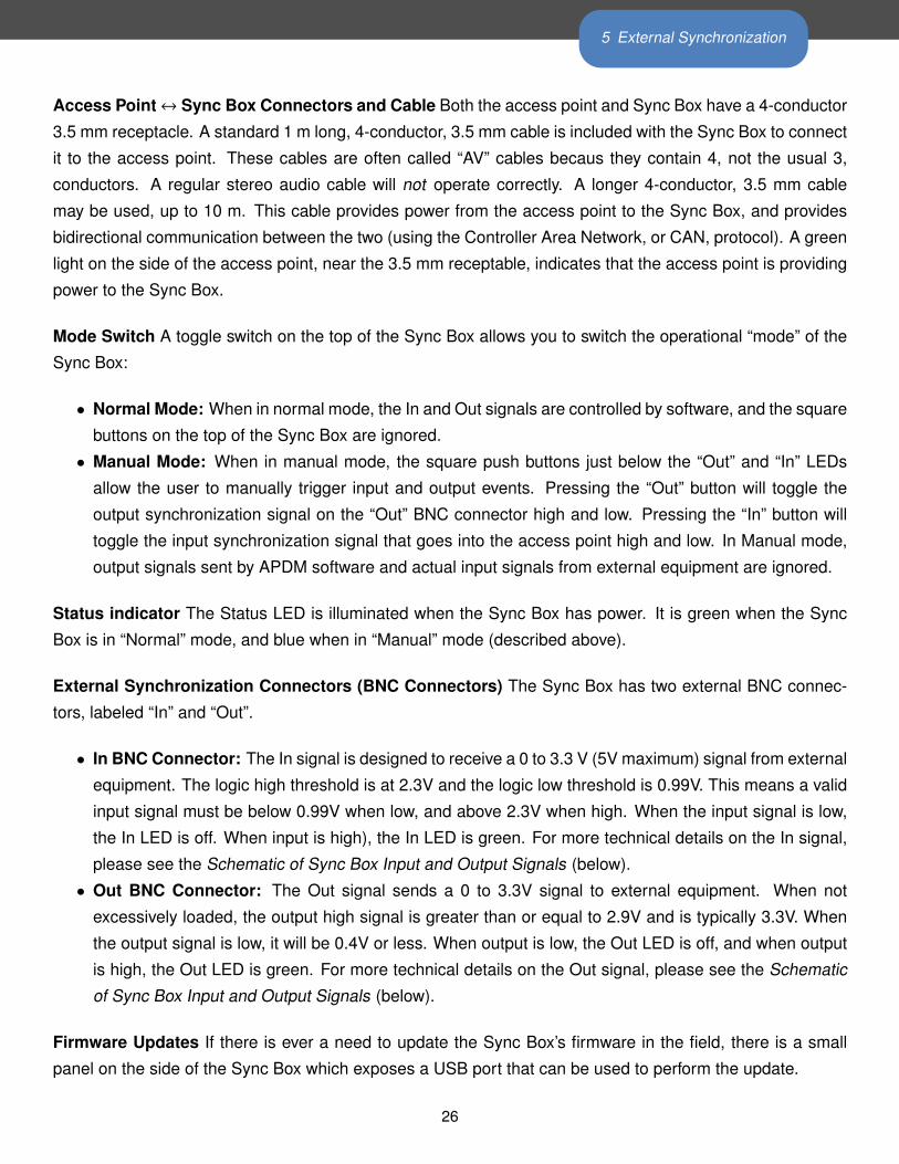
5.3 Configuration
External synchronization options are selected using the External Synchronization Configuration dialog. You
must specify the access point that will be connected to the Sync Box. Only one access point (and thus one
Sync Box) can be specified at a time.
The External Synchronization Configuration Dialog
5.3.1 Input Trigger Shape
The input trigger shape indicates the type of signal that will be input into the specified access point and
how you want your Opal system to respond. In the figure above, the four basic trigger shapes are shown.
The solid black line represents the external synchronization signal being sent to the access point. The blue
shaded region represents the period that will be recorded by your Opals.
27
5 External Synchronization
5.3.2 Input Trigger Level
Input triggers can be either low or high, depending on the nature of the signal generated by your external
synchronization source.
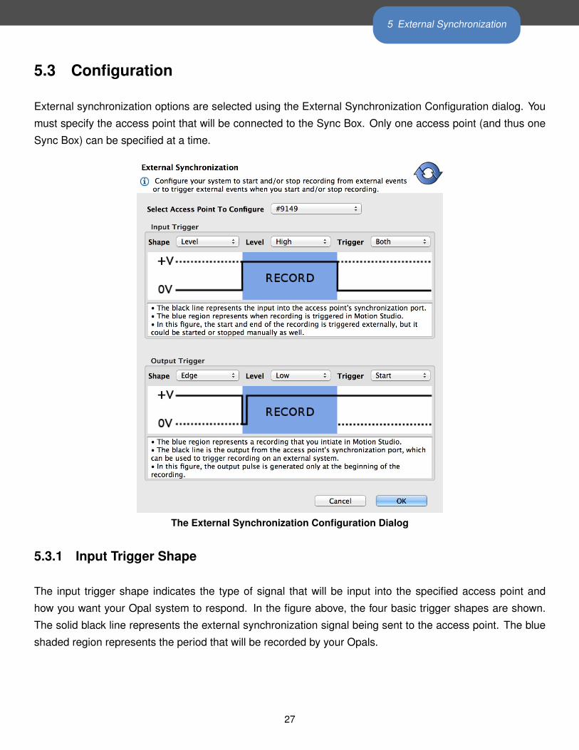
5.4 Input Synchronization
Input synchronization trigger types
5.4.1 Input Trigger
There are three input trigger options available:
• Start: The external trigger will only be used to start recording by your Opals.
• End: The external trigger will only be used to stop recording by your Opals.
• Both: The external trigger will be used to start and stop recording by your Opals.
5.4.2 Sample Selection with External Input Trigger Events
The time of the external input trigger events may not align exactly with the time of an individual samples
being collected in Motion Studio due to the discreet sampling interval. If the start trigger event time does
happen to align exactly with a sample captured in Motion Studio, the first sample recorded will correspond
exactly to the time of the start trigger event. If these do not align exactly (as will generally be the case) the
sample following the start trigger event will be the first sample recorded. Similarly, if the stop trigger event
aligns exactly with a sample captured in Motion Studio, the last sample recorded will correspond exactly to
the time of the stop trigger event. If these do not align exactly, the sample preceeding the stop trigger event
will be the last sample recorded.
28
5 External Synchronization
5.4.3 Annotation of Externally Triggered Recordings
Note: Annotations are implemented for the HDF file format only. When an external “Start” trigger event is
detected, an annotation is added to the recording that indicates the name of the event (in this case “External
trigger start time”) along with the timestamp of the event in epoch microseconds. Similarly, when an external
“Stop” trigger event is detected, a timestamped annotation is added to the recording (in this case labeled as
the “External trigger stop time”). These annotations allow you to align the recording captured by your Opals
with your external events in the case where the external trigger event times do not exactly align with the
samples captured in your HDF file.
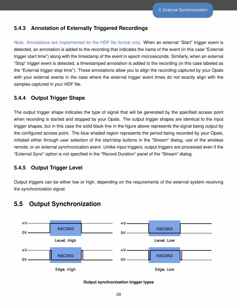
5.4.4 Output Trigger Shape
The output trigger shape indicates the type of signal that will be generated by the specified access point
when recording is started and stopped by your Opals. The output trigger shapes are identical to the input
trigger shapes, but in this case the solid black line in the figure above represents the signal being output by
the configured access point. The blue shaded region represents the period being recorded by your Opals,
initiated either through user selection of the start/stop buttons in the “Stream” dialog, use of the wireless
remote, or an external synchronization event. Unlike input triggers, output triggers are processed even if the
“External Sync” option is not specified in the “Record Duration” panel of the “Stream” dialog.
5.4.5 Output Trigger Level
Output triggers can be either low or high, depending on the requirements of the external system receiving
the synchronization signal.
5.5 Output Synchronization
Output synchronization trigger types
29
5 External Synchronization
5.5.1 Output Trigger
There are three output trigger options available:
• Start: The external signal will only be generated when recording is started by your Opals.
• End: The external signal will only be generated when recording is stopped by your Opals.
• Both: The external signal will be generated when recording is started and stopped by your Opals.
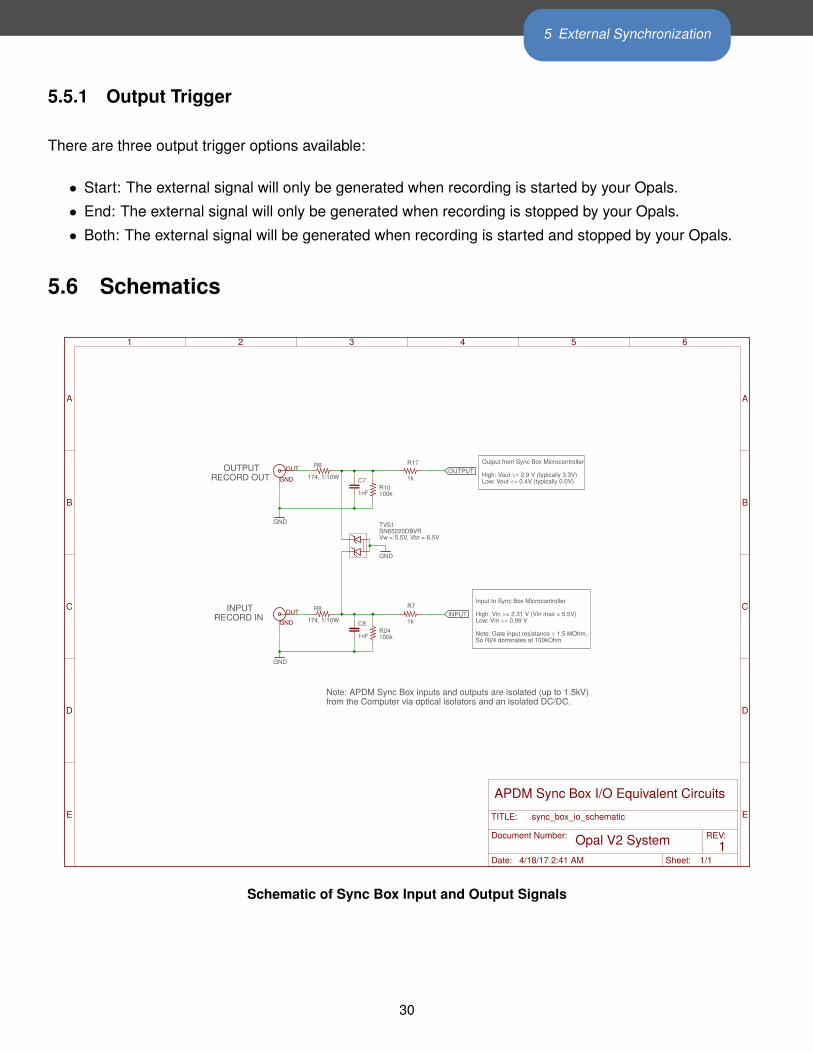
5.6 Schematics
RECORDOUT
RECORDININPUT
OUTPUT
Vw=5.5V,Vbr=6.5V
OutputfromSyncBoxMicrocontroller
High:Vout>=2.9V(typically3.3V)Low:Vout<=0.4V(typically0.0V)
InputtoSyncBoxMicrocontroller
High:Vin>=2.31V(Vinmax=5.5V)Low:Vin<=0.99V
Note:Gateinputresistance>1.5MOhm,SoR24dominatesat100kOhm
Note:APDMSyncBoxinputsandoutputsareisolated(upto1.5kV)fromtheComputerviaopticalisolatorsandanisolatedDC/DC.
GND
GND
1nF
1nF
SN65220DBVR
174,1/10W
1k174,1/10W
1k
100k
100k
GND
C8
C7
TVS1
R8
R17R6
R7
R24
R10
OUTPUT
INPUT
APDMSyncBoxI/OEquivalentCircuits
1OpalV2System
GNDOUT
GNDOUT
A
B
C
D
E
A
B
C
D
E
1 2 3 4 5 6
Date: 4/18/172:41AM Sheet: 1/1
REV:
TITLE:
DocumentNumber:
sync_box_io_schematic
Schematic of Sync Box Input and Output Signals
30
6 Programming Examples
6 Programming Examples
6.1 Example Code Provided with the SDK
The host library distribution provides sample code under dist/samples. Samples include source code and
pre-compiled binaries for the respective applications. The sample applications of most interest are as follows:
• autoconfigure_system.c: This is used to configure a set of attached movement monitors and access
points into wireless streaming mode.
• autoconfigure_rapid_streaming.c: This is used to configure a set of attached movement monitors
and access points into low-latency rapid streaming mode.
• stream_data.c: After a system has been autoconfigured and is streaming data to its respective access
points, this sample will stream data off the access points and print the data, correctly grouped, to the
console.
• stream_data_rapid.c: After a system has been autoconfigured in rapid mode, this demonstrates
retreiving data using the lowest latency mode possible, however it uses in the libraries in such as was
as correlation is not provided by the host libraries.
• autoconfigure_mesh.c: This program is used to configure a set of movement monitors into mesh
time synchronization and logging mode.
• convert_raw.c: This program is used to convert raw ”.apdm” files from a movement monitor into a
CSV or HDF output file.
• configure_low_power_mode.c: This program is used to configure any attached movement monitors
into low power, non-streaming mode.
6.2 Simple Configuration and Streaming Example
6.2.1 High Level Psuedocode
1. Allocate a handle:
apdm_ctx_allocate_new_context()
2. Using the handle, open access points attached to the system:
apdm_ctx_open_all_access_points()
3. Autoconfigure the access point(s) and attached movement monitors.
apdm_autoconfigure_devices_and_accesspoint2()
31
6 Programming Examples
4. Set the max latency value in the libraries.
apdm_ctx_set_max_sample_delay_seconds()
5. Get the attached movement monitor ID list, if useful:
apdm_ctx_get_device_id_list()
6. Synchronize the record head list in the libraries.
apdm_ctx_sync_record_list_head()
7. Collect a list of sensor readings, from all movement monitors, for the same sample point in time. This
is usually used within loop or as a regular event.
apdm_ctx_get_next_access_point_record_list()
8. Extract data readings on a per-movement monitor basis, by movement monitor ID number.
apdm_ctx_extract_data_by_device_id()
9. Disconnect from the attached access points and movement monitors
apdm_ctx_disconnect()
10. Free the allocated context
apdm_ctx_free_context()
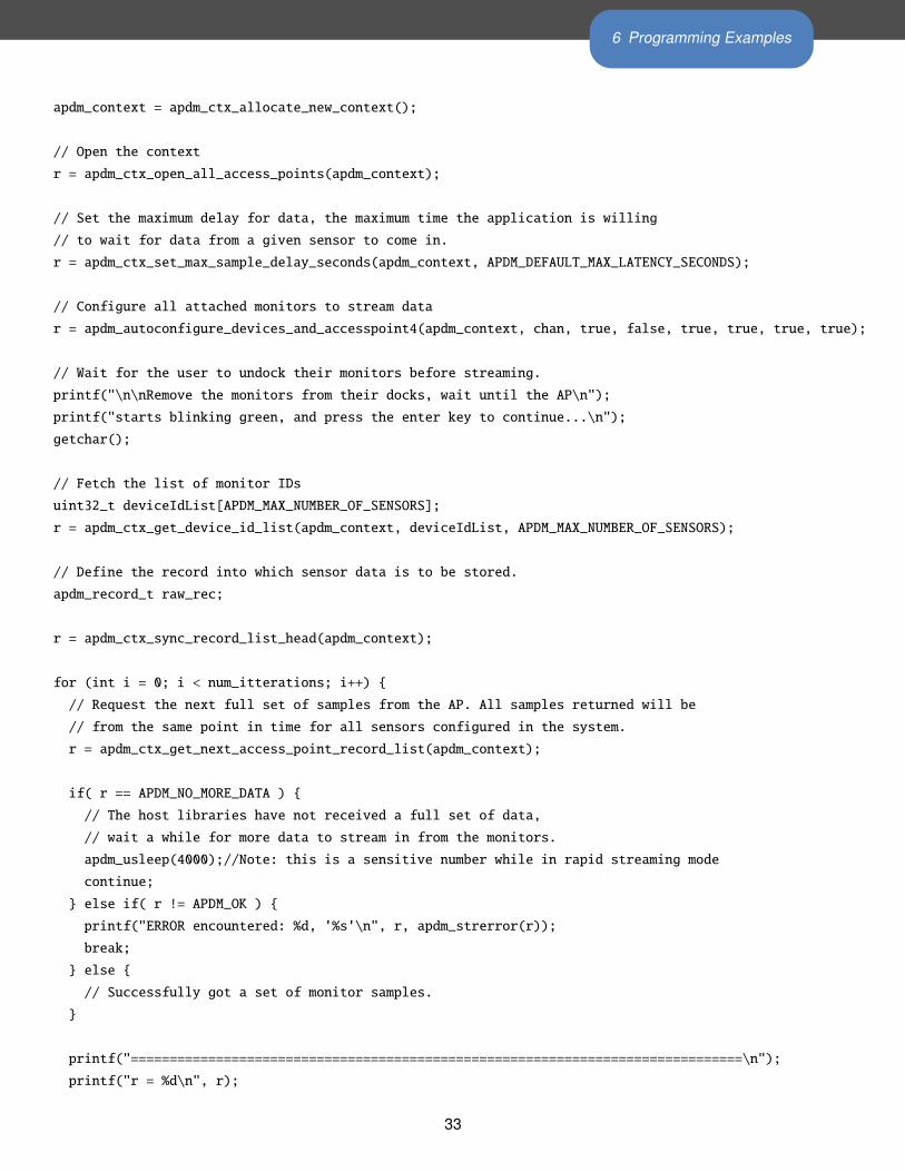
6.2.2 C Programming Example
The example below implements the above pseudocode using the C programming language. This example is
a combination of the autoconfigure_system.c and stream_data.c programs included in the SDK sample
code. Much of the verbose output and error handling was removed for this example to keep it short and tidy.
#include "apdm.h"
#include <stdio.h>
#include <inttypes.h>
int main(void)
{
const int32_t num_itterations = 20000000;
int chan = 90;
int r = 0;
apdm_ctx_t apdm_context = ADPM_DEVICE_COMMUNICATIONS_HANDLE_NEW_T_INITIALIZER;
32
6 Programming Examples
apdm_context = apdm_ctx_allocate_new_context();
// Open the context
r = apdm_ctx_open_all_access_points(apdm_context);
// Set the maximum delay for data, the maximum time the application is willing
// to wait for data from a given sensor to come in.
r = apdm_ctx_set_max_sample_delay_seconds(apdm_context, APDM_DEFAULT_MAX_LATENCY_SECONDS);
// Configure all attached monitors to stream data
r = apdm_autoconfigure_devices_and_accesspoint4(apdm_context, chan, true, false, true, true, true, true);
// Wait for the user to undock their monitors before streaming.
printf("\n\nRemove the monitors from their docks, wait until the AP\n");
printf("starts blinking green, and press the enter key to continue...\n");
getchar();
// Fetch the list of monitor IDs
uint32_t deviceIdList[APDM_MAX_NUMBER_OF_SENSORS];
r = apdm_ctx_get_device_id_list(apdm_context, deviceIdList, APDM_MAX_NUMBER_OF_SENSORS);
// Define the record into which sensor data is to be stored.
apdm_record_t raw_rec;
r = apdm_ctx_sync_record_list_head(apdm_context);
for (int i = 0; i < num_itterations; i++) {
// Request the next full set of samples from the AP. All samples returned will be
// from the same point in time for all sensors configured in the system.
r = apdm_ctx_get_next_access_point_record_list(apdm_context);
if( r == APDM_NO_MORE_DATA ) {
// The host libraries have not received a full set of data,
// wait a while for more data to stream in from the monitors.
apdm_usleep(4000);//Note: this is a sensitive number while in rapid streaming mode
continue;
} else if( r != APDM_OK ) {
printf("ERROR encountered: %d, '%s'\n", r, apdm_strerror(r));
break;
} else {
// Successfully got a set of monitor samples.
}
printf("===============================================================================\n");
printf("r = %d\n", r);
33
6 Programming Examples
for(int j = 0; j < APDM_MAX_NUMBER_OF_SENSORS; j++ ) {
if( deviceIdList[j] == 0 ) {
continue;
}
// Get the sensor data for the given device ID
int ret = apdm_ctx_extract_data_by_device_id(apdm_context, deviceIdList[j], &raw_rec);
if( ret != APDM_OK ) {
if( ret == APDM_NO_MORE_DATA ) {
// Depending on the error handling mode, this monitor may or may not have data for it.
printf("No More data for device id %d...\n", deviceIdList[j]);
}
continue;
}
// Print some of the calibrated data to the screen
if( raw_rec.accl_isPopulated ) {
printf("si, ");
printf("%.3f, %.3f, %.3f, ", raw_rec.accl_x_axis_si, raw_rec.accl_y_axis_si, raw_rec.accl_z_axis_si);
printf("%.3f, %.3f, %.3f, ", raw_rec.gyro_x_axis_si, raw_rec.gyro_y_axis_si, raw_rec.gyro_z_axis_si);
printf("%.3f, %.3f, %.3f, ", raw_rec.mag_x_axis_si, raw_rec.mag_y_axis_si, raw_rec.mag_z_axis_si);
printf("\n");
}
}
}
apdm_ctx_disconnect(apdm_context);
apdm_ctx_free_context(apdm_context);
return(0);
}
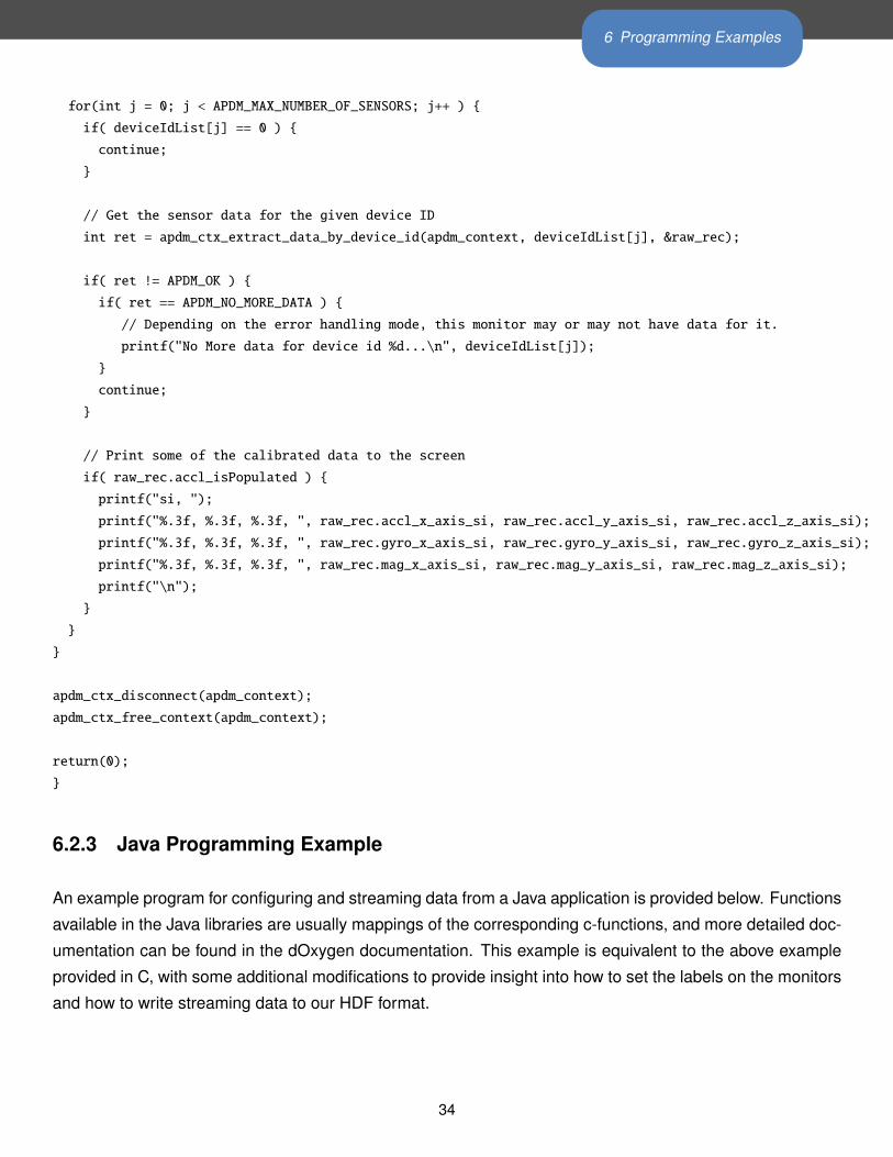
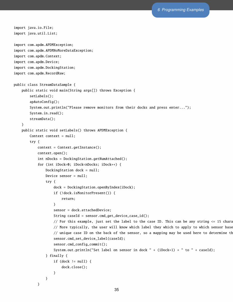
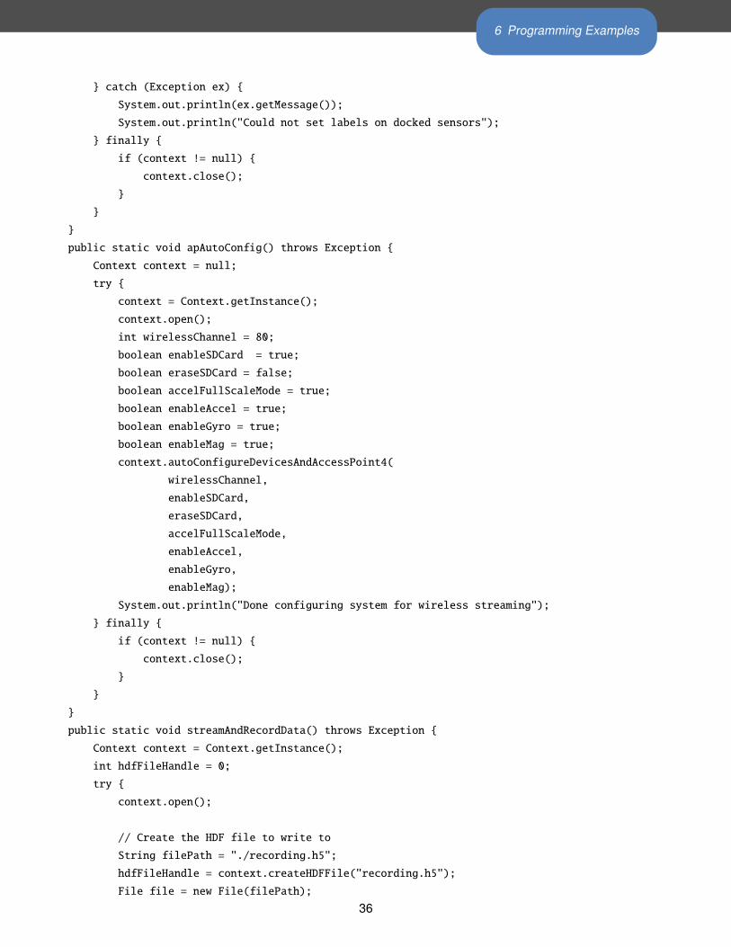
6.2.3 Java Programming Example
An example program for configuring and streaming data from a Java application is provided below. Functions
available in the Java libraries are usually mappings of the corresponding c-functions, and more detailed doc-
umentation can be found in the dOxygen documentation. This example is equivalent to the above example
provided in C, with some additional modifications to provide insight into how to set the labels on the monitors
and how to write streaming data to our HDF format.
34
6 Programming Examples
import java.io.File;
import java.util.List;
import com.apdm.APDMException;
import com.apdm.APDMNoMoreDataException;
import com.apdm.Context;
import com.apdm.Device;
import com.apdm.DockingStation;
import com.apdm.RecordRaw;
public class StreamDataSample {
public static void main(String args[]) throws Exception {
setLabels();
apAutoConfig();
System.out.println("Please remove monitors from their docks and press enter...");
System.in.read();
streamData();
}
public static void setLabels() throws APDMException {
Context context = null;
try {
context = Context.getInstance();
context.open();
int nDocks = DockingStation.getNumAttached();
for (int iDock=0; iDock<nDocks; iDock++) {
DockingStation dock = null;
Device sensor = null;
try {
dock = DockingStation.openByIndex(iDock);
if (!dock.isMonitorPresent()) {
return;
}
sensor = dock.attachedDevice;
String caseId = sensor.cmd_get_device_case_id();
// For this example, just set the label to the case ID. This can be any string <= 15 characters long.
// More typically, the user will know which label they which to apply to which sensor based on the
// unique case ID on the back of the sensor, so a mapping may be used here to determine the label.
sensor.cmd_set_device_label(caseId);
sensor.cmd_config_commit();
System.out.println("Set label on sensor in dock " + (iDock+1) + " to " + caseId);
} finally {
if (dock != null) {
dock.close();
}
}
}
35
6 Programming Examples
} catch (Exception ex) {
System.out.println(ex.getMessage());
System.out.println("Could not set labels on docked sensors");
} finally {
if (context != null) {
context.close();
}
}
}
public static void apAutoConfig() throws Exception {
Context context = null;
try {
context = Context.getInstance();
context.open();
int wirelessChannel = 80;
boolean enableSDCard = true;
boolean eraseSDCard = false;
boolean accelFullScaleMode = true;
boolean enableAccel = true;
boolean enableGyro = true;
boolean enableMag = true;
context.autoConfigureDevicesAndAccessPoint4(
wirelessChannel,
enableSDCard,
eraseSDCard,
accelFullScaleMode,
enableAccel,
enableGyro,
enableMag);
System.out.println("Done configuring system for wireless streaming");
} finally {
if (context != null) {
context.close();
}
}
}
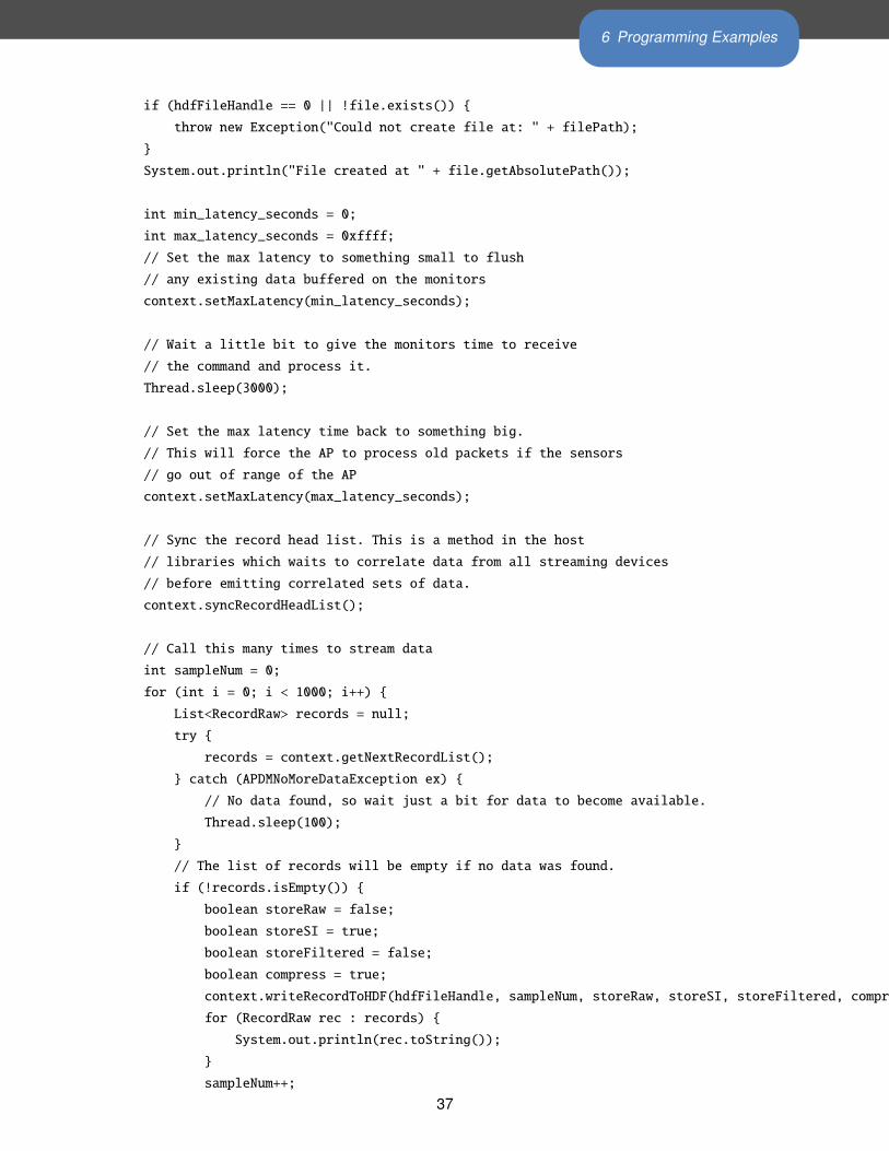
public static void streamAndRecordData() throws Exception {
Context context = Context.getInstance();
int hdfFileHandle = 0;
try {
context.open();
// Create the HDF file to write to
String filePath = "./recording.h5";
hdfFileHandle = context.createHDFFile("recording.h5");
File file = new File(filePath);
36
6 Programming Examples
if (hdfFileHandle == 0 || !file.exists()) {
throw new Exception("Could not create file at: " + filePath);
}
System.out.println("File created at " + file.getAbsolutePath());
int min_latency_seconds = 0;
int max_latency_seconds = 0xffff;
// Set the max latency to something small to flush
// any existing data buffered on the monitors
context.setMaxLatency(min_latency_seconds);
// Wait a little bit to give the monitors time to receive
// the command and process it.
Thread.sleep(3000);
// Set the max latency time back to something big.
// This will force the AP to process old packets if the sensors
// go out of range of the AP
context.setMaxLatency(max_latency_seconds);
// Sync the record head list. This is a method in the host
// libraries which waits to correlate data from all streaming devices
// before emitting correlated sets of data.
context.syncRecordHeadList();
// Call this many times to stream data
int sampleNum = 0;
for (int i = 0; i < 1000; i++) {
List<RecordRaw> records = null;
try {
records = context.getNextRecordList();
} catch (APDMNoMoreDataException ex) {
// No data found, so wait just a bit for data to become available.
Thread.sleep(100);
}
// The list of records will be empty if no data was found.
if (!records.isEmpty()) {
boolean storeRaw = false;
boolean storeSI = true;
boolean storeFiltered = false;
boolean compress = true;
context.writeRecordToHDF(hdfFileHandle, sampleNum, storeRaw, storeSI, storeFiltered, compress);
for (RecordRaw rec : records) {
System.out.println(rec.toString());
}
sampleNum++;
37
6 Programming Examples
}
}
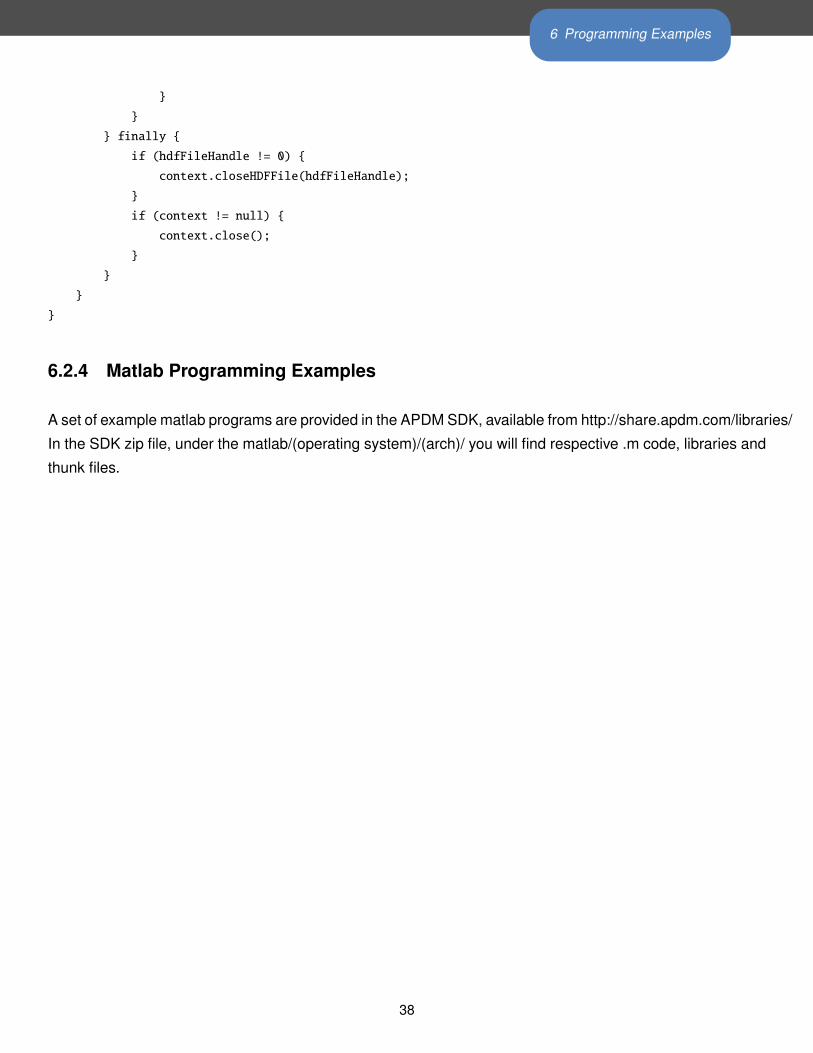
} finally {
if (hdfFileHandle != 0) {
context.closeHDFFile(hdfFileHandle);
}
if (context != null) {
context.close();
}
}
}
}
6.2.4 Matlab Programming Examples
A set of example matlab programs are provided in the APDM SDK, available from http://share.apdm.com/libraries/
In the SDK zip file, under the matlab/(operating system)/(arch)/ you will find respective .m code, libraries and
thunk files.
38
7 Working with HDF5 Files
7 Working with HDF5 FilesHDF5 is the preferred format for storing APDM movement monitor data. It is a standard format for scientific
data that is efficient and widely supported. It uses less space than CSV, is faster to load, and supports more
structured data. This section will cover the organization of the APDM movement monitor data and the basics
of reading HDF5 files in Python.
7.1 HDFView
A free program called HDFView (http://www.hdfgroup.org/hdf-java-html/hdfview/) can be used to
explore, plot, and export this data into other formats. Many free and commercial products are capable of read-
ing, writing, and editing HDF data, including Matlab, Python, and LabView. Many programming languages
are also supported, including, C, C++, Java, and Python.
7.2 Python
APDM embraces Python as a Mathematical scripting language. It has excellent support for reading, writing,
editin HDF files through the h5py package. It is also widely used and open source, which makes it available
to our entire customer base.
7.3 Data Organization
HDF5 files are organized like a file structure. The root of the file contains one or more attributes. One is the
version number for the organization of the HDF 5 file. APDM is currently on version 5 of our HDF format.
7.4 File Structure
Note about the latest version: Version 5 of APDM’s HDF format departs significantly from Version 4. It
is specific to our second iteration of hardware, so if you are using v1 hardware (without the displays), your
recordings will follow the Version 4 HDF convention. The information contained is largely identical, but it
is organized differently to make it more extensible. If you have created custom parsers for your recordings
or have used APDM’s examples for post-processing your recordings, you will likely have to change these
scripts to adapt. You can use the version attribute to modify your scripts to handle both versions from the
same script.
39
7 Working with HDF5 Files
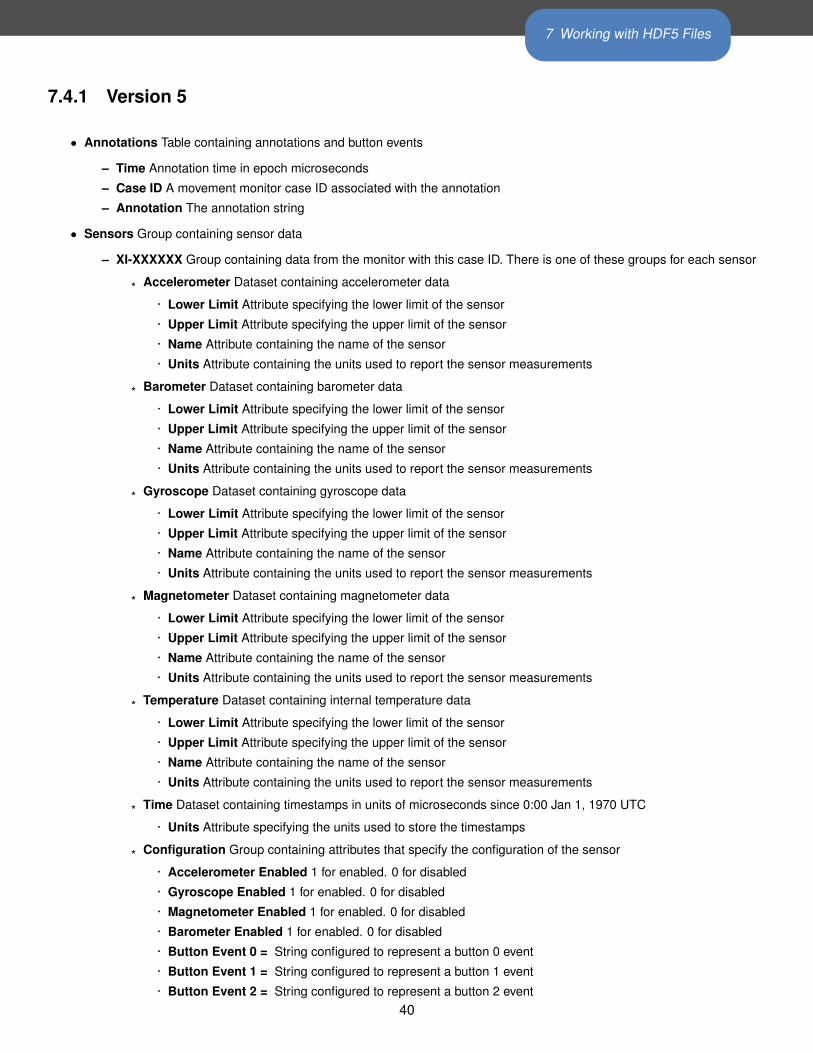
7.4.1 Version 5
• Annotations Table containing annotations and button events
– Time Annotation time in epoch microseconds
– Case ID A movement monitor case ID associated with the annotation
– Annotation The annotation string
• Sensors Group containing sensor data
– XI-XXXXXX Group containing data from the monitor with this case ID. There is one of these groups for each sensor
* Accelerometer Dataset containing accelerometer data
· Lower Limit Attribute specifying the lower limit of the sensor
· Upper Limit Attribute specifying the upper limit of the sensor
· Name Attribute containing the name of the sensor
· Units Attribute containing the units used to report the sensor measurements
* Barometer Dataset containing barometer data
· Lower Limit Attribute specifying the lower limit of the sensor
· Upper Limit Attribute specifying the upper limit of the sensor
· Name Attribute containing the name of the sensor
· Units Attribute containing the units used to report the sensor measurements
* Gyroscope Dataset containing gyroscope data
· Lower Limit Attribute specifying the lower limit of the sensor
· Upper Limit Attribute specifying the upper limit of the sensor
· Name Attribute containing the name of the sensor
· Units Attribute containing the units used to report the sensor measurements
* Magnetometer Dataset containing magnetometer data
· Lower Limit Attribute specifying the lower limit of the sensor
· Upper Limit Attribute specifying the upper limit of the sensor
· Name Attribute containing the name of the sensor
· Units Attribute containing the units used to report the sensor measurements
* Temperature Dataset containing internal temperature data
· Lower Limit Attribute specifying the lower limit of the sensor
· Upper Limit Attribute specifying the upper limit of the sensor
· Name Attribute containing the name of the sensor
· Units Attribute containing the units used to report the sensor measurements
* Time Dataset containing timestamps in units of microseconds since 0:00 Jan 1, 1970 UTC
· Units Attribute specifying the units used to store the timestamps
* Configuration Group containing attributes that specify the configuration of the sensor
· Accelerometer Enabled 1 for enabled. 0 for disabled
· Gyroscope Enabled 1 for enabled. 0 for disabled
· Magnetometer Enabled 1 for enabled. 0 for disabled
· Barometer Enabled 1 for enabled. 0 for disabled
· Button Event 0 = String configured to represent a button 0 event
· Button Event 1 = String configured to represent a button 1 event
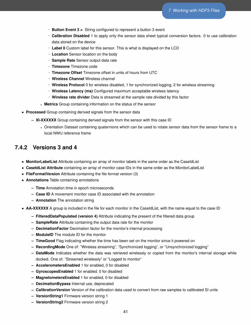
· Button Event 2 = String configured to represent a button 2 event40
7 Working with HDF5 Files
· Button Event 3 = String configured to represent a button 3 event
· Calibration Disabled 1 to apply only the sensor data sheet typical conversion factors. 0 to use calibration
data stored on the device
· Label 0 Custom label for this sensor. This is what is displayed on the LCD
· Location Sensor location on the body
· Sample Rate Sensor output data rate
· Timezone Timezone code
· Timezone Offset Timezone offset in units of hours from UTC
· Wireless Channel Wireless channel
· Wireless Protocol 0 for wireless disabled, 1 for synchronized logging, 2 for wireless streaming
· Wireless Latency (ms) Configured maximum acceptable wireless latency
· Wireless rate divider Data is streamed at the sample rate divided by this factor
* Metrics Group containing information on the status of the sensor
• Processed Group containing derived signals from the sensor data
– XI-XXXXXX Group containing derived signals from the sensor with this case ID
* Orientation Dataset containing quaternions which can be used to rotate sensor data from the sensor frame to a
local NWU reference frame
7.4.2 Versions 3 and 4
• MonitorLabelList Attribute containing an array of monitor labels in the same order as the CaseIdList
• CaseIdList Attribute containing an array of monitor case IDs in the same order as the MonitorLabelList
• FileFormatVersion Attribute containing the file format version (3)
• Annotations Table containing annotations
– Time Annotation time in epoch microseconds
– Case ID A movement monitor case ID associated with the annotation
– Annotation The annotation string
• AA-XXXXXX A group is included in the file for each monitor in the CaseIdList, with the name equal to the case ID
– FilteredDataPopulated (version 4) Attribute indicating the present of the filtered data group
– SampleRate Attribute containing the output data rate for the monitor
– DecimationFactor Decimation factor for the monitor’s internal processing
– ModuleID The module ID for the monitor
– TimeGood Flag indicating whether the time has been set on the monitor since it powered on
– RecordingMode One of: ”Wireless streaming”, ”Synchronized logging”, or ”Unsynchronized logging”
– DataMode Indicates whether the data was retrieved wirelessly or copied from the monitor’s internal storage while
docked. One of: ”Streamed wirelessly” or ”Logged to monitor”
– AccelerometersEnabled 1 for enabled, 0 for disabled
– GyroscopesEnabled 1 for enabled, 0 for disabled
– MagnetometersEnabled 1 for enabled, 0 for disabled
– DecimationBypass Internal use, deprecated
– CalibrationVersion Version of the calibration data used to convert from raw samples to calibrated SI units
– VersionString1 Firmware version string 1
– VersionString2 Firmware version string 2
41
7 Working with HDF5 Files
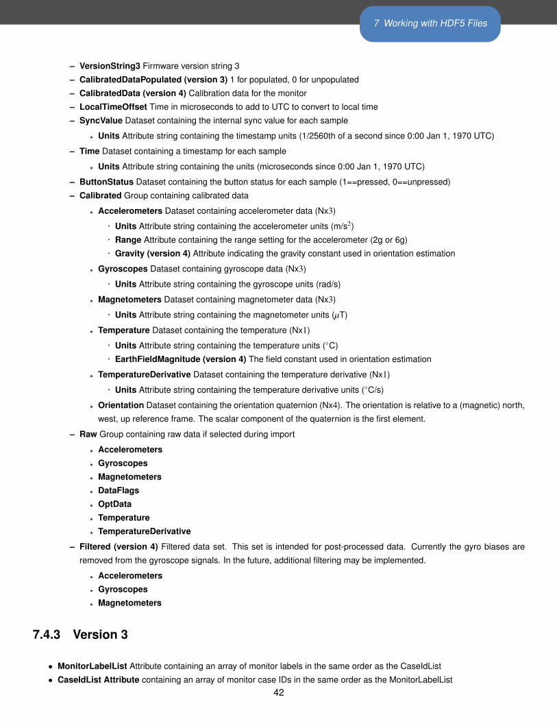
– VersionString3 Firmware version string 3
– CalibratedDataPopulated (version 3) 1 for populated, 0 for unpopulated
– CalibratedData (version 4) Calibration data for the monitor
– LocalTimeOffset Time in microseconds to add to UTC to convert to local time
– SyncValue Dataset containing the internal sync value for each sample
* Units Attribute string containing the timestamp units (1/2560th of a second since 0:00 Jan 1, 1970 UTC)
– Time Dataset containing a timestamp for each sample
* Units Attribute string containing the units (microseconds since 0:00 Jan 1, 1970 UTC)
– ButtonStatus Dataset containing the button status for each sample (1==pressed, 0==unpressed)
– Calibrated Group containing calibrated data
* Accelerometers Dataset containing accelerometer data (Nx3)
· Units Attribute string containing the accelerometer units (m/s2)
· Range Attribute containing the range setting for the accelerometer (2g or 6g)
· Gravity (version 4) Attribute indicating the gravity constant used in orientation estimation
* Gyroscopes Dataset containing gyroscope data (Nx3)
· Units Attribute string containing the gyroscope units (rad/s)
* Magnetometers Dataset containing magnetometer data (Nx3)
· Units Attribute string containing the magnetometer units (µT)
* Temperature Dataset containing the temperature (Nx1)
· Units Attribute string containing the temperature units (◦C)
· EarthFieldMagnitude (version 4) The field constant used in orientation estimation
* TemperatureDerivative Dataset containing the temperature derivative (Nx1)
· Units Attribute string containing the temperature derivative units (◦C/s)
* Orientation Dataset containing the orientation quaternion (Nx4). The orientation is relative to a (magnetic) north,
west, up reference frame. The scalar component of the quaternion is the first element.
– Raw Group containing raw data if selected during import
* Accelerometers
* Gyroscopes
* Magnetometers
* DataFlags
* OptData
* Temperature
* TemperatureDerivative
– Filtered (version 4) Filtered data set. This set is intended for post-processed data. Currently the gyro biases are
removed from the gyroscope signals. In the future, additional filtering may be implemented.
* Accelerometers
* Gyroscopes
* Magnetometers
7.4.3 Version 3
• MonitorLabelList Attribute containing an array of monitor labels in the same order as the CaseIdList
• CaseIdList Attribute containing an array of monitor case IDs in the same order as the MonitorLabelList42
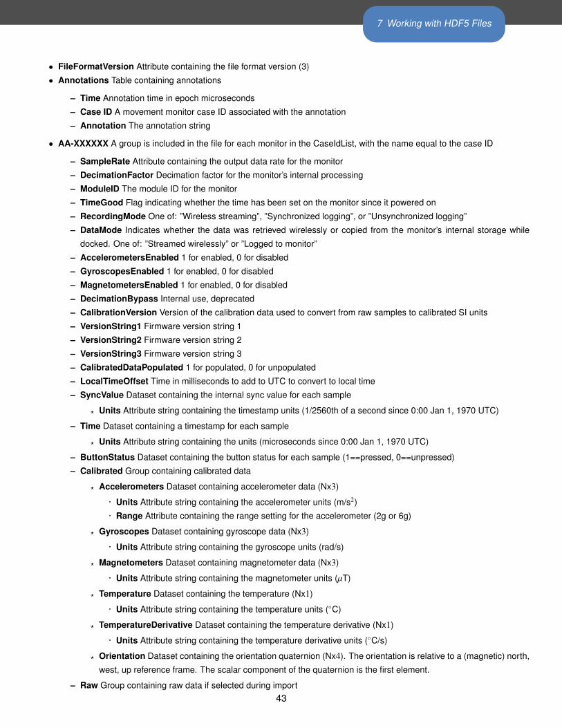
7 Working with HDF5 Files
• FileFormatVersion Attribute containing the file format version (3)
• Annotations Table containing annotations
– Time Annotation time in epoch microseconds
– Case ID A movement monitor case ID associated with the annotation
– Annotation The annotation string
• AA-XXXXXX A group is included in the file for each monitor in the CaseIdList, with the name equal to the case ID
– SampleRate Attribute containing the output data rate for the monitor
– DecimationFactor Decimation factor for the monitor’s internal processing
– ModuleID The module ID for the monitor
– TimeGood Flag indicating whether the time has been set on the monitor since it powered on
– RecordingMode One of: ”Wireless streaming”, ”Synchronized logging”, or ”Unsynchronized logging”
– DataMode Indicates whether the data was retrieved wirelessly or copied from the monitor’s internal storage while
docked. One of: ”Streamed wirelessly” or ”Logged to monitor”
– AccelerometersEnabled 1 for enabled, 0 for disabled
– GyroscopesEnabled 1 for enabled, 0 for disabled
– MagnetometersEnabled 1 for enabled, 0 for disabled
– DecimationBypass Internal use, deprecated
– CalibrationVersion Version of the calibration data used to convert from raw samples to calibrated SI units
– VersionString1 Firmware version string 1
– VersionString2 Firmware version string 2
– VersionString3 Firmware version string 3
– CalibratedDataPopulated 1 for populated, 0 for unpopulated
– LocalTimeOffset Time in milliseconds to add to UTC to convert to local time
– SyncValue Dataset containing the internal sync value for each sample
* Units Attribute string containing the timestamp units (1/2560th of a second since 0:00 Jan 1, 1970 UTC)
– Time Dataset containing a timestamp for each sample
* Units Attribute string containing the units (microseconds since 0:00 Jan 1, 1970 UTC)
– ButtonStatus Dataset containing the button status for each sample (1==pressed, 0==unpressed)
– Calibrated Group containing calibrated data
* Accelerometers Dataset containing accelerometer data (Nx3)
· Units Attribute string containing the accelerometer units (m/s2)
· Range Attribute containing the range setting for the accelerometer (2g or 6g)
* Gyroscopes Dataset containing gyroscope data (Nx3)
· Units Attribute string containing the gyroscope units (rad/s)
* Magnetometers Dataset containing magnetometer data (Nx3)
· Units Attribute string containing the magnetometer units (µT)
* Temperature Dataset containing the temperature (Nx1)
· Units Attribute string containing the temperature units (◦C)
* TemperatureDerivative Dataset containing the temperature derivative (Nx1)
· Units Attribute string containing the temperature derivative units (◦C/s)
* Orientation Dataset containing the orientation quaternion (Nx4). The orientation is relative to a (magnetic) north,
west, up reference frame. The scalar component of the quaternion is the first element.
– Raw Group containing raw data if selected during import43
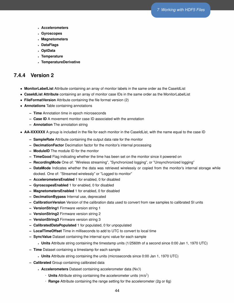
7 Working with HDF5 Files
* Accelerometers
* Gyroscopes
* Magnetometers
* DataFlags
* OptData
* Temperature
* TemperatureDerivative
7.4.4 Version 2
• MonitorLabelList Attribute containing an array of monitor labels in the same order as the CaseIdList
• CaseIdList Attribute containing an array of monitor case IDs in the same order as the MonitorLabelList
• FileFormatVersion Attribute containing the file format version (2)
• Annotations Table containing annotations
– Time Annotation time in epoch microseconds
– Case ID A movement monitor case ID associated with the annotation
– Annotation The annotation string
• AA-XXXXXX A group is included in the file for each monitor in the CaseIdList, with the name equal to the case ID
– SampleRate Attribute containing the output data rate for the monitor
– DecimationFactor Decimation factor for the monitor’s internal processing
– ModuleID The module ID for the monitor
– TimeGood Flag indicating whether the time has been set on the monitor since it powered on
– RecordingMode One of: ”Wireless streaming”, ”Synchronized logging”, or ”Unsynchronized logging”
– DataMode Indicates whether the data was retrieved wirelessly or copied from the monitor’s internal storage while
docked. One of: ”Streamed wirelessly” or ”Logged to monitor”
– AccelerometersEnabled 1 for enabled, 0 for disabled
– GyroscopesEnabled 1 for enabled, 0 for disabled
– MagnetometersEnabled 1 for enabled, 0 for disabled
– DecimationBypass Internal use, deprecated
– CalibrationVersion Version of the calibration data used to convert from raw samples to calibrated SI units
– VersionString1 Firmware version string 1
– VersionString2 Firmware version string 2
– VersionString3 Firmware version string 3
– CalibratedDataPopulated 1 for populated, 0 for unpopulated
– LocalTimeOffset Time in milliseconds to add to UTC to convert to local time
– SyncValue Dataset containing the internal sync value for each sample
* Units Attribute string containing the timestamp units (1/2560th of a second since 0:00 Jan 1, 1970 UTC)
– Time Dataset containing a timestamp for each sample
* Units Attribute string containing the units (microseconds since 0:00 Jan 1, 1970 UTC)
– Calibrated Group containing calibrated data
* Accelerometers Dataset containing accelerometer data (Nx3)
· Units Attribute string containing the accelerometer units (m/s2)
· Range Attribute containing the range setting for the accelerometer (2g or 6g)
44
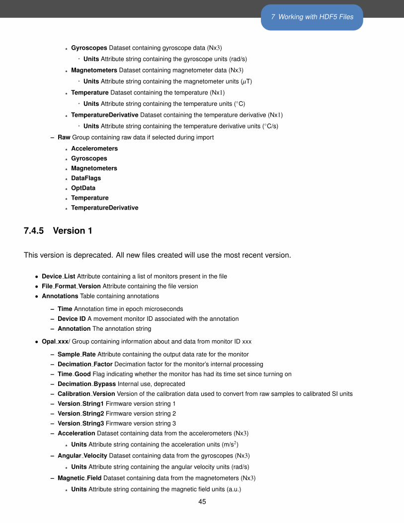
7 Working with HDF5 Files
* Gyroscopes Dataset containing gyroscope data (Nx3)
· Units Attribute string containing the gyroscope units (rad/s)
* Magnetometers Dataset containing magnetometer data (Nx3)
· Units Attribute string containing the magnetometer units (µT)
* Temperature Dataset containing the temperature (Nx1)
· Units Attribute string containing the temperature units (◦C)
* TemperatureDerivative Dataset containing the temperature derivative (Nx1)
· Units Attribute string containing the temperature derivative units (◦C/s)
– Raw Group containing raw data if selected during import
* Accelerometers
* Gyroscopes
* Magnetometers
* DataFlags
* OptData
* Temperature
* TemperatureDerivative
7.4.5 Version 1
This version is deprecated. All new files created will use the most recent version.
• Device List Attribute containing a list of monitors present in the file
• File Format Version Attribute containing the file version
• Annotations Table containing annotations
– Time Annotation time in epoch microseconds
– Device ID A movement monitor ID associated with the annotation
– Annotation The annotation string
• Opal xxx/ Group containing information about and data from monitor ID xxx
– Sample Rate Attribute containing the output data rate for the monitor
– Decimation Factor Decimation factor for the monitor’s internal processing
– Time Good Flag indicating whether the monitor has had its time set since turning on
– Decimation Bypass Internal use, deprecated
– Calibration Version Version of the calibration data used to convert from raw samples to calibrated SI units
– Version String1 Firmware version string 1
– Version String2 Firmware version string 2
– Version String3 Firmware version string 3
– Acceleration Dataset containing data from the accelerometers (Nx3)
* Units Attribute string containing the acceleration units (m/s2)
– Angular Velocity Dataset containing data from the gyroscopes (Nx3)
* Units Attribute string containing the angular velocity units (rad/s)
– Magnetic Field Dataset containing data from the magnetometers (Nx3)
* Units Attribute string containing the magnetic field units (a.u.)
45
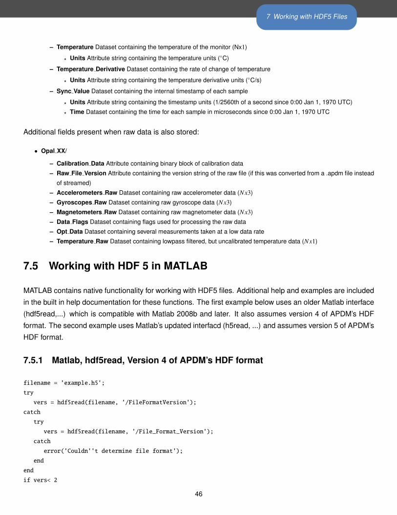
7 Working with HDF5 Files
– Temperature Dataset containing the temperature of the monitor (Nx1)
* Units Attribute string containing the temperature units (◦C)
– Temperature Derivative Dataset containing the rate of change of temperature
* Units Attribute string containing the temperature derivative units (◦C/s)
– Sync Value Dataset containing the internal timestamp of each sample
* Units Attribute string containing the timestamp units (1/2560th of a second since 0:00 Jan 1, 1970 UTC)
* Time Dataset containing the time for each sample in microseconds since 0:00 Jan 1, 1970 UTC
Additional fields present when raw data is also stored:
• Opal XX/
– Calibration Data Attribute containing binary block of calibration data
– Raw File Version Attribute containing the version string of the raw file (if this was converted from a .apdm file instead
of streamed)
– Accelerometers Raw Dataset containing raw accelerometer data (Nx3)
– Gyroscopes Raw Dataset containing raw gyroscope data (Nx3)
– Magnetometers Raw Dataset containing raw magnetometer data (Nx3)
– Data Flags Dataset containing flags used for processing the raw data
– Opt Data Dataset containing several measurements taken at a low data rate
– Temperature Raw Dataset containing lowpass filtered, but uncalibrated temperature data (Nx1)
7.5 Working with HDF 5 in MATLAB
MATLAB contains native functionality for working with HDF5 files. Additional help and examples are included
in the built in help documentation for these functions. The first example below uses an older Matlab interface
(hdf5read,...) which is compatible with Matlab 2008b and later. It also assumes version 4 of APDM’s HDF
format. The second example uses Matlab’s updated interfacd (h5read, ...) and assumes version 5 of APDM’s
HDF format.
7.5.1 Matlab, hdf5read, Version 4 of APDM’s HDF format
filename = 'example.h5';
try
vers = hdf5read(filename, '/FileFormatVersion');
catch
try
vers = hdf5read(filename, '/File_Format_Version');
catch
error('Couldn''t determine file format');
end
end
if vers< 2
46
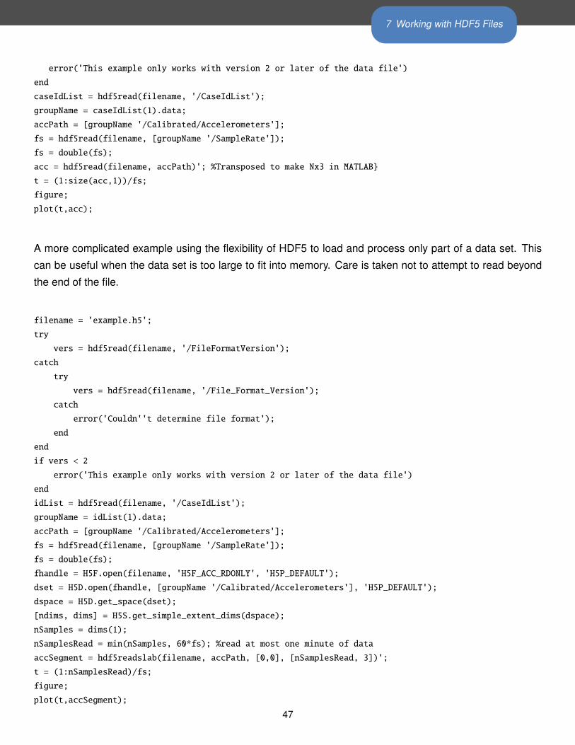
7 Working with HDF5 Files
error('This example only works with version 2 or later of the data file')
end
caseIdList = hdf5read(filename, '/CaseIdList');
groupName = caseIdList(1).data;
accPath = [groupName '/Calibrated/Accelerometers'];
fs = hdf5read(filename, [groupName '/SampleRate']);
fs = double(fs);
acc = hdf5read(filename, accPath)'; %Transposed to make Nx3 in MATLAB}
t = (1:size(acc,1))/fs;
figure;
plot(t,acc);
A more complicated example using the flexibility of HDF5 to load and process only part of a data set. This
can be useful when the data set is too large to fit into memory. Care is taken not to attempt to read beyond
the end of the file.
filename = 'example.h5';
try
vers = hdf5read(filename, '/FileFormatVersion');
catch
try
vers = hdf5read(filename, '/File_Format_Version');
catch
error('Couldn''t determine file format');
end
end
if vers < 2
error('This example only works with version 2 or later of the data file')
end
idList = hdf5read(filename, '/CaseIdList');
groupName = idList(1).data;
accPath = [groupName '/Calibrated/Accelerometers'];
fs = hdf5read(filename, [groupName '/SampleRate']);
fs = double(fs);
fhandle = H5F.open(filename, 'H5F_ACC_RDONLY', 'H5P_DEFAULT');
dset = H5D.open(fhandle, [groupName '/Calibrated/Accelerometers'], 'H5P_DEFAULT');
dspace = H5D.get_space(dset);
[ndims, dims] = H5S.get_simple_extent_dims(dspace);
nSamples = dims(1);
nSamplesRead = min(nSamples, 60*fs); %read at most one minute of data
accSegment = hdf5readslab(filename, accPath, [0,0], [nSamplesRead, 3])';
t = (1:nSamplesRead)/fs;
figure;
plot(t,accSegment);
47
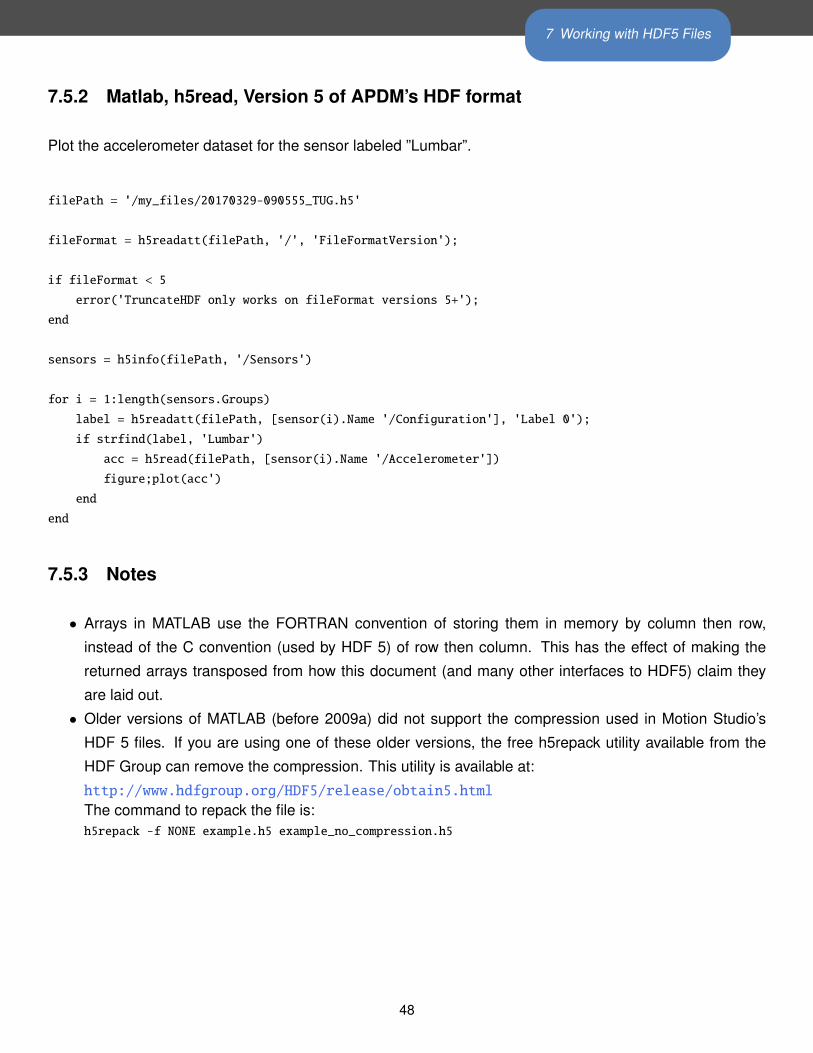
7 Working with HDF5 Files
7.5.2 Matlab, h5read, Version 5 of APDM’s HDF format
Plot the accelerometer dataset for the sensor labeled ”Lumbar”.
filePath = '/my_files/20170329-090555_TUG.h5'
fileFormat = h5readatt(filePath, '/', 'FileFormatVersion');
if fileFormat < 5
error('TruncateHDF only works on fileFormat versions 5+');
end
sensors = h5info(filePath, '/Sensors')
for i = 1:length(sensors.Groups)
label = h5readatt(filePath, [sensor(i).Name '/Configuration'], 'Label 0');
if strfind(label, 'Lumbar')
acc = h5read(filePath, [sensor(i).Name '/Accelerometer'])
figure;plot(acc')
end
end
7.5.3 Notes
• Arrays in MATLAB use the FORTRAN convention of storing them in memory by column then row,
instead of the C convention (used by HDF 5) of row then column. This has the effect of making the
returned arrays transposed from how this document (and many other interfaces to HDF5) claim they
are laid out.
• Older versions of MATLAB (before 2009a) did not support the compression used in Motion Studio’s
HDF 5 files. If you are using one of these older versions, the free h5repack utility available from the
HDF Group can remove the compression. This utility is available at:
http://www.hdfgroup.org/HDF5/release/obtain5.html
The command to repack the file is:h5repack -f NONE example.h5 example_no_compression.h5
48
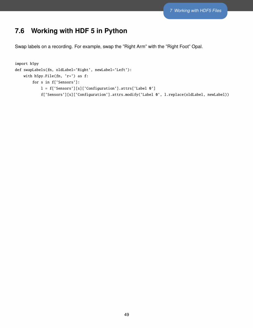
7 Working with HDF5 Files
7.6 Working with HDF 5 in Python
Swap labels on a recording. For example, swap the ”Right Arm” with the ”Right Foot” Opal.
import h5py
def swapLabels(fn, oldLabel='Right', newLabel='Left'):
with h5py.File(fn, 'r+') as f:
for s in f['Sensors']:
l = f['Sensors'][s]['Configuration'].attrs['Label 0']
f['Sensors'][s]['Configuration'].attrs.modify('Label 0', l.replace(oldLabel, newLabel))
49
8 Calibration
8 CalibrationThere are two 2KB blocks of calibration data stored on each monitor’s internal flash memory. The first of
these contains factory calibration and should not be modified. The second one contains user calibration. If
the user calibration block is valid, it will be used for calibrating raw data instead of the factory calibration.
There are two ways to modify the user calibration: using the recalibration functionality in Motion Studio, or by
loading a custom calibration .hex file in Motion Studio. This section details the .hex file format and contents.
8.1 File Format
The .hex file is a plain text (ASCII) file format based on the Tektronix extended HEX file format, with small
modifications. The file format has two types of records:
• Data records: contains the header field, the load address, and the object code.
• Termination records: signifies the end of a module.
The header field in the data record contains the following information.
Item Number of ASCII Characters Description
% 1 Data type is Tektronix format
Block Length 2 Number of characters in the record, minus the %
Block Type 16 = data record
8 = termination record
Checksum 2 A 2-digit hex sum modulo 256 of all values in the record
except the % and the checksum itself
The load address in the data record specifies where the object code will be located. The first digit specifies
the address length; this is always 8. The remaining characters of the data record contain the object code,
two characters per byte.
The termination record is not used in this context. It is also assumed that lines starting with ’#’ are comments
and should be ignored by the parser. Metadata lines are designated with a leading ’:’ character. The
comments and meta data extensions are not part of the original format.
50
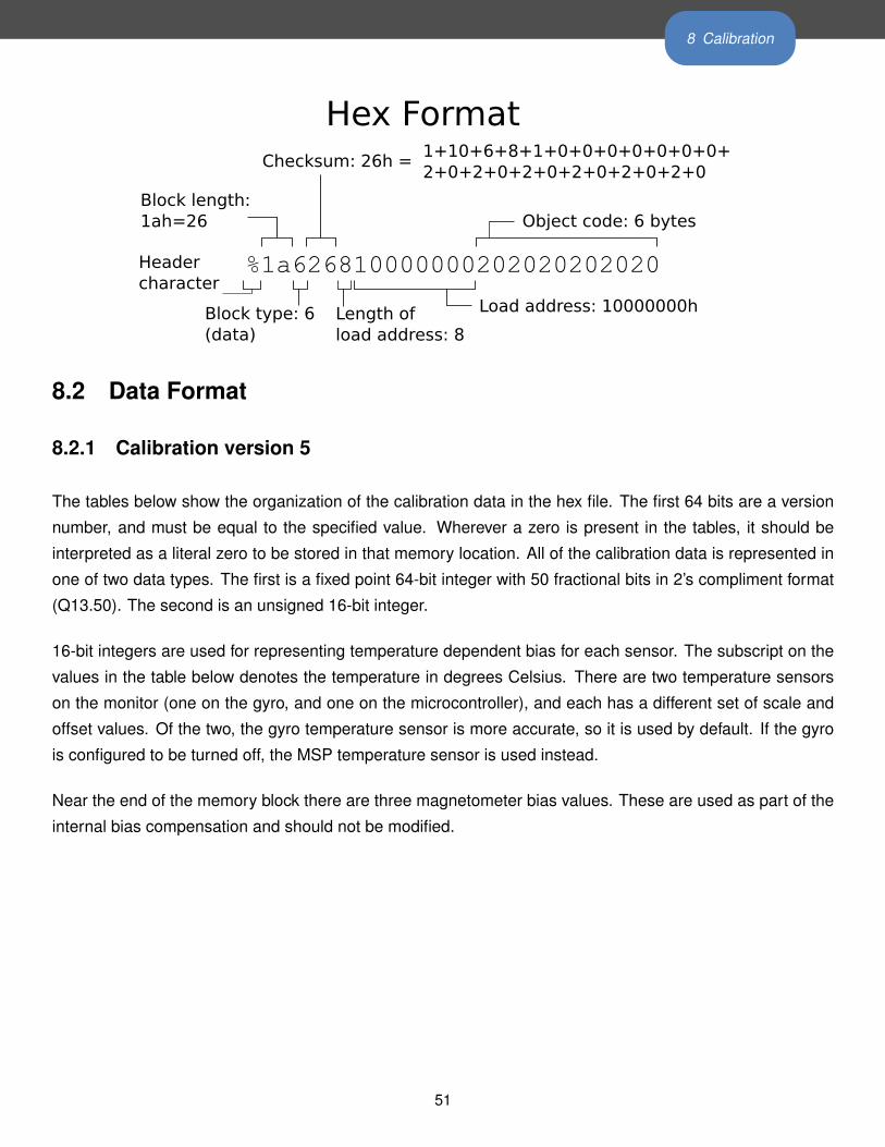
8 Calibration
Hex Format
%1a626810000000202020202020
Object code: 6 bytes
1+10+6+8+1+0+0+0+0+0+0+0+2+0+2+0+2+0+2+0+2+0+2+0
Load address: 10000000hLength of load address: 8
Checksum: 26h =
Block type: 6(data)
Block length:1ah=26
Headercharacter
8.2 Data Format
8.2.1 Calibration version 5
The tables below show the organization of the calibration data in the hex file. The first 64 bits are a version
number, and must be equal to the specified value. Wherever a zero is present in the tables, it should be
interpreted as a literal zero to be stored in that memory location. All of the calibration data is represented in
one of two data types. The first is a fixed point 64-bit integer with 50 fractional bits in 2’s compliment format
(Q13.50). The second is an unsigned 16-bit integer.
16-bit integers are used for representing temperature dependent bias for each sensor. The subscript on the
values in the table below denotes the temperature in degrees Celsius. There are two temperature sensors
on the monitor (one on the gyro, and one on the microcontroller), and each has a different set of scale and
offset values. Of the two, the gyro temperature sensor is more accurate, so it is used by default. If the gyro
is configured to be turned off, the MSP temperature sensor is used instead.
Near the end of the memory block there are three magnetometer bias values. These are used as part of the
internal bias compensation and should not be modified.
51
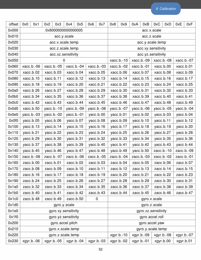
8 Calibration
offset 0x0 0x1 0x2 0x3 0x4 0x5 0x6 0x7 0x8 0x9 0xA 0xB 0xC 0xD 0xE 0xF
0x000 0x8000000000000005 acc x scale
0x010 acc y scale acc z scale
0x020 acc x scale temp acc y scale temp
0x030 acc z scale temp acc xy sensitivity
0x040 acc xz sensitivity acc yz sensitivity
0x050 0 xacc b -10 xacc b -09 xacc b -08 xacc b -07
0x060 xacc b -06 xacc b -05 xacc b -04 xacc b -03 xacc b -02 xacc b -01 xacc b 00 xacc b 01
0x070 xacc b 02 xacc b 03 xacc b 04 xacc b 05 xacc b 06 xacc b 07 xacc b 08 xacc b 09
0x080 xacc b 10 xacc b 11 xacc b 12 xacc b 13 xacc b 14 xacc b 15 xacc b 16 xacc b 17
0x090 xacc b 18 xacc b 19 xacc b 20 xacc b 21 xacc b 22 xacc b 23 xacc b 24 xacc b 25
0x0a0 xacc b 26 xacc b 27 xacc b 28 xacc b 29 xacc b 30 xacc b 31 xacc b 32 xacc b 33
0x0b0 xacc b 34 xacc b 35 xacc b 36 xacc b 37 xacc b 38 xacc b 39 xacc b 40 xacc b 41
0x0c0 xacc b 42 xacc b 43 xacc b 44 xacc b 45 xacc b 46 xacc b 47 xacc b 48 xacc b 49
0x0d0 xacc b 50 yacc b -10 yacc b -09 yacc b -08 yacc b -07 yacc b -06 yacc b -05 yacc b -04
0x0e0 yacc b -03 yacc b -02 yacc b -01 yacc b 00 yacc b 01 yacc b 02 yacc b 03 yacc b 04
0x0f0 yacc b 05 yacc b 06 yacc b 07 yacc b 08 yacc b 09 yacc b 10 yacc b 11 yacc b 12
0x100 yacc b 13 yacc b 14 yacc b 15 yacc b 16 yacc b 17 yacc b 18 yacc b 19 yacc b 20
0x110 yacc b 21 yacc b 22 yacc b 23 yacc b 24 yacc b 25 yacc b 26 yacc b 27 yacc b 28
0x120 yacc b 29 yacc b 30 yacc b 31 yacc b 32 yacc b 33 yacc b 34 yacc b 35 yacc b 36
0x130 yacc b 37 yacc b 38 yacc b 39 yacc b 40 yacc b 41 yacc b 42 yacc b 43 yacc b 44
0x140 yacc b 45 yacc b 46 yacc b 47 yacc b 48 yacc b 49 yacc b 50 zacc b -10 zacc b -09
0x150 zacc b -08 zacc b -07 zacc b -06 zacc b -05 zacc b -04 zacc b -03 zacc b -02 zacc b -01
0x160 zacc b 00 zacc b 01 zacc b 02 zacc b 03 zacc b 04 zacc b 05 zacc b 06 zacc b 07
0x170 zacc b 08 zacc b 09 zacc b 10 zacc b 11 zacc b 12 zacc b 13 zacc b 14 zacc b 15
0x180 zacc b 16 zacc b 17 zacc b 18 zacc b 19 zacc b 20 zacc b 21 zacc b 22 zacc b 23
0x190 zacc b 24 zacc b 25 zacc b 26 zacc b 27 zacc b 28 zacc b 29 zacc b 30 zacc b 31
0x1a0 zacc b 32 zacc b 33 zacc b 34 zacc b 35 zacc b 36 zacc b 37 zacc b 38 zacc b 39
0x1b0 zacc b 40 zacc b 41 zacc b 42 zacc b 43 zacc b 44 zacc b 45 zacc b 46 zacc b 47
0x1c0 zacc b 48 zacc b 49 zacc b 50 0 gyro x scale
0x1d0 gyro y scale gyro z scale
0x1e0 gyro xy sensitivity gyro xz sensitivity
0x1f0 gyro yz sensitivity gyro accel roll
0x200 gyro accel pitch gyro accel yaw
0x210 gyro x scale temp gyro y scale temp
0x220 gyro z scale temp xgyr b -10 xgyr b -09 xgyr b -08 xgyr b -07
0x230 xgyr b -06 xgyr b -05 xgyr b -04 xgyr b -03 xgyr b -02 xgyr b -01 xgyr b 00 xgyr b 01
52
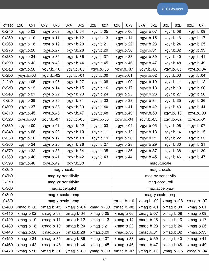
8 Calibration
offset 0x0 0x1 0x2 0x3 0x4 0x5 0x6 0x7 0x8 0x9 0xA 0xB 0xC 0xD 0xE 0xF
0x240 xgyr b 02 xgyr b 03 xgyr b 04 xgyr b 05 xgyr b 06 xgyr b 07 xgyr b 08 xgyr b 09
0x250 xgyr b 10 xgyr b 11 xgyr b 12 xgyr b 13 xgyr b 14 xgyr b 15 xgyr b 16 xgyr b 17
0x260 xgyr b 18 xgyr b 19 xgyr b 20 xgyr b 21 xgyr b 22 xgyr b 23 xgyr b 24 xgyr b 25
0x270 xgyr b 26 xgyr b 27 xgyr b 28 xgyr b 29 xgyr b 30 xgyr b 31 xgyr b 32 xgyr b 33
0x280 xgyr b 34 xgyr b 35 xgyr b 36 xgyr b 37 xgyr b 38 xgyr b 39 xgyr b 40 xgyr b 41
0x290 xgyr b 42 xgyr b 43 xgyr b 44 xgyr b 45 xgyr b 46 xgyr b 47 xgyr b 48 xgyr b 49
0x2a0 xgyr b 50 ygyr b -10 ygyr b -09 ygyr b -08 ygyr b -07 ygyr b -06 ygyr b -05 ygyr b -04
0x2b0 ygyr b -03 ygyr b -02 ygyr b -01 ygyr b 00 ygyr b 01 ygyr b 02 ygyr b 03 ygyr b 04
0x2c0 ygyr b 05 ygyr b 06 ygyr b 07 ygyr b 08 ygyr b 09 ygyr b 10 ygyr b 11 ygyr b 12
0x2d0 ygyr b 13 ygyr b 14 ygyr b 15 ygyr b 16 ygyr b 17 ygyr b 18 ygyr b 19 ygyr b 20
0x2e0 ygyr b 21 ygyr b 22 ygyr b 23 ygyr b 24 ygyr b 25 ygyr b 26 ygyr b 27 ygyr b 28
0x2f0 ygyr b 29 ygyr b 30 ygyr b 31 ygyr b 32 ygyr b 33 ygyr b 34 ygyr b 35 ygyr b 36
0x300 ygyr b 37 ygyr b 38 ygyr b 39 ygyr b 40 ygyr b 41 ygyr b 42 ygyr b 43 ygyr b 44
0x310 ygyr b 45 ygyr b 46 ygyr b 47 ygyr b 48 ygyr b 49 ygyr b 50 zgyr b -10 zgyr b -09
0x320 zgyr b -08 zgyr b -07 zgyr b -06 zgyr b -05 zgyr b -04 zgyr b -03 zgyr b -02 zgyr b -01
0x330 zgyr b 00 zgyr b 01 zgyr b 02 zgyr b 03 zgyr b 04 zgyr b 05 zgyr b 06 zgyr b 07
0x340 zgyr b 08 zgyr b 09 zgyr b 10 zgyr b 11 zgyr b 12 zgyr b 13 zgyr b 14 zgyr b 15
0x350 zgyr b 16 zgyr b 17 zgyr b 18 zgyr b 19 zgyr b 20 zgyr b 21 zgyr b 22 zgyr b 23
0x360 zgyr b 24 zgyr b 25 zgyr b 26 zgyr b 27 zgyr b 28 zgyr b 29 zgyr b 30 zgyr b 31
0x370 zgyr b 32 zgyr b 33 zgyr b 34 zgyr b 35 zgyr b 36 zgyr b 37 zgyr b 38 zgyr b 39
0x380 zgyr b 40 zgyr b 41 zgyr b 42 zgyr b 43 zgyr b 44 zgyr b 45 zgyr b 46 zgyr b 47
0x390 zgyr b 48 zgyr b 49 zgyr b 50 0 mag x scale
0x3a0 mag y scale mag z scale
0x3b0 mag xy sensitivity mag xz sensitivity
0x3c0 mag yz sensitivity mag accel roll
0x3d0 mag accel pitch mag accel yaw
0x3e0 mag x scale temp mag y scale temp
0x3f0 mag z scale temp xmag b -10 xmag b -09 xmag b -08 xmag b -07
0x400 xmag b -06 xmag b -05 xmag b -04 xmag b -03 xmag b -02 xmag b -01 xmag b 00 xmag b 01
0x410 xmag b 02 xmag b 03 xmag b 04 xmag b 05 xmag b 06 xmag b 07 xmag b 08 xmag b 09
0x420 xmag b 10 xmag b 11 xmag b 12 xmag b 13 xmag b 14 xmag b 15 xmag b 16 xmag b 17
0x430 xmag b 18 xmag b 19 xmag b 20 xmag b 21 xmag b 22 xmag b 23 xmag b 24 xmag b 25
0x440 xmag b 26 xmag b 27 xmag b 28 xmag b 29 xmag b 30 xmag b 31 xmag b 32 xmag b 33
0x450 xmag b 34 xmag b 35 xmag b 36 xmag b 37 xmag b 38 xmag b 39 xmag b 40 xmag b 41
0x460 xmag b 42 xmag b 43 xmag b 44 xmag b 45 xmag b 46 xmag b 47 xmag b 48 xmag b 49
0x470 xmag b 50 ymag b -10 ymag b -09 ymag b -08 ymag b -07 ymag b -06 ymag b -05 ymag b -04
53
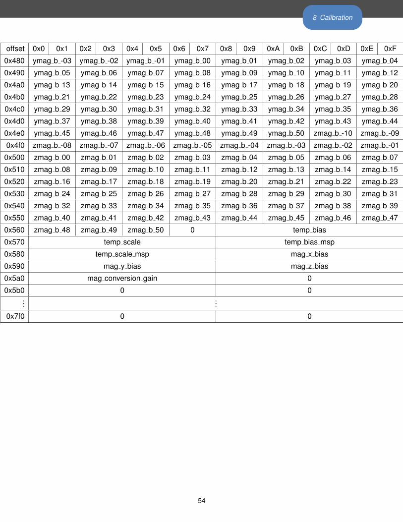
8 Calibration
offset 0x0 0x1 0x2 0x3 0x4 0x5 0x6 0x7 0x8 0x9 0xA 0xB 0xC 0xD 0xE 0xF
0x480 ymag b -03 ymag b -02 ymag b -01 ymag b 00 ymag b 01 ymag b 02 ymag b 03 ymag b 04
0x490 ymag b 05 ymag b 06 ymag b 07 ymag b 08 ymag b 09 ymag b 10 ymag b 11 ymag b 12
0x4a0 ymag b 13 ymag b 14 ymag b 15 ymag b 16 ymag b 17 ymag b 18 ymag b 19 ymag b 20
0x4b0 ymag b 21 ymag b 22 ymag b 23 ymag b 24 ymag b 25 ymag b 26 ymag b 27 ymag b 28
0x4c0 ymag b 29 ymag b 30 ymag b 31 ymag b 32 ymag b 33 ymag b 34 ymag b 35 ymag b 36
0x4d0 ymag b 37 ymag b 38 ymag b 39 ymag b 40 ymag b 41 ymag b 42 ymag b 43 ymag b 44
0x4e0 ymag b 45 ymag b 46 ymag b 47 ymag b 48 ymag b 49 ymag b 50 zmag b -10 zmag b -09
0x4f0 zmag b -08 zmag b -07 zmag b -06 zmag b -05 zmag b -04 zmag b -03 zmag b -02 zmag b -01
0x500 zmag b 00 zmag b 01 zmag b 02 zmag b 03 zmag b 04 zmag b 05 zmag b 06 zmag b 07
0x510 zmag b 08 zmag b 09 zmag b 10 zmag b 11 zmag b 12 zmag b 13 zmag b 14 zmag b 15
0x520 zmag b 16 zmag b 17 zmag b 18 zmag b 19 zmag b 20 zmag b 21 zmag b 22 zmag b 23
0x530 zmag b 24 zmag b 25 zmag b 26 zmag b 27 zmag b 28 zmag b 29 zmag b 30 zmag b 31
0x540 zmag b 32 zmag b 33 zmag b 34 zmag b 35 zmag b 36 zmag b 37 zmag b 38 zmag b 39
0x550 zmag b 40 zmag b 41 zmag b 42 zmag b 43 zmag b 44 zmag b 45 zmag b 46 zmag b 47
0x560 zmag b 48 zmag b 49 zmag b 50 0 temp bias
0x570 temp scale temp bias msp
0x580 temp scale msp mag x bias
0x590 mag y bias mag z bias
0x5a0 mag conversion gain 0
0x5b0 0 0...
...
0x7f0 0 0
54
9 Firmware Updates
9 Firmware UpdatesFirmware controls the various hardware components of your APDM product line (monitors, access points,
and docking stations). It is important to keep the firmware up to date to ensure that your system gets the
latest bug fixes and has access to the latest features. Firmware updates are bundled with updates to our
software products. Firmware can be updated either automatically or manually.
9.1 Automatic Firmware Updates
Whenever you configure your system, your hardware is first checked to ensure that the latest firmware is
installed. If not, you will be prompted to automatically update your hardware to the latest versions of the
firmware bundled with your system.
9.2 Manual Firmware Updates
Firmware can be updated manually as well. This functionality can be used to either flash the default firmware
to one of the hardware components, or to flash a different version. To access the “Update Firmware” dialog,
click on “Tools→ Update Firmware” in the menu bar.
9.2.1 Flash Default Firmware
Your system comes bundled with an up to date version of the firmware. This option will re-flash this version
of the firmware onto the specified monitor.
9.2.2 Flash Alternate Firmware
For testing purposes or to address an issue in a timely fashion, it may be necessary to flash a monitor with
a version of the firmware that is different than the bundled version. You will have to specify the alternate
firmware file to use with this option.
9.2.3 Force Update
When using either of the options above, if the firmware version on the target device(s) matches the firmware
version to be flashed, the device will be skipped. If the “Force update even if versions match” checkbox is
selected, however, the firmware will be flashed even if the versions match. This may be necessary in some
cases to recover a malfunctioning device.
55
10 Movement Monitor Reference
10 Movement Monitor Reference
10.1 Charging
A movement monitor charges its internal battery any time it is connected to a docking station. At the optimal
charge rate the movement monitors internal battery will complete its bulk charge (80%-90%) within an hour
for a fully discharged battery. It is recommended that the movement monitor be charged for up to 3 hours to
provide a peak charge to the battery ensuring it has the longest run time and improves battery life.
Warning: Your movement monitor uses a lithium battery. This battery may only be charged over a limited
temperature range. Never attempt to dock or charge your Opal when the temperature experienced can be
outside the range of 0 to 45 degrees Celsius (32 to 113 degrees Fahrenheit). The recommended charging
and docking temperature range is between 5 to 35 degrees Celsius (40 to 95 degrees Fahrenheit).
10.2 Powering Down
If you wish to power down your monitors for storage or travel, dock the monitors you wish to power down and
click on the “Power Off” button in Motion Studio. After this process is complete, these monitors will power
down when they are undocked. They can be powered back on by re-applying the saved configuration or
re-configuring the system.
10.3 Data Storage
The movement monitors utilize a flash card to store data while logging. This data can be downloaded by
using a docking station to dock the movement monitor. When the movement monitor is docked it finishes up
writing to the internal flash card and then releases it to the docking station. At this time the docking station
indicates to the PC that there is a new read only removable drive to be mounted. Using your file browser
you can navigate to the removable drive and copy the files off of it. The files are in a proprietary raw format
and need to be converted to either a HDF5 or CSV format that will provide data in calibrated SI units. This
conversion happens automatically if Motion Studiois used to import the data. Alternately, there are functions
in the SDK to do this conversion programmatically.
10.4 Cleaning
Cleaning the movement monitors case should be done by wiping the bottom of the case where it contacts
the skin with Rubbing alcohol or other cleaning wipe. If the entire case needs to be cleaned use only an ethyl
alcohol or isopropyl alcohol based wipe. Methyl alcohol should be avoided for cleaning the top since it will
56
10 Movement Monitor Reference
cause degradation of the plastic over time. The movement monitor should not be submerged in any liquids or
subjected to any high temperatures for cleaning. The straps on the monitor can be cleaned by wiping them
down with Rubbing alcohol. Alternatively the straps can be removed and washed separately using mild soap
and water.
10.5 Storage
Storage of the movement monitor should be in a dry static fee location. An anti-static bag or in the supplied
case is recommended. The movement monitor should also not be subjected to any large G forces to prevent
damage or changes to the calibration of the sensors in the monitor. It is recommended for the health of the
battery to to have at least a bulk charge during storage.
10.6 Drivers
Drivers are provided as part of the library distribution and Motion Studio. The drivers are installed automati-
cally as part of the Motion Studio installation process.
10.7 Firmware Updates
Updating the movement monitor firmware should be done using the Motion Studio software. This process is
detailed in Section 9 of this document.
10.8 Technical Specifications
• The accelerometer range is ±58.8 m/ s2 (6 g) (optionally ±19.6 m/ s2 (2 g)).
• Accelerometers have a typical noise density of 1.3 mm/ s2/√
Hz.
• The X and Y axis gyros have a range of ±34.9 rad/s (2000 dps)
• The Z axis gyro has a range of ±26.8 rad/s (1500 dps)
• The X and Y axis gyros have a typical noise density of 0.81 mrad/ s/√
Hz
• The Z axis gyro have a typical noise density of 2.2 mrad/ s/√
Hz
• Magnetometers have a range of ±6 Gauss
• The magnetometers have a typical noise density is 160 nT/√
Hz
• Positive X is pointing from the monitor toward the connector. Looking top down at the monitor with
positive X pointing away from you, positive Y is pointing left. Z is pointing up out of the top of the case.
Angular velocity sign is defined according to a right hand rule. A counterclockwise rotation about the Z
axis looking from the +Z direction is positive.
57
10 Movement Monitor Reference
10.9 LED Reference
10.9.1 Status Codes and LED Colors/Patterns
The LEDs on the access points and movement monitors provide important information about the operating
state of the hardware, including error statuses. The tables below list the LED patterns associated with these
states and can be useful in troubleshooting issues encountered with the hardware.
10.9.2 Movement Monitor LED Reference
Movement monitors contain a RGB LED capable of outputting a wide array of colors to the user to indicate
its current state. The following colors are used: white (�), red (�), yellow (�), green (�), cyan (�), blue (�),
magenta (�), and led off ( ). In the off state the LED will appear as a non illuminated white dot in the corner
of the monitor opposite the docking connector. All LED patterns are output on a repeating cycle which may
vary in period depending on the pattern. In all cases the last color listed will stay constant until the pattern
repeats. For example “� � ” will blink yellow twice and then stay off until the pattern repeats.
58
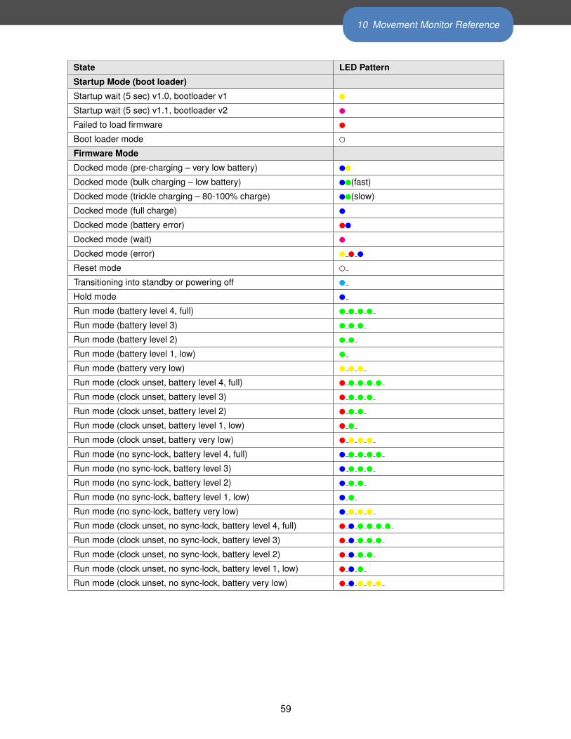
10 Movement Monitor Reference
State LED Pattern
Startup Mode (boot loader)
Startup wait (5 sec) v1.0, bootloader v1 �
Startup wait (5 sec) v1.1, bootloader v2 �
Failed to load firmware �
Boot loader mode �
Firmware Mode
Docked mode (pre-charging – very low battery) ��
Docked mode (bulk charging – low battery) ��(fast)
Docked mode (trickle charging – 80-100% charge) ��(slow)
Docked mode (full charge) �
Docked mode (battery error) ��
Docked mode (wait) �
Docked mode (error) � � �
Reset mode �
Transitioning into standby or powering off �
Hold mode �
Run mode (battery level 4, full) � � � �
Run mode (battery level 3) � � �
Run mode (battery level 2) � �
Run mode (battery level 1, low) �
Run mode (battery very low) � � �
Run mode (clock unset, battery level 4, full) � � � � �
Run mode (clock unset, battery level 3) � � � �
Run mode (clock unset, battery level 2) � � �
Run mode (clock unset, battery level 1, low) � �
Run mode (clock unset, battery very low) � � � �
Run mode (no sync-lock, battery level 4, full) � � � � �
Run mode (no sync-lock, battery level 3) � � � �
Run mode (no sync-lock, battery level 2) � � �
Run mode (no sync-lock, battery level 1, low) � �
Run mode (no sync-lock, battery very low) � � � �
Run mode (clock unset, no sync-lock, battery level 4, full) � � � � � �
Run mode (clock unset, no sync-lock, battery level 3) � � � � �
Run mode (clock unset, no sync-lock, battery level 2) � � � �
Run mode (clock unset, no sync-lock, battery level 1, low) � � �
Run mode (clock unset, no sync-lock, battery very low) � � � � �
59
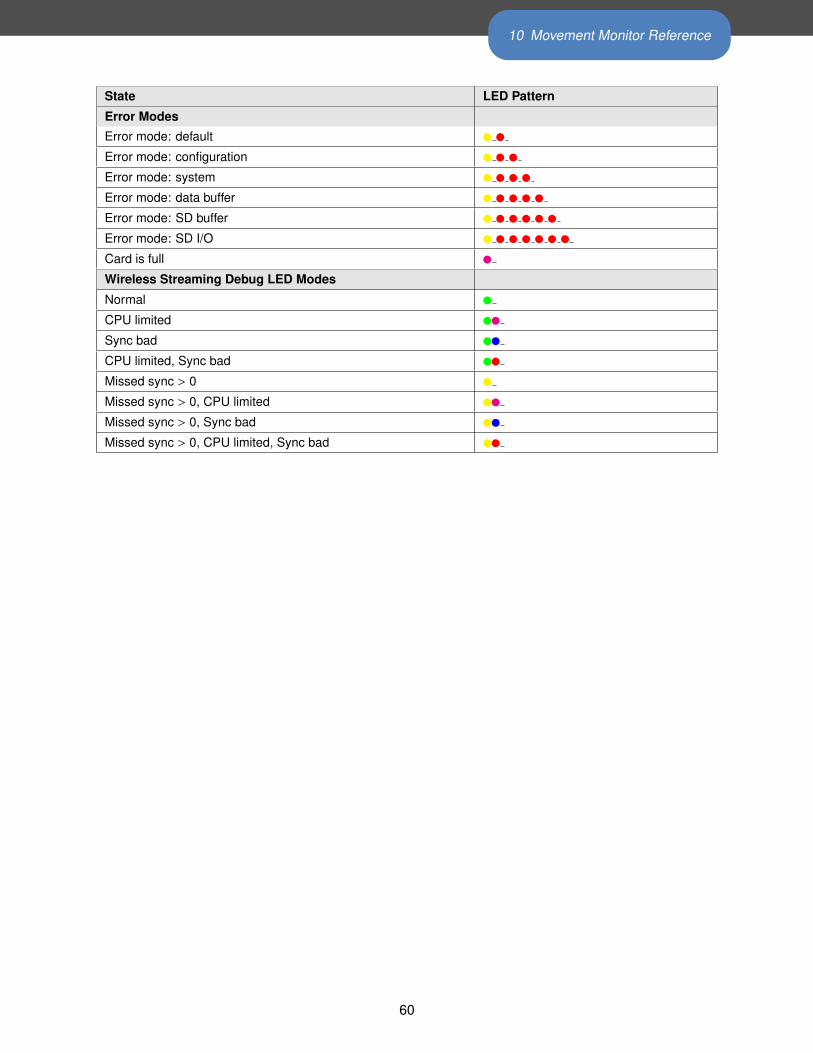
10 Movement Monitor Reference
State LED Pattern
Error Modes
Error mode: default � �
Error mode: configuration � � �
Error mode: system � � � �
Error mode: data buffer � � � � �
Error mode: SD buffer � � � � � �
Error mode: SD I/O � � � � � � �
Card is full �
Wireless Streaming Debug LED Modes
Normal �
CPU limited ��
Sync bad ��
CPU limited, Sync bad ��
Missed sync > 0 �
Missed sync > 0, CPU limited ��
Missed sync > 0, Sync bad ��
Missed sync > 0, CPU limited, Sync bad ��
60
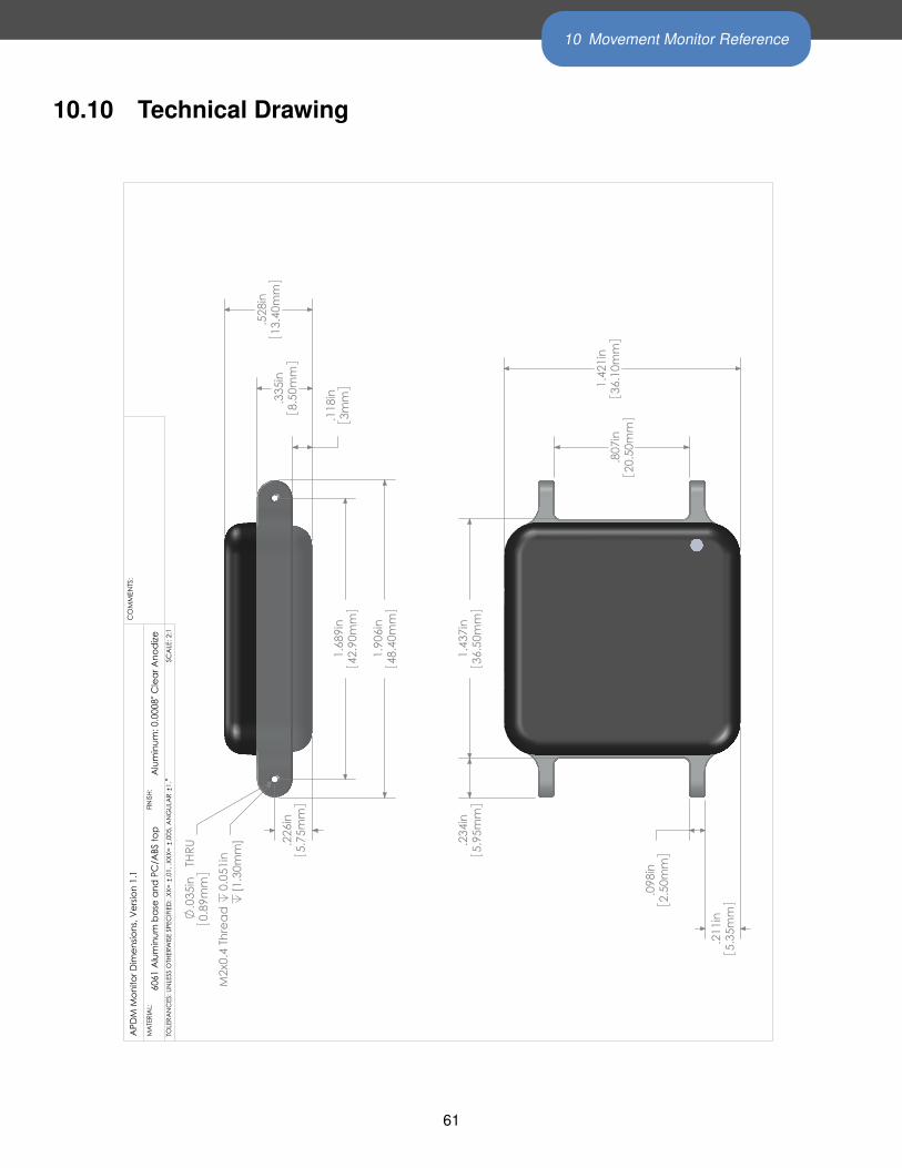
10 Movement Monitor Reference
10.10 Technical Drawing
.528
in13
.40m
m
1.90
6in
48.4
0mm
.118
in3m
m.335
in8.
50m
m
1.68
9in
42.9
0mm
.226
in5.
75m
m
.035
in T
HRU
0.89
mm [1.3
0mm
]M
2x0.
4 Th
read
0.
051i
n
1.43
7in
36.5
0mm
.234
in5.
95m
m
1.42
1in
36.1
0mm
.807
in20
.50m
m
.211
in5.
35m
m
.098
in2.
50m
m
APD
M M
onito
r Dim
ensio
ns, V
ersio
n 1.
1C
OM
MEN
TS:
6061
Alu
min
um b
ase
and
PC/A
BS to
pM
ATE
RIA
L:
SCA
LE: 2
:1
Alu
min
um: 0
.000
8" C
lear
Ano
dize
TOLE
RAN
CES
: UN
LESS
OTH
ERW
ISE
SPEC
IFIE
D: .
XX=
.01,
.XXX
= .0
05, A
NG
ULA
R 1.
FINIS
H:
61
11 Access Point Reference
11 Access Point Reference
11.1 Drivers
Drivers are provided as part of the SDK distribution and Motion Studio.
11.2 Firmware Updates
Updating the movement monitor firmware should be done using the Motion Studio software.
11.3 Mounting and Placement
The antennas of the access point are located directly behind the black plastic face of the access point. The
access point(s) should be aimed such that this face is in the approximate direction of the area where the
movement monitors will be used.
11.4 Using Multiple Access Points
Having multiple access points is useful when redundancy is needed or when recording from more than 6
Opals. To configure multiple access points, you must have them attached to your computer via USB at the
time of configuration. Additionally, the access points must be linked via RCA cable (a standard stereo cable).
The rest of the configuration is handled automatically.
11.4.1 Redundancy
In some recording environments, it may be difficult to always maintain line of site from your streaming Opals
to the access point. For example, you may have a bend in a hallway, or you may be operating in a large open
space where you are unlikely to receive a reflected signal if the Opal is pointed away from the access point.
In these scenarios, multiple access points can be used to provide better coverage. The streaming Opals will
communicate with whichever access point is providing the stronger signal.
11.4.2 Streaming from more than 6 Opals
Each access point can communicate with up to 6 Opals simultaneously. You can therefore stream from up to
12 Opals with 2 access points, or 24 Opals with 4 access points.
62
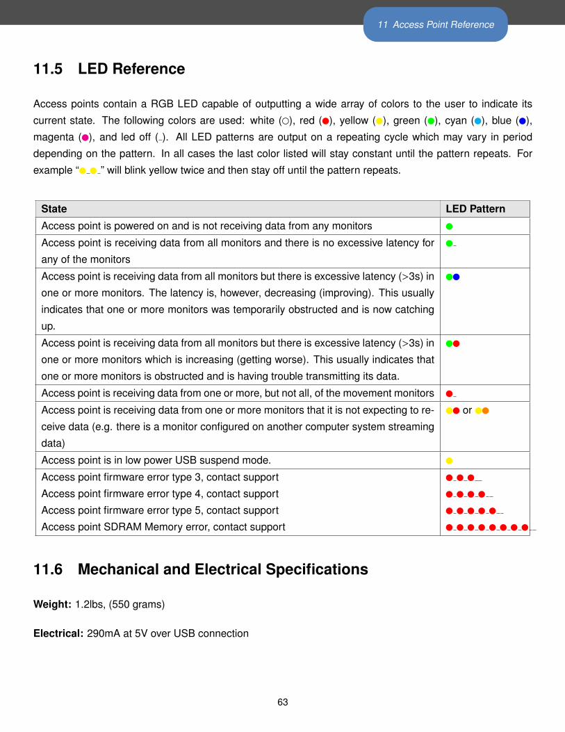
11 Access Point Reference
11.5 LED Reference
Access points contain a RGB LED capable of outputting a wide array of colors to the user to indicate its
current state. The following colors are used: white (�), red (�), yellow (�), green (�), cyan (�), blue (�),
magenta (�), and led off ( ). All LED patterns are output on a repeating cycle which may vary in period
depending on the pattern. In all cases the last color listed will stay constant until the pattern repeats. For
example “� � ” will blink yellow twice and then stay off until the pattern repeats.
State LED Pattern
Access point is powered on and is not receiving data from any monitors �
Access point is receiving data from all monitors and there is no excessive latency for
any of the monitors
�
Access point is receiving data from all monitors but there is excessive latency (>3s) in
one or more monitors. The latency is, however, decreasing (improving). This usually
indicates that one or more monitors was temporarily obstructed and is now catching
up.
��
Access point is receiving data from all monitors but there is excessive latency (>3s) in
one or more monitors which is increasing (getting worse). This usually indicates that
one or more monitors is obstructed and is having trouble transmitting its data.
��
Access point is receiving data from one or more, but not all, of the movement monitors �
Access point is receiving data from one or more monitors that it is not expecting to re-
ceive data (e.g. there is a monitor configured on another computer system streaming
data)
�� or ��
Access point is in low power USB suspend mode. �
Access point firmware error type 3, contact support � � �
Access point firmware error type 4, contact support � � � �
Access point firmware error type 5, contact support � � � � �
Access point SDRAM Memory error, contact support � � � � � � � �
11.6 Mechanical and Electrical Specifications
Weight: 1.2lbs, (550 grams)
Electrical: 290mA at 5V over USB connection
63
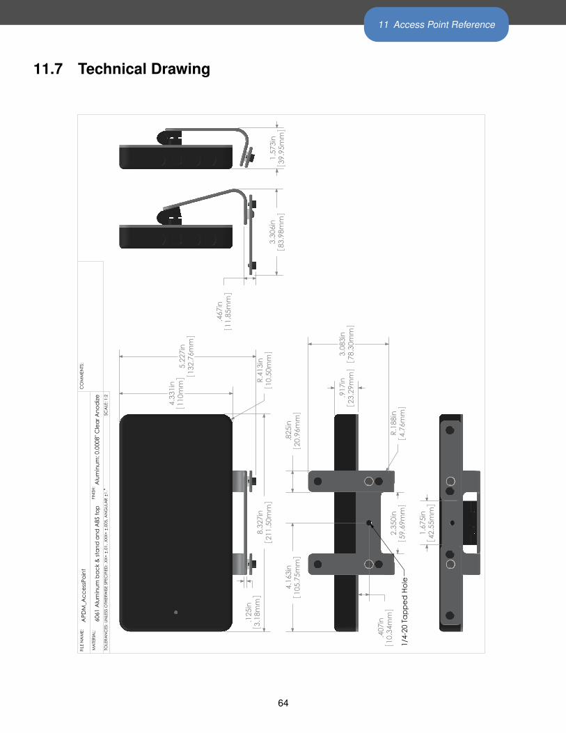
11 Access Point Reference
11.7 Technical Drawing
5.22
7in
132.
76m
m
4.33
1in
110m
m R.41
3in
10.5
0mm
8.32
7in
211.
50m
m
.125
in3.
18m
m
.917
in23
.29m
m
2.35
0in
59.6
9mm
3.08
3in
78.3
0mm
.825
in20
.96m
m
.407
in10
.34m
m
4.16
3in
105.
75m
m
R.18
8in
4.76
mm
1/4-
20 T
appe
d H
ole
3.30
6in
83.9
8mm
.467
in11
.85m
m
1.57
3in
39.9
5mm
1.67
5in
42.5
5mm
APD
M_A
cces
sPoi
ntFI
LE N
AM
E:C
OM
MEN
TS:
6061
Alu
min
um b
ack
& st
and
and
ABS
top
MA
TERI
AL:
SCA
LE: 1
:2
FINIS
H:
TOLE
RAN
CES
: UN
LESS
OTH
ERW
ISE
SPEC
IFIE
D: .
XX=
.01,
.XXX
= .0
05, A
NG
ULA
R 1.
Alu
min
um: 0
.000
8" C
lear
Ano
dize
64

12 Docking Station Reference
12 Docking Station Reference
12.1 Drivers
Drivers are provided as part of the SDK distribution and Motion Studio.
12.2 Power
• If running a single docking station, it can be powered from:
– a USB cable plugged into a dedicated USB port on your computer
– a USB cable plugged into a a powered USB hub
– a USB cable plugged into a wall adapter (charging only)
– the external AC adapter (charging only)
• If running a chain of 2 or more docking stations:
– For data transfer, both USB and external AC power are required. If a power-related error occurs,
then the docking station will blink yellow until external or power is plugged in.
– if only charging is required, the external AC power must be used
12.3 Mechanical and Electrical Specifications
Weight: 0.2 lbs, (90 grams)
Electrical: 500mA at 5V over USB connection, or 500mA per dock when a chain is supplied by external
power.
65
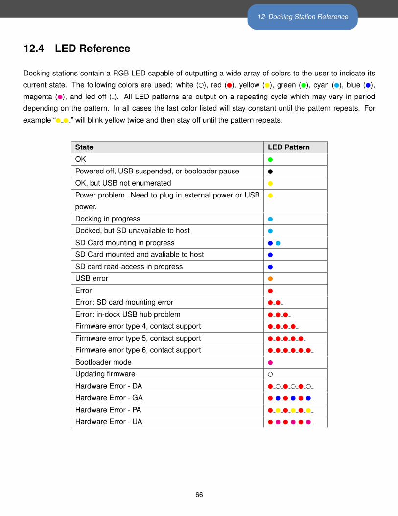
12 Docking Station Reference
12.4 LED Reference
Docking stations contain a RGB LED capable of outputting a wide array of colors to the user to indicate its
current state. The following colors are used: white (�), red (�), yellow (�), green (�), cyan (�), blue (�),
magenta (�), and led off ( ). All LED patterns are output on a repeating cycle which may vary in period
depending on the pattern. In all cases the last color listed will stay constant until the pattern repeats. For
example “� � ” will blink yellow twice and then stay off until the pattern repeats.
State LED Pattern
OK �
Powered off, USB suspended, or booloader pause �
OK, but USB not enumerated �
Power problem. Need to plug in external power or USB
power.
�
Docking in progress �
Docked, but SD unavailable to host �
SD Card mounting in progress � �
SD Card mounted and avaliable to host �
SD card read-access in progress �
USB error �
Error �
Error: SD card mounting error � �
Error: in-dock USB hub problem � � �
Firmware error type 4, contact support � � � �
Firmware error type 5, contact support � � � � �
Firmware error type 6, contact support � � � � � �
Bootloader mode �
Updating firmware �
Hardware Error - DA � � � � � �
Hardware Error - GA � � � � � �
Hardware Error - PA � � � � � �
Hardware Error - UA � � � � � �
66
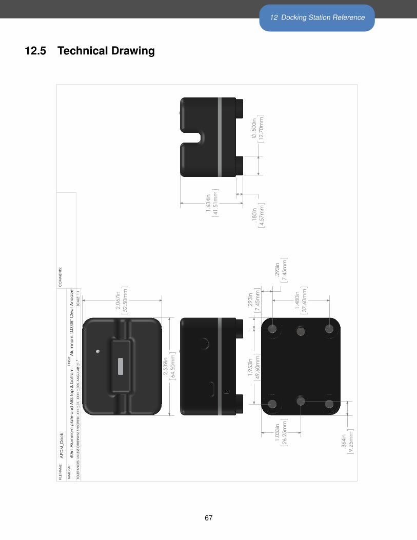
12 Docking Station Reference
12.5 Technical Drawing
1.
634i
n41
.51m
m
.1
80in
4.57
mm
.5
00in
12.7
0mm
1.
953i
n49
.60m
m
.2
93in
7.45
mm
.2
93in
7.45
mm
1.
480i
n37
.60m
m
1.
033i
n26
.25m
m
.3
64in
9.25
mm
2.
067i
n52
.50m
m
2.
539i
n64
.50m
m
APD
M_D
ock
FILE
NA
ME:
CO
MM
ENTS
:
6061
Alu
min
um p
late
and
ABS
top
& b
otto
mM
ATE
RIA
L:
SCA
LE: 1
:1TO
LERA
NC
ES: U
NLE
SS O
THER
WIS
E SP
ECIF
IED
: .XX
= .0
1, .X
XX=
.005
, AN
GUL
AR
1.
Alu
min
um: 0
.000
8" C
lear
Ano
dize
FINIS
H:
67

13 Technical Support
13 Technical SupportPlease contact us at:
web: support.apdm.com
email: [email protected]
68