Expanding the RBS 3206 from Mid-Size to Full-Size
20
Expanding the RBS 3206 from Mid-Size to Full-Size RBS 3206 OPERATING INSTRUCS
Transcript of Expanding the RBS 3206 from Mid-Size to Full-Size

Expanding the RBS 3206 from Mid-Size toFull-SizeRBS 3206
OPERATING INSTRUCS

Copyright
© Ericsson AB 2006 – All Rights Reserved
Disclaimer
No part of this document may be reproduced in any form without the writtenpermission of the copyright owner.
The contents of this document are subject to revision without notice due tocontinued progress in methodology, design and manufacturing. Ericsson shallhave no liability for any error or damage of any kind resulting from the useof this document.
4/1543-COH 109 2069 Uen B 2006-11-21

Contents
Contents
1 Introduction 1
1.1 Target Group 1
1.2 Abbreviations 1
2 Prerequisites 2
2.1 Documentation 2
2.2 Tools 3
2.3 Conditions 3
3 Procedure 4
3.1 Expanding the RBS 3206M Cabinet 4
3.2 Performing Concluding Routines 14
3.3 Environment 14
4 Related Documents 15
5 Revision History 16
5.1 Revision A to B 16
4/1543-COH 109 2069 Uen B 2006-11-21

Expanding the RBS 3206 from Mid-Size to Full-Size
4/1543-COH 109 2069 Uen B 2006-11-21

Introduction
1 Introduction
This document describes how to expand an RBS 3206 Mid-Size (3206M) to anRBS 3206 Full-Size (3206F).
1.1 Target Group
These instructions are for the installation personnel performing the expansionon site.
Qualifications of Installation Personnel
Ericsson recommends that personnel performing the expansion possess thefollowing:
• Technical college or equivalent education with an emphasis on electricalengineering
• Familiarity with the equipment used during the expansion
• An understanding of technical English
1.2 Abbreviations
CF Connection Field
CBU Control Base Unit
ESD Electrostatic Discharge
FCU Fan Control Unit
FU Filter Unit
OMC Operation and Maintenance Center
PDU Power Distribution Unit
PSU Power Supply Unit
RU Radio Unit
14/1543-COH 109 2069 Uen B 2006-11-21

Expanding the RBS 3206 from Mid-Size to Full-Size
2 Prerequisites
This section provides information on health and safety, tools, equipment, andthe conditions to be met before starting the work.
2.1 Documentation
Ensure that the following documents are read and understood:
• Personal Health and Safety Information
• System Safety Information
• Product Handling
Ensure that the following documents are available:
• Installation Instruction
• Hardware Configuration Data
• Replacing Power and Alarm Units
• Verification of Installation at Site
Danger!
Improper electrical installation may cause fire or electric shock that is likely tobe fatal. Only a qualified and authorized electrician is permitted to install ormodify electrical installations.
Caution!
Sharp metal edges may exist that can cause cuts to the skin or clothing. Wearprotective gloves when handling this equipment.
2 4/1543-COH 109 2069 Uen B 2006-11-21

Prerequisites
Caution!
Stop! This product contains components sensitive to ESD. Use an approvedESD wrist strap, connected to the product grounding point, to avoid damagingthese components.
2.2 Tools
The following tools are required:
ESD wrist strap
5 mm nut driver
Riveting tool
0.8 × 4.0 × 100 mm screwdriver
T10, T20, T25, and T30 Torx screwdrivers
0.8 Nm torque wrench for SMA connectors, LTT 601 83
1.7 Nm torque wrench for TNC connectors, LTT 601 93
2.8 Nm torque wrench for N-type connectors, LTT 601 94
25 Nm torque wrench for 7/16 connectors, LTT 601 115
RU extractor tool, LTD 117 02
2.3 Conditions
The following conditions must be met before work starts:
Before Going to the Site
Before going to the site, ensure the following:
• Permission to access the site has been received
• All tools and instruments are available
Before Starting the Installation
Before starting the expanding, ensure the following:
34/1543-COH 109 2069 Uen B 2006-11-21

Expanding the RBS 3206 from Mid-Size to Full-Size
• The Health and Safety Information has been read
• The equipment required for the procedure is available
• The tools and documentation are available
• No alarms are present in the RBS
3 Procedure
This section describes how to expand an RBS 3206M to an RBS 3206F.
3.1 Expanding the RBS 3206M Cabinet
This section describes how to expand the RBS 3206M cabinet.
3.1.1 Expanding the Cabinet with Site Power On
This section describes how to expand the RBS 3206M cabinet while the sitepower is turned on.
1. Remove the cover plates (A) located on either side of the lower part of theRBS, using a T20 Torx screwdriver.
P015714B
A
Figure 1 Cover Plates
4 4/1543-COH 109 2069 Uen B 2006-11-21

Procedure
2. Remove the screws attaching the cover vent (B) on top of the cabinet,using a T20 Torx screwdriver.
Caution!
Rotating fan blades can cause injury to body parts that come into contact withthe blades. Blades in fan units continue to rotate for a period of time, even afterthe fan has been switched off. Wait until fans have stopped rotating completelybefore starting work on or near fans.
P015715A
B
Figure 2 Cover Vent
3. Remove the air-stop plate (C) located under the baseband and RU subrack,using a T20 Torx screwdriver.
54/1543-COH 109 2069 Uen B 2006-11-21

Expanding the RBS 3206 from Mid-Size to Full-Size
RBS front
P015561C
Preinstalled air-stop plate
×3C
Figure 3 Air-Stop Plate
4. Remove the cover plate (D) in the FU subrack, using a T20 Torxscrewdriver.
P015716B
D
Figure 4 Filter Unit Cover Plate
5. Install up to three FUs and dummy units in the unused slots according toInstallation Instruction.
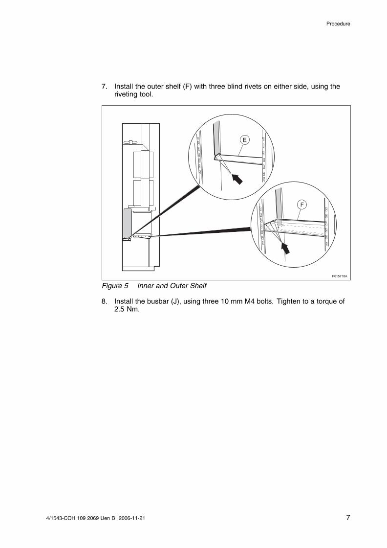
6. Install the inner shelf (E) with two blind rivets, using the riveting tool, oneither side.
6 4/1543-COH 109 2069 Uen B 2006-11-21
Procedure
7. Install the outer shelf (F) with three blind rivets on either side, using theriveting tool.
P015718A
E
F
Figure 5 Inner and Outer Shelf
8. Install the busbar (J), using three 10 mm M4 bolts. Tighten to a torque of2.5 Nm.
74/1543-COH 109 2069 Uen B 2006-11-21

Expanding the RBS 3206 from Mid-Size to Full-Size
P015720A
J
Figure 6 Busbar
9. Install the new digital subrack (G), using four M6 bolts. Tighten to a torqueof 9.8 Nm.
10. Install the cable shelf (H), using four M6 bolts. Tighten to a torque of 8 Nm.
8 4/1543-COH 109 2069 Uen B 2006-11-21

Procedure
P015719A
G
H
S
Figure 7 New Baseband Subrack and Cable Shelf
11. Remove the screws on the FCU (K), using a T20 Torx screwdriver.
12. Remove six plus six screws from each of the two CFs (L), using a T20Torx screwdriver.
Note: Loosen the entire CFs, not just the separate plates.
P015722B
L LK
Figure 8 FCU and CFs
94/1543-COH 109 2069 Uen B 2006-11-21

Expanding the RBS 3206 from Mid-Size to Full-Size
3.1.2 Expanding the Cabinet with Site Power Off
This section describes how to expand the RBS 3206M cabinet with the sitepower switched off.
13. Switch off the site power to the cabinet.
14. Disconnect the power cables (M) from the PDU-03 (N). See ReplacingPower and Alarm Units.
15. Disconnect and remove all PDU cables connected to the FCU, CBU, andRUs.
16. Remove the PDU-03 according to Replacing Power and Alarm Units andremove the cables.
17. Remove the right hand cover plate (T).
P015723B
N T
M
Figure 9 PDU-03
Note: When installing the units, be sure to use the new, longer cables fromthe installation kit.
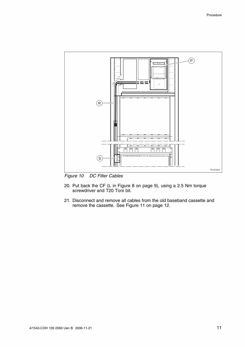
18. Install the DC filter (P) according to Replacing Power and Alarm Units androute the cables (R) to the left and down to the busbar (J, see Figure 6on page 8).
19. Open the cable holder (S), insert the cables, and close it. See Figure 10on page 11.
10 4/1543-COH 109 2069 Uen B 2006-11-21
Procedure
P015720A
R
P
S
Figure 10 DC Filter Cables
20. Put back the CF (L in Figure 8 on page 9), using a 2.5 Nm torquescrewdriver and T20 Torx bit.
21. Disconnect and remove all cables from the old baseband cassette andremove the cassette. See Figure 11 on page 12.
114/1543-COH 109 2069 Uen B 2006-11-21
Expanding the RBS 3206 from Mid-Size to Full-Size
P015726A
Figure 11 Old Baseband Cassette
22. Install up to three RUs according to Hardware Configuration Data.
23. Connect the power cable between the busbar and the PDU-02.
24. Install the PDU-02 according to Replacing Power and Alarm Units.
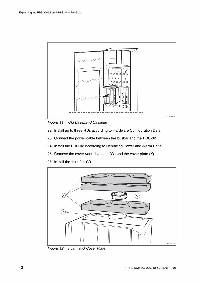
25. Remove the cover vent, the foam (W) and the cover plate (X).
26. Install the third fan (V).
P015717A
W
X
V
Figure 12 Foam and Cover Plate
12 4/1543-COH 109 2069 Uen B 2006-11-21

Procedure
Note: Route the cables from the fan to the FCU to ensure that the working ofthe fan is unaffected when the foam is put back.
27. Connect the fan connector (Y) to the FCU (K) and put back the foam. Seealso Hardware Configuration Data.
P015721B
K
Y
Figure 13 Fan and Fan Connector
28. Put back the cover vent (B) inFigure 2 on page 5, using a 2.5 Nm torquescrewdriver and T20 Torx bit.
29. Put back the FCU, using a 2.5 Nm torque screwdriver and T20 Torx bit.
30. Install the dummy plate (Z) in the old location of the PDU-03, using a 2.5Nm torque screwdriver and T20 Torx bit.
134/1543-COH 109 2069 Uen B 2006-11-21

Expanding the RBS 3206 from Mid-Size to Full-Size
P015727A
Z
Figure 14 PDU-03 Dummy Plate
31. Connect the new cables to the new digital subrack, FU, FCU, RUs, andPDU-02 according to Hardware Configuration Data.
Note: If an ET board is installed, then position it directly below the CF where itis connected. Otherwise the cables may not be long enough.
32. Connect the site power cables to the DC filter according to ReplacingPower and Alarm Units.
33. Turn on the site power to the cabinet.
34. Switch on the PDU-02 circuit breakers.
3.2 Performing Concluding Routines
This section describes what to do before leaving the site.
See Verification of Installation at Site for instructions on how to power up theRBS and perform concluding routines.
3.3 Environment
Ericsson strongly recommends that installers pay careful attention to theenvironment when cleaning the site after installation. In particular, recycleall waste that can be recycled and sort the rest so that it can be disposed ofin accordance with local regulations.
14 4/1543-COH 109 2069 Uen B 2006-11-21

Related Documents
Table 1 Waste Sorting and Recycling
Item Recycle or Sort
Bubble plastic
Cable insulation from crimping, brazingor welding
Cable pieces, low metallic content
Cable tie clippings
Foam
Packing chips
Polystyrene
Recycle or sort as plastic
Paper and wood Recycle or sort as paper
Cable pieces, high metallic content
Metal from cable ladders
Nuts, bolts, washers and screws
Recycle or sort as metal
4 Related Documents
The following documents are related to these installation instructions.
• Hardware Configuration Data, 3/1551-COH 109 548
• Installation Instruction, 1/1531-COH 109 2069
• Personal Health and Safety Information, 124 46-2885
• Product Handling, 11/1551-HRB 105 102/1
• Replacing Power and Alarm Units, 3/1543-COH 109 2069
• Replacing Radio Units, 1/1543-COH 109 2069
• System Safety Information, 124 46-2886
• Technical Product Description, 1/1551-COH 109 2069
• Verification of Installation at Site, 1/1532-COH 109 2069
154/1543-COH 109 2069 Uen B 2006-11-21

Expanding the RBS 3206 from Mid-Size to Full-Size
5 Revision History
5.1 Revision A to B
Editorial changes.
16 4/1543-COH 109 2069 Uen B 2006-11-21