Determination and selecting the optimum thickness of insulation for buildings in hot countries by...
10
Determination and selecting the optimum thickness of insulation for buildings in hot countries by accounting for solar radiation Mohammed J. Al-Khawaja * University of Qatar, Department of Mechanical Engineering, P.O. Box 2713, Doha, Qatar Received 17 November 2003; accepted 22 March 2004 Available online 18 May 2004 Abstract Determination and selecting the optimum thickness of insulation is the prime interest of many engi- neering applications. One of those applications is insulating buildings with an appropriate insulation. Calculations have been done for the determination of the optimum thickness of insulation for some insulating materials used in order to reduce the rate of heat flow to the buildings in hot countries. Reducing heat flow rate would reduce the electricity cost for the house lifetime. The solar energy radiation is cal- culated and used to calculate the solar-air temperature which is employed for the determination of the heat flow rate. Some results were obtained for a typical house in Qatar which is an example of hot area. The wallmate insulation is found to have the best performance for houses in Qatar. Ó 2004 Elsevier Ltd. All rights reserved. Keywords: Optimum thickness of insulation determination; Solar radiation calculations; Air conditioners for buildings, and insulation in hot countries 1. Introduction Insulating buildings, such as walls, roofs and floors is an important matter for reducing the rate of heat flowing into (in time of summer) and from (in time of winter) the houses. To reduce the heat flow efficiently we should select the proper insulation by accounting for the purpose, envi- ronment, ease of handling and installation, and the cost. The latter is an important factor that will alter our decision for selecting the insulation. As we know, the final selection among insulations * Corresponding author. Tel.: +974-485-2109; fax: +974-467-0421. E-mail address: [email protected] (M.J. Al-Khawaja). 1359-4311/$ - see front matter Ó 2004 Elsevier Ltd. All rights reserved. doi:10.1016/j.applthermaleng.2004.03.019 Applied Thermal Engineering 24 (2004) 2601–2610 www.elsevier.com/locate/apthermeng
-
Upload
independent -
Category
Documents
-
view
0 -
download
0
Transcript of Determination and selecting the optimum thickness of insulation for buildings in hot countries by...

Applied Thermal Engineering 24 (2004) 2601–2610www.elsevier.com/locate/apthermeng
Determination and selecting the optimum thicknessof insulation for buildings in hot countries by accounting
for solar radiation
Mohammed J. Al-Khawaja *
University of Qatar, Department of Mechanical Engineering, P.O. Box 2713, Doha, Qatar
Received 17 November 2003; accepted 22 March 2004
Available online 18 May 2004
Abstract
Determination and selecting the optimum thickness of insulation is the prime interest of many engi-
neering applications. One of those applications is insulating buildings with an appropriate insulation.
Calculations have been done for the determination of the optimum thickness of insulation for some
insulating materials used in order to reduce the rate of heat flow to the buildings in hot countries. Reducing
heat flow rate would reduce the electricity cost for the house lifetime. The solar energy radiation is cal-
culated and used to calculate the solar-air temperature which is employed for the determination of the heat
flow rate. Some results were obtained for a typical house in Qatar which is an example of hot area. The
wallmate insulation is found to have the best performance for houses in Qatar.� 2004 Elsevier Ltd. All rights reserved.
Keywords: Optimum thickness of insulation determination; Solar radiation calculations; Air conditioners for buildings,
and insulation in hot countries
1. Introduction
Insulating buildings, such as walls, roofs and floors is an important matter for reducing the rateof heat flowing into (in time of summer) and from (in time of winter) the houses. To reduce theheat flow efficiently we should select the proper insulation by accounting for the purpose, envi-ronment, ease of handling and installation, and the cost. The latter is an important factor that willalter our decision for selecting the insulation. As we know, the final selection among insulations
* Corresponding author. Tel.: +974-485-2109; fax: +974-467-0421.
E-mail address: [email protected] (M.J. Al-Khawaja).
1359-4311/$ - see front matter � 2004 Elsevier Ltd. All rights reserved.
doi:10.1016/j.applthermaleng.2004.03.019
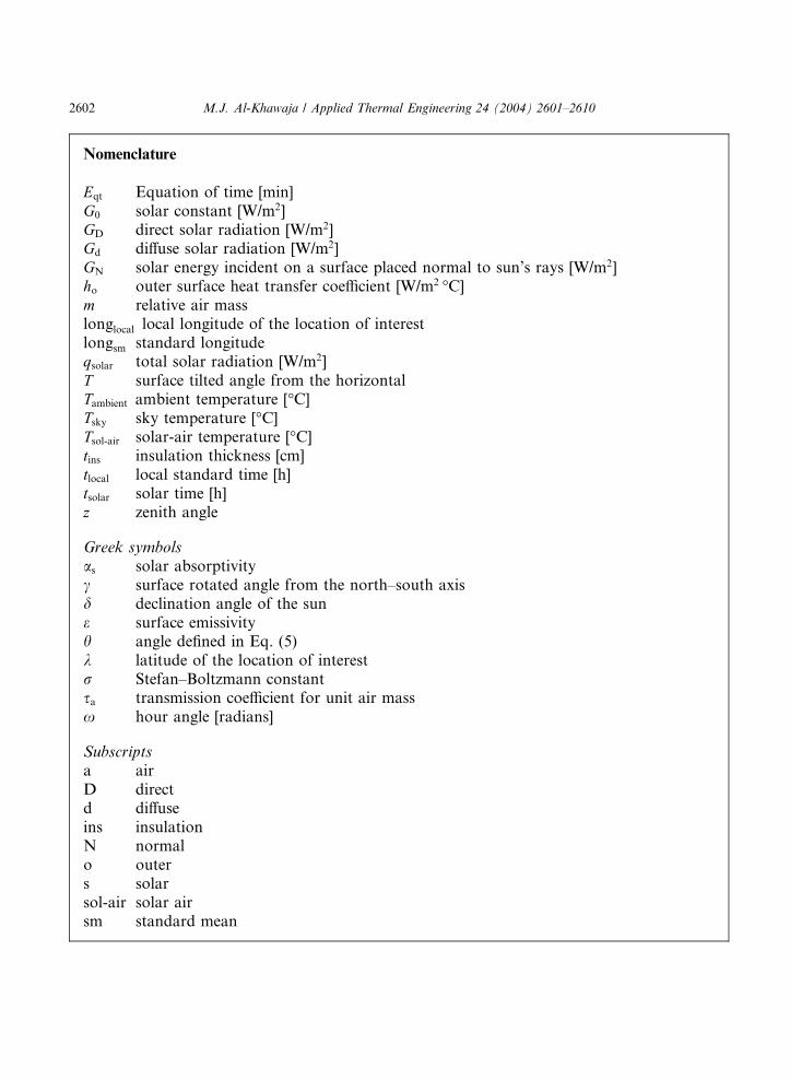
Nomenclature
Eqt Equation of time [min]G0 solar constant [W/m2]GD direct solar radiation [W/m2]Gd diffuse solar radiation [W/m2]GN solar energy incident on a surface placed normal to sun’s rays [W/m2]ho outer surface heat transfer coefficient [W/m2 �C]m relative air masslonglocal local longitude of the location of interestlongsm standard longitudeqsolar total solar radiation [W/m2]T surface tilted angle from the horizontalTambient ambient temperature [�C]Tsky sky temperature [�C]Tsol-air solar-air temperature [�C]tins insulation thickness [cm]tlocal local standard time [h]tsolar solar time [h]z zenith angle
Greek symbolsas solar absorptivityc surface rotated angle from the north–south axisd declination angle of the sune surface emissivityh angle defined in Eq. (5)k latitude of the location of interestr Stefan–Boltzmann constantsa transmission coefficient for unit air massx hour angle [radians]
Subscriptsa airD directd diffuseins insulationN normalo outers solarsol-air solar airsm standard mean
2602 M.J. Al-Khawaja / Applied Thermal Engineering 24 (2004) 2601–2610

M.J. Al-Khawaja / Applied Thermal Engineering 24 (2004) 2601–2610 2603
that meet the requirements is made on the basis of the lowest cost. Once the choices are narrowedto a few, an economic analysis is performed to identify the one with the minimum total cost. Thethickness of insulation is also determined on the basis of minimum cost, as discussed below.
To determine the lowest cost, we need to determine, for any given insulation, the optimumthickness of insulation, which is the thickness corresponding to the minimum total cost. Here, thetotal cost consists of the cost of the insulation and the cost of electricity for the lifetime of the house.
A tremendous work has been done for the determination of heating and cooling loads ofbuildings using the handbooks established by ASHRAE [1]. But the case of reducing the heattransfer to the buildings during summer using an adequate insulation was not analyzed consid-erably. It is clear that this insulation might make a lot of savings for the lifetime of the house.
Another important factor that effects the optimum thickness of insulation is the solar radiationenergy flowing into the house. The solar radiation can be accounted for by introducing the solar-air temperature [2] which is defined as the equivalent outdoor air temperature that gives the samerate of heat flow to a surface as would the combination of the incident solar radiation, convectionwith ambient air, and radiation exchange with the sky and the surrounding surfaces.
2. Solar radiation calculations
We have used the astronomical calculations to determine the hourly solar radiation flux overthe year. Solar radiation calculations have more advantages over the measured ones using solarcollector. This is because the measured solar radiation depends mainly on the weather conditions,but the calculated one which does not depend on the climate would be more reliable over theyears.
The solar radiation incident outside the earth’s atmosphere is called extraterrestrial radiation.On average the extraterrestrial irradiance is 1353 W/m2 [3] which is called solar constant G0. Thissolar energy is considerably weakened due to absorption, scattering, and reflection by theatmosphere. The solar energy that reaches the earth’s surface is attenuated to about 950 W/m2 ona clear sky and much less on cloudy or smoggy days.
It should be mentioned that the solar energy incident on a surface on earth is considered toconsist of direct and diffuse parts [3]. The part of solar radiation that reaches the earth’s surfacewithout being scattered or absorbed by the atmosphere is called direct solar radiation GD. Thescattered radiation is assumed to reach the earth’s surface uniformly from all directions and iscalled diffuse solar radiation Gd. Then the total solar energy incident on the unit area of a surfaceon a ground is qsolar ¼ GD þ Gd. The calculations of the direct solar energy would be proposedbelow. However, the diffuse radiation can be approximated as 10% of the total radiation on aclear day to nearly 100% on a totally cloudy day [4].
The direct solar radiation depends on the sun’s position and surface orientation. If the surfaceon earth is placed normal to the rays of sun, then the radiant energy incident GN upon the surfaceis given as [5]
GN ¼ G0sma ð1Þ
The value of transmission coefficient for unit air mass sa is slightly less in the summer than in thewinter because the atmosphere contains more water vapor during the summer. It also varies with

2604 M.J. Al-Khawaja / Applied Thermal Engineering 24 (2004) 2601–2610
the conditions of the sky, ranging from 0.81 on a clear day to 0.62 on a cloudy one. A mean valueof 0.7 is generally considered acceptable for most purposes. The value of relative air mass mdepends on the position of the sun given by the zenith distance z, the angle between the zenith (linevertical to horizontal plane) and the direction of the sun. Assuming that the thickness of theatmosphere is negligible compared to the radius of the earth, m is equal to secant z. This relation issufficiently accurate for z between 0� and 80�, and beyond this angle solar radiation is almostnegligible.
For a horizontal surface (such as roof), the incident solar radiation is calculated from the sun’szenith equation z [6]
Fig. 1. Comparison between the calculated and measured solar radiations. All data were taken at Doha, Qatar on May
5, 2003.
Fig. 2. Direct solar radiations for different directions for Doha, Qatar on July 15.

M.J. Al-Khawaja / Applied Thermal Engineering 24 (2004) 2601–2610 2605
cos z ¼ sin k sin d þ cos k cos d cosx ð2Þ
where the hour angle is determined fromx ¼ pð12� tsolarÞ12
ð3Þ
and the solar time tsolar is found from
tsolar ¼ tlocal þEqt
60þ ðlonglocal � longsmÞ
15ð4Þ
Values are in hours. There is an approximate formula for equation of time Eqt. Since it is lengthyformula, the reader should consult reference [7]. Also, the declination of the sun d is determinedfrom an approximate formula given in Ref. [6].
The amount of direct radiation on a horizontal surface can be calculated by multiplying thedirect normal irradiance GN times the cosine of the zenith angle z. On a surface tilted T � from thehorizontal and rotated c� counterclockwise from the south, the direct component on the tiltedsurface is determined by multiplying the direct normal irradiance GN by [6]
cosðhÞ ¼ sin d sin k cos T � sin d cos k sin T cos c þ cos d cos k cos T cosx
þ cos d sin k sin T cos c cosx þ cos d sin T sin c sinx ð5Þ
It is obvious that for vertical wall, the tilted angle T would have a value of 90�.Fig. 1 shows the solar radiation for clear sky versus local time for May 5, 2003 at Doha, State
of Qatar. The calculated solar radiation agrees well with the measured one (using solar collector)particularly in the morning. Fig. 2 shows the clear sky direct-solar radiation for different surfaceorientations for the same location but for July 15. It is obvious that the horizontal surface has thehighest solar radiation near noon time.
3. Calculation of solar-air temperature
For opaque surfaces such as the walls and the roofs, the effect of solar radiation is convenientlyaccounted for by considering the outside temperature to be higher by an amount equivalent to theeffect of solar radiation. This is done by replacing the ambient temperature in the heat transferrelation through the walls and the roof by the solar-air temperature defined as [2]
Tsol-air ¼ Tambient þasqsolarho
�erðT 4
ambient � T 4skyÞ
hoð6Þ
The last term is introduced as a correction when Tsky 6¼ Tambient. This difference is due to the loweffective sky temperature Tsky. Its value depends on atmospheric conditions, ranging from a low of230 K under a cold, clear sky to a high of approximately 285 K under warm, cloudy conditions[4]. For the sake of calculations, we will take Tsky as 275 K for hot, clear sky.

2606 M.J. Al-Khawaja / Applied Thermal Engineering 24 (2004) 2601–2610
The solar-air temperature for a surface obviously depends on the absorptivity of the surface forsolar radiation, as. Being conservative and taking ho ¼ 17 W/m2 �C, the summer design values ofthe ratio as=ho for light- and dark-colored surfaces are determined to be 0.026 and 0.052 m2 �C/W,respectively. Here we have assumed conservative values of 0.45 and 0.90 for the solar absorp-tivities of light- and dark-colored surfaces, respectively. The solar-air temperatures can bedetermined from Eq. (6) by using an appropriate ambient temperature Tambient for the entire year,which is obtained from local meteorology department, and the incident solar radiation calculatedbefore. The solar-air temperatures for different directions for dark- and light-colored surfaces areshown in Figs. 3 and 4, respectively, for Doha, Qatar versus local time.
Fig. 3. Solar-air temperatures of dark-colored surface for different directions for Doha, Qatar on July 15.
Fig. 4. Solar-air temperatures of light-colored surface for different directions for Doha, Qatar on July 15.

M.J. Al-Khawaja / Applied Thermal Engineering 24 (2004) 2601–2610 2607
4. Results
The purpose of this paper is the determination of the optimum thickness of insulation fordifferent insulating materials for a typical wall (see Fig. 5) used for the houses in the country. Thiswall consists of inner and outer plasters each of 5 cm thickness and concrete brick is in between.The dimensions of the brick are 20 by 40 cm and of the air gap in the brick are 10 by 10 cm.Practically speaking, the insulation should be installed from the inner side of the wall. Approx-imating the roof as a wall, taking the average solar-air temperatures over nine hot months (mid ofMarch to mid of December) and over all directions based on the surface area for each direction,and using the thermal resistance concept for 1-D heat conduction, we can plot the cost of elec-tricity for a typical house lifetime versus thickness of the insulation.
The insulating materials for buildings examined here are wallmate, fiberglass, and polyethylenefoam. The costs including installation are 0.85, 0.55, and 0.68 $/m2/cm thickness for wallmate,fiberglass, and polyethylene foam, respectively. Neglecting the escalating and inflation rates for
Fig. 5. Typical wall (top view) used for buildings in Doha, Qatar.
Fig. 6. Electricity, insulation, and total costs of wallmate for dark-colored surface for 25 years versus insulation
thickness.

2608 M.J. Al-Khawaja / Applied Thermal Engineering 24 (2004) 2601–2610
electricity cost and assuming the COP of air-conditioner to be 2 with a total surface area subjectedto the ambient of approximately 990 m2 for a typical house, we can generate the following plotsbased on the above values.
Fig. 6 shows the total electricity cost for 25 years (the average lifetime of the house) against thethickness of insulation for wallmate insulation for dark-colored surface. It is evident that theminimum cost occurs at a thickness of about 5 cm. However, if the annual interest rate is ac-counted for, the present worth for the electricity cost is calculated using reference [8]. Fig. 7 showsthe total cost for the same insulation and surface condition versus the thickness for an interest rateof 6%. Here, the optimum thickness of insulation is shifted to about 3 cm. Figs. 8 and 9 show a
Fig. 8. Comparison between wallmate, fiberglass, and polyethylene foam insulations for dark-colored surface for 25
years.
Fig. 7. Electricity, insulation, and total costs of wallmate with annual interest rate for dark-colored surface for 25 years
versus insulation thickness.

Fig. 9. Comparison between wallmate, fiberglass, and polyethylene foam insulations with annual interest rate for dark-
colored surface for 25 years.
Fig. 10. Comparison between wallmate, fiberglass, and polyethylene foam insulations for light-colored surface for 25
years.
M.J. Al-Khawaja / Applied Thermal Engineering 24 (2004) 2601–2610 2609
comparison among three insulations without and with interest rate of 6% for dark-colored sur-faces. Both figures show that the wallmate insulation has the best performance. Also for light-colored surfaces, the wallmate insulation is the best choice without and with interest rate. This isillustrated in Figs. 10 and 11.
5. Conclusion
From the results above we can conclude that for any surface condition, the wallmate insulationhas the best performance for insulating houses in hot areas since it has the lowest optimum

Fig. 11. Comparison between wallmate, fiberglass, and polyethylene foam insulations with annual interest rate for
light-colored surface for 25 years.
2610 M.J. Al-Khawaja / Applied Thermal Engineering 24 (2004) 2601–2610
thickness of insulation. Although it has the highest cost, it is still preferable insulation for theconditions considered. This is because the optimum thickness of insulation does not only accountfor the insulation cost but it does also for the thermal conductivity of the insulation. As we found,wallmate has the lowest thermal conductivity compared to the others considered in this paper.The results can be improved by accounting for the actual construction of the roof and treating theheat flow through the wall as 2-D heat conduction instead of 1-D. Also, here the reflection fromthe ground to the wall is not considered but instead we treated this as a diffuse radiation from thesurroundings. All those modifications can be done and left as a future work.
References
[1] American Society of Heating, Refrigeration, and Air-Conditioning Engineers, Handbook of Fundamentals,
ASHRAE, Atlanta, 1993.
[2] Y.A. Cengel, Heat Transfer: A Practical Approach, McGraw-Hill, Hightstown, NJ 08520, 1998, pp. 715–717
(Chapter 12).
[3] N.M. Ozizik, Heat Transfer: A Basic Approach, McGraw-Hill, North Carolina State University, 1985, pp. 618–620
(Chapter 12).
[4] I.P. Frank, D.P. DeWitt, Fundamentals of Heat and Mass Transfer, fourth ed., John Wiley & Sons, Purdue
University, 1996, pp. 683–684 (Chapter 12).
[5] H. Heywood, Solar energy: past, present and future applications, Engineering 176 (1956) 377–380.
[6] F. Vignola, Solar Radiation Basics, Solar Radiation Monitoring Laboratory, University of Oregon, Eugene,
Oregon, 2000. Available from: <http://solardat.uoregon.edu/>.
[7] Watt Engineering Ltd., On The Nature and Distribution of Solar Radiation, US Government Printing Office Stock
No. 016-000-00044-5, March 1978.
[8] K.W. Li, P.A. Priddy, Power Plant: System Design, John Wiley & Sons, North Dakota State University, Fargo,
1985, pp. 94–95 (Chapter 3).