DETECTING AND CORRECTING MULTIPLE CELL UPCETS WITH 64-BIT DECIMAL MATRIX CODE IN MEMORIES
13
1 [Swathi, 2(1): January 2015] ISSN 2348 – 8034 GLOBAL JOURNAL OF ENGINEERING SCIENCE AND RESEARCHES DETECTING AND CORRECTING MULTIPLE CELL UPCETS WITH 64-BIT DECIMAL MATRIX CODE IN MEMORIES BOLLAVARAM SWATHI (MTECH) *1 , S M K SUKUMAR REDDY (PHD) 2 VAAGDEVI INSTITUTE OF TECHNOLOGY AND SCIENCES *1 ABSTRACT Now a days to maintain good level of reliability, it is necessary to protect memory cells using protection codes, for this purpose, various error detection and correction methods are being used. In this paper 64-bit Decimal Matrix Code was proposed to assure the reliability of memory. Here to detect and correct up to 32 errors. The proposed protection code utilized decimal procedure to detect errors, so that more errors were detected and corrected. The results showed that the proposed scheme has a protection level against large MCUs in memory. Besides, the proposed decimal error detection technique is a striking opinion to detect MCUs in CAM since it can be combined with BICS to provide an adequate level of immunity. Transient multiple cell upsets (MCUs) are suitable major problems in the reliability of memories exposed to radiation environment. In the proposed method we are implement 64-bit decimal matrix for error correction in memories. In the proposed module to increase the error correction rate compared to the 32-bit decimal matrix code. To prevent MCUs from causing data corruption, more complex error correction codes (ECCs) are widely used to protect memory, but the main problem is that they would require higher delay overhead. Recently, matrix codes (MCs) based on Hamming codes include been proposed for memory protection. The main issue is that they are double error correction codes and the error correction capabilities are not enhanced in all cases. Moreover, the ERT (encoder-reuse technique) is proposed to reduce the area overhead of extra circuits exclusive of disturbing the total encoding and decoding processes. ERT use DMC encoder itself to be part of the decoder. Keywords: Error correction codes (ECCs), mean time to failure (MTTF), memory, Hamming code, multiple cells upsets (MCUs), memory. I. INTRODUCTION This paper is an extension for the work proposed by Jing Guo, Liyi Xiao, Member, IEEE, Zhigang Mao, Member, IEEE, and Qiang Zhao[1].The general idea for achieving error detection and correction is to add some redundancy (i.e., some extra data) to a message, which receiver can use to check consistency of the delivered message, and to pick up data determined to be corrupt. Error- detection and correction scheme can be either systematic or non-systematic: In a systematic scheme, the transmitter sends the unique data, and attaches a fixed number of check bits (or parity data), which are derived from the data bits by some deterministic algorithm. If only the error detection is required, (C) Global Journal Of Engineering Science And Researches
-
Upload
independent -
Category
Documents
-
view
3 -
download
0
Transcript of DETECTING AND CORRECTING MULTIPLE CELL UPCETS WITH 64-BIT DECIMAL MATRIX CODE IN MEMORIES
1
[Swathi, 2(1): January 2015] ISSN 2348 – 8034
GLOBAL JOURNAL OF ENGINEERING SCIENCE AND RESEARCHESDETECTING AND CORRECTING MULTIPLE CELL UPCETS WITH 64-BIT DECIMAL
MATRIX CODE IN MEMORIESBOLLAVARAM SWATHI (MTECH)*1, S M K SUKUMAR REDDY (PHD)2
VAAGDEVI INSTITUTE OF TECHNOLOGY AND SCIENCES*1
ABSTRACTNow a days to maintain good level of reliability, it is necessary to protectmemory cells using protection codes, for this purpose, various errordetection and correction methods are being used. In this paper 64-bit DecimalMatrix Code was proposed to assure the reliability of memory. Here to detectand correct up to 32 errors. The proposed protection code utilized decimalprocedure to detect errors, so that more errors were detected and corrected.The results showed that the proposed scheme has a protection level againstlarge MCUs in memory. Besides, the proposed decimal error detection techniqueis a striking opinion to detect MCUs in CAM since it can be combined with BICSto provide an adequate level of immunity. Transient multiple cell upsets(MCUs) are suitable major problems in the reliability of memories exposed toradiation environment. In the proposed method we are implement 64-bit decimalmatrix for error correction in memories. In the proposed module to increasethe error correction rate compared to the 32-bit decimal matrix code. Toprevent MCUs from causing data corruption, more complex error correction codes(ECCs) are widely used to protect memory, but the main problem is that theywould require higher delay overhead. Recently, matrix codes (MCs) based onHamming codes include been proposed for memory protection. The main issue isthat they are double error correction codes and the error correctioncapabilities are not enhanced in all cases. Moreover, the ERT (encoder-reusetechnique) is proposed to reduce the area overhead of extra circuits exclusiveof disturbing the total encoding and decoding processes. ERT use DMC encoderitself to be part of the decoder.
Keywords: Error correction codes (ECCs), mean time to failure (MTTF), memory,Hamming code, multiple cells upsets (MCUs), memory.I. INTRODUCTION
This paper is an extension for the work proposed by Jing Guo, Liyi Xiao,Member, IEEE, Zhigang Mao, Member, IEEE, and Qiang Zhao[1].The general idea forachieving error detection and correction is to add some redundancy (i.e., someextra data) to a message, which receiver can use to check consistency of thedelivered message, and to pick up data determined to be corrupt. Error-detection and correction scheme can be either systematic or non-systematic: Ina systematic scheme, the transmitter sends the unique data, and attaches afixed number of check bits (or parity data), which are derived from the databits by some deterministic algorithm. If only the error detection is required,
(C) Global Journal Of Engineering Science AndResearches
2
[Swathi, 2(1): January 2015] ISSN 2348 – 8034
a receiver can simple apply the same algorithm to the received data bits andcompare its output with the receive check bits; if the values do not match, anerror has occurred at some point throughout the transmission. Error-correctingcodes are regularly used in lower-layer communication, as well as for reliablestorage in media such as CDs, DVDs, hard disks and RAM.
In a system to uses a non-systematic code, the unique message is transformedinto an encoded message that has at least as many bits as the unique message.The aim of error detection and correction code is to provide against softerrors that manifest themselves as bit-flips in memory. Several techniques areused present to midi gate upsets in memories. For example, the Bose–Chaudhuri–Hocquenghem codes , Reed–Solomon codes , punctured difference set (PDS)codes , and matrix codes has been used to contact with MCUs in memories. Butthe codes require more area, power, and delay overheads since the encoding anddecoding circuits are more complex in these complicated codes.
Reed-Muller code is another protection code that is able to detect andcorrect additional error than a Hamming code. The main drawback of thisprotection code is its more area and power penalties.
Hamming Codes are more used to correct Single Error Upsets (SEU’s) in memorydue to their ability to correct single errors through reduced area andperformance overhead. Though brilliant for correction of single errors in adata word, they cannot correct double bit errors caused by single event upset.An extension of the basic SEC-DED Hamming Code has been proposed to form aspecial class of codes known as Hsiao Codes to increase the speed, cost andreliability of the decoding logic.
One more class of SEC-DED codes known as Single-error-correcting, Double-error-detecting Single-byte-error-detecting SEC-DED-SBD codes be proposed todetect any number of errors disturbing a single byte. These codes areadditional suitable than the conventional SEC-DED codes for protecting thebyte-organized memories. Though they operate through lesser overhead and aregood for multiple error detection, they cannot correct multiple errors. Thereare additional codes such as the single-byte-error-correcting, double-byte-error-detecting (SBC-DBD) codes, double-error-correcting, triple error-detecting (DEC-TED) codes that can correct multiple errors as discussed in .
The Single-error-correcting, Double-error-detecting and Double-adjacent-error-correcting (SEC-DED-DAEC) code provides a low cost ECC methodology to correctadjacent errors as proposed in. The only drawback through this code is thepossibility of miss-correction for a small subset of many errors.
AS CMOS technology scales down to nano-scale and memories are combinedthrough an increasing number of electronic systems, the soft error rate inmemory cells is rapidly increase, especially when memories operate in space
(C) Global Journal Of Engineering Science AndResearches
3
[Swathi, 2(1): January 2015] ISSN 2348 – 8034
environments due to ionizing effects of atmospheric neutron, alpha-particle,and cosmic rays.
Interleaving technique has been used to restrain MCUs, which rearrangecells in the physical arrangement to separate the bits in the same logicalword into different physical words. However, interleaving technique may not bepractically used in content-addressable memory (CAM), because of the tightcoupling of hardware structures from both cells and comparison circuitstructures.
Built-in current sensors (BICS) are proposed to assist with single-errorcorrection and double-error detection codes to provide protection againstMCUs. However, this technique can only correct two errors in a word.
More recently, in 2-D matrix codes (MCs) are proposed to efficientlycorrect MCUs per word with a low decoding delay, in which one word is dividedinto multiple rows and multiple columns in logical. The bits per row areprotected by Hamming code, while parity code is added in each column. For theMC based on Hamming, when two errors are detected by Hamming, the verticalsyndrome bits are activated so that these two errors can be corrected. As aresult, MC is capable of correcting only two errors in all cases. In anapproach that combines decimal algorithm with Hamming code has been conceivedto be applied at software level. It uses addition of integer values to detectand correct soft errors. The results obtained have shown that this approachhave a lower delay overhead over other codes.
In this paper, novel decimal matrix code (DMC) based on divide-symbol isproposed to provide enhanced memory reliability. The proposed DMC utilizedecimal algorithm (decimal integer addition and decimal integer subtraction)to identify errors. The advantage of using decimal algorithm is that the errordetection capability is maximize so that the reliability of memory isenhanced. Besides, the encoder-reuse technique (ERT) is proposed to minimizethe area overhead of extra circuits (encoder and decoder) without disturbingthe whole encoding and decoding processes, because ERT use DMC encoder itselfto be part of the decoder.
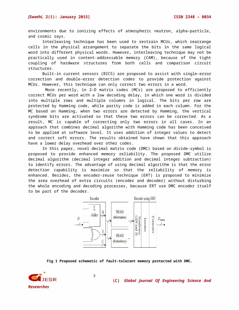
Fig 1 Proposed schematic of fault-tolerant memory protected with DMC.
(C) Global Journal Of Engineering Science AndResearches
4
[Swathi, 2(1): January 2015] ISSN 2348 – 8034
II.PROPOSED DMCIn this section, DMC is proposed to assure reliability in the presence
of MCUs through reduced performance overheads, and a 64-bit word is encodedand decoded as an example based on the proposed techniques.
A. Proposed Schematic of Fault-Tolerant MemoryThe proposed schematic of fault-tolerant memory is depicted in Fig. First,
during the encoding (write) process, information bits D are fed to the DMCencoder, and the horizontal redundant bits H and vertical redundant bits V areobtained from the DMC encoder. When encoding process is completed, theobtained DMC codeword is stored in the memory. If MCUs happen in the memory,these errors can be corrected in the decoding (read) method. Due to theadvantage of decimal algorithm, the proposed DMC has high fault-tolerantcapability with lower performance overheads. In the fault-tolerant memory, theERT technique is proposed to decrease the area overhead of extra circuits andwill be introduced in the following sections.
B. Proposed DMC EncoderIn the proposed DMC, first, the divide-symbol and place-matrix ideas are
performed, i.e., the N-bit word is divided into k symbols of m bits (N = k ×m), and these symbols are arranged in a k1 × k2 2-D matrix (k = k1 × k2, wherethe values of k1 and k2 represent the no. of rows and columns in the logicalmatrix respectively). Second, the horizontal redundant bits H are produced byperforming decimal integer addition of selected symbols per row. Here, eachsymbol is regard as a decimal integer. Third, the vertical redundant bits Vare obtained by binary operation among the bits per column. It should be notedthat both divide-symbol and arrange-matrix are implemented in logical insteadof in physical. Therefore, the proposed DMC does not require changing thephysical structure of the memory.
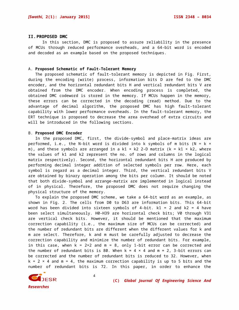
To explain the proposed DMC scheme, we take a 64-bit word as an example, asshown in Fig. 2. The cells from D0 to D63 are information bits. This 64-bitword has been divided into sixteen symbols of 4-bit. k1 = 2 and k2 = 4 havebeen select simultaneously. H0–H39 are horizontal check bits; V0 through V31are vertical check bits. However, it should be mentioned that the maximumcorrection capability (i.e., the maximum size of MCUs can be corrected) andthe number of redundant bits are different when the different values for k andm are select. Therefore, k and m must be carefully adjusted to decrease thecorrection capability and minimize the number of redundant bits. For example,in this case, when k = 2×2 and m = 8, only 1-bit error can be corrected andthe number of redundant bits is 80. When k = 4 × 4 and m = 2, 3-bit errors canbe corrected and the number of redundant bits is reduced to 32. However, whenk = 2 × 4 and m = 4, the maximum correction capability is up to 5 bits and thenumber of redundant bits is 72. In this paper, in order to enhance the
(C) Global Journal Of Engineering Science AndResearches
5
[Swathi, 2(1): January 2015] ISSN 2348 – 8034
reliability of memory, the error correction capability is first measured, so k= 2 × 8 and m = 4 are utilized to construct DMC.
The horizontal redundant bits H can be obtained by decimal integer additionas follow:H4H3H2H1H0 = D3D2D1D0 + D19D18D17D16 (1)H9H8H7H6H5 = D7D6D5D4 + D23D22D21D20 (2)and similarly for the horizontal redundant bits H14H13H12H11H10,H19H18H17H16H15H16, H24H23H22H21H20, H29H28H27H26H25, H34H33H32H31H30 andH39H38H37H36H35 where “+” represents decimal integer addition.
For the vertical redundant bits V, we haveV0 = D0 ^ D31 (3)V1 = D1 ^ D32 (4)and similarly for the rest vertical redundant bits.
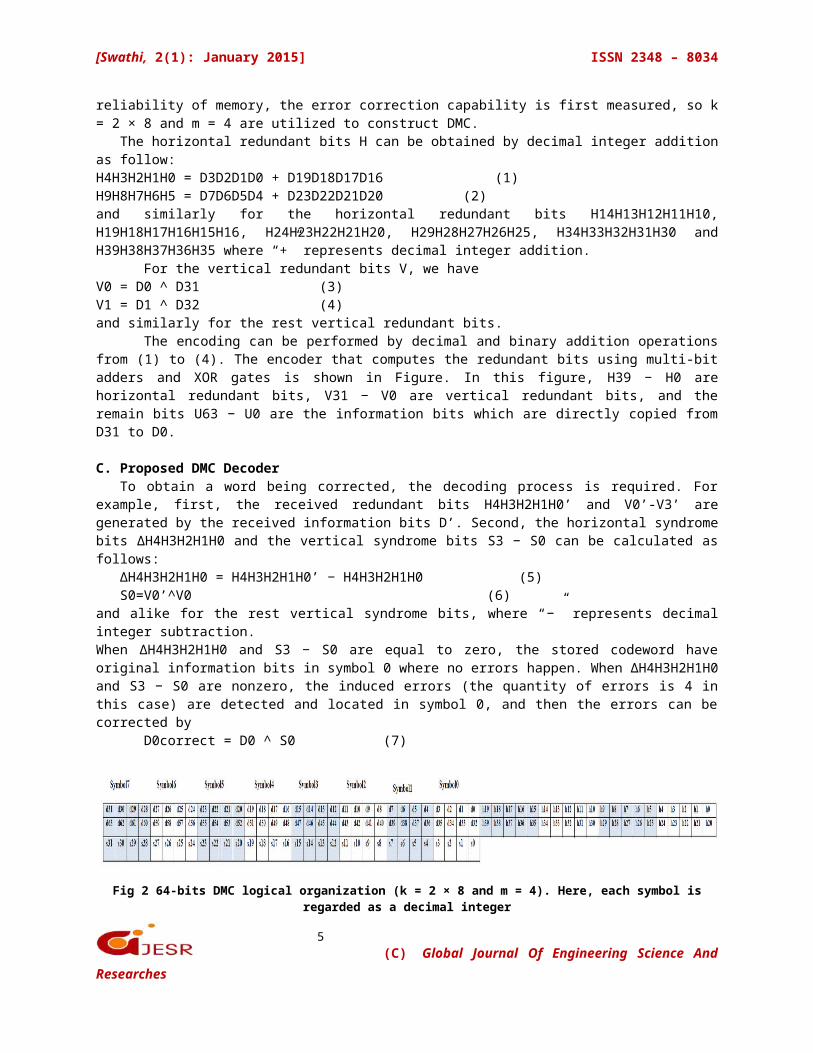
The encoding can be performed by decimal and binary addition operationsfrom (1) to (4). The encoder that computes the redundant bits using multi-bitadders and XOR gates is shown in Figure. In this figure, H39 − H0 arehorizontal redundant bits, V31 − V0 are vertical redundant bits, and theremain bits U63 − U0 are the information bits which are directly copied fromD31 to D0.
C. Proposed DMC DecoderTo obtain a word being corrected, the decoding process is required. For
example, first, the received redundant bits H4H3H2H1H0’ and V0’-V3’ aregenerated by the received information bits D’. Second, the horizontal syndromebits ∆H4H3H2H1H0 and the vertical syndrome bits S3 − S0 can be calculated asfollows:
∆H4H3H2H1H0 = H4H3H2H1H0’ − H4H3H2H1H0 (5)S0=V0’^V0 (6)
and alike for the rest vertical syndrome bits, where “−” represents decimalinteger subtraction.When ∆H4H3H2H1H0 and S3 − S0 are equal to zero, the stored codeword haveoriginal information bits in symbol 0 where no errors happen. When ∆H4H3H2H1H0and S3 − S0 are nonzero, the induced errors (the quantity of errors is 4 inthis case) are detected and located in symbol 0, and then the errors can becorrected by
D0correct = D0 ^ S0 (7)
Fig 2 64-bits DMC logical organization (k = 2 × 8 and m = 4). Here, each symbol isregarded as a decimal integer
(C) Global Journal Of Engineering Science AndResearches
6
[Swathi, 2(1): January 2015] ISSN 2348 – 8034
Fig 3 64-bit DMC encoder structure using multi bit adders and XOR gates
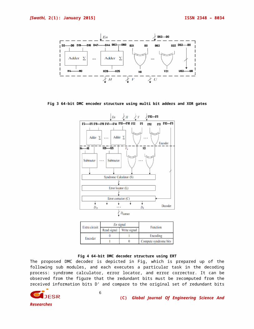
Fig 4 64-bit DMC decoder structure using ERTThe proposed DMC decoder is depicted in Fig, which is prepared up of thefollowing sub modules, and each executes a particular task in the decodingprocess: syndrome calculator, error locator, and error corrector. It can beobserved from the figure that the redundant bits must be recomputed from thereceived information bits D’ and compare to the original set of redundant bits
(C) Global Journal Of Engineering Science AndResearches
7
[Swathi, 2(1): January 2015] ISSN 2348 – 8034
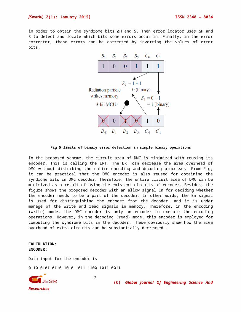
in order to obtain the syndrome bits ∆H and S. Then error locator uses ∆H andS to detect and locate which bits some errors occur in. Finally, in the errorcorrector, these errors can be corrected by inverting the values of errorbits.
Fig 5 limits of binary error detection in simple binary operations
In the proposed scheme, the circuit area of DMC is minimized with reusing itsencoder. This is calling the ERT. The ERT can decrease the area overhead ofDMC without disturbing the entire encoding and decoding processes. From Fig,it can be practical that the DMC encoder is also reused for obtaining thesyndrome bits in DMC decoder. Therefore, the entire circuit area of DMC can beminimized as a result of using the existent circuits of encoder. Besides, thefigure shows the proposed decoder with an allow signal En for deciding whetherthe encoder needs to be a part of the decoder. In other words, the En signalis used for distinguishing the encoder from the decoder, and it is undermanage of the write and read signals in memory. Therefore, in the encoding(write) mode, the DMC encoder is only an encoder to execute the encodingoperations. However, in the decoding (read) mode, this encoder is employed forcomputing the syndrome bits in the decoder. These obviously show how the areaoverhead of extra circuits can be substantially decreased .
CALCULATION:ENCODER:
Data input for the encoder is
0110 0101 0110 1010 1011 1100 1011 0011
(C) Global Journal Of Engineering Science AndResearches
8
[Swathi, 2(1): January 2015] ISSN 2348 – 8034
This input will be transforming into decimal matrix code by using divide by symbol method as
D0 to D31
1100 1101 1100 1011
0101 0110 0101 0110
For the redundant bits we are calculated as
H4H3H2H1H0=10011+1101=11000
H9H8H7H6H5=1100+1100=11000
H14H13H12H11H10=0110+0110=01100
H19H18H17H16H15=0101+0101=01010
V15V14V13V12V11V10V9V8V7V6V5V4V3V2V1V0 =1001101110011101
DECODER:
Decoder input D01 TO D31
1 is
1101 1110 1000 1001
0101 0110 0101 0110
Horizontal & vertical redundant bits are
H41H3
1H12H1
1H01=10111
H91H8
1H71H6
1H51=10101
H141 H13
1 H121 H11
1H101=01011
H191 H18
1 H171 H16
1H151=01010
V151 V14
1 V131 V12
1 V111 V10
1 V91 V8
1 V71 V6
1 V51 V4
1 V31 V2
1 V11 V0
1=1000 1000 1101 1111
DETECTING:
Δ H4H3H2H1H0=10111-11000=01111
Indicates there is an error so we are calculating
Vertical syndrome bits
S=V0^V01
S0=0 S1=1 S2=0 S3=0 Hence we get error in the D1 position. To correct this
(C) Global Journal Of Engineering Science AndResearches
9
[Swathi, 2(1): January 2015] ISSN 2348 – 8034
error we are inverting that bit as
D0correct = D0 ^ S0
D1correct= D1^S1=1^1=0.
Hence the bit in first position was corrected to ‘0’.
similarly for the rest of the errors.
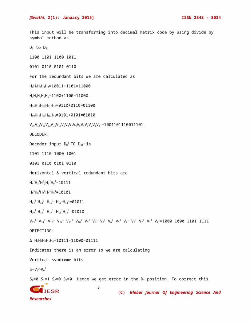
III. SIMULATION RESULTS
Block diagram
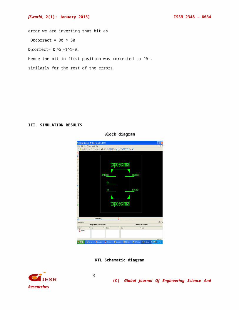
RTL Schematic diagram
(C) Global Journal Of Engineering Science AndResearches
10
[Swathi, 2(1): January 2015] ISSN 2348 – 8034
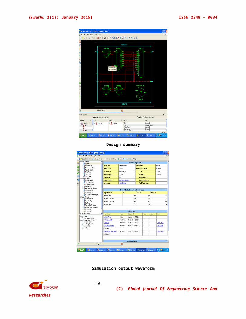
Design summary
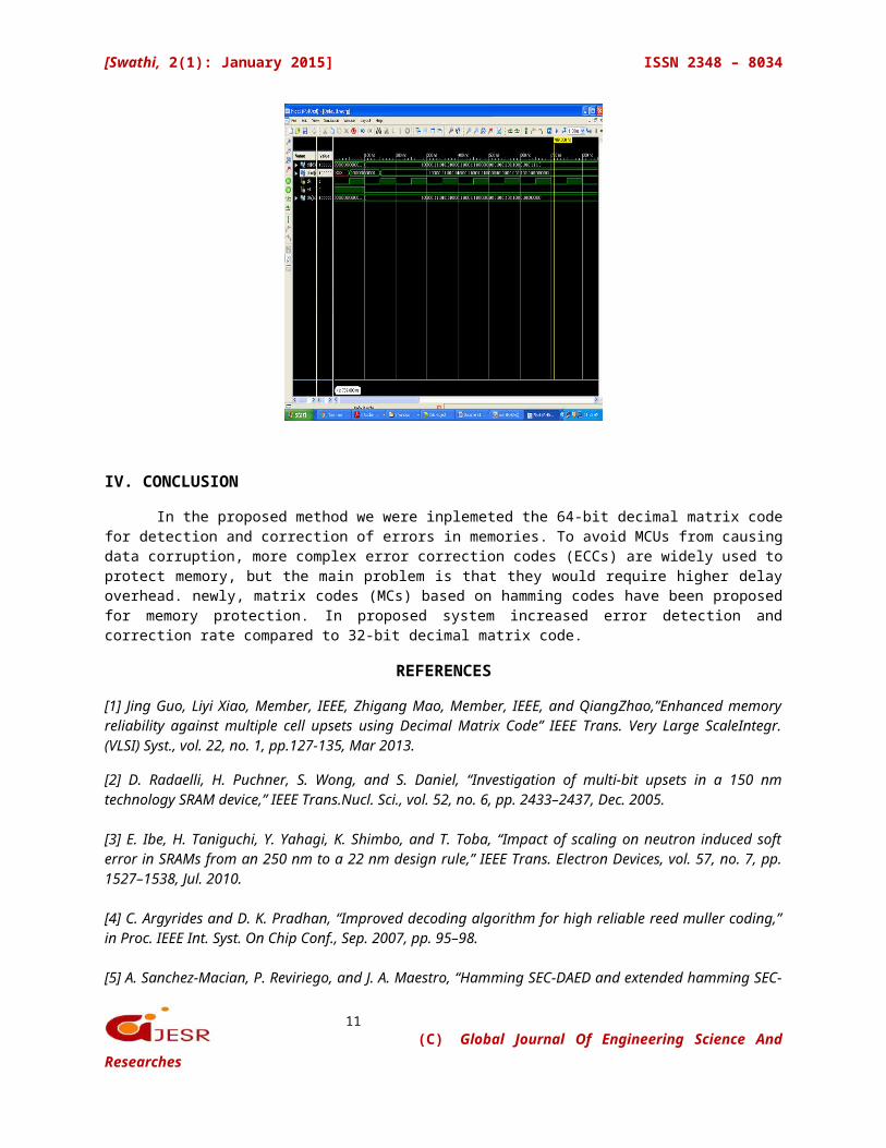
Simulation output waveform
(C) Global Journal Of Engineering Science AndResearches
11
[Swathi, 2(1): January 2015] ISSN 2348 – 8034
IV. CONCLUSION
In the proposed method we were inplemeted the 64-bit decimal matrix codefor detection and correction of errors in memories. To avoid MCUs from causingdata corruption, more complex error correction codes (ECCs) are widely used toprotect memory, but the main problem is that they would require higher delayoverhead. newly, matrix codes (MCs) based on hamming codes have been proposedfor memory protection. In proposed system increased error detection andcorrection rate compared to 32-bit decimal matrix code.
REFERENCES
[1] Jing Guo, Liyi Xiao, Member, IEEE, Zhigang Mao, Member, IEEE, and QiangZhao,”Enhanced memoryreliability against multiple cell upsets using Decimal Matrix Code” IEEE Trans. Very Large ScaleIntegr.(VLSI) Syst., vol. 22, no. 1, pp.127-135, Mar 2013.
[2] D. Radaelli, H. Puchner, S. Wong, and S. Daniel, “Investigation of multi-bit upsets in a 150 nmtechnology SRAM device,” IEEE Trans.Nucl. Sci., vol. 52, no. 6, pp. 2433–2437, Dec. 2005.
[3] E. Ibe, H. Taniguchi, Y. Yahagi, K. Shimbo, and T. Toba, “Impact of scaling on neutron induced softerror in SRAMs from an 250 nm to a 22 nm design rule,” IEEE Trans. Electron Devices, vol. 57, no. 7, pp.1527–1538, Jul. 2010.
[4] C. Argyrides and D. K. Pradhan, “Improved decoding algorithm for high reliable reed muller coding,”in Proc. IEEE Int. Syst. On Chip Conf., Sep. 2007, pp. 95–98.
[5] A. Sanchez-Macian, P. Reviriego, and J. A. Maestro, “Hamming SEC-DAED and extended hamming SEC-
(C) Global Journal Of Engineering Science AndResearches
12
[Swathi, 2(1): January 2015] ISSN 2348 – 8034
DED-TAED codes through selective shortening and bit placement,” IEEE Trans. Device Mater. Rel., to bepublished.
[6] S. Liu, P. Reviriego, and J. A. Maestro, “Efficient majority logic fault detection with difference-set codesfor memory applications,” IEEETrans. Very Large Scale Integr. (VLSI) Syst., vol. 20, no. 1, pp. 148–156, Jan.2012.
[7] M. Zhu, L. Y. Xiao, L. L. Song, Y. J. Zhang, and H. W. Luo, “New mix codes for multiple bit upsetsmitigation in fault-secure memories,” Microelectron. J., vol. 42, no. 3, pp. 553–561, Mar. 2011.
[8] R. Naseer and J. Draper, “Parallel double error correcting code design to mitigate multi-bit upsets inSRAMs,” in Proc. 34th Eur. Solid-StateCircuits, Sep. 2008, pp. 222–225.
[9] G. Neuberger, D. L. Kastensmidt, and R. Reis, “An automatic technique for optimizing Reed-Solomoncodes to improve fault tolerance in memories,” IEEE Design Test Comput., vol. 22, no. 1, pp. 50–58, Jan.–Feb. 2005.
[10] P. Reviriego, M. Flanagan, and J. A. Maestro, “A (64,45) triple error correction code for memoryapplications,” IEEE Trans. Device Mater. Rel., vol. 12, no. 1, pp. 101–106, Mar. 2012.
[11] S. Baeg, S. Wen, and R. Wong, “Interleaving distance selection with a soft error failure model,” IEEETrans. Nucl. Sci., vol. 56, no. 4, pp. 2111–2118, Aug. 2009.
[12] K. Pagiamtzis and A. Sheikholeslami, “Content addressable memory (CAM) circuits and architectures:A tutorial and survey,” IEEE J.Solid-State Circuits, vol. 41, no. 3, pp. 712–727, Mar. 2003.
[13] D. Radaelli, H. Puchner, S. Wong, and S. Daniel, “Investigation of multi-bit upsets in a 150 nmtechnology SRAM device,” IEEE Trans. Nucl. Sci., vol. 52, no. 6, pp. 2433–2437, Dec. 2005.
[14] E. Ibe, H. Taniguchi, Y. Yahagi, K. Shimbo, and T. Toba, “Impact of scaling on neutron induced softerror in SRAMs from an 250 nm to a 22 nm design rule,” IEEE Trans. Electron Devices, vol. 57, no. 7, pp.1527–1538, Jul. 2010.
[15] C. Argyrides and D. K. Pradhan, “Improved decoding algorithm for high reliable reed muller coding,”in Proc. IEEE Int. Syst. On Chip Conf., Sep. 2007, pp. 95–98.[16] A. Sanchez-Macian, P. Reviriego, and J. A. Maestro, “Hamming SEC-DAED and extended hammingSEC-DED-TAED codes through selective shortening and bit placement,” IEEE Trans. Device Mater. Rel., tobe published.
[17] S. Liu, P. Reviriego, and J. A. Maestro, “Efficient majority logic fault detection with difference-set codesfor memory applications,” IEEE Trans. Very Large Scale Integr. (VLSI) Syst., vol. 20, no. 1, pp. 148–156, Jan.2012.
[18] M. Zhu, L. Y. Xiao, L. L. Song, Y. J. Zhang, and H. W. Luo, “New mix codes for multiple bit upsets
(C) Global Journal Of Engineering Science AndResearches
13
[Swathi, 2(1): January 2015] ISSN 2348 – 8034
mitigation in fault-secure memories,” Microelectron. J., vol. 42, no. 3, pp. 553–561, Mar. 2011.
[19] R. Naseer and J. Draper, “Parallel double error correcting code design to mitigate multi-bit upsets inSRAMs,” in Proc. 34th Eur. Solid-State Circuits, Sep. 2008, pp. 222–225.
[20] G. Neuberger, D. L. Kastensmidt, and R. Reis, “An automatic technique for optimizing Reed-Solomoncodes to improve fault tolerance in memories,” IEEE Design Test Comput., vol. 22, no. 1, pp. 50–58, Jan.–Feb. 2005.
[21] P. Reviriego, M. Flanagan, and J. A. Maestro, “A (64,45) triple error correction code for memoryapplications,” IEEE Trans. Device Mater. Rel., vol. 12, no. 1, pp. 101–106, Mar. 2012.
[22] S. Baeg, S. Wen, and R. Wong, “Interleaving distance selection with a soft error failure model,” IEEETrans. Nucl. Sci., vol. 56, no. 4, pp. 2111–2118, Aug. 2009.
(C) Global Journal Of Engineering Science AndResearches