Study on dyeing behavior of cotton organic cotton knitted fabrics
Upload
mechanical-engineeringsCategory
view
0download
0
Designing Fabric Interactions
Ramyah Gowrishankar
Master of Arts Thesis
Media Lab Helsinki
Department of Media
School of Art and Design
Aalto University, 2011
A study of knitted fabrics as an electronic interface medium


Author
Ramyah GowrishankarYear of publication
2011Department
Media Lab Helsinki, Dept. of Media, Aalto University
Degree programme
MA in New Media
Title
Designing fabric interactions – An exploration of knitted fabrics as medium electronic interfaces
Type of work
Master's thesisLanguage
EnglishNumber of pages
Abstract
The field of electronic textiles though a young one, has gained momentum in the last decade. Creative practitioners working in the field of e-textiles aim at efficiently combining electronics with traditional fabric materials. However, not many have tried to derive inspiration from the existing language of fabrics to design these interfaces. Most of the commercial e-textile products, though incorporating cutting-edge technologies, seem to copy or directly follow previous trends in wearable computing rather than truly attempting to design specifically for the medium of fabrics. Textiles have been an integral part of our cultures for thousands of years and have adapted to the different needs and lives of people. They provide a rich source for interactions and scenarios from the context of our everyday lives that can be reinterpreted for electronic interfacing.
The thesis explores methods of integrating fabrics and electronics to create interfaces that are specific to the medium of fabrics. Following the approach of ludic design, this work also emphasizes on the potential of e-textile interfaces to invite unexpected interpretations and responses from the users while enabling an active, creative relationship to their surroundings. The practical work focused on an in-depth study of knitted fabrics as medium for electronic interfaces. The process involved working and experimenting with knitting yarns, conductive threads and off-the-shelf electronics while using traditional fabric construction tools like knitting and sewing machines. Using a material-driven approach, a collection of single instances of fabric interactions or “soft triggers” were designed and prototyped that explicitly interpret fabric related actions as input. These soft triggers were also designed to specifically incorporate physical properties like weight or shape of the other existing objects as essential to their working, as a way of creating an immediate relation between the user, the soft trigger and their surroundings.
The soft triggers prototyped were proofs of concepts representing parts or units of possible medium-specific e-textile interfaces that facilitate an active engagement between the user and her surroundings. Thus, the design process undertaken for this thesis was successful in illustrating methods for creating e-textile interfaces that were specific to the medium of fabrics and that curiously involved their users in a dialogue with her immediate environment.
Keywords
Electronic textiles, fabric interactions, knitted fabrics, ludic design.
Author Ramyah Gowrishankar
Year of publication 2011
Department Media Lab Helsinki, Dept. of Media, Aalto University
Degree programme MA in New Media
Title Designing fabric interactions: A study of knitted fabrics as an electronic interface medium
Type of work Master's thesis
Language English
Number of pages 111
Abstract The field of electronic textiles although a young one, has gained momentum in the last decade. Textiles have been an integral part of our cultures for thousands of years and have adapted to the different needs and lives of people. They provide a rich source for interactions and scenarios from the context of our everyday lives that can be reinterpreted for electronic interfacing. Creative practitioners working in the field of e-textiles aim at efficiently combining electronics with traditional fabric materials. However, not many have tried to derive inspiration from the existing language of fabrics to design these interfaces. Most of the commercial e-textile products, while incorporating cutting-edge technologies, seem to copy or directly follow previous trends in wearable computing rather than truly attempting to design specifically for the medium of fabrics.
This thesis explores methods of integrating fabrics and electronics to create interfaces that are specific to the medium of textiles. Following the approach of ludic design, this work also emphasizes the potential of e-textile interfaces to invite unexpected interpretations and responses from the users while enabling an active, creative relationship with their surroundings. The practical work focuses on an in-depth study of knitted fabrics as a medium for electronic interfaces. The process involves working and experimenting with knitting yarns, conductive threads and off-the-shelf electronics while using traditional fabric construction tools like knitting and sewing machines. Using a material-driven approach, a collection of single instances of fabric interactions or “soft triggers” that explicitly interpret fabric related actions as inputs were prototyped. These soft triggers were designed to essentially work with physical properties such as conductivity or shape of the other objects as a way of creating an immediate relation between the user, the soft trigger and their surroundings. The soft triggers prototyped are proofs of concepts representing parts or units of possible medium-specific e-textile interfaces that facilitate an active engagement between the user and her surroundings. Thus, the design process undertaken was successful in illustrating methods for creating e-textile interfaces that are specific to the medium of fabrics and that curiously involves the users in a dialogue with their immediate environment. Keywords Electronic textiles, fabric interactions, knitted fabrics, ludic design.


5
Acknowledgements
I would like to sincerely thank Katharina Bredies without whose guidance, support and inspiration this project would not have been possible. I also thank Till Bovermann for his valuable feedback and encouragement through the writing process. I would like to extend a special mention to Rosan Chow for giving me interesting reading material and helping with the beginning of the thesis. I am deeply grateful to Raija Jokinen for her enthusiasm and interest in the project, for helping me with my numerous knitting questions and also for kindly giving me access to the knitting studio in the textile department. My appreciation also goes to Anna Leinonen for her patience and help while using the industrial knitting machine.
I am thankful to Markku Reunanen, Michihito Mizutani and Rasmus Vuori for sharing their insights regarding my work at various stages of the project. A big thanks also to my colleagues Jonathan Cremieux and Gokce Taskan for reading and commenting on the text; and Liisa Tervinen and Lauri Kainulainen for testing the prototypes. I also thank Pipsa Asiala, for her encouragement through the thesis process; and Ilpo Kari and Heikki Tuononen, for their technical help. I would also like to convey my gratitude to Eila Hietanen who helped me print this document.
Finally, I am heartily grateful to my parents for their love, patience and support.

Table of contents
1. Introduction 8
1.1. Thesis overview 9
1.2. A brief history of electronic textiles 10
2. Motivation for this study 13
3. Fabric as a medium for electronic interfaces : Defining problem areas or identifying opportunities 16
3.1. Looking at related work: Types of fabric interfaces 16
3.2. Taking forward the Insights gained from my previous work in e-textiles 21
3.3. Critical thinking, ludic engagement and e-textile design 22
4. Research questions 25
5. Assumptions 26
6. Working with knitted soft triggers 28
6.1. Production goals 30
7. Process: Working with knitted fabrics and electronics 32
7.1. Building a reference base 34
7.2. A technical approach to fabrics 37
7.2.1 Digital and analogue fabric switches 37
7.2.2 Working with physical properties of other objects 38
7.3. Generating ideas and concept sketches 39
7.3.1 Translating fabric related actions into triggers 39
7.3.2 Working with ‘states’ of fabric objects 40
7.3.3 Using scenarios and use-contexts as starting points 40
7.3.4 Working with interaction methods 41
7.4. Materials and tools 43
7.5. Prototyping 47
7.5.1 Knitting-drawing and circuit-planning 47
7.5.2 Power supply 49
7.5.3 Stitching the knitted parts together 50
7.5.4 Thinking about output indication for triggers 50
7.5.5 Designing the micro-controller unit 52
7.5.6 Testing, troubleshooting and programming 53

References 99
Appendices 102
Appendix A 102
Appendix B 106
Appendix C 110
8. Results 54
8.1. Gallery 54
9. Summary of insights from the production process 76
10. Reflection 82
10.1. Looking at key factors that affected the design and attributes of the knitted soft triggers 82
10.2. Observations from a preliminary analysis of the soft trigger prototypes 84
10.2.1 Insights from finding different ways to activate the soft triggers in a home scenario 84
10.2.2 Observations from giving the prototypes out to others 86
10.3. Reviewing the prototypes in relation to the research questions 90
11. Discussion: Space for user re-interpretations in e-textile design 93
12. Conclusion and future development 96
– Feedback from interacting with soft triggers
– Arduino and Processing sketches used for testing
– DVD with video documentation of soft triggers

8
1. Introduction
Electronic Textiles or e-textiles is a new and upcoming field that aspires to integrate textile materials with electronic and computational elements.
E-textiles incorporate capabilities for sensing (biometric or external), communication (usually wireless), power transmission, and interconnection technology to allow sensors or things such as information processing devices to be networked together within a fabric. This is different from ‘smart textiles’ that features scientific advances in materials research and include things such as better insulators or fabrics that resist stains. E-textiles usually contain conductive yarns that are either spun or twisted and include some amount of conductive material (such as strands of silver or stainless steel) to enable electrical conductivity. (Berzowska, 2005a)
The researchers of e-textiles, as articulated by Leah Buechley (2006) strive to ubiquitously incorporate off-the shelf electronics and other fabric-friendly conductive materials such as conductive inks and threads in traditional fabric materials to create soft and comfortable devices. They may be wearable but also seek inspiration from wall hangings, quilts and other pervasive fabric-based artefacts.
The possibilities of electronic textiles to enter our lives seem almost as wide as there are fabric artefacts in our everyday surroundings. The last decade has seen a rise in e-textile products and research. Creative practitioners have adopted these techniques to create interactive garments and furniture. The vast cultural and social history of fabrics opens out multiple opportunities for designers and artists to reinterpret the existing interactions and the common understanding of fabric properties as means for digital interfacing. Wearable e-textiles allow little bits of computation to occur on the body (Berzowska, 2005a). This has enabled researchers to monitor the body of the wearer and its surroundings for medical (e.g. Cunha et al., 2010) and military purposes (e.g. ISN/MIT, 2002). Other wearable e-textile projects reinterpret clothes as assisting or reflecting on the social interactions of the wearer ( e.g. Berzowska, 2005) or even as musical instruments ( e.g. Grant and Grant, 2010). Some fabric artefacts such as tablecloths or wall hangings have also been reinterpreted by designers to create new forms of expressive and interactive displays.

9
The ability to embed computational elements or interactivity into textile products that are integral to our environments, has been seen by some designers and researchers as an opportunity to introduce another layer of meaning that aims at enriching our experience of the everyday. This layer of meaning has taken the form of additional electronic functions given to an otherwise traditional clothing, for instance a coat zipper (Jennifer, 2011) that controls the volume on the wearer’s mp3 player. This meaning can also be for a more evocative realm such as a tablecloth that reveals the patterns of everyday (Gaver et al., 2006), thus expressing a point of view or bringing forth behaviours that are otherwise less apparent. In both of these cases, e-textiles have been used to enhance or record experiences through computation embedded in fabric materials. Thus, the medium of e-textiles presents an opportunity to take a closer look at fabrics in our everyday lives and to explore the potential of reinterpreting them as a medium for electronic interfacing and create new experiences and interactions.
1.1. Thesis overview
This thesis builds on the idea of exploring new interactions by investigating the role of fabric as a medium for interfaces. It investigates the different ways to create fabric interfaces by translating fabric properties into electronically readable signals while enabling, through interaction, an active and creative relationship between the users and their surroundings. Although exploring and deriving from textiles in general, the practical process deals specifically with knitted fabrics. Using knitting yarn and conductive threads combined with basic electronic components, various concepts for fabric interfaces that essentially need other objects from their surroundings to work were designed and prototyped. The thesis project was thus an in-depth study of the different materials, as well as a play with reinterpreting gestures, actions and scenarios associated with fabrics.
The thesis can be divided into three main categories. The first part describes the context of work and the areas of enquiries that led to the production process. The second part gives an in-depth report of the production goals and the practical design process, while the third part presents the results of the production process followed by discussing my reflections and findings.
The first part of the thesis is included in the first five chapters. First, I give a brief overview of the history of e-textiles followed by explaining my background and how I became interested to delve deeper into my thesis subject. I describe how researching other works and publications in the field of e-textiles and looking at my previous
10
projects, helped me to identify some key problem areas or interesting aspects of fabrics and electronics that I wanted to investigate further. I also articulate the main research questions and the assumptions that guided the production process.
The second part, chapters 6 and 7, describes the hands-on approach taken to practically examine and investigate the research questions raised. The decision of working with soft triggers is explained and the production goals are listed. Chapter 7 gives a detailed account of the various steps and approaches taken to design and prototype various soft triggers.
The third part consisting of chapters 8 to 12 presents the results and insights gained from the production process. It illustrates the various fabric prototypes and relating soft components that were designed and tested through the process. The main findings from working with knitted fabrics and electronics are listed, followed by discussing my impressions about the project as a whole. Chapter 10 analyses and compares the different soft prototypes designed while also attempting to tackle the research questions. In Chapter 11, I raise some open questions regarding e-textiles and their potential for designing semi-ambiguous interfaces that could encourage play and user reinterpretations. I conclude with Chapter 12 and describe my visions for the future developments of the project.
1.2. A brief history of electronic textiles
The field of e-textiles is only a little more than a decade old. It primarily branched out of the research on wearable computing or ‘wearables’ which developed in the 1970s and 1980s propelled by the works of prominent researchers like Steve Mann, Mark Weiser and Thad Starner (Rhodes, 2000). The main focus of wearable computing was the development and prototyping of new techniques of human-computer interaction for body-worn applications (MIThril, 2003). However, these wearable computers were often hard, obtrusive and found to be uncomfortable by users. The wearable computers needed to be less fragile so that their users could wear them without the fear of damaging the equipment. (Berzowska, 2005a)
In 1997, a design collaboration between the students and faculty of Creapole Ecole de Creation (Paris) and professor Alex Pentland (MIT, Boston) produced the ‘Smart clothes fashion show’, with the goal of envisioning the impending marriage of fashion and wearable computers. (Rhodes, 2000)

11
The first breakthrough in e-textiles came with the development of a conductive fabric which was silk organza that contained two types of fibres, namely plain silk thread woven with a silk thread wrapped in thin copper foil. Wearable computers then aspired to be merged seamlessly into ordinary clothing. Using various conductive textiles, data and power distribution as well as sensing, circuitry could be incorporated directly into wash-and-wear clothing. Passive components could be sewed on fabric whereas others could be soldered directly on to the metallic yarn. (Post and Orth, 1997)
Textiles have mechanical, aesthetic, and material advantages that make them ubiquitous in everyday use and industrial applications. The woven structure of textiles and spun fibres makes them durable, washable, and conformal, while their composite nature affords tremendous variety in visual and tactile textures. (Post, 1999)
While the materials needed to be further developed for the fabric medium, the earliest projects such as the ‘Firefly dress’, Music jacket with embroidered keypad and electronic tablecloth in the early 2000s (see Figure 1) already started exploring designs that incorporated different production techniques (industrial and handmade), materials (different conductive fabrics) and ways of translating electronic circuits to be seamlessly integrated with textiles (Post, 1997).
Figure 1. Early e-textile projects (Left) Firefly dress. (Centre)Music jacket. (Right) Interactive tablecloth.
While focused research started to be conducted for military, medical and other telecommunications purposes at the beginning of the century, other researchers like Leah Beuchley worked towards creating kits and components to make working with e-textiles more accessible (Buechley, 2006). The ‘high low tech group’ at MIT Media Lab led by Buechley and the ‘XS labs’ founded by Joanna Berzowska also published various techniques and explorations for integrating fabrics and electronics (Buechley and Eisenberg, 2007; Berzowska, 2005a).
In 2008 the development of the ‘LilyPad Arduino’, a fabric based construction kit that enabled novices to design and build their own soft wearables and other textile artefacts (Buechley, Eisenberg, Catchen and Crockett, 2008), truly expanded the

12
scope of e-textiles by bringing it to designers and amateurs. With the easy availability of conductive yarns and fabrics in smaller amounts for non-industrial uses, Lilypad as an affordable sewable micro-controller opened out many possibilities for the growing community of electronic-textile enthusiasts, .
E-textiles research and projects have thus in a short time gained momentum in academic, commercial, artistic as well as experimental spheres.

13
2. Motivation for this study
Being a tangible interface designer, I was very familiar with working with electronics and physical computing. However, my first proper encounter with using textiles with electronics came during an internship at the Deutsche Telekom Laboratories in Berlin in Fall 2010. There, I worked extensively with fabrics and designed interface concepts for this medium under the supervision of doctoral student Katharina Bredies. During the three months, we designed and prototyped a wearable fabric controller called the ‘Music sleeve’ used for playing music on a mobile device (Gowrishankar, Bredies and Chow, 2011). Not only did I get interested to explore e-textiles further but working on this internship project also gave me invaluable practical and conceptual insights about the medium which I saw as a very engaging outlet for my interest and experience in tangible interactions.
Tangible interactions has been my key area of interest and enquiry through the past few years. Working under the larger theme of studying people’s everyday physical and emotional interactions with electronic objects, I find it intriguing how objects get personified or reinterpreted by their owners. I strive to understand this relationship with respect to the qualities it embodies and also how this relationship affects or defines the nature of our immediate environment.
Reinterpretations and reuse of objects beyond their intended functions by their users is well-established (Brandes and Erlhoff, 2006) although not fully accounted for in the design process. Traditional Human-computer interaction (HCI) studies believe that although the interpretations of a technical or electronic object could be various, there should be just one intended clear purpose for a designed object. However there are also discussions that counter argue this traditional view (Sengers and Gaver, 2006). It is curious how the objects by their very nature take on different roles; roles they play due to their physical properties, their functions or their socio-cultural background. All things have the potential of playing more than one role. For example in high school I had a calculator in which the zero button stopped working, so to calculate with numbers that contained a zero, I had to find other ways by adding or multiplying non-zero numbers to get the required result. In the traditional design sense, this calculator would be non-functional, but for me this broken calculator had acquired a personality that usually made the experience more interesting while sometimes also being difficult to deal with. Either ways my calculator was unique,

14
it was something I could laugh or complain about while also getting my task done.
Over the years I have noticed many such objects that gained or established a relationship with their owners and their surroundings on the account of some strangeness or uniqueness they possessed. For example, in my under graduation years, I purchased an extra plastic low-cost table fan to deal with the hot summer in South India. When I plugged it in the first time, I discovered that the table fan had such a light-weight body that when switched on it moved around with its own momentum and motor vibration. Thus, after being switched on for 5 minutes, the fan would have travelled about 20 cm and be pointing away from me towards a random direction to the far end of the room. Depending on the situation, I had to either put some more weight on this free spirit of a fan to keep it in one place or continue to move with the fan to be always in the wind direction.
While being playful, the fan made me think about the production and design of such goods and the compromises one makes in engineering or design while meeting the need for low-cost products that are produced knowingly or unknowingly with “imperfections” that can be easily overcome by the users. At the same time these products escape much responsibility of functional reliability by playing on the general low expectations people have from cheap goods. Not going into further discussion regarding this, I would just like to highlight that the fan surely made me raise some questions and created a dialogue.
Inferring from these small experiences, domestic electronic objects were found to have the ability to question, provoke, be opinionated, satirical or to embody any such characteristics or roles in one’s everyday life. Looking at it from a design perspective it is interesting to explore ways of inducing this kind of “strangeness” into technical objects as part of the design process to encourage creative dialogue between the user, the object and their surroundings. Advocating the use of ‘strangeness’ in a design process is not to say that one should make broken things or use this an excuse for bad design, rather it is a study of relationships and designing a possibility to reflect and respond to these relationships while performing everyday tasks.
I was thus interested in investigating how to design interactions that allowed for reinterpretations by users and engaged them in a playful yet critical manner through tangible interfaces. E-textiles proved to be an apt medium to tackle the enquiries explained above: While working with e-textiles for the internship, we discovered the natural potential of e-textile artefacts for being curious and unfamiliar. As I dabbled with the new conductive soft materials and tools to experiment and prototype, the contrasting nature of fabrics and traditional electronic components started becoming apparent. It was common that the ideas we had on paper would fail when actually constructed with the soft fabric material. Thus prototyping at every stage helped us to understand the materials better. I found working with fabrics inspiring and

15
challenging. During this process numerous fabric artefacts were conceptualized that adopted curious forms and textures as a result of attempting to efficiently integrate the two contrasting materials. What resulted was a fabric interface that was born out of technical requirements of the materials and acquired a unique aesthetic quality. (Gowrishankar, Bredies and Chow, 2011)
This unfamiliar and unique quality of the fabric interface created during the internship and the design process involved, provided an opportune lens to look into new interactions and a glimpse into designing for intuitive, explorative and context driven interpretations. Hence, I wanted to delve deeper and understand this quality of e-textile artefacts and continue to experiment with them. The approach taken during my internship that focused on fabric properties and interactions as the main inspiration for interface designs, was also a valuable learning experience. For this thesis, I was keen on taking further my skills in constructing and handling knitted fabrics along with following the process of sketching and prototyping as an integral part of the concept development and design. This was an interesting area to delve into because it involved readily available materials like regular textiles, conductive yarns and traditional electronic components which made it easily approachable.
The field of e-textiles or ‘wearables’ is fast growing and it is exciting to be a part of this upcoming community. With this work, I also wished to contribute to the methodologies and knowledge in this new field. Hence, I saw this thesis as an opportunity to not only develop my skill sets and understanding of fabrics to work with e-textiles but to investigate its relevance to interaction design and lay a foundation for my future work in the field.

16
3. Fabric as a medium for electronic interfaces : Defining problem areas or identifying opportunities
The techniques and methods required to use e-fabrics as a new medium for electronic interfaces are being actively developed. The following sections give an overview of the problem areas or rather opportunities that were explored through this project. They were identified through studying and sorting related works in the field of e-textiles, drawing from my own experiences in working with fabrics and electronics and importantly, looking at how alternative and critical approaches to traditional HCI can be studied through the process of designing e-textiles.
3.1. Looking at related work: Types of fabric interfaces
A wide spectrum of projects surfaced from delving deeper to find previous works done in the field of e-textiles, from research projects involving clothes and wall hangings that could change their physical appearance or enable the user to communicate with people around, to commercially available health monitoring wearables and mp3-incorporated jackets. They are better explained in the following paragraphs. There were also many smaller experimental projects from amateurs and enthusiasts interpreting gestures (e.g. Rowberg, 2011) or designing soft musical instruments (e.g. Grant and Grant, 2010). While some projects tried to investigate and assist the future of e-textiles (e.g. Buechley, 2006), others were playful explorations of forms and interactions.
A qualitative analysis of all the projects involving e-textiles showed that the specific role played by fabrics in the interface concepts could be broadly divided into three main categories. The first kind were interfaces that used fabric as an underlying layer or a substrate to mount other electronically active components. The second type used fabrics as means for output and the third incorporated fabrics as sensors or switches that acted as the input for a system. These categories are explained in detail below:

17
1. Fabric as substrate:
These interfaces or e-textile objects treated the fabric as an underlying surface over which electronically active elements were mounted. These were electronic components like light emitting diodes (LED), different kinds of sensors, speakers and other such devices. The circuit design aspired to complement the nature of the fabric to efficiently distribute the components across its surface but did not use the fabric itself as a component of the circuit.
It was found that most of the industry led innovations had taken this approach, taking advantage of the fabric being present in our environment by directly embedding another layer of electronics on them. The field of fashion has numerous projects that use fabric as substrate and use lights or sound as expressive elements placed on top of it. The interactive dress ‘Klight’ (see Figure 2) by fashion designer Mareike Michel and Fraunhofer IZM in 2008 (stretchable circuits, 2008) is one such example. The dress has miniaturized electronic modules and LEDs mounted on a flexible printed circuit board made specially for using with fabrics. The movement of the wearer is detected by a sensor and translated into light patterns illuminated by the LEDs (ibid.). The flexible circuit board represents a typical development in the field of e-textiles that attempts at a more seamless integration of electronics into fabrics by designing ‘soft’ versions of the traditional electronic components.
As fabrics are wearable and stay close the body, different kinds of sensors could be mounted on them for medical purposes such as electrocardiography (ECG) or other health monitoring systems. The heart rate monitor sports bra developed by NuMetrex (see Figure 3) is a commercially available product that measures the wearer’s heart rate and sends the information to a computer or a compatible wrist watch (NuMetrex, 2005). Some professional clothing also used fabric as substrate to embed capabilities to assist the wearer with her work. The clothing designed by VIKING for the safety of the firefighters have thermal sensors that visually indicate critical heat levels on the display unit integrated on the sleeve of the jacket (Eric, 2008).
2. Fabric as output:
The e-textile interfaces that used fabric as output were those in which the fabric material physically changed in shape or appearance as the result of an interaction. ‘Kukkia and Vilkas’ (see Figure 4) by Berzowska and Coelho are two animated dresses that use the shape memory alloy Nitinol to move or change shape over time by resistive heating and control electronics (2005).
Figure 2. Klight dress. Design by Mareike Michel, 2008.
Figure 3. Heart monitoring sports bra from Numetrex.

18
Some interfaces used the textile surface as a display by physically changing its colour or pattern with interaction. ‘Shimmering flower’ (see Figure 5) by Joanna Berzowska was one such example of a non-emissive colour changing display that could be programmed to slowly change its pattern and colour over time (2004).
Since textiles have a prominent yet silent presence in our surroundings, various e-textile projects have interpreted the fabric medium to mirror everyday occurrences and used it to physically reveal relevant patterns. They were found to be superimposed into our everyday and did not demand direct physical interaction. Instead, they involved the user on a more emotional or evocative realm. Their presence in an environment already ‘activated’ them. The ‘History Tablecloth’ (Gaver et al., 2006) collects data from load sensors placed at the corners of a table to illuminate relevant portions of the history tablecloth draped on the table (see Figure 6). The tablecloth itself was silk-printed with an electroluminescent material. When objects were left on the table, the portion of the tablecloth beneath them lighted to form a halo that grew over a period of hours, highlighting the flow of objects in a household. (Gaver et al., 2006)
Projects like ‘Pure Play’ (Berzowska, 2005) (see Figure 7) and ‘Feathery Dresses’ (Berzowska, 2005) (see Figure 8) in the Memory Rich clothing series interpret body heat and touch by using thermochromic ink applied on parts of clothing and LEDs respectively. Thus, in the above mentioned projects, the fabric changed its appearance to give a visual or tactile feedback to an interaction with the system.
Figure 4. (Left) Kukkia and Vilkas: Kinetic electronic garments.
Figure 5. (Right) The shimmering Flower: Color-changing textile display.
Figure 6. (Left) The history tablecloth: Illuminating interactive fabric.
Figure 7. (Centre) Pure Play: Heat sensitive colour detail.
Figure 8. (Right) Feathery dress: Touch sensitive garments.

19
3. Fabric as input:
This category included objects or clothing that incorporated fabrics by using them directly to generate the electronic impulse responsible for the output of the system. They used fabrics as sensors or switches that operated the system. The nature of interactions were various but they involved direct physical contact with the fabric ‘components’. The website ‘www.Kobakant.at’ by Perner-Wilson and Satomi (2007) has an extensive online database of various sensors and switches made with fabric materials. Its authors explore different ways to incorporate conductive threads and fabrics to create sensors that react to touch, pressure and other such interactions.
There are also fabric explorations like Joypad (Perner-Wilson, 2008) (see Figure 9), Joyslippers (Perner-Wilson, 2008b) (see Figure 10) and Felted Signal processing (Grant and Grant, 2010) (see Figure 11) that use fabrics to measure pressure and stretch applied during interactions as an input for generating different results. Joypad uses punching and pressing a round soft disk made of fabric whereas the Joyslippers interpret feet movements. The project from Felted Signal Processing find ways of creating interactions with long soft tube of felted wool. Figure 9. (Left) Joypad: Fabric
interface for controlling mouse movement on screen.
Figure 10. (Centre) Joy slippers: fabric weight-sensing shoes
Figure 11. (Right) Felted stroke sensors from Felted signal processing
These interfaces used fabric properties such as softness or flexibility to interpret the physical interactions as switches or triggers to generate an output. These interactions mostly involved some amount of play and the feedback loops were quite quick. They were mostly designed to be controllers for games or for video and audio manipulation.
Fabrics should be the focus of interaction design in e-textiles as it is the textiles that makes them different from other electronic interfaces. A lot of the e-textile products try to imitate existing electronic circuits and components onto fabrics, for example making a traditional PCB flexible. However, using fabric itself as an element of interaction was felt to be largely unexplored.
Looking at the above mentioned categories of how fabrics have been incorporated in e-textile interfaces revealed that not all approaches fully take into account the medium of fabrics in their designs. The interfaces that use fabrics as substrate

20
were concerned mainly with efficient distribution of electronic components over an existing piece of fabric thus only passively involved the medium. The ‘fabric as output’ group usually used inks and memory alloys to respectively change colour and shape in addition to the material of fabrics. E-textile researchers strive to build devices that are as soft, flexible and comfortable as traditional cloth artefacts (Buechley and Eisenberg, 2007). However, not many have tried to use the existing language of fabrics as key inspiration for designing these devices. One sees that a large portion of projects and ideas relating to e-textiles follow previous trends in wearable computing rather than analysing the true nature of the medium. They only try to change the face of existing technologies to be mounted on fabrics rather than taking this opportunity to really explore fabric properties to create novel digital artefacts that could enrich and expand our experience of everyday life. For example the ski jacket designed by Ralph Lauren (Technabob, 2010) that incorporates an mp3 controller in its sleeve relies on the same interaction as the existing player (see Figure 12) as it directly copies the traditional music interface onto the sleeve of a jacket. Although it uses revolutionary technologies, this e-textile product misses the possibility to truly reinterpret the fabric for creating a new experience of skiing and listening to music.
The category of interfaces that were found to have truly attempted to design specifically for the medium of fabrics was the third one: ‘fabric as Input’. These projects incorporated fabric as an element for direct interactions and used the familiarity of textiles as a motivation behind these interactions. For example the soft pressure sensor (see Figure 13) is a felted soft ball that senses the pressure applied on it. Being of a familiar form and soft material, squeezing it in your palm comes as a natural interaction. Thus, the fabric itself acts as the sensor or switch that activates a system.
These interface concepts did not only provide a fresh outlook to fabric oriented interface design but also aspired to create fabric-made sensors by reinterpreting existing electronic components such as a pressure sensor, using materials and techniques from the tradition of fabrics. Following a similar approach to the projects of Hannah Perer-Wilson and Mika Satomi, using fabrics as input was seen as an important opportunity to delve deeper into the ecosystem of actions and scenarios relating to textiles to translate them into interaction elements. It was felt that these interaction elements made from fabrics act as the building blocks for creating truly soft-devices.
Figure 12. Ralph Lauren RLX Aero Type Jacket. (Image from technabob.com/blog/2010/01/02/wired-ralph-lauren-aero-type-ski-jacket/)
Figure 13. Soft pressure sensor from http://www.kobakant.at/DIY/

21
3.2. Taking forward the Insights gained from my previous work in e-textiles
I have used the inferences and reflections gained from my internship as a starting point for my thesis. Being my first encounter with e-textiles, I gained important material and procedural insights about working with fabrics and electronics that opened a door for further enquiry. One such important discovery was the contrasting natures of fabrics and electronics. Both media have very definitive characteristics behaviourally, and also come with specific tools and context. Sewing machines, needles, knitting machines, soldering irons, pliers etc. have specific functions in their traditional environments. Electronics require tight connections, good contact, and insulation for a reliable circuit. Fabrics inherently possess qualities that are light, fluid, easily influenced by the shape and nature of objects around them. Trying to integrate electronic components, originally made for stiff circuit boards to be screwed and sealed inside a machine, with fabric materials that are soft and versatile, posed a curious challenge. It was often found that attempting to compensate for this contrast in materials led to unusual forms and interactions. Therefore it was recognized that there was a potential to generate interesting results in working with this incompatibility rather than to pacify it.
Another important observation from the internship work was regarding the inefficiency of fabrics to always solely meet the requirements posed by electronics. Textiles, being light and susceptible to the environment, caused the circuitry to be largely unreliable, often having insulation or connection problems. While thinking about fabric interface elements, one almost always needed to find conductive objects related to fabrics that could be stitched on as part of the soft circuit to help the electronics to function properly (e.g. metal snap buttons to connect or disconnect soft-circuits easily and reliably) (see Figure 14). Although one tried to stick purely to fabrics as much as possible, it became apparent that some assistance from external conductive objects was more often than not a necessity. This created a bridge between the e-fabric artefact and the context it came from. In the beginning this meant using conductive objects like buckles, zippers or metal buttons which were usually used in garments or accessories made from fabric. But the related conductive objects could also be extended to a larger context that involved objects from common use-cases. For example using metal cutlery and vessels with a table cloth or cloth clips and laundry baskets in the washroom. This provided an exciting opportunity to actively involve different fabric related contexts and environments into the design process.
Establishing that fabrics and electronics were contrasting as a constraint stretched the design process to go beyond the initial tendencies to imitate traditional electronic circuits. An in-depth understanding of the constraints and opportunities laid by
Figure 14. Using metal snap buttons to make reliable connections.

22
fabric and electronics were needed to find unconventional ways in which they could be juxtaposed.
The intrinsic nature of fabrics to work with other objects was identified as an opportunity for purposefully incorporating other objects from one’s surroundings in a meaningful way. There was also a possibility to use this incapacity of fabrics to meet the electronic requirements as a concept for design rather than trying to find ways to hide it at the cost of losing the ‘fabric-ness’ of the e-textile objects.
3.3. Critical thinking, ludic engagement and e-textile design
The field of e-textiles aspires to create artefacts and experiences in our everyday lives. Every new domestic technology is changing our behaviour, expectations and patterns. As technology enters every aspect of our lives, it is no longer a separate entity but rather a way of life. As the users get more varied with minute differences in their everyday lives, there is a need for more flexible systems that adapt to different scenarios. While design embraces new technologies, notions of society and time, it does not always reflect upon itself and the changes and effects it brings about in the micro and macro levels of users, their lives and the surroundings. Dunne and Raby (2001) while talking about the approach designers take towards electronic objects point out that the introduction of Sony Walkman in the early 1980s offered people a new kind of relationship to urban space. It functioned as an urban interface by providing a soundtrack for travel through the city thus encouraging different readings of familiar settings. After so many years, today there are many variations to the original walkman but the relationship it created to the city remains unchanged (Dunne and Raby, 2001, p.45). The walkman enabled people to reinterpret their surroundings. It enhanced the concept of mobility and used it to create a new kind of interaction that extended the perception of an urban landscape. However the designs and technologies for portable music players following the walkman have only changed in appearance, interface, formats but have not attempted to reinterpret the relationship it created with the surrounding environment.
In design, the main aim of interactivity has become user-friendliness. Although this goal is important in the workplace for improving productivity and efficiency, Dunne (2005) expresses his concern towards the assumption that closing the gap between humans and machines or designing “transparent” interfaces would be key to humanizing technology. He believes it to be problematic, particularly as this view spreads to the less utilitarian aspects of our lives. He further claims that user-friendliness helps to neutralize electronic objects and the values they embody

23
thus constraining people to the conceptual models, values and systems of thought embodied by the machines they use. Rather than closing the gap between the user and her machine, Dunne suggests poeticising the distance between people and their electronic objects to encourage sensitive skepticism instead of only supporting consumeristic goals. Coining “critical design” Dunne and Raby (2001, 2002) have designed series of conceptual artefacts that stimulate discussion and debate amongst designers, the industry and the public about the aesthetic quality of our electronically mediated existence. Although sometimes their arguments can seem manichaean, their objects are not. The critical design artefacts are alternative and often provocative and set out to engage people through humour, surprise and wonder (Dunne and Raby, 2001).
While critical design focuses on creating “value” fictions through artefacts, ‘Ludic design’ developed by William Gaver follows a similar pursuit of questioning the all-utilitarian perspective of HCI studies by bringing forward elements of play and curiosity into interaction design. Ludic design is based on the notion of designing for homo ludens– people as playful creatures. It identifies a home as not only a place for accomplishing utilitarian tasks like cooking dinner or adjust heating but also a place for less task-oriented activities like reading, playing games or pursuing idle speculation (Gaver, Bowers, Boucher and Pennington, 2004). It highlights that such activities are not simple matter of entertainment or wasting time, and on the contrary they can be mechanisms for developing new values and goals, for learning new things and for achieving new understandings. Ludic design recognizes the importance of developing domestic technologies that reflect both utilitarian and ludic values and an existing demand for products that support curiosity, exploration and reflection. Supporting ludic engagement may counterbalance tendencies for domestic technologies to portray a home as little more than a site for work, consumption and relaxation. (ibid.)
Although ludic design is more playful, both critical and ludic design aspire to create a space for reflection and wonder through artefacts that provoke the viewer or user by their unconventional appearance or behaviours. Compared to critical design, ludic design feels more approachable as it focuses on curiosity and reflection through more active interaction where thoughts, ideas and narratives surrounding the ludic design unravel and grow with more active exploration. However, both design practices take some common approaches for embedding the space for reflection in artefacts which I felt were apt for the medium of e-textiles:
Critical design points to the importance of conveying the ‘suspension of disbelief’. While being almost believable, the objects are designed to foreground the underlying value fictions and create room for one’s imagination. Similarly, Ludic design emphasises the methods of presenting the familiar as strange and the strange

24
as familiar and to avoid the appearance of a computer. Looking at e-textiles one finds that fabrics are a new medium for creating electronic interfaces, thus the metaphors for interaction have not been established or standardized like in the case of regular electronic interfaces where we know what a play button looks like or how to interact with a touch screen. Combining fabrics and electronics can thus result in strange and curious artefacts that are made from familiar fabric materials but create space for play and exploration through interactions that are not usually associated with electronic interfaces.
Hence I felt that e-textiles, due to their inherent ability to play with familiar and strange provide a space for creating ludic engagements. It also brought forward an opportunity to explore and find methods to combine fabrics and electronics in an effective manner to create engaging and curious artefacts that can enable a dialogue and make room for critical thinking.

25
4. Research questions
The research questions extracted from the opportunities identified in the previous section were as follows:
1. How to integrate fabrics and electronics to create electronic interfaces that are specific to the medium?
2. How to translate the versatility and material familiarity of fabrics into electronic interfaces that enable a dialogue, through interaction, between the underlying artefact, the user and their environment?
Fabrics have been present for thousands of years and have adapted to the different needs and lives of people. We interact with fabrics on a daily basis and understand their material qualities. For example, we know how a light fabric would behave in the wind or can guess quite accurately which fabric is good for a particular weather. Everyone is familiar with textiles and understand their ‘language’ of forms and affordances in common textile objects. For example, one can see an open piece of cloth and deduce various ways in which to use its materials properties such as a curtain to be hung on the window or to spread on the bed as a cover or tied across two poles to make a cradle for an infant. Fabrics have been very versatile and deeply rooted ‘interfaces’ in our lives with a strong foundation of an enormous material-knowledge base, construction techniques and a long history of uses and scenarios.
When using fabrics as a medium for designing electronic interfaces, it was felt that this vast traditional and practical knowledge of textiles should be key to the interaction design concepts. Since fabrics were central to the interface concepts, techniques and methods needed to be explored to design interactions that related directly and were specific to the medium of fabrics. For example an electronic interface that interprets a common action like folding up a sleeve as an interaction element uses the material quality of fabric – it can be folded or crunched up – while also interpreting the behavioural gesture of folding up one’s sleeve. It might also evoke other associations such as situations when one folds up their sleeves when its warm, when relaxed or getting ready for something.

26
However, a bag that displays the availability of wifi networks (see Figure 15) is simply a display integrated into the surface of the bag. Its an electronic module that could have been on any surface like a cardboard cover of a book or part of a cycle frame. The design of the module does not take advantage of being on the soft material of the bag, and in fact it also overlooks the interaction by placing the visual indicator on the back of its wearer where it wont be seen. Thus it is clearly not as specific to the medium of fabrics as the sleeve in the previous example, although both devices are examples of e-textile interfaces. Hence, the first research question relates to finding methods and techniques in which fabric is central to the design of the interface that it embodies.
The materials’ incompatibility between fabrics and electronics along with the dependency of fabrics on other objects to function as a medium for electronic interfaces (see section 3.2) led to the second research question. One needed to systematically search for other objects within the context of fabrics that could help in the design of reliable circuits while being inside the context of fabrics (e.g. using a metallic buckle to connect two sides of a conductive belt). I felt this quality of the medium enabled an entry point into the larger theme of designing for ludic engagement and provoking playful interpretations and dialogues through tangible interfaces. Inviting a diverse set of interpretations through fabric interfaces that intentionally involve other objects in their surroundings could be a way to facilitate a creative dialogue. I also felt that bringing forward this incapacity of fabrics to be compatible with electronics would encourage its users to take the extra step and explore ways of bridging this gap, thus creating a more engaging experience. The second research question aspires to explore the more evocative realm by finding ways in which these soft devices could facilitate an active relationship between the user and her surroundings.
5. Assumptions
The process of research and practical enquiry that was deployed to answer the two research questions were based on the following assumptions. These assumptions also closely guided the production process.
1. Electronic interfaces that take direct inspiration from our existing interactions with fabrics and use material properties of fabrics as integral elements in their design will lead to e-textile interfaces specific to the medium of fabrics.
Figure 15. Wiffinder™ 310 Backpack from Soyntec. (Image from http://www.soyntec.com/)

27
With respect to the first research question enquiring the integration of fabrics and electronics to create electronic interfaces that are specific to the medium, can be achieved by keeping fabrics as the central focus of the design process. By doing so, it was hoped that unique interactions and experiences which were specific to this medium could be drawn. Both textiles and electronics have very distinct characteristics, and it was assumed that listening to these specific material needs would result in new and unexpected designs. The attempt was to not enforce existing interface ideas onto the fabric medium but to derive new ones directly from the material properties.
2. Traditional electronics when integrated into fabrics that are of a contrasting nature result in digital artefacts that are transparent and unfamiliar.
These two media, each having a long history and presence in our everyday, when juxtaposed could create a kind of perceptual tug-of-war of meanings. When integrated to create an object, these combinations emit the properties of both textile and electronics at different times. Though fabrics and electronics can be merged together to an extent, the inherent conflict of their material properties can not be completely hidden, giving these digital artefacts a transparency and yet a strange unfamiliarity. It was assumed that this transparency would play an important role in motivating the users to interact with the fabric objects thus assisting the second research question of enabling a dialogue between the fabric device and its users.
3. Designing fabric interfaces that use other existing objects as essential to their working provoke the users to develop a diverse set of interpretations and associations between the underlying artefact and its surroundings.
The second research question enquired about how to translate the material properties of fabrics into electronic interfaces that enabled a dialogue, through interaction, between the underlying artefact, the user and their environment. One way to involve the surroundings of the user was assumed to be through the objects that are present in her immediate environment. Fabric interfaces that were designed specifically to respond to other objects would create a direct relationship between the fabric artefact and its near-by objects. If the e-textile artefacts relied on the physical properties such as conductivity, size, shape, weight of other objects to function, they would encourage the users to explore, reinterpret and adapt their immediate contexts differently in order to interact with the fabric object. Thus interacting with the fabric trigger would also mean interacting with other objects.

28
6. Working with knitted soft triggers
A hands-on approach was taken to test and analyse the assumptions stated in the previous chapter. Although addressing the material of fabrics in general, the practical part of the thesis focused specifically on working with knitted fabrics and finding e-textile solutions that were specific to this medium. Knitting is a popular activity with a unique aesthetic appeal that is soft, comfortable and approachable to everyone. There are numerous knitting techniques that can be used to knit fabrics of any desired shape or size. The different knitting structures not only form distinctive visual patterns but also influence the texture and behaviour of knitted fabrics; for example knitted fabrics with rib structures are more stretchable than single knit ones. As a process, knitting is intricate, strategic and methodic. It has many variables like yarn thickness, needle positions, knitting stitches that can be modified and combined to accurately produce different forms.
Knitted fabrics were an appealing choice as they helped to focus the production work on a particular material within the larger theme of fabrics and to generate ideas specific to the medium of knitted fabrics. At the same time, the medium was extensively versatile allowing for in-depth experimentation and learning. Knitted fabrics also enabled easy incorporation of conductive yarns with normal knitting yarns to form customized fabric surfaces. The decision of using knitted fabrics was also an initiative to take forward the experience gained by working on the knitting machine during my internship in Berlin (see section 3.2 on page 21).
Following the assumptions stated in chapter 5, an in-depth understanding of the following was needed for creating medium specific e-textile interfaces that worked with other objects:
1. fabrics in their ‘natural habitat’ and our everyday interactions with them to reinterpret them as electronic interfaces.
2. the constraints, characteristics and opportunities presented by the materials and the different construction tools to find efficient ways of creating soft devices.

29
3. the properties of surrounding objects like their weight, shape or conductivity that a soft device could respond to as a way for creating a physical relationship between the fabric interface and its surrounding objects.
Since my knowledge of fabrics and soft-circuitry was only at a basic level in the beginning of the project, a hands-on experimentation was essential to practically test the ideas sketched on paper. The everyday interactions with fabrics (1) were observed and collected for fabrics in general and also specifically for knitted fabrics. A deeper understanding of (2) and (3) were established through designing and experimenting with single elements of interactions made from knitted fabrics, or what I call “soft triggers”.
I define a soft trigger as an electronic artefact, made with fabric, that embodies a single action-reaction relation. In this case the action is the actual physical interaction and the reaction is the resultant change in voltage in the electronic circuit. Soft triggers can be seen as singular instances of interaction that are the building blocks for a fabric interface similar to sensors and switches of a regular electronic device. These have the ability to be combined in different contexts and assigned appropriate functions for creating more coherent interfaces or devices.
The soft triggers are thus parts of possible soft-devices that can be made from putting these triggers together. Designing the smallest unit also meant that the nature of interactions embodied by the triggers would be emitted in the larger coherent interface that it would be part of. Being made from knitted fabrics, the soft triggers gave an opportunity to fully explore and experiment with knitting methods and forms for incorporating soft circuitry. Thus, working with these single instances of fabric interactions allowed for quick tests and a broader range of explorations that focused specifically on the medium and interactions relevant for the thesis. While they were basic in their working, they provided enough complexity to produce a wide range of explorations and iterations.
These soft triggers were designed and prototyped to study the materials and explore different fabric related properties. The next section explains the goals established for creating the soft triggers.

30
6.1. Production goals
The assumptions made in chapter 5 stated that interfaces that incorporated fabric properties would be specific to the medium and that involving surrounding objects in the working of the interface would create a relationship between the user, the electronic artefact and their surroundings. Designing soft triggers was a way to take a closer look at fabric interfaces and tackling different aspects of knitted fabrics and electronics individually and methodically by implementing the assumptions as design guidelines for these triggers. The idea was to widely experiment and fully exploit the properties of knitted fabrics through the design of many different soft triggers that responded to other objects.
In this way, each knitted trigger was planned to be inspired from specific fabric qualities, incorporated singular gestures or actions in accordance with the first assumption. It addressed the contrasting nature of fabrics and electronics as stated in the second assumption and was designed to respond to at least one other physical property of other objects (such as their shape or volume) to encompass the third assumption. Every working soft trigger made was a result of an intense iterative process. An analysis of all the triggers created and the findings are described in chapter 9 and 10. The production process was thus aligned towards finding practical solutions to formalise these assumptions for further analysis and reflection.
In a nutshell, the goals behind the production process were to design knitted soft triggers that:
1. explicitly interpreted fabric related actions as input. For example folding or stretching.
2. incorporated physical properties like weight or shape of the other existing objects as an integral part of the soft triggers and essential for their working.
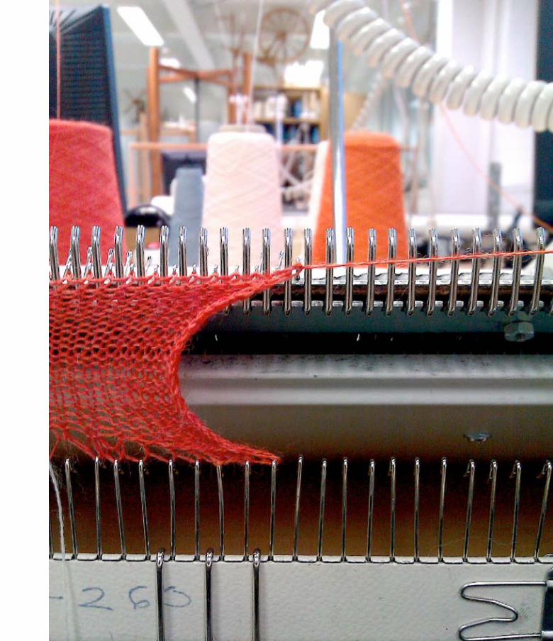
Figure 16. (Right) Close-up of fabric being knit on the knitting machine.
31

32
7. Process: Working with knitted fabrics and electronics
The overall thesis work spanned over nine months (see Figure 18). The practical work was of a highly iterative nature often going back and forth between the various steps as shown in Figure 17. One of the first steps was to create a reference base of common interactions and properties associated with textiles for a basic understanding of the medium. Since textiles were the central focus I also aimed at achieving an in-depth understanding of knitted fabrics as materials for integrating soft circuitry. A hands-on approach was taken in which sketching and prototyping were important steps for concept development. Learning to be proficient with construction and assisting tools was also an integral part of this investigative process. This portion of the project involved a material-driven production process with various soft trigger prototypes as its outcome. The other aspect of the process involved evaluation of these prototypes by relating them back to the everyday environments. A few of the triggers were also given to some test users to keep and interact with for a few days. An overall review
Figure 17. The different steps involved in the thesis process
Building a fabric reference-base
Sketching
Prototyping
Material understanding
Working with tools
Mapping fabric related actions
Collecting visual references
Listing material properties
Knitted fabrics + conductive yarns
Ways of integrating soft circuitry Knitting machine
E-textile related
Giving it out to see first reactions
Material Exploration Building e-textile interface concepts
ReflectionFabric interface analysis

33
was conducted evaluating the properties and characteristics of the soft triggers which was helpful to further the conceptual and practical understanding sought by the research queries.
The production process can be explained best by dividing it into three main categories (see Figure 19). The first was verbal and visual mapping of fabric properties followed by brainstorming ideas through sketching and then prototyping the more “realistic” sketches with a knitting machine. First I will explain the process of collecting references followed by illustrating the technical factors that were important for generating ideas. Further ahead, I highlight the nature and constraints presented by materials and tools used, and finally explain the prototyping process in detail. I would thus try to give an in-depth illustration of not only what was done but also how and why it was done.
Figure 18. Time span for thesis work.
Figure 19. Three steps of the production process.
2010 2011
Augu
st
Sept
embe
r
Oct
ober
Nov
embe
r
Dece
mbe
r
Janu
ary
Febr
uary
Mar
ch
April
May
June
July
Augu
st
Sept
embe
r
Oct
ober
Internship at Deutche Telekom Labs, Berlin.
Master thesis idea presentation, Media Lab
Research
Background research + idea evolution
Reading, finding references + developing overall concept
Production
Initail sketches
Concept sketches for prototyping
Giving out knitted prototypes for initial reactions
Knitting and experimenting with electronics
Troubleshooting, documenting
Half a day trial using industrial knitting machine at knitting factory, Otaniemi.
Reflection + Documentation
Writing
Masters thesis 2nd paper presentation, Media Lab
Paper presentation on e-textile project done for internship at Nordes design research conference
Collation, documentation, book design
Thesis submission
pre-thesis e-textile work single events time periods
Collecting referencesVisual + verbal
mappingUnderstanding
basic electronics
Learning to incorporate
other objects
Familiarizing with the
properties and constraints of materials and
tools
Sketching Knitting + Circuit planning
Idea generation Prototyping1. 2. 3.
34
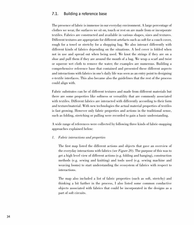
7.1. Building a reference base
The presence of fabric is immense in our everyday environment. A large percentage of clothes we wear, the surfaces we sit on, touch or rest on are made from or incorporate textiles. Fabrics are constructed and available in various shapes, sizes and textures. Different textures are appropriate for different artefacts such as soft for a couch cover, rough for a towel or stretchy for a shopping bag. We also interact differently with different kinds of fabrics depending on the situations. A bed cover is folded when not in use and spread out when being used. We knot the strings if they are on a shoe and pull them if they are around the mouth of a bag. We wrap a scarf and twist or squeeze wet cloth to remove the water; the examples are numerous. Building a comprehensive reference base that contained and presented these different aspects and interactions with fabrics in one’s daily life was seen as an entry point to designing e-textile interfaces. This also became also the guidelines that the rest of the process could align with.
Fabric substrates can be of different textures and made from different materials but there are some properties like softness or versatility that are commonly associated with textiles. Different fabrics are interacted with differently according to their form and texture/material. With new technologies the actual material properties of textiles is fast growing. However only fabric properties and actions in the traditional sense, such as folding, stretching or pulling were recorded to gain a basic understanding.
A wide range of references were collected by following three kinds of fabric-mapping approaches explained below:
1. Fabric interactions and properties
The first map listed the different actions and objects that gave an overview of the everyday interactions with fabrics (see Figure 20). The purpose of this was to get a high level view of different actions (e.g. folding and hanging), construction methods (e.g. sewing and knitting) and tools used (e.g. sewing machine and weaving looms) to start understanding the ecosystem of fabrics with respect to interactions.
The map also included a list of fabric properties (such as soft, stretchy) and thinking a bit further in the process, I also listed some common conductive objects associated with fabrics that could be incorporated in the designs as a part of soft circuits.

35
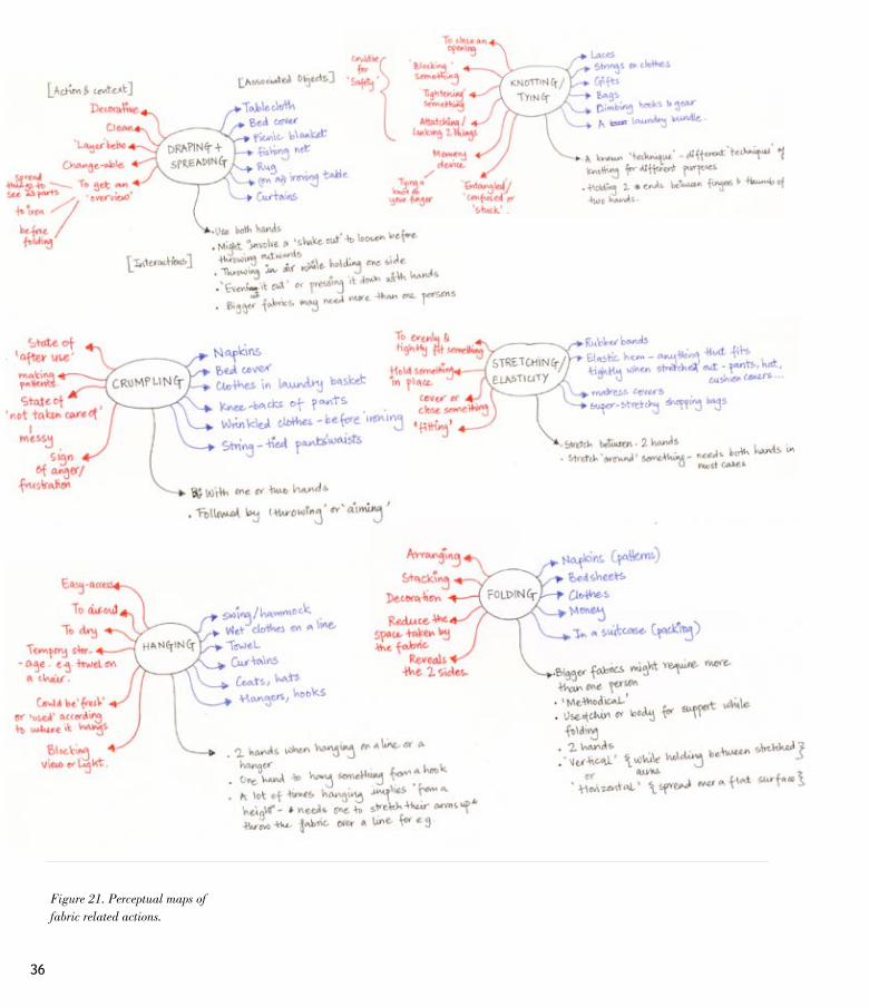
2. Mapping perceptual or situational understanding
When working with (1) it was felt that although it gave a good overview of the different interactions, the map of high-level fabric interactions was not always sufficient. A closer look was needed at some of these interactions to understand the different contexts and meanings they are commonly associated with. Working from an interaction point of view, the perceptual maps (see Figure 21) were made by listing fabric objects that are associated with a particular action and finding, through everyday life observations, the common contexts and motivations behind these actions. The physical gestures involved in each of these actions were also included.
This exercise revealed interesting aspects of fabric interactions that could be taken into account for concept development. For example the action of crumpling a piece of clothing was many times followed by throwing and aiming or the fact that sometimes more than one person is needed to interact with a piece of fabric either because of its shape or size thus bringing in a social aspect to these interactions. These insights were helpful further in the process as they enabled sketches that were more like ‘instances’ rather than ‘objects’. In other words, it helped to place or situate ideas in contexts and imagine use cases.
Figure 20. Mapping fabric interactions and properties: Mind map listing different fabric properties and fabric related actions, tools and construction techniques.
36
Figure 21. Perceptual maps of fabric related actions.

37
3. Collecting Visual References
The process of mind-mapping textile interactions and associations was also paralleled by finding visual references of the actions (see Figure 22). Collecting images and photos of these actions and properties furthered the idea generation process and enabled a richer web of associations.
Figure 22. Example of visual references collected for ‘knotting’.
Figure 23. Example of visual references collected for fabric textures.
Keeping in mind the focus on knitted fabrics, visuals of knitted textures and structures were also collected (see Figure 23). These were very helpful to imagine and seek appropriate techniques used to achieve a desired texture.
7.2. A technical approach to fabrics
While the association maps and visuals helped to paint an overview of everyday-life interactions with fabrics, a basic understanding of electronics was required for practically translating initial e-fabric interface concepts into ‘workable’ sketches.
7.2.1 Digital and analogue fabric switches
To sketch ideas for fabric interactions, it was crucial to understand how an electronic interface works. Over the years, with the growth of technology and design one sees many kinds of physical interface elements such as switches, knobs, sliders, trip switches, press buttons, touch screens etc. But at a basic level, every physical interaction generates either a digital on/off response or outputs a range of values that can be interpreted by the electronic circuit in different ways. There are numerous ways to achieve these results and some are better than others according to different contexts and needs.

38
Thus, all interactions, physical gestures and actions that are designed have to ultimately generate a measurable change in voltage to be read by a micro-controller (see Figure 24). It was realized while working with fabric triggers that they invariably include electrical noise due to being analogue circuits. This noise can be compensated or exaggerated as needed using software or other electronic components. A pure digital switch that produces only two clear values was not possible to make. Rather, digital switches in the case of knitted fabrics means those that generate a considerable difference in voltage between the on and off states. A traditional analog switch like a potentiometer in the case of knitted fabrics is one that generates determinable voltage changes proportional to the nature or extent of an interaction. The resultant change in voltage in both cases can then be translated to any programmable function.
7.2.2 Working with physical properties of other objects
The physical properties of common objects were identified to incorporate them as essential elements for activating the fabric triggers. Working with physical properties like weight, shape or size helped to generalize the requirements for making the soft triggers work and made the incorporation of other objects more flexible and open to interpretation. Figure 25 lists the various physical attributes that common domestic objects possess.
Out of the many properties listed, only a few could be prototypes as fabric interfaces. Since the knitted fabrics are soft and have some elasticity, stretching it is an intuitive action. Putting things inside knitted forms to stretch it could be one way of using external objects so that their properties like shape, size or weight could be ‘measured’ using stretch-sensitive conductive yarn. Conductivity being essential to the soft circuit was an object property that could included in many trigger concepts. Whereas temperature or moisture were more difficult to sense using only knitted fabrics.
volta
ge ch
ange
volta
ge ch
ange
INPUT (physical interaction)
m i c r o c o n t r o l l e r / electronic circuit
OUTPUT (feedback)
Fabric interface
Figure 24. Physical interaction interpreted by the micro-controller or electronic circuit in the fabric interface as change in voltage.
Figure 25. Physical properties of common domestic objects
* Conductivity* Shape* Size* Weight* Hardness/ Softness* Temperature* Elasticity* Moisture

39
7.3. Generating ideas and concept sketches
The idea generation process faced the following questions :
1. How to adapt fabric qualities to create input triggers that responded to physical properties of other objects such as weight or conductivity?
2. How to create a comprehensive mapping of the different states assumed by a soft trigger?
3. How to approach the various existing scenarios and contexts that include fabrics, for example a picnic in the park or inside a kitchen, to extract opportunities for designing electronic interactions ?
While taking inspirations from the reference base and keeping in mind the nature of electronics, the sketching process in the beginning was quite open and not constrained by practical concerns. Sketching was an important tool to articulate and think of ideas. I approached the subject from different directions as a strategy to avoid getting stuck with similar ideas while trying to cover all of the questions raised above. For instance using a fabric action as a starting point and using objects from an actual domestic setting as a starting point to brainstorm ideas for soft triggers were two different approaches that collectively led to concepts that had a wider range of forms and interactions. In the following sub-sections I would cover the different starting points or approaches taken for generating ideas for fabric triggers while also dealing with the questions above.
7.3.1 Translating fabric related actions into triggers
In this approach, the primary focus was to identify opportunities for inserting circuitry into existing fabric actions. Not much attention was paid to the use or the context from where these actions were extracted except in some cases where it came naturally.
I started from the fabric interaction map (see Section 7.1) to sketch ways of incorporating conductive thread and soft circuits in order to generate a readable electronic impulse from the listed interactions. I also kept in mind the necessary use of another object as a trigger element. It was always helpful to think of a few use cases along with the concept to better visualize the fabric interface.
For example, ‘knotting’ is a fabric action. Knotting two pieces of conductive fabric pieces could be used for making a connection (see Figure 26). Knotting, as an interaction, could thus lend itself to be a fabric ‘digital’ on/off switch. To include
Figure 26. Using the action of ‘knotting’ as a trigger.

40
other objects in this trigger, one could design it in such a way that the pieces of fabric have to be knotted to the same conductive object from its surroundings to connect them.
Similarly, stretching of fabric could be detected by using a conductive yarn that changes its resistance when pulled. A trigger that resembled a wrist band could be made such that when stretched around different objects it generates different outputs depending on the extent of stretch. This could be a way of making a soft trigger that responds to the size or shape of the object (see Figure 27).
Not all the sketches proved to be workable. Prototyping was an integral part of this process and a key factor in determining if the sketches that worked in theory would actually work when implemented with the materials. This aspect is covered in detail in section 7.5.
7.3.2 Working with ‘states’ of fabric objects
An important aspect to all approaches taken to create knitted triggers was to the ability to identify and work with different “states” of a fabric object. A blanket is folded when stored or spread when in use. A knot is tied or loose (see Figure 28). A pocket is full or empty. Extracting these formal or gestural ‘situations’ of fabrics indicating their state of ‘use’ and ‘non-use’ was a technique to relate them to, for instance, the ‘on’ and ‘off’ states in traditional electronic devices. These associations worked well as metaphors for indicating the different electronic outputs of a fabric interface while creating a more comprehensive mapping of forms and gestures.
7.3.3 Using scenarios and use-contexts as starting points
Finding places for fabric triggers to occur around objects in a real setting or scenario was another approach taken to generate ideas. I believed involving objects from one context in the design process might naturally lend itself to others as well. The situational or perceptual maps were a useful reference in this case. For example, taking ‘kitchen’ as a scenario, I was able to find objects that normally come in contact with fabrics like a handle of a cupboard drawer from which a hand towel hangs or the cutlery that is wiped with a cloth to dry. I also found other objects like a metal faucet which could used for its conductivity or for its peculiar shape and movement (see Figure 29).
Figure 27. Concept sketch of a stretchy band that responds to different thicknesses of the objects it is stretched around.
Figure 28. A pouch shaped soft trigger concept that uses the states ‘open’ and ‘close’ of a knot as indicators.

41
Starting from a place helped in involving other objects from a context while incorporating a scenario or a story that was understandable and thus also re-interpretable. A towel shape usually hangs temporarily on a handle or a hook while in use. A fabric trigger that is ‘activated’ when it is hung from a metal bar is indicative of this but can be activated by hanging from any appropriate metallic object. Thus a design inspired from one context could be generalized for multiple interpretations while involving other objects having similar physical properties as a metal handle of an drawer.
Figure 29. Sketches (Left) Using the metal handle of kitchen drawer as an activator. (Right) A soft trigger that stretches in different directions according to the movement of the nozzle of the faucet.
Conductive parts
When hung on the metal bar, the two conductive parts get connected.
7.3.4 Working with interaction methods
Different interfaces we interact with possess different yet understandable logic systems. This is communicated in many cases through their formal affordances like shape and degrees of freedom. A knob-shape, for example, can be turned. If its a full rotational knob or one with end points determines the nature of the values it is associated with. A knob is directional and linear in the sense that one has to follow path to reach the point desired. Similarly in other interfaces, the path is not a factor and one can jump directly to any needed place like in a keypad. Interacting with fabrics also work with different ‘flows’ or steps in interactions. Tying a shoe lace or buttoning a shirt follows a linear order where the same path is followed for doing a task. Similarly, folding up a sleeve or using a zipper focus more on the direction of the interaction. In other cases, the time taken or the duration of an interaction affects
The fabric stretches in different directions and makes corresponding shapes with the turning of the faucet handle and hose.

42
the feedback for example creating deep wrinkles on the couch cover as a result of long hours of use. Some other interactions work with combinations. A simple example of this would be the kind of knitted hats that have attached scarfs, depending on the combinations used, these fabric artefacts could be hats, scarfs or both.
After recognizing these different flows or methods in interactions, I attempted to use this as an approach for concept sketches while of course keeping the fabric actions and reference base in mind. So taking one ‘method’ at a time, I tried to come up with different fabric interfaces (see Figure 30 and Figure 31). This exercise was an interesting and challenging one.
* Direction* Path* Duration* Only destination* Combination
Figure 30. (Left) Example sketch for an interface that uses ‘Path’ : A soft trigger containing four buttons and a conductive string that needs to be wound around them. Depending on the path taken or the pattern created between these four buttons, different values are triggered.
Figure 31. (Right) Example for an interaction that uses ‘direction’ : A sketch for a scroll type interaction with a fabric trigger hanging on a metal rod. Different values are generated depending on the the direction of pulling.

43
7.4. Materials and tools
All the materials and tools used in the project were available in local shops or easily ordered online from within Europe. The practical exploration focused on knitted fabrics investigating it as a medium for creating soft triggers. Traditional construction tools for knitting and sewing were used to incorporate conductive yarns and for making other parts of the soft triggers. The electronics comprised of passive components such as resistors, output devices like LEDs and in some cases a Lilypad, a sewable micro-controller, to experiment with more “features”.
The characteristics and choice of these materials and tools are further explained below. Most of these aspects surfaces during prototyping. However, in the text, I present them together before going further, as describing the materials and tools in detail brings forward the constraints presented by them which defined the boundaries of the prototyping process described in the next section.
1. Knitting yarns
Knitting yarns come in different colours and thicknesses. Although not all of them are elastic in nature, the knitted structures provide elasticity to the fabric thus creating soft and flexible forms. Fine to medium fine yarns were used to knit the prototypes for this project. Regular yarns were knitted along with conductive yarns to form soft circuitry. The different conductive yarns used are explained below.
2. Conductive yarns
Conductive yarns are silver coated nylon yarns or made from steel fibres and designed to behave and be used as normal yarn. The nature of the metal coating enables these yarns to have different levels of conductance giving them different properties. I have used five kinds of conductive yarns of different thicknesses and conductive properties (see Figure 32). Table 1 shows the different conductive yarns used and their resistance values.
Conductive thread Manufacturer Resistance/ 50cm (ohms)
235/34 2 Ply HC Conductive Silver Thread Shieldex Statex 40 approx.
Bekinox steel fibre 17 approx.
Nm 50/2 Schoeller 11 approx.
Silver Plated Nylon 117/12 x 2ply Thread Shieldex Statex
234/34 4 Ply HC Conductive Silver Thread Shieldex Statex 23 approx.
Table 1: Details of the conduc-tive yarns used.
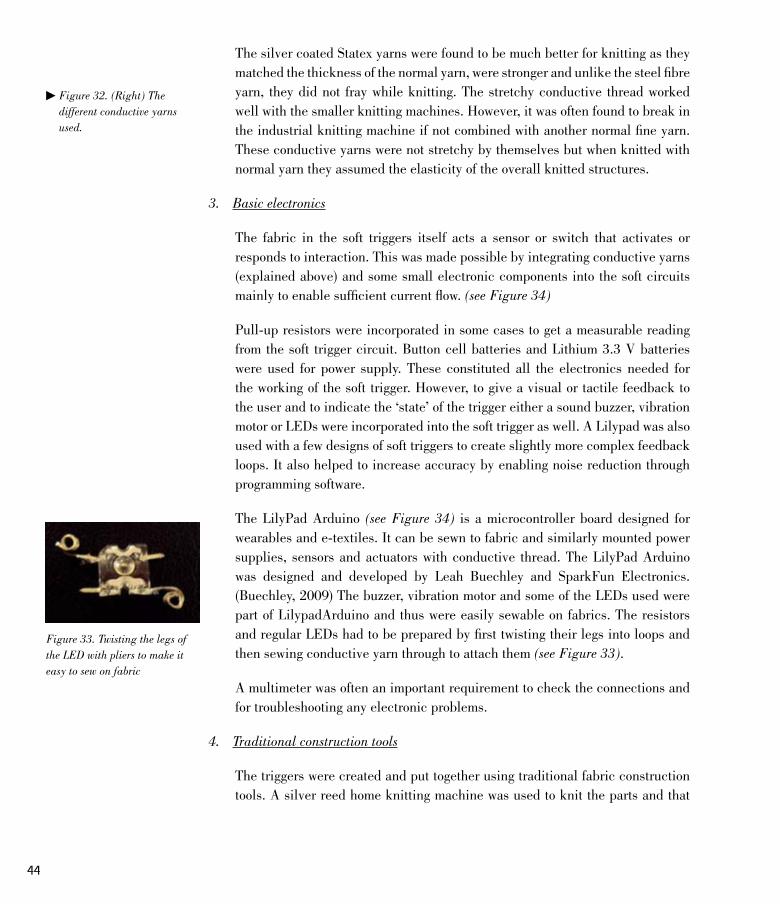
44
Figure 32. (Right) The different conductive yarns used.
Figure 33. Twisting the legs of the LED with pliers to make it easy to sew on fabric
The silver coated Statex yarns were found to be much better for knitting as they matched the thickness of the normal yarn, were stronger and unlike the steel fibre yarn, they did not fray while knitting. The stretchy conductive thread worked well with the smaller knitting machines. However, it was often found to break in the industrial knitting machine if not combined with another normal fine yarn. These conductive yarns were not stretchy by themselves but when knitted with normal yarn they assumed the elasticity of the overall knitted structures.
3. Basic electronics
The fabric in the soft triggers itself acts a sensor or switch that activates or responds to interaction. This was made possible by integrating conductive yarns (explained above) and some small electronic components into the soft circuits mainly to enable sufficient current flow. (see Figure 34)
Pull-up resistors were incorporated in some cases to get a measurable reading from the soft trigger circuit. Button cell batteries and Lithium 3.3 V batteries were used for power supply. These constituted all the electronics needed for the working of the soft trigger. However, to give a visual or tactile feedback to the user and to indicate the ‘state’ of the trigger either a sound buzzer, vibration motor or LEDs were incorporated into the soft trigger as well. A Lilypad was also used with a few designs of soft triggers to create slightly more complex feedback loops. It also helped to increase accuracy by enabling noise reduction through programming software.
The LilyPad Arduino (see Figure 34) is a microcontroller board designed for wearables and e-textiles. It can be sewn to fabric and similarly mounted power supplies, sensors and actuators with conductive thread. The LilyPad Arduino was designed and developed by Leah Buechley and SparkFun Electronics. (Buechley, 2009) The buzzer, vibration motor and some of the LEDs used were part of LilypadArduino and thus were easily sewable on fabrics. The resistors and regular LEDs had to be prepared by first twisting their legs into loops and then sewing conductive yarn through to attach them (see Figure 33).
A multimeter was often an important requirement to check the connections and for troubleshooting any electronic problems.
4. Traditional construction tools
The triggers were created and put together using traditional fabric construction tools. A silver reed home knitting machine was used to knit the parts and that

45
235/34 2 Ply HC Conductive Silver Thread
Bekinox steel fibre
Nm 50/2 80% Polyurethane, 20% Inox steel fibreThread
Silver Plated Nylon 117/12 x 2ply Thread
234/34 4 Ply HC Conductive Silver Thread
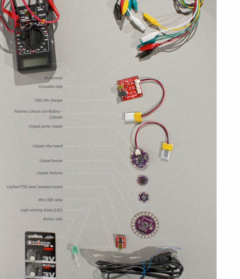
46
Multimeter
Crocodile clips
USB LiPo charger
Polymer Lithium Ion Battery - 110mAh
Lilypad power supply
Lilypad vibe-board
Lilypad buzzer
Lilypad Arduino
Mini USB cable
LilyPad FTDI basic breakout board
Light emiting diode (LED)
Button cells

47
were then stitched together by hand or with a sewing machine. Other fundamental tools like a stitch remover, measuring tape, needle threader etc were also useful (see Figure 35).
Using knitting as a technique was a decision made at an early stage in the project. The knitting machine is a unique tool and has a versatile but well defined language that needed to be studied in order to incorporate soft circuits. Like any other tool, it presented vast possibilities but also had some strict constraints. A few things to keep in mind when prototyping were that knitting only happens in one direction and that there was a possibility of having the conductive yarn only on one side of the knit depending the machine.
7.5. Prototyping
Prototyping on the whole was an extremely iterative process. Every sketch to be prototyped had to be first redrawn for the knitting machine. The soft circuit had to be planned accordingly making sure that all the conductive yarns were well insulated and that it would be secure to interact with. In most cases the trigger was knitted in parts and then sewed together later while also adding other required electronic components like resistors or LEDs.
In the below sub-sections I would give a detailed account of the prototyping process. I would also highlight some key issues like insulation and power source needed for the working of a trigger and illustrate different design solutions deployed to overcome these.
7.5.1 Knitting-drawing and circuit-planning
A sketch that needed to be prototyped first had to be drawn as it would be constructed with the knitting machine. In most cases this was determined by where the conductive yarns would be knitted for the trigger to work properly. The size and scale of the trigger were determined by doing sample knits. The drawing to be prototyped contained dimensions of each piece in centimetres or with the number of rows and columns to be knitted with the parts knitted with the conductive yarns clearly marked. (see Figure 36)
The drawings also included a plan for how the soft components would be powered and how the data cables from the triggers would be taken to the micro controller.
Figure 34. (Left) Electronic tools and components used.
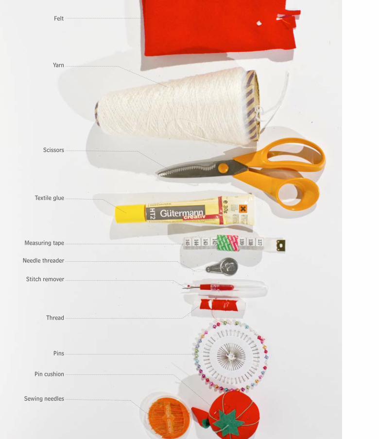
48
Felt
Yarn
Scissors
Textile glue
Measuring tape
Needle threader
Stitch remover
Thread
Pins
Pin cushion
Sewing needles
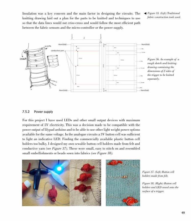
49
Figure 35. (Left) Traditional fabric construction tools used.
Figure 37. (Left) Button cell holders made from felt.
Figure 38. (Right) Button cell holders and LED sewed onto the surface of a trigger.
Insulation was a key concern and the main factor in designing the circuits. The knitting drawing laid out a plan for the parts to be knitted and techniques to use so that the data lines would not criss-cross and would follow the most efficient path between the fabric sensors and the micro-controller or the power supply.
7.5.2 Power supply
For this project I have used LEDs and other small output devices with maximum requirement of 5V electricity. This was a decision made to be compatible with the power output of lilypad arduino and to be able to use other light weight power options available for the same voltage. In the analogue circuits a 3V button cell was sufficient to light an indicative LED. Finding the commercially available plastic button cell holders too bulky, I designed my own sewable button cell holders made from felt and conductive yarn (see Figure 37). These were small, easy to stitch on and resembled small embellishments or beads sown into fabrics (see Figure 38).
Figure 36. An example of a rough sketch and knitting drawing containing the dimensions of 2 sides of the trigger to be knitted separately.

50
I also tried using a 3.3V Lithium battery in some triggers, which I found were easy to house discretely in small knitted pockets within the surface of the fabric. I used circular knitted channels to also hold LEDs and other components in many cases (see Figure 39). A detachable micro-controller (Lilypad) + power module (see Figure 40) was also designed separately to be attached to a few triggers to generate more distinct outputs. The description and design of this module is made more clear in the end of the section.
7.5.3 Stitching the knitted parts together
As mentioned before, to secure connections or to incorporate conductive yarns in a required direction, often the triggers were knitted in parts. This was followed by securing the loose hanging threads and cutting and glueing the ends to make sure they would remain in place. It was especially important to glue all the loosely hanging conductive yarn neatly so they do not create short circuits.
Most of the triggers were designed in a way that the ‘sensor part’ was knitted separately than the part carrying the soft cables. Thus the part with the hems or pockets, made to carry soft wiring, needed to be inserted with conductive yarns and stitched on the appropriate places to connect them to the sensor portions.
Once each of the pieces were prepared, they were stitched together either by hand or with a sewing machine. Once stitched the connections were checked for proper functioning which if did not work as intended was followed by troubleshooting. The LEDs and other output devices were also stitched on wherever required. (see Figure 41)
7.5.4 Thinking about output indication for triggers
Designing outputs with respect to functions associated with a fabric interface was out of the scope of this project. However, outputs as feedback of an interaction with the designed fabric triggers were essential to indicate its state.
In some analog circuits LEDs were used to indicate the current flow and the inherent noise. The LEDs would often flicker slightly and then be bright showing the inherent
Figure 39. (Left) Close up of a Lilypad LED module descretely inserted inside a circular-knitted portion. (Centre) A zoomed out view of the same knitted surface when the LED is off. (Right) The surface of the trigger when the LED is on and shines through the layer of fabric.
Figure 40. The Lilypad + power module powered with a LiPo 110mAh battery.
Figure 41. (Right) Steps involved in putting together a knitted trigger.

51
1 2 3
10
5
6 7
8 9
4
Knit in the loose threads with a needle and glue to secure them.
Cut away the extra thread to get a neat look.
Attach the parts together roughly first with pins.
Insert the conductive yarns and other components in the appropriate places.
Stitch the parts together using yarn and a needle. Remove the pins afterwards.
Sew in the metal snap-buttons at the end of data lines that need to be connected to the microcontroller.
Stitched and ready - but still inside out.
Invert for right side out. Program the microcontroller and test the trigger.
Knit the different parts of the trigger. For this one, there were 2 same-sized discs and a long knitted strip to be attached between.
glue

52
electrical noise. Although this was an accurate indication the noise and the change in brightness of the LED was not always perceivable.
I continued to work with LEDs but also tried connecting them to a micro-controller to generate more perceivable difference and in some cases to visualize the noise present in the system. Light was a good feedback especially for fabric digital switches that showed on/off states. It was also easily documented in the print format. Other outputs I tried were a buzzer for sound output and a vibration motor for a more tactile feedback.
7.5.5 Designing the micro-controller unit
After making purely analogue circuits, a need was felt to interpret signals through a micro controller for better feedback systems that can magnify small changes in voltage. A ‘Lilypad Arduino-unit’ was made such that the same unit could be used to plug different triggers. Modularity being essential, this unit was quite basic in its design. Soft data lines from the lilypad were attached to metal press buttons (see Figure 42), and the lilypad and the power units were sewed onto a flat knitted fabric.
Although it was not done for all the prototypes, some of the later soft triggers were designed to have all the soft data wires coming to the same side or portion of the trigger to make it easier to be connected with the microcontroller. They were also sewed metal snap buttons at the ends of the soft triggers to easily attach them to the corresponding leg of the micro-controller.
Figure 42. Detail of the micro-controller unit: The lilypad main board connected to metal snap buttons.

53
Figure 43. Testing the newly constructed soft triggers with a micro-controller and computer.
7.5.6 Testing , troubleshooting and programming
The prototypes once made had to be finally tested to see if everything worked as intended. The prototypes that worked without the micro-controller had to be tested to see if all the connections were well insulated and if the interaction with the fabric trigger produced the desired output. This meant first measuring the resistance changes or checking the different connections with a multimeter followed by ‘activating’ the trigger to see it working. The prototypes that worked with a micro-controller had to be further tested with a computer. As each prototype had different inputs and outputs, a different code was written and uploaded onto the lilypad micro-controller for each of the fabric triggers. Values generated from the interactions were then observed and accordingly programmed to generate the desirable output. For example, the readable values generated from a stretching trigger ranged between 40 to 500. Hence the output on the sound buzzer were mapped to correspond this specific range of values. Often it was also necessary to reduce noise coming from the circuit by averaging or omitting incorrect values in software to generate a more recognizable connection between interaction and feedback. Once everything was working well, the trigger could be disconnected from the computer and tested independently.

54
8. Results
1. Taking fabric as the main reference, various soft triggers were designed and prototyped. These soft triggers were designed to loosely sense properties of other objects such as their weight, shape, size and conductivity. The next section illustrates the different soft triggers and components created.
2. The making of prototypes and parts were documented and shared on a project process blog: www.defint.wordpress.com. This is in the public domain and can be viewed and used freely.
8.1 Gallery
This section presents the main results of the production process along with photographs and descriptions. It includes the various soft triggers designed, examples of use-cases for activating the fabric triggers with other objects in a home scenario and an explanation of how they work. A few prototypes were connected to a computer using a Lilypad to visually interpret the values they output when activated. The gallery also includes still frames showing these soft triggers controlling the programmed illustrations on screen. A copy of the Arduino and Processing sketches used to program the micro-controller and the corresponding screen illustrations respectively, are included in Appendix B.
While prototyping the triggers, some soft components were also designed like soft button cell holders or knitted cables that could be used with the soft triggers. The latter part of this section also shows the various soft components created. A set of videos showing the interaction and working of some of the soft triggers and components can be found in the included DVD – Appendix C.
The production process consisted of various steps, each involved producing a lot of visual material, for example collection of visual references and all the concept sketches. The highly iterative prototyping process involved many trials and experiments. Often

55
it took many trials before getting the yarn tension or technique right to produce the desired piece of knitted fabric. Although these were also considered as results of the production process, the gallery only includes the more finished versions of the concepts and experiments of soft triggers and components. I intend to document and give an overview of the secondary results including most of the visual materials like sketches and other trials or steps involved in knitting the soft triggers online in the project blog – www.defint.wordpress.com.
56
Page
no.
Index of the soft triggers and components presented in the section.
58
60
62
64
727273737374
66
6869
70
71
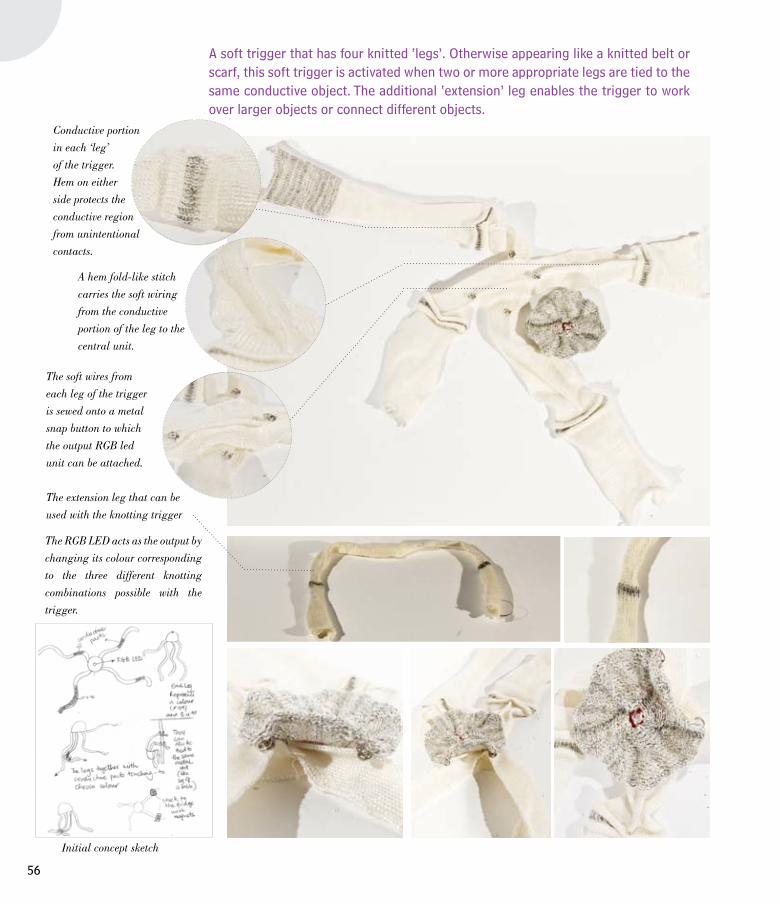
56
Conductive portion
in each ‘leg’
of the trigger.
Hem on either
side protects the
conductive region
from unintentional
contacts.
A hem fold-like stitch
carries the soft wiring
from the conductive
portion of the leg to the
central unit.
The soft wires from
each leg of the trigger
is sewed onto a metal
snap button to which
the output RGB led
unit can be attached.
The RGB LED acts as the output by
changing its colour corresponding
to the three different knotting
combinations possible with the
trigger.
The extension leg that can be
used with the knotting trigger
A soft trigger that has four knitted ‘legs’. Otherwise appearing like a knitted belt or scarf, this soft trigger is activated when two or more appropriate legs are tied to the same conductive object. The additional ‘extension’ leg enables the trigger to work over larger objects or connect different objects.
Initial concept sketch
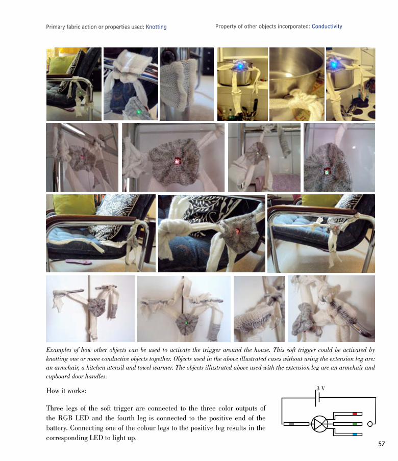
57
Primary fabric action or properties used: Knotting Property of other objects incorporated: Conductivity
How it works:
Three legs of the soft trigger are connected to the three color outputs of the RGB LED and the fourth leg is connected to the positive end of the battery. Connecting one of the colour legs to the positive leg results in the corresponding LED to light up.
Examples of how other objects can be used to activate the trigger around the house. This soft trigger could be activated by knotting one or more conductive objects together. Objects used in the above illustrated cases without using the extension leg are: an armchair, a kitchen utensil and towel warmer. The objects illustrated above used with the extension leg are an armchair and cupboard door handles.
3 V

58
Metal snap buttons at
the end of the sleeve
for connecting it to a
micro-controller
Blue conductive line on the
sleeve that can be connected
to the cuff with a sharp
conductive object like a
safety pin
Initial concept sketch
Cuff knitted with
conductive yarn.
The cuff of the sleeve can be
folded up once or multiple times
and connected to blue line on the
sleeve with a sharp conductive
object like a safety pin.
A soft trigger that resembles the sleeve of a shirt. The trigger is activated when the cuff is connected to the inside layer of the sleeve. This can be achieved by piercing through with a conductive object while folding up the sleeve. Different outputs are produced according to the number of folds made in the sleeve.

59
Examples of how other objects can be used to activate the trigger around the house. This sleeve shaped trigger could be put around an object or kept separately. Objects used in the above illustrated cases are: a safety pin, sewing pin and a badge.
Visualization of the different states of the soft trigger by connecting it to a computer with a Lilypad micro-controller. As the sleeve is rolled up and connected with a safety pin, the blue bar in the sleeve illustration on the screen gets correspondingly shorter.
Primary fabric action or properties used: Folding Property of other objects incorporated: Conductivity + sharpness
How it works:
The blue knitted line on the sleeve acts a variable resistor. The cuff is connected to the voltage line. The resistance changes with the point of contact of the cuff and the blue knitted line, reducing as the cuff is folded up closer to the other end. A sharp object is necessary to pierce through the layers making a good contact between the cuff and the appropriate point on the blue resistive line. +5 V
Ain
2.7 K Ω
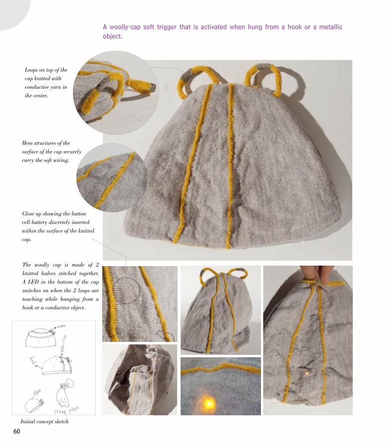
60
Loops on top of the
cap knitted with
conductive yarn in
the centre.
Hem structures of the
surface of the cap securely
carry the soft wiring.
Initial concept sketch
Close up showing the button
cell battery discretely inserted
within the surface of the knitted
cap.
The woolly cap is made of 2
knitted halves stitched together.
A LED in the bottom of the cap
switches on when the 2 loops are
touching while hanging from a
hook or a conductive object.
A woolly-cap soft trigger that is activated when hung from a hook or a metallic object.

61
The woolly cap soft trigger when worn.
Primary fabric action or properties used: Hanging Property of other objects incorporated: Conductivity
How it works:
The two loops on top of the woolly cap act as a switch between the circuit with the LED and a button cell battery. Thus hanging the cap so that the loops are connected completes the circuit and lights the LED at the bottom.
Examples of how other objects can be used to activate the trigger around the house. This soft trigger could be hung from different places in a home. Although originally designed to work with conductive objects, the soft trigger also worked when hung with the two loops touching. Hanging made the contact tighter due to its own weight. Objects used in the above illustrated cases are: handle of kitchen cabinet, a coat hanger and a metal window knob.
3 V
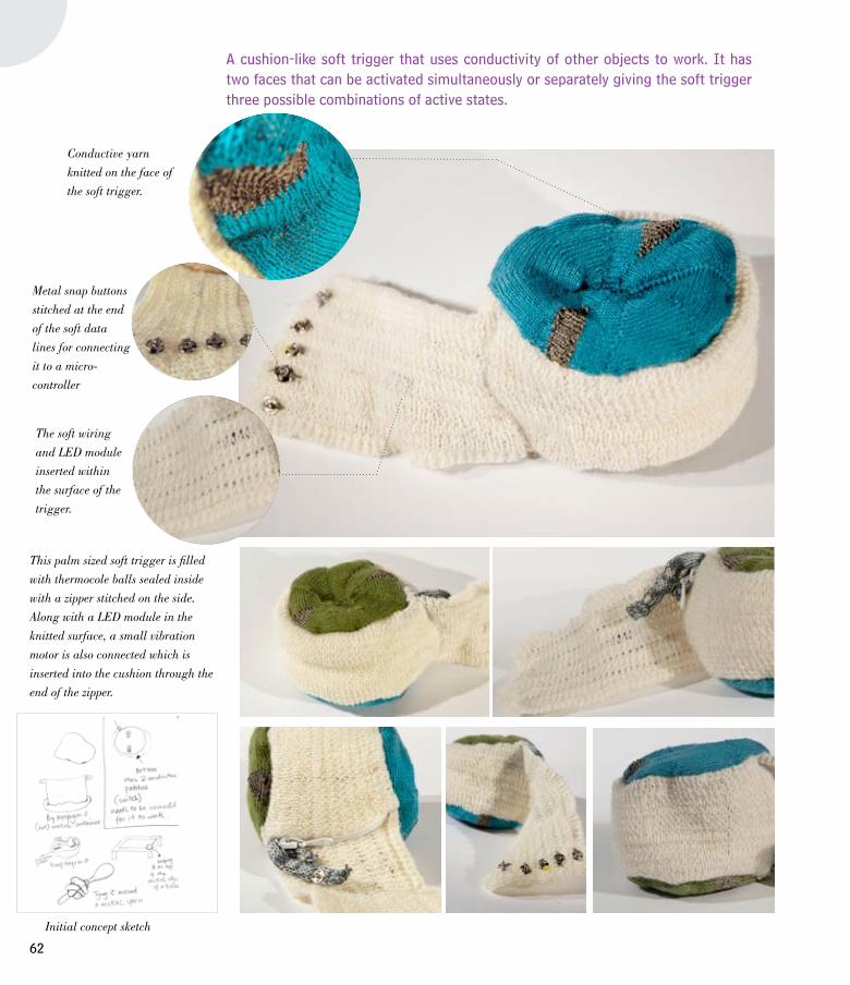
62
Conductive yarn
knitted on the face of
the soft trigger.
Metal snap buttons
stitched at the end
of the soft data
lines for connecting
it to a micro-
controller
The soft wiring
and LED module
inserted within
the surface of the
trigger.
This palm sized soft trigger is filled
with thermocole balls sealed inside
with a zipper stitched on the side.
Along with a LED module in the
knitted surface, a small vibration
motor is also connected which is
inserted into the cushion through the
end of the zipper.
A cushion-like soft trigger that uses conductivity of other objects to work. It has two faces that can be activated simultaneously or separately giving the soft trigger three possible combinations of active states.
Initial concept sketch

63
Primary fabric action or properties used: Softness Property of other objects incorporated: Conductivity
How it works:
The two conductive wedge shapes on each face of the soft trigger are connected when they come in contact with a conductive object. This completes the circuit triggering the corresponding output from the micro-controller. The green side triggers the LED and the blue side starts the vibration motor. The softness of the cushion enables it to take the form of the object it is in contact with thus making a better connection. The two faces in this case act as digital sensors and are read by the digital input pins on the Lilypad.
Examples of how other objects can be used to activate the trigger around the house. This cushion-like soft trigger could be activated by placing it over conductive objects or vice versa. Activating the green side resulted in the LED lighting up. Activating the blue side switched on a small vibration motor giving a tactile feedback. Objects used in the above illustrated cases are: Bottom of a moka pot, a utensil lid, kitchen sink, cutlery drawer and a mini swiss knife.
Visualization of the different states of the soft trigger by connecting it to a computer with a Lilypad micro-controller. The illustration on the screen responds by colouring the side corresponding to the face of the soft trigger that is activated. Both sides of the illustration are coloured when the two faces of the soft trigger are activated simultaneously.
VIBRMOTR
D1IN
D2IN
D1OUT
D2OUT

64
The other side
has three lines of
stretch-sensitive
conductive yarn.
Metal snap buttons
stitched at the end
of the soft data lines
for connecting it to
a micro-controller
Small LED modules
inserted within the
knitted surface in the
white bands.
This soft trigger is made of two parts. On
side has the stretch-sensitive conductive
thread which acts as the sensor and
other side has three corresponding
output LEDs. The soft data lines are
carried inside hem structures on the side
edges of the soft trigger.
A stretchy cylindrical soft trigger that detects the approximate shape of other objects. This knitted tube can be stretched around different shaped objects to generate different results.
Initial concept sketch

65
Primary fabric action or properties used: Stretching Property of other objects incorporated: Shape
How it works:
The soft trigger has three rows of stretch sensitive conductive yarn knitted along the width of the tube that divides it into three horizontal regions. The stretch sensitive conductive yarn changes resistance when stretched and is measured by the micro-controller. When the soft trigger is stretched over an object, the three conductive yarns give three different resistance values according to the amount of stretch. This can be loosely equated to the approximate shape of the object the soft trigger covers.
Examples of how other objects can be used to activate the trigger around the house. Apart from different shapes, the objects also needed to be larger than the knitted tube to activate it. Objects used in the above illustrated cases are: a book, a reading lamp and a cushion.
Visualization of the different states of the soft trigger by connecting it to a computer with a Lilypad micro-controller. The two white lines on the screen represent the contour of the stretchy soft trigger. The contour lines bend according to the shape of the object the soft trigger is stretched around. The portion of the soft trigger that is stretched over a certain point results in the LED in that region to light up. The three stretched regions are represented by a blue, yellow and green LED respectively.
A1IN
A2IN
A3IN
D1OUT
D2OUT
D3OUT
+5
2.7 K Ω

66
A soft button cell holder
and a LED connected to
the conductive strips on
either side.
Gaps in conductive
yarn indicating the
different regions that
can be activated.
The soft trigger has two
conductive strips on each edge.
The length of this knitted scroll
is divided into three regions that
can be activated by hanging and
‘scrolling’ the trigger around a
metal bar. There are three LEDs
corresponding to each region that
light up when activated.
A scroll-like fabric trigger that can be activated by hanging it over a metal bar. The soft trigger can be pulled down or up like a scroll around the metal bar activating a different region of the knitted scroll depending on the portion in contact with the bar.
Initial concept sketch

67
Primary fabric action or properties used: Hanging Property of other objects incorporated: Conductivity
How it works:
The conductive strips on the edge of the soft triggers are connected to a simple soft circuit with a LED and a battery. Hanging the soft trigger over a metal bar completes the circuit resulting in the LED to light up. The length of the trigger is divided into three regions. Thus by ‘scrolling’ the trigger in any direction, the colour of the LED can be controlled according to the region which is in contact with the metal bar.
Examples of how other objects can be used to activate the trigger around the house. Due to the light weight of the soft trigger, more objects were required to hold the trigger in place on the metal bar. In this case a clothes peg and a hair clip did the job. Conductive objects used in the above illustrated cases are: a hanger in the cupboard and a towel warmer in the bathroom.
3V
3V
3V

68
The soft trigger has two conductive
strips on each edge. A detachable
LED module with an integrated
battery is fixed on using metal
snap buttons. When placed over
a conductive object, the circuit
is completed causing the LED to
light up. The cushion shape is filled
with waste yarn. The mouth of the
cushion is currently open to keep
an option of filling it with another
material or using it for temporary
storage with or without the LED
module attached.
A version of the cushion-like soft trigger that can be activated using conductive objects.
Primary fabric action or properties used: Softness Property of other objects incorporated: Conductivity
Examples of how other objects can be used to activate the trigger around the house. The small cushion could be placed over or wrapped around conductive objects. The objects used in the above illustrated cases are: a candle stand, a room door handle and a cupboard door handle.

69
This pocked shaped soft trigger can be
activated with both conductive objects
and with objects of appropriate width/
size. The two knitted rows of low
resistance conductive yarn act as a
switch that activates when a conductive
object comes in contact with both the
rows. The stretch sensitive conductive
yarn on the other hand responds to
the size of the object in the pocket. A
wide enough object stretches the pocket
making the resistance across the two
ends of the stretch sensitive yarn to
drop, thus lighting the LED.
The soft trigger is knitted
with two rows of low
resistance conductive
yarn and a row of stretch
sensitive conductive yarn
in the middle.
A soft trigger that responds to the conductivity and size of the object kept inside it’s pocket.
Primary fabric action or properties used: Stretching Property of other objects incorporated: Size + conductivity
Examples of how other objects can be used to activate the trigger around the house. The objects used for their size in the above illustrated cases are: a thermos cap and a glass bottle. Objects used for their conductive properties are a couple of spoons and a wrist watch.

70
The soft trigger is made of four
conductive pompoms squeezed
between the layered surface of the
knitted fabric giving the trigger a
unique texture and tactile feel. The
pompoms are connected to LEDs and
batteries, also inserted within the
knitted fabric. Placing a conductive
object on the pompoms completes
the circuit lighting the connected
LED. There are two LEDs that can
be triggered by connecting 2 or more
pompoms in different combinations.
A soft trigger with conductive furry textures that when connected with conductive objects, activates the trigger.
Primary fabric action or properties used: Softness/ Texture Property of other objects incorporated: Conductivity
Example of how other objects can be used to activate the trigger around the house. The object used in the above illustrated case is a pair of scissors.

71
This soft trigger is a single piece
of knitted fabric. It consists of a
few knitted rows of high resistance
conductive yarn which is connected
to a LED module forming a complete
circuit. Crumpling the knitted
trigger reduces the resistance across
the two edges of the knit allowing
enough current to pass through the
soft circuit thus lighting the LED.
Initially tested with crocodile clips, I
later stitched on metal snap buttons
on either end of the knitted trigger
to be able to connect it easily to a
LED module.
A soft trigger that can be activated by crumpling it. Stuffing the knitted trigger in an appropriate sized object helps to maintain it’s crumpled state.
Primary fabric action or properties used: Crumpling Property of other objects incorporated: Volume
Examples of how other objects can be used to activate the trigger around the house. Crumpling the trigger activated it. However, objects of small enough volume were needed so that the soft trigger can be stuffed tightly inside to maintain it’s crumpled state. The objects used in the above illustrated cases are: a film canister and an i-sight webcam stand.

72
Soft components or modules designed for use with the knitted triggers:
Soft Button-cell Holders
RGB LED Module
Soft button-cell holders made
with felt and conductive thread.
They are small in size and easy
to sew on or insert between layers
of knitted fabric. Compared to the
commercially available plastic
button cell holders, my soft version
was more ‘fabricy’ and good for
integrating into soft circuits and
ideal for lighting a LED. They
were made to house a 3V button
cell battery. It is also possible to
have 2 batteries stacked inside for
a 6V output.
A circular detachable RGB LED
module that assists in visually
representing the state of the fabric
triggers it is connected to. The four
legs of the RGB LED are connected
to snap buttons at the border of
the circular form, thus making
it possible to attach it to other
components or triggers. This knitted
module also has a 3V battery in a
soft cell holder that is attached to
the LED on the reverse side.

73
Knitted Cables
Knitted Resistor Cables
Soft Component-mount
The knitted cables are narrow
tubes that have conductive yarn
threaded inside them. This provides
a well insulated means to make
soft circuitry. The conductive yarn
is stitched to metal snap buttons on
either end which make them easy to
connect with other components or
cables. Each end of the knitted cable
has both sides of the snap buttons
for convenience. This also allows
for multiple cables to be stacked
creating a junction point or parallel
connections in a circuit. These knitted
cables were mostly used to connect
the soft trigger prototypes and other
components with the Lilypad micro-
controller.
These short and brown coloured
knitted tubes are similar to the
normal knitted cables except that
they have a 2.7 K Ω resistor sewn
inside. They were used mainly as
pull-down resistors for reading
analog soft trigger values.
The soft component mount is a
small piece of knitted fabric onto
which components like a Lilypad
vibration motor is stitched on and
connected to metal snap buttons.
These components were mostly used
as output and the mounts made it
easy to attach and detach them from
the soft triggers.

74
Lilypad + Power Module
The Lilypad + power module is a band of knitted fabric with circular knitted channels that run parallel along the length of the fabric. These channels allow conductive yarn to be threaded inside them for securely connecting the different pins of the micro-controller to the corresponding metal snap buttons. For this project, I have used in total 6 pins of the Lilypad – 3 analog and 3 digital pins. The Lilypad power module is also stitched on and connected to the Lilypad with conductive yarn running through the narrow channels in the surface of the knitted fabric. The FTDI board on the Lilypad allows it to be connected to a computer with a USB cable. Alternatively, connecting a battery to the power module can also be used as more portable source of power. The metal snap buttons, one for each pin and two for power and ground respectively, are marked with different coloured threads to easily distinguish between them. The colour markers are also useful to mark the appropriate snap buttons on the soft triggers with the colour of the pin to which they would be attached.

75

76
9. Summary of insights from the production process
1. Knitting machine as a construction tool
Time and skill: Knitting enabled construction of custom-circuits on the fabric. The rich resources of knitting techniques and patterns presented different possibilities to be adapted advantageously for e-textiles, like knitting rib structures where stretchiness of the fabric was important for the trigger. Working with the knitting machine was a slow process. It often required a couple attempts to get the knitting right (see Figure 48). An understanding of using the right yarns, tensions, weights and most importantly troubleshooting when something went wrong were skills that developed slowly with practice over the period of the project.
Using an industrial knitting machine: At a later stage in the project an industrial knitting machine was used with to prototype a few triggers. The programming and the use of the industrial machine, although done by an expert, was complex and time consuming. It was found to be inefficient for small constructions especially those using thinner conductive yarns. However, it enabled speedy prototyping and gave a ‘professional’ finish to the triggers.
2. Interpreting different knitting techniques for e-textile construction:
Different knitting techniques were found to have unique properties that were useful for integrating electronics or soft circuitry in different ways. Some examples are listed below:
Ribs for stretchiness: Knitting ribs resulted in elastic structures that were useful to make triggers that responded to stretch (see Figure 45).
Inlay for texture: Inlay knitting with the combination of thick and thin yarns could be used to create tactile textures. However, in this technique the floating conductive yarn needed to be cut by hand wherever required and the ends glued to keep in place, making it impractical.
Figure 44. Knitting machine

77
Figure 48. Various attempts at knitting a disc shape before getting it as intended.
Circular knit for pockets within the fabric layer: Circular knitting in combination with regular knitting proved to be a very useful technique as it allowed for small pockets to be inserted between the layers of the surface. This was a discrete and elegant solution to incorporate small electronic components and soft wiring into the triggers (see Figure 46).
Figure 45. (Left) Knitted rib structure.
Figure 46. (Centre) Close up of a small pocket knitted using circular knitting to house battery and led.
Figure 47. (Right) A RGB LED module made with circular knitting.Two yarns for double sided knitting: With double yarn single knitting, two different
yarns could be knitted with each showing only on one side of the knitted fabric. This was a good technique to use when conductive yarn was needed to be kept only on one side of the fabric substrate.
Disc knitting for component mounts: Disc knitting was another important technique that resulted in radial conductive lines coming from the centre of the disc. This was different from the normal horizontal knitting that only produced parallel conductive lines. Thus, disc knitting was useful to incorporate small electronic components with multiple legs, like a RGB LED (see Figure 47) or a logic gate, to be placed in the centre of the disc and connected easily to the rest of the soft circuit.
3. About the properties of conductive yarns and threads used:
The workability of the prototypes was largely dependent on the different conductive yarns I was working with. Their incorporation in the soft circuitry were guided by their different properties. The insights regarding the quality of conductive yarns and their roles were as follows:

78
Using high resistance yarns: Higher resistance threads were better for making potentiometers.
Using stretch-sensitive threads: The thread that changed its resistance according to stretch was very usable in the context of knitted fabrics as they inherently have elasticity due to the knitted structures. This stretch-sensitive conductive thread (Shieldex Nm50/2) was found to work best for a width of around 50 rows when incorporated directly in the circuit without a micro-controller interpreting its values. Making the stretch-sensor too long required the fabric to be stretched to an unnatural extent in order to produce a significant change in current flow. On the other hand shorter lengths let too much current pass even when not stretched.
Using medium and low resistance yarns: The low resistance yarns were ideal for making power connections. The thin conductive yarn from Sparkfun has medium resistance and was ideal for shorter length power connections. Being much thinner, it hid better between the layers of the knitted fabric. The Sheildex yarns were easier to knit with than the Bekinox steel fibre yarns as the Sheildex ones were better twisted and did not fray or break easily while knitting with the thin needles of the machine. The Bekinox thread often broke and stretched when knitted.
The conductive threads and yarns on the whole were found to be strong and long-lasting. When stitched well, the connections were reliable and did not wear out with use.
4. Solutions for insulation:
With fabrics, insulation often becomes a crucial concern. Fabrics by nature are soft and stretchy. Conductive parts in the fabric need proper insulation in order to avoid short circuits and other malfunctions. One needed to find ways within the design to securely take the data lines to the desired output and power supply without touching each other. Through my various experiments I found the following ways to insulate soft wiring:
Layering: When more than one line of conductive yarn needed to be alongside one another, they could be put on different layers to avoid any contact. Using single knits was most appropriate as they could be layered without increasing the thickness of the surface. While this might work in some cases, it could easily become bulky if too many layers were needed.
Figure 49. An example of a knitted cable. It has metal snap button at its ends acting as connectors. The conductive yarn runs inside the knitted tube.

79
Cables: Making narrow knitted cables to house the conductive yarn was a way to cross over other conductive areas by safely taking the signal to the appropriate ‘port’. This could be designed as an aesthetic element or hidden inside the surface of the knitted trigger when possible (see Figure 49).
Hem structures: Small hems could be knitted in the fabric to form rows that carry the soft wiring. Conductive yarns could be strung through the hem securely. This was however a tedious and slow process. A similar result can be achieved by knitting a plain piece of fabric and then folding and stitching it into narrow rows (see Figure 50).
Circular knitting: Rows of circular knitting when inserted in between rows of double knit, formed narrow tubes in the fabric through which conductive yarn could be inserted. This was a good way to seamlessly integrate soft data lines and other components. However, if the circular knitting is too loose, the conductive yarn inside may be at risk of getting exposed when the material is stretched (see Figure 51).
Figure 50. (Left) Hem structures: folded rows of fabric to carry soft wiring.
Figure 51. (Right) Parallel rows of circular knitting with conductive yarn inserted.
5. Power sources
Power supplies are usually weighty, hard and require space. They are the most “un-fabricy” things that need to be carefully integrated into the triggers without making it too stiff. Thus power sources need to be accounted for early in the design process to ensure a reliable design.
Button cells: Soft button cell holders were ideal for fabric triggers that worked without the Lilypad unit. They were aesthetically easier to integrate with the knitted artefacts. Usually connected to a LED, a sewed button cell worked for a very long time. The battery could be replaced by removing the stitches along its sides and re-stitching with a new battery.
LiPo batteries: While using the micro-controller unit, the power of 3.3 V Lithium battery was sufficient to run the micro-controller and an output device. Being rechargeable and of small size made these batteries were very convenient and efficient.
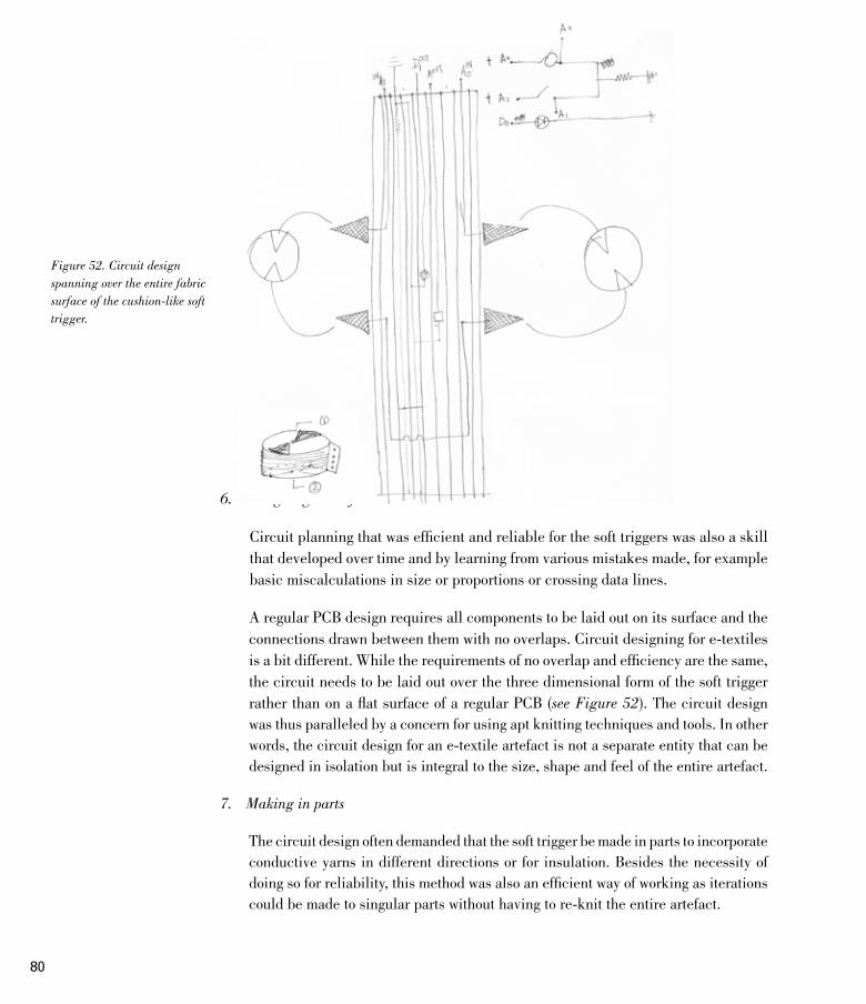
80
6. Designing the soft circuit
Circuit planning that was efficient and reliable for the soft triggers was also a skill that developed over time and by learning from various mistakes made, for example basic miscalculations in size or proportions or crossing data lines.
A regular PCB design requires all components to be laid out on its surface and the connections drawn between them with no overlaps. Circuit designing for e-textiles is a bit different. While the requirements of no overlap and efficiency are the same, the circuit needs to be laid out over the three dimensional form of the soft trigger rather than on a flat surface of a regular PCB (see Figure 52). The circuit design was thus paralleled by a concern for using apt knitting techniques and tools. In other words, the circuit design for an e-textile artefact is not a separate entity that can be designed in isolation but is integral to the size, shape and feel of the entire artefact.
7. Making in parts
The circuit design often demanded that the soft trigger be made in parts to incorporate conductive yarns in different directions or for insulation. Besides the necessity of doing so for reliability, this method was also an efficient way of working as iterations could be made to singular parts without having to re-knit the entire artefact.
Figure 52. Circuit design spanning over the entire fabric surface of the cushion-like soft trigger.
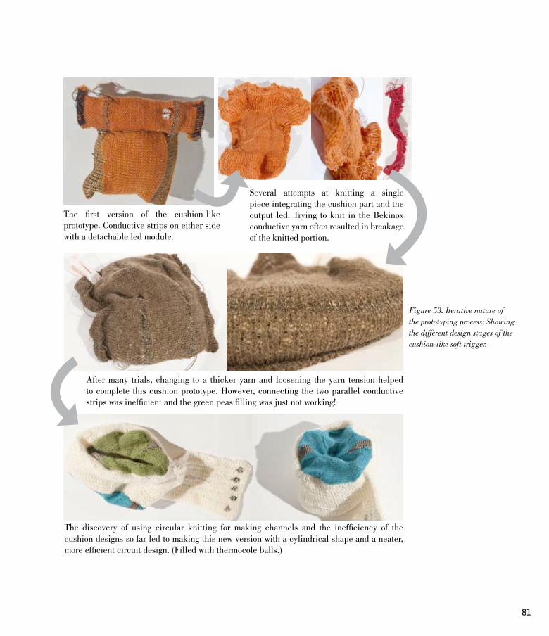
81
The first version of the cushion-like prototype. Conductive strips on either side with a detachable led module.
Several attempts at knitting a single piece integrating the cushion part and the output led. Trying to knit in the Bekinox conductive yarn often resulted in breakage of the knitted portion.
After many trials, changing to a thicker yarn and loosening the yarn tension helped to complete this cushion prototype. However, connecting the two parallel conductive strips was inefficient and the green peas filling was just not working!
The discovery of using circular knitting for making channels and the inefficiency of the cushion designs so far led to making this new version with a cylindrical shape and a neater, more efficient circuit design. (Filled with thermocole balls.)
Figure 53. Iterative nature of the prototyping process: Showing the different design stages of the cushion-like soft trigger.

82
10. Reflection
10.1. Looking at key factors that affected the design and attributes of the knitted soft triggers
Flexibility of working with conductive threads to make soft sensors:
Conductive yarns were an important invention in the field as they made it possible to create soft wiring and enabled the translation of electronic circuitry into that which is appropriate for the medium of fabrics. As most traditional sensors act essentially as potentiometers of different kinds, it was possible to make some by using only conductive threads and yarns of varying resistance while keeping the electronics at a basic level. There were mainly three kinds of soft sensors used in the triggers:
One was the stretch sensor made by knitting high resistance conductive yarn into the knitted fabric that changed it’s resistance according to the extent the fabric was pulled. The second kind was a ‘conductivity switch’ that was made by knitting an open circuit with two conductive portions that when connected with an external conductive object completed the circuit, thus activating the trigger. The third kind of sensor used was a ‘string’ potentiometer that changed the current passing through it depending on the amount of its high resistive surface that was in contact with the rest of the circuit.
These underlying three sensors were used to create the various triggers of different forms and interactions. Some fabric triggers resembled other fabric objects, for example the woollen cap shaped fabric trigger (see page 60) that is ‘activated’ by hanging it from a hook when not in use or a pocket that can sense the presence of objects inside it (see page 69). Other triggers were based on an action or gesture related to fabric like stretching or pulling but were more abstract in form, for example the tying interface with knitted ‘tentacles’ (see page 56) or the tube interface that sensed shape of the object that it is stretched around (see page 65). Looking at the these different results showed that many distinct designs and interactions could be created with the same underlying electronics. In other words, even simple soft circuits when designed specifically for the medium of fabrics could create new forms and experiences through interaction.
83
Opportunities gained from constraints of the traditional construction tools and techniques:
Producing ideas that did not deviate from the central focus of looking and feeling like traditional knitted fabrics was an important factor in designing the soft triggers. The traditional construction tools also played a crucial role in this as they provided the designs with practical constraints that were the same as those for the traditional fabrics. This led to finding new ways of constructing circuits that are not usually associated with electronics.
For example the directionality of the knitting machine forced the trigger concepts to be reworked by breaking them up into parts to assure the working of the soft circuitry. Instead of thinking about a flat circuit layout, the trigger designs needed to be broken down into knitted parts containing portions of the circuit that would later come together as a trigger. This often affected the form and shape of the triggers. On the other hand, fabric construction techniques needed to be reinterpreted for electronic purposes. ‘Re-using’ known fabric forms and aesthetics assured that the artefact would emit more fabric-like qualities than that associated with electronic interfaces. For example ‘hem stitching’ is a sewing technique involving folding up the edge of a fabric and stitching it to avoid fraying and securing loose thread ends. This results in a hollow fold at the edge of the fabric which in the context of e-textiles was ‘re-used’ for insulating soft wiring. Thus working with traditional tools and techniques led to soft trigger designs that were inspired by fabrics as material and also by aesthetic and formal elements.
Working with these tools and techniques also meant trying out different things and experimenting with different forms to find the most efficient and interesting solution. The iterative nature of the production process became apparent in many cases when one looked at the different prototypes made for the same concept or idea. In many cases, the forms were influenced directly from technical requirements presented both by electronics and the construction tools. For example, the soft cushion interface developed from a normal cushion with two conductive parts to a cylindrical shaped soft object that efficiently incorporated soft wiring to the micro-controller and introduced more possibilities for interaction (see Figure 53).
Imagining use-cases from places and near by objects for trigger concepts:
The dimensions and proportions of the soft triggers were not planned but rather loosely born from considering the objects they could interact with and the efficiency of making them. However, the size and shape of these soft triggers were often affected by how I imagined using the triggers. For example in the case of the knitted pocket, I felt that giving a tighter, constraining size provoked more trial and experimentation

84
leading to innovative interpretations than a bigger pocket that fits a large number of objects. Another example of how projecting possible use-cases affected the design was with the knotting soft trigger. When I found conductive objects disconnected from one another but in close proximity – like small door handles on rows of kitchen cabinets – I felt that expanding the capability of the knotting soft trigger to be tied over longer distances and connect different objects would make it more interesting. Hence I later knitted a long ‘extension leg’ that could be used to connect two separate metal objects or tied to the knitted legs, hoping to expand the reach of the soft trigger.
Thus, the concepts for soft triggers were influenced by objects and scenarios that were in close proximity to me and how I saw them as ‘useful’ for activating a trigger. Some features or forms got added on or changed accordingly to accommodate more diverse interpretations. Although I had some ideas for use-cases for these triggers, actually interacting with them and giving them out to others brought along another set of valuable insights.
10.2. Observations from a preliminary analysis of the soft trigger prototypes
The prototypes once made were placed back in the home environment from where the design concepts originally emerged. Since the soft triggers were designed to work with multiple objects, I tried to use different objects around the house to try and activate them. I also gave a couple prototypes to my colleagues to see their initial reactions. This was a way to study the prototypes by reflecting on the experience of interacting with them and other objects in their surroundings.
10.2.1 Insights from finding different ways to activate the soft triggers in a home scenario
While conceptualizing designs, I had some ideas regarding the different objects and scenarios where the triggers could be activated. However, the actual task of finding objects that worked with the triggers was a totally different and interesting experience than the one anticipated. The soft triggers reacted to physical properties like volume, shape and conductivity, and thus could be activated by finding an object from their environments that embodied the appropriate physical attributes. In a home setting, each trigger could be activated in multiple scenarios and using different things, thus

85
highlighting their flexibility across different use-cases. For example, the knitted legs could be activated in a kitchen scenario by tying the required combination of legs on a metal handle bar of a cupboard or knotted around the metal legs of a chair in the study. The different scenarios and objects that the triggers were placed in can be found in chapter 8.
Described below are the key insights from my experience of interacting with the soft trigger prototypes:
Revealing unexpected properties of common objects: In many cases, unexpected properties of common objects emerged while trying to get the trigger activated. For example, trying triggers that required to interact with conductive objects resulted in presuming all metallic looking objects, like door handles or chair legs, to be also conductive. This was often proved wrong when triggers did not work, thus bringing out qualities in objects different from those expected.
Intuitive analysis and comparison of near-by objects: In most cases, interacting with the knitted soft triggers and other relevant objects resulted in constantly comparing different objects with one another to assess how well they worked with the fabric trigger, thus creating an intuitive analysis of objects around, naming one to be better than other. This specially became apparent while interacting with the sleeve-shaped knitted trigger which worked with a relatively narrower set of objects. The sleeve trigger required to be folded up and pierced with a sharp conductive object in order to connect the different layers of fabric together. Sharpness being a key factor, the narrow range of common household items to be used were safety pins, badges, sewing needles, pins etc. Amongst these, the safety pin stood out as the most easy and convenient to use as there were no sharp ends sticking out and the pin could be locked in place unlike needles or pins. Thus a safety pin, originally designed to be used with traditional fabric materials, was actually the most efficient to use with this soft trigger. Using a badge was similar but a bit more tedious. The soft trigger prototypes, in this way, provided multiple options for its activation and the user could find one or various preferred ways.
Object locations and emerging patterns: While finding different ways to activate the soft trigger prototypes, I tried to utilize the entire home area for finding different objects in typical home environments like kitchen, living room or bathroom. When all the pictures taken with the working triggers were later observed, some simple patterns began to emerge, such as triggers requiring conductive objects to work were primarily placed in the kitchen or in the bathroom indicating the strong presence of such objects in these areas of a home. However, the tube trigger which responded to the shape of an object worked in a larger space of a home such as with a utensil in the kitchen, pillow in the bedroom or a chair in the study.

86
Unexpected interactions and new “problems”: There were also discrepancies between the originally anticipated interactions and the practical ones. For example the scroll shaped trigger (see page 66) was designed to be used over a metal rod-shaped object and pulled up or down around the rod to generate different outputs. Although the prototype worked well electronically, physically it was too light-weight to sit firmly on the metal rod thus a reliable connection could not be made as intended. This resulted in using other additional objects like cloth pegs or hair clips to hold the fabric trigger in place. Thus the trigger encouraged further improvisation and incorporated more objects than was originally intended.
10.2.2 Observations from giving the prototypes out to others
Along with trying to test the prototypes with different objects, I also gave a couple prototypes to some of my friends to see their initial reactions and have an informal feedback session. There were mainly two test users – Liisa and Lauri. A fabric trigger prototype was given to each of them to keep and interact with for a few days along with a scribble pad with a few directing questions to help them note down their observations and suggestions. Taking pictures of their interactions with triggers and other objects was also essential for documentation (see Figure 54 and Figure 55). The prototypes were then collected back while I asked them a few more questions about their general experience and their scribble pad- notes.
The idea behind this activity was not to conduct an in-depth user study but to loosely observe the reactions and interpretations of others. I was also curious to see these fabric artefacts in other people’s hands and how they hold or handle it. I was especially inspired by the Placebo project by Dunne and Raby (2002) and the nature of the interview questions they use for collecting insights from users about their experiences of living with the critical design artefacts made by Dunne and Raby. I followed a similar line of questioning which allowed for general feedback about the look and feel and experiences with the artefact rather than focusing on specific ‘features’ or technical aspects. My motives behind the questions were to find out how the users described or familiarized with the fabric artefact and related it to other objects they know. I was curious to see how they would understand the working of the fabric trigger and of course to see how they interpreted the fabric artefact in their home environments.
The two ‘users’ Liisa and Lauri, both had very different experiences with their fabric trigger. Below, I give a short description of each of their encounters followed by my reflections. A copy of their scribble pads can be found in appendix A.

87
1. Liisa
The fabric trigger given to Liisa was a pocket or a small bag-shaped object that had three LEDs that lit up when the appropriate part of the fabric object was stretched to a certain point. She was not told how the trigger worked as I wanted to see if she would be able to understand the trigger without any outside help. The knitted trigger was with her for 5 days during which she tried different interactions and objects to experiment and understand the knitted pocket trigger.
Reading the notes from her scribble pad and talking with her revealed that it wasn’t clear to Liisa how the trigger worked. Due to her prior knowledge of my previous prototypes, she tried working with conductive objects but felt that most of them were too heavy for the knitted pocket. Although she managed to switch on the LEDs with a few methods, she was not able to deduce a clear reasoning behind what the trigger responded to. I noticed that Liisa had tried both- putting in other objects like cellphone, coins etc into the pocket trigger and also experimented using it as cover over other objects. She tried stretching the fabric trigger but was unable to get a feedback. After many attempts, she was relieved to get the LEDs on by putting a metal spoon in the pocket. She also discovered that touching or pressing a certain part of the pocket made the LED light up. She clearly identified certain problems with the trigger showing that the pocket stretched too much under the weight of common objects like a cell phone, and that the absence of a handle or someway of fixing it to normal clothing discouraged her from carrying this trigger out of the house. Although she had found some ways of ‘activating’ the trigger with a spoon or by pressing, she expressed her difficulty and little frustration towards not finding a satisfactory and reliable interaction. She also brought forward her surprise of not finding as many conductive objects as she had expected to find around the house.
Figure 54. Some images taken by Liisa of her interactions with the soft trigger.

88
It was clear that Liisa understood the form of the trigger and its affordances very well. She was descriptive and deductive. She thought that this trigger could be a device used to remotely control lighting in her room. However, it also became apparent that the trigger had some problems as the the knitted object needed to be stretched horizontally to an unnaturally high extent for the LED to come on. Also, the first response of putting things into the pocket stretches it vertically rather than horizontally, thus a pocket like this might create a better response if it sensed vertical stretching rather than horizontal. Also, as the user herself pointed out, the mouth of the knitted trigger was a bit less stretchy making it difficult to put bigger things into the pocket.
These were clearly specific design issues that could be further developed for specific devices or scenarios. However, the more interesting insights were regarding the overall interpretation and process of understanding this unfamiliar fabric object. One was that the pocket shape of the trigger created some expectations which were identifiable and motivated Liisa to follow these expectations in her experiments. Thus using other objects intuitively became part of the process, analysing their weight, size or conductivity with respect to the trigger. Secondly, the trigger being a ‘new’ object, it took a lot of time and effort to just figure out how it worked. I felt that if I had explained the working behind the trigger then her time would have been better spent in creatively manipulating this ability of the trigger rather than only focusing on turning the led on. This may not be the case for more coherent fabric devices, but with a stand-alone fabric trigger some more introduction to the technical part was probably needed.
2. Lauri
The soft trigger given to Lauri was the scroll type long fabric that could be activated by hanging it over a metal bar. Three different LEDs could be turned on by scrolling the fabric trigger around the metal rod. Learning from my experience with Liisa, this time while introducing the fabric trigger to Lauri I also explained this original intent and the working behind the prototype.
Lauri also had the trigger for a few days. His first associations with the trigger was that it looked like a band-aid due to its colour and texture. He mentioned that the trigger felt like part of a larger whole ripped out of its original context. The soft stretchy nature of fabric assured him that it would not break easily and thus encouraged him to experiment with stretching the material. He associated numerous functions that could work with stretching of this knitted soft trigger such as a band-aid that measures pulse rate or socks that warm up when worn. He also imagined folding and squeezing as interesting interactions with the trigger.

89
He tried different things to activate the trigger like connecting the conductive parts on the knitted prototype with a wire or placing it on a metallic looking surface which were not successful. Whereas hanging the trigger on a door handle or squeezing it against a smaller conductive object worked well for activating the trigger. He explained that squeezing the soft trigger to turn the LED on was the most satisfactory interaction mostly because of the softness of the fabric and the easy feedback of leds lighting up. He also identified the need for applying pressure to make a good contact between the conductive portion of the trigger and the metallic surfaces.
It was interesting to note that knowing the initial intention behind the design and the working of the trigger, Lauri explored many other ways to activate the trigger. He even had a preferred interaction, that of squeezing the artefact rather then hanging it as initially intended. The LED coming on while squeezing the soft trigger was mainly due to a mistake in wiring where one led was inversely connected making the led come on when two conductive portions on the same side of the fabric scroll touched. This resulted in a surprising feedback and intuitive interaction of squeezing that the user discovered. Lauri had also tried wrapping the soft trigger around objects and presented quite a wide range of interpretations and interactions evoked by this fabric interface that went beyond the initial design concept.
Reflecting on my interactions with the two users and their feedback led me to the following insights:
The soft triggers embodied a clear indication towards needing other objects: Both users interpreted the triggers as needing other objects to work and both tried to explore the objects around their homes to find the ones that they thought could work with the trigger. Both fabric prototypes had some design problems but the activity of giving them out to others was largely successful as it brought forward the users’ perception and interpretations of the soft trigger while they understood that the fabric artefact was not itself an end product.
Figure 55. Some images taken by Lauri of his interactions with the soft trigger.

90
Presenting simple yet challenging constraints: Presenting clear, simple but challenging constraints in the form of physical affordances of the fabric triggers was a valuable insight. Clarity and simplicity contribute to the transparency and the ease of understanding the working of the trigger. Understanding the constraints led to more innovative solutions. This was clearly seen when a soft trigger was given to Liisa without telling her how it worked. She tried different things but was unable to understand the working of the trigger and thus lost interest in the artefact. Whereas in the other case, Lauri was told of the constraints and the intention behind how it was thought to be used. He understood the constraints and yet was able to innovate new ways to interact with the artefact that were totally different than those imagined by me, the designer. Being an unfamiliar medium and being only parts of possible interfaces, the soft triggers were not totally comprehensible, a little help and starting points defined for the user helped them to take the concept much further.
Using the element of surprise: The unfamiliarity of the medium also played a crucial role in raising curiosity and an interest to investigate and ‘play along’ with these triggers. Surprise was also an important factor for motivation behind the interaction with these soft triggers. As inferred by G.Bell et al. (2005) reflection is often triggered by an element of surprise, where someone moves from knowing-in-action, operating within the status quo, to reflection-in-action, puzzling out what to do next or why the status quo has been disrupted. The accidental squeezing of the soft scroll trigger created a surprising feedback of the LED coming on, which Lauri described as the most satisfactory interaction. It was easy to achieve, consistent and fun and thus encouraged interaction.
These were important insights that I learnt from and incorporated into the soft trigger concepts designed afterwards. These two user tests were helpful and showed that I was on the right track for evoking fabric oriented interactions while relating these fabric artefacts to their surrounding objects.
10.3. Reviewing the prototypes in relation to the research questions
The two research questions that guided this project aspired to find ways or methods of integrating electronics and fabrics that resulted in e-textile artefacts that were specific to the medium of fabrics and enabled a dialogue, through interaction, between the underlying artefact, the user and their environment. These two questions found resolution in the assumption guided production process followed in this thesis and the resulting soft trigger prototypes.

91
The design and production process closely followed the fabric properties and actions at every stage of the project. The process also studied everyday objects and identified their physical properties that could work together with the fabric qualities to create soft triggers that essentially needed other objects to work. Analysing and reflecting on the characteristics of the resulting soft triggers showed that they evoked similar interpretations of forms and materials than those we have with traditional knitted fabrics. The prototypes also proved to invite their users to have an active dialogue with their surrounding objects while interacting with the knitted soft triggers. These reflections and insights justified the design process implemented in this project as a way for creating e-textile interactions that are specific to the medium and engage their users in an active dialogue with their surroundings. Below I explain these characteristics of soft triggers in more detail to illustrate how they align to the design process sought by the research query.
The process of integrating the two contrasting materials – electronics and fabrics – led to medium specific design innovations:
Guided by the contrasting material requirements of fabrics and electronics, the design process led to multiple iterations and experiments to find ways to integrate their differences. This was a key factor in creating unique forms and techniques for constructing the soft triggers. For example the need for insulating the soft wiring was first solved by mimicking regular wires using knitted cables with conductive thread running inside them. However, the inconvenient and obstructive nature of these cables made it difficult to integrate with other knitted forms which led to innovative reinterpretations of knitting techniques and construction to make channels or stitches in the surface of the fabric triggers, hence pushing the designs forward from the obvious to the unconventional.
The presence of small but visible electronic components such as LEDs or micro controllers on the soft triggers were an instant give away, indicating that these fabric artefacts were different from the usual ones. The obvious contrast in materials thus assisted in pushing the concepts forward and also induced a sense of unfamiliarity and curiosity. The unexpected results from familiar interactions added an element of surprise. In Lauri’s case, the intuitive interaction of squeezing the soft fabric trigger resulting in the fabric surface lighting up, was surprising and acknowledged as most engaging.
Interactions with the soft trigger were motivated by fabric qualities but invited further interpretations:
The soft triggers prototyped were proofs of concepts representing parts or units of possible medium-specific fabric interfaces. Knitted fabrics were easily understood as stretchable and in many cases, the interactions evoked by them were motivated

92
by this recognition of material properties and familiar forms. Both Liisa and Lauri who were given fabric prototypes to keep, mentioned that they tried stretching the fabric triggers and they knew that the knitted fabric would not break easily. Thus following the fabric properties as stated in the assumption led directly to the design of fabric triggers that were understood, through their appearance and interaction, to be fabric-like. This made the interfaces approachable for the users to make associations and draw interpretations that were related to fabrics rather than those of regular electronic interfaces.
While the fabric material was familiar, the fabric trigger itself was not so much. This part-unfamiliarity encouraged users to explore further. An example to explain this aspect would be the soft trigger that resembles the bottom of a sleeve (see page 58) and produces different results when the sleeve shape is folded up. The form evoked a familiar action of folding or rolling up your sleeves. The sleeve shape did not have to be attached to a traditional shirt to look or be understood as a sleeve. The soft trigger thus, evoked a behaviour similar to a shirt sleeve which gave it a transparency in interaction, but because it was not attached to a traditional shirt it needed to be understood differently and had the openness to be reinterpreted in other ways.
Using other objects from the surroundings as essential to the interaction with the soft triggers was one way to actively engage the user in a dialogue with her surroundings:
The soft triggers reacted to physical properties like weight, shape and conductivity, thus could be activated by finding an object from their surroundings with the appropriate physical attributes. In a home setting, each trigger could be activated in multiple scenarios and using different things, thus highlighting their flexibility across different use-cases. Sometimes interacting with the soft triggers revealed qualities of objects, such as their conductive properties, which were otherwise not as apparent. In the case of the pocket that responded to stretch and conductive objects, Liisa expressed her surprise towards not finding as many conductive objects in her kitchen as she had imagined. In these instances, it became apparent that designing fabric triggers that reacted to other objects was a way to involve the immediate surroundings while interacting with the triggers.
The user was encouraged to be an active participant to find different ‘solutions’ for activating the soft trigger. For example, the knitted legs could be activated in a kitchen scenario by tying the required combination of legs on a metal handle bar of a cupboard or knotted around the metal legs of a chair in the study. Thus the fabric trigger provoked an immediate analysis and reinterpretation of surrounding objects in order to use them appropriately with the soft triggers. This was an effective way to create a relationship between the fabric artefact and its surroundings.

93
Thinking in a longer time frame, it might be that with trial and error the user identifies certain objects that work best with the trigger and limit to only using these ‘tried and tested’ objects. However, the process of getting to these conclusions itself would be an interesting reflective process of reanalysing and appropriating objects. Thus giving other objects roles other than the ones they normally play. Encouraging these small enquiries was a way to motivate users to find creative ways to interact with their surroundings.
11. Discussion: Space for user re-interpretations in e-textile design
Taking familiar objects out of context or mixing elements and scenarios to engage the viewer, provoke them or express a view point have been known strategies in art (for e.g surrealism that played with reality extending its possibilities and fuelling imagination). These tools have been used in design as well to bring forward the designer’s intention or support a cause. Common examples are designs that use recycled materials – chairs made from newspaper or paper roll cores. They use unconventional materials to highlight an ideology – that of sustainability or recycling. The displacement of objects from their natural environment thus gives a unique insight into alternate interpretations and taps into one’s imagination. In a similar way, the fabric materials that are part of our everyday lives can be thought to be a bit displaced from their usual context of traditional clothing or furniture when made into e-fabric triggers. The soft triggers emit the qualities of traditional knitted fabrics but embody additional capabilities. Although they evoke similar interactions like stretching or pulling, they could potentially work with different motivations and expectations. I found using the two contrasting media – electronics and fabrics – was an important factor for the mixing of familiarity and unconventionality and to play with the expectations and curiosity of the users. The ‘strangely familiar’ as described by Betsy (2003) are designs that have familiar forms but work in sophisticated ways. He discusses how designing strangely familiar artefacts can be a way for human beings to be conscious

94
of the world they increasingly make in their image (ibid.). While Betsy argues for a way of revealing the actual strangeness of the familiar through the strangely familiar, it could also be used as a tool for making design approachable and yet surprising. The strangeness is a positive quality that attracts people and invites them to interpret it in their own ways.
In alignment with the discussions presented by Gaver, Beaver and Benford (2003) about using ‘ambiguity’ to design engaging and thought provoking interactions, I also found that a certain level of ambiguity in the process of designing the fabric artefacts played an important role to bring forth reinterpretation and interactions. Design is not always driven by needs only but also inspired by new technological advancements. In this case, the invention of conductive yarns and fabrics made it possible to explore different ways of using it with conventional fabric materials to create unique interpretations and interactions. Thus the design process for the thesis was guided only by materials and interactions keeping use and functions fairly open. It was possible to make this separation between interaction and use at this explorative level due to the nature of electronic interfaces. Unlike analog interfaces that have a direct physical relationship between input and output electronic interfaces ‘interpret’ the input to an interface through an electronic circuit or software. This also makes electronic interfaces more flexible, enabling one to design interactions and experiences while keeping the output more ambiguous and user-dependent as technically any task can be programmed to be executed corresponding to a desired interaction. The functions mapped to the soft trigger interactions can be numerous – some described by the test users were controllers for light in a room or ‘intelligent’ curtains and clothing, they could also be toys or musical instruments. This can be researched further in dialogue with users and other actors involved and is not within the scope of this thesis. However, what is interesting in the interaction design of the soft triggers is the space it provides for interpretation. Some level of ambiguity with respect to how to make the trigger work, enabled the user to adapt and invent ways of doing so. In this case it would be by finding other appropriate objects that activate the soft trigger. Ambiguity should of course, not be allowed to interfere with the accomplishment of well-defined tasks but it can be used in some cases to engage the user and to express the designer’s point of view while enabling the users of different socio-cultural backgrounds to find their own interpretations (Gaver, Beaver and Benford, 2003).
If we understand interpretation as the process by which users, non-users, and designers come to assign meaning to the structures and functions of computational systems at all levels of an interaction– from physical to evocative, then it is difficult to understand interaction without interpretation (Sengers and Gaver, 2006). While traditional Human-computer interaction studies believe that a specific preferred interpretation should drive system design choices and used as a factor for measuring

95
the success of the design, Sengers and Gaver (ibid.) argue that technologies are inherently interpretively flexible, and that people appropriate and reinterpret design to deal with their varied everyday situations. They further explain that systems that are open to interpretation enable people to play a more substantial role in actively understanding both the system and its situation of use. I found by working with fabrics and electronics, that they were an apt medium to design interfaces that encouraged reinterpretations and innovativeness:
The soft triggers presented examples or snippets of interactions and experiences with possible e-fabric devices or artefacts that exhibited certain affordances and requirements while leaving room for interpretation and adaptation by the users. Often designed objects or objects in the process of design go through the different stages of being read and understood to find meaning and place in the world of their users. Akrich (1992), in her paper about the ecosystem of technical objects presents the problem of ‘inscribing’ the innovator’s vision of the world in the technical content of the new object. Thus predetermining the settings that the users are asked to imagine for a particular piece of technology without considering the practical sociological, political and actual everyday dialogues the users will have with the object. She proposes that one way of approaching this problem is to follow the negotiations between the innovator and the potential users and to study the way in which these negotiations are translated into technological form. Furthermore, one needs to go back and forth between the points of view of the designer and the user, between the world inscribed in the object and the world described by its displacement (ibid.). Having to find other objects to work with the soft triggers was a way of making the fabric prototypes flexible over different contexts. The soft triggers needed other objects to work but the extent and nature of other objects to be adapted and used with them was completely left up to the user. By opening out the possibilities of interaction with other existing objects and connecting them to the surroundings gave room for interpretation and re-appropriation. Following a similar argument as Akrich’s, the soft triggers that have a level of uncertainty already designed into them, in this case the need to literally work with surrounding objects, allowed for the negotiations between the different actors present in the interactions. Making things open ended to an extent could assist this adaptation and thus create a unique relationship with the user and her objects.

96
12. Conclusion and future development
The thesis project started from an interest to investigate the potential of using fabrics as a medium for electronic interfaces, and a keen interest in ways of designing artefacts that could engage its user in a creative dialogue with her environment. The process guided me to study the everyday scenarios and ecosystems of fabrics and to sketch many ideas of possible soft triggers that essentially incorporated physical properties of surrounding objects to work. While following the properties of the medium, trying to effectively integrate contrasting materials and including surrounding objects, a number of soft triggers were prototyped that embodied different fabric related actions and used physical properties such as shape or weight of objects to work. Interacting with these soft triggers thus evoked intuitive fabric-oriented actions while their unconventional appearance and behaviour raised the users’ curiosity, inviting them to explore further. Interacting with the triggers also meant interacting with other objects from the surroundings hence encouraging users to analyse, test and experiment with their immediate environments to make the triggers work.
The resulting soft triggers were a reflection of the process that focused on interactions and materials. Being only concept sketches, these soft triggers also possess the ability to be scaled up or down as needed. They represent the variety of explorations and working examples of e-textile interaction elements that can be produced following the approach described here. The thesis however does not include the functions or tasks that can be mapped onto these fabric triggers. Although these interaction elements can be combined and modified to form more coherent interfaces, descriptions or designs of actual soft devices produced by these methods are not covered in this project, which rather focuses mainly on the process for designing fabric-friendly interactions.
I see this project as a starting point for my future work in the field. I took an explorative approach to build my skills and knowledge in the field of e-textiles and articulate my point of view. Having done this work makes me excited and keen to delve deeper into the field and develop more coherent soft devices or artefacts that can be part of our everyday lives. The soft triggers produced were specific to the medium of

97
knitted fabrics. However the insights gained from the process of designing medium-specific interactions, working with the constraints and opportunities of the traditional construction tools and using fabric qualities to design for an active engagement with one’s everyday surroundings, gave an understanding of the medium that is applicable to any kind of fabrics.
Designing and working with knitted fabrics was a relatively time consuming process. Apart from needing to learn how to work with the tools, a considerable amount of handwork was required for putting knitted pieces together, insulating soft wiring, stitching etc. Standardized plans and knitting drawings need to be made to help duplicate and optimise the production of these soft devices by others. I feel that sharing my process would help others interested to be more time efficient. I would thus also like to develop my online project blog (www.defint.wordpress.com) further in the near future by including tutorials, circuit maps and other resources from my thesis work to share with those interested.
This project was self-funded and hence I was working with a small budget. I mostly focused on using conductive yarns and threads. These materials were easily available and in small quantities that allowed for an in-depth investigation. In the future, if I have more resources, I would also like to experiment with other materials such as conductive paints or light and temperature sensitive inks and printing techniques to create soft interfaces.
The explorative process of working with materials and prototyping was extremely engaging for me as a designer and gave many valuable insights. Having spent a lot of time working individually with the medium, it would be interesting to further my ideas and findings in a more collaborative environment. Brainstorming ideas and working with designers from other fields like textile or product design would be an opportunity to share my experiences and bring different perspectives and expertise into the process of designing new artefacts or systems using this medium.
Working on the thesis gave me valuable material knowledge. The highly iterative prototyping process made me aware of the opportunities and constraints presented by fabrics as a medium for electronic interfaces. The e-textile soft triggers not only allowed me to experiment with tools and techniques for combining electronics and fabrics but also provided a lens to critically look at the traditional view of interaction design and explore the role of play, ambiguity and accommodating user re-interpretations in the design process. Although there are new technologies and intelligent materials being researched, a large percentage of designers are still working with traditional electronics and textile materials. This project shows the wide range of experiences and interactions that can be designed with these basic materials. More over the new

98
fabric technology research can also align itself to the fabric specific approach taken in this project to create technologies that enable a new language of interaction, which is driven by textiles rather than merely copying the ones developed for traditional electronic devices. I also hope this work to be of interest to other students and amateurs in the field to learn from or take forward the ideas presented in the project.

99
References
Akrich, M. (1992). The De-scription of Technical Objects. In W. E. Bijker and J. Law (Eds.), Shaping technology/building society. Studies in sociotechnical change (pp. 205-224). Cambridge, MA, USA: MIT Press.
Bell, G., Blythe, M., Sengers, P. (2005). Making by making strange. ACM Transactions on Computer-Human Interaction, 12(2), 149-173. doi: 10.1145/1067860.1067862.
Berzowska, J. (2004). Very slowly animating textiles: shimmering flower. ACM SIGGRAPH 2004 Sketches (p. 34--). New York, NY, USA: ACM. doi: http://doi.acm.org/10.1145/1186223.1186266.
Berzowska, J. (2005a). Electronic Textiles: Wearable Computers, Reactive Fashion, and Soft Computation. Textile: The Journal of Cloth and Culture, 3(1), 58-75. doi: 10.2752/147597505778052639.
Berzowska, J. (2005b). Memory rich clothing: second skins that communicate physical memory. Proceedings of the 5th conference on Creativity and Cognition (pp. 32-40). London, UK: ACM Press. doi: 10.1145/1056224.1056231.
Berzowska, J. and Coelho, M. (2005). Kukkia and Vilkas: kinetic electronic garments. Ninth IEEE International Symposium on Wearable Computers (pp. 82-85). Retrieved November 4, 2010, from http://ieeexplore.ieee.org/xpls/abs_all.jsp?arnumber=1550790.
Betsky, A. (2003). The strangeness of the familiar in design. In P. Johnson & K. McLean (Eds.), Strangely familiar: Design and everyday life (pp. 38-55). Minneapolis, Minnesota: Walker Art Centre.
Brandes, U. and Erlhoff, M. (2006). Non Intentional Design (NID) (p. 160). Retrieved August 17, 2011, from http://www.citeulike.org/group/7111/article/3399643?citation_format=harvard#.
Buechley, L. (2006). A Construction Kit for Electronic Textiles. 2006 10th IEEE International Symposium on Wearable Computers, 83-90. Ieee. doi: 10.1109/ISWC.2006.286348.
Buechley, L. (2009). Arduino LilyPad. Retrieved July 18, 2011, from http://www.arduino.cc/en/Main/ArduinoBoardLilyPad.
Buechley, L. and Eisenberg, M. (2007). Fabric PCBs, electronic sequins, and socket buttons: techniques for e-textile craft. Personal and Ubiquitous Computing, 13(2), 133-150. doi: 10.1007/s00779-007-0181-0.
Buechley, L., Eisenberg, M., Catchen, J. and Crockett, A. (2008). The LilyPad Arduino: using

100
computational textiles to investigate engagement, aesthetics, and diversity in computer science education. Proceeding of the twenty-sixth annual SIGCHI conference on Human factors in computing systems (pp. 423-432). New York, NY, USA: ACM. doi: http://doi.acm.org/10.1145/1357054.1357123.
Cunha, J. P. S., Cunha, B., Pereira, A. S., Xavier, W., Ferreira, N. and Meireles, L. (2010). Vital-Jacket® : A wearable wireless vital signs monitor for patients’ mobility in Cardiology and Sports. 4th International ICST Conference on Pervasive Computing Technologies for Healthcare. Munich, Germany. Retrieved October 2, 2011, from http://www.biodevices.info/en/media/uploads/VJ/docs_download/VJ_Munich_2010.pdf.
Dunne, A. (2005). Hertzian Tales: Electronic Products, Aesthetic Experience, and Critical Design (p. 174). MIT press. Retrieved September 15, 2011, from http://mitpress.mit.edu/catalog/item/default.asp?tid=10771&ttype=2.
Dunne, A. and Raby, F. (2001). Design Noir: The secret life of electronic objects. Basel: Birkhäuser.
Dunne, A. and Raby, F. (2002). The Placebo project. DIS ’02: Proceedings of the 4th conference on Designing interactive systems (pp. 9-12). New York, NY, USA: ACM. doi: http://doi.acm.org/10.1145/778712.778714.
Eric. (2008). Intelligent clothing for the safety of Firefighters - talk2myShirt. Talk2myshirt.com/blog. Retrieved February 16, 2011, from http://www.talk2myshirt.com/blog/archives/390.
Gaver, W., Beaver, J. and Benford, S. (2003). Ambiguity as a resource for Design. Proceedings of the conference on Human factors in computing systems - CHI ’03 (p. 233). New York, New York, USA: ACM Press. doi: 10.1145/642651.642653.
Gaver, W., Bowers, J., Boucher, A., Law, A., Pennington, S. and Villar, N. (2006). The History Tablecloth: Illuminating Domestic Activity. Proceedings of DIS 2006 (pp. 199-208). University Park: ACM Press.
Gaver, W., Bowers, J., Boucher, A. and Pennington, S. (2004). The Drift Table: Designing for Ludic Engagement. Proceedings of CHI 2004. Vienna, Austria: ACM Press.
Gowrishankar, R., Bredies, K. and Chow, R. (2011). The Music Sleeve : Fabric As An Electronic Interface Medium. Nordic Design Research Conferences. North America 31 03 2011. Retrieved from http://ocs.sfu.ca/nordes/index.php/nordes/2011/paper/view/400.
Grant, S. and Grant, L. (2010). FSP 005 Modular Synth. Felted Signal Processing. Retrieved February 17, 2011, from http://www.fsp.fm/index.php/projects/project/fsp_005_modular_analog_synth/.

101
ISN/MIT. (2002). Institute for Soldier Nanotechnologies @ MIT. Retrieved October 2, 2011, from http://web.mit.edu/isn/index.html.
Jennifer. (2011). Zip: Control your music | electricfoxy. Retrieved March 21, 2011, from http://www.electricfoxy.com/2011/01/zip-control-your-music/.
MIThril. (2003). MIThril. Retrieved July 3, 2011, from http://www.media.mit.edu/wearables/mithril/.
NuMetrex. (2005). Strapless Heart Rate Monitor Clothes by NuMetrex. Retrieved February 16, 2011, from http://www.numetrex.com/.
Perner-Wilson, H. (2008a). Joypad. Plusea.at. Retrieved February 17, 2011, from http://www.plusea.at/?p=521.
Perner-Wilson, H. (2008b). JoySlippers. Plusea.at. Retrieved February 17, 2011, from http://www.plusea.at/?p=111.
Perner-Wilson, H. and Satomi, M. (2007). How To Get What You Want. Kobakant.at. Retrieved February 17, 2011, from http://www.kobakant.at/DIY/?cat=26.
Post, E Rehmi and Orth, M. (1997). Smart Fabric, or “Wearable Clothing”. Proceedings of the 1st IEEE International Symposium on Wearable Computers (p. 167--). Washington, DC, USA: IEEE Computer Society. Retrieved from http://portal.acm.org/citation.cfm?id=851036.856432.
Post, Ernest Rehmatulla. (1999). E-broidery : An Infrastructure for Washable Computing by. Science.
Post, Ernest Rematullah. (1997). Early Smart Textiles Projects : Electronic Fashions (pp. 151-161).
Rhodes, B. (2000). A brief history of wearable computing. Retrieved February 15, 2011, from http://www.media.mit.edu/wearables/lizzy/timeline.html.
Rowberg, J. (2011). Keyglove. Retrieved August 17, 2011, from http://www.keyglove.net/.
Sengers, P. and Gaver, W. (2006). Staying Open to Interpretation: Engaging Multiple Meanings in Design and Evaluation. Proceedings of DIS 2006 (pp. 99-108). University Park: ACM Press.
Stretchable circuits. (2008). Klight Dress. Retrieved February 15, 2011, from http://www.stretchable-circuits.com/projects/fashion.

102
APPENDIX ASome sheets from the scribble pads filled by Liisa and Lauri to record their interactions with the fabric triggers.
The scribble pads had mainly four questions:
1. How would you describe the fabric object that you have been given?
2. What interactions do you think will be possible with this object?
3. Have you found a way to light the LED on the fabric object? Can you think of more ways or
places where it could work?
4. Right now the interface output is indicated by lighting the appropriate LED. But lets stretch
our imagination a little. If this object could trigger anything, absolutely anything, what
would you want it to do?

103
Scribble sheets from Liisa

104
Scribble sheets from Lauri

105

106
APPENDIX BLilypad- Arduino codes along with the corresponding Processing sketches used to visualize the values from three of the soft triggers.
Arduino code for the sleeve-like soft trigger (see
Page 58). The values are printed on the serial
that is read by the Processing sketch and inter-
preted to change the length of the blue bands
in the illustration.
int sensorPin = 0; int ledPin = 13; // LED is connected to digital pin 13int speakerPin = 11;float sensorValue = 0;
int arraysize = 5; //quantity of values to find the median //(sample size). Needs to be an odd numberlong rangevalue[] = { 0, 0, 0, 0, 0};
void setup() { pinMode(sensorPin, INPUT); pinMode(ledPin, OUTPUT); pinMode(speakerPin, OUTPUT); Serial.begin(9600);}
void loop() {
for(int i = 0; i < arraysize; i++) { rangevalue[i]=analogRead(sensorPin);
} medSort(rangevalue, arraysize); sensorValue = rangevalue[arraysize/2]; Serial.print(sensorValue); Serial.print(“,”); delay(1000); // delay for 1 second}
void medSort(long *a, int n) // function for noise reduction// *a is an array pointer function{ for (int i = 1; i < n; ++i) { long j = a[i]; long k; for (k = i - 1; (k >= 0) && (j < a[k]); k--) { a[k + 1] = a[k]; } a[k + 1] = j; }}
import processing.serial.*;
Serial myPort; // Create object from Serial classString val; // Data received from the serial port
float rectMax;float rectTarget;float rectCurr ;float speed = 0.01; //how fast to interpolate between rectCurr and rectTragetfloat sleeveVal;float sensorMin = 1001;float sensorMax = 1015;PImage sleeve;void setup(){ sleeve = loadImage(“graphics_sleeve.png”); size(600, 800); smooth(); rectMax = 900; rectTarget = 0; // hte target height in the range 0..1 rectCurr =0; // the current height in the range 0..1 sleeveVal =0; String portName = Serial.list()[0]; myPort = new Serial(this, portName, 9600);}

107
Arduino code for the stretchy tube shaped
interface (see Page 64). The values are
printed on the serial that is read by the
Processing sketch and interpreted to change
the shape of the two parallel lines in the
illustration.
void draw(){ background(255); noStroke(); if(abs(rectTarget-rectCurr) > speed){ rectCurr += rectTarget>rectCurr ? speed : - speed; } translate(160,0); scale(0.66); image(sleeve,0,0); rect(224,66,27,40+rectMax*(1-rectCurr)); fill(55,171,200); if ( myPort.available() > 0) { // If data is available, val = myPort.readStringUntil(‘,’); // read it and store it in val if(val==null) return; try{ sleeveVal =Float.parseFloat(val.substring(0,val.length()-1).trim()); println(val); } catch(Exception e){ } } rectTarget = sleeveVal<=0 ? 0: map(sleeveVal,sensorMin,sensorMax,0,1);}
/* Built on - http://arduino.cc/en/Tutorial/AnalogInput */
int sensorPin = 0;int sensorPin2 = 1;int sensorPin3 = 2;int ledPin = 13; int ledPin2 = 12;int ledPin3 = 11;
// variable to store the value coming from the sensorint sensorValue = 0;int sensorValue2 = 0;int sensorValue3 = 0;
void setup() {
pinMode(sensorPin, INPUT); pinMode(ledPin, OUTPUT); pinMode(sensorPin2, INPUT); pinMode(ledPin2, OUTPUT); pinMode(sensorPin3, INPUT); pinMode(ledPin3, OUTPUT);
Serial.begin(9600);}
void loop() { // read the values from the sensor: sensorValue = analogRead(sensorPin); sensorValue2 = analogRead(sensorPin2); sensorValue3 = analogRead(sensorPin3);
//write the values in the serial for the processing sketch to read Serial.print(sensorValue); Serial.print(“,”); Serial.print(sensorValue2); Serial.print(“,”); Serial.print(sensorValue3); Serial.print(“.”);
//light the LED when strecthed beyond 200 if(sensorValue>200 ){ digitalWrite(ledPin, LOW); } else{ digitalWrite(ledPin, HIGH); } if(sensorValue2>200 ){ digitalWrite(ledPin2, LOW); } else{ digitalWrite(ledPin2, HIGH); } if(sensorValue3>200 ){ digitalWrite(ledPin3, LOW); } else{ digitalWrite(ledPin3, HIGH); } delay(100);}
import controlP5.*;
import processing.serial.*;
Serial myPort; // Create object from Serial classString val; // Data received from the serial port

108
//sensor valuesfloat Top = 0;float Middle = 0;float Bottom = 0;float sensorMin = 5;float sensorMax = 450;
//visualization point mapped coordinatesPVector pointTop;PVector pointMiddle;PVector pointBottom;
//point movement speedfloat speed = 0.01;
//rest point horizontal coordinatefloat restPoint;
//max distance from rest pointfloat maxDistance;
//Used to reflect drawingPImage reflection;
//A chalk style brushint brushSize = 10;PImage brush;
void setup(){ size(800, 500); smooth(); restPoint = width/3.0; maxDistance = restPoint-30; pointTop = new PVector(0,30); pointMiddle = new PVector(0, height/2); pointBottom = new PVector(0, height-30); brush = loadImage(“brush_black_thin.png”); String portName = Serial.list()[0]; myPort = new Serial(this, portName, 9600);}
void draw(){ stroke(255); noFill(); strokeWeight(5); if ( myPort.available() > 0) { // If data is available, val = myPort.readStringUntil(‘.’); // read it and store it in val if(val==null) return; try{ String[] stretchValues = val.substring(0,val.length()-1).trim().split(“,”);
if(stretchValues.length > 0) Top = map(Float.parseFloat(stretchValues[0]),sensorMin,sensorMax,0,1); if(stretchValues.length > 1) Middle = map(Float.parseFloat(stretchValues[1]), sensorMin,sensorMax,0,1); if(stretchValues.length > 1) Bottom = map(Float.parseFloat(stretchValues[2]), sensorMin,sensorMax,0,1); } catch(Exception e){ } } background(0); //update points position if( abs(pointTop.x-Top) > speed ){ pointTop.x += pointTop.x<Top ? speed : -speed; } if( abs(pointMiddle.x-Middle) > speed ){ pointMiddle.x += pointMiddle.x < Middle ? speed : -speed; } if( abs(pointBottom.x-Bottom) > speed ){ pointBottom.x += pointBottom.x < Bottom ? speed : -speed; } //draw curve pushMatrix(); translate(restPoint,0); beginShape(); curveVertex( -pointTop.x*maxDistance, pointTop.y ); curveVertex( -pointTop.x*maxDistance, pointTop.y ); curveVertex( -pointMiddle.x*maxDistance, pointMiddle.y ); curveVertex( -pointBottom.x*maxDistance, pointBottom.y ); curveVertex( -pointBottom.x*maxDistance, pointBottom.y ); endShape(); popMatrix(); imageMode(CORNER); //copy left side of drawing and flip and past on the other side reflection = get(0,0,width/2,height); scale(-1,1); image(reflection,-width,0);}
void controlEvent(ControlEvent theControlEvent) { if(theControlEvent.controller().name().equals(“rangeController”)) { // min and max values are stored in an array. // access this array with controller().arrayValue(). // min is at index 0, max is at index 1. sensorMin = theControlEvent.controller().arrayValue()[0]; sensorMax = theControlEvent.controller().arrayValue()[1]; }}

109
Arduino code and Processing sketches for the soft cushion-like soft trigger (see Page 62). The processing sketch responds to the states of the trigger by colouring the corresponding side of the illustration.
int ledPin = 11;int vibPin = 13;int switchPin = 16;int switchPin2 = 14;int switchValue;int switchValue2;
void setup(){ pinMode(ledPin, OUTPUT); pinMode(switchPin, INPUT); pinMode(switchPin2, INPUT); digitalWrite(switchPin, HIGH); digitalWrite(switchPin2, HIGH); Serial.begin(9600);}
void loop(){ switchValue2 = digitalRead(switchPin2); switchValue = digitalRead(switchPin); if(switchValue == LOW){ digitalWrite(ledPin, HIGH); Serial.print(“1,”); } else{ digitalWrite(ledPin, LOW); Serial.print(“2,”); } if(switchValue2 == LOW){ digitalWrite(vibPin, HIGH); Serial.print(“1.”); } else{ digitalWrite(vibPin, LOW); Serial.print(“2.”); } }
import processing.opengl.*;import geomerative.*;import processing.serial.*;Serial myPort; // Create object from Serial classString val; // Data received from the serial portRShape shp;PImage buttons;
int first = 0;void setup(){ buttons = loadImage(“graphics_cushion22.png”); size(buttons.width,buttons.height); smooth(); RG.init(this); shp = RG.loadShape(“graphics_cushion_no_circle.svg”); shp = RG.centerIn(shp, g); String portName = Serial.list()[0]; myPort = new Serial(this, portName, 9600);}
void draw(){ background(179); noStroke(); rect(0,0,width,height/3); fill(100); translate(width/2,height/2); RG.shape(shp); resetMatrix(); scale(0.80); translate(15,87); image(buttons,0,0); if ( myPort.available() > 0) { // If data is available, val = myPort.readStringUntil(‘.’); println(val); // read it and store it in val if(val==null) return; try{ String[] cushionValues = val.substring(0,val.length()-1).trim().split(“,”); if(cushionValues.length > 0) { if(Integer.parseInt(cushionValues[0]) > 0){ shp.getChild(“blue1”).setFill(color(55,171,200)); } else{ shp.getChild(“blue1”).setFill(color(255,255,255)); } } if(cushionValues.length > 1){ if(Integer.parseInt(cushionValues[1]) > 0){ shp.getChild(“green1”).setFill(color(136,170,0)); } else{ shp.getChild(“green1”).setFill(color(255,255,255)); } } } catch (Exception e){ println(“OOOPS!!”) ; } }}

110
APPENDIX CA set of videos showing the interaction and working of some of the soft triggers and components in the DVD.

111
Ramyah Gowrishankar
www.defint.wordpress.com
www.narrativize.net
Copyright © 2022 FDOKUMEN